Yamaha 2009 Vmax Owners Manual
Vmx17Yc-Users-Manual yamaha-vmx17yc-users-manual-134095
VMX17Y(C) to the manual cc147db8-f58a-4a32-9de3-77bc08b04d36
2015-03-13
: Yamaha 2009-Vmax-Owners-Manual yamaha-2009-vmax-owners-manual-648491 yamaha pdf
Open the PDF directly: View PDF ![]() .
.
Page Count: 114 [warning: Documents this large are best viewed by clicking the View PDF Link!]
- 2S3-28199-10
- INTRODUCTION
- IMPORTANT MANUAL INFORMATION
- TABLE OF CONTENTS
- LOCATION OF IMPORTANT LABELS
- SAFETY INFORMATION
- DESCRIPTION
- INSTRUMENT AND CONTROL FUNCTIONS
- FOR YOUR SAFETY – PRE-OPERATION CHECKS
- OPERATION AND IMPORTANT RIDING POINTS
- PERIODIC MAINTENANCE AND ADJUSTMENT
- MOTORCYCLE CARE AND STORAGE
- SPECIFICATIONS
- CONSUMER INFORMATION
- INDEX

2S3-28199-10
VMX17Y(C)
OWNER’S MANUAL
Read this manual carefully before operating this vehicle.
LIT-11626-22-64
EAU10042
Read this manual carefully before operating this vehicle. This manual should stay with this vehicle if it is sold.
Q
INTRODUCTION
EAU10081
Congratulations on your purchase of the Yamaha VMX17Y(C). This model is the result of Yamaha’s vast experience in the
production of fine sporting, touring, and pacesetting racing machines. It represents the high degree of craftsmanship and
reliability that have made Yamaha a leader in these fields.
This manual will give you an understanding of the operation, inspection, and basic maintenance of this motorcycle. If you
have any questions concerning the operation or maintenance of your motorcycle, please consult a Yamaha dealer.
The design and manufacture of this Yamaha motorcycle fully comply with the emissions standards for clean air applicable
at the date of manufacture. Yamaha has met these standards without reducing the performance or economy of operation of
the motorcycle. To maintain these high standards, it is important that you and your Yamaha dealer pay close attention to the
recommended maintenance schedules and operating instructions contained within this manual.
Yamaha continually seeks advancements in product design and quality. Therefore, while this manual contains the most cur-
rent product information available at the time of printing, there may be minor discrepancies between your motorcycle and this
manual. If there is any question concerning this manual, please consult a Yamaha dealer.
WARNING
EWA10011
Please read this manual and the “YOU AND YOUR MOTORCYCLE: RIDING TIPS” booklet carefully before operating
this motorcycle. Do not attempt to operate this motorcycle until you have attained adequate knowledge of its con-
trols and operating features. Regular inspections and careful maintenance, along with good operating techniques,
will help ensure that you safely enjoy the capabilities and reliability of this motorcycle.
IMPORTANT MANUAL INFORMATION
EAU10132
Particularly important information is distinguished in this manual by the following notations:
This is the safety alert symbol. It is used to alert you to potential personal injury
hazards. Obey all safety messages that follow this symbol to avoid possible injury
or death.
A WARNING indicates a hazardous situation which, if not avoided, could result in
death or serious injury.
A NOTICE indicates special precautions that must be taken to avoid damage to the
vehicle or other property.
A TIP provides key information to make procedures easier or clearer.
WARNING
NOTICE
TIP
IMPORTANT MANUAL INFORMATION
EAU10193
VMX17Y(C)
OWNER’S MANUAL
©2008 by Yamaha Motor Corporation, U.S.A.
1st edition, July 2008
All rights reserved.
Any reprinting or unauthorized use
without the written permission of
Yamaha Motor Corporation, U.S.A.
is expressly prohibited.
Printed in Japan.
P/N LIT-11626-22-64

TABLE OF CONTENTS
LOCATION OF IMPORTANT
LABELS
..............................................1-1
SAFETY INFORMATION
...................2-1
DESCRIPTION
...................................3-1
Left view ...........................................3-1
Right view .........................................3-2
Controls and instruments..................3-3
INSTRUMENT AND CONTROL
FUNCTIONS
........................................4-1
Main switch/steering lock .................4-1
Indicator and warning lights .............4-2
Speedometer unit ............................4-4
Multi-function display .......................4-5
Handlebar switches .......................4-12
Clutch lever ....................................4-14
Shift pedal ......................................4-14
Brake lever ....................................4-15
Brake pedal ...................................4-15
ABS ...............................................4-16
Fuel tank cap .................................4-17
Fuel ................................................4-18
Catalytic converters .......................4-19
Seats .............................................4-20
Adjusting the front fork ...................4-22
Adjusting the shock absorber
assembly ....................................4-24
Luggage strap holders ...................4-26
EXUP system ................................4-26
Sidestand ...................................... 4-26
Ignition circuit cut-off system ......... 4-27
FOR YOUR SAFETY –
PRE-OPERATION CHECKS
.............. 5-1
OPERATION AND IMPORTANT
RIDING POINTS
.................................. 6-1
Starting the engine .......................... 6-1
Shifting ............................................ 6-2
Engine break-in ............................... 6-3
Parking ............................................ 6-4
PERIODIC MAINTENANCE AND
ADJUSTMENT
.................................... 7-1
Owner’s tool kit ................................ 7-2
Periodic maintenance chart for the
emission control system .............. 7-3
General maintenance and
lubrication chart ........................... 7-4
Removing and installing the
cowling and panels ...................... 7-9
Checking the spark plugs .............. 7-11
Canister (for California only) ......... 7-12
Engine oil and oil filter cartridge .... 7-12
Final gear oil .................................. 7-15
Coolant .......................................... 7-17
Air filter element ............................ 7-20
Checking the engine idling
speed ......................................... 7-20
Checking the throttle cable free
play ............................................ 7-21
Valve clearance ............................ 7-21
Tires .............................................. 7-21
Cast wheels .................................. 7-24
Clutch lever ................................... 7-24
Checking the front brake lever
free play ..................................... 7-24
Adjusting the rear brake light
switch ......................................... 7-25
Checking the front and rear brake
pads ........................................... 7-25
Checking the brake fluid level ....... 7-26
Changing the brake and clutch
fluids .......................................... 7-27
Checking and lubricating the
cables ........................................ 7-27
Checking and lubricating the
throttle grip and cable ................ 7-28
Checking and lubricating the
brake and clutch levers .............. 7-28
Checking and lubricating the
brake pedal ................................ 7-29
Checking and lubricating the
shift pedal .................................. 7-29
Checking and lubricating the
sidestand ................................... 7-29
Checking the front fork .................. 7-30
Checking the steering ................... 7-30
Checking the wheel bearings ........ 7-31
Battery ........................................... 7-31

TABLE OF CONTENTS
Replacing the fuses .......................7-34
Replacing the headlight bulb .........7-36
Tail/brake light ...............................7-37
Replacing a turn signal light
bulb ............................................7-37
Replacing a license plate light
bulb ............................................7-38
Replacing the auxiliary light
bulb ............................................7-39
Supporting the motorcycle .............7-40
Troubleshooting .............................7-40
Troubleshooting charts ..................7-42
MOTORCYCLE CARE AND
STORAGE
...........................................8-1
Matte color caution ..........................8-1
Care .................................................8-1
Storage ............................................8-4
SPECIFICATIONS
..............................9-1
CONSUMER INFORMATION
............10-1
Identification numbers ...................10-1
Reporting safety defects ................10-3
Motorcycle noise regulation ...........10-4
Maintenance record .......................10-5
YAMAHA MOTOR CORPORATION,
U.S.A. STREET AND ENDURO
MOTORCYCLE LIMITED
WARRANTY ...............................10-7
YAMAHA EXTENDED SERVICE
(Y.E.S.) ...................................... 10-9
1-1
1
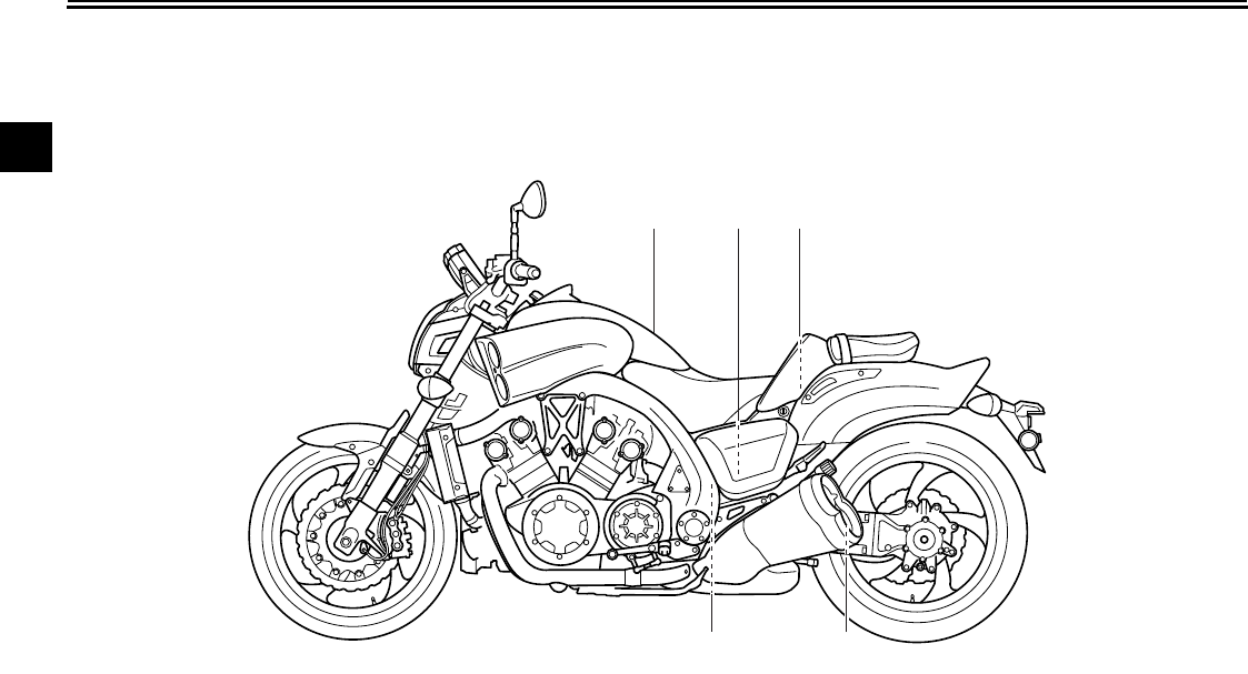
LOCATION OF IMPORTANT LABELS
EAU10383
Read and understand all of the labels on your vehicle. They contain important information for safe and proper operation of
your vehicle. Never remove any labels from your vehicle. If a label becomes difficult to read or comes off, a replacement label
is available from your Yamaha dealer.
123
4
5
LOCATION OF IMPORTANT LABELS
1-2
1
2
3
4
5
6
7
8
9
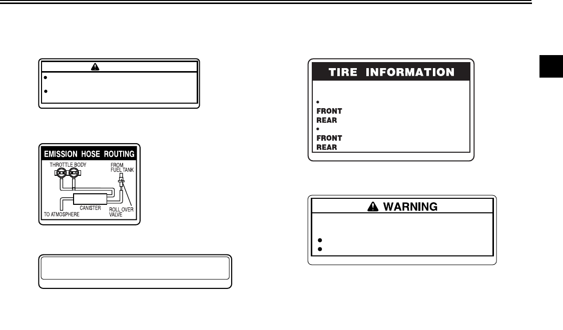
This unit contains high pressure nitrogen gas.
Mishandling can cause explosion.
Read owner's manual for instructions.
Do not incinerate, puncture or open.
4AA-22259-80
2S3-21668-00
Cold tire normal pressure should be set
as follows.
Up to 90kg (198 lbs) load
: 250 kPa, ( 2.50 kgf/cm2 ), 36 psi
: 290 kPa, ( 2.90 kgf/cm2 ), 42 psi
: 250 kPa, ( 2.50 kgf/cm2 ), 36 psi
: 290 kPa, ( 2.90 kgf/cm2 ), 42 psi
90 kg (198 lbs) ~maximum load
5
WARNING
BEFORE YOU OPERATE THIS VEHICLE, READ
THE OWNER’S MANUAL AND ALL LABELS.
ALWAYS WEAR AN APPROVED MOTORCYCLE
HELMET, eye protection, and protective clothing.
5GK-2118K-00
PREMIUM UNLEADED GASOLINE ONLY
91 Min. Pump
Octane (R+M) / 2
5PW-2415E-11
1
3
2 CALIFORNIA ONLY
4
4B5-21686-00
2-1
1
2
SAFETY INFORMATION
EAU10283
Be a Responsible Owner
As the vehicle’s owner, you are respon-
sible for the safe and proper operation
of your motorcycle.
Motorcycles are single-track vehicles.
Their safe use and operation are de-
pendent upon the use of proper riding
techniques as well as the expertise of
the operator. Every operator should
know the following requirements before
riding this motorcycle.
He or she should:
●
Obtain thorough instructions from
a competent source on all aspects
of motorcycle operation.
●
Observe the warnings and mainte-
nance requirements in this Own-
er’s Manual.
●
Obtain qualified training in safe
and proper riding techniques.
●
Obtain professional technical ser-
vice as indicated in this Owner’s
Manual and/or when made neces-
sary by mechanical conditions.
Safe Riding
Perform the pre-operation checks each
time you use the vehicle to make sure it
is in safe operating condition. Failure to
inspect or maintain the vehicle properly
increases the possibility of an accident
or equipment damage. See page 5-1
for a list of pre-operation checks.
●
This motorcycle is designed to car-
ry the operator and a passenger.
●
The failure of motorists to detect
and recognize motorcycles in traf-
fic is the predominating cause of
automobile/motorcycle accidents.
Many accidents have been caused
by an automobile driver who did
not see the motorcycle. Making
yourself conspicuous appears to
be very effective in reducing the
chance of this type of accident.
Therefore:
●
Wear a brightly colored jacket.
●
Use extra caution when you are
approaching and passing
through intersections, since in-
tersections are the most likely
places for motorcycle accidents
to occur.
●
Ride where other motorists can
see you. Avoid riding in another
motorist’s blind spot.
●
Many accidents involve inexperi-
enced operators. In fact, many op-
erators who have been involved in
accidents do not even have a cur-
rent motorcycle license.
●
Make sure that you are qualified
and that you only lend your mo-
torcycle to other qualified opera-
tors.
●
Know your skills and limits.
Staying within your limits may
help you to avoid an accident.
●
We recommend that you prac-
tice riding your motorcycle
where there is no traffic until you
have become thoroughly famil-
iar with the motorcycle and all of
its controls.
●
Many accidents have been caused
by error of the motorcycle opera-
tor. A typical error made by the op-
erator is veering wide on a turn
due to excessive speed or under-
cornering (insufficient lean angle
for the speed).
●
Always obey the speed limit and
never travel faster than warrant-

SAFETY INFORMATION
2-2
1
2
ed by road and traffic conditions.
●
Always signal before turning or
changing lanes. Make sure that
other motorists can see you.
●
The posture of the operator and
passenger is important for proper
control.
●
The operator should keep both
hands on the handlebar and
both feet on the operator foot-
rests during operation to main-
tain control of the motorcycle.
●
The passenger should always
hold onto the operator, the seat
strap or grab bar, if equipped,
with both hands and keep both
feet on the passenger footrests.
Never carry a passenger unless
he or she can firmly place both
feet on the passenger footrests.
●
Never ride under the influence of
alcohol or other drugs.
●
This motorcycle is designed for
on-road use only. It is not suitable
for off-road use.
Protective apparel
The majority of fatalities from motorcy-
cle accidents are the result of head in-
juries. The use of a safety helmet is the
single most critical factor in the preven-
tion or reduction of head injuries.
●
Always wear an approved helmet.
●
Wear a face shield or goggles.
Wind in your unprotected eyes
could contribute to an impairment
of vision that could delay seeing a
hazard.
●
The use of a jacket, heavy boots,
trousers, gloves, etc., is effective in
preventing or reducing abrasions
or lacerations.
●
Never wear loose-fitting clothes,
otherwise they could catch on the
control levers, footrests, or wheels
and cause injury or an accident.
●
Always wear protective clothing
that covers your legs, ankles, and
feet. The engine or exhaust sys-
tem become very hot during or af-
ter operation and can cause burns.
●
A passenger should also observe
the above precautions.
Avoid Carbon Monoxide Poisoning
All engine exhaust contains carbon
monoxide, a deadly gas. Breathing car-
bon monoxide can cause headaches,
dizziness, drowsiness, nausea, confu-
sion, and eventually death.
Carbon Monoxide is a colorless, odor-
less, tasteless gas which may be
present even if you do not see or smell
any engine exhaust. Deadly levels of
carbon monoxide can collect rapidly
and you can quickly be overcome and
unable to save yourself. Also, deadly
levels of carbon monoxide can linger
for hours or days in enclosed or poorly
ventilated areas. If you experience any
symptoms of carbon monoxide poison-
ing, leave the area immediately, get
fresh air, and SEEK MEDICAL TREAT-
MENT.
●
Do not run engine indoors. Even if
you try to ventilate engine exhaust
with fans or open windows and
doors, carbon monoxide can rap-
idly reach dangerous levels.
●
Do not run engine in poorly venti-
lated or partially enclosed areas
such as barns, garages, or car-
ports.
●
Do not run engine outdoors where
SAFETY INFORMATION
2-3
1
2
engine exhaust can be drawn into
a building through openings such
as windows and doors.
Loading
Adding accessories or cargo to your
motorcycle can adversely affect stabili-
ty and handling if the weight distribution
of the motorcycle is changed. To avoid
the possibility of an accident, use ex-
treme caution when adding cargo or
accessories to your motorcycle. Use
extra care when riding a motorcycle
that has added cargo or accessories.
Here, along with the information about
accessories below, are some general
guidelines to follow if loading cargo to
your motorcycle:
The total weight of the operator, pas-
senger, accessories and cargo must
not exceed the maximum load limit.
Operation of an overloaded vehicle
could cause an accident.
When loading within this weight limit,
keep the following in mind:
●
Cargo and accessory weight
should be kept as low and close to
the motorcycle as possible. Se-
curely pack your heaviest items as
close to the center of the vehicle as
possible and make sure to distrib-
ute the weight as evenly as possi-
ble on both sides of the motorcycle
to minimize imbalance or instabili-
ty.
●
Shifting weights can create a sud-
den imbalance. Make sure that ac-
cessories and cargo are securely
attached to the motorcycle before
riding. Check accessory mounts
and cargo restraints frequently.
●
Properly adjust the suspension
for your load (suspension-ad-
justable models only), and
check the condition and pres-
sure of your tires.
●
Never attach any large or heavy
items to the handlebar, front
fork, or front fender. These
items, including such cargo as
sleeping bags, duffel bags, or
tents, can create unstable han-
dling or a slow steering re-
sponse.
●
This vehicle is not designed to
pull a trailer or to be attached to
a sidecar.
Genuine Yamaha Accessories
Choosing accessories for your vehicle
is an important decision. Genuine
Yamaha accessories, which are avail-
able only from a Yamaha dealer, have
been designed, tested, and approved
by Yamaha for use on your vehicle.
Many companies with no connection to
Yamaha manufacture parts and acces-
sories or offer other modifications for
Yamaha vehicles. Yamaha is not in a
position to test the products that these
aftermarket companies produce.
Therefore, Yamaha can neither en-
dorse nor recommend the use of ac-
cessories not sold by Yamaha or
modifications not specifically recom-
mended by Yamaha, even if sold and
installed by a Yamaha dealer.
Maximum load:
189 kg (417 lb) (CAL)
190 kg (419 lb) (U49)

SAFETY INFORMATION
2-4
1
2
Aftermarket Parts, Accessories,
and Modifications
While you may find aftermarket prod-
ucts similar in design and quality to
genuine Yamaha accessories, recog-
nize that some aftermarket accessories
or modifications are not suitable be-
cause of potential safety hazards to you
or others. Installing aftermarket prod-
ucts or having other modifications per-
formed to your vehicle that change any
of the vehicle’s design or operation
characteristics can put you and others
at greater risk of serious injury or death.
You are responsible for injuries related
to changes in the vehicle.
Keep the following guidelines in mind,
as well as those provided under “Load-
ing” when mounting accessories.
●
Never install accessories or carry
cargo that would impair the perfor-
mance of your motorcycle. Care-
fully inspect the accessory before
using it to make sure that it does
not in any way reduce ground
clearance or cornering clearance,
limit suspension travel, steering
travel or control operation, or ob-
scure lights or reflectors.
●
Accessories fitted to the handle-
bar or the front fork area can
create instability due to improper
weight distribution or aerody-
namic changes. If accessories
are added to the handlebar or
front fork area, they must be as
lightweight as possible and
should be kept to a minimum.
●
Bulky or large accessories may
seriously affect the stability of
the motorcycle due to aerody-
namic effects. Wind may at-
tempt to lift the motorcycle, or
the motorcycle may become un-
stable in cross winds. These ac-
cessories may also cause
instability when passing or being
passed by large vehicles.
●
Certain accessories can dis-
place the operator from his or
her normal riding position. This
improper position limits the free-
dom of movement of the opera-
tor and may limit control ability,
therefore, such accessories are
not recommended.
●
Use caution when adding electri-
cal accessories. If electrical acces-
sories exceed the capacity of the
motorcycle’s electrical system, an
electric failure could result, which
could cause a dangerous loss of
lights or engine power.
Aftermarket Tires and Rims
The tires and rims that came with your
motorcycle were designed to match the
performance capabilities and to provide
the best combination of handling, brak-
ing, and comfort. Other tires, rims, siz-
es, and combinations may not be
appropriate. Refer to page 7-21 for tire
specifications and more information on
replacing your tires.
3-1
1
2
3
4
5
6
7
8
9
DESCRIPTION
EAU10410
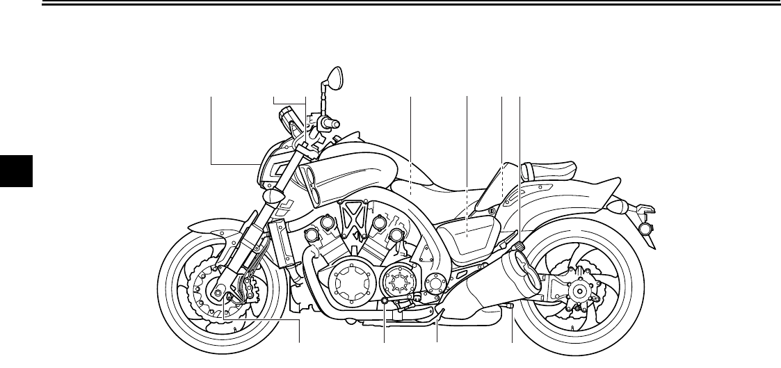
Left view
14567
8
9
10
23
11
1. Headlight (page 7-36)
2. Front fork spring preload adjusting bolt (page 4-22)
3. Front fork rebound damping force adjusting knob (page 4-22)
4. Battery (page 7-31)
5. Owner’s tool kit (page 7-2)
6. Fuel tank cap (page 4-17)
7. Shock absorber assembly spring preload adjusting knob (page 4-24)
8. Shock absorber assembly rebound damping force adjusting knob
(page 4-24)
9. Sidestand (page 4-26)
10. Shift pedal (page 4-14)
11. Front fork compression damping force adjusting screw (page 4-22)
DESCRIPTION
3-2
2
3
4
5
6
7
8
9
EAU10420
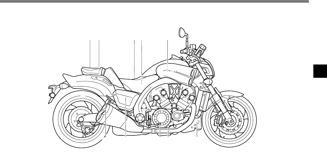
Right view
12 3 5
69
4
810 7
1. Passenger seat (page 4-20)
2. Rear brake fluid reservoir (page 7-26)
3. Rider seat (page 4-20)
4. Fuse box 1 (page 7-34)
5. Radiator cap (page 7-17)
6. Coolant reservoir (page 7-17)
7. Engine oil level check window (page 7-12)
8. Brake pedal (page 4-15)
9. Fuse box 2 (page 7-34)
10. Shock absorber assembly compression damping force adjusting
knob (page 4-24)
DESCRIPTION
3-3
1
2
3
4
5
6
7
8
9
EAU10430
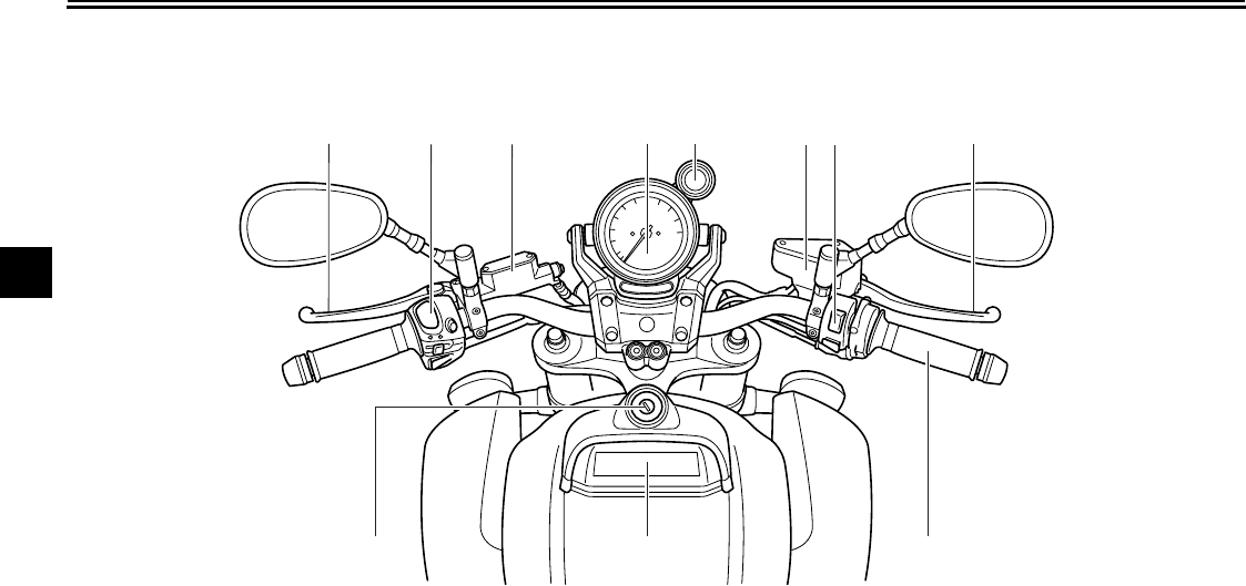
Controls and instruments
123 4 67 8
910
11
5
1. Clutch lever (page 4-14)
2. Left handlebar switches (page 4-12)
3. Clutch fluid reservoir (page 7-26)
4. Speedometer unit (page 4-4)
5. Shift timing indicator light
6. Front brake fluid reservoir (page 7-26)
7. Right handlebar switches (page 4-12)
8. Brake lever (page 4-15)
9. Throttle grip (page 7-21)
10. Multi-function display (page 4-5)
11. Main switch/steering lock (page 4-1)
4-1
2
3
4
5
6
7
8
9
INSTRUMENT AND CONTROL FUNCTIONS
EAU10460
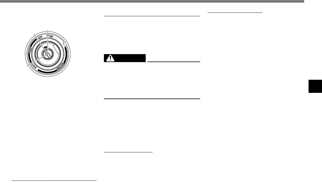
Main switch/steering lock
The main switch/steering lock controls
the ignition and lighting systems, and is
used to lock the steering. The various
positions are described below.
EAU39242
ON
All electrical circuits are supplied with
power, and the meter lighting, taillight,
license plate light, auxiliary light and
position lights come on, and the engine
can be started. The key cannot be re-
moved.
TIP
The headlight comes on automatically
when the engine is started and stays on
until the key is turned to “OFF”, even if
the engine stalls.
EAU10661
OFF
All electrical systems are off. The key
can be removed.
WARNING
EWA10061
Never turn the key to “OFF” or
“LOCK” while the vehicle is moving.
Otherwise the electrical systems will
be switched off, which may result in
loss of control or an accident.
EAU10681
LOCK
The steering is locked, and all electrical
systems are off. The key can be re-
moved.
To lock the steering
1. Turn the handlebars all the way to
the left.
2. Push the key in from the “OFF” po-
sition, and then turn it to “LOCK”
while still pushing it.
3. Remove the key.
To unlock the steering
Push the key in, and then turn it to
“OFF” while still pushing it.
ON
OFF
LOCK
INSTRUMENT AND CONTROL FUNCTIONS
4-2
1
2
3
4
5
6
7
8
9
EAU11003
Indicator and warning lights
EAU11030
Turn signal indicator lights “ ” and
“”
The corresponding indicator light flash-
es when the turn signal switch is
pushed to the left or right.
EAU11060
Neutral indicator light “ ”
This indicator light comes on when the
transmission is in the neutral position.
EAU11080
High beam indicator light “ ”
This indicator light comes on when the
high beam of the headlight is switched
on.
EAU46562
Oil level warning light “ ”
This warning light comes on if the en-
gine oil level is low. To check the elec-
trical circuit of the warning light, place
the vehicle on a level surface, set the
engine stop switch to “ ” and turn the
key from “OFF” to “ON”.
If the warning light does not come on
and then go off, have a Yamaha dealer
check the electrical circuit.
If the warning light stays on, proceed as
follows.
1. Set the engine stop switch to “ ”.
2. Turn the key to “OFF”, wait two
minutes, and then turn the key to
“ON”.
3. If the warning light comes on and
does not go off, check the engine
oil level. (See page 7-12.) If the
warning light still stays on after
confirming the oil level is correct,
have a Yamaha dealer check the
vehicle.
TIP
This warning light WILL NOT come on:
●
when the engine is idling
●
when riding
●
if the engine has stalled and the
key has not been turned from “ON”
to “OFF” and then back to “ON”
HOWEVER, if the warning light is on
when the engine is started, it will stay
on until the key is turned to “OFF”.
EAU11350
Fuel level warning light “ ”
This warning light comes on when the
fuel level drops below approximately
1. Fuel level warning light “ ”
2. Right turn signal indicator light “ ”
3. Coolant temperature warning light “ ”
4. Neutral indicator light “ ”
5. High beam indicator light “ ”
6. Engine trouble warning light “ ”
7. Left turn signal indicator light “ ”
8. Anti-lock Brake System (ABS) warning
light “ ”
9. Oil level warning light “ ”
9
8
765432
1
ABS
INSTRUMENT AND CONTROL FUNCTIONS
4-3
2
3
4
5
6
7
8
9
3.9 L (1.03 US gal, 0.86 Imp.gal). When
this occurs, refuel as soon as possible.
The electrical circuit of the warning light
can be checked by turning the key to
“ON”.
If the warning light does not come on
for a few seconds, then go off, have a
Yamaha dealer check the electrical cir-
cuit.
EAU11442
Coolant temperature warning light
“”
This warning light comes on if the en-
gine overheats. If this occurs, stop the
engine immediately and allow the en-
gine to cool.
The electrical circuit of the warning light
can be checked by turning the key to
“ON”.
If the warning light does not come on
for a few seconds, then go off, have a
Yamaha dealer check the electrical cir-
cuit.
NOTICE
ECA10021
Do not continue to operate the en-
gine if it is overheating.
TIP
●
For radiator-fan-equipped vehi-
cles, the radiator fan(s) automati-
cally switch on or off according to
the coolant temperature in the ra-
diator.
●
If the engine overheats, see page
7-42 for further instructions.
EAU46440
Engine trouble warning light “ ”
This warning light comes on if a prob-
lem is detected in the electrical circuit
monitoring the engine. If this occurs,
have a Yamaha dealer check the
self-diagnosis system. (See page 4-12
for an explanation of the self-diagnosis
device.)
The electrical circuit of the warning light
can be checked by turning the key to
“ON”. If the warning light does not come
on for a few seconds, then go off, have
a Yamaha dealer check the electrical
circuit.
TIP
This warning light will come on when
the key is turned to “ON” and the start
switch is pushed, but this does not indi-
cate a malfunction.
EAU39501
ABS warning light “ ”
If this warning light comes on or flashes
while riding, the ABS may not work cor-
rectly. If this occurs, have a Yamaha
dealer check the system as soon as
possible. (See page 4-16.)
WARNING
EWA10081
If the ABS warning light comes on or
flashes while riding, the brake sys-
tem reverts to conventional braking.
Therefore, be careful not to cause
the wheels to lock during emergen-
cy braking. If the warning light
comes on or flashes while riding,
have a Yamaha dealer check the
brake system as soon as possible.
The electrical circuit of the warning light
can be checked by turning the key to
“ON”.
ABS

INSTRUMENT AND CONTROL FUNCTIONS
4-4
1
2
3
4
5
6
7
8
9
If the warning light does not come on or
remains on, have a Yamaha dealer
check the electrical circuit.
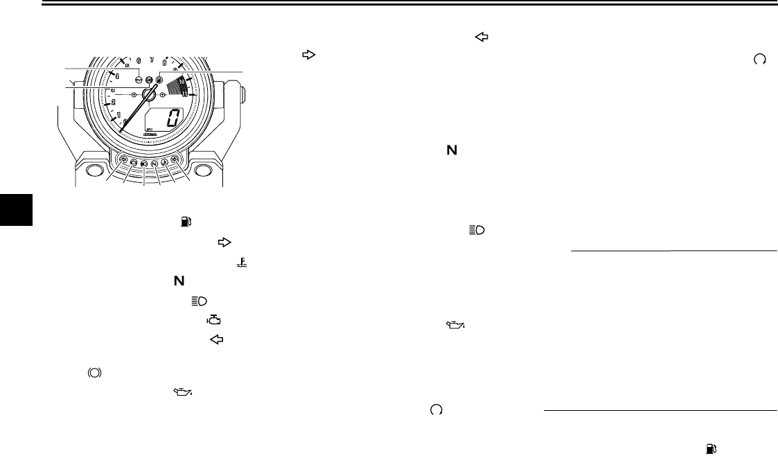
EAU46352
Speedometer unit
Speedometer
The speedometer shows the riding
speed, and can be switched between
miles and kilometers. (See page 4-5 for
details.)
Tachometer
The tachometer allows the rider to
monitor the engine speed and keep it
within the ideal power range. When the
key is turned to “ON”, the tachometer
needle will sweep once across the r/
min range and then return to zero r/min
in order to test the electrical circuit.
NOTICE
ECA10031
Do not operate the engine in the ta-
chometer red zone.
Red zone: 9500 r/min and above
Shift timing indicator light
See page 4-6 for an explanation and
settings for this indicator light.
1. Tachometer
2. Shift timing indicator light
3. Tachometer red zone
4. Speedometer
1
2
4
3
INSTRUMENT AND CONTROL FUNCTIONS
4-5
2
3
4
5
6
7
8
9
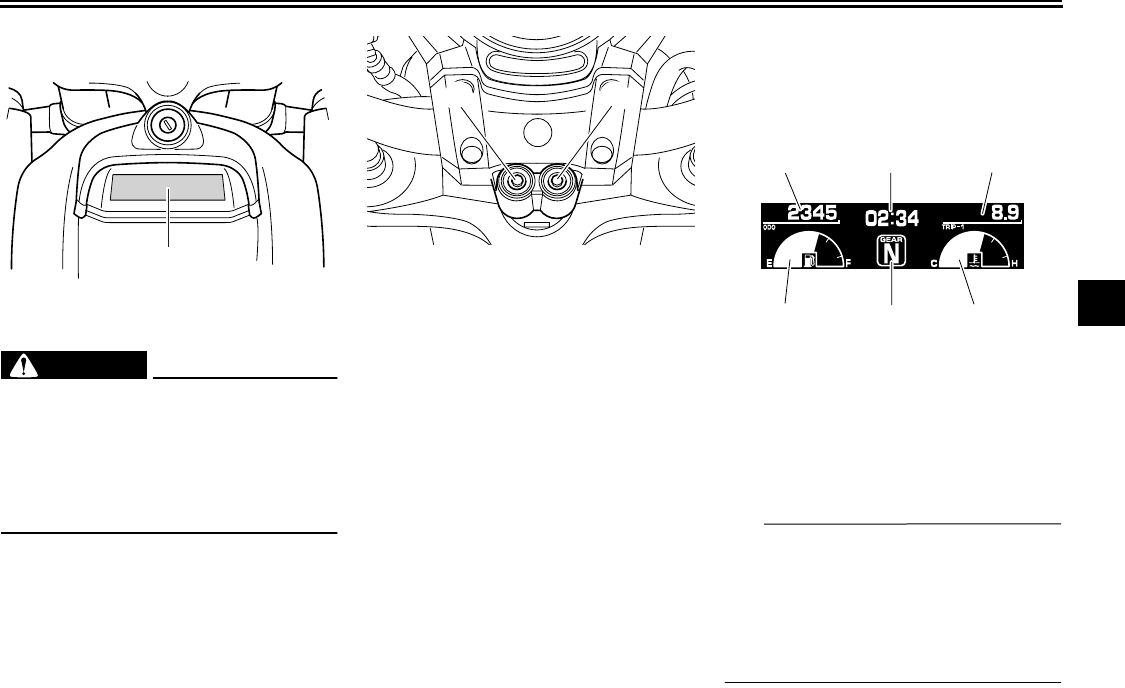
EAU46592
Multi-function display
WARNING
EWA12312
Be sure to stop the vehicle before
making any setting changes to the
multi-function display. Changing
settings while riding can distract the
operator and increase the risk of an
accident.
A “SELECT” button and a “RESET”
button are located on the handlebar
holder. These buttons allow you to con-
trol or change the settings in the
multi-function display.
The multi-function display is set to the
Normal mode every time the key is
turned to “ON”.
Normal mode
The following functions are available in
the Normal mode:
●
an odometer (which shows the to-
tal distance traveled)
●
a clock
●
two tripmeters (which show the
distance traveled since they were
last set to zero)
●
a fuel reserve tripmeter (which
shows the distance traveled since
the fuel level warning indicator
started flashing)
●
a fuel meter
●
a transmission gear indicator
●
a coolant temperature display
●
a self-diagnosis device
TIP
The speedometer and odometer/trip-
meter displays can be switched be-
tween miles and kilometers. To switch
the speedometer and odometer/tripme-
ter displays, press “SELECT” for at
least two seconds.
1. Multi-function display
1
1. “SELECT” button
2. “RESET” button
12
1. Odometer
2. Clock
3. Trip/Fuel
4. Fuel meter
5. Transmission gear display
6. Coolant temperature display
123
456
INSTRUMENT AND CONTROL FUNCTIONS
4-6
1
2
3
4
5
6
7
8
9
Tripmeters
Turn the key to “ON”. Push “SELECT”
to switch the display between the trip-
meters “TRIP-1” and “TRIP-2” in the fol-
lowing order.
TRIP-1
→
TRIP-2
→
TRIP-1
When the fuel amount in the fuel tank
decreases to 3.9 L (1.03 US gal, 0.86
Imp.gal), the fuel warning indicator
starts flashing, and the tripmeter auto-
matically changes to the fuel reserve
tripmeter “TRIP-F” and starts counting
the distance traveled from that point. In
that case, push “SELECT” to switch the
display between the various tripmeters
in the following order:
TRIP-F
→
TRIP-1
→
TRIP-2
→
TRIP-F
To reset a tripmeter, select it by push-
ing “SELECT”, and then push “RESET”
for at least one second. If you do not re-
set the fuel reserve tripmeter manually,
it resets itself automatically and the dis-
play returns to the prior meter after re-
fueling and traveling 5 km (3 mi).
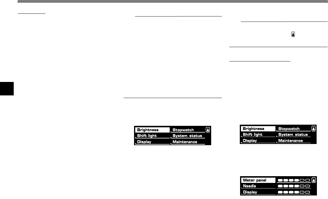
Select mode
The various functions of this multi-func-
tion display are adjusted in the Select
mode.
TIP
●
The transmission must be in neu-
tral to change settings in this
mode.
●
Shifting the transmission into gear
saves all settings made, then can-
cels the Select mode and displays
the Normal mode in all screens.
●
Depending on the screen, pushing
“RESET” saves settings or can-
cels the Select mode to display the
Normal mode.
Push and hold “SELECT” and “RESET”
for at least three seconds to enter the
Select mode.
The following items can be set/adjusted
in this mode:
●
brightness
●
shift timing indicator light
●
clock
●
stopwatch
●
countdown clock
●
system status
●
maintenance counters
TIP
To return to the Normal mode, push
“SELECT” to scroll to “ ”, then push
“RESET”.
Adjusting the brightness
This function allows you to adjust the
brightness of the tachometer unit panel
(“Meter panel”), the tachometer needle
(“Needle”), and the speedometer and
multi-function displays (“Display”) to
suit the outside lighting conditions.
1. Push “SELECT” to highlight
“Brightness”.
2. Push “RESET”, then push
“SELECT” to scroll through the
functions and to highlight an item.
3. Push “RESET”; the brightness lev-
INSTRUMENT AND CONTROL FUNCTIONS
4-7
2
3
4
5
6
7
8
9
el segments for the selected item
starts flashing.
4. Push “SELECT” to highlight the
desired brightness level.
5. Push “RESET” to set the bright-
ness level.
6. Push “SELECT” to scroll to “ ”,
then push “RESET” to return to the
previous menu.
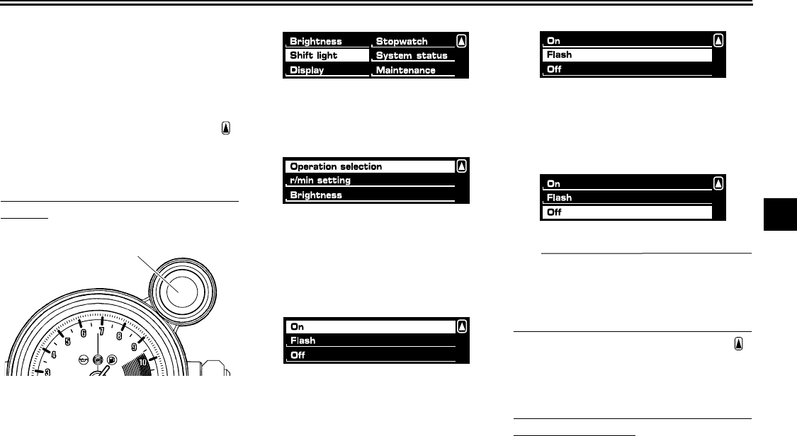
Selecting the shift timing indicator light
settings
This function allows you to choose
whether or not the shift timing indicator
light is activated and whether it flashes
or stays on when activated.
1. Push “SELECT” to highlight “Shift
light”.
2. Push “RESET”.
3. Push “SELECT” to highlight “Oper-
ation selection”.
4. Push “RESET”.
Push “SELECT” and highlight “On”
to activate the indicator light; the
indicator light comes on and stays
on when activated.
Push “SELECT” and highlight
“Flash” to activate the indicator
light; the indicator light flashes
when activated.
Push “SELECT” and highlight “Off”
to deactivate the indicator light; the
indicator light neither comes on
nor flashes.
TIP
The indicator light flashes once every
two seconds to show that it has been
deactivated. The indicator light goes off
after this menu is exited.
5. Push “SELECT” to scroll to “ ”,
then push “RESET” to return to the
previous menu.
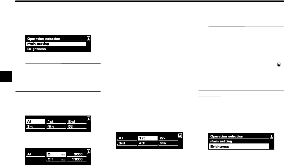
Setting the r/min in relation to the shift
timing indicator light
This function allows you to select the
engine speed at which the indicator
light is activated and deactivated. All
gears can be set to the same activation/
1. Shift timing indicator light
1
INSTRUMENT AND CONTROL FUNCTIONS
4-8
1
2
3
4
5
6
7
8
9
deactivation r/min or the gears can be
set individually.
Push “SELECT” to highlight “r/min set-
ting”, then push “RESET”.
TIP
The shift timing indicator light can be
set to activate and deactivate between
3000 r/min and 11000 r/min in incre-
ments of 500 r/min.
To set all gears to the same r/min:
1. Push “SELECT” to highlight “All”.
2. Push “RESET”; “On” is displayed.
3. Push “RESET” and the r/min digits
start flashing.
4. Push “SELECT” to highlight the
engine speed at which the shift
timing indicator light is activated.
5. Push “RESET” to set the selected
engine speed. “Off” is highlighted
and the r/min digits start flashing.
6. Push “SELECT” to highlight the
engine speed at which the shift
timing indicator light is deactivat-
ed.
7. Push “RESET” to set the selected
engine speed.
8. Push “RESET” again to return to
the previous menu.
To set individual gear r/min:
1. Push “SELECT” to highlight gears
from “1st” through “5th”, then push
“RESET”.
2. Push “RESET” and the r/min digits
for the highlighted gear start flash-
ing, then perform steps 4–8 under
“To set all gears to the same r/
min:” in order to set the r/min for
the individual gears.
TIP
After setting r/min for individual gears, if
“All” is chosen, all previously set r/min
for individual gears return to the default
settings of 9000 (activation) and 11000
(deactivation).
3. Push “SELECT” to scroll to “ ”,
then push “RESET” to return to the
previous menu.
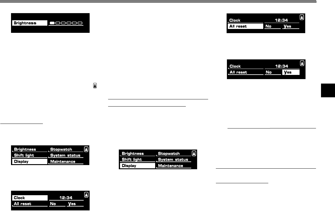
Setting the shift timing indicator light
brightness
This function allows you to adjust the
brightness of the shift timing indicator
light.
1. Push “SELECT” to highlight
“Brightness”.
2. Push “RESET” and the brightness
level segments start flashing.
INSTRUMENT AND CONTROL FUNCTIONS
4-9
2
3
4
5
6
7
8
9
3. Push “SELECT” to highlight the
desired brightness level.
4. Push “RESET” to set the selected
brightness level.
5. Push “RESET” to return to the pre-
vious menu.
6. Push “SELECT” to scroll to “ ”,
then push “RESET”. This allows
you to select another item in the
menu.
Setting the clock
1. Push “SELECT” to highlight “Dis-
play”.
2. Push “RESET”; the following
screen is displayed.
3. Push “RESET” and the hour digits
start flashing.
4. Push “SELECT” to increment the
hours.
5. Push “RESET”, and the minute
digits start flashing.
6. Push “SELECT” to increment the
minutes.
7. Push “RESET” to start the clock.
8. Push “RESET” again to return to
the previous menu.
Resetting all the brightness and shift
timing indicator light functions:
This resets ALL settings made to the
brightness and shift timing indicator
light functions.
1. Push “SELECT” to highlight “Dis-
play”.
2. Push “RESET”.
3. Push “SELECT” to highlight “All re-
set”.
4. Push “RESET”, then push
“SELECT” to highlight “Yes”.
5. Push “RESET” to reset the bright-
ness and shift timing light indicator
values to the factory setting. The
display returns to the Normal
mode.
TIP
To perform further multi-function dis-
play settings, enter the Select mode
again by pushing and holding
“SELECT” and “RESET” for at least
three seconds.
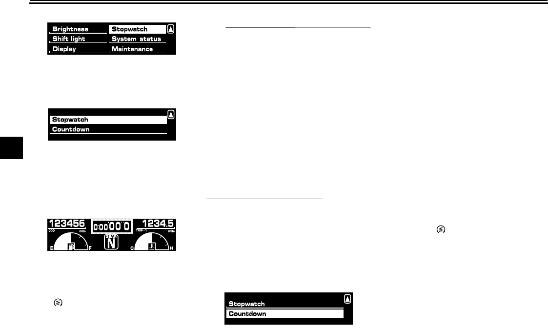
Using the stopwatch
The stopwatch can be activated as fol-
lows.
1. Push “SELECT” to highlight “Stop-
watch”.
INSTRUMENT AND CONTROL FUNCTIONS
4-10
1
2
3
4
5
6
7
8
9
2. Push “RESET”.
3. Push “SELECT” to highlight “Stop-
watch”.
4. Push “RESET”.
The multi-function display chang-
es to the Normal mode and the
stopwatch is displayed in place of
the clock.
5. Push “SELECT” to start the stop-
watch.
6. Push “SELECT” or the start switch
“” to stop the stopwatch.
7. Push “RESET” to reset the stop-
watch.
TIP
●
If neither “SELECT” or “RESET”
are pushed for one minute, the
screen automatically changes to
the Normal mode.
●
Pushing “RESET” for at least two
seconds changes the screen to
the Normal mode.
●
To perform further multi-function
display settings, enter the Select
mode again by pushing and hold-
ing “SELECT” and “RESET” for at
least three seconds.
Using the countdown clock:
The countdown clock can be activated
as follows.
1. Push “SELECT” to highlight “Stop-
watch”.
2. Push “RESET”.
3. Push “SELECT” to highlight
“Countdown”.
4. Push “RESET”. The multi-function
display changes to the Normal
mode, the stopwatch is displayed
in place of the clock, and the trans-
mission gear indicator changes to
the countdown clock.
5. Push “SELECT” or shift into gear
and the countdown clock starts
counting down from “5”. Simulta-
neously, the shift timing indicator
flashes according to the number
displayed (i.e., when “5” is dis-
played, the indicator flashes five
times, when “4” is displayed, the
indicator flashes four times, etc.).
The stopwatch starts counting
when the countdown clock finishes
counting.
6. Push “SELECT” or push the start
switch “ ” to stop the countdown
clock.
7. Push “RESET” to reset the count-
down clock and stopwatch.
8. Push “RESET” to reset the count-
down clock, and then repeat steps
5–6, OR push “RESET” again for
at least two seconds to enter the
Normal mode.
INSTRUMENT AND CONTROL FUNCTIONS
4-11
2
3
4
5
6
7
8
9
TIP
To perform further multi-function dis-
play settings,
be sure the transmis-
sion is in neutral,
then enter the
Select mode again by pushing and
holding “SELECT” and “RESET” for at
least three seconds.
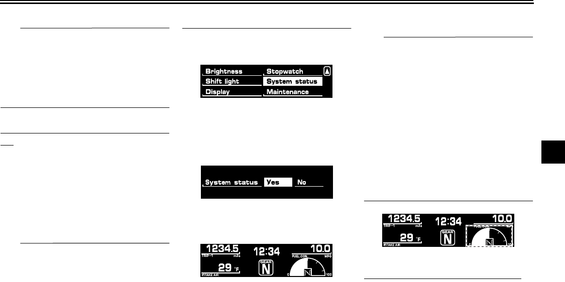
Checking and resetting the system sta-
tus
The status/readings of the following
items are displayed, and the tripmeters
can be reset.
●
tripmeters and odometer
●
fuel consumption
●
air intake temperature
●
throttle opening position
TIP
●
The “System status” menu cannot
be entered if the fuel level warning
light or coolant temperature warn-
ing light is on.
●
If, when the engine is running
while the system status menu is
displayed, the fuel level warning
light or coolant temperature warn-
ing light comes on, the Normal
mode is automatically displayed.
1. Push “SELECT” to highlight “Sys-
tem status”, then push “RESET”.
2. Push “SELECT” to highlight “Yes”,
then push “RESET”. (Highlighting
“No” and pushing “RESET” returns
to the previous menu.)
The display changes to the status
screen.
Push “SELECT” and the various trip-
meters and the odometer are displayed
in the following order:
(TRIP-F)
→
TRIP-1
→
TRIP-2
→
ODO
→
(TRIP-F)
Push “RESET” to reset a tripmeter.
TIP
●
Push “SELECT” for at least two
seconds to switch between miles
and kilometers.
●
Pushing “RESET” displays the
Normal mode for five seconds.
Pushing “SELECT” and “RESET”
for at least three seconds, chang-
es the display to the Normal mode.
●
To perform further multi-function
display settings, enter the Select
mode again by pushing and hold-
ing “SELECT” and “RESET” for at
least three seconds.
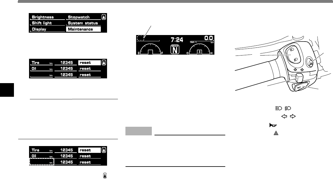
Resetting the maintenance counters
This function allows you to reset the
maintenance counters for the tires, the
engine oil, and an item of your choice.
1. Push “SELECT” to highlight “Main-
tenance”, then push “RESET”.
INSTRUMENT AND CONTROL FUNCTIONS
4-12
1
2
3
4
5
6
7
8
9
2. Push “SELECT” to highlight the
item to reset.
3. Push “RESET” to reset the item.
TIP
The bottom area was left blank for an-
other item the rider cares to check the
distance of since it has been changed,
replaced or checked (i.e., air filter ele-
ment, engine parts, etc.).
4. Push “SELECT” to scroll to “ ”.
5. Push “RESET” to return to the pre-
vious menu.
Self-diagnosis device
This model is equipped with a self-diag-
nosis device for various electrical cir-
cuits.
If a problem is detected in any of those
circuits, the engine trouble warning light
comes on and the display indicates a
two-digit error code.
NOTICE
ECA11590
If the display indicates an error
code, the vehicle should be checked
as soon as possible in order to avoid
engine damage.
If the display indicates any error codes,
note the code number, and then have a
Yamaha dealer check the vehicle.
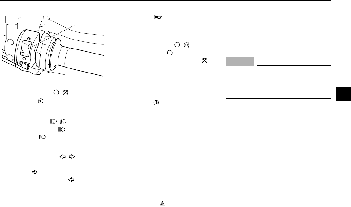
EAU12347
Handlebar switches
Left
1. Error code display
1
1. Dimmer switch “ / ”
2. Turn signal switch “ / ”
3. Horn switch “ ”
4. Hazard switch “ ”
1
23
4
INSTRUMENT AND CONTROL FUNCTIONS
4-13
2
3
4
5
6
7
8
9
Right
EAU12400
Dimmer switch “ / ”
Set this switch to “ ” for the high
beam and to “ ” for the low beam.
EAU12460
Turn signal switch “ / ”
To signal a right-hand turn, push this
switch to “ ”. To signal a left-hand
turn, push this switch to “ ”. When re-
leased, the switch returns to the center
position. To cancel the turn signal
lights, push the switch in after it has re-
turned to the center position.
EAU12500
Horn switch “ ”
Press this switch to sound the horn.
EAU12660
Engine stop switch “ / ”
Set this switch to “ ” before starting
the engine. Set this switch to “ ” to
stop the engine in case of an emergen-
cy, such as when the vehicle overturns
or when the throttle cable is stuck.
EAU12711
Start switch “ ”
Push this switch to crank the engine
with the starter. See page 6-1 for start-
ing instructions prior to starting the en-
gine.
EAU41700
The engine trouble warning light will
come on when the key is turned to “ON”
and the start switch is pushed, but this
does not indicate a malfunction.
EAU12765
Hazard switch “ ”
With the key in the “ON” position, use
this switch to turn on the hazard lights
(simultaneous flashing of all turn signal
lights).
The hazard lights are used in case of
an emergency or to warn other drivers
when your vehicle is stopped where it
might be a traffic hazard.
NOTICE
ECA10061
Do not use the hazard lights for an
extended length of time with the en-
gine not running, otherwise the bat-
tery may discharge.
1. Engine stop switch “ / ”
2. Start switch “ ”
1
2
INSTRUMENT AND CONTROL FUNCTIONS
4-14
1
2
3
4
5
6
7
8
9
EAU12830
Clutch lever
The clutch lever is located at the left
handlebar grip. To disengage the
clutch, pull the lever toward the handle-
bar grip. To engage the clutch, release
the lever. The lever should be pulled
rapidly and released slowly for smooth
clutch operation.
The clutch lever is equipped with a
clutch lever position adjusting dial. To
adjust the distance between the clutch
lever and the handlebar grip, turn the
adjusting dial while holding the lever
pushed away from the handlebar grip.
Make sure that the appropriate setting
on the adjusting dial is aligned with the
arrow mark on the clutch lever.
The clutch lever is equipped with a
clutch switch, which is part of the igni-
tion circuit cut-off system. (See
page 4-27.)
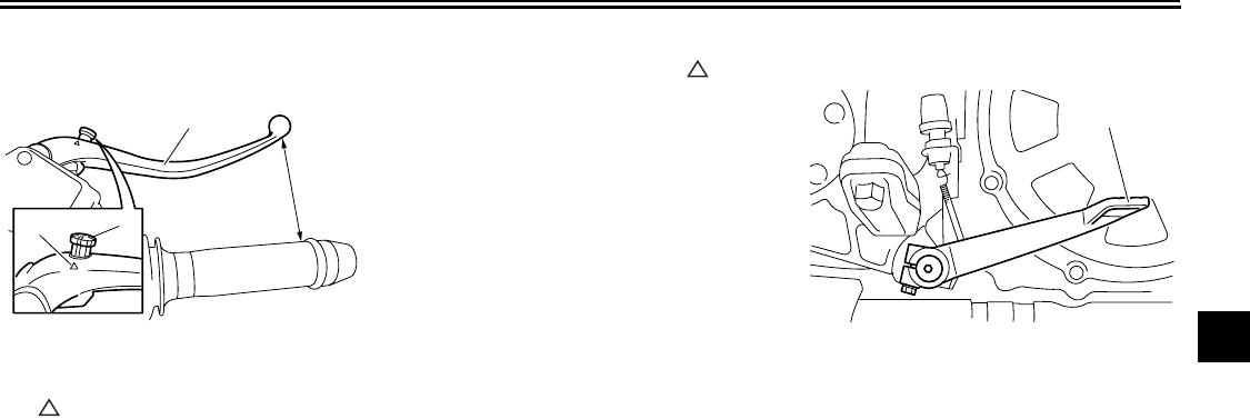
EAU12870
Shift pedal
The shift pedal is located on the left
side of the engine and is used in com-
bination with the clutch lever when
shifting the gears of the 5-speed con-
stant-mesh transmission equipped on
this motorcycle.
1. Clutch lever
2. Clutch lever position adjusting dial
3. Arrow mark
4. Distance between clutch lever and
handlebar grip
4
12
3
1. Shift pedal
1
INSTRUMENT AND CONTROL FUNCTIONS
4-15
2
3
4
5
6
7
8
9
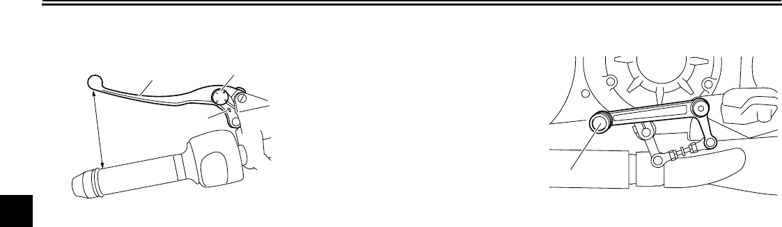
EAU33851
Brake lever
The brake lever is located at the right
handlebar grip. To apply the front
brake, pull the lever toward the handle-
bar grip.
The brake lever is equipped with a
brake lever position adjusting knob. To
adjust the distance between the brake
lever and the handlebar grip, turn the
adjusting knob while holding the lever
pushed away from the handlebar grip.
When the desired position is obtained,
be sure to set it by aligning a groove on
the adjusting knob with the “ ” mark
on the brake lever.
EAU12941
Brake pedal
The brake pedal is on the right side of
the motorcycle. To apply the rear
brake, press down on the brake pedal.
1. Brake lever
2. Brake lever position adjusting knob
3. “ ” mark
4. Distance between brake lever and
handlebar grip
1
4
2
3
1. Brake pedal
1
INSTRUMENT AND CONTROL FUNCTIONS
4-16
1
2
3
4
5
6
7
8
9
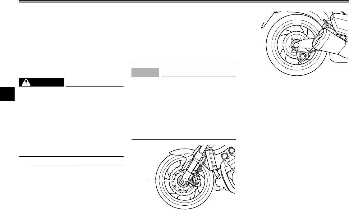
EAU46390
ABS
The Yamaha ABS (Anti-lock Brake
System) features a dual electronic con-
trol system, which acts on the front and
rear brakes independently. The ABS is
monitored by an ECU (Electronic Con-
trol Unit), which will have recourse to
manual braking if a malfunction occurs.
WARNING
EWA10090
●
The ABS performs best on long
braking distances.
●
On certain (rough or gravel)
roads, the braking distance may
be longer with than without the
ABS. Therefore, always keep a
sufficient distance to the vehi-
cle ahead to match the riding
speed.
TIP
●
When the ABS is activated, the
brakes are operated in the usual
way. A pulsating action may be felt
at the brake lever or brake pedal,
but this does not indicate a mal-
function.
●
This ABS has a test mode which
allows the owner to experience the
pulsating at the brake lever or
brake pedal when the ABS is oper-
ating. However, special tools are
required, so please consult your
Yamaha dealer when performing
this test.
NOTICE
ECA16120
Keep any type of magnets (including
magnetic pick-up tools, magnetic
screwdrivers, etc.) away from the
front and rear wheel hubs, otherwise
the magnetic rotors equipped in the
wheel hubs may be damaged, result-
ing in improper performance of the
ABS system.
1. Front wheel hub
1
1. Rear wheel hub
1
INSTRUMENT AND CONTROL FUNCTIONS
4-17
2
3
4
5
6
7
8
9
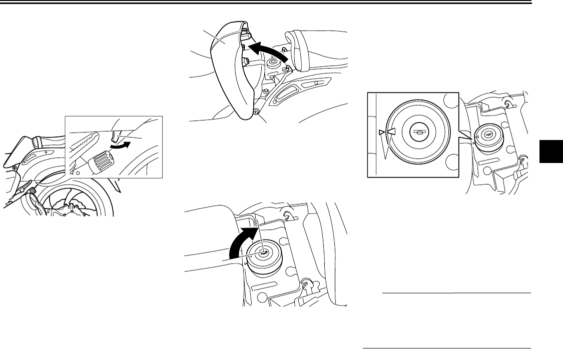
EAU46850
Fuel tank cap
To remove the fuel tank cap
1. Pull the rider seat backrest release
lever on the left side of the vehicle
as shown. The backrest will slide
forward.
2. Insert the key into the lock, and
then turn it 1/4 turn clockwise. The
lock will be released and the fuel
tank cap can be removed.
To install the fuel tank cap
1. Insert the fuel tank cap into the
tank opening with the key inserted
in the lock and with the mark on the
cap aligned with the mark on the
fuel tank.
2. Turn the key counterclockwise to
the original position, and then re-
move it.
3. Return the backrest to the original
position.
TIP
The fuel tank cap cannot be installed
unless the key is in the lock. In addition,
the key cannot be removed if the cap is
not properly installed and locked.
1. Rider seat backrest release lever
1
1. Rider seat backrest
1. Unlock.
1
1
1. Match marks
1
INSTRUMENT AND CONTROL FUNCTIONS
4-18
1
2
3
4
5
6
7
8
9
WARNING
EWA10131
Make sure that the fuel tank cap is
properly installed before riding.
Leaking fuel is a fire hazard.
EAU13212
Fuel
Make sure there is sufficient gasoline in
the tank.
WARNING
EWA10881
Gasoline and gasoline vapors are
extremely flammable. To avoid fires
and explosions and to reduce the
risk of injury when refueling, follow
these instructions.
1. Before refueling, turn off the en-
gine and be sure that no one is sit-
ting on the vehicle. Never refuel
while smoking, or while in the vi-
cinity of sparks, open flames, or
other sources of ignition such as
the pilot lights of water heaters and
clothes dryers.
2. Do not overfill the fuel tank. Stop
filling when the fuel reaches the
bottom of the filler tube. Because
fuel expands when it heats up,
heat from the engine or the sun
can cause fuel to spill out of the
fuel tank.
3. Wipe up any spilled fuel immedi-
ately.
NOTICE:
Immediately wipe
off spilled fuel with a clean, dry,
soft cloth, since fuel may deteri-
orate painted surfaces or plastic
parts.
[ECA10071]
4. Be sure to securely close the fuel
tank cap.
WARNING
EWA15151
Gasoline is poisonous and can
cause injury or death. Handle gaso-
line with care. Never siphon gaso-
line by mouth. If you should swallow
some gasoline or inhale a lot of gas-
oline vapor, or get some gasoline in
1. Fuel tank filler tube
2. Fuel level
12
INSTRUMENT AND CONTROL FUNCTIONS
4-19
2
3
4
5
6
7
8
9
your eyes, see your doctor immedi-
ately. If gasoline spills on your skin,
wash with soap and water. If gaso-
line spills on your clothing, change
your clothes.
EAU13381
NOTICE
ECA11400
Use only unleaded gasoline. The use
of leaded gasoline will cause severe
damage to internal engine parts,
such as the valves and piston rings,
as well as to the exhaust system.
Your Yamaha engine has been de-
signed to use premium unleaded gaso-
line with a pump octane number
[(R+M)/2] of 91 or higher, or a research
octane number of 95 or higher. If
knocking (or pinging) occurs, use a
gasoline of a different brand. Use of un-
leaded fuel will extend spark plug life
and reduce maintenance costs.
Gasohol
There are two types of gasohol: gaso-
hol containing ethanol and that contain-
ing methanol. Gasohol containing
ethanol can be used if the ethanol con-
tent does not exceed 10% (E10). Gas-
ohol containing methanol is not
recommended by Yamaha because it
can cause damage to the fuel system
or vehicle performance problems.
EAU13445
Catalytic converters
This vehicle is equipped with catalytic
converters in the exhaust system.
WARNING
EWA10862
The exhaust system is hot after op-
eration. To prevent a fire hazard or
burns:
●
Do not park the vehicle near
possible fire hazards such as
grass or other materials that
easily burn.
●
Park the vehicle in a place
where pedestrians or children
are not likely to touch the hot
exhaust system.
●
Make sure that the exhaust sys-
tem has cooled down before do-
ing any maintenance work.
●
Do not allow the engine to idle
more than a few minutes. Long
idling can cause a build-up of
heat.
NOTICE
ECA10701
Use only unleaded gasoline. The use
of leaded gasoline will cause unre-
Recommended fuel:
PREMIUM UNLEADED GASOLINE
ONLY
Fuel tank capacity:
15.0 L (3.96 US gal, 3.30 Imp.gal)
Fuel reserve amount (when the fuel
level warning light comes on):
3.9 L (1.03 US gal, 0.86 Imp.gal)
INSTRUMENT AND CONTROL FUNCTIONS
4-20
1
2
3
4
5
6
7
8
9
pairable damage to the catalytic
converter.
EAU46840
Seats
Rider seat
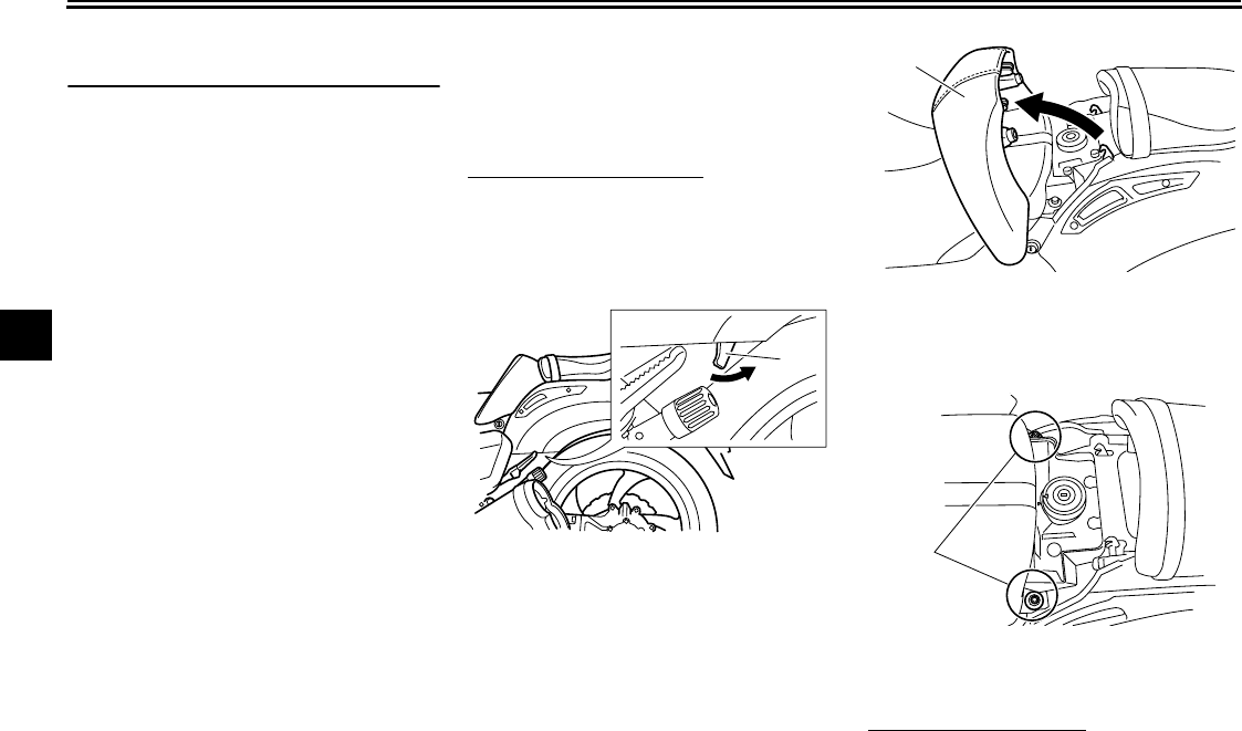
To remove the rider seat
1. Pull the rider seat backrest release
lever on the left side of the vehicle
as shown. The backrest will slide
forward.
2. Remove the bolts, and then pull
the rider seat off.
To install the rider seat
1. Insert the projection on the front of
the rider seat into the seat holder
1. Rider seat backrest release lever
1
1. Rider seat backrest
1. Bolt
1
1
INSTRUMENT AND CONTROL FUNCTIONS
4-21
2
3
4
5
6
7
8
9
as shown.
2. Place the rider seat in the original
position, and then tighten the bolts.
TIP
Make sure that the rider seat is properly
secured before riding.
3. Return the backrest to the original
position.
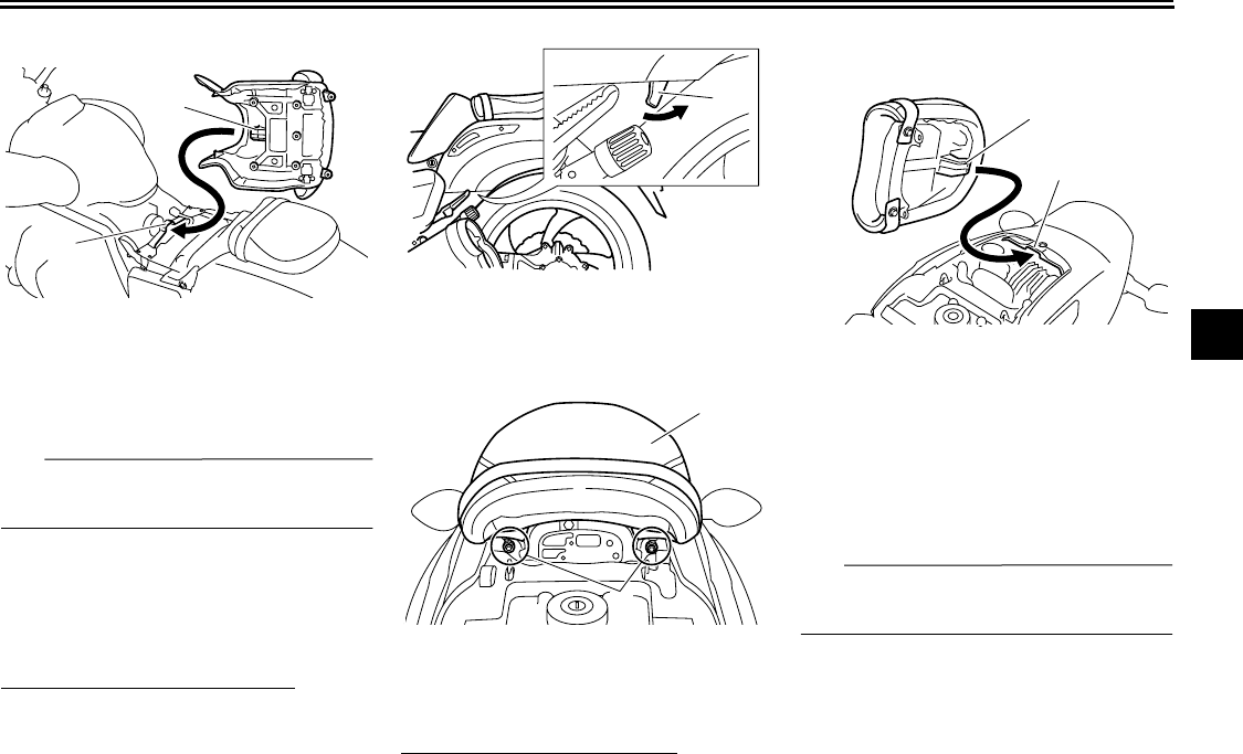
Passenger seat
To remove the passenger seat
1. Pull the rider seat backrest release
lever on the left side of the vehicle
as shown. The backrest will slide
forward.
2. Remove the bolts, and then pull
the passenger seat off.
To install the passenger seat
1. Insert the projection on the pas-
senger seat into the holder as
shown.
2. Place the passenger seat in the
original position, and then install
the bolts.
3. Return the backrest to the original
position.
TIP
Make sure that the passenger seat is
properly secured before riding.
1. Projection
2. Seat holder
1
2
1. Rider seat backrest release lever
1. Bolt
2. Passenger seat
1
2
1
1. Projection
2. Seat holder
1
2
INSTRUMENT AND CONTROL FUNCTIONS
4-22
1
2
3
4
5
6
7
8
9
EAU14732
Adjusting the front fork
WARNING
EWA10180
Always adjust both fork legs equal-
ly, otherwise poor handling and loss
of stability may result.
This front fork is equipped with spring
preload adjusting bolts, rebound damp-
ing force adjusting knobs and compres-
sion damping force adjusting screws.
NOTICE
ECA10101
To avoid damaging the mechanism,
do not attempt to turn beyond the
maximum or minimum settings.
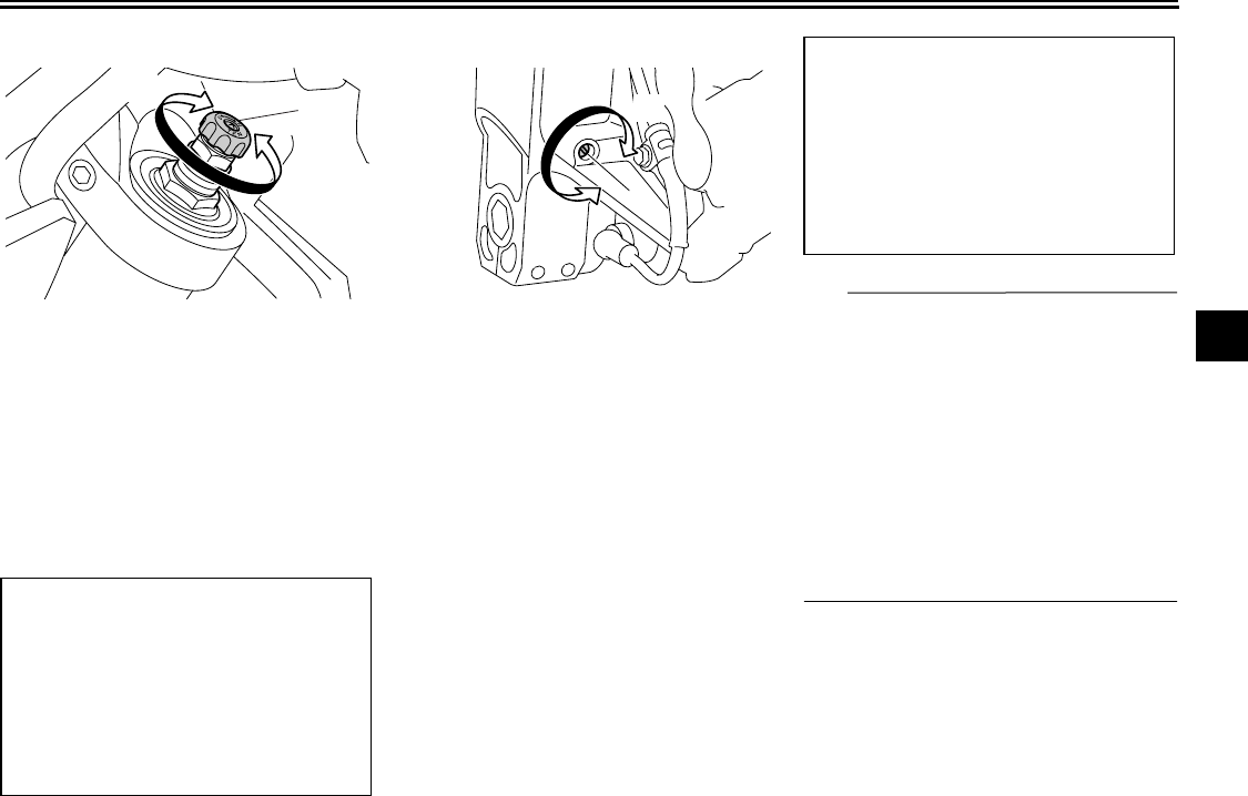
Spring preload
To increase the spring preload and
thereby harden the suspension, turn
the adjusting bolt on each fork leg in di-
rection (a). To decrease the spring pre-
load and thereby soften the
suspension, turn the adjusting bolt on
each fork leg in direction (b).
Align the appropriate groove on the ad-
justing mechanism with the top of the
front fork cap bolt.
1. Spring preload adjusting bolt
(a)
(b)
1
1. Current setting
2. Front fork cap bolt
Spring preload setting:
Minimum (soft):
5
Standard:
4
Maximum (hard):
1
54321
2
1
INSTRUMENT AND CONTROL FUNCTIONS
4-23
2
3
4
5
6
7
8
9
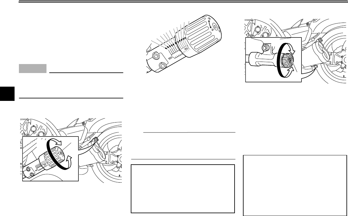
Rebound damping force
To increase the rebound damping force
and thereby harden the rebound damp-
ing, turn the adjusting knob on each
fork leg in direction (a). To decrease the
rebound damping force and thereby
soften the rebound damping, turn the
adjusting knob on each fork leg in direc-
tion (b).
Compression damping force
To increase the compression damping
force and thereby harden the compres-
sion damping, turn the adjusting screw
on each fork leg in direction (a). To de-
crease the compression damping force
and thereby soften the compression
damping, turn the adjusting screw on
each fork leg in direction (b).
TIP
Although the total number of clicks of a
damping force adjusting mechanism
may not exactly match the above spec-
ifications due to small differences in
production, the actual number of clicks
always represents the entire adjusting
range. To obtain a precise adjustment,
it would be advisable to check the num-
ber of clicks of each damping force ad-
justing mechanism and to modify the
specifications as necessary.
1. Rebound damping force adjusting knob
Rebound damping setting:
Minimum (soft):
25 click(s) in direction (b)*
Standard:
12 click(s) in direction (b)*
Maximum (hard):
1 click(s) in direction (b)*
*With the adjusting knob fully turned in
direction (a)
(a)
(b)
1
1. Compression damping force adjusting
screw
1
(b)
(a)
Compression damping setting:
Minimum (soft):
20 click(s) in direction (b)*
Standard:
12 click(s) in direction (b)*
Maximum (hard):
1 click(s) in direction (b)*
*With the adjusting screw fully turned
in direction (a)
INSTRUMENT AND CONTROL FUNCTIONS
4-24
1
2
3
4
5
6
7
8
9
EAU46491
Adjusting the shock absorber
assembly
This shock absorber assembly is
equipped with a spring preload adjust-
ing knob and rebound and compres-
sion damping force adjusting knobs.
NOTICE
ECA10101
To avoid damaging the mechanism,
do not attempt to turn beyond the
maximum or minimum settings.
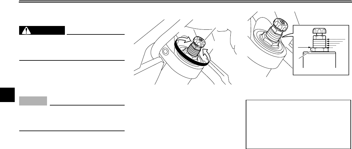
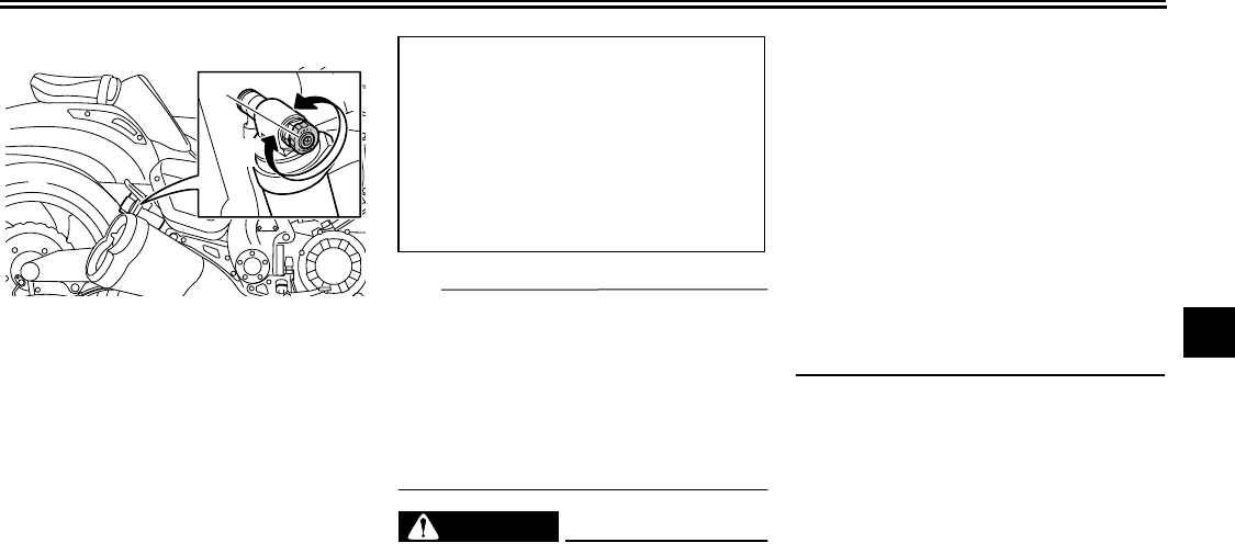
Spring preload
To increase the spring preload and
thereby harden the suspension, turn
the adjusting knob in direction (a). To
decrease the spring preload and there-
by soften the suspension, turn the ad-
justing knob in direction (b).
TIP
Align the appropriate mark on the ad-
justing mechanism with the end of the
adjusting knob.
Rebound damping force
To increase the rebound damping force
and thereby harden the rebound damp-
ing, turn the adjusting knob in direction
(a). To decrease the rebound damping
force and thereby soften the rebound
damping, turn the adjusting knob in di-
rection (b).
1. Spring preload adjusting knob
(a)
(b)
1
Spring preload setting:
Minimum (soft):
11
Standard:
6
Maximum (hard):
1
5
4
3
2
1
11
67
10
9
8
1. Rebound damping force adjusting knob
Rebound damping setting:
Minimum (soft):
20 clicks in direction (b)*
Standard:
12 clicks in direction (b)*
Maximum (hard):
3 clicks in direction (b)*
*With the adjusting knob fully turned in
direction (a)
(b)
(a)
1
INSTRUMENT AND CONTROL FUNCTIONS
4-25
2
3
4
5
6
7
8
9
Compression damping force
To increase the compression damping
force and thereby harden the compres-
sion damping, turn the adjusting knob
in direction (a). To decrease the com-
pression damping force and thereby
soften the compression damping, turn
the adjusting knob in direction (b).
TIP
To obtain a precise adjustment, it is ad-
visable to check the actual total number
of clicks or turns of each damping force
adjusting mechanism. This adjustment
range may not exactly match the spec-
ifications listed due to small differences
in production.
WARNING
EWA10221
This shock absorber assembly con-
tains highly pressurized nitrogen
gas. Read and understand the fol-
lowing information before handling
the shock absorber assembly.
●
Do not tamper with or attempt to
open the cylinder assembly.
●
Do not subject the shock ab-
sorber assembly to an open
flame or other high heat source.
This may cause the unit to ex-
plode due to excessive gas
pressure.
●
Do not deform or damage the
cylinder in any way. Cylinder
damage will result in poor
damping performance.
●
Do not dispose of a damaged or
worn-out shock absorber as-
sembly yourself. Take the shock
absorber assembly to a Yamaha
dealer for any service.
1. Compression damping force adjusting
knob
(b)
(a)
1
Compression damping setting:
Minimum (soft):
12 clicks in direction (b)*
Standard:
10 clicks in direction (b)*
Maximum (hard):
1 clicks in direction (b)*
*With the adjusting knob fully turned in
direction (a)

INSTRUMENT AND CONTROL FUNCTIONS
4-26
1
2
3
4
5
6
7
8
9
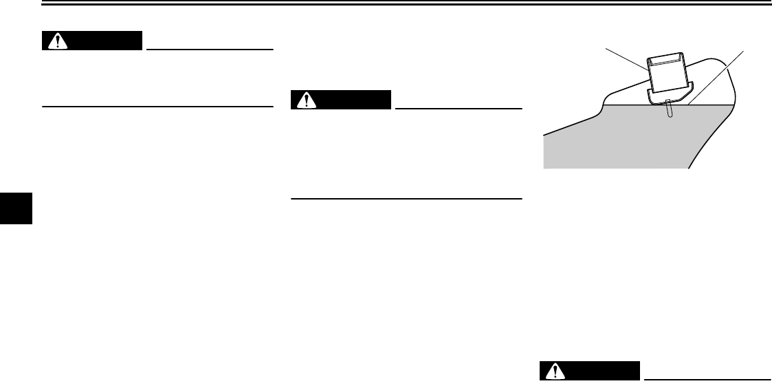
EAU15210
Luggage strap holders
There are four luggage strap holders:
one on each passenger footrest and
two below the passenger seat.
EAU41940
EXUP system
This model is equipped with Yamaha’s
EXUP (EXhaust Ultimate Power valve)
system. This system boosts engine
power by means of a valve that regu-
lates the diameter of the exhaust pipe.
The EXUP system valve is constantly
adjusted in accordance with the engine
speed by a computer-controlled servo-
motor.
NOTICE
ECA15610
The EXUP system has been set and
extensively tested at the Yamaha
factory. Changing these settings
without sufficient technical knowl-
edge may result in poor perfor-
mance of or damage to the engine.
EAU15301
Sidestand
The sidestand is located on the left side
of the frame. Raise the sidestand or
lower it with your foot while holding the
vehicle upright.
TIP
The built-in sidestand switch is part of
the ignition circuit cut-off system, which
cuts the ignition in certain situations.
(See further down for an explanation of
the ignition circuit cut-off system.)
WARNING
EWA10240
The vehicle must not be ridden with
the sidestand down, or if the side-
stand cannot be properly moved up
(or does not stay up), otherwise the
sidestand could contact the ground
and distract the operator, resulting
in a possible loss of control.
Yamaha’s ignition circuit cut-off
system has been designed to assist
the operator in fulfilling the respon-
sibility of raising the sidestand be-
fore starting off. Therefore, check
this system regularly as described
below and have a Yamaha dealer re-
1. Luggage strap holder
11

INSTRUMENT AND CONTROL FUNCTIONS
4-27
2
3
4
5
6
7
8
9
pair it if it does not function proper-
ly.
EAU44892
Ignition circuit cut-off system
The ignition circuit cut-off system (com-
prising the sidestand switch, clutch
switch and neutral switch) has the fol-
lowing functions.
●
It prevents starting when the trans-
mission is in gear and the side-
stand is up, but the clutch lever is
not pulled.
●
It prevents starting when the trans-
mission is in gear and the clutch le-
ver is pulled, but the sidestand is
still down.
●
It cuts the running engine when the
transmission is in gear and the sid-
estand is moved down.
Periodically check the operation of the
ignition circuit cut-off system according
to the following procedure.
INSTRUMENT AND CONTROL FUNCTIONS
4-28
1
2
3
4
5
6
7
8
9
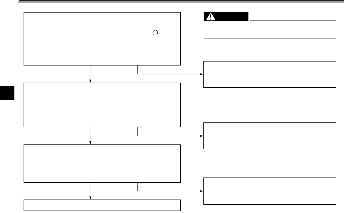
With the engine turned off:
1. Move the sidestand down.
2. Make sure that the engine stop switch is set to “
3. Turn the key on.
4. Shift the transmission into the neutral position.
5. Push the start switch.
Does the engine start?
With the engine still running:
6. Move the sidestand up.
7. Keep the clutch lever pulled.
8. Shift the transmission into gear.
9. Move the sidestand down.
Does the engine stall?
After the engine has stalled:
10. Move the sidestand up.
11. Keep the clutch lever pulled.
12. Push the start switch.
Does the engine start?
The system is OK. The motorcycle can be ridden.
The neutral switch may not be working correctly.
The motorcycle should not be ridden until
checked by a Yamaha dealer.
The sidestand switch may not be working correctly.
The motorcycle should not be ridden until
checked by a Yamaha dealer.
The clutch switch may not be working correctly.
The motorcycle should not be ridden until
checked by a Yamaha dealer.
YES NO
YES NO
YES NO
If a malfunction is noted, have a Yamaha
dealer check the system before riding.
WARNING
”.
5-1
2
3
4
5
6
7
8
9
FOR YOUR SAFETY – PRE-OPERATION CHECKS
EAU15596
Inspect your vehicle each time you use it to make sure the vehicle is in safe operating condition. Always follow the inspection
and maintenance procedures and schedules described in the Owner’s Manual.
WARNING
EWA11151
Failure to inspect or maintain the vehicle properly increases the possibility of an accident or equipment damage.
Do not operate the vehicle if you find any problem. If a problem cannot be corrected by the procedures provided in
this manual, have the vehicle inspected by a Yamaha dealer.
Before using this vehicle, check the following points:
ITEM CHECKS PAGE
Fuel
●
Check fuel level in fuel tank.
●
Refuel if necessary.
●
Check fuel line for leakage.
4-18
Engine oil
●
Check oil level in engine.
●
If necessary, add recommended oil to specified level.
●
Check vehicle for oil leakage.
7-12
Final gear oil
●
Check vehicle for oil leakage. 7-15
Coolant
●
Check coolant level in reservoir.
●
If necessary, add recommended coolant to specified level.
●
Check cooling system for leakage.
7-17
Front brake
●
Check operation.
●
If soft or spongy, have Yamaha dealer bleed hydraulic system.
●
Check brake pads for wear.
●
Replace if necessary.
●
Check fluid level in reservoir.
●
If necessary, add recommended brake fluid to specified level.
●
Check hydraulic system for leakage.
7-25, 7-26
FOR YOUR SAFETY – PRE-OPERATION CHECKS
5-2
1
2
3
4
5
6
7
8
9
Rear brake
●
Check operation.
●
If soft or spongy, have Yamaha dealer bleed hydraulic system.
●
Check brake pads for wear.
●
Replace if necessary.
●
Check fluid level in reservoir.
●
If necessary, add recommended brake fluid to specified level.
●
Check hydraulic system for leakage.
7-25, 7-26
Clutch
●
Check operation.
●
If soft or spongy, have Yamaha dealer bleed hydraulic system.
●
Check hydraulic system for leakage.
7-24
Throttle grip
●
Make sure that operation is smooth.
●
Check cable free play.
●
If necessary, have Yamaha dealer adjust cable free play and lubricate cable
and grip housing.
7-21, 7-28
Control cables
●
Make sure that operation is smooth.
●
Lubricate if necessary. 7-27
Wheels and tires
●
Check for damage.
●
Check tire condition and tread depth.
●
Check air pressure.
●
Correct if necessary.
7-21, 7-24
Brake and shift pedals
●
Make sure that operation is smooth.
●
Lubricate pedal pivoting points if necessary. 7-29, 7-29
Brake and clutch levers
●
Make sure that operation is smooth.
●
Lubricate lever pivoting points if necessary. 7-28
Sidestand
●
Make sure that operation is smooth.
●
Lubricate pivot if necessary. 7-29
Chassis fasteners
●
Make sure that all nuts, bolts and screws are properly tightened.
●
Tighten if necessary. —
Instruments, lights, signals
and switches
●
Check operation.
●
Correct if necessary. —
ITEM CHECKS PAGE

FOR YOUR SAFETY – PRE-OPERATION CHECKS
5-3
2
3
4
5
6
7
8
9
Sidestand switch
●
Check operation of ignition circuit cut-off system.
●
If system is not working correctly, have Yamaha dealer check vehicle. 4-26
ITEM CHECKS PAGE
6-1
1
2
3
4
5
6
7
8
9
OPERATION AND IMPORTANT RIDING POINTS
EAU15951
Read the Owner’s Manual carefully to
become familiar with all controls. If
there is a control or function you do not
understand, ask your Yamaha dealer.
WARNING
EWA10271
Failure to familiarize yourself with
the controls can lead to loss of con-
trol, which could cause an accident
or injury.
EAU46632
TIP
This model is equipped with:
●
a lean angle sensor to stop the en-
gine in case of a turnover. In this
case, the multi-function display in-
dicates error code 30, but this is
not a malfunction. Turn the key to
“OFF” and then to “ON” to clear the
error code. Failing to do so will pre-
vent the engine from starting even
though the engine will crank when
pushing the start switch.
●
an engine auto-stop system. The
engine stops automatically if left
idling for 20 minutes. In this case,
the multi-function display indicates
error code 70, but this is not a mal-
function. Push the start switch to
clear the error code and to restart
the engine.
EAU46510
Starting the engine
In order for the ignition circuit cut-off
system to enable starting, one of the
following conditions must be met:
●
The transmission is in the neutral
position.
●
The transmission is in gear with
the clutch lever pulled and the sid-
estand up.
See page 4-27 for more information.
1. Turn the key to “ON” and make
sure that the engine stop switch is
set to “ ”.
The following warning lights
should come on for a few seconds,
then go off.
●
Oil level warning light
●
Fuel level warning light
●
Coolant temperature warning light
●
Engine trouble warning light
●
ABS warning light
NOTICE
ECA15482
If a warning light does not go off, see
page 4-2 for the corresponding
warning light circuit check.
2. Shift the transmission into the neu-
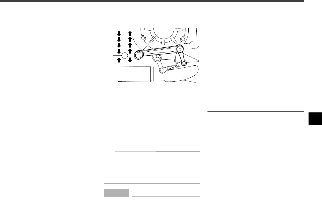
OPERATION AND IMPORTANT RIDING POINTS
6-2
2
3
4
5
6
7
8
9
tral position. The neutral indicator
light should come on. If not, ask a
Yamaha dealer to check the elec-
trical circuit.
3. Start the engine by pushing the
start switch.
NOTICE:
For maxi-
mum engine life, always warm
the engine up before starting
off. Never accelerate hard when
the engine is cold!
[ECA11131]
If the engine fails to start, release
the start switch, wait a few sec-
onds, and then try again. Each
starting attempt should be as short
as possible to preserve the bat-
tery. Do not crank the engine more
than 10 seconds on any one at-
tempt.
EAU16671
Shifting
Shifting gears lets you control the
amount of engine power available for
starting off, accelerating, climbing hills,
etc.
The gear positions are shown in the il-
lustration.
TIP
To shift the transmission into the neu-
tral position, press the shift pedal down
repeatedly until it reaches the end of its
travel, and then slightly raise it.
NOTICE
ECA10260
●
Even with the transmission in
the neutral position, do not
coast for long periods of time
with the engine off, and do not
tow the motorcycle for long dis-
tances. The transmission is
properly lubricated only when
the engine is running. Inade-
quate lubrication may damage
the transmission.
●
Always use the clutch while
changing gears to avoid damag-
ing the engine, transmission,
and drive train, which are not
designed to withstand the
shock of forced shifting.
EAU16681
To start out and accelerate
1. Pull the clutch lever to disengage
the clutch.
2. Shift the transmission into first
gear. The neutral indicator light
should go out.
3. Open the throttle gradually, and at
the same time, release the clutch
lever slowly.
4. At the recommended shift points
shown in the following table, close
1. Shift pedal
2. Neutral position
1
22
3
4
5
N
1

OPERATION AND IMPORTANT RIDING POINTS
6-3
1
2
3
4
5
6
7
8
9
the throttle, and at the same time,
quickly pull the clutch lever in.
5. Shift the transmission into second
gear. (Make sure not to shift the
transmission into the neutral posi-
tion.)
6. Open the throttle part way and
gradually release the clutch lever.
7. Follow the same procedure when
shifting to the next higher gear.
TIP
When shifting gears in normal operat-
ing conditions, use the recommended
shift points.
EAU16700
To decelerate
1. Apply both the front and the rear
brakes to slow the motorcycle.
2. Shift the transmission into first
gear when the motorcycle reaches
25 km/h (16 mi/h). If the engine is
about to stall or runs very roughly,
pull the clutch lever in and use the
brakes to stop the motorcycle.
3. Shift the transmission into the neu-
tral position when the motorcycle
is almost completely stopped. The
neutral indicator light should come
on.
EAU16720
Recommended shift points
The recommended shift points during
acceleration and deceleration are
shown in the table below.
EAU16841
Engine break-in
There is never a more important period
in the life of your engine than the period
between 0 and 1600 km (1000 mi). For
this reason, you should read the follow-
ing material carefully.
Since the engine is brand new, do not
put an excessive load on it for the first
1600 km (1000 mi). The various parts in
the engine wear and polish themselves
to the correct operating clearances.
During this period, prolonged full-throt-
tle operation or any condition that might
result in engine overheating must be
avoided.
EAU17122
0–1000 km (0–600 mi)
Avoid prolonged operation above 4700
r/min.
NOTICE:
After 1000 km (600
mi) of operation, the engine oil and
final gear oil must be changed, and
the oil filter cartridge or element re-
placed.
[ECA10332]
1000–1600 km (600–1000 mi)
Avoid prolonged operation above
Shift up points:
1st
→
2nd: 20 km/h (13 mi/h)
2nd
→
3rd: 30 km/h (19 mi/h)
3rd
→
4th: 40 km/h (25 mi/h)
4th
→
5th: 50 km/h (31 mi/h)
Shift down points:
5th
→
4th: 25 km/h (16 mi/h)
4th
→
3rd: 25 km/h (16 mi/h)
3rd
→
2nd: 25 km/h (16 mi/h)
2nd
→
1st: 25 km/h (16 mi/h)
OPERATION AND IMPORTANT RIDING POINTS
6-4
2
3
4
5
6
7
8
9
7000 r/min.
1600 km (1000 mi) and beyond
The vehicle can now be operated nor-
mally.
NOTICE
ECA10310
●
Keep the engine speed out of
the tachometer red zone.
●
If any engine trouble should oc-
cur during the engine break-in
period, immediately have a
Yamaha dealer check the vehi-
cle.
EAU17213
Parking
When parking, stop the engine, and
then remove the key from the main
switch.
WARNING
EWA10311
●
Since the engine and exhaust
system can become very hot,
park in a place where pedestri-
ans or children are not likely to
touch them and be burned.
●
Do not park on a slope or on soft
ground, otherwise the vehicle
may overturn, increasing the
risk of a fuel leak and fire.
●
Do not park near grass or other
flammable materials which
might catch fire.
7-1
1
2
3
4
5
6
7
8
9
PERIODIC MAINTENANCE AND ADJUSTMENT
EAU17232
Periodic inspection, adjustment, and lu-
brication will keep your vehicle in the
safest and most efficient condition pos-
sible. Safety is an obligation of the vehi-
cle owner/operator. The most important
points of vehicle inspection, adjust-
ment, and lubrication are explained on
the following pages.
WARNING
EWA10321
Failure to properly maintain the ve-
hicle or performing maintenance ac-
tivities incorrectly may increase
your risk of injury or death during
service or while using the vehicle. If
you are not familiar with vehicle ser-
vice, have a Yamaha dealer perform
service.
WARNING
EWA15121
Turn off the engine when performing
maintenance unless otherwise
specified.
●
A running engine has moving
parts that can catch on body
parts or clothing and electrical
parts that can cause shocks or
fires.
●
Running the engine while ser-
vicing can lead to eye injury,
burns, fire, or carbon monoxide
poisoning – possibly leading to
death. See page 2-1 for more in-
formation about carbon monox-
ide.
EAU17302
Emission controls not only function to
ensure cleaner air, but are also vital to
proper engine operation and maximum
performance. In the following periodic
maintenance charts, the services relat-
ed to emissions control are grouped
separately. These services require
specialized data, knowledge, and
equipment. Maintenance, replacement,
or repair of the emission control devic-
es and systems may be performed by
any repair establishment or individual
that is certified (if applicable). Yamaha
dealers are trained and equipped to
perform these particular services.
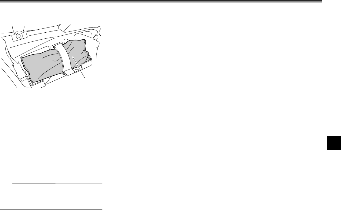
PERIODIC MAINTENANCE AND ADJUSTMENT
7-2
2
3
4
5
6
7
8
9
EAU17341
Owner’s tool kit
The owner’s tool kit is located behind
panel A. (See page 7-9.)
The service information included in this
manual and the tools provided in the
owner’s tool kit are intended to assist
you in the performance of preventive
maintenance and minor repairs. How-
ever, additional tools such as a torque
wrench may be necessary to perform
certain maintenance work correctly.
TIP
If you do not have the tools or experi-
ence required for a particular job, have
a Yamaha dealer perform it for you.
1. Owner’s tool kit
1
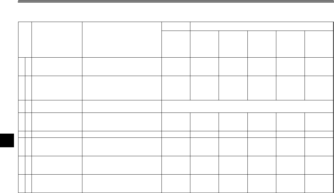
PERIODIC MAINTENANCE AND ADJUSTMENT
7-3
1
2
3
4
5
6
7
8
9
EAU17600
Periodic maintenance chart for the emission control system
* Since these items require special tools, data and technical skills, have a Yamaha dealer perform the service.
No. ITEM ROUTINE
INITIAL ODOMETER READINGS
600 mi
(1000 km)
or
1 month
4000 mi
(7000 km)
or
6 months
8000 mi
(13000 km)
or
12 months
12000 mi
(19000 km)
or
18 months
16000 mi
(25000 km)
or
24 months
20000 mi
(31000 km)
or
30 months
1*
Fuel line
●
Check fuel hoses for cracks or
damage.
●
Replace if necessary.
√√√√√
2*
Spark plugs
●
Check condition.
●
Clean.
●
Replace every 12000 mi (19000
km) or 18 months.
√
Replace.
√
3*
Valve clearance
●
Check and adjust valve clear-
ance when engine is cold. Every 26600 mi (42000 km)
4*
Crankcase breather
system
●
Check breather hose for cracks
or damage.
●
Replace if necessary.
√√√√√
5*
Fuel injection
●
Adjust synchronization.
√√√√√
6*
Exhaust system
●
Check for leakage.
●
Tighten if necessary.
●
Replace gasket(s) if necessary.
√√√√√
7*
Evaporative emis-
sion control system
(For California only)
●
Check control system for dam-
age.
●
Replace if necessary.
√√
8*
Air induction system
●
Check the air cut-off valve, reed
valve, and hose for damage.
●
Replace any damaged parts.
√√
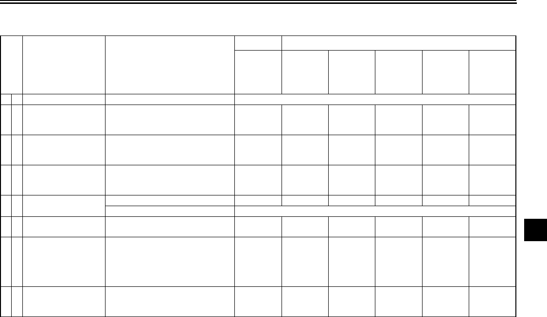
PERIODIC MAINTENANCE AND ADJUSTMENT
7-4
2
3
4
5
6
7
8
9
EAU32185
General maintenance and lubrication chart
No. ITEM ROUTINE
INITIAL ODOMETER READINGS
600 mi
(1000 km)
or
1 month
4000 mi
(7000 km)
or
6 months
8000 mi
(13000 km)
or
12 months
12000 mi
(19000 km)
or
18 months
16000 mi
(25000 km)
or
24 months
20000 mi
(31000 km)
or
30 months
1*
Air filter element
●
Replace. Every 24000 mi (37000 km)
2*
Clutch
●
Check operation and fluid leak-
age.
●
Correct if necessary.
√√√√√√
3*
Front brake
●
Check operation, fluid level, and
for fluid leakage.
●
Replace brake pads if necessary.
√√√√√√
4*
Rear brake
●
Check operation, fluid level, and
for fluid leakage.
●
Replace brake pads if necessary.
√√√√√√
5*
Brake hoses
●
Check for cracks or damage.
√√√√√
●
Replace. Every 4 years
6*
Wheels
●
Check runout and for damage.
●
Replace if necessary.
√√√√√
7*
Tires
●
Check tread depth and for dam-
age.
●
Replace if necessary.
●
Check air pressure.
●
Correct if necessary.
√√√√√
8*
Wheel bearings
●
Check bearings for smooth oper-
ation.
●
Replace if necessary.
√√√√√
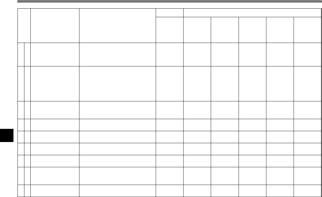
PERIODIC MAINTENANCE AND ADJUSTMENT
7-5
1
2
3
4
5
6
7
8
9
9*
Swingarm pivot
bearings
●
Check bearing assemblies for
looseness.
●
Moderately repack with lith-
ium-soap-based grease.
√
Repack.
10
*
Steering bearings
●
Check bearing assemblies for
looseness.
●
Moderately repack with lith-
ium-soap-based grease every
16000 mi (25000 km) or 24
months.
√√√√
Repack.
√
11
*
Chassis fasteners
●
Check all chassis fitting and fas-
teners.
●
Correct if necessary.
√√√√√
12
Brake lever pivot
shaft
●
Apply silicone grease lightly.
√√√√√
13
Brake pedal pivot
shaft
●
Apply lithium-soap-based grease
lightly.
√√√√√
14
Clutch lever pivot
shaft
●
Apply silicone grease lightly.
√√√√√
15
Shift pedal pivot
shaft
●
Apply lithium-soap-based grease
lightly.
√√√√√
16
Sidestand pivot
●
Check operation.
●
Apply lithium-soap-based grease
lightly.
√√√√√
17
*
Sidestand switch
●
Check operation and replace if
necessary.
√√√√√√
No. ITEM ROUTINE
INITIAL ODOMETER READINGS
600 mi
(1000 km)
or
1 month
4000 mi
(7000 km)
or
6 months
8000 mi
(13000 km)
or
12 months
12000 mi
(19000 km)
or
18 months
16000 mi
(25000 km)
or
24 months
20000 mi
(31000 km)
or
30 months
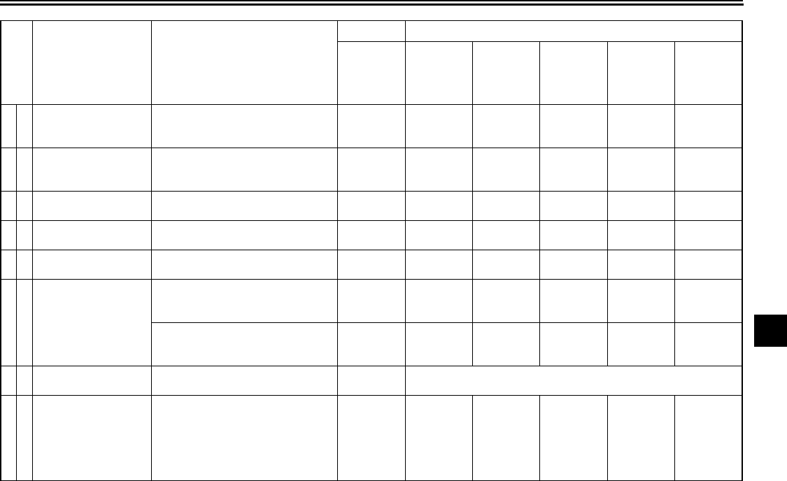
PERIODIC MAINTENANCE AND ADJUSTMENT
7-6
2
3
4
5
6
7
8
9
18
*
Front fork
●
Check operation and for oil leak-
age.
●
Replace if necessary.
√√√√√
19
*
Shock absorber
assembly
●
Check operation and for oil leak-
age.
●
Replace if necessary.
√√√√√
20
*
Rear suspension
link pivots
●
Check operation.
●
Correct if necessary.
√√
21
Engine oil
●
Change (warm engine before
draining).
√√√√√√
22
*
Engine oil filter car-
tridge
●
Replace.
√√√
23
*
Cooling system
●
Check hoses for cracks or dam-
age.
●
Replace if necessary.
√√√√√
●
Change with ethylene glycol
anti-freeze coolant every 24
months.
Change.
24
*
EXUP system
●
Check operation, cable free play
and pulley position.
√
Every 12000 mi (19000 km)
25
Final gear oil
●
Check oil level and for oil leak-
age.
●
Change at initial 600 mi (1000
km) or 1 month, and thereafter
every 16000 mi (25000 km) or 24
months.
Change.
√√√
Change.
√
No. ITEM ROUTINE
INITIAL ODOMETER READINGS
600 mi
(1000 km)
or
1 month
4000 mi
(7000 km)
or
6 months
8000 mi
(13000 km)
or
12 months
12000 mi
(19000 km)
or
18 months
16000 mi
(25000 km)
or
24 months
20000 mi
(31000 km)
or
30 months
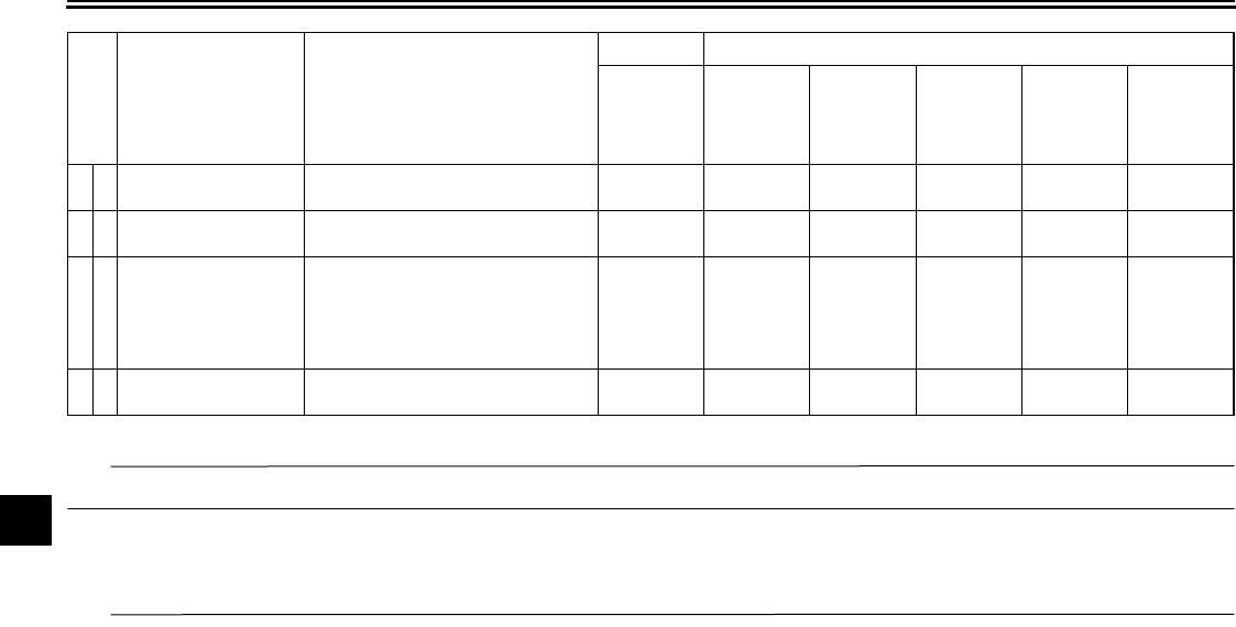
PERIODIC MAINTENANCE AND ADJUSTMENT
7-7
1
2
3
4
5
6
7
8
9
* Since these items require special tools, data and technical skills, have a Yamaha dealer perform the service.
TIP
From 24000 mi (37000 km) or 36 months, repeat the maintenance intervals starting from 8000 mi (13000 km) or 12 months.
EAU38440
TIP
●
Air filter
●
This model’s air filter is equipped with a disposable oil-coated paper element, which must not be cleaned with com-
pressed air to avoid damaging it.
●
The air filter element needs to be replaced more frequently when riding in unusually wet or dusty areas.
●
Hydraulic brake and clutch systems
●
After disassembling the brake or clutch master cylinders, caliper cylinders or clutch release cylinder, always change
26
*
Front and rear brake
switches
●
Check operation.
√√√√√√
27
*
Control cables
●
Apply Yamaha chain and cable
lube or engine oil thoroughly.
√√√√√√
28
*
Throttle grip hous-
ing and cable
●
Check operation and free play.
●
Adjust the throttle cable free play
if necessary.
●
Lubricate the throttle grip hous-
ing and cable.
√√√√√
29
*
Lights, signals and
switches
●
Check operation.
●
Adjust headlight beam.
√√√√√√
No. ITEM ROUTINE
INITIAL ODOMETER READINGS
600 mi
(1000 km)
or
1 month
4000 mi
(7000 km)
or
6 months
8000 mi
(13000 km)
or
12 months
12000 mi
(19000 km)
or
18 months
16000 mi
(25000 km)
or
24 months
20000 mi
(31000 km)
or
30 months

PERIODIC MAINTENANCE AND ADJUSTMENT
7-8
2
3
4
5
6
7
8
9
the fluid. Regularly check the brake and clutch fluid levels and fill the reservoirs as required.
●
Replace the oil seals on the inner parts of the brake or clutch master cylinders, caliper cylinders and clutch release
cylinder every two years.
●
Replace the brake and clutch hoses every four years or if cracked or damaged.
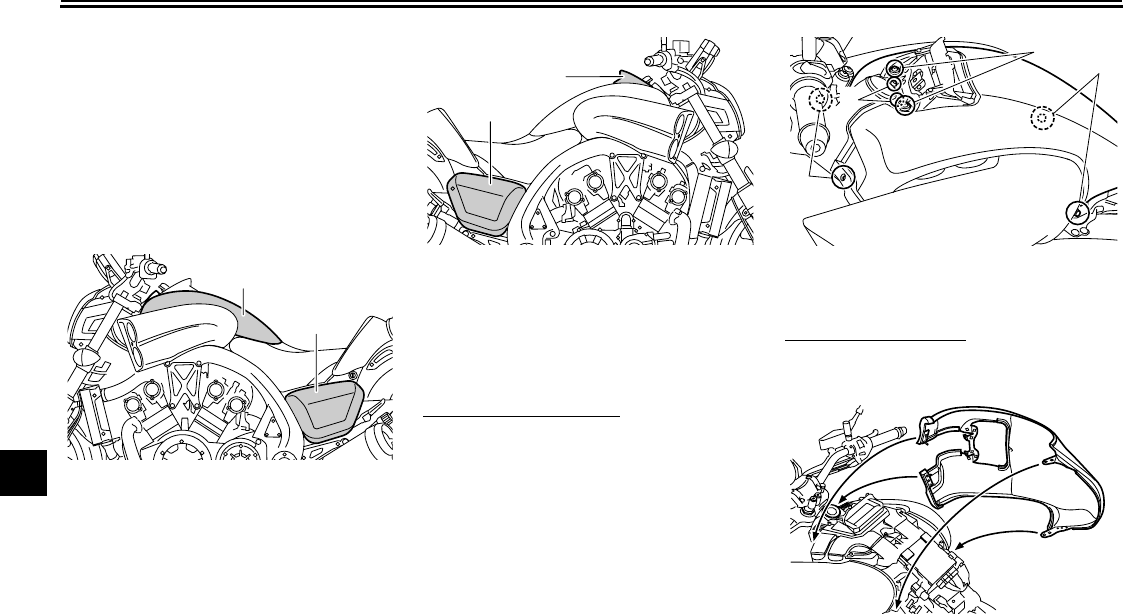
PERIODIC MAINTENANCE AND ADJUSTMENT
7-9
1
2
3
4
5
6
7
8
9
EAU18722
Removing and installing the
cowling and panels
The cowling and panels shown need to
be removed to perform some of the
maintenance jobs described in this
chapter. Refer to this section each time
the cowling or a panel needs to be re-
moved and installed.
EAU46430
Cowling A
To remove the cowling
1. Remove the rider seat. (See page
4-20.)
2. Remove panel C. (See page
7-10.)
3. Remove the bolts, and then pull
the cowling off.
To install the cowling
1. Place the cowling in the original
position, and then install the bolts.
2. Install the panel.
3. Install the rider seat.
1. Cowling A
2. Panel A
1
2
1. Panel B
2. Panel C
1
2
1. Bolt
1
1
1
1
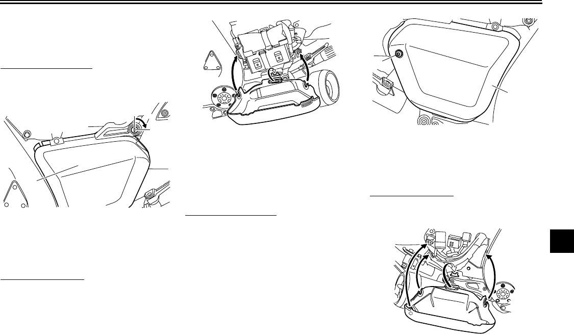
PERIODIC MAINTENANCE AND ADJUSTMENT
7-10
2
3
4
5
6
7
8
9
EAU46471
Panel A
To remove the panel
1. Insert the key into the lock, and
then turn it 1/4 turn clockwise.
2. Pull the panel outward.
To install the panel
1. Place the panel in the original po-
sition.
2. Turn the key counterclockwise to
the original position, and then re-
move it.
Panel B
To remove the panel
1. Remove the bolt.
2. Pull the panel outward.
To install the panel
Place the panel in the original position,
and then install the bolt.
1. Unlock.
2. Panel A
2
1
1. Bolt
2. Panel B
1
2
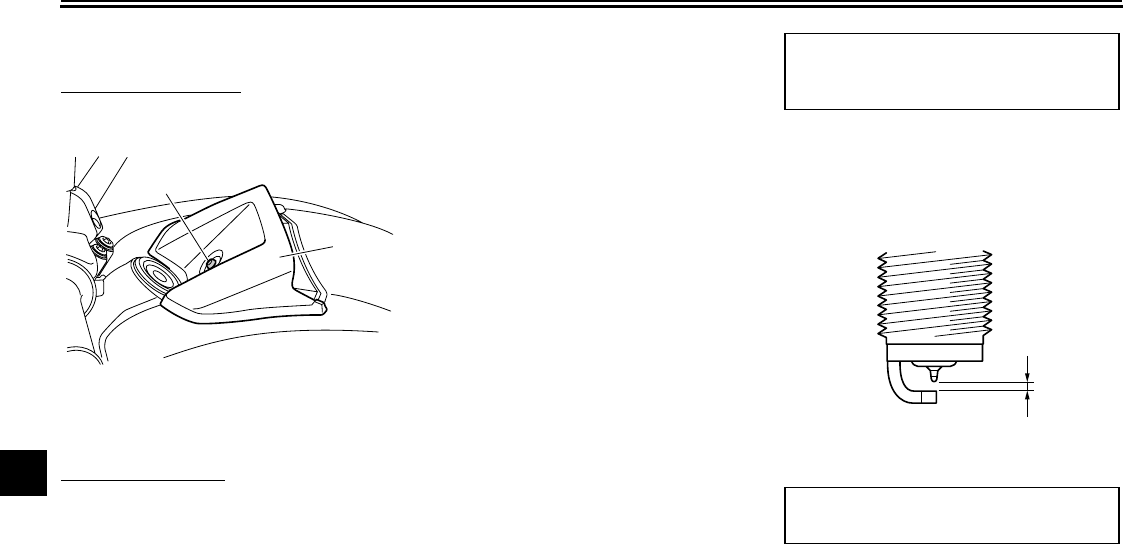
PERIODIC MAINTENANCE AND ADJUSTMENT
7-11
1
2
3
4
5
6
7
8
9
Panel C
To remove the panel
1. Remove the bolt.
2. Pull the panel upward.
To install the panel
Place the panel in the original position,
and then install the bolt.
EAU46680
Checking the spark plugs
The spark plugs are important engine
components, which should be checked
periodically, preferably by a Yamaha
dealer. Since heat and deposits will
cause any spark plug to slowly erode,
they should be removed and checked
in accordance with the periodic mainte-
nance and lubrication chart. In addition,
the condition of the spark plugs can re-
veal the condition of the engine.
The porcelain insulator around the cen-
ter electrode of each spark plug should
be a medium-to-light tan (the ideal color
when the vehicle is ridden normally),
and all spark plugs installed in the en-
gine should have the same color. If any
spark plug shows a distinctly different
color, the engine could be operating im-
properly. Do not attempt to diagnose
such problems yourself. Instead, have
a Yamaha dealer check the vehicle.
If a spark plug shows signs of electrode
erosion and excessive carbon or other
deposits, it should be replaced.
Before installing a spark plug, the spark
plug gap should be measured with a
wire thickness gauge and replaced if
out of specification.
Clean the surface of the spark plug
gasket and its mating surface, and then
wipe off any grime from the spark plug
threads.
1. Panel C
2. Bolt
1
2
Specified spark plug:
NGK/CR9EIA
DENSO/IU27D
1. Spark plug gap
Spark plug gap:
0.8–0.9 mm (0.031–0.035 in)
1
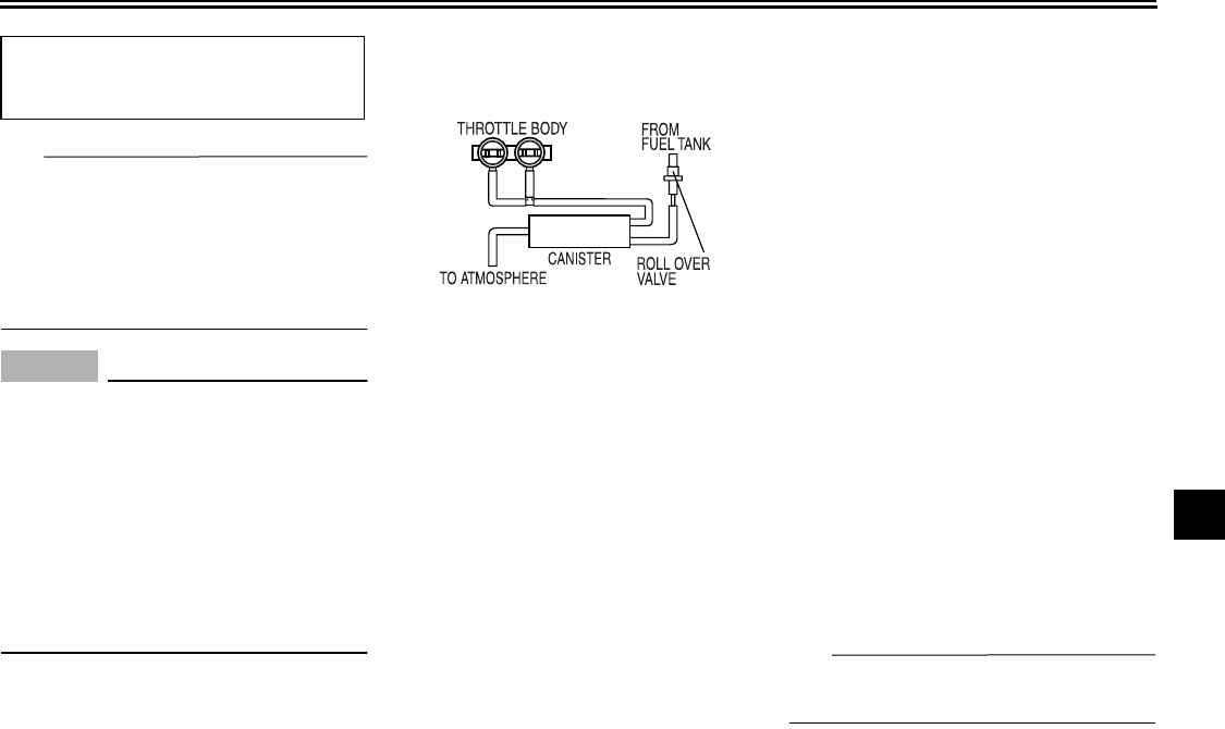
PERIODIC MAINTENANCE AND ADJUSTMENT
7-12
2
3
4
5
6
7
8
9
TIP
If a torque wrench is not available when
installing a spark plug, a good estimate
of the correct torque is 1/4–1/2 turn
past finger tight. However, the spark
plug should be tightened to the speci-
fied torque as soon as possible.
NOTICE
ECA10840
Do not use any tools to remove or in-
stall the spark plug cap, otherwise
the ignition coil coupler may get
damaged. The spark plug cap may
be difficult to remove because the
rubber seal on the end of the cap fits
tightly. To remove the spark plug
cap, simply twist it back and forth
while pulling it out; to install it, twist
it back and forth while pushing it in.
EAU19681
Canister (for California only)
This model is equipped with a canister
to prevent the discharging of fuel vapor
into the atmosphere. Before operating
this vehicle, make sure to check the fol-
lowing:
●
Check each hose connection.
●
Check each hose and canister for
cracks or damage. Replace if
damaged.
●
Make sure that the canister breath-
er is not blocked, and if necessary,
clean it.
EAU19907
Engine oil and oil filter
cartridge
The engine oil level should be checked
before each ride. In addition, the oil
must be changed and the oil filter car-
tridge replaced at the intervals speci-
fied in the periodic maintenance and
lubrication chart.
To check the engine oil level
1. Place the vehicle on a level sur-
face and hold it in an upright posi-
tion. A slight tilt to the side can
result in a false reading.
2. Start the engine, warm it up for
several minutes, and then turn it
off.
3. Wait a few minutes until the oil set-
tles, and then check the oil level
through the check window located
at the bottom-right side of the
crankcase.
TIP
The engine oil should be between the
minimum and maximum level marks.
Tightening torque:
Spark plug:
12.5 Nm (1.3 m·kgf, 9 ft·lbf)
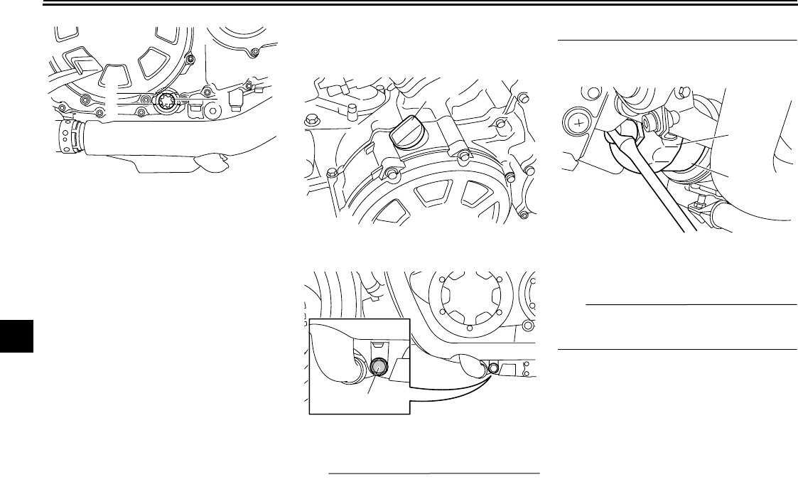
PERIODIC MAINTENANCE AND ADJUSTMENT
7-13
1
2
3
4
5
6
7
8
9
4. If the engine oil is below the mini-
mum level mark, add sufficient oil
of the recommended type to raise
it to the correct level.
To change the engine oil (with or
without oil filter cartridge replace-
ment)
1. Place the vehicle on a level sur-
face.
2. Start the engine, warm it up for
several minutes, and then turn it
off.
3. Place an oil pan under the engine
to collect the used oil.
4. Remove the engine oil filler cap
and drain bolt to drain the oil from
the crankcase.
TIP
Skip steps 5–7 if the oil filter cartridge is
not being replaced.
5. Remove the oil filter cartridge with
an oil filter wrench.
TIP
An oil filter wrench is available at a
Yamaha dealer.
6. Apply a thin coat of clean engine
oil to the O-ring of the new oil filter
cartridge.
1. Engine oil level check window
2. Maximum level mark
3. Minimum level mark
2
31
1. Engine oil filler cap
1. Engine oil drain bolt
1
1
1. Oil filter wrench
2. Oil filter cartridge
1
2
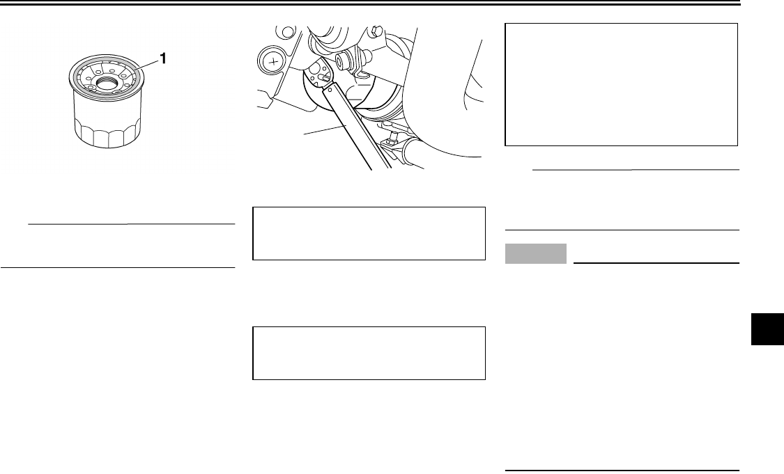
PERIODIC MAINTENANCE AND ADJUSTMENT
7-14
2
3
4
5
6
7
8
9
TIP
Make sure that the O-ring is properly
seated.
7. Install the new oil filter cartridge
with an oil filter wrench, and then
tighten it to the specified torque
with a torque wrench.
8. Install the engine oil drain bolt, and
then tighten it to the specified
torque.
9. Refill with the specified amount of
the recommended engine oil, and
then install and tighten the oil filler
cap.
TIP
Be sure to wipe off spilled oil on any
parts after the engine and exhaust sys-
tem have cooled down.
NOTICE
ECA11620
●
In order to prevent clutch slip-
page (since the engine oil also
lubricates the clutch), do not
mix any chemical additives. Do
not use oils with a diesel speci-
fication of “CD” or oils of a high-
er quality than specified. In
addition, do not use oils labeled
“ENERGY CONSERVING II” or
higher.
●
Make sure that no foreign mate-
rial enters the crankcase.
1. O-ring
1. Torque wrench
Tightening torque:
Oil filter cartridge:
17 Nm (1.7 m·kgf, 12 ft·lbf)
Tightening torque:
Engine oil drain bolt:
43 Nm (4.3 m·kgf, 30 ft·lbf)
1
Recommended engine oil:
See page 9-1.
Oil quantity:
Without oil filter cartridge replace-
ment:
4.30 L (4.55 US qt, 3.78 Imp.qt)
With oil filter cartridge replacement:
4.70 L (4.97 US qt, 4.14 Imp.qt)
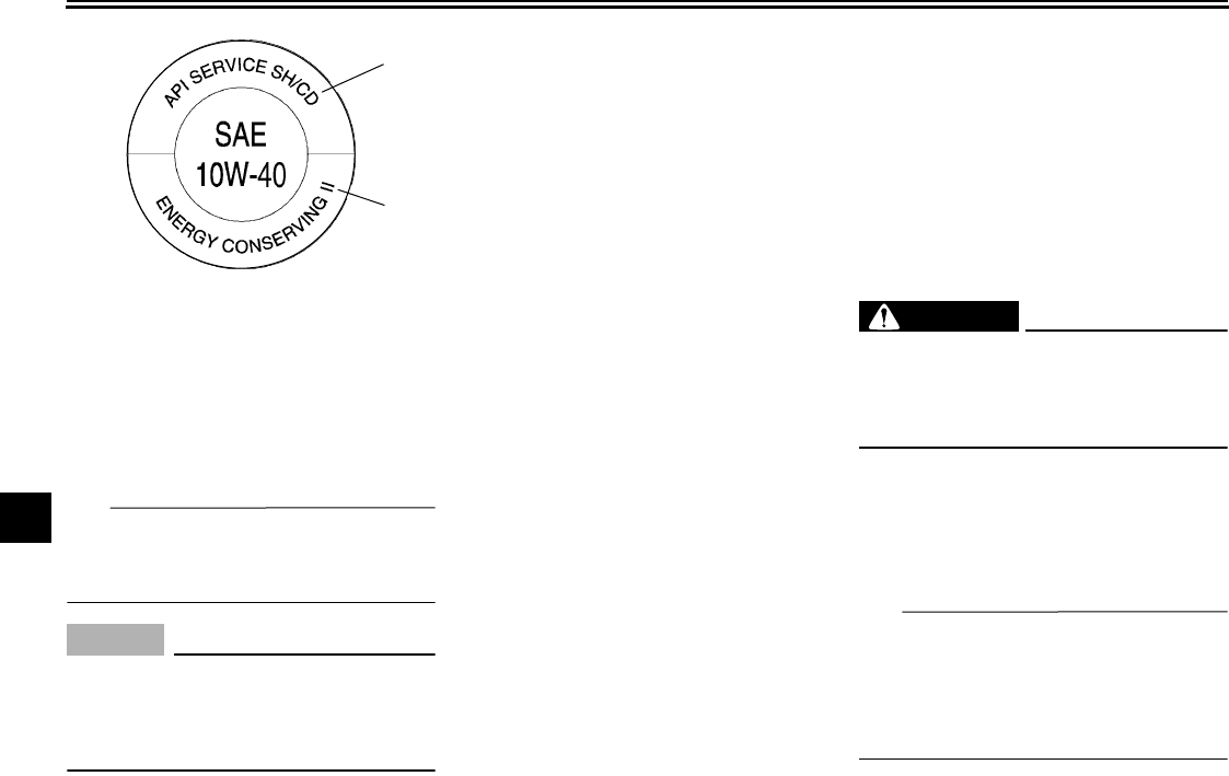
PERIODIC MAINTENANCE AND ADJUSTMENT
7-15
1
2
3
4
5
6
7
8
9
10. Start the engine, and then let it idle
for several minutes while checking
it for oil leakage. If oil is leaking, im-
mediately turn the engine off and
check for the cause.
TIP
After the engine is started, the engine
oil level warning light should go off if the
oil level is sufficient.
NOTICE
ECA10400
If the oil level warning light flickers
or remains on, immediately turn the
engine off and have a Yamaha dealer
check the vehicle.
11. Turn the engine off, and then
check the oil level and correct it if
necessary.
EAU46572
Final gear oil
The final gear case must be checked
for oil leakage before each ride. If any
leakage is found, have a Yamaha deal-
er check and repair the vehicle. In addi-
tion, the final gear oil must be checked
and changed as follows at the intervals
specified in the periodic maintenance
and lubrication chart.
WARNING
EWA10370
●
Make sure that no foreign mate-
rial enters the final gear case.
●
Make sure that no oil gets on the
tire or wheel.
To check the final gear oil level
1. Place the vehicle on a level sur-
face and hold it in an upright posi-
tion.
TIP
●
The final gear oil level must be
checked on a cold engine.
●
Make sure that the vehicle is posi-
tioned straight up when checking
the oil level.
1. “CD” specification
2. “ENERGY CONSERVING II”
1
2
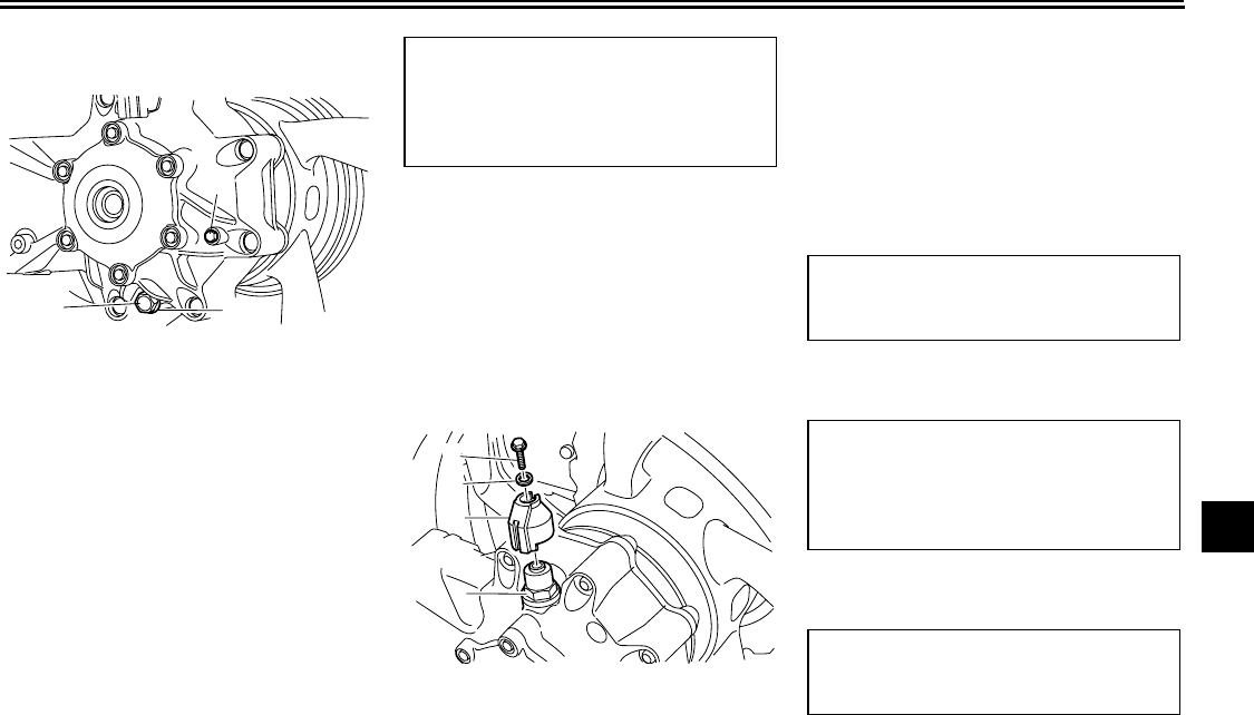
PERIODIC MAINTENANCE AND ADJUSTMENT
7-16
2
3
4
5
6
7
8
9
2. Loosen the final gear oil check bolt
until oil flows out.
3. If no oil flows out, remove the final
gear oil filler bolt. (See steps 3–4
under “To change the final gear oil”
for oil filler bolt removal.)
4. Pour the recommended type of oil
in the final gear oil filler hole until it
flows out of the oil check bolt hole.
5. Install the final gear oil filler bolt
and final gear oil check bolt, and
then tighten them to their specified
torques.
To change the final gear oil
1. Place the vehicle on a level sur-
face.
2. Place an oil pan under the final
gear case to collect the used oil.
3. Remove the final gear case
breather cap by removing the bolt
and washer.
4. Remove the oil drain bolt and the
filler bolt to drain the oil from the fi-
nal gear case.
5. Replace the final gear oil drain bolt
washer, and then install the final
gear oil drain bolt.
6. Tighten the final gear oil drain bolt
to the specified torque.
7. Refill with the recommended final
gear oil.
8. Install the oil filler bolt, and then
tighten it to the specified torque.
9. Install the final gear case breather
cap by installing the washer and
1. Final gear oil drain bolt
2. Final gear oil check bolt
3. Final gear oil drain bolt washer
1
2
3
Tightening torques:
Final gear oil filler bolt:
23 Nm (2.3 m·kgf, 16 ft·lbf)
Final gear oil check bolt:
10 Nm (1.0 m·kgf, 7.2 ft·lbf)
1. Final gear oil filler bolt
2. Final gear case breather cap
3. Washer
4. Final gear case breather cap bolt
2
3
4
1
Tightening torque:
Final gear oil drain bolt:
23 Nm (2.3 m·kgf, 16 ft·lbf)
Recommended final gear oil:
Shaft drive gear oil (Part No.:
9079E-SH001-00)
Oil quantity:
0.30 L (0.32 US qt, 0.26 Imp.qt)
Tightening torque:
Final gear oil filler bolt:
23 Nm (2.3 m·kgf, 16 ft·lbf)
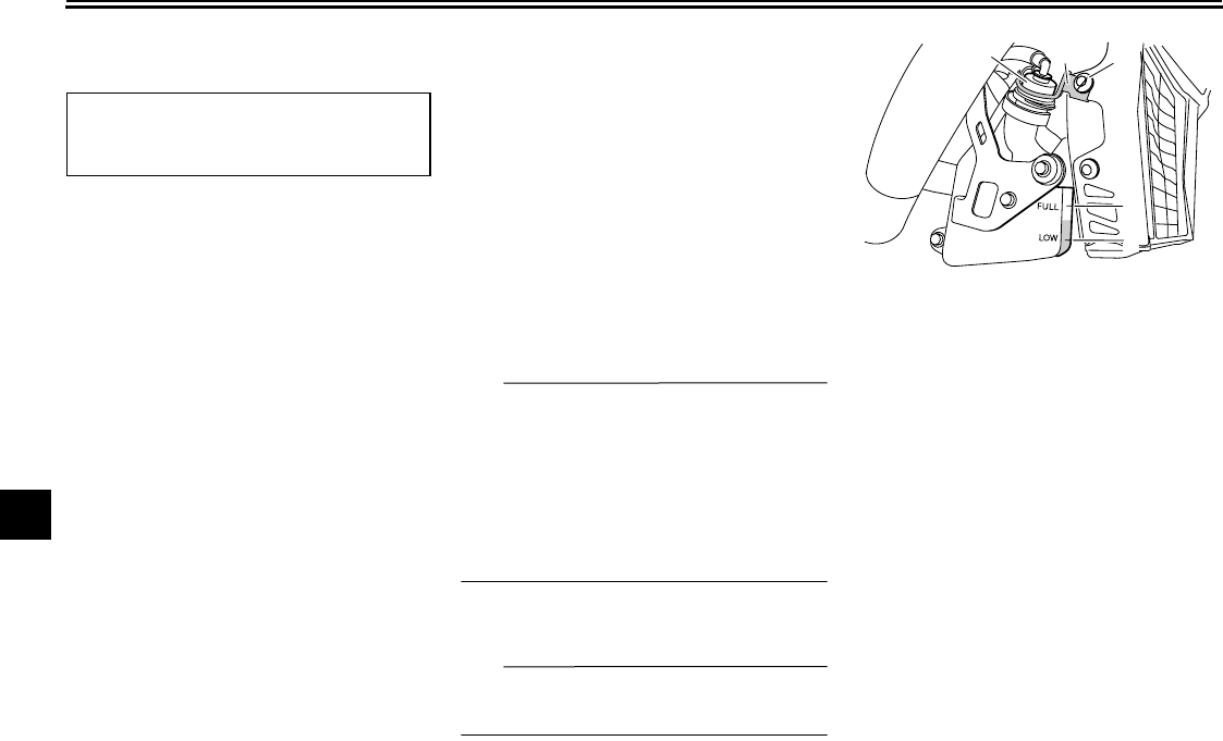
PERIODIC MAINTENANCE AND ADJUSTMENT
7-17
1
2
3
4
5
6
7
8
9
bolt, and then tighten the bolt to the
specified torque.
10. Check the final gear case for oil
leakage. If oil is leaking, check for
the cause.
EAU20070
Coolant
The coolant level should be checked
before each ride. In addition, the cool-
ant must be changed at the intervals
specified in the periodic maintenance
and lubrication chart.
EAU46690
To check the coolant level
1. Place the vehicle on a level sur-
face and hold it in an upright posi-
tion.
TIP
●
The coolant level must be checked
on a cold engine since the level
varies with engine temperature.
●
Make sure that the vehicle is posi-
tioned straight up when checking
the coolant level. A slight tilt to the
side can result in a false reading.
2. Check the coolant level in the cool-
ant reservoir.
TIP
The coolant should be between the
minimum and maximum level marks.
3. If the coolant is at or below the
minimum level mark, remove the
coolant reservoir cap guard by re-
moving the bolt, and then remove
the reservoir cap.
4. Add coolant to the maximum level
mark, and then install the reservoir
cap.
WARNING! Remove only
the coolant reservoir cap. Never
attempt to remove the radiator
cap when the engine is
hot.
[EWA15161]
NOTICE:
If coolant is
not available, use distilled water
Tightening torque:
Final gear case breather cap bolt:
10 Nm (1.0 m·kgf, 7.2 ft·lbf)
1. Coolant reservoir cap
2. Coolant reservoir cap guard
3. Bolt
4. Maximum level mark
5. Minimum level mark
2
1
5
4
3
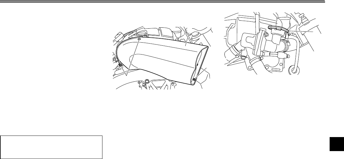
PERIODIC MAINTENANCE AND ADJUSTMENT
7-18
2
3
4
5
6
7
8
9
or soft tap water instead. Do not
use hard water or salt water
since it is harmful to the engine.
If water has been used instead
of coolant, replace it with cool-
ant as soon as possible, other-
wise the cooling system will not
be protected against frost and
corrosion. If water has been
added to the coolant, have a
Yamaha dealer check the anti-
freeze content of the coolant as
soon as possible, otherwise the
effectiveness of the coolant will
be reduced.
[ECA10472]
5. Install the coolant reservoir cap
guard by installing the bolt.
EAU46422
To change the coolant
1. Place the vehicle on a level sur-
face and let the engine cool if nec-
essary.
2. Remove cowling A. (See
page 7-9.)
3. Remove the air intake duct by re-
moving the bolts.
4. Place a container under the engine
to collect the used coolant.
5. Remove the radiator cap.
WARNING! Never attempt to re-
move the radiator cap when the
engine is hot.
[EWA10381]
6. Remove the coolant reservoir cov-
er and coolant reservoir by remov-
ing the bolts.
Coolant reservoir capacity (up to the
maximum level mark):
0.27 L (0.29 US qt, 0.24 Imp.qt)
1. Bolt
2. Air intake duct
1
1
2
1. Radiator cap
1
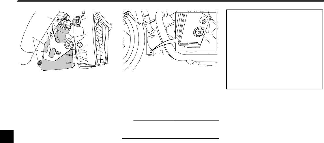
PERIODIC MAINTENANCE AND ADJUSTMENT
7-19
1
2
3
4
5
6
7
8
9
7. Remove the coolant reservoir cap
guard by removing the bolt, and
then remove the reservoir cap.
8. Drain the coolant from the coolant
reservoir by turning it upside down.
9. Install the coolant reservoir cover
and the coolant reservoir by plac-
ing them in their original position,
and then installing the bolts.
10. Remove the coolant drain bolt to
drain the cooling system.
11. After the coolant is completely
drained, thoroughly flush the cool-
ing system with clean tap water.
12. Install the coolant drain bolt.
TIP
Check the O-ring for damage and re-
place it if necessary.
13. Hold the vehicle upright, and pour
the specified amount of the recom-
mended coolant into the radiator
and reservoir.
NOTICE:
Failing to
hold the vehicle upright when
filling the radiator with coolant
may cause air to be trapped in
the cooling system.
[ECA16540]
14. Install the coolant reservoir cap,
and then install the reservoir cap
guard by installing the bolt.
15. Install the radiator cap.
16. Start the engine, let it idle for sev-
eral minutes, and then turn it off.
17. Remove the radiator cap to check
the coolant level in the radiator. If
necessary, add sufficient coolant
until it reaches the top of the radia-
tor, and then install the radiator
cap.
18. Check the coolant level in the res-
ervoir. If necessary, remove the
coolant reservoir cap guard and
the cap, add coolant to the maxi-
1. Bolt
2. Coolant reservoir cap
3. Coolant reservoir cap guard
4. Bolt
5. Coolant reservoir cover
6. Coolant reservoir
5
6
1
234
1. Coolant drain bolt
1
Antifreeze/water mixture ratio:
1:1
Recommended antifreeze:
High-quality ethylene glycol anti-
freeze containing corrosion inhibitors
for aluminum engines
Coolant quantity:
Radiator capacity (including all
routes):
3.75 L (3.96 US qt, 3.30 Imp.qt)
Coolant reservoir capacity (up to the
maximum level mark):
0.27 L (0.29 US qt, 0.24 Imp.qt)
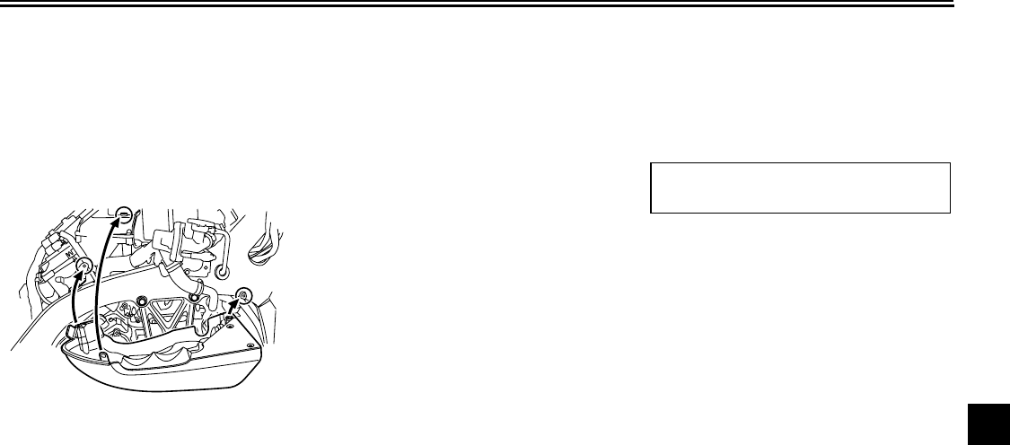
PERIODIC MAINTENANCE AND ADJUSTMENT
7-20
2
3
4
5
6
7
8
9
mum level mark, and then install
the cap and the cap guard.
19. Start the engine, and then check
the vehicle for coolant leakage. If
coolant is leaking, have a Yamaha
dealer check the cooling system.
20. Install the air intake duct by install-
ing the bolts.
21. Install the cowling.
EAU36762
Air filter element
The air filter element must be replaced
at the intervals specified in the periodic
maintenance and lubrication chart.
Have a Yamaha dealer replace the air
filter element.
EAU44734
Checking the engine idling
speed
Check the engine idling speed and, if
necessary, have it corrected by a
Yamaha dealer.
Engine idling speed:
950–1050 r/min
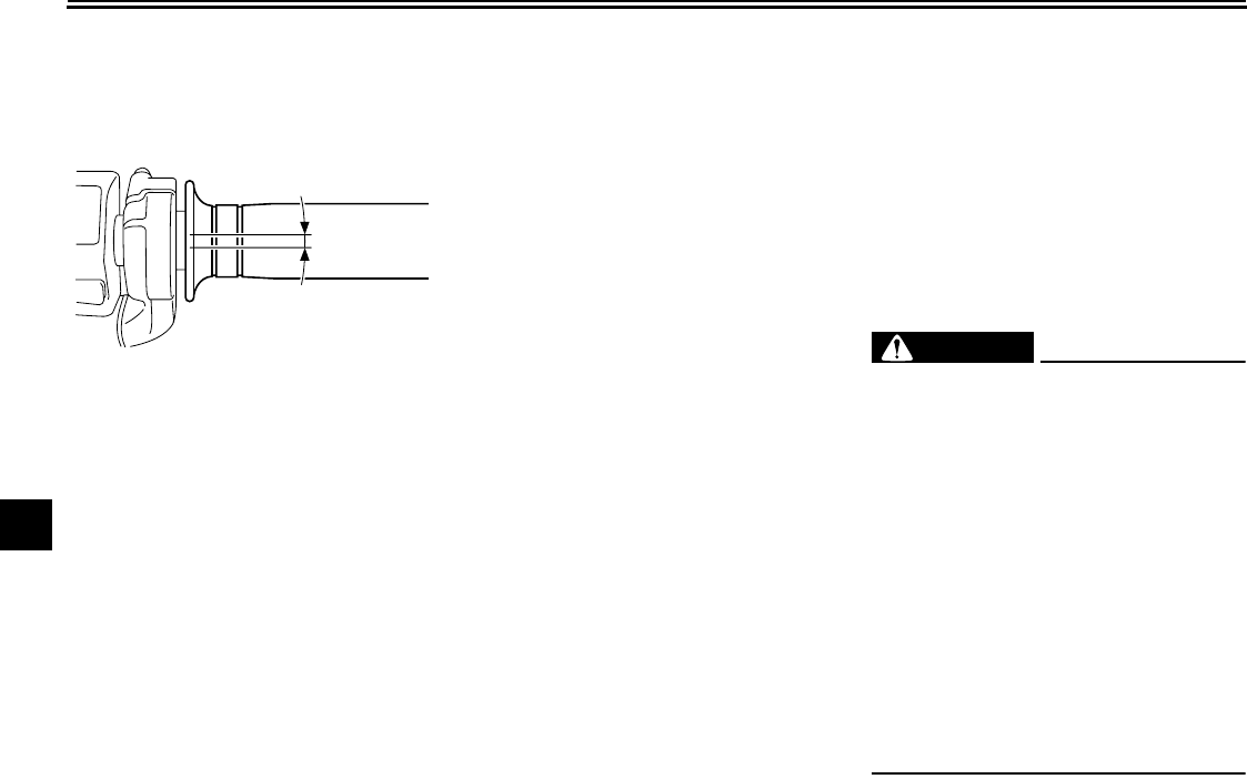
PERIODIC MAINTENANCE AND ADJUSTMENT
7-21
1
2
3
4
5
6
7
8
9
EAU21382
Checking the throttle cable
free play
The throttle cable free play should mea-
sure 3.0–5.0 mm (0.12–0.20 in) at the
throttle grip. Periodically check the
throttle cable free play and, if neces-
sary, have a Yamaha dealer adjust it.
EAU21401
Valve clearance
The valve clearance changes with use,
resulting in improper air-fuel mixture
and/or engine noise. To prevent this
from occurring, the valve clearance
must be adjusted by a Yamaha dealer
at the intervals specified in the periodic
maintenance and lubrication chart.
EAU21751
Tires
To maximize the performance, durabil-
ity, and safe operation of your motorcy-
cle, note the following points regarding
the specified tires.
Tire air pressure
The tire air pressure should be checked
and, if necessary, adjusted before each
ride.
WARNING
EWA10501
Operation of this vehicle with im-
proper tire pressure may cause se-
vere injury or death from loss of
control.
●
The tire air pressure must be
checked and adjusted on cold
tires (i.e., when the temperature
of the tires equals the ambient
temperature).
●
The tire air pressure must be ad-
justed in accordance with the
riding speed and with the total
weight of rider, passenger, car-
go, and accessories approved
for this model.
1. Throttle cable free play
1
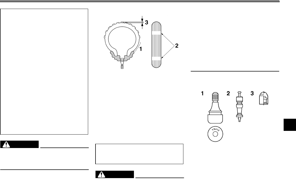
PERIODIC MAINTENANCE AND ADJUSTMENT
7-22
2
3
4
5
6
7
8
9
WARNING
EWA10511
Never overload your vehicle. Opera-
tion of an overloaded vehicle could
cause an accident.
Tire inspection
Always check the tires before operating
the motorcycle. If a tire tread shows
crosswise lines (minimum tread depth),
if the tire has a nail or glass fragments
in it, or if the sidewall is cracked, con-
tact a Yamaha dealer immediately and
have the tire replaced.
WARNING
EWA10580
●
It is dangerous to ride with a
worn-out tire. When a tire tread
begins to show crosswise lines,
have a Yamaha dealer replace
the tire immediately.
●
The replacement of all wheel-
and brake-related parts, includ-
ing the tires, should be left to a
Yamaha dealer, who has the
necessary professional knowl-
edge and experience.
Tire information
This motorcycle is equipped with cast
wheels and tubeless tires with valves.
Tire air pressure (measured on cold
tires):
0–90 kg (0–198 lb):
Front:
250 kPa (2.50 kgf/cm
2
, 36 psi)
Rear:
290 kPa (2.90 kgf/cm
2
, 42 psi)
90–189 kg (198–417 lb) (CAL)
90–190 kg (198–419 lb) (U49):
Front:
250 kPa (2.50 kgf/cm
2
, 36 psi)
Rear:
290 kPa (2.90 kgf/cm
2
, 42 psi)
High-speed riding:
Front:
290 kPa (2.90 kgf/cm
2
, 42 psi)
Rear:
290 kPa (2.90 kgf/cm
2
, 42 psi)
Maximum load*:
189 kg (417 lb) (CAL)
190 kg (419 lb) (U49)
*Total weight of rider, passenger, car-
go and accessories
1. Tire sidewall
2. Tire wear indicator
3. Tire tread depth
Minimum tire tread depth (front and
rear):
1.0 mm (0.04 in)
1. Tire air valve
2. Tire air valve core
3. Tire air valve cap with seal
PERIODIC MAINTENANCE AND ADJUSTMENT
7-23
1
2
3
4
5
6
7
8
9
WARNING
EWA10481
●
The front and rear tires should
be of the same make and de-
sign, otherwise the handling
characteristics of the motorcy-
cle may be different, which
could lead to an accident.
●
Always make sure that the valve
caps are securely installed to
prevent air pressure leakage.
●
Use only the tire valves and
valve cores listed below to
avoid tire deflation during a
high-speed ride.
After extensive tests, only the tires list-
ed below have been approved for this
model by Yamaha Motor Co., Ltd.
WARNING
EWA10600
This motorcycle is fitted with su-
per-high-speed tires. Note the fol-
lowing points in order to make the
most efficient use of these tires.
●
Use only the specified replace-
ment tires. Other tires may run
the danger of bursting at super
high speeds.
●
Brand-new tires can have a rela-
tively poor grip on certain road
surfaces until they have been
“broken in”. Therefore, it is ad-
visable before doing any
high-speed riding to ride con-
servatively for approximately
100 km (60 mi) after installing a
new tire.
●
The tires must be warmed up
before a high-speed run.
●
Always adjust the tire air pres-
sure according to the operating
conditions.
Front tire:
Size:
120/70R18M/C 59V
Manufacturer/model:
BRIDGESTONE/BT028F
Rear tire:
Size:
200/50R18M/C 76V
Manufacturer/model:
BRIDGESTONE/BT028R
FRONT and REAR:
Tire air valve:
TR412
Valve core:
#9100 (original)
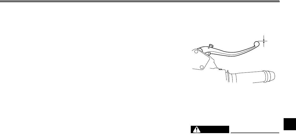
PERIODIC MAINTENANCE AND ADJUSTMENT
7-24
2
3
4
5
6
7
8
9
EAU21960
Cast wheels
To maximize the performance, durabil-
ity, and safe operation of your vehicle,
note the following points regarding the
specified wheels.
●
The wheel rims should be checked
for cracks, bends or warpage be-
fore each ride. If any damage is
found, have a Yamaha dealer re-
place the wheel. Do not attempt
even the smallest repair to the
wheel. A deformed or cracked
wheel must be replaced.
●
The wheel should be balanced
whenever either the tire or wheel
has been changed or replaced. An
unbalanced wheel can result in
poor performance, adverse han-
dling characteristics, and a short-
ened tire life.
●
Ride at moderate speeds after
changing a tire since the tire sur-
face must first be “broken in” for it
to develop its optimal characteris-
tics.
EAU42850
Clutch lever
Since this model is equipped with a hy-
draulic clutch, adjusting the clutch lever
free play is not needed. However, it is
necessary to check the hydraulic sys-
tem for leakage before each ride. If the
clutch lever free play does become ex-
cessive, and shifting becomes rough or
clutch slippage occurs, causing poor
acceleration, there may be air in the
clutch system. If there is air in the hy-
draulic system, have a Yamaha dealer
bleed the system before operating the
motorcycle.
EAU37912
Checking the front brake lever
free play
There should be no free play at the
brake lever end. If there is free play,
have a Yamaha dealer inspect the
brake system.
WARNING
EWA14211
A soft or spongy feeling in the brake
lever can indicate the presence of air
in the hydraulic system. If there is air
in the hydraulic system, have a
Yamaha dealer bleed the system be-
fore operating the vehicle. Air in the
hydraulic system will diminish the
braking performance, which may re-
1. Brake lever free play
1
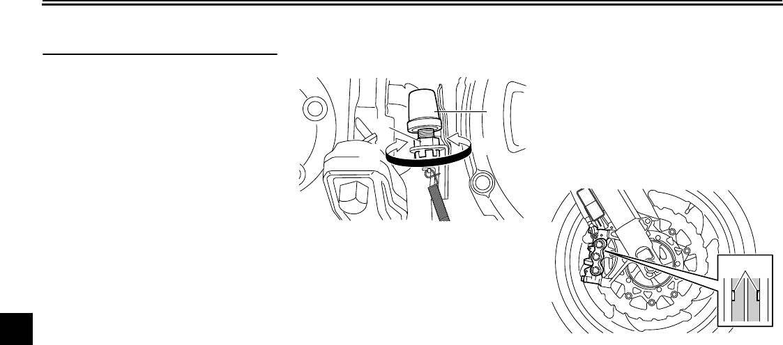
PERIODIC MAINTENANCE AND ADJUSTMENT
7-25
1
2
3
4
5
6
7
8
9
sult in loss of control and an acci-
dent.
EAU22272
Adjusting the rear brake light
switch
The rear brake light, which is activated
by the brake pedal, should come on just
before braking takes effect. If neces-
sary, adjust the rear brake light switch
as follows.
Turn the rear brake light switch adjust-
ing nut while holding the rear brake light
switch in place. To make the brake light
come on earlier, turn the adjusting nut
in direction (a). To make the brake light
come on later, turn the adjusting nut in
direction (b).
EAU22390
Checking the front and rear
brake pads
The front and rear brake pads must be
checked for wear at the intervals spec-
ified in the periodic maintenance and
lubrication chart.
EAU22410
Front brake pads
Each front brake pad is provided with a
wear indicator, which allows you to
check the brake pad wear without hav-
ing to disassemble the brake. To check
the brake pad wear, check the position
of the wear indicator while applying the
brake. If a brake pad has worn to the
1. Rear brake light switch
2. Rear brake light switch adjusting nut
1
2
(a) (b)
1. Brake pad wear indicator
1
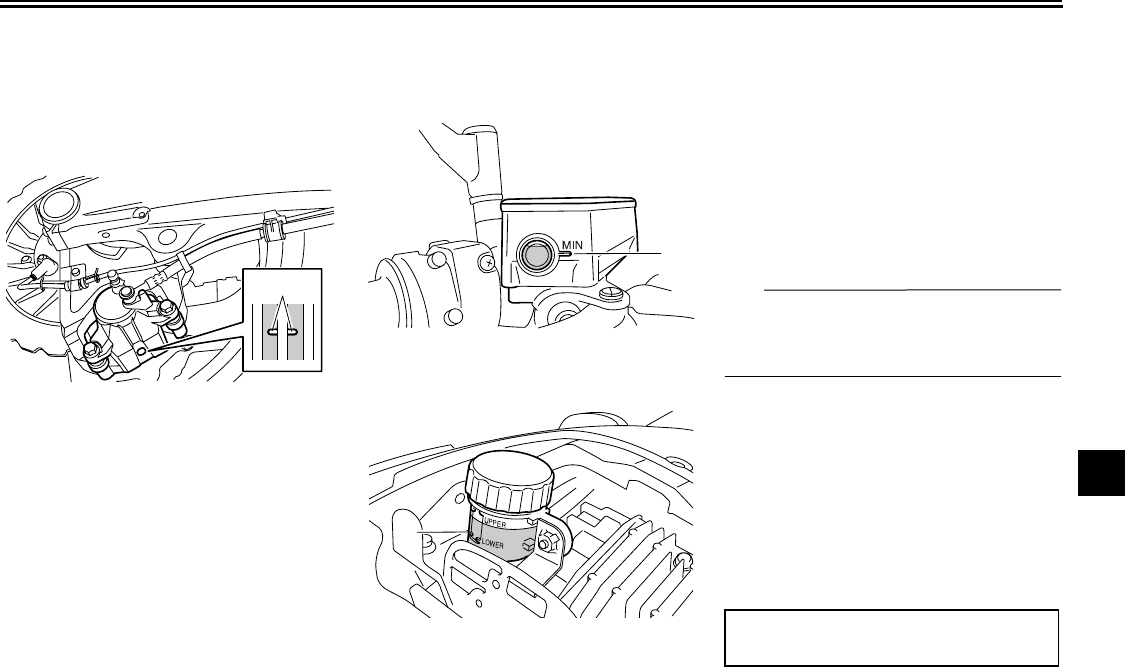
PERIODIC MAINTENANCE AND ADJUSTMENT
7-26
2
3
4
5
6
7
8
9
point that the wear indicator almost
touches the brake disc, have a Yamaha
dealer replace the brake pads as a set.
EAU22470
Rear brake pads
Each rear brake pad is provided with a
wear indicator groove, which allows
you to check the brake pad wear with-
out having to disassemble the brake.
To check the brake pad wear, check
the wear indicator groove. If a brake
pad has worn to the point that the wear
indicator groove has almost disap-
peared, have a Yamaha dealer replace
the brake pads as a set.
EAU46540
Checking the brake fluid level
Front brake
Rear brake
Insufficient brake fluid may allow air to
enter the brake system, possibly caus-
ing it to become ineffective.
Before riding, check that the brake fluid
is above the minimum level mark and
replenish if necessary. A low brake fluid
level may indicate worn brake pads
and/or brake system leakage. If the
brake fluid level is low, be sure to check
the brake pads for wear and the brake
system for leakage.
TIP
The rear brake fluid reservoir is located
under the passenger seat. (See
page 4-20.)
Observe these precautions:
●
When checking the fluid level,
make sure that the top of the brake
fluid reservoir is level.
●
Use only the recommended quality
brake fluid, otherwise the rubber
seals may deteriorate, causing
leakage and poor braking perfor-
mance.
●
Refill with the same type of brake
1. Brake pad wear indicator groove
1
1. Minimum level mark
1. Minimum level mark
1
1
Recommended brake fluid:
DOT 4
PERIODIC MAINTENANCE AND ADJUSTMENT
7-27
1
2
3
4
5
6
7
8
9
fluid. Mixing fluids may result in a
harmful chemical reaction and
lead to poor braking performance.
●
Be careful that water or dust does
not enter the brake fluid reservoir
when refilling. Water will signifi-
cantly lower the boiling point of the
fluid and may result in vapor lock,
and dirt may clog the ABS hydrau-
lic unit valves.
●
Brake fluid may deteriorate paint-
ed surfaces or plastic parts. Al-
ways clean up spilled fluid
immediately.
●
As the brake pads wear, it is nor-
mal for the brake fluid level to grad-
ually go down. However, if the
brake fluid level goes down sud-
denly, have a Yamaha dealer
check the cause.
EAU22751
Changing the brake and
clutch fluids
Have a Yamaha dealer change the
brake and clutch fluids at the intervals
specified in the TIP after the periodic
maintenance and lubrication chart. In
addition, have the oil seals of the brake
and clutch master cylinders and cali-
pers as well as the brake and clutch
hoses replaced at the intervals listed
below or whenever they are damaged
or leaking.
●
Oil seals: Replace every two
years.
●
Brake and clutch hoses: Replace
every four years.
EAU23093
Checking and lubricating the
cables
The operation of all control cables and
the condition of the cables should be
checked before each ride, and the ca-
bles and cable ends should be lubricat-
ed if necessary. If a cable is damaged
or does not move smoothly, have a
Yamaha dealer check or replace it.
WARNING! Damage to the outer
housing of cables may result in in-
ternal rusting and cause interfer-
ence with cable movement. Replace
damaged cables as soon as possi-
ble to prevent unsafe condi-
tions.
[EWA10711]
Recommended lubricant:
Yamaha Chain and Cable Lube or
engine oil
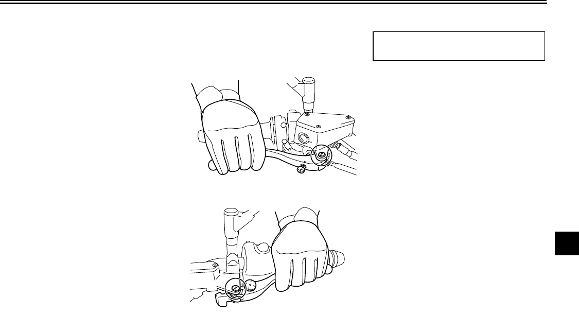
PERIODIC MAINTENANCE AND ADJUSTMENT
7-28
2
3
4
5
6
7
8
9
EAU23111
Checking and lubricating the
throttle grip and cable
The operation of the throttle grip should
be checked before each ride. In addi-
tion, the cable should be lubricated at
the intervals specified in the periodic
maintenance chart.
EAU43600
Checking and lubricating the
brake and clutch levers
Brake lever
Clutch lever
The operation of the brake and clutch
levers should be checked before each
ride, and the lever pivots should be lu-
bricated if necessary.
Recommended lubricant:
Silicone grease
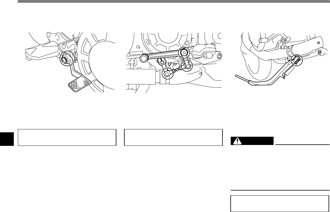
PERIODIC MAINTENANCE AND ADJUSTMENT
7-29
1
2
3
4
5
6
7
8
9
EAU23182
Checking and lubricating the
brake pedal
The operation of the brake pedal
should be checked before each ride,
and the pedal pivot should be lubricat-
ed if necessary.
EAU43071
Checking and lubricating the
shift pedal
The operation of the shift pedal should
be checked before each ride, and the
shift pedal rod pivots should be lubricat-
ed if necessary.
EAU23202
Checking and lubricating the
sidestand
The operation of the sidestand should
be checked before each ride, and the
sidestand pivot and metal-to-metal
contact surfaces should be lubricated if
necessary.
WARNING
EWA10731
If the sidestand does not move up
and down smoothly, have a Yamaha
dealer check or repair it. Otherwise,
the sidestand could contact the
ground and distract the operator, re-
sulting in a possible loss of control.
Recommended lubricant:
Lithium-soap-based grease
Recommended lubricant:
Lithium-soap-based grease
Recommended lubricant:
Lithium-soap-based grease
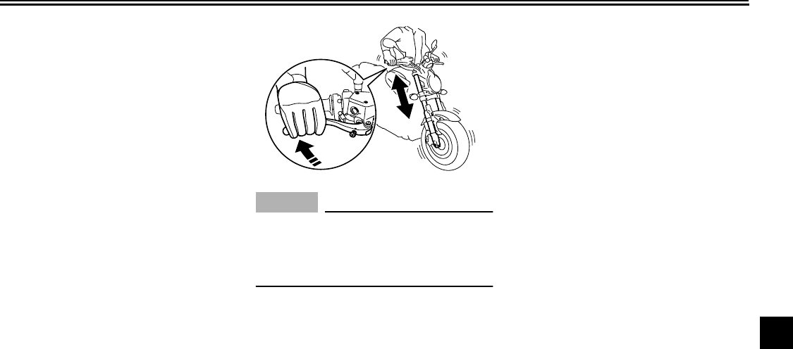
PERIODIC MAINTENANCE AND ADJUSTMENT
7-30
2
3
4
5
6
7
8
9
EAU23272
Checking the front fork
The condition and operation of the front
fork must be checked as follows at the
intervals specified in the periodic main-
tenance and lubrication chart.
To check the condition
Check the inner tubes for scratches,
damage and excessive oil leakage.
To check the operation
1. Place the vehicle on a level sur-
face and hold it in an upright posi-
tion.
WARNING! To avoid injury,
securely support the vehicle so
there is no danger of it falling
over.
[EWA10751]
2. While applying the front brake,
push down hard on the handlebars
several times to check if the front
fork compresses and rebounds
smoothly.
NOTICE
ECA10590
If any damage is found or the front
fork does not operate smoothly,
have a Yamaha dealer check or re-
pair it.
EAU23283
Checking the steering
Worn or loose steering bearings may
cause danger. Therefore, the operation
of the steering must be checked as fol-
lows at the intervals specified in the pe-
riodic maintenance and lubrication
chart.
1. Place a stand under the engine to
raise the front wheel off the
ground. (See page 7-40 for more
information.)
WARNING! To
avoid injury, securely support
the vehicle so there is no danger
of it falling over.
[EWA10751]
2. Hold the lower ends of the front
fork legs and try to move them for-
ward and backward. If any free
play can be felt, have a Yamaha
dealer check or repair the steering.
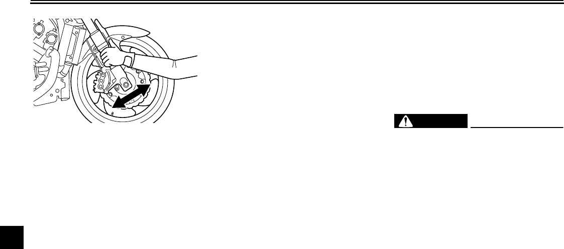
PERIODIC MAINTENANCE AND ADJUSTMENT
7-31
1
2
3
4
5
6
7
8
9
EAU23290
Checking the wheel bearings
The front and rear wheel bearings must
be checked at the intervals specified in
the periodic maintenance and lubrica-
tion chart. If there is play in the wheel
hub or if the wheel does not turn
smoothly, have a Yamaha dealer check
the wheel bearings.
EAU46551
Battery
This model is equipped with a VRLA
(Valve Regulated Lead Acid) battery.
There is no need to check the electro-
lyte or to add distilled water. However,
the battery lead connections need to be
checked and, if necessary, tightened.
WARNING
EWA10760
●
Electrolyte is poisonous and
dangerous since it contains sul-
furic acid, which causes severe
burns. Avoid any contact with
skin, eyes or clothing and al-
ways shield your eyes when
working near batteries. In case
of contact, administer the fol-
lowing FIRST AID.
●
EXTERNAL: Flush with plenty
of water.
●
INTERNAL: Drink large quan-
tities of water or milk and im-
mediately call a physician.
●
EYES: Flush with water for 15
minutes and seek prompt
medical attention.
●
Batteries produce explosive hy-
drogen gas. Therefore, keep
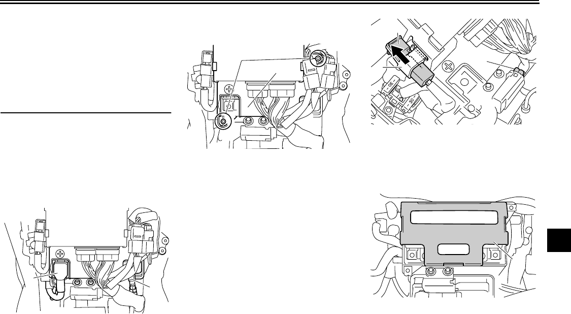
PERIODIC MAINTENANCE AND ADJUSTMENT
7-32
2
3
4
5
6
7
8
9
sparks, flames, cigarettes, etc.,
away from the battery and pro-
vide sufficient ventilation when
charging it in an enclosed
space.
●
KEEP THIS AND ALL BATTER-
IES OUT OF THE REACH OF
CHILDREN.
To remove the battery
1. Remove cowling A. (See
page 7-9.)
2. Disconnect the negative battery
lead first, then the positive battery
lead by removing their bolt.
3. Remove the battery cover (togeth-
er with the ECU) by removing the
bolts.
4. Remove the main fuse (together
with the holding band) from its
holder.
5. Disconnect coupler A.
6. Remove the rubber damper.
7. Unfold the heat insulator as
shown.
1. Negative battery lead (black)
2. Positive battery lead (red)
2
1
1. Bolt
2. Battery cover
1
2
1. Main fuse
2. Holding band
3. Coupler A
1. Rubber damper
2
1
3
1
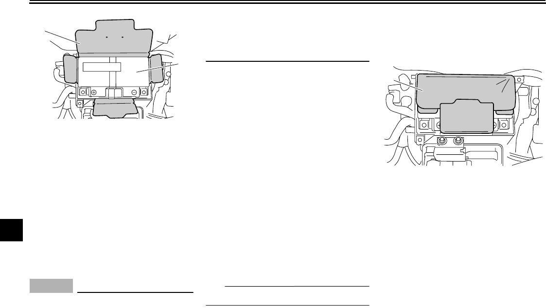
PERIODIC MAINTENANCE AND ADJUSTMENT
7-33
1
2
3
4
5
6
7
8
9
8. Pull the battery out of its compart-
ment.
To charge the battery
Have a Yamaha dealer charge the bat-
tery as soon as possible if it seems to
have discharged. Keep in mind that the
battery tends to discharge more quickly
if the vehicle is equipped with optional
electrical accessories.
NOTICE
ECA16520
To charge a VRLA (Valve Regulated
Lead Acid) battery, a special (con-
stant-voltage) battery charger is re-
quired. Using a conventional battery
charger will damage the battery. If
you do not have access to a con-
stant-voltage battery charger, have a
Yamaha dealer charge your battery.
To store the battery
1. If the vehicle will not be used for
more than one month, remove the
battery, fully charge it, and then
place it in a cool, dry place.
NOTICE:
When removing the
battery, be sure the key is
turned to “OFF”, then discon-
nect the negative lead before
disconnecting the positive
lead.
[ECA16302]
2. If the battery will be stored for more
than two months, check it at least
once a month and fully charge it if
necessary.
To install the battery
TIP
Be sure the battery is fully charged.
1. Place the battery in its compart-
ment.
2. Fold the heat insulator back to its
original position.
NOTICE:
Make
sure that the heat insulator is in
its original position and it is
properly folded.
[ECA16550]
3. Install the rubber damper.
4. Install the battery cover (together
with the ECU) by installing the
bolts.
5. Connect coupler A.
6. Install the main fuse (together with
the holding band) on its holder.
7. Connect the positive battery lead
first, then connect the negative
battery lead by installing their bolt.
1. Heat insulator
2. Battery
1
2
1. Heat insulator
1

PERIODIC MAINTENANCE AND ADJUSTMENT
7-34
2
3
4
5
6
7
8
9
8. Install the cowling.
NOTICE
ECA16530
Always keep the battery charged.
Storing a discharged battery can
cause permanent battery damage.
EAU46451
Replacing the fuses
The main fuse, fuse box 1 and ABS
motor fuse are located behind panel A.
(See page 7-9.)
Fuse box 1
Fuse box 2 is located behind panel B.
(See page 7-9.)
1. Main fuse
2. ABS motor fuse
3. ABS motor spare fuse
1
3
2
1. ABS solenoid fuse
2. Fuel injection system fuse
3. Spare fuse
1
2
3
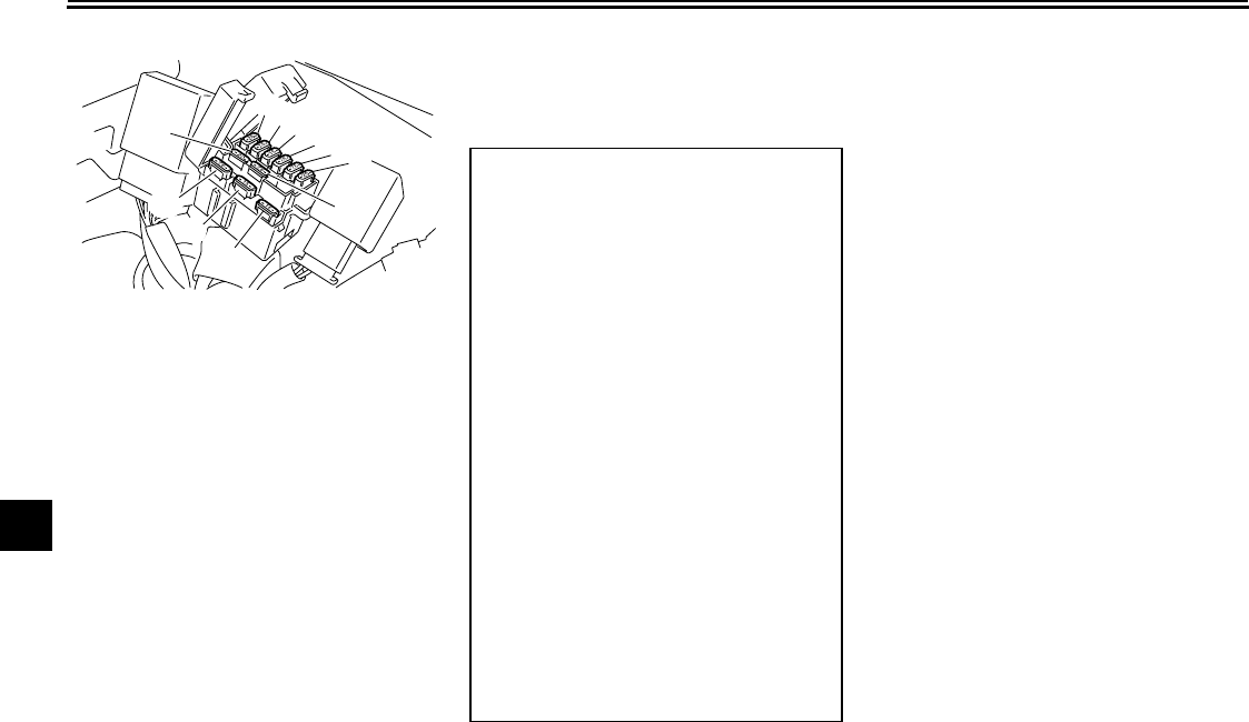
PERIODIC MAINTENANCE AND ADJUSTMENT
7-35
1
2
3
4
5
6
7
8
9
Fuse box 2
If a fuse is blown, replace it as follows.
1. Turn the key to “OFF” and turn off
the electrical circuit in question.
2. Remove the blown fuse, and then
install a new fuse of the specified
amperage.
WARNING! Do not
use a fuse of a higher amperage
rating than recommended to
avoid causing extensive dam-
age to the electrical system and
possibly a fire.
[EWA15131]
3. Turn the key to “ON” and turn on
the electrical circuit in question to
check if the device operates.
4. If the fuse immediately blows
again, have a Yamaha dealer
check the electrical system.
1. Ignition fuse
2. ABS control unit fuse
3. Headlight fuse
4. Backup fuse
5. Electronic throttle valve fuse
6. Radiator fan fuse
7. Spare fuse
8. Spare fuse
9. Signaling system fuse
10. Sub radiator fan fuse
11. Spare fuse
123456
7
8
9
10
11
Specified fuses:
Main fuse:
50.0 A
Ignition fuse:
20.0 A
Signaling system fuse:
15.0 A
Headlight fuse:
15.0 A
Radiator fan fuse:
20.0 A
Sub radiator fan fuse:
7.5 A
Fuel injection system fuse:
15.0 A
ABS control unit fuse:
7.5 A
ABS motor fuse:
30.0 A
ABS solenoid fuse:
15.0 A
Backup fuse:
7.5 A
Electronic throttle valve fuse:
7.5 A
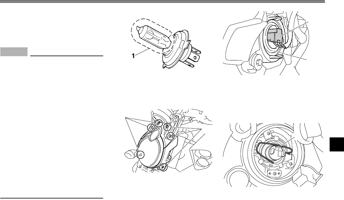
PERIODIC MAINTENANCE AND ADJUSTMENT
7-36
2
3
4
5
6
7
8
9
EAU46461
Replacing the headlight bulb
This model is equipped with a quartz
bulb headlight. If the headlight bulb
burns out, replace it as follows.
NOTICE
ECA10650
Take care not to damage the follow-
ing parts:
●
Headlight bulb
Do not touch the glass part of
the headlight bulb to keep it free
from oil, otherwise the transpar-
ency of the glass, the luminosity
of the bulb, and the bulb life will
be adversely affected. Thor-
oughly clean off any dirt and fin-
gerprints on the headlight bulb
using a cloth moistened with al-
cohol or thinner.
●
Headlight lens
Do not affix any type of tinted
film or stickers to the headlight
lens.
Do not use a headlight bulb of a
wattage higher than specified.
1. Remove the headlight unit by re-
moving the bolts.
2. Disconnect the headlight coupler,
and then remove the bulb cover.
3. Unhook the headlight bulb holder,
and then remove the burnt-out
bulb.
4. Place a new headlight bulb into po-
sition, and then secure it with the
1. Do not touch the glass part of the bulb.
1. Bolt
1
1
1. Headlight coupler
2. Headlight bulb cover
1. Headlight bulb holder
1
2
1
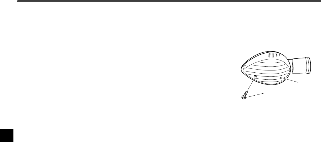
PERIODIC MAINTENANCE AND ADJUSTMENT
7-37
1
2
3
4
5
6
7
8
9
bulb holder.
5. Install the headlight bulb cover,
and then connect the coupler.
6. Install the headlight unit by install-
ing the bolts.
7. Have a Yamaha dealer adjust the
headlight beam if necessary.
EAU24181
Tail/brake light
This model is equipped with an
LED-type tail/brake light.
If the tail/brake light does not come on,
have a Yamaha dealer check it.
EAU24204
Replacing a turn signal light
bulb
1. Remove the turn signal light lens
by removing the screw.
2. Remove the burnt-out bulb by
pushing it in and turning it counter-
clockwise.
1. Screw
2. Turn signal light lens
1
2
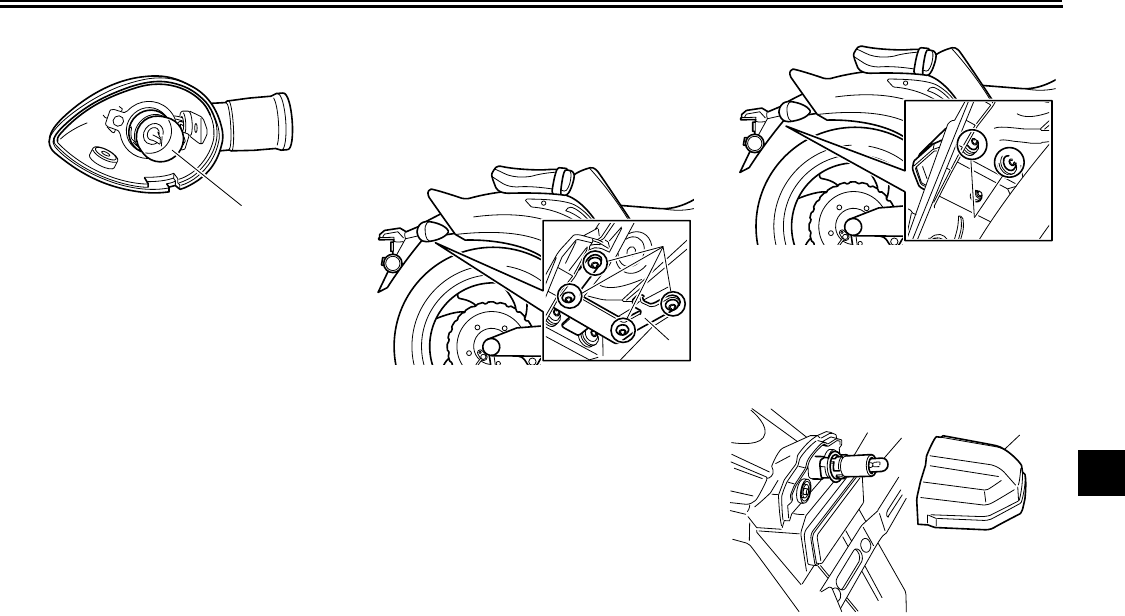
PERIODIC MAINTENANCE AND ADJUSTMENT
7-38
2
3
4
5
6
7
8
9
3. Insert a new bulb into the socket,
push it in, and then turn it clock-
wise until it stops.
4. Install the lens by installing the
screw.
NOTICE:
Do not over-
tighten the screw, otherwise the
lens may break.
[ECA11191]
EAU46780
Replacing a license plate light
bulb
1. Remove the holding plate by re-
moving the bolts.
2. Remove the license plate light lens
by removing the bolts.
3. Remove the license plate light
socket (together with the bulb) by
turning it counterclockwise, and
then pulling it out.
1. Turn signal light bulb
1
1. Holding plate
2. Bolt
1
2
1. Bolt
1. License plate light bulb socket
2. License plate light bulb
3. License plate light lens
1
23
1
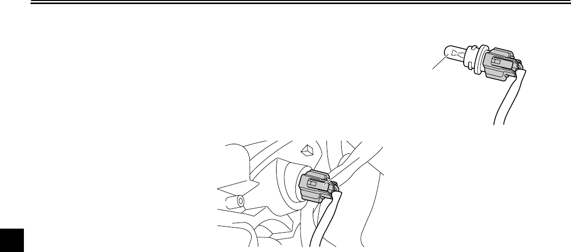
PERIODIC MAINTENANCE AND ADJUSTMENT
7-39
1
2
3
4
5
6
7
8
9
4. Remove the burnt-out bulb by pull-
ing it out.
5. Insert a new bulb into the socket.
6. Install the socket (together with the
bulb) by pushing it in, and then turn
it clockwise until it stops.
7. Install the license plate light lens
by installing the bolts.
8. Install the holding plate by install-
ing the bolts.
EAU46403
Replacing the auxiliary light
bulb
If the auxiliary light bulb burns out, re-
place it as follows.
1. Remove the headlight unit. (See
page 7-36.)
2. Remove the auxiliary light socket
(together with the bulb) by turning
it counterclockwise.
3. Remove the burnt-out bulb by pull-
ing it out of the socket.
4. Insert a new bulb into the socket.
5. Install the auxiliary light socket (to-
gether with the bulb) by turning it
clockwise.
6. Install the headlight unit.
1. Auxiliary light bulb socket
1
1. Auxiliary light bulb
1
PERIODIC MAINTENANCE AND ADJUSTMENT
7-40
2
3
4
5
6
7
8
9
EAU24350
Supporting the motorcycle
Since this model is not equipped with a
centerstand, follow these precautions
when removing the front and rear
wheel or performing other maintenance
requiring the motorcycle to stand up-
right. Check that the motorcycle is in a
stable and level position before starting
any maintenance. A strong wooden
box can be placed under the engine for
added stability.
To service the front wheel
1. Stabilize the rear of the motorcycle
by using a motorcycle stand or, if
an additional motorcycle stand is
not available, by placing a jack un-
der the frame in front of the rear
wheel.
2. Raise the front wheel off the
ground by using a motorcycle
stand.
To service the rear wheel
Raise the rear wheel off the ground by
using a motorcycle stand or, if a motor-
cycle stand is not available, by placing
a jack either under each side of the
frame in front of the rear wheel or under
each side of the swingarm.
EAU25871
Troubleshooting
Although Yamaha motorcycles receive
a thorough inspection before shipment
from the factory, trouble may occur dur-
ing operation. Any problem in the fuel,
compression, or ignition systems, for
example, can cause poor starting and
loss of power.
The following troubleshooting charts
represent quick and easy procedures
for checking these vital systems your-
self. However, should your motorcycle
require any repair, take it to a Yamaha
dealer, whose skilled technicians have
the necessary tools, experience, and
know-how to service the motorcycle
properly.
Use only genuine Yamaha replace-
ment parts. Imitation parts may look like
Yamaha parts, but they are often inferi-
or, have a shorter service life and can
lead to expensive repair bills.
WARNING
EWA15141
When checking the fuel system, do
not smoke, and make sure there are
no open flames or sparks in the ar-
ea, including pilot lights from water

PERIODIC MAINTENANCE AND ADJUSTMENT
7-41
1
2
3
4
5
6
7
8
9
heaters or furnaces. Gasoline or
gasoline vapors can ignite or ex-
plode, causing severe injury or
property damage.
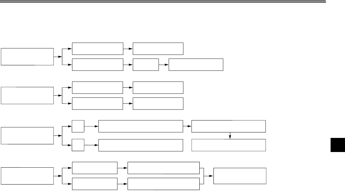
PERIODIC MAINTENANCE AND ADJUSTMENT
7-42
2
3
4
5
6
7
8
9
EAU46790
Troubleshooting charts
Starting problems or poor engine performance
Check the fuel level in
the fuel tank.
1. Fuel
There is enough fuel.
There is no fuel.
Check the compression.
Supply fuel. The engine does not start.
Check the compression.
Operate the electric starter.
2. Compression
There is compression.
There is no compression.
Check the ignition.
Have a Yamaha dealer
check the vehicle.
Remove the spark plugs
and check the electrodes.
3. Ignition Wipe off with a dry cloth or replace the
spark plugs.
Have a Yamaha dealer check the vehicle.
The engine does not start.
Have a Yamaha dealer
check the vehicle.
The engine does not start.
Check the battery.
Operate the electric starter.
4. Battery The engine turns over
quickly.
The engine turns over
slowly.
The battery is good.
Check the battery lead connections,
and charge the battery if necessary.
Dry
Wet Operate the electric starter.
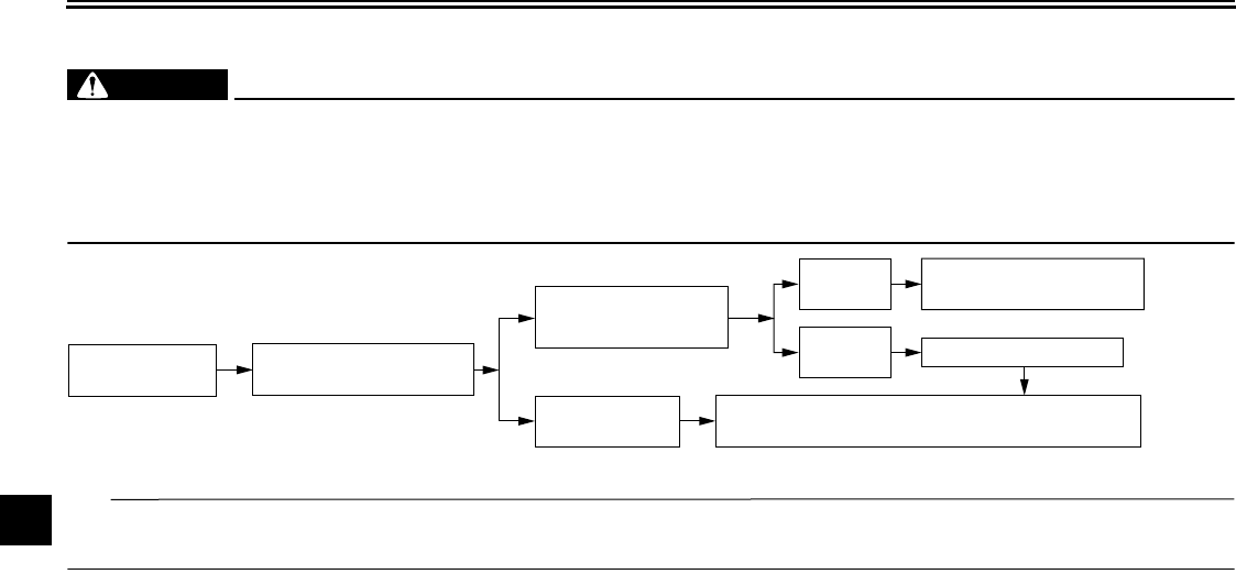
PERIODIC MAINTENANCE AND ADJUSTMENT
7-43
1
2
3
4
5
6
7
8
9
Engine overheating
WARNING
EWAT1040
●
Do not remove the radiator cap when the engine and radiator are hot. Scalding hot fluid and steam may be
blown out under pressure, which could cause serious injury. Be sure to wait until the engine has cooled.
●
Place a thick rag, like a towel, over the radiator cap, and then slowly rotate the cap counterclockwise to the de-
tent to allow any residual pressure to escape. When the hissing sound has stopped, press down on the cap
while turning it counterclockwise, and then remove the cap.
TIP
If coolant is not available, tap water can be temporarily used instead, provided that it is changed to the recommended coolant
as soon as possible.
Wait until the
engine has cooled.
Check the coolant level in the
reservoir and radiator.
The coolant level
is OK.
The coolant level is low.
Check the cooling system
for leakage.
Have a Yamaha dealer check
and repair the cooling system.
Add coolant. (See TIP.)
Start the engine. If the engine overheats again, have a
Yamaha dealer check
and repair the cooling system.
There is
leakage.
There is
no leakage.
8-1
2
3
4
5
6
7
8
9
MOTORCYCLE CARE AND STORAGE
EAU37833
Matte color caution
NOTICE
ECA15192
Some models are equipped with
matte colored finished parts. Be
sure to consult a Yamaha dealer for
advice on what products to use be-
fore cleaning the vehicle. Using a
brush, harsh chemical products or
cleaning compounds when cleaning
these parts will scratch or damage
their surface. Wax also should not
be applied to any matte colored fin-
ished parts.
EAU46410
Care
While the open design of a motorcycle
reveals the attractiveness of the tech-
nology, it also makes it more vulnera-
ble. Rust and corrosion can develop
even if high-quality components are
used. A rusty exhaust pipe may go un-
noticed on a car, however, it detracts
from the overall appearance of a motor-
cycle. Frequent and proper care does
not only comply with the terms of the
warranty, but it will also keep your mo-
torcycle looking good, extend its life
and optimize its performance.
Before cleaning
1. Cover the muffler outlets with a
plastic bag after the engine has
cooled down.
2. Make sure that all caps and covers
as well as all electrical couplers
and connectors, including the
spark plug caps, are tightly in-
stalled.
3. Remove extremely stubborn dirt,
like oil burnt onto the crankcase,
with a degreasing agent and a
brush, but never apply such prod-
ucts onto seals, gaskets and wheel
axles. Always rinse the dirt and de-
greaser off with water.
Cleaning
NOTICE
ECA10772
●
Avoid using strong acidic wheel
cleaners, especially on spoked
wheels. If such products are
used on hard-to-remove dirt, do
not leave the cleaner on the af-
fected area any longer than in-
structed. Also, thoroughly rinse
the area off with water, immedi-
ately dry it, and then apply a cor-
rosion protection spray.
●
Improper cleaning can damage
plastic parts (such as cowlings,
panels, windshields, headlight
lenses, meter lenses, etc.) and
the mufflers. Use only a soft,
clean cloth or sponge with wa-
ter to clean plastic. However, if
the plastic parts cannot be thor-
oughly cleaned with water, di-
luted mild detergent with water
may be used. Be sure to rinse
off any detergent residue using
MOTORCYCLE CARE AND STORAGE
8-2
1
2
3
4
5
6
7
8
9
plenty of water, as it is harmful
to plastic parts.
●
Do not use any harsh chemical
products on plastic parts. Be
sure to avoid using cloths or
sponges which have been in
contact with strong or abrasive
cleaning products, solvent or
thinner, fuel (gasoline), rust re-
movers or inhibitors, brake flu-
id, antifreeze or electrolyte.
●
Do not use high-pressure wash-
ers or steam-jet cleaners since
they cause water seepage and
deterioration in the following ar-
eas: seals (of wheel and swing-
arm bearings, fork and brakes),
electric components (couplers,
connectors, instruments,
switches and lights), breather
hoses and vents.
●
For motorcycles equipped with
a windshield: Do not use strong
cleaners or hard sponges as
they will cause dulling or
scratching. Some cleaning com-
pounds for plastic may leave
scratches on the windshield.
Test the product on a small hid-
den part of the windshield to
make sure that it does not leave
any marks. If the windshield is
scratched, use a quality plastic
polishing compound after
washing.
After normal use
Remove dirt with warm water, a mild
detergent, and a soft, clean sponge,
and then rinse thoroughly with clean
water. Use a toothbrush or bottlebrush
for hard-to-reach areas. Stubborn dirt
and insects will come off more easily if
the area is covered with a wet cloth for
a few minutes before cleaning.
After riding in the rain, near the sea or
on salt-sprayed roads
Since sea salt or salt sprayed on roads
during winter are extremely corrosive in
combination with water, carry out the
following steps after each ride in the
rain, near the sea or on salt-sprayed
roads.
TIP
Salt sprayed on roads in the winter may
remain well into spring.
1. Clean the motorcycle with cold wa-
ter and a mild detergent, after the
engine has cooled down.
NOTICE:
Do not use warm water
since it increases the corrosive
action of the salt.
[ECA10791]
2. After drying the motorcycle, apply
a corrosion protection spray on all
metal, including chrome- and nick-
el-plated, surfaces (except the tita-
nium mufflers) to prevent
corrosion.
Cleaning the titanium mufflers
This model is equipped with titanium
mufflers, which require the following
special care.
●
Use only a soft, clean cloth or
sponge with mild detergent and
water to clean the titanium muf-
flers. However, if the mufflers can-
not be thoroughly cleaned with
mild detergent, alkaline products
and a soft brush may be used.
●
Never use compounds or other
special treatments to clean the tita-
nium mufflers, as they will remove
MOTORCYCLE CARE AND STORAGE
8-3
2
3
4
5
6
7
8
9
the finish on the outer surface of
the mufflers.
●
Even the smallest amounts of oil,
such as from oily towels or finger-
prints, will leave stains on the tita-
nium mufflers, which can be
removed with a mild detergent.
●
Note that the thermally induced
discoloring of the portion of the ex-
haust pipe leading into the titanium
mufflers is normal and cannot be
removed.
After cleaning
1. Dry the motorcycle with a chamois
or an absorbing cloth.
2. Immediately dry the drive chain
and lubricate it to prevent it from
rusting.
3. Use a chrome polish to shine
chrome, aluminum and stain-
less-steel parts.
4. To prevent corrosion, it is recom-
mended to apply a corrosion pro-
tection spray on all metal,
including chrome- and nickel-plat-
ed, surfaces.
5. Use spray oil as a universal clean-
er to remove any remaining dirt.
6. Touch up minor paint damage
caused by stones, etc.
7. Wax all painted surfaces.
8. Let the motorcycle dry completely
before storing or covering it.
WARNING
EWA11131
Contaminants on the brakes or tires
can cause loss of control.
●
Make sure that there is no oil or
wax on the brakes or tires.
●
If necessary, clean the brake
discs and brake linings with a
regular brake disc cleaner or ac-
etone, and wash the tires with
warm water and a mild deter-
gent. Before riding at higher
speeds, test the motorcycle’s
braking performance and cor-
nering behavior.
NOTICE
ECA10800
●
Apply spray oil and wax spar-
ingly and make sure to wipe off
any excess.
●
Never apply oil or wax to any
rubber and plastic parts, but
treat them with a suitable care
product.
●
Avoid using abrasive polishing
compounds as they will wear
away the paint.
TIP
●
Consult a Yamaha dealer for ad-
vice on what products to use.
●
Washing, rainy weather or humid
climates can cause the headlight
lens to fog. Turning the headlight
on for a short period of time will
help remove the moisture from the
lens.
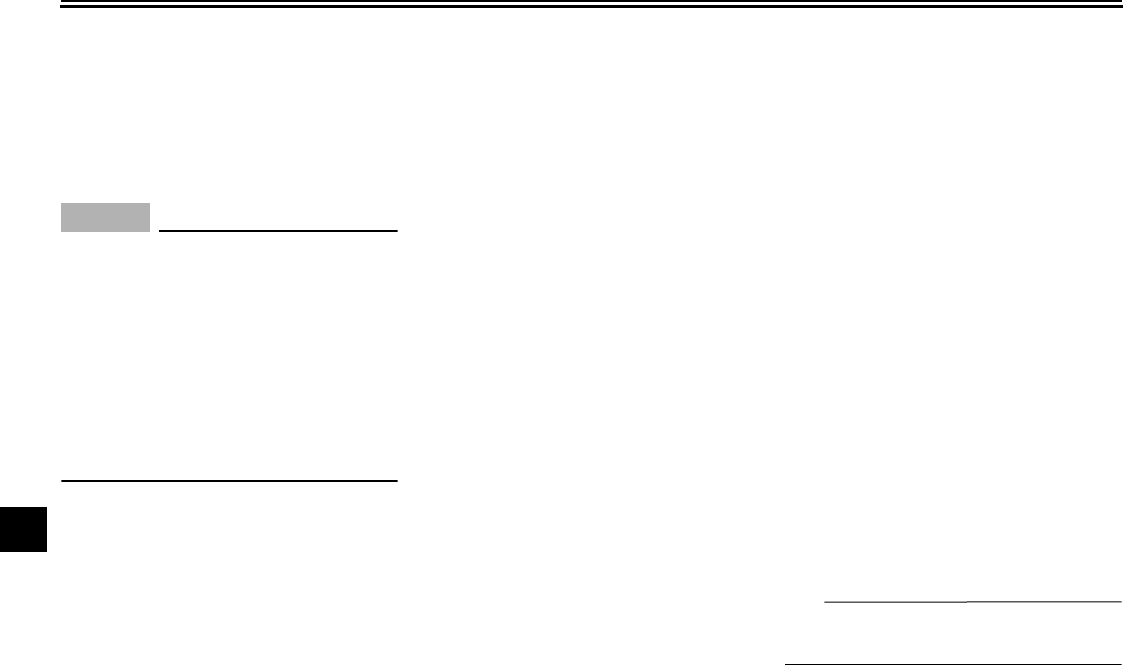
MOTORCYCLE CARE AND STORAGE
8-4
1
2
3
4
5
6
7
8
9
EAU26242
Storage
Short-term
Always store your motorcycle in a cool,
dry place and, if necessary, protect it
against dust with a porous cover.
NOTICE
ECA10810
●
Storing the motorcycle in a
poorly ventilated room or cover-
ing it with a tarp, while it is still
wet, will allow water and humid-
ity to seep in and cause rust.
●
To prevent corrosion, avoid
damp cellars, stables (because
of the presence of ammonia)
and areas where strong chemi-
cals are stored.
Long-term
Before storing your motorcycle for sev-
eral months:
1. Follow all the instructions in the
“Care” section of this chapter.
2. Fill up the fuel tank and add fuel
stabilizer (if available) to prevent
the fuel tank from rusting and the
fuel from deteriorating.
3. Perform the following steps to pro-
tect the cylinders, piston rings, etc.
from corrosion.
a. Remove the spark plug caps
and spark plugs.
b. Pour a teaspoonful of engine oil
into each spark plug bore.
c. Install the spark plug caps onto
the spark plugs, and then place
the spark plugs on the cylinder
head so that the electrodes are
grounded. (This will limit spark-
ing during the next step.)
d. Turn the engine over several
times with the starter. (This will
coat the cylinder walls with oil.)
WARNING! To prevent dam-
age or injury from sparking,
make sure to ground the
spark plug electrodes while
turning the engine
over.
[EWA10951]
e. Remove the spark plug caps
from the spark plugs, and then
install the spark plugs and the
spark plug caps.
4. Lubricate all control cables and the
pivoting points of all levers and
pedals as well as of the sidestand/
centerstand.
5. Check and, if necessary, correct
the tire air pressure, and then lift
the motorcycle so that both of its
wheels are off the ground. Alterna-
tively, turn the wheels a little every
month in order to prevent the tires
from becoming degraded in one
spot.
6. Cover the muffler outlets with plas-
tic bags to prevent moisture from
entering them.
7. Remove the battery and fully
charge it. Store it in a cool, dry
place and charge it once a month.
Do not store the battery in an ex-
cessively cold or warm place [less
than 0 °C (30 °F) or more than 30
°C (90 °F)]. For more information
on storing the battery, see page
7-31.
TIP
Make any necessary repairs before
storing the motorcycle.
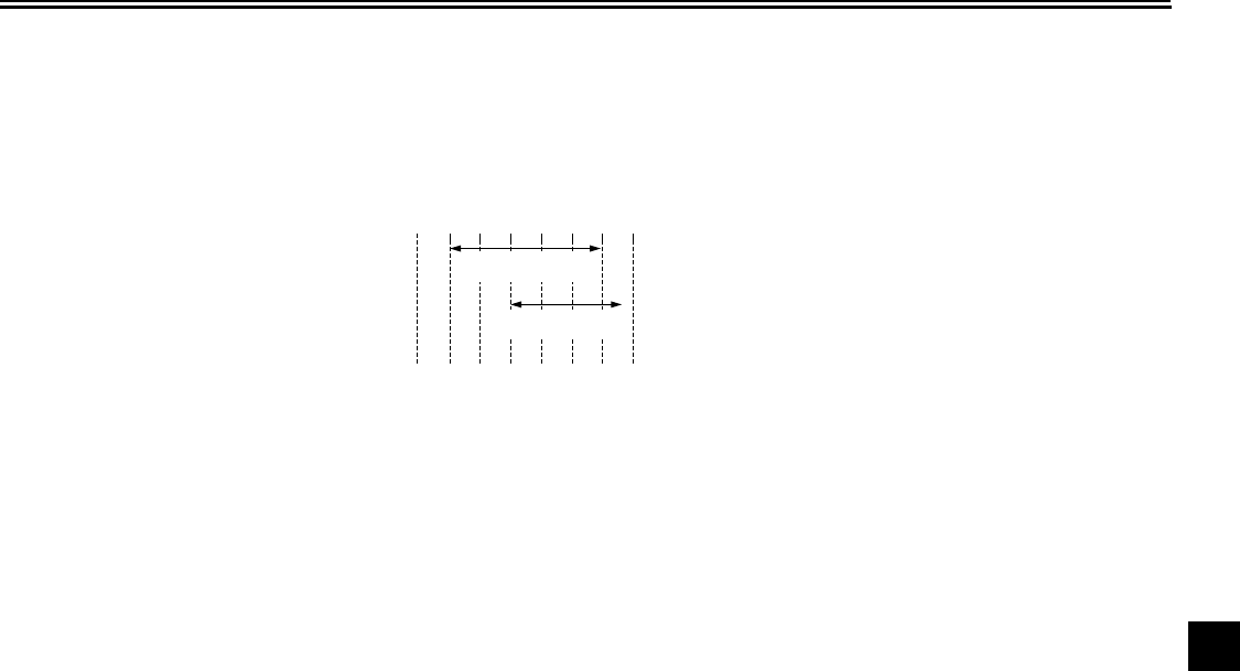
9-1
2
3
4
5
6
7
8
9
SPECIFICATIONS
EAU2633P
Dimensions:
Overall length:
2395 mm (94.3 in)
Overall width:
820 mm (32.3 in)
Overall height:
1190 mm (46.9 in)
Seat height:
775 mm (30.5 in)
Wheelbase:
1700 mm (66.9 in)
Ground clearance:
140 mm (5.51 in)
Minimum turning radius:
3500 mm (137.8 in)
Weight:
With oil and fuel:
310.0 kg (683 lb) (U49)
311.0 kg (686 lb) (CAL)
Engine:
Engine type:
Liquid cooled 4-stroke, DOHC
Cylinder arrangement:
V-type 4-cylinder
Displacement:
1679.0 cm
3
Bore
×
stroke:
90.0
×
66.0 mm (3.54
×
2.60 in)
Compression ratio:
11.30 :1
Starting system:
Electric starter
Lubrication system:
Wet sump
Engine oil:
Type:
YAMALUBE 4 10W-40 or 20W-50, SAE
10W-40 or SAE 20W-50
Recommended engine oil grade:
API service SG type or higher, JASO stan-
dard MA
Engine oil quantity:
Without oil filter cartridge replacement:
4.30 L (4.55 US qt, 3.78 Imp.qt)
With oil filter cartridge replacement:
4.70 L (4.97 US qt, 4.14 Imp.qt)
Final gear oil:
Type:
Shaft drive gear oil (Part No.:
9079E-SH001-00)
Quantity:
0.30 L (0.32 US qt, 0.26 Imp.qt)
Cooling system:
Coolant reservoir capacity (up to the maxi-
mum level mark):
0.27 L (0.29 US qt, 0.24 Imp.qt)
Radiator capacity (including all routes):
3.75 L (3.96 US qt, 3.30 Imp.qt)
Air filter:
Air filter element:
Oil-coated paper element
Fuel:
Recommended fuel:
Premium unleaded gasoline only
Fuel tank capacity:
15.0 L (3.96 US gal, 3.30 Imp.gal)
Fuel reserve amount:
3.9 L (1.03 US gal, 0.86 Imp.gal)
Fuel injection:
Throttle body:
Manufacturer:
MIKUNI
Type/quantity:
EIS48/4
Spark plug (s):
Manufacturer/model:
NGK/CR9EIA
Manufacturer/model:
DENSO/IU27D
Spark plug gap:
0.8–0.9 mm (0.031–0.035 in)
Clutch:
Clutch type:
Wet, multiple-disc
10 30 50 70 90 110
0130 ˚F
YAMALUBE 4 10W-40
or SAE 10W-40
YAMALUBE 4 20W-50
or SAE 20W-50
–10 0 10 20 30 40
–20 50 ˚C

SPECIFICATIONS
9-2
1
2
3
4
5
6
7
8
9
Transmission:
Primary reduction system:
Spur gear
Primary reduction ratio:
86/57 (1.509)
Secondary reduction system:
Shaft drive
Secondary reduction ratio:
22/23
×
29/09 (3.082)
Transmission type:
Constant mesh 5-speed
Operation:
Left foot operation
Gear ratio:
1st:
38/16 (2.375)
2nd:
38/21 (1.810)
3rd:
35/25 (1.400)
4th:
29/26 (1.115)
5th:
29/31 (0.935)
Chassis:
Frame type:
Diamond
Caster angle:
31.00 °
Trail:
148.0 mm (5.83 in)
Front tire:
Type:
Tubeless
Size:
120/70R18M/C 59V
Manufacturer/model:
BRIDGESTONE/BT028F
Rear tire:
Type:
Tubeless
Size:
200/50R18M/C 76V
Manufacturer/model:
BRIDGESTONE/BT028R
Loading:
Maximum load:
189 kg (417 lb) (CAL)
190 kg (419 lb) (U49)
(Total weight of rider, passenger, cargo and
accessories)
Tire air pressure (measured on cold
tires):
Loading condition:
0–90 kg (0–198 lb)
Front:
250 kPa (2.50 kgf/cm
2
, 36 psi)
Rear:
290 kPa (2.90 kgf/cm
2
, 42 psi)
Loading condition:
90–189 kg (198–417 lb) (CAL)
90–190 kg (198–419 lb) (U49)
Front:
250 kPa (2.50 kgf/cm
2
, 36 psi)
Rear:
290 kPa (2.90 kgf/cm
2
, 42 psi)
High-speed riding:
Front:
290 kPa (2.90 kgf/cm
2
, 42 psi)
Rear:
290 kPa (2.90 kgf/cm
2
, 42 psi)
Front wheel:
Wheel type:
Cast wheel
Rim size:
18M/C x MT3.50
Rear wheel:
Wheel type:
Cast wheel
Rim size:
18M/C x MT6.00
Front brake:
Type:
Dual disc brake
Operation:
Right hand operation
Recommended fluid:
DOT 4
Rear brake:
Type:
Single disc brake
Operation:
Right foot operation
Recommended fluid:
DOT 4

SPECIFICATIONS
9-3
2
3
4
5
6
7
8
9
Front suspension:
Type:
Telescopic fork
Spring/shock absorber type:
Coil spring/oil damper
Wheel travel:
120.0 mm (4.72 in)
Rear suspension:
Type:
Swingarm (link suspension)
Spring/shock absorber type:
Coil spring/gas-oil damper
Wheel travel:
110.0 mm (4.33 in)
Electrical system:
Ignition system:
TCI (digital)
Charging system:
AC magneto
Battery:
Model:
YTZ14S
Voltage, capacity:
12 V, 11.2 Ah
Headlight:
Bulb type:
Halogen bulb
Bulb voltage, wattage
×
quantity:
Headlight:
12 V, 60 W/55.0 W
×
1
Tail/brake light:
LED
Front turn signal/position light:
12 V, 21 W/5.0 W
×
2
Rear turn signal light:
12 V, 21.0 W
×
2
Auxiliary light:
12 V, 5.0 W
×
1
Meter lighting:
LED
Neutral indicator light:
LED
High beam indicator light:
LED
Oil level warning light:
LED
Turn signal indicator light:
LED x 2
Fuel level warning light:
LED
Coolant temperature warning light:
LED
Engine trouble warning light:
LED
ABS warning light:
LED
Fuses:
Main fuse:
50.0 A
Headlight fuse:
15.0 A
Signaling system fuse:
15.0 A
Ignition fuse:
20.0 A
Radiator fan fuse:
20.0 A
Fuel injection system fuse:
15.0 A
ABS control unit fuse:
7.5 A
ABS motor fuse:
30.0 A
ABS solenoid fuse:
15.0 A
Backup fuse:
7.5 A
Electronic throttle valve fuse:
7.5 A
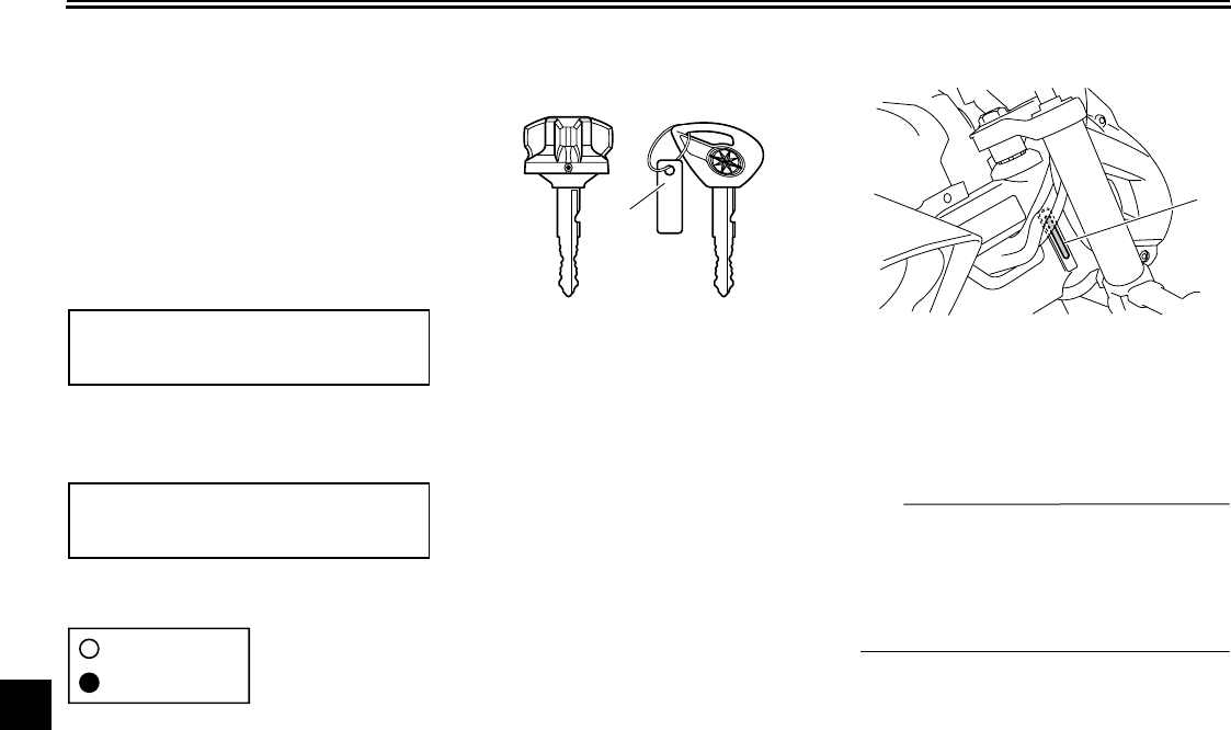
10-1
1
2
3
4
5
6
7
8
9
10
CONSUMER INFORMATION
EAU26351
Identification numbers
Record the key identification number,
vehicle identification number and mod-
el label information in the spaces pro-
vided below for assistance when
ordering spare parts from a Yamaha
dealer or for reference in case the vehi-
cle is stolen.
KEY IDENTIFICATION NUMBER:
VEHICLE IDENTIFICATION
NUMBER:
MODEL LABEL INFORMATION:
EAU26381
Key identification number
The key identification number is
stamped into the key tag. Record this
number in the space provided and use
it for reference when ordering a new
key.
EAU26400
Vehicle identification number
The vehicle identification number is
stamped into the steering head pipe.
Record this number in the space pro-
vided.
TIP
The vehicle identification number is
used to identify your motorcycle and
may be used to register your motorcy-
cle with the licensing authority in your
area.
1. Key identification number
1
1. Vehicle identification number
1
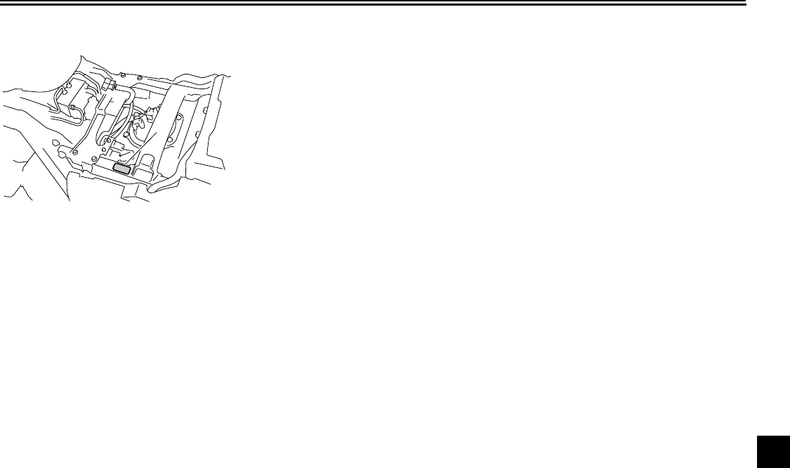
CONSUMER INFORMATION
10-2
2
3
4
5
6
7
8
9
10
EAU26470
Model label
The model label is affixed to the frame
under the rider seat. (See page 4-20.)
Record the information on this label in
the space provided. This information
will be needed when ordering spare
parts from a Yamaha dealer.
1. Model label
1

CONSUMER INFORMATION
10-3
1
2
3
4
5
6
7
8
9
10
EAU26551
Reporting safety defects
If you believe that your vehicle has a defect which could cause a crash or could cause injury or death, you should immediately
inform the National Highway Traffic Safety Administration (NHTSA) in addition to notifying Yamaha Motor Corporation,
U.S.A. If NHTSA receives similar complaints, it may open an investigation, and if it finds that a safety defect exists in a group
of vehicles, it may order a recall and remedy campaign. However, NHTSA cannot become involved in individual problems
between you, your dealer, or Yamaha Motor Corporation, U.S.A.
To contact NHTSA, you may call the Vehicle Safety Hotline toll-free at 1-888-327-4236 (TTY: 1-800-424-9153); go to http://
www.safercar.gov; or write to: Administrator, NHTSA, 400 Seventh Street, SW., Washington, DC 20590. You can also obtain
other information about motor vehicle safety from http://www.safercar.gov.
CONSUMER INFORMATION
10-4
2
3
4
5
6
7
8
9
10
EAU26560
Motorcycle noise regulation
TAMPERING WITH NOISE CONTROL SYSTEM PROHIBITED:
Federal law prohibits the following acts or the causing thereof: (1) The removal or rendering inoperative by any person other
than for purposes of maintenance, repair, or replacement of any device or element of design incorporated into any new ve-
hicle for the purpose of noise control prior to its sale or delivery to the ultimate purchaser or while it is in use or (2) the use of
the vehicle after such device or element of design has been removed or rendered inoperative by any person.
“AMONG THOSE ACTS PRESUMED TO CONSTITUTE TAMPERING ARE THE ACTS LISTED BELOW”.
These acts include tampering with the following systems; i.e., modification, removal, etc.
Exhaust system
●
Muffler
●
Exhaust pipe
●
Silencer
Intake system
●
Air cleaner case
●
Air cleaner element
●
Intake duct
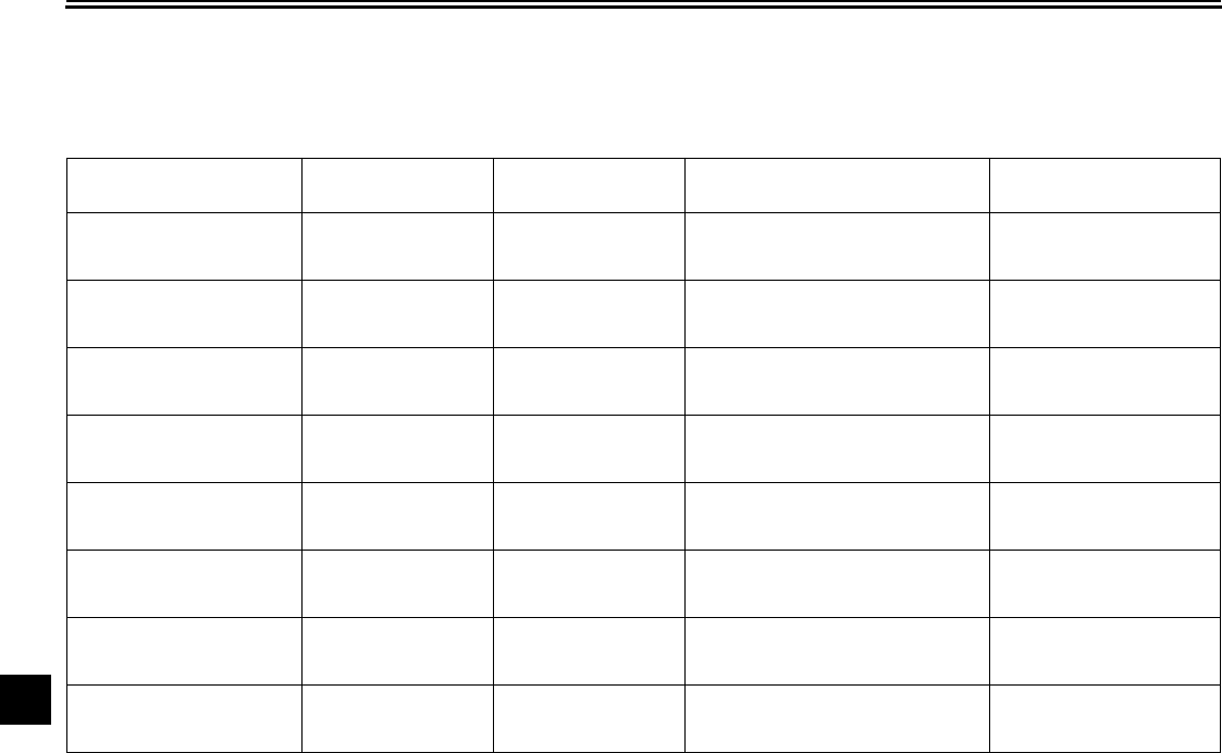
CONSUMER INFORMATION
10-5
1
2
3
4
5
6
7
8
9
10
EAU26632
Maintenance record
Copies of work orders and/or receipts for parts purchased and installed on your vehicle will be required to document that
maintenance has been completed in accordance with the emissions warranty. The chart below is printed only as a reminder
that maintenance work is required. It is not acceptable proof of maintenance work.
Maintenance
interval
Date of
service Mileage Servicing dealer
name and address Remarks
600 mi
(1000 km) or
1 month
4000 mi
(7000 km) or
6 months
8000 mi
(13000 km) or
12 months
12000 mi
(19000 km) or
18 months
16000 mi
(25000 km) or
24 months
20000 mi
(31000 km) or
30 months
24000 mi
(37000 km) or
36 months
28000 mi
(43000 km) or
42 months
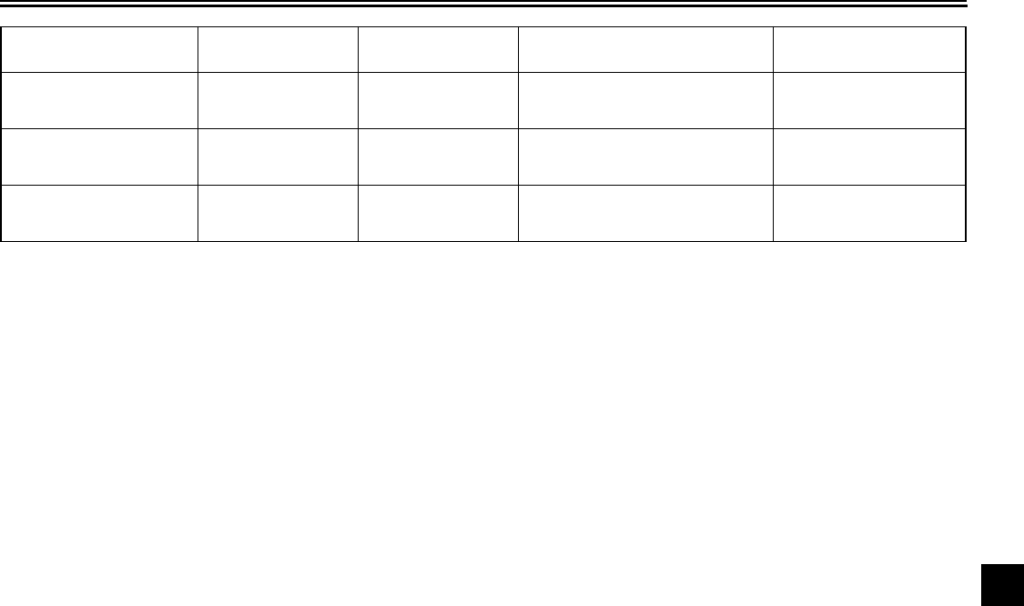
CONSUMER INFORMATION
10-6
2
3
4
5
6
7
8
9
10
32000 mi
(49000 km) or
48 months
36000 mi
(55000 km) or
54 months
40000 mi
(61000 km) or
60 months
Maintenance
interval
Date of
service Mileage Servicing dealer
name and address Remarks

CONSUMER INFORMATION
10-7
1
2
3
4
5
6
7
8
9
10
EAU26663
YAMAHA MOTOR CORPORATION, U.S.A. STREET AND ENDURO MOTORCYCLE LIMITED
WARRANTY
a)
b)
c)
d)
e)
f)
1.
2.
Yamaha Motor Corporation, U.S.A. hereby warrants that
new Yamaha motorcycles will be free from defects in
material and workmanship for the period of time stated
herein, subject to certain stated limitations.
THE PERIOD OF WARRANTY for Yamaha motorcycles
originally equipped with headlight, stoplight, and turn
signals shall be one (1) year from the date of purchase,
with no mileage limitation.
MODELS EXCLUDED FROM WARRANTY include
those used for non-Yamaha-authorized renting, leasing
or other commercial purposes, and TZ models.
DURING THE PERIOD OF WARRANTY, any authorized
Yamaha motorcycle dealer will, free of charge, repair or
replace any part adjudged defective by Yamaha due to
faulty workmanship or material from the factory. Parts used
in warranty repairs will be warranted for the balance of the
product’s warranty period. All parts replaced under
warranty become property of Yamaha Motor Corporation,
U.S.A.
GENERAL EXCLUSIONS from this warranty shall
include any failures caused by:
Competition or racing use.
Installation of parts or accessories that are not
qualitatively equivalent to genuine Yamaha parts.
Abnormal strain, neglect, or abuse.
Lack of proper maintenance.
Accident or collision damage.
Modification to original parts.
SPECIFIC EXCLUSIONS from this warranty shall
include parts replaced due to normal wear or routine
maintenance.
THE CUSTOMER’S RESPONSIBILITY under this
warranty shall be to:
Operate and maintain the motorcycle as specified in
the appropriate Owner’s Manual, and
Give notice to an authorized Yamaha motorcycle
dealer of any and all apparent defects within ten (10)
days after discovery, and make the machine available
at that time for inspection and repairs at such dealer’s
place of business.
WARRANTY TRANSFER: To transfer the warranty from
the original purchaser to any subsequent purchaser, it is
imperative that the machine be inspected and registered
for warranty by an authorized Yamaha motorcycle dealer.
In order for this warranty to remain in effect, this
inspection and registration must take place within ten
(10) days after transfer. An inspection and registration fee
will be charged for this service.
EMISSION CONTROL SYSTEM WARRANTY:
Yamaha Motor Corporation, U.S.A. also warrants to the
ultimate purchaser and each subsequent purchaser of
each Yamaha motorcycle covered by this warranty with a
displacement of 50cc or greater, that the vehicle is
designed, built, and equipped so as to conform at the
time of sale with all U.S. emissions standards applicable
at the time of manufacture and that it is free from defects
in materials and workmanship which would cause it not
to meet these standards within the period listed
immediately below. Failures other than those resulting
from defects in material or workmanship, which arise
solely as a result of owner abuse and/or lack of proper
maintenance, are not covered by this warranty.
Period
6,000 km (3,750 miles)
or five years, whichever occurs first
12,000 km (7,465 miles)
or five years whichever occurs first
18,000 km (11,185 miles)
or five years, whichever occurs first
30,000 km (18,641 miles)
or five years, whichever occurs first
YAMAHA MOTOR CORPORATION, U.S.A. MAKES NO
OTHER WARRANTY OF ANY KIND, EXPRESSED OR
IMPLIED. ALL IMPLIED WARRANTIES OF
MERCHANTABILITY AND FITNESS FOR A
PARTICULAR PURPOSE WHICH EXCEED THE
OBLIGATIONS AND TIME LIMITS STATED IN THIS
WARRANTY ARE HEREBY DISCLAIMED BY YAMAHA
MOTOR CORPORATION, U.S.A. AND EXCLUDED
FROM THIS WARRANTY.
SOME STATES DO NOT ALLOW LIMITATIONS ON
HOW LONG AN IMPLIED WARRANTY LASTS, SO THE
ABOVE LIMITATION MAY NOT APPLY TO YOU. ALSO
EXCLUDED FROM THIS WARRANTY ARE ANY
INCIDENTAL OR CONSEQUENTIAL DAMAGES
INCLUDING LOSS OF USE. SOME STATES DO NOT
ALLOW THE EXCLUSION OR LIMITATION OF
INCIDENTAL OR CONSEQUENTIAL DAMAGES, SO
THE ABOVE EXCLUSION MAY NOT APPLY TO YOU.
THIS WARRANTY GIVES YOU SPECIFIC LEGAL
RIGHTS, AND YOU MAY ALSO HAVE OTHER RIGHTS
WHICH VARY FROM STATE TO STATE.
YAMAHA MOTOR CORPORATION, U.S.A.
P. O. Box 6555
Cypress, California 90630
Engine
Displacement
Under 50cc
50cc to 169cc
170cc to 279cc
280cc and over

CONSUMER INFORMATION
10-8
2
3
4
5
6
7
8
9
10
WARRANTY QUESTIONS AND ANSWERS
What costs are my responsibility during the warranty period?
The customer’s responsibility includes all costs of normal maintenance services,
non-warranty repairs, accident and collision damages, and oil, oil filters, air filters,
spark plugs, and brake shoes.
What are some examples of “abnormal” strain, neglect, or abuse?
These terms are general and overlap each other in areas. Specific examples
include: Running the machine out of oil, sustained high rpm, full-throttle, operating
the machine with a broken or damaged part which causes another part to fail,
damage or failure due to improper or careless transportation and/or tie-down. If
you have any specific questions on operation or maintenance, please contact your
dealer for advice.
Does the warranty cover incidental costs such as towing or transportation due to
a failure?
No. The warranty is limited to repair of the machine itself.
May I perform any or all of the recommended maintenance shown in the Owner’s
Manual instead of having the dealer do them?
Ye s, if you are a qualified mechanic and follow the procedures specified in the
Owner’s and Service Manual. We do recommend, however, that items requiring
special tools or equipment be done by a Yamaha motorcycle dealer.
Will the warranty be void or cancelled if I do not operate or maintain my new
motorcycle exactly as specified in the Owner’s Manual?
No. The warranty on a new motorcycle cannot be “voided” or “cancelled.” However,
if a particular failure is caused by operation or maintenance other than as
described in the Owner’s Manual, that failure may not be covered under
warranty.
What responsibility does my dealer have under this warranty?
Each Yamaha motorcycle dealer is expected to:
Completely set up every new machine before sale.
Explain the operation, maintenance, and warranty requirements to your
satisfaction at the time of sale, and upon your request at any later date.
Each Yamaha motorcycle dealer is held responsible for his setup, service and
warranty repair work.
Is the warranty transferable to second owners?
Ye s. The remainder of the existing warranty can be transferred upon request. The
unit has to be inspected and re-registered by an authorized Yamaha motorcycle
dealer for the policy to remain effective.
CUSTOMER SERVICE
If your machine requires warranty service, you must take it to any authorized Yamaha
motorcycle dealer within the continental United States. Be sure to bring your warranty
registration card or other valid proof of the original date of purchase. If a question or
problem arises regarding the warranty, first contact the owner of the dealership. Since
all warranty matters are handled at the dealer level, this person is in the best position to
help you. IF you are still not satisfied and require additional assistance, please write to:
YAMAHA MOTOR CORPORATION, U.S.A.
CUSTOMER RELATIONS DEPARTMENT
P. O. Box 6555
Cypress, California 90630
When contacting Yamaha Motor Corporation, U.S.A., don’t forget to include any
important information such as names, addresses, model, V.I.N. (frame number),
dates, and receipts.
CHANGE OF ADDRESS
The federal government requires each manufacturer of a motor vehicle to maintain a
complete, up-to-date list of all first purchasers against the possibility of a safety-
related defect and recall. This list is compiled from the purchase registrations sent to
Yamaha Motor Corporation, U.S.A. by the selling dealer at the time of your purchase.
If you should move after you have purchased your new motorcycle, please advise us
of your new address by sending a postcard listing your motorcycle model name, V.I.N.
(frame number), dealer number (or dealer’s name) as it is shown on your warranty
card, your name and new mailing address. Mail to:
YAMAHA MOTOR CORPORATION, U.S.A.
P. O. Box 6555
Cypress, California 90630
Attention: Warranty Department
This will ensure that Yamaha Motor Corporation, U.S.A. has an up-to-date registration
record in accordance with federal law.
Q.
A.
Q.
A.
Q.
A.
Q.
A.
Q.
A.
Q.
A.
1.
2.
3.
Q.
A.
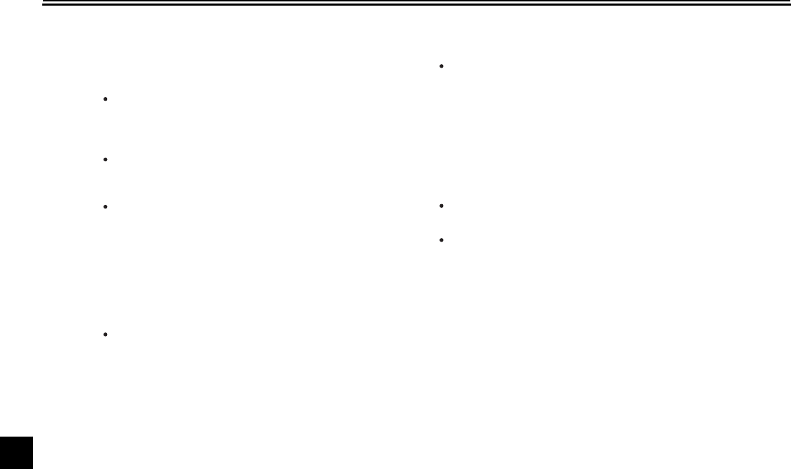
CONSUMER INFORMATION
10-9
1
2
3
4
5
6
7
8
9
10
EAU26750
YAMAHA EXTENDED SERVICE (Y.E.S.)
Keep your Yamaha protected even after your warranty
expires with genuine Yamaha Extended Service (Y.E.S.).
Y.E.S. is designed and administered by Yamaha Motor
Corporation to provide maximum owner satisfaction. You
get uninterrupted factory-backed coverage for extra
peace of mind.
Y.E.S. is flexible. You choose the plan that’s right for
you: 12 months, 24 months, 36 months or, on certain
models, even 48 months beyond your warranty period.
Y. E.S. is designed and administered by the same
Yamaha people who handle your warranty – and it
shows in the comprehensive coverage benefits. There
are no mileage limitations. Coverage isn’t limited to
“moving parts” or the “drive train” like many other plans.
And Y.E.S. covers manufacturing defects just like the
warranty. See the sample contract at your Yamaha
dealer to see how comforting uninterrupted factory-
backed protection can be.
You don’t have to pay anything for covered repairs.
There’s no deductible to pay, and repairs aren’t
“pro-rated.” You don’t have any “out-of-pocket” expenses
for covered repairs.
In addition, Travel and Recreation Interruption Protection
(TRIP) is included at no extra cost. TRIP gives you up to
$150 reimbursement per occurrence for any reasonable
expenses you incur because your Yamaha needs
covered service: replacement vehicle rental, emergency
towing, phone calls, even food and lodging when you are
away from home. This superb coverage goes into effect
when you purchase Y.E.S., so it applies to any warranty
repairs as well as covered repairs during your entire
Y.E.S. plan period.
Y.E.S. coverage is honored at any authorized Yamaha
dealer nationwide.
Y.E.S. coverage is transferable to a new owner if you
sell or trade-in. That can make your Yamaha much more
valuable!
This excellent Y.E.S. plan coverage is only available to
Yamaha owners like you, and only while your Yamaha is still
within the Yamaha Limited Warranty period. So visit your
authorized Yamaha dealer to get all the facts. He can show
you how easy it is to protect your investment with Yamaha
Extended Service.
CONSUMER INFORMATION
10-10
2
3
4
5
6
7
8
9
10
We urge you to act now. You’ll get the excellent benefits of
TRIP coverage right away, and you’ll rest easy knowing
you’ll have strong factory-backed protection even after your
Yamaha Limited Warranty expires.
A special note:
If visiting your dealer isn’t convenient, contact Yamaha with
your Primary ID number (your frame number). We’ll be
happy to help you get the Y.E.S. coverage you need.
Yamaha Service Marketing
P. O. Box 6555
Cypress, CA 90630
1-(866)-YES-EXTD (1-866-937-3983)

INDEX
A
ABS......................................................... 4-16
ABS warning light...................................... 4-3
Air filter element ...................................... 7-20
Auxiliary light bulb, replacing .................. 7-39
B
Battery..................................................... 7-31
Brake and clutch fluids, changing ........... 7-27
Brake and clutch levers, checking and
lubricating ............................................. 7-28
Brake fluid level, checking ...................... 7-26
Brake lever.............................................. 4-15
Brake pedal............................................. 4-15
Brake pedal, checking and lubricating .... 7-29
C
Cables, checking and lubricating ............ 7-27
Canister (for California only) ................... 7-12
Care .......................................................... 8-1
Catalytic converters ................................ 4-19
Clutch lever ....................................4-14
,
7-24
Coolant.................................................... 7-17
Coolant temperature warning light ............ 4-3
Cowling and panels, removing and
installing.................................................. 7-9
D
Dimmer switch ........................................ 4-13
E
Engine break-in......................................... 6-3
Engine idling speed, checking ................ 7-20
Engine oil and oil filter cartridge.............. 7-12
Engine stop switch.................................. 4-13
Engine trouble warning light...................... 4-3
EXUP system.......................................... 4-26
F
Final gear oil ............................................7-15
Front and rear brake pads, checking.......7-25
Front brake lever free play, checking ......7-24
Front fork, adjusting.................................4-22
Front fork, checking .................................7-30
Fuel..........................................................4-18
Fuel level warning light ..............................4-2
Fuel tank cap ...........................................4-17
Fuses, replacing ......................................7-34
H
Handlebar switches .................................4-12
Hazard switch ..........................................4-13
Headlight bulb, replacing .........................7-36
High beam indicator light ...........................4-2
Horn switch..............................................4-13
I
Identification numbers .............................10-1
Ignition circuit cut-off system ...................4-27
Indicator and warning lights.......................4-2
K
Key identification number ........................10-1
L
Labels, location..........................................1-1
License plate light bulb, replacing ...........7-38
Luggage strap holders.............................4-26
M
Main switch/steering lock...........................4-1
Maintenance and lubrication, periodic .......7-4
Maintenance, emission control system......7-3
Maintenance record.................................10-5
Matte color, caution ...................................8-1
Model label ..............................................10-2
Multi-function display .................................4-5
N
Neutral indicator light ................................ 4-2
Noise regulation ...................................... 10-4
O
Oil level warning light ................................ 4-2
P
Parking ...................................................... 6-4
Part locations ............................................ 3-1
R
Rear brake light switch, adjusting ........... 7-25
S
Safety defects, reporting ......................... 10-3
Safety information ..................................... 2-1
Seats ....................................................... 4-20
Shifting ...................................................... 6-2
Shift pedal ............................................... 4-14
Shift pedal, checking and lubricating....... 7-29
Shock absorber assembly, adjusting ...... 4-24
Sidestand ................................................ 4-26
Sidestand, checking and lubricating........ 7-29
Spark plugs, checking ............................. 7-11
Specifications ............................................ 9-1
Speedometer unit...................................... 4-4
Starting the engine .................................... 6-1
Start switch.............................................. 4-13
Steering, checking................................... 7-30
Storage...................................................... 8-4
Supporting the motorcycle ...................... 7-40
T
Tail/brake light......................................... 7-37
Throttle cable free play, checking ........... 7-21
Throttle grip and cable, checking and
lubricating.............................................. 7-28
Tires ........................................................ 7-21

INDEX
Tool kit .......................................................7-2
Troubleshooting.......................................7-40
Troubleshooting charts ............................7-42
Turn signal indicator lights.........................4-2
Turn signal light bulb, replacing...............7-37
Turn signal switch....................................4-13
V
Valve clearance .......................................7-21
Vehicle identification number...................10-1
W
Warranty, extended .................................10-9
Warranty, limited......................................10-7
Wheel bearings, checking .......................7-31
Wheels.....................................................7-24

PRINTED ON RECYCLED PAPER
YAMAHA MOTOR CO., LTD.
PRINTED IN JAPAN
2008.8–1.1×1 !
(E)
