Yamaha ATS 1010 User Manual SURROUND SYSTEM Manuals And Guides 1409384L
User Manual: Yamaha ATS-1010 ATS-1010 YAMAHA SURROUND SYSTEM - Manuals and Guides View the owners manual for your YAMAHA SURROUND SYSTEM #ATS1010. Home:Electronics Parts:Yamaha Parts:Yamaha SURROUND SYSTEM Manual
Open the PDF directly: View PDF ![]() .
.
Page Count: 19

CAUTION
RISKOF
ELECTRIC
SHOCKDONOT
OPEN
CAUTION: TO REDUCE THE RISK OF
ELECTRIC SHOCK, DO NOT REMOVE
COVER (OR BACK). NO USER-
SERVICEABLE PARTS INSIDE. REFER
SERVICING TO QUALIFIED SERVICE
PERSONNEL.
•Explanation of Graphical Symbols
1
2
3
4
5
6
7
The lightning ['lash wilh arrowhead 10
symbol within an equilateral triangle, is
intended to alert you to the presence of
uninsulaled "dangerous voltage" wilhin 11
the product's enclosure that may be of 12
sufficient magnitude to constitute a risk
of electric shock to persons.
The exclamation point within an
equilateral triangle is intended to alert
you to the presence of important
operating and maintenance (servicing)
instructions in the literature 13
accompanying the appliance. 14
IMPORTANT
Please record the serial number of this unit in the space
below.
MODEL:
Serial No.:
The serial number is located on the rear of the unit.
Retain this Owner's Manual in a safe place lbr future
reference.
Read these instructions.
Keep these instructions.
Heed all warnings.
Follow all instructions.
Do not else this apparatus near water.
Clean only with dry cloth.
Do not block any ventilation openings, lnstall in
accordance with the mannlacmrer's instructious.
Do not install near any heat sources such as radiators,
heat registers, stoves, or other apparatus (including
amplifiers) that produce heat.
Do not deleat the salbty purpose of the polarized or
grounding=type plug. A polarized plug has two blades
with one wider thau the other. A grounding type plug has
two blades and a third grounding prong. The wide blade
or the third prong are provided for your safety. If the
provided plug does not fit into yore" outlet, consult an
electrician for replacement of the obsolete outlet.
Protect the power cord fi'om being walked on or pinched
particularly at plugs, convenience receptacles, and the
point where they exit from the apparatus.
Only else attachments/accessories specified by the
manufacturer.
Use only with the cart, stand, tripod,
bracket, or table specified by the
manufacturer, or sold with the
apparatus. When a cart is used, use
caution wheu moving the cart/
apparatus combination to avoid injury
from tip-over.
{lnplug this apparatus during lightning storms or when
ulmsed lot long periods of time.
Re[L'r all servicing to qualified service personnel.
Servicing is required when the apparatus has been
damaged in any way, such as power=supply cord or plug
is damaged, liquid has been spilled or objects have fallen
into the apparatus, the apparatus has been exposed to rain
or moisture, does not operate normally, or has been
dropped.
FOR CANADIAN CUSTOMERS
To prevent electric shock, match wide blade of plug to
wide slot and fully insert.
This Class B digital apparatus complies with Canadian
ICES-003.
iEn
FCC INFORMATION (for US customers)
1 IMPORTANT NOTICE: DO NOT MODIFY THIS 4
UNIT!
This product, when installed as indicated in the
instructions contained in this manual, meets FCC
requirements. Modifications not expressly approved by
Yamaha may void ynur authority, granted by the FCC,
to use the product. 5
IMPORTANT: When connecting this product to
accessnries and/or another product use only high 6
quality shielded cables. Cable/s supplied with this
product MUST be used. Follow all installation
instructions. Failure to lollow instructions could void 7
your FCC authorization to use this product in the USA.
NOTE: This product has been tested and lonnd to
comply with the requirements listed in FCC 8
Regulations, Part 15 for Class "B" digital devices.
Compliance with these requirements prnvides a
reasonable level of assurance that your use of this
product in a residential environment will not result in
harmfnl interference with other electronic devices.
This equipment generates/uses radio fl'equencies and, 9
if nnt installed and used according tn the instructions
found in the users manuah may cause interfi_rence
harmful tn the operation nf other electrnnic devices.
Compliance with FCC regulations does not guarantee
that interfi_rence will nnt occur in all installations. If
this product is found to be the snnrce nf interli_rence,
which can be determined by turning the unit "OFF"
and "ON", please try to eliminate the problem by using
one of the lollnwing measures:
Relocate either this product or the device that is being
affected by the interli_rence.
Utilize power outlets that are on difli_rent branch
(circuit breaker or fuse) circuits or install AC line
filter/s.
In the case of radio or TV interference, relocate/
reorient the antenna. If the antenna lea&in is 300 ohm
ribbon lead, change the lead=in to coaxial type cable.
If these corrective measures do not produce
satislactnry results, please contact the local retailer
authorized to distribute this type of product. If you can
not locate the appropriate retailer, please contact
Yamaha Electronics Corp., U.S.A. 6660 Orangethnrpe
Ave., Buena Park. CA 90620.
The above statements apply ONLY to those products
distributed by Yamaha Corporation of America or its
subsidiaries.
We Want You Listening For A Lifetime
Yamaha and the Electronic Industries Association's Consumer Electronics Group want you to get the
most out of your equipment by playing it at a safe level. One that lets the sound come through loud
and clear without annoying blaring or distortion - and, most imporlantly, without affecting your
sensitive hearing. Since hearing damage from loud sounds is olden undetectable until it is too late,
Yamaha and the Electronic Industries Association's Consumer Electronics Group recommend you to
LISTENING
Fo_ALiletime avoid prolonged exposure from excessive volume levels.
ii En
1 To assure the finest perlormance, please read this manual
carefully. Keep it in a sale place for future reli_rence.
2 Install this unit in a well vemilated, cool, dry, clean place
- away from direct sunlight, heat sources, vibration, dust,
moisture, and/or cold. For proper ventilation, allow the
following minimum clearances.
Top: 5 crn (2 in)
Rear: 5 cm (2 in)
Sides: 1 cm (3/8 in)
3 Locate this unit away from other electrical appliances,
motors, or translormers to avoid humming sounds.
4 Do not expose this unit to sudden temperature changes
from cold to hot, and do not locate this unit in an
environment with high humidity (i.e. a room with a
humidifier) to prevent condensation inside this unit,
which may cause an electrical shock, fire, damage to this
unit, and!or personal injury.
5 Avoid installing this unit where foreign ohjects may lull
onto this unit and/or this unit may be exposed to liquid
dripping or splashing. On the top of this unit, do not
place:
Other components, as they may cause damage and/or
discoloration on the surface of this unit.
Burning objects (i.e. candles), as they may cause fire,
damage to this unit, and/or personal injury.
Containers with liquid in them. as they may f:dl and
liquid may cause electrical shock to the user and/or
damage to this unit.
6 Do not cover this unit with a newspaper, tablecloth,
curtain, etc. in order not to obstruct heat radiation. If the
temperature inside this unit rises, it may cause fire,
damage to this unit, and!or personal injury.
7 Do not plug in this unit to a wall outlet until all
connections are complete.
8 Do not operate this unit upside-down. It may overheat,
possibly causing damage.
9 Do not use force on switches, knobs and!or cords.
10 Wizen disconnecting the power cable from the wall
outlet, grasp the plug; do not pull the cable.
11 Do not clean this unit with chemical solvents: this might
damage the finish. Use a clean, dry cloth.
12 Only voltage specified on this unit must be used. Using
this unit with a higher voltage than specified is dangerous
and may cause fire, damage to this unit, and/or personal
injury. Yamaha will not be held responsible lot any
damage resulting from use of this unit with a voltage
other than specified.
13 To prevent damage by lightning, keep the power cable
and outdoor antennas disconnected from a wall outlet or
the unit during a lightning storm.
14 Do not attempt to modif'r or fix this unit. Contact
qualified Yamaha service personnel wizen any service is
needed. The cabinet should never be opened for any
reasol]S.
15 Wizen not planning to use this unit for long periods of
time (i.e. vacation), disconnect the AC power plug from
the wall outlet.
16 Be sure to read the "Troubleshooting" section on
common operating errors before concluding that this unit
is lanlty.
17 Befk>re moving this unit, press (_) to set this unit in
standby mode, and disconnect the power supply cable
from the wall outlet.
18 Condensation will lorm when the surrounding
temperature changes suddenly. Disconnect the power
supply cable from the outlet, then leave the unit alone.
19 lustall this unit near the wall outlet and where the AC
power plug can be reached easily.
20 The batteries shall not be exposed to excessive heat such
as sunshine, fire or like.
21 Secure placement or installation is the owner's
responsibility. Yamaha shall not be liable lot any accident
caused by improper placement or installation of speakers.
WARNING
TO REDUCE THE RISK OF FIRE OR ELECTRIC
SHOCK, DO NOT EXPOSE THIS UNIT TO RAIN
OR MOISTURE.
As long as this unit is connected to the AC wall outlet,
it is not disconnected from the AC power source even
if you turn off this unit by _). In this state, this unit is
designed to consume a very small quantity of power.
(Power key)
Turns on the: pov_c'r of this unit or sc'ts it to the standby
mode.
III En

Supplied items ............................................ 2
Front panel ................................................. 2
Placing ........................................................ 3
Connection ................................................. 4
Operation .................................................... 6
Enjoying sound with your preference ......... 7
Additional Information ................................ 8
Operation indicators of the unit ................ 11
Troubleshooting ....................................... 12
Specification ............................................. 14
II About this manual
• In this manual, operations that can be performed using either the front panel buttons or the remote control are
explained using the remote contmh
• -"4_"-indicates a tip for your operation. Notes contain important iulimnation about safety and operating instructions.
• This manual is produced prior to production. Design and specifications are subject to change in part as a result of
improvements, etc. In case of differences between the manual and the product, the product has priority.
II Notes on the remote control and batteries
• Do not spill water or other liquids on the remote control.
• Do not drop the remote contmh
• Do not leave or store the remote control in the following places:
- places of high humidity, such as near a bath
- places of high temperatures, such as near a heater or a stove
- places of extremely low temperatures
- dusty places
• Do not expose the remote control sensor of this unit to direct sunlight or lighting such as inverted fluorescent lamps.
• If the batteries grow old, the effective operation range of the remote control decreases considerably. If this happens,
replace the batteries with two new ones as soon as possible.
• Do not use old batteries together with new ones.
• Do not use different types of batteries (such as alkaline and manganese batteries) together. Read the packaging
carefully as these different types of batteries may have the same shape and color.
• Exhausted bmteries may leak. If the bmteries have leaked, dispose of them immedimely. Avoid touching the leaked material
or letting it come into contact with clothing, etc. Clean the battery compartment thoroughly before installing new batteries.
• Do not throw away batteries with general house waste. Dispose of them correctly in accordance with your local regulations.
• Keep batteries away from childrcn. If a battery is accidentally swallowed, contact your doctor immediately.
• When not planning to use the remote control for long periods of time, remove the batteries from the remote controh
• Do not charge or disassemble the supplied batteries.
1En

Before assembly and connecting, make sure you have received all of the following items.
Main unit x1
Remote control x 1
[__ _ ^
Mounting template x 1
Optical cable x 1
(1.5 m(4.9 ft))
Spacer x 2
(for attaching to a wall)
Battery x 2
(AAA, R03, ua4)
IDrlD
iNPUT SURROUND CLEAR VOICE URIVOLUME DTS D[IPL_
[] D [] D D []
LfiNPUT -- VOLUME +_"_
@Indicators
Light up to show the system condition.(_;, P. 11)
\11
The indicators automatically become darker if the unit is
left turned on fk>r5 seconds without any operation being
performed. (Auto dimmer ftmction)
@Remote control sensor
Receives infrared signals from the remote control of
this unit.
@TV remote control sensor
Recei_.cs infrared signals from the TV remote
contmh
® INPUT
Selects an input source you want to listen to. (_'_ P. 6)
@ VOLUME -/+
Controls the volume of the unit. (_<, P. 8)
@ @ (Power)
Turns on the unit, or sets it to standby mode.
2En

Installation: illustrated examples
Example 1 Example 2 Example 3
Example 1: Unit beneath TV
Example 2: Unit without stand beneath TV (_ P. 9)
Example 3: Wall mounting
Ir#6Ig-N
•Do not place the unit on/under any other components such
as BD player in a pile. The vibration of the unit may cause
system failure, etc. in other components.
•Depending on your installation environment, connections
to external components such as TV or BD player can be
done befk_re installing the unit. We recommend that you
temporarily place and arrange all components in order to
decide which procedure is best done first.
• When you clean the unit, use a clean, dry and snl: cloth
(such as cloth f_>r glasses).
•Do not touch the grille on the frnnt and bottom nf the unit.
• Place the unit away from your TV more than 51) mm (2")
sn as not tn damage ynur TV with real" panel nf the unit.
The brackets on the rear nf the unit are removable.
1 Attach the supplied mounting template
on a wall and mark the holes of the
mounting template.
Tapes or
thum tac'sk
/Mark
^
2Remove the mounting template and then
install the commercially available screws
and the supplied spacers at the marks.
!................................................................................................
"Spacer (5 mm (1/_4_2)---T-_
7to 9 mm -_ -_ 4 mm (#81
(114" to 318")j__,_ ._-._:_, .....
,'_/,_J-L_ Minimum
2 to 4 mm 20 mm (3/4")
(1/16" to 3/16")
3Hang the unit on the screws using the
brackets on the rear of the unit.
You can attach the unit to a wall using the brackets on the
rear of the unit.
When installing the unit on a wall, all
installation work must be performed by a
qualified contractor or dealer. The customer
must never attempt to perform this installation
work. Improper or inadequate installation
could cause the unit to fall, resulting in
personal injury.
• Do not attach the unit to a wall that is made of weak
materials such as plaster nr veneered woods. Doing so may
cause the unit to f:dl.
• Use commercially available screws that can support the
weight nf the installation.
• Make sure you use specified screws to attach the unit. Using
clamps ntber than specified screws, such as short screws,
nails, or two-sided tape, may cause the unit tn lhll.
• When connecting the unit, fix the cables in place where they
will not become loose. If your loot or hand accidentally gets
caught on a loose cable, the unit may lhll.
• Alter attaching the unit, check that the unit is fixed
securely. Yamaha will bear no responsibility li)r any
accidents caused by improper installations.
3En
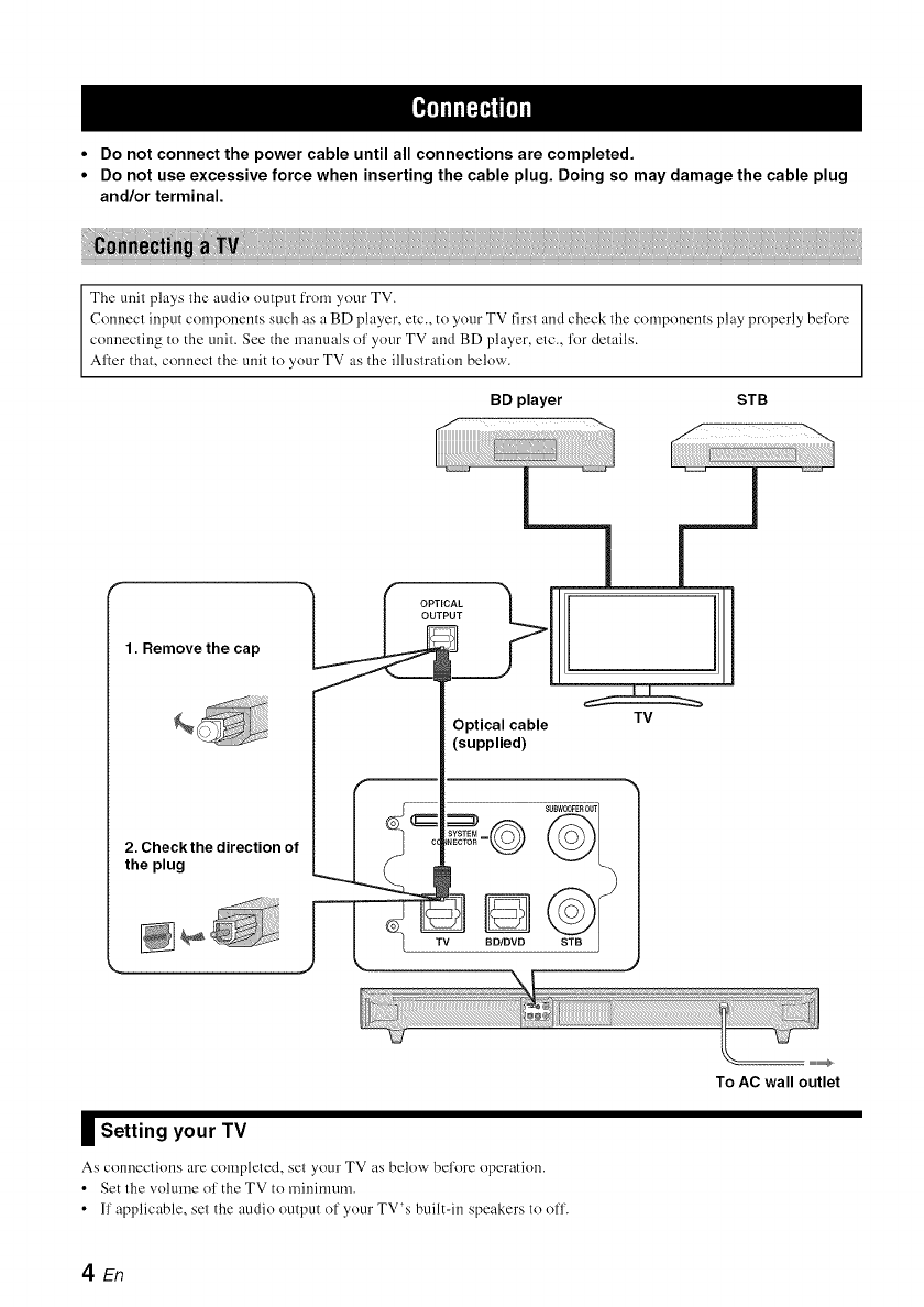
•Do not connect the power cable until all connections are completed.
•Do not use excessive force when inserting the cable plug. Doing so may damage the cable plug
and/or terminal.
The unit plays the audio output from your TV.
Connect input compouents such as a BD player, etc., to your TV first and check the compouents play properly before
connecting to the unit. See the manuals of your TV and BD player, etc., for details.
After that, connect the unit to your TV as the illustration below.
BD player STB
1. Remove the cap
2. Check the direction of
the plug
m
I[
Optical cable TV
(supplied)
II Setting your TV
As conneclions are completed, set your TV as below bel'ore operation.
• Set the volume ol' the TV to minimum.
• ll' applicable, set the audio output of your TV's built-in speakers to off.
To AC wall outlet
den
_lflf_qlf['ll
\1/
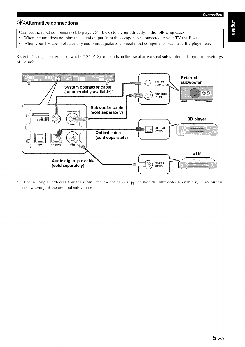
--'@'--Alternative connections
Connect the input componcnts (BD player, STB, etc) to the unit directly in the folloxxAng cases.
• When the unit does not play the sound output from the components connected to your TV (_, P. 4).
• When your TV does not have any audio input jacks to connect input components, such as a BD player, etc.
Refer to "Using an external subwoofcr" (_ P. 8) for details on the use of an external subwoofcr and appropriate settings
of the unit.
* ff connecting an external Yamaha subwool)r, use the cable supplied with the subwoofer to enable synchronous on/
ofl' switching of the unit and subwoofer.
5En
Once you have l'inished all cable connections and remole control operation, l'ollow the procedure below to start basic
playback Ol')eration.
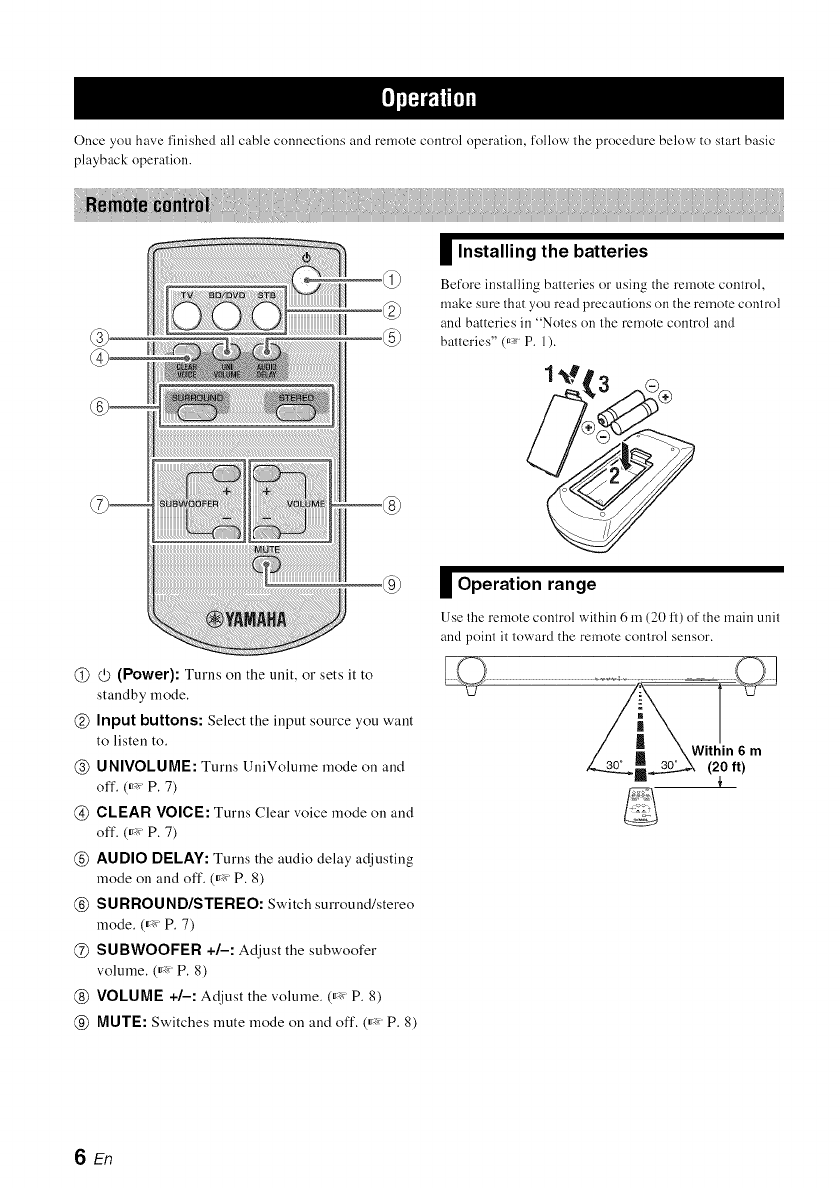
@@(Power): Turns on the unit, or sets it to
standby mode.
@Input buttons: Select the input source you want
to listen to.
@UNIVOLUME: Turns UniVolume mode on and
off. (_'_ P. 7)
@CLEAR VOICE: Turns Clear voice mode on and
off. (_'_ P. 7)
@AUDIO DELAY: Turns the audio delay a_!justiug
mode on and off. (_'_ P. 8)
@SURROUND/STEREO: Switch surround/stereo
mode. (_'_ P. 7)
@SUBWOOFER +/-: Adjust the subwoofer
volume. (_'_ P. 8)
@ VOLUME +/-: At!just the volume. (_'_ P. 8)
@MUTE: Switches mute mode on and off. (_'_ P. 8)
Installing the batteries
Before installing batteries or using the remote control,
make sure that you read precautions on the remote control
and batteries in "Notes on the remote control and
batteries" (_* P. 1).
Operation range
Use Ihe remote control wit hin 6 m (20 1_)of the main unit
and point it toward the remote control sensor.
SEn
1 Turn your TV on.
2Press the TV button to switch the input of
the unit to "TV."
The unit plays the TV sound, iNPUT
The INPUT indicator lights up in green. _m=
,=7,"
3Switch the input of your TV if you use
components such as a BD player.
\1/
-'c_'-When you play back components such as
a BD player connected to the audio input
jack of the unit.
1Switch the video input of your TV to the
video source such as a BD player.
2Press the BD/DVD or STB button to
switch the input of the unit.
The color of INPUT indicator depends on the selected
inpul.(_ P. 11)
3Start playback.
\11
For inl2)rmation on the external component, refer to the
instruction manual lor the producl.
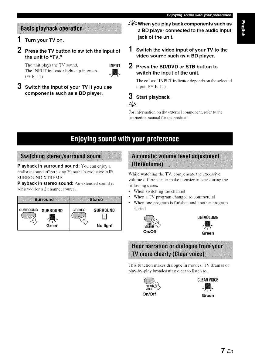
Playback in surround sound: You can enjoy a
realistic sound efl)ct using Yamaha's exclusive AIR
SURROUND XTREME.
Playback in stereo sound: An extended sound is
achieved for a 2 channel source.
iiiii!!_iiii_!!!i_ii_ii_!i_!i_!iN_i_i!!i_i_iiiiii!!i_ii_ii_!i_!i_ii_iiiii!!_iiii_!!!i_ii_ii_!i_!i_!i_!i_!i_iiiiii!Jiiiiii_iii!ii!ii!ii!ili!
SURROUND SURROUND STEREO SURROUND
,,L []
Green No light
While watching the TV, compensate the excessive
volume dif[_:rences to make it easier to hear during the
following cases.
•When switching the channel
• When a TV program changed to commercial
• When one program is finished and another program
started
UNIVOLUIE
,¢1%
On/Off Green
This function makes dialogue in movies, TV dramas or
play-by-play broadcasting clear to listen lo.
CLEARV0iCE
On/Off Green
7En

l_2r_[_[_[ol#Dlll_[oldlnDI¢[oli
Press VOLUME +/- to adjust the volume
level.
[1110
SURROUND CLEARV01CE UNJVOLUNE DTS
[] [] [] []
Up .......
_" Down
The color of FII'ID DTS inclicator changes depending on
the adjustable range. Green indicates a lower volume
level, orange a moderate level, and red a higher leveh
Note that when the FlrlD DTS indicator is red, the volume is
set to a higher level. Excessive sound may damage your
hearing or bother others.
\ll
..-@-_
To turn off the volume temporarily, press MUTE
MUTE.
To resume the volume, press MUTE again or
press VOLUME +_.
Press SUBWOOFER +/- to adjust the bass
level.
The color of lIPID DTS indicator changes depending on
the bass level. Green indicates a minus level, orange a
standard level (default value is 0), and red a plus level.
You can use 1his function to delay sOUnLIto synchronize
with a lagging video image.
1Press and hold AUDIO DELAY
more than 3 seconds to enter
D[LAY
adjustment mode.
2
D[10
iNPUT SURROUND CLEAR VOICE UNIVOLNNE DT8 D[I PL_
..m.. [] [] [] [] []
Flashes in green (_, P. 11)
Press SUBWOOFER +/- to adjust the
delay time. (+ increases the delay time)
IXIR
iNPUT SURROUND CLEAR VOICE UNiVOLDME OTS DO PLO
..Ill. [] [] D D []
Make the delay time longer
Make the delay time shorter
The color of lIPID DTS indicator changes depending on
the adjustable range. Green indicates a shomer delay time,
orange a medium delay, and red a longer delay.
3Press AUDIO DELAY to exit the
adjustment mode.
\1/
The adjustment mode is canceled if"the unit is ]eft for 20
secondswithout any operation being performed.
Although the unit has a subwoofer built-in, you can use
commercially available powered subwoofcr of your
choice. Refer to "Alternative connections" (_ P. 5).
1 Set the unit to standby mode.
2Press both the VOLUME - button and
button of the main unit, release the (_
button first, then release the VOLUME -
button.
This unit is turned on when switching between the
built-in subwoofcr and external subwoolbr.
The SURROUND indicator lights up as the following
illustration. Check if the setting is correct. (_, P. 11)
NNtn
The SURROUND
indicator (for 2 SURROUND SURROUND
seconds after Ihe %m,. []
unil is turned on)
Green No light
•The default setting is playback of the built-in
subwoofcr.
• You can verify the current setting by turning the
unit on again from standby mode.
You cannot use the built-in subwoofer and the external
subwoofer simtlltaneousl.v.
SEn
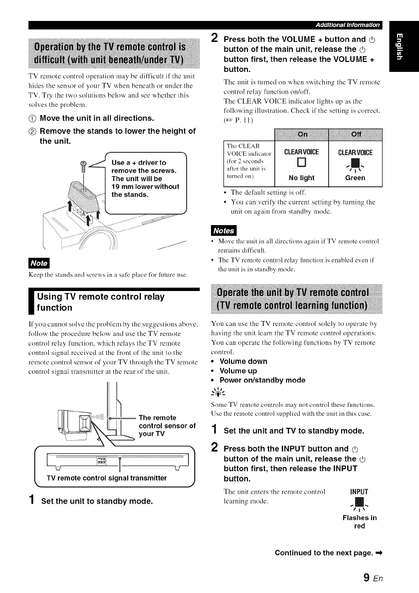
TV remote control operation may be difficult if the unit
hides the sensor of your TV when beneath or under the
TV. Try the two solutions below and see whether this
solves the problem.
@Move the unit in all directions.
@Remove the stands to lower the height of
the unit.
Keep the stands and screws in a safe place for future use.
_sing TV remote control relayfunction
If you cannot solve the problem by the suggestions abo_,c,
follow the procedure below and use the TV remote
control relay l'unction, which relays the TV remote
control signal received at the front of the unit to the
remote control sensor of your TV through the TV remote
control signal transmitter at the rear of the unit.
The remote
control sensor of
your TV
ITV remote control signal transmitter L/_ 1
1 Set the unit to standby mode.
2Press both the VOLUME +button and _)
button of the main unit, release the
button first, then release the VOLUME +
button.
The unit is turned on when switching the TV remote
control relay l'unction on/off.
The CLEAR VOICE indicator lights up as the
following illustration. Check if the setting is correct.
(_, P. 11 )
! !!i!:!i!!!
The (?LEAR
VOICE indicator CLEARVOICE CLEARVOiCE
(for 2 seconds [] _ [],_
after tile tlnit iS * I_
turned on) No light Green
•The default setting is off.
• You can verify the current setting by turning the
unit on again from standby mode.
• Move tlle unit in all directions again ifTV remote control
remains difficult.
• The TV remote control relay ffmction is enabled even if
tlle unit is in standby mode.
You can use the TV remote control solely to operate by
having the unit learn the TV remote control operations.
You can operate the following functions by TV remote
control.
•Volume down
•Volume up
•Power on/standby mode
Some TV remote controls may not control these functions.
Use the remote control supplied with the unit in this case.
1Set the unit and TV to standby mode.
2Press both the INPUT button and _)
button of the main unit, release the (_
button first, then release the INPUT
button.
The unit enters the remote control iNPUT
learning mode. %=.,
Flashes in
red
Continued to the next page. ,,*
9En

3Press the button below of the main unit to
select the operation you want the unit to
learn.
4
_nt _ _n,tto m;ngi
Volume down VOLUME [] [] m [] [] m
Volume up VOLUME +[] [] [] [] [] m
Power on/standby (/) [] [] [] ,1!
mode
Point your TV remote control at the 1
remote control sensor and press the 2
respective button twice or three times
until the indicator changes from flashing
green to lit green.
5
6
Press
(1 sec) Flashes
rapidly [] [] j [] []
Success in learning [] [] m [] [] []
e.g.
Volume up
Fault in learning
The UNIVOLUME, CLEAR VOICE and
SURROUND indicators fhtsh in green
simultaneously for about 3 seconds.
Repeat steps 3 and 4 to make the unit
learn the other operations.
Press the d) button of the main unit for
more than 3 seconds to finish the remote
control learning mode.
Release the Q) button of the main unit when all the
indicators light up in green. The unit enters standby
nlode.
• The unit will automatically set to standby mode if the trait
in the remote control learning mode is left turned on for 5
minutes without any operation being perlormed.
• If learning fails, try again with your TV turned off. Note
that screen glare may disturb TV remote control learning.
3
4
Set the unit to standby mode.
Press both the INPUT
button and d) button of the DBD
DTS
main unit, release the (b _
button first, then release the t _
INPUT button. Flashes in
red
Press the INPUT button of the main unit
again for more than 3 seconds.
Release the INPUT button of the main unit
when ODD DTS indicator flashes.
Press the (/) button of' the main unit for more than 3
seconds to finish the remote control learning mode, or
to have the unit learn operations of another TV
remote control.
Should the unit freeze for any reason, this may be
remedied by initiating the factory settings.
1 Set the unit to standby mode.
2
3
Press and hold the (b button of the main
unit for more than 3 seconds.
All the indicator flashes in green.
IXI0
INPUT SURROUND CLEAR VOISE UNIVOLUME ors 013 PL_
..11.... Ill. .11, ..11. ..111. ,ill,
"/i"," "/i"," /i", "/i"," L"i"," /i","
Release the d) button of the main unit.
10 En
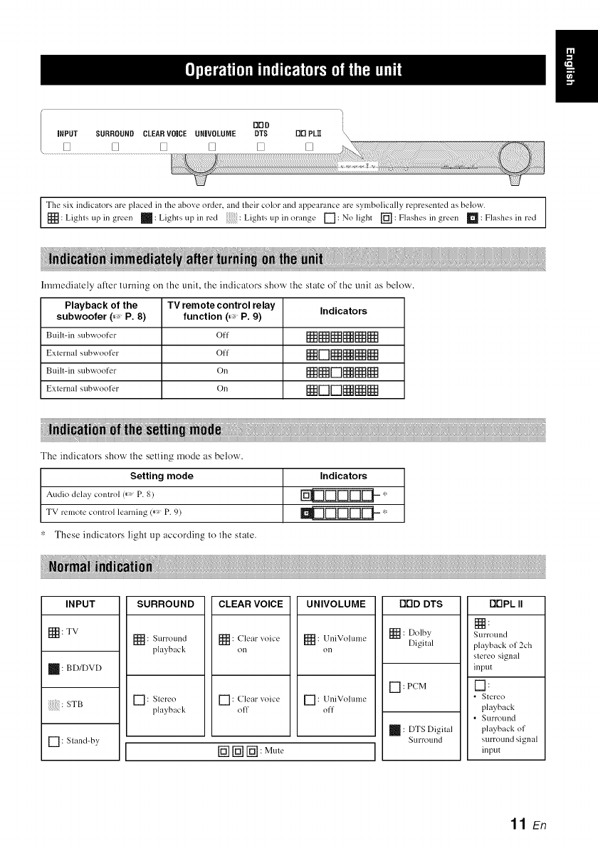
DDD
iNPUT SURROUND CLEARVOICE URIVOLUME DTS DD PL_
[] [] [] [] [] []
Tile six indicators are placed in tile abo;e order, and their colorand alpeal-ance are sylnbolically repl-esented as below.
[_: Lights up in gr ...... _: Lights up in l-_.'d Lights up i......... gc [-7: No light [_: Flashes in g....... _: F?]ash_.,sill l'_.'d
hmnediately after turning on the unit, the indicators show the state of the unit as below.
Playback of the TV remote control relay Indicators
subwoofer (=:, P. 8) function (=:, P. 9)
Built-in s/I bvqoo ft.'r (fl [[ _[]_NNN
External subwoofer Off N[-'ll_NNN
Built-in s/ibwoo for On NN[_]NNN
Extcrn;,l subwoolk, r On N ['-'] ['-"IN N[ _
The indicators show the setting mode as below.
Setting mode
Audio delay control (_' P. 8)
TV remote control learning (_> P. 9)
These indicators light up according to the state.
Indicators
UDDDDE1-- "
SURROUND ODD DTS DrIPL IIINPUT
[_: TV
: BD/DVD
: STB
[] : Stand-by
[_: Surround
l_layback
CLEAR VOICE
: Clear _oicc
on
UNIVOLUME
[_ : UniVolumc
on
[] : Slereo [] : Clear xoice [] : UniVolume
playback off off
[_ [_ [-_ : MuW
[] : Dolby
Digital
[] : PCM
: DTS Digfial
Surround
Nurround
playback of 2ch
stereo signal
input
I-1:
•Stereo
playback
•Surl-ound
playback of
surround signal
input
11 En
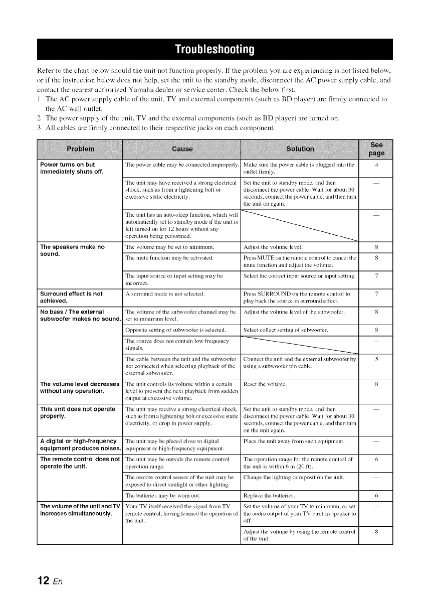
Refer to the chart below should the unit not function properly. If' the problem you are experiencing is not listed below,
or if the instruction below does not help, set the unit to the standby mode, disconnect the AC power supply cable, and
contact the nearest authorized Yamaha dealer or service center. Check the below first.
1 The AC power supply cable of the unit, TV and external components (such as BD player) are firmly connected to
the AC wall outlet.
2 The power supply of' the unit, TV and the external components (such as BD player) are turned on.
3 All cables are firmly connected to their respective jacks on each component.
Power turns on but
immediately shuts oft'.
The speakers make no
sound,
Surround effect is not
achieved,
No bass /The external
subwoot'er makes no sound.
The power cable may be connected improperly. Make sure the power cable is plugged into the 4
outlet firmly.
The unit may have received a strong electrical Set the unit to standby mode, and then
shock, such as l_om a lightening boll or disconnect the power cable. Wait lk)l"about 30
excessive static electricity, seconds, connect the power cable, and then turn
the unil oil again.
The unit has an auto-sleep lkmclion, which will
lett turned on lk)r 12 hours without any
automatically set to standby mode if the unit is
operation being pertk)rmed.
Tile volume may be set to minimum.
The mute hmction may be activated.
The input source or input setting may be
incorrect.
A surround mode is ]lot selected.
Adjust the volume level.
Press MUTE on the Ivmote control to cancel the
mute hmclion and adjust the volume.
Select tile correct input source or input setting.
Press SURROUND on the remote control to
play back the source in surround effi:cl.
Adjusl the vohune level of lhe subwool)r.
8
8
7
7
8
8
5
Select collect setting ol subwooti_r.
Connect the unit and the external subwoofer by
using a subwooli?r pill cable.
The volume of the subwooler channel may be
set to minimuln level.
Opposite setting of subwooti:r is selected.
The source does ilol conlain low frequency
signals.
The cable between the unit and the subwooti:r
not connected when selecting playback of the
external subwooti2r.
The volume level decreases The uili[ controls its volume within a certain Reset the volume. 8
without any operation, level to prevent the next playback lrom sudden
output at excessive volume.
This unit does not operate The unit may ivceive a strong electrical shock, Set the unit to standby mode, and theli
properly, such as from a lightening bolt or excessive static disconnect the power cable. Wait lor about 30
electricity, or drop ill power supply, seconds, connect the power cable, and then mrn
on the unit again.
A digRal or high-frequency The unit may be placed close to digital Place the unit away from such equipment.
equipment produces noises, eqllipmenl or high-lrequency equipment.
The remote control does not The unit may be outside the remote coiItrol The operation range lor the remote control of 6
operate the unit. operation range, the unit is within 6 m (20 1i).
The remote control sensor of the unit may be Change the lighting or ivposition the unit.
exposed to direct sunlight or other lighting.
The batteries may be worn out. Replace tile batteries. 6
The Volume of the unit and "IV Your TV itself received the signal lrom TV Set the volume of your TV to minimum, or set
increases simultaneously, remote control, having learned the operation of the audio output of your TV builtqn speaker to
the unit. oil.
Adjust the volume by using the remote control 8
of the unit.
12 En
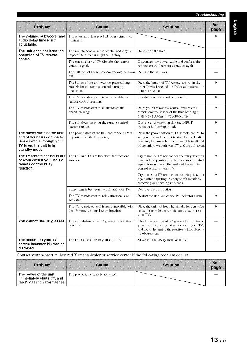
_'lmfl_ff¢
The volume, subwoofer and
audio delay time is not
adjustable.
The unit does not learn the
operation of TV remote
control.
The a@lstment has reached the n/axinmm or
millimuln.
The remote control sensor of the unit may be
exposed to direct sunlight or lighting.
The scl_en glare of TV disturbs the remote
control signah
The batteries of TV remote control may be worn
out.
The button of the unit was not pl_ssed long
enough t_or the l_motc control learning
operation.
The TV remote control is not available tier
l_2ii/otc corltro] ]earrling.
The TV remote control is outside (if the
operation range.
The unit does not enler the remote conlro]
learning mode.
The power state of the unit The power state of the unit and of your TV is
and of your TV is opposite, opposite h'om the beginning.
(For example, though your
TV is on, the unit is in
standby mode.)
The TV remote control is out The unit and TV are too close/tar lrom one
of work even if you use TV another.
remote control relay
function,
Something is between the unit and your TV.
The TV remote control relay tilnction is not
activated.
The TV remote control is not compatible with
the TV remote control relay hmction.
You cannot use 3D glasses. The unit obstructs the 3[) glasses transmitler of
your TV.
The picture on your TV The unit is to() close to your CRT TV.
screen becomes blurred or
distorted.
Reposition the unit.
Disconnect the power cable and pertbrm the
remote coiitrol learrling operation again.
Replace the batleries.
Plx:ss the button of TV remote control in the
order "plx:ss 1secorld" _"release 1second" _
"press ] secorld"
Use the remote control of the unit.
Point your TV remote control towards the
remote control sensor of the unit keeping a
distance of 30 cm (I ft) between them.
Operate after checking that the INPUT
indicator is flashing in red.
Press the power button of TV remote control to
set your TV and the unit to standby mode after
pressing the power button of your TV itself and
of the unit to set both your TV and the urlit to oil.
9
9
9
9
9
Try to use the TV remote control relay ltlrlctiorl 9
again after repositioning the TV remote control
signal transmitter (if the unit and the remote
conlrol serlsor of your TV.
Try to use the TV remote control relay hmction 9
again atler ac/iusting the height of the unit by
removing or atlaching its stands.
Remove the obstruction.
Restart the urlit arid check the indicator status. 9
Place the unit (without the stands, tbr example) 9
so as not to hide the remote control sensor of
your TV.
Check the position (If 3[) glasses transmitter (if
your TV by referring to the manual of your TV.
arid move the unit to the position where there is
IIO obstlllctiorl.
Move the unit away from your TV.
Contact your nearest authorized Yamaha dealer or service center if the l'ollowing problem occurs.
13 En
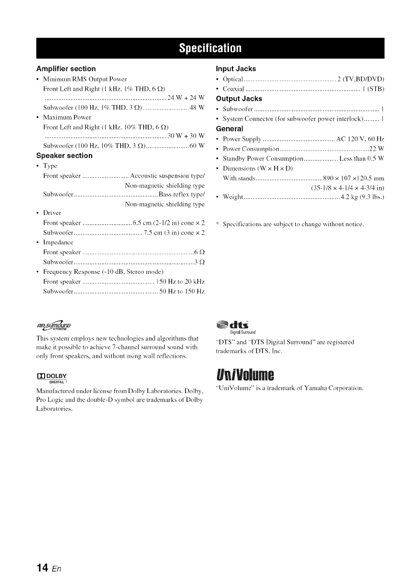
Amplifier section
• Minimum RMS Output Power
Front Left and Right (1 kHz. l(/_ THD. 6 _2)
....................................................................... 24W+24W
Snbwooler (10I) Hz. l(/, THD. 3 _2) ........................... 48 W
• Maximum Power
Front Left and Right (1 kHz. 1(t% THD. 6 g2)
....................................................................... 30 W + 3(1 W
Snbwooler (100 Hz. I(F/_ THD. 3£2) ......................... 60 W
Speaker section
•Type
Front speaker. .......................... Accoustic suspension type/
Non=magnetic shielding type
Snbwooler. ................................................ Bass reflex type/
Non=magnetic shielding type
• Driver
Front speaker. ............................ 6.5 cm (2-112 in) cone × 2
Snbwooler. ....................................... 7.5 cm (3 in) cone x 2
• Impedance
Front speaker. ................................................................ 6 £2
Snbwooler. ..................................................................... 3 _2
• Frequency Response (-10 dB, Stereo mode)
Front speaker .......................................... 150 Hz to 20 kHz
Subwoolbr ................................................. 50 Hz to 150 Hz
Input Jacks
• Optical ...................................................... 2 (TV,BD/DVD)
• Coaxial ................................................................... 1 (STB)
Output Jacks
• Subwoofer. ........................................................................ 1
• System Connector (for subwoofer power interlock) ......... 1
General
• Power Supply .......................................... AC 120 V, 60 Hz
• Power Consumption .................................................... 22 W
• Standby Power Consumption .................... Less than 0.5 W
• Dimensions (W x H x D)
With stands ....................................... 890 x 107 x 120.5 mm
(35-1/8 x 4-1/4 x 4-3/4 in)
• Weight ........................................................ 4.2 kg (9.3 lbs.)
" Specifications are subject to change without notice.
alr_o_o
This system employs new technologies and algorithms that
make it possible to achieve 7-channel summnd sound with
only fi'ont speakers, and without using wall reflections.
I'_ DOLBY
DIGITAL I
Mmmlhcmred under ]k'ensefi'om Do]by Laboratories. Do]by,
Pro Logic and the double-D symbol are trademarks of Dolby
Laboratories.
_dlt_
DigitalSurmu_ld
"DTS" and "DTS Digital Surround" are registered
trademarks of DTS, Inc.
geNolme
"UniVolume" is a tmdemm'k of Yamaha Corporation.
14 En

@YAMAHA
YAMAHA CORPORATION
© 2011 Yamaha Corporation Printed in Malaysia ZA81330
