Yamaha AX 596(UCA)PRE 596 Manual
User Manual: Yamaha AX-596 Manual
Open the PDF directly: View PDF ![]() .
.
Page Count: 32

I
AX-596
STEREO AMPLIFIER
AMPLIFICATEUR STEREO
OWNER’S MANUAL
MODE D’EMPLOI
U C A
II
• Explanation of Graphical Symbols
The lightning flash with arrowhead
symbol, within an equilateral triangle,
is intended to alert you to the
presence of uninsulated “dangerous
voltage” within the product’s
enclosure that may be of sufficient
magnitude to constitute a risk of
electric shock to persons.
The exclamation point within an
equilateral triangle is intended to alert
you to the presence of important
operating and maintenance
(servicing) instructions in the
literature accompanying the
appliance.
SAFETY INSTRUCTIONS
1Read Instructions – All the safety and operating
instructions should be read before the unit is operated.
2Retain Instructions – The safety and operating
instructions should be retained for future reference.
3Heed Warnings – All warnings on the unit and in the
operating instructions should be adhered to.
4Follow Instructions – All operating and other
instructions should be followed.
5Water and Moisture – The unit should not be used near
water – for example, near a bathtub, washbowl, kitchen
sink, laundry tub, in a wet basement, or near a
swimming pool, etc.
6Carts and Stands – The unit should be used only with
a cart or stand that is recommended by the
manufacturer.
6A A unit and cart combination should be
moved with care. Quick stops, excessive
force, and uneven surfaces may cause
the unit and cart combination to overturn.
7Wall or Ceiling Mounting – The unit should be mounted
to a wall or ceiling only as recommended by the
manufacturer.
8Ventilation – The unit should be situated so that its
location or position does not interfere with its proper
ventilation. For example, the unit should not be
situated on a bed, sofa, rug, or similar surface, that
may block the ventilation openings; or placed in a built-
in installation, such as a bookcase or cabinet that may
impede the flow of air through the ventilation openings.
9Heat – The unit should be situated away from heat
sources such as radiators, stoves, or other appliances
that produce heat.
10 Power Sources – The unit should be connected to a
power supply only of the type described in the
operating instructions or as marked on the unit.
11 Power-Cord Protection – Power-supply cords should
be routed so that they are not likely to be walked on or
pinched by items placed upon or against them, paying
particular attention to cords at plugs, convenience
receptacles, and the point where they exit from the
unit.
12 Cleaning – The unit should be cleaned only as
recommended by the manufacturer.
13 Nonuse Periods – The power cord of the unit should be
unplugged from the outlet when left unused for a long
period of time.
14 Object and Liquid Entry – Care should be taken so that
objects do not fall into and liquids are not spilled into
the inside of the unit.
15 Damage Requiring Service – The unit should be
serviced by qualified service personnel when:
A. The power-supply cord or the plug has been
damaged; or
B. Objects have fallen, or liquid has been spilled into
the unit; or
C. The unit has been exposed to rain; or
D. The unit does not appear to operate normally or
exhibits a marked change in performance; or
E. The unit has been dropped, or the cabinet
damaged.
16 Servicing – The user should not attempt to service the
unit beyond those means described in the operating
instructions. All other servicing should be referred to
qualified service personnel.
17 Power Lines – An outdoor antenna should be located
away from power lines.
18 Grounding or Polarization – Precautions should be
taken so that the grounding or polarization is not
defeated.
WARNING
TO REDUCE THE RISK OF FIRE OR ELECTRIC
SHOCK, DO NOT EXPOSE THIS APPLIANCE TO RAIN
OR MOISTURE.
CAUTION
CAUTION: TO REDUCE THE RISK OF
ELECTRIC SHOCK, DO NOT REMOVE
COVER (OR BACK). NO USER-SERVICEABLE
PARTS INSIDE. REFER SERVICING TO
QUALIFIED SERVICE PERSONNEL.
IMPORTANT
Please record the serial number of this system in the
space below.
Model:
Serial No.:
The serial number is located on the rear of the main
unit.
Retain this Owner’s Manual in a safe place for future
reference.
RISK OF ELECTRIC SHOCK
DO NOT OPEN

III
We Want You Listening For A Lifetime
YAMAHA and the Electronic Industries Association’s
Consumer Electronics Group want you to get the most out
of your equipment by playing it at a safe level. One that lets
the sound come through loud and clear without annoying
blaring or distortion – and, most importantly, without
affecting your sensitive hearing.
Since hearing damage from loud sounds is
often undetectable until it is too late, YAMAHA
and the Electronic Industries Association’s
Consumer Electronics Group recommend you
to avoid prolonged exposure from excessive
volume levels.
FCC INFORMATION (for US customers only)
1. IMPORTANT NOTICE : DO NOT MODIFY THIS
UNIT!
This product, when installed as indicated in the
instructions contained in this manual, meets FCC
requirements. Modifications not expressly approved
by Yamaha may void your authority, granted by the
FCC, to use the product.
2. IMPORTANT : When connecting this product to
accessories and/or another product use only high
quality shielded cables. Cable/s supplied with this
product MUST be used. Follow all installation
instructions. Failure to follow instructions could void
your FCC authorization to use this product in the
USA.
3. NOTE : This product has been tested and found to
comply with the requirements listed in FCC
Regulations, Part 15 for Class “B” digital devices.
Compliance with these requirements provides a
reasonable level of assurance that your use of this
product in a residential environment will not result in
harmful interference with other electronic devices.
This equipment generates/uses radio frequencies
and, if not installed and used according to the
instructions found in the users manual, may cause
interference harmful to the operation of other
electronic devices.
Compliance with FCC regulations does not guarantee that
interference will not occur in all installations. If this
product is found to be the source of interference, which
can be determined by turning the unit “OFF” and “ON”,
please try to eliminate the problem by using one of the
following measures:
Relocate either this product or the device that is being
affected by the interference.
Utilize power outlets that are on different branch (circuit
breaker or fuse) circuits or install AC line filter/s.
In the case of radio or TV interference, relocate/reorient
the antenna. If the antenna lead-in is 300 ohm ribbon
lead, change the lead-in to coaxial type cable.
If these corrective measures do not produce satisfactory
results, please contact the local retailer authorized to
distribute this type of product. If you can not locate the
appropriate retailer, please contact Yamaha Electronics
Corp., U.S.A. 6660 Orangethorpe Ave, Buena Park, CA
90620.
The above statements apply ONLY to those products
distributed by Yamaha Corporation of America or its
subsidiaries.
IV
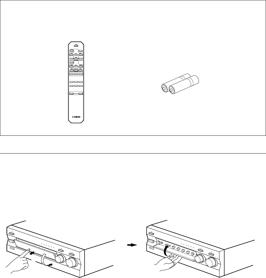
UNPACKING After unpacking, check that the following items are contained.
DEBALLAGE Après le déballage, vérifier que les pièces suivantes sont incluses.
●Remote control
●Télécommande
●Batteries (size AA, R6, UM-3)
●Piles (format AA, R6, UM-3)
CD/DVD
TAPE
MD
TUNERPHONO
AUX
+
–
A/B/C/D/E
DECK
A/B
DIR BDIR A
TAPE
DISC SKIP
CD
STANDBY/ON
PRESET
+–
TUNER
VOLUME
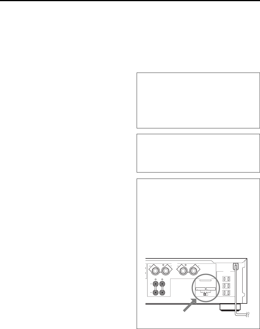
Opening and closing the front cover
Close the front cover whenever the controls inside the panel are not used.
Ouverture et fermeture du couvercle avant
Fermer le couvercle avant lorsque les commandes placées à l’intérieur du panneau ne sont pas utilisées.
To open the front cover
Pour ouvrir le couvercle avant
To close the front cover
Pour fermer le couvercle avant
2
1

English
E-1
Thank you for selecting this YAMAHA stereo amplifier.
FEATURES
v100W + 100W (8Ω) RMS Output Power, 0.015% THD, 20–20,000 Hz
vHighly Dynamic Power, Low Impedance Drive Capability
vContinuously Variable LOUDNESS Control
vCD/DVD DIRECT AMP Switch Used to Reproduce the Purest CD and DVD Sound
vPURE DIRECT Switch Used to Reproduce the Purest Source Sound
vREC OUT Selector Independent of Input Source Selection
vPRE OUT/MAIN IN Terminals for Connecting An Equalizer, Surround-Sound Processor, etc.
vRemote Control Capability
CONTENTS
SAFETY INSTRUCTIONS ....................................................................................... II
UNPACKING ........................................................................................................... IV
FEATURES ............................................................................................................... 1
CAUTION ...................................................................................................................2
NOTES ABOUT THE REMOTE CONTROL.............................................................. 3
CONTROLS AND THEIR FUNCTIONS .................................................................... 4
CONNECTIONS........................................................................................................ 7
OPERATION ........................................................................................................... 10
TROUBLESHOOTING ............................................................................................ 13
SPECIFICATIONS................................................................................................... 14
E-2
1. To assure the finest performance, please read this
manual carefully. Keep it in a safe place for future
reference.
2. Install this unit in a cool, dry, clean place – away from
windows, heat sources, sources of excessive vibration,
dust, moisture and cold. Avoid sources of humming
(transformers, motors). To prevent fire or electrical
shock, do not expose the unit to rain or water.
3. Never open the cabinet. If something drops into the
set, contact your dealer.
4. Do not use force on switches, controls or connection
wires. When moving the unit, first disconnect the
power plug and the wires connected to other
equipments. Never pull the wires themselves.
5. The openings on the unit cover assure proper
ventilation of the unit. If these openings are
obstructed, the temperature inside the unit will rise
rapidly; therefore, avoid placing objects against these
openings. Install the unit in a well-ventilated area to
prevent fire or damage.
<Europe, U.K. and China models only>
Be sure to allow a space of at least 20 cm behind, 20
cm on both sides and 30 cm above the top panel of the
unit to prevent fire or damage.
6. The voltage used must be the same as that specified
on this unit. Using this unit with a higher voltage than
specified is dangerous and may result in fire or other
accidents. YAMAHA will not be held responsible for
any damage resulting from use of this unit with a
voltage other than specified.
7. Always set the VOLUME control to “∞” before starting
the audio source play. Increase the volume gradually
to an appropriate level after the play has been started.
8. Do not attempt to clean the unit with chemical solvents
as this might damage the finish. Use a clean, dry
cloth.
9. Be sure to read the “TROUBLESHOOTING” section
regarding common operating errors before concluding
that the unit is faulty.
10. When not planning to use this unit for a long period
(ie., vacation, etc.), disconnect the AC power plug from
the wall outlet.
11.
To prevent lightning damage, disconnect the AC power
plug when there is an electric storm.
12. Grounding or polarization – Precautions should be
taken so that the grounding or polarization of an
appliance is not defeated.
13. Do not connect any audio equipment to the AC outlet
on the rear panel if the equipment requires more power
than the outlet is rated to provide.
14. VOLTAGE SELECTOR
(China and General models only)
The voltage selector on the rear panel of this unit
must be set for your local main voltage BEFORE
plugging into the AC main supply.
Voltages are 110/120/220/240 V AC, 50/60 Hz.
When this unit is turned off by pressing the STANDBY/ON
switch on the front panel or the remote control, the
STANDBY indicator on the front panel lights up. This state
is called the standby mode. In this mode, this unit is
designed to consume a small amount of power. This
unit’s power supply is completely cut off from the AC line
only when the POWER switch on the front panel is set in
the OFF position or the AC power cord is disconnected.
For Canadian Customers
To prevent electric shock, match wide blade of plug to
wide slot and fully insert.
This Class B digital apparatus complies with Canadian
ICES-003.
WARNING
Do not change the IMPEDANCE SELECTOR switch
setting while the power to this unit is on, otherwise
this unit may be damaged.
If this unit fails to turn on when the POWER switch is
pressed:
The IMPEDANCE SELECTOR switch may not be set to
either end. If so, set the switch to either end when this
unit’s power supply is completely cut off.
CAUTION: Read this before operating your unit.
(U.S.A. model)
IMPEDANCE SELECTOR
A
B
CAUTION
SEE INSTRUCTION MANUAL FOR CORRECT SETTING.
IMPEDANCE SELECTOR
SET BEFORE POWER ON
A OR B : 6
Ω
MIN. /SPEAKER
A B : I2
Ω
MIN. /SPEAKER
A OR B : 4
Ω
MIN. /SPEAKER
A B : 8
Ω
MIN. /SPEAKER
SWITCHED
I20V 60Hz
l00W MAX. TOTAL
MAINS
R
R L
L
SPEAKERS
AC OUTLETS
English
E-3
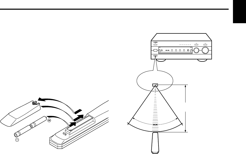
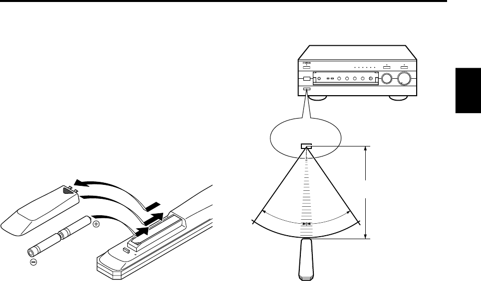
30°
30°
Remote control operation range
Notes
●The area between the remote control and the main unit
must be clear of large obstacles.
●Do not expose the remote control sensor to strong
lighting, in particular, an inverter type fluorescent lamp;
otherwise, the remote control may not work properly. If
necessary, position the main unit away from direct
lighting.
NOTES ABOUT THE REMOTE CONTROL
Battery installation
Since the remote control will be used for many of this unit’s
control operations, you should begin by installing the
supplied batteries.
1. Turn the remote control over and remove the battery
compartment cover by sliding it in the direction of the
arrow.
2. Insert the batteries (AA, R6, UM-3 type) according to the
polarity markings on the inside of the battery
compartment.
3. Close the battery compartment cover.
Battery replacement
If you notice that the remote control must be used closer to
the main unit, the batteries are weak. Replace both
batteries with new ones.
Notes
●Use AA, R6, UM-3 batteries.
●Be sure the polarities are correct. (See the illustration
inside the battery compartment.)
●Remove the batteries if the remote control is not used for
an extended period of time.
●If batteries leak, dispose of them immediately. Avoid
touching the leaked material and contact with clothing,
etc. Clean the battery compartment thoroughly before
installing new batteries.
Remote control
sensor
Within approximately
6 m (19.7 feet)
2
1
3
E-4
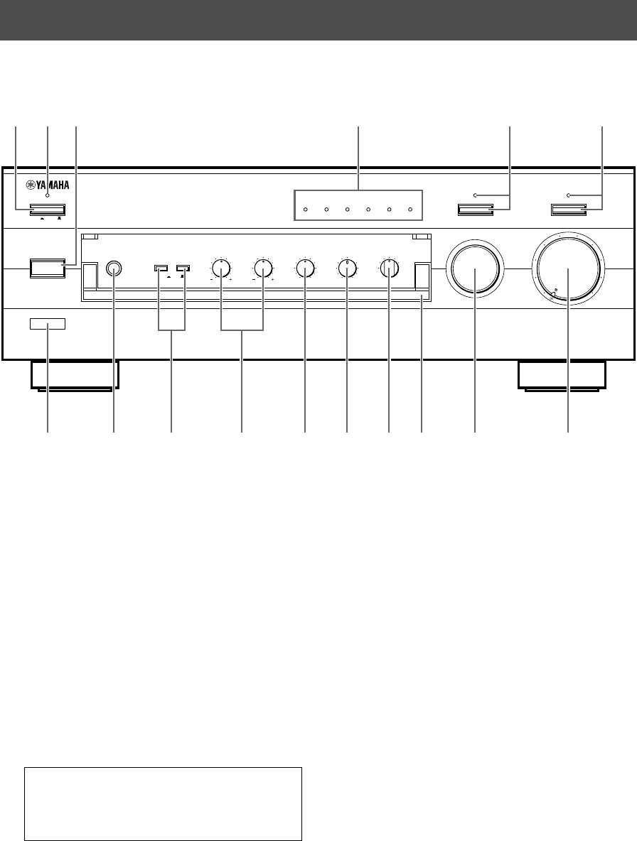
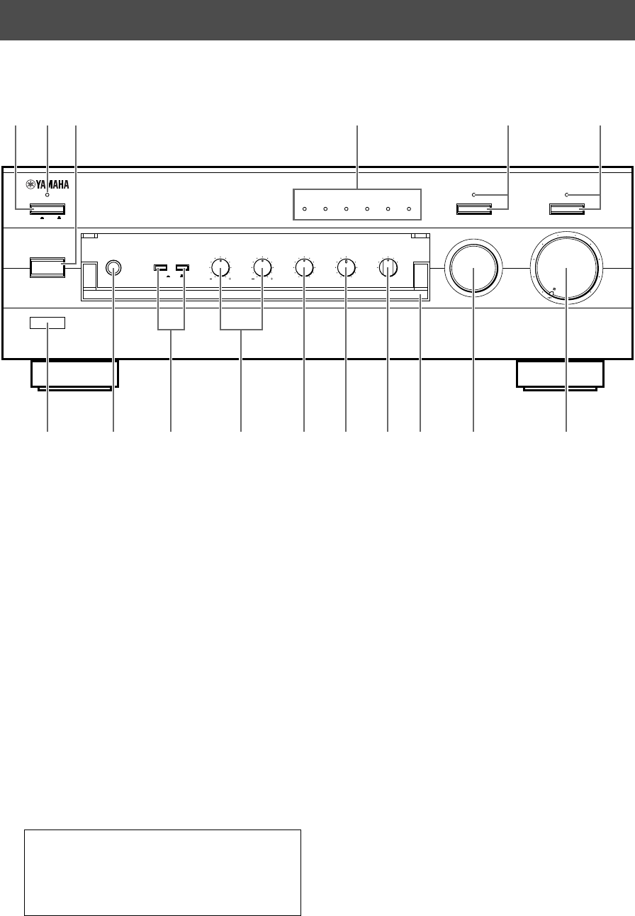
FRONT PANEL
CONTROLS AND THEIR FUNCTIONS
NATURAL SOUND STEREO AMPLIFIER
AX–596
VOLUME
l6
20
28
40
60
l2
8
4
2
0
–dB
PHONES
BASS
55
4
3
2
l0l
2
3
4
TREBLE
55
4
3
2
l0l
2
3
4
BALANCE
55
4
3
2
l0l
2
3
4
LR
SPEAKERS
A
ON OFF
B
STANDBY/ON
POWER
ON OFF
STANDBY
INPUT
PURE DIRECT CD/DVD DIRECT AMP
AUX PHONOTUNERCD/DVDTAPEMD
LOUDNESS
567
4
3
2
lFLAT
I0
—30dB
9
8
REC OUT
CD/DVD
TUNER
PHONO
TAPE
MD
AUX
456321
789 A B C DFE0
1POWER
Press this switch inward (ON) to use this unit. In this
state, you can turn on this unit or turn this unit in the
standby mode by pressing STANDBY/ON. Press this
switch to release it outward (OFF) to completely cut off
this unit’s power supply from the AC line.
2STANDBY indicator
Lights up only while this unit is in the standby mode.
3STANDBY/ON
Press this switch to turn on the power. Press again to
set this unit in the standby mode.
* This switch can be used only when POWER is set in
the ON position.
Standby mode
This unit is still using a small amount of power in this
mode in order to be ready to receive infrared-signals
from the remote control.
4Input source indicators
The indicator of the currently selected input source
lights up.
5PURE DIRECT and indicator
Press this switch, and the indicator above it lights up.
You can listen to a source in the purest sound with this
function. (Refer to page 12 for details.)
Press this switch again to cancel this function.
6CD/DVD DIRECT AMP and indicator
Press this switch, and the indicator above it lights up.
You can listen to a CD or DVD source in the purest
sound with this function. (Refer to page 12 for details.)
Press this switch again to cancel this function.
7Remote control sensor
Receives signals from the remote control.

English
E-5
8PHONES jack
When you listen with headphones, connect the
headphones to the PHONES jack and set both
SPEAKERS A and B switches to the OFF position.
9SPEAKERS
Press the switch A or B (or both) inward (ON) for the
speakers you will use. Press and release the switch
outward (OFF) for the speakers you do not use.
0Tone controls
BASS
Rotate this knob to increase or decrease the low
frequency response. The 0 position produces a flat
response.
TREBLE
Rotate this knob to increase or decrease the high
frequency response. The 0 position produces a flat
response.
ABALANCE
The balance of the output volume to the left and right
speakers can be adjusted to compensate for sound
imbalances caused by the speaker location or listening
room conditions.
BLOUDNESS
Used to compensate for the human ears’ loss of
sensitivity to high and low-frequency ranges at low
volume. (Refer to page 12 for details.)
CREC OUT selector
Rotate this knob to select the source for recording to
an MD recorder or tape deck. This setting is
independent of the INPUT selector setting, so this
function allows you to record the selected source while
listening to another source.
DFront cover
Refer to inside of the front cover on how to open and
close the front cover.
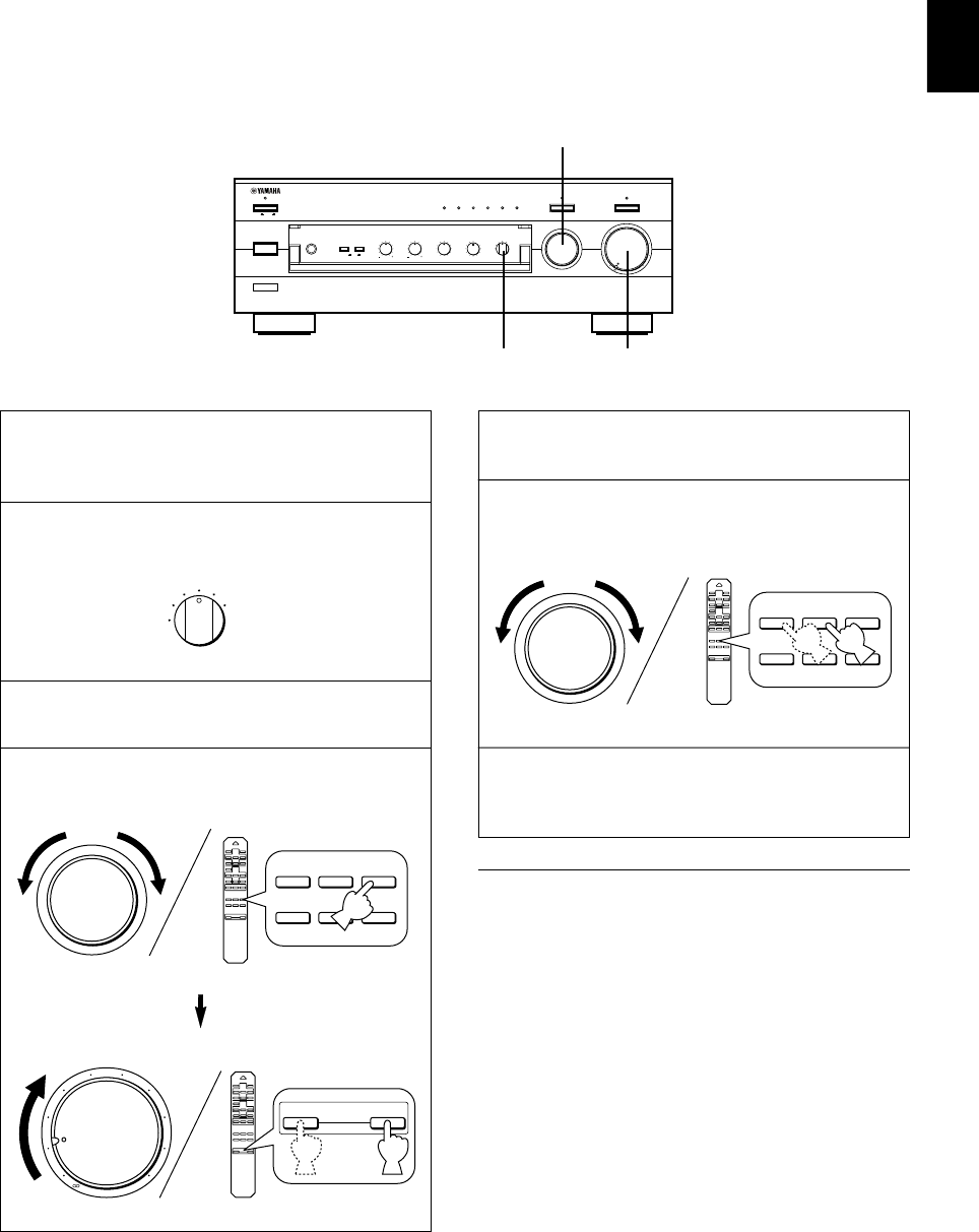
EINPUT selector
Turn this knob to select the input source.
The selected source will be shown by the lighting of
corresponding input source indicator.
FVOLUME
Turn this knob to raise or lower the volume level. (The
REC OUT level is not affected.)
PHONES
PHONES
E-6
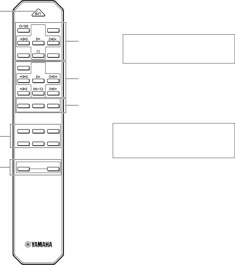
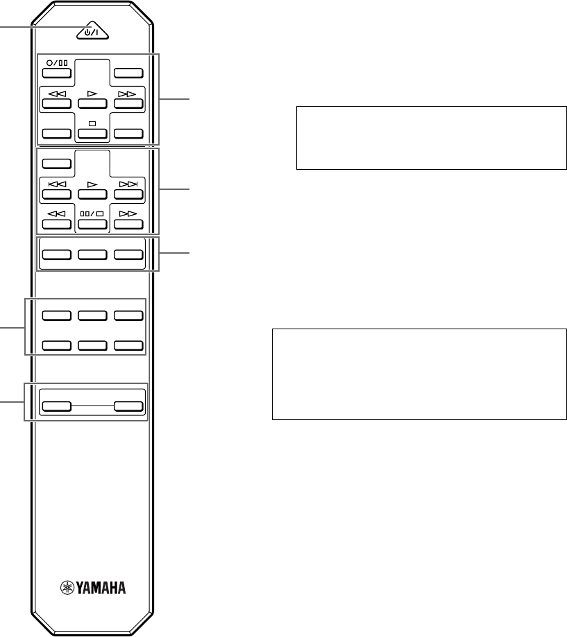
For Control of This Unit
1STANDBY/ON
Press this key to turn on this unit or turn it into the
standby mode.
This key can be used only when the POWER switch on
the main unit is set in the ON position.
Standby mode
In this state, this unit consumes a very small
quantity of power to receive infrared-signals from
the remote control.
2Input selector keys
Press a key to select the input source.
3VOLUME +/–
Press these keys to increase or decrease the volume.
For Control of Other Components
Note
The functions of the keys to control other YAMAHA
components are the same as the corresponding keys on
those components. Refer to those components’
instruction manuals for details.
1Tape deck keys
These keys control tape decks.
*DIR A, B and A/B apply only to double cassette tape
decks.
* Pressing DIR A will reverse the tape direction on a
single cassette tape deck with the automatic reverse
function.
2CD player keys
These keys control compact disc players.
*DISC SKIP is used for disc changers only.
3Tuner keys
These keys control tuners.
PRESET +: Press this key to select the next preset
station number.
PRESET –: Press this key to select the previous
preset station number.
A/B/C/D/E: Press this key to select the group (A – E)
of preset station numbers.
REMOTE CONTROL
The remote control is designed to control the most commonly used functions of the main unit. If you have a YAMAHA CD
player, tuner, tape deck, etc. with remote control compatibility, this remote control will also control their various functions.
CD/DVD
TAPE
MD
TUNERPHONO
AUX
+
–
A/B/C/D/E
DECK
A/B
DIR BDIR A
TAPE
DISC SKIP
CD
STANDBY/ON
PRESET
+–
TUNER
VOLUME
2
3
11
2
3
1
English
E-7
GND
PHONO
2
TUNER
3
IN
(PLAY)
4
TAPE
OUT
(REC)
3
IN
(PLAY)
4
OUT
(REC)
MD
AUX
A
B
CAUTION
SEE INSTRUCTION MANUAL FOR CORRECT SETTING.
IMPEDANCE SELECTOR
SET BEFORE POWER ON
A OR B : 6
Ω
MIN. /SPEAKER
A B : I2
Ω
MIN. /SPEAKER
A OR B : 4
Ω
MIN. /SPEAKER
A B : 8
Ω
MIN. /SPEAKER
SWITCHED
I20V 60Hz
l00W MAX. TOTAL
MAINS
R
R L
L
RLRL
RL
RL
1
CD/DVD
PRE
OUT
MAIN
IN
AUDIO SIGNAL COUPLER SPEAKERS
AC OUTLETS
OUTPUT
GND
OUTPUT
AUDIO OUT
LINE OUT
LINE IN
AUDIO OUT
LINE OUT
LINE IN
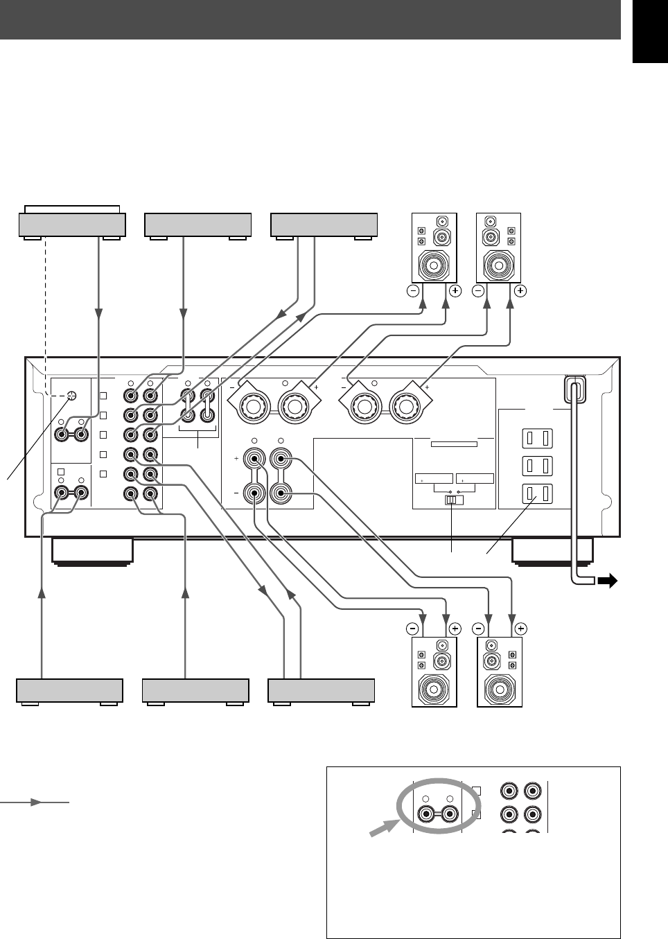
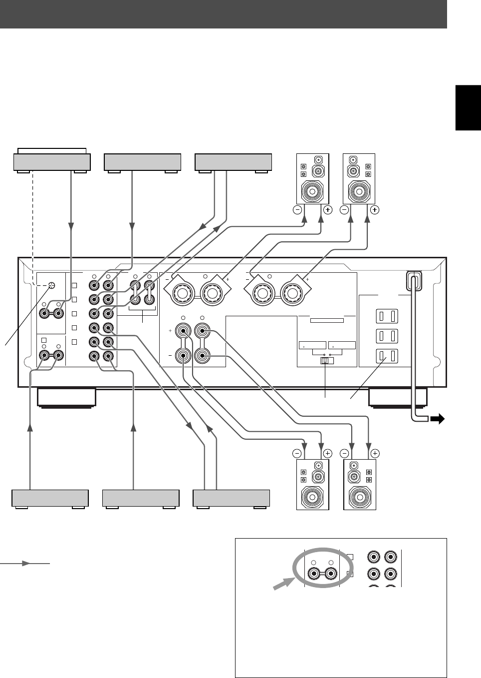
CONNECTIONS
Caution: Plug in this unit and other components after all connections are completed.
●All connections must be correct, that is to say L (left) to L, R (right) to R, “+” to “+” and “–” to “–”. Also refer to the owner’s
manual for each of your components.
●Use RCA type pin plug cables for audio/video units except speakers.
●The output (or input) terminals of YAMAHA audio/video units numbered 1, 2, 3, 4, etc. on the rear panel must be
connected to the same-numbered terminals of this unit.
Turntable
MD recorder, etc.
Tape deck, etc.
Left
Speakers A
Right
CD player or
DVD player
Tuner
Video cassette player,
etc. Speakers B
Right Left
To AC outlet
(U.S.A. model)
: Indicates the direction of signals.
*1, *2, *3, *4: Refer to page 9 for descriptions.
*3
*1*2
*4
Note
These terminals are for connecting a turntable with an
MM or high output MC cartridge. If you have a turntable
with a low output MC cartridge, use an inline boosting
transformer or MC-head amplifier when connecting to
these terminals.
PHONO
3
IN
(PLAY)
4
TAPE
OUT
(REC)
RL
E-8
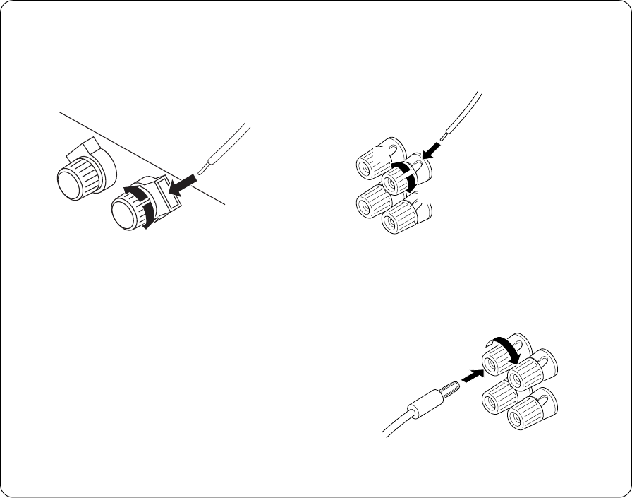
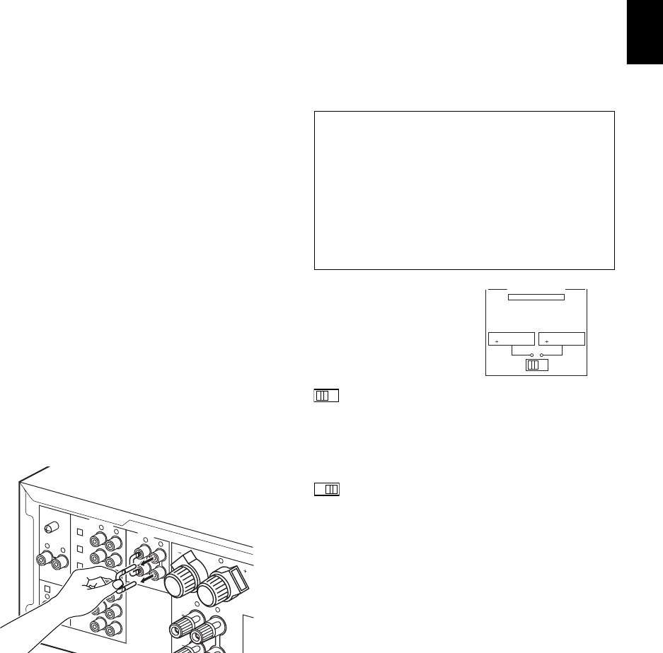
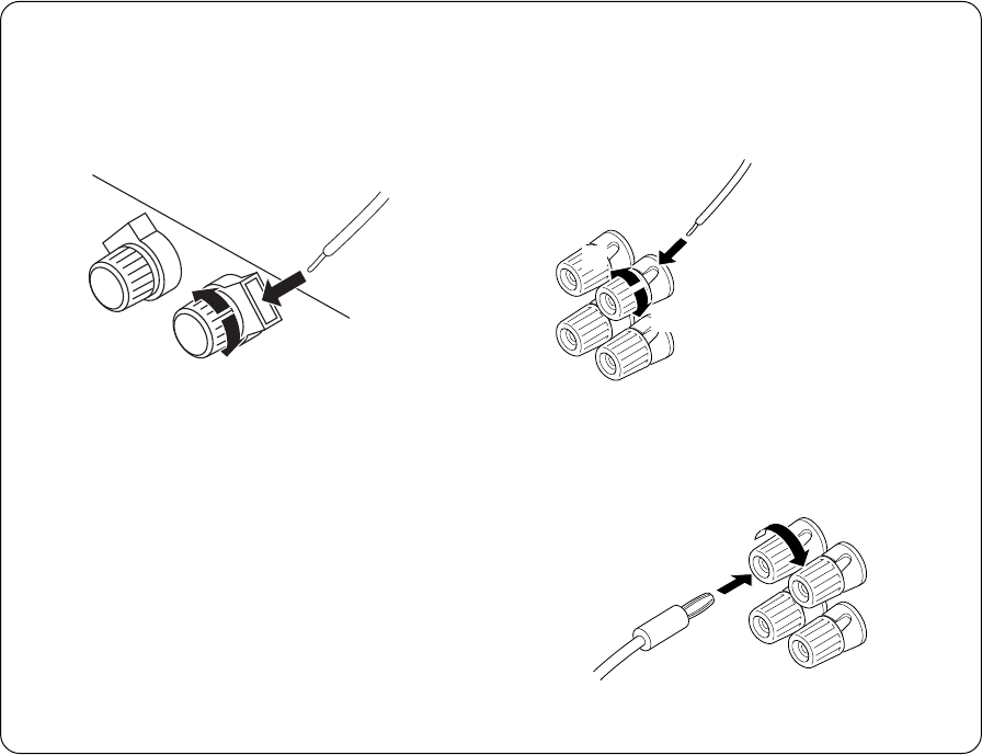
m Connecting speakers
Connect the SPEAKERS terminals to your speakers with
the wire with the proper gauge (keep it as short as
possible). If the connections are faulty, no sound will be
heard from the speakers. Make sure that the + and –
polarity markings of the speaker wires are observed and set
correctly. If these wires are reversed, the sound will be
unnatural and lack bass.
How to Connect:
SPEAKERS A terminals
Red: positive (+)
Black: negative (–)
1Loosen the knob.
2Insert the bare wire. [Remove approx.
10 mm (3/8”) insulation from the speaker wires.]
3Tighten the knob and secure the wire.
12
3
●One or two speaker systems can be connected to this
unit. If you use only one speaker system, connect it to
either the SPEAKERS A or B terminals.
●Use speakers with the specified impedance shown on the
rear of this unit.
Caution
Do not let the bare speaker wires touch each other or
any metal part of this unit. This could damage this unit
or the speakers, or both.
SPEAKERS B terminals
Red: positive (+)
Black: negative (–)
1Loosen the knob.
2Insert the bare wire.
[Remove approx.
10 mm (3/8”)
insulation from the
speaker wires.]
3Tighten the knob
and secure the wire.
<U.S.A., Canada, Australia, China and General
models only>
Banana Plug connections are also possible.
1Tighten the terminal knob.
2Simply insert the Banana Plug connector into the
terminal.
1
2
1
2
3
English
E-9
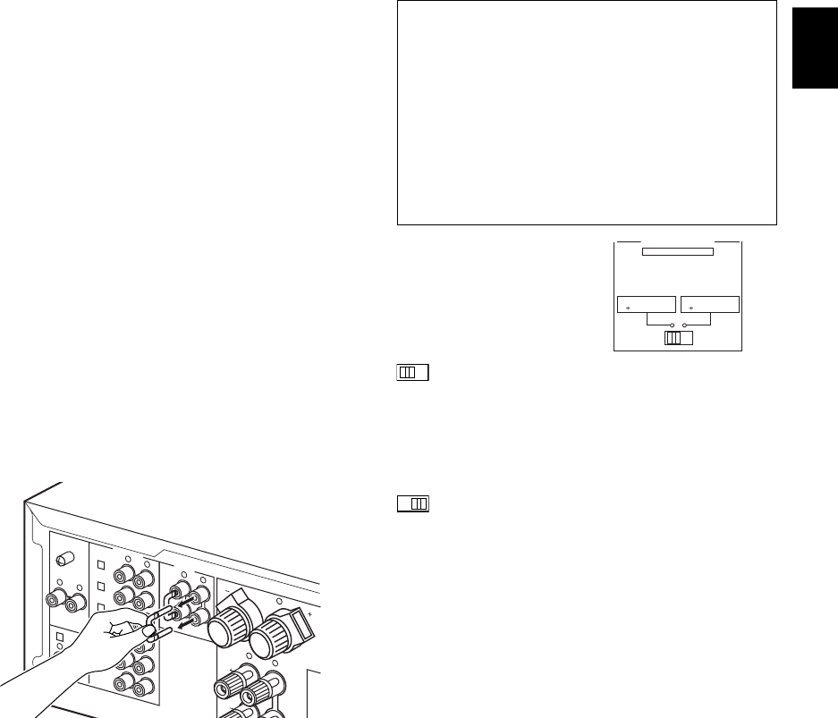
m Rear panel parts
GND terminal (For turntable use)
Connecting the ground wire of the turntable to the GND
terminal will normally minimize hum, but in some cases
better results may be obtained with the ground wire
disconnected.
PRE OUT/MAIN IN terminals
Removing the jumper pins from the PRE OUT/MAIN IN
terminals enables this unit to operate separately as a
control amplifier and a power amplifier. These terminals are
used for connecting a signal-processing system such as a
graphic equalizer or a surround-sound processor to this
unit.
If such an external unit is connected to these terminals, the
VOLUME control of this unit can be used for adjusting the
overall sound level.
To connect an external unit, first remove the jumper pins
from the PRE OUT/MAIN IN terminals, and then connect
the input terminals of that unit to the PRE OUT terminals
and its output terminals to the MAIN IN terminals. For
details, refer to the owner’s manual included with the unit to
be connected.
Notes
●When you do not use the PRE OUT/MAIN IN terminals,
never remove the jumper pins from these terminals. If
removed, no sound will be outputted from this unit.
●When you use this unit with an external unit connected to
the PRE OUT and MAIN IN terminals, make sure that the
CD/DVD DIRECT AMP switch and the PURE DIRECT
switch on the front panel are turned off.
●When you use this unit as a power amplifier, connect the
output terminals of an external control amplifier etc. to
this unit’s MAIN IN terminals. In this case, this unit’s
controls will not function except the PHONES jack and
the SPEAKERS switches. Use the controls on the
external control amplifier to make volume adjustment etc.
*1
*2
*3
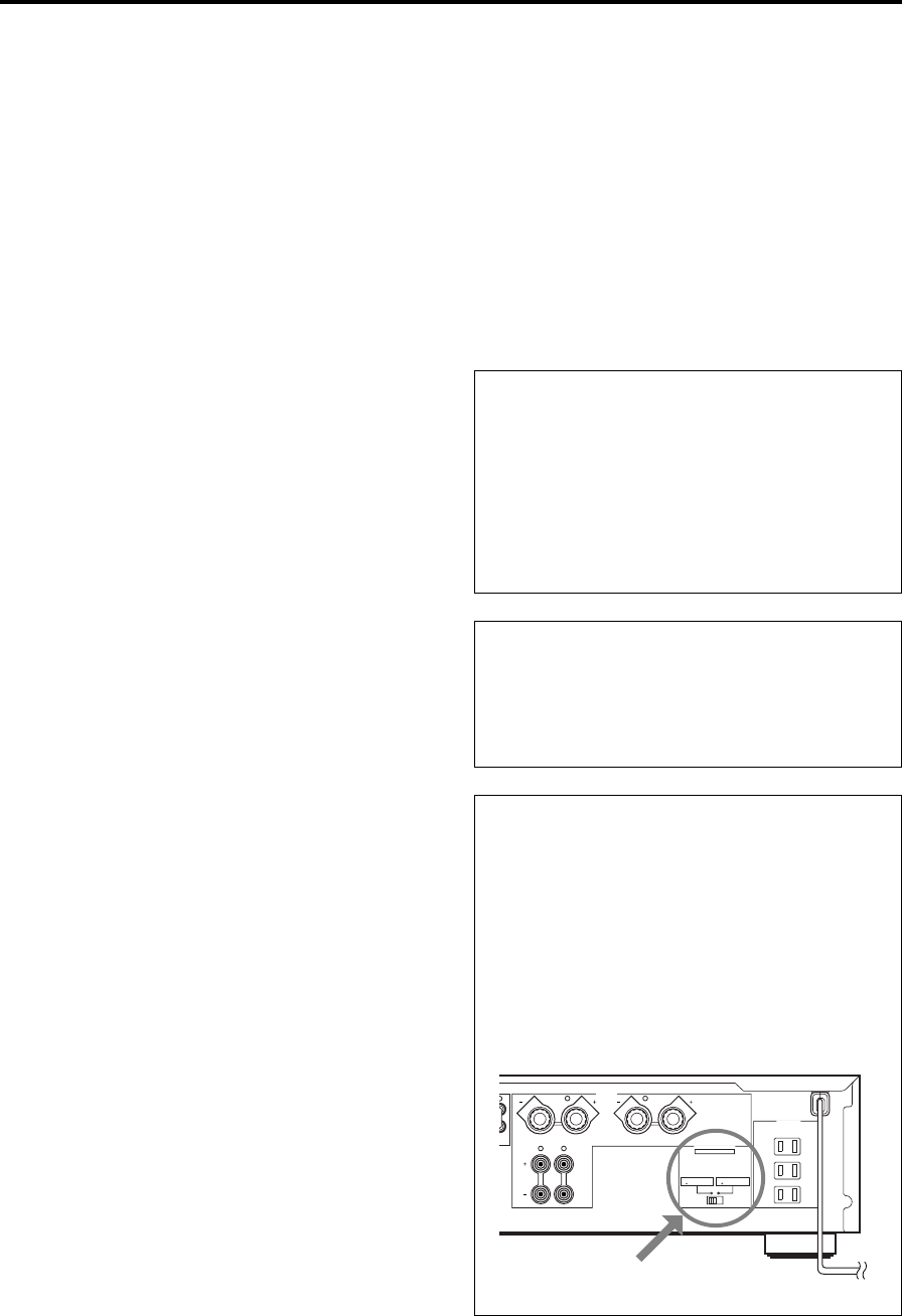
IMPEDANCE SELECTOR switch
WARNING
Do not change the IMPEDANCE SELECTOR switch
setting while the power to this unit is on, otherwise
this unit may be damaged.
If this unit fails to turn on when the POWER switch is
pressed:
The IMPEDANCE SELECTOR switch may not be set to
either end. If so, set the switch to either end when this
unit’s power supply is completely cut off.
Select the position whose
requirements your speaker
system meets.
(Left position)
If you use one pair of speakers, the impedance of
each speaker must be 4Ω or higher.
If you use two pairs of speakers, the impedance of
each speaker must be 8Ω or higher.
(Right position)
If you use one pair of speakers, the impedance of
each speaker must be 6Ω or higher.
If you use two pairs of speakers, the impedance of
each speaker must be 12Ω or higher.
AC OUTLET(S) (SWITCHED)
(U.S.A., Canada, Europe, China and General models)
...................................................... 3 SWITCHED OUTLETS
(U.K. and Australia models)............. 1 SWITCHED OUTLET
Use these to connect the power cords of your components
to this unit.
The power to the SWITCHED outlets is controlled by this
unit’s POWER or STANDBY/ON switch. These outlets will
supply power to any connected unit whenever this unit is
turned on.
The maximum power (total power consumption of
components) that can be connected to the SWITCHED AC
OUTLET(S) is 100W.
IMPEDANCE SELECTOR
SET BEFORE POWER ON
A OR B : 6
Ω
MIN. /SPEAKER
A B : I2
Ω
MIN. /SPEAKER
A OR B : 4
Ω
MIN. /SPEAKER
A B : 8
Ω
MIN. /SPEAKER
GND
PHONO
2
TUNER
3
IN
(PLAY)
4
TAPE
OUT
(REC)
3
IN
(PLAY)
4
OUT
(REC)
MD
AUX
B
R
R
L
RLRL
RL
RL
1
CD/DVD
PRE
OUT
MAIN
IN
AUDIO SIGNAL COUPLER
*4

E-10
VOLUME
l6
20
28
40
60
l2
8
4
2
0
–dB
PHONES
BASS
55
4
3
2
l0l
2
3
4
TREBLE
55
4
3
2
l0l
2
3
4
BALANCE
55
4
3
2
l0l
2
3
4
LR
SPEAKERS
A
ON OFF
B
STANDBY/ON
POWER
ON OFF
STANDBY
INPUT
CD/DVD DIRECT AMP
AUX PHONOTUNERCD/DVDTAPEMD
LOUDNESS
567
4
3
2
lFLAT
I0
—30dB
9
8
REC OUT
CD/DVD
TUNER
PHONO
TAPE
MD
AUX
PURE DIRECT
1
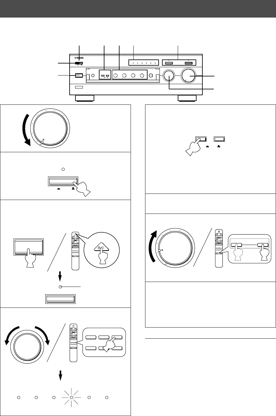
2Press POWER inward (ON).
3If the STANDBY indicator is illuminated, press
STANDBY/ON to turn on the power. (The STANDBY
indicator turns off.)
4Select the desired input source.
The indicator of the selected source lights up.
5Select speakers A or B.
* Both speakers A and B can be selected.
* Be sure that the IMPEDANCE SELECTOR switch is
correctly set as explained on page 9.
* If you listen with headphones, press both switches to
release them outward (OFF).
6Play the source.
7
Adjust the output level.
8Adjust the tonal quality by using the BASS,
TREBLE, BALANCE, LOUDNESS controls, the
CD/DVD DIRECT AMP switch or the PURE
DIRECT switch. (Refer to page 12).
When you finish using this unit
Press STANDBY/ON again to set this unit in the standby
mode. (The STANDBY indicator lights up.)
To completely cut off this unit’s power
supply from the AC line
Press POWER to release it outward (OFF).
OPERATION
2
4
m Playing a source
l6
20
28
40
60
l2
8
4
2
0
–dB
POWER
ON OFF
STANDBY
STANDBY/ON
+
–
CD/DVD
TAPE
MD
TUNERPHONO
AUX
+
–
STANDBY/ON
AUX PHONOTUNERCD/DVDTAPEMD
SPEAKERS
A
ON OFF
B
+
–
+
–
VOLUME
l6
20
28
40
60
l2
8
4
2
0
–dB
3
85 4
1, 7
STANDBY
Turns off.
POWER
STANDBY
8
Set to the “∞” position.
English
E-11
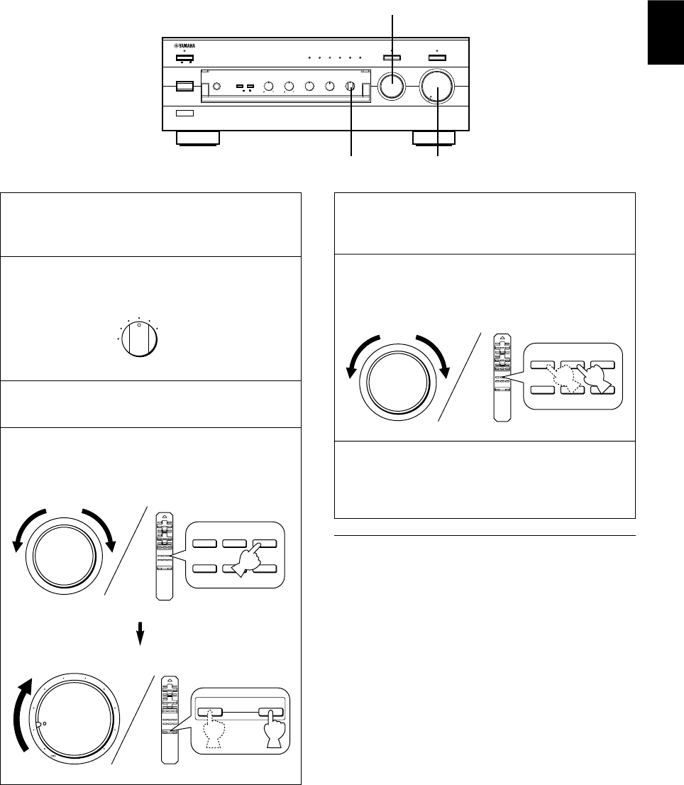
1Follow the steps 1–3 of “Playing a source” on page
10.
2Select the source you want to record.
3Play the source.
4Select the source with the INPUT selector and
adjust VOLUME to check the sound output.
m Recording a source to tape (or MD)
5Begin recording on the tape deck (or MD recorder).
6The sound of the recording can be monitored by
selecting the tape deck (or MD recorder) with the
INPUT selector.
7Listening to another source by selecting it with the
INPUT selector will not affect the recording.
Notes
●The VOLUME, BASS, TREBLE, BALANCE, LOUDNESS
controls, the CD/DVD DIRECT AMP switch and the
PURE DIRECT switch have no effect on the material
being recorded.
●Please check the copyright laws in your country to record
from records, compact discs, radio, etc. Recording of
copyright material may infringe on copyright laws.
VOLUME
l6
20
28
40
60
l2
8
4
2
0
–dB
PHONES
BASS
55
4
3
2
l0l
2
3
4
TREBLE
55
4
3
2
l0l
2
3
4
BALANCE
55
4
3
2
l0l
2
3
4
LR
SPEAKERS
A
ON OFF
B
STANDBY/ON
POWER
ON OFF
STANDBY
INPUT
CD/DVD DIRECT AMP
AUX PHONOTUNERCD/DVDTAPEMD
LOUDNESS
567
4
3
2
lFLAT
I0
—30dB
9
8
REC OUT
CD/DVD
TUNER
PHONO
TAPE
MD
AUX
PURE DIRECT
REC OUT
CD/DVD
TUNER
PHONO
TAPE
MD
AUX
+
–
CD/DVD
TAPE
MD
TUNERPHONO
AUX
l6
20
28
40
60
l2
8
4
2
0
–dB
+
–
+
–
VOLUME
4, 6, 7
4
2
+
–
CD/DVD
TAPE
MD
TUNERPHONO
AUX
E-12
Adjusting the BALANCE control
Adjust the balance of the output volume to the left and right
speakers to compensate for sound imbalance caused by
speaker location or listening room conditions.
Using the CD/DVD DIRECT AMP switch
You can enjoy the purest possible sound from your CD or
DVD player by pressing this switch. The indicator above it
lights up. With this function on, input signals from the CD or
DVD player are sent directly to the built-in special amplifier
for CD/DVD bypassing the INPUT selector, the BASS,
TREBLE, BALANCE, LOUDNESS controls and the PRE
OUT/MAIN IN terminals, and then sent to the power
amplifier. This signal routing reproduces the purest sound
eliminating any alterations to the CD or DVD signals.
Using the PURE DIRECT switch
You can enjoy the purest possible sound from your audio
sources by pressing this switch. The indicator above this
switch lights up. With this function on, the audio signals
bypass the BASS, TREBLE, BALANCE, LOUDNESS
controls and the PRE OUT/MAIN IN terminals, thus
eliminating any alterations to the audio signals.
Notes
●If both the CD/DVD DIRECT AMP and PURE DIRECT
switches are on, only the CD/DVD DIRECT AMP switch
will function.
●If this unit is turned off, sound may be distorted when
listening to a source with headphones that are connected
to an externally connected unit such as the CD player,
tape deck, etc.
●If any of the external units connected to this unit is turned
off, sound may be distorted when playing a source on
another unit that is also connected to this unit.
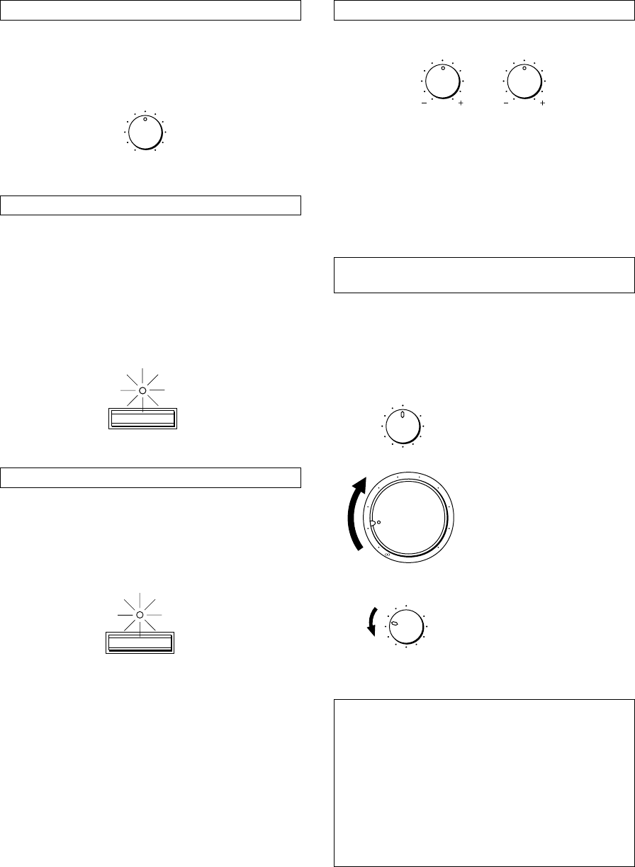
Adjusting the BASS and TREBLE controls
BASS: Turn this knob clockwise to increase (or counter-
clockwise to decrease) the low frequency
response.
TREBLE: Turn this knob clockwise to increase (or counter
clockwise to decrease) the high frequency
response.
Adjusting the continuously variable
LOUDNESS control
This control compensates for the human ears’ loss of
sensitivity to high and low-frequency ranges at low volume.
This control is adjustable to retain full tonal range at any
volume level.
1
Set to the “FLAT” position.
2
Set to the loudest listening level
that you would listen to.
3
Turn until the desired volume is
obtained.
WARNING
If the CD/DVD DIRECT AMP switch or PURE DIRECT
switch is pressed to turn it on with the LOUDNESS
control set at a certain level, the sound will suddenly
increase and may damage your ears or the speakers.
(The LOUDNESS control function may be bypassed.)
For this reason, be sure to press the CD/DVD DIRECT
AMP switch or PURE DIRECT switch after lowering the
volume or after checking that the LOUDNESS control is
properly set.
m Sound control
BALANCE
55
4
3
2
l0l
2
3
4
LR
BASS
55
4
3
2
l0l
2
3
4
TREBLE
55
4
3
2
l0l
2
3
4
CD/DVD DIRECT AMP
PURE DIRECT
LOUDNESS
567
4
3
2
lFLAT
I0
—30dB
9
8
l6
20
28
40
60
l2
8
4
2
0
–dB
LOUDNESS
567
4
3
2
lFLAT
I0
—30dB
9
8

English
E-13
Problem
The unit cannot be turned on or
turns off suddenly soon after the
power is turned on.
This unit does not work normally.
No sound.
The sound suddenly goes off.
Only one of the speakers
produces the sound.
There is a lack of bass and no
ambience.
Sound “hums”.
The volume level is low while
playing a record.
The volume level cannot be
increased, or sound is distorted.
The sound is degraded when
listening with the headphones
connected to the compact disc
player or tape deck that are
connected with this unit.
Sound level is low.
The input source cannot be
changed, though the INPUT
selector is turned.
Using the BASS, TREBLE,
BALANCE and LOUDNESS
controls does not affect the tone.
The remote control does not
work.
The remote control does not
function properly.
What to Do
Firmly plug in the power cord.
Set the switch to either end when this
unit is off.
Turn off this unit by pressing the
POWER switch. After about 30 seconds
have passed, turn on this unit and
operate this unit again.
Connect the cords properly. If the
problem persists, the cords may be
defective.
Select an appropriate input source with
the INPUT selector.
Set the corresponding SPEAKERS
switch to the ON position.
Secure the connections.
Turn off this unit by pressing the
POWER switch, and then turn this unit
on to reset the protection circuit.
Adjust it to the appropriate position.
Connect the cords properly. If the
problem persists, the cords may be
defective.
Connect the speaker wires in the
correct phase (+ and –).
Firmly connect the audio plugs. If the
problem persists, the cords may be
defective.
Make the GND connection between the
turntable and this unit.
The turntable should be connected to
this unit through the MC head amplifier.
Turn on the power to the component.
Turn on the power to this unit.
Set the LOUDNESS control to the FLAT
position.
Switch off the CD/DVD DIRECT AMP
switch.
The CD/DVD DIRECT AMP switch or
PURE DIRECT switch must be
switched OFF to use those controls.
Replace the batteries with new ones.
The remote control will function from a
maximum range of 6 meters and no
more than 30 degrees off-axis from the
front panel.
Reposition of the main unit.
Cause
Power cord is not plugged in nor
completely inserted.
The IMPEDANCE SELECTOR switch on
the rear panel is not set to either end.
There is an influence of strong external
noise (lightning, excessive static
electricity, etc.) or a misoperation on this
unit while using this unit.
Incorrect output cord connections.
Appropriate input source is not selected.
The SPEAKERS switches are not set
properly.
Speaker connections are not secure.
The protection circuit has been activated
because of short circuit etc.
Incorrect setting of the BALANCE
control.
Incorrect cord connections.
The + and – wires are connected in
reverse at the amplifier or speakers.
Incorrect cord connections.
No connection from the turntable to the
GND terminal.
The record is being played on a
turntable with an MC cartridge.
The component connected to the TAPE
OUT or MD OUT terminals of this unit is
turned off.
This unit is turned off or in the standby
mode.
The LOUDNESS control is functioning.
The CD/DVD DIRECT AMP switch is
ON.
The CD/DVD DIRECT AMP switch or
PURE DIRECT switch is ON.
The batteries of this remote control are
weak.
Wrong distance or angle.
Direct sunlight or lighting (of an inverter
type fluorescent lamp etc.) is striking the
remote control sensor of the main unit.
TROUBLESHOOTING
Refer to the chart below when this unit does not function properly. If the problem you are experiencing is not listed below or if
the instructions given below do not help, disconnect the power cord and contact your authorized YAMAHA dealer or service
center.

E-14
SPECIFICATIONS
Power Section
Minimum RMS Output Power
8Ω, 20 Hz to 20 kHz, 0.015% THD ................ 100W+100W
Maximum Output Power (EIAJ)
(1 kHz, 10% THD)
8/6Ω ........................................................................ 145/170W
Dynamic Power (IHF)
8/6/4/2Ω............................................... 140/170/220/290W
DIN Standard Output Power
(4Ω, 1 kHz, 0.7% THD) ................................................ 155W
IEC Output Power (8Ω, 1 kHz, 0.015% THD) .............. 110W
Power Band Width
8Ω, 50W, 0.03% THD ............................... 10 Hz to 50 kHz
Damping Factor
8Ω, 20 Hz to 20 kHz ..................................................... 320
Frequency Response .................... 20 Hz to 20 kHz50.5 dB
20 Hz to 100 kHz +0.5, –3 dB
Total Harmonic Distortion (20 Hz to 20 kHz)
CD/DVD to SP OUT (8Ω, 50W) ..............................0.008%
Signal-to-Noise Ratio (IHF-A Network)
CD/DVD (Input Shorted, CD/DVD DIRECT AMP: ON)
............................................................................... 110 dB
PHONO (MM)
(Input Shorted) ........................................................ 92 dB
Residual Noise (IHF-A Network)
CD/DVD DIRECT AMP: ON..................................... 35 µV
Control Section
Input Sensitivity/Impedance
CD/DVD, etc. ............................................... 150 mV/47 kΩ
PHONO (MM) ...............................................2.5 mV/47 kΩ
Output Level
PRE OUT............................................................ 1V/1.2 kΩ
REC OUT ................................................... 150 mV/0.6 kΩ
Headphone Output .............................................0.33V/680Ω
Channel Separation (1 kHz/10 kHz)
CD/DVD (Input 5.1 kΩ Terminated) ................ 65 dB/50 dB
Tone Control Characteristics
BASS ........................................................ 510 dB (20 Hz)
TREBLE.................................................. 510 dB (20 kHz)
Continuous LOUDNESS Control
Attenuation ................................................ –30 dB (1 kHz)
General
Power Supply
[U.S.A. and Canada models] .................... AC 120V, 60 Hz
[Europe and U.K. models] ......................... AC 230V, 50 Hz
[Australia model] ....................................... AC 240V, 50 Hz
[China and General models]
........................................ AC 110/120/220/240V, 60/50 Hz
Power Consumption ...................................... Approx. 220W
AC Outlets
3 SWITCHED OUTLETS
[U.S.A., Canada, Europe, China and General models]
............................................................... 100W max. total
1 SWITCHED OUTLET
[U.K. and Australia models] .................... 100W max. total
Dimensions (W x H x D) ....................... 435 x 151 x 396 mm
(17-1/8” x 5-15/16” x 15-9/16”)
Weight ................................................ 10.6 kg (23 lbs. 5 oz.)
Accessories .................................................. Remote control
Batteries
Specifications subject to change without notice.

Français
F-1
Nous vous remercions d’ avoir porté votre choix sur cet amplificateur stéréo YAMAHA.
CARACTERISTIQUES
vPuissance de sortie RMS de 100W + 100W (8Ω), distorsion harmonique totale de 0,015%,
20–20.000 Hz
vGrande puissance dynamique, entraînement à impédance faible
vCommande de compensation physiologique continuellement variable (LOUDNESS)
vInterrupteur CD/DVD DIRECT AMP utilisé pour obtenir le son CD et DVD le plus fidèle
vInterrupteur PURE DIRECT utilisé pour la reproduction la plus fidèle du son d’origine
vSélecteur REC OUT indépendant de la sélection de la source d’entrée
vBornes PRE OUT/MAIN IN pour raccorder un égaliseur graphique, un processeur de son
ambiophonique, etc.
vFonctionnement par télécommande
TABLES DE MATIERES
DEBALLAGE ........................................................................................................... IV
CARACTERISTIQUES...............................................................................................1
PRECAUTION D’USAGE...........................................................................................2
REMARQUES CONCERNANT LA TELECOMMANDE .............................................3
LES COMMANDES ET LEURS FONCTIONS ...........................................................4
RACCORDEMENTS ..................................................................................................7
FONCTIONNEMENT ...............................................................................................10
EN CAS DE DIFFICULTE ........................................................................................13
CARACTERISTIQUES TECHNIQUES ....................................................................14
F-2
1. Afin d’obtenir les meilleures performances de cet
appareil, lire attentivement ce manuel et le conserver
soigneusement pour pouvoir s’y référer ultérieurement.
2. Installer l’appareil dans un endroit frais, sec et propre –
le tenir éloigné des fenêtres et de toute source de
chaleur, ainsi que d’endroits où les vibrations, la
poussière, l’humidité ou le froid sont excessifs. Eviter
la présence de sources de bourdonnement
(transformateurs, moteurs). Pour prévenir tout risque
d’incendie ou d’électrocution, ne pas exposer l’appareil
à la pluie ou à une forte humidité.
3. Ne jamais ouvrir le coffret. Si un objet pénètre dans
l’appareil, contacter son revendeur.
4. Ne pas forcer les commutateurs, les touches ou les
câbles de raccordement.
Lors du déplacement de l’appareil, d’abord débrancher
la prise d’alimentation et les câbles le raccordant à
d’autres appareils. Ne jamais tirer sur les cordons.
5. Les ouvertures pratiquées sur le couvercle de
l’appareil assurent une ventilation adéquate de
l’appareil. Si ces ouvertures sont bouchées, la
température va s’élever rapidement à l’intérieur de
l’appareil; par conséquent, éviter de placer des objets
sur ces ouvertures. Installer l’appareil dans un endroit
suffisamment ventilé pour éviter tout risque d’incendie
ou de dommages.
<Modèles pour l’Europe, le Royaume-Uni et la
Chine seulement>
Veiller à laisser un espace d’au moins 20 cm derrière,
20 cm sur les deux côtés et 30 cm au-dessus du
panneau supérieur de l’appareil pour éviter tout risque
d’incendie ou de dommages.
6. Respecter la tension indiquée sur l’unité. Le
fonctionnement sur une tension plus élevée est
dangereux et risque de provoquer un incendie ou
d’autres accidents. YAMAHA ne sera pas tenu pour
responsable des dommages causés par le non-respect
de la tension spécifiée.
7. Toujours régler la commande de volume sur “∞” avant
de commencer la lecture d’une source audio.
Augmenter petit à petit le volume jusqu’à un niveau
adéquat une fois que la lecture a commencé.
8. Ne pas essayer de nettoyer l’appareil avec des diluants
chimiques, ceci endommagerait le fini. Utiliser un
chiffon propre et sec.
9. Bien lire la section “EN CAS DE DIFFICULTE”
concernant les erreurs de fonctionnement communes
avant de conclure que votre appareil est en panne.
10. Lorsqu’on prévoit de ne pas utiliser cet appareil
pendant longtemps (pendant les vacances, par
exemple), débrancher le cordon d’alimentation CA de
la prise murale.
11.
Pour prévenir tout dégât dû à la foudre, débrancher la
prise d’alimentation CA en cas d’orage.
12. Mise à la terre ou polarisation – Prendre les
précautions nécessaires afin de préserver une mise à
la terre et une polarisation correctes de l’appareil.
13. La consommation de puissance de tout appareil audio
branché à la prise CA du panneau arrière ne doit pas
dépasser la puissance nominale spécifiée à cette
prise.
14.
VOLTAGE SELECTOR (Sélecteur de tension)
(modèles pour la Chine et général seulement)
Le sélecteur de tension sur le panneau arrière de
cet appareil doit être réglé sur la tension locale
AVANT de brancher l’appareil sur une prise de
courant CA.
Les tensions sont de 110/120/220/240V CA 50/60 Hz.
Lorsque cet appareil est mis hors tension en appuyant
sur l’interrupteur STANDBY/ON du panneau avant ou de
la télécommande, le témoin STANDBY du panneau
avant s’allume. Cet état est appelé mode veille. Dans ce
mode, l’appareil consomme une faible quantité de
courant. L’alimentation électrique de cet appareil est
coupée complètement de la ligne d’alimentation CA
seulement lorsqu’on a mis l’interrupteur POWER du
panneau avant sur la position OFF ou qu’on a
débranché le cordon d’alimentation CA.
POUR LES CONSOMMATEURS CANADIENS
Pour eviter les chocs electriques, introduire la lame la
plus large de la fiche dans la borne correspondante de
la prise et pousser jusqu’au fond.
Cet appareil numérique de la classe B est conforme à la
norme NMB-003 du Canada.
ATTENTION
Ne pas changer pas le réglage de l’interrupteur
IMPEDANCE SELECTOR lorsque l’amplificateur est
sous tension, car cela risquerait d’endommager
l’appareil.
Si cet appareil ne se met pas sous tension quand
l’interrupteur POWER est actionné:
L’interrupteur IMPEDANCE SELECTOR n’est pas réglé
sur une position ou l’autre. Le pousser à fond dans un
sens ou l’autre lorsque cet appareil est mis
complètement hors tension.
PRECAUTION D’USAGE: Tenir compte des precautions ci-dessous
avant de faire fonctionner l’appareil.
(Modèle pour les Etats-Unis)
IMPEDANCE SELECTOR
A
B
CAUTION
SEE INSTRUCTION MANUAL FOR CORRECT SETTING.
IMPEDANCE SELECTOR
SET BEFORE POWER ON
A OR B : 6
Ω
MIN. /SPEAKER
A B : I2
Ω
MIN. /SPEAKER
A OR B : 4
Ω
MIN. /SPEAKER
A B : 8
Ω
MIN. /SPEAKER
SWITCHED
I20V 60Hz
l00W MAX. TOTAL
MAINS
R
R L
L
L
SPEAKERS
AC OUTLETS
Français
F-3
Portée de fonctionnement de la télécommande
Remarques
●En outre, veiller à ce qu’il n’y ait aucun obstacle entre la
télécommande et l’appareil.
●Ne pas exposer le capteur de la télécommande à une
forte lumière (provenant d’une lampe fluorescente de
type inverseur, etc.). Sinon, la télécommande risquera de
ne pas fonctionner correctement. Si besoin est,
positionner l’appareil principal de manière qu’il ne reçoive
pas un éclairage trop direct.
REMARQUES CONCERNANT LA TELECOMMANDE
Mise en place des piles
Etant donné que la télécommande servira à commander de
nombreuses fonctions de commande de cet appareil, il est
conseillé de commencer par mettre les piles fournies en
place.
1. Retourner la télécommande et retirer le couvercle du
compartiment des piles en le faisant glisser dans le sens
indiqué par la flèche.
2. Introduire les piles (format AA, R6, UM-3), en respectant
les indications de polarité situées à l’intérieur du
compartiment des piles.
3. Remettre le couvercle du compartiment en place.
Remplacement de piles
Si lorsque l’on utilise la télécommande il est nécessaire de
la rapprocher de l’appareil, les piles sont sans doute
déchargées. Dans ce cas, remplacer les deux piles par des
neuves.
Remarques
●Utiliser des piles AA, R6, UM-3.
●Veiller à ce que les polarités soient respectées. (Voir
l’illustration se trouvant dans le compartiment des piles.)
●Lorsque l’on n’utilise pas la télécommande pendant un
certain temps, retirer les piles de la télécommande.
●Si les piles fuient, les jeter immédiatement. Ne pas
toucher l’électrolyte et éviter son contact avec des
vêtements, etc. Nettoyer soigneusement le
compartiment des piles avant de mettre en place des
piles neuves.
2
1
3
30°
30°
Capteur de signaux
de télécommande
Portée de 6 mètres
(19,7 ft.) environ
F-4
1POWER
Enfoncer cet interrupteur (ON) pour utiliser cet
appareil. Dans cet état, on peut mettre cet appareil
sous tension ou en mode veille en appuyant sur
STANDBY/ON. Appuyer sur cet interrupteur pour le
faire sortir (position OFF) afin de couper complètement
l’alimentation électrique de cet appareil de la ligne
d’alimentation CA.
2Témoin veille (STANDBY)
S’allume seulement lorsque l’appareil est en mode
veille.
3Interrupteur de veille/marche (STANDBY/ON)
Le presser pour mettre cet appareil en marche.
Presser à nouveau cet interrupteur pour mettre cet
appareil en mode veille.
* Cet interrupteur peut être utilisé seulement lorsque
POWER est mis sur la position ON.
Mode veille
Cet appareil continue à consommer une faible
quantité de courant dans ce mode, de manière à être
prêt à recevoir les signaux infrarouge de la
télécommande.
PANNEAU AVANT
LES COMMANDES ET LEURS FONCTIONS
NATURAL SOUND STEREO AMPLIFIER
AX–596
VOLUME
l6
20
28
40
60
l2
8
4
2
0
–dB
PHONES
BASS
55
4
3
2
l0l
2
3
4
TREBLE
55
4
3
2
l0l
2
3
4
BALANCE
55
4
3
2
l0l
2
3
4
LR
SPEAKERS
A
ON OFF
B
STANDBY/ON
POWER
ON OFF
STANDBY
INPUT
PURE DIRECT CD/DVD DIRECT AMP
AUX PHONOTUNERCD/DVDTAPEMD
LOUDNESS
567
4
3
2
lFLAT
I0
—30dB
9
8
REC OUT
CD/DVD
TUNER
PHONO
TAPE
MD
AUX
456321
789 A B C DFE0
4Témoins de source d’entrée
Le témoin de la source d’entrée actuellement
sélectionnée s’allume.
5Interrupteur et témoin de son direct pur (PURE
DIRECT)
Lorsqu’on appuie sur cet interrupteur, le témoin situé
au-dessus de celui-ci s’allume. Cette fonction permet
d’effectuer l’écoute avec le son le plus pur possible.
(Pour plus de détails, se reporter à la page 12.)
Appuyer à nouveau sur cet interrupteur pour annuler
cette fonction.
6Interrupteur et témoin d’amplification directe du
disque compact/DVD (CD/DVD DIRECT AMP)
Appuyer sur cet interrupteur pour écouter un disque
compact ou un DVD avec le son le plus pur possible
avec cette fonction. (Pour plus de détails, se reporter à
la page 12.) Appuyer à nouveau sur cet interrupteur
pour annuler cette fonction.
7Capteur de télécommande
Il reçoit les signaux transmis par la télécommande.

Français
F-5
8Prise de casque d’écoute (PHONES)
Pour effectuer une écoute au casque, brancher le
casque d’écoute à la prise pour casque (PHONES) et
régler les deux interrupteurs d’enceintes SPEAKERS
A et B sur la position OFF.
9Interrupteurs d’enceintes (SPEAKERS)
Enfoncer en position rentrée (ON) l’interrupteur A ou B
(ou les deux) pour les enceintes que l’on utilisera.
Enfoncer à nouveau et relâcher en position sortie
(OFF) l’interrupteur des enceintes que l’on n’utilise
pas.
0Commandes de tonalité
Commande des basses (BASS)
Tourner ce bouton pour augmenter ou diminuer la
réponse en basses fréquences. La position 0
correspond à une réponse neutre.
Commande des aigus (TREBLE)
Tourner ce bouton pour augmenter ou diminuer la
réponse en hautes fréquences. La position 0
correspond à une réponse neutre.
ACommande de l’équilibre sonore (BALANCE)
L’équilibre des sons entre les enceintes gauche et
droite peut être réglé pour compenser les déséquilibres
provoqués par un emplacement particulier des
enceintes ou une disposition particulière de la pièce
d’écoute.
BCommande de compensation physiologique
(LOUDNESS)
Elle permet de compenser la perte de sensibilité de
l’oreille pour les fréquences basses et élevées lors
d’une écoute à faible volume. (Pour plus de détails, se
reporter à la page 12.)
CSélecteur de sortie d’enregistrement (REC OUT)
Tourner ce sélecteur pour sélectionner la source pour
enregistreur de minidisc ou une platine cassette. Ce
réglage est indépendant du réglage de INPUT, et donc
cette fonction permet d’enregistrer la source
sélectionnée tout en écoutant une autre source.
DCouvercle avant
Pour plus de détails concernant l’ouverture et la
fermeture du couvercle avant, se reporter à l’intérieur
du couvercle avant.
ESélecteur d’entrée (INPUT)
Tourner ce bouton pour sélectionner la source d’entrée.
La source sélectionnée sera indiquée par le témoin de
source d’entrée correspondant allumé.
FCommande du niveau de volume sonore (VOLUME)
Tourner ce bouton pour augmenter ou diminuer le
niveau du volume.
(Le niveau REC OUT n’est pas affecté.)
PHONES
PHONES
F-6
Pour commander cet appareil
1STANDBY/ON
Appuyer sur cette touche pour mettre cet appareil sous
tension ou en mode veille.
Cet interrupteur peut être utilisé seulement lorsque
l’interrupteur POWER est mis sur la position ON.
Mode veille
Dans cet état, cet appareil consomme une très
faible quantité de courant lui permettant de recevoir
les signaux infrarouge de la télécommande.
2Touches de sélection d’entrée
Appuyer sur une touche pour sélectionner la source
d’entrée.
3Touches d’augmentation/diminution de volume
sonore (VOLUME +/–)
Appuyer sur ces touches pour augmenter ou diminuer
le volume.
Pour la commande des autres appareils
Remarque
Les fonctions des touches commandant d’autres
appareils YAMAHA sont les mêmes que les touches
correspondantes se trouvant sur ces appareils. Pour
plus de détails, se reporter au mode d’emploi de ces
appareils.
1Touches de platine cassette
Ces touches commandent les platines cassette.
* Les touches DIR A, B et A/B concernent les platines
deux cassettes seulement.
* Lorsqu’on appuie sur DIR A, le sens de défilement
de la bande sera inversé sur une seule platine
cassette avec la fonction d’inversion automatique.
2Touches de lecteur de disque compact
Ces touches commandent les lecteurs de disque
compact.
* La touche DISC SKIP est utilisée pour les
changeurs de disques compacts seulement.
3Touches de tuner
Ces touches permettent de commander les tuners.
PRESET +: Appuyer sur cette touche pour
sélectionner le numéro de station
mémorisée suivant.
PRESET –: Appuyer sur cette touche pour
sélectionner le numéro de station
mémorisée précédent.
A/B/C/D/E: Appuyer sur cette touche pour
sélectionner les numéros de stations
mémorisées des groupes correspondants
(A à E).
TELECOMMANDE
La télécommande permet de commander les fonctions les plus utilisées de l’appareil principal. Si le lecteur de disque
compact, le tuner, la platine cassette, etc. raccordés à cet appareil sont des appareils YAMAHA compatibles avec le
fonctionnement télécommande, il sera aussi possible de commander leurs diverses fonctions avec cette télécommande.
CD/DVD
TAPE
MD
TUNERPHONO
AUX
+
–
A/B/C/D/E
DECK
A/B
DIR BDIR A
TAPE
DISC SKIP
CD
STANDBY/ON
PRESET
+–
TUNER
VOLUME
2
3
11
2
3
1
Français
F-7
GND
PHONO
2
TUNER
3
IN
(PLAY)
4
TAPE
OUT
(REC)
3
IN
(PLAY)
4
OUT
(REC)
MD
AUX
A
B
CAUTION
SEE INSTRUCTION MANUAL FOR CORRECT SETTING.
IMPEDANCE SELECTOR
SET BEFORE POWER ON
A OR B : 6
Ω
MIN. /SPEAKER
A B : I2
Ω
MIN. /SPEAKER
A OR B : 4
Ω
MIN. /SPEAKER
A B : 8
Ω
MIN. /SPEAKER
SWITCHED
I20V 60Hz
l00W MAX. TOTAL
MAINS
R
R L
L
RLRL
RL
RL
1
CD/DVD
PRE
OUT
MAIN
IN
AUDIO SIGNAL COUPLER SPEAKERS
AC OUTLETS
OUTPUT
GND
OUTPUT
AUDIO OUT
LINE OUT
LINE IN
AUDIO OUT
LINE OUT
LINE IN
RACCORDEMENTS
Attention: Brancher cet appareil et les autres composants après avoir accompli tous les
raccordements.
●Tous les branchements doivent être effectués correctement, c’est-à-dire entre “L” (gauche) et “L”, entre “R” (droite) et “R”,
entre “+” et “+” et entre “–” et “–”. Voir aussi le mode d’emploi de chacun des appareils.
●Utiliser des câbles à fiche à broche de type RCA pour les appareils audio/vidéo, sauf pour les enceintes.
●Les bornes de sortie (ou d’entrée) des appareils audio/vidéo YAMAHA numérotés 1, 2, 3, 4, etc. sur le panneau arrière
doivent être raccordées aux bornes portant les mêmes numéros sur cet appareil.
Platine tourne-disque
Enregistreur de
minidisc, etc.
Platine cassette
Gauche
Enceintes A
Droite
Lecteur de disque
compact ou DVD
Tuner
Lecteur de cassette
vidéo, etc. Enceintes B
Droite Gauche
Vers une prise
CA
(Modèle pour les
Etats-Unis)
: Indique la direction des signaux
*1, *2, *3, *4: Voir les descriptions à la page 9.
*3
*1*2
*4
Remarque
Ces prises sont destinées au raccordement d’une
platine de lecture équipée d’une cellule à aimant mobile
(MM) ou à bobine mobile (MC) délivrant une tension
élevée. Si la cellule à bobine mobile qui est montée sur
la platine ne fournit pas une tension élevée, utilisez un
transformateur-élévateur ou un amplificateur pour cellule
MC.
PHONO
3
IN
(PLAY)
4
TAPE
OUT
(REC)
RL
F-8
m Raccordement des enceintes
Raccorder les bornes SPEAKERS aux enceintes avec des
câbles de section adéquate (aussi courts que possible). Si
les branchements sont mal faits, aucun son ne sera
entendu aux enceintes. Respecter la polarité des câbles de
raccord (repères + et –). Si les polarités sont inversées, le
son perçu manquera de naturel et de profondeur de
basses.
Branchement:
Bornes SPEAKERS A
Rouge: positif (+)
Noir: négatif (–)
1Desserrer le bouton.
2Introduire le câble dénudé.
(Enlever environ 10 mm (3/8”) de gaîne pour dénuder
le câble.)
3Revisser le bouton et fixer le câble.
12
3
●Une ou deux paires d’enceintes peuvent être branchées
à cet appareil. Si I’on utilise une seule paire d’enceintes,
choisir les bornes d’enceintes (SPEAKERS) A ou B.
●Utiliser des enceintes dont l’impédance correspond à la
valeur indiquée à l’arrière de l’appareil.
Précaution
Veiller à ce que les portions dénudées des câbles ne se
touchent pas et n’entrent pas en contact avec des
pièces métalliques de cet appareil. Ceci pourrait
endommager l’appareil et/ou les enceintes.
Bornes SPEAKERS B
Rouge: positif (+)
Noir: négatif (–)
1Desserrer le bouton.
2Introduire le câble
dénudé.
(Enlever environ 10
mm (3/8”) de gaîne
pour dénuder le
câble.)
3Revisser le bouton
et fixer le câble.
<Modèles pour les Etats-Unis, le Canada, l’Australie,
la Chine et général seulement>
Il est également possible d’utiliser des fiches banane.
1Serrer le bouton de la borne.
2Il suffit d’introduire la fiche banane dans la borne.
1
2
1
2
3
Français
F-9
Interrupteur IMPEDANCE SELECTOR
ATTENTION
Ne pas changer pas le réglage de l’interrupteur
IMPEDANCE SELECTOR lorsque l’amplificateur est
sous tension, car cela risquerait d’endommager
l’appareil.
Si cet appareil ne se met pas sous tension quand
l’interrupteur POWER est actionné:
L’interrupteur IMPEDANCE SELECTOR n’est pas réglé
sur une position ou l’autre. Le pousser à fond dans un
sens ou l’autre lorsque cet appareil est mis
complètement hors tension.
Sélectionner la position
correspondant à la
configuration des
d’enceintes utilisées.
(Position gauche)
Si l’on utilise une seule paire d’enceintes,
l’impédance de chaque enceinte doit être de 4Ω ou
plus.
Si l’on utilise deux paires d’enceintes, l’impédance de
chaque enceinte doit être de 8Ω ou plus.
(Position droite)
Si l’on utilise une seule paire d’enceintes,
l’impédance de chaque enceinte doit être de 6Ω ou
plus.
Si l’on utilise deux paires d’enceintes, l’impédance de
chaque enceinte doit être de 12Ω ou plus.
Prise(s) CA [AC OUTLETS (SWITCHED)]
(Modèles pour les Etats-Unis, le Canada, l’Europe,
la Chine et général) .............................. 3 prises commutées
(Modèles pour le Royaume-Uni et l’Australie)
................................................................. 1 prise commutée
Brancher à ces prises les cordons d’alimentation de vos
appareils.
L’alimentation aux prises commutées SWITCHED est
contrôlée par l’interrupteur POWER ou STANDBY/ON de
cet appareil. En d’autres termes, lorsque l’appareil est mis
sous tension, tous les appareils qui sont raccordés à ces
prises seront aussi sous tension.
La puissance totale maximum (puissance cumulée de tous
les appareils branchés) autorisée aux prises commutées
SWITCHED AC OUTLET(S) est de 100W.
m Parties du panneau arrière
Borne de mise à la terre (GND)
(Pour le tourne-disque)
En branchant le câble de mise à la terre d’un tourne-disque
à la borne de mise à la terre (GND), on obtient en général
une réduction du ronflement. Cependant, dans certains cas,
les résultats sont meilleurs si le câble de mise à la terre
reste débranché.
Bornes PRE OUT/MAIN IN
En retirant les cavaliers, cet appareil peut fonctionner
indépendamment en tant qu’amplificateur de contrôle et
amplificateur de puissance. Ces bornes servent à
connecter un système de traitement des signaux tel qu’un
égaliseur ou un processeur sonore ambiophonique à cet
appareil.
Si un tel appareil extérieur est connecté entre ces bornes, il
est possible d’utiliser la commande VOLUME de cet
appareil pour effectuer un réglage global du niveau sonore.
Pour connecter un tel appareil extérieur, retirez les cavaliers
des bornes PRE OUT/MAIN IN et raccordez les bornes
d’entrée de l’appareil aux bornes PRE OUT et les bornes
de sortie aux bornes MAIN IN. Pour plus de détails,
reportez-vous au mode d’emploi de l’appareil devant être
connecté.
Remarques
●Si l’on n’utilise pas les bornes PRE OUT/MAIN IN, ne
jamais retirer les cavaliers de ces bornes. Si on les retire,
aucun son ne sera émis.
●Si l’on utilise cet appareil avec un appareil extérieur
raccordé entre les bornes PRE OUT et MAIN IN, veiller à
ce que l’interrupteur CD/DVD DIRECT AMP et
l’interrupteur PURE DIRECT du panneau avant soient
placés sur la position d’arrêt.
●Si l’on utilise cet appareil comme amplificateur, raccorder
les bornes de sortie d’un amplificateur de contrôle
externe, etc. aux bornes MAIN IN de cet appareil. Dans
ce cas, les commandes de l’appareil ne fonctionneront
pas, à l’exception de la prise PHONES et des
interrupteurs SPEAKERS. Utiliser les commandes de
l’amplificateur de contrôle extérieur pour faire le réglage
du volume, etc.
*1
*2
*3
IMPEDANCE SELECTOR
SET BEFORE POWER ON
A OR B : 6
Ω
MIN. /SPEAKER
A B : I2
Ω
MIN. /SPEAKER
A OR B : 4
Ω
MIN. /SPEAKER
A B : 8
Ω
MIN. /SPEAKER
GND
PHONO
2
TUNER
3
IN
(PLAY)
4
TAPE
OUT
(REC)
3
IN
(PLAY)
4
OUT
(REC)
MD
AUX
B
R
R
L
RLRL
RL
RL
1
CD/DVD
PRE
OUT
MAIN
IN
AUDIO SIGNAL COUPLER
*4
F-10
VOLUME
l6
20
28
40
60
l2
8
4
2
0
–dB
PHONES
BASS
55
4
3
2
l0l
2
3
4
TREBLE
55
4
3
2
l0l
2
3
4
BALANCE
55
4
3
2
l0l
2
3
4
LR
SPEAKERS
A
ON OFF
B
STANDBY/ON
POWER
ON OFF
STANDBY
INPUT
CD/DVD DIRECT AMP
AUX PHONOTUNERCD/DVDTAPEMD
LOUDNESS
567
4
3
2
lFLAT
I0
—30dB
9
8
REC OUT
CD/DVD
TUNER
PHONO
TAPE
MD
AUX
PURE DIRECT
2
4
3
85 4
1, 7
STANDBY 8
1
Régler à la position “∞”.
2Enfoncer POWER (position ON).
3Si le témoin STANDBY est allumé, appuyer sur
STANDBY/ON pour établir l’alimentation électrique.
(Le témoin STANDBY s’éteint.)
4Sélectionner la source d’entrée désirée.
Le témoin de la source sélectionnée s’allume.
5Sélectionner les enceintes A ou B.
* Il est possible de sélectionner les deux enceintes A et B.
* Veiller à ce que l’interrupteur IMPEDANCE SELECTOR
soit correctement réglé, comme indiqué à la page 9.
* Si l’on effectue l’écoute au casque, appuyer sur les
deux interrupteurs pour les faire sortir (position OFF).
6Enclencher la lecture sur la source.
7
Régler le volume.
8Régler la qualité de la tonalité en utilisant les
commandes BASS, TREBLE, BALANCE,
LOUDNESS, l’interrupteur CD/DVD DIRECT AMP
ou l’interrupteur PURE DIRECT. (Se reporter à la
page 12).
Après avoir utilisé cet appareil
Appuyer à nouveau sur STANDBY/ON pour faire passer cet
appareil au mode veille. (Le témoin STANDBY s’allume.)
Pour couper complètement l’alimentation
électrique de cet appareil de la ligne
d’alimentation CA
Appuyer sur POWER pour le faire sortir (position OFF).
FONCTIONNEMENT
m Reproduction d’une source
l6
20
28
40
60
l2
8
4
2
0
–dB
POWER
ON OFF
STANDBY
STANDBY/ON
+
–
CD/DVD
TAPE
MD
TUNERPHONO
AUX
+
–
STANDBY/ON
AUX PHONOTUNERCD/DVDTAPEMD
SPEAKERS
A
ON OFF
B
+
–
+
–
VOLUME
l6
20
28
40
60
l2
8
4
2
0
–dB
S’éteint.
POWER
STANDBY
Français
F-11
1Effectuer les étapes 1 à 3 de la section
“Reproduction d’une source” de la page 10.
2Sélectionner la source que l’on veut enregistrer.
3Enclencher la lecture sur la source.
4Sélectionner la source à l’aide du sélecteur INPUT
et régler le niveau de la commande VOLUME pour
vérifier l’émission du son.
VOLUME
l6
20
28
40
60
l2
8
4
2
0
–dB
PHONES
BASS
55
4
3
2
l0l
2
3
4
TREBLE
55
4
3
2
l0l
2
3
4
BALANCE
55
4
3
2
l0l
2
3
4
LR
SPEAKERS
A
ON OFF
B
STANDBY/ON
POWER
ON OFF
STANDBY
INPUT
CD/DVD DIRECT AMP
AUX PHONOTUNERCD/DVDTAPEMD
LOUDNESS
567
4
3
2
lFLAT
I0
—30dB
9
8
REC OUT
CD/DVD
TUNER
PHONO
TAPE
MD
AUX
PURE DIRECT
4, 6, 7
4
2
mEnregistrement d’une source sur une cassette (ou un minidisc)
5Enclencher l’enregistrement sur la platine cassette
(ou l’enregistreur de minidisc).
6Le son de l’enregistrement peut être contrôlé en
sélectionnant la platine cassette (ou l’enregistreur de
minidisc) à l’aide du sélecteur INPUT.
7Si l’on écoute une autre source en la sélectionnant à
l’aide du sélecteur INPUT, l’enregistrement ne sera
pas affecté.
REC OUT
CD/DVD
TUNER
PHONO
TAPE
MD
AUX
+
–
CD/DVD
TAPE
MD
TUNERPHONO
AUX
l6
20
28
40
60
l2
8
4
2
0
–dB
+
–
+
–
VOLUME
+
–
CD/DVD
TAPE
MD
TUNERPHONO
AUX
Remarques
●Les commandes VOLUME, BASS, TREBLE, BALANCE
et LOUDNESS, l’interrupteur CD/DVD DIRECT AMP et
l’interrupteur PURE DIRECT n’affectent pas
l’enregistrement.
●Vérifier les lois concernant les droits d’auteur en vigueur
dans le pays d’utilisation avant d’enregistrer des disques
phonographiques, des disques compacts, des émissions
radiodiffusées, etc. L’enregistrement de programmes
soumis à des droits d’auteur peut constituer une violation
de ces lois.
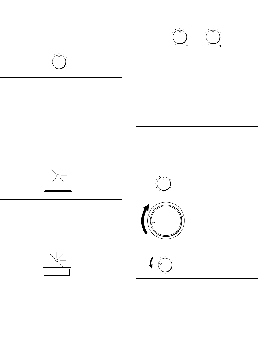
F-12
Réglage de la commande d’équilibre
(BALANCE)
Régler l’équilibre des sons entre les enceintes gauche et
droite pour compenser tout déséquilibre provoqué par un
emplacement particulier des enceintes ou une disposition
particulière de la pièce d’écoute.
Utilisation de l’interrupteur CD/DVD
DIRECT AMP
Il est possible d’obtenir le son le plus pur possible du lecteur
de disque compact ou de DVD en appuyant sur cet
interrupteur. Le témoin situé au-dessus de l’interrupteur
s’allume. Avec cette fonction en circuit, les signaux d’entrée
provenant du lecteur de disque compact ou de DVD sont
envoyés directement à l’amplificateur spécial incorporé pour
disque compact/DVD en contournant le sélecteur INPUT,
les commandes BASS, TREBLE, BALANCE, LOUDNESS
et les bornes PRE OUT/MAIN IN, puis sont ensuite
envoyés à l’amplificateur. Ce mode d’acheminement permet
d’obtenir le son le plus pur en éliminant toutes les
altérations des signaux de disque compact ou de DVD.
Utilisation de l’interrupteur PURE DIRECT
Il est possible d’obtenir le son le plus pur possible des
sources audio en appuyant sur cet interrupteur. Le témoin
situé au-dessus de l’interrupteur s’allume. Avec cette
fonction en circuit, les signaux audio contournent, les
commandes BASS, TREBLE, BALANCE, LOUDNESS et
les bornes PRE OUT/MAIN IN; les altérations des signaux
audio sont ainsi éliminées.
Remarques
●Si les interrupteurs CD/DVD DIRECT AMP et PURE
DIRECT sont tous deux en position “ON”, l’interrupteur
CD/DVD DIRECT AMP seulement fonctionnera.
●Si cet appareil est mis hors tension, le son pourra être
déformé lorsqu’on écoute une source avec un casque
d’écoute raccordé à un appareil raccordé extérieurement
tel qu’un lecteur de disque compact, une platine cassette,
etc.
●Si l’un quelconque des appareils extérieurs raccordés à
cet appareil est mis hors tension, le son pourra être
déformé lorsqu’on effectue la lecture d’une source sur un
autre appareil qui est aussi raccordé à cet appareil.
Réglage des commandes des basses
(BASS) et des aigus (TREBLE)
Basses (BASS) : Tourner ce bouton vers la droite pour
accentuer les sons de basse
fréquence, vers la gauche pour les
diminuer.
Aiguës (TREBLE) : Tourner ce bouton vers la droite pour
accentuer les sons de haute
fréquence, vers la gauche pour les
diminuer.
Réglage de la commande de compensation
physiologique continuellement variable
(LOUDNESS)
Lors d’une écoute à volume faible, cette commande
compense la perte de sensibilité de l’oreille humaine pour
les fréquences basses et élevées. Cette commande est
réglable afin de conserver une portée tonale étendue, quel
que soit le niveau de volume des sons.
1
Régler à la position “FLAT”.
2
Régler à son niveau d’écoute le
plues fort.
3
Tourner jusqu’à ce que le
volume désiré soit obtenu.
AVERTISSEMENT
Si l’on appuie sur l’interrupteur CD/DVD DIRECT AMP
ou sur l’interrupteur PURE DIRECT pour le mettre en
circuit avec la commande LOUDNESS réglée à un
certain niveau, le son augmentera brutalement et
risquera de vous abîmer les oreilles ou d’abîmer les
enceintes. (La fonction de la commande LOUDNESS
peut être contournée.) Pour cette raison, veiller à
appuyer sur l’interrupteur CD/DVD DIRECT AMP ou sur
l’interrupteur PURE DIRECT seulement après avoir
baissé le volume sonore ou après avoir vérifié que la
commande LOUDNESS est réglée correctement.
m Contrôle sonore
BALANCE
55
4
3
2
l0l
2
3
4
LR
BASS
55
4
3
2
l0l
2
3
4
TREBLE
55
4
3
2
l0l
2
3
4
CD/DVD DIRECT AMP
PURE DIRECT
LOUDNESS
567
4
3
2
lFLAT
I0
—30dB
9
8
l6
20
28
40
60
l2
8
4
2
0
–dB
LOUDNESS
567
4
3
2
lFLAT
I0
—30dB
9
8

Français
F-13
Probléme
L’appareil ne se met pas sous
tension ou se met soudain hors
tension après la mise sous
tension.
Cet appareil ne fonctionne pas
normalement.
Pas de son.
Le son se coupe soudainement.
Les sons ne sont émis que par
une seule enceinte.
Il y a une perte de basse et pas de
son d’ambiance.
Le son “bourdonne”.
Le niveau de volume est bas à la
lecture d’un disque.
Il est impossible d’augmenter le
niveau de volume, ou il y a une
distorsion du son.
Les sons se dégradent lorsqu’on
écoute avec un casque relié à un
lecteur de disque compact ou à
une platine cassette raccordés à
cet appareil.
Le volume sonore est faible.
Il est impossible de changer la
source d’entrée, bien que l’on
tourne le sélecteur INPUT.
Les commandes BASS, TREBLE,
BALANCE et LOUDNESS ne
fonctionnent pas.
La télécommande de fonctionne
pas.
La télécommande fonctionne mal.
Marche à suivre
Bien brancher le cordon d’alimentation
Placer l’interrupteur contre l’une ou
l’autre extrémité lorsque cet appareil
est hors tension.
Mettre cet appareil hors tension en
appuyant sur l’interrupteur POWER.
Après environ trente secondes,
remettre cet appareil sous tension et
utiliser à nouveau cet appareil.
Raccorder correctement les câbles. Si
le problème persiste, les câbles sont
peut-être en mauvais état.
Sélectionner une source d’entrée
correcte au moyen du sélecteur INPUT.
Régler l’interrupteur SPEAKERS
correspondant sur la position “ON”.
Effectuer des connexions correctes.
Mettre cet appareil hors tension en
appuyant sur l’interrupteur POWER
puis à nouveau en marche pour
remettre à zéro le circuit de protection.
Régler correctement la commande.
Raccorder correctement les câbles. Si
le probléme persiste, les câbles sont
peut-être en mauvais état.
Connecter les fils d’enceintes avec les
phases correctes (+ et –).
Raccorder fermement les prises audio.
Si le problème persiste, le câble est
peut-être en mauvais état.
Raccorder le tourne-disque à la borne
GND de cet appareil.
Raccorder le tourne-disque à l’appareil
par le biais de l’amplificateur à tête à
aimant mobile.
Mettre l’appareil concerné sous tension.
Mettre cet appareil sous tension.
Placer la commande LOUDNESS sur la
position FLAT (réponse plate).
Mettre l’interrupteur CD/DVD DIRECT
AMP sur la position “OFF”.
L’interrupteur CD/DVD DIRECT AMP ou
l’interrupteur PURE DIRECT doit être
placé sur la position “OFF” pour pouvoir
utiliser ces commandes.
Remplacer les piles.
La télécommande fonctionné à une
distance maximum de 6 mètres et dans
un angle de 30° s’ouvrant de part et
d’autre de l’axe dirigé vers le panneau
avant.
Changer la position de l’appareil
principal.
Cause
Le cordon d’alimentation n’est pas
branché ou ne l’est pas complètement.
L’interrupteur IMPEDANCE SELECTOR
situé sur le panneau arrière n’est pas
placé contre une des extrémités.
Il y a interférence de bruits extérieurs
puissants (orage, électricité statique
excessive, etc.) ou on a effectué une
opération erronée en utilisant cet
appareil.
Mauvais raccordement des câbles de
sortie.
Sélection d’entrée incorrecte.
Les interrupteurs SPEAKERS ne sont
pas correctement réglés.
Les connexions des enceintes ne sont
pas correctes.
Le circuit de protection s’est déclenché
dû à un court-circuit, etc.
La commande BALANCE n’est pas
correctement réglée.
Mauvais raccordement des câbles.
Les cordons + et – ont été inversés au
niveau de l’appareil ou des enceintes.
Mauvais raccordement des câbles.
Le tourne-disque n’est pas raccordé à la
borne GND.
Le disque est lu sur un tourne-disque
avec cellule à aimant mobile.
L’appareil branché aux bornes TAPE
OUT ou MD OUT de cet appareil est
hors tension.
Cet appareil est hors tension ou en
mode veille.
La fonction de compensation
physiologique (LOUDNESS) est activée.
L’interrupteur CD/DVD DIRECT AMP est
placé sur la position “ON”.
L’interrupteur CD/DVD DIRECT AMP ou
l’interrupteur PURE DIRECT est réglé
sur la position “ON”.
Les piles de cette télécommande sont
trop faibles.
Distance ou angle incorrect.
La télécommande de l’appareil principal est
exposée à la lumière directe du soleil ou à
un éclairage excessif (provenant d’une
lampe fluorescente à inverseur, etc.).
EN CAS DE DIFFICULTE
Se reporter au tableau ci-dessous lorsque l’appareil ne fonctionne pas correctement. Si le problème rencontré n’est pas décrit
ci-dessous ou si les instructions données ne suffisent pas à le résoudre, débrancher le cordon d’alimentation et s’adresser à
son concessionnaire ou son centre de service YAMAHA.

F-14
CARACTERISTIQUES TECHNIQUES
Section alimentation
Puissance de sortie minimum RMS
8Ω, 20 Hz à 20 kHz, 0,015% de DHT
....................................................................... 100W+100W
Puissance de sortie maximum (EIAJ)
(1 kHz, 10% de DHT)
8/6Ω........................................................................... 145/170W
Puissance dynamique (IHF)
8/6/4/2Ω............................................... 140/170/220/290W
Puissance de sortie standard DIN
(4Ω, 1 kHz, 0,7% de DHT) ........................................ 155W
Puissance de sortie IEC (8Ω, 1 kHz, 0,015% de DHT)
...................................................................................110W
Largeur de bande de puissance
8Ω, 50W, 0,03% de DHT ........................... 10 Hz à 50 kHz
Facteur d’amortissement
8Ω, 20 Hz à 20 kHz ...................................................... 320
Réponse en fréquence ................... 20 Hz à 20 kHz50,5 dB
20 Hz à 100 kHz`0,5, 13 dB
Distorsion harmonique totale (20 Hz à 20 kHz)
CD/DVD à SP OUT (8Ω, 50W) .............................. 0,008%
Rapport signal/bruit (IHF réseau A)
CD/DVD (Entrée court-circuitée, CD/DVD DIRECT
AMP: ON) ................................................................ 110 dB
PHONO (MM)
(Entrée court-circuitée) ............................................ 92 dB
Bruit résiduel (IHF réseau A)
CD/DVD DIRECT AMP: ON..................................... 35 µV
Section commandes
Sensibilité d’entrée/impédance
CD/DVD, etc. ................................................ 150 mV/47 kΩ
PHONO (MM) ...............................................2,5 mV/47 kΩ
Niveau de sortie
PRE OUT............................................................ 1V/1,2 kΩ
REC OUT ................................................... 150 mV/0,6 kΩ
Sortie de casque ................................................0,33V/680Ω
Séparation des canaux (1 kHz/10 kHz)
CD/DVD (Entrée terminée 5,1 kΩ) ................. 65 dB/50 dB
Caratéristiques de contrôle de la tonalité
Graves (BASS) ......................................... 510 dB (20 Hz)
Aiguës (TREBLE) ................................... 510 dB (20 kHz)
Commande de compensation physiologique continue
(LOUDNESS)
Atténuation ................................................. –30 dB (1 kHz)
Général
Alimentation
[Modèles pour les Etats-Unis et le Canada]
.................................................................. CA 120V, 60 Hz
[Modèles pour l’Europe et le Royaume-Uni]
.................................................................. CA 230V, 50 Hz
[Modèle pour l’Australie] ........................... CA 240V, 50 Hz
[Modèles pour la Chine et général]
......................................... CA 110/120/220/240V, 60/50 Hz
Consommation .............................................. Environ 220W
Prises CA
3 prises commutées
[Modèles pour les Etats-Unis, le Canada, l’Europe,
la Chine et général] ........................... 100W max. au total
1 prise commutée
[Modèles pour le Royaume-Uni et l’Australie]
.......................................................... 100W max. au total
Dimensions (L x H x P) ........................ 435 x 151 x 396 mm
(17-1/8” x 5-15/16” x 15-9/16”)
Poids .................................................. 10,6 kg (23 lbs. 5 oz.)
Accessoires .................................................. Télécommande
Piles
Caractéristiques techniques modifiables sans préavis.
YAMAHA ELECTRONICS CORPORATION, USA 6660 ORANGETHORPE AVE., BUENA PARK, CALIF. 90620, U.S.A.
YAMAHA CANADA MUSIC LTD. 135 MILNER AVE., SCARBOROUGH, ONTARIO M1S 3R1, CANADA
YAMAHA ELECTRONIK EUROPA G.m.b.H. SIEMENSSTR. 22-34, 25462 RELLINGEN BEI HAMBURG, F.R. OF GERMANY
YAMAHA ELECTRONIQUE FRANCE S.A. RUE AMBROISE CROIZAT BP70 CROISSY-BEAUBOURG 77312 MARNE-LA-VALLEE CEDEX02, FRANCE
YAMAHA ELECTRONICS (UK) LTD. YAMAHA HOUSE, 200 RICKMANSWORTH ROAD WATFORD, HERTS WD1 7JS, ENGLAND
YAMAHA SCANDINAVIA A.B. J A WETTERGRENS GATA 1, BOX 30053, 400 43 VÄSTRA FRÖLUNDA, SWEDEN
YAMAHA MUSIC AUSTRALIA PTY, LTD. 17-33 MARKET ST., SOUTH MELBOURNE, 3205 VIC., AUSTRALIA
Printed in Malaysia V576270-1
