Yamaha Dsp1D Installation Manual Optional Boards
Dsp1D-Installation-Manual yamaha-dsp1d-installation-manual-132882
DSP1D to the manual 412338c9-2c43-4550-b5e0-2fc75f7325b4
2014-12-13
: Yamaha Dsp1D-Installation-Manual yamaha-dsp1d-installation-manual-132882 pdf
Open the PDF directly: View PDF ![]() .
.
Page Count: 4
Optional Boards
for
DSP UNIT
Thank you for choosing the board for Yamaha DSP1D (DSP unit).
Ask an authorized Yamaha service engineer to install the board. Do not install the board yourself.
ここの度はヤマハ DSPユニットDSP1D用ボードをお 買 上げ いただき、ありがとうござ います 。
ボードの取付けは、必ずヤマハサービスエンジニアにご依頼ください。お客様ご自身では行なわないでください。
The following items are optional boards available for the DSP1D.
DSP1D用にオプションでお求めいただけるボードは次のとおりです。
INPUT DSP BOARD インプット DSPボードIDB1D
CONSOLE INTERFACE BOARD コンソールインタフェースボードCIB1D
ENGINE MANAGEMENT BOARD エンジンマネージメントボ ードEMB1D
PATCH DSP BOARD パッチD S PボードPDB1D
GROUP DSP BOARD グループDSPボードGDB1D
EFFECT DSP BOARD エフェクトDSPボードEDB1D
■Installing the board (For only an authorized Yamaha service engineers)
ボード装着手順(ヤマハサービスエンジニア用)
Before installing the board, be sure to turn off the power to the DSP1D and disconnect the power cord.
You need to remove the front cover of the DSP1D to install any board. To install the PDB1D board, you also need to remove the
left side cover.
ボードの装着作業は必ずDSP1D の電源スイッチを切り、電源コードを抜いてから行なってください。
パッチDSPボード PDB1D以外のボードの装着はユニット正面のカバーを取りはずして行ないます。PDB1Dボードの装着はさらに ユ ニット
左側面カバーのとりはずしが必要です。
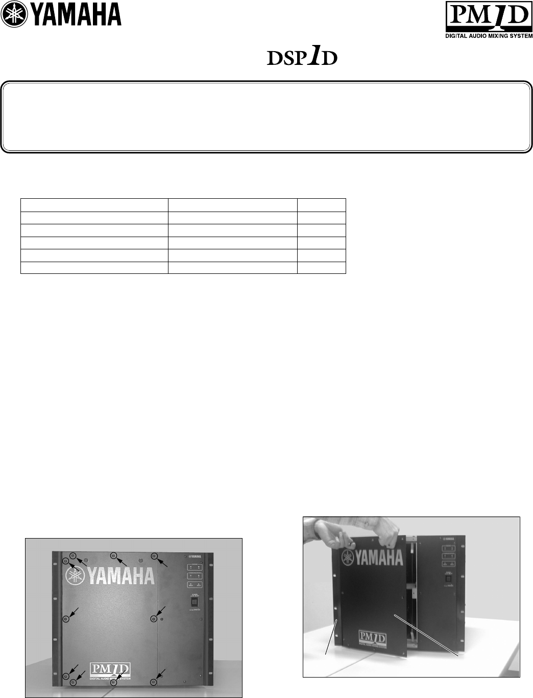
1. Remove ten screws as
shown in the picture. Do
not remove any other
screws. Keep the re-
moved screws in a safe
place since you will need
them to re-attach the
cover.
2. As shown in the picture,
remove the cover by
opening from the right
side to avoid damage to
the hardware on the left
side of the rack.
10ヶ所のネジをはずします。写
真に示した以外のネジははずさ
ないでください。また取りは ずし
たネジはカバーを再 び 取り付け
る際、必要ですので紛失しない
でください。
正面カバー
front cover
左側ラック金具
hardware on the left side of the rack
左側ラック金具を破損しないよ
う写真のように正面カバーを右
側から先に開けて取りはずしま
す。
2
ガイドレール
guide rail
6. Slide the board into the
slot along the upper and
lower guide rails.
The sliding position is la-
belled with the corre-
sponding board model
name.
保護バー
protect bar
保護バー
protect bar
3. Loosen two screws on the
protect bar. 保護バーの2ヶ所のネジを少し
ゆるめます。
4. Lift up the protect bar and
remove it. 写真のように保護バーを上に持
ち上げながらはずします。
5. If you are replacing the
PDB1D board and the
GDB1D board, remove
two connecting ribbon
cables.
PDB1DボードおよびGDB1D
ボードを交換の際は接続されて
いるフラットケーブ ルを 2 本 取り
はずします。
装着するスロット内 の 上と下 に
あるガイドレール に ボードを沿
わせてボードを挿入します。
各ボードの挿入位置はここに
ボードのモデル名がありますの
でこれに従ってください。
7. Press both edges of the
board firmly and slide the
board all the way into the
slot.
Reverse these steps to re-
install the protect bar and
the front cover.
写真のようにボードの両端を強
く押し ボ ードをスロットの 奥 に 確
実に差し込みます。
前述の手順の逆で保護バー、正
面カバーを再び取り付けてくだ
さい。
接続フラット
ケーブル
Connecting
the ribbon
cable
3
フラットケーブル
ribbon cables
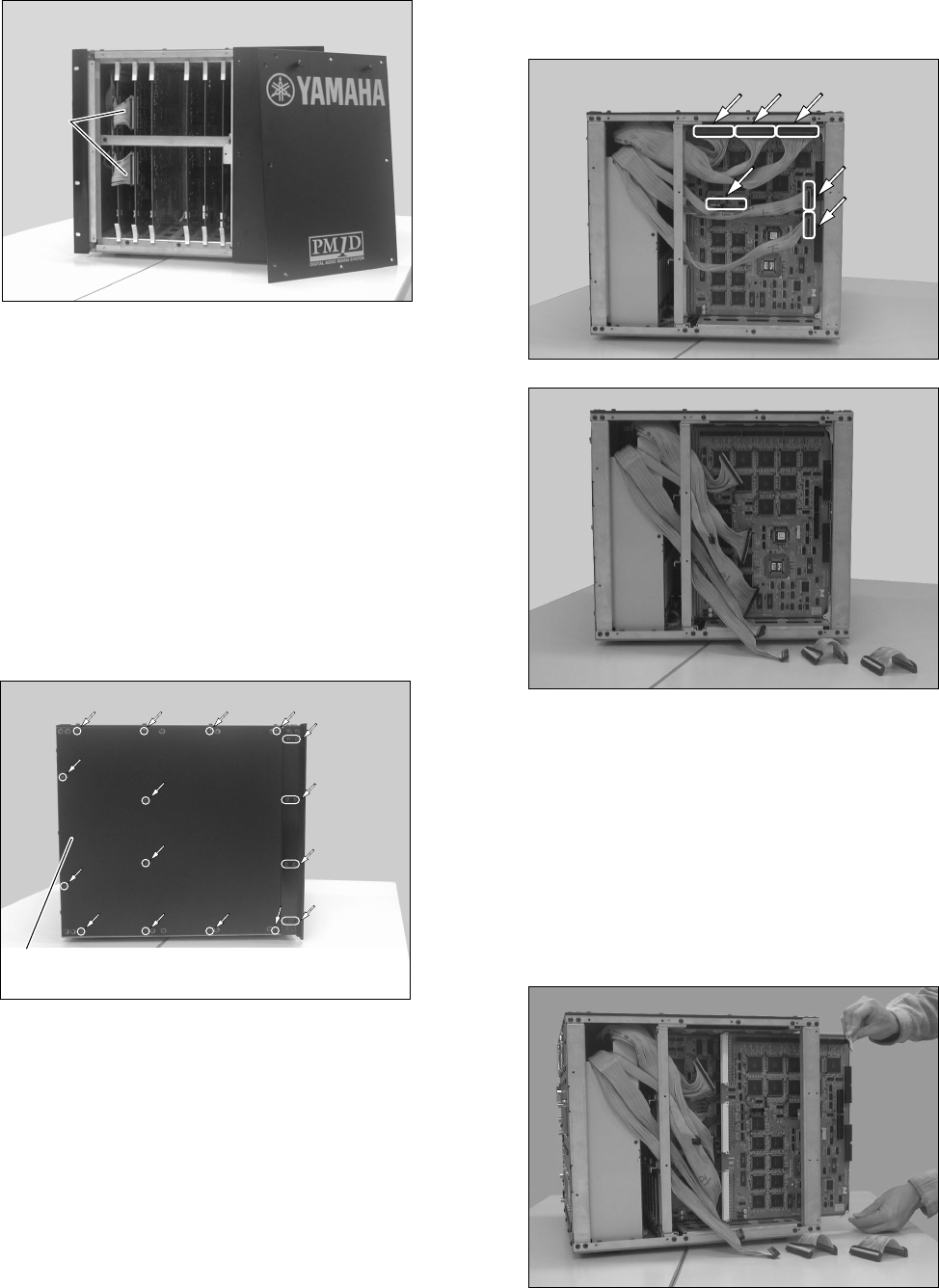
1. Remove the unit front cover as
described in the previous pro-
cedure. Remove two ribbon
cables from the board.
<Installing the PDB1D board>
<PDB1Dボードの装着>
3. Remove six ribbon cables
from the board. At this
time, mark the ribbon
cables so that you can
identify each of them and
re-connect them correctly
later.
側面カバー
side cover ラックマウント金具12ヶ
12 screws for the rack mount hardwa
re
上2個
Two bottom
screws
下2個
Two top
screws
2. Remove eight fixing screws
on the rack mount hardware,
and remove the rack mount
hardware. Do not remove any
screws or hardware other than
those shown in the picture.
Remove twelve screws on the
left side cover, then remove
it. Note that the screws for the
rack mount hardware are dif-
ferent from the screws on the
side cover.
前述の手順でユニット正
面カバーを取りはずしま
す。フラットケーブル2本を
取りは ずします。
ラックマ ウント金 具 の 固 定
ネジ 8ヶ所をとりは ずし、
ラックマ ウント金 具を取りは
ずします。写真に示した以
外ははずさないでくださ
い。そのあと左側面カバー
の12ヶのネジを取りはず
し、左側面カバーを取りは
ずします。ラックマウント金
具 のネジと側 面カバーのネ
ジは種類が異なりますの
でご注意ください。
フラットケーブル6本をボードから
取りは ずします。
この際フラットケーブルを再装着
するときに誤接続を防ぐため各フ
ラットケーブルにマーキング等で
識 別 できるようにしておきます。
4. Remove the PDB1D board. At
this time, care should be taken
so that the board will not catch
the ribbon cable.
After replacing it with a new
board, follow the steps de-
scribed previously to re-install
the ribbon cables, side cover,
rack mount hardware, and
front cover.
PDBボードを引き抜きます。
新しいPDBボード交換しま
す。その際、フラットケーブ
ルをはさまないよう注意し
てください。前述の手順の
逆でフラットケ ーブ ル 、側面
カバー、ラックマ ウント金 具
正面カバーを順に再び取り
付けてください。
フラット
ケーブル
ribbon
cable
ADVARSEL!
Lithiumbatteri—Eksplosionsfare ved fejlagtig
håndtering. Udskiftning må kun ske med batteri
af samme fabrikat og type. Levér det brugte
batteri tilbage til leverandoren.
VARNING
Explosionsfara vid felaktigt batteribyte. Använd
samma batterityp eller en ekvivalent typ som
rekommenderas av apparattillverkaren.
Kassera använt batteri enligt fabrikantens
instruktion.
VAROITUS
Paristo voi räjähtää, jos se on virheellisesti
asennettu. Vaihda paristo ainoastaan
laitevalmistajan suosittelemaan tyyppiin. Hävitä
käytetty paristo valmistajan ohjeiden
mukaisesti.
NEDERLAND THE NETHERLANDS
● Dit apparaat bevat een lithium batterij voor geheugen
back-up.
● Raadpleeg uw leverancier over de verwijdering van de
batterij op het moment dat u het apparaat ann het einde
van de levensduur afdankt of de volgende Yamaha Service
Afdeiing:
Yamaha Music Nederland Service Afdeiing
Kanaalweg 18-G, 3526 KL UTRECHT
Tel. 030-2828425
● Gooi de batterij niet weg, maar lever hem in als KCA.
● This apparatus contains a lithium battery for memory
back-up.
● For the removal of the battery at the moment of the
disposal at the end of the service life please consult your
retailer or Yamaha Service Center as follows:
Yamaha Music Nederland Service Center
Address: Kanaalweg 18-G, 3526 KL
UTRECHT
Tel: 030-2828425
● Do not throw away the battery. Instead, hand it in as small
chemical waste.
The above statements apply only to the IDB1D board.
YAMAHA CORPORATION
V510760 R1 1 IP 4 Pro Audio & Digital Musical Instrument Division
P.O. Box 3, Hamamatsu, 430-8651, Japan
00 06 300 AP Printed in Japan
