Yamaha Htr 5950 Owners Manual
HTR-5950 Manual HTR-5950_e_U
If not then HTR-5950_e_U Manual: ://www.yamaha.com/yamahavgn/s/YEC/AV_Receivers/Manual/HTR-5950_e_U
HTR-5950 to the manual de908625-7e72-4a75-a958-6af7dd388d47
2015-01-15
: Yamaha Htr-5950-Owners-Manual yamaha-htr-5950-owners-manual-134297 yamaha pdf
Open the PDF directly: View PDF ![]() .
.
Page Count: 116 [warning: Documents this large are best viewed by clicking the View PDF Link!]
- FEATURES
- GETTING STARTED
- CONTROLS AND FUNCTIONS
- CONNECTIONS
- Placing speakers
- Connecting speakers
- Information on jacks and cable plugs
- Audio and video signal flow
- Connecting a TV
- Connecting a DVD player, a DVD recorder, a VCR or an STB
- Connecting a CD player, an MD player or a tape deck
- Connecting a YAMAHA iPod universal dock
- Connecting a multi-format player or an external decoder
- Connecting a game console, a video camera or a portable audio player
- Connecting the FM and AM antennas
- Connecting the power cable
- Setting the speaker impedance
- Turning on this unit or setting it to the standby mode
- BASIC SETUP
- PLAYBACK
- USING AUDIO FEATURES
- Using SILENT CINEMA
- Muting the audio output
- Selecting the night listening mode
- Selecting the input mode
- Using the sleep timer
- Adjusting the speaker level
- Selecting the Compressed Music Enhancer mode
- Selecting the MULTI CH INPUT component
- Enjoying multi-channel sources in 2-channel stereo
- Enjoying unprocessed input sources
- Enjoying pure hi-fi stereo sound
- USING VIDEO FEATURES
- ENJOYING SURROUND SOUND
- RECORDING
- FM/AM TUNING
- XM® SATELLITE RADIO TUNING
- Connecting the XM Connect-and-Play digital antenna accessory
- XM Satellite Radio controls and functions
- Activating XM Satellite Radio
- Basic XM Satellite Radio operations
- Selecting the XM Satellite Radio search mode
- Setting the XM Satellite Radio preset channels
- Displaying the XM Satellite Radio information
- SOUND FIELD PROGRAMS
- SET MENU
- ADVANCED SETUP
- REMOTE CONTROL FEATURES
- USING iPod®
- RESETTING THE SYSTEM
- TROUBLESHOOTING
- GLOSSARY
- SPECIFICATIONS
- LIST OF REMOTE CONTROL CODES

YAMAHA ELECTRONICS CORPORATION, USA
6660 ORANGETHORPE AVE., BUENA PARK, CALIF. 90620, U.S.A.
YAMAHA CANADA MUSIC LTD.
135 MILNER AVE., SCARBOROUGH, ONTARIO M1S 3R1, CANADA
YAMAHA ELECTRONIK EUROPA G.m.b.H.
SIEMENSSTR. 22-34, 25462 RELLINGEN BEI HAMBURG, GERMANY
YAMAHA ELECTRONIQUE FRANCE S.A.
RUE AMBROISE CROIZAT BP70 CROISSY-BEAUBOURG 77312 MARNE-LA-VALLEE CEDEX02, FRANCE
YAMAHA ELECTRONICS (UK) LTD.
YAMAHA HOUSE, 200 RICKMANSWORTH ROAD WATFORD, HERTS WD18 7GQ, ENGLAND
YAMAHA SCANDINAVIA A.B.
J A WETTERGRENS GATA 1, BOX 30053, 400 43 VÄSTRA FRÖLUNDA, SWEDEN
YAMAHA MUSIC AUSTRALIA PTY, LTD.
17-33 MARKET ST., SOUTH MELBOURNE, 3205 VIC., AUSTRALIA
©
2006 All rights reserved.
HTR-5950
Printed in Malaysia WG73510
HTR-5950
AV R e c e i ve r
OWNER’S MANUAL
U
TEAC 80163, 81074
TECHNICS 80039, 80309,
81308, 81518
THORENS 81189
TOSHIBA 80135
VICTOR 80074
WARDS 80014, 80054,
80158, 80189
XM 81406, 81414
YAMAHA 80176, 81176,
81276, 81331,
81375, 81908,
(TUNER ID1) 81916
(TUNER ID2) 81917
(XM ID1) 81918
(XM ID 2) 81919
OTHER AUDIO
ACCESSORIES
YAMAHA (iPod) 81981
HTR-5950_U_cv.fm Page 1 Monday, November 28, 2005 10:08 AM
IMPORTANT SAFETY INSTRUCTIONS
i
• Explanation of Graphical Symbols
The lightning flash with arrowhead symbol, within an
equilateral triangle, is intended to alert you to the
presence of uninsulated “dangerous voltage” within
the product’s enclosure that may be of sufficient
magnitude to constitute a risk of electric shock to
persons.
The exclamation point within an equilateral triangle
is intended to alert you to the presence of important
operating and maintenance (servicing) instructions in
the literature accompanying the appliance.
1Read Instructions – All the safety and operating instructions
should be read before the product is operated.
2Retain Instructions – The safety and operating instructions
should be retained for future reference.
3Heed Warnings – All warnings on the product and in the
operating instructions should be adhered to.
4Follow Instructions – All operating and use instructions
should be followed.
5Cleaning – Unplug this product from the wall outlet before
cleaning. Do not use liquid cleaners or aerosol cleaners.
6Attachments – Do not use attachments not recommended by
the product manufacturer as they may cause hazards.
7Water and Moisture – Do not use this product near water –
for example, near a bath tub, wash bowl, kitchen sink, or
laundry tub; in a wet basement; or near a swimming pool;
and the like.
8Accessories – Do not place this product on an unstable cart,
stand, tripod, bracket, or table. The product may fall,
causing serious injury to a child or adult, and serious
damage to the product. Use only with a cart, stand, tripod,
bracket, or table recommended by the manufacturer, or sold
with the product. Any mounting of the product should
follow the manufacturer’s instructions, and should use a
mounting accessory recommended by the manufacturer.
9A product and cart combination should be moved with care.
Quick stops, excessive force, and uneven surfaces may
cause the product and cart combination to
overturn.
10 Ventilation – Slots and openings in the cabinet are provided
for ventilation and to ensure reliable operation of the
product and to protect it from overheating, and these
openings must not be blocked or covered. The openings
should never be blocked by placing the product on a bed,
sofa, rug, or other similar surface. This product should not
be placed in a built-in installation such as a bookcase or rack
unless proper ventilation is provided or the manufacturer’s
instructions have been adhered to.
11 Power Sources – This product should be operated only from
the type of power source indicated on the marking label. If
you are not sure of the type of power supply to your home,
consult your product dealer or local power company. For
products intended to operate from battery power, or other
sources, refer to the operating instructions.
12 Grounding or Polarization – This product may be equipped
with a polarized alternating current line plug (a plug having
one blade wider than the other). This plug will fit into the
power outlet only one way. This is a safety feature. If you
are unable to insert the plug fully into the outlet, try
reversing the plug. If the plug should still fail to fit, contact
your electrician to replace your obsolete outlet. Do not
defeat the safety purpose of the polarized plug.
13 Power-Cord Protection – Power-supply cords should be
routed so that they are not likely to be walked on or pinched
by items placed upon or against them, paying particular
attention to cords at plugs, convenience receptacles, and the
point where they exit from the product.
14 Lightning – For added protection for this product during a
lightning storm, or when it is left unattended and unused for
long periods of time, unplug it from the wall outlet and
disconnect the antenna or cable system. This will prevent
damage to the product due to lightning and power-line
surges.
15 Power Lines – An outside antenna system should not be
located in the vicinity of overhead power lines or other
electric light or power circuits, or where it can fall into such
power lines or circuits. When installing an outside antenna
system, extreme care should be taken to keep from touching
such power lines or circuits as contact with them might be
fatal.
16 Overloading – Do not overload wall outlets, extension
cords, or integral convenience receptacles as this can result
in a risk of fire or electric shock.
17 Object and Liquid Entry – Never push objects of any kind
into this product through openings as they may touch
dangerous voltage points or short-out parts that could result
in a fire or electric shock. Never spill liquid of any kind on
the product.
18 Servicing – Do not attempt to service this product yourself
as opening or removing covers may expose you to
dangerous voltage or other hazards. Refer all servicing to
qualified service personnel.
19 Damage Requiring Service – Unplug this product from the
wall outlet and refer servicing to qualified service personnel
under the following conditions:
a) When the power-supply cord or plug is damaged,
b) If liquid has been spilled, or objects have fallen into the
product,
c) If the product has been exposed to rain or water,
IMPORTANT SAFETY INSTRUCTIONS
CAUTION
CAUTION: TO REDUCE THE RISK OF
ELECTRIC SHOCK, DO NOT REMOVE
COVER (OR BACK). NO USER-SERVICEABLE
PARTS INSIDE. REFER SERVICING TO
QUALIFIED SERVICE PERSONNEL.
RISK OF ELECTRIC SHOCK
DO NOT OPEN
IMPORTANT SAFETY INSTRUCTIONS
ii
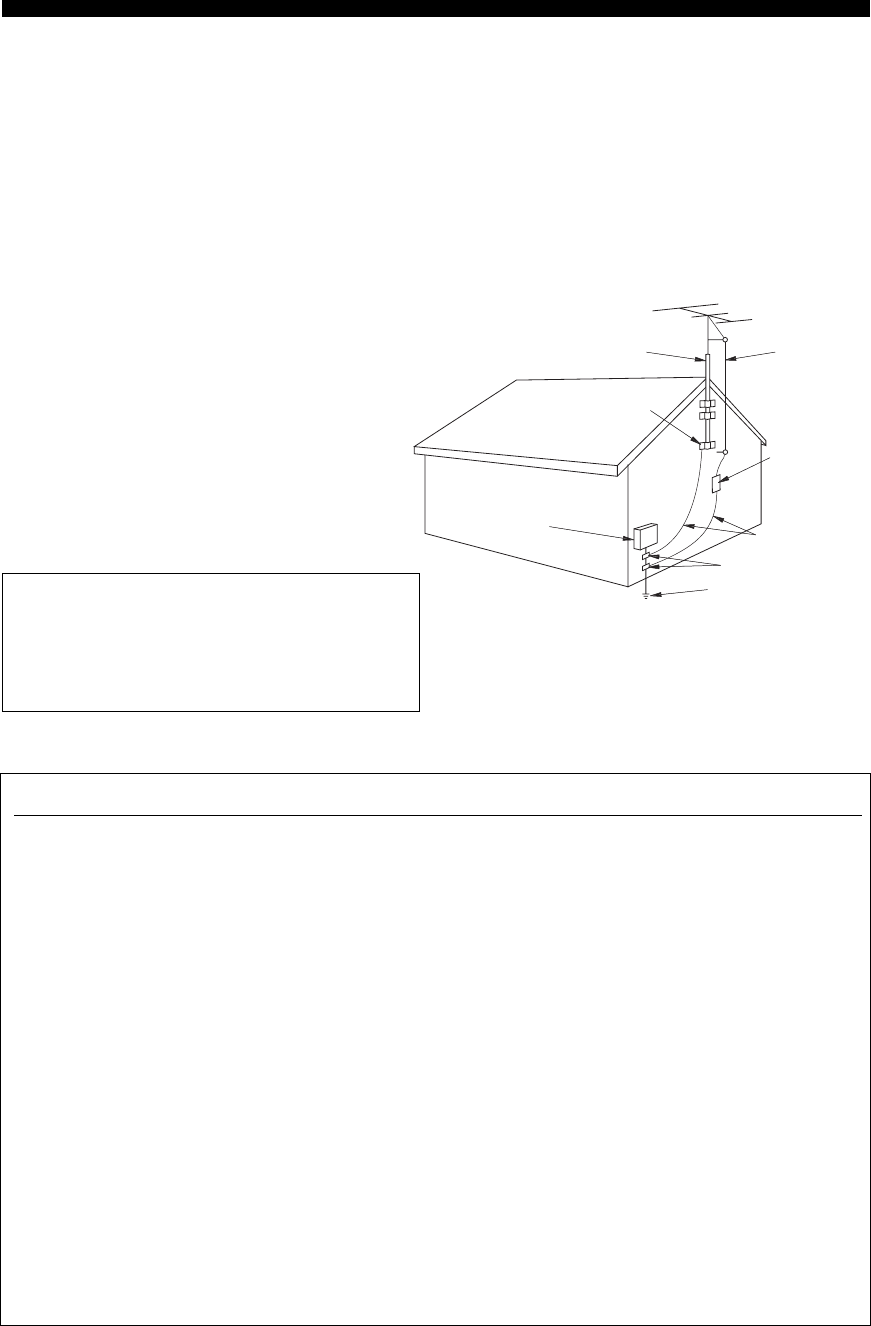
EXAMPLE OF ANTENNA GROUNDING
MAST
GROUND
CLAMP
ANTENNA
LEAD IN
WIRE
ANTENNA
DISCHARGE UNIT
(NEC SECTION 810–20)
GROUNDING CONDUCTORS
(NEC SECTION 810–21)
GROUND CLAMPS
POWER SERVICE GROUNDING
ELECTRODE SYSTEM
(NEC ART 250. PART H)
ELECTRIC
SERVICE
EQUIPMENT
NEC – NATIONAL ELECTRICAL CODE
d) If the product does not operate normally by following
the operating instructions. Adjust only those controls
that are covered by the operating instructions as an
improper adjustment of other controls may result in
damage and will often require extensive work by a
qualified technician to restore the product to its normal
operation,
e) If the product has been dropped or damaged in any
way, and
f) When the product exhibits a distinct change in perfor-
mance - this indicates a need for service.
20 Replacement Parts – When replacement parts are required,
be sure the service technician has used replacement parts
specified by the manufacturer or have the same
characteristics as the original part. Unauthorized
substitutions may result in fire, electric shock, or other
hazards.
21 Safety Check – Upon completion of any service or repairs to
this product, ask the service technician to perform safety
checks to determine that the product is in proper operating
condition.
22 Wall or Ceiling Mounting – This unit should be mounted
to a wall or ceiling only as recommended by the
manufacturer.
23 Heat – The product should be situated away from heat
sources such as radiators, heat registers, stoves, or other
products (including amplifiers) that produce heat.
24 Outdoor Antenna Grounding – If an outside antenna or
cable system is connected to the product, be sure the antenna
or cable system is grounded so as to provide some
protection against voltage surges and built-up static charges.
Article 810 of the National Electrical Code, ANSI/NFPA 70,
provides information with regard to proper grounding of the
mast and supporting structure, grounding of the lead-in wire
to an antenna discharge unit, size of grounding conductors,
location of antenna discharge unit, connection to grounding
electrodes, and requirements for the grounding electrode.
Note to CATV system installer:
This reminder is provided to call the CATV system installer’s
attention to Article 820-40 of the NEC that provides
guidelines for proper grounding and, in particular, specifies
that the cable ground shall be connected to the grounding
system of the building, as close to the point of cable entry as
practical.
FCC INFORMATION (for US customers)
1 IMPORTANT NOTICE: DO NOT MODIFY THIS
UNIT!
This product, when installed as indicated in the
instructions contained in this manual, meets FCC
requirements. Modifications not expressly approved by
Yamaha may void your authority, granted by the FCC, to
use the product.
2 IMPORTANT: When connecting this product to
accessories and/or another product use only high quality
shielded cables. Cable/s supplied with this product MUST
be used. Follow all installation instructions. Failure to
follow instructions could void your FCC authorization to
use this product in the USA.
3 NOTE: This product has been tested and found to comply
with the requirements listed in FCC Regulations, Part 15
for Class “B” digital devices. Compliance with these
requirements provides a reasonable level of assurance that
your use of this product in a residential environment will
not result in harmful interference with other electronic
devices.
This equipment generates/uses radio frequencies and, if
not installed and used according to the instructions found
in the users manual, may cause interference harmful to the
operation of other electronic devices.
Compliance with FCC regulations does not guarantee that
interference will not occur in all installations. If this
product is found to be the source of interference, which
can be determined by turning this unit “OFF” and “ON”,
please try to eliminate the problem by using one of the
following measures:
Relocate either this product or the device that is being
affected by the interference.
Utilize power outlets that are on different branch (circuit
breaker or fuse) circuits or install AC line filter/s.
In the case of radio or TV interference, relocate/reorient
the antenna. If the antenna lead-in is 300 ohm ribbon lead,
change the lead-in to coaxial type cable.
If these corrective measures do not produce satisfactory
results, please contact the local retailer authorized to
distribute this type of product. If you can not locate the
appropriate retailer, please contact Yamaha Electronics
Corp., U.S.A. 6660 Orangethorpe Ave, Buena Park, CA
90620.
The above statements apply ONLY to those products
distributed by Yamaha Corporation of America or its
subsidiaries.

CAUTION: READ THIS BEFORE OPERATING YOUR UNIT.
iii
1To assure the finest performance, please read this manual
carefully. Keep it in a safe place for future reference.
2Install this sound system in a well ventilated, cool, dry, clean
place – away from direct sunlight, heat sources, vibration,
dust, moisture, and/or cold. Allow ventilation space of at
least 30 cm on the top, 20 cm on the left and right, and 20
cm on the back of this unit.
3Locate this unit away from other electrical appliances,
motors, or transformers to avoid humming sounds.
4Do not expose this unit to sudden temperature changes from
cold to hot, and do not locate this unit in a environment with
high humidity (i.e. a room with a humidifier) to prevent
condensation inside this unit, which may cause an electrical
shock, fire, damage to this unit, and/or personal injury.
5Avoid installing this unit where foreign object may fall onto
this unit and/or this unit may be exposed to liquid dripping
or splashing. On the top of this unit, do not place:
– other components, as they may cause damage and/or
discoloration on the surface of this unit.
– burning objects (i.e. candles), as they may cause fire,
damage to this unit, and/or personal injury.
– containers with liquid in them, as they may fall and
liquid may cause electrical shock to the user and/or
damage to this unit.
6Do not cover this unit with a newspaper, tablecloth, curtain,
etc. in order not to obstruct heat radiation. If the temperature
inside this unit rises, it may cause fire, damage to this unit,
and/or personal injury.
7Do not plug in this unit to a wall outlet until all connections
are complete.
8Do not operate this unit upside-down. It may overheat,
possibly causing damage.
9Do not use force on switches, knobs and/or cords.
10 When disconnecting the power cable from the wall outlet,
grasp the plug; do not pull the cord.
11 Do not clean this unit with chemical solvents; this might
damage the finish. Use a clean, dry cloth.
12 Only voltage specified on this unit must be used. Using this
unit with a higher voltage than specified is dangerous and
may cause fire, damage to this unit, and/or personal injury.
YAMAHA will not be held responsible for any damage
resulting from use of this unit with a voltage other than
specified.
13 To prevent damage by lightning, keep the power cable and
outdoor antennas disconnected from a wall outlet or this unit
during a lightning storm.
14 Do not attempt to modify or fix this unit. Contact qualified
YAMAHA service personnel when any service is needed.
The cabinet should never be opened for any reasons.
15 When not planning to use this unit for long periods of time
(i.e. vacation), disconnect the AC power plug from the wall
outlet.
16 Install this unit near the AC wall outlet where the power
cable plug can be reached easily.
17 Be sure to read the “TROUBLESHOOTING” section on
common operating errors before concluding that this unit is
faulty.
18 Before moving this unit, press STANDBY/ON to set this
unit to the standby mode, and then disconnect the power
cable from the AC wall outlet.
We Want You Listening For A Lifetime
YAMAHA and the Electronic Industries Association’s Consumer Electronics Group want you to get the most out of your
equipment by playing it at a safe level. One that lets the sound come through loud and clear without annoying blaring or
distortion – and, most importantly, without affecting your sensitive hearing.
Since hearing damage from loud sounds is often undetectable until it is too late, YA M A H A and the Electronic Industries
Association’s Consumer Electronics Group recommend you to avoid prolonged exposure from excessive volume levels.
CAUTION: READ THIS BEFORE OPERATING YOUR UNIT.
WARNING
TO REDUCE THE RISK OF FIRE OR ELECTRIC
SHOCK, DO NOT EXPOSE THIS UNIT TO RAIN
OR MOISTURE.
This unit is not disconnected from the AC power
source as long as it is connected to the wall outlet, even
if this unit itself is set to the standby mode. In this
state, this unit is designed to consume a very small
quantity of power.
FOR CANADIAN CUSTOMERS
To prevent electric shock, match wide blade of plug to
wide slot and fully insert.
This Class B digital apparatus complies with Canadian
ICES-003.
IMPORTANT
Please record the serial number of this unit in the space
below.
MODEL:
Serial No.:
The serial number is located on the rear panel of this
unit. Retain this Owner’s Manual in a safe place for
future reference.

1
PREPARATIONINTRODUCTION
BASIC
OPERATION
SOUND FIELD
PROGRAMS
ADVANCED
OPERATION
ADDITIONAL
INFORMATION
FEATURES............................................................. 2
GETTING STARTED............................................ 3
Supplied accessories .................................................. 3
Installing batteries in the remote control ................... 3
CONTROLS AND FUNCTIONS ......................... 4
Front panel ................................................................. 4
Remote control........................................................... 6
Front panel display .................................................... 9
Rear panel ................................................................ 11
CONNECTIONS .................................................. 12
Placing speakers....................................................... 12
Connecting speakers ................................................ 13
Information on jacks and cable plugs ...................... 16
Audio and video signal flow.................................... 17
Connecting a TV...................................................... 18
Connecting a DVD player, a DVD recorder,
a VCR or an STB................................................. 19
Connecting a CD player, an MD player
or a tape deck....................................................... 21
Connecting a YAMAHA iPod universal dock ........ 22
Connecting a multi-format player
or an external decoder ......................................... 23
Connecting a game console, a video camera
or a portable audio player .................................... 23
Connecting the FM and AM antennas ..................... 24
Connecting the power cable..................................... 25
Setting the speaker impedance................................. 26
Turning on this unit or setting it
to the standby mode............................................. 27
BASIC SETUP ...................................................... 28
PLAYBACK.......................................................... 31
USING AUDIO FEATURES............................... 33
Using SILENT CINEMA ........................................ 33
Muting the audio output........................................... 33
Selecting the night listening mode........................... 33
Selecting the input mode ......................................... 34
Using the sleep timer ............................................... 34
Adjusting the speaker level...................................... 35
Selecting the Compressed Music
Enhancer mode .................................................... 36
Selecting the MULTI CH INPUT component......... 37
Enjoying multi-channel sources
in 2-channel stereo............................................... 38
Enjoying unprocessed input sources........................ 38
Enjoying pure hi-fi stereo sound.............................. 38
USING VIDEO FEATURES ............................... 39
Displaying the input source information ................. 39
Selecting the OSD mode.......................................... 40
Playing video sources in the background ................ 40
ENJOYING SURROUND SOUND .....................41
Enjoying multi-channel sources in surround ........... 41
Enjoying 2-channel sources in surround.................. 42
Using Virtual CINEMA DSP .................................. 43
RECORDING ........................................................44
FM/AM TUNING..................................................45
Automatic tuning ..................................................... 45
Manual tuning.......................................................... 46
Automatic preset tuning........................................... 47
Manual preset tuning ............................................... 48
Selecting preset stations........................................... 49
Exchanging preset stations ...................................... 50
XM® SATELLITE RADIO TUNING.................52
Connecting the XM Connect-and-Play
digital antenna accessory..................................... 52
XM Satellite Radio controls and functions.............. 53
Activating XM Satellite Radio ................................ 54
Basic XM Satellite Radio operations....................... 55
Selecting the XM Satellite Radio search mode ....... 56
Setting the XM Satellite Radio preset channels ...... 60
Displaying the XM Satellite Radio information...... 61
SOUND FIELD PROGRAMS .............................63
Selecting sound field programs ............................... 63
Sound field program descriptions............................ 64
Changing sound field parameter settings................. 66
Sound field program speaker layouts ...................... 72
SET MENU ............................................................75
Using SET MENU................................................... 77
1 SOUND MENU.................................................... 78
2 INPUT MENU...................................................... 83
3 OPTION MENU................................................... 85
ADVANCED SETUP ............................................88
REMOTE CONTROL FEATURES ...................90
Controlling this unit, a TV,
or other components ............................................ 90
Setting the remote control code ............................... 92
Setting library codes ................................................ 93
Resetting all remote control codes........................... 94
USING iPod®.........................................................95
Setting the remote control code ............................... 95
Controlling iPod ...................................................... 95
RESETTING THE SYSTEM...............................97
TROUBLESHOOTING .......................................98
GLOSSARY.........................................................103
Audio information ................................................. 103
Video information.................................................. 104
Sound field program information .......................... 105
SPECIFICATIONS.............................................106
CONTENTS
INTRODUCTION
PREPARATION
BASIC OPERATION
SOUND FIELD PROGRAMS
ADVANCED OPERATION
ADDITIONAL INFORMATION

FEATURES
2
Built-in 6-channel power amplifier
◆Minimum RMS output power
(0.7% THD, 1 kHz, 8 Ω)
Front: 110 W + 110 W
Center: 110 W
Surround: 110 W + 110 W
Surround back: 110 W
Sound field programs
◆Proprietary YAMAHA technology for the creation of sound
fields
◆Dolby Digital/Dolby Digital EX decoder
◆DTS/DTS-ES Matrix 6.1, Discrete 6.1, DTS Neo:6, DTS 96/
24 decoder
◆Dolby Pro Logic/Dolby Pro Logic II/
Dolby Pro Logic IIx decoder
◆Neural Surround decoder (U.S.A. and Canada models only)
◆Virtual CINEMA DSP
◆SILENT CINEMA™
Sophisticated AM/FM tuner
◆40-station random and direct preset tuning
◆Automatic preset tuning
◆Preset station shifting capability (preset editing)
XM Satellite Radio (U.S.A. model only)
◆XM Satellite Radio tuning capability (using the “XM
Connect-and-Play digital antenna accessory” sold separately)
◆Neural Surround decoder to play back the surround sound
content of the XM Satellite Radio broadcasts in multi-
channels, resulting in a full surround sound experience
iPod controlling capability
◆DOCK terminal to connect a YAMAHA iPod universal dock
(such as YDS-10 sold separately), which supports iPod (Click
and Wheel), iPod nano, and iPod mini
Other features
◆192-kHz/24-bit D/A converter
◆OSD (on-screen display) menus that allow you to optimize
this unit to suit your individual audiovisual system
◆6 additional input jacks for discrete multi-channel input
◆S-video signal input/output capability
◆Component video input/output capability
(3 COMPONENT VIDEO INs and 1 MONITOR OUT)
◆Digital video signal conversion (composite video ↔
S-video → component video) capability for monitor out
◆Optical and coaxial digital audio signal jacks
◆Sleep timer
◆Cinema and music night listening modes
◆Remote control with preset remote control codes,
backlighting input selector buttons, and an iPod (stationed in a
YAMAHA iPod universal dock connected to the DOCK
terminal) controlling capability
◆PORTABLE mini analog input jack on the front panel for a
portable audio player
◆Compressed Music Enhancer mode to improve the sound
quality of compression artifacts (such as the MP3 format) to
that of a high-quality stereo
•y indicates a tip for your operation.
• Some operations can be performed by using either the buttons on the front panel or the ones on the remote control. In case the button
names differ between the front panel and the remote control, the button name on the remote control is given in parentheses.
• This manual is printed prior to production. Design and specifications are subject to change in part as a result of improvements, etc. In
case of differences between the manual and product, the product has priority.
Manufactured under license from Dolby Laboratories.
“Dolby”, “Pro Logic”, and the double-D symbol are trademarks
of Dolby Laboratories.
Manufactured under license from Digital Theater Systems, Inc.
“DTS”, “DTS-ES”, “NEO:6”, and “DTS 96/24” are trademarks
of Digital Theater Systems, Inc. Copyright 1996, 2003 Digital
Theater Systems, Inc. All right reserved.
“iPod” is a trademark of Apple Computer, Inc., registered in the
U.S. and other countries.
“SILENT CINEMA” is a trademark of YAMAHA
CORPORATION.
The XM name and related logos are registered trademarks of XM
Satellite Radio Inc.
Neural Surround™ name and related logos are trademarks owned
by Neural Audio Corporation.
FEATURES
Notes
iPod®
GETTING STARTED
3
INTRODUCTION
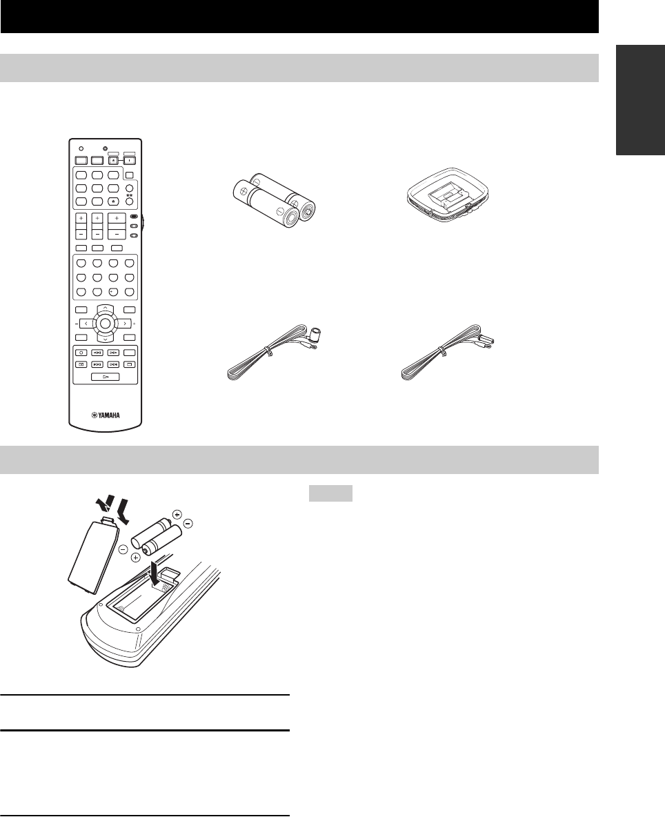
Check that you received all of the following parts.
1Take off the battery compartment cover.
2Insert the two supplied batteries
(AA, R6, UM-3) according to the polarity
markings (+ and –) on the inside of the
battery compartment.
3Snap the battery compartment cover back
into place.
• Change all of the batteries if you notice the following
conditions:
– the operation range of the remote control decreases.
– the TRANSMIT indicator does not flash or its light becomes
dim.
• Do not use an old battery together with a new one.
• Do not use different types of batteries (such as alkaline and
manganese batteries) together. Read the packaging carefully as
these different types of batteries may have the same shape and
color.
• If the batteries have leaked, dispose of them immediately. Avoid
touching the leaked material or letting it come into contact with
clothing, etc. Clean the battery compartment thoroughly before
installing new batteries.
• Do not throw away batteries with general house waste; dispose
of them correctly in accordance with your local regulations.
• If the remote control is without batteries for more than 2
minutes, or if exhausted batteries remain in the remote control,
the contents of the memory may be cleared. When the memory
is cleared, insert new batteries, set up the remote control code
and program any acquired functions that may have been
cleared.
GETTING STARTED
Supplied accessories
Installing batteries in the remote control
TV MUTE TV INPUT
MUTE
AMP
SOURCE
TV
MENUTITLE
SET MENU
LEVEL
DISPLAYRETURN
BAND
SRCH MODE
XM MEMORY
A-E/CAT. A-E/CAT.
ENTER
PRESET/CH
REC
AUDIO
DISC SKIP
STEREO
1
EFFECT
VOLUME
TV VOL TV CH
TRANSMITCODE SET
STANDBY
POWER
POWERPOWER
CD
AVTV
MULTI CH IN
SLEEP
CD-R XM
DVD DTV
MD
CBL
TUNER
V-AU X DV R
STANDARD
5
SPEAKERS
9
MUSIC
2
SELECT
6
ENHANCER
0
ENTERTAIN
3
EXTD SUR.
7
NIGHT
10
MOVIE
4
DIRECT ST.
8
STRAIGHT
ENT.
Remote control
Batteries (2)
(AA, R6, UM-3)
Indoor FM antenna
(U.S.A., Canada and
China models)
AM loop antenna
Indoor FM antenna
(Australia model)
13
2
Notes
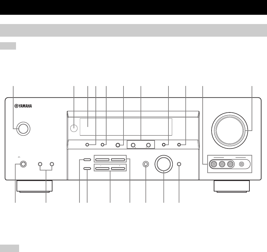
CONTROLS AND FUNCTIONS
4
The XM Satellite Radio controlling functions in the following buttons (SEARCH MODE, CATEGORY, PRESET/TUNING/CH l /
h, MEMORY, and DISPLAY) are only applicable to the U.S.A. model and are operational only when “XM” is selected as the input
source. For details, see “XM Satellite Radio controls and functions” on page 53.
1STANDBY/ON
Turns on this unit or sets it to the standby mode
(see page 27).
• In the standby mode, this unit consumes a small amount of
power in order to receive infrared signals from the remote
control.
• When you turn on this unit, there will be a 4 to 5-second delay
before this unit can reproduce sound.
2Remote control sensor
Receives signals from the remote control (see page 8).
3Front panel display
Shows information about the operational status of this unit
(see page 9).
4PRESET/TUNING, EDIT
• Switches the function of PRESET/TUNING/CH l /
h between selecting preset station numbers and
selecting the tuning frequency.
• Edits the assignments of preset stations (see page 50).
5FM/AM
Switches the reception band between FM and AM when
“TUNER” is selected as the input source (see page 45).
6A/B/C/D/E, NEXT
• Selects one of the 5 preset station groups (A to E) when
“TUNER” is selected as the input source (see page 45).
• Selects the speaker channel whose output level you
want to adjust when “TUNER” is not selected as the
input source (see page 35).
7PRESET/TUNING/CH l / h, LEVEL +/–
• Selects one of the 8 preset station numbers (1 to 8)
when “TUNER” is selected as the input source. The
colon (:) is displayed in the front panel display (see
page 45).
• Selects the tuning frequency when “TUNER” is
selected as the input source. The colon (:) is not
displayed in the front panel display (see page 45).
• Adjusts the level of the speaker channel selected using
NEXT when “TUNER” is not selected as the input
source (see page 35).
CONTROLS AND FUNCTIONS
Front panel
Note
VOLUME
AUTO/MAN'LMAN'L/AUTO FMLEVELNEXTEDIT
EFFECT
MEMORY
FM/AMPRESET/TUNING
A/B/C/D/E
l PROGRAM h
BASS/TREBLE
l PRESET/TUNING/CH h
TUNING MODE
INPUT MODE
TONE CONTROL
STRAIGHT
SPEAKERSPHONES
SILENT CINEMA
STANDBY
/ON
BA
MULTI CH
INPUT
INPUT
SEARCH MODE CATEGORY
VIDEO PORTABLEL AUDIO R
VIDEO AUX
21347 856 09
JHGECBDFI
DISPLAY
A
(U.S.A. model)
Notes

CONTROLS AND FUNCTIONS
5
INTRODUCTION
8MEMORY (MAN’L/AUTO FM)
Stores a preset station in the memory. Hold down this
button for more than 3 seconds to start automatic preset
tuning (see page 47).
9TUNING MODE (AUTO/MAN’L)
Switches between automatic tuning (the AUTO indicator
is turned on) and manual tuning (the AUTO indicator is
turned off) (see page 45).
0VIDEO AUX jacks
Input audio and video signals from a portable external
source such as a game console, a video camera or a
portable audio player (see page 23).
y
To reproduce the source signals input at these jacks, select
“V-AUX” as the input source.
• The audio signals input at the PORTABLE mini jack take
priority over the ones input at the AUDIO L/R jacks.
• The audio signals input at the DOCK terminal on the rear panel
take priority over the ones input at the VIDEO AUX jacks.
AVOLUME
Controls the output level of all audio channels.
y
This does not affect the AUDIO OUT (REC) level.
BPHONES (SILENT CINEMA) jack
Outputs audio signals for private listening with
headphones (see page 33).
• When you connect headphones, no signals are output at the
SUBWOOFER OUTPUT jack or the speaker terminals.
• All Dolby Digital and DTS audio signals are mixed down to the
left and right headphone channels.
CSPEAKERS A/B
Turns on or off the set of front speakers connected to the
FRONT A and/or B terminals on the rear panel each time
the corresponding button is pressed.
DSTRAIGHT (EFFECT)
Turns the sound field programs off or on. When the
“STRAIGHT” mode is selected, 2-channel or multi-
channel input signals are output directly from their
respective speakers without effect processing (see
page 38).
ETONE CONTROL
Selects “BASS” or “TREBLE” to adjust the tonal balance
of the front left and right speakers in conjunction with
BASS/TREBLE +/– (see page 32).
FBASS/TREBLE +/–
Adjusts the bass/treble balance of the front left and right
speakers in conjunction with TONE CONTROL
(see page 32).
GPROGRAM l / h
Selects sound field programs (see page 32).
HINPUT MODE
Selects either digital or analog input signals exclusively or
sets this unit to automatically detect the type of input
signals and select the corresponding input signals when
one component is connected via both digital and analog
connections (see page 34).
IINPUT selector
Selects the desired input source.
JMULTI CH INPUT
Selects the component connected to the MULTI CH
INPUT jacks as the input source (see page 37).
The input source connected to the MULTI CH INPUT jacks takes
priority over the source selected with the INPUT selector on the
front panel (or the input selector buttons on the remote control).
Notes
Notes
Note
CONTROLS AND FUNCTIONS
6
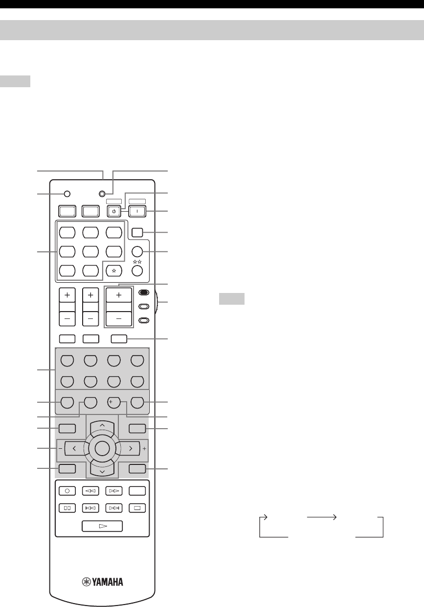
This section describes the function of each control on the remote control used to control this unit. To operate other
components, see “REMOTE CONTROL FEATURES” on page 90.
• The XM Satellite Radio controlling functions in the following buttons (XM, XM MEMORY, SRCH MODE, DISPLAY, cursor
buttons u / d / j / i, numeric buttons and ENT.) are only applicable to the U.S.A. model and are operational only when “XM” is
selected as the input source. For details, see “XM Satellite Radio controls and functions” on page 53.
• The operation mode of the remote control buttons in the shaded area below depends on the component selector switch position. Set the
component selector switch to AMP to control this unit. To control the TUNER functions, set the component selector switch to
SOURCE and then press TUNER to select “TUNER” as the input source.
■Controlling this unit
Set the component selector switch to AMP to control this
unit.
1Infrared window
Outputs infrared control signals. Aim this window at the
component you want to operate (see page 8).
2CODE SET
Use to set up remote control codes (see page 92).
3Input selector buttons
Select the input source you want to control.
The corresponding input selector button for the currently selected
input source lights up for approximately 5 seconds after you press
any buttons on the remote control, showing which source
component is currently being operated.
4Sound field program selector buttons
Select sound field programs (see page 63).
– Use SELECT to play back 2-channel sources in
surround (see page 42).
– Use EXTD SUR. to switch between 5.1 and
6.1-channel playback of multi-channel sources
(see page 41).
– Use DIRECT ST. to play back 2-channel sources in
hi-fi stereo sound (see page 38).
5SPEAKERS
Turns on or off the set of front speakers connected to the
FRONT A and/or B terminals on the rear panel. Press this
button repeatedly to toggle as follows:
6ENHANCER
Turns on or off the Compressed Music Enhancer mode
(see page 36).
7LEVEL
Selects the speaker channel to be adjusted and sets the
output level (see page 35).
Remote control
Notes
TV MUTE TV INPUT
MUTE
AMP
SOURCE
TV
MENUTITLE
SET MENU
LEVEL
DISPLAYRETURN
BAND
SRCH MODE
XM MEMORY
A-E/CAT. A-E/CAT.
ENTER
PRESET/CH
REC
AUDIO
DISC SKIP
STEREO
1
EFFECT
VOLUME
TV VOL TV CH
TRANSMITCODE SET
STANDBY
POWER
POWERPOWER
CD
AVTV
MULTI CH IN
SLEEP
CD-R XM
DVD DTV
MD
CBL
TUNER
V-AU X DVR
STANDARD
5
SPEAKERS
9
MUSIC
2
SELECT
6
ENHANCER
0
ENTERTAIN
3
EXTD SUR.
7
NIGHT
10
MOVIE
4
DIRECT ST.
8
STRAIGHT
ENT.
K
0
A
B
C
D
F
E
G
H
I
J
1
2
3
4
5
6
8
9
7
(U.S.A. model)
Note
A on B on
A and B off

CONTROLS AND FUNCTIONS
7
INTRODUCTION
8Cursor buttons u / d / j / i, ENTER
Select and adjust the sound field program parameters or
the “SET MENU” parameters.
9RETURN
Returns to the previous menu level when adjusting the
“SET MENU” parameters.
0TRANSMIT indicator
Flashes while the remote control is sending infrared
signals.
ASTANDBY
Sets this unit to the standby mode (see page 27).
BPOWER
Turns on this unit (see page 27).
CSLEEP
Sets the sleep timer (see page 34).
DMULTI CH IN
Selects the component connected to the MULTI CH
INPUT jacks as the input source when using an external
decoder, etc. (see page 37).
EVOLUME +/–
Increases or decreases the volume level.
FComponent selector switch
Selects the operation mode of the remote control buttons
in the shaded area.
AMP
Operates this unit.
SOURCE
Operates the component selected with an input
selector button (see page 91).
TV
Operates the TV assigned to either DTV/CBL or
(see page 90).
• To set the remote control codes for other components, see
page 92.
• When you set the remote control codes for both DTV/CBL and
(see page 92), priority is given to the one set for DTV/
CBL.
GMUTE
Mutes the audio output. Press again to restore the audio
output to the previous volume level (see page 33).
HSTRAIGHT (EFFECT)
Turns the sound field programs off or on. When the
“STRAIGHT” mode is selected, 2-channel or multi-
channel input signals are output directly from their
respective speakers without effect processing (see
page 38).
INIGHT
Turns on or off the night listening modes (see page 33).
JSET MENU
Enters “SET MENU” (see page 77).
KDISPLAY
Selects the on-screen display (OSD) mode for your video
monitor (see page 40).
Notes
CONTROLS AND FUNCTIONS
8
■Controlling the TUNER functions
Set the component selector switch to SOURCE and then
press TUNER to select “TUNER” as the input source.
4Numeric buttons
Use numbers 1 through 8 to select preset stations.
7BAND
Switches the reception band between FM and AM
(see page 45).
8Cursor buttons u / d / j / i
Press j / i to select a preset station group (A to E) and
u / d to select a preset station number (1 to 8)
(see page 49).
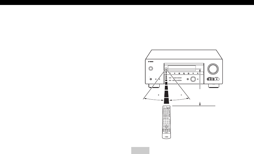
■Using the remote control
The remote control transmits a directional infrared ray.
Be sure to aim the remote control directly at the remote
control sensor on this unit during operation.
• Do not spill water or other liquids on the remote control.
• Do not drop the remote control.
• Do not leave or store the remote control in the following types
of conditions:
– places of high humidity, such as near a bath
– places of high temperatures, such as near a heater or stove
– places of extremely low temperatures
– dusty places
Notes
VOLUME
AUTO/MAN'LMAN'L/AUTO FMLEVELNEXTEDIT
EFFECT
MEMORY
FM/AMPRESET/TUNING
A/B/C/D/E
l PROGRAM h
BASS/TREBLE
TUNING MODE
INPUT MODE
TONE CONTROL
STRAIGHT
SPEAKERSPHONES
SILENT CINEMA
STANDBY
/ON
BA
MULTI CH
INPUT
INPUT
SEARCH MODE CATEGORY
l PRESET/TUNING/CH h
DISPLAY
VIDEO PORTABLEL AUDIO R
VIDEO AUX
30 30
TV MUTE TV INPUT
MUTE
AMP
SOURCE
TV
MENUTITLE
SET MENU
LEVEL
DISPLAYRETURN
BAND
SRCH MODE
XM MEMORY
A-E/CAT. A-E/CAT.
ENTER
PRESET/CH
REC
AUDIO
DISC SKIP
STEREO
1
EFFECT
VOLUME
TV VOL TV CH
TRANSMITCODE SET
STANDBY
POWER
POWERPOWER
CD
AVTV
MULTI CH IN
SLEEP
CD-R XM
DVD DTV
MD
CBL
TUNER
V-AUX DVR
STANDARD
5
SPEAKERS
9
MUSIC
2
SELECT
6
ENHANCER
0
ENTERTAIN
3
EXTD SUR.
7
NIGHT
10
MOVIE
4
DIRECT ST.
8
STRAIGHT
ENT.
Approximately 6 m (20 ft)
(U.S.A. model)
CONTROLS AND FUNCTIONS
9
INTRODUCTION
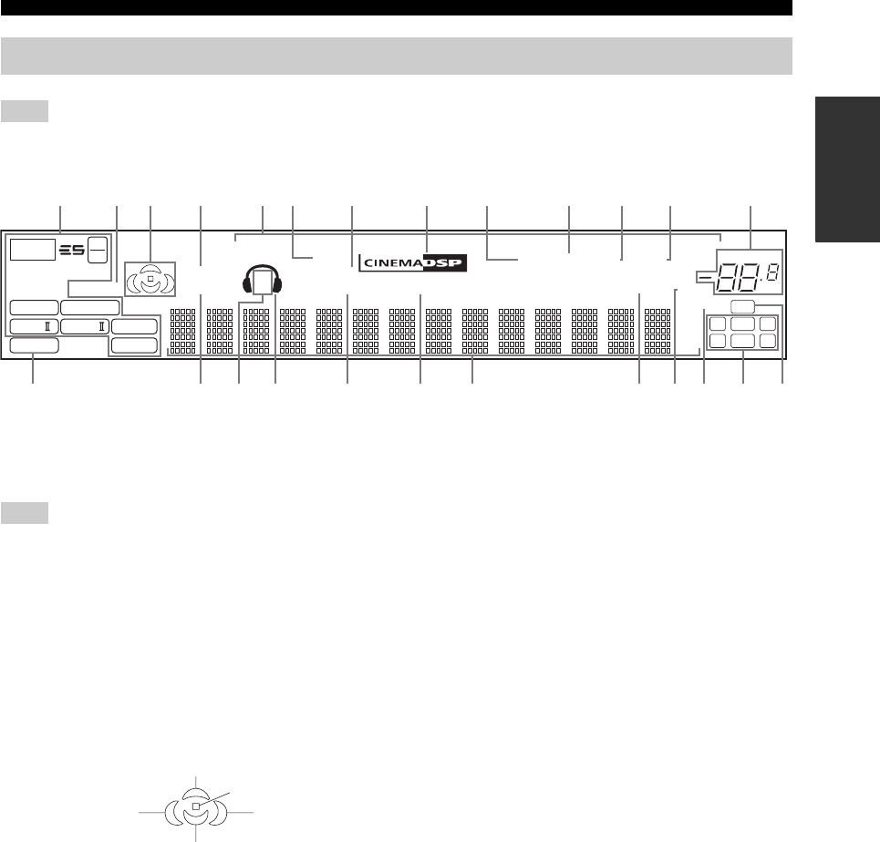
The XM indicator is only applicable to the U.S.A. model and the cursor on the left of the XM indicator lights up only when “XM” is
selected as the input source. For details, see “Basic XM Satellite Radio operations” on page 55.
1Decoder indicators
The respective indicator lights up when any of the
decoders of this unit function.
The neural indicator is only applicable to the U.S.A. and Canada
models and lights up only when the Neural Surround decoder is
selected
(see page 42).
2ENHANCER indicator
Lights up when the Compressed Music Enhancer mode is
turned on (see page 36).
3Sound field indicators
Light up to indicate the active DSP sound fields.
4VIRTUAL indicator
Lights up when Virtual CINEMA DSP is active (see
page 43).
5Input source indicators
The corresponding cursor lights up to show the currently
selected input source.
6DOCK indicator
Lights up when you station your iPod in a YAMAHA iPod
universal dock (such as YDS-10 sold separately)
connected to the DOCK terminal of this unit
(see page 22).
7SILENT CINEMA indicator
Lights up when headphones are connected and a sound
field program is selected (see page 33).
8CINEMA DSP indicator
Lights up when you select a CINEMA DSP sound field
program (see page 64).
9AUTO indicator
Lights up when this unit is in the automatic tuning mode
(see page 45).
0TUNED indicator
Lights up when this unit is tuned into a station
(see page 45).
ASTEREO indicator
Lights up when this unit is receiving a strong signal for an
FM stereo broadcast while the AUTO indicator is lit
(see page 45).
BMEMORY indicator
Flashes to show that a station can be stored (see page 47).
Front panel display
Note
p
DVR
p
DVD
p
CD
p
XM
p
V-AUX
p
DTV/CBL
p
MD/CD-R
p
TUNER
96
24
q PL
q EX
q PL
ENHANCER
MATRIX DISCRETE
SILENT CINEMA
NIGHT
DOCK
STANDARD
AUTO TUNED
MUTE
VOLUME
MEMORY
SLEEP
VIRTUAL
PCM
q PL x
neural
A B
SP
mS
ft
dB
96/24
HiFi DSP
LFE
LCR
SL SB SR
q
DIGITAL
t
dB
STEREO
2
EHGIJ KMLOND F
1345768 B
0A9C
Note
Presence DSP sound field
Listening position
Surround left
DSP sound field
Surround right
DSP sound field
Surround back DSP sound field

CONTROLS AND FUNCTIONS
10
CVOLUME level indicator
Indicates the current volume level.
DPCM indicator
Lights up when this unit is reproducing PCM (Pulse Code
Modulation) digital audio signals.
ESTANDARD indicator
Lights up when the “SUR. STANDARD” or “SUR.
ENHANCED” program is selected (see page 42).
FSP A B indicators
Light up according to the set of front speakers selected.
GHeadphones indicator
Lights up when headphones are connected (see page 33).
HNIGHT indicator
Lights up when you select a night listening mode
(see page 33).
IHiFi DSP indicator
Lights up when you select a HiFi DSP sound field
program (see page 64).
JMulti-information display
Shows the name of the current sound field program and
other information when adjusting or changing settings.
KSLEEP indicator
Lights up while the sleep timer is on (see page 34).
LMUTE indicator
Flashes while the MUTE function is on (see page 33).
M96/24 indicator
Lights up when a DTS 96/24 signal is input to this unit.
NInput channel indicators
Indicate the channel components of the current digital
input signal (see page 29).
OLFE indicator
Lights up when the input signal contains the LFE signal.
CONTROLS AND FUNCTIONS
11
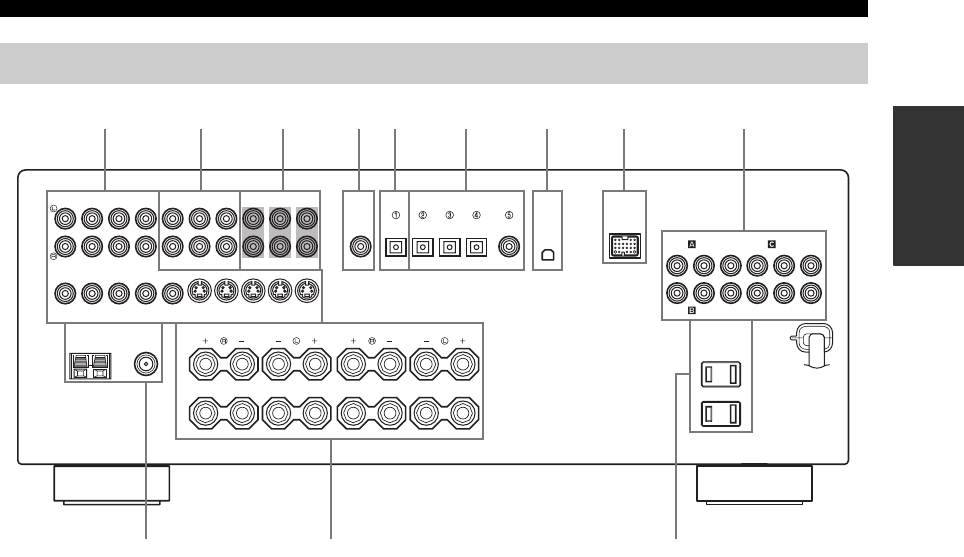
INTRODUCTION
1Video component jacks
See pages 18 and 19 for connection information.
2Audio component jacks
See page 21 for connection information.
3MULTI CH INPUT jacks
See page 23 for connection information.
4SUBWOOFER OUTPUT jack
See page 13 for connection information.
5DIGITAL OUTPUT jack
See page 21 for connection information.
6DIGITAL INPUT jacks
See page 19 for connection information.
7XM jack (U.S.A. model only)
See page 52 for connection information.
8DOCK terminal
Use to connect a YAMAHA iPod universal dock (such as
YDS-10 sold separately) where your iPod can be
stationed.
See page 22 for connection information.
9COMPONENT VIDEO jacks
See pages 18 and 19 for connection information.
0Antenna terminals
See page 24 for connection information.
ASpeaker terminals
See page 13 for connection information.
BAC OUTLET(S)
Use to supply power to your other audiovisual
components.
See page 25 for details.
Rear panel
AUDIO AUDIO OUTPUT DIGITAL INPUT
DVD DVD
COAXIAL
DTV/CBLMD/CD-RMD/CD-R
SUB
WOOFER
SUB
WOOFER
SURROUND
FRONT
OUT
(REC)
IN
(PLAY)
MD/
CD-R
CD
DVD MONITOR OUT
DTV/CBL
DVD DVR
COMPONENT VIDEO
PRPBY
FM ANT
75Ω
UNBAL.
AM
ANT GND
TUNER SPEAKERS
XM DOCK
DTV/CBL IN OUT
DVR DVD DTV/CBL IN OUT
DVR
CENTER
DIGITAL
OUTPUT
MULTI CH INPUT
VIDEO S VIDEO
MONITOR
OUT
MONITOR
OUT
FRONT
A
B
SURROUND
CENTER SURROUND BACK
PRPBY
OPTICAL OPTICAL
97654321
0AB
8
(U.S.A. model)
CONNECTIONS
12
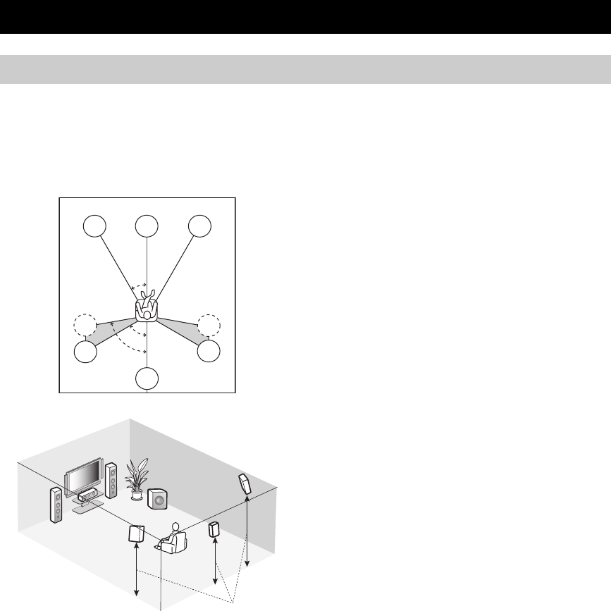
The speaker layout below shows the standard ITU-R*
speaker setting. You can use it to enjoy CINEMA DSP and
multi-channel audio sources.
*ITU-R is the radio communication sector of the ITU
(International Telecommunication Union).
Front left and right speakers (FL and FR)
The front speakers are used for the main source sound plus
effect sounds. Place these speakers at an equal distance
from the ideal listening position. The distance of each
speaker from each side of the video monitor should be the
same.
Center speaker (C)
The center speaker is for the center channel sounds
(dialog, vocals, etc.). If for some reason it is not practical
to use a center speaker, you can do without it. Best results,
however, are obtained with the full system. Place the
center speaker centrally between the front speakers and as
close to the monitor as possible, such as directly over or
under it.
Surround left and right speakers (SL and SR)
The surround speakers are used for effect and surround
sounds. Place these speakers behind your listening
position, facing slightly inwards, about 1.8 m (6 ft) above
the floor.
Surround back speaker (SB)
The surround back speaker supplements the surround
speakers and provides more realistic front-to-back
transitions. Place this speaker directly behind the listening
position and at the same height as the surround speakers.
Subwoofer (SW)
The use of a subwoofer with a built-in amplifier, such as
the YAMAHA Active Servo Processing Subwoofer
System, is effective not only for reinforcing bass
frequencies from any or all channels, but also for hi-fi
stereo sound reproduction of the LFE (low-frequency
effect) channel included in Dolby Digital and DTS
sources. The position of the subwoofer is not so critical,
because low bass sounds are not highly directional. But it
is better to place the subwoofer near the front speakers.
Turn it slightly toward the center of the room to reduce
wall reflections.
CONNECTIONS
Placing speakers
SW
FR
FL
SB
SL
SR
C
60˚
30˚
SB
FL
FR
C
SL
SR
SR
80˚
SL
1.8 m (6 ft)
13
CONNECTIONS
PREPARATION
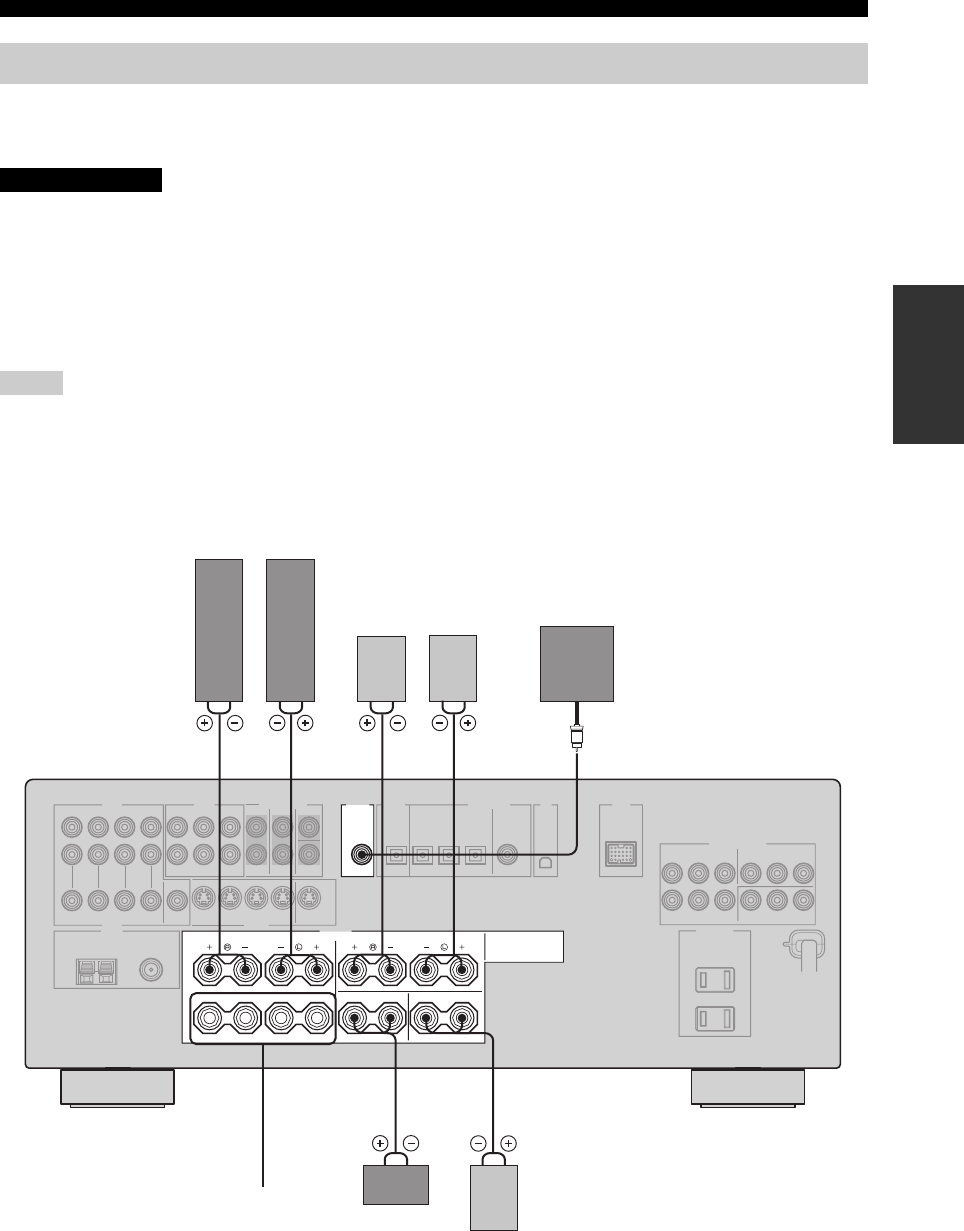
Be sure to connect the left channel (L), right channel (R), “+” (red) and “–” (black) properly. If the connections are faulty,
no sound will be heard from the speakers, and if the polarity of the speaker connections is incorrect, the sound will be
unnatural and lack bass.
• Before connecting the speakers, make sure that this unit is set to the standby mode (see page 27).
• Do not let the bare speaker wires touch each other or do not let them touch any metal part of this
unit. This could damage this unit and/or speakers.
• Use magnetically shielded speakers. If this type of speakers still creates the interference with the
monitor, place the speakers away from the monitor.
• If you are to use 4 or 6 ohm speakers, be sure to set “SP IMP.” to “6ΩMIN” before using this unit
(see page 26).
• A speaker cord is actually a pair of insulated cables running side by side. Cables are colored or shaped differently, perhaps with a
stripe, groove or ridge. Connect the striped (grooved, etc.) cable to the “+” (red) terminals of this unit and your speaker. Connect the
plain cable to the “–” (black) terminals.
• The low-frequency signals of other speakers set to “SML” (or “SMALL”) or to “NONE” in “SPEAKER SET” (see pages 78 and 79)
are directed to the speakers selected in “LFE/BASS OUT” (see page 79).
Connecting speakers
Notes
CAUTION
OUTPUT
SUB
WOOFER
SPEAKERS
FRONT
A
B
SURROUND
CENTER SURROUND BACK
1 2 4 57
63
Subwoofer
Center
speaker
Front speakers (A)
Surround back
speaker
LeftRight
LeftRight
Surround speakers
Front
speakers
(B)
(U.S.A. model)

14
CONNECTIONS
FRONT terminals
Connect one or two front speaker systems (1, 2) to these
terminals. If you use only one front speaker system,
connect it to the FRONT A or B terminal.
CENTER terminals
Connect a center speaker (3) to these terminals.
SURROUND terminals
Connect surround speakers (4, 5) to these terminals.
SURROUND BACK terminals
Connect a surround back speaker (6) to these terminals.
SUBWOOFER jack
Connect a subwoofer with a built-in amplifier (7) (such as
the YAMAHA Active Servo Processing Subwoofer
System) to this jack.
7
1
2
6
5
4
3
Speaker layout
15
CONNECTIONS
PREPARATION
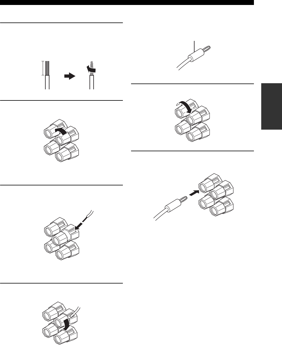
■Connecting the speaker cable
1Remove approximately 10 mm (0.4 in) of
insulation from the end of each speaker
cable and then twist the exposed wires of the
cable together to prevent short circuits.
2Loosen the knob.
3Insert one bare wire into the hole on the side
of each terminal.
4Tighten the knob to secure the wire.
■Connecting the banana plug
The banana plug is a single-pole electrical connector
widely used to terminate speaker cables.
1Tighten the knob.
2Insert the banana plug connector into the
end of the corresponding terminal.
10 mm (0.4 in)
Red: positive (+)
Black: negative (–)
Red: positive (+)
Black: negative (–)
Red: positive (+)
Black: negative (–)
Banana plug
16
CONNECTIONS
You can use the digital jacks to input PCM, Dolby Digital and DTS bitstreams. When you connect components to both the COAXIAL
and OPTICAL jacks, priority is given to the signals input at the COAXIAL jack. All digital input jacks are compatible with 96-kHz
sampling digital signals.
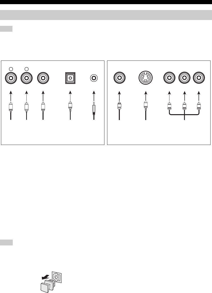
■Audio jacks
This unit has four types of audio jacks. Connection
depends on the availability of audio jacks on your other
components.
AUDIO jacks
For conventional analog audio signals transmitted via left
and right analog audio cables. Connect red plugs to the
right jacks and white plugs to the left jacks.
DIGITAL AUDIO COAXIAL jacks
For digital audio signals transmitted via coaxial digital
audio cables.
DIGITAL AUDIO OPTICAL jacks
For digital audio signals transmitted via optical digital
audio cables.
Pull out the cap from the optical jack before you connect the fiber
optic cable. Do not discard the cap. When you are not using the
optical jack, be sure to put the cap back in place. This cap protects
the jack from dust.
PORTABLE jack
For analog audio signals transmitted via stereo analog
audio mini cables.
■Video jacks
This unit has three types of video jacks. Connection
depends on the availability of input jacks on your video
monitor. When “VIDEO CONV.” is set to “ON” (see
page 85), the video signals input at the VIDEO and S
VIDEO jacks are converted and output at the VIDEO, S
VIDEO and COMPONENT VIDEO jacks
interchangeably.
VIDEO jacks
For conventional composite video signals transmitted via
composite video cables.
S VIDEO jacks
For S-video signals, separated into the luminance (Y) and
chrominance (C) video signals transmitted on separate
wires of S-video cables.
COMPONENT VIDEO jacks
For component video signals, separated into the
luminance (Y) and chrominance (PB, PR) video signals
transmitted on separate wires of component video cables.
Information on jacks and cable plugs
Note
VIDEO S VIDEO
COMPONENT VIDEO
Y PB PR
PB
YPR
S
V
COAXIAL
DIGITAL AUDIO
AUDIO PORTABLE
OPTICAL
DIGITAL AUDIO
R
L
CO
M
R
L
Left and right
analog audio
cable plugs
Optical
digital
audio cable
plug
Coaxial
digital audio
cable plug
Composite
video cable
plug
S-video
cable plug
Component
video cable
plugs
Stereo
analog
audio
mini cable
plug
Audio jacks and cable plugs Video jacks and cable plugs
(Red)(White) (Orange) (Yellow) (Green) (Blue) (Red)
Note
17
CONNECTIONS
PREPARATION
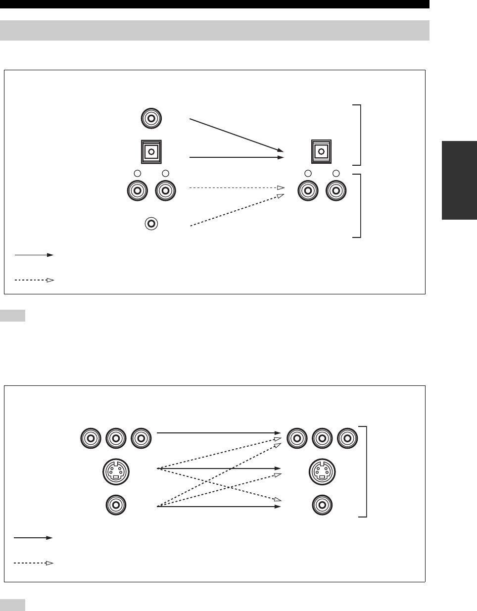
■Audio signal flow for AUDIO OUT (REC)
This unit handles digital and analog signals independently. Thus, audio signals input at the analog jacks are output only at the analog
AUDIO OUT (REC) jacks. Likewise, audio signals input at the DIGITAL INPUT (OPTICAL or COAXIAL) jacks are output only at the
DIGITAL OUTPUT jack.
■Video signal flow for MONITOR OUT
When video signals are input at the COMPONENT VIDEO, S VIDEO and VIDEO jacks, the priority order of the input signals is as
follows where the video signals input at the COMPONENT VIDEO jacks have the top priority:
COMPONENT VIDEO > S VIDEO > VIDEO
Audio and video signal flow
Note
Note
DIGITAL AUDIO
OPTICAL
DIGITAL AUDIO
COAXIAL
PORTABLE
AUDIO
RLRL
Digital output
Output
AUDIO OUT (REC)
Input
Analog output
Digital audio
Analog audio
S VIDEO
VIDEO
COMPONENT
VIDEO
Y P
B
P
R
Y P
B
P
R
Through
Output
(MONITOR OUT)
Input
Video conversion when “VIDEO CONV.” is set to “ON” (see page 85)
Analog video
18
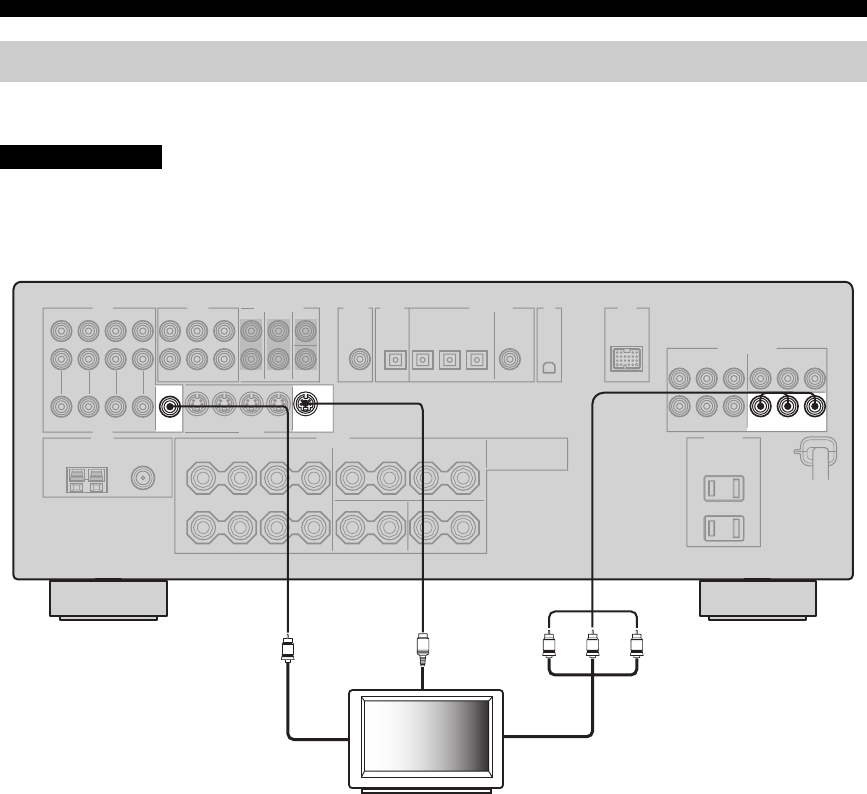
CONNECTIONS
Connect your TV to the VIDEO MONITOR OUT jack, the S VIDEO MONITOR OUT jack or the COMPONENT
VIDEO MONITOR OUT jacks of this unit.
Do not connect this unit or other components to the AC power supply until all connections between
components are complete.
Connecting a TV
CAUTION
MONITOR OUT
COMPONENT VIDEO
VIDEO S VIDEO
MONITOR
OUT
MONITOR
OUT
PRPBY
PRPB
VSY
TV
(U.S.A. model)
S-video in
Component video in
Video in
19
CONNECTIONS
PREPARATION
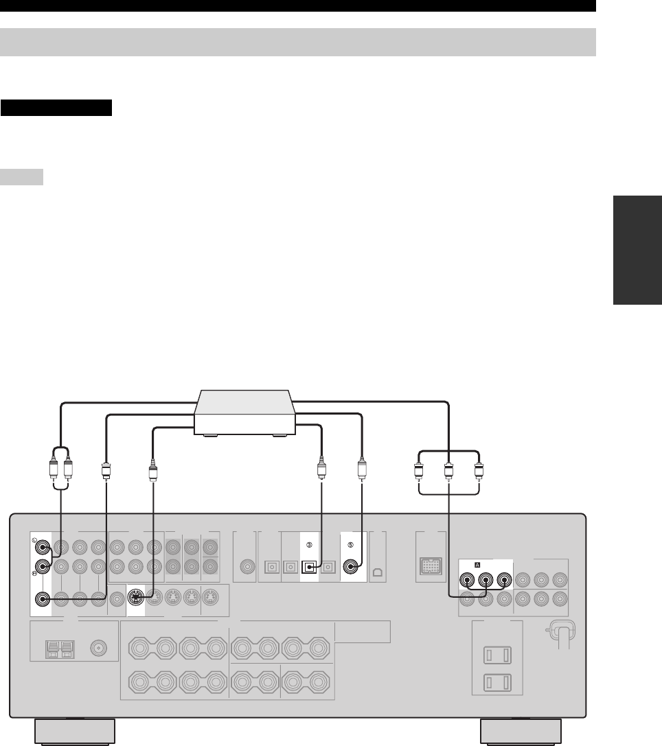
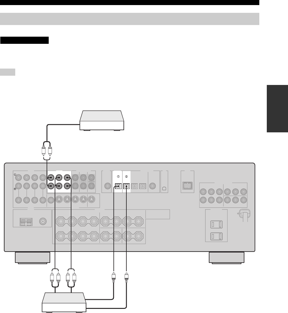
Connect your DVD player, DVD recorder, VCR or STB (set-top box) using the same type of video connections as those
made for your TV (see page 18). The cable TV receiver and the satellite receiver are examples of the STB.
Do not connect this unit or other components to the AC power supply until all connections between
components are complete.
• When “VIDEO CONV.” is set to “OFF” (see page 85), be sure to make the same type of video connections as those made for your TV
(see page 18). For example, if you connected your TV to the VIDEO MONITOR OUT jack of this unit, connect your other
components to the VIDEO jacks.
• When “VIDEO CONV.” is set to “ON” (see page 85), the converted video signals are output only at the MONITOR OUT jacks. When
recording a source, you must make the same type of video connections between each component.
• To make a digital connection to a component other than the default component assigned to each DIGITAL INPUT or DIGITAL
OUTPUT jack, select the corresponding setting for “OPTICAL OUT”, “OPTICAL IN”, or “COAXIAL IN” in “I/O ASSIGNMENT”
(see page 83).
• If you connect your DVD player to both the DIGITAL INPUT (OPTICAL) and the DIGITAL INPUT (COAXIAL) jacks, priority is
given to the signals input at the DIGITAL INPUT (COAXIAL) jack.
■Connecting a DVD player
Connecting a DVD player, a DVD recorder, a VCR or an STB
Notes
CAUTION
AUDIO DIGITAL INPUT
DVD DVD
COAXIAL
DVD
DVD
COMPONENT VIDEO
PRPBY
DVD
VIDEO S VIDEO
OPTICAL
SPRPBY
V
C
LR O
DVD player
Optical audio out
Coaxial audio out
Video out
Audio out
S-video out
Component video out
(U.S.A. model)
20
CONNECTIONS
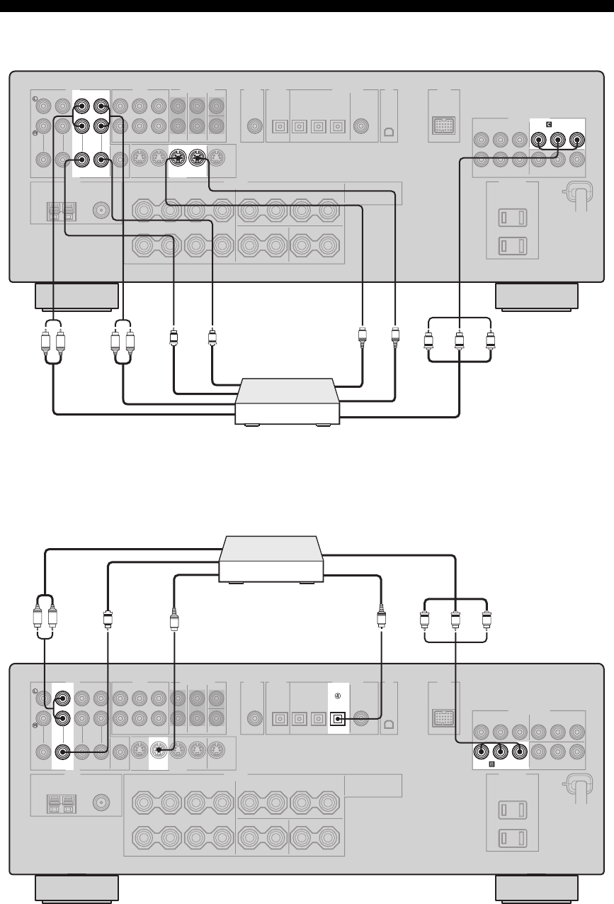
■Connecting a DVD recorder or a VCR
■Connecting an STB
AUDIO
DVR
COMPONENT VIDEO
IN OUT
DVR IN OUT
DVR
VIDEO S VIDEO
PRPBY
VS
V
LR LR PRPBY
S
DVD recorder or
VCR
Audio in
Audio out
Video in
Video out
Component video out
S-video in
S-video out
(U.S.A. model)
AUDIO DIGITAL INPUT
DTV/CBL
DTV/CBL
COMPONENT VIDEO
PRPBY
DTV/CBL DTV/CBL
VIDEO S VIDEO
OPTICAL
SPRPBY
V
LR O
Cable TV receiver or
satellite receiver
Optical audio out
Component video out
Video out
Audio out
S-video out
(U.S.A. model)
21
CONNECTIONS
PREPARATION
Connect your CD player, MD player or tape deck via analog and/or digital connections.
Do not connect this unit or other components to the AC power supply until all connections between
components are complete.
To make a digital connection to a component other than the default component assigned to each DIGITAL INPUT or DIGITAL
OUTPUT jack, select the corresponding setting for “OPTICAL OUT”, “OPTICAL IN”, or “COAXIAL IN” in “I/O ASSIGNMENT”
(see page 83).
Connecting a CD player, an MD player or a tape deck
Note
CAUTION
AUDIO DIGITAL INPUT
MD/CD-RMD/CD-R
OUT
(REC)
IN
(PLAY)
MD/
CD-R
CD
DIGITAL
OUTPUT
OPTICAL OPTICAL
LR
LR LR
O
O
CD player
MD recorder or
tape deck
(U.S.A. model)
Audio out
Audio out Audio in
Optical audio out
Optical audio in
22
CONNECTIONS
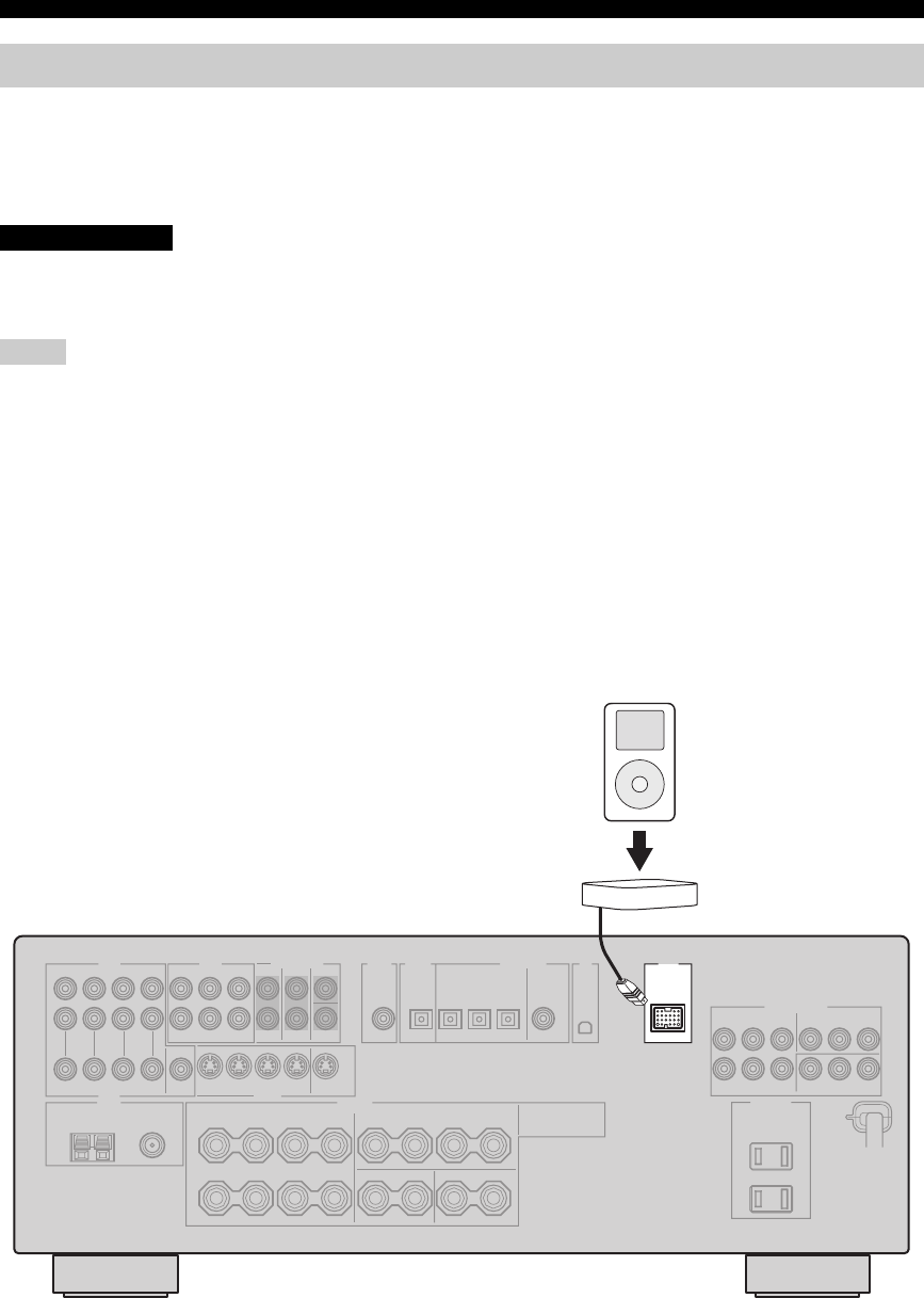
This unit is equipped with the DOCK terminal on the rear panel that allows you to connect a YAMAHA iPod universal
dock (such as YDS-10 sold separately) where you can station your iPod and control playback of your iPod using the
supplied remote control. Connect a YAMAHA iPod universal dock (such as YDS-10 sold separately) to the DOCK
terminal on the rear panel of this unit using its dedicated cable. Once the connection is complete, station your iPod in the
YAMAHA iPod universal dock.
Do not connect this unit or other components to the AC power supply until all connections between
components are complete.
• Only iPod (Click and Wheel), iPod nano, and iPod mini are supported.
• You need a YAMAHA iPod universal dock (such as YDS-10 sold separately) and its dedicated cable compatible with the DOCK
terminal of this unit.
• Once your iPod is stationed in a YAMAHA iPod universal dock (such as YDS-10 sold separately) connected to the DOCK terminal of
this unit, this unit begins the signal transmission with your iPod.
• Once the connection between your iPod and this unit is complete, “iPod connected” appears in the front panel display and the DOCK
indicator lights up in the front panel display. If the connection between your iPod and this unit fails, a status message appears in the
front panel display. For a complete list of connection status messages, see the iPod section in “TROUBLESHOOTING” on page 102.
• Only analog audio and video signals of your iPod are input at the DOCK terminal, and the analog audio signals can be output at the
analog AUDIO OUT (REC) jacks for recording.
• Your iPod battery is automatically charged when your iPod is stationed in a YAMAHA iPod universal dock (such as YDS-10 sold
separately) connected to the DOCK terminal of this unit as long as this unit is turned on.
• Depending on the type of iPod, you may need to insert one of the iPod adapters supplied with a YAMAHA iPod universal dock (such
as YDS-10 sold separately) into the dock slot before you station your iPod.
Connecting a YAMAHA iPod universal dock
Notes
CAUTION
DOCK
YAMAHA iPod universal dock
(such as YDS-10 sold separately)
(U.S.A. model)
iPod
23
CONNECTIONS
PREPARATION
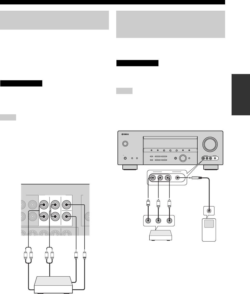
This unit is equipped with 6 additional input jacks
(FRONT L/R, CENTER, SURROUND L/R and
SUBWOOFER) for discrete multi-channel input from a
multi-format player, external decoder or sound processor.
Connect the output jacks on your multi-format player or
external decoder to the MULTI CH INPUT jacks. Be sure
to match the left and right output jacks to the left and right
input jacks for the front and surround channels.
Do not connect this unit or other components to
the AC power supply until all connections
between components are complete.
• When you select the component connected to the MULTI CH
INPUT jacks as the input source (see page 37), this unit
automatically turns off the digital sound field processor, and
you cannot select sound field programs.
• This unit does not redirect signals input at the MULTI CH
INPUT jacks to accommodate for missing speakers. We
recommend that you connect at least a 5.1-channel speaker
system before using this feature.
• When headphones are used, signals are output only from the
front left and right channels.
Use the VIDEO AUX jacks on the front panel to connect a
game console, a video camera or a portable audio player to
this unit.
Be sure to turn off the volume of this unit and
other components before making connections.
• The audio signals input at the PORTABLE mini jack take
priority over the ones input at the AUDIO L/R jacks.
• The audio signals input at the DOCK terminal takes priority
over the ones input at the VIDEO AUX jacks.
Connecting a multi-format player
or an external decoder
Notes
CAUTION
SUB
WOOFER
SURROUND
FRONT
CENTER
MULTI CH INPUT
L R L R
Multi-format player or
external decoder
Front out
Surround out
Subwoofer out
Center out
Connecting a game console, a
video camera or a portable audio
player
Notes
CAUTION
V
L
R
M
VOLUME
AUTO/MAN'LMAN'L/AUTO FMLEVELNEXTEDIT
EFFECT
MEMORY
FM/AMPRESET/TUNING
A/B/C/D/E
l PROGRAM h
BASS/TREBLE
TUNING MODE
INPUT MODE
TONE CONTROL
STRAIGHT
SPEAKERSPHONES
SILENT CINEMA
STANDBY
/ON
BA
MULTI CH
INPUT
INPUT
SEARCH MODE CATEGORY
l PRESET/TUNING/CH h
DISPLAY
VIDEO PORTABLEL AUDIO R
VIDEO AUX
VIDEO PORTABLEL AUDIO R
VIDEO AUX
Game console or
video camera
Audio out L/R
Video out
Portable audio
player
Audio out
(U.S.A. model)

24
CONNECTIONS
Both FM and AM indoor antennas are supplied with this
unit. In general, these antennas should provide sufficient
signal strength. Connect each antenna correctly to the
designated terminals.
• The AM loop antenna should be placed away from this unit.
• The AM loop antenna should always be connected, even if an
outdoor AM antenna is connected to this unit.
• A properly installed outdoor antenna provides clearer reception
than an indoor one. If you experience poor reception quality,
install an outdoor antenna. Consult the nearest authorized
YAMAHA dealer or service center about outdoor antennas.
■Connecting the AM loop antenna
1Set up the AM loop antenna.
2Press and hold the tab of the AM ANT
terminal.
3Insert one of the AM loop antenna lead wires
into the AM ANT terminal.
4Release the tab of the AM ANT terminal back
into place.
5Repeat steps 2 through 4 to connect the
other lead wire to the GND terminal.
y
Once you have properly connected the AM loop antenna to
this unit, orient the AM loop antenna for the best reception
when you tune into AM stations (see page 45).
Connecting the FM and AM antennas
Notes
FM ANT
75Ω
UNBAL.
AM
ANT GND
TUNER
AM loop antenna
(supplied)
Ground (GND terminal)
For maximum safety and
minimum interference,
connect the antenna GND
terminal to a good earth
ground. A good earth ground
is a metal stake driven into
moist earth.
Indoor FM antenna
(supplied)
(U.S.A. model)
Outdoor AM antenna
Use a 5 to 10 m (16.4 to 32.8 ft) of
vinyl-covered wire extended outdoors
from a window.
25
CONNECTIONS
PREPARATION
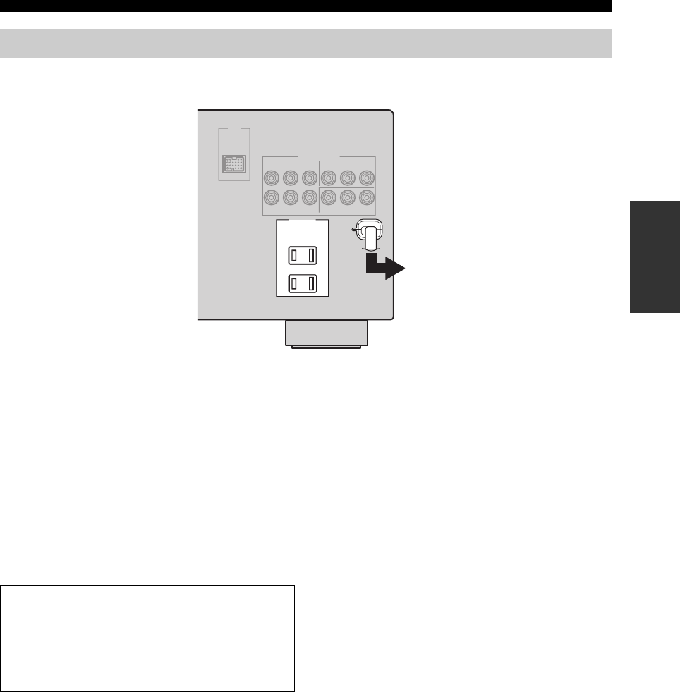
Once all connections are complete, plug the power cable into the AC wall outlet.
■AC OUTLET(S) (SWITCHED)
Australia model...................................................... 1 outlet
Other models......................................................... 2 outlets
Use these outlet(s) to supply power to any connected
components. Connect the power cable of your other
components to these outlet(s). Power to these outlet(s) is
supplied when this unit is turned on. However, power to
these outlet(s) is cut off when this unit is set to the standby
mode. For information on the maximum power or the total
power consumption of the components that can be
connected to these outlet(s), see “SPECIFICATIONS” on
page 106.
Connecting the power cable
AC OUTLETS
To the AC wall outlet
(U.S.A. model)
Memory back-up
The memory back-up circuit prevents the stored data
from being lost even if this unit is in the standby mode.
However, the stored data will be lost in case the power
cable is disconnected from the AC wall outlet or if the
power supply is cut off for more than one week.
26
CONNECTIONS
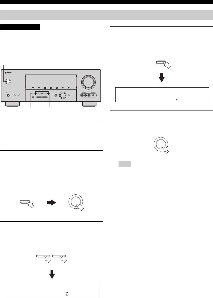
If you are to use 4 or 6 ohm speakers, set “SP
IMP.” to “6ΩMIN” as follows BEFORE using this
unit.
1Make sure this unit is set to the standby
mode.
See page 27 for details about turning on this unit or
setting it to the standby mode.
2Press and hold STRAIGHT (EFFECT) on the
front panel and then press STANDBY/ON to
turn on this unit.
This unit turns on, and the advanced setup menu
appears in the front panel display.
3Press PROGRAM l / h on the front panel
repeatedly to select “SP IMP.”.
The following display appears in the front panel
display.
4Press STRAIGHT (EFFECT) on the front
panel repeatedly to select “6ΩMIN”.
The following display appears in the front panel
display.
5Press STANDBY/ON on the front panel to
save the new setting and set this unit to the
standby mode.
The setting you made is reflected next time you turn on this
unit.
Setting the speaker impedance
CAUTION
VOLUME
AUTO/MAN'LMAN'L/AUTO FMLEVELNEXTEDIT
EFFECT
MEMORY
FM/AMPRESET/TUNING
A/B/C/D/E
l PROGRAM h
BASS/TREBLE
TUNING MODE
INPUT MODE
TONE CONTROL
STRAIGHT
SPEAKERSPHONES
SILENT CINEMA
STANDBY
/ON
BA
MULTI CH
INPUT
INPUT
SEARCH MODE CATEGORY
l PRESET/TUNING/CH h
DISPLAY
VIDEO PORTABLEL AUDIO R
VIDEO AUX
32,4
2,5
(U.S.A. model)
EFFECT
STRAIGHT
STANDBY
/ON
While holding
down
l PROGRAM h
SP IMP.-8 MIN
Note
EFFECT
STRAIGHT
SP IMP.-6 MIN
STANDBY
/ON
27
CONNECTIONS
PREPARATION
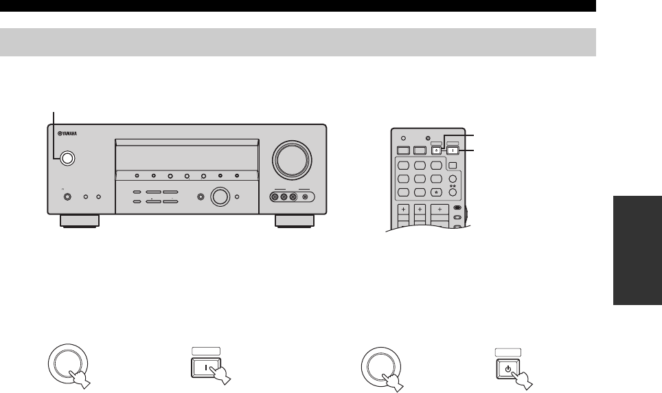
When all connections are complete, turn on this unit.
■Turning on this unit
Press STANDBY/ON on the front panel (or
POWER on the remote control) to turn on this
unit.
■Setting this unit to the standby mode
Press STANDBY/ON on the front panel again (or
STANDBY on the remote control) to set this unit
to the standby mode.
Turning on this unit or setting it to the standby mode
VOLUME
AUTO/MAN'LMAN'L/AUTO FMLEVELNEXTEDIT
EFFECT
MEMORY
FM/AMPRESET/TUNING
A/B/C/D/E
l PROGRAM h
BASS/TREBLE
TUNING MODE
INPUT MODE
TONE CONTROL
STRAIGHT
SPEAKERSPHONES
SILENT CINEMA
STANDBY
/ON
BA
MULTI CH
INPUT
INPUT
SEARCH MODE CATEGORY
l PRESET/TUNING/CH h
DISPLAY
VIDEO PORTABLEL AUDIO R
VIDEO AUX
AMP
SOURCE
TV
VOLUME
TV VOL TV CH
TRANSMITCODE SET
STANDBY
POWER
POWERPOWER
CD
AVTV
MULTI CH IN
SLEEP
CD-R XM
DVD DTV
MD
CBL
TUNER
V-AU X DV R
(U.S.A. model) (U.S.A. model)
STANDBY/ON
STANDBY
POWER
STANDBY
/ON
Front panel
POWER
or
Remote control
STANDBY
/ON
Front panel
STANDBY
Remote control
or
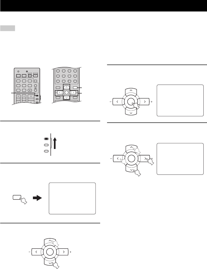
BASIC SETUP
28
The “BASIC SETUP” feature is a useful way to set up your system quickly and with minimal effort.
• Make sure you disconnect your headphones from this unit.
• If you wish to configure this unit manually using more precise adjustments, use the detailed parameters in “SOUND MENU” (see
page 78).
• Altering any parameters in “BASIC SETUP” resets all parameters manually adjusted in “SOUND MENU” (see page 78).
• Initial settings are indicated in bold under each parameter.
• Press RETURN on the remote control to return to the previous menu level.
1Set the component selector switch to AMP.
2Press SET MENU to enter “SET MENU”.
The top “SET MENU” display appears in the OSD.
3Press u / d to select “BASIC SETUP”.
4Press ENTER to enter “BASIC SETUP”.
The following display appears in the OSD.
5Press u / d to select “ROOM” and then j / i
to select the desired setting.
Select the size of the room where you have installed
your speakers. In general, the room sizes are defined
as follows:
Choices: S, M, L
[U.S.A. and Canada models]
S (small) 16 x 13ft, 200ft2 (4.8 x 4.0m, 20m2)
M (medium) 20 x 16ft, 300ft2 (6.3 x 5.0m, 30m2)
L (large) 26 x 19ft, 450ft2 (7.9 x 5.8m, 45m2)
[Other models]
S (small) 3.6 x 2.8m, 10m2
M (medium) 4.8 x 4.0m, 20m2
L (large) 6.3 x 5.0m, 30m2
BASIC SETUP
Notes
AMP
SOURCE
TV
VOLUME
TV VOL TV CH
TRANSMITCODE SET
STANDBY
POWER
POWERPOWER
CD
AVTV
MULTI CH IN
SLEEP
CD-R XM
DVD DTV
MD
CBL
TUNER
V-AU X DV R
MENUTITLE
SET MENU
LEVEL
DISPLAYRETURN
BAND
SRCH MODE
XM MEMORY
A-E/CAT. A-E/CAT.
ENTER
PRESET/CH
REC
AUDI O
STEREO
1
EFFECT
STANDARD
5
SPEAKERS
9
MUSIC
2
SELECT
6
ENHANCER
0
ENTERTAIN
3
EXTD SUR.
7
NIGHT
10
MOVIE
4
DIRECT ST.
8
STRAIGHT
ENT.
13-12
2,13
(U.S.A. model)
AMP
SOURCE
TV
MENU
SET MENU
SRCH MODE
SET MENU
.;BASICSETUP
;MANUALSETUP
.;SIGNAL INFO
[ ]/[]:Up/Down
[ENTER]:Enter
p
p
A-E/CAT. A-E/CAT.
ENTER
PRESET/CH
;BASIC SETUP
.ROOM: S >M L
SUBWOOFER;;;;YES
SPEAKERS;;;;6spk
SETUP:>OK CANCEL
[]/[]:Up/Down
[<]/[>]:Select
p
p
A-E/CAT. A-E/CAT.
ENTER
PRESET/CH
;BASIC SETUP
.ROOM: S >M L
SUBWOOFER;;;;YES
SPEAKERS;;;;6spk
SETUP:>OK CANCEL
[]/[]:Up/Down
[<]/[>]:Select
p
p
A-E/CAT. A-E/CAT.
ENTER
PRESET/CH
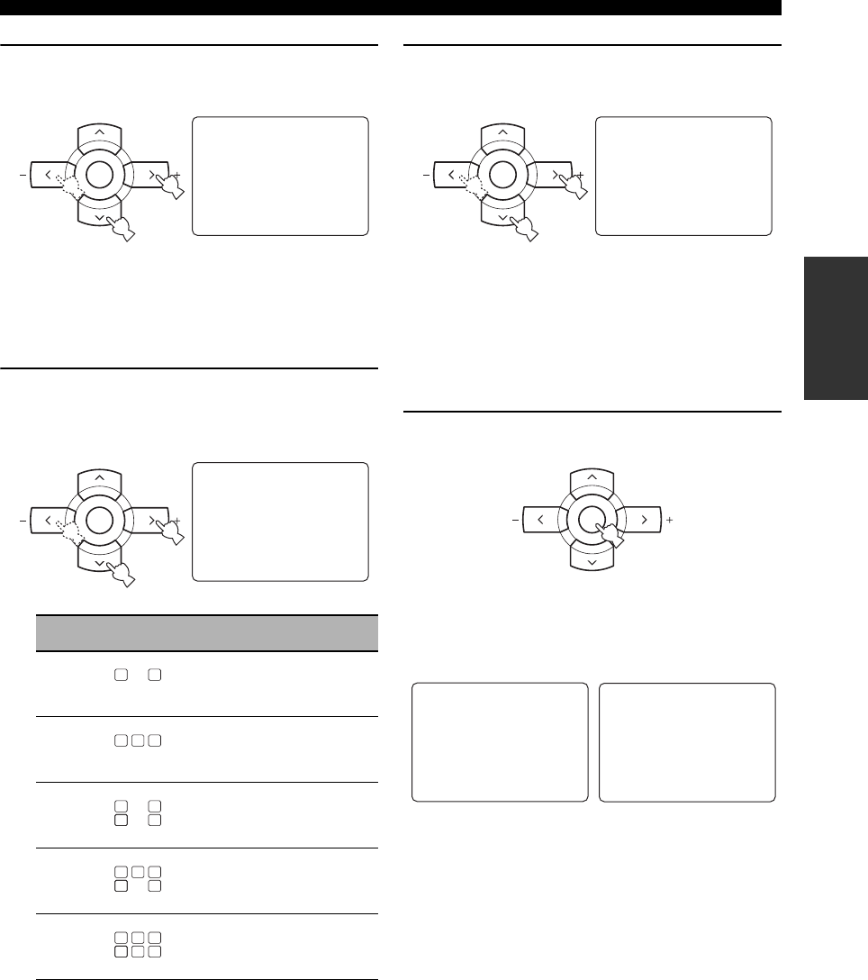
29
BASIC SETUP
PREPARATION
6Press d to select “SUBWOOFER” and then
j / i to select the desired setting.
Choices: YES, NONE
• Select “YES” if you have a subwoofer in your
system.
• Select “NONE” if you do not have a subwoofer in
your system.
7Press d to select “SPEAKERS” and then j / i
to select the number of speakers connected
to this unit.
8Press d to select “SETUP” and then j / i to
select the desired setting.
Choices: OK, CANCEL
• Select “OK” to apply the settings you made.
• Select “CANCEL” to cancel the setup procedure
without making any changes.
y
You can also press SET MENU to cancel the setup
procedure.
9Press ENTER to confirm your selection.
If you selected “OK” in step 8, each speaker outputs a
test tone twice in turn. “CHECK:Test Tone” appears
in the OSD for a few seconds and then “CHECK
OK?” appears in the OSD.
y
Check the speaker connections (see page 13) and adjust the
“SPEAKERS” settings back in step 7, if necessary.
Choice Display Speakers
2spk Front L/R
3spk Front L/R, Center
4spk Front L/R, Surround L/R
5spk Front L/R, Center, Surround L/R
6spk Front L/R, Center, Surround L/R,
Surround back
A-E/CAT. A-E/CAT.
ENTER
PRESET/CH
;BASIC SETUP
ROOM: S >M L
.SUBWOOFER;;;;YES
SPEAKERS;;;;6spk
SETUP:>OK CANCEL
[]/[]:Up/Down
[<]/[>]:Select
p
p
A-E/CAT. A-E/CAT.
ENTER
PRESET/CH
;BASIC SETUP
ROOM: S >M L
SUBWOOFER;;;;YES
.SPEAKERS;;;;6spk
SETUP:>OK CANCEL
[]/[]:Up/Down
[<]/[>]:Select
p
p
LL CR
SL SB SR
LL CR
SL SB SR
LL CR
SL SB SR
LL CR
SL SB SR
LL C R
SL SB
SB
SR
LL C R
SL SB SR
A-E/CAT. A-E/CAT.
ENTER
PRESET/CH
;BASIC SETUP
ROOM: S >M L
SUBWOOFER;;;;YES
SPEAKERS;;;;6spk
.SETUP:>OK CANCEL
[]/[]:Up/Down
[<]/[>]:Select
p
p
A-E/CAT. A-E/CAT.
ENTER
PRESET/CH
;BASIC SETUP
ROOM: S >M L
SUBWOOFER;;;;YES
SPEAKERS;;;;6spk
SETUP:>OK CANCEL
.CHECK:Test Tone
[]/[]:Up/Down
[<]/[>]:Select
p
p
;BASIC SETUP
ROOM: S >M L
SUBWOOFER;;;;YES
SPEAKERS;;;;6spk
SETUP:>OK CANCEL
.CHECK OK?;;;;YES
[]/[]:Up/Down
[<]/[>]:Select
p
p
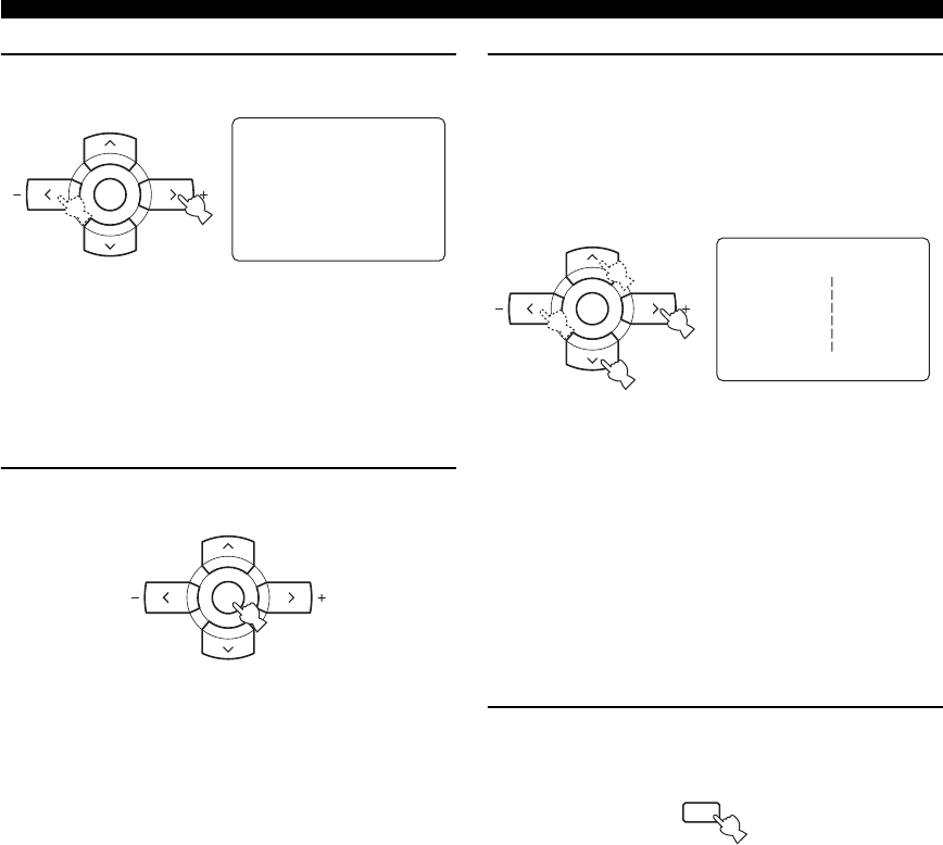
30
BASIC SETUP
10 Press j / i to select the desired setting.
Choices: YES, NO
• Select “YES” to complete the setup procedure if
the test tone levels from each speaker were
satisfactory.
• Select “NO” to proceed to the speaker level
adjustment menu in step 12 to balance the output
level of each speaker.
11 Press ENTER to confirm your selection.
• If you selected “YES” in step 10, the setup
procedure is completed and the display returns to
the top “SET MENU” display.
• If you selected “NO” in step 10, the front speaker
level adjustment display appears in the front panel
display.
12 Press u / d to select a speaker and then j / i
to adjust the balance.
The selected speaker and the front left speaker (or the
surround left speaker) output a test tone in turn.
•Press i to increase the value.
•Press j to decrease the value.
• Select “FR” to adjust the balance between the front
left and right speakers.
• Select “C” to adjust the balance between the front
left and center speakers.
• Select “SL” to adjust the balance between the front
left and surround left speakers.
• Select “SB” to adjust the balance between the
surround left and surround back speakers.
• Select “SR” to adjust the balance between the
surround left and surround right speakers.
• Select “SWFR” to adjust the balance between the
front left speaker and the subwoofer.
13 Press SET MENU to exit from “BASIC
SETUP”.
;BASIC SETUP
ROOM: S >M L
SUBWOOFER;;;;YES
SPEAKERS;;;;6spk
SETUP:>OK CANCEL
.CHECK OK?;;;;YES
[]/[]:Up/Down
[<]/[>]:Select
p
p
A-E/CAT. A-E/CAT.
ENTER
PRESET/CH
A-E/CAT. A-E/CAT.
ENTER
PRESET/CH
A-E/CAT. A-E/CAT.
ENTER
PRESET/CH
;BASIC SETUP
.FR;;;;;;;;;;
C;;;;;;;;;;
SL;;;;;;;;;;
SB;;;;;;;;;;
SR;;;;;;;;;;
SWFR;;;;;;;;;;
[]/[]:Select
[<]/[>]:Adjust
p
p
MENU
SET MENU
SRCH MODE
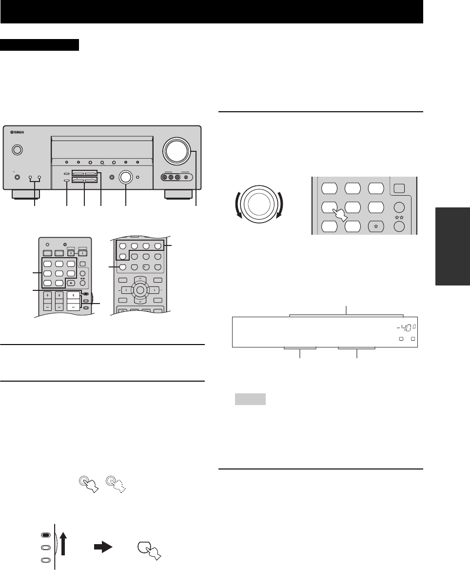
PLAYBACK
31
BASIC
OPERATION
Extreme caution should be exercised when you play back CDs encoded in DTS. If you play back a CD
encoded in DTS on a DTS-incompatible CD player, you will only hear some unwanted noise that may
damage your speakers. Check whether your CD player supports CDs encoded in DTS. Also, check the
sound output level of your CD player before you play back a CD encoded in DTS.
1Turn on the video monitor connected to this
unit.
2Press SPEAKERS A or B on the front panel
(or set the component selector switch to
AMP and then press SPEAKERS on the
remote control repeatedly).
Each time you press SPEAKERS A or B, the
respective speakers are turned on or off.
3Rotate the INPUT selector on the front panel
(or press one of the input selector buttons on
the remote control) to select the desired
input source.
The name of the currently selected input source
appears in the front panel display and in the OSD for
a few seconds.
• If you are to select an input source connected via digital
connections, set “INPUT MODE” to “AUTO” or “DTS”
(see page 34).
• For details about controlling XM Satellite Radio when
“XM” is selected as the input source, see page 55.
4Start playback on the selected source
component or select a broadcast station.
Refer to the operating instructions for the source
component.
See page 45 for details about tuning instructions.
PLAYBACK
CAUTION
VOLUME
AUTO/MAN'LMAN'L/AUTO FMLEVELNEXTEDIT
EFFECT
MEMORY
FM/AMPRESET/TUNING
A/B/C/D/E
l PROGRAM h
BASS/TREBLE
TUNING MODE
INPUT MODE
TONE CONTROL
STRAIGHT
SPEAKERSPHONES
SILENT CINEMA
STANDBY
/ON
BA
MULTI CH
INPUT
INPUT
SEARCH MODE CATEGORY
l PRESET/TUNING/CH h
DISPLAY
VIDEO PORTABLEL AUDIO R
VIDEO AUX
766 32 5
TV MUTE TV INPUT
MUTE
MENUTITLE
SET MENU
LEVEL
DISPLAYRETURN
BAND
SRCH MODE
XM MEMORY
A-E/CAT. A-E/CAT.
ENTER
PRESET/CH
REC
AUDI O
DISC SKIP
STEREO
1
EFFECT
STANDARD
5
SPEAKERS
9
MUSIC
2
SELECT
6
ENHANCER
0
ENTERTAIN
3
EXTD SUR.
7
NIGHT
10
MOVIE
4
DIRECT ST.
8
STRAIGHT
ENT.
7
5
2
TV MUTE TV INPUT
MUTE
AMP
SOURCE
TV
VOLUME
TV VOL TV CH
TRANSMITCODE SET
STANDBY
POWER
POWERPOWER
CD
AVTV
MULTI CH IN
SLEEP
CD-R XM
DVD DTV
MD
CBL
TUNER
V-AU X DV R
3
2
(U.S.A. model)
(U.S.A. model)
SPEAKERS
BA
SPEAKERS
9
AMP
SOURCE
TV
Front panel
Remote control
or
Notes
CD
MULTI CH IN
SLEEP
CD-R XM
DVD DTV
MD
CBL
TUNER
V-AU X DVR
INPUT
Front panel Remote control
or
DVR
p
DVD CD
XM
V-AUX DTV/CBL
MD/CD-R
TUNER
VOLUME
A
SP
dB
LR
DVD AUTO
Currently selected
input source
Currently selected
input mode
Available input sources
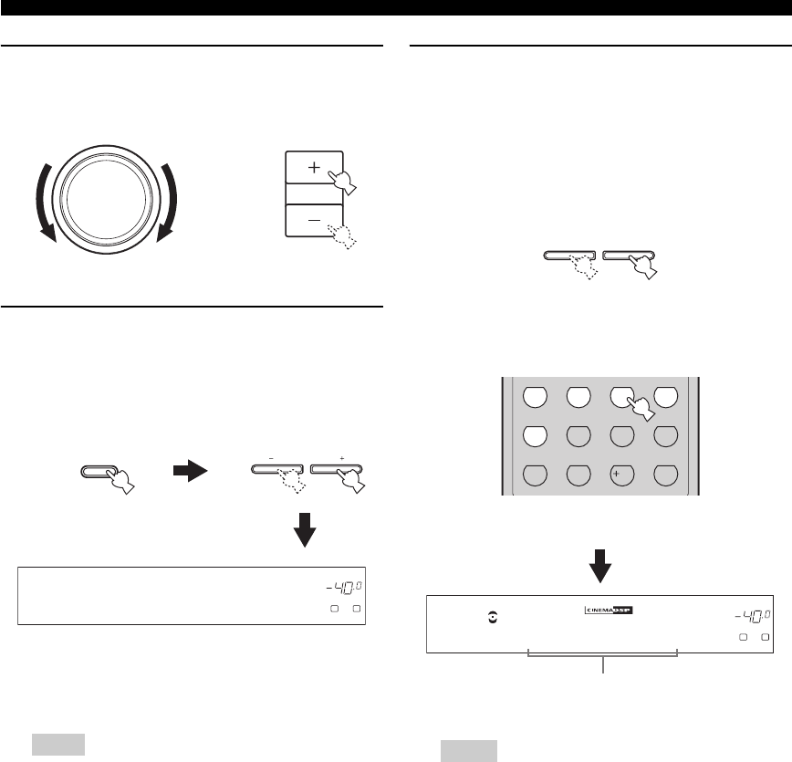
32
PLAYBACK
5Rotate VOLUME on the front panel (or press
VOLUME +/– on the remote control) to adjust
the volume to the desired output level.
6Press TONE CONTROL on the front panel
repeatedly to select “TREBLE” or “BASS”
and then press BASS/TREBLE +/– repeatedly
to adjust the corresponding frequency
response level.
• Select “TREBLE” to adjust the high-frequency
response.
• Select “BASS” to adjust the low-frequency
response.
• Speaker and headphone adjustments are stored
independently.
• When “TONE BYPASS” is set to “AUTO” (see page 82),
and “BASS” and “TREBLE” are set to 0 dB, audio output
automatically bypasses the tone control circuitry of this
unit.
• If you increase or decrease the high-frequency or low-
frequency sound to an extreme level, the tonal quality of
the surround speakers may not match that of the front left
and right speakers.
• TONE CONTROL is not effective when the “DIRECT
STEREO” mode (see page 38) is selected or when the
component connected to the MULTI CH INPUT jacks is
selected as the input source (see page 37).
• To enjoy multi-channel sources in surround, see page 41
for details.
7Press PROGRAM l / h on the front panel (or
press one of the sound field program
selector buttons on the remote control)
repeatedly to select the desired sound field
program.
The name of the selected sound field program appears
in the front panel display and in the OSD.
See page 64 for details about sound field programs.
• Choose a sound field program based on your listening
preference, not merely on the name of the program.
• When you select an input source, this unit automatically
selects the last sound field program used with the
corresponding input source.
• Sound field programs cannot be selected when the
component connected to the MULTI CH INPUT jacks is
selected as the input source (see page 37).
• Sampling frequencies higher than 48 kHz (except for DTS
96/24 signals) are sampled down to 48 kHz and then sound
field programs are applied.
• To display information about the currently selected input
source in the OSD, see page 39 for details.
Notes
VOLUME
VOLUME
or
Remote control
Front panel
TONE CONTROL
BASS/TREBLE
DVR
p
DVD CD
XM
V-AUX DTV/CBL
MD/CD-R
TUNER
VOLUME
A
SP
dB
LR
TREBLE 0dB
Notes
l PROGRAM h
STEREO
1
EFFECT
STANDARD
5
SPEAKERS
9
MUSIC
2
SELECT
6
ENHANCER
0
ENTERTAIN
3
EXTD SUR.
7
NIGHT
10
MOVIE
4
DIRECT ST.
8
STRAIGHT
ENT.
Front panel
or
Remote control
DVR
p
DVD CD
XM
V-AUX DTV/CBL
MD/CD-R
TUNER
VOLUME
A
SP
dB
LR
TV Sports
Currently selected
surround field program
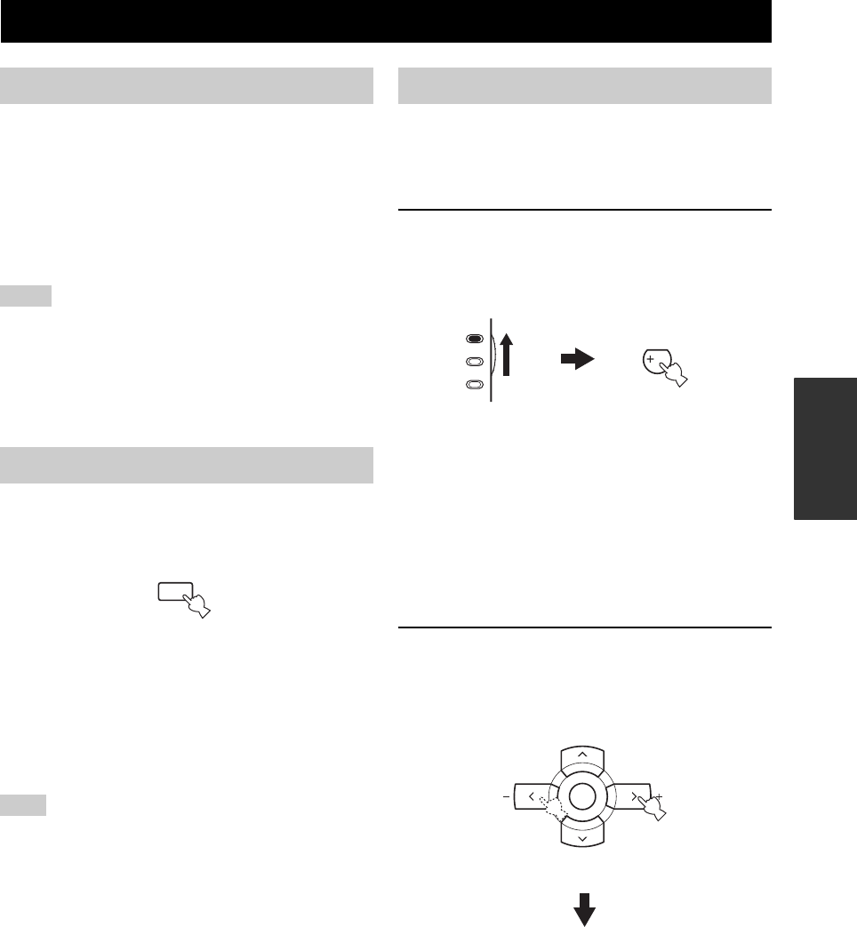
USING AUDIO FEATURES
33
BASIC
OPERATION
SILENT CINEMA allows you to enjoy multi-channel
music or movie sound, including Dolby Digital and DTS
sources, through ordinary headphones. SILENT CINEMA
activates automatically whenever you connect headphones
to the PHONES jack while listening to CINEMA DSP or
HiFi DSP sound field programs (see page 64). When
activated, the SILENT CINEMA indicator lights up in the
front panel display.
• SILENT CINEMA does not activate when the component
connected to the MULTI CH INPUT jacks is selected as the
input source (see page 37).
• SILENT CINEMA is not effective when the “DIRECT
STEREO” (see page 38) or “2ch Stereo” mode (see page 38) is
selected, or when this unit is in the “STRAIGHT” mode (see
page 38).
Press MUTE on the remote control to mute the
audio output. Press MUTE again to resume the
audio output.
y
• You can also rotate VOLUME on the front panel or VOLUME
+/– on the remote control to resume the audio output.
• You can adjust the muting level by using the “MUTING TYPE”
parameter in “SOUND MENU” (see page 82).
• The MUTE indicator flashes in the front panel display when the
audio output is muted and disappears from the front panel
display when the audio output is resumed.
If you change the input source or the sound field program while
the audio output is being muted, this unit resumes the audio
output.
The night listening modes are designed to improve
listenability at lower volumes or at night. Choose either
“NIGHT:CINEMA” or “NIGHT:MUSIC” depending on
the type of material you are playing.
1Set the component selector switch to AMP
and then press NIGHT on the remote control
repeatedly to select “NIGHT:CINEMA” or
“NIGHT:MUSIC”.
Choices: NIGHT:CINEMA, NIGHT:MUSIC, OFF
• Select “NIGHT:CINEMA” when watching films to
reduce the dynamic range of film soundtracks and
make dialog easier to hear at lower volumes.
• Select “NIGHT:MUSIC” when listening to music
sources to preserve ease-of-listening for all sounds.
• Select “OFF” if you do not want to use this feature.
y
When a night listening mode is selected, the NIGHT
indicator lights up in the front panel display.
2Press j / i on the remote control to adjust the
effect level while “NIGHT:CINEMA” or
“NIGHT:MUSIC” is displayed in the front
panel display.
Choices: MIN, MID, MAX
• Select “MIN” for minimum compression.
• Select “MID” for standard compression.
• Select “MAX” for maximum compression.
USING AUDIO FEATURES
Using SILENT CINEMA
Notes
Muting the audio output
Note
MUTE
Selecting the night listening mode
NIGHT
10
AMP
SOURCE
TV
A-E/CAT. A-E/CAT.
ENTER
PRESET/CH
Remote control
Effect.Lvl:MID
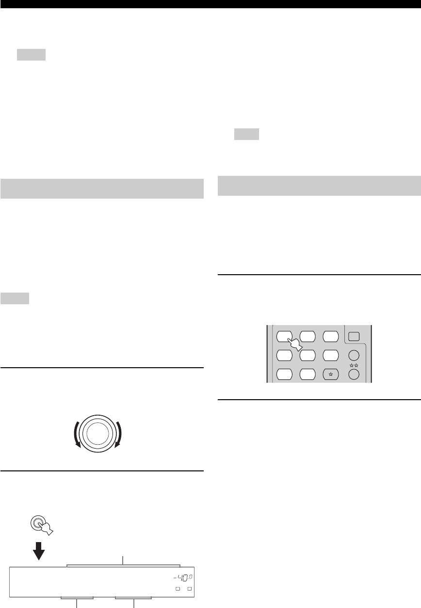
34
USING AUDIO FEATURES
y
“NIGHT:CINEMA” and “NIGHT:MUSIC” adjustments are
stored independently.
• You cannot use the night listening modes in the following
cases:
– when the “DIRECT STEREO” mode (see page 38) is
selected.
– when the component connected to the MULTI CH
INPUT jacks is selected as the input source (see
page 37).
– when headphones are connected to the PHONES jack.
• The night listening modes may vary in effectiveness
depending on the input source and surround sound settings
you use.
This unit comes with a variety of input jacks. Do the
following to select the type of input signals you want to
use.
y
• We recommend setting “INPUT MODE” to “AUTO” in most
cases.
• You can adjust the default input mode of this unit by using the
“INPUT MODE” parameter in “INPUT MENU” (see page 84).
• To play DTS-encoded CDs when using a digital audio
connection, be sure to set “INPUT MODE” to “DTS”.
• DTS decoding may not be performed correctly depending on
the player even if you make a digital connection between this
unit and the player.
1Rotate the INPUT selector on the front panel
to select the desired input source.
2Press INPUT MODE on the front panel
repeatedly to select the desired input mode.
AUTO Automatically selects input signals in
the following order:
(1) Digital signals
(2) Analog signals
DTS Selects only digital signals encoded in
DTS. If no DTS signals are input, no
sound is output.
ANALOG Selects only analog signals. If no
analog signals are input, no sound is
output.
When “INPUT MODE” is set to “AUTO”, this unit
automatically switches to the appropriate decoder if a Dolby
Digital or DTS signal is detected.
Use this feature to automatically set this unit to the
standby mode after a certain amount of time. The sleep
timer is useful when you are going to sleep while this unit
is playing or recording a source. The sleep timer also
automatically turns off any external components
connected to AC OUTLET(S) (see page 25).
1Press one of the input selector buttons on
the remote control to select the desired input
source.
2Start playback on the selected source
component or select a broadcast station.
Refer to the operating instructions for the source
component.
See page 45 for details about tuning instructions.
Notes
Selecting the input mode
Notes
INPUT
INPUT MODE
DVR
p
DVD CD
XM
V-AUX DTV/CBL
MD/CD-R
TUNER
VOLUME
A
SP
dB
LR
DVD AUTO
Currently selected
input source
Currently selected
input mode
Available input sources
Note
Using the sleep timer
CD
MULTI CH IN
SLEEP
CD-R XM
DVD DTV
MD
CBL
TUNER
V-AU X DVR
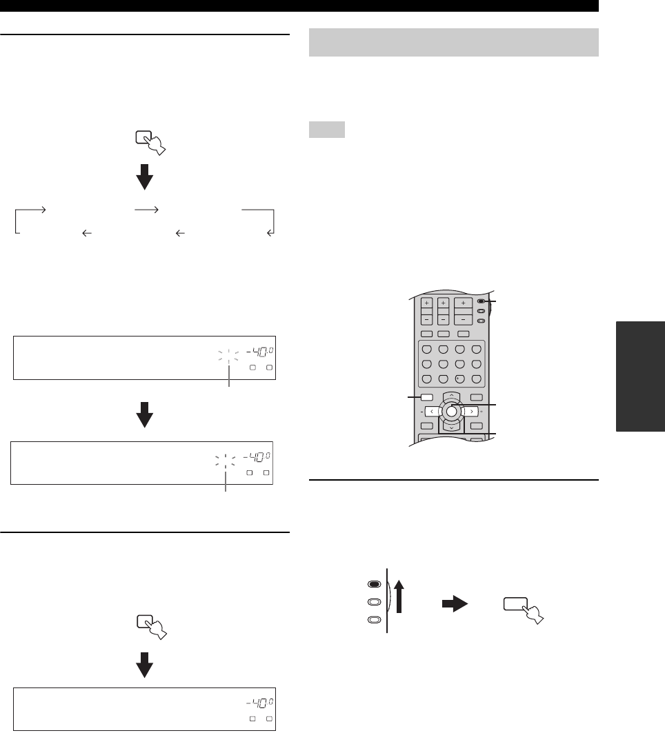
35
USING AUDIO FEATURES
BASIC
OPERATION
3Press SLEEP on the remote control
repeatedly to set the amount of time.
Each time you press SLEEP, the front panel display
changes as shown below.
The SLEEP indicator flashes while you are switching
the amount of time for the sleep timer. Once the sleep
timer is set, the SLEEP indicator lights up in the front
panel display, and the display returns to the selected
sound field program.
4To cancel the sleep timer, press SLEEP on
the remote control repeatedly until “SLEEP
OFF” appears in the front panel display.
The SLEEP indicator turns off, and “SLEEP OFF”
disappears from the front panel display after a few
seconds.
y
The sleep timer setting can also be canceled by pressing
STANDBY on the remote control (or STANDBY/ON on the
front panel) to set this unit to the standby mode.
You can adjust the output level of each speaker while
listening to a music source. This is also possible when
playing sources input at the MULTI CH INPUT jacks.
This operation will override the level adjustments made in
“BASIC SETUP” (see page 28) and “SPEAKER LEVEL” (see
page 80).
y
This operation can also be performed using the control buttons on
the front panel. Press NEXT on the front panel repeatedly to
select the speaker channel whose output level you want to adjust
and then press LEVEL +/– on the front panel to adjust the output
level.
1Set the component selector switch to AMP
and then press LEVEL on the remote control
repeatedly to select the speaker you want to
adjust.
• Select “FRONT L” to adjust the front left speaker
output level.
• Select “CENTER” to adjust the center speaker
output level.
• Select “FRONT R” to adjust the front right speaker
output level.
• Select “SUR. R” to adjust the surround right
speaker output level.
• Select “SUR. B” to adjust the surround back
speaker output level.
• Select “SUR. L” to adjust the surround left speaker
output level.
• Select “SWFR” to adjust the subwoofer output
level.
y
Once you press LEVEL on the remote control, you can also
select the speaker by pressing u / d.
SLEEP
SLEEP 90min
SLEEP 60minSLEEP 30minSLEEP OFF
SLEEP 120min
DVR DVD
p
CD
XM
V-AUX DTV/CBL
MD/CD-R
TUNER
VOLUME
SLEEP
A
SP
dB
LR
SLEEP 120min
Flashes
DVR DVD
p
CD
XM
V-AUX DTV/CBL
MD/CD-R
TUNER
VOLUME
SLEEP
A
SP
dB
LR
STRAIGHT
Lights up
SLEEP
DVR DVD
p
CD
XM
V-AUX DTV/CBL
MD/CD-R
TUNER
VOLUME
A
SP
dB
LR
SLEEP OFF
Adjusting the speaker level
Note
TV MUTE TV INPUT
MUTE
AMP
SOURCE
TV
MENUTITLE
SET MENU
LEVEL
DISPLAYRETURN
BAND
SRCH MODE
XM MEMORY
A-E/CAT. A-E/CAT.
ENTER
PRESET/CH
REC
AUDIO
DISC SKIP
STEREO
1
EFFECT
VOLUME
TV VOL TV CH
STANDARD
5
SPEAKERS
9
MUSIC
2
SELECT
6
ENHANCER
0
ENTERTAIN
3
EXTD SUR.
7
NIGHT
10
MOVIE
4
DIRECT ST.
8
STRAIGHT
ENT.
2
3
1
1
(U.S.A. model)
AMP
SOURCE
TV
TITLE
LEVEL
BAND
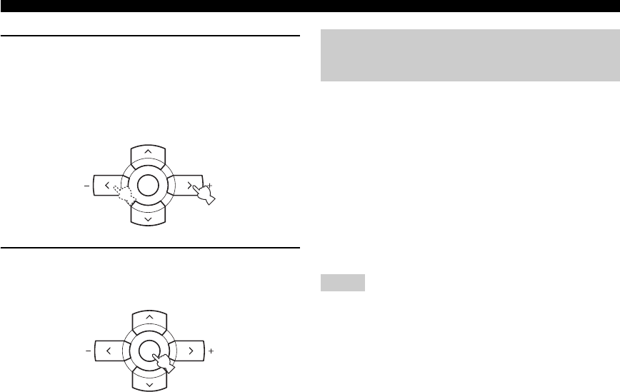
36
USING AUDIO FEATURES
2Press j / i on the remote control to adjust the
speaker output level.
• Press i to increase the value.
• Press j to decrease the value.
Control range: –10 dB to +10 dB
3Press ENTER on the remote control when
you have completed your adjustment.
Compression artifacts (such as the MP3 format) are
created by a lossy compression scheme where the audio is
resampled to lower the bitrate and to remove sounds that
are indistinguishable to typical human hearing. The
Compressed Music Enhancer feature of this unit enhances
your listening experience by regenerating the missing
harmonics in a compression artifact. As a result, flattened
complexity due to the loss of high-frequency fidelity as
well as lack of bass due to the loss of low-frequency bass
is compensated, providing the improved performance of
the overall sound system.
• The Compressed Music Enhancer mode is compatible with the
PCM signals (32 kHz, 44.1 kHz and 48 kHz) and the analog 2-
channel input sources.
• The Compressed Music Enhancer mode is not effective with
any of the sound field programs.
• When the Compressed Music Enhancer mode is turned on while
an incompatible input source is being played back, “Not
Available” appears in the front panel display and in the OSD.
• When the input source is changed to an incompatible input
source while the Compressed Music Enhancer mode is turned
on, the Compressed Music Enhancer mode is automatically
turned off and the incompatible input source is played back in
2-channel or 6-channel stereo.
y
The ENHANCER indicator lights up in the front panel display
when one of the Compressed Music Enhancer modes is selected.
A-E/CAT. A-E/CAT.
ENTER
PRESET/CH
A-E/CAT. A-E/CAT.
ENTER
PRESET/CH
Selecting the Compressed Music
Enhancer mode
Notes
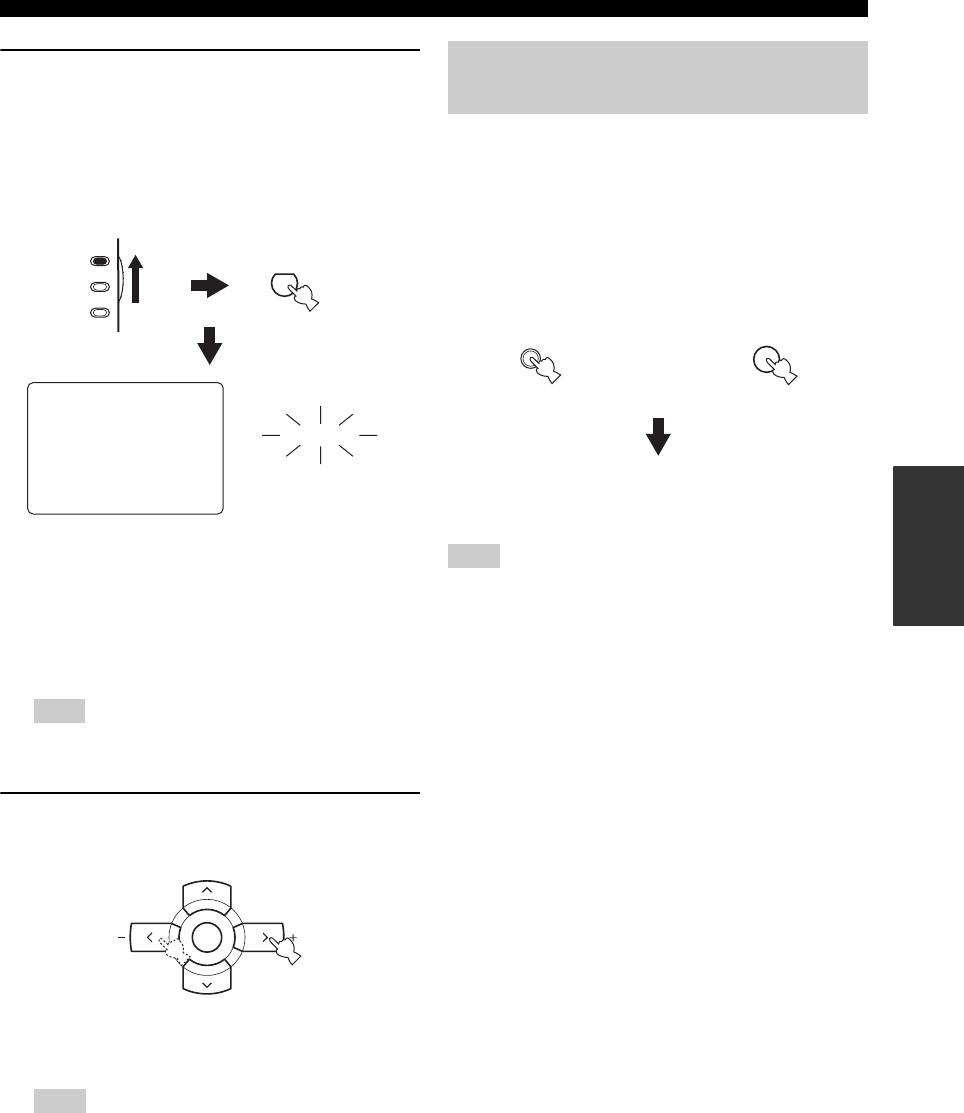
37
USING AUDIO FEATURES
BASIC
OPERATION
1Set the component selector switch to AMP
and then press ENHANCER on the remote
control repeatedly to select the desired
Compressed Music Enhancer mode.
The following display is shown in the OSD and the
ENHANCER indicator lights up in the front panel
display.
Choices: 2ch Stereo, 6ch Stereo, Off
• Select “2ch Stereo” to play back compression
artifacts in 2-channel stereo.
• Select “6ch Stereo” to play back compression
artifacts in 6.1-channel stereo.
• Select “Off ” to turn off the Compressed Music
Enhancer mode.
When you select “Off ”, this unit returns to the previously
selected sound field program.
2Press j / i on the remote control to select the
desired effect level.
Choices: HIGH, LOW
• Select “HIGH” for a high effect level.
• Select “LOW” for a low effect level.
Set the effect level to “HIGH” or “LOW” according to the
characteristics of a source. The high-frequency signals of
some sources may be emphasized too much. In this case, se
the effect level to “LOW”.
Use this feature to select the component connected to the
MULTI CH INPUT jacks (see page 23) as the input
source.
Press MULTI CH INPUT on the front panel (or
MULTI CH IN on the remote control) so that
“MULTI CH INPUT” appears in the front panel
display.
When “MULTI CH INPUT” is shown in the front panel display,
no other source can be played. To select another input source with
the INPUT selector on the front panel (or one of the input selector
buttons), press MULTI CH INPUT (or MULTI CH IN on the
remote control) so that “MULTI CH INPUT” disappears from the
front panel display.
Note
Note
ENHANCER
0
MUSIC ENHANCER
2ch Stereo
. LOW >HIGH
ENHANCER
AMP
SOURCE
TV
Lights up
A-E/CAT. A-E/CAT.
ENTER
PRESET/CH
Selecting the MULTI CH INPUT
component
Note
MULTI CH
INPUT
MULTI CH IN
Front panel Remote control
or
MULTI CH INPUT
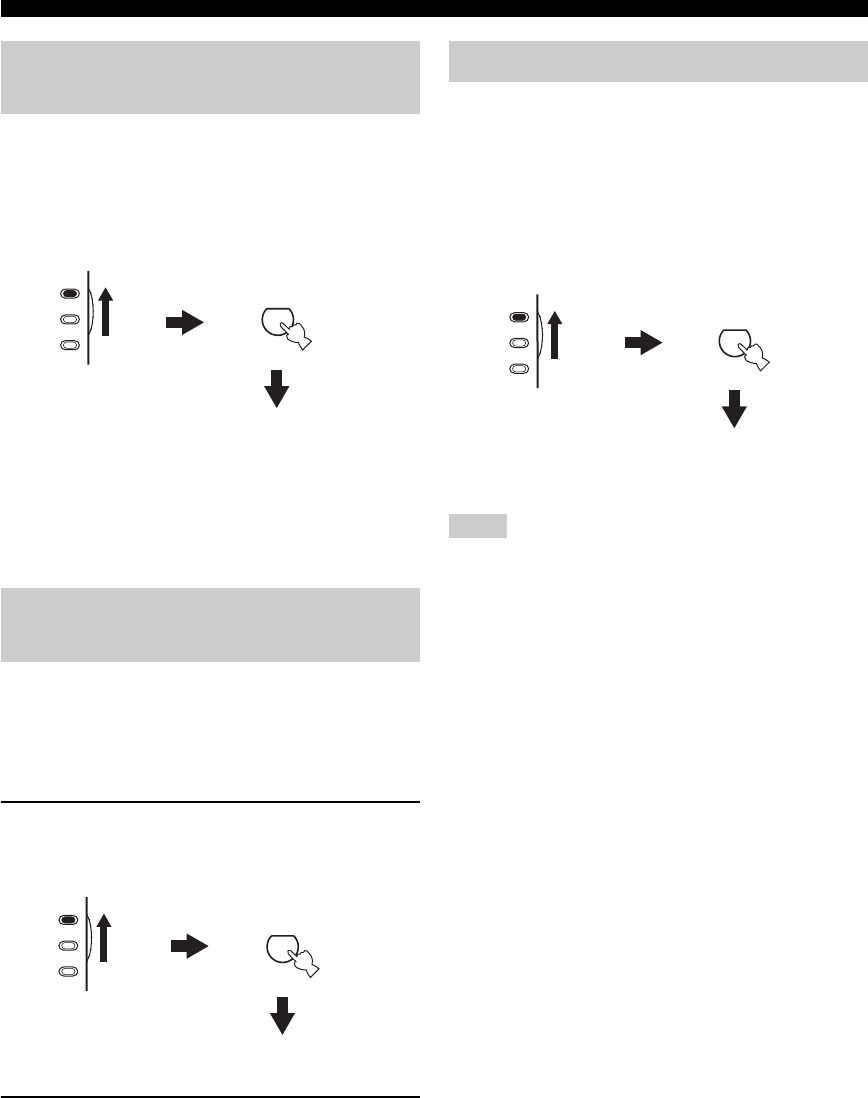
38
USING AUDIO FEATURES
You can mix down multi-channel sources to 2 channels
and enjoy playback in 2-channel stereo.
Set the component selector switch to AMP and
then press STEREO on the remote control
repeatedly to select “2ch Stereo”.
y
• You can use a subwoofer with this program when “LFE/BASS
OUT” is set to “SWFR” or “BOTH” (see page 79).
• You can also select the “2ch Stereo” mode by pressing
PROGRAM l / h on the front panel repeatedly.
When this unit is in the “STRAIGHT” mode, 2-channel
stereo sources are output from only the front left and right
speakers. Multi-channel sources are decoded straight into
the appropriate channels without any additional effect
processing.
1Set the component selector switch to AMP
and then press STRAIGHT on the remote
control to select “STRAIGHT”.
2To deactivate the “STRAIGHT” mode, press
STRAIGHT on the remote control again so
that “STRAIGHT” disappears from the front
panel display.
The sound effect is turned back on.
y
You can also select the “STRAIGHT” mode by pressing
STRAIGHT (EFFECT) on the front panel.
The “DIRECT STEREO” mode allows sources to bypass
the decoders and DSP processors of this unit so that you
can enjoy pure hi-fi sound from 2-channel PCM and
analog sources.
Set the component selector switch to AMP and
then press DIRECT ST. on the remote control to
select “DIRECT STEREO”.
• To avoid unexpected noise, do not play CDs encoded in DTS
when the “DIRECT STEREO” mode is selected.
• When multi-channel signals (Dolby Digital and DTS) are input,
this unit automatically switches to the corresponding analog
input. When “DTS” is selected as the input mode (see page 34),
no sound will be output.
• No sound will be output from the subwoofer.
• “TONE CONTROL” (see page 32) and “SOUND MENU” (see
page 78) settings (except for speaker level settings) are not
effective.
• The front panel display automatically dims.
y
You can also select the “DIRECT STEREO” mode by pressing
PROGRAM l / h on the front panel repeatedly.
Enjoying multi-channel sources in
2-channel stereo
Enjoying unprocessed input
sources
STEREO
1
AMP
SOURCE
TV
2ch Stereo
EFFECT
STRAIGHT
ENT.
AMP
SOURCE
TV
STRAIGHT
Enjoying pure hi-fi stereo sound
Notes
AMP
SOURCE
TV
DIRECT ST.
8
DIRECT STEREO
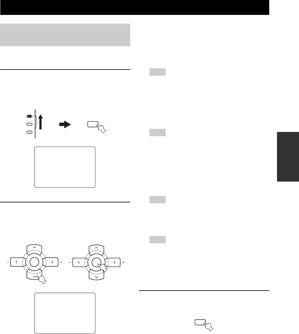
USING VIDEO FEATURES
39
BASIC
OPERATION
You can display the format, sampling frequency, channel,
bit rate and flag data of the current input signal.
1Set the component selector switch to AMP
and then press SET MENU on the remote
control.
The top “SET MENU” display appears in the OSD.
2Press d repeatedly to select “SIGNAL INFO”
and then press ENTER.
The following information about the input source
appears in the OSD.
Signal format FORMAT
Signal format display. When this unit cannot detect a
digital signal, it automatically switches to analog
input.
Display status: Analog, Digital, Dolby D, DTS, PCM,
---
“---” appears when this unit cannot detect any signals.
Sampling frequency SAMPLING
The number of samples per second taken from a
continuous signal to make a discrete signal.
Display status: 32kHz, 44.1kHz, 48kHz, 64kHz,
88.2kHz, 96kHz, ---
“---” appears when this unit cannot detect the sampling
frequency.
Channel CHANNEL
The number of source channels in the input signal
(front/surround/LFE). For example, a multi-channel
soundtrack with 3 front channels, 2 surround
channels and LFE, is displayed as “3/2/0.1”.
“---” appears when there is no source channel available.
Bit rate BITRATE
The number of bits passing a given point per second.
“---” appears when this unit cannot detect the bit rate.
Flag FLAG
Flag data encoded in DTS, Dolby Digital, or PCM
signals that cue this unit to automatically switch
decoders.
3Press SET MENU on the remote control again
to exit from “SET MENU”.
USING VIDEO FEATURES
Displaying the input source
information
SET MENU
.;BASICSETUP
;MANUALSETUP
.;SIGNAL INFO
[ ]/[]:Up/Down
[ENTER]:Enter
p
p
AMP
SOURCE
TV
MENU
SET MENU
SRCH MODE
;SIGNAL INFO
FORMAT PCM
SAMPLING 48kHz
CHANNEL 2/0/---
BITRATE ---
FLAG NONE
A-E/CAT. A-E/CAT.
ENTER
PRESET/CH
A-E/CAT. A-E/CAT.
ENTER
PRESET/CH
Note
Note
Note
Note
MENU
SET MENU
SRCH MODE
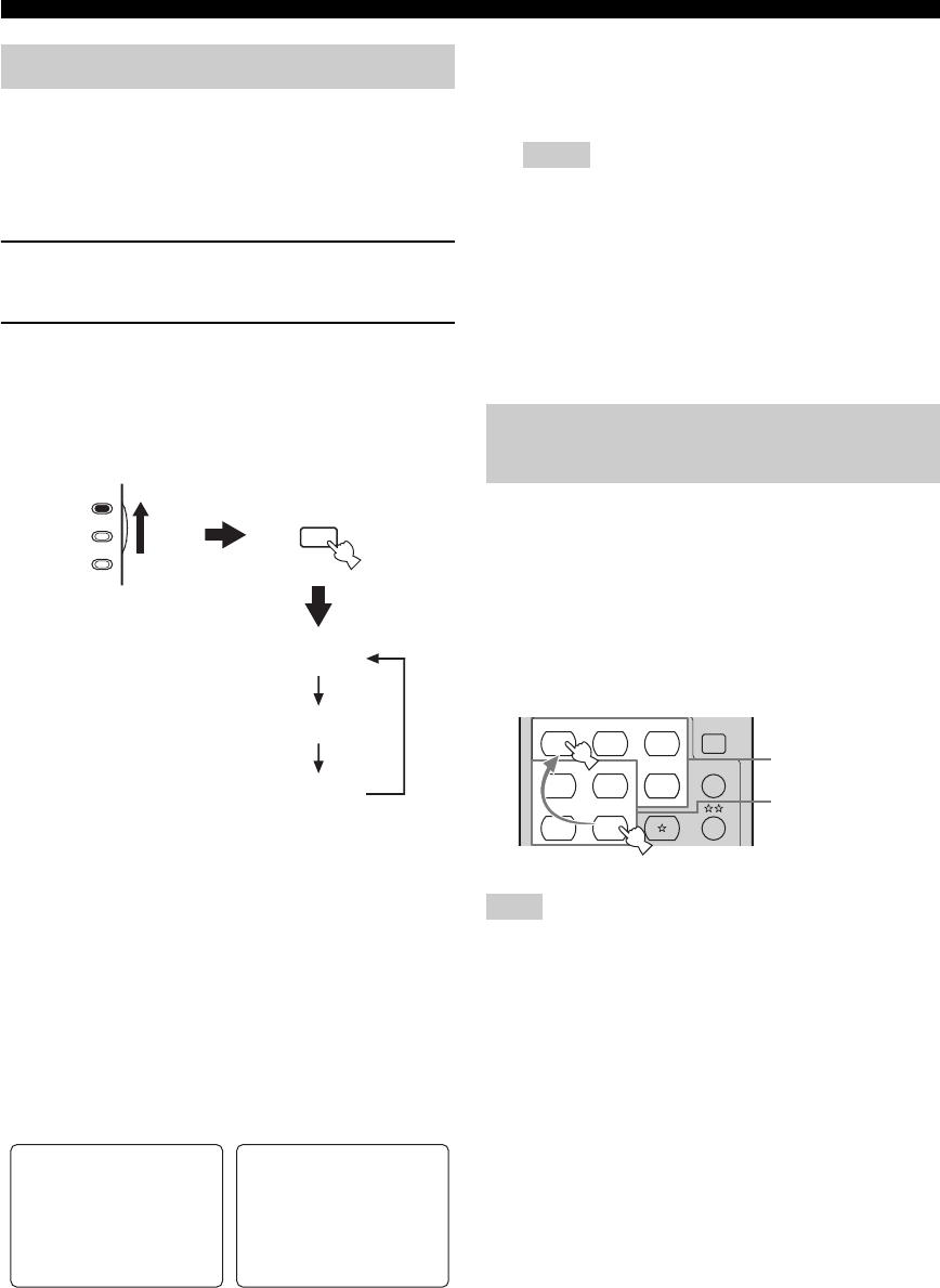
40
USING VIDEO FEATURES
You can display the operating information of this unit on a
video monitor. If you display the “SET MENU” and sound
field program parameter settings on a video monitor, it is
much easier to see the available options and parameters
than it is to read the information in the front panel display.
1Turn on the video monitor connected to this
unit.
2Set the component selector switch to AMP
and then press DISPLAY on the remote
control repeatedly to toggle between the
OSD modes.
The OSD mode changes in the following order.
Full display
Fully shows the sound field program parameter
settings as well as the contents of the front panel
display.
Short display
Briefly shows the contents of the front panel display
at the bottom of the screen each time you operate this
unit.
Display off
No information is displayed except for the “SET
MENU” screen.
y
You can display a gray background in the OSD when there
is not video signal being input by setting “GRAY BACK” in
“OPTION MENU” to “AUTO” (see page 86).
• The OSD signal is not output at the DVR OUT jacks and
will not be recorded.
• You must set “VIDEO CONV.” in “OPTION MENU” to
“ON” (see page 85) to display the OSD.
• To display the OSD with the component video signals
output at the COMPONENT VIDEO MONITOR OUT
jacks, set the OSD mode to the full display mode.
• When “GRAY BACK” in “OPTION MENU” is set to
“OFF” (see page 86), the OSD may not be displayed
correctly depending on the conditions of the picture.
You can combine a video image from a video source with
sound from an audio source. For example, you can enjoy
listening to classical music while viewing beautiful
scenery from the video source on the video monitor.
Press the input selector buttons on the remote
control to select a video source and then an
audio source.
If you want to enjoy an audio source input at the MULTI CH
INPUT jacks together with a video source, first select the video
source and then press MULTI CH INPUT on the front panel (or
MULTI CH IN on the remote control) to select the component
connected to the MULTI CH INPUT jacks as the input source
(see page 37).
Selecting the OSD mode
DISPLAY
AMP
SOURCE
TV
Full display
Short display
Display off
P02 MUSIC
. Pop/Rock
DSP LEVEL;;;;0dB
P.INIT.DLY;;21ms
P.ROOM SIZE;;1.0
S.INIT.DLY;;25ms
S.ROOM SIZE;;1.0 P02 MUSIC
Pop/Rock
Full display Short display
Notes
Playing video sources in the
background
Note
CD
MULTI CH IN
SLEEP
CD-R
DVD DTV
MD
CBL
TUNER
V-AU X DVR
XM
CD CD-R
DVD DTV
MD
CBL
TUNER
V-AU X DVR
Audio sources
Video sources
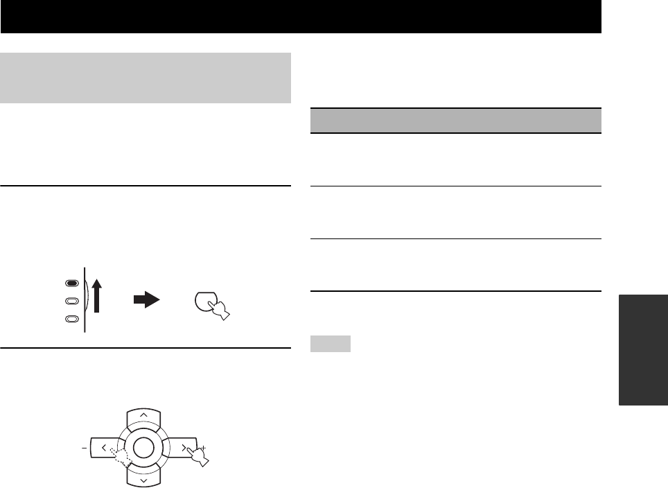
ENJOYING SURROUND SOUND
41
BASIC
OPERATION
If you connected a surround back speaker, use this feature
to enjoy 6.1-channel playback for multi-channel sources
using the Dolby Pro Logic IIx, Dolby Digital EX or
DTS-ES decoders.
1Set the component selector switch to AMP
and then press EXTD SUR. on the remote
control repeatedly to switch between 5.1 and
6.1-channel playback.
2Press j / i repeatedly to select a decoder
while “PLIIxMusic” (etc.) is displayed.
Auto AUTO
When a signal flag that can be recognized by this unit is
input, this unit selects the optimum decoder to play back
the signal in 6.1 channels.
If this unit cannot recognize the flag or no flag is present
in the input signal, it cannot automatically be played in 6.1
channels.
Decoders
You can select from the following decoders depending on
the format of the source you are playing.
Off OFF
Decoders are not used to create 6.1 channels.
• Some 6.1-channel compatible discs do not have a signal flag
that can be automatically detected by this unit. When playing
these kinds of discs in 6.1 channels, select a decoder manually
from “PLIIx Music”, “EX/ES” or “EX”.
• 6.1-channel playback is not possible even if you press EXTD
SUR. in the following cases:
– when “SUR. L/R SP” (see page 79) or “SUR. B SP” (see
page 79) is set to “NONE”.
– when the component connected to the MULTI CH INPUT
jacks is being played.
– when the source being played does not contain surround left
and right channel signals.
– when a Dolby Digital KARAOKE source is being played.
– when the “2ch Stereo” (see page 38) or “DIRECT STEREO”
(see page 38) mode is selected.
• When this unit is set to the standby mode, this setting will be
reset to “AUTO”.
• The Pro Logic IIx decoder is not available when “SUR. B SP” is
set to “NONE” (see page 79).
ENJOYING SURROUND SOUND
Enjoying multi-channel sources in
surround
EXTD SUR.
7
AMP
SOURCE
TV
A-E/CAT. A-E/CAT.
ENTER
PRESET/CH
Decoder Functions
PLIIxMusic
Plays back Dolby Digital or DTS signals
in 6.1 channels using the Pro Logic IIx
music decoder.
EX/ES
Plays back Dolby Digital or DTS signals
in 6.1 channels using the Dolby Digital
EX or DTS-ES decoder.
EX
Plays back Dolby Digital or DTS signals
in 6.1 channels using the Dolby Digital
EX decoder.
Notes
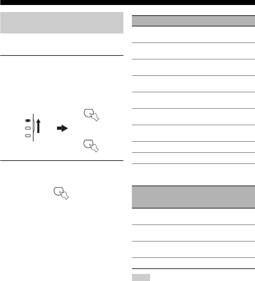
42
ENJOYING SURROUND SOUND
Signals input from 2-channel sources can also be played
back on multi-channels.
1Set the component selector switch to AMP
and then press STANDARD on the remote
control repeatedly to switch between the
“SUR. STANDARD” and “SUR. ENHANCED”
programs or press MOVIE to select the
“MOVIE THEATER” program.
2Press SELECT on the remote control
repeatedly to select the desired decoder.
You can select from the following modes depending
on the type of source you are playing and your
personal preference.
y
You can also select a decoder by pressing j / i on the remote
control while the decoder type is displayed in the front panel
display.
• The Pro Logic IIx decoder is not available when “SUR. B SP” is
set to “NONE” (see page 79).
• The Neural Surround decoder is compatible with the PCM
signals (32 kHz, 44.1 kHz and 48 kHz) and the analog 2-
channel input sources.
• The Neural Surround decoder is not effective with any of the
sound field programs.
• When Neural Surround-incompatible signals are being input
while the Neural Surround decoder is selected, multi-channel
sources are decoded straight into the appropriate channels
without any additional effect processing and the Neural
Surround-incompatible PCM signals are played back in stereo.
Enjoying 2-channel sources in
surround
AMP
SOURCE
TV
STANDARD
5
MOVIE
4
or
SELECT
6
SUR. STANDARD Functions
PRO LOGIC Dolby Pro Logic processing for any
sources
PLII Movie Dolby Pro Logic II processing for
movie sources
PLII Music Dolby Pro Logic II processing for
music sources
PLII Game Dolby Pro Logic II processing for
game sources
PLIIx Movie Dolby Pro Logic IIx processing for
movie sources
PLIIx Music Dolby Pro Logic IIx processing for
music sources
PLIIx Game Dolby Pro Logic IIx processing for
game sources
Neo:6 Cinema DTS processing for movie sources
Neo:6 Music DTS processing for music sources
Neural Sur.
Neural Surround processing for any
sources
(U.S.A. and Canada models only)
SUR. ENHANCED
or
MOVIE THEATER
Functions
PRO LOGIC Dolby Pro Logic processing for any
sources
PLII Movie Dolby Pro Logic II processing for
movie sources
PLIIx Movie Dolby Pro Logic IIx processing for
movie sources
Neo:6 Cinema DTS processing for movie sources
Notes

43
ENJOYING SURROUND SOUND
BASIC
OPERATION
Virtual CINEMA DSP allows you to enjoy the CINEMA
DSP programs without surround speakers. It creates
virtual speakers to reproduce the natural sound field.
If you set “SUR. L/R SP” to “NONE” (see page 79),
Virtual CINEMA DSP activates automatically whenever
you select a CINEMA DSP sound field program (see
page 64).
Virtual CINEMA DSP will not activate even when “SUR. L/R
SP” is set to “NONE” (see page 79) in the following cases:
– when the component connected to the MULTI CH INPUT
jacks is selected as the input source (see page 37).
– when headphones are connected to the PHONES jack.
– when the “DIRECT STEREO” (see page 38) or “2ch Stereo”
mode (see page 38) is selected, or when this unit is in the
“STRAIGHT” mode (see page 38).
Using Virtual CINEMA DSP
Note
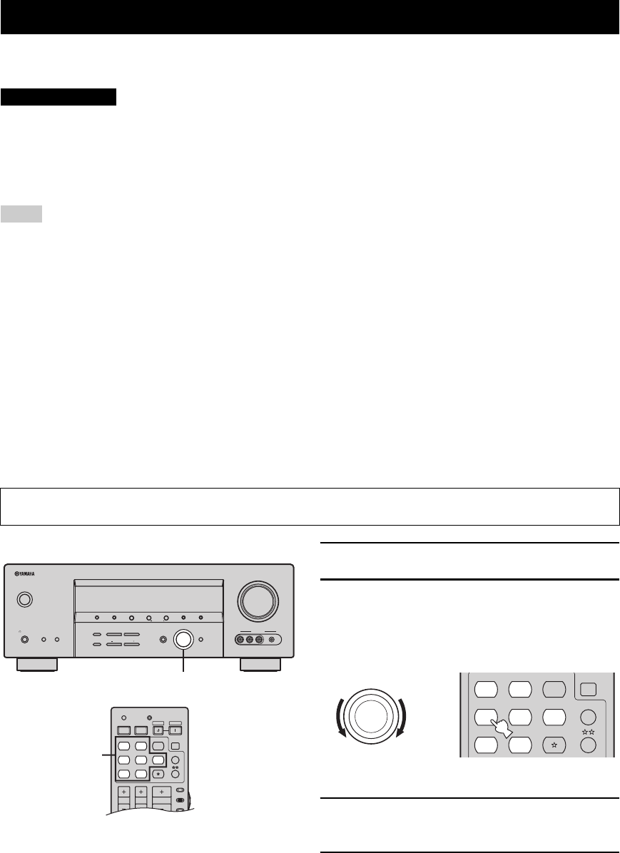
RECORDING
44
Recording adjustments and other operations are performed from the recording components. Refer to the operating
instructions for those components.
The DTS signal is a digital bitstream. Attempting to digitally record the DTS bitstream will result in
noise being recorded. Therefore, if you want to use this unit to record sources encoded in DTS, the
following considerations and adjustments need to be made. To play DTS-encoded DVDs and CDs
(when using a digital audio connection) on your DTS-compatible player, follow its operating
instructions to make a setting so that the analog signal will be output from the player.
• When this unit is set to the standby mode, you cannot record between other components connected to this unit.
• The settings of TONE CONTROL (see page 32), VOLUME, the speaker level (see page 80) and the sound field programs (see
page 64) do not affect the recorded material.
• The source connected to the MULTI CH INPUT jacks of this unit cannot be recorded.
• S-video and composite video signals pass independently through the video circuits of this unit. Therefore, when recording or dubbing
video signals input from a video source component that provides only an S-video or a composite video signal, you can record only an
S-video or a composite video signal on your VCR.
• Digital signals input at the DIGITAL INPUT jacks are not output at the analog AUDIO OUT (REC) jacks for recording. Likewise,
analog signals input at the AUDIO IN or PORTABLE jacks are not output at the DIGITAL OUTPUT jack. Therefore, if your source
component is connected to provide only digital or analog signals, you can only record digital or analog signals.
• A given input source is not output on the same OUT (REC) channel.
• Check the copyright laws in your country to record from CDs, radio, etc. Recording of copyrighted material may infringe copyright
laws.
• The XM Satellite Radio (U.S.A. model only) signals cannot be output at the AUDIO OUT (REC) jacks.
• The analog audio signals input at the DOCK terminal can be output at the analog AUDIO OUT (REC) jacks for recording.
y
Do a test recording before you start an actual recording.
1Turn on all the connected components.
2Rotate the INPUT selector on the front panel
(or press one of the input selector buttons on
the remote control) to select the source
component you want to record from.
3Start playback on the selected source
component or select a broadcast station.
4Start recording on the recording component.
RECORDING
Notes
If you play back a video source that uses scrambled or encoded signals to prevent it from being dubbed, the picture
itself may be disturbed due to those signals.
CAUTION
VOLUME
AUTO/MAN'LMAN'L/AUTO FMLEVELNEXTEDIT
EFFECT
MEMORY
FM/AMPRESET/TUNING
A/B/C/D/E
l PROGRAM h
BASS/TREBLE
TUNING MODE
INPUT MODE
TONE CONTROL
STRAIGHT
SPEAKERSPHONES
SILENT CINEMA
STANDBY
/ON
BA
MULTI CH
INPUT
INPUT
SEARCH MODE CATEGORY
l PRESET/TUNING/CH h
DISPLAY
VIDEO PORTABLEL AUDIO R
VIDEO AUX
2
AMP
SOURCE
TV
VOLUME
TV VOL TV CH
TRANSMITCODE SET
STANDBY
POWER
POWERPOWER
CD
AVTV
MULTI CH IN
SLEEP
CD-R XM
DVD DTV
MD
CBL
TUNER
V-AU X DV R
2
(U.S.A. model)
(U.S.A. model)
INPUT
CD
MULTI CH IN
SLEEP
CD-R XM
DVD DTV
MD
CBL
TUNER
V-AU X DVR
or
Front panel Remote control
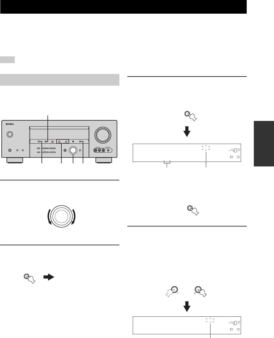
FM/AM TUNING
45
BASIC
OPERATION
There are 2 tuning methods: automatic and manual. Automatic tuning is effective when station signals are strong and
there is no interference. If the signal from the station you want to select is weak, tune into it manually. You can also use
the automatic and manual preset tuning features to store up to 40 stations (A1 to E8: 8 preset station numbers in each of
the 5 preset station groups). Furthermore, you can recall any preset stations and exchange the assignment of two preset
stations with each other.
Orient the connected FM and AM antennas for the best reception.
Automatic tuning is effective when station signals are
strong and there is no interference.
1Rotate the INPUT selector to select “TUNER”
as the input source.
2Press FM/AM to select the reception band.
“FM” or “AM” appears in the front panel display.
3Press TUNING MODE (AUTO/MAN’L) so that
the AUTO indicator lights up in the front
panel display.
If a colon (:) appears in the front panel display, tuning
is not possible. Press PRESET/TUNING to turn the
colon (:) off.
4Press PRESET/TUNING/CH l / h once to
begin automatic tuning.
When this unit is tuned into a station, the TUNED
indicator lights up and the frequency of the received
station is shown in the front panel display.
•Press h to tune into a higher frequency.
•Press l to tune into a lower frequency.
FM/AM TUNING
Note
Automatic tuning
VOLUME
AUTO/MAN'LMAN'L/AUTO FMLEVELNEXTEDIT
EFFECT
MEMORY
FM/AMPRESET/TUNING
A/B/C/D/E
l PROGRAM h
BASS/TREBLE
TUNING MODE
INPUT MODE
TONE CONTROL
STRAIGHT
SPEAKERSPHONES
SILENT CINEMA
STANDBY
/ON
BA
MULTI CH
INPUT
INPUT
SEARCH MODE CATEGORY
l PRESET/TUNING/CH h
DISPLAY
VIDEO PORTABLEL AUDIO R
VIDEO AUX
3 31
2
4
(U.S.A. model)
INPUT
Front panel
FM/AM
or AM
FM
AUTO/MAN'L
TUNING MODE
DISPLAY
DVR DVD CD
XM
V-AUX DTV/CBL
MD/CD-R
p
TUNER
AUTO TUNED
VOLUME
A
SP
dB
LR
A AM 1440 kHz
Lights upNo colon (:)
EDIT
PRESET/TUNING
SEARCH MODE
DVR DVD CD
XM
V-AUX DTV/CBL
MD/CD-R
p
TUNER
AUTO TUNED
VOLUME
A
SP
dB
LR
A AM 1530 kHz
LEVEL
l PRESET/TUNING/CH h
Lights up
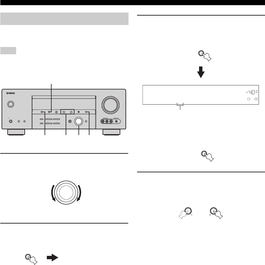
46
FM/AM TUNING
If the signal received from the station you want to select is
weak, tune into it manually.
Manually tuning into an FM station automatically switches the
tuner to monaural reception to increase the signal quality.
1Rotate the INPUT selector to select “TUNER”
as the input source.
2Press FM/AM to select the reception band.
“FM” or “AM” appears in the front panel display.
3Press TUNING MODE (AUTO/MAN’L) so that
the AUTO indicator disappears from the front
panel display.
If a colon (:) appears in the front panel display, tuning
is not possible. Press PRESET/TUNING to turn the
colon (:) off.
4Press PRESET/TUNING/CH l / h to tune
into the desired station manually.
Hold down the button to continue searching.
Manual tuning
Note
VOLUME
AUTO/MAN'LMAN'L/AUTO FMLEVELNEXTEDIT
EFFECT
MEMORY
FM/AMPRESET/TUNING
A/B/C/D/E
l PROGRAM h
BASS/TREBLE
TUNING MODE
INPUT MODE
TONE CONTROL
STRAIGHT
SPEAKERSPHONES
SILENT CINEMA
STANDBY
/ON
BA
MULTI CH
INPUT
INPUT
SEARCH MODE CATEGORY
l PRESET/TUNING/CH h
DISPLAY
VIDEO PORTABLEL AUDIO R
VIDEO AUX
3 31
2
4
(U.S.A. model)
INPUT
Front panel
FM/AM
or AM
FM
AUTO/MAN'L
TUNING MODE
DISPLAY
DVR DVD CD
XM
V-AUX DTV/CBL
MD/CD-R
p
TUNER
TUNED
VOLUME
A
SP
dB
LR
A AM 1440 kHz
No colon (:)
EDIT
PRESET/TUNING
SEARCH MODE
LEVEL
l PRESET/TUNING/CH h
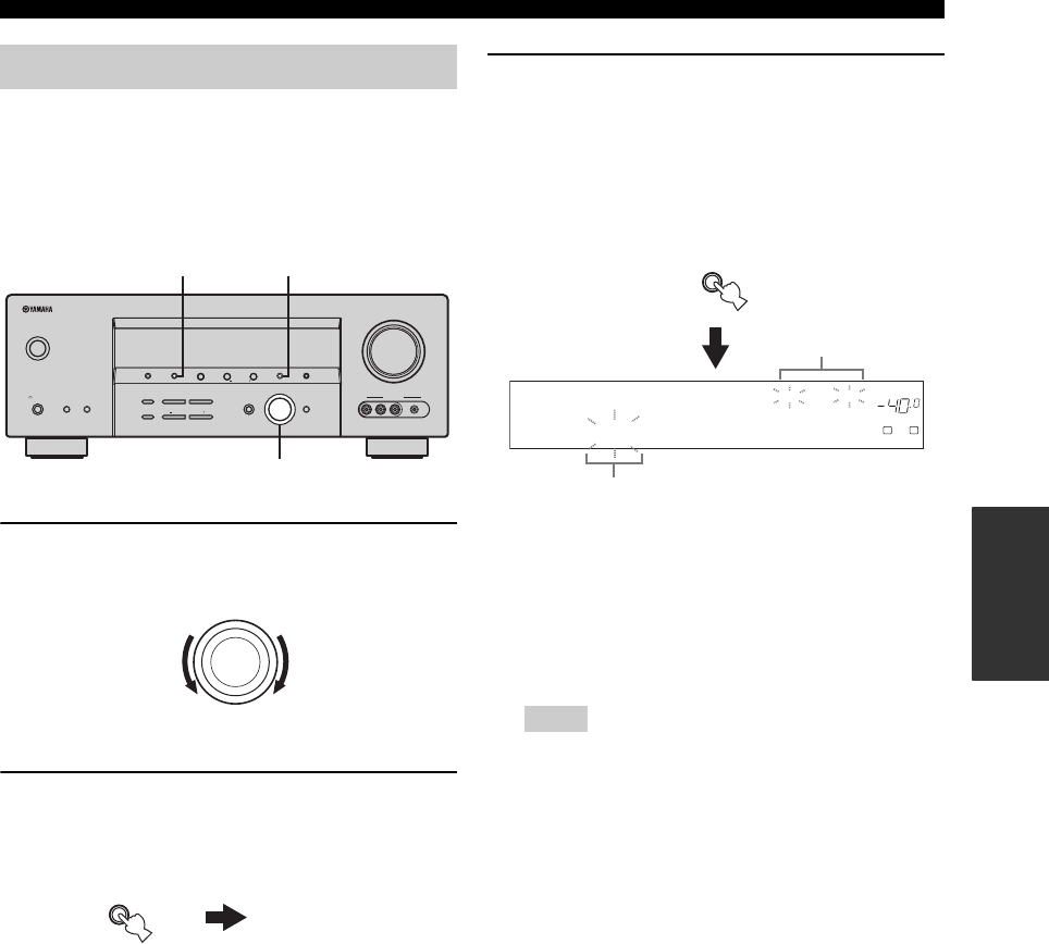
47
FM/AM TUNING
BASIC
OPERATION
You can use the automatic preset tuning feature to store
FM stations with strong signals up to 40 (A1 to E8: 8
preset station numbers in each of the 5 preset station
groups) of those stations in order. You can then recall any
preset station easily by selecting the preset station number.
1Rotate the INPUT selector to select “TUNER”
as the input source.
2Press FM/AM to select “FM” as the reception
band.
“FM” appears in the front panel display.
3Press and hold MEMORY (MAN’L/AUTO FM)
for more than 3 seconds.
The preset station number as well as the MEMORY
and AUTO indicators flashes. After approximately 5
seconds, automatic presetting starts from the current
frequency and proceeds toward the higher
frequencies.
When automatic preset tuning is completed, the front
panel display shows the frequency of the last preset
station.
y
You can specify the preset number from which this unit
stores FM stations and/or begins tuning toward lower
frequencies. For details, see “Automatic preset tuning
options” on page 48.
• Any stored station data existing under a preset station
number is cleared when you store a new station under the
same preset station number.
• If the number of received stations does not reach 40 (E8),
automatic preset tuning automatically stops after
searching for all the available stations.
• Only FM stations with sufficient signal strength are stored
automatically by automatic preset tuning. If the station
you want to store is weak in signal strength, tune into it
manually and store it as described in “Manual preset
tuning” on page 48.
Automatic preset tuning
VOLUME
AUTO/MAN'LMAN'L/AUTO FMLEVELNEXTEDIT
EFFECT
MEMORY
FM/AMPRESET/TUNING
A/B/C/D/E
l PROGRAM h
BASS/TREBLE
TUNING MODE
INPUT MODE
TONE CONTROL
STRAIGHT
SPEAKERSPHONES
SILENT CINEMA
STANDBY
/ON
BA
MULTI CH
INPUT
INPUT
SEARCH MODE CATEGORY
l PRESET/TUNING/CH h
DISPLAY
VIDEO PORTABLEL AUDIO R
VIDEO AUX
3
1
2
(U.S.A. model)
INPUT
Front panel
FM/AM
FM
Notes
DVR DVD CD
XM
V-AUX DTV/CBL
MD/CD-R
p
TUNER
AUTO TUNED
VOLUME
MEMORY
A
SP
dB
LR
A1:FM 87.5 MHz
MAN'L/AUTO FM
MEMORY
Flashes
Flash
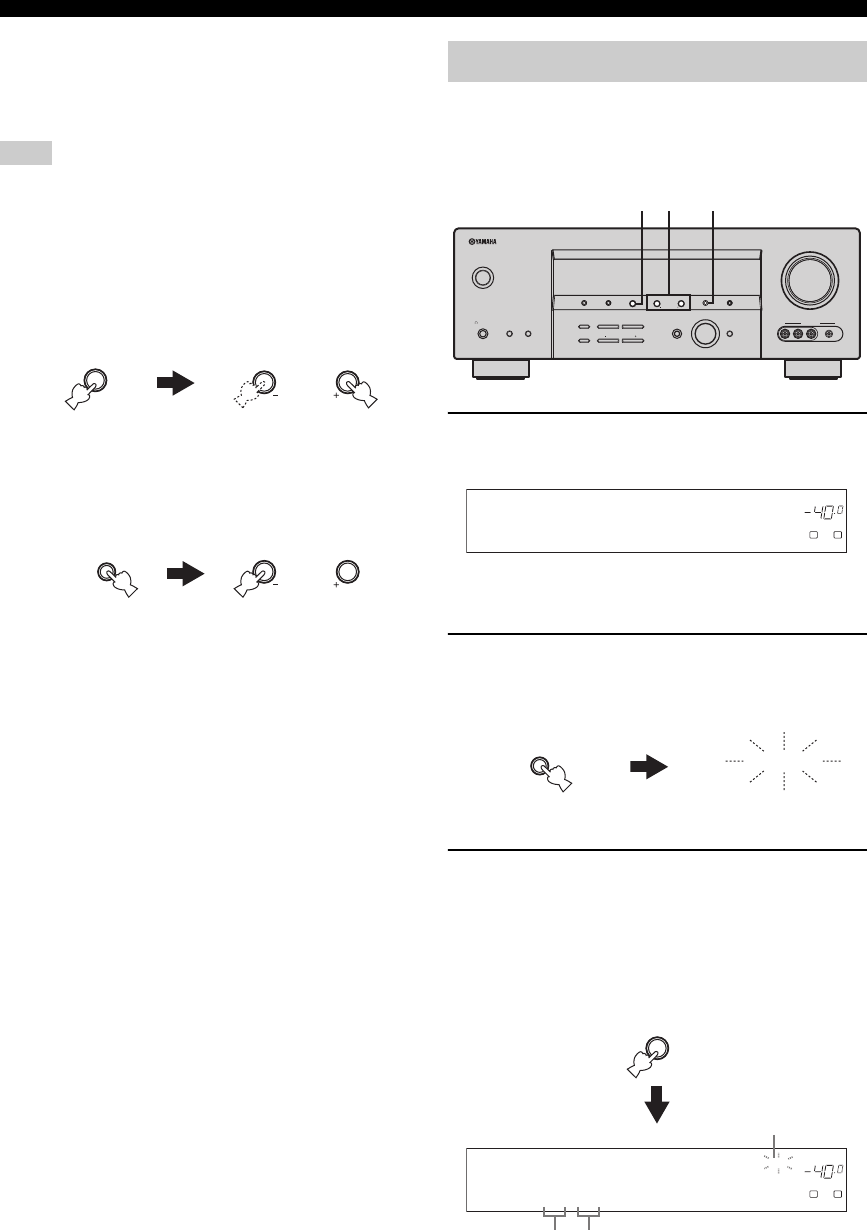
48
FM/AM TUNING
■Automatic preset tuning options
You can specify the preset number from which this unit
stores FM stations and/or begins tuning toward lower
frequencies.
First carry out steps 1 through 3 in “Automatic preset tuning” on
page 47.
• Press A/B/C/D/E and then PRESET/TUNING/
CH l / h to select the preset station number
under which the first station will be stored.
Automatic preset tuning stops when stations have all
been stored up to E8.
• Press PRESET/TUNING so that the colon (:)
disappears from the front panel display and
then press PRESET/TUNING/CH l to begin
tuning toward lower frequencies.
You can also store up to 40 stations (A1 to E8: 8 preset
station numbers in each of the 5 preset station groups)
manually.
1Tune into a station automatically or manually.
See pages 45 and 46 for tuning instructions.
When this unit is tuned into a station, the front panel
display shows the frequency of the station received.
2Press MEMORY (MAN’L/AUTO FM).
The MEMORY indicator flashes in the front panel
display for approximately 5 seconds.
3Press A/B/C/D/E repeatedly to select a preset
station group (A to E) while the MEMORY
indicator is flashing.
The selected preset station group letter appears.
Check that the colon (:) appears in the front panel
display.
Note
NEXT
A/B/C/D/E
CATEGORY
LEVEL
l PRESET/TUNING/CH h
EDIT
PRESET/TUNING
SEARCH MODE
LEVEL
l PRESET/TUNING/CH h
Manual preset tuning
VOLUME
AUTO/MAN'LMAN'L/AUTO FMLEVELNEXTEDIT
EFFECT
MEMORY
FM/AMPRESET/TUNING
A/B/C/D/E
l PROGRAM h
BASS/TREBLE
TUNING MODE
INPUT MODE
TONE CONTROL
STRAIGHT
SPEAKERSPHONES
SILENT CINEMA
STANDBY
/ON
BA
MULTI CH
INPUT
INPUT
SEARCH MODE CATEGORY
l PRESET/TUNING/CH h
DISPLAY
VIDEO PORTABLEL AUDIO R
VIDEO AUX
43 2,5
(U.S.A. model)
DVR DVD CD
XM
V-AUX DTV/CBL
MD/CD-R
p
TUNER
TUNED
VOLUME
A
SP
dB
LR
A AM 630 kHz
MAN'L/AUTO FM
MEMORY
MEMORY
Flashes
NEXT
A/B/C/D/E
CATEGORY
DVR DVD CD
XM
V-AUX DTV/CBL
MD/CD-R
p
TUNER
TUNED
VOLUME
MEMORY
A
SP
dB
LR
C :AM 630 kHz
Preset station
group
Flashes
Colon (:)
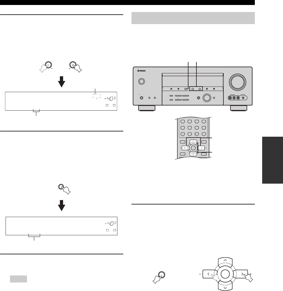
49
FM/AM TUNING
BASIC
OPERATION
4Press PRESET/TUNING/CH l / h to select a
preset station number (1 to 8) while the
MEMORY indicator is flashing.
• Press h to select a higher preset station number.
• Press l to select a lower preset station number.
5Press MEMORY (MAN’L/AUTO FM) while the
MEMORY indicator is flashing.
The station band and frequency appear in the front
panel display with the preset station group and
number you have selected. The MEMORY indicator
disappears from the front panel display.
6Repeat steps 1 through 5 to store other
stations.
• Any stored station data existing under a preset station
number is cleared when you store a new station under the
same preset station number.
• The reception mode (stereo or monaural) is stored along
with the station frequency.
You can tune into any desired station simply by selecting
the preset station group and number under which it was
stored.
y
When performing this operation with the remote control, set the
component selector switch to SOURCE and then press TUNER
to select “TUNER” as the input source.
1Press A/B/C/D/E on the front panel (or A-E/
CAT. j / i on the remote control) to select the
desired preset station group (A to E).
The preset station group letter appears in the front
panel display and changes each time you press the
button.
Notes
LEVEL
l PRESET/TUNING/CH h
DVR DVD CD
XM
V-AUX DTV/CBL
MD/CD-R
p
TUNER
TUNED
VOLUME
MEMORY
A
SP
dB
LR
C3:AM 630 kHz
Preset station number
Flashes
DVR DVD CD
XM
V-AUX DTV/CBL
MD/CD-R
p
TUNER
TUNED
VOLUME
A
SP
dB
LR
C3:AM 630 kHz
The displayed station has been stored as C3.
MAN'L/AUTO FM
MEMORY
Selecting preset stations
VOLUME
AUTO/MAN'LMAN'L/AUTO FMLEVELNEXTEDIT
EFFECT
MEMORY
FM/AMPRESET/TUNING
A/B/C/D/E
l PROGRAM h
BASS/TREBLE
TUNING MODE
INPUT MODE
TONE CONTROL
STRAIGHT
SPEAKERSPHONES
SILENT CINEMA
STANDBY
/ON
BA
MULTI CH
INPUT
INPUT
SEARCH MODE CATEGORY
l PRESET/TUNING/CH h
DISPLAY
VIDEO PORTABLEL AUDIO R
VIDEO AUX
21
MENUTITLE
SET MENU
LEVEL
DISPLAYRETURN
BAND
SRCH MODE
XM MEMORY
A-E/CAT. A-E/CAT.
ENTER
PRESET/CH
REC
STEREO
1
EFFECT
STANDARD
5
SPEAKERS
9
MUSIC
2
SELECT
6
ENHANCER
0
ENTERTAIN
3
EXTD SUR.
7
NIGHT
10
MOVIE
4
DIRECT ST.
8
STRAIGHT
ENT.
2
1
(U.S.A. model)
(U.S.A. model)
NEXT
A/B/C/D/E
CATEGORY
A-E/CAT. A-E/CAT.
ENTER
PRESET/CH
or
Front panel Remote control
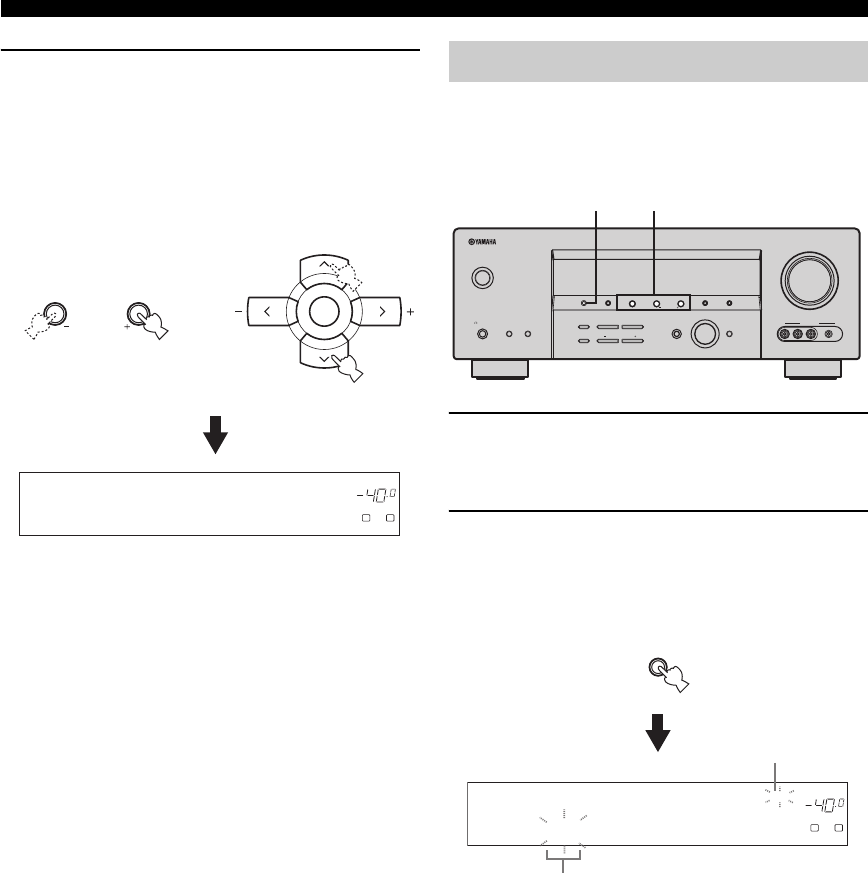
50
FM/AM TUNING
2Press PRESET/TUNING/CH l / h on the
front panel (or PRESET/CH u / d on the
remote control) to select the desired preset
station number (1 to 8).
The preset station group and number appear in the
front panel display along with the station band and
frequency.
You can exchange the assignments of two preset stations
with each other. The example below describes the
procedure to exchange preset station “E1” with “A5”.
1Select preset station “E1” using A/B/C/D/E
and PRESET/TUNING/CH l / h.
See “Selecting preset stations” on page 49.
2Press and hold EDIT for more than 3
seconds.
“E1” and the MEMORY indicator flash in the front
panel display.
LEVEL
l PRESET/TUNING/CH h
DVR DVD CD
XM
V-AUX DTV/CBL
MD/CD-R
p
TUNER
TUNED
VOLUME
A
SP
dB
LR
E1:FM 87.5 MHz
A-E/CAT. A-E/CAT.
ENTER
PRESET/CH
or
Front panel Remote control
Exchanging preset stations
VOLUME
AUTO/MAN'LMAN'L/AUTO FMLEVELNEXTEDIT
EFFECT
MEMORY
FM/AMPRESET/TUNING
A/B/C/D/E
l PROGRAM h
BASS/TREBLE
TUNING MODE
INPUT MODE
TONE CONTROL
STRAIGHT
SPEAKERSPHONES
SILENT CINEMA
STANDBY
/ON
BA
MULTI CH
INPUT
INPUT
SEARCH MODE CATEGORY
l PRESET/TUNING/CH h
DISPLAY
VIDEO PORTABLEL AUDIO R
VIDEO AUX
1,32,4
(U.S.A. model)
EDIT
PRESET/TUNING
SEARCH MODE
DVR DVD CD
XM
V-AUX DTV/CBL
MD/CD-R
p
TUNER
TUNED
VOLUME
MEMORY
A
SP
dB
LR
E1:FM 87.5 MHz
Flashes
Flashes
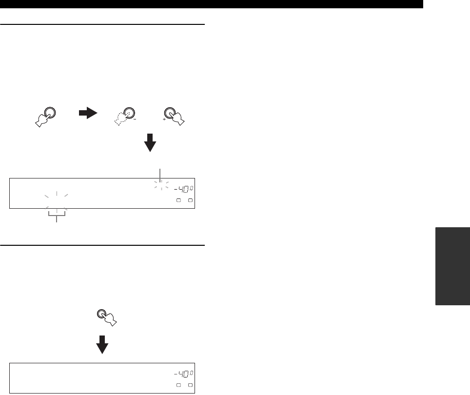
51
FM/AM TUNING
BASIC
OPERATION
3Select preset station “A5” using A/B/C/D/E
and PRESET/TUNING/CH l / h.
“A5” and the MEMORY indicator flash in the front
panel display.
See “Selecting preset stations” on page 49.
4Press EDIT again.
“EDIT E1–A5” appears in the front panel display and
the assignments of the two preset stations are
exchanged.
DVR DVD CD
XM
V-AUX DTV/CBL
MD/CD-R
p
TUNER
TUNED
VOLUME
MEMORY
A
SP
dB
LR
A5:FM 90.6 MHz
NEXT
A/B/C/D/E
CATEGORY
LEVEL
l PRESET/TUNING/CH h
Flashes
Flashes
DVR DVD CD
XM
V-AUX DTV/CBL
MD/CD-R
p
TUNER
TUNED
VOLUME
A
SP
dB
LR
EDIT E1-A5
EDIT
PRESET/TUNING
SEARCH MODE
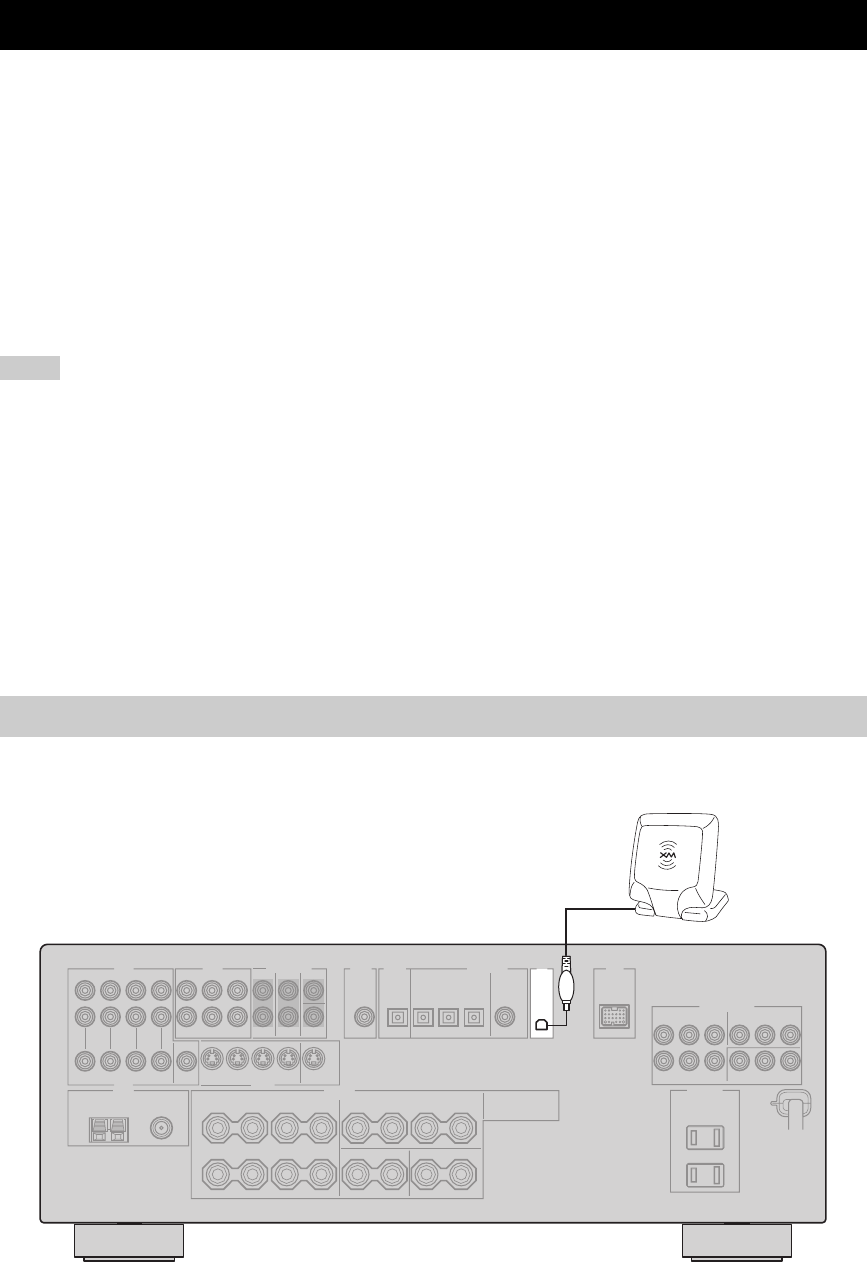
XM® SATELLITE RADIO TUNING
52
XM Satellite Radio is the satellite radio service with millions of listeners across the United States, broadcasting live
daily. The XM Satellite Radio channel lineup includes more than 150 digital channels of choice from coast to coast: 67
commercial-free music channels, featuring hip hop to opera, classical to country, bluegrass to blues; 33 channels of
premier sports, talk, comedy, children’s and entertainment programming; and more than 20 channels of the traffic and
weather information for major metropolitan areas nationwide.
Because XM Satellite Radio is a subscription service, you will need to set up an account and activate service with XM
using your XM Satellite Radio ID number. To check your ID number, follow “Activating XM Satellite Radio” on
page 54. For further information on XM Satellite Radio services, visit the XM Satellite Radio website at
“http://www.xmradio.com/”.
This unit is equipped with the Neural Surround decoder (U.S.A. and Canada models only) that plays back the surround
sound content of the XM Satellite Radio broadcasts in multi-channels, resulting in a full surround sound experience.
• The XM Satellite Radio service is only available in the 48 contiguous United States (not available in Alaska and Hawaii).
• XM Connect-and-Play digital antenna accessory and monthly subscription are sold separately. For details, visit the XM Satellite Radio
website at “http://www.xmradio.com/”.
• For information on obtaining the XM Connect-and-Play digital antenna accessory, visit the XM Satellite Radio website at
“http://www.xmradio.com/” or consult your local retailer that sells XM Ready products.
• To ensure the optimal reception of the XM Satellite Radio signals, the XM Connect-and-Play digital antenna accessory must be placed
at or near a southerly facing window with no obstacles in the path to the sky. You can mount it indoors or outdoors.
■Information from XM Satellite Radio Inc.
Hardware and required basic monthly subscription sold separately. Premium Channel available at additional monthly cost. Installation
costs and other fees and taxes, including a one-time activation fee may apply. Subscription fee is consumer only. All fees and
programming subject to change. Channels with frequent explicit language are indicated with an “XL”. Channel blocking is available for
XM radio receivers by calling “1-800-XM-RADIO (1-800-967-2346)”. Subscriptions subject to Customer Agreement available at
xmradio.com. Only available in the 48 continuous United States. © 2005 XM Satellite Radio Inc. All rights reserved. All other
trademarks are the property of their respective owners.
Connect the XM Connect-and-Play digital antenna accessory (sold separately) to the XM jack on the rear panel of this
unit. For details, see the operating instructions provided with the XM Connect-and-Play digital antenna accessory.
XM® SATELLITE RADIO TUNING
Notes
Connecting the XM Connect-and-Play digital antenna accessory
XM
XM Connect-and-Play
digital antenna accessory
(sold separately)
(U.S.A. model)
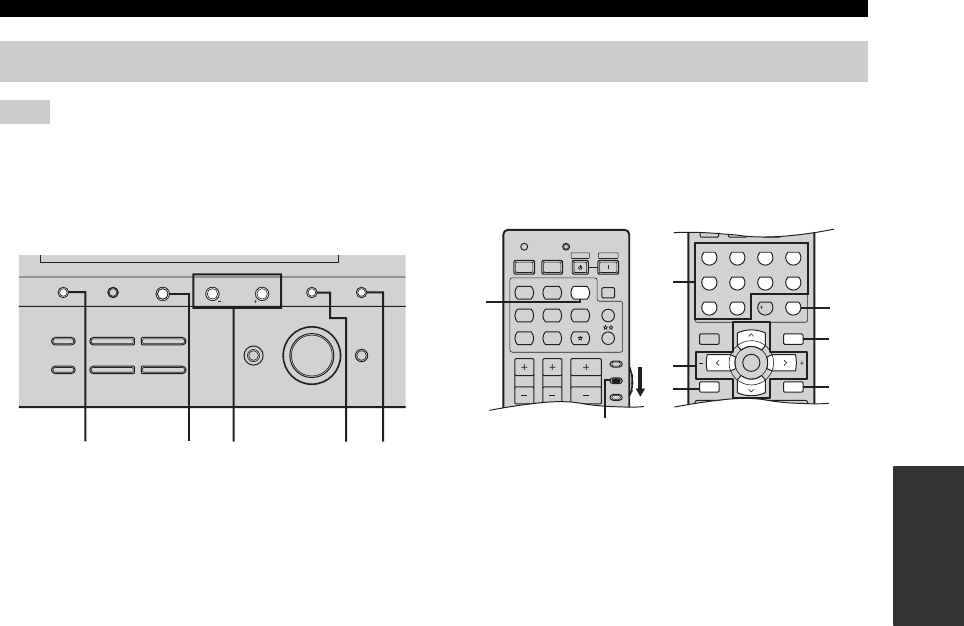
53
XM® SATELLITE RADIO TUNING
BASIC
OPERATION
The following controls are available only when “XM” is selected as the input source. Rotate the INPUT selector on the front panel (or
set the component selector switch to SOURCE and then press XM on the remote control) to select “XM” as the input source.
■Front panel functions
1SEARCH MODE
Changes the search mode between the All Channel
Search, Category Search, and Preset Search modes
(see page 56).
2CATEGORY
(All Channel Search mode)
Changes the channel category while staying in the All
Channel Search mode.
(Category Search mode)
Changes the channel category.
(Preset Search mode)
Changes the preset channel group (A to E).
3PRESET/TUNING/CH l / h
(All Channel Search mode)
Searches for a channel within all channels. Press and hold
for quick search.
(Category Search mode)
Searches for a channel within the selected category. Press
and hold for quick search.
(Preset Search mode)
Changes the preset channel number (1 to 8).
4MEMORY (MAN’L/AUTO FM)
Stores a preset channel in the memory (see page 60).
5DISPLAY
Displays the XM Satellite Radio information such as
channel number, channel name, category, artist name, or
song title displayed in the front panel display or in the
OSD (see page 61).
■Remote control functions
1XM
Selects “XM” as the input source.
2Numeric buttons
(All Channel Search or Category Search mode)
Use 1 to 9 and 0 to enter a channel number directly.
(Preset Search mode)
Use 1 to 8 to enter a preset channel number directly.
3Cursor buttons u / d / j / i
(All Channel Search mode)
Press A-E/CAT. j / i to change the channel category.
Press PRESET/CH u / d to search for a channel within
all channels. Press and hold for quick search.
(Category Search mode)
Press A-E/CAT. j / i to change the channel category.
Press PRESET/CH u / d to search for a channel within
the selected category. Press and hold for quick search.
(Preset Search mode)
Press A-E/CAT. j / i to change the preset channel group
(A to E).
Press PRESET/CH u / d to change the preset channel
number (1 to 8).
4XM MEMORY
Stores a preset channel in the memory (see page 60).
5ENT.
Confirms an entered channel number in the Direct
Number Access mode (see page 59).
6SRCH MODE
Changes the search mode between the All Channel
Search, Category Search, and Preset Search modes
(see page 56).
7DISPLAY
Displays the XM Satellite Radio information such as
channel number, channel name, category, artist name, or
song title displayed in the front panel display or in the
OSD (see page 61).
XM Satellite Radio controls and functions
Note
DISPLAY
AUTO/MAN'LMAN'L/AUTO FMLEVELNEXTEDIT
EFFECT
MEMORY
FM/AMPRESET/TUNING
A/B/C/D/E
l PROGRAM h
BASS/TREBLE
l PRESET/TUNING/CH h
TUNING MODE
INPUT MODE
TONE CONTROL
STRAIGHT
MULTI CH
INPUT
INPUT
SEARCH MODE CATEGORY
21 35
4
DISPLAY
(U.S.A. model)
TV MUTE TV INPUT
MUTE
MENUTITLE
SET MENU
LEVEL
DISPLAYRETURN
BAND
SRCH MODE
XM MEMORY
A-E/CAT. A-E/CAT.
ENTER
PRESET/CH
REC
STEREO
1
EFFECT
STANDARD
5
SPEAKERS
9
MUSIC
2
SELECT
6
ENHANCER
0
ENTERTAIN
3
EXTD SUR.
7
NIGHT
10
MOVIE
4
DIRECT ST.
8
STRAIGHT
ENT.
AMP
SOURCE
TV
VOLUME
TV VOL TV CH
TRANSMITCODE SET
STANDBY
POWER
POWERPOWER
CD
AVTV
MULTI CH IN
SLEEP
CD-R XM
DVD DTV
MD
CBL
TUNER
V-AUX DVR
1
2
3
4
5
6
7
(U.S.A. model)
Set to SOURCE.
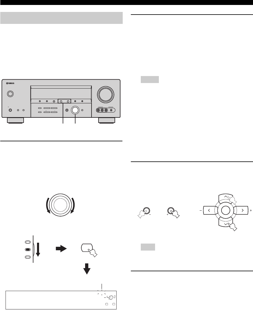
54
XM® SATELLITE RADIO TUNING
To sign up for an account with the XM Satellite Radio
service, an XM Satellite Radio ID number is required.
Follow the procedure below to check your ID number, and
then visit the website at “http://activate.xmradio.com/” or
call “1-800-XM-RADIO (1-800-967-2346)” with a major
credit card handy for signing up.
1Rotate the INPUT selector on the front panel
(or set the component selector switch to
SOURCE and then press XM on the remote
control) to select “XM” as the input source.
The cursor on the left of the XM indicator lights up in
the front panel display.
2Check the XM Satellite Radio reception level
and adjust the orientation of the XM Connect-
and-Play digital antenna accessory for a
better percentage of the reception level.
y
You can display the XM Satellite Radio reception level by
using the “XM ANTENNA” parameter in “OPTION
MENU” (see page 87).
• If “CHECK ANTENNA” appears in the front panel
display, the XM Connect-and-Play digital antenna
accessory may not be connected to the XM jack on the
rear panel of this unit properly. See “Connecting the XM
Connect-and-Play digital antenna accessory” on page 52
and check the connection.
• The “XM ANTENNA” parameter in “OPTION MENU”
(see page 87) cannot be adjusted by using the remote
control. Instead, you need to adjust the orientation of the
XM Connect-and-Play digital antenna accessory
connected to the XM jack of this unit for a better
percentage of the reception level.
3Press PRESET/TUNING/CH l / h on the
front panel (or PRESET/CH u / d on the
remote control) to select channel “0”.
You cannot select channel “0” if the All Channel Search
mode (see page 56) is not selected.
4Check the XM Satellite Radio ID number
displayed in the front panel display and write
it down.
ID:_____________________________________
Activating XM Satellite Radio
VOLUME
AUTO/MAN'LMAN'L/AUTO FMLEVELNEXTEDIT
EFFECT
MEMORY
FM/AMPRESET/TUNING
A/B/C/D/E
l PROGRAM h
BASS/TREBLE
TUNING MODE
INPUT MODE
TONE CONTROL
STRAIGHT
SPEAKERSPHONES
SILENT CINEMA
STANDBY
/ON
BA
MULTI CH
INPUT
INPUT
SEARCH MODE CATEGORY
l PRESET/TUNING/CH h
DISPLAY
VIDEO PORTABLEL AUDIO R
VIDEO AUX
12
(U.S.A. model)
INPUT
XM
AMP
SOURCE
TV
or
Remote control
Front panel
DVR DVD CD
p
XM
V-AUX DTV/CBL
MD/CD-R
TUNER
VOLUME
A
SP
dB
LR
XM RADIO
Lights up
Notes
Note
LEVEL
l PRESET/TUNING/CH h
A-E/CAT. A-E/CAT.
ENTER
PRESET/CH
Remote control
Front panel
or
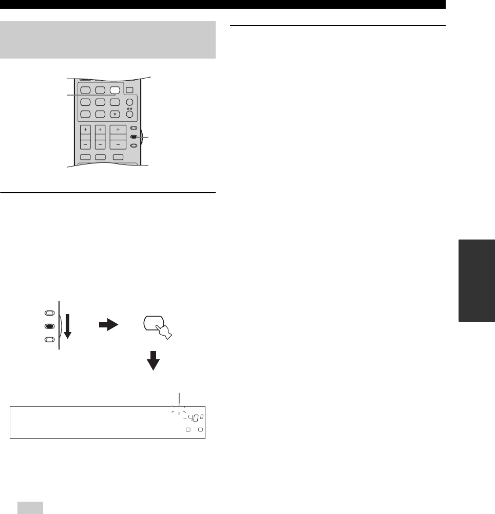
55
XM® SATELLITE RADIO TUNING
BASIC
OPERATION
1Set the component selector switch to
SOURCE and then press XM on the remote
control to select “XM” as the input source.
The cursor on the left of the XM indicator lights up in
the front panel display and the XM Satellite Radio
information (such as channel number, channel name,
category, artist name, or song title) for the currently
selected channel appears in the front panel display.
y
When you select “XM” as the input source, this unit
automatically recalls the previously selected channel.
The XM Satellite Radio signals cannot be output at the
AUDIO OUT (REC) jacks.
2Search for a channel by using one of the XM
Satellite Radio search modes.
See “Selecting the XM Satellite Radio search mode”
on page 56 for details.
y
• You can use the Neural Surround decoder to enjoy the
surround sound content of the XM Satellite Radio
broadcasts in multi-channels (see page 42).
• You can set the XM Satellite Radio preset channels (see
page 60).
• You can display the XM Satellite Radio information in the
front panel display or in the OSD (see page 61).
Basic XM Satellite Radio
operations
Note
TV MUTE TV INPUT
MUTE
AMP
SOURCE
TV
STEREO
VOLUME
TV VOL TV CH
CD
AVTV
MULTI CH IN
SLEEP
CD-R XM
DVD DTV
MD
CBL
TUNER
V-AUX DVR
MUSIC ENTERTAIN MOVIE
1
1
(U.S.A. model)
DVR DVD CD
p
XM
V-AUX DTV/CBL
MD/CD-R
TUNER
VOLUME
A
SP
dB
LR
[001] Preview
Lights up
XM
AMP
SOURCE
TV
Remote control
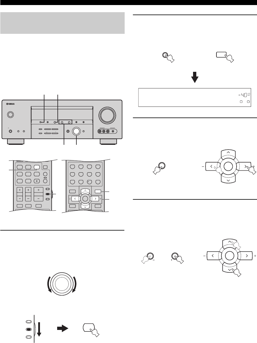
56
XM® SATELLITE RADIO TUNING
You can search for the desired channel using one of the
three search modes (All Channel Search, Category Search,
and Preset Search modes). You can also enter the channel
number directly to select the desired channel by using the
Direct Number Access mode (see page 59).
■All Channel Search mode
1Rotate the INPUT selector on the front panel
(or set the component selector switch to
SOURCE and then press XM on the remote
control) to select “XM” as the input source.
2Press SEARCH MODE on the front panel (or
SRCH MODE on the remote control)
repeatedly to select “ALL CH SEARCH”.
3Press CATEGORY on the front panel (or
A-E/CAT. j / i on the remote control)
repeatedly to change the channel category.
4Press PRESET/TUNING/CH l / h on the
front panel (or PRESET/CH u / d on the
remote control) repeatedly to search for a
channel within all channels.
y
You can search for a channel quickly by pressing and
holding PRESET/TUNING/CH l / h on the front panel
(or PRESET/CH u / d on the remote control).
Selecting the XM Satellite Radio
search mode
VOLUME
AUTO/MAN'LMAN'L/AUTO FMLEVELNEXTEDIT
EFFECT
MEMORY
FM/AMPRESET/TUNING
A/B/C/D/E
l PROGRAM h
BASS/TREBLE
TUNING MODE
INPUT MODE
TONE CONTROL
STRAIGHT
SPEAKERSPHONES
SILENT CINEMA
STANDBY
/ON
BA
MULTI CH
INPUT
INPUT
SEARCH MODE CATEGORY
l PRESET/TUNING/CH h
DISPLAY
VIDEO PORTABLEL AUDIO R
VIDEO AUX
1
23
4
(U.S.A. model)
MENUTITLE
SET MENU
LEVEL
DISPLAYRETURN
BAND
SRCH MODE
XM MEMORY
A-E/CAT. A-E/CAT.
ENTER
PRESET/CH
REC
STEREO
1
EFFECT
STANDARD
5
SPEAKERS
9
MUSIC
2
SELECT
6
ENHANCER
0
ENTERTAIN
3
EXTD SUR.
7
NIGHT
10
MOVIE
4
DIRECT ST.
8
STRAIGHT
ENT.
TV MUTE TV INPUT
MUTE
AMP
SOURCE
TV
STEREO
VOLUME
TV VOL TV CH
CD
AVTV
MULTI CH IN
SLEEP
CD-R XM
DVD DTV
MD
CBL
TUNER
V-AUX DVR
MUSIC ENTERTAIN MOVIE
3-4
2
1
1
(U.S.A. model)
INPUT
XM
AMP
SOURCE
TV
or
Remote control
Front panel
DVR DVD CD
p
XM
V-AUX DTV/CBL
MD/CD-R
TUNER
VOLUME
A
SP
dB
LR
ALL CH SEARCH
EDIT
PRESET/TUNING
SEARCH MODE
MENU
SET MENU
SRCH MODE
or
Front panel Remote control
NEXT
A/B/C/D/E
CATEGORY
A-E/CAT. A-E/CAT.
ENTER
PRESET/CH
Front panel Remote control
or
LEVEL
l PRESET/TUNING/CH h
A-E/CAT. A-E/CAT.
ENTER
PRESET/CH
Remote control
Front panel
or
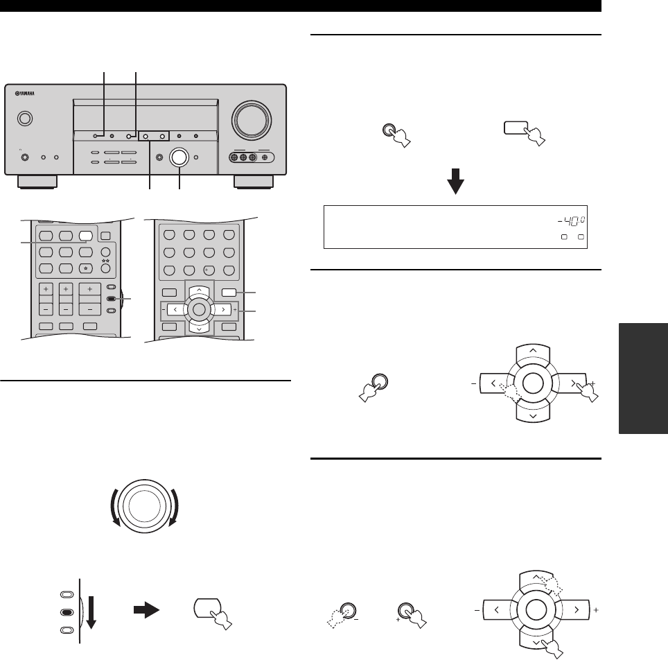
57
XM® SATELLITE RADIO TUNING
BASIC
OPERATION
■Category Search mode
1Rotate the INPUT selector on the front panel
(or set the component selector switch to
SOURCE and then press XM on the remote
control) to select “XM” as the input source.
2Press SEARCH MODE on the front panel (or
SRCH MODE on the remote control)
repeatedly to select “CAT SEARCH”.
3Press CATEGORY on the front panel (or
A-E/CAT. j / i on the remote control)
repeatedly to change the channel category.
4Press PRESET/TUNING/CH l / h on the
front panel (or PRESET/CH u / d on the
remote control) repeatedly to search for a
channel within the selected channel
category.
y
You can search for a channel quickly by pressing and
holding PRESET/TUNING/CH l / h on the front panel
(or PRESET/CH u / d on the remote control).
MENUTITLE
SET MENU
LEVEL
DISPLAYRETURN
BAND
SRCH MODE
XM MEMORY
A-E/CAT. A-E/CAT.
ENTER
PRESET/CH
REC
STEREO
1
EFFECT
STANDARD
5
SPEAKERS
9
MUSIC
2
SELECT
6
ENHANCER
0
ENTERTAIN
3
EXTD SUR.
7
NIGHT
10
MOVIE
4
DIRECT ST.
8
STRAIGHT
ENT.
TV MUTE TV INPUT
MUTE
AMP
SOURCE
TV
STEREO
VOLUME
TV VOL TV CH
CD
AVTV
MULTI CH IN
SLEEP
CD-R XM
DVD DTV
MD
CBL
TUNER
V-AUX DVR
MUSIC ENTERTAIN MOVIE
3-4
2
1
1
(U.S.A. model)
VOLUME
AUTO/MAN'LMAN'L/AUTO FMLEVELNEXTEDIT
EFFECT
MEMORY
FM/AMPRESET/TUNING
A/B/C/D/E
l PROGRAM h
BASS/TREBLE
TUNING MODE
INPUT MODE
TONE CONTROL
STRAIGHT
SPEAKERSPHONES
SILENT CINEMA
STANDBY
/ON
BA
MULTI CH
INPUT
INPUT
SEARCH MODE CATEGORY
l PRESET/TUNING/CH h
DISPLAY
VIDEO PORTABLEL AUDIO R
VIDEO AUX
1
23
4
(U.S.A. model)
INPUT
XM
AMP
SOURCE
TV
or
Remote control
Front panel
DVR DVD CD
p
XM
V-AUX DTV/CBL
MD/CD-R
TUNER
VOLUME
A
SP
dB
LR
CAT SEARCH
EDIT
PRESET/TUNING
SEARCH MODE
MENU
SET MENU
SRCH MODE
or
Front panel Remote control
NEXT
A/B/C/D/E
CATEGORY
A-E/CAT. A-E/CAT.
ENTER
PRESET/CH
Front panel Remote control
or
LEVEL
l PRESET/TUNING/CH h
A-E/CAT. A-E/CAT.
ENTER
PRESET/CH
Remote control
Front panel
or
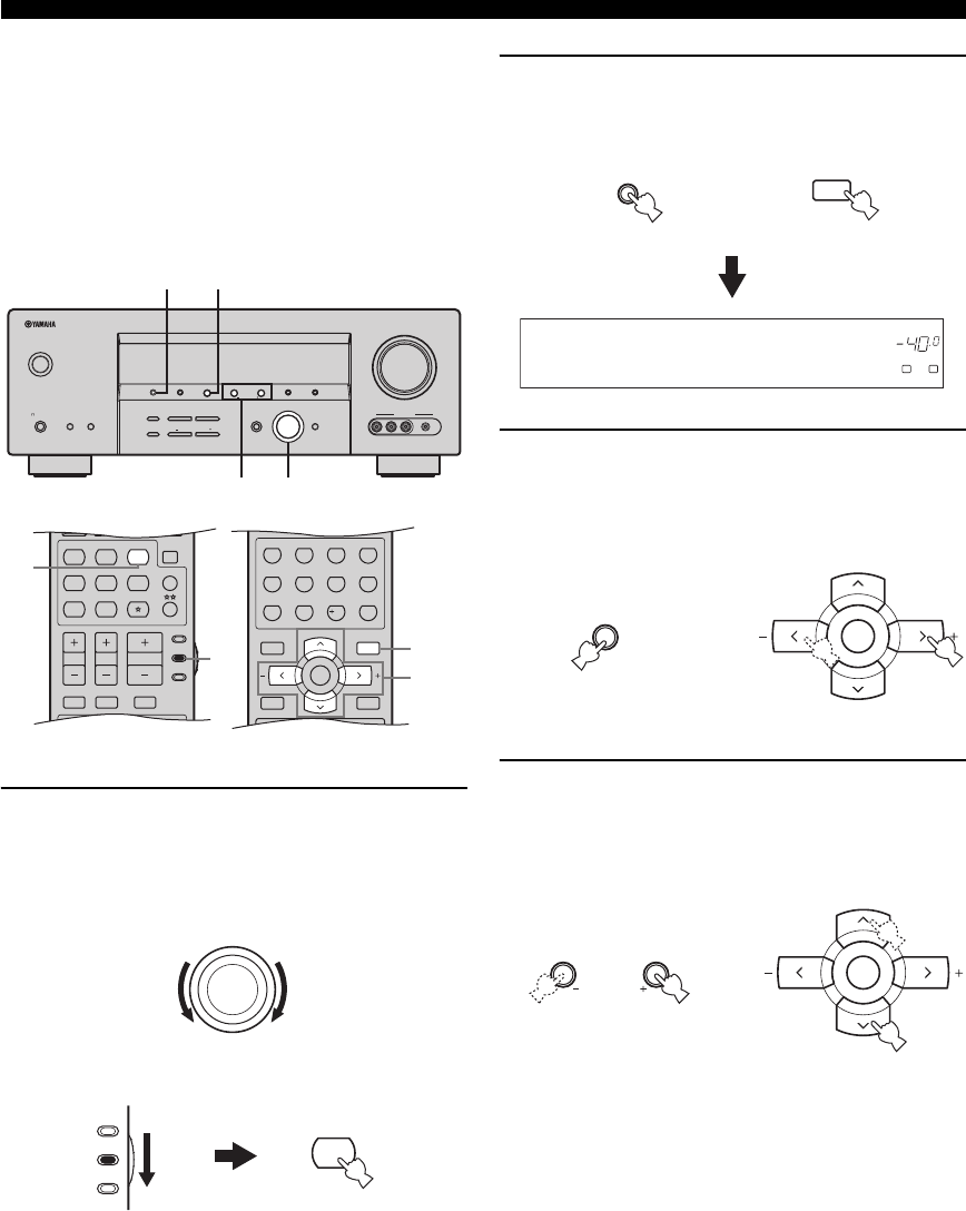
58
XM® SATELLITE RADIO TUNING
■Preset Search mode
Prior to selecting a preset channel in the Preset Search
mode, you must preset XM Satellite Radio channels. For
details, see “Setting the XM Satellite Radio preset
channels” on page 60.
y
All preset channels (A1 to E8) recalls “001 Preview” by the initial
factory setting.
1Rotate the INPUT selector on the front panel
(or set the component selector switch to
SOURCE and then press XM on the remote
control) to select “XM” as the input source.
2Press SEARCH MODE on the front panel (or
SRCH MODE on the remote control)
repeatedly to select “PRESET SEARCH”.
3Press CATEGORY on the front panel (or
A-E/CAT. j / i on the remote control)
repeatedly to change the preset channel
group (A to E).
4Press PRESET/TUNING/CH l / h on the
front panel (or PRESET/CH u / d on the
remote control) repeatedly to change the
preset channel number (1 to 8).
y
You can also select the preset channel number directly by
pressing the numeric buttons (1 to 8) on the remote control.
MENUTITLE
SET MENU
LEVEL
DISPLAYRETURN
BAND
SRCH MODE
XM MEMORY
A-E/CAT. A-E/CAT.
ENTER
PRESET/CH
REC
STEREO
1
EFFECT
STANDARD
5
SPEAKERS
9
MUSIC
2
SELECT
6
ENHANCER
0
ENTERTAIN
3
EXTD SUR.
7
NIGHT
10
MOVIE
4
DIRECT ST.
8
STRAIGHT
ENT.
TV MUTE TV INPUT
MUTE
AMP
SOURCE
TV
STEREO
VOLUME
TV VOL TV CH
CD
AVTV
MULTI CH IN
SLEEP
CD-R XM
DVD DTV
MD
CBL
TUNER
V-AUX DVR
MUSIC ENTERTAIN MOVIE
3-4
2
1
1
(U.S.A. model)
VOLUME
AUTO/MAN'LMAN'L/AUTO FMLEVELNEXTEDIT
EFFECT
MEMORY
FM/AMPRESET/TUNING
A/B/C/D/E
l PROGRAM h
BASS/TREBLE
TUNING MODE
INPUT MODE
TONE CONTROL
STRAIGHT
SPEAKERSPHONES
SILENT CINEMA
STANDBY
/ON
BA
MULTI CH
INPUT
INPUT
SEARCH MODE CATEGORY
l PRESET/TUNING/CH h
DISPLAY
VIDEO PORTABLEL AUDIO R
VIDEO AUX
1
23
4
(U.S.A. model)
INPUT
XM
AMP
SOURCE
TV
or
Remote control
Front panel
DVR DVD CD
p
XM
V-AUX DTV/CBL
MD/CD-R
TUNER
VOLUME
A
SP
dB
LR
PRESET SEARCH
EDIT
PRESET/TUNING
SEARCH MODE
MENU
SET MENU
SRCH MODE
or
Front panel Remote control
NEXT
A/B/C/D/E
CATEGORY
A-E/CAT. A-E/CAT.
ENTER
PRESET/CH
Front panel Remote control
or
LEVEL
l PRESET/TUNING/CH h
A-E/CAT. A-E/CAT.
ENTER
PRESET/CH
Remote control
Front panel
or
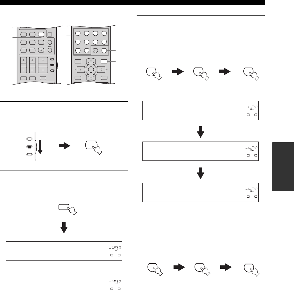
59
XM® SATELLITE RADIO TUNING
BASIC
OPERATION
■Direct Number Access mode
1Set the component selector switch to
SOURCE and then press XM on the remote
control to select “XM” as the input source.
2Press SRCH MODE on the remote control
repeatedly to select “ALL CH SEARCH” or
“CAT SEARCH”.
3Press the numeric buttons on the remote
control to enter the desired three-digit
channel number.
For example, to enter the number 123, press the
numeric buttons as shown below.
The display changes as follows.
Press the numeric buttons and ENT. on the
remote control to enter the desired one-digit
or two-digit channel number.
For example, to enter the number 12, press the
numeric buttons as shown below.
y
• Instead of pressing ENT. to tune into the channel
immediately, you can wait a few seconds until this unit
confirms the entered channel number.
• If no button is pressed within a few seconds after you enter
a one-digit or two-digit number, this unit automatically
confirms the entered channel number.
• Pressing a button other than the numeric buttons or ENT.
cancels the Direct Number Access mode procedure.
MENUTITLE
SET MENU
LEVEL
DISPLAYRETURN
BAND
SRCH MODE
XM MEMORY
A-E/CAT. A-E/CAT.
ENTER
PRESET/CH
REC
STEREO
1
EFFECT
STANDARD
5
SPEAKERS
9
MUSIC
2
SELECT
6
ENHANCER
0
ENTERTAIN
3
EXTD SUR.
7
NIGHT
10
MOVIE
4
DIRECT ST.
8
STRAIGHT
ENT.
TV MUTE TV INPUT
MUTE
AMP
SOURCE
TV
STEREO
VOLUME
TV VOL TV CH
CD
AVTV
MULTI CH IN
SLEEP
CD-R XM
DVD DTV
MD
CBL
TUNER
V-AUX D VR
MUSIC ENTERTAIN MOVIE
1
1
3
3
2
(U.S.A. model)
XM
AMP
SOURCE
TV
MENU
SET MENU
SRCH MODE
DVR DVD CD
p
XM
V-AUX DTV/CBL
MD/CD-R
TUNER
VOLUME
A
SP
dB
LR
ALL CH SEARCH
DVR DVD CD
p
XM
V-AUX DTV/CBL
MD/CD-R
TUNER
VOLUME
A
SP
dB
LR
CAT SEARCH
or
STEREO
1
MUSIC
2
ENTERTAIN
3
DVR DVD CD
p
XM
V-AUX DTV/CBL
MD/CD-R
TUNER
VOLUME
A
SP
dB
LR
<XM> -12
DVR DVD CD
p
XM
V-AUX DTV/CBL
MD/CD-R
TUNER
VOLUME
A
SP
dB
LR
<XM>123
DVR DVD CD
p
XM
V-AUX DTV/CBL
MD/CD-R
TUNER
VOLUME
A
SP
dB
LR
<XM> --1
STEREO
1
MUSIC
2
EFFECT
STRAIGHT
ENT.
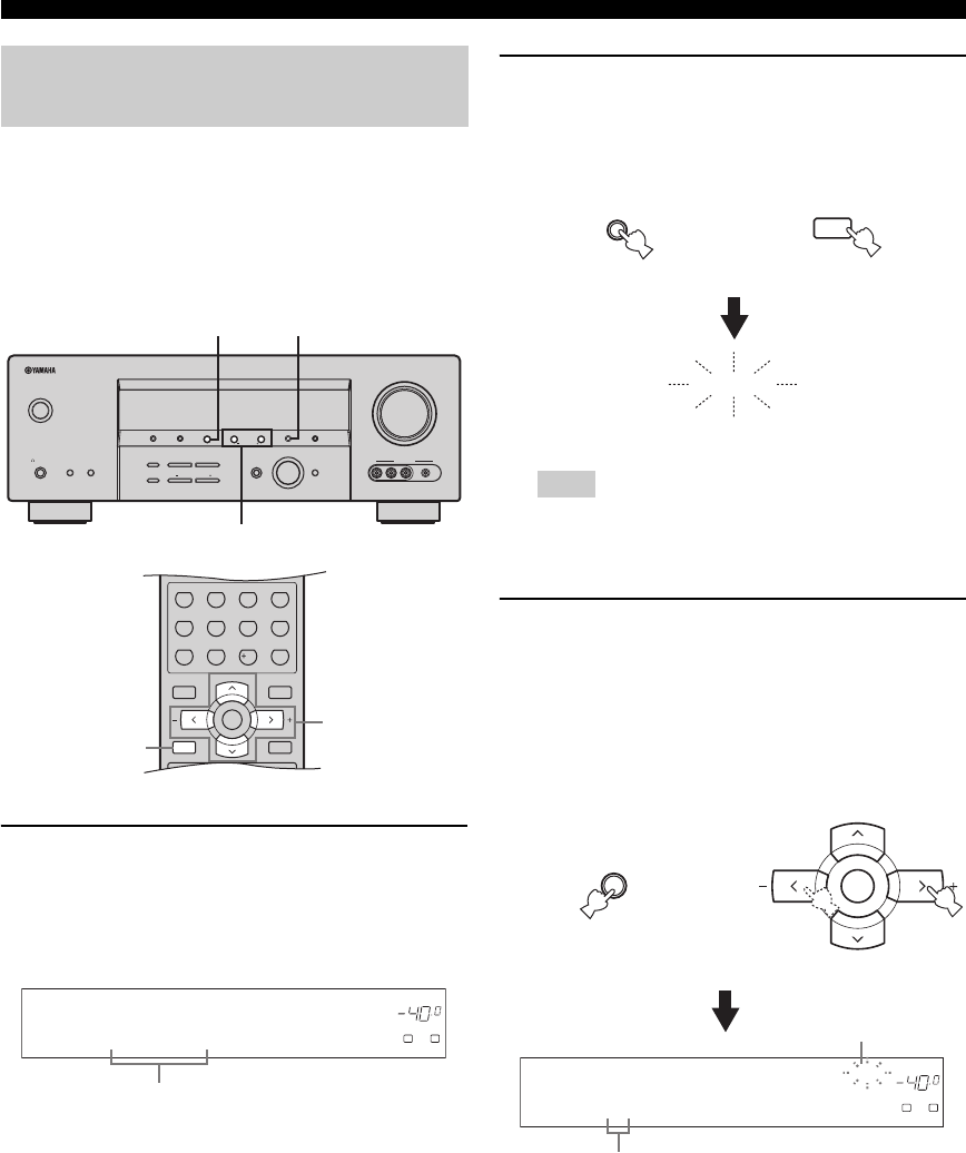
60
XM® SATELLITE RADIO TUNING
You can use this feature to store up to 40 XM Satellite
Radio channels (A1 to E8: 8 preset channel numbers in
each of the 5 preset channel groups). You can then recall
any preset channel easily by selecting the preset channel
group and number as described in “Preset Search mode”
on page 58.
1Search for a channel you want to set as a
preset channel by using one of the XM
Satellite Radio search modes.
See “Selecting the XM Satellite Radio search mode”
on page 56 for details.
2Press MEMORY on the front panel (or XM
MEMORY on the remote control).
The MEMORY indicator flashes in the front panel
display for approximately 5 seconds.
You must proceed to and carry out steps 3 through 5 while
the MEMORY indicator is flashing in the front panel
display.
3Press CATEGORY on the front panel (or
A-E/CAT. j / i on the remote control)
repeatedly to select a preset channel group
(A to E) while the MEMORY indicator is
flashing.
The preset channel group letter appears in the front
panel display.
Setting the XM Satellite Radio
preset channels
MENUTITLE
SET MENU
LEVEL
DISPLAYRETURN
BAND
SRCH MODE
XM MEMORY
A-E/CAT. A-E/CAT.
ENTER
PRESET/CH
REC
STEREO
1
EFFECT
STANDARD
5
SPEAKERS
9
MUSIC
2
SELECT
6
ENHANCER
0
ENTERTAIN
3
EXTD SUR.
7
NIGHT
10
MOVIE
4
DIRECT ST.
8
STRAIGHT
ENT.
2,5
3-4
(U.S.A. model)
VOLUME
AUTO/MAN'LMAN'L/AUTO FMLEVELNEXTEDIT
EFFECT
MEMORY
FM/AMPRESET/TUNING
A/B/C/D/E
l PROGRAM h
BASS/TREBLE
TUNING MODE
INPUT MODE
TONE CONTROL
STRAIGHT
SPEAKERSPHONES
SILENT CINEMA
STANDBY
/ON
BA
MULTI CH
INPUT
INPUT
SEARCH MODE CATEGORY
l PRESET/TUNING/CH h
DISPLAY
VIDEO PORTABLEL AUDIO R
VIDEO AUX
2,53
4
(U.S.A. model)
DVR DVD CD
p
XM
V-AUX DTV/CBL
MD/CD-R
TUNER
VOLUME
A
SP
dB
LR
[040] Deep Tra
Currently selected channel number
Note
MAN'L/AUTO FM
MEMORY
MEMORY
RETURN
XM MEMORY
Flashes
or
Front panel Remote control
DVR DVD CD
p
XM
V-AUX DTV/CBL
MD/CD-R
TUNER
VOLUME
MEMORY
A
SP
dB
LR
C [040] Deep
Currently selected preset channel group
NEXT
A/B/C/D/E
CATEGORY
A-E/CAT. A-E/CAT.
ENTER
PRESET/CH
Front panel Remote control
or
Flashes
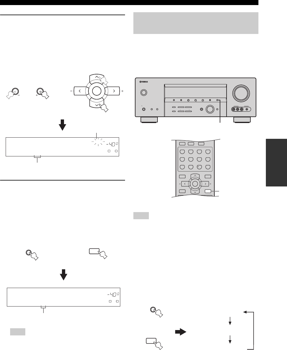
61
XM® SATELLITE RADIO TUNING
BASIC
OPERATION
4Press PRESET/TUNING/CH l / h on the
front panel (or PRESET/CH u / d on the
remote control) repeatedly to select a preset
channel number (1 to 8) while the MEMORY
indicator is flashing.
The preset channel number appears in the front panel
display.
5Press MEMORY on the front panel (or XM
MEMORY on the remote control) to set the
selected XM Satellite Radio channel as a
preset channel while the MEMORY indicator
is flashing.
A colon (:) appears next to the preset channel number
for confirmation, and the MEMORY indicator turns
off in the front panel display.
Once you set a new preset channel, the one previously
stored in the same preset channel group and number is
cleared.
You can display the XM Satellite Radio information (such
as channel number, channel name, category, artist name,
or song title) for the currently selected channel in the front
panel display or in the OSD.
If a status message or an error message appears in the front panel
display or in the OSD, see the “XM Satellite Radio (U.S.A.
model only)” section in “TROUBLESHOOTING” on page 101
for appropriate remedies.
■Displaying the XM Satellite Radio
information in the front panel display
Press DISPLAY on the front panel or on the
remote control repeatedly to toggle between the
following XM Satellite Radio information display
modes.
Note
DVR DVD CD
p
XM
V-AUX DTV/CBL
MD/CD-R
TUNER
VOLUME
MEMORY
A
SP
dB
LR
C5 [040] Deep
Currently selected preset channel number
LEVEL
l PRESET/TUNING/CH h
A-E/CAT. A-E/CAT.
ENTER
PRESET/CH
Remote control
Front panel
or
Flashes
MAN'L/AUTO FM
MEMORY
RETURN
XM MEMORY
Front panel Remote control
or
DVR DVD CD
p
XM
V-AUX DTV/CBL
MD/CD-R
TUNER
VOLUME
A
SP
dB
LR
C5:[040] Deep
Colon (:)
Displaying the XM Satellite Radio
information
Note
VOLUME
AUTO/MAN'LMAN'L/AUTO FMLEVELNEXTEDIT
EFFECT
MEMORY
FM/AMPRESET/TUNING
A/B/C/D/E
l PROGRAM h
BASS/TREBLE
TUNING MODE
INPUT MODE
TONE CONTROL
STRAIGHT
SPEAKERSPHONES
SILENT CINEMA
STANDBY
/ON
BA
MULTI CH
INPUT
INPUT
SEARCH MODE CATEGORY
l PRESET/TUNING/CH h
DISPLAY
VIDEO PORTABLEL AUDIO R
VIDEO AUX
TV MUTE TV INPUT
MUTE
MENUTITLE
SET MENU
LEVEL
DISPLAYRETURN
BAND
SRCH MODE
XM MEMORY
A-E/CAT. A-E/CAT.
ENTER
PRESET/CH
REC
STEREO
1
EFFECT
STANDARD
5
SPEAKERS
9
MUSIC
2
SELECT
6
ENHANCER
0
ENTERTAIN
3
EXTD SUR.
7
NIGHT
10
MOVIE
4
DIRECT ST.
8
STRAIGHT
ENT.
(U.S.A. model)
DISPLAY
DISPLAY
(U.S.A. model)
AUTO/MAN'L
TUNING MODE
DISPLAY
DISPLAY
Channel number / name
Channel category
Artist name / Song title
or
Front panel
Remote control
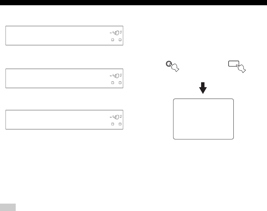
62
XM® SATELLITE RADIO TUNING
When the channel number / name is displayed:
When the channel category is displayed:
When the artist name / song title is displayed:
y
• The front panel display can indicate up to 14 alphanumeric
characters at once. You can set whether to display the XM
Satellite Radio information in the front panel display in a
continuous manner or by 14 alphanumeric characters at once by
using the “SCROLL” parameter in “OPTION MENU” (see
page 87).
• If the XM Satellite Radio information contains a character that
cannot be recognized by this unit, the character will be
displayed with an underscore “_”.
If you press DISPLAY while the XM Satellite Radio information
display is scrolling from right to left in the front panel display, the
XM Satellite Radio information display mode toggles as
described above.
■Displaying the XM Satellite Radio
information in the OSD
Press DISPLAY on the front panel or on the
remote control.
The following screen is displayed in the OSD.
y
• You can select the amount of time while the XM Satellite Radio
information is displayed in the OSD by using the “XM
DISPLAY” parameter in “OPTION MENU” (see page 87).
• To hold the XM Satellite Radio information screen, press
ENTER on the remote control while it is being displayed in the
OSD.
• The XM Satellite Radio information screen on hold is released
if you press ENTER on the remote control again or if you
change the XM Satellite Radio channel.
• This unit can save up to two XM Satellite Radio information
screens for future reference. To view the previous two XM
Satellite Radio information screens, press TITLE on the remote
control repeatedly while the current XM Satellite Radio
information screen is being on hold.
Note
DVR DVD CD
p
XM
V-AUX DTV/CBL
MD/CD-R
TUNER
VOLUME
A
SP
dB
LR
[040] Deep Tra
DVR DVD CD
p
XM
V-AUX DTV/CBL
MD/CD-R
TUNER
VOLUME
A
SP
dB
LR
<CAT>Rock
DVR DVD CD
p
XM
V-AUX DTV/CBL
MD/CD-R
TUNER
VOLUME
A
SP
dB
LR
Coldplay / Clo
XM INFORMATION
ALL CH SEARCH
XM :040
CHAN :Deep Tracks
CAT :Rock
NAME :Coldplay
TITLE :Clocks
.( Coldplay / Clo )
[]/[]:CHANNEL
[<]/[>]:CATEGORY
p
p
AUTO/MAN'L
TUNING MODE
DISPLAY
DISPLAY
Front panel Remote control
or
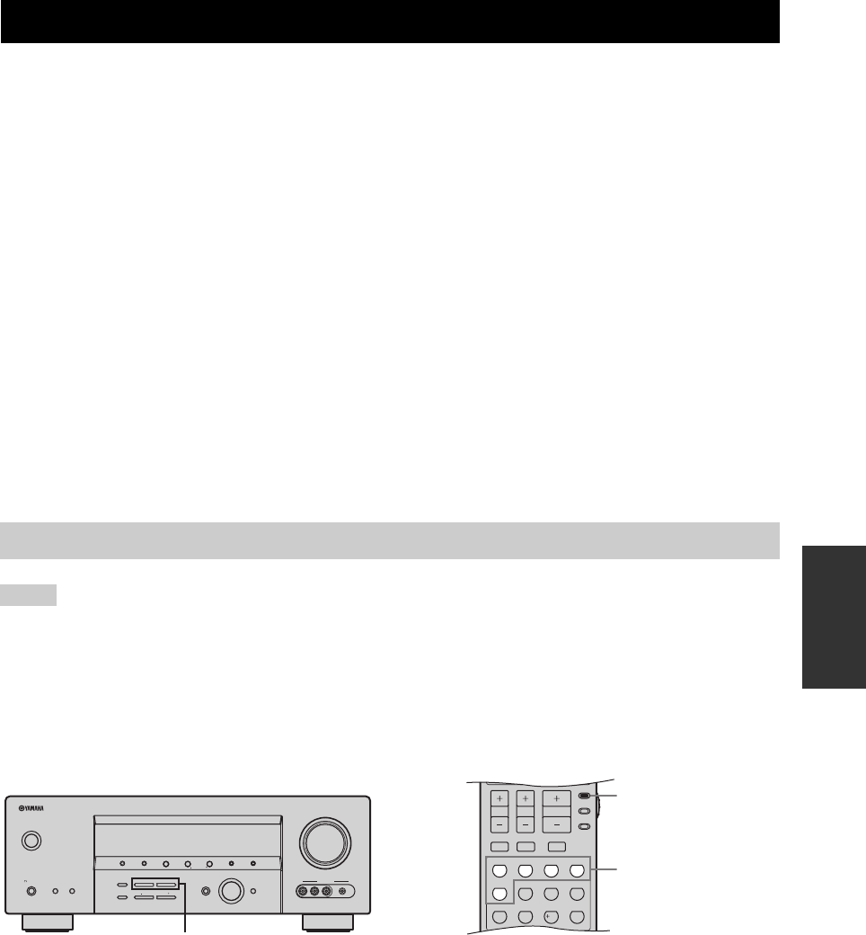
SOUND FIELD PROGRAMS
63
SOUND FIELD
PROGRAMS
What really creates the rich, full tones of a live instrument are the multiple reflections from the walls of the room. In
addition to making the sound live, these reflections enable us to tell where the player is situated as well as the size and
shape of the room in which we are sitting.
■Elements of a sound field
There are two distinct types of sound reflections that combine to make up the sound field in addition to the direct sound
coming straight to our ears from the player’s instrument.
Early reflections
Reflected sounds reach our ears extremely rapidly (50 ms to 100 ms after the direct sound), after reflecting from one
surface only (for example, from a wall or the ceiling). Early reflections actually add clarity to the direct sound.
Reverberations
These are caused by reflections from more than one surface (for example, from the walls, and the ceiling) so numerous
that they merge together to form a continuous sonic afterglow. They are non-directional and lessen the clarity of the direct
sound.
Direct sound, early reflections and subsequent reverberations taken together help us to determine the subjective size and
shape of the room, and it is this information that the digital sound field processor reproduces in order to create sound
fields.
If you could create the appropriate early reflections and subsequent reverberations in your listening room, you would be
able to create your own listening environment. The acoustics in your room could be changed to those of a concert hall, a
dance floor, or a room with virtually any size at all. This ability to create sound fields at will is exactly what YAMAHA
has done with the digital sound field processor.
• Choose a sound field program based on your listening preference, not merely on the name of the program.
• When you select an input source, this unit automatically selects the last sound field program used with the corresponding input source.
• Sound field programs cannot be selected when the component connected to the MULTI CH INPUT jacks is selected as the input
source (see page 37).
• Sampling frequencies higher than 48 kHz (except for DTS 96/24 signals) are sampled down to 48 kHz and then sound field programs
are applied.
■Front panel operations
Press PROGRAM l / h on the front panel
repeatedly.
The name of the selected sound field program appears in
the front panel display and in the OSD.
■Remote control operations
Set the component selector switch to AMP and
then press one of the sound field program
selector buttons on the remote control
repeatedly.
The name of the selected sound field program appears in
the front panel display and in the OSD.
SOUND FIELD PROGRAMS
Selecting sound field programs
Notes
VOLUME
AUTO/MAN'LMAN'L/AUTO FMLEVELNEXTEDIT
EFFECT
MEMORY
FM/AMPRESET/TUNING
A/B/C/D/E
l PROGRAM h
BASS/TREBLE
TUNING MODE
INPUT MODE
TONE CONTROL
STRAIGHT
SPEAKERSPHONES
SILENT CINEMA
STANDBY
/ON
BA
MULTI CH
INPUT
INPUT
SEARCH MODE CATEGORY
l PRESET/TUNING/CH h
DISPLAY
VIDEO PORTABLEL AUDIO R
VIDEO AUX
(U.S.A. model)
PROGRAM l / h
TV MUTE TV INPUT
MUTE
AMP
SOURCE
TV
PRESET/CH
STEREO
1
EFFECT
VOLUME
TV VOL TV CH
STANDARD
5
SPEAKERS
9
MUSIC
2
SELECT
6
ENHANCER
0
ENTERTAIN
3
EXTD SUR.
7
NIGHT
10
MOVIE
4
DIRECT ST.
8
STRAIGHT
ENT.
(U.S.A. model)
AMP
Sound field program
selector buttons

64
SOUND FIELD PROGRAMS
This unit is equipped with a variety of precise digital decoders that allow you to enjoy multi-channel playback from
almost any stereo or multi-channel sound source. This unit is also equipped with a YAMAHA digital sound field
processing (DSP) chip containing several sound field programs which you can use to enhance your playback experience.
y
The YAMAHA CINEMA DSP modes are compatible with all Dolby Digital, DTS, and Dolby Surround sources. Set “INPUT MODE”
to “AUTO” (see page 34) to enable this unit to automatically switch to the appropriate digital decoder according to the input signal.
• The DSP sound field programs of this unit are recreations of real-world acoustic environments made from precise measurements taken
in the actual concert hall, music venue, movie theater, etc. Thus, you may notice variations in the strength of the reflections coming
from the front, back, left and right.
• Choose a sound field program based on your listening preference, not merely on the name of the program itself.
■For movie/video sources
You can select from the following sound fields when playing movie or video sources. The sound fields marked “MULTI”
can be used with multi-channel sources, like DVD, digital TV, etc. Those marked “2-CH” can be used with 2-channel
stereo sources like TV programs, video tapes, etc.
y
Press PROGRAM l / h on the front panel repeatedly (or set the component selector switch to AMP and then press one of the sound
field program selector buttons on the remote control) to select the desired sound field program (see page 63).
Sound field program descriptions
Notes
Remote
control
button
Sound field program Features Sources
1STEREO
2ch Stereo
Downmixes multi-channel sources to 2 channels or plays back 2-channel
sources as they are.
MULTI
2-CH
2MUSIC
Pop/Rock
CINEMA DSP processing. Creates an enthusiastic atmosphere where you can
feel as if you are in an actual jazz or rock concert.
3
ENTERTAINMENT
TV Sports
CINEMA DSP processing. Reproduces the sound environment of a large concert
hall using the surround sound field to enhance your experience of watching
various TV programs such as news, variety shows, music programs or sports
programs.
ENTERTAINMENT
Mono Movie
CINEMA DSP processing. Reproduces monaural video sources (such as old
movies) at the optimum reverberation level to create sound depth using only the
presence sound field.
ENTERTAINMENT
Game
CINEMA DSP processing. Adds a deep and spatial feeling to video game
sounds.

65
SOUND FIELD PROGRAMS
SOUND FIELD
PROGRAMS
■For music sources
You can select from the following sound fields when playing music sources, like CD, FM/AM broadcasting, tapes, etc.
y
Press PROGRAM l / h on the front panel repeatedly (or set the component selector switch to AMP and then press one of the sound
field program selector buttons on the remote control) to select the desired sound field program (see page 63).
4
MOVIE THEATER
Spectacle
CINEMA DSP processing. This program reproduces the extremely wide sound
field of a 70-mm movie theater in detail, making both the video and the sound
field incredibly real. This is ideal for any kind of video source encoded in Dolby
Surround, Dolby Digital or DTS, especially large-scale movie productions.
MULTI
2-CH
MOVIE THEATER
Sci-Fi
CINEMA DSP processing. This program reproduces dialog and sound effects in
the latest sound form for science fiction films, thus creating a broad and
expansive cinematic space amid silence. You can enjoy science fiction films
encoded in Dolby Surround, Dolby Digital or DTS in a virtual-space sound field
employing the most advanced techniques.
MOVIE THEATER
Adventure
CINEMA DSP processing. This program reproduces the sound design of the
newest 70-mm and multi-channel soundtrack films similar to the sound field of
the newest movie theaters, so the reverberations of the sound field itself are
restrained as much as possible.
MOVIE THEATER
General
CINEMA DSP processing. This program reproduces sounds from 70-mm and
multi-channel soundtrack films characterized by soft and extensive sound field.
5
SUR. STANDARD Standard processing for the selected decoder.
SUR. ENHANCED Enhanced processing for the selected decoder.
Remote
control
button
Sound field program Features Sources
Remote
control
button
Sound field program Features Sources
1
STEREO
2ch Stereo
Plays back 2-channel sources.
2-CH
STEREO
6ch Stereo
Plays back 2-channel sources from all speakers in 6.1 channels, providing a
larger sound field ideal for background music at parties, etc.
2
MUSIC
Hall in Vienna
HiFi DSP processing. The program reproduces a classic shoe-box type concert
hall with approximately 1700 seats. Pillars and ornate carvings create extremely
complex reflections which produce a very full, rich sound.
MULTI
2-CH
MUSIC
The Bttm Line
HiFi DSP processing. This program reproduces the stage front in “The Bottom
Line”, a famous New York jazz club where 300 people can be seated.
MUSIC
The Roxy Thtr
HiFi DSP processing. This program reproduces the dynamic rock music
environment of “The Roxy Theatre”, one of the hottest rock clubs in L.A.The
listener’s imaginary seat is at the center-left of the hall.
3
ENTERTAINMENT
Disco
HiFi DSP processing. This program reproduces the acoustic environment of a
lively disco in the heart of a big city to create a highly concentrated and
energetic sound.
5
SUR. STANDARD Standard processing for the selected decoder.
SUR. ENHANCED Enhanced processing for the selected decoder.
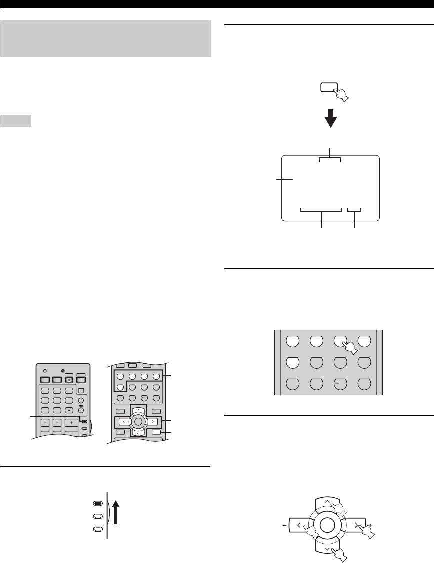
66
SOUND FIELD PROGRAMS
You can enjoy good quality sound with the initial factory
settings. Although you do not have to change the initial
factory settings, you can change some of the parameters to
better suit the input source or your listening room.
• Use the “PARAM. INI” feature in “OPTION MENU” to
initialize the parameters of each sound field program within a
sound field program group (see page 86).
• When you set a sound field parameter to a value other than the
initial factory settings, an asterisk mark (*) appears by the
sound field parameter name in the OSD.
• You cannot change the sound field parameter values when
“MEMORY GUARD” in “OPTION MENU” is set to “ON”
(see page 86). If you want to change the sound field parameter
values, set “MEMORY GUARD” to “OFF”.
y
• For details about the function and control range of each sound
field parameter, see page 67.
• Repeat steps 3 and 4 as necessary to change other sound field
program parameter settings.
• The available sound field parameters for some of the sound field
programs may be displayed on more than one page in the OSD.
In this case, press u / d to scroll through pages.
• If you press and hold j / i to change the sound field parameter
value, the initial factory settings are shown momentarily in the
front panel display.
1Set the component selector switch to AMP.
2Turn on the video monitor and then press
DISPLAY on the remote control.
The following display is shown in the OSD.
3Press one of the sound field program
selector buttons repeatedly to select the
desired sound field program you want to
adjust.
4Press u / d to select the desired sound field
parameter and then j / i to change the
selected sound field parameter value.
•Press i to increase the value.
•Press j to decrease the value.
Changing sound field parameter
settings
Notes
AMP
SOURCE
TV
VOLUME
TV VOL TV CH
TRANSMITCODE SET
STANDBY
POWER
POWERPOWER
CD
AVTV
MULTI CH IN
SLEEP
CD-R XM
DVD DTV
MD
CBL
TUNER
V-AU X DV R
TV MUTE TV INPUT
MUTE
MENUTITLE
SET MENU
LEVEL
DISPLAYRETURN
BAND
SRCH MODE
XM MEMORY
A-E/CAT. A-E/CAT.
ENTER
PRESET/CH
REC
AUDI O
STEREO
1
EFFECT
STANDARD
5
SPEAKERS
9
MUSIC
2
SELECT
6
ENHANCER
0
ENTERTAIN
3
EXTD SUR.
7
NIGHT
10
MOVIE
4
DIRECT ST.
8
STRAIGHT
ENT.
2
4
1
3
(U.S.A. model)
AMP
SOURCE
TV
DISPLAY
P02 MUSIC
. Pop/Rock
DSP LEVEL;;;;0dB
P.INIT.DLY;;21ms
P.ROOM SIZE;;1.0
S.INIT.DLY;;25ms
S.ROOM SIZE;;1.0
Sound field program category
Sound field parameters Sound field parameter
values
Cursor
STEREO
1
EFFECT
STANDARD
5
SPEAKERS
9
MUSIC
2
SELECT
6
ENHANCER
0
ENTERTAIN
3
EXTD SUR.
7
NIGHT
10
MOVIE
4
DIRECT ST.
8
STRAIGHT
ENT.
A-E/CAT. A-E/CAT.
ENTER
PRESET/CH
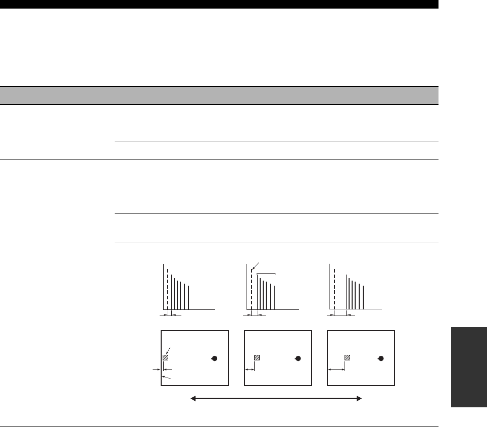
67
SOUND FIELD PROGRAMS
SOUND FIELD
PROGRAMS
■Sound field parameter descriptions
You can adjust the values of certain digital sound field parameters so that the sound fields are recreated accurately in your
listening room. Not all of the following parameters are found in every program.
y
To change sound field parameter settings to suit your listening environment, see page 66 for details.
Sound field parameter Features
DSP LEVEL DSP level. Adjusts the level of all the DSP effect sounds within a narrow range. Depending on
the acoustics of your listening room, you may want to increase or decrease the DSP effect level
relative to the level of the direct sound.
Control range: –6 dB to +3 dB
INIT.DLY
P.INIT.DLY
S.INIT.DLY
SB INI.DLY
Initial delay. Presence, surround, and surround back initial delay. Changes the apparent distance
from the source sound by adjusting the delay between the direct sound and the first reflection
heard by the listener. The smaller the value, the closer the sound source seems to the listener. The
larger the value, the farther it seems. For a small room, set to a small value. For a large room, set
to a large value.
Control range: 1 to 99 ms (INIT.DLY and P.INIT.DLY)
1 to 49 ms (S.INIT.DLY and SB INI.DLY)
Source sound
Early
reflections
Time Time Time
Delay Delay Delay
Sound source
Reflection face
Level
Small value = 1 ms Large value = 99 ms
Level
Level
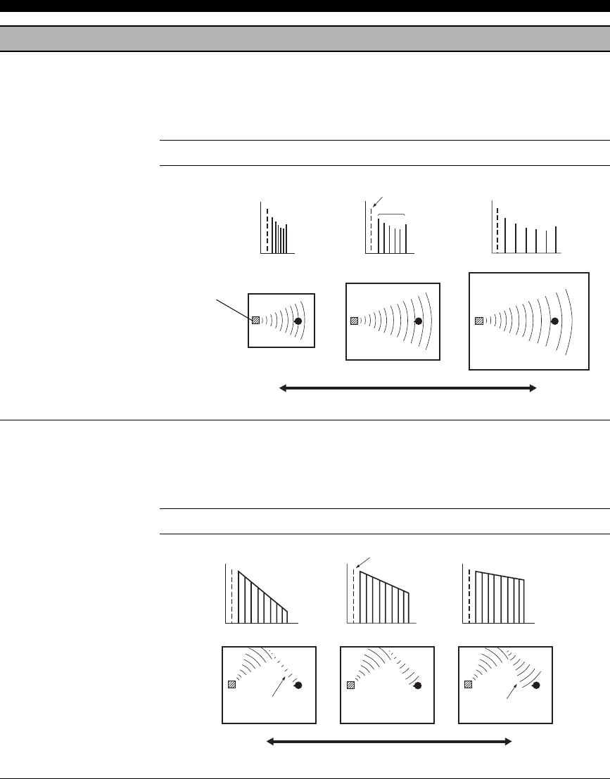
68
SOUND FIELD PROGRAMS
ROOM SIZE
P.ROOM SIZE
S.ROOM SIZE
SB ROOM SIZE
Room size. Presence, surround, and surround back room size. Adjusts the apparent size of the
surround sound field. The larger the value, the larger the surround sound field becomes. As the
sound is repeatedly reflected around a room, the larger the hall is, the longer the time between
the original reflected sound and the subsequent reflections. By controlling the time between the
reflected sounds, you can change the apparent size of the virtual venue. Changing this parameter
from one to two doubles the apparent length of the room.
Control range: 0.1 to 2.0
LIVENESS
S.LIVENESS
SB LIVENESS
Liveness. Surround and surround back liveness. Adjusts the reflectivity of the virtual walls in the
hall by changing the rate at which the early reflections decay. The early reflections of a sound
source decay much faster in a room with acoustically absorbent wall surfaces than in one which
has highly reflective surfaces. A room with acoustically absorbent surfaces is referred to as
“dead”, while a room with highly reflective surfaces is referred to as “live”. This parameter lets
you adjust the early reflection decay rate and thus the “liveness” of the room.
Control range: 0 to 10
Sound field parameter Features
Level
Level
Level
Time Time Time
Source sound
Early
reflections
Small value = 0.1 Large value = 2.0
Sound source
Source sound
Level
Level
Level
Dead
Live
Time Time Time
Small reflected
sound Large reflected
sound
Small value = 0 Large value = 10
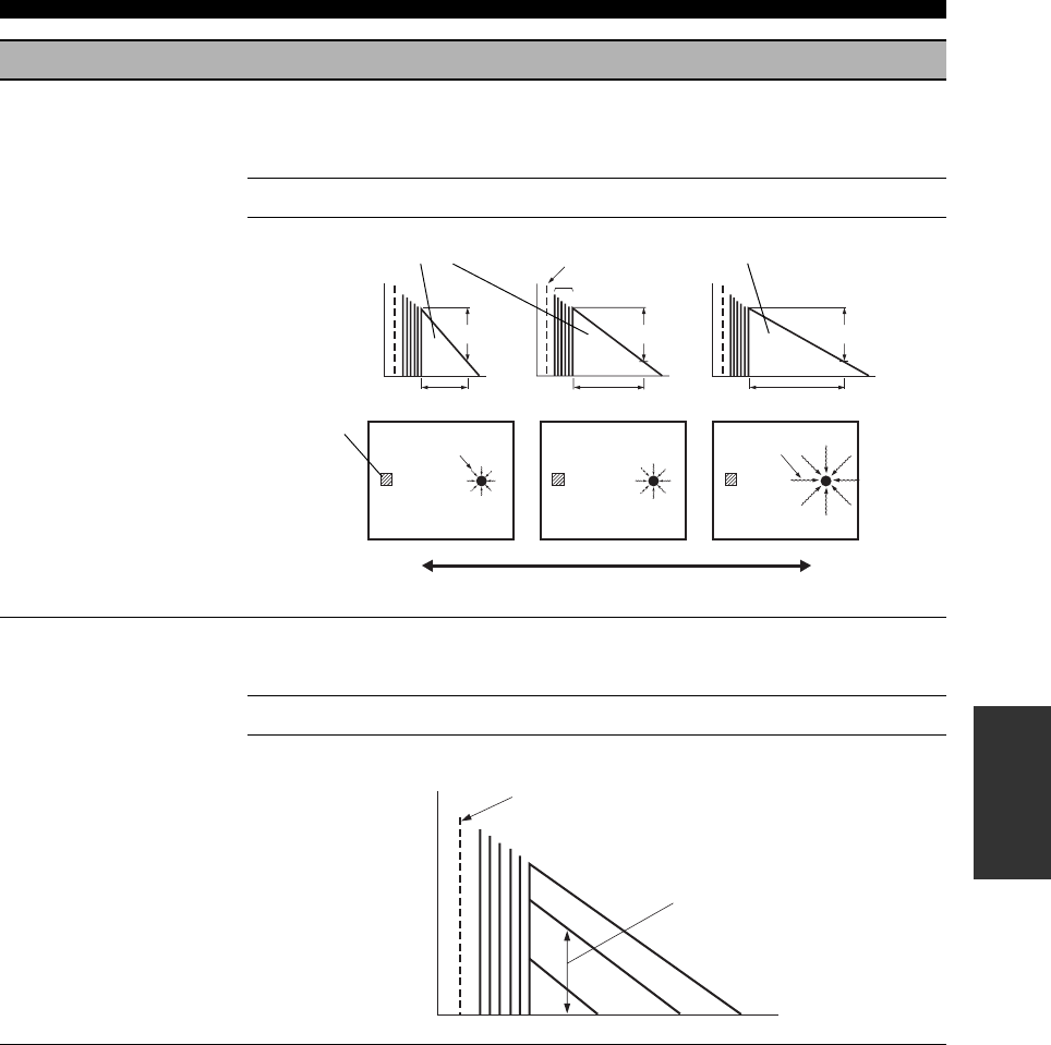
69
SOUND FIELD PROGRAMS
SOUND FIELD
PROGRAMS
REV.TIME Reverberation time. Adjusts the amount of time taken for the dense, subsequent reverberation
sound to decay by 60 dB at 1 kHz. This changes the apparent size of the acoustic environment
over an extremely wide range. Set a longer reverberation time for “dead” sources and listening
room environments, and a shorter time for “live” sources and listening room environments.
Control range: 1.0 to 5.0 s
REV.DELAY Reverberation delay. Adjusts the time difference between the beginning of the direct sound and
the beginning of the reverberation sound. The larger the value, the later the reverberation sound
begins. A later reverberation sound makes you feel as if you are in a larger acoustic environment.
Control range: 0 to 250 ms
Sound field parameter Features
Reverberation Reverberation
60 dB 60 dB 60 dB
Source sound
REV.TIME REV.TIME REV.TIME
Sound source Short
reverberation Long
reverberation
Small value = 1.0 s Large value = 5.0 s
Early reflections
Source sound
Level
REV. LEVEL
Time
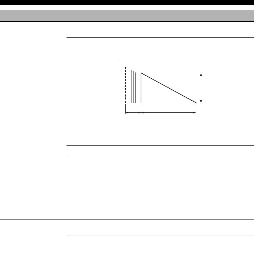
70
SOUND FIELD PROGRAMS
REV.LEVEL Reverberation level. Adjusts the volume of the reverberation sound. The larger the value, the
stronger the reverberation becomes.
Control range: 0 to 100%
2ch Stereo
DIRECT
2-channel stereo direct. Bypasses the decoders and DSP processors of this unit for pure hi-fi
stereo sound when playing 2-channel analog sources.
Choices: AUTO, OFF
y
• The “AUTO” setting bypasses the decoders and DSP processors only when “BASS” and
“TREBLE” are set to 0 dB (see page 32).
• When multi-channel signals (Dolby Digital and DTS) are input, they are downmixed to 2
channels and output from the front left and right speakers.
• The low-frequency signals input from the front left and right speakers are redirected to the
subwoofer in the following cases:
– “LFE/BASS OUT” is set to “BOTH” (see page 79).
– “FRONT SP” is set to “SMALL” (see page 78) and “LFE/BASS OUT” is set to “SWFR”
(see page 79).
6ch Stereo
CT LEVEL
SL LEVEL
SR LEVEL
SB LEVEL
6-channel stereo center, surround left, surround right and surround back levels. Adjusts the
volume level of each channel in the 6-channel stereo mode.
Control range: 0 to 100%
Sound field parameter Features
(dB)
60 dB
Level
Source sound
Reverberation
REV.TIME
REV.DELAY
Time

71
SOUND FIELD PROGRAMS
SOUND FIELD
PROGRAMS
y
The “PRO LOGIC IIx Music”, “PRO LOGIC II Music”, and “DTS Neo:6 Music” parameters can be set only when “SUR.
STANDARD” is selected. Set the component selector switch to AMP and then press STANDARD on the remote control repeatedly to
select “SUR. STANDARD” (see page 42).
PRO LOGIC IIx Music
PRO LOGIC II Music
PANORAMA
Pro Logic IIx Music and Pro Logic II Music panorama. Sends stereo signals to the surround
speakers as well as the front speakers for a wraparound effect.
Choices: OFF, ON
PRO LOGIC IIx Music
PRO LOGIC II Music
DIMENSION
Pro Logic IIx Music and Pro Logic II Music dimension. Adjusts the sound field either towards
the front or towards the rear.
Control range: –3 (towards the rear) to +3 (towards the front)
Initial setting: STD (standard)
PRO LOGIC IIx Music
PRO LOGIC II Music
CENTER WIDTH
Pro Logic IIx Music and Pro Logic II Music center width. Moves the center channel output
completely towards the center speaker or towards the front left and right speakers. A larger value
moves the center channel output towards the front left and right speakers.
Control range: 0 (center channel sound is output only from the center speaker) to
7 (center channel sound is output only from the front left and right speakers)
Initial setting: 3
DTS Neo:6 Music
C.IMAGE
DTS Neo:6 Music center image. Adjusts the front left and right channel output relative to the
center channel to make the center channel more or less dominant as necessary.
Control range: 0.0 to 1.0
Initial setting: 0.3
Sound field parameter Features
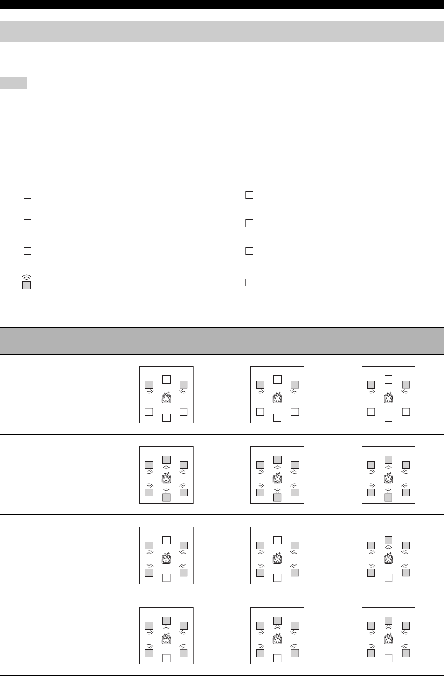
72
SOUND FIELD PROGRAMS
Sound output from each speaker depends on the type of audio signals being input. Refer to the diagrams in the table
below to understand the speaker layout for each sound field program.
Be advised that there may be no or not enough sound output from speakers depending on the type of input source being played back.
Furthermore, there may be some channels that can only be used partially when they are adjusted to specific aspects of movies, such as
special sound effects, etc.
y
Except for “2ch Stereo”, “6ch Stereo”, and “STRAIGHT”, you can select a decoder to output sound from the surround back speaker
(see page 41).
The abbreviations and symbols used in each diagram are as follows:
*When the q EX / q PL IIx / ES indicators are turned off in the front panel display
Sound field program speaker layouts
Note
Front left speaker Surround left speaker
Center speaker Surround right speaker
Front right speaker Surround back speaker
Speaker from which sound is being output Speaker from which no sound is being output
Sound field program 2-channel audio
(monaural)
2-channel audio
(stereo) 5.1/6.1-channel audio *
STEREO
2ch Stereo
STEREO
6ch Stereo
MUSIC
Hall in Vienna
The Bttm Line
The Roxy Thtr
ENTERTAINMENT
Disco
MUSIC
Pop/Rock
ENTERTAINMENT
TV Sports
Mono Movie
Game
L
SL
C SR
RSB
SB
L
C
R
SL SR
L
C
R
SL SR
SB
L
C
R
SL SR
SB
L
C
R
SL
SB
SR
L
C
R
SL
SB
SR
L
C
R
SL
SB
SR
L
C
R
SL
SB
SR
L
C
R
SL
SB
SR
L
C
R
SL
SB
SR
L
C
R
SL
SB
SR
L
C
R
SL
SB
SR
L
C
R
SL
SB
SR
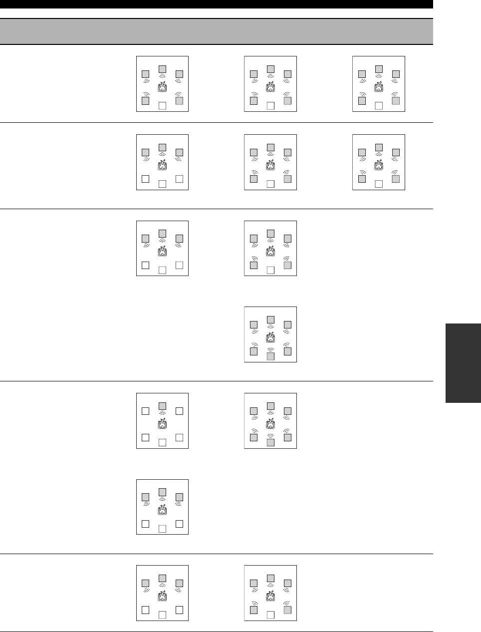
73
SOUND FIELD PROGRAMS
SOUND FIELD
PROGRAMS
MOVIE THEATER
Spectacle
Sci-Fi
Adventure
General
SUR. STANDARD
DOLBY DIGITAL
PRO LOGIC
DTS
Pro Logic Pro Logic
SUR. STANDARD
PLII Movie
PLII Music
PLII Game
PLIIx Movie
PLIIx Music
PLIIx Game
Pro Logic II/Pro Logic IIx Pro Logic II
Pro Logic IIx
SUR. STANDARD
Neo:6 Cinema
Neo:6 Music
Cinema Cinema/Music
Music
SUR. STANDARD
Neural Sur.
Sound field program 2-channel audio
(monaural)
2-channel audio
(stereo) 5.1/6.1-channel audio *
L
C
R
SL
SB
SR
L
C
R
SL
SB
SR
L
C
R
SL
SB
SR
L
C
R
SL
SB
SR
L
C
R
SL
SB
SR
L
C
R
SL
SB
SR
L
C
R
SL
SB
SR
L
C
R
SL
SB
SR
L
C
R
SL
SB
SR
L
C
R
SL
SB
SR
L
C
R
SL
SB
SR
L
C
R
SL
SB
SR
L
C
R
SL
SB
SR
L
C
R
SL
SB
SR
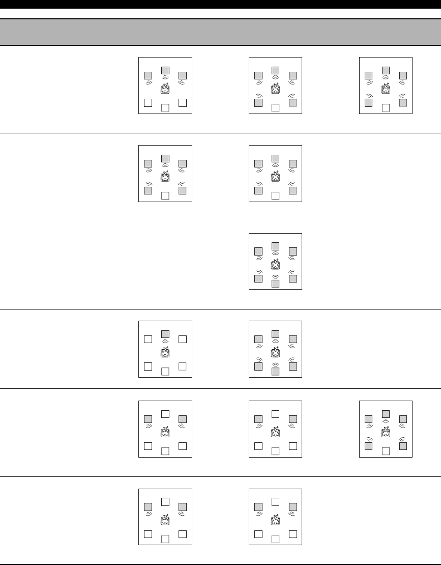
74
SOUND FIELD PROGRAMS
SUR. ENHANCED
DOLBY DIGITAL
PRO LOGIC
DTS
Pro Logic Pro Logic
SUR. ENHANCED
PLII Movie
PLIIx Movie
Pro Logic II
Pro Logic IIx
SUR. ENHANCED
Neo:6 Cinema
STRAIGHT
Monaural playback
DIRECT STEREO
Monaural playback
Sound field program 2-channel audio
(monaural)
2-channel audio
(stereo) 5.1/6.1-channel audio *
L
C
R
SL
SB
SR
L
C
R
SL
SB
SR
L
C
R
SL
SB
SR
L
C
R
SL
SB
SR
L
C
R
SL
SB
SR
L
C
R
SL
SB
SR
L
C
R
SL
SB
SR
L
C
R
SL
SB
SR
L
C
R
SL
SB
SR
L
C
R
SL
SB
SR
L
C
R
SL
SB
SR
L
C
R
SL
SB
SR
L
C
R
SL
SB
SR

SET MENU
75
ADVANCED
OPERATION
You can use the following parameters in “SET MENU” to adjust a variety of system settings and customize the way this
unit operates. Change the initial settings (indicated in bold under each parameter) to reflect the needs of your listening
environment.
■Basic setup BASIC SETUP
Use this feature to set up your system quickly and with minimal effort (see page 28).
■Manual setup MANUAL SETUP
Use this feature to manually adjust speaker and system parameters.
Sound menu 1 SOUND MENU
Use this menu to manually adjust any speaker settings, alter the quality and tone of the sound output by the system or
compensate for video signal processing delays when using LCD monitors or projectors.
Input menu 2 INPUT MENU
Use this menu to manually reassign the input/output jacks, select the input mode or rename the input source.
SET MENU
Parameter Features Page
A)SPEAKER SET Selects the size of each speaker, the speakers for low-frequency signal output, and the
crossover frequency. 78
B)SPEAKER LEVEL Adjusts the output level of each speaker. 80
C)SP DISTANCE Adjusts the delay time of each speaker. 81
D)CENTER GEQ Adjusts the tonal quality of the center speaker. 81
E)LFE LEVEL Adjusts the output level of the LFE channel for Dolby Digital or DTS signals. 81
F)DYNAMIC RANGE Adjusts the dynamic range of Dolby Digital or DTS signals. 82
G)AUDIO SET Adjusts the muting level, audio delay and tone bypass settings. 82
Parameter Features Page
A)I/O ASSIGNMENT Assigns the input/output jacks of this unit according to the component to be used. 83
B)INPUT MODE Selects the initial input mode of the source. 84
C)INPUT RENAME Changes the name of the input source. 84
D)VOLUME TRIM Adjusts the output volume of each jack. 85

76
SET MENU
Option menu 3 OPTION MENU
Use this menu to manually adjust the optional system parameters.
The “XM RADIO SET” parameter is only applicable to the U.S.A. model.
■Signal information SIGNAL INFO
Use this feature to check audio signal information (see page 39).
Parameter Features Page
A)DISPLAY SET Adjusts the brightness of the display and converts video signals. 85
B)MEMORY GUARD Locks sound field program parameters and other “SET MENU” settings. 86
C)PARAM. INI Initializes the parameters of a group of sound field programs. 86
D)MULTI ZONE SET Specifies the location of the speakers connected to the SPEAKERS B terminals. 87
E)XM RADIO SET Displays the current reception level of the XM Connect-and-Play digital antenna accessory or
adjusts the XM Satellite Radio information display settings. 87
Note
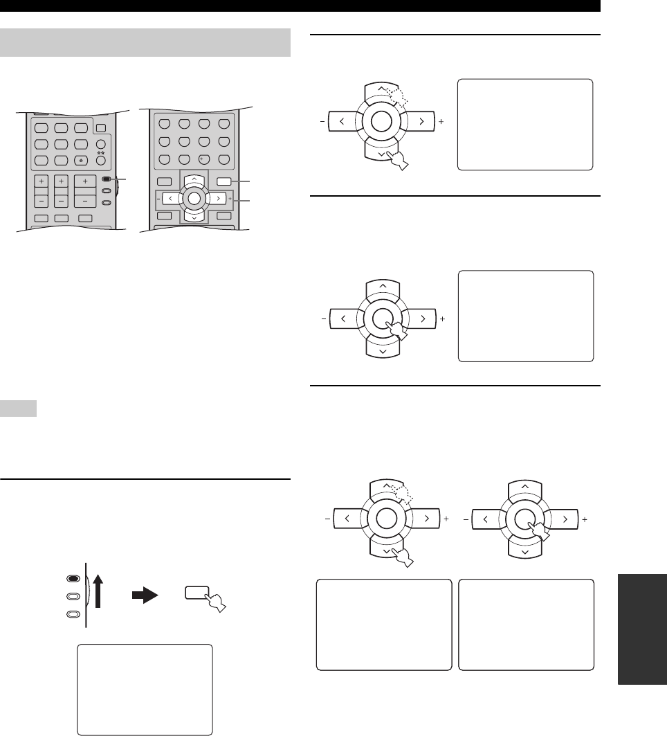
77
SET MENU
ADVANCED
OPERATION
Use the remote control to access and adjust each
parameter.
y
• You can change the “SET MENU” parameters while this unit is
reproducing sound.
• If you press one of the sound field program selector buttons
during the “SET MENU” operation, the “SET MENU”
operation is canceled.
• Repeat the following procedure to select and adjust each
parameter setting.
• Press RETURN to return to the previous menu level.
You cannot change some “SET MENU” parameters when
“NIGHT:CINEMA” or “NIGHT:MUSIC” is selected as the night
listening mode (see page 33).
1Set the component selector switch to AMP
and then press SET MENU to enter “SET
MENU”.
The top “SET MENU” display appears in the OSD.
2Press u / d to select “MANUAL SETUP”.
3Press ENTER to enter “MANUAL SETUP”.
The “MANUAL SETUP” display appears in the
OSD.
4Press u / d repeatedly and then press
ENTER to select and enter the desired menu.
The following displays are examples where “SOUND
MENU” is selected.
Using SET MENU
Note
MENUTITLE
SET MENU
LEVEL
DISPLAYRETURN
BAND
SRCH MODE
XM MEMORY
A-E/CAT. A-E/CAT.
ENTER
PRESET/CH
REC
STEREO
1
EFFECT
STANDARD
5
SPEAKERS
9
MUSIC
2
SELECT
6
ENHANCER
0
ENTERTAIN
3
EXTD SUR.
7
NIGHT
10
MOVIE
4
DIRECT ST.
8
STRAIGHT
ENT.
TV MUTE TV INPUT
MUTE
AMP
SOURCE
TV
STEREO
VOLUME
TV VOL TV CH
CD
AVTV
MULTI CH IN
SLEEP
CD-R XM
DVD DTV
MD
CBL
TUNER
V-AUX DVR
MUSIC ENTERTAIN MOVIE
1
2-6
1,7
(U.S.A. model)
MENU
SET MENU
SRCH MODE
SET MENU
.;BASICSETUP
;MANUALSETUP
.;SIGNAL INFO
[ ]/[]:Up/Down
[ENTER]:Enter
p
p
AMP
SOURCE
TV
SET MENU
;BASICSETUP
.;MANUALSETUP
.;SIGNAL INFO
[ ]/[]:Up/Down
[ENTER]:Enter
p
p
A-E/CAT. A-E/CAT.
ENTER
PRESET/CH
;MANUAL SETUP
.1SOUNDMENU
2INPUTMENU
3OPTIONMENU
[]/[]:Up/Down
[ENTER]:Enter
p
p
A-E/CAT. A-E/CAT.
ENTER
PRESET/CH
.A)SPEAKERSET
B)SPEAKERLEVEL
C)SPDISTANCE
D)CENTER GEQ
[]/[]:Up/Down
[ENTER]:Enter
1 SOUND
MENU 1/2
p
p
.E)LFE LEVEL
F)DYNAMIC RANGE
G)AUDIO SET
[]/[]:Up/Down
[ENTER]:Enter
1 SOUND
MENU 2/2
p
p
A-E/CAT. A-E/CAT.
ENTER
PRESET/CH
A-E/CAT. A-E/CAT.
ENTER
PRESET/CH
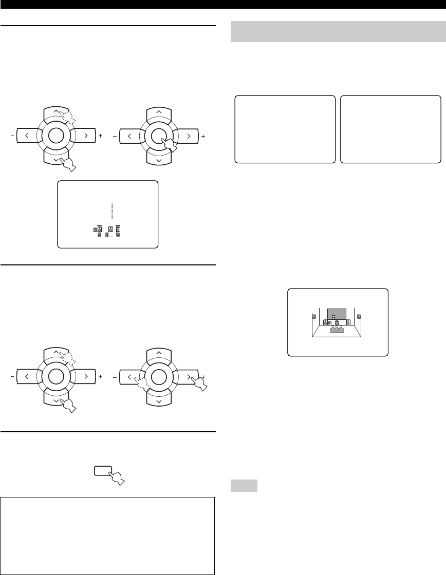
78
SET MENU
5Press u / d repeatedly and then press
ENTER to select and enter the desired
submenu.
The following display is an example where
“SPEAKER LEVEL” is selected.
6Press u / d to select the desired parameter
and then j / i to change the parameter
settings.
• Press i to increase the value.
• Press j to decrease the value.
7Press SET MENU to exit from “SET MENU”.
Use this menu to manually adjust any speaker settings or
compensate for video signal processing delays when using
LCD monitors or projectors.
■Speaker settings A)SPEAKER SET
Use this feature to manually adjust any speaker settings.
y
If you are not satisfied with the bass sounds from your speakers,
you can change these settings according to your preference.
Front speakers FRONT SP
Choices: SMALL, LARGE
• Select “SMALL” (small) if you have small front
speakers that do not reproduce low-frequency signals
effectively. The low-frequency signals of the front left
and right channels are directed to the speakers selected
in “LFE/BASS OUT” (see page 79).
• Select “LARGE” (large) if you have large front
speakers that reproduce low-frequency signals
effectively. All the front left and right channel signals
are directed to the front left and right speakers.
If “LFE/BASS OUT” is set to “FRNT” (see page 79), the LFE
signals found in Dolby Digital or DTS sources, the low-frequency
signals of the front left and right channels, and the low-frequency
signals of other speakers set to “SML” (or “SMALL”) or to
“NONE” are all directed to the front left and right speakers
regardless of the “FRONT SP” setting.
Memory back-up
The memory back-up circuit prevents the stored data
from being lost even if this unit is in the standby mode.
However, the stored data will be lost in case the power
cable is disconnected from the AC wall outlet or if the
power supply is cut off for more than one week.
.FL;;;;;;;;;;
FR;;;;;;;;;;
C;;;;;;;;;;
B)SPEAKER
LEVEL
-__________+
A-E/CAT. A-E/CAT.
ENTER
PRESET/CH
A-E/CAT. A-E/CAT.
ENTER
PRESET/CH
A-E/CAT. A-E/CAT.
ENTER
PRESET/CH
A-E/CAT. A-E/CAT.
ENTER
PRESET/CH
MENU
SET MENU
SRCH MODE
1 SOUND MENU
Note
.A)SPEAKERSET
B)SPEAKERLEVEL
C)SPDISTANCE
D)CENTER GEQ
[]/[]:Up/Down
[ENTER]:Enter
1 SOUND
MENU 1/2
p
p
.E)LFE LEVEL
F)DYNAMIC RANGE
G)AUDIO SET
[]/[]:Up/Down
[ENTER]:Enter
1 SOUND
MENU 2/2
p
p
SMALL>LARGE
FRONT SP
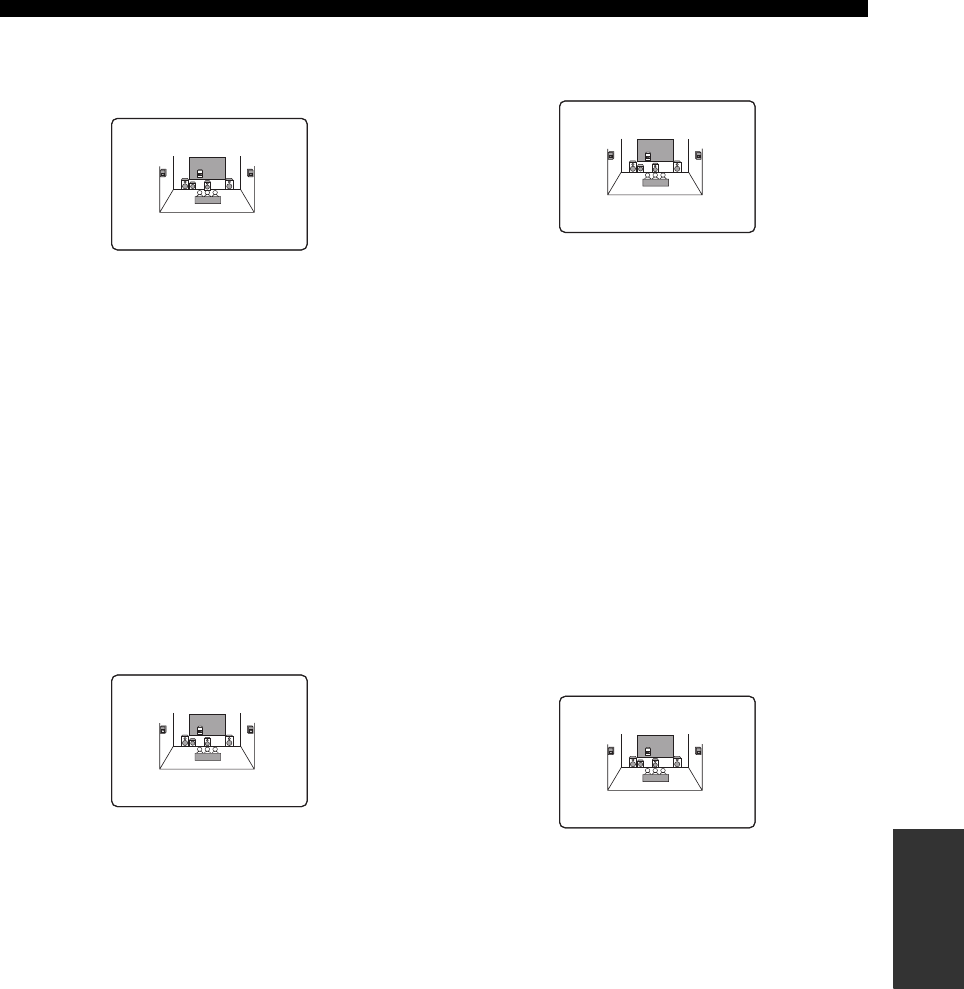
79
SET MENU
ADVANCED
OPERATION
Center speaker CENTER SP
Choices: NONE, SML, LRG
• Select “NONE” (none) if you did not connect a center
speaker. The low-frequency signals of the center
channel are directed to the speakers selected in “LFE/
BASS OUT”, and the rest of the center channel signals
are directed to the front left and right speakers.
• Select “SML” (small) if you have a small center
speaker that does not reproduce low-frequency signals
effectively. The low-frequency signals of the center
channel are directed to the speakers selected in “LFE/
BASS OUT”.
• Select “LRG” (large) if you have a large center speaker
that reproduces low-frequency signals effectively. All
the center channel signals are directed to the center
speaker.
Surround left/right speakers SUR. L/R SP
Choices: NONE, SML, LRG
• Select “NONE” (none) if you did not connect surround
speakers. This unit is set to the Virtual CINEMA DSP
mode (see page 43) and “SUR. B SP” is automatically
set to “NONE”. The low-frequency signals of the
surround left and right channels are directed to the
speakers selected in “LFE/BASS OUT”.
• Select “SML” (small) if you have small surround left
and right speakers that do not reproduce low-frequency
signals effectively. The low-frequency signals of the
surround left and right channels are directed to the
speakers selected in “LFE/BASS OUT”.
• Select “LRG” (large) if you have large surround left
and right speakers that reproduce low-frequency
signals effectively. All the surround channel signals are
directed to the surround left and right speakers.
Surround back speakers SUR. B SP
Choices: NONE, SML, LRG
• Select “NONE” (none) if you did not connect a
surround back speaker. The low-frequency signals of
the surround back channel are directed to the speakers
selected in “LFE/BASS OUT”, and the rest of the
surround back channel signals are directed to the
surround left and right speakers.
• Select “SML” (small) if you have a small surround
back speaker that does not reproduce low-frequency
signals effectively. The low-frequency signals of the
surround back channel are directed to the speakers
selected in “LFE/BASS OUT”.
• Select “LRG” (large) if you have a large surround back
speaker that reproduces low-frequency signals
effectively. All the surround back channel signals are
directed to the surround back speaker.
Bass out LFE/BASS OUT
Use this feature to select the speakers that output the LFE
(low-frequency effect) and the low-frequency signals.
Choices: SWFR, FRNT, BOTH
• Select “SWFR” (subwoofer) if you connected a
subwoofer. The LFE signals as well as the low-
frequency signals of other speakers set to “SML” (or
“SMALL”) or to “NONE” are directed to the
subwoofer.
• Select “FRNT” (front) if you did not connect a
subwoofer. The LFE signals, the low-frequency signals
of the front left and right channels, and the low-
frequency signals of other speakers set to “SML” (or
“SMALL”) or to “NONE” are all directed to the front
left and right speakers regardless of the “FRONT SP”
setting (see page 78).
• Select “BOTH” (both) if you connected a subwoofer.
The low-frequency signals of any source are output
from the subwoofer. The LFE signals as well as the
low-frequency signals of other speakers set to “SML”
(or “SMALL”) or to “NONE” are directed to the
subwoofer. The low-frequency signals of the front left
and right channels are directed to the front left and
right speakers and the subwoofer regardless of the
“FRONT SP” setting (see page 78).
NONE>SMLLRG
CENTER SP
NONE>SMLLRG
SUR. L/R SP
NONE>SML LRG
SUR. B SP
SWFRFRNT>BOTH
LFE/BASS OUT
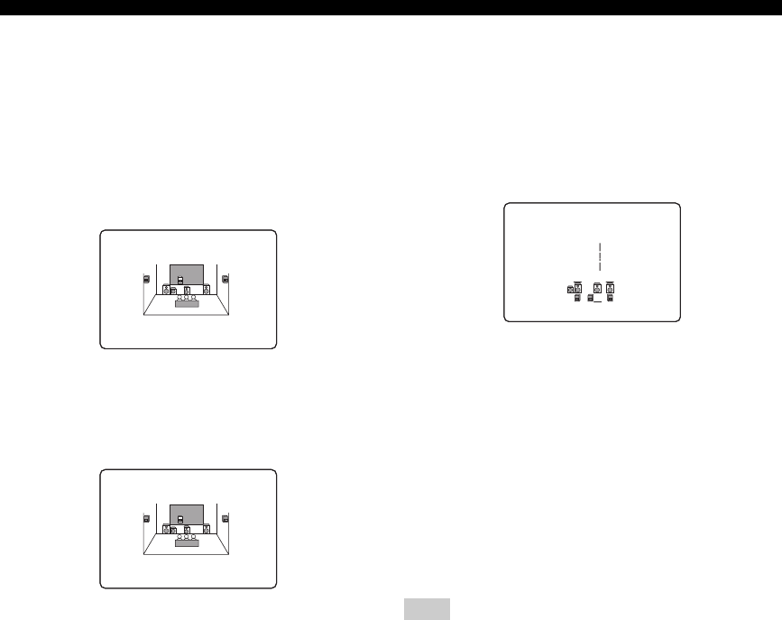
80
SET MENU
Crossover CROSS OVER
Use this feature to select a crossover frequency of all the
speakers set to “SML” (or “SMALL”) or to “NONE” in
“SPEAKER SET” (see pages 78 and 79). All frequencies
below the selected frequency will be sent to the subwoofer
or to the speakers set to “LRG” (or “LARGE”) in
“SPEAKER SET” (see pages 78 and 79).
Choices: 40Hz, 60Hz, 80Hz, 90Hz, 100Hz, 110Hz,
120Hz, 160Hz, 200Hz
Subwoofer phase SUBWOOFER PHASE
Use this feature to switch the phase of your subwoofer if
bass sounds are lacking or unclear.
Choices: NORMAL, REVERSE
• Select “NORMAL” if you do not want to reverse the
phase of your subwoofer.
• Select “REVERSE” to reverse the phase of your
subwoofer.
■Speaker level B)SPEAKER LEVEL
Use this feature to manually balance the speaker levels
between the front left or surround left speakers and each
speaker selected in “SPEAKER SET” (see page 78).
Control range: –10.0 to +10.0 dB
Control step: 1.0 dB
Initial setting: 0 dB
• Select “FL” to adjust the balance of the front left
speaker.
• Select “FR” to adjust the balance of the front right
speaker.
• Select “C” to adjust the balance of the center speaker.
• Select “SL” to adjust the balance of the surround left
speaker.
• Select “SR” to adjust the balance of the surround right
speaker.
• Select “SB” to adjust the balance of the surround back
speaker.
• Select “SWFR” to adjust the balance of the subwoofer.
“C”, “SL”, “SR”, “SB” and “SWFR” cannot be adjusted if
“CENTER SP” (see page 79), “SUR. L/R SP” (see page 79),
“SUR. B SP” (see page 79) and “LFE/BASS OUT” (see page 79)
are set to “NONE” respectively.
FREQ;;;80Hz
CROSS OVER
>NORMALREVERSE
02ASUBWOOFER PHASE
Note
.FL;;;;;;;;;;
FR;;;;;;;;;;
C;;;;;;;;;;
B)SPEAKER
LEVEL
-__________+

81
SET MENU
ADVANCED
OPERATION
■Speaker distance C)SP DISTANCE
Use this feature to manually adjust the distance of each
speaker and the delay applied to the respective channel.
Ideally, each speaker should be the same distance from the
main listening position. However, this is not possible in
most home situations. Thus, a certain amount of delay
must be applied to the sound from each speaker so that all
sounds will arrive at the listening position at the same
time.
Unit UNIT
Choices: meters (m), feet (ft)
Initial setting:
[U.S.A. and Canada models]: feet (ft)
[Other models]: meters (m)
• Select “meters” to adjust speaker distances in meters.
• Select “feet” to adjust speaker distances in feet.
Speaker distances
Control range: 0.30 to 24.00 m (1.0 to 80.0 ft)
Control step: 0.10 m (0.5 ft)
• Select “FRONT L” to adjust the distance of the front
left speaker.
Initial setting: 3.00 m (10.0 ft)
• Select “FRONT R” to adjust the distance of the front
right speaker.
Initial setting: 3.00 m (10.0 ft)
• Select “CENTER” to adjust the distance of the center
speaker.
Initial setting: 3.00 m (10.0 ft)
• Select “SUR. L” to adjust the distance of the surround
left speaker.
Initial setting: 3.00 m (10.0 ft)
• Select “SUR. R” to adjust the distance of the surround
right speaker.
Initial setting: 3.00 m (10.0 ft)
• Select “SUR. B” to adjust the distance of the surround
back speaker.
Initial setting: 2.10 m (7.0 ft)
• Select “SWFR” to adjust the distance of the subwoofer.
Initial setting: 3.00 m (10.0 ft)
“CENTER”, “SUR.L”, “SUR.R”, “SUR.B” and “SWFR” cannot
be adjusted if “CENTER SP” (see page 79), “SUR. L/R SP” (see
page 79), “SUR. B SP” (see page 79) and “LFE/BASS OUT” (see
page 79) are set to “NONE” respectively.
■Center graphic equalizer D)CENTER GEQ
Use this feature to adjust the built-in 5-frequency band
(100Hz, 300Hz, 1kHz, 3kHz and 10kHz) graphic
equalizer for the center channel so that the tonal quality of
the center speaker matches that of the front speakers. You
can make adjustments while listening to the currently
selected source component or a test tone.
Control range: –6 to +6 dB
Control step: 0.5 dB
Initial setting: 0 dB
Test tone TEST
Choices: OFF, ON
• Select “OFF” to stop test tones and output the currently
selected source component.
• Select “ON” to output test tones from the front left and
center speakers, and adjust the tonal quality of the
center speaker.
y
Press u / d to select a frequency band and j / i to adjust the
selected frequency band.
■Low-frequency effect level E)LFE LEVEL
Use this feature to adjust the output level of the LFE (low-
frequency effect) channel according to the capacity of
your subwoofer or headphones. The LFE channel carries
low-frequency special effects which are only added to
certain scenes. This setting is effective only when this unit
decodes Dolby Digital or DTS signals.
Control range: –20 to 0 dB
Control step: 1 dB
Speaker SPEAKER
Adjusts the speaker LFE level.
Headphone HEADPHONE
Adjusts the headphone LFE level.
Depending on the settings of “LFE/BASS OUT” (see page 79),
some signals may not be output at the SUBWOOFER OUTPUT
jack.
Note
.UNIT;;;;;;;;feet
FRONTL;;;10.0ft
FRONTR;;;10.0ft
CENTER;;;;10.0ft
[]/[]:Up/Down
[<]/[>]:Adjust
C)SP
DISTANCE
p
p
Note
.TEST>OFFON
100Hz ;;;;;; 0dB
300Hz ;;;;;; 0dB
1kHz ;;;;;; 0dB
3kHz ;;;;;; 0dB
10kHz ;;;;;; 0dB
[]/[]:Up/Down
[<]/[>]:Adjust
D)CENTER GEQ
-______+
p
p
.SPEAKER;;;;;;0dB
HEADPHONE;;;;0dB
[]/[]:Up/Down
[<]/[>]:Adjust
E)LFE
LEVEL
p
p

82
SET MENU
■Dynamic range F)DYNAMIC RANGE
Use this feature to select the amount of dynamic range
compression to be applied to your speakers or
headphones. This setting is effective only when this unit is
decoding Dolby Digital and DTS signals.
Speaker SP
Adjusts the speaker compression.
Headphone HP
Adjusts the headphone compression.
Choices: MIN, STD, MAX
• Select “MIN” (minimum) if you regularly listen at low
volume levels.
• Select “STD” (standard) for general use.
• Select “MAX” (maximum) to preserve the greatest
amount of dynamic range.
■Audio settings G)AUDIO SET
Use this feature to adjust the overall audio settings of this
unit.
Muting type MUTING TYPE
Use this feature to adjust how much the mute function
reduces the output volume (see page 33).
Choices: FULL, –20dB
• Select “FULL” to completely mute all the audio
output.
• Select “–20dB” to reduce the current volume by 20 dB.
Audio delay AUDIO DELAY
Use this feature to delay the sound output and synchronize
it with the video image. This may be necessary when
using certain LCD monitors or projectors.
Control range: 0 to 160 ms
Control step: 1 ms
Tone bypass TONE BYPASS
Use this feature to select whether audio output bypasses
tone control circuitry when “TREBLE” and “BASS” are
set to 0 dB (see page 32).
Choices: AUTO, OFF
• Select “AUTO” if you want signals to bypass tone
control circuitry to provide the purest signal possible.
• Select “OFF” if you do not want signals to bypass tone
control circuitry.
.SP:MINSTD>MAX
HP:MINSTD>MAX
[]/[]:Up/Down
[<]/[>]:Select
F)DYNAMIC RANGE
p
p
.MUTING TYPE;FULL
AUDIO DELAY;;0ms
TONE BYPASS;AUTO
[]/[]:Up/Down
[<]/[>]:Select
G)AUDIO SET
p
p
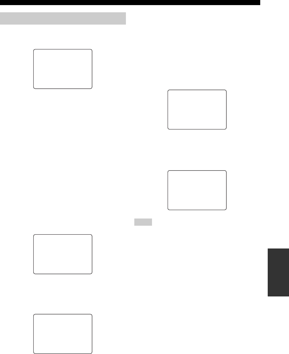
83
SET MENU
ADVANCED
OPERATION
Use this menu to reassign the input/output jacks, select the
input mode or rename the input source.
■Input/output assignment
A)I/O ASSIGNMENT
Use this feature to assign the input/output jacks according
to the component to be used if the initial settings of this
unit do not correspond to your needs. Change the
following parameters to reassign the respective jacks and
effectively connect more components.
Once the input/output jacks are reassigned, you can select
the corresponding component by using the INPUT
selector on the front panel (or the input selector buttons on
the remote control).
For COMPONENT VIDEO jacks A, B and C
CMPNT-V INPUT [A]
CMPNT-V INPUT [B]
CMPNT-V INPUT [C]
Choices: [A] DVD, DTV/CBL, V-AUX, DVR
[B] DVD, DTV/CBL, V-AUX, DVR
[C] DVD, DTV/CBL, V-AUX, DVR
For OPTICAL OUTPUT jack 1 OPTICAL OUT (1)
Choices: CD, MD/CD-R, DVD, DTV/CBL, V-AUX,
DVR
For OPTICAL INPUT jacks 2, 3 and 4
OPTICAL IN (2)
OPTICAL IN (3)
OPTICAL IN (4)
Choices: (2) CD, MD/CD-R, DVD, DTV/CBL, V-AUX,
DVR
(3) CD, MD/CD-R, DVD, DTV/CBL, V-AUX,
DVR
(4) CD, MD/CD-R, DVD, DTV/CBL, V-AUX,
DVR
For COAXIAL INPUT jack 5 COAXIAL IN (5)
Choices: (5) CD, MD/CD-R, DVD, DTV/CBL, V-AUX,
DVR
• You cannot select a specific item more than once for the same
type of jack.
• When you connect a component to both the DIGITAL INPUT
(COAXIAL) and DIGITAL INPUT (OPTICAL) jacks, priority
is given to the signals input at the DIGITAL INPUT
(COAXIAL) jack.
2 INPUT MENU
.A)I/OASSIGNMENT
B)INPUTMODE
C)INPUTRENAME
D)VOLUME TRIM
[]/[]:Up/Down
[ENTER]:Enter
2
INPUT
MENU
p
p
.[A];;;;;DVD
(DVD)
[B];;;;;DTV/CBL
(DTV/CBL)
[C];;;;; DVR
( DVR )
CMPNT-V
INPUT
.(1);;;;;MD/CD-R
(MD/CD-R )
OPTICAL
OUT
Notes
.(2);;;;;MD/CD-R
(MD/CD-R)
(3);;;;; DVD
(DVD )
(4);;;;;DTV/CBL
(DTV/CBL )
OPTICAL
IN
.(5);;;;; DVD
( DVD )
COAXIAL
IN
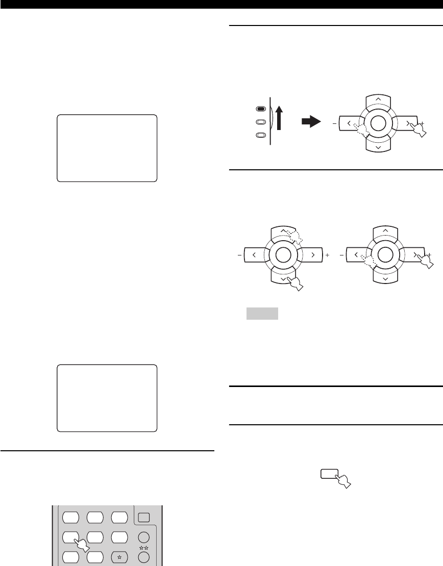
84
SET MENU
■Input mode B)INPUT MODE
Use this feature to set this unit to reset “INPUT MODE”
back to “AUTO” (see page 34) regardless of the previous
setting or to recall the last input mode (“AUTO”, “DTS”,
or “ANALOG”) used for that source whenever you turn on
this unit.
Choices: AUTO, LAST
• Select “AUTO” to reset “INPUT MODE” back to
“AUTO” (see page 34) regardless of the previous
setting whenever you turn on this unit. This unit
automatically selects input signals in the following
order:
(1) Digital signals
(2) Analog signals
• Select “LAST” to set this unit to automatically recall
the last input mode (“AUTO”, “DTS”, or “ANALOG”)
used for that source whenever you turn on this unit.
■Input rename C)INPUT RENAME
Use this feature to change the name of the input source
that appears in the OSD and in the front panel display.
1Press one of the input selector buttons on
the remote control to select the input source
you want to change the name of.
2Set the component selector switch to AMP
and then press j / i on the remote control to
place the “_” (underscore) under the space
or the character you want to edit.
3Press u / d to select the character you want
to use and then press j / i to move to the
next space.
• You can use up to 8 characters for each input.
• Press d to change the character in the following order, or
press u to go in the reverse order:
A to Z, a space, 0 to 9, a space, a to z, a space, symbols (#,
*, –, +, etc.)
4Repeat steps 1 through 3 to rename each
input source.
5Press SET MENU on the remote control to
exit from “INPUT RENAME”.
>AUTOLAST
[<]/[>]:Select
[ENTER]:Return
B)INPUT
MODE
DVD-> DVD
[<]/[>]:Position
[]/[]:Chara.
C)INPUT
RENAME
________
p
p
CD
MULTI CH IN
SLEEP
CD-R XM
DVD DTV
MD
CBL
TUNER
V-AU X DVR
Notes
AMP
SOURCE
TV A-E/CAT. A-E/CAT.
ENTER
PRESET/CH
A-E/CAT. A-E/CAT.
ENTER
PRESET/CH
A-E/CAT. A-E/CAT.
ENTER
PRESET/CH
MENU
SET MENU
SRCH MODE

85
SET MENU
ADVANCED
OPERATION
■Volume Trim D)VOLUME TRIM
Use this feature to adjust the level of the signal input at
each jack. This is useful if you want to balance the level of
each input source to avoid sudden changes in volume
when switching between input sources.
Choices: CD, MD/CD-R, TUNER, DVD, DTV/CBL,
V-AUX, DVR
Control range: –6.0 to +6.0 dB
Control step: 1.0 dB
Initial setting: 0.0 dB
Use this menu to adjust the optional system parameters.
■Display settings A)DISPLAY SET
Dimmer DIMMER
Use this feature to adjust the brightness of the front panel
display.
Control range: – 4 to 0
Control step: 1
• Press j to make the front panel display dimmer.
• Press i to make the front panel display brighter.
Video conversion VIDEO CONV.
Use this feature to set whether to convert the video signals
input at the VIDEO and S VIDEO jacks.
Choices: ON, OFF
• Select “ON” to convert composite and S-video signals
interchangeably and up-convert composite and S-video
signals to component video signals.
• Select “OFF” not to convert any signals.
• The converted video signals are only output at the MONITOR
OUT jacks. When recording a video source, you must make the
same type of video connections between each component.
• When composite video or S-video signals from a VCR are
converted to component video signals, the picture quality may
suffer depending on your VCR.
• You must set “VIDEO CONV.” to “ON” to display the OSD.
• Unconventional signals input at the composite video or S-video
jacks cannot be converted or may be output abnormally. In such
cases, set “VIDEO CONV.” to “OFF”.
DVD->0.0dB
[<]/[>]:Adjust
[RETURN]:Exit
D)VOLUME TRIM
3 OPTION MENU
Notes
.A)DISPLAYSET
B)MEMORYGUARD
C)PARAM.INI
D)MULTI ZONESET
[]/[]:Up/Down
[ENTER]:Enter
3
OPTION
MENU 1/2
p
p
.E)XM RADIO SET
[]/[]:Up/Down
[ENTER]:Enter
3
OPTION
MENU 2/2
p
p
.DIMMER;;;;;;;;;0
VIDEOCONV.;;;ON
OSD SHIFT;;;;;;0
GRAY BACK;;;AUTO
[]/[]:Up/Down
[<]/[>]:Adjust
A)DISPLAY
SET
p
p

86
SET MENU
OSD shift OSD SHIFT
Use this feature to adjust the vertical position of the OSD.
Control range: –5 (upward) to +5 (downward)
Control step: 1
Initial setting: 0
• Press j to raise the position of the OSD.
• Press i to lower the position of the OSD.
Gray back GRAY BACK
Use this feature to display a gray background in the OSD
when there is no video signal being input.
Choices: AUTO, OFF
• Select “AUTO” to display a gray background in the
OSD when there is no video signal being input.
• Select “OFF” not to display any background in the
OSD.
• Depending on the video signals being input or the system
setting of your video monitor (NTSC or PAL), the OSD may be
displayed abnormally. In such cases, set “GRAY BACK” to
“OFF”.
• Even when “GRAY BACK” is set to “OFF”, the OSD may not
be displayed correctly depending on the conditions of the
picture.
■Memory guard B)MEMORY GUARD
Use this feature to prevent accidental changes to DSP
program parameter values and other system settings.
Choices: OFF, ON
• Select “OFF” to turn off the “MEMORY GUARD”
feature.
• Select “ON” to protect:
– DSP program parameters
– all “SET MENU” items
– all speaker levels
When “MEMORY GUARD” is set to “ON”, you cannot select
and adjust any other “SET MENU” items.
■Parameter initialization C)PARAM. INI
Use this feature to initialize the parameters of each sound
field program within a sound field program group. When
you initialize a sound field program group, all of the
parameter values within that group revert to their initial
factory settings.
Press the corresponding sound field program selector
buttons on the remote control to select the sound field
program that you want to initialize.
An asterisk (*) appears to the left of the sound field
program names that have been changed from their initial
factory settings.
Choices: STEREO, MUSIC, ENTERTAINMENT,
MOVIE THEATER, STANDARD
• You cannot automatically revert to the previous parameter
settings once you initialize a sound field program group.
• You cannot separately initialize individual sound field
programs.
• You cannot initialize any sound field program groups when
“MEMORY GUARD” is set to “ON” (see page 86).
Notes
Note
>OFFON
[<]/[>]:Select
[ENTER]:Return
B)MEMORY
GUARD
Notes
STEREO
*MUSIC
ENTERTAINMENT
MOVIE THEATER
*STANDARD
Press DSP key
C)PARAM.
INI

87
SET MENU
ADVANCED
OPERATION
■Zone set D)MULTI ZONE SET
Use this feature to specify the location of speakers
connected to the SPEAKERS B terminals of this unit.
Speaker B setting SP B
Use this feature to select the location of the front speakers
connected to the SPEAKERS B terminals.
Choices: FRONT, ZONE B
• Select “FRONT” to turn on or off SPEAKERS A and B
when the speakers connected to the SPEAKERS B
terminals are set in the main zone.
• Select “ZONE B” if the speakers connected to the
SPEAKERS B terminals are set in another zone. If
SPEAKERS A is turned off and SPEAKERS B is
turned on, all the speakers including the subwoofer in
the main zone are muted and this unit outputs sound at
the SPEAKERS B terminals only.
• If you connect headphones to the PHONES jack of this unit, the
sound is output from both headphones and the SPEAKERS B
terminals when “SP B” is set to “ZONE B”.
• If a DSP program is selected when “SP B” is set to “ZONE B”,
this unit automatically enters the Virtual CINEMA DSP mode
(see page 43).
■XM Radio setting E)XM RADIO SET
(U.S.A. model only)
XM Radio information display time XM DISPLAY
Use this feature to set the time to display the XM Satellite
Radio information in the OSD after pressing DISPLAY on
the front panel or on the remote control.
Choices: ON, 10S, 30S, OFF
• Select “ON” to display the XM Satellite Radio
information while this unit is tuned into a channel.
• Select “10S” to display the XM Satellite Radio
information for 10 seconds.
• Select “30S” to display the XM Satellite Radio
information for 30 seconds.
• Select “OFF” not to display the XM Satellite Radio
information.
XM Radio antenna XM ANTENNA
Use this feature to check the current reception level of the
XM Connect-and-Play digital antenna accessory
connected to the XM jack of this unit (see page 52). For
the best reception, orient the XM Connect-and-Play digital
antenna accessory so that a value of 60% or more is
displayed here.
Display status: NONE, 0 to 100%
•
“
NONE
” is displayed if the
XM Connect-and-Play
digital antenna
accessory is not connected to this unit. In this case, check the
antenna connections (see page 52).
• The “XM ANTENNA” parameter cannot be adjusted by using
the remote control. Instead, you need to adjust the orientation of
the XM Connect-and-Play digital antenna accessory connected
to the XM jack of this unit for a better percentage of the
reception level.
XM Radio information display scroll SCROLL
Use this feature to set whether to display the XM Satellite
Radio information in the front panel display in a
continuous manner or by 14 alphanumeric characters at
once (see page 61).
Choices: CONT, ONCE
• Select “CONT” to display the XM Satellite Radio
information in the front panel display in a continuous
manner.
• Select “ONCE” to display the XM Satellite Radio
information in the front panel display by 14
alphanumeric characters at once.
Notes
.SPB;;;;;;;FRONT
[<]/[>]:Select
[ENTER]:Return
D)MULTI ZONE
SET
Notes
E)XM RADIO SET
.XM DISPLAY;;;10S
XM ANTENNA;;NONE
SCROLL;;;;;;CONT
[<]/[>]:Select
[ENTER]:Return
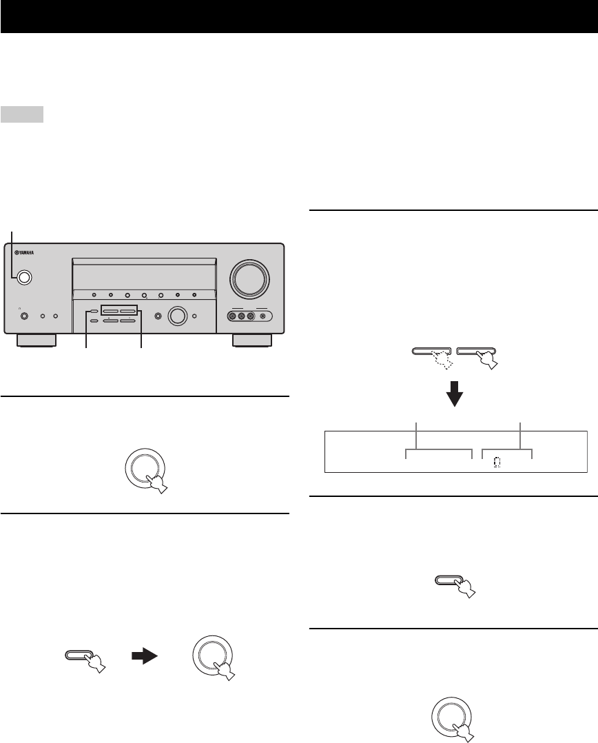
ADVANCED SETUP
88
This unit has additional menus that are displayed in the front panel display. The advanced setup menu offers additional
operations to adjust and customize the way this unit operates. Change the initial settings (indicated in bold under each
parameter) to reflect the needs of your listening environment.
• The settings you make are reflected next time you turn on this unit by pressing STANDBY/ON on the front panel (or POWER on the
remote control) (see page 27).
• Only STANDBY/ON, STRAIGHT (EFFECT) and PROGRAM l / h are effective while you are using the advanced setup menu.
• All the other operations cannot be made while you are using the advanced setup menu.
• The advanced setup menu is only available in the front panel display.
1Press STANDBY/ON on the front panel to set
this unit to the standby mode.
2Press and hold STRAIGHT (EFFECT) on the
front panel and then press STANDBY/ON to
turn on this unit.
This unit turns on, and the advanced setup menu
appears in the front panel display.
3Press PROGRAM l / h on the front panel
repeatedly to select the parameter you want
to adjust.
The name of the selected parameter appears in the
front panel display.
See page 89 for a complete list of available
parameters.
4Press STRAIGHT (EFFECT) on the front
panel repeatedly to change the selected
parameter setting.
5Press STANDBY/ON on the front panel to
save the new setting and set this unit to the
standby mode.
y
The settings you made are reflected next time you turn on
this unit.
ADVANCED SETUP
Notes
VOLUME
AUTO/MAN'LMAN'L/AUTO FMLEVELNEXTEDIT
EFFECT
MEMORY
FM/AMPRESET/TUNING
A/B/C/D/E
l PROGRAM h
BASS/TREBLE
TUNING MODE
INPUT MODE
TONE CONTROL
STRAIGHT
SPEAKERSPHONES
SILENT CINEMA
STANDBY
/ON
BA
MULTI CH
INPUT
INPUT
SEARCH MODE CATEGORY
l PRESET/TUNING/CH h
DISPLAY
VIDEO PORTABLEL AUDIO R
VIDEO AUX
32,4
1-2,5
(U.S.A. model)
STANDBY
/ON
STANDBY
/ON
EFFECT
STRAIGHT
While holding
down
l PROGRAM h
SP IMP.-8 MIN
Currently selected
parameter setting
Currently selected
parameter
EFFECT
STRAIGHT
STANDBY
/ON
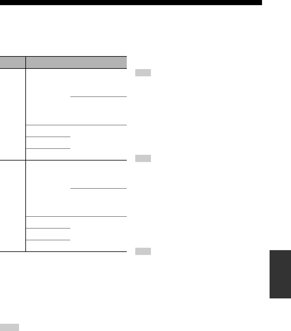
89
ADVANCED SETUP
ADVANCED
OPERATION
■Speaker impedance SP IMP.
Use this feature to set the speaker impedance of this unit
so that it matches that of your speakers.
Choices: 8ΩMIN, 6ΩMIN
• Select “8ΩMIN” to set the speaker impedance to 8 Ω .
• Select “6ΩMIN” to set the speaker impedance to 6 Ω .
*The Canada model cannot use two separate speaker systems
(A and B) simultaneously when “SP IMP.” is set to “8ΩMIN”.
■Factory presets PRESET
Use this feature to reset all the parameters of this unit to
the initial factory settings (see page 97).
Choices: CANCEL, RESET
• Select “CANCEL” not to reset any parameters of this
unit.
• Select “RESET” to reset the parameters of this unit.
• This setting completely resets all the parameters of this unit
including the “SET MENU” parameters. However, the
advanced setup menu parameters will not be initialized.
• The initial factory settings are activated next time you turn on
this unit.
■Remote control AMP ID REMOTE AMP
Use this feature to set the AMP ID of this unit for remote
control recognition (see page 93).
Choices: ID1, ID2
• Select “ID1” when the remote control AMP ID library
code is set to “00001”.
• Select “ID2” when the remote control AMP ID library
code is set to “00002”.
You need to set the corresponding remote control AMP library
code for the remote control (see page 93).
■Remote control TUNER ID REMOTE TUN
Use this feature to set the TUNER ID of this unit for
remote control recognition (see page 93).
Choices: ID1, ID2
• Select “ID1” when the remote control TUNER ID
library code is set to “81916”.
• Select “ID2” when the remote control TUNER ID
library code is set to “81917”.
You need to set the corresponding remote control TUNER library
code for the remote control (see page 93).
■Remote control XM ID REMOTE XM
(U.S.A. model only)
Use this feature to set the XM ID of this unit for remote
control recognition (see page 94).
Choices: ID1, ID2
• Select “ID1” when the remote control XM ID library
code is set to “81918”.
• Select “ID2” when the remote control XM ID library
code is set to “81919”.
You need to set the corresponding remote control XM library
code for the remote control (see page 93).
SP IMP. Speaker Impedance level
8ΩMIN
Front
If you use one set (A or B),
the impedance of each
speaker must be 8 Ω or
higher.
If you use two sets (A and
B), the impedance of each
speaker must be 16 Ω or
higher.*
Center
The impedance of each
speaker must be 8 Ω or
higher.
Surround
Surround back
6ΩMIN
Front
If you use one set (A or B),
the impedance of each
speaker must be 4 Ω or
higher.
If you use two sets (A and
B), the impedance of each
speaker must be 8 Ω or
higher.
Center
The impedance of each
speaker must be 6 Ω or
higher.
Surround
Surround back
Notes
Note
Note
Note
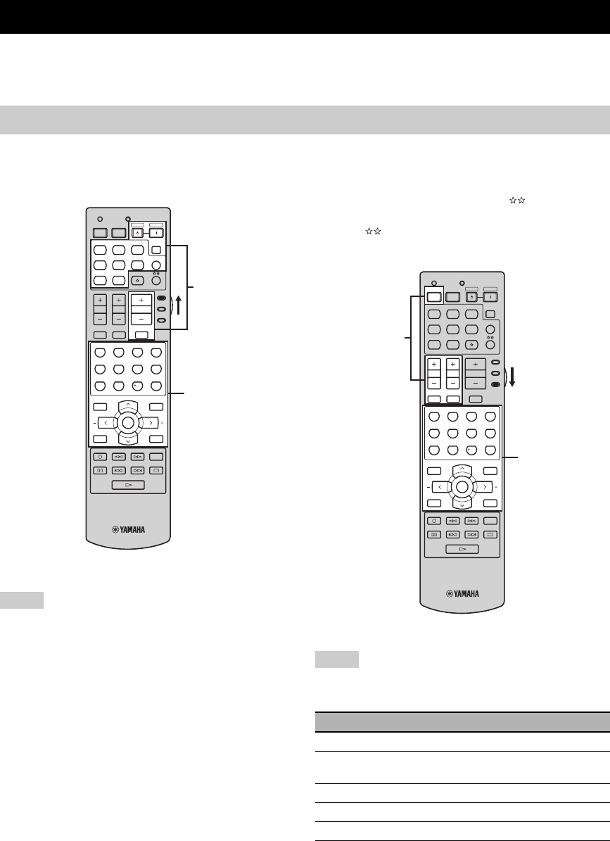
REMOTE CONTROL FEATURES
90
In addition to controlling this unit, the remote control can also operate other audiovisual components made by YAMAHA
and other manufacturers. To control your TV or other components, you must set the appropriate remote control code for
each input source (see page 92).
■Controlling this unit
Set the component selector switch to AMP to control this
unit.
*1 These buttons always control this unit regardless of the
component selector switch position.
*2 These buttons control this unit only when the component
selector switch is set to AMP.
■Controlling a TV
Set the component selector switch to TV to control your
TV. To control your TV, you must set the appropriate
remote control code for DTV/CBL or (see page 92).
When you set the remote control codes for both DTV/
CBL and , priority is given to the one set for DTV/
CBL.
*1 These buttons always control your TV regardless of the
component selector switch position.
*2 These buttons control your TV only when the component
selector switch is set to TV. For details, see the “Digital TV/
Cable TV” column on page 91.
REMOTE CONTROL FEATURES
Controlling this unit, a TV, or other components
Notes
TV MUTE TV INPUT
MUTE
AMP
SOURCE
TV
MENUTITLE
SET MENU
LEVEL
DISPLAYRETURN
BAND
SRCH MODE
XM MEMORY
A-E/CAT. A-E/CAT.
ENTER
PRESET/CH
REC
AUDIO
DISC SKIP
STEREO
1
EFFECT
VOLUME
TV VOL TV CH
TRANSMITCODE SET
STANDBY
POWER
POWERPOWER
CD
AVTV
MULTI CH IN
SLEEP
CD-R XM
DVD DTV
MD
CBL
TUNER
V-AU X DV R
STANDARD
5
SPEAKERS
9
MUSIC
2
SELECT
6
ENHANCER
0
ENTERTAIN
3
EXTD SUR.
7
NIGHT
10
MOVIE
4
DIRECT ST.
8
STRAIGHT
ENT.
*1
*2
(U.S.A. model)
Notes
Remote control Digital TV/Cable TV
TV POWER Turns on or off the power.
TV VOL +/– Increases or decreases the volume
level.
TV CH +/– Changes the channel number.
TV MUTE Mutes the audio output.
TV INPUT Changes the input source.
TV MUTE TV INPUT
MUTE
AMP
SOURCE
TV
MENUTITLE
SET MENU
LEVEL
DISPLAYRETURN
BAND
SRCH MODE
XM MEMORY
A-E/CAT. A-E/CAT.
ENTER
PRESET/CH
REC
AUDIO
DISC SKIP
STEREO
1
EFFECT
VOLUME
TV VOL TV CH
TRANSMITCODE SET
STANDBY
POWER
POWERPOWER
CD
AVTV
MULTI CH IN
SLEEP
CD-R XM
DVD DTV
MD
CBL
TUNER
V-AU X DV R
STANDARD
5
SPEAKERS
9
MUSIC
2
SELECT
6
ENHANCER
0
ENTERTAIN
3
EXTD SUR.
7
NIGHT
10
MOVIE
4
DIRECT ST.
8
STRAIGHT
ENT.
*1
*2
(U.S.A. model)
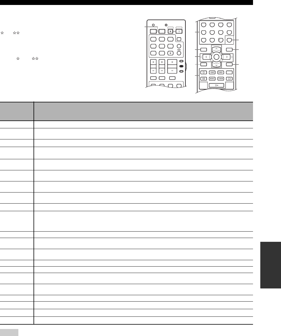
91
REMOTE CONTROL FEATURES
ADVANCED
OPERATION
■Controlling other components
Set the component selector switch to SOURCE to control
other components selected with the input selector buttons,
, or . You must set the appropriate remote control
code for each input source (see page 92). The following
table shows the function of each control button used to
control other components assigned to each input selector
button, , and . Be advised that some buttons may not
correctly operate the selected component.
*1 This button is operational only when the original remote control supplied with the component has a POWER button.
*2 These buttons control your VCR or DVD recorder only when you set the appropriate remote control code for DVR (see page 92).
*3 When you use this button to record a source, press it twice repeatedly to prevent a malfunction.
*4 Press and hold to search backward or forward.
TV MUTE TV INPUT
MUTE
AMP
SOURCE
TV
STEREO
1
VOLUME
TV VOL TV CH
TRANSMITCODE SET
STANDBY
POWER
POWERPOWER
CD
AVTV
MULTI CH IN
SLEEP
CD-R XM
DVD DTV
MD
CBL
TUNER
V-AUX D VR
MUSIC
2
ENTERTAIN
3
MOVIE
4
UU
U
MENUTITLE
SET MENU
LEVEL
DISPLAYRETURN
BAND
SRCH MODE
XM MEMORY
A-E/CAT. A-E/CAT.
ENTER
PRESET/CH
REC
AUDIO
DISC SKIP
STEREO
1
EFFECT
STANDARD
5
SPEAKERS
9
MUSIC
2
SELECT
6
ENHANCER
0
ENTERTAIN
3
EXTD SUR.
7
NIGHT
10
MOVIE
4
DIRECT ST.
8
STRAIGHT
ENT.
2
3
4
7
9
5
6
8
1
(U.S.A. model)
Remote
control
DVD
player/
recorder
VCR Digital TV/
Cable TV LD player CD player MD/CD
recorder Tuner iPod®
1AV POWER Power *1 Power *1 Power *2 Power *1 Power *1 Power *1
21-9, 0, +10 Numeric
buttons
Numeric
buttons
Numeric
buttons
Numeric
buttons
Numeric
buttons
Numeric
buttons
Preset stations
(1-8)
3TITLE Title Band
4PRESET/CH
uUp VCR channel
up Up Preset up (1-8) Up
PRESET/CH
dDown VCR channel
down Down Preset down
(1-8) Down
A-E/CAT. jLeft Left Preset down
(A-E)
A-E/CAT. iRight Right Preset up
(A-E)
ENTER Enter Enter Subsequent
menu
5RETURN Return Return
6REC/
DISC SKIP
Disc skip
(player)
Rec (recorder)
*3
Rec *3 Rec *2*3 Disc skip Rec *3
pPlay Play Play *2 Play Play Play Play
wSearch
backward
Search
backward
Search
backward *2
Search
backward
Search
backward
Search
backward
Search
backward *4
fSearch forward Search forward Search forward
*2 Search forward Search forward Search forward Search forward
*4
AUDIO Audio Audio Audio *2 Sound
ePause Pause Pause *2 Pause Pause Pause Pause
bSkip backward Skip backward Skip backward
*2 Skip backward Skip backward Skip backward Skip backward
aSkip forward Skip forward Skip forward
*2 Skip forward Skip forward Skip forward Skip forward
sStop Stop Stop *2 Stop Stop Stop Stop
7ENT. Title/Index Enter Enter Chapter/Time Index Index
8MENU Menu Menu Previous menu
9DISPLAY Display Display Display Display Display Display Display
Notes
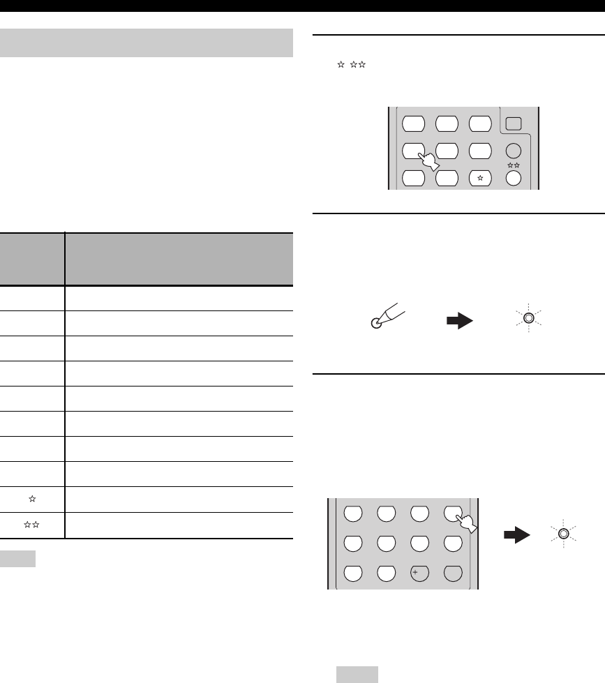
92
REMOTE CONTROL FEATURES
You can control your TV and other components by setting
the appropriate remote control code for each input source.
For a complete list of available remote control codes, refer
to “LIST OF REMOTE CONTROL CODES” at the end of
this manual.
The following table shows the default component in the
“Library (component category)” column and the remote
control code for each input source.
Remote Control Code Default Settings
You may not be able to operate your YAMAHA component even
if a YAMAHA remote control code is initially set as listed above.
In this case, try setting other YAMAHA remote control codes.
1Press one of the input selector buttons or
/ to select the component you want to
set up.
2Press CODE SET using a ballpoint pen or a
similar object.
The TRANSMIT indicator on the remote control
flashes twice.
3Press the numeric buttons (0 to 9) to enter
the five-digit remote control code for the
component to be used.
The TRANSMIT indicator on the remote control
flashes twice, and the remote control code for the
selected component is set.
y
Refer to “LIST OF REMOTE CONTROL CODES” at the
end of this manual.
• If the manufacturer of your component has more than one
code, try each of them until you find the correct one.
• If you do not press any buttons within 30 seconds in step
3, the setup process is canceled. If this happens, repeat the
setup procedure.
• If you enter the code number “9980”, the remote control
code previously set for the selected component is cleared.
Setting the remote control code
Input
source
Library
(component
category)
Manufacturer Default
code
CD CD YAMAHA 61907
MD/CD-R MD YAMAHA 70888
XM TUNER YAMAHA 81918
DVD DVD YAMAHA 40539
DTV/CBL – – –
TUNER TUNER YAMAHA 81916
V-AUX – – –
DVR DVR YAMAHA 51544
–––
–––
Note
Notes
CD
MULTI CH IN
SLEEP
CD-R XM
DVD DTV
MD
CBL
TUNER
V-AU X DVR
TRANSMIT
CODE SET
Flashes
STEREO
1
EFFECT
STANDARD
5
SPEAKERS
9
MUSIC
2
SELECT
6
ENHANCER
0
ENTERTAIN
3
EXTD SUR.
7
NIGHT
10
MOVIE
4
DIRECT ST.
8
STRAIGHT
ENT.
TRANSMIT
Flashes
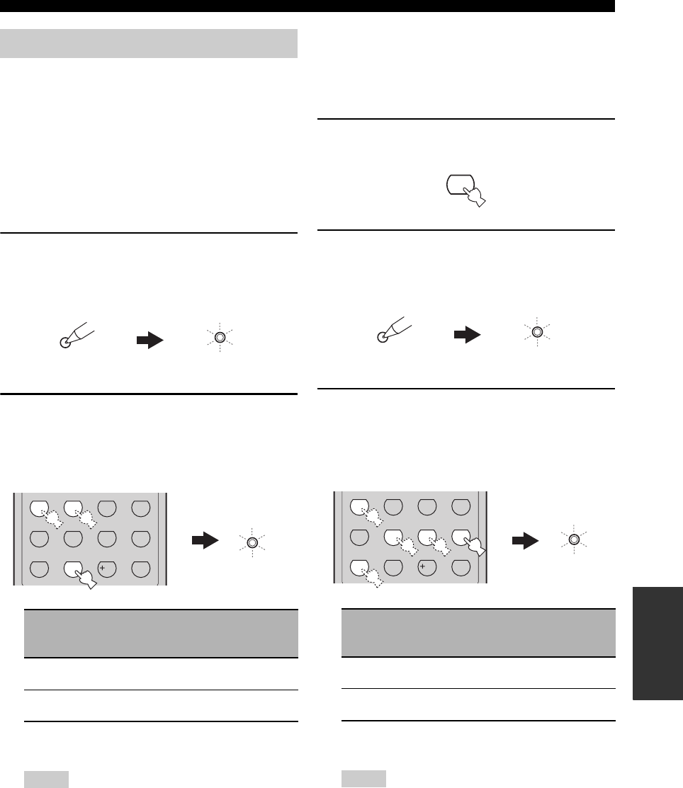
93
REMOTE CONTROL FEATURES
ADVANCED
OPERATION
You can operate multiple YAMAHA receivers or
amplifiers in the same room with the supplied remote
control simultaneously. Set the appropriate library code to
select and operate the desired component with the
supplied remote control.
■Setting remote control AMP ID library
codes
Select one of the following codes to set the remote control
AMP ID library code for the component you want to use.
1Press CODE SET using a ballpoint pen or a
similar object.
The TRANSMIT indicator on the remote control
flashes twice.
2Press the numeric buttons to enter the code
number “00001” or “00002”.
The TRANSMIT indicator on the remote control
flashes twice, and the AMP ID library code is
changed.
*1 The remote control setting
*2 The setting of this unit (see page 89)
• You need to set the corresponding remote control AMP ID
of this unit in the advanced setup (see page 89).
• When using multiple YAMAHA receivers/amplifiers, you
may be able to operate the other components
simultaneously with the default code setting. In this case,
set one of the alternative codes to operate this unit
separately.
■Setting remote control TUNER ID library
codes
Select one of the following codes to set the remote control
TUNER ID library code for the component you want to
use.
1Press TUNER to select “TUNER” as the input
source.
2Press CODE SET using a ballpoint pen or a
similar object.
The TRANSMIT indicator on the remote control
flashes twice.
3Press the numeric buttons to enter the code
number “81916” or “81917”.
The TRANSMIT indicator on the remote control
flashes twice, and the TUNER ID library code is
changed.
*1 The remote control setting
*2 The setting of this unit (see page 89)
• You need to set the corresponding remote control TUNER
ID of this unit in the advanced setup (see page 89).
• When using multiple YAMAHA receivers/amplifiers, you
may be able to operate the other components
simultaneously with the default code setting. In this case,
set one of the alternative codes to operate this unit
separately.
Setting library codes
AMP ID
library code
*1
Function
Remote
control AMP
ID *2
00001
(initial setting)
To operate this unit using
the default code.
ID1
(initial setting)
00002 To operate this unit using
an alternative code. ID2
Notes
TRANSMIT
CODE SET
Flashes
STEREO
1
EFFECT
STANDARD
5
SPEAKERS
9
MUSIC
2
SELECT
6
ENHANCER
0
ENTERTAIN
3
EXTD SUR.
7
NIGHT
10
MOVIE
4
DIRECT ST.
8
STRAIGHT
ENT.
TRANSMIT
Flashes
TUNER ID
library code
*1
Function
Remote
control
TUNER ID *2
81916
(initial setting)
To operate this unit using
the default code.
ID1
(initial setting)
81917 To operate this unit using
an alternative code. ID2
Notes
TUNER
TRANSMIT
CODE SET
Flashes
STEREO
1
EFFECT
STANDARD
5
SPEAKERS
9
MUSIC
2
SELECT
6
ENHANCER
0
ENTERTAIN
3
EXTD SUR.
7
NIGHT
10
MOVIE
4
DIRECT ST.
8
STRAIGHT
ENT.
TRANSMIT
Flashes
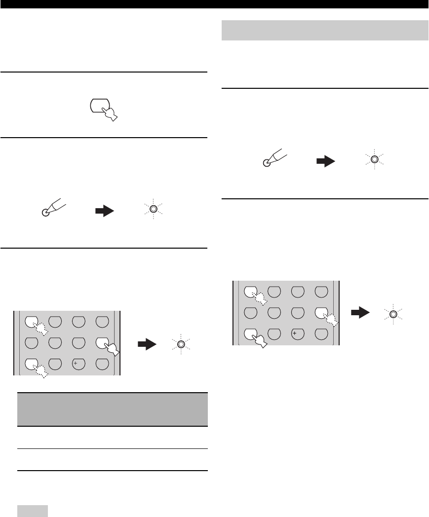
94
REMOTE CONTROL FEATURES
■Setting remote control XM ID library
codes (U.S.A. model only)
Select one of the following codes to set the remote control
XM ID library code for the component you want to use.
1Press XM to select “XM” as the input source.
2Press CODE SET using a ballpoint pen or a
similar object.
The TRANSMIT indicator on the remote control
flashes twice.
3Press the numeric buttons to enter the code
number “81918” or “81919”.
The TRANSMIT indicator on the remote control
flashes twice, and the XM ID library code is changed.
*1 The remote control setting
*2 The setting of this unit (see page 89)
• You need to set the corresponding remote control XM ID
of this unit in the advanced setup (see page 89).
• When using multiple YAMAHA receivers/amplifiers, you
may be able to operate the other components
simultaneously with the default code setting. In this case,
set one of the alternative codes to operate this unit
separately.
Use this feature to clear all the remote control codes
previously set and reset all of them to the initial factory
settings.
1Press CODE SET using a ballpoint pen or a
similar object.
The TRANSMIT indicator on the remote control
flashes twice.
2Press the numeric buttons to enter the code
number “9981”.
The TRANSMIT indicator on the remote control
flashes twice, and all the remote control codes
previously set are cleared and reset to the initial
factory settings.
y
If you do not press any buttons within 30 seconds after step
2, the clearing process is canceled. In this case, repeat the
clearing procedure.
XM ID
library code
*1
Function
Remote
control XM
ID *2
81918
(initial setting)
To operate this unit using
the default code.
ID1
(initial setting)
81919 To operate this unit using
an alternative code. ID2
Notes
XM
TRANSMIT
CODE SET
Flashes
STEREO
1
EFFECT
STANDARD
5
SPEAKERS
9
MUSIC
2
SELECT
6
ENHANCER
0
ENTERTAIN
3
EXTD SUR.
7
NIGHT
10
MOVIE
4
DIRECT ST.
8
STRAIGHT
ENT.
TRANSMIT
Flashes
Resetting all remote control codes
TRANSMIT
CODE SET
Flashes
STEREO
1
EFFECT
STANDARD
5
SPEAKERS
9
MUSIC
2
SELECT
6
ENHANCER
0
ENTERTAIN
3
EXTD SUR.
7
NIGHT
10
MOVIE
4
DIRECT ST.
8
STRAIGHT
ENT.
TRANSMIT
Flashes
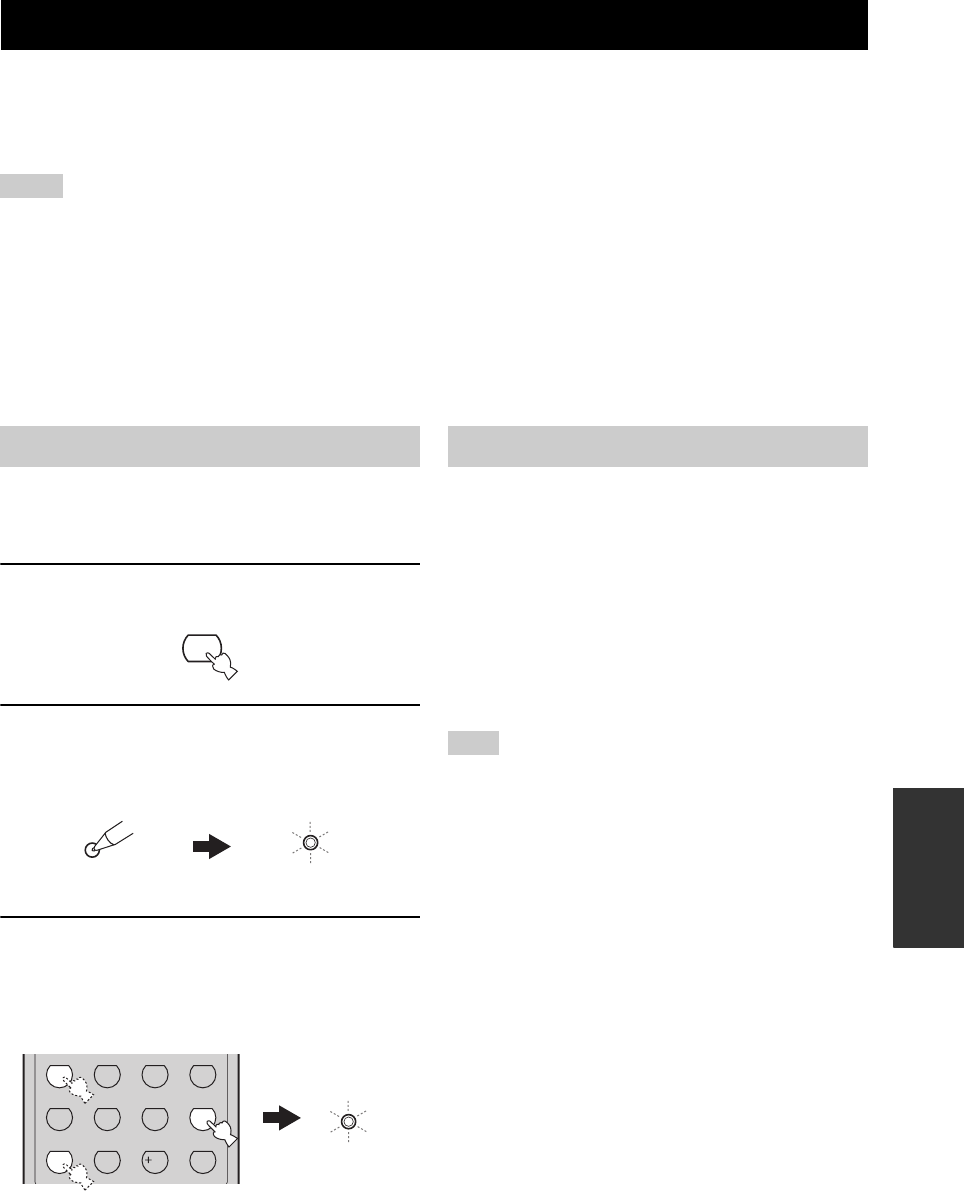
USING IPOD®
95
ADVANCED
OPERATION
Once you have stationed your iPod in a YAMAHA iPod universal dock (such as YDS-10 sold separately) connected to
the DOCK terminal of this unit (see page 22), you can enjoy playback of your iPod using the supplied remote control.
You can also use the Compressed Music Enhancer mode of this unit to improve the sound quality of the compression
artifacts (such as the MP3 format) stored on your iPod (see page 36).
• Only iPod (Click and Wheel), iPod nano, and iPod mini are supported.
• Compatibility with your iPod may vary depending on the software version of your iPod.
• The controls on your iPod are not operational when you operate your iPod using the OSD of this unit.
• There are some characters that cannot be displayed in the front panel or in the OSD of this unit.
• The name of the song being played appears in the front panel display up to 14 alphanumeric characters.
y
• For a complete list of the remote control functions used to control your iPod, see the “iPod” column in “Controlling other
components” on page 91.
• For a complete list of status messages that appear in the front panel display and in the OSD, see the “iPod” section in
“TROUBLESHOOTING” on page 102.
You need to first assign the remote control code to V-AUX
on the remote control to control your iPod when “V-AUX”
is selected as the input source.
1Press V-AUX on the remote control to select
“V-AUX” as the input source.
2Press CODE SET on the remote control using
a ball point pen or a similar object.
The TRANSMIT indicator on the remote control
flashes twice.
3Press the numeric buttons to enter the code
number “81981”.
The TRANSMIT indicator on the remote control
flashes twice, and the remote control code for V-AUX
is set.
Once the remote control code is assigned to V-AUX on the
remote control, you can control your iPod when “V-AUX”
is selected as the input source. The operations of your iPod
can be done with or without the aid of the OSD of this
unit.
■Controlling iPod without using the OSD
Once “V-AUX” is selected as the input source, you can
perform the basic operations of your iPod (see page 91)
using the supplied remote control without the aid of the
OSD of this unit.
Operations can be also done with the controls on your iPod.
y
For a complete list of the remote control buttons used to control
your iPod, see the “iPod” column in “Controlling other
components” on page 91.
USING iPod®
Notes
Setting the remote control code
V-AUX
TRANSMIT
CODE SET
Flashes
STEREO
1
EFFECT
STANDARD
5
SPEAKERS
9
MUSIC
2
SELECT
6
ENHANCER
0
ENTERTAIN
3
EXTD SUR.
7
NIGHT
10
MOVIE
4
DIRECT ST.
8
STRAIGHT
ENT.
TRANSMIT
Flashes
Controlling iPod
Note
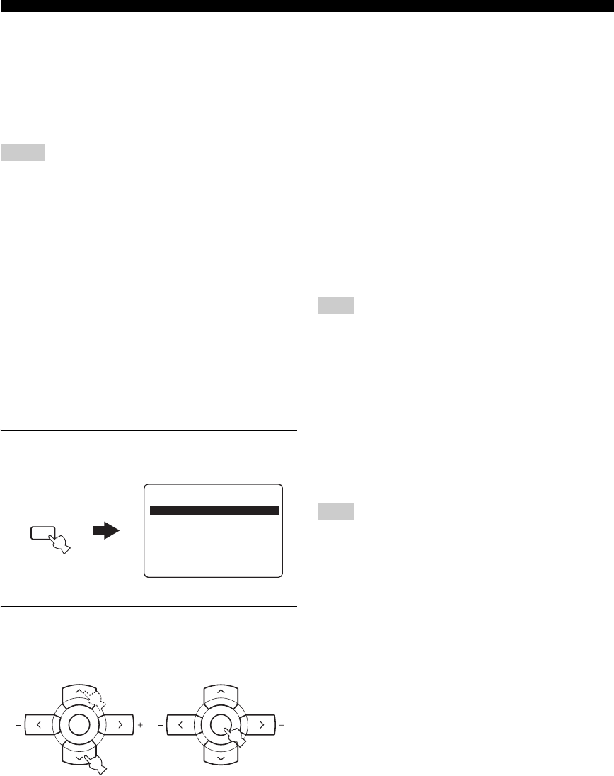
96
USING iPod®
■Controlling iPod using the OSD
Once “V-AUX” is selected as the input source, you can
perform the advanced operations of your iPod using the
supplied remote control with the aid of the OSD of this
unit. You can also browse the songs stored on your iPod in
the OSD. Further, you can change or adjust settings for
your iPod to suit your personal preferences.
• Operations cannot be done with the controls on your iPod.
• The YAMAHA logo appears in the display window of your
iPod.
• The “Setup” parameters can be changed or adjusted only in the
OSD.
• Press ENTER on the remote control to toggle between the
“Setup” parameter settings.
• You cannot browse the photos or video clips stored on your
iPod in the OSD. Instead, you must use the controls on your
iPod to select the desired photos or video clips. For details, see
“Controlling iPod without using the OSD” on page 95.
y
• Press MENU on the remote control to move back to the
previous menu level.
• For a complete list of the remote control buttons used to control
your iPod, see the “iPod” column in “Controlling other
components” on page 91.
1Press DISPLAY on the remote control.
The following display appears in the OSD.
2Press u / d on the remote control to select
the desired menu and then press ENTER to
enter the selected menu.
Choices: Playlists (playlists), Artists (artists),
Albums (albums), Songs (songs),
Genres (genres), Composers (composers),
Setup (setup)
• Playlists > Songs
• Artists > Albums > Songs
• Albums > Songs
• Songs
• Genres > Artists > Albums > Songs
• Composers > Albums > Songs
• Setup > Shuffle, Repeat, Onscreen, FL Scroll
Shuffle Shuffle
Use this feature to set this unit to play songs or albums in a
random order.
Choices: Off, Songs, Albums
• Select “Off ” to deactivate this feature.
• Select “Songs” to set this unit to play songs in a
random order.
• Select “Albums” to set this unit to play albums in a
random order.
When “Shuffle” is set to a setting other than “Off ”, the
highlighted letter “S” appears in the top right corner while songs
or albums are being shuffled.
Repeat Repeat
Use this feature to set this unit to repeat one song or a
sequence of songs.
Choices: Off, One, All
• Select “Off ” to deactivate this feature.
• Select “One” to set this unit to repeat one song.
• Select “All” to set this unit to repeat a sequence of
songs.
When “Repeat” is set to a setting other than “Off ”, the
highlighted letter “R” appears in the top right corner while one
song or a sequence of songs are being repeated.
On-screen display time Onscreen
Use this feature to set the amount of time for which the
OSD is displayed after you perform a certain operation on
your iPod.
Choices: Always, 5s, 10s
• Select “Always” to display the OSD unceasingly while
you are operating your iPod.
• Select “5s” to turn off the OSD 5 seconds after you
perform a certain operation on your iPod.
• Select “10s” to turn off the OSD 10 seconds after you
perform a certain operation on your iPod.
Front panel display scroll FL Scroll
Use this feature to set whether to display the iPod
operation status in the front panel display in a continuous
manner or by 14 alphanumeric characters at once.
Choices: Cont, Once
• Select “Cont” to display the iPod operation status in
the front panel display in a continuous manner.
• Select “Once” to display the iPod operation status in
the front panel display by 14 alphanumeric characters
at once.
Notes
>
>
>
>
>
>
>
Playlists
Artists
Albums
Songs
Genres
Composers
Setup
iPod Top
DISPLAY
A-E/CAT. A-E/CAT.
ENTER
PRESET/CH
A-E/CAT. A-E/CAT.
ENTER
PRESET/CH
Note
Note
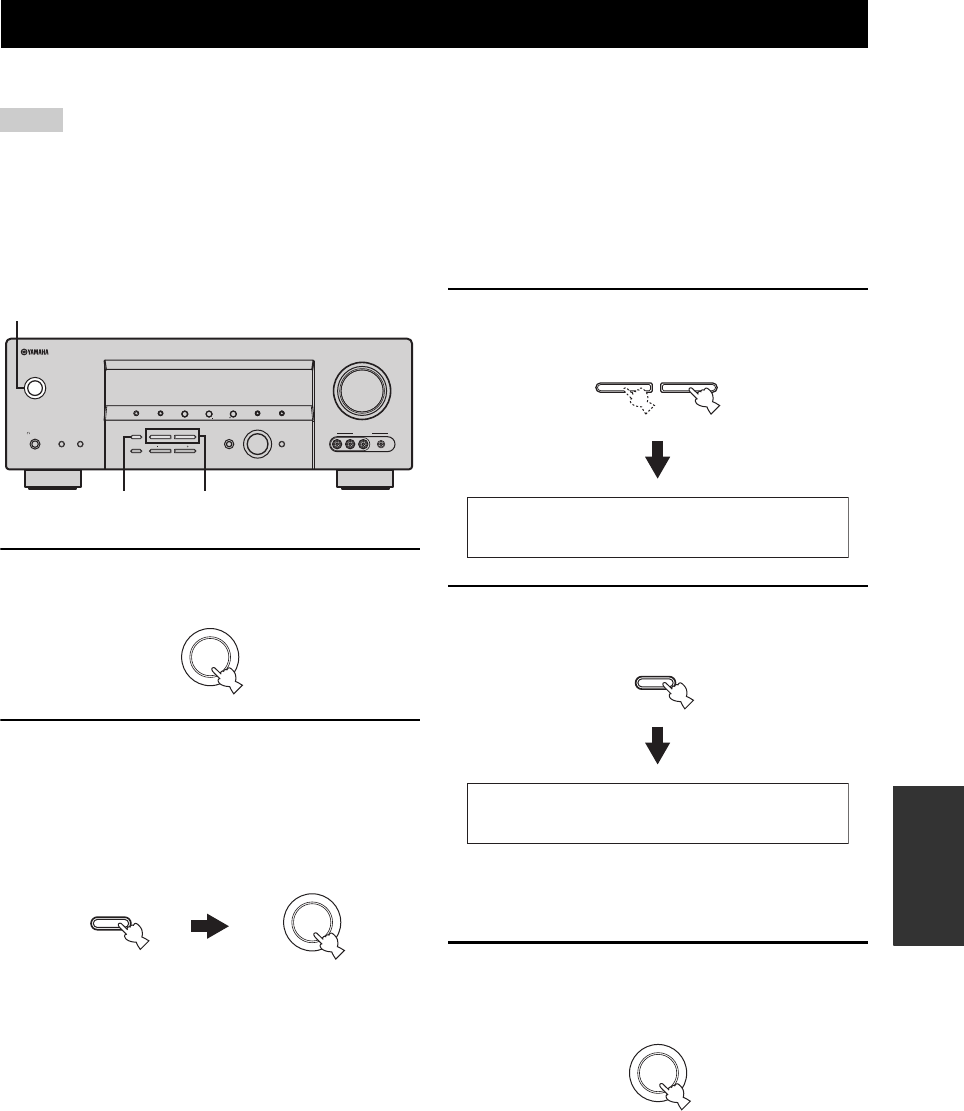
RESETTING THE SYSTEM
97
ADVANCED
OPERATION
Use this feature to reset all the parameters of this unit to the initial factory settings.
• This procedure completely resets all the parameters of this unit including the “SET MENU” parameters. However, the advanced setup
menu parameters will not be initialized.
• The initial factory settings are activated next time you turn on this unit.
y
To cancel the initialization procedure at any time without making any changes, press STANDBY/ON on the front panel (or STANDBY
on the remote control) to set this unit to the standby mode.
1Press STANDBY/ON on the front panel to set
this unit to the standby mode.
2Press and hold STRAIGHT (EFFECT) on the
front panel and then press STANDBY/ON to
turn on this unit.
This unit turns on, and the advanced setup menu
appears in the front panel display.
3Press PROGRAM l / h on the front panel
repeatedly to select “PRESET”.
4Press STRAIGHT (EFFECT) on the front
panel repeatedly to select “RESET”.
y
Select “CANCEL” to cancel the initialization procedure
without making any changes.
5Press STANDBY/ON on the front panel to
confirm your selection and set this unit to the
standby mode.
RESETTING THE SYSTEM
Notes
VOLUME
AUTO/MAN'LMAN'L/AUTO FMLEVELNEXTEDIT
EFFECT
MEMORY
FM/AMPRESET/TUNING
A/B/C/D/E
l PROGRAM h
BASS/TREBLE
TUNING MODE
INPUT MODE
TONE CONTROL
STRAIGHT
SPEAKERSPHONES
SILENT CINEMA
STANDBY
/ON
BA
MULTI CH
INPUT
INPUT
SEARCH MODE CATEGORY
l PRESET/TUNING/CH h
DISPLAY
VIDEO PORTABLEL AUDIO R
VIDEO AUX
32,4
1-2,5
(U.S.A. model)
STANDBY
/ON
EFFECT
STRAIGHT
STANDBY
/ON
While holding
down
l PROGRAM h
PRESET-CANCEL
EFFECT
STRAIGHT
PRESET-RESET
STANDBY
/ON

TROUBLESHOOTING
98
Refer to the table below when this unit does not function properly. If the problem you are experiencing is not listed below
or if the instruction below does not help, set this unit to the standby mode, disconnect the power cable, and contact the
nearest authorized YAMAHA dealer or service center.
■General
TROUBLESHOOTING
Problem Cause Remedy See
page
This unit fails to turn
on or enters the
standby mode soon
after the power is
turned on.
The power cable is not connected or the
plug is not completely inserted.
Connect the power cable firmly. —
The speaker impedance setting is
incorrect.
Set the speaker impedance to match your speakers. 26
The protection circuitry has been
activated.
Make sure that all speaker wire connections on this
unit and on all speakers are secure and that the wire
for each connection does not touch anything other
than its respective connection.
13
This unit has been exposed to a strong
external electric shock (such as lightning
or strong static electricity).
Set this unit to the standby mode, disconnect the
power cable, plug it back in after 30 seconds and then
use it normally.
—
No sound Incorrect input or output cable
connections.
Connect the cables properly. If the problem persists,
the cables may be defective.
18-23
“INPUT MODE” is set to “DTS” or
“ANALOG”.
Set “INPUT MODE” to “AUTO”. 34
No appropriate input source has been
selected.
Select an appropriate input source with the INPUT
selector on the front panel (or the input selector
buttons on the remote control) and MULTI CH
INPUT on the front panel (or MULTI CH IN on the
remote control).
31, 37
Speaker connections are not secure. Secure the connections. 13
The front speakers to be used have not
been selected properly.
Select the set of front speakers with SPEAKERS A or
B on the front panel or SPEAKERS on the remote
control.
31
The volume is turned down. Turn up the volume. —
The sound is muted. Press MUTE or VOLUME +/– on the remote control
to resume audio output and then adjust the volume.
33
“INPUT MODE” is set to “ANALOG”
while playing a source encoded in DTS.
Set “INPUT MODE” to “AUTO” or “DTS”. 34
Signals this unit cannot reproduce are
being input from a source component,
such as a CD-ROM.
Play a source whose signals can be reproduced by this
unit.
—
No picture The output and input for the picture are
connected to different types of video
jacks.
Set “VIDEO CONV.” to “ON”. 85

99
TROUBLESHOOTING
ADDITIONAL
INFORMATION
Problem Cause Remedy See
page
The sound suddenly
goes off.
The protection circuitry has been activated
because of a short circuit, etc.
Check that the speaker impedance setting is correct. 26, 89
Check that the speaker wires are not touching each
other and then turn this unit back on.
—
The sleep timer has set this unit to the
standby mode.
Turn on this unit, and play the source again. —
The sound is muted. Press MUTE or VOLUME +/– on the remote control
to resume audio output.
33
Sound is heard from
the speaker on one
side only.
Incorrect cable connections. Connect the cables properly. If the problem persists,
the cables may be defective.
13
Incorrect settings in “SPEAKER
LEVEL”.
Adjust the “SPEAKER LEVEL” settings. 80
Only the center
speaker outputs
substantial sound.
When playing a monaural source with a
CINEMA DSP program, the source signal
is directed to the center channel, and the
front and surround speakers output effect
sounds.
No sound is heard
from the center
speaker.
“CENTER SP” in “SET MENU” is set to
“NONE”.
Set “CENTER SP” to “SML” or “LRG”. 79
One of the HiFi DSP programs (except for
“6ch Stereo”) has been selected.
Try another sound field program. 63
No sound is heard
from the surround
speakers.
“SUR. L/R SP” in “SET MENU” is set to
“NONE”.
Set “SUR. L/R SP” to “SML” or “LRG”. 79
This unit is in the “STRAIGHT” mode
and a monaural source is being played
back.
Press STRAIGHT (EFFECT) on the front panel so
that “STRAIGHT” disappears from the front panel
display.
38
No sound is heard
from the surround
back speaker.
“SUR. L/R SP” in “SET MENU” is set to
“NONE” and “SUR. B SP” is
automatically set to “NONE”.
Set “SUR. L/R SP” and “SUR. B SP” to “SML” or
“LRG”.
79
“SUR. B SP” in “SET MENU” is set to
“NONE”.
Set “SUR. B SP” to “SML” or “LRG”. 79
No sound is heard
from the subwoofer.
“LFE/BASS OUT” in “SET MENU” is
set to “FRNT” when a Dolby Digital or
DTS signal is being played.
Set “LFE/BASS OUT” to “SWFR” or “BOTH”. 79
“LFE/BASS OUT” in “SET MENU” is
set to “SWFR” or “FRNT” when a 2-
channel source is being played.
Set “LFE/BASS OUT” to “BOTH”. 79
The source does not contain low-
frequency signals.

100
TROUBLESHOOTING
Problem Cause Remedy See
page
Dolby Digital or DTS
sources cannot be
played. (Dolby Digital
or DTS indicator in
the front panel
display does not light
up.)
The connected component is not set to
output Dolby Digital or DTS digital
signals.
Make an appropriate setting following the operating
instructions for your component.
—
“INPUT MODE” is set to “ANALOG”. Set “INPUT MODE” to “AUTO” or “DTS”. 34
A humming sound is
heard.
Incorrect cable connections. Connect the audio cables firmly. If the problem
persists, the cables may be defective.
—
The volume level
cannot be increased,
or the sound is
distorted.
The component connected to the AUDIO
OUT (REC) jacks of this unit is turned
off.
Turn on the power of the component. —
The sound effect
cannot be recorded.
It is not possible to record the sound effect
with a recording component.
A source cannot be
recorded by a digital
recording component
connected to the
DIGITAL OUTPUT
jack.
The source component is not connected to
the DIGITAL INPUT jacks of this unit.
Connect the source component to the DIGITAL
INPUT jacks.
19, 21
Some components cannot record the
Dolby Digital or DTS sources.
A source cannot be
recorded by an
analog component
connected to the
AUDIO OUT (REC)
jacks.
The source component is not connected to
the analog AUDIO IN jacks of this unit.
Connect the source component to the analog AUDIO
IN jacks.
21
The sound field
parameters and some
other settings of this
unit cannot be
changed.
“MEMORY GUARD” in “SET MENU”
is set to “ON”.
Set “MEMORY GUARD” to “OFF”. 86
This unit does not
operate properly.
The internal microcomputer has been
frozen by an external electric shock (such
as lightning or excessive static electricity)
or by a power supply with low voltage.
Disconnect the power cable from the AC wall outlet
and then plug it in again after about 30 seconds.
—
“CHECK SP WIRES”
appears in the front
panel display.
Speaker cables are short-circuited. Make sure all speaker cables are connected correctly. 13
There is noise
interference from
digital or radio
frequency equipment.
This unit is too close to the digital or high-
frequency equipment.
Move this unit further away from such equipment. —
The picture is
disturbed.
The video source uses scrambled or
encoded signals to prevent dubbing.
This unit suddenly
enters the standby
mode.
The internal temperature becomes too
high and the overheat protection circuitry
has been activated.
Wait about 1 hour for this unit to cool down and then
turn it back on.
—
101
TROUBLESHOOTING
ADDITIONAL
INFORMATION
■Tuner
■ XM Satellite Radio (U.S.A. model only)
If an operation takes longer than usual or an error occurs, one of the following messages may appear in the front panel
display. In this case, read the cause and follow the corresponding remedies.
Problem Cause Remedy See
page
FM
FM stereo reception is
noisy.
The characteristics of FM stereo
broadcasts may cause this problem
when the transmitter is too far away or
the antenna input is poor.
Check the antenna connections. 24
Try using a high-quality directional FM
antenna.
—
Use the manual tuning method. 46
There is distortion, and
clear reception cannot
be obtained even with a
good FM antenna.
There is multi-path interference. Adjust the antenna position to eliminate
multi-path interference.
—
The desired station
cannot be tuned into
with the automatic
tuning method.
The signal is too weak. Use a high-quality directional FM antenna. —
Use the manual tuning method. 46
Previously preset
stations can no longer
be tuned into.
This unit has been disconnected for a
long period.
Set preset stations 47, 48
AM
The desired station
cannot be tuned into
with the automatic
tuning method.
The signal is weak or the antenna
connections are loose.
Tighten the AM loop antenna connections
and orient it for the best reception.
—
Use the manual tuning method. 46
There are continuous
crackling and hissing
noises.
Noises result from lightning,
fluorescent lamps, motors, thermostats
and other electrical equipment.
Use an outdoor antenna and a ground wire.
This will help somewhat, but it is difficult to
eliminate all noise.
—
There are buzzing and
whining noises.
A TV set is being used nearby. Move this unit away from the TV set. —
Status message Cause Remedy See
page
CHECK ANTENNA The XM Connect-and-Play digital antenna
accessory is not connected to the XM jack
of this unit or does not work properly.
Check the XM Connect-and-Play digital antenna
accessory connections and orient it for the best
reception level.
52
UPDATING The XM user encryption code is being
updated.
Wait until the encryption code is updated. —
NO SIGNAL The signal is too weak. Check the XM Connect-and-Play digital antenna
accessory connections and orient it for the best
reception level.
52
LOADING It takes longer than four seconds for audio
or text data to be decoded.
Wait until the decoding process has finished. —
OFF AIR The XM Satellite Radio channel you
selected is not currently broadcasting any
signals.
Check the channel number again or select another
XM Satellite Radio channel.
—
<XM> - - - The Channel Station ID (SID) is no longer
available.
- - - / - - - No artist name or song title is available.
<CAT> - - - No channels are available for the selected
category.
Select another channel category by pressing
CATEGORY on the front panel (or A-E/CAT. j / i on
the remote control) repeatedly.
57

102
TROUBLESHOOTING
■Remote control
■iPod
In case of a transmission error without a status message appearing in the front panel and in the OSD, check the connection to your iPod
(see page 22).
Problem Cause Remedy See
page
The remote control
does not work nor
function properly.
Wrong distance or angle. The remote control functions within a maximum
range of 6 m (20 ft) and no more than 30 degrees off-
axis from the front panel.
8
Direct sunlight or lighting (from an
inverter type of fluorescent lamp, etc.) is
striking the remote control sensor of this
unit.
Reposition this unit. —
The batteries are weak. Replace all batteries. 3
The remote control code is not correctly
set.
Set the remote control code correctly using “LIST OF
REMOTE CONTROL CODES” at the end of this
manual.
92
Try setting another code for the same manufacturer
using “LIST OF REMOTE CONTROL CODES” at
the end of this manual.
92
The library code of the remote control and
the remote control ID of this unit do not
match.
Match the remote control ID of this unit with the
corresponding remote control library code.
89, 93
Even if the remote control code is
correctly set, there are some models that
do not respond to the remote control.
Note
Status message Cause Remedy See
page
Loading... This unit is in the middle of recognizing
the connection with your iPod.
This unit is in the middle of acquiring
song lists from your iPod.
Connect error There is a problem with the signal path
from your iPod to this unit.
Set this unit to the standby mode and reconnect the
YAMAHA iPod universal dock to the DOCK
terminal of this unit.
22
Try resetting your iPod. —
Unknown type The iPod being used is not supported by
this unit.
Only iPod (Click and Wheel), iPod nano, and iPod
mini are supported.
—
iPod connected Your iPod is properly stationed in a
YAMAHA iPod universal dock (such as
YDS-10 sold separately) connected to the
DOCK terminal of this unit, and the
connection between your iPod and this
unit is complete.
Disconnected Your iPod was removed from a YAMAHA
iPod universal dock (such as YDS-10 sold
separately) connected to the DOCK
terminal of this unit.
Station your iPod back in a YAMAHA iPod universal
dock (such as YDS-10 sold separately) connected to
the DOCK terminal of this unit.
22
Unable to play This unit cannot play back the songs
currently stored on your iPod.
Check that the songs currently stored on your iPod
are playable.
—
Store some other playable music files on your iPod. —

GLOSSARY
103
ADDITIONAL
INFORMATION
■Dolby Digital
Dolby Digital is a digital surround sound system that gives
you completely independent multi-channel audio. With 3
front channels (front L/R and center), and 2 surround
stereo channels, Dolby Digital provides 5 full-range audio
channels. With an additional channel especially for bass
effects, called LFE (Low Frequency Effect), the system
has a total of 5.1-channels (LFE is counted as 0.1
channel). By using 2-channel stereo for the surround
speakers, more accurate moving sound effects and
surround sound environment are possible than with Dolby
Surround. The wide dynamic range from maximum to
minimum volume reproduced by the 5 full-range channels
and the precise sound orientation generated using digital
sound processing provide listeners with unprecedented
excitement and realism. With this unit, any sound
environment from monaural up to a 5.1-channel
configuration can be freely selected for your enjoyment.
■Dolby Digital EX
Dolby Digital EX creates 6 full-bandwidth output
channels from 5.1-channel sources. This is done using a
matrix decoder that derives 3 surround channels from the
2 in the original recording. For the best results, Dolby
Digital EX should be used with movie sound tracks
recorded with Dolby Digital Surround EX. With this
additional channel, you can experience more dynamic and
realistic moving sound especially with scenes with “fly-
over” and “fly-around” effects.
■Dolby Pro Logic II
Dolby Pro Logic II is an improved technique used to
decode vast numbers of existing Dolby Surround sources.
This new technology enables a discrete 5-channel
playback with 2 front left and right channels, 1 center
channel, and 2 surround left and right channels instead of
only 1 surround channel for conventional Pro Logic
technology. There are three modes available: “Music
mode” for music sources, “Movie mode” for movie
sources and “Game mode” for game sources.
■Dolby Pro Logic IIx
Dolby Pro Logic IIx is a new technology enabling discrete
multi-channel playback from 2-channel or multi-channel
sources. There are three modes available: “Music mode”
for music sources, “Movie mode” for movie sources (for
2-channel sources only) and “Game mode” for game
sources.
■Dolby Surround
Dolby Surround uses a 4-channel analog recording system
to reproduce realistic and dynamic sound effects: 2 front
left and right channels (stereo), a center channel for dialog
(monaural), and a surround channel for special sound
effects (monaural). The surround channel reproduces
sound within a narrow frequency range. Dolby Surround is
widely used with nearly all video tapes and laser discs,
and in many TV and cable broadcasts as well. The Dolby
Pro Logic decoder built into this unit employs a digital
signal processing system that automatically stabilizes the
volume on each channel to enhance moving sound effects
and directionality.
■DTS 96/24
DTS 96/24 offers an unprecedented level of audio quality
for multi-channel sound on DVD video, and is fully
backward-compatible with all DTS decoders. “96” refers
to a 96 kHz sampling rate compared to the typical 48 kHz
sampling rate. “24” refers to 24-bit word length. DTS 96/
24 offers sound quality transparent to the original 96/24
master, and 96/24 5.1-channel sound with full-quality full-
motion video for music programs and motion picture
soundtracks on DVD video.
■DTS (Digital Theater Systems)
Digital Surround
DTS digital surround was developed to replace the analog
soundtracks of movies with a 6.1-channel digital sound
track, and is now rapidly gaining popularity in movie
theaters around the world. Digital Theater Systems Inc.
has developed a home theater system so that you can enjoy
the depth of sound and natural spatial representation of
DTS digital surround in your home. This system produces
practically distortion-free 6.1-channel sound (technically,
front left and right, center, surround left and right, and
LFE 0.1 (subwoofer) channels for a total of 5.1 channels).
This unit incorporates a DTS-ES decoder that enables 6.1-
channel reproduction by adding the surround back channel
to the existing 5.1-channel format.
■ITU-R
ITU-R is the radio communication sector of the ITU
(International Telecommunication Union). ITU-R
recommends a standard speaker placement which is used
in many critical listening rooms, especially for mastering
purposes.
GLOSSARY
Audio information

104
GLOSSARY
■LFE 0.1 channel
This channel reproduces low-frequency signals. The
frequency range of this channel is from 20 Hz to 120 Hz.
This channel is counted as 0.1 because it only enforces a
low-frequency range compared to the full-range
reproduced by the other 5/6 channels in Dolby Digital or
DTS 5.1/6.1-channel systems.
■Neo:6
Neo:6 decodes the conventional 2-channel sources for 6-
channel playback by the specific decoder. It enables
playback with the full-range channels with higher
separation just like digital discrete signal playback. There
are two modes available: “Music mode” for music sources
and “Cinema mode” for movie sources.
■Neural Surround
Neural Surround™ represents the latest advancement in
surround technology and has been adopted by XM
Satellite Radio for digital radio broadcast of surround
recordings and live events in surround sound. Neural
Surround™ employs psychoacoustic frequency domain
processing which allows delivery of a more detailed sound
stage with superior channel separation and localization of
audio elements. System playback is scalable from 5.1 to
7.1 multi-channel surround playback.
■PCM (Linear PCM)
Linear PCM is a signal format under which an analog
audio signal is digitized, recorded and transmitted without
using any compression. This is used as a method of
recording CDs and DVD audio. The PCM system uses a
technique for sampling the size of the analog signal per
very small unit of time. Standing for “Pulse Code
Modulation”, the analog signal is encoded as pulses and
then modulated for recording.
■Sampling frequency and number of
quantized bits
When digitizing an analog audio signal, the number of
times the signal is sampled per second is called the
sampling frequency, while the degree of fineness when
converting the sound level into a numeric value is called
the number of quantized bits. The range of rates that can
be played back is determined based on the sampling rate,
while the dynamic range representing the sound level
difference is determined by the number of quantized bits.
In principle, the higher the sampling frequency, the wider
the range of frequencies that can be played back, and the
higher the number of quantized bits, the more finely the
sound level can be reproduced.
■Component video signal
With the component video signal system, the video signal
is separated into the Y signal for the luminance and the PB
and PR signals for the chrominance. Color can be
reproduced more faithfully with this system because each
of these signals is independent. The component signal is
also called the “color difference signal” because the
luminance signal is subtracted from the color signal. A
monitor with component input jacks is required in order to
output component signals.
■Composite video signal
With the composite video signal system, the video signal
is composed of three basic elements of a video picture:
color, brightness and synchronization data. A composite
video jack on a video component transmits these three
elements combined.
■S-video signal
With the S-video signal system, the video signal normally
transmitted using a pin cable is separated and transmitted
as the Y signal for the luminance and the C signal for the
chrominance through the S-video cable. Using the
S VIDEO jack eliminates video signal transmission loss
and allows recording and playback of even more beautiful
images.
Video information

105
GLOSSARY
ADDITIONAL
INFORMATION
■CINEMA DSP
Since the Dolby Surround and DTS systems were
originally designed for use in movie theaters, their effect
is best felt in a theater having many speakers designed for
acoustic effects. Since home conditions, such as room
size, wall material, number of speakers, and so on, can
differ so widely, it is inevitable that there are differences in
the sound heard. Based on a wealth of actually measured
data, YAMAHA CINEMA DSP uses YAMAHA original
sound field technology to combine Dolby Pro Logic,
Dolby Digital and DTS systems to provide the audiovisual
experience of movie theater in the listening room of your
own home.
■SILENT CINEMA
YAMAHA has developed a natural, realistic sound effect
DSP algorithm for headphones. Parameters for
headphones have been set for each sound field so that
accurate representations of all the sound field programs
can be enjoyed on headphones.
■Virtual CINEMA DSP
YAMAHA has developed a Virtual CINEMA DSP
algorithm that allows you to enjoy DSP sound field
surround effects even without any surround speakers by
using virtual surround speakers. It is even possible to
enjoy Virtual CINEMA DSP using a minimal two-speaker
system that does not include a center speaker.
Sound field program information

SPECIFICATIONS
106
AUDIO SECTION
• Minimum RMS Output Power for Front, Center, Surround,
Surround back
1 kHz, 0.7% THD, 8 Ω....................................................... 110 W
• Maximum Power (EIAJ) [China model]
1 kHz, 10% THD, 8 Ω......................................................... 135 W
• Dynamic Power (IHF)
8/6/4/2 Ω ....................................................... 130/165/195/240 W
• Damping Factor (IHF)
20 Hz to 20 kHz, 8 Ω...................................................120 or more
• Frequency Response
CD terminal to Front L/R ...................... 10 Hz to 100 kHz, –3 dB
• Total Harmonic Distortion
CD, etc. to Front L/R (20 Hz to 20 kHz, 50 W, 8 Ω)
................................................................................ 0.06% or less
• Signal to Noise Ratio (IHF-A Network)
CD (250 mV) to Front L/R, Effect Off .................. 100 dB or more
• Residual Noise (IHF-A Network)
Front L/R ................................................................ 150 µV or less
• Channel Separation (1 kHz/10 kHz)
CD (5.1 kΩ terminated) to Front L/R ......... 60 dB/45 dB or more
• Tone Control (Front L/R)
BASS Boost/Cut ...................................................... ±10 dB/60 Hz
TREBLE Boost/Cut .............................................. ±10 dB/20 kHz
• Phones Output .......................................................... 150 mV/100 Ω
• Input Sensitivity/Input Impedance
CD, etc. ................................................................. 200 mV/47 kΩ
MULTI CH INPUT ............................................... 200 mV/47 kΩ
• Output Level/Output Impedance
REC OUT.............................................................. 200 mV/1.2 kΩ
SUBWOOFER ............................................................ 4 V/1.2 kΩ
VIDEO SECTION
• Video Signal Type .......................................................... PAL/NTSC
• Signal to Noise Ratio ................................................ 50 dB or more
• Frequency Response (MONITOR OUT)
Component ............................................... 5 Hz to 60 MHz, –3 dB
FM SECTION
• Tuning Range
[U.S.A. and Canada models] .......................... 87.5 to 107.9 MHz
[Other models] ............................................ 87.50 to 108.00 MHz
• Usable Sensitivity (IHF)....................................... 1.0 µV (11.2 dBf)
• Signal to Noise Ratio (IHF)
Mono/Stereo ............................................................. 76 dB/70 dB
• Harmonic Distortion (1 kHz)
Mono/Stereo ................................................................ 0.2%/0.3%
• Stereo Separation (1 kHz) ....................................................... 42 dB
• Frequency Response ......................... 20 Hz to 15 kHz, +0.5, –2 dB
AM SECTION
• Tuning Range
[U.S.A. and Canada models] .............................. 530 to 1710 kHz
[Other models] .................................................... 531 to 1611 kHz
• Usable Sensitivity ............................................................. 300 µV/m
GENERAL
• Power Supply
[U.S.A. and Canada models] ............................. AC 120 V, 60 Hz
[Australia model] ............................................... AC 240 V, 50 Hz
[China model] .................................................... AC 220 V, 50 Hz
• Power Consumption
[U.S.A. and Canada models] ................................. 350 W/440 VA
[Other models] .................................................................... 360 W
• Standby Power Consumption ...................................... 0.1 W or less
• AC Outlets
[Australia model] ................................ 1 (Total 100 W maximum)
[U.S.A., Canada and China models] .... 2 (Total 100 W maximum)
• Dimensions (W x H x D) .................................. 435 x 161 x 391 mm
(17.1 x 6.3 x 15.4 in)
• Weight .................................................................. 10.5 kg (23.1 lbs)
SPECIFICATIONS

APPENDIX-i
LIST OF REMOTE CONTROL CODES
CABLE TV RECEIVER
ABC 10003, 10008,
10014, 10017,
10033
AMERICAST 10899
BELL & HOWELL
10014
BELL SOUTH 10899
CLEARMASTER
10883
CLEARMAX 10883
COOLMAX 10883
DIGEO 11187
DIGI 10637
DIRECTOR 10476
DUMONT 10637
GENERAL INSTRUMENT
10003, 10276,
10476, 10810
GOLDSTAR 10144
HAMLIN 10009, 10273
I3 MICRO 11602
JERROLD 10003, 10012,
10014, 10276,
10476, 10810
MACOM 10033
MEMOREX 10000
MOTOROLA 10014, 10276,
10476, 10810,
11187, 11254,
11376
MULTITECH 10883
MYRIO 11602
PACE 10008, 10237,
11877
PANASONIC 10000, 10107
PANTHER 10637
PARAGON 10000
PHILIPS 10317, 11305
PIONEER 10144, 10533,
10877, 11877
PULSAR 10000
QUASAR 10000
RADIOSHACK
10883
RCA 11256
REGAL 10273, 10279
RUNCO 10000
SAMSUNG 10144
SCIENTIFIC ATLANTA
10008, 10017,
10477, 10877,
11877
SEJIN 11602
SONY 11006
STARCOM 10003
SUPERCABLE
10276
SUPERMAX 10883
THOMSON 11256
TOCOM 10012
TORX 10003
TOSHIBA 10000
TRISTAR 10883
V2 10883
VIEWMASTER10883
VISION 10883
VORTEX VIEW10883
ZENITH 10000, 10525,
10899
CABLE/PVR
COMBINATION
AMERICAST 10899
DIGEO 11187
GENERAL INSTRUMENT
10476, 10810
JERROLD 10476, 10810
MOTOROLA 10476, 10810,
11187, 11376
PACE 10237, 11877
PIONEER 10877, 11877
RCA 11256
SCIENTIFIC ATLANTA
10877, 11877
SONY 11006
SUPERCABLE
10276
THOMSON 11256
ZENITH 10899
DBS/PVR
COMBINATION
DIRECTV 10099, 10392,
10639, 11076,
11142, 11377,
11392, 11442,
11443, 11444,
11640
DISH NETWORK SYSTEM
10775, 11505
DISHPRO 10775, 11505
ECHOSTAR 10775, 11170,
11505
EXPRESSVU 10775
HUGHES NETWORK SYSTEMS
11142, 11442,
11443, 11444
JVC 11170
MOTOROLA 10869
PHILIPS 11142, 11442
PROSCAN 10392
RCA 11392
SAMSUNG 11442
SONY 10639, 11640
STAR CHOICE
10869
SATELLITE RECEIVER
ALPHASTAR 10772
CHAPARRAL 10053, 10216
CROSSDIGITAL
11109
DIRECTV 10099, 10247,
10392, 10566,
10639, 10724,
10749, 10819,
11076, 11108,
11109, 11142,
11377, 11392,
11414, 11442,
11443, 11444,
11609, 11639,
11640, 11749,
11856
DISH NETWORK SYSTEM
10775, 11005,
11170, 11505,
11775
DISHPRO 10775, 11005,
11505, 11775
ECHOSTAR 10269, 10280,
10775, 11005,
11170, 11505,
11775
EXPRESSVU 10775, 11775
GE 10392, 10566
GENERAL INSTRUMENT
10869
GOI 10775, 11775
GOODMANS 11246
HISENSE 11535
HITACHI 10819, 11250
HOMECABLE 10238
HTS 10775, 11775
HUGHES 10749, 11442,
11749
HUGHES NETWORK SYSTEMS
10749, 11142,
11442, 11443,
11444, 11749
ILO 11535
IQ 10210
IQ PRISM 10210
JERROLD 10869
JVC 10775, 11170,
11775
LEGEND 10269
LG 11226, 11414
MAGNAVOX 10722, 10724
MEMOREX 10269, 10724
MITSUBISHI 10749
MOTOROLA 10856, 10869
NEC 11270
NEXT LEVEL 10869
PANASONIC 10247, 10701
PAYSAT 10724
PHILIPS 10099, 10722,
10724, 10749,
10819, 11076,
11142, 11442,
11749
PIONEER 11442
PROSCAN 10392, 10566
PROTON 11535
RADIOSHACK
10869
RCA 10143, 10392,
10566, 10855,
11392
REALISTIC 10052
SAMSUNG 11108, 11109,
11142, 11276,
11377, 11442,
11609
SANYO 11219
SONY 10639, 11639,
11640
STAR CHOICE 10869
STS 10210
TIVO 11142, 11442,
11443, 11444
TOSHIBA 10082, 10749,
10790, 10819,
11285, 11749
ULTIMATETV 11392, 11640
UNIDEN 10052, 10074,
10238, 10722,
10724
US DIGITAL 11535
USDTV 11535
VOOM 10869
ZENITH 11856
HDTV DECORDER
ACCURIAN 11653
EPSON 11563, 11650
LG 11415
MACRO IMAGE TECHNOLOGY
11383
MOTOROLA 11363
MYHD 11383
PANASONIC 11120
PIONEER 11010
PRINCETON 10113, 10295
SAMSUNG 11190, 11490
SASEM 11641
SENSORY SCIENCE
11126
SHARP 11010
SYLVANIA 11563
TELEMANN 11604
VIEWSONIC 11329
VIZIO 11126
OTHER VIDEO
ACCESSORIES
ABS 11272
ACCURIAN 11653
ALIENWARE 11272
CYBERPOWER
11272
D-LINK 11554
ECS 11553
EPSON 11563, 11650
GATEWAY 11272
HEWLETT PACKARD
11267, 11272
HOWARD COMPUTERS
11272
HP 11272
HUSH 11272
IBUYPOWER 11272
INTERVIDEO 11393
KEYSPAN 11344
KWORLD 11403
LEADTEK 11614
LG 11415
LINKSYS 11272, 11365
MACRO IMAGE TECHNOLOGY
11383
MEDIA CENTER PC
11272
MICROSOFT 11272
MIND 11272
MOTOROLA 11363
MYHD 11383
NIVEUS MEDIA
11272
NORTHGATE 11272
PANASONIC 11120
PINNACLE SYSTEMS
11268
PIONEER 11010
PRINCETON 10113, 10295
RICAVISION 11272

APPENDIX-ii
ROKU 11486
SAMSUNG 11190, 11490
SASEM 11641
SENSORY SCIENCE
11126
SHARP 11010
SMC 11456
SONY 11272, 11324,
11364
STACK 9 11272
STREAMZAP 11309
SYLVANIA 11563
SYSTEMAX 11272
TAGAR SYSTEMS
11272
TELEMANN 11604
TOSHIBA 11272
TOUCH 11272
VIEWSONIC 11272, 11329
VIZIO 11126
VOODOO 11272
ZT GROUP 11272
TV
ADMIRAL 20093, 20463
ADVENT 20761, 20783,
20815, 20817,
20842, 21933
AIKO 20092
AIWA 20701
AKAI 20030, 20060,
20672, 20702,
20812, 21903
ALBATRON 20700, 20843
AMERICA ACTION
20180
AMPRO 20751
ANAM 20180
AOC 20030
APEX DIGITAL
20156, 20748,
20765, 20767,
20879, 21943
AUDIOVOX 20092, 20180,
20451, 20623,
20802, 20875,
21937, 21951,
21952
AVENTURA 20171
AXION 21937
BELL & HOWELL
20154
BENQ 21032
BOXLIGHT 20893
BRADFORD 20180
BROKSONIC 20180, 20236,
20463, 21929,
21935, 21938
CANDLE 20030
CARNIVALE 20030
CARVER 20054
CELEBRITY 20000
CELERA 20765
CHANGHONG
20765
CITIZEN 20030, 20060,
20092, 21928
CLARION 20180
COMMERCIAL SOLUTIONS
20047, 21447
CONTEC 20180
CRAIG 20180
CROSLEY 20054
CROWN 20180
CURTIS MATHES
20030, 20047,
20054, 20060,
20093, 20145,
20154, 20166,
20451, 20466,
20702, 21147,
21347, 21919
CXC 20180
DAEWOO 20092, 20451,
20623, 20661,
20672, 21661,
21928
DELL 21080, 21178,
21454
DENON 20145, 20511
DUMONT 20017
DURABRAND 20171, 20178,
20180, 20463,
21034
DWIN 20093, 20720,
20774
ELECTROBAND
20000
ELECTROGRAPH
21755
EMERSON 20038, 20154,
20171, 20178,
20180, 20236,
20451, 20463,
20623, 21928,
21929, 21944
ENVISION 20030, 20813
EPSON 20833, 20840
ESA 20171, 20812
FISHER 20154
FUJITSU 20683, 20809,
20853
FUNAI 20171, 20180,
21904
FUTURETECH
20180
GATEWAY 21755, 21756
GE 20047, 20051,
20178, 20451,
21147, 21347,
21447, 21917,
21919, 21922
GIBRALTER 20017, 20030
GO VIDEO 20886
GOLDSTAR 20030, 20178,
21926
GOODMANS 20360
GRUNDIG 20683
GRUNPY 20180
HAIER 21034
HALLMARK 20178
HARLEY DAVIDSON
21904
HARMAN/KARDON
20054
HARVARD 20180
HAVERMY 20093
HELIOS 20865
HELLO KITTY
20451
HISENSE 20748
HITACHI 20038, 20145,
20151, 20413,
21145, 21904,
21960
HYUNDAI 20849
INFINITY 20054
INTEQ 20017
JBL 20054
JCB 20000
JENSEN 20761, 20815,
20817, 21933
JVC 20053, 20069,
20160, 20169,
20731, 21253
KEC 20180
KENWOOD 20030, 20859
KLH 20765, 20767,
21962
KTV 20030, 20180
LG 20178, 20442,
20700, 20856,
21178, 21265
LLOYD'S 21904
LOEWE 20136
LXI 20047, 20054,
20154, 20156,
20178
MAGNASONIC
21928
MAGNAVOX 20030, 20054,
20706, 20802,
21254, 21454,
21904, 21931,
21944
MARANTZ 20030, 20054,
20704, 20854,
20855, 21154,
21454
MATSUSHITA 20250, 20650
MAXENT 21755
MEGAPOWER
20700
MEGATRON 20145, 20178
MEMOREX 20150, 20154,
20178, 20463,
21926
MGA 20030, 20150,
20155, 20178
MIDLAND 20017, 20047,
20051
MITSUBISHI 20014, 20093,
20150, 20155,
20178, 20331,
20358, 20836,
20868, 21250,
21917
MONIVISION 20700, 20843
MOTOROLA 20093
MTC 20030, 20060
MULTITECH 20180
NAD 20156, 20178,
20866
NEC 20030, 20497,
20882, 21704
NETTV 21755
NIKKO 20030, 20092,
20178
NORCENT 20748, 20824
NTC 20092
ONWA 20180
OPTIMUS 20154, 20166,
20250, 20650
OPTOMA 20887
OPTONICA 20093
ORION 20236, 20463,
21463, 21929
PANASONIC 20051, 20226,
20250, 20650,
20863, 21410,
21919, 21941,
21946, 21947
PENNEY 20030, 20047,
20051, 20060,
20156, 20178,
21347, 21919,
21926
PHILCO 20030, 20054
PHILIPS 20054, 20690,
21154, 21454
PILOT 20030
PIONEER 20038, 20166,
20679, 20866
POLAROID 20765, 20865
PORTLAND 20092
PRIMA 20761, 20783,
20815, 20817,
21933
PRINCETON 20700, 20717
PRISM 20051
PROSCAN 20047, 20466,
21347, 21447,
21922
PROTON 20178, 20466
PULSAR 20017
QUASAR 20051, 20250,
20650, 21919
RADIOSHACK
20030, 20047,
20154, 20178,
20180, 21904
RCA 20038, 20047,
20090, 20679,
21047, 21147,
21247, 21347,
21447, 21547,
21917, 21919,
21922, 21948,
21953, 21958
REALISTIC 20030, 20154,
20178, 20180
RUNCO 20017, 20030,
20497, 20603
SAMPO 20030, 21755
SAMSUNG 20030, 20060,
20178, 20587,
20702, 20766,
20812, 20814,
21060, 21903,
21959
SANSUI 20463, 21904,
21929, 21935
SANYO 20088, 20154,
20484, 20799,
20893
SCOTCH 20178
SCOTT 20178, 20180,
20236
SEARS 20047, 20054,
20154, 20156,
20171, 20178,
21904, 21926
SHARP 20093, 20153,
20491, 20688,
20689, 20818,
20851, 21917
SHENG CHIA 20093
SOLE 20813
SONY 20000, 20011,
20080, 20111,
20810, 20834,
20867, 21100,
21904, 21925
SOUNDESIGN
20178, 20180
SOVA 21952

APPENDIX-iii
SQUAREVIEW
20171
SSS 20180
STARLITE 20180
STUDIO EXPERIENCE
20843
SUPERSCAN 20093, 20864
SUPREME 20000
SVA 20587, 20748,
20865, 20870,
20871, 20872
SYLVANIA 20030, 20054,
20171, 21931,
21944
SYMPHONIC 20171, 20180,
21904
TANDY 20093
TATUNG 21756
TECHNICS 20051, 20250
TECHVIEW 20847
TECHWOOD 20051
TEKNIKA 20054, 20060,
20092, 20150,
20180
TELEFUNKEN
20702
THOMAS 21904
TMK 20178
TNCI 20017
TOSHIBA 20060, 20154,
20156, 20650,
20832, 20845,
21156, 21256,
21265, 21356,
21656, 21704,
21918, 21935,
21936, 21945
TVS 20463
VECTOR RESEARCH
20030
VICTOR 20053
VIDIKRON 20054
VIDTECH 20178
VIEWSONIC 20857, 20864,
20885, 21755
VIZIO 20864, 20885,
21756
WARDS 20030, 20054,
20080, 20111,
20178, 20866,
21156
WAYCON 20156
WESTINGHOUSE
20451, 20889
WHITE WESTINGHOUSE
20463, 20623
YAMAHA 20030, 20650,
20769, 20833,
20839, 21405,
21406, 21407
ZENITH 20017, 20092,
20178, 20463,
21145, 21904,
21929
PVR
ABS 31972
ALIENWARE 31972
CYBERPOWER31972
DELL 31972
DIRECTV 30739
GATEWAY 31972
HEWLETT PACKARD
31972
HOWARD COMPUTERS
31972
HP 31972
HUGHES NETWORK SYSTEMS
30739
HUMAX 30739
HUSH 31972
IBUYPOWER 31972
LG 32010
LINKSYS 31972
MEDIA CENTER PC
31972
MICROSOFT 31972
MIND 31972
NIVEUS MEDIA
31972
NORTHGATE 31972
PANASONIC 30616, 31807,
31808, 31809
PHILIPS 30618, 30739
RCA 30880
REPLAYTV 30614, 30616
SONIC BLUE 30614, 30616
SONY 30636, 31972
STACK 9 31972
SYSTEMAX 31972
TAGAR SYSTEMS
31972
TIVO 30618, 30636,
30739
TOSHIBA 31008, 31972
TOUCH 31972
VIEWSONIC 31972
VOODOO 31972
ZT GROUP 31972
VCR
ABS 31972
ADMIRAL 30048, 30209,
30479
AIKO 30278
AIWA 30037
AKAI 30041
ALIENWARE 31972
AMERICA ACTION
30278
AMERICAN HIGH
30035
ASHA 30240
AUDIOVOX 30037, 30278
BEAUMARK 30240
BELL & HOWELL
30104
BROKSONIC 30002, 30121,
30184, 30209,
30479
CALIX 30037
CANON 30035
CARVER 30081
CCE 30072, 30278
CITIZEN 30037, 30278
COLT 30072
CRAIG 30037, 30047,
30072, 30240
CURTIS MATHES
30035, 30041,
30060, 30162
CYBERNEX 30240
CYBERPOWER
31972
DAEWOO 30045, 30278
DELL 31972
DENON 30042
DIRECTV 30739
DURABRAND
30038, 30039
ELECTROHOME
30037, 30043
ELECTROPHONIC
30037
EMEREX 30032
EMERSON 30002, 30037,
30043, 30121,
30184, 30209,
30278, 30479,
30593, 31593
FISHER 30047, 30104
FUJI 30033, 30035
FUNAI 30593, 31593
GATEWAY 31972
GE 30035, 30060,
30240
GO VIDEO 30240, 30432
GOLDSTAR 30037, 30038
HARMAN/KARDON
30038, 30081
HARWOOD 30072
HEWLETT PACKARD
31972
HI-Q 30047
HITACHI 30041, 30042
HOWARD COMPUTERS
31972
HP 31972
HUGHES NETWORK SYSTEMS
30042, 30739
HUMAX 30739, 31988
HUSH 31972
IBUYPOWER 31972
JENSEN 30041
JVC 30041, 30067,
31162
KEC 30037, 30278
KENWOOD 30038, 30041,
30067
KLH 30072
KODAK 30035, 30037
LG 31037, 32010
LINKSYS 31972
LOGIK 30072
LXI 30037
MAGNASONIC
30593
MAGNAVOX 30035, 30039,
30081, 30149,
30563, 30593
MAGNIN 30240
MARANTZ 30035, 30081
MARTA 30037
MATSUSHITA 30035, 30162,
31162
MEDIA CENTER PC
31972
MEI 30035
MEMOREX 30035, 30037,
30039, 30047,
30048, 30104,
30162, 30209,
30240, 30479,
31037, 31162,
31262
MGA 30043, 30240
MGN TECHNOLOGY
30240
MICROSOFT 31972
MIND 31972
MINOLTA 30042
MITSUBISHI 30043, 30067
MOTOROLA 30035, 30048
MTC 30240
MULTITECH 30072
NEC 30038, 30041,
30067, 30104
NIKKO 30037
NIVEUS MEDIA
31972
NOBLEX 30240
NORTHGATE 31972
OLYMPUS 30035
OPTIMUS 30037, 30048,
30104, 30162,
30432, 30593,
31048, 31062,
31162, 31262
ORION 30002, 30184,
30209, 30479
PANASONIC 30035, 30162,
30616, 31062,
31162, 31244,
31262, 31562,
31807, 31808,
31809
PENNEY 30035, 30037,
30038, 30042,
30240
PENTAX 30042
PHILCO 30035
PHILIPS 30035, 30081,
30618, 30739,
31081, 31181
PILOT 30037
PIONEER 30067
POLK AUDIO 30081
PROFITRONIC
30240
PROSCAN 30060
PROTEC 30072
PULSAR 30039
QUASAR 30035, 30162,
31162
RADIOSHACK
31037
RADIX 30037
RANDEX 30037
RCA 30042, 30060,
30149, 30240,
30880
REALISTIC 30035, 30037,
30047, 30048,
30104
REPLAYTV 30614, 30616
RICAVISION 31972
RUNCO 30039
SAMSUNG 30045, 30240,
30739
SANKY 30039, 30048
SANSUI 30041, 30067,
30209, 30479
SANYO 30047, 30104,
30240
SCOTT 30043, 30045,
30121, 30184
SEARS 30035, 30037,
30042, 30047,
30104
SHARP 30048, 30848
SHINTOM 30072
SHOGUN 30240
SINGER 30072
SONIC BLUE 30614, 30616
SONY 30032, 30033,
30035, 30636,
31032, 31972
STACK 9 31972

APPENDIX-iv
STS 30042
SYLVANIA 30035, 30043,
30081, 30593,
31593
SYMPHONIC 30593, 31593
SYSTEMAX 31972
TAGAR SYSTEMS
31972
TATUNG 30041
TEAC 30041
TECHNICS 30035, 30162
TEKNIKA 30035, 30037
TIVO 30618, 30636,
30739, 31503
TMK 30240
TOSHIBA 30043, 30045,
30209, 31008,
31972, 31988
TOTEVISION 30037, 30240
TOUCH 31972
UNITECH 30240
VECTOR 30045
VECTOR RESEARCH
30038
VIDEO CONCEPTS
30045
VIDEOMAGIC 30037
VIDEOSONIC 30240
VIEWSONIC 31972
VOODOO 31972
WARDS 30035, 30042,
30047, 30048,
30060, 30072,
30081, 30149,
30240
WHITE WESTINGHOUSE
30072, 30209
XR-1000 30035, 30072
YAMAHA 30038
ZENITH 30033, 30039,
30209, 30479,
31139
ZT GROUP 31972
DVD PLAYER
ADCOM 41094
ADVENT 41016
AIWA 40641
AKAI 40899, 41089
ALCO 40790
ALLEGRO 40869
AMPHION MEDIA WORKS
40872
AMW 40872
APEX DIGITAL
40672, 40717,
40755, 40794,
40796, 40797,
40830, 41004,
41020, 41061,
41100
ASPIRE DIGITAL
41407
AUDIOVOX 40790, 41041,
41071, 41072,
41121, 41122
AXION 41071, 41072
B & K 40655, 40662
BEL CANTO DESIGN
41571
BLAUPUNKT 40717
BLUE PARADE40571
BROKSONIC 40695, 40868
CALIFORNIA AUDIO LABS
40490
CINEVISION 40833, 40869,
40876
CITIZEN 41277
COBY 40778, 40852,
41107, 41177,
41351
CURTIS MATHES
41087
CYBERHOME
40816, 40874,
41023, 41024,
41117
DAEWOO 40705, 40833,
40869, 41169,
41172, 41234,
41242
DAYTEK 40872
DENON 40490
DESAY 41407
DISNEY 40675, 41270
DUAL 41068, 41085
DURABRAND
41127
DVD2000 40521
EMERSON 40591, 40675,
40821, 41268
ENTERPRISE 40591
FUNAI 40675, 41268
GATEWAY 41073, 41077
GE 40522, 40717,
40815
GO VIDEO 40715, 40741,
40744, 40783,
40833, 40869,
41044, 41075,
41099
GO VISION 41071, 41072
GOLDSTAR 40741
GPX 40699, 40769
GRADIENTE 40490
GREENHILL 40717
GRUNDIG 40539
HARMAN/KARDON
40582, 40702
HITACHI 40573, 40664,
41247
HITEKER 40672
INITIAL 40717
INTEGRA 40571, 40627
JATON 41078
JBL 40702
JENSEN 41016
JSI 41423
JVC 40558, 40623,
40867
JWIN 41049, 41051
KAWASAKI 40790
KENWOOD 40490, 40534,
40682, 40737
KLH 40717, 40790,
41020, 41149,
41261
KONKA 40711
KOSS 40651, 41423
LANDEL 40826
LASONIC 40798, 41173
LECSON 41533
LENOXX 41127
LG 40591, 40741,
40801, 40869
LOEWE 40511
MAGNAVOX 40503, 40539,
40675, 40821
MALATA 40782, 41159
MARANTZ 40539
MCINTOSH 41273, 41533
MEMOREX 40695, 41270
MICROSOFT 40522
MINTEK 40717, 40839
MITSUBISHI 40521, 41521
MOMITSU 41082
MYRYAD 40894
NAD 40591, 40692,
40741
NAKAMICHI 41222
NEC 40785
NESA 40717
NEXT BASE 40826
NORCENT 40872, 41003,
41107, 41265
ONKYO 40503, 40627,
40792, 41627
ORITRON 40651
PANASONIC 40490, 40503,
40632, 40703,
41762
PHILIPS 40503, 40539,
40675, 40854,
41260, 41267,
41354
PIANODISC 41024
PIONEER 40525, 40571,
40632, 41571
POLAROID 41020, 41061
POLK AUDIO 40539
PRIMA 41016
PRINCETON 40674
PROCEED 40672
PROSCAN 40522
PROVISION 40778
QWESTAR 40651
RCA 40522, 40571,
40717, 40790,
40822, 41022,
41132, 41193
RIO 40869
RJTECH 41360
ROTEL 40623, 41178
ROWA 40823
SAMPO 40698, 40752
SAMSUNG 40490, 40573,
40744, 40820,
40899, 41044,
41075
SANSUI 40695
SANYO 40695, 40873
SHARP 40630, 40675,
40752, 41256
SHARPER IMAGE
41117
SHERWOOD 40633, 41043,
41077
SHINSONIC 40533, 40839
SIGMA DESIGNS
40674
SONIC BLUE 40869, 41099
SONY 40533, 40864,
41017, 41033,
41533
SOVA 41122
SUNGALE 41074
SUPERSCAN 40821
SVA 40860, 41105
SYLVANIA 40675, 40821,
41268
SYMPHONIC 40675, 41268
TAG MCLARE N
40894
TEAC 40790, 40809
TECHNICS 40490, 40703
TECHNOSONIC
40730
TECHWOOD 40692
THETA DIGITAL
40571
TOSHIBA 40503, 40695,
41154
TREDEX 40799, 40800,
40803, 40804
URBAN CONCEPTS
40503
US LOGIC 40839
VENTURER 40790
VIZIO 41064, 41226
XBOX 40522
YAMAHA 40490, 40539,
40545, 41543
YAMAKAWA 40872
ZENITH 40503, 40591,
40741, 40869
ZOECE 41265
LD PLAYER
AIWA 40203
CARVER 40064, 40194,
40323
DENON 40059, 40172
DISCO VISION
40023
FUNAI 40203
HARMAN/KARDON
40194
HITACHI 40023
MAGNAVOX 40194, 40217
MARANTZ 40064, 40194
MITSUBISHI 40059
NAD 40059
OPTIMUS 40059
PANASONIC 40204
PHILIPS 40064, 40194
PIONEER 40023, 40059
POLK AUDIO
40194
QUASAR 40204
REALISTIC 40203
SAMSUNG 40323
SEGA 40023
SONY 40193, 40201
TECHNICS 40204
THETA DIGITAL
40194
YAMAHA 40217
DVD RECORDER
APEX DIGITAL
51056
ASPIRE DIGITAL
51168
COBY 51086
CYBERHOME
51129
FUNAI 50675, 51334
GATEWAY 51073, 51158
GO VIDEO 50741, 51158,
51304, 51730
ILO 51348
JVC 51164, 51275
LG 50741
LITEON 51158, 51416,
51440
MAGNAVOX 50646

APPENDIX-v
PANASONIC 50490, 51010,
51011
PHILIPS 50646
PIONEER 50631, 51475,
51476
POLAROID 51086
RCA 50522
SAMSUNG 50490
SENSORY SCIENCE|
51158
SHARP 50675, 51550,
51556, 50630
SONY 51033, 51069,
51070, 51431
SYLVANIA 50675
TOSHIBA 51510
VICTOR 51275
YAMAHA 51544
ZENITH 50741
CD PLAYER
AIWA 60157
ARCAM 60157
BURMESTER 60420
CALIFORNIA AUDIO LABS
60029, 60303
CARVER 60157, 60179
DENON 60003, 60034
DKK 60000
DMX ELECTRONICS
60157
FISHER 60179
GARRARD 60393, 60420
GENEXXA 60032
HARMAN/KARDON
60157
HITACHI 60032
INTEGRA 60101
JVC 60072
KENWOOD 60028, 60190,
60626
KLH 61318, 61372,
61711
KRELL 60157
LINN 60157
MAGNAVOX 60038, 60157
MARANTZ 60029, 60038,
60157, 60180,
60435, 60626
MCINTOSH 60256, 60290,
60660
MCS 60029
MIRO 60000
MISSION 60157
MTC 60420
NSM 60157
ONKYO 60101, 61327
OPTIMUS 60000, 60032,
60087, 60179,
60420, 60468
PANASONIC 60029, 60303,
60388, 60752
PARASOUND 60420
PHILIPS 60157, 60274,
60626
PIONEER 60032, 60468,
61062
POLK AUDIO 60157
PROCEED 60420
PROTON 60157
QED 60157
QUAD 60157
QUASAR 60029
RCA 60032, 60053,
60179, 60420,
60468, 61062
REALISTIC 60179, 60180,
60420
ROTEL 60157, 60420
SAE 60157
SANSUI 60157
SANYO 60087, 60179
SHARP 60180
SHERWOOD 60180
SONIC FRONTIERS
60157
SONY 60000, 60490
SUGDEN 60157
TAG MCL ARE N
60157
TASCAM 60420
TEAC 60180, 60378,
60393, 60420
TECHNICS 60029, 60303
VICTOR 60072
WARDS 60053, 60157
YAMAHA 60036, 60490,
61907
CD RECORDER
HARMAN/KARDON
71202
JVC 71294
KENWOOD 70626
KLH 71373
LG 71208
MARANTZ 70626
PHILIPS 70626
PIONEER 71062, 71087
RCA 70053, 70420
SONY 70000, 70100,
71364
TDK 71208
TEAC 70420
YAMAHA 70888, 71292
MD RECORDER
DENON 70873
KENWOOD 70681, 70826
ONKYO 70868
OPTIMUS 71063
PIONEER 71063
SHARP 70861
SHERWOOD 71067
SONY 70490
YAMAHA 70490, 70888,
71909
TAPE DECK
AIWA 70029, 70197
CARVER 70029
DENON 70076
HARMAN/KARDON
70029, 70182
JVC 70244, 70273
KENWOOD 70070
MAGNAVOX 70029
MARANTZ 70029
ONKYO 70135, 70282
OPTIMUS 70027, 70220
PANASONIC 70229
PHILIPS 70029
PIONEER 70027, 70099,
70220
POLK AUDIO
70029
RCA 70027, 70220
SANSUI 70029
SONY 70170, 70243,
70291
TECHNICS 70229
VICTOR 70273
WARDS 70027
YAMAHA 70094, 70097,
70524
TUNER
ADC 80531
ADCOM 80616, 81616,
81617
AIWA 80121, 80158,
80189, 81405
AMC 81077
AMPLIFIER TECHNOLOGIES
81584
ANAM 81074, 81609
ARCAM 81189
ATLANTIC TECHNOLOGY
81487
AUDIOTRONIC
81189
AUDIOVOX 81627
B & K 80701, 80820,
80840
BEL CANTO DESIGN
81584
BK 80702
BOSE 81933
BOSTON ACOUSTICS
81918
BRIX 81602
CAPETRONIC 80531
CARVER 80008, 80121,
80189, 80360,
81189
CLASSE 81916
DELPHI 81414
DENON 80121, 81360
EMERSON 80424
FISHER 80219, 80360
FOSGATE 81487
GARRARD 80424
GATEWAY 81567
HARMAN/KARDON
80110, 80189,
80891, 81304
INTEGRA 80135, 81320
JBL 80110
JVC 80074, 81058,
81811
KENWOOD 80027, 80077,
81313, 81569,
81570
KLH 81428
KOSS 80424
LEXICON 81076
LINN 80189
MAGNAVOX 80189, 80531,
81189, 81269
MARANTZ 80039, 80189,
80200, 81189,
81269
MCS 80039, 80346
MICROMEGA 81189
MITSUBISHI 81393
MYRYAD 81189, 81918
NAD 80320
NAKAMICHI 80347, 81313,
81555, 81919
NIRO 81908
ONKYO 80135, 81320
OPTIMUS 80177, 80219,
80531, 80670,
81023, 81074
OUTLAW 81487
OUTLAW AUDIO81487
PANASONIC 80039, 80309,
81308, 81518
PHILIPS 80189, 81189,
81269
PIONEER 80014, 80150,
80531, 80630,
81023
POLK AUDIO 80189, 81414
QUASAR 80039
RCA 80054, 80346,
80360, 80531,
81023, 81074,
81154, 81609
REALISTIC 80163
SAMSUNG 81304
SANSUI 80189, 80346,
81189
SANYO 80219
SCOTT 80163, 80322
SHERWOOD 81077, 81423,
81567, 81918
SIRIUS 81602, 81627,
81811
SONY 80158, 81058,
81406, 81759
SOUNDESIGN
80670
STEREOPHONICS
81023
SUNFIRE 81313

YAMAHA ELECTRONICS CORPORATION, USA
6660 ORANGETHORPE AVE., BUENA PARK, CALIF. 90620, U.S.A.
YAMAHA CANADA MUSIC LTD.
135 MILNER AVE., SCARBOROUGH, ONTARIO M1S 3R1, CANADA
YAMAHA ELECTRONIK EUROPA G.m.b.H.
SIEMENSSTR. 22-34, 25462 RELLINGEN BEI HAMBURG, GERMANY
YAMAHA ELECTRONIQUE FRANCE S.A.
RUE AMBROISE CROIZAT BP70 CROISSY-BEAUBOURG 77312 MARNE-LA-VALLEE CEDEX02, FRANCE
YAMAHA ELECTRONICS (UK) LTD.
YAMAHA HOUSE, 200 RICKMANSWORTH ROAD WATFORD, HERTS WD18 7GQ, ENGLAND
YAMAHA SCANDINAVIA A.B.
J A WETTERGRENS GATA 1, BOX 30053, 400 43 VÄSTRA FRÖLUNDA, SWEDEN
YAMAHA MUSIC AUSTRALIA PTY, LTD.
17-33 MARKET ST., SOUTH MELBOURNE, 3205 VIC., AUSTRALIA
©
2006 All rights reserved.
HTR-5950
Printed in Malaysia WG73510
HTR-5950
AV R e c e i ve r
OWNER’S MANUAL
U
TEAC 80163, 81074
TECHNICS 80039, 80309,
81308, 81518
THORENS 81189
TOSHIBA 80135
VICTOR 80074
WARDS 80014, 80054,
80158, 80189
XM 81406, 81414
YAMAHA 80176, 81176,
81276, 81331,
81375, 81908,
(TUNER ID1) 81916
(TUNER ID2) 81917
(XM ID1) 81918
(XM ID 2) 81919
OTHER AUDIO
ACCESSORIES
YAMAHA (iPod) 81981
HTR-5950_U_cv.fm Page 1 Monday, November 28, 2005 10:08 AM
