Yamaha LMY4 MLF/LMY2 MLAB/LMY4 AD/LMY4 DA Owner's Manual LMY4MLE
User Manual: Yamaha LMY4-MLF/LMY2-MLAB/LMY4-AD/LMY4-DA Owner's Manual
Open the PDF directly: View PDF ![]() .
.
Page Count: 3

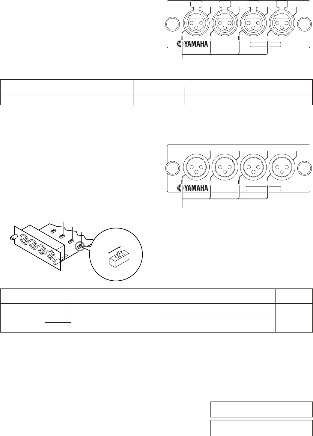
When the indicator is lit in orange,
channel B is selected. When the indicator
is turned off, channel A is selected.
点灯時 (オレンジ) はチャンネルBが選択、
消灯時はチャンネルAが選択
The green LED lights up
at 34 dB before clipping.
クリッピング手前34dBで
緑色LEDが点灯
I/O cards
for
ANALOG OUTPUT BOX
ANALOG INPUT BOX
MIC/LINE INPUT CARD LMY2-MLAB, LMY4-MLF
AD CARD LMY4-AD
DA CARD LMY4-DA
Thank you for choosing the Yamaha input card for the analog input box AI8, and the Yamaha output card for the analog
output box AO8.
Be sure to ask an authorized Yamaha service engineer to install the cards. Do not install the cards yourself.
The connecting screw also functions as the ground. Secure the screw tightly.
ここの度はヤマハ アナログインプットボックスAI8用インプットカード、アナログアウトプットボックスAO8用アウトプットカードをお買上げいただき、
ありがとうござ います。
カードの取付けは、必ずヤマハサービスエンジニアにご依頼ください。お客様ご自身では行なわないでください。
接続ネジはアース兼用ですのでしっかり締めてあるか確認してください。
■ LMY2-MLAB
This is a two-channel analog input card. Set the input level in the
range of –68 dB to +10 dB.
You can install up to eight cards in the analog input box AI8.
PM1D system software prior to V1.70 recognizes this card as
LMY2-ML. However, the card will function properly.
2チャンネルのアナログ入力カードです。入力レベルは−68 dB∼+10dB
の範囲で設定します。
アナログインプットボックスAI8に8枚まで装着できます。
PM1D V1.70より前のシステムソフトウェアでは、カード名が「LMY2-ML」
と表示されますが正しく動作します。
Input GAIN*** Actual Load For Use With Input Level Connector
Terminals Impedance Nominal Nominal Max. Before Clip
CH1A, CH1B –68 dB 3 kΩ50–600 Ω Mics –68 dBu (309 µV)* –54 dBu (775 µV)* XLR-3-31 type
CH2A, CH2B +10 dB & 600 Ω Lines +10 dBu (2.45 V)* +24 dBu (12.3 V)* (Balanced)**
* 0 dBu is referenced to 0.775 Vrms. ** 1=GND, 2=HOT, 3=COLD *** The GAIN control level displayed on the CS1D.
+48VDC (phantom power) is individually supplied to each input connectors. AD Conversion: 24 bit linear +4 bit floating, 128 times oversampling.
+48VDC(ファンタム電源)が各入力端子にそれぞれ供給されます。ADコンバージョン:2 4ビットリニ ア +4 ビットフローティング、128倍オーバーサンプリング
The green LED lights up at 34 dB before clipping.
クリッピング手前34dBで緑色LEDが点灯
■ LMY4-MLF
This is a four-channel analog input card. Set the input level in the
range of –68 dB to +10 dB.
You can install up to eight cards in the analog input box AI8.
PM1D system software prior to V1.70 recognizes this card as
“Unknown” and cannot communicate with it. Be sure to use this
card with PM1D V1.70 or higher.
4チャンネルのアナログ入力カードです。入力レベルは−68 dB∼+10dB
の範囲で設定します。
アナログインプットボックスAI8に8枚まで装着できます。
PM1D V1.70より前のシステムソフトウェアでは、カード名が「Unknown」と
表示され、お使いいただけません。必ずPM1D V1.70以上のシステムでお
使いください。
Input GAIN*** Actual Load For Use With Input Level Connector
Terminals Impedance Nominal Nominal Max. Before Clip
CH1–4 –68 dB 3 kΩ50–600 Ω Mics –68 dBu (309 µV)* –54 dBu (775 µV)* XLR-3-31 type
+10 dB & 600 Ω Lines +10 dBu (2.45 V)* +24 dBu (12.3 V)* (Balanced)**
* 0 dBu is referenced to 0.775 Vrms. ** 1=GND, 2=HOT, 3=COLD *** The GAIN control level displayed on the CS1D.
+48VDC (phantom power) is individually supplied to each input connectors. AD Conversion: 24 bit linear, 128 times oversampling.
+48VDC(ファンタム電源)が各入力端子にそれぞれ供給されます。ADコンバージョン:2 4ビットリニア、128倍オーバーサンプリング
For European Model
Purchaser/User Information specified in EN55103-1 and EN55103-2.
Conformed Environment: E1, E2, E3 and E4
ANALOG OUT
DA CARD
MODEL LMY4-DA
SIGNAL SIGNAL SIGNAL SIGNAL
CH4 CH3 CH2 CH1
The green LED lights up at 34 dB before clipping.
クリッピング手前34dBで緑色LEDが点灯
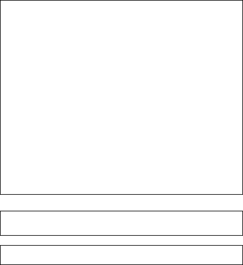
■ LMY4-DA
This is a four-channel analog output card. Set the maximum output
level in the range of +15 dB to +24 dB. The factory default setting is
+24 dB.
You can install up to eight cards in the analog output box AO8.
4チャンネルのアナログ出力カードです。最大出力レベルは+15 dB∼
+24 dBの範囲で設定します。工場出荷時は+24 dBです。
アナログアウトプットボックスAO8に8枚まで装着できます。
Output GAIN Actual Source For Use With Output Level Connector
Terminals switch Impedance Nominal Nominal Max. Before Clip
+24 dB +10 dBu (2.45 V)* +24 dBu (12.3 V)*
XLR-3-32 type
CH 1–4 +18 dB 150 Ω600 Ω Lines +4 dBu (1.23 V)* +18 dBu (6.16 V)*
+15 dB +1 dBu (870 mV)* +15 dBu (4.36 V)*
(Balanced)**
* 0 dBu is referenced to 0.775 Vrms. ** 1=GND, 2=HOT, 3=COLD
DA Conversion: 24 bit linear +3 bit floating, 128 times oversampling.
DA コンバージョン: 24ビットリニ ア +3 ビットフローティング、128倍オーバーサンプリング
+24dB
+15dB
+15dB
+18dB +24dB
1
2
3
4
+18dB
ANALOG IN
CH4
SIGNAL SIGNAL
AD CARD
MODEL LMY4-AD
SIGNAL SIGNAL
CH3 CH2 CH1
The green LED lights up at 34 dB before clipping.
クリッピング手前34dBで緑色LEDが点灯
Input Actual Load For Use With Input Level Connector
Terminals Impedance Nominal Nominal Max. Before Clip
CH 1–4 10 kΩ600 Ω Lines +10 dBu (2.45 V)* +24 dBu (12.3 V)* XLR-3-31 type (Balanced)**
* 0 dBu is referenced to 0.775 Vrms. ** 1=GND, 2=HOT, 3=COLD
AD Conversion: 24 bit linear +4 bit floating, 128 times oversampling.
AD コンバージョン: 24ビットリニ ア + 4 ビットフローティング、128倍オーバーサンプリング
■ LMY4-AD
This is a four-channel analog input card.
You can install up to eight cards in the analog input box AI8.
4チャンネルのアナログ入力カードです。
アナログインプットボックスAI8に8枚まで装着できます。
U.R.G., Pro Audio & Digital Musical Instrument Division, Yamaha Corporation
© 2003 Yamaha Corporation
WC62510 312IPAPx.x-01A0
Printed in Japan
ヤマハマニュアルライブラリー
Ya maha Manual Library
http://www2.yamaha.co.jp/manual/english/
http://www2.yamaha.co.jp/manual/japan/
1. IMPORTANT NOTICE: DO NOT MODIFY THIS
UNIT!
This product, when installed as indicated in the
instructions contained in this manual, meets FCC
requirements. Modifications not expressly
approved by Yamaha may void your authority,
granted by the FCC, to use the product.
2. IMPORTANT: When connecting this product to
accessories and/or another product use only high
quality shielded cables. Cable/s supplied with this
product MUST be used. Follow all installation
instructions. Failure to follow instructions could void
your FCC authorization to use this product in the
USA.
3. NOTE: This product has been tested and found to
comply with the requirements listed in FCC Regu-
lations, Part 15 for Class “B” digital devices. Com-
pliance with these requirements provides a
reasonable level of assurance that your use of this
product in a residential environment will not result
in harmful interference with other electronic
devices. This equipment generates/uses radio fre-
quencies and, if not installed and used according
to the instructions found in the users manual, may
cause interference harmful to the operation of
other electronic devices. Compliance with FCC
regulations does not guarantee that interference
will not occur in all installations. If this product is
found to be the source of interference, which can
be determined by turning the unit “OFF” and “ON”,
please try to eliminate the problem by using one of
the following measures:
Relocate either this product or the device that is
being affected by the interference.
Utilize power outlets that are on different branch
(circuit breaker or fuse) circuits or install AC line fil-
ter/s.
In the case of radio or TV interference, relocate/
reorient the antenna. If the antenna lead-in is 300
ohm ribbon lead, change the lead-in to co-axial
type cable.
If these corrective measures do not produce satis-
factory results, please contact the local retailer
authorized to distribute this type of product. If you
can not locate the appropriate retailer, please con-
tact Yamaha Corporation of America, Electronic
Service Division, 6600 Orangethorpe Ave, Buena
Park, CA90620
The above statements apply ONLY to those products distributed by Yamaha Corporation of America or its
subsidiaries.
* This applies only to products distributed by YAMAHA CORPORATION OF AMERICA. (class B)
FCC INFORMATION (U.S.A.)
This device complies with Part 15 of the FCC Rules. Operation is subject to the following two conditions:
(1) this device may not cause harmful interference, and (2) this device must accept any interference
received, including interference that may cause undesired operation.
This Class B digital apparatus complies with Canadian ICES-003.
Cet appareil numérique de la classe B est conforme à la norme NMB-003 du Canada.
