Yamaha Mtx Setup Instructions Manual
2015-03-09
: Yamaha Mtx-Setup-Setup-Instructions yamaha-mtx-setup-setup-instructions-647533 yamaha pdf
Open the PDF directly: View PDF ![]() .
.
Page Count: 129 [warning: Documents this large are best viewed by clicking the View PDF Link!]
- Cover
- Introduction
- Setup workflow
- Example 1) Basic MTX3 system example (analog connections)
- Example 2) High audio quality system with XMV and YDIF connections (digital connections)
- Example 3) Using cascade mode to add MTX input channels (analog connection)
- Example 4) A system using Dante
- Using the Device Configuration Wizard to create your device setup
- Making preliminary settings in MTX Editor
- Dante settings between systems
- Connecting the equipment
- Powering-on the MTX
- Powering-on the amp
- Specifying the computer’s TCP/IP address
- Taking MTX Editor online
- Making XMV settings
- Verifying that the settings were applied
- Q&A
- Uninstalling the software (Removing the application)

MTX Setup Manual 1
MTX Setup Manual
This manual serves as an introduction to possible installation methods and application examples
for the MTX series of DSP processors used in conjunction with MTX Editor control software.
Please refer to the owner’s manual on a device about the details of MTX, and refer to the “MTX
Editor User’s Manual” (PDF file) about the details of MTX Editor.
Special Notice
• The software and this manual are the exclusive copyrights of Yamaha Corporation.
• Copying of the software or reproduction of this manual in whole or in part by any means is expressly forbidden without the written consent of
the manufacturer.
• Yamaha makes no representations or warranties with regard to the use of the software and documentation and cannot be held responsible for
the results of the use of this manual and the software.
• Future upgrades of application and system software and any changes in specifications and functions will be announced at the following web-
site.
http://www.yamahaproaudio.com/
• The screen displays as illustrated in this manual are for instructional purposes, and may appear somewhat different from the screens which
appear on your computer.
• Copying of the commercially available musical data including but not limited to MIDI data and/or audio data is strictly prohibited except for your
personal use.
• Ethernet is trademarks of Xerox Corporation.
• Windows is a registered trademark of Microsoft® Corporation in the United States and other countries.
• Bonjour is trademarks of Apple Inc., registered in the U.S. and other countries.
• The SDHC and SD logos are trademarks of SD-3C, LLC.
• MPEG Layer-3 audio coding technology licensed from Fraunhofer IIS and Thomson.
• The company names and product names in this manual are the trademarks or registered trademarks of their respective companies.
MTX Setup Manual
EN
MTX Setup Manual 2
The MTX Setup Manual explains how to create setups using the MTX and MTX Editor.
As examples, we will provide simple explanations of the typical setups described below.
For detailed parameter settings, refer to “MTX Editor User’s Manual” and to the owner’s manuals of the XMV, MTX, and
DCP.
When you install MTX Editor, the four example files described here will be found in the following folders.
-32-bit operating system
C:\Program Files\Yamaha\MTX Editor\V*.*\ProjectFile
-64-bit operating system
C:\Program Files(x86)\Yamaha\MTX Editor\V*.*\ProjectFile
*.* will be the version of the installed MTX Editor.
Example 1 : MTX3 basic system-*.mtx
Example 2 : MTX3 XMV digital system-*.mtx
Example 3 : MTX3 cascade example-*.mtx
Example 4 : MTX5-D Dante system-*.mtx
-* is a management number. In some cases, there will be no -*.
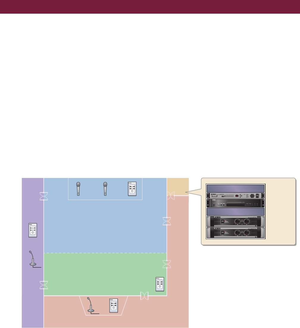
Example 1) Basic MTX3 system example (analog connections)
This example assumes that you’re using the following equipment.
•MTX3 1
• DCP1V4S 4
• Amplifiers (four channels of amplification)
• Speakers (the number needed)
• SD memory card 1
• Background music source such as a CD player 1
• Paging microphones with switch 2
• Wireless microphone receivers (2 channels)
• Wireless microphones 2
The number of speakers is not specified; choose amps that are suitable for your speaker setup. You will also need to
provide the appropriate number of cables.
Introduction
DCP
ID=3
Kitchen
(Zone 4)
Hall A
(Zone 1)
Hall B
(Zone 2)
Entrance
(Zone 3)
DCP
ID=1
Microphone
Ch=2
Microphone
Ch=1
Microphone
Ch=4
DCP
ID=0
Amp
Room
DCP
ID=2
Microphone
Ch=3
MTX3 ID=01
CD Player
Power Amp 1
Power Amp 2
BGM Player
Wireless Microphone Reciever
Introduction
MTX Setup Manual 3
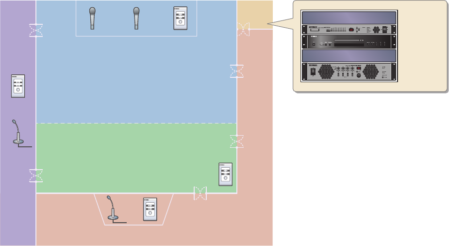
Example 2) High audio quality system with XMV and YDIF connections (digital connections)
This repeats the system of example 1, replacing the amps with an XMV series unit.
This example assumes that you’re using the following equipment.
•MTX3 1
• DCP1V4S 4
• XMV4280 (four channels of amplification) 1
• Speakers (the number needed)
• SD memory card 1
• Background music source such as a CD player 1
• Network switch 1
• Paging microphones with switch 2
• Wireless microphone receivers (2 channels)
• Wireless microphones 2
The number of speakers is not specified; choose amps that are suitable for your speaker setup. You will also need to
provide the appropriate number of cables.
XMV4280 ID
=1A
BGM Player
DCP
ID=3
Kitchen
(Zone 4)
Hall A
(Zone 1)
Hall B
(Zone 2)
Entrance
(Zone 3)
DCP
ID=1
Microphone
Ch=2
Microphone
Ch=1
Microphone
Ch=4
DCP
ID=0
Amp
Room
DCP
ID=2
Microphone
Ch=3
MTX3 ID=01
CD Player
Wireless Microphone Reciever
Introduction
MTX Setup Manual 4
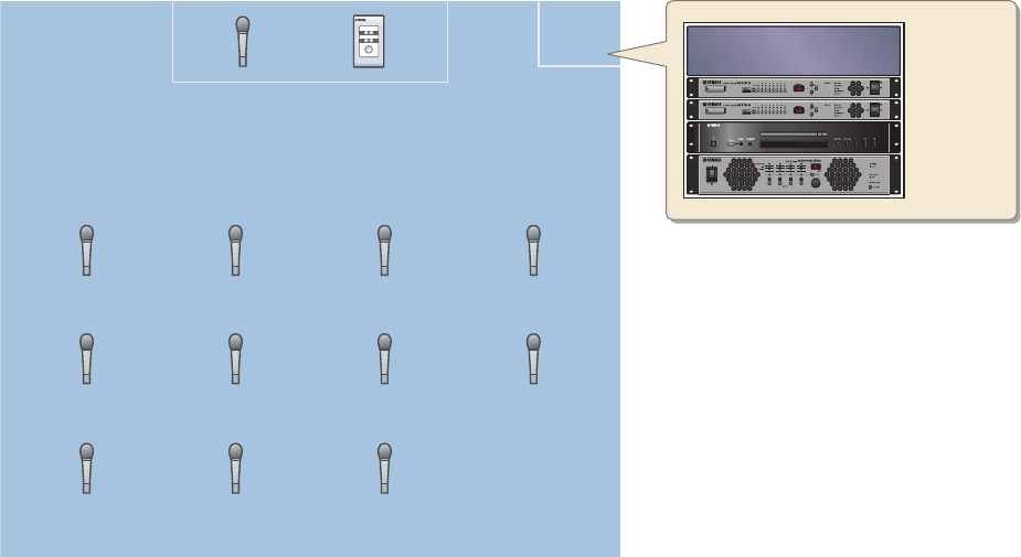
Example 3) Using cascade mode to add MTX input channels (analog connection)
Cascade mode allows the matrix buses to be shared between MTX units. This mode lets you use two MTX units to
increase the number of inputs, and output the combined inputs to a single amp.
In cascade mode, audio cannot be transmitted to the XMV via YDIF.
This example assumes that you’re using the following equipment.
•MTX3 2
• XMV4280 (or an amp with analog input) 1
• Background music source such as a CD player 1
• Speakers (the number needed)
• Microphone with switch (for the MC or chair) 1
• Wireless microphone receivers (11 channels)
• Wireless microphones 11
The number of speakers is not specified; choose amps that are suitable for your speaker setup. You will also need to
provide the appropriate number of cables.
W/L Mic 1
Ch1 (MTX ID=01)
W/L Mic 5
Ch1 (MTX ID=02)
W/L Mic 9
Ch5 (MTX ID=01)
W/L Mic 2
Ch2 (MTX ID=01)
W/L Mic 6
Ch2 (MTX ID=02)
W/L Mic 10
Ch6 (MTX ID=01)
W/L Mic 3
Ch3 (MTX ID=01)
W/L Mic 7
Ch3 (MTX ID=02)
W/L Mic 11
Ch7 (MTX ID=01)
W/L Mic 4
Ch4 (MTX ID=01)
W/L Mic 8
Ch4 (MTX ID=02)
DCP
ID=0
Rack
Microphone
Ch8 (MTX ID=01)
MTX3 ID=01
MTX3 ID=02
CD Player
XMV4280 ID
=1A
Room
Wireless Microphone
Receivers
Introduction
MTX Setup Manual 5
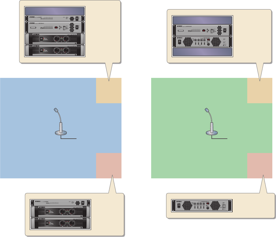
Example 4) A system using Dante
In this example, existing amps continue to be used, while we set up a new system at a distant location, with connec-
tions made using Dante.
The system using the existing amps is labeled System A, and the new system is labeled System B.
In example 4, our explanation will be centered on the network settings. For more about increasing the number of
mics, DCP settings, or presets, refer to example 2.
This example assumes that you’re using the following equipment.
* As the network switch for Dante connections, we recommend that you use a model that provides IGMP snooping
functionality.
The number of speakers is not specified; choose amps that are suitable for your speaker setup. You will also need to
provide the appropriate number of cables.
System A
Microphone Ch1 Microphone Ch1
Amp
Room A
Amp
Room B
System B Amp
Room A
Amp
Room B
EXi8 ID=02
MTX5-D ID=01
Power Amp 3
Power Amp 4
Network Switch for MTX Editor
MTX5-D ID=04
XMV4280 ID=30
Network Switch for Primary
Network Switch for Secondary
XMV4280-D ID=31
EXo8 ID=03
Power Amp 1
Power Amp 2
System A
•MTX5-D 1
• Exi8 1
•EXo8 1
• Amplifiers (eight channels of amplification)
• Network switch 1
• Speakers (the number needed)
• SD memory card 1
• Paging microphones with switch 1
System B
•MTX5-D 1
• XMV4280 1
• XMV4280-D 1
• Network switch 2*
• Speakers (the number needed)
• SD memory card 1
• Paging microphones with switch 1
MTX Setup Manual 6
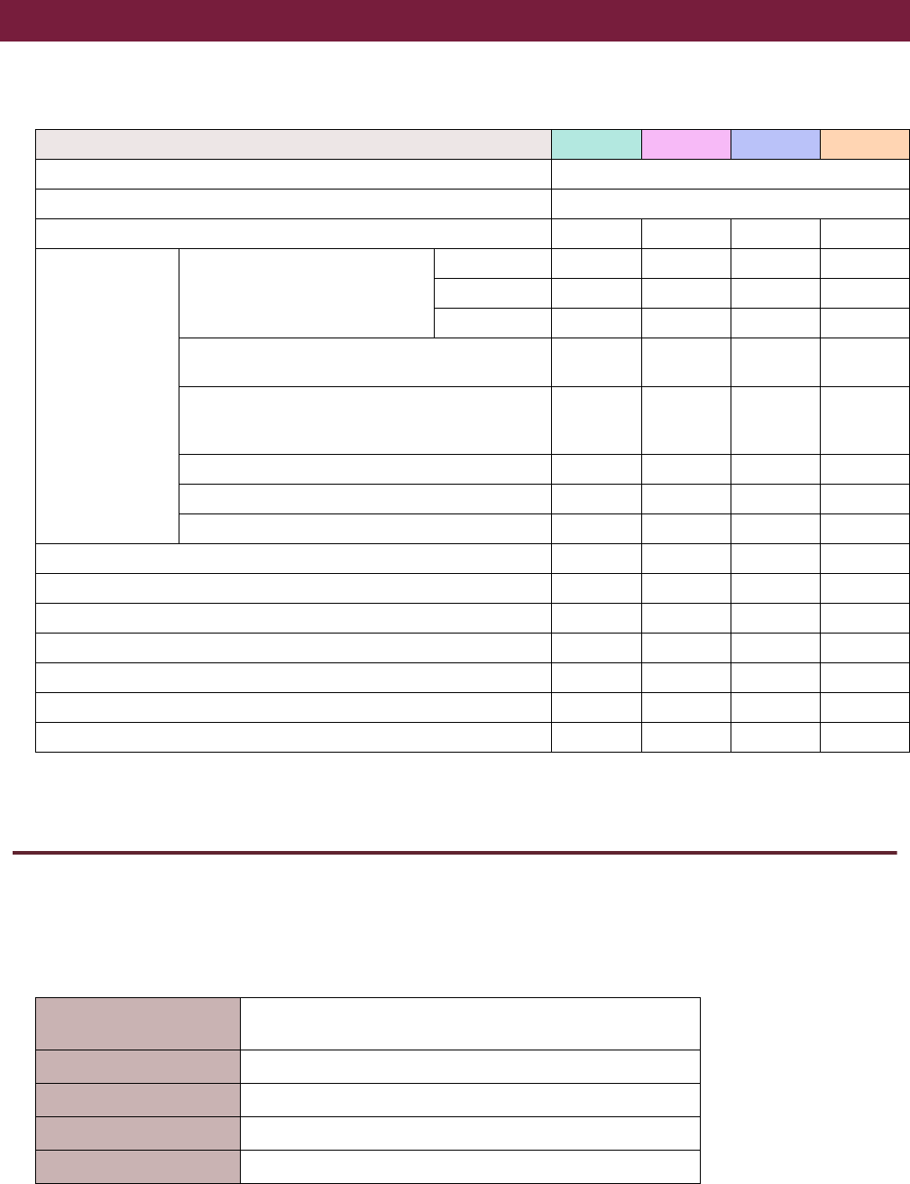
The following table shows the workflow for connecting equipment such as MTX series matrix mixers and XMV series
power amplifiers to your computer, and making settings in MTX Editor.
Installing MTX Editor
In order to connect MTX series devices to your computer, you’ll need to download MTX Editor from the “download” page
of the Yamaha Pro Audio website.
http://www.yamahaproaudio.com/
System Requirements
Example 1 Example 2 Example 3 Example 4
Installing MTX Editor Page 6
Starting up MTX Editor Page 7
Using the Device Configuration Wizard to create your device setup Page 8Page 29 Page 54 Page 81
Making preliminary
settings in MTX
Editor
Making EXT. I/O settings
YDIF — Page 34 — Page 93
XMV (Analog) — — Page 59 —
XMV (Dante) — — — Page 106
Parameter settings for the MTX and external devices
(Parameter settings such as for jacks and channels) Page 13 Page 38Page 62 Page
98, 112
Settings in the “DCA” screen
(Settings that control the level or mute of multiple
channels in a single operation)
— — Page 71 —
Digital Control Panel (DCP) settings Page 20 Page 45 Page 72 —
Storing a preset (Presets and recall filter settings) Page 22 Page 47 Page 73 —
Dante settings between systems — — — Page 115
Connecting the equipment Page 25 Page 50 Page 76 Page 121
Powering-on the MTX Page 25 Page 51 Page 77 Page 123
Powering-on the amp Page 25 Page 51 Page 77 Page 123
Specifying the computer’s TCP/IP address Page 26 Page 51 Page 77 Page 123
Taking MTX Editor online Page 27 Page 52 Page 78Page 125
Making XMV settings — Page 53 Page 79 Page 125
Verifying that the settings were applied Page 28Page 53 Page 79 Page 126
OS Windows 7 Home Premium or higher
Windows 8
CPU Core i3/5 or better
Memory 4 GB or more
H.D.D 150 MB or more free
Other Bonjour must be installed, Ethernet (1000BASE-T or higher)
NOTE
The System Requirements described above are applied to the MTX Editor version 1.2.0. You can check the latest version information
of each program and its system requirements at the following website
http://www.yamahaproaudio.com/
The system requirements may differ slightly depending on the particular computer.
Setup workflow

Setup workflow
MTX Setup Manual 7
Follow the steps below to install MTX Editor.
1. After decompressing the downloaded file, double-click “setup.exe” in the decompressed
file location.
The MTX Editor setup wizard will appear.
2. Proceed with the installation as directed by the instructions in the screen.
Starting up MTX Editor
Follow the steps below to start up MTX Editor.
1. Double-click the MTX Editor icon on the desktop.
2. If the “Network Setup” dialog box appears, click [OK] or [Cancel].
You’ll be performing the setup during the step “Making settings in MTX Editor.”
3. The “Startup” dialog box will appear; click [New file] and then click [OK].
The “Device Configuration Wizard” will start up. Now you can proceed to make basic settings.
We will use specific examples to explain “Using the Device Configuration Wizard to create your device setup” and subse-
quent steps.
NOTE
If the computer you’re using does not have Bonjour installed, a screen asking you to install Bonjour will appear during the installa-
tion.
If you are asked to install Bonjour, download Bonjour from the Yamaha Pro Audio website, and install it. Then install MTX Editor
again.
http://www.yamahaproaudio.com/
NOTE
The “User Account Control” dialog box may appear. Click [Continue] or [Yes].
“Using the Device Configuration Wizard to create your device setup” for example 1: Page 8
“Using the Device Configuration Wizard to create your device setup” for example 2: Page 29
“Using the Device Configuration Wizard to create your device setup” for example 3: Page 54
“Using the Device Configuration Wizard to create your device setup” for example 4: page 81
MTX Setup Manual 8
Using the Device Configuration Wizard to create your device setup
You will use MTX Editor’s wizard to create your device setup before actually connecting your equipment.
After you’ve made basic settings, you’ll be able to print information about system cabling and ID numbers.
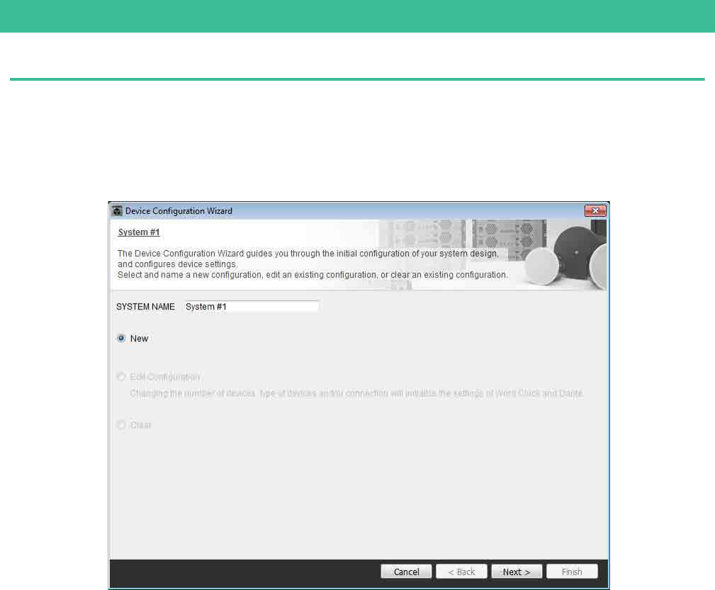
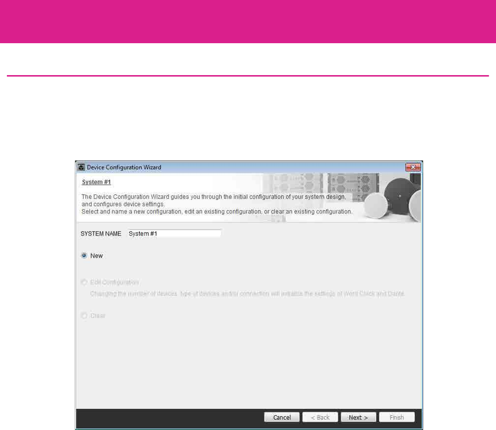
Use the following procedure to make basic settings.
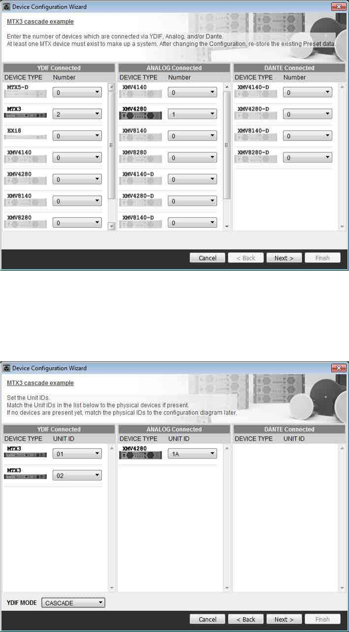
1. Type a name for the MTX system you’ll be constructing, and click [Next>].
Example 1) Basic MTX3 system example (analog connections)
Example 1) Basic MTX3 system example (analog connections)
MTX Setup Manual 9
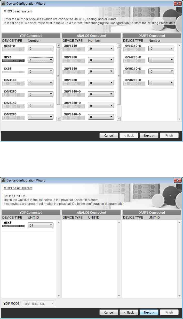
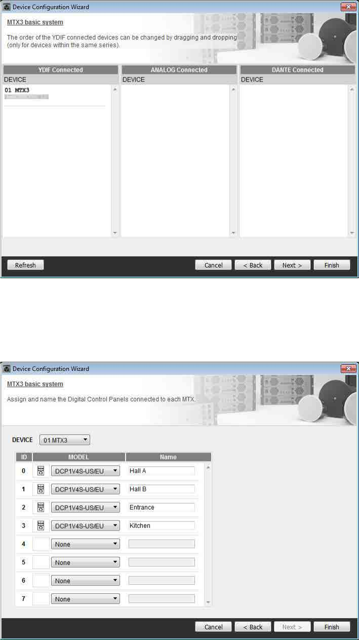
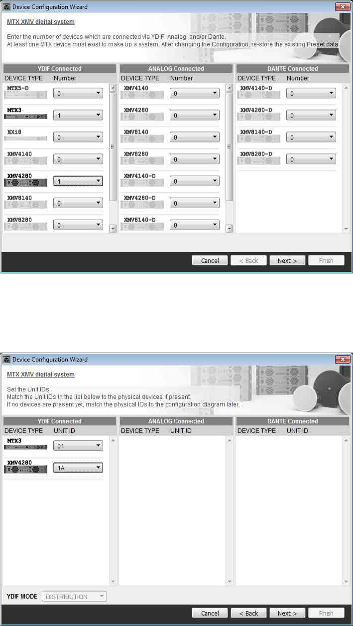
2. Specify the number of units that will be connected in your MTX system, and click [Next>].
In “YDIF Connected,” specify 1 as the number of MTX3 units.
3. Verify that the MTX’s UNIT ID is 1, and then click [Next>].
Unless you have specific reasons for doing so, use the UNIT ID that is assigned.
Example 1) Basic MTX3 system example (analog connections)
MTX Setup Manual 10
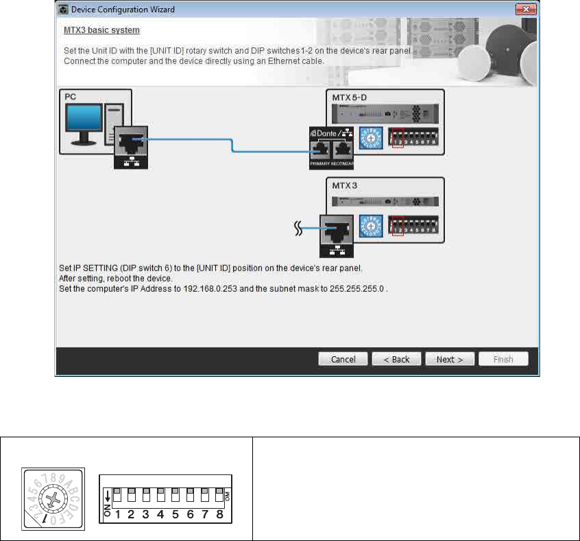
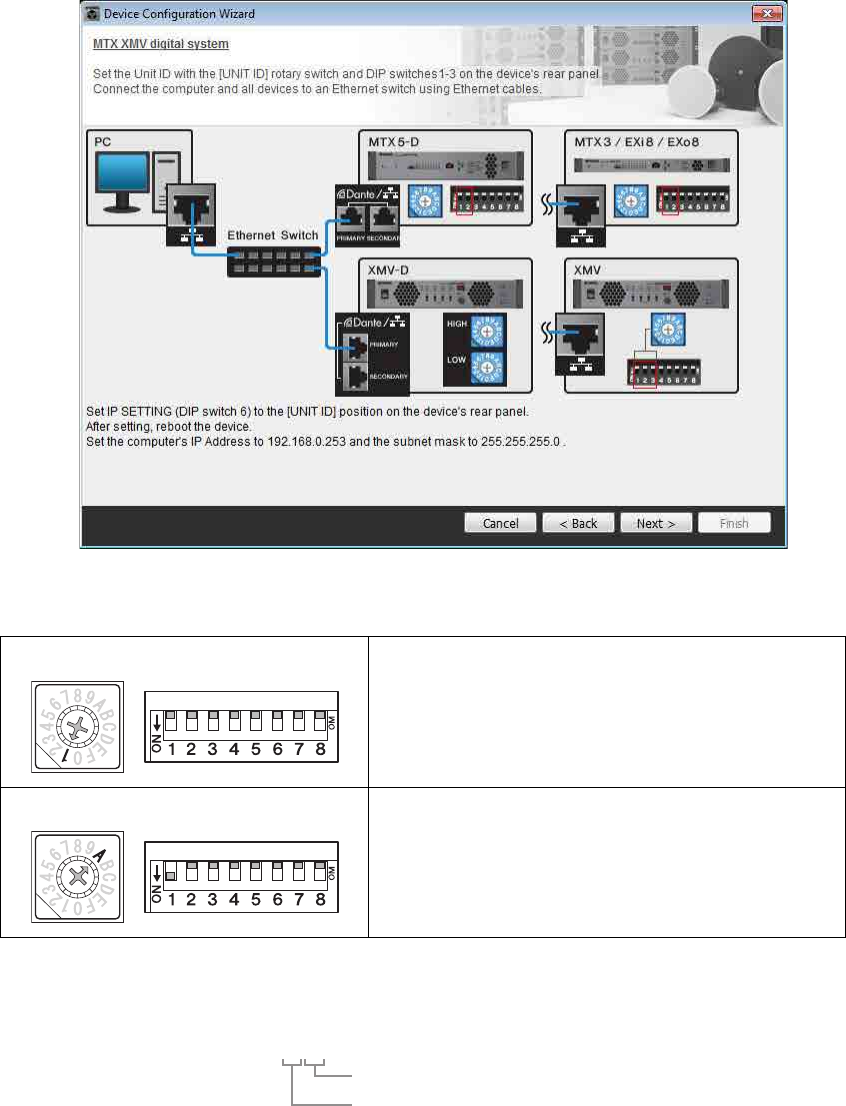
4. Set the MTX’s [UNIT ID] rotary switch and DIP switch.
You will set the computer’s IP address after completing the wizard, in “Specifying the computer’s TCP/IP address.”
If the MTX is not nearby, make settings during the step “Connecting the equipment.”
Make the following settings.
5. When you’ve finished setting the MTX’s [UNIT ID] rotary switch and DIP switch, click
[Next>].
MTX3
UNIT ID = 01
[UNIT ID] rotary switch = 1
DIP switches are all OFF (upward)
Example 1) Basic MTX3 system example (analog connections)
MTX Setup Manual 11
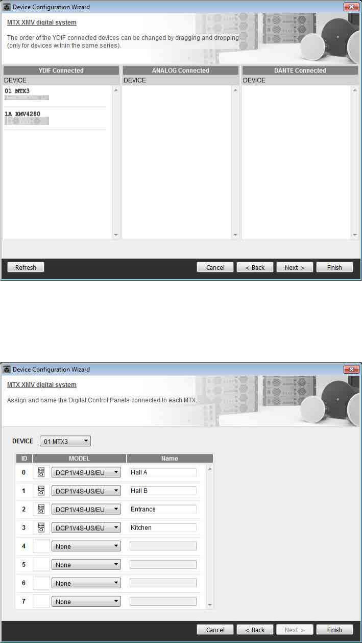
6. Verify that the MTX is shown, and click [Next>].
7. Choose the model of DCP that is connected to the MTX, enter a device name, and click
[Finish].
Since four DCP1V4S units will be connected, make settings for four units.
Example 1) Basic MTX3 system example (analog connections)
MTX Setup Manual 12
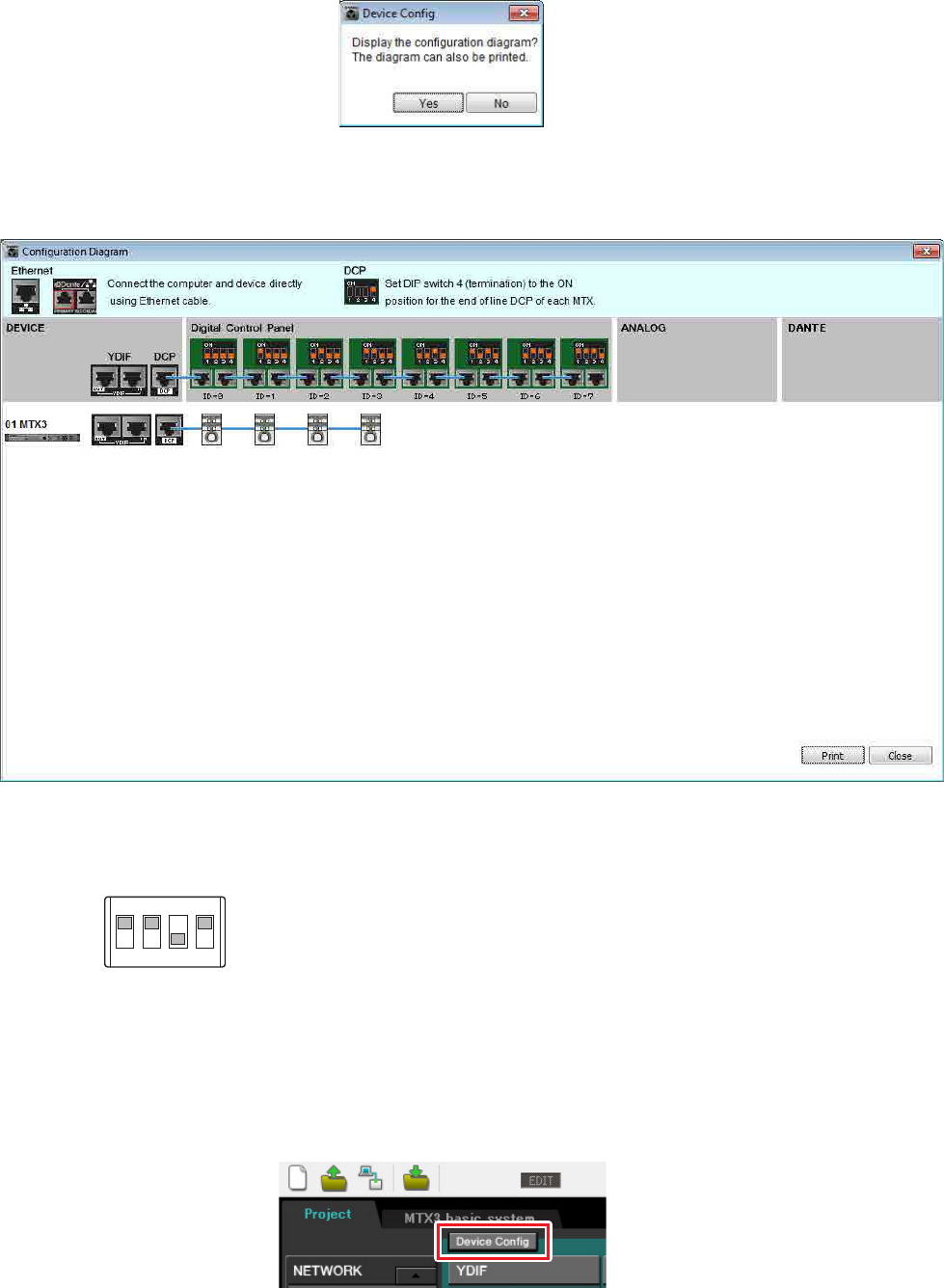
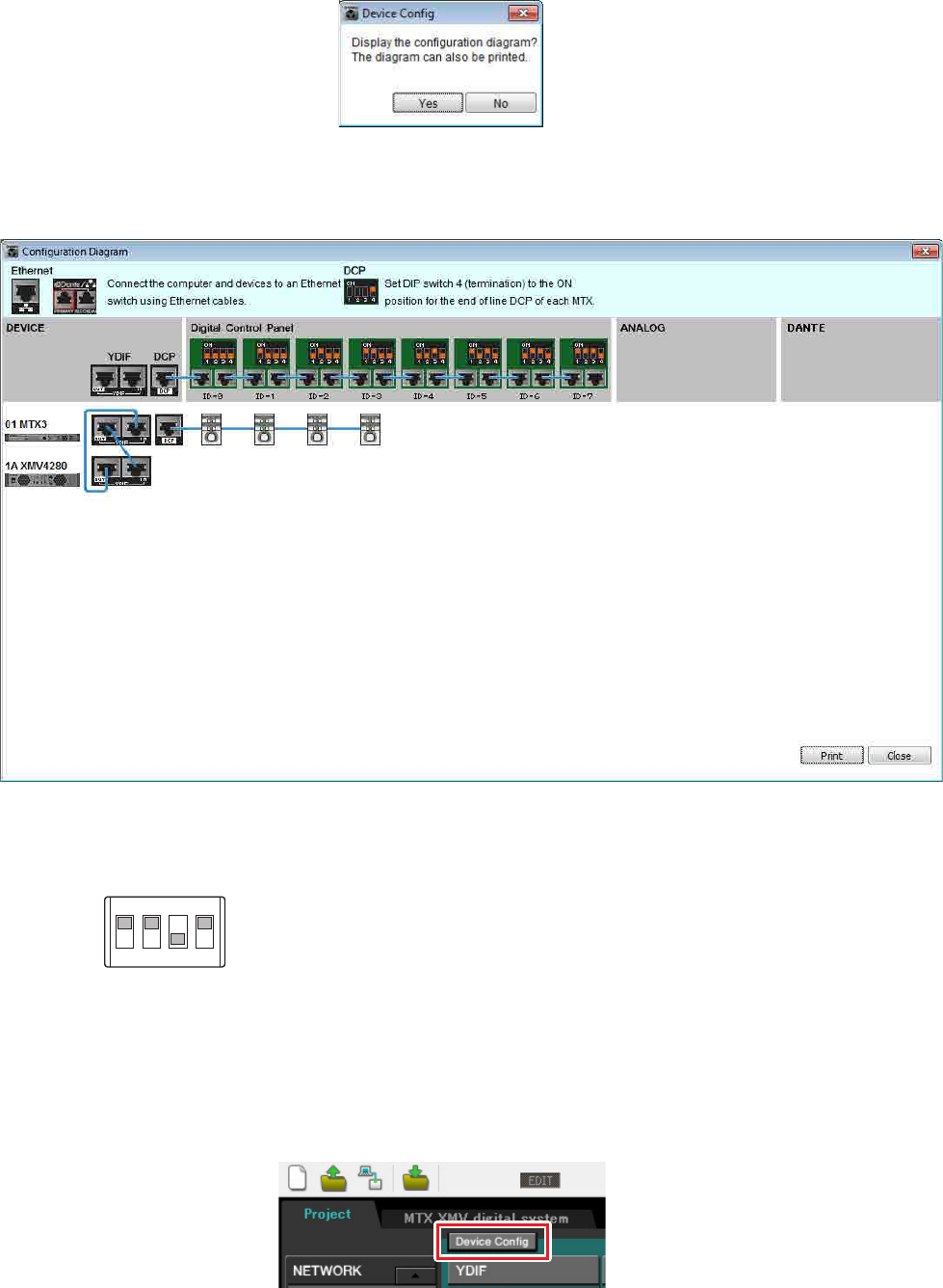
8. When you see the dialog box “Display the configuration diagram? The diagram can also
be printed.” click [Yes].
A cabling diagram will appear. If you want, click [Print] to print the diagram.
To close the screen, click [Close].
Set the DIP switches of the DCP units as shown in the “Digital Control Panel” section of the schematic diagram.
For the last DCP (ID=3), set DIP switch 4 ON (upward).
If you want to use the Device Configuration Wizard to change the device configuration, click the [Device Config] but-
ton in the Project screen.
NOTE
If you want to view the cabling diagram again, do so by choosing [File] menu [Print Configuration Diagram].
1
ON
2 3 4
Example 1) Basic MTX3 system example (analog connections)
MTX Setup Manual 13
Making preliminary settings in MTX Editor
Here’s how to make detailed MTX system settings in MTX Editor.
When you’ve finished making settings, you should save them by clicking [File] menu, then [Save].
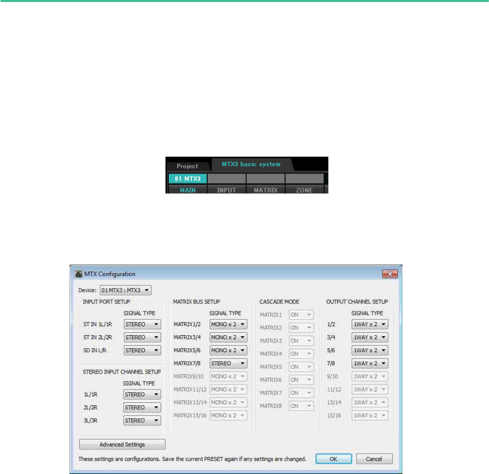
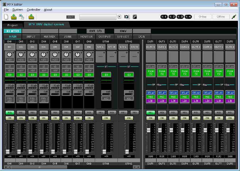
Specifying the MTX configuration
Here you’ll specify how the MTX’s inputs and outputs will be handled.
Move to the System screen by clicking the tab of the system name you specified in step 1 of “Using the Device Config-
uration Wizard to create your device setup.”
On the [System] menu, click [MTX Configuration] to open the “MTX Configuration” dialog box.
The default settings are shown in the screen below. You can change them as necessary. In this example, we’ll use the
default settings without change.
NOTE
The “User Account Control” dialog box may appear. Click [Continue] or [Yes].
Example 1) Basic MTX3 system example (analog connections)
MTX Setup Manual 14
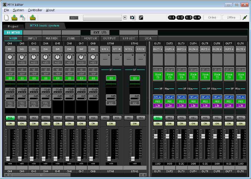
Settings in the “MAIN” screen
In the “MAIN” screen you can make overall settings for each channel.
For details on each parameter, refer to “MTX Editor User’s Manual.”
Here you’ll make the following settings.
• Channel name
• Channel on/off
• Gain and phantom power
• (As necessary) EQ settings
Example 1) Basic MTX3 system example (analog connections)
MTX Setup Manual 15
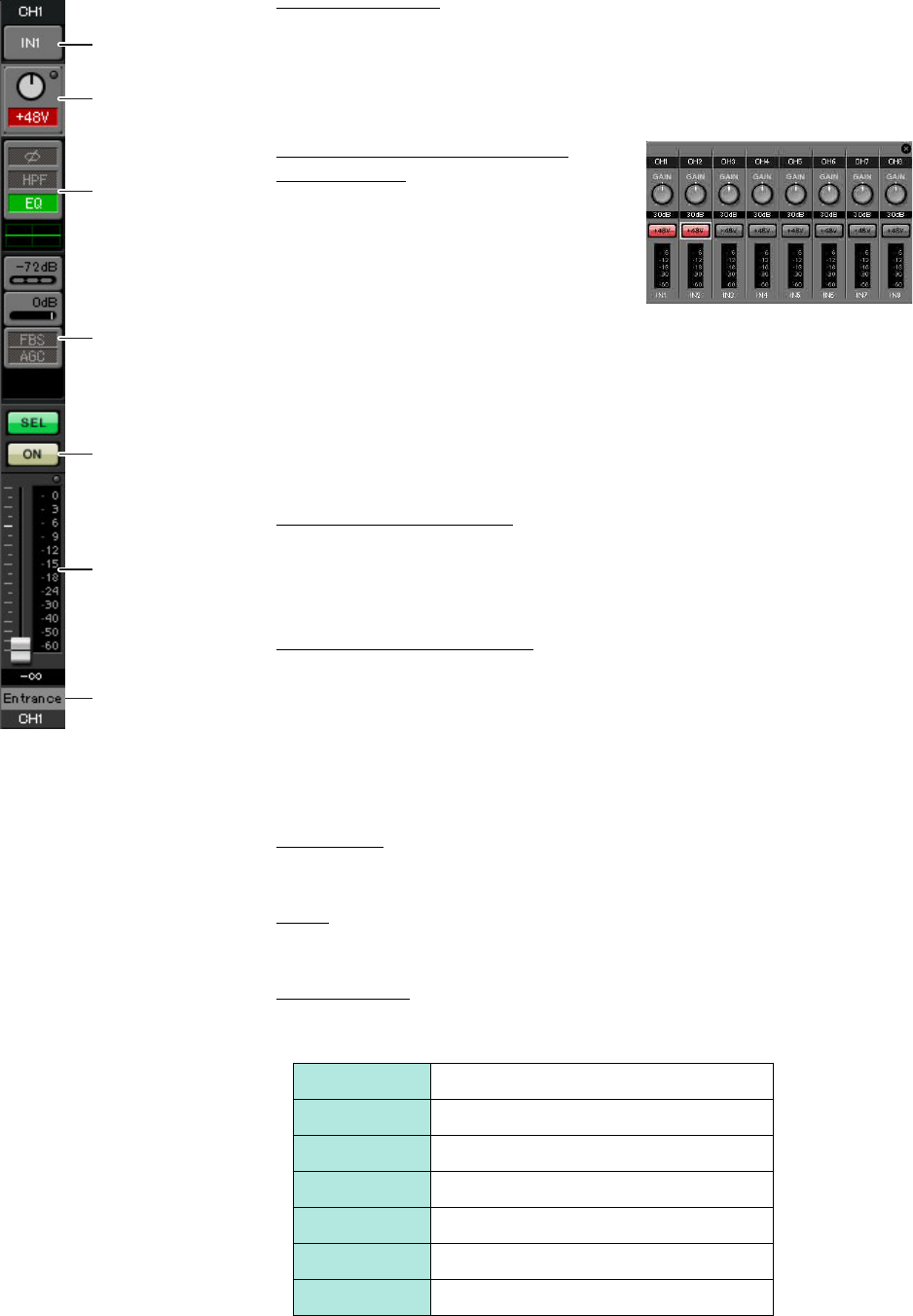
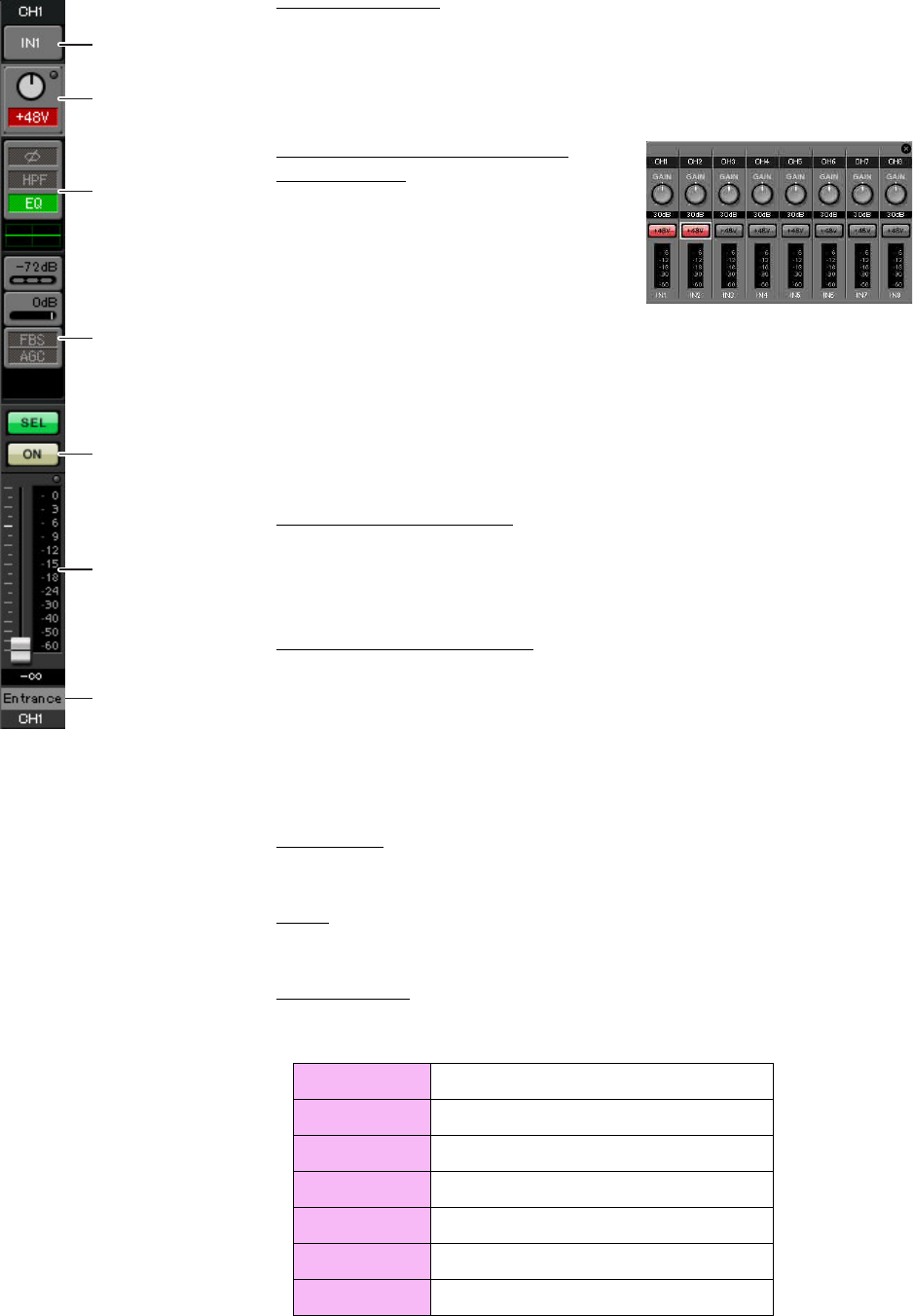
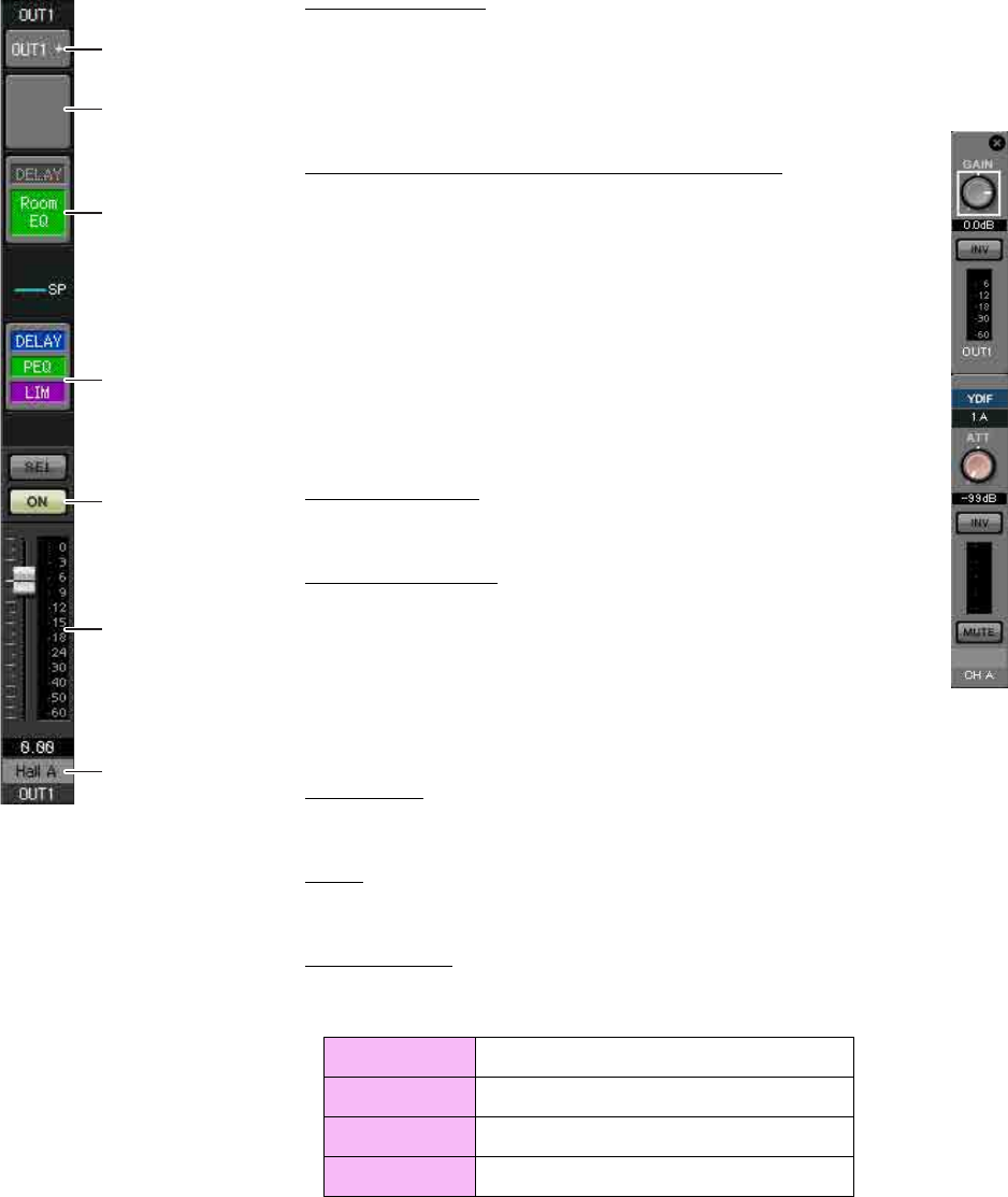
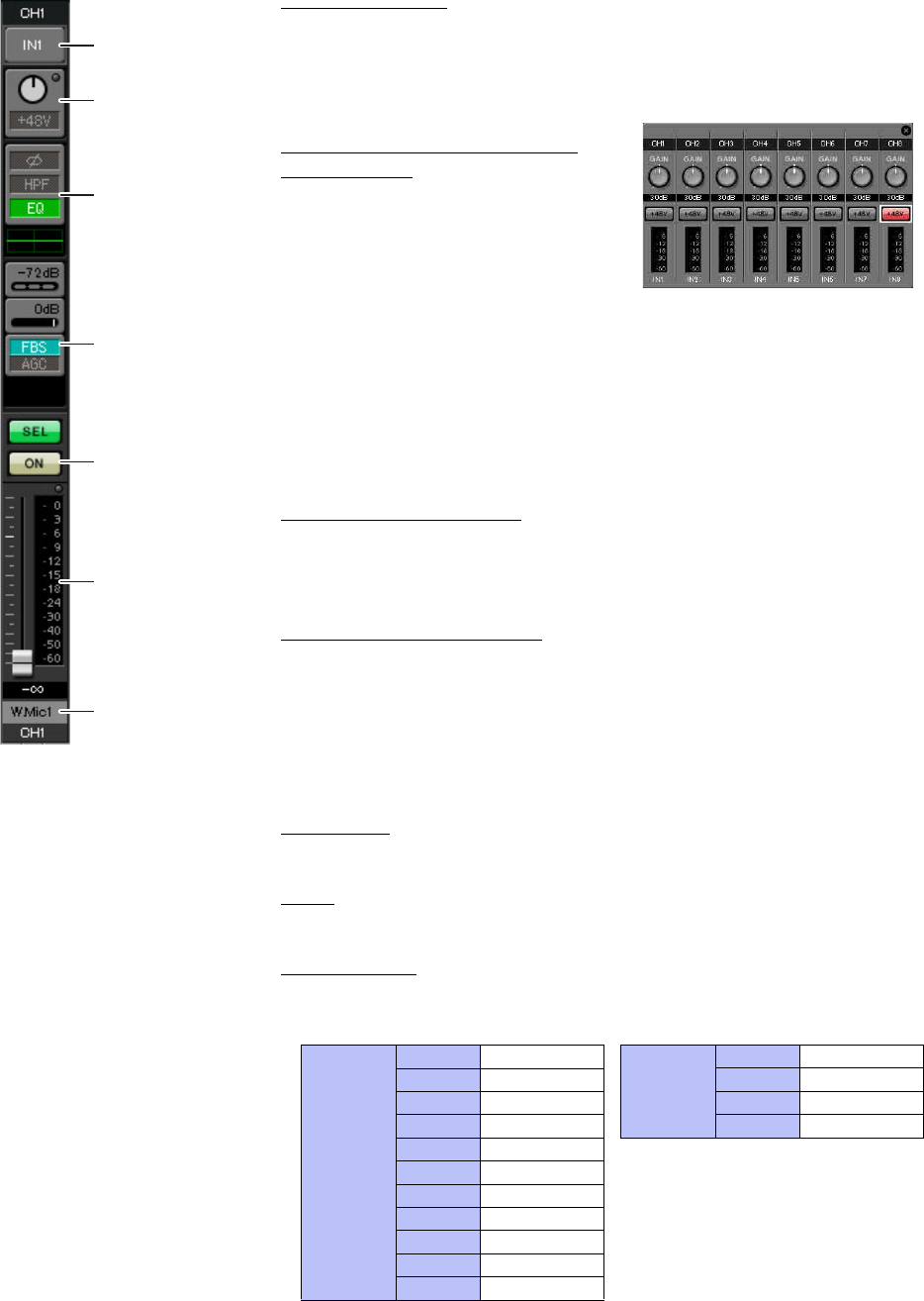
-INPUT settings
Port select button
When you click this, the “Input Patch” dialog box will open. In this example we
are using the default settings, but if you want to switch to a different input port of
the MTX, click this button, choose the desired input port, and then click the
[Close] button.
Port/External Device parameter
access button
This button lets you adjust the gain and turn
phantom power on/off. When you click the
button, a popup window will appear, allow-
ing you to adjust the gain and turn phantom
power on/off. Make the desired settings,
and then in the upper right, click × to close
the popup window. The appropriate gain level will depend on the devices that are
connected, so set the level appropriately for your devices.
For channels 1 through 8, the gain is set to 30 dB by default. Because condenser
microphones are connected to CH1 and 2, leave the gain at 30 dB and turn phan-
tom power on. Because wireless microphones are connected to CH3 and 4, lower
the gain to 0 dB.
EQ/HPF (High Pass Filter)
Click this to switch to the “CHANNEL EDIT” screen. Adjust the EQ and HPF
appropriately for the microphone you’re using. For ST IN, only EQ is available.
When you want to return to the “MAIN” screen, click the [MAIN] button.
FBS (Feedback suppressor)
FBS is provided on input channels 1 through 4. We recommend that microphone
inputs, and particularly movable microphones such as wireless microphones, be
connected to channels 1 through 4. When you click here, you will switch to the
FBS setting screen.
When you want to return to the “MAIN” screen, click the [MAIN] button.
For details on FBS settings, refer to “MTX Editor User’s Manual.”
[ON] button
This turns the channel on/off. You should turn off unused channels.
Fader
This adjusts the input level. Leave the fader at -∞ until the system goes online.
Channel name
You can double-click this to edit the name.
In this example, names have been assigned as follows.
CH1 Entrance
CH2 Kitchen
CH3 W.Mic1
CH4 W.Mic2
STIN1 CD Player
STIN2 BGM
SDIN SD Player
Port select button
Port/External Device
parameter access
button
EQ/HPF
FBS (Feedback sup-
pressor)
[ON] button
Fader
Channel name
Example 1) Basic MTX3 system example (analog connections)
MTX Setup Manual 16
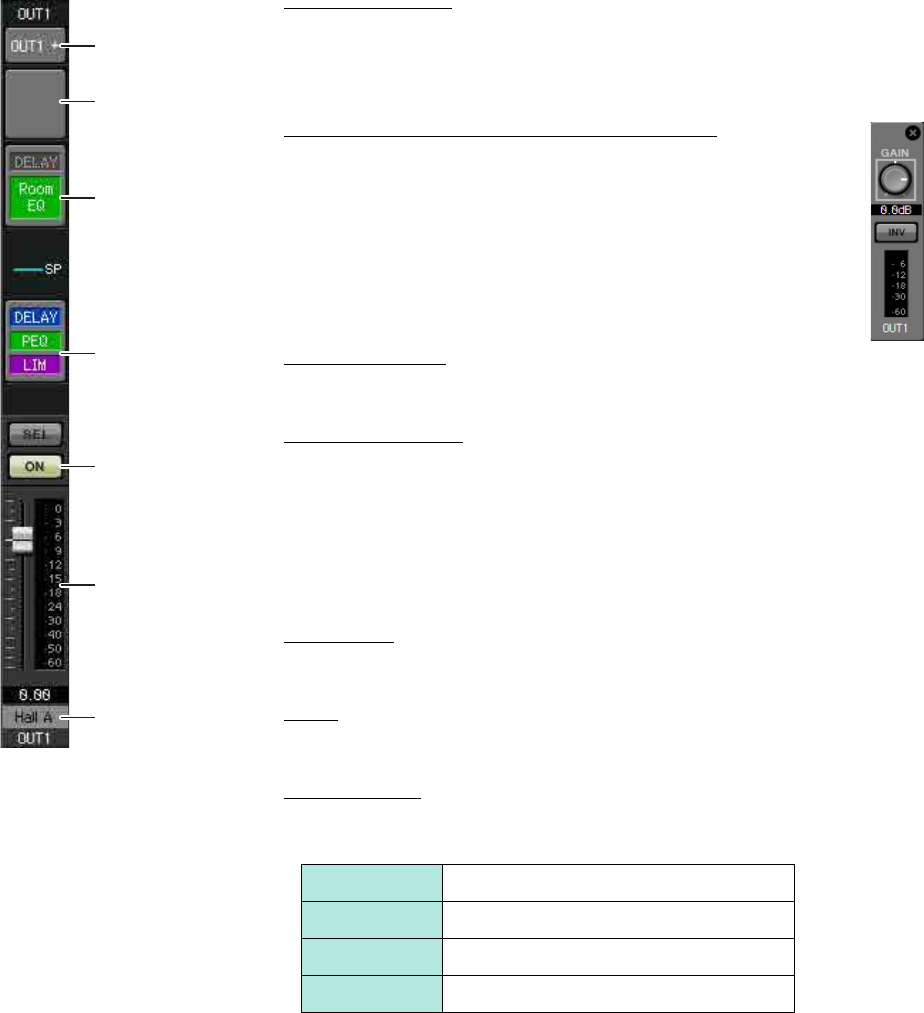
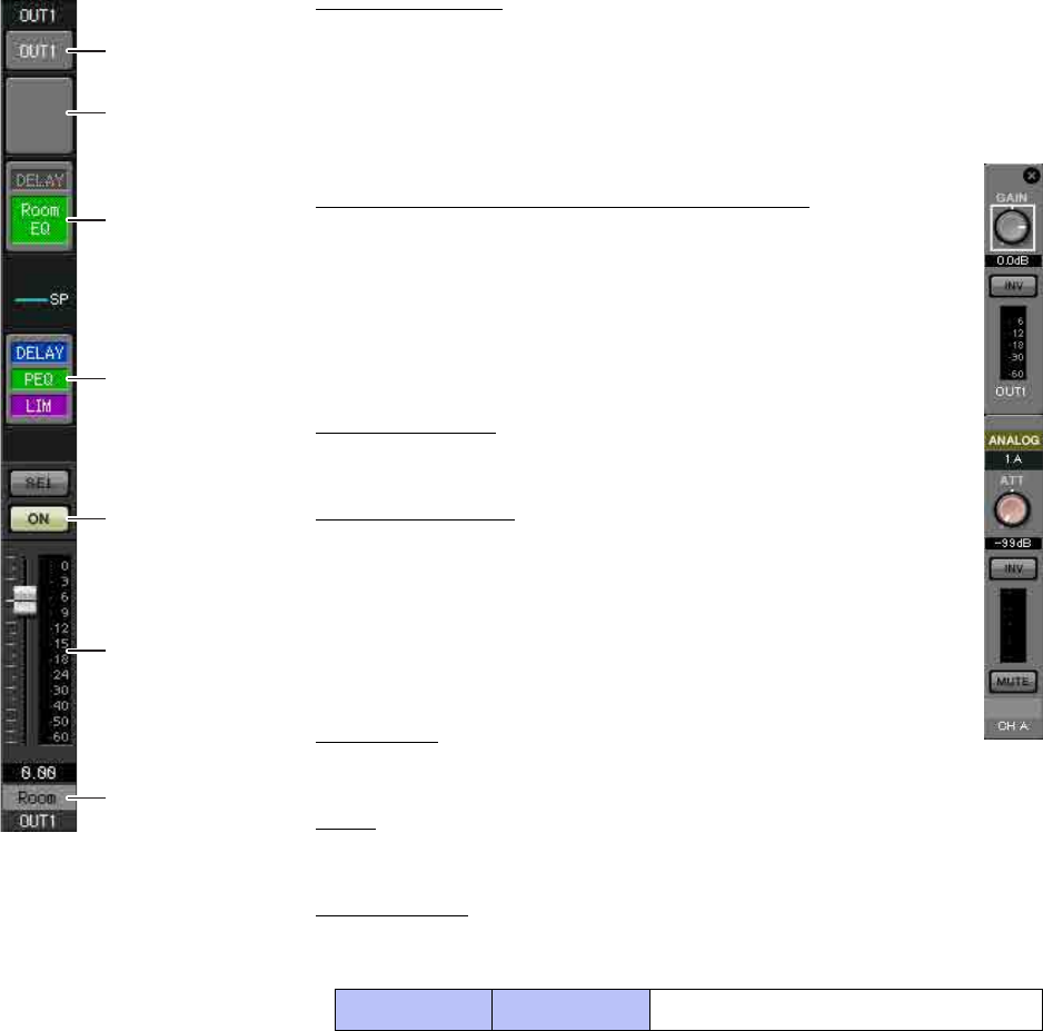
-OUTPUT settings
Port select button
Click this to open the “Output Patch” dialog box. In this example we will use the
default settings, but if you want to use a different output port of the MTX, click
this button, choose the desired output port, and then click the [Close] button.
Port/External Device parameter access button
When you click this button, the MTX output connector parameter
edit screen will appear as a popup. Verify that GAIN is set to 0.0 dB.
DELAY/Room EQ
Click this to move to a screen where you can set delay and room EQ.
Speaker processor
Click this to move to the “CHANNEL EDIT” screen. Make the appropriate set-
tings for the speakers that will be connected.
[ON] button
This button turns the channel on/off. Turn off unused channels.
Fader
This adjusts the output level.
Channel name
You can double-click this to edit the name.
In this example, names have been assigned as follows.
NOTE
The pre-installed library contains speaker processor files that are appropriate
for the response of various speakers. By using these files you can make
speaker processor settings easily.
OUT1 Hall A
OUT2 Hall B
OUT3 Entrance
OUT4 Kitchen
Port select button
Port/External Device
parameter access
button
DELAY/Room EQ
Speaker processor
[ON] button
Fader
Channel name
Example 1) Basic MTX3 system example (analog connections)
MTX Setup Manual 17
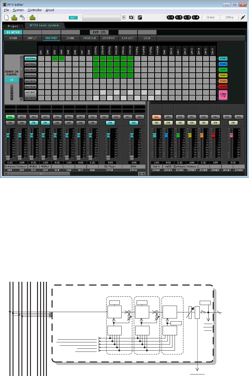
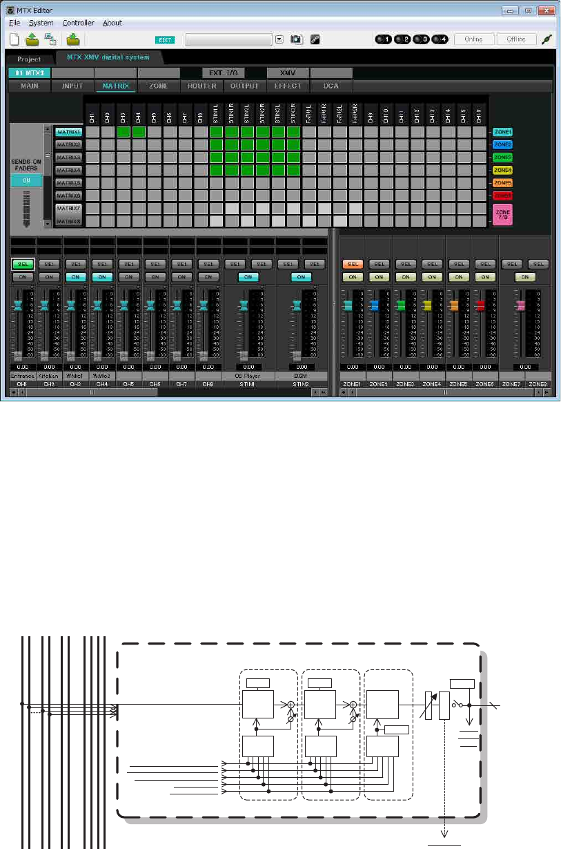
Settings in the “MATRIX” screen
Here you can specify which input channel will be sent to which zone. For details on send level and other parameters,
refer to “MTX Editor User’s Manual.”
In this example, make the settings shown in the above illustration. Clicking a cross point (a square area) or dragging
cross points will switch it on/off. If you right-click on a cross point, a context menu appears. You can select [All OFF]
to turn off all cross points. The cross point shows the send level as the amount of green.
With the settings shown here, the two microphones in hall A (CH3 and 4) are broadcast only to hall A. In addition, CD/
BGM/SD (STIN1–3) are being broadcast to the entire building. The microphone in the entrance (CH1) is assigned to be
broadcast to the entire building in the event of an emergency, and is therefore assigned in the “ZONE” screen
(described next) as 1st PRIORITY. If channel 1 is turned on in the matrix, the signal from the matrix (attenuated) and
the signal from Priority will be combined and output. Similarly, the microphone in the kitchen (CH2) is assigned as 2nd
PRIORITY that is valid only in zone 4 (Kitchen), and therefore is not specified in the matrix.
For the input channel faders in the lower left of the screen, the grayed-out faders show input levels, and the other faders
show input channel send levels. Grayed-out faders cannot be operated in this screen.
PRIORITY
DUCKER ANC
AMBIENT
SOURCE
From INPUT CHANNEL POST ON 1-16
*1 From YDIF IN 1-16
From ANC BUS 1-2
From STEREO INPUT CHANNEL POST ON 1L-3R
ZONE 1-8
ZONE OUT
To YDIF
OUTPUT
PATCH
MIXMIX
2nd PRIORITY 1st PRIORITY ANC
PRIORITY
SOURCE PRIORITY
SOURCE
From DIRECT INPUT POST ON 9-16
8
PRIORITY
DUCKER
METER
ON
D
C
A
MASTER
LEVEL
GR GR
AMBIENT
METER
To other MTXs
*1 DISTRIBUTION MODE only
Priority signal flow
Example 1) Basic MTX3 system example (analog connections)
MTX Setup Manual 18
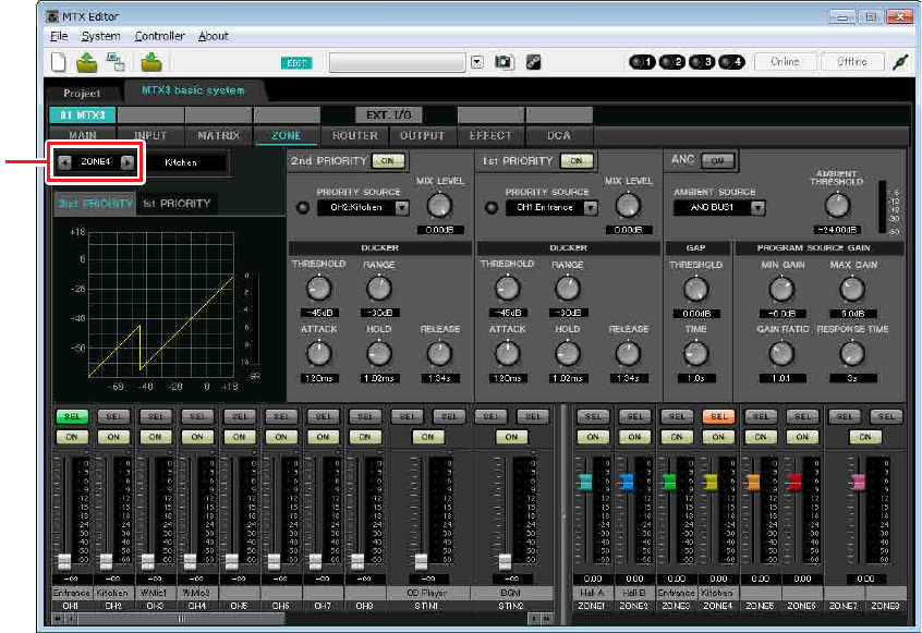
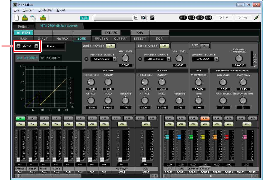
Settings in the “ZONE” screen
In the “ZONE” screen you can make Priority DUCKER settings. The Priority Ducker function temporarily attenuates
the inputs from other channels when audio is input from a specified input channel, ensuring that the audio from the
specified input channel will be broadcast clearly. Priority is given in the order of “1st PRIORITY > 2nd PRIORITY
>Matrix Out signals.”
In this example, we assume that the microphone in the entrance (CH1) will be used to speak to the entire building.
Therefore, we select CH1 as the 1st PRIORITY SOURCE for zone 1 through zone 4, and click the [ON] button located
at the right of 1st PRIORITY to make it light. We select the kitchen microphone (CH2) as the 2nd PRIORITY
SOURCE only for zone 4 (Kitchen), and click the [ON] button located at the right of 2nd PRIORITY to make it light.
Because there’s no need to make settings for zones 5 through 8, make sure that the [ON] button at the right of 1st PRI-
ORITY and 2nd PRIORITY are unlit (turned off).
Use the ZONE select buttons to switch the zone.
For details on each parameter, refer to “MTX Editor User’s Manual.”
ZONE select
button
Example 1) Basic MTX3 system example (analog connections)
MTX Setup Manual 19
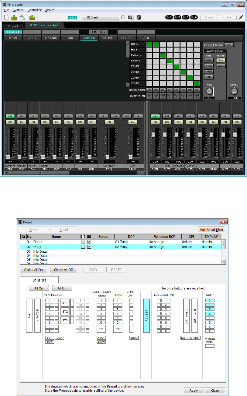
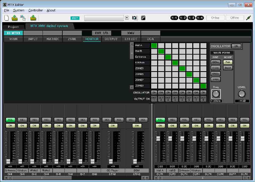
Settings in the “ROUTER” screen
In the “ROUTER” screen you can assign zones to outputs.
In this example we will leave the default settings unchanged, since the assignments are ZONE1=OUTPUT 1,
ZONE2=OUTPUT 2, ZONE3=OUTPUT 3, and ZONE4=OUTPUT 4.
Example 1) Basic MTX3 system example (analog connections)
MTX Setup Manual 20
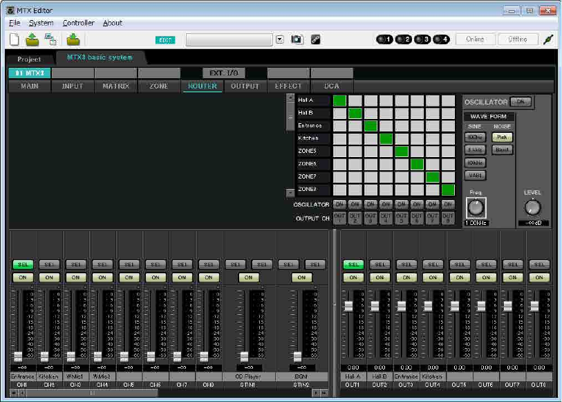
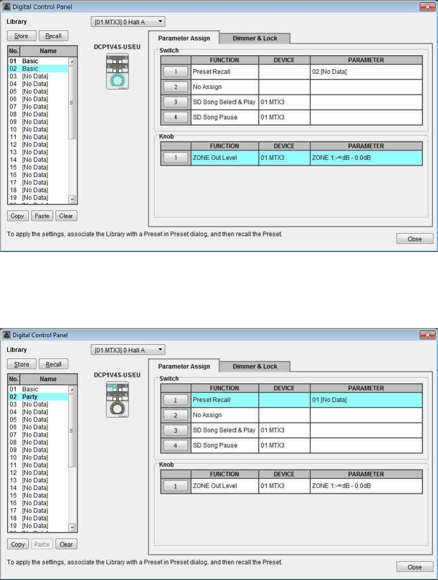
Digital Control Panel (DCP) settings
Here’s how to assign functions to the DCP that is installed in each zone.
To make these settings, choose the [Controller] menu item [Digital Control Panel].
Here we will use the example of the DCP located in Hall A of the Preset 01 Basic library.
Use the drop down list at the top of the screen to select the DCP for which you want to make settings.
When you click one of the numbered buttons, a “Settings” dialog box will appear; assign parameters to the controls. If
you assigned [SD Song Select & Play], enter the name of the file that you want to play.
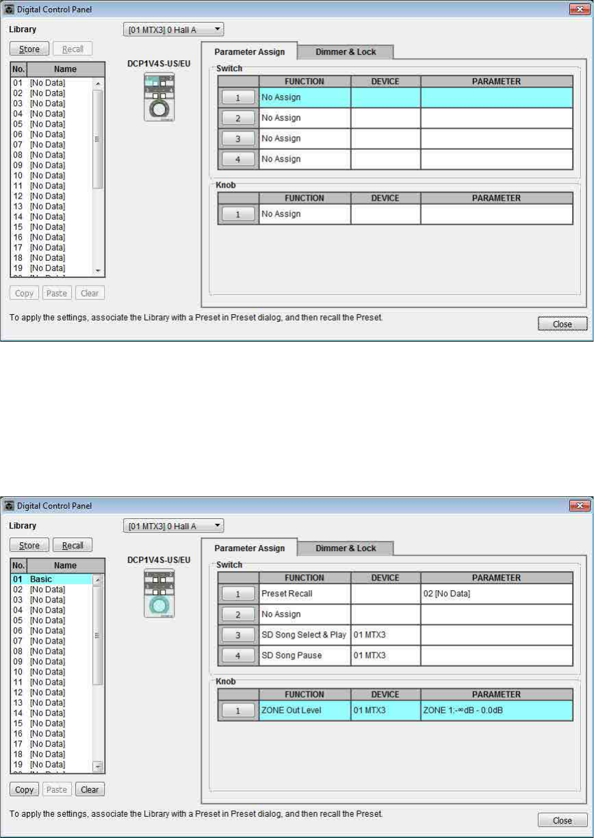
When you’ve made the assignments, click to select “01 [No data]” and then click the [Store] button. In the “Store
Library” dialog box, change the name to “Basic” and then click the [OK] button.
In Basic, switch 1 is the preset select switch for the Party settings. Switches 3 and 4 control pause/resume for playback
of audio sources on the SD memory card. The knob controls the output level of zone 1.

Example 1) Basic MTX3 system example (analog connections)
MTX Setup Manual 21
Next click the [Copy] button, and then click “02 [No Data]” to select the second library item. With this selected, click
the [Paste] button. The library item you created as “Basic” will be copied.
After changing the PARAMETER of switch 1 to “01,” double-click “Basic” in “02 Basic” located in the left of the
screen, and change the name of the library item to “Party.” (After you’ve entered the name, press the <Enter> key to
confirm the name change.) After making this change, click the [Store] button to overwrite-save the library item.
In Party, switch 1 is the preset select switch for the Basic settings. Other settings are the same as for Basic.
Example 1) Basic MTX3 system example (analog connections)
MTX Setup Manual 22
Example settings for other DCP units
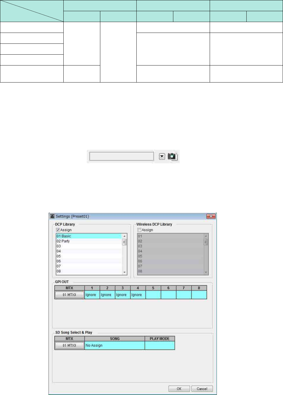
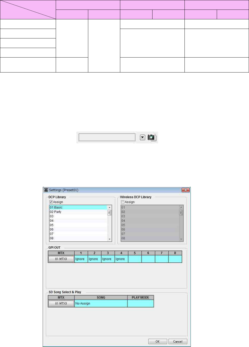
Storing a preset
Now we’ll store the settings we’ve made up to this point as a preset.
By recalling presets from the MTX itself or from the DCP, you can switch the settings as appropriate for various situa-
tions.
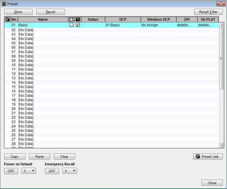
To store or recall a preset, click the camera icon in the upper part of MTX Editor.
When you click the camera icon, the “Preset” dialog box will appear. You can create up to 50 presets.
Click the preset number that you want to store; the line will be selected. Then click the [Store] button, specify the preset
name, and click the [OK] button.
Click a location where the DCP column indicates “No Assign,” and choose a library that you specified on the DCP.
1 (Hall B) 2 (Entrance) 3 (Kitchen)
Basic Party Basic Party Basic Party
Switch 1
Same as ID=0
(Hall A) Same as ID=0
(Hall A)
Input Ch ON (CH1) Input Ch ON (CH2)
Switch 2
No Assign No AssignSwitch 3
Switch 4
Knob 1 ZONE OUT
Level (ZONE2) Input Ch Level (CH1) Input Ch Level (CH2)
ID of the DCP
Library name
Example 1) Basic MTX3 system example (analog connections)
MTX Setup Manual 23
Up to this point, you made separate settings for zone 1 and zone 2. However in some cases, such as a party, you might
want to remove the boundary between zone 1 and zone 2 so that they can be a single meeting area. In this case, make
settings in the “ROUTER” screen to route zone 1 to output 2, so that zone 1 and zone 2 can be used as a single space.
Example 1) Basic MTX3 system example (analog connections)
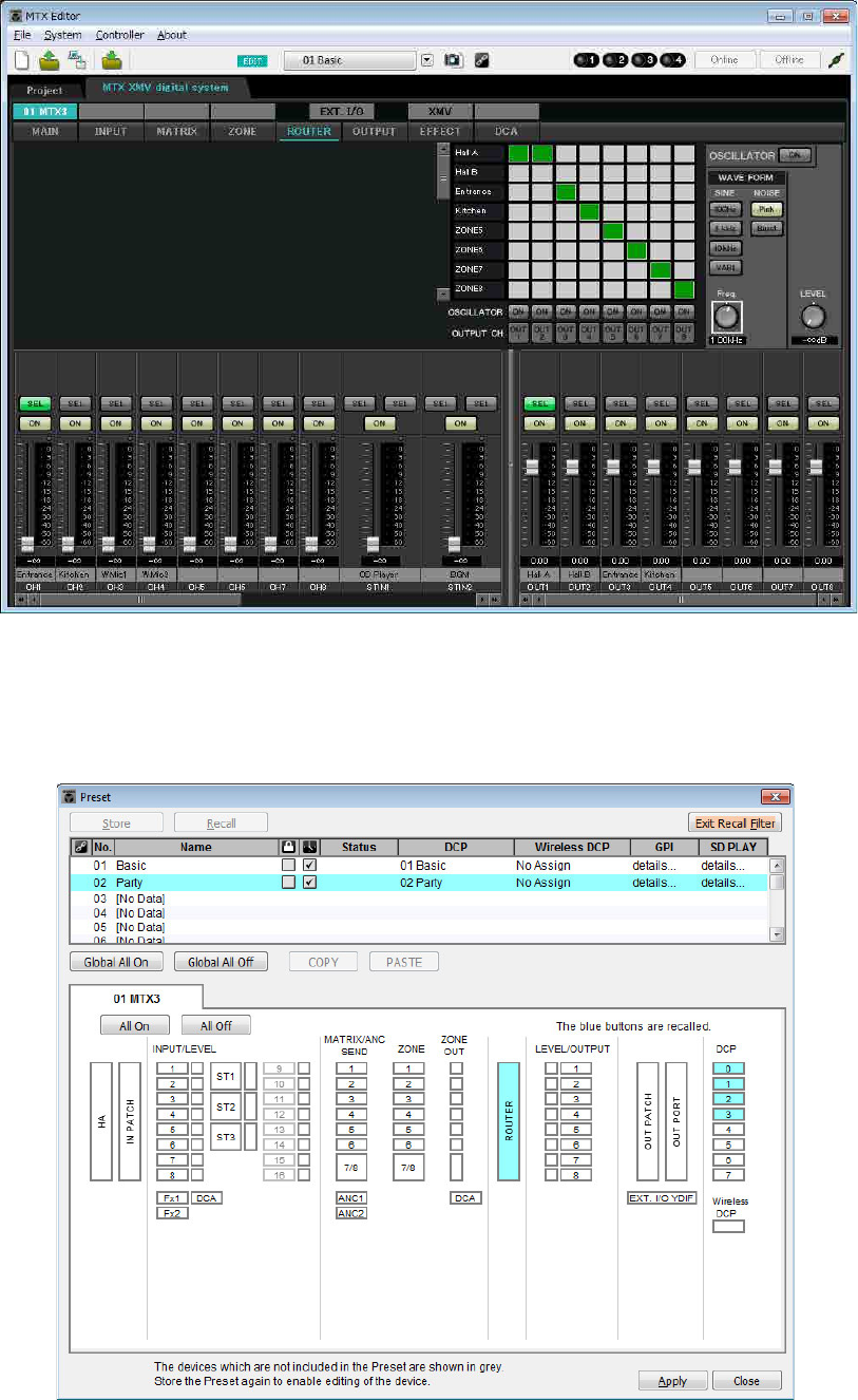
MTX Setup Manual 24
If you store these settings as a different preset, you’ll be able to easily switch to settings suitable for a party.
If you use Recall Filter to specify that only ROUTER and DCP settings are recalled, other settings such as gain will
remain at the Basic settings even if you recall a party preset.
This completes settings in the offline state. Save the settings once again.
Example 1) Basic MTX3 system example (analog connections)
MTX Setup Manual 25
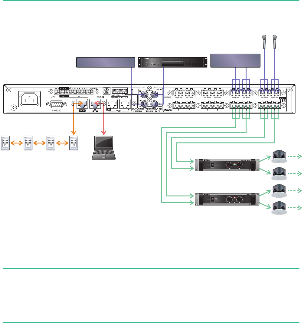
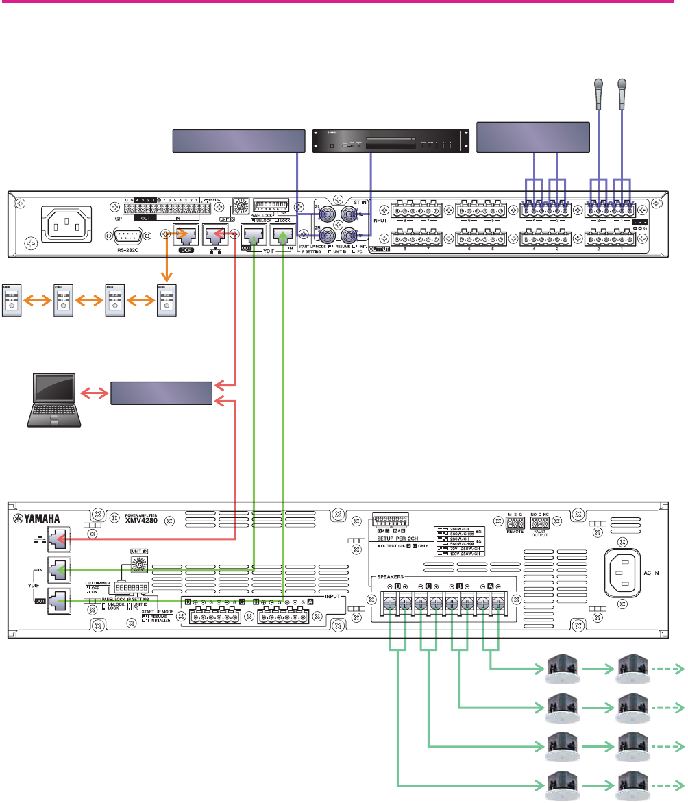
Connecting the equipment
After you’ve rack-mounted the MTX and your other equipment, connect the MTX and the other equipment as shown
below. If you’ve copied audio sources to an SD memory card, insert the card into the MTX now.
To connect the MTX to your computer, use a CAT5e or higher cable with all eight pins connected.
Powering-on the MTX
Turn on the power of the MTX.
Turn off the amplifier before you power-off the MTX.
Powering-on the amp
Turn on the power of the amplifier.
To prevent unwanted sound from being output, we recommend that you turn down the attenuator settings of all channels on
the amp itself before you turn it on.
Power Amp 1
Power Amp 2
Wireless Microphone
Reciever
BGM Player
CD Player
DCP
ID=3
DCP
ID=2
DCP
ID=1
DCP
ID=0 Computer
Entrance
Microphone
Kitchen
Microphone
Example 1) Basic MTX3 system example (analog connections)
MTX Setup Manual 26
Specifying the computer’s TCP/IP address
To allow the MTX and the computer to communicate, specify the computer’s TCP/IP as follows.
1. On the [System] menu, click [Network Setup].
The “Network Setup” dialog box will appear.
2. Click [Open Network Connection].
“Network Connections” will appear.
3. Right-click the adapter to which the MTX is connected, and choose [Properties].
The “Local Area Connection Properties” dialog box will appear.
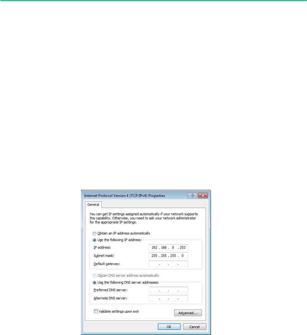
4. Choose [Internet Protocol Version 4 (TCP/IPv4)], and then click [Properties].
The “Internet Protocol Version 4 (TCP/IPv4) Properties” dialog box will appear.
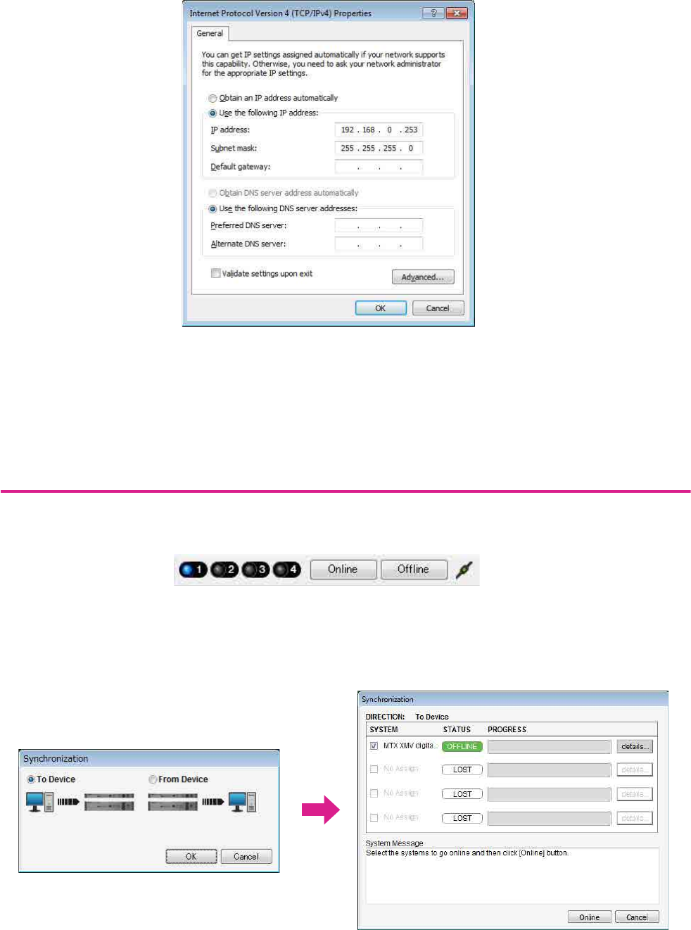
5. Click [Use the following IP address (S)].
6. In the [IP address] box, enter “192.168.0.253”; in the [Subnet mask] box, enter
“255.255.255.0.”
7. Click [OK].
NOTE
The IP address of the MTX3 is set to “192.168.0.1”.
NOTE
In some cases, Windows firewall may block MTX Editor when you make this setting. Select the [Private Network] check box, and
click [Allow Access].
Example 1) Basic MTX3 system example (analog connections)
MTX Setup Manual 27
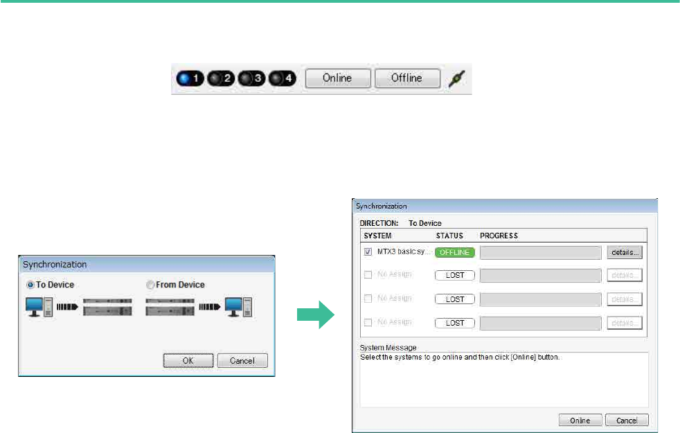
Taking MTX Editor online
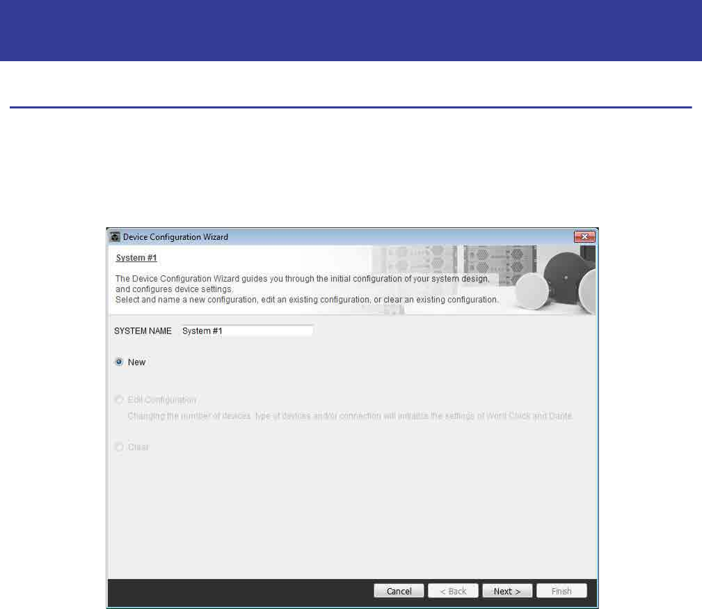
In the upper right of MTX Editor, click the [Online] button. When the unit has successfully come online, the indicator 1
will light blue.
When the “Synchronization” dialog box appears, select “To Device,” and click the [OK] button. When the indication in the
dialog box has switched, select the system that you want to place online, and click the [Online] button.
The project created in MTX Editor will be sent to the MTX.

Example 1) Basic MTX3 system example (analog connections)
MTX Setup Manual 28
Verifying that the settings were applied
The main items to verify are listed below. For details on each parameter setting, refer to “MTX Editor User’s Manual.”
1. Recall the Basic preset.
2. Using the oscillator in the “ROUTER” screen, adjust the output level.
Adjust the amp’s attenuator value to an appropriate level.
3. Specify the gain from the microphone.
You can set the gain in the dialog box that appears when you press the parameter recall button for a port or external
device of an input channel in the “MAIN” screen. Watch the input meter, and adjust the setting appropriately.
4. Set the input levels and output levels.
Using the input/output faders in the “MAIN” screen, adjust the levels. As necessary, apply the output limiter in the
“CHANNEL EDIT” screen to prevent your speakers from being damaged.
Adjust the amp attenuator values to obtain the optimal S/N ratio.
In addition, make FBS settings as necessary.
5. Store the Basic preset.
Store by overwriting the previously-specified content.
6. Recall the Party preset.
Verify that the audio from the wireless microphone is also heard in Hall B.
If you’re not using Recall Filter, perform steps 2 through 4 before you overwrite-store the Party preset.
7. Check the DCP settings.
Verify that the DCP operates as you expect.
Check these for each preset.
When you have finished making all settings, save the project and switch MTX Editor offline.
This completes the settings for example 1.
MTX Setup Manual 29
Using the Device Configuration Wizard to create your device setup
You will use MTX Editor’s wizard to create your device setup before actually connecting your equipment.
After you’ve made basic settings, you’ll be able to print information about system cabling and ID numbers.
Use the following procedure to make basic settings.
1. Type a name for the MTX system you’ll be constructing, and click [Next>].
Example 2) High audio quality system with XMV and YDIF connec-
tions (digital connections)
Example 2) High audio quality system with XMV and YDIF connections (digital connections)
MTX Setup Manual 30
2. Specify the number of units that will be connected in your MTX system, and click [Next>].
Specify “1” as the number of MTX3 units in “YDIF Connected,” and specify “1” as the number of XMV4280 units to
be connected.
3. Specify the UNIT ID of each device, and click [Next>].
Unless you have specific reasons for doing so, use the UNIT ID that is assigned.
In this example, set the XMV’s UNIT ID to 1A so that we can explain how to change the UNIT ID.
Example 2) High audio quality system with XMV and YDIF connections (digital connections)
MTX Setup Manual 31
4. Set the [UNIT ID] rotary switch and DIP switch of the MTX and XMV.
You will set the computer’s IP address after completing the wizard, in “Specifying the computer’s TCP/IP address.”
If the MTX and XMV are not nearby, you can set them during the step “Connecting the equipment.”
Make the following settings.
5. When you have finished setting the [UNIT ID] rotary switch and DIP switch of the MTX and
the XMV, click [Next>].
MTX3
UNIT ID = 01
[UNIT ID] rotary switch = 1
DIP switches are all OFF (upward)
XMV
UNIT ID = 1A
[UNIT ID] rotary switch = A
DIP switch 1 is ON (downward), others are OFF (upward)
NOTE
Use the DIP switch to specify the upper digit of the UNIT ID, and use the [UNIT ID] rotary switch to specify the lower digit. For
details, refer to the owner’s manual of each unit.
UNIT ID = 1 A
Lower digit: specify using the rotary switch
Upper digit: specify using DIP switch 1–3
Example 2) High audio quality system with XMV and YDIF connections (digital connections)
MTX Setup Manual 32
6. Verify that the MTX and XMV are shown in the screen, and click [Next>].
Since there is only one MTX unit and one XMV unit, there’s no need to change the order.
7. Choose the model of DCP that is connected to the MTX, enter a device name, and click
[Finish].
Since four DCP1V4S units will be connected, make settings for four units.
Example 2) High audio quality system with XMV and YDIF connections (digital connections)
MTX Setup Manual 33
8. When you see the dialog box “Display the configuration diagram? The diagram can also
be printed.” click [Yes].
A cabling diagram will appear. If you want, click [Print] to print the diagram.
To close the screen, click [Close].
Set the DIP switches of the DCP units as shown in the “Digital Control Panel” section of the schematic diagram.
For the last DCP (ID=3), set DIP switch 4 ON (upward).
If you want to use the Device Configuration Wizard to change the device configuration, click the [Device Config] but-
ton in the Project screen.
NOTE
If you want to view the cabling diagram again, do so by choosing [File] menu [Print Configuration Diagram].
1
ON
2 3 4
Example 2) High audio quality system with XMV and YDIF connections (digital connections)
MTX Setup Manual 34
Making preliminary settings in MTX Editor
Here’s how to make detailed MTX system settings in MTX Editor.
When you’ve finished making settings, you should save them by clicking [File] menu, then [Save].
Making EXT. I/O settings
Here you’ll make settings for inputting digital audio into the XMV.
Move to the System screen by clicking the tab of the system name you specified in step 1 of “Using the Device Config-
uration Wizard to create your device setup.”
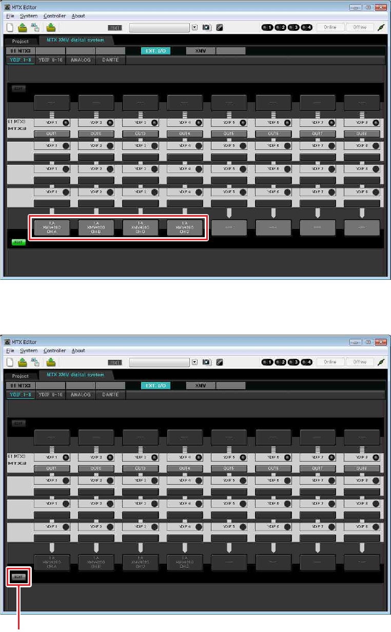
1. Click the [EXT. I/O] button.
The “EXT. I/O” screen will appear, allowing you to make input/output settings for the external devices. Since
you’ll be making settings for YDIF 1–8, there’s no need to switch screens; simply make the settings in this screen.
NOTE
The “User Account Control” dialog box may appear. Click [Continue] or [Yes].
Step 2
Example 2) High audio quality system with XMV and YDIF connections (digital connections)
MTX Setup Manual 35
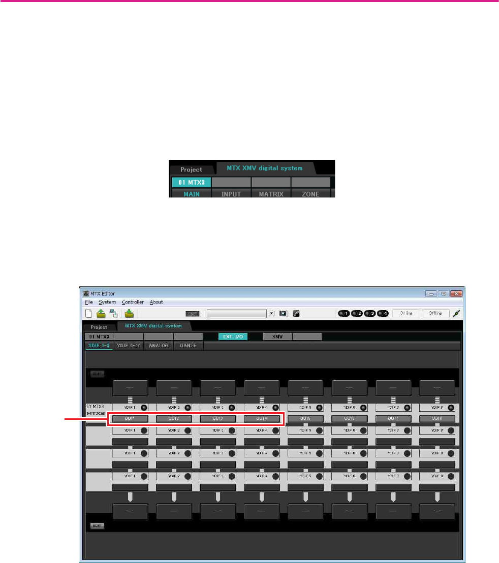
2. Verify that for the MTX with UNIT ID = 01, the buttons located below YDIF 1 through YDIF
4 are set to OUT1 (OUTPUT 1) through OUT 4 (OUTPUT 4) respectively.
If the settings are different, click the button and change the setting.
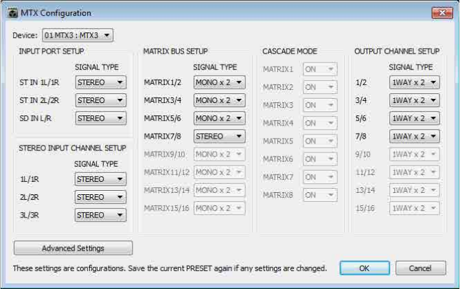
3. In the lower left, click the [EDIT] button.
Now you can specify the outputs from the MTX to YDIF 1–8.
[EDIT] button Output routing select button
Example 2) High audio quality system with XMV and YDIF connections (digital connections)
MTX Setup Manual 36
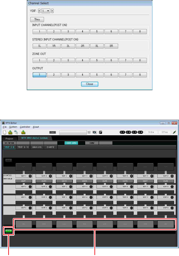
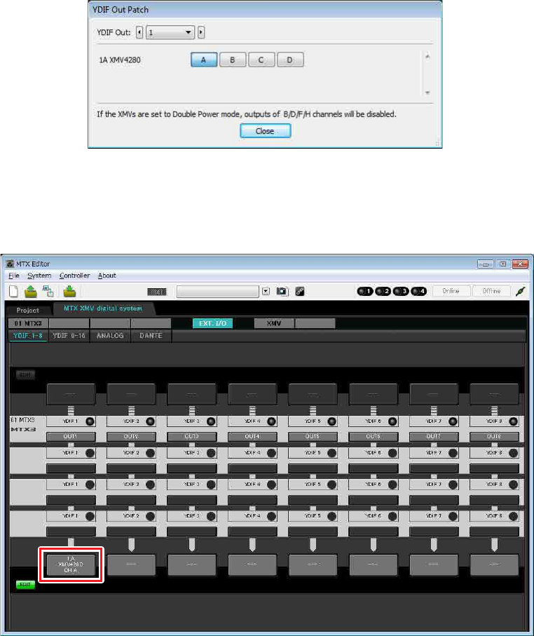
4. Click the output routing select button located below YDIF 1.
The “YDIF Out Patch” dialog box will appear.
5. For CHANNEL, click [A] button.
The YDIF 1 output routing select button shows that the YDIF 1 output has been assigned to CH A of the UNIT
ID=1A XMV.
Example 2) High audio quality system with XMV and YDIF connections (digital connections)
MTX Setup Manual 37
6. Change the output destination in the [YDIF Out:] list box, to assign YDIF 2 through YDIF
4 to CH B through CH D of the XMV and then click [Close] button.
7. In the lower left, click [EDIT] button to lock the settings.
[EDIT] button
Example 2) High audio quality system with XMV and YDIF connections (digital connections)
MTX Setup Manual 38
Specifying the MTX configuration
Here you’ll specify how the MTX’s inputs and outputs will be handled.
On the [System] menu, click [MTX Configuration] to open the “MTX Configuration” dialog box.
The default settings are shown in the screen below. You can change them as necessary. In this example, we’ll use the
default settings without change.
Example 2) High audio quality system with XMV and YDIF connections (digital connections)
MTX Setup Manual 39
Settings in the “MAIN” screen
In the “MAIN” screen you can make overall settings for each channel.
Click the [01 MTX3] button to access the MTX “MAIN” screen.
For details on each parameter, refer to “MTX Editor User’s Manual.”
Here you’ll make the following settings.
• Channel name
• Channel on/off
• Gain and phantom power
• (As necessary) EQ settings
Example 2) High audio quality system with XMV and YDIF connections (digital connections)
MTX Setup Manual 40
-INPUT settings
Port select button
When you click this, the “Input Patch” dialog box will open. In this example we
are using the default settings, but if you want to switch to a different input port of
the MTX, click this button, choose the desired input port, and then click the
[Close] button.
Port/External Device parameter
access button
This button lets you adjust the gain and turn
phantom power on/off. When you click the
button, a popup window will appear, allow-
ing you to adjust the gain and turn phantom
power on/off. Make the desired settings,
and then in the upper right, click × to close
the popup window. The appropriate gain level will depend on the devices that are
connected, so set the level appropriately for your devices.
For channels 1 through 8, the gain is set to 30 dB by default. Because condenser
microphones are connected to CH1 and 2, leave the gain at 30 dB and turn phan-
tom power on. Because wireless microphones are connected to CH3 and 4, lower
the gain to 0 dB.
EQ/HPF (High Pass Filter)
Click this to switch to the “CHANNEL EDIT” screen. Adjust the EQ and HPF
appropriately for the microphone you’re using. For ST IN, only EQ is available.
When you want to return to the “MAIN” screen, click the [MAIN] button.
FBS (Feedback suppressor)
FBS is provided on input channels 1 through 4. We recommend that microphone
inputs, and particularly movable microphones such as wireless microphones, be
connected to channels 1 through 4. When you click here, you will switch to the
FBS setting screen.
When you want to return to the “MAIN” screen, click the [MAIN] button.
For details on FBS settings, refer to “MTX Editor User’s Manual.”
[ON] button
This turns the channel on/off. You should turn off unused channels.
Fader
This adjusts the input level. Leave the fader at -∞ until the system goes online.
Channel name
You can double-click this to edit the name.
In this example, names have been assigned as follows.
CH1 Entrance
CH2 Kitchen
CH3 W.Mic1
CH4 W.Mic2
STIN1 CD Player
STIN2 BGM
SDIN SD Player
Port select button
Port/External Device
parameter access
button
EQ/HPF
FBS (Feedback sup-
pressor)
[ON] button
Fader
Channel name
Example 2) High audio quality system with XMV and YDIF connections (digital connections)
MTX Setup Manual 41
-OUTPUT settings
Port select button
Click this to open the “Output Patch” dialog box. In this example we will use the
default settings, but if you want to use a different output port of the MTX, click
this button, choose the desired output port, and then click the [Close] button.
Port / External Device parameter access button
When you click this button, a popup window will appear, allowing
you to set the MTX’s output connector parameters and the parameters
of the external device associated with the channel. Verify that GAIN is
set to 0.0 dB.
In this example, the MTX output parameters are above, and the XMV
parameters are below. Put the system online before you edit the set-
tings of these parameters.
When you click this button, the MTX output connector parameter edit
screen will appear as a popup. Verify that GAIN is set to 0.0 dB.
DELAY/Room EQ
Click this to move to a screen where you can set delay and room EQ.
Speaker processor
Click this to move to the “CHANNEL EDIT” screen. Make the appro-
priate settings for the speakers that will be connected.
[ON] button
This button turns the channel on/off. Turn off unused channels.
Fader
This adjusts the output level.
Channel name
You can double-click this to edit the name.
In this example, names have been assigned as follows.
NOTE
The pre-installed library contains speaker processor files that are appropri-
ate for the response of various speakers. By using these files you can
make speaker processor settings easily.
OUT1 Hall A
OUT2 Hall B
OUT3 Entrance
OUT4 Kitchen
Port select button
Port / External Device
parameter access
button
DELAY/Room EQ
Speaker processor
[ON] button
Fader
Channel name
Example 2) High audio quality system with XMV and YDIF connections (digital connections)
MTX Setup Manual 42
Settings in the “MATRIX” screen
Here you can specify which input channel will be sent to which zone. For details on send level and other parameters,
refer to “MTX Editor User’s Manual.”
In this example, make the settings shown in the above illustration. Clicking a cross point (a square area) or dragging
cross points will switch it on/off. If you right-click on a cross point, a context menu appears. You can select [All OFF]
to turn off all cross points. The cross point shows the send level as the amount of green.
With the settings shown here, the two microphones in hall A (CH3 and 4) are broadcast only to hall A. In addition, CD/
BGM/SD (STIN1–3) are being broadcast to the entire building. The microphone in the entrance (CH1) is assigned to be
broadcast to the entire building in the event of an emergency, and is therefore assigned in the “ZONE” screen
(described next) as 1st PRIORITY. If channel 1 is turned on in the matrix, the signal from the matrix (attenuated) and
the signal from Priority will be combined and output. Similarly, the microphone in the kitchen (CH2) is assigned as 2nd
PRIORITY that is valid only in zone 4 (Kitchen), and therefore is not specified in the matrix.
For the input channel faders in the lower left of the screen, the grayed-out faders show input levels, and the other faders
show input channel send levels. Grayed-out faders cannot be operated in this screen.
PRIORITY
DUCKER ANC
AMBIENT
SOURCE
From INPUT CHANNEL POST ON 1-16
*1 From YDIF IN 1-16
From ANC BUS 1-2
From STEREO INPUT CHANNEL POST ON 1L-3R
ZONE 1-8
ZONE OUT
To YDIF
OUTPUT
PATCH
MIXMIX
2nd PRIORITY 1st PRIORITY ANC
PRIORITY
SOURCE PRIORITY
SOURCE
From DIRECT INPUT POST ON 9-16
8
PRIORITY
DUCKER
METER
ON
D
C
A
MASTER
LEVEL
GR GR
AMBIENT
METER
To other MTXs
*1 DISTRIBUTION MODE only
Priority signal flow
Example 2) High audio quality system with XMV and YDIF connections (digital connections)
MTX Setup Manual 43
Settings in the “ZONE” screen
In the “ZONE” screen you can make Priority DUCKER settings. The Priority Ducker function temporarily attenuates
the inputs from other channels when audio is input from a specified input channel, ensuring that the audio from the
specified input channel will be broadcast clearly. Priority is given in the order of “1st PRIORITY > 2nd PRIORITY
>Matrix Out signals.”
In this example, we assume that the microphone in the entrance (CH1) is used for broadcasting to the entire building.
Therefore, we select CH1 as the 1st PRIORITY SOURCE for zone 1 through zone 4, and click the [ON] button located
at the right of 1st PRIORITY to make it light. We select the kitchen microphone (CH2) as the 2nd PRIORITY
SOURCE only for zone 4 (Kitchen), and click the [ON] button located at the right of 2nd PRIORITY to make it light.
Because there’s no need to make settings for zones 5 through 8, make sure that the [ON] button at the right of 1st PRI-
ORITY and 2nd PRIORITY are unlit (turned off).
Use the ZONE select buttons to switch the zone.
For details on each parameter, refer to “MTX Editor User’s Manual.”
ZONE select
button
Example 2) High audio quality system with XMV and YDIF connections (digital connections)
MTX Setup Manual 44
Settings in the “ROUTER” screen
In the “ROUTER” screen you can assign zones to outputs.
In this example we will leave the default settings unchanged, since the assignments are ZONE1=OUTPUT 1,
ZONE2=OUTPUT 2, ZONE3=OUTPUT 3, and ZONE4=OUTPUT 4.

Example 2) High audio quality system with XMV and YDIF connections (digital connections)
MTX Setup Manual 45
Digital Control Panel (DCP) settings
Here’s how to assign functions to the DCP that is installed in each zone.
To make these settings, choose the [Controller] menu item [Digital Control Panel].
Here we will use the example of the DCP located in Hall A of the Preset 01 Basic library.
Use the drop down list at the top of the screen to select the DCP for which you want to make settings.
When you click one of the numbered buttons, a “Settings” dialog box will appear; assign parameters to the controls. If
you assigned [SD Song Select & Play], enter the name of the file that you want to play.
When you’ve made the assignments, click to select “01 [No data]” and then click the [Store] button. In the “Store
Library” dialog box, change the name to “Basic” and then click the [OK] button.
In Basic, switch 1 is the preset select switch for the Party settings. Switches 3 and 4 control pause/resume for playback
of audio sources on the SD memory card. The knob controls the output level of zone 1.
Example 2) High audio quality system with XMV and YDIF connections (digital connections)
MTX Setup Manual 46
Next click the [Copy] button, and then click “02 [No Data]” to select the second library item. With this selected, click
the [Paste] button. The library item you created as “Basic” will be copied.
After changing the PARAMETER of switch 1 to “01,” double-click “Basic” in “02 Basic” located in the left of the
screen, and change the name of the library item to “Party.” (After you’ve entered the name, press the <Enter> key to
confirm the name change.) After making this change, click the [Store] button to overwrite-save the library item.
In Party, switch 1 is the preset select switch for the Basic settings. Other settings are the same as for Basic.
Example 2) High audio quality system with XMV and YDIF connections (digital connections)
MTX Setup Manual 47
Example settings for other DCP units
Storing a preset
Now we’ll store the settings we’ve made up to this point as a preset.
By recalling presets from the MTX itself or from the DCP, you can switch the settings as appropriate for various situa-
tions.
To store or recall a preset, click the camera icon in the upper part of MTX Editor.
When you click the camera icon, the “Preset” dialog box will appear. You can create up to 50 presets.
Click the preset number that you want to store; the line will be selected. Then click the [Store] button, specify the preset
name, and click the [OK] button.
Click a location where the DCP column indicates “No Assign,” and choose a library that you specified on the DCP.
1 (Hall B) 2 (Entrance) 3 (Kitchen)
Basic Party Basic Party Basic Party
Switch 1
Same as ID=0
(Hall A) Same as ID=0
(Hall A)
Input Ch ON (CH1) Input Ch ON (CH2)
Switch 2
No Assign No AssignSwitch 3
Switch 4
Knob 1 ZONE OUT
Level (ZONE2) Input Ch Level (CH1) Input Ch Level (CH2)
ID of the DCP
Library name

Example 2) High audio quality system with XMV and YDIF connections (digital connections)
MTX Setup Manual 48
Up to this point, you made separate settings for zone 1 and zone 2. However in some cases, such as a party, you might
want to remove the boundary between zone 1 and zone 2 so that they can be a single meeting area. In this case, make
settings in the “ROUTER” screen to route zone 1 to output 2, so that zone 1 and zone 2 can be used as a single space.
Example 2) High audio quality system with XMV and YDIF connections (digital connections)
MTX Setup Manual 49
If you store these settings as a different preset, you’ll be able to easily switch to settings suitable for a party.
If you use Recall Filter to specify that only ROUTER and DCP settings are recalled, other settings such as gain will
remain at the Basic settings even if you recall a party preset. For External I/O as well, press the [All Off] button so that
all settings are carried over.
This completes settings in the offline state. Save the settings once again.
Example 2) High audio quality system with XMV and YDIF connections (digital connections)
MTX Setup Manual 50
Connecting the equipment
After you’ve rack-mounted the MTX and your other equipment, connect the MTX and the other equipment as shown
below. If you’ve copied audio sources to an SD memory card, insert the card into the MTX now.
To connect the MTX to your computer, use a CAT5e or higher cable with all eight pins connected.
1 2 3 4 5 6 7 8
ON
ON
BGM Player
Network Switch
CD Player
DCP
ID=3
DCP
ID=2
DCP
ID=1
DCP
ID=0
Computer
MTX
ID=01
XMV
ID=1A
Kitchen
Microphone
Entrance
Microphone
Wireless Microphone
Reciever

Example 2) High audio quality system with XMV and YDIF connections (digital connections)
MTX Setup Manual 51
Powering-on the MTX
Turn on the power of the MTX.
Turn off the amplifier before you power-off the MTX.
Powering-on the amp
On the rear panel of the XMV, set the [SPEAKERS] DIP switch, and then turn on the power of the amps (XMV).
To prevent unwanted sound from being output, we recommend that you turn down the attenuator settings of all channels on
the amp itself before you turn it on.
To change the XMV attenuator setting, press the button of the appropriate channel and then turn the encoder.
Specifying the computer’s TCP/IP address
To allow the MTX and the computer to communicate, specify the computer’s TCP/IP as follows.
1. On the [System] menu, click [Network Setup].
The “Network Setup” dialog box will appear.
2. Click [Open Network Connection].
“Network Connections” will appear.
3. Right-click the adapter to which the MTX is connected, and choose [Properties].
The “Local Area Connection Properties” dialog box will appear.
4. Choose [Internet Protocol Version 4 (TCP/IPv4)], and then click [Properties].
The “Internet Protocol Version 4 (TCP/IPv4) Properties” dialog box will appear.
5. Click [Use the following IP address (S)].
NOTE
• With the factory settings, the XMV’s attenuators are set to the lowest value.
• For more about the [SPEAKERS] DIP switch, refer to the XMV owner’s manual.
Example 2) High audio quality system with XMV and YDIF connections (digital connections)
MTX Setup Manual 52
6. In the [IP address] box, enter “192.168.0.253”; in the [Subnet mask] box, enter
“255.255.255.0.”
7. Click [OK].
Taking MTX Editor online
In the upper right of MTX Editor, click the [Online] button. When the unit has successfully come online, the indicator 1 at
the left will light blue.
When the “Synchronization” dialog box appears, select “To Device,” and click the [OK] button. When the indication in the
dialog box has switched, select the system that you want to place online, and click the [Online] button.
The project created in MTX Editor will be sent to the MTX.
NOTE
The MTX3’s IP address is set to “192.168.0.1,” and the XMV’s IP address is set to “192.168.0.26.”
NOTE
In some cases, Windows firewall may block MTX Editor when you make this setting. Select the [Private Network] check box, and
click [Allow Access].

Example 2) High audio quality system with XMV and YDIF connections (digital connections)
MTX Setup Manual 53
Making XMV settings
If necessary, use the XMV’s front panel to make settings such as the high pass filter. For more about the settings you can
make on the XMV, refer to the XMV owner’s manual.
Verifying that the settings were applied
The main items to verify are listed below. For details on each parameter setting, refer to “MTX Editor User’s Manual.”
1. Recall the Basic preset.
2. Using the oscillator in the “ROUTER” screen, adjust the output level.
Adjust the amp’s attenuator value to an appropriate level.
3. Specify the gain from the microphone.
You can set the gain in the dialog box that appears when you press the parameter recall button for a port or external
device of an input channel in the “MAIN” screen. Watch the input meter, and adjust the setting appropriately.
4. Set the input levels and output levels.
Using the input/output faders in the “MAIN” screen, adjust the levels. As necessary, apply the output limiter in the
“CHANNEL EDIT” screen to prevent your speakers from being damaged.
Adjust the amp attenuator values to obtain the optimal S/N ratio.
In addition, make FBS settings as necessary.
5. Store the Basic preset.
Store by overwriting the previously-specified content.
6. Recall the Party preset.
Verify that the audio from the wireless microphone is also heard in Hall B.
If you’re not using Recall Filter, perform steps 2 through 4 before you overwrite-store the Party preset.
7. Check the DCP settings.
Verify that the DCP operates as you expect.
Check these for each preset.
When you have finished making all settings, save the project and switch MTX Editor offline.
This completes the settings for example 2.
MTX Setup Manual 54
Using the Device Configuration Wizard to create your device setup
You will use MTX Editor’s wizard to create your device setup before actually connecting your equipment.
After you’ve made basic settings, you’ll be able to print information about system cabling and ID numbers.
Use the following procedure to make basic settings.
1. Type a name for the MTX system you’ll be constructing, and click [Next>].
Example 3) Using cascade mode to add MTX input channels (ana-
log connection)
Example 3) Using cascade mode to add MTX input channels (analog connection)
MTX Setup Manual 55
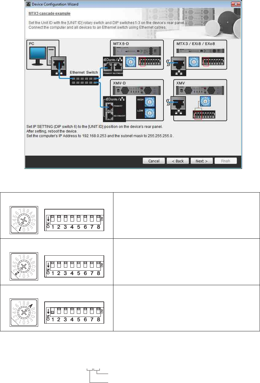
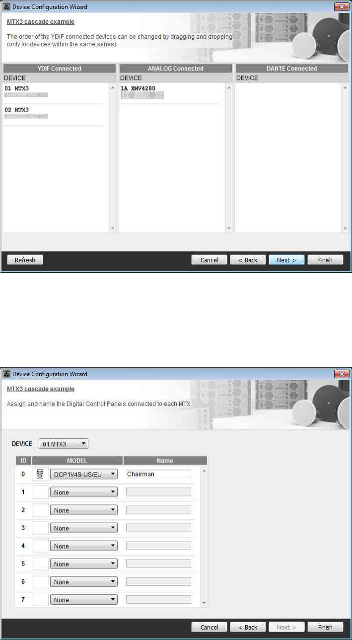
2. Specify the number of units that will be connected in your MTX system, and click [Next>].
Specify “2” as the number of “YDIF Connected” MTX3 units, and specify “1” as the number of “ANALOG Con-
nected” XMV4280.
3. Specify the YDIF MODE to CASCADE, and then click [Next>].
A dialog box will appear when you change this to CASCADE; click [OK].
Unless you have specific reasons for doing so, use the UNIT ID that is assigned.
In this example, set the XMV’s UNIT ID to 1A so that we can explain how to change the UNIT ID.
Example 3) Using cascade mode to add MTX input channels (analog connection)
MTX Setup Manual 56
4. Set the [UNIT ID] rotary switch and DIP switch of the MTX and XMV.
You will set the computer’s IP address after completing the wizard, in “Specifying the computer’s TCP/IP address.”
If the MTX and XMV are not nearby, you can set them during the step “Connecting the equipment.”
Make the following settings.
5. When you have finished setting the [UNIT ID] rotary switch and DIP switch of the MTX and
the XMV, click [Next>].
MTX3
UNIT ID = 01
[UNIT ID] rotary switch = 1
DIP switches are all OFF (upward)
MTX3
UNIT ID = 02
[UNIT ID] rotary switch = 2
DIP switches are all OFF (upward)
XMV
UNIT ID = 1A
[UNIT ID] rotary switch = A
DIP switch 1 is ON (downward), others are OFF (upward)
NOTE
Use the DIP switch to specify the upper digit of the UNIT ID, and use the [UNIT ID] rotary switch to specify the lower digit. For
details, refer to the owner’s manual of each unit.
UNIT ID = 1 A
Lower digit: specify using the rotary switch
Upper digit: specify using DIP switch 1–3
Example 3) Using cascade mode to add MTX input channels (analog connection)
MTX Setup Manual 57
6. Verify that the MTX and XMV are shown in the screen, and click [Next>].
7. Choose the model of DCP that is connected to the MTX, enter a device name, and click
[Finish].
Since one DCP1V4S will be connected to the UNIT ID=01 MTX3, choose [01 MTX3] for Device, and register the
one DCP unit.
Example 3) Using cascade mode to add MTX input channels (analog connection)
MTX Setup Manual 58
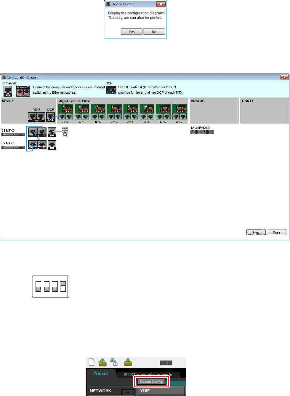
8. When you see the dialog box “Display the configuration diagram? The diagram can also
be printed.” click [Yes].
A cabling diagram will appear. If you want, click [Print] to print the diagram.
To close the screen, click [Close].
Set the DIP switches of the DCP units as shown in the “Digital Control Panel” section of the schematic diagram.
For the last DCP (ID=0), set DIP switch 4 ON (upward).
If you want to use the Device Configuration Wizard to change the device configuration, click the [Device Config] but-
ton in the Project screen.
NOTE
If you want to view the cabling diagram again, do so by choosing [File] menu [Print Configuration Diagram].
1
ON
2 3 4
Example 3) Using cascade mode to add MTX input channels (analog connection)
MTX Setup Manual 59
Making preliminary settings in MTX Editor
Here’s how to make detailed MTX system settings in MTX Editor.
When you’ve finished making settings, you should save them by clicking [File] menu, then [Save].
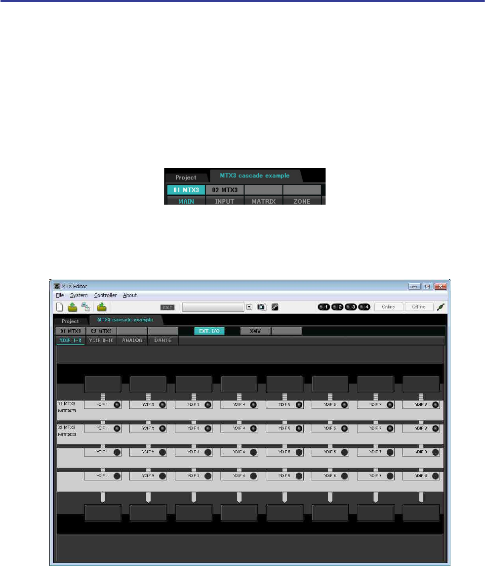
Making EXT. I/O settings
Here you’ll make settings for inputting analog audio into the XMV.
Move to the System screen by clicking the tab of the system name you specified in step 1 of “Using the Device Config-
uration Wizard to create your device setup.”
If you’re using an amp other than the XMV, proceed from “Specifying the MTX configuration.”
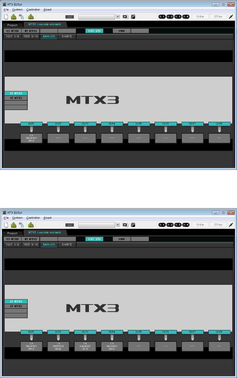
1. Click the [EXT. I/O] button.
The output setting screen will appear.
NOTE
The “User Account Control” dialog box may appear. Click [Continue] or [Yes].
Example 3) Using cascade mode to add MTX input channels (analog connection)
MTX Setup Manual 60
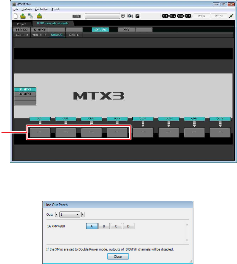
2. Click the [ANALOG] button.
The MTX analog output setting screen will appear.
3. Click the button located below OUT1.
The “Line Out Patch” dialog box will appear.
Step 3
Example 3) Using cascade mode to add MTX input channels (analog connection)
MTX Setup Manual 61
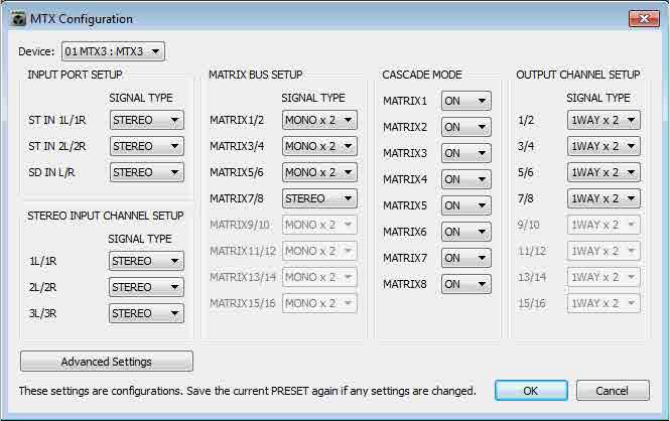
4. Click the “CHANNEL” [A] button.
The screen will show that with these settings, analog output 1 of the ID=01 MTX is connected to the CH A analog
input of the XMV.
5. Change the output destination in the [Out:] list box, to assign CH B through CH D of the
XMV to OUT 2 through OUT 4, and then click the [Close] button.
Example 3) Using cascade mode to add MTX input channels (analog connection)
MTX Setup Manual 62
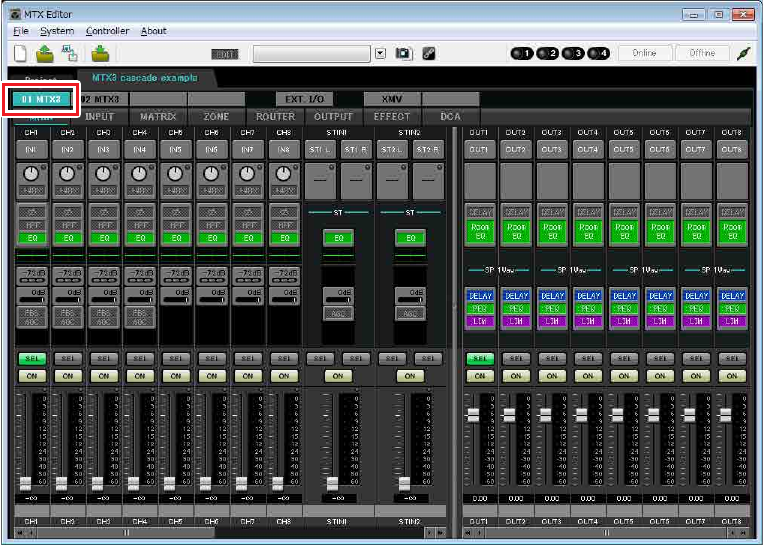
Specifying the MTX configuration
Here you’ll specify how the MTX’s inputs and outputs will be handled.
On the [System] menu, click [MTX Configuration] to open the “MTX Configuration” dialog box.
The default settings are shown in the screen below. You can change them as necessary. In this example, we’ll use the
default settings without change.
Example 3) Using cascade mode to add MTX input channels (analog connection)
MTX Setup Manual 63
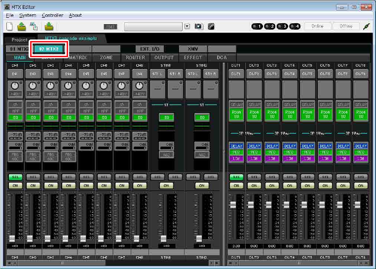
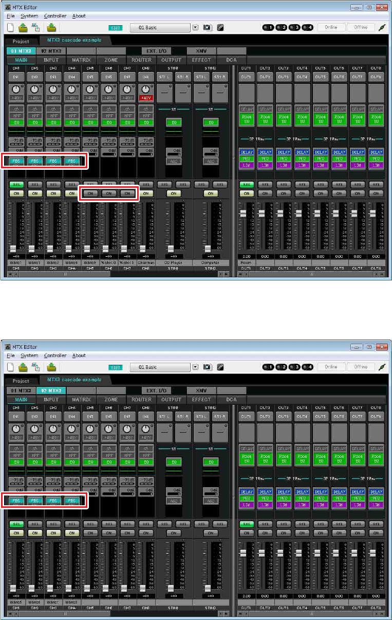
Settings in the “MAIN” screen
In the “MAIN” screen you can make overall settings for each channel.
For details on each parameter, refer to “MTX Editor User’s Manual.”
You’ll make these settings for both MTX units, UNIT ID=01 and UNIT ID=02.
Here you’ll make the following settings.
• Channel name
• Channel on/off
• Gain and phantom power
• (As necessary) EQ settings
-ID=01
Example 3) Using cascade mode to add MTX input channels (analog connection)
MTX Setup Manual 64
-ID=02
Example 3) Using cascade mode to add MTX input channels (analog connection)
MTX Setup Manual 65
-INPUT settings
Port select button
When you click this, the “Input Patch” dialog box will open. In this example we
are using the default settings, but if you want to switch to a different input port of
the MTX, click this button, choose the desired input port, and then click the
[Close] button.
Port/External Device parameter
access button
This button lets you adjust the gain and
turn phantom power on/off. When you
click the button, a popup window will
appear, allowing you to adjust the gain
and turn phantom power on/off. Make the
desired settings, and then in the upper right, click × to close the popup window.
The appropriate gain level will depend on the devices that are connected, so set
the level appropriately for your devices.
For channels 1 through 8, the gain is set to 30 dB by default. Because a con-
denser microphone is connected to CH8 of UNIT ID=01, leave the gain at 30 dB
and turn phantom power on. For the other channels to which wireless micro-
phones are connected, lower the gain to 0 dB.
EQ/HPF (High Pass Filter)
Click this to switch to the “CHANNEL EDIT” screen. Adjust the EQ and HPF
appropriately for the microphone you’re using. For ST IN, only EQ is available.
When you want to return to the “MAIN” screen, click the [MAIN] button.
FBS (Feedback suppressor)
FBS is provided on input channels 1 through 4. We recommend that microphone
inputs, and particularly movable microphones such as wireless microphones, be
connected to channels 1 through 4. When you click here, you will switch to the
FBS setting screen.
When you want to return to the “MAIN” screen, click the [MAIN] button.
For details on FBS settings, refer to “MTX Editor User’s Manual.”
[ON] button
This turns the channel on/off. You should turn off unused channels.
Fader
This adjusts the input level. Leave the fader at -∞ until the system goes online.
Channel name
You can double-click this to edit the name.
In this example, names have been assigned as follows.
The UNIT ID = 01 MTX is the base unit, and the UNIT ID = 02 MTX is for
expanding the number of microphones. Since wireless microphones are suscepti-
ble to feedback because of their mobility, we assign them preferentially to CH1
through CH4, which are equipped with FBS (feedback suppressor).
Port select button
Port/External Device
parameter access
button
EQ/HPF
FBS (Feedback sup-
pressor)
[ON] button
Fader
Channel name
UNIT ID
= 01
CH1 W.Mic1
CH2 W.Mic2
CH3 W.Mic3
CH4 W.Mic4
CH5 W.Mic9
CH6 W.Mic10
CH7 W.Mic11
CH8 Chairman
STIN1 CD Player
STIN2 Computer
STIN3 SD Player
UNIT ID
= 02
CH1 W.Mic5
CH2 W.Mic6
CH3 W.Mic7
CH4 W.Mic8
Example 3) Using cascade mode to add MTX input channels (analog connection)
MTX Setup Manual 66
-OUTPUT settings
Port select button
Click this to open the “Output Patch” dialog box. In this example we will use the
default settings, but if you want to use a different output port of the MTX, click
this button, choose the desired output port, and then click the [Close] button.
Port / External Device parameter access button
When you click this button, a popup window will appear, allowing
you to set the MTX’s output connector parameters and the parameters
of the external device(XMV) associated with the channel. Verify that
GAIN is set to 0.0 dB.
DELAY/Room EQ
Click this to move to a screen where you can set delay and room EQ.
Speaker processor
Click this to move to the “CHANNEL EDIT” screen. Make the appro-
priate settings for the speakers that will be connected.
[ON] button
This button turns the channel on/off. Turn off unused channels.
Fader
This adjusts the output level.
Channel name
You can double-click this to edit the name.
In this example, names have been assigned as follows.
NOTE
The pre-installed library contains speaker processor files that are appropri-
ate for the response of various speakers. By using these files you can
make speaker processor settings easily.
UNIT ID = 01 OUT1 Room
Port select button
Port / External Device
parameter access
button
DELAY/Room EQ
Speaker processor
[ON] button
Fader
Channel name
Example 3) Using cascade mode to add MTX input channels (analog connection)
MTX Setup Manual 67
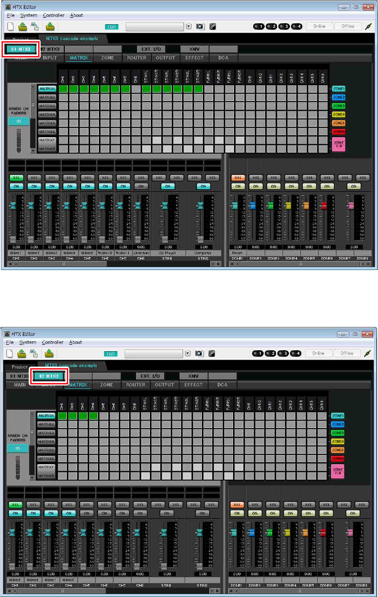
Settings in the “MATRIX” screen
Here you can specify which input channel will be sent to which zone. For details on send level and other parameters,
refer to “MTX Editor User’s Manual.”
-ID=01
-ID=02

Example 3) Using cascade mode to add MTX input channels (analog connection)
MTX Setup Manual 68
In this example, make the settings shown in the above illustration. Clicking a cross point (a square area) or dragging
cross points will switch it on/off. If you right-click on a cross point, a context menu appears. You can select [All OFF]
to turn off all cross points. The cross point shows the send level as the amount of green.
With these settings, all input signals other than the microphone at the chairman’s seat (CH8 of ID=1) are handled in the
same way. To give the microphone at the chairman’s seat higher priority than the other signals, it is assigned to 1st Pri-
ority in the following “ZONE” screen. When CH8 is turned on in MATRIX, the signal from the matrix (attenuated) will
be combined with the signal from Priority, and output together.
For the input channel faders in the lower left of the screen, the grayed-out faders show input levels, and the other faders
show input channel send levels. Grayed-out faders cannot be operated in this screen.
PRIORITY
DUCKER ANC
AMBIENT
SOURCE
From INPUT CHANNEL POST ON 1-16
*1 From YDIF IN 1-16
From ANC BUS 1-2
From STEREO INPUT CHANNEL POST ON 1L-3R
ZONE 1-8
ZONE OUT
To YDIF
OUTPUT
PATCH
MIXMIX
2nd PRIORITY 1st PRIORITY ANC
PRIORITY
SOURCE PRIORITY
SOURCE
From DIRECT INPUT POST ON 9-16
8
PRIORITY
DUCKER
METER
ON
D
C
A
MASTER
LEVEL
GR GR
AMBIENT
METER
To other MTXs
*1 DISTRIBUTION MODE only
Priority signal flow
Example 3) Using cascade mode to add MTX input channels (analog connection)
MTX Setup Manual 69
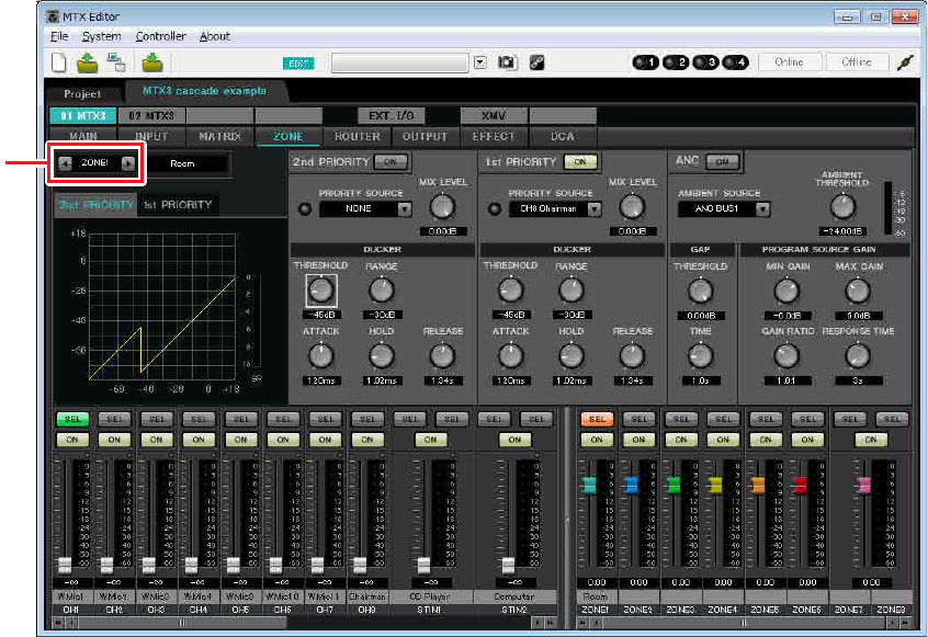
Settings in the “ZONE” screen
In the “ZONE” screen you can make Priority DUCKER settings. The Priority Ducker function temporarily attenuates
the inputs from other channels when audio is input from a specified input channel, ensuring that the audio from the
specified input channel will be broadcast clearly. Priority is given in the order of “1st PRIORITY > 2nd PRIORITY
>Matrix Out signals.”
In this example, the chairman’s microphone (assigned to CH8 of UNIT ID=01) has the highest priority. Thus, we select
CH8 as the PRIORITY SOURCE for 1st PRIORITY in ZONE 1, and click the [ON] button located at the right of 1st
PRIORITY to make it light. Since there is no need to make settings for ZONE2 through 8, make sure that the [ON] but-
tons at the right of 1st PRIORITY and 2nd PRIORITY are unlit (turned off).
Use the ZONE select buttons to switch the zone.
For details on each parameter, refer to “MTX Editor User’s Manual.”
ZONE select
button
Example 3) Using cascade mode to add MTX input channels (analog connection)
MTX Setup Manual 70
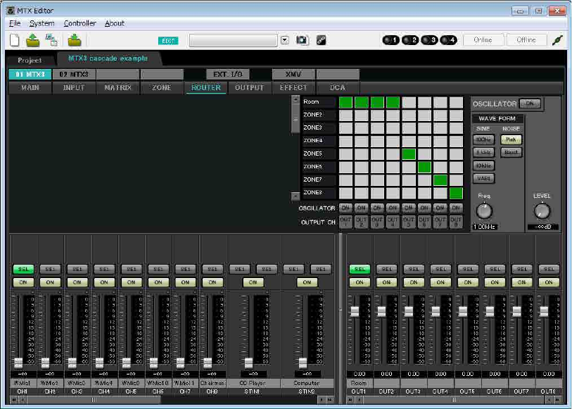
Settings in the “ROUTER” screen
In the “ROUTER” screen you can assign zones to outputs.
In this example, since ZONE1 will be output to OUTPUT1 through 4, set the MTX units of ID=01 and 02 as shown in
the illustration.
Example 3) Using cascade mode to add MTX input channels (analog connection)
MTX Setup Manual 71
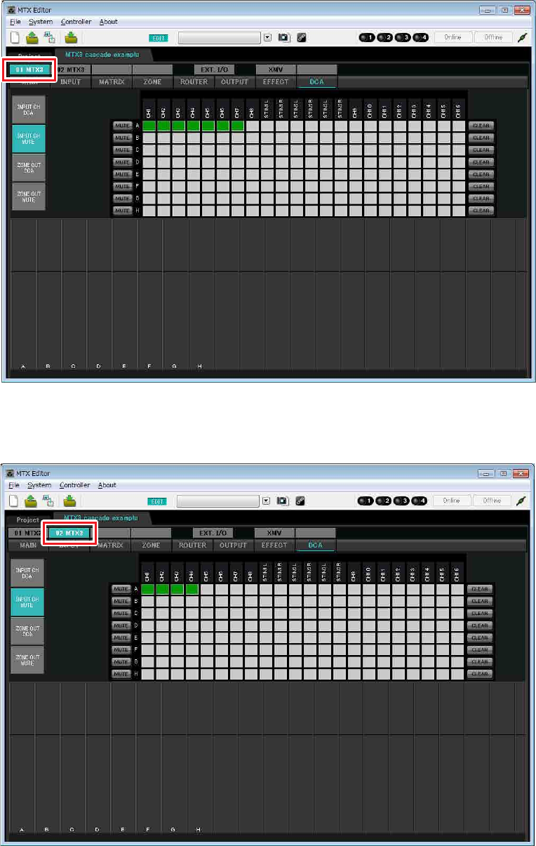
Settings in the “DCA” screen (INPUT CH MUTE)
In the “DCA” screen you can make level and mute settings for multiple channels in a single operation.
-ID=01
-ID=02
In this example, press the [INPUT CH MUTE] button on the digital control panel at the chairman’s seat to mute all
microphones other than the chairman’s microphone. Turn on CH1 through CH7 of ID=01, and CH1 through CH4 of
ID=02.
Example 3) Using cascade mode to add MTX input channels (analog connection)
MTX Setup Manual 72
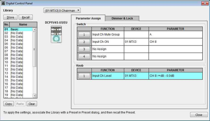
Digital Control Panel (DCP) settings
Here we’ll assign functions to the DCP that is located at the chairman’s seat.
To make these settings, choose the [Controller] menu item [Digital Control Panel].
When you click one of the numbered buttons, a “Settings” dialog box will appear; assign parameters to the controls.
When you’ve made the assignments, click to select “01 [No data]” and then click the [Store] button. In the “Store
Library” dialog box, change the name to “Basic” and then click the [OK] button.
Assign the parameters. If you assigned [SD Song Select & Play], enter the name of the file that you want to play or the
name of the folder that contains the file you want to play.
Switch 1 turns mute on/off for the microphone inputs other than the chairman’s seat. Switch 2 turns the chairman’s
microphone on/off. The knob adjusts the input level of the chairman’s microphone.
Example 3) Using cascade mode to add MTX input channels (analog connection)
MTX Setup Manual 73
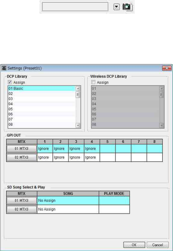
Storing a preset
Now we’ll store the settings we’ve made up to this point as a preset.
By recalling presets from the MTX itself or from the DCP, you can switch the settings as appropriate for various situa-
tions.
To store or recall a preset, click the camera icon in the upper part of MTX Editor.
When you click the camera icon, the “Preset” dialog box will appear. You can create up to 50 presets.
Click the preset number that you want to store; the line will be selected. Then click the [Store] button, specify the preset
name, and click the [OK] button.
Click a location where the DCP column indicates “No Assign,” and choose a library that you specified on the DCP.

Example 3) Using cascade mode to add MTX input channels (analog connection)
MTX Setup Manual 74
Up to this point, our settings use all of the microphones connected to MTX units of UNIT ID =01 and 02, but there
might be cases in which you want to use a different number of microphones. In such cases, you can limit the number of
microphones by turning off the channels of unused microphones in the “MAIN” screen.
NOTE
If you don’t store the preset, alert number 61 will occur.
Example 3) Using cascade mode to add MTX input channels (analog connection)
MTX Setup Manual 75
-ID=01
-ID=02
If you store these settings as a different preset, you’ll be able to easily switch to settings with a limited number of
microphones. In the example above, wireless microphones 9 through 11 are not used, so FBS is used on all of the wire-
less microphones (1 through 8) that are being used.
This completes settings in the offline state. Save the settings once again.
Example 3) Using cascade mode to add MTX input channels (analog connection)
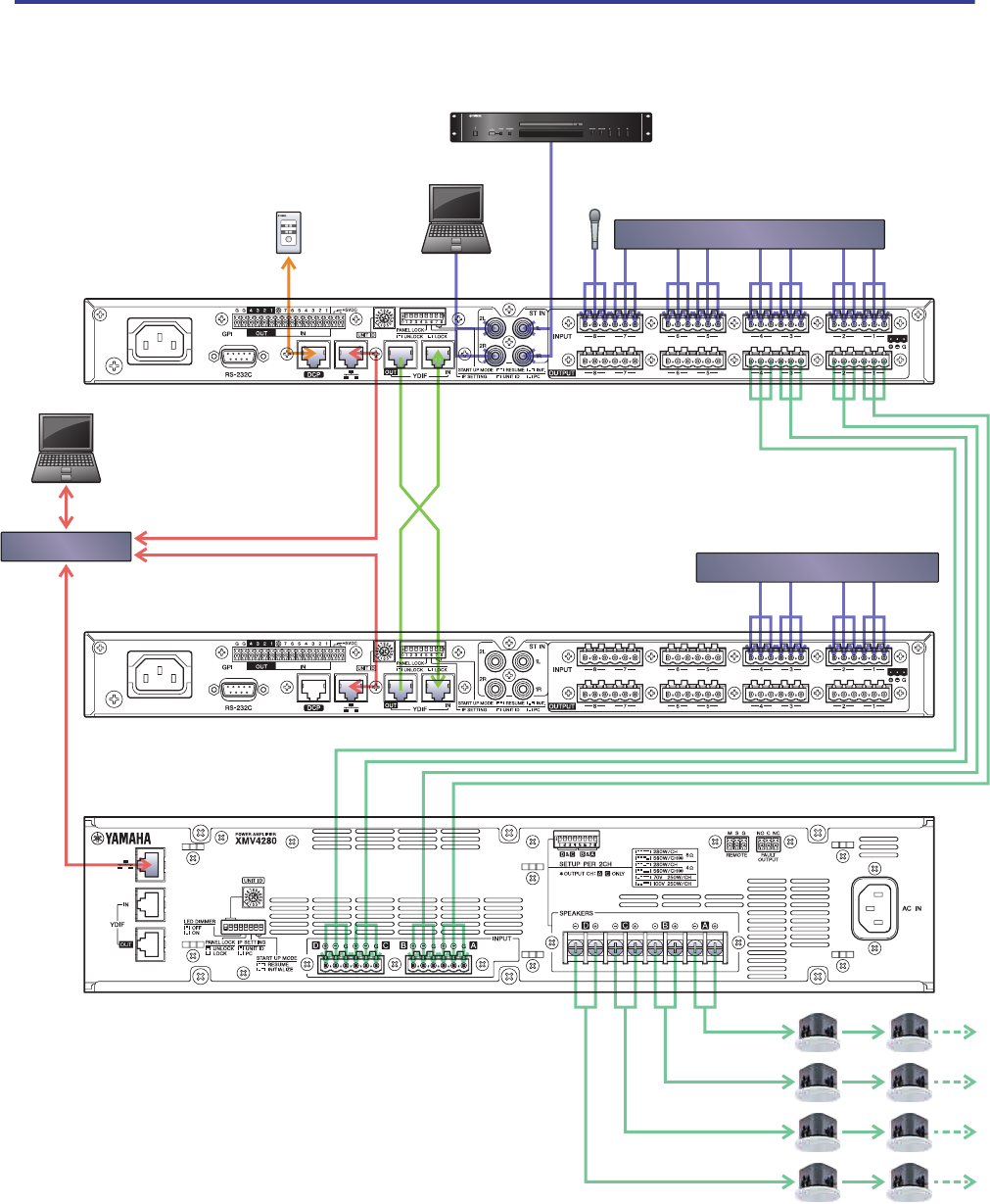
MTX Setup Manual 76
Connecting the equipment
After you’ve rack-mounted the MTX and your other equipment, connect the MTX and the other equipment as shown
below. If you’ve copied audio sources to an SD memory card, insert the card into the MTX now.
To connect the MTX to your computer, use a CAT5e or higher cable with all eight pins connected.
1 2 3 4 5 6 7 8
ON
ON
Wireless Microphone Receivers
Wireless Microphone Receivers
CD Player
DCP
ID=0
Chairman
Microphone
Network Switch
Computer
Computer
MTX
ID=01
MTX
ID=02
XMV
ID=1A

Example 3) Using cascade mode to add MTX input channels (analog connection)
MTX Setup Manual 77
Powering-on the MTX
Turn on the power of the MTX.
Turn off the amplifier before you power-off the MTX.
Powering-on the amp
On the rear panel of the XMV, set the [SPEAKERS] DIP switch, and then turn on the power of the amps (XMV).
To prevent unwanted sound from being output, we recommend that you turn down the attenuator settings of all channels on
the amp itself before you turn it on.
To change the XMV attenuator setting, press the button of the appropriate channel and then turn the encoder.
Specifying the computer’s TCP/IP address
To allow the MTX and the computer to communicate, specify the computer’s TCP/IP as follows.
1. On the [System] menu, click [Network Setup].
The “Network Setup” dialog box will appear.
2. Click [Open Network Connection].
“Network Connections” will appear.
3. Right-click the adapter to which the MTX is connected, and choose [Properties].
The “Local Area Connection Properties” dialog box will appear.
4. Choose [Internet Protocol Version 4 (TCP/IPv4)], and then click [Properties].
The “Internet Protocol Version 4 (TCP/IPv4) Properties” dialog box will appear.
5. Click [Use the following IP address (S)].
NOTE
• With the factory settings, the XMV’s attenuators are set to the lowest value.
• For more about the [SPEAKERS] DIP switch, refer to the XMV owner’s manual.
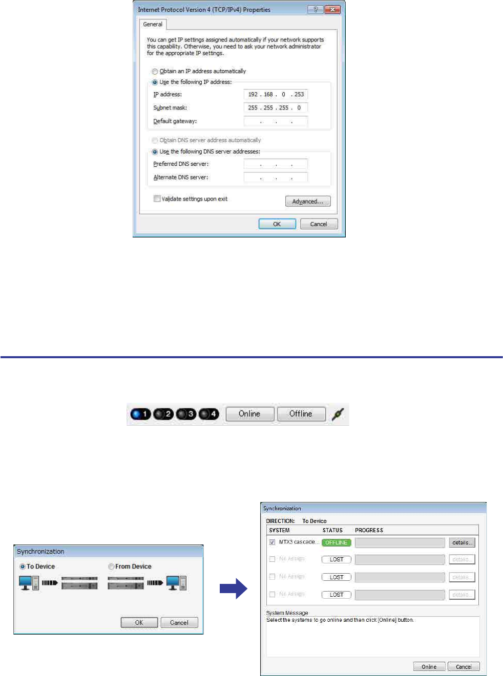
Example 3) Using cascade mode to add MTX input channels (analog connection)
MTX Setup Manual 78
6. In the [IP address] box, enter “192.168.0.253”; in the [Subnet mask] box, enter
“255.255.255.0.”
7. Click [OK].
Taking MTX Editor online
In the upper right of MTX Editor, click the [Online] button. When the unit has successfully come online, the indicator 1 at
the left will light blue.
When the “Synchronization” dialog box appears, select “To Device,” and click the [OK] button. When the indication in the
dialog box has switched, select the system that you want to place online, and click the [Online] button.
The project created in MTX Editor will be sent to the MTX.
NOTE
The MTX3’s IP address is set to “192.168.0.1” and “192.168.0.2,” and the XMV’s IP address is set to “192.168.0.26.”
NOTE
In some cases, Windows firewall may block MTX Editor when you make this setting. Select the [Private Network] check box, and
click [Allow Access].

Example 3) Using cascade mode to add MTX input channels (analog connection)
MTX Setup Manual 79
Making XMV settings
If necessary, use the XMV’s front panel to make settings such as the high pass filter. For more about the settings you can
make on the XMV, refer to the XMV owner’s manual.
Verifying that the settings were applied
The main items to verify are listed below. For details on each parameter setting, refer to “MTX Editor User’s Manual.”
1. Recall the Basic preset.
2. Using the oscillator in the “ROUTER” screen, adjust the output level.
Adjust the amp’s attenuator value to an appropriate level.
3. Specify the gain from the microphone.
You can set the gain in the dialog box that appears when you press the parameter recall button for a port or external
device of an input channel in the “MAIN” screen. Watch the input meter, and adjust the setting appropriately.
4. Set the input levels and output levels.
Using the input/output faders in the “MAIN” screen, adjust the levels. As necessary, apply the output limiter in the
“CHANNEL EDIT” screen to prevent your speakers from being damaged.
Adjust the amp attenuator values to obtain the optimal S/N ratio.
In addition, make FBS settings as necessary.
5. Store the Basic preset.
Store by overwriting the previously-specified content.
6. Check the DCP settings.
Verify that the DCP operates as you expect.
When you have finished making all settings, save the project and switch MTX Editor offline.
This completes the settings for example 3.
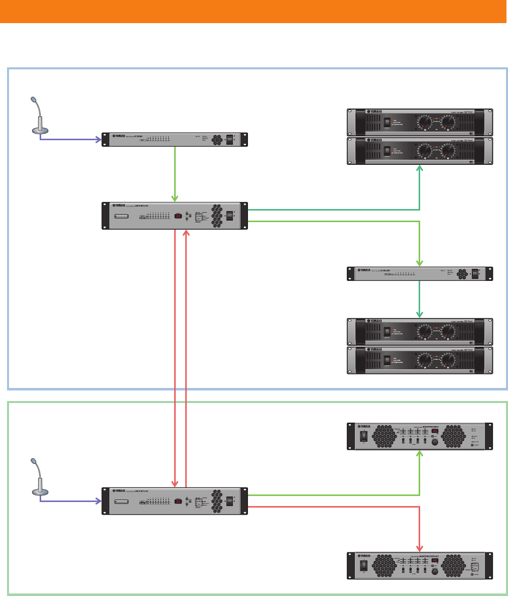
MTX Setup Manual 80
This example assumes an audio signal flow like the one shown below.
Example 4) A system using Dante
System A
System B
EXi8
MTX5-D
MTX5-D
Power Amp
Power Amp
XMV4280
XMV4280-D
EXo8
Main
Microphone
CH1
OUTPUT 1 (YDIF)
INPUT 1 (YDIF)
OUTPUT 1–4 (Analog)
OUTPUT 5–8 (YDIF)
INPUT 9/10 (Dante) :
Channel 9 is the main
microphone for System B.
OUTPUT 9/10 (Dante) :
Channel 9 is the main
microphone for System A.
INPUT 1–4 (YDIF)
CH1–4 (Analog)
OUTPUT 9/10 (Dante)INPUT 9/10 (Dante)
Main
Microphone
OUTPUT 1–4 (YDIF)
OUTPUT 5–8 (Dante)
CHANNEL A–D
(YDIF)
CHANNEL A–D
(Dante)
INPUT 1
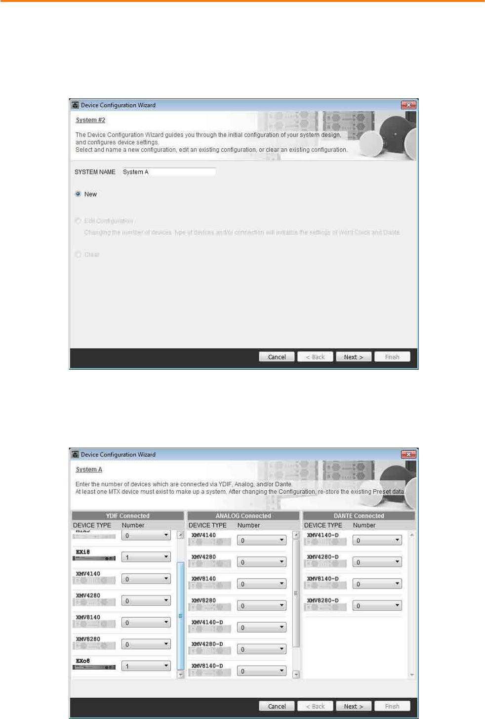
Example 4) A system using Dante
MTX Setup Manual 81
Using the Device Configuration Wizard to create your device setup
You will use MTX Editor’s wizard to create your device setup before actually connecting your equipment.
After you’ve made basic settings, you’ll be able to print information about system cabling and ID numbers.
Make basic settings for System A, and then make basic settings for System B.
Use the following procedure to make basic settings.
1. Enter a name for the MTX system that we are calling System A, and then click [NEXT>].
2. Specify the number of units that will be connected in your MTX system, and click [Next>].
In “YDIF Connected,” specify 1 each as the number of MTX5-D, EXi8, and EXo8 devices.
To make settings for the EXo8, use the scroll bar to make the EXo8 visible.
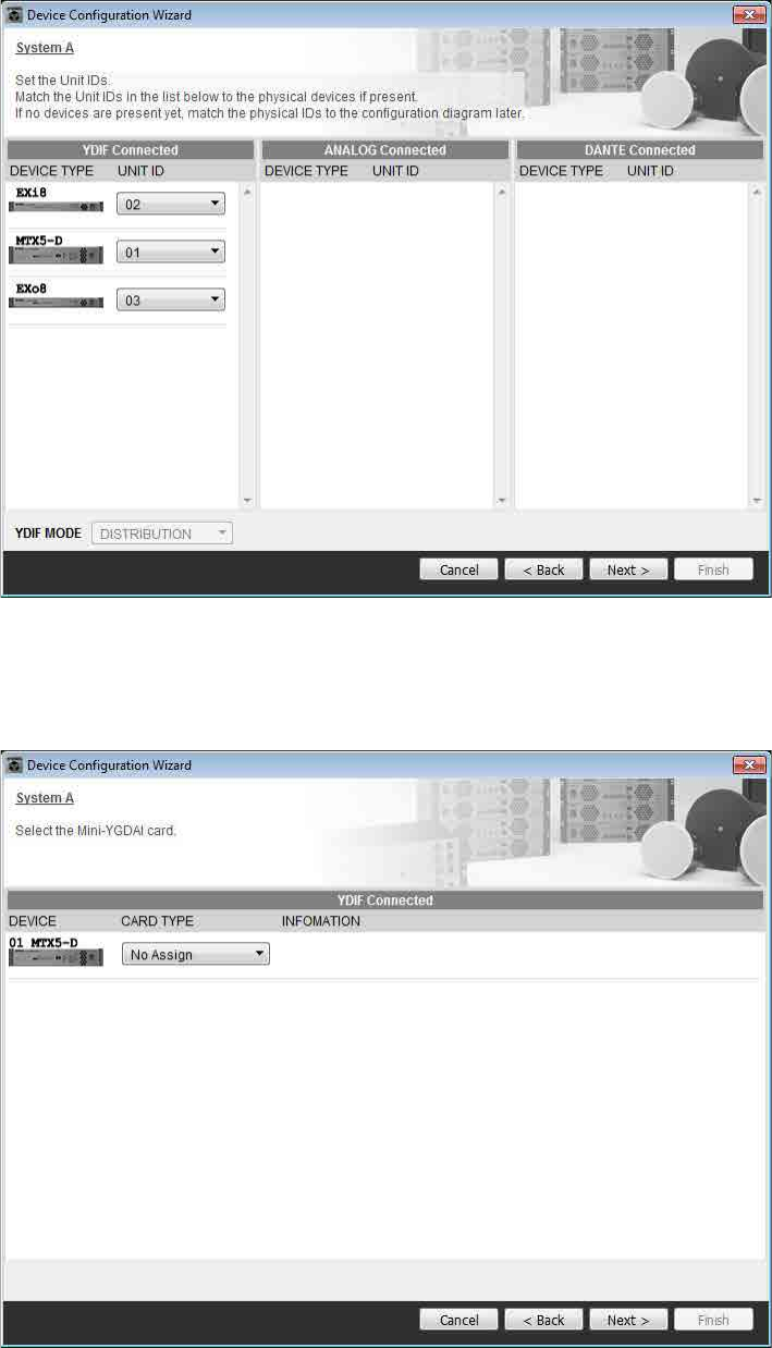
Example 4) A system using Dante
MTX Setup Manual 82
3. Specify the UNIT ID of each device, and click [Next>].
Unless you have specific reasons for doing so, use the UNIT ID that is assigned.
4. Select the Mini-YGDAI card, and click [NEXT>].
In this example we are not using a Mini-YGDAI card, so leave the setting at [No Assign] and click [Next>].
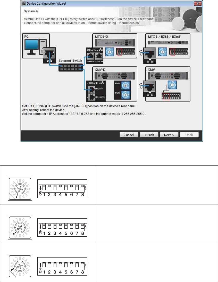
Example 4) A system using Dante
MTX Setup Manual 83
5. Set the [UNIT ID] rotary switch and DIP switch of the devices.
You will set the computer’s IP address after completing the wizard, in “Specifying the computer’s TCP/IP address.”
If the devices are not nearby, you can set them during the step “Connecting the equipment.”
Make the following settings.
6. When you have finished setting the [UNIT ID] rotary switch and DIP switch of the devices,
click [Next>].
MTX5-D
UNIT ID = 01
[UNIT ID] rotary switch = 1
DIP switches are all OFF (upward)
EXi8
UNIT ID = 02
[UNIT ID] rotary switch = 2
DIP switches are all OFF (upward)
EXo8
UNIT ID = 03
[UNIT ID] rotary switch = 3
DIP switches are all OFF (upward)
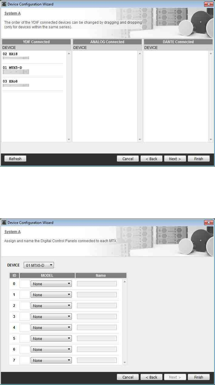
Example 4) A system using Dante
MTX Setup Manual 84
7. Verify that the devices are shown in the screen, and click [Next>].
8. Choose the model of DCP that is connected to the MTX, enter a device name, and click
[Finish].
In this example we are not using a DCP, so leave the settings as they are.
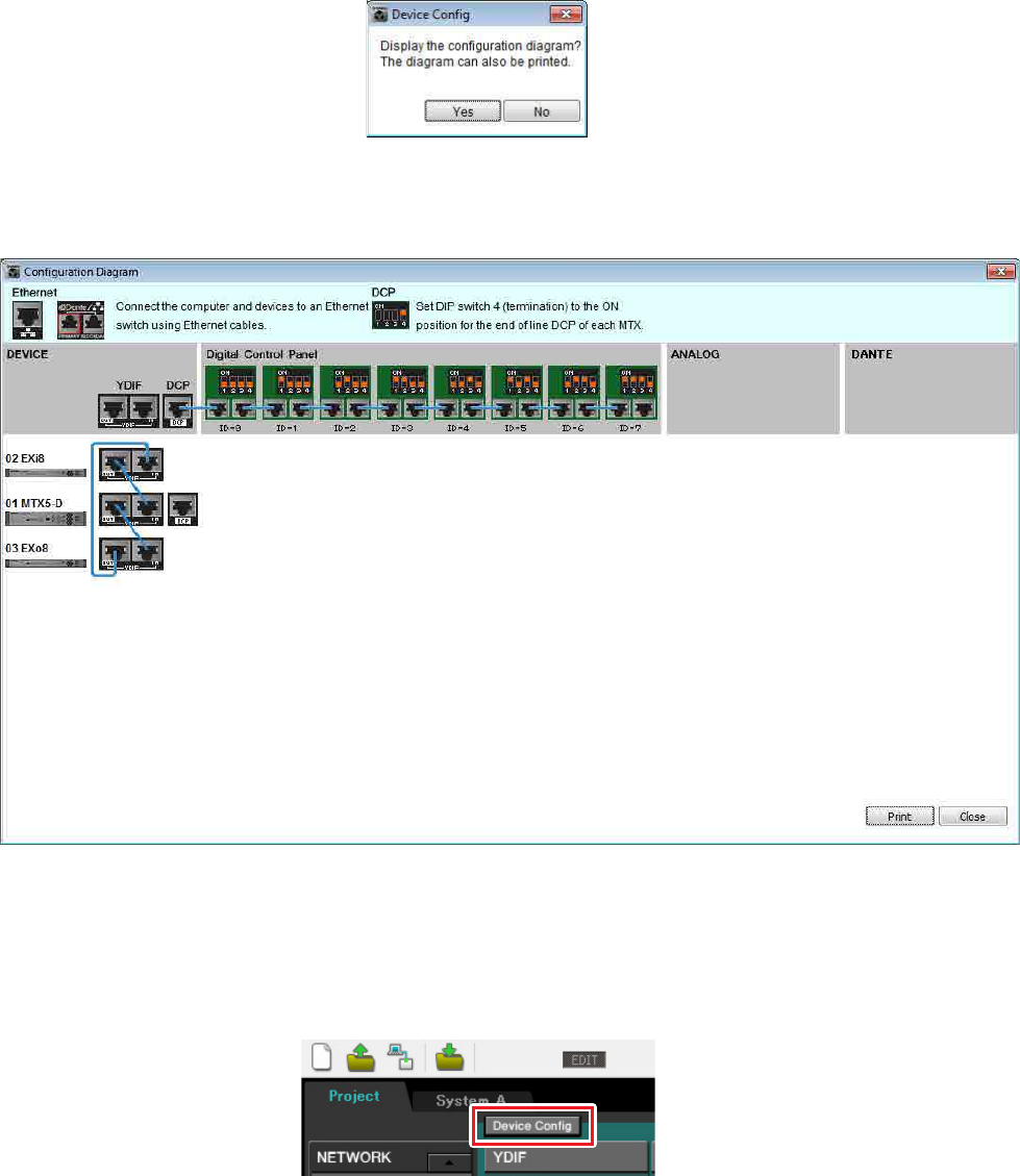
Example 4) A system using Dante
MTX Setup Manual 85
9. When you see the dialog box “Display the configuration diagram? The diagram can also
be printed.” click [Yes].
A cabling diagram will appear. If you want, click [Print] to print the diagram.
To close the screen, click [Close].
If you want to use the Device Configuration Wizard to change the device configuration, click the [Device Config] but-
ton in the Project screen.
NOTE
If you want to view the cabling diagram again, do so by choosing [File] menu [Print Configuration Diagram].
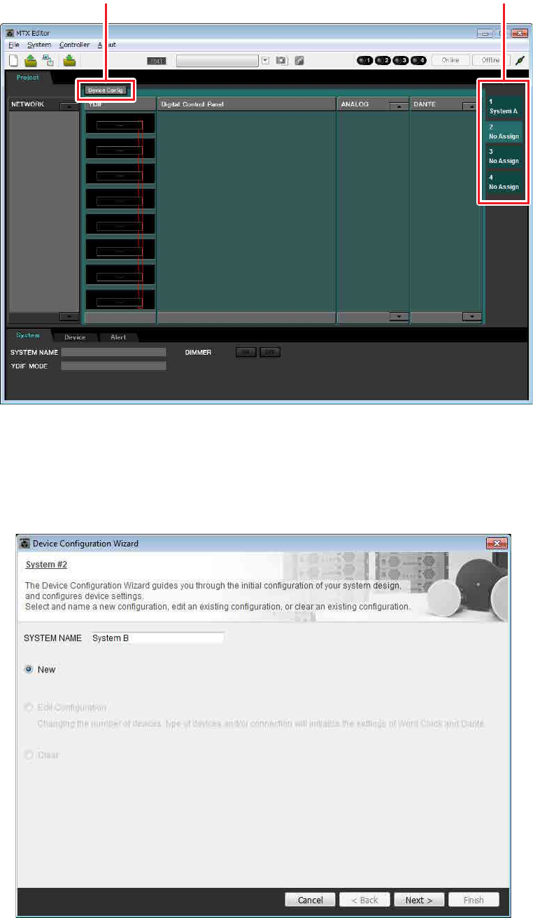
Example 4) A system using Dante
MTX Setup Manual 86
10. In order to make basic settings for System B, click the system select tab [2 No Assign].
11. Click [Device Config].
The Device Configuration Wizard for System B will appear.
12. Enter a name for the MTX system that we are calling System B, and then click [NEXT>].
Step 11 System select tabs
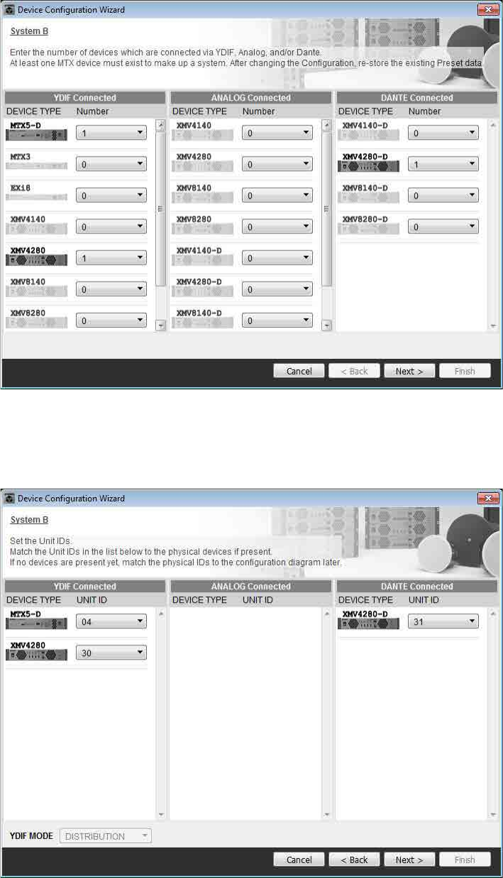
Example 4) A system using Dante
MTX Setup Manual 87
13. Specify the number of units that will be connected in your MTX system, and click [Next>].
In the “YDIF Connected” area, specify 1 each as the number of MTX5-D and XMV4280 units; in the “Dante Con-
nected” area, specify 1 as the number of XMV4280-D devices.
14. Specify the UNIT ID of each device, and click [Next>].
Unless you have specific reasons for doing so, use the UNIT ID that is assigned.
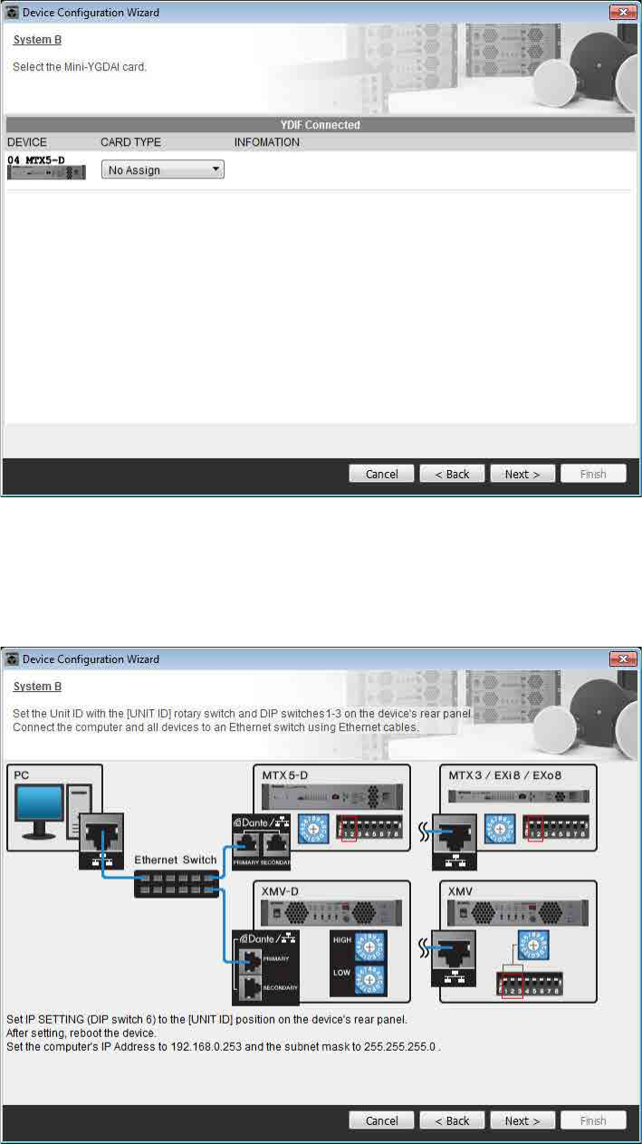
Example 4) A system using Dante
MTX Setup Manual 88
15. Select the Mini-YGDAI card, and click [NEXT>].
In this example we are not using a Mini-YGDAI card, so leave the setting at [No Assign] and click [Next>].
16. Set the [UNIT ID] rotary switch and DIP switch of the devices.
You will set the computer’s IP address after completing the wizard, in “Specifying the computer’s TCP/IP address.”
If the devices are not nearby, you can set them during the step “Connecting the equipment.”
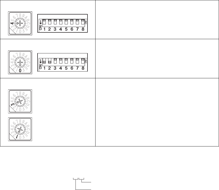
Example 4) A system using Dante
MTX Setup Manual 89
Make the following settings.
17. When you have finished setting the [UNIT ID] rotary switch and DIP switch of the devices,
click [Next>].
MTX5-D
UNIT ID = 04
[UNIT ID] rotary switch = 4
DIP switches are all OFF (upward)
XMV4280
UNIT ID = 30
[UNIT ID] rotary switch = 0
DIP switch 1 and 2 are ON (downward), others are OFF
(upward)
XMV4280-D
UNIT ID = 31
[UNIT ID] rotary switch [HIGH] = 3
[UNIT ID] rotary switch [LOW] = 1
NOTE
On the XMV4280, the higher digit of the UNIT ID is set by the DIP switch, and the lower digit is set by the [UNIT ID] rotary switch.
For details, refer to the owner’s manual of each device.
[HIGH]
[LOW]
UNIT ID = 3 0
Lower digit: specify using the rotary switch
Upper digit: specify using DIP switch 1–3
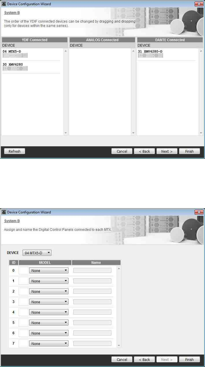
Example 4) A system using Dante
MTX Setup Manual 90
18. Verify that the devices are shown in the screen, and click [Next>].
19. Choose the model of DCP that is connected to the MTX, enter a device name, and click
[Finish].
In this example we are not using a DCP, so leave the settings as they are.
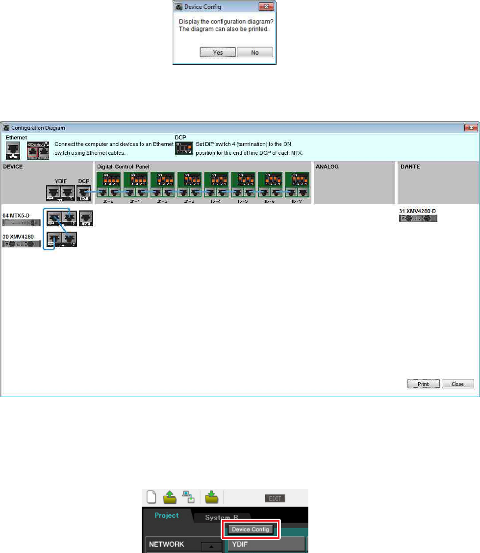
Example 4) A system using Dante
MTX Setup Manual 91
20. When you see the dialog box “Display the configuration diagram? The diagram can also
be printed.” click [Yes].
A cabling diagram will appear. If you want, click [Print] to print the diagram.
To close the screen, click [Close].
If you want to use the Device Configuration Wizard to change the device configuration, click the [Device Config] but-
ton in the Project screen.
NOTE
If you want to view the cabling diagram again, do so by choosing [File] menu [Print Configuration Diagram].
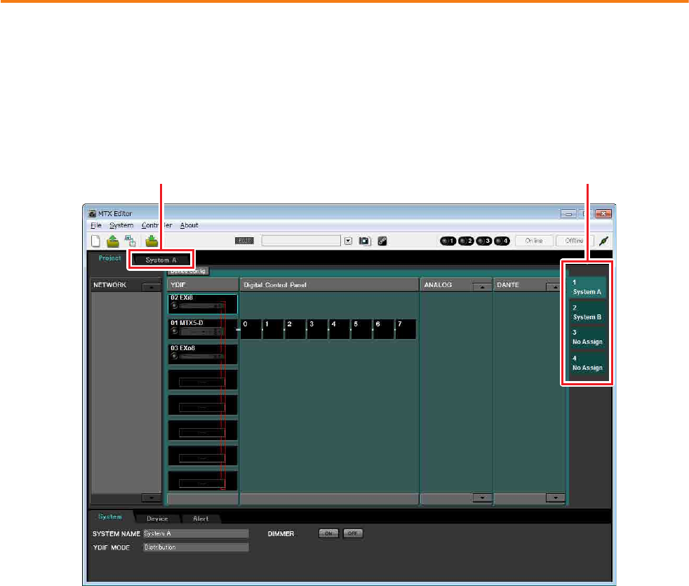
Example 4) A system using Dante
MTX Setup Manual 92
Making preliminary settings in MTX Editor
Here’s how to make detailed MTX system settings in MTX Editor.
When you’ve finished making settings, you should save them by clicking [File] menu, then [Save].
To switch between System A and System B, use the system select tabs in the “Project” screen.
The currently selected MTX system is indicated by the system select tabs and the SYSTEM tab.
NOTE
The “User Account Control” dialog box may appear. Click [Continue] or [Yes].
SYSTEM tab System select tabs
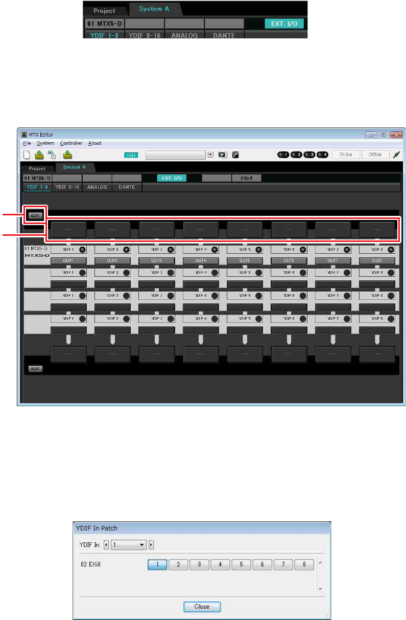
Example 4) A system using Dante
MTX Setup Manual 93
We’ll start by making settings for System A.
Making EXT. I/O settings
Make settings for inputting and outputting digital audio. First we will make YDIF settings for System A. Click the
SYSTEM tab to access the setting screen.
1. Click the [EXT. I/O] button.
The “EXT. I/O” screen will appear, allowing you to make input/output settings for the external devices. Since
you’ll be making settings for YDIF 1–8, there’s no need to switch screens; simply make the settings in this screen.
2. In the upper left, click the [EDIT] button.
Now you can specify the outputs from the EXi8 to YDIF 1–8.
3. Click the input routing select button located above YDIF 1.
The “YDIF In Patch” dialog box will appear.
[EDIT] button
Input routing
select buttons
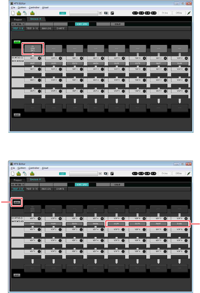
Example 4) A system using Dante
MTX Setup Manual 94
4. For CHANNEL, click [1] and then click [Close] button.
The YDIF 1 input routing select button shows that CH1 of the EXi8 whose UNIT ID = 02 has been assigned to
YDIF 1.
5. In the upper left, click [EDIT] to lock the settings.
[EDIT] button
Step 6
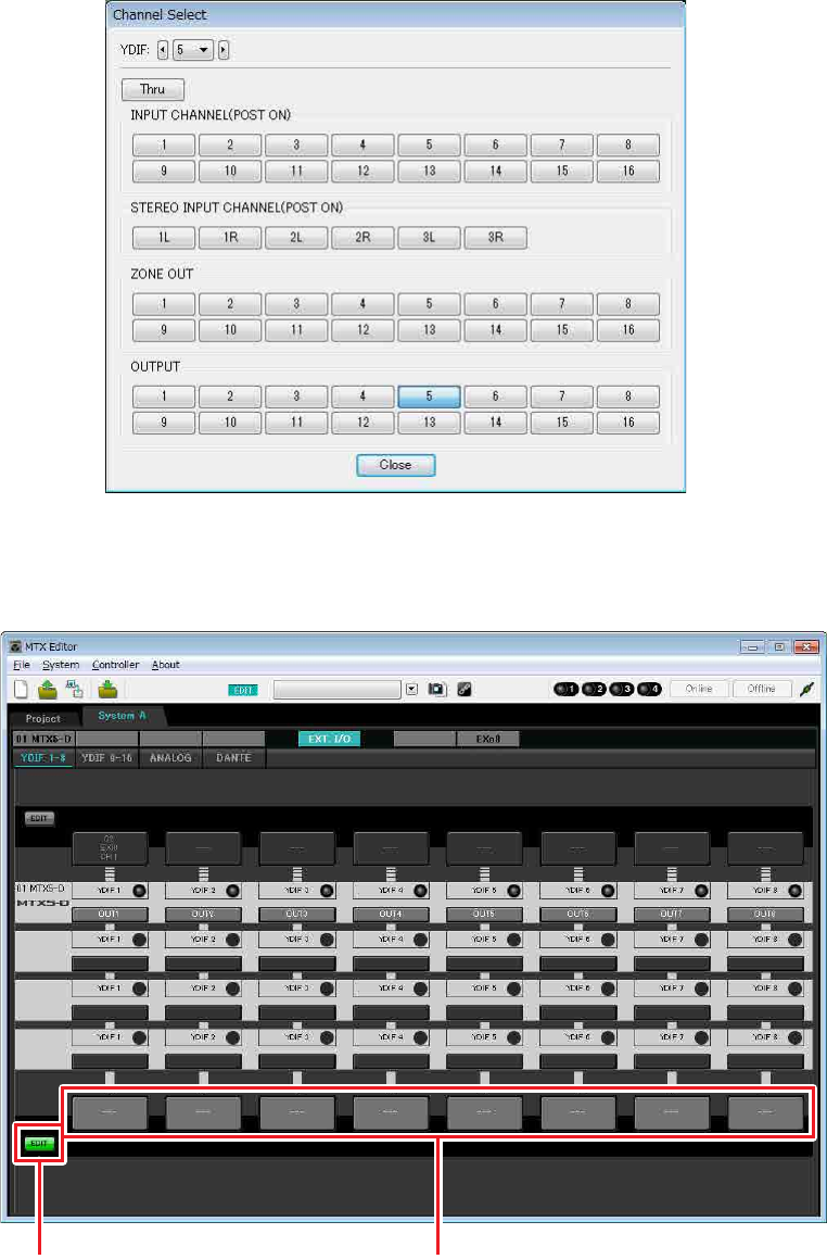
Example 4) A system using Dante
MTX Setup Manual 95
6. Verify that for the MTX5-D with UNIT ID = 01, the buttons located below YDIF 5 through
YDIF 8 are set to OUT5 (OUTPUT 5) through OUT 8 (OUTPUT 8) respectively.
If the settings are different, click the button and change the setting.
7. In the lower left, click the [EDIT] button.
Now you can specify the outputs from the MTX to YDIF 1–8.
[EDIT] button Output routing select buttons
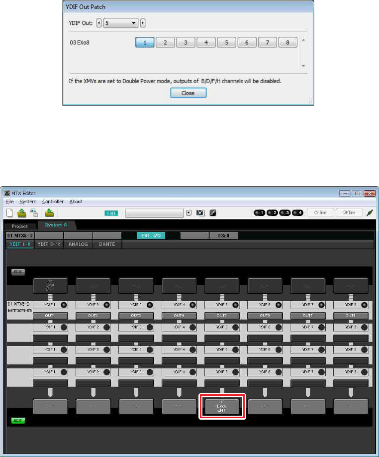
Example 4) A system using Dante
MTX Setup Manual 96
8. Click the output routing select button located below YDIF 5.
The “YDIF Out Patch” dialog box will appear.
9. For CHANNEL, click [1] button.
The YDIF 5 output routing select button shows that the YDIF 5 output has been assigned to CH 1 of the UNIT
ID=03 EXo8.
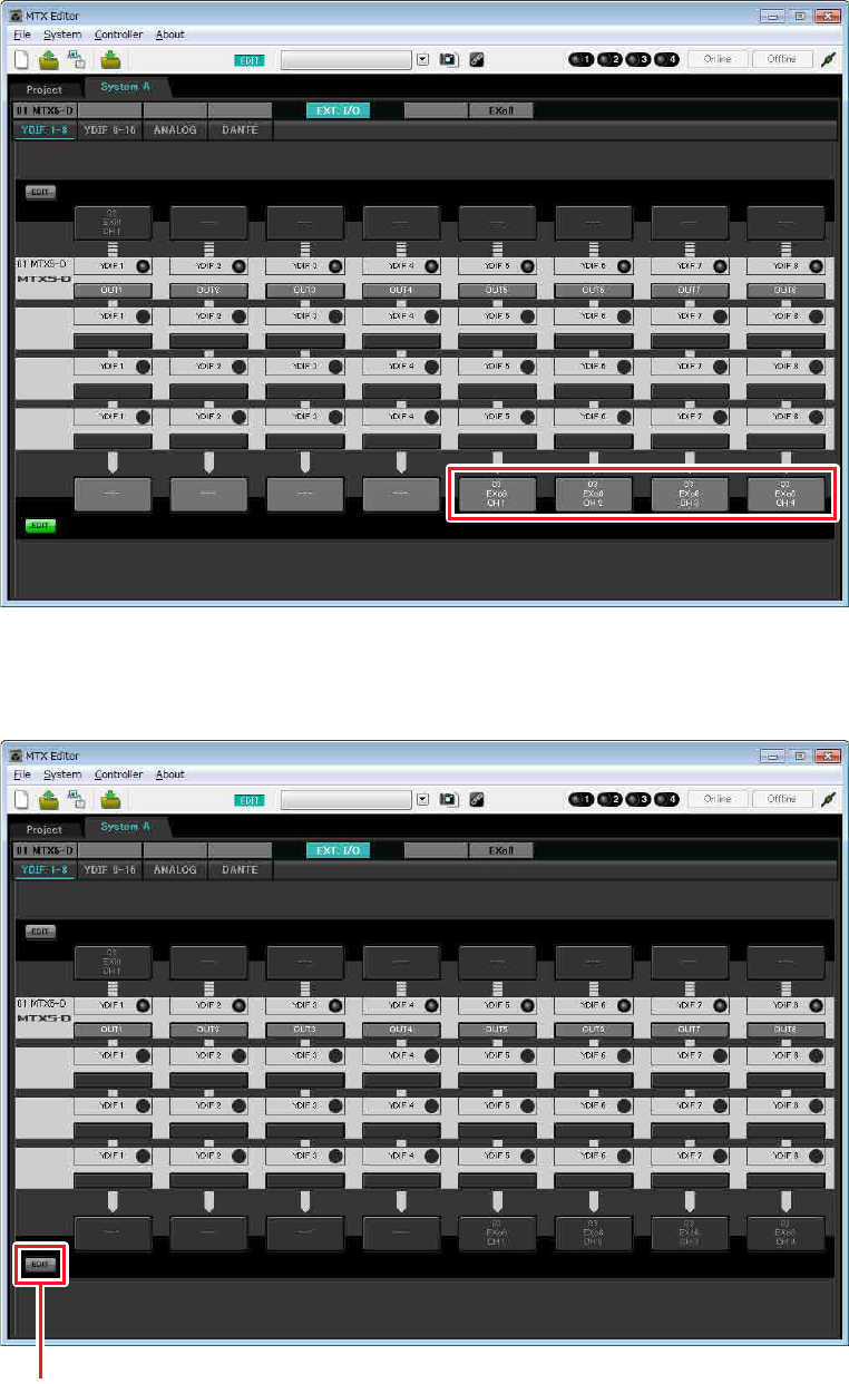
Example 4) A system using Dante
MTX Setup Manual 97
10. Change the output destination in the [YDIF Out:] list box, to assign YDIF 6 through YDIF
8 to CH 2 through CH 4 of the EXo8, and then click “Close” button.
11. In the lower left, click [EDIT] button to lock the settings.
[EDIT] button
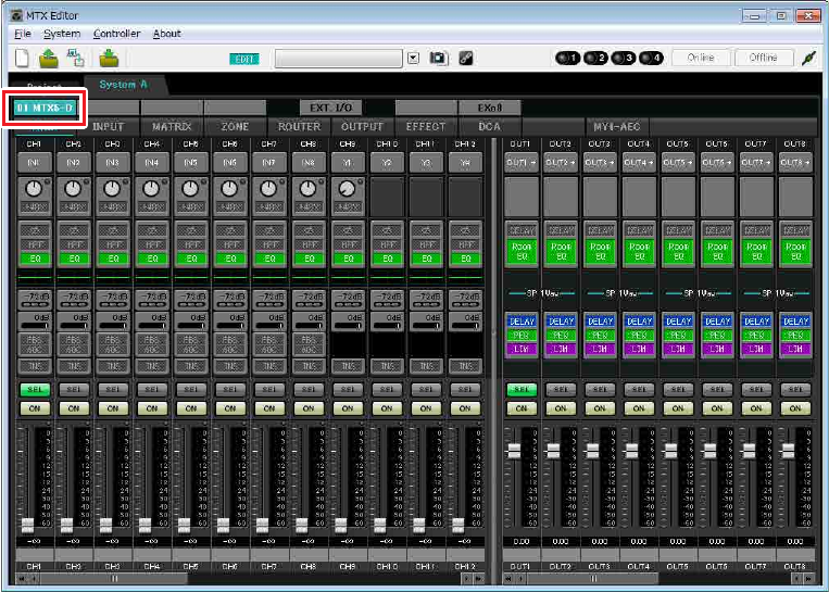
Example 4) A system using Dante
MTX Setup Manual 98
Settings in the “MAIN” screen
In the “MAIN” screen you can make overall settings for each channel.
Click the [01 MTX5-D] button to access the MTX “MAIN” screen.
For details on each parameter, refer to “MTX Editor User’s Manual.”
Here you’ll make the following settings.
• Channel name
• Channel on/off
• Gain and phantom power
• (As necessary) EQ settings
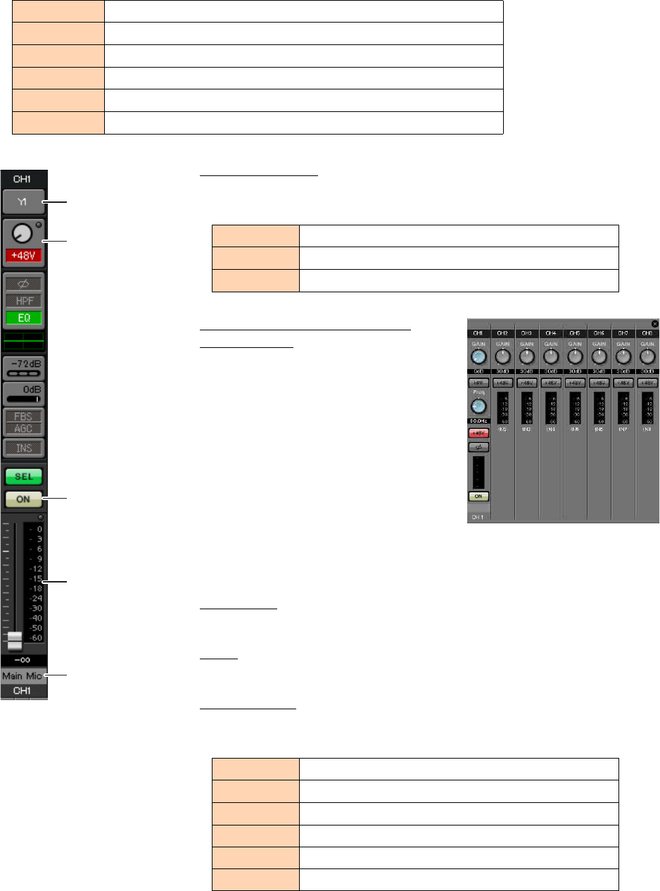
Example 4) A system using Dante
MTX Setup Manual 99
-INPUT settings
Make the following input settings.
Port select button
When you click this, the “Input Patch” dialog box will open. This example
makes the following changes to the default settings.
Port/External Device parameter
access button
This lets you make input connector settings
for the MTX and EXi8. When you click the
button, a popup window will appear. Make
the desired settings, and then in the upper
right, click × to close the popup window.
The appropriate gain level will depend on
the devices that are connected, so set the
level appropriately for your devices.
For CH1, make settings for input connector
1 of the EXi8. The gain of the EXi8 is set to
-6 dB by default.
Because condenser microphone is connected to CH1, leave the gain at 30 dB and
turn phantom power on.
[ON] button
This turns the channel on/off. You should turn off unused channels.
Fader
This adjusts the input level. Leave the fader at -∞ until the system goes online.
Channel name
You can double-click this to edit the name.
In this example, names have been assigned as follows.
CH1 Signal from the main mic of System A, connected to the EXi8
CH9Signal from the main mic of System B
CH10 System B signal other than the main mic
STIN1 L/R Signal from the CD player connected to ST IN1
STIN2 L/R Signal from the background music player connected to ST IN2
STIN3 L/R SD player built into the MTX5-D
CH1 YDIF [1] (System A main mic connected to the EXi8)
CH9DANTE [9] (Signal from the system B main mic)
CH10 DANTE [10] (System B signal other than the main mic)
CH1 Main Mic
CH9Sys B9
CH10 Sys B10
STIN1 CD Player
STIN2 BGM
STIN3 SD Player
Port select button
Port/External Device
parameter access
button
[ON] button
Fader
Channel name
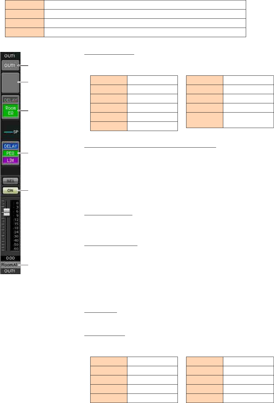
Example 4) A system using Dante
MTX Setup Manual 100
-OUTPUT settings
Make the following output settings.
Port select button
Click this to open the “Output Patch” dialog box. This example makes the fol-
lowing changes to the default settings.
Port / External Device parameter access button
When you click this button, a popup window will appear.
For OUT1 through OUT4, make settings for MTX output connectors 1 through
4.
For OUT5 through OUT8, make settings for EXo8 output connectors 1 through
4.
For OUT9 and OUT10, make settings for output to the Dante network.
Verify that each GAIN is set to 0.0 dB.
DELAY/Room EQ
Click this to move to a screen where you can set delay and room EQ.
Since OUT9 and OUT10 are for transmission to System B, do not make settings.
Speaker processor
Click this to move to the “CHANNEL EDIT” screen. Make the appropriate set-
tings for the speakers that will be connected.
Since OUT9 and OUT10 are for transmission to System B, do not make settings.
[ON] button
This button turns the channel on/off. Turn off unused channels.
Channel name
You can double-click this to edit the name.
In this example, names have been assigned as follows.
CH1–4 Output to the amps in Amp Room A using the analog outputs of the MTX5-D
CH5–8 Output to the amps of Amp Room B using CH1–4 of the EXo8 connected via YDIF
CH9 Output the signal of the main mic connected to the EXi8 to System B via Dante[9]
CH10 Output a signal other than the main mic to System B via Dante [10]
NOTE
The pre-installed library contains speaker processor files that are appropriate for the
response of various speakers. By using these files you can make speaker processor set-
tings easily.
Port select button
Port / External Device
parameter access
button
DELAY/Room EQ
Speaker processor
[ON] button
Channel name
OUT1 OUTPUT [1]
OUT2 OUTPUT [2]
OUT3 OUTPUT [3]
OUT4 OUTPUT [4]
OUT5 YDIF [5]
OUT6 YDIF [6]
OUT7 YDIF [7]
OUT8 YDIF [8]
OUT9 DANTE [9]
OUT10 DANTE [10]
OUT11–
OUT16 No setting
OUT1 RoomA1
OUT2 RoomA2
OUT3 RoomA3
OUT4 RoomA4
OUT5 RoomB1
OUT6 RoomB2
OUT7 RoomB3
OUT8 RoomB4
OUT9 Sys B9
OUT10 Sys B10
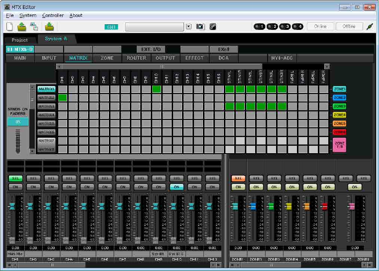
Example 4) A system using Dante
MTX Setup Manual 101
Settings in the “MATRIX” screen
Here you can specify which input channel will be sent to which zone. For details on send level and other parameters,
refer to “MTX Editor User’s Manual.”
When making settings for System A, “this MTX system” refers to System A, and “the other MTX system” refers to
System B.
When making settings for System B, “this MTX system” refers to System B, and “the other MTX system” refers to
System A.
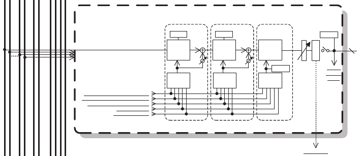
Example 4) A system using Dante
MTX Setup Manual 102
In this example, make the settings shown in the illustration in before page. Clicking a cross point (a square area) or
dragging cross points will switch it on/off. If you right-click on a cross point, a context menu appears. You can select
[All OFF] to turn off all cross points. The cross point shows the send level as the amount of green.
For each zone, this setting will be as follows.
Zone 1: Input channel 1, CD/BGM/SD (SDIN1–3), and the audio from the other MTX system are broadcast to this
entire MTX system. Since the mic (CH1) of this MTX system and the mic (CH9) of the other MTX sys-
tem are assigned for emergency announcements etc. for the entire building, specify their Priority in the
“ZONE” screen that follows.
When you turn CH1 and CH9 on in the matrix, the (attenuated) signal from the matrix will be combined
with the signal from Priority, and output.
Zone 2: This is for broadcasting the voice from the main mic (CH1) to the other MTX system.
Zone 3: This is for broadcasting signals other than the main mic to the other MTX system.
For the input channel faders in the lower left of the screen, the grayed-out faders show input levels, and the other faders
show input channel send levels. Grayed-out faders cannot be operated in this screen.
PRIORITY
DUCKER ANC
AMBIENT
SOURCE
From INPUT CHANNEL POST ON 1-16
*1 From YDIF IN 1-16
From ANC BUS 1-2
From STEREO INPUT CHANNEL POST ON 1L-3R
ZONE 1-8
ZONE OUT
To YDIF
OUTPUT
PATCH
MIXMIX
2nd PRIORITY 1st PRIORITY ANC
PRIORITY
SOURCE PRIORITY
SOURCE
From DIRECT INPUT POST ON 9-16
8
PRIORITY
DUCKER
METER
ON
D
C
A
MASTER
LEVEL
GR GR
AMBIENT
METER
To other MTXs
*1 DISTRIBUTION MODE only
Priority signal flow
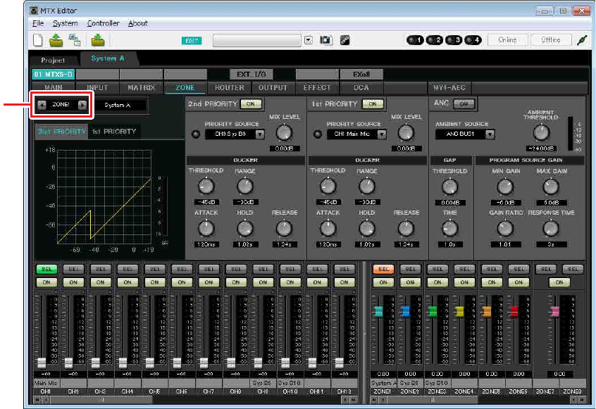
Example 4) A system using Dante
MTX Setup Manual 103
Settings in the “ZONE” screen
In the “ZONE” screen you can make Priority DUCKER settings. The Priority Ducker function temporarily attenuates
the inputs from other channels when audio is input from a specified input channel, ensuring that the audio from the
specified input channel will be broadcast clearly. Priority is given in the order of “1st PRIORITY > 2nd PRIORITY >
Matrix Out signals.”
In this example, we are assuming that the main A mic (CH1) and the other MTX system’s mic (CH9) will be used for
broadcast to the entire building. Thus, for 1st PRIORITY, we set the PRIORITY SOURCE to CH1; as the 2nd PRIOR-
ITY SOURCE we select CH9 in ZONE1, and click the [ON] button located at the right to make it light. Because there’s
no need to make settings for zones 2 through 8, make sure that the [ON] button at the right of 1st PRIORITY and 2nd
PRIORITY are unlit (turned off).
Use the ZONE select buttons to switch the zone.
For details on each parameter, refer to “MTX Editor User’s Manual.”
ZONE select
button
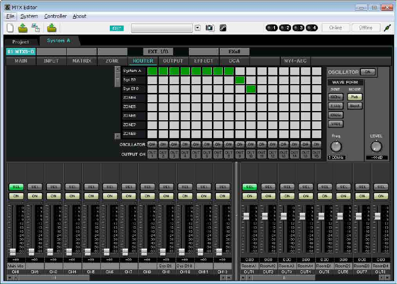
Example 4) A system using Dante
MTX Setup Manual 104
Settings in the “ROUTER” screen
In the “ROUTER” screen you can assign zones to outputs.
In this example, set ZONE1=OUTPUT 1 through 8, ZONE2=OUTPUT 9, and ZONE3=OUTPUT 10.
With these settings, this MTX system will broadcast all of its own audio as well as all audio of the other MTX system,
the main mic of this MTX system will be sent to Dante channel 9, and signals of this MTX system other than the main
mic will be sent to Dante channel 10.
This completes settings for this MTX system.
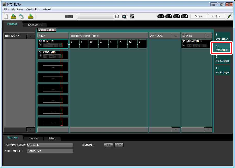
Example 4) A system using Dante
MTX Setup Manual 105
Next we will make settings for System B.
System B will have many of the same settings as System A. For the System B settings, we will explain settings made in the
“EXT I/O” screen and settings made in the “MAIN” screen. Other settings will be the same as previously explained.
If you’ve also finished the settings for System B, proceed to “Dante settings between systems.”
First, select System B in the “Project” screen.
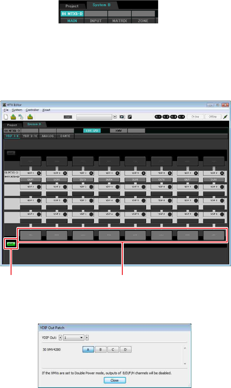
Example 4) A system using Dante
MTX Setup Manual 106
Making EXT. I/O settings
Make settings for inputting and outputting digital audio. First make YDIF and Dante settings for System B. Click the
SYSTEM tab to access the setting screen.
1. Click the [EXT. I/O] button.
The “EXT. I/O” screen will appear, allowing you to make input/output settings for the external devices. Since
you’ll be making settings for YDIF 1–8, there’s no need to switch screens; simply make the settings in this screen.
2. In the lower left, click the [EDIT] button.
Now you can specify the outputs from the MTX to YDIF 1–8.
3. Click the output routing select button located below YDIF 1.
The “YDIF Out Patch” dialog box will appear.
[EDIT] button Output routing select buttons
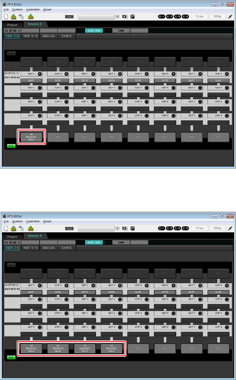
Example 4) A system using Dante
MTX Setup Manual 107
4. For CHANNEL, click [A] button.
The YDIF 1 output routing select button shows that the YDIF 1 output has been assigned to CH A of the UNIT
ID=30 XMV4280.
5. Change the output destination in the [YDIF Out:] list box, to assign YDIF 2 through YDIF
4 to CH B through CH D of the XMV4280, and then click [Close] button.
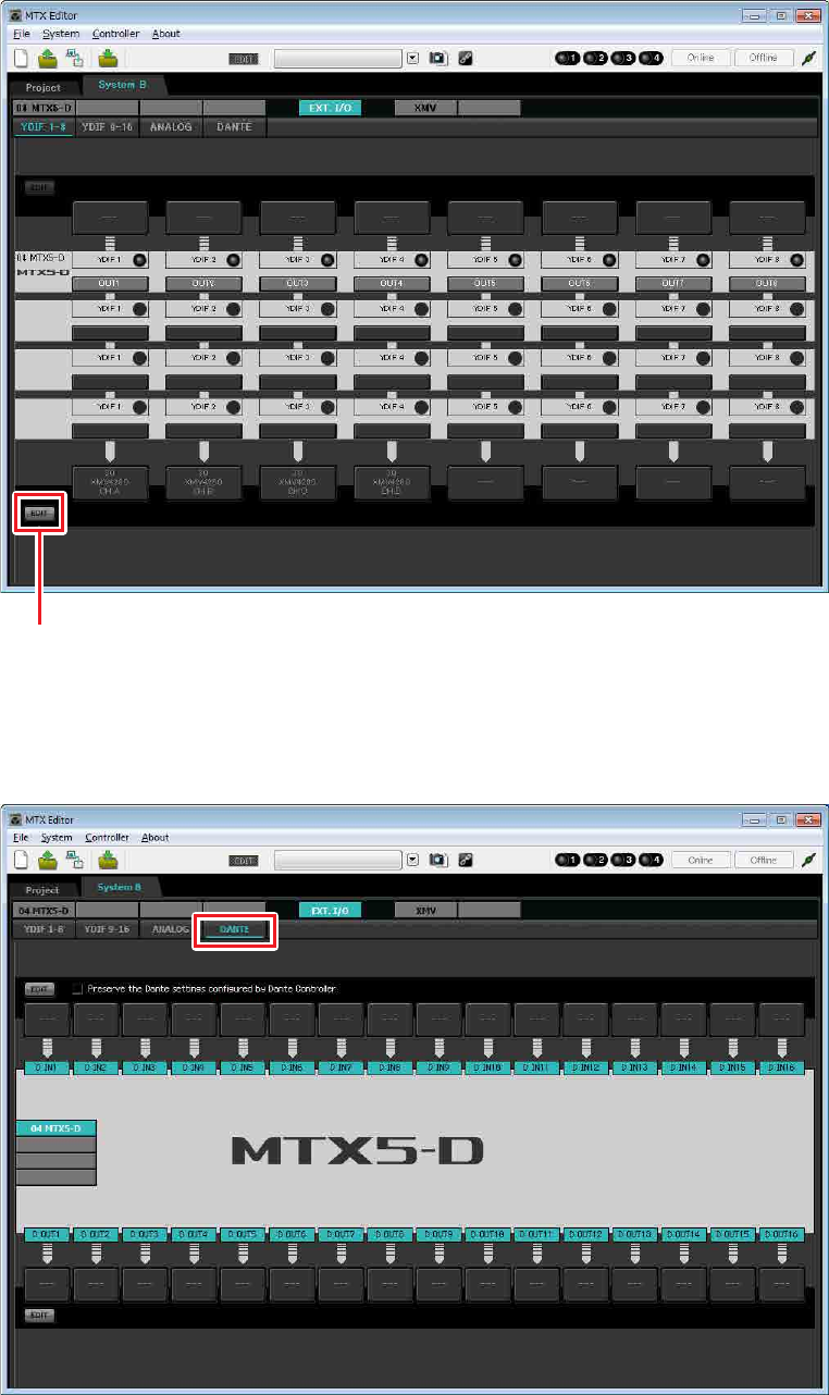
Example 4) A system using Dante
MTX Setup Manual 108
6. In the lower left, click [EDIT] button to lock the settings.
7. Click [DANTE] button.
The Dante setting screen will appear. Here you will specify the output to the XMV4280-D.
[EDIT] button
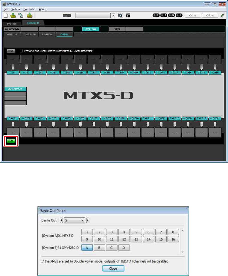
Example 4) A system using Dante
MTX Setup Manual 109
8. In the lower left, click the [EDIT] button.
Now you can specify the outputs from the MTX to Dante.
If the [Preserve the Dante settings configured by Dante Controller] check box is selected, clear the check box.
9. Click the output routing select button located below D OUT 5.
The “Dante Out Patch” dialog box will appear.
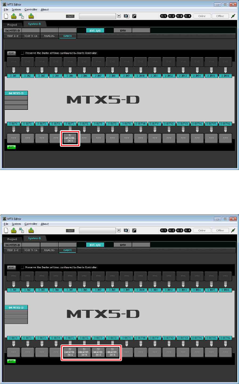
Example 4) A system using Dante
MTX Setup Manual 110
10. In “[System B]31 XMV428 ...”, click [A].
The D OUT 5 output routing select button shows that the Dante 5 output has been assigned to CH A of the UNIT
ID=31 XMV4280-D.
11. Change the output destination in the [Dante Out:] list box, to assign D OUT 6 through D
OUT 8 to CH B through CH D of the XMV4280-D, and then click [Close] button.
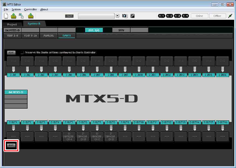
Example 4) A system using Dante
MTX Setup Manual 111
12. In the lower left, click [EDIT] button to lock the settings.
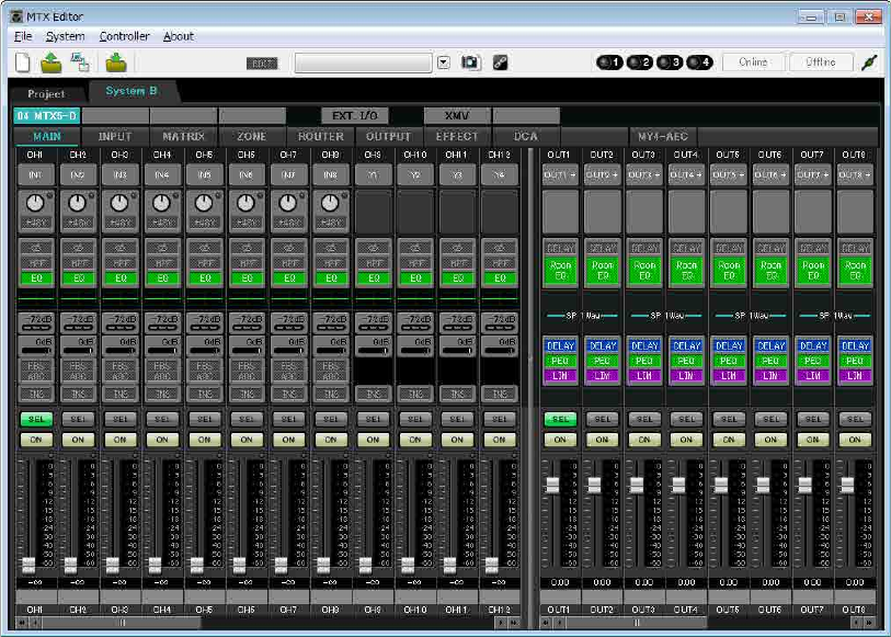
Example 4) A system using Dante
MTX Setup Manual 112
Settings in the “MAIN” screen
In the “MAIN” screen you can make overall settings for each channel.
Click the [04 MTX5-D] button to access the MTX “MAIN” screen.
For details on each parameter, refer to “MTX Editor User’s Manual.”
Here you’ll make the following settings.
• Channel name
• Channel on/off
• Gain and phantom power
• (As necessary) EQ settings
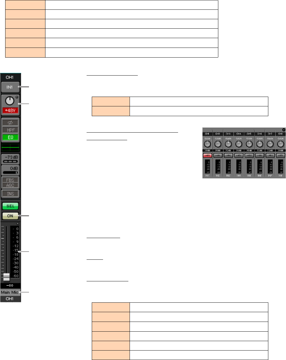
Example 4) A system using Dante
MTX Setup Manual 113
-INPUT settings
Make the following input settings.
Port select button
When you click this, the “Input Patch” dialog box will open. This example
makes the following changes to the default settings.
Port/External Device parameter
access button
This lets you make input connector settings
for the MTX. When you click the button, a
popup window will appear. Make the
desired settings, and then in the upper right,
click × to close the popup window.
The appropriate gain level will depend on
the devices that are connected, so set the level appropriately for your devices.
For CH1, make settings for input connector 1 of the MTX. The gain is set to 30
dB by default.
Because condenser microphone is connected to CH1, leave the gain at 30 dB and
turn phantom power on.
[ON] button
This turns the channel on/off. You should turn off unused channels.
Fader
This adjusts the input level. Leave the fader at -∞ until the system goes online.
Channel name
You can double-click this to edit the name.
In this example, names have been assigned as follows.
CH1 Signal from the main mic of System B, connected to the MTX5-D
CH9 Signal from the main mic of System A
CH10 System A signal other than the main mic
STIN1 L/R Signal from the CD player connected to ST IN1
STIN2 L/R Signal from the background music player connected to ST IN2
STIN3 L/R SD player built into the MTX5-D
CH9 DANTE [9] (Signal from the system A main mic)
CH10 DANTE [10] (System A signal other than the main mic)
CH1 Main Mic
CH9 Sys A9
CH10 Sys A10
STIN1 CD Player
STIN2 BGM
STIN3 SD Player
Port select button
Port/External Device
parameter access
button
[ON] button
Fader
Channel name
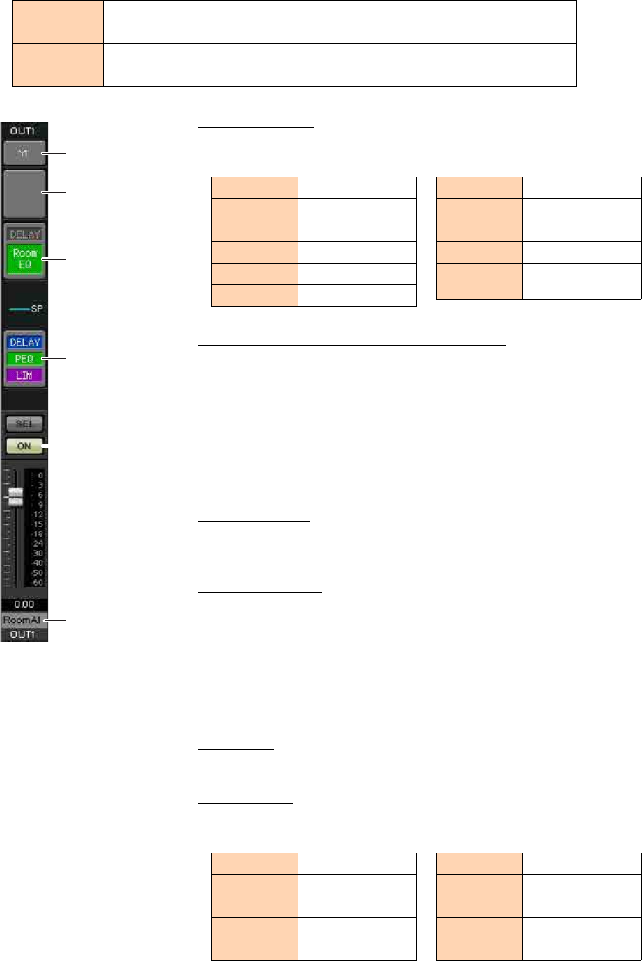
Example 4) A system using Dante
MTX Setup Manual 114
-OUTPUT settings
Make the following output settings.
Port select button
Click this to open the “Output Patch” dialog box. This example makes the fol-
lowing changes to the default settings.
Port / External Device parameter access button
When you click this button, a popup window will appear, allowing you to set the
MTX’s output connector parameters.
For OUT1 through OUT4, make settings for XMV4280 output connectors A
through D.
For OUT5 through OUT8, make settings for XMV4280-D output connectors A
through D.
For OUT9 and OUT10, make settings for output to the Dante network.
Verify that GAIN is set to 0.0 dB.
DELAY/Room EQ
Click this to move to a screen where you can set delay and room EQ.
Since OUT9 and OUT10 are for transmission to System A, do not make settings.
Speaker processor
Click this to move to the “CHANNEL EDIT” screen. Make the appropriate set-
tings for the speakers that will be connected.
Since OUT9 and OUT10 are for transmission to System A, do not make settings.
[ON] button
This button turns the channel on/off. Turn off unused channels.
Channel name
You can double-click this to edit the name.
In this example, names have been assigned as follows.
CH1–4 Output via YDIF to the XMV4280 in Amp Room A
CH5–8 Output via Dante to the XMV4280-D in Amp Room B
CH9 Output the signal of the main mic to System A via Dante[9]
CH10 Output a signal other than the main mic to System A via Dante [10]
NOTE
The pre-installed library contains speaker processor files that are appropriate for the
response of various speakers. By using these files you can make speaker processor set-
tings easily.
Port select button
Port / External Device
parameter access
button
DELAY/Room EQ
Speaker processor
[ON] button
Channel name
OUT1 YDIF [1]
OUT2 YDIF [2]
OUT3 YDIF [3]
OUT4 YDIF [4]
OUT5 DANTE [5]
OUT6 DANTE [6]
OUT7 DANTE [7]
OUT8 DANTE [8]
OUT9 DANTE [9]
OUT10 DANTE [10]
OUT11–
OUT16 No setting
OUT1 RoomA1
OUT2 RoomA2
OUT3 RoomA3
OUT4 RoomA4
OUT5 RoomB1
OUT6 RoomB2
OUT7 RoomB3
OUT8 RoomB4
OUT9 Sys A9
OUT10 Sys A10
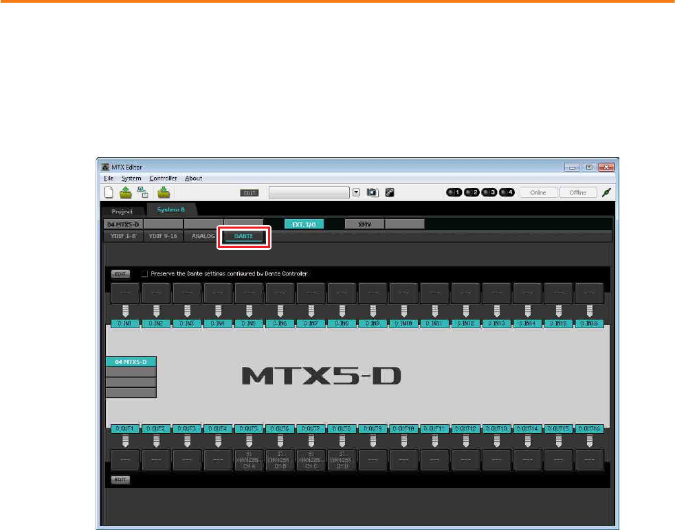
Example 4) A system using Dante
MTX Setup Manual 115
Subsequent settings in MTX Editor are the same as System A “MATRIX” screen settings through “ROUTER” screen set-
tings. Make the Settings in the “MATRIX” screen through the settings in the “ROUTER” screen.
Dante settings between systems
Here you’ll make Dante settings for between System A and System B.
Regardless of whether you make these settings in System A or in System B, the settings will be applied to each other. For
this example, our explanation will use the System B screen.
1. Click the [EXT. I/O] button.
The “EXT. I/O” screen will appear, allowing you to make input/output settings for the external devices.
If the Dante setting screen is not shown, click the [DANTE] button to access the Dante setting screen.
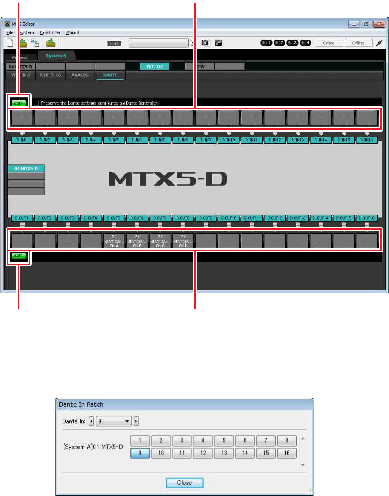
Example 4) A system using Dante
MTX Setup Manual 116
2. In the upper left and lower left, click the [EDIT] buttons.
Now you can make Dante input/output settings.
If the [Preserve the Dante settings configured by Dante Controller] check box is selected, clear the check box.
3. Click the input routing select button located above D IN9.
The “Dante In Patch” dialog box will appear.
[EDIT] button Input routing select buttons
[EDIT] button Output routing select buttons
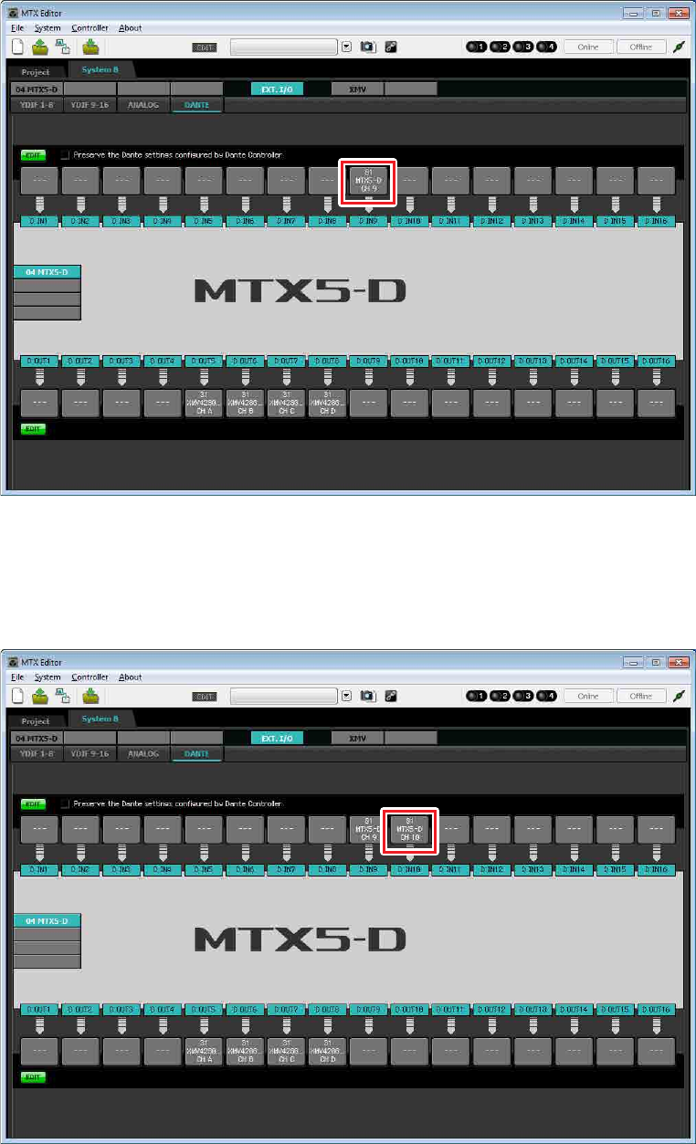
Example 4) A system using Dante
MTX Setup Manual 117
4. For CHANNEL, click [9] button.
The D IN9 input routing select button shows that it is assigned to the signal being output by the MTX5-D (UNIT
ID=01) from D OUT9.
5. Change the input destination in the [Dante In:] list box, so that the signal being output
from D OUT10 by the MTX5-D (UNIT ID=01) is assigned to D IN10, and then click [Close]
button.
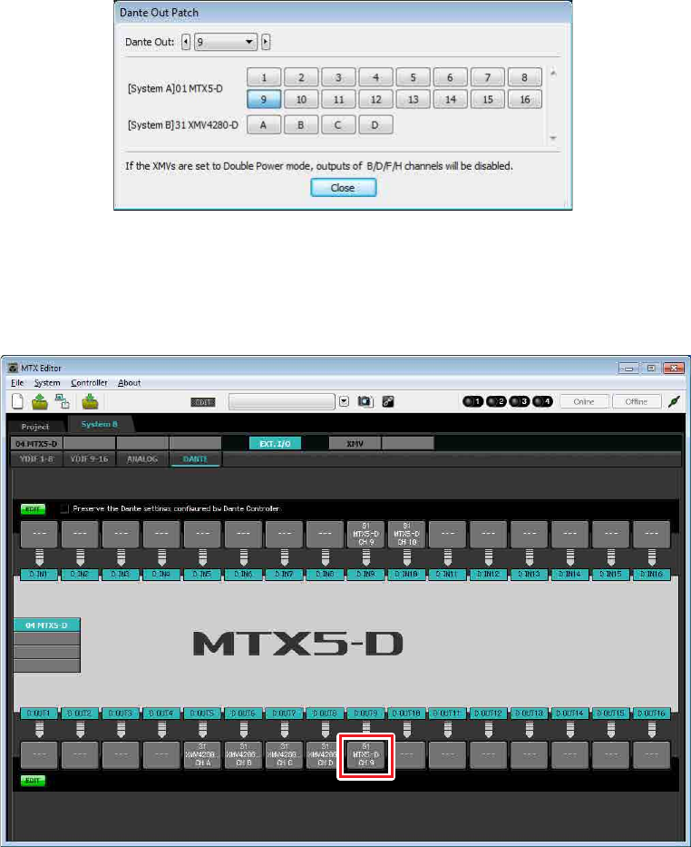
Example 4) A system using Dante
MTX Setup Manual 118
6. Click the output routing select button located below D Out9.
The “Dante Out Patch” dialog box will appear.
7. In “[System A]01 MTX5-D”, click [9].
The D OUT9 output routing select button shows that it is assigned to the signal being input by the MTX5-D (UNIT
ID=01) as D IN9.
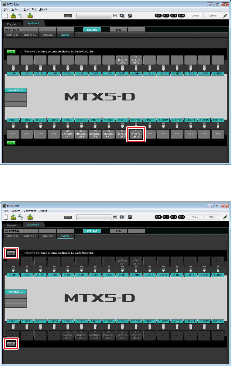
Example 4) A system using Dante
MTX Setup Manual 119
8. Change the output destination in the [Dante Out:] list box, so that the output of D OUT10
will be input to D IN10 of the MTX5-D (UNIT ID=01), and then click [Close] button.
9. In the upper left and lower left, click [EDIT] buttons to lock the settings.

Example 4) A system using Dante
MTX Setup Manual 120
Storing a preset
Now we’ll store the settings we’ve made up to this point as a preset.
To store or recall a preset, click the camera icon in the upper part of MTX Editor.
When you click the camera icon, the “Preset” dialog box will appear. You can create up to 50 presets.
Click the preset number that you want to store; the line will be selected. Then click the [Store] button, specify the preset
name, and click the [OK] button.
This completes settings in the offline state. Save the settings once again.
NOTE
If you don’t store the preset, alert number 61 will occur.

Example 4) A system using Dante
MTX Setup Manual 121
Connecting the equipment
After you’ve rack-mounted the MTX and your other equipment, connect the MTX and the other equipment as shown
below. If you’ve copied audio sources to an SD memory card, insert the card into the MTX now.
Here we will explain an example of redundant Dante connections. If you’re using daisy-chain connections, refer to the
Q&A.
System A connections
ON
ON
Main
Microphone
Network Switch
EXi8
ID=02
MTX5-D
ID=01
EXo8
ID=03
BGM Player
CD Player
Power Amp 1
Power Amp 2
Power Amp 3
Power Amp 4
Room A
Room B
to the System B Network Switch for Primary
to the System B Network Switch
for Secondary
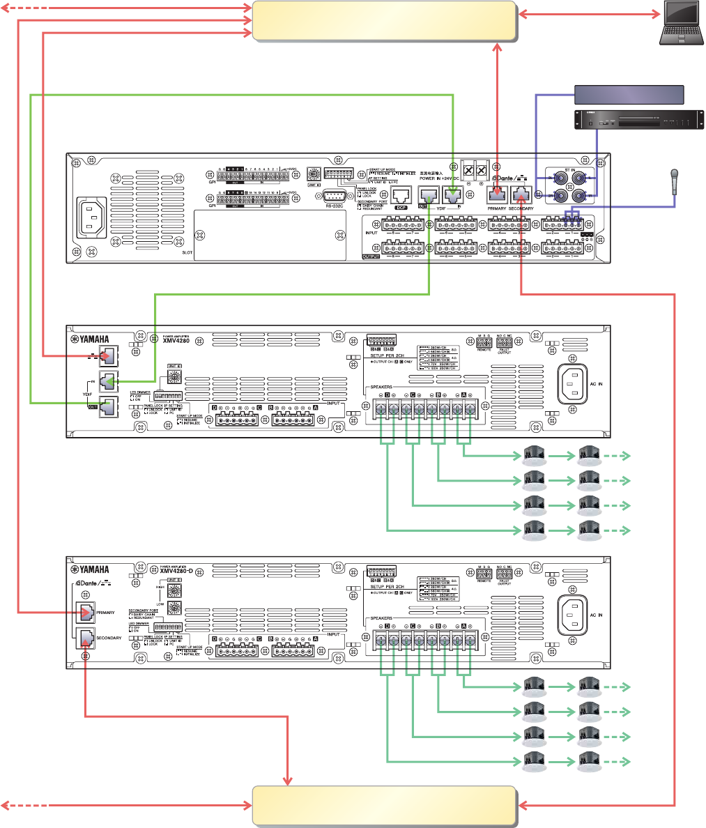
Example 4) A system using Dante
MTX Setup Manual 122
System B connections
To connect the MTX to your computer, use a CAT5e or higher cable with all eight pins connected.
1 2 3 4 5 6 7 8
ON
ON
ON
1 2 3 4 5 6 7 8
ON
Main
Microphone
Network Switch for Primary
Network Switch for Secondary
Computer
MTX5-D
ID=04
XMV4280
ID=30
XMV4280-D
ID=31
BGM Player
CD Player
from the System A Network Switch
from the System A MTX5-D’s
SECONDARY connector

Example 4) A system using Dante
MTX Setup Manual 123
Powering-on the MTX
Turn on the power of the MTX.
Turn off the amplifier before you power-off the MTX.
Powering-on the amp
On the rear panel of the XMV, set the [SPEAKERS] DIP switch, and then turn on the power of the amps (XMV).
To prevent unwanted sound from being output, we recommend that you turn down the attenuator settings of all channels on
the amp itself before you turn it on.
To change the XMV attenuator setting, press the button of the appropriate channel and then turn the encoder.
Specifying the computer’s TCP/IP address
To allow the MTX and the computer to communicate, specify the computer’s TCP/IP as follows.
1. On the [System] menu, click [Network Setup].
The “Network Setup” dialog box will appear.
2. Click [Open Network Connection].
“Network Connections” will appear.
3. Right-click the adapter to which the MTX is connected, and choose [Properties].
The “Local Area Connection Properties” dialog box will appear.
4. Choose [Internet Protocol Version 4 (TCP/IPv4)], and then click [Properties].
The “Internet Protocol Version 4 (TCP/IPv4) Properties” dialog box will appear.
5. Click [Use the following IP address (S)].
NOTE
• With the factory settings, the XMV’s attenuators are set to the lowest value.
• For more about the [SPEAKERS] DIP switch, refer to the XMV owner’s manual.

Example 4) A system using Dante
MTX Setup Manual 124
6. In the [IP address] box, enter “192.168.0.253”; in the [Subnet mask] box, enter
“255.255.255.0.”
7. Click [OK].
NOTE
The IP address of each device is set as follows.
System A: MTX5-D : 192.168.0.1
EXi8 : 192.168.0.2
EXo8 : 192.168.0.3
System B: MTX5-D : 192.168.0.4
XMV4280 : 192.168.0.48
XMV4280-D : 192.168.0.49
NOTE
In some cases, Windows firewall may block MTX Editor when you make this setting. Select the [Private Network] check box, and
click [Allow Access].
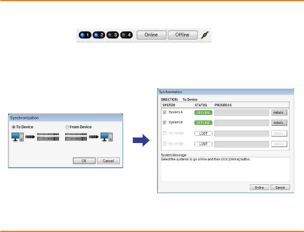
Example 4) A system using Dante
MTX Setup Manual 125
Taking MTX Editor online
In the upper right of MTX Editor, click the [Online] button. When the unit has successfully come online, the indicator 1
and 2 at the left will light blue.
When the “Synchronization” dialog box appears, select “To Device,” and click the [OK] button. When the indication in the
dialog box has switched, select the system that you want to place online, and click the [Online] button.
The project created in MTX Editor will be sent to the MTX.
Making XMV settings
If necessary, use the XMV’s front panel to make settings such as the high pass filter. For more about the settings you can
make on the XMV, refer to the XMV owner’s manual.

Example 4) A system using Dante
MTX Setup Manual 126
Verifying that the settings were applied
The main items to verify are listed below. For details on each parameter setting, refer to “MTX Editor User’s Manual.” Per-
form these checks for each MTX system.
1. Using the oscillator in the “ROUTER” screen, adjust the output level.
Adjust the amp’s attenuator value to an appropriate level.
The attenuator values of the XMV can be adjusted in the popup that is accessed by the port/external device parameter
recall button located in the output channel area of the “MAIN” screen.
2. Specify the gain from the microphone.
You can set the gain in the dialog box that appears when you press the parameter recall button for a port or external
device of an input channel in the “MAIN” screen. Watch the input meter, and adjust the setting appropriately.
3. Set the input levels and output levels.
Using the input/output faders in the “MAIN” screen, adjust the levels. As necessary, apply the output limiter in the
“CHANNEL EDIT” screen to prevent your speakers from being damaged.
Adjust the amp attenuator values to obtain the optimal S/N ratio.
In addition, make FBS settings as necessary.
4. Store the preset.
When you have finished making all settings, save the project and switch MTX Editor offline.
This completes the settings for example 4.
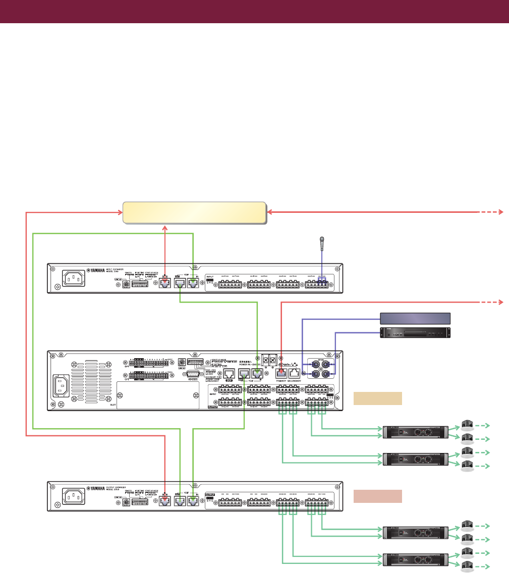
MTX Setup Manual 127
Q: If YDIF connections are in a ring, does the order of connections matter?
A: The order is very important. If you ignore the order, it will not be possible to correctly specify the YDIF routing. Make
connections according to the “Configuration Diagram” displayed in [File] menu [Print Configuration Diagram].
Q: How should I make connections when daisy-chaining the Dante network connections in example 4?
A: Make connections as follows.
Do not route the connection from the System B network switch to the System B XMV4280-D via the System A net-
work switch. This will cause the Dante network to loop within System B, making communication impossible.
-System A
Q&A
ON
ON
Network Switch
EXi8
ID=02
MTX5-D
ID=01
EXo8
ID=03
BGM Player
CD Player
Power Amp 1
Power Amp 2
Power Amp 3
Power Amp 4
Room A
Room B
Main
Microphone
to the System B Network Switch for Primary
to the System B XMV4280-D
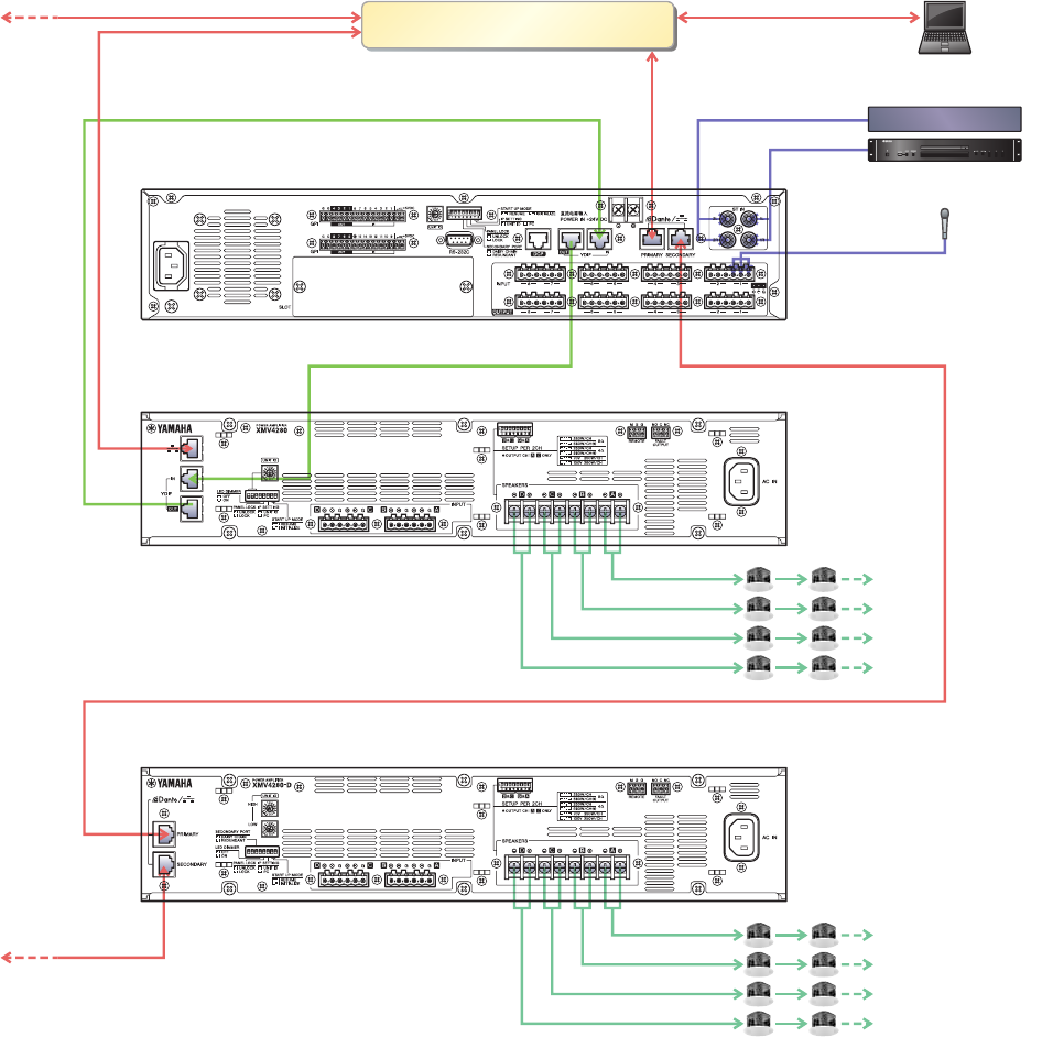
Q&A
MTX Setup Manual 128
-System B
1 2 3 4 5 6 7 8
ON
ON
ON
1 2 3 4 5 6 7 8
ON
Network Switch for Primary
Computer
MTX5-D
ID=04
XMV4280
ID=30
XMV4280-D
ID=31
Main
Microphone
BGM Player
CD Player
from the System A Network Switch
from the System A MTX5-D

MTX Setup Manual 129
Use “Control Panel” to uninstall the software.
In Control Panel, click [Programs and functions] or [Uninstall a program], then select the item you want to uninstall, and
click [Uninstall or change].
A dialog box will appear; follow the instructions in the screen to uninstall the software.
If the “User Account Control” dialog box appears, click [Continue] or [Yes].
The way to access Control Panel will depend on your operating system.
-Windows 7 users
Click [Start] [Control Panel].
-Windows 8 users
1. In the start screen, click [Desktop].
The desktop will appear.
2. Move the cursor to the upper right or lower right of the desktop.
The charms bar will appear.
3. Click [Settings] [Control Panel].
Uninstalling the software (Removing the application)
C.S.G., PA Development Division
© 2013 Yamaha Corporation
312PO-C0
