Yamaha Professional Audio Workstation Aw4416 Operation Manual Owner's Manuals
Yamaha-Professional-Audio-Workstation-Aw4416-Operation-Manual-132166 yamaha-professional-audio-workstation-aw4416-operation-manual-132166
AW4416 to the manual 9734bf86-f6fa-42bb-9f2a-f891244ac8ac
2014-12-13
: Yamaha Professional-Audio-Workstation-Aw4416-Operation-Manual yamaha-professional-audio-workstation-aw4416-operation-manual-132166 yamaha pdf
Open the PDF directly: View PDF ![]() .
.
Page Count: 507 [warning: Documents this large are best viewed by clicking the View PDF Link!]
- Local Disk
- Yamaha AW4416 Owner's Manuals
- AW4416 Operation Guide
- Important
- Table of contents
- Before you begin
- Important points you must observe
- 1 Welcome to the world of the AW4416
- 2 Parts and their functions
- Top panel
- Analog input/output section
- WORK NAVIGATE section
- UNIT section
- MIXER section
- FADER MODE section
- MIXING LAYER section
- [SEL] keys, [ON] keys, faders
- Display section
- Level meter/counter section
- RECORDER section
- AUTOMATION section
- SCENE MEMORY section
- CURSOR/JOG & SHUTTLE section
- Locate section
- Transport section
- SAMPLING PAD section
- Rear panel
- Front panel
- Top panel
- 3 The user interface of the AW4416
- 4 Connections and setup
- 5 Recording on the AW4416
- 6 Transport/locate operations
- Table of transport key operations
- Shuttle function (cue/review operation)
- Nudge function
- Rollback function
- Locating to a specific point
- Locating to the zero location of the counter
- Locating to the start/end points
- A-B repeat
- In/out points
- Markers
- Adjusting the location of a locate point
- Deleting a locate point
- Deleting a locate point using the panel keys
- 7 Punch-in/out
- 8 Patching
- 9 Track and virtual track operations
- 10 Internal effects
- 11 Song management
- 12 Sampling pads
- 13 Scene memory
- 14 Automix
- 15 MIDI
- What you can do using MIDI
- MIDI connectors and the TO HOST connector
- Using the TO HOST connector for direct connection to your computer
- Switching AW4416 scenes from an external device
- Using MTC to synchronize the AW4416 and a MIDI sequencer
- Using MIDI Clock to synchronize the AW4416 and a MIDI sequencer
- Using MMC to control the AW4416
- 16 Backing up and restoring songs
- 17 Mastering
- AW4416 Reference Guide
- Table of contents
- SONG screen
- QUICK REC screen
- MASTERING screen
- CD PLAY screen
- SET UP screen
- FILE screen
- UTILITY screen
- MIDI screen
- VIEW screen
- PAN/ROUTE screen
- EQ/ATT/GRP screen
- DYN/DLY screen
- AUX1–AUX6 screens
- AUX7/EFF1 and AUX8/EFF2 screens
- HOME screen
- SAMP. PAD screen
- TRACK screen
- EDIT screen
- AUTOMIX screen
- SCENE screen
- Appendix
- AW4416 Tutorial

PROFESSIONAL AUDIO WORKSTATION
E
Operation Guide
FCC INFORMATION (U.S.A.)
1. IMPORTANT NOTICE: DO NOT MODIFY THIS UNIT! This product, when installed as indicated in the instructions contained in this manual, meets FCC
requirements. Modifications not expressly approved by Yamaha may void your authority, granted by the FCC, to use the product.
2. IMPORTANT: When connecting this product to accessories and/or another product use only high quality shielded cables. Cable/s supplied with this product MUST
be used. Follow all installation instructions. Failure to follow instructions could void your FCC authorization to use this product in the USA.
3. NOTE: This product has been tested and found to comply with the requirements listed in FCC Regulations, Part 15 for Class “B” digital devices. Compliance with
these requirements provides a reasonable level of assurance that your use of this product in a residential environment will not result in harmful interference with
other electronic devices. This equipment generates/uses radio frequencies and, if not installed and used according to the instructions found in the users manual, may
cause interference harmful to the operation of other electronic devices. Compliance with FCC regulations does not guarantee that interference will not occur in all
installations. If this product is found to be the source of interference, which can be determined by turning the unit “OFF” and “ON”, please try to eliminate the
problem by using one of the following measures: Relocate either this product or the device that is being affected by the interference. Utilize power outlets that are on
different branch (circuit breaker or fuse) circuits or install AC line filter/s. In the case of radio or TV interference, relocate/reorient the antenna. If the antenna lead-in
is 300 ohm ribbon lead, change the lead-in to coaxial type cable. If these corrective measures do not produce satisfactory results, please contact the local retailer
authorized to distribute this type of product. If you can not locate the appropriate retailer, please contact Yamaha Corporation of America, Electronic Service
Division, 6600 Orangethorpe Ave, Buena Park, CA 90620
The above statements apply ONLY to those products distributed by Yamaha Corporation of America or its subsidiaries.
WARNING: THIS APPARATUS MUST BE EARTHED
IMPORTANT
THE WIRES IN THIS MAINS LEAD ARE COLOURED IN
ACCORDANCE WITH THE FOLLOWING CODE:
GREEN-AND-YELLOW : EARTH
BLUE : NEUTRAL
BROWN : LIVE
As the colours of the wires in the mains lead of this apparatus may
not correspond with the coloured markings identifying the terminals in
your plug, proceed as follows:
The wire which is coloured GREEN and YELLOW must be
connected to the terminal in the plug which is marked by the letter E
or by the safety earth symbol or coloured GREEN and YELLOW.
The wire which is coloured BLUE must be connected to the terminal
which is marked with the letter N or coloured BLACK.
The wire which is coloured BROWN must be connected to the
terminal which is marked with the letter L or coloured RED.
* This applies only to products distributed by YAMAHA KEMBLE
MUSIC (U.K.) LTD.
ADVARSEL!
Lithiumbatteri—Eksplosionsfare ved fejlagtig
håndtering. Udskiftning må kun ske med batteri
af samme fabrikat og type. Levér det brugte
batteri tilbage til leverandoren.
VARNING
Explosionsfara vid felaktigt batteribyte. Använd
samma batterityp eller en ekvivalent typ som
rekommenderas av apparattillverkaren.
Kassera använt batteri enligt fabrikantens
instruktion.
VAROITUS
Paristo voi räjähtää, jos se on virheellisesti
asennettu. Vaihda paristo ainoastaan
laitevalmistajan suosittelemaan tyyppiin. Hävitä
käytetty paristo valmistajan ohjeiden
mukaisesti.
• Explanation of Graphical Symbols
The exclamation point within an equilat-
eral triangle is intended to alert the user to
the presence of important operating and
maintenance (servicing) instructions in the
literature accompanying the product.
The lightning flash with arrowhead symbol
within an equilateral triangle is intended to
alert the user to the presence of uninsulated
“dangerous voltage” within the product’s
enclosure that may be of sufficient magni-
tude to constitute a risk of electric shock to
persons.
CAUTION: TO REDUCE THE RISK OF
ELECTRIC SHOCK, DO NOT REMOVE
COVER (OR BACK). NO USER-SERVICEABLE
PARTS INSIDE. REFER SERVICING TO
QUALIFIED SERVICE PERSONNEL.
CAUTION
RISK OF ELECTRIC SHOCK
DO NOT OPEN
The above warning is located on the
rear of the unit

NEDERLAND THE NETHERLANDS
● Dit apparaat bevat een lithium batterij voor geheugen
back-up.
● Raadpleeg uw leverancier over de verwijdering van de
batterij op het moment dat u het apparaat ann het einde
van de levensduur afdankt of de volgende Yamaha Service
Afdeiing:
Yamaha Music Nederland Service Afdeiing
Kanaalweg 18-G, 3526 KL UTRECHT
Tel. 030-2828425
● Gooi de batterij niet weg, maar lever hem in als KCA.
● This apparatus contains a lithium battery for memory
back-up.
● For the removal of the battery at the moment of the
disposal at the end of the service life please consult your
retailer or Yamaha Service Center as follows:
Yamaha Music Nederland Service Center
Address: Kanaalweg 18-G, 3526 KL
UTRECHT
Tel: 030-2828425
● Do not throw away the battery. Instead, hand it in as small
chemical waste.

Important
iv
— Operation Guide
Important
Read the following before operating the
AW4416
❒
Warnings
• Do not allow water to enter this unit or allow the unit to become wet. Fire or
electrical shock may result.
• Connect this unit’s power cord only to an AC outlet of the type stated in this
Owner’s Manual or as marked on the unit. Failure to do so is a fire and electri-
cal shock hazard.
• Do not scratch, bend, twist, pull, or heat the power cord. A damaged power
cord is a fire and electrical shock hazard.
• Do not place heavy objects, including this unit, on top of the power cord. A
damaged power cord is a fire and electrical shock hazard. In particular, be
careful not to place heavy objects on a power cord covered by a carpet.
• If you notice any abnormality, such as smoke, odor, or noise, or if a foreign
object or liquid gets inside the unit, turn it off immediately. Remove the
power cord from the AC outlet. Consult your dealer for repair. Using the unit
in this condition is a fire and electrical shock hazard.
• Should this unit be dropped or the cabinet be damaged, turn the power
switch off, remove the power plug from the AC outlet, and contact your
dealer. If you continue using the unit without heeding this instruction, fire or
electrical shock may result.
• If the power cord is damaged (i.e., cut or a bare wire is exposed), ask your
dealer for a replacement. Using the unit with a damaged power cord is a fire
and electrical shock hazard.
• Do not modify the unit. Doing so is a fire and electrical shock hazard.
❒
Cautions
• When rack-mounting the unit, allow enough free space around the unit for
normal ventilation. This should be: 10 cm at the sides, 20 cm behind, and 30
cm above.
For normal ventilation during use, remove the rear of the rack or open a ven-
tilation hole.
If the airflow is not adequate, the unit will heat up inside and may cause a
fire.
• This unit has ventilation holes at the bottom to prevent the internal tempera-
ture rising too high. Do not block them. Blocked ventilation holes are a fire
hazard.
• Hold the power cord plug when disconnecting it from an AC outlet. Never
pull the cord. A damaged power cord is a potential fire and electrical shock
hazard.

Important
— Operation Guide
v
• Do not touch the power plug with wet hands. Doing so is a potential electri-
cal shock hazard.
• Use only the included power supply cable for this unit. Using other types may
be a fire hazard.
• Always touch a well-grounded metal surface or the like to fully discharge any
static electric charge on your body and clothing before handling an I/O card
or hard disk.
Neglecting this precaution can cause damage to the unit from static electric-
ity.
• Be careful not to touch the leads (metal feet) on the rear side when handling
an I/O card or hard disk. Touching the leads can cause contact defects.
❒
Operating Notes
• Using a mobile telephone near this unit may induce noise. If noise occurs,
use the telephone away from the unit.
• XLR-type connectors are wired as follows: pin 1: ground, pin 2: hot (+), and
pin 3: cold (–).
• Insert TRS phone jacks are wired as follows: sleeve: ground, tip: send, and
ring: return.
• If the message “LOW BATTERY” appears when you turn on this unit, contact
your dealer as soon as possible about replacing the internal data backup bat-
tery. The unit will still operate correctly, but data other than the presets will be
lost.
We recommend that you save the data on CD-RW drive or external SCSI
device before replacing the battery.
• The performance of components with moving contacts, such switches, rotary
controls, faders, and connectors, deteriorates over time. The rate of deteriora-
tion depends on the operating environment and is unavoidable. Consult your
dealer about replacing defective components.
Handling the CD-R/RW media
Please observe the following points when handling the disk.
Failure to do so may cause problems such as the recorded data being lost, the
drive to malfunction, or the printed label to become blurred.
• Do not place the disk in locations of direct sunlight, high temperature, or high
humidity.
• Do not touch either surface of the disk.
• Hold the disk at the edges. Gently wipe dust or dirt off of the recording sur-
face of the disk.
• Do not wipe the disk with chemicals or detergents.
• Do not bend or drop the disk.
• Use an air duster or cleaner to remove dust. Vigorously rubbing the surface of
the disk with a dry cloth may scratch the disk.
• Do not write on the disk or affix labels to it.

Important
vi
— Operation Guide
Storing produced data
Produced data can be lost due to breakdown or mistaken operation. We recom-
mend that you store all important data on CD-R or CD-RW disks or other external
storage medium.
Responsibility for loss of data, etc.
• Yamaha will accept no responsibility for any damages (including consequen-
tial or incidental) incurred by the customer or any third party as a result of
loss or impairment of the data stored on the CD-R media, regardless of
whether such loss could have been or actually was foreseen by Yamaha.
• Nor does Yamaha guarantee the media against any defect that may render it
unusable.
Cautions for handling optional equipment
• For inquiries concerning I/O card, hard disk, or CD-RW drive handling,
please consult your Yamaha dealer.
• Always switch off the power for the main unit and all peripherals, unplug the
power cord for the main unit from the outlet, then disconnect the cables con-
necting the main unit with the peripherals before starting installation work.
• Wear thick gloves when working on this equipment to avoid cutting your
hands on metal fittings or the like on the main unit, I/O card, hard disk, or
CD-RW drive.
• Always touch a well-grounded metal surface or the like to fully discharge any
static electric charge on your body and clothing before starting to work on
this equipment.
• Take extreme care to avoid touching any terminals or board surface parts.
• In order to protect the electronic circuits of the I/O card, hard disk, CD-RW
drive, etc. from damage due to static electricity, when handling any of this
equipment, take the most extreme care to avoid touching IC leads or other
electronic parts.
• Be careful not to drop any screws into the main unit. If you switch the power
on with a dropped screw still in the main unit, the main unit may malfunction
or break down. If a dropped screw can not be retrieved, consult your Yamaha
dealer.
• If the hard disk or CD-RW drive breaks down, contact the store where you
purchased that equipment.
Except for duplication for personal use or when there is no copyright problem,
the duplication or transfer of commercially sold music/sound data without the
permission of the copyright holder is prohibited. When using this equipment,
please consult with a copyright specialist.

Important
— Operation Guide
vii
❍
Warning
The Yamaha Professional Audio Workstation is designed to be used professionally
and responsibly by recording industry professionals. The reproduction, distribu-
tion, or, in some instances, the public performance, of all or a portion of a sound
recording or musical composition protected by copyright, without having
obtained a proper license from the relevant copyright holders, may constitute
copyright infringement and may otherwise violate copyright laws and other laws.
In addition, laws (such as the Audio Home Recording Act and the Digital Millen-
nium Copyright Act in USA) contain certain restrictions and requirements that
may apply to your use of works protected by copyright and related information
and data that may accompany such works. Violation of such laws may result in
civil remedies and, in some cases, criminal liability.
Because violations of copyright laws may be serious offenses, you should consult
a lawyer familiar with the law of copyright, including all laws that may be appli-
cable to your use of the Workstation (such as the Audio Home Recording Act and
the Digital Millennium Copyright Act in USA), if you have any questions regard-
ing your intended use of all or parts of sound recordings or musical compositions
protected by copyright.

Table of contents
viii
— Operation Guide
Thank you for purchasing the Yamaha AW4416 audio workstation. In order
to take full advantage of the AW4416’s functionality and enjoy trouble-free
operation, please carefully read the “Operation Guide” (this manual) and
the separate “Reference Manual” and “Tutorial.”
Table of contents
Before you begin . . . . . . . . . . . . . . . . . . . . . . . . . . . . . . 1
Checking the included items . . . . . . . . . . . . . . . . . . . . . . . . . . . . . . . 1
Installing an internal hard disk . . . . . . . . . . . . . . . . . . . . . . . . . . . . . 2
About the internal hard disk. . . . . . . . . . . . . . . . . . . . . . . . . . . . . . 2
Installation. . . . . . . . . . . . . . . . . . . . . . . . . . . . . . . . . . . . . . . . . . . 3
Installing a CD-RW drive. . . . . . . . . . . . . . . . . . . . . . . . . . . . . . . . . . 5
About the CD-RW drives . . . . . . . . . . . . . . . . . . . . . . . . . . . . . . . . 5
The SCSI ID of the CD-RW drive. . . . . . . . . . . . . . . . . . . . . . . . . . . . . 5
Installation procedure . . . . . . . . . . . . . . . . . . . . . . . . . . . . . . . . . . 6
Removing the transport protection pad. . . . . . . . . . . . . . . . . . . . . . . 9
How to remove the transport protection pad . . . . . . . . . . . . . . . . . 9
Manual eject (emergency disc removal). . . . . . . . . . . . . . . . . . . . 10
Attaching an external SCSI device. . . . . . . . . . . . . . . . . . . . . . . . . . 10
About external SCSI devices . . . . . . . . . . . . . . . . . . . . . . . . . . . . 10
Connection procedure. . . . . . . . . . . . . . . . . . . . . . . . . . . . . . . . . 11
About terminators . . . . . . . . . . . . . . . . . . . . . . . . . . . . . . . . . . . . . . . 12
About SCSI errors . . . . . . . . . . . . . . . . . . . . . . . . . . . . . . . . . . . . . . . 12
Installing I/O cards . . . . . . . . . . . . . . . . . . . . . . . . . . . . . . . . . . . . . 13
About I/O cards . . . . . . . . . . . . . . . . . . . . . . . . . . . . . . . . . . . . . . 13
Installation procedure . . . . . . . . . . . . . . . . . . . . . . . . . . . . . . . . . 14
Important points you must observe. . . . . . . . . . . . . . . 15
Turning the power on or off . . . . . . . . . . . . . . . . . . . . . . . . . . . . . . 15
Turning the power on . . . . . . . . . . . . . . . . . . . . . . . . . . . . . . . . . . . . 15
Setting the internal clock. . . . . . . . . . . . . . . . . . . . . . . . . . . . . . . . . 16
Turning the power off . . . . . . . . . . . . . . . . . . . . . . . . . . . . . . . . . . . . 17
Transporting the AW4416 . . . . . . . . . . . . . . . . . . . . . . . . . . . . . . . . 18
Vibration during use . . . . . . . . . . . . . . . . . . . . . . . . . . . . . . . . . . . . 18

Table of contents
— Operation Guide
ix
Chapter 1 Welcome to the world of the AW4416. . . . . . . . 19
Features of the AW4416. . . . . . . . . . . . . . . . . . . . . . . . . . . . . . . . . 19
Mixer section . . . . . . . . . . . . . . . . . . . . . . . . . . . . . . . . . . . . . . . . . . 19
Recorder section . . . . . . . . . . . . . . . . . . . . . . . . . . . . . . . . . . . . . . . . 20
Sampling pad section . . . . . . . . . . . . . . . . . . . . . . . . . . . . . . . . . . . . 21
CD-RW drive (option) . . . . . . . . . . . . . . . . . . . . . . . . . . . . . . . . . . . . 21
Other features . . . . . . . . . . . . . . . . . . . . . . . . . . . . . . . . . . . . . . . . . . 21
Signal flow within the AW4416 . . . . . . . . . . . . . . . . . . . . . . . . . . . 22
Input patch . . . . . . . . . . . . . . . . . . . . . . . . . . . . . . . . . . . . . . . . . 23
Input channels 1–24 . . . . . . . . . . . . . . . . . . . . . . . . . . . . . . . . . . 24
Return channels 1/2 . . . . . . . . . . . . . . . . . . . . . . . . . . . . . . . . . . 25
Recorder input patching . . . . . . . . . . . . . . . . . . . . . . . . . . . . . . . 26
Monitor channels 1–16. . . . . . . . . . . . . . . . . . . . . . . . . . . . . . . . 26
Digital cascade connections . . . . . . . . . . . . . . . . . . . . . . . . . . . . 27
Oscillator . . . . . . . . . . . . . . . . . . . . . . . . . . . . . . . . . . . . . . . . . . 27
Stereo output channel. . . . . . . . . . . . . . . . . . . . . . . . . . . . . . . . . 27
Buses 1–8 . . . . . . . . . . . . . . . . . . . . . . . . . . . . . . . . . . . . . . . . . . 28
AUX buses 1–8 . . . . . . . . . . . . . . . . . . . . . . . . . . . . . . . . . . . . . . 28
Output patch . . . . . . . . . . . . . . . . . . . . . . . . . . . . . . . . . . . . . . . 29
Internal effects 1/2 . . . . . . . . . . . . . . . . . . . . . . . . . . . . . . . . . . . 29
Monitor output/headphone output . . . . . . . . . . . . . . . . . . . . . . . 30
Chapter 2 Parts and their functions . . . . . . . . . . . . . . . . . . 31
Top panel . . . . . . . . . . . . . . . . . . . . . . . . . . . . . . . . . . . . . . . . . . . . 31
Analog input/output section . . . . . . . . . . . . . . . . . . . . . . . . . . . . 31
WORK NAVIGATE section . . . . . . . . . . . . . . . . . . . . . . . . . . . . . 32
UNIT section . . . . . . . . . . . . . . . . . . . . . . . . . . . . . . . . . . . . . . . 32
MIXER section. . . . . . . . . . . . . . . . . . . . . . . . . . . . . . . . . . . . . . . 33
FADER MODE section . . . . . . . . . . . . . . . . . . . . . . . . . . . . . . . . 34
MIXING LAYER section. . . . . . . . . . . . . . . . . . . . . . . . . . . . . . . . 35
[SEL] keys, [ON] keys, faders . . . . . . . . . . . . . . . . . . . . . . . . . . . 37
Display section . . . . . . . . . . . . . . . . . . . . . . . . . . . . . . . . . . . . . . 38
Level meter/counter section . . . . . . . . . . . . . . . . . . . . . . . . . . . . 39
RECORDER section. . . . . . . . . . . . . . . . . . . . . . . . . . . . . . . . . . . 40
AUTOMATION section . . . . . . . . . . . . . . . . . . . . . . . . . . . . . . . 41
SCENE MEMORY section . . . . . . . . . . . . . . . . . . . . . . . . . . . . . . 41
CURSOR/JOG & SHUTTLE section . . . . . . . . . . . . . . . . . . . . . . . 42
Locate section. . . . . . . . . . . . . . . . . . . . . . . . . . . . . . . . . . . . . . . 43
Transport section . . . . . . . . . . . . . . . . . . . . . . . . . . . . . . . . . . . . 44
SAMPLING PAD section. . . . . . . . . . . . . . . . . . . . . . . . . . . . . . . 45
Rear panel . . . . . . . . . . . . . . . . . . . . . . . . . . . . . . . . . . . . . . . . . . . 46
Front panel . . . . . . . . . . . . . . . . . . . . . . . . . . . . . . . . . . . . . . . . . . . 50

Table of contents
x
— Operation Guide
Chapter 3 The user interface of the AW4416 . . . . . . . . . . . .51
Display . . . . . . . . . . . . . . . . . . . . . . . . . . . . . . . . . . . . . . . . . . . . . . 51
Level meters/counter. . . . . . . . . . . . . . . . . . . . . . . . . . . . . . . . . . . . 54
Basic operation of the AW4416 . . . . . . . . . . . . . . . . . . . . . . . . . . . 56
Accessing a screen/page . . . . . . . . . . . . . . . . . . . . . . . . . . . . . . . 56
Using the controls of the top panel . . . . . . . . . . . . . . . . . . . . . . . . . . 56
Using the mouse. . . . . . . . . . . . . . . . . . . . . . . . . . . . . . . . . . . . . . . . 56
Turning a button on/off . . . . . . . . . . . . . . . . . . . . . . . . . . . . . . . . 57
Using the controls of the top panel . . . . . . . . . . . . . . . . . . . . . . . . . . 57
Using the mouse. . . . . . . . . . . . . . . . . . . . . . . . . . . . . . . . . . . . . . . . 57
Editing the value of a fader/knob/numerical box . . . . . . . . . . . . . 58
Using the controls of the top panel . . . . . . . . . . . . . . . . . . . . . . . . . . 58
Using the mouse. . . . . . . . . . . . . . . . . . . . . . . . . . . . . . . . . . . . . . . . 58
Using the additional function buttons . . . . . . . . . . . . . . . . . . . . . 59
Using the controls of the top panel . . . . . . . . . . . . . . . . . . . . . . . . . . 59
Using the mouse. . . . . . . . . . . . . . . . . . . . . . . . . . . . . . . . . . . . . . . . 59
Inputting text . . . . . . . . . . . . . . . . . . . . . . . . . . . . . . . . . . . . . . . . 60
Using the controls of the tab page. . . . . . . . . . . . . . . . . . . . . . . . . . . 60
Using the mouse. . . . . . . . . . . . . . . . . . . . . . . . . . . . . . . . . . . . . . . . 62
Selecting channels. . . . . . . . . . . . . . . . . . . . . . . . . . . . . . . . . . . . 63
Chapter 4 Connections and setup . . . . . . . . . . . . . . . . . . . . .67
Connections . . . . . . . . . . . . . . . . . . . . . . . . . . . . . . . . . . . . . . . . . . 67
Word clock settings. . . . . . . . . . . . . . . . . . . . . . . . . . . . . . . . . . . . . 68
Chapter 5 Recording on the AW4416 . . . . . . . . . . . . . . . . . .73
Preparations for recording . . . . . . . . . . . . . . . . . . . . . . . . . . . . . . . 73
Connections and start-up. . . . . . . . . . . . . . . . . . . . . . . . . . . . . . . 73
Creating a new song . . . . . . . . . . . . . . . . . . . . . . . . . . . . . . . . . . 75
Recording the first tracks . . . . . . . . . . . . . . . . . . . . . . . . . . . . . . . . 78
Set the input level . . . . . . . . . . . . . . . . . . . . . . . . . . . . . . . . . . . . 78
Assign the signals to buses. . . . . . . . . . . . . . . . . . . . . . . . . . . . . . 81
Set the tracks to record-ready mode. . . . . . . . . . . . . . . . . . . . . . . 82
Make monitor settings . . . . . . . . . . . . . . . . . . . . . . . . . . . . . . . . . 83
Let’s record!. . . . . . . . . . . . . . . . . . . . . . . . . . . . . . . . . . . . . . . . . 85
Overdubbing . . . . . . . . . . . . . . . . . . . . . . . . . . . . . . . . . . . . . . . . . . 87
Set the input level . . . . . . . . . . . . . . . . . . . . . . . . . . . . . . . . . . . . 87
Assign the signal to a bus. . . . . . . . . . . . . . . . . . . . . . . . . . . . . . . 88
Put the track in record-ready mode . . . . . . . . . . . . . . . . . . . . . . . 89
Make monitor settings . . . . . . . . . . . . . . . . . . . . . . . . . . . . . . . . . 90
Using EQ and the dynamics processor. . . . . . . . . . . . . . . . . . . . . 91
Using the four-band EQ . . . . . . . . . . . . . . . . . . . . . . . . . . . . . . . . . . 91
Using the dynamics processor. . . . . . . . . . . . . . . . . . . . . . . . . . . . . . 92
Let’s overdub! . . . . . . . . . . . . . . . . . . . . . . . . . . . . . . . . . . . . . . . 94

Table of contents
— Operation Guide
xi
Mixdown . . . . . . . . . . . . . . . . . . . . . . . . . . . . . . . . . . . . . . . . . . . . 95
Creating the mix balance of the tracks . . . . . . . . . . . . . . . . . . . . 95
Using the Solo function. . . . . . . . . . . . . . . . . . . . . . . . . . . . . . . . 96
Using the internal effects. . . . . . . . . . . . . . . . . . . . . . . . . . . . . . . 99
Other convenient functions . . . . . . . . . . . . . . . . . . . . . . . . . . . . . 101
Fader groups . . . . . . . . . . . . . . . . . . . . . . . . . . . . . . . . . . . . . . . . . . 101
Mute groups . . . . . . . . . . . . . . . . . . . . . . . . . . . . . . . . . . . . . . . . . . 101
Automix . . . . . . . . . . . . . . . . . . . . . . . . . . . . . . . . . . . . . . . . . . . . . 102
Recording the stereo track. . . . . . . . . . . . . . . . . . . . . . . . . . . . . 102
Saving a scene/song . . . . . . . . . . . . . . . . . . . . . . . . . . . . . . . . . . . 105
Saving a scene . . . . . . . . . . . . . . . . . . . . . . . . . . . . . . . . . . . . . . . . 105
Saving a song . . . . . . . . . . . . . . . . . . . . . . . . . . . . . . . . . . . . . . . . . 106
Chapter 6 Transport/locate operations. . . . . . . . . . . . . . . 109
Table of transport key operations . . . . . . . . . . . . . . . . . . . . . . . . . 109
Shuttle function (cue/review operation). . . . . . . . . . . . . . . . . . . . 110
Nudge function. . . . . . . . . . . . . . . . . . . . . . . . . . . . . . . . . . . . . . . 110
Using the Nudge function. . . . . . . . . . . . . . . . . . . . . . . . . . . . . . . . 110
Nudge function settings . . . . . . . . . . . . . . . . . . . . . . . . . . . . . . . . . 112
Rollback function . . . . . . . . . . . . . . . . . . . . . . . . . . . . . . . . . . . . . 113
Locating to a specific point. . . . . . . . . . . . . . . . . . . . . . . . . . . . . . 114
Locating to the zero location of the counter. . . . . . . . . . . . . . . . . 115
Setting the zero relative time location . . . . . . . . . . . . . . . . . . . . . . . 115
Locating to the start/end points . . . . . . . . . . . . . . . . . . . . . . . . . . 117
A-B repeat . . . . . . . . . . . . . . . . . . . . . . . . . . . . . . . . . . . . . . . . . . 118
Setting the A/B points . . . . . . . . . . . . . . . . . . . . . . . . . . . . . . . . . . . 118
Performing A-B repeat playback . . . . . . . . . . . . . . . . . . . . . . . . . . . 118
In/out points. . . . . . . . . . . . . . . . . . . . . . . . . . . . . . . . . . . . . . . . . 120
Setting the In point/Out point . . . . . . . . . . . . . . . . . . . . . . . . . . . . . 120
Markers . . . . . . . . . . . . . . . . . . . . . . . . . . . . . . . . . . . . . . . . . . . . 121
Setting a marker . . . . . . . . . . . . . . . . . . . . . . . . . . . . . . . . . . . . . . . 121
Locating to a marker . . . . . . . . . . . . . . . . . . . . . . . . . . . . . . . . . . . . 121
Adjusting the location of a locate point . . . . . . . . . . . . . . . . . . . . 123
Deleting a locate point . . . . . . . . . . . . . . . . . . . . . . . . . . . . . . . . . 125
Deleting a locate point using the panel keys. . . . . . . . . . . . . . . . . 126
Deleting an In/Out point or A/B point . . . . . . . . . . . . . . . . . . . . . . . 126
Deleting a marker . . . . . . . . . . . . . . . . . . . . . . . . . . . . . . . . . . . . . . 126
Chapter 7 Punch-in/out . . . . . . . . . . . . . . . . . . . . . . . . . . . 127
About punch-in/out . . . . . . . . . . . . . . . . . . . . . . . . . . . . . . . . . . . 127
Manual punch-in/out (
→
P.128) . . . . . . . . . . . . . . . . . . . . . . . . . . . 127
Auto punch-in/out (
→
P.130). . . . . . . . . . . . . . . . . . . . . . . . . . . . . . 127
Manual punch-in/out . . . . . . . . . . . . . . . . . . . . . . . . . . . . . . . . . . 128
Preparations . . . . . . . . . . . . . . . . . . . . . . . . . . . . . . . . . . . . . . . 128
Make input monitor settings . . . . . . . . . . . . . . . . . . . . . . . . . . . . . . 128
Connect a foot switch . . . . . . . . . . . . . . . . . . . . . . . . . . . . . . . . . . . 128
Manual punch-in/out recording . . . . . . . . . . . . . . . . . . . . . . . . 129

Table of contents
xii
— Operation Guide
Auto punch-in/out. . . . . . . . . . . . . . . . . . . . . . . . . . . . . . . . . . . . . 130
Preparations. . . . . . . . . . . . . . . . . . . . . . . . . . . . . . . . . . . . . . . . 130
Make input monitor settings . . . . . . . . . . . . . . . . . . . . . . . . . . . . . . 130
Set the auto punch-in/out points . . . . . . . . . . . . . . . . . . . . . . . . . . . 130
Set the pre-roll/post-roll times . . . . . . . . . . . . . . . . . . . . . . . . . . . . . 130
Rehearsing and recording with auto punch-in/out . . . . . . . . . . . 131
Rehearsing with auto punch-in/out . . . . . . . . . . . . . . . . . . . . . . . . . 131
Recording with auto punch-in/out. . . . . . . . . . . . . . . . . . . . . . . . . . 132
Chapter 8 Patching . . . . . . . . . . . . . . . . . . . . . . . . . . . . . . .133
Patching to the input channels . . . . . . . . . . . . . . . . . . . . . . . . . . . 133
Patching to the recorder inputs . . . . . . . . . . . . . . . . . . . . . . . . . . . 135
Patching to the outputs . . . . . . . . . . . . . . . . . . . . . . . . . . . . . . . . . 136
Patch library . . . . . . . . . . . . . . . . . . . . . . . . . . . . . . . . . . . . . . . . . 138
Storing to the patch library . . . . . . . . . . . . . . . . . . . . . . . . . . . . . . . 138
Recalling a patch program . . . . . . . . . . . . . . . . . . . . . . . . . . . . . . . 139
Patching input/output jacks to an insert I/O point . . . . . . . . . . . . 140
Using the Quick Rec function . . . . . . . . . . . . . . . . . . . . . . . . . . . . 143
Chapter 9 Track and virtual track operations. . . . . . . . . . .147
The track structure of the AW4416. . . . . . . . . . . . . . . . . . . . . . . . 147
Switching virtual tracks . . . . . . . . . . . . . . . . . . . . . . . . . . . . . . . . . 149
Pairing tracks. . . . . . . . . . . . . . . . . . . . . . . . . . . . . . . . . . . . . . . . . 151
Editing tracks and virtual tracks . . . . . . . . . . . . . . . . . . . . . . . . . . 152
Tracks, parts, and regions . . . . . . . . . . . . . . . . . . . . . . . . . . . . . 152
Naming a virtual track or region . . . . . . . . . . . . . . . . . . . . . . . . 153
Naming a virtual track . . . . . . . . . . . . . . . . . . . . . . . . . . . . . . . . . . 153
Naming a region. . . . . . . . . . . . . . . . . . . . . . . . . . . . . . . . . . . . . . . 155
Track editing procedure. . . . . . . . . . . . . . . . . . . . . . . . . . . . . . . 156
Virtual track editing procedure . . . . . . . . . . . . . . . . . . . . . . . . . 159
Editing command list . . . . . . . . . . . . . . . . . . . . . . . . . . . . . . . . . . . 161
TRACK menu. . . . . . . . . . . . . . . . . . . . . . . . . . . . . . . . . . . . . . . 161
PART menu . . . . . . . . . . . . . . . . . . . . . . . . . . . . . . . . . . . . . . . . 162
REGION menu . . . . . . . . . . . . . . . . . . . . . . . . . . . . . . . . . . . . . 163
Chapter 10 Internal effects . . . . . . . . . . . . . . . . . . . . . . . . . .165
About the internal effects . . . . . . . . . . . . . . . . . . . . . . . . . . . . . . . 165
Using AUX send/return . . . . . . . . . . . . . . . . . . . . . . . . . . . . . . . . . . 165
Inserting an effect into a channel . . . . . . . . . . . . . . . . . . . . . . . . . . 165
Using AUX send/return to apply an effect. . . . . . . . . . . . . . . . . . . 166
Patching . . . . . . . . . . . . . . . . . . . . . . . . . . . . . . . . . . . . . . . . . . . . . 166
Recalling an effect program from the library . . . . . . . . . . . . . . . . . . 167
Switching between pre-fader and post-fader . . . . . . . . . . . . . . . . . . 169
Adjusting the send level/return level . . . . . . . . . . . . . . . . . . . . . . . . 170
Adjusting the send level . . . . . . . . . . . . . . . . . . . . . . . . . . . . . . . . . 170

Table of contents
— Operation Guide
xiii
Inserting an effect into a desired channel . . . . . . . . . . . . . . . . . . . 171
Patching . . . . . . . . . . . . . . . . . . . . . . . . . . . . . . . . . . . . . . . . . . . . . 171
Inserting an effect into monitor channel 1 . . . . . . . . . . . . . . . . . . . . 172
Recalling an effect program . . . . . . . . . . . . . . . . . . . . . . . . . . . . . . 174
Chapter 11 Song management . . . . . . . . . . . . . . . . . . . . . . 175
About songs . . . . . . . . . . . . . . . . . . . . . . . . . . . . . . . . . . . . . . . . . 175
Saving/loading a song . . . . . . . . . . . . . . . . . . . . . . . . . . . . . . . . . . 176
Saving the current song. . . . . . . . . . . . . . . . . . . . . . . . . . . . . . . . . . 176
Loading a song . . . . . . . . . . . . . . . . . . . . . . . . . . . . . . . . . . . . . . . . 177
Editing the song name/comment . . . . . . . . . . . . . . . . . . . . . . . . . 178
Deleting/copying a song . . . . . . . . . . . . . . . . . . . . . . . . . . . . . . . . 179
Deleting a song. . . . . . . . . . . . . . . . . . . . . . . . . . . . . . . . . . . . . . . . 179
Copying a song. . . . . . . . . . . . . . . . . . . . . . . . . . . . . . . . . . . . . . . . 181
Optimizing a song . . . . . . . . . . . . . . . . . . . . . . . . . . . . . . . . . . 182
Importing mixer data of an existing song . . . . . . . . . . . . . . . . . . . 183
Chapter 12 Sampling pads . . . . . . . . . . . . . . . . . . . . . . . . . . 185
About the sampling pads . . . . . . . . . . . . . . . . . . . . . . . . . . . . . . . 185
Assigning the pad outputs to channels . . . . . . . . . . . . . . . . . . . . . 186
Assigning a region to a sampling pad . . . . . . . . . . . . . . . . . . . . . . 187
Trimming a sample . . . . . . . . . . . . . . . . . . . . . . . . . . . . . . . . . . . . 190
Naming a pad . . . . . . . . . . . . . . . . . . . . . . . . . . . . . . . . . . . . . . . . 193
Erasing a pad sample and name . . . . . . . . . . . . . . . . . . . . . . . . . . 194
Recording your performance on the sampling pads . . . . . . . . . . . 196
Copying a pad performance . . . . . . . . . . . . . . . . . . . . . . . . . . . . . 198
Erasing a pad performance . . . . . . . . . . . . . . . . . . . . . . . . . . . . . . 201
Chapter 13 Scene memory . . . . . . . . . . . . . . . . . . . . . . . . . . 203
About scene memory . . . . . . . . . . . . . . . . . . . . . . . . . . . . . . . . . . 203
Parameters included in a scene. . . . . . . . . . . . . . . . . . . . . . . . . . . . 203
About scene numbers . . . . . . . . . . . . . . . . . . . . . . . . . . . . . . . . . . . 203
Storing a scene . . . . . . . . . . . . . . . . . . . . . . . . . . . . . . . . . . . . . . . 204
Recalling a scene . . . . . . . . . . . . . . . . . . . . . . . . . . . . . . . . . . . . . 206
Editing the name of a scene . . . . . . . . . . . . . . . . . . . . . . . . . . . . . 207
Protecting a scene . . . . . . . . . . . . . . . . . . . . . . . . . . . . . . . . . . . . 208
Changing the order of scenes . . . . . . . . . . . . . . . . . . . . . . . . . . . . 209
Using keys to store/recall a scene. . . . . . . . . . . . . . . . . . . . . . . . . 211
Storing a scene . . . . . . . . . . . . . . . . . . . . . . . . . . . . . . . . . . . . . 211
Recalling a scene . . . . . . . . . . . . . . . . . . . . . . . . . . . . . . . . . . . 212
Chapter 14 Automix. . . . . . . . . . . . . . . . . . . . . . . . . . . . . . . 213
What is automix? . . . . . . . . . . . . . . . . . . . . . . . . . . . . . . . . . . . . . 213
Creating a new automix . . . . . . . . . . . . . . . . . . . . . . . . . . . . . . . . 214

Table of contents
xiv — Operation Guide
Recording the first section. . . . . . . . . . . . . . . . . . . . . . . . . . . . . . . 216
Playing back automix . . . . . . . . . . . . . . . . . . . . . . . . . . . . . . . . . . 218
Overwriting events . . . . . . . . . . . . . . . . . . . . . . . . . . . . . . . . . . . . 219
Automix punch-in/out . . . . . . . . . . . . . . . . . . . . . . . . . . . . . . . . . . 221
Editing the fader movements . . . . . . . . . . . . . . . . . . . . . . . . . . . . . 223
Editing automix off-line . . . . . . . . . . . . . . . . . . . . . . . . . . . . . . . . . 225
Storing an automix . . . . . . . . . . . . . . . . . . . . . . . . . . . . . . . . . . . . 228
Recalling an automix . . . . . . . . . . . . . . . . . . . . . . . . . . . . . . . . . . . 230
Chapter 15 MIDI. . . . . . . . . . . . . . . . . . . . . . . . . . . . . . . . . . .231
What you can do using MIDI . . . . . . . . . . . . . . . . . . . . . . . . . . . . 231
MIDI connectors and the TO HOST connector. . . . . . . . . . . . . . . 232
Using the TO HOST connector for direct connection to your
computer. . . . . . . . . . . . . . . . . . . . . . . . . . . . . . . . . . . . . . . . . . . . 233
Connections . . . . . . . . . . . . . . . . . . . . . . . . . . . . . . . . . . . . . . . 233
Setting the PORT SELECT parameter . . . . . . . . . . . . . . . . . . . . . 234
Switching AW4416 scenes from an external device . . . . . . . . . . . 235
Using MTC to synchronize the AW4416 and a MIDI sequencer . . 238
Using MIDI Clock to synchronize the AW4416 and a MIDI
sequencer . . . . . . . . . . . . . . . . . . . . . . . . . . . . . . . . . . . . . . . . . . . 240
Using MMC to control the AW4416 . . . . . . . . . . . . . . . . . . . . . . . 243
Chapter 16 Backing up and restoring songs . . . . . . . . . . . . .245
Selecting the backup format . . . . . . . . . . . . . . . . . . . . . . . . . . . . . 245
Backing up a song . . . . . . . . . . . . . . . . . . . . . . . . . . . . . . . . . . . . . 246
Restoring a song . . . . . . . . . . . . . . . . . . . . . . . . . . . . . . . . . . . . . . 248
Disk utilities . . . . . . . . . . . . . . . . . . . . . . . . . . . . . . . . . . . . . . . . . 250
Formatting the internal hard disk/external SCSI device. . . . . . . . 250
Formatting the internal hard disk. . . . . . . . . . . . . . . . . . . . . . . . . . . 251
Formatting an external hard disk. . . . . . . . . . . . . . . . . . . . . . . . . . . 251
Formatting removable media such as an MO drive . . . . . . . . . . . . . 253
Erasing CD-RW media. . . . . . . . . . . . . . . . . . . . . . . . . . . . . . . . 254
Chapter 17 Mastering . . . . . . . . . . . . . . . . . . . . . . . . . . . . . .255
About mastering . . . . . . . . . . . . . . . . . . . . . . . . . . . . . . . . . . . . . . 255
Stereo tracks that can be mastered. . . . . . . . . . . . . . . . . . . . . . . 255
CD-R and CD-RW . . . . . . . . . . . . . . . . . . . . . . . . . . . . . . . . . . . 256
Track At Once and Disc At Once . . . . . . . . . . . . . . . . . . . . . . . 257
Preparations for mastering . . . . . . . . . . . . . . . . . . . . . . . . . . . . . 258
Mastering mode settings . . . . . . . . . . . . . . . . . . . . . . . . . . . . . . . . . 258
Writing the master . . . . . . . . . . . . . . . . . . . . . . . . . . . . . . . . . . . 259
Finalizing. . . . . . . . . . . . . . . . . . . . . . . . . . . . . . . . . . . . . . . . . . . . 263
Playing CD-R/RW media (the CD Play function). . . . . . . . . . . . . . 264

— Operation Guide 1
Before you begin
This chapter explains preparations you need to make before using the
AW4416, such as checking the included items and installing options.
Checking the included items
Please make sure that the package contains the following items. If any items are
missing, please contact your dealer.
• AW4416 mixer/recorder unit: 1
• Operation guide (this document): 1
• Reference guide: 1
• Tutorial: 1
• Power supply cable: 1
• CD-ROM: 1
• Red and white cable for CD-RW drive (four conductor): 1
• Screws for installing 2.5 inch hard disk/CD-RW drive: 8
• ADP25H 2.5 inch hard disk adapter: 1 (pre-installed in the 2.5" HARD DISK
DRIVE slot on the rear panel of the AW4416)
❍ Trademarks
ADAT MultiChannel Optical Digital Interface is a trademark and ADAT and Alesis
are registered trademarks of Alesis Corporation. Apple and Macintosh are regis-
tered trademarks of Apple Computer, Inc. Tascam Digital Interface is a trademark
and Tascam and Teac are registered trademarks of Teac Corporation. MS-DOS is a
registered trademark and Windows is a trademark of Microsoft Corporation.
Yamaha is a trademark of Yamaha Corporation. All other trademarks are the prop-
erty of their respective holders and are hereby acknowledged.
❍ Copyright
No part of the AW4416 software or the manuals may be reproduced or distrib-
uted in any form or by any means without the prior written authorization of
Yamaha Corporation.
© 2000 Yamaha Corporation. All rights reserved.
❍ Yamaha website
<http://www.yamaha.co.jp/product/proaudio/homeenglish/>
Before you begin
2 — Operation Guide
Installing an internal hard disk
You must install a hard disk in the AW4416 before using it. If you attempt to use
the AW4416 without installing a hard disk, the recorder section and mixer sec-
tion will fail to operate correctly, and the AW4416 will be damaged as well.
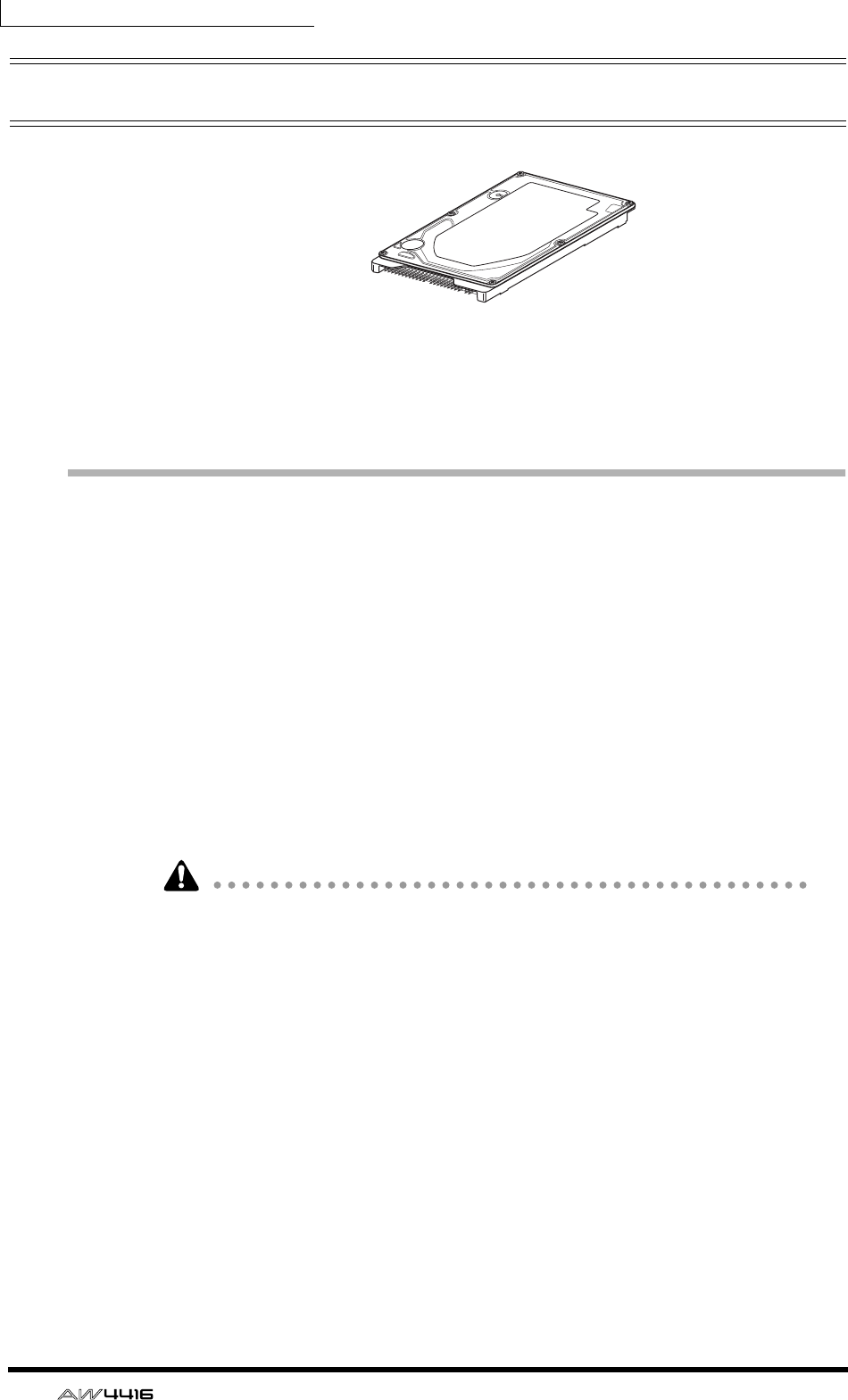
About the internal hard disk
On the AW4416, all data necessary for reproducing a composition (mixer set-
tings, recorder settings, audio data etc.) is stored on the hard disk as a “song.”
An internal hard disk is attached to the ADP25H 2.5 inch hard disk adapter and
installed in the 2.5" HARD DISK DRIVE slot located on the rear panel. Hard disks
with the following specifications can be used.
• Type: IDE 2.5 inch (attachment location conforms to SFF-8201)
• Thickness: no particular limitation
• Capacity: no particular limitation (however, the AW4416 can use a maximum
capacity of 64 GB)
• Models known to work: consult your local Yamaha distributor or refer to the
website at the following URL.
<http://www.aw4416.com/>
• By “models known to work,” we mean commercially available models that
Yamaha has obtained, installed in the AW4416, and successfully tested by
means of various operational tests. However, we cannot take into account
slight differences in performance that may occur due to the manufacturing tol-
erances of each manufacturer.
• Hard disks are precision devices. Strong physical shock, magnetism, static
electricity, or excessive current etc. can damage the data on a hard disk. You
must use media such as an external SCSI device or CD-RW to backup your
important musical data.
• Please be aware that Yamaha Corporation will accept no responsibility for any
damages, neither direct nor indirect, resulting from the use of any of the above
hard disks.
Before you begin
— Operation Guide 3
Installation
Please read and observe the cautions on installing optional equipment listed at
the beginning of this manual.
Here’s how to attach a 2.5 inch IDE hard disk to the ADP25H hard disk adapter
included with the AW4416, and install it into the appropriate slot of the
AW4416.
• Hard disks are precision devices. Do not subject them to physical shock or
static electricity, etc.
• Do not place a hard disk nearby devices that produce a strong magnetic field,
or in locations of extreme cold, heat, or moisture.
• Before you handle a hard disk, touch your hand to a grounded metallic object
to release any static charge that may be present in your body or clothing. If you
fail to do so, static electricity may damage the hard disk.
• Never attempt to disassemble a hard disk or apply excessive force to it.
• The AW4416 is shipped with four screws for attaching a 2.5 inch hard disk,
and four screws for attaching a CD-RW drive, making a total of eight included
screws of the same type.
1. You will need the following items.
• The AW4416 itself
• A 2.5 inch IDE hard disk (sold separately) for installation
• Four screws included with the AW4416 for attaching the 2.5 inch hard disk
• A philips (+) screwdriver
2. Make sure that the power of the AW4416 is turned off. For safety’s sake,
disconnect the power cable from the AC outlet.
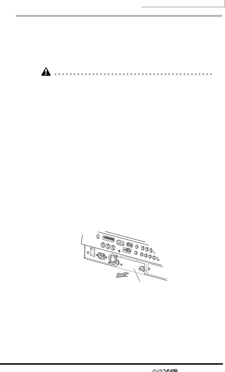
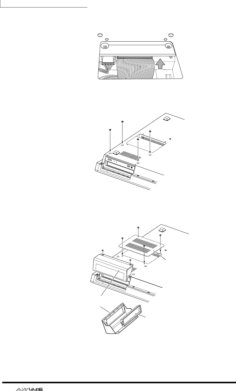
3. On the rear panel of the AW4416, remove the two screws that hold the
ADP25H 2.5 inch hard disk adapter to the 2.5" HARD DISK DRIVE slot.
ADP25H
(2.5 inch hard disk adapter)
Before you begin
4 — Operation Guide
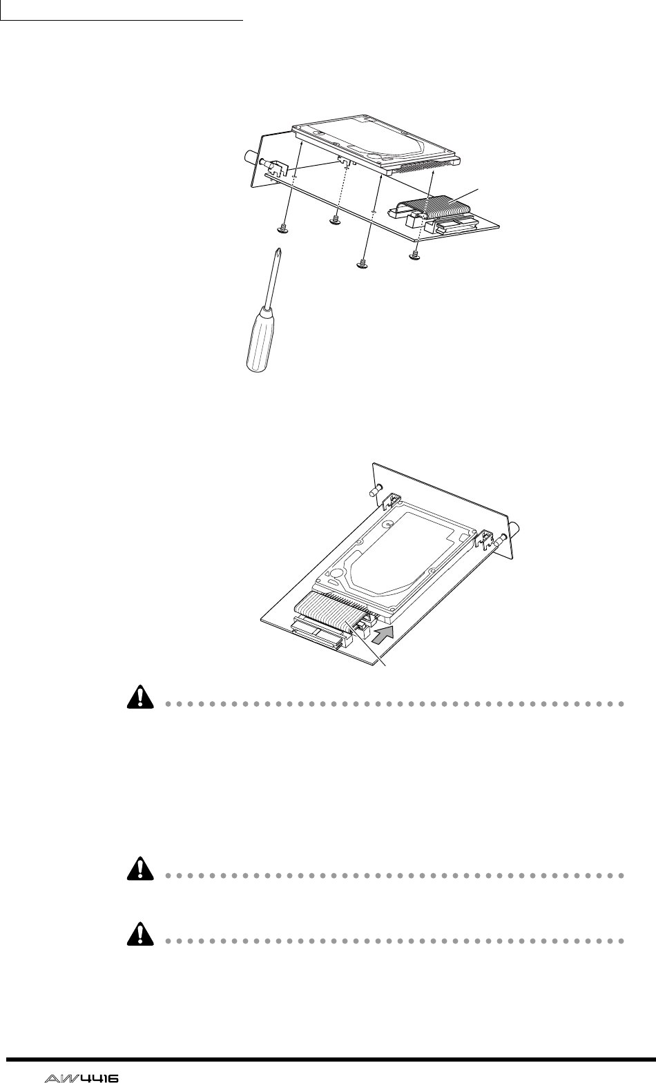
4. Place the hard disk on the ADP25H as shown in the diagram below,
align the screw holes of the hard disk and the ADP25H, and use your
screwdriver to fasten the screws at the four locations shown.
5. Plug the connector of the flat cable extending from the ADP25H into
the connector of the hard disk.
• Even if it is difficult to plug in the connector, do not use excessive pressure to
force it in. This may damage the hard disk, or you may injure yourself.
6. Aligning the ADP25H (with the hard disk attached) with the rails inside
the 2.5" HARD DISK DRIVE slot, push it in until it clicks into place.
7. Use the screws that you removed in step 3 to fasten the ADP25H into
the 2.5" HARD DISK DRIVE slot.
If you fail to tighten the screws all the way, the hard disk may vibrate and fail to
operate correctly.
• Do not turn on the power of the AW4416 until all options have been installed.
• When you turn on the power of the AW4416 after installing a new hard disk,
formatting of the hard disk will begin automatically (
→
P.15).
Flat cable
Flat cable connector
Before you begin
— Operation Guide 5
Installing a CD-RW drive
About the CD-RW drives
A CD-RW drive is an option that allows you to create music CD’s, to backup/
restore internal hard disk data, to play a music CD or to read a CD-ROM. An
internal-type CD-RW drive can be installed by removing the CD-RW drive cover
from the front panel. CD-RW drives with the following specifications can be
used.
• Interface: SCSI-2
• Models known to work: consult your local Yamaha distributor or refer to the
website at the following URL.
<http://www.aw4416.com/>
• By “models known to work,” we mean commercially available models that
Yamaha has obtained, installed in the AW4416, and successfully tested by
means of various operational tests. However, we cannot take into account
slight differences in performance that may occur due to the manufacturing tol-
erances of each manufacturer.
• Please be aware that Yamaha Corporation will accept no responsibility for any
damages, neither direct nor indirect, resulting from the use of any of the above
CD-RW drives.
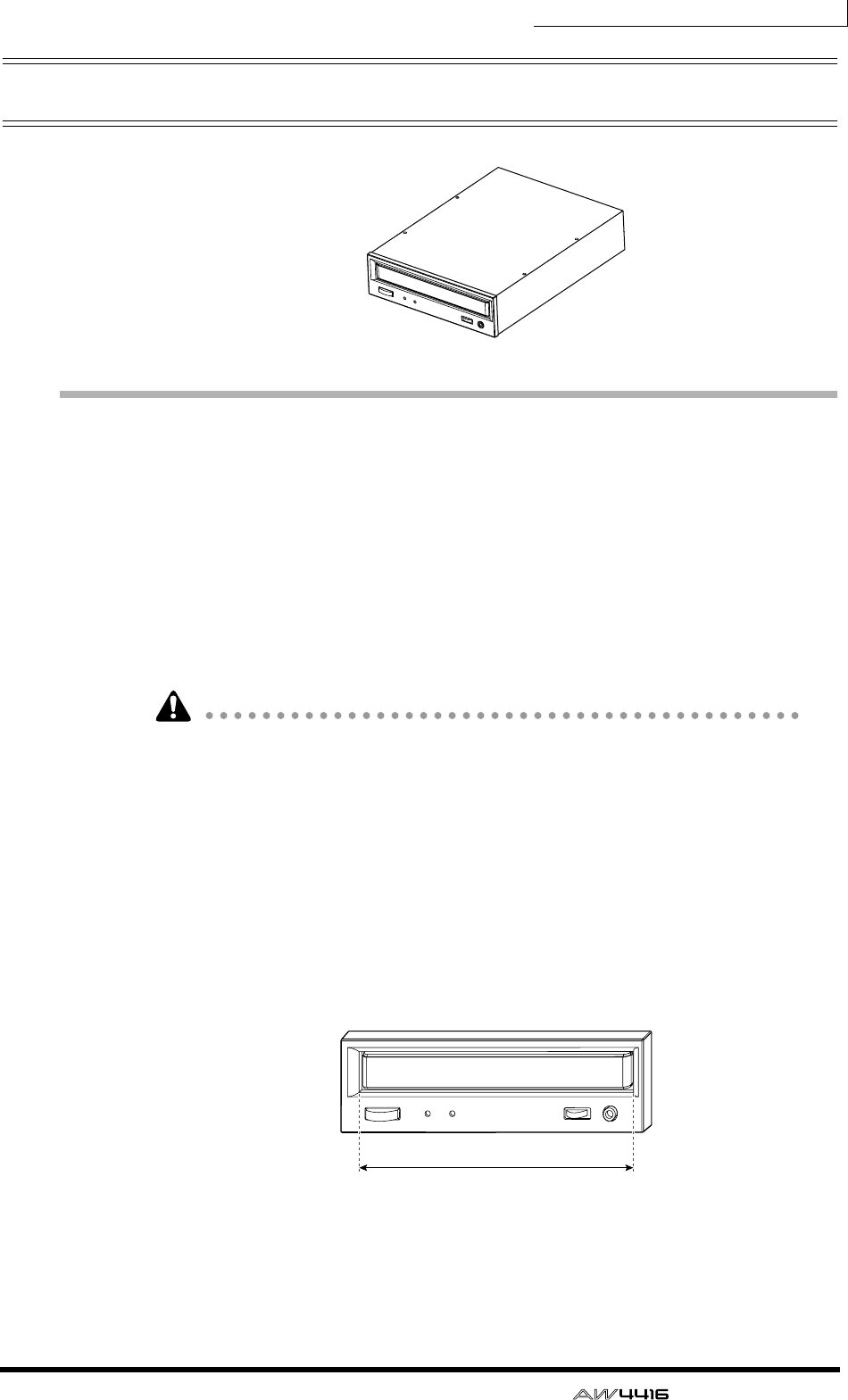
* Note that the cover panel of the AW4416 cannot be attached to a CD-RW
drive with a lid-type tray. The AW4416’s cover panel can be attached to a CD-
RW drive with a tray of the following dimensions.
❒The SCSI ID of the CD-RW drive
• The SCSI ID of the AW4416 itself is fixed at “6.” For this reason, you must set
the SCSI ID of the CD-RW drive to “6” before installing it.
Maximum 138 mm
Before you begin
6 — Operation Guide
• In the various screens of the AW4416, the SCSI ID of the internal CD-RW
drive has been set to “3” by default. For this reason, you will find it conve-
nient to set the ID of the CD-RW to “3.” (For details on setting the SCSI ID,
refer to the manual for your CD-RW drive.)
• If you are installing a CD-RW drive manufactured by Yamaha, the SCSI ID will
be set to “3” at the factory, and we recommend that you leave it at this setting.
Installation procedure
Please carefully read the cautions for installing optional equipment given at the
beginning of this manual.
1. You will need the following items.
• The AW4416 itself
• Internal CD-RW drive (option)
• Screws (included with the AW4416) for attaching the CD-RW drive
• Red and white cable for CD-RW drive (four conductor)
• Philips (+) screwdriver
• Work surface
• In order to install the CD-RW drive you will need to turn the AW4416 on its
back. Make sure that you have a sufficiently broad work surface.
• The AW4416 is shipped with four screws for attaching the 2.5 inch hard disk,
and four screws for attaching the CD-RW drive, making a total of eight screws
of the same type.
2. Make sure that the power of the AW4416 is turned off. For safety’s sake,
disconnect the power cable from the AC outlet.
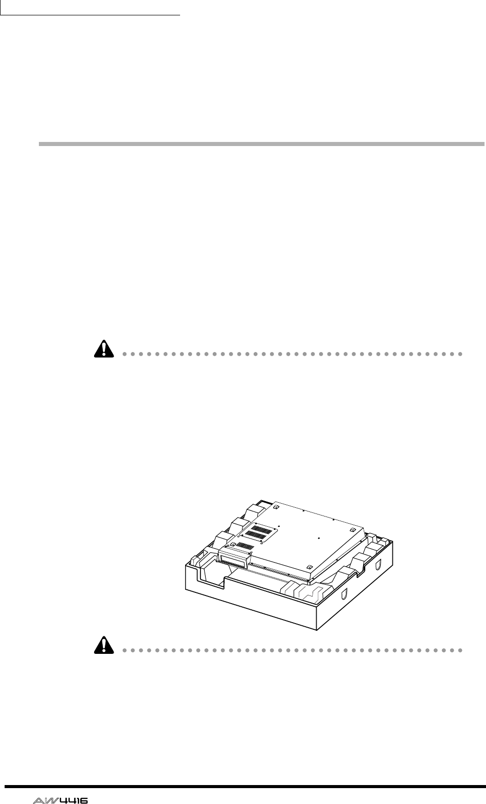
3. Turn the AW4416 upside down on the work surface.
When turning the AW4416 upside down, we recommend that you use the pack-
ing foam from the AW4416’s shipping carton as shown in the diagram at above,
so that the controls of the top panel are not damaged. If the packing foam is not
available, please spread out a soft cloth, and support each of the four corners of
the AW4416 with a stack of magazines etc.
Before you begin
— Operation Guide 7
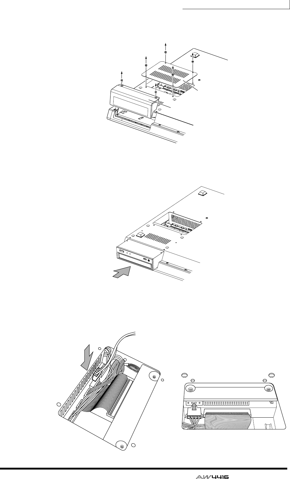
4. Remove the CD-RW drive cover from the front panel, and remove the
bottom panel.
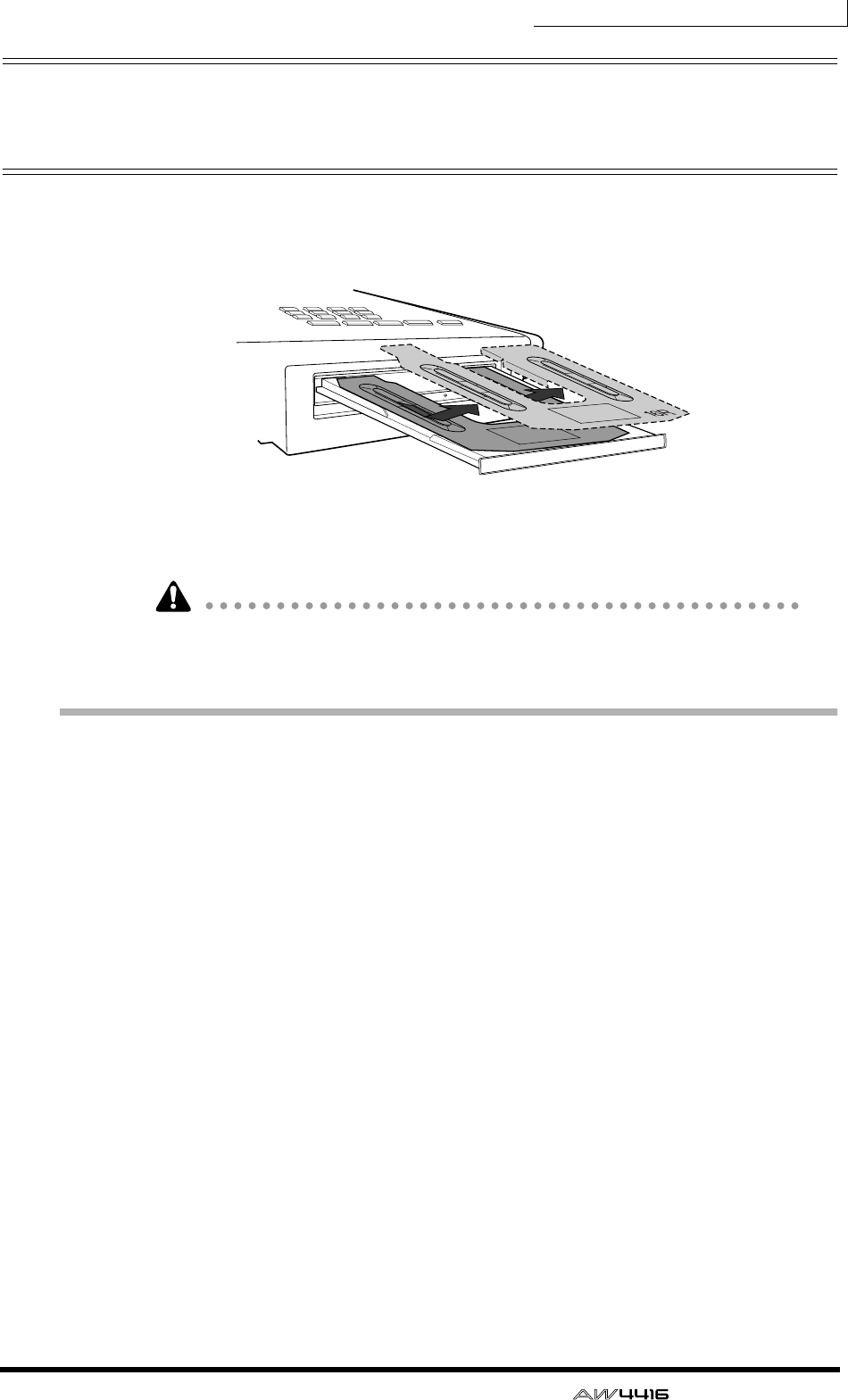
5. Turn the CD-RW drive over, and insert it little by little, stopping when
the connector end of the CD-RW drive enters the opening in the bottom
of the AW4416.
6. Connect the red and white four-conductor cable included with the
AW4416 to the internal connector of the AW4416 as shown in the dia-
gram. Then connect the cable to the connector of the CD-RW drive.
Bottom panel
CD-R/RW drive
cover panel
Before you begin
8 — Operation Guide
7. Plug the connector of the flat cable (extending from inside the AW4416)
into the connector of the CD-RW drive.
8. Align the screw holes in the bottom of the CD-RW drive with the screw
holes of the AW4416, and use a screwdriver to fasten the drive with the
four included screws.
9. Re-attach the CD-RW drive cover and the bottom panel that you
removed in step 3. At this time, remove the inner cover from the CD-RW
drive cover.
CD-R/RW drive
cover panel
Inner cover
Bottom panel
Before you begin
— Operation Guide 9
Removing the transport protection
pad
When CD-RW drives are shipped, the disc tray contains a transport protection
pad that protects the internal mechanism from physical shock suffered during
shipment. Please remove this protective pad before use.
Be sure to save the transport protection pad for the next time you need to trans-
port the unit.
How to remove the transport protection pad
1. Install the CD-RW drive in the AW4416.
2. Turn on the power of the AW4416.
Set the SCSI ID number as necessary (→ P.259).
3. Press the [CD PLAY] key, and then press the [SHIFT] + [F2] keys to open
the disc tray.
4. Remove the transport protection pad.
Before transporting the unit, reverse this procedure to insert the pad.
†gpO ˝‚ ˜› ‡¢
Appbh
Pad for transportation
Remove it before use.
Protection pour le transport
A enlever avant usage.
Transportpolster
Vor der Inbetriebnahme entfernen.
†gpO ˝‚ ˜› ‡¢
Appbh
Pad for transportation
Remove it before use.
Protection pour le transport
A enlever avant usage.
Transportpolster
Vor der Inbetriebnahme entfernen.
* This diagram shows a CD-RW
drive manufactured by Yamaha
Corporation.
Before you begin
10 — Operation Guide
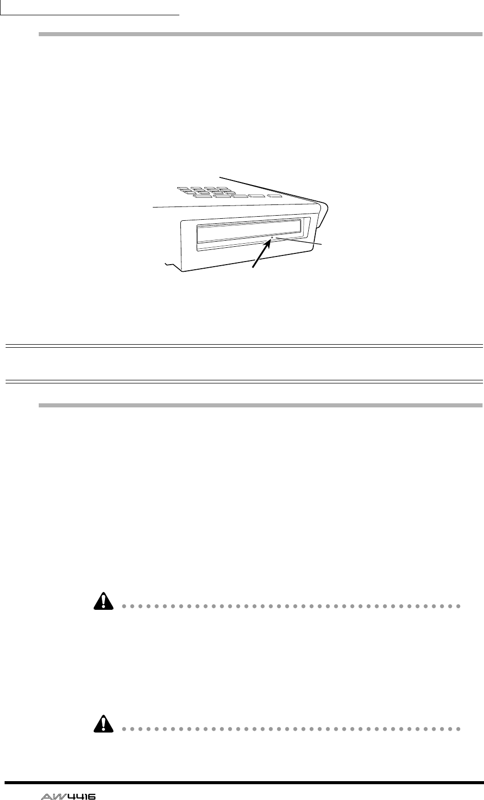
Manual eject (emergency disc removal)
Manual eject allows you to remove the disc manually in the case of an emer-
gency such as a malfunction of the disc tray mechanism (usually temporary) or a
power failure. Please be aware that using this method frequently can cause the
CD-RW drive to malfunction. For the location of the eject hole and the proce-
dure, refer to the manual of your CD-RW drive.
In order to perform this operation, you will need a pin-like object 2 mm or less in
diameter, such as a straightened paper clip.
Attaching an external SCSI device
About external SCSI devices
The external SCSI devices referred to here are storage devices used to backup/
restore the internal data of the AW4416, and can be connected to the SCSI con-
nector on the rear panel of the AW4416. The following types of storage device
can be used.
• Type of drive: MO drives (128 MB, 230 MB, 540MB, 640 MB 1.3 GB), hard
disk drives, CD-RW drives
• Interface: SCSI-2
• Models known to work: consult your local Yamaha distributor or refer to the
website at the following URL.
<http://www.aw4416.com/>
• By “models known to work,” we mean commercially available models that
Yamaha has obtained, connected to the AW4416, and successfully tested by
means of various operational tests. However, we cannot take into account
slight differences in performance that may occur due to the manufacturing tol-
erances of each manufacturer.
• Please be aware that Yamaha Corporation will accept no responsibility for any
damages, neither direct nor indirect, resulting from the use of any of the above
storage devices.
It is not possible to directly record or play back audio signals in realtime on an
external storage device connected to the SCSI connector.
* This diagram shows a CD-RW drive
manufactured by Yamaha Corporation.
Eject Hall
Insert a pin-like object 2 mm
or less in diameter.
Before you begin
— Operation Guide 11
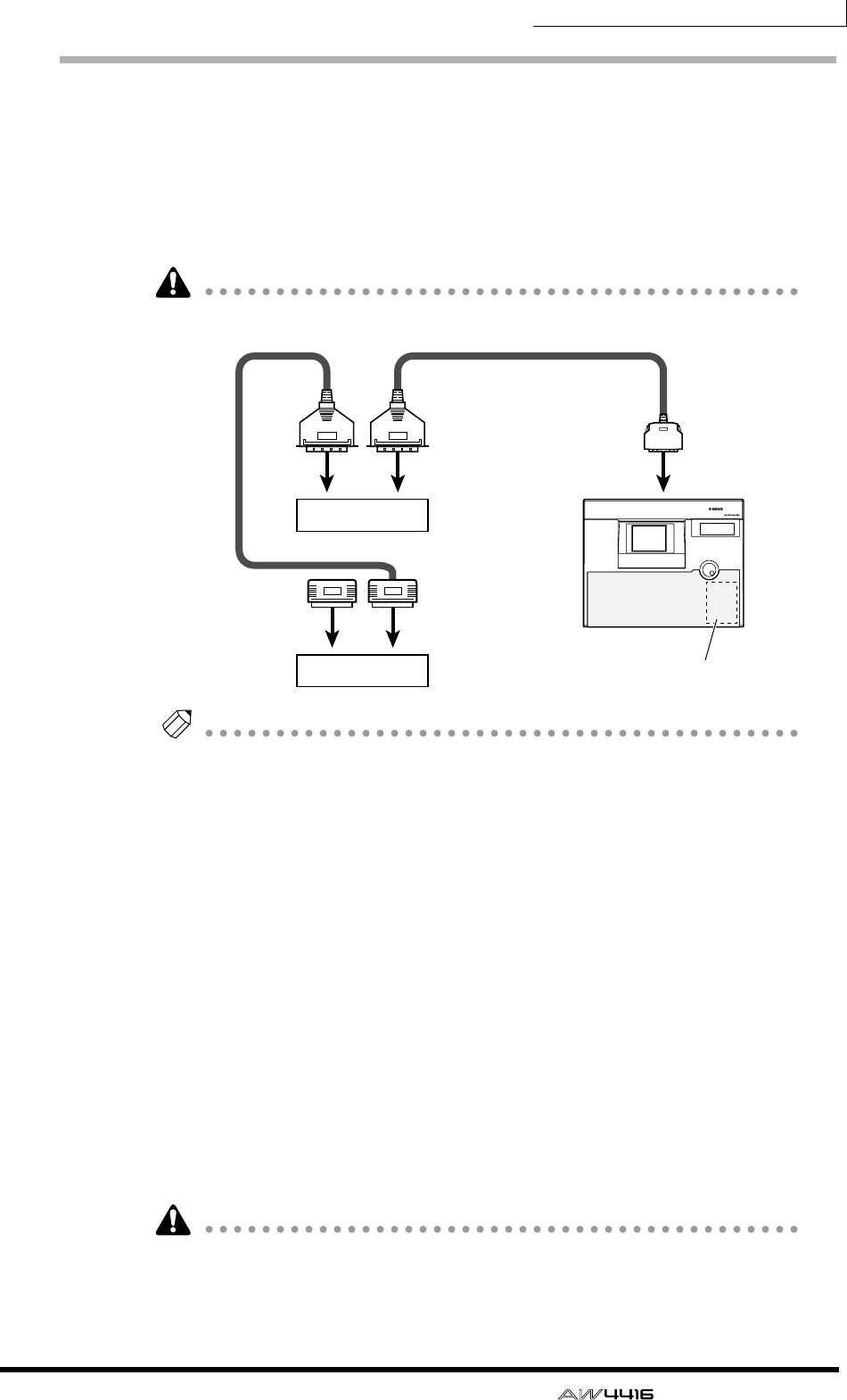
Connection procedure
1. Make sure that the power is turned off for the AW4416 and for the
external SCSI device(s), and use a SCSI cable to connect the SCSI con-
nectors of each device.
When connecting an external SCSI device, use only high impedance SCSI cables
of 100 ohms (±10 ohms) impedance that are 1 meter or shorter in length.
Use only good-quality SCSI cables.
Note
• A maximum of seven SCSI devices (SCSI ID= 0–5,7) can be connected in a
daisy-chain (including the internal CD-RW drive).
• When connecting multiple SCSI devices, you must make sure that the SCSI ID
of each device (including the internal CD-RW drive) does not conflict with any
other device. (For details on how to set the SCSI ID, refer to the manuals for
your SCSI devices.)
• The SCSI ID of the AW4416 itself is fixed at “6.”
• In the various screens of the AW4416, the SCSI ID of the internal CD-RW drive
has been set to “3” by default. For this reason, if you install a CD-RW drive,
you will find it convenient to set its ID to “3.” (For details on setting the SCSI
ID, refer to the manual for your CD-RW drive.)
• If you install a CD-RW drive manufactured by Yamaha, the SCSI ID will be set
to “3” at the factory, and we recommend that you leave it at this setting.
2. Attach a terminator to the last SCSI device in the chain.
A “terminator” is a device that terminates the SCSI signal at the end of the chain,
and is normally attached to the vacant SCSI connector of the last device in the
daisy chain. If the SCSI device has an active terminator (a circuit that terminates
the signal electrically), turn it on. (For details of how to turn on the active termi-
nator, refer to the manual of your SCSI device.)
Before using an external SCSI device, you will need to format it. For details on
this procedure, refer to page 250.
SCSI connector
SCSI
connector
PROFESSIONAL AUDIO WORKSTATION
SCSI connector
SCSI connectorSCSI connector
AW4416
ID=6 (fixed)
Internal CD-RW
ID-3 (default setting)
Terminator
External SCSI device 1
External SCSI device 2

Before you begin
12 — Operation Guide
❒About terminators
“Termination” refers to the process of applying a resistor appropriate for the
impedance of the SCSI bus to terminate the end of the circuit. The resistor
required for this is called the “terminator.” Normally, a terminator must be
installed at the beginning and end of the SCSI bus (in the case of the example
shown above, this would be the AW4416 itself, and the SCSI device connected to
the end of the daisy chain).
However, this is only a general principle, and is not an absolute. Depending on
the combination of SCSI devices, the order of connection, or on the length of the
SCSI cables, there may be cases in which better results are obtained by terminat-
ing only one end of the chain. If problems occur such as the AW4416 failing to
start up when an external SCSI device is connected, try defeating one of the ter-
minators. (For details on how to defeat the internal terminator of the AW4416,
refer to “UTILITY screen → Prefer. 3 page” in the Reference Guide.)
❒About SCSI errors
The SCSI bus is able to transfer data in a stable manner only if all connected SCSI
devices are operating correctly. If the SCSI bus of the AW4416 is connected to a
device whose operation is unstable or which produces noise, errors may occur in
other devices, or the AW4416 may fail to start up correctly. If such problems
occur, check the following points.
❍ Check the SCSI ID
Make sure that the SCSI ID of each SCSI device (including the AW4416 and the
internal CD-RW drive) does not conflict with the SCSI ID of any other device. The
SCSI ID of the AW4416 is fixed at “6.”
❍ Check the terminator
Check the location of the terminator. Under certain conditions, better results may
be obtained by terminating only one end of the SCSI chain.
❍ Check the SCSI cables
Since errors are often caused by low-quality SCSI cables or unnecessarily long
SCSI cables, you should avoid using such cables. Please use double-shielded
cables that are as short as possible. It is also important that the shield within the
cable is grounded to the connector.
❍ External SCSI devices with 25-pin connectors
Most SCSI cables with 25-pin connectors at both ends do not meet SCSI specifi-
cations. For this reason if the system includes a SCSI device that uses a 25-pin
connector, the problems may be due to this type of cable.

Before you begin
— Operation Guide 13
Installing I/O cards
About I/O cards
I/O cards compatible with the Yamaha mini-YGDAI format can be installed in the
OPTION I/O slots 1/2 located on the rear panel of the AW4416 in order to add
input/output ports. For example by installing an ADAT format compatible I/O
card into an OPTION I/O slot, you can transmit/receive eight channels of digital
audio to/from an ADAT format digital recorder.
At present, the following types of I/O cards can be used.
❍ MY8-AT
This card transmits and receives eight channels of Alesis ADAT format digital sig-
nals.
❍ MY8-TD
This card transmits and receives eight channels of TASCAM format digital signals.
❍ MY8-AE
This card transmits and receives eight channels of AES/EBU format digital signals.
❍ MY8-AD
This is an A/D card with eight channels of analog input jacks (balanced TRS
phone jacks).
❍ MY4-AD
This is an A/D card with four channels of analog input jacks (balanced XLR jacks).
❍ MY4-DA
This is a D/A card with four channels of analog output jacks (balanced XLR
jacks).
For up-to-date information on available MY cards, contact your local Yamaha dis-
tributor or check the following website.
<http://www.aw4416.com/>
Some types of MY card sold by other manufacturers may be usable only in SLOT
1 or 2.
Before you begin
14 — Operation Guide
Installation procedure
Please carefully read the cautions for installing optional devices, given at the
beginning of this manual.
1. Make sure that the power of the AW4416 is turned off. For safety’s sake,
disconnect the power cable from the AC outlet.
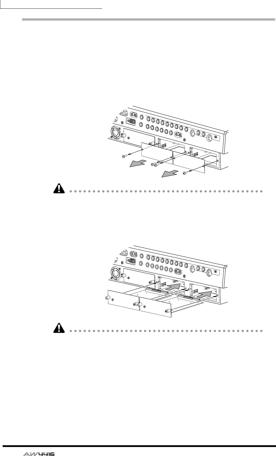
2. From the OPTION I/O slot located on the rear panel of the AW4416,
remove the two screws that hold the cover in place.
Please keep the cover and screws you removed in a safe place.
3. Slide the I/O card along the rails inside the slot until it clicks into place.
4. Tighten the two screws included with the I/O card to fasten the card
securely.
Please note that if the screws are loose, the card may not be grounded correctly.
— Operation Guide 15
Important points you
must observe
Turning the power on or off
You must use the following procedure to turn the power of the AW4416 on or off.
❒Turning the power on
To turn on the power of a system that includes the AW4416, you must turn on the
power switches in the following order.
1Storage devices connected to the AW4416’s SCSI connector, and external
sound sources connected to the input/output jacks
BThe AW4416 itself
CThe monitor system connected to the output jacks of the AW4416
If the SCSI device is turned on after the AW4416 is turned on, it will not function
correctly.
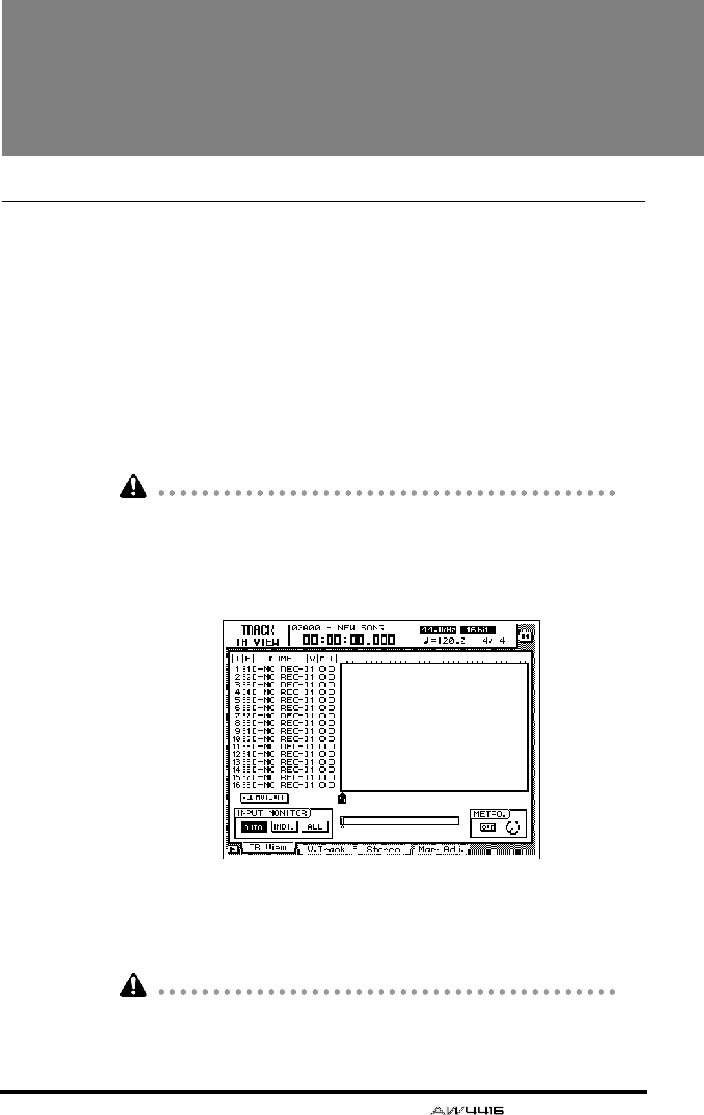
After the opening screen appears in the display of the AW4416, a TRACK screen
like the following will appear.
When the AW4416 is first turned on after a new internal hard disk has been
installed, the display will ask “Format OK? [Y (Enter)/N (Any)].” If you now press
the [ENTER] key, formatting of the hard disk will begin automatically. When for-
matting is completed, the screen shown above will appear.
Never turn off the power of the AW4416 while formatting is in progress. Doing
so may damage the hard disk itself.
Important points you must observe
16 — Operation Guide
Setting the internal clock
When the AW4416 is shipped from the factory, its internal clock is set to Japan
time. When you create a song on the AW4416, the song will store the date and
time using this internal time.
If it becomes necessary to reset the internal clock after replacing a run-down bat-
tery or for any other reason, use the following procedure.
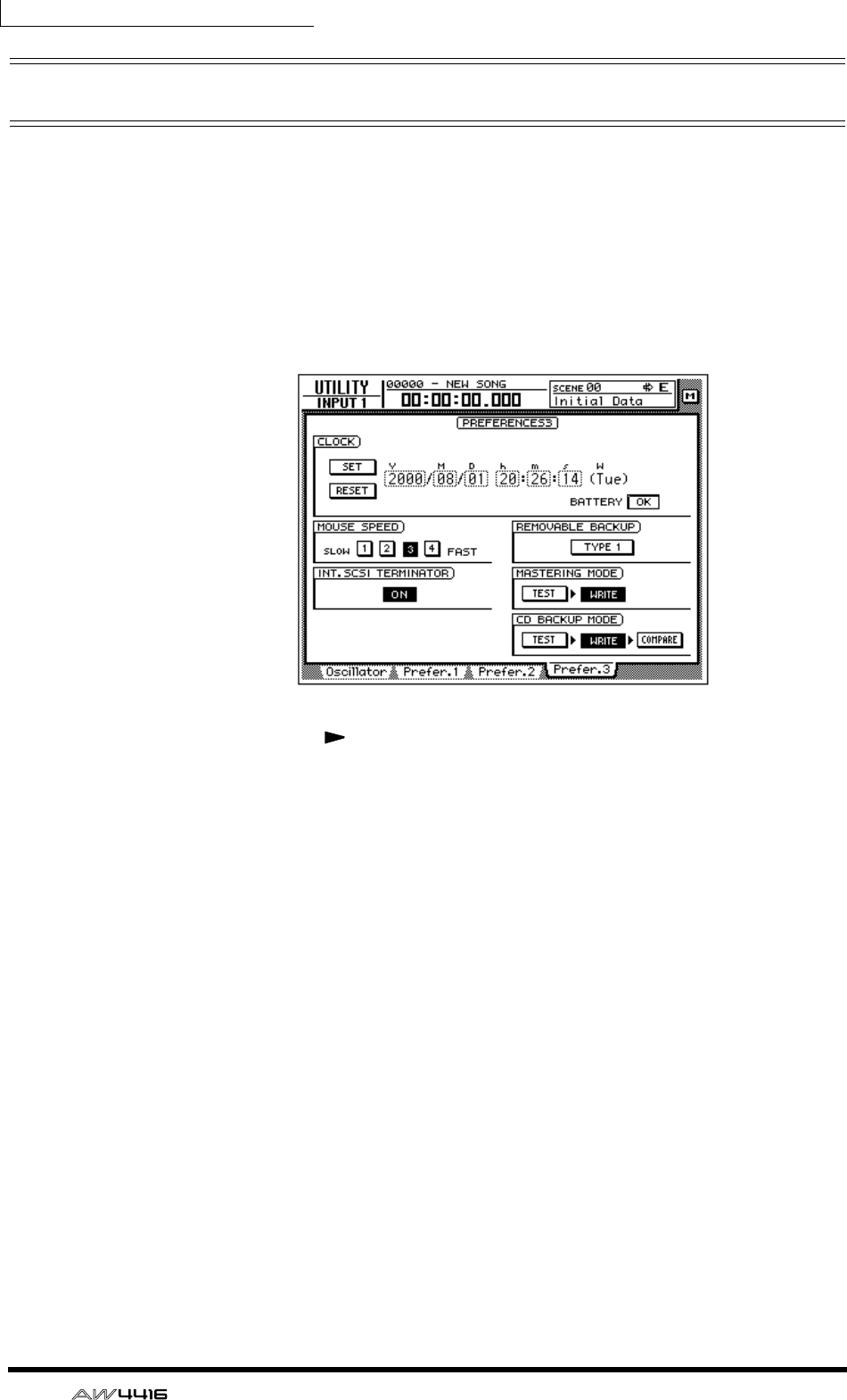
1. Press the [UTILITY] key → [F4] key.
The UTILITY screen Prefer.3 page will appear.
Use the CURSOR [ ] key to move the cursor to the square frame of the Y (year)
field in the CLOCK area, and use the [DATA/JOG] dial to input the year. In the
same way, input M (month), D (date), h (hour), m (minute), and s (second). (W is
the day of the week, and will be set automatically.)
The time you specified will blink. Move the cursor to the SET button to confirm
the setting, or to the RESET button to cancel, and then press the [ENTER] key. The
internal clock of the AW4416 will be set to the specified time. If you select the
RESET button and press the [ENTER] key, the clock will return to the previous
state.
Important points you must observe
— Operation Guide 17
❒Turning the power off
To turn off the power of a system that includes the AW4416, you must turn off the
power switches in the following order.
1The monitor system connected to the output jacks of the AW4416
BThe AW4416 itself
CStorage devices connected to the AW4416’s SCSI connector, and external
sound sources connected to the input/output jacks
Before turning off the power of the AW4416 itself, you must perform the follow-
ing shut-down procedure.
❍ Shut-down operation
1. In the WORK NAVIGATE section located in the upper left of the
AW4416’s top panel, press the [SONG] key.
2. Below the display, press the [F5] (Shut Down) key.
3. The CURRENT SONG STATUS screen will appear, allowing you to check
the content of the last-saved song.
The data for the current song (date, size, quantization bits, protect) shown here in
the song list is the data for when the song was last saved. When you perform the
following Save procedure and press the [ENTER] key, it will be overwritten by the
new data.
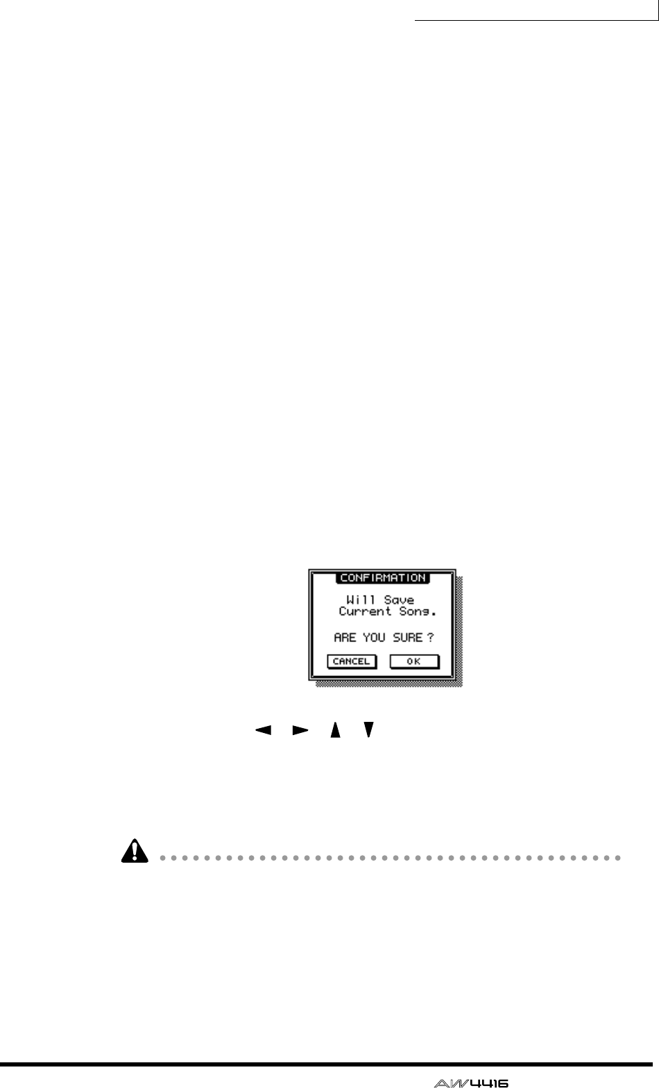
Move the cursor to the EXECUTE button and press the [ENTER] key.
A message will ask you whether you wish to save the current song.
4. Use the CURSOR [ ]/[ ]/[ ]/[ ] keys in the center right of the top
panel to move the cursor (the blinking rectangle) to the OK button, and
press the [ENTER] key located immediately below.
5. When the “Now safe to turn off” message appears, turn off the [POWER]
switch located on the rear panel.
• If you turn off the power of the AW4416 without performing the shut-down
procedure described at the above, the audio data on the hard disk may be lost.
• Never turn off the power while the access indicator in the level meter/counter
is lit, since this may damage the hard disk itself.
• If lightning is occurring nearby, disconnect the power cable from the AC out-
let. The AW4416 can be damaged by lightning.

Important points you must observe
18 — Operation Guide
Transporting the AW4416
When transporting the AW4416, you must disconnect all cables, and pack it in
the packing foam in which the unit was shipped (or the equivalent). If a CD-RW
drive (option) is installed, insert the protective pad that was included with it into
the drive.
• If you transport the AW4416 without packing it as described at the above, any
damage or malfunctions that occur during transport may not be covered under
warranty.
• Even if the AW4416 is packed as described at the above, any damage or mal-
functions that occur due to dropping the unit etc. may not be covered under
warranty. Please handle the AW4416 with care.
Vibration during use
The internal hard disk or CD-RW drive of the AW4416 are very sensitive to vibra-
tion. Do not allow them to be subject to vibration or shock during operation, and
do not move the AW4416 while its power is turned on.
In particular, you must never apply physical shock or vibration while the access
indicator of the level meter/counter is lit, since this may damage the hard disk
itself.

— Operation Guide 19
1Welcome to the world
of the AW4416
This chapter explains the features and basic concepts of the AW4416, and
outlines the signal flow.
Features of the AW4416
The AW4416 is an audio workstation that combines a digital mixer, hard disk
recorder, multi-effects, and sampling pads. It is the only equipment you need to
perform the entire music production process, from multi-track recording, mixing,
audio editing, effect processing, and creating a final CD(*1). In the following
pages of this manual, the functionality of each section is described separately.
*1. An optional internal/external CD-RW drive is required.
❒Mixer section
❍ Professional-quality audio with 32 bit internal processing
The AW4416 carries on the technology made famous on the de-facto standard for
digital consoles — the Yamaha 02R. Internal processing is performed with 32 bit
precision (54 bit precision for EQ) to guarantee the highest possible audio quality.
❍ Up to 44 input channels and 20 buses, rivaling even large consoles
A total of 44 mixing inputs are provided, with 8 analog inputs, digital stereo
input, 16 (maximum) digital/analog inputs via the OPTION I/O slot, in addition
to 16 recorder monitor channels, and 2 return channels. Output buses total 20,
with 8 group buses, 8 AUX buses, stereo bus, and SOLO bus (stereo). With a bus
configuration that rivals large consoles, the AW4416 can handle a wide variety of
applications.
❍ Four-band EQ and dynamics processing on each channel
Every input as well as the stereo output channel provides the same powerful four-
band full-parametric EQ and dynamics processor as on the 02R. (The two return
channels are excepted.)
Each band of the EQ is fully adjustable in the range of ±18 dB/f= 20 Hz–20 kHz/
Q= 41 points. The dynamics processor provides compressor, gate, ducking,
expander, and compander functionality. Key-in and stereo link are also supported
for precise control of the input signals.
❍ Two high-quality multi-effect processors are built-in
Two multi-effect processors provide spatial effects such as reverb and delay, mod-
ulation effects such as chorus and flanger, and guitar effects such as distortion
and amp simulator.
In addition to using these via the AUX bus send/return, they can be inserted into a
channel or the stereo bus. A high-impedance jack for direct connection of an
electric guitar is also provided.

Chapter1—Welcome to the world of the AW4416
20 — Operation Guide
❍ Scenes and libraries
Faders locations and mix parameters for each channel, together with effect set-
tings, can be stored as a scene.
Up to 96 scenes can be used for each song. Scenes that you save can be recalled
instantly using the top panel keys, or by transmitting program change messages
from an external MIDI device. Libraries for storing EQ, dynamics processor, and
channel settings are also provided.
❍ Full mixing automation
The AW4416 features seventeen 60 mm motorized faders.
In addition to the ability to recall scene memories and libraries, the AW4416 pro-
vides fully automated mixing that records fader/pan/EQ movements in realtime.
❒Recorder section
❍ High capacity hard disk up to 64 GB(*2)
An internal hard disk (2.5 inch IDE type) of up to 64 GB (maximum 6.4 GB per
song) is supported.
A hard disk attached to the ADP25H cartridge (sold separately) can be inserted
into the hard disk slot of the AW4416, allowing you to exchange hard disks as
easily and conveniently as if you were using removable media.
*2. Hard disks are sold separately.
❍ Efficient data management
All of the audio data (multi-track and stereo track), scene memories, libraries, and
automix data used in a song are managed on the internal hard disk as a “Song.”
A desired song can be recalled from disk at any time. Songs can also be backed
up on an external hard disk, MO disk, or CD-R/RW disc.
❍ 16×8 virtual tracks + stereo track
A single song consists of 16 tracks × 8 virtual tracks + stereo track (total of 130
tracks).
The quantization (16 bit/24 bit) and sampling frequency (44.1 kHz/48 kHz) can
be selected for each song. 16 tracks can be recorded simultaneously, or 16 tracks
played back while recording 8 tracks simultaneously, making the AW4416 an
ideal choice for live recording or for re-recording or ping-ponging from an exter-
nal recorder. The 16 tracks can also be mixed down directly to the stereo track.
This has the advantage not only of making a master recorder unnecessary, but
also of allowing multi-track and two-track mix data to be managed together.
❍ Versatile editing functionality
Data can be edited freely at every level — song, track, part, and region.
Editing functions include “time compression” that allows you to compress or
expand time over a range of 50%–200%, and “pitch change” that can modify the
pitch as far as an octave upward or downward. Editing is non-destructive, allow-
ing up to fifteen levels of undo/redo.
❍ Locate functions, and auto punch-in/out
A total of eight locate keys are provided: start, end, RTZ, A, B, in, out, and roll-
back. In addition, you can set 99 markers for each song, making it fast and easy
to locate to any desired point. Auto punch-in/out at the specified punch-in and
punch-out points is also provided. The AW4416 also has a built-in click metro-
nome linked with the tempo map.

Chapter1—Welcome to the world of the AW4416
— Operation Guide 21
❒Sampling pad section
❍ Assign 16 sounds to the sampling pads
Sixteen sounds can be assigned to the eight pads with switchable A/B banks.
Sounds can be sampled into these pads at the same 16 bit/24 bit and 44.1 kHz/
48 kHz audio quality as for recording. Sampling sources can be taken from a
sound file on hard disk, an external input from the mixer, or from a WAV file on a
SCSI device. The playback timing can be recorded on a special sequencer track,
and edited later. Pad polyphony is eight notes, and a total of approximately 90
seconds can be sampled in the pads (16 bit/44.1 kHz).
❒CD-RW drive (option)
❍ CD-RW drive(*3) can be installed internally
You can produce an audio CD off-line, using stereo tracks from the hard disk. This
allows entire process from recording to CD production to be completed within a
single unit. The CD-RW drive can also be used to store recorded data, making
backups easy. Playback of audio CD’s and loading from CD-ROM is also sup-
ported, allowing these to be used as sources for the sampling pads.
*3. A CD-RW drive is optional.
❒Other features
❍ Simple panel layout and efficient operation
The AW4416 features a large backlit LCD and a three-color FL display, providing
a graphic user interface that can be used intuitively and efficiently. A serial mouse
(9 pin D-sub connector) can also be connected.
❍ Two I/O card option slots
Two slots support a variety of formats including ADAT, TASCAM, AES/EBU, and
analog. The AW4416 is designed with an open architecture for superb expand-
ability.
❍ Sophisticated connectivity
TO HOST connector and SCSI connector (SCSI-2) are standard, ensuring easy
connection to computers, external SCSI devices(*4), and MIDI devices. WORD
CLOCK IN/OUT connectors are also provided to allow the construction of digital
systems for a variety of applications. In addition, MTC/MIDI clock can be used
for synchronization, and MMC commands can control the AW4416 from an
external device.
*4. External SCSI devices can be used only to back up data. They cannot be used to
record audio data directly.
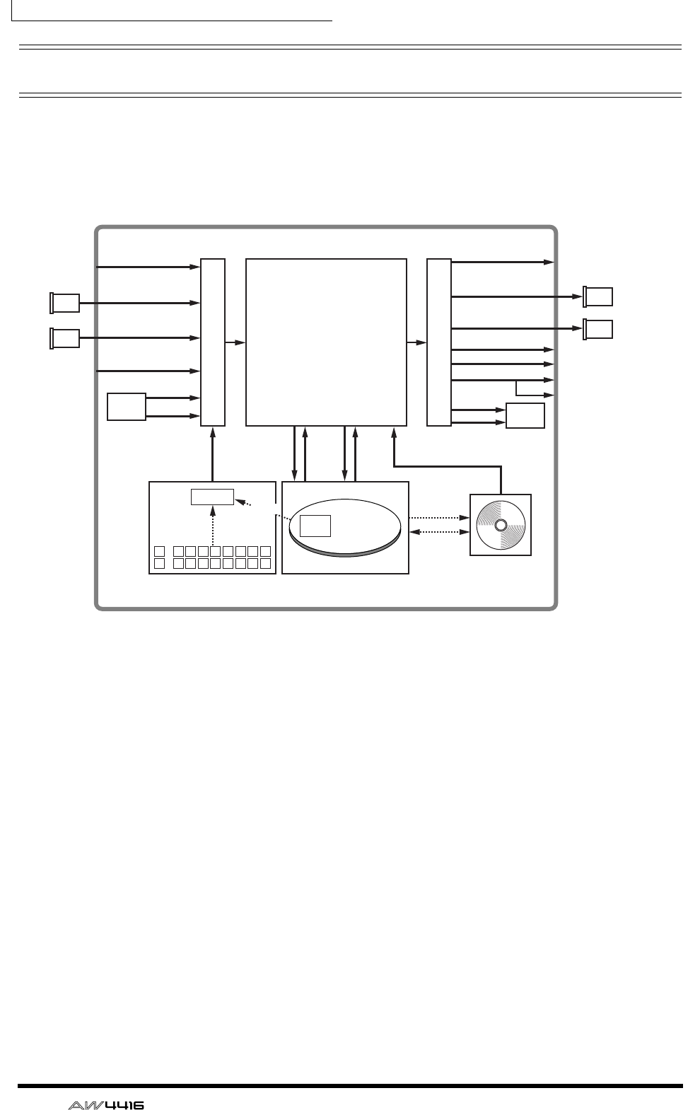
Chapter1—Welcome to the world of the AW4416
22 — Operation Guide
Signal flow within the AW4416
The following diagram shows the general signal flow of the AW4416. As you can
see from this diagram, the AW4416 consists of several sections: input patch, out-
put patch, mixer, sampling pads, recorder, and CD-RW drive (optional).
The signal flow within each section is explained in detail in the pages that follow.
Input channels 1–24
Effect returns 1/2
Monitor channels 1–16
Buses 1–8
STEREO bus
AUX buses 1–8
SOLO bus
Channel insert I/O
Stereo bus insert I/O
Output patch
Input patch
Mixer section
AW4416
Sampling pads section Recorder section
×8
×8×16 ×16
×8
×4
×8
×2
×2×2×2
×2
×2
×2
×2
×2
×8
×8
Trigger
CD Writing
Data Backup/
Restore
INPUT jacks 1–8 OMNI OUT jacks 1–4
MONITOR OUT jacks
PHONES jack
STEREO OUT jacks
DIGITAL STEREO OUT jack
Effect
1/2 Effect
1/2
D-RAM
12345678
1
A
B 2 3 4 5 6 7 8
Audio
File
Import
I/O
card
I/O
card
I/O
card
I/O
card
OPTION I/O
slot 1
OPTION I/O
slot 2
OPTION I/O
slot 1
OPTION I/O
slot 2
DIGITAL STEREO
IN connector
CD-RW
Drive

Chapter1—Welcome to the world of the AW4416
— Operation Guide 23
Input patch
The input patch section is where input signals are assigned to input channels 1–
24 and return channels 1/2. The following types of input signal can be selected.
❍ MIC/LINE INPUT
Input signals from analog INPUT jacks 1–8.
❍ OPTION IN
Input signals from an I/O card installed in rear panel OPTION I/O slots 1/2. Up to
8 channels of signal can be input simultaneously from a single I/O card.
❍ SAMPLING PAD
Output signals of pads 1–8 in the sampling pad section.
❍ EFFECT 1/2
Return signals from internal effects 1/2.
❍ DIGITAL STEREO IN
Input signals from the DIGITAL STEREO IN jack.
❍ METRONOME
The playback of the internal metronome.
The following input signals can be assigned to each channel.
Input channel 1–24
(mono) Return channel
1 (stereo) Return channel
2 (stereo)
MIC/LINE INPUT OOO
OPTION IN OOO
SAMPLING PAD O
EFFECT 1 O
EFFECT 2 O
DIGITAL STEREO IN OOO
METRONOME O
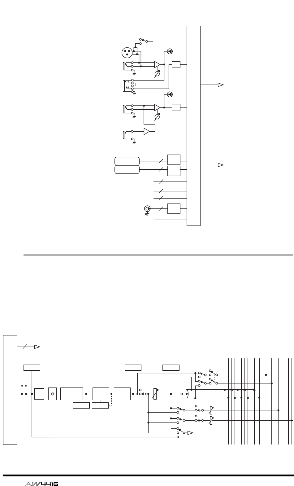
Chapter1—Welcome to the world of the AW4416
24 — Operation Guide
Input channels 1–24
There are monaural input channels used mainly for inputting mics or line level
instruments. The signals input to input channels 1–24 are routed through an
attenuator, phase switch, four-band EQ, dynamics processor, and delay, and are
sent to buses 1–8, the stereo bus, or AUX buses 1–8. Input channels 1–16 have a
direct output (DIRECT OUT) function that allows their signal to be output directly
to an output jack or to the recorder section.
MIC/LINE
INPUT
OPTION IN
INPUT PATCH
METRONOME
EFFECT 1
EFFECT 2
SAMPLING
PAD
DIGITAL
STEREO IN
48V
INPUT
1-2
INPUT
3-8
Hi-z
8 ch
ONLY
INSERT
I/O
SLOT1
SLOT2
AD
RETURN 1/2
INPUT 1-24
AD
PEAK
PEAK
8
8
8
2
2
2
De-
Emp
De-
Emp
De-
Emp
INPUT 1(...24)
Mono in X 24
INPUT PATCH
INSERT
METERMETER
METER METER
PREFADER LISTEN/
AFTER PAN
DIRECT OUT
(1~16 only)
4 BAND EQ
46 SELECTED INSERT RETURNS
ON LEVEL PAN
PRE/POST ON AUX
INPUT
DELAY
DY-
NAMICS
ATT
BUS1
BUS2
BUS3
BUS4
BUS5
BUS6
BUS7
BUS8
STEREO L
STEREO R
SOLO L
SOLO R
AUX 1
AUX 6
AUX 7(EFF1)
AUX 8(EFF2)
SOLO
METER
(EQ) (Gain Reduction)
...
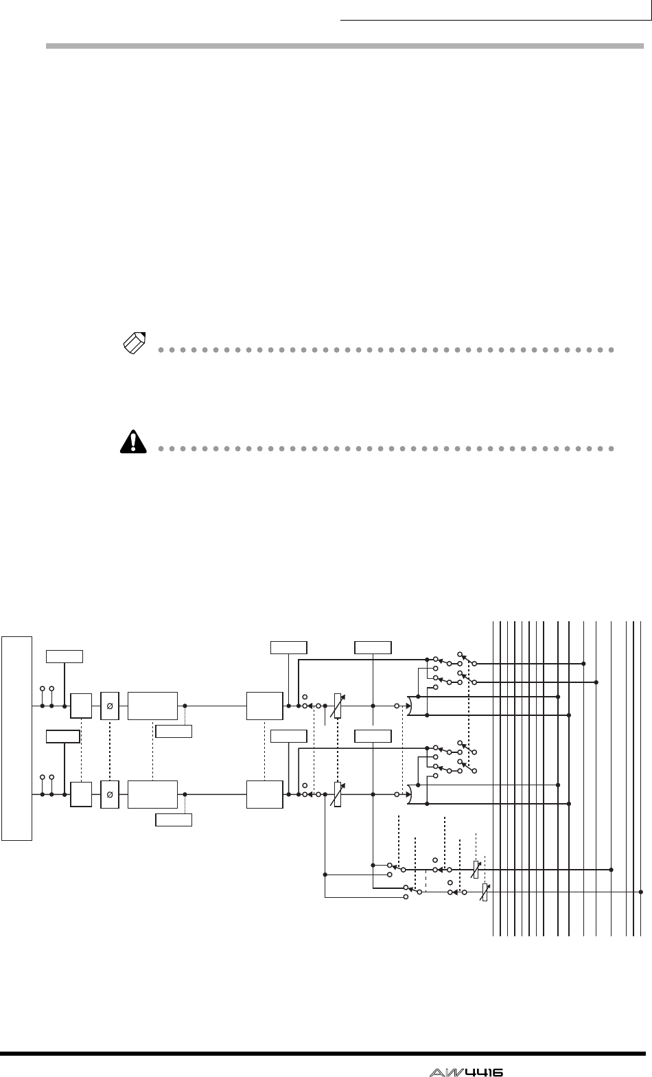
Chapter1—Welcome to the world of the AW4416
— Operation Guide 25
Return channels 1/2
These are stereo input channels used mainly to input the return signals from inter-
nal effects 1/2. However they can also be used as supplementary input channels
by changing the input signal assignments of the input patch section.
The structure of these channels is identical to that of the input channels, with the
exception of the following differences:
1Stereo
BNo dynamics processor
CNo direct output
DNo AUX 7 send level from return channel 1
ENo AUX 8 send level from return channel 2
Tip!
Since return channels 1/2 are stereo, selecting MIC/LINE INPUT or OPTION IN as
input signals will cause two adjacent odd-numbered/even-numbered signals to be
assigned. Also if DIGITAL STEREO IN is selected, the signals of both L/R will be
assigned.
• The reason that return channel 1 (2) has no send level to AUX 7 (8) is to pre-
vent the feedback loop that would occur if the signal returned from internal
effect 1 (2) were sent back to the same internal effect.
• Be aware that the AUX 7 (8) send level is not available even if a different input
signal is assigned to return channel 1 (2).
RETURN 1(...2)
Stereo in X 2
INPUT PATCH
INSERT
INSERT
METER METER
METER METER
METER
METER
ATT
ATT
BUS1
BUS2
BUS3
BUS4
BUS5
BUS6
BUS7
BUS8
STEREO L
STEREO R
SOLO L
SOLO R
AUX 1
AUX 6
AUX 7(EFF1)
AUX 8(EFF2)
PREFADER LISTEN/
AFTER PAN SOLO
SOLO
PAN
PAN
PRE/POST
RETURN1 can not be assigned to AUX7
(EFF1)
RETURN2 can not be assigned to AUX8
(EFF2)
ON AUX
ON LEVEL
INPUT
DELAY
INPUT
DELAY
METER
4 BAND EQ
(EQ)
METER
4 BAND EQ
(EQ)
...
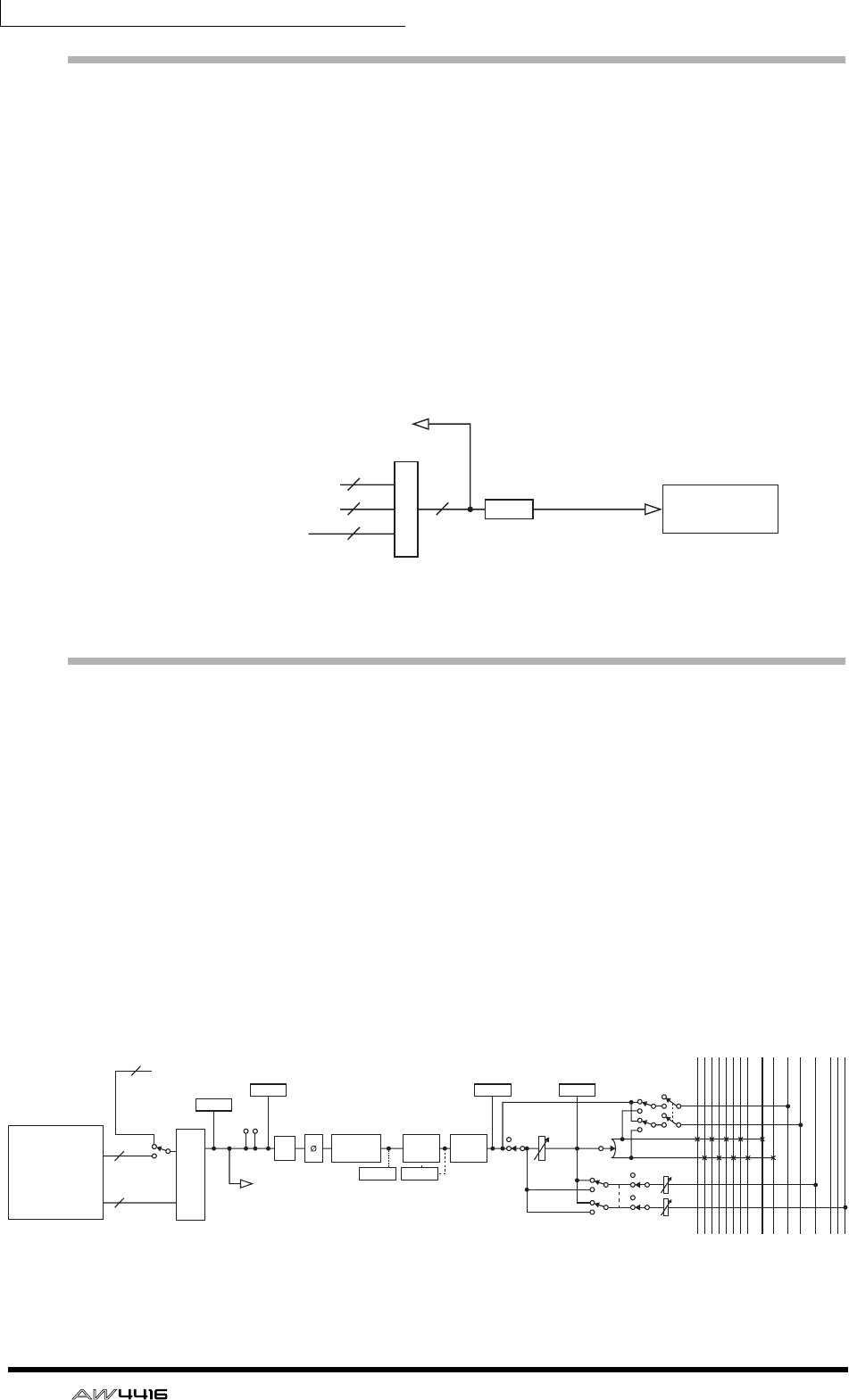
Chapter1—Welcome to the world of the AW4416
26 — Operation Guide
Recorder input patching
This section assigns the signals that are input to tracks 1–16 of the recorder sec-
tion. The following types of signal can be selected.
❍ STEREO
The stereo bus output signal that has passed through the stereo output channel.
❍ BUS 1–8
The output signal of buses 1–8.
❍ DIRECT OUT 1–16
The direct output signal of input channels 1–16.
Monitor channels 1–16
These are monaural channels that are assigned to the track 1–16 outputs of the
recorder section. According to the input monitor settings or the state of the trans-
port, they will input either the signals being input to tracks 1–16, or the playback
signals of tracks 1–16.
As an exception, the stereo track will be patched to monitor channels 1/2 when
the stereo track of that song is being played back, and the remainder of the moni-
tor channels 3–16 will be muted.
The structure of these channels is the same as that of the input channels, with the
exception that the direct output is fixed at a point immediately before the attenu-
ator.
RECORDER
INPUT 1(...16)
INPUT PATCH
BUS 1~8
CH DIRECT OUT1~16
STEREO
RECORDER INPUT 1~16
DITHER
8
16 16
2
RECORDER
RECORDER MONI 1(...16)
Mono in X 16
INPUT PATCH
ON LEVEL PAN
PRE/POST ON AUX
16
16
2
RECORDER INPUT 1-16
INPUT
MONITOR
RECORDER
DIRECT OUT
RECORDER
REPRO1-16
RECORDER
ST Trk L/R
INSERT
METER
METER
(FL Display)
ATT
BUS1
BUS2
BUS3
BUS4
BUS5
BUS6
BUS7
BUS8
STEREO L
STEREO R
SOLO L
SOLO R
AUX 1
AUX 6
AUX 7(EFF1)
AUX 8(EFF2)
METER METER
PREFADER LISTEN/
AFTER PAN SOLO
METERMETER
4 BAND EQ INPUT
DELAY
DY-
NAMICS
(EQ) (Gain Reduction)
...
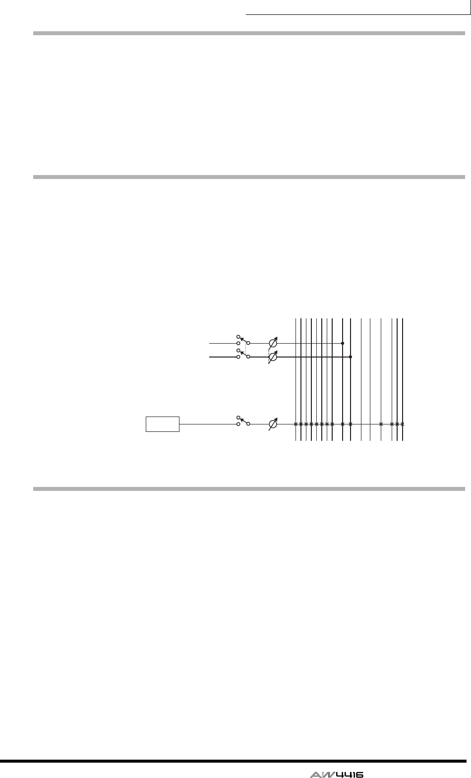
Chapter1—Welcome to the world of the AW4416
— Operation Guide 27
Digital cascade connections
The input signal from the rear panel DIGITAL STEREO IN jack can be cascaded
directly into the stereo bus, instead of being sent via the input patch section and
patched to a pair of input channels. This is convenient when you wish to use an
external digital mixer without linking it to the mixer section of the AW4416. Set-
tings for cascade connection are made in the SET UP screen D.InSetup page.
* For the signal flow diagram, refer to Oscillator, below.
Oscillator
The AW4416 has a built-in oscillator section that allows you to select a sine wave
(100 Hz, 1 kHz, 10 kHz) or white noise. The signal of the oscillator can be output
from one of the following buses: buses 1–8, AUX buses 1–8, or the stereo bus.
Oscillator settings are made in the UTILITY screen Oscillator page.
Stereo output channel
This is the stereo output channel that processes the signals sent from each chan-
nel to the stereo bus. It provides the same four-band EQ and dynamics processor
as do the input channels. The output signal of the stereo output channel is sent
via the output patch section to the various output jacks, and is simultaneously
output from the MONITOR OUT jacks and the PHONES jack.
When an internal or external CD-RW drive is used to play back an audio CD, the
CD audio signal is patched to a point before the fader of the stereo output chan-
nel.
ON
OSC
BUS1
BUS2
BUS3
BUS4
BUS5
BUS6
BUS7
BUS8
STEREO L
STEREO R
SOLO L
SOLO R
AUX 1
AUX 6
AUX 7(EFF1)
AUX 8(EFF2)
ATT
ATT
ENABLE
DIGITAL STEREO L
DIGITAL STEREO R
(BUS CASCADE)
...
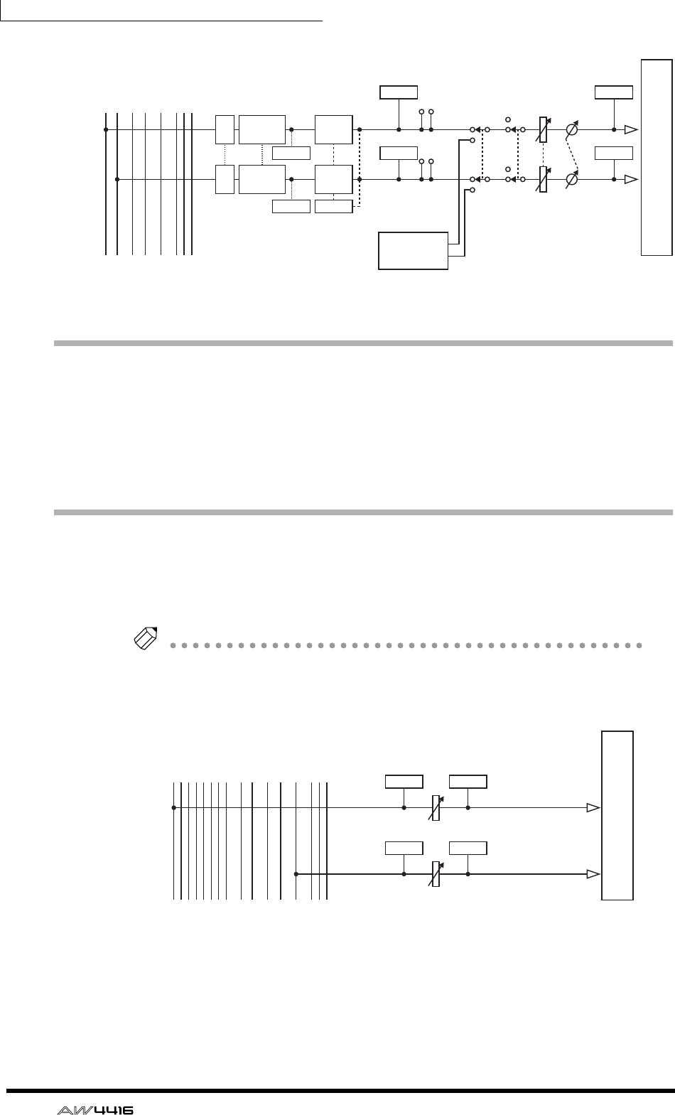
Chapter1—Welcome to the world of the AW4416
28 — Operation Guide
Buses 1–8
The signals sent from each channel to buses 1–8 pass through the master level,
and are sent to the output patch section. The master level is adjusted in the
HOME screen Bus page ([HOME] key → [F3] key).
* For the signal flow diagram, refer to AUX buses 1–8, below.
AUX buses 1–8
The signals sent to AUX buses 1–8 from each channel pass through the master
level, and are sent to the output patch section. The master level is adjusted in the
HOME screen Bus page ([HOME] key → [F3] key).
Tip!
When the AW4416 is in its default state, the output of AUX buses 7/8 is sent to the
output patch section, and simultaneously assigned to the inputs of internal effects 1/
2 as well.
STEREO
CD-RW
DRIVE
OUTPUT PATCH
LEVEL BALON
INSERT
METER
METER
METER
METER
METER
METER
METER
ATT 4BAND EQ
ATT 4BAND EQ
DY-
NAMICS
DY-
NAMICS
STEREO L
STEREO R
SOLO L
SOLO R
AUX 1
AUX 6
AUX 7(EFF1)
AUX 8(EFF2)
(EQ)
(EQ) (Gain Reduction) CD PLAY mode
L
R
...
AUX1(...8)
BUS1(...8)
LEVEL
LEVEL
METER
METER
METER
METER
BUS1
BUS2
BUS3
BUS4
BUS5
BUS6
BUS7
BUS8
STEREO L
STEREO R
SOLO L
SOLO R
AUX 1
AUX 6
AUX 7(EFF1)
AUX 8(EFF2)
...
OUTPUT PATCH
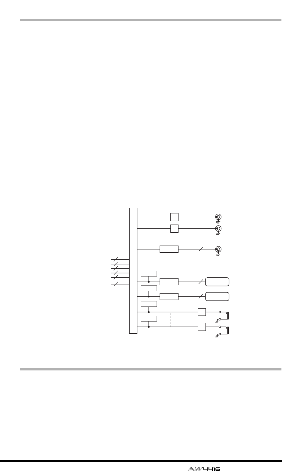
Chapter1—Welcome to the world of the AW4416
— Operation Guide 29
Output patch
This section assigns the output signals to the STEREO OUT jacks, DIGITAL STE-
REO OUT jack, I/O cards installed in OPTION I/O slots 1/2, and OMNI OUT
jacks 1–4. The following types of signals can be selected.
❍ STEREO
The stereo bus output signal that has passed through the stereo output channel.
❍ BUS 1–8
The output signals of buses 1–8.
❍ AUX 1–8
The output signals of buses 1–8.
❍ CH DIRECT OUT 1–16
The direct output of input channels 1–16.
❍ INSERT SEND
An insertion output for inserting an external effect into each channel.
❍ RECORDER DIRECT OUT 1–16
The direct output of tracks 1–16 of the recorder section.
Internal effects 1/2
When the AW4416 is in its default state, the output of AUX bus 7/8 is sent to the
output patch section, and simultaneously assigned to the inputs of internal effects
1/2 as well. The outputs of effects 1/2 are respectively assigned to return channels
1/2.
DIGITAL
STEREO OUT
OPTION OUT
OMNI OUT
STEREO
OUT
DITHER
DA
DA
DA
DA
SLOT1 OUT
SLOT2 OUT
2
L
R
X 2
X 4
0dB
8
8
OUTPUT PATCH
STEREO
BUS1~8
AUX1~8
CH DIRECT OUT1~16
INSERT SEND
2
8
8
16
46
16
RECORDER DIRECT
OUT 1~16
10dBV
DITHER
DITHER
METER
METER
METER
METER
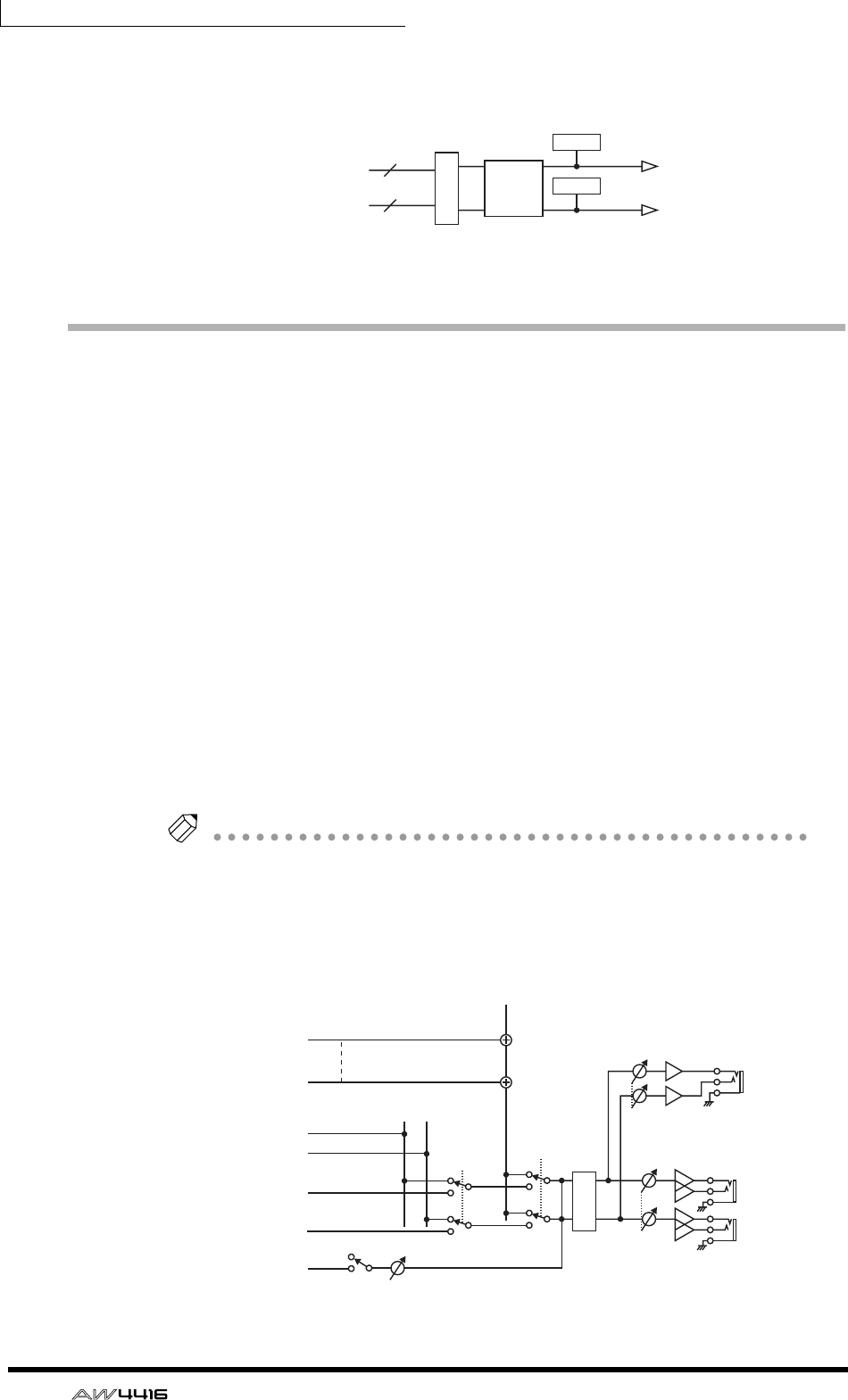
Chapter1—Welcome to the world of the AW4416
30 — Operation Guide
By defeating these assignments, you can insert internal effects 1/2 into any
desired channel, or use AUX bus 7/8 or return channels 1/2 for other purposes.
Monitor output/headphone output
As monitoring jacks, the AW4416 provides MONITOR OUT jacks and a
PHONES jack. The types of signal that are output from these jacks will change as
follows, depending on the state of the AW4416.
1Initial state
The signal of the stereo output channel will be output without change from the
MONITOR OUT jacks/PHONES jack.
BWhen the [SOLO] key is on
The signal of the channel selected by the [ON] key will be sent to the SOLO bus,
and output from the MONITOR OUT jacks/PHONES jack. At this time, all other
signals will be muted.
CWhen the TRACK [CUE] key is on
The direct output signal of the track selected by the [REC TRACK SELECT] key will
be output from the MONITOR OUT jacks/PHONES jack.
DWhen the internal metronome function is on
The metronome signal will be mixed with the output signals of 1–3.
Tip!
• The same signal is always sent from the MONITOR OUT jacks and the
PHONES jack. However, the level adjustment is independent; the output level
of the MONITOR OUT jacks is adjusted by the [MONITOR OUT] control, and
the output level of the PHONES jack is adjusted by the [PHONES] control.
• Whenever the [SOLO] key and the TRACK [CUE] key are both on, only the
TRACK [CUE] key will be valid.
EFFECT
SELECT
46
2
EFFECT RETURN 1/2
X 2
AUX7 (EFF1),
AUX8 (EFF2)
INSERT SEND
METER
METER
PHONES
MONITOR
OUT
PHONES
MONITOR
L
R
+4dB
DA
RECORDER
TRACK CUE
Logic
MIXER SOLO
Logic
ON ATT
RECORDER
DIRECT OUT 1
RECORDER
DIRECT OUT 16
STEREO L
STEREO R
METRONOME
SOLO L
SOLO R
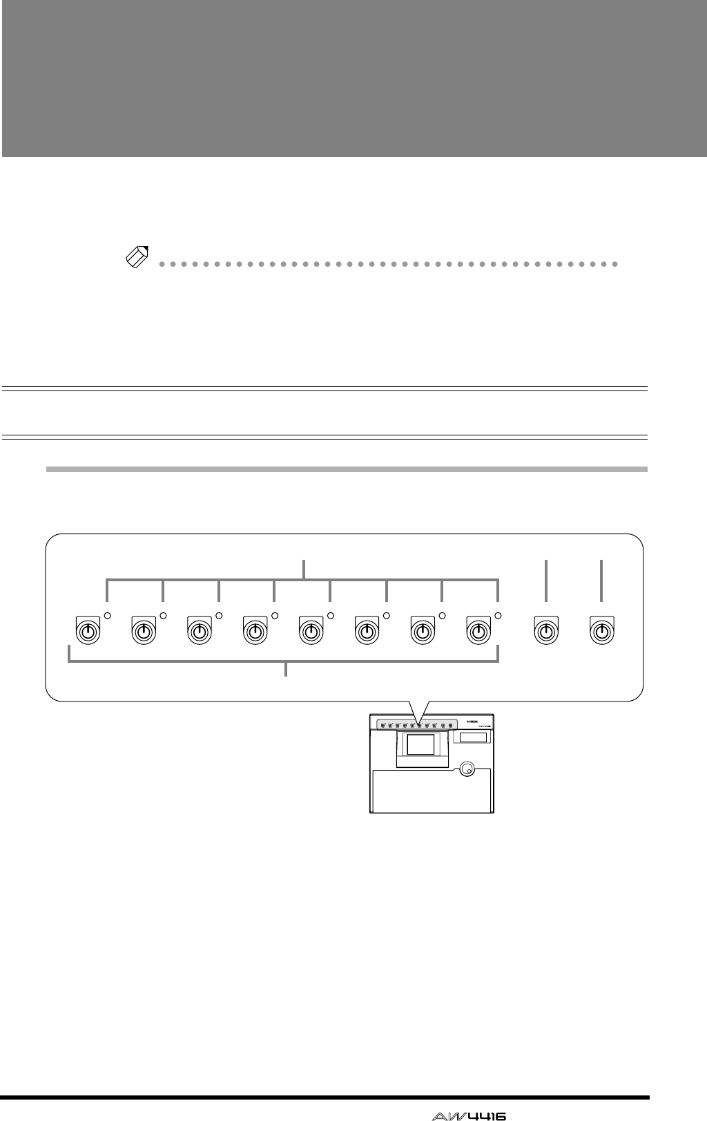
— Operation Guide 31
2Parts and their func-
tions
This chapter explains the names and functions of the various objects on
the top panel, rear panel, and front panel.
Note
Names of the controllers on the top panel are enclosed in square brackets [ ], in
order to distinguish them from the “software” knobs or buttons displayed in the
display.
Example: [SEL] key, EQ [Q] control
Top panel
Analog input/output section
1[GAIN] controls
These controls adjust the input sensitivity of INPUT jacks 1–8. The supported
input level range is –46 dB– +4 dB.
BPEAK indicators
These LEDs will light red when the input signal of INPUT jacks 1–8 reaches a
level 3 dB below the clipping point.
C[PHONES] control
This control adjusts the output level of the signal that is sent from the rear panel
PHONES jack.
PEAK PEAK PEAK PEAK PEAK PEAK PEAK PEAK MONITOR OUT
PHONES
12345678
MICLINE MICLINE MICLINE MICLINE MICLINE MICLINE MICLINE MICLINE MIN MAX MIN MAX
PROFESSIONAL AUDIO WORKSTATION
PEAK PEAK PEAK PEAK PEAK PEAK PEAK PEAK MONITOR OUT
PHONES
12345678
MICLINE MICLINE MICLINE MICLINE MICLINE MICLINE MICLINE MICLINE MIN MAX MIN MAX
234
1
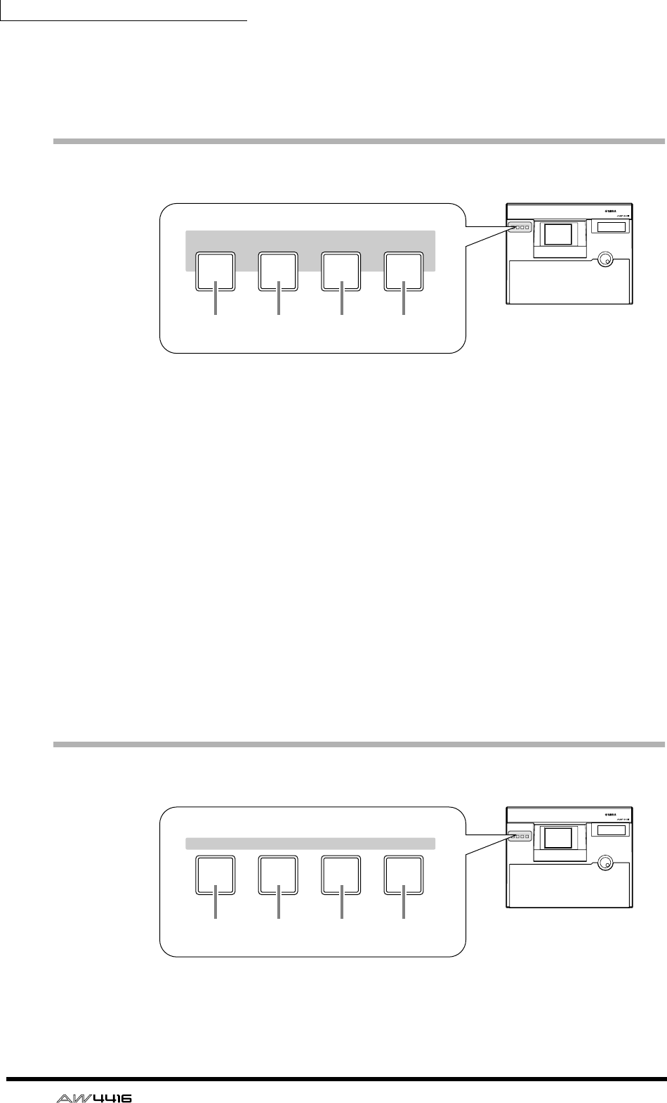
Chapter2—Parts and their functions
32 — Operation Guide
D[MONITOR OUT] control
This control adjusts the output level of the signal that is sent from the rear panel
MONITOR OUT jacks.
WORK NAVIGATE section
1[SONG] key
This key is used for song settings and editing, and to access the SONG screen
where you can perform the shut-down operation.
B[QUICK REC] (quick record) key
At one touch, this key assigns the physical input jacks to the channels of the
mixer section and the tracks of the recorder section, and accesses the QUICK
REC screen in which you can record 16 tracks simultaneously.
C[MASTERING] key
This key accesses the MASTERING screen, where the audio data of the stereo
tracks can be recorded as CD-DA (CD audio) on a CD-R/RW disc inserted in the
CD-R/CD-RW drive (optional).
D[CD PLAY] key
This key accesses the CD PLAY screen, where you can play a music CD or the
audio tracks of a CD-ROM/CD-R inserted in the CD-R/CD-RW drive (optional).
UNIT section
1[SETUP] key
This key accesses the SETUP screen, where you can make settings such as exter-
nal input/output patching, word clock, dither, and the solo function.
PROFESSIONAL AUDIO WORKSTATION
SHUT DOWN
WORK NAVIGATE
CD
PLAY
QUICK
REC
MASTER-
ING
SONG
SHUT DOWN
WORK NAVIGATE
CD
PLAY
QUICK
REC
MASTER-
ING
SONG
1 2 3 4
PROFESSIONAL AUDIO WORKSTATION
FILE MIDI
SETUP
UNIT
UTILITY
FILE MIDI
SETUP
UNIT
UTILITY
1 2 3 4
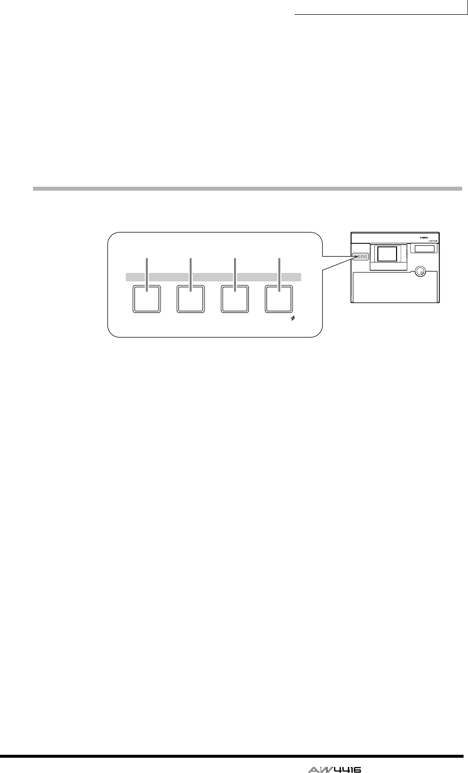
Chapter2—Parts and their functions
— Operation Guide 33
B[FILE] key
This key accesses the FILE screen, where you can backup/restore songs and for-
mat external storage devices connected to the SCSI connector.
C[UTILITY] key
This key accesses the UTILITY screen, where you can operate the built-in oscilla-
tor, and make various system settings.
D[MIDI] key
This key accesses the MIDI screen, where you can make MIDI-related settings.
MIXER section
1[VIEW] key
This key accesses the VIEW screen, where you can view all the mix parameters of
the currently selected channel.
B[PAN] key
This key accesses the PAN screen, where you can set the pan and routing of each
channel.
C[EQ] (equalizer) key
This key accesses the EQ/ATT/GRP screen, where you can make equalizer/attenu-
ator settings for the currently selected channel, and make fader group and mute
group settings.
D[DYN] key
This key accesses the DYN/DLY screen, where you can make dynamics processor
and delay settings for the currently selected channel.
PROFESSIONAL AUDIO WORKSTATION
DYN/DLY/
EQ/ATT/GRP
CH VIEW PAN/ROUTING
VIEW PAN EQ DYN
MIXER
DYN/DLY/
EQ/ATT/GRP
CH VIEW PAN/ROUTING
VIEW PAN EQ DYN
MIXER
1 2 3 4
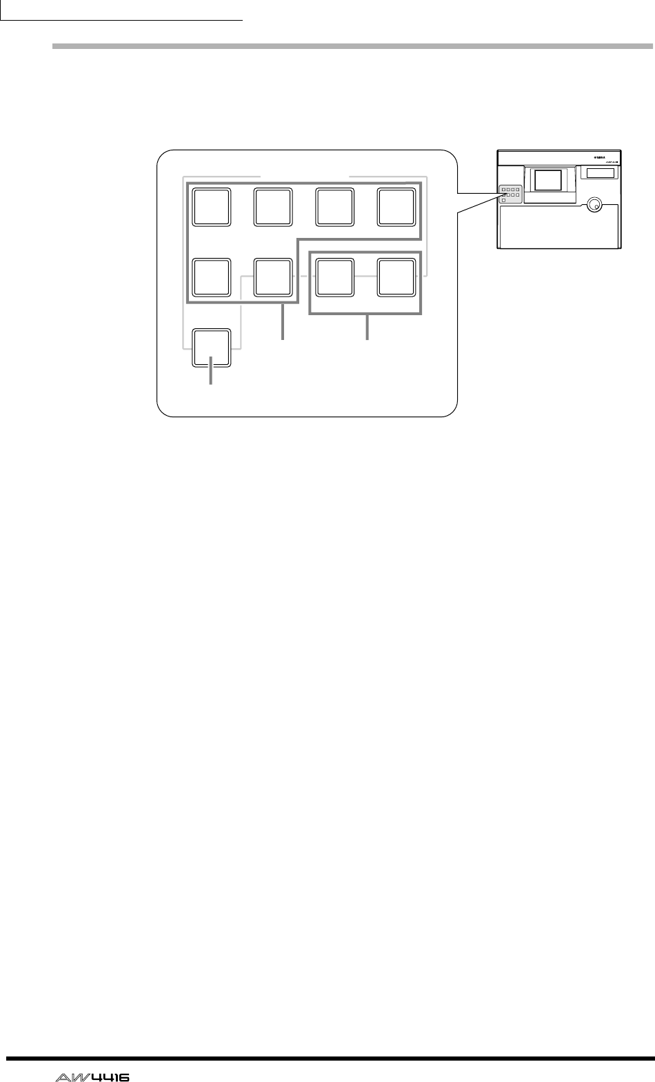
Chapter2—Parts and their functions
34 — Operation Guide
FADER MODE section
In this section you can select the items that will be controlled by faders 1–16 of
the top panel.
1[HOME] key
When this key is on, faders 1–16 will adjust the input levels of the channels
selected in the MIXING LAYER section. The HOME page will appear in the dis-
play, showing meters to indicate the input/output levels of each channel.
B[AUX 1]–[AUX 6] keys
When these keys are on, faders 1–16 will adjust the send levels of the signals sent
to AUX 1–6 from the channels selected in the MIXING LAYER section. The AUX
1–AUX 6 pages will appear in the display, allowing you to switch the pre or post
setting for the signals sent from each channel to AUX 1–6.
C[AUX 7]/[AUX 8] keys
When these keys are on, faders 1–16 will adjust the send levels of the signals sent
to internal effects 1/2 from the channels selected in the MIXING LAYER section.
The AUX7/EFF1 screen or AUX8/EFF2 screen will appear in the display, allowing
you to switch the pre or post setting for the signals sent from each channel to
internal effects 1 and 2, and to set the effect parameters.
PROFESSIONAL AUDIO WORKSTATION
FADER MODE
EFF 1 EFF 2
AUX
1AUX
2AUX
3AUX
4
AUX
5AUX
6AUX
7AUX
8
HOME
FADER MODE
EFF 1 EFF 2
AUX
1AUX
2AUX
3AUX
4
AUX
5AUX
6AUX
7AUX
8
HOME 32
1
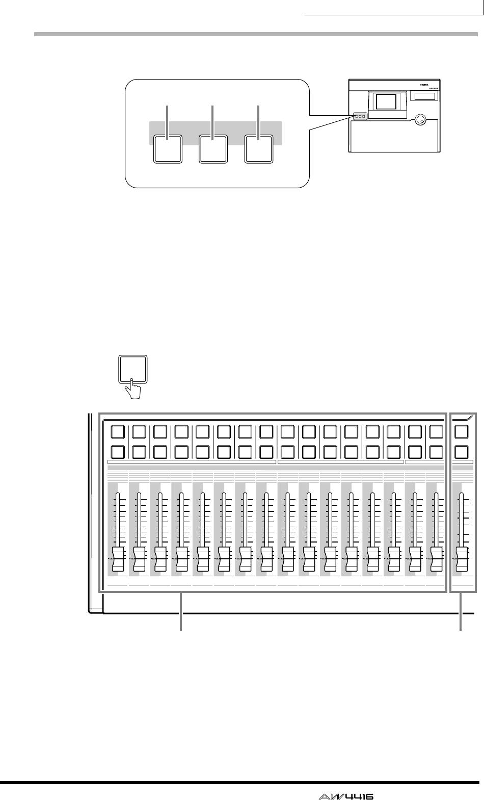
Chapter2—Parts and their functions
— Operation Guide 35
MIXING LAYER section
1[1-16] key
B[17-24] key
C[MONI] key
In this section you can select the mixing layer that will be controlled by the top
panel [SEL] keys 1–16, [ON] keys 1–16 and faders 1–16.
These keys correspond to mixing layers as follows.
PROFESSIONAL AUDIO WORKSTATION
MIXING LAYER
INPUT INPUT RECORDER
17-24
RTN MONI
1-16
MIXING LAYER
INPUT INPUT RECORDER
17-24
RTN MONI
1-16
1 2 3
12
RTN
17 18 19 20 21 22 23 24
34 56 78 910111212 13 14 15 16
STEREO
34 56789101112
1213 14 15 16
5
10
20
30
70
50
40
15
ON
SEL
ON
SEL
ON
SEL
ON
SEL
ON
SEL
ON
SEL
ON
SEL
ON
SEL
ON
SEL
ON
SEL
ON
SEL
ON
SEL
ON
SEL
ON
SEL
ON
SEL
ON
SEL
ON
SEL
0
0
5
40
60
10
20
+6
0
5
40
60
10
20
+6
0
5
40
60
10
20
+6
0
5
40
60
10
20
+6
0
5
40
60
10
20
+6
0
5
40
60
10
20
+6
0
5
40
60
10
20
+6
0
5
40
60
10
20
+6
0
5
40
60
10
20
+6
0
5
40
60
10
20
+6
0
5
40
60
10
20
+6
0
5
40
60
10
20
+6
0
5
40
60
10
20
+6
0
5
40
60
10
20
+6
0
5
40
60
10
20
+6
0
5
40
60
10
20
+6
Input channels 1–16 Stereo output channel
1-16
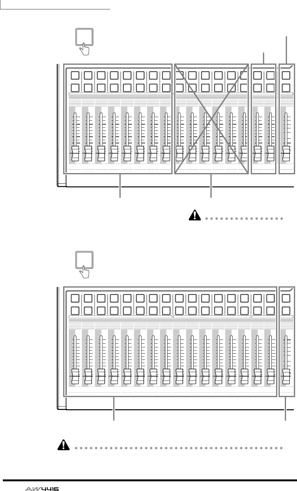
Chapter2—Parts and their functions
36 — Operation Guide
The parameters controlled by faders 1–16 will also change depending on the set-
tings of the FADER MODE section.
12
RTN
17 18 19 20 21 22 23 24
34 56 78 910111212 13 14 15 16
STEREO
34 56789101112
1213 14 15 16
5
10
20
30
70
50
40
15
ON
SEL
ON
SEL
ON
SEL
ON
SEL
ON
SEL
ON
SEL
ON
SEL
ON
SEL
ON
SEL
ON
SEL
ON
SEL
ON
SEL
ON
SEL
ON
SEL
ON
SEL
ON
SEL
ON
SEL
0
0
5
40
60
10
20
+6
0
5
40
60
10
20
+6
0
5
40
60
10
20
+6
0
5
40
60
10
20
+6
0
5
40
60
10
20
+6
0
5
40
60
10
20
+6
0
5
40
60
10
20
+6
0
5
40
60
10
20
+6
0
5
40
60
10
20
+6
0
5
40
60
10
20
+6
0
5
40
60
10
20
+6
0
5
40
60
10
20
+6
0
5
40
60
10
20
+6
0
5
40
60
10
20
+6
0
5
40
60
10
20
+6
0
5
40
60
10
20
+6
Input channels 17–24 No function
Stereo output channel
Effect return channels 1/2
17-24
RTN
The faders will not be operable.
will cause malfunctions.
Attempting to move them by force
12
RTN
17 18 19 20 21 22 23 24
34 56 78 910111212 13 14 15 16
STEREO
34 56789101112
1213 14 15 16
5
10
20
30
70
50
40
15
ON
SEL
ON
SEL
ON
SEL
ON
SEL
ON
SEL
ON
SEL
ON
SEL
ON
SEL
ON
SEL
ON
SEL
ON
SEL
ON
SEL
ON
SEL
ON
SEL
ON
SEL
ON
SEL
ON
SEL
0
0
5
40
60
10
20
+6
0
5
40
60
10
20
+6
0
5
40
60
10
20
+6
0
5
40
60
10
20
+6
0
5
40
60
10
20
+6
0
5
40
60
10
20
+6
0
5
40
60
10
20
+6
0
5
40
60
10
20
+6
0
5
40
60
10
20
+6
0
5
40
60
10
20
+6
0
5
40
60
10
20
+6
0
5
40
60
10
20
+6
0
5
40
60
10
20
+6
0
5
40
60
10
20
+6
0
5
40
60
10
20
+6
0
5
40
60
10
20
+6
Monitor channels 1–16 Stereo output channel
MONI
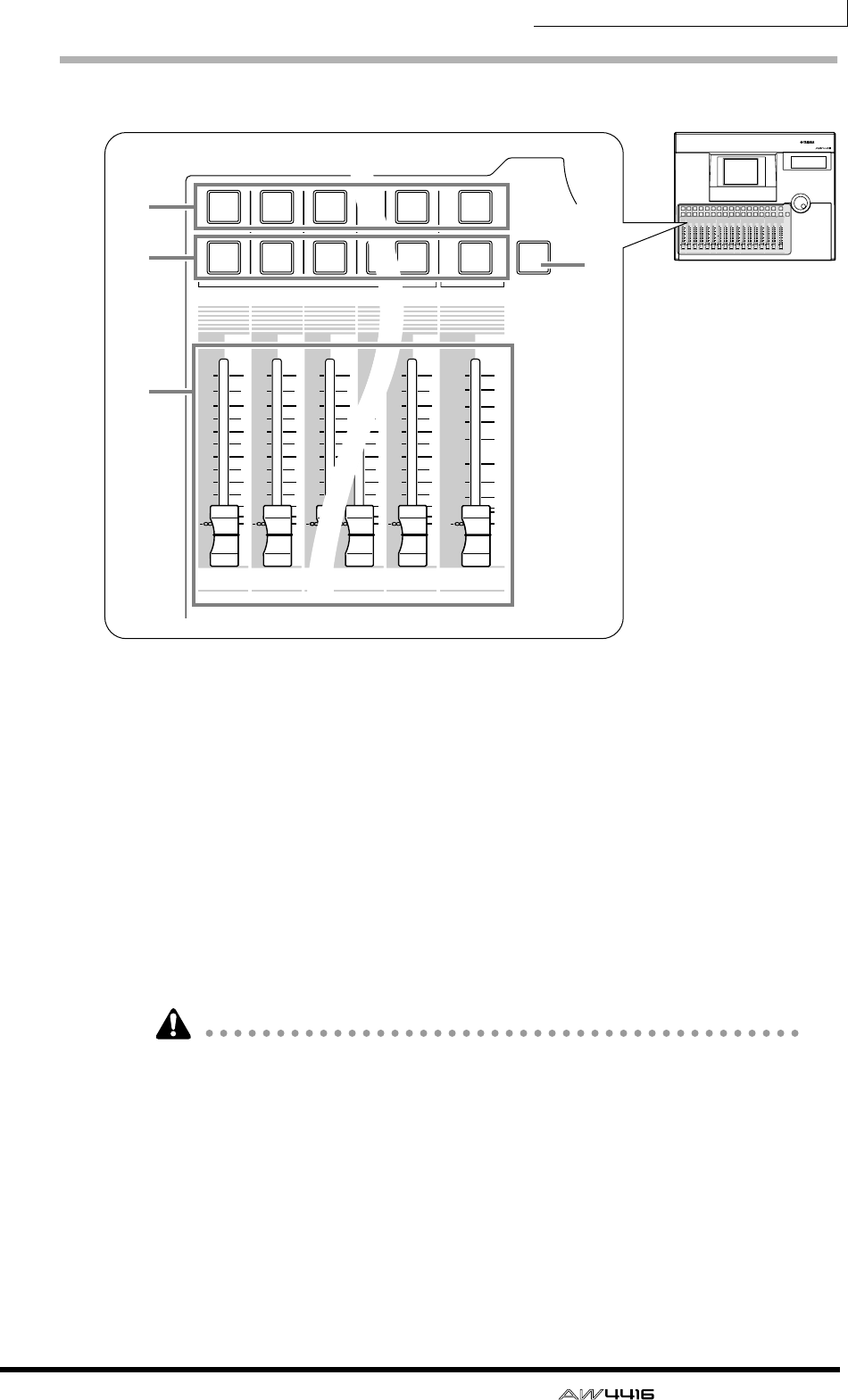
Chapter2—Parts and their functions
— Operation Guide 37
[SEL] keys, [ON] keys, faders
1[SEL] (select) keys
These keys select the channel to be operated. The [SEL] key of the currently
selected channel will light. When using automix, the [SEL] keys are used to select
the channels that will be recorded.
B[ON] key
These keys turn each channel on/off. The [ON] key will be lit for channels that
are currently on; the [ON] key will be dark for channels that are off (muted).
When the solo function is on, the [ON] keys will function as solo keys.
CFaders
Depending on the settings of the FADER mode section, these moving faders
adjust the input level or send levels to AUX 1–8 for each channel.
• The channels that correspond to the [SEL] keys 1–16, [ON] keys 1–16, and
faders 1–16 will change depending on the setting of the MIXING LAYER sec-
tion.
• The STEREO [SEL] key, STEREO [ON] key, and STEREO fader always control
the stereo output channel. They are not affected by the MIXING LAYER sec-
tion.
D[SOLO] key
This key turns the Solo function on/off.
PROFESSIONAL AUDIO WORKSTATION
12
RTN
17 18 19 20 21 22 23 24
345678 910111212 13 14 15 16
STEREO
34567 8 9101112
1213 14 15 16
5
10
20
30
70
50
40
15
ON
SEL
ON
SEL
ON
SEL
ON
SEL
ON
SEL
ON
SEL
ON
SEL
ON
SEL
ON
SEL
ON
SEL
ON
SEL
ON
SEL
ON
SEL
ON
SEL
ON
SEL
ON
SEL
ON
SEL
SOLO
0
0
5
40
60
10
20
+6
0
5
40
60
10
20
+6
0
5
40
60
10
20
+6
0
5
40
60
10
20
+6
0
5
40
60
10
20
+6
0
5
40
60
10
20
+6
0
5
40
60
10
20
+6
0
5
40
60
10
20
+6
0
5
40
60
10
20
+6
0
5
40
60
10
20
+6
0
5
40
60
10
20
+6
0
5
40
60
10
20
+6
0
5
40
60
10
20
+6
0
5
40
60
10
20
+6
0
5
40
60
10
20
+6
0
5
40
60
10
20
+6
17 18 19
312
12
ON
SEL
ON
SEL
ON
SEL
0
5
40
60
10
20
+6
0
5
40
60
10
20
+6
0
5
40
60
10
20
+6 +6
0
5
40
60
10
20
+6
0
5
40
60
10
20
+6
0
5
40
60
10
20
+6 +6
2
16
STEREO
15 16
5
10
20
30
70
50
40
15
ON
SEL
ON
SEL
SOLO
0
40
60
20
0
5
40
60
10
20
+6
20
0
5
40
60
10
20
+6
40
60
1
24
3
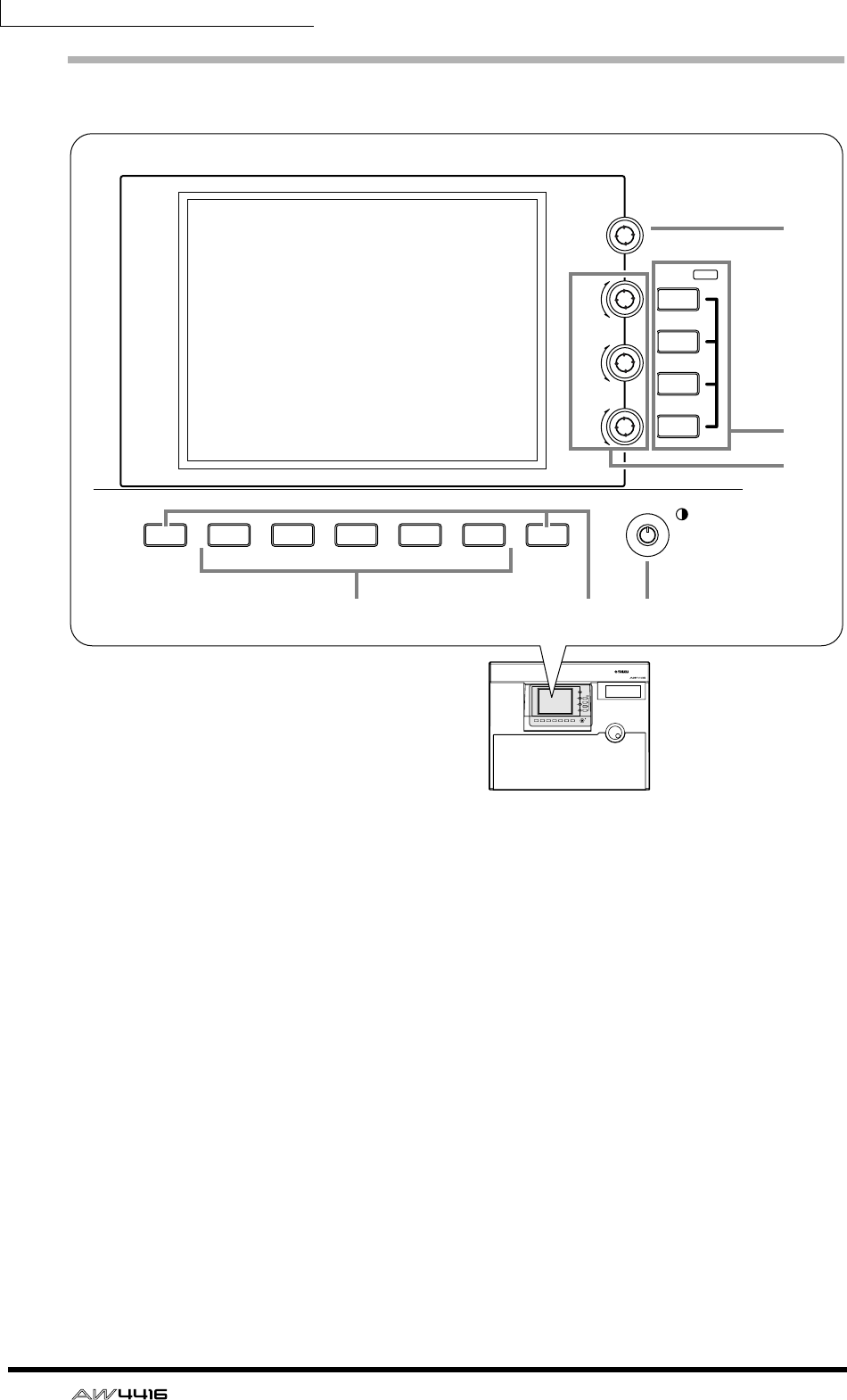
Chapter2—Parts and their functions
38 — Operation Guide
Display section
1Display
This is a 320×240 pixel liquid crystal display with backlight, that displays the val-
ues of the mix parameters and the current operating status.
B[PAN] control
This controls the pan of the channel currently selected by the [SEL] key. If the ste-
reo output channel is selected, this controls the L/R channel balance.
CEQ [Q]/EQ [F] (EQ frequency)/EQ [G] (EG gain) controls
These are controls for manually operating the EQ of the channel currently
selected by the [SEL] key. From above, they adjust the Q (steepness), F (center fre-
quency), and G (gain) parameters. Use the 4 EQ [HIGH]–EQ [LOW] keys to
select the band that will be controlled.
DEQ [HIGH]/EQ [HI-MID]/EQ [LO-MID]/EQ [LOW] keys
These keys select the band that will be controlled by the 3 controls.
E[F1]–[F5] (function 1–5) keys
These keys are used to access pages or to execute specific functions, according to
the tabs or buttons shown at the bottom of the display.
PROFESSIONAL AUDIO WORKSTATION
LO
LO-MID
HI-MID
HI
EQ
F
PAN
G
Q
SHIFT F1 SHIFT
F2 F3 F4 F5
SHIFT F1 SHIFT
LOW
LO-MID
HI-MID
HIGH
F2 F3 F4 F5
EQ
F
PAN
G
Q
6
1
75
2
4
3
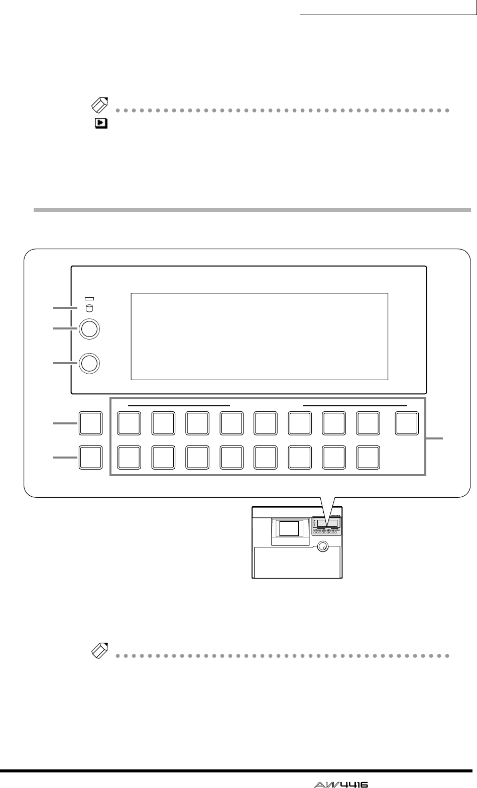
Chapter2—Parts and their functions
— Operation Guide 39
F[SHIFT] key
This key is used to switch the tabs or buttons shown at the bottom of the display.
You can use a variety of additional functions by holding down the [SHIFT] key
and pressing the [F1]–[F5] keys.
Note
symbol is displayed in the lower left of the screen to indicate a page that sup-
ports the [SHIFT] key.
GContrast
This adjusts the contrast of the display.
Level meter/counter section
1Access indicator
This indicator shows that the internal hard disk is being accessed. This indicator
will light red while the hard disk is being read or written.
Note
Turning off the power while the access indicator is lit may not only result in loss
of the data on disk, but may also destroy the disk itself. You must perform the
shut-down process (
→
P.17) before turning the power off.
B[ABS/REL] switch
This switches the counter display between absolute time (ABS) or relative time
(REL).
PROFESSIONAL AUDIO WORKSTATION
9
TRACK REC TRACK SELECT
ST
CUE
ALL
SAFE
12
10
3
11
4
12
5
13
6
14
7
15
8
16
ABS/REL
PEAK HOLD
9
TRACK REC TRACK SELECT
ST
CUE
ALL
SAFE
12
10
3
11
4
12
5
13
6
14
7
15
8
16
ABS/REL
PEAK HOLD
4
6
1
2
3
5
7
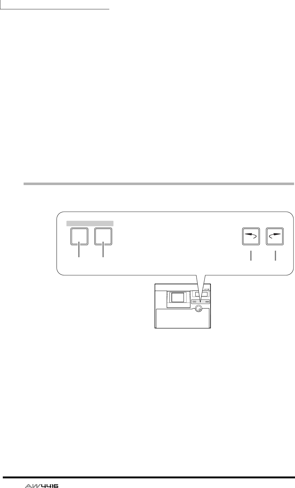
Chapter2—Parts and their functions
40 — Operation Guide
C[PEAK HOLD] switch
This switch sets/defeats the peak hold function of the level meters.
DLevel meters/counter
This area displays various information necessary when operating the recorder
section of the AW4416, such as level meters for each track of the recorder sec-
tion, a time counter, and the number of the currently selected scene memory.
ETRACK [CUE] key
This key is used to output the signal of the desired track directly to the MONITOR
OUT jacks for monitoring. Use the [REC TRACK SELECT] keys to select the track.
F[REC TRACK SELECT] keys
Use these keys to select the track(s) to be recorded. When the TRACK [CUE] key
is on, these keys select the track to be monitored.
G[ALL SAFE] key
This key cancels all record-ready settings of the [REC TRACK SELECT] keys.
RECORDER section
1[TRACK] key
This key accesses the TRACK screen, where you can view the recorded status of
each track and make virtual track assignments.
B[EDIT] key
This key accesses the EDIT page, where you can edit tracks and virtual tracks.
C[UNDO] key
This key cancels the recording or editing operation that was last executed in the
recorder section, restoring the data to its previous state. By repeatedly pressing
the [UNDO] key, you can return through as many as sixteen previous operations.
D[REDO] key
This key re-executes the recording or editing operation that was cancelled by the
[UNDO] key.
PROFESSIONAL AUDIO WORKSTATION
EDITTRACK
UNDO REDO
RECORDER
EDITTRACK
UNDO REDO
RECORDER
1 2 3 4
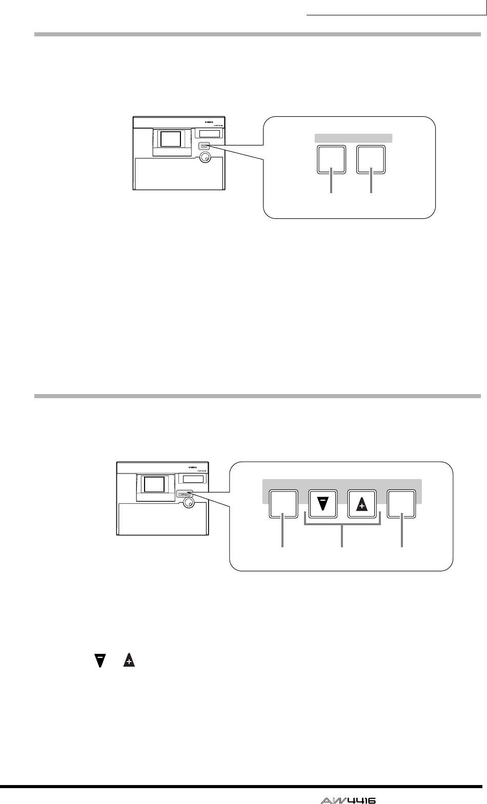
Chapter2—Parts and their functions
— Operation Guide 41
AUTOMATION section
The keys of this section access screen pages where you can operate the automix
and scene memory functions.
The following screens correspond to these keys.
1[AUTOMIX] key
This key accesses the AUTOMIX screen, where you can operate and edit auto-
mix.
B[SCENE] key
This key accesses the SCENE screen, where you can perform scene memory oper-
ations.
SCENE MEMORY section
In this section you can directly store or recall scene memories.
1[STORE] key
This key stores the state of the mixer section and input/output patching into the
scene number shown in the display or the level meter/counter.
B[ ]/[ ] keys
These keys select the scene number for storing or recalling.
C[RECALL] key
This key recalls the scene whose number is shown in the display or in the level
meter/counter.
PROFESSIONAL AUDIO WORKSTATION
SCENE
AUTOMATION
AUTO
MIX
SCENE
AUTOMATION
AUTO
MIX
1 2
PROFESSIONAL AUDIO WORKSTATION
SCENE MEMORY
STORE RECALL
SCENE MEMORY
STORE RECALL
213
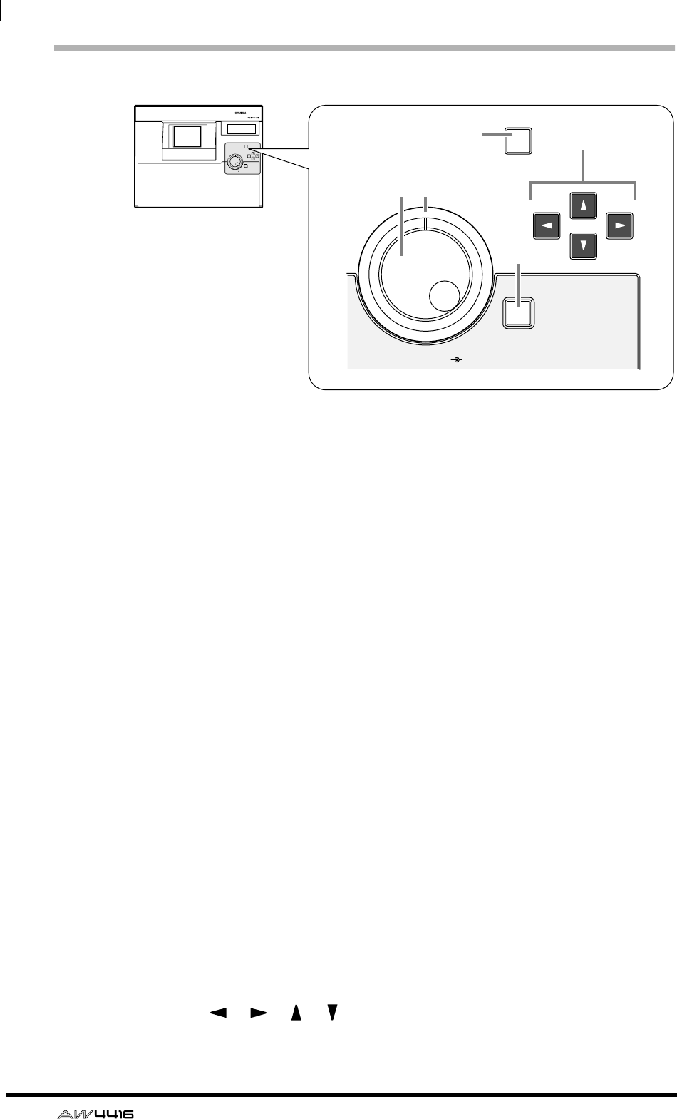
Chapter2—Parts and their functions
42 — Operation Guide
CURSOR/JOG & SHUTTLE section
1[JOG ON] key
This key turns the “nudge” function on/off for the [DATA/JOG] dial and [SHUT-
TLE] dial. (“Nudge” is a function that repeatedly plays back a fixed region starting
at the current location, either forward or backward.) When this is turned on, the
key will light.
B[DATA/JOG] dial
The function of this dial will depend on the on/off status of the [JOG ON] key,
and on the on/off status of the [NUM LOCATE] key in the locate section.
❍ When the [JOG ON] key is off
The dial will adjust the value of the parameter currently selected in the display, or
select an item from a list.
❍ When the [JOG ON] key is on
Depending on the direction in which you turn the dial, playback of a fixed region
will occur repeatedly in the forward or reverse direction, allowing you to search
for a desired location.
❍ When the [NUM LOCATE] key is on
The dial will advance the time counter in the display.
C[SHUTTLE] dial
The function of this dial will depend on the on/off status of the [JOG ON] key.
❍ When the [JOG ON] key is on
The current nudge playback region will be moved either forward or backward,
depending on the direction in which you turn the dial.
❍ When the [JOG ON] key is off
Depending on the direction and angle to which you turn the dial, reverse
(review) or fast-forward (cue) playback will occur at a variety of speeds.
DCURSOR [ ]/[ ]/[ ]/[ ] keys
These keys move the cursor (the blinking box) in the display.
PROFESSIONAL AUDIO WORKSTATION
JOG ON
CURSOR
SHUTTLE
DATA/
JOG
YES/LOCATE
ENTER
CURSOR
JOG ON
SHUTTLE
DATA/
JOG
LOCATE
ENTER
14
2
5
3
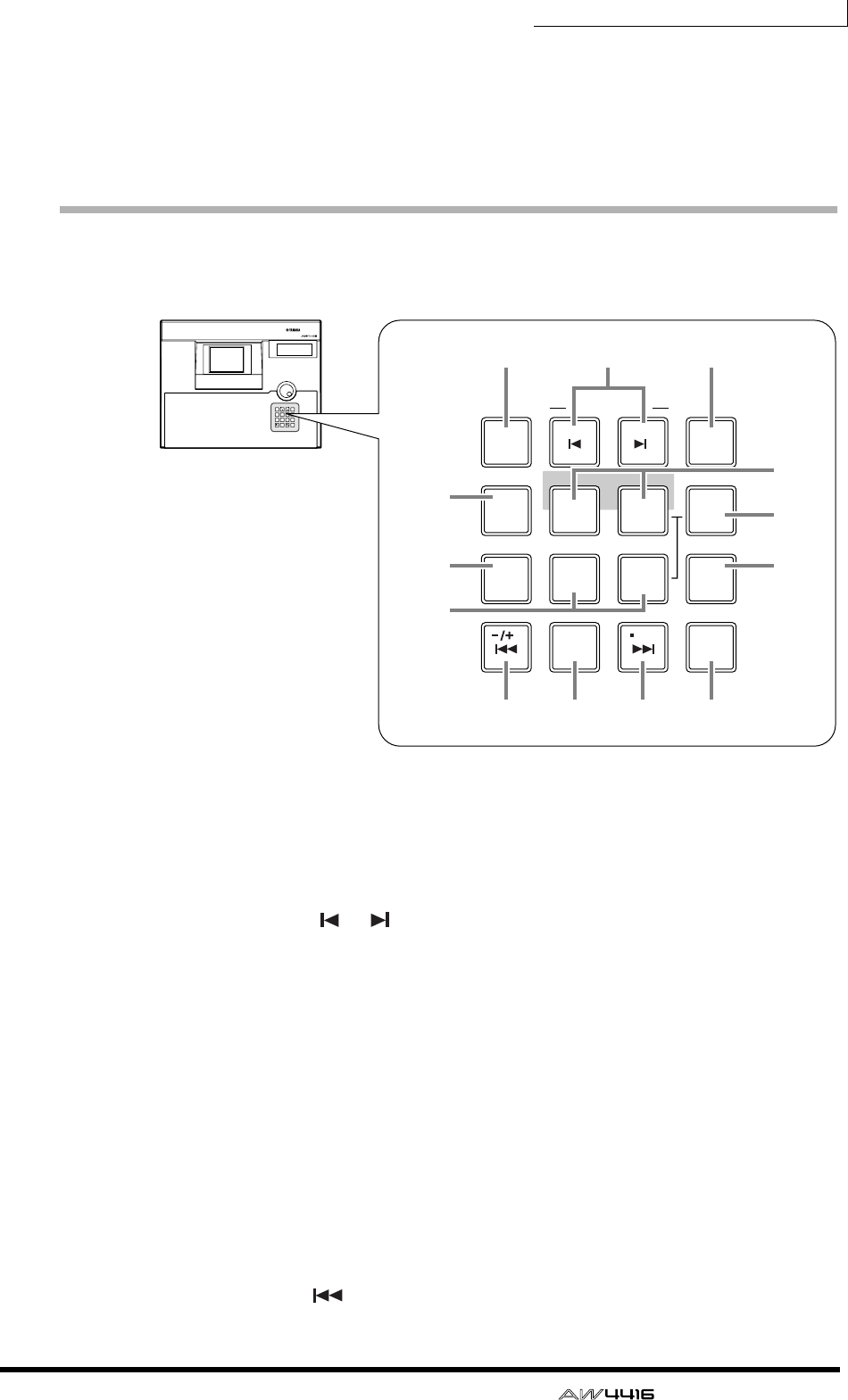
Chapter2—Parts and their functions
— Operation Guide 43
E[ENTER] key
This key is used to finalize a value, execute a function, or move to the specified
locate point.
Locate section
In this section you can perform locate operations for the recorder.
1[NUM LOCATE] (number locate) key
This key is used to specify a locate point as a numerical value. When this key is
lit, you can use the numeric keys or the [DATA/JOG] dial to input a locate posi-
tion, and press the [ENTER] key to execute the Locate operation.
BMARK SEARCH [ ]/[ ] keys
These keys are used to move to the nearest pre-specified mark point.
C[MARK] key
When you press this key, the current location will be memorized as a mark point.
D[AUTO PUNCH] key
This key turns the auto punch-in/out function on/off.
ELAST REC[IN]/[OUT] (last record in/out) keys
These keys move to the point at which recording was last begun (the IN point) or
ended (the OUT point).
F[SET] key
This key is used in conjunction with the LAST REC[IN]/[OUT] keys and the [A]/
[B] keys to set the last record in/out points or the A/B points. It is also used in con-
junction with the [ ] key to set the zero point of relative time (REL).
LAST REC
MARK SEARCH
LAST REC
54IN OUT
NO
AB
REPEAT
RTZ
231
0
ROLL
BACK
CANCEL
SET
MARK
NUM
LOCATE
897
6
AUTO
PUNCH
PROFESSIONAL AUDIO WORKSTATION
LAST REC
LAST REC
54IN OUT
AB
REPEAT
RTZ
231
0
ROLL
BACK
CANCEL
SET
6
AUTO
PUNCH
MARK SEARCH
MARK
NUM
LOCATE
897
1 32
4
9
7
8
JK L M
5
6
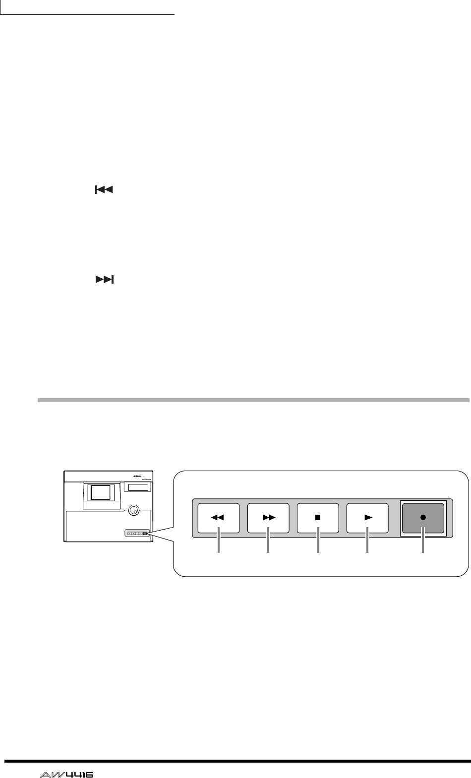
Chapter2—Parts and their functions
44 — Operation Guide
G[REPEAT] key
When this key is on, the area from the A point → B point will be played repeat-
edly. To cancel repeat playback, press the [REPEAT] key once again, or press the
[STOP] key in the transport section.
H[A]/[B] keys
These keys move to the pre-specified A or B points.
I[ROLL BACK] key
When this key is pressed, you will move backward from the current location by
the length of time specified in the UTILITY screen → Prefer.2 page.
J[ ] key
Pressing this key will move to the start point of the song.
K[RTZ] (return to zero) key
Pressing this key will move to the zero location of absolute time (if the counter
indicates ABS) or the zero location of relative time (if the counter indicates REL).
L[ ] key
Pressing this key will move to the end point of the song.
M[CANCEL] key
This key is used to discard a numerical value that you input, or to cancel opera-
tion of a function.
Transport section
In this section you can operate the transport of the recorder.
1[REW] (rewind) key
This key rewinds the current location. By repeatedly pressing this key, you can
switch between 8x and 16x speeds. To stop rewind, press the [STOP] key or the
[PLAY] key.
B[FF] (fast-forward) key
This key fast-forwards the current location. By repeatedly pressing this key, you
can switch between 8x and 16x speeds. To stop fast-forward, press the [STOP]
key or the [PLAY] key.
PROFESSIONAL AUDIO WORKSTATION
REW FF STOP PLAY REC
REW FF STOP PLAY REC
1 2 3 4 5
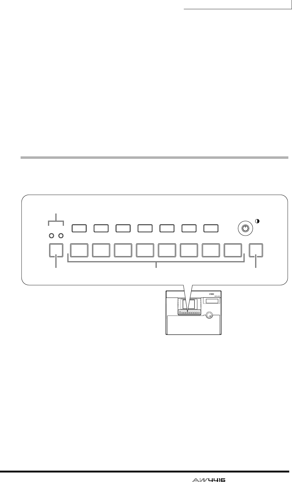
Chapter2—Parts and their functions
— Operation Guide 45
C[STOP] key
This key interrupts playback, recording, rewind, or fast-forward, and stops the
recorder.
D[PLAY] key
If the recorder is stopped, pressing this key will begin playback (if the key is
pressed by itself) or record (if the key is pressed with the [REC] key). If this key is
pressed during rewind or fast-forward, the respective operation will be inter-
rupted, and normal-speed playback will begin. If this key is pressed during
recording, recording will be interrupted and playback will continue (punch-out).
E[REC] key
If the recorder is stopped, pressing this key holding down the [PLAY] key will
begin recording. Pressing this key during playback will begin recording from that
point (punch-in).
SAMPLING PAD section
In this section you can operate the built-in sampler.
1A/B bank indicators
These will light to indicate the currently selected bank (A or B) of sampling pads.
B[BANK] pad
This pad selects the pad bank (A or B).
C[EDIT] pad
This pad accesses the SAMP.PAD screen, where you can assign sampled sounds
or tracks to each pad.
DPads 1–8
These pads play back the sampled sounds that have been assigned to each pad.
PROFESSIONAL AUDIO WORKSTATION
EDIT
8754321
AB
6
BANK
SAMPLING PAD
EDIT
8754321
AB
6
BANK
SAMPLING PAD
SHIFT F1 SHIFT
F2 F3 F4 F5
1
4
2 3
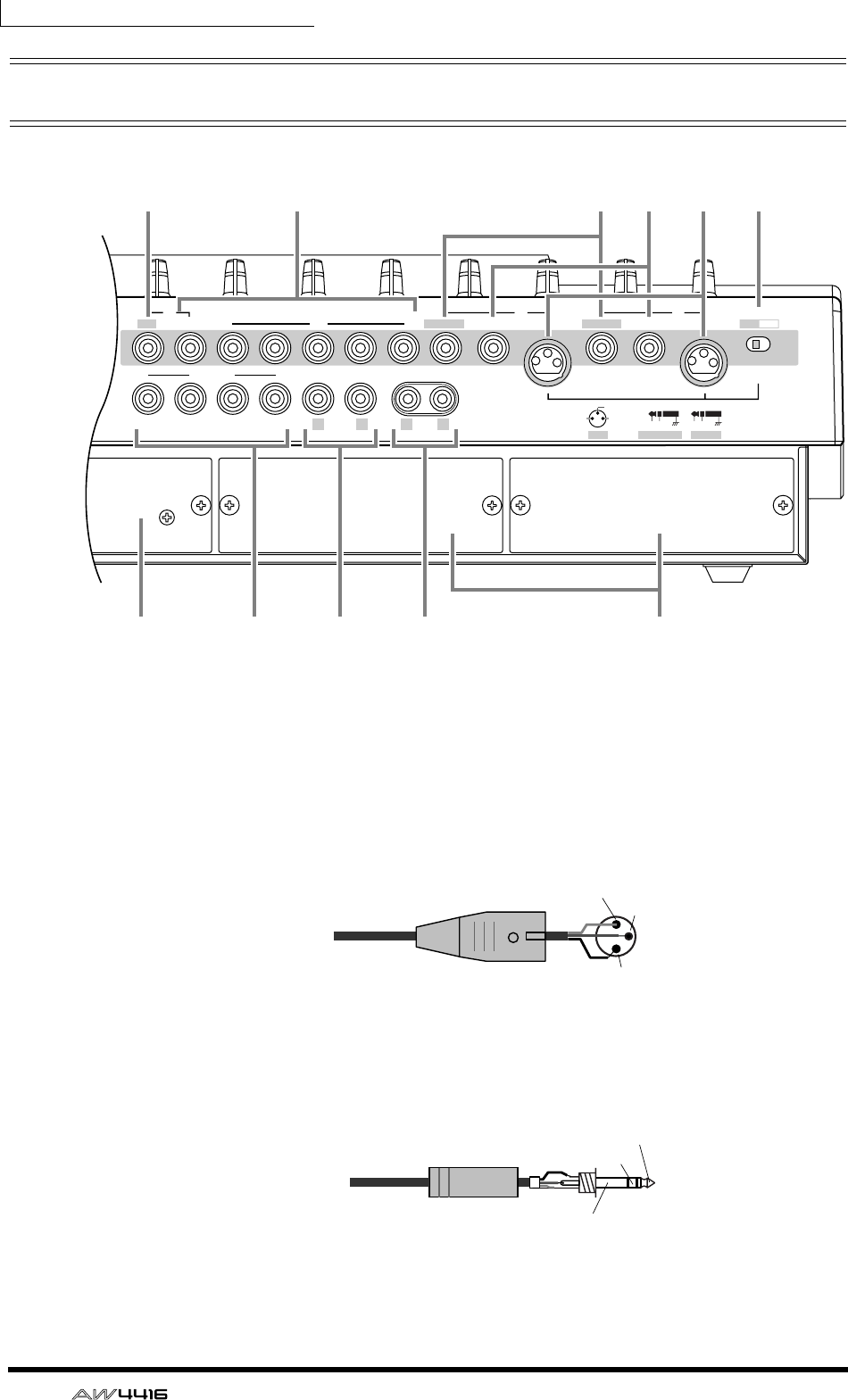
Chapter2—Parts and their functions
46 — Operation Guide
Rear panel
1[PHANTOM +48V ON/OFF] switch
This switch supplies +48 V phantom power to the INPUT (XLR) 1/2 jacks.
BINPUT 1/2 (XLR) jacks
These are balanced XLR-3-31 type input jacks. Nominal input level is –46 dB–
+4 dB. Pin connections are as follows.
CINPUT 1/2 (phone) jacks
These are balanced TRS phone type input jacks. Nominal input level is –46 dB–
+4 dB. Pin connections are as follows.
BAL BAL
4321
MONITOR OUT
BAL (+4dB)UNBAL ( 0dB ) UNBAL (–10dBV)
STEREO OUT
OMNI OUT
876543 2 1
BAL
BALINSERT I/O
BAL
BALHI-Z INSERT I/O
OUT INHOT COLD
INSERTBAL PHONEXLR
3:COLD
1:GND 2:HOT
PHANTOM +48V
ON OFF
RL LR
1
7
6
8 J9 K
54 3 2
Male XLR connector 1 (ground)
3 (cold)
2 (hot)
1/4" TRS phone plug
Tip (hot)
Ring (cold)
Sleeve (ground)
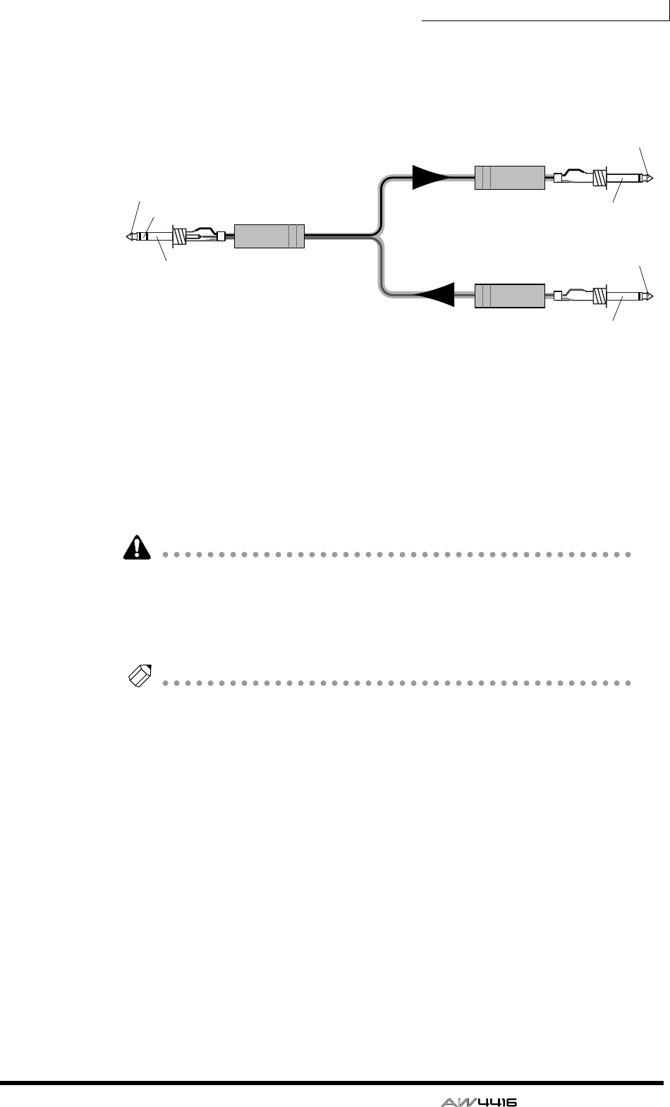
Chapter2—Parts and their functions
— Operation Guide 47
DINSERT I/O 1/2 jacks
These are TRS phone jacks that allow an external effect etc. to be inserted into the
input signal of INPUT jacks 1/2. Nominal input level is 0 dB. Pin connections are
as follows.
EINPUT 3–8 (phone) jacks
These are balanced TRS phone type input jacks. The specifications are the same
as for 3 INPUT 1/2 (phone) jacks.
FINPUT 8 (HI-Z) jack
This is a high impedance unbalanced phone type input jack. Instruments with a
high output impedance such as passive type electric guitars can be directly con-
nected here. Nominal input level is –46 dB– +4 dB.
If plugs are inserted into both the normal INPUT 8 (BAL) jack and the INPUT 8
(HI-Z) jack, the INPUT 8 (HI-Z) jack will take priority.
G2.5" HARD DISK DRIVE slot
This slot allows an IDE 2.5 inch hard disk to be installed.
Note
• For the procedure of installing the hard disk, refer to page 2.
• For a list of manufacturers and models of hard disk that are known to work
when installed in the AW4416, please refer to the website
<http://www.aw4416.com>
HOMNI OUT 1–4 jacks
These are unbalanced phone jacks that output the analog signal assigned to
OMNI OUT 1–4 in the SETUP screen → Patch OUT page (→ P.136). Nominal
output level is 0 dB.
IMONITOR OUT jacks
These are balanced TRS phone jacks that output analog monitor signals such as
the stereo bus, internal metronome, solo signal, or direct output from recorder
tracks 1–16. Nominal output level is +4 dB.
JSTEREO OUT jacks
These are unbalanced RCA phono jacks that output the analog signal assigned to
ST OUT in the SETUP screen → Patch OUT page (→ P.136). Nominal output level
is –10 dBV.
1/4" phone plug
1/4" phone plug
1/4" TRS phone plug To the input jack of
the external processor
To the output jack of
the external processor
To the INSERT I/O jack of the AW4416
OUT
Tip (OUT)
IN
Sleeve (ground)
Sleeve (ground)
Tip (IN)
Sleeve (ground)
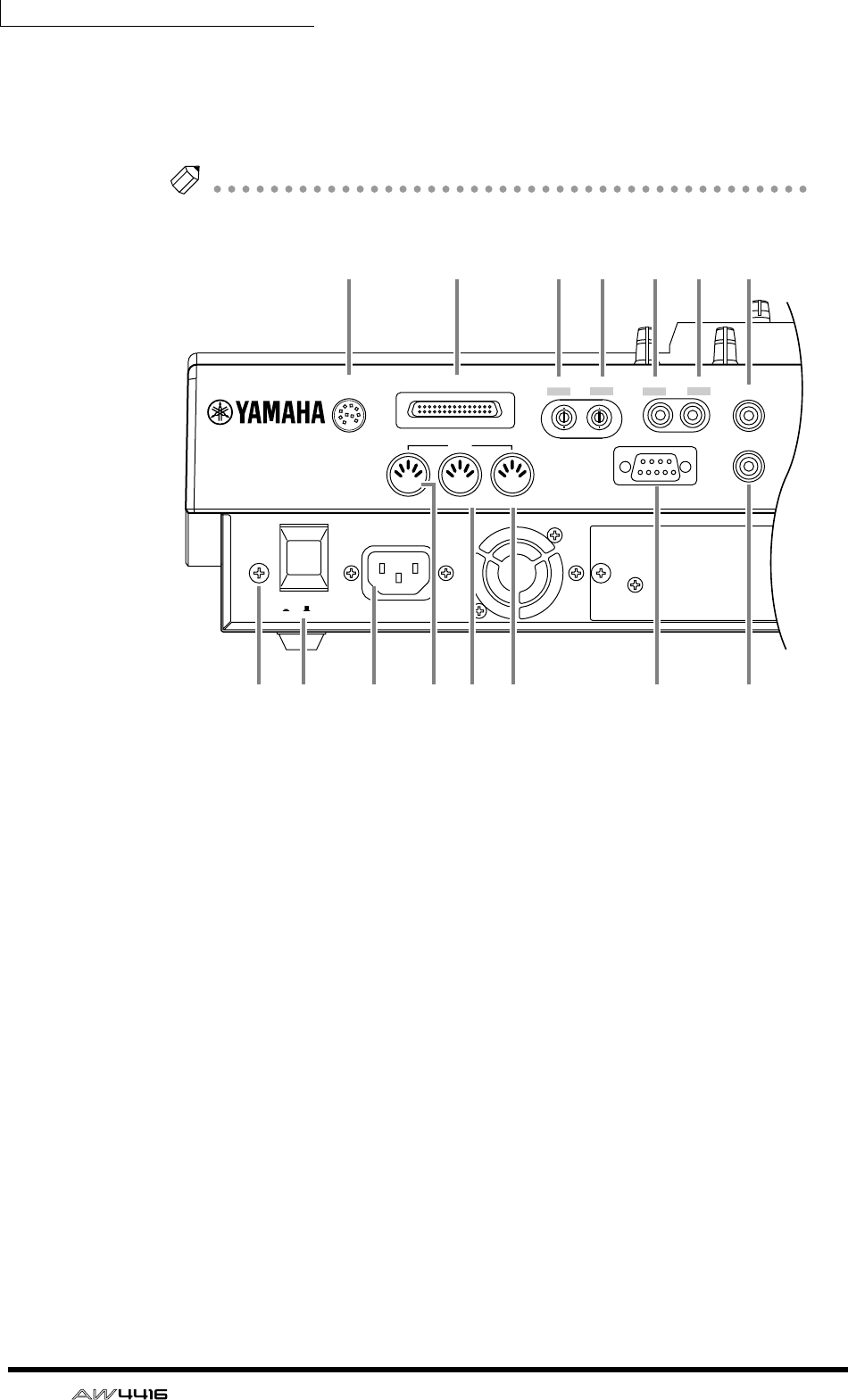
Chapter2—Parts and their functions
48 — Operation Guide
KOPTION I/O slots 1/2
These slots allow optional I/O cards to be installed. Assignments for the signals
input or output via the I/O cards are made in the SETUP screen → Patch IN page
(→ P.133), and in the SETUP screen → Patch OUT page (→ P.136).
Note
For details on installing an I/O card, refer to page 14.
LPHONES jack
This is a stereo headphone jack that allows a set of stereo headphones to be con-
nected. This jack will always output the same signal as the MONITOR OUT jacks.
MDIGITAL STEREO IN jack
This is a coaxial jack that digitally inputs a stereo signal. It is compatible with the
IEC958 consumer format. The channel to which this signal will be input is
assigned in the SETUP screen → Patch IN page (→ P.133).
NDIGITAL STEREO OUT jack
This is a coaxial jack that digitally outputs the stereo signal assigned to D.ST OUT
in the SETUP screen → Patch OUT page (→ P.136). It is compatible with the
IEC958 consumer format.
OWORD CLOCK IN jack
PWORD CLOCK OUT jack
These are BNC type jacks for input/output of a word clock signal. They are used
to synchronize the digital audio signal processing with an external device.
QSCSI connector
This is a D-sub half-pitch 50 pin SCSI connector that is compatible with the SCSI-
2 standard. SCSI-2 compatible storage devices can be connected for data backup.
POWER
ON/ OFF AC INLET
MTC OUT OUT/ THRU IN
MIDI FOOT SW
SCSI PHONES
TO HOST
MOUSE
WORD CLOCK DIGITAL STEREO
OUT OUTIN IN
R
STZ YXWVU
Q LMNOP
Chapter2—Parts and their functions
— Operation Guide 49
• To connect the AW4416 to an external device, use only high-impedance SCSI
cables shorter than 1 meter and with an impedance of 100 ohms (±10 ohms).
• Storage devices connected to the SCSI connector are used for data backup.
They cannot be used directly for recording or playback.
• The only types of SCSI-2 storage devices that can be connected are MO, HD,
and CD-R/W drives. For a list of manufacturers and models of storage device
that are known to work with the AW4416, please refer to the website
<http://www.aw4416.com>
RTO HOST connector
This is an 8-pin mini-DIN connector that can be connected directly to the serial
port of a PC or Macintosh, allowing MIDI applications programs to be used.
SPOWER switch
This switch turns the power on/off.
TAC INLET connector
Connect the included power supply cable here to supply power to the unit.
Use only the included power supply cable.
UMTC OUT connector
These connectors are used to send and receive MIDI messages to and from exter-
nal MIDI devices. The MIDI IN connector receives messages. The MIDI OUT/
THRU jack can function either as a MIDI OUT or MIDI THRU connector,
depending on the setting of the MIDI screen → MIDI Setup page MIDI OUT
SELECT. parameter. The MTC OUT connector is an output connector dedicated to
MTC (MIDI Time Code) messages.
VMIDI OUT/THRU connector
WMIDI IN connector
XMOUSE connector
This is a D-sub 9-pin (male) connector for connecting a serial mouse. By using
this connector, you can use a mouse to select parameters within the display or to
change pages.
YFOOT SW jack
An optional foot switch (Yamaha FC5) can be connected to this jack, and used to
play/stop the transport, or to manually punch-in/out.
If a foot switch of the wrong format is connected, the unit may not operate cor-
rectly.
ZGrounding connector
To reduce the risk of electrical shock, connect this to a grounding connection
(earth) before you connect the power cable. This unit comes with a three-conduc-
tor power cable. In this case, the same result will be obtained if the ground pin of
the electrical outlet is connected to ground. This will also reduce hum and noise.
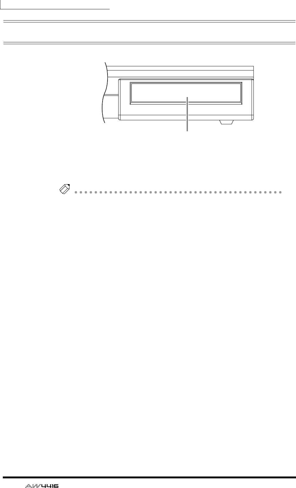
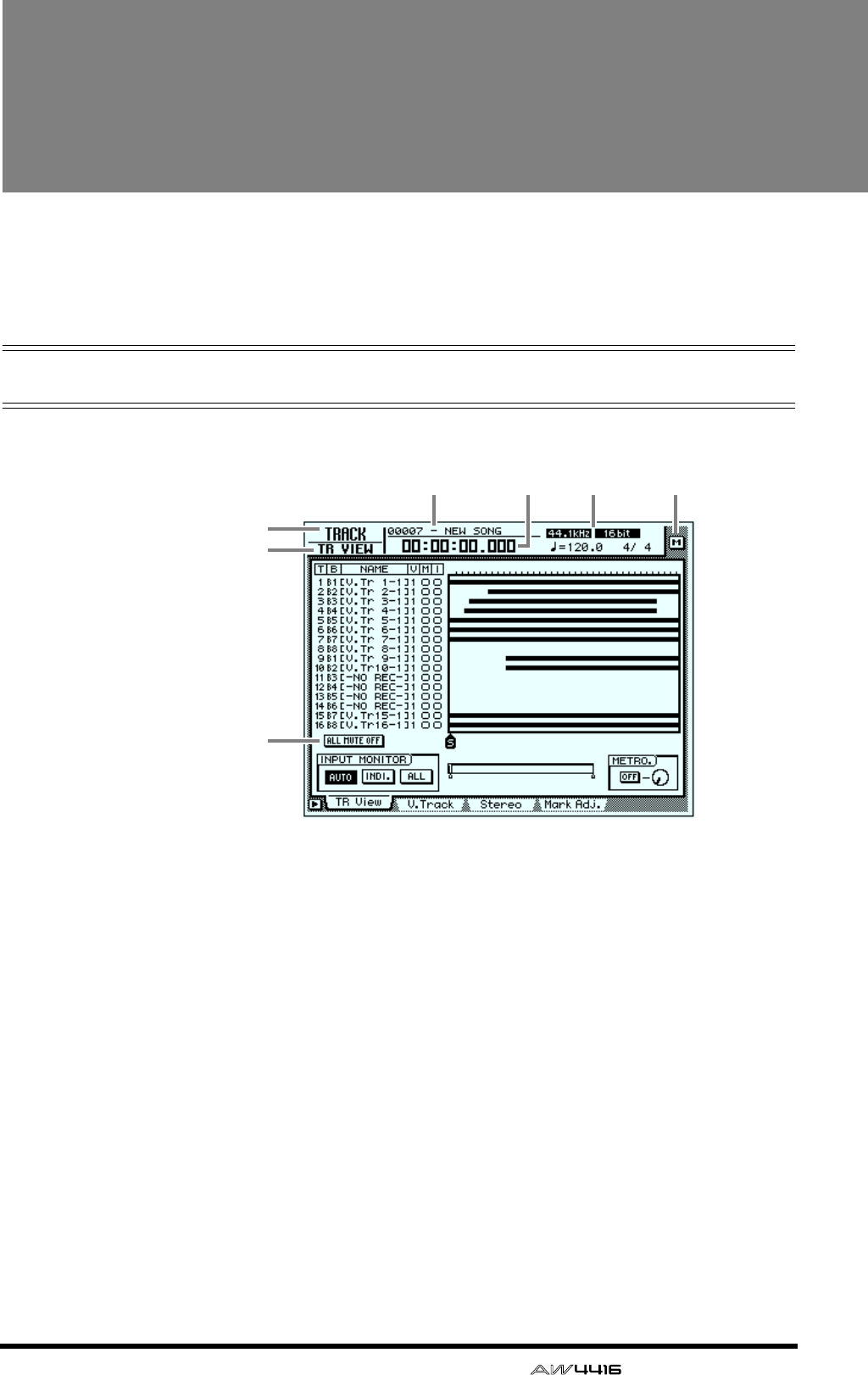
— Operation Guide 51
3The user interface of
the AW4416
This chapter explains the various parts of the AW4416’s user interface, and
basic operation of the AW4416.
Display
The display in the top panel shows the following information.
1Screen name
This is the name of the currently selected screen.
BPage name/channel
The information shown here will depend on the screen. It will show either the
name of the page selected within the screen, or the channel that is selected for
operation.
CSong name
This is the name of the currently selected song.
DCurrent location
This shows the current time location of the song, and the remaining available
recording time. The units of the current location can be selected from the follow-
ing. (Refer to Reference Guide “SONG screen/Setting page.”)
•Time display (SECOND) ............... Hours:minutes:seconds:milliseconds
•Time code display (TIME CODE) .. Hours:minutes:seconds:frames:sub-frames
•Measure display (MEASURE) ........ Measures/beats/ticks (1/960th of a quarter
note)
3 5 6
1
7
2
4
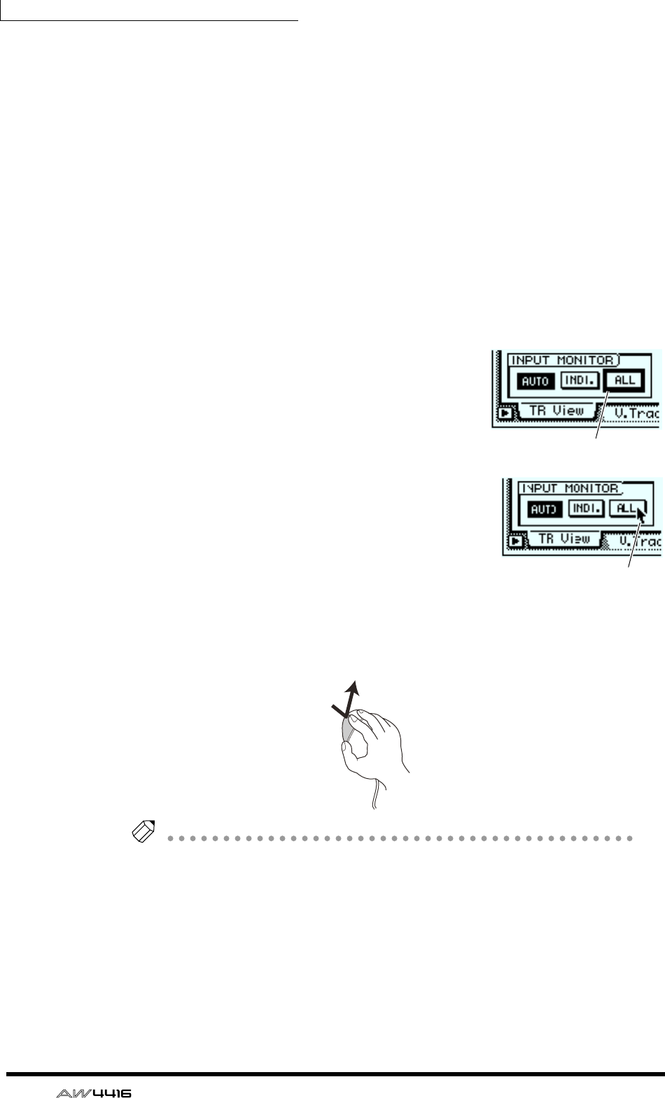
Chapter3—The user interface of the AW4416
52 — Operation Guide
The remaining recording time will be displayed in the TRACK screen TR View
page when you press the [SHIFT] + [F1] key.
ESong/scene information
The information shown in this location will depend on the screen: the sampling
frequency, quantization, and tempo/meter of the currently selected song, or the
number and name of the currently selected scene.
FM (menu) button
This button selects the display access menu. The display access menu lets you
switch screens using the mouse instead of the keys of the top panel (→ P.56).
GMain screen
The information shown here will depend on the key that was pressed last. The fol-
lowing user interface components are used in the main screen.
❍ Cursor
The blinking rectangular frame in the display is
called the “cursor.” When the cursor surrounds an
on-screen item, that item is selected for opera-
tion.
❍ Pointer
If a serial mouse is connected to the MOUSE con-
nector on the rear panel, a black arrow will
appear in the display. This arrow is called the
“pointer.” The pointer is used to select the item
that will be manipulated by the mouse.
The action of moving the pointer to the desired item pressing the left button or
right button of the mouse is called “clicking.”
Tip!
When clicking the mouse to adjust a parameter value, the value will increase by
one each time you click the right button, and decrease by one each time you click
the left button.
Cursor
Pointer
Clicking
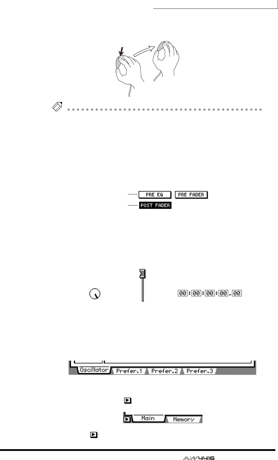
Chapter3—The user interface of the AW4416
— Operation Guide 53
The action of moving the pointer to the desired item, then pressing and holding
the left button or right button of the mouse and moving the mouse is called “drag-
ging.”
Tip!
When dragging the mouse to continuously adjust a parameter value, the value will
change more rapidly if you hold down the right button while dragging. The value
will change at the usual rate if you hold down the left button while dragging.
❍ Buttons
Buttons in the display are used to turn parameters on/off, or to select one of mul-
tiple possibilities. Buttons that are currently on are displayed as white text on a
black background, and buttons that are currently off are displayed as black text
on a white background.
< Buttons >
❍ Knobs/faders/numerical boxes
Knobs/faders/numerical boxes in the display are used to modify the value of the
corresponding parameter. The value of a knob or fader is displayed below or at
the right.
❍ Tab
If a screen includes multiple pages, the name of each page will be shown at the
bottom of the display. The areas where these names appear are called “tabs.” Tabs
are used to switch pages within a screen.
< Tabs >
In some screens, you can access additional items or buttons in this area. Such
screens are indicated by a symbol in the lower left of the display.
< symbol indicating that there are additional tabs or buttons >
Dragging
On
Off
< Knob > < Numerical box >< Fader >
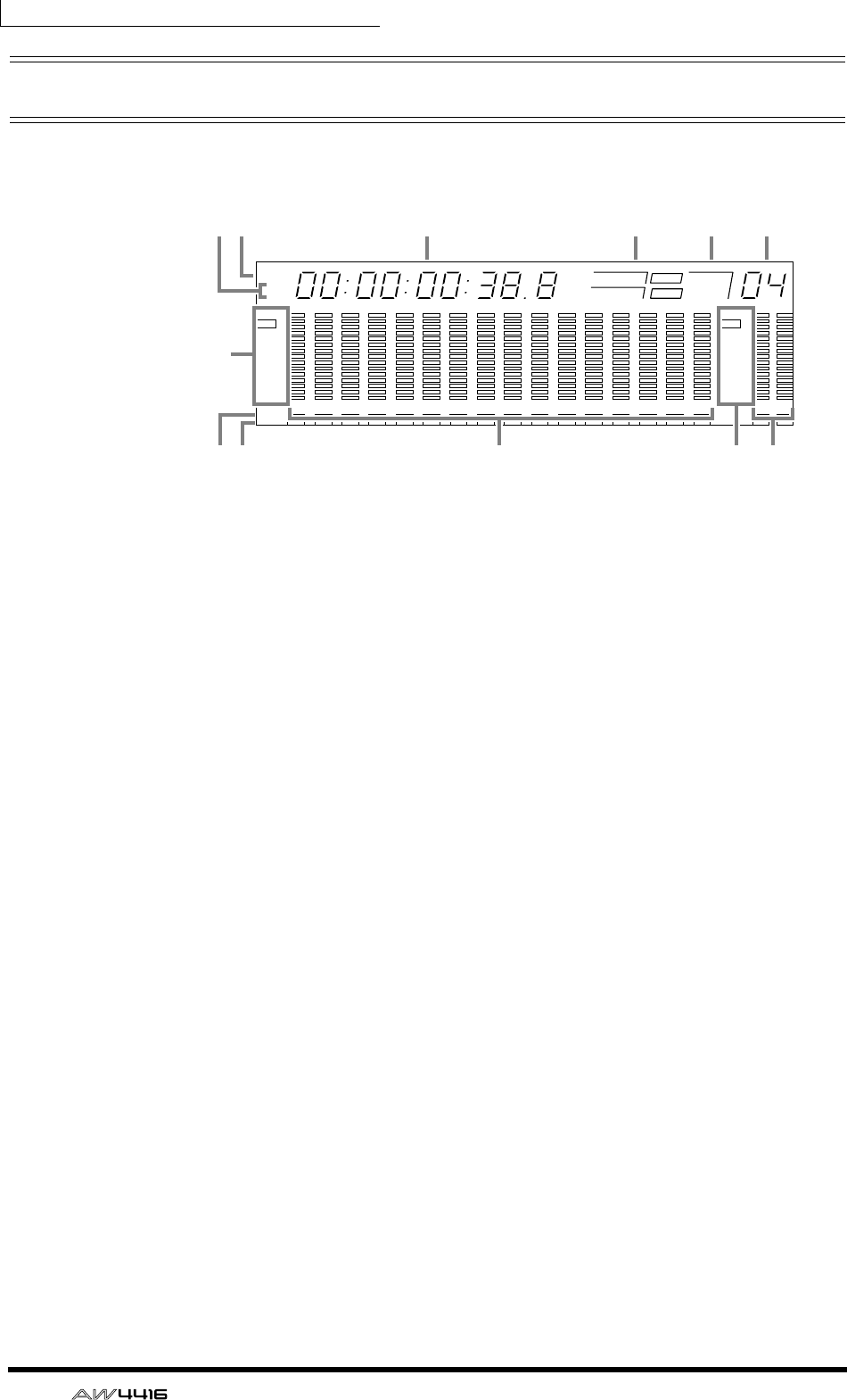
Chapter3—The user interface of the AW4416
54 — Operation Guide
Level meters/counter
The level meters/counter in the upper right of the top panel show the following
information.
1REMAIN indicator
This will light when the counter 3 shows the remaining recording time. In the
TRACK screen TR View page, this will appear when you press [SHIFT] + [F1].
BABS/REL indicator
One of these indicators will light when the time/timecode shown in the counter
3 is either absolute time (ABS) or relative time (REL). To switch between absolute
time and relative time, use the ABS/REL switch located at the right of the level
meter/counter.
CCounter
This is the current time in the song. You can select from the following units for
display (Refer to Reference Guide “SONG screen/Setting page”).
•Time display (SECOND) ............... Hours:minutes:seconds:milliseconds
•Time code display (TIME CODE) .. Hours:minutes:seconds:frames:sub-frames
•Measure display (MEASURE)........ Measures/beats/ticks (1/960th of a quarter
note)
DWord clock
This shows the source (INT=internal clock or EXT=external clock) of the clock
according to which the AW4416 is operating, and the frequency (44.1 k or 48 k).
This will indicate “LOCK” if the AW4416 is locked to the clock source, and
“VARI” if the vari-pitch function (Refer to Reference Guide “SET UP screen/D.in
Setup page”) is enabled.
EMTC
This shows the status of MTC synchronization. If the AW4416 is following MTC
messages from an external device, this will indicate “SLAVE.” It the AW4416 is
transmitting MTC to an external device, this will indicate “MASTER”
FScene
This is the number of the currently selected scene (the current scene). When the
mix parameters of the last stored or recalled scene are modified, an “E” (edited)
character will be displayed at the lower right.
123456789 13 14 15 1610 11 12
–dB 0
2
6
20
30
42
60
10
14
18
20
26
12
FINE
READY
INPUT
–dB 0
2
6
20
30
42
60
10
14
18
20
26
12
FINE
READY
INPUT
LR
REMAIN
ABS
REL
HM S Fms
EXT
VARI
44.1k 48k
LOCK
WORD CLOCK MTC SCENE
SLAVE
MASTER
INT
E
3 4 5 6
8K7
K
9J
12

Chapter3—The user interface of the AW4416
— Operation Guide 55
GLevel meters 1–16
These level meters show the input level and output level for each track 1–16 of
the recorder section.
HLevel meter L/R
These level meters show the output level (the signal after passing through EQ and
dynamics processing) of the stereo output channel.
IREC READY indicator
This indicator will light red for tracks that are in record-ready mode.
JINPUT MONITOR indicator
This indicator will light white for tracks whose input is being monitored.
KLevel display
The range of the display can be switched between two ranges: 0 to –60 dB (nor-
mal) and 0 to –26 dB (fine).
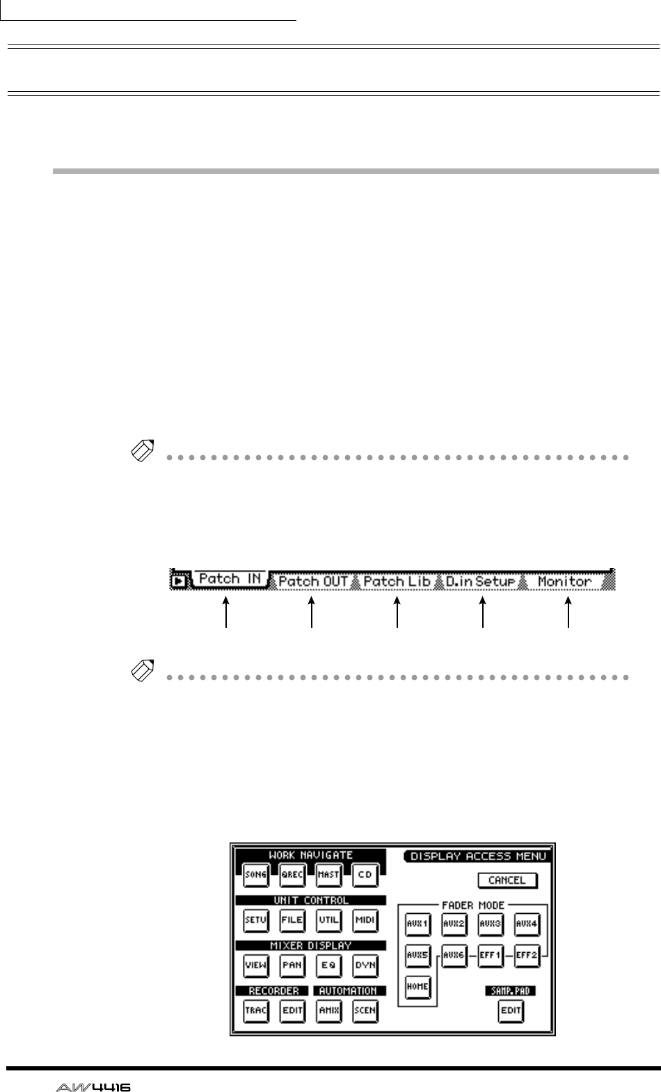
Chapter3—The user interface of the AW4416
56 — Operation Guide
Basic operation of the AW4416
This section explains basic operation of the AW4416.
Accessing a screen/page
To operate the mix parameters of the AW4416 or to edit the internal settings, you
must first access the desired screen in the display. If a screen contains two or
more pages, you must then select the desired page.
❒Using the controls of the top panel
1. Press the key for the desired screen.
The keys of the WORK NAVIGATE, UNIT, MIXER, FADER MODE, RECORDER,
and AUTOMATION sections of the top panel, and the [EDIT] key of the sample
pad section each correspond to their own screens, which you can access by
pressing the appropriate key.
Tip!
If a screen contains multiple pages, the most recently operated page will appear.
2. To switch pages within a screen, press the function key ([F1]–[F5] keys)
that corresponds to the tab for the desired page.
Each tab corresponds to the following function key.
Tip!
By repeatedly pressing the same key you pressed in step 1, you can cycle through
the pages of the screen.
❒Using the mouse
1. Click the M (menu) button in the upper right of the screen.
The display access menu will appear. From this menu you can use the mouse to
select screens.
[F1 key] [F2 key] [F3 key] [F4 key] [F5 key]
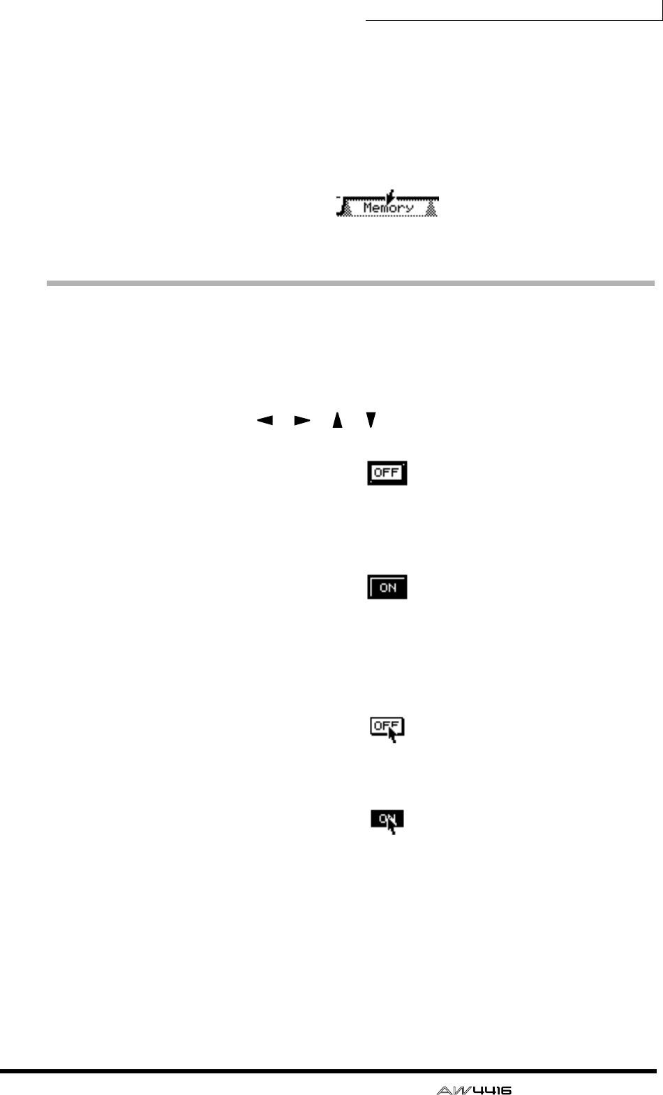
Chapter3—The user interface of the AW4416
— Operation Guide 57
2. In the display access menu, click the button that corresponds to the
desired screen.
3. To changes pages within the same screen, move the pointer to one of
the tabs in the bottom of the screen, and click the left or right mouse
button.
The corresponding page will appear.
< Click a tab >
Turning a button on/off
Here’s how a button displayed in the screen can be turned on/off.
❒Using the controls of the top panel
1. Use the CURSOR [ ]/[ ]/[ ]/[ ] keys to move the cursor to the
desired button.
< Move the cursor >
2. Press the [ENTER] key.
The button will be turned on or off.
< Switch on/off >
❒Using the mouse
1. Move the pointer to the desired button.
< Move the pointer >
2. Click the left or right button of the mouse.
< Switch on/off >
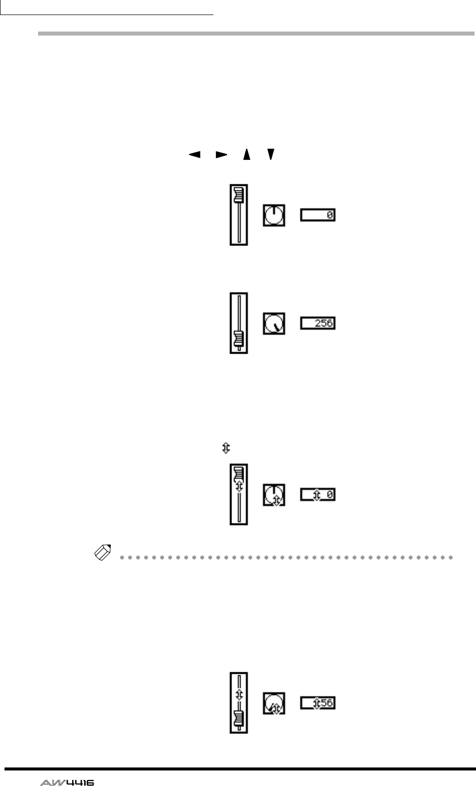
Chapter3—The user interface of the AW4416
58 — Operation Guide
Editing the value of a fader/knob/numerical
box
Here’s how to edit the value of an on-screen fader/knob/numerical box.
❒Using the controls of the top panel
1. Use the CURSOR [ ]/[ ]/[ ]/[ ] keys to move the cursor to the
desired fader/knob numerical box.
< Move the cursor >
2. Rotate the [DATA/JOG] dial to edit the value.
< Edit the value >
❒Using the mouse
1. Move the pointer to the desired fader/knob/numerical box, and click the
left or right mouse button.
The cursor will change to a shape.
< Click the fader/knob/numerical box >
Tip!
The amount by which the value changes will differ depending on whether you
clicked the left or right mouse button. If you wish to change the value in large steps,
click the right button. If you wish to change the value in fine steps, click the left
mouse button.
2. Continue to hold down the mouse button, and drag the mouse up or down.
The value will increase or decrease depending on the direction in which you drag
the mouse.
< Drag the fader/knob/numerical box up or down >
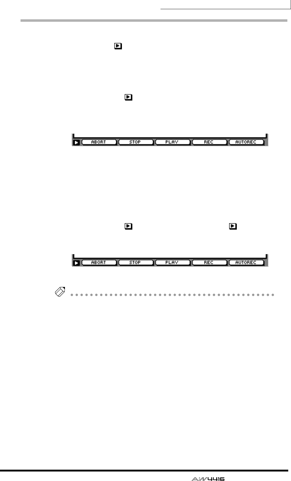
Chapter3—The user interface of the AW4416
— Operation Guide 59
Using the additional function buttons
In screens where the symbol is displayed in the lower left, you can access
additional buttons or tabs in the bottom of the display to use various additional
functions.
❒Using the controls of the top panel
1. In a screen where the symbol is displayed in the lower left, press the
[SHIFT] key.
While you continue holding the [SHIFT] key, buttons for the additional functions
will appear in the tab area at the bottom of the display.
< Additional function buttons >
2. Continue to hold down the [SHIFT] key, and press the function key
([F1]–[F5]) that corresponds to the desired button.
The function assigned to the corresponding button will be executed.
❒Using the mouse
1. In a screen where the symbol is displayed, click the symbol.
Buttons for the additional functions will appear in the tab area at the bottom of
the display.
< Additional function buttons >
Tip!
When using the mouse, the additional function buttons will continue to be dis-
played even after you take your finger off of the mouse button.
2. Directly click one of the additional function buttons.
The function assigned to the corresponding button will be executed.
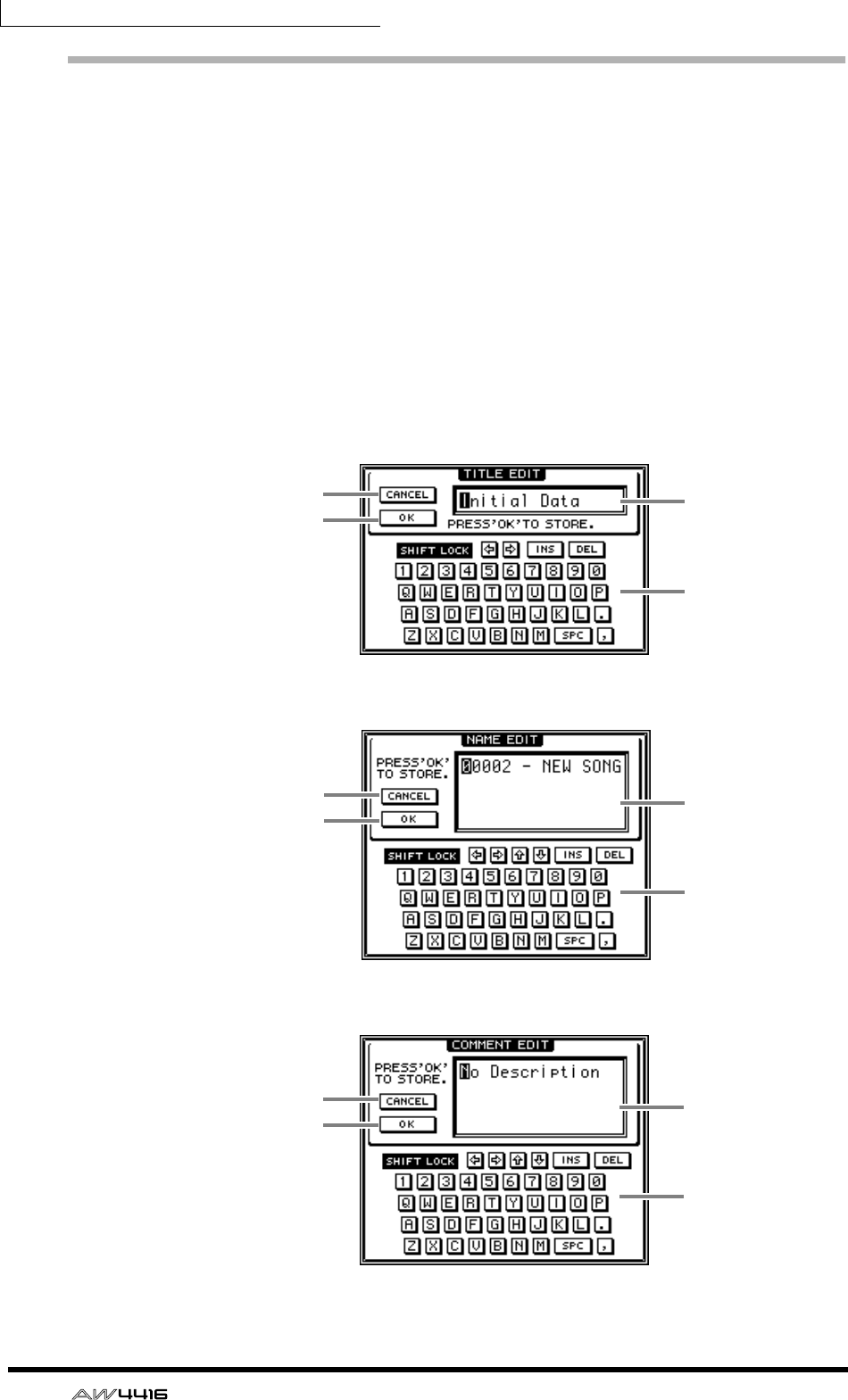
Chapter3—The user interface of the AW4416
60 — Operation Guide
Inputting text
When you create a new song, or when you save the settings of a scene memory
or library, a popup window will appear, allowing you to assign a name to the
song or the settings. Here’s how to input text into the popup window.
❒Using the controls of the tab page
1. Perform the scene or library Save operation, or create a new song.
If you perform the scene or library Save operation, a TITLE EDIT popup window
will appear, allowing you to assign a name to the scene or library.
If you create a new song, a NAME EDIT popup window will appear, allowing you
to assign a name to the song. Then a COMMENT EDIT popup window will
appear, allowing you to add a comment to the song.
< TITLE EDIT popup window >
< NAME EDIT popup window >
< COMMENT EDIT popup window >
2
31
4
2
31
4
2
31
4
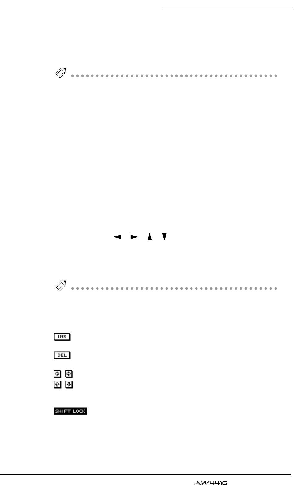
Chapter3—The user interface of the AW4416
— Operation Guide 61
The items in each popup window and their function are as follows.
1Text input box
Characters, numerals, and symbols can be input in this box. When you create a
new song or save for the first time, a default name will be input. The highlighted
text indicates that it is being changed.
Tip!
Scene and library names can be up to 16 characters long. Song names and song
comments can be up to 64 characters long.
BCANCEL button
If you move the cursor to this button and press the [ENTER] key, the procedure
will be cancelled and you will return to the previous screen.
COK button
If you move the cursor to this button and press the [ENTER] key, the text you
entered will be finalized. (If you are creating a new song, you will proceed to the
next step of the procedure.)
DText palette
Here you can select the character to input in the text input box. The following
characters, symbols, and numerals can be used.
2. Use the CURSOR [ ]/[ ]/[ ]/[ ] keys to move the cursor in the text
palette to the button for the desired character, and press the [ENTER]
key.
The corresponding character/symbol/numeral will be input into the text input
box, and the highlighted area will move to the right.
Tip!
If you wish to correct a character that was input by mistake, you can use the [DATA/
JOG] dial to move the highlighted area to left or right.
3. Input the remaining characters in the same way.
While inputting text, you can use the following buttons in the text palette.
button........... Insert a space (blank) at the highlighted area. Subsequent
characters will be moved backward.
button........... Delete the character at the highlighted area. Subsequent
characters will be moved forward.
/ buttons........ Move the highlighted area to left or right.
/ buttons
(NAME EDIT, COMMENT EDIT windows only)......Move the highlighted area
upward or downward.
button.. Switch between uppercase alphabet + numerals and lower-
case alphabet + symbols. When this button is on, you can
input uppercase alphabetical characters and numerals.
4. When you have finished inputting the desired text, move the cursor to
the OK button, and press the [ENTER] key.
A B C D E F G H I J K L M N O P Q R S T U V W X Y Z
a b c d e f g h i j k l m n o p q r s t u v w x y z
spc (space) 1 2 3 4 5 6 7 8 9 0 , . ! " # & / * - + < > : ;
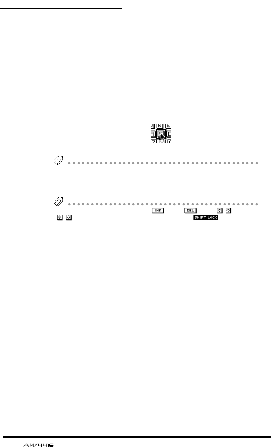
Chapter3—The user interface of the AW4416
62 — Operation Guide
❒Using the mouse
1. Perform the scene or library Save operation, or create a new song.
If you perform the scene or library Save operation, a TITLE EDIT popup window
will appear, allowing you to assign a name to the scene or library.
If you create a new song, a NAME EDIT popup window will appear, allowing you
to assign a name to the song. Then a COMMENT EDIT popup window will
appear, allowing you to add a comment to the song.
2. In the text palette, click the mouse on the button for the character that
you wish to input.
The corresponding character/symbol/numeral will be input into the text input
box, and the highlighted area will move to the right.
< Click a character button >
Tip!
If you wish to correct a character that you input by mistake, click the incorrect char-
acter to move the highlighted area to that location.
3. Input the remaining characters in the same way.
Tip!
When using the mouse, you can use the button, button,
/
buttons,
/
(NAME EDIT/COMMENT EDIT windows only), or button by
clicking the corresponding button in the text palette.
4. When you have finished inputting the desired text, move the cursor to
the OK button, and press the [ENTER] key.
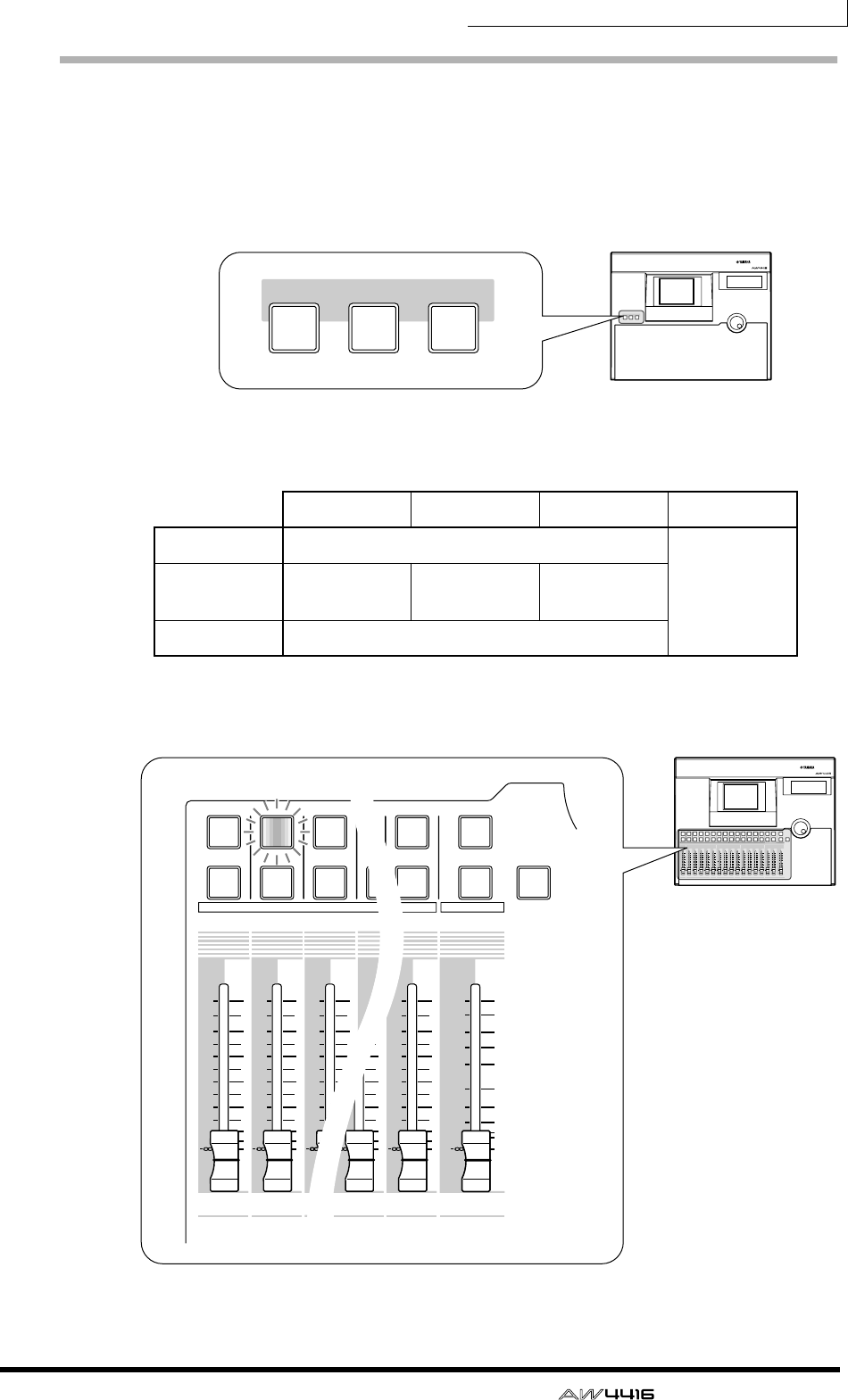
Chapter3—The user interface of the AW4416
— Operation Guide 63
Selecting channels
When editing the channel mix parameters on the AW4416, you must first select
the channel that you wish to control. Here’s how to select channels.
1. Use the keys of the MIXING LAYER section to select the mixing layer that
you wish to control
According to the selected key of the MIXING LAYER section, the channels con-
trolled by the [SEL] keys, [ON] keys, and faders of the top panel will change as
follows.
2. Press the [SEL] key of the channel you wish to control.
The [SEL] key of the corresponding channel will light.
1–8 9–14 15/16 STEREO
[1-16] Input channels 1–16
Stereo output
channel
[17-24 RTN] Input chan-
nels 17–24 —Effect return
1/2
[MONI] Monitor channels 1–16
PROFESSIONAL AUDIO WORKSTATION
MIXING LAYER
INPUT INPUT RECORDER
17-24
RTN MONI
1-16
MIXING LAYER
INPUT INPUT RECORDER
17-24
RTN MONI
1-16
PROFESSIONAL AUDIO WORKSTATION
12
RTN
17 18 19 20 21 22 23 24
345678 910111212 13 14 15 16
STEREO
34567 8 9101112
1213 14 15 16
5
10
20
30
70
50
40
15
ON
SEL
ON
SEL
ON
SEL
ON
SEL
ON
SEL
ON
SEL
ON
SEL
ON
SEL
ON
SEL
ON
SEL
ON
SEL
ON
SEL
ON
SEL
ON
SEL
ON
SEL
ON
SEL
ON
SEL
SOLO
0
0
5
40
60
10
20
+6
0
5
40
60
10
20
+6
0
5
40
60
10
20
+6
0
5
40
60
10
20
+6
0
5
40
60
10
20
+6
0
5
40
60
10
20
+6
0
5
40
60
10
20
+6
0
5
40
60
10
20
+6
0
5
40
60
10
20
+6
0
5
40
60
10
20
+6
0
5
40
60
10
20
+6
0
5
40
60
10
20
+6
0
5
40
60
10
20
+6
0
5
40
60
10
20
+6
0
5
40
60
10
20
+6
0
5
40
60
10
20
+6
17 18 19
312
12
ON
SEL
ON ON
SEL
0
5
40
60
10
20
+6
0
5
40
60
10
20
+6
0
5
40
60
10
20
+6 +6
0
5
40
60
10
20
+6
0
5
40
60
10
20
+6
0
5
40
60
10
20
+6 +6
2
16
STEREO
15 16
5
10
20
30
70
50
40
15
ON
SEL
ON
SEL
SOLO
0
40
60
20
0
5
40
60
10
20
+6
20
0
5
40
60
10
20
+6
40
60
SEL
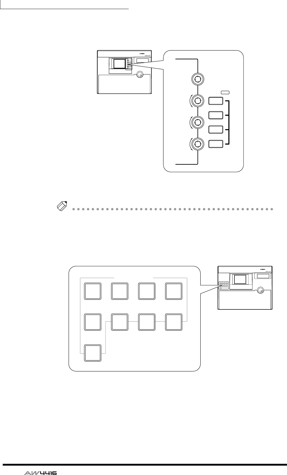
Chapter3—The user interface of the AW4416
64 — Operation Guide
3. Use the [PAN] control, EQ [Q]/[F]/[G] controls, and EQ [HIGH]–
EQ[LOW] keys at the right of the display to adjust the pan and EQ of the
channel that you selected by pressing its [SEL] key.
The controls and keys at the right of the display apply only to the channel that
was last-selected by its [SEL] key.
Tip!
If the VIEW, PAN, EQ, or DYN screens are shown in the display, you can control the
parameters of the channel selected by its [SEL] key.
4. To operate the faders, use the [HOME] key or [AUX 1]–[AUX 8] keys of
the FADER MODE section to select the fader mode (the parameters that
will be controlled by the faders).
The table on the following page shows the parameters controlled by each fader
will change.
PROFESSIONAL AUDIO WORKSTATION
LO
LO-MID
HI-MID
HI
EQ
F
PAN
G
Q
LOW
LO-MID
HI-MID
HIGH
EQ
F
PAN
G
Q
PROFESSIONAL AUDIO WORKSTATION
FADER MODE
EFF 1 EFF 2
AUX
1AUX
2AUX
3AUX
4
AUX
5AUX
6AUX
7AUX
8
HOME
FADER MODE
EFF 1 EFF 2
AUX
1AUX
2AUX
3AUX
4
AUX
5AUX
6AUX
7AUX
8
HOME

Chapter3—The user interface of the AW4416
— Operation Guide 65
❍ If the mixing layer is [1-16]
❍ If the mixing layer is [17-24 RTN]
Fader mode Fader
1–8 9–14 15 16 STEREO
HOME Input level of input channels 1–16
Output level of the
stereo output
channel
AUX1 Send level from input channels 1–16 to AUX 1
AUX2 Send level from input channels 1–16 to AUX 2
AUX3 Send level from input channels 1–16 to AUX 3
AUX4 Send level from input channels 1–16 to AUX 4
AUX5 Send level from input channels 1–16 to AUX 5
AUX6 Send level from input channels 1–16 to AUX 6
AUX7 Send level from input channels 1–16 to effect 1
AUX8 Send level from input channels 1–16 to effect 2
Fader mode Fader
1–8 9–14 15 16 STEREO
HOME Input level of
input channels
17–24
—
Input level of
effect return 1
Input level of
effect return 2
Output level of the
stereo output
channel
AUX1 Send level from
input channels
17–24 to AUX 1
Send level from
effect return 1 to
AUX 1
Send level from
effect return 2 to
AUX 1
AUX2 Send level from
input channels
17–24 to AUX 2
Send level from
effect return 1 to
AUX 2
Send level from
effect return 2 to
AUX 2
AUX3 Send level from
input channels
17–24 to AUX 3
Send level from
effect return 1 to
AUX 3
Send level from
effect return 2 to
AUX 3
AUX4 Send level from
input channels
17–24 to AUX 4
Send level from
effect return 1 to
AUX 4
Send level from
effect return 2 to
AUX 4
AUX5 Send level from
input channels
17–24 to AUX 5
Send level from
effect return 1 to
AUX 5
Send level from
effect return 2 to
AUX 5
AUX6 Send level from
input channels
17–24 to AUX 6
Send level from
effect return 1 to
AUX 6
Send level from
effect return 2 to
AUX 6
AUX7 Send level from
input channels
17–24 to effect 1
—
Send level from
effect return 2 to
effect 1
AUX8 Send level from
input channels
17–24 to effect 2
Send level from
effect return 1 to
effect 2
—

Chapter3—The user interface of the AW4416
66 — Operation Guide
❍ If the mixing layer is [MONI]
Fader mode Fader
1–8 9–14 15 16 STEREO
HOME Input level of monitor channels 1–16
Output level of the
stereo output
channel
AUX1 Send level from monitor channels 1–16 to AUX 1
AUX2 Send level from monitor channels 1–16 to AUX 2
AUX3 Send level from monitor channels 1–16 to AUX 3
AUX4 Send level from monitor channels 1–16 to AUX 4
AUX5 Send level from monitor channels 1–16 to AUX 5
AUX6 Send level from monitor channels 1–16 to AUX 6
AUX7 Send level from monitor channels 1–16 to effect 1
AUX8 Send level from monitor channels 1–16 to effect 2
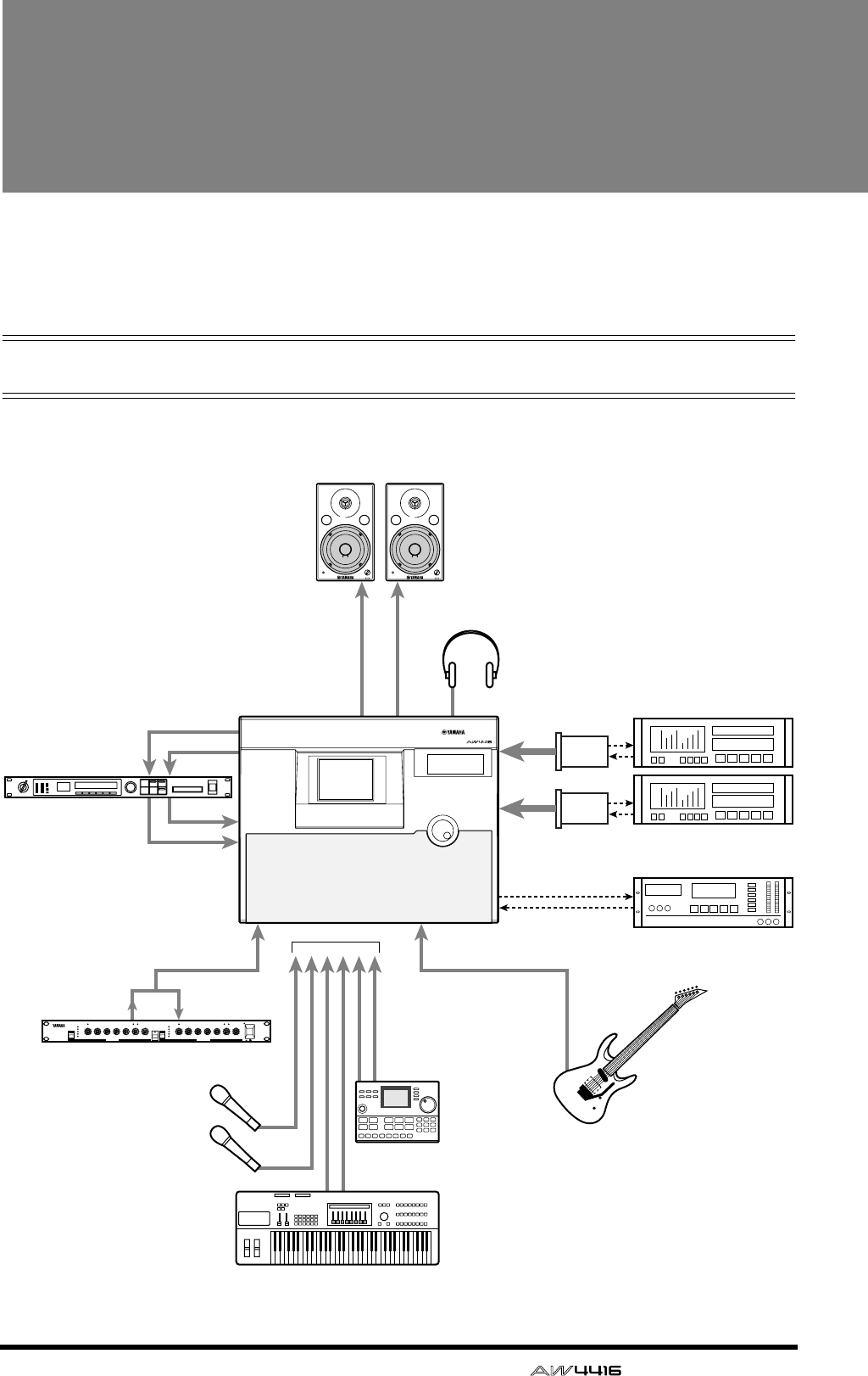
— Operation Guide 67
4Connections and setup
This chapter explains how to connect external devices and set up your sys-
tem before you begin using the AW4416.
Connections
The following diagram shows typical audio connections for the AW4416.
Monitor system
Headphones
MONITOR OUT
OMNI OUT 1/2
INPUT 1–8
INPUT 1–8INSERT I/O INPUT 8
Hi-Z
PHONES
OPTION
SLOT 1
STEREO DIGITAL IN
STEREO DIGITAL OUT
DAT
00.00.00.00
Rhythm machine
Effect processor
Signal processor
Synthesizer
Electric guitar/
Electric bass
DAT recorder
Digital MTR
I/O card
OPTION
SLOT 2
88
PROFESSIONAL AUDIO WORKSTATION
AW4416
VOL VOL
GC2020C
COMP/LIMITER
COMP
GAIN
REDUCTION
0
–4
–8
–16
–24
EXP GATE THRESHOLD RATIO ATTACK RELEASE INPUT OUTPUT
CHANNEL A CHANNEL B
SIGNAL PEAK GAIN
REDUCTION
0
–4
–8
–16
–24
EXP GATE THRESHOLD RATIO ATTACK RELEASE INPUT OUTPUT
SIGNAL PEAK
LINK COMP
ON OFF
POWER
0 10 0 10 0 10 0 10
1
2
48
20
00 0.2
1
35
10
20 0.05
0.1
0.3 0.5
1
20 10 0 10 0 10 0 10
1
2
48
20
00 0.2
1
35
10
20 0.05
0.1
0.3 0.5
1
2
secms
secms
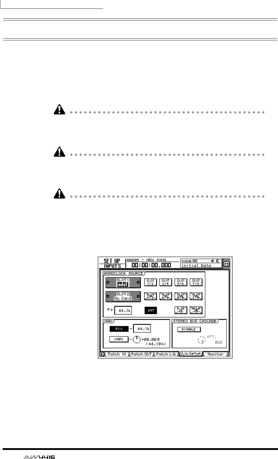
Chapter4—Connections and setup
68 — Operation Guide
Word clock settings
If a device such as a digital MTR or DAT recorder is digitally connected to the
AW4416, the clock that controls the timing at which digital audio is processed
(referred to as the “word clock”) must be synchronized. To do so, you must select
one of the devices as the word clock master, and set the remaining devices so
that they will follow the word clock supplied from the master device. Here we
will explain how to select the clock source to which the AW4416 will synchro-
nize.
Be aware that if the system includes an unsynchronized device, drop-outs and
click noise will occur.
1. Turn on the power of the external digital device and of the AW4416.
If an external device is connected to the SCSI connector of the AW4416, you
must turn on the power in the order of external SCSI device
→
AW4416. If the
power of the external SCSI device is off when you turn on the AW4416, it may
not start up correctly.
If the D.in Setup tab is not assigned to the [F4] key when you press the [SETUP]
key, press the [SHIFT] key + [F1] key to switch the tab, and then press the [F4]
key.
2. 2. Press the [SETUP] key → [F4] key.
The SETUP UP screen D.in Setup page will appear, allowing you to make word
clock settings.
In the WORD CLOCK SOURCE area of this screen you can select one of the fol-
lowing as the clock source to which the AW4416 will synchronize.
❍ SLOT 1 1/2–7/8
❍ SLOT 2 1/2–7/8
An input signal from a digital I/O card installed in OPTION I/O slot 1/2 will be
the clock source. You can select one pair from input channels 1/2–7/8 of the digi-
tal I/O card, and the AW4416 will synchronize to the word clock data included
in the input signal of the corresponding channel.
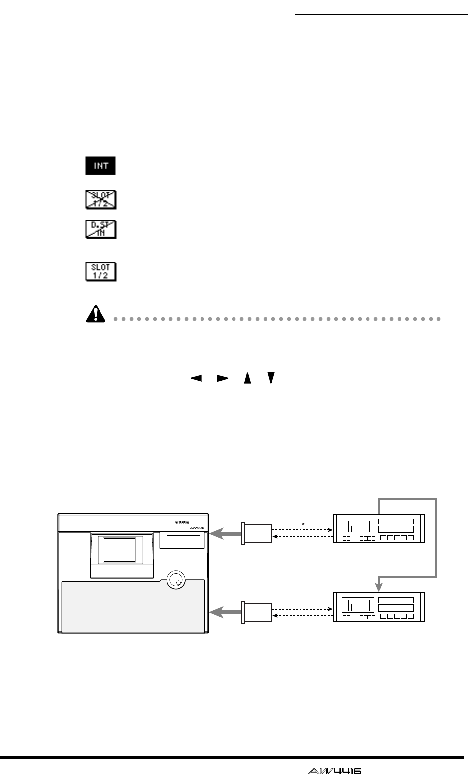
Chapter4—Connections and setup
— Operation Guide 69
❍ D.ST IN
The word clock data included in the input signal from the DIGITAL STEREO IN
jack will be the clock source.
❍ WCLK IN
The word clock data included in the input signal from the WORD CLOCK IN jack
will be the clock source.
❍ INT
The internal clock of the AW4416 will be the clock source.
The currently highlighted button is selected as the word clock source.
Buttons marked with an × symbol indicate that no digital audio signal is
being input from the corresponding slot/jack.
Buttons marked with a / symbol indicate that either no digital audio sig-
nal is being input from the corresponding slot/jack, or that it is not syn-
chronized with the AW4416’s internal clock.
Buttons without an × or / symbol indicate that a digital audio signal is
being input from the corresponding slot/jack, and that it is synchronized
with the AW4416’s internal clock.
If the AW4416 is set to be an MTC slave, it is not possible for the AW4416 to
simultaneously be set as the word clock slave.
3. Select the desired clock source in the WORD CLOCK SOURCE area by
using the CURSOR [ ]/[ ]/[ ]/[ ] keys to move the cursor to the
corresponding button.
The clock source you should select will depend on the system in which you are
using the AW4416. Here we will explain some typical situations.
❍ Using the AW4416 as the word clock master
If no external digital device is connected to the AW4416, or if you wish to use the
AW4416 as the word clock master so that external devices such as a digital MTR
will follow it, turn on the INT button of the WORD CLOCK SOURCE area.
• Set the digital MTR so that it will synchronize to the word clock included in
the input signal from the AW4416.
• If you are using two digital MTR units, connect the Sync Out jack of the first
to the Sync In jack of the second as shown here, so that the second digital
MTR will follow the first.
OPTION
SLOT 1
Digital MTR
(word clock slave)
Digital MTR
(word clock slave)
Word clock
Word
clock
OPTION
SLOT 2
Sync Out
Sync In
PROFESSIONAL AUDIO WORKSTATION
AW4416
(word clock master)
WORD CLOCK SOURCE= INT
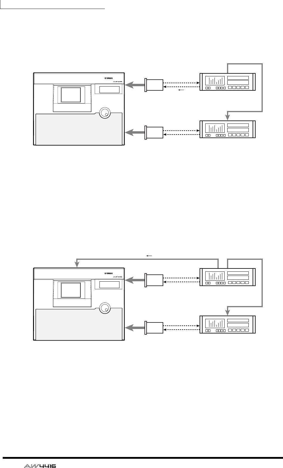
Chapter4—Connections and setup
70 — Operation Guide
❍ Using a digital MTR as the word clock master (1)
This method uses a digital MTR as the word clock master, and causes the
AW4416 to synchronize to the word clock included in the input signal from the
digital I/O card. For this method, turn on one of the 1/2–7/8 buttons for the slot to
which that digital MTR is connected.
• Set the digital MTR so that it will operate according to its own internal clock.
• If you are using two digital MTR units, connect the Sync Out jack of the first
to the Sync In jack of the second as shown here, so that the second digital
MTR will follow the first.
❍ Using a digital MTR as the word clock master (2)
This method uses a digital MTR as the word clock master, and causes the
AW4416 to synchronize to the word clock supplied from the word clock output
jack of the digital MTR to the WORD CLOCK IN jack of the AW4416. For this
method, turn on the WCLK IN button.
• Set the digital MTR so that it will operate according to its own internal clock.
• If you are using two digital MTR units, connect the Sync Out jack of the first
to the Sync In jack of the second as shown here, so that the second digital
MTR will follow the first.
OPTION
SLOT 1 Digital MTR
(word clock master)
OPTION
SLOT 2
Sync Out
Sync In
PROFESSIONAL AUDIO WORKSTATION
WORD CLOCK SOURCE= SLOT 1 1/2–7/8
Word
clock
AW4416
(word clock slave)
Digital MTR
(word clock slave)
Word clock
OPTION
SLOT 1
Word
clock
OPTION
SLOT 2
Sync OutWord Clock OutWord Clock In
Sync In
PROFESSIONAL AUDIO WORKSTATION
WORD CLOCK SOURCE= WCLK IN
AW4416
(word clock slave)
Digital MTR
(word clock master)
Digital MTR
(word clock slave)
Word clock
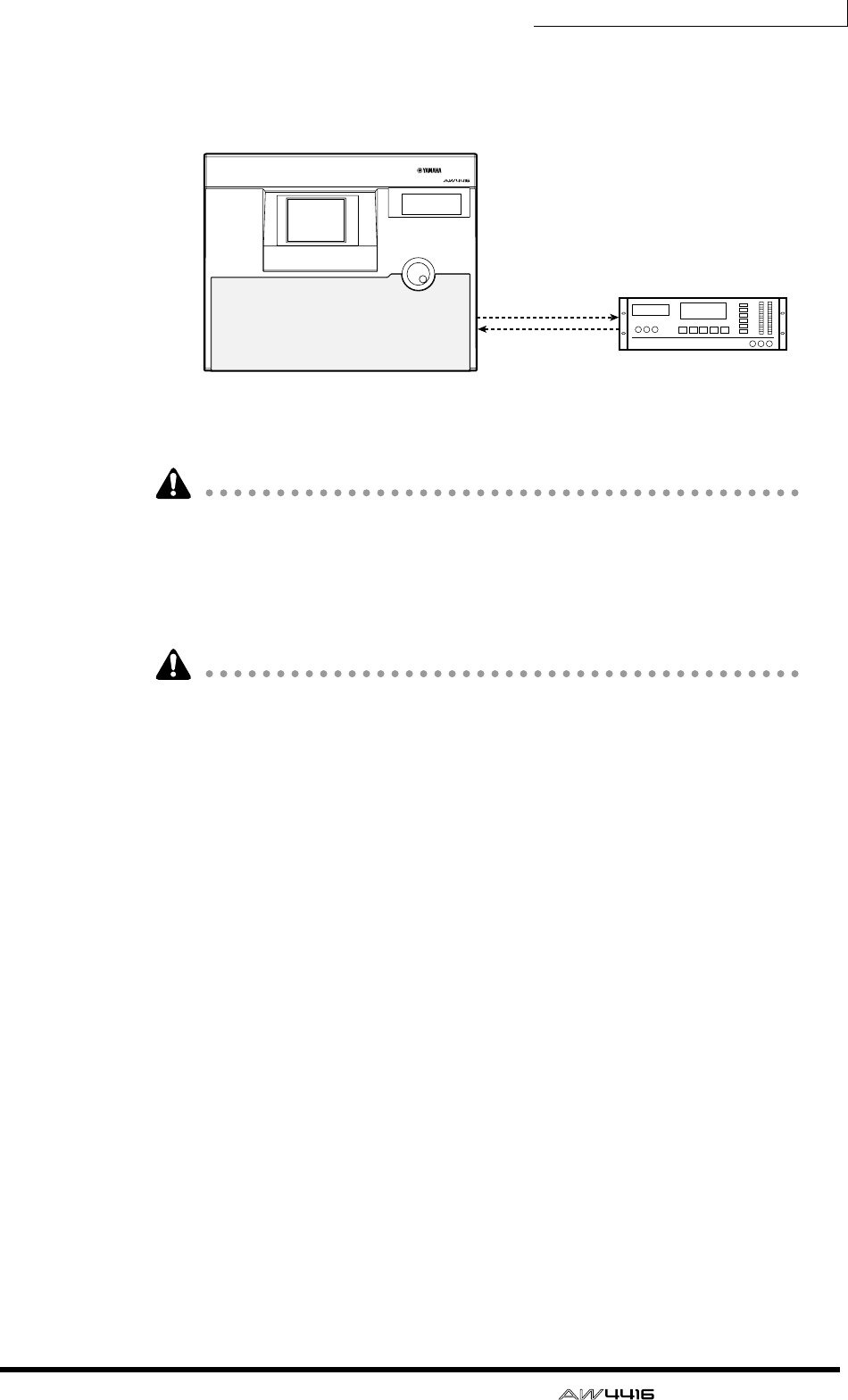
Chapter4—Connections and setup
— Operation Guide 71
❍ Using a DAT recorder as the word clock master
If you wish to input a digital signal from a DAT recorder or sampler etc. into the
AW4416 via the DIGITAL STEREO IN jack, turn on the D.ST IN button.
• Set the DAT recorder so that it will operate according to its own internal
clock.
Most consumer DAT recorders are designed to forcibly follow the word clock of
the input signal when recording. This type of DAT recorder can be used as the
word clock master only when it is playing back.
4. After selecting the desired button, press the [ENTER] key.
The AW4416 will switch to the specified clock source.
• A slight interval of time is required for the AW4416 to select clock sources,
and the sound may be muted during this time.
• After switching the clock source, verify that the button you selected in step 3 is
not marked with an X symbol or / symbol. If an X symbol or / symbol appears
on the button, or if an error message is displayed, check the connections or the
clock setting of the external device.
PROFESSIONAL AUDIO WORKSTATION
WORD CLOCK SOURCE= D.ST IN
DIGITAL STEREO OUT
DIGITAL STEREO IN
DAT
00.00.00.00
DAT recorder
(word clock master)
AW4416
(word clock slave)

Chapter4—Connections and setup
72 — Operation Guide
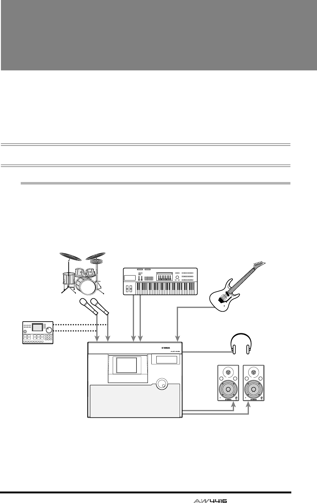
— Operation Guide 73
5Recording on the
AW4416
This chapter explains basic operation for performing multitrack recording
and mixdown on the AW4416, using the example of recording instruments
such as rhythm machine (drums), bass, guitar, and keyboard on their own
tracks.
Preparations for recording
Connections and start-up
Here’s how to connect your instruments and monitor system, and start up the
AW4416.
1. Connect your instruments, mics, and monitor system to the AW4416 as
shown in the following diagram.
Connect mics, synthesizers or rhythm machines, direct boxes, or guitar/bass
preamps to the INPUT 1/2 (XLR) jacks or INPUT 1–8 (phone) jacks, according to
the type of their output connector.
When directly connecting instruments with a high output impedance, such as
passive type electric guitars or electric basses, connect them to the INPUT 8 (HI-
Z) jack.
Headphones
MONITOR OUT
INPUT 1 2 3–8 INPUT 8
(HI-Z)
PHONES
Rhythm machine
Synthesizer
Mics for
recording drums Electric guitar/
Electric bass
PROFESSIONAL AUDIO WORKSTATION
AW4416 VOL VOL
Monitor
system
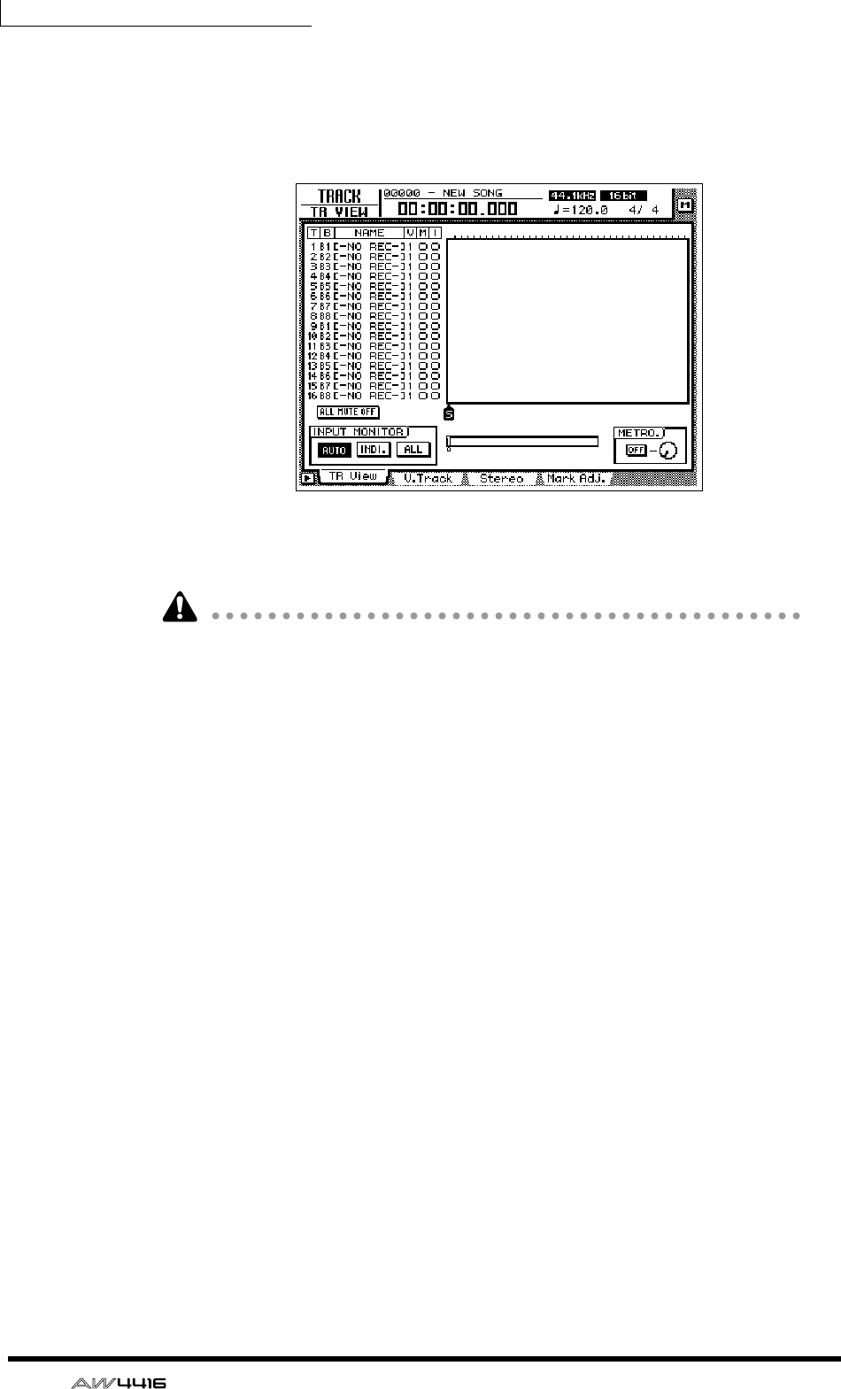
Chapter5—Recording on the AW4416
74 — Operation Guide
2. Turn on the power in the following order: audio sources/SCSI devices
connected to the AW4416 → the AW4416 → monitor system.
The display of the AW4416 will show the opening screen, and will then change
to the TRACK screen TR View page.
When the power of the AW4416 is turned on, the song you were last operating
will be loaded automatically.
• If the internal hard disk of the AW4416 has not been formatted, a message of
“Format OK? [Y (Enter)/N (Any)]” will appear instead of the above screen when
the power is turned on.
• If a SCSI device is connected to the AW4416, and you turn on the power of the
AW4416 when the SCSI device is turned off, it may not start up correctly. If the
SCSI device is turned on after the AW4416 is turned on, it will not function
correctly.
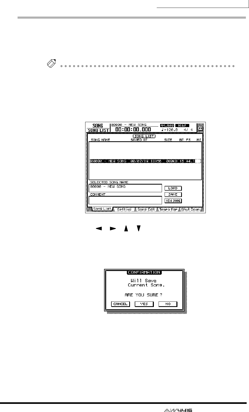
Chapter5—Recording on the AW4416
— Operation Guide 75
Creating a new song
On the AW4416, all data (mixer settings, recorder settings, audio data etc.) nec-
essary for reproducing a musical work are stored on the hard disk as a unit called
a “song.” In order to record, you must begin by creating a new song.
Tip!
A new 44.1 kHz/16 bit song is created when the internal hard disk is formatted, and
will automatically be loaded the next time you turn on the power of the AW4416. If
you wish to use this song, the following procedure is not necessary.
1. Press the [SONG] key → [F1] key.
The SONG screen Song List page will appear. In this page you can create a new
song, and save/load existing songs.
2. Use the CURSOR [ ]/[ ]/[ ]/[ ] keys to move the cursor to the NEW
SONG button in the lower right of the screen, and press the [ENTER]
key.
A popup window will appear, asking you whether you wish to save the song you
are now working on (referred to as the “current song”).
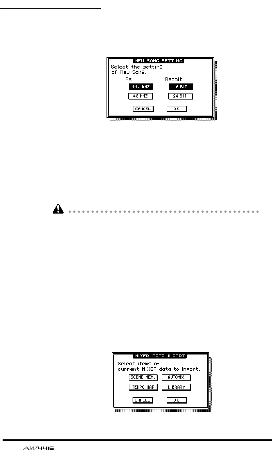
Chapter5—Recording on the AW4416
76 — Operation Guide
3. Move the cursor to the YES button to save the current song, or to the
NO button if you do not wish to save it. Then press the [ENTER] key.
The NEW SONG SETTING popup window will appear. In this popup window
you can specify the basic settings for the new song.
❍ Fs
This is the sampling frequency at which the input signals are converted into digi-
tal form. Move the cursor to either the 44.1 kHz or 48 kHz button, and press the
[ENTER] key to make your selection.
❍ Recbit
This is the number of quantization bits for the audio data recorded on the hard
disk. Move the cursor to either 16 BIT or 24 BIT, and press the [ENTER] key to
make your selection.
• It is not possible to change the sampling frequency or quantization after creat-
ing a song.
• The number of tracks that can be simultaneously played or recorded will
depend on the specified quantization.
• If you intend to use a CD-RW drive to create an audio CD of your song when it
is completed, you must select 44.1 kHz as the sampling frequency. A song
with a sampling frequency of 48 kHz cannot be recorded on an audio CD.
4. After you have selected the sampling frequency and the quantization,
move the cursor to the OK button and press the [ENTER] key.
If you selected 48 kHz as the sampling frequency, the display will indicate “Not
for Audio CD -48 kHz- ARE YOU SURE?”, warning you that an audio CD cannot
be produced from this song. Move the cursor to either the OK button or the CAN-
CEL button, and press the [ENTER] key.
The MIXER DATA IMPORT popup window will appear. This popup window
allows you to import mixer data from an existing song. For this example, it is not
necessary to make any settings.
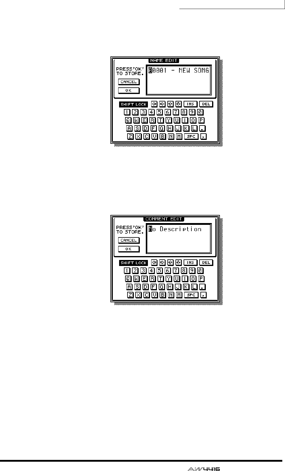
Chapter5—Recording on the AW4416
— Operation Guide 77
5. Make sure that the cursor is located at the OK button, and press the
[ENTER] key.
The NAME EDIT popup window will appear, allowing you to assign a name to
the song.
6. Use the character palette to assign a song name of up to 64 characters.
(For details on inputting characters, refer to page 60.) When you have
finished inputting the song name, move the cursor to the OK button
and press the [ENTER] key.
The COMMENT EDIT popup window will appear, allowing you to assign a com-
ment to the song.
7. As desired, input a comment in the same way as the song name. Then
move the cursor to the OK button and press the [ENTER] key.
The new song will be created. (If you selected YES in step 3, the song you had
been operating will be saved before the new song is created.)
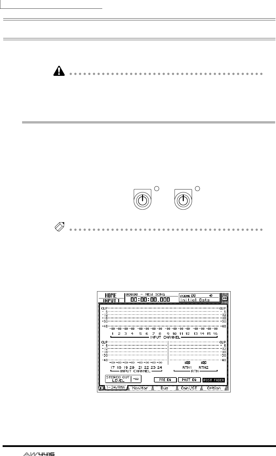
Chapter5—Recording on the AW4416
78 — Operation Guide
Recording the first tracks
This section explains the procedure for recording a rhythm machine (or drum
mics) connected to INPUT jacks 1/2 onto tracks 1/2 of the recorder.
The explanation in this section assumes that the AW4416’s mixer and patching
settings are in their initial state. If you have already modified the mixer parame-
ters or the input/output patching, please recall the default scene (scene number
00) from the scene memory (
→
P.206).
Set the input level
1. While producing sound on your instrument, adjust [GAIN] controls 1/2
so that the PEAK indicators of INPUT jacks 1/2 light briefly when the
loudest sounds are played.
Tip!
The [GAIN] control adjusts the sensitivity of the analog input. In order to record the
sound cleanly and with the widest possible range, you should adjust the [GAIN] as
high as possible without allowing clipping to occur.
2. Press the [HOME] key → [F1] key
The HOME screen 1–24/Rtn page will appear. This page shows the input levels of
input channels 1–24 and return channels 1/2.
3. In the MIXING LAYER section, press the [1–16] key to select input chan-
nels 1–16 as the mixing layer.
PEAK PEAK
12
MICLINE MICLINE
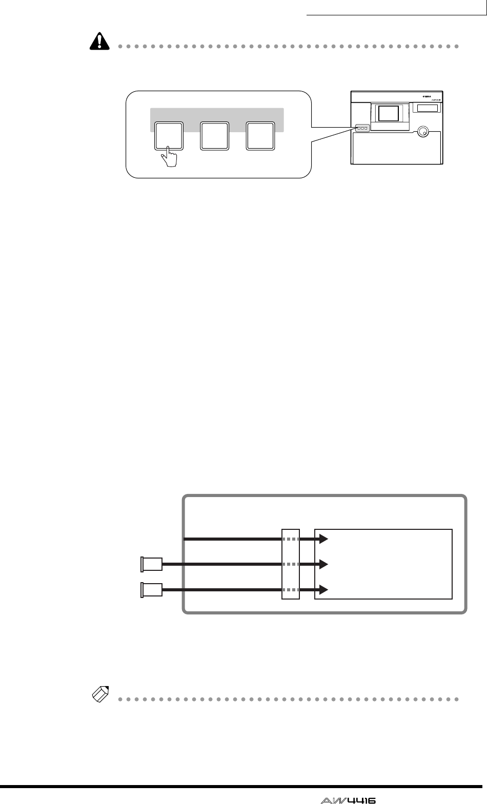
Chapter5—Recording on the AW4416
— Operation Guide 79
When you switch mixing layers, the faders will move instantly to new positions.
Be careful not to place objects near the faders.
The “mixing layer” is the group of channels controlled by the top panel [ON]
keys 1–16, [SEL] keys 1–16, and faders 1–16. The AW4416 has the following
three mixing layers:
1Input channels 1–16
BInput channels 17–24 + return channels
CMonitor channels
Even when you switch to a different mixing layer, the fader locations and [ON]
key settings of the previous mixing layer are remembered, and will return when
that mixing layer is selected once again.
4. Make sure that [ON] keys 1/2 are turned on, and raise faders 1/2 to the
0 dB position.
5. While playing your instrument, watch the level meters displayed in the
screen and adjust the input level of inputs 1/2.
When the AW4416 is in the initial state, the input jacks are patched to input
channels as follows. As you can see from this diagram, the rhythm machine (or
drum mics) connected to INPUT jacks 1/2 are patched to input channels 1/2.
Now raise the faders of input channels 1/2 and check that the signals are being
input. If the level meters reach the “CLIP” position, you should lower [GAIN]
controls 1/2.
Tip!
The patching of the input jacks and input channels can be changed freely. For
details refer to page 133.
PROFESSIONAL AUDIO WORKSTATION
MIXING LAYER
INPUT INPUT RECORDER
17-24
RTN MONI
1-16
MIXING LAYER
INPUT INPUT RECORDER
17-24
RTN MONI
1-16
Input channels 1–8
Input channels 9–16
Input channels 17–24
OPTION I/O
slot 1
OPTION I/O
slot 2
Mixer section
Input
patch
×8
×8
×8
INPUT jacks 1–8
I/O card
I/O card
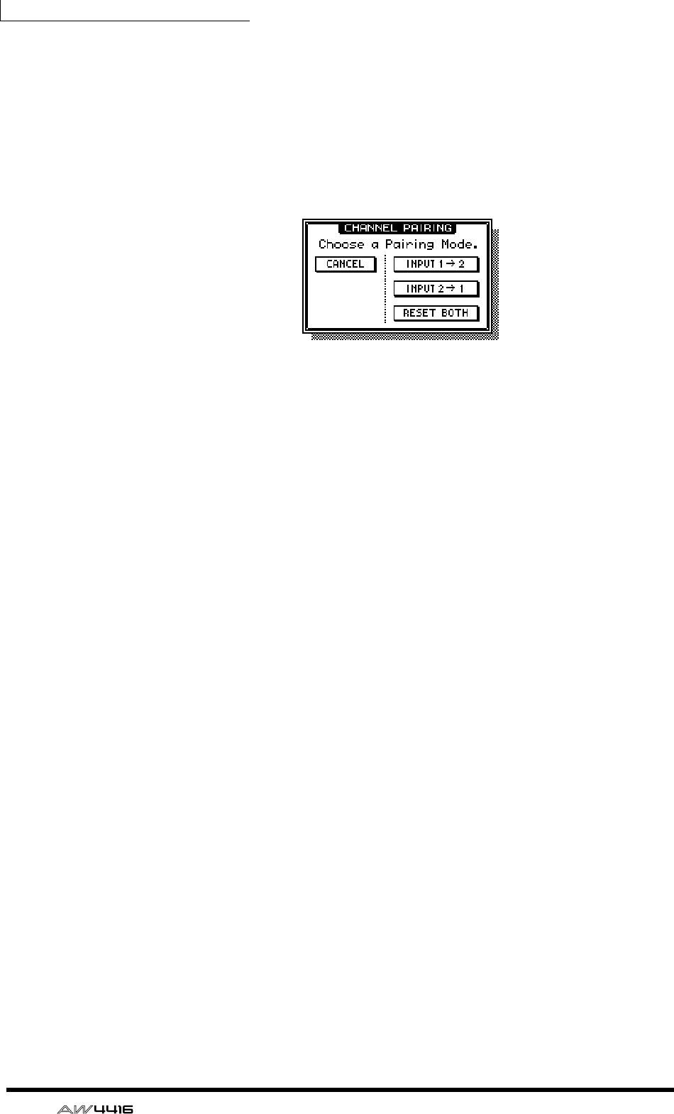
Chapter5—Recording on the AW4416
80 — Operation Guide
6. If you wish to set the input signals of INPUT jacks 1/2 as a stereo pair,
hold down [SEL] key 1 and press [SEL] key 2.
Adjacent odd-numbered → even-numbered input channels can be specified as a
stereo pair. You will find it convenient to pair two channels that are inputting a
stereo source, so that all mix parameters except for attenuation and pan will be
linked.
When you simultaneously press the two [SEL] keys, a CHANNEL PAIRING popup
window will appear, allowing you to specify how pairing will occur.
7. Move the cursor to either the “INPUT 1→2,” “INPUT 2→1,” or “RESET
BOTH” button, and press the [ENTER] key.
One of the following can be selected as the pairing method.
❍ INPUT x→y (x=odd number, y=even number)
The parameters (except for attenuation and pan) of the odd-numbered channel
will be copied to the even-numbered channel.
❍ INPUT y→x (x=odd number, y=even number)
The parameters (except for attenuation and pan) of the even-numbered channel
will be copied to the odd-numbered channel.
❍ RESET BOTH
The parameters of both channels will be reset to their initial settings.
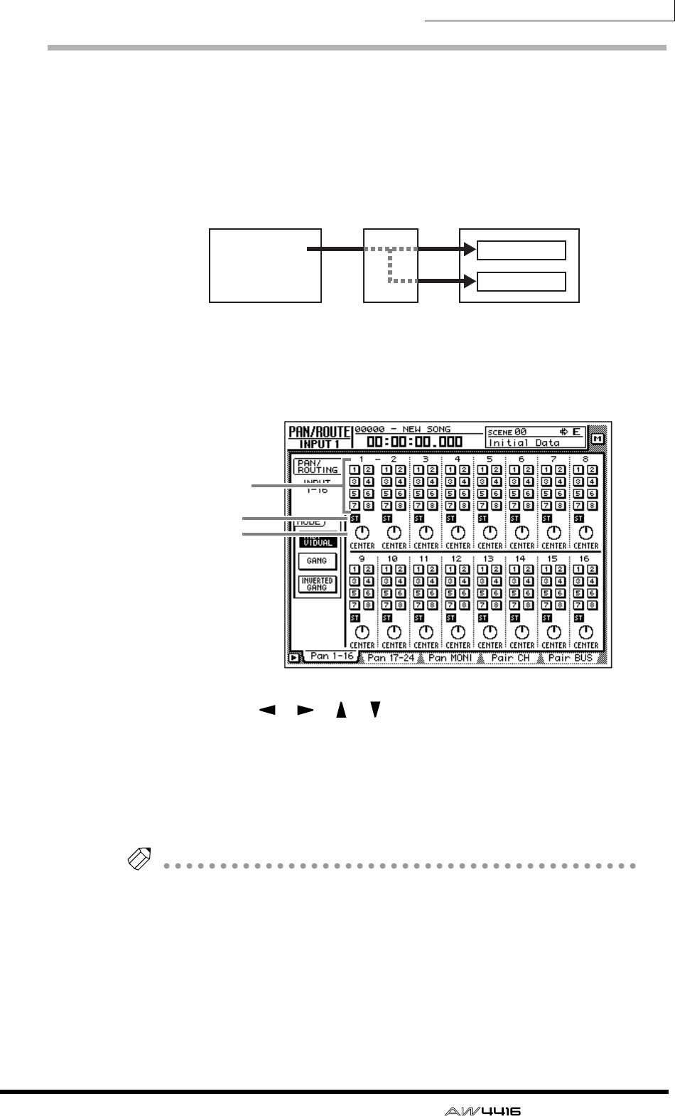
Chapter5—Recording on the AW4416
— Operation Guide 81
Assign the signals to buses
When the AW4416 is in the initial state, bus outputs 1–8 of the mixer section are
patched as follows to tracks 1–16 of the recorder. In our example here, we will
assign the signal from the rhythm machine (or drum mics) input via input chan-
nels 1/2 to buses 1/2 and send to them to tracks 1/2 of the recorder.
1. Press the [PAN] key → [F1] key.
The PAN/ROUTE screen Pan 1–16 page will appear. In this page you can assign
input channels 1–16 to buses (stereo bus, buses 1–8) and make pan settings.
2. Use the CURSOR [ ]/[ ]/[ ]/[ ] keys to move the cursor to the input
channel 1 area. Turn the ST button off, and turn the bus assign 1/2 but-
tons on.
With these settings, the signal of input channel 1 will not be sent to the stereo
bus, but will be sent instead to buses 1–2. The ST button and bus assign 1/2 but-
tons of input channel 2 (which is paired with input channel 1) will follow these
settings.
Tip!
To switch an on-screen button on/off, move the cursor to the button and press the
[ENTER] key.
3. Move the cursor to the PAN knob of input channel 1, and set the pan to
far left (L16).
The PAN knob sets the stereo position between the L/R channels of the stereo
bus, and pans between odd-numbered buses and even-numbered buses of bus
1–8. In this example, the signal will be sent only to bus 1 if you rotate the PAN
knob to the far left.
Buses 1–8
Mixer section Recorder section
Recorder
input patch
Tracks 1–8
Tracks 9–16
×8
×8
ST button
PAN knob
Bus assign
1–8 buttons
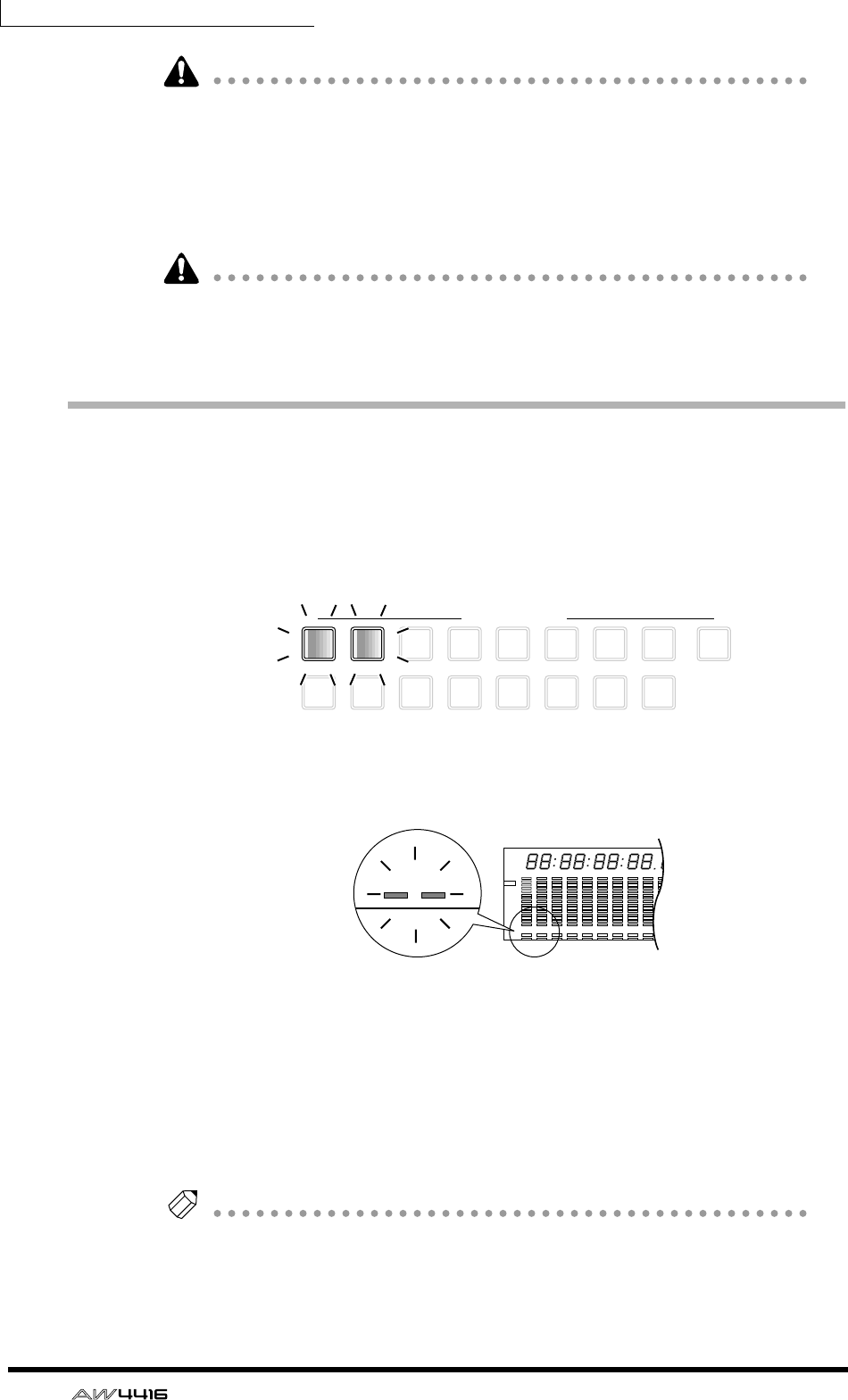
Chapter5—Recording on the AW4416
82 — Operation Guide
Note that the level when the PAN knob is positioned at full left or full right will
differ between paired and unpaired channels.
The level of a channel that is not paired will rise 3 dB when the PAN knob is
positioned at full left (L16) or full right (R16).
4. In the same way, move the cursor to the input channel 2 area, and set
the PAN knob to far right (R16).
Even for paired channels, the PAN knobs will not operate in tandem if the MODE
area Pan parameter is set to INDIVIDUAL (default setting). The PAN knobs will
move in tandem if this parameter is set to GANG or INVERTED GANG.
Set the tracks to record-ready mode
Next we will set tracks 1/2 of the recorder to record-ready mode, and adjust the
input level of each track.
1. In the level meters/counter section, press [REC TRACK SELECT] keys 1
and 2.
[REC TRACK SELECT] keys 1 and 2 will begin blinking. In the level meters/
counter section, REC READY indicators 1 and 2 will blink red. This indicates that
tracks 1/2 are in record-ready mode.
2. While producing sound on your instrument, watch level meters 1/2 in
the level meters/counter section.
The level of the signals being input to tracks 1/2 (which are in record-ready
mode) will be shown in level meters 1/2. If the red segment at the 0 dB position
lights for level meters 1/2, lower faders 1/2 (input channel 1/2 input levels).
In this example, tracks 1/2 are paired, so be sure to operate only one of the fad-
ers.
Tip!
When the AW4416 is in its initial state, the input monitor mode of each track is set
to “AUTO.” For tracks that are currently in record-ready mode, the level meters will
show the level of the input signal while the recorder is stopped, and the level of the
track playback signal when the recorder is playing back.
9
REC TRACK SELECT
ST
12
10
3
11
4
12
5
13
6
14
7
15
8
16
123456789 13 14 15 1610 11 12
–dB 0
2
6
20
30
42
60
10
14
18
20
26
12
FINE
READY
INPUT
REMAIN
ABS
REL
HM S Fms
EXT
VARI
44.1k 48k
LOCK
WORD CLOCK MTC
SLAVE
MASTER
INT
–dB 0
2
6
20
30
42
60
10
14
18
20
26
12
FINE
READY
INPUT
LR
SCENE
E
123
20
30
42
60
14
18
20
26
READY
NPUT
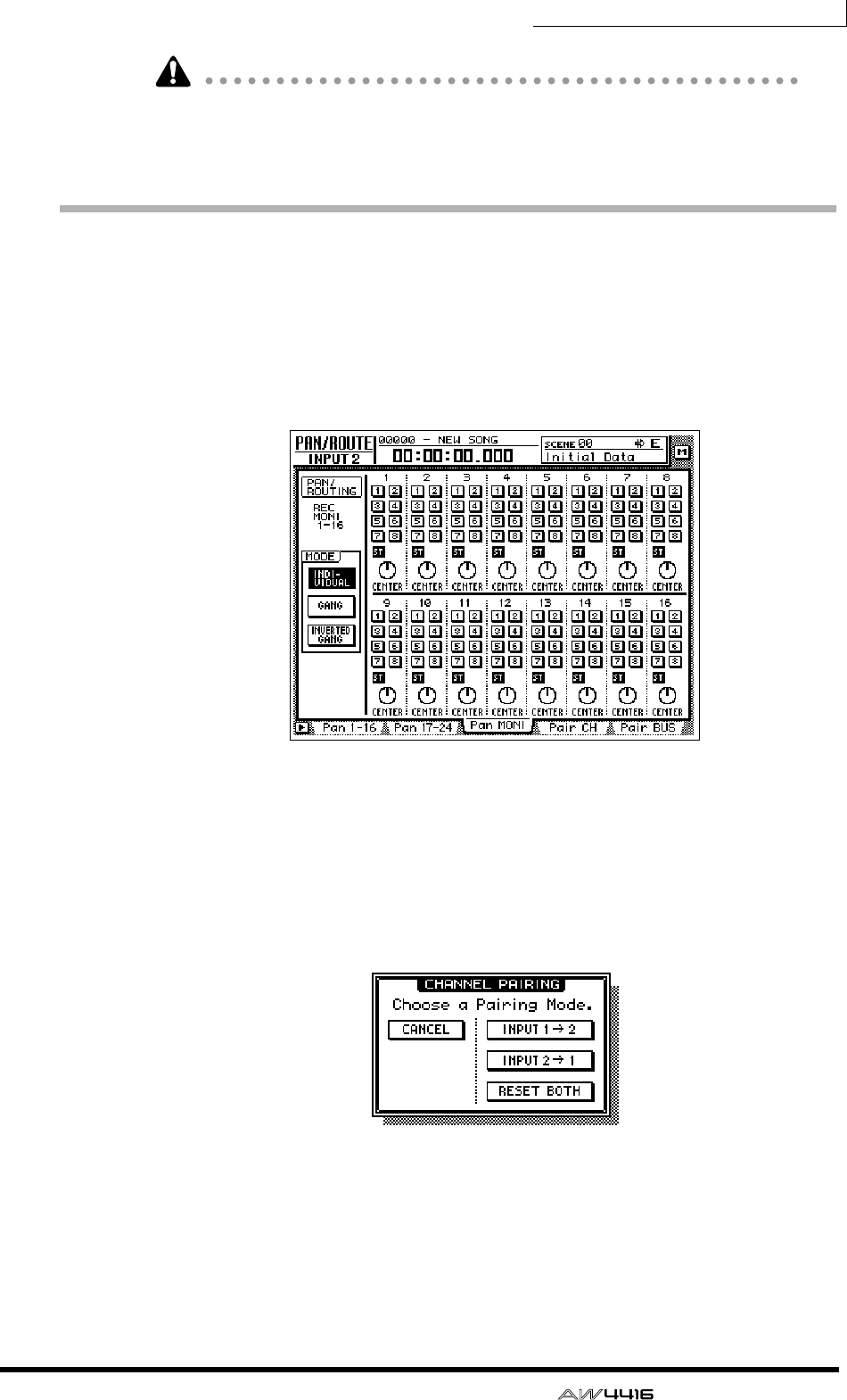
Chapter5—Recording on the AW4416
— Operation Guide 83
When tracks are paired, you must operate only one of the faders. Attempting to
move both faders simultaneously will place a strain on the motor, and may cause
malfunctions.
Make monitor settings
Now we will send the signal of monitor channels 1/2 to the stereo bus, so that it
can be monitored via the MONITOR OUT jacks or the PHONES jack.
1. Press the [PAN] key → [F3] key.
The PAN/ROUTE screen Pan MONI page will appear. In this page you can make
bus assignments and pan settings for monitor channels 1–16.
2. Press the [MONI] key.
Monitor channels 1–16 will be selected as the mixing layer.
3. Hold down [SEL] key 1, and press [SEL] key 2.
Just as we did for input channels 1/2, we will also pair monitor channels 1/2.
When you simultaneously hold down the monitor channel 1/2 [SEL] keys, the
CHANNEL PAIRING popup window will appear.
4. Move the cursor to one of the three buttons and press the [ENTER] key.
Monitor channels 1/2 will be paired.
5. In the monitor channel 1/2 area, make sure that the ST buttons are on
and the 1–8 buttons are off.
With these settings, the signal of the monitor channels will be sent to the stereo
bus.

Chapter5—Recording on the AW4416
84 — Operation Guide
6. In the same way as for the input channels, set the PAN knobs of monitor
channels 1/2 to far left (L16) for channel 1 and far right (R16) for chan-
nel 2.
7. Make sure that [ON] keys 1/2 and the STEREO [ON] key are on, and
raise faders 1/2 and the STEREO fader to the 0 dB position.
When tracks are paired, you must operate only one of the faders. Attempting to
move both faders simultaneously will place a strain on the motor, and may cause
malfunctions.
8. While producing sound on your instrument, watch the L/R level meters
of the level meter/counter.
The signal from the rhythm machine (or drum mics) will be sent via tracks 1/2 →
monitor channels 1/2 to the stereo bus. If the red 0 dB segment lights, lower fad-
ers 1/2 (input level of monitor channels 1/2).
9. Raise the MONITOR OUT control/PHONES control.
You can monitor the input signal via your monitor system or headphones.
Note that the signals being controlled here are not the signals recorded on the
recorder; rather, they are the signals passing through the recorder. Operating the
pan, fader, or [ON] key of a monitor channel will not affect the signal that is
recorded.
8 9 13 14 15 1610 11 12
–dB 0
2
6
20
30
42
60
10
14
18
20
26
12
FINE
READY
INPUT
LR
SFms
EXT
VARI
44.1k 48k
LOCK
WORD CLOCK MTC SCENE
SLAVE
MASTER
INT
E
1234567
–dB 0
2
6
20
30
42
60
10
14
18
20
26
12
FINE
READY
INPUT
REMAIN
ABS
REL
HM
–dB 0
2
6
20
30
42
60
10
14
18
20
26
12
FINE
READY
INPUT
LR
E
L/R level meter
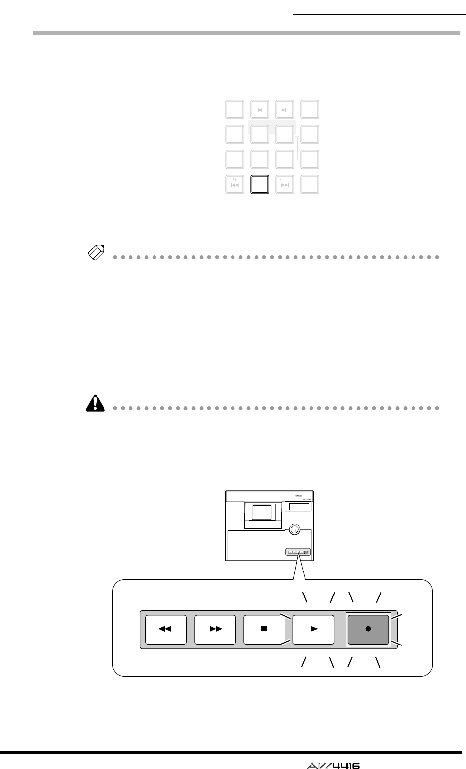
Chapter5—Recording on the AW4416
— Operation Guide 85
Let’s record!
1. Press the Locate section [RTZ] key.
The level meter/counter and the display counter will rewind to zero
(00:00:00.000).
Tip!
With the default settings of the song, hours (hours/minutes/seconds/milliseconds)
are selected as the counter unit of the level meter/counter and display counter.
However you may switch this to time code display (hours/minutes/seconds/frames/
sub-frames) or measure display (measure/beat/tick) if desired.
2. To begin recording, hold down the Transport section [REC] (●) key and
press the [PLAY] (®) key.
The [REC] key and [PLAY] key will light, and the red REC READY indicators of the
[REC TRACK SELECT] keys 1/2 and the level meter/counter will change from
blinking to lit.
When you attempt to record the signal being input from the DIGITAL STEREO IN
jack, the display may sometimes indicate “DIGITAL-ST-IN-PROHIBIT,” and you
will be unable to perform step 2. In this case, go to UTILITY screen Prefer.2 page
([UTILITY] key
→
[F3] key), and set CD/DAT DIGITAL REC to ENABLE. (For
details refer to Reference Guide “UTILITY” screen.)
LAST REC
MARK SEARCH
LAST REC
54IN OUT
NO
AB
REPEAT
RTZ
231
0
ROLL
BACK
CANCEL
SET
MARK
NUM
LOCATE
897
6
AUTO
PUNCH
PROFESSIONAL AUDIO WORKSTATION
REW FF STOP PLAY REC
REW FF STOP PLAY REC

Chapter5—Recording on the AW4416
86 — Operation Guide
If the following keys are on, the keys of the Locate section and the Transport sec-
tion will have no effect. (Alternatively, the functions assigned to the keys will
change.) Select a different key before you continue with this procedure.
• WORK NAVIGATE section: [SONG] key, [MASTERING] key, [CD PLAY] key
• UNIT section: [FILE] key
• RECORDER section: [EDIT] key
• SAMPLING PAD section: [EDIT] pad (except for when the Trig.List page is dis-
played)
3. Start the rhythm machine (drum) performance.
4. When the performance is finished, press the [STOP] (■) key.
5. To listen to the recorded content, press the Locate section [RTZ] key,
and then press the Transport section [PLAY] (®) key.
6. When you are satisfied with the recorded content, press the [STOP] (■)
key to stop the transport. Then press [REC TRACK SELECT] keys 1/2 to
defeat record-ready mode for tracks 1/2.
Tip!
• By using the [ALL SAFE] key instead of step 6, you can cancel record-ready
mode in one operation.
• If you wish to re-do the recording, repeat steps 1–4.
• We recommend that you save the song whenever you take a break from your
work. (
→
P.106)
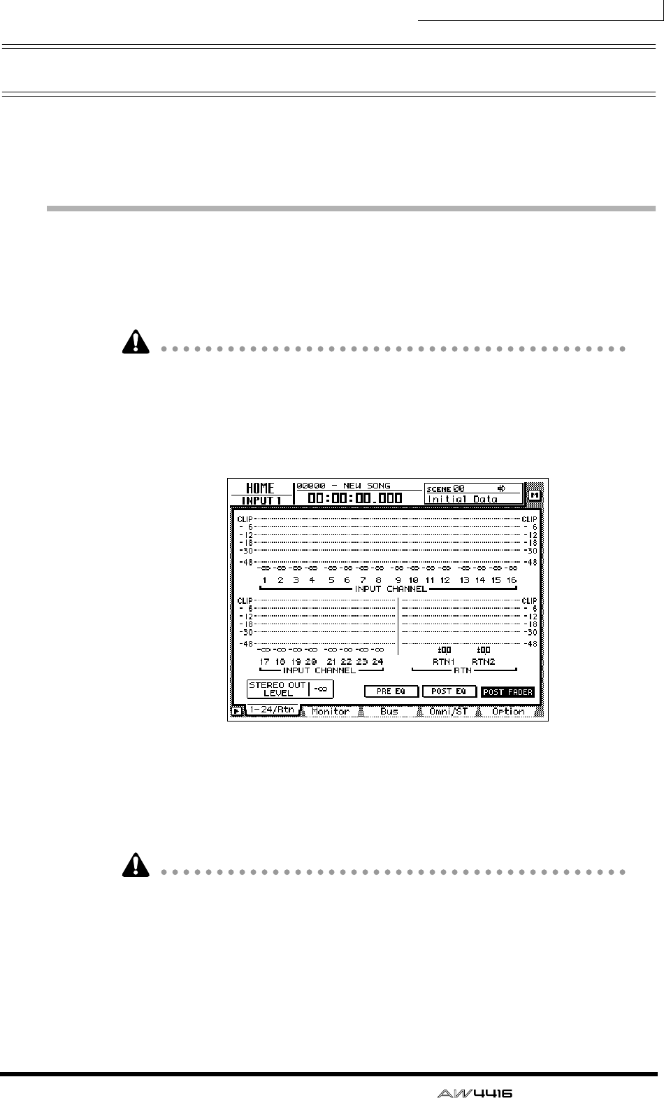
Chapter5—Recording on the AW4416
— Operation Guide 87
Overdubbing
In this section we will explain how to record an electric bass connected to
INPUT 8 (HI-Z) jack while monitoring the rhythm machine (or drums) recorded
on tracks 1/2.
Set the input level
1. While producing sound on your instrument, adjust [GAIN] control 8 so
that the PEAK indicator of INPUT 8 (HI-Z) lights briefly when you play
most loudly.
The INPUT 8 (HI-Z) jack is an input jack designed for high impedance instru-
ments. It cannot be used simultaneously with the conventional INPUT 8 (phone)
jack.
2. Press the [HOME] key → [F1] key.
The HOME screen 1–24/Rtn page will appear.
3. Press the MIXING LAYER section [1–16] key to select input channels 1–
16 as the mixing layer.
4. Make sure that [ON] key 8 is turned on, and raise fader 8 to the 0 dB
position.
To avoid confusion, turn off the [ON] keys for all input channels that you are not
using.
5. While producing sound on your instrument, watch the input level of
input channel 8 that is displayed in the on-screen level meter.
If the AW4416 is in the initial state, the electric bass connected to the INPUT 8
(HI-Z) jack will be sent to input channel 8. If the level meter reaches the “CLIP”
position, lower [GAIN] control 8.

Chapter5—Recording on the AW4416
88 — Operation Guide
Assign the signal to a bus
Here we will make settings so that the electric bass signal being input from input
channel 8 will be sent to recorder track 3 via bus 3.
1. Press the [VIEW] key → [F1] key.
The VIEW screen CH View page will appear. The CH View page shows all mix
parameters of the currently selected channel. (Major parameters can also be
operated here.) It is convenient to use this page when you wish to control all the
mix parameters of a specific channel.
In the preceding section “Recording the first track,” we used the PAN/ROUTE
screen to set bus assignments and pan for multiple channels at once. Here, how-
ever, we are going to use the VIEW screen CH View page to perform the same
operations.
2. In the MIXING LAYER section, press the [1–16] key → [SEL] key 8.
On the AW4416, you select the channel to be controlled by selecting a mixing
layer in the MIXING LAYER section, and then pressing a [SEL] key to select a
channel. When you are using the CH View page, the currently selected channel
will be shown in the upper left of the display. The corresponding [SEL] key will
also light.
3. Move the cursor to the PAN/ROUTE area. Turn the ST button off and the
bus assign 3 button on.
4. Make sure that the PAN/ROUTE area PAN knob is positioned in the cen-
ter (CENTER).
With these settings, the signal of input channel 8 will no longer be sent to the ste-
reo bus, but will be sent to bus 3 instead.
Note that the level of a channel that is not paired will rise 3 dB when the PAN
knob is positioned at full left (L16) or full right (R16).
ST button
Bus assign
1–8 buttons
PAN knob
Selected
channel
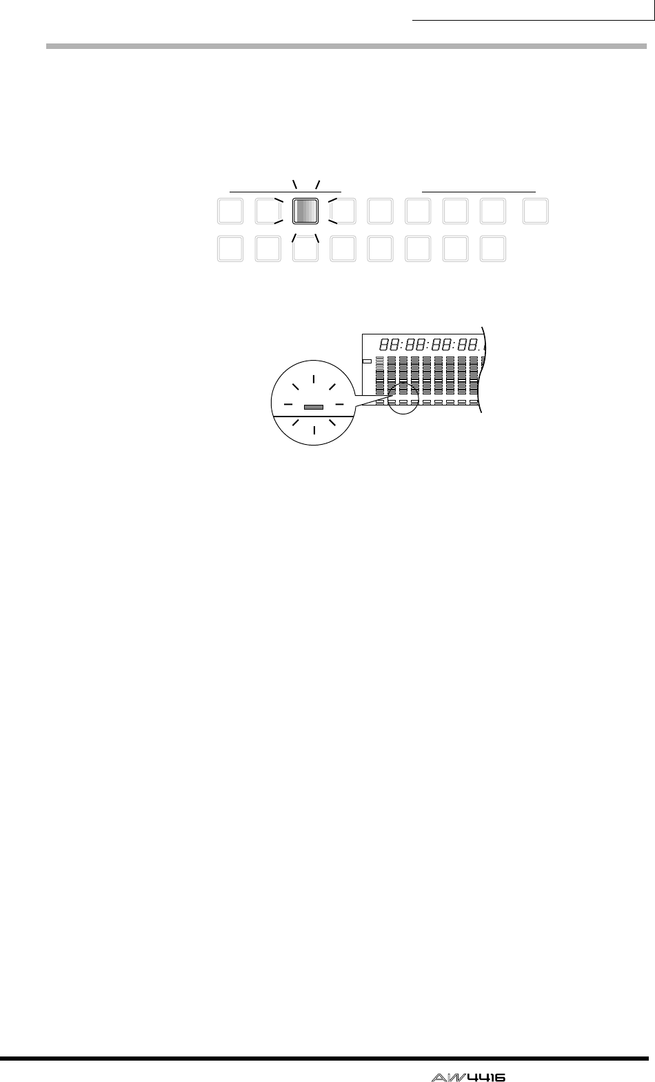
Chapter5—Recording on the AW4416
— Operation Guide 89
Put the track in record-ready mode
Next we will put track 3 of the recorder in record-ready mode, and adjust the
input level.
1. In the level meters/counter section, press [REC TRACK SELECT] key 3.
[REC TRACK SELECT] key 3 and REC READY indicator 3 in the level meter/
counter will blink, indicating that track 3 is in record-ready mode.
2. Make sure that [ON] key 8 is lit, and while producing sound on your
instrument, watch level meter 3 in the level meters/counter section.
Level meter 3 will show the level of the input signal of track 3. If the red 0 dB seg-
ment lights, lower fader 8 (input level of input channel 8).
9
REC TRACK SELECT
ST
12
10
3
11
4
12
5
13
6
14
7
15
8
16
1 2 3 4 5 6 7 8 9 13 14 15 1610 11 12
–dB 0
2
6
20
30
42
60
10
14
18
20
26
12
FINE
READY
INPUT
REMAIN
ABS
REL
HM S Fms
EXT
VARI
44.1k 48k
LOCK
WORD CLOCK MTC
SLAVE
MASTER
INT
–dB 0
2
6
20
30
42
60
10
14
18
20
26
12
FINE
READY
INPUT
LR
SCENE
E
234

Chapter5—Recording on the AW4416
90 — Operation Guide
Make monitor settings
We will make settings so that the signal of the rhythm machine (drums) that were
earlier recorded on tracks 1/2 and the bass signal being recorded on track 3 will
be sent to the stereo bus, and can be monitored via the MONITOR OUT jacks or
PHONES jack.
1. Press the [PAN] key → [F3] key.
The PAN/ROUTE screen PAN Moni page will appear, allowing you to make pan
and bus assignment settings for monitor channels 1–16.
2. For monitor channel 3, turn the ST button on and the bus assign 1–8
buttons off.
At this time, verify that the ST button is on and the bus assign 1–8 button is off for
monitor channels 1–2 as well.
3. Move the cursor to the PAN knob of monitor channel 3, and pan the
bass where you can monitor it most comfortably.
4. Make sure that [ON] key 3 is turned on. Then produce sound on your
bass, and raise fader 3 to a volume that is comfortable for monitoring.
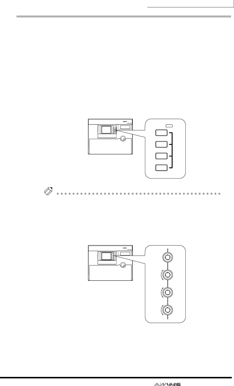
Chapter5—Recording on the AW4416
— Operation Guide 91
Using EQ and the dynamics processor
By using the four-band EQ and dynamics processor that are provided for each
input channel, you can process the bass sound as you record it on a track.
❒Using the four-band EQ
1. In the MIXING LAYER section, press the [1–16] key → [SEL] key 8.
[SEL] key 8 will light, and input channel 8 will be selected for control.
2. Press one of the EQ [HIGH]/[HI-MID]/[LO-MID]/[LOW] keys in the row
at the right of the display to select the band that you wish to control.
When you press a key, the settings of that band will appear for a time in the upper
right of the display.
Tip!
The keys/controls at the right of the display can be used as dedicated controls for
the channel that is currently selected by the [SEL] key. As with EQ, you can also use
the [PAN] control located at the right of the display to adjust the panning of the cur-
rently selected channel.
3. Use the EQ [Q]/[F]/[G] controls to adjust the band that you selected in
step 2. The function of each control is described below.
• [Q] .................Adjust the steepness of each band. The range is 10.0–0.10, and
higher settings will produce a steeper EQ curve.
The [Q] control of the HIGH band can also be used as a switch
to change the EQ type between shelving and LPF. The [Q] con-
trol of the LOW band can also be used as a switch to change
the EQ type between shelving and HPF.
PROFESSIONAL AUDIO WORKSTATION
LO
LO-MID
HI-MID
HI
EQ
LOW
LO-MID
HI-MID
HIGH
EQ
PROFESSIONAL AUDIO WORKSTATION
F
PAN
G
Q
F
PAN
G
Q
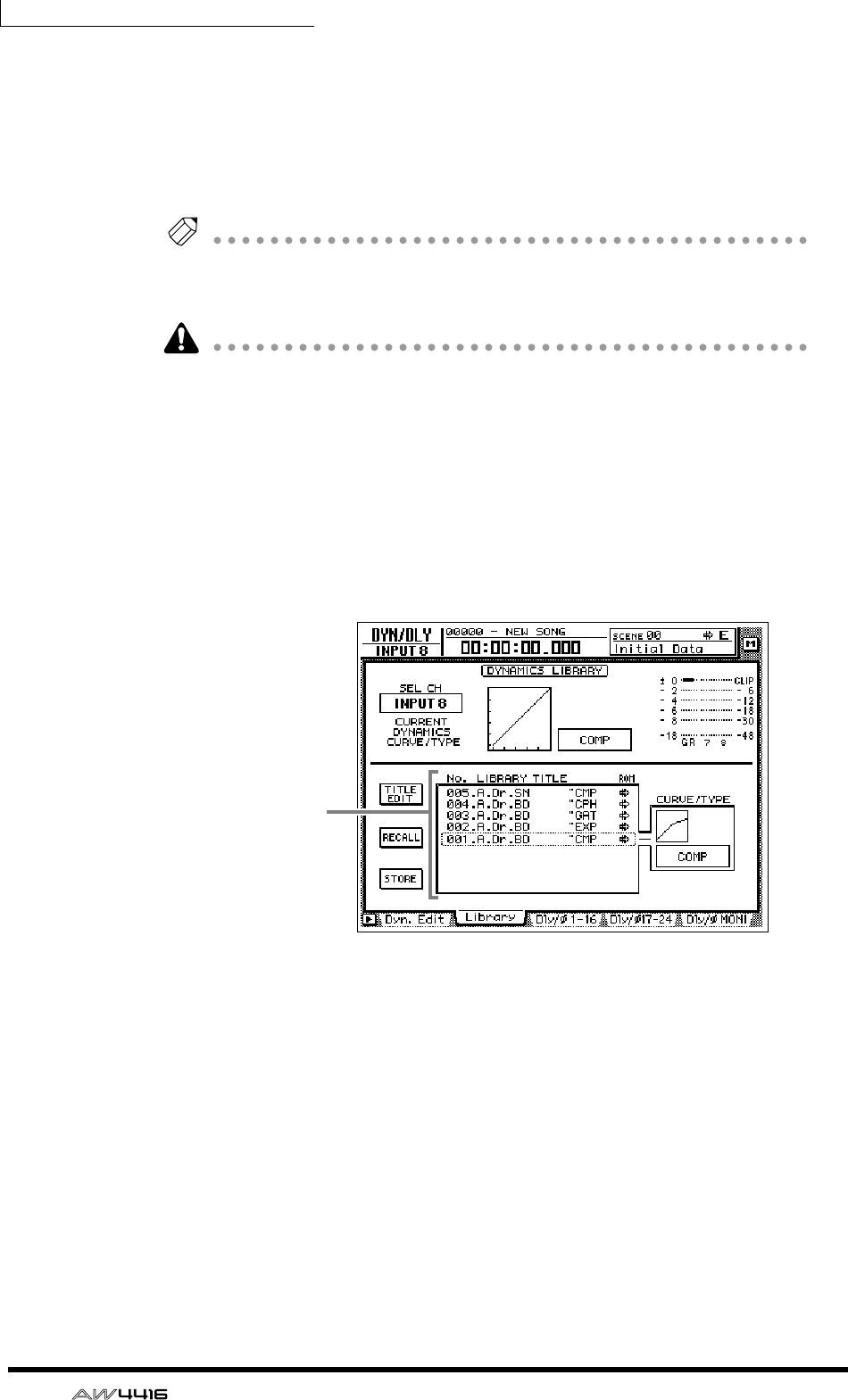
Chapter5—Recording on the AW4416
92 — Operation Guide
• [F] ..................Set the center frequency of each band. For each band, the
range is 21 Hz–20.1 kHz.
• [G] .................Set the amount of boost/cut for each band. For each band, the
range is ±18 dB.
When you operate the EQ [Q]/[F]/[G] controls, the parameter values of that band
will briefly appear in the upper right of the display.
Tip!
As an alternative way to make EQ settings, you can also use the EQ/ATT/GRP screen
EQ/Att page ([EQ] key
→
[F1] key). The EQ/Att page displays all EQ parameters of
the currently selected channel.
If the sound does not change when you operate the EQ, check whether the EQ
ON button is turned on in the EQ/ATT/GRP screen EQ/ATT page.
❒Using the dynamics processor
1. In the MIXING LAYER section, press the [1–16] key → [SEL] key 8.
[SEL] key 8 will light, and input channel 8 will be selected for control.
2. Press the [DYN] key → [F2].
The DYN/DLY screen Library page will appear.
In this page you can load or save dynamics programs from or to the dynamics
library. From the library list in the center of the screen, you can select the dynam-
ics program that you wish to load or save.
3. Move the cursor to the library list, and rotate the [DATA/JOG] dial to
move the cursor location to “011.E.B.Finger.”
Dynamics library numbers 000–040 are read-only programs, and contains stan-
dard dynamics settings for frequently used instruments. For this example, we will
select a program named “E.B. Finger.”
4. Move the cursor to the RECALL button at the left of the library list, and
press the [ENTER] key.
Library list
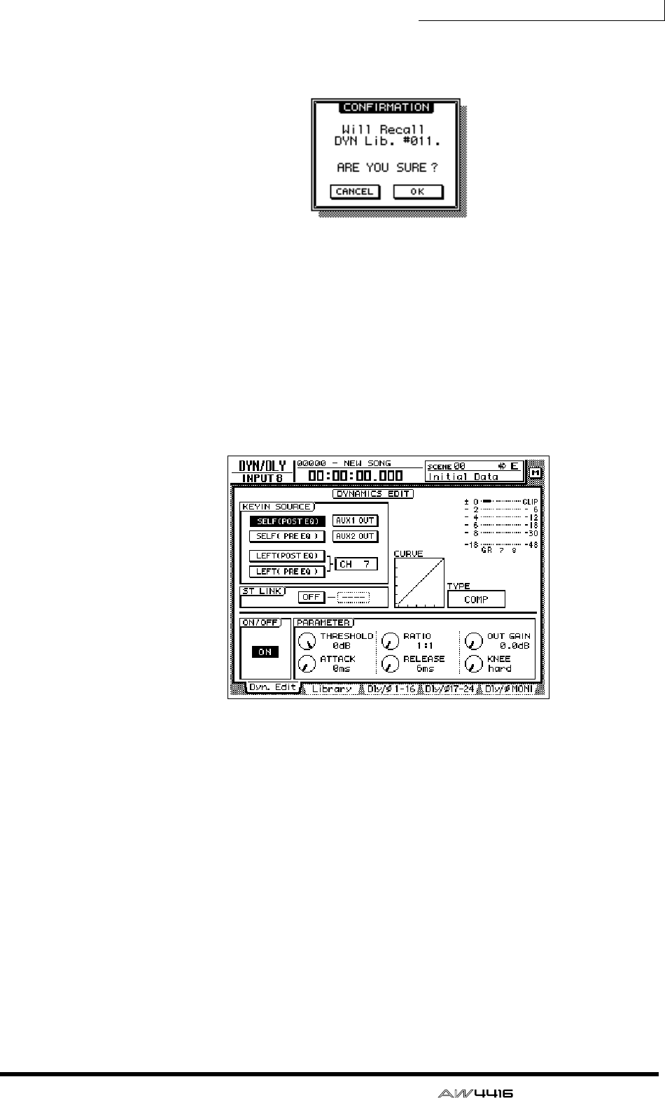
Chapter5—Recording on the AW4416
— Operation Guide 93
5. A CONFIRMATION popup window will appear, asking you confirm the
recall operation.
6. Move the cursor to the OK button and press the [ENTER] key.
The “E.B.Finger” dynamics program will be loaded into input channel 8.
7. Press the [F1] key.
The DYN/DLY screen Dyn.Edit page will appear. In this page you can set the
parameters of the dynamics processor.
8. Press the [ENTER] key, and turn on the ON/OFF button located in the
lower left of the screen.
As the name suggests, the ON/OFF button turns the dynamics processor on/off.
9. While playing the bass, move the cursor to the PARAMETER area in the
lower right of the screen, and adjust the parameters of the dynamics
processor.
• Five types of dynamics processor are provided: CMP (compressor), EXP
(expander), GAT (gate), CPS (compander S), and CPH (compander H). Each
type has different parameters. (For details on the parameters of each type, see
the Reference Guide.)
• It is not possible to change the type of the dynamics processor in the Dyn.Edit
page. For this reason if you wish to use a specific type, you must first load a
program that uses that type from the dynamics library, and then modify its
parameters as necessary.
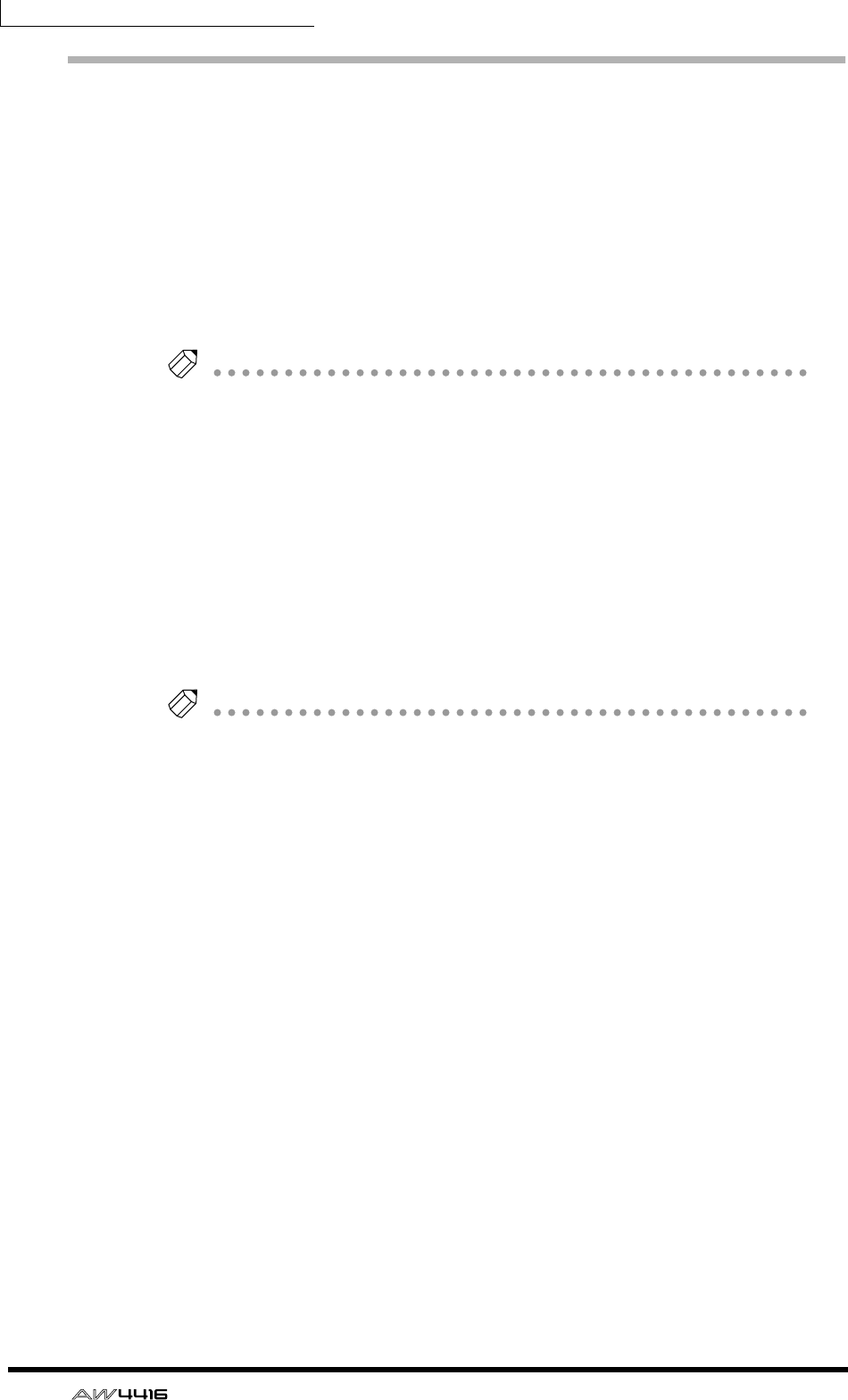
Chapter5—Recording on the AW4416
94 — Operation Guide
Let’s overdub!
1. Press the Locate section [RTZ] key.
2. To begin recording, hold down the Transport section [REC] (●) key and
press the [PLAY] (®) key.
The [REC] key and [PLAY] key will light, and the red REC READY indicator of
track 3 will change from blinking to lit.
3. Play the bass while listening to the rhythm machine (drum) performance
recorded on tracks 1/2.
Tip!
If you wish to adjust the volume at which you are monitoring the rhythm machine
(drums) and bass, press the MIXING LAYER section [MONI] key, and adjust faders
1–3.
4. When you are finished playing, press the [STOP] (■) key.
5. To listen to the recorded performance, press the Locate section [RTZ]
key, and then press the Transport section [PLAY] (®) key.
6. If you are satisfied with the recorded performance, press [REC TRACK
SELECT] key 3 to defeat record-ready mode for track 3.
If you wish to continue overdubbing more instrumental tracks, simply use the
same procedure. Go ahead and record the remaining instruments.
Tip!
If you wish to try the recording again, press the [UNDO] key and repeat steps 1–4.
It is also possible to re-record from the middle of the song. If you will be re-record-
ing repeatedly from the same location, it is convenient to assign a marker (
→
P.121)
to that location so that you can move rapidly to it, or to use the auto punch-in/out
function (
→
P.130).
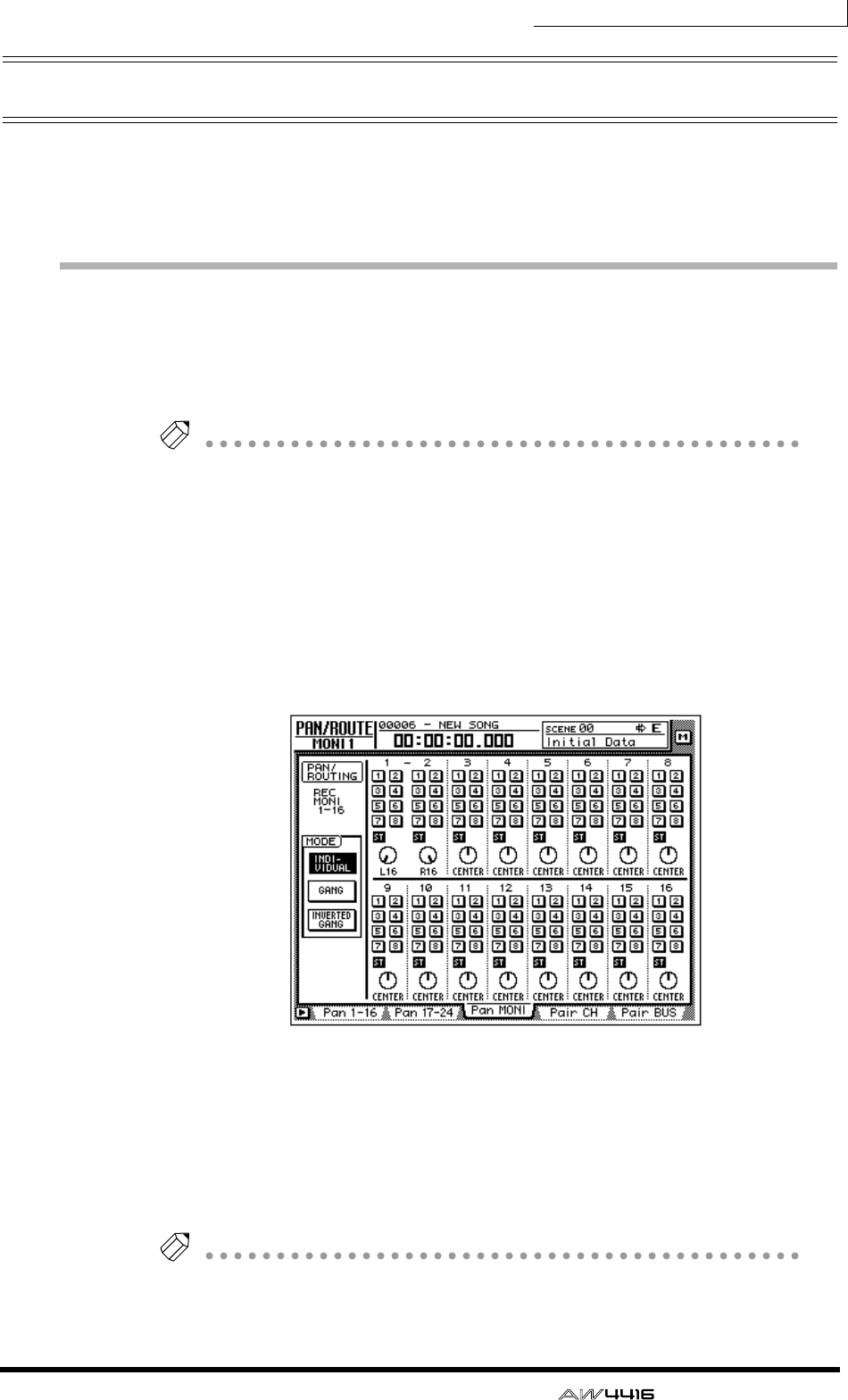
Chapter5—Recording on the AW4416
— Operation Guide 95
Mixdown
In this section we will explain the procedure for creating a stereo mix of the sig-
nals recorded on tracks 1–16, applying internal effects, and recording the stereo
track on the hard disk.
Creating the mix balance of the tracks
1. Make sure that [REC TRACK SELECT] keys 1–16 are dark (record-ready
mode is defeated). Also make sure that the [ON] key is dark for all input
channels 1–24.
Tip!
If necessary, the input signals from input channels 1–24 can be mixed down
together with the signals of tracks 1–16. In this case, turn on the [ON] keys of the
input channels that you wish to use, so that they are lit.
2. Press the [MONI] key.
Monitor channels 1–16 will be selected as the mixing layer.
3. Press the [PAN] key → [F3] key.
The PAN/ROUTE screen Pan MONI page will appear, allowing you to make pan
settings and bus assignments for monitor channels 1–16.
4. For monitor channels 1–16, turn the ST button on and the bus assign 1–
8 buttons off.
With these settings, all monitor channels will be sent to the stereo bus.
5. Use the PAN knobs of monitor channels 1–16 to set the stereo position
of each track.
Tip!
You can also use the [SEL] keys to select a channel and use the [PAN] control at the
right of the display to set the pan of the corresponding monitor channel.
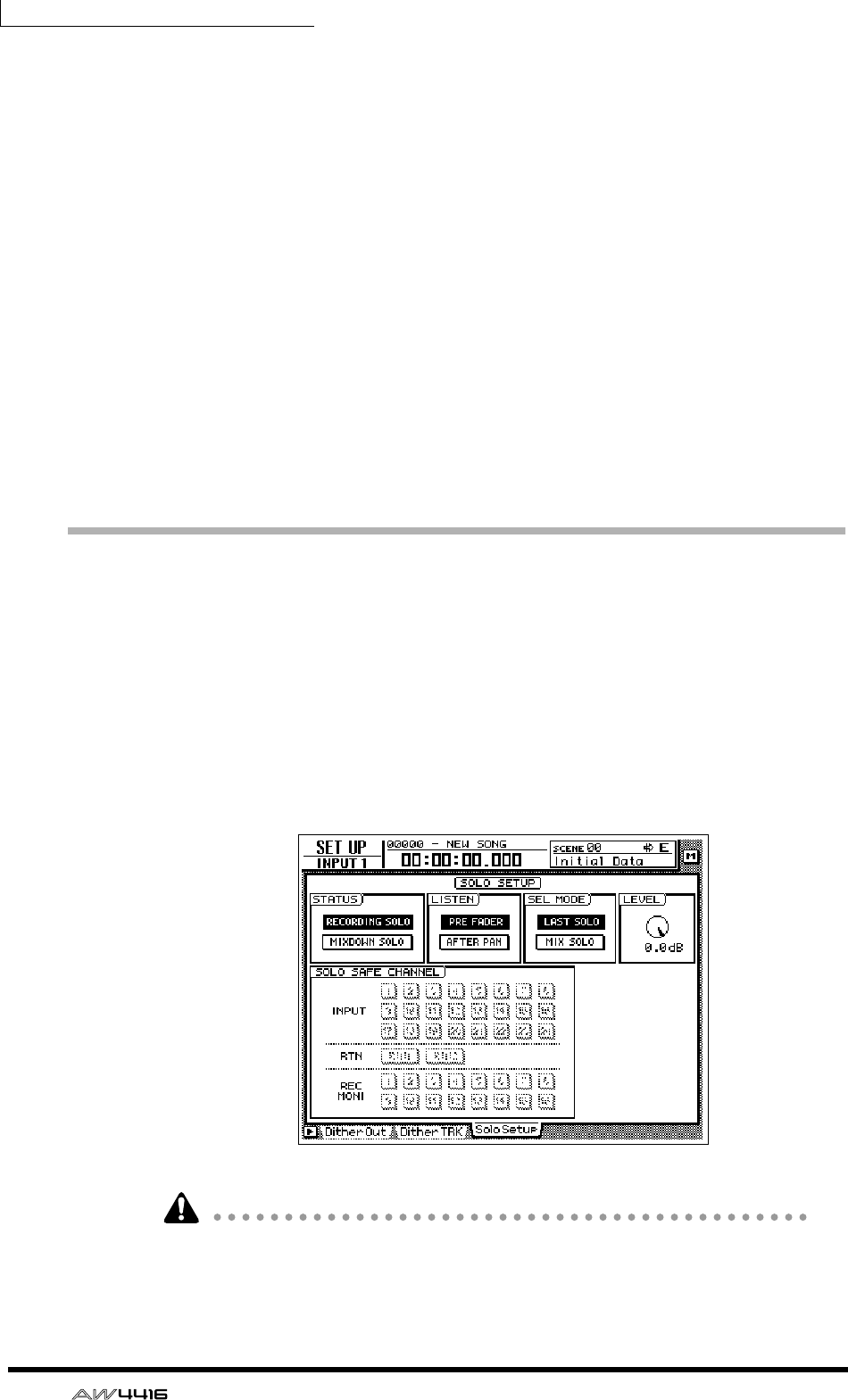
Chapter5—Recording on the AW4416
96 — Operation Guide
6. Raise the STEREO fader to the 0 dB position.
7. Make sure that [ON] keys 1–16 and the STEREO [ON] key are lit, play
back the song from the beginning, and use faders 1–16 to set the level
of each track.
At this time, watch the L/R level meter of the level meter/counter, and do not
allow the red 0 dB segment to light.
8. To adjust the EQ of a specific channel, use the [SEL] key to select the
channel and operate the EQ [HIGH]/[HI-MID]/[LO-MID]/[LOW] keys and
the EQ [Q]/[F]/[G] controls.
9. To use the dynamics processor of a specific channel, use the [SEL] key to
select the channel and press [DYN] key → [F2] key to load the desired
dynamics program.
For the procedure of loading a dynamics program, refer to page 92. To edit the
dynamics processor parameters, press the MIXER section [DYN] key → [F1] key
to access the DYN/DLY screen Dyn.Edit page.
Using the Solo function
The AW4416 provides a flexible Solo function. By pressing the top panel [SOLO]
during recording or playback and using one of the [ON] keys to select a desired
channel, you can monitor only the corresponding channel. Here we will explain
how you can use the Solo function to monitor only the desired track during mix-
down.
1. Press the [SETUP] key → [F3] key.
The SET UP screen Solo Setup page will appear. In this page you can make vari-
ous settings for the Solo function.
If the Solo Setup tab is not assigned to the [F3] key, press the [SHIFT] key + [F1]
key to switch the tab, and then press the [F3] key.
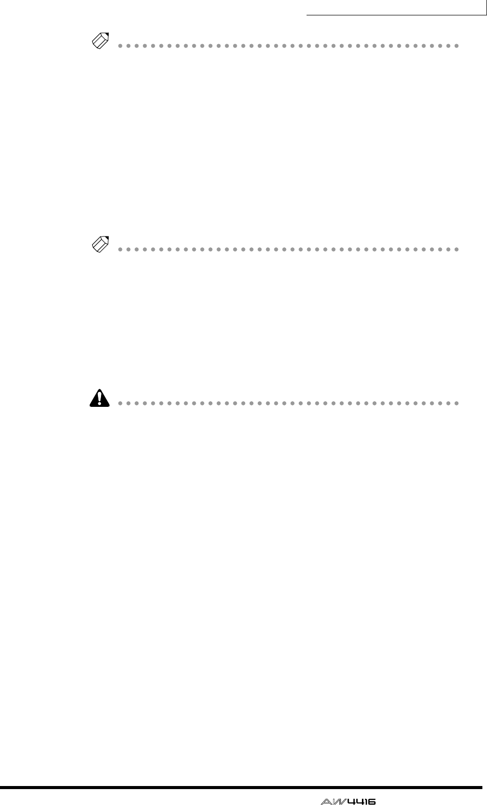
Chapter5—Recording on the AW4416
— Operation Guide 97
Tip!
As an alternative to using the Solo function, you can also monitor just a specific
track by pressing the TRACK [CUE] switch in the level meters/counter section, and
then using [REC TRACK SELECT] keys 1–16 to select a track. By using this method,
the direct output of the recorder (the signal that has not passed through the monitor
channel) can be sent directly to the MONITOR OUT jacks and the PHONES jack.
2. Move the cursor to the SOLO STATUS area, and select one of the follow-
ing two modes for the Solo function.
❍ RECORDING SOLO
In this mode, the solo signal is routed through the dedicated SOLO bus and out-
put from the MONITOR OUT jacks and PHONES jack. The stereo bus and buses
1–8 will not be affected. You can monitor even channels that are not assigned to
the stereo bus or to buses 1–8, or channels whose [ON] key is turned off.
Tip!
If you will be using the Solo function during multitrack recording, it is convenient to
select RECORDING SOLO so that specific channels can be monitored without
affecting the stereo bus or buses 1–8.
❍ MIXDOWN SOLO
In this mode, the solo signal is routed through the stereo bus and output from the
MONITOR OUT jacks and PHONES jack. When the Solo function is turned on,
only the soloed channels will be sent to the stereo bus, and the remaining chan-
nels will be muted. It will not be possible to monitor channels whose [ON] key is
turned off, nor channels that are not assigned to the stereo bus.
If MIXDOWN SOLO mode is selected, the Solo Setup page LISTEN settings and
LEVEL settings will be ignored (they will be grayed out).
In this example, we will use MIXDOWN SOLO mode. Move the cursor to the
MIXDOWN SOLO button, and press the [ENTER] key.
3. Move the cursor to the SEL MODE area, and choose one of the following
ways in which the channel(s) to be monitored in Solo mode will be
selected.
❍ LAST SOLO
When the [SOLO] key is on, only the channel whose [ON] key was pressed last
will be monitored.
❍ MIX SOLO
When the [SOLO] key is on, all channels selected by their [ON] key will be mon-
itored.
Move the cursor to one of these buttons, and press the [ENTER] key.
4. Move the cursor to the SOLO SAFE CHANNEL section, and select the
channel(s) that you wish to set to Solo Safe mode.
Solo Safe is a function that excludes specified channels from the Solo function
when MIXDOWN SOLO mode is selected. Move the cursor to the button(s) for
the channel(s) that you wish to set to Solo Safe, and press the [ENTER] key. (You
may select more than one channel.)
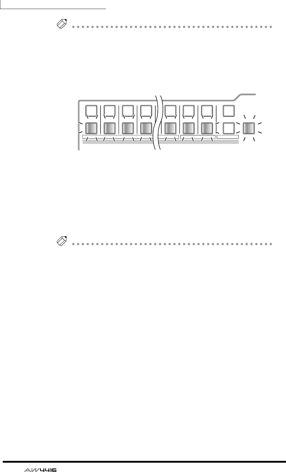
Chapter5—Recording on the AW4416
98 — Operation Guide
Tip!
For example if the SOLO SAFE CHANNEL section RTN1/RTN2 buttons are on, the
Solo function will not affect return channels 1/2. This allows you to monitor the
soloed channel with an effect such as reverb still applied.
5. To use the Solo function, play back the recorder and press the [SOLO]
key.
The [SOLO] key and [ON] keys 1–16 will blink.
6. Press the MIXING LAYER section [MONI] key, and press the [ON] key for
the monitor channel corresponding to the track you wish to monitor.
If you selected LAST SOLO in step 3, only the channel whose [ON] key was last
pressed will be monitored. If you selected MIX SOLO, all channels selected by
their [ON] key will be monitored.
At this time, all [ON] keys 1–16 other than the selected key(s) will go dark.
7. To defeat the Solo function, press the [SOLO] key once again.
Tip!
Solo operations using the [ON] keys are also linked for paired channels.
12
RTN
17 18 19 20
341 2 14 15 16
SEL SEL SEL SEL SEL SEL SEL SEL
ON ON ON ON ON ON ON ON SOLO
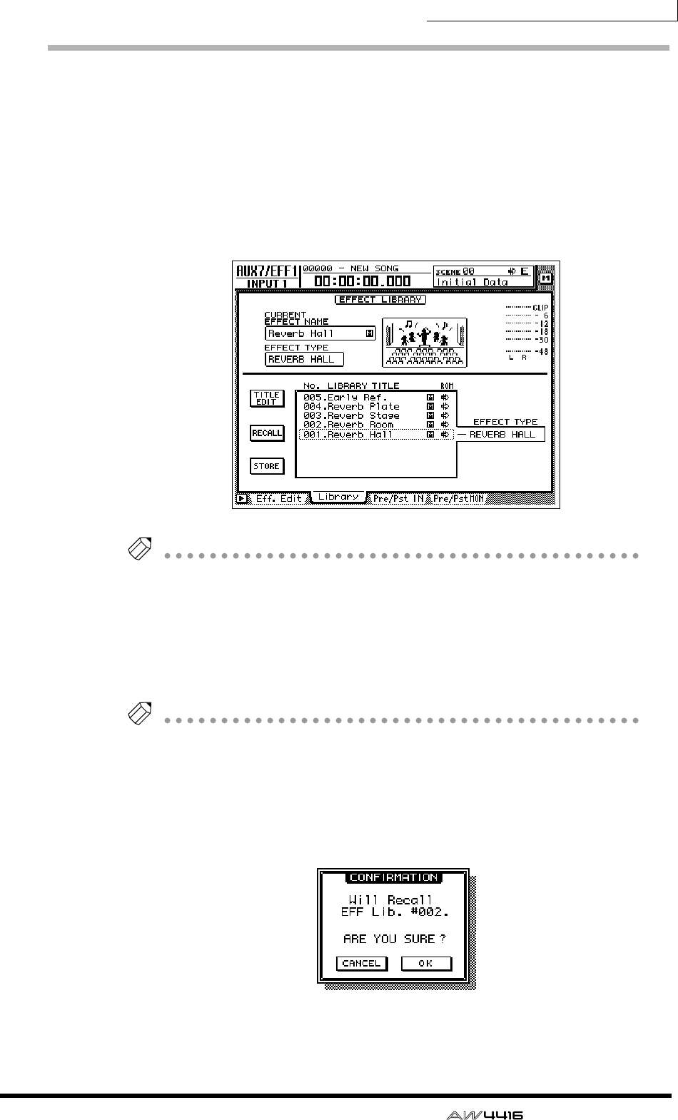
Chapter5—Recording on the AW4416
— Operation Guide 99
Using the internal effects
The AW4416 provides two internal effects, which can be used either via AUX
send/return or by being inserted into a specific channel. Here we will explain
how to use the AUX bus to apply reverb to the signals of the tracks.
1. Press the [AUX 7] key → [F2] key.
The AUX7/EFF1 screen Library page will appear. In this page you can load or save
effect programs from or to the effect library. The list in the display shows the effect
programs that have been saved.
Tip!
When the AW4416 is in the initial state, the outputs of AUX buses 7/8 are patched
to the inputs of internal effects 1/2, and the outputs of internal effects 1/2 are
patched to return channels 1/2.
2. Move the cursor to the library list, and rotate the [DATA/JOG] dial to dis-
play “002.Reverb Room” at the cursor location.
In this example we will select a reverb room program.
Tip!
If desired, you can recall the effect program directly without having to reply to the
recall confirmation popup window. To make this setting, access the UTILITY screen
Prefer.1 page ([UTILITY] key
→
[F2] key), and turn RECALL CONFIRMATION off.
3. Move the cursor to the RECALL button and press the [ENTER] key.
A CONFIRMATION popup window will appear, asking you to confirm the recall
operation.
4. Move the cursor to the OK button and press the [ENTER] key.
The “Reverb Room” effect program will be loaded into internal effect 1.
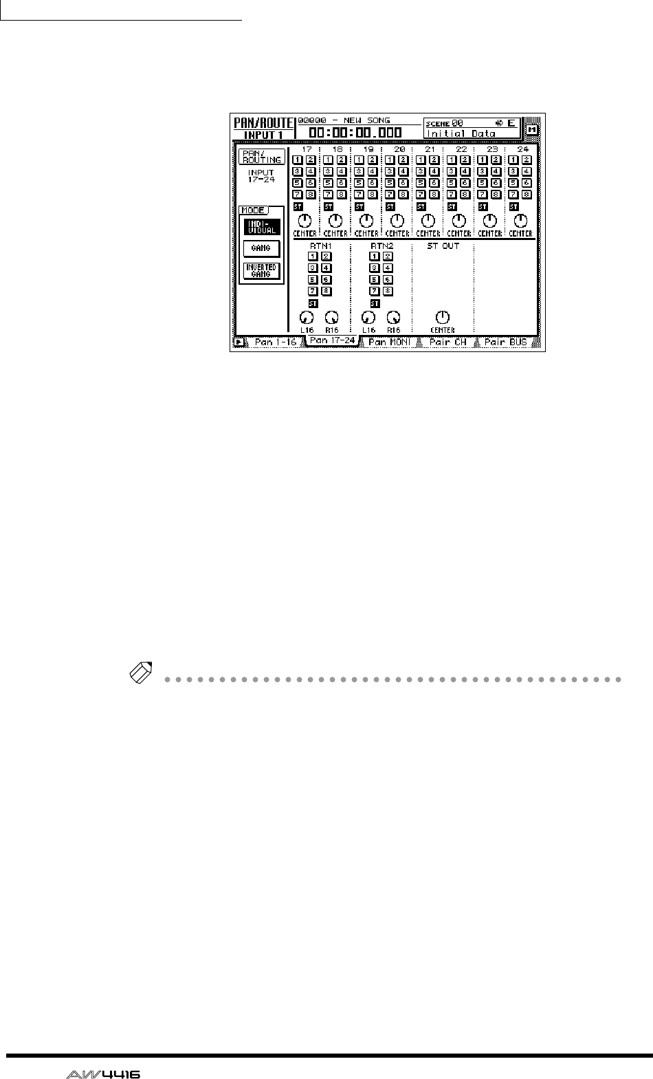
Chapter5—Recording on the AW4416
100 — Operation Guide
5. Press [PAN] key → [F2] key.
The PAN/ROUTE screen Pan 17–24 page will appear, allowing you to make pan
settings and bus assignments for input channels 17–24 and return channels 1/2.
6. Make sure that the RTN1 (return channel 1) area ST button is on, and
that the two PAN knobs are turned to the far left and right.
With these settings, the return signal from effect 1 will be sent to the stereo bus
and mixed with the signals of the monitor channels.
7. Press the [MONO] key → [AUX 7] key.
Monitor channels 1–16 will be selected as the mixing layer. In this state, faders 1–
16 will adjust the send level of the signals sent from monitor channels 1–16 to
AUX 7 (effect 1).
8. Play back the song from the beginning, and use faders 1–16 to adjust
the send level of each monitor channel.
9. If necessary, press the [HOME] key → [17–24 RTN] key and use fader 15
to readjust the effect return level.
Tip!
When the AW4416 is in the initial state, the faders of return channels 1/2 are set to
nominal level (0 dB).
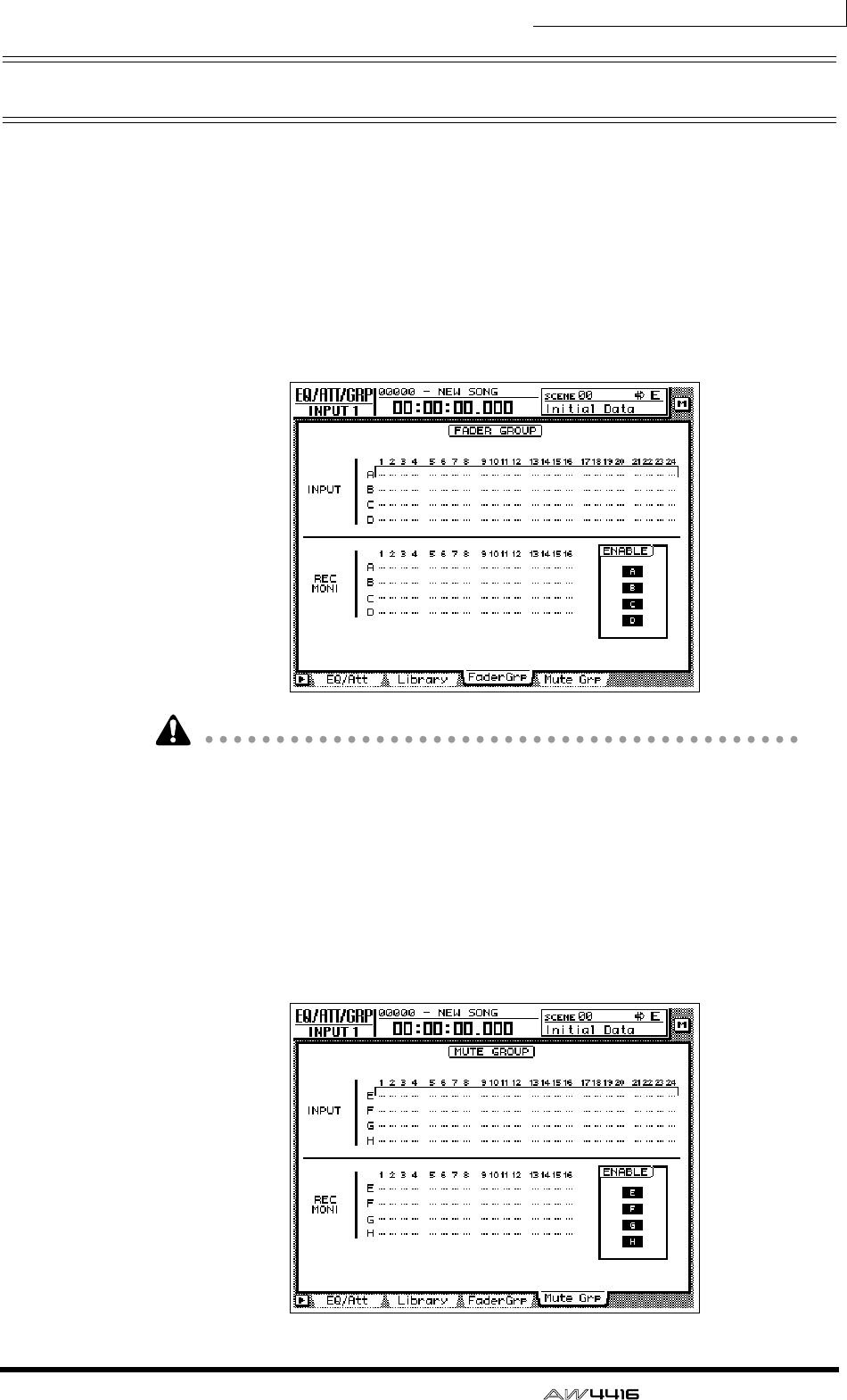
Chapter5—Recording on the AW4416
— Operation Guide 101
Other convenient functions
The mixer section of the AW4416 provides other convenient functions as
described below. You can use them as needed.
❒Fader groups
This function groups fader operations for multiple channels. By moving a single
fader, you can adjust all faders in that group while preserving the current bal-
ance. To set or cancel fader groups, use the EQ/ATT/GRP screen FaderGrp page
([EQ] key → [F3] key). (Refer to Reference Guide “EQ/ATT/GRP screen/FaderGrp
page.”)
Faders in the same group must not be moved manually at the same time. Doing
so will strain the motors and cause malfunctions.
❒Mute groups
This function groups [ON] key operations for multiple channels. (On and off sta-
tuses can be mixed.) By operating a single [ON] key, you can switch the on/off
status of each channel in the group. To set or cancel mute groups, use the EQ/
ATT/GRP screen MuteGrp page ([EQ] key → [F4] key). (Refer to Reference Guide
“EQ/ATT/GRP screen/MuteGrp page.”)
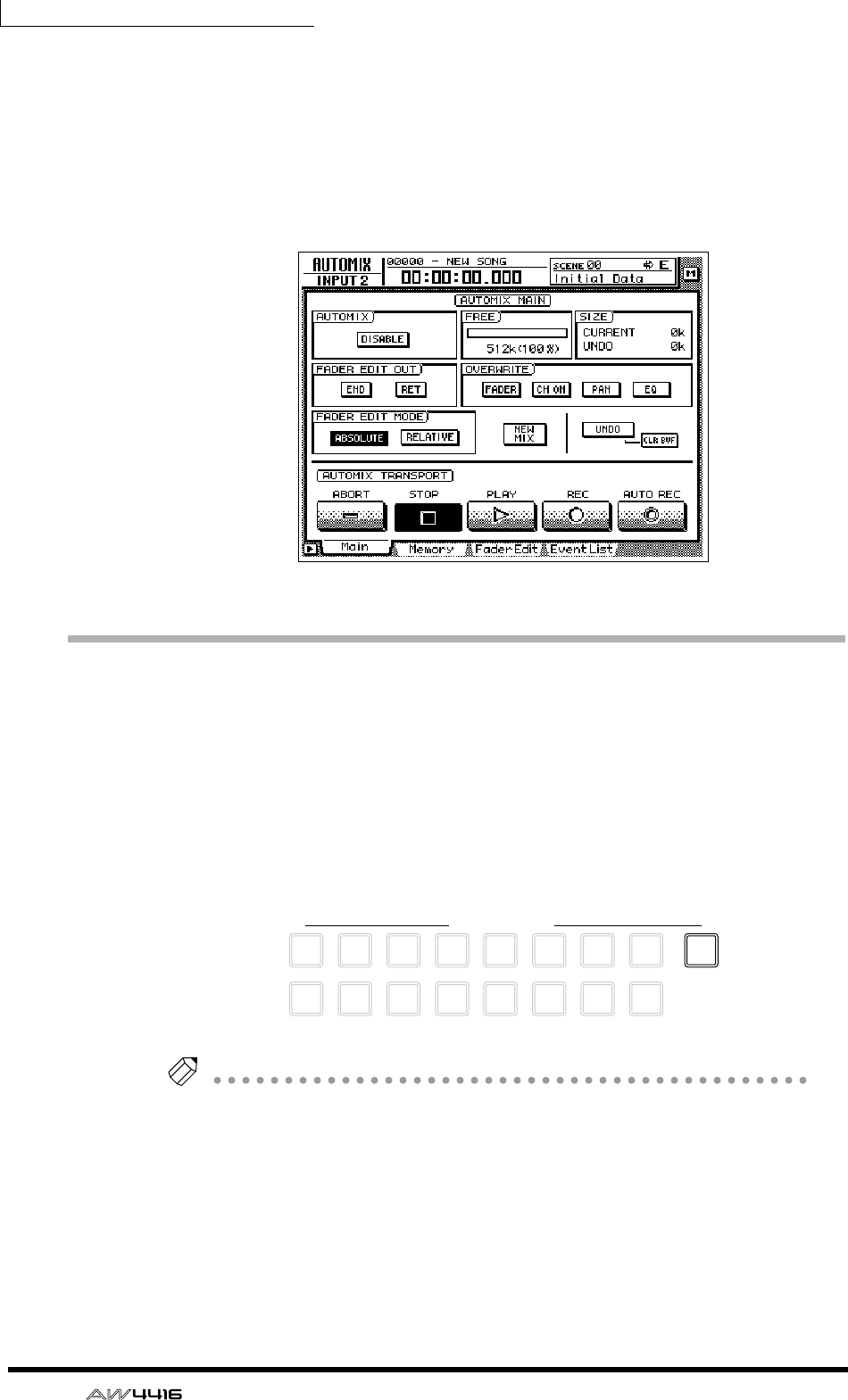
Chapter5—Recording on the AW4416
102 — Operation Guide
❒Automix
By using this function, fader and [ON] key operations, changes in mix parameters
such as EQ and pan, and events such as scene memory or library selection can
be recorded and played back in realtime in synchronization with the song. You
can also record operations in multiple stages, or edit recorded events later. To
record or play back scene memories, you can use the AUTOMIX screen Main
page ([AUTOMIX] key → [F1] key), etc.
Recording the stereo track
The recorder section of the AW4416 provides a stereo track that is independent
of audio tracks 1–16, and which is used mainly as a master track for creating a
two-track mix.
Here we will explain the procedure of mixing the signals of tracks 1–16 and the
return signals from the internal effects into a stereo track to create a finished song.
1. Press the REC TRACK SELECT [ST] key.
The stereo track will be in record-ready mode.
Tip!
The input of the stereo track is internally connected to the stereo output channel of
the mixer. This means that the L/R level meter in the level meters/counter section
can be used as the input level meter for the stereo track.
9
REC TRACK SELECT
ST
12
10
3
11
4
12
5
13
6
14
7
15
8
16
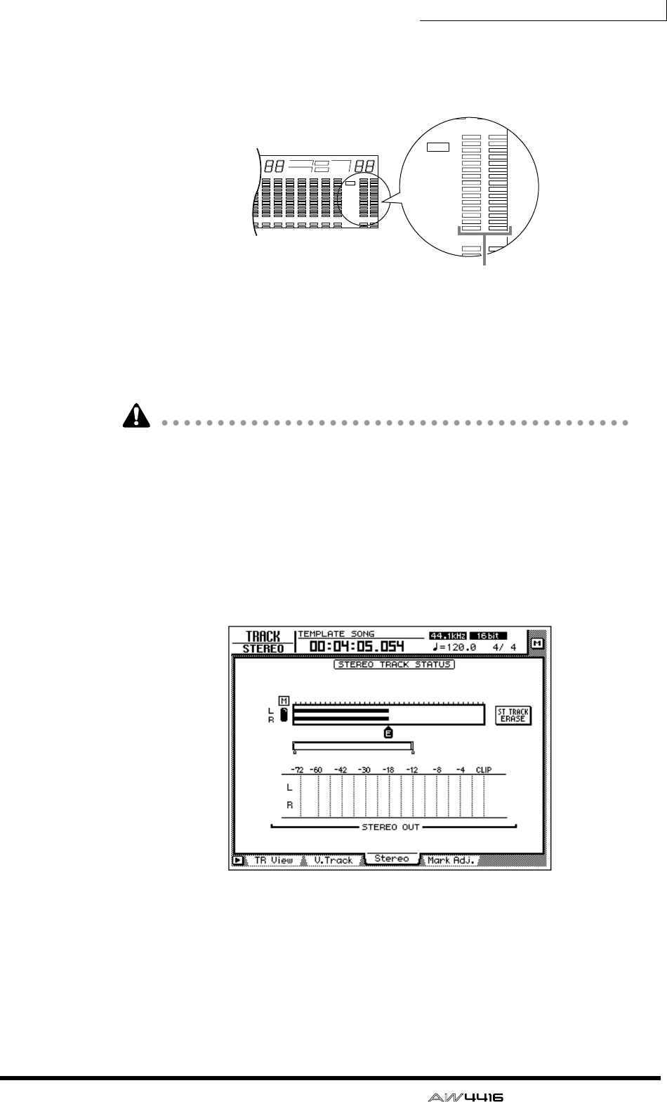
Chapter5—Recording on the AW4416
— Operation Guide 103
2. Play back the song from the beginning, and watch the L/R level meter in
the level meters/counter section.
If the red 0 dB segment lights, lower faders 1–16 and/or the STEREO fader.
3. After you have set the level, rewind the song to the beginning. Then
hold down the Transport section [REC] (●) key and press the [PLAY] key
(®).
Recording on the stereo track will begin.
In order to create an audio CD (44.1 kHz), there must be at least four seconds of
data in the stereo track.
4. When you are finished recording, press the [STOP] (■) key.
5. To listen to the newly recorded stereo track, press the Recorder section
[TRACK] key → [F3] key.
The TRACK screen Stereo page will appear, allowing you to play back or erase
the stereo track. When the AW4416 is in the initial state, the M (mute) button in
the upper left of the screen will be turned on, muting the stereo track.
6. Move the cursor to the M (mute) button and press the [ENTER] key.
Muting of the stereo track will be defeated, allowing the stereo track to play back.
At this time, the stereo track will automatically be assigned to monitor channels
1/2, and the remaining monitor channels will be muted. If you play back the song
in this state, the stereo track can be monitored via monitor channels 1/2 → stereo
bus.
8 9 13 14 15 1610 11 12
–dB 0
2
6
20
30
42
60
10
14
18
20
26
12
FINE
READY
INPUT
LR
SFms
EXT
VARI
44.1k 48k
LOCK
WORD CLOCK MTC SCENE
SLAVE
MASTER
INT
E
1234567
–dB 0
2
6
20
30
42
60
10
14
18
20
26
12
FINE
READY
INPUT
REMAIN
ABS
REL
HM
–dB 0
2
6
20
30
42
60
10
14
18
20
26
12
FINE
READY
INPUT
LR
E
L/R level meter
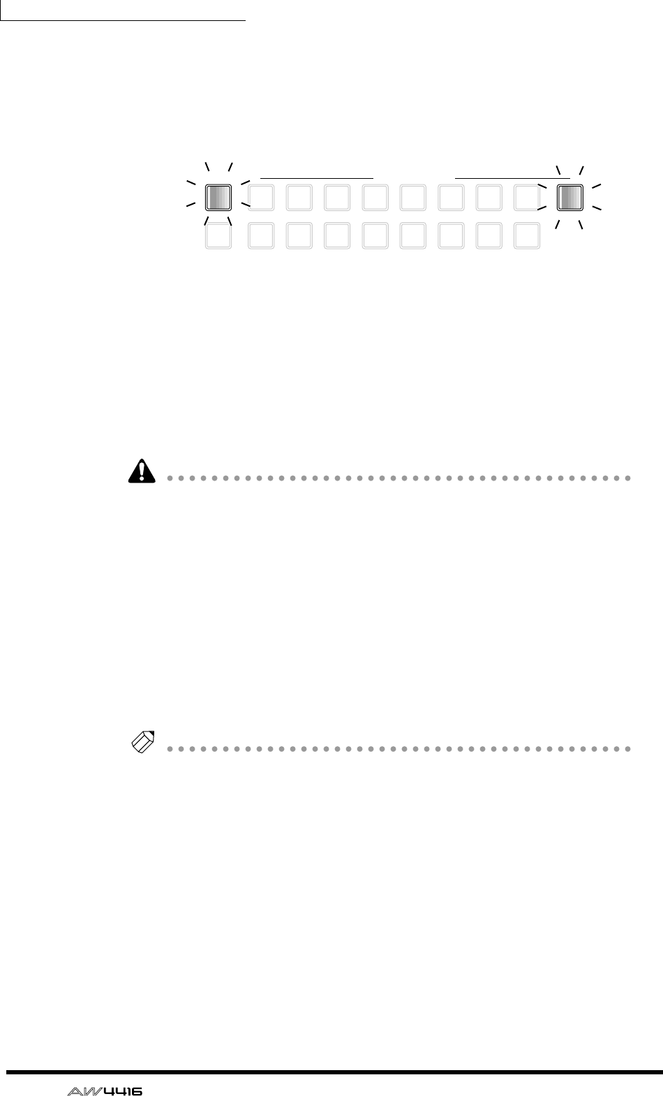
Chapter5—Recording on the AW4416
104 — Operation Guide
However with this monitoring method, the signal will pass through the monitor
channel and the output channel, meaning that you will not necessarily be moni-
toring in a “flat” state. Here’s how you can output the stereo track directly from
the MONITOR OUT jacks.
7. In the level meters/counter section, turn the TRACK [CUE] key on.
The TRACK [CUE] key is used to output the signal of the desired track directly to
the MONITOR OUT jacks. If you press the TRACK [CUE] key when the stereo
track is not muted, the TRACK [CUE] key will blink and the REC TRACK SELECT
[ST] key will blink red. This indicates that only the stereo track can be selected as
the signal for monitoring.
8. Press the REC TRACK SELECT [ST] key.
The TRACK [CUE] key and REC TRACK SELECT [ST] key will change from blink-
ing to lit. This indicates that the stereo track is selected as the signal for monitor-
ing.
When you use the TRACK [CUE] key, the signal will be output directly to the
MONITOR OUT jacks, and therefore the fader cannot be used to adjust the level.
To avoid sudden loud sounds, lower the MONITOR OUT control beforehand.
9. Press the Locate section [RTZ] key, and then press the Transport section
[PLAY] (®) key.
The signal of the stereo track will be sent directly to the MONITOR OUT jacks.
10. If you are satisfied with the recorded result, turn off the TRACK [CUE]
key.
The REC TRACK SELECT [ST] key will go dark simultaneously. To defeat muting
for audio tracks 1–16, access the TRACK screen Stereo page and turn the M
(mute) button on once again.
Tip!
Only one stereo track can be used for each song. If you wish to try the mixdown
again, perform the Undo operation. If Undo is not possible, access the TRACK
screen Stereo page, move the cursor to the ST TRACK ERASE button in the right side
of the screen, and press the [ENTER] key to erase the stereo track. Then record it
once again.
9
TRACK REC TRACK SELECT
ALL
SAFE
12
10
3
11
4
12
5
13
6
14
7
15
8
16
ST
CUE
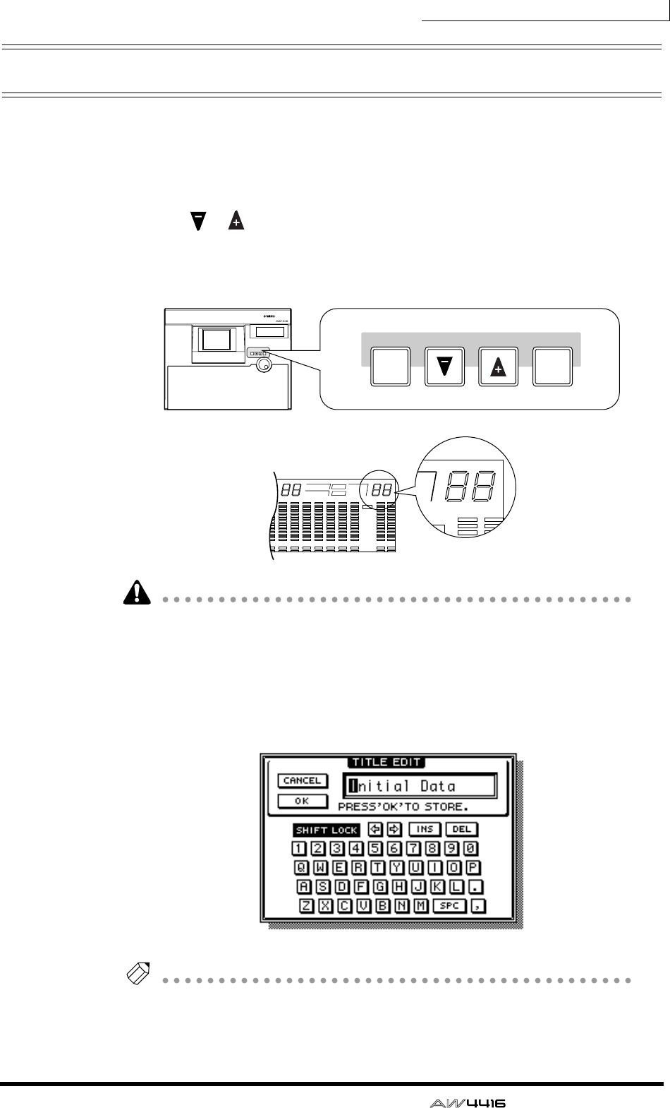
Chapter5—Recording on the AW4416
— Operation Guide 105
Saving a scene/song
❒Saving a scene
If you wish to reproduce the mixer settings as well when you recall the current
song at a later time, you must store the current mix parameters as a Scene.
1. Use the [ ]/[ ] keys in the SCENE MEMORY section of the top panel
to select the store destination scene number (01–96).
The currently selected scene number will appear in the upper right of the level
meter/counter.
Scene number 00 contains a preset recall-only scene that returns all mix parame-
ters to their default state. For this reason, it is not possible to store a scene into
number 00.
2. Press the SCENE MEMORY section [STORE] key.
The TITLE EDIT popup window will appear, allowing you to assign a name to the
scene memory.
Tip!
If STORE CONFIRMATION is turned “OFF” in the UTILITY screen Prefer.1 page
([UTILITY] key
→
[F2] key), the scene will be stored directly to the specified scene
number without displaying this confirmation popup window. This is more conve-
nient if you will be repeatedly overwriting a scene onto the same scene number.
PROFESSIONAL AUDIO WORKSTATION
SCENE MEMORY
STORE RECALL
SCENE MEMORY
STORE RECALL
5 6 7 8 9 13 14 15 1610 11 12
–dB 0
2
6
20
30
42
60
10
14
18
20
26
12
FINE
READY
INPUT
LR
MSFms
EXT
VARI
44.1k 48k
LOCK
WORD CLOCK MTC SCENE
SLAVE
MASTER
INT
E
E
–dB 0
2
FINE
MTC SCENE
SLAVE
MASTER
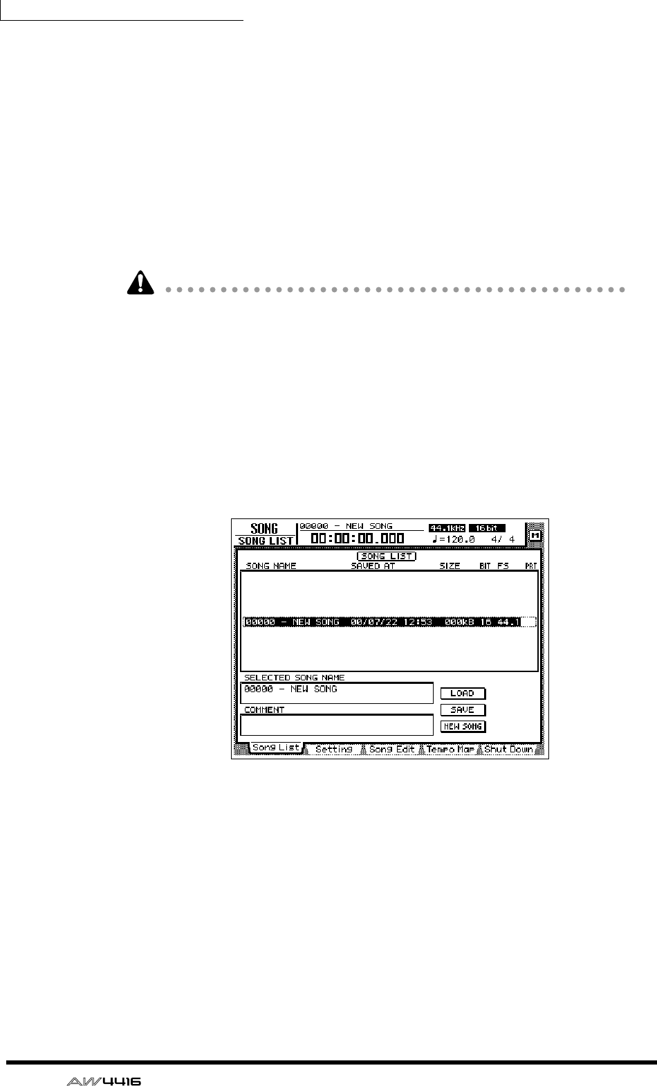
Chapter5—Recording on the AW4416
106 — Operation Guide
3. As desired, assign a scene name of up to 16 characters. (For details on
inputting characters, refer to page 60.) When you are finished, move the
cursor to the OK button and press the [ENTER] key.
The scene will be stored.
❒Saving a song
The current song will be saved automatically when you create a new song, load
an existing song, or perform the shut-down procedure. However as a precaution
against the power being accidentally turned off while you are working, it is a
good idea to save your song frequently, and not just after completing the mix-
down.
• When you save a song, the scene memory contents and only the scene num-
ber (i.e., not the settings) of the most recently stored/recalled scene will be
saved together with the song. Be aware that the current mix parameters are not
saved.
• When an existing song is loaded, the scene number that was most recently
stored/recalled for that song will be displayed in the upper right of the level
meter/counter. If you wish to reproduce both the song and the mix parameters,
you must press the SCENE MEMORY section [RECALL] key and recall that
scene immediately after loading the song.
1. Press the WORK NAVIGATE section [SONG] key → [F1] key.
The SONG screen Song List page will appear.
The data for the current song (date, size, quantization bits, protect) shown here in
the song list is the data for when the song was last saved. When you perform the
following Save procedure and press the [ENTER] key, it will be overwritten by the
new data.
2. Move the cursor to the SAVE button at the bottom of the screen, and
press the [ENTER] key.
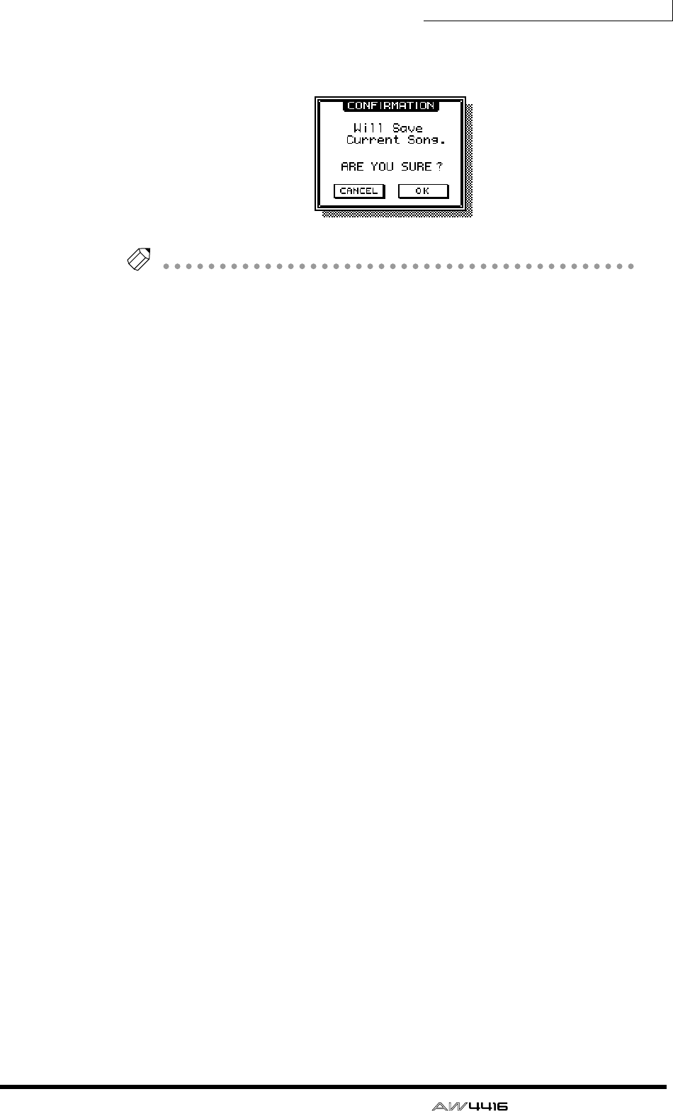
Chapter5—Recording on the AW4416
— Operation Guide 107
A CONFIRMATION popup window will appear, asking you to confirm the Save
operation.
Tip!
When you shut down the AW4416, the current song will be saved automatically.
However, we recommend that you save the song manually when you are finished
recording (
→
P.176). If you fail to do this, the song will revert to the last-saved state
if the power of the AW4416 is turned off accidentally.
3. Move the cursor to the OK button and press the [ENTER] key.
The song will be saved.

Chapter5—Recording on the AW4416
108 — Operation Guide
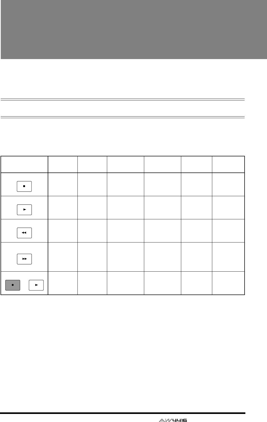
— Operation Guide 109
6Transport/locate oper-
ations
This chapter explains transport and locate operations on the AW4416.
Table of transport key operations
The function of the keys in the transport section of the AW4416 will change
depending on the status (current operating mode) of the transport. The following
table shows how the transport keys change function according to the status of the
transport.
* : Recording will occur only if any of the [REC TRACK SELECT] keys are blinking.
— : Key has no function.
Status/
Transport keys Stopped Playing Rewinding Fast-
forwarding Recording A-B
repeating
— Stop Stop Stop Stop Stop
Play — Play Play Play
(punch-out) —
Rewind
(8X)
Rewind
(8X)
Switch rewind
speeds
(8X⇔16X)
Rewind (8X) —
Defeat
repeat, and
rewind (8X)
Fast-for-
ward (8X)
Fast-for-
ward (8X)
Fast-forward
(8X)
Switch fast-
forward
speeds
(8X⇔16X)
—
Defeat
repeat, and
fast-forward
(8X)
Record* Record*
(punch-in) Play Play — —
STOP
PLAY
REW
FF
PLAY
REC
+

Chapter6—Transport/locate operations
110 — Operation Guide
Shuttle function (cue/review opera-
tion)
While the transport is stopped or playing, you can operate the [SHUTTLE] dial to
play forward (cue) or play backward (review) at various speeds.
The cue or review speed will change according to the angle of the [SHUTTLE]
dial, as shown in the following diagram. When the [SHUTTLE] dial is returned to
the center, the shuttle function is defeated, and the transport will return to the
state in which it was before you operated the dial (i.e., stopped or playing).
Nudge function
“Nudge” is a function that repeatedly plays back a short region before and after
the current location, and lets you move the current location forward or backward
in small steps so that you can search for a desired point. This lets you accurately
specify a point in the song, such as when setting the auto punch-in/out points, or
setting the range for a track editing operation.
❒Using the Nudge function
1. Use normal transport operations or the shuttle function to locate to the
general area of the desired point in the song.
2. Press [JOG ON].
The [JOG ON] key will light, and playback will repeat over a fixed region (the
default setting is 100 milliseconds) starting at the current location.
The result may sound different depending on the number of tracks that are being
played back simultaneously.
Cue (forward)
Stop
+8
+16
–8
+4
–4
+2
–2
+1(normal speed)
–1
+1/2–1/2 +1/4–1/4
Review (backward)
–16
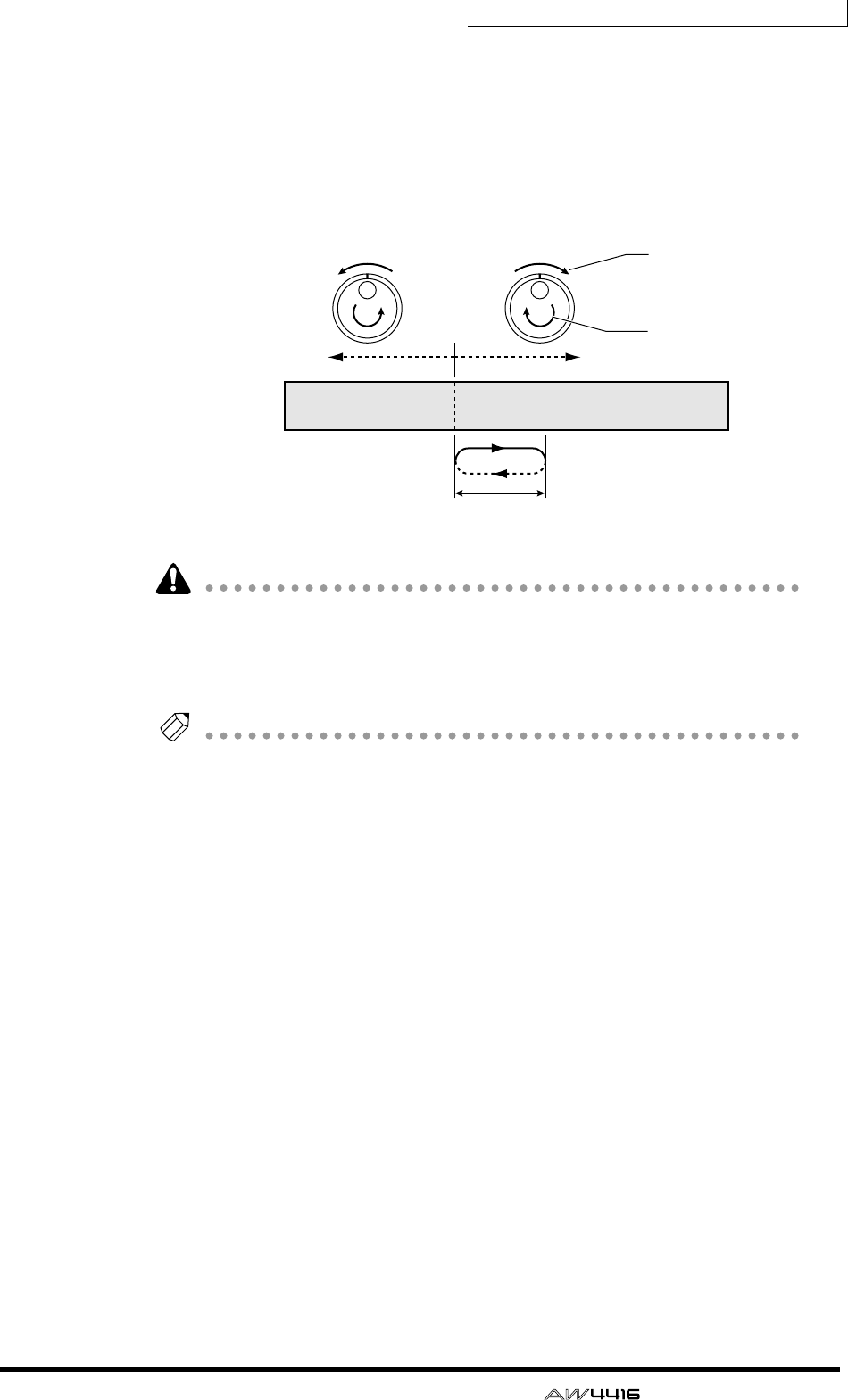
Chapter6—Transport/locate operations
— Operation Guide 111
3. To move the current location forward, turn the [DATA/JOG] dial toward
the right. To move the current location backward, turn the [DATA/JOG]
dial toward the left.
If time display (SECOND) is selected as the counter display mode, the current
location will move in millisecond steps. If time code display (TIME CODE) is
selected as the counter display mode, the current location will move in sub-frame
steps.
If you use the Nudge function when the counter display is set to MEASURE, turn-
ing the [DATA/JOG] dial will move only in steps of one beat, meaning that you
will not be able to set the location precisely. Before using the Nudge function,
you should switch the counter display to either the Time display or the Time Code
display (Refer to Reference Guide “SONG screen/Setting page”).
Tip!
Normally, turning the Nudge function on will repeatedly play a 100 msec region
starting at the current location. However, you can change the play mode of the
Nudge function so that the repeated region ends at the current location, or adjust
the length (“nudge time”) of the repeated region. For details on play mode and
nudge time settings, refer to the section below, “Nudge function settings.”
4. To defeat the Nudge function, press the [JOG ON] key or the [STOP] key
of the transport section.
Nudge time
Current
location
Song tracks
Use [SHUTTLE] dial
to move to approxi-
mate location
Use [DATA/JOG]
dial to move in
small steps
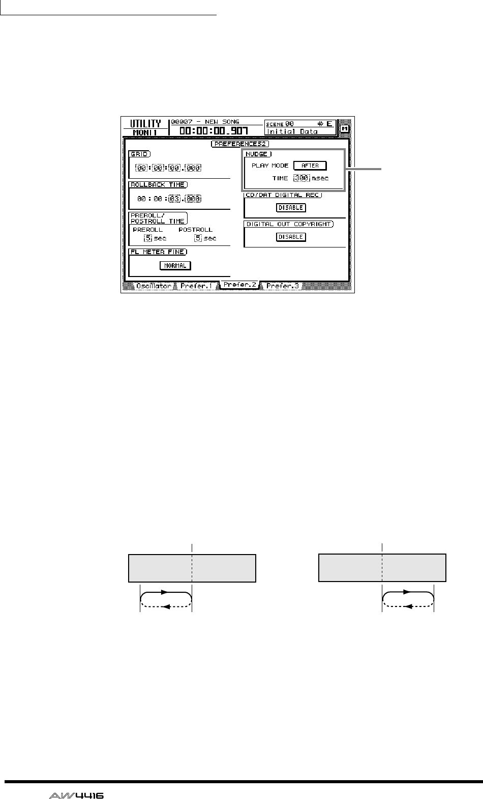
Chapter6—Transport/locate operations
112 — Operation Guide
❒Nudge function settings
Here’s how to adjust the nudge time and play mode of the Nudge function.
1. With the song stopped, press the [UTILITY] key → [F3] key.
2. To set the nudge time, move the cursor to the TIME field of the NUDGE
area, and rotate the [DATA/JOG] dial to set the nudge time (25–800
msec).
3. To change the play mode of the nudge function, move the cursor to the
PLAY MODE field of the NUDGE area, and press the [ENTER] key to
switch between the following two play modes.
• AFTER...................Repeatedly play back a range starting at the current location
and extending the length of the nudge time setting.
• BEFORE................Repeatedly play back a range corresponding to the length of
the nudge time setting and ending at the current location.
Nudge function
settings
Current
location Current
location
PLAY MODE= BEFORE PLAY MODE= AFTER
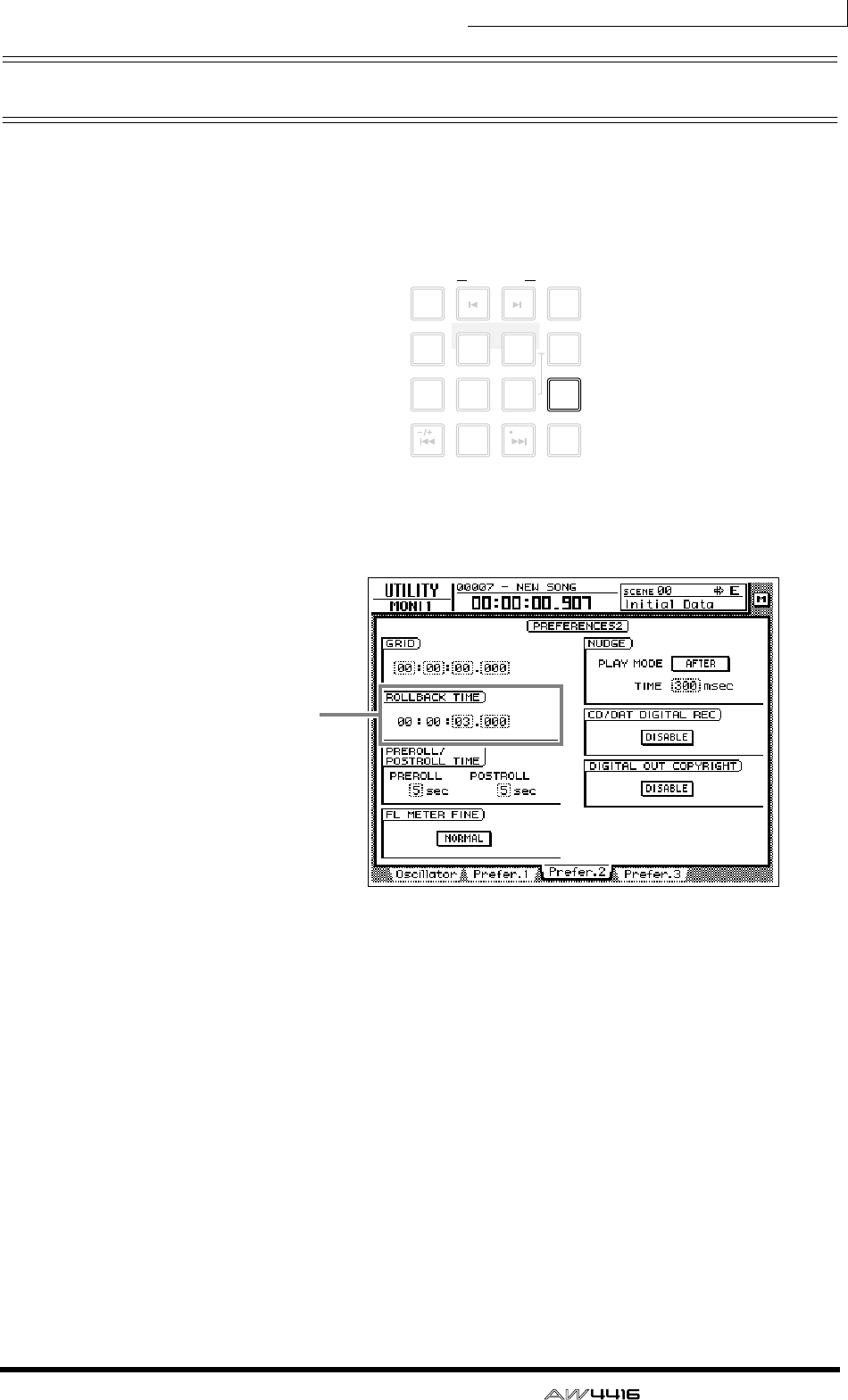
Chapter6—Transport/locate operations
— Operation Guide 113
Rollback function
While the song is stopped or playing, you can press the [ROLL BACK] key of the
Locate section to move the current location back by a fixed length. This is conve-
nient when you are playing back, and come to a location that you wish to listen
to once again. The rollback time is set to 5 seconds by default, but can be
adjusted as desired.
1. With the song stopped, press the [UTILITY] key → [F3] key.
2. Move the cursor to the ROLLBACK TIME field, and use the [DATA/JOG]
dial to set the rollback time.
The rollback time can be adjusted in millisecond steps over a range of 0–5 sec-
onds (default setting is 5 seconds).
3. When the song is stopped or playing, press the [ROLL BACK] key.
If the [ROLL BACK] key is pressed while stopped, the current location will simply
move back by the length of the rollback time. If pressed while playing, playback
will resume immediately after the rollback occurs.
LAST REC
MARK SEARCH
LAST REC
54IN OUT
NO
AB
REPEAT
RTZ
231
0
ROLL
BACK
CANCEL
SET
MARK
NUM
LOCATE
897
6
AUTO
PUNCH
Rollback time
setting
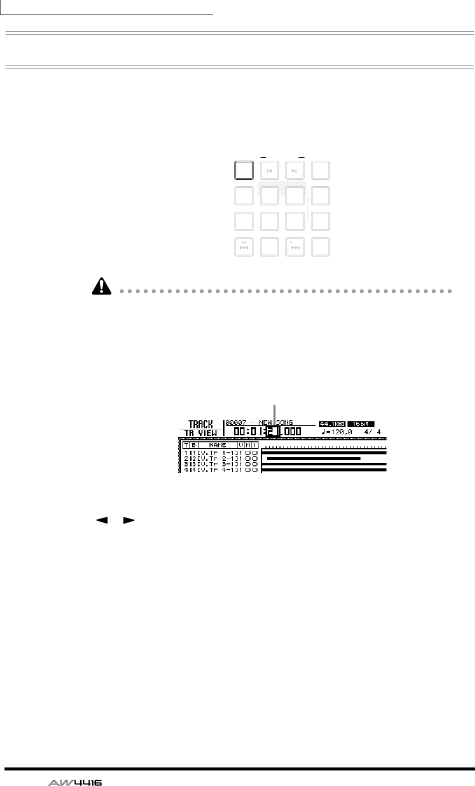
Chapter6—Transport/locate operations
114 — Operation Guide
Locating to a specific point
You can directly specify a locate point as a numerical value, and locate to it.
Here’s how.
1. With the transport stopped, press the [NUM LOCATE] key of the Locate
section.
If you have selected a screen where normal transport operations cannot be per-
formed, such as the SONG screen or the MASTERING screen, the [NUM
LOCATE] key cannot be used even if the cursor is displayed at the counter in the
upper part of the display.
The cursor will move to the counter in the upper part of the display.
2. To specify the locate point using the [DATA/JOG] dial, use the CURSOR
[ ]/[ ] keys to move the cursor to the digit that you wish to change,
and rotate the [DATA/JOG] dial to specify the value.
3. To specify the locate point using the numeric keys (keys 0–9 of the
locate section), move the cursor to the lowest digit of the value you wish
to input, and use the numeric keys to directly input the value.
If the time display (SECOND) is selected as the counter display type, you can
specify the value as hours/minutes/seconds/milliseconds; if time code display
(TIME CODE) is selected, you can specify hours/minutes/seconds/frames/sub-
frames; if measure display (MEASURE) is selected, you can specify measures/
beats.
4. To execute the Locate operation, press the [ENTER] key.
LAST REC
MARK SEARCH
LAST REC
54IN OUT
NO
AB
REPEAT
RTZ
231
0
ROLL
BACK
CANCEL
SET
MARK
NUM
LOCATE
897
6
AUTO
PUNCH
Cursor
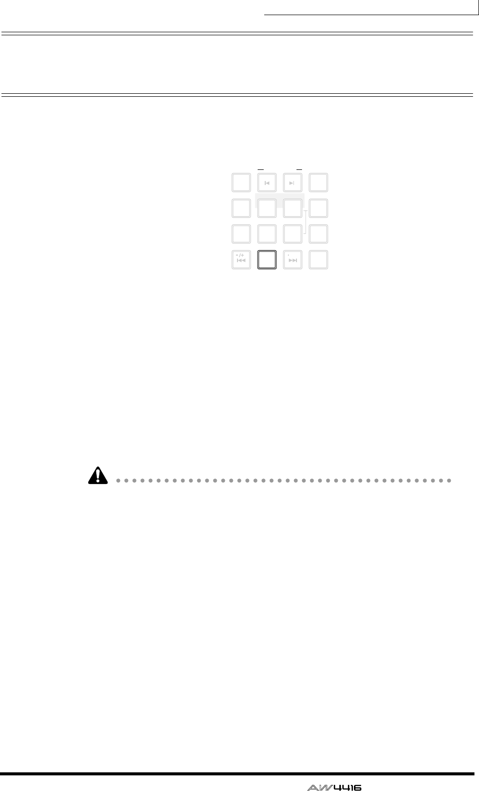
Chapter6—Transport/locate operations
— Operation Guide 115
Locating to the zero location of the
counter
When the song is stopped or playing, you can press the [RTZ] key of the Locate
section to locate to the zero location of the currently displayed counter. (If the
counter is displaying measures, you will locate to the beginning of the first mea-
sure.)
If the counter display type is set to Time (SECOND) or Time Code (TIME CODE),
the point to which the [RTZ] key will locate will depend on whether absolute
time or relative time is being displayed.
❍ If the counter shows absolute time (ABS)
Pressing the [RTZ] key will locate to the 00:00:00.00 position if the counter
shows the time code, or to the start point (zero absolute time) if the counter
shows the time.
❍ If the counter shows relative time (REL)
Pressing the [RTZ] key will locate to the point that the user specified as zero rela-
tive time. (For details on setting the zero relative time, refer to the section below.)
If Measure display (MEASURE) is selected for the counter, you cannot switch
between absolute time and relative time; pressing the [RTZ] key will always
locate to the start point of the song.
❒Setting the zero relative time location
You can use the following procedure to set the relative (REL) zero point that is dis-
played by the counter.
1. Locate the song to the point that you wish to set as relative zero.
2. Hold down the Locate section [SET] key, and press the [RTZ] key.
If the counter had been displaying the relative time (REL), the counter display will
be reset to zero (00:00:00.000). If the counter had been displaying the absolute
time (ABS), it will automatically switch to relative time, and will be reset to zero
(00:00:00.000).
LAST REC
MARK SEARCH
LAST REC
54IN OUT
NO
AB
REPEAT
RTZ
231
0
ROLL
BACK
CANCEL
SET
MARK
NUM
LOCATE
897
6
AUTO
PUNCH
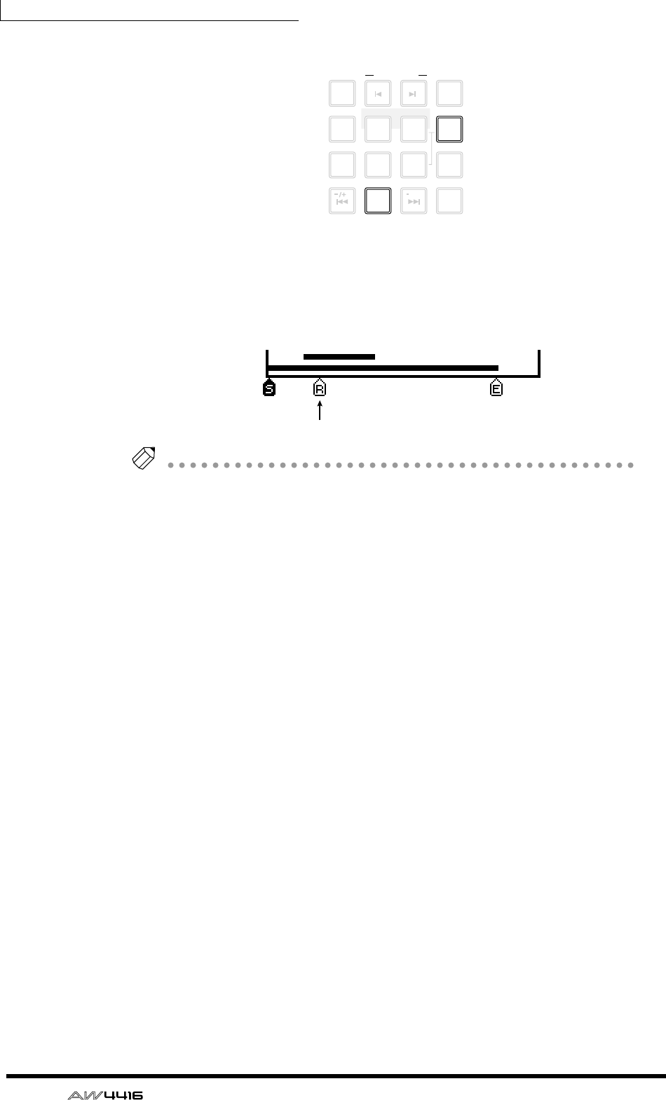
Chapter6—Transport/locate operations
116 — Operation Guide
3. If you wish to return the counter to the absolute time display, press the
[ABS/REL] key.
The specified relative zero location will be displayed as follows in the TRACK
screen → TR View page that appears when you press the [TRACK] key → [F1] key.
Tip!
The zero relative time location is saved on the hard disk as part of the currently
selected song.
LAST REC
MARK SEARCH
LAST REC
54IN OUT
NO
AB
REPEAT
RTZ
231
0
ROLL
BACK
CANCEL
SET
MARK
NUM
LOCATE
897
6
AUTO
PUNCH
Zero relative time location
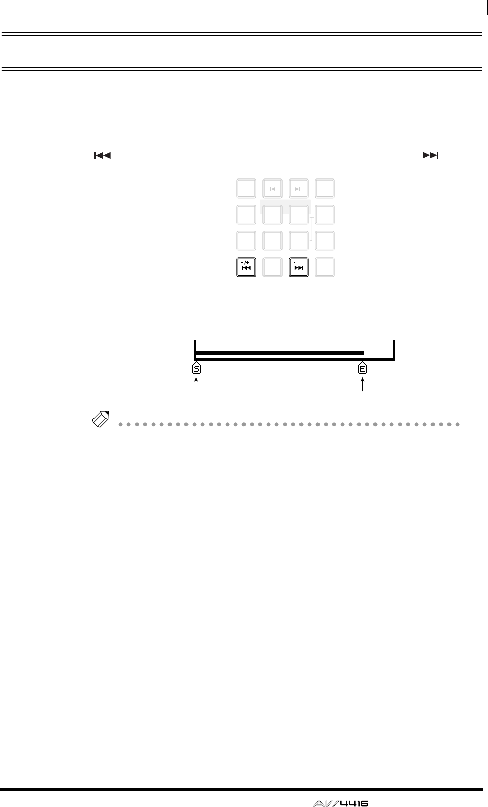
Chapter6—Transport/locate operations
— Operation Guide 117
Locating to the start/end points
The start point and end point normally correspond to the beginning and end of
the song. When you create a new song, absolute time 00:00:00.000 will be set as
the default start point. When you record a song, the last point in the song will
automatically be set as the end point. (If you extend the length of the song, the
end point will move accordingly.) You can locate to the start point by pressing the
[ ] key of the Locate section, or to the end point by pressing the [ ] key.
The start point and end point will be displayed as follows in the TRACK screen TR
View page that appears when you press the [TRACK] key → [F1] key.
Tip!
The locations of the start point and end point can be adjusted as desired (
→
P.123).
LAST REC
MARK SEARCH
LAST REC
54IN OUT
NO
AB
REPEAT
RTZ
231
0
ROLL
BACK
CANCEL
SET
MARK
NUM
LOCATE
897
6
AUTO
PUNCH
Start point End point
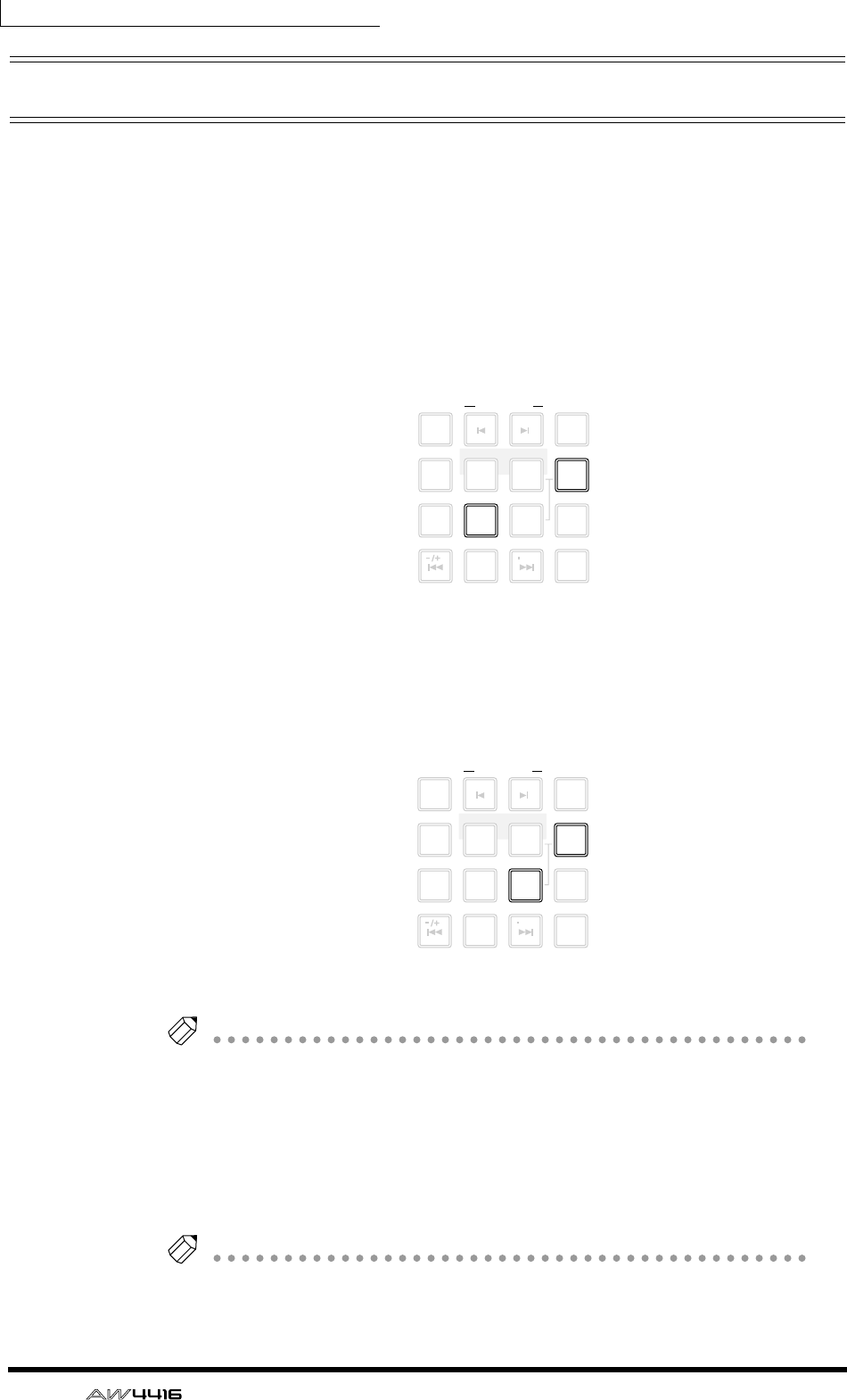
Chapter6—Transport/locate operations
118 — Operation Guide
A-B repeat
A-B Repeat is a function that repeatedly plays back the region between the point
A and point B that you specify. The A/B points can be set when the song is either
stopped or playing.
❒Setting the A/B points
1. Locate the song to the location where you wish to set point A (the
beginning of the repeated playback).
2. Hold down the Locate section [SET] key and press the [A] key.
The [A] key will light, indicating that point A has been set.
3. Locate the song to the location where you wish to set point B (the end
of the repeated playback).
4. Hold down the [SET] key and press the [B] key.
The [B] key will light, indicating that point B has been set.
Tip!
You can also use the [A]/[B] keys to locate directly to points A/B.
❒Performing A-B repeat playback
5. To perform repeat playback, press the Locate section [REPEAT] key when
the transport is stopped. The transport will automatically locate to point
A.
Tip!
If you press the [REPEAT] key during playback, repeated playback between points A/
B will begin automatically. If you press the [REPEAT] key during repeat playback,
you will return to normal playback.
LAST REC
MARK SEARCH
LAST REC
54IN OUT
NO
AB
REPEAT
RTZ
231
0
ROLL
BACK
CANCEL
SET
MARK
NUM
LOCATE
897
6
AUTO
PUNCH
LAST REC
MARK SEARCH
LAST REC
54IN OUT
NO
AB
REPEAT
RTZ
231
0
ROLL
BACK
CANCEL
SET
MARK
NUM
LOCATE
897
6
AUTO
PUNCH
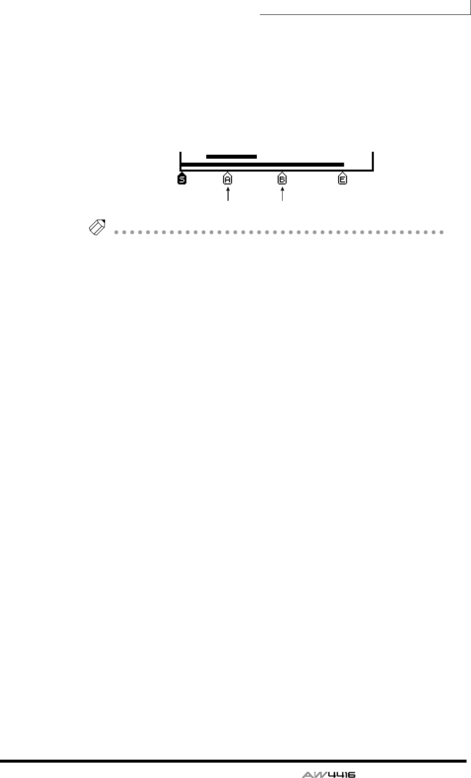
Chapter6—Transport/locate operations
— Operation Guide 119
6. Press the [PLAY] key. Repeated playback between points A/B will begin.
7. To defeat A-B repeat, press the [REPEAT] key.
The [REPEAT] key will go dark, indicating that A-B repeat has been defeated. If
you pressed the [REPEAT] key to defeat A-B repeat, normal playback will resume
from that point.
The A/B points that you specify will be displayed as follows in the TRACK screen
TR View page that appears when you press the [TRACK] key → [F1] key.
Tip!
• If you set point B earlier than point A and press the [REPEAT] key, playback
will repeat from B
→
A.
• The A/B points you set can be deleted (
→
P.126) or moved (
→
P.123) as
desired.
• The A/B point settings are saved on the hard disk as part of the currently
selected song.
Point A Point B
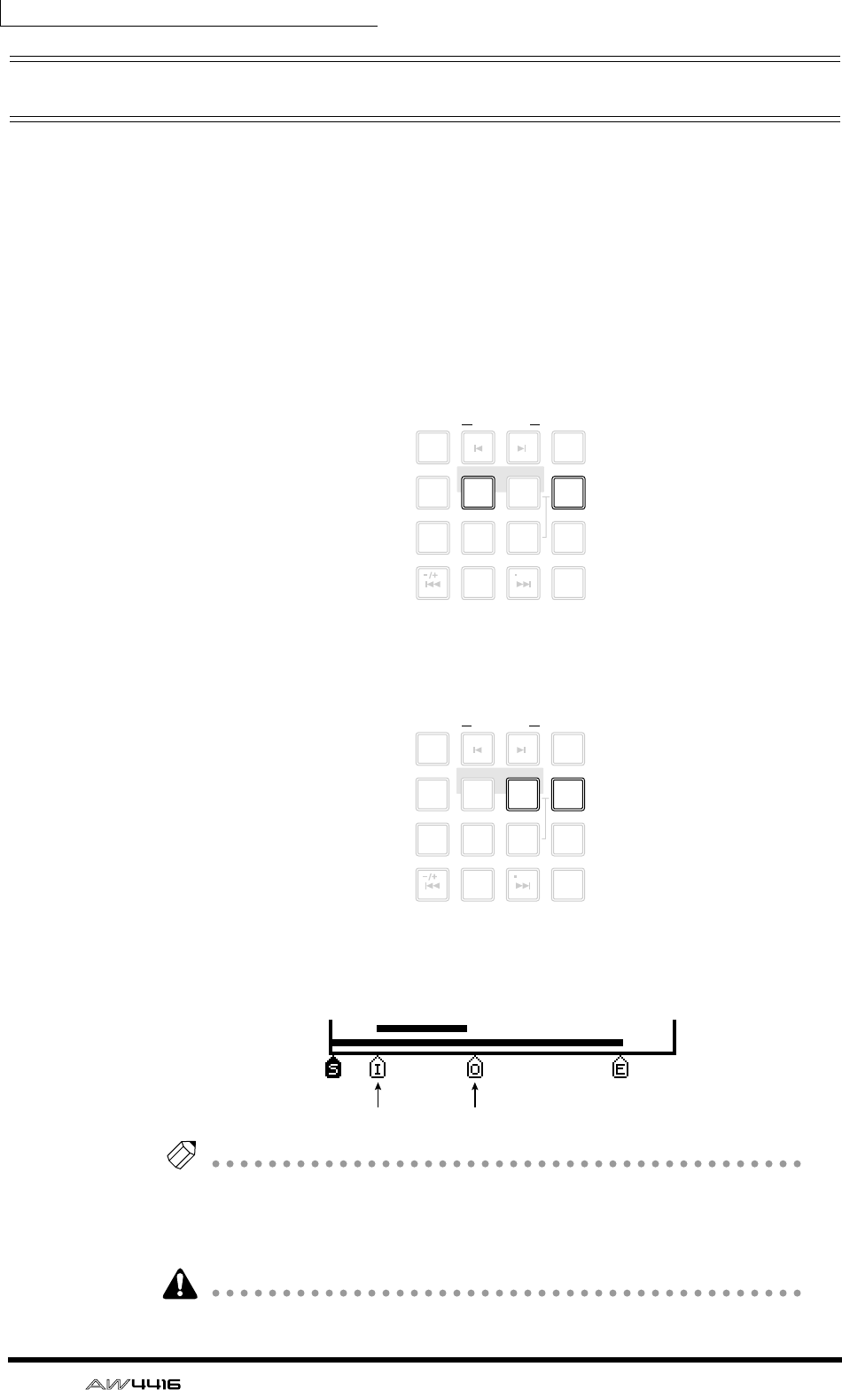
Chapter6—Transport/locate operations
120 — Operation Guide
In/out points
The AW4416 remembers the locations at which recording was last begun and
ended as the In point and the Out point. When the In and Out points are memo-
rized, the [IN] and [OUT] keys will light. In this state, you can press the [IN] key
or the [OUT] key to locate to the In or Out points. You can also set the In or Out
points manually.
❒Setting the In point/Out point
1. Locate the song to the location where you wish to set the In point.
2. Hold down the Locate section [SET] key and press the [IN] key.
3. Locate the song to the location where you wish to set the Out point.
4. Hold down the [SET] key and press the [OUT] key.
The In point and Out point that you specify will be displayed as follows in the
TRACK screen TR View page that appears when you press the [TRACK] key →
[F1] key.
Tip!
• The In/Out points are also used as the auto punch-in/out points used by auto
punch-in/out (
→
P.130).
• The In/Out point settings are saved on the hard disk as part of the currently
selected song.
You must set the In point ahead of the Out point.
LAST REC
MARK SEARCH
LAST REC
54IN OUT
NO
AB
REPEAT
RTZ
231
0
ROLL
BACK
CANCEL
SET
MARK
NUM
LOCATE
897
6
AUTO
PUNCH
LAST REC
MARK SEARCH
LAST REC
54IN OUT
NO
AB
REPEAT
RTZ
231
0
ROLL
BACK
CANCEL
SET
MARK
NUM
LOCATE
897
6
AUTO
PUNCH
In point Out point
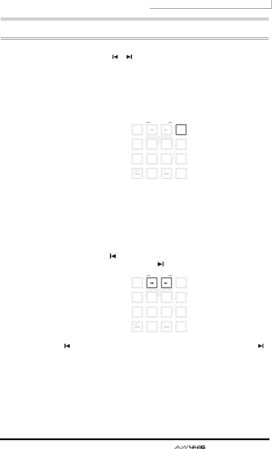
Chapter6—Transport/locate operations
— Operation Guide 121
Markers
The AW4416 allows you to set up to 99 markers at any desired locations in the
song. You can use the [ ]/[ ] keys to search/locate these markers. Markers are
convenient when you wish to locate repeatedly to specific points in the song.
❒Setting a marker
1. Locate the song to the point where you wish to set a marker.
2. Press the Locate section [MARK] key.
Marker settings can be made when the song is either playing or stopped. When
you press the [MARK] key, a message of “MARK SET” will be displayed briefly at
the bottom of the display, indicating that marker has been inserted at that point.
Each time you press the [MARK] key, a new marker will be inserted.
❒Locating to a marker
3. To locate to the marker immediately before the current location, press
the Locate section [ ] key. To locate to the marker immediately follow-
ing the current location, press the [ ] key.
The [ ] key will light if a marker exists before the current location, and the [ ]
key will light if a marker exists after the current location.
LAST REC
MARK SEARCH
LAST REC
54IN OUT
NO
AB
REPEAT
RTZ
231
0
ROLL
BACK
CANCEL
SET
MARK
NUM
LOCATE
897
6
AUTO
PUNCH
LAST REC
MARK SEARCH
LAST REC
54IN OUT
NO
AB
REPEAT
RTZ
231
0
ROLL
BACK
CANCEL
SET
MARK
NUM
LOCATE
897
6
AUTO
PUNCH
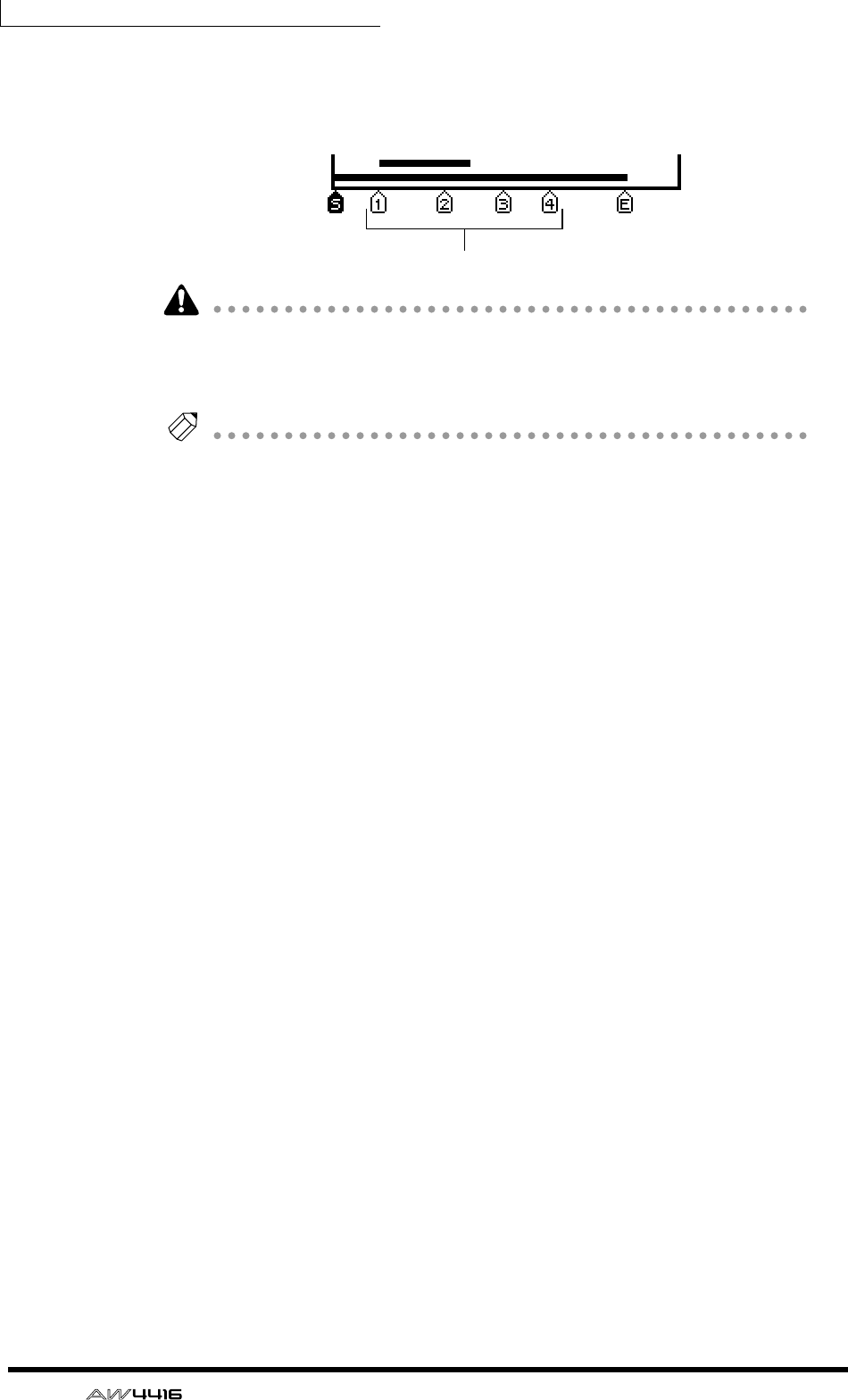
Chapter6—Transport/locate operations
122 — Operation Guide
A number in the range of 1–99 will be assigned to each marker you set, and these
will be displayed as follows in the TRACK screen TR View page that appears when
you press the [TRACK] key → [F1] key.
Please note that the numbers 1–99 do not indicate the order in which you speci-
fied the markers; they indicate the order from the beginning of the song. For
example if you insert a new marker between two existing markers, the subse-
quent markers will be renumbered.
Tip!
• Marker settings are saved on the hard disk as part of the currently selected
song.
• The markers you set can be deleted (
→
P.125) or moved (
→
P.123) as desired.
Markers
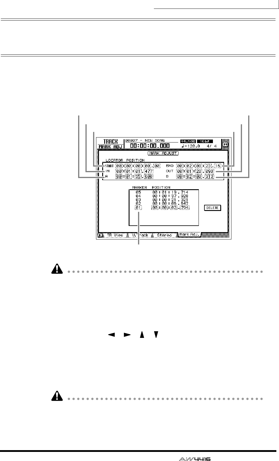
Chapter6—Transport/locate operations
— Operation Guide 123
Adjusting the location of a locate
point
The location of the Start/End points, A/B points, In/Out points, and Markers can
be adjusted as desired.
1. Press the [TRACK] key → [F4] key.
A screen will appear in which you can adjust the various locate points.
• Except for the Start/End points, the displayed location of the locate points will
differ depending on the currently selected counter display type (Time, Time
Code, Measure). The Start point and End point are always displayed as time
code, regardless of the currently selected display method.
• The automix of the AW4416 operates according to the absolute time of the
song. Be aware that if you change the start point after recording events in the
automix, the song will no longer be synchronized with the automix.
2. Use the CURSOR [ ]/[ ]/[ ]/[ ] keys to move the cursor, and use
the [DATA/JOG] dial to adjust the location of each locate point.
When you change the Start point, the absolute time zero of the song will change.
For example if you change the Start point to “00:00:05:00.00,” the location five
seconds after the beginning of the song will be specified as absolute time zero. (If
you press the [RTZ] key when absolute time is displayed, you will move to this
point.)
• The smallest unit of adjustment will be a “millisecond” if time (SECOND) is
selected as the counter display method, “sub-frame” if time code display (TIME
CODE) is selected, or “beats” if measure display (MEASURE) is selected.
• When adjusting the location of a marker, it is not possible to move the marker
beyond the preceding or following marker.
Marker number
Start Point
A point
In point
End point
B point
Out point
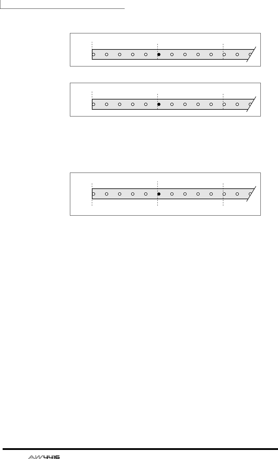
Chapter6—Transport/locate operations
124 — Operation Guide
However, please be aware that changing the Start point will not affect the time
code display of the counter. If you want the time code display to match the abso-
lute time display, set the time code top to the Start point (Refer to Reference
Guide “SONG screen/Setting page.”).
Absolute time (ABS) zero
Song
00:00:00.000 00:00:05.000 00:00:10.000
Start point= 00:00:00:00.00
Start point = 00:00:05:00.00
Absolute time (ABS) zero
Song
– 0:00:0505.000 00:00:00.000 00:00:05.000
Absolute time (ABS) zero
00:00:00.000
00:00:00:00.00
00:00:10.000
00:00:0505:00.00 00:00:10:00.00
Time – 0:00:0505.000
Start point = 00:00:05:00.00
Song
Time code
display
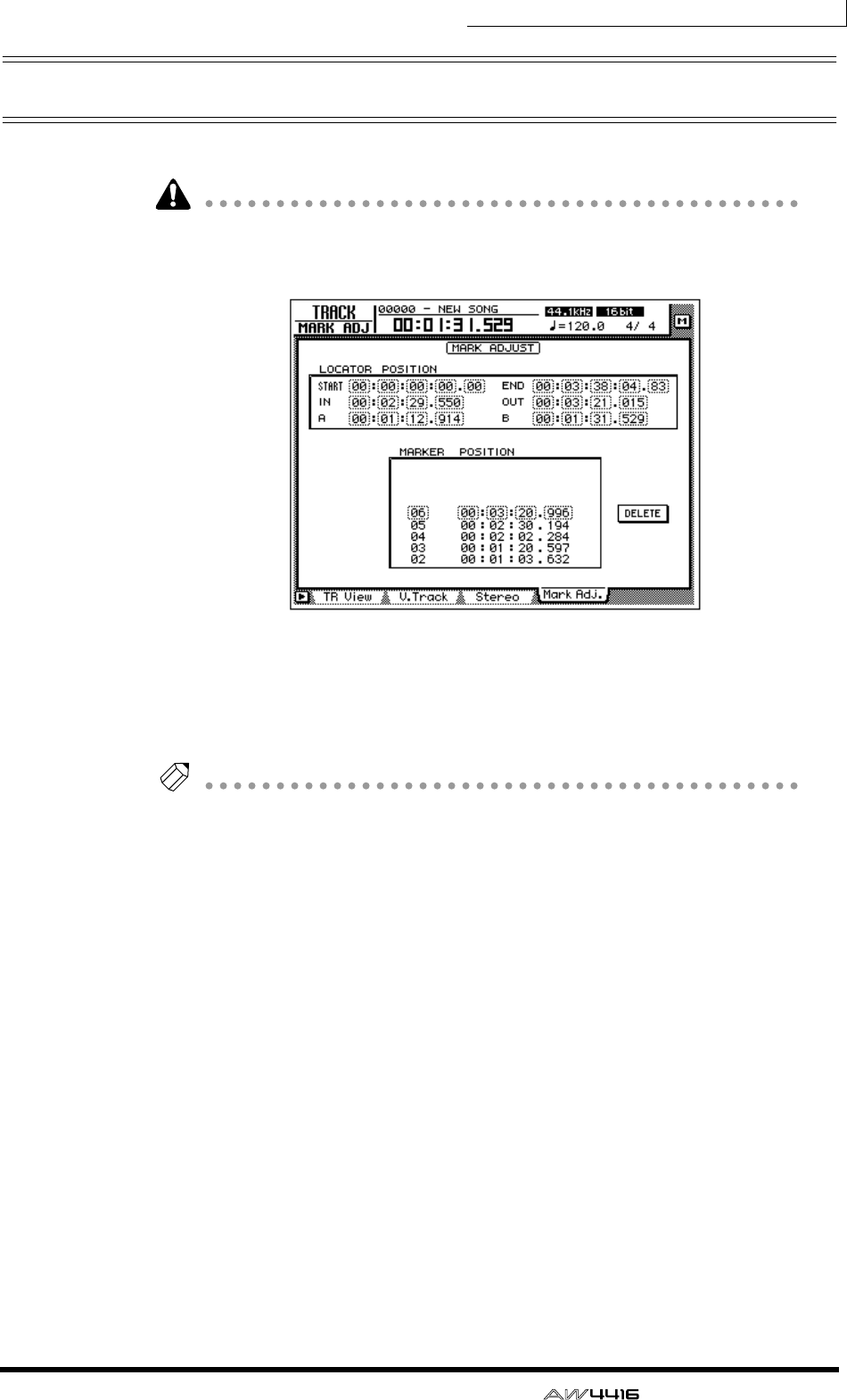
Chapter6—Transport/locate operations
— Operation Guide 125
Deleting a locate point
A locate point (except for the Start/End points) can be deleted as follows.
Be aware that a locate point you delete cannot be recovered.
1. Press the [TRACK] key → [F4] key.
2. Move the cursor to the display area of the locate point you wish to
delete, and press the [ENTER] key.
The selected locate point will be deleted. When you delete the In/Out point or
the A/B point, the corresponding key ([IN]/[OUT] key or [A]/[B] key) will go dark.
Tip!
• If using the mouse, you can delete a locate point by clicking it in the locate
point display and then clicking the DELETE button in the lower right of the dis-
play.
• The DELETE button is used only when operating the mouse. When using the
top panel keys, you can delete simply by moving the cursor to the desired
locate point or marker and pressing the [ENTER] key.

Chapter6—Transport/locate operations
126 — Operation Guide
Deleting a locate point using the
panel keys
A locate point (except for the Start/End points) can be deleted as follows using
only the panel keys.
❒Deleting an In/Out point or A/B point
Hold down the [CANCEL] key, and press the key for the locate point that you
wish to delete ([A]/[B] key or [IN]/[OUT] key). The locate point will be deleted,
and the corresponding key will go dark.
❒Deleting a marker
Use the [ ]/[ ] keys to locate to the marker that you wish to delete. Then hold
down the [CANCEL] key and press the [MARK] key. A message of “MARK ERASE”
will briefly appear at the bottom of the display, indicating that the selected
marker has been erased.

— Operation Guide 127
7Punch-in/out
This chapter explains how to use punch-in/out.
About punch-in/out
Punch-in/out is a method for re-recording a portion of a previously recorded
track. There are two types of punch-in/out.
❒Manual punch-in/out (→ P.128)
In this method you can punch in or out manually, using the transport keys of the
AW4416 or a separately sold foot switch (Yamaha FC-5). If a foot switch is used,
the entire procedure of playback → punch-in → punch-out → stop can be per-
formed using your foot, which is convenient when you are playing an instrument
while operating the AW4416.
❒Auto punch-in/out (→ P.130)
In this method, punch-in/out will occur automatically at the points that you spec-
ify ahead of time (the auto punch-in/out points). This method allows the location
to be specified with sub-frame or millisecond accuracy, and lets you punch-in/
out repeatedly. You can also practice (rehearse) the auto punch-in/out.
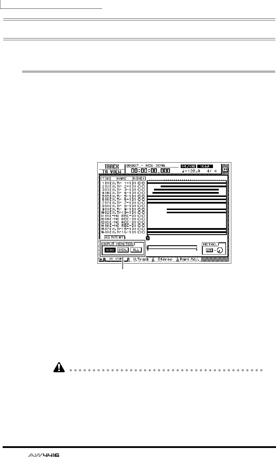
Chapter7—Punch-in/out
128 — Operation Guide
Manual punch-in/out
Here’s how to perform manual punch-in/out.
Preparations
❒Make input monitor settings
For the track on which you wish to punch-in/out, you will need to monitor the
track playback up to the punch-in point, and then monitor the input signal of the
track (the recording source) after you punch-in. To do this, set the input monitor
setting to “auto input monitor,” as explained below.
1. Press the [TRACK] key → [F1] key.
2. In the INPUT MONITOR area, move the cursor to the AUTO button and
press the [ENTER] key.
The AUTO button will be turned on, and Auto Input Monitor will be selected as
the input monitor setting.
❒Connect a foot switch
If you will be using a separately sold foot switch (Yamaha FC-5) to perform man-
ual punch-in/out, connect the foot switch to the FOOT SW jack on the rear panel.
If a foot switch other than the Yamaha FC-5 is connected, it may not operate cor-
rectly.
Input monitor setting
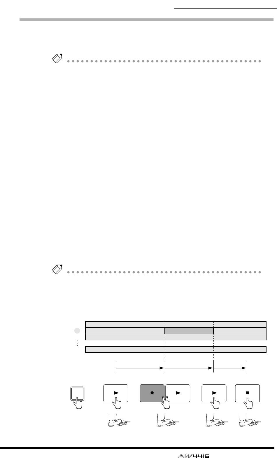
Chapter7—Punch-in/out
— Operation Guide 129
Manual punch-in/out recording
1. Locate the song to a location earlier than where you wish to punch-in.
Tip!
If you set a locate point such as a marker or the A/B point at this location, it will be
convenient when you later check the recorded result or perform punch-in/out again.
For details on setting a locate point, refer to page 114.
2. Press the [REC TRACK SELECT] key for the track that you wish to record.
The [REC TRACK SELECT] key will blink, and the track will be in record-
ready mode.
3. Press the [PLAY] key. (If you are using a foot switch, press the foot
switch.)
The song will begin playing.
4. At the location where you wish to punch-in, hold down the [REC] key
and press the [PLAY] key (or press the foot switch).
The [REC] key will light, and recording will begin on the track you selected in
step 2.
5. At the location where you wish to punch-out, press the [PLAY] key (or
press the foot switch).
The [REC] key will go dark, and you will return to normal playback mode.
6. To stop the song, press the [STOP] key (or press the foot switch).
The song will stop.
7. To check the recorded result, locate to the location of step 1, and press
the [PLAY] key.
Tip!
If you make a mistake during punch-in/out recording, stop the transport and press
the [UNDO] key to cancel the previous recording and return the data to the state
before recording.
The following diagram shows the manual punch-in/out procedure.
STOPPLAYPLAY PLAY
REC
REC TRACK SELECT
2
1
2
3
16
Record PlaybackPlayback
Punch-in Punch-out
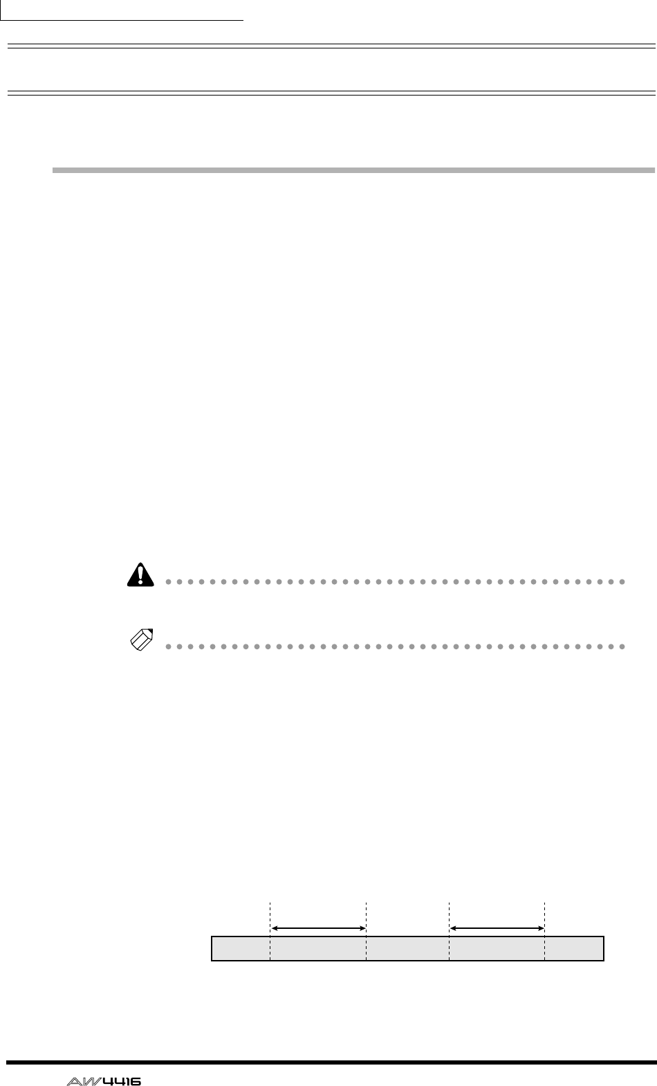
Chapter7—Punch-in/out
130 — Operation Guide
Auto punch-in/out
Here’s how to use auto punch-in/out.
Preparations
❒Make input monitor settings
To perform punch-in/out recording, you will need to select “auto input monitor”
as the input monitor setting. For details refer to page 128.
❒Set the auto punch-in/out points
Specify the location at which punch-in/out will start (Auto Punch In point) and
end (Auto Punch Out Point). Auto punch-in/out uses the in/out point settings (→
P.120).
1. At the location where you wish to punch-in, hold down the [SET] key
and press the [IN] key.
The [IN] key will light, indicating that the In point has been set.
2. At the location where you wish to punch-out, hold down the [SET] key
and press the [OUT] key.
The [OUT] key will light, indicating that the Out point has been set.
Be aware that auto punch-in/out will not occur if the Out point is earlier than the
In point.
Tip!
The auto punch-in/out points (in/out points) can be precisely adjusted in millisec-
onds or in sub-frame units. For details refer to page 123.
❒Set the pre-roll/post-roll times
When executing auto punch-in/out, you can specify intervals of playback before
the punch-in and after the punch-out. The playback before punch-in is called the
“pre-roll time,” and the playback after punch-out is called the “post-roll time.”
With the factory settings, these are set to five seconds, but you can change this as
desired. The beginning of the pre-roll is called the “pre-roll point,” and the end of
the post-roll is called the “post-roll point.”
Song
Pre-roll
point
Pre-roll time
Post-roll
point
Auto punch-out
point
Auto punch-in
point
Post-roll time
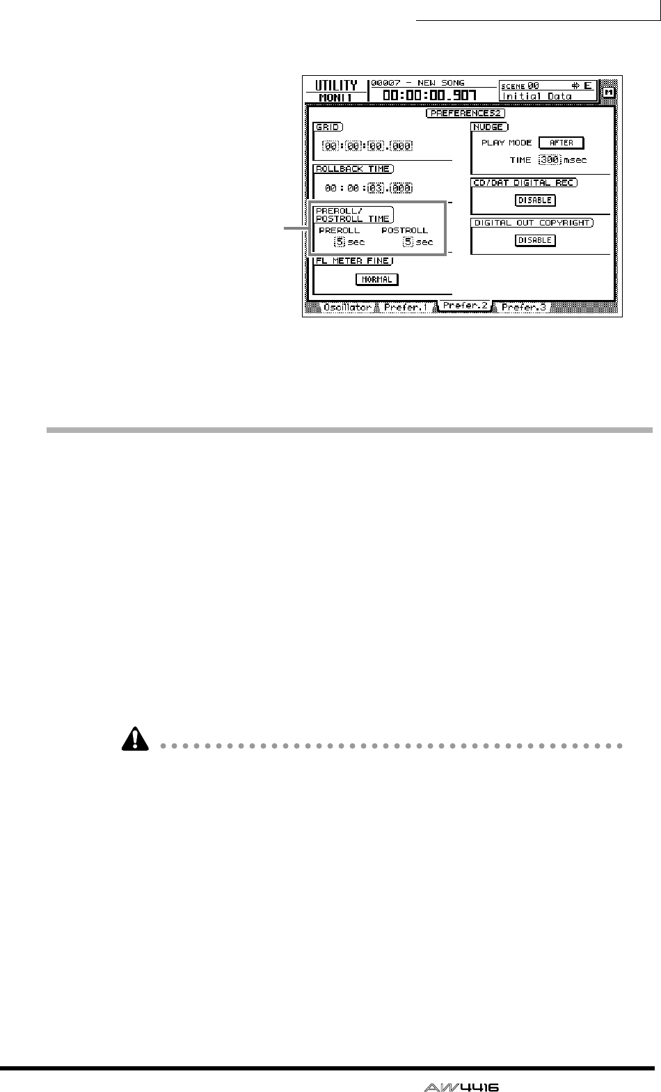
Chapter7—Punch-in/out
— Operation Guide 131
1. Press the [UTILITY] key → [F3] key.
2. Move the cursor to the pre-roll (PREROLL) or post-roll (POSTROLL) fields,
and use the [DATA/JOG] dial to set the pre-roll time and post-roll time.
Rehearsing and recording with auto punch-
in/out
❒Rehearsing with auto punch-in/out
1. Press the [REC TRACK SELECT] key for the track that you wish to record
using auto punch-in/out.
The [REC TRACK SELECT] key will blink, and the track will be in record-ready
mode.
2. Make sure that the Locate section [IN]/[OUT] keys are lit, and press the
[AUTO PUNCH] key.
The [AUTO PUNCH] key will light, and you will locate to the pre-roll point.
While the [AUTO PUNCH] key is lit, transport/locate operations other than the
[STOP]/[PLAY]/[REC] keys cannot be used.
3. To begin rehearsing the auto punch-in/out, press the [PLAY] key.
1The [PLAY] key will light, and playback will begin from the pre-roll point.
BWhen you reach the auto punch-in point, the [REC] key will begin blinking,
and the monitor signal of the track you selected in step 1 will change from the
track playback to the input signal (recording source). However, recording will
not actually occur.
CWhen you reach the auto punch-out point, the [REC] key will go dark, and
the monitor signal will return to the track playback. (During rehearsal, record-
ing will not actually occur.)
DWhen you reach the post-roll point, the transport will locate to the pre-roll
point and stop.
Pre-roll/post-roll time
settings
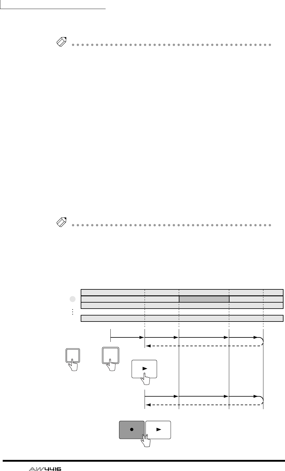
Chapter7—Punch-in/out
132 — Operation Guide
4. If you wish to rehearse once again, press the [PLAY] key once again while
the transport is stopped.
Tip!
If you press the [REHEARSAL] key before or during rehearsal, operations
1
–
4
of
step 3 will continue repeating. (In this case, the A-B Repeat function will be
defeated.) To stop repeating the rehearsal, press the [REPEAT] key once again, or
press the [STOP] key.
❒Recording with auto punch-in/out
5. To actually record using auto punch-in/out, stop the transport, and hold
down the [REC] key and press the [PLAY] key.
1The [PLAY] key will light and the [REC] key will blink, then playback will
begin from the pre-roll point.
BWhen you reach the auto punch-in point, the [REC] key will light, and
recording will begin on the track you selected in step 1 (punch-in).
CWhen you reach the auto punch-out point, the [REC] key will blink, recording
will end, and playback will resume (punch-out).
DWhen you reach the post-roll point, the transport will locate to the pre-roll
point and stop.
6. If you wish to listen to the recorded result, press the [AUTO PUNCH] key
to make it go dark, and then press the [PLAY] key.
Tip!
If you make a mistake during auto punch-in/out recording, stop the transport and
press the [UNDO] key to cancel the previous recording and return the data to the
state before recording.
The following diagram shows the operating procedure for auto punch-in/out.
PLAY
PLAY
REC
REC TRACK SELECT
2AUTO
PUNCH
1
2
3
16
Rehearsal
Rehearsal
Actual recording
PlaybackPlayback
Recording PlaybackPlayback
Locate
Auto punch-in
point
Pre-roll
point Post-roll
point
Auto punch-out
point
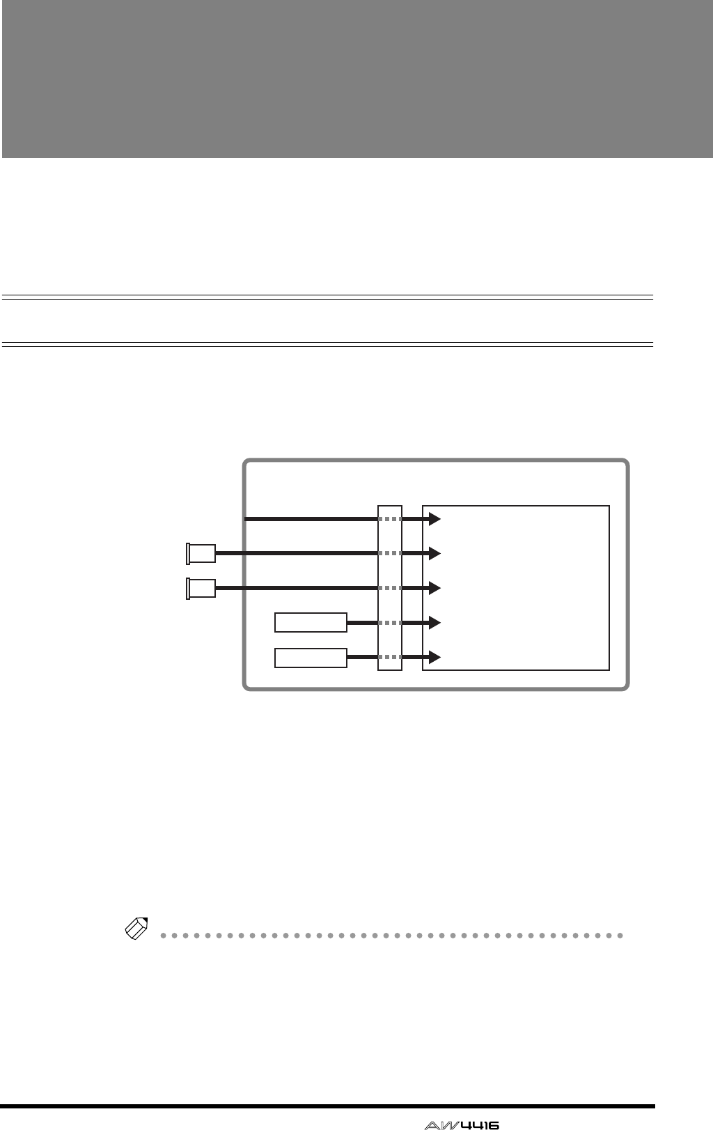
— Operation Guide 133
8Patching
This chapter explains how to patch the inputs and outputs, and how to use
the Quick Rec function to simultaneously record sixteen channels of input
sources.
Patching to the input channels
When the AW4416 is in the default state, input signals are patched to input chan-
nels 1–24 as shown in the following diagram. However, you can change the
input signals assigned to each input channel as necessary.
Here’s how to patch input signals to input channels 1–24 and return channels 1/
2.
1. Press the [SETUP] key → [F1] (Patch IN) key.
The display will show the SETUP screen Patch IN page, where you can patch sig-
nals to the input channels and recorder inputs. In this page, the MIXER CHAN-
NEL INPUT ASSIGN column shows the patched status of input channels 1–24
and return channels 1/2.
Tip!
If the Patch IN tab is not assigned to the [F1] key, press the [SHIFT] key + [F1] key to
switch the tabs, and then press the [F1] key.
Input channels 1–8
Input channels 9–16
Input channels 17–14
Return channel 1
Return channel 2
Mixer section
Input
patch
Effect 1
Effect 2
INPUT jacks 1–8
I/O
card
I/O
card
OPTION I/O
slot 1
OPTION I/O
slot 2
×8
×8
×2
×2
×8
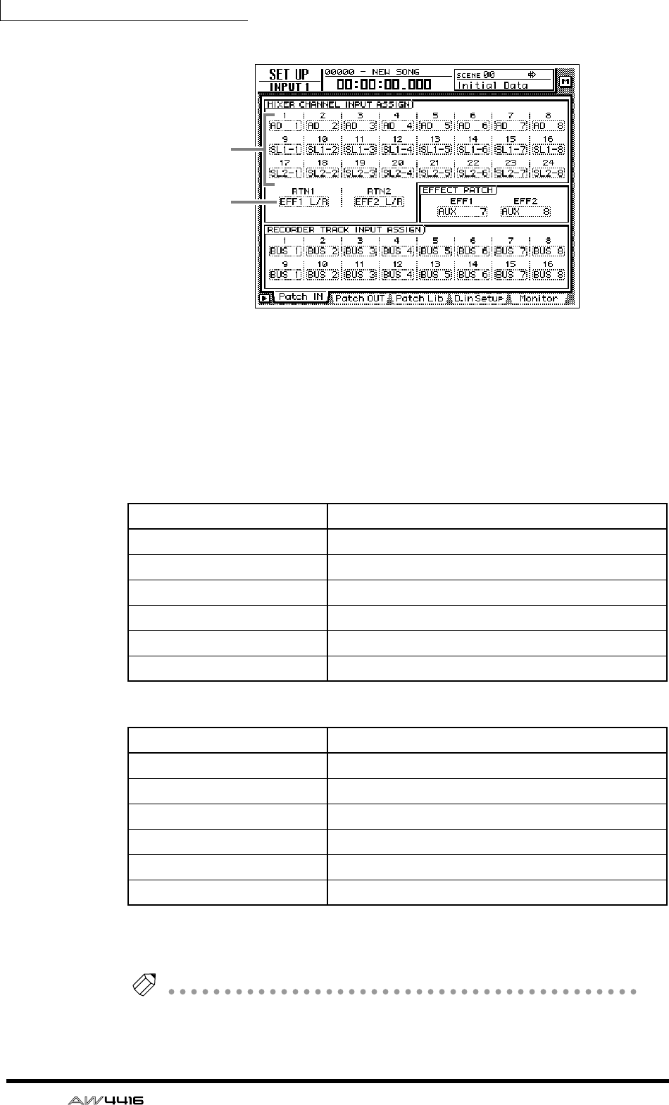
Chapter8—Patching
134 — Operation Guide
1Input channels 1–24
BReturn channels 1/2
2. Move the cursor to the channel that you wish to patch, and use the
[DATA/JOG] dial to select the signal that you wish to assign.
The following signals can be assigned to each channel.
❍ Input channels 1–24
❍ Return channels 1/2
Tip!
You can use the patch library to save the state of the patch settings you make. For
details refer to page 138.
Display Type of signal
AD 1 – AD 8 INPUT jacks 1–8
SL1-1 – SL1-8 INPUT 1–8 of an I/O card (slot 1)
SL2-1 – SL2-8 INPUT 1–8 of an I/O card (slot 2)
DIN L/DIN R L/R channels of the DIGITAL STEREO IN jack
SMP 1 – SMP 8 Sampling pads 1–8
MET Internal metronome
Display Type of signal
EFF 1 L/R Return from internal effect 1*1
*1. Selectable only for return 1
EFF 2 L/R Return from internal effect 2*2
*2. Selectable only for return 2
AD 1/2 – AD 7/8 INPUT jacks 1/2–7/8
SL1-1/2 – SL1-7/8 INPUT 1/2–7/8 of an I/O card (slot 1)
SL2-1/2 – SL2-7/8 INPUT 1/2–7/8 of an I/O card (slot 2)
DIN L/R DIGITAL STEREO IN jack (stereo)
1
2
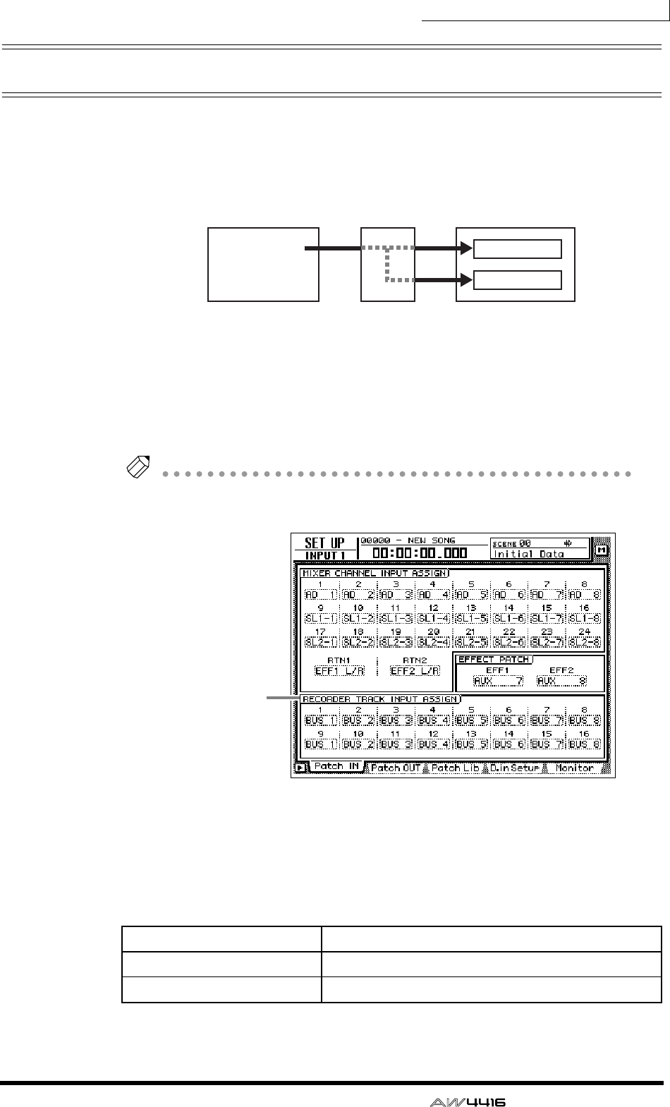
Chapter8—Patching
— Operation Guide 135
Patching to the recorder inputs
When the AW4416 is in the default state, buses 1–8 are assigned respectively to
recorder inputs 1–8 and 9–16, but you can assign the direct signals from the
input channels as desired.
Here’s how to assign the desired signals to recorder inputs 1–16.
1. Press the [SETUP] key → [F1] (Patch IN) key to access the SETUP screen
Patch IN page.
The RECORDER TRACK INPUT ASSIGN column will indicate the patched status
of recorder inputs 1–16.
Tip!
If the Patch IN tab is not assigned to the [F1] key, press the [SHIFT] key + [F1] key to
switch the tabs, and then press the [F1] key.
2. Move the cursor to the recorder input whose patching you wish to
change, and use the [DATA/JOG] dial to select the signal that you wish
to assign.
The following types of signal can be assigned to each input.
❍ Recorder inputs 1–16
Display Type of signal
BUS 1 – BUS 8 Buses 1–8
DIR 1 – DIR16 Input channel direct out 1–16
Buses 1–8
Mixer section Recorder section
Recorder
input patch
Tracks 1–8
Tracks 9–16
×8
×8
RECORDER
TRACK INPUT
ASSIGN column
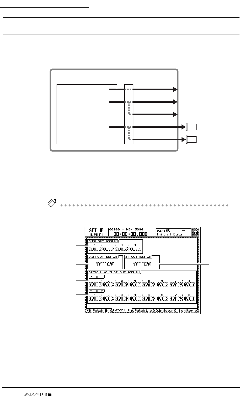
Chapter8—Patching
136 — Operation Guide
Patching to the outputs
When the AW4416 is in the default state, the following signals are assigned to the
OMNI OUT jacks, STEREO OUT jacks, and digital I/O card outputs. If necessary,
you can change the output signals that are assigned to these output jacks.
Here’s how to assign the desired signal to each output jack.
1. Press the [SETUP] key → [F2] (Patch OUT) key.
The display will show the SETUP screen Patch OUT page. The various fields of
the display will show the patched status of each output jack.
Tip!
If the Patch OUT tab is not assigned to the [F2] key, press the [SHIFT] key + [F1] key
to switch the tabs, and then press the [F2] key.
1OMNI OUT jack 1–4
BDIGITAL STEREO OUT jack
CSTEREO OUT jack
DOUTPUT 1–8 of an I/O card (slot 1)
EOUTPUT 1–8 of an I/O card (slot 2)
AUX buses 1–4
Stereo output channel
Buses 1–8
OMNI OUT jacks 1–4
DIGITAL STEREO OUT jack
STEREO OUT jacks
Mixer section Output
patch
×8
×2
×2
×4
×8
OPTION I/O
slot 1
OPTION I/O
slot 2
I/O
card
I/O
card
1
23
4
5
Chapter8—Patching
— Operation Guide 137
2. Move the cursor to the output jack whose patching you wish to change,
and use the [DATA/JOG] dial to select the signal that you wish to assign.
The following types of signal can be assigned to each output jack.
❍ OMNI OUT jacks 1–4
❍ DIGITAL STEREO OUT jack
❍ STEREO OUT jacks
❍ Digital I/O card (slot 1) OUTPUT 1–8
❍ Digital I/O card (slot 2) OUTPUT 1–8
Tip!
When selecting a signal for assignment to an output jack, selections beginning with
“I-” such as “I-I8” or “I-M16” may be displayed in gray. Selections beginning with
“I-” indicate insert-out points of each channel. The gray display indicates that this
insert point is invalid. (For details on insert I/O patching, refer to page 140.)
Display Type of signal
AUX 1 – AUX 8 AUX buses 1–8
RDR 1 – RDR16 Recorder direct out 1–16
ST L/ST R L/R channels of the stereo output channel
BUS 1 – BUS 8 Buses 1–8
DIR 1 – DIR16 Input channel direct out 1–16
Display Type of signal
ST L/R Stereo output channel
BUS 1/2 – BUS 7/8 Buses 1/2–7/8
DIR 1/2 – DIR15/16 Input channel direct out 1/2–15/16
AUX 1/2 – AUX 7/8 AUX buses 1/2–7/8
RDR 1/2 – RDR15/16 Recorder direct out 1/2–15/16
Display Type of signal
BUS 1 – BUS 8 Buses 1–8
DIR 1 – DIR16 Input channel direct out 1–16
AUX 1 – AUX 8 AUX buses 1–8
RDR 1 – RDR16 Recorder direct out 1–16
ST L/ST R L/R channels of the stereo output channel
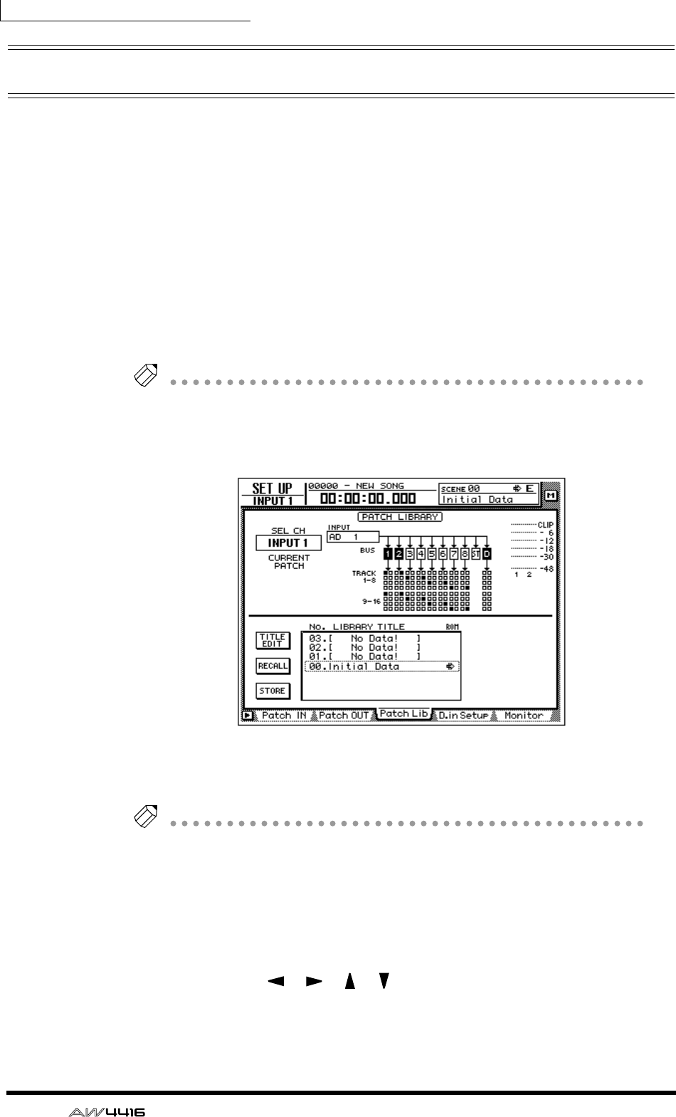
Chapter8—Patching
138 — Operation Guide
Patch library
Patch settings that you make in the SETUP screen Patch IN page and Patch OUT
page can be stored in the patch library as one of twenty patch programs. The con-
tents of the patch library are saved on the internal hard disk as part of the song.
Here’s how to use the patch library.
❒Storing to the patch library
Here’s how to assign a name to your patch settings, and store them in the patch
library.
1. Press the [SETUP] key → [F3] (Patch Lib) key.
The display will show the PATCH screen Patch Lib page. The list in the lower part
of the display shows the contents of the patch library.
Tip!
• If the Patch Lib tab is not assigned to the [F3] key, press the [SHIFT] key + [F1]
key to switch the tabs, and then press the [F3] key.
• Patch library numbers in which no data has been stored will be displayed with
a title of “[No Data!]”.
2. Use the [DATA/JOG] dial to select the patch library number (01–20) in
which you will store the settings.
Tip!
Patch library number 00 contains a preset patch program (recall-only) that returns
all patch settings to the initial state. For this reason, your settings cannot be stored in
patch number 00.
3. Move the cursor to the STORE button, and press the [ENTER] key.
A TITLE EDIT popup window will appear, allowing you to assign a name to the
patch program.
4. Use the CURSOR [ ]/[ ]/[ ]/[ ] keys and the [ENTER] key to specify
the name for the patch program.
For details on inputting characters, refer to page 60.
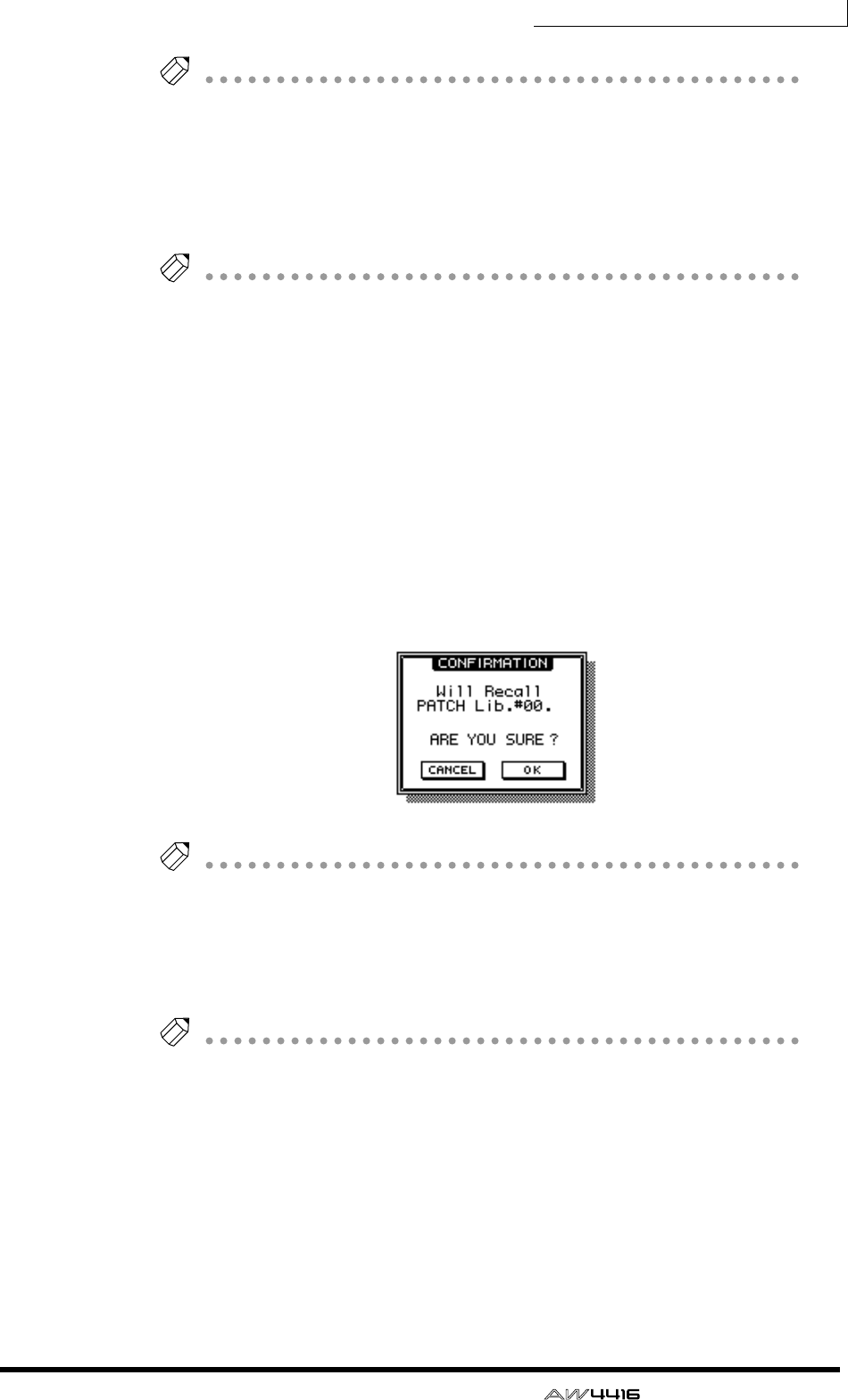
Chapter8—Patching
— Operation Guide 139
Tip!
You can also write the patch program directly, without accessing the TITLE EDIT
popup window. To do so, turn off the STORE CONFIRMATION setting in the UTIL-
ITY screen Prefer.1 page ([UTILITY] key
→
[F2] key). In this case, your settings will
be saved in a library named “New Data” when you execute step 3.
5. To execute the Store operation, move the cursor to the OK button and
press the [ENTER] key.
Tip!
If you decide to cancel without storing, move the cursor to the CANCEL button and
press the [ENTER] key.
❒Recalling a patch program
Here’s how to recall a patch program that you saved in the patch library.
1. Press the [SETUP] key → [F3] (Patch Lib) key to access the SETUP screen
Patch Lib page.
2. Use the [DATA/JOG] dial to select the patch program that you wish to
recall.
3. Move the cursor to the RECALL button and press the [ENTER] key.
A popup window will ask you to confirm the Recall operation.
Tip!
You can also recall the patch program directly, bypassing the confirmation popup
window. To do so, turn off the RECALL CONFIRMATION setting in the UTILITY
screen Prefer.1 page ([UTILITY] key
→
[F2] key).
4. To execute the Recall, move the cursor to the OK button and press the
[ENTER] key.
Tip!
If you decide to cancel without recalling, move the cursor to the CANCEL button
and press the [ENTER] key.
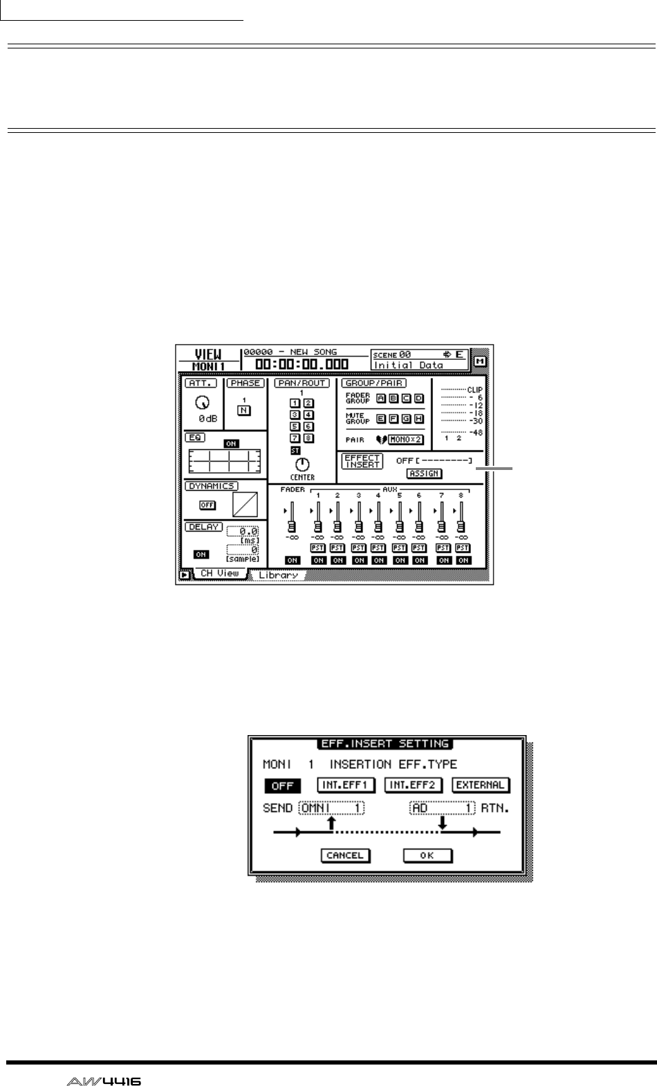
Chapter8—Patching
140 — Operation Guide
Patching input/output jacks to an
insert I/O point
You can patch various input/output jacks to the insert I/O point of a channel. This
patching method allows you to apply an external effect to a monitor channel dur-
ing mixdown.
1. Use the MIXING LAYER section keys and the [SEL] keys to select the
channel whose insert I/O point you wish to patch to input/output jacks.
2. Press the [VIEW] key → [F1] key.
The display will show the VIEW screen CH View page. In the example shown
here, monitor channel 1 is selected.
3. Move the cursor to the ASSIGN button of the EFFECT INSERT field, and
press the [ENTER] key.
The EFF.INSERT SETTING popup window will appear. The SEND and RTN. fields
of the popup window will respectively show the types of output jack and input
jack that are patched.
4. Move the cursor to the EXTERNAL button and press the [ENTER] key.
EFFECT INSERT
field
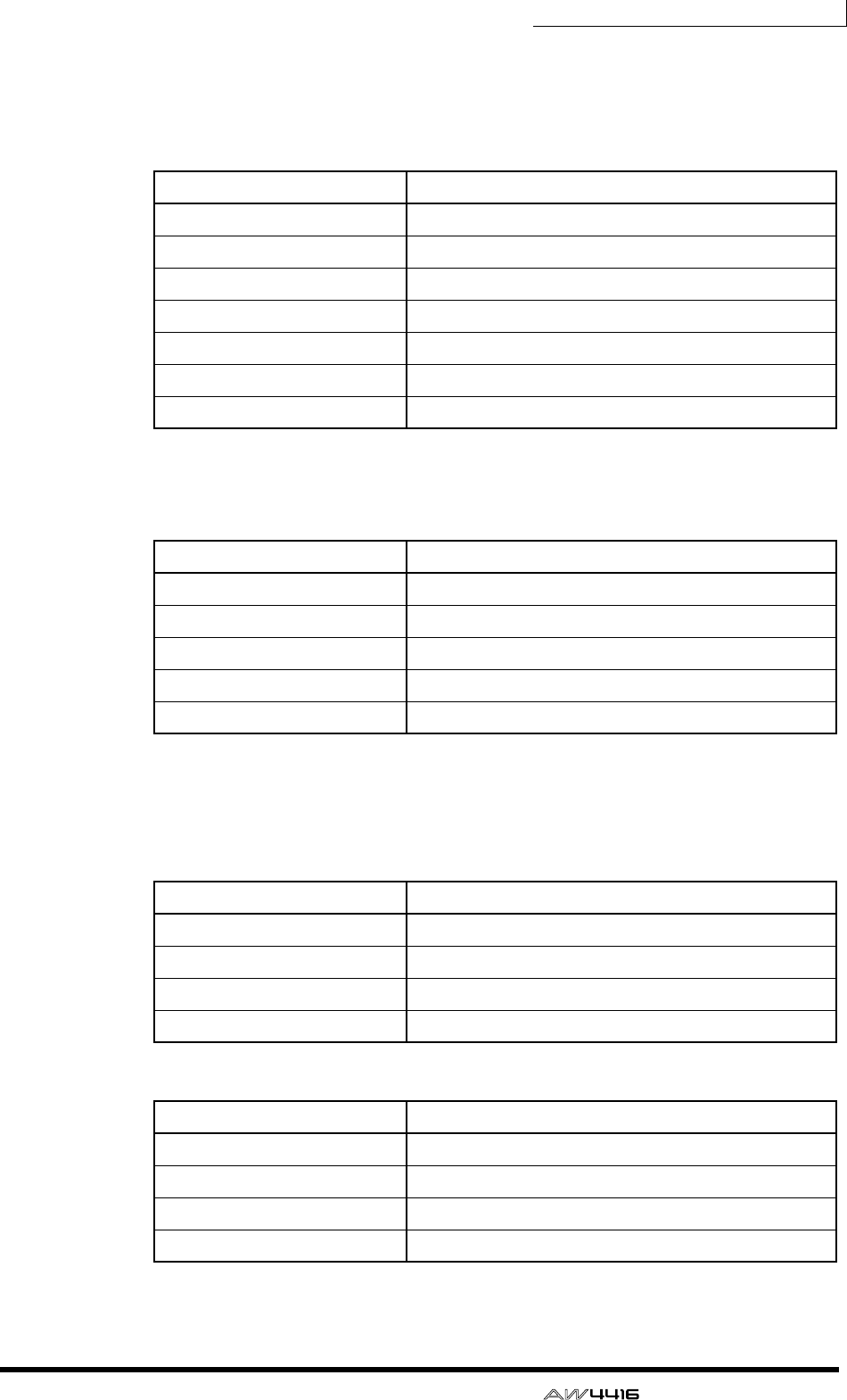
Chapter8—Patching
— Operation Guide 141
5. Move the cursor to the SEND field, and use the [DATA/JOG] dial to select
the insert send jack.
You can select from the following jacks.
❍ When selecting for an input channel 1–24 or a monitor channel 1–16
❍ When selecting for a return channel 1/2 or the stereo output channel
6. Move the cursor to the RTN. field, and use the [DATA/JOG] dial to select
the inert return jack.
You can select from the following jacks.
❍ When selecting for an input channel 1–24 or monitor channel 1–16
❍ When selecting for a return channel 1/2 or the stereo output channel
Display Jack
OMNI 1 – OMNI 4 OMNI OUT jacks 1–4
SL1-1 – SL1-8 OUTPUT 1–8 of an I/O card (slot 1)
SL2-1 – SL2-8 OUTPUT 1–8 of an I/O card (slot 2)
D STO L*1
*1. Selectable only for odd-numbered channels
L channel of the DIGITAL STEREO OUT jack
D STO R*2
*2. Selectable only for even-numbered channels
R channel of the DIGITAL STEREO OUT jack
STOUT L*1 L channel of the STEREO OUT jack
STOUT R*2 R channel of the STEREO OUT jack
Display Jack
OMNI 1/2 – OMNI 3/4 OMNI OUT jacks 1/2–3/4
SL1-1/2 – SL1-7/8 OUTPUT 1/2–7/8 of an I/O card (slot 1)
SL2-1/2 – SL2-7/8 OUTPUT 1/2–7/8 of an I/O card (slot 2)
D STOUT DIGITAL STEREO OUT jack (L/R)
STOUT STEREO OUT jack (L/R)
Display Jack
AD 1 – AD 8 INPUT jacks 1–8
SL1-1 – SL1-8 INPUT 1–8 of an I/O card (slot 1)
SL2-1 – SL2-8 INPUT 1–8 of an I/O card (slot 2)
D STIN L/D STIN R L/R channels of the DIGITAL STEREO IN jack
Display Jack
AD 1/2 – AD 7/8 INPUT jacks 1/2–7/8
SL1-1/2 – SL1-7/8 INPUT 1/2–7/8 of an I/O card (slot 1)
SL2-1/2 – SL2-7/8 INPUT 1/2–7/8 of an I/O card (slot 2)
D ST L/R DIGITAL STEREO IN jack (L/R)
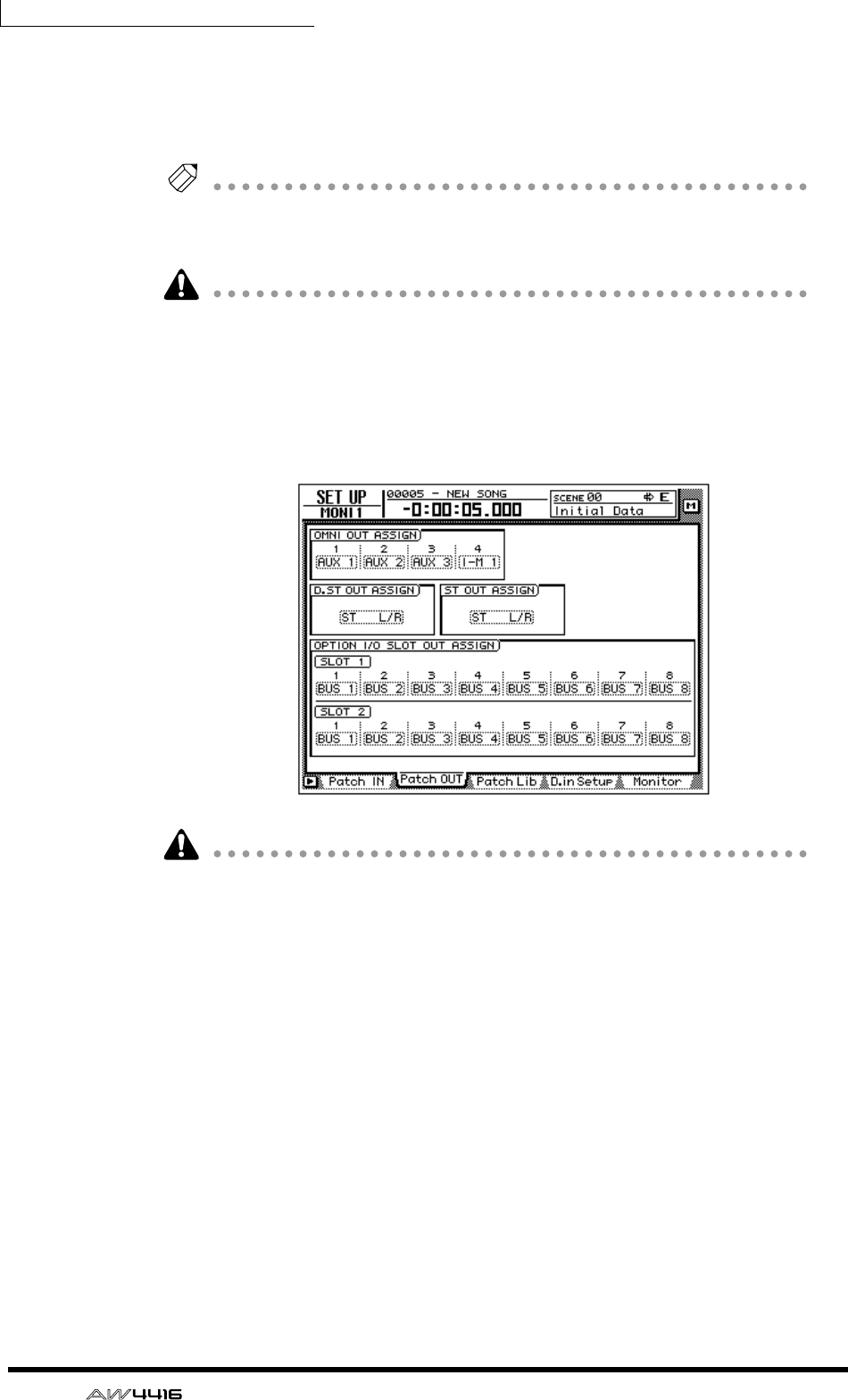
Chapter8—Patching
142 — Operation Guide
7. When you have finished making patching settings, move the cursor to
the OK button and press the [ENTER] key.
The EFFECT INSERT field will indicate “ON [EXTERNAL] ,” indicating that the
selected input/output jacks have been patched to the insert I/O point.
Tip!
To defeat the patching of an insert I/O point, use the ASSIGN button of the EFFECT
INSERT field to access the EFF.INSERT SETTING popup window, turn on the OFF
button, and select the OK button.
The procedure described above can be made for multiple channels. However, it
is not possible for multiple insert sends to share the same output jack.
8. Press the [SETUP] key → [F2] (Patch OUT) key.
The display will show the SETUP screen Patch OUT page. Notice that OMNI
OUT ASSIGN field 4 shows “I-M 1”. This means that OMNI OUT jack 4 is being
used as an insert send jack for monitor channel 1.
• In this case, changing the patching of OMNI OUT jack 4 in the Patch OUT
page will defeat the insert I/O patching as well.
• If you wish to save the patching and insert I/O point settings that you made
here, you must store the current settings in a scene memory (not in the patch
library or channel library).
• The patch library cannot store insert I/O point settings. (When a patch program
is recalled from the patch library, the insert I/O points of all channels will be
reset to “OFF.”)
• Patching information cannot be stored in the channel library.
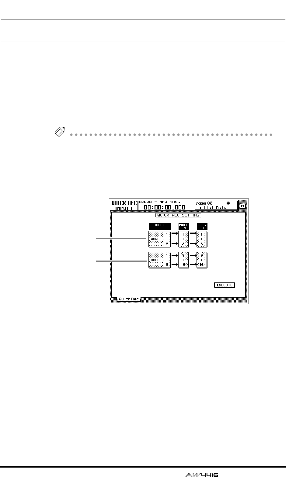
Chapter8—Patching
— Operation Guide 143
Using the Quick Rec function
Quick Rec is a function that rapidly makes the appropriate settings so that you
can simultaneously record sixteen input sources to audio tracks 1–16. When you
execute Quick Rec, groups of eight input sources will be assigned directly to
tracks 1–16, and input patch and mix parameter settings will also be reset. All
that remains for you to do is to press the [REC] key + [PLAY] key, and you will be
ready to record sixteen tracks simultaneously. This is convenient when you wish
to transfer multiple tracks from an external MTR to the AW4416.
Here we will explain the procedure by which the input signals from I/O cards
installed in slots 1 and 2 can be recorded simultaneously on tracks 1–16.
Tip!
When you execute Quick Rec, patching settings and mix parameters will be reset. If
you will need to reproduce the current patching or mix settings, we recommend
that you store the current scene into a scene memory before you execute Quick
Rec. (
→
P.211)
1. Press the [QUICK REC] key.
The display will show the QUICK REC screen.
1Input jacks sent to track 1–8 inputs
BInput jacks sent to track 9–16 inputs
2. Move the cursor to fields 1/2 in the above screen, and use the [DATA/
JOG] dial to select the input jacks that will be sent to the inputs of tracks
1–8/9–16.
You can select from the following choices. For this example, we will select
“SLOT1 1–8” for tracks 1–8, and “SLOT2 1–8” for tracks 9–16.
• ANALOG 1–8 ..... INPUT jacks 1–8
• SLOT1 1–8 ......... INPUT 1–8 of an I/O card (slot 1)
• SLOT2 1–8 ......... INPUT 1–8 of an I/O card (slot 2)
1
2
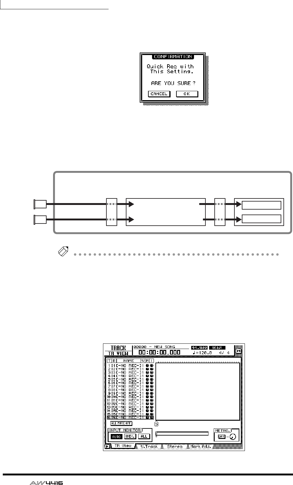
Chapter8—Patching
144 — Operation Guide
3. Move the cursor to the EXECUTE button in the lower right of the display,
and press the [ENTER] key.
A popup window will appear, asking you to confirm execution of Quick Rec.
4. To execute the Quick Rec settings, move the cursor to the OK button
and press the [ENTER] key.
All [REC TRACK SELECT] keys will blink, and the input patch settings and mix
parameters of each channel will be reset. At this time, the signal flow will be as
follows.
Tip!
• If you decide to cancel without executing Quick Rec, move the cursor to the
CANCEL button and press the [ENTER] key.
• At this time, you can also turn off the blinking [REC TRACK SELECT] buttons to
limit the number of recording tracks, or re-adjust the mix parameters and input
patch settings of each channel.
5. Press the [TRACK] key → [F1] key.
The display will show the TRACK screen TR View page. As you can see from the
display shown below, executing Quick Rec will turn input monitor on (I field= ●)
for all tracks, and will mute (M field= ●) all tracks.
Input channels 1–8
Input channels 9–16
Recorder section
Tracks 1–8
Tracks 9–16
Mixer section
Input
patch
Recorder
Input
patch
×8
×8
OPTION I/O
slot 1
OPTION I/O
slot 2
I/O
card
I/O
card

Chapter8—Patching
— Operation Guide 145
6. Play back the audio source connected to the input jacks of the I/O cards
(slots 1/2).
The levels of the signals sent from the I/O card INPUT to tracks 1–16 (i.e., record-
ing levels) will be displayed in the level meter/counter.
7. As necessary, use the faders of input channels 1–16 to adjust the record-
ing level of tracks 1–16.
The faders of input channels 1–16 will be reset to nominal level (0 dB) when
Quick Rec is executed. Adjust the recording level if necessary.
If you wish to use the faders to adjust the recording level, the POST FADER but-
ton must be turned on in the DIRECT OUT EXTRACT POSITION field of the
UTILITY screen
→
Prefer.1 page.
8. When you finish recording on the AW4416, press the [ALL SAFE] key.
Record-ready and mute status will be canceled for all tracks.

Chapter8—Patching
146 — Operation Guide
— Operation Guide 147
9Track and virtual track
operations
This chapter explains the track structure of the recorder section, and how
to perform editing and other operations.
The track structure of the AW4416
The recorder section of the AW4416 handles three types of tracks: audio tracks,
virtual tracks, and the stereo track.
❍ Audio tracks
These are physical tracks that are used for actual recording and playback, and are
also referred to simply as “tracks.” When the AW4416 is in its initial state, the
output of buses 1–8 is patched to the inputs of tracks 1–8/9–16, and the output of
tracks 1–16 is patched to monitor channels 1–16. This allows a maximum of 16
tracks to be recorded simultaneously.
However, the number of tracks that can be played back simultaneously is limited
by the number of tracks that are being recorded simultaneously. Be aware that
tracks will automatically be muted depending on the number of simultaneously
recorded tracks. The tables below show the numbers of tracks that can be
recorded simultaneously and played back simultaneously, and the number of
tracks that will be muted in each case.
For example if you simultaneously record nine or more tracks in a 16 bit song, no
tracks can be played back simultaneously, meaning that the moment you put the
ninth track in record-ready mode (the instant you turn on the ninth [REC TRACK
SELECT] key), tracks 1–16 will all be muted automatically.
• 16 bit song
Simultaneously
recordable tracks Simultaneously
playable tracks Automatically muted
tracks
0–8 16 0
9–16 0 16
• 24 bit song
Simultaneously
recordable tracks Simultaneously
playable tracks Automatically muted
tracks
0160
1–2 14 2
3–4 12 4
5–8 8 8
16016
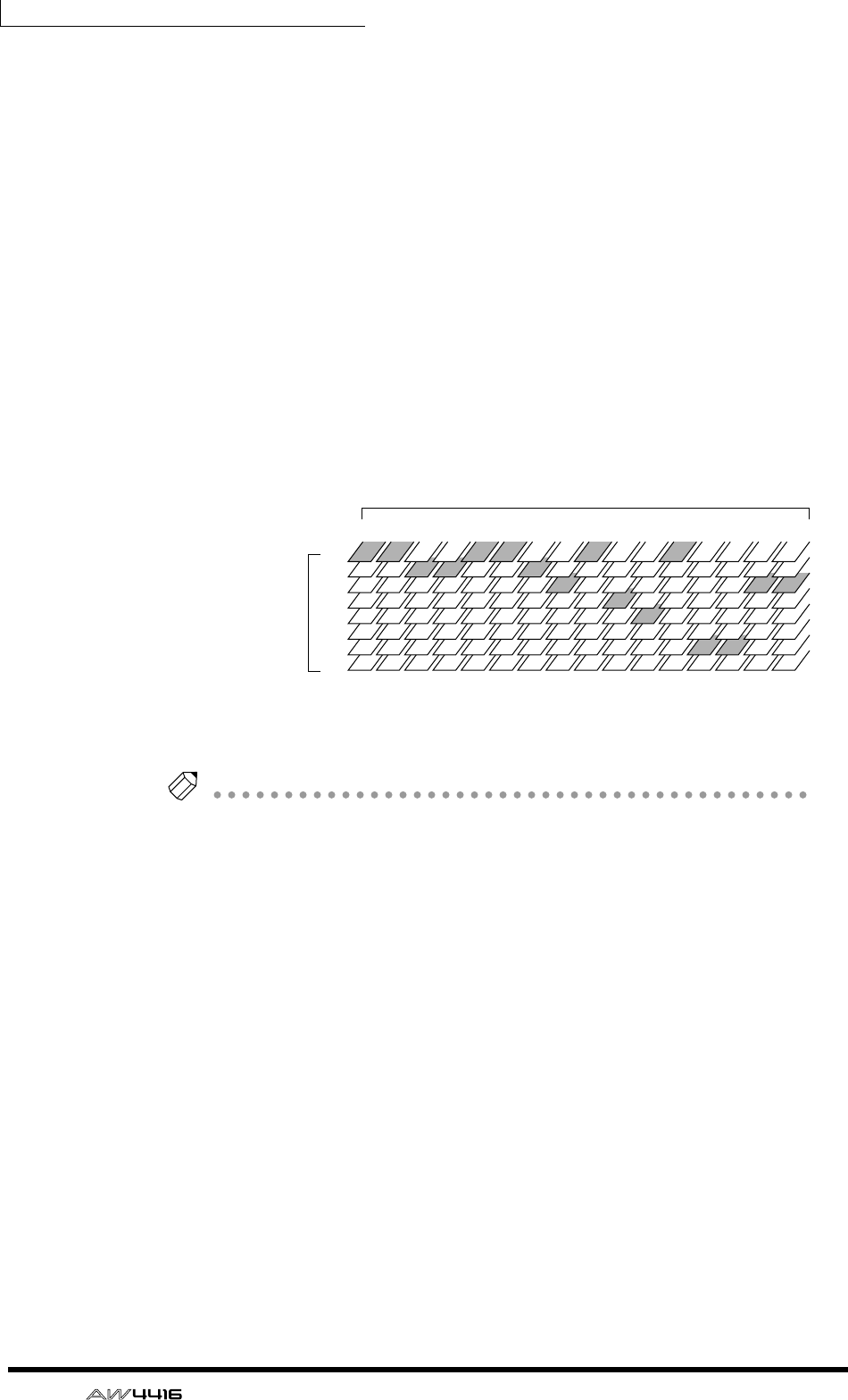
Chapter9—Track and virtual track operations
148 — Operation Guide
To defeat muting of tracks 1–16, you must first reduce the number of record-
ready tracks to eight tracks or fewer, and then use the TRACK screen TR View
page ([TRACK] key → [F1] key) to manually un-mute each track. (For details refer
to Reference Guide “TRACK screen.”)
By pressing the [ALL SAFE] button in the level meter/counter section, you can
cancel record-ready/mute status for all tracks at once. It is convenient to use this
method as a shortcut when you wish to quickly cancel the mute settings and re-
do the settings.
❍ Virtual tracks
These are “virtual” tracks from which you can select. On the AW4416, recording
and playback will occur on the virtual track 1–8 that you select for each audio
track 1–16.
The following diagram shows the concept of virtual tracks. The horizontal rows
represent audio tracks 1–16, and the vertical columns represent virtual tracks 1–
8. The shaded areas indicate the virtual tracks that are currently selected for
recording and playback.
For example if you are recording a solo part on a certain track, you can switch
virtual tracks to record multiple takes, and select the best take later.
Tip!
In the initial state of the AW4416, virtual track 1 is selected for all tracks.
❍ Stereo track
This is a stereo track that is independent of the audio tracks, and is used mainly as
a master track to create a two-track mix. The AW4416 provides one stereo track
for each song.
The input of the stereo track is internally connected to the stereo bus, so that you
can record the signal of the stereo bus at any time simply by putting the stereo
track in record mode. At this time, recording on the normal audio tracks 1–16
will not be possible. These tracks will only play back.
When you play back the stereo track, the output of the stereo track is automati-
cally assigned to monitor channels 1/2. At this time, all of the normal audio tracks
will be muted.
1
2
3
4
5
6
7
8
12 3 4 5 6 7 8 9 10 11 12 13 14 15 16
Virtual tracks
Audio tracks
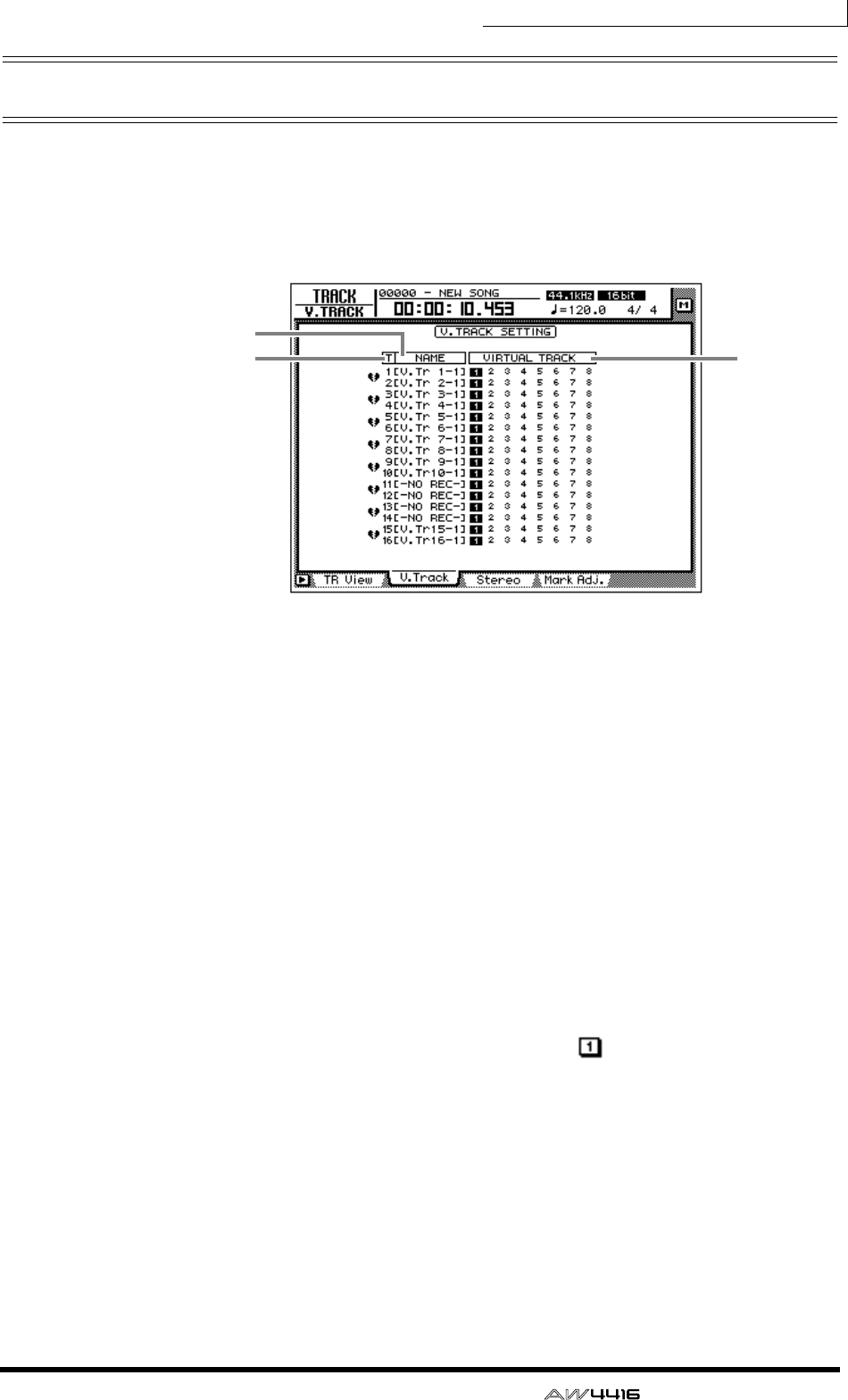
Chapter9—Track and virtual track operations
— Operation Guide 149
Switching virtual tracks
Here’s how to switch the virtual track that a specific track will use.
1. Press the [TRACK] key → [F2] key.
The TRACK screen V.Track page will appear in the display.
This page shows the following information.
1Track number
These are the track numbers 1–16.
BTrack name
These are the names assigned to the virtual track currently selected for each track.
By default, virtual tracks that have already been recorded will be named “V.Tr x-
y” (“x” will be a track number 1–16, and “y” will be a virtual track number 1–8).
This name can be changed later as desired (→ P.153). Virtual tracks that have not
yet been recorded will be displayed as “-NO REC-”.
CVirtual track
The highlighted number is the virtual track number currently selected for track 1–
16. In the screen shown above, virtual track 1 is assigned to all tracks 1–16
(default setting).
Of the currently selected virtual tracks, the numbers of tracks that have already
been recorded will be enclosed by a square; e.g., .
2
13
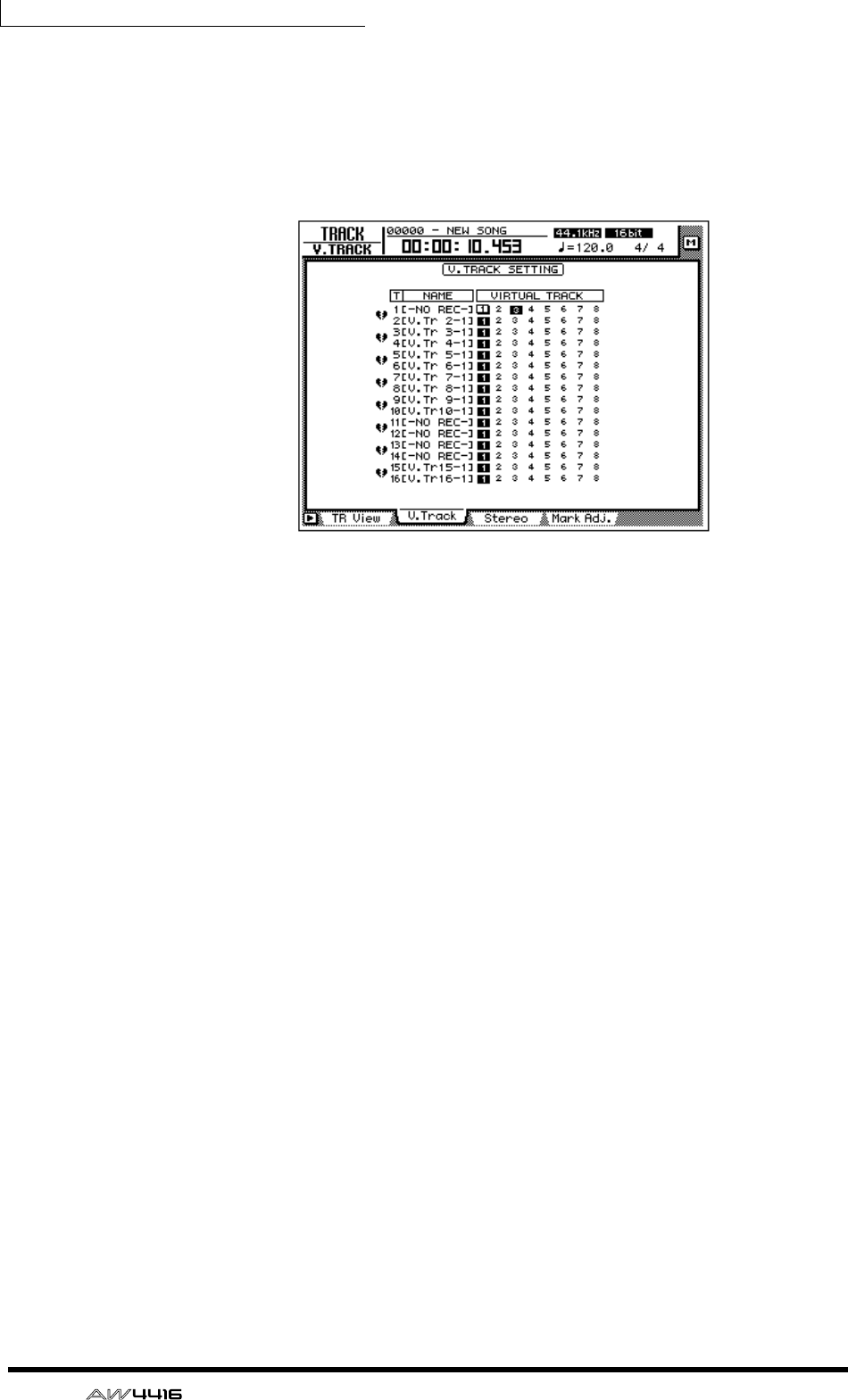
Chapter9—Track and virtual track operations
150 — Operation Guide
2. Move the cursor to the virtual track number that you wish to assign to
track 1, and press the [ENTER] key.
The virtual track number you select will be highlighted. Now you can record and
play back the newly selected virtual track without affecting the previous virtual
track.
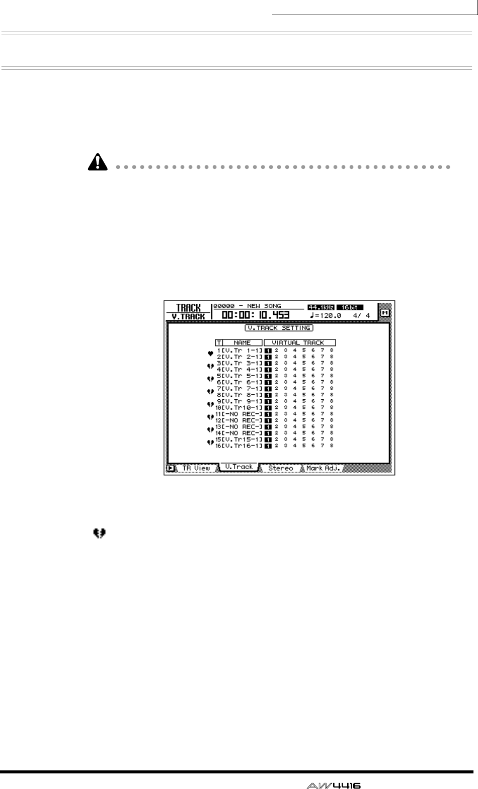
Chapter9—Track and virtual track operations
— Operation Guide 151
Pairing tracks
Adjacent odd-numbered → even-numbered tracks (tracks 1/2, tracks 3/4 ... tracks
15/16) can be set as a stereo pair. Paired tracks will always operate in tandem,
such as when tracks are selected for editing, or when you switch virtual tracks.
For example if you pair two tracks on which a stereo source was recorded, both
tracks can be processed by a single operation, for greater convenience.
Even if tracks are paired, this will not affect the pairing settings of the monitor
channels. If necessary, you can make separate settings to pair the monitor chan-
nels of these tracks as well.
1. Press the [TRACK] key → [F2] key.
The TRACK screen V.Track page will appear. The heart symbols in the left of the
display indicate the current pairing status. Paired tracks are connected by a heart
symbol.
2. To create a pair, move the cursor to the corresponding heart symbol
( ), and press the [ENTER] key.
The heart symbol will be connected, and the two tracks will be paired. To cancel
pairing, move the cursor to the heart symbol once again, and press the [ENTER]
key.
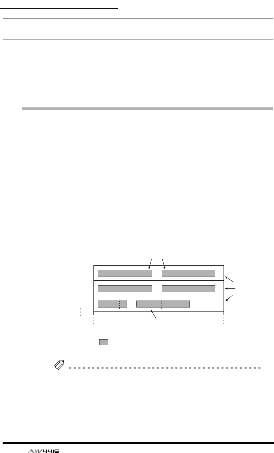
Chapter9—Track and virtual track operations
152 — Operation Guide
Editing tracks and virtual tracks
A variety of editing operations can be performed on the audio data recorded on
tracks 1–16 of the AW4416, such as copying data between tracks, moving data to
an earlier or later location within the same track, or changing the pitch. In the
same way, you can also copy or move data between the virtual tracks 1–8 that are
included in each track. The following pages explain how to edit tracks and virtual
tracks.
Tracks, parts, and regions
Track and virtual track editing can be performed in three editing units.
❍ Track
The entire currently selected track (1–16) or virtual track (1–8) will be affected by
the editing operation. When editing in units of a track, tracks that contain no
audio data cannot be selected.
❍ Part
Within the currently selected track (1–16) or virtual track (1–8), the currently
selected range is called the “part.” Unlike the case when editing tracks, portions
that contain no audio data can be selected as a part.
❍ Region
A continuous piece of audio that was recorded on a track in a single operation is
called a “region.” When editing in units of a region, portions that contain no
audio data cannot be selected.
Tip!
It is possible for a single track or a single part to include multiple regions.
Track 1
Track 2
Track 3
Region
Track
Part
= Continuous audio data
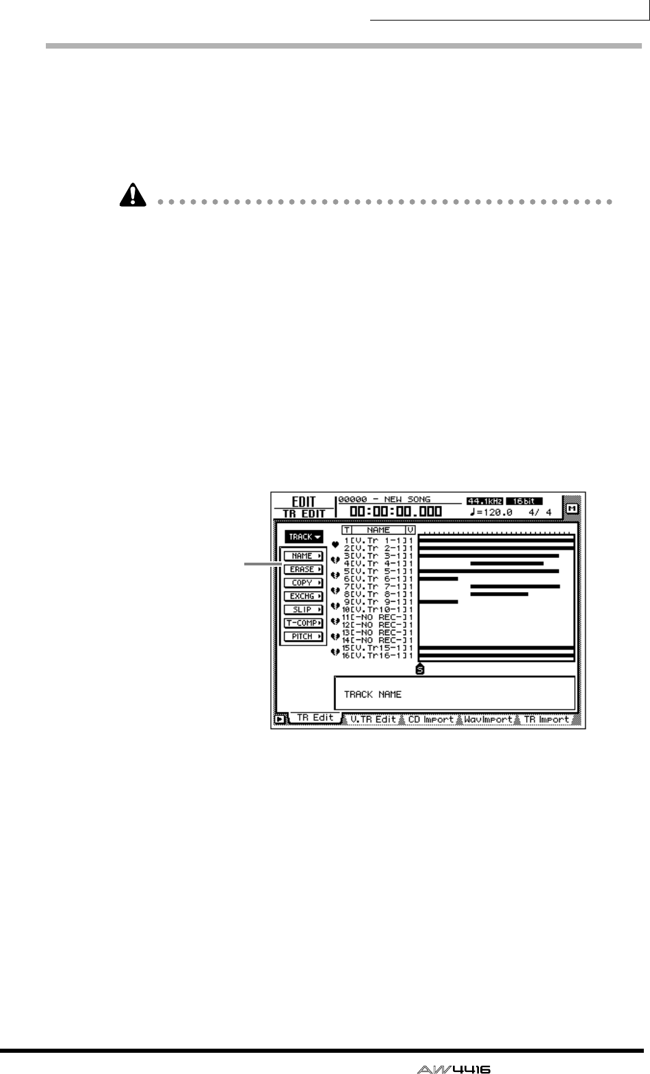
Chapter9—Track and virtual track operations
— Operation Guide 153
Naming a virtual track or region
When you record something on a track, the following default name will be
assigned to that virtual track.
• Default virtual track name .. V.Tr x-y (x=track number, y=virtual track number)
• Default region name ........... VTxy (x=track number, y=virtual track number)
If multiple regions exist in the same track (i.e., if you recorded the track in more
than one stage), all the default region names will be the same.
These track names and region names can be modified using the following proce-
dure.
❒Naming a virtual track
1. In the RECORDER section, press the [EDIT] key → [F1] key.
The EDIT screen TR Edit page will appear.
2. Move the cursor to the TRACK menu and press the [ENTER] key.
The TRACK menu will show the available editing commands.
Editing
commands
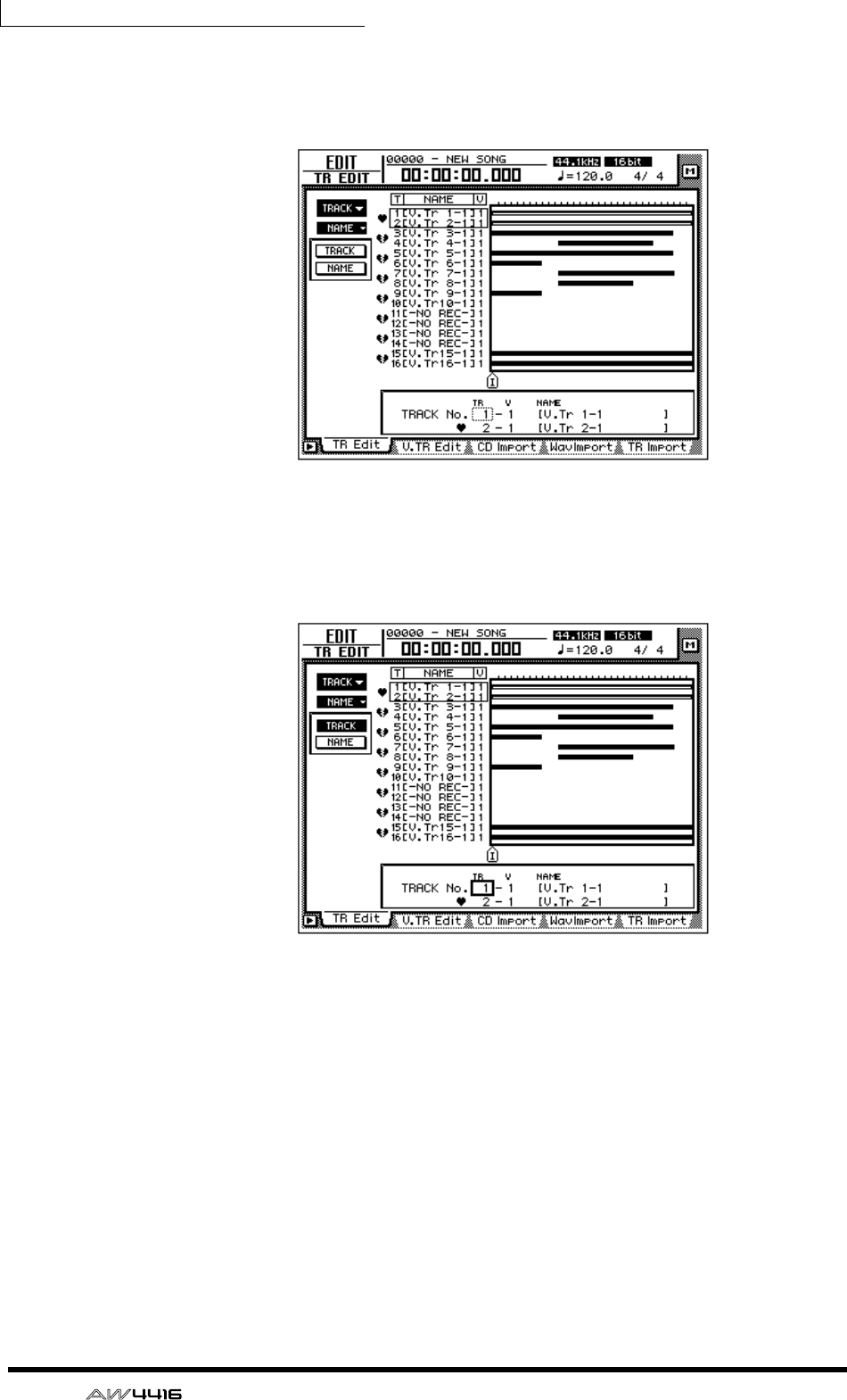
Chapter9—Track and virtual track operations
154 — Operation Guide
3. Move the cursor to the NAME menu and press the [ENTER] key.
Buttons to specify NAME menu options will appear.
4. Move the cursor to the TRACK button and press the [ENTER] key.
The cursor will move to the area at the bottom of the screen.
5. Use the [DATA/JOG] dial to select the track that you wish to name, and
press the [ENTER] key.
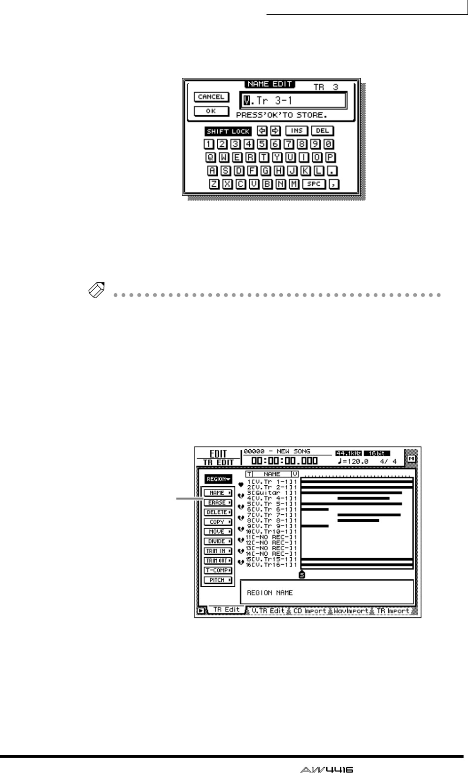
Chapter9—Track and virtual track operations
— Operation Guide 155
6. Move the cursor to the NAME button and press the [ENTER] key.
A NAME EDIT popup window will appear, allowing you to assign a name to the
track/region.
7. When you have finished inputting the name, move the cursor to the OK
button and press the [ENTER] key. (For details on inputting characters,
refer to page 60.)
You will return to the screen of step 1.
Tip!
You can assign a track name of up to 16 characters. In the TRACK screen etc., the
first eight characters of the name will be displayed.
❒Naming a region
1. In the RECORDER section, press the [EDIT] key → [F1] key.
The EDIT screen TR Edit page will appear.
2. Move the cursor to the REGION menu and press the [ENTER] key.
The REGION menu will show the available editing commands.
3. Move the cursor to the NAME menu and press the [ENTER] key.
Buttons to specify NAME menu options will appear.
4. Move the cursor to the REGION button and press the [ENTER] key.
The cursor will move to the area at the bottom of the screen.
Editing
commands
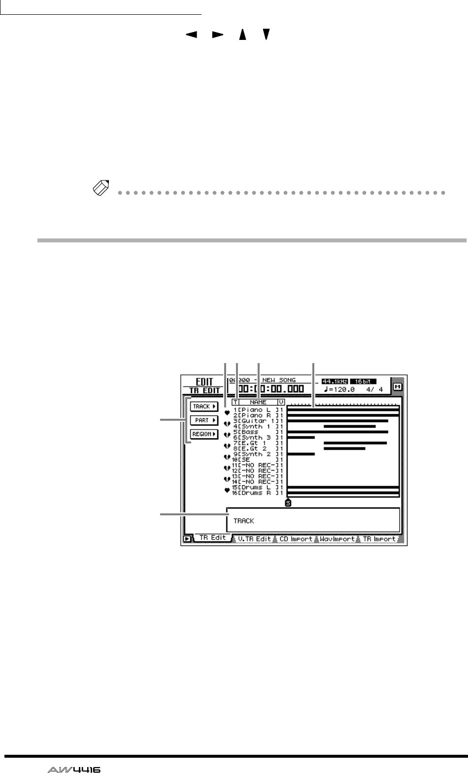
Chapter9—Track and virtual track operations
156 — Operation Guide
5. Use the CURSOR [ ]/[ ]/[ ]/[ ] keys to select the region that you
wish to name, and press the [ENTER] key.
6. Move the cursor to the NAME button and press the [ENTER] key.
A NAME EDIT popup window will appear, allowing you to assign a name to the
region.
7. When you have finished inputting the name, move the cursor to the OK
button and press the [ENTER] key. (For details on inputting characters,
refer to page 60.)
You will return to the screen of step 1.
Tip!
You can assign a region name of up to 16 characters.
Track editing procedure
Here’s the basic procedure for editing tracks, parts, or regions for audio tracks 1–
16.
1. In the RECORDER section, press the [EDIT] key → [F1] key.
The EDIT screen TR Edit page will appear.
This screen shows the following information.
1Track number
This is the track number 1–16.
BPair
This shows the pairing status for adjacent odd-numbered → even-numbered
tracks. Pairing can also be set or defeated in this screen.
CTrack name
This is the name assigned to each virtual track.
DBar graph
Bar graphs indicate the presence or absence of audio data for each track.
5
21 3 4
6
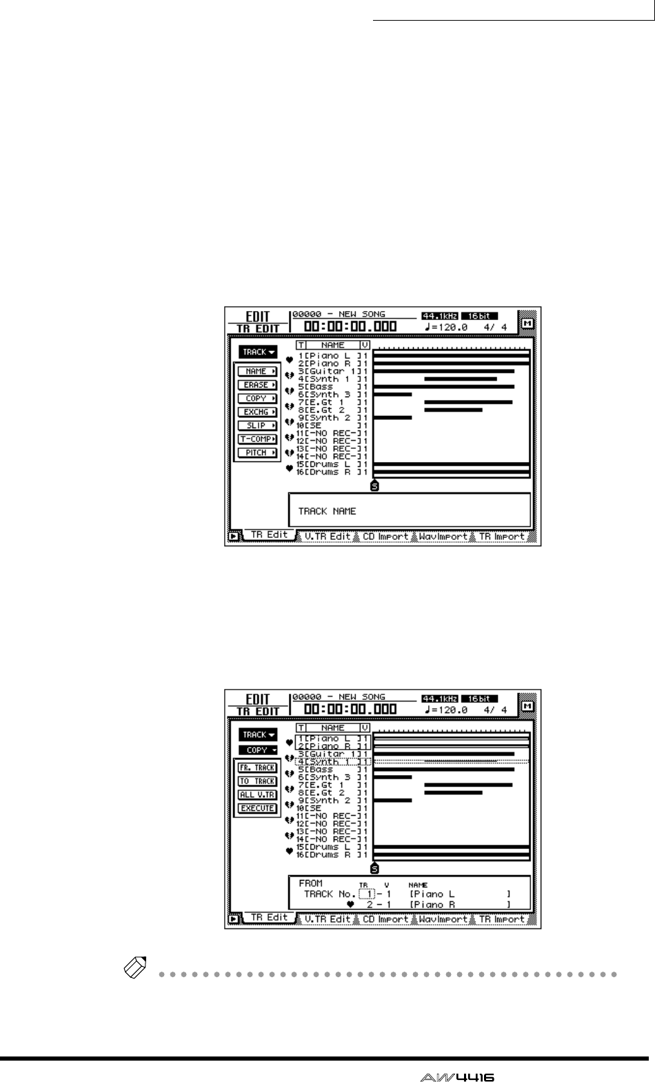
Chapter9—Track and virtual track operations
— Operation Guide 157
ETRACK/PART/REGION menus
These respectively access editing commands for editing entire tracks, parts, or
regions. Move the cursor to the desired menu, and press the [ENTER] key to view
the list of editing commands.
FParameter setting area
In this area you can make the necessary parameter settings when executing the
editing command.
2. According to the smallest unit (track/part/region) that you wish to edit,
move the cursor to the TRACK, PART, or REGION menu and press the
[ENTER] key.
The selected menu of editing commands will appear. The following screen shows
the commands that appear when the TRACK menu is selected.
3. Move the cursor to the desired editing command and press the [ENTER]
key.
Buttons to set the parameters for the selected editing command will appear. The
screen shown below is an example of when the TRACK menu COPY command is
selected.
Tip!
Page 161 provides brief explanations of the editing commands of each menu. For
details of each command, refer to the Reference Guide.
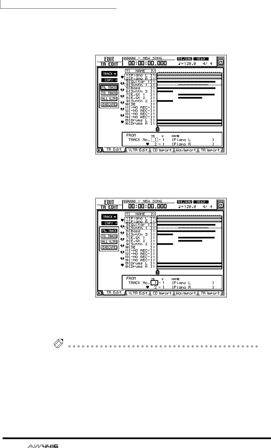
Chapter9—Track and virtual track operations
158 — Operation Guide
4. To change the parameter settings, move the cursor to the correspond-
ing button.
The lower part of the display will show the settings of the parameter at which the
cursor is currently located.
5. Press the [ENTER] key.
The cursor will move to the setting area in the lower part of the display. The
screen shown below is an example of when the COPY command is selected.
6. Use the [DATA/JOG] dial to modify the parameter value, and press the
[ENTER] key.
The cursor will return to the button selected in step 4.
Tip!
If you decide to cancel without executing the editing command, move the cursor
from here to a button at a higher level, and press the [ENTER] key.
7. Repeat steps 4–6 to make settings for the remaining parameters.
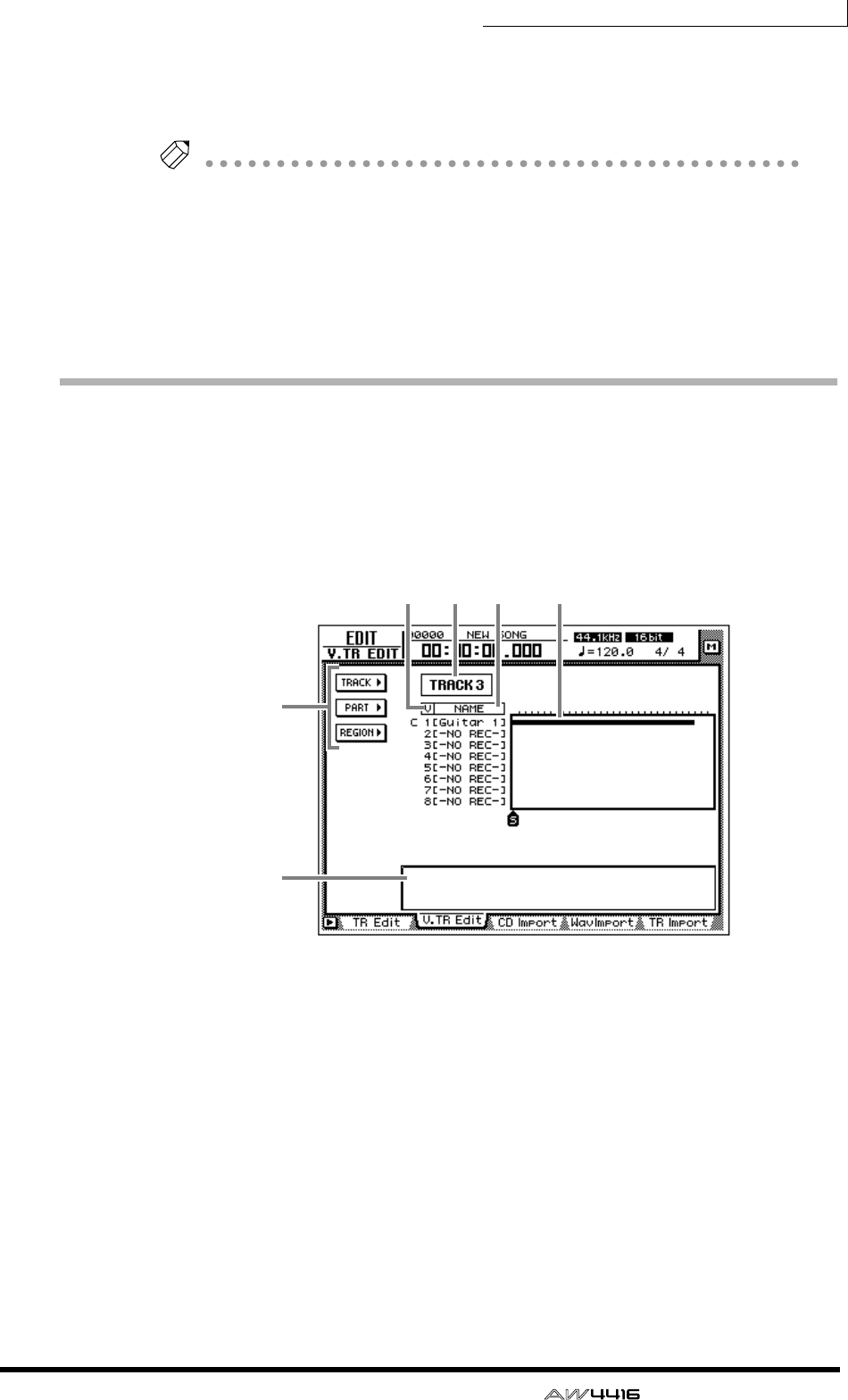
Chapter9—Track and virtual track operations
— Operation Guide 159
8. To execute the editing command, move the cursor to the EXECUTE but-
ton, and press the [ENTER] key.
The editing command you selected in step 3 will be executed.
Tip!
• If you wish to halt the editing operation, move the cursor to a button in the top
level, and press the [ENTER] key.
• As exceptions, the TRACK menu NAME command and the REGION menu
NAME command do not require you to use the EXECUTE button.
• Even after executing an editing command, you can use the [UNDO] button to
cancel the results of the operation. (The TRACK menu NAME command and
the REGION menu NAME command are exceptions to this.)
Virtual track editing procedure
Here’s the basic procedure for editing entire tracks, parts, or regions for virtual
tracks 1–8 of the desired track.
1. In the RECORDER section, press the [EDIT] key → [F2] key.
The EDIT screen V.TR Edit page will appear, where you can edit virtual tracks.
This screen shows the following information.
1Track number
This is the track number (1–16) currently selected for editing.
If this track is paired, a heart symbol and the other track of the pair will be dis-
played.
BVirtual track number
This is the virtual track number 1–8.
CTrack name
This is the name assigned to the virtual track.
DBar graph
Bar graphs indicate the presence or absence of audio data for each virtual track.
5
21 3 4
6

Chapter9—Track and virtual track operations
160 — Operation Guide
ETRACK/PART/REGION menus
These respectively access editing commands for editing entire tracks, parts, or
regions. Move the cursor to the desired menu, and press the [ENTER] key to view
the list of editing commands.
FParameter setting area
In this area you can make the necessary parameter settings when executing the
editing command.
2. Move the cursor to the track number area and use the [DATA/JOG] dial
to select the track (1–16) that you wish to edit.
When you switch tracks, the track names and bar graph display of virtual tracks
1–8 will change accordingly.
3. According to the smallest unit (entire virtual track/part/region) that you
wish to edit, move the cursor to the TRACK, PART, or REGION menu and
press the [ENTER] key.
The selected menu of editing commands will appear.
Tip!
Page 161 provides brief explanations of the editing commands of each menu. For
details of each command, refer to the Reference Guide.
4. Move the cursor to the desired editing command and press the [ENTER]
key.
Buttons to set the parameters for the selected editing command will appear.
5. To change the parameter settings, move the cursor to the correspond-
ing button.
The lower part of the display will show the settings of the parameter at which the
cursor is currently located.
6. Press the [ENTER] key.
The cursor will move to the setting area in the lower part of the display.
Tip!
If you decide to cancel without executing the editing command, move the cursor
from here to a button at a higher level, and press the [ENTER] key.
7. Use the [DATA/JOG] dial to modify the parameter value, and press the
[ENTER] key.
The cursor will return to the button selected in step 4.
8. Repeat steps 5–7 to make settings for the remaining parameters.

Chapter9—Track and virtual track operations
— Operation Guide 161
9. To execute the editing command, move the cursor to the EXECUTE but-
ton, and press the [ENTER] key.
The editing command you selected in step 4 will be executed.
Tip!
• If you wish to halt the editing operation, move the cursor to a button in the top
level, and press the [ENTER] key.
• As exceptions, the TRACK menu NAME command and the REGION menu
NAME command do not require you to use the EXECUTE button.
• Even after executing an editing command, you can use the [UNDO] button to
cancel the results of the operation. (The TRACK menu NAME command and
the REGION menu NAME command are exceptions to this.)
Editing command list
This section provides brief explanations for the editing commands of the TRACK/
PART/REGION menus for tracks and virtual tracks. Details and parameters for
each command are given in the Reference Guide.
TRACK menu
These commands edit entire tracks or entire virtual tracks.
❍ NAME (Track Name)
Assign a name to an already-recorded virtual track.
❍ ERASE
Erase the audio data of the selected track.
❍ COPY
Copy the audio data of the selected track to another track. The Fr.Track (From
Track) parameter specifies the copy source track, and the To Track parameter
specifies the copy destination track.
❍ EXCHG (Exchange)
Exchange the audio data of two selected tracks. The Fr.Track (From Track) and To
Track parameters specify the tracks to be exchanged.
❍ SLIP
Move all audio data of the selected track forward or backward. The SLIP parame-
ter specifies the distance of the movement (maximum ±5 hours).
❍ T-COMP (Time Compression/Expansion)
Compress or expand the length of the audio data in the selected track. (As the
length changes, the pitch will change correspondingly.) The RATIO parameter
specifies the amount of compression or expansion (50%–200%).
❍ PITCH (Pitch Change)
Change only the pitch without affecting the length of the audio data. The PITCH
parameter specifies the change in semitones (maximum ±12 semitones) and the
FINE parameter specifies the change in one-cent steps (maximum ±50 cents).

Chapter9—Track and virtual track operations
162 — Operation Guide
PART menu
These commands edit data in units of parts. When using these commands, you
will need to specify not only the track for editing, but also the editing start loca-
tion (START) and end location (END).
❍ ERASE
Erase the audio data of the selected part. Audio data following that part will not
be affected.
❍ DELETE
Delete the audio data of the selected part. Audio data following that part will
move forward by the length of the deleted data.
❍ COPY
Copy the audio data of the selected part to the specified location of the specified
track. You can also specify the number of times the data will be copied, and the
interval between copies. If audio data exists at the destination, you can specify
whether the copied data will be inserted or overwritten.
❍ MOVE
Move the audio data of the selected part to the specified location of the specified
track. At this time, the audio data of the move source will be erased. If audio data
exists at the destination, you can specify whether the moved data will be inserted
or overwritten.
❍ INSERT
Insert silence into the selected part. Audio data following that part will move
backward by the length of the inserted data.
❍ T-COMP (Time Compression/Expansion)
Compress or expand the length of the audio data in the selected part. (As the
length changes, the pitch will change correspondingly.) The RATIO parameter
specifies the amount of compression or expansion (50%–200%).
❍ PITCH (Pitch Change)
Change only the pitch without affecting the length of the audio data of the
selected part. The PITCH parameter specifies the change in semitones (maximum
±12 semitones) and the FINE parameter specifies the change in one-cent steps
(maximum ±50 cents).

Chapter9—Track and virtual track operations
— Operation Guide 163
REGION menu
These commands edit data in units of regions.
❍ NAME
Assign a name to a region.
❍ ERASE
Erase the selected region. Audio data following that region will not be affected.
❍ DELETE
Delete the selected region. Audio data following that region will move forward
by the length of the deleted data.
❍ COPY
Copy the selected region to the specified location of the specified track. You can
also specify the number of times the data will be copied, and the interval
between copies. If audio data exists at the copy destination, you can specify
whether the copied data will be inserted or overwritten.
❍ MOVE
Move the selected region to the specified location of the specified track. At this
time, the move source region will be erased. If audio data exists at the move des-
tination, you can specify whether the moved data will be inserted or overwritten.
❍ DIVIDE
Divide the selected region into two at the location you specify.
❍ TRIM IN
Trim the starting location of the selected region toward the end in sample units.
❍ TRIM OUT
Trim the ending location of the selected region toward the beginning in sample
units.
❍ T-COMP (Time Compression/Expansion)
Compress or expand the length of the audio data in the selected region. (As the
length changes, the pitch will change correspondingly.) The RATIO parameter
specifies the amount of compression or expansion (50%–200%).
❍ PITCH (Pitch Change)
Change only the pitch without affecting the length of the audio data of the
selected region. The PITCH parameter specifies the change in semitones (maxi-
mum ±12 semitones) and the FINE parameter specifies the change in one-cent
steps (maximum ±50 cents).

Chapter9—Track and virtual track operations
164 — Operation Guide

— Operation Guide 165
10 Internal effects
This chapter explains the two built-in effects of the AW4416.
About the internal effects
The AW4416 contains two multi-effect units (respectively called “effect 1” and
“effect 2”). In general, the internal effects can be used in the following two ways.
❒Using AUX send/return
In this method, the two AUX sends are used to send signals from each channel to
the inputs of effects 1/2, and the outputs of effects 1/2 are mixed with the signals
of the stereo bus or buses 1–8. When the AW4416 is in the default state, AUX
send 7/8 are patched to the inputs of effects 1/2, and the outputs of effects 1/2 are
patched to return channels 1/2.
The signals sent from input channels 1–24 and monitor channels 1–16 to AUX
buses 7/8 are input to effects 1/2 respectively. For each channel, you can adjust
the AUX 7/8 send levels and switch between pre- or post-fader.
The output signals from effects 1/2 are sent to return channels 1/2. By routing the
return channels to buses 1–8 or the stereo bus, they can be mixed with the origi-
nal sound of each channel.
❒Inserting an effect into a channel
If you defeat the assignment of effect 1/2 to AUX send 7/8, you can insert an
effect into the desired channel (immediately before the attenuator). In this case,
the mixed effect and direct signals will be input to the corresponding channel. An
effect that is used for insertion cannot be inserted into another channel, or used
via send/return.
Effects can be inserted into the following channels.
• Input channels 1–24
• Monitor channels 1–16
• Return channels 1/2
• Stereo output channel
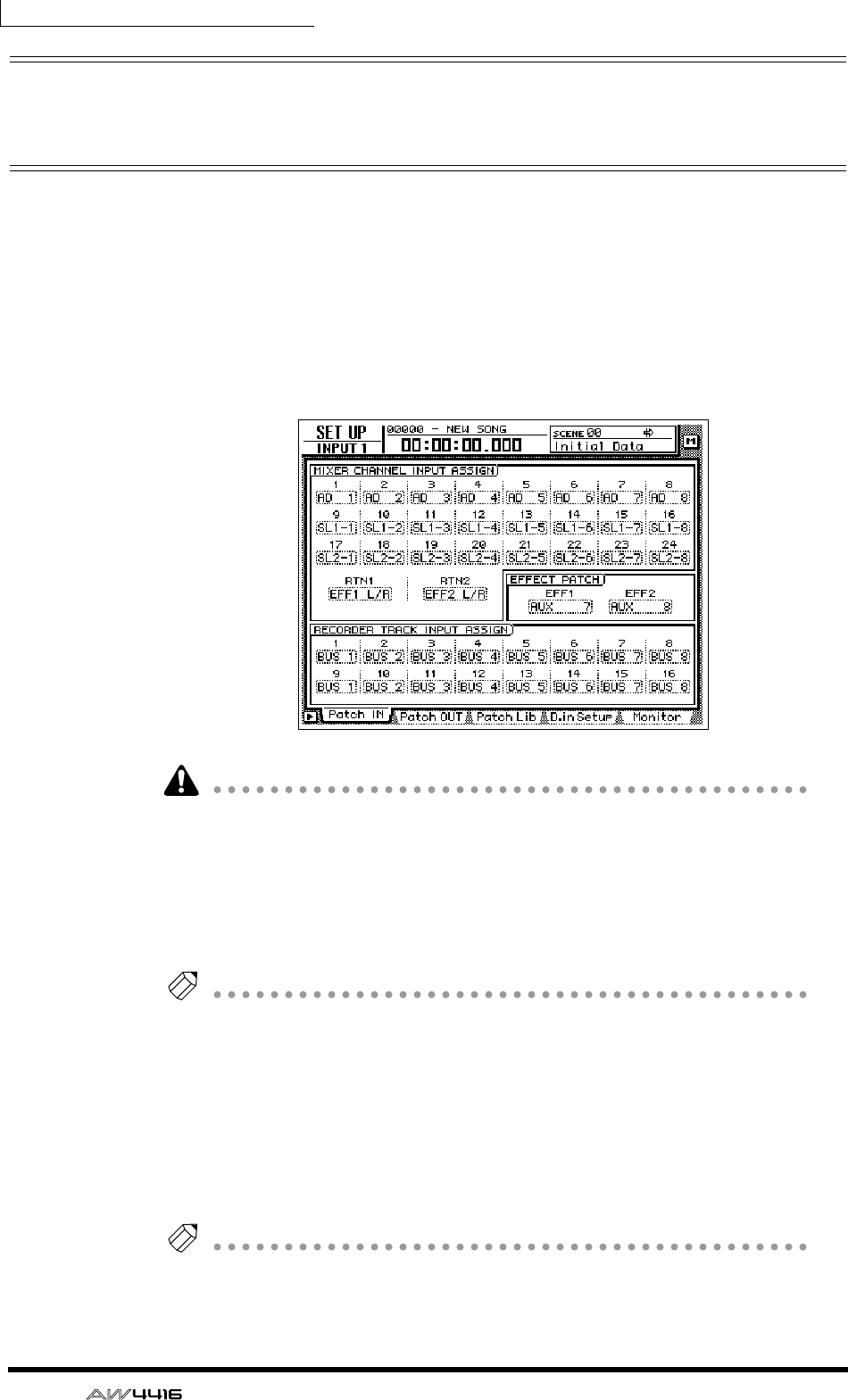
Chapter10—Internal effects
166 — Operation Guide
Using AUX send/return to apply an
effect
As an example of using an effect with AUX send/return, here’s how to apply effect
1 via AUX bus 7.
❒Patching
Make sure that the AUX send/return patching for effect 1 is appropriate.
1. Press the [SETUP] key → [F1] (Patch IN) key.
The SETUP screen Patch IN page will appear.
If the Patch IN tab is not assigned to the [F1] key, press the [SHIFT] key + [F1] key
to switch the tab, and then press the [F1] key.
2. Make sure that the EFFECT PATCH parameter EFF1 is set to “AUX 7.”
The EFFECT PATCH parameters select whether effects 1/2 will be used via AUX or
inserted into a specific channel. By default, EFF1 (effect 1) is assigned to AUX 7
and EFF2 (effect 2) is assigned to AUX 8, as shown above.
Tip!
If EFF1 is set to “INSERT,” move the cursor to the “INSERT” field and use the [DATA/
JOG] dial to change it to “AUX 7.” Then move the cursor to the OK button and press
the [ENTER] key.
3. Make sure that the MIXER CHANNEL INPUT ASSIGN parameter RTN1 is
set to “EFF1 L/R.”
The MIXER CHANNEL INPUT ASSIGN area switches the signal that is assigned to
the input channel/return channel of the mixer. By default, “EFF1 L/R” (L/R output
of effect 1) is assigned to RTN1 (return channel 1).
Tip!
If RTN1 has been changed to another setting, move the cursor to the setting area,
and rotate the [DATA/JOG] dial to change the setting to “EFF 1 L/R.”
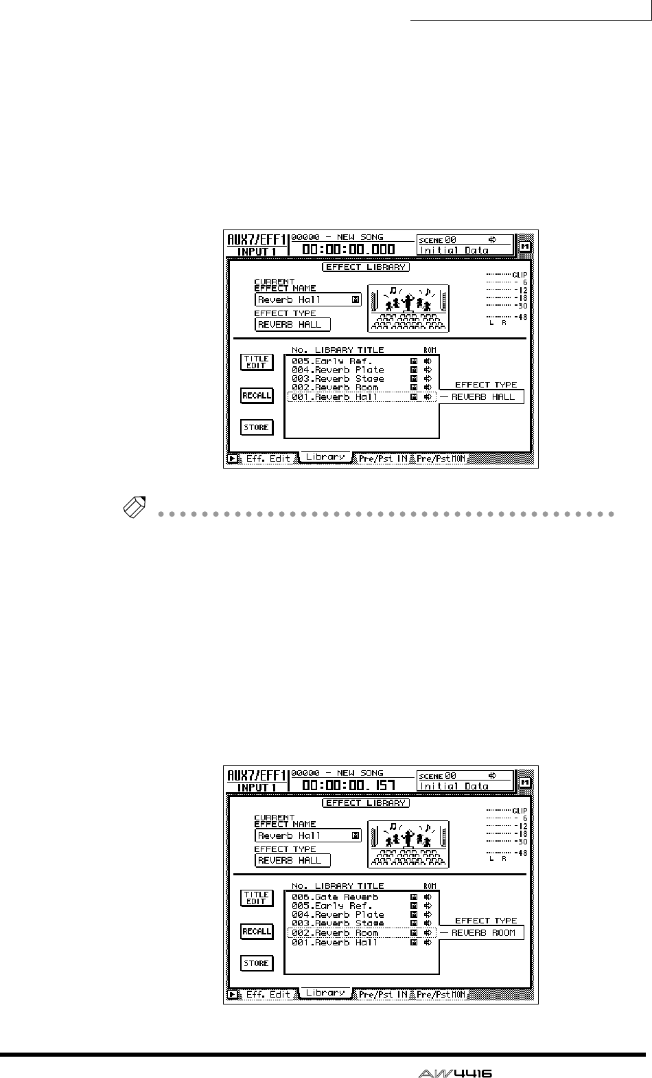
Chapter10—Internal effects
— Operation Guide 167
❒Recalling an effect program from the library
The AW4416 provides 41 effect types such as Reverb Hall, Gate Reverb, and Ste-
reo Delay. The effect type library contains factory-set effect programs that use
these effect types. Here’s how to recall an effect program of the effect type you
wish to use.
1. Press the [AUX 7] key → [F2] key.
The AUX7/EFF1 screen Library page will appear. A list of effect programs will be
displayed.
Tip!
• In general, the effect library is common to both effects 1 and 2. However,
effect program no. 19 “HQ-Pitch” can be used only by effect 2.
• Effect library 001–041 contain read-only effect programs using the corre-
sponding effect type.
• It is not possible to change the effect type of the currently used effect program.
For this reason, you must load a program that uses the desired effect type from
the library even if you wish to create an effect program from scratch.
2. Move the cursor to the list, and rotate the [DATA/JOG] dial to select the
program that you wish to recall.
When you select a program, the effect type used by that program will be dis-
played at the right of the list. For this example, let’s select the room reverb pro-
gram “Reverb Room.”
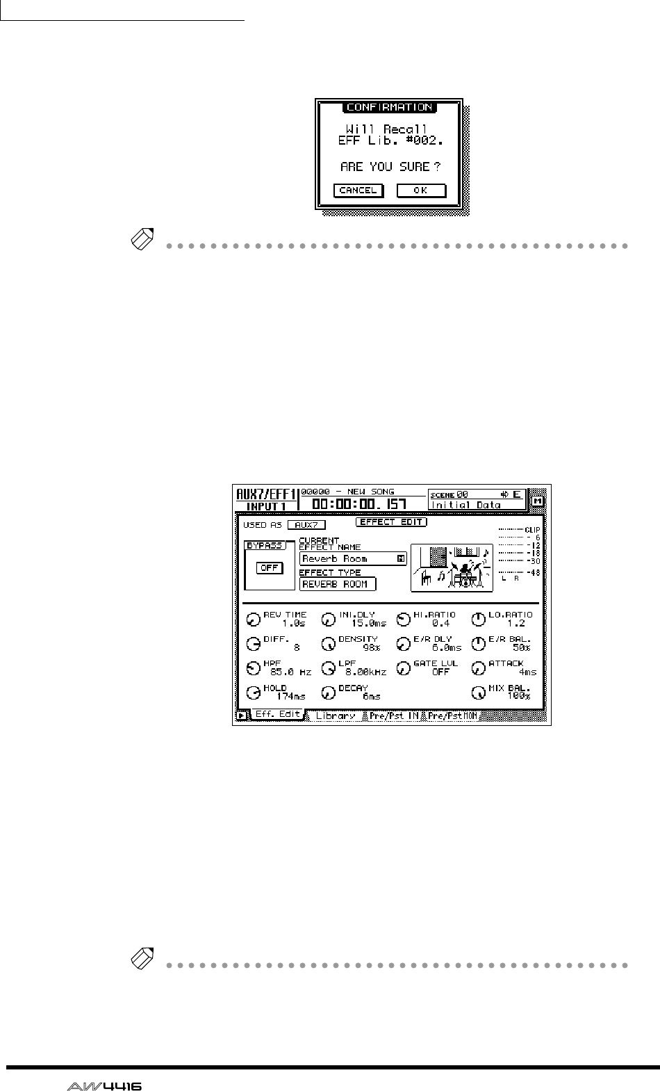
Chapter10—Internal effects
168 — Operation Guide
3. Move the cursor to the RECALL button, and press the [ENTER] key.
A popup window will appear, asking you to confirm the recall operation.
Tip!
It is also possible to recall the effect program directly, without displaying the popup
window that asks you to confirm the recall operation. To do so, access the UTILITY
screen Pref. 1 page ([UTILITY] key
→
[F2] key), and turn RECALL CONFIRMATION
off.
4. To recall the program, move the cursor to the OK button and press the
[ENTER] key.
The effect program will be recalled. The name of the recalled program will
appear in the “CURRENT EFFECT NAME” area in the upper left of the display.
5. Press the [F1] key.
The Eff.Edit page will appear in the display.
6. Make sure that the MIX BAL knob located in the lower right of the dis-
play is set to 100%.
The Eff.Edit page allows you to edit the effect parameters. Regardless of the effect
type that is selected, the MIX BAL (a parameter that adjusts the balance between
the dry and effect sounds) knob will be located in the lower right of the Eff.Edit
page.
When using an effect via AUX send/return, you will need to set this parameter to
100% so that the effect will output only the “wet” (processed) sound. To adjust
this setting, move the cursor to the MIX BAL knob, and rotate the [DATA/JOG]
dial.
Tip!
• Other effect parameters can be edited in the same way by moving the cursor to
them and rotating the [DATA/JOG] dial.
• For the type and function of the effect parameters of each effect type, refer to
the Reference Guide.
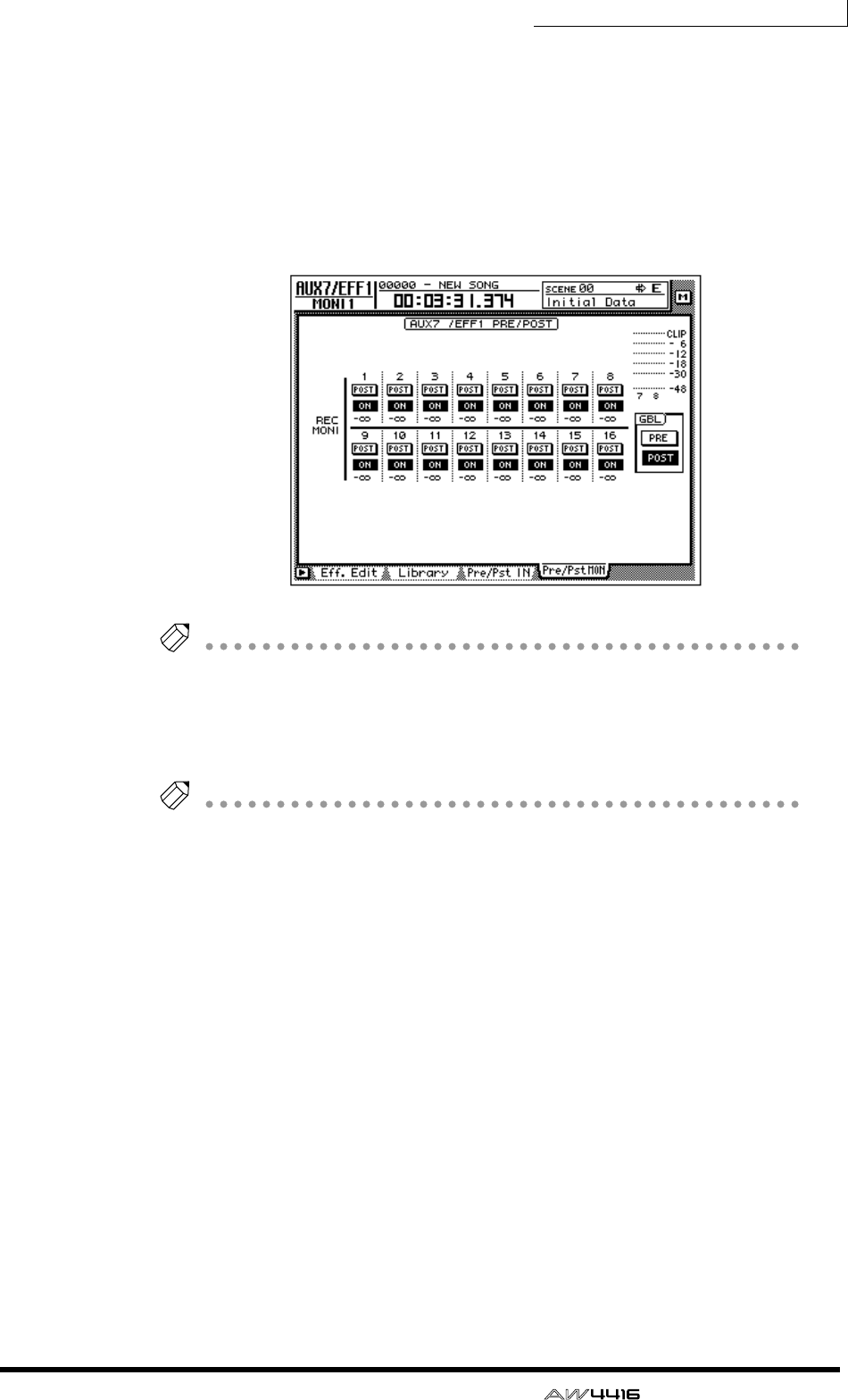
Chapter10—Internal effects
— Operation Guide 169
❒Switching between pre-fader and post-fader
For each monitor channel, you can select the location (pre-fader or post-fader)
from which the signal will be sent to AUX 7.
1. Press the [AUX 7] → [F4] key.
The Pre/PstMON page will appear, where you can make pre-/post-fader settings
for monitor channels 1–16.
Tip!
When the AW4416 is in the initial state, this will be set to post-fader.
2. To switch a specific channel between pre-fader (PRE) and post-fader
(POST), move the cursor to the button for that channel and press the
[ENTER] key.
Tip!
To switch all monitor channels between pre-fader/post-fader, move the cursor to the
PRE/POST button in the GBL (global) section at the right of the display, and press the
[ENTER] key.
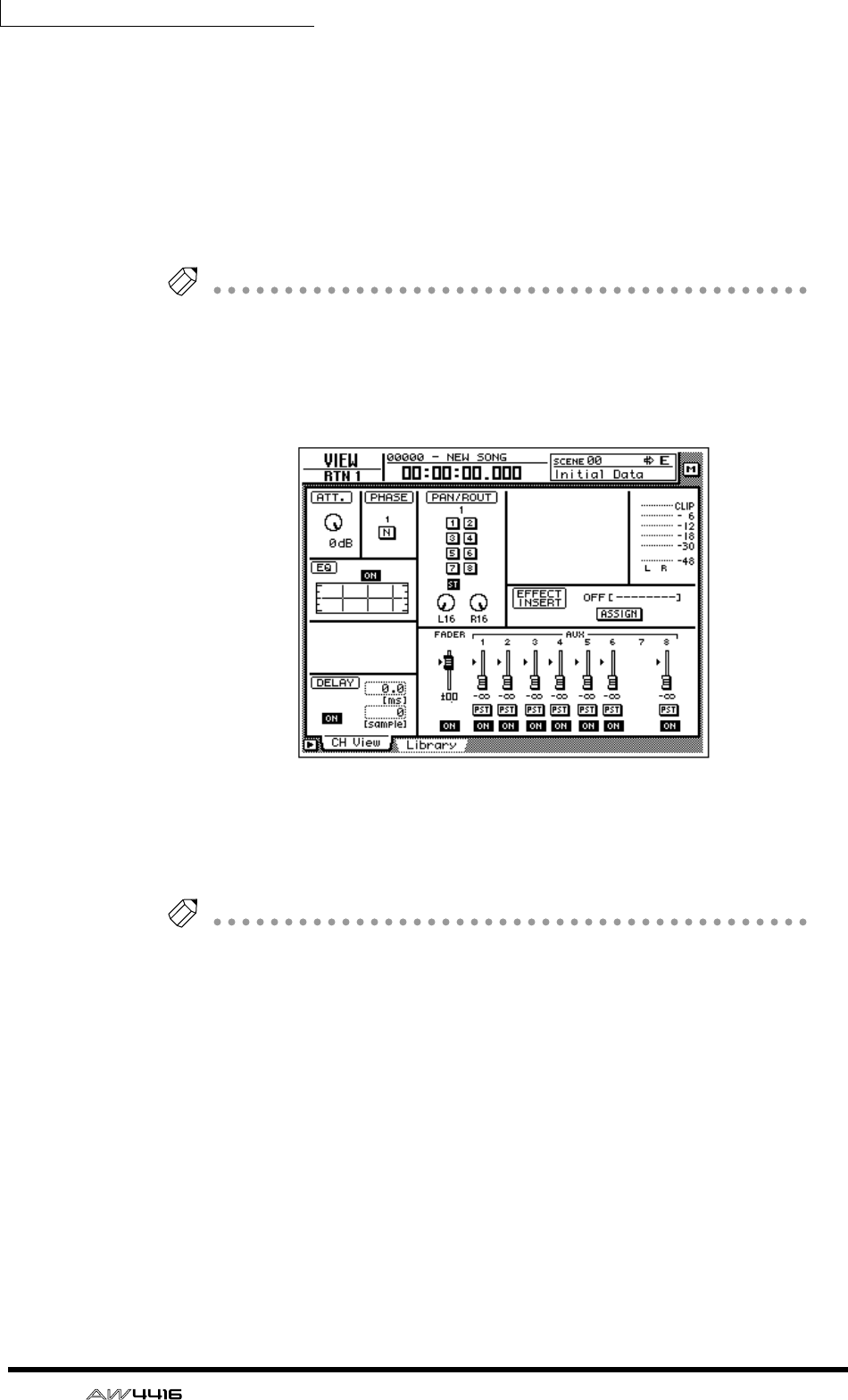
Chapter10—Internal effects
170 — Operation Guide
❒Adjusting the send level/return level
Here’s how to adjust the send level for each monitor channel, and the return level
of the return channel.
1. Press the [HOME] key → [17-24 RTN] key.
[SEL] keys 15/16, [ON] keys 15/16, and faders 15/16 will be assigned to return
channels 1/2. At this time, faders 15/16 will adjust the input level of the return
signals from effects 1/2.
Tip!
When the AW4416 is in the initial state, the faders of return channels 1/2 will be set
to nominal level (0 dB).
2. Press the [VIEW] key → [SEL] key 15.
The VIEW screen of return channel 1 will appear in the display.
3. Make sure that the ST button of the PAN/ROUT area is on.
In this state, the return signal from effect 1 will be sent to the stereo bus and
mixed with the signals of the monitor channels.
Tip!
If the ST button is off, move the cursor to the button and press the [ENTER] key.
❒Adjusting the send level
1. Press the [AUX 7] key → [MONI] key.
[SEL] keys 1–16, [ON] keys 1–16, and faders 1–16 will be assigned to monitor
channels 1–16. At this time, faders 1–16 will adjust the send level of the signals
sent from monitor channels 1–16 to AUX 7 (effect 1).
2. While the song plays back, use faders 1–16 to adjust the send level of
each monitor channel.
3. As necessary, press the [HOME] key → [17-24] RTN key, and use fader 15
to readjust the return level.
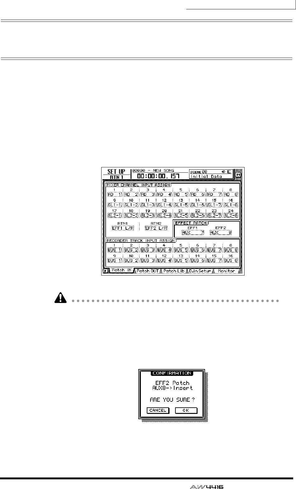
Chapter10—Internal effects
— Operation Guide 171
Inserting an effect into a desired
channel
If you defeat their assignment to AUX 7/8, the AW4416’s internal effects can be
inserted into a desired channel. As an example, here’s how effect 2 can be
inserted into monitor channel 1.
❒Patching
Here’s how to release effect 2 from its assignment to AUX send 8, and use it as an
insertion effect.
1. Press the [SETUP] key → [F1] (Patch IN) key.
The SETUP screen Patch IN page will appear in the display.
If the Patch IN tab is not assigned to the [F1] key, press the [SHIFT] key + [F1] key
to switch the tab, and then press the [F1] key.
2. Move the cursor to the EFF2 parameter of the EFFECT PATCH area, and
rotate the [DATA/JOG] dial.
A popup window will appear, asking you to confirm that you wish to disconnect
effect 2 from AUX bus 8 and use it for insertion.
3. Move the cursor to the OK button and press the [ENTER] key.
In the EFFECT PATCH area, EFF2 will change to “INSERT.” Now the effect can be
inserted into the desired channel.
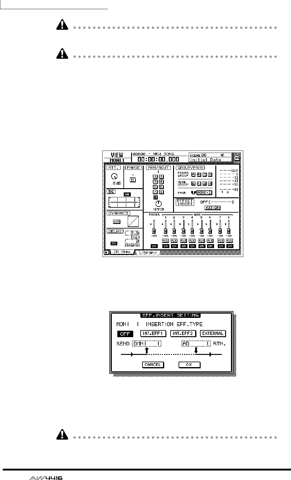
Chapter10—Internal effects
172 — Operation Guide
An effect that has been specified for insertion cannot again be used via AUX
send/return until you reassign it to the AUX bus in the EFFECT PATCH area.
If RTN 2 is set to “EFF 2 L/R” in the Patch IN page, performing this step will auto-
matically cancel the assignment.
❒Inserting an effect into monitor channel 1
1. Press [MONI] key → [SEL] key 1.
Monitor channel 1 will be selected.
2. Press the [VIEW] key → [F1] key.
The VIEW screen CH View page will appear in the display.
3. Move the cursor to the ASSIGN button in the EFFECT INSERT area, and
press the [ENTER] key.
The EFF.INSERT SETTING popup window will appear. In this popup window, you
can use the following four buttons to select the type of effect that will be inserted.
• OFF .....................Effect insertion will be cancelled.
• INT.EFF1 ..............Insert internal effect 1.
• INT.EFF2 ..............Insert internal effect 2.
• EXTERNAL ...........Insert an external effect.
The INT.EFF1 and INT.EFF2 buttons cannot be turned on if the respective internal
effect 1/2 has not been disconnected from AUX send.
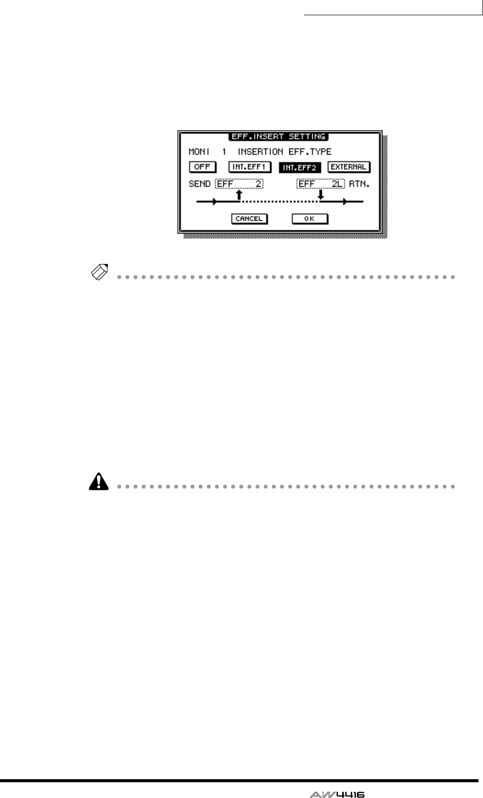
Chapter10—Internal effects
— Operation Guide 173
4. To insert effect 2, move the cursor to the INT.EFF2 button and press the
[ENTER] key.
In the popup window, SEND will change to “EFF2,” and RTN. will change to “EFF
2L.” This indicates that the input of effect 2 has been patched to the insert send of
monitor channel 1, and the L output of effect 2 has been patched to the insert
return.
Tip!
• Regardless of the channel, the effect will be inserted at a position immediately
after the attenuator.
• If you move the cursor to the RTN. field and rotate the [DATA/JOG] dial, you
can switch between “EFF 2L” and “EFF 2R.”
• If an effect is inserted into a stereo channel (return channels 1/2, stereo output
channel), the L/R outputs of the effect will be returned to the L/R of that chan-
nel.
5. When you have finished making settings in the EFF.INSERT SETTING
popup window, move the cursor to the OK button and press the
[ENTER] key.
The EFFECT INSERT field of the CH View page will be displayed as “ON
[INT.EFF2].” This indicates that effect 2 has been inserted into the corresponding
channel (in this case, monitor channel 1).
An effect that has been inserted into a channel will be usable only for that chan-
nel until you insert the same effect into a different channel or turn on the OFF
button in the EFF.INSERT SETTING popup window.
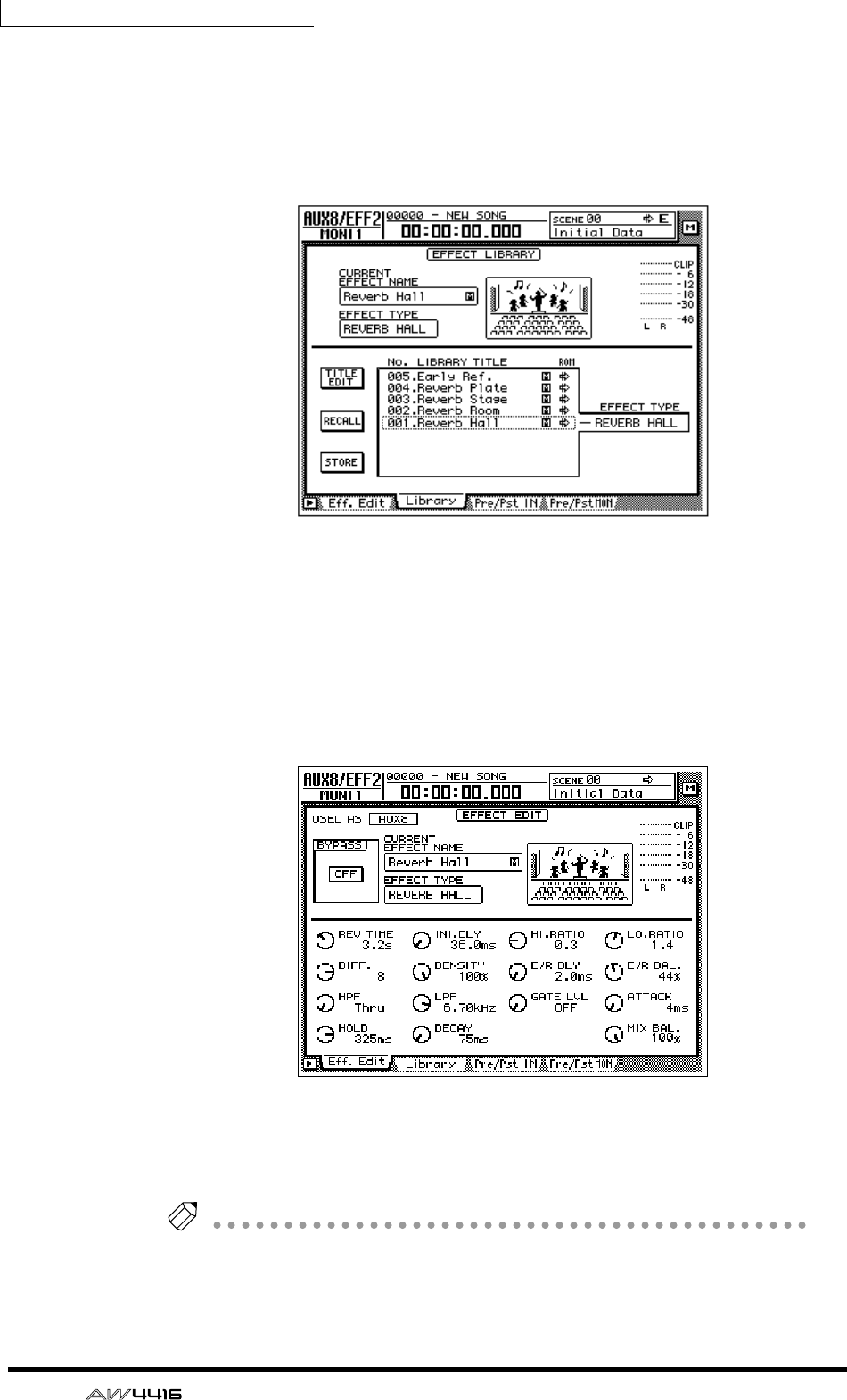
Chapter10—Internal effects
174 — Operation Guide
❒Recalling an effect program
Here’s how you can recall the desired program for effect 2 from the effect library.
1. Press the [AUX 8] key → [F2] key.
The AUX8/EFF2 screen Library page will appear in the display.
2. Move the cursor to the list at the bottom of the display, and use the
[DATA/JOG] dial to select the effect program that you wish to recall.
3. Move the cursor to the RECALL button, and press the [ENTER] key.
The selected program will be recalled to effect 2.
4. Press the [F1] key.
The Eff.Edit page will appear.
5. As necessary, move the cursor to the MIX BAL. knob and rotate the
[DATA/JOG] dial to adjust the balance between the “wet” (processed)
and “dry” (unprocessed) sound.
Tip!
Immediately after an effect program is recalled, MIX BAL. will be reset to 100%
(only “wet” sound).

— Operation Guide 175
11 Song management
This chapter explains song management operations such as saving, load-
ing, deleting, or copying songs.
About songs
On the AW4416, all the data necessary to reproduce a musical composition you
create (i.e., mixer settings, recorder settings, audio data, etc.) is saved in the inter-
nal hard disk as a “song.” By loading a song into internal memory, you can return
to the saved state at any time. A song includes the following data.
• Audio data for all virtual tracks
• TRACK screen settings (including locate point settings)
• Tempo map settings
• Scene memories
• Automix memory
• Patch library
• EQ library
• Dynamics library
• Channel library
• Data and settings for the Sampling Pad function
• Song name and comment
• Counter display method (SECOND/TIME CODE/MEASURE)
• Song Protect setting
• Time Code Top setting
• Region Fade Time setting
• Undo data
Tip!
• Multiple songs can be saved on the internal hard disk. However, only the sin-
gle song currently being controlled on the AW4416 (the “current song”) can
be handled at any given time.
• When the power of the AW4416 is turned on, the most-recently saved song
will be loaded automatically.
Be aware that if you turn off the power of the AW4416 without saving the current
song, any changes in the current song will be lost. When you wish to turn off the
power of the AW4416, you must perform the shut-down procedure (
→
P.17).
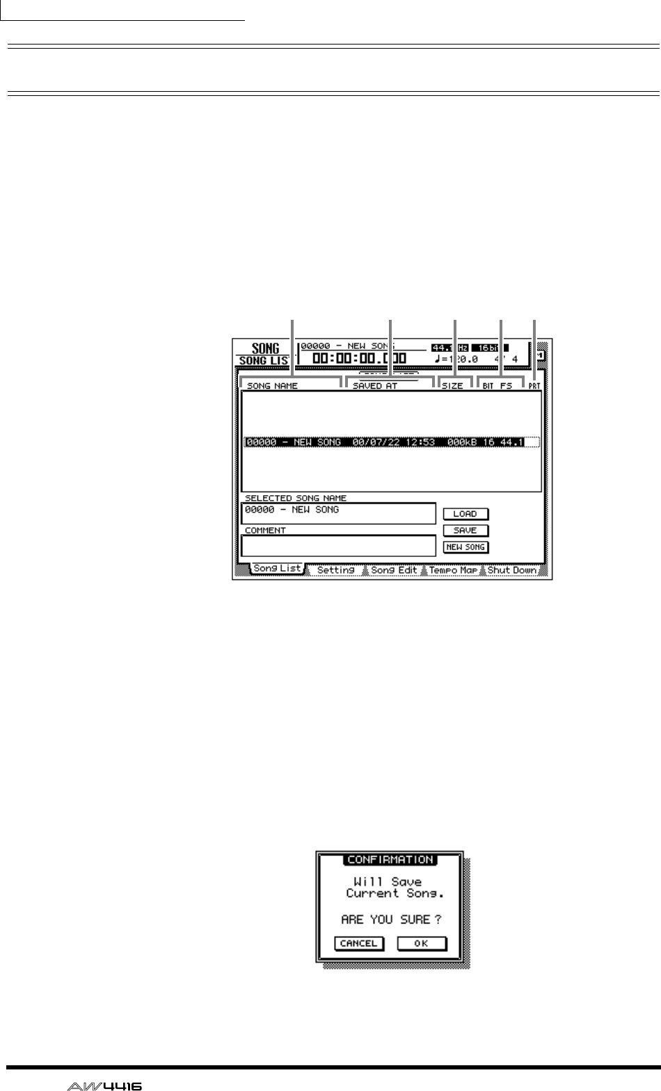
Chapter11—Song management
176 — Operation Guide
Saving/loading a song
Here’s how to save the current song on the internal hard disk, and how to load a
song from the internal hard disk into the current song.
❒Saving the current song
1. Press the [SONG] key → [F1] key.
The SONG screen Song List page will appear in the display. A list of information
on the songs currently saved on the internal hard disk will appear in the upper
part of the display. The current song will be highlighted in the list.
1Song name
BDate and time when the song was saved
CSong size
DSong quantization/sampling frequency
ESong protect
2. To save the current song, move the cursor to the SAVE button in the
lower right of the screen and press the [ENTER] key.
A popup window will appear, asking you to confirm that you wish to save the
current song.
1 2 3 4 5
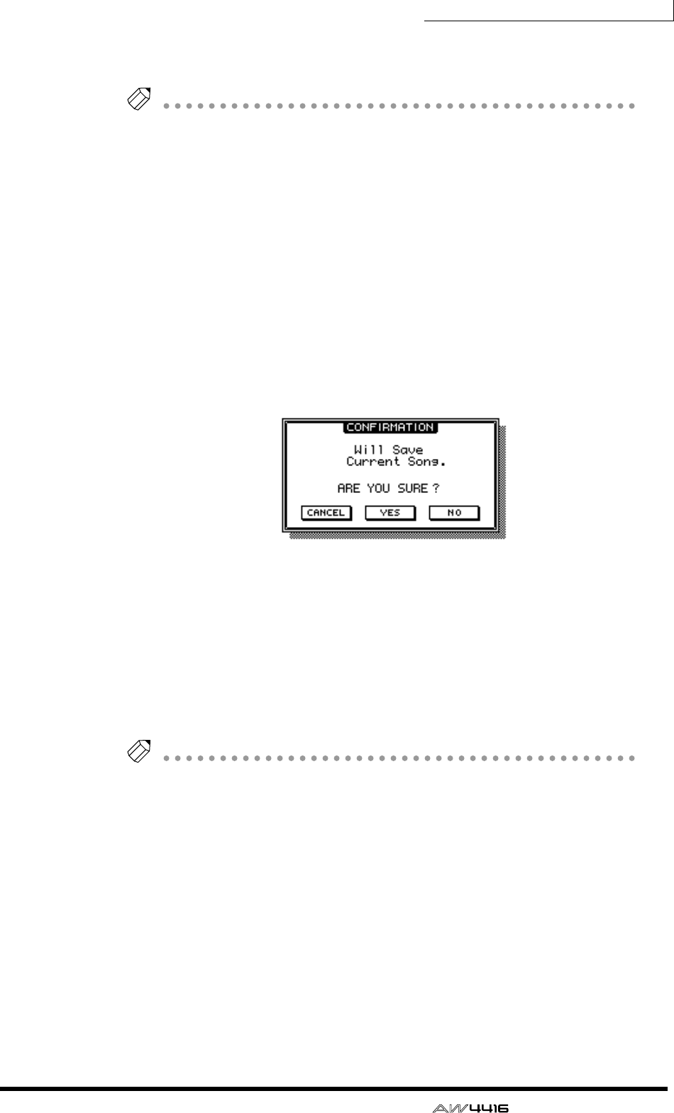
Chapter11—Song management
— Operation Guide 177
3. To execute the Save operation, move the cursor to the OK button and
press the [ENTER] key.
Tip!
• If you decide to cancel without saving, move the cursor to the CANCEL button
and press the [ENTER] key.
• If the free space on the internal hard disk is running low, execute the Song
Optimize operation (
→
P.182). You can also back up desired songs on an exter-
nal device such as CD-RW or MO (
→
P.246).
❒Loading a song
1. Press the [SONG] key → [F1] key.
The SONG screen Song List page will appear.
2. Use the [DATA/JOG] dial to select the song that you wish to load. Then
move the cursor to the LOAD button and press the [ENTER] key.
A popup window will appear, asking you whether you wish to save the current
song first.
3. If you wish to save the current song before loading another song, move
the cursor to the YES button. If you wish to load the song without saving
the current song, move the cursor to the NO button. Then press the
[ENTER] key.
If you selected the YES button, the current song will be saved and then the
selected song will be loaded immediately. If you selected the NO button, any
changes to the current song will be discarded, and the selected song will be
loaded.
Tip!
If you decide to cancel the Load operation, move the cursor to the CANCEL button
and press the [ENTER] key.
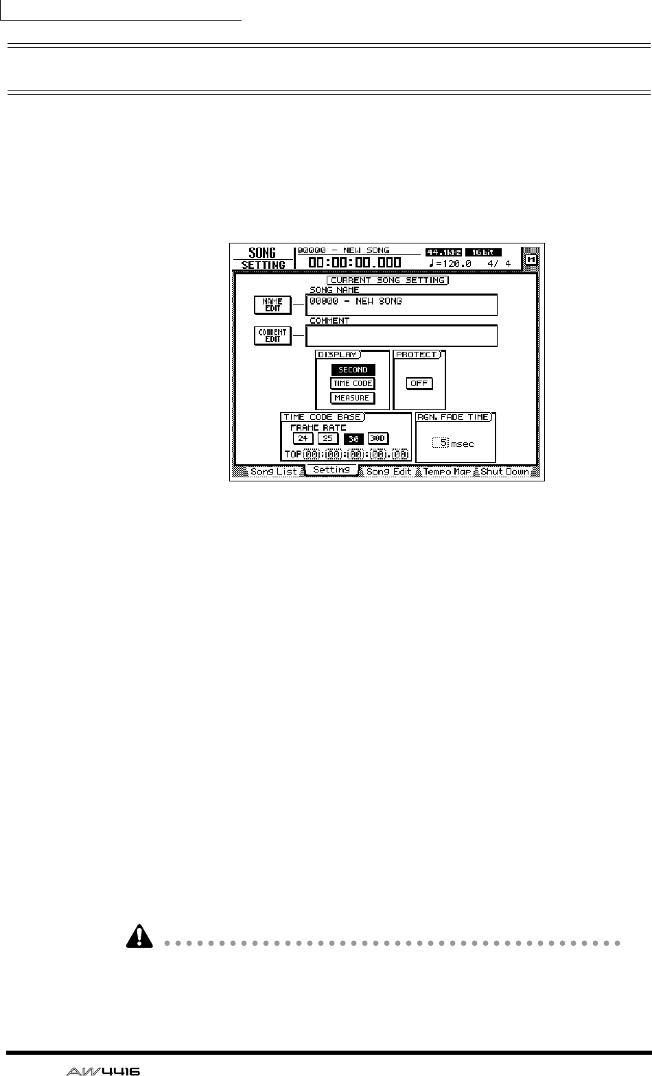
Chapter11—Song management
178 — Operation Guide
Editing the song name/comment
When you create a new song, a default song name “xxxx - NEW SONG -” (xxxxx
will be a serial number) will be assigned unless you specify otherwise, and the
comment will be blank. You can edit the song name and comment afterward.
1. Press the [SONG] key → [F2] key.
The SONG screen Setting page will appear.
The SONG NAME field in the upper part of the screen will show the song name
of the current song, and the COMMENT field will show the comment. (If no com-
ment has been assigned, this will be displayed as “No Description.”)
2. To edit the song name, move the cursor to the NAME EDIT button in the
upper left of the screen, and press the [ENTER] key.
The NAME EDIT window will appear, allowing you to assign a name to the song.
3. Use the character palette to modify the name. Then move the cursor to
the OK button and press the [ENTER] key. (For details on inputting char-
acters, refer to page 60.)
You will return to the SONG screen Setting page.
4. To edit the comment, move the cursor to the COMMENT EDIT button in
the upper left of the screen, and press the [ENTER] key.
The COMMENT EDIT window will appear, allowing you to assign a comment to
the song.
5. Use the character palette to modify the comment. Then move the cursor
to the OK button and press the [ENTER] key. (For details on inputting
characters, refer to page 60.)
You will return to the SONG screen Setting page.
Simply modifying the song name in this page will not change the song name
shown in the list of the SONG screen Song List page. The new name will be
reflected in the list when you save the current song.
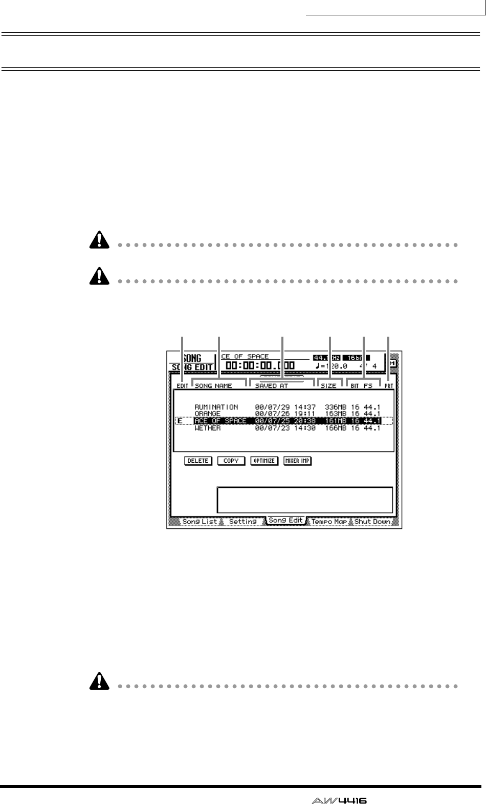
Chapter11—Song management
— Operation Guide 179
Deleting/copying a song
Here’s how to delete a song saved on the internal hard disk, or copy (duplicate) a
song within the hard disk.
❒Deleting a song
1. Press the [SONG] key → [F3] key.
The SONG screen Song Edit page will appear in the display. The upper part of the
display will show a list of the songs currently saved on the hard disk. The current
song will be highlighted in the list. The song currently selected for editing will be
indicated by an “E” symbol at the left of the list.
Songs you delete will be lost forever. Use this procedure with caution.
When you delete, copy, or optimize a song, the current song will be saved auto-
matically.
1The song currently selected for editing
BSong name
CDate and time when the song was saved
DSong size
ESong quantization/sampling frequency
FSong protect
It is not possible to delete a protected song. You must load the song, and turn off
the PROTECT button in the SONG screen Setting page before performing the
Delete operation.
21 3 4 5 6
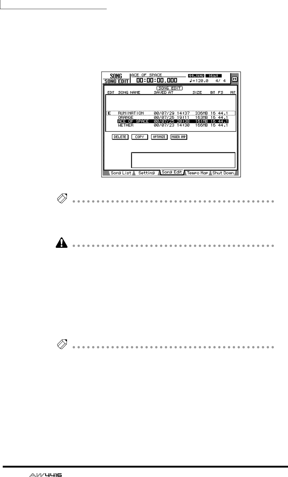
Chapter11—Song management
180 — Operation Guide
2. Move the cursor to the list in the upper part of the display, use the
[DATA/JOG] dial to select the song that you wish to delete, and press the
[ENTER] key.
An “E” symbol will appear at the left within the list, indicating that the corre-
sponding song is selected for deletion.
Tip!
• If you select a song that is already marked with an “E” and press the [ENTER]
key, the “E” symbol will disappear, and the song will be excluded from the
Delete operation.
• You can select multiple songs for deletion.
It is not possible to delete the current song. If you execute Song Delete with an
“E” symbol displayed for the current song, an error message will appear. Load a
different song to change the current song. Then execute the operation.
3. Move the cursor to the DELETE button and press the [ENTER] key.
A popup window will appear, asking you to confirm the Delete operation.
4. To execute the Delete operation, move the cursor to the OK button and
press the [ENTER] key.
The current song will automatically be saved, and the specified song(s) will be
deleted.
Tip!
If you wish to cancel without deleting, move the cursor to the CANCEL button and
press the [ENTER] key.

Chapter11—Song management
— Operation Guide 181
❒Copying a song
1. Press the [SONG] key → [F3] key to access the SONG screen Song Edit
page.
2. Move the cursor to the list in the upper part of the display. Use the
[DATA/JOG] dial to select the song that you wish to copy, and press the
[ENTER] key.
An “E” symbol will appear in the left edge of the list, indicating that the corre-
sponding song is selected for the Copy operation.
Tip!
You may select multiple songs (including the current song) for copying.
3. Move the cursor to the COPY button, and press the [ENTER] key.
A popup window will ask you to confirm the Copy operation.
Tip!
• If you decide to cancel the Copy operation, move the cursor to the CANCEL
button and press the [ENTER] key.
• After the Copy operation is executed, the hard disk will contain two songs with
identical song name, date, and size. To avoid confusion, we recommend that
you change the song name immediately.
4. To execute the Copy operation, move the cursor to the OK button and
press the [ENTER] key.
The current song will be saved automatically, and then the Copy operation will
be executed.
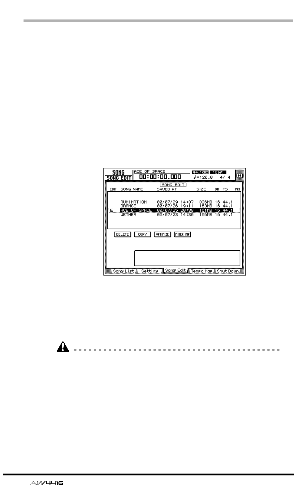
Chapter11—Song management
182 — Operation Guide
Optimizing a song
By using the top panel [UNDO] key and [REDO] key, you can cancel or re-exe-
cute the last-performed recording or track editing operation. By repeatedly press-
ing the [UNDO] key, you can retrace as many as 15 previous operations. Undo/
redo can be a very convenient function, but when you record or perform a track
editing operation, data for the corresponding number of Undo operations must
be maintained, and this data will occupy space on the hard disk.
The “Optimize” command deletes any audio data that is not currently being used
by the song; i.e., it deletes the Undo data. In order to recover this space, we rec-
ommend that you execute the Song Optimize command when you are finished
recording and editing.
1. Press the [SONG] key → [F3] key.
The SONG screen Song Edit page will appear in the display. The upper part of the
display will show a list of the songs currently saved on the hard disk.
2. Move the cursor to the list in the upper part of the display, use the
[DATA/JOG] dial to select the song that you wish to optimize, and press
the [ENTER] key.
An “E” symbol will appear in the left edge of the list, and the corresponding song
will be selected optimization.
It is not possible to execute Optimize with more than one song selected. If Opti-
mize is executed when the “E” symbol is displayed for more than one song, an
error message will be displayed.
3. Move the cursor to the OPTIMIZE button, and press the [ENTER] key.
A popup window will ask you to confirm the Optimize command.
4. To execute the Optimize command, move the cursor to the OK button
and press the [ENTER] key.
The current song will be saved automatically, and then the Optimize command
will be executed.
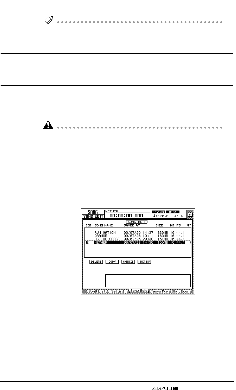
Chapter11—Song management
— Operation Guide 183
Tip!
If you decide to cancel the Optimize command without executing, move the cursor
to the CANCEL button and press the [ENTER] key.
Importing mixer data of an existing
song
You can extract the scene memory, automix, tempo map, and library data
(referred to as “mixer data”) of a previously-saved song, and import it into the
current song. For example, this function is convenient when an existing song has
a special effect library that you wish to use in a newly created song.
• Be aware that when you execute the mixer data import command, the corre-
sponding mixer data of the import destination song (the current song) will be
erased, and replaced by the imported mixer data.
• Library mixer data includes all libraries: channel, EQ, dynamics, and effect.
1. If necessary, load the import destination song as the current song.
2. Press the [SONG] key → [F3] key.
The SONG screen Song Edit page will appear in the display. The upper part of the
display will show a list of the songs currently saved in the hard disk. The current
song will be highlighted in the list.
3. Move the cursor to the list in the upper part of the display, and use the
[DATA/JOG] dial to select the import source song from which you wish
to import mixer data.
4. Press the [ENTER] key.
An “E” symbol will appear at the left edge of the list, and the corresponding song
will be selected as the import source for mixer data.
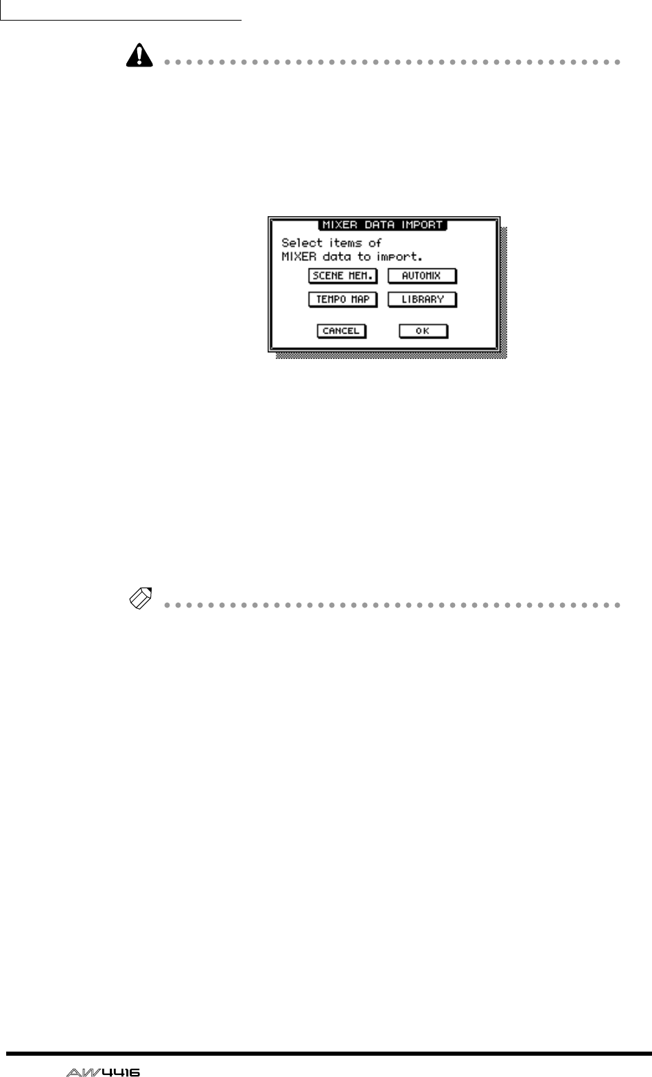
Chapter11—Song management
184 — Operation Guide
• The current song cannot be selected as the import source. If you execute
Import when the current song is marked with an “E” symbol, an error message
will be displayed.
• It is not possible to select two or more songs as the import source.
5. Move the cursor to the MIXER IMP button and press the [ENTER] key.
The MIXER DATA IMPORT popup window will appear.
6. Turn on the button(s) for the type(s) of mixer data that you wish to
import. (You may select more than one.)
• SCENE MEM. button ....Scene memories
• AUTOMIX button .........Automix
• TEMPO MAP button .....Tempo map
• LIBRARY button ...........Libraries (channel/EQ/dynamics/effect)
7. To execute the Import, move the cursor to the OK button and press the
[ENTER] key.
Tip!
If you decide to cancel the Import command without executing, move the cursor to
the CANCEL button and press the [ENTER] key.
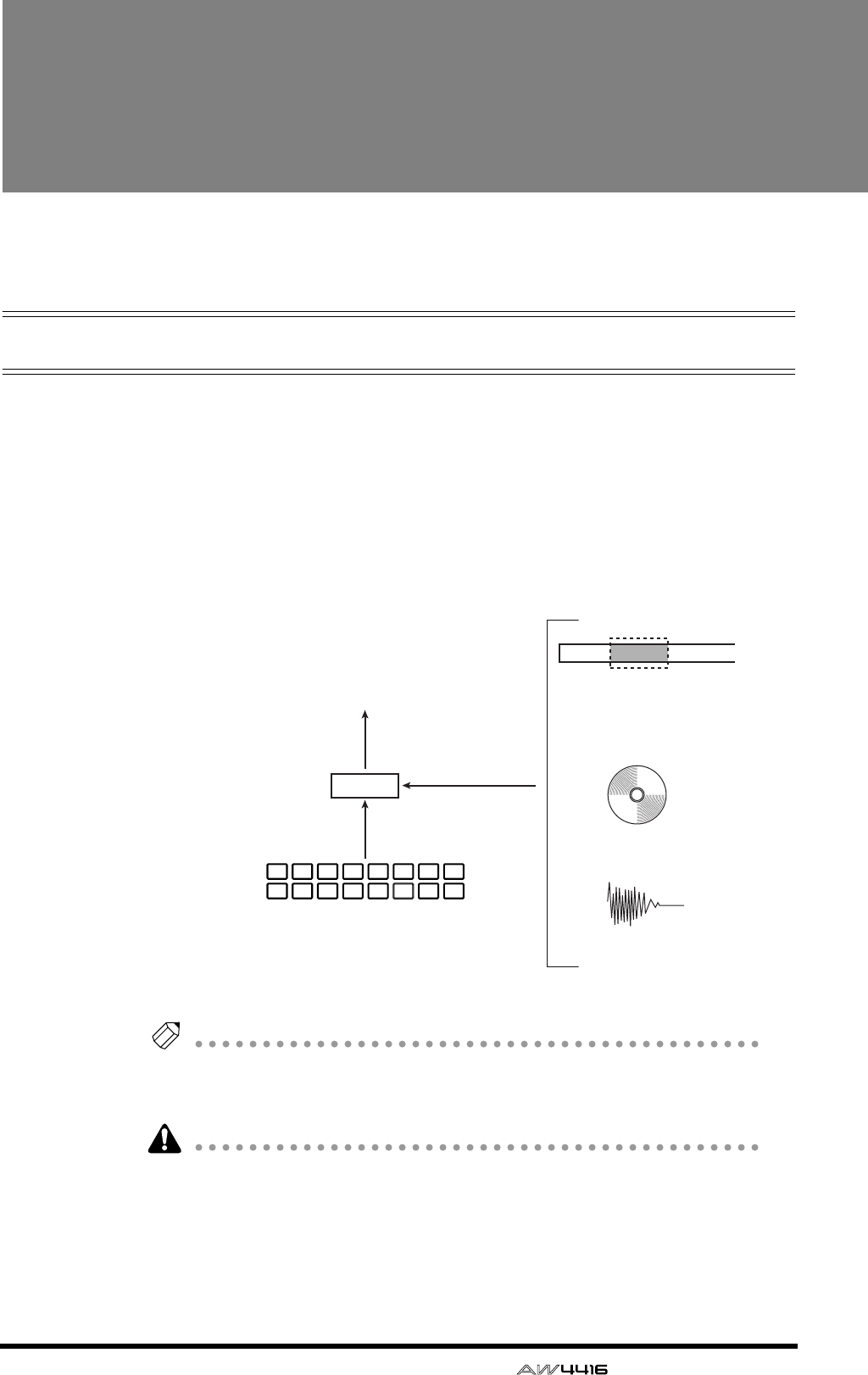
— Operation Guide 185
12 Sampling pads
This chapter explains the sampling pads of the AW4416.
About the sampling pads
The AW4416 has a sampling pad function that allows you to play samples by
striking pads. By striking the eight pads in the SAMPLING PAD section you can
play up to sixteen samples held in RAM, and record your playing on a simple
sequencer that is linked with the recorder.
A sample can be assigned to a pad on one of three ways. You can directly assign
a region (a piece of continuous audio data that was recorded in a single opera-
tion) that was recorded earlier on a track, import CD-DA data from an audio CD,
or import a WAV file from a CD-ROM or MO disk.
Tip!
• The eight sampling pads can be used as sixteen pads by switching between
two banks A and B.
• Sampling pad settings and the samples in RAM are saved as part of the song.
The samples that can be assigned to the pads must be the same audio format as
that song. For example in the case of a song that was created as 24 bit/48 kHz,
CD-DA (16 bit/44.1 kHz) data cannot be imported. In the case of a 16 bit/44.1
kHz song, 16 bit/48 kHz WAV files cannot be imported.
CD-DA
WAV file
Sampling pads
Region recorded
on a track
Input channel
Bank A
Bank B
D-RAM
87543216
87543216
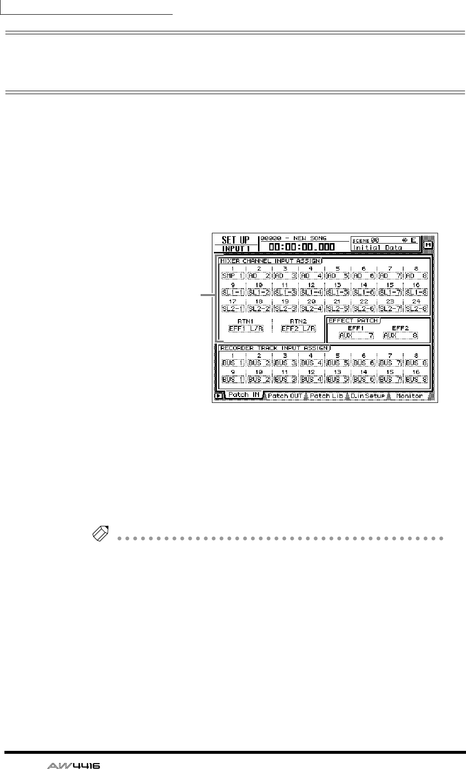
Chapter12—Sampling pads
186 — Operation Guide
Assigning the pad outputs to chan-
nels
In order to use the sampling pads, you must first assign each pad output to an
input channel 1–24. The output of a pad that is assigned to a channel can be con-
trolled by attenuation, phase, EQ, and dynamics in the same way as a conven-
tional input, and can be recorded on a track of the recorder.
1. Press the [SETUP] key → [F1] key.
The SETUP screen Patch In page will appear, allowing you to select the input sig-
nal for each input channel.
2. In the MIXER CHANNEL INPUT ASSIGN area, move the cursor to the
input channel to which you will assign the pad output.
3. Rotate the [DATA/JOG] dial to make a selection in the range of “SMP 1”–
”SMP 8.”
The output of the selected pad will be assigned to the input channel.
Tip!
• Pad assignments are common to banks A and B. If “SMP 1” is selected for a
channel, the output of pad 1 for both banks A and B will be assigned to it.
• All sounds assigned to pads will be monaural output.
4. Turn on the [ON] key of the input channel to which the pad is assigned,
and raise the fader.
Now the signal of the pad you selected in step 3 will be sent to the corresponding
input channel, and can be recorded or monitored.
MIXER CHANNEL
INPUT ASSIGN area

Chapter12—Sampling pads
— Operation Guide 187
Assigning a region to a sampling pad
In order to use the pads to play samples, you must first assign the desired samples
to those pads. There are three ways to assign samples to pads.
1Assign a desired region from tracks 1–16 of the recorder section
BImport an audio CD track from an internal/external CD-RW drive
CImport a WAV file from a SCSI device
As an example, here’s how to assign a region that was previously recorded on a
track.
1. In the SAMPLING PAD section, press the [EDIT] pad → [F1] key.
The SAMP.PAD screen From Rgn. page will appear, allowing you to assign a
desired region to a pad. This page shows three buttons and the regions recorded
on each track.
The three buttons have the following functions.
1PAD SEL button
Selects the pad to which the region will be assigned.
BRGN. SEL button
Selects the region.
CEXECUTE button
Executes the assignment of the region to the pad.
1
2
3
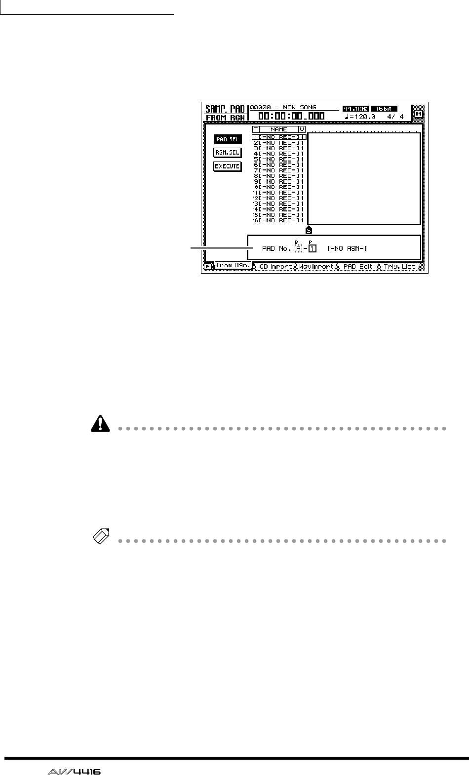
Chapter12—Sampling pads
188 — Operation Guide
2. Move the cursor to the PAD SEL button in the upper left of the display,
and press the [ENTER] key.
The cursor will move to the PAD No. area in the lower right of the display. Pads to
which nothing is assigned will be displayed as “-NO ASN-”.
3. Use the [CURSOR] keys and the [DATA/JOG] dial to select the pad bank
(A/B) and pad number (1–8) to which a region will be assigned.
4. Press the [ENTER] key.
The cursor will return to the PAD SEL button.
5. Move the cursor to the RGN. SEL button and press the [ENTER] key.
The currently selected region will blink.
If you perform this step when no region exists (i.e., when nothing has been
recorded on any track), an message of “ERROR SELECTED SONG HAS NO
REGION” will appear, and it will not be possible to make settings.
6. Use the [CURSOR] keys to move the cursor to select the region.
The currently selected region will be highlighted, and its size will be displayed at
the bottom of the screen.
Tip!
The sample size that can be assigned to the sampling pads are limited to a total of
approximately 8 MB (approximately 90 seconds at 16 bit/44.1 kHz). If you wish to
assign only a portion of a long region to a pad, you should first use the EDIT screen
TR Edit page to divide the region (
→
P.156).
7. Press the [ENTER] key.
The selected region will be highlighted, and the cursor will return to the RGN.
SEL button.
PAD No. area
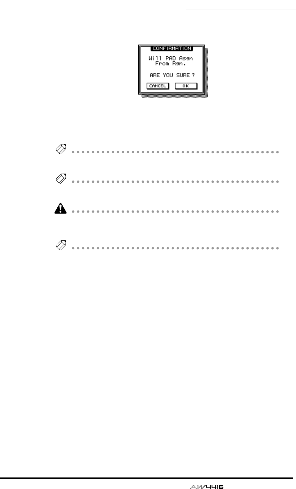
Chapter12—Sampling pads
— Operation Guide 189
8. Move the cursor to the EXECUTE button, and press the [ENTER] key.
A popup window will appear, asking you to confirm the assignment to the pad.
9. To execute the assignment, move the cursor to the OK button and press
the [ENTER] key.
When the assignment is completed, the display will indicate “COMPLETE.”
Tip!
When you assign a region to a pad, a name of “Smpltr” will automatically be
assigned to that pad. If you wish to change this name, refer to page 193.
Tip!
For the procedure of importing CD-DA data or a WAV file to a pad, refer to the Ref-
erence Guide.
If you attempt to assign a sample that would exceed the memory capacity, an
error message of “Memory Full” will be displayed, and the assignment will not
be executed.
Tip!
You can check the approximate amount of sample pad memory in the SMPL. PAD
screen PAD Edit page ([EDIT] pad
→
[F4] key).
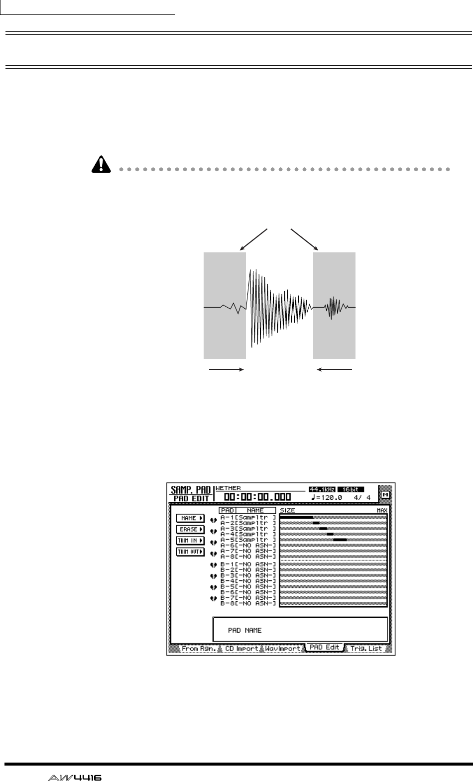
Chapter12—Sampling pads
190 — Operation Guide
Trimming a sample
You can make fine adjustments to the playback start location and playback end
location of a sample assigned to a pad in order to eliminate unwanted portions at
the beginning and end.
Use the TRIM IN command to adjust the playback start location, and use the
TRIM OUT command to adjust the playback end location.
Trimming a sample will not increase the sample size that can be assigned to the
sampling pads.
1. In the SAMPLING PAD section, press the [EDIT] pad → [F4].
The PAD Edit page will appear.
2. Move the cursor to the TRIM IN menu (if you wish to edit the playback
start location) or the TRIM OUT menu (if you wish to edit the playback
end location), and press the [ENTER] key.
Unwanted portions
Adjust the playback
end location
(TRIM OUT)
Adjust the playback
start location
(TRIM IN)
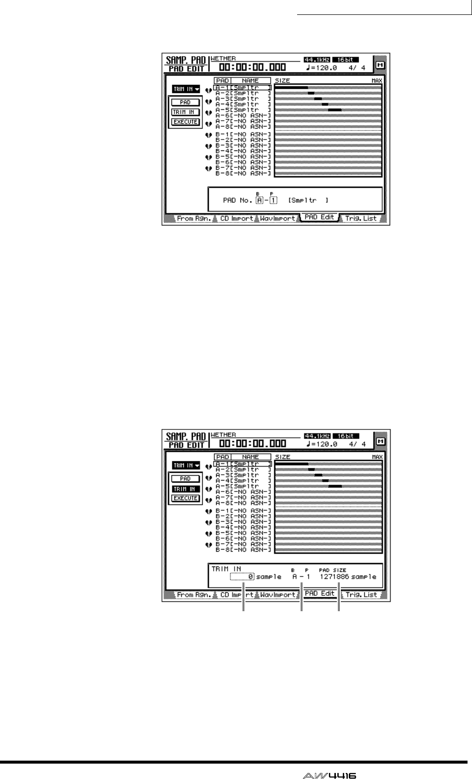
Chapter12—Sampling pads
— Operation Guide 191
Buttons for setting the TRIM IN/TRIM OUT command parameters will appear.
3. Move the cursor to the PAD button, and press the [ENTER] key.
The cursor will move to the PAD No. area in the lower right.
4. Use the [CURSOR] keys and the [DATA/JOG] dial to select the pad bank
and pad number that you wish to trim.
5. Press the [ENTER] key.
The cursor will return to the PAD button.
6. Move the cursor to the TRIM IN button (if editing the playback start
location) or the TRIM OUT button (if editing the playback end location),
and press the [ENTER] key.
The cursor will move to the trim value field.
1TRIM IN/TRIM OUT
Here you can specify the amount of trimming in units of a sample.
BBank/pad number
This displays the bank and pad number of the currently selected pad.
CPAD SIZE
This displays the length of the currently assigned sample, in units of one sample.
1 2 3
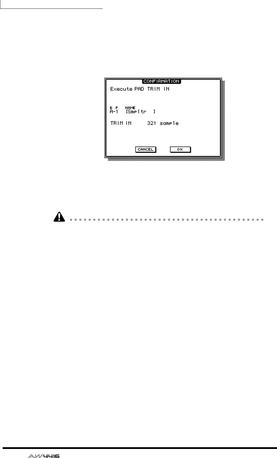
Chapter12—Sampling pads
192 — Operation Guide
7. Use the [DATA/JOG] dial to specify the amount of trimming in sample
units.
8. Press the [ENTER] key.
9. Move the cursor to the EXECUTE button, and press the [ENTER] key.
A popup window will appear, asking you to confirm the trimming operation.
10. To execute the trimming operation, move the cursor to the OK button
and press the [ENTER] key.
The beginning or end of the sample will be deleted as you specified. Strike the
pad to hear the results.
Once you execute the trimming operation, it cannot be reversed by pressing the
[UNDO] key. If you wish to make fine adjustments again, you must re-assign the
region.
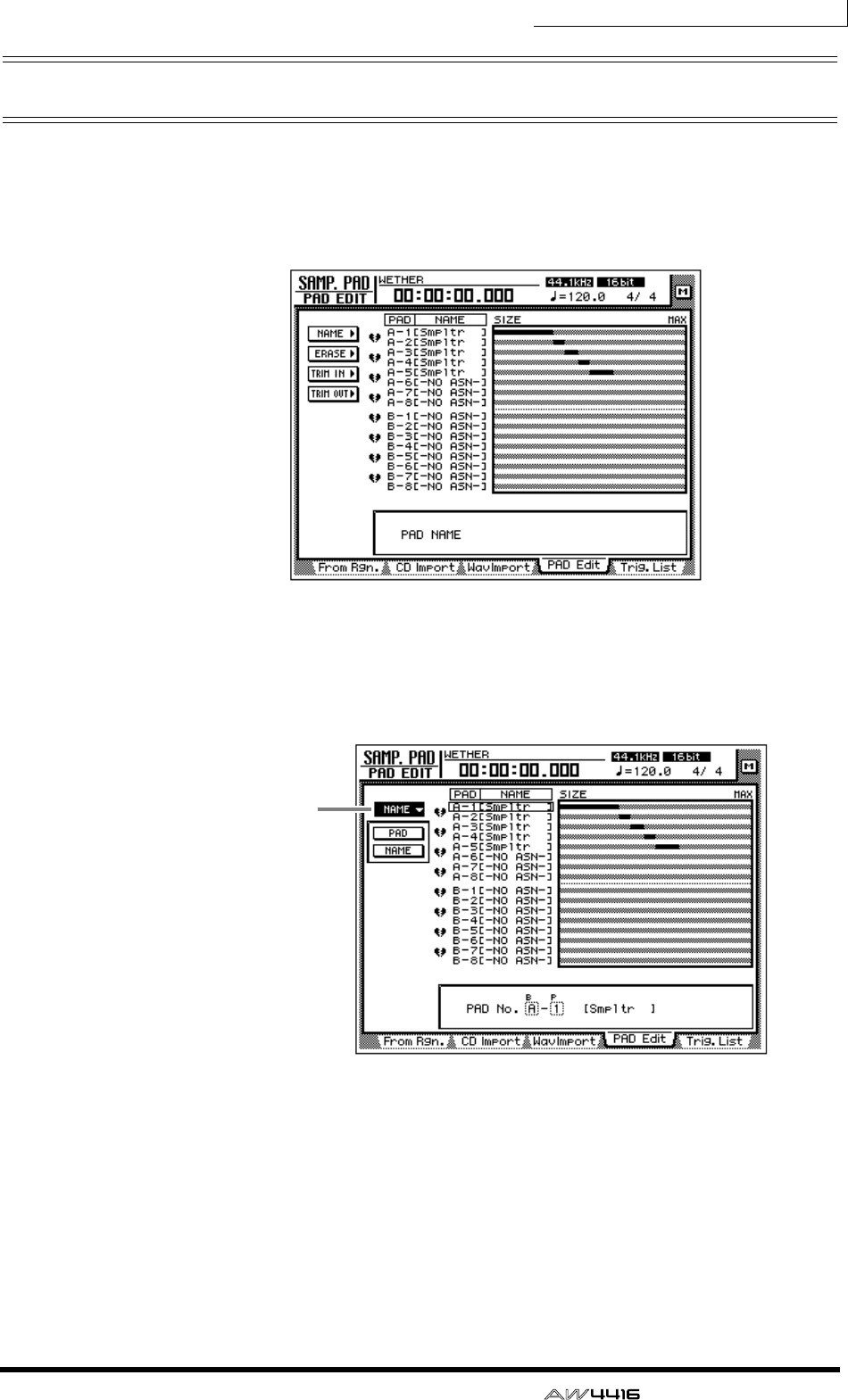
Chapter12—Sampling pads
— Operation Guide 193
Naming a pad
You can name each pad to which a sample is assigned.
1. In the SAMPLING PAD section, press the [EDIT] pad → [F4] key.
The PAD Edit page will appear.
2. Move the cursor to the NAME menu and press the [ENTER] key.
The display will show the PAD button used to select a pad, and the NAME button
used to assign a name.
3. Move the cursor to the PAD button and press the [ENTER] key.
The cursor will move to the PAD No. area at the lower right.
4. Use the [CURSOR] keys and the [DATA/JOG] dial to select the bank and
number of the pad that you wish to name.
5. Press the [ENTER] key.
The cursor will return to the PAD button.
NAME button
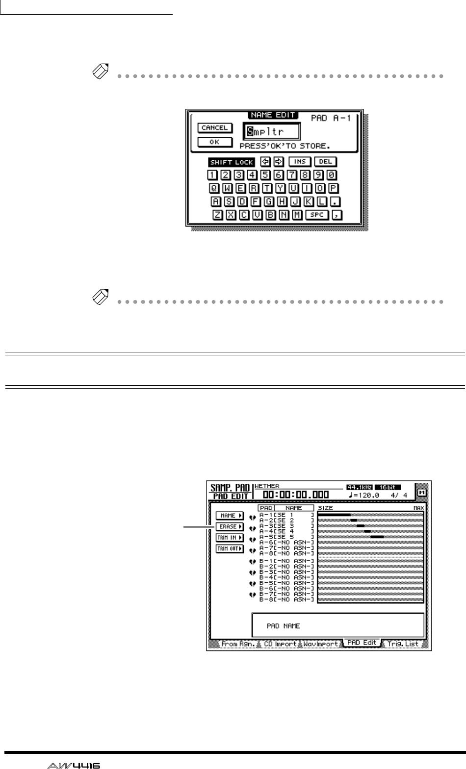
Chapter12—Sampling pads
194 — Operation Guide
6. Move the cursor to the NAME button and press the [ENTER] key.
The NAME EDIT popup window will appear, allowing you to input the name.
Tip!
A name of up to eight characters can be input.
7. After assigning the desired name, move the cursor to the OK button and
press the [ENTER] key.
Tip!
For details on inputting characters, refer to page 60.
Erasing a pad sample and name
Here’s how to erase the sample and name assigned to a pad, returning that pad to
the initial state.
1. In the SAMPLING PAD section, press the [EDIT] pad → [F4] key.
The SAMP.PAD screen PAD Edit page will appear.
2. Move the cursor to the ERASE button and press the [ENTER] key.
The display will show the PAD button used to select the pad, and the EXECUTE
button used to execute the Erase command.
ERASE button
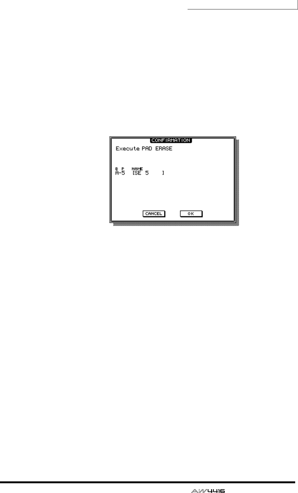
Chapter12—Sampling pads
— Operation Guide 195
3. Move the cursor to the PAD button and press the [ENTER] key.
The cursor will move to the PAD No. area at the lower right.
4. Use the [CURSOR] keys and the [DATA/JOG] dial to select the bank and
pad number of the pad that you wish to erase.
5. Press the [ENTER] key.
Press the [ENTER] key.
The pad will be selected, and the cursor will return to the PAD button.
6. Move the cursor to the EXECUTE button, and press the [ENTER] key.
A popup window will appear, asking you to confirm that you wish to erase the
pad settings.
7. To execute the Erase command, move the cursor to the OK button and
press the [ENTER] key.
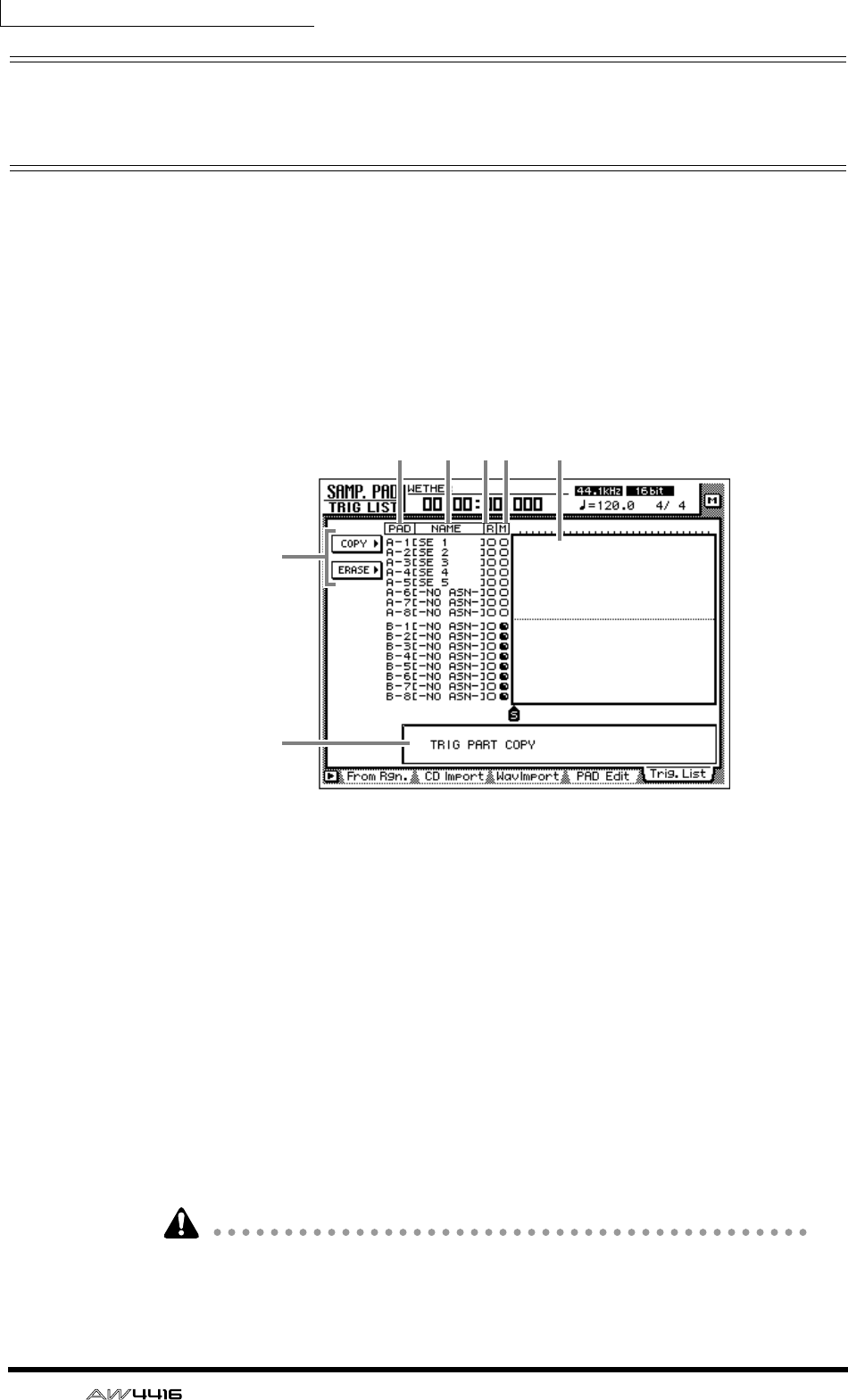
Chapter12—Sampling pads
196 — Operation Guide
Recording your performance on the
sampling pads
The AW4416 provides a simple sequencer dedicated to the sampling pads which
operates in conjunction with the recorder. This simple sequencer records the tim-
ing of the trigger events that occur when you strike a pad, and can be used to
layer kick or snare sounds on the audio tracks, or to add sound effects. Events in a
specified area can also be copied repeatedly as a pattern, or erased.
Here’s how to record your pad performance on the simple sequencer.
1. In the SAMPLING PAD section, press the [EDIT] pad → [F5] key.
The Trig. List page will appear, allowing you to record your pad performance.
This screen shows the following information.
1PAD
The bank and number of the pads that will be recorded/played.
BNAME (pad name)
This is the name assigned to each pad. Pads to which no sample has been
assigned will be displayed as “-NO ASN-”.
CR button
This is the recording switch for each pad. When you move the cursor and press
the [ENTER] key to change the button display from O to ●, that pad can now be
recorded.
DM button
This is the mute switch for each pad. When you move the cursor and press the
[ENTER] key to change the button display from O to ●, that pad will be muted.
It is not possible to play bank A and B pads simultaneously. The M buttons will
automatically switch to
●
for the bank that is not currently selected by the
[BANK] switch, and will be muted.
6
12 34 5
7
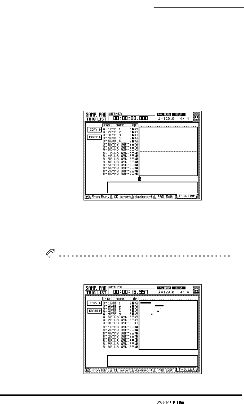
Chapter12—Sampling pads
— Operation Guide 197
EPad tracks
These tracks record the timing of the trigger events for each pad. The time from
while you press the pad until you release it is shown as a bar graph.
FCOPY/ERASE menu
This menu accesses commands for copying/erasing previously-recorded trigger
events. Move the cursor to the desired menu and press the [ENTER] key to access
the list of commands.
GParameter value area
In this area you can set the parameters required to execute the command.
2. Use the [CURSOR] keys and the [ENTER] key to switch the R column of
the pad(s) you wish to record from O to ●.
3. Start the recorder, and strike the pads while listening to the playback of
the audio tracks.
Trigger events will be recorded on the corresponding pad track.
4. When you are finished performing, stop playback on the recorder.
Tip!
• You can also begin recording from the middle of the song.
• Immediately after recording, you can press the [UNDO] key to cancel trigger
event recording.
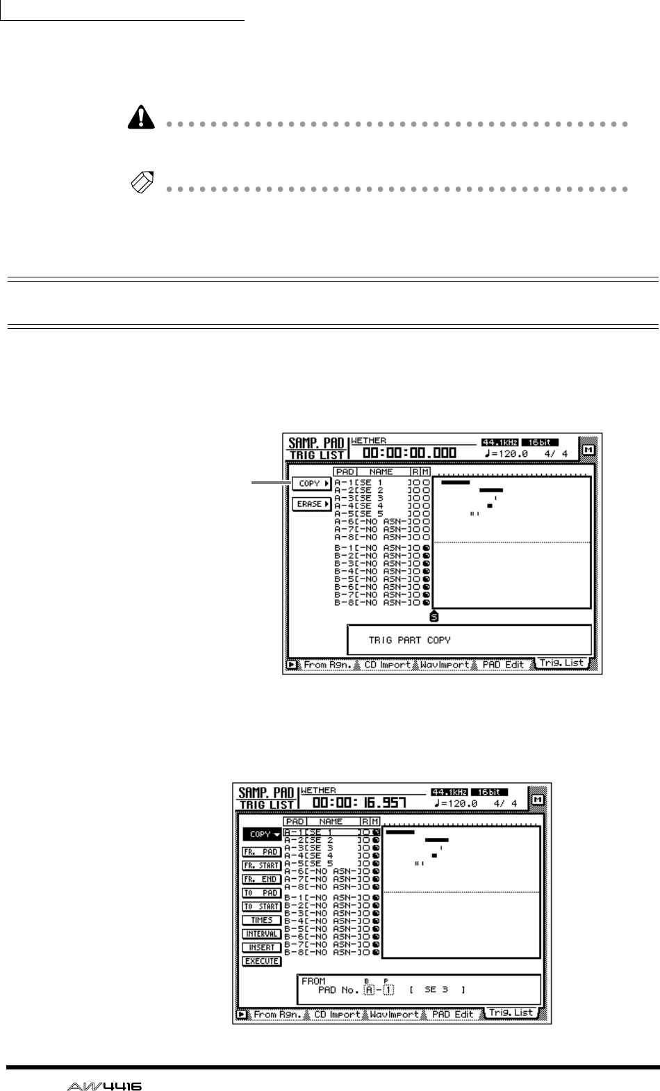
Chapter12—Sampling pads
198 — Operation Guide
5. Use the [CURSOR] keys and the [ENTER] key to change the R column
from ● back to O, and play back the recorder to hear the playback of
the trigger events.
Be aware that if you play back the recorder when the R column still displays
●
and strike the pads, your new performance will be recorded.
Tip!
If you switch the M column of a pad from O to
●
, that pad track will be muted even
if you play back the recorder.
Copying a pad performance
Here’s how to copy a recorded pad performance to another location.
1. In the SAMPLING PAD section, press the [EDIT] pad → [F5] key.
The Trig. List page will appear.
2. Move the cursor to the COPY menu and press the [ENTER] key.
The parameters for the copy command will appear. These parameters have the
following functions.
COPY button
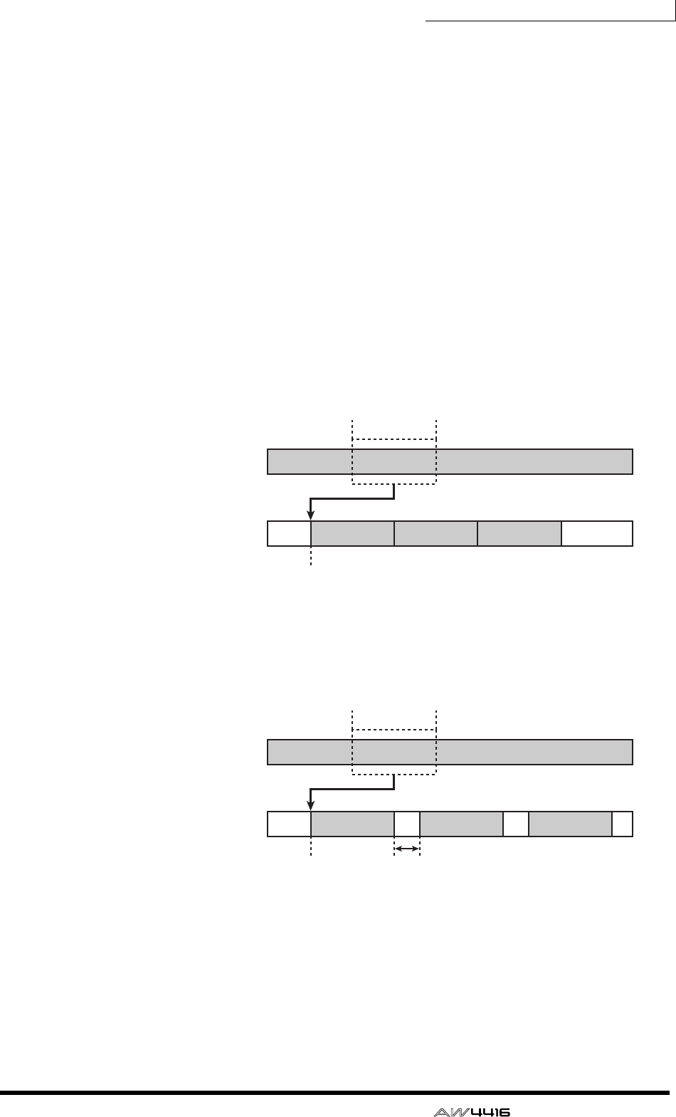
Chapter12—Sampling pads
— Operation Guide 199
❍ FR. PAD (from pad)
Specify the copy source pad track.
❍ FR. START (from start)
❍ FR. END (from end)
Specify the beginning (FR. START) and end (FR. END) of the area that will be cop-
ied from the pad track specified by FR. PAD. The specified area will be selected
as a pattern.
❍ TO PAD
Select the copy destination pad track.
❍ TO START
Specify the location in the pad track selected by TO PAD at which the data will
be copied.
❍ TIMES (copy times)
Specify the number of times that the data will be copied. The pattern selected as
the copy source will be copied repeatedly.
❍ INTERVAL
When copying multiple times, this parameter specifies the interval between copy
destination patterns.
❍ INSERT
Specify whether the pattern will be inserted (Insert) or overwritten (OverWrite) at
the copy destination.
❍ EXECUTE
This button executes the Copy operation.
Copy source
pad track
(FR. PAD)
FR. START
TO START
COPY (TIMES= 3)
Copy destination
pad track
(TO PAD)
FR. END
FR. START
TO START INTERVAL
COPY (TIMES= 3)
FR. END
Copy source
pad track
(FR. PAD)
Copy destination
pad track
(TO PAD)
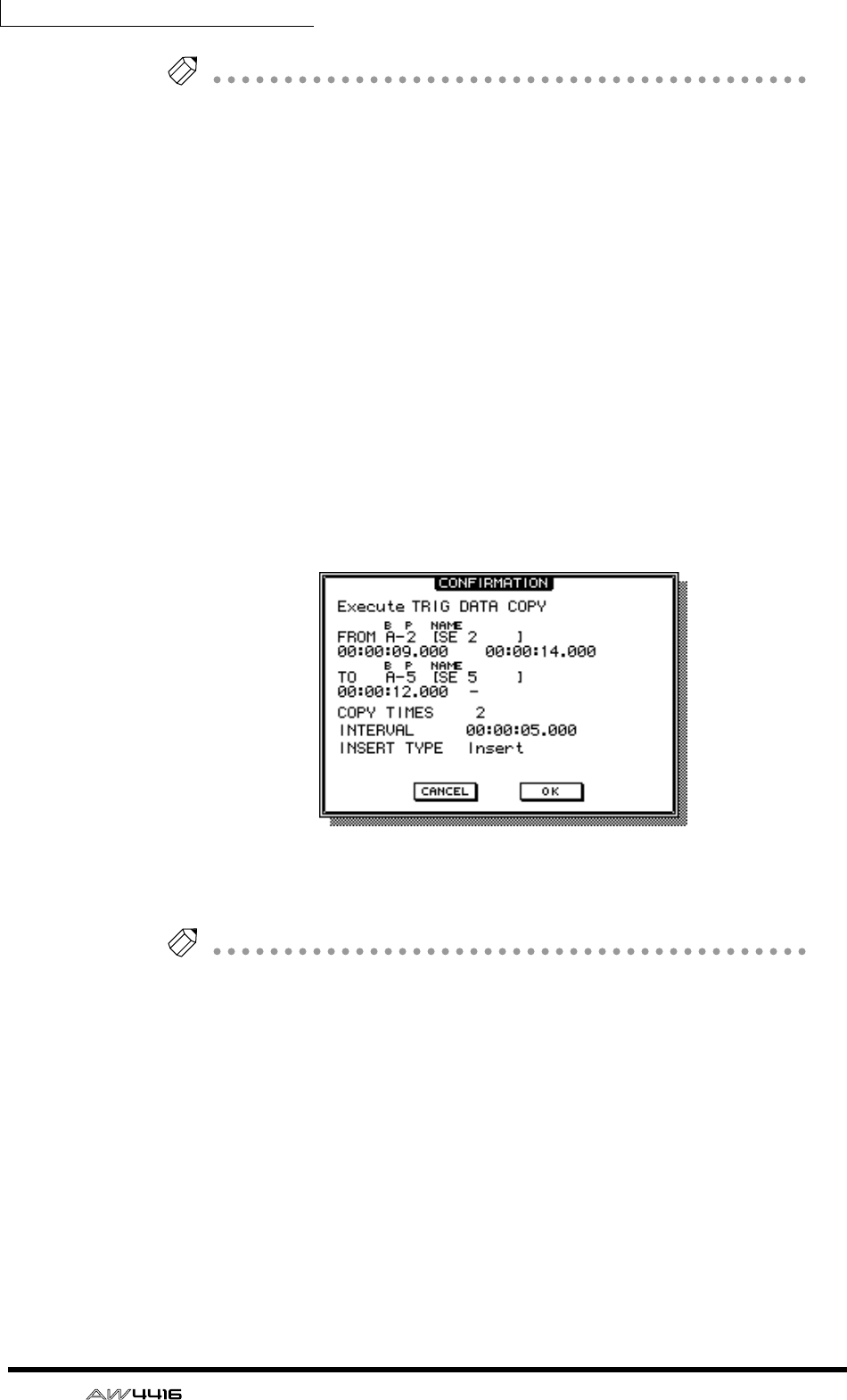
Chapter12—Sampling pads
200 — Operation Guide
Tip!
• If you set the counter to measure units, you can set the FR. START, FR. END,
and TO START parameters in measure/beat units.
• Instead of using the [DATA/JOG] dial to vary a location continuously, you can
use the keys of the locate section to move instantly to a desired locate point or
marker.
3. Move the cursor to the parameter whose setting you wish to change,
and press the [ENTER] key.
The cursor will move to the parameter setting, and the value of the selected
parameter will be displayed.
4. Use the [DATA/JOG] dial to set the parameter, and press the [ENTER]
key.
The setting will change, and the cursor will return to the parameter location of
step 3.
5. Repeat steps 3–4 to set the remaining parameters.
6. Move the cursor to the EXECUTE button and press the [ENTER] key.
A popup window will appear, asking you to confirm the Copy command.
7. To execute the Copy, move the cursor to the OK button and press the
[ENTER] key.
Tip!
You can undo the result of the copy by pressing the [UNDO] key immediately after
executing Copy.
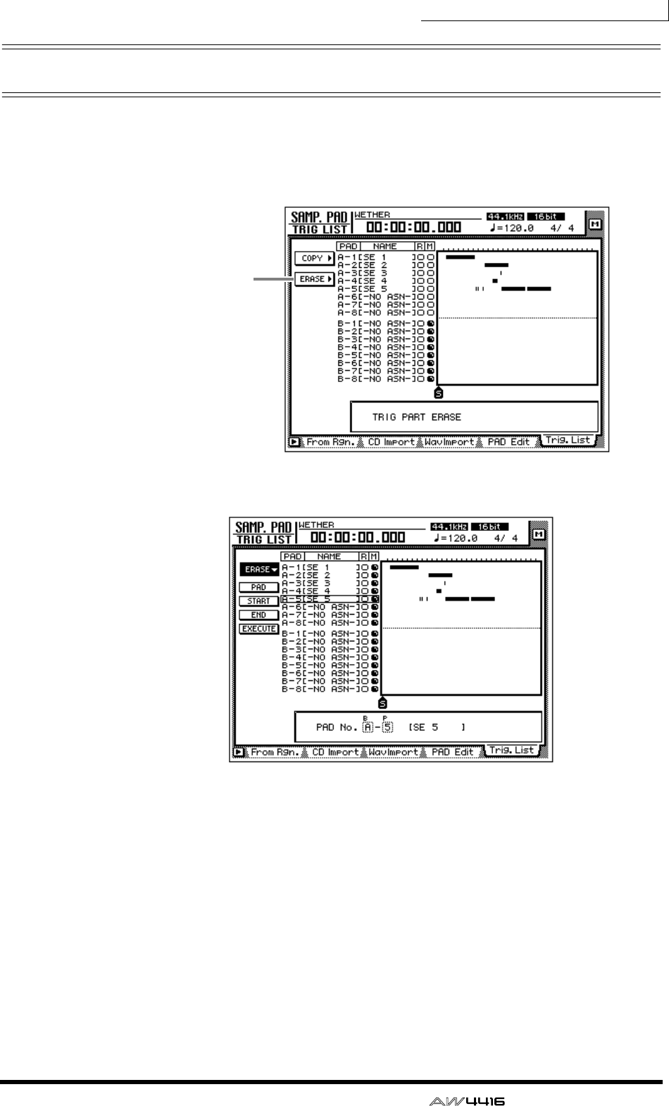
Chapter12—Sampling pads
— Operation Guide 201
Erasing a pad performance
Here’s how to erase a pad performance that you recorded.
1. In the SAMPLING PAD section, press the [EDIT] pad → [F5] key.
The Trig. List page will appear.
2. Move the cursor to the ERASE menu, and press the [ENTER] key.
The parameters for the Erase command will appear. Each parameter has the fol-
lowing function.
❍ PAD
Select the pad track that will be erased.
❍ START
❍ END
Specify the beginning (START) and end (END) of the area that will be erased from
the pad track selected by PAD.
❍ EXECUTE
This button executes the Erase command.
ERASE button
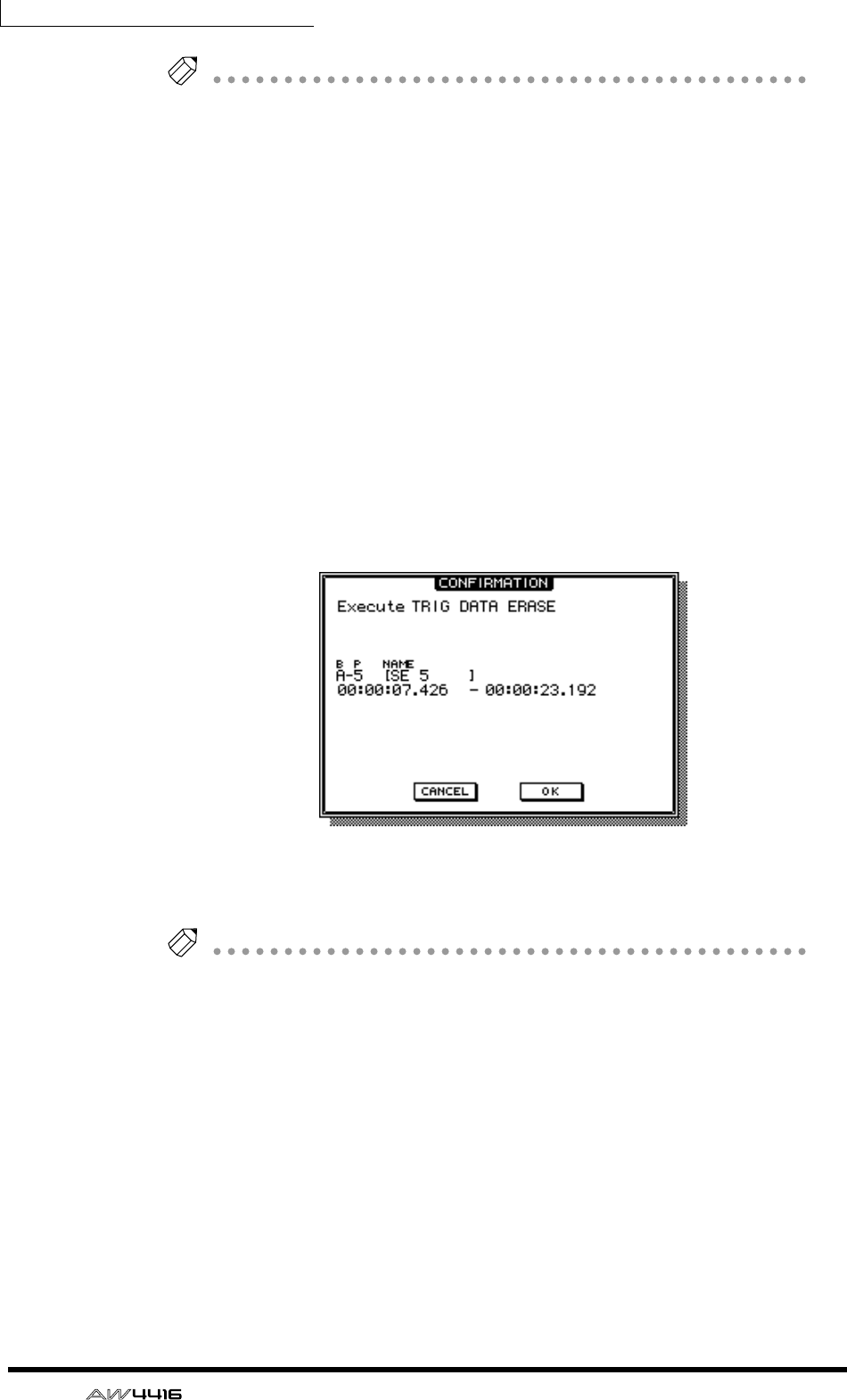
Chapter12—Sampling pads
202 — Operation Guide
Tip!
• If you set the counter to measure units, you can set the START and END
parameters in measure/beat units.
• Instead of using the [DATA/JOG] dial to vary a location continuously, you can
use the keys of the locate section to move instantly to a desired locate point or
marker.
3. Move the cursor to the parameter whose setting you wish to change,
and press the [ENTER] key.
The cursor will move to the parameter setting, and the value of the selected
parameter will be displayed.
4. Use the [DATA/JOG] dial to set the parameter, and press the [ENTER]
key.
The setting will change, and the cursor will return to the parameter location of
step 3.
5. Repeat steps 3–4 to set the remaining parameters.
6. Move the cursor to the EXECUTE button and press the [ENTER] key.
A popup window will appear, asking you to confirm the Erase command.
7. To execute the Erase command, move the cursor to the OK button and
press the [ENTER] key.
Tip!
You can undo the result of the erasure by pressing the [UNDO] key immediately
after executing Erase.
— Operation Guide 203
13 Scene memory
This chapter explains the scene memory function and how to use it.
About scene memory
On the AW4416, settings such as the mix parameters of each channel, external
input/output patching, and effect 1/2 parameters can be assigned a name and stored
in internal memory as a “scene.” The memory area in which these scenes are stored
is called “scene memory.” Up to 96 scenes can be stored for a single song, and can
be recalled by operations of the AW4416’s keys or by the automix function. All
scenes stored in scene memory are saved on the hard disk as part of the song.
❒Parameters included in a scene
The following parameters are included in a scene.
❒About scene numbers
There are 97 scene numbers, numbered 00–96. Of these, scenes can be stored in
scene numbers 01–96. Scene number 00 contains a scene that returns the param-
eters to the initial state of the AW4416, and is for recall only.
Mix parameters
Fader locations for all channels and buses (input channels
1–24, recorder monitor channels 1–16, AUX send levels 1–
8, effect returns 1/2, stereo)
ON key settings of all channels
Attenuation settings of all channels
Phrase settings of all channels
EQ settings of all channels
Pan settings of all channels
Routing settings of all channels
Fader group settings of all channels
Pair settings of all channels
Dynamics settings of all channels
Delay settings of all channels
Effect parameters Parameter settings of effects 1/2
Other
Scene name settings
Fader recall fade time settings
Internal input/output patching and insert settings
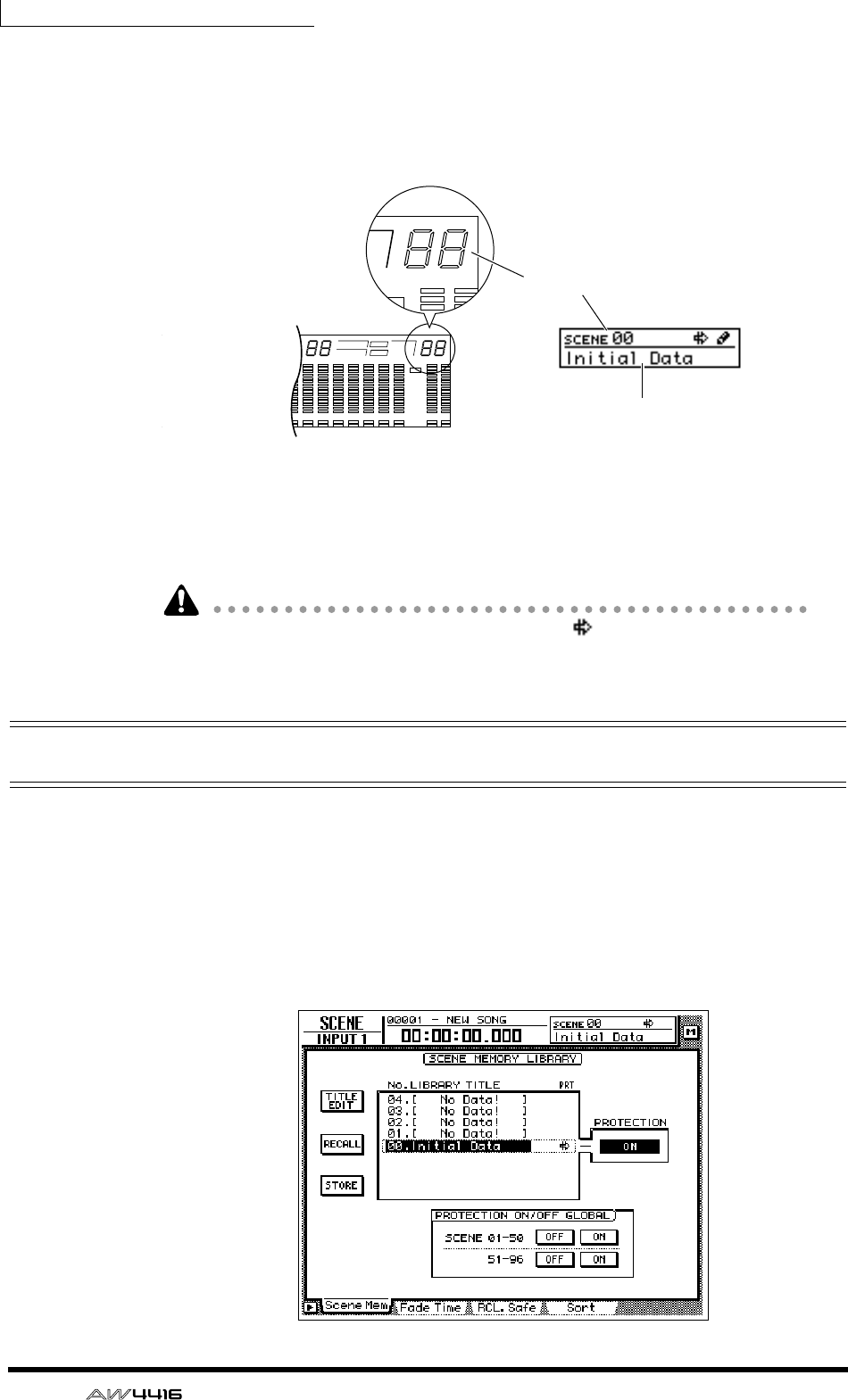
Chapter13—Scene memory
204 — Operation Guide
The currently recalled scene number is displayed at the upper right of the level
meter/counter. When a key of the MIXER section, FADER MODE section, AUTO-
MATION section, or UNIT section (except for the [FILE] key) is pressed, the upper
right of the display will show the number and name of the currently recalled
scene.
If an “E” character is displayed at the right of the scene number, this means that
the currently operated scene (the “current scene”) is different than the previously
recalled or saved contents.
When the read-only scene number 00 is recalled, a symbol will appear, indi-
cating that the scene is read-only.
Storing a scene
Here’s how to assign a name to the current scene and store it in a scene memory.
1. Press the [SCENE] key → [F1] key.
The Scene Mem page of the SCENE screen will appear. A list of the scenes (scene
numbers and scene names) stored in scene memory will be shown in the center
of the display. The last-recalled scene will be highlighted in the list. For scene
numbers in which no data has been stored, the scene number field will indicate
“[ No Data ! ].”
Scene number
Scene name
• Level meter/counter • Display
1 2 3 4 5 6 7 8 9 13 14 15 1610 11 12
–dB 0
2
6
20
30
42
60
10
14
18
20
26
12
FINE
READY
INPUT
0
2
6
0
0
4
2
0
2
Y
T
LR
A
IN
B
S
E
L
HM S Fms
EXT
VARI
44.1k 48k
LOCK
WORD CLOCK MTC SCENE
SLAVE
MASTER
INT
E
E
–dB 0
2
FINE
TC SCENE
VE
TER
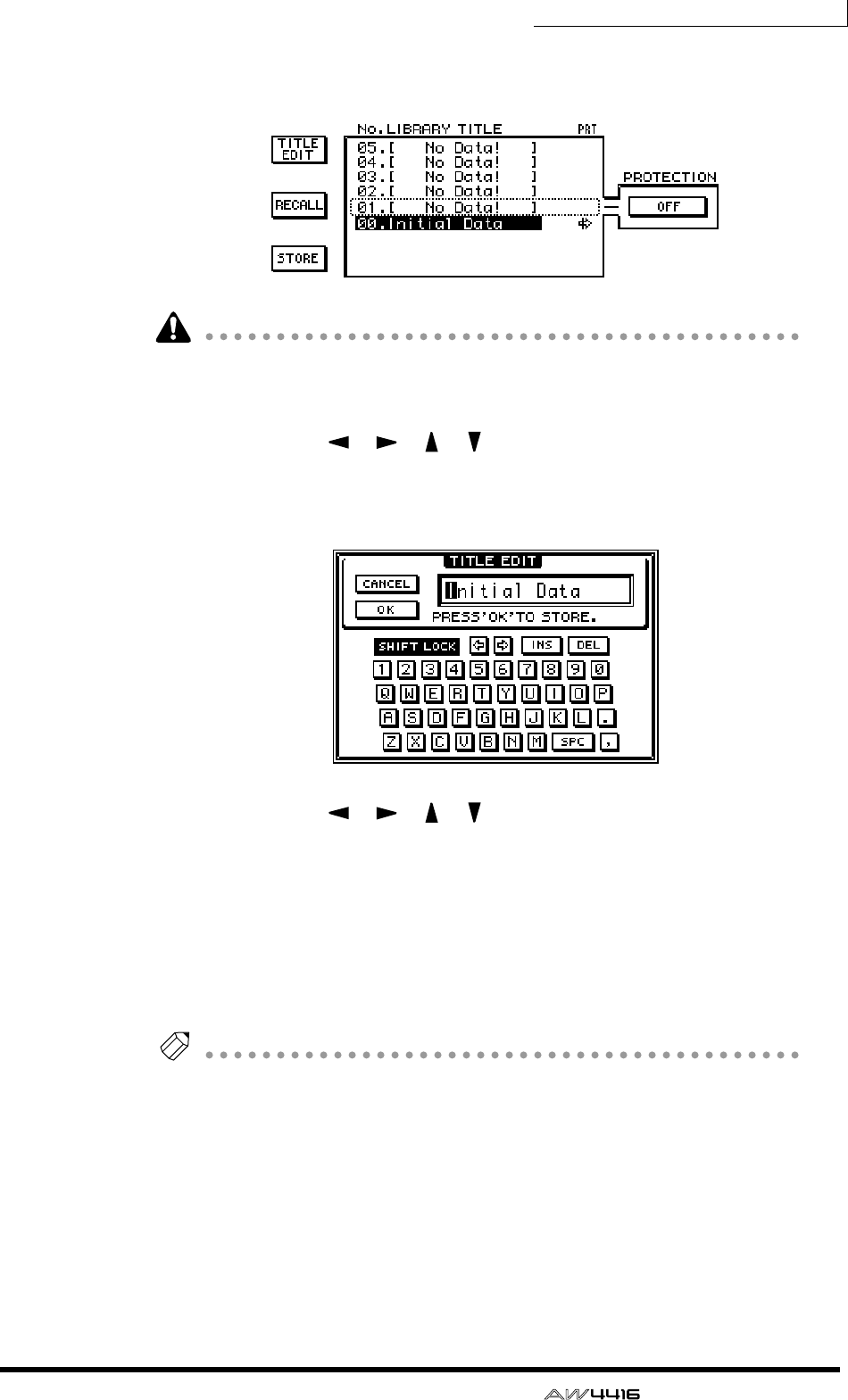
Chapter13—Scene memory
— Operation Guide 205
2. Use the [DATA/JOG] dial to select the store destination scene number
(01–96).
• Scene number 00 is for recall only, and cannot be stored.
• Be aware that if you select a previously-stored scene number and execute the
Store operation, the previous scene will be lost.
3. Use the CURSOR [ ]/[ ]/[ ]/[ ] keys to move the cursor to the
STORE button in the screen, and press the [ENTER] key.
The TITLE EDIT popup window will appear, allowing you to specify the name of
the scene (scene name).
4. Use the CURSOR [ ]/[ ]/[ ]/[ ] keys and the [DATA/JOG] dial to
specify the name of the scene.
For details on inputting characters, refer to page 60.
5. To store the scene, move the cursor to the OK button in the screen and
press the [ENTER] key.
The scene will be stored, and the AW4416 will be in the same state as when the
store destination scene number of step 2 is recalled. To cancel without storing the
scene, move the cursor to the CANCEL button and press the [ENTER] key.
Tip!
• To prevent a stored scene from accidentally being overwritten, you can make
memory protect settings for each scene number. For details refer to page 208.
• You can use the keys of the SCENE MEMORY section to store a scene even
when you are in a screen other than the SCENE screen Scene Mem page. For
details refer to page 211.
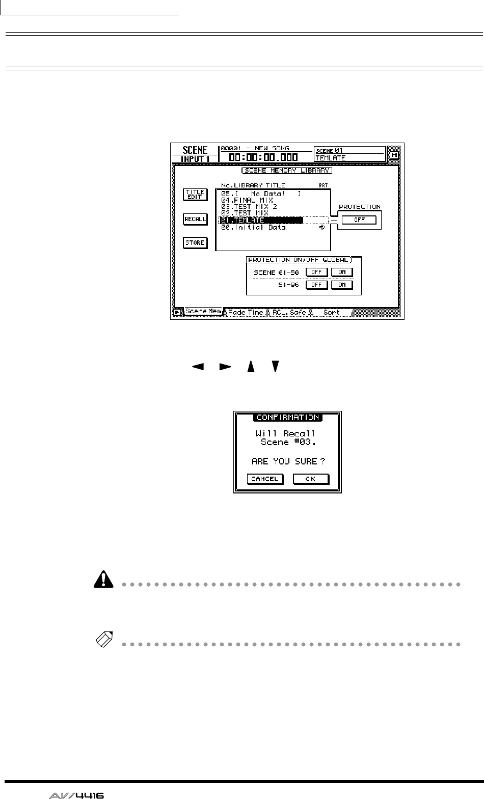
Chapter13—Scene memory
206 — Operation Guide
Recalling a scene
Here’s how to recall the scene data stored in a scene memory.
1. Press the [SCENE] key → [F1] key.
The Scene Mem page of the SCENE screen will appear.
2. Use the [DATA/JOG] dial to select the scene that you wish to recall.
3. Use the CURSOR [ ]/[ ]/[ ]/[ ] keys to move the cursor to the
RECALL button and press the [ENTER] key.
A popup window will appear, asking you to confirm the recall.
4. To execute the recall, move the cursor to the OK button and press the
[ENTER] key.
To cancel without recalling, move the cursor to the CANCEL button and press the
[ENTER] key.
When you execute the recall, the data of the current scene will be discarded. If
you will need to reproduce the current scene, you must save it before recalling
another scene.
Tip!
• You can use the keys of the SCENE MEMORY section to recall a scene even
when you are in a screen other than the SCENE screen Scene Mem page. For
details refer to page 212.
• You can use program changes to recall AW4416 scenes from an external
device (
→
P.235), or use the automix function to recall scenes (
→
P.225).
• If desired, you can specify the time (fade time) over which the faders will move
to their new locations when a scene is recalled, or exclude specific faders from
the recall. For details on these settings, refer to the Reference Guide “SCENE
screen/Fade Time page”, “SCENE screen/RCL. Safe page”.
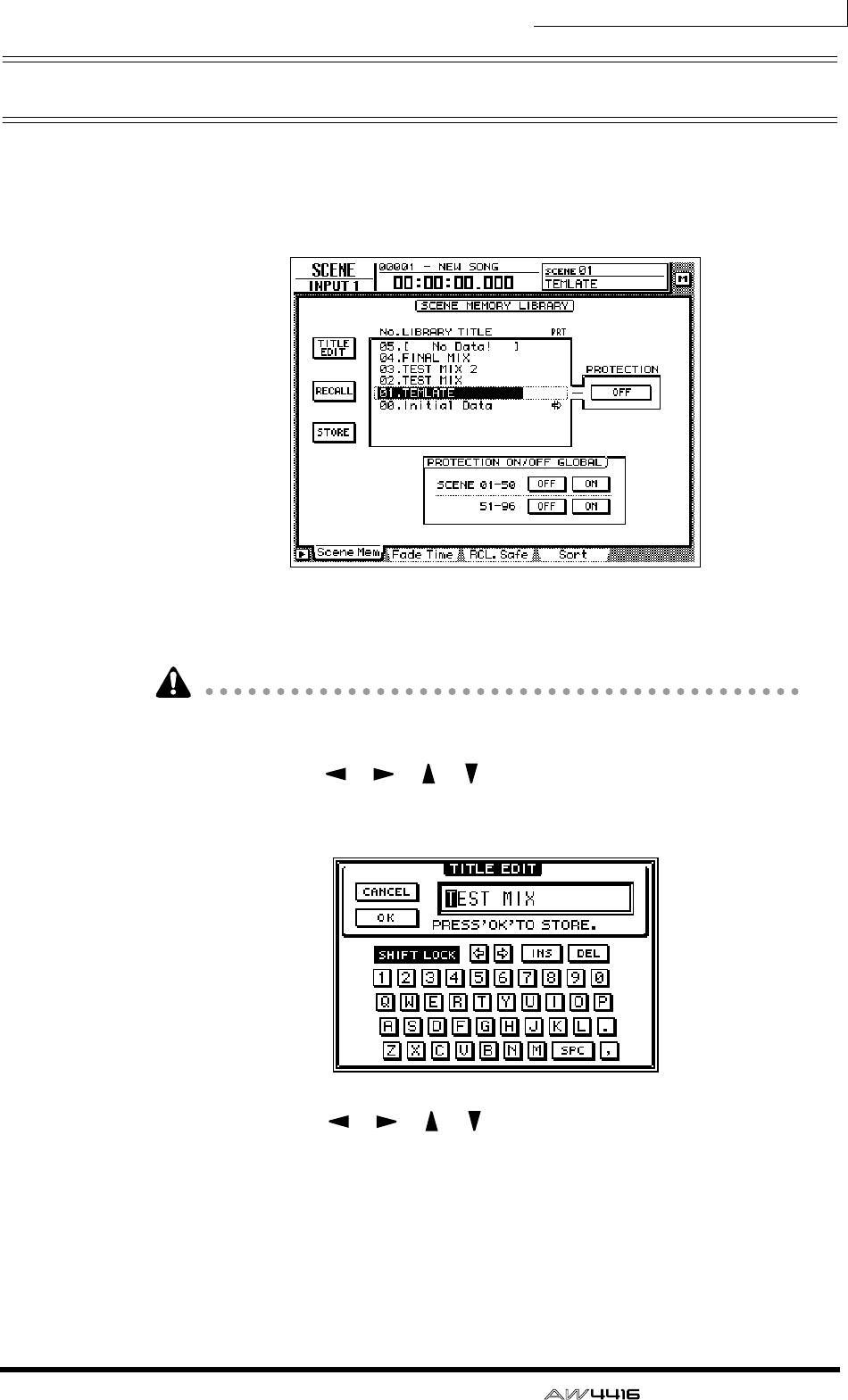
Chapter13—Scene memory
— Operation Guide 207
Editing the name of a scene
Here’s how you can edit just the name of a stored scene.
1. Press the [SCENE] key → [F1] key.
The Scene Mem page of the SCENE screen will appear.
2. Use the [DATA/JOG] dial to select the scene whose scene name you wish
to edit.
It is not possible to select a scene that has not been stored, a scene whose protect
setting is on, or scene number 00.
3. Use the CURSOR [ ]/[ ]/[ ]/[ ] keys to move the cursor to the TITLE
EDIT button in the upper left of the display, and press the [ENTER] key.
The TITLE EDIT popup window will appear, allowing you to edit the scene name.
4. Use the CURSOR [ ]/[ ]/[ ]/[ ] keys and the [ENTER] key to input
the new scene name.
5. To finalize the edited scene name, move the cursor to the OK button
and press the [ENTER] key.
The scene name will be updated. If you wish to cancel without changing the
scene name, move the cursor to the CANCEL button and press the [ENTER] key.
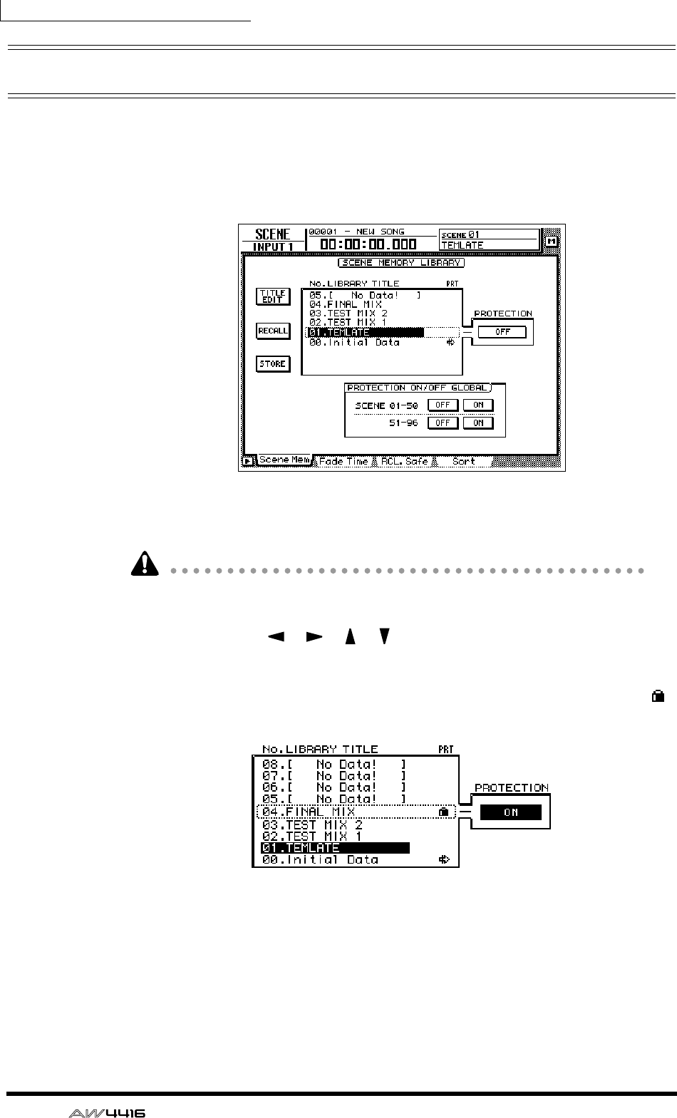
Chapter13—Scene memory
208 — Operation Guide
Protecting a scene
You can memory-protect each individual scene that has been stored. A scene
number for which protect is turned on can only be recalled.
1. Press the [SCENE] key → [F1] key.
The Scene Mem page of the SCENE screen will appear.
2. Use the [DATA/JOG] dial to select the scene number that you wish to
protect.
It is not possible to select a scene number that has not been stored or scene num-
ber 00.
3. Use the CURSOR [ ]/[ ]/[ ]/[ ] keys to move the cursor to the PRO-
TECTION field and press the [ENTER] key.
The button display will change from “OFF” to “ON,” indicating that the selected
scene is protected. Scenes that are protected will be indicated by a lock icon ( )
displayed in the PRT column of the list.
4. To turn protect off, use the [DATA/JOG] dial to select a protected scene
in the same page, move the cursor to the PROTECTION button, and
press the [ENTER] key.
The button display will change from “ON” to “OFF,” indicating that protect has
been turned off.
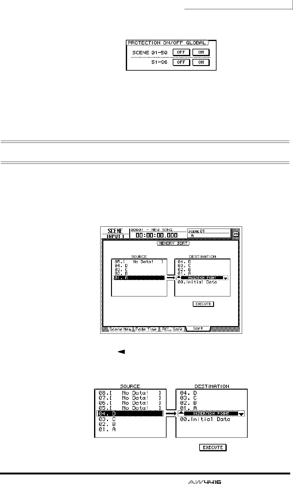
Chapter13—Scene memory
— Operation Guide 209
By using the PROTECTION ON/OFF GLOBAL buttons in the Scene Mem page,
you can turn protect on/off for entire groups of scene memories.
❍ SCENE 01–50 ON/OFF buttons
Turn protect on/off for scene numbers 01–50.
❍ SCENE 51–96 ON/OFF buttons
Turn protect on/off for scene numbers 51–96.
Changing the order of scenes
Any scene saved in scene numbers 01–96 can be moved to a different scene
number.
1. Press the [SCENE] key → [F4] key.
In this example, scene names “A,” “B,” “C,” and “D” have been saved in scene
numbers 01–04.
2. Press the CURSOR [ ] key to move the cursor to the list at left
(SOURCE), and use the [DATA/JOG] dial to select the move source scene.
In this example, we will select scene “D” which is stored in scene number 04.
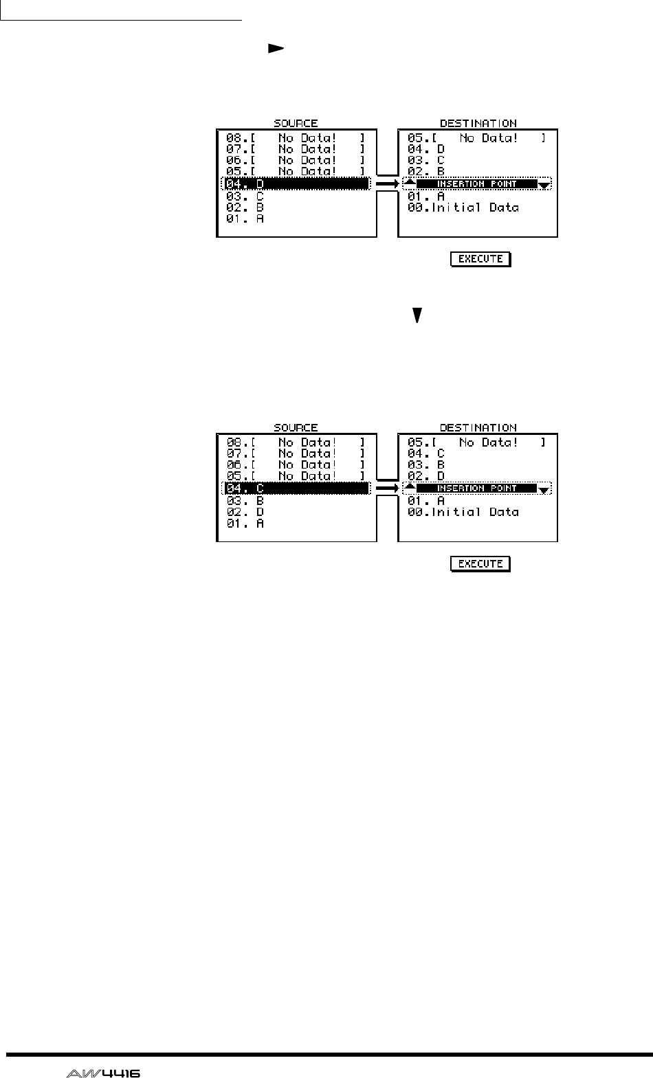
Chapter13—Scene memory
210 — Operation Guide
3. Press the CURSOR [ ] key to move the cursor to the list at right (DESTI-
NATION), and use the [DATA/JOG] dial to select the move destination.
In this example, we will select a location between scene numbers 01 and 02.
4. To move the scene, press the CURSOR [ ] key to move the cursor to the
EXECUTE button and press the [ENTER] key.
Scene “D” will move to scene number 02, and the scene numbers of scenes “B”
and “C” will be incremented. In this example, scene numbers 01–04 will be rear-
ranged in the order of scenes “A,” “D,” “B,” and “C.”
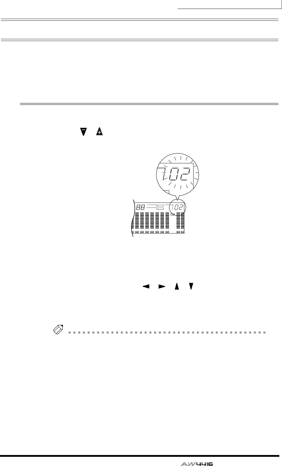
Chapter13—Scene memory
— Operation Guide 211
Using keys to store/recall a scene
You can also store/recall a scene by using the keys of the SCENE MEMORY sec-
tion. By using this method, you can perform these operations even when you are
in a screen other than the Scene Mem page of the SCENE screen. For example,
this method is convenient when you are editing mix parameters, and wish to
overwrite the same scene repeatedly.
Storing a scene
1. Use the [ ]/[ ] keys to select the store destination scene number.
The scene number is displayed in the upper right of the level meter/counter.
2. Press the [STORE] key.
The TITLE EDIT popup window will appear in the display, allowing you to specify
the scene name.
3. As desired, use the CURSOR [ ]/[ ]/[ ]/[ ] keys and the [ENTER] key
to specify the scene name.
4. To execute the Store operation, move the cursor to the OK button and
press the [ENTER] key.
Tip!
If desired, you can cause the Store operation to be executed immediately when you
press the [STORE] key, instead of accessing the popup window. For details on this
setting, refer to the Reference Guide “UTILITY screen/Prefer.1 page.”
1 2 3 4 5 6 7 8 9 13 14 15 1610 11 12
–dB 0
2
6
20
30
42
60
10
14
18
20
26
12
FINE
READY
INPUT
–dB 0
2
6
20
30
42
60
10
14
18
20
26
12
FINE
READY
INPUT
LR
REMAIN
ABS
REL
HM S Fms
EXT
VARI
44.1k 48k
LOCK
WORD CLOCK MTC SCENE
SLAVE
MASTER
INT
E
–dB 0
2
FINE
TC SCENE
VE
TER
E

Chapter13—Scene memory
212 — Operation Guide
Recalling a scene
1. Use the [ ]/[ ] keys to select the scene number that you wish to
recall.
The scene number is displayed in the upper right of the level meter/counter.
2. Press the [RECALL] key.
A popup window will appear in the display, asking you to confirm the recall.
3. To execute the recall, move the cursor to the OK button and press the
[ENTER] key.
Tip!
If desired, you can cause the Recall operation to be executed immediately when
you press the [RECALL] key, instead of accessing the popup window. For details on
this setting, refer to the Reference Guide “UTILITY screen/Prefer.1 page.”

— Operation Guide 213
14 Automix
This chapter explains how to record and play back automix, and how to
edit a recorded automix.
What is automix?
The AW4416 provides an “automix function” that allows controller operations
and parameter changes to be recorded in realtime along with the song. Scene
recall operations or movements of the channel faders and [ON] keys can be
recorded into the automix to completely automate the mix. You will find this par-
ticularly valuable when performing ping-pong recording or during mixdown.
The following items can be recorded in the automix.
• Fader operations of each channel
• [ON] key operations of each channel
• Pan operations of each channel
• EQ operations of each channel
• AUX send operations of each channel
• Scene memory/library recall operations
You can record fader operations, pan operations, EQ operations, and scene mem-
ory recall operations etc. in separate passes, or use punch-in/out to re-record spe-
cific items. The timing and values of individual pieces of recorded data (referred
to as “events”) can be edited off-line (i.e., with automix stopped).
Up to sixteen different automixes can be stored in internal memory for a song,
and you can recall and use any one of these automixes as desired. (The currently
selected automix is called the “current automix.”) The sixteen automixes saved in
internal memory are saved on the hard disk as part of the currently selected song
(the current song).
The automix of the AW4416 is always linked to the absolute time of the song.
When you play back the song, automix will start playing or recording at the same
absolute time, and when you stop the song, automix will also stop. It is not pos-
sible to use the automix function by itself with the song stopped, or to change the
alignment between the starting location of the song and the starting location of
automix.
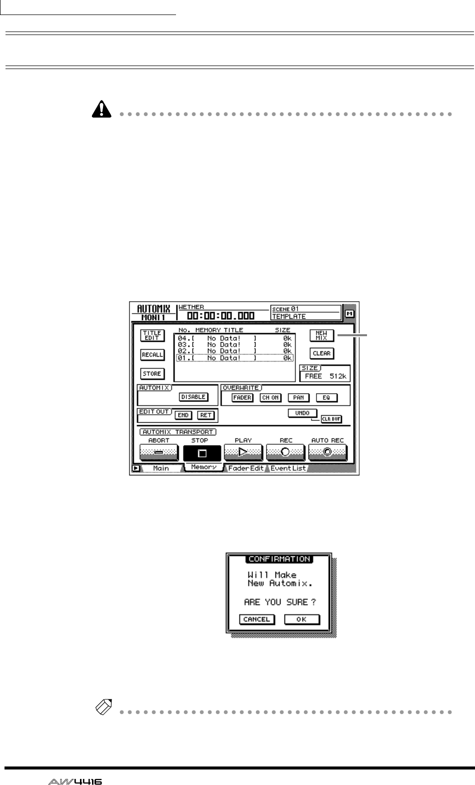
Chapter14—Automix
214 — Operation Guide
Creating a new automix
In order to record an automix, you must first create a new automix.
When you create a new automix, the contents of the current automix will be
erased. If you wish to save the contents of the current automix, refer to page 228
“Storing an automix.”
1. While playing back the beginning of the song, set the channel faders,
pan, EQ, and effect send/return etc., and save the settings in a scene
memory.
The scene you save here will be the starting point for recording the automix.
Alternatively, if you wish to use a previously-recorded scene as the starting point
for the automix, recall that scene.
2. Press the [AUTOMIX] key → [F2] key.
The following display will appear.
3. Move the cursor to the NEW MIX button in the upper right of the
screen, and press the [ENTER] key.
A message of “Will Make New Automix, ARE YOU SURE?” will appear.
4. Move the cursor to the OK button and press the [ENTER] key.
The current automix will be erased, and the automix will be initialized.
Note
If you decide to cancel without creating a new automix, move the cursor to the
CANCEL button after step 3, and press the [ENTER] key.
NEW MIX button
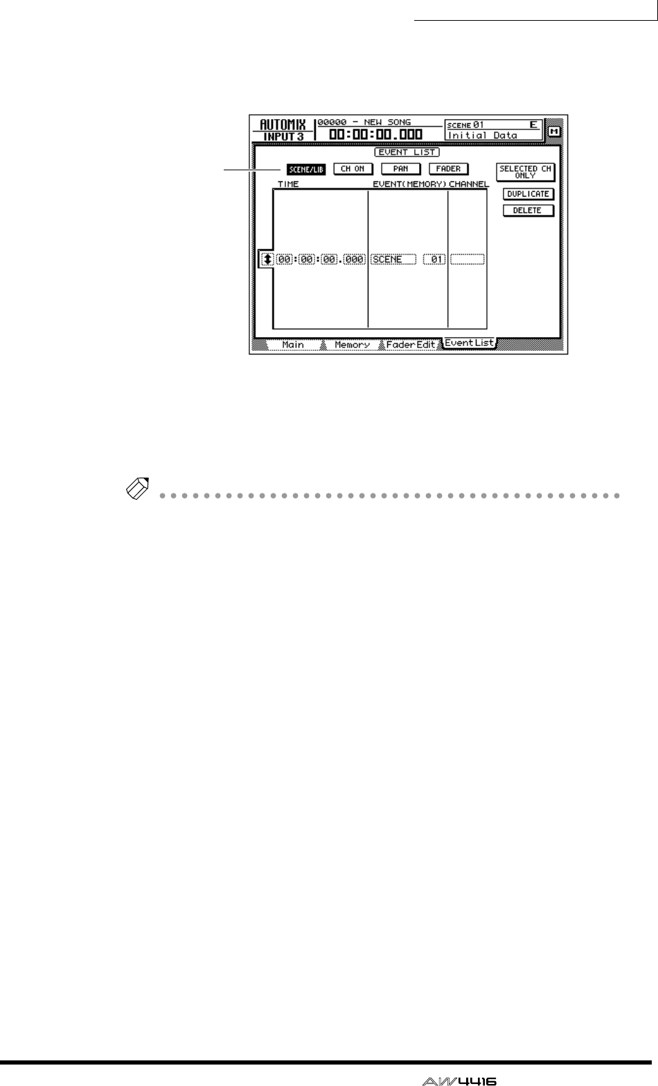
Chapter14—Automix
— Operation Guide 215
5. Press the [F4] key.
The Event List page will appear, where you can edit the events recorded in the
current automix.
Notice that data for the scene number you saved in step 1 is entered at the
“00:00:00.000” location in the TIME column. This event recalls a scene at abso-
lute time location “00:00:00.000” of the song. When you create a new automix,
data recalling the current scene (the last recalled or stored scene) will be written
into this location. This scene number or time can be modified later if desired.
Note
If an event recalling the scene memory is not displayed when you press the [F4] but-
ton, make sure that the SCENE/LIB button in the upper left of the screen is on (high-
lighted).
On
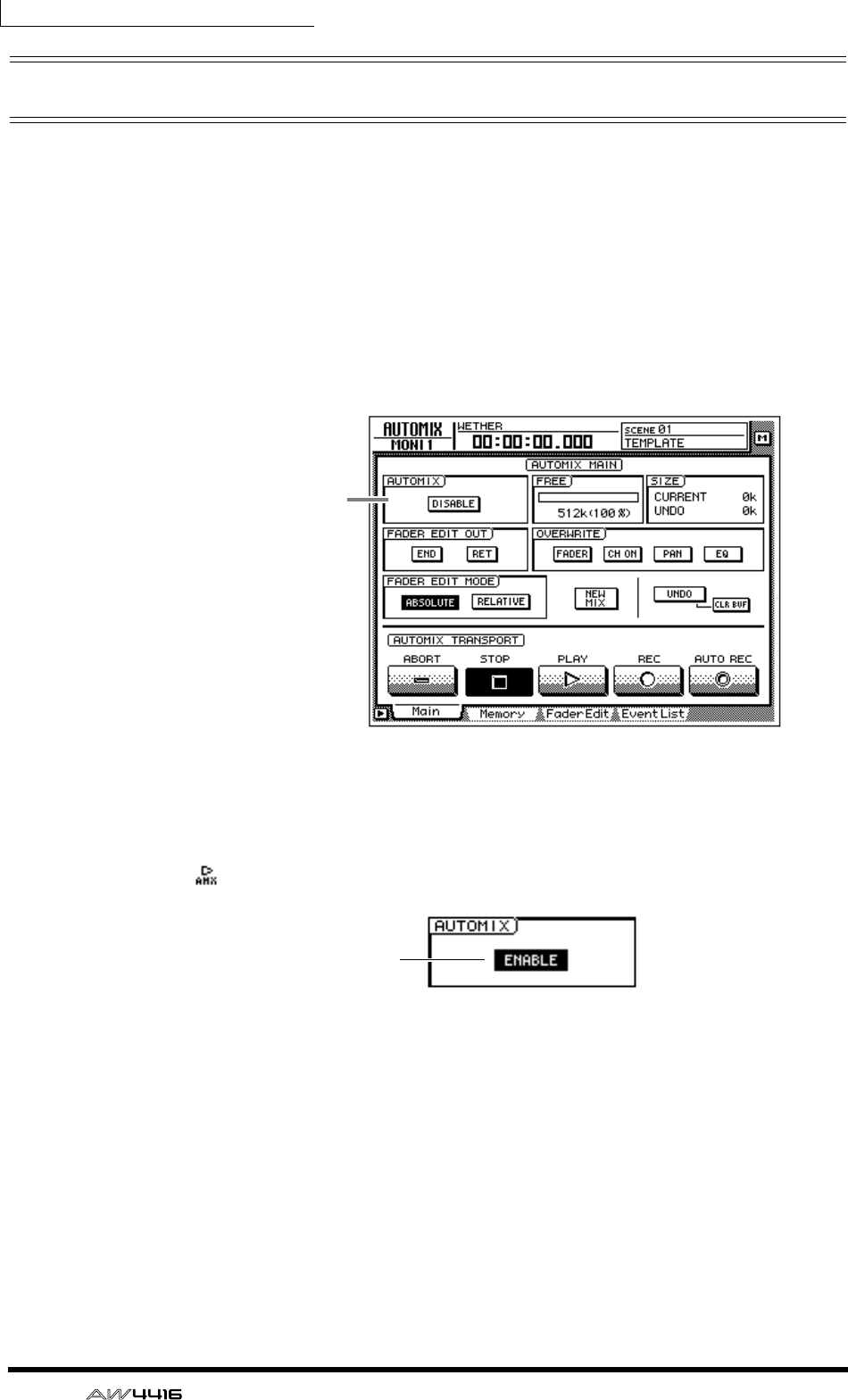
Chapter14—Automix
216 — Operation Guide
Recording the first section
Here we will explain the procedure for recording fader operations of the monitor
channels.
1. Press the [HOME] key of the FADER MODE section, and the [MONI] key
of the MIXING LAYER section.
Faders 1–16 will function as the channel faders for monitor channels 1–16.
2. Locate the song to a point slightly earlier than where you wish to begin
recording the automix.
3. Press the [AUTOMIX] key → [F1] key.
4. Move the cursor to the DISABLE button of the AUTOMIX field, and press
the [ENTER] key.
The button will be turned on (highlighted), and its title will change to ENABLE.
Now automix is on (i.e., can be recorded or played). Whenever automix is on,
the icon will always be displayed at the left of the on-screen counter.
5. Move the cursor to the OVERWRITE field. Turn the FADER button on,
and turn off the remaining buttons (CH ON, PAN, EQ).
The FADER/CH ON/PAN/EQ buttons in the OVERWRITE field are used to select
the events that will be recorded in the automix. If a button is on (highlighted), the
corresponding type of event can be recorded in the automix. The following
events correspond to each button.
• FADER..................Operations of the faders and AUX send 1–8 faders of each
channel
• CH ON.................Operations of the [ON] switches of each channel
• PAN......................Pan operations of each channel
• EQ........................EQ operations of each channel
AUTOMIX field
On
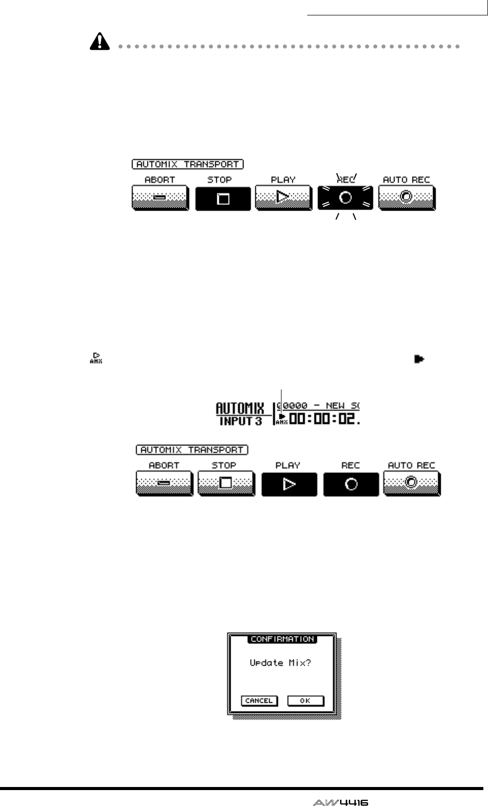
Chapter14—Automix
— Operation Guide 217
Scene and library recall operations can be recorded at any time, regardless of
these settings.
6. Move the cursor to the REC button in the screen, and press the [ENTER]
key.
The REC button will blink, indicating that the AW4416 is ready to record auto-
mix.
7. Use the [SEL] keys to select the channels whose fader operations you
wish to record.
When automix is in record-ready mode, you can use the [SEL] keys to select the
channel that will be recorded. At this time, the [SEL] keys will blink.
8. Press the [PLAY] key on the top panel to begin song playback.
When you press the [PLAY] key, the REC button in the screen will turn on (high-
lighted), and automix recording will begin. While automix is being recorded, the
symbol at the left of the on-screen counter will be highlighted ( ).
9. While listening to the song, operate the faders of each channel.
10. When you have finished your operations, press the [STOP] key on the
top panel to stop the song.
The on-screen REC button will turn off (normal display), and automix recording
will stop. A message will ask whether you wish to update the automix with the
newly recorded content.
on (highlighted)
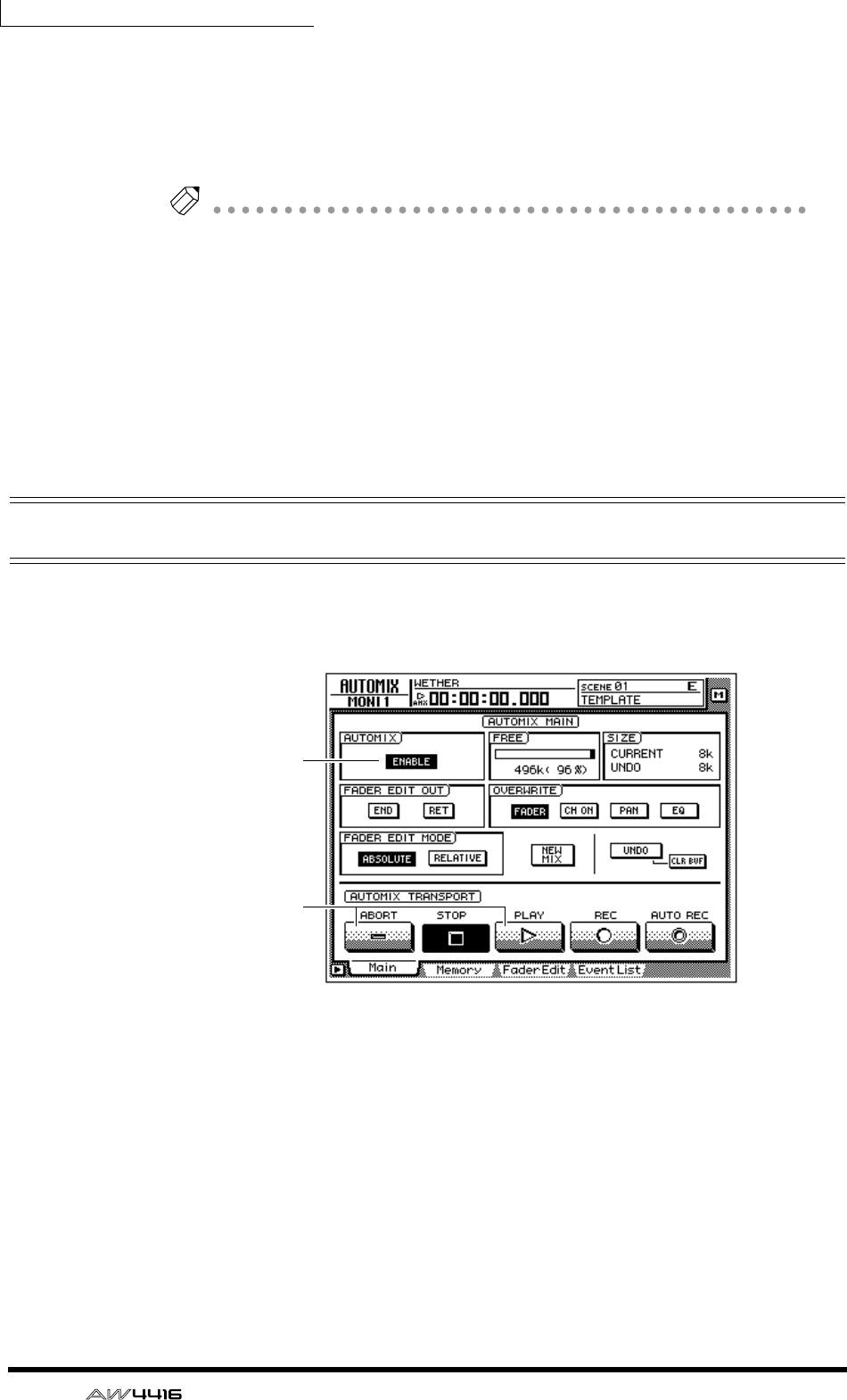
Chapter14—Automix
218 — Operation Guide
11. If you wish to update the automix with the newly recorded content,
move the cursor to the OK button and press the [ENTER] key.
The automix will be updated. If you move the cursor to the CANCEL button and
press the [ENTER] key, the recorded content will be discarded, and the automix
will return to its previous state.
Note
• If in step 10 you move the cursor to the ABORT button and press the [ENTER]
key, the recorded content will be discarded in the same way, and the automix
will return to its previous state.
• Automix recording can also be stopped by using the on-screen STOP button
instead of the [STOP] key. In this case, automix recording will stop, but the
song will continue playing.
• Even after updating the automix content, you still move the cursor to the
UNDO button in the right side of the screen, and press the [ENTER] key to
return the automix to its state before recording (Undo). The front panel
[UNDO] key cannot be used to undo automix.
Playing back automix
Here’s how to play back the recorded automix.
1. Press the [AUTOMIX] key → [F1] key.
2. Make sure that the button in the AUTOMIX field is displayed as
“ENABLE.”
If the button is displayed as “DISABLE,” move the cursor to the button, and press
the [ENTER] key.
3. Make sure that the on-screen REC button and AUTO REC button are
turned off.
If they are on, move the cursor to the corresponding button, and press the
[ENTER] key.
4. Locate the song to a point slightly earlier than where you began record-
ing automix, and press the top panel [PLAY] key.
On
Off
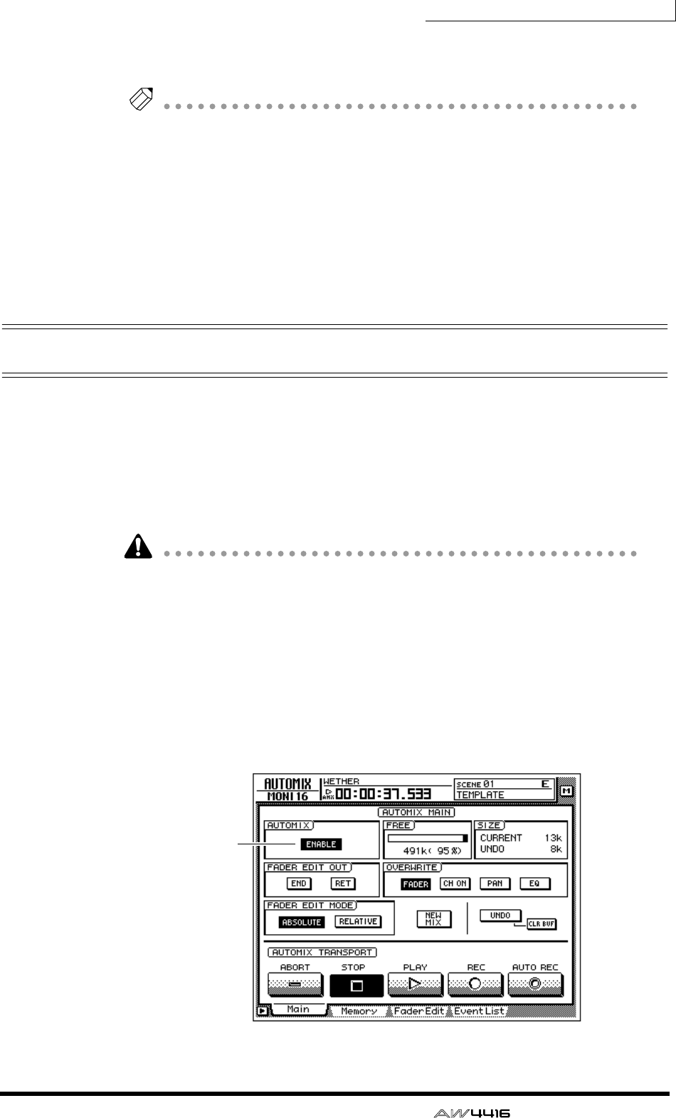
Chapter14—Automix
— Operation Guide 219
The on-screen PLAY button will turn on (the STOP button will turn off), and auto-
mix will begin playing automatically.
Note
If you begin playback from the middle of the song, automix will also begin playing
from the same location. At this time if any automix events exist before the playback
start location, automix will begin playback from a state of having executed all of
these earlier events (i.e., the mix will be updated before playback begins).
5. To stop automix playback, move the cursor to the on-screen STOP but-
ton and press the [ENTER] key, or press the top panel [STOP] key.
Even if automix is not stopped manually in this way, it will stop automatically
after all of the recorded automix events have been played.
Overwriting events
New data can be overwritten (added or rewritten) onto a previously-recorded
automix, either on a different channel or different mix element on the same chan-
nel. For example after recording fader operations for monitor channel 1, you can
then record fader operations for monitor channel 2, or record pan operations on
the same channel. The following explanation shows pan or EQ operations can be
overwritten onto an automix that already contains previously-recorded opera-
tions of the monitor channel faders.
You can use the same procedure to overwrite (rewrite) the previously-recorded
events of a previously-recorded channel. In this case, the previously-recorded
content will be erased when you begin overwrite-recording.
1. Press the [HOME] key of the FADER MODE section, and the [MONI] key
of the MIXING LAYER section.
2. Locate the song to a point slightly before the location where you wish to
begin overwriting.
3. Press the [AUTOMIX] key → [F1] key.
On
Chapter14—Automix
220 — Operation Guide
4. Make sure that the button in the AUTOMIX field is displayed as
“ENABLE.”
5. Move the cursor to the OVERWRITE field. Turn the PAN button and EQ
button on, and the remaining buttons (FADER, CH ON) off.
6. Move the cursor to the on-screen REC button, and press the [ENTER]
key.
7. Press [SEL] key 1.
Monitor channel 1 will be selected for recording.
You can use the [SEL] keys to select multiple channels for overwriting. However,
operations of the [PAN]/[EQ] controls will be recorded only for the channel that
you selected last by pressing the [SEL] key.
8. Press the top panel [PLAY] key to begin song playback.
Simultaneously with the start of song playback, the previously-recorded automix
will also play back.
9. While listening to the song, operate the [PAN] control.
When recording pan or EQ operations in the automix, it is convenient to use the
[PAN]/[EQ] controls at the right of the display.
Note
When you operate the [PAN] control and [EQ] controls, the pan and EQ settings of
the corresponding channel will be displayed briefly in the upper part of the screen.
10. When you are finished, press the top panel [STOP] key.
Automix recording will stop, and a message will ask whether you wish to update
the automix with the newly recorded content.
11. To update the automix with the newly recorded content, move the cur-
sor to the OK button and press the [ENTER] key.
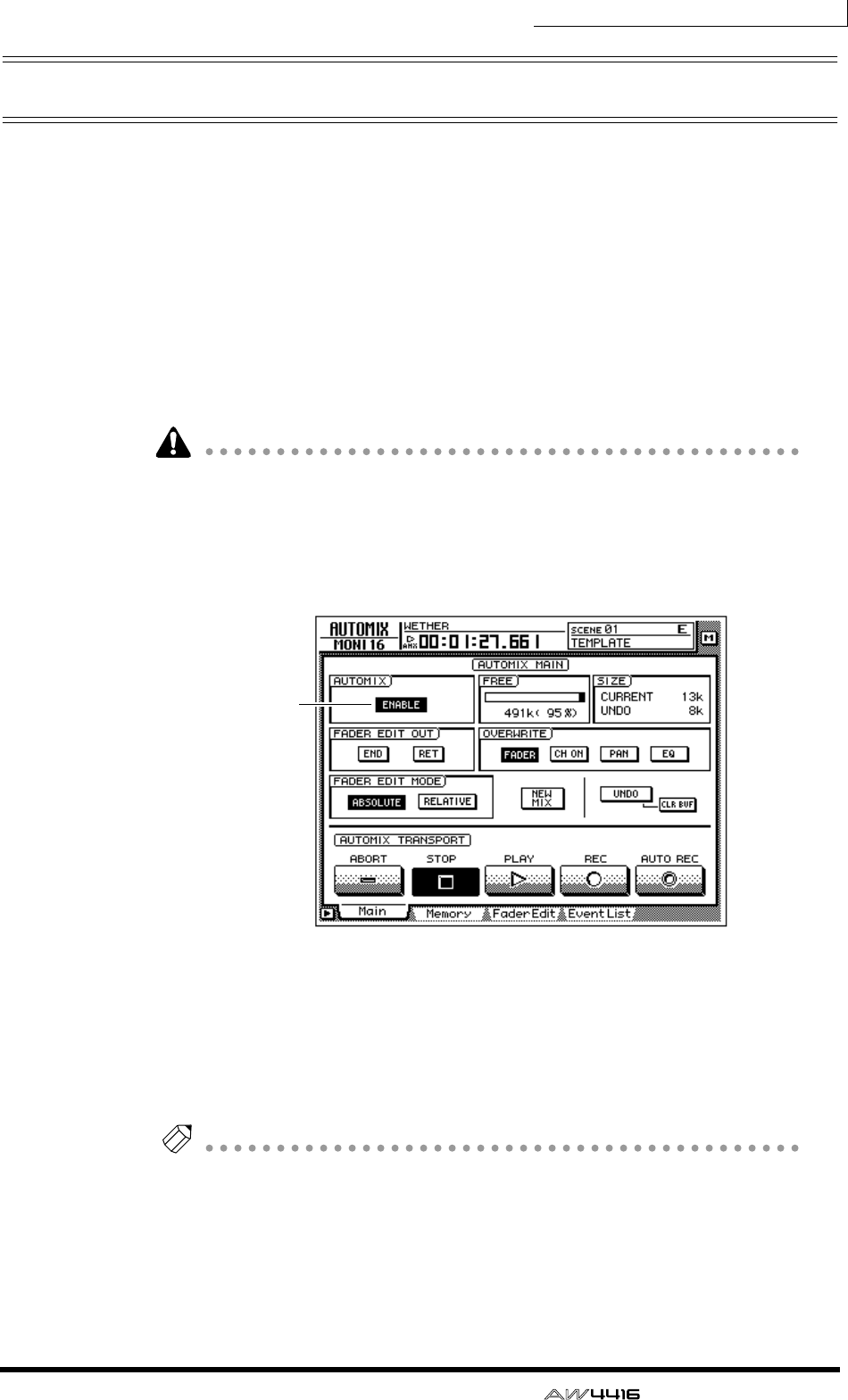
Chapter14—Automix
— Operation Guide 221
Automix punch-in/out
If you make a mistake while recording the automix, you can re-record just the
location of your error (punch-in/out). As an example here, we will explain how to
punch-in/out to re-record the pan operations of monitor channel 1 that you
already recorded. When punching-in/out on only a specific channel, it is conve-
nient to use the on-screen AUTO REC button instead of the on-screen REC but-
ton.
1. Press the [HOME] key in the FADER MODE section, and the [MONI] key
in the MIXING LAYER section.
2. Locate the song to a point slightly earlier than the location where you
wish to punch-in.
If you will be punching-in/out repeatedly on the automix, it is convenient to set a
locate point at a location earlier than the intended punch-in. For details on
locate points, refer to page 109.
3. Press the [AUTOMIX] key → [F1] key.
Make sure that the AUTOMIX button is displayed as “ENABLE.”
4. Move the cursor to the OVERWRITE field. Turn the PAN button on, and
the remaining buttons (FADER, CH ON, EQ) off.
5. Move the cursor to the AUTO REC button in the lower right of the
screen, and press the [ENTER] key.
The AUTO REC button will turn on.
Note
When you use the AUTO REC button instead of the REC button, you can select the
recording channel after placing automix in record-ready mode. It is not necessary to
use the [SEL] keys to select the channel beforehand.
On

Chapter14—Automix
222 — Operation Guide
6. Press the top panel [PLAY] key to play back the song.
When song playback is started with the AUTO REC button on, the REC button
will be turned on automatically, and automix will be in record mode. However,
recording will not actually occur since the recording channel has not yet been
selected.
7. When the song arrives at the punch-in location, press [SEL] key 1 (moni-
tor channel 1).
Recording of pan operations on the corresponding channel will begin at the
moment you press the [SEL] key (punch-in). At this time, the corresponding [SEL]
key will blink.
8. While listening to the song, operate the [PAN] control.
9. When you are finished, press the [SEL] key of the same channel once
again.
The [SEL] key of the corresponding channel will go dark, and recording will end
(punch-out). Automix will still be in a recordable state, but recording will not
actually occur since no recording channel is selected.
Note
If you did not operate the [PAN] control in step 8, the currently-recorded pan oper-
ation events between the punch-in and punch-out locations will be erased. This
method can be used to erase specific events from the corresponding section of the
song.
10. Press the top panel [STOP] key.
A message will ask whether you wish to update the automix with the newly
recorded content. If you wish to update the automix, move the cursor to the OK
button and press the [ENTER] key.
When you stop the song, the on-screen REC will return to the Off state. However,
since the AUTO REC button will remain on, you can punch-in on the automix
again by pressing the [PLAY] key. If you wish to turn off the AUTO REC button,
move the cursor to the AUTO REC button, and press the [ENTER] key.
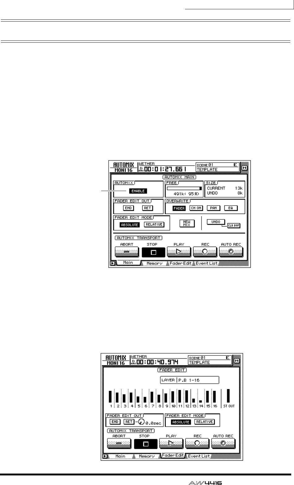
Chapter14—Automix
— Operation Guide 223
Editing the fader movements
Fader operation events recorded in the automix can be precisely edited in real-
time while watching the fader movements in a special screen. As an example
here, we will explain how to edit the previously-recorded fader movements of
monitor channel 1.
1. Press the [HOME] key of the FADER MODE section, and the [MONI] key
of the MIXING LAYER section.
2. Locate the song to a point slightly earlier that where you wish to punch-
in.
3. Press the [AUTOMIX] key → [F1] key.
Make sure that the button in the AUTOMIX field is displayed as “ENABLE.”
4. Move the cursor to the OVERWRITE field. Turn the FADER button on,
and the other buttons (CH ON, PAN, EQ) off.
5. Press the [F3] key.
A page will appear in which the current locations for the faders of each channel
(monitor channels 1–16) are shown as a bar graph. When you wish to make
detailed edits to the fader movements recorded in the automix, it is convenient to
do so while viewing this screen.
On

Chapter14—Automix
224 — Operation Guide
6. Make sure that the ABSOLUTE button in the FADER EDIT MODE field is
turned on.
The two buttons of the FADER EDIT MODE field in the screen are used to select
the fader editing method. When the ABSOLUTE button is on, previously-
recorded events will be erased, and new events will be recorded.
Note
Use the RELATIVE button when you wish to make relative changes to the previ-
ously-recorded fader events. For details refer to the Reference Guide “AUTOMIX
screen/Main page.”
7. Move the cursor to the on-screen AUTO REC button, and press the
[ENTER] key.
8. Press the top panel [PLAY] key to play back the song.
When song playback is started with the AUTO REC button on, the REC button
will be turned on automatically, and automix will be in record mode. However,
recording will not actually occur, since a recording channel has not yet been
selected.
9. While listening to the song, press [SEL] key 1 (monitor channel 1) at the
point where you wish to punch-in, and begin operating the fader.
Punch-in will begin at the instant you press the [SEL] key. When you operate the
fader, the previously-recorded position of the fader and the position currently
being recorded will both be displayed in the bar graph. The upward or downward
arrow shown beside the bar graph indicates the direction in which you can move
the fader to return to the previously-recorded position.
10. When you are finished operating the fader, press the [SEL] key of the
same channel to punch-out.
Note
If you turn on the RET button in the FADER EDIT OUT field before you begin
punch-in, the faders will automatically return to the previously-recorded positions
as soon as you punch-out. This is convenient when you wish to change the level
only for the punch-in/out area. You can use the knob located at the right of the RET
button to adjust the time over which faders will return to the previously-recorded
positions. For details refer to the Reference Guide “AUTOMIX screen/Main page.”
Previously-recorded
fader/encoder position
Fader/encoder position
now being recorded
Fader/encoder position
now being recorded
Previously-recorded
fader/encoder position
(1) If the fader/encoder is lowered
below the previous value
(2) If the fader/encoder is raised
above the previous value
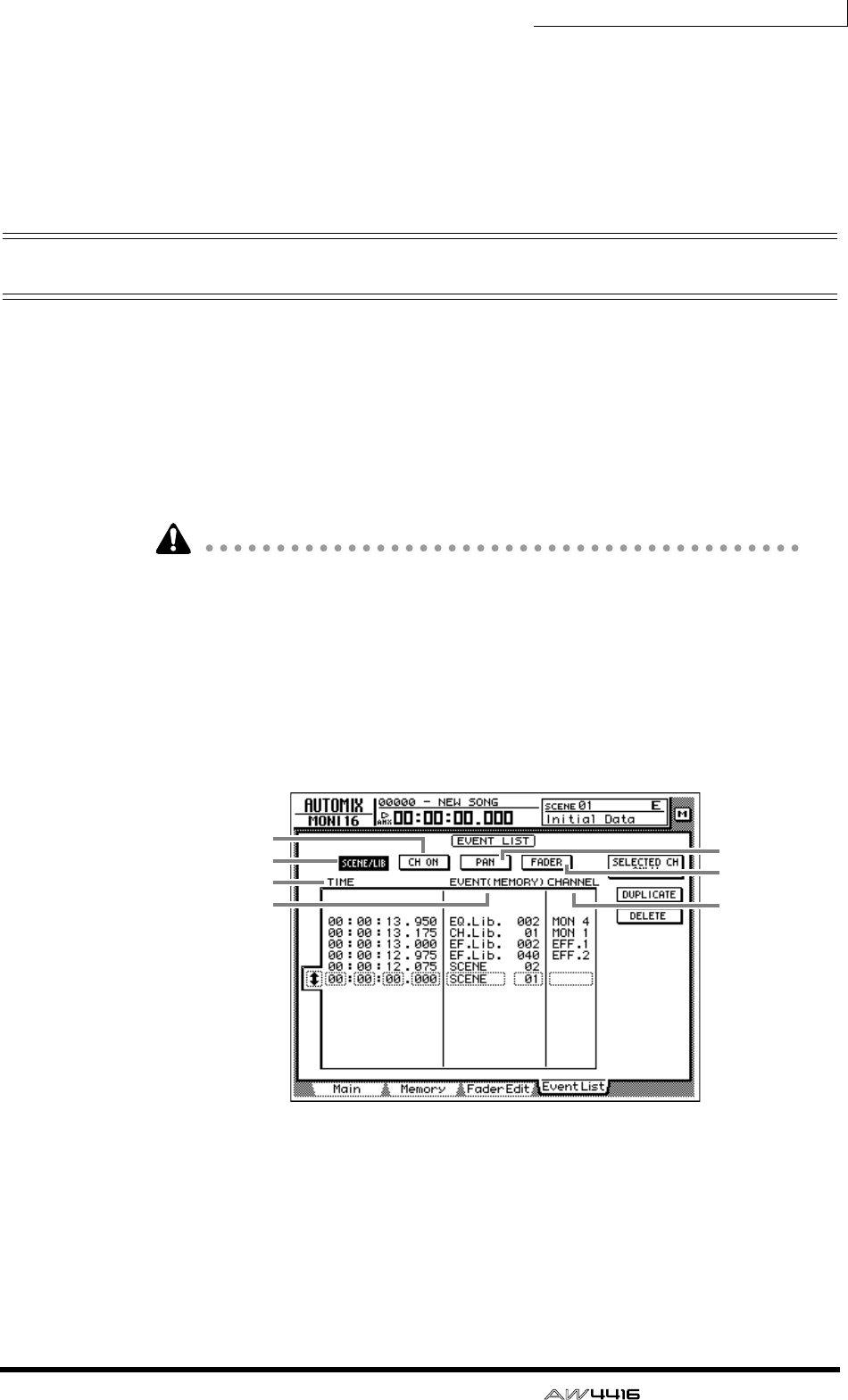
Chapter14—Automix
— Operation Guide 225
11. When you are finished with punch-in/out, press the top panel [STOP]
key.
A message will ask you whether you wish to update the automix with the newly
recorded content. If you wish to update the automix, move the cursor to the OK
button and press the [ENTER] key.
Editing automix off-line
While the AW4416 is off-line, you can adjust the timing or value of previously-
recorded events, or delete unwanted events. The following types of event can be
edited off-line.
• Fader operations for each channel
• [ON] key operations for each channel
• Pan operations for each channel
• Scene memory or library recall operations
Event times are always displayed as absolute song time. For this reason, we rec-
ommend that you display the absolute song time in the counter when editing
events off-line (
→
P.39).
As an example, we will explain how to edit a scene recall or library recall event.
1. Press the [AUTOMIX] key → [F4] key.
The EventList page will appear, displaying a list of the events recorded in auto-
mix.
Use the SCENE/LIB, CH ON, PAN, and FADER buttons in the upper part of the
screen to select the type of events that will be displayed. The following events
correspond to each button.
1SCENE/LIB button.......Scene or library recall operations
BCH ON button ............[ON] key operations for each channel
CPAN button .................Pan operations for each channel
DFADER button .............Fader operations for each channel
1
5
7
3
4
2
6
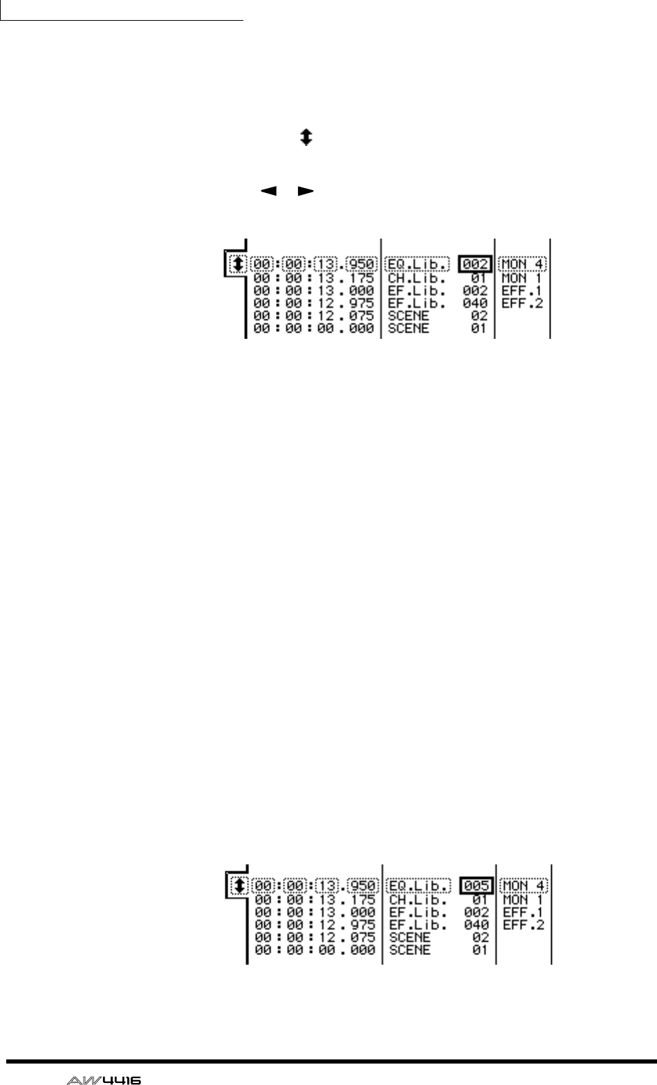
Chapter14—Automix
226 — Operation Guide
2. Move the cursor to the SCENE/LIB button, and press the [ENTER] key.
The scene/library recall events recorded in the automix will be displayed in the
list. The event enclosed by the dashed line in the center of the list is the event cur-
rently selected for editing.
3. Move the cursor to the at the left of the list, and rotate the [DATA/
JOG] dial to scroll the list and select the event that you wish to edit.
4. Use the CURSOR [ ]/[ ] keys to move the cursor to the data item
within that event that you wish to edit.
ETIME
The timing at which the event will be executed is displayed as “hours:min-
utes:seconds:milliseconds.”
FEVENT
This area shows the type and value of the event. The type of events that can be
selected in this area will depend on which of the buttons above has been pressed.
When the SCENE/LIB button is on, the following events can be selected.
• SCENE .................Scene memories. The value at the right is the number of the
scene that will be recalled.
• EQ.Lib. ................EQ libraries. The value at the right is the number of the EQ
library that will be recalled.
• DY.Lib. ................Dynamics libraries. The value at the right is the number of
the dynamics library that will be recalled.
• EF.Lib. ..................Effect libraries. The value at the right is the number of the
effect library that will be recalled.
• CH.Lib. ................Channel libraries. The value at the right is the number of the
channel library that will be recalled.
GCHANNEL
This shows the channel (input channels 1–24, monitor channels 1–16, stereo out-
put channel, return channels 1/2) for which the event will be recalled. This will
be blank if scene memory has been selected in 6.
5. Rotate the [DATA/JOG] dial to modify the value of the item where the
cursor is located.

Chapter14—Automix
— Operation Guide 227
When you change the timing of an event, the cursor may jump one or more rows
of the list to another location. This is because events are sorted in order of time,
and is not a malfunction. The timing of events can be adjusted in fine steps of 25
msec.
Note
If the SELECTED CH ONLY button in the upper right of the screen is turned on, the
screen will display only events of the channel selected by the [SEL] key.
6. To add a new event, move the cursor to the DUPLICATE button in the
upper right of the screen, and press the [ENTER] key.
The event currently selected for editing will be duplicated. Modify its timing,
event type, and value as desired.
7. To delete an unwanted event, move the cursor to the DELETE button in
the upper right of the screen, and press the [ENTER] key.
The event currently selected for editing will be deleted.
Note
AUX 1–8 send level or EQ operations cannot be performed off-line. You must use
punch-in/out to overwrite or delete these operations in the specified range.
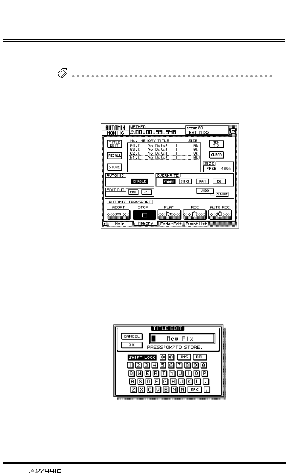
Chapter14—Automix
228 — Operation Guide
Storing an automix
When you have completed the current automix, you should assign a name and
store it in automix memory. Sixteen automixes can be stored in internal memory.
Note
Automix data that you store is saved on the hard disk as part of the current song.
This means that you can create up to sixteen different automix versions for one
song, and compare them at any time.
1. Press the [AUTOMIX] key → [F2] key.
2. Move the cursor to the list in the center of the screen, and rotate the
[DATA/JOG] dial to select the store destination automix number.
You can select automix numbers 01–16. Vacant automix numbers will be dis-
played in the list as “[ No Data! ].”
3. Move the cursor to the STORE button located at the left of the list, and
press the [ENTER] key.
A screen will appear where you can input the automix name. Assign a name of
up to sixteen characters. (For details on inputting characters, refer to page 60.)
4. After you have input the automix name, move the cursor to the OK but-
ton and press the [ENTER] key.
The current automix data will be stored in the selected automix number.

Chapter14—Automix
— Operation Guide 229
Tip!
If you turn STORE CONFIRMATION “OFF” in the Prefer.1 page of the UTILITY
screen ([UTILITY] key
→
[F2] key), the automix will be stored in the specified auto-
mix number without this screen appearing. This method is convenient when you
wish to repeatedly overwrite an automix into the same automix number.
The internal automix memory is shared between the current automix and a max-
imum of sixteen stored automixes. This means that if the current automix occu-
pies a large amount of automix memory, it may be impossible to store the
automix even if there are vacant automix numbers in the list. If this occurs, clear
previously-saved automix data that you no longer need (Refer to
the Reference
Guide “AUTOMIX screen/Memory page”
), and then execute the Store operation
once again.
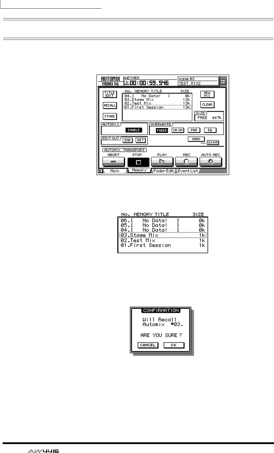
Chapter14—Automix
230 — Operation Guide
Recalling an automix
Here’s how to recall an automix that was saved in memory.
1. Press the [AUTOMIX] key → [F2] key.
2. Move the cursor to the list in the center of the screen, and rotate the
[DATA/JOG] dial to select the automix number that you wish to recall.
3. Move the cursor to the RECALL button located at the left of the list, and
press the [ENTER] key.
A message will ask you to confirm that you wish to recall the automix number
selected in step 2.
4. Move the cursor to the OK button and press the [ENTER] key.
The recall will be executed, and the current automix will be replaced by the
automix data that you recalled.

— Operation Guide 231
15 MIDI
This chapter explains how you can use MIDI when operating the AW4416.
What you can do using MIDI
On the AW4416, MIDI can be used to perform the following operations.
❍ Change scenes by remote control
By transmitting program changes from an external device to the AW4416, you
can switch AW4416 scenes by remote control. You can also cause program
changes to be transmitted to an external device when you select scenes on the
AW4416.
❍ Synchronize with an external device via MTC/MIDI Clock
Synchronization messages such as MTC (MIDI Time Code) or MIDI Clock can be
transmitted from the AW4416 to an external device such as a MIDI sequencer, so
that it will operate in synchronization with the AW4416 song. (MTC can also be
received by the AW4416.)
❍ Remote control via MMC
MMC (MIDI Machine Control) messages from a computer or other external
device can be received to remotely control the operation of the AW4416’s trans-
port, or to select/defeat recording tracks.

Chapter15—MIDI
232 — Operation Guide
MIDI connectors and the TO HOST
connector
The AW4416 provides the following connectors used to convey MIDI messages.
❍ MIDI IN connector
MIDI messages such as program change, MMC, and MTC are received at this
connector.
❍ MIDI OUT/THRU connector
By changing the setting of an internal parameter, this connector can function
either as a MIDI OUT connector or a MIDI THRU connector. When used as a
MIDI OUT connector, it will transmit MIDI messages such as program change,
MMC, and MIDI Clock. When used as a MIDI THRU connector, it will re-transmit
the messages received at the MIDI IN connector without change.
❍ MTC OUT connector
This is a dedicated output connector for MTC.
❍ TO HOST connector
A separately sold cable can be used to connect this to the serial port of your com-
puter, allowing MIDI messages to be exchanged directly between the AW4416
and your computer. In order to use this connector, you will need to set the MIDI
port setting to “TO HOST PC1,” “TO HOST PC 2,” or “TO HOST MAC,” depend-
ing on the computer you are using (→ P.233).
• The TO HOST connector cannot be used simultaneously with the MIDI IN
connector and MIDI OUT/THRU connector.
• MTC cannot be transmitted via the TO HOST connector. If you need to trans-
mit MTC to your computer, use the MTC OUT connector.
• Regardless of the port setting, the OUT/THRU connector will function as
THRU if MIDI THRU is selected.
MTC OUT OUT/ THRU IN
MIDI
TO HOST
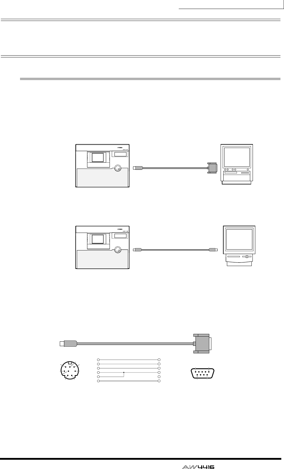
Chapter15—MIDI
— Operation Guide 233
Using the TO HOST connector for
direct connection to your computer
Connections
To exchange MIDI messages directly between the AW4416 and your computer,
use a separately sold cable to connect the TO HOST connector of the AW4416 to
the serial port of your computer.
❍ IBM/PC series: D-SUB9P → mini DIN8P cross cable
PROFESSIONAL AUDIO WORKSTATION
PROFESSIONAL AUDIO WORKSTATION
RS-232C
(DB-9)
TO HOST
connector
TO HOST
connector
Connection cable
(YAMAHA-CCJ-PC2)
MODEM
port
IBM/PC seriesAW4416
Apple Macintosh series
Connection to an IBM/PC series computer
Connection cable
(YAMAHA-CCJ-MAC)
AW4416
Connection to an Apple Macintosh series computer
PORT SELECT Setting=
TO HOST PC2
PORT SELECT Setting=
TO HOST MAC
mini DIN 8-pin 8 (CTS)
7 (RTS)
2 (RxD)
5 (GND)
3 (TxD)
1
2
3
4
8
5
D-SUB 9-pin
67
3
8
5
1
1
69
5
2
4
If your PC has a D-SUB 25-pin connector,
use a Yamaha CCJ-PC1 cable together with
a male/female conversion adapter.
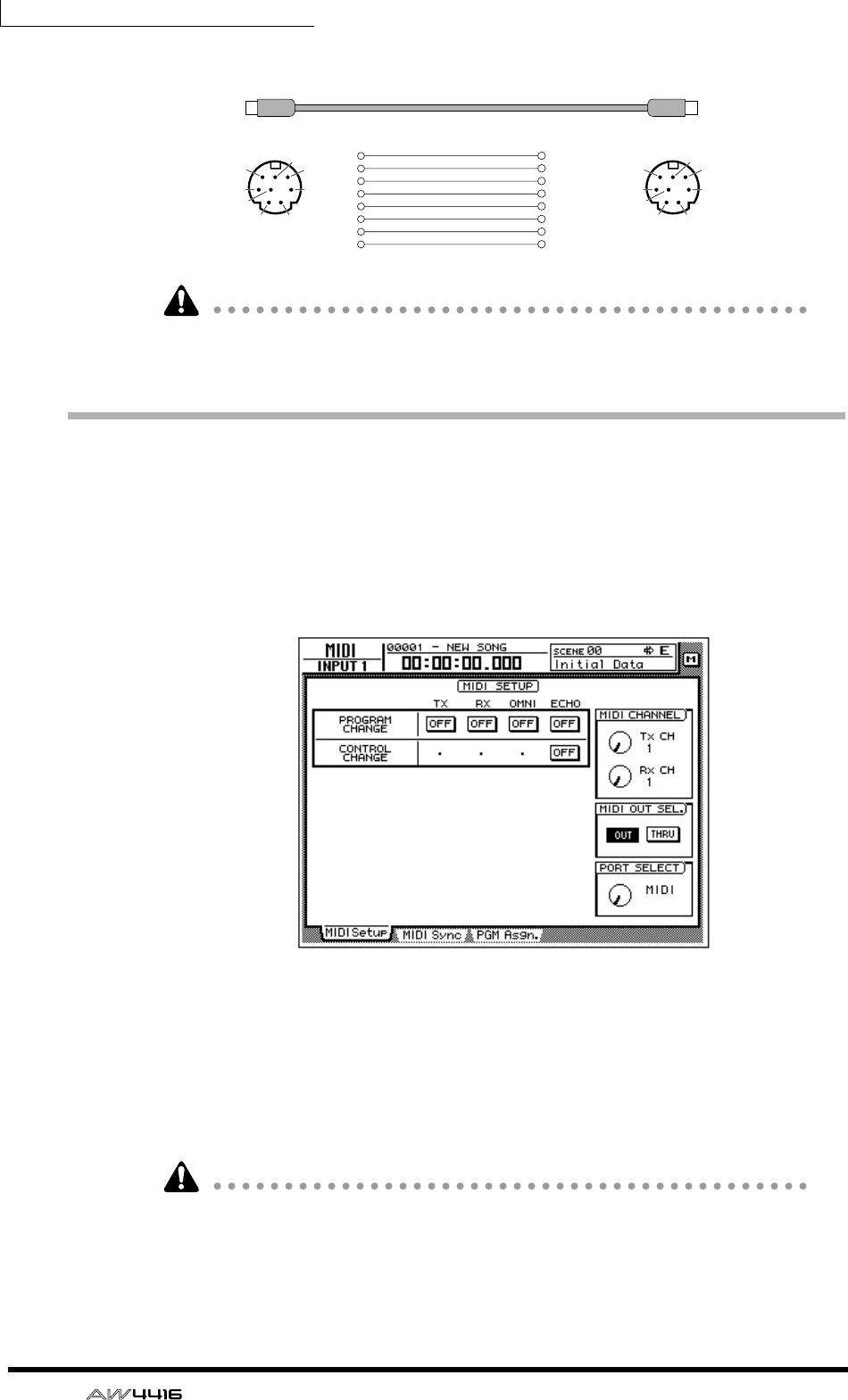
Chapter15—MIDI
234 — Operation Guide
❍ Apple Macintosh series: 8-pin system peripheral cable
In the case of some Macintosh computers that have no modem/printer cable, it is
not possible to make direct connections to the AW4416’s TO HOST connector.
Setting the PORT SELECT parameter
In order to use the TO HOST connector, the AW4416’s PORT SELECT parameter
must be set appropriately for the type of computer that is selected.
1. Press [MIDI], and then press the [F1] key.
The MIDI Setup page will appear, allowing you to make MIDI-related settings for
the AW4416.
2. Move the cursor to the PORT SELECT knob, and use the [DATA/JOG] dial
to select the setting appropriate for your computer.
The following types of computer require the following PORT SELECT parameter
settings.
• IBM/PC series: TO HOST PC 2 (38.4 kbps)
• Apple Macintosh series (models with modem/printer port): TO HOST MAC
• Depending on your system, you may need separate driver software in order to
make serial port connections.
• When connecting to a Macintosh, you must set the MIDI interface clock set-
ting of your application to 1 MHz.
mini DIN 8-pin
67
3
8
5
12
4
mini DIN 8-pin
67
3
8
5
12
4
2 (HSK i)
1 (HSK O)
5 (RxD -)
4 (GND)
3 (TxD -)
8 (RxD +)
7 (GPI)
6 (TxD +)
1
2
3
4
5
6
7
8

Chapter15—MIDI
— Operation Guide 235
Switching AW4416 scenes from an
external device
By transmitting program changes from an external device to the AW4416, you
can recall AW4416 scene memories by remote control.
1. Connect the MIDI OUT connector of the external device to the MIDI IN
connector of the AW4416.
2. Press the [MIDI] key, and then press the [F1] key.
The MIDI Setup page will appear in the display. In this page you can select the
MIDI channel on which the AW4416 will transmit and receive, and specify
whether program changes and control changes will be transmitted and received.
3. Move the cursor to the RX (receive) button in the PROGRAM CHANGE
area, and press the [ENTER] key.
The button will change from “OFF” to “ON.” With this setting, program changes
can be received.
4. Move the cursor to the Rx CH knob in the MIDI CHANNEL area, and
rotate the [DATA/JOG] dial to select the MIDI receive channel of the
AW4416.
Tip!
If you turn on the OMNI button in the PROGRAM CHANGE area, program changes
of all channels will be received.
MIDI OUT connector
MIDI IN connector
PROFESSIONAL AUDIO WORKSTATION
AW4416
External device
(MIDI sequencer etc.)
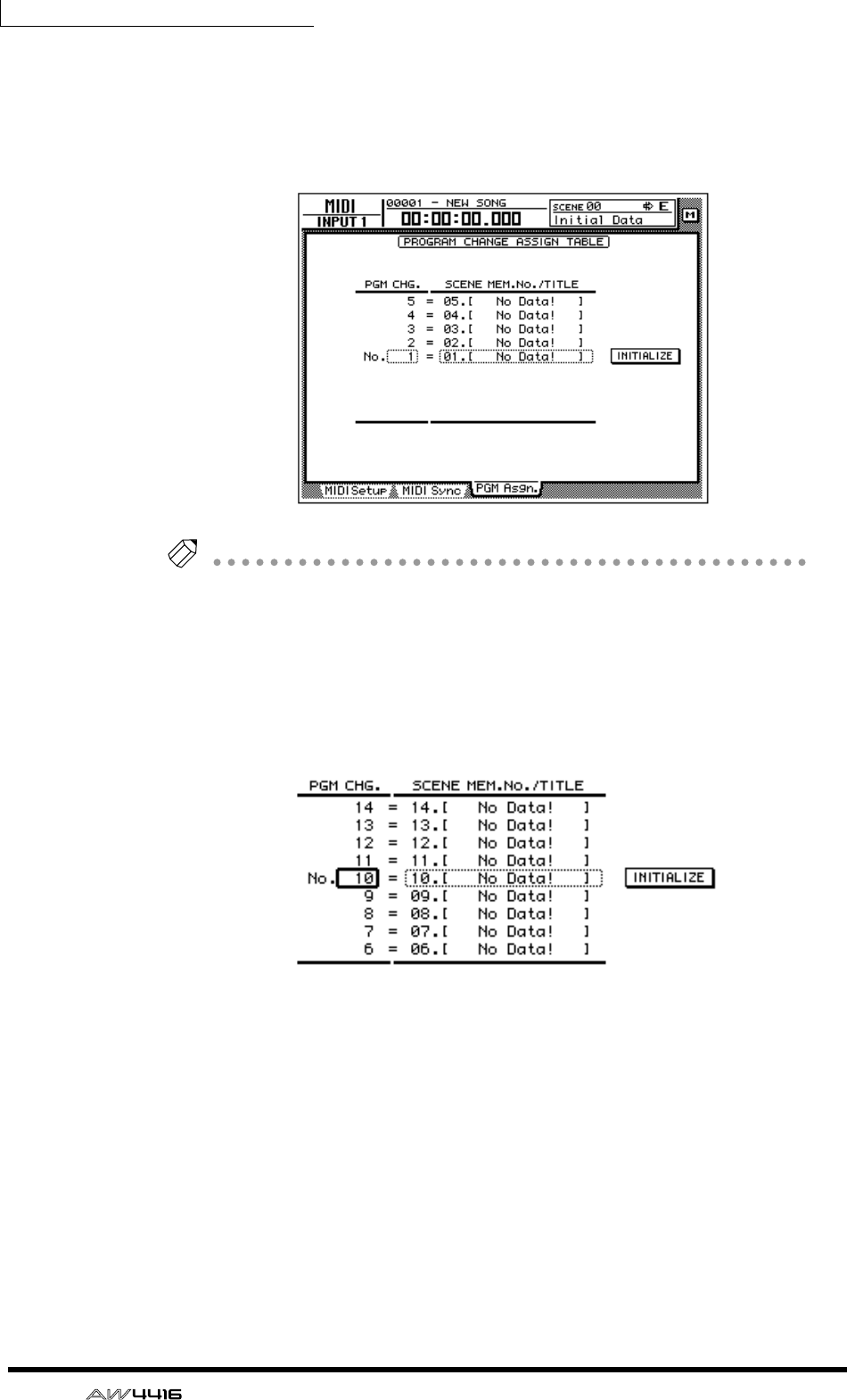
Chapter15—MIDI
236 — Operation Guide
5. Press the [F3] key.
The PGM Asgn. page will appear, allowing you to assign AW4416 scene numbers
to each program number 1–128. The “PGM CHG.” column is the program
change number, and the “SCENE MEM.No./TITLE” column is the scene number
and title.
Tip!
If you move the cursor to the INITIALIZE button located in the right of the screen
and press the [ENTER] key, the scene number assignments will be initialized; scene
numbers 01–96 will be assigned to program numbers 1–96, and scene number 00
will be assigned to program change 100. (All other program change numbers will
be “-NO ASSIGN-.”)
6. Move the cursor to the PGM CHG. column, and use the [DATA/JOG] dial
to select a program change number (1–128).
7. Move the cursor to the right, and use the [DATA/JOG] dial to select the
scene number (00–96) that will be assigned to the program change
number you selected in step 6.
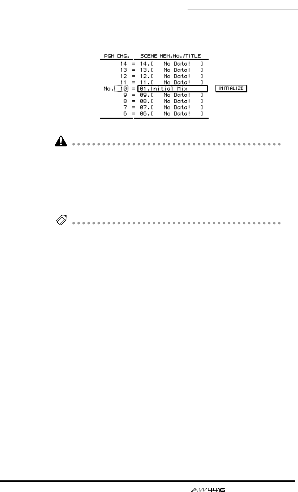
Chapter15—MIDI
— Operation Guide 237
If you select “–NO ASSIGN–,” no scene number will be assigned to that program
change number. If you select a scene number which has not been stored in the
AW4416’s internal memory, the title area will indicate “[ No Data! ].”
If the same scene number is assigned to multiple program change numbers,
recalling the corresponding scene will cause only the lowest of the assigned pro-
gram change numbers to be transmitted. When you recall a scene number to
which no program change is assigned, no program change will be transmitted.
8. Transmit a program change message from the external device.
The AW4416 will recall the scene corresponding to the program change that was
received.
Tip!
When you use the AW4416’s keys to recall a scene, you can cause a program
change corresponding to that scene to be transmitted. To do so, turn on the Tx but-
ton in the PROGRAM CHANGE area in the screen for step 2.
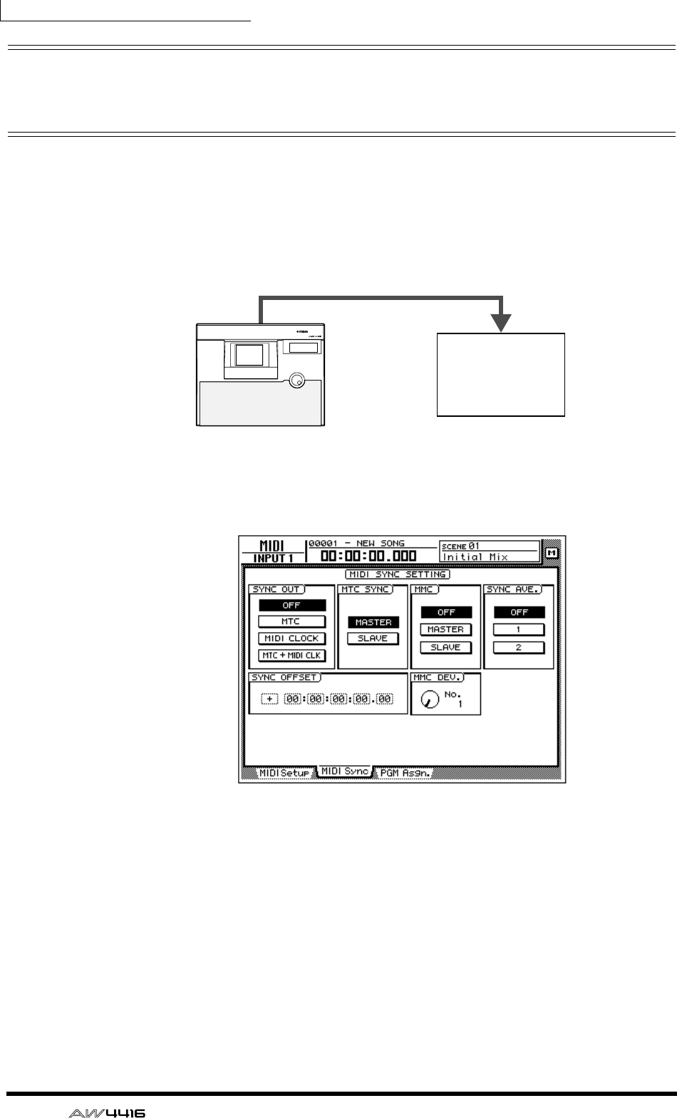
Chapter15—MIDI
238 — Operation Guide
Using MTC to synchronize the
AW4416 and a MIDI sequencer
MTC can be transmitted from the MTC OUT connector of the AW4416 to an
external device such as a MIDI sequencer or computer, causing the MIDI
sequencer (or computer-based sequencer program) to synchronize to the
AW4416 song.
1. Use a MIDI cable to connect the AW4416’s MTC OUT connector to the
MIDI IN connector of your MIDI sequencer.
2. Press the [MIDI] key, and then press the [F2] key.
The following screen will appear in the display.
3. Move the cursor to the MASTER button in the MTC SYNC area, and
press the [ENTER] key.
With this setting, the AW4416 will function as the MTC master (the device that
transmits MTC).
4. Move the cursor to the MTC button in the SYNC OUT area, and press
the [ENTER] key.
With this setting, MTC will be transmitted from the MTC OUT connector when
the AW4416 is running.
5. If you need to set the MTC frame rate, press the [SONG] key and then
press the [F2] key.
MIDI IN connector
MTC OUT connector
PROFESSIONAL AUDIO WORKSTATION
AW4416
MTC master MTC slave
MIDI sequencer
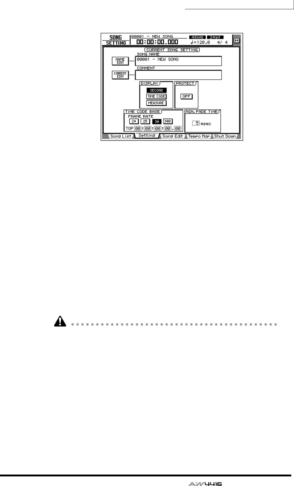
Chapter15—MIDI
— Operation Guide 239
The following screen will appear in the display.
6. Move the cursor to the TIME CODE area, and turn on one of the 24/25/
30/30D (drop) buttons to select the frame rate.
By default, a frame rate of 30 is selected. The frame rate you select here will also
affect the time code that is displayed in the counter.
7. If you wish to display time code in the counter, move the cursor to the
TIME CODE button in the DISPLAY area, and press the [ENTER] key.
8. Set your MIDI sequencer so that it will follow MTC messages that it
receives, and put it in playback mode. At this time, make sure that the
frame rate setting of the sequencer matches the setting that you
selected in step 6.
With these settings, the MIDI sequencer will be the MTC slave (the device that
receives MTC).
9. Record or play back the AW4416 song.
When the AW4416 begins running, MTC will be transmitted from the MTC OUT
connector to the external MIDI sequencer, causing it to begin synchronized oper-
ation from the same location.
• It is possible to use the AW4416 as the MTC slave. However in order to ensure
that the recorder section operates with maximum stability, we recommend that
you use the AW4416 as the MTC master whenever possible.
• For the MTC time that is transmitted by the AW4416, you can specify an offset
value that will be applied to the internal absolute time (ABS time). For details
refer to the Song screen/Setting page in the Reference Guide.
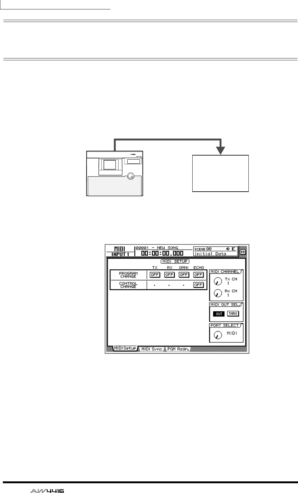
Chapter15—MIDI
240 — Operation Guide
Using MIDI Clock to synchronize the
AW4416 and a MIDI sequencer
Here we will explain how MIDI Clock (and Song Position Pointer) messages can
be transmitted from the AW4416 instead of MTC, and used to synchronize an
external MIDI sequencer. Use this method if the MIDI sequencer or rhythm
machine you wish to synchronize with the AW4416 does not support MTC, or if
you wish to specify the locate positions in terms of measures/beats.
1. Use a MIDI cable to connect the AW4416’s MIDI OUT connector to the
MIDI IN connector of your MIDI sequencer.
2. Press the [MIDI] key, and then press the [F1] key.
The MIDI Setup screen will appear in the display.
3. Move the cursor to the OUT button of the MIDI OUT SEL. area, and
press the [ENTER] key.
The MIDI OUT SEL. buttons select whether the MIDI OUT/THRU connector will
function as a MIDI OUT connector (when the OUT button is on) or as a MIDI
THRU connector (when the THRU button is on). In this example we will turn on
the OUT button, in order to output the MIDI clock that is generated inside the
AW4416.
MIDI IN connector
MIDI OUT/THRU connector
PROFESSIONAL AUDIO WORKSTATION
AW4416
MIDI clock master MIDI clock slave
MIDI sequencer
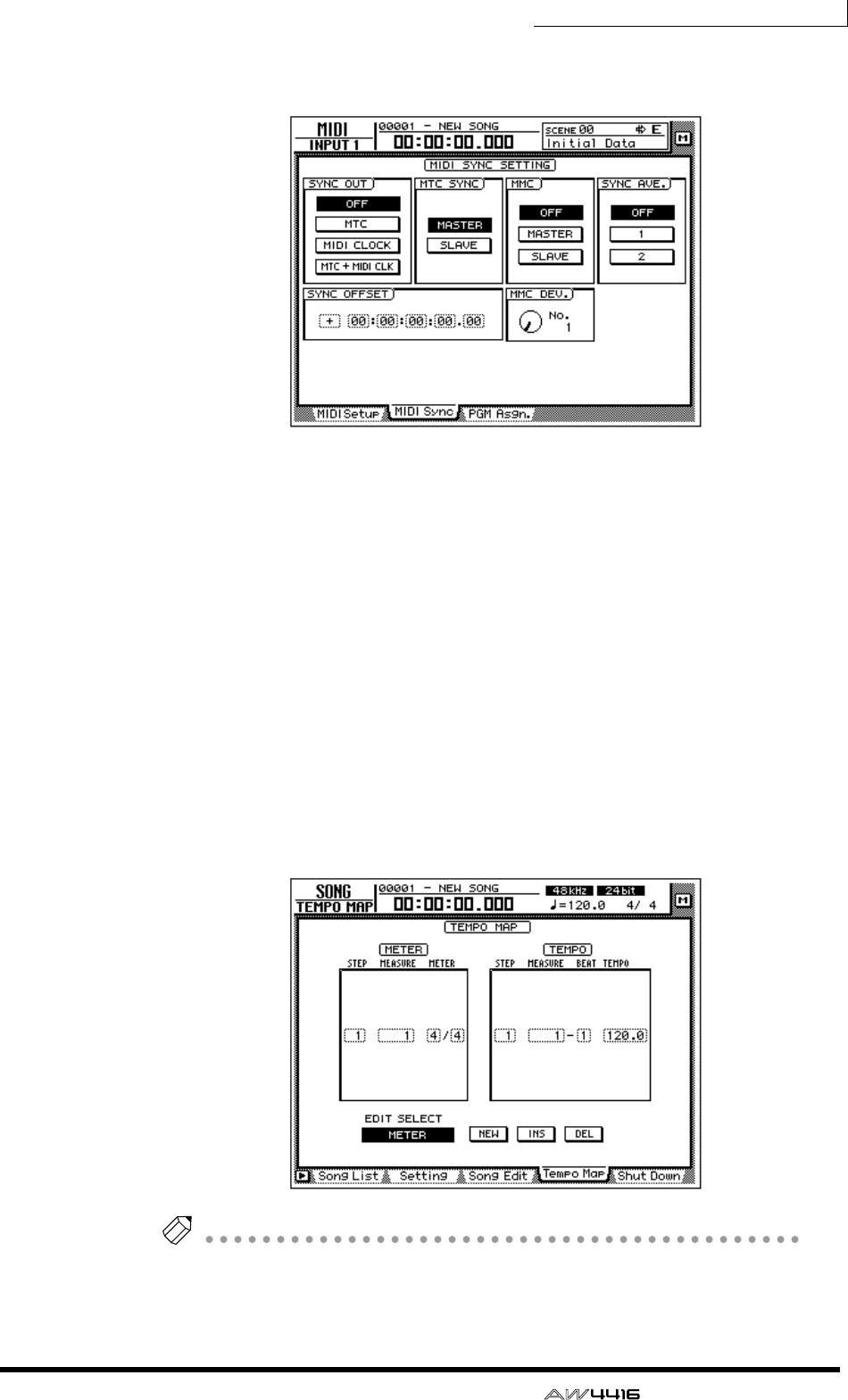
Chapter15—MIDI
— Operation Guide 241
4. Press the [F2] key.
The MIDI Sync page will appear in the display.
5. Move the cursor to the MIDI CLOCK button in the SYNC OUT area, and
press the [ENTER] key. Also make sure that the MASTER button in the
MTC SYNC area is on.
With these settings, MIDI Clock messages will be transmitted from the MIDI
OUT/THRU connector when the AW4416 is running.
6. Press the [SONG] key → [F2] key, and turn on the MEASURE button in
the DISPLAY area.
The counter display will be in measure/beat/tick (1/960th of a quarter note) units.
With this setting, you will be able to specify locate positions in measure/beat
units.
7. Press the [SONG] key, and then press the [F4] key.
The left side of the screen will show the beat map in which you can input time
signature data for the song, and the right side of the screen will show the tempo
map in which you can input tempo data. With the default settings for a song, a
time signature of 4/4 and a tempo of BPM=120.0 will be input at measure 1.
Note
In order for a MIDI sequencer to synchronize to the MIDI Clock messages send from
the AW4416, tempo settings and time signature settings must be made on the
AW4416. You can input this tempo data and time signature data in the Tempo Map
page described above.

Chapter15—MIDI
242 — Operation Guide
8. Move the cursor to the METER area of the beat map, and use the [DATA/
JOG] dial to specify the time signature for measure 1.
The time signature can be specified in a range of 1/2–8/8.
9. If you wish to change time signatures in the middle of the song, switch
the EDIT SELECT buttons at the bottom of the screen to METER. Then
move the cursor to the NEW button and press the [ENTER] key.
New time signature data will be added, allowing you to specify the new location
(measure) and time signature. (For details refer to the Song screen/Tempo Map
page in the Reference Guide.)
10. Move the cursor to the TEMPO column of the tempo map, and use the
[DATA/JOG] dial to specify the tempo for the first measure.
The tempo (BPM) can be set in 0.1 units over a range of 20.0–300.0.
11. If you wish to change tempo in the middle of the song, switch the EDIT
SELECT buttons at the bottom of the screen to TEMPO. Then move the
cursor to the NEW button and press the [ENTER] key.
New tempo data will be added, allowing you to specify the new location (mea-
sure/beat) and tempo. (For details refer to the Song screen/Tempo Map page in
the Reference Guide.)
12. Make settings on your MIDI sequencer so that it will synchronize to an
external MIDI clock, and put it in playback-ready mode.
13. Record/play back the AW4416 song.
When you specify a location on the AW4416 in measure/beat units, the external
MIDI sequencer will also move to the same location. When the AW4416 begins
running, the MIDI sequencer will begin running in synchronization according to
the MIDI clock that is being transmitted.
Tip!
The internal metronome of the AW4416 will sound according to the tempo data
and time signature data you specify here.
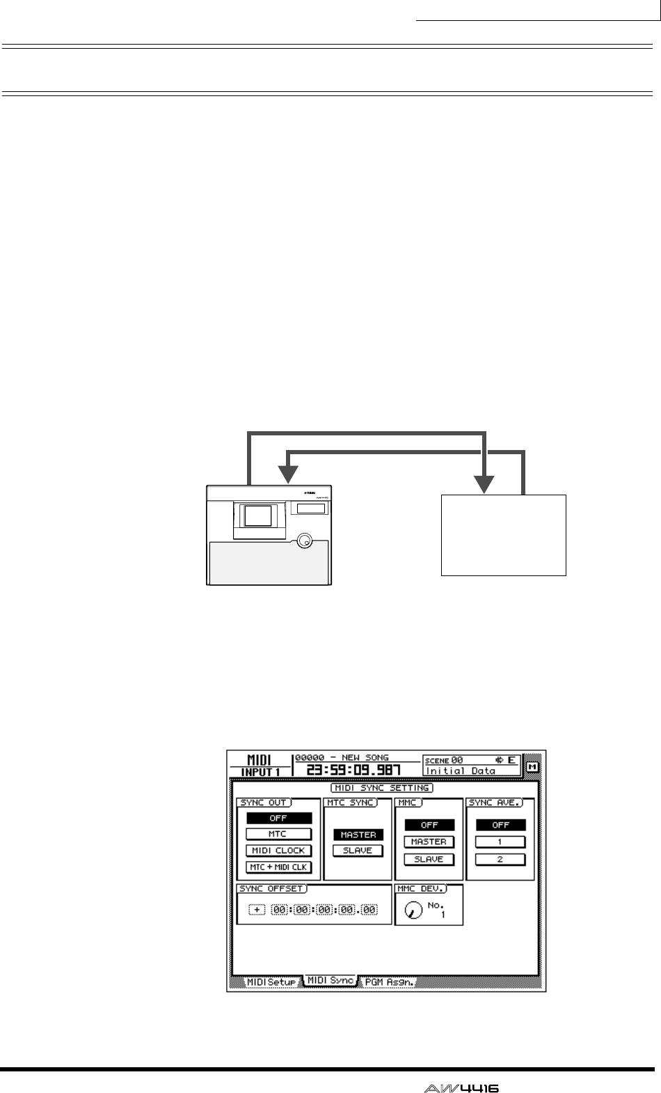
Chapter15—MIDI
— Operation Guide 243
Using MMC to control the AW4416
MMC (MIDI Machine Control) is a group of MIDI messages used to control the
transport of an audio recorder etc. from an external MIDI device. The AW4416
supports MMC transmission and reception. This means that an external MIDI
device can control AW4416 transport operations, locate operations, selection
and disabling of recording tracks, or conversely that the AW4416 can control
transport and other operations on another MMC-compatible device.
In this section we will explain how MMC can be used to control various opera-
tions of the AW4416 from an external MIDI sequencer while MTC is being used
to synchronize the AW4416 and MIDI sequencer.
1. Connect the AW4416’s MIDI IN connector to the MIDI OUT connector
of the MIDI sequencer, and connect the AW4416’s MTC OUT connector
to the MIDI IN connector of the MIDI sequencer.
In this case, the MIDI sequencer will be the MMC master (the device transmitting
MTC) and MTC slave, and the AW4416 will be the MMC slave (the device receiv-
ing MMC) and MTC master.
2. As described in “Using MTC to synchronize the AW4416 and a MIDI
sequencer” (→ P.238), make settings on both devices so that the
AW4416 and MIDI sequencer will run in synchronization.
3. Press the [MIDI] key, and then press the [F2] key.
MIDI OUT
connector
MIDI IN
connector
MIDI IN
connector
MTC OUT
connector
PROFESSIONAL AUDIO WORKSTATION
AW4416
MMC slave MMC master
MIDI sequencer

Chapter15—MIDI
244 — Operation Guide
4. Move the cursor to the SLAVE button in the MMC area, and press the
[ENTER] key.
With this setting the AW4416 will function as an MMC slave device.
5. Move the cursor to the MMC DEV. knob, and use the [DATA/JOG] dial to
set the MMC device ID.
The device ID is a number in the range of 1–127 that is used to distinguish the
device to be controlled when a single system contains multiple MMC-compatible
devices. By default, the AW4416 is set to device ID = 1.
6. On your MIDI sequencer, set the device ID of the MMC device to be
controlled to the same setting as in step 5.
Note
If necessary, you can specify the AW4416 recording track after step 6, and control
recording operations in step 7. For details on selecting the recording track and on
controlling record operations, refer to the manual for your MIDI sequencer.
7. Start playback on your MIDI sequencer.
When you start the MIDI sequencer, MMC commands will be transmitted to the
AW4416, and the AW4416 will begin running. At this time, MTC will be trans-
mitted from the AW4416’s MTC OUT connector to the MIDI sequencer, and the
sequencer will synchronize to the AW4416.
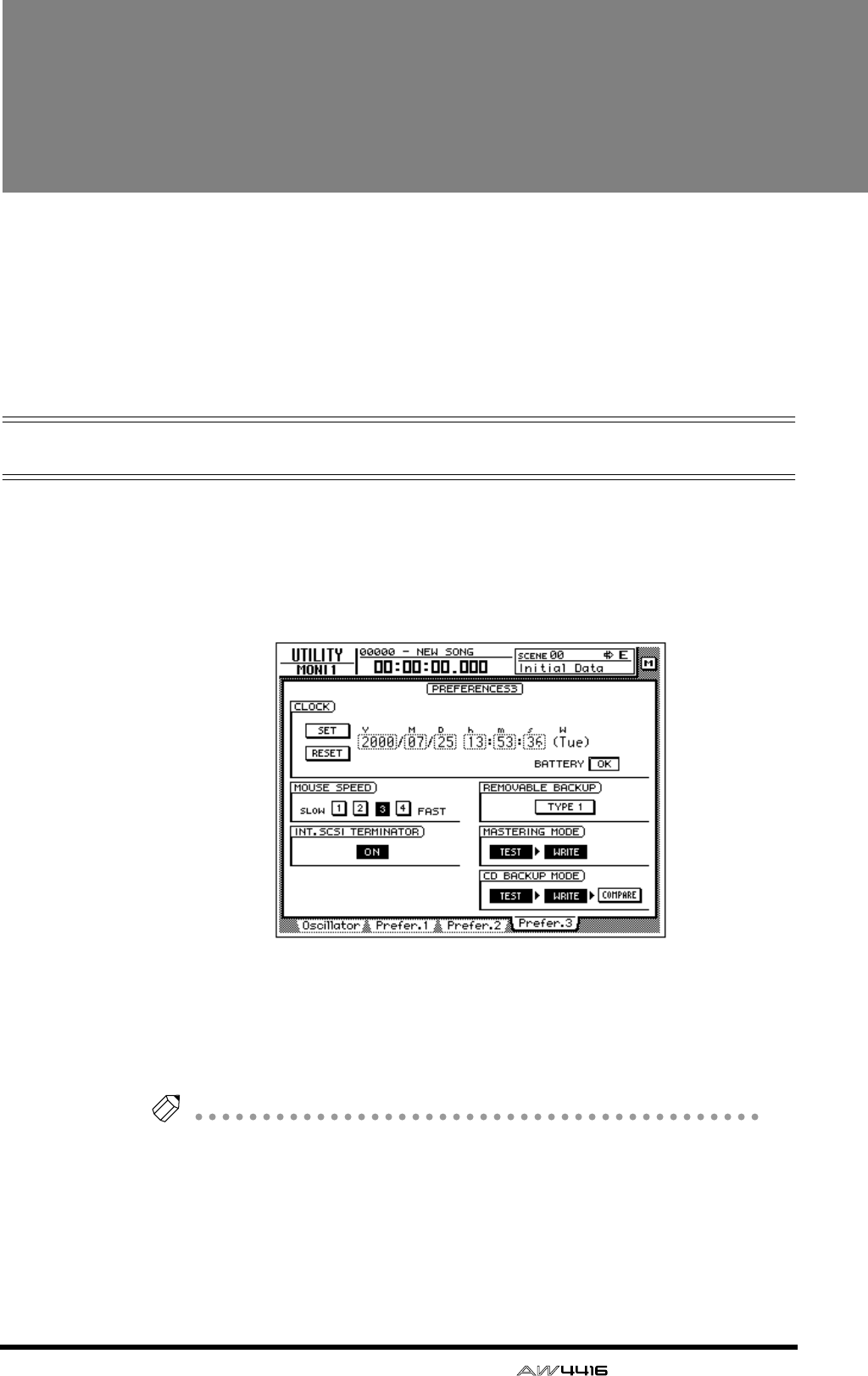
— Operation Guide 245
16 Backing up and
restoring songs
This chapter explains how part or all of the song data on the internal hard
disk can be backed up to a SCSI device (such as a CD-RW drive or MO
drive), and how backed-up data can be restored to the internal hard disk.
This chapter also explains how to re-format the internal hard disk, and
how to erase CD-RW media.
Selecting the backup format
When using removable media such as MO as the backup destination, you must
first select the backup format.
1. Press the [UTILITY] key → [F4] key.
The UTILITY screen Prefer.3 page will appear in the display.
2. Move the cursor to the button in the REMOVABLE BACKUP area, and
select either “TYPE1” or “TYPE2” as the backup format.
Each time you press the [ENTER] key, the button display will alternate between
“TYPE1” and “TYPE2.” The difference between these formats is described below.
Tip!
When you backup on CD-RW media, TYPE 1 will be selected as the backup format
regardless of this setting. If the song being backed up will not fit on a single piece of
CD-RW media, the backup can extend across multiple volumes of media.
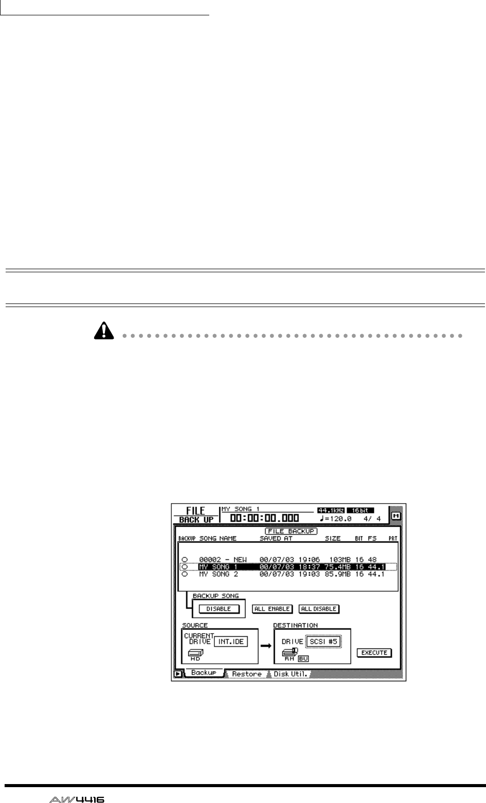
Chapter16—Backing up and restoring songs
246 — Operation Guide
❍ TYPE1
This is the usual backup format, in which part or all of the songs are backed up
using the full capacity of the removable media. This format has the advantage that
even if the size of the song(s) being backed up exceeds the capacity of one vol-
ume of media, the backup can be performed using multiple volumes of media.
If this format is selected, the media will be formatted/erased automatically before
backup is performed.
❍ TYPE2
This backup format stores the specified song(s) or all songs as individual files on
removable media. This format has the advantage that new files can be stored on a
volume of media that already contains data backed up in the same format. How-
ever, it is not possible to backup data that extends across multiple volumes.
Before you can use this format to backup on newly purchased media, you must
first manually format the media.
Backing up a song
• If “TYPE1” is selected as the backup format, the media will automatically be
formatted before the backup is performed.
• If “TYPE2” is selected as the backup format, the media will not be formatted
automatically. If necessary, you must format the media manually.
• If you are backing up on removable media such as CD-RW or MO, insert the
CD-RW media or MO media into the drive before you begin this procedure.
1. Press the [FILE] key → [F1] key.
The FILE screen Backup page will appear in the display. The list in the upper part
of the display shows the songs that are currently saved on the internal hard disk.
The current song is highlighted in the list.
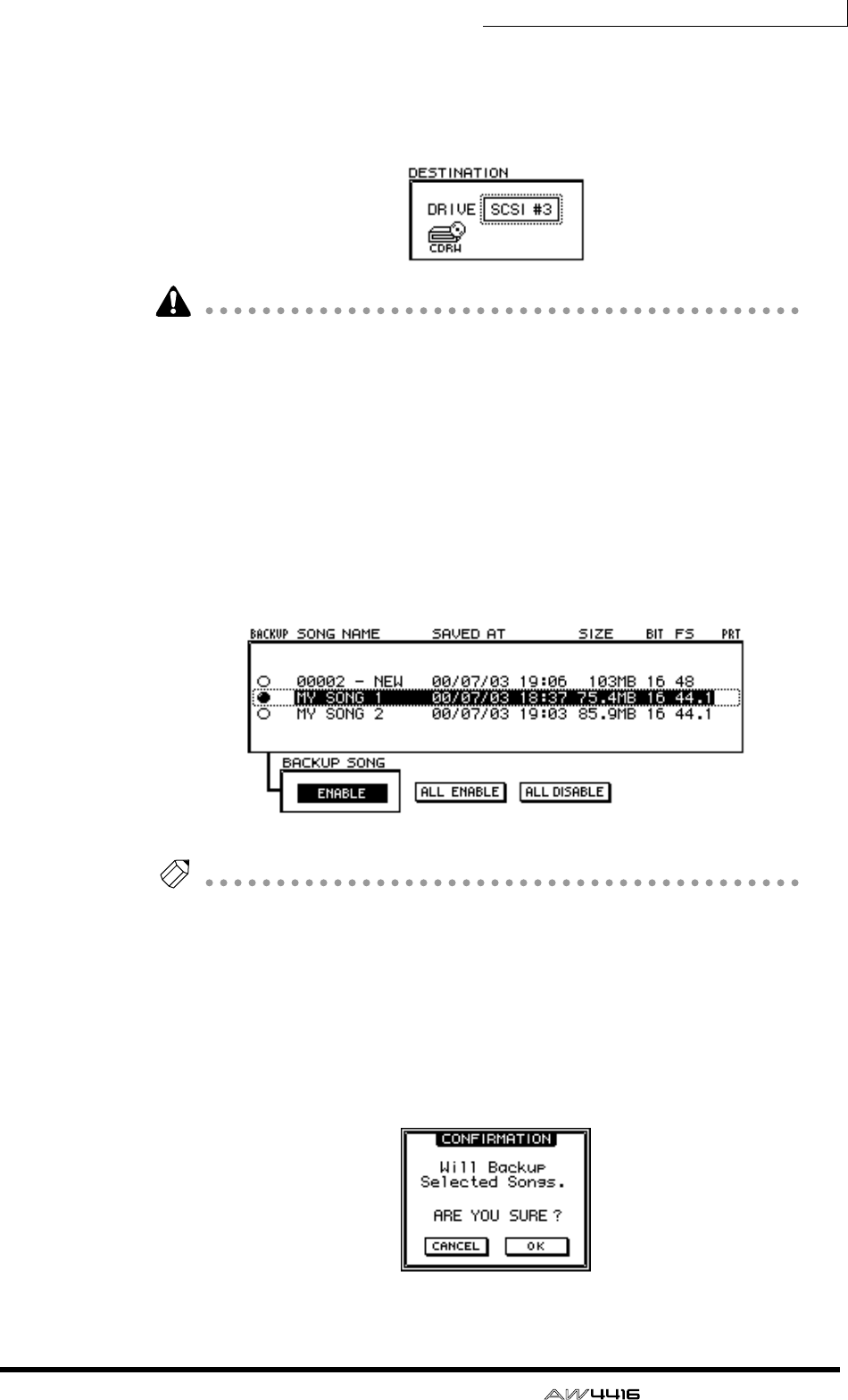
Chapter16—Backing up and restoring songs
— Operation Guide 247
2. Move the cursor to the DESTINATION area in the lower right of the dis-
play, and use the [DATA/JOG] dial to select the ID number of the backup
destination SCSI device (e.g., internal CD-RW drive or external hard disk
or MO drive).
It is also possible to backup on CD-R media using an internal or external CD-RW
drive. However, you should be aware that CD-R media on which a backup has
been created cannot be erased or added to.
3. Move the cursor to the list in the upper part of the display, and use the
[DATA/JOG] dial to select the sound that you wish to backup.
4. Move the cursor to the button in the BACKUP SONG area and press the
[ENTER] key.
The button display will change from “DISABLE” to “ENABLE,” and the song will
be selected for backup. The “O” symbol at the left edge of the list will change to
“●” for songs that are selected for backup.
Tip!
• You can repeat steps 3 and 4 to select multiple songs for backup.
• If you wish to backup all songs, move the cursor to the ALL ENABLE button
located in the center of the display, and press the [ENTER] key.
• Conversely if you wish to exclude all songs from backup, move the cursor to
the ALL DISABLE button and press the [ENTER] key.
5. Move the cursor to the EXECUTE button in the lower right of the display,
and press the [ENTER] key.
A popup window will appear, asking you to confirm the backup operation.
Chapter16—Backing up and restoring songs
248 — Operation Guide
6. To execute the backup, move the cursor to the OK button and press the
[ENTER] key.
If “TYPE2” was selected as the backup format, the backup will begin immedi-
ately.
If “TYPE1” was selected as the backup format, the media will be formatted auto-
matically (in the case of CD-RW media, all data will be erased). Then the backup
will begin. If the selected song(s) will not fit on a single volume of media, as mes-
sage will ask you to insert the next volume. Eject the media and insert a new vol-
ume of media.
When backing up on a hard disk or MO disk, the disk will be formatted before
the backup is performed.
When backing up on a CD-RW disc, a popup window will ask you to confirm
that it is OK to erase the media. Move the cursor to the OK button and press the
[ENTER] key, and the media will first be erased and then the backup will be per-
formed.
Tip!
If you decide to cancel the backup, move the cursor to the CANCEL button and
press the [ENTER] key.
• In the case of removable media such as MO, make sure that write protect is
defeated.
• If the backup extends across multiple volumes of media, be sure to note the
order of volumes on the label of the media.
• Once backup has begun, the operation cannot be cancelled.
Restoring a song
Here’s how data for the selected song(s) or all songs previously backed up to a
SCSI device (e.g., internal CD-RW drive, or external hard disk or MO drive) can
be restored to the AW4416’s internal hard disk.
• Before you begin, insert the disk (e.g., CD-RW or MO) containing the backed-
up data into the appropriate device. If the backup extended across multiple
volumes of media, make sure that the first volume of media is inserted.
• Once the restore operation has begun, it cannot be cancelled.
1. Press the [FILE] key → [F2] key.
The FILE screen Restore page will appear in the display.
2. Move the cursor to the SOURCE area in the lower left of the display, and
use the [DATA/JOG] dial to select the ID number of the SCSI device on
which the backup data is saved.
3. Press the [ENTER] key.
The FILE RESTORE in the upper part of the display will show the song data that
was backed up to the selected SCSI device.
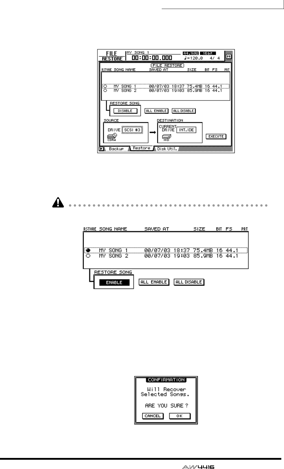
Chapter16—Backing up and restoring songs
— Operation Guide 249
4. Move the cursor to the FILE RESTORE area in the upper part of the dis-
play, and use the [DATA/JOG] dial to select the song(s) that you wish to
restore, then press the [ENTER] key.
The button in the RESTORE SONG area will change from DISABLE to ENABLE,
indicating that the corresponding song has been selected for restore. The “O”
symbol at the left edge of the list will change to “●” for songs that are selected for
restore.
You can select multiple songs for restoring.
If you wish to restore all songs, move the cursor to the ALL ENABLE button in the
center of the display, and press the [ENTER] key.
Conversely, if you wish to exclude all songs from the restore operation, move the
cursor to the ALL DISABLE button and press the [ENTER] key.
5. Move the cursor to the EXECUTE button in the lower right of the display,
and press the [ENTER] key.
A popup window will appear, asking you to confirm the restore operation.
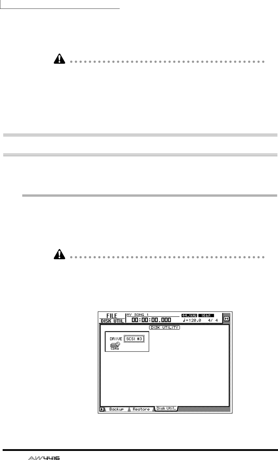
Chapter16—Backing up and restoring songs
250 — Operation Guide
6. To execute the restore operation, move the cursor to the OK button and
press the [ENTER] key.
To cancel the restore operation, move the cursor to the CANCEL button and press
the [ENTER] key.
• Even when you restore from a SCSI device to the internal hard disk, the songs
that were previously recorded on the internal hard disk will remain unaffected.
Be aware that if songs of identical song names exist both in the backup and on
the internal hard disk at this time, the internal hard disk will end up containing
two identically-named songs.
• If the internal hard disk does not have sufficient free space to load the backup
data, the restore operation will not be executed.
Disk utilities
This section explains the disk utility functions, such as formatting the internal
hard disk or external SCSI device, and erasing CD-RW media.
Formatting the internal hard disk/external
SCSI device
Here’s how to format the internal hard disk/external SCSI device (hard disk, MO
disk drive).
When you execute the format operation, all songs saved on the device will be
lost forever. In particular, be very careful about formatting the internal hard disk.
Be sure to create a backup of important song data before you proceed.
1. Press the [FILE] key → [F3] key.
The FILE screen Disk Util. page will appear in the display.
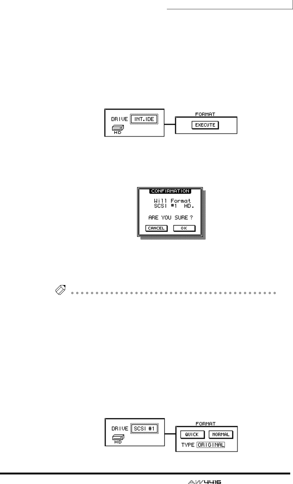
Chapter16—Backing up and restoring songs
— Operation Guide 251
2. Rotate the [DATA/JOG] dial to select the drive that you wish to format,
and press the [ENTER] key.
To format the internal hard disk, select “INT.IDE.” To format an external SCSI
device, select the SCSI ID of that device.
The rest of the procedure will differ depending on the type of drive you are for-
matting.
❒Formatting the internal hard disk
3. Move the cursor to the EXECUTE button in the FORMAT area, and press
the [ENTER] key.
A popup window will appear, asking you to confirm the Format operation.
4. Move the cursor to the OK button and press the [ENTER] key.
A popup window will appear once again, asking you to confirm that you really
want to format the internal hard disk.
Tip!
If you decide to cancel the format operation, move the cursor to the CANCEL button
and press the [ENTER] key.
5. Once again, move the cursor to the OK button and press the [ENTER]
key.
Formatting will begin. When formatting of the internal disk is completed, an
empty song (16 bit/44.1 kHz) will be created automatically, and selected as the
current song.
❒Formatting an external hard disk
3. Select the SCSI ID of the external hard disk, and press the [ENTER] key.
A popup window will appear, allowing you to select the type of file system and
the formatting method.
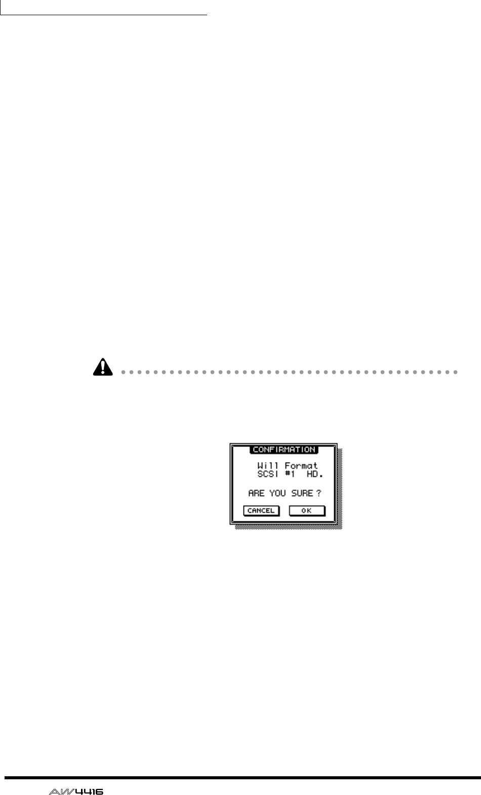
Chapter16—Backing up and restoring songs
252 — Operation Guide
4. Move the cursor to either the QUICK or the NORMAL button, and press
the [ENTER] key.
The formatting method will depend on the button you select.
❍ QUICK (quick format)
Use this when you wish to quickly erase data from a previously-formatted hard
disk.
❍ NORMAL (normal format)
Use this when formatting a newly purchased hard disk. Depending on the capac-
ity of the hard disk, this may require several minutes or several-ten minutes.
After selecting one or the other button, press the [ENTER] key, and a popup win-
dow will appear, asking you to confirm the Format operation.
5. Move the cursor to the TYPE area, and rotate the [DATA/JOG] dial to
select one of the following two types of file system that will be created
during the formatting operation.
• ORIGINAL ...................This is the native file system of the AW4416. Select
this file system if you have selected TYPE2 as the
backup format.
• FAT 16 ..........................This is the file system used on PC-type computers
(e.g., Windows 95 or Windows 98 machines). Select
this file system if you wish to exchange files with a
PC.
The AW4416 does not support the “FAT32” file system used on Windows 95
OSR2 and subsequent operating systems.
A popup window will appear, asking you to confirm the Format operation.
6. Move the cursor to the OK button and press the [ENTER] key.
Formatting will be performed.
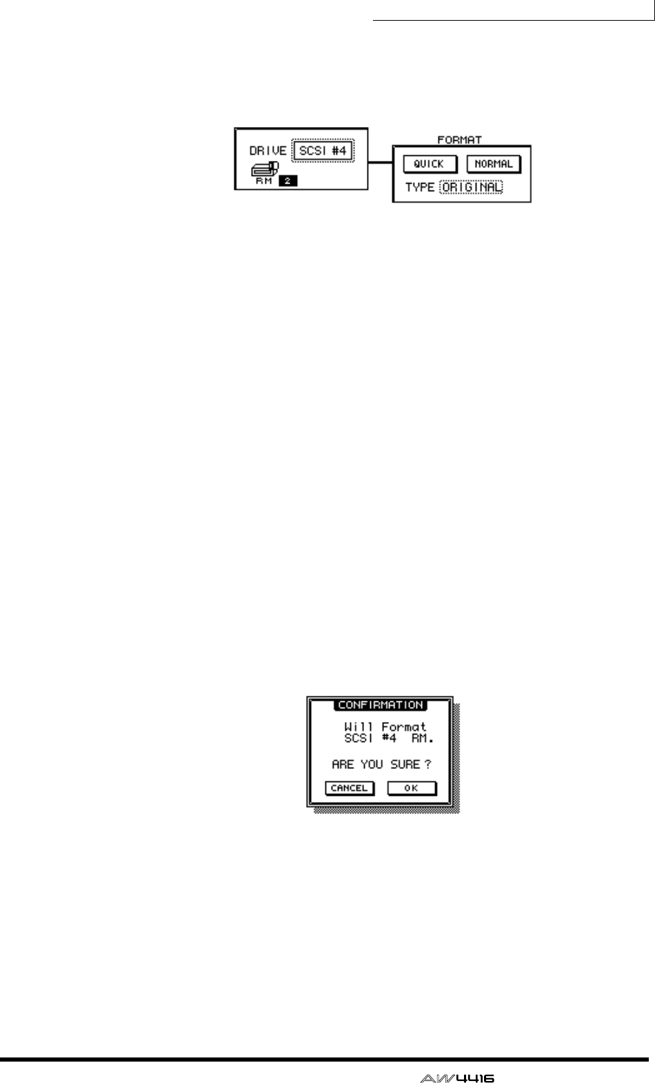
Chapter16—Backing up and restoring songs
— Operation Guide 253
❒Formatting removable media such as an MO drive
A FORMAT window will appear, allowing you to select the type of file system
and the formatting method.
3. Move the cursor to the TYPE area, and rotate the [DATA/JOG] dial to
select one of the following two types of file system that will be created
during the formatting operation.
• ORIGINAL ...................This is the native file system of the AW4416. Select
this file system if you have selected TYPE2 as the
backup format.
• FAT 16 ..........................This is the file system used on PC-type computers
(e.g., Windows 95 or Windows 98 machines). Select
this file system if you wish to exchange files with a
PC.
4. Move the cursor to either the QUICK or the NORMAL button, and press
the [ENTER] key.
The formatting method will depend on the button you select.
❍ QUICK (quick format)
Use this when you wish to quickly erase data from a previously-formatted MO
disk.
❍ NORMAL (normal format)
Use this when formatting a newly purchased MO disk. Depending on the capac-
ity of the MO disk, this may require several minutes or several-ten minutes.
After selecting one or the other button, press the [ENTER] key, and a popup win-
dow will appear, asking you to confirm the Format operation.
5. Move the cursor to the OK button and press the [ENTER] key.
Formatting will begin.
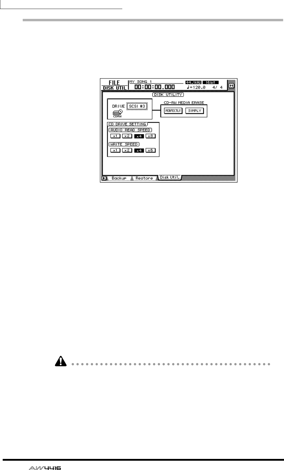
Chapter16—Backing up and restoring songs
254 — Operation Guide
Erasing CD-RW media
Here’s how to erase CD-RW media inserted in the CD-RW drive.
1. Press the [FILE] key → [F3] key.
The FILE screen Disk Util. page will appear in the display.
2. Use the [DATA/JOG] dial to select the SCSI ID number of the CD-RW
drive, and press the [ENTER] key.
3. Use the two buttons (PERFECTLY/SIMPLY buttons) in the CD-RW MEDIA
ERASE area to select the method by which the CD-RW media will be
erased.
The CD-RW media can be erased in one of the following two ways.
• SIMPLE .........................Only the table of contents (TOC) of the data written
on the CD-RW will be erased. This method has the
advantage of being fast.
• PERFECT .......................All data written on the CD-RW media will be erased.
This will take significantly longer than SIMPLE, but
can be selected when you want to be sure that the
data is completely erased.
Move the cursor to one of these methods and press the [ENTER] key. A popup
window will ask you to confirm the erasure.
4. To execute the Erase operation, move the cursor to the OK button and
press the [ENTER] key.
When you execute the Erase operation, all data that was saved on the CD-RW
media will be lost forever. Please use caution.
— Operation Guide 255
17 Mastering
This chapter explains the “mastering function” which allows you to use the
internal CD-RW drive (option) of the AW4416 to create an audio CD.
About mastering
By installing a CD-RW drive in the AW4416 (or connecting an external CD-RW
drive to the SCSI connector), you can write the audio data of the stereo track
(included in each song) onto CD-R/RW media in CD-DA format. This function is
called “mastering.” The CD-R/RW media to which the data is written can be
played back on the internal CD-RW drive or on conventional CD players in the
same way as an audio CD.
Some CD players and CD-ROM drives which do not support CD-R/RW may be
unable to play back audio data that was written on CD-R/RW media.
Stereo tracks that can be mastered
To master a song, you will select the desired stereo track from the stereo track
included in each song on the internal hard disk, and write it to a track on the CD-
R/RW media. However, only stereo tracks (more than four seconds) from songs
recorded as 16 bit/24 bit and a 44.1 kHz sampling frequency can be mastered.
• Mastering cannot be performed from the stereo track of a song whose sam-
pling frequency is 48 kHz.
• When mastering is performed from a 24 bit/44.1 kHz stereo track, the lower
8 bits will be discarded when the data is written, converting it into 16 bit/
44.1 kHz format.

Chapter17—Mastering
256 — Operation Guide
CD-R and CD-RW
CD-RW drives support two types of media: “CD-R” and “CD-RW.” These two
types of media differ in the following ways.
❍ CD-R
CD-R media can only be recorded or added to. Previously-recorded data cannot
be erased and rewritten.
CD-R media to which audio data has been written by the AW4416’s mastering
function can be played back on a CD-RW drive or on most CD players if the
media has been “finalized.” Additional audio data can be recorded on CD-R
media only if the disc has not yet been finalized.
❍ CD-RW
CD-RW media allows previously-recorded data to be entirely erased and rewrit-
ten. (CD-RW does not allow data to be added as on a CD-R.) CD-RW media to
which audio data has been written by the AW4416’s mastering function can be
played back on a CD-RW drive or on some CD players. However caution is nec-
essary, since many CD players do not support CD-RW at the present time.
The following table shows compatibility between CD-R/CD-RW media on which
audio data has been recorded, and CD-RW drives and CD players.
●: playable
O : playable on most devices
q: playable on some devices
× : not playable
Recording/Playback CD-RW drives CD players
CD-R
Disc At Once
(finalized automatically)
●
No silence between
tracks
O
No silence between
tracks
Track At
Once
Finalized
●
Two seconds of silence
between tracks
O
Two seconds of silence
between tracks
Not finalized ×
(data can be added) ×
CD-RW
Disc At Once
(finalized automatically)
●
No silence between
tracks
q
No silence between
tracks
Track At Once CD-RW media does not support Track At Once
Chapter17—Mastering
— Operation Guide 257
Track At Once and Disc At Once
Data can be written to CD-R/RW media in one of the following two ways.
❍ Track At Once
In this method, data is written in units of tracks (individual regions of audio data).
This method can be used only for CD-R media.
When the Track At Once method is used to write data to a CD-R, approximately
two seconds of silence will be created between tracks each time a track is writ-
ten. Additional audio data can be recorded later on CD-R media that was written
using this method.
• In order for CD-R media written using Track At Once to be played on a CD-RW
drive or on a conventional CD player, you must perform the Finalize operation
to write track location data etc. on the disc after all tracks have been written.
• No further recording is possible on CD-R media that has been finalized.
❍ Disc At Once
This method writes the data for all tracks in one operation, and can be used for
either CD-R or CD-RW media. Unlike the Track At Once method, the operation
will not stop until all data has been written, meaning that there will be no silent
sections between tracks.
• CD-R/CD-RW media written using Disc At Once will automatically be final-
ized, and can therefore be played immediately on a CD player.
• No further data can be recorded on media written using Disc At Once. (How-
ever in the case of CD-RW media, you can erase all of the audio data and then
rewrite.)
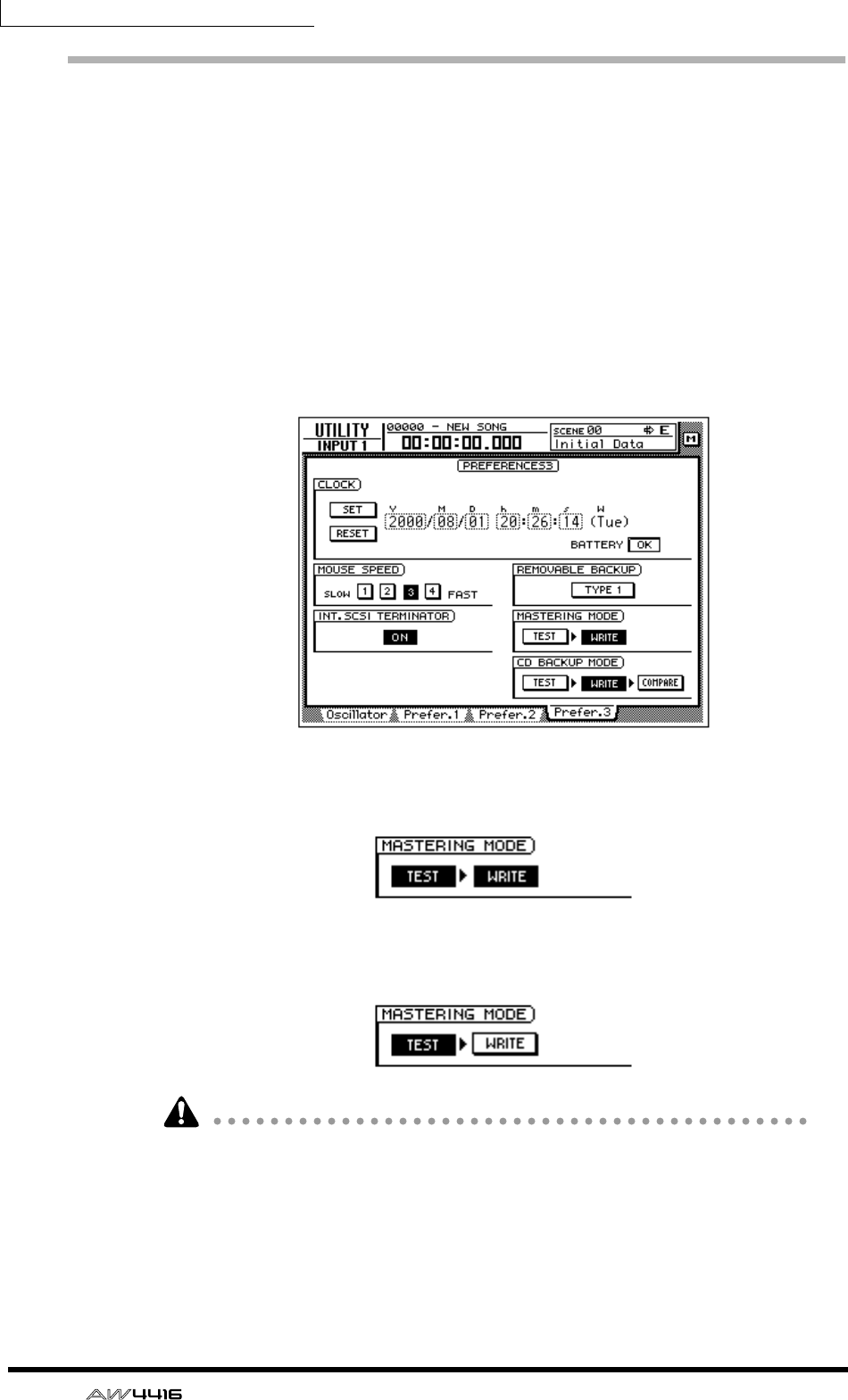
Chapter17—Mastering
258 — Operation Guide
Preparations for mastering
Here we will explain the preparations that you will need to make before writing
audio data to CD-R/CD-RW media.
❒Mastering mode settings
The AW4416 has a “writing test” function that checks before mastering to see
whether errors will occur during data transmission. By default, the AW4416 will
not perform this test before mastering, but you may perform the test if desired, or
execute only the test by itself. Here’s how to make these settings.
1. Press the [UTILITY] key → [F4] key.
The UTILITY screen Prefer.3 page will appear.
2. To perform the writing test, turn the TEST button on and the WRITE but-
ton on in the MASTERING MODE area.
3. To execute only the writing test, turn the TEST button on and the WRITE
button off in the MASTERING MODE area.
• It is not possible to turn off both the TEST and WRITE buttons.
• When writing for the first time, we recommend that you leave the TEST button
on.
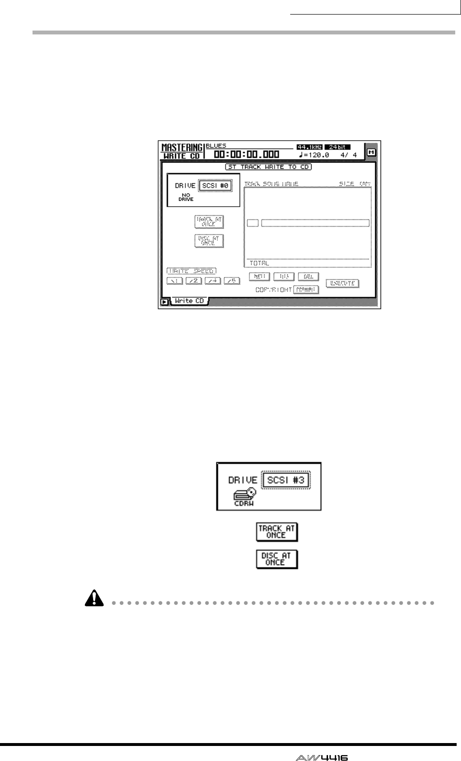
Chapter17—Mastering
— Operation Guide 259
Writing the master
Here’s how to use the mastering function to write the stereo track data to CD-R/
RW media.
1. Press the [MASTERING] key.
The MASTERING screen will appear in the display.
2. Hold down the [SHIFT] key and press the [F2] key (CD UNLOAD).
The tray of the CD-RW drive will open.
3. Place a CD-R/RW disc on the tray. Then hold down [SHIFT] and press the
[F1] key (CD LOAD).
The tray will close.
4. Use the [DATA/JOG] dial to select the SCSI ID number of the AW4416’s
internal CD-RW drive, and press the [ENTER] key.
• In the MASTERING screen, you can access all stereo tracks (44.1 kHz sam-
pling frequency) saved on the internal hard disk. Thus, it is not necessary that
the stereo track be part of the current song.
• However, the mastering function cannot be used if the current song has a sam-
pling frequency of 48 kHz. In this case, you must load a 44.1 kHz song before
you begin the mastering procedure.
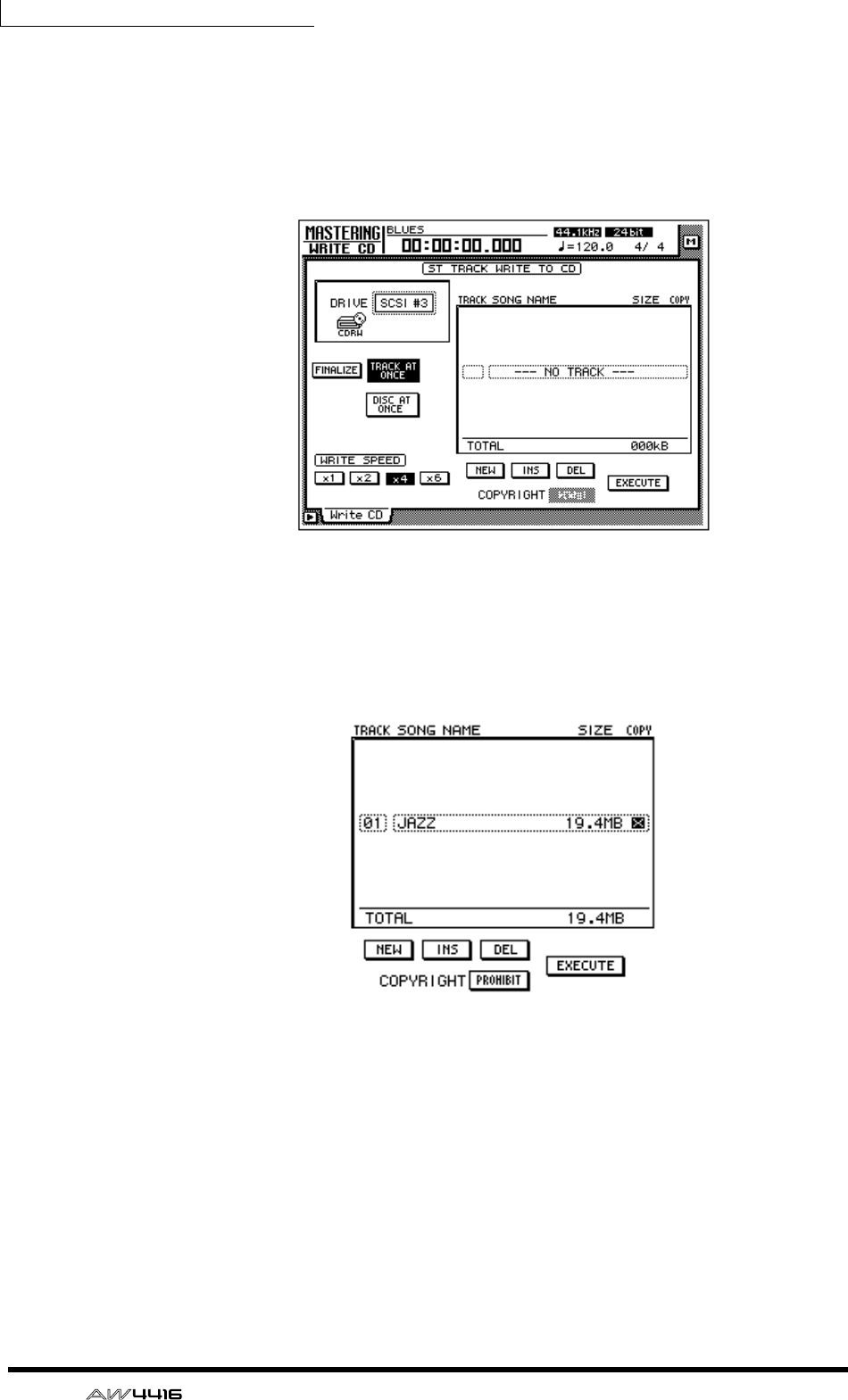
Chapter17—Mastering
260 — Operation Guide
5. Move the cursor to the TRACK AT ONCE button if you wish to master
using Track At Once, or to the DISC AT ONCE button if you wish to mas-
ter using Disc At Once. Then press the [ENTER] key.
If you are using CD-RW media, only DISC AT ONCE can be used. The following
screen is an example of when you have inserted CD-R media in the tray, moved
the cursor to TRACK AT ONCE, and pressed the [ENTER] key.
6. Move the cursor to the NEW button at the bottom of the display, and
press the [ENTER] key.
The list in the right of the display will show information (the name of the song
containing the stereo track, the size of the stereo track, and the copy protect set-
ting) for the stereo track that will be written to CD audio track 1.
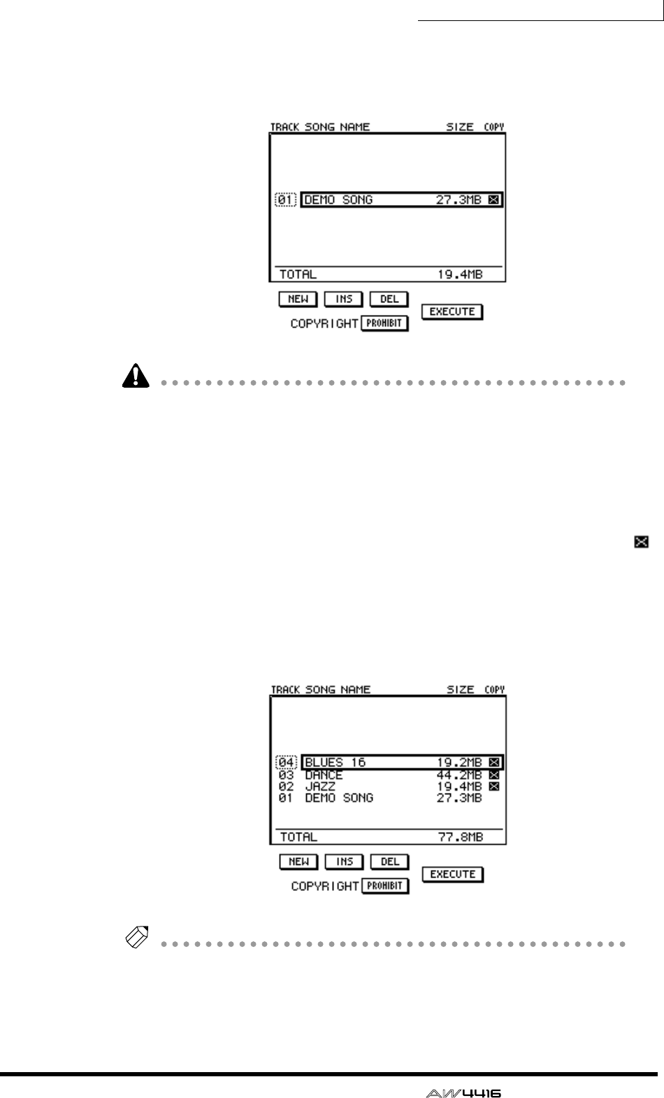
Chapter17—Mastering
— Operation Guide 261
7. Move the cursor to the stereo track data area of the list, and use the
[DATA/JOG] dial to select the stereo track that you wish to write to track
1 of the CD.
Stereo tracks from 48 kHz songs cannot be selected in this list. Also in some
cases, it may not be possible to select stereo tracks from songs for which Opti-
mize has not been executed. To optimize a song, refer to page 182.
8. If you wish to allow digital copying of the track you selected in step 7,
move the cursor to the COPYRIGHT button at the bottom of the screen,
and press the [ENTER] key.
The COPYRIGHT button specifies whether copy prohibit data will be written into
the subcode channel of the CD. When the button is displayed as PROHIBIT, a
symbol will be displayed in the COPY column of the corresponding track, and
digital copying will be prohibited for that track. If you switch the COPYRIGHT
button to PERMIT, digital copying will be allowed for that track.
9. Repeat steps 5–7 to select the stereo tracks that will be written into track
numbers 2 and following of the CD.
Tip!
By using the DEL button at the bottom of the display, you can remove the currently
selected stereo track from the list. By using the INS button, you can insert data for a
new audio track into the track number that follows the currently selected track.
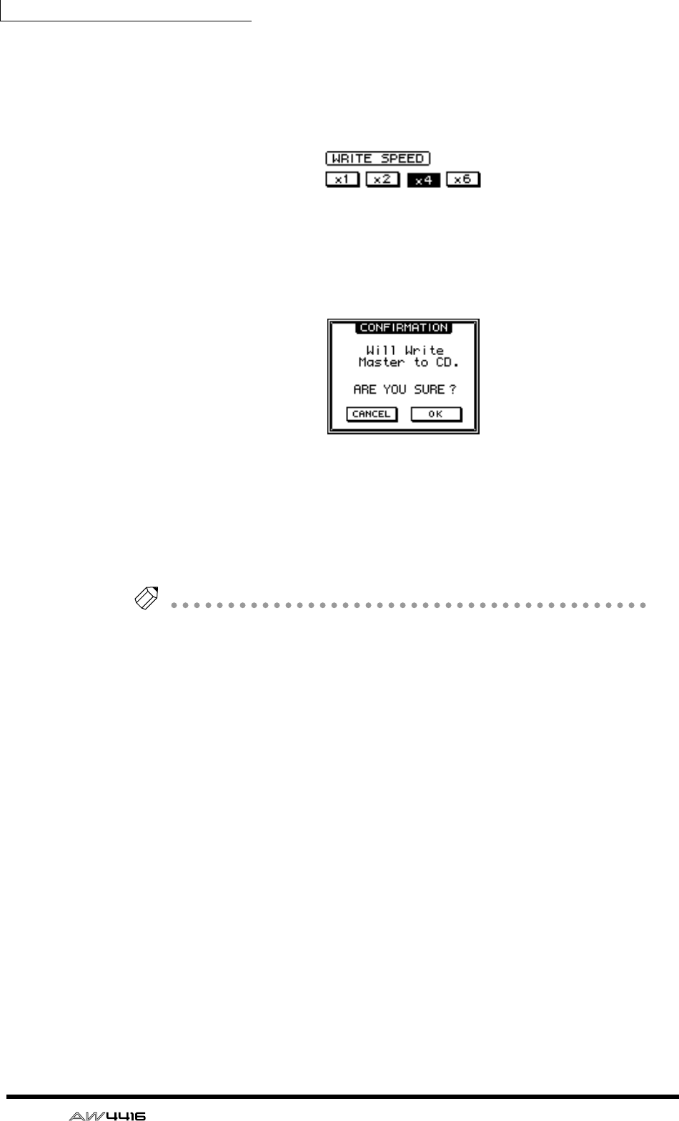
Chapter17—Mastering
262 — Operation Guide
10. As necessary, use the WRITE SPEED buttons located in the lower left of
the display to select the writing speed.
The x1/x2/x4/x6 buttons correspond to single-speed/double-speed/quad-speed/
6x speed writing. Normally you should select the fastest speed that your CD-RW
drive supports.
11. When you have finished selecting all of the stereo tracks that will be
written to the CD, move the cursor to the EXECUTE button in the lower
right of the display, and press the [ENTER] key.
A popup window will appear, asking you to confirm the operation.
12. To execute the writing operation, move the cursor to the OK button and
press the [ENTER] key.
If you decide to cancel the disc writing operation, move the cursor to CANCEL
and press the [ENTER] key.
After all data has been written, the media will be ejected automatically.
Tip!
• If Writing Test is turned on, the writing test will be executed before the actual
writing begins. If a problem occurs during the test, a message will appear.
• If you write using Disc At Once, the media can be played in a CD player as
soon as it is ejected.
• If you write to CD-R media using Track At Once, a popup window will ask you
whether you wish to finalize the disc.
13. If you wish to execute the Finalize operation, move the cursor to the OK
button and press the [ENTER] key. The CD-RW tray will close automati-
cally, and the disc will be finalized.
If you do not wish to finalize, move the cursor to the CANCEL button and press
the [ENTER] key. In this case, additional data can be recorded later on the ejected
CD-R media.
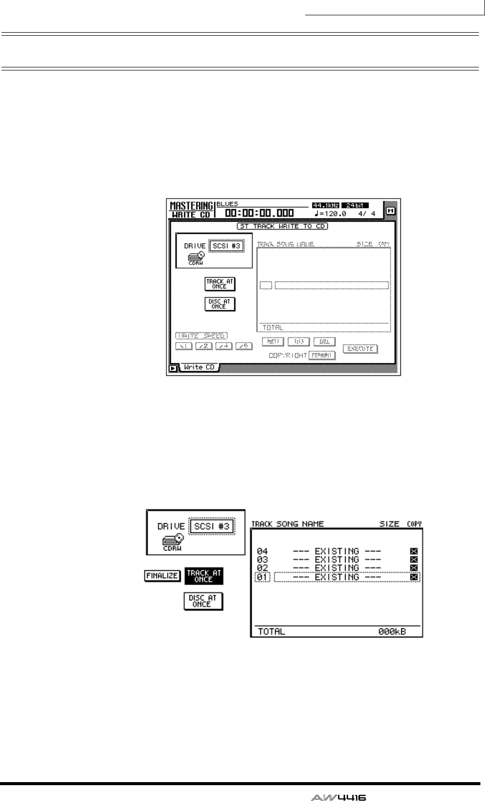
Chapter17—Mastering
— Operation Guide 263
Finalizing
As long as you have not executed the Finalize operation, other stereo track data
can be added to CD-R media that was recorded using Track At Once. However,
media that has not yet been finalized cannot be played back by a CD-RW drive
or a conventional CD player. In order to use a CD player to play CD-R media on
which you have written data, use the following procedure to execute the Finalize
operation.
1. Press the [MASTERING] key.
2. Place the CD-R media that you wish to finalize on the CD-RW drive tray.
3. Move the cursor to the TRACK AT ONCE button, and press the [ENTER]
key.
The FINALIZE button will appear at the left of the TRACK AT ONCE button. The
list in the right side of the display will show the tracks that have been written on
the CD-R media.
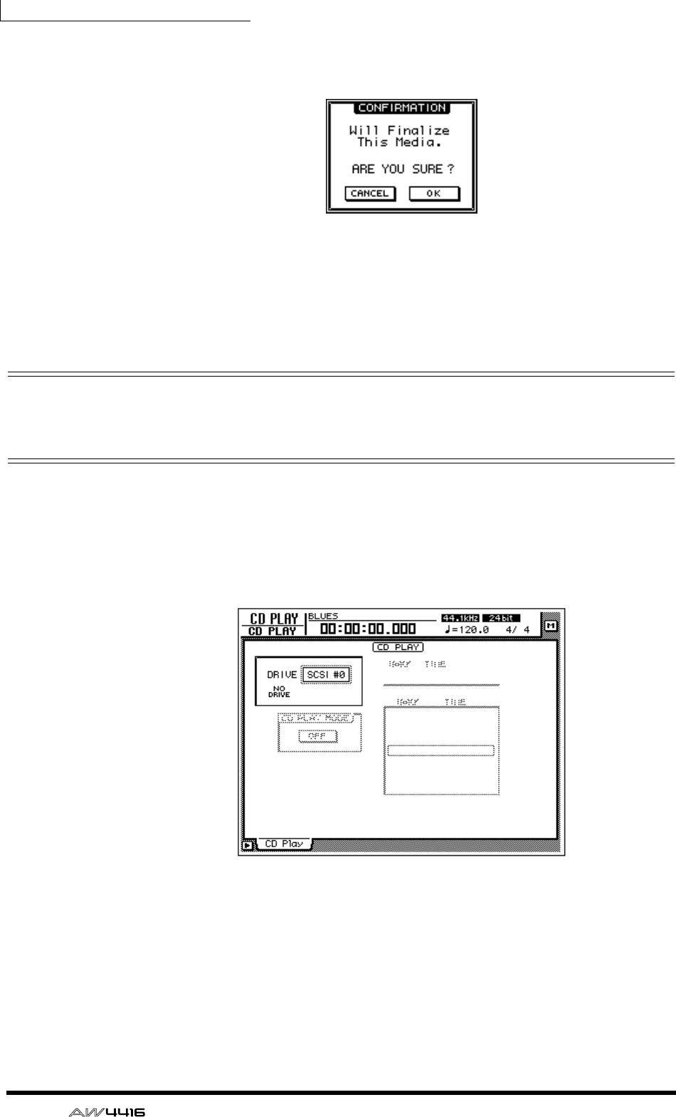
Chapter17—Mastering
264 — Operation Guide
4. Move the cursor to the FINALIZE button and press the [ENTER] key.
A popup window will appear, asking you to confirm the Finalize command.
5. To execute the Finalize command, move the cursor to the OK button
and press the [ENTER] key.
To cancel without executing, move the cursor to the CANCEL button and press
the [ENTER] key.
Playing CD-R/RW media (the CD Play
function)
By using the AW4416’s CD Play function, CD-R/RW media that contains audio
data can be played back from the internal CD-RW drive (or from an external CD-
RW drive connected to the SCSI connector).
1. Press the [CD PLAY] key.
The CD PLAY screen will appear in the display.
2. Use the [DATA/JOG] dial to select the SCSI ID of the CD-RW drive, and
press the [ENTER] key.
3. Hold down the [SHIFT] key and press the [F2] key (CD UNLOAD).
The tray of the CD-RW drive will open.
4. Place the CD-R/RW media on which data was written into the drive.
Then hold down the [SHIFT] key and press the [F1] key (CD LOAD).
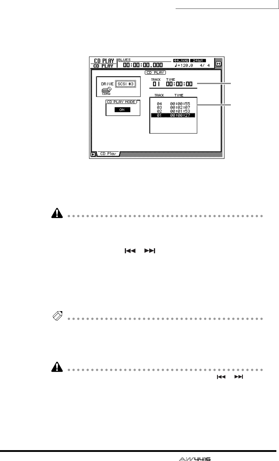
Chapter17—Mastering
— Operation Guide 265
5. Move the cursor to the CD PLAY MODE button, and press the [ENTER]
key.
The CD PLAY MODE button will change from OFF to ON, and track information
for the CD-R/RW media in the drive will be displayed.
1Currently selected track number (TRACK column) and elapsed time (TIME
column).
BTrack numbers on the disc (TRACK column) and their track times (TIME col-
umn).
• CD-R media that has not been finalized cannot be played back.
• The counter in the level meters/counter section will not function while you are
using the CD Play function.
6. Use the Locate section [ ]/[ ] keys to select the track that you wish
to play.
7. To begin playback, press the Transport section [PLAY] key.
The audio output of the CD-RW drive will be sent directly to the stereo bus. Use
the STEREO fader to adjust the volume.
8. To stop playback, press the [STOP] key.
Tip!
While playback is stopped, you can press and hold the [REW]/[FF] keys to rewind or
fast-forward. (However, there will be no sound.)
9. To exit the CD PLAY function, move the cursor to the CD PLAY MODE
button and press the [ENTER] key.
• While the CD Play function is being used, all keys except for [ ]/[ ],
[PLAY], [STOP], [REW]/[FF], and [ENTER] will have no effect.
• If you wish to perform other operations, turn off the CD Play function.
1
2

YAMAHA CORPORATION
V618350 R0 1 IP 284 Pro Audio & Digital Musical Instrument Division
P.O. Box 3, Hamamatsu, 430-8651, Japan
00 08 7000 AP Printed in Japan
PROFESSIONAL AUDIO WORKSTATION
E
Reference Guide

SONG
QUICK
REC
CD
PLAY
SET
UP
FILE
UTILI-
TY
MIDIVIEW
PAN/
ROUTE
EQ/ATT
/GRP
DYN/
DLY
AUX1–
AUX6
AUX7/EFF1
AUX8/EFF2
HOME
SAMP.
PAD
TRACKEDIT
AUTO
MIX
SCENE
MASTER-
ING
Appendix
Table of contents
— Reference Guide
iii
Table of contents
SONG screen . . . . . . . . . . . . . . . . . . . . . . . . . . . . . . . 1
Song List page . . . . . . . . . . . . . . . . . . . . . . . . . . . . . . . . . . . . . . . 1
Saving/loading a song . . . . . . . . . . . . . . . . . . . . . . . . . . . . . . . . . . 1
Setting page . . . . . . . . . . . . . . . . . . . . . . . . . . . . . . . . . . . . . . . . . 2
Make various settings for the current song . . . . . . . . . . . . . . . . . . 2
Song Edit page . . . . . . . . . . . . . . . . . . . . . . . . . . . . . . . . . . . . . . . 4
Deleting/copying/optimizing songs . . . . . . . . . . . . . . . . . . . . . . . . 4
Tempo Map page . . . . . . . . . . . . . . . . . . . . . . . . . . . . . . . . . . . . . 5
Programming the tempo map . . . . . . . . . . . . . . . . . . . . . . . . . . . . 5
Shut Down page . . . . . . . . . . . . . . . . . . . . . . . . . . . . . . . . . . . . . 7
Shut down the AW4416 . . . . . . . . . . . . . . . . . . . . . . . . . . . . . . . . 7
QUICK REC screen . . . . . . . . . . . . . . . . . . . . . . . . . . 8
Quick Rec page . . . . . . . . . . . . . . . . . . . . . . . . . . . . . . . . . . . . . . 8
Simultaneously recording 16 inputs/16 tracks . . . . . . . . . . . . . . . . 8
MASTERING screen . . . . . . . . . . . . . . . . . . . . . . . . . 10
Write CD page . . . . . . . . . . . . . . . . . . . . . . . . . . . . . . . . . . . . . 10
Using a CD-RW drive to create an audio CD . . . . . . . . . . . . . . . 10
CD PLAY screen . . . . . . . . . . . . . . . . . . . . . . . . . . . 12
CD Play page . . . . . . . . . . . . . . . . . . . . . . . . . . . . . . . . . . . . . . . 12
Use the CD-RW drive to play an audio CD . . . . . . . . . . . . . . . . . 12
SET UP screen . . . . . . . . . . . . . . . . . . . . . . . . . . . . . 14
Patch IN page . . . . . . . . . . . . . . . . . . . . . . . . . . . . . . . . . . . . . . 14
Patching a signal to a channel/track . . . . . . . . . . . . . . . . . . . . . . 14
Patch OUT page . . . . . . . . . . . . . . . . . . . . . . . . . . . . . . . . . . . . 16
Patch signals to output jacks . . . . . . . . . . . . . . . . . . . . . . . . . . . . 16
Patch Lib page . . . . . . . . . . . . . . . . . . . . . . . . . . . . . . . . . . . . . . 18
Store or recall patching settings . . . . . . . . . . . . . . . . . . . . . . . . . 18
D.in Setup page . . . . . . . . . . . . . . . . . . . . . . . . . . . . . . . . . . . . . 20
Make word clock/cascade settings . . . . . . . . . . . . . . . . . . . . . . . 20
Monitor page . . . . . . . . . . . . . . . . . . . . . . . . . . . . . . . . . . . . . . . 22
Monitor the digital input signals . . . . . . . . . . . . . . . . . . . . . . . . . 22
Dither Out page . . . . . . . . . . . . . . . . . . . . . . . . . . . . . . . . . . . . 24
Specify dithering and word length of the digital outputs . . . . . . . 24
Dither TRK page . . . . . . . . . . . . . . . . . . . . . . . . . . . . . . . . . . . . 25
Specify dithering and word length for tracks . . . . . . . . . . . . . . . . 25

Table of contents
iv
— Reference Guide
Solo Setup page . . . . . . . . . . . . . . . . . . . . . . . . . . . . . . . . . . . . . 26
Make solo settings . . . . . . . . . . . . . . . . . . . . . . . . . . . . . . . . . . . 26
FILE screen . . . . . . . . . . . . . . . . . . . . . . . . . . . . . . . 28
Backup page . . . . . . . . . . . . . . . . . . . . . . . . . . . . . . . . . . . . . . . . 28
Backup a song . . . . . . . . . . . . . . . . . . . . . . . . . . . . . . . . . . . . . . 28
Restore page . . . . . . . . . . . . . . . . . . . . . . . . . . . . . . . . . . . . . . . . 30
Restore backed-up songs . . . . . . . . . . . . . . . . . . . . . . . . . . . . . . 30
Disk Util. page . . . . . . . . . . . . . . . . . . . . . . . . . . . . . . . . . . . . . . 31
Format or erase a disk . . . . . . . . . . . . . . . . . . . . . . . . . . . . . . . . 31
UTILITY screen . . . . . . . . . . . . . . . . . . . . . . . . . . . . 33
Oscillator page . . . . . . . . . . . . . . . . . . . . . . . . . . . . . . . . . . . . . . 33
Using the test tone oscillator . . . . . . . . . . . . . . . . . . . . . . . . . . . 33
Prefer.1 page . . . . . . . . . . . . . . . . . . . . . . . . . . . . . . . . . . . . . . . 34
Make overall settings for the AW4416 (1) . . . . . . . . . . . . . . . . . . 34
Prefer.2 page . . . . . . . . . . . . . . . . . . . . . . . . . . . . . . . . . . . . . . . 35
Make overall settings for the AW4416 (2) . . . . . . . . . . . . . . . . . . 35
Prefer.3 page . . . . . . . . . . . . . . . . . . . . . . . . . . . . . . . . . . . . . . . 37
Make overall settings for the AW4416 (3) . . . . . . . . . . . . . . . . . . 37
MIDI screen . . . . . . . . . . . . . . . . . . . . . . . . . . . . . . 39
MIDI Setup page . . . . . . . . . . . . . . . . . . . . . . . . . . . . . . . . . . . . 39
Make basic MIDI settings . . . . . . . . . . . . . . . . . . . . . . . . . . . . . . 39
MIDI Sync page . . . . . . . . . . . . . . . . . . . . . . . . . . . . . . . . . . . . . 41
Make settings related to MIDI synchronization . . . . . . . . . . . . . . 41
PGM Asgn. page . . . . . . . . . . . . . . . . . . . . . . . . . . . . . . . . . . . . . 43
Assign a scene number to each program change number . . . . . . 43
VIEW screen . . . . . . . . . . . . . . . . . . . . . . . . . . . . . . 44
CH View page . . . . . . . . . . . . . . . . . . . . . . . . . . . . . . . . . . . . . . 44
View all parameters of a channel . . . . . . . . . . . . . . . . . . . . . . . . 44
Library page . . . . . . . . . . . . . . . . . . . . . . . . . . . . . . . . . . . . . . . . 47
Store or recall channel settings . . . . . . . . . . . . . . . . . . . . . . . . . . 47
PAN/ROUTE screen . . . . . . . . . . . . . . . . . . . . . . . . 49
Pan 1–16/Pan17–24/Pan MONI pages . . . . . . . . . . . . . . . . . . . . 49
Set pan and routing . . . . . . . . . . . . . . . . . . . . . . . . . . . . . . . . . . 49
Pair CH/Pair BUS pages . . . . . . . . . . . . . . . . . . . . . . . . . . . . . . . 52
Set channel/bus pairing . . . . . . . . . . . . . . . . . . . . . . . . . . . . . . . 52

SONG
QUICK
REC
CD
PLAY
SET
UP
FILE
UTILI-
TY
MIDIVIEW
PAN/
ROUTE
EQ/ATT
/GRP
DYN/
DLY
AUX1–
AUX6
AUX7/EFF1
AUX8/EFF2
HOME
SAMP.
PAD
TRACKEDIT
AUTO
MIX
SCENE
MASTER-
ING
Appendix
Table of contents
— Reference Guide
v
EQ/ATT/GRP screen . . . . . . . . . . . . . . . . . . . . . . . . 54
EQ/Att page . . . . . . . . . . . . . . . . . . . . . . . . . . . . . . . . . . . . . . . . 54
EQ and attenuation settings . . . . . . . . . . . . . . . . . . . . . . . . . . . . 54
Library page . . . . . . . . . . . . . . . . . . . . . . . . . . . . . . . . . . . . . . . 56
Store or recall EQ settings . . . . . . . . . . . . . . . . . . . . . . . . . . . . . . 56
FaderGrp page . . . . . . . . . . . . . . . . . . . . . . . . . . . . . . . . . . . . . . 58
Set and cancel fader groups . . . . . . . . . . . . . . . . . . . . . . . . . . . . 58
Mute Grp page . . . . . . . . . . . . . . . . . . . . . . . . . . . . . . . . . . . . . 59
Set and cancel mute groups . . . . . . . . . . . . . . . . . . . . . . . . . . . . 59
DYN/DLY screen . . . . . . . . . . . . . . . . . . . . . . . . . . 60
Dyn. Edit page . . . . . . . . . . . . . . . . . . . . . . . . . . . . . . . . . . . . . . 60
Dynamics processor parameter settings . . . . . . . . . . . . . . . . . . . 60
Library page . . . . . . . . . . . . . . . . . . . . . . . . . . . . . . . . . . . . . . . 62
Storing and recalling dynamics processor settings . . . . . . . . . . . . 62
Dly/ø1–16, Dly/ø17–24, Dly/øMONI pages . . . . . . . . . . . . . . . 65
Set delay and phase . . . . . . . . . . . . . . . . . . . . . . . . . . . . . . . . . . 65
AUX1–AUX6 screens . . . . . . . . . . . . . . . . . . . . . . . . 67
Pre/Pst IN, Pre/Pst MONI pages . . . . . . . . . . . . . . . . . . . . . . . . 67
Make on/off and pre/post settings for the AUX sends . . . . . . . . . . 67
AUX7/EFF1 and AUX8/EFF2 screens . . . . . . . . . . . 69
Eff. Edit page . . . . . . . . . . . . . . . . . . . . . . . . . . . . . . . . . . . . . . . 69
Edit internal effects 1/2 . . . . . . . . . . . . . . . . . . . . . . . . . . . . . . . . 69
Library page . . . . . . . . . . . . . . . . . . . . . . . . . . . . . . . . . . . . . . . 71
Store or recall an effect program . . . . . . . . . . . . . . . . . . . . . . . . . 71
Pre/Pst IN, Pre/Pst MONI pages . . . . . . . . . . . . . . . . . . . . . . . . 73
Make on/off and pre/post settings for the effect sends . . . . . . . . . 73
HOME screen . . . . . . . . . . . . . . . . . . . . . . . . . . . . . 75
1–24/Rtn page . . . . . . . . . . . . . . . . . . . . . . . . . . . . . . . . . . . . . . 75
Monitor the input level of the input channels . . . . . . . . . . . . . . . 75
MONITOR page . . . . . . . . . . . . . . . . . . . . . . . . . . . . . . . . . . . . 76
Monitor the input levels of the monitor channels . . . . . . . . . . . . 76
Bus page . . . . . . . . . . . . . . . . . . . . . . . . . . . . . . . . . . . . . . . . . . 77
Monitor the output levels of buses 1–8/AUX buses 1–8 . . . . . . . . 77
Omni/ST page . . . . . . . . . . . . . . . . . . . . . . . . . . . . . . . . . . . . . . 78
Monitor the output levels of the OMNI OUT jacks and
stereo output . . . . . . . . . . . . . . . . . . . . . . . . . . . . . . . . . . . . . . . . 78
Option page . . . . . . . . . . . . . . . . . . . . . . . . . . . . . . . . . . . . . . . 79
Monitor the output level of option I/O cards . . . . . . . . . . . . . . . . 79

Table of contents
vi
— Reference Guide
SAMP. PAD screen . . . . . . . . . . . . . . . . . . . . . . . . . 80
From Rgn. page . . . . . . . . . . . . . . . . . . . . . . . . . . . . . . . . . . . . . 80
Assign a region to a sampling pad . . . . . . . . . . . . . . . . . . . . . . . 80
CD Import page . . . . . . . . . . . . . . . . . . . . . . . . . . . . . . . . . . . . . 82
Assign CD-DA to a sampling pad . . . . . . . . . . . . . . . . . . . . . . . . 82
WAV Import page . . . . . . . . . . . . . . . . . . . . . . . . . . . . . . . . . . . 84
Assign a WAV file to a sampling pad . . . . . . . . . . . . . . . . . . . . . 84
PAD Edit page . . . . . . . . . . . . . . . . . . . . . . . . . . . . . . . . . . . . . . 86
Editing a sample pad . . . . . . . . . . . . . . . . . . . . . . . . . . . . . . . . . 86
Trig. List page . . . . . . . . . . . . . . . . . . . . . . . . . . . . . . . . . . . . . . . 88
Recording and playing sampling pad operations . . . . . . . . . . . . 88
TRACK screen . . . . . . . . . . . . . . . . . . . . . . . . . . . . 90
TR View page . . . . . . . . . . . . . . . . . . . . . . . . . . . . . . . . . . . . . . . 90
Viewing the recorded content for each track . . . . . . . . . . . . . . . 90
V. Track page . . . . . . . . . . . . . . . . . . . . . . . . . . . . . . . . . . . . . . . 94
Switching virtual tracks . . . . . . . . . . . . . . . . . . . . . . . . . . . . . . . 94
Stereo page . . . . . . . . . . . . . . . . . . . . . . . . . . . . . . . . . . . . . . . . 95
Playing or erasing the stereo track . . . . . . . . . . . . . . . . . . . . . . . 95
Mark Adj. page . . . . . . . . . . . . . . . . . . . . . . . . . . . . . . . . . . . . . . 97
Adjust or erase locate points or markers . . . . . . . . . . . . . . . . . . . 97
EDIT screen . . . . . . . . . . . . . . . . . . . . . . . . . . . . . . 99
TR Edit page . . . . . . . . . . . . . . . . . . . . . . . . . . . . . . . . . . . . . . . . 99
Edit tracks . . . . . . . . . . . . . . . . . . . . . . . . . . . . . . . . . . . . . . . . . 99
V.TR Edit page . . . . . . . . . . . . . . . . . . . . . . . . . . . . . . . . . . . . . 107
Edit virtual tracks . . . . . . . . . . . . . . . . . . . . . . . . . . . . . . . . . . . 107
CD Import page . . . . . . . . . . . . . . . . . . . . . . . . . . . . . . . . . . . . 109
Import CD-DA to an audio track . . . . . . . . . . . . . . . . . . . . . . . 109
WavImport page . . . . . . . . . . . . . . . . . . . . . . . . . . . . . . . . . . . 111
Import a WAV file to an audio track . . . . . . . . . . . . . . . . . . . . . 111
TR Import page . . . . . . . . . . . . . . . . . . . . . . . . . . . . . . . . . . . . 113
Import a track from an existing song . . . . . . . . . . . . . . . . . . . . . 113
AUTOMIX screen . . . . . . . . . . . . . . . . . . . . . . . . . 115
Main page . . . . . . . . . . . . . . . . . . . . . . . . . . . . . . . . . . . . . . . . 115
Make basic automix settings . . . . . . . . . . . . . . . . . . . . . . . . . . . 115
Memory page . . . . . . . . . . . . . . . . . . . . . . . . . . . . . . . . . . . . . . 119
Store or recall automix . . . . . . . . . . . . . . . . . . . . . . . . . . . . . . . 119
Fader Edit page . . . . . . . . . . . . . . . . . . . . . . . . . . . . . . . . . . . . . 121
View fader events as a bar graph . . . . . . . . . . . . . . . . . . . . . . . 121
Event List page . . . . . . . . . . . . . . . . . . . . . . . . . . . . . . . . . . . . . 122
Edit events off-line . . . . . . . . . . . . . . . . . . . . . . . . . . . . . . . . . . 122

SONG
QUICK
REC
CD
PLAY
SET
UP
FILE
UTILI-
TY
MIDIVIEW
PAN/
ROUTE
EQ/ATT
/GRP
DYN/
DLY
AUX1–
AUX6
AUX7/EFF1
AUX8/EFF2
HOME
SAMP.
PAD
TRACKEDIT
AUTO
MIX
SCENE
MASTER-
ING
Appendix
Table of contents
— Reference Guide
vii
SCENE screen . . . . . . . . . . . . . . . . . . . . . . . . . . . . 124
Scene Mem page . . . . . . . . . . . . . . . . . . . . . . . . . . . . . . . . . . . 124
Store or recall a scene . . . . . . . . . . . . . . . . . . . . . . . . . . . . . . . . 124
Fade Time page . . . . . . . . . . . . . . . . . . . . . . . . . . . . . . . . . . . . 126
Specify the fade time . . . . . . . . . . . . . . . . . . . . . . . . . . . . . . . . 126
RCL. Safe page . . . . . . . . . . . . . . . . . . . . . . . . . . . . . . . . . . . . . 127
Make fader recall safe settings . . . . . . . . . . . . . . . . . . . . . . . . . 127
Sort page . . . . . . . . . . . . . . . . . . . . . . . . . . . . . . . . . . . . . . . . . 128
Sort scenes . . . . . . . . . . . . . . . . . . . . . . . . . . . . . . . . . . . . . . . . 128
Appendix . . . . . . . . . . . . . . . . . . . . . . . . . . . . . . . . . 1
Preset EQ Program Parameters . . . . . . . . . . . . . . . . . . . . . . . . . . 2
Preset Effects Programs . . . . . . . . . . . . . . . . . . . . . . . . . . . . . . . . 6
Effects Parameters . . . . . . . . . . . . . . . . . . . . . . . . . . . . . . . . . . . . 8
Dynamics Processors . . . . . . . . . . . . . . . . . . . . . . . . . . . . . . . . . 24
Preset Dynamics Programs . . . . . . . . . . . . . . . . . . . . . . . . . . . . . 24
Preset Dynamics Program Parameters . . . . . . . . . . . . . . . . . . . . 29
Troubleshooting . . . . . . . . . . . . . . . . . . . . . . . . . . . . . . . . . . . . 35
Display message list . . . . . . . . . . . . . . . . . . . . . . . . . . . . . . . . . . 39
Messages . . . . . . . . . . . . . . . . . . . . . . . . . . . . . . . . . . . . . . . . . . 39
Popup messages . . . . . . . . . . . . . . . . . . . . . . . . . . . . . . . . . . . . . 41
Specifications . . . . . . . . . . . . . . . . . . . . . . . . . . . . . . . . . . . . . . 43
General Specifications . . . . . . . . . . . . . . . . . . . . . . . . . . . . . . . . 43
Mixer section . . . . . . . . . . . . . . . . . . . . . . . . . . . . . . . . . . . . . . . 44
Recorder section . . . . . . . . . . . . . . . . . . . . . . . . . . . . . . . . . . . . . 46
Controls . . . . . . . . . . . . . . . . . . . . . . . . . . . . . . . . . . . . . . . . . . . 47
Control I/O . . . . . . . . . . . . . . . . . . . . . . . . . . . . . . . . . . . . . . . . . 48
Dimensions . . . . . . . . . . . . . . . . . . . . . . . . . . . . . . . . . . . . . . . . 49
MIDI data format . . . . . . . . . . . . . . . . . . . . . . . . . . . . . . . . . . . 50
MIDI Implementation Chart. . . . . . . . . . . . . . . . . . . . . . . . . . . . 54
Block diagram
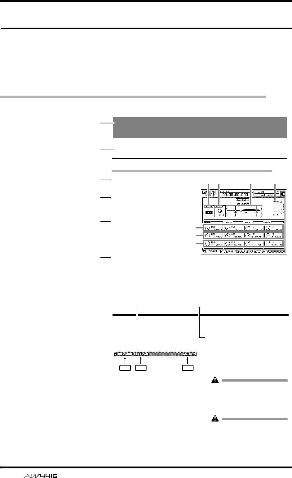
Reference guide
viii
— Reference Guide
Reference guide
The reference guide explains all screens and all pages that appear in the display.
Use it like a dictionary when you wish to learn more about the functions in the
screen, or to find the page from which to execute a desired operation.
How to read the reference guide
Here’s how to read the reference guide.
A
Screen name
B
Page name/title
C
[Function]
A brief summary of the
functions of this page.
D
[Key operation]
The procedure for using
the top panel keys to
access this page.
E
[Mouse operation]
The procedure for using
the mouse to access this
page.
F
[Screen functions]
Explanations of the func-
tion of each item or
operation in this page.
G
■
Additional func-
tions in the page
Explanations of the addi-
tional functions assigned
to the function keys
([F1]–[F5]) in this page.
H
[Procedure]
The procedure for per-
forming a specific opera-
tion in this page.
EQ/ATT/GRP screen
EQ/Att page
EQ and attenuation settings
[Function]
Make four-band EQ and attenuation set-
tings for the selected channel.
[Key operation]
• [EQ] key → [F1] key (EQ/Att) key
• Repeatedly press the [EQ] key until the
screen shown at the right appears.
[Mouse operation]
M button → EQ button → EQ/Att tab
[Screen functions]
AEQ ON button
This switches EQ on/off. When this page is dis-
played, you can use the [ENTER] key to switch
this button on/off regardless of the cursor loca-
tion.
the EQ type to H.SHELF (shelving), and turning
it all the way in the counter-clockwise direction
will switch the EQ type to LPF (low pass filter).
Range: 10–0.10, HPF/L.SHELF (LOW band
only), LPF/H.SHELF (HIGH band only)
2134
5
6
7
1
2
3
4
5
6
EQ/ATT/GRP screen
■Additional functions in the EQ/
Att page
In the EQ/Att page you can press the [SHIFT] key to
assign the following additional functions to the
[F1]–[F2] and [F5] keys.
• [F1] (FLAT) key
Reset all bands to a boost/cut amount of 0.0 dB
(off if HPF/LPF is selected).
• [F2] (BAND FLAT) key
Reset only the selected band to a boost/cut
amount of 0.0 dB (off if HPF/LPF is selected).
• [F5] (COPY ATT. TO ALL) key
Copy the attenuation setting of the selected
channel to all channels. (However, the stereo
output channel is excepted.)
●Copying the attenuation setting
to all channels
[Procedure]
1. Access the EQ/Att page for the copy
source channel, and move the cursor to
the ATT. knob.
2. Press the [SHIFT] key + [F5] key.
A CONFIRMATION popup window will appear,
asking you to confirm the copy.
If the cursor is at a location other than the
ATT. knob, a message of “Can’t Copy This
Parameter” will appear, and the copy will not
occur.
3. To execute the copy, move the cursor to
the OK button and press the [ENTER] key.
Only the attenuation setting will be copied. If
you wish to copy EQ settings, you must store
the settings in the library and recall them into
the copy destination channel. For the proce-
dure refer to page 47.
F1 F2 F5
7 8
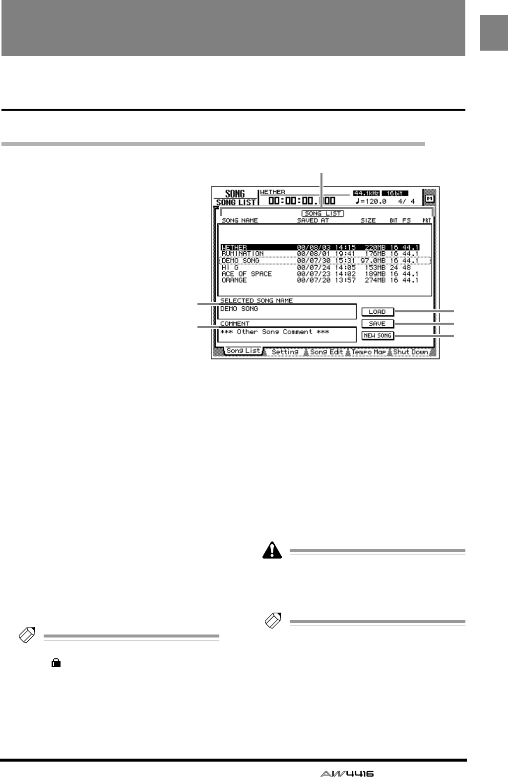
— Reference Guide
1
SONG
SONG screen
Song List page
Saving/loading a song
[Function]
Load a song from hard disk, or
save the current song to hard disk.
[Key operation]
• [SONG] key
→
[F1] (Song List)
key
• Repeatedly press the [SONG]
key until the display shown at
right appears.
[Mouse operation]
M button
→
SONG button
→
Song
List tab
[Screen functions]
A
Song list
This lists the songs that are saved on the internal
hard disk. The highlighted line is the current
song, and the line enclosed by a dotted line is
the song selected for loading. Use the [DATA/
JOG] dial to select the song for loading.
This list shows the following data for each song.
•
SONG NAME
.....First 16 characters of the
song name
•
SAVED AT
...........Date and time at which the
song was last saved
•
SIZE
...................Size of the song
•
BIT/FS
................Quantization (bit number)/
sampling frequency of the
song
•
PRT
....................Song protect on/off (
→ P.2)
Tip!
If song protect is on, the PRT column will
show “ ”.
BSELECTED SONG NAME
This shows the name of the song selected by the
cursor. This field is for display only, and cannot
be edited.
CCOMMENT
This shows the comment of the song selected by
the cursor. This field is for display only, and can-
not be edited.
DLOAD button
This button loads the song enclosed by the dot-
ted line in the list.
ESAVE button
This button saves the current song.
The location of the dotted frame in the list
does not affect the save location of the cur-
rent song. It is not possible to change the
save location of the current song.
Tip!
For details on loading or saving songs, refer
to Operation Guide “Chapter 11. Song man-
agement.”
FNEW SONG button
This button creates a new song. For details on
creating a new song, refer to Operation Guide
“Chapter 5. Recording on the AW4416.”
3
2
1
4
5
6
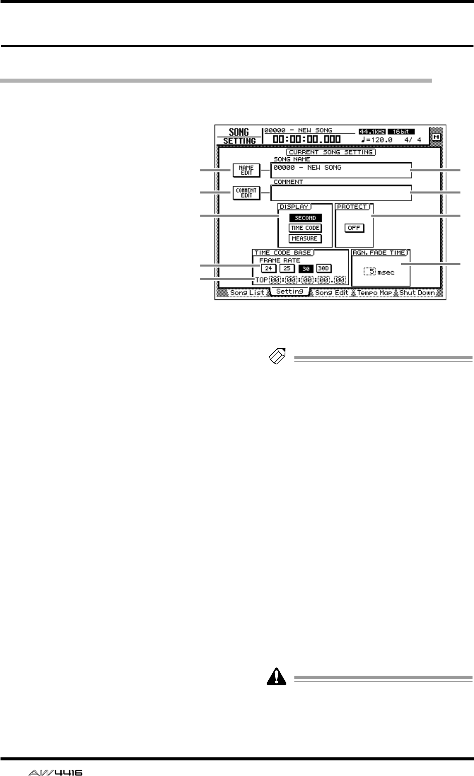
SONG screen
2 — Reference Guide
Setting page
Make various settings for the current song
[Function]
Make various settings for the cur-
rent song, such as editing the song
name, selecting the counter dis-
play method, and selecting the
time code frame rate.
[Key operation]
• [SONG] key → [F2] (Setting) key
• Repeatedly press the [SONG]
key until the display shown at
the right appears.
[Mouse operation]
M button → SONG button → Set-
ting tab
[Screen functions]
ANAME EDIT button
This button edits the song name of the current
song.
BSONG NAME
This displays the song name of the current song.
CCOMMENT EDIT button
This button edits the comment of the current
song.
DCOMMENT
This displays the comment of the current song.
EDISPLAY
You can select one of the following three dis-
play methods for the current location that is
shown in the counter/level meter and in the
counter in the upper part of the display.
● SECOND button
The counter will be displayed as time (hours/
minutes/seconds/milliseconds).
● TIME CODE button
The counter will be displayed as time code
(hours/minutes/seconds/frames/sub-frames).
● MEASURE button
The counter will be displayed as measures
(measures/beats/ticks).
Tip!
The display method you select here will also
affect how the track editing range is specified
(EDIT screen TR Edit page), and how locate
points are displayed (TRACK screen Mark
Adj. page etc.).
FPROTECT
This specifies the protect setting of the song.
When you move the cursor to the button in the
PROTECT area and press the [ENTER] key, the
button will alternate between ON and OFF.
When protect is on, it will not be possible to
edit or record tracks, edit the sampling pads, or
set/change locate points.
GFRAME RATE buttons
Use the following four buttons to select the
frame rate of the time code. The frame rate set-
ting will affect the counter time code display
and the MTC that is transmitted and received.
• 24 button ...........24 fps
• 25 button ...........25 fps
• 30 button ...........30 fps (30 non-drop frame)
• 30D button ........29.97 fps (30 drop-frame)
If you wish to use MTC to synchronize the
AW4416 and an external device, you must
use the FRAME RATE buttons to match the
frame rate of the two devices.
3
5
7
8
12
4
6
9
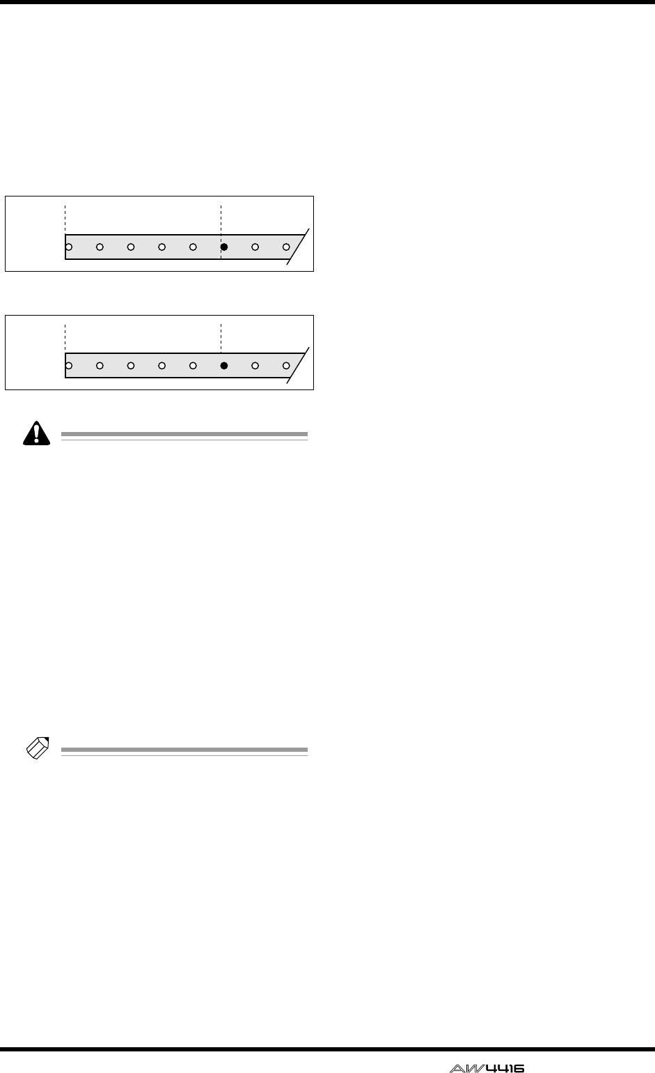
SONG screen
— Reference Guide 3
HTOP
This adjusts the time code time that corresponds
to the beginning of the song (“time code top”) in
the range of “00:00:00:00.00”–
”24:00:00:00.00”. (Negative values cannot be
set.) Move the cursor to the TOP area, and use
the [DATA/JOG] dial to adjust the hours/min-
utes/seconds/frames/subframes value.
• Changing the time code Top will affect the
time code indications in the display and the
MTC that the AW4416 transmits and
receives.
• When you modify the time code Top, the
start point and end point will be adjusted
automatically. For details on the start point
and end point, refer to the explanation in
“TRACK screen/Mark Adj. page.”
IRGN. FADE TIME (region fade time)
This parameter automatically fades-in/fades-out
the starting and ending point of regions. You can
select from 3, 5, 10, 20, or 45 msec as the time
over which the fade-in/out will take place
(“region fade time”). The default setting is 5
msec.
Tip!
If the level changes abruptly at the start/end
point of a region, noise or a click may be
heard during playback. For this reason, it is
not possible to set the region fade time to 0
msec. If you notice noise or clicks, set the
region fade time to a longer value.
00:00:00:00.00 00:00:05:00.00
00:00:055:00.00 00:00:10:00.00
Time code
display
Time code
display
Song
Song
Time code top= 00:00:00:00.00
Time code top= 00:00:05:00.00
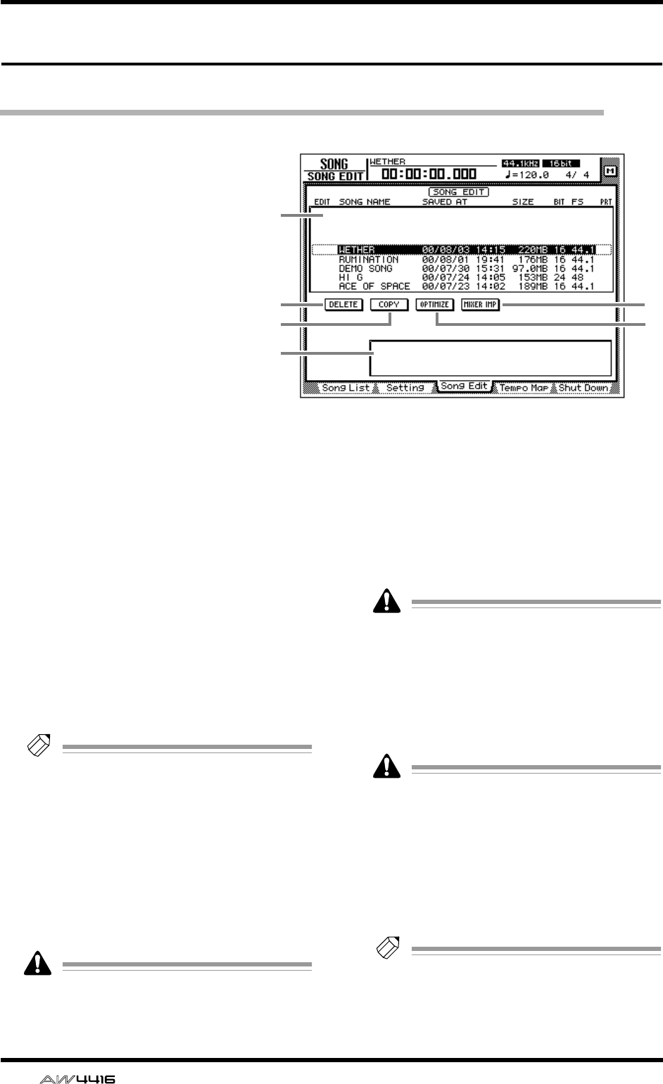
SONG screen
4 — Reference Guide
Song Edit page
Deleting/copying/optimizing songs
[Function]
Edit songs saved on the internal hard disk,
such as by deleting, copying, or optimiz-
ing them.
[Key operation]
• [SONG] key → [F3] (Song Edit) key
• Repeatedly press the [SONG] key until
the screen shown at the right appears.
[Mouse operation]
M button → SONG button → Song Edit
tab
[Screen functions]
ASong list
This lists the songs saved on the internal hard
disk. The current song is highlighted in the list.
An “E” symbol displayed at the left edge of the
list indicates a song selected for editing. The fol-
lowing information is also displayed in the song
list.
• SONG NAME .....First 16 characters of the
song name
• SAVED AT ...........Date and time at which the
song was last saved
• SIZE....................Size of the song
• BIT/FS.................Quantization (bit number)/
sampling frequency of the
song
• PRT.....................Song protect on/off status
Tip!
• When you use the cursor to select a song in
the list and press the [ENTER] key, the “E”
symbol that indicates the editing selection
will alternately appear and disappear.
• Depending on the operation, you may be
able to select more than one song for edit-
ing.
BDELETE button
This button deletes the song marked by the “E”
symbol from the internal hard disk.
• The current song cannot be deleted.
• A deleted song is gone forever. Use this
operation with caution.
CCOPY button
This button copies the song marked by the “E”
symbol onto the internal hard disk.
DOPTIMIZE button
This button optimizes the song marked by the
“E” symbol. When optimize is executed, audio
files not currently used by that song (e.g., undo
files) will be deleted.
Optimize can be executed on only one song
at a time. Optimize can be executed on the
current song.
EMIXER IMP (mixer import) button
This button imports the mixer settings (scene mem-
ory/automix/tempo map/libraries) from the song
marked by the “E” symbol into the current song.
Only one song can be selected as the import
source for mixer data. The current song can-
not be selected as the import source.
FParameter area
When you move the cursor to one of the but-
tons 2–5, the operation (DELETE/COPY/OPTI-
MIZE/MIXER IMPORT) that can be executed by
that button will appear in this area.
Tip!
For details on using each operation, refer to
Operation Guide “Chapter 11. Song Manage-
ment.”
2
3
5
4
6
1
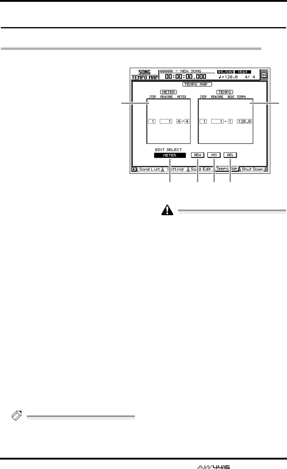
SONG screen
— Reference Guide 5
Tempo Map page
Programming the tempo map
[Function]
Program tempo data and time sig-
nature data into the tempo map.
[Key operation]
• [SONG] key → [F4] (Tempo
Map) key
• Repeatedly press the [SONG]
key until the screen shown at the
right appears.
[Mouse operation]
M button → SONG button →
Tempo Map tab
[Screen functions]
AMETER
In this area you can specify the time signature.
The area enclosed by the dotted frame is the
currently selected time signature data. In the
METER area you can make the following set-
tings for the STEP/MEASURE/METER items.
● STEP
Move the cursor to this area and rotate the
[DATA/JOG] dial to select the number (step
number) of the time signature data. The step
number is assigned consecutively, starting at the
time signature data of the lowest-numbered
measure.
● MEASURE
Move the cursor to this area and rotate the
[DATA/JOG] dial to modify the measure number
of the time signature. If you move the time sig-
nature beyond the previous or next time signa-
ture data, their step numbers will be exchanged
automatically.
● METER
Move the cursor to this area and rotate the
[DATA/JOG] dial to specify the time signature
(2/1–8/8) for that measure. The numerator and
denominator of the time signature can be set
independently.
Tip!
When the AW4416 is in the default state,
time signature data of 4/4 is already input at
measure 1.
• It is not possible to move the time signature
data of measure 1.
• It is not possible to place two time signatures
at the same measure. If you move the cursor
to the MEASURE area and specify the same
measure number as an existing time signa-
ture, the previous time signature data will be
deleted.
BTEMPO
In this area you can specify tempo data. The
area enclosed by the dotted line is the currently
selected tempo data. In the TEMPO area you
can make the following settings for the STEP/
MEASURE/BEAT/TEMPO items.
● STEP
Move the cursor to this area and rotate the
[DATA/JOG] dial to select the number (step
number) of the tempo data. The step number is
assigned consecutively, starting at the tempo
data of the lowest-numbered measure.
● MEASURE/BEAT
Move the cursor to this area and rotate the
[DATA/JOG] dial to modify the location (mea-
sure/beat) of the tempo data. If you move the
tempo data beyond the previous or next tempo
data, their step numbers will be exchanged
automatically.
1
34 5 6
2
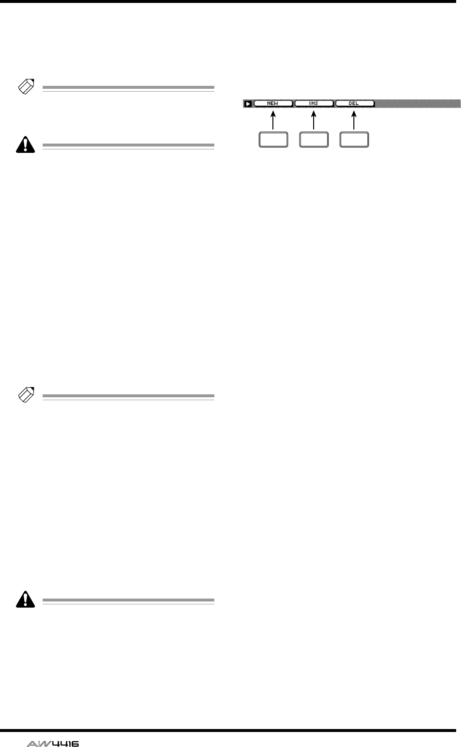
SONG screen
6 — Reference Guide
● TEMPO
Move the cursor to this area and rotate the
[DATA/JOG] dial to set the tempo (BPM) of that
location. The BPM value can be set in a range of
20.0–300.0, in 0.1 steps.
Tip!
When the AW4416 is in the default state,
tempo data of BPM=120 is already input at
measure 1 beat 1.
• The tempo data at step number 1 cannot be
moved.
• It is not possible to place two tempo data at
the same location. If you move the cursor to
the MEASURE/BEAT area and specify the
same location as an existing tempo data, the
previous tempo data will be deleted.
CEDIT SELECT button
Use this button to specify whether you will edit
time signature data (METER) or tempo data
(TEMPO). Move the cursor to the button and
press the [ENTER] key to switch between
METER and TEMPO.
DNEW button
When you move the cursor to this button and
press the [ENTER] key, new time signature/
tempo data will be added following the last step
number that is currently input.
Tip!
• For details on inputting the tempo map, refer
to Operation Guide “Chapter 15. MIDI.”
• A maximum of 26 time signature data/tempo
data items can be input in the METER area/
TEMPO area.
EINS button
When you move the cursor to this button and
press the [ENTER] key, new time signature/
tempo data will be inserted after the currently
selected time signature/tempo data.
FDEL button
When you move the cursor to this button and
press the [ENTER] key, the currently selected
time signature/tempo data will be deleted.
It is not possible to delete the time signature/
tempo data of step number 1.
■Additional functions in the
Tempo Map page
In the Tempo Map page, pressing the [SHIFT] key
will assign the following functions to the [F1]–[F3]
keys.
• [F1] (NEW) key
This key inputs additional time signature data or
tempo data. This is the same function as the 4
NEW button.
• [F2] (INS) key
This key inserts time signature data or tempo
data. This is the same function as the 5 INS
button.
• [F3] (DEL) key
This key deletes time signature data or tempo
data. This is the same function as the 6 DEL
button.
F1 F2 F3
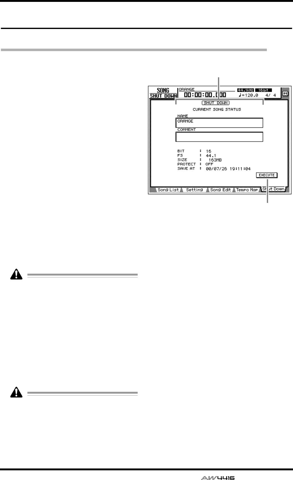
SONG screen
— Reference Guide 7
Shut Down page
Shut down the AW4416
[Function]
Shut down the AW4416 so that the power can
be turned off.
[Key operation]
• [SONG] key → [F5] (Shut Down) key
• Repeatedly press the [SONG] key until the
screen shown at the right appears.
[Mouse operation]
M button → SONG button → Shut Down tab
[Screen functions]
ACurrent song status
This area displays various information on the
last-saved song.
The data for the current song (date, size,
quantization bits, protect) shown here in the
song list is the data for when the song was
last saved. When you perform the Save pro-
cedure and press the [ENTER] key, it will be
overwritten by the new data.
BEXECUTE button
In this page, the cursor is fixed at the EXECUTE
button, so you can shut-down simply by press-
ing the [ENTER] key. For details on the order in
which the AW4416 and peripheral devices
should be shut down, refer to Operation Guide
“Important points you must observe.”
If you turn off the power of the AW4416
without performing the shut-down operation,
audio data on the internal hard disk may be
damaged. Be sure to perform this shut-down
operation before turning off the power of the
AW4416.
1
2
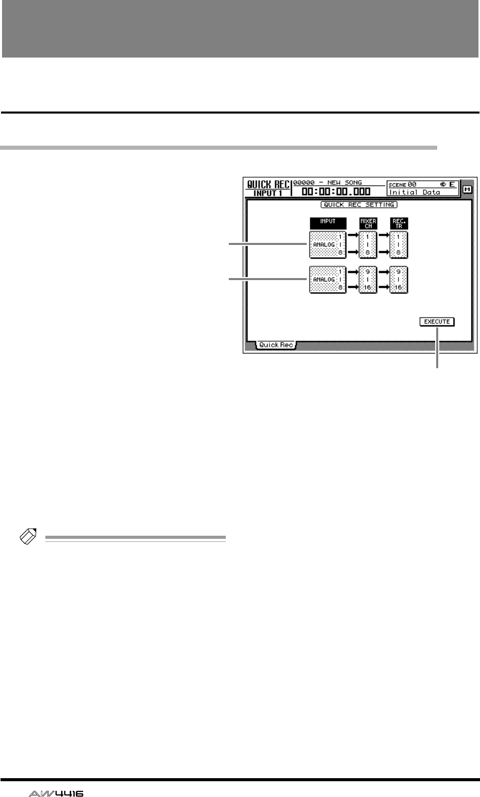
8 — Reference Guide
QUICK REC screen
Quick Rec page
Simultaneously recording 16 inputs/16 tracks
[Function]
Instantly make settings (Quick Rec
function) for simultaneously
recording 16 input sources on
audio tracks 1–16.
[Key operation]
[QUICK REC] key
[Mouse operation]
M button → Quick REC button
[Screen functions]
AInput select 1–8
BInput select 9–16
Select from the following input sources to send
to audio tracks 1–8/9–16.
• ANALOG 1–8 .....INPUT jacks 1–8
• SLOT1 1–8..........INPUT 1–8 of an I/O card
(slot 1)
• SLOT2 1–8..........INPUT 1–8 of an I/O card
(slot 2)
Tip!
It is possible to select the same source for
1
and
2
. In this case, the same signal will be
sent to tracks 1–8 and tracks 9–16.
CEXECUTE button
When you move the cursor to this button and
press the [ENTER] key, the settings of the
AW4416 will change as follows.
• Mix parameters such as fader, pan, and EQ for
each channel will be reset.
• [REC TRACK SELECT] keys 1–16 will blink,
and tracks 1–16 will be in record-ready mode.
• The output of all tracks 1–16 will be muted.
• Input patch and recorder input patch settings
will be switched as follows.
1
2
3
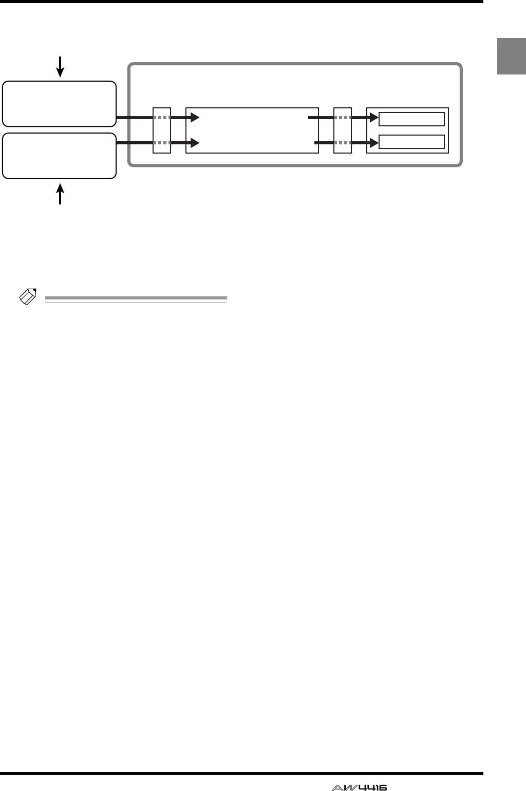
QUICK REC screen
— Reference Guide 9
QUICK
REC
After you have used the EXECUTE button, you
can simply press the [REC] key + [PLAY] key to
simultaneously record 16 inputs on tracks 1–16.
Tip!
• To defeat record-ready and mute settings for
tracks 1–16, press the [ALL SAFE] key.
• For details on operation of the Quick Rec
function, refer to Operation Guide “Chapter
8. Patching.”
Input channels 1–8
Input channels 9–16
Mixer section
Input
patch
×8
×8
• Input jacks 1–8
• I/O card SLOT1 1–8
• I/O card SLOT2 1–8
Recorder
input
patch Recorder section
Tracks 1–8
Tracks 9–16
1 Input select 1–8
2 Input select 9–16
• Input jacks 1–8
• I/O card SLOT1 1–8
• I/O card SLOT2 1–8
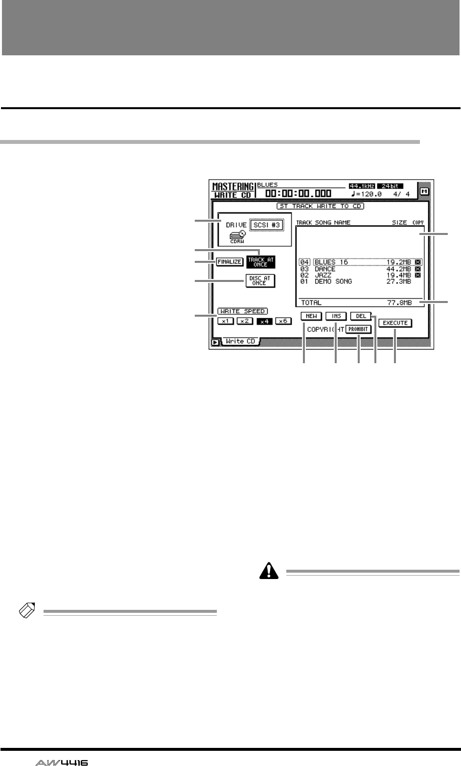
10 — Reference Guide
MASTERING screen
Write CD page
Using a CD-RW drive to create an audio CD
[Function]
Create an audio CD by writing the
stereo track data of songs to CD-R/
RW media as CD audio tracks.
[Key operation]
[MASTERING] key
[Mouse operation]
M button → MAST button
[Screen functions]
ADRIVE
Select the SCSI ID number of the internal or
external CD-RW drive.
BFINALIZE button
When you press this button, CD-R media that
was written using Track At Once will be final-
ized (information on track locations etc. will be
written into the data area). You must perform the
finalize operation in order for CD-R media writ-
ten using Track At Once to be playable on a CD
player.
Tip!
If you used Disc At Once to write the data,
finalize will be performed automatically. For
this reason, the FINALIZE button will be dis-
played only if the TRACK AT ONCE button
3
is turned on.
CTRACK AT ONCE button
DDISC AT ONCE button
Use these buttons to select the way in which
data will be written to the CD-R/RW media
(either Track At Once or Disc At Once). Before
you execute the Write operation, you must
move the cursor to one of these buttons and
press the [ENTER] key.
CD-RW media does not support Track At
Once.
EWRITE SPEED buttons
Use the x1, x2, x4, and x6 buttons to select the
writing speed (normal speed/double speed/
quad speed/x6 speed). Normally you should
select the fastest speed supported by your CD-
RW drive.
1
6
7
LK8 9 J
5
2
3
4
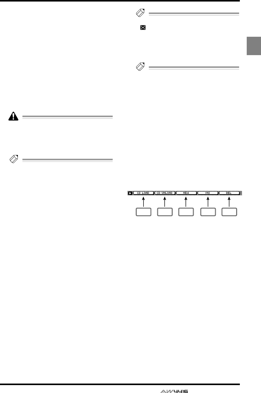
MASTERING screen
— Reference Guide 11
MASTER-
ING
FTrack list
Here you can select the stereo tracks that will
be written as audio tracks on the CD.
The track list shows the following information.
● TRACK
This is the track number on the CD. Move the
cursor to this area and rotate the [DATA/JOG]
dial to change the track number.
● SONG NAME/SIZE/COPY
This shows the song name, stereo track data
size, and copy protect setting of songs that con-
tain a stereo track. Move the cursor to this area
and use the [DATA/JOG] dial to select the stereo
track that will be written to the corresponding
audio track.
• The track list will show only the stereo tracks
of songs whose sampling frequency is
44.1 kHz. Stereo tracks of 48 kHz sampling
frequency songs will not be displayed.
•
Tip!
If CD-R media containing data written using
Track At Once is in the CD-RW drive, the
SONG NAME/SIZE/COPY area will indicate
“–EXISTING–”.
GTotal
This shows the total of the SIZE column of the
track list. A maximum of approximately 650 MB
can be written to 74 minute CD-R/RW media.
HNEW button
Add a new audio track to the track list.
IINS button
Insert a new audio track after the track number
currently selected in the track list.
JDEL
Delete the currently selected audio track from
the track list.
KCOPYRIGHT button
Set the copy protect setting of the audio track
currently selected in the track list. Move the
cursor to this button and press the [ENTER] key
to switch between the following two button dis-
plays.
● PROHIBIT
Digital copying of the corresponding track will
be prohibited.
● PERMIT
Digital copying of the corresponding track will
be permitted.
Tip!
If the button is displayed as PROHIBIT, an
“ ” symbol will be displayed in the COPY
column of the track list.
LEXECUTE button
Use this button to execute writing (mastering) to
CD-R/RW media.
Tip!
• The AW4416 has a “writing test” function
that can check before mastering is per-
formed to see whether data transmission
errors will occur. By default, this test will not
be performed. However, you can make set-
tings so that the test will be performed
before writing, or execute the test by itself.
(
→
P.37)
• For details on the procedure of the Mastering
function, refer to Operation Guide “Chapter
17. Mastering.”
■Additional functions in the Write
CD page
In the Write CD page you can press the [SHIFT] key
to assign the following functions to the [F1]–[F5]
keys.
• [F1] (CD LOAD) key
Close the tray of the CD-RW drive.
• [F2] (CD UNLOAD) key
Eject the tray of the CD-RW drive.
• [F3] (NEW) key
Add a new audio track to the track list 6. This is
the same function as the NEW button 8.
• [F4] (INS) key
Insert a new audio track after the track number
currently selected in the track list 6. This is the
same function as the INS button 9.
• [F5] (DEL) key
Delete the audio track currently selected in the
track list 6. This is the same function as the DEL
button J.
F1 F2 F3 F4 F5
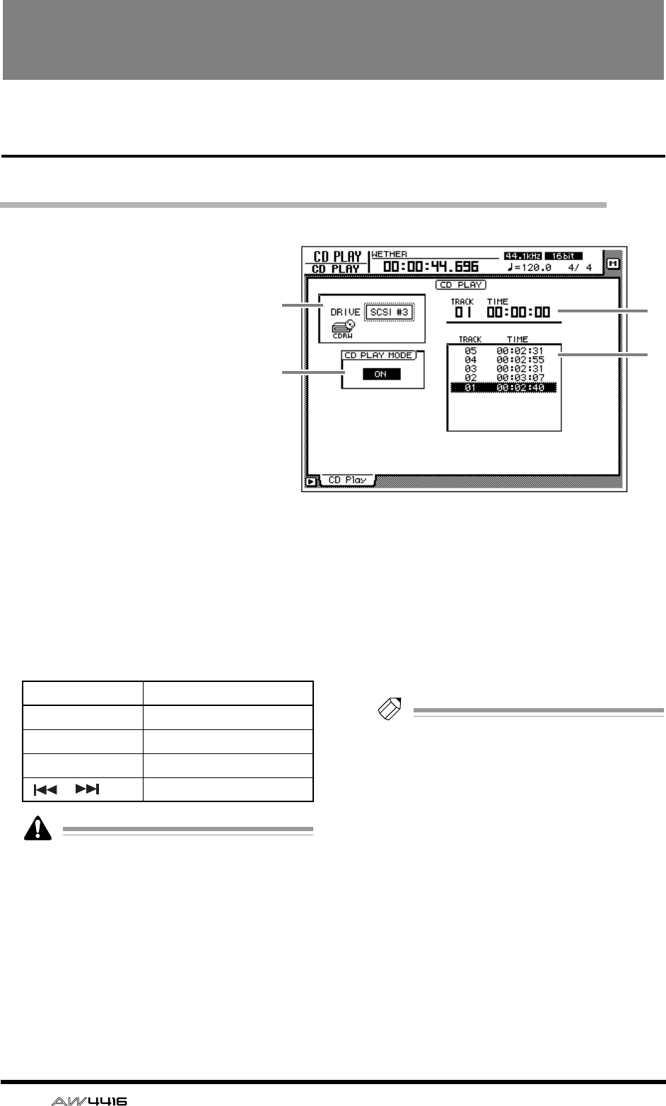
12 — Reference Guide
CD PLAY screen
CD Play page
Use the CD-RW drive to play an audio CD
[Function]
Use a CD-RW drive connected to
the AW4416 to play back an audio
CD (CD Play function).
[Key operation]
[CD PLAY] key
[Mouse operation]
M button → CD button
[Screen functions]
ADRIVE
Select the SCSI ID number of the internal or
external CD-RW drive.
BCD PLAY MODE button
This button switches the CD Play function on/
off. When the CD PLAY function is on, you can
use the keys of the Transport section to operate
the CD-RW drive.
• While the CD PLAY MODE button
2
is on,
all keys except the [CURSOR] keys, [DATA/
JOG] dial, [ENTER] key, and Transport sec-
tion keys will be disabled.
• The CD audio signal is routed through the
stereo output channel and output from the
STEREO OUT jacks. (Use the STEREO fader
to adjust the volume.) During this time, the
signals of other channels will not be sent to
the stereo output channel.
• For details on the CD Play function, refer to
Operation Guide “Chapter 17. Mastering.”
CCounter
This displays the track number (TRACK) cur-
rently selected in the track list 4, and the
elapsed time of that track (TIME).
DTrack list
This list shows the audio track numbers on the
CD (TRACK area), and the times for each track
(TIME area). The currently selected audio track
will be highlighted.
Tip!
You can move the cursor to the track list and
switch the playback track by using the
[DATA/JOG] dial and the [ENTER] key.
4
3
1
2
Key CD-RW drive operation
[PLAY] key Play the CD
[STOP] key Stop the CD
[FF]/[REW] keys Rewind/fast-forward the CD
[ ]/[ ] keys Select tracks
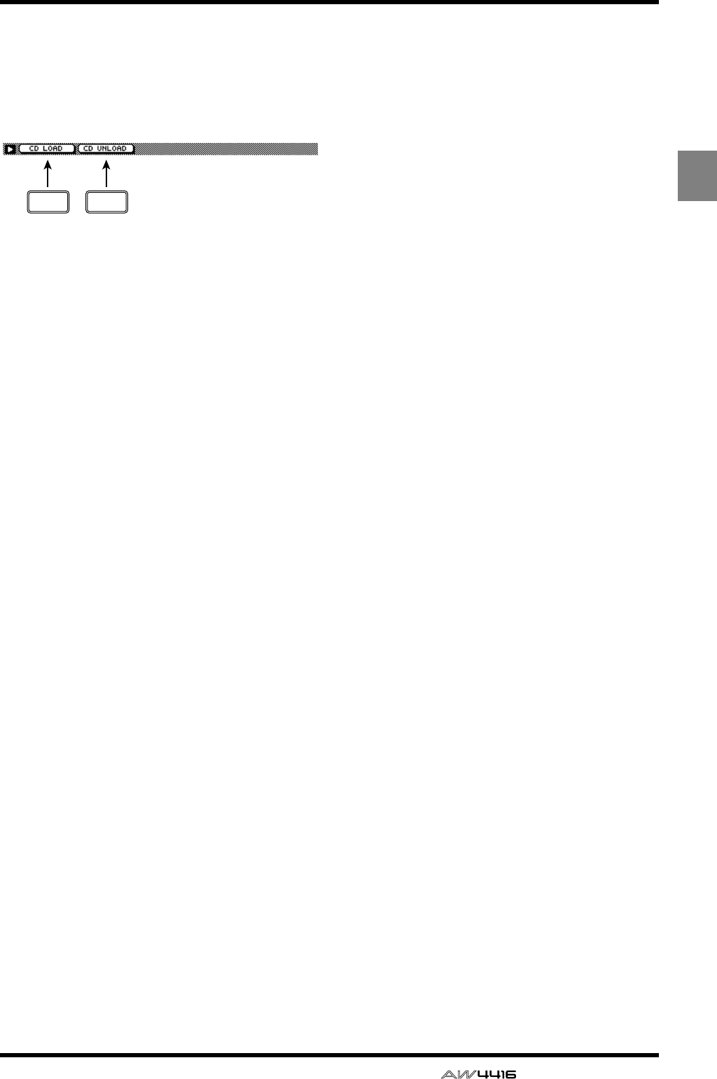
CD PLAY screen
— Reference Guide 13
CD
PLAY
■Additional functions in the CD
Play page
In the CD Play page you can press the [SHIFT] key
to assign the following functions to the [F1]–[F2]
keys.
• [F1] (CD LOAD) key
Close the tray of the CD-RW drive.
• [F2] (CD UNLOAD) key
Eject the tray of the CD-RW drive.
F1 F2
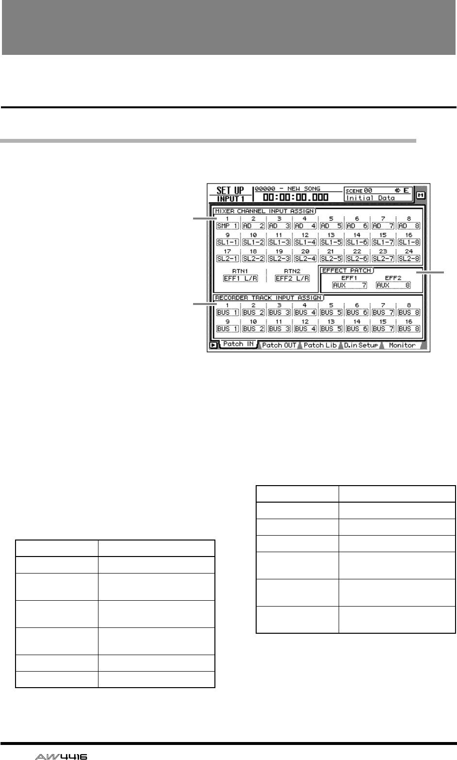
14 — Reference Guide
SET UP screen
Patch IN page
Patching a signal to a channel/track
[Function]
Assign signals to the inputs of input
channels 1–24, return channels 1/2,
and recorder tracks 1–16.
[Key operation]
• [SETUP] key → [F1] (Patch IN) key (*1)
• Repeatedly press the [SETUP] key
until the display shown at right
appears.
*1. In the SET UP screen, the tabs dis-
played at the bottom are divided
into two groups. If the Patch IN tab is
not assigned to the [F1] key when
you press the [SETUP] key, press the
[SETUP] key + [F1] (CHANGE TAB)
key to switch the tab.
[Mouse operation]
M button → SETU button → Patch IN tab
[Screen functions]
AMIXER CHANNEL INPUT ASSIGN
Select the signal that will be assigned to input
channels 1–24 and return channels 1/2. The fol-
lowing signals can be assigned to each channel.
● Input channels 1–24
● Return channels 1/2
BEFFECT PATCH
Select whether effects 1/2 will be used via AUX
send/return (AUX7/AUX8), or inserted into a
specified channel (INSERT). For details on oper-
ation, refer to Operation Guide “Chapter 10.
Internal effects.”
2
1
3
Display Signal type
AD 1–AD 8 INPUT jacks 1–8
SL1-1 – SL1-8 INPUT 1–8 of an I/O card
(slot 1)
SL2-1 – SL2-8 INPUT 1–8 of an I/O card
(slot 2)
DIN L/DIN R L/R channels of the DIGITAL
STEREO IN jack
SMP 1–SMP 8 Sampling pads 1–8
MET Internal metronome
Display Signal type
EFF1 L/R Return of internal effect 1
EFF2 L/R Return of internal effect 2
AD 1/2–AD 7/8 INPUT jacks 1/2–7/8
SL1-1/2 – SL1-7/8 INPUT 1/2–7/8 of an I/O
card (slot 1)
SL2-1/2 – SL2-7/8 INPUT 1/2–7/8 of an I/O
card (slot 2)
DIN L/R DIGITAL STEREO IN jack
(stereo)
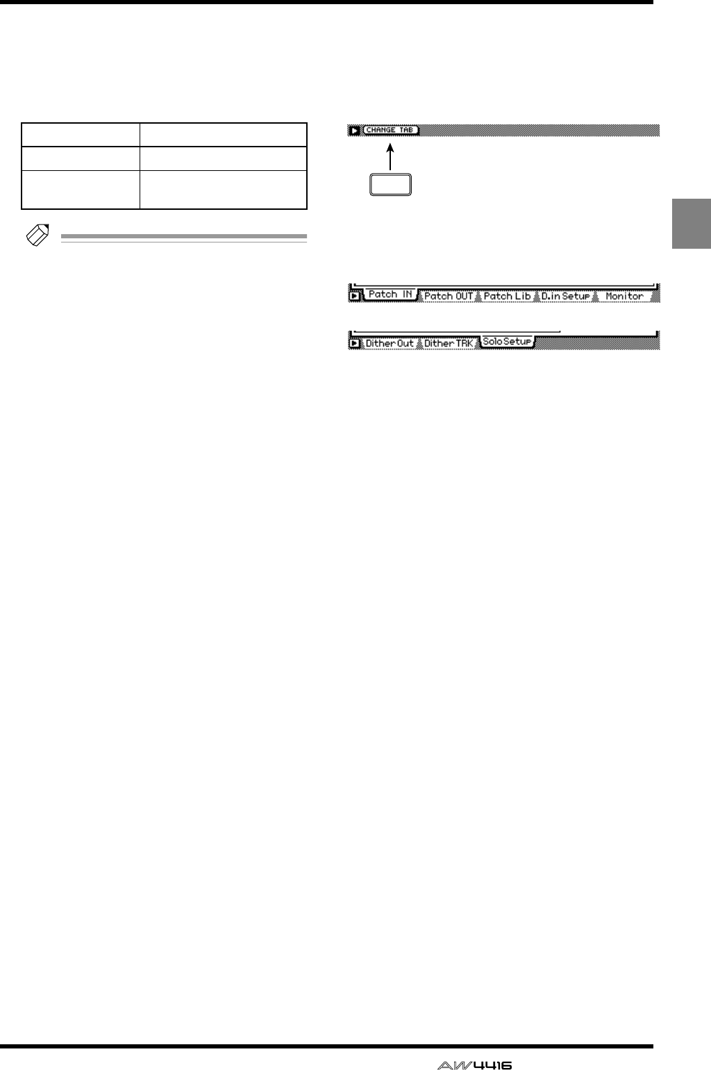
SET UP screen
— Reference Guide 15
SET
UP
CRECORDER TRACK INPUT ASSIGN
Here you can select the signals to be assigned
to the inputs of tracks 1–16. The following sig-
nals can be assigned.
● Recorder inputs 1–16
Tip!
For detai ls on operations in the Patch IN
page, refer to Operation Guide “Chapter 8.
Patching.”
■Additional functions in the Patch
IN page
In the Patch IN page you can press the [SHIFT] key
to assign the following function to the [F1] key.
• [F1] (CHANGE TAB) key
Switch between the following two tab displays.
Display Signal type
BUS 1–BUS 8 Bus 1–8
DIR 1–DIR16 Input channel direct out 1–
16 F1
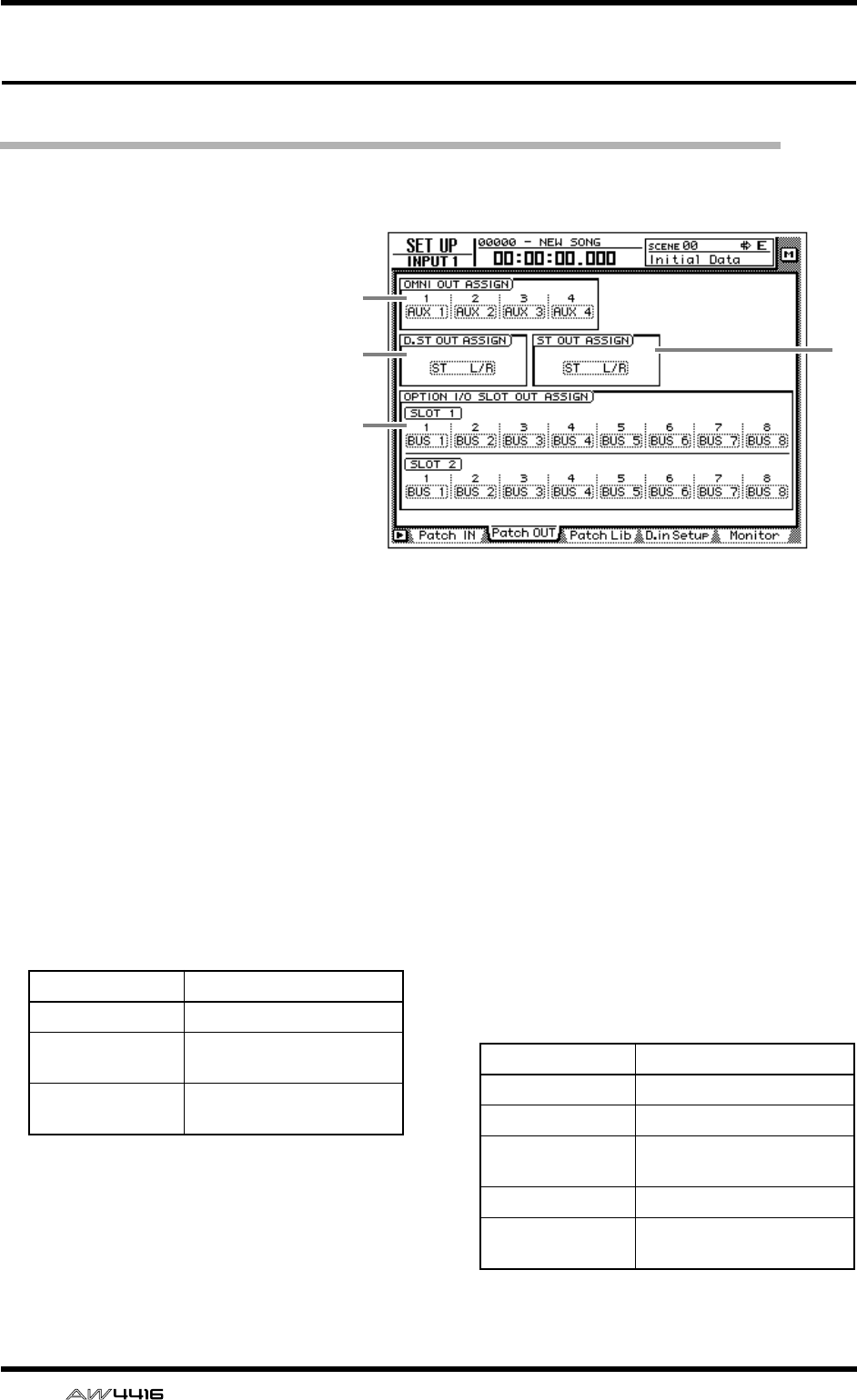
SET UP screen
16 — Reference Guide
Patch OUT page
Patch signals to output jacks
[Function]
Assign output signals to the OMNI
OUT jacks, STEREO OUT jacks,
DIGITAL STEREO OUT jack, and
the output channels of I/O cards.
[Key operations]
• [SETUP] key → [F2] (Patch OUT)
key (*1)
• Repeatedly press the [SETUP]
key until the display shown at
right appears.
*1. In the SET UP screen, the tabs
displayed at the bottom of the
screen are divided into two
groups. If the Patch OUT tab is
not assigned to the [F2] key
when you press the [SETUP]
key, press [SHIFT] key + [F1]
(CHANGE TAB) key to switch
the tabs.
[Mouse operation]
M button → SETU button → Patch OUT tab
[Screen functions]
AOMNI OUT ASSIGN
Select the signals that will be output from the
OMNI OUT 1–4 jacks. The following signals
can be assigned.
BD.ST OUT ASSIGN (digital stereo out
assign)
CST OUT ASSIGN (stereo out assign)
These respectively select the pair of signals that
will be output from the DIGITAL STEREO OUT
jack and the STEREO OUT jack. The following
signals can be assigned.
3
1
2
4
Display Signal type
AUX 1–AUX 8 AUX buses 1–8
RDR 1–RDR16 Recorder direct outputs 1–
16
ST L/ST R L/R channels of the stereo
output channel
Display Signal type
ST L/R Stereo output channel
BUS 1/2–BUS 7/8 Bus 1/2–7/8
DIR 1/2–DIR15/16 Input channel direct out 1/
2–15/16
AUX 1/2–AUX 7/8 AUX buses 1/2–7/8
RDR 1/2–RDR15/
16
Recorder direct outs 1/2–
15/16

SET UP screen
— Reference Guide 17
DOPTION I/O SLOT OUT ASSIGN
This selects the signals that will be output from
I/O cards installed in OPTION I/O slots 1/2. The
following signals can be assigned.
Tip!
For details on operation in the Patch OUT
page, refer to Operation Guide “Chapter 8.
Patching.”
■Additional functions in the Patch
OUT page
In the Patch OUT page you can press the [SHIFT]
key to assign the following function to the [F1] key.
• [F1] (CHANGE TAB) key
Switch between the two tab displays.
Display Signal type
BUS 1–BUS 8 Buses 1–8
DIR 1–DIR16 Input channel direct out 1–
16
AUX 1–AUX 8 AUX buses 1–8
RDR 1–RDR16 Recorder direct outputs 1–
16
F1
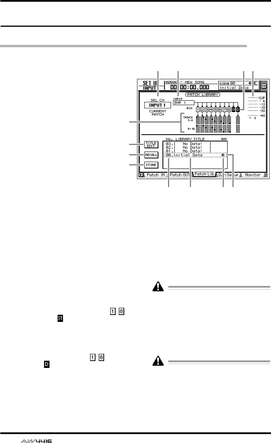
SET UP screen
18 — Reference Guide
Patch Lib page
Store or recall patching settings
[Function]
Store the settings of the Patch IN/Patch
OUT pages in the patch library, or recall
previously-stored settings.
[Key operation]
• [SETUP] key → [F3] (Patch Lib) key (*1)
• Repeatedly press the [SETUP] key until
the display shown at right appears.
*1. In the SET UP screen, the tabs dis-
played at the bottom of the screen are
divided into two groups. If the Patch
Lib tab is not assigned to the [F3] key
when you press the [SETUP] key, press
[SHIFT] key + [F1] (CHANGE TAB) key
to switch the tabs.
[Mouse operation]
M button → SETU button → Patch Lib tab
[Screen functions]
ASEL CH
This indicates the channel currently selected by
the [SEL] key.
BINPUT
This indicates the input signal patched to the
channel shown in 1. Refer to the explanation
of the Patch IN page for the meaning of each
abbreviation.
CBUS
This area shows the buses to which the signal of
the channel is being sent. For buses 1–8 ( – )
and the stereo bus ( ), buses to which that
channel is assigned will be displayed as white
characters on black background.
DTRACK 1-8/9-16
This area displays ■ symbols to indicate the
track inputs to which buses 1–8 ( – ) and the
direct output ( ) of the input channel currently
selected by the [SEL] key are patched.
EInput meter
This shows the input level of the odd-numbered
→ even-numbered channels adjacent to the
channel selected in 1, or the output level of the
stereo output channel.
FTITLE EDIT button
Use this button when you wish to edit the name
(library title) of the patching settings saved in the
library. Move the cursor to the TITLE EDIT but-
ton and press the [ENTER] key to access the
TITLE EDIT screen where you can input the
name.
Library number 0 is a recall-only preset, and
therefore its name cannot be changed. Patch
library numbers in which no data has been
stored will be displayed as “No Data!,” and
their title cannot be edited.
GRECALL button
This button recalls the currently selected patch-
ing settings from the list.
If you select a number in which nothing has
been stored and attempt to recall it, an error
message of “ERROR NO DATA TO RECALL”
will be displayed, and the recall will not take
place.
HSTORE button
Store the current patching settings.
1 2 3 5
6
4
7
8
9JKL
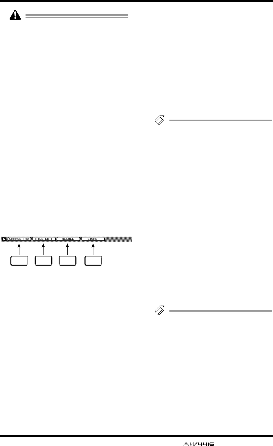
SET UP screen
— Reference Guide 19
• Library number 0 is a recall-only preset; data
cannot be stored in it. Data can be stored
only in library numbers 1–20.
• When you execute the Store operation, the
patching settings that had been stored in that
number will be erased.
ILIBRARY No. (library number)
This area displays library numbers 00–20.
JLIBRARY TITLE
This area displays the names assigned to the
library settings.
KROM
Recall-only library number 0 is indicated by a
write-prohibit symbol in this column.
LSelected patching
The patching settings enclosed by the dotted
line in the library list will be the subject of the
Store or Recall operation. In this page, you can
use the [DATA/JOG] dial to select patching set-
tings regardless of where the cursor is located.
■Additional functions in the Patch
Lib page
In the Patch Lib page you can press the [SHIFT] key
to assign the following functions to the [F1]–[F4]
keys.
• [F1] (CHANGE TAB) key
Switch between the two tab displays.
• [F2] (TITLE EDIT) key
Use this to edit the name (library title) of patch-
ing settings saved in the library. This is the same
function as the 6 TITLE EDIT button.
• [F3] (RECALL) key
Recall the currently selected patching settings
from the list. This is the same function as the 7
RECALL button.
• [F4] (STORE) key
Store the current patching settings. This is the
same function as the 8 STORE button.
●To store the patching settings
into a library
[Procedure]
1. Access the SET UP screen Patch Lib page.
2. Use the [DATA/JOG] dial to select the
library number 1–20 into which you wish
to store the settings.
3. Move the cursor to the STORE button and
press the [ENTER] key.
The NAME EDIT display will appear, allowing
you to input the name.
Tip!
If STORE CONFIRMATION is turned “OFF”
in the UTILITY screen Prefer.1 page ([UTIL-
ITY] key
→
[F2] key), this popup window will
not appear.
4. Input the library title. For details on input-
ting characters, refer to Operation Guide
P.60.
5. Move the cursor to the OK button and
press the [ENTER] key.
The Store operation will be executed.
●To recall patching settings from a
library
[Procedure]
1. Access the SET UP screen Patch Lib page.
2. Use the [DATA/JOG] dial to select the
library number that you wish to recall.
3. Move the cursor to the RECALL button
and press the [ENTER] key.
A confirmation message will appear.
Tip!
If RECALL CONFIRMATION is turned “OFF”
in the UTILITY screen Prefer.1 page ([UTIL-
ITY] key
→
[F2] key), this popup window will
not appear.
4. Move the cursor to the OK button and
press the [ENTER] key.
The Recall operation will be executed.
F1 F2 F3 F4
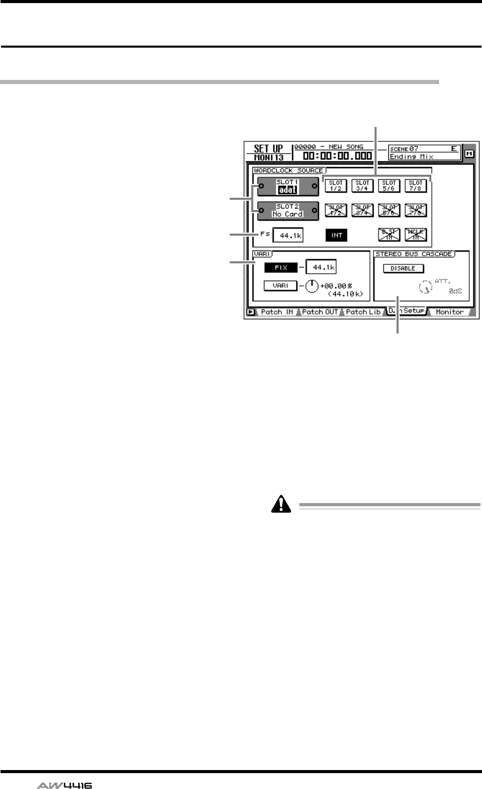
SET UP screen
20 — Reference Guide
D.in Setup page
Make word clock/cascade settings
[Function]
Select the word clock source to which the
AW4416 will synchronize. In this page
you can also make settings for stereo bus
cascade connections.
[Key operation]
• [SETUP] key → [F4] (D.in Setup) key (*1)
• Repeatedly press the [SETUP] key until
the screen shown at the right appears.
*1. In the SET UP screen, the tabs dis-
played at the bottom of the screen are
divided into two groups. If the D.in
Setup tab is not assigned to the [F4]
key when you press the [SETUP] key,
press the [SHIFT] key + [F1] (CHANGE
TAB) key to switch the tabs.
[Mouse operation]
M button → SETU button → D.in Setup
tab
[Screen functions]
ASlots 1/2
If an optional I/O card is installed in OPTION I/
O slots 1/2, a graphic will be displayed to show
the type of I/O card. Cards in which no card is
installed will be displayed as “No Card!”
BWORD CLOCK SOURCE
From the following choices, select one of the
following clock source to which the AW4416
will synchronize.
● SLOT 1 1/2–7/8
● SLOT 2 1/2–7/8
The input signal from a digital I/O card installed
in OPTION I/O slots 1/2 will be the clock
source. One pair of digital I/O card input chan-
nels 1/2–7/8 can be selected.
● INT
The internal clock of the AW4416 will be used
as the clock source.
● D.ST IN
The word clock data included in the input sig-
nal of the DIGITAL STEREO IN jack will be the
clock source.
● WCLK IN
The word clock data included in the input sig-
nal of the WORD CLOCK IN jack will be the
clock source.
• The highlighted button indicates the cur-
rently selected word clock source.
• Buttons marked with an “X” indicate that no
digital audio signal is being input from the
corresponding slot/jack.
• Buttons marked by a / indicate that a digital
audio signal is being input from the corre-
sponding slot/jack, but is not synchronized
with the internal clock of the AW4416.
• Buttons without an X or / symbol indicate
that a digital audio signal is being input from
the corresponding slot/jack, and is synchro-
nized with the internal clock of the
AW4416.
4
3
5
2
1
SET UP screen
— Reference Guide 21
CFS (sampling frequency)
This shows the sampling frequency of the signal
that is currently selected as the clock source.
If you select an external clock as the clock
source, you must check that the sampling fre-
quency of the song matches the frequency of
the external clock. For example if you are
synchronized to a 48 kHz external clock and
record on a 44.1 kHz song, be aware that the
pitch will change when you return the clock
source setting to “INT” and play back.
DVARI (vari-pitch)
If “INT” is selected as the clock source, you can
select whether the sampling frequency will be
fixed (FIX button on) or variable (VARI button
on). If “FIX” is selected, the control change fre-
quency of the internal clock will be displayed at
the right.
If “VARI” is selected, you can move the cursor
to the knob at the right and rotate the [DATA/
JOG] dial to make fine adjustments to the sam-
pling frequency over a range of –5.97%–
+6.00%.
ESTEREO BUS CASCADE
This selects whether the digital device con-
nected to the DIGITAL STEREO IN jack will be
cascaded with the stereo bus of the AW4416.
When you move the cursor to the “DISABLE”
button and press the [ENTER] key, the button
display will change to “ENABLE,” and the input
signal from the DIGITAL STEREO IN jack will
be sent directly to the stereo bus of the
AW4416. At this time, you can use the ATT.
knob to adjust the level (attenuation) of the
input signal.
In order for the device connected to the DIG-
ITAL STEREO IN jack to be cascade-con-
nected to the stereo bus, the clock source
must be set to “D.ST IN.” If another clock
source is selected, a message of “CANNOT
ASSIGN DIGITAL-ST-IN.” will be displayed,
and it will not be possible to set the button to
“ENABLE.”
■Additional functions in the D.in
Setup page
In the D.in Setup page, you can press the [SHIFT]
key to assign the following function to the [F1] key.
• [F1] (CHANGE TAB) key
Switch between the two types of tab display.
F1
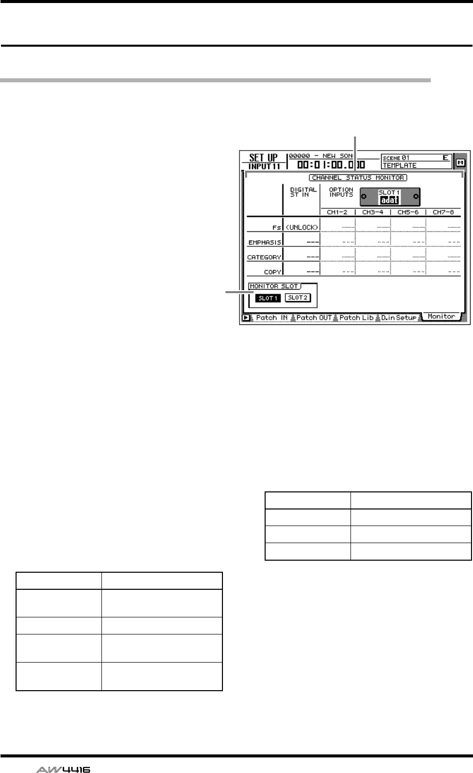
SET UP screen
22 — Reference Guide
Monitor page
Monitor the digital input signals
[Function]
Monitor the state of the digital audio sig-
nals being input from the DIGITAL STE-
REO IN jack or from digital I/O cards
installed in the OPTION I/O slots.
[Key operation]
• [SETUP] key → [F5] (Monitor) key (*1)
• Repeatedly press the [SETUP] key until
the screen shown at the right appears.
*1. In the SET UP screen, the tabs dis-
played at the bottom of the screen are
divided into two groups. If the Monitor
tab is not assigned to the [F5] key
when you press the [SETUP] key, press
the [SHIFT] key + [F1] (CHANGE TAB)
key to switch the tabs.
[Mouse operation]
M button → SETU button → Monitor tab
[Screen functions]
ACHANNEL STATUS MONITOR
This area monitors the state of the digital input
signals from the DIGITAL STEREO IN jack (DIG-
ITAL ST IN) or from a digital I/O card installed
in an OPTION I/O slot (OPTION INPUTS). The
following items are displayed.
● Fs
This shows the sampling frequency of the input
signal.
● EMPHASIS
This shows whether the input signal has been
processed by emphasis.
2
1
Display Meaning
44.1k 44.1 kHz sampling fre-
quency
48k 48 kHz sampling frequency
None Unknown sampling fre-
quency
UNLOCK No signal being input, or
invalid signal being input
Display Meaning
ON Emphasis on
OFF Emphasis off
??? Unknown
SET UP screen
— Reference Guide 23
● CATEGORY
This shows the category of the digital input sig-
nal.
● COPY
This shows the copy permit/prohibit status of
the digital input signal.
Tip!
Digital input signals from the OPTION I/O
slots are displayed in units of two adjacent
odd-numbered
→
even-numbered channels
(channels 1/2, 3/4 ...). The buttons in the
MONITOR SLOT area (
2
) select whether slot
1 or 2 will be displayed.
BMONITOR SLOT
These buttons select the OPTION I/O slot that
will be monitored in the OPTION INPUTS area.
■Additional functions in the Moni-
tor page
In the Monitor page, you can press the [SHIFT] key
to assign the following function to the [F1] key.
• [F1] (CHANGE TAB) key
Switch between the two types of tab display.
Display Meaning
GEN General use
LASER OPTICAL Optical laser device such as
a CD player
D/D Conv D/D converter or signal pro-
cessor
D.Broadcast Digital broadcast
Instrument Instrument or sound mod-
ule
AD Conv A/D converter (without
copyright data)
A/D Conv with (c) A/D converter (with copy-
right data)
Solid Memory Solid-state memory device
Experimental Experimental device
Unknown Unknown device
Display Meaning
OK Copying permitted
Prohibit Copying prohibited
F1
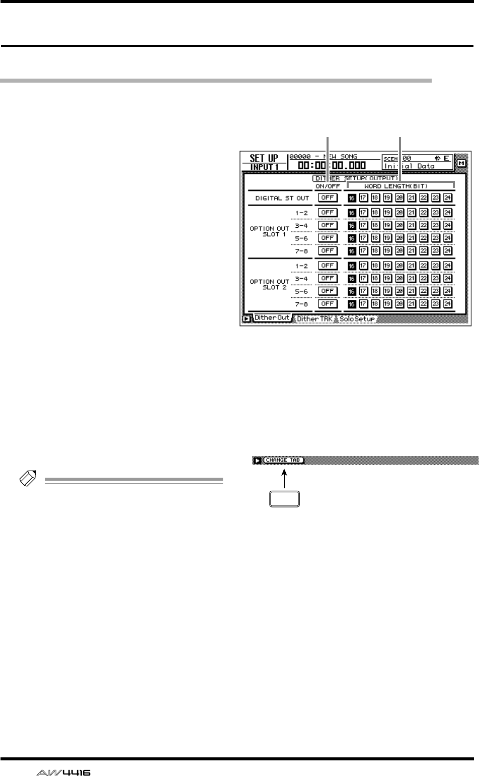
SET UP screen
24 — Reference Guide
Dither Out page
Specify dithering and word length of the digital outputs
[Function]
Turn dithering on/off and specify the word
length of the output signal for the various
digital outputs.
[Key operation]
• [SETUP] key → [F1] (Dither Out) key (*1)
• Repeatedly press the [SETUP] key until the
screen shown at the right appears.
*1. In the SET UP screen, the tabs displayed at
the bottom of the screen are divided into
two groups. If the Dither Out tab is not
assigned to the [F1] key when you press
the [SETUP] key, press the [SHIFT] key +
[F1] (CHANGE TAB) key to switch the
tabs.
[Mouse operation]
M button → SETU button → Dither Out tab
[Screen functions]
AON/OFF (dithering on/off)
Turn dithering on/off for the DIGITAL STEREO
OUT jack (DIGITAL OUT) or the output chan-
nels of the OPTION I/O slots (OPTION OUT
SLOT).
Tip!
• Dithering is a process by which a small
amount of noise is added to the signal in
order to make the sound smoother, prevent-
ing the obtrusive sound that can occur if bits
are discarded when digital audio data is
transmitted from a high-resolution system to
a lower resolution system (for example when
copying from a 24 bit system to a 16 bit sys-
tem).
• For digital I/O cards, dithering is switched
on/off by pairs of adjacent odd-numbered
→
even-numbered channels (channels 1/2, 3/4,
...).
BWORD LENGTH (BIT)
Select the word length (number of bits) for the
signals that are output to the DIGITAL STEREO
OUT jack (DIGITAL OUT) or to digital I/O cards
installed in the OPTION I/O slots (OPTION
OUT SLOT). Set this to the word length of the
destination device.
■Additional functions in the Dither
Out page
In the Dither Out page, you can press the [SHIFT]
key to assign the following function to the [F1] key.
• [F1] (CHANGE TAB) key
Switch between the two types of tab display.
21
F1
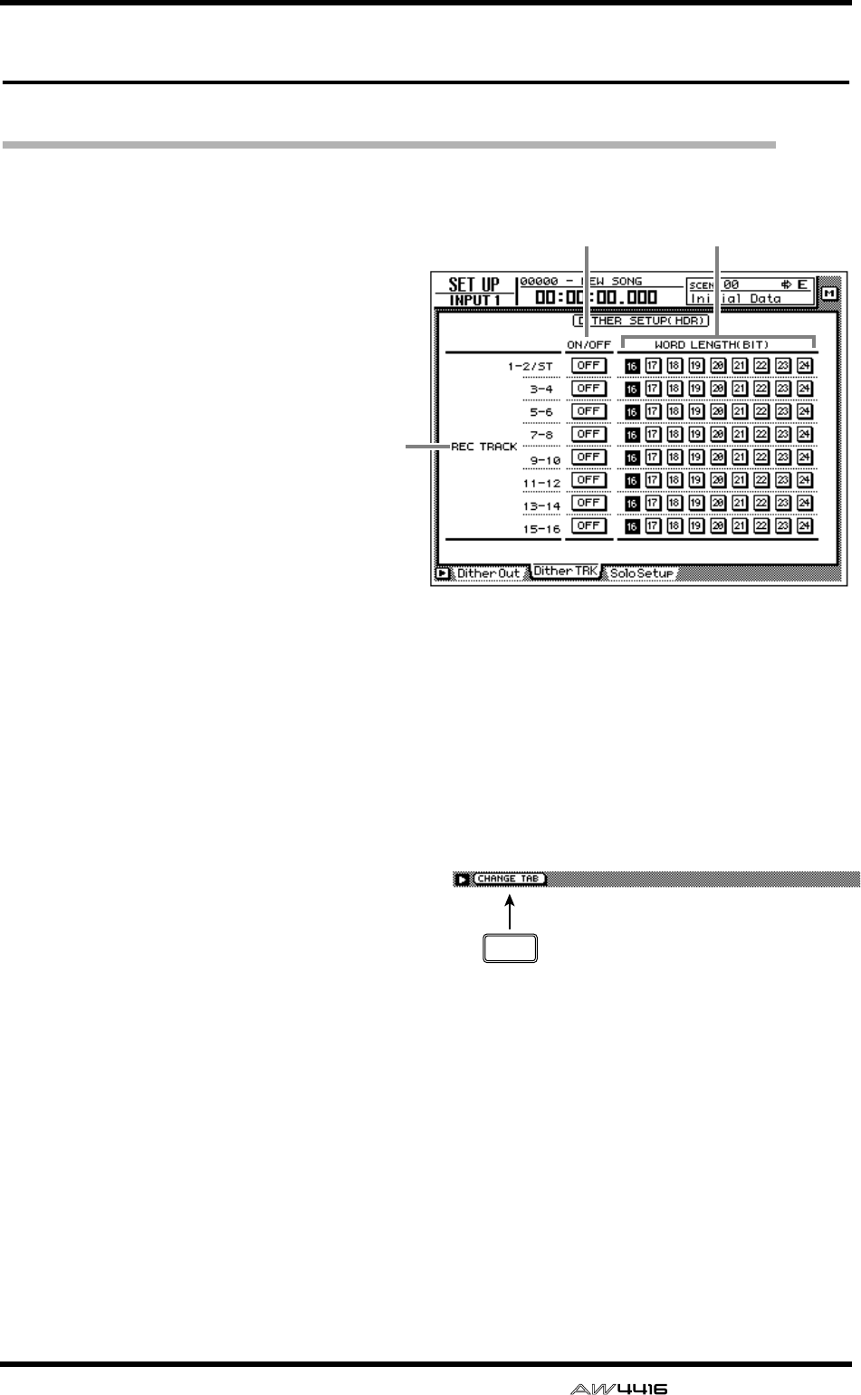
SET UP screen
— Reference Guide 25
Dither TRK page
Specify dithering and word length for tracks
[Function]
Turn dithering on/off and specify the word
length for recording on tracks 1–16 of the
recorder.
[Key operation]
• [SETUP] key → [F2] (Dither TRK) key (*1)
• Repeatedly press the [SETUP] key until
the screen shown at the right appears.
*1. In the SET UP screen, the tabs dis-
played at the bottom of the screen are
divided into two groups. If the Dither
TRK tab is not assigned to the [F1] key
when you press the [SETUP] key, press
the [SHIFT] key + [F1] (CHANGE TAB)
key to switch the tabs.
[Mouse operation]
M button → SETUP button → Dither TRK
tab
[Screen functions]
AREC TRACK
In pairs of adjacent odd-numbered → even-
numbered tracks (tracks 1/2, 3/4 ...), this indi-
cates the tracks for which you can specify dith-
ering and word length. The settings for the
stereo track are common to tracks 1/2.
BON/OFF (dithering on/off)
Turn dithering on/off for the data that is
recorded on adjacent odd-numbered → even-
numbered tracks.
CWORD LENGTH (BIT)
Select the word length (number of bits) for the
data that is recorded on adjacent odd-num-
bered → even-numbered tracks. Set this to
match the quantization (number of bits) that
you selected when creating the song.
■Additional functions in the Dither
TRK page
In the Dither TRK page, you can press the [SHIFT]
key to assign the following function to the [F1] key.
• [F1] (CHANGE TAB) key
Switch between the two types of tab display.
32
1
F1
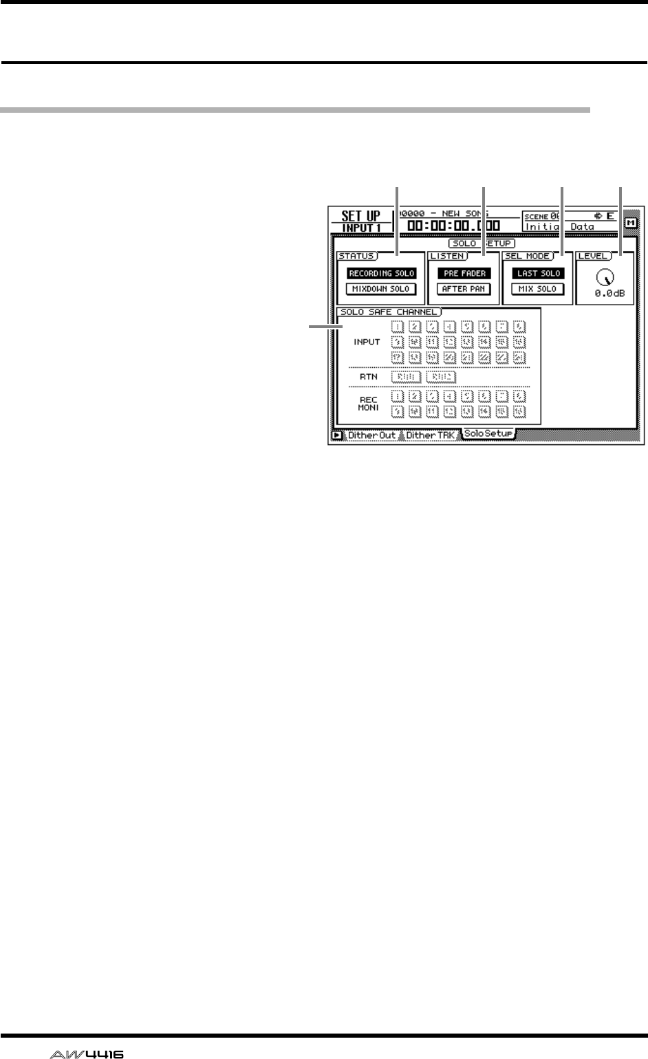
SET UP screen
26 — Reference Guide
Solo Setup page
Make solo settings
[Function]
Make various settings related to the Solo
function.
[Key operation]
• [SETUP] key → [F3] (Solo Setup) key (*1)
• Repeatedly press the [SETUP] key until
the screen shown at the right appears.
*1. In the SET UP screen, the tabs dis-
played at the bottom of the screen are
divided into two groups. If the Solo
Setup tab is not assigned to the [F3]
key when you press the [SETUP] key,
press the [SHIFT] key + [F1] (CHANGE
TAB) key to switch the tabs.
[Mouse operation]
M button → SETUP button → Solo Setup
tab
[Screen functions]
ASTATUS
Turn on one of the following two buttons to
select the operating mode of the Solo function.
● RECORDING SOLO
If this button is on, the solo signal will be output
via the dedicated SOLO bus to the MONITOR
OUT jacks/PHONES jack. (The output of the
stereo bus and buses 1–8 will not be affected.)
You can also monitor channels that are not
assigned to the stereo bus or to buses 1–8, or
channels whose [ON] key is off.
● MIXDOWN SOLO
If this button is on, the solo signal will be output
via the stereo bus to the MONITOR OUT jacks/
PHONES jack. When the Solo function is turned
on, only the channel(s) being soloed will be
sent to the stereo bus, and the remaining chan-
nels will be muted. It is not possible to monitor
channels that are not assigned to the stereo bus,
nor channels whose [ON] key is turned off.
BLISTEN
When RECORDING SOLO is selected for 1,
you can select one of the following two loca-
tions from which the signal will be sent from
each channel to the SOLO bus.
● PRE FADER
The pre-fader signal will be sent to the SOLO
bus. Since the pan setting of the channel will
have no effect, the signal being monitored from
the MONITOR OUT jacks/PHONES jack will be
monaural.
● AFTER FADER
The signal after passing through fader and pan
will be sent to the SOLO bus. The pan and fader
settings of each channel will affect the signal
that is monitored by the MONITOR OUT jacks/
PHONES jack.
CSEL MODE (select mode)
Select one of the following two ways by which
the monitored signal will be selected when the
Solo function is on.
1 2 3 4
5

SET UP screen
— Reference Guide 27
● LAST SOLO
When the Solo function is on, only the channel
last-selected by pressing its [ON] key will be
monitored.
● MIX SOLO
When the Solo function is on, all channels
selected by pressing their [ON] keys will be
monitored.
DLEVEL
This adjusts the level of the signal that is sent to
the SOLO bus when RECORDING SOLO mode
is selected for 1.
ESOLO SAFE CHANNEL
This area selects the channels that will be
excluded from the Solo function when MIX-
DOWN SOLO is selected for 1. Channels that
are turned on in this area will not be affected
when you press the [SOLO] key.
■Additional functions in the Solo
Setup page
In the Solo Setup page, you can press the [SHIFT]
key to assign the following function to the [F1] key.
• [F1] (CHANGE TAB) key
Switch between the two types of tab display.
F1
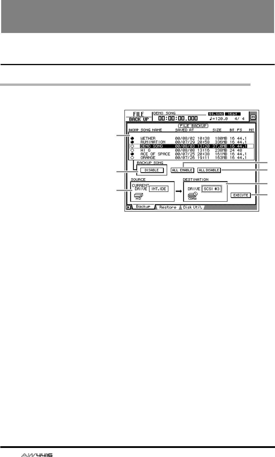
28 — Reference Guide
FILE screen
Backup page
Backup a song
[Function]
Backup song data from the internal
hard disk to a SCSI device (e.g.,
internal CD-RW drive or external
MO drive).
[Key operation]
• [FILE] key → [F1] (Backup) key
• Repeatedly press the [FILE] key
until the screen shown at the
right appears.
[Mouse operation]
M button → FILE button → Backup
tab
[Screen functions]
ASong list
This list shows the songs saved on the internal
hard disk. The current song is highlighted in the
list, and songs selected for backup are indicated
by a “●” symbol in the BACKUP column.
The following information is also shown in the
list.
• SONG NAME .. Song name
• SAVED AT ........ Date and time at which the
song was last saved
• SIZE................. Data size of the song
• BIT/FS.............. Quantization (word length)/
sampling frequency of the
song
• PRT.................. Song protect on/off setting
BBACKUP SONG button
This button selects whether the song currently
selected in the song list 1 will be included in
the backup (ENABLE) or excluded from the
backup (DISABLE). Move the cursor to this but-
ton and press the [ENTER] key to switch
between ENABLE and DISABLE.
CALL ENABLE button
If you move the cursor to this button and press
the [ENTER] key, all songs will be selected for
backup.
DALL DISABLE button
If you move the cursor to this button and press
the [ENTER] key, all songs will be excluded
from the backup.
ESOURCE
This shows the backup source drive (internal
hard disk). This item is for display only, and can-
not be modified.
FDESTINATION
This selects the SCSI ID number of the backup
destination drive.
4
3
7
6
1
2
5
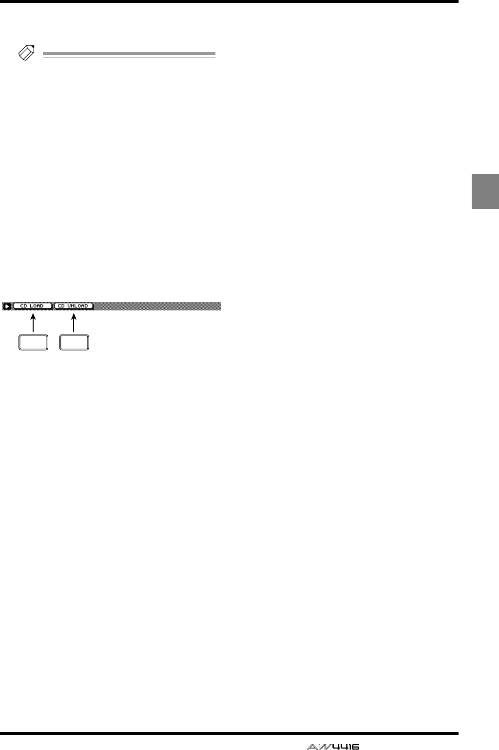
FILE screen
— Reference Guide 29
FILE
GEXECUTE button
Execute the song backup.
Tip!
• When backing up to removable media such
as an MO drive, you can select from two
types of backup: “TYPE 1” in which the
backup can extend across multiple volumes
of media, and “TYPE 2” in which data can
be backed up in units of individual songs on
one volume of media. The selection of either
TYPE 1 or TYPE 2 is made in the UTILITY
screen Prefer.3 page (
→
P.37).
• For details on the song backup procedure,
refer to Operation Guide “Chapter 16. Back-
ing up and restoring songs.”
■Additional functions in the
Backup page
In the Backup page you can press the [SHIFT] key
to assign the following functions to the [F1]–[F2]
keys.
• [F1] (CD LOAD) key
Close the open tray of the CD-RW drive.
• [F2] (CD UNLOAD) key
Eject the tray of the CD-RW drive.
F1 F2
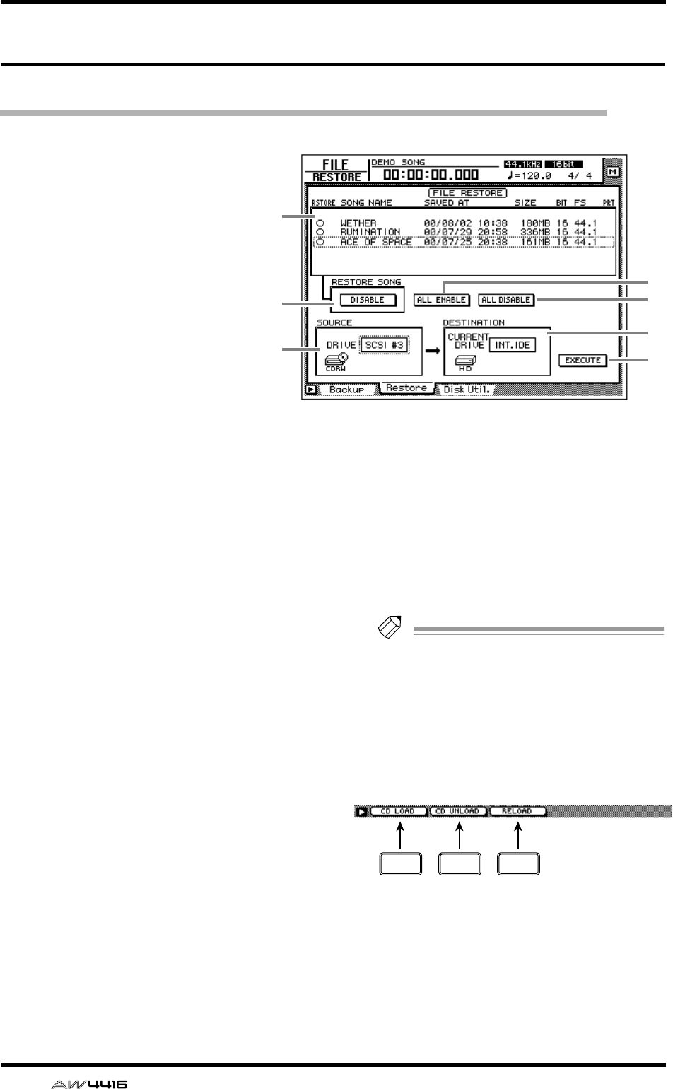
FILE screen
30 — Reference Guide
Restore page
Restore backed-up songs
[Function]
Restore songs from the backup
destination SCSI device to the
AW4416’s internal hard disk.
[Key operation]
• [FILE] key → [F2] (Restore) key
• Repeatedly press the [FILE] key
until the screen shown at the
right appears.
[Mouse operation]
M button → FILE button → Restore
tab
[Screen functions]
ASong list
This list shows the songs saved on the backup
destination SCSI device. Songs selected for
restore are indicated by a “●” symbol in the
RESTORE column.
The following information is also shown in the
list.
• SONG NAME .. Song name
• SAVED AT ........ Date and time at which the
song was last saved on the
AW4416’s internal hard disk
• SIZE................. Data size of the song
• BIT/FS.............. Quantization (word length)/
sampling frequency of the
song
• PRT.................. Song protect on/off setting
BRESTORE SONG button
This button selects whether the song currently
selected in the song list 1 will be included in
the restore (ENABLE) or excluded from the
restore (DISABLE). Move the cursor to this but-
ton and press the [ENTER] key to switch
between ENABLE and DISABLE.
CALL ENABLE button
If you move the cursor to this button and press
the [ENTER] key, all songs will be selected for
restore.
DALL DISABLE button
If you move the cursor to this button and press
the [ENTER] key, all songs will be excluded
from the restore.
ESOURCE
This selects the ID number of the SCSI device
on which the data was backed up.
FDESTINATION
This shows the restore destination drive (internal
hard disk). This item is for display only, and can-
not be modified.
GEXECUTE button
Execute the song restore.
Tip!
For details on song restore, refer to Operation
Guide “Chapter 16. Backing up and restoring
songs.”
■Additional functions in the
Restore page
In the Restore page you can press the [SHIFT] key to
assign the following functions to the [F1]–[F3] keys.
• [F1] (CD LOAD) key
Close the open tray of the CD-RW drive.
• [F2] (CD UNLOAD) key
Eject the tray of the CD-RW drive.
• [F3] (RELOAD) key
Reload the removable media and update the
displayed list.
4
3
7
6
1
2
5
F1 F2 F3
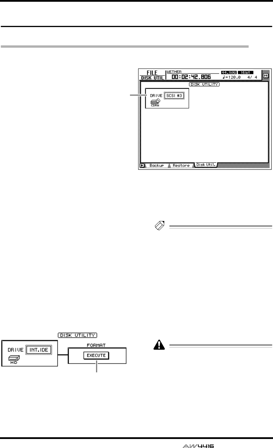
FILE screen
— Reference Guide 31
Disk Util. page
Format or erase a disk
[Function]
Format the internal hard disk or an exter-
nal SCSI device, or erase CD-RW media.
[Key operation]
• [FILE] key → [F3] (Disk Util.) key
• Repeatedly press the [FILE] key until
the screen shown at the right appears.
[Mouse operation]
M button → FILE button → Disk Util. tab
[Screen functions]
ADrive select
Select the SCSI ID number of the drive that you
wish to format (external SCSI device such as
MO) or of the CD-RW drive in which you wish
to erase CD-RW media. To format the internal
hard disk, select “INT.IDE.”
The display will change as follows, depending
on the type of drive that you select here.
■If the internal hard disk or an
external SCSI device (MO or
external hard disk) is selected
BEXECUTE button
Execute formatting of the selected drive/media.
Tip!
• If a removable media drive (e.g., MO) is
selected, FORMAT column will appear
before the Format operation is executed,
allowing you to select the file system that
will be used for formatting and the format-
ting method.
However if REMOVABLE BACKUP is set to
“TYPE 1” in the UTILITY screen Prefer.3
page, the media will be formatted automati-
cally, and therefore the FORMAT item for
selecting the format method will not be dis-
played.
• For details on this procedure, refer to Opera-
tion Guide “Chapter 16. Backing up and
restoring songs.”
When you execute the Format operation, all
the saved data will be lost forever. Please use
caution.
1
2
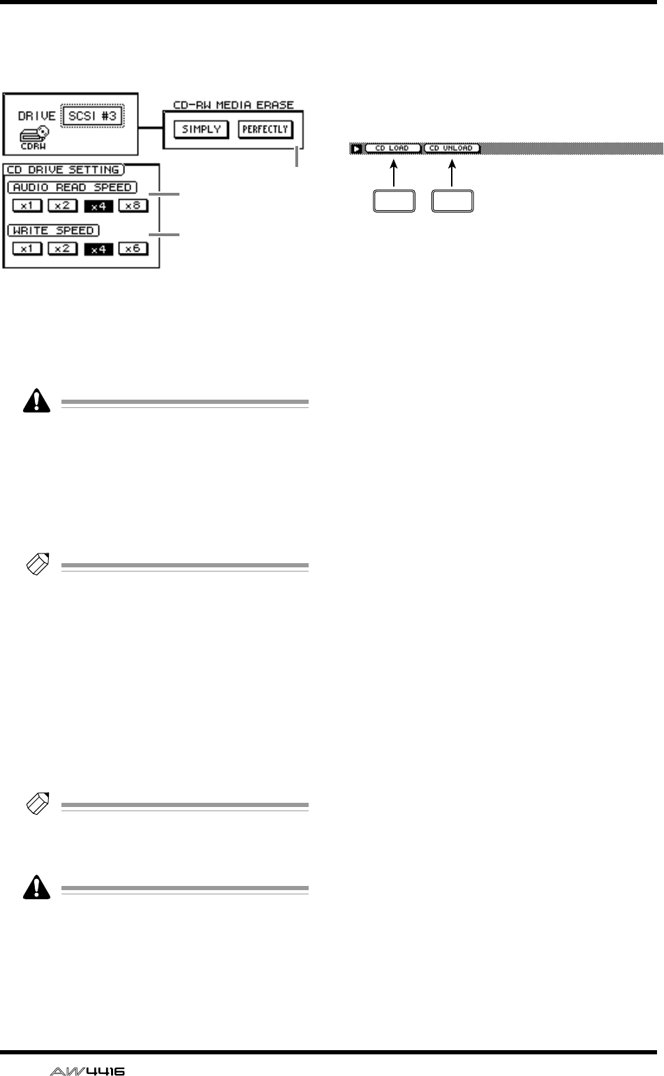
FILE screen
32 — Reference Guide
■If an internal or external CD-RW
drive is selected
CAUDIO READ SPEED
Use the x1, x2, x4, or x8 buttons to select the
reading speed (normal speed, double speed,
quad speed or 8x speed).
This setting is valid only for CD-IMPORT. If
errors occur during CD-IMPORT, lower the
read speed and try again.
DWRITE SPEED
Use the x1, x2, x4, or x6 buttons to select the
writing speed (normal speed, double speed,
quad speed or 6x speed).
Tip!
Normally you should set the read and write
speeds to the fastest speeds supported by
your CD-RW drive.
ECD-RW MEDIA ERASE
Use the following two buttons to specify how
the CD-RW media will be erased.
• SIMPLE ............ Only the TOC (Table Of Con-
tents) of the CD-RW media
will be erased.
• PERFECT.......... All data on the CD-RW
media will be erased.
Tip!
For details on erasing CD-RW media, refer to
Operation Guide “Chapter 16. Backing up
and restoring songs.”
When you execute the Erase operation, all
data on the CD-RW media will be lost for-
ever. Please use caution.
■Additional functions in the Disk
Util. page
In the Disk Util. page you can press the [SHIFT]
key to assign the following functions to the [F1]–
[F2] keys.
• [F1] (CD LOAD) key
Close the open tray of the CD-RW drive.
• [F2] (CD UNLOAD) key
Eject the tray of the CD-RW drive.
3
4
5
F1 F2
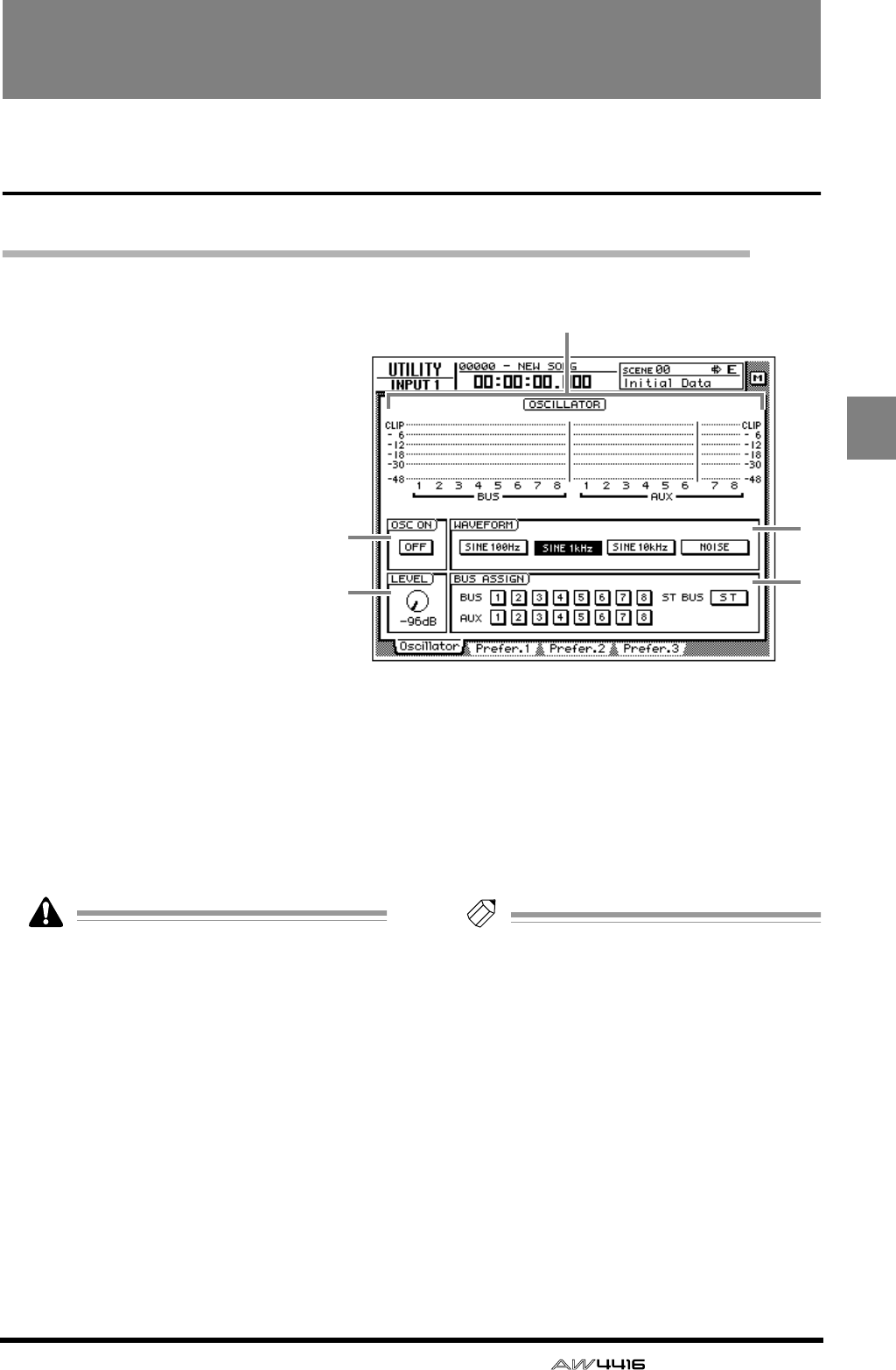
— Reference Guide 33
UTILI-
TY
UTILITY screen
Oscillator page
Using the test tone oscillator
[Function]
Select the waveform of the test
tone oscillator built into the
AW4416, and send it to the
desired bus.
[Key operation]
• [UTILITY] key → [F1] (Oscillator)
key
• Repeatedly press the [UTILITY]
key until the screen shown at the
right appears.
[Mouse operation]
M button → UTIL button → Oscil-
lator tab
[Screen functions]
ALevel meter
This shows the oscillator output level that is
being sent to buses 1–8 and AUX buses 1–8.
BOSC ON (oscillator on) button
This button switches the oscillator on/off.
(Default=OFF)
Sine waves and white noise have a higher
sound pressure level than they appear to your
ears. Use caution, since they may damage
your speakers if played back at a high vol-
ume.
CLEVEL knob
This knob adjusts the output level (–96 dB–
0 dB) of the oscillator.
DWAVEFORM
Use the following four buttons to select the
waveform of the test tone oscillator.
• SINE 100 Hz button .....100 Hz sine wave
• SINE 1 kHz button .......1 kHz sine wave
• SINE 10 kHz button .....10 kHz sine wave
• NOISE ..........................White noise
EBUS ASSIGN
Use the following buttons to specify the bus to
which the oscillator signal will be sent.
• BUS 1–8 buttons.......... Buses 1–8
• AUX 1–8 buttons.......... AUX buses 1–8
• ST BUS button ............. Stereo bus
Tip!
You can specify more than one bus as the
oscillator output destination.
3
2
1
4
5
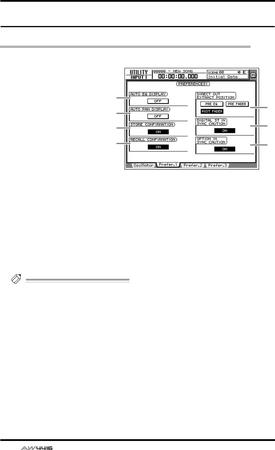
UTILITY screen
34 — Reference Guide
Prefer.1 page
Make overall settings for the AW4416 (1)
[Function]
Enable/disable warning messages,
and specify the point from which
direct output will be taken.
[Key operation]
• [UTILITY] key → [F2] (Prefer.1)
key
• Repeatedly press the [UTILITY]
key until the screen shown at the
right appears.
[Mouse operation]
M button → UTIL button → Pre-
fer.1 tab
[Screen functions]
AAUTO EQ DISPLAY
BAUTO PAN DISPLAY
If the 1 or 2 buttons are ON, operating the
[EQ] controls or [PAN] control located at the
right of the display will cause the corresponding
page to automatically appear in the display.
(Default=off)
Tip!
If buttons
1
/
2
are off, the current EQ/pan
settings will appear in the upper right of the
display when you operate the [EQ]/[PAN]
controls.
CSTORE CONFIRMATION
DRECALL CONFIRMATION
If the 3 or 4 buttons are ON, a popup window
will ask you to confirm the operation when stor-
ing or recalling a scene or library. (Default=on)
EDIRECT OUT EXTRACT POSITION
Use the following three buttons to select the
position from which the signal will be taken for
direct output from input channels 1–24.
• PRE EQ button..............Immediately before
the EQ
• PRE FADER button........Pre-fader position
• POST FADER button.....Post-fader position
(default)
FDIGITAL ST IN SYNC CAUTION
GOPTION IN SYNC CAUTION
If the 6 or 7 buttons are ON, an error message
will be displayed if a digital signal that cannot
be synchronized with the word clock source is
input from the DIGITAL STEREO IN jack or from
an optional I/O card. (Default=on)
5
6
7
1
2
3
4
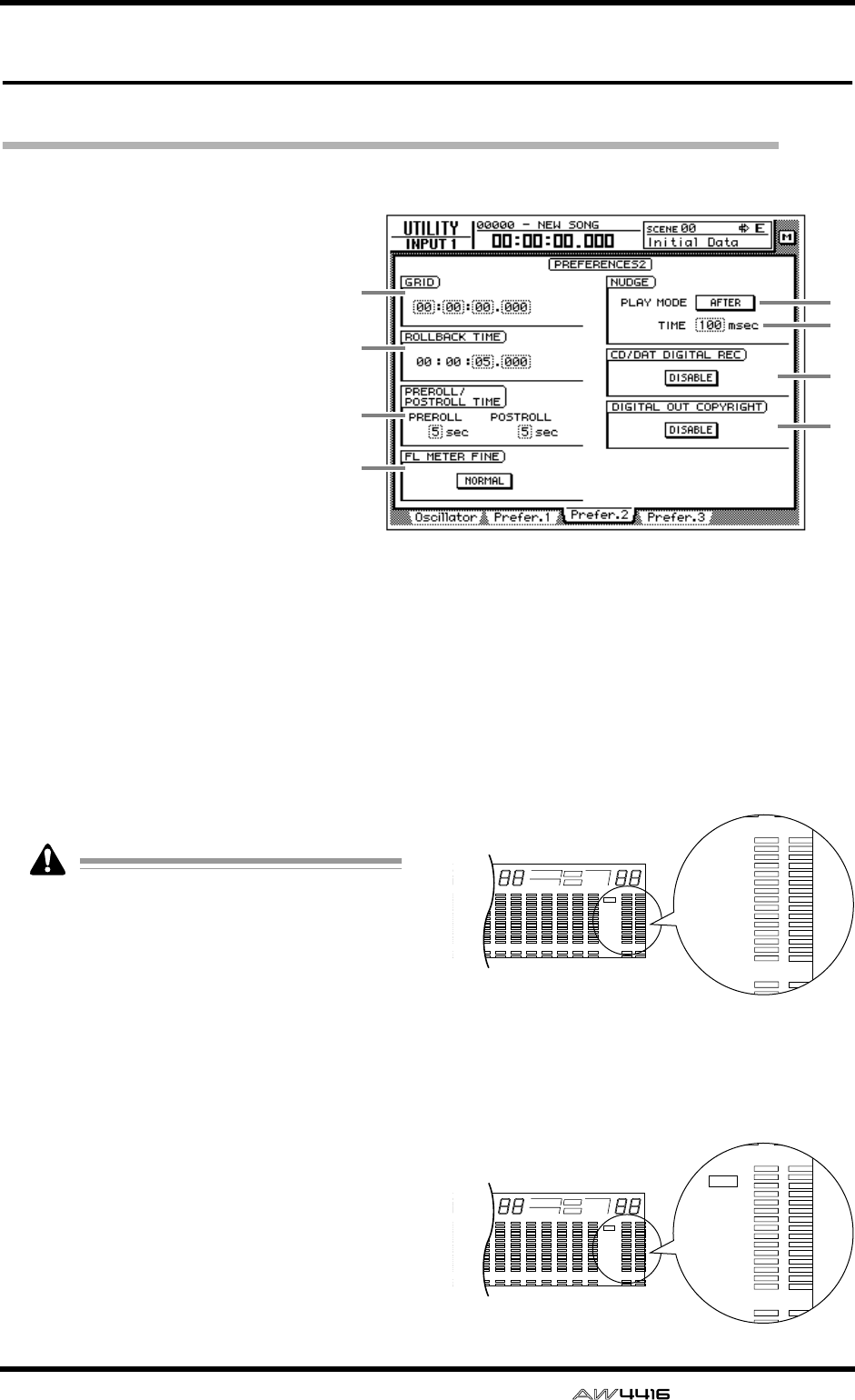
UTILITY screen
— Reference Guide 35
Prefer.2 page
Make overall settings for the AW4416 (2)
[Function]
Set the rollback time, pre-roll/post-
roll time, and the nudge playback
method etc.
[Key operation]
• [UTILITY] key → [F3] (Prefer.2)
key
• Repeatedly press the [UTILITY]
key until the screen shown at the
right appears.
[Mouse operation]
M button → UTIL button → Pre-
fer.2 tab
[Screen functions]
AGRID
This sets the minimum unit when you specify an
area in the EDIT screen TR Edit page or V.TR Edit
page. For example if the grid value is set to
“00:00:00.010,” the specified location will
move in 10 millisecond increments for each
click of the [DATA/JOG] dial. (Default=
00:00:00.000)
• The value you specify here will not affect
how you adjust locate points (TRACK screen
Mark Adj. page) or how you specify locate
points using the [NUM LOCATE] key.
• The value you specify here has no effect if
“measure display” is selected as the counter
display method.
BROLLBACK TIME
This specifies the rollback time (0–5 seconds) of
the [ROLL BACK] key. For details on rollback,
refer to Operation Guide “Chapter 6. Transport/
locate operations.” (Default= 5 seconds)
CPREROLL/POSTROLL TIME
Specify the pre-roll time (0–5 seconds) and
post-roll time (0–5 seconds) used when you per-
form auto punch-in/out. For details on pre-roll
time and post-roll time, refer to Operation
Guide “Chapter 7. Punch-in/out.” (Default= 5
seconds)
DFL METER FINE
Select one of the following two scales for the
level meter/counter display.
● NORMAL
The full range of the level meter will indicate
levels of –60 dB–0 dB. (Default setting)
● FINE
The full range of the level meter will indicate
levels of –26 dB–0 dB. This setting is convenient
when you wish to make fine adjustments to the
level near the 0 dB region.
5
6
7
8
1
2
3
4
8 9 13 14 15 1610 11 12
–dB 0
2
6
20
30
42
60
10
14
18
20
26
12
FINE
READY
INPUT
LR
SFms
EXT
VARI
44.1k 48k
LOCK
WORD CLOCK MTC SCENE
SLAVE
MASTER
INT
E
7
–dB 0
2
6
20
30
42
60
12
READY
INPUT
LR
E
8 9 13 14 15 1610 11 12
–dB 0
2
6
20
30
42
60
10
14
18
20
26
12
FINE
READY
INPUT
LR
SFms
EXT
VARI
44.1k 48k
LOCK
WORD CLOCK MTC SCENE
SLAVE
MASTER
INT
E
7
–dB
10
14
18
20
26
FINE
READY
INPUT
LR
E
0
2
6
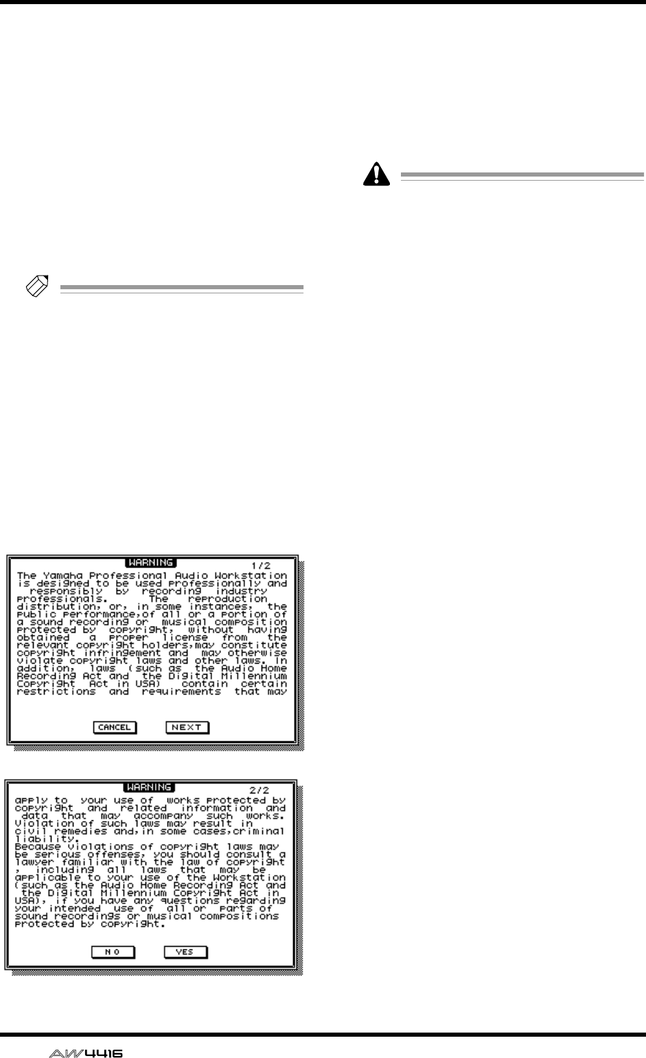
UTILITY screen
36 — Reference Guide
EPLAY MODE
Select one of the following two play modes for
the Nudge function. (Default= AFTER)
● AFTER
Playback will be repeated for the specified
nudge time 6 starting at the current location.
● BEFORE
Playback will be repeated for the specified
nudge time 6 ending at the current location.
FTIME
Specify the playback length (nudge time) of the
Nudge function over a range of 25–800 milli-
seconds. (Default= 100 milliseconds)
Tip!
For details on using the Nudge function, refer
to Operation Guide “Chapter 6. Transport/
locate operations.”
GCD/DAT DIGITAL REC
This setting specifies whether digital recording
from an audio CD or DAT tape via a CD-RW
drive or the DIGITAL STEREO IN jack will be
allowed (ENABLE) or not (DISABLE). When you
move the cursor to the “DISABLE” button and
press the [ENTER] key, the following two-page
warning will be displayed. If you select the YES
button in the second page, the button display
will change to ENABLE.
HDIGITAL OUT COPYRIGHT
This setting specifies whether SCMS (Serial
Copy Management System) copy protect data
will be enabled (ENABLE) or not (DISABLE) for
the digital signal output from the DIGITAL STE-
REO OUT jack. When you move the cursor to
this button and press the [ENTER] key, the set-
ting will alternate between ENABLE/DISABLE.
Even if copy protect data is enabled, it will
still be possible to make a digital recording
from the DIGITAL STEREO OUT jack on a
DAT recorder or MD recorder. However, it
will not be possible to create a second-gener-
ation digital copy.
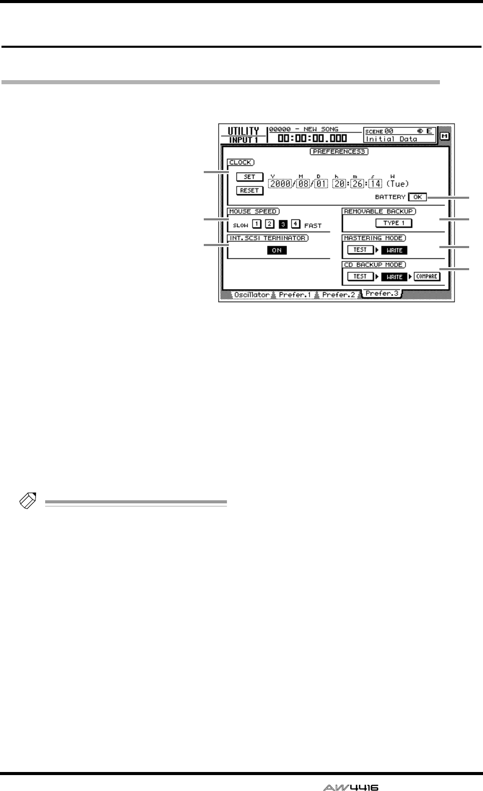
UTILITY screen
— Reference Guide 37
Prefer.3 page
Make overall settings for the AW4416 (3)
[Function]
Set the internal clock, mouse cur-
sor speed, and removable media
backup method etc.
[Key operation]
• [UTILITY] key → [F4] (Prefer.3)
key
• Repeatedly press the [UTILITY]
key until the screen shown at the
right appears.
[Mouse operation]
M button → UTIL button → Pre-
fer.3 tab
[Screen functions]
ACLOCK
Here you can set the internal clock of the
AW4416. Use the [DATA/JOG] dial to adjust the
year (Y), month (M), date (D), hour (h), minute
(m), and second (s) fields, and use the SET but-
ton to finalize the date and time. If you use the
RESET button, the date and time you input will
be cancelled.
Tip!
• When you save a song, date and time infor-
mation will be stored in the song according
to this internal clock.
• When shipped from the factory, the internal
clock of the AW4416 is set to Japan time.
• For details on setting the internal clock, refer
to the opening section of the Operation
Guide, “Important points you must observe.”
BMOUSE SPEED
Use buttons 1–4 to specify the movement speed
of the mouse pointer. Higher value will produce
faster movement.
CINT. SCSI TERMINATOR (internal SCSI
terminator)
This switches the internal SCSI bus terminator
on/off. For details on the terminator setting, refer
to Operation Guide “Before you begin.”
(Default: on)
DBATTERY
This displays the state of the battery that oper-
ates the AW4416’s internal clock. If the battery
capacity is sufficient, this will indicate “OK.” If
the battery has run low and needs to be
replaced, this will indicate “LOW.” If the
“LOW” indication appears, please contact your
dealer to have the battery replaced.
EREMOVABLE BACKUP
This specifies the backup method when backing
up songs to removable media such as MO.
Move the cursor to this button and press the
[ENTER] key to switch the setting between the
following two methods. (Default= TYPE 1)
● TYPE 1
This backup method makes full use of the
capacity of the removable media, but does not
allow backup data to be added later. Even if the
data being backed up will not fit on a single vol-
ume of media, the backup can extend across
multiple volumes of media. If this method is
selected, the media will be formatted automati-
cally before the backup begins.
5
4
6
7
1
2
3

UTILITY screen
38 — Reference Guide
● TYPE 2
This backup method allows new backup data to
be added to media on which data was previ-
ously backed up. It is not possible to backup
data that extends across multiple volumes of
media. Before you can use this method to
backup on previously-unused media, you must
format the media manually.
Tip!
For details on the procedure for backing up
songs, refer to Operation Guide “Chapter 16.
Backing up and restoring songs.”
FMASTERING MODE
Use the following two buttons to select the writ-
ing mode that will be used when you execute
the Mastering function.
● TEST button
If this button is on, a test will be performed
before writing data to the CD-R/RW media to
see whether writing errors will occur. (Default=
off)
● WRITE button
This turns data writing on/off. If the TEST button
= on and the WRITE button = off, only the writ-
ing test will be executed. (Default= on)
GCD BACKUP MODE
Use the following three buttons to select the
writing mode when backing up songs to CD-R/
RW media.
● TEST/WRITE buttons
These are the same functions as the MASTER-
ING MODE 6 TEST/WRITE buttons.
● COMPARE button
When this button is on, the backup source song
data on the internal hard disk will be compared
with the backup destination data on the CD-R/
RW media after the data has been written. If for
some reason the backup was not written cor-
rectly, an error message will be displayed when
Compare is executed.
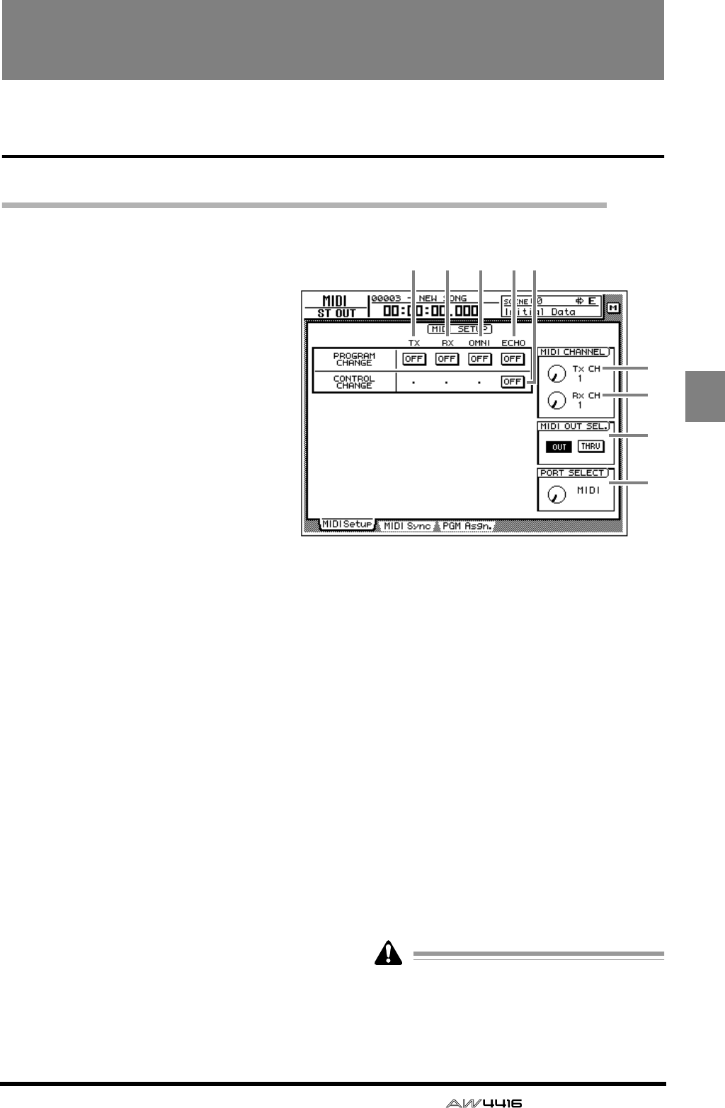
— Reference Guide 39
MIDI
MIDI screen
MIDI Setup page
Make basic MIDI settings
[Function]
Set the MIDI transmit/receive channels,
turn transmission/reception of various
messages on/off, and specify the port
used for transmission and reception.
[Key operation]
• [MIDI] key → [F1] (MIDI Setup) key
• Repeatedly press the [MIDI] key until
the screen shown at the right appears.
[Mouse operation]
M button→ MIDI button → MIDI Setup
tab
[Screen functions]
APROGRAM CHANGE TX (program
change transmission)
Specify whether program changes will be trans-
mitted to external MIDI devices. If this button is
on, the program change assigned to a scene
number will be transmitted when that scene is
recalled.
BPROGRAM CHANGE RX (program
change reception)
Specify whether program changes will be
received from external MIDI devices. If this but-
ton is on, receiving a program change will
recall the scene assigned to that program num-
ber.
CPROGRAM CHANGE OMNI
If this button is on, program changes of all MIDI
channels will be received, regardless of the Rx
(receive channel) setting.
DPROGRAM CHANGE ECHO
If this button is on, received program changes
will be re-transmitted without change (“thru-
ed”) from the MIDI OUT connector or TO
HOST connector.
ECONTROL CHANGE ECHO
If this button is on, received control changes
will be re-transmitted without change from the
MIDI OUT connector or TO HOST connector.
FTx CH (transmit channel)
Select the channel (1–16) on which MIDI mes-
sages will be transmitted to external MIDI
devices.
GRx CH (receive channel)
Select the channel (1–16) on which MIDI mes-
sages will be received from external MIDI
devices.
HMIDI OUT SEL. (MIDI OUT select)
This selects whether the MIDI OUT connector
will be used as MIDI OUT or as MIDI THRU. If
“MIDI THRU” is selected, operations performed
on the AW4416 itself will not be output.
If you wish to transmit MIDI Clock to an
external MIDI device, you must set this to
“MIDI OUT.” For details on synchronization,
refer to P.41.
9
8
6
7
12 3 4 5

MIDI screen
40 — Reference Guide
IPORT SELECT
Select the port and transmission speed with
which MIDI messages will be transmitted and
received.
*1. Only usable with Macintosh computers that have
a modem/printer port. On the software that you
use, set the clock to “1 MHz.”
Setting Computer platform Port type Transmission speed
MIDI MIDI compatible MIDI IN, OUT/THRU connectors 31.25 kbps
TO HOST PC2 IBM PC compatible TO HOST connector 38.4 kbps
TO HOST MAC Apple Macintosh series (*1) TO HOST connector 31.25 kbps
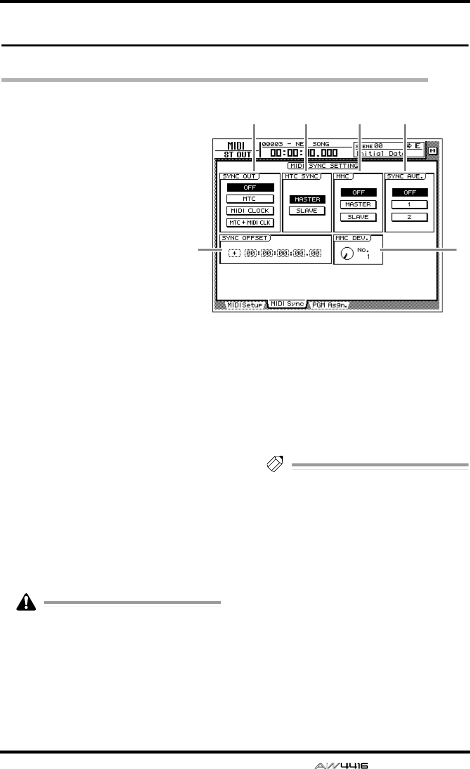
MIDI screen
— Reference Guide 41
MIDI Sync page
Make settings related to MIDI synchronization
[Function]
Make various settings for synchro-
nization operation.
[Key operation]
• [MIDI] key → [F2] (MIDI Sync)
key
• Repeatedly press the [MIDI] key
until the screen shown at the
right appears.
[Mouse operation]
M button → MIDI button → MIDI
Sync tab
[Screen functions]
ASYNC OUT
Select one of the following synchronization sig-
nals for output.
● OFF
Synchronization signals will not be output.
● MTC
MIDI Time Code will be transmitted from the
MTC OUT connector.
● MIDI CLOCK
MIDI Clock will be transmitted from the MIDI
OUT connector or TO HOST connector.
● MTC + MIDI CLK
Both MIDI Time Code (MTC OUT connector)
and MIDI Clock (MIDI OUT connector or TO
HOST connector) will be transmitted.
When using the AW4416 as the MIDI Clock
master, you must set MIDI OUT SEL. to
“MIDI OUT” in the MIDI screen MIDI Setup
page. (
→
P.39)
BMTC SYNC
Specify whether the AW4416 will be the MTC
master (MASTER) or slave (SLAVE) when MTC is
used to synchronize an AW4416 song with the
operation of an external MIDI device.
If master is selected, MTC messages will be
transmitted from the MTC OUT connector in
synchronization with the progress of the song. If
slave is selected, the AW4416 song will follow
the MTC messages received at the MIDI IN con-
nector.
Tip!
The MTC frame rate is selected in the SONG
screen Setting page (
→
P.2).
CMMC (MIDI Machine Control)
When using MMC for remote control between
the AW4416 and an external MIDI device, this
setting specifies whether the AW4416 will be
the MMC master (MASTER) or slave (SLAVE).
If master is selected, operating the transport of
the AW4416 will cause the corresponding
MMC command to be transmitted from the
MIDI OUT connector or TO HOST connector.
If slave is selected, MMC commands sent from a
MIDI sequencer or other external device can be
used to remotely select or de-select recording
tracks and control transport operations on the
AW4416.
56
12 3 4
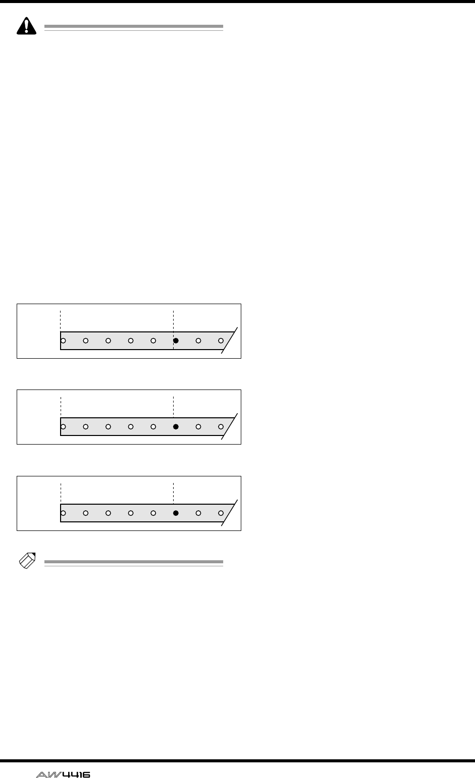
MIDI screen
42 — Reference Guide
When using MMC, you must match the
device ID of the AW4416 and the external
MIDI device. For details on setting the device
ID, refer to MMC DEV.
6
.
DSYNC AVE. (sync average)
When the AW4416 is used as an MTC slave,
this parameter specifies the precision with
which MTC will be received.
Normally you will use this with the “OFF” but-
ton selected. However if synchronization is
unreliable, try the 1 or 2 setting.
ESYNC OFFSET
When the AW4416 is used as an MTC slave,
this parameter specifies how the absolute time
of the AW4416 will be shifted relative to the
time code (MTC) received from the external
device. You can specify a range of “–
24:00:00:00.00”–”+24:00:00:00.00”.
Tip!
The offset value you specify here does not
affect the MTC that is transmitted from the
MTC OUT connector of the AW4416. If you
want the MTC transmitted from the MTC
OUT connector to be shifted relative to the
absolute time of the AW4416, you must
adjust the Time Code Top (SONG screen Set-
ting page).
FMMC DEV. (MIDI Machine Control
device)
When using MMC for remote control, specify a
device ID of 1–127 to distinguish each device.
Received
time code
Received
time code
Received
time code
00:00:00:00.00 00:00:05:00.00
Sync offset= 00:00:00:00.00
Sync offset= +00:30:00:00.00
00:3030:00:00.00 00:35:00:00.00
Sync offset= –01:00:00:00.00
23:00:00:00.00 23:05:00:00.00
Song
Song
Song
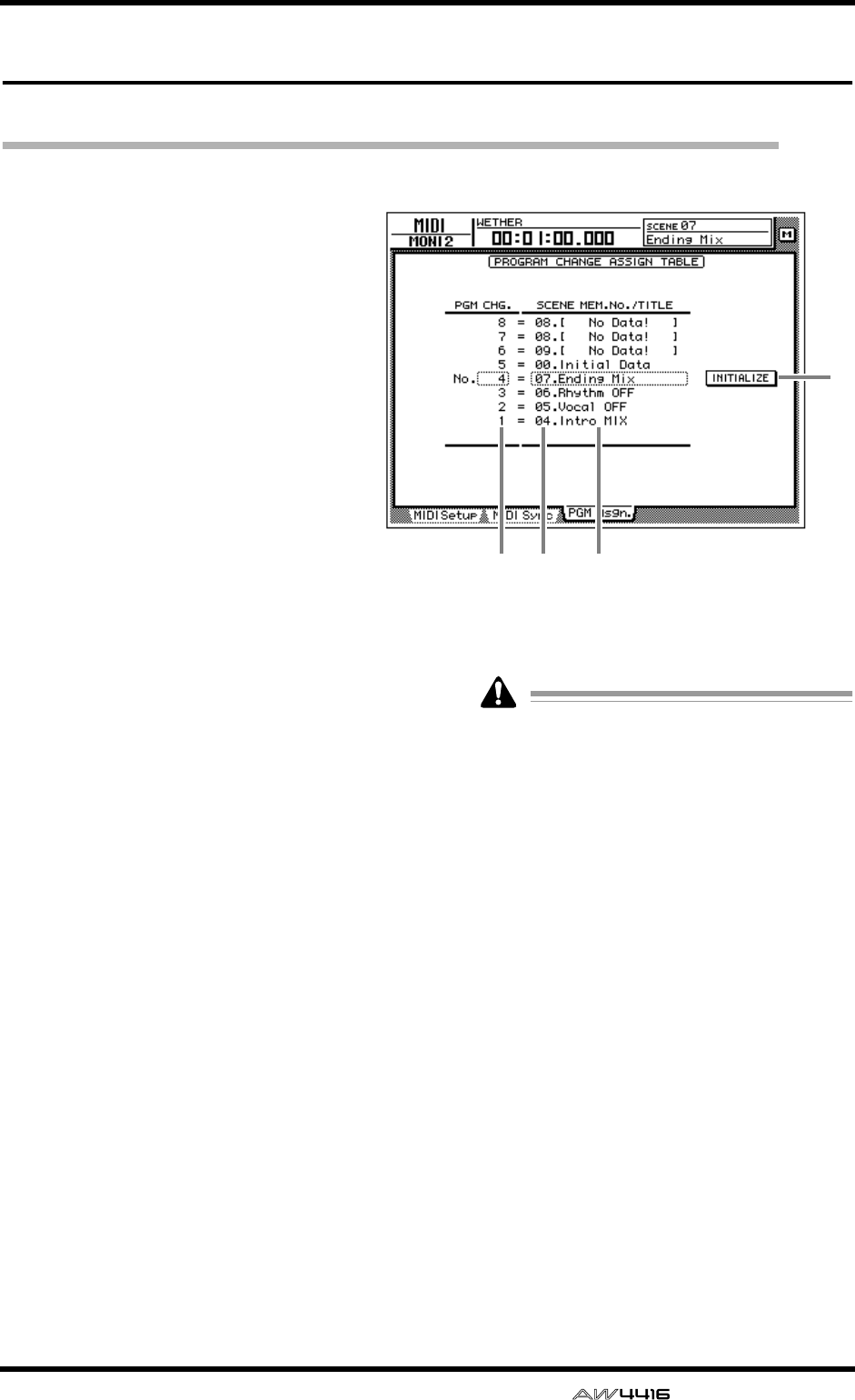
MIDI screen
— Reference Guide 43
PGM Asgn. page
Assign a scene number to each program change number
[Function]
Assign a scene number to each program
change number 1–128.
[Key operation]
• [MIDI] key → [F3] (PGM Asgn.) key
• Repeatedly press the [MIDI] key until
the screen shown at the right appears.
[Mouse operation]
M button → MIDI button → PGM Asgn.
tab
[Screen functions]
APGM CHG. No. (program change num-
ber)
These are the program change numbers 1–128.
Move the cursor to this area, and rotate the
[DATA/JOG] dial to select the program number.
BSCENE MEM. No. (scene memory num-
ber)
This is the scene number assigned to each pro-
gram number. Move the cursor to this area, and
rotate the [DATA/JOG] dial to select the scene
number.
CSCENE MEM. TITLE (scene memory
title)
The scene name of each scene is displayed.
DINITIALIZE
If you move the cursor to this button and press
the [ENTER] key, the scene number assignments
will be reset to the following default settings.
● Program change numbers 1–96
Scenes 1–96
● Program change numbers 97–99/101–128
No assignment
● Program change number 100
Initial data (default scene)
Scene numbers in which nothing has been
stored will be displayed as “No Data!”.
4
12 3
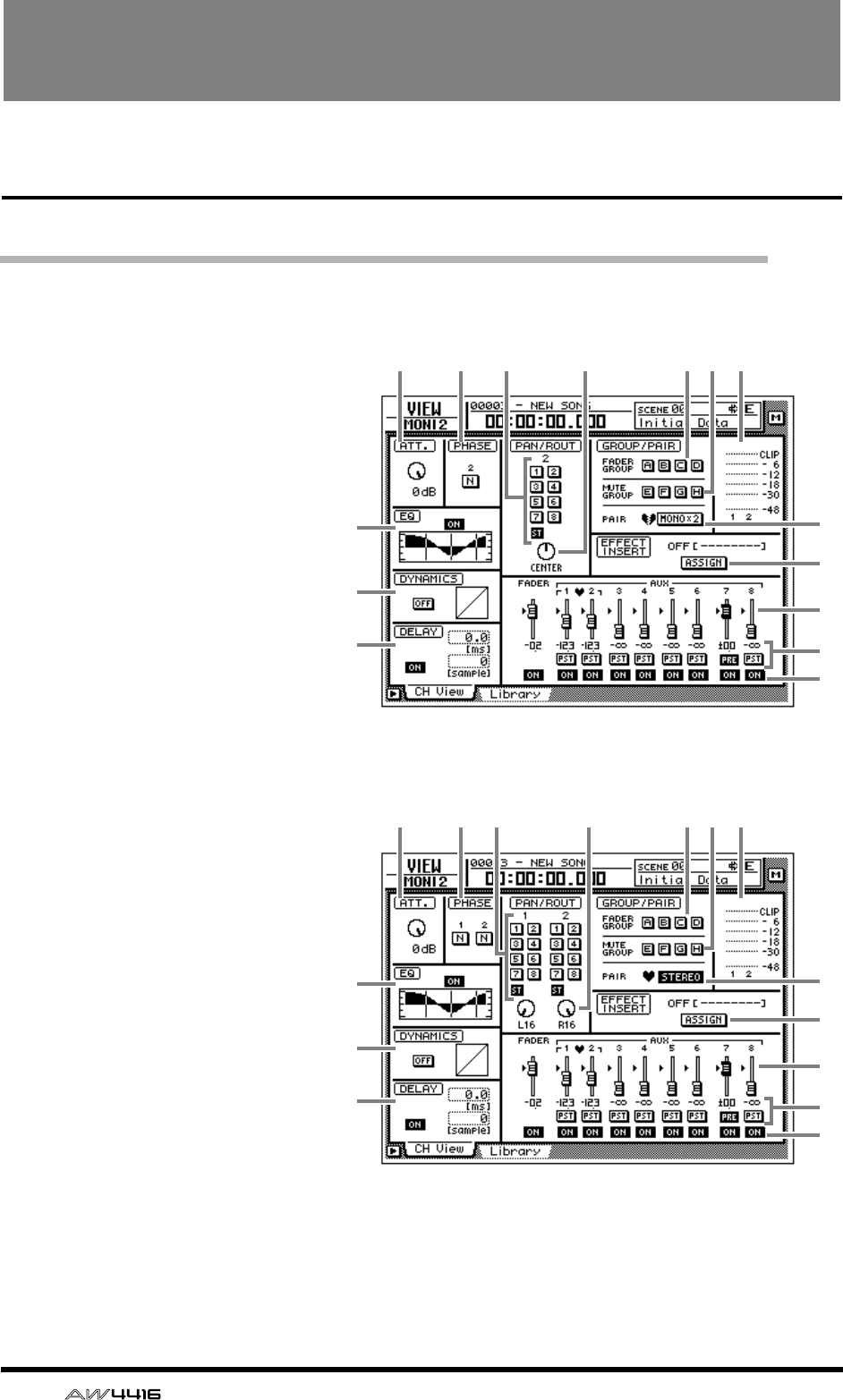
44 — Reference Guide
VIEW screen
CH View page
View all parameters of a channel
[Function]
This page displays all mix parame-
ters of the selected channel.
Parameters other than EQ and
dynamics can also be edited in this
page.
[Key operation]
• [VIEW] key → [F1] (CH View)
key
• Repeatedly press the [VIEW] key
until the screen shown at the
right appears.
[Mouse operation]
M button → VIEW button → CH
View tab
[Screen functions]
AATT. (attenuation)
Set the attenuation value.
BPHASE
Switch between normal (N) and
reverse (R) phase.
CEQ (equalizer)
Turn the EQ on/off. This area
also displays a graph showing
the approximate response of
the current EQ settings.
DDYNAMICS
Turn the dynamics processor
on/off. This area also displays a
graph showing the approximate
response of the current dynam-
ics processor settings.
EDELAY
Turn the delay on/off. The delay
time can also be edited here.
FROUT (routing)
Assign the channel to buses 1–
8 and the stereo bus.
6 8 9
L
M
N
O
K
7 J21
3
4
5
● Input channel/monitor channel
●
Paired input channels/monitor channels
6 8 9
L
M
N
O
K
7 J21
3
4
5
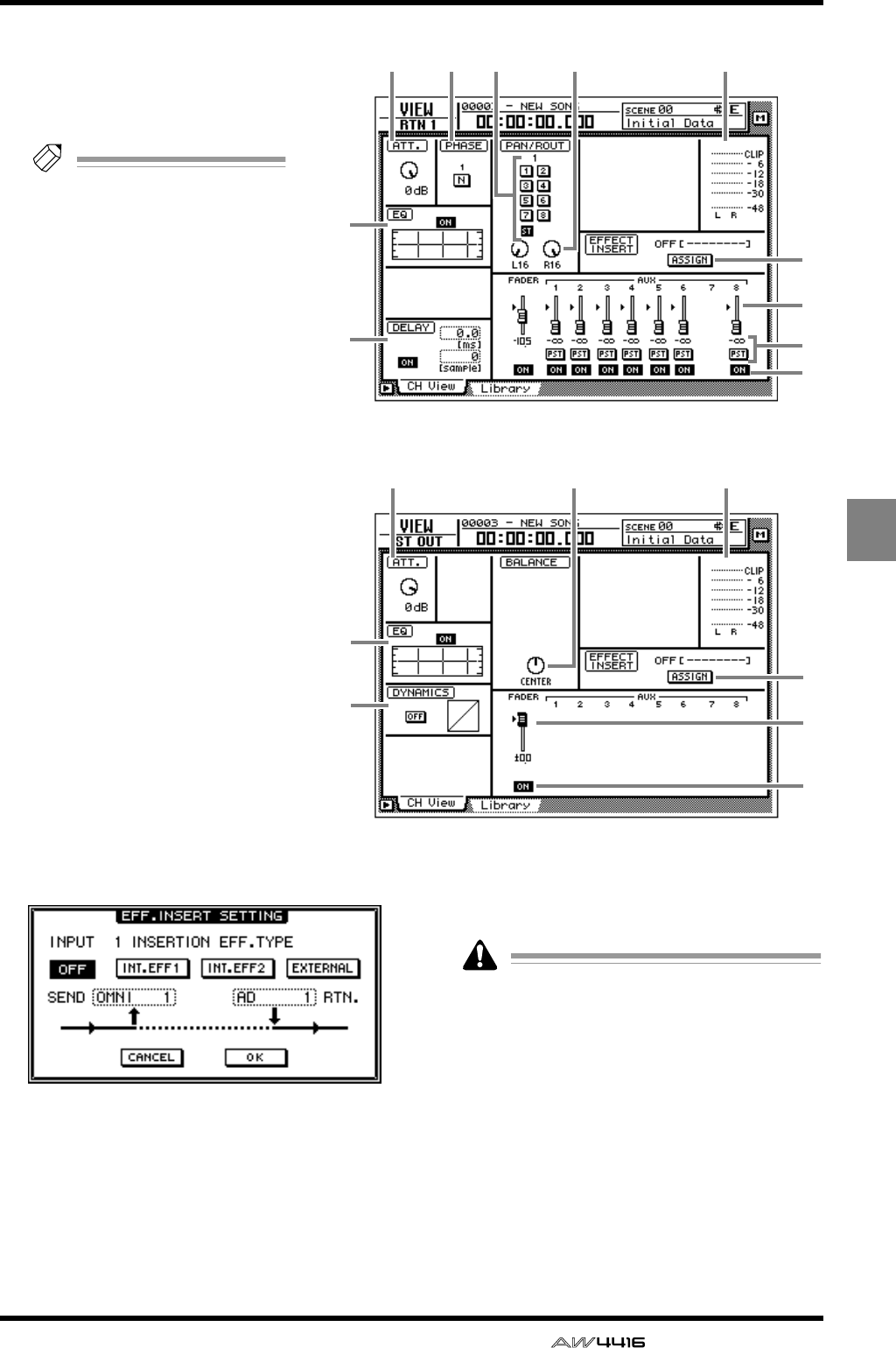
VIEW screen
— Reference Guide 45
● Return channel
6
L
M
N
O
7 J21
3
5
L
M
O
7 J1
3
4
● Stereo output channel
VIEW
GPAN
Adjust the panning between the L/
R channels of the stereo bus or
between odd-numbered → even-
numbered buses.
Tip!
If you move the cursor to the
PAN knob and press the
[ENTER] key, the knob will
move to the center position.
HFader group
This area shows the fader group to
which the channel belongs. You
can also defeat or register groups
in this page.
IMute group
This area shows the mute group to
which the channel belongs. You
can also defeat or register groups
in this page.
JInput/output meter
This shows the input level of the
input channel, monitor channel,
or return channel, and the output
level of the stereo output channel.
KPair
This shows the pairing status. Pair-
ing can also be set/defeated in this
page.
LASSIGN button
Use this button to insert an exter-
nal effect or internal effect into the
channel.
Move the cursor to this button and
press the [ENTER] key to access a
screen like the following.
● OFF button
When this button is on, an effect will not be
inserted.
● INT.EFF 1 button
When this button is on, internal effect 1 will be
inserted into the corresponding channel.
● INT.EFF 2 button
When this button is on, internal effect 2 will be
inserted into the corresponding channel.
When inserting the internal effect 1/2 into a
channel, you must set either EFF1 or EFF2 to
“INSERT” in the SETUP screen Patch IN page.
If neither of the effects is set to “INSERT,”
attempting to turn on the INT.EFF1/INT.EFF2
button in this screen will produce an error
message of “ERROR INT. EFF NOW
SELECTED AUX.”
● EXTERNAL button
When this button is on, you can select the
desired input and output jacks for use as the
insert send/return jacks for the corresponding
channel.
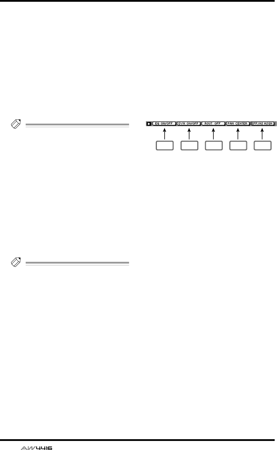
VIEW screen
46 — Reference Guide
● SEND
When the EXTERNAL button is on, move the
cursor to this area and rotate the [DATA/JOG]
dial to select one of the following jacks for use
as the insert send jack.
• OMNI 1–4..........OMNI OUT 1–4 jacks
• SL1-1–SL1-8........Output channels 1–8 of
OPTION I/O slot 1
• SL2-1–SL2-8........Output channels 1–8 of
OPTION I/O slot 2
• D STO L/R ..........L/R channels of the DIGI-
TAL STEREO OUT jack
• STOUT L/R .........L/R channels of the STEREO
OUT jack
Tip!
If you select D STO or STOUT, only the L
channel can be selected for odd-numbered
channels, and only the R channel can be
selected for even-numbered channels.
● RTN.
When the EXTERNAL button is on, move the
cursor to this area and rotate the [DATA/JOG]
dial to select one of the following jacks for use
as the insert return jack.
• AD1–AD8...........INPUT 1–8 jacks
• SL1-1–SL1-8........Input channels 1–8 of
OPTION I/O slot 1
• SL2-1–SL2-8........Input channels 1–8 of
OPTION I/O slot 2
• D STIN L/R.........L/R channels of the DIGI-
TAL STEREO IN jack
Tip!
• When the INT.EFF 1 or INT.EFF 2 button is
on, the input and output of internal effect 1/
2 will automatically be assigned to the insert
send/return of that channel. This assignment
cannot be changed.
• For the procedure of inserting an external
effect into a channel, refer to Operation
Guide “Chapter 8. Patching.”
• For the procedure of inserting an internal
effect into a channel, refer to Operation
Guide “Chapter 10. Internal effects.”
MFader
This shows the current fader location both
graphically and numerically. The setting can
also be edited in this page.
You can also move the cursor to the fader and
rotate the [DATA/JOG] dial to modify the fader
setting.
NAUX
This shows the send level and pre/post selection
for AUX buses 1–8. These settings can also be
edited in this page. The heart symbol indicates
AUX buses that are paired.
OON/OFF
This switches the channel on/off.
■Additional functions in the CH
View page
In the CH View page you can press the [SHIFT] key
to assign the following additional functions to the
[F1]–[F5] keys.
• [F1] (EQ ON/OFF) keys
Switch EQ on/off. This is the same function as
the ON/OFF button of 3 EQ.
• [F2] (DYN ON/OFF) key
Switch the dynamics processor on/off. This is
the same function as the ON/OFF button of 4
DYNAMICS.
• [F3] (ROUT OFF) key
Turn off all signals sent from that channel to
AUX buses 1–8.
• [F4] (PAN CENTER) key
Set the pan to center.
• [F5] (EFF. INS ASGN) key
This button is used to insert an external effect or
internal effect into a channel. This is the same
function as the L ASSIGN button.
F1 F2 F3 F4 F5
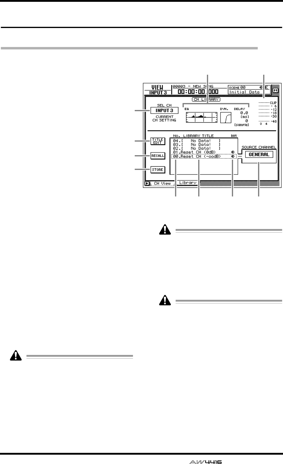
VIEW screen
— Reference Guide 47
Library page
Store or recall channel settings
[Function]
Store the settings of the currently selected
channel into the channel library, or recall
stored settings.
[Key operation]
• [VIEW] key → [F2] (Library) key
• Repeatedly press the [VIEW] key until
the screen shown at the right appears.
[Mouse operation]
M button → VIEW button → Library tab
[Screen functions]
AChannel
This indicates the currently selected channel.
BEQ/DYN./DELAY settings
This area shows the EQ/dynamics processor/
delay settings for the channel.
CInput meter
This meter shows the input level of the channel.
DTITLE EDIT button
Use this to edit the name (library title) of the set-
tings stored in the channel library. Move the
cursor to the TITLE EDIT button and press the
[ENTER] key to access the TITLE EDIT popup
window where you can input the name. For
details on inputting text, refer to page 60 of the
Operation Guide.
Library numbers 0 and 1 are recall-only pre-
set programs, and their names cannot be
edited. Also, numbers in which channel set-
tings have not been stored will be displayed
as “No Data!,” and their title cannot be
edited.
ERECALL button
Recall the currently selected settings from the
list.
If you select a number in which nothing has
been stored and attempt to recall it, an error
message of “ERROR NO DATA TO RECALL”
will be displayed, and recall will not be pos-
sible.
FSTORE button
Store the current channel settings.
Library numbers 0 and 1 are recall-only pre-
set programs; data cannot be stored in them.
Data can be stored only in library numbers
2–64.
GLIBRARY No. (library number)
This shows the library number 1–64.
HLIBRARY TITLE
This shows the name assigned to the library.
IROM
This write-prohibit symbol is displayed for
recall-only numbers 0/1.
JSOURCE CHANNEL
This shows the original channel from which the
settings were stored. For preset numbers 0/1 this
is displayed as “GENERAL.”
3
1
4
5
6
2
78 9 J
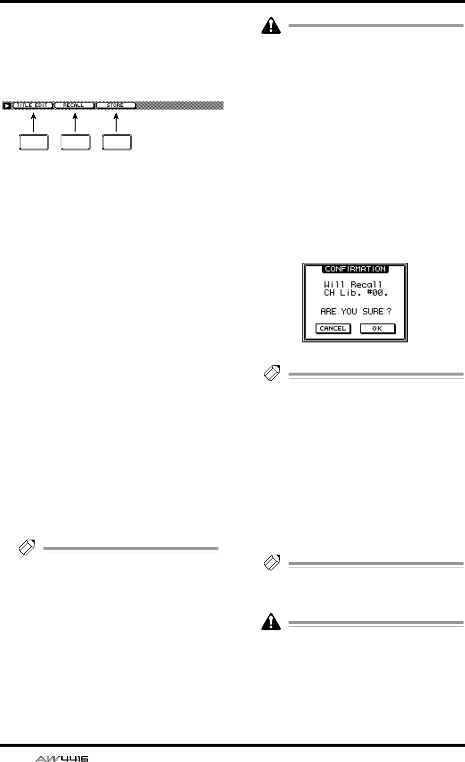
VIEW screen
48 — Reference Guide
■Additional functions in the
Library page
In the Library page you can press the [SHIFT] key
to assign the following functions to the [F1]–[F3]
keys.
• [F1] (TITLE EDIT) key
Use this to edit the name (library title) of the set-
tings saved in the channel library. This is the
same function as the 4 TITLE EDIT button.
• [F2] (RECALL) key
Recall the currently selected channel settings
from the list. This is the same function as the 5
RECALL button.
• [F3] (STORE) key
Store the current channel settings. This is the
same function as the 6 STORE button.
●To store channel settings in the
library
[Procedure]
1. Select the channel whose settings you
wish to store, and access the VIEW screen
Library page.
2. Use the [DATA/JOG] dial to select the
library number in which you wish to store
the settings.
3. Move the cursor to the STORE button and
press the [ENTER] key.
The TITLE EDIT popup window will appear,
allowing you to input a name.
Tip!
It is possible to store the settings directly
without accessing the TITLE EDIT popup win-
dow. To do so, turn STORE CONFIRMATION
off in the UTILITY screen Prefer.1 page
([UTILITY] key
→
[F2] key).
4. Input the library title.
For details on inputting characters, refer to
Operation Guide page 60.
5. Move the cursor to the OK button and
press the [ENTER] key.
The settings will be stored.
When you execute the Store operation, the
channel settings that had previously been
stored in that number will be lost.
●To recall channel settings from
the library
1. Select the channel into which you wish to
recall the settings, and access the VIEW
screen Library page.
2. Use the [DATA/JOG] dial to select the
library number that you wish to recall.
3. Move the cursor to the RECALL button
and press the [ENTER] key.
The following message will ask you for confir-
mation.
Tip!
• It is possible to recall the library settings
without seeing the CONFIRMATION popup
window. To do so, access the UTILITY
screen Prefer.1 page ([UTILITY] key
→
[F2]
key) and turn the RECALL CONFIRMATION
setting off.
• When you recall an EQ program into a
paired channel or the stereo output channel,
the same settings will be recalled for both
channels.
4. Move the cursor to the OK button and
press the [ENTER] key.
The Recall operation will be executed.
Tip!
When you recall to a paired channel or to the
stereo channel, the same settings will be
recalled to both channels.
If you select a number in which nothing has
been stored and attempt to recall, an error
message of “ERROR NO DATA TO RECALL”
will be displayed, and the Recall will not be
performed.
F1 F2 F3
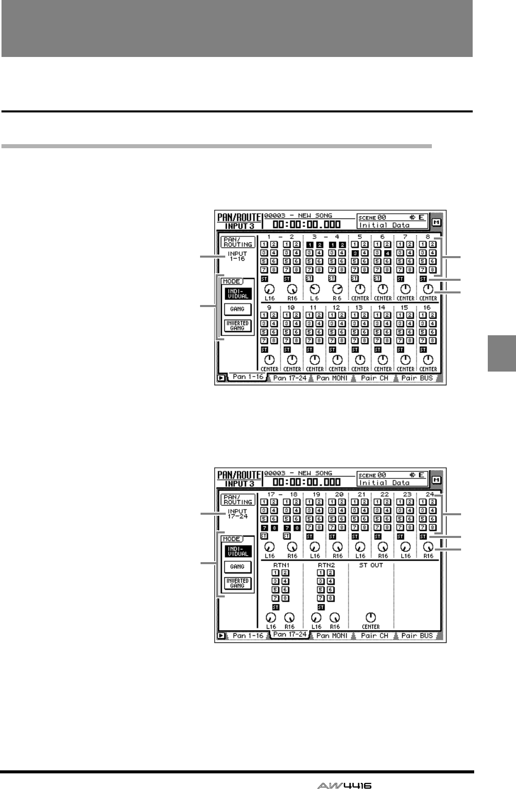
— Reference Guide 49
PAN/
ROUTE
PAN/ROUTE screen
Pan 1–16/Pan17–24/Pan MONI pages
Set pan and routing
[Function]
Set pan and routing for the input
channels, return channels and
monitor channels, and set the bal-
ance of the stereo output channel.
[Key operation]
• [EQ] key → [F1] key (Pan 1–16)/
[F2] key (Pan 17–24)/[F3] key
(Pan MONI)
• Repeatedly press the [PAN] key
until one of the screens shown at
the right appear.
[Mouse operation]
M button → EQ button → Pan 1–16
tab/Pan 17–24 tab/Pan MONI tab
● Pan 1–16
12
3
4
5
12
3
4
5
● Pan 17–24
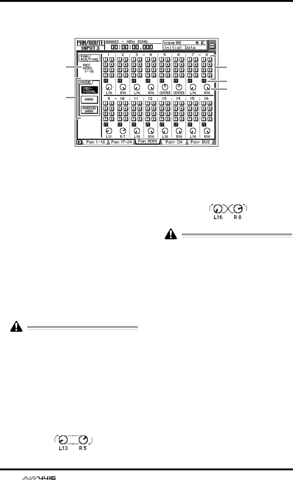
PAN/ROUTE screen
50 — Reference Guide
[Screen functions]
AChannel
This indicates the channel for which pan/rout-
ing is being set.
BBus assign buttons 1–8
These buttons assign the signal of each channel
to buses 1–8.
CST (stereo bus assign) buttons
These buttons assign the signal of each channel
to the stereo bus.
DPAN knobs
These knobs pan the signal between L/R of the
stereo bus and between odd-numbered and
even-numbered buses. Use the [DATA/JOG]
dial to operate the knobs. Pressing the [ENTER]
key will set the knob to the CENTER position.
The ST OUT knobs in the Pan 17–24 page
adjust the output channel balance.
EMODE
Use the following three buttons to select how
the PAN knob will function for paired channels.
● INDIVIDUAL button
The pan of each channel will operate indepen-
dently. (Default setting)
● GANG button
The pan of paired channels will be linked while
preserving the existing spatial relationship.
● INVERTED GANG button
The pan of paired channels will be linked
inversely.
On the AW4416, the pan of a channel can be
adjusted in the following two ways.
(1). Use the [SEL] keys to select the desired
channel, and rotate the [PAN] control.
If AUTO PAN DISPLAY is turned “ON” in
the UTILITY screen Prefer.1 page ([UTIL-
ITY] key
→
[F2] key), operating the [PAN]
control will automatically switch the dis-
play to the PAN/ROUTE screen even if a
screen other than the PAN/ROUTE
screen had been displayed.
(2). In the PAN 1–16/PAN 17–24/PAN MONI
pages, move the cursor to the PAN knob
of the desired channel and rotate the
[DATA/JOG] dial.
In the PAN 1–16/PAN 17–24/PAN MONI
pages, the channel can be specified freely,
regardless of the state of the [SEL] keys. For
this reason, there may be cases in which the
channel whose pan is adjusted by the [PAN]
control is different than the channel whose
pan is adjusted by the [DATA/JOG] dial.
● Pan MONI
12
3
4
5
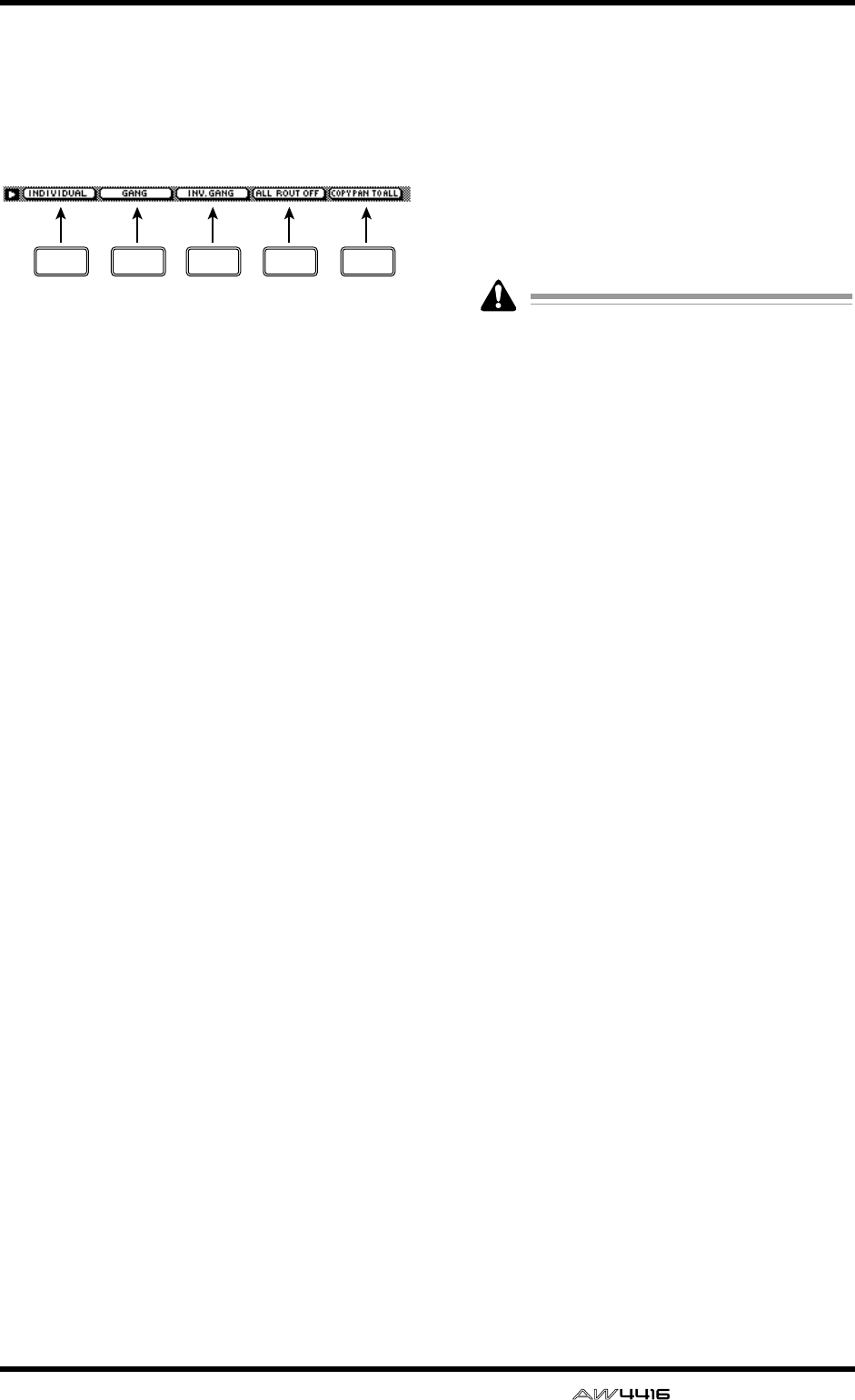
PAN/ROUTE screen
— Reference Guide 51
■Additional functions in the Pan
page
In the Pan 1–16/Pan 17–24/Pan MONI pages, you
can press the [SHIFT] key to assign the following
additional functions to the [F1]–[F5] keys.
• [F1] (INDIVIDUAL) key
Independently control the pan of paired chan-
nels. This is the same function as the INDIVID-
UAL button.
• [F2] (GANG) key
Link the pan of paired channels while maintain-
ing their existing spatial relationship. This is the
same function as the GANG button.
• [F3] (INVERTED GANG) key
Inversely link the pan of paired channels. This is
the same function as the INVERTED GANG but-
ton.
• [F4] (ALL ROUT OFF) key
Turn off bus assign 1–8 buttons for all channels
in the page.
• [F5] (COPY PAN TO ALL) key
Copy the pan setting of the currently selected
channel to all channels (including the channels
of other pages).
●Copying pan settings to all chan-
nels
[Procedure]
1. In the PAN screen, move the cursor to the
PAN knob of the copy source channel.
2. Press the [SHIFT] key + [F5] key.
The CONFIRMATION popup window will
appear, asking you to confirm the copy.
If the cursor is at a parameter other than the
PAN knob, a message of “Can’t Copy This
Parameter” will appear, and the copy will not
occur.
3. To execute the copy, move the cursor to
the OK button and press the [ENTER] key.
F1 F2 F5F3 F4
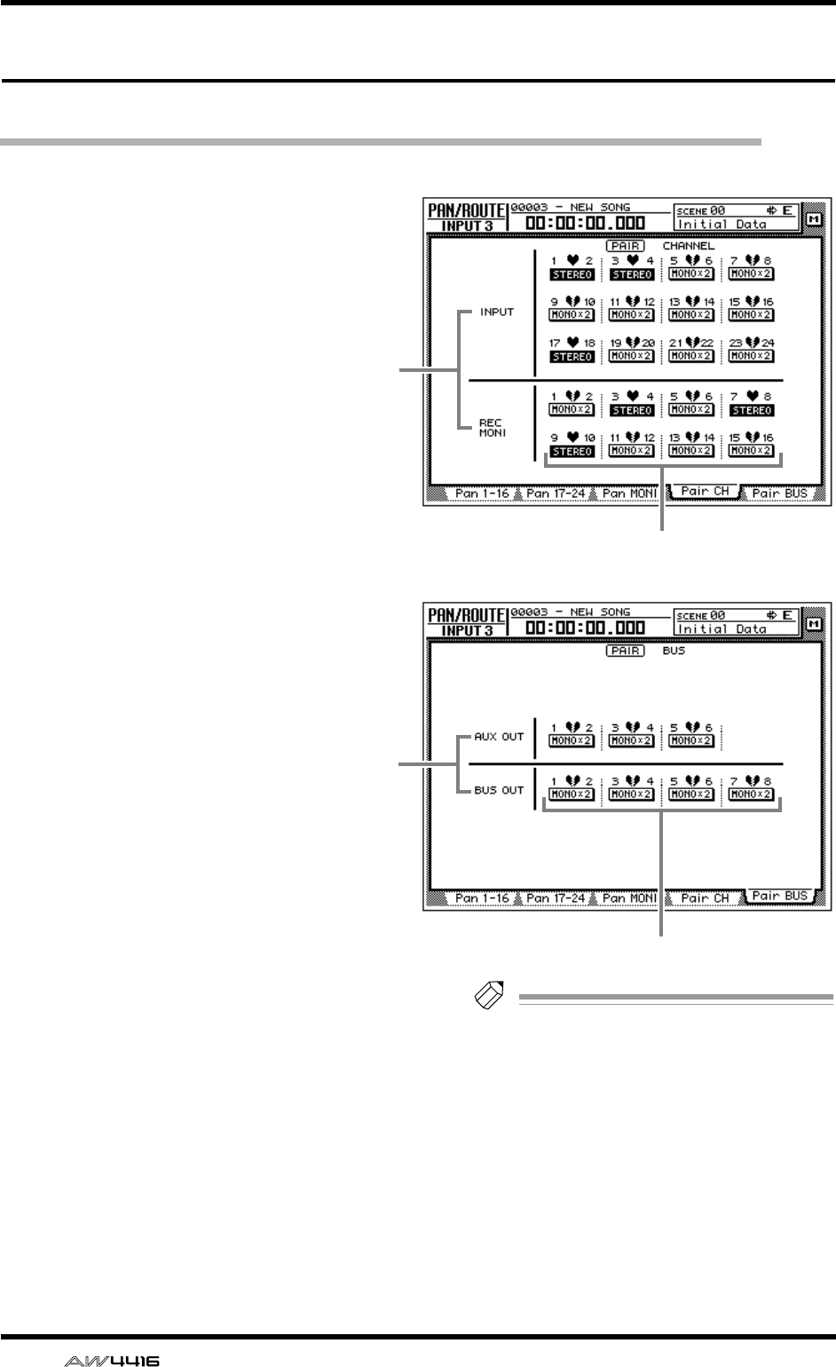
PAN/ROUTE screen
52 — Reference Guide
Pair CH/Pair BUS pages
Set channel/bus pairing
[Function]
Set or defeat pairing of buses 1/2–7/8 and
AUX 1/2–5/6 for adjacent odd-numbered
→ even-numbered channels.
[Key operation]
• [EQ] key → [F4] key (Pair CH)/[F5] (Pair
BUS)
• Repeatedly press the [PAN] key until
one of the screens shown at the right
appears.
[Mouse operation]
M button → EQ button → Pair CH tab/Pair
BUS tab
[Screen functions]
AChannel/bus
These are the channels/bus for which pairing
will be set or defeated.
BPairing
These buttons set or defeat pairing.
The heart symbol will be connected for chan-
nels/buses that are paired, and the button will
be displayed as “STEREO.”
The heart symbol will be divided for channels/
buses that are not paired, and the button will be
displayed as “MONO x2.”
Tip!
• All parameters other than attenuation and
pan will be linked for channels that are
paired.
However, pan will be linked if the pan mode
is set to GANG or INVERTED GANG. It will
not be linked if the pan mode is set to INDI-
VIDUAL (the default setting).
• For buses that are paired, the master level
(HOME screen/Bus page) will be linked.
• For AUX buses that are paired, the master
level (HOME screen/Bus page) and the send
level of the signals sent from each channel to
the corresponding AUX bus will be linked.
● Pair CH
1
2
● Pair BUS
1
2
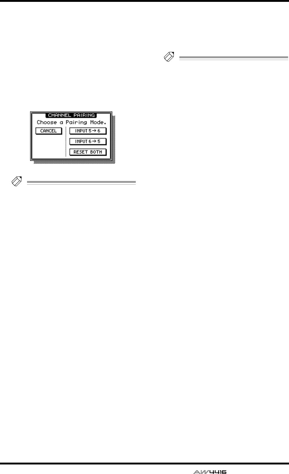
PAN/ROUTE screen
— Reference Guide 53
●Setting or defeating pairing for
channels/buses
[Procedure]
1. To pair channels or buses, move the cur-
sor in the Pair CH page/Pair Bus page to a
button that is displayed as “MONO x 2,”
and press the [ENTER] key.
The PAIRING popup window will appear,
allowing you to specify how the pairing will
occur.
Tip!
Another way to pair channels is to simulta-
neously press adjacent odd-numbered
→
even-numbered [SEL] keys. In this case, the
above window will appear when you press
the two [SEL] keys simultaneously.
2. Move the cursor to either the “INPUT 1 →
2,” “INPUT 2 → 1,” or “RESET BOTH” but-
ton, and press the [ENTER] key.
You can select one of the following three pair-
ing methods.
● INPUT x → y (x=odd number, y=even num-
ber)
The parameters of the odd-numbered channel/
bus (except for attenuator and pan) will be cop-
ied to the even-numbered channel.
● INPUT y → x (x=odd number, y=even num-
ber)
The parameters of the even-numbered channel/
bus (except for attenuator and pan) will be cop-
ied to the odd-numbered channel.
● RESET BOTH
The parameters of both odd and even-num-
bered channels/buses will be reset to their
default values.
When you execute pairing, the button display
will change to “STEREO.” When you use the
[SEL] keys to select a paired channel, the other
[SEL] key will blink.
3. To defeat pairing, move the cursor to a
button displayed as “STEREO” and press
the [ENTER] key.
A popup window will appear, asking you to
confirm that you wish to defeat pairing.
Tip!
You can also defeat channel pairing by press-
ing the two [SEL] keys simultaneously.
4. Move the cursor to the OK button and
press the [ENTER] key.
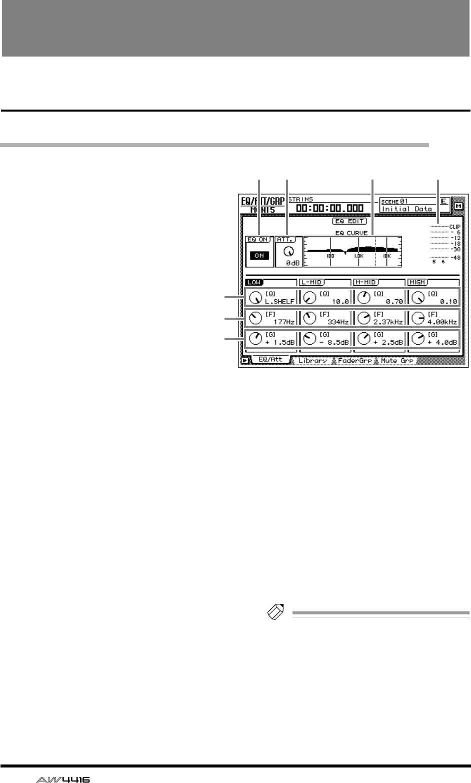
54 — Reference Guide
EQ/ATT/GRP screen
EQ/Att page
EQ and attenuation settings
[Function]
Make four-band EQ and attenuation set-
tings for the selected channel.
[Key operation]
• [EQ] key → [F1] key (EQ/Att) key
• Repeatedly press the [EQ] key until the
screen shown at the right appears.
[Mouse operation]
M button → EQ button → EQ/Att tab
[Screen functions]
AEQ ON button
This switches EQ on/off. When this page is dis-
played, you can use the [ENTER] key to switch
this button on/off regardless of the cursor loca-
tion.
BATT. (attenuation) knob
Set the amount of attenuation for the signal
before it enters the EQ. This is used mainly to
prevent clipping when the EQ is boosted.
Range: –96 dB–0 dB
CEQ CURVE
This graphically displays the EQ settings.
DOutput meter
This meter shows the post-EQ output level.
EQ knob
This sets the steepness at which the boost/cut
will occur at the center frequency specified by
the F knob. Higher settings will produce a
steeper curve.
For the LOW band EQ, turning the Q knob all
the way in the clockwise direction will switch
the EQ type to L.SHELF (shelving), and turning it
all the way in the counter-clockwise direction
will switch the EQ type to HPF (high pass filter).
For the HIGH band EQ, turning the Q knob all
the way in the clockwise direction will switch
the EQ type to H.SHELF (shelving), and turning
it all the way in the counter-clockwise direction
will switch the EQ type to LPF (low pass filter).
Range: 10–0.10, HPF/L.SHELF (LOW band
only), LPF/H.SHELF (HIGH band only)
FF (frequency) knob
Set the center frequency that will be boosted or
cut.
Range: 21 Hz–20.1 kHz
GG (gain) knob
Set the amount of boost or cut. If the LOW or
HIGH bands are set to HPF or LPF respectively,
this knob switches them on/off.
Range: –18 dB– +18 dB, ON/OFF (LOW/HIGH
bands only)
Tip!
The Q, F, and G parameters of each band can
also be controlled by the EQ [HIGH]/[HI-
MID]/[LO-MID]/[LOW] keys and EQ [Q]/[F]/
[G] keys located at the right of the display.
If AUTO EQ DISPLAY is turned “ON” in the
UTILITY screen Prefer.1 page ([UTILITY] key
→
[F2] key), operating these keys or controls
will automatically cause the EQ/ATT page to
automatically appear if any other page is cur-
rently selected.
2134
5
6
7
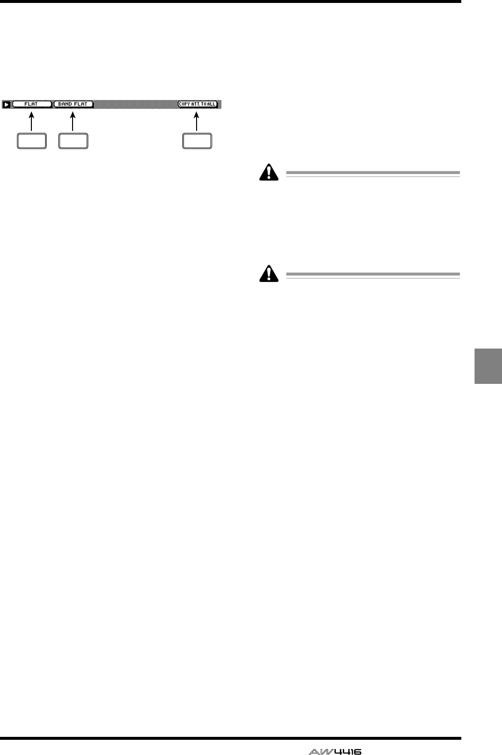
EQ/ATT/GRP screen
— Reference Guide 55
EQ/ATT
/GRP
■Additional functions in the EQ/
Att page
In the EQ/Att page you can press the [SHIFT] key to
assign the following additional functions to the
[F1]–[F2] and [F5] keys.
• [F1] (FLAT) key
Reset all bands to a boost/cut amount of 0.0 dB
(off if HPF/LPF is selected).
• [F2] (BAND FLAT) key
Reset only the selected band to a boost/cut
amount of 0.0 dB (off if HPF/LPF is selected).
• [F5] (COPY ATT. TO ALL) key
Copy the attenuation setting of the selected
channel to all channels. (However, the stereo
output channel is excepted.)
●Copying the attenuation setting
to all channels
[Procedure]
1. Access the EQ/Att page for the copy
source channel, and move the cursor to
the ATT. knob.
2. Press the [SHIFT] key + [F5] key.
A CONFIRMATION popup window will appear,
asking you to confirm the copy.
If the cursor is at a location other than the
ATT. knob, a message of “Can’t Copy This
Parameter” will appear, and the copy will not
occur.
3. To execute the copy, move the cursor to
the OK button and press the [ENTER] key.
Only the attenuation setting will be copied. If
you wish to copy EQ settings, you must store
the settings in the library and recall them into
the copy destination channel. For the proce-
dure refer to page 47.
F1 F2 F5
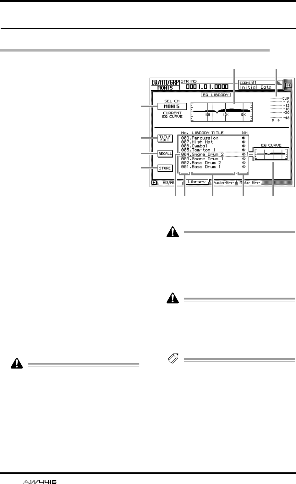
EQ/ATT/GRP screen
56 — Reference Guide
Library page
Store or recall EQ settings
[Function]
Store EQ settings in the EQ library, or
recall a stored EQ program.
[Key operation]
• [EQ] key → [F2] (Library) key
• Repeatedly press the [EQ] key until the
screen shown at the right appears.
[Mouse operation]
M button → EQ button → Library tab
[Screen functions]
ASEL CH
This indicates the currently selected channel.
BEQ graph
This graphically displays the EQ settings.
COutput meter
This meter shows the post-EQ output level.
DTITLE EDIT button
Use this to edit the name (library title) of the EQ
program stored in the EQ library. A library name
of up to 16 characters can be input. Move the
cursor to the TITLE EDIT button and press the
[ENTER] key to access the TITLE EDIT popup
window where you can input a name. For
details on inputting characters, refer to Opera-
tion Guide P.60.
Library numbers 1–40 are recall-only preset
memories, and their names cannot be
changed. Numbers in which no EQ program
has been stored are displayed as “No Data!,”
and their title cannot be changed.
ERECALL button
Recall the currently selected EQ program from
the list.
If you attempt to recall a number in which no
data has been stored, a message of “ERROR
NO DATA TO RECALL” will appear, and the
recall will not occur.
FSTORE button
Store the current EQ settings.
• Library numbers 1–40 are recall-only preset
memories, and cannot be stored. You can
store only in library numbers 41–128.
• When you store, the EQ program that was
previously stored in that number will be
erased.
Tip!
GLIBRARY No. (library number)
This shows the library number 1–128.
HLIBRARY TITLE
This shows the names assigned to each library
number.
IROM
A write-protect symbol is displayed for recall-
only programs (library numbers 1–40).
1
4
5
6
JK78 9
32
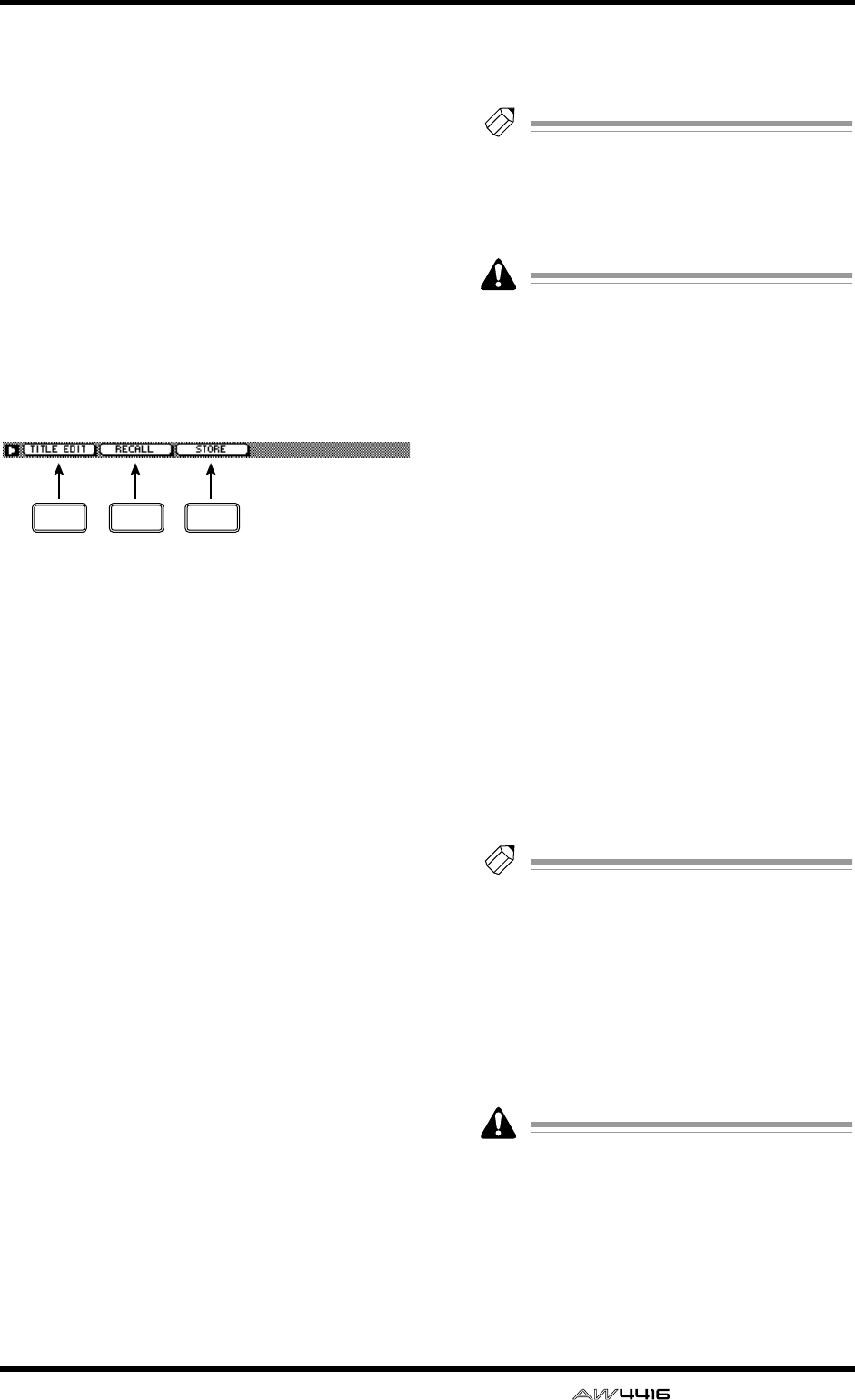
EQ/ATT/GRP screen
— Reference Guide 57
JSelected program
The EQ program selected for store/recall is
enclosed by a dotted frame in the EQ library list.
In this page you can use the [DATA/JOG] dial to
select the EQ program regardless of the cursor
location.
KEQ CURVE
Of the EQ programs stored in the library, the
curve of the currently selected EQ program is
shown as a graph.
■Additional functions in the
Library page
In the Library page you can press the [SHIFT] key
to assign the following functions to the [F1]–[F3]
keys.
• [F1] (TITLE EDIT) key
Use this to edit the name (library title) of an EQ
program stored in the EQ library. This is the
same function as the 4 TITLE EDIT button.
• [F2] (RECALL) key
Recall the currently selected EQ program from
the list. This is the same function as the 5
RECALL button.
• [F3] (STORE)
Store the current EQ settings. This is the same
function as the 6 STORE button.
●Storing EQ settings in the EQ
library
[Procedure]
1. Select the EQ settings that you wish to
store, and access the EQ/ATT/GRP screen
Library page.
2. Use the [DATA/JOG] dial to select the store
destination library number 41–128.
3. Move the cursor to the STORE button and
press the [ENTER] key.
The TITLE EDIT popup window will appear,
allowing you to assign a name to the EQ pro-
gram.
4. Input the library title as desired. For details
on inputting characters, refer to Opera-
tion Guide P.60.
5. Move the cursor to the OK button and
press the [ENTER] key.
The EQ settings will be stored.
Tip!
It is possible to store the EQ settings immedi-
ately, without displaying the TITLE EDIT
popup window. To do so, access the UTILITY
screen Prefer.1 page ([UTILITY] key
→
[F2]
key) and turn STORE CONFIRMATION off.
When you store, the EQ program that had
been previously stored in that number will be
erased.
●Recalling EQ settings from the EQ
library
[Procedure]
1. Select the channel into which you wish to
recall the EQ settings, and access the EQ/
ATT/GRP screen Library page.
2. Use the [DATA/JOG] dial to select the
library number 1–128 that you wish to
recall.
3. Move the cursor to the RECALL button
and press the [ENTER] key.
A CONFIRMATION popup window will appear,
asking you to confirm the recall operation.
4. Move the cursor to the OK button and
press the [ENTER] key.
The recall will be executed.
Tip!
• It is possible to recall the EQ settings imme-
diately, without displaying the CONFIRMA-
TION popup window. To do so, access the
UTILITY screen Prefer.1 page ([UTILITY] key
→
[F2] key) and turn RECALL CONFIRMA-
TION off.
• When you recall an EQ program to a paired
channel or the stereo output channel, the
same settings will be recalled into both
channels.
If you attempt to recall a number in which
nothing has been stored, an error message of
“ERROR NO DATA TO RECALL” will appear,
and the recall will not occur.
F1 F2 F3
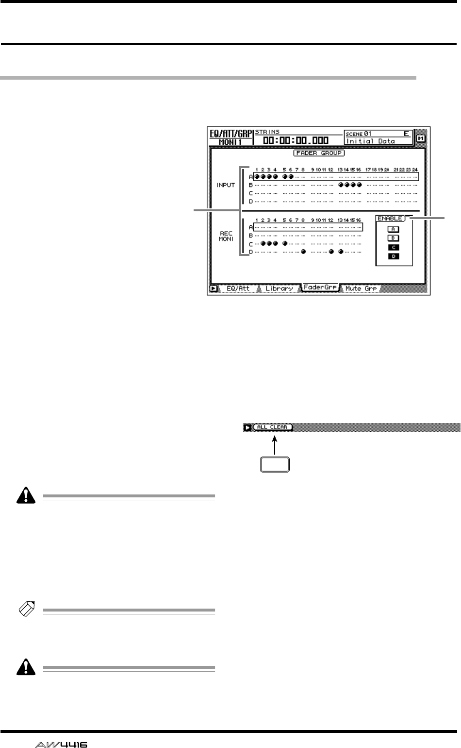
EQ/ATT/GRP screen
58 — Reference Guide
FaderGrp page
Set and cancel fader groups
[Function]
Assign input channels 1–24/moni-
tor channels 1–16 to fader groups
A–D. If channels are assigned to a
fader group, you can move a single
fader to control all the faders in
that group while preserving the
current balance.
[Key operation]
• [EQ] key → [F3] (FaderGrp) key
• Repeatedly press the [EQ] key
until the screen shown at the
right appears.
[Mouse operation]
M button → EQ button → FaderGrp
tab
[Screen functions]
AFader groups A–D
The ● symbols indicate the fader group A–D to
which each input channel 1–24 and monitor
channel 1–16 belongs.
When you move the cursor up or down to select
group A–D and use the [SEL] key to select a
channel, that channel will be assigned to the
corresponding fader group. When you press the
[SEL] key once again, the channel will be
removed from the fader group.
A channel cannot belong to more than one
fader group. If a channel that is already
assigned to a fader group is assigned to
another group, only the newly assigned
group will be valid.
BENABLE button
Turn fader groups A–D on/off.
Tip!
If you wish to adjust the position of a fader
assigned to a group, you can use the ENABLE
button to temporarily disable that group.
Do not manually operate two or more faders
of a group at the same time. Doing so will
strain the motor and cause malfunctions.
■Additional functions in the Fader-
Grp page
In the FaderGrp page you can press the [SHIFT] key
to assign the following additional function to the
[F1] key.
• [F1] (ALL CLEAR) key
Clear all fader group settings.
2
1
F1
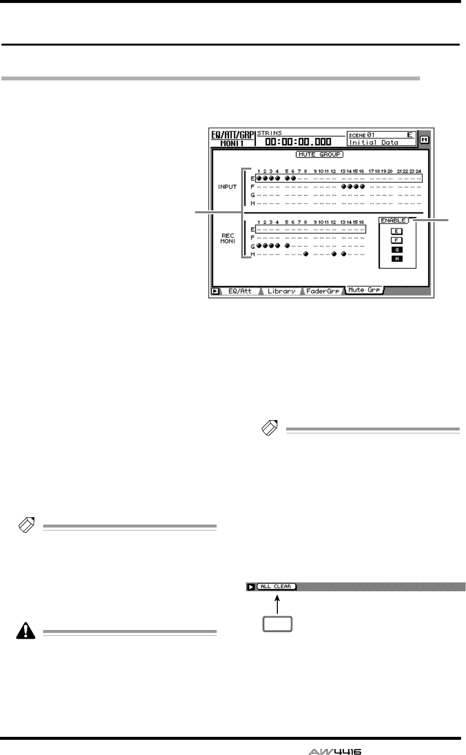
EQ/ATT/GRP screen
— Reference Guide 59
Mute Grp page
Set and cancel mute groups
[Function]
Assign input channels 1–24/moni-
tor channels 1–16 to mute groups
E–H. If channels are assigned to a
mute group, you can operate a sin-
gle [ON] key to switch the on/off
status of all [ON] keys in that
group.
[Key operation]
• [EQ] key → [F4] (Mute Grp) key
• Repeatedly press the [EQ] key
until the screen shown at the
right appears.
[Mouse operation]
M button → EQ button → Mute
Grp tab
[Screen functions]
AMute groups E–H
The ● symbols indicate the mute group E–H to
which each input channel 1–24 and monitor
channel 1–16 belongs.
When you move the cursor up or down to select
mute group E–H and use the [SEL] key to select
a channel, that channel will be assigned to the
corresponding mute group. When you press the
[SEL] key once again, the channel will be
removed from the mute group.
Tip!
A mute group may contain both channels
that are On and channels that are Off. If a
mute group contains channels that are On
and channels that are Off, operating the
[ON] key of one of the channels will turn off
the channels that are on, and turn on the
channels that are off.
A channel cannot belong to more than one
mute group. If a channel that is already
assigned to a mute group is assigned to
another group, only the newly assigned
group will be valid.
BENABLE button
Turn mute groups E–H on/off.
Tip!
If you wish to change the on/off status after
assigning a channel to a group, you can use
the ENABLE button of that group to tempo-
rarily disable the group.
■Additional functions in the Mute
Grp page
In the Mute Grp page you can press the [SHIFT]
key to assign the following additional function to
the [F1] key.
• [F1] (ALL CLEAR) key
Clear all mute group settings.
2
1
F1
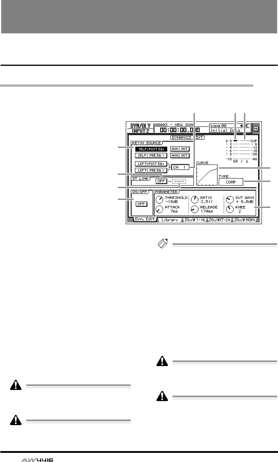
60 — Reference Guide
DYN/DLY screen
Dyn. Edit page
Dynamics processor parameter settings
[Function]
Set the dynamics processor param-
eters for the selected channel.
[Key operation]
• [DYN] key → [F1] (Dyn. Edit) key
• Repeatedly press the [DYN] key
until the screen shown at the
right appears.
[Mouse operation]
M button → DYN button → Dyn.
Edit tab
[Screen functions]
AKEYIN SOURCE
Select one of the following key-in signals to
control the dynamics processor.
● SELF (POST EQ)
The post-EQ signal of the same channel
● SELF (PRE EQ)
The pre-EQ signal of the same channel
● AUX 1 OUT
The signal being output to AUX bus 1
● AUX 2 OUT
The signal being output to AUX bus 2
● LEFT (POST EQ)
The post-EQ signal of the next channel to the
left
● LEFT (PRE EQ)
The pre-EQ signal of the next channel to the left
LEFT (POST EQ) or LEFT (PRE EQ) cannot be
selected for input channel 1, monitor chan-
nel 1, or the stereo output channel.
Return channels 1/2 do not have dynamics
processors.
Tip!
If either one of two paired channels exceeds
the threshold level, both channels will oper-
ate simultaneously.
BChannel
If LEFT is selected as the KEYIN SOURCE (1),
the key-in signal source channel will be shown
here.
CST LINK ON/OFF (stereo link on/off)
button
If this button is on, dynamics processor parame-
ter settings and operation will be linked for
adjacent odd-numbered → even-numbered
channels.
For the stereo out channel and for paired
channels, this Stereo Link setting will always
be on and cannot be defeated.
When Stereo Link is turned on, the dynamics
processor settings of the odd-numbered
channel will be copied to the even-num-
bered channel.
8
J
9
6
2 7
1
3
4
5
DYN/DLY screen
— Reference Guide 61
DYN/
DLY
DChannel
Select the channel(s) to which the dynamics
processor will apply when the 3 ST LINK ON/
OFF button is on; L (left/odd-numbered chan-
nel), R (right/even-numbered channel), or
BOTH (both channels).
If the ST LINK ON/OFF button is off, this will
be displayed as “----” and cannot be selected.
EON/OFF
This button turns the dynamics processor on/off.
When the cursor is located at on/off or in the
PARAMETER area, press the [ENTER] key to turn
the dynamics processor on/off.
FGR (gain reduction)
This displays the amount of gain reduction pro-
duced by the dynamics processor in dB units.
GLevel meter
This shows the output level of the dynamics
processor in dB units.
HCURVE
This graph shows the approximate response of
the current dynamics processor settings.
ITYPE
This shows the type of the currently selected
dynamics processor.
The following types of dynamics processor are
available.
● COMP (compressor)
● EXPAND (expander)
● GATE
● COMPANDER (HARD/SOFT)
● DUCKING
The type cannot be changed in this page. If
you wish to use a specific type, you must
recall a program that uses that type from the
library. For details on recalling a program,
refer to P.47.
JPARAMETER
Set the parameters of the dynamics processor. The
type of parameters and their range will differ
depending on the currently selected type. For
details on parameters and their functions, refer to
the following appendices: “Dynamics Processors”
and “Preset Dynamics Program Parameters.”
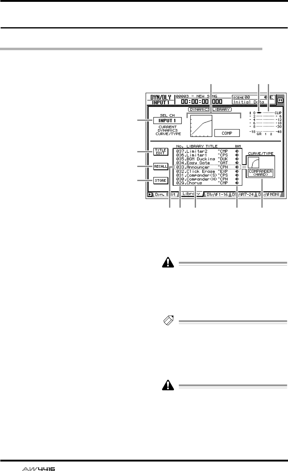
DYN/DLY screen
62 — Reference Guide
Library page
Storing and recalling dynamics processor settings
[Function]
Store dynamics processor settings in the
library, or recall stored programs.
[Key operation]
• [DYN] key → [F2] (Library) key
• Repeatedly press the [DYN] key until
the screen shown at the right appears.
[Mouse operation]
M button → DYN button → Library tab
[Screen functions]
ASEL CH
This displays the currently selected recall desti-
nation channel.
BCurve/type
This indicates the approximate dynamics curve
of the currently selected channel, and shows
the name of the dynamics processor type.
CGR (gain reduction)
This displays the amount of gain reduction pro-
duced by the dynamics processor in dB units.
DLevel meter
This shows the output level of the dynamics
processor in dB units.
ETITLE EDIT button
Use this when you wish to edit the name
(library title) of the dynamics program saved in
the library. Move the cursor to the TITLE EDIT
button and press the [ENTER] key to access the
TITLE EDIT popup window where you can input
the name. You can input a library name of up to
16 characters.
Library numbers 1–40 are recall-only preset
programs, and their name cannot be
changed. Numbers in which no dynamics
program has been stored are displayed as
“No Data!,” and their title cannot be
changed.
Tip!
For details on the library preset dynamics
programs, refer to appendix “Preset Dynam-
ics Program Parameters”.
FRECALL button
Recall the currently selected program from the
list.
If you attempt to recall a number in which
nothing has been stored, an error message of
“ERROR NO DATA TO RECALL” will be dis-
played, and the recall will not take place.
K 98 J L
1
5
7
6
23 4
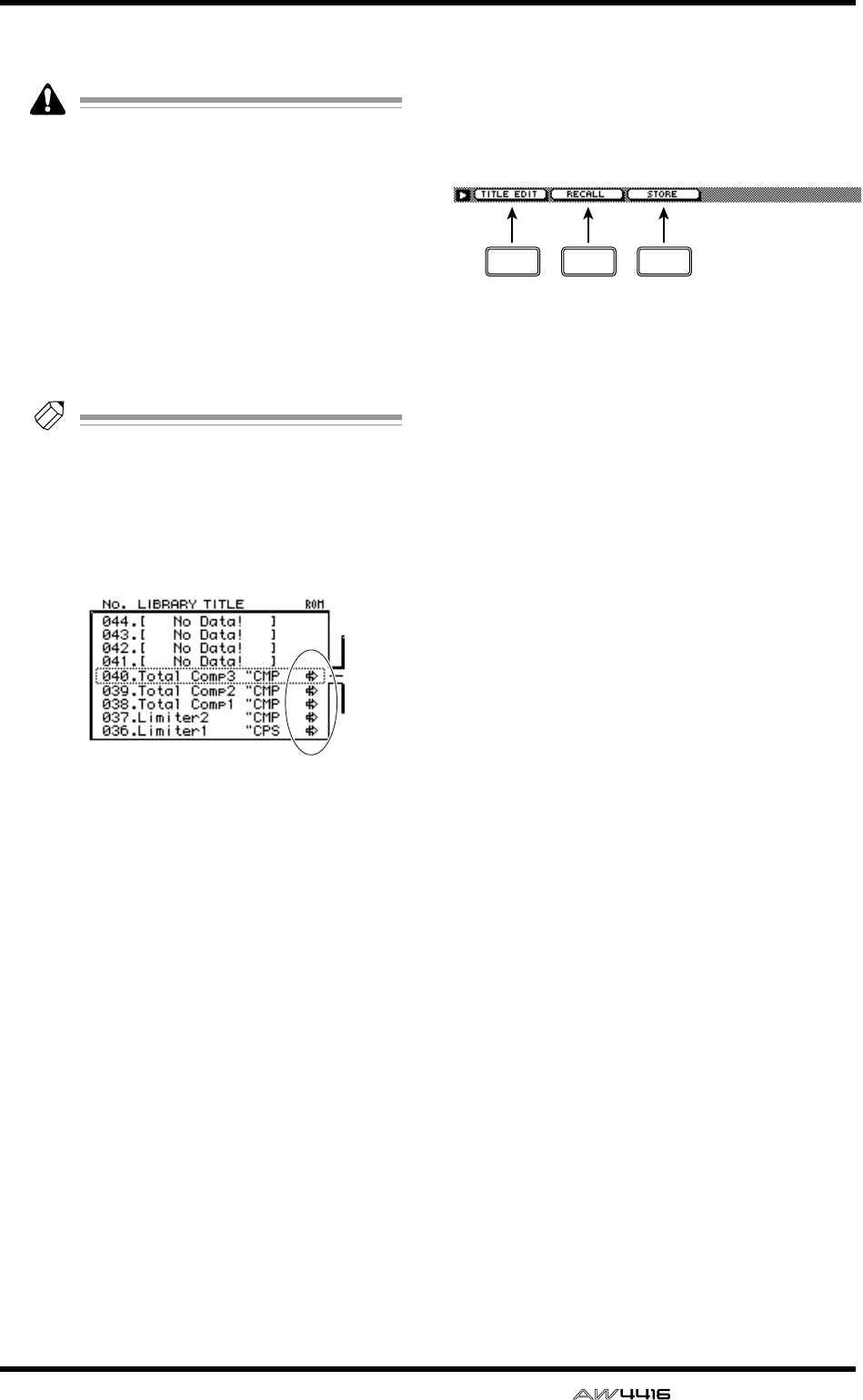
DYN/DLY screen
— Reference Guide 63
GSTORE button
Store the current dynamics settings.
• Library numbers 1–40 are recall-only; data
cannot be stored in them. You can store only
to library numbers 41–128.
• When you execute the Store operation, the
dynamics program that had been stored in
that number will be erased.
HLIBRARY No. (library number)
This displays the library number 1–128.
ILIBRARY TITLE
This displays the name assigned to the library
and the type of dynamics processor.
Tip!
Library numbers in which nothing has been
stored are displayed as “No Data!”
JROM
This write-prohibit symbol is displayed for
recall-only library numbers 1–40.
KSelected program
Store/recall operations will apply to the pro-
gram enclosed by a dotted line in the library list.
In this page, you can always use the [DATA/
JOG] dial to select the program, regardless of
where the cursor is located.
LCURVE/TYPE
Of the dynamics programs stored in the library,
the response and type of the currently selected
dynamics program are shown in this area.
■Additional functions in the
Library page
In the Library page you can press the [SHIFT] key
to assign the following functions to the [F1]–[F3]
keys.
• [F1] (TITLE EDIT) key
Use this to edit the name (library title) assigned
to settings in the library. This is the same func-
tion as the 5 TITLE EDIT button.
• [F2] (RECALL) key
Recall the currently selected dynamics settings
from the list. This is the same function as the 6
RECALL button.
• [F3] (STORE) key
Store the current dynamics settings. This is the
same function as the 7 STORE button.
F1 F2 F3

DYN/DLY screen
64 — Reference Guide
●Storing dynamics settings in the
library
[Procedure]
1. Select the channel whose settings you
wish to store, and access the DYN/DLY
screen Library page.
2. Use the [DATA/JOG] dial to select the
library number 41–128 in which you will
store the settings.
Library numbers in which nothing has been
stored are displayed as “No Data!”
3. Move the cursor to the STORE button and
press the [ENTER] key.
The TITLE EDIT popup window will appear,
allowing you to input a name.
Tip!
It is also possible to store the settings directly
into the library without accessing the TITLE
EDIT popup window. To do so, access the
UTILITY screen Prefer.1 page ([UTILITY] key
→
[F2] key) and turn STORE CONFIRMA-
TION off.
4. Input the library title. For details on input-
ting characters, refer to Operation Guide
P.60.
The Store operation will be executed.
●Recalling dynamics settings from
the library
[Procedure]
1. Select the recall destination channel, and
access the DYN/DLY screen Library page.
2. Use the [DATA/JOG] dial to select the
library number that you wish to recall.
3. Move the cursor to the RECALL button
and press the [ENTER] key.
A confirmation message will appear.
Tip!
• It is possible to recall the library data with-
out seeing the CONFIRMATION popup win-
dow. To do so, access the UTILITY screen
Prefer.1 page ([UTILITY] key
→
[F2] key),
and turn RECALL CONFIRMATION off.
• When you recall a dynamics program into a
paired channel or into the stereo out chan-
nel, the same settings will be recalled into
both channels.
4. Move the cursor to the OK button and
press the [ENTER] key.
The recall will be executed.
Tip!
When you recall a dynamics program into a
stereo channel or a paired channel, the same
settings will be recalled into both channels.
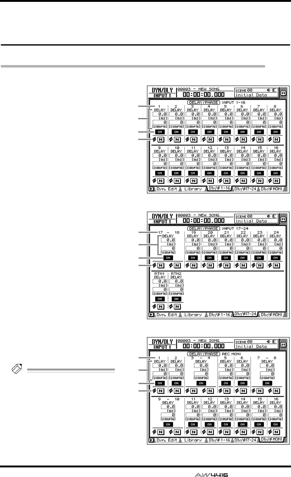
DYN/DLY screen
— Reference Guide 65
Dly/ø1–16, Dly/ø17–24,
Dly/øMONI pages
Set delay and phase
[Function]
Set the delay and phase of each channel.
[Key operation]
• [DYN] key → [F3] (Dly/ø1–16) key, [F4]
(Dly/ø17–24) key/[F5] (Dly/øMONI)
key
• Repeatedly press the [DYN] key until
the desired page appears.
[Mouse operation]
M button → DYN button → Dly/ø1–16
tab, Dly/ø17–24 tab, Dly/øMONI tab
[Screen functions]
AChannel
This displays the channels for which
you can make delay and phase set-
tings.
BDELAY
Set the delay time for the signal of
each channel. The upper row shows
the delay in ms (millisecond) units,
and the lower row shows the delay in
sample units. Adjusting either one will
cause the other value to change in
tandem.
CON/OFF
Switch the delay on/off.
Dø (phase)
Switch the phase of each channel.
Tip!
Phase (ø) will operate indepen-
dently even for paired channels.
1
3
4
2
● Dly/ø1–16
1
3
4
2
● Dly/ø17–24
1
3
4
2
● Dly/øMONI

DYN/DLY screen
66 — Reference Guide
■Additional functions in the Dly/
øpages
In the Dly/ø1–16, Dly/ø17–24, Dly/øMONI pages
you can press the [SHIFT] key to assign the follow-
ing additional function to the [F5] key.
• [F5] (COPY TO ALL) key
Copy the delay time or phase setting selected by
the cursor to all other channels.
●Copying delay time or phase set-
tings to other channels
1. Access the DYN/DLY screen Dly/ø1–16,
Dly/ø17–24, Dly/øMONI page.
2. Move the cursor to the delay time param-
eter or the ø button of the copy source
channel.
3. Press the [SHIFT] key + [F5] key.
The following confirmation screen will appear.
4. Move the cursor to the OK button and
press the [ENTER] key.
F5
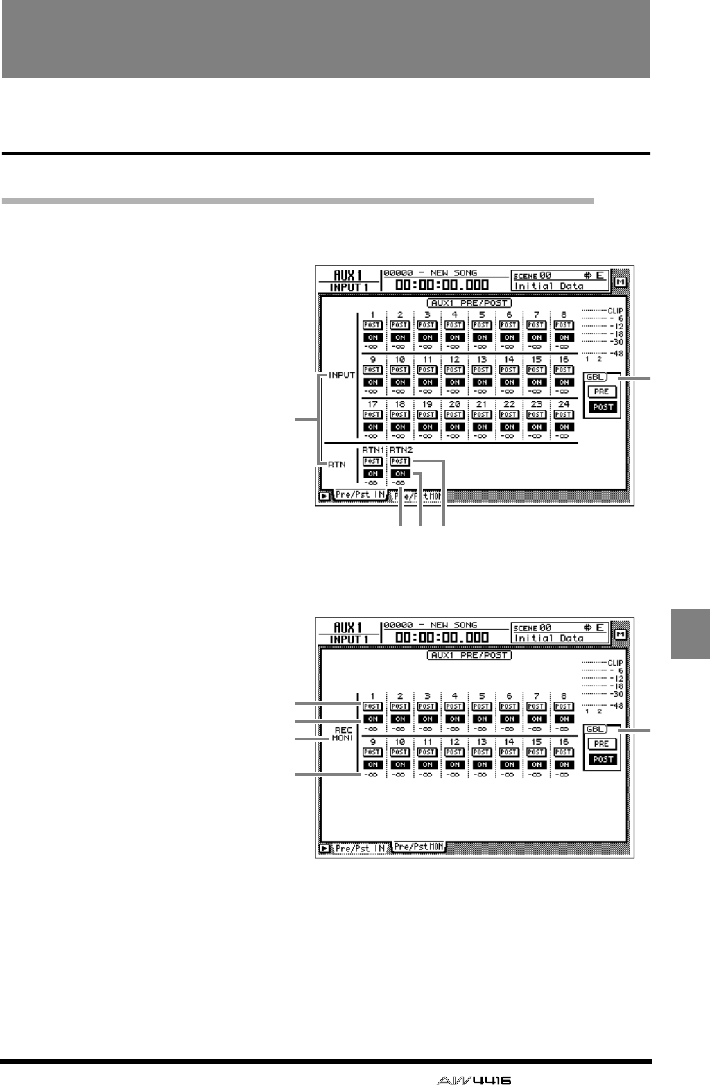
— Reference Guide 67
AUX1–
AUX6
AUX1–AUX6 screens
Pre/Pst IN, Pre/Pst MONI pages
Make on/off and pre/post settings for the AUX sends
[Function]
Make on/off and pre/post settings for
the signal sent from the input chan-
nels, return channels, and monitor
channels to AUX buses 1–6.
[Key operation]
• [AUX 1]–[AUX 6] keys → [F1] (Pre/
Pst IN) key/[F2] (Pre/Pst MONI) key
• Repeatedly press an [AUX 1]–[AUX
6] key until the desired page
appears.
[Mouse operation]
M button → AUX 1–AUX 6 buttons →
Pre/Pst IN tab/Pre/Pst MONI tab
[Screen functions]
AChannels
This area shows the channels
whose AUX send pre/post settings
are being switched.
BON/OFF buttons
These buttons are on/off switches
for the signal that is sent from each
channel to the corresponding AUX
bus.
CPRE/POST buttons
These buttons switch the signal
sent from each channel to the cor-
responding AUX bus between pre-
fader and post-fader locations.
DSend levels
These indicate the send level val-
ues of each channel.
EGBL (global)
If you move the cursor to the PRE
button or the POST button and
press the [ENTER] key, the pre/post
setting of all channels in that page
will be switched together.
● Pre/Pst IN
42 3
1
1
2
3
4
● Pre/Pst MONI
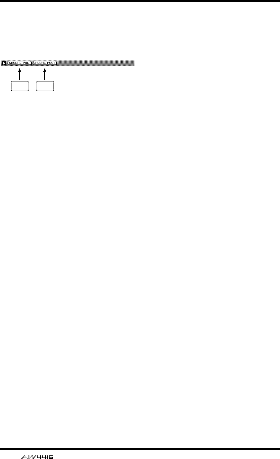
AUX1–AUX6 screens
68 — Reference Guide
■Additional functions in the Pre/
Pst IN, Pre/Pst MONI pages
In the Pre/Pst IN/Pre/Pst MONI pages, you can
press the [SHIFT] key to assign the following func-
tions to the [F1]–[F2] keys.
• [F1] (GLOBAL PRE) key
Switch all channels in that page to pre-fader.
This is the same function as the PRE button in
the GBL area 5.
• [F2] (GLOBAL POST) key
Switch all channels in that page to post-fader.
This is the same function as the POST button in
the GBL area 5.
F1 F2
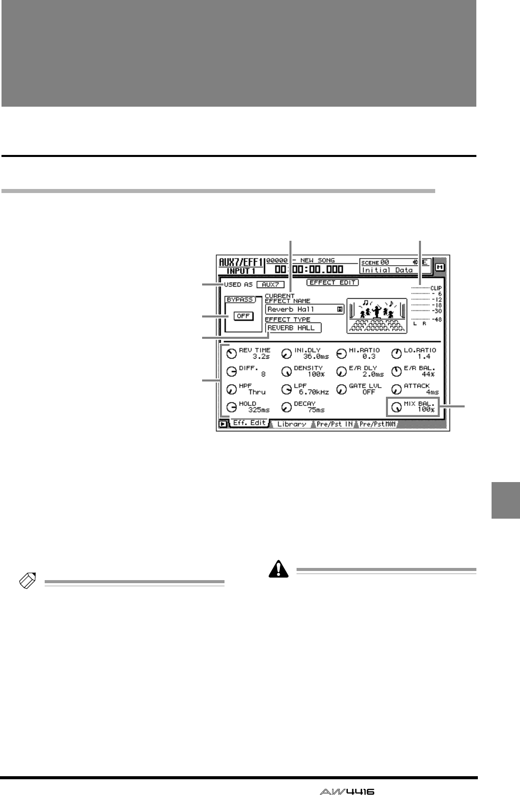
— Reference Guide 69
AUX7/EFF1
AUX8/EFF2
AUX7/EFF1 and
AUX8/EFF2 screens
Eff. Edit page
Edit internal effects 1/2
[Function]
Edit the parameters of the effect
that is selected for internal effect 1
(AUX7/EFF1 screen) or external
effect 2 (AUX8/EFF2).
[Key operation]
• [AUX 7] key/[AUX 8] → [F1] (Eff.
Edit) key
• Repeatedly press the [AUX 7]
key or [AUX 8] key until the
desired screen appears
[Mouse operation]
M button → EFF 1 button/EFF 2
button → Eff. Edit tab
[Screen functions]
AUSED AS (effect usage method)
If the effect is patched to AUX send/return this
will indicate “AUX 7”/”AUX 8.” If the effect is
patched to a specific channel this will indicate
“INSERT.”
Tip!
The choice of AUX send/return or insertion is
made in the SET UP screen Patch IN page.
BBYPASS ON/OFF button
This button switches effect bypass on/off. This
ON/OFF button can be switched by pressing the
[ENTER] key regardless of where the cursor is
located.
CCURRENT EFFECT NAME
This shows the name of the currently used effect
program.
DEFFECT TYPE
This shows the name of the currently used effect
type. A graphic indicating the effect type is also
displayed as the right.
It is not possible to change the effect type in
this page. If you wish to use a specific effect
type, load a program using that effect type
from the effect library (
→
P.71).
EOutput meter
This level meter shows the effect output level.
FEffect parameters
Use the knobs displayed in this area to edit the
effect parameter values. The type of parameters
will differ depending on the currently-used
effect type.
3 5
7
1
2
4
6
AUX7/EFF1 and AUX8/EFF2 screens
70 — Reference Guide
GMIX BAL. (mix balance) knob
This knob adjust the mix amount of the effect
sound. A setting of 0% will output only the orig-
inal sound, 50% will output equal amounts of
direct and effect sound, and 100% will output
only the effect sound. If the effect is patched via
AUX send/return, set this to 100%. If the effect
is inserted in a specific channel, adjust this to
the desired value.
Tip!
This knob will be located in the same place
regardless of the effect type.
■Additional functions in the Eff
Edit page
In the Eff Edit page you can press the [SHIFT] key to
assign the following function to the [F1] key.
• [F1] (BYPASS ON/OFF) key
Switch effect bypass on/off. This is the same
function as the 2 BYPASS ON/OFF button.
F1
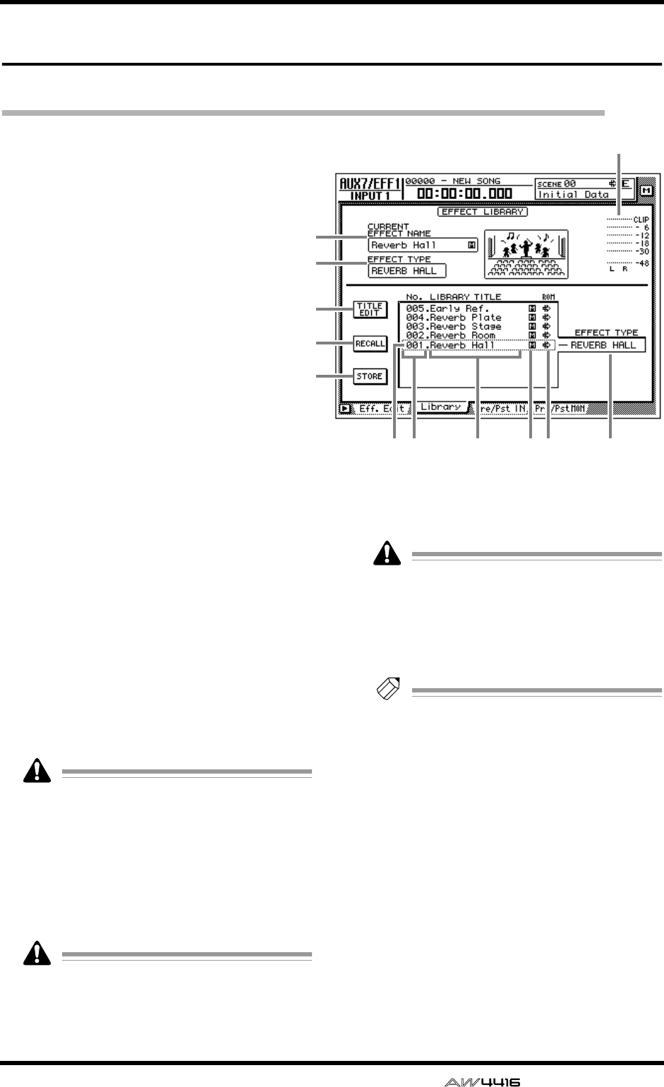
AUX7/EFF1 and AUX8/EFF2 screens
— Reference Guide 71
Library page
Store or recall an effect program
[Function]
Store an effect program in the library, or
recall a stored effect program.
[Key operation]
• [AUX 7]–[AUX 8] keys → [F2] (Library)
key
• Repeatedly press an [AUX 7]–[AUX 8]
key until the desired screen appears
[Mouse operation]
M button → EFF 1–EFF 2 button → Library
tab
[Screen functions]
ACURRENT EFFECT NAME
BEFFECT TYPE
COutput meter
These are the same as in the Eff. Edit page. Refer
to P.69.
DTITLE EDIT button
Use this when you wish to edit the name
(library title) of an effect program saved in the
effect library. Move the cursor to the TITLE EDIT
button and press the [ENTER] key to access the
TITLE EDIT popup window where you can input
the name. For details on inputting characters,
refer to Operation Guide P.60.
Library numbers 1–41 are recall-only presets;
their name cannot be edited. Numbers in
which no effect program has been stored will
be displayed as “No Data!,” and their name
cannot be edited either.
ERECALL button
Recall the currently selected effect program
from the list.
If you select and attempt to recall a number
in which nothing has been stored, a message
of “ERROR NO DATA TO RECALL” will
appear, and the recall will not take place.
FSTORE button
Store the current effect settings.
• Library numbers 1–41 are recall-only pre-
sets, and cannot be stored. Settings can be
stored only in library numbers 42–128.
• When you execute the Store operation, the
effect program that had been stored in that
number will be erased.
Tip!
For the programs that are preset in the effect
library, refer to the appendix “Preset Effects
Programs.”
GLIBRARY No. (library number)
This shows the library number 1–128.
HLIBRARY TITLE
This shows the name assigned to each library
number.
IS/M (stereo/monaural)
This indicates whether the effect type used by
each program is stereo or monaural. Stereo
effect types are indicated by “S,” and monaural
effect types are indicated by “M.”
JROM
Recall-only programs (library numbers 1–41)
are indicated by a write-prohibit symbol in this
column.
1
2
4
5
6
KL78 J9
3
AUX7/EFF1 and AUX8/EFF2 screens
72 — Reference Guide
KSelected program
Store/recall operations will apply to the pro-
gram enclosed by a dotted line in the library list.
In this page, you can always use the [DATA/
JOG] dial to select the program, regardless of
where the cursor is located.
LEFFECT TYPE
This displays the effect type used by the pro-
gram currently selected for store or recall.
In general, the effect library is common to
both effects 1 and 2. However, effect pro-
gram no.19 “HQ-Pitch” can be used only by
effect 2.
■Additional functions in the
Library page
In the Library page, you can press the [SHIFT] key
to assign the following functions to the [F1]–[F3]
keys.
• [F1] (TITLE EDIT) key
Use this to edit the name (library title) of the
effect program saved in the library. This is the
same function as the 4 TITLE EDIT button.
• [F2] (RECALL) key
Recall the currently selected effect program
from the list. This is the same function as the 5
RECALL button.
• [F3] (STORE) key
Store the current effect settings. This is the same
function as the 6 STORE button.
●Storing an effect program in the
library
[Procedure]
1. Access the Library page of the AUX7/EFF1
screen or the AUX8/EFF2 screen.
2. Use the [DATA/JOG] dial to select the store
destination library number 42–128.
3. Move the cursor to the STORE button and
press the [ENTER] key.
The TITLE EDIT popup window will appear,
allowing you to assign a name to the effect pro-
gram.
4. Input the library title as desired. For details
on inputting characters, refer to Opera-
tion Guide P.60.
A maximum of 16 characters can be input.
5. Move the cursor to the OK button and
press the [ENTER] key.
The Store operation will be executed.
Tip!
It is possible to store the settings directly in
the library without seeing the TITLE EDIT
popup window. To do so, access the UTILITY
screen Prefer.1 page ([UTILITY] key
→
[F2]
key) and turn STORE CONFIRMATION off.
When you store, the effect program that had
been stored in that number will be erased.
●Recalling an effect program from
the library
[Procedure]
1. Access the Library page of the AUX7/EFF1
screen or the AUX8/EFF2 screen.
2. Use the [DATA/JOG] dial to select the
library number that you wish to recall.
3. Move the cursor to the RECALL button
and press the [ENTER] key.
The CONFIRMATION popup window will
appear, asking you to confirm the Recall opera-
tion.
4. Move the cursor to the OK button and
press the [ENTER] key.
The Recall operation will be executed.
Tip!
It is possible to execute the recall immedi-
ately without seeing the CONFIRMATION
popup window. To do so, access the UTILITY
screen Prefer.1 page ([UTILITY] key
→
[F2]
key) and turn RECALL CONFIRMATION off.
If you attempt to recall a number in which no
data has been stored, an error message of
“ERROR NO DATA TO RECALL” will appear,
and the recall will not take place.
F1 F2 F3
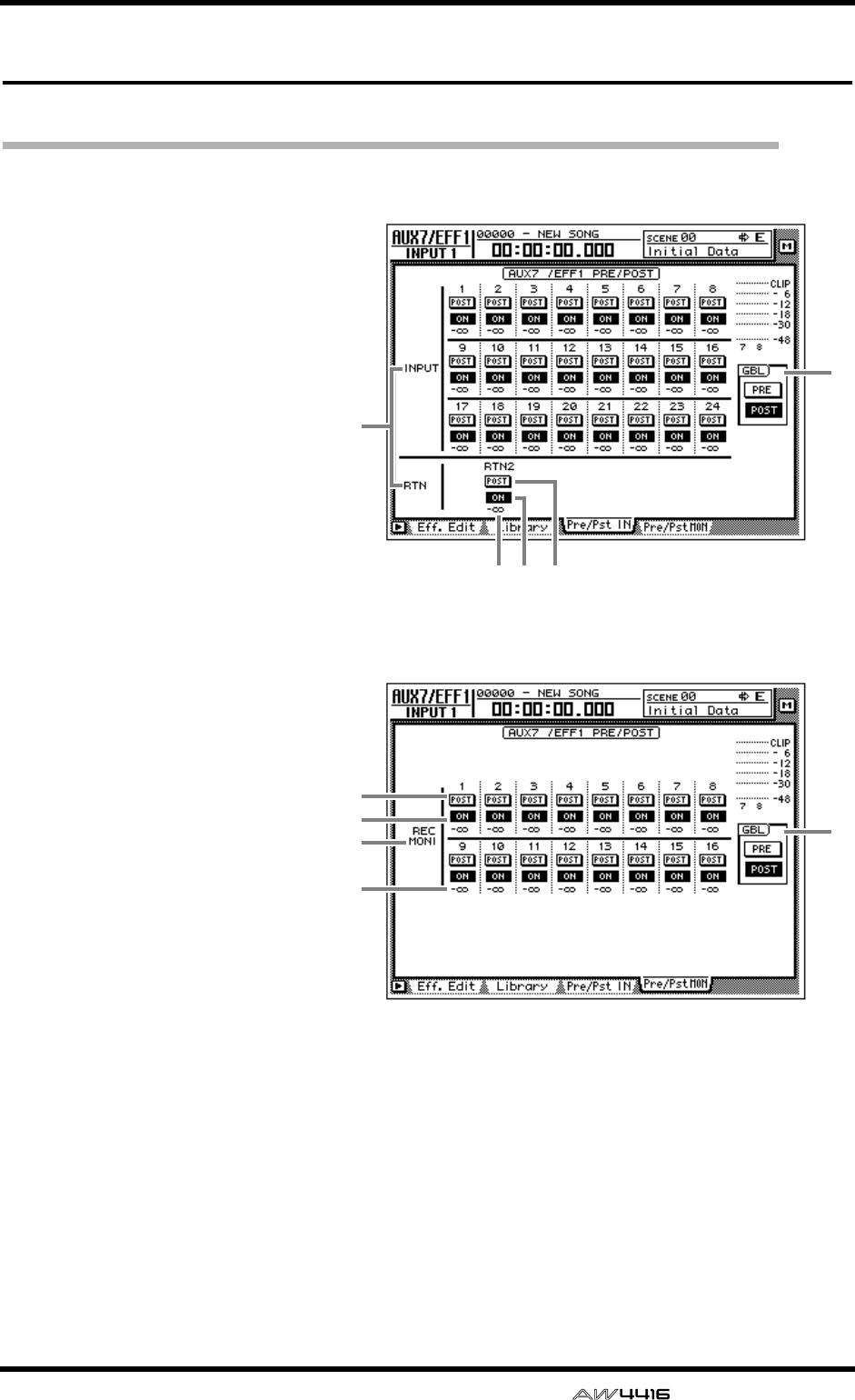
AUX7/EFF1 and AUX8/EFF2 screens
— Reference Guide 73
Pre/Pst IN, Pre/Pst MONI pages
Make on/off and pre/post settings for the effect sends
[Function]
Make on/off and pre/post settings
for the signal sent from the input
channels, return channels, and
monitor channels to AUX buses 7/
8 (effects 1/2).
[Key operation]
• [AUX 7] key/[AUX 8] key → [F3]
(Pre/Pst IN) key/[F4] (Pre/Pst
MONI) key
• Repeatedly press the [AUX 7]
key or [AUX 8] key until the
desired page appears.
[Mouse operation]
M button → EFF 1 button/EFF 2
button → Pre/Pst IN tab/Pre/Pst
MONI tab
[Screen functions]
AChannels
This area shows the channels
whose effect send pre/post set-
tings are being switched.
BON/OFF buttons
These buttons are on/off
switches for the signal that is
sent from each channel to
effect 1/2.
CPRE/POST buttons
These buttons select either pre-
fader or post-fader signals to be
sent from each channel to the
effect send.
DSend levels
These indicate the send level
values of each channel.
EGBL (global)
If you move the cursor to the
PRE button or the POST button
and press the [ENTER] key, the
pre/post setting of all channels
in that page will be switched
together.
● Pre/Pst IN
42 3
5
1
● Pre/Pst MONI
5
1
2
3
4
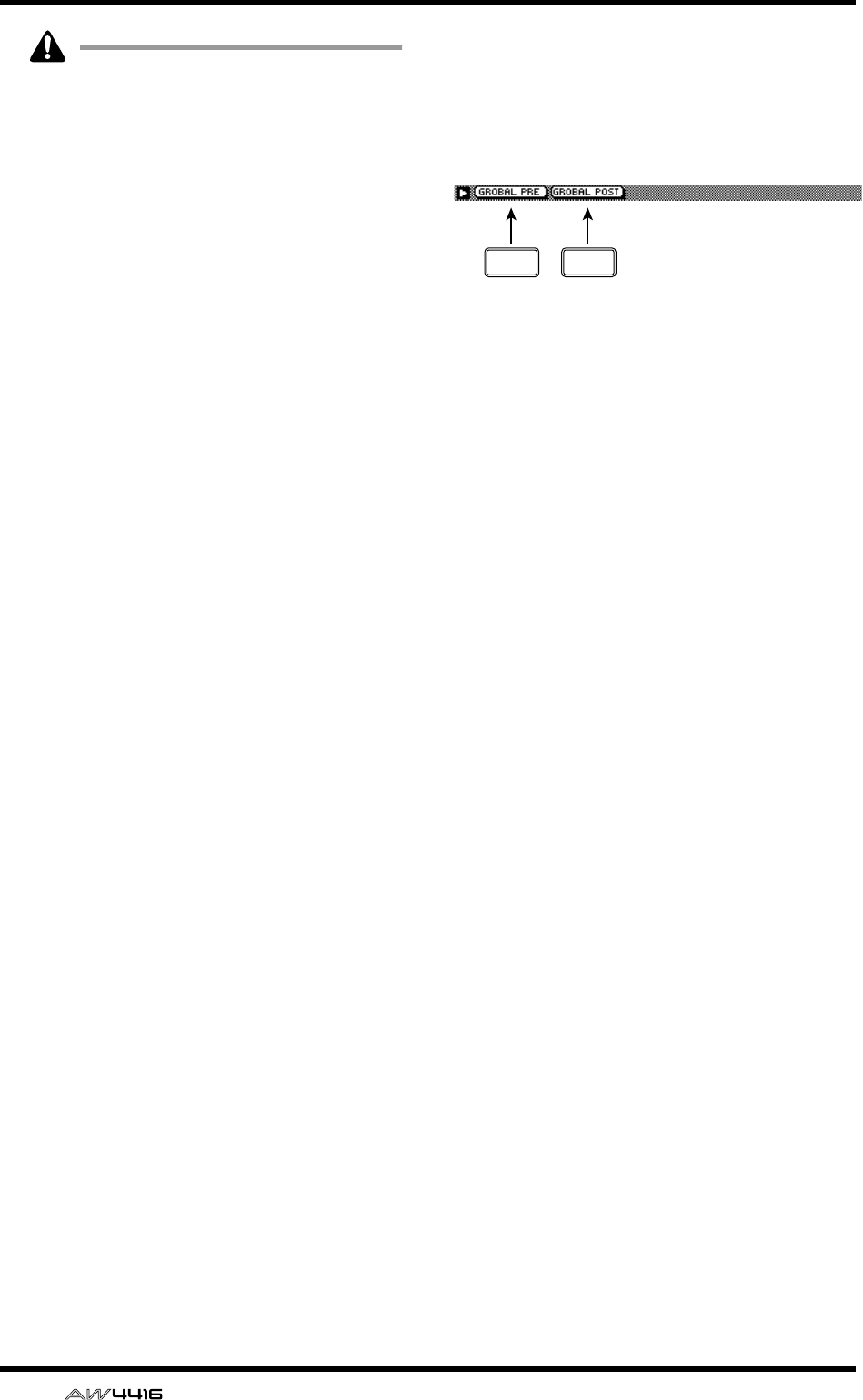
AUX7/EFF1 and AUX8/EFF2 screens
74 — Reference Guide
It is not possible to send signals from return
channel 1 to AUX7. Likewise, it is not possi-
ble to send signals from return channel 2 to
AUX8. This is to prevent the return signal of
an effect from being accidentally returned to
the same effect, creating a loop.
■Additional functions in the Pre/
Pst IN/Pre/Pst MONI pages
In the Pre/Pst IN/Pre/Pst MONI pages, you can
press the [SHIFT] key to assign the following func-
tions to the [F1]–[F2] keys.
• [F1] (GLOBAL PRE) key
Switch all channels in that page to pre-fader.
This is the same function as the PRE button in
the GBL area 5.
• [F2] (GLOBAL POST) key
Switch all channels in that page to post-fader.
This is the same function as the POST button in
the GBL area 5.
F1 F2
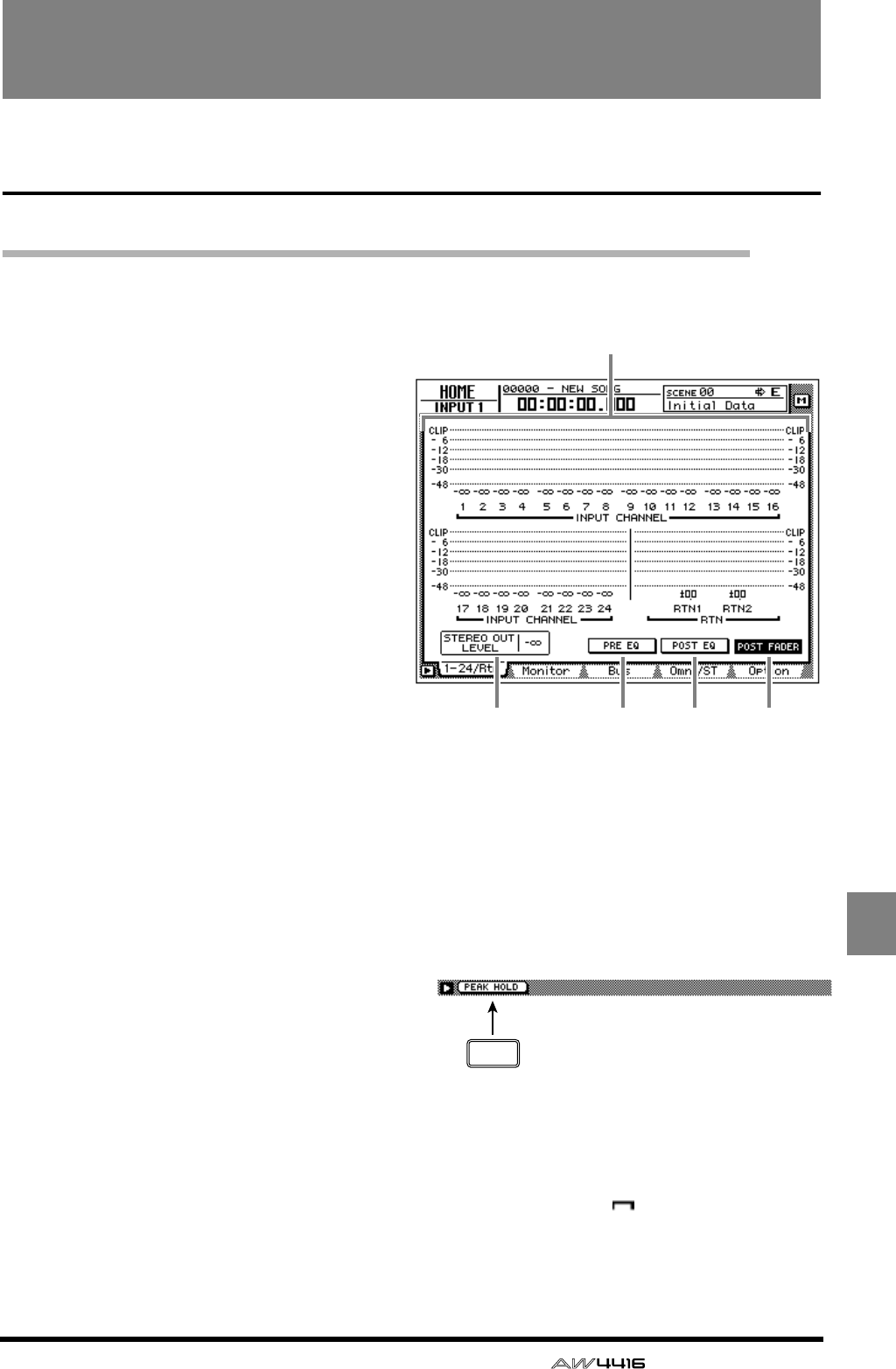
— Reference Guide 75
HOME
HOME screen
1–24/Rtn page
Monitor the input level of the input channels
[Function]
Monitor the input levels of input channels
1–24 and return channels 1/2.
[Key operation]
• [HOME] key → [F1] (1–24/Rtn) key
• Repeatedly press the [HOME] key until
the screen shown at the right appears
[Mouse operation]
M button → HOME button → 1–24/Rtn
tab
[Screen functions]
ALevel meters
These meters show the input levels of input
channels 1–24 and return channels 1/2. The
fader position is shown in dB units below each
level meter.
BSTEREO OUT LEVEL
This shows the position of the STEREO fader in
dB units.
CPRE EQ button
DPOST EQ button
EPOST FADER button
Select one of these three buttons to select the
location in the signal path (pre-EQ/post-EQ/
post-fader) whose level will be shown by the
level meters.
■Additional functions in the 1–24/
Rtn page
In the 1–24/Rtn page you can press the [SHIFT] key
to assign the following function to the [F1] key.
• [F1] (PEAK HOLD) key
This key sets/defeats the Peak Hold function.
This is the same function as the [PEAK HOLD]
key in the level meter/counter section. When
Peak Hold is on, a “ ” symbol will be main-
tained in the level meter to indicate the peak
level.
1
2 3 4 5
F1
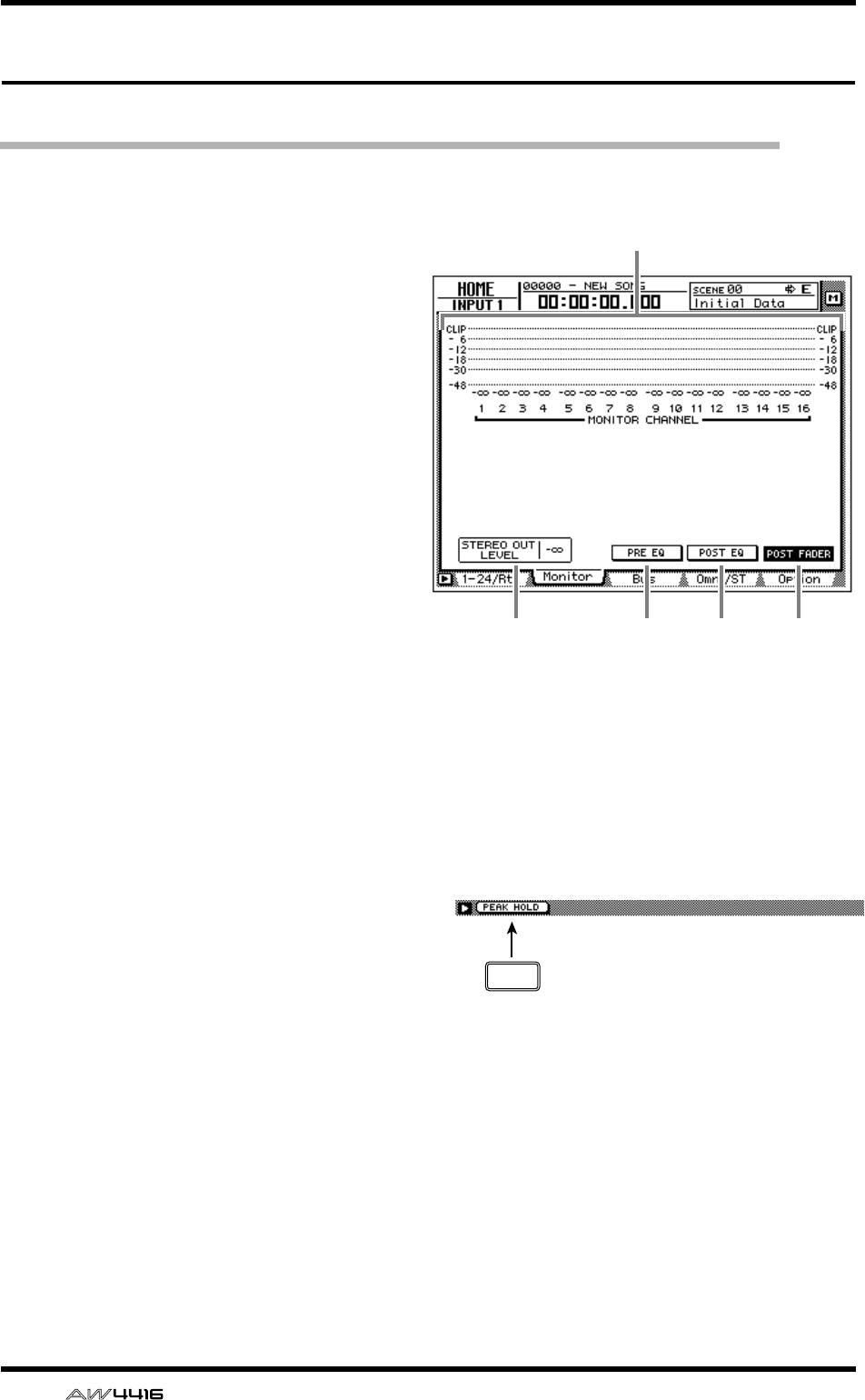
HOME screen
76 — Reference Guide
MONITOR page
Monitor the input levels of the monitor channels
[Function]
Monitor the input levels of monitor chan-
nels 1–16
[Key operation]
• [HOME] key → [F2] (Monitor) key
• Repeatedly press the [HOME] key until
the screen shown at the right appears
[Mouse operation]
M button → HOME button → Monitor tab
[Screen functions]
ALevel meters
These meters show the input levels of monitor
channels 1–16. The fader position of each chan-
nel is shown in dB units below each level meter.
BSTEREO OUT LEVEL
This shows the position of the STEREO fader in
dB units.
CPRE EQ button
DPOST EQ button
EPOST FADER button
Select one of these three buttons to select the
location in the signal path (pre-EQ/post-EQ/
post-fader) whose level will be shown by the
level meters.
■Additional functions in the Moni-
tor page
In the Monitor page you can press the [SHIFT] key
to assign the following function to the [F1] key.
• [F1] (PEAK HOLD) key
This key sets/defeats the Peak Hold function.
This is the same function as the [PEAK HOLD]
key in the level meter/counter section.
2 3 4 5
1
F1
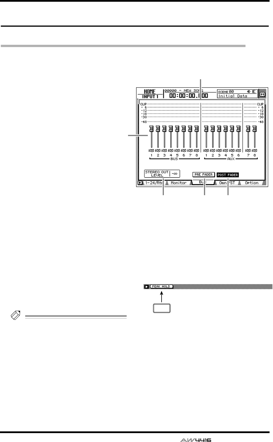
HOME screen
— Reference Guide 77
Bus page
Monitor the output levels of buses 1–8/AUX buses 1–8
[Function]
Monitor the output level of buses 1–8 and
AUX buses 1–8. In this page you can also
adjust the master level of each bus.
[Key operation]
• [HOME] key → [F3] (Bus) key
• Repeatedly press the [HOME] key until
the screen shown at the right appears
[Mouse operation]
M button → HOME button → Bus tab
[Screen functions]
ALevel meters
These meters show the output levels of buses 1–
8/AUX buses 1–8.
BFaders
These faders adjust the master level of buses 1–
8/AUX buses 1–8. The fader location of each
bus is shown in dB units below each fader.
Tip!
To adjust the value of a fader, move the cur-
sor to the desired fader and rotate the [DATA/
JOG] dial.
CSTEREO OUT LEVEL
The location of the STEREO fader is shown in
dB units.
DPRE FADER (pre-EQ) button
EPOST FADER (post-EQ) button
Select one of these two buttons to select the
location in the signal path (pre-fader/post-fader)
whose level will be shown by the level meters.
■Additional functions in the Bus
page
In the Bus page you can press the [SHIFT] key to
assign the following function to the [F1] key.
• [F1] (PEAK HOLD) key
This key sets/defeats the Peak Hold function.
This is the same function as the [PEAK HOLD]
key in the level meter/counter section.
1
3 4 5
2
F1
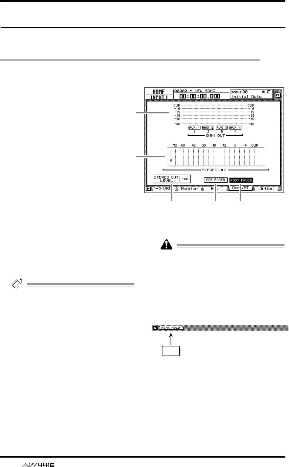
HOME screen
78 — Reference Guide
Omni/ST page
Monitor the output levels of the OMNI OUT jacks and
stereo output
[Function]
Monitor the output levels of OMNI OUT
jacks 1–4 and the stereo output.
[Key operation]
• [HOME] key → [F4] (Omni/ST) key
• Repeatedly press the [HOME] key until
the screen shown at the right appears
[Mouse operation]
M button → HOME button → Omni/St tab
[Screen functions]
AOMNI OUT level meters
These meters show the output level of OMNI
OUT jacks 1–4. The type of signal assigned to
each OMNI OUT jack is indicated below each
level meter.
Tip!
This page is for display only; assignments
cannot be changed in this page. The signals
assigned to OMNI OUT jacks 1–4 can be
selected in the SETUP screen Patch OUT
page.
BSTEREO OUT level meter
This meters shows the output level of stereo out-
put.
CSTEREO OUT LEVEL
This shows the position of the STEREO fader in
dB units.
DPRE FADER (pre-EQ) button
EPOST FADER (post-EQ) button
Select one of these two buttons to select the
location in the signal path (pre-fader/post-fader)
whose level will be shown by the STEREO OUT
level meters.
The PRE FADER button/POST FADER button
setting will not affect the OMNI OUT level
meter display.
■Additional functions in the Omni/
ST page
In the Omni/ST page you can press the [SHIFT] key
to assign the following function to the [F1] key.
• [F1] (PEAK HOLD) key
This key sets/defeats the Peak Hold function.
This is the same function as the [PEAK HOLD]
key in the level meter/counter section.
3
1
2
4 5
F1
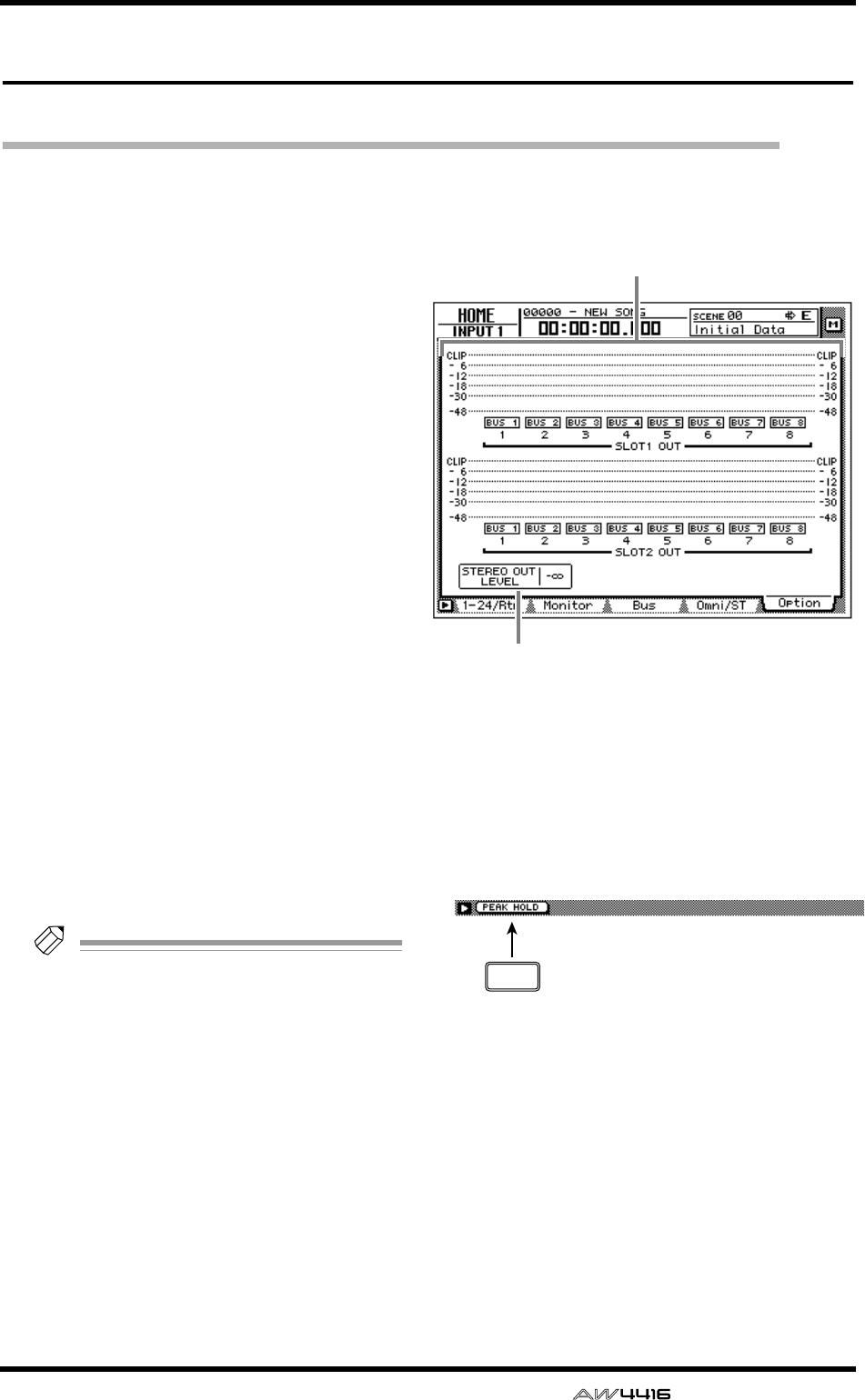
HOME screen
— Reference Guide 79
Option page
Monitor the output level of option I/O cards
[Function]
Monitor the output level of option I/O
cards inserted in slots 1/2 of the AW4416.
[Key operation]
• [HOME] key → [F5] (Option) key
• Repeatedly press the [HOME] key until
the screen shown at the right appears
[Mouse operation]
M button → HOME button → Option tab
[Screen functions]
ALevel meters
These meters shows the output levels of the
option I/O cards inserted in slots 1/2. The type
of signal assigned to each OUTPUT is indicated
below each level meter.
Tip!
This page is for display only; the assignments
cannot be changed here. The signals assigned
to each OUTPUT of an option I/O card can
be selected in the SETUP screen Patch OUT
page.
BSTEREO OUT LEVEL
The position of the STEREO fader is shown in
dB units.
■Additional functions in the
Option page
In the Option page you can press the [SHIFT] key
to assign the following function to the [F1] key.
• [F1] (PEAK HOLD) key
This key sets/defeats the Peak Hold function.
This is the same function as the [PEAK HOLD]
key in the level meter/counter section.
1
2
F1
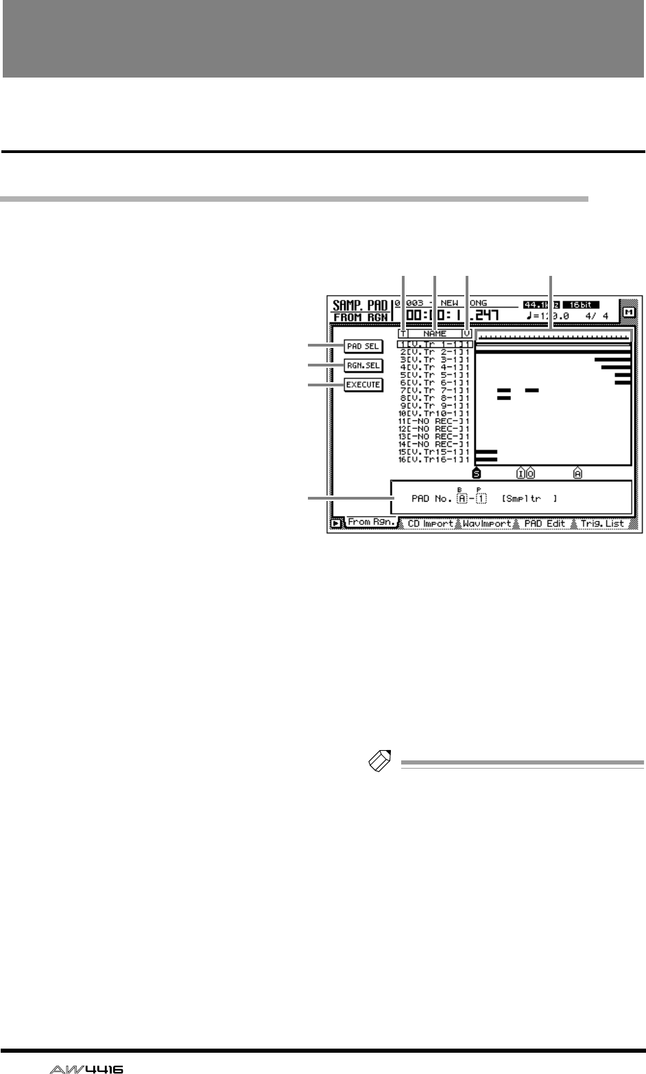
80 — Reference Guide
SAMP. PAD screen
From Rgn. page
Assign a region to a sampling pad
[Function]
Assign a region (continuous audio data
recorded in one operation) to a sampling
pad.
[Key operation]
• Sampling pad section [EDIT] pad → [F1]
(From Rgn.) key
• Repeatedly press the [EDIT] pad until the
screen shown at the right appears.
[Mouse operation]
M button → SAMP. PAD EDIT button →
From Rgn. tab
[Screen functions]
APAD SEL (pad select) button
This button selects the pad to which a region
will be assigned.
BRGN. SEL (region select) button
This button selects the region that will be
assigned to the pad.
CEXECUTE button
This button executes the assignment. When you
move the cursor to this button and press the
[ENTER] key, the region you selected in 2 will
be assigned to the pad you selected in 1.
DT (track)
This column shows the track number (1–16).
EN (name)
This column shows the virtual track name.
Tracks in which nothing has been recorded are
displayed as “-NO REC-”.
FV (virtual track)
This column shows the virtual track number (1–
8) selected for each track.
GTrack view
This area shows a bar graph to indicate the
regions included in each track.
HParameter area
In this area you can set the parameters for the
selected menu.
Note
The total length of the samples that can be
assigned to the sampling pads is a maximum
of 90 seconds (for a 44.1 kHz/16 bit song). If
you wish to use part of a region that is longer
than this, you must first divide the region
appropriately (EDIT screen TR Edit page).
4 5 6
1
2
3
8
7
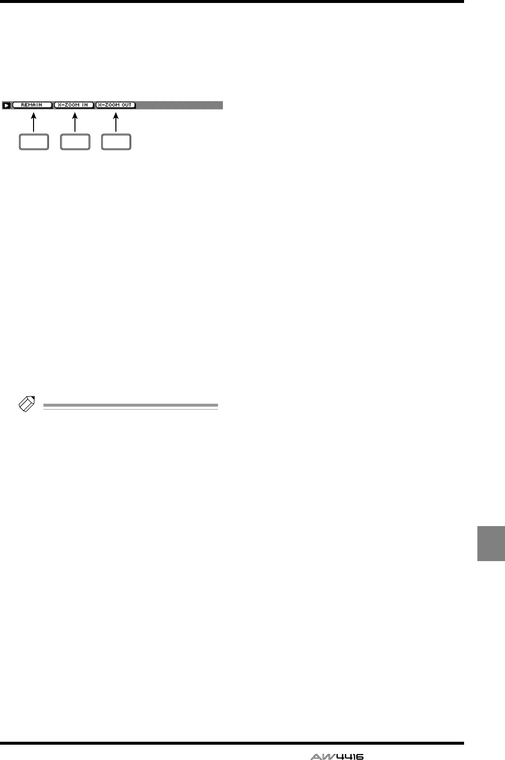
SAMP. PAD screen
— Reference Guide 81
SAMP.
PAD
■Additional functions in the From
Rgn. page
In the From Rgn. page you can press the [SHIFT]
key to assign the following additional functions to
the [F1]–[F3] keys.
• [F1] (REMAIN) key
This causes the counter/level meter and the
counter at the top of the display to show the
remaining time available for recording in the
trigger list. For details on the trigger list, refer to
the explanation for the “SAMP.PAD screen/
Trig.List page” (→ P.88). When you press the
[SHIFT] key + [F1] (REMAIN) key once again,
the usual counter display will reappear.
• [F2] (X-ZOOM IN) key
Each time you press the [SHIFT] key + [F2] (X-
ZOOM IN) key, the track view 7 will zoom-in
horizontally (three stages).
• [F3] (X-ZOOM OUT) key
Each time you press the [SHIFT] key + [F3] (X-
ZOOM OUT) key, the track view 7 will zoom-
out horizontally (three stages).
Tip!
For the procedure of assigning a region to a
pad, refer to Operation Guide “Chapter 12.
Sampling pads.”
F1 F2 F3
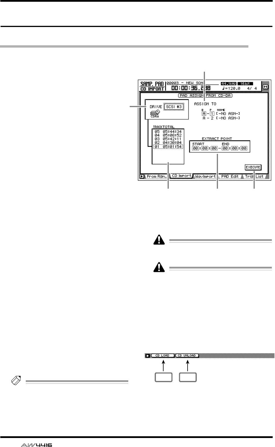
SAMP. PAD screen
82 — Reference Guide
CD Import page
Assign CD-DA to a sampling pad
[Function]
Import CD-DA (CD audio) audio data from
an audio CD/mixed-mode CD-ROM
inserted in an internal or external CD-RW
drive, and assign it to a sampling pad.
[Key operation]
• Sampling pad section [EDIT] pad → [F2]
(CD Import) key
• Repeatedly press the [EDIT] key until the
screen shown at the right appears.
[Mouse operation]
M button → SAMP.PAD EDIT button → CD
Import tab
[Screen functions]
ADRIVE
Move the cursor to this area and rotate the
[DATA/JOG] dial to select the internal or exter-
nal CD-RW drive.
BASSIGN TO
Select the pad to which you wish to assign CD-
DA data. Pads to which no sample has been
assigned will be displayed as “-NO ASN-”.
CTRACK/TOTAL
This is the track list of the audio CD/mixed-
mode CD-ROM inserted in the CD-RW drive.
Move the cursor to this list, and rotate the
[DATA/JOG] dial to select a track. The value at
the right shows the total time of that track.
DEXTRACT POINT
Select the area of the track specified in 3 that
will be assigned to the pad, in units of “min-
utes:seconds:frames (1/75 seconds).”
Move the cursor to this area and use the [DATA/
JOG] dial to specify the START (start point) and
END (end point).
Tip!
Later, you can trim the sample assigned to the
pad to make even finer adjustments. Samples
can be trimmed in the SAMP. PAD screen
PAD Edit page (
→
P.86).
EEXECUTE button
This button executes the sample import opera-
tion.
CD-DA data can be imported only for songs
whose sampling frequency is 44.1 kHz.
Execution of this operation requires a longer
time than the actual time length of the data.
Also, processing cannot be cancelled once
the operation has been executed.
■Additional functions in the CD
Import page
In the CD Import page you can press the [SHIFT]
key to assign the following additional functions to
the [F1]–[F2] keys.
• [F1] (CD LOAD) key
Close the tray of the CD-RW drive.
• [F2] (CD UNLOAD) key
Eject the tray of the CD-RW drive.
2
4
3 5
1
F1 F2
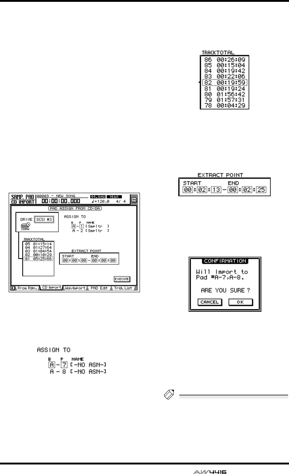
SAMP. PAD screen
— Reference Guide 83
●Assigning CD-DA data to a sam-
pling pad
[Procedure]
1. Access the SAMP. PAD screen CD Import
page, and press [SHIFT] key + [F2] (CD
UNLOAD) key.
The tray of the CD-RW drive will be ejected.
2. Place an audio CD or mixed-mode CD in
the tray, and press the [SHIFT] key + [F1]
(CD LOAD) key.
The tray of the CD-RW drive will close, and the
CD will be inserted.
3. Move the cursor to the DRIVE area, use
the [DATA/JOG] dial to select the SCSI ID
of the CD-RW drive, and press the
[ENTER] key.
The AW4416 will recognize the CD that was
inserted, and a display like the following will
appear.
4. Move the cursor to the ASSIGN TO area,
and use the [DATA/JOG] dial to select the
bank and pad number to which the CD-
DA data will be assigned.
In this page a pair of adjacent odd-numbered →
even-numbered pads of the same bank will be
selected (e.g., A–1/A–2, B–1/B–2) and automati-
cally specified as a pair, and the L/R channels of
the CD-DA data will be assigned to these.
5. Move the cursor to the TRACK/TOTAL
area, and use the [DATA/JOG] dial to
select the track from which you wish to
import.
6. Move the cursor to the EXTRACT POINT
area, and use the [DATA/JOG] dial to spec-
ify START (start point) and END (end
point) to select the area that will be
assigned to the pad.
7. To execute the sample import, move the
cursor to the EXECUTE button and press
the [ENTER] key.
A confirmation message like the following will
appear.
If a message of “Prohibit CD Import” appears
instead of this message, access the UTILITY
screen/Prefer.2 page ([UTILITY] key → [F3] key)
and change the CD/DAT DIGITAL REC button
display to ENABLE.
8. Move the cursor to the OK button and
press the [ENTER] key.
The sample import will be executed.
Tip!
So that the samples assigned to the two pads
will play back in stereo, assign the pad out-
puts to paired channels. (SETUP screen Patch
IN page)
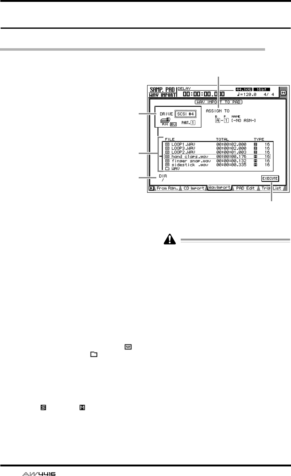
SAMP. PAD screen
84 — Reference Guide
WAV Import page
Assign a WAV file to a sampling pad
[Function]
Import a WAV format audio file from a CD-
ROM or MO disk inserted in the internal
CD-RW drive or an external SCSI device,
and assign it to a sampling pad.
[Key operation]
• Sampling pad section [EDIT] pad → [F3]
(WavImport) key
• Repeatedly press the [EDIT] pad until the
screen shown at the right appears.
[Mouse operation]
M button → SAMP. PAD EDIT button →
WavImport tab
[Screen functions]
ADRIVE
Move the cursor to this area and rotate the
[DATA/JOG] dial to select the internal CD-RW
drive or external SCSI device.
BASSIGN TO
Select the pad to which you wish to assign the
WAV file. Pads to which no sample is assigned
are displayed as “-NO ASN-”.
CFile list
This shows a list of the WAV files on the internal
CD-RW drive or external SCSI device. This list
contains the following information.
●FILE
The file name/directory name is displayed.
icons indicate WAV files, and files indicate
directories.
●TOTAL
The playback time of the WAV file is displayed
in hours/minutes/seconds/milliseconds.
●TYPE
The stereo ( )/monaural ( ) status of the WAV
file and its quantization (word length) is dis-
played.
The AW4416 can recognize only WAV files
that have the same sampling frequency as the
current song which have a filename exten-
sion of “.WAV” following their name. Other
files will not be displayed in the list.
DDIR (directory)
The “/” symbol and the directory name indicate
the directory in which the list shown in 3 is
located. For example this will indicate “/” if you
are in the highest level (root directory), or “/
WAV/” if you are in a directory named WAV
located one level lower.
EEXECUTE button
This button executes the WAV file import.
2
5
1
4
3
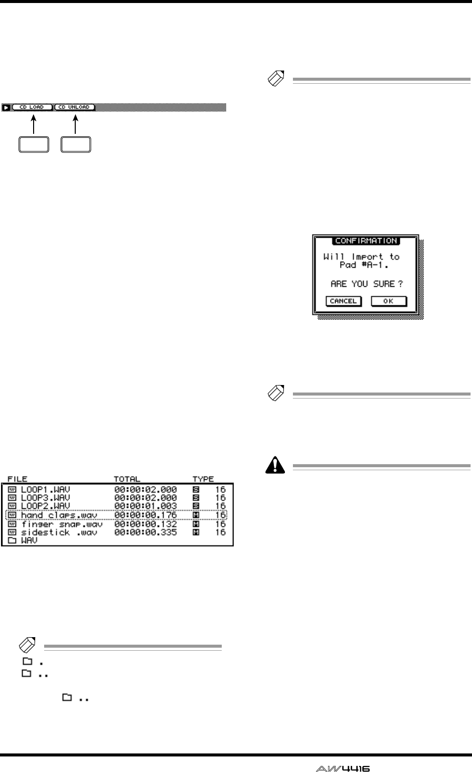
SAMP. PAD screen
— Reference Guide 85
■Additional functions in the Wav
Import page
In the Wav Import page you can press the [SHIFT]
key to assign the following additional functions to
the [F1]–[F2] keys.
• [F1] (CD LOAD) key
Close the tray of the CD-RW drive.
• [F2] (CD UNLOAD) key
Eject the tray of the CD-RW drive.
●Assigning a WAV file to a sam-
pling pad
[Procedure]
1. Insert the media containing the WAV file
into an external SCSI device (e.g., MO
drive) or the internal CD-RW drive.
2. Access the SAMP. PAD screen WavImport
page.
3. Move the cursor to the DRIVE area, use
the [DATA/JOG] dial to select the SCSI ID
of the drive, and press the [ENTER] key.
The AW4416 will recognize the WAV files on
the inserted media (CD-ROM, MO disk etc.),
and will display a list like the following.
4. Move the cursor to the file list, and use
the [DATA/JOG] dial to select the WAV file
that you wish to import.
The file enclosed by the dotted lines in the cen-
ter of the list is selected for the operation.
Tip!
indicates the current directory, and
indicates the directory above. To
return to the next highest directory, move the
cursor to and press the [ENTER] key.
5. Move the cursor to the ASSIGN TO area,
and use the [DATA/JOG] dial to select the
bank and pad number to which the WAV
file will be assigned.
Tip!
If you select a stereo WAV file in step 4, a
pair of adjacent odd-numbered
→
even-num-
bered pads in the same bank will be selected
(e.g., A–1/A–2, B–1/B–2) and automatically
assigned as a pair to the L/R channels of the
WAV file.
6. To execute the sample import, move the
cursor to the EXECUTE button and press
the [ENTER] key.
A popup window will ask you for confirmation.
7. Move the cursor to the OK button and
press the [ENTER] key.
The sample import will be executed.
Tip!
If you want the samples assigned to the two
pads to play back in stereo, assign the pad
outputs to paired channels. (SETUP screen
Patch IN page)
Execution of this operation requires a longer
time than the actual time length of the data.
Also, processing cannot be cancelled once
the operation has been executed.
F1 F2
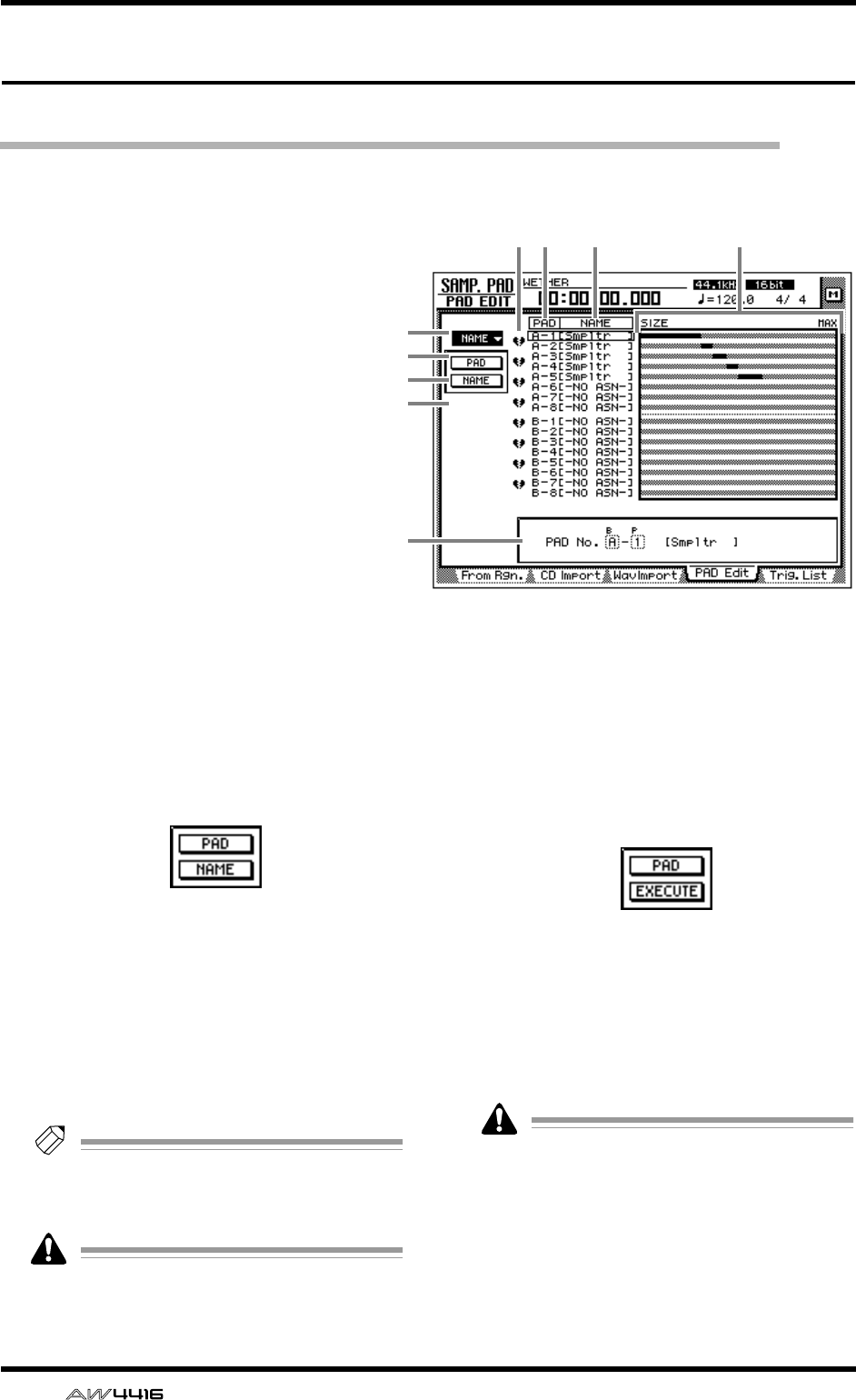
SAMP. PAD screen
86 — Reference Guide
PAD Edit page
Editing a sample pad
[Function]
Assign a name to a sampling pad, erase a
pad, or trim a sample.
[Key operation]
• Sampling pad section [EDIT] pad → [F4]
(PAD Edit) key
• Repeatedly press the [EDIT] pad until the
screen shown at the right appears.
[Mouse operation]
M button → SAMP. PAD EDIT button →
PAD Edit tab
[Screen functions]
ANAME
This menu allows you to assign the desired
name to a pad. When you move the cursor to
this menu and press the [ENTER] key, the fol-
lowing buttons will appear.
These buttons have the following functions.
●PAD
Select the bank/pad number of the pad that you
wish to name.
●NAME
Access the NAME EDIT screen where you can
input a name. You can input a maximum of 8
characters.
Tip!
Immediately after a sample has been
assigned to a pad, a default name of “Smpltr”
will be assigned automatically.
Undo is not possible after the pad name has
been edited.
BERASE
This menu allows you to erase the sample and
name assigned to a pad, and return the pad to
its initial state. When you move the cursor to
this menu and press the [ENTER] key, the fol-
lowing buttons will appear.
These buttons have the following functions.
●PAD
Select the bank/pad number of the pad that you
wish to erase.
●EXECUTE
Execute the pad erase operation.
Undo is not possible after a pad has been
erased.
5 6 7
1
2
3
4
9
8
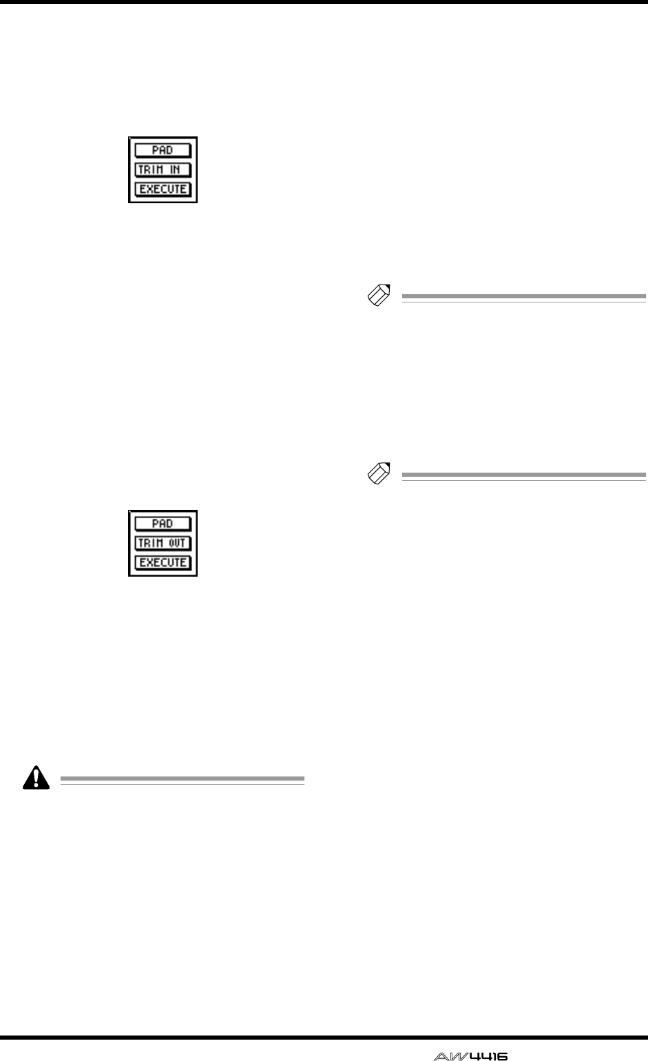
SAMP. PAD screen
— Reference Guide 87
CTRIM IN
This menu allows you to adjust the playback
start location of the sample assigned to a pad.
When you move the cursor to this menu and
press the [ENTER] key, the following buttons
will appear.
These buttons have the following functions.
●PAD
Select the bank/pad number of the pad whose
playback start location you wish to trim.
●TRIM IN
Adjust the amount of trimming in sample units.
●EXECUTE
Execute the trim operation.
DTRIM OUT
This menu allows you to adjust the playback
end location of the sample assigned to a pad.
When you move the cursor to this menu and
press the [ENTER] key, the following buttons
will appear.
These buttons have the following functions.
●PAD
Select the bank/pad number of the pad whose
playback end location you wish to trim.
●TRIM OUT
Adjust the amount of trimming in sample units.
●EXECUTE
Execute the trim operation.
• TRIM IN/TRIM OUT cannot be undone.
• Trimming a sample will not increase the
available memory area.
EPairing
Here you can set or cancel pairing of adjacent
odd-numbered/even-numbered pads. Move the
cursor to the heart symbol and press the
[ENTER] key to connect the heart symbol, pair-
ing the two channels. In this state, pressing
either of the pads will sound both pads simulta-
neously.
FPAD
This column shows the bank and pad number
(A1–A8/B1–B8).
GNAME (pad name)
This column shows the pad name. When a sam-
ple is assigned to a pad, a name of “Smpltr” will
automatically be assigned. Pads to which noth-
ing is assigned will be displayed as “-NO ASN-
”.
HSIZE
This area shows a bar graph that indicates the
length of the sample assigned to each pad. MAX
(at the right edge) is the maximum RAM that
can be assigned to the sampling pad.
Tip!
The maximum total length of sound that can
be assigned to the sampling pads is 90 sec-
onds (for a 44.1 kHz/16 bit song).
IParameter area
In this area you can set the parameters for the
selected menu. When you select a button for
menu 1–4, the corresponding parameter val-
ues will appear here.
Tip!
For examples of editing the sampling pads,
refer to Operation Guide “Chapter 12. Sam-
pling pads.”

SAMP. PAD screen
88 — Reference Guide
Trig. List page
Recording and playing sampling pad operations
[Function]
Use a dedicated “convenience sequencer”
to record and play back pad operations,
and edit the recorded performance.
[Key operation]
• Sampling pad section [EDIT] pad → [F5]
(Trig. List) key
• Repeatedly press the [EDIT] pad until the
screen shown at the right appears.
[Mouse operation]
M button → SAMP. PAD EDIT button →
Trig. List tab
[Screen functions]
ACOPY menu
Using this menu, events recorded in the conve-
nience sequencer can be copied to another
location in the same pad track or to another pad
track. When you move the cursor here and
press the [ENTER] key, the following buttons
will appear.
These buttons have the following functions.
●FR. PAD
Select the copy source pad track.
●FR. START
●FR. END
Specify the beginning (FR. START) and end (FR.
END) of the pad track selected in FR. PAD that
will be the copy source. The specified portion of
the performance will be the copy source pat-
tern.
●TO PAD
Specify the pad track to which you wish to
copy.
●TO START
Specify the location in the pad track selected for
TO PAD at which the data will be copied.
●TIMES
Specify the number of times the data will be
copied. If you specify a multiple number of cop-
ies, the pattern selected as the copy source will
be copied repeatedly.
●INTERVAL
When copying multiple times, this parameter
specifies the interval between copy destination
patterns.
●INSERT
Select whether the pattern will be inserted
(Insert) or overwritten (OverWrite) at the copy
destination. If you select “Insert,” the events fol-
lowing the insert location will be moved toward
the end of the song for the length of the copied
pattern. If you select “OverWrite,” the existing
events will be erased for the length of the cop-
ied pattern.
●EXECUTE
Execute the copy.
3 4 56
1
2
8
7
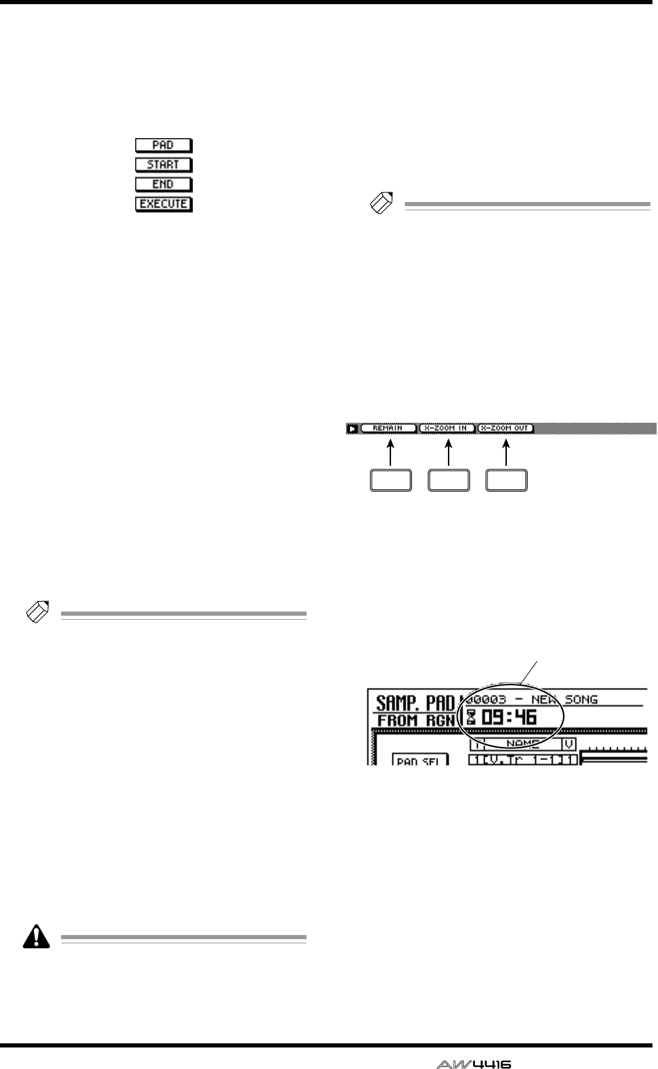
SAMP. PAD screen
— Reference Guide 89
BERASE menu
Using this menu, a specified range of events
recorded in the convenience sequencer can be
erased. When you move the cursor here and
press the [ENTER] key, the following buttons
will appear.
These buttons have the following functions.
●PAD
Select the pad track from which you wish to
erase events.
●START
●END
Specify the beginning (START) and end (END) of
the range that you wish to erase from the pad
track specified by PAD.
●EXECUTE
Execute the erase command.
CPAD
This column shows the pad and pad number
(A1–A8/B1–B8).
DNAME (pad name)
This column shows the name of each pad. Pads
to which nothing has been assigned will be dis-
played as “-NO ASN-”.
Tip!
When you assign a sample to a pad, it will
automatically be given a default name of
“Smpltr”. To edit the name, use the SAMP.
PAD screen PAD Edit page (
→
P.86).
ER (recording) buttons
These buttons enable recording for each pad.
When you move the cursor to a button and
press the [ENTER] key, the O display will
change to ●, and your performance on the pad
can be recorded as events.
FM (mute) buttons
These are mute switches for each pad. When
you move the cursor to a button and press the
[ENTER] key, the O display will change to ●,
and that pad track will no longer be played
back.
If bank A (B) is selected by the BANK pad,
pads 1–8 of bank B (A) will be forcibly
muted. To cancel muting, press the BANK
switch to change banks.
GPad track view
The timing at which trigger events are played
can be recorded separately for each pad on
these tracks. The bar graphs indicate the time
from when a pad was pressed until it was
released.
HParameter area
The parameters required in order to execute the
editing operation can be set in this area.
Tip!
For the procedure of recording or playing
your pad performances, and copying or eras-
ing a recorded performance, refer to Opera-
tion Guide “Chapter 12. Sampling pads.”
■Additional functions in the Trig.
List page
In the Trig. List page you can press the [SHIFT] key
to assign the following additional functions to the
[F1]–[F3] keys.
• [F1] (REMAIN) key
The counter will show the remaining time avail-
able for recording in the trigger list. When you
press the [SHIFT] key + [F1] (REMAIN) key once
again, the usual counter display will reappear.
Remaining time for recording in the trigger list
• [F2] (X-ZOOM IN) key
Each time you press the [SHIFT] key + [F2] (X-
ZOOM IN) key, the pad track view will zoom-in
horizontally (three levels).
• [F3] (X-ZOOM OUT) key
Each time you press the [SHIFT] key + [F3] (X-
ZOOM OUT) key, the pad track view will
zoom-out horizontally (three levels).
F1 F2 F3
Remaining time for recording
in the trigger list
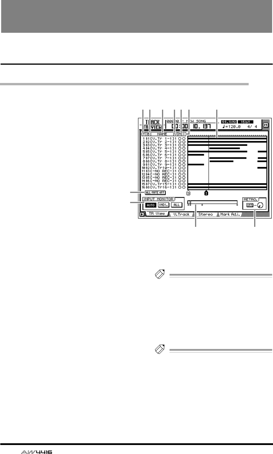
90 — Reference Guide
TRACK screen
TR View page
Viewing the recorded content for each track
[Function]
View a bar graph that shows the regions
recorded on each track, and switch the
input monitor mode or mute on/off for
each track.
[Key operation]
• [TRACK] key → [F1] (TR View) key
• Repeatedly press the [TRACK] key until
the screen shown at the right appears
[Mouse operation]
M button → TRAC button → TR View tab
[Screen functions]
AT (track)
This column shows the track number 1–16.
BB (bus)
This column indicates the type of signal that is
sent to the input (recorder input) of each track
1–16. The abbreviations have the following sig-
nificance.
• B1–B8.................Buses 1–8
• D1–D16..............Direct output of input chan-
nels 1–16
CNAME
This column shows the name of the virtual track
currently selected for each track 1–16. When
you record something on a track, a default
name of “V.Tr x-y” (x=track number 1–16,
y=virtual track number 1–8) will be assigned
automatically. Tracks on which nothing has
been recorded will be displayed as “-NO REC-”.
Tip!
Up to 16 characters can be specified as the
name of a virtual track, but only the first eight
characters will be displayed in this column.
The name can be edited in the EDIT screen
TR Edit page.
DV (virtual track)
This column shows the virtual track number (1–
8) that is selected for each track.
Tip!
Virtual tracks are selected in the TRACK
screen V.Track page.
EM (mute)
In this column you can turn muting on/off for
each track. Move the cursor to the 5 column
and press the [ENTER] key to switch muting on
(●) or off (O) for that track.
12 3 45 6 7
JK
8
9
TRACK screen
— Reference Guide 91
TRACK
• On the AW4416, the number of tracks that
can be played back simultaneously may be
limited according to the quantization (word
bit length) of the song and by the number of
tracks being recorded simultaneously. In this
case, a message of “PLAY TRACK MUTE
ON” will be displayed, and tracks that can-
not be played back will be forcibly muted.
• If you wish to monitor a track that has been
forcibly muted, you must first turn muting on
for other tracks, and then defeat muting for
the desired track. If you simply attempt to
defeat muting without increasing the num-
ber of muted tracks, a message of “CANNOT
CHANGE MUTE” will appear, and muting
cannot be defeated.
• By pressing the [ALL SAFE] key you can can-
cel the record-ready and muted status of all
tracks.
• The mute on/off setting of the tracks does not
affect the [ON] keys of the monitor chan-
nels.
FI (input monitor)
This column indicates the signal that can be
monitored for each track. The track input signal
is being monitored when ● is displayed, and
the track playback signal is being monitored
when O is displayed. The INPUT MONITOR 9
setting, the state of the [REC TRACK SELECT]
key, and the current transport mode will deter-
mine which signal is being monitored for each
track.
GTrack view
The regions (continuous audio data recorded in
a single operation) included in each track are
displayed as bar graphs in this area. The vertical
line in this area indicates the current location.
The symbols displayed at the bottom of the
frame indicate locate points or markers that
have been set in those locations. The following
types of symbols are displayed.
• S.........................Start point
• E.........................End point
• I.........................In point
• O........................Out point
• A........................A point
• B........................B point
• 1–99...................Markers 1–99
HALL MUTE OFF button
This button defeats muting for all tracks.
Tracks that have been forcibly muted due to
limitations on the number of simultaneously
playable tracks cannot be un-muted.
IINPUT MONITOR
Select one of the following three buttons to
select the input mode (monitor source selection)
for each track. The following table shows how
the track monitor signal will change according
to the state of the [REC TRACK SELECT] key and
the transport mode when each mode is
selected.
●When the AUTO button is on (Auto Input
Monitor)
The input mode of all tracks will change auto-
matically depending on the on/off status of the
[REC TRACK SELECT] key. It is not possible to
change 6 input monitor manually.
●When the INDI. button is on (Individual
Input Monitor)
*1. Depends on the 6 input monitor setting.
You can manually change the 6 input monitor
for each track. This is unaffected by the on/off
status of the [REC TRACK SELECT] key.
Even for tracks whose
6
input monitor is set
to the input source (
●
), turning on a [REC
TRACK SELECT] key that had been off will
automatically cause the input source (
●
) to
switch to playback (O).
REC TRACK
SELECT Monitored signal
Stopped Off Silence
On Input source
Playing Off Playback
On Playback
Recording Off Playback
On Input source
REC TRACK
SELECT Monitored signal
Stopped (irrelevant) Input source or
silence (*1)
Playing (irrelevant) Input source or play-
back (*1)
Recording (irrelevant) Input source or play-
back (*1)
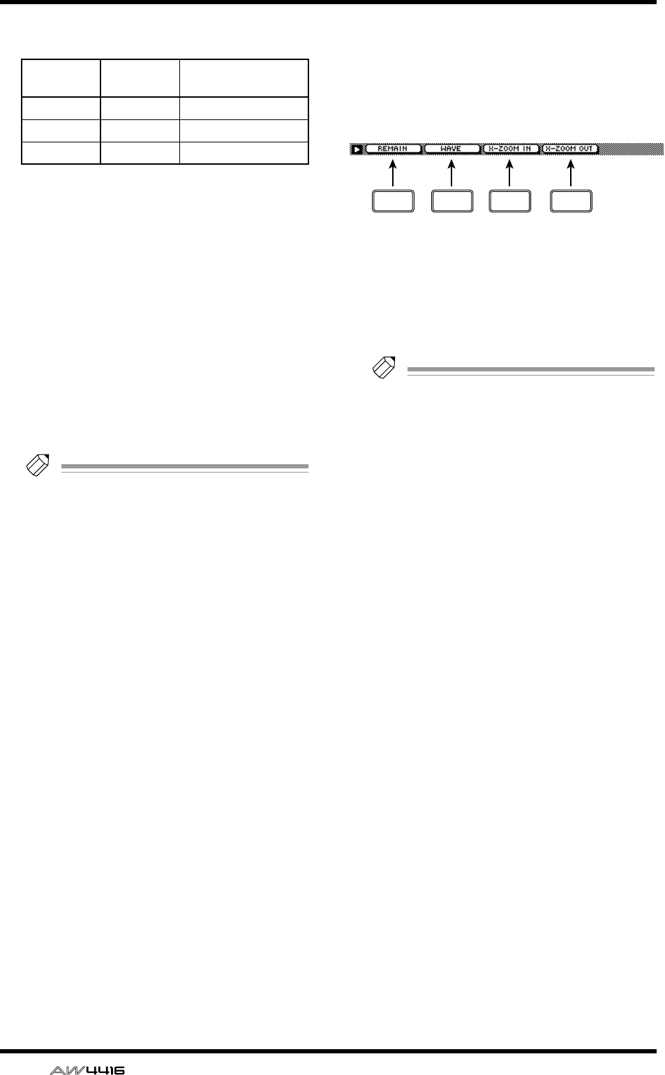
TRACK screen
92 — Reference Guide
●When the ALL button is on (All Input Moni-
tor)
Regardless of the on/off status of the [REC
TRACK SELECT] key, the input source will be
monitored for all tracks. The 6 input monitor
cannot be switched manually.
JCurrent position
The vertical line in the frame shows the approx-
imate current position. The small markers below
the frame show the approximate locations of
each locate point.
KMETRO. (metronome)
Here you can turn the internal metronome on/
off (ON/OFF button) and adjust its volume
(knob). The tempo and time signature of the
metronome are set in the SONG screen Tempo
Map page.
Tip!
• When the AW4416 is in its initial state, the
internal metronome will be output from the
MONITOR OUT jacks mixed with other sig-
nals. However, it is possible to patch the
metronome output signal (MET) to any of the
input channels 1–24. For details refer to
SETUP screen Patch IN page.
• The metronome sound will not be output
while the song is stopped.
■Additional functions in the Track
View page
In the Track View page you can press the [SHIFT]
key to assign the following additional functions to
the [F1]–[F4] keys.
• [F1] (REMAIN) key
The remaining recordable time will be dis-
played in the level meter/counter and in the dis-
play counter area. When you press the [SHIFT]
key + [F1] (REMAIN) key once again, the nor-
mal counter display will reappear.
Tip!
The remaining recordable time will differ
depending on the number of tracks that are
currently in record-ready mode. For example
if you increase the number of tracks in
record-ready mode from one track to two
tracks, the remaining recordable time will be
halved.
• [F2] (WAVE) key
Display the waveform for the audio of a desired
track. This is convenient when you wish to view
the waveform while searching precisely for a
locate point. For the procedure, refer to “View-
ing a waveform for the audio data of a track” in
the section that follows.
• [F3] (X-ZOOM IN) key
Each time you press the [SHIFT] key + [F3] (X-
ZOOM IN) key, the track view 7 will zoom-in
horizontally (three levels).
• [F4] (X-ZOOM OUT) key
Each time you press the [SHIFT] key + [F4] (X-
ZOOM OUT) key, the track view 7 will zoom-
out horizontally (three levels).
REC TRACK
SELECT Monitored signal
Stopped (irrelevant) Input source
Playing (irrelevant) Input source
Recording (irrelevant) Input source
F1 F2 F3 F4
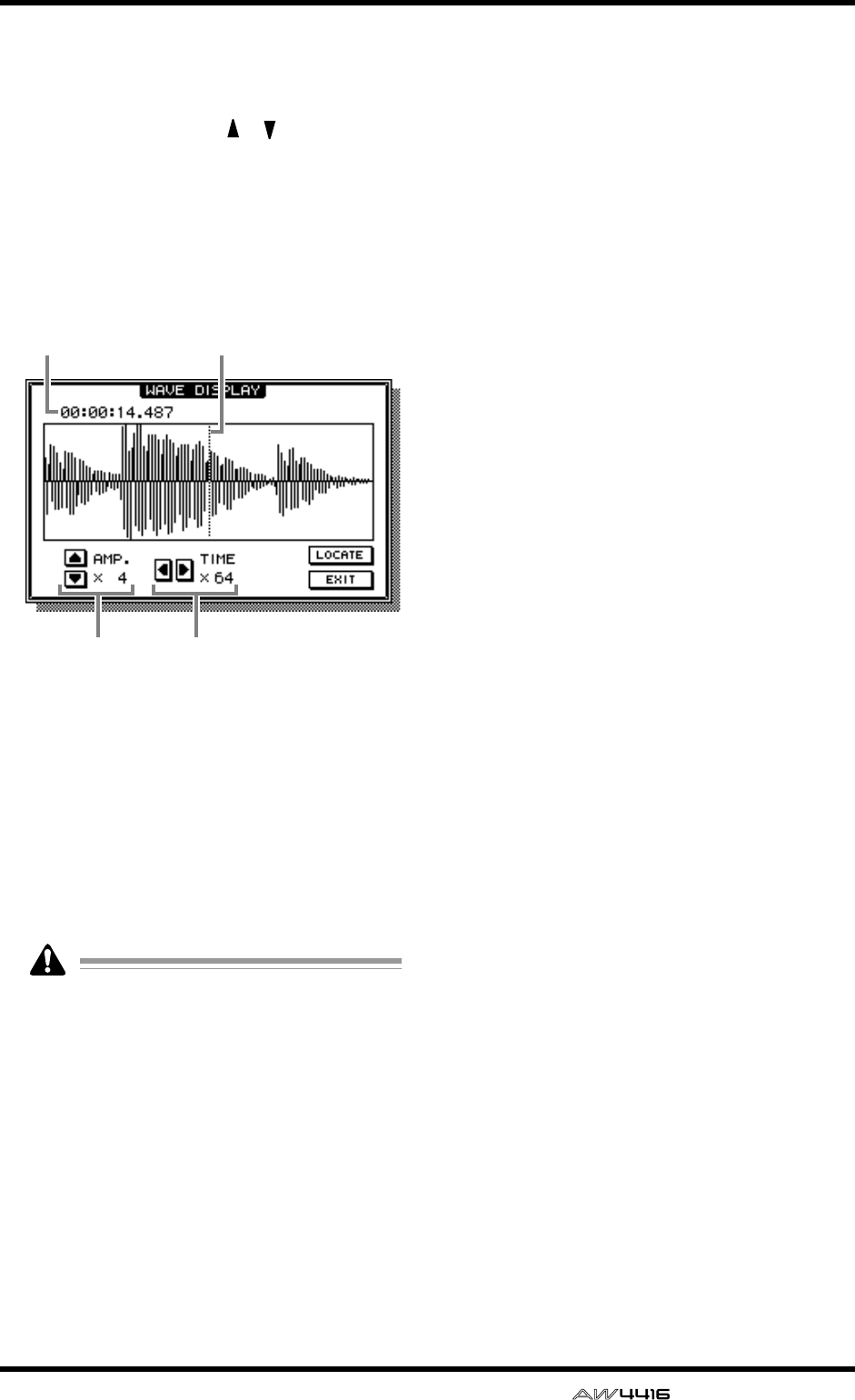
TRACK screen
— Reference Guide 93
■Viewing a waveform for the
audio data of a track
1. Access the TRACK screen TR View page,
and use the CURSOR [ ]/[ ] keys to
select the track whose waveform you wish
to view.
2. While stopped, locate the song to the
place where you wish to view the wave-
form, and press the [SHIFT] key + [F2] key.
The WAVE DISPLAY popup window will
appear.
1Pointer
2Pointer location
3Level magnification (×1–×64) adjustment
4Time axis magnification (×1–×4096) adjust-
ment
3. If you wish to move the pointer location,
rotate the [DATA/JOG] dial.
Rotating the [DATA/JOG] dial toward the right
will move the pointer forward, and rotating it
toward the left will move the pointer backward.
• The keys of the locate/transport section can-
not be used while the waveform is displayed.
• The audio of the corresponding track cannot
be monitored while the [DATA/JOG] dial is
being used to move the pointer.
• This function can be used only while the
song is stopped.
4. If you wish to locate the song to the
pointer position, move the cursor to the
LOCATE button and press the [ENTER]
key.
The WAVE DISPLAY popup window will close,
and the song will locate to the location of the
pointer.
5. If you wish to close the WAVE DISPLAY
popup window without locating, move
the cursor to the EXIT button and press
the [ENTER] key.
12
3 4
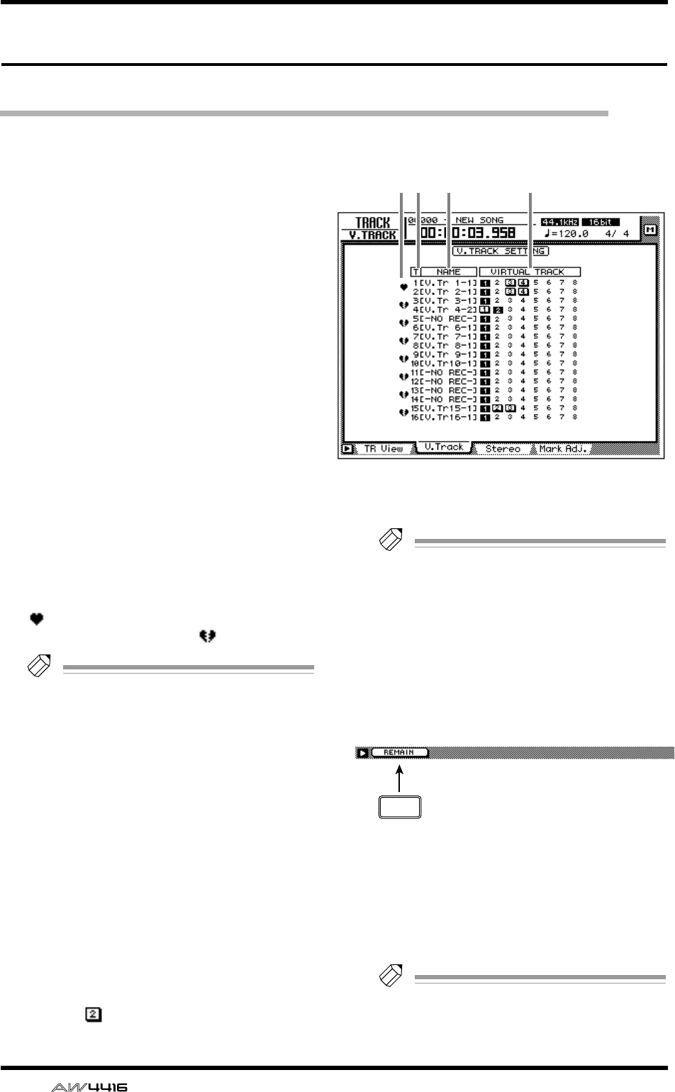
TRACK screen
94 — Reference Guide
V. Track page
Switching virtual tracks
[Function]
Switch the virtual track number assigned to
each track 1–16, and set/cancel pairing
between tracks.
[Key operation]
• [TRACK] key → [F2] (V. Track) key
• Repeatedly press the [TRACK] key until
the screen shown at the right appears.
[Mouse operation]
M button → TRAC button → V.Track tab
[Screen functions]
APairing
By moving the cursor to this area and pressing
the [ENTER] key, you can pair (or cancel pairing
for) two adjacent odd-numbered → even-num-
bered tracks. Paired tracks are indicated by a
“ ” symbol, and tracks for which pairing is
defeated are indicated by a “ ” symbol.
Tip!
• Paired tracks will be linked when you switch
virtual tracks, or when you select them for
track editing.
• Track pairing does not affect pairing of mon-
itor channels.
BT (track)
These are the track numbers 1–16.
CNAME
This column shows the name of the virtual track
that is currently selected for each track 1–16.
DVIRTUAL TRACK
Move the cursor to this column and press the
[ENTER] key to select the virtual track number
used by each track 1–16. The currently selected
virtual track number will be highlighted. Of the
virtual track numbers that are not currently
selected, tracks that have been recorded are dis-
played as .
Tip!
For details on operating virtual tracks, refer to
Operation Guide “Chapter 9. Track and vir-
tual track operations.”
■Additional functions in the V.
Track page
In the V. Track page you can press the [SHIFT]
key to assign the following additional function
to [F1].
• [F1] (REMAIN) key
The remaining recordable time will appear in
the level meter/counter and in the counter area
of the display. When you press the [SHIFT] key
+ [F1] (REMAIN) key once again, the normal
display will reappear.
Tip!
The remaining recordable time will depend
on the number of tracks that is currently in
record-ready mode.
12 3 4
F1
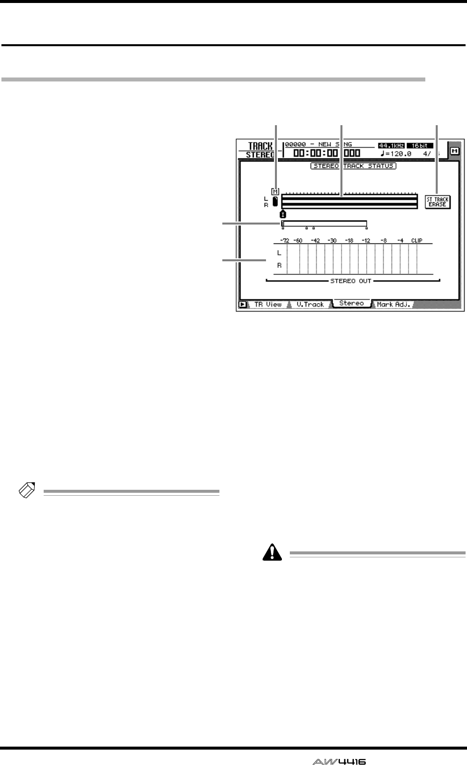
TRACK screen
— Reference Guide 95
Stereo page
Playing or erasing the stereo track
[Function]
Play back the stereo track, or erase the
recorded contents.
[Key operation]
• [TRACK] key → [F3] (Stereo) key
• Repeatedly press the [TRACK] key until
the screen shown at the right appears.
[Mouse operation]
M button → TRAC button → Stereo tab
[Screen functions]
AM (mute) button
Use this button to switch muting on (●) or off
(O) for the stereo track. When muting is off, the
output of the stereo track will be assigned to
monitor channels 1/2. (Normally muting is on.)
When you play back the song in this state, the
stereo track can be monitored via monitor chan-
nels 1/2 → stereo bus. (At this time, tracks 1–16
will be forcibly muted.) When you turn muting
on for the stereo track, tracks 1–16 will return to
their previous status.
Tip!
For details on recording/playing the stereo
track, refer to Operation Guide “Chapter 5.
Recording on the AW4416.”
BTrack view
Continuous audio data in the stereo track is dis-
played as a bar graph. The symbols displayed
below the track view indicate locate points and
markers at those locations. The following types
of symbols are displayed.
• S.........................Start point
• E.........................End point
• I.........................In point
• O........................Out point
• A........................A point
• B........................B point
• 1–99...................Markers 1–99
CCurrent position
The vertical line in the frame indicates the
approximate current position. The small sym-
bols beneath the frame indicates the approxi-
mate location of the locate points.
DSTEREO OUT
This meter indicates the output level of the ste-
reo output channel. The pre/post-fader position
can be selected in the HOME screen Omni/ST
page.
EST TRACK ERASE (stereo track erase)
button
If you move the cursor to this button and press
the [ENTER] key, the recorded contents of the
stereo track will be erased.
The stereo track is an L/R pair and has only
one region. If you re-record a previous
recording on the stereo track, the previously-
recorded content will be erased. (However,
you can use the [UNDO] key to return to the
previous state.)
1 52
3
4
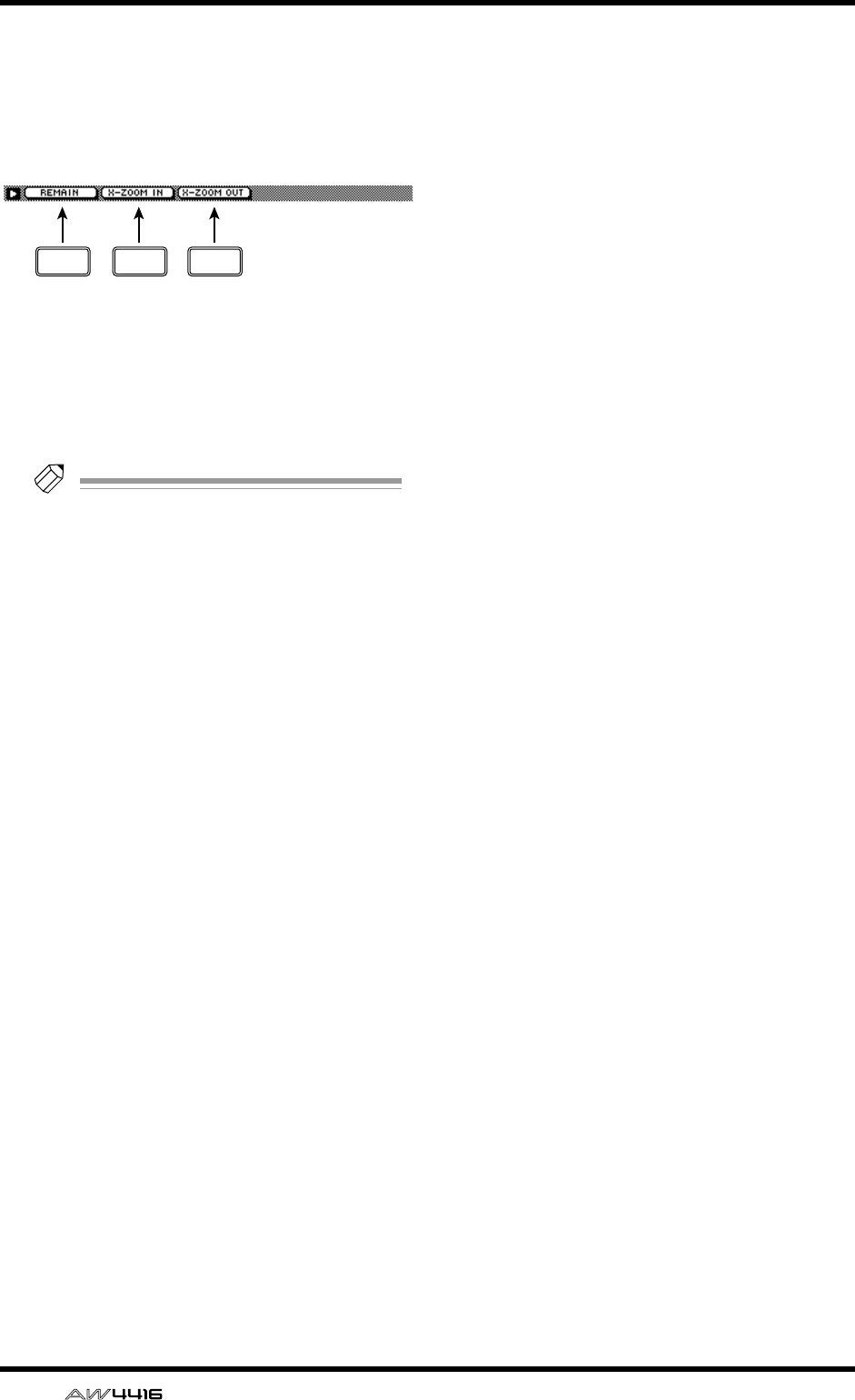
TRACK screen
96 — Reference Guide
■Additional functions in the Stereo
page
In the Stereo page you can press the [SHIFT] key to
assign the following additional functions to the
[F1]–[F3] keys.
• [F1] (REMAIN) key
The level meter/counter and the counter area of
the display will show the remaining time avail-
able for recording. When you press the [SHIFT]
key + [F1] (REMAIN) key once again, the usual
counter display will reappear.
Tip!
The remaining time available for recording
will depend on the number of tracks that are
currently in record-ready mode.
• [F2] (X-ZOOM IN) key
Each time you press the [SHIFT] key + [F2] (X-
ZOOM IN) key, the track view 2 will zoom-in
horizontally in three levels.
• [F3] (X-ZOOM OUT) key
Each time you press the [SHIFT] key + [F3] (X-
ZOOM OUT) key, the track view 2 will zoom-
out horizontally in three levels.
F1 F2 F3
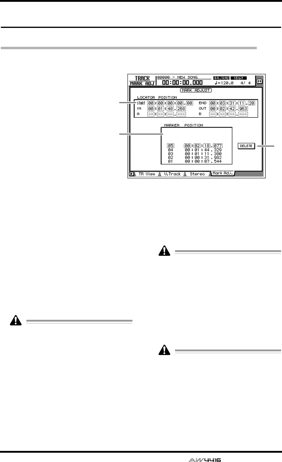
TRACK screen
— Reference Guide 97
Mark Adj. page
Adjust or erase locate points or markers
[Function]
Adjust the position of markers or
locate points such as the IN/OUT
points, or erase locate points or
markers.
[Key operation]
• [TRACK] key → [F4] (Mark Adj.)
key
• Repeatedly press the [TRACK] key
until the screen shown at the right
appears.
[Mouse operation]
M button → TRAC button → Mark
Adj. tab
[Screen functions]
ALOCATOR POSITION
Display the positions of the various locate
points listed below. The position of an existing
locate point can be adjusted by moving the cur-
sor to the desired numerical box and rotating
the [DATA/JOG] dial. Locate points that have
not been set are displayed as “–”.
●START/END (start point/end point)
These locate points normally correspond with
the beginning and end of the song. When you
create a new song, the Start point will be ini-
tially set to absolute time 00:00:00.000. When
you record the song, the end of the song will
automatically be set as the End point.
• The start/end points are always displayed as
time code, regardless of the counter display
method selected in the SONG screen/Setting
page.
• If measure display is selected in the SONG
screen/Setting page, only beats will be dis-
played for a location earlier than the start
point.
●IN/OUT (in point/out point)
These locate points can be used as the punch-
in/out points. The in/out points are automati-
cally set at the beginning and end of the area
that was last-recorded, and can also be set indi-
vidually by using the [SET] key + [IN] key or
[SET] key + [OUT] key.
●A/B (A point/B point)
These locate points can be used as the area for
A-B repeat playback. These points can be set
individually by using the [SET] key + [A] key or
[SET] key + [B] key.
The units used for the in/out points and the A/
B points will depend on the counter display
method (time/time code/measure). If measure
display is selected, “beat” will be the smallest
unit by which a locate point can be adjusted.
BMarker
This area displays a list of markers 1–99. Move
the cursor to the MARKER column and select
the marker number. Then move the cursor to the
POSITION column and adjust the position of
the corresponding marker.
• When adjusting the position of a marker, it is
not possible to move a marker beyond the
preceding or following marker.
• Marker numbers are automatically assigned
in sequence from the beginning of the song.
If you delete a marker, the marker numbers
will be re-assigned appropriately.
1
3
2
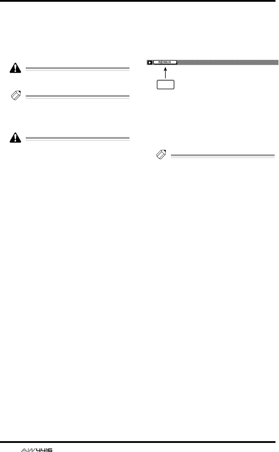
TRACK screen
98 — Reference Guide
CDELETE button (valid only when using
the mouse)
This button deletes a previously-set locate point
or marker. In this page, you can delete the
locate point or marker simply by moving the
cursor to it and pressing the [ENTER] key (or
using the mouse to click the DELETE button).
The start point and end point cannot be
deleted.
Tip!
For details on setting the various locate points
or modifying a locate point, refer to Opera-
tion Guide “Chapter 6. Transport/locate oper-
ations.”
Be aware that locate points or markers you
delete cannot be recovered.
■Additional functions in the Mark
Adj. page
In the Mark Adj. page, you can press the [SHIFT]
key to assign the following additional function to
the [F1] key.
• [F1] (REMAIN) key
The level meter/counter and the counter area of
the display will show the remaining time avail-
able for recording. When you press the [SHIFT]
key + [F1] (REMAIN) key once again, the usual
counter display will reappear.
Tip!
The remaining time available for recording
will depend on the number of tracks that are
currently in record-ready mode.
F1
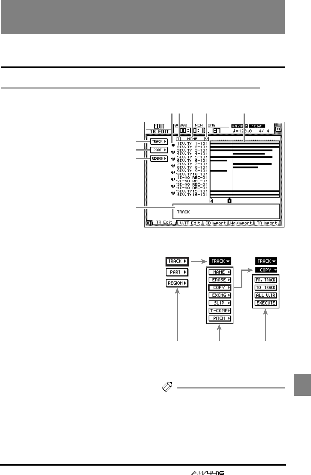
— Reference Guide 99
EDIT
EDIT screen
TR Edit page
Edit tracks
[Function]
Assign a name to each track, and edit
audio data by tracks, parts, or regions.
[Key operation]
• RECORDER [EDIT] key → [F1] (TR Edit)
key
• Repeatedly press the RECORDER
[EDIT] key until the screen shown at
the right appears.
[Mouse operation]
M button → RECORDER EDIT button →
TR Edit tab
[Screen functions]
ATRACK menu
BPART menu
CREGION menu
Select one of the following three units of data
that you wish to edit.
●Track
Edit the audio data of the entire currently
selected track (1–16).
●Part
Within the currently selected track, edit the
specified area of audio data.
●Region
Edit a piece of continuous audio data that was
recorded in a single operation.
When you move the cursor to the desired menu
and press the [ENTER] key, a list of buttons will
appear, allowing you to select an editing com-
mand (center column in the illustration at right).
When you then move the cursor to the desired
command and press the [ENTER] key, a list of
buttons for setting the parameters of that com-
mand will appear (right column in the illustra-
tion at right).
For details on the commands and parameters
that can be selected from the TRACK/PART/
REGION menus, refer to page 101.
Tip!
If you move the cursor to the command
whose button is highlighted and press the
[ENTER] key, you will return to the command
list. If you move the cursor to the menu high-
lighted at the top of the list and press the
[ENTER] key, you will return to the first
menu.
4
1
2
3
8
5 6 7 9
Menus Commands Parameters
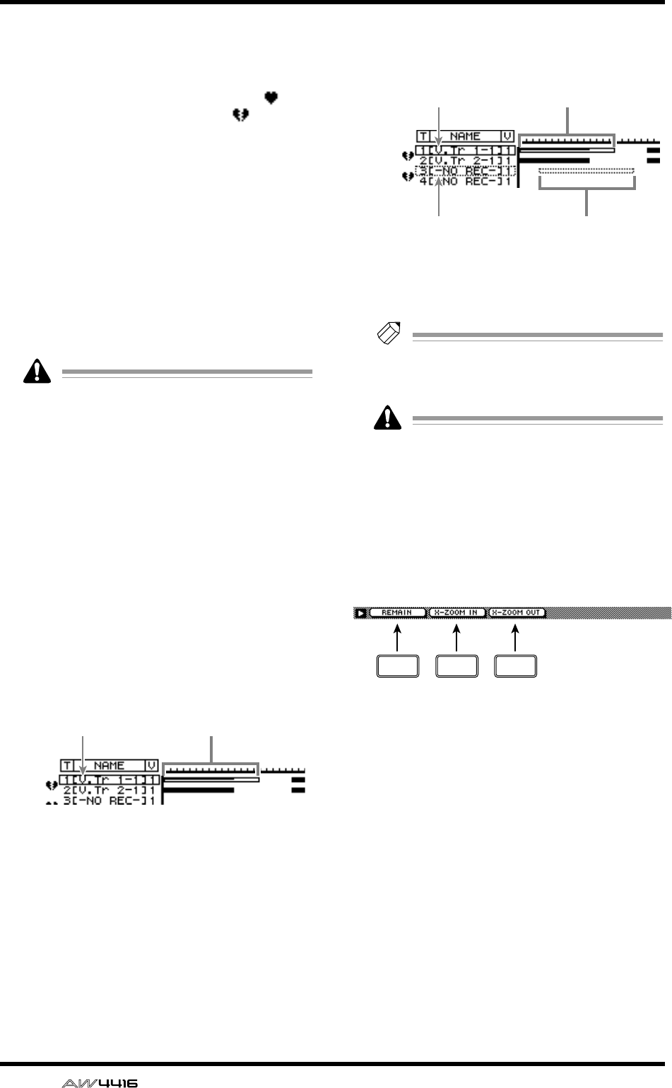
EDIT screen
100 — Reference Guide
DPairing
By moving the cursor to this column and press-
ing the [ENTER] key, you can set/defeat pairing
for adjacent odd-numbered → even-numbered
tracks. Paired tracks are indicated by a “ ”
symbol, and unpaired tracks by a “ ” symbol.
When editing tracks or parts, both tracks of a
pair will be selected for editing.
ET (track)
This column shows the track numbers 1–16.
FNAME
This column shows the name of the virtual track
currently selected for each track 1–16. Tracks
that have already been recorded are assigned a
default name of “V. Tr x-y” (x=track number 1–
16, y=virtual track number 1–8). Tracks in
which nothing has been recorded will be dis-
played as “-NO REC-”.
A name of up to 16 characters can be
assigned to a virtual track, but this column
will show only the first eight characters.
GV (virtual track)
This shows the virtual track number (1–8) that is
currently selected for each track 1–16. Virtual
track numbers can be changed in the TRACK
screen V. Track page.
HTrack view
In this area, the regions included in each track
are displayed as a bar graph. The vertical line in
the track view area indicates the location at
which the area for editing has been set. The
symbols displayed at the bottom of the track
view area indicate locate points and markers.
While editing, the track and area selected for
editing will be displayed as follows.
When selecting the edit source and edit destina-
tion tracks, as when copying or moving audio
data, the display will be as follows.
IParameter settings
In this area you can set the necessary parame-
ters for executing the edit command.
Tip!
For the track editing procedure, refer to
Operation Guide “Chapter 9. Track/virtual
track operations.”
The keys of the transport section will have no
effect while the TR Edit page is displayed.
■Additional functions in the TR
Edit page
In the TR Edit page you can press the [SHIFT] key to
assign the following additional functions to the
[F1]–[F3] keys.
• [F1] (REMAIN) key
The level meter/counter and the counter area of
the display will show the remaining time avail-
able for recording. When you press the [SHIFT]
key + [F1] (REMAIN) key once again, the usual
counter display will reappear.
• [F2] (X-ZOOM IN) key
Each time you press the [SHIFT] key + [F2] (X-
ZOOM IN) key, the track view 8 will zoom-in
on the time axis in three levels.
• [F3] (X-ZOOM OUT) key
Each time you press the [SHIFT] key + [F3] (X-
ZOOM OUT) key, the track view 8 will zoom-
out on the time axis in three levels.
Track to be edited Edited area
Edit source track
Edit destination track
Edit source area
Edit destination area
F1 F2 F3

EDIT screen
— Reference Guide 101
■TRACK menu commands and
parameters
The TRACK menu allows you to select a track (or
virtual track) and edit all of the audio data of the
track together.
In the TRACK menu, tracks containing no
audio data cannot be selected for editing.
The commands that can be selected in the TRACK
menu and their parameters are listed below.
●NAME (track name)
Edit the name of an already-recorded track.
• TRACK
Select the track whose name you wish to edit.
• NAME
Access the NAME EDIT popup window, and
input the new name. Move the cursor to the OK
button of the NAME EDIT popup window, and
press the [ENTER] key to finalize the new name.
●ERASE
Erase the audio data of a track. When you exe-
cute the Erase command, the track name will
return to the “-NO REC-” display.
• TRACK
Select the track that you wish to erase. For the
Erase command, you can specify all tracks as
the subject of the operation. To do so, rotate the
[DATA/JOG] dial all the way clockwise when
setting the TRACK parameter, to make the selec-
tion read “AL-C” (ALL-CURRENT). With this set-
ting, all virtual tracks currently selected for
tracks 1–16 will be selected for the operation.
• ALL V.TR (all virtual tracks)
Select whether all virtual tracks included in the
corresponding track(s) will be erased (YES) or
whether only the currently selected virtual track
will be erased (NO).
• EXECUTE
Execute the command.
●COPY
Copy the audio data of a track to another track.
• FR.TRACK (from track)
Select the copy source track.
• TO TRACK
Select the copy destination track.
• ALL V.TR (all virtual tracks)
Select whether all virtual tracks included in the
corresponding track(s) will be copied (YES) or
whether only the currently selected virtual track
will be copied (NO).
• EXECUTE
Execute the command.
Tip!
If you selected one track of a pair of tracks as
the copy destination, the same content will
be copied to both of the paired tracks.
●EXCHG (exchange)
Exchange the audio data of two tracks.
• FR. TRACK (from track)
• TO TRACK
Select the two tracks that will be exchanged. For
TO TRACK, it is also possible to select an unre-
corded track.
• ALL V.TR (all virtual tracks)
Select whether all virtual tracks included in the
two tracks will be exchanged (YES) or whether
only the currently selected virtual tracks will be
exchanged (NO).
• EXECUTE
Execute the command.
●SLIP
Shift the audio data of the entire track forward
or backward.
• TRACK
Select the track that you wish to shift forward or
backward. For the Slip command, you can spec-
ify all tracks as the subject of the operation. To
do so, rotate the [DATA/JOG] dial all the way
clockwise when setting the TRACK parameter,
to make the selection read “AL-C” (ALL-CUR-
RENT). With this setting, all virtual tracks cur-
rently selected for tracks 1–16 will be selected
for the operation.
• ALL V.TR (all virtual tracks)
Select whether all virtual tracks included in the
corresponding track(s) will be moved (YES) or
whether only the currently selected virtual track
will be moved (NO).
• SLIP
Specify the time by which the data will be
shifted (range: maximum of ±5 hours).
• EXECUTE
Execute the command.
●T-COMP (time compression/expansion)
Compress or expand the length of the track in a
range of 50%–200% without affecting the pitch.
After this command is executed, all regions
included in the track will be combined into a
single region.
• TRACK
Select the track that you wish to compress or
expand.
• RATIO
Specify the compression/expansion ratio in
units of 0.01% (range: 50–200%).
• EXECUTE
Execute the command.
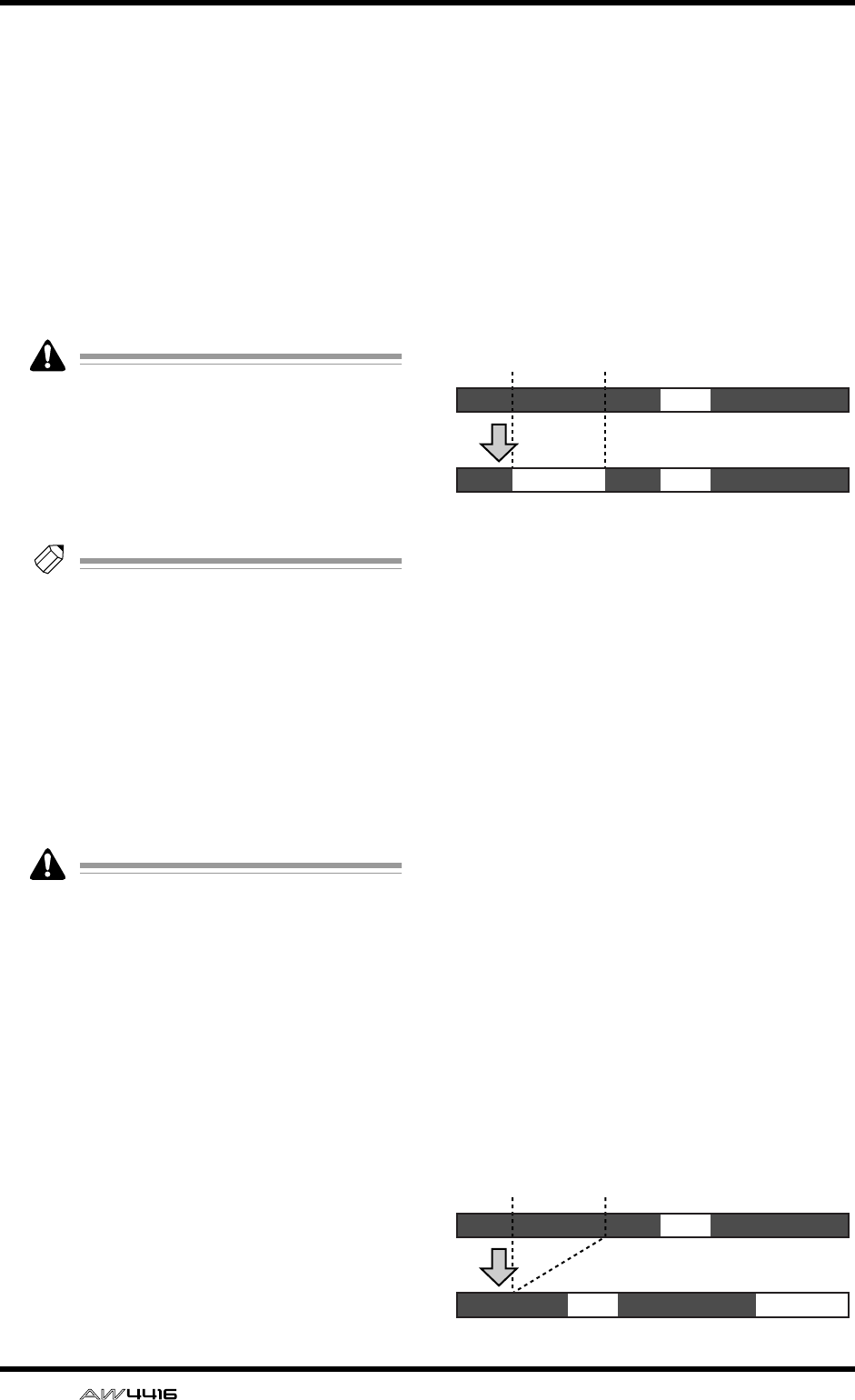
EDIT screen
102 — Reference Guide
●PITCH (pitch change)
Modify the pitch of the entire track without
changing the length of the audio. After this
command is executed, all regions included in
the track will be combined into a single region.
• TRACK
Select the track whose pitch you wish to modify.
• PITCH
Adjust the amount of pitch change in semitone
units (range: ±12 semitones).
• FINE
Adjust the amount of pitch change in one-cent
units (range: ±50 cents).
Executing the T-COMP or PITCH commands
will require more processing time than the
actual length of the audio. Also, it is not pos-
sible to cancel the command after it has been
executed.
• EXECUTE
Execute the command.
Tip!
Immediately after executing an editing com-
mand of the TRACK menu (except for the
NAME command), you can press the
[UNDO] key to return the data to its previous
condition.
■PART menu commands and
parameters
The PART menu allows you to specify an area
(“part”) of the selected track, and execute an edit-
ing command.
An area that contains no audio data cannot
be specified as a part.
The commands that can be selected in the PART
menu and their parameters are listed below.
●ERASE
Erase the audio data from the selected part. If all
audio data in a track is erased, the track name
will return to the “-NO REC-” display.
• TRACK
Select the track from which you wish to erase
data. For the Erase command, you can specify
all tracks as the subject of the operation. To do
so, rotate the [DATA/JOG] dial all the way
clockwise when setting the TRACK parameter,
to make the selection read “AL-C” (ALL-CUR-
RENT). With this setting, the START→END por-
tion of the virtual tracks currently selected for
tracks 1–16 will be selected for the operation.
• ALL V.TR (all virtual tracks)
Select whether data will be erased from all vir-
tual tracks included in the selected track(s) (YES)
or only from the currently selected virtual track
(NO).
•START
Specify the starting location of the part to be
erased.
• END
Specify the ending location of the part to be
erased.
• EXECUTE
Execute the command.
●DELETE
Delete the audio data from the selected part.
Subsequent audio data will be moved forward
by the length of the deleted part.
• TRACK
Select the track from which you wish to delete
data. For the Delete command, you can specify
all tracks as the subject of the operation. To do
so, rotate the [DATA/JOG] dial all the way
clockwise when setting the TRACK parameter,
to make the selection read “AL-C” (ALL-CUR-
RENT). With this setting, the START→END range
of the virtual tracks currently selected for tracks
1–16 will be selected for the operation.
• ALL V.TR (all virtual tracks)
Select whether data will be deleted from all vir-
tual tracks included in the selected track(s) (YES)
or only from the currently selected virtual track
(NO).
•START
Specify the starting location of the part to be
deleted.
• END
Specify the ending location of the part to be
deleted.
• EXECUTE
Execute the command.
AB
ABA’
START END
ERASE
AB
A’ B
START END
DELETE
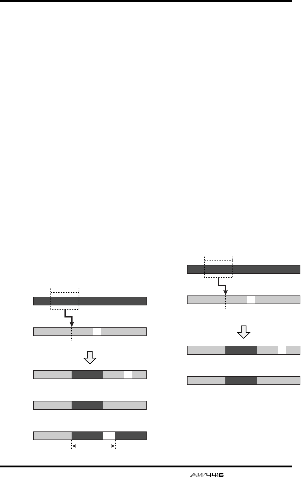
EDIT screen
— Reference Guide 103
●COPY
Copy the audio data of the selected part to the
specified location of the specified track.
• FR. TRACK (from track)
Select the copy source track.
• FR. START (from start)
Specify the starting location of the copy source
part.
• FR. END (from end)
Specify the ending location of the copy source
part.
• ALL V.TR (all virtual tracks)
Select whether all virtual tracks included in the
corresponding track(s) will be copied (YES) or
whether only the currently selected virtual track
will be copied (NO).
• TO TRACK
Select the copy destination track.
• TO START
Specify the starting location of the copy destina-
tion.
• TIMES
Specify the number of times (1–99) that the data
will be copied.
• INTERVAL
When copying multiple times, specify the spac-
ing of the copy destination starting locations.
• INSERT
Specify whether the copied audio data will be
inserted (Insert) or overwritten (OverWrite) in
the copy destination track.
• EXECUTE
Execute the command.
●MOVE
Move the audio data of the selected part to the
specified location of the specified track. At this
time, the move source audio data will be
erased.
• FR. TRACK (from track)
Select the move source track.
• FR. START (from start)
Specify the starting location of the move source
part.
• FR. END (from end)
Specify the ending location of the move source
part.
• ALL V.TR (all virtual tracks)
Select whether all virtual tracks included in the
corresponding track(s) will be moved (YES) or
whether only the currently selected virtual track
will be moved (NO).
• TO TRACK
Select the move destination track.
• TO START
Specify the starting location of the move desti-
nation.
• INSERT
Specify whether the moved audio data will be
inserted (Insert) or overwritten (OverWrite) in
the move destination track.
• EXECUTE
Execute the command.
FR.START
TO START
FR.END
COPY
COPY
INSERT= Insert
Copy
source
track
(FR. TRACK)
Copy
destination
track
(TO TRACK)
Copy
destination
track after
execution
Copy
destination
track after
execution
Copy
destination
track after
execution
A
BC
BBC
A’
INSERT= OverWrite
BC
A’
TIMES= 2 INTERVAL
BA’ A’
FR.START
TO START
FR.END
MOVE
INSERT= Insert
Move
source
track
(FR. TRACK)
Move
destination
track
(TO TRACK)
A
BC
BBC
A’
INSERT= OverWrite
BC
A’
MOVE
Move
destination
track after
execution
Move
destination
track after
execution
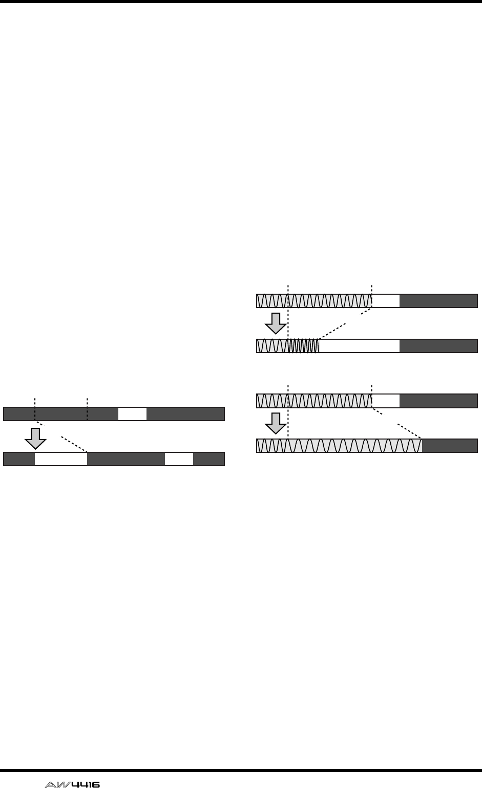
EDIT screen
104 — Reference Guide
●INSERT
Insert a length of silence into the selected part.
Subsequent audio data will be moved backward
by the length of the inserted silence.
• TRACK
Select the track into which you wish to insert
silence. For the Insert command, you can spec-
ify all tracks as the subject of the operation. To
do so, rotate the [DATA/JOG] dial all the way
clockwise when setting the TRACK parameter,
to make the selection read “AL-C” (ALL-CUR-
RENT). With this setting, the START→END por-
tion of the virtual tracks currently selected for
tracks 1–16 will be selected for the operation.
•START
Specify the starting location of the part into
which silence will be inserted.
• END
Specify the ending location of the part into
which silence will be inserted.
• ALL V.TR (all virtual tracks)
Select whether silence will be inserted into all
virtual tracks included in the selected track(s)
(YES) or only into the currently selected virtual
track (NO).
• EXECUTE
Execute the command.
●T-COMP (time compression/expansion)
Compress or expand the length of the selected
part in a range of 50%–200% without affecting
the pitch.
• TRACK
Select the track that you wish to compress/
expand.
•START
Specify the starting location of the part that you
wish to compress/expand.
• END
Specify the ending location of the part that you
wish to compress/expand.
• RATIO
Specify the compression/expansion ratio in
units of 0.01% (range: 50–200%).
• EXECUTE
Execute the command.
AB
AA’
START END
B
INSERT
START END
START END
T-COMP (time compression)
(50%)
T-COMP (time expansion)
(150%)
EDIT screen
— Reference Guide 105
●PITCH (pitch change)
Modify the pitch of the selected part without
changing the length of the audio.
• TRACK
Select the track whose pitch you wish to modify.
•START
Specify the starting location of the part whose
pitch you wish to modify.
• END
Specify the ending location of the part whose
pitch you wish to modify.
• PITCH
Adjust the amount of pitch change in semitone
units (range: ±12 semitones).
• FINE
Adjust the amount of pitch change in one-cent
units (range: ±50 cents).
• EXECUTE
Execute the command.
Tip!
Immediately after executing any editing com-
mand of the PART menu you can press the
[UNDO] key to return the data to its previous
condition.
Executing the T-COMP or PITCH commands
will require more processing time than the
actual length of the audio. Also, it is not pos-
sible to cancel the command after it has been
executed.
■REGION menu commands and
parameters
In the REGION menu you can specify a region (a
continuous piece of audio data that was recorded
in a single operation) in the selected track, and exe-
cute an editing command.
Tip!
For the commands of the REGION menu, it is
not possible to select only part of the region
for editing. If you wish to do this, you must
either use the PART menu, or use the DIVIDE
command to divide the region.
The commands that can be selected in the REGION
menu and their parameters are listed below.
●NAME
Modify the name of a region.
• REGION
Select the region whose name you wish to mod-
ify.
• NAME
Access the NAME EDIT popup window, and
input the new name. Move the cursor to the OK
button of the NAME EDIT popup window, and
press the [ENTER] key to finalize the new name.
●ERASE
Erase the selected region. If all regions are
erased from a track, the track name will return
to the “-NO REC-” display.
• REGION
Select the region that will be erased.
• EXECUTE
Execute the command.
●DELETE
Delete the selected region. Subsequent audio
data will be moved forward by the length of the
deleted region.
• REGION
Select the region that will be deleted.
• EXECUTE
Execute the command.
●COPY
Copy the selected region to the specified loca-
tion of the specified track.
• REGION
Select the region that you wish to copy.
• TO TRACK
Select the copy destination track.
• TO START
Specify the starting location of the copy destina-
tion.
• TIMES
Specify the number of times (1–99) that the data
will be copied.
• INTERVAL
When copying multiple times, specify the spac-
ing of the copy destination starting locations.
• INSERT
Specify whether the copied data will be inserted
(Insert) or overwritten (OverWrite) in the copy
destination track.
• EXECUTE
Execute the command.
●MOVE
Move the selected region to the specified loca-
tion of the specified track. At this time, the
move source region will be erased.
• REGION
Select the region that you wish to move.
• TO TRACK
Select the move destination track.
• TO START
Specify the starting location of the move desti-
nation.

EDIT screen
106 — Reference Guide
• INSERT
Specify whether the moved audio data will be
inserted (Insert) or overwritten (OverWrite) in
the move destination track.
• EXECUTE
Execute the command.
●DIVIDE
Divide the selected region into two regions at
the specified point.
• REGION
Select the region that you wish to divide.
• DIVIDE
Specify the location at which the region will be
divided.
• EXECUTE
Execute the command.
●TRIM IN
Trim the starting location of the selected region
toward the end of the song in units of a sample.
• REGION
Select the region that you wish to trim.
• TRIM IN
Specify the amount of trimming in units of a
sample.
• EXECUTE
Execute the command.
●TRIM OUT
Trim the ending location of the selected region
toward the beginning of the song in units of a
sample.
• REGION
Select the region that you wish to trim.
• TRIM OUT
Specify the amount of trimming in units of a
sample.
• EXECUTE
Execute the command.
●T-COMP (time compression/expansion)
Compress or expand the length of the selected
region in a range of 50%–200% without affect-
ing the pitch.
• REGION
Select the region that you wish to compress or
expand.
• RATIO
Specify the compression/expansion ratio in
units of 0.01% (range: 50–200%).
• EXECUTE
Execute the command.
●PITCH (pitch change)
Modify the pitch of the selected region without
changing the length of the audio data.
• REGION
Select the region whose pitch you wish to mod-
ify.
• PITCH
Adjust the amount of pitch change in semitone
units (range: ±12 semitones).
• FINE
Adjust the amount of pitch change in one-cent
units (range: ±50 cents).
• EXECUTE
Execute the command.
Tip!
Immediately after executing an editing com-
mand of the REGION menu (except for the
NAME command), you can press the
[UNDO] key to return the data to its previous
condition.
Executing the T-COMP or PITCH commands
will require more processing time than the
actual length of the audio. Also, it is not pos-
sible to cancel the command after it has been
executed.
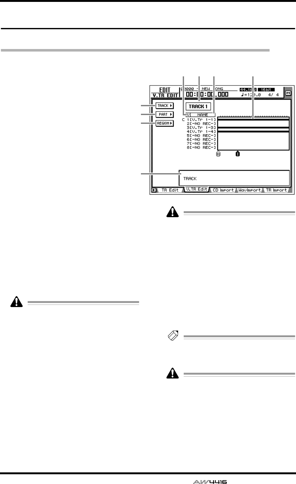
EDIT screen
— Reference Guide 107
V.TR Edit page
Edit virtual tracks
[Function]
Edit the virtual tracks 1–8 included in the
specified track.
[Key operation]
• [EDIT] key → [F2] (V. TR Edit) key
• Repeatedly press the RECORDER
[EDIT] key until the screen shown at
the right appears.
[Mouse operation]
M button → RECORDER EDIT button → V.
TR Edit tab
[Screen functions]
ATRACK menu
BPART menu
CREGION menu
These are the same as the TR Edit page TRACK
menu, PART menu, and REGION menu, with
the difference that the editing will apply to vir-
tual tracks 1–8 of the same track. For details
refer to the explanation that begins on page 99.
For the commands that can be selected in each
menu and their parameters, refer to page 99 and
following.
In the V. TR Edit page it is not possible to
select all tracks for editing.
DTrack number
Move the cursor to this area and use the [DATA/
JOG] dial to select the track number that con-
tains the virtual track you wish to edit.
EV (virtual track number)
This column shows the virtual track numbers 1–
8. The virtual track currently used by the track
3 is indicated by a “C” (Current) symbol at the
left of this column.
FNAME
This column shows the names of virtual tracks
1–8. Virtual tracks that have already been
recorded are assigned a default name of “V.Tr x-
y” (x=track number 1–16, y=virtual track num-
ber 1–8). Virtual tracks on which nothing has
been recorded are displayed as “-NO REC-”.
A name of up to 16 characters can be
assigned to a virtual track, but only the first
eight characters will be displayed in this col-
umn.
GTrack view
In this area, the regions included in each virtual
track are displayed as a bar graph. With the
exception that virtual tracks 1–8 of the same
track are displayed simultaneously, this display
is the same as in the TR Edit page.
HParameter area
In this area you can set the required parameters
for executing the edit command.
Tip!
For the track editing procedure, refer to
Operation Guide “Chapter 9. Track/virtual
track operations.”
The keys of the transport section will have no
effect while the V. TR Edit page is displayed.
1
2
3
7
5 4 6 8
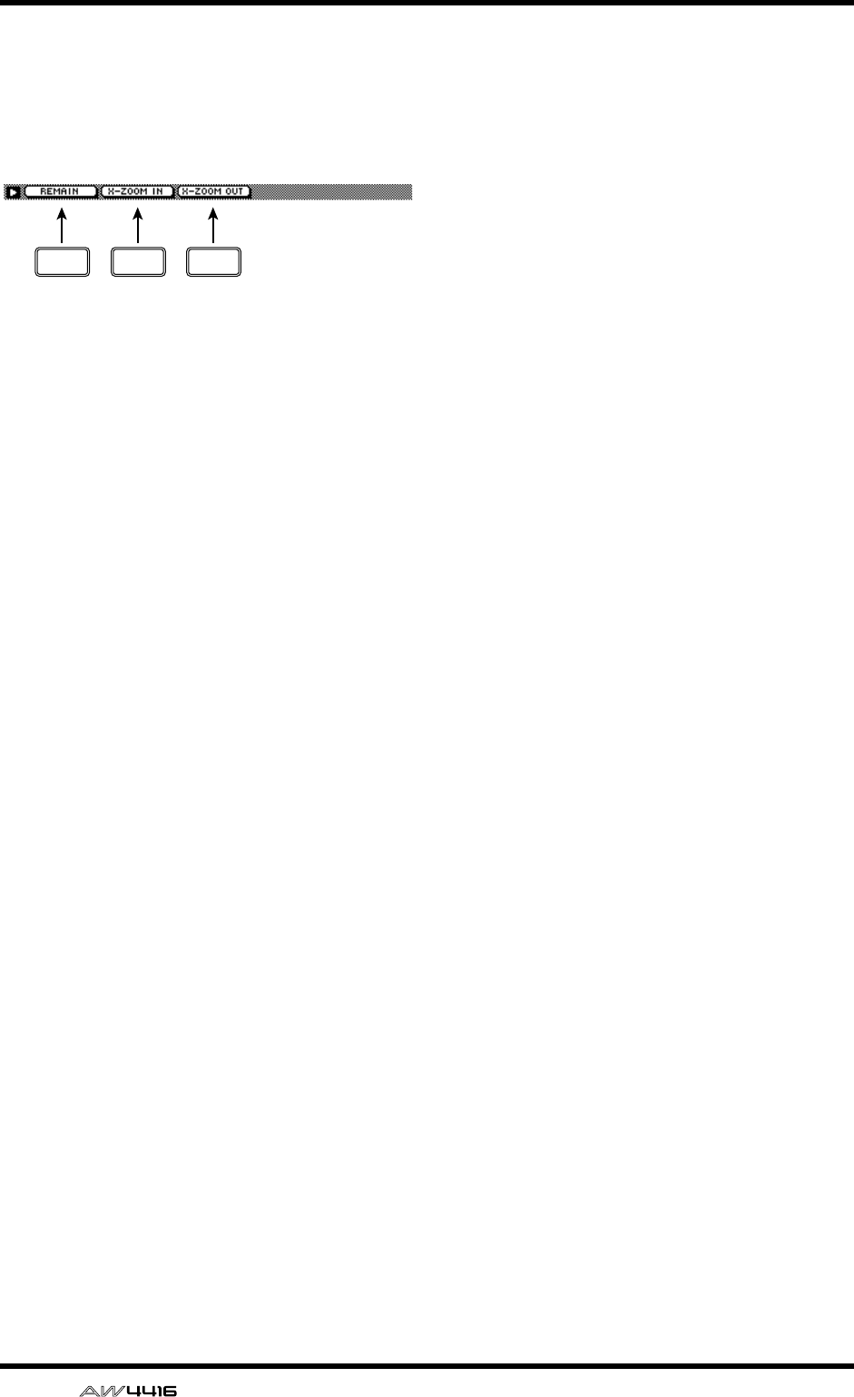
EDIT screen
108 — Reference Guide
■Additional functions in the V.TR
Edit page
In the V.TR Edit page, you can press the [SHIFT]
key to assign the following additional functions
to the [F1]–[F3] keys.
• [F1] (REMAIN) key
• [F2] (X-ZOOM IN) key
• [F3] (X-ZOOM OUT) key
These are the same as the additional functions
of the TR Edit page.
F1 F2 F3
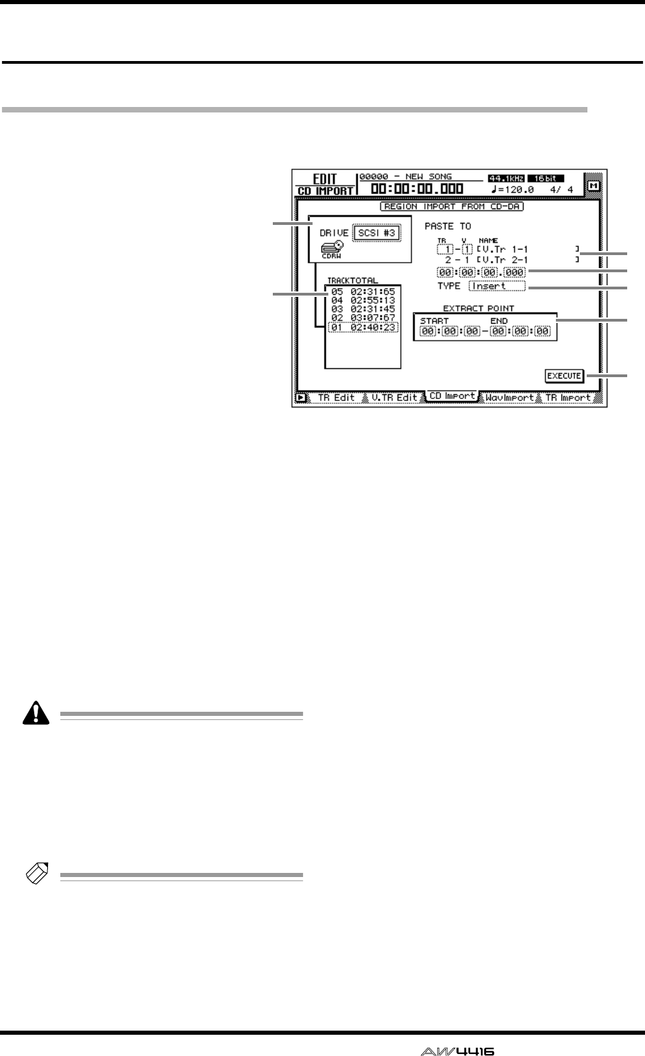
EDIT screen
— Reference Guide 109
CD Import page
Import CD-DA to an audio track
[Function]
Import CD-DA (CD audio) data
from an audio CD/mixed-mode
CD-ROM inserted in the internal
or external CD-RW drive, and
assign it to the desired audio track.
[Key operation]
• [EDIT] key → [F3] (CD Import)
key
• Repeatedly press the [EDIT] key
until the screen shown at the
right appears.
[Mouse operation]
M button → RECORDER EDIT but-
ton → CD Import tab
[Screen functions]
ADRIVE
Move the cursor to this area and rotate the
[DATA/JOG] dial to select the internal or exter-
nal CD-RW drive.
BPASTE TO
Select the track number and virtual track num-
ber of the destination track in which the CD-DA
data will be placed.
Since the CD-DA audio data is imported in
stereo, the track number will always be
selected as an odd-numbered/even-num-
bered pair.
CDestination point
Specify the point in the track at which the
imported CD-DA data will be placed.
Tip!
The units used to specify this point will
change depending on the counter display
method (time/units/measures) selected in the
SONG screen Setting page. If measure dis-
play is selected, “measures” will be the
smallest settable unit.
D TYPE
Select whether the imported CD-DA data will
be inserted into the track (Insert) or overwritten
(OverWrite). If “Insert” is selected, any subse-
quent audio data in the import destination track
will be moved toward the end of the song by the
length of the inserted audio data.
ETRACK/TOTAL
This is the track list of the audio CD/mixed-
mode CD-ROM inserted in the CD-RW drive.
Move the cursor to this list and rotate the
[DATA/JOG] dial to select the import source
track.
FEXTRACT POINT
From the track selected in 5, specify the area
that will be imported in units of “minutes:sec-
onds:frames (1/75 second).” Move the cursor to
this area, and use the [DATA/JOG] dial to set
START (start point) and END (end point).
GEXECUTE button
This button executes the CD-DA import opera-
tion.
1
5
7
6
2
4
3
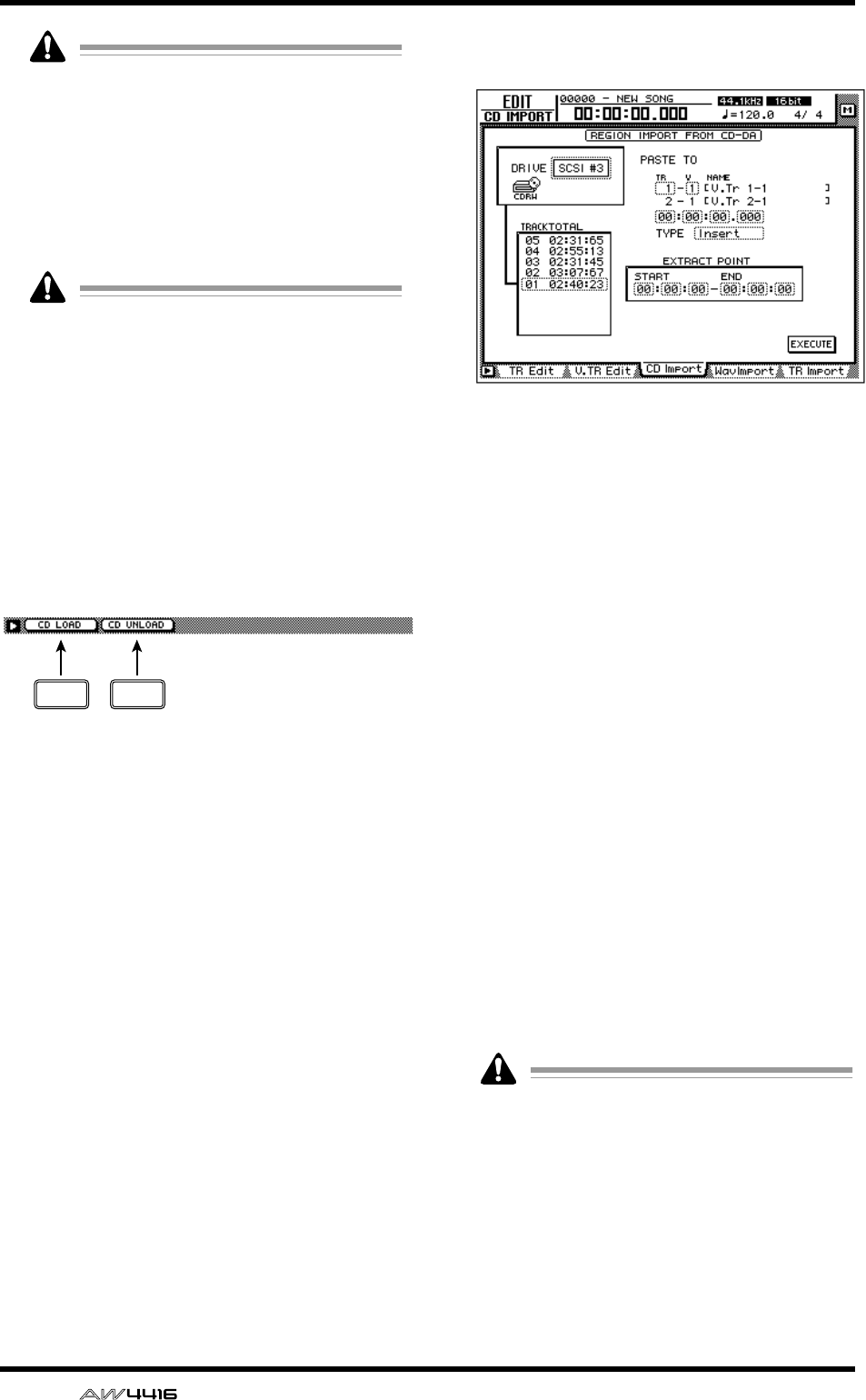
EDIT screen
110 — Reference Guide
• CD-DA data can be imported only into
songs whose sampling frequency is
44.1 kHz. If the current song has a sampling
frequency of 48 kHz, a message of “Current
Song is 48 (kHz) Fs Type” will appear, and
this page cannot be used.
• The keys of the transport section will have
no effect while the CD Import page is dis-
played.
If a “Prohibit CD Import!” message is dis-
played and the import cannot be executed,
access the UTILITY screen Prefer.2 page, and
after reading the warning regarding copy-
right, switch the CD/DAT DIGITAL REC “DIS-
ABLE” button to “ENABLE.”
■Additional functions in the CD
Import page
In the CD Import page you can press the [SHIFT]
key to assign the following additional functions to
the [F1]–[F2] keys.
• [F1] (CD LOAD) key
Close the tray of the CD-RW drive.
• [F2] (CD UNLOAD) key
Eject the tray of the CD-RW drive.
●Importing CD-DA data into a
track
[Procedure]
1. Access the EDIT screen CD Import page,
and press the [SHIFT] key + [F2] (CD
UNLOAD) key.
The CD-RW drive tray will be ejected.
2. Place the audio CD or mixed-mode CD-
ROM on the tray, and press the [SHIFT]
key + [F1] (CD LOAD) key.
The CD-RW drive tray will close, and the disc
will be inserted.
3. Move the cursor to the DRIVE area, use
the [DATA/JOG] dial to select the SCSI ID
of the CD-RW drive, and press the
[ENTER] key.
The AW4416 will detect the inserted CD, and a
screen like the following will appear.
4. Move the cursor to PASTE TO, and use the
[DATA/JOG] dial to specify the track num-
ber and virtual track number of the track
in which the CD-DA data will be placed.
In this page, identically-numbered virtual tracks
of adjacent odd-numbered/even-numbered
tracks will be selected (e.g., 1–1/2–1, 1–2/2–2),
and the L/R channels of the CD-DA data will be
assigned to these tracks.
5. Move the cursor to the destination point
area, and use the [DATA/JOG] dial to spec-
ify the location in the track where the CD-
DA audio data will be placed.
6. Move the cursor to the TYPE area. Select
“Insert” if you want the CD-DA audio data
to be inserted into the track, or “Over-
Write” if you want the data to be overwrit-
ten onto the track.
7. To execute the Import operation, move
the cursor to the EXECUTE button and
press the [ENTER] key.
A message will ask you to confirm.
8. Move the cursor to the OK button and
press the [ENTER] key.
The CD-DA import will be executed.
Execution of this operation will require more
time than the actual data length. Also, execu-
tion of the operation cannot be halted once it
has begun.
F1 F2
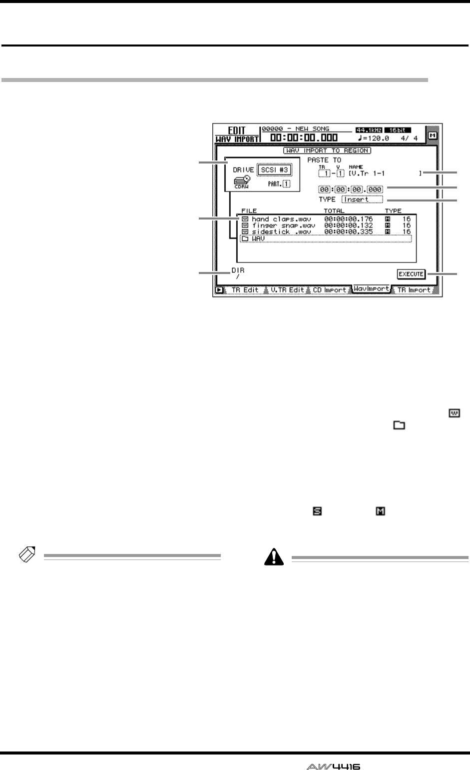
EDIT screen
— Reference Guide 111
WavImport page
Import a WAV file to an audio track
[Function]
Import a WAV format audio file
from a CD-ROM or CD-ROM/MO
disk inserted in the internal CD-
RW drive or an external SCSI
device, and assign it to a track.
[Key operation]
• [EDIT] key → [F4] (WavImport)
key
• Repeatedly press the RECORDER
[EDIT] key until the screen
shown at the right appears.
[Mouse operation]
M button → RECORDER EDIT but-
ton → WavImport tab
[Screen functions]
ADRIVE
Move the cursor to this area and rotate the
[DATA/JOG] dial to select the internal CD-RW
drive or external SCSI device.
BPASTE TO
Select the track number (1–16 and virtual track
number (1–8) of the track into which you wish
to import the WAV file. The NAME field shows
the track name of the selected track.
If a stereo WAV file is selected, two adjacent
odd-numbered → even-numbered tracks will be
displayed.
CDestination point
Specify the point in the track at which the WAV
file will be placed.
Tip!
The units used to specify this point will
change depending on the counter display
method (time/units/measures) selected in the
SONG screen Setting page. If measure dis-
play is selected, “measures” will be the
smallest settable unit.
DTYPE
Select whether the imported WAV file will be
inserted into the track (Insert) or overwritten
(OverWrite). If “Insert” is selected, any subse-
quent audio data in the import destination track
will be moved toward the end of the song by the
length of the inserted WAV file.
EFile list
This shows a list of the WAV files on the internal
CD-RW drive or external SCSI device. This list
contains the following information.
●FILE
The file name/directory name is displayed.
icons indicate WAV files, and files indicate
directories.
●TOTAL
The playback time of the WAV file is displayed
in hours/minutes/seconds/milliseconds.
●TYPE
The stereo ( )/monaural ( ) status of the WAV
file and its quantization (word length) is dis-
played.
The AW4416 can recognize only WAV files
that have the same sampling frequency as the
current song, and have a filename extension
of “.WAV” following their name. Other files
will not be displayed in the list.
FDIR (directory)
The “/” symbol and the directory name indicate
the directory in which the list shown in 5 is
located. For example this will indicate “/” if you
are in the highest level (root directory), or “/
WAV/” if you are in a directory named WAV
located one level lower.
1
5
67
2
4
3
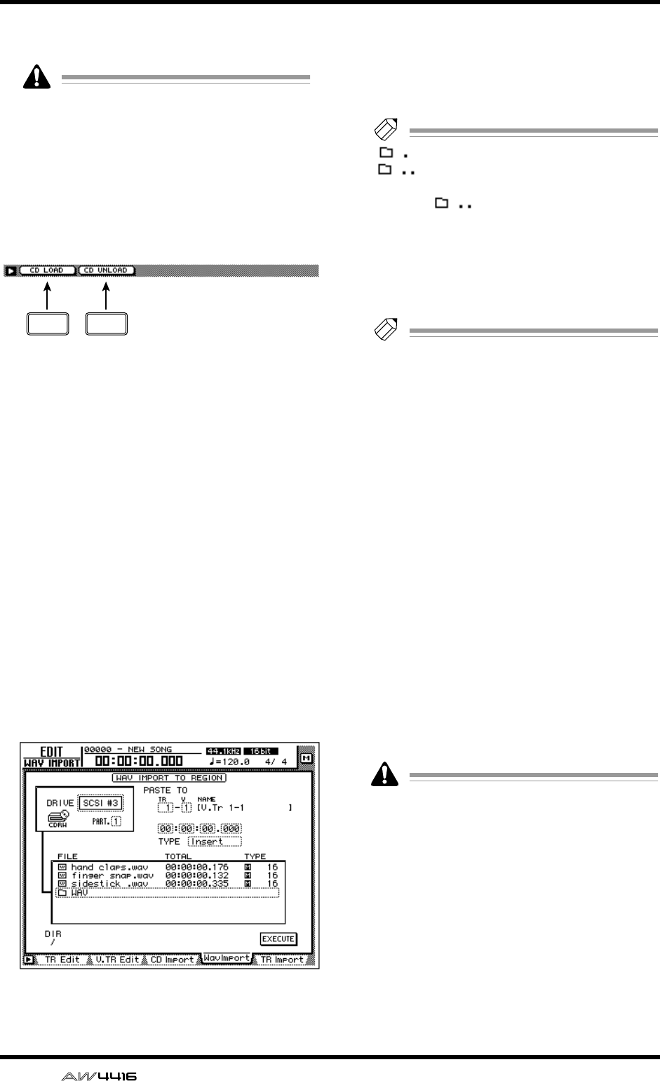
EDIT screen
112 — Reference Guide
GEXECUTE button
This button executes the WAV file import.
The keys of the transport section will have no
effect when the WavImport page is displayed.
■Additional functions in the Wav
Import page
In the Wav Import page you can press the [SHIFT]
key to assign the following additional functions to
the [F1]–[F2] keys.
• [F1] (CD LOAD) key
Close the tray of the CD-RW drive.
• [F2] (CD UNLOAD) key
Eject the tray of the CD-RW drive.
●Importing a WAV file to a track
[Procedure]
1. Insert the media containing the WAV file
into an external SCSI device (e.g., MO
drive) or the internal CD-RW drive.
2. Access the EDIT screen WavImport page.
3. Move the cursor to the DRIVE area, use
the [DATA/JOG] dial to select the SCSI ID
of the drive, and press the [ENTER] key.
The AW4416 will recognize the WAV files on
the inserted media (CD-ROM, MO disk etc.),
and will display a list like the following.
4. Move the cursor to the file list, and use
the [DATA/JOG] dial to select the WAV file
that you wish to import.
The file enclosed by the dotted lines in the cen-
ter of the list is selected for the operation.
Tip!
indicates the current directory, and
indicates the directory above. To
return to the next highest directory, move the
cursor to and press the [ENTER] key.
5. Move the cursor to the PASTE TO area,
and use the [DATA/JOG] dial to select the
track number (1–16) and virtual track
number (1–8) of the track in which the
WAV file will be placed.
Tip!
If you select a stereo WAV file in step 4, iden-
tically-numbered virtual tracks for a pair of
adjacent odd-numbered
→
even-numbered
tracks (e.g., 1–1/2–1, 1–2/2–2) will be
selected, and the L/R channels of the WAV
file will be assigned to these tracks.
6. Move the cursor to the location point area
below PASTE TO, and use the [DATA/JOG]
dial to specify the location in the track
where the WAV file will be placed.
7. Set the TYPE parameter to “Insert” if you
wish to insert the WAV file into the track,
or to “OverWrite” if you wish to overwrite
the WAV file onto the track.
8. To execute the WAV file import, move the
cursor to the EXECUTE button and press
the [ENTER] key.
A popup window will ask you for confirmation.
9. Move the cursor to the OK button and
press the [ENTER] key.
The WAV file import will be executed.
Execution of this operation requires a longer
time than the actual time length of the data.
Also, processing cannot be cancelled once
the operation has been executed.
F1 F2
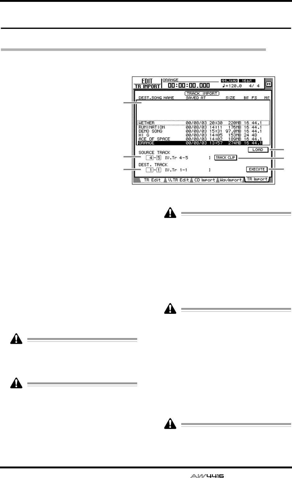
EDIT screen
— Reference Guide 113
TR Import page
Import a track from an existing song
[Function]
Import a track from a song on the
hard disk into the desired track of
the current song.
[Key operation]
• [EDIT] key → [F5] (TR Import)
key
• Repeatedly press the RECORDER
[EDIT] key until the screen
shown at the right appears.
[Mouse operation]
M button → RECORDER EDIT but-
ton → TR Import tab
[Screen functions]
ASong list
This lists the songs that are saved on the internal
hard disk. The current song will be highlighted
in the list. Move the cursor to this list, and use
the [DATA/JOG] dial to select the import source
song.
The list shows the following information.
•
DEST. SONG NAME
..Song name
• SAVED AT................Date and time at which
the song was last saved
• SIZE.........................Song data size (includ-
ing audio data)
• BIT/FS .....................Song quantization and
sampling rate
• PRT .........................Song protect on/off
Only a song with the same quantization and
sampling rate as the current song can be
selected as the import source. The current
song cannot be selected.
The current song will be displayed with the
most recently saved content.
BSOURCE TRACK
From the song selected in the song list 1, select
the track number (1–16) and virtual track num-
ber (1–8) of the track that you wish to import.
The name of the selected track is displayed at
the right.
• This parameter will be valid only after you
have used the LOAD button
4
to load the
track information for the selected song.
• The track name is not included in the data
that is imported.
CDEST. TRACK (destination track)
Specify the track number (1–16) and virtual
track number (1–8) for the import destination
track. The name of the selected track is dis-
played at the right.
This display will appear only after you have
used the TRACK CLIP button
5
to register the
desired track from the import source song.
DLOAD button
When you move the cursor to this button and
press the [ENTER] key, track information for the
song selected in the track list will be loaded.
ETRACK CLIP button
When you move the cursor to this button and
press the [ENTER] key, the track selected in
SOURCE TRACK 3 will be registered as the
import source.
This button will be valid only after you have
used the LOAD button
4
to load the track
information for the song.
1
2
36
4
5
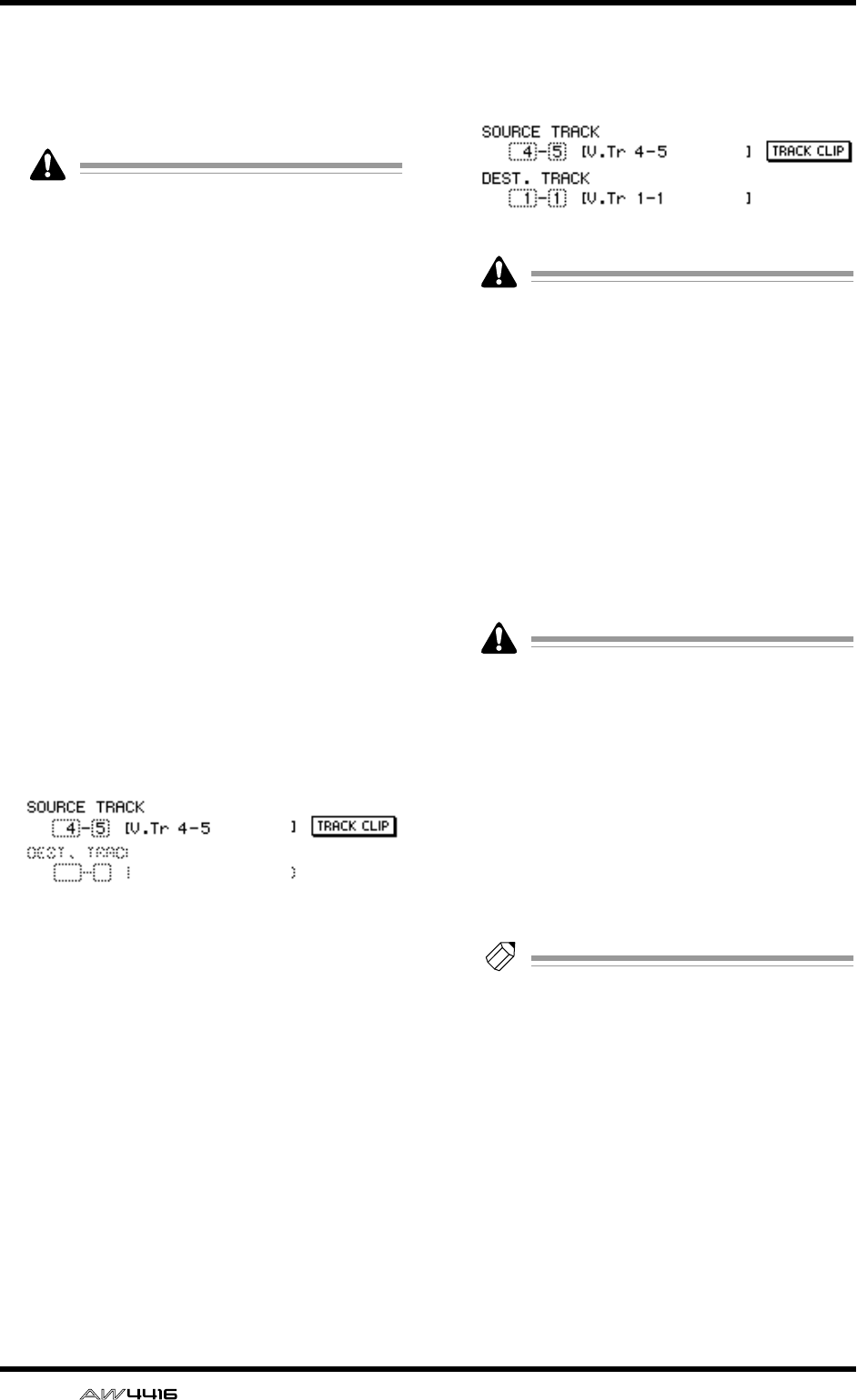
EDIT screen
114 — Reference Guide
FEXECUTE button
This button executes the track import operation.
For the procedure of importing a track, refer to
“Importing a track from an existing song,”
below.
• This button will be valid only after you have
used the TRACK CLIP button
5
to register
the import source track.
• The keys of the transport section will have
no effect in the TR Import page.
●Importing a track from an exist-
ing song
[Procedure]
1. Access the EDIT screen TR Import page.
2. Move the cursor to the upper part of the
display, and use the [DATA/JOG] dial to
select the song from which a track will be
imported.
3. Move the cursor to the LOAD button and
press the [ENTER] key.
A confirmation popup window will appear.
4. Move the cursor to the OK button and
press the [ENTER] key.
The track information will be read from the
selected song, and the display will change as
follows.
5. Move the cursor to the SOURCE TRACK
field, and select the track number (1–16)
and virtual track number (1–8) of the
track that you wish to import.
6. Move the cursor to the TRACK CLIP but-
ton and press the [ENTER] key.
A confirmation popup window will appear.
7. Move the cursor to the OK button and
press the [ENTER] key.
The track selected in the SOURCE TRACK field
will be selected as the import source, and the
display will change as follows.
When you use the TRACK CLIP button to reg-
ister the import source track, it will no longer
be possible to change the track in the
SOURCE TRACK field. If you wish to change
the import source track, move the cursor to
the song list in the upper part of the display,
and rotate the [DATA/JOG] dial. In the confir-
mation popup window that appears, select
the OK button and you will return to the state
of step 2.
8. Move the cursor to the DEST. TRACK field,
and specify the track number (1–16) and
virtual track number (1–8) of the import
destination track.
If you select an already-recorded virtual track
as the import destination, all the contents of
the corresponding track will be erased and
replaced by the contents of the imported
track.
9. Move the cursor to the EXECUTE button
and press the [ENTER] key.
A confirmation popup window will appear.
10.Move the cursor to the OK button and
press the [ENTER] key.
The track will be imported into the current song.
Tip!
By pressing the [UNDO] key immediately
after you execute the import, you can return
the data to the state before importing.
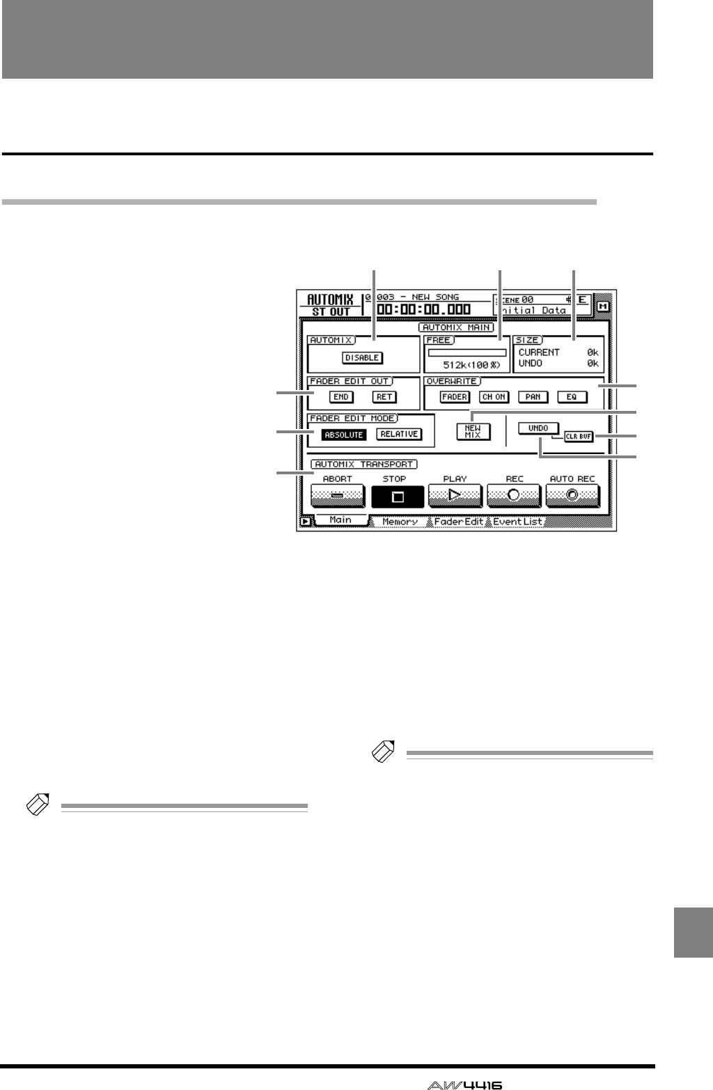
— Reference Guide 115
AUTO
MIX
AUTOMIX screen
Main page
Make basic automix settings
[Function]
Make basic settings for recording
and playing automix.
[Key operation]
• [AUTO MIX] key → [F1] (Main)
key
• Repeatedly press the [AUTO
MIX] key until the screen shown
at the right appears.
[Mouse operation]
M button → AMIX button → Main
tab
[Screen functions]
AAUTOMIX
Turn automix on (ENABLE) or off (DISABLE). If
this button is set to “ENABLE,” automix record-
ing or playback will begin automatically when
the song is started.
BFREE
This shows the free area of automix memory in
kilobytes and as a percentage.
CSIZE
This shows the sizes in kilobytes of the current
automix and of the undo buffer.
Tip!
The undo buffer is dedicated memory for
automix undo, and contains the automix data
prior to the last operation.
DFADER EDIT OUT
This setting specifies how the fader and other
parameter values will change when automix
recording ends.
●END
If this button is on, all subsequent recorded
events of the same parameter will be erased
when you finish editing fader or other parame-
ter data.
●RET
If this button is on, the fader will return to the
previously-recorded value when you finish edit-
ing fader data. (The time over which it returns to
the original value can be set in the Fader Edit
page. → P.121)
If this button is off, the value at which fader
editing ended will be maintained until the next
time the fader changes.
Tip!
• The AW4416 remembers the previously-
recorded fader movements even when you
are editing fader operations. If you leave the
RET button turned on, the fader will auto-
matically return to the previous location
when editing ends, which is convenient
when you are editing only a portion of the
fader operations.
• If you want the fader locations at which edit-
ing ended to be maintained to the end of the
automix, it is convenient to turn on the END
button.
5
7
9
8
12 3
6
4
J
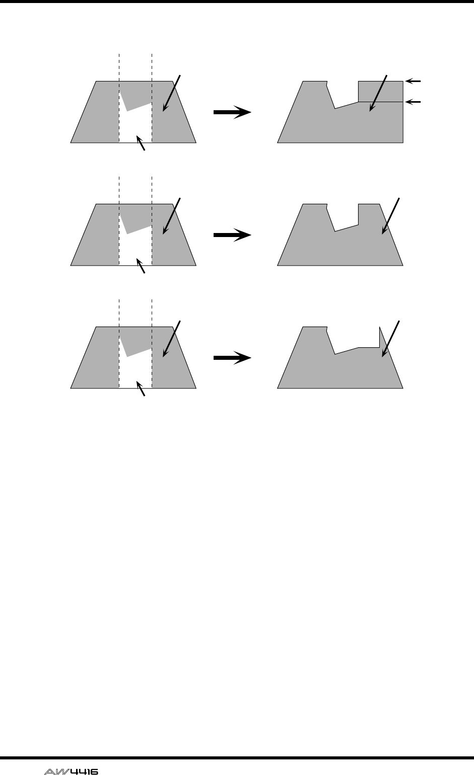
AUTOMIX screen
116 — Reference Guide
EOVERWRITE
Switch recording on/off for each parameter.
Each button corresponds to the following
parameters.
●FADER
Fader operations of each channel
●CH ON
[ON] key operations of each channel
●PAN
Pan operations of each channel
●EQ
EQ operations of each channel
FFADER EDIT MODE
Select one of the following two ways in which
fader movements recorded in automix will be
edited.
●ABSOLUTE
This is the usual mode, in which previously-
recorded fader events are erased and the new
events recorded.
●RELATIVE
In this mode, the previously-recorded fader
operation events are combined with the new
events and recorded. This is convenient when
you wish to add relative changes to the previ-
ously-recorded fader movements.
When END= on Previously-recorded
fader movement
Fader movement
after editing
Edited fader movement
When RET= on,
END= off Previously-recorded
fader movement
Fader movement
after editing
Edited fader movement
When RET= off,
END= off Previously-recorded
fader movement
Fader movement
after editing
Edited fader movement
RET= on
RET= off
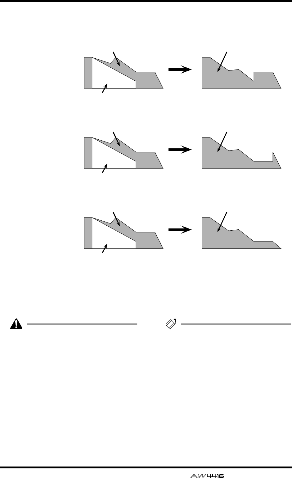
AUTOMIX screen
— Reference Guide 117
GNEW MIX button
When you move the cursor to this button and
press the [ENTER] key, the current automix will
be erased, and a new automix will be created.
When a song is in its initial state, there is no
current automix. You must first create a new
automix before you can operate the automix.
HUNDO
When you move the cursor to this button and
press the [ENTER] key, the content that was last-
recorded in the automix will be erased, return-
ing the automix to its previous state.
ICLR.BUF (clear buffer) button
When you move the cursor to this button and
press the [ENTER] key, the undo buffer will be
erased.
Tip!
For example if the current automix is too
large to be stored in memory, you can try
using this button. (However, the data prior to
the most recent operation will be lost.)
JAUTOMIX TRANSPORT
These buttons control automix recording and
playback. By moving the cursor and pressing
the [ENTER] key you can perform the corre-
sponding operation. These buttons have the fol-
lowing functions.
●ABORT
This button stops automix recording and dis-
cards the changes. If you turn on this button
while recording automix, a popup window will
ask whether you wish to discard the automix.
Fader movement
before editing
Fader movement
after editing
Fader movement edited
in RELATIVE mode
Fader Edit Mode= RELATIVE
RET= on
Fader movement
before editing
Fader movement
after editing
Fader movement edited
in RELATIVE mode
Fader Edit Mode= RELATIVE
RET= off
END= off
Fader movement
before editing
Fader movement
after editing
Fader movement edited
in RELATIVE mode
Fader Edit Mode= RELATIVE
RET= off
END= on
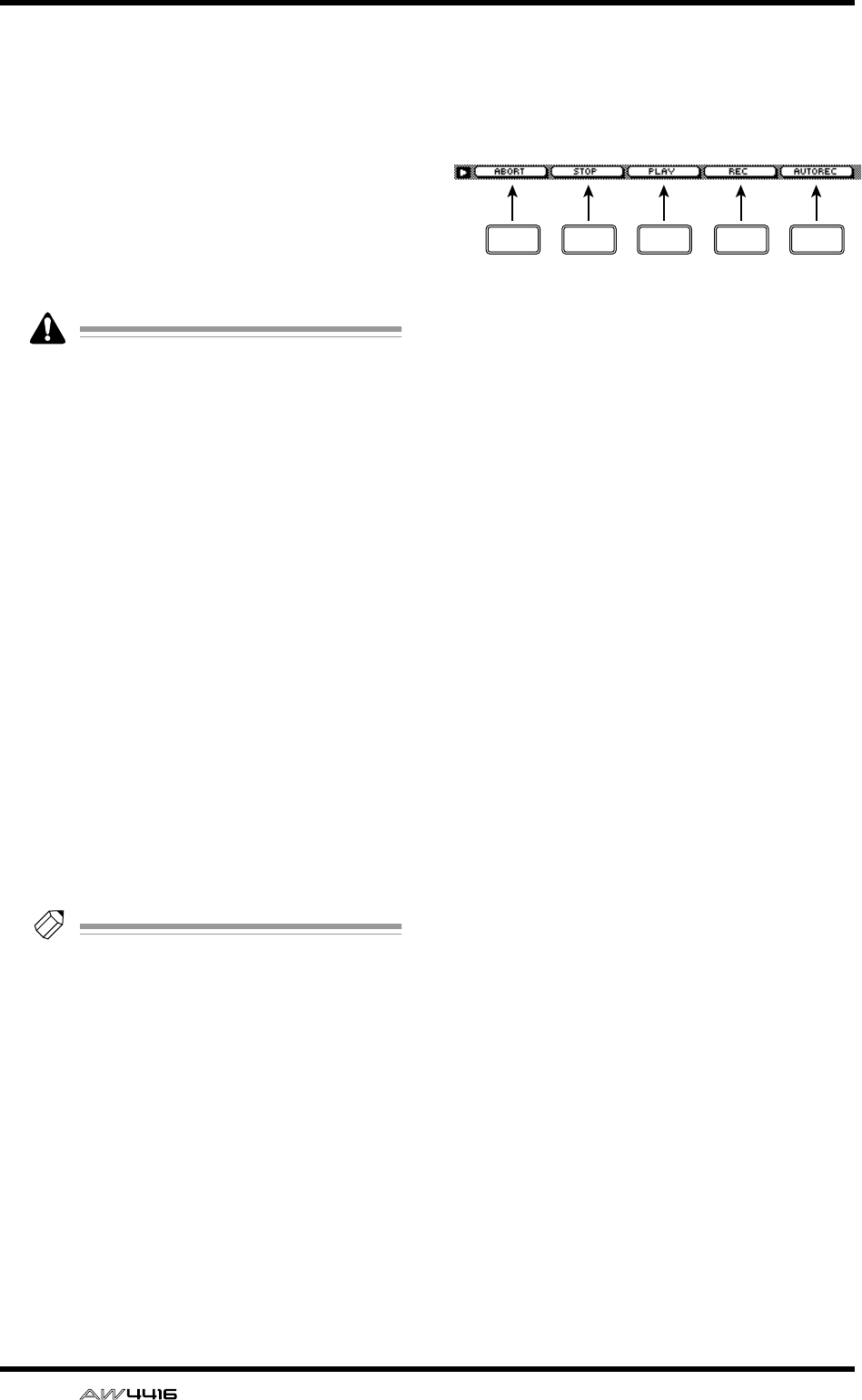
AUTOMIX screen
118 — Reference Guide
●STOP button
This button stops automix recording or play-
back. If you turn on this button while recording
automix, a popup window will ask whether you
wish to update the data.
●PLAY button
If the recorder is started with the ENABLE button
turned on, this button will automatically be
turned on, and automix recording/playback will
begin. While automix is playing, you can use
this button in conjunction with the REC button
to punch-in.
• Automix will not start even if you move the
cursor to the on-screen PLAY button and
press the [ENTER] key.
• When the REC button is blinking, you can
punch-in by moving the cursor to the PLAY
button and pressing the [ENTER] key.
●REC (record) button
When automix is stopped, turning this button
on will cause the button to blink and record-
ready mode to be selected. In this state, starting
playback on the recorder will cause automix
recording to begin, and when recording ends
the REC button will also turn off automatically.
When automix is playing, this button can be
used in conjunction with the PLAY button to
punch-in.
●AUTO REC button
If you turn this button on (lit) and play back the
recorder, automix recording will begin. How-
ever, this differs from the REC button in that this
button will not turn off automatically when
recording ends. If you wish to turn it back off,
move the cursor to this button and press the
[ENTER] key.
Tip!
For the procedure of recording and playing
automix, refer to Operation Guide “Chapter
14. Automix.”
■Additional functions in the Main
page
In the Main page you can press the [SHIFT] key to
assign the following functions to the [F1]–[F5] keys.
• [F1] (ABORT) key
Stop automix recording and discard the
changes. This is the same function as the
ABORT button.
• [F2] (STOP) key
Stop recording or playing automix. This is the
same function as the STOP button.
• [F3] (PLAY) key
Execute punch-in when the REC (record) button
is blinking. This is the same function as the
PLAY button.
• [F4] (REC) key
Record or punch-in automix. This is the same
function as the REC (record) button.
• [F5] (AUTO REC) key
Automatically record automix. This is the same
function as the AUTO REC (auto record) button.
F1 F2 F3 F4 F5
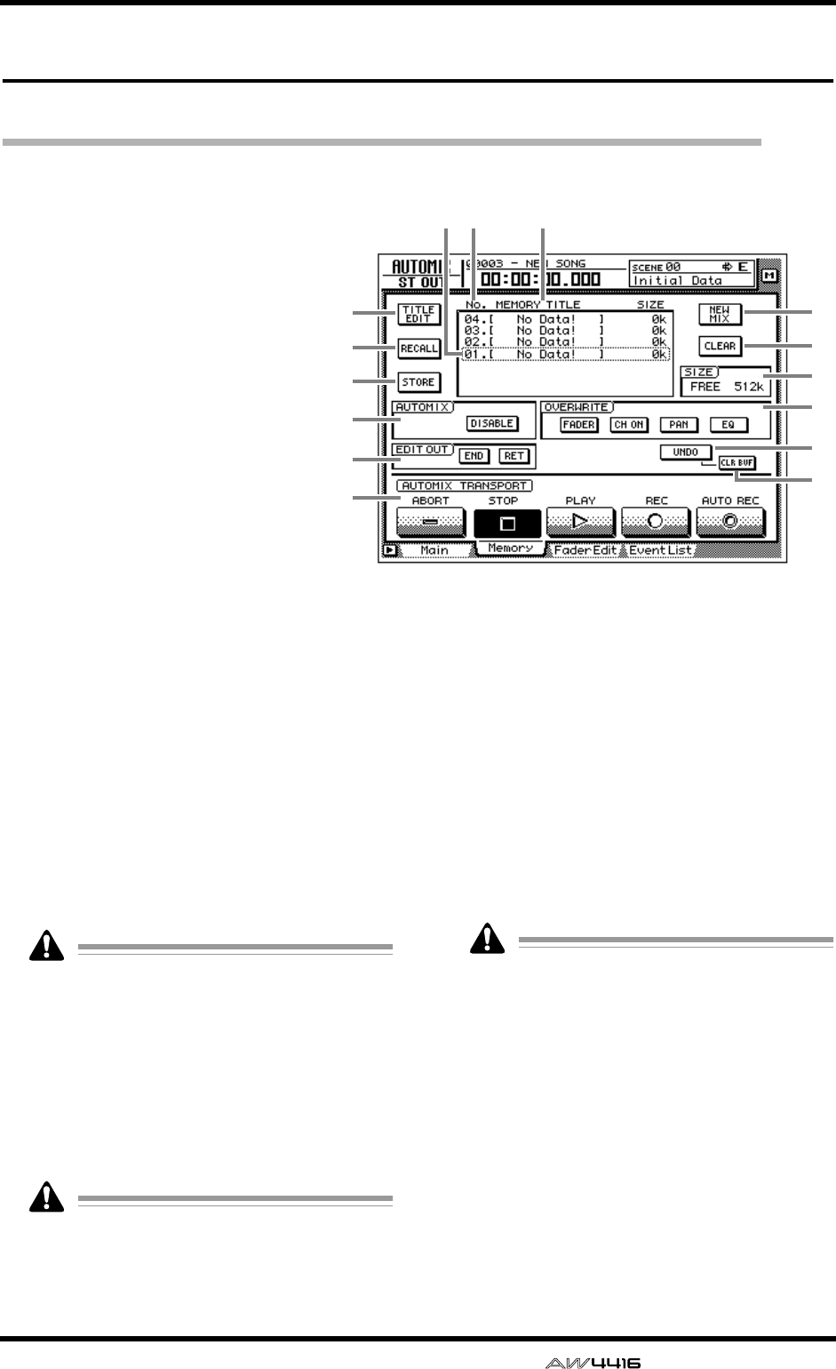
AUTOMIX screen
— Reference Guide 119
Memory page
Store or recall automix
[Function]
Store or recall automix data to/
from memory.
[Key operation]
• [AUTO MIX] key → [F2] (Mem-
ory) key
• Repeatedly press the [AUTO
MIX] key until the screen shown
at the right appears.
[Mouse operation]
M button → AMIX button → Mem-
ory tab
[Screen functions]
ATITLE EDIT button
Use this to edit the name (memory title) of an
automix stored in memory. When you move the
cursor to the TITLE EDIT button and press the
[ENTER] key, the TITLE EDIT popup window
will appear, allowing you to input a name. A
maximum of 16 characters can be input. For
details on inputting characters, refer to Opera-
tion Guide P.60.
BRECALL button
Recall the currently selected automix from the
list.
If you select an automix number in which
nothing has been stored and attempt to recall
it, an error message of “CANNOT AUTOMIX
RECALL” will appear, and recall will not be
possible.
CSTORE button
This button stores the current automix data into
memory. You can select an automix number 1–
16 as the store destination.
When you execute the Store operation, the
automix data that had previously been stored
in that number will be erased.
DSelected memory
Store/recall operations will apply to the automix
data enclosed by the dotted line in the memory
list. In this page, you can use the [DATA/JOG]
dial to select automix data regardless of where
the cursor is located.
ENo. (number)
This column shows the memory number 1–16.
FMEMORY TITLE
This column shows the names of the automixes
stored in memory.
Automix numbers in which nothing has been
stored will be displayed as “No Data!”
GNEW MIX button
When you move the cursor to this button and
press the [ENTER] key, the current automix will
be erased, and a new automix will be created.
HCLEAR button
Erase the automix data that is currently selected
in the memory list.
ISIZE
This shows the free area of automix memory in
kilobytes.
9
7
8
K
M
N
45 6
1
2
3
J
L
O
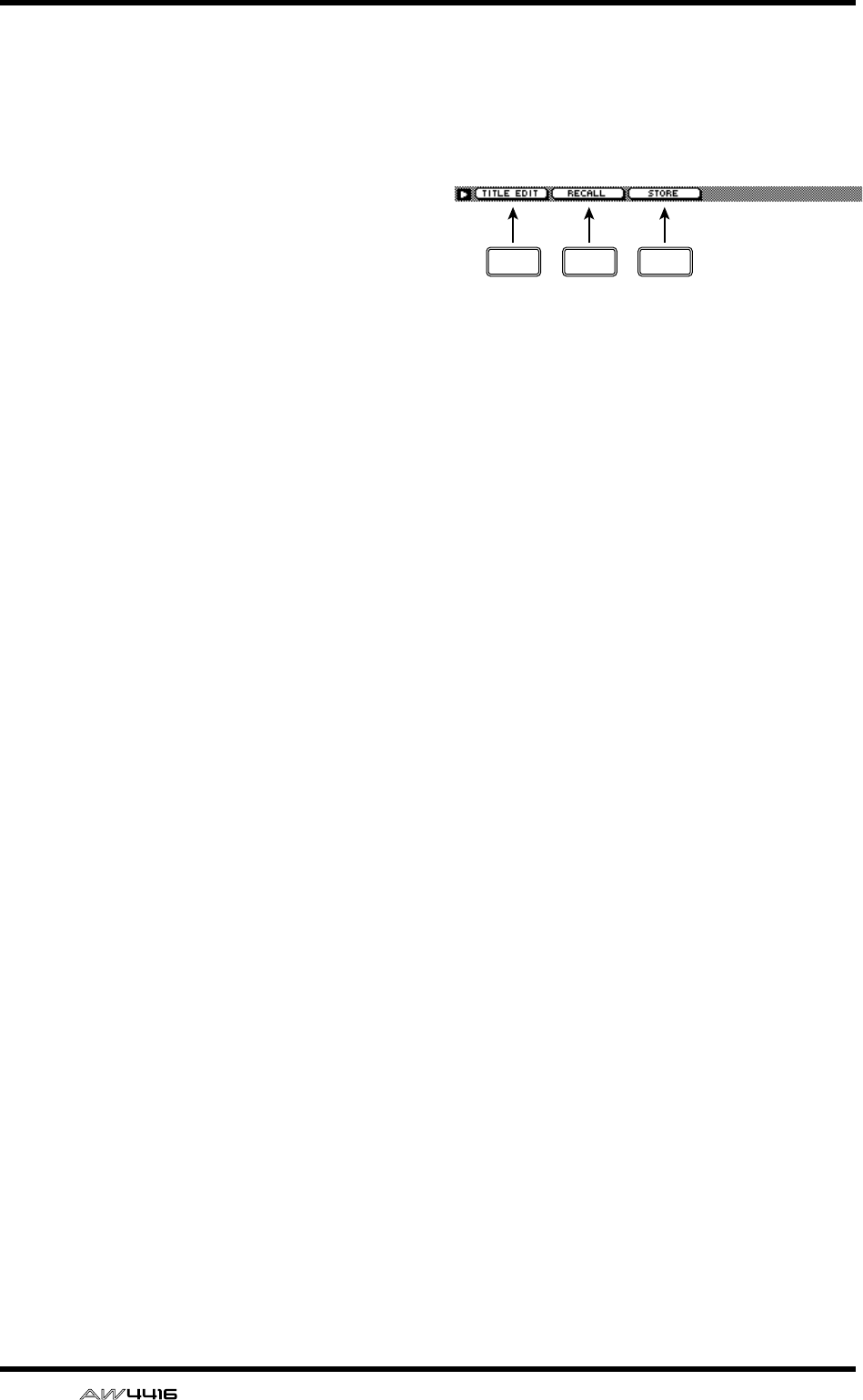
AUTOMIX screen
120 — Reference Guide
JAUTOMIX
KOVERWRITE
LEDIT OUT
MUNDO button
NCLR. BUF (clear buffer) button
OAUTOMIX TRANSPORT
These are the same functions as described in the
Main page. Refer to the explanation on page
115.
■Additional functions in the Mem-
ory page
In the Memory page you can press the [SHIFT] key
to assign the following functions to the [F1]–[F3]
keys.
• [F1] (TITLE EDIT) key
Use this to edit the name (memory title) of auto-
mix data saved in memory. This is the same
function as the 1 TITLE EDIT button.
• [F2] (RECALL) key
Recall the automix that is currently selected by
the cursor in the list. This is the same function as
the 2 RECALL button.
• [F3] (STORE) key
Store the current automix data. This is the same
function as the 3 STORE button.
F1 F2 F3
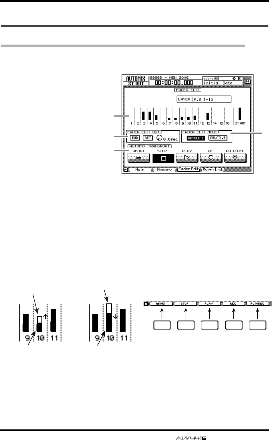
AUTOMIX screen
— Reference Guide 121
Fader Edit page
View fader events as a bar graph
[Function]
View a bar graph representation of
the fader operation events
recorded in the automix.
[Key operation]
• [AUTO MIX] key → [F3] (Fader
Edit) key
• Repeatedly press the [AUTO
MIX] key until the screen shown
at the right appears.
[Mouse operation]
M button → AMIX button → Fader
Edit tab
[Screen functions]
ABar graph
This area shows the fader position of each chan-
nel as a bar graph. (Use the keys of the MIXING
LAYER section to select the channels that are
displayed.) For the fader being edited, both the
previously-recorded position and the edited
position are displayed, as shown in the follow-
ing diagram. At this time, the arrow displayed
beside the bar graph indicates the direction in
which you can move the fader to return it to the
previous position.
BFADER EDIT OUT
These are the same functions as the END/RET
buttons of the Main page. Refer to the explana-
tion on page 115. If the RET button is on, the
knob located at the right sets the time over
which the faders will return to their original val-
ues after fader editing is ended.
CFADER EDIT MODE
DAUTOMIX TRANSPORT
These are the same functions as in the Main
page. Refer to the explanation on page 115.
■Additional functions in the Fader
Edit page
In the Fader Edit page you can press the [SHIFT]
key to assign the following functions to the [F1]–
[F5] keys.
• [F1] (ABORT) key
• [F2] (STOP) key
• [F3] (PLAY) key
• [F4] (REC) key
• [F5] (AUTO REC) key
These are identical to the additional functions of
the Main page.
3
2
4
1
Previously-recorded
fader position
Fader position now
being recorded
Previously-recorded
fader position
Fader position now
being recorded
(1)
If the fader is lower than
previously recorded (2)
If the fader is higher than
previously recorded
F1 F2 F3 F4 F5
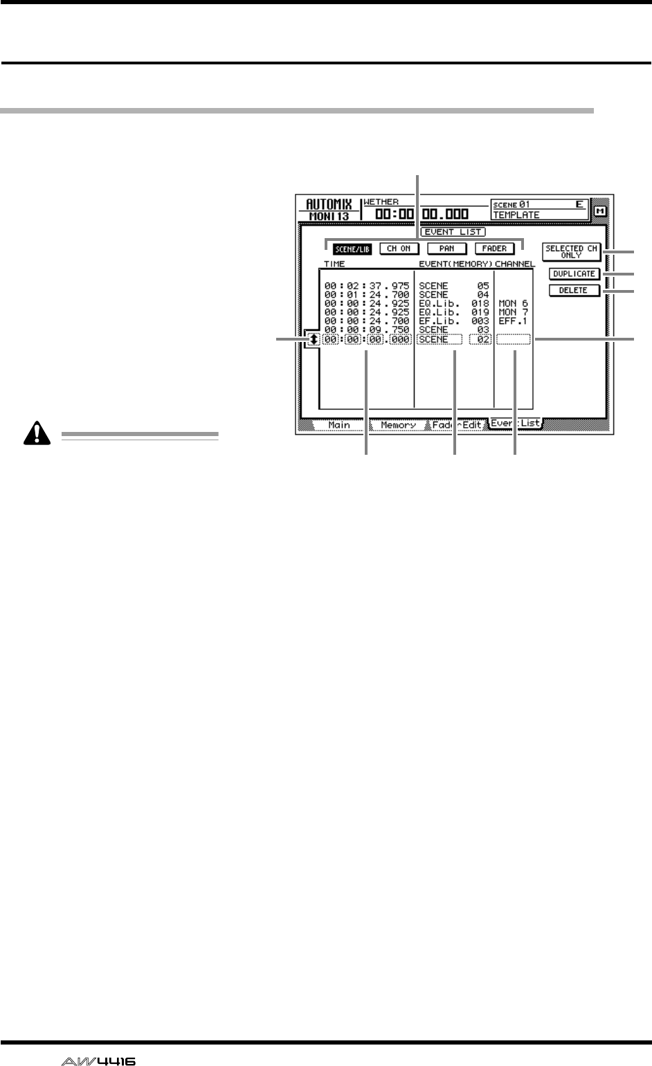
AUTOMIX screen
122 — Reference Guide
Event List page
Edit events off-line
[Function]
Perform off-line editing of the
scene/library recall, channel on/
off, pan, and fade operations
recorded in the automix.
[Key operation]
• [AUTO MIX] key → [F4] (Event
List) key
• Repeatedly press the [AUTO
MIX] key until the screen shown
at the right appears.
[Mouse operation]
M button → AMIX button → Event
List tab
This page cannot be operated
while automix is being played
or recorded. Also, if automix
playback or recording is
started when this page is dis-
played, the display will auto-
matically change to the
AUTOMIX screen Main page.
[Screen functions]
AEvent list select buttons
Of the events recorded in automix, these but-
tons select the type of automix events that will
be displayed in the event list. Move the cursor
to one of the four buttons, and press the
[ENTER] key to select the type of events. Each
button corresponds to the following events.
●SCENE/LIB (scene/library) button
Scene memory and library recall events will be
displayed. The following types of events will be
displayed.
• SCENE .......... Scene memory recall events.
The numeric value indicates
the scene number.
• EQ. Lib. ........ EQ library recall events. The
numeric value indicates the EQ
library number.
• DY. Lib.......... Dynamics library recall events.
The numeric value indicates
the dynamics library number.
• EF. Lib............Effect library recall events. The
numeric value indicates the
effect library number.
• CH. Lib..........Channel library recall events.
The numeric value indicates
the channel library number.
●CH ON (channel on) button
On/off events of each channel will be displayed.
●PAN button
Pan operation events of each channel will be
displayed.
●FADER button
Fader operation events of each channel will be
displayed.
BEvent selection cursor
Move the cursor to this area and rotate the
[DATA/JOG] dial to select the data that you
wish to edit.
7
8
9
3
45 6
2
1

AUTOMIX screen
— Reference Guide 123
CSelected event
Editing will apply to the event that is enclosed
by a dotted line in the list. Move the cursor to
the parameter that you wish to edit, and rotate
the [DATA/JOG] dial to edit the value.
DTIME
This area shows the time at which the event is
recorded, as hours/minutes/seconds/millisec-
onds. (The minimum unit is 25 milliseconds.)
You can move the cursor to this area and rotate
the [DATA/JOG] dial to move the location of the
event.
Tip!
Regardless of the display method selected in
the SONG screen Setting page, the timing in
the event list is always displayed as time.
If you edit the TIME the events in the list will
be re-ordered automatically. This means that
the displayed order of the events may
change.
EEVENT
This area shows the type of each event. Move
the cursor here and rotate the [DATA/JOG] dial
to edit the event.
FCHANNEL
This area shows the channel of the event. Move
the cursor here and rotate the [DATA/JOG] dial
to change the channel.
GSELECTED CH ONLY (selected channel
only) button
If you press a [SEL] key when this button is on,
only the events of that channel will be dis-
played.
HDUPLICATE button
When you move the cursor to this button and
press the [ENTER] key, a duplicate of the
selected event will be created at the same loca-
tion.
IDELETE button
When you move the cursor to this button and
press the [ENTER] key, the selected event will
be deleted.
Tip!
For the procedure of duplicating or deleting
an event, refer to Operation Guide “Chapter
14. Automix.”
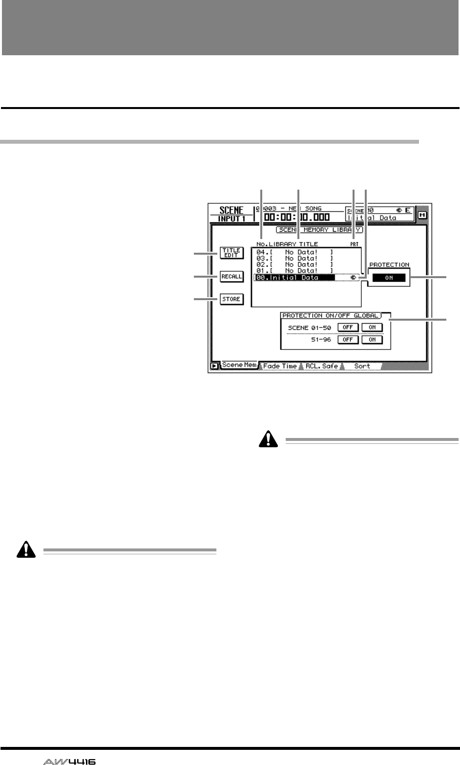
124 — Reference Guide
SCENE screen
Scene Mem page
Store or recall a scene
[Function]
Store the current settings of the
AW4416 into scene memory, or
recall a scene that was stored in
scene memory.
[Key operation]
• [SCENE] key → [F1] (Scene
Mem) key
• Repeatedly press the [SCENE]
key until the screen shown at the
right appears.
[Mouse operation]
M button → SCEN button → Scene
Mem tab
[Screen functions]
ATITLE EDIT button
Use this to edit the name (library title) of a scene
stored in the library. When you move the cursor
to the TITLE EDIT button and press the [ENTER]
key, the TITLE EDIT popup window will appear,
allowing you to input the name. You can input a
library name of up to 16 characters. For details
on inputting characters, refer to page 60 of the
Operation Guide.
It is not possible to change the name of scene
number 0 or of a scene in which PROTEC-
TION is turned on. Also, numbers in which
no scene has been stored will be displayed as
“No Data!,” and their title cannot be edited.
BRECALL button
Recall the currently selected scene from the
scene list. This is the same function as the
[RECALL] key of the top panel SCENE MEMORY
section.
If you select a number in which nothing has
been stored and attempt to recall it, an error
message of “ERROR NO DATA TO RECALL”
will be displayed, and recall will not be pos-
sible.
CSTORE button
Store the current settings (current scene) of the
AW4416 into scene memory. This is the same
function as the [STORE] key of the SCENE
MEMORY section.
4 5 6
8
9
1
2
3
7
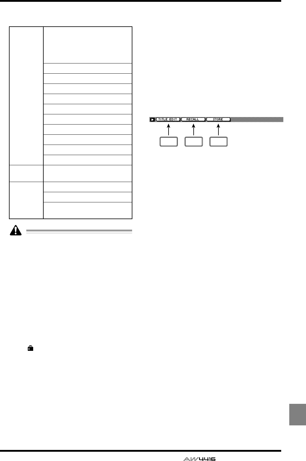
SCENE screen
— Reference Guide 125
SCENE
The following parameters are saved in memory
as a scene.
• Scene number 0 is recall-only, and settings
cannot be stored in it.
• When you execute the Store operation, the
scene that had been stored in that number
will be erased.
DLIBRARY No. (library number)
This column displays the scene number 0–96.
ELIBRARY TITLE
This column displays the name assigned to each
scene.
FPRT (protect)
A write-prohibit symbol is displayed in this col-
umn for recall-only scene number 0. In addi-
tion, a symbol is displayed for scenes for
which the PROTECTION button is on, indicat-
ing that they cannot be stored.
GSelected scene
Scene store/recall operations will apply to the
scene enclosed by a dotted line in the library
list. In this page, you can use the [DATA/JOG]
dial to select scenes regardless of where the cur-
sor is located.
HPROTECTION
Turn memory protect on/off for the scene cur-
rently selected by the cursor.
IPROTECTION ON/OFF GLOBAL
Turn memory protect on/off for all scene num-
bers 1–50/51–96.
■Additional functions in the Scene
Mem page
In the Scene Mem page you can press the [SHIFT]
key to assign the following functions to the [F1]–
[F3] keys.
• [F1] (TITLE EDIT) key
Use this to edit the name of a scene saved in the
library. This is the same function as the 1 TITLE
EDIT button.
• [F2] (RECALL) key
Use this to recall the scene currently selected by
the cursor from the list. This is the same function
as the 2 RECALL button.
• [F3] (STORE) key
Store the current scene. This is the same func-
tion as the 3 STORE button.
Mix param-
eters
Fader locations of all channels and
buses (input channels 1–24,
recorder monitor channels 1–16,
AUX send levels 1-8, effect returns
1/2, stereo)
ON key settings of all channels
Attenuation settings of all channels
Phase settings of all channels
EQ settings of all channels
Pan settings of all channels
Routing settings of all channels
Fader group settings of all channels
Pairing settings of all channels
Dynamics settings of all channels
Delay settings of all channels
Effect
parameters Parameter settings for effects 1/2
Other
Scene name settings
Fader recall fade time settings
Patching and insert settings for
external input/output
F1 F2 F3
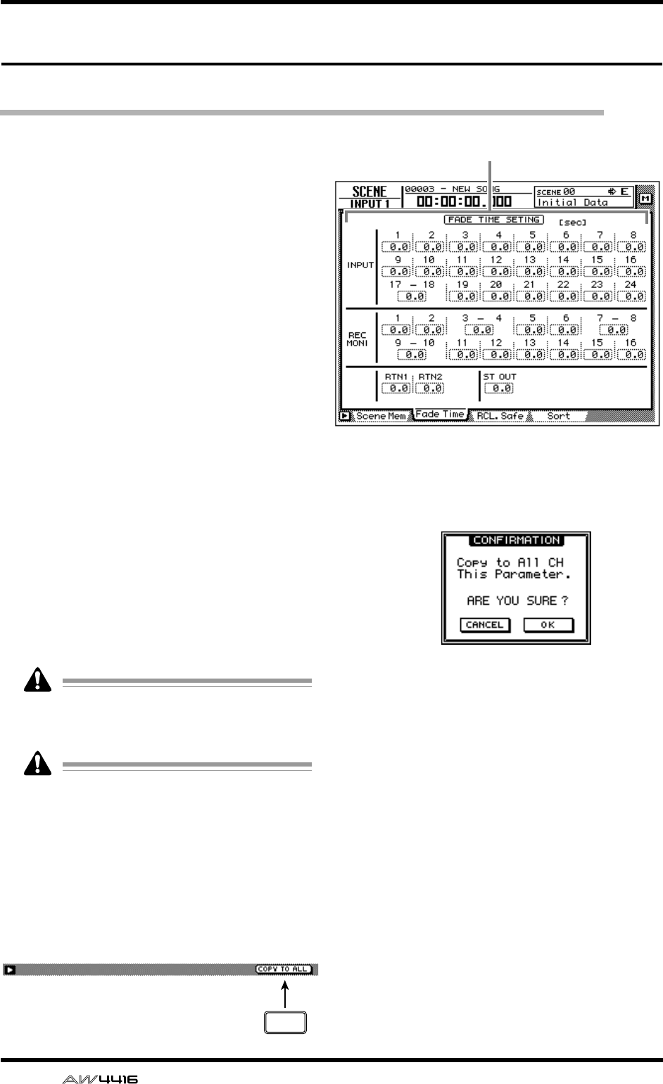
SCENE screen
126 — Reference Guide
Fade Time page
Specify the fade time
[Function]
Specify the time over which the faders will
reach their new locations when a scene is
recalled.
[Key operation]
• [SCENE] key → [F2] (Fade Time) key
• Repeatedly press the [SCENE] key until the
screen shown at the right appears.
[Mouse operation]
M button → SCEN button → Fade Time tab
[Screen functions]
AFade time
Specify the time (fade time) over which the fad-
ers of each channel will move their new loca-
tions when a scene is recalled, in steps of 0.1
second. (Range: 0.1 second–10 seconds). Fade
time can be set for the following channels.
●Input channels 1–24
●Monitor channels 1–16
●Effect return channels 1/2
●Stereo output channel
Fade time will have no effect unless it is spec-
ified for the scene being recalled (even if it is
specified for the current scene).
The fade time is specified independently for
each scene. Be sure to save the scene after
editing the fade time.
■Additional functions in the Fade
Time page
In the Fade Time page you can press the [SHIFT]
key to assign the following additional function to
the [F5] key.
• [F5] (COPY TO ALL) key
Copy the fade time setting selected by the cur-
sor to all other channels.
●Copying fade time settings to all
channels
[Procedure]
1. In the SCENE screen Fade Time page,
move the cursor to the fade time setting
of the copy source channel.
2. Press the [SHIFT] key + [F5] key.
A CONFIRMATION popup window will appear,
asking you to confirm the copy.
3. To execute the copy, move the cursor to
the OK button and press the [ENTER] key.
4. Press the [STORE] key to store the scene.
1
F5
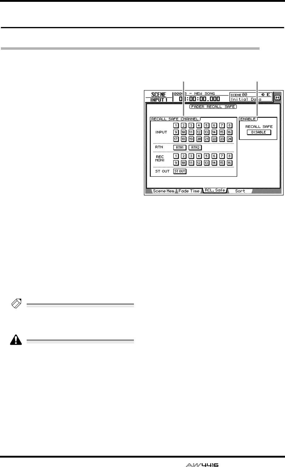
SCENE screen
— Reference Guide 127
RCL. Safe page
Make fader recall safe settings
[Function]
Specify the faders that will be excluded from
the recall when a scene is recalled.
[Key operation]
• [SCENE] key → [F3] (RCL. Safe) key
• Repeatedly press the [SCENE] key until the
screen shown at the right appears.
[Mouse operation]
M button → SCEN button → RCL. Safe tab
[Screen functions]
ARECALL SAFE CHANNEL
If a button in this area is turned on, the fader of
the corresponding channel will maintain its cur-
rent position even when a scene is recalled. The
following channels can be set to Recall Safe sta-
tus.
●Input channels 1–24
●Monitor channels 1–16
●Effect return channels 1/2
●Stereo output channel
Tip!
When a scene is recalled, Fader Recall Safe is
valid only if that scene was saved with the
ENABLE parameter
2
set to ENABLE.
Recall Safe settings are not linked for paired
channels. This means that if one channel of a
pair is set to Recall Safe, the faders of the pair
may be in different positions immediately
after a scene is recalled. However even in
this case, moving one of the faders will cause
the other fader to follow immediately.
BENABLE
Move the cursor to this button and press the
[ENTER] key to specify whether the Fader Recall
Safe function will be enabled (ENABLE) or not
(DISABLE).
1 2
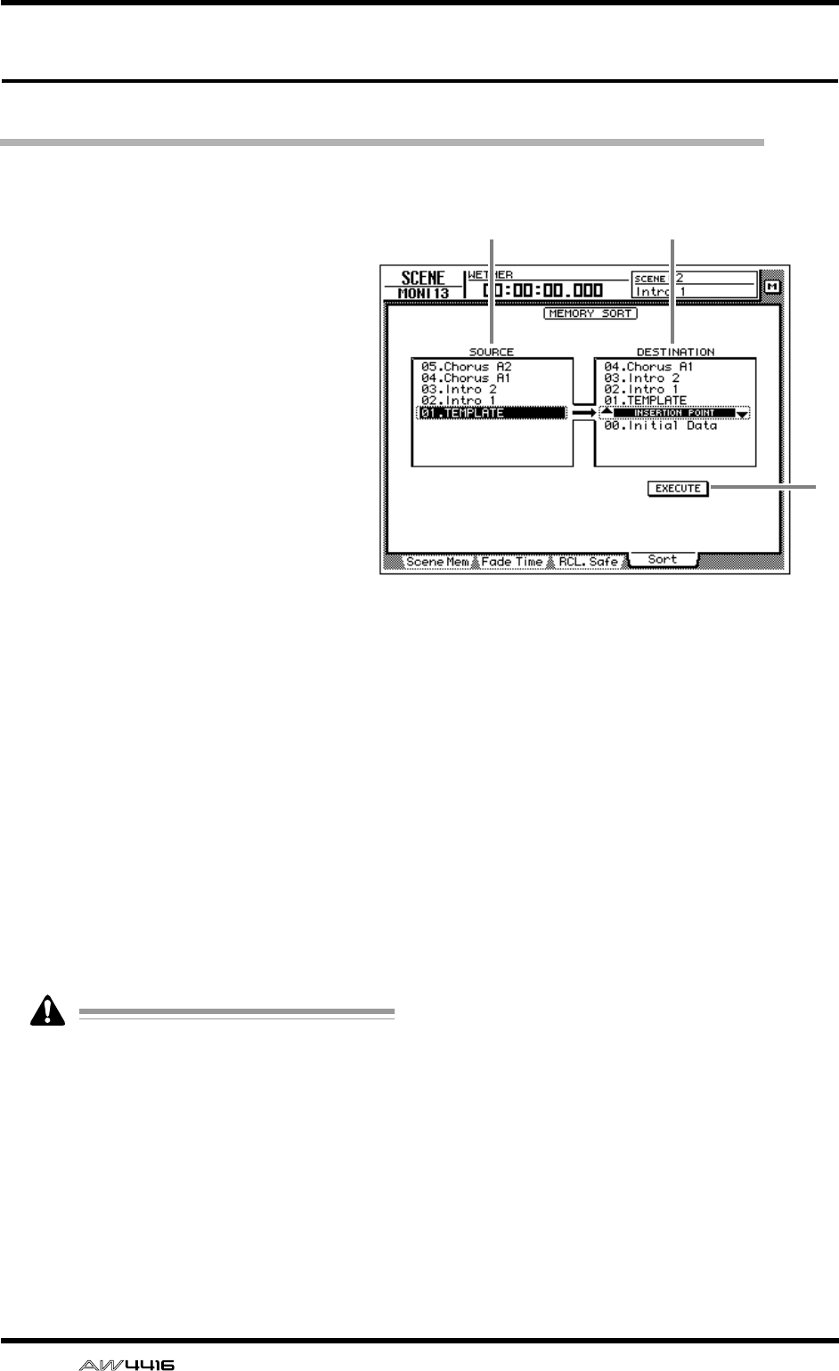
SCENE screen
128 — Reference Guide
Sort page
Sort scenes
[Function]
Sort the scenes stored in scene memory.
[Key operation]
• [SCENE] key → [F4] (Sort) key
• Repeatedly press the [SCENE] key until
the screen shown at the right appears.
[Mouse operation]
M button → SCEN button → Sort tab
[Screen functions]
ASOURCE
This list shows the current state of the scene
memories. Move the cursor to this list, and
rotate the [DATA/JOG] dial to select the scene
whose sorting order you wish to change. (The
currently selected scene will be highlighted.)
BDESTINATION
Specify the scene number to which the scene
selected in the SOURCE list will be moved.
Move the cursor to this area and rotate the
[DATA/JOG] dial to select the point where the
scene will be inserted. (The location currently
selected for insertion is displayed as “INSER-
TION POINT.”)
CEXECUTE button
Move the cursor to this button and press the
[ENTER] key to change the order of the scenes.
Even if you select a scene in which nothing
has been stored, it is not possible to change
its order.
1 2
3

Appendix
— Reference Guide Appendix– 1
Appendix
Preset EQ Program Parameters . . . . . . . . . . . . . . . . . . 2
Preset Effects Programs . . . . . . . . . . . . . . . . . . . . . . . . 6
Effects Parameters . . . . . . . . . . . . . . . . . . . . . . . . . . . . 8
Dynamics Processors . . . . . . . . . . . . . . . . . . . . . . . . 24
Preset Dynamics Programs . . . . . . . . . . . . . . . . . . . . . . . . . . 24
Preset Dynamics Program Parameters . . . . . . . . . . . . 29
Troubleshooting . . . . . . . . . . . . . . . . . . . . . . . . . . . . 35
Display message list . . . . . . . . . . . . . . . . . . . . . . . . . 39
Messages . . . . . . . . . . . . . . . . . . . . . . . . . . . . . . . . . . . . . . . 39
Popup messages . . . . . . . . . . . . . . . . . . . . . . . . . . . . . . . . . . 41
Specifications . . . . . . . . . . . . . . . . . . . . . . . . . . . . . . 43
General Specifications . . . . . . . . . . . . . . . . . . . . . . . . . . . . . 43
Mixer section . . . . . . . . . . . . . . . . . . . . . . . . . . . . . . . . . . . . 44
Recorder section . . . . . . . . . . . . . . . . . . . . . . . . . . . . . . . . . . 46
Controls . . . . . . . . . . . . . . . . . . . . . . . . . . . . . . . . . . . . . . . . 47
Control I/O . . . . . . . . . . . . . . . . . . . . . . . . . . . . . . . . . . . . . . 48
Dimensions . . . . . . . . . . . . . . . . . . . . . . . . . . . . . . . . 49
MIDI data format . . . . . . . . . . . . . . . . . . . . . . . . . . . 50
MIDI Implementation Chart . . . . . . . . . . . . . . . . . . . . 54
Block diagram
Appendix
Appendix
Appendix–2 — Reference Guide
Preset EQ Program Parameters
No Name Parameter Description
LOW L-MID H-MID HIGH
001 Bass Drum 1
PEAKING PEAKING PEAKING H.SHELF Emphasizes the low range
of the bass drum and the
attack created by the
beater.
Q1.2 10 0.9
F99Hz 265Hz 1.05kHz 5.33kHz
G+3.5dB –3.5dB 0.0dB +4.0dB
002 Bass Drum 2
PEAKING PEAKING PEAKING LPF Creates a peak around
80Hz, producing a tight,
stiff sound.
Q1.4 4.5 2.2
F79Hz 397Hz 2.52kHz 12.6kHz
G+8.0dB –7.0dB +6.0dB ON
003 Snare Drum 1
PEAKING PEAKING PEAKING H.SHELF Emphasizes snapping
and rimshot sounds.
Q1.2 4.5 0.11
F132Hz 1.00kHz 3.17kHz 5.04kHz
G–0.5dB 0.0dB +3.0dB +4.5dB
004 Snare Drum 2
L.SHELF PEAKING PEAKING PEAKING Emphasizes the ranges of
that classic rock snare
drum sound.
Q10 0.7 0.1
F177Hz 334Hz 2.37kHz 4.00kHz
G+1.5dB –8.5dB +2.5dB +4.0dB
005 Tom-tom 1
PEAKING PEAKING PEAKING PEAKING Emphasizes the attack of
tom-toms, and creates a
long, “leathery” decay.
Q1.4 10 1.2 0.28
F210Hz 667Hz 4.49kHz 6.35kHz
G+2.0dB –7.5dB +2.0dB +1.0dB
006 Cymbal
L.SHELF PEAKING PEAKING H.SHELF Emphasizes the attack of
crash cymbals, extending
the “sparkling” decay.
Q8 0.9
F105Hz 420Hz 1.05kHz 13.4kHz
G–2.0dB 0.0dB 0.0dB +3.0dB
007 High Hat
L.SHELF PEAKING PEAKING H.SHELF Use on a tight high-hat,
emphasizing the mid to
high range.
Q0.5 1
F94Hz 420Hz 2.82kHz 7.55kHz
G–4.0dB –2.5dB +1.0dB +0.5dB
008 Percussion
L.SHELF PEAKING PEAKING H.SHELF Emphasizes the attack
and clarifies the high-
range of instruments,
such as shakers,
cabasas, and congas.
Q4.5 0.56
F99Hz 397Hz 2.82kHz 16.9kHz
G–4.5dB 0.0dB +2.0dB 0.0dB
009 E.Bass 1
L.SHELF PEAKING PEAKING H.SHELF Makes a tight electric bass
sound by cutting very low
frequencies.
Q5 4.5
F35Hz 111Hz 2.00kHz 4.00kHz
G–7.5dB +4.5dB +2.5dB 0.0dB
010 E.Bass 2
PEAKING PEAKING PEAKING H.SHELF Unlike program 009, this
emphasizes the low range
of the electric bass.
Q0.1 5 6.3
F111Hz 111Hz 2.24kHz 4.00kHz
G+3.0dB 0.0dB +2.5dB +0.5dB
Appendix
— Reference Guide Appendix– 3
011 Syn.Bass 1
PEAKING PEAKING PEAKING H.SHELF Use on a synth bass with
emphasized low range.
Q0.1 8 4.5
F83Hz 944Hz 4.00kHz 12.6kHz
G+3.5dB +8.5dB 0.0dB 0.0dB
012 Syn.Bass 2
PEAKING PEAKING PEAKING H.SHELF Emphasizes the attack
that is peculiar to a synth
bass.
Q1.6 8 2.2
F125Hz 177Hz 1.12kHz 12.6kHz
G+2.5dB 0.0dB +1.5dB 0.0dB
013 Piano 1
L.SHELF PEAKING PEAKING H.SHELF This is used to make a
piano sound brighter.
Q8 0.9
F94Hz 944Hz 3.17kHz 7.55kHz
G–6.0dB 0.0dB +2.0dB +4.0dB
014 Piano 2
PEAKING PEAKING PEAKING H.SHELF Emphasize the attack and
low range of the piano
sound by using a
compressor.
Q5.6 10 0.7
F223Hz 595Hz 3.17kHz 5.33kHz
G+3.5dB –8.5dB +1.5dB +3.0dB
015 E.G.Clean
PEAKING PEAKING PEAKING H.SHELF Use for line-recording an
electric guitar or semi-
acoustic guitar to get a
slightly hard sound.
Q0.18 10 6.3
F265Hz 397Hz 1.33kHz 4.49kHz
G+2.0dB –5.5dB +0.5dB +2.5dB
016 E.G.Crunch 1
PEAKING PEAKING PEAKING PEAKING Adjusts the tonal quality of
a slightly distorted guitar
sound.
Q8 4.5 0.63 9
F140Hz 1.00kHz 1.88kHz 5.65kHz
G+4.5dB 0.0dB +4.0dB +2.0dB
017 E.G.Crunch 2
PEAKING PEAKING PEAKING H.SHELF This is a variation on
program 016.
Q8 0.4 0.16
F125Hz 445Hz 3.36kHz 19.0kHz
G+2.5dB +1.5dB +2.5dB 0.0dB
018 E.G.Distortion 1
L.SHELF PEAKING PEAKING H.SHELF Makes a heavily distorted
guitar sound clearer.
Q910
F354Hz 944Hz 3.36kHz 12.6kHz
G+5.0dB 0.0dB +3.5dB 0.0dB
019 E.G.Distortion 2
L.SHELF PEAKING PEAKING H.SHELF This is a variation on
program 018.
Q10 4
F315Hz 1.05kHz 4.23kHz 12.6kHz
G+6.0dB –8.5dB +4.5dB +4.0dB
020 A.G.Stroke 1
PEAKING PEAKING PEAKING H.SHELF Emphasizes the bright
tones of an acoustic
guitar.
Q0.9 4.5 3.5
F105Hz 1.00kHz 1.88kHz 5.33kHz
G–2.0dB 0.0dB +1.0dB +4.0dB
021 A.G.Stroke 2
L.SHELF PEAKING PEAKING H.SHELF This is a variation on
program 020. You can
also use it for the electric
gut guitar.
Q9 4.5
F297Hz 749Hz 2.00kHz 3.56kHz
G–3.5dB –2.0dB 0.0dB +2.0dB
No Name Parameter Description
LOW L-MID H-MID HIGH

Appendix
Appendix–4 — Reference Guide
022 A.G.Arpeggio 1
L.SHELF PEAKING PEAKING PEAKING Corrects arpeggio
technique of an acoustic
guitar.
Q4.5 4.5 0.12
F223Hz 1.00kHz 4.00kHz 6.72kHz
G–0.5dB 0.0dB 0.0dB +2.0dB
023 A.G.Arpeggio 2
L.SHELF PEAKING PEAKING H.SHELF This is a variation on
program 022.
Q7 4.5
F177Hz 354Hz 4.00kHz 4.23kHz
G0.0dB –5.5dB 0.0dB +4.0dB
024 Brass Section
PEAKING PEAKING PEAKING PEAKING Use with trumpets,
trombones, or sax. With
one instrument, adjust the
HIGH or H-MID
frequency.
Q2.8 2 0.7 7
F88Hz 841Hz 2.11kHz 4.49kHz
G–2.0dB +1.0dB +1.5dB +3.0dB
025 Male Vocal 1
PEAKING PEAKING PEAKING PEAKING Use as a template for
male vocal. Adjust the
HIGH or H-MID setting
according to the voice
quality.
Q0.11 4.5 0.56 0.11
F187Hz 1.00kHz 2.00kHz 6.72kHz
G–0.5dB 0.0dB +2.0dB +3.5dB
026 Male Vocal 2
PEAKING PEAKING PEAKING H.SHELF This is a variation on
program 025.
Q0.11 10 5.6
F167Hz 236Hz 2.67kHz 6.72kHz
G+2.0dB –5.0dB +2.5dB +4.0dB
027 Female Vocal 1
PEAKING PEAKING PEAKING PEAKING Use as a template for
female vocal. Adjust the
HIGH or H-MID setting
according to the voice
quality.
Q0.18 0.45 0.56 0.14
F118Hz 397Hz 2.67kHz 5.99kHz
G–1.0dB +1.0dB +1.5dB +2.0dB
028 Female Vocal 2
L.SHELF PEAKING PEAKING H.SHELF This is a variation on
program 027.
Q0.16 0.2
F111Hz 334Hz 2.00kHz 6.72kHz
G–7.0dB +1.5dB +1.5dB +2.5dB
029 Chorus & Harmony
PEAKING PEAKING PEAKING PEAKING Use as a template for a
chorus. It makes the entire
chorus much brighter.
Q2.8 2 0.7 7
F88Hz 841Hz 2.11kHz 4.49kHz
G–2.0dB +1.0dB +1.5dB +3.0dB
030 Total EQ 1
PEAKING PEAKING PEAKING H.SHELF Use on the STEREO bus
during mixdown. For more
effect, try it with a
compressor.
Q7 2.2 5.6
F94Hz 944Hz 2.11kHz 16.0kHz
G–0.5dB 0.0dB +3.0dB +6.5dB
031 Total EQ 2
PEAKING PEAKING PEAKING H.SHELF This is a variation on
program 030.
Q7 2.8 5.6
F94Hz 749Hz 1.78kHz 17.9kHz
G+4.0dB +1.5dB +2.0dB +6.0dB
032 Total EQ 3
L.SHELF PEAKING PEAKING H.SHELF This is a variation on
program 030. Also use
these programs for stereo
inputs or external effect
returns.
Q0.28 0.7
F66Hz 841Hz 1.88kHz 15.1kHz
G+1.5dB +0.5dB +2.0dB +4.0dB
No Name Parameter Description
LOW L-MID H-MID HIGH
Appendix
— Reference Guide Appendix– 5
Note
The EQ programs were programmed for recording acoustic musical instruments. If you are using them
for a sampler, synthesizer, or rhythm machine, adjust the parameters accordingly.
033 Bass Drum 3
PEAKING PEAKING PEAKING PEAKING This is a variation on
program 001. The low and
mid range is removed.
Q2 10 0.4 0.4
F118Hz 315Hz 4.23kHz 20.1kHz
G+3.5dB –10.0dB +3.5dB 0.0dB
034 Snare Drum 3
L.SHELF PEAKING PEAKING PEAKING This is a variation on
program 003. It creates
rather thick sound.
Q4.5 2.8 0.1
F223Hz 561Hz 4.23kHz 4.00kHz
G0.0dB +2.0dB +3.5dB 0.0dB
035 Tom-tom 2
L.SHELF PEAKING PEAKING H.SHELF This is a variation on
program 005. Emphasizes
the mid and high range.
Q4.5 1.2
F88Hz 210Hz 5.33kHz 16.9kHz
G–9.0dB +1.5dB +2.0dB 0.0dB
036 Piano 3
PEAKING PEAKING PEAKING H.SHELF This is a variation on
program 013.
Q8109
F99Hz 472Hz 2.37kHz 10.0kHz
G+4.5dB –13.0dB +4.5dB +2.5dB
037 Piano Low
PEAKING PEAKING PEAKING H.SHELF Use for the low range of
the piano sound when it is
recorded in stereo. Use
with program 038.
Q10 6.3 2.2
F187Hz 397Hz 6.72kHz 12.6kHz
G–5.5dB +1.5dB +6.0dB 0.0dB
038 Piano High
PEAKING PEAKING PEAKING PEAKING Use for the high range of
the piano sound when it is
recorded in stereo. Use
with program 037.
Q10 6.3 2.2 0.1
F187Hz 397Hz 6.72kHz 5.65kHz
G–5.5dB +1.5dB +5.0dB +3.0dB
039 Fine-EQ(Cass)
L.SHELF PEAKING PEAKING H.SHELF Use for recording to or
from cassette tape to
make the sound clearer.
Q4.5 1.8
F74Hz 1.00kHz 4.00kHz 12.6kHz
G–1.5dB 0.0dB +1.0dB +3.0dB
040 Narrator
PEAKING PEAKING PEAKING H.SHELF Use for recording a voice
reading a text.
Q4 7 0.63
F105Hz 707Hz 2.52kHz 10.0kHz
G–4.0dB –1.0dB +2.0dB 0.0dB
No Name Parameter Description
LOW L-MID H-MID HIGH
Appendix
Appendix–6 — Reference Guide
Preset Effects Programs
The following table lists the preset effects programs. See “Effects Parameters” on page Appendix–8 for detailed
parameter information. Effects programs that use the HQ. PITCH effect can be used only with Effect 2.
Reverb-type Effects
Delays
Modulation-type Effects
# Title Type Description
01 Reverb Hall REVERB HALL Reverb simulating a large space such as a concert hall.
02 Reverb Room REVERB ROOM Reverb simulating the acoustics of a smaller space (room) than REVERB
HALL.
03 Reverb Stage REVERB STAGE Reverb designed with vocals in mind.
04 Reverb Plate REVERB PLATE Simulation of a metal-plate reverb unit, producing a feeling of hard-
edged reverberation.
05 Early Ref. EARLY REF. An effect which isolates only the early reflection (ER) component from
reverberation. A flashier effect than reverb is produced.
06 Gate Reverb GATE REVERB A type of ER designed for use as gated reverb.
07 Reverse Gate REVERSE GATE A reverse-playback type ER.
# Title Type Description
08 Mono Delay MONO DELAY Mono delay with simple operation. Use when you don't need to use
complex parameter settings.
09 Stereo Delay STEREO DELAY Stereo delay with independent left and right.
10 Mod.delay MOD.DELAY Mono delay with modulation.
11 Delay LCR DELAY LCR Three-tap delay (L, C, R).
12 Echo ECHO Stereo delay with additional parameters for more detailed control. The
signal can be fed back from left to right, and right to left.
# Title Type Description
13 Chorus CHORUS Three-phase stereo chorus.
14 Flange FLANGE The well-known flanging effect.
15 Symphonic SYMPHONIC A Yamaha proprietary effect that produces a richer and more complex
modulation than chorus.
16 Phaser PHASER Stereo phaser with 2–16 stages of phase shift.
17 Auto Pan AUTO PAN An effect which cyclically moves the sound between left and right.
18 Tremolo TREMOLO Tremolo
19 HQ.Pitch HQ.PITCH
(Effect 2 only) Only one note is pitch-shifted, but a stable effect is produced.
20 Dual Pitch DUAL PITCH Stereo pitch shift with left and right pitches set independently.
21 Rotary ROTARY Simulation of a rotary speaker.
22 Ring Mod. RING MOD.
An effect that modifies the pitch by applying amplitude modulation to
the frequency of the input. On the AW4416, even the modulation fre-
quency can be controlled by modulation.
23 Mod.Filter MOD.FILTER An effect which uses an LFO to modulate the frequency of the filter.
Appendix
— Reference Guide Appendix– 7
Distortion-type Effects
Dynamic Effects
Combined Effects
Other Effects
# Title Type Description
24 Distortion DISTORTION Distortion
25 Amp Simulate AMP SIMULATE Guitar Amp Simulator
# Title Type Description
26 Dyna.Filter DYNA.FILTER Dynamically controlled filter. Responds to MIDI Note On velocity
when SOURCE set to MIDI.
27 Dyna.Flange DYNA.FLANGE Dynamically controlled flanger. Responds to MIDI Note On velocity
when SOURCE set to MIDI.
28 Dyna.Phaser DYNA.PHASER Dynamically controlled phase shifter. Responds to MIDI Note On
velocity when SOURCE set to MIDI.
# Title Type Description
29 Rev+Chorus REV+CHORUS Reverb and chorus in parallel
30 Rev->Chorus REV->CHORUS Reverb and chorus in series
31 Rev+Flange REV+FLANGE Reverb and flanger in parallel
32 Rev->Flange REV->FLANGE Reverb and flanger in series
33 Rev+Sympho. REV+SYMPHO. Reverb and symphonic in parallel
34 Rev->Sympho. REV->SYMPHO. Reverb and symphonic in series
35 Rev->Pan REV->PAN Reverb and auto-pan in parallel
36 Delay+ER. DELAY+ER. Delay and early reflections in parallel
37 Delay->ER. DELAY->ER. Delay and early reflections in series
38 Delay+Rev DELAY+REV Delay and reverb in parallel
39 Delay->Rev DELAY->REV Delay and reverb in series
40 Dist->Delay DIST->DELAY Distortion and delay in series
# Title Type Description
41 Multi.Filter MULTI.FILTER Three-band parallel filter (24 dB/octave).
Appendix
Appendix–8 — Reference Guide
Effects Parameters
REVERB HALL, REVERB ROOM, REVERB STAGE, REVERB PLATE
Hall, room, stage, and plate simulations, all with gates.
EARLY REF.
Early reflections.
Parameter Range Description
REV TIME 0.3–99.0 s Reverb time
INI.DLY 0.0–500.0 ms Initial delay before reverb begins
HI.RATIO 0.1–1.0 High-frequency reverb time ratio
LO.RATIO 0.1–2.4 Low-frequency reverb time ratio
DIFF. 0–10 Reverb diffusion (left–right reverb spread)
DENSITY 0–100% Reverb density
E/R DLY 0.0–100.0 ms Delay between early reflections and reverb
E/R BAL. 0–100% Balance of early reflections and reverb (0% = ER, 100% = reverb)
HPF Thru, 21 Hz–8.0 kHz High-pass filter cutoff frequency
LPF 50 Hz–16.0 kHz, Thru Low-pass filter cutoff frequency
GATE LVL OFF, –60 to 0 dB Level at which gate kicks in
ATTACK 0–120 ms Gate opening speed
HOLD *1
*1. 0.02 ms–2.13 s (fs=44.1 kHz), 0.02 ms–1.96 s (fs=48 kHz)
Gate open time
DECAY *2
*2. 6.0 ms–46.0 s (fs=44.1 kHz), 5.0 ms–42.3 s (fs=48 kHz)
Gate closing speed
MIX BAL. 0–100 [%] Mix balance of the effects and dry sounds
Parameter Range Description
TYPE S-Hall, L-Hall, Random,
Reverse, Plate, Spring Type of early reflection simulation
ROOMSIZE 0.1–20.0 Reflection spacing
LIVENESS 0–10 Early reflections decay characteristics (0 = dead, 10 = live)
INI.DLY 0.0–500.0 ms Initial delay before reverb begins
DIFF. 0–10 Reverb diffusion (left–right reverb spread)
DENSITY 0–100% Reverb density
ER NUM. 1–19 Number of early reflections
FB.GAIN –99 to +99% Feedback gain
HI.RATIO 0.1–1.0 High-frequency feedback ratio
HPF Thru, 21 Hz–8.0 kHz High-pass filter cutoff frequency
LPF 50 Hz–16.0 kHz, Thru Low-pass filter cutoff frequency
MIX BAL. 0–100 [%] Mix balance of the effects and dry sounds
Appendix
— Reference Guide Appendix– 9
GATE REVERB, REVERSE GATE
Early reflections with gate, and early reflections with reverse gate.
MONO DELAY
Basic repeat delay.
STEREO DELAY
Basic stereo delay.
Parameter Range Description
TYPE Type-A, Type-B Type of early reflection simulation
ROOMSIZE 0.1–20.0 Reflection spacing
LIVENESS 0–10 Early reflections decay characteristics (0 = dead, 10 = live)
INI.DLY 0.0–500.0 ms Initial delay before reverb begins
DIFF. 0–10 Reverb diffusion (left–right reverb spread)
DENSITY 0–100% Reverb density
ER NUM. 1–19 Number of early reflections
FB.GAIN –99 to +99% Feedback gain
HI.RATIO 0.1–1.0 High-frequency feedback ratio
HPF Thru, 21 Hz–8.0 kHz High-pass filter cutoff frequency
LPF 50 Hz–16.0 kHz, Thru Low-pass filter cutoff frequency
MIX BAL. 0–100 [%] Mix balance of the effects and dry sounds
Parameter Range Description
DELAY 0.0–2730.0 ms Delay time
FB.GAIN –99 to +99% Feedback gain (plus values for normal-phase feedback, minus values
for reverse-phase feedback)
HI.RATIO 0.1–1.0 High-frequency feedback ratio
HPF Thru, 21 Hz–8.0 kHz High-pass filter cutoff frequency
LPF 50 Hz–16.0 kHz, Thru Low-pass filter cutoff frequency
MIX BAL. 0–100 [%] Mix balance of the effects and dry sounds
Parameter Range Description
DELAY L 0.0–1350.0 ms Left channel delay time
FB.G L –99 to +99% Left channel feedback (plus values for normal-phase feedback, minus
values for reverse-phase feedback)
DELAY R 0.0–1350.0 ms Right channel delay time
FB.G R –99 to +99% Right channel feedback (plus values for normal-phase feedback,
minus values for reverse-phase feedback)
HI.RATIO 0.1–1.0 High-frequency feedback ratio
HPF Thru, 21 Hz–8.0 kHz High-pass filter cutoff frequency
LPF 50 Hz–16.0 kHz, Thru Low-pass filter cutoff frequency
MIX BAL. 0–100 [%] Mix balance of the effects and dry sounds
Appendix
Appendix–10 — Reference Guide
MOD.DELAY
Basic repeat delay with modulation.
DELAY LCR
Three-tap delay (left, center, right).
ECHO
Stereo delay with crossed feedback loop.
Parameter Range Description
DELAY 0.0–2725.0 ms Delay time
FB.GAIN –99 to +99% Feedback gain (plus values for normal-phase feedback, minus values
for reverse-phase feedback)
HI.RATIO 0.1–1.0 High-frequency feedback ratio
FREQ. 0.05–40.00 Hz Modulation speed
DEPTH 0–100% Modulation depth
HPF Thru, 21 Hz–8.0 kHz High-pass filter cutoff frequency
LPF 50 Hz–16.0 kHz, Thru Low-pass filter cutoff frequency
MIX BAL. 0–100 [%] Mix balance of the effects and dry sounds
Parameter Range Description
DELAY L 0.0–2730.0 ms Left channel delay time
DELAY C 0.0–2730.0 ms Center channel delay time
DELAY R 0.0–2730.0 ms Right channel delay time
LEVEL L –100 to +100% Left channel delay level
LEVEL C –100 to +100% Center channel delay level
LEVEL R –100 to +100% Right channel delay level
FB.DLY 0.0–2730.0 ms Feedback delay time
FB.GAIN –99 to +99% Feedback gain (plus values for normal-phase feedback, minus values
for reverse-phase feedback)
HI.RATIO 0.1–1.0 High-frequency feedback ratio
HPF Thru, 21 Hz–8.0 kHz High-pass filter cutoff frequency
LPF 50 Hz–16.0 kHz, Thru Low-pass filter cutoff frequency
MIX BAL. 0–100 [%] Mix balance of the effects and dry sounds
Parameter Range Description
DELAY L 0.0–1350.0 ms Left channel delay time
FB.DLY L 0.0–1350.0 ms Left channel feedback delay time
FB.G L –99 to +99% Left channel feedback gain (plus values for normal-phase feedback,
minus values for reverse-phase feedback)
DELAY R 0.0–1350.0 ms Right channel delay time
FB.DLY R 0.0–1350.0 ms Right channel feedback delay time
FB.G R –99 to +99% Right channel feedback gain (plus values for normal-phase feedback,
minus values for reverse-phase feedback)
L->R FBG –99 to +99% Left to right channel feedback gain (plus values for normal-phase
feedback, minus values for reverse-phase feedback)
R->L FBG –99 to +99% Right to left channel feedback gain (plus values for normal-phase
feedback, minus values for reverse-phase feedback)
HI.RATIO 0.1–1.0 High-frequency feedback ratio
HPF Thru, 21 Hz–8.0 kHz High-pass filter cutoff frequency
LPF 50 Hz–16.0 kHz, Thru Low-pass filter cutoff frequency
MIX BAL. 0–100 [%] Mix balance of the effects and dry sounds
Appendix
— Reference Guide Appendix– 11
CHORUS
Chorus effect.
FLANGE
Flange effect.
Parameter Range Description
FREQ. 0.05–40.00 Hz Modulation speed
PM DEP. 0–100% Pitch modulation depth
AM DEP. 0–100% Amp modulation depth
MOD.DLY 0.0–500.0 ms Modulation delay time
WAVE Sine, Tri Modulation waveform
LSH F 21.2–8.00 k [Hz] Low-shelving filter frequency
LSH G –12 to +12 [dB] Low-shelving filter gain
EQ F 100–8.00 k [Hz] Parametric equalizer center frequency
EQ G –12 to +12 [dB] Parametric equalizer gain
EQ Q 10–0.10 Parametric equalizer band width
HSH F 50.0–16.0 k [Hz] High-shelving filter frequency
HSH G –12 to +12 [dB] High-shelving filter gain
MIX BAL. 0–100 [%] Mix balance of the effects and dry sounds
Parameter Range Description
FREQ. 0.05–40.00 Hz Modulation speed
DEPTH 0–100% Modulation depth
MOD.DLY 0.0–500.0 ms Modulation delay time
FB.GAIN –99 to +99% Feedback gain (plus values for normal-phase feedback, minus values
for reverse-phase feedback)
WAVE Sine, Tri Modulation waveform
LSH F 21.2–8.00 k [Hz] Low-shelving filter frequency
LSH G –12 to +12 [dB] Low-shelving filter gain
EQ F 100–8.00 k [Hz] Parametric equalizer center frequency
EQ G –12 to +12 [dB] Parametric equalizer gain
EQ Q 10–0.10 Parametric equalizer band width
HSH F 50.0–16.0 k [Hz] High-shelving filter frequency
HSH G –12 to +12 [dB] High-shelving filter gain
MIX BAL. 0–100 [%] Mix balance of the effects and dry sounds
Appendix
Appendix–12 — Reference Guide
SYMPHONIC
Symphonic efect.
PHASER
16-stage phaser.
AUTOPAN
Auto-panner.
Parameter Range Description
FREQ. 0.05–40.00 Hz Modulation speed
DEPTH 0–100% Modulation depth
MOD.DLY 0.0–500.0 ms Modulation delay time
WAVE Sine, Tri Modulation waveform
LSH F 21.2–8.00 k [Hz] Low-shelving filter frequency
LSH G –12 to +12 [dB] Low-shelving filter gain
EQ F 100–8.00 k [Hz] Parametric equalizer center frequency
EQ G –12 to +12 [dB] Parametric equalizer gain
EQ Q 10–0.10 Parametric equalizer band width
HSH F 50.0–16.0 k [Hz] High-shelving filter frequency
HSH G –12 to +12 [dB] High-shelving filter gain
MIX BAL. 0–100 [%] Mix balance of the effects and dry sounds
Parameter Range Description
FREQ. 0.05–40.00 Hz Modulation speed
DEPTH 0–100% Modulation depth
FB.GAIN –99 to +99% Feedback gain (plus values for normal-phase feedback, minus values
for reverse-phase feedback)
OFFSET 0–100 Lowest phase-shifted frequency offset
STAGE 2, 4, 8, 10, 12, 14, 16 Number of phase shift stages
LSH F 21.2–8.00 k [Hz] Low-shelving filter frequency
LSH G –12 to +12 [dB] Low-shelving filter gain
HSH F 50.0–16.0 k [Hz] High-shelving filter frequency
HSH G –12 to +12 [dB] High-shelving filter gain
MIX BAL. 0–100 [%] Mix balance of the effects and dry sounds
Parameter Range Description
FREQ. 0.05–40.00 Hz Modulation speed
DEPTH 0–100% Modulation depth
DIR. *1
*1. L<->R, L—>R, L<—R, Turn L, Turn R
Panning direction
WAVE Sine, Tri, Square Modulation waveform
LSH F 21.2–8.00 k [Hz] Low-shelving filter frequency
LSH G –12 to +12 [dB] Low-shelving filter gain
EQ F 100–8.00 k [Hz] Parametric equalizer center frequency
EQ G –12 to +12 [dB] Parametric equalizer gain
EQ Q 10–0.10 Parametric equalizer band width
HSH F 50.0–16.0 k [Hz] High-shelving filter frequency
HSH G –12 to +12 [dB] High-shelving filter gain
MIX BAL. 0–100 [%] Mix balance of the effects and dry sounds
Appendix
— Reference Guide Appendix– 13
TREMOLO
Tremolo effect.
HQ.PITCH (Effect 2 only)
High-quality pitch shifter.
DUAL PITCH
Twin-voice pitch shifter.
Parameter Range Description
FREQ. 0.05–40.00 Hz Modulation speed
DEPTH 0–100% Modulation depth
WAVE Sine, Tri, Square Modulation waveform
LSH F 21.2–8.00 k [Hz] Low-shelving filter frequency
LSH G –12 to +12 [dB] Low-shelving filter gain
EQ F 100–8.00 k [Hz] Parametric equalizer center frequency
EQ G –12 to +12 [dB] Parametric equalizer gain
EQ Q 10–0.10 Parametric equalizer band width
HSH F 50.0–16.0 k [Hz] High-shelving filter frequency
HSH G –12 to +12 [dB] High-shelving filter gain
MIX BAL. 0–100 [%] Mix balance of the effects and dry sounds
Parameter Range Description
PITCH –12 to +12 semitones Pitch shift
FINE –50 to +50 cents Pitch shift fine
DELAY 0.0–1000.0 ms Delay time
FB.GAIN –99 to +99% Feedback gain (plus values for normal-phase feedback, minus values
for reverse-phase feedback)
MODE 1–10 Pitch shift precision
MIX BAL. 0–100 [%] Mix balance of the effects and dry sounds
Parameter Range Description
PITCH 1 –24 to +24 semitones Channel 1 pitch shift
FINE 1 –50 to +50 cents Channel 1 pitch shift fine
PAN 1 L16–1, C, R1–16 Channel 1 panpot
DELAY 1 0.0–1000.0 ms Channel 1 delay time
FB.G 1 –99 to +99% Channel 1 feedback gain (plus values for normal-phase feedback,
minus values for reverse-phase feedback)
LEVEL 1 –100 to +100% Channel 1 level (plus values for normal phase, minus values for
reverse phase)
PITCH 2 –24 to +24 semitones Channel 2 pitch shift
FINE 2 –50 to +50 cents Channel 2 pitch shift fine
PAN 2 L16–1, C, R1–16 Channel 2 panpot
DELAY 2 0.0–1000.0 ms Channel 2 delay time
FB.G 2 –99 to +99% Channel 2 feedback gain (plus values for normal-phase feedback,
minus values for reverse-phase feedback)
LEVEL 2 –100 to +100% Channel 2 level (plus values for normal phase, minus values for
reverse phase)
MODE 1–10 Pitch shift precision
MIX BAL. 0–100 [%] Mix balance of the effects and dry sounds
Appendix
Appendix–14 — Reference Guide
ROTARY
Rotary speaker simulator.
RING MOD.
Ring modulator.
MOD.FILTER
LFO modulation-type filter.
DISTORTION
Distortion effect.
Parameter Range Description
ROTATE STOP, START Rotation stop, start
SPEED SLOW, FAST Rotation speed (see SLOW and FAST parameters)
DRIVE 0–100 Overdrive level
ACCEL 0–10 Accelation at speed changes
LOW 0–100 Low-frequency filter
HIGH 0–100 High-frequency filter
SLOW 0.05–10.00 Hz SLOW rotation speed
FAST 0.05–10.00 Hz FAST rotation speed
MIX BAL. 0–100 [%] Mix balance of the effects and dry sounds
Parameter Range Description
SOURCE OSC, SELF Modulation source: oscillator or input signal
OSC FREQ 0.0–3000.0 Hz Oscillator frequency
FM FREQ 0.05–40.00 Hz Oscillator frequency modulation speed
FM DEPTH 0–100% Oscillator frequency modulation depth
MIX BAL. 0–100 [%] Mix balance of the effects and dry sounds
Parameter Range Description
FREQ. 0.05–40.00 Hz Modulation speed
DEPTH 0–100% Modulation depth
TYPE LPF, HPF, BPF Filter type: low pass, high pass, band pass
OFFSET 0–100 Filter frequency offset
RESO. 0–20 Filter resonance
PHASE 0.00–354.38° Left-channel modulation and right-channel modulation phase differ-
ence
LEVEL 0–100 Output level
MIX BAL. 0–100 [%] Mix balance of the effects and dry sounds
Parameter Range Description
DST TYPE DST1, DST2, OVD1,
OVD2, CRUNCH Distortion type (DST = distortion, OVD = overdrive)
DRIVE 0–100 Distortion drive
MASTER 0–100 Master volume
TONE –10 to +10 Tone
N.GATE 0–20 Noise reduction
MIX BAL. 0–100 [%] Mix balance of the effects and dry sounds
Appendix
— Reference Guide Appendix– 15
AMP SIMULATE
Guitar Amp Simulator.
DYNA.FILTER
Dynamically controlled filter.
Parameter Range Description
AMP TYPE *1
*1. STK-M1, STK-M2, THRASH, MIDBST, CMB-PG, CMB-VR, CMB-DX, CMB-TW, MINI, FLAT
Guitar amp simulation type
DST TYPE DST1, DST2, OVD1,
OVD2, CRUNCH Distortion type (DST = distortion, OVD = overdrive)
N.GATE 0–20 Noise reduction
DRIVE 0–100 Distortion drive
MASTER 0–100 Master volume
CAB DEP 0–100% Speaker cabinet simulation depth
BASS 0–100 Bass tone control
MIDDLE 0–100 Middle tone control
TREBLE 0–100 High tone control
EQ F 99–8.0 kHz Parametric equalizer frequency
EQ G –12 to +12 dB Parametric equalizer gain
EQ Q 10.0–0.10 Parametric equalizer bandwidth
MIX BAL. 0–100 [%] Mix balance of the effects and dry sounds
Parameter Range Description
SOURCE INPUT, MIDI Control source: input signal or MIDI note on velocity
SENSE 0–100 Sensitivity
TYPE LPF, HPF, BPF Filter type
OFFSET 0–100 Filter frequency offset
RESO. 0–20 Filter resonance
DIR. UP, DOWN Upward or downward frequency change
DECAY *1
*1. 6.0 ms–46.0 s (fs=44.1 kHz), 5.0 ms–42.3 s (fs=48 kHz)
Filter frequency change decay speed
LEVEL 0–100 Output Level
MIX BAL. 0–100 [%] Mix balance of the effects and dry sounds
Appendix
Appendix–16 — Reference Guide
DYNA.FLANGE
Dynamically controlled flanger.
DYNA.PHASER
Dynamically controlled phaser.
Parameter Range Description
SOURCE INPUT, MIDI Control source: input signal or MIDI note on velocity
SENSE 0–100 Sensitivity
FB.GAIN –99 to +99% Feedback gain (plus values for normal-phase feedback, minus values
for reverse-phase feedback)
OFFSET 0–100 Delay time offset
DIR. UP, DOWN Upward or downward frequency change
DECAY *1
*1. 6.0 ms–46.0 s (fs=44.1 kHz), 5.0 ms–42.3 s (fs=48 kHz)
Decay speed
LSH F 21.2–8.00 k [Hz] Low-shelving filter frequency
LSH G –12 to +12 [dB] Low-shelving filter gain
EQ F 100–8.00 k [Hz] Parametric equalizer center frequency
EQ G –12 to +12 [dB] Parametric equalizer gain
EQ Q 10–0.10 Parametric equalizer band width
HSH F 50.0–16.0 k [Hz] High-shelving filter frequency
HSH G –12 to +12 [dB] High-shelving filter gain
MIX BAL. 0–100 [%] Mix balance of the effects and dry sounds
Parameter Range Description
SOURCE INPUT, MIDI Control source: input signal or MIDI note on velocity
SENSE 0–100 Sensitivity
FB.GAIN –99 to +99% Feedback gain (plus values for normal-phase feedback, minus values
for reverse-phase feedback)
OFFSET 0–100 Lowest phase-shifted frequency offset
STAGE 2, 4, 8, 10, 12, 14, 16 Number of phase shift stages
DIR. UP, DOWN Upward or downward frequency change
DECAY *1
*1. 6.0 ms–46.0 s (fs=44.1 kHz), 5.0 ms–42.3 s (fs=48kHz)
Decay speed
LSH F 21.2–8.00 k [Hz] Low-shelving filter frequency
LSH G –12 to +12 [dB] Low-shelving filter gain
HSH F 50.0–16.0 k [Hz] High-shelving filter frequency
HSH G –12 to +12 [dB] High-shelving filter gain
MIX BAL. 0–100 [%] Mix balance of the effects and dry sounds
Appendix
— Reference Guide Appendix– 17
REV+CHORUS
Reverb and chorus effects in parallel.
REV->CHORUS
Reverb and chorus effects in series.
Parameter Range Description
REV TIME 0.3–99.9 s Reverb time
INI.DLY 0.0–500.0 ms Initial delay before reverb begins
HI.RATIO 0.1–1.0 High-frequency reverb time ratio
DIFF. 0–10 Reverb diffusion (left-right reverb spreed)
DENSITY 0–100% Reverb density
HPF Thru, 21 Hz–8.0 kHz High-pass filter cutoff frequency
LPF 50 Hz–16.0 kHz, Thru Low-pass filter cutoff frequency
FREQ. 0.05–40.00 Hz Modulation speed
PM DEP. 0–100% Pitch modulation depth
AM DEP. 0–100% Amp modulation depth
MOD.DLY 0.0–500.0 ms Modulation delay time
WAVE Sine, Tri Modulation waveform
REV/CHO 0–100% Reverb and chorus balance (0% = chorus, 100% = reverb)
MIX BAL. 0–100 [%] Mix balance of the effects and dry sounds
Parameter Range Description
REV TIME 0.3–99.9 s Reverb time
INI.DLY 0.0–500.0 ms Initial delay before reverb begins
HI.RATIO 0.1–1.0 High-frequency reverb time ratio
DIFF. 0–10 Reverb diffusion (left-right reverb spreed)
DENSITY 0–100% Reverb density
HPF Thru, 21 Hz–8.0 kHz High-pass filter cutoff frequency
LPF 50 Hz–16.0 kHz, Thru Low-pass filter cutoff frequency
FREQ. 0.05–40.00 Hz Modulation speed
PM DEP. 0–100% Pitch modulation depth
AM DEP. 0–100% Amp modulation depth
MOD.DLY 0.0–500.0 ms Modulation delay time
WAVE Sine, Tri Modulation waveform
REV/CHO 0–100% Reverb and chorused reverb balance (0% = chorused reverb, 100% =
reverb)
MIX BAL. 0–100 [%] Mix balance of the effects and dry sounds
Appendix
Appendix–18 — Reference Guide
REV+FLANGE
Reverb and flanger effects in parallel.
REV->FLANGE
Reverb and flanger effects in series.
Parameter Range Description
REV TIME 0.3–99.9 s Reverb time
INI.DLY 0.0–500.0 ms Initial delay before reverb begins
HI.RATIO 0.1–1.0 High-frequency reverb time ratio
DIFF. 0–10 Reverb diffusion (left-right reverb spreed)
DENSITY 0–100% Reverb density
HPF Thru, 21 Hz–8.0 kHz High-pass filter cutoff frequency
LPF 50 Hz–16.0 kHz, Thru Low-pass filter cutoff frequency
FREQ. 0.05–40.00 Hz Modulation speed
DEPTH 0–100% Modulation depth
MOD.DLY 0.0–500.0 ms Modulation delay time
FB.GAIN –99 to +99% Feedback gain (plus values for normal-phase feedback, minus values
for reverse-phase feedback)
WAVE Sine, Tri Modulation waveform
REV/FLG 0–100% Reverb and flange balance (0% = flange, 100% = reverb)
MIX BAL. 0–100 [%] Mix balance of the effects and dry sounds
Parameter Range Description
REV TIME 0.3–99.9 s Reverb time
INI.DLY 0.0–500.0 ms Initial delay before reverb begins
HI.RATIO 0.1–1.0 High-frequency reverb time ratio
DIFF. 0–10 Reverb diffusion (left-right reverb spreed)
DENSITY 0–100% Reverb density
HPF Thru, 21 Hz–8.0 kHz High-pass filter cutoff frequency
LPF 50 Hz–16.0 kHz, Thru Low-pass filter cutoff frequency
FREQ. 0.05–40.00 Hz Modulation speed
DEPTH 0–100% Modulation depth
MOD.DLY 0.0–500.0 ms Modulation delay time
FB.GAIN –99 to +99% Feedback gain (plus values for normal-phase feedback, minus values
for reverse-phase feedback)
WAVE Sine, Tri Modulation waveform
REV/FLG. 0–100% Reverb and flanged reverb balance (0% = flanged reverb, 100% =
reverb)
MIX BAL. 0–100 [%] Mix balance of the effects and dry sounds
Appendix
— Reference Guide Appendix– 19
REV+SYMPHO.
Reverb and symphonic effects in parallel.
REV->SYMPHO.
Reverb and symphonic effects in series.
Parameter Range Description
REV TIME 0.3–99.9 s Reverb time
INI.DLY 0.0–500.0 ms Initial delay before reverb begins
HI.RATIO 0.1–1.0 High-frequency reverb time ratio
DIFF. 0–10 Reverb diffusion (left-right reverb spreed)
DENSITY 0–100% Reverb density
HPF Thru, 21 Hz–8.0 kHz High-pass filter cutoff frequency
LPF 50 Hz–16.0 kHz, Thru Low-pass filter cutoff frequency
FREQ. 0.05–40.00 Hz Modulation speed
DEPTH 0–100% Modulation depth
MOD.DLY 0.0–500.0 ms Modulation delay time
WAVE Sine, Tri Modulation waveform
REV/SYM 0–100% Reverb and symphonic balance (0% = symphonic, 100% = reverb)
MIX BAL. 0–100 [%] Mix balance of the effects and dry sounds
Parameter Range Description
REV TIME 0.3–99.9 s Reverb time
INI.DLY 0.0–500.0 ms Initial delay before reverb begins
HI.RATIO 0.1–1.0 High-frequency reverb time ratio
DIFF. 0–10 Reverb diffusion (left-right reverb spreed)
DENSITY 0–100% Reverb density
HPF Thru, 21 Hz–8.0 kHz High-pass filter cutoff frequency
LPF 50 Hz–16.0 kHz, Thru Low-pass filter cutoff frequency
FREQ. 0.05–40.00 Hz Modulation speed
DEPTH 0–100% Modulation depth
MOD.DLY 0.0–500.0 ms Modulation delay time
WAVE Sine, Tri Modulation waveform
REV/SYM 0–100% Reverb and symphonic reverb balance (0% = symphonic reverb,
100% = reverb)
MIX BAL. 0–100 [%] Mix balance of the effects and dry sounds
Appendix
Appendix–20 — Reference Guide
REV->PAN
Reverb and auto-pan effects in parallel.
DELAY+ER.
Delay and early reflections effects in parallel.
Parameter Range Description
REV TIME 0.3–99.9 s Reverb time
INI.DLY 0.0–500.0 ms Initial delay before reverb begins
HI.RATIO 0.1–1.0 High-frequency reverb time ratio
DIFF. 0–10 Reverb diffusion (left-right reverb spreed)
DENSITY 0–100% Reverb density
HPF Thru, 21 Hz–8.0 kHz High-pass filter cutoff frequency
LPF 50 Hz–16.0 kHz, Thru Low-pass filter cutoff frequency
FREQ. 0.05–40.00 Hz Modulation speed
DEPTH 0–100% Modulation depth
DIR. *1
*1. L<->R, L—>R, L<—R, Turn L, Turn R
Panning direction
WAVE Sine, Tri, Square Modulation waveform
REV BAL. 0–100% Reverb and panned reverb balance (0% = panned reverb, 100% =
reverb)
MIX BAL. 0–100 [%] Mix balance of the effects and dry sounds
Parameter Range Description
DELAY L 0.0–1000.0 ms Left channel delay time
DELAY R 0.0–1000.0 ms Right channel delay time
FB.DLY 0.0–1000.0 ms Feedback delay time
FB.GAIN –99 to +99% Feedback gain (plus values for normal-phase feedback, minus values
for reverse-phase feedback)
HI.RATIO 0.1–1.0 High-frequency feedback ratio
TYPE S-Hall, L-Hall, Random,
Revers, Plate, Spring Type of early reflection simulation
ROOMSIZE 0.1–20.0 Reflection spacing
LIVENESS 0–10 Early reflections decay characteristics (0 = dead, 10 = live)
INI.DLY 0.0–500.0 ms Initial delay before reverb begins
DIFF. 0–10 Reverb diffusion (left-right reverb spreed)
DENSITY 0–100% Reverb density
ER NUM. 1–19 Number of early reflections
HPF Thru, 21 Hz–8.0 kHz High-pass filter cutoff frequency
LPF 50 Hz–16.0 kHz, Thru Low-pass filter cutoff frequency
DLY/ER 0–100% Delay and early reflections balance (0% = early reflections, 100% =
delay)
MIX BAL. 0–100 [%] Mix balance of the effects and dry sounds
Appendix
— Reference Guide Appendix– 21
DELAY->ER.
Delay and early reflections effects in series.
DELAY+REV
Delay and reverb effects in parallel.
Parameter Range Description
DELAY L 0.0–1000.0 ms Left channel delay time
DELAY R 0.0–1000.0 ms Right channel delay time
FB.DLY 0.0–1000.0 ms Feedback delay time
FB.GAIN –99 to +99% Feedback gain (plus values for normal-phase feedback, minus values
for reverse-phase feedback)
HI.RATIO 0.1–1.0 High-frequency feedback ratio
TYPE S-Hall, L-Hall, Random,
Revers, Plate, Spring Type of early reflection simulation
ROOMSIZE 0.1–20.0 Reflection spacing
LIVENESS 0–10 Early reflections decay characteristics (0 = dead, 10 = live)
INI.DLY 0.0–500.0 ms Initial delay before reverb begins
DIFF. 0–10 Reverb diffusion (left-right reverb spreed)
DENSITY 0–100% Reverb density
ER NUM. 1–19 Number of early reflections
HPF Thru, 21 Hz–8.0 kHz High-pass filter cutoff frequency
LPF 50 Hz–16.0 kHz, Thru Low-pass filter cutoff frequency
DLY/ER 0–100% Delay and early reflected delay balance (0% = early reflected delay,
100% = delay)
MIX BAL. 0–100 [%] Mix balance of the effects and dry sounds
Parameter Range Description
DELAY L 0.0–1000.0 ms Left channel delay time
DELAY R 0.0–1000.0 ms Right channel delay time
FB.DLY 0.0–1000.0 ms Feedback delay time
FB.GAIN –99 to +99% Feedback gain (plus values for normal-phase feedback, minus values
for reverse-phase feedback)
DELAY HI 0.1–1.0 Delay high-frequency feedback ratio
REV TIME 0.3–99.9 s Reverb time
INI.DLY 0.0–500.0 ms Initial delay before reverb begins
REV HI 0.1–1.0 High-frequency reverb time ratio
DIFF. 0–10 Reverb diffusion (left-right reverb spreed)
DENSITY 0–100% Reverb density
HPF Thru, 21 Hz–8.0 kHz High-pass filter cutoff frequency
LPF 50 Hz–16.0 kHz, Thru Low-pass filter cutoff frequency
DLY/REV 0–100% Delay and reverb balance (0% = reverb, 100% = delay)
MIX BAL. 0–100 [%] Mix balance of the effects and dry sounds

Appendix
Appendix–22 — Reference Guide
DELAY->REV
Delay and reverb effects in series.
DIST->DELAY
Distortion and delay effects in series.
Parameter Range Description
DELAY L 0.0–1000.0 ms Left channel delay time
DELAY R 0.0–1000.0 ms Right channel delay time
FB.DLY 0.0–1000.0 ms Feedback delay time
FB.GAIN –99 to +99% Feedback gain (plus values for normal-phase feedback, minus values
for reverse-phase feedback)
DELAY HI 0.1–1.0 Delay high-frequency feedback ratio
REV TIME 0.3–99.9 s Reverb time
INI.DLY 0.0–500.0 ms Initial delay before reverb begins
REV HI 0.1–1.0 High-frequency reverb time ratio
DIFF. 0–10 Reverb diffusion (left-right reverb spreed)
DENSITY 0–100% Reverb density
HPF Thru, 21 Hz–8.0 kHz High-pass filter cutoff frequency
LPF 50 Hz–16.0 kHz, Thru Low-pass filter cutoff frequency
DLY/REV 0–100% Delay and delayed reverb balance (0% = delayed reverb, 100% =
delay)
MIX BAL. 0–100 [%] Mix balance of the effects and dry sounds
Parameter Range Description
DST TYPE DST1, DST2, OVD1,
OVD2, CRUNCH Distortion type (DST = distortion, OVD = overdrive)
DRIVE 0–100 Distortion drive
MASTER 0–100 Master volume
TONE –10 to +10 Tone control
N.GATE 0–20 Noise reduction
DELAY 0.0–2725.0 ms Delay time
FB.GAIN –99 to +99% Feedback gain (plus values for normal-phase feedback, minus values
for reverse-phase feedback)
HI.RATIO 0.1–1.0 High-frequency feedback ratio
FREQ. 0.05–40.00 Hz Modulation speed
DEPTH 0–100% Modulation depth
DLY BAL 0–100% Distortion and delay balance (0% = distortion, 100% = delayed dis-
tortion)

Appendix
— Reference Guide Appendix– 23
MULTI FILTER
Three-band parallel filter (24 dB/octave)
Parameter Range Description
TYPE 1 HPF, LPF, BPF Filter 1 type: low pass, high pass, band pass
TYPE 2 HPF, LPF, BPF Filter 2 type: low pass, high pass, band pass
TYPE 3 HPF, LPF, BPF Filter 3 type: low pass, high pass, band pass
FREQ. 1 28 Hz–16.0 kHz Filter 1 frequency
FREQ. 2 28 Hz–16.0 kHz Filter 2 frequency
FREQ. 3 28 Hz–16.0 kHz Filter 3 frequency
LEVEL 1 0–100 Filter 1 level
LEVEL 2 0–100 Filter 2 level
LEVEL 3 0–100 Filter 3 level
RESO. 1 0–20 Filter 1 resonance
RESO. 2 0–20 Filter 2 resonance
RESO. 3 0–20 Filter 3 resonance
MIX BAL. 0–100 [%] Mix balance of the effects and dry sounds

Appendix
Appendix–24 — Reference Guide
Dynamics Processors
Dynamics processors are generally used to correct or control signal levels. However, you can also use them
creatively to shape the volume envelope of a sound. The AW4416 features comprehensive dynamics proces-
sors for all the input channels, tape returns, and the bus and stereo outputs. These processors allow you to
compress, expand, compress-expand (compand), gate, or duck the signals passing through the mixer, giving
you unparalleled sonic quality and flexibility.
Preset Dynamics Programs
These are the preset dynamics programs.
No Program Name No Program Name
001 A.Dr.BD "CMP 021 BrassSection "CMP
002 A.Dr.BD "EXP 022 Syn.Pad "CMP
003 A.Dr.BD "GAT 023 SamplingPerc "CPS
004 A.Dr.BD "CPH 024 Sampling BD "CMP
005 A.Dr.SN "CMP 025 Sampling SN "CMP
006 A.Dr.SN "EXP 026 Hip Comp "CPS
007 A.Dr.SN "GAT 027 Solo Vocal1 "CMP
008 A.Dr.SN "CPS 028 Solo Vocal2 "CMP
009 A.Dr.Tom "EXP 029 Chorus "CMP
010 A.Dr.OverTop "CPS 030 Compander(H) "CPH
011 E.B.finger "CMP 031 Compander(S) "CPS
012 E.B.slap "CMP 032 Click Erase "EXP
013 Syn.Bass "CMP 033 Announcer "CPH
014 Piano1 "CMP 034 Easy Gate "GAT
015 Piano2 "CMP 035 BGM Ducking "DUK
016 E.Guitar "CMP 036 Limiter1 "CPS
017 A.Guitar "CMP 037 Limiter2 "CMP
018 Strings1 "CMP 038 Total Comp1 "CMP
019 Strings2 "CMP 039 Total Comp2 "CMP
020 Strings3 "CMP 040 Total Comp3 "CMP

Appendix
— Reference Guide Appendix– 25
Compressor
A compressor provides a form of automatic level control. By attenuating
high levels, thus effectively reducing the dynamic range, the compressor
makes it much easier to control signals and set appropriate fader levels.
Reducing the dynamic range also means that recording levels can be set
higher, therefore improving the signal-to-noise performance.
Compressor (CMP) parameters:
Threshold determines the level of input signal required to trigger the
compressor. Signals at a level below the threshold pass through unaffected.
Signals at and above the threshold level are compressed by the amount
specified using the Ratio parameter. The trigger signal is determined using
the KEY IN parameter.
Ratio controls the amount of compression—the change in output signal
level relative to change in input signal level. With a 2:1 ratio, for example, a
10 dB change in input level (above the threshold) results in a 5 dB change
in output level. For a 5:1 ratio, a 10 dB change in input level (above the
threshold) results in a 2 dB change in output level.
Attack controls how soon the signal is compressed once the compressor
has been triggered. With a fast attack time, the signal is compressed almost
immediately. With a slow attack time, the initial transient of a sound passes
through unaffected.
Out Gain sets the compressor’s output signal level. Compression tends to
reduce the average signal level. Out Gain can be used to counter this level
reduction and set an appropriate level for the next stage in the audio path.
Knee sets the transition of the signal at the threshold. With a hard knee, the
transition between uncompressed and compressed signal is immediate.
With the softest knee, knee5, the transition starts before the signal reaches
the threshold and gradually ends above the threshold.
Release determines how soon the compressor returns to its normal gain
once the trigger signal level drops below the threshold. If the release time is
too short, the gain will recover too quickly causing level pumping—notice-
able gain fluctuations. If it is set too long, the compressor may not have time
to recover before the next high level signal appears, and it will be com-
pressed incorrectly.
Parameter Value
Threshold (dB) –54 to 0 (55 points)
Ratio 1.0, 1.1, 1.3, 1.5, 1.7, 2.0, 2.5, 3.0, 3.5, 4.0, 5.0, 6.0, 8.0,
10, 20, ∞ (16 points)
Attack (ms) 0 to 120 (121 points)
Outgain (dB) 0 to +18 (36 points)
Knee hard,1,2,3,4,5 (6 points)
Release (ms) 5 ms to 42.3 sec*1, 6 ms to 46.0 sec*2,
8 ms to 63.4 sec*3 (160 points)
*1. These values are obtained when the sampling frequency is 48 kHz.
*2. These values are obtained when the sampling frequency is 44.1 kHz.
*3. These values are obtained when the sampling frequency is 32 kHz
-70
-60
-50
-40
-30
-20
-10
0
+10
+20
-70 -60 -50 -40 -30 -20 -10 0 +10 +20
Input Level
Output Level
dB
dB
Knee = hard
Threshold = -20dB
Compression ratio = 2:1
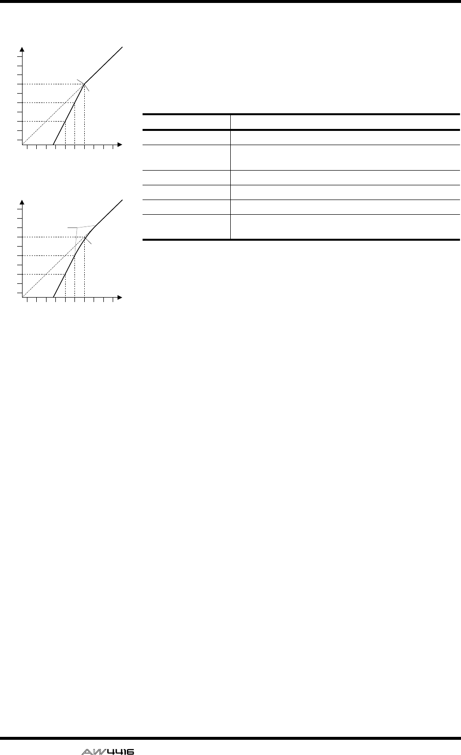
Appendix
Appendix–26 — Reference Guide
Expander
An expander is another form of automatic level control. By attenuating the
signal below the threshold, the expander reduces low-level noise and effec-
tively increases the dynamic range of the recorded material.
Expander (EXP) parameters:
Threshold determines the level of input signal required to trigger the
expander. Signals above the threshold pass through unaffected. Signals at
and below the threshold level are attenuated by the amount specified using
the Ratio parameter. The trigger signal is determined using the KEY IN
parameter.
Ratio controls the amount of expansion—the change in output signal level
relative to change in input signal level. With a 1:2 ratio, for example, a 5 dB
change in input level (below the threshold) results in a 10 dB change in out-
put level. For a 1:5 ratio, a 2 dB change in input level (below the threshold)
results in a 10 dB change in output level.
Attack controls how soon the signal is expanded once the expander has
been triggered. With a fast attack time, the signal is expanded almost imme-
diately. With a slow attack time, the initial transient of a sound passes
through unaffected.
Out Gain sets the expander’s output signal level.
Knee sets the transition of the signal at the threshold. With a hard knee, the
transition between unexpanded and expanded signal is immediate. With
the softest knee, knee5, the transition starts before the signal reaches the
threshold and gradually ends above the threshold.
Release determines how soon the expander returns to its normal gain once
the trigger signal level drops below the threshold.
Parameter Value
Threshold (dB) –54 to 0 (55 points)
Ratio 1.0, 1.1, 1.3, 1.5, 1.7, 2.0, 2.5, 3.0, 3.5, 4.0, 5.0, 6.0, 8.0,
10, 20, ∞(16 points)
Attack (ms) 0 to 120 (121 points)
Outgain (dB) 0 to +18 (36 points)
Knee hard,1,2,3,4,5 (6 points)
Release (ms) 5 ms to 42.3 sec*1, 6 ms to 46.0 sec*2,
8 ms to 63.4 sec*3 (160 points)
*1. These values are obtained when the sampling frequency is 48kHz.
*2. These values are obtained when the sampling frequency is 44.1 kHz.
*3. These values are obtained when the sampling frequency is 32 kHz
-70
-60
-50
-40
-30
-20
-10
0
+10
+20
-70 -60 -50 -40 -30 -20 -10 0 +10 +20
Input Level
Output Level
dB
dB
Threshold = -10dB
Knee = hard
Expansion ratio = 2:1
-70
-60
-50
-40
-30
-20
-10
0
+10
+20
-70 -60 -50 -40 -30 -20 -10 0 +10 +20
Input Level
Output Level
dB
dB
Threshold = -20dB
Knee = knee5
Expansion ratio = 2:1
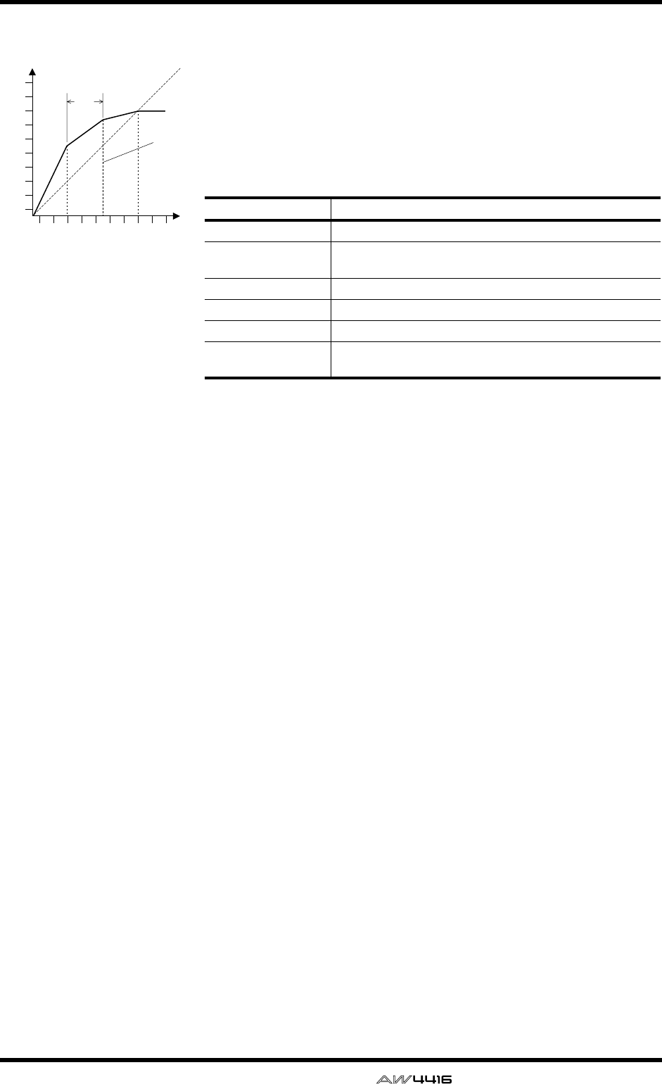
Appendix
— Reference Guide Appendix– 27
Compander
A compander is a compressor-expander—a combination of signal compres-
sion and expansion. The compander attenuates the input signal above the
threshold as well as the level below the width. For very dynamic material,
this program allows you to retain the dynamic range without having to be
concerned with excessive output signal levels and clipping.
CompanderH (CPH) and CompanderS (CPS) parameters:
Threshold determines the level of input signal required to trigger the com-
pander. Signals above the threshold pass through unaffected. Signals at and
below the threshold level are attenuated by the amount specified using the
Ratio parameter. The trigger signal is determined using the KEY IN parame-
ter.
Ratio controls the amount of companding—the change in output signal
level relative to change in input signal level. With a 2:1 ratio, for example, a
10 dB change in input level (above the threshold) results in a 5 dB change
in output level. The hard compander (CPH) has a fixed ratio of 5:1 for
expansion and the soft compander (CPS) has a fixed ratio of 1.5:1 for
expansion.
Attack controls how soon the signal is companded once the compander has
been triggered. With a fast attack time, the signal is companded almost
immediately. With a slow attack time, the initial transient of a sound passes
through unaffected.
Out Gain sets the compander’s output signal level.
Width is used to determine the distance, in decibels, between the expander
and the compressor. With a width of 90 dB, the expander is effectively
switched off and the compander is simply a compressor-limiter. With a
smaller width (30dB) and a high threshold (0dB), the compander is an
expander-compressor-limiter.
Release determines how soon the compander returns to its normal gain
once the trigger signal level drops below the threshold.
Parameter Value
Threshold (dB) –54 to 0 (55 points)
Ratio 1.0, 1.1, 1.3, 1.5, 1.7, 2.0, 2.5, 3.0, 3.5, 4.0, 5.0, 6.0, 8.0,
10, 20 (15 points)
Attack (ms) 0 to 120 (121 points)
Outgain (dB) –18 to 0 (36 points)
Width (dB) 1 to 90 (90 points)
Release (ms) 5 ms to 42.3 sec*1, 6 ms to 46.0 sec*2,
8 ms to 63.4 sec*3 (160 points)
*1. These values are obtained when the sampling frequency is 48kHz.
*2. These values are obtained when the sampling frequency is 44.1 kHz.
*3. These values are obtained when the sampling frequency is 32 kHz
-70
-60
-50
-40
-30
-20
-10
0
+10
+20
-70 -60 -50 -40 -30 -20 -10 0 +10 +20
Input Level
Output Level
dB
dB
Threshold
Width
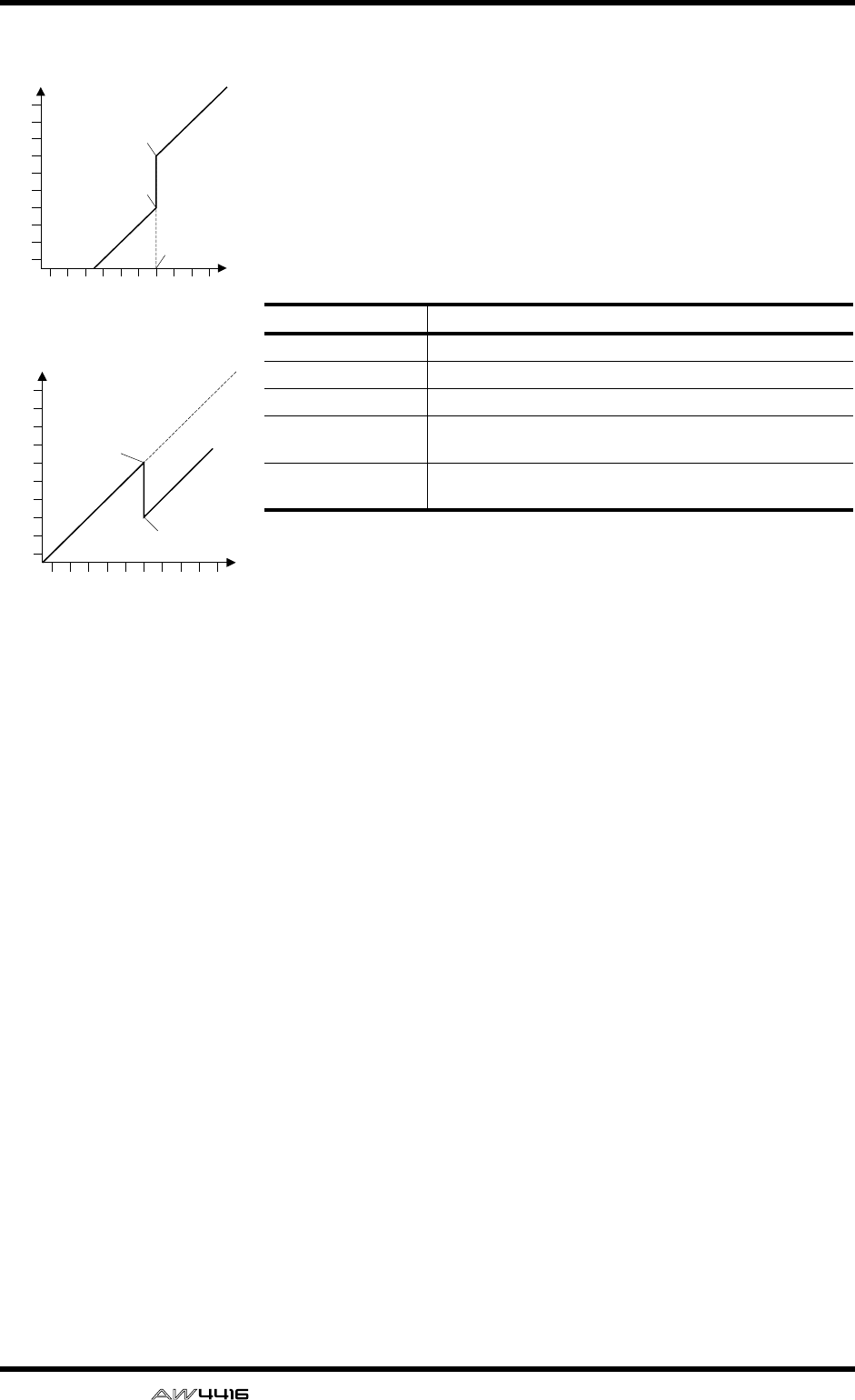
Appendix
Appendix–28 — Reference Guide
Gate and Ducking
A gate, or noise gate is an audio switch used to mute signals below a set
threshold level. It can be used to suppress background noise and hiss from
valve (tube) amps, effects pedals, and microphones.
Ducking is used to automatically reduce the levels of one signal when the
level of a source signal exceeds a specified threshold. It is used for voice-
over applications where, for example, level of background music is auto-
matically reduced, allowing an announcer to be heard clearly.
Gate (GAT) and Ducking (DUK) parameters:
Threshold sets the level at which the gate closes, cutting off the signal. Sig-
nals above the threshold level pass through unaffected. Signals at or below
the threshold cause the gate to close.
For ducking, trigger signal levels at and above the threshold level activate
ducking, and the signal level is reduced to a level set by the Range parame-
ter.
The trigger signal is determined using the KEY IN parameter.
Range controls the level to which the gate closes. It can be used to reduce
the signal level rather than cut it completely. At a setting of –70 dB, the gate
closes completely when the input signal falls below the threshold. At a set-
ting of –30 dB, the gate only closes so far allowing an attenuated signal
through. At a setting of 0 dB, the gate has no effect. When signals are gated
abruptly, the sudden cutoff can sound odd.
For ducking, a setting of –70 dB causes the signal to be virtually cutoff. At a
setting of –30 dB the signal is ducked by 30 dB. At a setting of 0 dB, the
duck has no effect.
Attack determines how fast the gate opens when the signal exceeds the
threshold level. Slow attack times can be used to remove the initial transient
edge of percussive sounds. Too slow an attack time makes some signals
sound backwards.
For ducking, this controls how soon the signal is ducked once the duck has
been triggered. With a fast attack time, the signal is ducked almost immedi-
ately. With a slow attack time, ducking fades the signal. Too fast an attack
time may sound abrupt.
Hold sets how long the gate stays open or the ducking remains active once
the trigger signal has fallen below the threshold level.
Decay controls how fast the gate closes once the hold time has expired. A
longer decay time produces a more natural gating effect, allowing the natu-
ral decay of an instrument to pass through.
For ducking, this determines how soon the ducker returns to its normal gain
after the hold time has expired.
Parameter Value
Threshold (dB) –54 to 0 (55 points)
Range (dB) –70 to 0 (71 points)
Attack (ms) 0 to 120 (121 points)
Hold (ms) 0.02 ms to 1.96s*1, 0.02 ms to 2.13 sec*2, 0.03 ms to 2.94 sec*3
(216 points)
*1. These values are obtained when the sampling frequency is 48kHz.
*2. These values are obtained when the sampling frequency is 44.1 kHz.
*3. These values are obtained when the sampling frequency is 32 kHz
Decay (ms) 5ms to 42.3s *1., 6 ms to 46.0 sec*2.,
8 ms to 63.4 sec *3. (160 points)
-70
-60
-50
-40
-30
-20
-10
0
+10
+20
-70 -60 -50 -40 -30 -20 -10 0 +10 +20
Input Level
Output Level
dB
dB
Threshold = -10dB
Range = -30dB
Range = -70dB
-70
-60
-50
-40
-30
-20
-10
0
+10
+20
-70 -60 -50 -40 -30 -20 -10 0 +10 +20
Input Level
Output Level
dB
dB
Range = -30dB
Threshold = -20dB
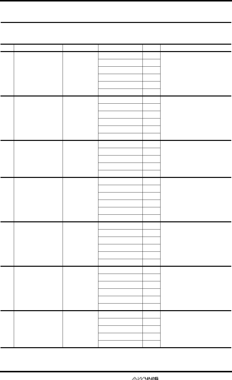
Appendix
— Reference Guide Appendix– 29
Preset Dynamics Program Parameters
The “Release”, “Hold”, and “Decay” values shown in the following table are valid when the AW4416 is set at
a sampling frequency of 44.1 kHz.
No. Name Type Parameter Value Description
001 A.Dr.BD "CMP Compressor
Threshold (dB) –24 Compressor that gives the best
results with an acoustic bass drum.
Ratio ( :1) 3
Attack (ms) 9
Outgain (dB) 5.5
Knee 2
Release (ms) 58
002 A.Dr.BD "EXP Expander
Threshold (dB) –23 Expander for the same purpose as
program 001.
Ratio ( :1) 1.7
Attack (ms) 1
Outgain (dB) 3.5
Knee 2
Release (ms) 70
003 A.Dr.BD "GAT Gate
Threshold (dB) –11 Gate for the same purpose as
program 001.
Range (dB) –53
Attack (ms) 0
Hold (ms) 1.93
Decay (ms) 400
004 A.Dr.BD "CPH CompanderH
Threshold (dB) –11 Hard compander for the same
purpose as program 001.
Ratio ( :1) 3.5
Attack (ms) 1
Outgain (dB) –1.5
Width (dB) 7
Release (ms) 192
005 A.Dr.SN "CMP Compressor
Threshold (dB) –17 Compressor that gives the best
results with an acoustic snare
drum.
Ratio ( :1) 2.5
Attack (ms) 8
Outgain (dB) 3.5
Knee 2
Release (ms) 12
006 A.Dr.SN "EXP Expander
Threshold (dB) –23 Expander for the same purpose as
program 005.
Ratio ( :1) 2
Attack (ms) 0
Outgain (dB) 0.5
Knee 2
Release (ms) 151
007 A.Dr.SN "GAT Gate
Threshold (dB) –8 Gate for the same purpose as
program 005.
Range (dB) –23
Attack (ms) 1
Hold (ms) 0.63
Decay (ms) 238

Appendix
Appendix–30 — Reference Guide
008 A.Dr.SN "CPS CompanderS
Threshold (dB) –8 Soft compander for the same
purpose as program 005.
Ratio ( :1) 1.7
Attack (ms) 11
Outgain (dB) 0.0
Width (dB) 10
Release (ms) 128
009 A.Dr.Tom "EXP Expander
Threshold (dB) –20 Expander for acoustic toms
automatically reduces the volume
when the toms are not played,
helping to differentiate the bass and
snare drums clearly.
Ratio ( :1) 2
Attack (ms) 2
Outgain (dB) 5.0
Knee 2
Release (ms) 749
010 A.Dr.OverTop "CPS CompanderS
Threshold (dB) –24 Soft compander to emphasize the
attack and ambience of cymbals
using overhead microphones. It
automatically reduces the volume
when the cymbals are not played,
helping differentiate the bass and
snare drums clearly.
Ratio ( :1) 2
Attack (ms) 38
Outgain (dB) –3.5
Width (dB) 54
Release (ms) 842
011 E.B.finger "CMP Compressor
Threshold (dB) –12 Compressor to equalize the attack
and volume level of a finger-picked
electric bass guitar.
Ratio ( :1) 2
Attack (ms) 15
Outgain (dB) 4.5
Knee 2
Release (ms) 470
012 E.B.slap "CMP Compressor
Threshold (dB) –12 Compressor to equalize the attack
and volume level of a slap electric
bass guitar
Ratio ( :1) 1.7
Attack (ms) 6
Outgain (dB) 4.0
Knee hard
Release (ms) 133
013 Syn.Bass "CMP Compressor
Threshold (dB) –10 Compressor to adjust and/or
emphasize the level of a synth
bass.
Ratio ( :1) 3.5
Attack (ms) 9
Outgain (dB) 3.0
Knee hard
Release (ms) 250
014 Piano1 "CMP Compressor
Threshold (dB) –9 Compressor to brighten the tonal
color of a piano.
Ratio ( :1) 2.5
Attack (ms) 17
Outgain (dB) 1.0
Knee hard
Release (ms) 238
No. Name Type Parameter Value Description

Appendix
— Reference Guide Appendix– 31
015 Piano2 "CMP Compressor
Threshold (dB) –18 A variation on program 014,
adjusting the attack and entire level
using a deeper threshold.
Ratio ( :1) 3.5
Attack (ms) 7
Outgain (dB) 6.0
Knee 2
Release (ms) 174
016 E.Guitar "CMP Compressor
Threshold (dB) –8 Compressor for backing
performances, such as electric
rhythm guitar playing chords or
arpeggios.
Ratio ( :1) 3.5
Attack (ms) 7
Outgain (dB) 2.5
Knee 4
Release (ms) 261
017 A.Guitar "CMP Compressor
Threshold (dB) –10 A variation on program 016,
intended for acoustic guitar playing
rhythm chords or arpeggios.
Ratio ( :1) 2.5
Attack (ms) 5
Outgain (dB) 1.5
Knee 2
Release (ms) 238
018 Strings1 "CMP Compressor
Threshold (dB) –11 Compressor for string instruments.
This program was intended for
violins.
Ratio ( :1) 2
Attack (ms) 33
Outgain (dB) 1.5
Knee 2
Release (ms) 749
019 Strings2 "CMP Compressor
Threshold (dB) –12 A variation on program 018,
intended for violas or cellos.
Ratio ( :1) 1.5
Attack (ms) 93
Outgain (dB) 1.5
Knee 4
Release (ms) 1.35 S
020 Strings3 "CMP Compressor
Threshold (dB) –17 A variation on program 018,
intended for string instruments with
a very low range, such as cellos or
contrabass.
Ratio ( :1) 1.5
Attack (ms) 76
Outgain (dB) 2.5
Knee 2
Release (ms) 186
021 BrassSection "CMP Compressor
Threshold (dB) –18 Compressor intended for brass
sounds with fast and strong attack.
Ratio ( :1) 1.7
Attack (ms) 18
Outgain (dB) 4.0
Knee 1
Release (ms) 226
No. Name Type Parameter Value Description

Appendix
Appendix–32 — Reference Guide
022 Syn.Pad "CMP Compressor
Threshold (dB) –13 Compressor for synth pad,
intended to prevent diffusion of the
sound.
Ratio ( :1) 2
Attack (ms) 58
Outgain (dB) 2.0
Knee 1
Release (ms) 238
023 SamplingPerc "CPS CompanderS
Threshold (dB) –18 Compressor for sampled sounds to
boost them to be as powerful and
clear as the acoustic sounds. This
program is for percussion sounds.
Ratio ( :1) 1.7
Attack (ms) 8
Outgain (dB) –2.5
Width (dB) 18
Release (ms) 238
024 Sampling BD "CMP Compressor
Threshold (dB) –14 A variation on program 023,
intended for sampled bass drum
sounds.
Ratio ( :1) 2
Attack (ms) 2
Outgain (dB) 3.5
Knee 4
Release (ms) 35
025 Sampling SN "CMP Compressor
Threshold (dB) –18 A variation on program 023,
intended for sampled snare drum
sounds.
Ratio ( :1) 4
Attack (ms) 8
Outgain (dB) 8.0
Knee hard
Release (ms) 354
026 Hip Comp "CPS CompanderS
Threshold (dB) –23 A variation on program 023,
intended for sampled sounds for
loops.
Ratio ( :1) 20
Attack (ms) 15
Outgain (dB) 0.0
Width (dB) 15
Release (ms) 163
027 Solo Vocal1 "CMP Compressor
Threshold (dB) –20 Compressor suited for a solo vocal
source.
Ratio ( :1) 2.5
Attack (ms) 31
Outgain (dB) 2.0
Knee 1
Release (ms) 342
028 Solo Vocal2 "CMP Compressor
Threshold (dB) –8 A variation on program 027.
Ratio ( :1) 2.5
Attack (ms) 26
Outgain (dB) 1.5
Knee 3
Release (ms) 331
No. Name Type Parameter Value Description

Appendix
— Reference Guide Appendix– 33
029 Chorus "CMP Compressor
Threshold (dB) –9 A variation on program 027,
intended for chorus vocals.
Ratio ( :1) 1.7
Attack (ms) 39
Outgain (dB) 2.5
Knee 2
Release (ms) 226
030 Compander(H) "CPH CompanderH
Threshold (dB) –10 A template for the hard knee
compander program.
Ratio ( :1) 3.5
Attack (ms) 1
Outgain (dB) 0.0
Width (dB) 6
Release (ms) 250
031 Compander(S) "CPS CompanderS
Threshold (dB) –8 A template for the soft knee
compander program.
Ratio ( :1) 4
Attack (ms) 25
Outgain (dB) 0.0
Width (dB) 24
Release (ms) 180
032 Click Erase "EXP Expander
Threshold (dB) –33 Expander to remove click track
sounds that may bleed out of the
monitor headphones the musicians
are using.
Ratio ( :1) 2
Attack (ms) 1
Outgain (dB) 2.0
Knee 2
Release (ms) 284
033 Announcer "CPH CompanderH
Threshold (dB) –14 Hard compander reduces the level
during the interval between the
words, making the voice sound
even.
Ratio ( :1) 2.5
Attack (ms) 1
Outgain (dB) –2.5
Width (dB) 18
Release (ms) 180
034 Easy Gate "GAT Gate
Threshold (dB) –26 A template for the gate program.
Range (dB) –56
Attack (ms) 0
Hold (ms) 2.56
Decay (ms) 331
035 BGM Ducking "DUK Ducking
Threshold (dB) –19 Ducking background music for
voiceovers, typically keyed from the
announcer’s channel.
Range (dB) –22
Attack (ms) 93
Hold (ms) 1.20 S
Decay (ms) 6.32 S
036 Limiter1 "CMP CompanderS
Threshold (dB) –8 A template for a limiter using the
soft compander program. This
program has a slow release.
Ratio ( :1) 4
Attack (ms) 25
Outgain (dB) 0.0
Width (dB) 24
Release (ms) 180
No. Name Type Parameter Value Description
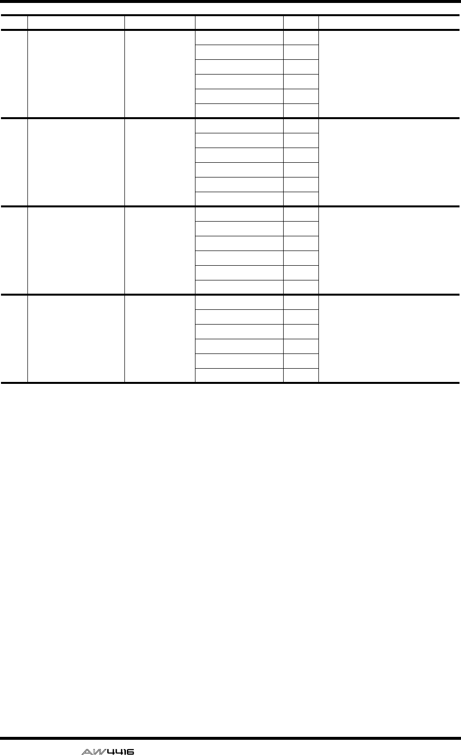
Appendix
Appendix–34 — Reference Guide
037 Limiter2 "CMP Compressor
Threshold (dB) 0 A template for a limiter using the
compressor program. This program
is a PEAK STOP type.
Ratio ( :1) ∞
Attack (ms) 0
Outgain (dB) 0.0
Knee hard
Release (ms) 319
038 Total Comp1 "CMP Compressor
Threshold (dB) –8 Compressor intended to reduce the
overall volume level. Use for the
stereo out during mixdown. It is also
interesting on stereo input signals.
Ratio ( :1) 2.5
Attack (ms) 60
Outgain (dB) 0.0
Knee 2
Release (ms) 1.12 S
039 Total Comp2 "CMP Compressor
Threshold (dB) –18 A variation of program 038. It has a
harder compression ratio.
Ratio ( :1) 3.5
Attack (ms) 94
Outgain (dB) 2.5
Knee hard
Release (ms) 447
040 Total Comp3 "CMP Compressor
Threshold (dB) –16 A variation of program 038. It has
an extreme compression ratio,
almost a limiter in effect.
Ratio ( :1) 6
Attack (ms) 11
Outgain (dB) 6.0
Knee 1
Release (ms) 180
No. Name Type Parameter Value Description

Appendix
— Reference Guide Appendix–35
Troubleshooting
If the AW4416 does not operate as you expect, or if you suspect a prob-
lem, please refer to the following points and take the appropriate action.
■Power does not turn on
• Is the power cable connected to an AC outlet of
the correct voltage?
• Is the POWER switch turned ON?
• If the power still does not turn on, please contact
your Yamaha dealer.
■Internal hard disk is not detected
• Is the internal hard disk connected correctly?
• The pins of the internal hard disk may have been
deformed.
• Has the internal hard disk been formatted appro-
priately? *
* If an unformatted hard disk is installed, a message
will appear when the power is turned on, asking
you whether you wish to format the hard disk.
■LCD display is dim or dark
• Use the contrast knob located at the lower right
of the screen to adjust the contrast.
■Input sound is not output
• Are speakers or headphones connected cor-
rectly?
• Is your amp and other external devices turned
on?
• Is the signal from the external device being input?
• The connection cable from the external device
may be broken.
• Is the [GAIN] control set to an appropriate level?
• Is the fader of the input channel or monitor chan-
nel raised?
• Is the [ON] key of the input channel or monitor
channel lit?
• Is the fader of the stereo output channel raised?
• Is the [ON] key of the stereo output channel lit?
• Is the option card installed correctly?
• Is the input/output patching set correctly?
• Is the word clock set correctly?
• The jack being used for input may have been
assigned as an EFFECT INSERT return.
• Is the attenuator raised in the EQ screen or VIEW
screen?
■Recorded sound is not output
• Has audio data been recorded on the recorder?
• Muting may be enabled in the TRACK screen TR
View page.
• The input monitor mode may be set to INPUT.
• Is the virtual track set to the track that was
recorded?
• A region shorter than the specified region fade
time cannot be played.
■Can’t hear the signal from the INPUT 1/2 jacks
• An external effect unit may be connected to the
INSERT jack, and turned off.
■Signal from the INPUT 8 jack is too loud
• A conventional line-level signal may be con-
nected to the Hi-Z jack.
■Sound is too soft
• Are the speakers or headphones connected cor-
rectly?
• Is the volume of your amp or external equipment
raised?
• Is the [GAIN] control set correctly?
• Is the fader of the input channel or monitor chan-
nel raised?
• Is the fader of the stereo output channel raised?
• The EQ gain may be set to an extremely low
value.
• The dynamics processor may be set to an
extreme threshold or ratio.
• If you are connecting an electric guitar, is it con-
nected to the Hi-Z jack?
• Check the level in the HOME screen. For details
refer to P.75 “HOME screen.”
• Is the attenuator of the EQ screen or VIEW screen
raised?
■Sound is distorted
• Is the [GAIN] control set correctly?
• The connection cable from the external device
may be broken.
• The fader of the input channel or monitor chan-
nel may be raised excessively.
• The stereo output channel fader may be raised
excessively.
• The stereo output channel attenuator may be
raised excessively.
• The EQ gain may be excessively high.
• Did you record at an appropriate level?
• Is the word clock setting correct for both the
AW4416 and the external device(s)?
• An effect such as Distortion or Amp Simulate
may be in use.

Appendix
Appendix–36 — Reference Guide
■Can’t record
• Is the internal hard disk connected?
• Is there sufficient free space on the internal hard
disk?
• The song may be protected.
• Is the [REC TRACK SELECT] key lit?
• The stereo track may be in playback mode.
• Is the input signal routed appropriately to the
recorder? *
* If the signal is being input appropriately to the
recorder, pressing the [REC TRACK SELECT] key
will cause the meter in the FL display to react.
• When a file input/output page such as the SONG
screen Song List page is displayed, recording and
playback are not possible.
• CD/DAT DIGITAL REC in the UTILITY screen Pre-
fer.2 page may be set to DISABLE.
• Please read and understand the copyright warn-
ing (→ P.36) before using digital input signals.
■Can’t record on the STEREO track
• It is not possible to record on the STEREO track
while recording on other tracks.
■Can’t play back the STEREO track
• Muting may be selected in the TRACK screen Ste-
reo page.
• Are monitor channels 1 and 2 raised? *
* For STEREO track playback mode, the signal is
output from monitor channels 1 and 2.
■Not all tracks will play back
• There are limitations on the number of tracks that
can be simultaneously recorded or played. Refer
to page 90.
■The volume of a particular channel increases or
decreases
• Are the dynamics processor settings appropriate?
• EQ may have been recorded in the automix.
■Faders move to the lowest position on their own
• Automix may have been recorded.
• Faders 9–14 cannot be operated when the mixing
layer is 17–24/RTN.
■Meters move even though the faders are lowered
• The direct out setting may be PRE EQ or PRE
FADER.
• The meter display may be set to PRE FADER.
■Can’t store a scene
• Is the scene memory protected?
• A scene cannot be stored in scene number 00.
■Can’t reproduce a scene
• One or more channels may be set to Recall Safe.
■Can’t recall a scene during recording
• The AW4416 may be set to record the digital
input signal.
• Make sure that CD/DAT DIGITAL REC is set to
ENABLE.
■Can’t change input patches during recording
• The AW4416 may be set to record the digital
input signal.
• Make sure that CD/DAT DIGITAL REC in the
UTILITY screen Prefer.2 page is set to ENABLE.
■Can’t save to a library
• It is not possible to save to the factory-preset
libraries.
■Can’t recall a channel library to the stereo out-
put channel
• Channel libraries saved from other channels can-
not be recalled to the stereo output channel.
■Can’t exchange MIDI data
• Are the MIDI cables connected correctly?
• A MIDI cable may be broken.
• Is the power turned on for the transmitting and
receiving devices?
• Do the channel settings match for the transmitted
and receiving devices?
• In the MIDI screen MIDI Setup page, is PORT
SELECT effect to MIDI?
• In the MIDI screen MIDI Setup page, are PRO-
GRAM CHANGE TX and RX set to ON?
• Is a scene assigned to the program change num-
ber being transmitted?
■MIDI messages are looped
• In the MIDI screen MIDI Setup page, ECHO may
be turned ON.
• Also check the settings of the connected external
MIDI devices.
■MTC messages are not transmitted
• Is the MIDI cable correctly connected to the MTC
OUT connector? MTC is not transmitted from the
MIDI OUT connector.
• Is SYNC OUT set correctly?
• Is MTC SYNC set to MASTER?
■The AW4416 does not synchronize to incoming
MTC messages
• Is the MIDI cable connected to the MIDI IN con-
nector?
• In the MIDI screen MIDI Sync page, is MTC Sync
set to SLAVE?
■MTC messages are received, but synchronization
drifts
• Is a large amount of MIDI data (notes etc.) being
received together with the MTC messages?

Appendix
— Reference Guide Appendix–37
■MTC synchronization drifts
• Does the frame rate match between the AW4416
and the external device?
• SYNC OFFSET may have been set.
• If jumps occur in the synchronized time, change
the SYNC AVE. setting in the MIDI screen MIDI
Sync page, and try again.
■Something happens to the sound when the
[DATA/JOG] dial, [SHUTTLE] dial, [FF] key, or
[REW] key are operated
• Differences in the number of simultaneously
played tracks will affect the way in which the
sound is heard when these controls are operated.
■MMC is not transmitted
• Is the MIDI cable connected to the MIDI OUT
connector?
• MMC messages are not transmitted from the
MTC OUT connector.
■MIDI data is not exchanged via the TO HOST
connector
• Is the cable correctly connected to the TO HOST
connector?
• PORT SELECT may be set to MIDI.
• Is the PORT SELECT setting appropriate for your
computer? *
* For details on this setting, refer to page 39 “MIDI
screen.”
• A computer application other than your
sequencer may be using the port.
■Metronome cannot be heard
• The metronome sound is normally sent only to
the MONITOR OUT and headphones. *
* Settings can also be made in the SETUP screen
Patch IN page to assign the metronome to an out-
put channel.
■Moving a fader does not change the level
• Is the appropriate fader mode and mixing layer
selected?
• The fader may be set to PRE FADE in AUX.
■The ON key and SEL key select the wrong chan-
nel
• Is the appropriate mixing layer selected?
■Noise is present in the recorded signal
• Does the word clock setting match for the
AW4416 and the external device(s)?
• Is an unsynchronized signal being input?
• Is the dither setting appropriate?
• The oscillator may be functioning.
• If the speed of your internal hard disk is slow,
problems may occur during recording and play-
back. Please use only the recommended internal
hard disks.
■Sound recorded via the digital input sounds
grainy
• Is the dither setting appropriate?
■Pairing was specified, but the signal is monaural
• Is the odd-numbered channel panned far left and
the even-numbered channel panned far right?
■Pairing was specified, but the signal phase does
not match
• Even when channels are paired, the phase setting
is not linked.
■Signal is delayed
• Is the channel delay set correctly?
■Automix cannot be recorded
• Is automix set to ENABLE?
• In the AUTOMIX screen, is the REC or AUTO
REC button turned ON?
• Is the [SEL] key lit for the channel you are operat-
ing?
• Is OVERWRITE turned ON for the control (e.g.,
fader or EQ) you are operating?
■Can’t use the internal effects
• Effect BYPASS may be turned ON.
• Are the EFF.RTN 1, 2 faders raised?
• In the SETUP screen Patch IN page, EFFECT
PATCH may be set to INSERT.
• It is not possible to insert one effect into multiple
channels.
• 019. HQ. Pitch can be used only with EFFECT 2.
■Can’t use SOLO
• The channel may be set to Solo Safe.
• Is the SETUP screen Solo Setup page set appro-
priately? *
* For details on the settings, refer to page 14,
“SETUP screen.”
■Can’t edit a recorded track
• Have you selected the virtual track that you
recorded?
■Fader groups and mute groups don’t work
• In the EQ screen Fader Group page and Mute
Group page, check that grouping is set to
ENABLE.
■Editing results are not heard in the sound
• Have you selected the virtual track that you
recorded?
• Are you using the appropriate editing
command? *
* For details on editing commands, refer to page 99
“EDIT screen.”

Appendix
Appendix–38 — Reference Guide
■Playback pitch is wrong
• VARI may be selected.
• Is the AW4416 operating on the same sampling
frequency as the synchronized external device?
• Is the master device operating in a stable way?
• You may have executed the EDIT screen PITCH
command.
• Is an effect such as HQ.Pitch or Dual Pitch
selected for a monitor channel?
■Counter display is not 0 when you return to the
beginning of the song
• The display mode may be set to REMAIN
(remaining recording time).
• If the display mode is set to REL (relative time),
the start point may be specified.
• The SONG screen Setting page may be set to
MEASURE. *
* For details on this setting, refer to page 1 “SONG
screen.”
■No sound from the sampling pads
• In the SETUP screen Patch IN page, are the sig-
nals from the sampling pads assigned to a chan-
nel?
• The bank A/B setting may be incorrect.
■Can’t save a file
• Is there sufficient space on the internal hard disk?
• Did you perform the correct shut-down proce-
dure when you last turned off the power? *
* If you turn off the power without performing the
shut-down, data may be lost or the hard disk may
be damaged.
■Song file size is unnaturally large
• Even after you use recorder editing to erase a
track etc., that sound file will be saved on the
disk as an unused file. Execute the optimize oper-
ation in the SONG screen Song Edit page.
■File date is not recorded correctly
• Is the internal clock set to the correct date and
time? *
* If the date and time of the internal clock has
drifted, the internal battery may have run down.
Please contact your Yamaha dealer.
■A device connected to the SCSI connector is not
recognized
• The power of the SCSI device may have been
turned on after the AW4416.
• Is the SCSI cable connected correctly?
• The pins of the SCSI cable may have been bent.
• Is the ID of the SCSI device set correctly?
• Is termination specified correctly for the SCSI
device?
■Can’t save files on a SCSI device
• Is there sufficient free space on the save destina-
tion media?
• Has the save destination media been formatted
appropriately?
■Can’t load files from a SCSI device
• Is there sufficient free space on the internal hard
disk?
■CD-RW drive is not recognized
• Is the CD-RW drive connected correctly?
■Can’t create an audio CD
• Is CD-R media inserted?
• The inserted CD-R may have already been final-
ized.
• Is a signal recorded on the stereo track?
• The stereo track must be at least four seconds
long.
• It is not possible to create an audio CD from a
song whose Fs (sampling frequency) setting is
48 kHz.
■An audio CD you created does not play back on
a conventional player
• An audio CD you created you not play back on a
conventional player unless the disc has been
finalized.
■Audio recorded on CD-RW media does not play
back on some players
• In order for audio data recorded on CD-RW
media to be played back, the player must support
CD-RW. Contact the manufacturer of the player
regarding CD-RW support.
■The sound skips while playing an audio CD that
you created
• There may be differences in the quality of the
completed CD depending on the type of CD-R
media you use. If this occurs, try using single
speed (normal speed) recording rather than dou-
ble-speed or faster recording.
■The screen changes on its own when you oper-
ate the PAN or EQ encoders
• In the UTILITY screen Prefer. 1 page, turn the
AUTO PAN DISPLAY and AUTO EQ DISPLAY
settings OFF. *
* For details refer to page 33 “UTILITY screen.”
■Can’t use the [DATA/JOG] dial to control on-
screen parameters
• The [NUM LOCATE] key may be on.
• The [JOG ON] key may be on.

Appendix
— Reference Guide Appendix–39
Display message list
Messages
AUTOMIX DISABLED. Automix is not enabled, and cannot be recorded.
AUTOMIX MEMORY FULL! Automix memory has no free area.
AUTOMIX NOT RUNNING. Automix has been stopped, so recording is not possible. Pause the
recorder, and then playback.
AUTOMIX REC ABORTED. Automix recording was stopped, and the data was discarded.
AUTOMIX RECORDING. The operation cannot be executed since automix is being
recorded.
AUTOMIX RUNNING. The operation cannot be executed since automix is being
recorded or played.
BANK A SELECTED Since sampling pad bank A is selected, muting cannot be defeated
for this pad.
BANK B SELECTED Since sampling pad bank B is selected, muting cannot be defeated
for this pad.
CANNOT ASSIGN DIGITAL-ST-IN. DIGITAL STEREO IN cannot be assigned to the stereo bus cas-
cade.
CANNOT CHANGE THE MUTE Muting cannot be defeated since this would exceed the number of
simultaneously playable tracks.
CANNOT PLAY THIS PAGE Playback is not possible in this page.
CANNOT RECALL AUTOMIX Recall is not possible, since automix data has not been stored.
CANNOT REDO Redo (re-execution of an operation) is not possible.
CANNOT SELECT (MTC SLAVE) Since the AW4416 is set to be the MTC slave, the external word
clock cannot be selected as the word clock source.
CANNOT SELECT (WC EXTERNAL) Since the external word clock is selected as the word clock
source, the AW4416 cannot be set as the MTC slave.
CANNOT SET MARK It is not possible to specify a mark at an already-specified position.
CANNOT UNDO Undo (cancellation of an operation) is not possible.
CANNOT USE BOTH SLOTS! OPTION I/O slot 1 and slot 2 cannot be used simultaneously.
CD PLAY MODE NOW. Since the AW4416 is in CD Play mode, this operation is not possi-
ble.
DIFFERENT TC FRAME TYPE MTC of a different frame type than the internal setting is being
received.
DIGITAL-ST-IN REC PROHIBIT. Recording is prohibited for the signal being input from DIGITAL
STEREO IN.
DIGITAL-ST-IN SYNC ERROR! The signal being input from DIGITAL STEREO IN is not synchro-
nized to the word clock master.
DIN TO STEREO BUS REFUSE. Since the signal was interrupted, cascading from DIGITAL STE-
REO IN to the stereo bus has been defeated.
EFF1 INSERT RELEASED Effect 1 has been released from insertion because a patch library
was recalled.
EFF2 INSERT RELEASED Effect 2 has been released from insertion because a patch library
was recalled.
FOR EFFECT2 ONLY. The selected effect program can be used only with effect 2.
IN/OUT POINTS TOO CLOSE The auto punch-in/out interval is too short. It cannot be set less
than approximately 100 msec.

Appendix
Appendix–40 — Reference Guide
INT.EFF NOW SELECTED AUX. The internal effect is connected to the AUX send, and cannot be
inserted.
LOW BATTERY!! The internal battery is running down.
MAKE NEW MIX. There are no events to be edited. Please create a new mix.
MARK ERASED The mark has been erased.
MARK SET The mark has been set.
MIDI IN: DATA FRAMING ERROR! Invalid data may have been received at the MIDI IN connector.
MIDI IN: DATA OVERRUN! Invalid data may have been received at the MIDI IN connector.
MIDI: RX BUFFER FULL! The AW4416 is receiving more MIDI data than it can handle.
MIDI: TX BUFFER FULL! The AW4416 is attempting to transmit more MIDI data than it can
handle.
NO CURRENT AUTOMIX. There is no valid automix data. Please create a new mix.
NO DATA TO RECALL. Since data has not been stored, it cannot be recalled.
NO MARK LEFT The allowable number of marks has been exceeded.
PLAY TRACK MUTE IS ON Playback tracks were muted because the allowable number of
simultaneously recorded/played tracks was exceeded.
RECORDER BUSY The operation cannot be executed because the recorder is operat-
ing.
RECORDER RUNNING The operation cannot be executed because the recorder is record-
ing or playing.
REDO COMPLETE Redo (re-execution of the previous operation) has been com-
pleted.
REPEAT POINTS TOO CLOSE The repeat interval is too short. It cannot be set to less than one
second.
SELECTED AREA HAS NO DATA. The selected area contains no trigger data.
SELECTED AREA HAS NO REGION. The selected area contains no region.
SELECTED CH IS NONE. The selected channel cannot be selected since it does not exist.
SELECTED CH ONLY MODE. The channel cannot be changed, since the display mode is set to
SELECTED CH ONLY.
SELECTED PAD NOT ASSIGNED. No sample is assigned to the selected sampling pad.
SELECTED SONG HAS NO REGION. The selected song does not contain a region.
SELECTED TRACK HAS NO REGION. The selected track does not contain a region.
SELECTED TRACK NOT RECORDED. The selected track does not contain recorded data.
SLOT1 INPUT SYNC ERROR! The signal being input to the input jack of a card installed in
OPTION I/O slot 1 is not synchronized to the word clock master.
SLOT1,2 INPUT SYNC ERROR! The signal being input to the input jack of a card installed in an
OPTION I/O slot is not synchronized to the word clock master.
SLOT2 INPUT SYNC ERROR! The signal being input to the input jack of a card installed in
OPTION I/O slot 2 is not synchronized to the word clock master.
SOLO READY. The Solo function is ready. Use the [SEL] keys to select the solo
channel.
SOLO SLAVE. The Solo status cannot be changed when the AW4416 is function-
ing as a cascade slave. Press the Solo key on the master console.
SONG NUMBER FULL. The maximum number of songs has been reached.
SONG TOP/END OUT OF RANGE You located outside the top/end range of the song.
STEREO PAIRED. You are attempting to defeat ST LINK for the dynamics of paired
channels.

Appendix
— Reference Guide Appendix–41
Popup messages
STEREO TRACK MUTE IS OFF Since muting is off for the stereo track, track muting cannot be
turned off.
THIS SONG IS PROTECTED. This song is protected, and cannot be edited or recorded.
TO HOST: DATA FRAMING ERROR! Invalid data may have been received at the TO HOST connector.
TO HOST: DATA OVERRUN! Invalid data may have been received at the TO HOST connector.
TO HOST: DATA PARITY ERROR! Invalid data may have been received at the TO HOST connector.
TO HOST: RX BUFFER FULL! Excessive amounts of data may have been received at the TO
HOST connector.
TO HOST: TX BUFFER FULL! The AW4416 may be attempting to transmit excessive amounts of
data from the TO HOST connector.
TRIGGER LIST RECORDING A sampling pad trigger list is being recorded.
UNDO COMPLETE Undo (cancellation of the previous operation) has been executed.
WRONG WORD CLOCK!! The word clock from a connected device selected by the AW4416
for synchronization is not appropriate.
CD Access Error! A error occurred when accessing the CD.
CD Size Full! Data exceeding the recordable length of the CD cannot be added.
CD Track Over! The maximum number of tracks has been reached, and further
addition is not possible.
Can’t Copy This Parameter! This parameter cannot be copied.
Can’t Create Image File! Since the disk is full, a CD image file cannot be created.
Can’t Delete Current Song! The currently loaded song cannot be deleted.
Can’t Delete Protected Song! A protected song cannot be deleted.
Can’t Edit Multiple Songs! This editing operation cannot be executed on multiple songs
simultaneously.
Can’t Optimize Protected Song! Optimize cannot be executed on a protected song.
Can’t REDO Redo is not possible.
Can’t Select Current Song! The currently loaded song cannot be edited.
Can’t UNDO Undo is not possible.
Can’t Write CD-RW by Track At Once! A CD-RW cannot be written using Track At Once.
Change Media, Invalid Order. Please exchange the media. The order of media volumes is incor-
rect.
Change Media, Not 1st Media Please exchange the media. This is not the first media volume.
Change Media, Not TYPE 1 Backup. Please exchange the media. This media was not backed up as
TYPE 1.
Change Media, Not TYPE 2 Backup. Please exchange the media. This media was not backed up as
TYPE 2.
Change Media, Please The media is an incorrect type. Please exchange it.
Device Error! A problem has occurred with the SCSI device.
Directory Name Too Long! The directory name is too long and cannot be displayed.
Directory Not Found! The specified directory cannot be found.
Disk Full! The disk has no free capacity.
File System Error! An error has occurred in the file system of the internal hard disk.
Finalized Media! The media has already been finalized.
Invalid Parameter! The parameter setting exceeds the allowable range.

Appendix
Appendix–42 — Reference Guide
Media Error! A problem has occurred on the media.
Media Full! The media has no free space.
Media Protected! The media is write-protected.
Memory Full! There is no free space in the sampling pad memory.
No Song to Backup! There is no song to backup.
No Song to Edit! There is no song to edit.
No Song to Load! There is no song to load.
No Song to Restore! There is no song to restore.
No Song to Save! There is no song to save.
No Song to Write! No songs to write to the CD have been selected.
No Song! No songs can be found.
No Stereo Track! There is no stereo track.
No Track to Open Wave Display! There is no track data for waveform display.
Not WAV Drive! The selected drive contains no WAV files.
Not WAV File! The file is not a WAV file.
Partition Not Found! The specified partition was not found.
Recall Channel Data Conflict! The specified channel library cannot be loaded into this channel.
SCSI Error! An error has occurred in the SCSI connection.
Selected Drive is not CD Drive! The drive of the selected SCSI ID is not a CD drive.
Selected Drive is not Connected! The drive of the selected SCSI ID is not connected.
Selected Preset is Effect2 Only! The selected preset can be used only by effect 2.
Selected Song Status Conflict! The track cannot be imported, since it is from a song with a differ-
ent sampling frequency or quantization (bit length).
Selected Track is not Recorded! The selected track is not recorded.
Too Many Regions! There are too many regions.
Too Small Region! Time compression/expansion cannot be executed since the region
is too small.

Appendix
— Reference Guide Appendix–43
Specifications
General Specifications
AD converter 24-bit linear, 64-times oversampling
DA converter 24-bit linear, 128-times oversampling
Internal processing 32-bit
Sampling frequency Internal 44.1 kHz/48kHz
External 44.1 kHz (–6%) to 48 kHz (+6%)
Audio input section max. 26 channels
MIC/LINE 8 channels
DIGITAL STEREO IN 2 channels (stereo × 1)
mini YGDAI card (option) max. 16 channels
Audio output section max. 28 channels
STEREO OUT 2 channels (stereo × 1)
OMNI OUT 4 channels
MONITOR OUT 2 channels (stereo × 1)
PHONES 2 channels (stereo × 1)
DIGITAL STEREO OUT 2 channels (stereo × 1)
mini YGDAI card (option) max. 16 channels
Mixing layer section 44 channels
Input channel 24 channels
Internal effect return 4 channels (stereo × 2)
Playback 16 channels (16 track direct out playback), or
stereo 2 channels (stereo track playback)
Internal effects section
Multi-effects × 2
Bus section 20 channels
Bus 8 channels
Aux 8 channels
Stereo 2 channels (stereo × 1)
Solo 2 channels (stereo × 1)
Sampler section
Assign to mixer section
Playback 8 voices
Trigger pads 8 × 2 banks
Sampling time max. 90 sec. (16-bit/44.1 kHz)
Recorder section
Recording medium 2.5" IDE hard disk drive
Sound file format AW4416 original format
Recording resolution 16-bit, 24-bit

Appendix
Appendix–44 — Reference Guide
Tracks 130 tracks (16 tracks × 8 virtual tracks plus ste-
reo track)
Maximum recording time Approx. 140 min (44.1 kHz, 16-bit, 16 tracks,
12 GB hard disk)
Power requirements U.S.A. & Canada 120 V 80 W AC, 60 Hz
Europe 230 V 80 W AC, 50 Hz
Dimensions (W × H × D) 558.0 × 147.7 × 459.7 mm
(22 x 5.8 x 18.1 inches)
Weight 11.8 kg (26 lbs)
Operating temperature range 5° to 35° C
Options Removable 2.5" hard disk adapter (ADP25H),
mini YGDAI cards (MY8-AT, MY8-TD, MY8-AE,
MY8-AT, MY4-AD, MY4-DA), Footswitch FC5
Mixer section
■Input/output
MIC/LINE input Channel 1, 2 (balanced, XLR-type, TRS phone
jack)
+48 V DC phantom powering
PEAK LED –3 dB (clipping level)
Input impedance 3 kΩ
Nominal input level –46 dB to +4 dB
Minimum input level –52 dB
Maximum input level +22 dB
Insert I/O Channel 1, 2 (unbalanced, TRS phone jack)
Input impedance 10 kΩ
Nominal input level 0 dB
Output impedance 600Ω
Nominal output level 0 dB
MIC/LINE input channel 3–8 (balanced, TRS phone jack)
PEAK LED –3 dB (clipping level)
Input impedance 3 kΩ
Nominal input level –46 dB to +4 dB
Minimum input level –52 dB
Maximum input level +22 dB
MIC/LINE input (Hi-Z) channel 8 (unbalanced, phone jack)
Input impedance 500 kΩ
Nominal input level –46 dB to +4 dB
Minimum input level –52 dB
Maximum input level +20 dB

Appendix
— Reference Guide Appendix–45
STEREO OUT L, R (unbalanced, phono)
Output impedance 1 kΩ
Nominal load impedance 10 kΩ
Nominal output level –10 dBV
Maximum output level +8 dBV
MONITOR OUT L, R (balanced, TRS phone jack)
Output impedance 150Ω
Nominal load impedance 10 kΩ
Nominal output level +4 dB
Maximum output level +22 dB
OMNI OUT 1–4 (unbalanced, phone jack)
Output impedance 1 kΩ
Nominal load impedance 10 kΩ
Nominal output level 0 dB
Maximum output level +18 dBV
PHONES (unbalanced, TRS phone jack)
Nominal load impedance 8–40Ω
Maximum output level 100 mW + 100 mW (40 Ω load)
DIGITAL STEREO I/O Coaxial (phono)
Option card slot Slot × 2
Digital I/O MY-8-AT (Adat)
MY-8-TD (Tascam)
MY-8-AE (AES/EBU)
Analog input MY-8-AD (TRS phone jack × 8)
MY-4-AD (XLR-type × 4)
Analog output MY-4-DA (XLR-type × 4)
■Digital mixer
Input channel (channel 1–24, playback 1–16)
Attenuator, Phase (normal, reverse), EQ (4-band
PEQ), Dynamics, Delay, On/Off, Fader (60 mm
motorized), Pan, Bus assign (stereo, bus, aux,
solo, direct out)
Internal effects return
Attenuator, Phase (normal, reverse), EQ (4-band
PEQ), Delay, On/Off, Fader (60 mm motorized),
Pan, Bus assign (stereo, bus, aux, solo)
Bus
Stereo L, R Attenuator, EQ (4-band PEQ), Dynamics, On/
Off, Fader (60 mm motorized), Balance
Bus 1–8 Attenuator
Aux 1–8 Attenuator
Solo L, R

Appendix
Appendix–46 — Reference Guide
Fader 60 mm motorized × 17
Frequency response +1, –3 dB, 20 Hz–20 kHz (MIC/LINE IN to STE-
REO OUT)
Dynamic range 109 dB (typical) DA converter (STEREO OUT)
(20 kHz, LPF, IHF-A) 104 dB (typical) AD + DA (LINE IN to STE-
REO OUT)
Total harmonic distortion
(20 kHz, LPF) Less than 0.02% @1 kHz (LINE IN to STEREO
OUT)
Recorder section
■General
Recording resolution 16-bit, 24-bit (set per song)
Sampling frequency 44.1 kHz, 48 kHz (set per song)
Maximum simultaneous recording tracks
Tracks 130 tracks (16 tracks × 8 virtual tracks plus ste-
reo track)
■Format
File system AW4416 original format
Internal hard disk drive 2.5" IDE
Max. hard disk capacity 64 GB (8 GB partition)
Max. songs per hard disk Approx. 30,000 songs
■Edit
Song edit Name, comment, delete, copy, optimize, pro-
tect, fade in/out
Track edit Name, erase, copy, exchange, slip, time com-
pression/ expansion, pitch change, import
Part edit Erase, delete, copy, move, insert, time compres-
sion/ expansion, pitch change
• 16 bit song • 24 bit song
Simultaneous
recording tracks
Simultaneous
playback tracks
Simultaneous
recording tracks
Simultaneous
playback tracks
0–8 16 0 16
9–16 0 1–2 14
3–4 12
5–8 8
16 0

Appendix
— Reference Guide Appendix–47
Region edit Erase, delete, copy, move, time compression/
expansion, pitch change, insert
■Others
Locate Direct locate: data entry search (time, measure)
Quick locate: start, end, RTZ, A/B, last rec in/
out, roll back
Punch I/O Manual punch I/O, auto punch I/O
Controls
Analog section
Input (channel 1–8) Gain (variable)
Input (channel 1, 2) +48 V (phantom switch)
Output Phones level, monitor out level
Mixer section
WORK NAVIGATE buttons SONG, QUICK REC, MASTERING, CD PLAY
UNIT buttons SETUP, FILE, UTILITY, MIDI
MIXER buttons VIEW, PAN, EQ, DYN
FADER MODE buttons AUX1, AUX2, AUX3, AUX4, AUX5, AUX6,
AUX7, AUX8, HOME
MIXING LAYER buttons 1–16, 17–24 RTN, MONI
ON buttons, SEL buttons, Faders
1–8 channel 1–8, channel 17–24
9–14 channel 9–14
15 channel 15/return1
16 channel 16/return 2
17 stereo master
SOLO buttons
Function buttons SHIFT × 2, F1, F2, F3, F4, F5
EQ buttons HIGH, HI-MID, LO-MID, LOW
Encoders PAN, Q, F, G
Sampler section
SAMPLING PAD buttons 1, 2, 3, 4, 5, 6, 7, 8, BANK, EDIT
Recorder section
CUE button
REC TRACK SELECT buttons 1, 2, 3, 4, 5, 6, 7, 8, 9, 10, 11, 12, 13, 14, 15,
16, ST, ALL, SAFE
RECORDER buttons TRACK, EDIT
Locate buttons NUM LOCATE, , , MARK, AUTO PUNCH,
IN, OUT, SET, REPEAT, A, B, ROLL BACK, ,
RTZ, , CANCEL
Transport buttons REW, FF, STOP, PLAY, REC

Appendix
Appendix–48 — Reference Guide
Others
ABS/REL button, PEAK HOLD button, AUTO-
MATION button (AUTOMIX, SCENE), SCENE
MEMORY button (STORE, RECALL, –, +), JOG
ON button, UNDO button, REDO button, CUR-
SOR button, ( , , , ), DATA ENTRY but-
ton (JOG/SHUTTLE), ENTER button
Display 320 × 240 dots graphical LCD (with contrast
control), 3-color FL display
Control I/O
WORD CLOCK IN BNC
WORD CLOCK OUT BNC
MIDI IN 5-pin DIN
MIDI OUT/THRU 5-pin DIN
MTC OUT 5-pin DIN
TO HOST 8-pin mini DIN
SCSI 50-pin half pitch D-Sub
MOUSE 9-pin D-Sub
Foot switch Phone jack
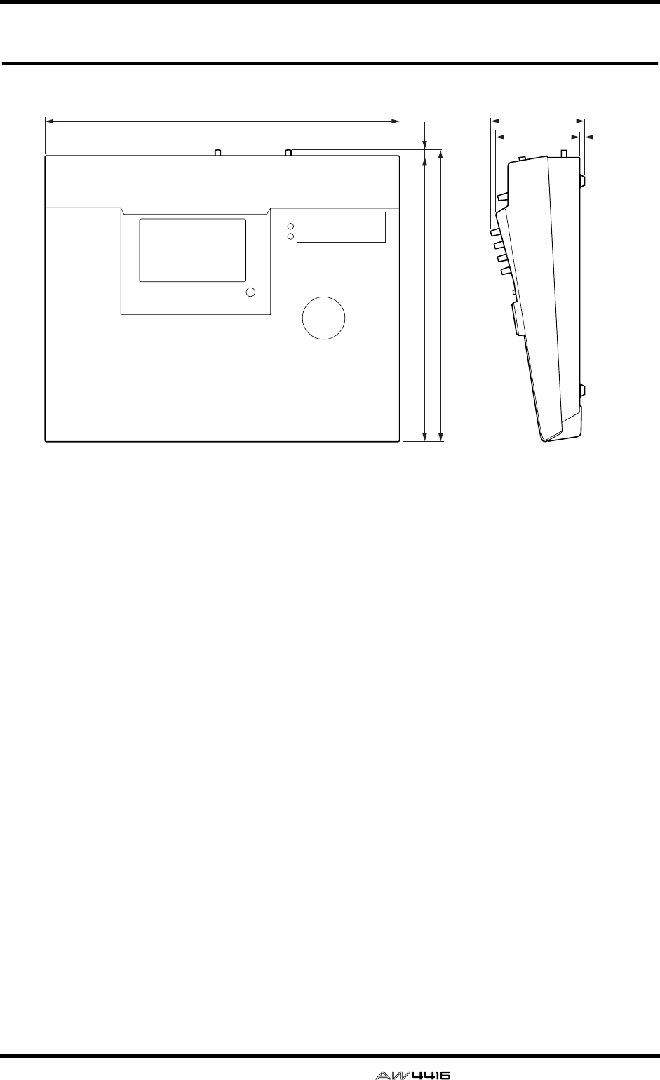
Appendix
— Reference Guide Appendix–49
Dimensions
Specifications and external appearance subject to change without notice.
For European Model
Purchaser/User Information specified in EN55103-1 and EN55103-2.
Inrush Current: 30A
Conformed Environment: E1, E2, E3 and E4
558
450
459.7
9.7
147.7
132.1 7.6
Unit: mm

Appendix
Appendix–50 — Reference Guide
MIDI data format
1. Functions
1.1 MIDI-SETUP
There are two types of serial connector: the MIDI connec-
tors and the TO HOST. They have the same functionality,
and you can select which type to use as appropriate for the
connection destination. Both types use the MIDI format for
communication.
In the case of the TO HOST connector, the transmission
method must be selected appropriate for the other device.
The available methods are listed below.
Regardless of which method is selected, MTC is transmitted
from the dedicated MTC OUT connector.
You can select either THRU or OUT as the function of the
MIDI THRU/OUT connector. If THRU is selected, messages
received at the MIDI IN connector will be retransmitted
without change from the MIDI OUT/THRU connector.
Name Connector
Transmission speed
Destination
---------+-----------+----------+-------------------------------
MIDI MIDI 31.25k for MIDI
PC1 ToHost 31.25k for NEC PC9800series
PC2 ToHost 38.4k for DOS/V
Mac ToHost 31.25k for Macintosh (contain CLOCK)
1.2 SCENE CHANGE
When a program change message is received, a scene will
be recalled as specified by the [MIDI Program Change
Assign Table].
Program change messages are transmitted with the program
number specified by the [MIDI Program Change Assign
Table]. If multiple program numbers are assigned to that
memory number, the lowest-numbered program change
will be transmitted.
1.3 MMC CONTROL
Basic recorder operations such as stop/play/rec/locate can
be controlled.
If you select MMC MASTER from the MIDI SETUP menu,
MMC commands will be transmitted according to opera-
tions of the transport. If you select MMC SLAVE, the internal
recorder will operate according to the MMC commands
that are received.
1.4 EFFECT CONTROL
Depending on the effect type, note on/off messages can be
received for control.
These settings are made by the parameters of the corre-
sponding effect.
1.5 MIDI CLOCK transmission
If you select MIDI CLOCK transmission from the MIDI
SETUP menu, MIDI clock messages will be transmitted dur-
ing playback and recording.
When the AW4416 is in MIDI clock transmission mode,
Start/Stop/Continue commands will be transmitted by the
corresponding operations, and MIDI Clock and Song Posi-
tion Pointer messages will be transmitted according to the
MIDI Tempo Map.
1.6 MTC master
If you select MTC transmission from the MIDI SETUP menu,
MTC will be transmitted during playback and recording.
1.7 MTC slave synchronization
If you select SLAVE operation from the MIDI SETUP menu,
the AW4416’s internal recorder will operate in synchroniza-
tion with the MTC messages received from the MIDI IN or
TO HOST connector.
2. Internal settings and operations
2.1 MIDI-SETUP
2.1.1 MIDI Channel
2.1.1.1 Transmit channel
Select the MIDI channel used for transmission.
However, transmissions in response to requests are trans-
mitted on the Receive Channel in order to specify the trans-
mitting device.
2.1.1.2 Receive channel
Specify the MIDI channel used for reception. In general,
MIDI messages are received only if the MIDI channel
matches, but this is not the case if OMNI is turned on.
2.1.2 ON/OFF
2.1.2.1 Program change
Reception and transmission can be enabled or disabled. If
OMNI is turned on, program changes will be received
regardless of their MIDI channel. If ECHO is on, they will
be echoed regardless of the channel.
2.1.2.2 Control change
If ECHO is on, these messages will be echoed regardless of
the channel.
2.1.3 MMC Device ID
Specify the ID number used when transmitting and receiv-
ing MMC commands.
2.1.4 PORT
Select whether serial communication will use the MIDI IN/
OUT connectors or the TO HOST connector.
(MTC is always transmitted from the MTC OUT connector.)
If the TO HOST connector is selected, you must also select
one of three settings as appropriate for the other device.
2.1.5 THRU
You can select whether the MIDI OUT/THRU connector
will function as OUT or THRU.
If THRU is selected, messages received at the MIDI IN con-
nector will be retransmitted without change from the MIDI
OUT/THRU connector.
If MIDI THRU is selected, the connector will function as
THRU regardless of the PORT setting. In order to function
as MIDI OUT, the PORT setting must be set to MIDI IN/
OUT.
2.2 MIDI program change assign table
The correspondence between program change numbers
and scene numbers can be set freely.
This conversion is applied to both transmission and recep-
tion.

Appendix
— Reference Guide Appendix–51
3. MIDI message formats
3.1 CHANNEL MESSAGE
command rx/tx function
-----+----------------------------+-------+-------------------------------
8n NOTE OFF rx Control internal effects
9n NOTE ON rx Control internal effects
Bn CONTROL CHANGE Only echoed
Cn PROGRAM CHANGE rx/tx Select scene memories
(using the Program
Change Table)
3.2 SYSTEM COMMON MESSAGE
command rx/tx function
-----+----------------------------+-------+-------------------------------
F1 MIDI TIME CODE rx/tx MTC transmission (when
MTC master), MTC
reception (when MTC
slave)
F2 SONG POSITION
POINTER tx SPP transmission (when
using MIDI Clock)
3.3 SYSTEM REAL TIME MESSAGE
command rx/tx function
-----+----------------------------+-------+-------------------------------
F8 TIMING CLOCK tx MIDI Clock reception
(when using MIDI Clock)
FA START tx Start command transmis-
sion (when using MIDI
Clock)
FB CONTINUE tx Continue command
transmission (when
using MIDI Clock)
FC STOP tx Stop command transmis-
sion (when using MIDI
Clock)
FE ACTIVE SENSING rx MIDI cable connection
checking
FF RESET rx Clear running status
3.4 SYSTEM EXCLUSIVE MESSAGE
3.4.1 Real Time System Exclusive
3.4.1.1 MMC
command rx/tx function
-----+----------------------------+-------+-------------------------------
01 STOP rx/tx Transport Stop
02 PLAY rx Transport Play
03 DEFERRED PLAY rx/tx Transport Play
04 FAST FOWARD rx/tx Transport Fast-forward
05 REWIND rx/tx Transport Rewind
06 RECORD STROBE rx Transport Record/Punch-
in
07 RECORD EXIT rx Transport Punch-out
0F RESET rx/tx MMC Reset
40 WRITE rx Write Information Field
44 LOCATE rx/tx Transport Locate
4. MIDI format details
4.1 NOTE OFF (8n)
< Reception >
Received if [Rx CH] matches.
Used to control effects. See below for details.
STATUS 1000nnnn 8n Note Off Message
DATA 0nnnnnnn nn Note No.
0vvvvvvv vv Velocity (ignored)
4.2 NOTE ON (9n)
< Reception >
Received if [Rx CH] matches.
Used to control effects. See below for details.
If velocity is 0x00, same as note-off.
STATUS 1001nnnn 9n Note On Message
DATA 0nnnnnnn nn Note No.
0vvvvvvv vv Velocity (1-127:On,
0:off)
* Notes used to control effects.
1: Dynamic Flange / Dynamic Phase / Dynamic Filter
If the SOURCE parameter is set to MIDI, velocity will con-
trol the width of frequency modulation for both note-on and
note-off.
4.3 CONTROL CHANGE (Bn)
< Reception >
Echoed if [Control Change ECHO] is on.
< Transmission >
If [Control Change ECHO] is on, this is merged with the
AW4416’s own output while taking advantage of running
status.
4.4 PROGRAM CHANGE (Cn)
< Reception >
Received if [Program Change RX] is on and [Rx CH]
matches. However if [OMNI] is on, this is received regard-
less of the channel.
This is echoed if [Program Change ECHO] is on.
A scene memory will be recalled according to the [Program
change table].
< Transmission >
If [Program Change TX] is on, a recall operation will cause a
program change to be transmitted on the [Tx CH] according
to the settings of the [Program change table].
If more than one program number is assigned to the mem-
ory number that was recalled, the lowest-numbered pro-
gram will be transmitted.
If [Program Change ECHO] is on, program changes will be
echoed.
(If a memory number is recalled for which there is no setting
in the [MIDI Program Change Assign Table], no program
change will be transmitted.)
STATUS 1100nnnn Cn Program Change
DATA 0nnnnnnn nn Program No. (0-127)
4.5 MIDI TIME CODE QUARTER FRAME (F1)
< Transmission >
When MTC transmission is selected and the recorder is in
PLAY or REC status, Quarter Frame messages will be trans-
mitted according to the time code operation of the recorder.
< Reception >
These messages are received if the AW4416 is operating as
a MTC slave. Quarter Frame messages received in realtime
are assembled internally to create time code values that
control the recorder.

Appendix
Appendix–52 — Reference Guide
STATUS 11110001 F1 Quarter Frame Message
DATA 0nnndddd dd nnn = message type (0-7)
dddd = data
4.6 SONG POSITION POINTER (F2)
< Transmission >
If MIDI Clock is being transmitted, Song Position Pointer
messages will be transmitted when the recorder stops or
locates, in order to indicate the song position at which play-
back should begin for the next Start/Continue.
STATUS 11110010 F2 Song Position Pointer
DATA 0ddddddd dd0 data (H) high 7 bits of
14 bits data
0ddddddd dd1 data (L) low 7 bits of 14
bits data
4.7 TIMING CLOCK (F8)
< Transmission >
If MIDI Clock is being transmitted, Timing Clock messages
are transmitted according to the MIDI tempo map whenever
the recorder is playing or recording (until it stops).
STATUS 11111000 F8 Timing Clock
4.8 START (FA)
< Transmission >
If MIDI Clock is being transmitted, this message is transmit-
ted when the recorder begins playback or recording from
the first measure.
STATUS 11111010 FA Start
4.9 CONTINUE (FB)
< Transmission >
If MIDI Clock is being transmitted, this message is transmit-
ted when the recorder begins playback or recording from a
location other than the first measure.
STATUS 11111011 FB Continue
4.10 STOP (FC)
< Transmission >
If MIDI Clock is being transmitted, this message is transmit-
ted when the recorder stops.
STATUS 11111100 FC Stop
4.11 ACTIVE SENSING (FE)
< Reception >
Once this message has been received, an interval of 300 ms
in which no message has been received will cause MIDI
communications to be initialized by clearing the running
status, etc.
STATUS 11111110 FE Active Sensing
4.12 RESET
< Reception >
If a Reset message is received, MIDI communications will
be initialized by clearing the running status, etc.
STATUS 11111111 FF Reset
4.13 EXCLUSIVE MESSAGES (F0-F7)
4.13.1 MMC STOP
< Transmission >
Transmitted with a device number of 7F when the STOP key
is pressed.
< Reception >
If the AW4416 is operating as the MMC SLAVE, it will stop
when this message is received if the device number
matches or is 7F.
STATUS 11110000 F0 System Exclusive Message
ID No. 01111111 7F Real Time System Exclu-
sive
Device ID 0ddddddd dd Destination (00-7E,
7F:all call)
Command 00000110 06 Machine Control Command
(mcc) sub-id
00000001 01 Stop (MCS)
EOX 11110111 F7 End Of Exclusive
4.13.2 MMC PLAY
< Reception >
If the AW4416 is operating as the MMC SLAVE, it will begin
playback when this message is received if the device num-
ber matches or is 7F.
STATUS 11110000 F0 System Exclusive Message
ID No. 01111111 7F Real Time System Exclu-
sive
Device ID 0ddddddd dd Destination (00-7E,
7F:all call)
Command 00000110 06 Machine Control Command
(mcc) sub-id
00000010 02 Play (MCS)
EOX 11110111 F7 End Of Exclusive
4.13.3 MMC DEFERRED PLAY
< Transmission >
Transmitted with device number 7F when the PLAY key is
pressed.
< Reception >
If the AW4416 is operating as the MMC SLAVE, it will begin
playback when this message is received if the device num-
ber matches or is 7F.
STATUS 11110000 F0 System Exclusive Message
ID No. 01111111 7F Real Time System Exclu-
sive
Device ID 0ddddddd dd Destination (00-7E,
7F:all call)
Command 00000110 06 Machine Control Command
(mcc) sub-id
00000011 03 Deferred play (MCS)
EOX 11110111 F7 End Of Exclusive
4.13.4 MMC FAST FORWARD
< Transmission >
Transmitted with device number 7F when the FF key is
pressed, or when the shuttle is rotated toward the right to
enter Cue mode.
< Reception >
If the AW4416 is operating as the MMC SLAVE, it will begin
fast-forward when this message is received if the device
number matches or is 7F.
STATUS 11110000 F0 System Exclusive Message
ID No. 01111111 7F Real Time System Exclu-
sive
Device ID 0ddddddd dd Destination (00-7E,
7F:all call)
Command 00000110 06 Machine Control Command
(mcc) sub-id
00000110 04 Fast Forward (MCS)
EOX 11110111 F7 End Of Exclusive
4.13.5 MMC REWIND
< Transmission >
Transmitted with device number 7F when the REWIND key
is pressed, or when the shuttle is rotated toward the left to
enter Review mode.
< Reception >
If the AW4416 is operating as the MMC SLAVE, it will begin
rewind when this message is received if the device number
matches or is 7F.
STATUS 11110000 F0 System Exclusive Message
ID No. 01111111 7F Real Time System Exclu-
sive
Device ID 0ddddddd dd Destination (00-7E,
7F:all call)
Command 00000110 06 Machine Control Command
(mcc) sub-id
00000101 05 Rewind (MCS)
EOX 11110111 F7 End Of Exclusive

Appendix
— Reference Guide Appendix–53
4.13.6 MMC RECORD STROBE
< Reception >
If the AW4416 is operating as the MMC SLAVE and the
device number of the message matches or is 7F, it will begin
recording if stopped, or punch-in if playing.
STATUS 11110000 F0 System Exclusive Message
ID No. 01111111 7F Real Time System Exclu-
sive
Device ID 0ddddddd dd Destination (00-7E,
7F:all call)
Command 00000110 06 Machine Control Command
(mcc) sub-id
00000110 06 Record strobe
EOX 11110111 F7 End Of Exclusive
4.13.7 MMC RECORD EXIT
< Reception >
If the AW4416 is operating as the MMC SLAVE and the
device number of the message matches or is 7F, the
AW4416 will punch-out if it had been recording.
STATUS 11110000 F0 System Exclusive Message
ID No. 01111111 7F Real Time System Exclu-
sive
Device ID 0ddddddd dd Destination (00-7E,
7F:all call)
Command 00000110 06 Machine Control Command
(mcc) sub-id
00000111 07 Record Exit
EOX 11110111 F7 End Of Exclusive
4.13.8 MMC RESET
< Transmission >
Transmitted with a device number of 7F when song loading
is completed.
< Reception >
If the AW4416 is operating as the MMC SLAVE and the
device number of the message matches or is 7F, internal
MMC-related settings will be reset to the power-on state.
STATUS 11110000 F0 System Exclusive Message
ID No. 01111111 7F Real Time System Exclu-
sive
Device ID 0ddddddd dd Destination (00-7E,
7F:all call)
Command 00000110 06 Machine Control Command
(mcc) sub-id
00001101 0D Reset
EOX 11110111 F7 End Of Exclusive
4.13.9 MMC WRITE
< Reception >
If the AW4416 is operating as the MMC SLAVE and the
device number of the message matches or is 7F, data will be
written to the specified information field.
STATUS 11110000 F0 System Exclusive Message
ID No. 01111111 7F Real Time System Exclu-
sive
Device ID 0ddddddd dd Destination (00-7E,
7F:all call)
Command 00000110 06 Machine Control Command
(mcc) sub-id
01000000 40 Write
0ccccccc cc Byte Count
0nnnnnnn nn Writeable Information
Field name
0ddddddd dd Format defined by the
Information Filed name
: :
0nnnnnnn nn More nn dd... pairs as
required..
EOX 11110111 F7 End Of Exclusive
4.13.9.1 MMC INFORMATION FIELD - TRACK
RECORD READY
< Reception >
If the AW4416 is operating as the MMC SLAVE and the
device number of the message matches, REC SELECT for the
recorder tracks will be switched on/off according to the data
of the standard track bitmap.
01001111 4F Track Record Ready
(Information Field name)
0nnnnnnn nn Data Length (0:all track
off, 3:record track on)
0aaaaaaa aa 1-2tr rec track On(Stan-
dard Track Bitmap)
0bbbbbbb bb 3-9tr rec track On
0ccccccc cc 10-16tr rec track On
4.13.10 MMC LOCATE (TARGET)
< Transmission >
This message will be transmitted with a device number of
7F when a locate-related key such as MARK SEARCH/IN/
OUT is pressed, when a FF/REW/shuttle operation is per-
formed, when returning to the auto-punch pre-roll point, or
when repeating.
< Reception >
If the AW4416 is operating as the MMC SLAVE and the
device number of the message matches, the AW4416 will
locate to the time code location specified by the command
data of the message.
STATUS 11110000 F0 System Exclusive Message
ID No. 01111111 7F Real Time System Exclu-
sive
Device ID 0ddddddd dd Destination (00-7E,
7F:all call)
Command 00000110 06 Machine Control Command
(mcc) sub-id
01000100 44 Locate
00000110 06 byte count
00000001 01 "target" sub command
0hhhhhhh hh hour(Standard Time Code)
0mmmmmmm mm minute
0sssssss ss second
0fffffff ff frame
0sssssss ss sub-frame
EOX 11110111 F7 End Of Exclusive

YAMAHA [PROFESSIONAL AUDIO WORKSTATION] Date: 18 Feb. 2000
Model: AW4416
MIDI Implementation Chart
Version: 1.0
Function... Transmitted Recognized Remarks
Basic
Channel
Default
Changed
1–16
1–16
1–16
1–16
Memorized
Memorized
Mode
Default
Messages
Altered
X
X
**************
OMNI off/OMNI on
X
X
Memorized
Note
Number :True Voice
X
**************
0–127
X
Velocity Note On
Note Off
X
X
X
X
After
Touch
Key’s
Ch’s
X
X
X
X
Pitch Bend X X
Control
Change XX
Prog
Change :True#
0–127
**************
0–127
0–96
System Exclusive X O *1
System
Common
:Song Pos
:Song Sel
:Tune
O
X
X
X
X
X
*2
System
Real Time
:Clock
:Commands
O
O
X
X
*2
*2
Aux
Messages
:Local ON/OFF
:All Notes OFF
:Active Sense
:Reset
X
X
X
X
X
X
O
O
Notes
MTC quarter frame message is transmitted.(When MTC Sync mode)
MTC quarter frame message is recognized.(When MTC Sync mode)
*1: MMC
*2: When MCLK Sync mode
Mode 1: OMNI ON, POLY
Mode 3: OMNI OFF, POLY
Mode 2: OMNI ON, MONO
Mode 4: OMNI OFF, MONO
O: Yes
X: No
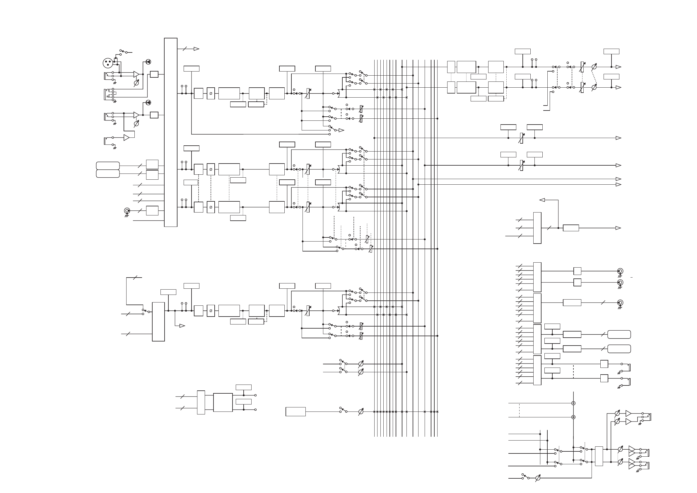
MIC/LINE
INPUT
OPTION IN
RECORDER
RECORDER
INPUT 1(...16)
AUX1(...8)
BUS1(...8)
STEREO
CD-RW
DRIVE
SOLO
DIGITAL
STEREO OUT
OPTION OUT
OMNI OUT
PHONES
MONITOR
OUT
STEREO
OUT
EFFECT
INPUT 1(...24)
RECORDER MONI 1(...16)
RETURN 1(...2)
Mono in X 24
Stereo in X 2
Mono in X 16
INPUT SELECT
(1,2 only)
INPUT SELECT
SELECT
SELECTSELECT
METRONOME
EFFECT 1
EFFECT 2
SAMPLING
PAD
DIGITAL
STEREO IN
48V
INPUT
1-2
INPUT
3-8
Hi-z
8 ch
ONLY
INSERT
I/O
SLOT1
SLOT2
AD
INSERT
INSERT
INSERT
AD
PEAK
METER
METER
METER METER
METER METER
METER METER
PREFADER LISTEN/
AFTER PAN
DIRECT OUT
(1~16 only)
4 BAND EQ
METER
METER
PEAK
8
8
8
2
2
2
De-
Emp
De-
Emp
De-
Emp
46 SELECTED INSERT RETURNS
ON LEVEL PAN
ON LEVEL PAN
PRE/POST ON AUX
PRE/POST ON
ON
AUX
INPUT
DELAY
DY-
NAMICS
ATT
ATT
ATT
16
16
46
2
2
RECORDER INPUT 1-16
INPUT
MONITOR
RECORDER
DIRECT OUT
BUS 1~8
CH DIRECT OUT1~16
STEREO
RECORDER INPUT 1~16
EFFECT EFFECT1~2
X 2
OSC
RECORDER
REPRO1-16
AUX7 (EFF1),
AUX8 (EFF2)
INSERT SEND
RECORDER
ST Trk L/R
INSERT
METER
METER
(FL Display)
ATT
DITHER
DITHER
STEREO
BUS1~8
AUX1~8
CH DIRECT OUT1~16
INSERT SEND
DITHER
DITHER
8
16 16
2
DA
DA
DA
DA
PHONES
MONITOR
SLOT1 OUT
SLOT2 OUT
2
2
8
8
16
46
16
L
R
LEVEL
LEVEL
LEVEL BALON
INSERT
METER
METER
METER
METER
METER
METER
METER
METER
METER
METER
METER
X 2
X 4
0dB
L
R
+4dB
8
8
DA
RECORDER
TRACK CUE
Logic
MIXER SOLO
Logic
ATT
BUS1
BUS2
BUS3
BUS4
BUS5
BUS6
BUS7
BUS8
4BAND EQ
ATT 4BAND EQ
DY-
NAMICS
DY-
NAMICS
STEREO L
STEREO R
SOLO L
SOLO R
AUX 1
AUX 6
AUX 7(EFF1)
AUX 8(EFF2)
SOLO
PREFADER LISTEN/
AFTER PAN SOLO
METER METER
PREFADER LISTEN/
AFTER PAN SOLO
SOLO
PAN
PAN
PRE/POST
RETURN1 can not be assigned to AUX7
(EFF1)
RETURN2 can not be assigned to AUX8
(EFF2)
ON AUX
ON LEVEL
INPUT
DELAY
INPUT
DELAY
RECORDER DIRECT
OUT 1~16
SELECT
STEREO
BUS1~8
AUX1~8
CH DIRECT OUT1~16
INSERT SEND
2
8
8
16
46
16
RECORDER DIRECT
OUT 1~16
SELECT
STEREO
BUS1~8
AUX1~8
CH DIRECT OUT1~16
INSERT SEND
2
8
8
16
46
16
RECORDER DIRECT
OUT 1~16
SELECT
STEREO
BUS1~8
AUX1~8
CH DIRECT OUT1~16
INSERT SEND
2
8
8
16
46
16
RECORDER DIRECT
OUT 1~16
(EQ)
(EQ) (Gain Reduction)
CD PlayBack
CD PLAY mode
L
R
METER
(EQ)
METER
4 BAND EQ
(EQ)
METER
4 BAND EQ
(EQ)
(Gain Reduction)
METERMETER
4 BAND EQ INPUT
DELAY
DY-
NAMICS
(EQ) (Gain Reduction)
ATT
ATT
ENABLE
DIGITAL STEREO L
DIGITAL STEREO R
(BUS CASCADE)
ON ATT
RECORDER
DIRECT OUT 1
RECORDER
DIRECT OUT 16
STEREO L
STEREO R
METRONOME
SOLO L
SOLO R
...
METER
METER
METER
METER
10dBV
METER
METER
AW4416 Block diagram

YAMAHA CORPORATION
V566460 R0 1 IP 194 Pro Audio & Digital Musical Instrument Division
P.O. Box 3, Hamamatsu, 430-8651, Japan
00 08 7000 AP Printed in Japan

PROFESSIONAL AUDIO WORKSTATION
E
Tutorial

Tutorial—AW4416 Professional Audio Workstation
— Tutorial
1
AW4416 Professional Audio Workstation
Showing a Yamaha AW4416 to a recording engineer, say, 20 years ago, would
have a similar effect to showing an interplanetary probe to Galileo. After the ini-
tial shock both parties would probably nod their heads and mumble something
about inevitability. It had to happen. The AW4416 can do what once required a
couple of rooms full of very, very expensive equipment that required consider-
able expertise to operate. And it does it very well, indeed. In short, the AW4416
can take your sound recording projects from conception to completion with pro-
fessional-level control and quality.
If you’ve worked with a Yamaha O2R Digital Mixing Console (a de-facto standard
through the recording and production industries today) or one of Yamaha’s other
top-quality digital consoles, operating the AW4416 will not be a challenge. But if
you’ve never had the pleasure, the power and depth of the AW4416 (translation:
lots of features and flexibility) might be a little daunting at first. This tutorial is
designed to help you make friends with the AW4416 as quickly and as painlessly
as possible. Since the actual recording process is pretty much the same no matter
what equipment you use, we’ve provided a complete set of pre-recorded tracks
for the demo song “So Fine”, and will walk you through the process of mixing
and mastering the tracks to create the final product. We haven’t completely
ignored the initial recording process, however; a few guidelines are provided
below.
❒
A Note About the Tutorial
This tutorial assumes that you already have a basic knowledge of how the
AW4416 controls and main features work. If you get lost, refer to the AW4416
operation guide for details.
We’ve also included a simple glossary at the end of the tutorial. If you encounter
any terms you’re not familiar with, you might find explanations in the glossary.

Tutorial—AW4416 Professional Audio Workstation
2
— Tutorial
❒
Contents
AW4416 Professional Audio Workstation ........................................ 1
A Note About the Tutorial .................................................................... 1
Contents .............................................................................................. 2
Laying Down the Basic Tracks .......................................................... 5
Rhythm First! ........................................................................................ 5
Separation ............................................................................................ 5
“Scratch” or “Guide” Vocals ................................................................. 6
Microphone Selection? ......................................................................... 6
Overdubs ............................................................................................. 7
To Process or Not To Process? .............................................................. 7
Load the Demo Song ........................................................................ 8
Load the Demo Song From the CD-ROM Onto the AW4416 Hard Disk.......... 8
Load the Demo Song from the Hard Disk ....................................................... 9
Mixdown .........................................................................................10
Phase 1: Listen To the Tracks and Make a Plan ............................................. 10
Do It ................................................................................................... 10
Phase 2: Set Up a Rough Mix ....................................................................... 12
Start with the Drums .......................................................................... 12
Add the Claves/Electronic Drums Track .............................................. 13
Add the Bass Track ............................................................................. 13
Add the Guitar Tracks ......................................................................... 13
Add the Organ & Piano Tracks ........................................................... 13
Add the String Tracks ......................................................................... 13
Add the Lead Vocal ............................................................................ 14
Add the Chorus .................................................................................. 14
Listen! ................................................................................................ 14
Save the Song! ................................................................................... 14
Phase 3: Assemble the Mix Part by Part ........................................................ 15
Tracks 1 & 2: Drums ........................................................................... 15
Track 3: Claves/Electronic Drums ........................................................ 16
Track 4: Bass ....................................................................................... 16
Track 5: Rhythm Guitar ...................................................................... 17
Track 6: Lead Guitar ........................................................................... 17
Track 7: Organ ................................................................................... 17
Track 8: Piano ..................................................................................... 18
Tracks 9 & 10: Strings ........................................................................ 18
Tracks 11 & 12: Female Chorus 1 & 2 ................................................ 18
Track 13: Male Chorus ....................................................................... 19
Track 14: Lead Vocal .......................................................................... 19
Save the Song! ................................................................................... 19
Phase 4: Add Ambience ................................................................................ 20
Engage the “Effect 1 Sends” and Select an Effect ................................ 20
Add Ambience to the Tracks as Required ............................................ 21
Tracks 1 & 2: Drums ........................................................................... 21
Track 3: Claves/Electronic Drums ........................................................ 21
Track 4: Bass ....................................................................................... 21
Tracks 5 & 6: Rhythm & Lead Guitar .................................................. 21
Track 7: Organ ................................................................................... 22
Track 8: Piano ..................................................................................... 22

Tutorial—AW4416 Professional Audio Workstation
— Tutorial
3
Tracks 9 & 10: Strings ........................................................................ 22
Tracks 11, 12, & 13: Chorus ............................................................... 22
Track 14: Lead Vocal ........................................................................... 22
Save the Song! ................................................................................... 23
Phase 5: Finalize the Mix & Set Up Automation ............................................ 24
The Automix ....................................................................................... 25
Phase 6: Use the Virtual Tracks to Create an Alternate Mix ............................ 27
Mastering ....................................................................................... 28
Step 1: Set Up the “Master” EQ and Dynamics............................................. 28
Step 2: Record the Song to the Stereo Track................................................. 29
Step 3: Write the Song to a CD-R Disk .......................................................... 30
Practice, Practice … ........................................................................ 30
Glossary .......................................................................................... 31

Tutorial—AW4416 Professional Audio Workstation
4
— Tutorial

Tutorial—Laying Down the Basic Tracks
— Tutorial
5
Laying Down the Basic Tracks
Although the basic tracks you’ll use to assemble the “So Fine” mix have already
been recorded for you (of course you can add your own tracks, if you like), let’s
take a moment to discuss the initial recording process.
The basic steps introduced here may not apply if you’re recording something very
“avant-garde,” but if you’re laying down a song or instrumental piece with a fairly
standard arrangement, here are a few issues to keep in mind:
❒
Rhythm First!
Since the rhythm parts define the tempo and “groove” of the music, it makes
sense that they should be recorded first so that the musicians who will be over-
dubbing the subsequent parts — lead guitar, lead vocal, chorus, etc. — will have
something to lock onto. Of course this isn’t necessary if the piece to be recorded
consists of just one person strumming a guitar and singing or, for that matter, if
you’ll be recording an entire ensemble in one take. But if you’ll be recording your
masterpiece track-by-track or at least section-by-section — whether it’s because
like most of us you’re recording with limited studio space and resources, or sim-
ply because you’re a perfectionist who demands total creative control at all times
— start with the rhythm. The first rhythm part to be recorded could simply be
drums and/or percussion alone, drums and bass, or drums plus bass and a rhythm
keyboard or guitar part.
❒
Separation
Remember that the more instruments you record via microphones at the same
time, the more you need to think about separation (or “isolation” depending on
whom you talk to). Once again, there are no hard-and-fast rules: if you’ll be
recording an entire rhythm section or ensemble with one stereo microphone pair,
for example, separation is a non-issue — but instrument layout and microphone
placement are critical! But assuming you want all instruments cleanly recorded
on separate tracks so you can do all your spatial arranging and processing later
on, you’ll need to ensure that leakage between instruments and microphones is
minimized. How? Physical separation is the best way. Record different instru-
ments in different rooms, if possible (this corresponds to using “isolation booths”
in a recording studio), or use baffles to reduce leakage when recording more than
one source in the same room. Directional microphones are a good idea, and
close-miking can be a big help. The only way to achieve total separation, though,
is to overdub acoustic sources one-at-a-time. Even then, you’ll probably end up
with a little leakage from the vocalist’s headphones, for example. Line sources,
naturally, do not present a problem.
A little leakage is not a big problem, though, so don’t let it bog you down. Listen
carefully to the individual “So Fine” tracks and you’ll hear what we mean.

Tutorial—Laying Down the Basic Tracks
6
— Tutorial
❒
“Scratch” or “Guide” Vocals
If you’re working alone this won’t be necessary, but when recording a band it’s
sometimes a good idea to have the singer lay down a “scratch vocal” track while
recording the rhythm section. This is simply because bands are generally used to
playing with vocals, and the performance can suffer if there is a void where the
vocals are supposed to be. The scratch vocal track can also be a useful guide
while laying down other overdubs such as guitar or keyboard solos. DON’T rely
on the scratch vocal track to record chorus parts, though, because the teeniest
changes in the pitch or phrasing of the lead vocal part can throw the entire cho-
rus out of whack.
❒
Microphone Selection?
Oowee! Here’s a subject that can make even the most seasoned recording engi-
neer cringe. But, reality check firmly established, we realize that for most of us
this is not a problem simply because we don’t have a dazzling selection of micro-
phones at our disposal. And that’s that.
But there is one thing we would like to stress: if you don’t already own the micro-
phone(s) you intend to use for recording, CHOOSE THEM WITH CARE!! Really.
Here are a few guidelines for the minimum microphone selection for most home
recording applications.
❍
If you will be recording vocals and/or acoustic instruments in the (home) stu-
dio.
Quite a number of high-quality large-diaphragm condenser microphones have
become available at very reasonable prices in the last few years. Get one. But, if
at all possible, try out a few before making a final commitment. Although most
microphones in this category have uniformly excellent frequency response and
high sensitivity, they do have distinctive sounds. Choose the one that sounds the
best to your own ears. Don’t worry about switchable directivity unless you really
think you’ll need an omni-directional pattern for some application; the plain-
vanilla cardioid pattern is probably all you’ll ever need for most recording. And
since the AW4416 provides switchable phantom power on inputs 1 and 2, you
can choose studio-quality phantom-powered microphones with confidence.
The same microphone you choose for recording vocals will most probably also
be ideal for recording acoustic guitar, piano, and a range of wind instruments as
well. Not a good choice for close-miking drums and percussion, though. One or
two large-diaphragm condenser mics are, however, perfect for use as drum “over-
heads.”
❍
Close-miking guitar amps, drums, and other loud stuff.
Here’s where you need one, or perhaps a few, good-quality dynamic micro-
phones. There are a number of “standard” dynamic microphones that are ideal
for this type of application, and which can be acquired for surprisingly little out-
lay. If you don’t already have a couple of established makers and models in mind,
ask around.

Tutorial—Laying Down the Basic Tracks
— Tutorial
7
❒
Overdubs
The actual procedure for recording overdubs is really no different from recording
the basic tracks, except that you’ll be monitoring previously recorded material
while doing it. Remember to use a good pair of closed headphones to monitor
the backing tracks while recording acoustic overdubs or vocals (not open types or
the in-ear types often used with portable stereos) to prevent leakage of the head-
phone mix back into the microphone.
❒
To Process or Not To Process?
Now things get a little tricky, because you will be making decisions that will
directly affect your freedom to make changes later in the production process.
Some engineers almost never use processing of any kind (compression, EQ, etc.)
when recording the initial tracks, the reasoning being that it not only reduces
their freedom to shape the sound as required at subsequent stages, but that it also
compromises the “openness” of the sound. There is a good deal of truth in this,
but there are also a few good reasons for some judiciously-applied processing
right from the outset.
❍
Compression & Limiting
Of the several processing options available during initial recording, compression
is probably the most often used. But at this early stage in the production process
it must be applied with care. Compression or limiting is most often used at this
point to reduce high-level transients that, although not a critical part of the instru-
ment’s sound, would otherwise take up a large portion of the recording system’s
available dynamic range. By reducing transient peaks you can effectively record
the main body of the signal at a higher level and thus, in the case of digital
media, increase the resolution of the reproduced sound while reducing potential
problems with system noise. Bass guitar, electric guitar, vocals, and drums are
often compressed during recording. Avoid compression on instruments like
acoustic piano in which the initial attack is critical in conveying the instrument’s
character.
❍
Equalization
During initial recording equalization is normally only used as a compensation
tool. You might need to compensate for irregularities in the response of a micro-
phone or other piece of equipment in the recording chain, or perhaps beef up the
response of a guitar pickup. All mix-related equalization should be left until the
mixdown stage, when you can hear how response changes affect the overall
sound.
❍
Effects
As a rule, don’t apply any ambience-type effects (reverb, delay, etc.) during initial
recording. Ambience added at this stage in the game can’t be removed later, and
will almost certainly get in the way of the overall sound. You’ll have much more
flexibility and control if you save ambience processing until mixdown. Of course,
there are exceptions; but those are creative decisions you’ll have to make on your
own.
Other effects such as modulation and distortion are often applied during record-
ing, but only when they function as an inherent part of the instrument’s sound
(distortion on electric guitar or rotary speaker on an organ, for example).

Tutorial—Load the Demo Song
8
— Tutorial
Load the Demo Song
Before you can work on the demo song, you’ll first need to load it onto the
AW4416 hard disk from the supplied CD-ROM.
This tutorial assumes that you already have a CD-RW drive configured for use
with your AW4416. See the Operation Guide for information on installing and
connecting an external CD-RW drive.
Load the Demo Song From the CD-ROM
Onto the AW4416 Hard Disk
1. Press the AW4416 [FILE] key.
2. Press the [F2] function key to go to the “Restore” page.
3. Make sure that the SCSI ID number of your CD-RW drive is selected in the
SOURCE DRIVE window (if it isn’t, move the cursor to the SOURCE DRIVE
window and use the DATA dial to select the appropriate SCSI ID number,
then press the [ENTER] key). The default SCSI drive number is SCSI#3. If
you install a CD-RW drive manufactured by Yamaha, the SCSI ID will be set
to “3” at the factory, and we recommend that you leave it at this setting.
4. Open the CD-tray by pressing the [F2] function key (“CD UNLOAD”) while
holding the [SHIFT] key. Place the demo CD-ROM on the tray (label side
up) and press the [F1] function key (“CD LOAD”) while holding the [SHIFT]
key to close the tray and load the CD.
5. The demo song “So Fine” should appear in the list on the display.
Move the cursor to the RESTORE SONG window, and then use the [ENTER]
key to switch the DISABLE button to ENABLE.
6. Move the cursor to “EXECUTE” on the display, then press the [ENTER] key.
When the “ARE YOU SURE?” confirmation prompt appears, move the cur-
sor to “OK” and press [ENTER] to begin the restore operation.
7. When the “COMPLETE” window appears, the restore operation has fin-
ished.
It take about 10 minutes to restore the demo song. Once the restore pro-
cess has begun, it cannot be stopped.

Tutorial—Load the Demo Song
— Tutorial
9
Load the Demo Song from the Hard Disk
1. Press the [SONG] key (and the [F1] function key if necessary to select the
“Song List” page).
2. Use the DATA dial to select “So Fine”.
3. Move the cursor to “LOAD” on the display and press [ENTER]. When the
“Will Save Current song … ARE YOU SURE?” confirmation prompt appears,
move the cursor to “YES” or “NO” and press [ENTER] to begin the load
operation.
4. When the progress window disappears, the demo song has been loaded
and is ready for playback.
If you want to hear the pre-mixed version of “So Fine” before mixing it yourself …
Actually, all you have to do is hit the [PLAY] button. The “So Fine” demo will be loaded
with automix enabled, and will play through exactly the way we set it up.

Tutorial—Mixdown
10
— Tutorial
Mixdown
Although the term “mixdown” seems to imply a single action, it is really a pro-
cess that can involve many interrelated steps. As you become more experienced,
the individual steps will sort of blend into one larger operation. This is important
because at all times you’ll need to consider how each small action will affect the
overall sound. A small change in equalization on one instrument, for example,
can affect the way the others sound. The ability to anticipate cause-and-effect
relationships like this can only come through experience. The more you mix, the
better you’ll get!
Phase 1: Listen To the Tracks and Make a Plan
One of the most important steps in any mix is to make at least a mental plan
before even starting the actual mix. Here are a few points to consider:
• First and foremost think about the music! What is the song saying? What kind
of mood is the piece attempting to convey? How can you approach the mix in
a way that will enhance the music itself?
• Does the piece depend mostly on the lyrics? The singer’s voice? The rhythm? A
particular instrument or sound? You’ll probably want to emphasize whichever
element(s) of the piece you determine to be the most important. If the lyrics
are critical, for example, you won’t want the vocal track buried in the back-
ground or rendered unintelligible by an excessive wash of reverb.
• How do you want to place the instruments in the stereo soundstage? Are you
trying to create a realistic “live performance” image, or just shooting for an
overall effect?
• What kind of “space” do you want to place the music in? Open and dry?
Large and reverberant? Small and tight? Distant? Intimate?
• What instruments are in similar frequency ranges and are likely to get in each
other’s way? Distorted electric guitar and organ are perfect examples of instru-
ments that do this. You’ll need to think about panning such instruments to dif-
ferent areas of the soundstage and/or using equalization to give them separate
“identities”.
• Will you need to make any mood or scene changes during the mix that might
involve major changes in levels, EQ or effects? Here’s where automation
might make the job a lot easier.
• Remember that the points given here are only a guide, and that every piece of
music is different. In fact, planning the mix is probably the most creative part
of the entire production process.
❒
Do It
OK, the tracks are loaded, now let’s go ahead and listen to the raw tracks.
Make sure that AUTOMIX is disabled before proceeding! You can do this by pressing the
AUTOMATION [AUTOMIX] key, moving the cursor to the AUTOMIX “ENABLE” parame-
ter, and pressing [ENTER] to switch this to “DISABLE”.

Tutorial—Mixdown
— Tutorial
11
1. Make sure that the RECORDER [MONI] MIXING LAYER is selected.
2. Recall the scene number 01 “FADERS NOMINAL” provided to set faders 1
through 14 to nominal (Press the [SCENE] key, use the data dial to select
the scene number 01 “FADERS NOMINAL”, move the cursor to “RECALL”,
press [ENTER], select “OK” in the confirmation and press [ENTER] again).
3. Press the MIXER [VIEW] key so you can see the selected monitor channel
parameters on the display. You might also have to press the [F1] function
key to select the “CH View” page.
4. Hit the [PLAY] button and listen.
The chart below lists the contents of the “So Fine” tracks. “V.Trk” at the left side of
the chart refers to the recorder’s virtual tracks (there are actually 8 virtual tracks
for each recorder track). Note that although we’ll be using only the main tracks
(virtual track 1) for most of this tutorial, an alternate string take is provided on the
second virtual tracks for recorder tracks 9 and 10, and a male lead vocal track is
provided on the second virtual track of recorder track 14. Later on you’ll use
these alternate takes to build a mix based around a male rather than female lead
vocal part.
12345678
V.Trk 1
Drums
Left
Drums
Right
Claves
&
E.Drm
Bass Rthm
Guitar
Lead
Guitar Organ Piano
V.Trk 2
9 10111213141516
V.Trk 1
String
Left
String
Right
Fem.
Ch. 1
Fem.
Ch. 2
Male
Ch. &
Rap
Lead
Vocal
(Fem)
V.Trk 2
Alt.
String
Left
Alt.
String
Right
Lead
Vocal
(Male)
Tutorial—Mixdown
12
— Tutorial
Phase 2: Set Up a Rough Mix
The rough mix is only the starting point for the final mix, and it doesn’t have to be
perfect. The purpose of setting up a rough mix using only levels and panning is to
give you a reference point on which to base decisions about more detailed pro-
cessing, effects, automation, etc. You shouldn’t spend a lot of time on this phase
of the mixdown process. But if a fader or pan setting really bugs you, you should
readjust it to within an acceptable range so that it doesn’t stick out like a sore
thumb and affect your ability to make appropriate decisions about the rest of the
mix. Also keep in mind that mixing is really a trial-and-error process, and you’re
likely to adjust and readjust parameters many times before you’re totally satisfied
with the results.
❒
Start with the Drums
Use the channel [ON] keys to turn off all tracks except the stereo drums on 1 and
2 (leave the STEREO track on, too).
Since the drums are recorded in stereo on tracks 1 and 2, and you’ll want to
adjust the levels of those tracks simultaneously, it’s a good idea to pair the tracks
to make adjusting level and other parameters easier. To do this:
1. Press the track 2 [SEL] key while holding the track 1 [SEL] key.
2. When the CHANNEL PAIRING window appears select the “MONITOR
1
→
2” mode and press [ENTER].
The tracks are now paired so that when you move the fader for one track the
other will automatically follow. Also note that in the MIXER VIEW display the pan
and routing controls for both channels appear in the same display.
Now to pan the stereo drum tracks left and right to create a stereo image. There is
a tendency to pan stereo drum tracks (or any type of stereo track, for that matter)
hard left and right but, depending on how the drums have been recorded or the
type of drum module you’re using, this isn’t always a good idea. If the hi-hat is
way over in one channel and the low floor tom hard over in the opposite chan-
nel, you have an inordinately large drum set. For a more realistic drum image in
INSTANT GRATIFICATION!
If you don’t want to set up the rough mix yourself, or simply want to see how we’ve done
it, recall the scene number 02 “ROUGH MIX” we have provided. Press the [SCENE] key
(and the [F1] function key if necessary to select the “Scene Mem” page), use the data dial
to select the scene number 02 “ROUGH MIX”, move the cursor to “RECALL”, press
[ENTER], select “OK” in the confirmation window and press [ENTER] again. After doing
this you’ll need to press the MIXER [VIEW] key to go back to the VIEW display.
An alternate method of doing this — without leaving the VIEW display — is to use the
panel SCENE MEMORY keys. Use the [-] and [+] keys to select the scene to be recalled
(scene numbers and names appear in the upper right corner of the display), then press
[RECALL], select “OK” in the confirmation window, press [ENTER] again, and you’re
done.
While setting up the rough mix it can be useful to set up a repeat loop that covers the
entire song, or at least a “representative” section of the song that will allow you to easily
set up the levels and pan positions. Use the A and B markers to specify the beginning and
end points of your repeat loop, then press the [REPEAT] key to engage repeat playback
(see page 118 of the operation guide for details).
Tip!

Tutorial—Mixdown
— Tutorial
13
cases where the drums or other instrument seems to occupy the entire stereo
field, try panning the left and right channels between about a third and half way
to the maximum values. In the case of the “So Fine” demo, however, the drums
were recorded “live” in the studio with proper stereo imaging (i.e. this is not a
sampler or drum module), and sound fine panned full left and right. Go ahead
and set the left and right drum track pan values to L16 and R16, respectively.
To pan the drum tracks:
1. Use the [SEL] keys to select the track you’re going to pan (since the chan-
nels are paired, the other [SEL] key will flash when one is selected).
2. Use the PAN control near the upper right corner of the display while watch-
ing the graphic pan controls in the display.
❒
Add the Claves/Electronic Drums Track
For now just turn channel 3 ON and set the fader at about –4.5 dB.
❒
Add the Bass Track
Turn on channel 4 and listen. Bass is usually panned to center so you won’t need
to adjust the pan control, but you might find that the bass is a little hot (loud) in
relation to the drum tracks with their faders at nominal, so move fader 4 down to
reduce the bass track level by about 5 dB (“–5.0” on the fader display).
❒
Add the Guitar Tracks
Turn ON channel 5 and 6. The guitar tracks are REALLY hot in relation to the
drums and bass, so use faders 5 and 6 to reduce them to reasonable levels (track
5 rhythm guitar to about –10.5 dB, and track 6 lead guitar also to about –10.5
dB). Also pan the track 5 guitar to the left and the track 6 guitar to the right (about
L14 and R15, respectively).
❒
Add the Organ & Piano Tracks
Turn ON channel 7 and 8. The organ and piano tracks will also need to be
reduced in level a bit, so use faders 7 and 8 to reduce the track 7 organ to about
–9.8 dB, and track 8 piano to about –10.5 dB. Also pan the track 7 organ a little
to the left and the track 8 piano a little to the right (about L11 and R9, respec-
tively).
❒
Add the String Tracks
Like the drum tracks, the “So Fine” string tracks are basically a stereo pair. After
turning channels 9 and 10 ON and making sure that the faders are both at exactly
the same level, use the same pairing technique described for the drum tracks,
above, to pair the string tracks. Then reduce the level to about –5.7 dB, and pan
the string tracks left and right (about L13 and R13).

Tutorial—Mixdown
14
— Tutorial
❒
Add the Lead Vocal
Ah-ha! Fooled you! You thought we were going to add the chorus parts on tracks
11, 12, and 13, and THEN add the lead vocal track, didn’t you! Well we won’t,
and the reason is simply that the chorus parts really must be heard in relation to
the lead vocal in order to set appropriate levels.
Turn ON channel 14, leave the pan control set at center (the normal position for
lead vocals), and reduce the fader level to about –7.3 dB.
❒
Add the Chorus
Although the chorus appears before the lead vocal part during the introduction,
and this might require a bit of automation at the final mix stage, adjust the chorus
levels while listening to a section of the song during which the chorus parts
appear with the lead vocal. Turn channels 11, 12, and 13 ON, then set their fader
levels to about –10.0. Pan the same tracks to L14, R14, and CENTER, respectively.
❒
Listen!
Although you’ve been listening to the song during the entire rough mix process,
now it’s time to listen to the entire song in context rather than concentrating on
individual parts. Hear something you don’t like? Change it.
❒Save the Song!
Now would be a good time to save your work. Press the WORK NAVIGATE
[SONG] key to go to the SONG display, if necessary also press the [F1] function
key to select the “Song List” page. Move the cursor to “SAVE” on the display and
press [ENTER]. When the confirmation window appears move the cursor to “OK”
and press [ENTER] again to actually save the song.

Tutorial—Mixdown
— Tutorial 15
Phase 3: Assemble the Mix Part by Part
Now we’re ready to do some serious work on the sound of the individual tracks
in an attempt to make them “mesh” to create a well-balanced overall mix.
❒Tracks 1 & 2: Drums
Listening to the drums in the context of the rough mix we notice that they sound
a little dull. The lower end is fine, but the cymbals don’t have quite the degree of
presence we’d like to hear. Otherwise, the drums are fine. If we attempted to use
any compression on these tracks we’d probably lose the natural dynamics that
make this track work — and dilute the contrast between the acoustic drums and
the electronic drums at the end of the song.
A subtle touch of high-end EQ is all that is needed here:
1. Press the track 1 [SEL] key (tracks 1 and 2 are paired, so EQ settings you
make to track 1 will also be applied to track 2 — convenient, eh?)
2. Press the MIXER [EQ] key (this is so you can see the detailed EQ parameters
as we make the adjustment).
3. Make sure that the EQ for the selected tracks is ON (if not, move the cursor
to the “EQ ON” parameter and press [ENTER] to turn it “ON”).
4. Press the [HIGH] key in the “virtual EQ” control section to the right of the
display to select the HIGH EQ band.
5. Use the [G] control to increase the gain of the 10-kHz shelving EQ to +4.0
dB. No need to change the EQ type of frequency.
INSTANT GRATIFICATION!
Once again, we’ve provided a scene you can simply recall to automatically make all the
settings included in “Phase 3”, below. Press the [SCENE] key (and the [F1] function key if
necessary to select the “Scene Mem” page), use the data dial to select the scene number
03 “PHASE 3 MIX”, move the cursor to “RECALL”, press [ENTER], select “OK” in the con-
firmation window and press [ENTER] again. After doing this you’ll need to press the
MIXER [VIEW] key to go back to the VIEW display.
An alternate method of doing this — without leaving the VIEW display — is to use the
panel SCENE MEMORY keys. Use the [–] and [+] keys to select the scene to be recalled
(scene numbers and names appear in the upper right corner of the display), then press
[RECALL], select “OK” in the confirmation window, press [ENTER] again, and you’re
done.
As you’re working on the various parts of the mix you’ll constantly be turning channels on
and off so you can hear things alone or in combination with certain other tracks. In order
to use the SOLO function for this select “MIXDOWN SOLO” and “AFTER PAN” in the
Solo Setup page (see page 96 of the operation guide for details). The reason for this is that
during this phase of the mix you’ll almost always want to hear the tracks with EQ, dynam-
ics, and other effects applied. Normal solo monitoring lets you hear the tracks “dry”, and
that won’t help you here.
Tip!
Tutorial—Mixdown
16 — Tutorial
❒Track 3: Claves/Electronic Drums
This track needs a bit of compression to make the electronic drums jump out of
the mix when they appear at the outro. Later, when we work on the automation,
we’ll boost this track a bit at the outro for extra impact.
1. Press the track 3 [SEL] key to select the claves/electronic drums track.
2. Press the MIXER [DYN] key to access the dynamics parameters.
3. The “COMP” dynamics type should already be selected (it’s the default).
Move the cursor to the “ON/OFF” parameter and turn dynamics for the
selected track “ON”.
4. Use the cursor keys and data dial to make the following dynamics settings
for the claves/electronic drums track:
❒Track 4: Bass
The bass track is a bit “flabby” and lacks punch. We’ll use EQ to tighten the
sound up a little, and compression to give the track a little more uniformity and
power.
1. Press the track 4 [SEL] key to select the bass track.
2. Press the MIXER [EQ] key.
3. Make sure that the EQ for the selected track is ON.
4. Use the cursor keys and data dial or the virtual EQ controls to make the fol-
lowing EQ settings for the bass track:
5. Press the MIXER [DYN] key to access the dynamics parameters.
6. The “COMP” dynamics type should already be selected. Move the cursor to
the “ON/OFF” parameter and turn dynamics for the selected track “ON”.
7. Use the cursor keys and data dial to make the following dynamics settings
for the bass track:
THRESH. RATIO OUT GAIN ATTACK RELEASE KNEE
–24 10:1 0.0 29 6 hard
LOW L-MID H-MID HIGH
Q6.3 7 8 —
F66.0 223 4.75 kHz —
G+2.5 –4.5 +6.0 —
THRESH. RATIO OUT GAIN ATTACK RELEASE KNEE
–15 8:1 +2.0 51 192 2
Tutorial—Mixdown
— Tutorial 17
❒Track 5: Rhythm Guitar
The rhythm guitar track needs to be a little “chunkier” to achieve the classic R&B
type of sound we’re after. A little EQ and compression will accomplish that feat,
and the compression will also help to even out dynamic variations that cause the
guitar part to be buried in the mix from time to time.
You should know how to make the EQ and dynamics adjustments by now, so
we’ll just give you the figures and you can make the settings yourself.
❍Rhythm Guitar EQ
❍Rhythm Guitar Compression
❒Track 6: Lead Guitar
In terms of tone the lead guitar part sounds fine the way it is. But perhaps we
should apply a little compression to even it out a bit.
Here are the figures; do the dialing yourself:
❍Lead Guitar Compression
❒Track 7: Organ
The ultra-lows of the organ sound are muddying the sound a little. We can take
care of that by using a high-pass filter to remove some of the offending frequen-
cies. The LOW band of the AW4416 parametric equalizer functions as a high-
pass filter — all you have to do is make the appropriate settings. No compression
is required.
❍Organ EQ
LOW L-MID H-MID HIGH
QL.SHELF 9 — —
F125 420 — —
G+2.5 +3.5 — —
THRESH. RATIO OUT GAIN ATTACK RELEASE KNEE
–9 4:1 0.0 9 110 4
THRESH. RATIO OUT GAIN ATTACK RELEASE KNEE
–5 3.5:1 0.0 35 238 4
LOW L-MID H-MID HIGH
QHPF — — —
F66———
GON———
Tutorial—Mixdown
18 — Tutorial
❒Track 8: Piano
We’ll use some EQ to “thin out” the piano sound a bit, and give it a touch more
presence so that it will come through in the mix a bit more.
❍Piano EQ
❒Tracks 9 & 10: Strings
If we’d recorded real strings we might have needed a bit of processing here, but
since this is pretty-much a “pre-processed” synth string patch, we can leave it
alone.
❒Tracks 11 & 12: Female Chorus 1 & 2
Processing to make a chorus “blend” well can be tricky, but in general you’ll just
have to rely on you ears. In this case we’ve used high-pass filtering to remove
rumble from the studio and other low-frequency noise that can lead to unclear
overall sound. Some midrange has been removed to prevent the chorus from get-
ting in the way of the lead vocal, and a touch of high-end presence has been
added to help the voices cut through. Compression also helps to achieve a tighter
chorus blend by smoothing out dynamic variations.
❍Female Chorus 1 EQ
❍Female Chorus 2 EQ
❍Female Chorus 1 Compression
LOW L-MID H-MID HIGH
QL.SHELF 8.0 — H.SHELF
F74 21 — 7.55 kHz
G–3.5 –4.0 — +2.0
LOW L-MID H-MID HIGH
QHPF 10.0 9 H.SHELF
F94 841 1.49 13.4 kHz
GON –1.5 –2.5 +4.0
LOW L-MID H-MID HIGH
QHPF 1.0 — H.SHELF
F50 1.00 kHz — 13.4 kHz
GON –2.5 — +3.5
THRESH. RATIO OUT GAIN ATTACK RELEASE KNEE
–16 2.5:1 +2.0 21 319 1
Tutorial—Mixdown
— Tutorial 19
❍Female Chorus 2 Compression
❒Track 13: Male Chorus
The quality of this singer’s voice makes EQ unnecessary in this situation, but
some compression will be helpful to help the blend with the female chorus.
❍Male Chorus Compression
❒Track 14: Lead Vocal
The lead vocalist on this track has a beautiful wide-range voice, one of the attrac-
tions of which is the rich, sensuous low-end. We want all of this to come through,
so we’ll only use a high pass filter set at 79 Hz to cut out the extreme low fre-
quencies (mostly ambient rumble), and a bit of high boost to provide a little extra
presence. The lead voice is well controlled, so not much compression is required
… but we’ll use a little anyway, for a subtle boost in punch and power.
❍Lead Vocal EQ
❍Lead Vocal Compression
❒Save the Song!
Once again, now’s a good time to save your work. Press the WORK NAVIGATE
[SONG] key to go to the SONG display, if necessary also press the [F1] function
key to select the “Song List” page. Move the cursor to “SAVE” on the display and
press [ENTER]. When the confirmation window appears move the cursor to “OK”
and press [ENTER] again to actually save the song.
THRESH. RATIO OUT GAIN ATTACK RELEASE KNEE
–16 2.5:1 +2.0 22 226 4
THRESH. RATIO OUT GAIN ATTACK RELEASE KNEE
–20 2.5:1 +2.0 31 315 1
LOW L-MID H-MID HIGH
QHPF — — H.SHELF
F79 — — 10.0 kHz
GON — — +1.5
THRESH. RATIO OUT GAIN ATTACK RELEASE KNEE
–13 2.5:1 +1.5 26 6 3
As you make adjustments to EQ, dynamics, etc., don’t be afraid to adjust the fader levels
as you go along. EQ and dynamics invariably alter the levels of the tracks, and you’ll
almost certainly need to make minor adjustments to compensate.
Tip!
Tutorial—Mixdown
20 — Tutorial
Phase 4: Add Ambience
“Ambience” effects such as reverb, delay, and echo are generally used to provide
a sense of space and warmth. So far we’ve worked with the “dry” (i.e. no effects)
tracks, but many engineers and artists would already have ambience effects in
place. In fact, many artists insist on monitoring “wet” while laying down the
tracks. There are no rules regarding when in the mix process you should add
ambience, but for this tutorial we’ve chosen to make ambience a separate subject
because, unlike EQ and compression, it doesn’t directly affect the actual sound of
the tracks. Ambience “adds” to the sound rather than changing it.
For the sake of consistency we’ll use only one reverb effect for the entire piece.
The AW4416 has two separate effect processors built in, so it would be no prob-
lem to set up two different reverbs or other effects and use them on different
tracks, but the straightforward, “earthy” feel of the song demands a more simple
approach.
❒Engage the “Effect 1 Sends” and Select an Effect
1. Press the FADER MODE [AUX7] key. The faders will now function as auxiliary
sends for the corresponding tracks. In the AW4416 AUX 7 is pre-assigned to
internal effect processor 1 and AUX 8 is pre-assigned to effect processor 2.
We’ll only use the AUX 7 sends for this example.
2. Press the [F2] function key to select the “Effect Library” page. The default
“Reverb Hall” effect is a little too big and spacious for our needs. The
“Reverb Room” effect, on the other hand, has just about the right combina-
tion of warmth and intimacy.
3. Use the data dial to select “Reverb Room” from the effect library list, then
move the cursor to “RECALL” on the display and press [ENTER]. When the
confirmation window appears move the cursor to “OK” and press [ENTER]
again.
4. Press the [F1] function key to select the “Effect Edit” page and make sure
that the BYPASS setting is “OFF” (if it is ON, move the cursor there and turn
it OFF).
There’s nothing worse than too much reverb all over everything!! Use ambience effects
sparingly! And remember, reverb is cumulative! That is, the seemingly small amounts of
reverb you add to individual tracks can add up to a great big mess when the entire mix is
played back. In the beginning you’ll probably have to go back and readjust individual
reverb sends many times until you get it right, but as you gain experience you’ll develop a
feel for how much to add right from the outset.
INSTANT GRATIFICATION!
You can instantly recall all the reverb settings described below (as well as all other settings
made up until this point) by recalling the scene number 04 “AMBIENCE” we’ve provided
for you. You should know how to do this by now, but if you don’t, go back and check the
previous sections.
Tutorial—Mixdown
— Tutorial 21
❒Add Ambience to the Tracks as Required
All you have to do now is use the faders in the AUX 7 mode to add the required
degree of the Reverb Room effect to the tracks.
❒Tracks 1 & 2: Drums
Drums usually benefit from a touch of reverb, especially if they have been
recorded fairly dry like the “So Fine” drum track. But beware of adding too much.
Fairly heavy reverb is sometimes used on drum tracks for ballads, but usually only
specific drums — particularly the snare. In order to do this you’ll obviously need
to have at least the snare recorded on a separate track. It’s perfectly OK to leave
the drums totally dry, too, depending on the overall effect you’re after. For “So
Fine” we’ll add a barely-noticeable amount of reverb to help define the record-
ing’s “space”.
Move the AUX 7 faders for tracks 1 & 2 (they’re paired, remember, so you only
have to move one) up to about –25dB.
❒Track 3: Claves/Electronic Drums
Leave this track dry. The claves sound has enough natural room ambience which
was undoubtedly picked up during the initial recording. The electronic drum
sequence for the outro needs to remain dry to emphasize its “techno” quality as
well as maximize the contrast with the acoustic drums.
❒Track 4: Bass
It’s usually a good idea to avoid adding reverb to bass because the resultant
boomy wash of sound can severely compromise the clarity of the mix. And that’s
precisely what we’ll do with the “So Fine” bass track — no reverb.
❒Tracks 5 & 6: Rhythm & Lead Guitar
Electric guitar is one of those instruments that almost demands added reverb
(unless the guitarist applied reverb himself while recording the tracks). In the stu-
dio electric guitar is often recorded close-miked or directly injected into the con-
sole, so the sound tends to be extremely dry and brittle. Unless you’re specifically
looking for a very dry sound, you can safely add a fair amount of reverb.
Track 5 rhythm guitar reverb at –12.7; track 6 lead guitar reverb at –11.8.
As with other stages in the mix process you’ll probably be turning channels on and off so
you can hear how the processed tracks sound alone or in combination with certain other
tracks. As we mentioned earlier, don’t use the SOLO function to do this, use the channel
[ON] buttons instead.
You can check and edit precise fader settings for the selected channel in the MIXER VIEW
display (press the MIXER [VIEW] key). The AUX 7 fader near the lower right corner of the
display shows the current level, and if you move the cursor there you can use the data dial
to make precise adjustments. Remember to press the FADER MODE [AUX7] key if you
want to go back and make further reverb adjustments via the channel faders.
Tip!
Tip!

Tutorial—Mixdown
22 — Tutorial
❒Track 7: Organ
Instruments like organ always present a challenge when trying to decide on the
right amount of reverb to add. The sustained nature of the sound means you can
add a LOT of reverb before you really notice it … but it’s there, and probably
playing havoc with the overall mix. You’ll probably need to add a touch of reverb
to integrate the instrument into the overall space of the recording, but only a
touch!
Organ reverb at –20.
❒Track 8: Piano
The amount of reverb you add to piano track will depend both on the type of
sound you are trying to create and on how the piano is played. Reverb is much
more noticeable when the instrument is played in a sparse, staccato style than
when played with lots of sustain and/or big chords. Particularly in the latter case
the caution given for organ applies to piano as well: don’t overdo it!
Piano reverb at –15.
❒Tracks 9 & 10: Strings
Since the strings themselves are sort of used as a “wash” or “pad” type of sound,
some reverb is essential to fill out the image. In short, the right amount of reverb
can give strings — especially the synth strings that most of us will be using — a
more lush, rich sound.
String reverb level at –5.5.
❒Tracks 11, 12, & 13: Chorus
Here we’ll use just enough reverb to fill out and unify the sound of the backing
vocals. More reverb would produce a more lush sound, but would at the same
time reduce the intelligibility of the vocals as well as the clarity of the overall
mix.
Track 11, 12, and 13 reverb to –15.9.
❒Track 14: Lead Vocal
There is a tendency to add lots of reverb to the lead vocal, but listen to the results
carefully. Less is usually better. Increase the reverb gradually until you begin to
hear a slight thickening or “glow”, and stop there. If you’re hearing reverb as a
separate entity, there’s too much reverb.
Lead vocal reverb to –10.9.
Everything, yes, everything you do to the mix can change the perceived balance of the
tracks. Make adjustments to the fader levels whenever you feel the urge to do so.
Tip!

Tutorial—Mixdown
— Tutorial 23
❒Save the Song!
We can’t emphasize enough how important it is to keep saving your work at rela-
tively short intervals. Accidents do happen, and if after several hours of hard work
your AW4416 is accidentally unplugged, or there’s a power failure, or your pet
cat decides to do a mix of his own, you’ll have to go back and start again. Ouch!
Press the WORK NAVIGATE [SONG] key to go to the SONG display, if necessary
also press the [F1] function key to select the “Song List” page. Move the cursor to
“SAVE” on the display and press [ENTER]. When the confirmation window
appears move the cursor to “OK” and press [ENTER] again to actually save the
song.

Tutorial—Mixdown
24 — Tutorial
Phase 5: Finalize the Mix & Set Up Automa-
tion
Well, the basic mix is pretty much done. Now that all the processing and effects
are in place you should listen carefully and make any final adjustments. But as
you listen to the mix we’ve set up you’ll probably notice that one “average” mix
doesn’t quite do justice to the entire song. You’ll probably notice sections on
which you’d like make a temporary change to the level of one track or another.
This is where automation comes in handy. Back in the “pre-automation” days
recording engineers would have to make such changes manually “on the fly”.
And if the changes involved a number of faders and controls simultaneously, then
several people would have to be recruited to do the job. Of course, timing is crit-
ical, so the mix would often have to re-run many times until all the required
changes could be made satisfactorily. Thank goodness for the AW4416. It will let
you record fader, channel ON/Off, pan, and EQ automation changes one at a
time so you can put together the perfect automix with relative ease.
For the “So Fine” automix we’ve used a combination of fader, channel ON/OFF,
and pan automation. Please refer to the AW4416 operation guide for details on
how to record and edit automation. In this section we’ll simply describe the
changes we made and why we thought they were necessary. We suggest you
enable our automix and watch the faders and channel ON keys as the song plays.
To enable the automix:
1. Press the AUTOMATION [AUTOMIX] key and, if necessary, the [F1] function
key to select the “Main” page.
2. Move the cursor to the “AUTOMIX” parameter and press [ENTER] to select
“ENABLE”.
3. And to select the pre-master automix: press the [F4] key to select the “Event
List” page, move the cursor to the SCENE/LIB button on the display and
press [ENTER] to highlight it, then move the cursor down to the scene num-
ber in the event list (it should be “06” initially) and use the data dial to
change the scene number to “05”.
4. Now go back to the VIEW display or any other display you want to watch
while studying the automix.

Tutorial—Mixdown
— Tutorial 25
❒The Automix
The general flow of the automix is described below in reference to absolute counter
times. Please note that the times given are not precise. Use them as a guide.
❍00:00:00
The first thing you’ll notice is that the channel ON keys for tracks 8 through 14
are all off. We’ll turn those tracks on just before the corresponding parts come in.
❍00:00:13
Channels 11, 12, and 13 are turned ON just before the chorus comes in on the
introduction.
❍00:00:15
The level of the second introductory lead guitar phrase (track 6) was a little lower
than the first, and it was getting buried in the chorus. We used fader automation
to boost it a bit.
❍ 00:00:25
The lead vocal track (14) is turned ON just before the lead vocal comes in. At the
same time we’ve turned the chorus tracks (11, 12, and 13) back off because the
chorus won’t be coming back in for a while. Why bother? Well, with any source
recorded via microphone you’re also likely to pick up some extraneous ambient
noise, and this can reduce the clarity of the mix if allowed to play while the
desired source isn’t doing anything. This is the case with the “So Fine” chorus
tracks. In fact, if you watch the track 11, 12, and 13 level meters while the chorus
isn’t singing you can see that there’s a surprising amount of signal where there
really shouldn’t be any. This type of unwanted noise can also be removed auto-
matically by “gating” (a type of dynamics processing in which signals below a
specified level are cut off — the AW4416 dynamics processors can do this). But
since the noise is effectively masked by the other tracks during denser parts of the
song, we’ll simply use channel ON/OFF automation for the “So Fine” demo.
You’ll also notice that we reduced the level of the organ track (7) at about this
point. This is because we wanted a slightly higher organ level during the intro-
duction to achieve a better overall balance before the lead vocal comes in. Now
that the lead vocal has begun, however, we’ve lowered the organ track back to its
“normal” level.
❍00:00:47
Chorus channels 11 and 12 are turned back ON, and the level of left female
vocal track (11) has been boosted a bit to maintain optimum balance between
the two female chorus parts during this section of the song.
The piano track (8) is turned ON just before the piano part comes in.
❍00:01:08
Chorus track 11 is brought down again for optimum chorus balance, and the
level of the lead vocal track is boosted just a bit to allow the lead vocal to come
through the denser instrumentation of the bridge section.
The strings tracks (9 and 10) are turned ON just before the string part begins.
Also note that the level of the lead guitar track (6) was boosted a bit just before
this point. We did this to emphasize the distinctive guitar part during the bridge.
The organ level has been lowered to “make room” for the strings, piano, and cho-
rus parts during the bridge.

Tutorial—Mixdown
26 — Tutorial
❍00:01:31
The lead guitar on track 6 and the lead vocal on track 14 have been brought back
down to their “normal” levels.
The organ level is also returned to normal.
❍00:01:39
The level of the male chorus track (13) is boosted a bit here because for the next
couple of phrases the male chorus doubles with the lead vocalist while the
female chorus provides “0oh” type support.
❍00:01:53
Male chorus brought back down to normal chorus level.
❍00:2:13
Once again, the lead vocal (14) and lead guitar (6) are boosted a bit for the
bridge.
The organ drops out a bit to leave room for the denser arrangement of the bridge
section.
❍00:02:36
The level of the lead vocal track is briefly lowered just a bit to soften the impact
of the very high notes.
❍00:02:47
Another brief dip in the lead vocal level to even out the dynamics.
❍00:02:57
Track 13 is boosted in preparation for the male rap part on the outro.
Track 3 contains the electronic drum part used on the outro, so this track is also
boosted.
The strings tracks (9 and 10) play an important role on the outro, so they are
boosted as well.
The level of the lead vocal track is reduced to move it more into the background.
❍00:02:58
The pan automation on the rap track (13) begins here. Note that the rap part pans
alternately to the left and right for each phrase, and to the center for the final
phrase.
❍00:03:33
Fade out.

Tutorial—Mixdown
— Tutorial 27
Phase 6: Use the Virtual Tracks to Create an
Alternate Mix
If you feel that you need a little more practice with the mixing process, try select-
ing the alternative string and vocal tracks we’ve provided and see how they
change the overall sound. Otherwise you can skip ahead to the “Mastering” sec-
tion that follows.
Tracks 9 and 10 of the “So Fine” demo contain alternative string parts, and track
14 contains an alternative male lead vocal part. Switch to virtual tracks 2 on
these tracks (i.e. 9-2, 10-2, and 14-2) as follows:
1. Press the RECORDER [TRACK] key.
2. Press the [F2] function key to go to the “V.Track” page.
3. Move the cursor to virtual track buttons 9-2, 10-2, and 14-2, and press
[ENTER] each time so that the alternate tracks are highlighted.
4. Now that you have selected the alternative tracks you can go back to the
VIEW display or any other display you want to work on.
Play the mix as is with the alternative string and lead vocal parts. Now go ahead
and make any adjustments you feel are necessary to make the mix work better
with the new parts. Note that if you play back the song with AUTOMIX enabled
the automix values will automatically be recalled, so you will probably initially
want to disable AUTOMIX to experiment with the virtual tracks.

Tutorial—Mastering
28 — Tutorial
Mastering
When you think mastering, think “subtle”. But just because it’s subtle doesn’t
mean that it can’t have a huge impact on the overall sound of a song. Mastering is
the process of making final adjustments to the overall sound, usually involving
the application of EQ and/or compression. In some instances an engineer might
even decide to add a touch of overall reverb. In the context of an album contain-
ing several individual songs or compositions, mastering also covers the process of
matching levels and sound between songs, and deciding on the amount of space
to leave between tracks. For our discussion here we’ll concentrate on mastering
and “burning” the song to a CD-R disk which can then be played in just about
any standard CD player.
Step 1: Set Up the “Master” EQ and Dynamics
It won’t always be necessary to use EQ and dynamics during mastering; in fact,
we’ll use only compression for this example. The dynamics are set using the STE-
REO channel processor. Press the STEREO channel [SEL] key, then use the MIXER
[DYN] key to access the dynamics parameters. The nice thing about this system is
that you can hear how your master EQ and/or dynamics settings affect the overall
mix immediately. In some cases you might even decide to go back and make
changes to the mix because of the way everything sounds “mastered” as opposed
to straight, before committing to a specific set of mastering parameters. Generally,
though, the better the mix, the less master processing is required.
To enable the pre-programmed “mastered” automix:
1. Press the AUTOMATION [AUTOMIX] key and, if necessary, press the [F4]
key to select the “Event List” page.
2. Move the cursor to the SCENE/LIB button on the display and press [ENTER]
to highlight it.
THE IMPORTANCE OF ACCURATE MONITORING
One of the most critical factors in successful mastering (and mixing, for that matter) is to
have a good monitoring setup. This is also one of the most difficult to achieve simply
because it involves not only your amp and speakers, but the room you monitor in and
everything in it as well. Quite simply, your mix will sound different on different systems
and in different rooms. If the environment you work in tends to be bass deficient, you will
probably crank the bass up too high and end up with excessively boomy sound on other
systems. If your “studio” is reverberant (we don’t recommend mixing or mastering in the
bathroom), you won’t be able to accurately judge the effect of ambience processing on
your mix. What you really need is a mixing and mastering environment that is relatively
dry (in the sonic sense, that is) and has a broad, flat frequency response without unnatural
dips or peaks. If your studio isn’t perfect (and this is the norm for home studios) then expe-
rience is the answer. The more you mix, master, and listen to the results on different sys-
tems and in different rooms, the more you’ll get a feel for how the sound of your studio
relates to the real-world “average”. Listening to your own work in a variety of environ-
ments is a very good idea in any case. Listen on big, expensive hi-fi systems as well as
cheap portables. Don’t forget car stereos, either. The more you listen, the better your mixes
will become.

Tutorial—Mastering
— Tutorial 29
3. Move the cursor down to the scene number in the event list (it should be
“05” if you changed it as we suggested on page 24) and use the data dial
to change the scene number to “06”.
4. Now go back to the VIEW display or any other display you want to watch
while listening to the mastered automix.
❍Equalization
As mentioned above, you won’t always need to do this, but overall master EQ
can be useful when you want to add a little brilliance or low end, or both, to a
finished mix. You might also find that some mixes are too “boomy” or “middly”,
and that applying a slight dip in the appropriate frequency range can clean things
up considerably.
The “So Fine” demo doesn’t need any EQ (at least we think so), so we’ll leave it
alone.
❍Compression
You’ll probably end up using master compression a lot more than master EQ. The
trend these days in popular music is to squeeze as much level onto the final mas-
ter as possible without making the music sound unnatural (sometimes, on the
other hand, “unnatural” is a desirable goal). Some compression can also give the
mix more punch and presence.
The master compression settings for “So Fine” are not particularly extreme, but if
you feel the urge to experiment with other settings we encourage you to do so.
❍So Fine Master Compression
Step 2: Record the Song to the Stereo Track
The AW4416 requires that your song be recorded to the stereo track before it can
be written to a CD. So once you’re satisfied with the master EQ and/or compres-
sion settings, record the song to the AW4416 stereo track, as follows:
1. Press the [ST] key to engage the STEREO track record mode (the key will
flash).
2. Locate to the top of the song and start recording (press the [REC] and
[PLAY] keys simultaneously).
3. Press the [STOP] key when the song has finished.
Simple, isn’t it?
THRESH. RATIO OUT GAIN ATTACK RELEASE KNEE
–10 1.7:1 +3.5 55 192 1

Tutorial—Practice, Practice …
30 — Tutorial
Step 3: Write the Song to a CD-R Disk
This procedure is described in detail in the AW4416 operation guide (page 255),
so we won’t go into it here. But now you know how the entire process works —
from the basic tracks to CD.
Practice, Practice …
Really. Mixing and mastering are skills which, like playing an instrument, can
only be acquired through practice. You have the tools (the AW4416 is about the
coolest little mixing and mastering toolkit you can lay your hands on), now it’s up
to you to learn how to use them like a pro. Don’t be afraid to go back and change
things. Even if you’ve gone right through the process and mastered a CD, if it
doesn’t sound right when you play it back on CD player, by all means go back
and make the necessary changes. That’s how we learn. As you gain experience
and skill the need to backtrack and redo things will decrease, and you’ll make
better mixes more quickly and easily.
Happy mixing!

Tutorial—Glossary
— Tutorial 31
Glossary
❒Galileo
An early astronomer who lived in the 16th –17th century, and who most certainly
never saw anything like an interplanetary probe. We’re pretty sure he never saw
an AW4416, either.
❒Close-miking
As the term implies, “close-miking” involves placing a microphone very close to
the source in order to maximize the amount of sound picked up from the desired
source in relation to other ambient sound.
❒Condenser Microphone
Condenser microphones employ a very thin, light diaphragm with a low moving
mass to pick up sound. This makes it possible to achieve high sensitivity and
broad frequency response, but has the disadvantage that this type of microphone
tends to be delicate. They can be damaged by physical shock as well as high
humidity. Condenser microphones, particularly the more delicate large-dia-
phragm types (yep, they have a large diaphragm) are generally never taken out of
the studio.
❒Dynamic Microphone
Dynamic microphones use a rigid diaphragm connected to a coil which moves in
a magnetic field to transform acoustic sound into electric energy. Dynamic
microphones are generally rugged and provide consistent performance under a
wide range of conditions, but they rarely provide the high sensitivity and flat
broad frequency response of their condenser counterparts. Still, dynamics are the
microphones of choice for high-SPL (Sound Pressure Level) percussive sources
such as drums (particularly when close-miked) and live sound.
❒Phantom Power
A number of studio-type microphones have built-in preamplifiers that, naturally,
require some sort of power to operate. Power can be provided by an external
power supply (not too common these days), batteries, or phantom power from
the console. It’s called “phantom” power because it sort of sneaks into the micro-
phone from the console via the microphone cable without affecting the audio
signal. Neat trick, huh!. Since dynamic microphones rarely require external
power, most phantom-powered microphones are condenser types.
❒Baffle
Usually a movable sound-absorbing partition which can be placed strategically
in the studio to prevent leakage between sources and microphones.

Tutorial—Glossary
32 — Tutorial
❒Directional Microphone
A microphone which primarily picks up sound from only one general direction is
a “directional” microphone. This can be handy in maximizing separation in the
studio (and in reducing feedback on stage), because you can simply aim the
microphone away from sources of sound you don’t want to pick up.
❒Cardioid Pattern
This refers to a widely-used type of response pattern for directional microphones.
It’s called a “cardioid” pattern because the graph representing this type of
response sort of resembles a heart shape. Sort of.
❒Omni-directional Microphone
A microphone which will pick up sound equally from all directions. Not often
used in studio recording or live sound, but this type of microphone can be useful
when you want to capture the main source as well as it’s environment (room
ambience, for example) in one go.
❒Overheads
Microphones that are placed “overhead”, sometimes as a stereo pair, to pick up
the overall sound of an instrument or group of instruments. Overheads are often
used in addition to close-miking when recording drums. Microphones set up this
way are also sometimes called “showers” for, well, obvious reasons.
❒Closed Headphones
This is the type of headphone that completely covers your ears rather than fitting
in you ears or simply pressing against your ears. This is definitely the type of
headphones you want to use for monitoring while recording, because they pre-
vent the headphone sound from leaking out to any microphones in the room, and
well as preventing extraneous sound from leaking in.
So Fine
Written and arranged by
Karl Christmas
Engineered and produced by
Darren Allison
Vocals: Rusharn Simpson
Vocals, backing vocals, guitars and keyboards: Karl Christmas
Backing vocals: Billie Godfrey
Bass: Finn Day-Lewis
Drums: Andrew Small
Recorded at Protocol Studios and Darren’s Studios, London.
Mixed at Transmedia Services Ltd, Bedford, UK.
Special thanks to Dreamhire, John Henry’s Hire,
HHB Communications and Digital Village for their support.
Additional mixing and production by
Kent Ibbott

YAMAHA CORPORATION
V678610 R0 1 IP 36 Pro Audio & Digital Musical Instrument Division
P.O. Box 3, Hamamatsu, 430-8651, Japan
00 08 7000 AP Printed in Japan
