Yamaha RX V2065 Owner's Manual U
User Manual: Yamaha RX-V2065 Owner's Manual
Open the PDF directly: View PDF ![]() .
.
Page Count: 114 [warning: Documents this large are best viewed by clicking the View PDF Link!]
- RX-V2065_cd_U
- RX-V2065_om_U
- INTRODUCTION
- PREPARATION
- Connections
- Placing speakers
- Connecting speakers
- Information on jacks and cable plugs
- Connecting a TV monitor or projector
- Connecting other components
- Connecting a Yamaha iPod universal dock or Bluetooth™ wireless audio receiver
- Connecting to the network
- Connecting a USB storage device
- Using the VIDEO AUX jacks
- Connecting the FM and AM antennas
- Connecting the power cable
- Turning this unit on and off
- Optimizing the speaker setting for your listening room (YPAO)
- Connections
- BASIC OPERATION
- Playback
- Enjoying the sound field programs
- FM/AM tuning
- Using HD Radio™ features (U.S.A. model only)
- XM® Satellite Radio tuning (U.S.A. model only)
- SIRIUS Satellite Radio™ tuning (U.S.A. model only)
- Using iPod™
- Using Bluetooth™ components
- Using USB storage devices
- Using PC servers
- Using the Internet Radio feature
- Using the Rhapsody® service (U.S.A. model only)
- Other functions
- ADVANCED OPERATION
- APPENDIX
- Information about software
- List of remote control codes

© 2009 Yamaha Corporation All rights reserved. Printed in Malaysia WS30700
RX-V2065
RX-V2065
AV R e c e i ve r
OWNER’S MANUAL
U
00_RX-V2065_U_cv.fm Page 1 Wednesday, June 24, 2009 4:10 PM
Black process 45.0° 240.0 LPI
Caution-i En
• Explanation of Graphical Symbols
The lightning flash with arrowhead symbol, within an
equilateral triangle, is intended to alert you to the
presence of uninsulated “dangerous voltage” within
the product’s enclosure that may be of sufficient
magnitude to constitute a risk of electric shock to
persons.
The exclamation point within an equilateral triangle
is intended to alert you to the presence of important
operating and maintenance (servicing) instructions in
the literature accompanying the appliance.
1Read these instructions.
2Keep these instructions.
3Heed all warnings.
4Follow all instructions.
5Do not use this apparatus near water.
6Clean only with dry cloth.
7Do not block any ventilation openings. Install in accordance
with the manufacturer’s instructions.
8Do not install near any heat sources such as radiators, heat
registers, stoves, or other apparatus (including amplifiers)
that produce heat.
9Do not defeat the safety purpose of the polarized or
grounding-type plug. A polarized plug has two blades with
one wider than the other. A grounding type plug has two
blades and a third grounding prong. The wide blade or the
third prong are provided for your safety. If the provided plug
does not fit into your outlet, consult an electrician for
replacement of the obsolete outlet.
10 Protect the power cord from being walked on or pinched
particularly at plugs, convenience receptacles, and the point
where they exit from the apparatus.
11 Only use attachments/accessories specified by the
manufacturer.
12 Use only with the cart, stand, tripod, bracket,
or table specified by the manufacturer, or sold
with the apparatus. When a cart is used, use
caution when moving the cart/apparatus
combination to avoid injury from tip-over.
13 Unplug this apparatus during lightning storms or when
unused for long periods of time.
14 Refer all servicing to qualified service personnel. Servicing
is required when the apparatus has been damaged in any
way, such as power-supply cord or plug is damaged, liquid
has been spilled or objects have fallen into the apparatus, the
apparatus has been exposed to rain or moisture, does not
operate normally, or has been dropped.
IMPORTANT SAFETY INSTRUCTIONS
FCC INFORMATION (for US customers)
1 IMPORTANT NOTICE: DO NOT MODIFY THIS UNIT!
This product, when installed as indicated in the instructions
contained in this manual, meets FCC requirements. Modifications
not expressly approved by Yamaha may void your authority,
granted by the FCC, to use the product.
2 IMPORTANT:
When connecting this product to accessories
and/or another product use only high quality shielded cables.
Cable/s supplied with this product MUST be used. Follow all
installation instructions. Failure to follow instructions could void
your FCC authorization to use this product in the USA.
3NOTE:
This product has been tested and found to comply with
the requirements listed in FCC Regulations, Part 15 for Class “B”
digital devices. Compliance with these requirements provides a
reasonable level of assurance that your use of this product in a
residential environment will not result in harmful interference with
other electronic devices.
This equipment generates/uses radio frequencies and, if not
installed and used according to the instructions found in the users
manual, may cause interference harmful to the operation of other
electronic devices.
Compliance with FCC regulations does not guarantee that
interference will not occur in all installations. If this product is
found to be the source of interference, which can be determined by
turning the unit “OFF” and “ON”, please try to eliminate the
problem by using one of the following measures:
Relocate either this product or the device that is being affected by
the interference.
Utilize power outlets that are on different branch (circuit breaker or
fuse) circuits or install AC line filter/s.
In the case of radio or TV interference, relocate/reorient the
antenna. If the antenna lead-in is 300 ohm ribbon lead, change the
lead-in to coaxial type cable.
If these corrective measures do not produce satisfactory results,
please contact the local retailer authorized to distribute this type of
product. If you can not locate the appropriate retailer, please
contact Yamaha Electronics Corp., U.S.A. 6660 Orangethorpe
Ave, Buena Park, CA 90620.
The above statements apply ONLY to those products distributed by
Yamaha Corporation of America or its subsidiaries.
CAUTION
CAUTION: TO REDUCE THE RISK OF
ELECTRIC SHOCK, DO NOT REMOVE
COVER (OR BACK). NO USER-SERVICEABLE
PARTS INSIDE. REFER SERVICING TO
QUALIFIED SERVICE PERSONNEL.
RISK OF ELECTRIC SHOCK
DO NOT OPEN

Caution-ii En
1To assure the finest performance, please read this manual
carefully. Keep it in a safe place for future reference.
2Install this sound system in a well ventilated, cool, dry, clean
place – away from direct sunlight, heat sources, vibration,
dust, moisture, and/or cold. Allow ventilation space of at least
30 cm on the top, 20 cm on the left and right, and 20 cm on
the back of this unit.
3Locate this unit away from other electrical appliances, motors,
or transformers to avoid humming sounds.
4Do not expose this unit to sudden temperature changes from
cold to hot, and do not locate this unit in an environment with
high humidity (i.e. a room with a humidifier) to prevent
condensation inside this unit, which may cause an electrical
shock, fire, damage to this unit, and/or personal injury.
5Avoid installing this unit where foreign objects may fall onto
this unit and/or this unit may be exposed to liquid dripping or
splashing. On the top of this unit, do not place:
– Other components, as they may cause damage and/or
discoloration on the surface of this unit.
– Burning objects (i.e. candles), as they may cause fire,
damage to this unit, and/or personal injury.
– Containers with liquid in them, as they may fall and liquid
may cause electrical shock to the user and/or damage to
this unit.
6Do not cover this unit with a newspaper, tablecloth, curtain,
etc. in order not to obstruct heat radiation. If the temperature
inside this unit rises, it may cause fire, damage to this unit,
and/or personal injury.
7Do not plug in this unit to a wall outlet until all connections
are complete.
8Do not operate this unit upside-down. It may overheat,
possibly causing damage.
9Do not use force on switches, knobs and/or cords.
10 When disconnecting the power cable from the wall outlet,
grasp the plug; do not pull the cable.
11 Do not clean this unit with chemical solvents; this might
damage the finish. Use a clean, dry cloth.
12 Only voltage specified on this unit must be used. Using this
unit with a higher voltage than specified is dangerous and may
cause fire, damage to this unit, and/or personal injury. Yamaha
will not be held responsible for any damage resulting from use
of this unit with a voltage other than specified.
13 To prevent damage by lightning, keep the power cord and
outdoor antennas disconnected from a wall outlet or the unit
during a lightning storm.
14 Do not attempt to modify or fix this unit. Contact qualified
Yamaha service personnel when any service is needed. The
cabinet should never be opened for any reasons.
15 When not planning to use this unit for long periods of time
(i.e. vacation), disconnect the AC power plug from the wall
outlet.
16 Install this unit near the AC outlet and where the AC power
plug can be reached easily.
17 Be sure to read the “Troubleshooting” section on common
operating errors before concluding that this unit is faulty.
18 Before moving this unit, press LMAIN ZONE ON/OFF to
set this unit to the standby mode, and disconnect the AC
power plug from the wall outlet in the main room.
19 VOLTAGE SELECTOR (Asia and General models only)
The VOLTAGE SELECTOR on the rear panel of this unit
must be set for your local main voltage BEFORE plugging
into the AC wall outlet. Voltages are:
.....AC 110/120/220/230-240 V, 50/60 Hz (General model)
.........................AC 220/230-240 V, 50/60 Hz (Asia model)
20 The batteries shall not be exposed to excessive heat such as
sunshine, fire or like.
21 Excessive sound pressure from earphones and headphones can
cause hearing loss.
Caution: Read this before operating your unit.
WARNING
TO REDUCE THE RISK OF FIRE OR ELECTRIC
SHOCK, DO NOT EXPOSE THIS UNIT TO RAIN
OR MOISTURE.
As long as this unit is connected to the AC wall outlet,
it is not disconnected from the AC power source even
if you turn off this unit by LMAIN ZONE ON/OFF.
In this state, this unit is designed to consume a very
small quantity of power.
FOR CANADIAN CUSTOMERS
To prevent electric shock, match wide blade of plug to
wide slot and fully insert.
This Class B digital apparatus complies with Canadian
ICES-003.
POUR LES CONSOMMATEURS CANADIENS
Pour éviter les chocs électriques, introduire la lame la
plus large de la fiche dans la borne correspondante de
la prise et pousser jusqu’au fond.
Cet appareil numérique de la classe B est conforme à
la norme NMB-003 du Canada.
IMPORTANT
Please record the serial number of this unit in the space
below.
MODEL:
Serial No.:
The serial number is located on the rear of the unit.
Retain this Owner’s Manual in a safe place for future
reference.

Caution-iii En
■Notes on remote controls and batteries
• Do not spill water or other liquids on the remote control.
• Do not drop the remote control.
• Do not leave or store the remote control in the following
conditions:
– places of high humidity, such as near a bath
– places of high temperatures, such as near a heater or stove
– places of extremely low temperatures
– dusty places
• Insert the battery according to the polarity markings (+ and -).
• Change all batteries if you notice the following conditions:
– the operation range of the remote control narrows
– the transmit indicator does not flash or is dim
• If the batteries run out, immediately remove them from the
remote control to prevent an explosion or acid leak.
• If you find leaking batteries, discard the batteries
immediately, taking care not to touch the leaked material. If
the leaked material comes into contact with your skin or gets
into your eyes or mouth, rinse it away immediately and
consult a doctor. Clean the battery compartment thoroughly
before installing new batteries.
• Do not use old batteries together with new ones. This may
shorten the life of the new batteries or cause old batteries to
leak.
• Do not use different types of batteries (such as alkaline and
manganese batteries) together. Specification of batteries may
be different even though they look the same.
• Before inserting new batteries, wipe the compartment clean.
• If the remote control is without batteries for more than 2
minutes, or if exhausted batteries remain in the remote
control, the contents of the memory may be cleared. In such a
case, install new batteries and set the remote control code.
• Dispose of batteries according to your regional regulations.
COMPLIANCE INFORMATION STATEMENT (DECLARATION OF CONFORMITY PROCEDURE
Responsible Party: Yamaha Electronics Corporation, U.S.A.
Address: 6660 Orangethorpe Avenue
Buena Park, CA 90620
Telephone: 714-522-9105
Fax: 714-670-0108
Type of Equipment: AV Receiver
Model Name: RX-V2065
• This device complies with Part 15 of the FCC Rules.
• Operation is subject to the following conditions:
– This device may not cause harmful interference.
– This device must accept any interference received including
interference that may cause undesired operation.
See the Troubleshooting section at the end of this manual if
interference to radio reception is suspected.
We Want You Listening For A Lifetime
Yamaha and the Electronic Industries Association’s Consumer Electronics Group want you to get the most out of your
equipment by playing it at a safe level. One that lets the sound come through loud and clear without annoying blaring or
distortion – and, most importantly, without affecting your sensitive hearing. Since hearing damage from loud sounds is
often undetectable until it is too late, Yamaha and the Electronic Industries Association’s Consumer Electronics Group
recommend you to avoid prolonged exposure from excessive volume levels.

1 En
English
INTRODUCTION
ADDITIONAL
INFORMATION APPENDIX
PREPARATION
BASIC
OPERATION
ADVANCED
OPERATION
Features.................................................................... 2
About this manual................................................... 3
Supplied accessories................................................ 3
Part names and functions....................................... 4
Front panel ................................................................. 4
Rear panel .................................................................. 5
Front panel display..................................................... 6
Remote control........................................................... 6
Simplified remote control .......................................... 8
Quick start guide..................................................... 9
L
Connections ........................................................... 10
Placing speakers....................................................... 10
Connecting speakers ................................................ 11
Information on jacks and cable plugs ...................... 13
Connecting a TV monitor or projector .................... 14
Connecting other components ................................. 16
Connecting a Yamaha iPod universal dock or
Bluetooth™ wireless audio receiver.................... 18
Connecting to the network ....................................... 19
Connecting a USB storage device ........................... 19
Using the VIDEO AUX jacks.................................. 19
Connecting the FM and AM antennas ..................... 20
Connecting the power cable..................................... 20
Turning this unit on and off ..................................... 20
Optimizing the speaker setting for your
listening room (YPAO) ..................................... 21
Using Auto Setup..................................................... 21
When an error message is displayed during
measurement ........................................................ 23
When a warning message is displayed after
measurement ........................................................ 23
Playback................................................................. 24
Basic procedure........................................................ 24
Using the SCENE function ...................................... 24
Selecting a source on the GUI screen ...................... 25
Muting audio output................................................. 25
Adjusting high/low frequency sounds
(tone control) ....................................................... 25
Enjoying pure hi-fi sound ........................................ 25
Using your headphones............................................ 26
Changing information on the front panel display .... 26
Enjoying the sound field programs ..................... 27
Selecting sound field programs................................ 27
Enjoying unprocessed input sources
(Straight decode mode)........................................ 30
Enjoying sound field programs without surround
speakers (Virtual CINEMA DSP) ....................... 30
Enjoy sound field programs with headphones
(SILENT CINEMA™) ........................................ 30
Using CINEMA DSP 3D mode ............................... 30
FM/AM tuning ...................................................... 31
Tuning in to the desired FM/AM station
(Frequency tuning) .............................................. 31
Registering FM/AM stations and tuning in
(Preset tuning)...................................................... 31
Using HD Radio™ features
(U.S.A. model only) ...........................................33
Selecting HD Radio™ audio programs ................... 33
Using the iTunes Tagging feature............................ 33
Displaying HD Radio™ information....................... 34
XM® Satellite Radio tuning
(U.S.A. model only) ...........................................35
Connecting XM Mini-Tuner Home Dock ............... 35
Activating XM Satellite Radio ................................ 35
XM Satellite Radio® operations ............................. 36
Registering XM Satellite Radio channels ................ 37
Displaying the XM Satellite Radio™
information .......................................................... 38
SIRIUS Satellite Radio™ tuning
(U.S.A. model only)........................................... 39
Connecting the SiriusConnect™ tuner .................... 39
Activating SIRIUS Satellite Radio™
subscription.......................................................... 39
SIRIUS Satellite Radio™ operations...................... 39
Registering SIRIUS Satellite Radio™ channels...... 41
Setting the Parental Lock......................................... 42
Displaying the SIRIUS Satellite Radio™
information .......................................................... 43
Using iPod™.......................................................... 44
Controlling iPod™................................................... 44
Using Bluetooth™ components ........................... 46
Pairing the Bluetooth™ wireless audio receiver
and your Bluetooth component............................ 46
Playback of the Bluetooth™ component ................. 46
Using USB storage devices................................... 47
Playback of the USB storage device........................ 47
Using PC servers................................................... 48
Windows Media Player 11 setup ............................. 48
Playback of PC music contents................................ 48
Using the Internet Radio feature......................... 50
Listening to Internet Radio ...................................... 50
Using the Rhapsody® service
(U.S.A. model only)........................................... 51
Account setup for Rhapsody®................................. 51
Playback of Rhapsody® contents............................. 51
Other functions ..................................................... 53
Selecting the HDMI OUT jack ................................ 53
Using the HDMI™ control function........................ 53
Using the sleep timer ............................................... 53
Setting the option menu for each input source
(Option menu)................................................... 54
Option menu items................................................... 54
Selecting a video signal to be output during an
audio reproduction............................................... 56
Operating various settings for this unit
(Setup menu) ..................................................... 57
Basic operation of the Setup menu .......................... 59
Using multi-zone configuration ........................... 69
Connecting Zone2/3................................................. 69
Controlling Zone2/3................................................. 71
Controlling other components with the remote
control................................................................ 72
Setting remote control codes.................................... 72
Resetting all remote control codes........................... 72
Advanced setup..................................................... 73
Troubleshooting .................................................... 75
Glossary ................................................................. 88
Sound field program information ....................... 91
Information on HDMI™...................................... 92
Specifications......................................................... 93
Index ...................................................................... 94
(at the end of this manual)
Contents
INTRODUCTION
PREPARATION
BASIC OPERATION
ADVANCED OPERATION
APPENDIX
Information about software...................................i
List of remote control codes.................................iii

2 En
INTRODUCTION
■Built-in 7-channel power amplifier
•Minimum RMS Output Power (20 Hz to 20 kHz, 0.08%
THD, 8 Ω)
•FRONT L/R: 130 W + 130 W
•CENTER: 130 W
•SURROUND L/R: 130 W + 130 W
•SURROUND BACK L/R: 130 W + 130 W
■Speaker/Preout outputs
•Speaker terminals (7-channel), extra speaker terminals
(2-channel for presence or Zone2, 2-channel for
Zone3), preout jacks (7.1-channel)
■Input/Output terminals
Input terminals
•HDMI input x 5 (rear x 4, front V-AUX x 1)
•Audio/Visual input
[Audio] Digital input (coaxial) x 2, digital input
(optical) x 2, analog input x 3 (rear x 2, front V-AUX
x 1)
[Video] Component video x 2, Video x 5 (rear x 4,
front V-AUX x 1)
•Audio input (analog) x 2
•Phono input (analog) x 1
•Multi-channel audio input (7.1-channel)
•DOCK terminal to connect a Yamaha iPod universal
dock (such as YDS-11, sold separately) or Bluetooth
wireless audio receiver (such as YBA-10, sold
separately)
•USB port to connect a USB storage device
•NETWORK port to connect a PC or access the Internet
Radio and Rhapsody® (U.S.A. model only) via LAN
Output terminals
•Monitor output
[Audio/Video] HDMI x 2
[Video] Component video x 1, Video x 1
•Audio/Visual output
[Audio] Analog x 1
[Video] Video x 1
•Audio output
Digital (optical) x 1, Analog x 1
•Zone2/3 output
Analog x 2
Other terminals
Remote input x 1, Remote output x 1
Trigger output x 2
■Proprietary Yamaha technology for the
creation of sound fields
•CINEMA DSP 3D
•Compressed Music Enhancer mode
•Virtual CINEMA DSP
•SILENT CINEMA
■Digital audio decoders
•Dolby TrueHD, Dolby Digital Plus decoder
•DTS-HD Master Audio, DTS-HD High Resolution
Audio, DTS Express
•Dolby Digital/Dolby Digital EX decoder
•DTS, DTS 96/24 decoder, DTS-ES Matrix 6.1, DTS-ES
Discrete 6.1
•Dolby Pro Logic/Dolby Pro Logic II/Dolby Pro Logic
IIx decoder
•DSD decoder
•DTS NEO:6 decoder
•Neural Surround decoder (U.S.A. model only)
■Radio tuners
•HD Radio digital broadcast reception capability (U.S.A.
model only)
•
XM Satellite Radio tuning capability, using XM Mini-
Tuner and Home Dock, sold separately (U.S.A. model only)
•
SIRIUS Satellite Radio tuning capability, using
SiriusConnect tuner, sold separately (U.S.A. model only)
■
HDMI™ (High-Definition Multimedia Interface)
•HDMI interface for standard, enhanced or high-
definition video as well as multi-channel digital audio.
–Automatic audio and video synchronization (lip sync)
information capability
–Deep Color video signal (30/36 bit) transmission
–“x.v.Color” video signal transmission capability
–High refresh rate and high resolution video signals
–High definition digital audio format signals capability
•Analog to analog and HDMI digital video up-
conversion (video ↔ component video → HDMI)
capability for monitor out
•
Analog video input up-scaling for HDMI digital video
output 480i(576i) or 480p(576p)
→
720p, 1080i or 1080p
•HDMI control function supported
•Dual HDMI output (possible to select individual or
simultaneous output)
■Automatic speaker setup features
•“YPAO” (Yamaha Parametric Room Acoustic
Optimizer) for automatically optimizing speaker
outputs suitable for listening environments.
■Other features
•192-kHz/24-bit D/A converter
•GUI (graphic user interface) menus to optimize this unit
to suit individual audiovisual system
•iPod, USB and PC file browsing
•Album art display capability
•Pure Direct mode for pure hi-fi sound for all sources
•Adaptive dynamic range controlling capability
•SCENE function for changing input sources and sound
field programs with one key
•Bi-amplification connection capability
•Multi-zone function (Zone2/3)
•DHCP automatic or manual network configuration
•iTunes Tagging function (U.S.A. model only)
Features

3 En
English
INTRODUCTION
ADDITIONAL
INFORMATION APPENDIX
PREPARATION
BASIC
OPERATION
ADVANCED
OPERATION
Manufactured under license from Dolby Laboratories.
Dolby, Pro Logic and the double-D symbol are trademarks of Dolby
Laboratories
Manufactured under license under U.S. Patent No’s:
5,451,942;5,956,674;5,974,380;5,978,762;6,226,616;6,487,535 &
other U.S. and worldwide patents issued & pending. DTS is a
registered trademark and the DTS logos, Symbol, DTS-HD and DTS-
HD Master Audio are trademark of DTS, Inc. © 1996-2007 DTS, Inc.
All Rights Reserved.
Neural Surround™ name and related logos are trademarks owned
by Neural Audio Corporation.
iPod™
“iPod” is a trademark of Apple Inc., registered in the U.S. and other
countries.
MPEG Layer-3 audio coding technology licensed from
Fraunhofer IIS and Thomson.
This receiver supports network connections.
Bluetooth™
Bluetooth is a registered trademark of Bluetooth SIG and is used by
Yamaha in accordance with a license agreement.
“HDMI”, the “HDMI” logo and “High-Definition Multimedia
Interface” are trademarks, or registered trademarks of HDMI
Licensing LLC.
x.v.Color
“x.v.Color” is a trademark of Sony Corporation.
“SILENT CINEMA” is a trademark of Yamaha Corporation.
SIRIUS, XM and all related marks and logos are trademarks of Sirius
XM Radio Inc. and its subsidiaries. All rights reserved. Service not
available in Alaska and Hawaii.
HD Radio™ Technology Manufactured Under License From iBiquity
Digital Corp. U.S. and Foreign Patents. HD Radio™ and the HD
Radio logo are proprietary trademarks of iBiquity Digital Corp.
Rhapsody and the Rhapsody logo are registered trademarks of
RealNetworks, Inc.
Check that you received all of the following parts.
•Remote control (page 6)
•Simplified remote control (page 8)
•Batteries (2) (AAA, R03, UM-4) (page 6)
•Power cable (page 20)
•Optimizer microphone (page 21)
•AM loop antenna (page 20)
•Indoor FM antenna (page 20)
•VIDEO AUX input cover (page 19)
About this manual
•Some operations can be performed by using either the keys on the front panel or the ones on the remote control. In case the key names differ between
the front panel and the remote control, the key name on the remote control is given in parentheses.
•This manual is printed prior to production. Design and specifications are subject to change in part as a result of improvements, etc. In case of
differences between the manual and product, the product has priority.
•For better viewing, we increase the size of characters used in example screen images in this manual. Therefore the size ratio of characters to other
objects (such as icons) may be different from that of the actual display image.
•“LMAIN ZONE ON/OFF” or “dHDMI 1” (example) indicates the name of the parts on the front panel or the remote control. Refer to the
attached sheet or “Part names and functions” (page 4) for the information about each position of the parts.
•☞ indicates the page describing the related information.
•y indicates a tip for your operation.
Supplied accessories
4 En
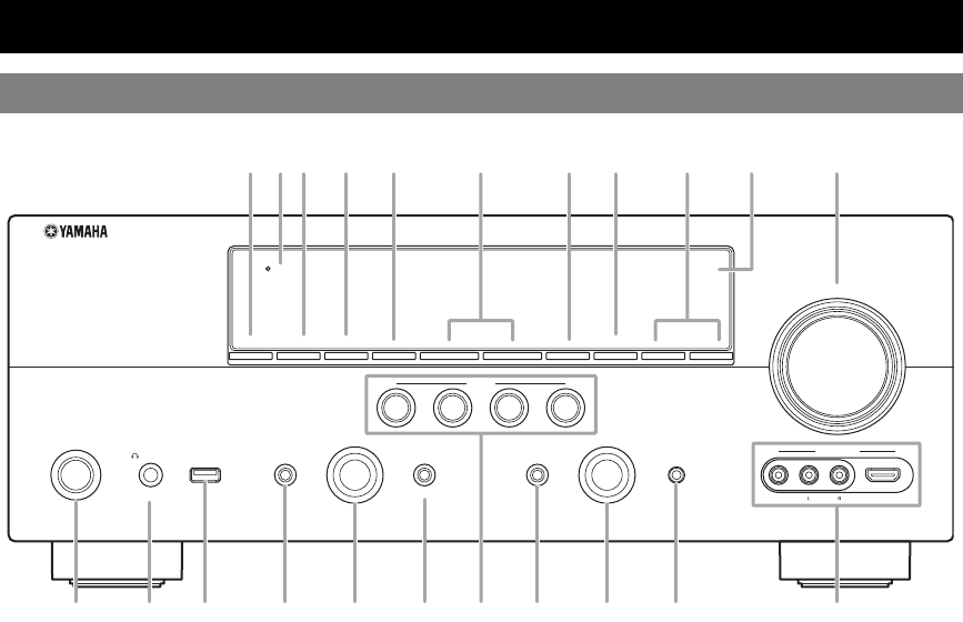
AZONE2 ON/OFF
Switches Zone2 on and off (page 71).
BHDMI THROUGH
Lights up in the following cases while this unit is on standby.
• when the HDMI control function is on
• when the HDMI signal standby-through function is currently
working
CZONE3 ON/OFF
Switches Zone3 on and off (page 71).
DZONE CONTROLS
Selects a zone to control with the main amplifier operations
(page 71).
EINFO
Changes information (input, DSP program, audio decoder, etc)
displayed on the front panel display (page 26).
FPRESET l / h
Selects an FM/AM preset station (page 32) or an XM/SIRIUS
preset channel (pages 37 and 41).
GMEMORY
Registers FM/AM stations as preset stations (page 32) or XM/
SIRIUS channels as preset channels (pages 37 and 41).
HBAND (CATEGORY)
Change the tuner bands between FM and AM.
Select a channel category for a XM/SIRIUS.
ITUNING/CH l / h
Changes FM/AM frequencies or XM/SIRIUS tuner channels.
JFront panel display
Displays information on this unit (page 6).
KVOLUME control
Controls the volume of this unit (page 24).
LMAIN ZONE ON/OFF
Turns this unit on and off (page 20).
MPHONES jack
For plugging headphones (page 26).
NUSB port
For connecting a USB memory device or USB portable audio
player (page 19)
OTONE CONTROL
Adjusts high-frequency/low-frequency output of speakers
(page 25).
PPROGRAM selector
Changes sound field programs (page 27).
QSTRAIGHT
Toggles between the selected sound field program and straight
decode mode (page 30).
RSCENE
Switches between linked sets of input sources and sound field
programs (page 24).
SPURE DIRECT
Changes mode to Pure Direct mode (page 25). This key lights up
when Pure Direct mode is on.
TINPUT selector
Selects an input source (page 24).
UOPTIMIZER MIC jack
For connecting the supplied optimizer microphone and adjusting
output characteristics of speakers (page 21).
VVIDEO AUX jacks
For connecting a game console, camcorder or digital camera to
either the HDMI IN jack or analog AUDIO/VIDEO jacks
(page 19).
Part names and functions
Front panel
ON/OFF
PHONES
MAIN ZONE
SILENT CINEMA
TONE CONTROL
PROGRAM
STRAIGHT PURE DIRECT
INPUT
OPTIMIZER MIC
VIDEO
HDMI IN
AUDIO
THROUGH
VIDEO
AUX
VOLUME
HDMI
EFFECT
BD/DVD
TV
CD
RADIO
SCENE
INFO
PRESET
lhlh
MEMORY
ZONE2
ON/OFF
ZONE
CONTROLS
ZONE3
ON/OFF
BAND
CATEGORY
TUNING/CH
USB
LPSOQ T
ABC D E G HFIJK
UMN R V
5 En
Part names and functions
English
INTRODUCTION
ADDITIONAL
INFORMATION APPENDIX
PREPARATION
BASIC
OPERATION
ADVANCED
OPERATION
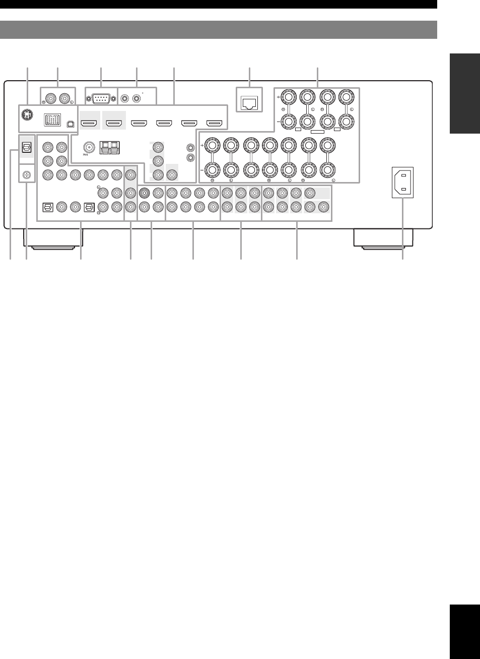
aSIRIUS jack
For connecting a SiriusConnect tuner (sold separately)
(page 39).
DOCK terminal
For connecting an optional Yamaha iPod universal dock (YDS-
11) or Bluetooth wireless audio receiver (YBA-10) (page 18).
XM jack
For connecting XM Mini-Tuner in XM Mini-Tuner Home Dock
(sold separately) (page 35).
bPHONO jacks
For connecting a turntable (page 16).
GND terminal
For connecting a turntable to reduce noise in the signal
(page 16).
cRS-232C terminal
Control expansion terminal for factory use only. Consult your
dealer for details.
dTRIGGER OUT 1/2 jacks
For connecting an external terminal with a trigger input terminal
to operate it linked with operation of this unit. Consult your
dealer for details.
eHDMI OUT 1/2 jacks
For connecting HDMI-compatible video monitors (page 14).
HDMI 1-4 jacks
For connecting external components for HDMI inputs 1-4
(page 16).
ANTENNA terminals
For connecting supplied FM and AM antennas (page 20).
MONITOR OUT jacks
Outputs visual signals from this unit to a video monitor, such as
a TV (page 14).
REMOTE IN/OUT jacks
For connecting an external component that supports the remote
control function (page 18).
fNETWORK port
For connecting to the network (page 19).
gSPEAKERS terminals
For connecting front, center, surround and surround back
speakers (page 11). Connect the presence speakers (page 11) or
the speakers for Zone2/3 (page 70) to EXTRA SP terminals.
hDIGITAL AUDIO jack
Outputs audio signals from a selected digital audio input source
to an external component (page 16).
iAV 1-6 jacks
For connecting external components for audio/visual inputs 1-6
(page 16).
jAV OUT jacks
Outputs audio/visual signals from a selected analog input source
to an external component (page 16).
kAUDIO 1/2 jacks
For connecting external components for audio inputs 1-2
(page 16).
lMULTI CH INPUT jacks
For connecting a player that supports a multi-channel output
(page 18).
mAUDIO OUT jacks
Outputs audio signals from a selected analog input source to an
external component (page 16).
ZONE2/3 OUT jacks
Output sound of this unit to an external amplifier set in a
different zone (page 69).
nPRE OUT jacks
Outputs multi-channel signals from up to 7.1 channels to an
external amplifier (page 18).
oAC IN
For connecting the supplied power cable (page 20).
Rear panel
AC IN
DOCK
PHONO RS
-
232C
TRIGGER OUT
NETWORK
COMPONENT
VIDEO
PR
PB
12
Y
OPTICAL
OPTICAL
OUT
( TV )
AV 1
AV 2
COAXIAL
AV 3
(CD)
COAXIAL OPTICAL
AV 4 AV 5 AV 6
AV
OUT
AUDIO1 AUDIO2
FRONT
SURROUND
SUR.BACK
SUBWOOFER
MULTI CH INPUT
AUDIO
OUT
ZONE3
OUT
ZONE2
OUT
FRONT
SURROUND
SUR. BACK SUBWOOFER
PRE OUT
CENTER
SINGLE
VIDEO
HDMI OUT 2HDMI OUT 1
ANTENNA
UNBAL.
FM
HD Radio
GND
AM
HDMI 1
(BD/DVD)
(HDMI CONTROL)
HDMI 2 HDMI 3 HDMI 4
VIDEO
IN
OUT
MONITOR OUT
SPEAKERS
12V
0.1A MAX.
FRONT
CENTER
SINGLE
CLASS 2 WIRING
SURROUND
SURROUND BACK/
BI-AMP
ZONE2/PRESENCEZONE3
12
CENTER
PR
PB
Y
REMOTE
COMPONENT
VIDEO
SIRIUS
DIGITAL
AUDIO
GND
XM
EXTRA SP
SP2 SP1
bca
ijbhklmno
dfeg
6 En
Part names and functions
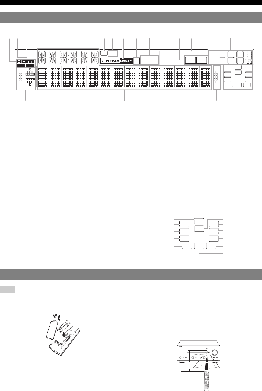
aHDMI indicator
Lights up during normal communication when HDMI is
selected as an input source.
OUT 1/OUT 2 indicators
The respective indicator lights up when HDMI signals are
output from the HDMI OUT 1/2 jacks.
bXM indicator
Lights up when an XM tuner is selected as an input source.
cSIRIUS indicator
Lights up when a SiriusConnect tuner is selected as an input
source.
dHD indicator
Lights up when this unit is tuned into the HD Radio reception
band (page 33).
eTAG indicator
Lights up when the selected HR Radio program (or song being
played) supports the iTunes Tagging feature (page 33).
fCINEMA DSP indicator
Lights up when a sound field program that uses CINEMA DSP
is selected.
gCINEMA DSP 3D indicator
Lights up when CINEMA DSP 3D is activated.
hTuner indicator
Lights up during receiving radio broadcast signals from an FM/
AM station (page 31).
iZONE2/ZONE3 indicator
Lights up when Zone2 or Zone3 is turned on.
jSLEEP indicator
Lights up when the sleep timer is activated (page 53).
kMUTE indicator
Flashes when audio is muted.
VOLUME indicator
Displays volume levels.
lCursor indicators
Light up if corresponding cursors on the remote control are
available for operations.
mMulti information display
Displays menu items and settings for the current operation.
nSpeaker indicators
Indicate speaker terminals from which signals are currently
output.
Note
•Before installing batteries or using the remote control, make sure that you read “Notes on remote controls and batteries” in the “Caution” section.
■Installing batteries
aTake off the battery compartment cover.
bInsert the two supplied batteries (AAA, R03, UM-4)
according to the polarity markings (+ and -) on the
inside of the battery compartment.
cSnap the battery compartment cover back into the
place.
■Operation range
The remote control transmits a directional infrared ray. Be
sure to aim the remote control directly at the remote
control sensor on this unit during operation.
Front panel display
STEREO
SLEEP
TAG VOL.
TUNED
PL PR
SW
C
LR
SL SR
SBL SB SBR
MUTE
SIRIUS
XM
3
ZONE
2
ZONE
3
HD
OUT 1 OUT 2
ab gfdecjihk
lm nl
SW
C
LR
SL SR
SBL SB SBR
PL PR
Subwoofer
Front L
Surround L
Surround back L
Center
Front R
Surround R
Surround back R
Surround back
Presence L Presence R
Remote control
ac
b
30 30
Remote control sensor window
within 6 m (20 ft)
7 En
Part names and functions
English
INTRODUCTION
ADDITIONAL
INFORMATION APPENDIX
PREPARATION
BASIC
OPERATION
ADVANCED
OPERATION
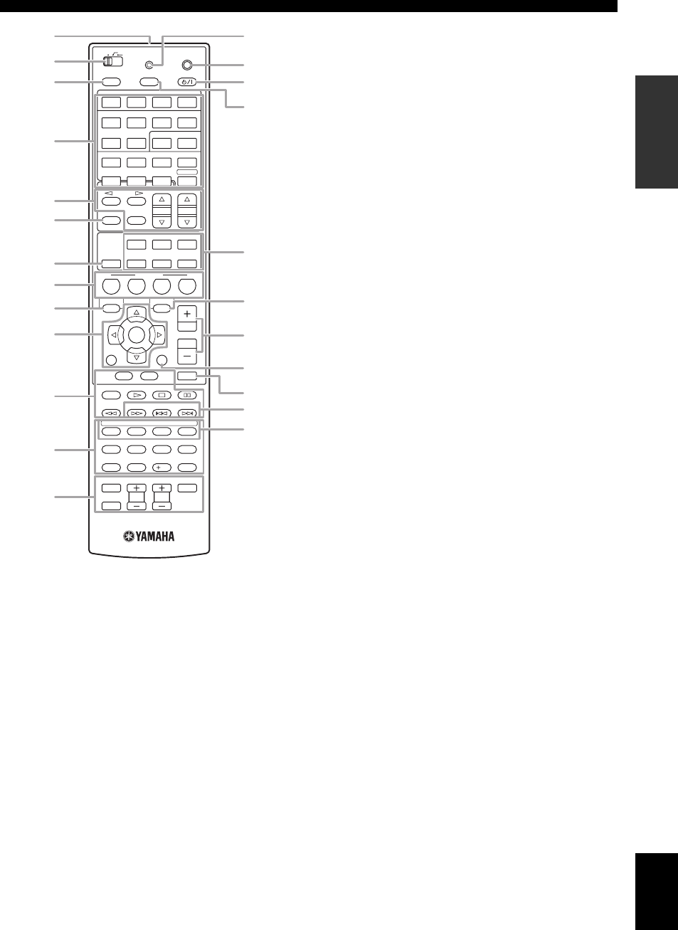
aRemote control signal transmitter
Transmits infrared signals.
bZone selection switch
Switches amplifiers (main, Zone2 or Zone3) to be operated by
the remote control (page 71).
cSOURCE POWER
Switches an external component on and off.
dInput selection keys
eTuner keys
fINFO
Changes the information shown on the front panel display
(page 26).
gHDMI OUT
Switches the HDMI OUT jacks to output HDMI signals
(page 53).
hSCENE
Switches between linked sets of input sources and sound field
programs (page 24).
iON SCREEN
Displays the GUI screen (page 25).
kExternal component operation keys
Operate recording, playback etc. of external components
(page 72).
lNumeric keys
Enter numbers.
mTV control keys
Enables operations of a TV or a projector (page 72).
nTRANSMIT
Lights up when a signal is output from the remote control.
oCODE SET
Sets remote control codes for external component operations
(page 72).
pPOWER
Switches this unit on and standby (page 20).
qSLEEP
Switches the sleep timer operations (page 53).
rSound selection keys
Selects sound field programs (page 27).
sOPTION
Displays the Option menu (page 54).
tVOLUME +/–
Adjust the volume of this unit (page 24).
uDISPLAY
Displays the play information on the video monitor.
When an iPod is connected: Changes the operation mode of the
iPod connected to the Yamaha iPod universal dock (page 44).
vMUTE
Turns the mute function on and off (page 25).
wHD Radio keys
xSub-input selection keys
Selects USB, NET RADIO, PC or Rhapsody when “USB/NET”
is selected as the input source.
HDMI 1-4 Selects HDMI inputs 1 through 4.
AV 1-6 Selects AV inputs 1 through 6.
AUDIO 1/2 Selects AUDIO inputs 1 and 2.
V-AUX
Selects a signal input from the VIDEO AUX jacks.
PHONO Selects a signal input from the PHONO jacks.
MULTI Selects a signal input from the MULTI CH
INPUT jacks.
DOCK
Selects a Yamaha iPod universal dock/Bluetooth
wireless audio receiver connected to the DOCK terminal.
TUNER Selects the FM/AM tuner.
SIRIUS Selects a SiriusConnect tuner as an input source.
XM Selects an XM tuner as an input source.
USB/NET Selects a USB device or a signal input via
network (selected by xSub-input
selection keys).
BD
DVD TV
CD
RADIO
SLEEPSOURCE
FM AM
INFO
MEMORY
1234
1234
5612
PHONO
MULTI
DOCK
TUNER SIRIUS
XM
V-AUX
HDMI
MUSIC
STEREO
ENHANCER SUR. DECODE
MOVIE
MUTE
STRAIGHT
HDMI OUT
PURE DIRECT
USB/NET
PRESET
TUN./CH
ON SCREEN OPTION
MAIN
POWER
7856
90
10
1234
USB NET RADIO PC RHAPSODY
POWER
TOP
MENU
SCENE
RETURN
REC
ENT
POWER
TV
TV VOL
INPUT
MUTE
TV CH
ENTER
VOLUME
DISPLAY
POP-UP
MENU
CATEGORY
HDMI
AUDIO
ZONE 2
ZONE 3
TRANSMIT
CODE SET
TAG PRG SELECT
AV
p
q
s
r
t
u
v
w
x
o
n
a
c
d
e
g
h
i
k
l
m
b
j
f
FM/AM Switches a band between FM and AM.
(CATEGORY l / h)Select a channel category for XM/
SIRIUS.
MEMORY Presets radio stations.
PRESET k / nSelects a preset station.
TUN./CH k / nChanges FM/AM frequencies or
XM/SIRIUS tuner channels.
jCursors k / n / l / hSelect menu items or change
settings.
ENTER Confirms a selected item.
RETURN Returns to the previous screen or
ends the menu display.
TAG Stores “tag” data to the iPod or internal
memory of this unit (page 33).
PRG SELECT Selects an HD Radio audio program
(page 33).
8 En
Part names and functions
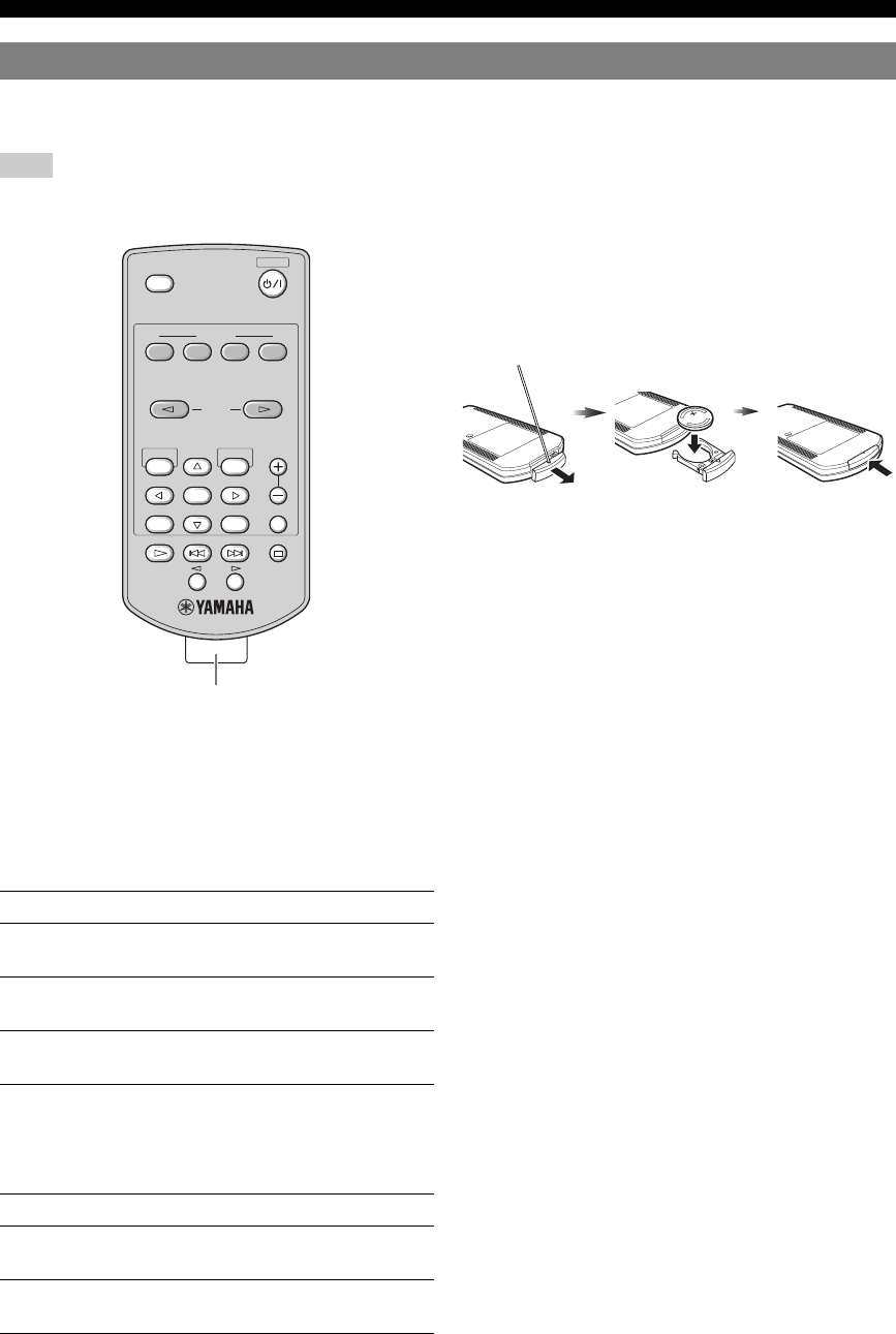
Use the supplied simplified remote control to make basic controls of this unit. Keys on the simplified remote control
function as well as the identical keys on the main remote control (page 6).
Note
•Before using the simplified remote control or replacing the battery, make sure that you read “Notes on remote controls and batteries” in the “Caution”
section.
y
•To select an input source, press INPUT l / h repeatedly.
•The printings “TAG” and “PRG SELECT” are for U.S.A. model.
■Setting the controlling zone
Follow the procedure below to select an amplifier (main,
Zone2 or Zone3) to be operated by the simplified remote
control (page 71).
■Setting the remote control ID
Follow the procedure below to set the remote control ID of
the simplified remote control. For details about remote
control ID, see page 74.
■Replacing the battery of the simplified
remote control
Change the battery when the operation range of the
simplified remote control decreases.
Simplified remote control
Zone to select Procedure
Main Press and hold h (right of ENTER) and
BD/DVD for more than 3 seconds.
Zone2 Press and hold h (right of ENTER) and TV
for more than 3 seconds.
Zone3 Press and hold h (right of ENTER) and CD
for more than 3 seconds.
Zone to select Procedure
ID1 Press and hold l (left of ENTER) and BD/
DVD for more than 3 seconds.
ID2 Press and hold l (left of ENTER) and TV
for more than 3 seconds.
MUTE
VOLUME
INPUT
SLEEP
SCENE
BD
DVD TV CD
RADIO
POWER
ON SCREEN OPTION
TAG
PRESET
PRG SELECT
ENTER
DISPLAYRETURN
Remove the insulation sheet
Use a straight
pin to remove
the cover.
Replace the
battery with a
new CR2025
battery.
Close the
cover.
9 En
English
INTRODUCTION
ADDITIONAL
INFORMATION APPENDIX
PREPARATION
BASIC
OPERATION
ADVANCED
OPERATION
When you use this product for the first time, perform setup following the steps below. See the related pages for details on
operations and settings.
Prepare speakers, DVD player, cables, and other items
necessary for setup.
For example, prepare the following items for setting up a
7.1-channel sound system.
y
•The priority of the requirement of other speakers is as follows:
1 Two surround speakers
2 One center speaker
3 One (or two) surround back speaker(s)
•Video and audio cables are unnecessary if you use HDMI cables.
Place your speakers in the room and connect them to this
unit.
y
•This unit has a YPAO (Yamaha Parametric Room Acoustic Optimizer)
that automatically optimizes this unit based on room acoustic
characteristics (audio characteristics of the speakers, speaker positions,
and room acoustics, etc.).
You can enjoy good balanced sound without special knowledge by using
the YPAO technology (☞P. 21).
Connect your TV, DVD player, or other components.
Connect the power cable and turn on this unit.
Select the component connected in step 3 as an input
source and start playback.
y
•This unit supports the SCENE function (page 24) that changes the input
source and sound field program at one time. Four scenes are preset for
different purposes for Blu-ray disc, DVD and CD, and you can select
from a scene from those just by pressing a remote control key.
Quick start guide
Step 1: Prepare items for setup
Requirements qty.
Speakers Front speaker 2
Center speaker 1
Surround speaker 2
Surround back
speaker
2
Active subwoofer 1
Speaker cable 7
Subwoofer cable 1
Reproduction component such as DVD player 1
Video monitor such as TV 1
Video cable or HDMI cable 2
Audio cable 2
Front right speaker
Subwoofer
Surround left speaker
Surround right speaker
Front left
speaker
Video monitor
Center
speaker
Components
(such as DVD player)
Surround Back
right speaker
Surround Back
left speaker
Step 2: Set up your speakers
•Placing speakers ☞P. 10
•Connecting speakers ☞P. 11
Step 3: Connect your components
•Connecting a TV monitor or projector ☞P. 14
•Connecting other components ☞P. 16
•Connecting a multi-format player or an
external decoder ☞P. 18
•Connecting an external amplifier ☞P. 18
•Connecting a USB storage device ☞P. 19
•Connecting a Yamaha iPod universal dock or
Bluetooth wireless audio receiver ☞P. 1 8
•Connecting to the network ☞P. 19
•Connecting the FM and AM antennas ☞P. 20
•Connecting an XM Mini-Tuner Home Dock ☞P. 35
•Connecting a SiriusConnect tuner ☞P. 39
Step 4: Turn on the power
•Connecting the power cable ☞P. 20
•Turning this unit on and off ☞P. 20
Step 5: Select the input source and start
playback
•Basic procedure ☞P. 24
•Selecting sound field programs ☞P. 27
10 En
PREPARATION
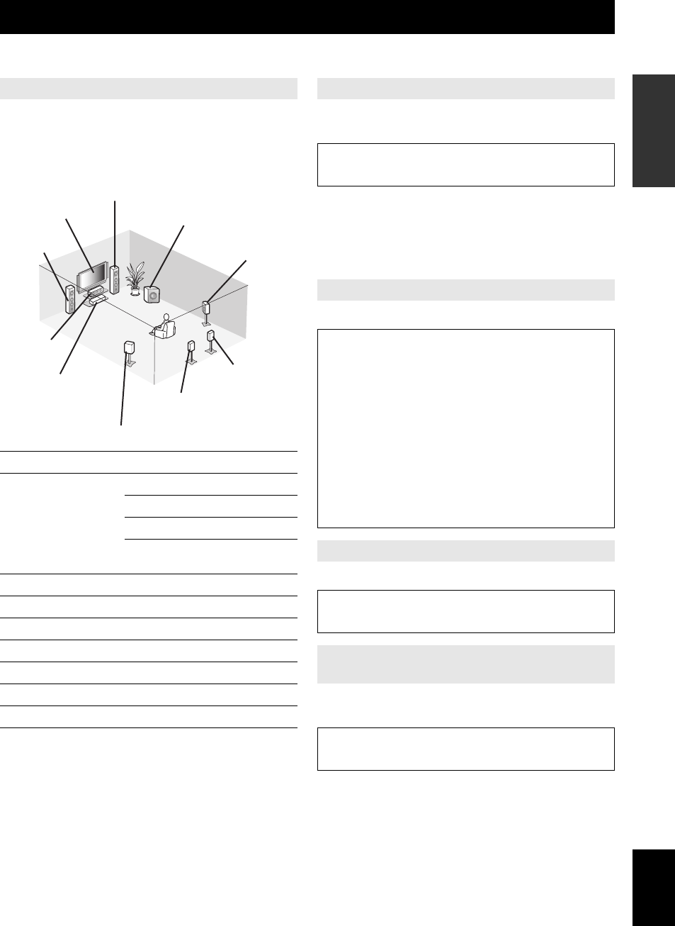
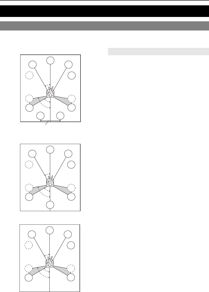
This unit supports up to 7.1-channel surround. We recommend the following speaker layout in order to obtain the
optimum surround effect.
7.1-channel speaker layout
6.1-channel speaker layout
5.1-channel speaker layout
■Front left and right speakers (FL and FR)
The front speakers are used for the front channel sounds
(stereo sound) and effect sounds. Place these speakers at
an equal distance from the ideal listening position. Adjust
the height of the TV or screen so that about 1/4 of the
screen from the bottom is aligned with the tweeters of the
front speakers.
■Center speaker (C)
The center speaker is for the center channel sounds
(dialog, vocals, etc.). Place it halfway between the left and
right speakers. When using a TV, place the speaker just
above or just under the center of the TV with the front
surfaces of the TV and the speaker aligned. When using a
screen, place it just under the center of the screen.
■Surround left and right speakers (SL and SR)
The surround speakers are used for effect and surround
sounds. Place them at the rear left and rear right facing the
listening position. To obtain a natural sound flow in the
5.1-channel speaker layout, place them slightly further
back than in the 7.1-channel speaker layout.
■Surround back left and right speakers (SBL
and SBR) / Surround back speaker (SB)
The surround back left and right speakers are used for rear
effect sounds. Place them at the rear of the room facing the
listening position at least 30 cm (1 ft) away from each
other, ideally at the same distance as that between the
front left and right speakers.
In the 6.1-channel speaker layout, surround back left and
right channel sound signals are mixed down and output
from the single surround back speaker.
In the 5.1-channel speaker layout, surround back left and
right channel sound signals are output from the surround
left and right speakers.
■Subwoofer (SW)
The subwoofer speaker is used for bass sounds and low-
frequency effect (LFE) sounds included in Dolby Digital
and DTS signals. Use a subwoofer with a built-in
amplifier, such as the Yamaha Active Servo Processing
Subwoofer System. Place it exterior to the front left and
right speakers facing slightly inward to reduce reflections
from a wall.
Connections
Placing speakers
60˚
30˚
SBR
SBL
FL
FR
C
SL
SR
SR
80˚
SL
SW
SW
30 cm (12 in) or more
60˚
30˚
SB
FL
FR
C
SL
SR
SR
80˚
SL
SW
SW
60˚
30˚
FL
FR
C
SL
SR
SR
80˚
SL
SW
SW
Speaker channels
11 En
English
INTRODUCTION
ADDITIONAL
INFORMATION APPENDIX
PREPARATION
BASIC
OPERATION
ADVANCED
OPERATION
■Presence left and right speakers (PL and PR)
The presence speakers supplement the sound from the
front speakers with extra ambient effects produced by the
sound field programs (page 27). We recommend that you
use the presence speakers especially for the CINEMA
DSP sound field programs. To use the presence speakers,
connect the speakers to SP1 terminals and then set “Extra
Speaker Assignment” to “Presence” (page 60).
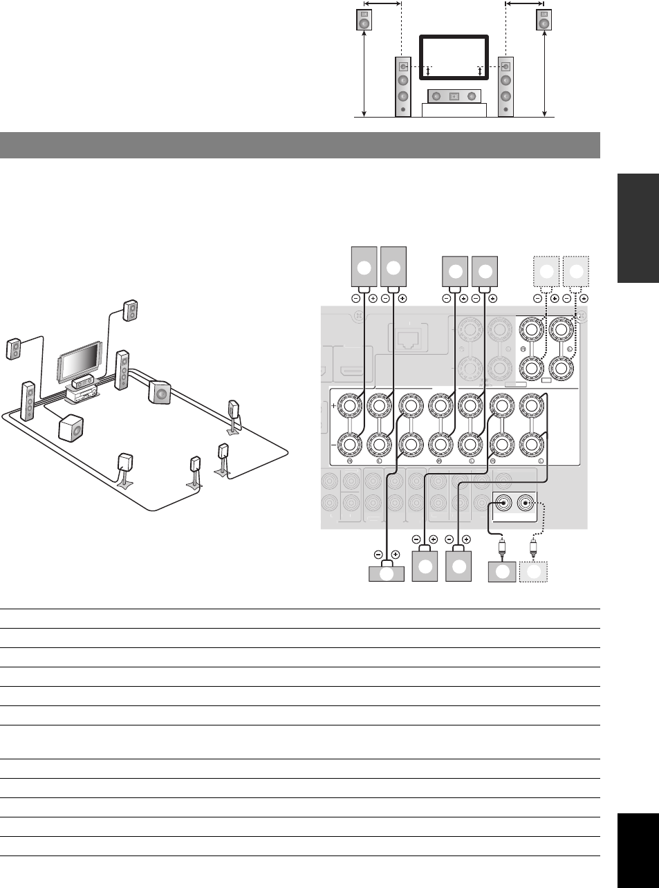
Connect your speakers to the respective terminals according to your speaker layout. The following illustration shows how
to connect speakers for 7.1-channel speaker layout.
y
•You can connect Zone2/3 speakers to the EXTRA SP (SP1/SP2) terminals (page 70).
•You can connect up to two subwoofers. When two subwoofers are connected, the same sound is output from them.
FR
PRPL
C
FL
0.5 to 1 m (1 to 3 ft)0.5 to 1 m (1 to 3 ft)
1.8 m
(6 ft)
1.8 m
(6 ft)
1/4 from
bottom
Connecting speakers
a
b
c
d
e
f
g
h
i
j
k
SUBWOOFER
SPEAKERS
FRONT
CENTER
SINGLE
CLASS 2 WIRING
SURROUND
SURROUND BACK/
BI-AMP
ZONE2/PRESENCE
12
R
A
SP
SP1
NETW
ORK
SU
R.B
A
CK
SU
BW
OO
FE
R
H
INPU
T
A
U
DIO
O
UT
ZO
NE
3
OU
T
ZO
NE
2
OUT
FR
O
N
T
S
URROUN
D
SUR
.
BA
CK
P
RE
OUT
C
ENTER
S
IN
G
L
E
3
HDMI
4
C
ENTER
E
E
XT
R
cg f h i
e d
b a k j
Speakers Jacks on this unit 7.1-channel 6.1-channel 5.1-channel
aFront left FRONT (L) ✔✔✔
bFront right FRONT (R) ✔✔✔
cCenter CENTER ✔✔✔
dSurround left SURROUND (L) ✔✔✔
eSurround right SURROUND (R) ✔✔✔
fSurround back left
(Surround back for 6.1-channel)
SURROUND BACK (L)
(SINGLE) ✔✔
gSurround back right SURROUND BACK (R) ✔
hSubwoofer 1 SUBWOOFER 1 ✔✔✔
iSubwoofer 2 SUBWOOFER 2 Option Option Option
jPresence left SP1 (L) Option Option Option
kPresence right SP1 (R) Option Option Option
12 En
Connections
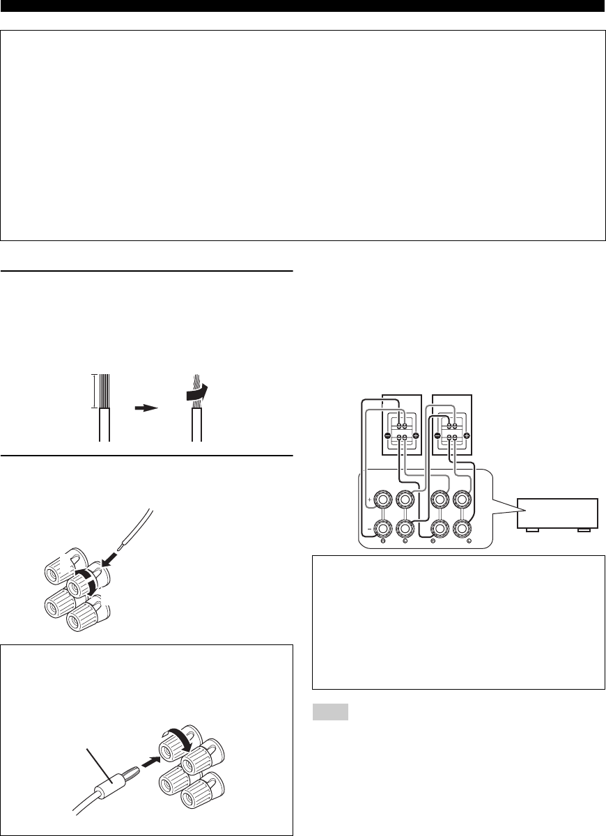
■Connecting speaker cables
1Remove approximately 10 mm (0.4 in) of
insulation from the end of each speaker
cable and then twist bare wires of the cable
together so that they will not cause a short
circuits.
2Loosen the knob, insert the twisted bare
wires into the hole and then tighten the knob.
■Using bi-amplification connections
If you do not connect surround back speakers, you can use
the SURROUND BACK/BI-AMP jacks to make bi-
amplification connections to one speaker system which
supports bi-amplification connection as shown below.
To activate the connections, set “BI-AMP” to “ON” in the
advanced setup menu (page 73).
Note
•You cannot use surround back speakers or extra speakers (presence and
Zone2 speakers) when bi-amplification connections are made.
Caution
•A speaker cable is a pair of insulated cables running side by side in general. One of the cables is colored differently
or striped to indicate a polarity. Connect one end of the colored/striped cable to the “+” (red) terminal of this unit
and the other end to that of your speaker, and connect one end of the other cable to the “–” (black) terminal of this
unit and the other end to that of your speaker.
•Before connecting the speakers, be sure to disconnect the power cable.
•Do not let the bare speaker wires touch each other or any metal part of this unit. This could damage this unit and/or
speakers. If the circuit shorts out, “CHECK SP WIRES!” appears on the front panel display when this unit is turned
on.
•If images on the monitor (CRT) are distorted, place the speakers away from the video monitor.
•Use speakers with an impedance of 6-ohm or larger. Set speaker impedance in the advanced setup menu before
connecting the speakers (page 73). You can also use 4-ohm speakers as the front speakers when you set “SP IMP.” to
“6ΩMIN”.
Connecting the banana plug (Except Korea,
U.K., Europe, Russia and Asia models)
Tighten the knob and then insert the banana plug into
the end of the terminal.
10 mm (0.4 in)
1
2
3
Red: positive (+)
Black: negative (–)
Banana plug
Caution
Before making bi-amplification connections, remove
any brackets or cables that connect a woofer with a
tweeter. Refer to the instruction manuals of speakers for
details.
When not making bi-amplification connections, make
sure that the brackets or cables are connected before
connecting the speaker cables.
SURROUND BACK/
BI-AMP
FRONT
Front speakers
Right Left
This unit
13 En
Connections
English
INTRODUCTION
ADDITIONAL
INFORMATION APPENDIX
PREPARATION
BASIC
OPERATION
ADVANCED
OPERATION
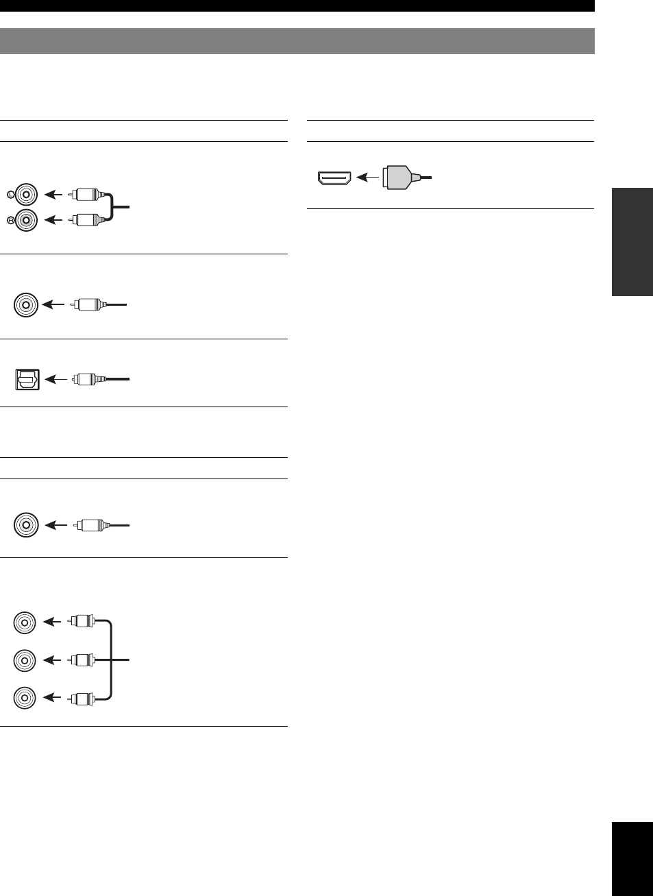
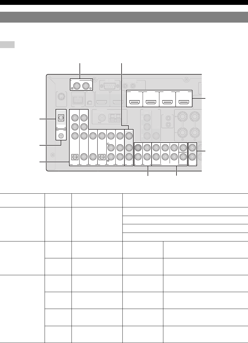
This unit has the following input and output jacks. Use jacks and cables appropriate for components that you are
connecting.
■Audio jacks
■Video jacks
■Video/audio jacks
y
•We recommend that you use a commercially available 19-pin HDMI
cable no longer than 5 meters (16 feet) with the HDMI logo printed on it.
•Use a conversion cable (HDMI jack ↔ DVI-D jack) to connect this unit
to other DVI components.
•You can check the potential problem about the HDMI connection
(page 55).
Information on jacks and cable plugs
Jack and cables Description
Analog audio jacks To transmit conventional analog
stereo audio signals. Use stereo pin
cables.
COAXIAL jacks To transmit coaxial digital audio
signals. Use pin cables.
OPTICAL jacks To transmit optical digital audio
signals. Use optical fiber cables.
Jack and cables Description
VIDEO jacks To transmit conventional
composite video signals. Use pin
cables.
COMPONENT VIDEO
jacks
To transmit component video
signals that include luminance (Y),
chrominance blue (PB) and
chrominance red (PR) components.
Use component video cables.
L
R
(white)
(red)
COAXIAL
C
(orange)
OPTICAL
O
VIDEO
V
(yellow)
PR
PB
Y
COMPONENT
VIDEO
P
B
Y
P
R
(red)
(blue)
(green)
Jack and cables Description
HDMI jacks To transmit digital video and
digital audio signals. Use HDMI
cables.
HDMI
HDMI
14 En
Connections
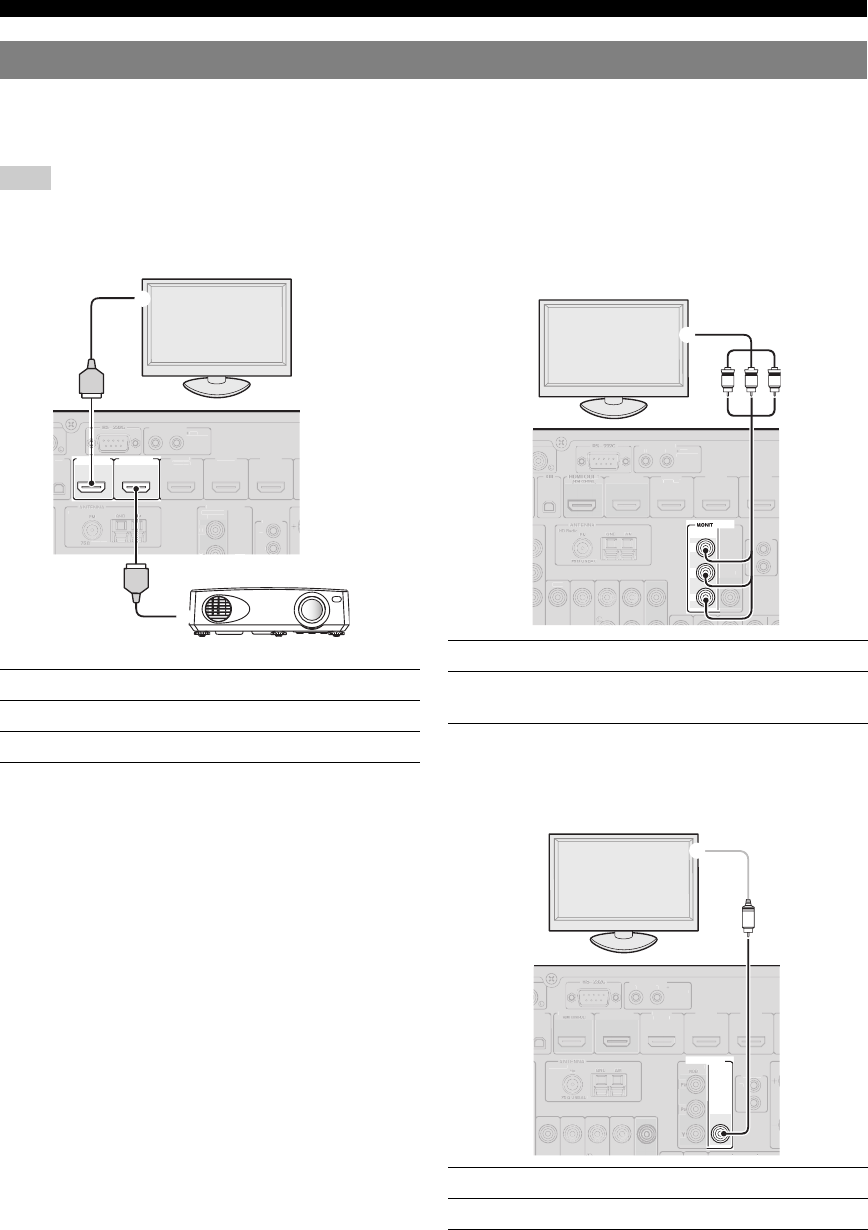
According to the types of video input jacks available on your video monitor (such as a TV or projector), choose one of
the connection methods as shown below. When you connect video players such as a DVD player to this unit with an
HDMI connection, connect your video monitor to this unit with an HDMI connection.
Note
•Make sure that this unit and other components are unplugged from the AC wall outlets.
■If your video monitor has an HDMI input jack
y
•This unit is equipped with two HDMI OUT jacks. You can select the
active HDMI OUT jack(s) by pressing gHDMI OUT (page 53).
•This unit supports the HDMI control function (page 53). If your TV
supports the HDMI control function, connect the TV to the HDMI OUT
1 jack to control this unit with the remote control of your TV.
■If your video monitor does not have HDMI
input jacks but component video input jacks
■If your video monitor has neither HDMI nor
component video input jacks
Connecting a TV monitor or projector
Jacks on components Jacks on this unit
aHDMI input HDMI OUT 1
bHDMI input HDMI OUT 2
HDMI OUT 2HDMI OUT 1
(HDMI CONTROL)
T
RIGGER OUT
1
2
UNB
AL.
HD R
adio
HDMI
1
(
BD
/
D
VD
)
H
DMI
2
H
DMI 3
VIDEO
IN
O
UT
MO
NI
T
O
R
OU
T
12
V
0
.1A MAX
.
P
R
P
B
REM
O
TE
CO
MP
O
NENT
VIDE
O
X
M
a
HDMI
HDMI
b
TV
Projector Jacks on components Jacks on this unit
cComponent video output MONITOR OUT
(COMPONENT VIDEO)
Jacks on components Jacks on this unit
dVideo input (composite) MONITOR OUT (VIDEO)
O
R
OU
T
P
R
P
B
Y
COMPONENT
VIDEO
T
RIGGER OUT
1
2
VIDE
O
H
DMI
OU
T 2
HDMI
1
(
BD
/
D
VD
)
H
DMI
2
HDMI 3
VIDE
O
IN
O
UT
1
2
V
0
.1A MAX
.
R
EM
O
TE
c
PB
YP
R
TV
VIDEO
M
ONI
T
OR OUT
T
RIGGER OUT
1
2
V
IDE
O
H
DMI
OU
T 2
H
DMI
OU
T 1
HD Radio
HDMI
1
(
BD/D
VD
)
HDMI 2
H
DMI 3
IN
OU
T
12
V
0.1A MAX
.
REM
O
TE
CO
MP
O
NENT
XM
V
d
TV
15 En
Connections
English
INTRODUCTION
ADDITIONAL
INFORMATION APPENDIX
PREPARATION
BASIC
OPERATION
ADVANCED
OPERATION
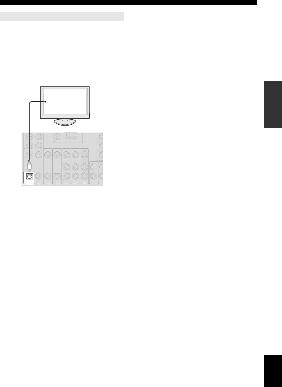
To output sound of a TV from this unit, make connection
between one of the AV 1-6 jacks of this unit and an audio
output jack of the TV.
If the TV supports an optical digital output, we
recommend that you use the AV 1 jack. Connecting to the
AV 1 jack allows you to switch an input source to the AV 1
jack with a just a single key operation using the SCENE
function (page 24).
Outputting TV sounds from this unit
OPTICAL
(
TV
)
A
V 1
A
P
R
A
V2
A
A
CO
A
XIA
L
A
V 3
A
A
(
CD
)
CO
AXIA
L
O
PTI
C
AL
A
V 4
A
A
A
V 5
A
A
A
V 6
A
A
A
V
A
A
O
UT
A
U
DI
O1
A
UD
VIDE
O
UNB
AL
.
P
R
P
B
Y
O
Digital output
(optical)
TV
16 En
Connections
This unit has input and output terminals for respective input and output sources. You can reproduce sound and movies
from input sources selected with the front panel display or remote control.
Note
•Make sure that this unit and other components are unplugged from the AC wall outlets.
■Audio and video player / Set-top box
Connecting other components
External
component Signal Output jacks on
components Input jacks on this unit
External component
with HDMI output
Audio/Video HDMI output HDMI 1 (BD/DVD)
HDMI 2
HDMI 3
HDMI 4
External component
with component video
output
Audio Optical digital output AV 1 (TV) OPTICAL
Video Component video output COMPONENT VIDEO
Audio Coaxial digital output AV 2 COAXIAL
Video Component video output COMPONENT VIDEO
External component
with composite video
output
Audio Coaxial digital output AV 3 (CD) COAXIAL
Video Composite output VIDEO
Audio Optical digital output AV 4 OPTICAL
Video Composite output VIDEO
Audio Analog audio output AV 5 Analog audio
Video Composite output VIDEO
Audio Analog audio output AV 6 Analog audio
Video Composite output VIDEO
PHONO
COMPONENT
VIDEO
P
R
P
B
Y
OPTICAL
OPTICAL
OUT
( TV )
AV 1
AV 2
COAXIAL
AV 3
(CD)
COAXIAL OPTICAL
AV 4 AV 5 AV 6
AV
OUT
AUDIO1 AUDIO2
FRONT
SURROUND
SUR.BACK
SUBWOOFER
MULTI CH INPUT
AUDIO
OUT
VIDEO
HDMI 1
(BD/DVD)
HDMI 2 HDMI 3 HDMI 4
CENTER
DIGITAL
AUDIO
GND
DOCK
RS
-
232
C
T
RI
GG
ER
O
UT
1
2
ZO
N
OU
HDMI
OU
T 2
H
DMI
OU
T
1
ANTENNA
UNBAL.
FM
HD R
adio
G
N
D
AM
(
HDMI
CO
NTR
OL
)
V
IDE
O
IN
OU
T
MO
NIT
O
R
OUT
1
2
V
0
.1
A
MAX.
F
RONT
P
R
P
B
Y
REMOTE
C
OMPONENT
VIDE
O
S
IRIU
S
XM
GND terminal
Audio / video output (AV OUT)
Audio input (AUDIO 1/2)
HDMI input
(HDMI 1-4)
Audio output
(AUDIO OUT)
Multi channel audio input (MULTI CH INPUT)
Audio input (PHONO)
Audio output
(DIGITAL AUDIO)
Audio / video input
(AV 1-6)
17 En
Connections
English
INTRODUCTION
ADDITIONAL
INFORMATION APPENDIX
PREPARATION
BASIC
OPERATION
ADVANCED
OPERATION
y
•Input jacks in parentheses indicate the jacks to which the SCENE function (page 24) is assigned by the initial factory settings. To use the SCENE function
with the initial factory settings, connect external components that support the SCENE function to these jacks.
•You can change the name of the input source displayed on the front panel display as necessary (page 64).
•See page 69 on how to use the ZONE2/3 OUT jacks.
•When you connect an external component with analog audio and component video (or composite) output jacks, connect the analog audio output to the
AUDIO 1 or AUDIO 2 jacks of this unit while making a video connection (component video or composite). Then select the video to be output when
“AUDIO 1” or “AUDIO 2” is selected as the input source (page 56).
■Audio player
y
•If your CD player has a coaxial digital output jack, connect it to the AV3 jack of this unit. In this case, you can use the SCENE function (page 24) with the
initial factory settings.
•When connecting a turntable with a low-output MC cartridge to the PHONO jacks, use an in-line boosting transformer or MC-head amplifier.
•Connect your turntable to the GND terminal of this unit to reduce noise in the signal.
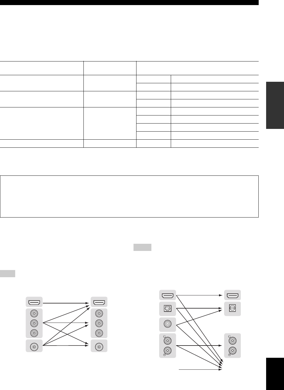
■Internal signal flow
Video signal flow
This unit automatically converts input video signals and
outputs the signals to the HDMI OUT jacks and
MONITOR OUT (COMPONENT VIDEO and VIDEO)
jacks (video conversion).
Note
•The AV OUT (composite video) jack only outputs video signals input to
the composite video input jacks.
Audio signal flow
Notes
•Audio signals input to the HDMI input jacks are output from either the
speaker terminals or HDMI OUT 1/2 jacks depending on the “Audio
Output” setting (page 62).
•The DIGITAL AUDIO (OPTICAL OUT) jack outputs digital audio
signals only when signals are input to the optical or coaxial optical input
jacks and corresponding input source is selected.
External component Output jacks on
components Input jacks on this unit
External component with optical digital
output
Optical digital output AV 1 (TV) OPTICAL
AV 4 OPTICAL
External component with coaxial digital
output
Coaxial digital output AV 2 COAXIAL
AV 3 (CD) COAXIAL
External component with analog audio
output
Analog audio output AV 5 Analog audio
AV 6 Analog audio
AUDIO 1 Analog audio
AUDIO 2 Analog audio
Turntable Analog audio output PHONO Analog audio
About audio/video output jacks
When using the AV OUT jacks: connect these jacks to composite video and analog audio input jacks of an external
component.
When using the AUDIO OUT jacks: connect these jacks to analog audio input jacks of an external component.
When using the DIGITAL AUDIO (OPTICAL OUT) jack: connect this jack to optical digital input jack of an
external component.
HDMI
VIDEO
P
R
P
B
Y
HDMI OUT
VIDEO
P
R
P
B
Y
HDMI
Component
video
Composite
video
Input Output
HDMI
OPTICAL
HDMI OUT
OPTICAL
OUT
COAXIAL
HDMI
Optical
digital
Analog
Input Output
MULTI CH INPUT Speaker
terminals
Coaxial
digital
18 En
Connections
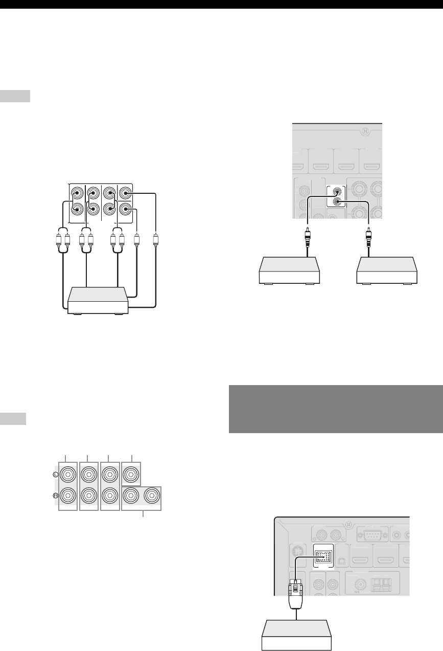
■Connecting a multi-format player or an
external decoder
This unit is equipped with 8 additional input jacks (Front
L/R, Center, Surround L/R, Surround Back L/R and
Subwoofer) for analog multi-channel input from a multi-
format player, external decoder, etc.
Notes
•When you select “MULTI CH” as the input source, the digital sound field
processor is automatically disabled.
•Since this unit does not redirect signals input at the MULTI CH INPUT
jacks to accommodate for missing speakers, connect at least a 5.1-
channel speaker system when using this feature.
•You can specify a video signal to be output during a multi-channel audio
reproduction (page 56). If your DVD player has analog multi-channel
output jacks, connect them to the MULTI CH INPUT jacks while making
a video connection (component video or composite).
■Connecting an external amplifier
If you want to use another amplifier, connect an external
amplifier to the PRE OUT jacks. Each PRE OUT jack
outputs the same channel signals as the corresponding
speaker terminals.
Note
•When you make connections to the PRE OUT jacks, do not make any
connections to the speaker terminals.
aFRONT PRE OUT jacks
Front channel output jacks.
bSURROUND PRE OUT jacks
Surround channel output jacks.
cSUR.BACK PRE OUT jacks
Surround back output jacks. When you only connect one
external amplifier for the surround back channel, connect it to
the left SUR.BACK (SINGLE) jack.
y
•To output surround back channel signals at these jacks, set
“Surround Speaker” to any parameter except “None” (page 60).
dCENTER PRE OUT jack
Center channel output jack.
eSUBWOOFER PRE OUT 1/2 jack
Connect a subwoofer with a built-in amplifier.
■Transmitting/receiving remote control signals
When the components have the capability of the
transmission of the remote control signals, connect the
REMOTE IN and REMOTE OUT jacks to the remote
control input and output jack with the monaural analog
mini cable as follows.
y
•If connecting a Yamaha component that supports the SCENE control
signal reception to the REMOTE OUT jack of this unit, you can start
playback on the Yamaha component by using the SCENE function
(page 24).
•If connecting a component other than Yamaha products to the REMOTE
OUT jack of this unit, set “SCENE IR” to “OFF” in the advanced setup
menu (page 73).
This unit has the DOCK terminal, to which you can
connect a Yamaha iPod universal dock (YDS-11, sold
separately) or a Bluetooth wireless audio receiver (YBA-
10, sold separately). You can play an iPod or a Bluetooth
component with this unit by connecting it to the DOCK
terminal.
FRONT
SURROUND
SUR.BACK
SUBWOOFER
MULTI CH INPUT
CENTER
LRLR RL
Surround
back out
Surround
out
Front out
Subwoofer out
Center out
Multi-format player or external decoder
(7.1-channel output)
FRONT
SURROUND
SUR. BACK SUBWOOFER
PRE OUT
CENTERSINGLE
12
abc d
e
Connecting a Yamaha iPod universal
dock or Bluetooth™ wireless audio
receiver
IN
OUT
REMOTE
HDMI 1
B
D
/
DVD
)
HDMI
2
HDMI
3
HDMI 4
VIDE
O
MO
NIT
O
R
OU
T
P
R
P
B
Y
CO
MP
O
NEN
T
VIDE
O
Remote
control out
Remote
control in
Infrared signal
receiver or Yamaha
component
IR flasher or
Yamaha component
(CD or DVD player, etc.)
DOCK
P
H
O
N
O
R
S
-
2
3
2
C
TRI
GG
ER
O
CO
MP
O
NENT
V
IDE
O
P
R
1
2
OPTICAL
OU
T
HDMI OUT 2
H
DMI OUT 1
ANTENNA
UNB
AL.
FM
H
D R
adio
G
ND
AM
HD
(
BD
(
HDMI CONT
R
OL
)
S
IRIU
S
XM
Yamaha iPod universal dock or
Bluetooth wireless audio receiver
19 En
Connections
English
INTRODUCTION
ADDITIONAL
INFORMATION APPENDIX
PREPARATION
BASIC
OPERATION
ADVANCED
OPERATION
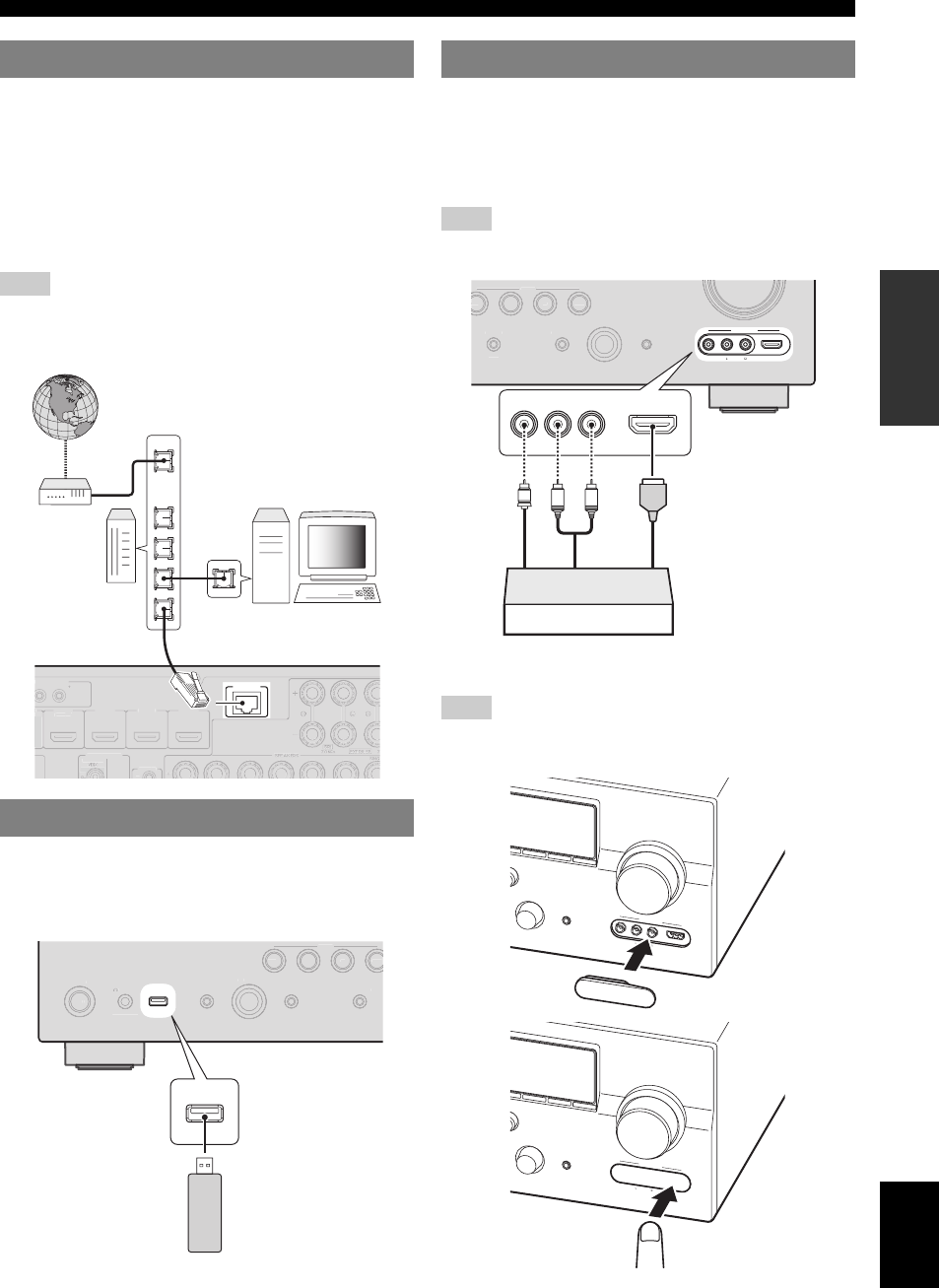
To connect this unit to your network, plug one end of a
network cable (CAT-5 or higher straight cable) into the
NETWORK port of this unit, and plug the other end into
one of the LAN ports on your router that supports the
DHCP (Dynamic Host Configuration Protocol) server
function. To enjoy Internet Radio or music files saved on
your PC, each device must be connected properly in the
network.
Note
•Use an STP (shielded twisted pair) cable (commercially available) to
connect a network hub or router and this unit.
•If the DHCP server function on your router is disabled, you need to
configure the network settings manually (page 64).
Connect a USB memory device or USB portable audio
player to the USB port on the front panel of this unit. For
information about USB storage devices supported by this
unit, see page 47.
Use either the HDMI IN jack or analog AUDIO/VIDEO
jacks on the front panel to connect a game console,
camcorder or digital camera to this unit. Be sure to turn
down the volume of this unit and other components before
making connections.
Note
•When signals are input to the HDMI IN and analog input jacks (AUDIO
L/R and VIDEO) at the same time, the HDMI connection has a priority.
Note
•To protect against dust, attach the supplied VIDEO AUX input cover to
the VIDEO AUX jacks when you do not use the jacks. To remove the
cover, push the right section of it.
Connecting to the network
Connecting a USB storage device
NETWORK
T
RI
GG
ER
OUT
1
2
2
HDMI 1
(
B
D
/
D
VD
)
HDMI
2
HDMI
3
HDMI 4
IN
M
O
NIT
O
R
OUT
12
V
0
.1A MAX.
REM
O
TE
COMPONEN
T
LAN
WAN
Network cable
Modem
Router
PC
Internet
ON/OFF
PHONES
MAIN ZONE
SILENT CINEMA
TONE CONTROL
PROGRAM
STRAIGHT PURE DIRECT
EFFECT
BD/DVD
TV
CD
RADIO
SCENE
USB
O
N
/
O
F
F
P
H
O
NE
S
MAIN
Z
O
N
E
S
ILENT
C
INEMA
T
O
NE
CO
NTR
OL
PR
O
GRAM
S
TRAI
G
HT
P
URE DIRE
CT
E
FFE
C
T
BD
/D
VD
TV
C
D
RADI
O
S
CEN
E
USB
USB memory device or
USB portable audio player
Using the VIDEO AUX jacks
STRAIGHT PURE DIRECT
INPUT
OPTIMIZER MIC
VIDEO
HDMI IN
AUDIO
VIDEO
AUX
EFFECT
B
D/DVD
TV
CD
RADIO
SCENE
STRAIGHT
P
URE DIREC
T
INP
UT
OPTIMIZER MI
C
E
FFE
C
T
B
D/
D
VD
TV
C
D
R
ADI
O
SC
ENE
R
L
AUDIO
VIDEO
HDMI IN
V
L
R
HDMI
Game console, camcorder
or digital camera
Analog audio
output
Video output
HDMI output
INPUT
OPTIMIZER MIC
VIDEO
HDMI IN
AUDIO
VIDEO
AUX
VOLUME
lh
O
RY
BAND
CATEGORY
TUNING/CH
PUSH
Atlach the cover
INPUT
OPTIMIZER MIC
VIDEO
HDMI IN
AUDIO
VIDEO
AUX
VOLUME
lh
O
RY
BAND
CATEGORY
TUNING/CH
PUSH
Remove the cover
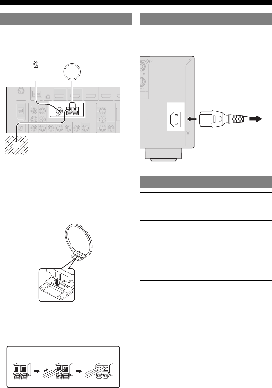
20 En
Connections
An indoor FM antenna and an AM loop antenna are
supplied with this unit. Connect these antennas properly to
the respective jacks.
y
•The supplied antennas are normally sensitive enough to obtain good
reception.
•Position the AM loop antenna away from this unit.
•If you cannot get good reception, we recommend that you use an outdoor
antenna. For details, consult the nearest authorized Yamaha dealer or
service center.
•Always use the AM loop antenna even when the outdoor antenna is
connected.
Assembling the AM loop antenna
Connecting the AM loop antenna
The wires of the AM loop antenna have no polarity. You
can connect either wire to the AM terminal and the other
to the GND terminal.
After all connections are complete, plug the supplied
power cable into the AC inlet and then plug it into an AC
wall outlet.
1Press LMAIN ZONE ON/OFF on the front
panel (or pPOWER on the remote control)
to turn on this unit.
2Press LMAIN ZONE ON/OFF (or
pPOWER) again to turn off this unit
(standby mode).
y
•The unit needs a few seconds until ready to play back.
•You can also turn on this unit by pressing RSCENE (or hSCENE).
•This unit consumes a small amount of electricity even in the standby
mode. We recommend disconnecting the power cable from the AC wall
outlet.
Connecting the FM and AM antennas
ANTENNA
UNBAL.
FM
HD Radio
GND
AM
D
OC
K
CO
MP
O
NEN
T
VIDE
O
P
R
P
B
Y
O
PTI
C
A
L
O
U
T
V
IDE
O
(
B
D
/
DV
D
)
(
H
DMI
CO
NTR
OL
)
VIDE
O
I
N
OUT
M
O
NIT
O
R
O
U
T
P
R
P
B
Y
R
CO
MP
O
NENT
V
IDE
O
DI
G
ITAL
AUDI
O
G
ND
Ground (GND terminal)
The GND terminal is for noise reduction.
Indoor FM antenna AM loop
antenna
Press and hold ReleaseInsert
Connecting the power cable
Turning this unit on and off
Caution
Do not unplug this unit while it is turned on. Doing so
may damage this unit or cause the settings of this unit
to be saved incorrectly.
AC IN
To the AC wall outlet
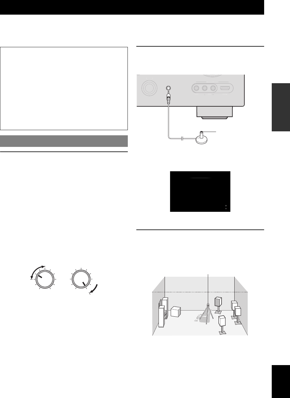
21 En
English
INTRODUCTION
ADDITIONAL
INFORMATION APPENDIX
PREPARATION
BASIC
OPERATION
ADVANCED
OPERATION
This unit has a Yamaha Parametric Acoustic Optimizer (YPAO). With the YPAO, this unit automatically adjusts the
output characteristics of your speakers based on speaker position, speaker performance, and the acoustic characteristics
of the room. We recommend that you first adjust the output characteristics with the YPAO when you use this unit.
1Check the following points.
Before starting the automatic setup, check the
following.
•All speakers and subwoofer are connected
properly.
•Headphones are disconnected from this unit.
•The video monitor is connected properly.
•This unit and the video monitor are turned on.
•This unit is selected as the video input source of the
video monitor.
•The connected subwoofer is turned on and the
volume level is set to about half way (or slightly
less).
•The crossover frequency controls of the connected
subwoofer are set to the maximum.
2Connect the supplied optimizer microphone
to the UOPTIMIZER MIC jack on the front
panel.
“MIC ON. View GUI MENU” appears on the front panel
display.
The GUI screen appears on the video monitor.
y
•You can bring up the above menu screen from the Setup menu (page 59).
3Place the optimizer microphone at your
normal listening position on a flat level
surface with the omni-directional
microphone heading upward.
y
•It is recommended that you use a tripod or something similar to fix the
optimizer microphone at the same height as your ears would be when
seated in your listening position. You can fix the optimizer microphone to
the tripod with the attaching screw of the tripod.
Optimizing the speaker setting for your listening room (YPAO)
Caution
•Be advised that it is normal for loud test tones to be
output during the “Auto Setup” procedure. Do not
allow small children to enter the room during the
procedure.
•To achieve the best results, make sure the room is as
quiet as possible while the “Auto Setup” procedure is
in progress. If there is too much ambient noise, the
results may not be satisfactory.
y
•You can manually adjust the output characteristics of your speakers
with “Manual Setup” in the Setup menu (page 59).
Using Auto Setup
VOLUME
MIN MAX
CROSSOVER/
HIGH CUT
MIN MAX
Subwoofer
INPUT
V
IDE
O
HDMI I
N
A
U
DI
O
V
IDE
O
A
UX
OPTIMIZER MIC
Optimizer microphone
Auto Setup
Extra Speaker Assignment
Zone2+Zone3Zone2
None
Presence
FrontFlat Natural
EQ Type
Move focus
Start
Start
Optimizer microphone

22 En
Optimizing the speaker setting for your listening room (YPAO)
4When the speakers are connected to EXTRA
SP terminals, press jCursor k repeatedly
to select “Extra Speaker Assignment” and
then press jCursor l / h to select how to
use EXTRA SP terminals from “Zone2”,
“Zone2+Zone3”, “Presence” or “None”.
If this unit does not work when you press jCursor,
press iON SCREEN once and then operate this
unit.
5To select sound characteristics for
adjustment, press jCursor n to select “EQ
Type” and then press jCursor l / h.
If this unit does not work when you press jCursor,
press iON SCREEN once and then operate this
unit.
This unit has a parametric equalizer that adjusts the
output levels for each frequency range. The equalizer
is adjusted to produce a cohesive sound field based on
automatically measured speaker characteristics.
In “EQ Type”, you can select the following
parametric equalizer characteristics suitable for the
desired sound characteristics.
Flat
This adjusts each speaker to obtain the same
characteristics. Select this if your speakers have
similar qualities.
Front
This adjusts each speaker to obtain the same
characteristics as the front left and right speakers.
Select this if your front left and right speakers have
significantly better qualities than the other speakers.
Natural
This adjusts all speakers to achieve natural sound.
Select this if sounds in the high frequency range seem
too strong when “EQ Type” is set to “Flat”.
6Press jCursor n to select “Start” and then
press jENTER to start the setup procedure.
A countdown starts and a measurement starts in 10
seconds. A loud test tone is output during
measurement.
Notes
•During the automatic setup procedure, do not perform any
operation on this unit.
•Press jCursor k to cancel the automatic setup procedure.
When measurement is successfully completed,
“YPAO Complete” appears on the front panel display
and the measurement result appears on the GUI
screen.
Speaker Config
Displays the number of speakers connected to this unit in
the following order:
Total of Front and Center/Total of Surround and Surround
Back/Subwoofer
Distance (Min / Max)
Displays the speaker distance from the listening position
in the following order:
Closest speaker distance/Farthest speaker distance
Level (Min / Max)
Displays the speaker output levels in the following order:
Lowest speaker output level/Highest speaker output level
Notes
•If “Error” appears on the GUI screen during “Auto Setup”, measurement
is canceled and the type of error is displayed. For details, see “When an
error message is displayed during measurement” (page 23).
•If problems occur during measurement, “Check xx warning(s)” (xx
indicates the number of warnings) appears in red. For details, see “When
a warning message is displayed after measurement” (page 23).
7Press jENTER to confirm the settings.
To cancel the operation, press jCursor l / h to
select “Cancel” and press jENTER.
The speaker characteristics are adjusted according to
measurement results.
When the following screen appears, remove the
optimizer microphone. “Auto Setup” is now
complete.
y
•If you do not want to apply the measurement results, select “Cancel”.
•Perform “Auto Setup” again if you change the number or positions of
speakers.
Measurement takes about 3 minutes. To obtain precise
results, stay where you will not disturb the
measurement, such as to the side of or behind the
speakers or outside the room.
The optimizer microphone is sensitive to heat. Store it
in a cool place and away from direct sunlight after
measurement. Do not leave it in a place where it will be
subjected to high temperatures such on an AV
component.
3 /4 / 0.1
8.0ft / 8.5ft
-3.5dB / +4.5dB
Auto Setup
Speaker Config :
Distance (Min / Max) :
Level (Min / Max) :
Result
Set Cancel
Finish
Select items
Auto Setup
Please disconnect the micorphone
(Then this screen will automatically disappear)
Return
Auto Setup Completed !

23 En
Optimizing the speaker setting for your listening room (YPAO)
English
INTRODUCTION
ADDITIONAL
INFORMATION APPENDIX
PREPARATION
BASIC
OPERATION
ADVANCED
OPERATION
If an error is detected during measurement, the
measurement is canceled and “Error” appears on the GUI
screen. Check the error and solve the problem. For details
on each error message, see page 86.
Press jCursor n once, press jCursor l / h
to select “Retry” or “Exit” and then press
jENTER.
Retry
Performs “Auto Setup” again.
Exit
Terminates the measurement and “Auto Setup”.
y
•When “E-5:NOISY” appears, you can continue measurement. To
continue measurement, select “Proceed”. However, we recommend that
you solve the problem first and then perform measurement again.
If a problem occurs during measurement, “Check xx
warning(s)” appears on the GUI screen. Check the
warning and solve the problem. For details on each
warning message, see page 87.
y
•Optimization will not be performed while a warning message is
displayed. We recommend that you solve the problem and perform “Auto
Setup” again.
1Press jCursor n / k to select “Check xx
warning(s)” and then press jENTER.
Details of the warning message are displayed. If there
are multiple warning messages, you can display the
next message using jCursor h.
2To return to the top result display, press
jENTER again.
When an error message is displayed
during measurement
When a warning message is displayed
after measurement
Error
FrontL/R channel signals are not detected.
Check wiring and connections of the front L/R speakers.
Move focus
E-1 : No Front Speakers
Retry Exit
3 /4 / 0.1
8.0ft / 8.5ft
-3.5dB / +4.5dB
Auto Setup
Speaker Config :
Distance (Min / Max) :
Level (Min / Max) :
Result
Set Cancel
See details
Select items
Check 2 warnings
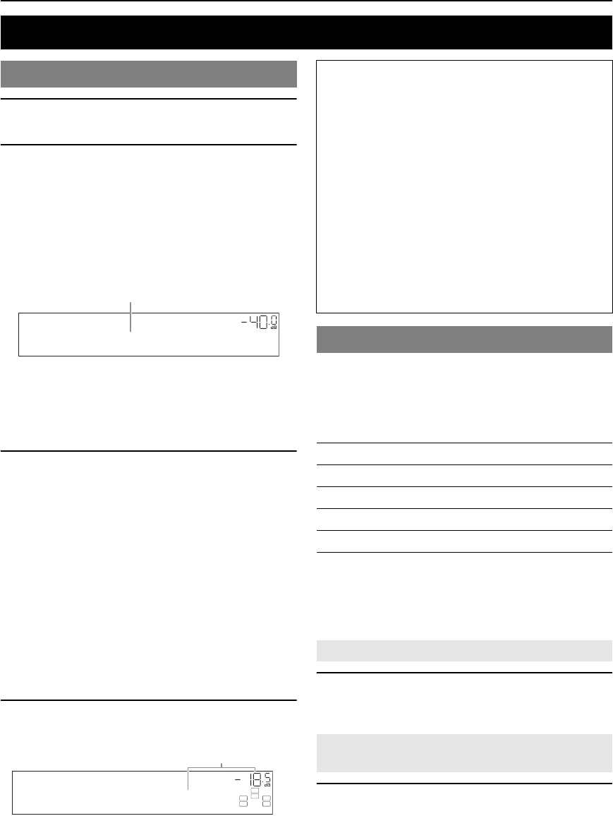
24 En
BASIC OPERATION
1Turn on external components (TV, DVD
player, etc.) connected to this unit.
2Rotate the TINPUT selector (or press
dInput selection key) to select an input
source.
If you press dUSB/NET on the remote control,
press xSub-input selection key to select a
sub-input source.
The name of the selected input source is displayed for
a few seconds.
y
•If you connect two video monitors to the HDMI OUT jacks of this
unit, press gHDMI OUT repeatedly to select the active video
monitor(s) (page 53).
•You can also select an input source from the GUI screen (page 25).
•You can change the input source name displayed on the front panel
display or GUI screen as necessary (page 64).
3Play the external component that you have
selected as the source input, or select a radio
station on the tuner.
Refer to the operating instructions of the external
component for details on playback. For selecting
radio stations or playback of an iPod, Bluetooth
component, USB storage device or network contents
using this unit, see the following.
•FM/AM radio tuning (page 31)
•iPod playback (page 44)
•Bluetooth component playback (page 46)
•USB storage device playback (page 47)
•Internet Radio playback (page 50)
•PC playback (page 48)
•Rhapsody® playback (page 51)
4Turn the KVOLUME control (or press
tVOLUME +/–) to adjust the volume.
This unit has a SCENE function that allows you to change
input sources and sound field programs with one key. Four
scenes are available for different usages, such as playing
movies or music. The following input sources and sound
field programs are provided as the initial factory settings.
y
•When this unit is on standby, you can turn on this unit by pressing
RSCENE (or hSCENE).
•If you connect a Yamaha DVD/CD player that has the capability of the
SCENE control signals to the REMOTE OUT jack of this unit, you can
start playback on the player by using the SCENE function.
Press RSCENE (or hSCENE).
y
•You can also select a SCENE from the GUI screen (page 25).
Select the desired input source/sound field
program and then press and hold RSCENE (or
hSCENE) to edit until “SET Complete” appears
on the front panel display.
y
•If you change the input source setting, register the remote control code of
an external component to the input source (page 72).
Playback
Basic procedure
VOL.
AV1
Input source name
VOL.
SW
C
LR
SL SR
Volume-18.5dB
Volu me
Note
When you play back a DTS-CD, noise may be output in some
conditions, which may cause a speaker malfunction. Make sure
that the volume is set to low before starting playback. If noise is
output, do the following.
1) When only noise is output
If a DTS bitstream signal is not properly input to this unit,
only noise is output. Connect the playback component to this
unit by digital connection and play back the DTS-CD. If the
condition is not improved, the problem may results from the
playback component. Consult the manufacturer of the
playback component.
2) When noise is output during playback or skip operation
Before playing back the DTS-CD, display the Option menu
after selecting the input source and set “Decoder Mode” to
“DTS” (page 54).
Using the SCENE function
Keys Input source Sound field program
BD/DVD HDMI 1 Straight
TV AV 1 Straight
CD AV 3 Straight
RADIO TUNER 7ch Enhancer
Selecting a SCENE
Registering input source/sound field
program to SCENE

25 En
Playback
English
INTRODUCTION
ADDITIONAL
INFORMATION APPENDIX
PREPARATION
BASIC
OPERATION
ADVANCED
OPERATION
You can operate an external component with the remote
control of this unit by setting a remote control code for the
external component for each input source. Setting remote
control codes for desired input sources allows you to
switch between external components linked to scene
selections.
1Register the remote control code of an
external component to the desired input
source (page 72).
Note
•This feature is not available for TUNER, SIRIUS and XM input
sources.
2While holding down the desired hSCENE
key, press and hold the dInput selection
key to which you registered a remote control
code in step 1.
From now on the external component can be remotely
controllable just by selecting a scene.
1Press iON SCREEN on the remote control.
The GUI screen appears on the video monitor.
2Use jCursor k / n repeatedly to switch the
page and jCursor l / h repeatedly to
select the desired source.
y
•If an input source you want to select is available in “Select Scene”, you
can select the desired input source and sound field program at once.
3Press jENTER.
1Press vMUTE on the remote control to mute
the audio output.
2Press vMUTE again to resume audio
output.
You can adjust the balance of the high frequency range
(Treble) and low frequency range (Bass) of sounds output
from the front left and right speakers to obtain desired
tone.
1Press OTONE CONTROL on the front panel
repeatedly to select “Treble” or “Bass”.
2Rotate the PPROGRAM selector to adjust
the frequency range.
Control range: –10.0 dB to +10.0 dB
The display returns to the previous screen
automatically in few seconds.
Note
•The tone control settings are not effective when this unit is in the Pure
Direct mode or “MULTI CH” is selected as an input source.
Use Pure Direct mode to enjoy the pure high fidelity
sound of the selected source. When Pure Direct mode is
activated, this unit plays back the selected source with the
least circuitry.
Press SPURE DIRECT (or rPURE DIRECT)
to turn the Pure Direct mode on or off.
SPURE DIRECT lights up when you set Pure Direct
mode on.
The following features are disabled in the Pure Direct
mode.
–sound field program, tone control
–display and operation of the Option menu and Setup
menu
–multi-zone function
y
•The font panel display automatically turns off while this unit in the Pure
Direct mode.
Switching remotely controlled external
components linked to scene selections
Selecting a source on the GUI screen
Category Source
Select Scene BD/DVD, TV, CD, RADIO
Select Input HDMI1-4, V-AUX, PHONO, MULTI CH,
DOCK, AV1-6, AUDIO1/2, USB, NET
RADIO, PC, Rhapsody, TUNER, SIRIUS, XM
Select Scene
BD/DVD TV CD RADIO
Muting audio output
Adjusting high/low frequency sounds
(tone control)
Enjoying pure hi-fi sound
Treble
0.0dB
26 En
Playback
Plug your headphones in the MPHONES jack on
the front panel.
When you select a sound field program while using the
headphones, the mode is automatically set to SILENT
CINEMA mode.
Notes
•When you connect headphones, no signals are output at the speaker
terminals.
•When multi-channel signals are processed, sounds in all channels are
divided to left and right channels. When “MULTI CH” is selected as the
input source, only front L/R sounds are output from the headphones.
Press EINFO (or fINFO) repeatedly.
Available information differs depending on the selected
input source.
For example, if you select HDMI1 input and display “DSP
Program”, the following screen appears on the front panel
display.
Note
•Information marked with “*” is not available when analog HD Radio
station is selected.
Using your headphones
Changing information on the front
panel display
Input source Information
HDMI1-4
AV1-6
AUDIO1/2
V-AUX
PHONO
iPod (DOCK) (simple
remote mode)
BLUETOOTH (DOCK)
Input
DSP Program
Audio Decoder
MULTI CH Input
TUNER Frequency, DSP Program, Audio
Decoder
(for HD Radio information)
Call Sign*, Category*, Artist /
Song*, Album*, Tag Info, DSP
Program, Audio Decoder, Frequency
SIRIUS Channel, Category, Artist / Song,
Composer, Antenna, DSP Program,
Audio Decoder
XM Channel, Category, Artist / Song,
Antenna, DSP Program, Audio
Decoder
Straight
Input source
Sound field program
iPod (DOCK) (menu
browse mode)
USB (USB/NET)
PC (USB/NET)
(on play information display)
DSP Program, Audio Decoder,
Song, Artist, Album
(on GUI screen)
List
Rhapsody (USB/NET) (on play information screen)
DSP Program, Audio Decoder,
Song, Artist (or Artist / Channel if
channel name is available), Album
(on GUI screen)
List
NET RADIO (USB/NET) (on play information display)
DSP Program, Audio Decoder,
Station Name
(on GUI screen)
List
Input source Information
27 En
English
INTRODUCTION
ADDITIONAL
INFORMATION APPENDIX
PREPARATION
BASIC
OPERATION
ADVANCED
OPERATION
This unit is also equipped with a Yamaha digital sound field processing (DSP) chip. You can enjoy multi-channel sounds
for almost all input sources using various sound field programs stored on the chip and a variety of surround decoders.
■Selecting a sound field program on the front panel
Rotate the PPROGRAM selector to select a desired sound field program.
■Selecting a sound field program with the remote control
Perform the following operations depending on the category of the sound field programs.
Sound field programs for movies/TV programs............................... Press rMOVIE repeatedly.
Sound field programs for music ....................................................... Press rMUSIC repeatedly.
Stereo reproduction .......................................................................... Press rSTEREO repeatedly.
Multi-channel stereo reproduction ................................................... Press rSTEREO repeatedly.
Compressed music enhancer ............................................................ Press rSTEREO repeatedly.
Surround decoder ............................................................................. Press rSUR.DECODE repeatedly.
For example, if you select “Sci-Fi”, the following screen appears on the front panel display.
Notes
•Sound field programs are stored for each input source. When you change the input source, the sound field program previously selected for that input
source is applied again.
•When you play back DTS Express sources or audio signals with sampling frequency of higher than 96 kHz, the straight decode mode (page 30) is
automatically selected.
•When you play back Dolby TrueHD sources with CINEMA DSP, another program may be automatically selected in specific cases.
•When you play back DTS-HD sources with CINEMA DSP, the DTS decoder is automatically selected.
This unit provides sound field programs for multiple categories including music, movies and stereo reproduction. Select
a sound field program based on your listening preference, not merely on the name of the program, etc.
y
•You can check what speakers are currently outputting signals with the speaker indicators on the front panel display (page 6).
•Each program can adjust sound field elements (sound field parameters). For details, see page 65.
• in the table indicates the sound field program with CINEMA DSP (page 91).
Enjoying the sound field programs
Selecting sound field programs
Sound field program descriptions
For movie/TV program sources (MOVIE)
Program Descriptions
Standard This program creates a sound field emphasizing the surrounding feeling without disturbing the original acoustic
positioning of multi-channel audio such as Dolby Digital and DTS. It has been designed with the concept of “an
ideal movie theater”, in which the audience is surrounded by beautiful reverberations from the left, right and rear.
Spectacle This program represents the spectacular feeling of large-scale movie productions.
It reproduces a broad theater sound field matching the cinemascope and wider-screen movies with an excellent
dynamic range from very small to extremely large sound.
Sci-Fi This program clearly reproduces the finely elaborated sound design of the latest science fiction and special effects-
featuring movies. You can enjoy a variety of cinematographically created virtual spaces reproduced with clear
separation between dialog, sound effects and background music.
Adventure This program is ideal for precisely reproducing the sound design of action and adventure movies.
The sound field restrains reverberations but puts emphasis on reproducing a powerful space expanded widely to
the left and right. The reproduced depth is also restrained relatively to ensure the separation between audio
channels and the clarity of the sound.
Sci-Fi
Program name
Sound field program category
28 En
Enjoying the sound field programs
y
•When multi-channel signals are input, they are downmixed to 2 channels and output from the front left and right speakers.
Drama This sound field features stable reverberations that match a wide range of movie genres from serious dramas to
musicals and comedies. The reverberations are modest but offer an optimum 3D feeling, reproducing effects tones
and background music softly but cubically around clear words and center positioning in a way that does not fatigue
the listener even after long hours of viewing.
Mono Movie This program is provided for reproducing monaural video sources such as a classic movie in an atmosphere of a
good old movie theater. The program produces the optimum expansion and reverberation to the original audio to
create a comfortable space with a certain sound depth.
Sports This program allows the listeners to enjoy stereo sport broadcasts and studio variety programs with enriched live
feeling. In sports broadcasts, the voices of the commentator and sportscaster are positioned clearly at the center
while the atmosphere of the stadium expands in an optimum space to offer the listeners with a feeling of presence
in the stadium.
Action Game This sound field has been suitable for action games such as car racing and FPS games. It uses the reflection data
that limits the effects range per channel in order to offer a powerful playing environment with a being-there feeling
by enhancing various effects tones while maintaining a clear sense of directions.
Roleplaying Game This sound field has been suitable for role-playing and adventure games. It combines the sound field effects for
movies and the sound field designs for “Action Game” to represent the depth and 3D feeling of the field during
play, while offering movie-like surround effects in the movie scenes in the game.
For audio music sources (MUSIC)
Program Descriptions
Hall in Munich This sound field simulates a concert hall with approximately 2500 seats in Munich, using stylish wood for the
interior finishing as normal standards for European concert halls. Fine, beautiful reverberations spread richly,
creating a calming atmosphere. The listener’s virtual seat is at the center left of the arena.
Hall in Vienna This is an approximately 1700-seated, middle-sized concert hall with a shoebox shape that is traditional in Vienna.
Pillars and ornate carvings create extremely complex reflections from all around the audience, producing a very
full, rich sound.
Chamber This program creates a relatively wide space with a high ceiling like an audience hall in a palace. It offers pleasant
reverberations that are suitable for courtly music and chamber music.
Cellar Club This program simulates a live house with a low ceiling and homey atmosphere. A realistic, live sound field
features powerful sound as if the listener is in a row in front of a small stage.
The Roxy Theatre This is the sound field of a rock music live house in Los Angeles, with approximately 460 seats. The listener’s
virtual seat is at the center left of the hall.
The Bottom Line This is the sound field at stage front in The Bottom Line, that was a famous New York jazz club once. The floor
can seat 300 people to the left and right in a sound field offering real and vibrant sound.
Music Video This sound field offers an image of a concert hall for live performance of pop, rock and jazz music. The listener
can indulge oneself in a hot live space thanks to the presence sound field that emphasizes the vividness of vocals
and solo play and the beat of rhythm instruments, and to the surround sound field that reproduces the space of a
big live hall.
For stereo reproduction (STEREO)
Program Descriptions
2ch Stereo Use this program to mix down multi-channel sources to 2 channels.
Program Descriptions

29 En
Enjoying the sound field programs
English
INTRODUCTION
ADDITIONAL
INFORMATION APPENDIX
PREPARATION
BASIC
OPERATION
ADVANCED
OPERATION
Select this program to playback sources with selected decoders. You can playback 2-channel sources on multi-channels.
y
•An input source is played back in straight decode mode (page 30) when “MULTI CH” is selected as the input source.
For multi-channel stereo reproduction (STEREO)
Program Descriptions
7ch Stereo Use this program to output sound from all speakers. When you play back multi-channel sources, this unit
downmixes the source to 2 channels and then outputs the sound from all speakers. This program creates a larger
sound field and is ideal for background music at parties, etc.
Compressed Music Enhancer (ENHANCER)
Program Descriptions
Straight Enhancer Use this program to enhance the sound nearest to the original depth and width of the 2-channel or multi-channel
compression artifacts.
7ch Enhancer Use this program to play back compression artifacts in 7-channel stereo.
Surround decode mode (SUR. DECODE)
Decoder Descriptions
Pro Logic Dolby Pro Logic decoder suitable for all kinds of sources.
PLIIx Movie /
PLII Movie
Dolby Pro Logic IIx (or Dolby Pro Logic II) decoder suitable for movies. If your listening environment is as
follows, you cannot select the Dolby Pro Logic IIx decoder.
•When the surround back speakers are not connected
•When headphones are connected
PLIIx Music /
PLII Music
Dolby Pro Logic IIx (or Dolby Pro Logic II) decoder suitable for music. If your listening environment is as
follows, you cannot select the Dolby Pro Logic IIx decoder.
•When the surround back speakers are not connected
•When headphones are connected
PLIIx Game /
PLII Game
Dolby Pro Logic IIx (or Dolby Pro Logic II) decoder suitable for games. If your listening environment is as
follows, you cannot select the Dolby Pro Logic IIx decoder.
•When the surround back speakers are not connected
•When headphones are connected
Neo:6 Cinema DTS decoder suitable for movies.
Neo:6 Music DTS decoder suitable for music.
Neural Sur.
(U.S.A. model only)
Neural Surround processing for any sources.
The Neural Surround decoder supports PCM (sampling rate of 96 kHz or lower), Dolby Digital, DTS Digital
Surround (except for DTS 96/24), DSD and analog 2-channel input sources. When Neural Surround-incompatible
signals are being input while the Neural Surround decoder is selected, multi-channel sources are decoded straight
into the appropriate channels without any additional effect processing and the Neural Surround-incompatible PCM
signals are reproduced in stereo. The Neural Surround decoder is especially suitable for the XM HD Surround
program of XM Satellite Radio.

30 En
Enjoying the sound field programs
In straight decode mode, sounds are reproduced without
sound field effect. 2-channel stereo sources are output
from only the front left and right speakers. Multi-channel
input sources are decoded straight into the appropriate
channels and multi-channel sounds are reproduced
without a sound field effect.
1To enable straight decode mode, press
QSTRAIGHT (or rSTRAIGHT).
“Straight” appears on the front panel display.
2To cancel straight decode mode, press
QSTRAIGHT (or rSTRAIGHT) again.
A sound field program name appears on the front
panel display, and sound is reproduced with that
sound field effect.
Virtual CINEMA DSP allows you to enjoy DSP sound
field surround effects even without any surround speakers
by using virtual surround speakers. You can even enjoy
Virtual CINEMA DSP using a minimal two-speaker
system that does not include a center speaker.
When “Surround Speaker” in the Setup menu is set to
“None” (page 60), this unit operates in Virtual CINEMA
DSP mode.
Note
•Virtual CINEMA DSP is not available in the following conditions even if
you set “Surround Speaker” to “None” (page 60).
–headphone plug is connected to the PHONES jack.
–7ch Stereo of the field sound program is selected.
–Pure Direct mode or straight decode mode is used.
SILENT CINEMA allows you to enjoy multi-channel
sources with your headphones. SILENT CINEMA mode
is automatically selected when you connect the headphone
plug to the PHONES jack.
Note
•SILENT CINEMA mode is not available in the following conditions.
–2ch Stereo of the sound field program is selected.
–Pure Direct mode or straight decode mode is selected.
CINEMA DSP 3D mode creates the intensive and
accurate stereoscopic sound field in the listening room.
To use this unit in CINEMA DSP 3D mode, presence
speakers are required. Connect the presence speakers to
the SP1 terminals, perform the following settings and then
select a CINEMA DSP related sound field program.
•Disconnect the headphones from the PHONES jack.
•Set “Extra Speaker Assignment” to “Presence”
(page 60).
•Set “3D DSP” to “On” (page 66).
When the sound field program runs in CINEMA DSP 3D
mode, the 3D indicator on the front panel display lights
up.
Enjoying unprocessed input sources
(Straight decode mode)
Enjoying sound field programs without
surround speakers (Virtual CINEMA
DSP)
Enjoy sound field programs with
headphones (SILENT CINEMA™)
Using CINEMA DSP 3D mode
31 En
English
INTRODUCTION
ADDITIONAL
INFORMATION APPENDIX
PREPARATION
BASIC
OPERATION
ADVANCED
OPERATION
The FM/AM tuner of this unit provides the following two
modes for tuning.
■Frequency tuning mode
You can tune in to a desired FM/AM station by searching
or specifying its frequency.
■Preset tuning mode
You can preset the frequencies of FM/AM stations by
registering them to specific numbers, and later just select
those numbers to tune in.
Note
•Adjust the FM/AM antennas connected to this unit for the best reception.
1Rotate the TINPUT selector (or press
dTUNER) to select “TUNER” as the input
source.
2Press HBAND (or eFM or eAM) to select a
band.
3Press ITUNING/CH l / h (or eTUN./CH
k / n) to specify the frequency.
The TUNED indicator on the front panel display
lights up when the tuner is tuned in to a station. The
STEREO indicator also lights up if the program being
broadcasted is in stereo.
The frequency changes in the following manner according
to how you press ITUNING/CH l / h (or eTUN./
CH k / n).
When you press the key more than 1 second
The tuner searches the frequency of a station that is
detectable around the current frequency. This is effective
when the tuner can receive strong signals without any
interference. Once the search starts, release the key.
When you keep holding the key, the search continues even
when a station is detected. This is useful when you want to
tune in to a specific station.
When you press and release the key
The tuner increases or decreases the frequency in steps.
Use this method when the tuner cannot receive strong
signals and stations are skipped during the search.
y
•You can switch between stereo and monaural for FM broadcast in the
Option menu (page 55).
•(U.S.A. model only)
When tuning in to an HD Radio station, the HD indicator lights up. See
page 33 for details about the HD Radio features.
4To tune in by direct frequency tuning, press
lNumeric keys to enter the frequency of
the station.
Enter only integers. For example, if you want to set
the frequency to 88.9 MHz, enter “889”.
Notes
•When you press lNumeric keys during preset tuning, a
preset number is selected. Set tuning mode to frequency tuning
mode using ITUNING/CH l / h (or eTUN./CH k / n)
prior to the operation.
•“Wrong Station!” appears on the front panel display when you
enter a frequency that is out of receivable range. Make sure that the
entered frequency is correct.
You can register up to 40 FM/AM stations (Preset).
The tuner automatically detects FM stations with strong
signals and registers up to 40 stations. To register AM
stations, use manual station preset.
(U.S.A. model only)
You can register up to 40 FM HD Radio, AM HD Radio
and analog FM radio stations with strong signals.
Note
•(U.S.A. model only)
If you register an FM HD Radio station with this feature, only the main
audio program of the station (HD1) will be stored. To store other audio
program, preset the station manually.
1Rotate the TINPUT selector (or press
dTUNER) to select “TUNER” as the input
source.
2Press sOPTION on the remote control.
The Option menu for “TUNER” is displayed
(page 54).
3Select “Auto Preset” and then press
jENTER.
Automatic station preset starts about 5 seconds later
from the lowest frequency upwards.
FM/AM tuning
Tuning in to the desired FM/AM station
(Frequency tuning)
STEREO
TUNED
FM92.5MHz
Registering FM/AM stations and
tuning in (Preset tuning)
Registering stations by automatic station
preset
Auto Preset
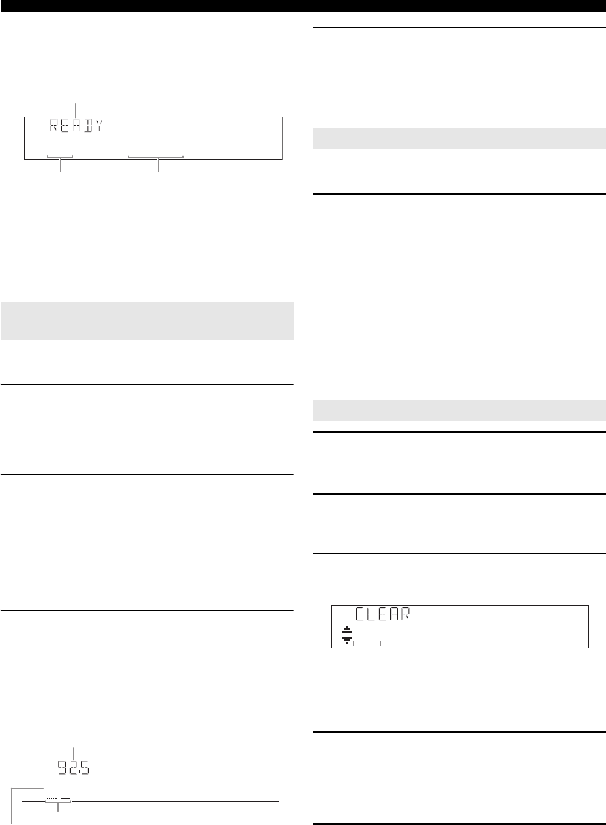
32 En
FM/AM tuning
y
•You can select the preset number at which the preset starts by
pressing ePRESET k / n or jCursor k / n while “READY”
is displayed on the front panel display.
•To cancel registration, press jRETURN.
During the automatic station preset, “MEMORY”
appears in the front panel display each time a station
is registered.
When registration is complete, “FINISH” appears
and then the display returns to the Option menu.
To return the display to the original state, press
sOPTION.
You can manually register FM stations with weak signals
or AM stations.
1Tune in to the desired station (page 31).
y
•(U.S.A. model only)
To register a sub-audio program of the HD Radio station (HD2 to
HD8), press wPRG SELECT to select the desired audio
program.
2Press GMEMORY (or eMEMORY).
“Manual Preset” appears on the front panel display,
followed soon by the preset number to which the
station will be registered.
y
•By holding down GMEMORY (or eMEMORY) for more than
2 seconds, you can skip the following steps and automatically
register the selected station to an empty preset number (next to the
lastly-registered preset number).
3Press FPRESET l / h (or ePRESET k / n)
to select the preset number to which the
station will be registered.
When you select a preset number to which no station
is registered, “Empty” appears. When you select a
preset number to which any station has been already
registered, the frequency of the station is displayed.
y
•You can also select a preset number using the lNumeric
keys.
4Press GMEMORY (or eMEMORY).
When registration is complete, the display returns to
the original state.
y
•To cancel registration, press jRETURN or leave this unit
without any operations for about 30 seconds.
You can call preset stations registered by automatic station
preset or manual station preset.
Press FPRESET l / h (or ePRESET k / n) to
select a preset number.
y
•Preset numbers to which no stations are registered are skipped.
•“No Presets” or “No Presets in Memory” is displayed if no stations are
registered.
•You can directly select a preset number by pressing lNumeric keys
while calling a preset station. “Empty” appears on the display if you
enter a preset number to which no station is registered. “Wrong Num.”
appears if you enter an invalid number.
•When you press lNumeric keys during normal tuning, a frequency
is entered. Set tuning mode to preset tuning mode using FPRESET l
/ h (or ePRESET k / n) prior to the operation.
•(U.S.A. model only)
This unit may take a little time to call a sub-audio program of an HD
Radio station.
1Rotate the TINPUT selector (or press
dTUNER) to select “TUNER” as the input
source.
2Press sOPTION on the remote control.
The Option menu for “TUNER” is displayed
(page 54).
3Press jCursor k / n to select “Clear Preset”
and then press jENTER.
y
•To cancel the operation and return to the Option menu, press
jRETURN.
4Press jCursor k / n to select a preset
number to reset and then press jENTER.
The preset station registered to the selected preset
number is cleared. To clear the registration of
multiple preset numbers, repeat step 4.
5To exit the Option menu, press sOPTION.
Registering stations by manual station
preset
01:FM87.5MHz
Preset number Frequency
Status
01:Empty
Flashes
Frequency to be registered
Preset
number
Calling a preset station (Preset tuning)
Clearing preset stations
01:FM92.5MHz
Preset number
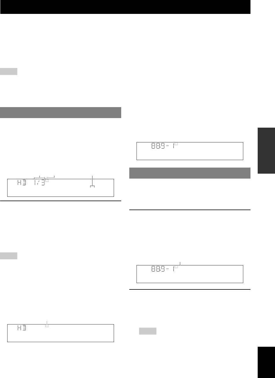
33 En
English
INTRODUCTION
ADDITIONAL
INFORMATION APPENDIX
PREPARATION
BASIC
OPERATION
ADVANCED
OPERATION
HD Radio technology is a new technology that enables FM and AM radio stations to broadcast programs digitally.
Digital broadcasting provides listeners with radically improved audio quality and reception as well as new data services.
Furthermore, supplemental program services allow listeners to select from up to 8 HD Radio programs multicast on a
single FM HD Radio channel. For further information on HD Radio technology, visit “http://www.hdradio.com/”.
This unit is equipped with an HD Radio reception feature, facilitating CD quality FM broadcasts as well as analog FM
stereo quality AM broadcasts. In addition, this unit can receive both audio and data (such as song titles, artist names,
program types, and comments) from all HD Radio programs (HD1 to HD8).
Notes
•The tuning method for HD Radio stations are same as analog FM/AM radio stations; however, you only tune into the analog part of a hybrid HD Radio
station while this unit is in the monaural tuning mode (page 55).
•This unit is capable of receiving both hybrid and all-digital HD Radio station signals. However, this unit may not automatically receive all-digital FM
station signals and the automatic tuning operation may stop. In this case, enter the frequency of the desired all-digital FM HD Radio station directly by
using the lNumeric keys (page 31).
The HD indicator lights up in the front panel display when
this unit is tuned into an HD Radio reception band. In this
state, you can select the desired audio program if the
selected FM HD Radio station provides multiple audio
programs (up to 8).
■When multiple audio programs are provided
Press wPRG SELECT b / a on the remote
control repeatedly to select the desired audio
program.
y
•You can also select audio program using lNumeric keys(1-8) and
lENT when this unit is in the automatic or manual tuning mode. In
case you select an audio program currently not available, “HDx Off” (“x”
indicates the program number) appears.
Notes
•When reception for an audio program ceases, the HD indicator
disappears from the front panel display and HD1 is automatically
selected after approximately 20 seconds.
•Some audio programs may not contain data programs depending on the
broadcasting station and the time period.
■When only one audio program is provided
If this unit is tuned into an FM HD Radio station including
only one audio program or an AM HD Radio station, you
cannot select audio programs.
■Behavior of the display
This unit automatically shows the HD Radio information
(call sign, etc) on the front panel display after 3 seconds.
You can switch HD Radio information to be displayed
(page 34).
This unit is equipped with the iTunes Tagging feature that
enables HD Radio listeners to “tag” songs for subsequent
preview and purchase on iTunes. For details on the iTunes
Tagging feature, visit “http://www.hdradio.com/”.
1Tune into an HD Radio station and select HD
Radio audio program (if available).
If the selected HD Radio program (or song being
played) supports the iTunes Tagging feature, the TAG
indicator lights up in the front panel display and
“TAG” appears on the GUI screen.
2While a song you want to tag is being played
back, press wTAG on the remote control.
If a song is tagged, “StorageSuccess” and the number
of stored iTunes Tagging information files (up to 50)
appear in the front panel display.
Notes
•“Insufficient Data’ appears in the front panel display and GUI
screen if tagging is not available.
•If a status message or an error message appears on the front panel
display or the GUI screen, see “iTunes Tagging” (page 80).
Using HD Radio™ features (U.S.A. model only)
Selecting HD Radio™ audio programs
HD
FM
88.9MHz1
Lights up
Audio program
number (relative/total)
Audio program
number (absolute)
HD
FM
87.5MHz
Lights up
Using the iTunes Tagging feature
HD
WXYZ-FM
HD
WXYZ-FM
TAG
TUNED
Lights up
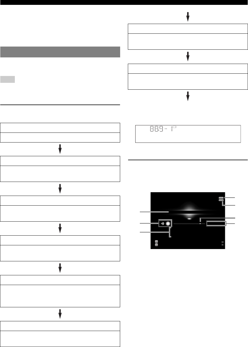
34 En
Using HD Radio™ features (U.S.A. model only)
y
•This unit transmits the “tag” data to the iPod if an iPod that
supports iTunes Tagging feature is stationed in the Yamaha iPod
universal dock (YDS-11, sold separately) connected to the DOCK
terminal of this unit. Otherwise, this unit stores the “tag” data (up
to 50) in the internal memory and will transmit it next time your
iPod is stationed.
Use this feature to display the HD Radio information in
the front panel display or on the GUI screen.
Note
•If a status message or an error message appears on the front panel display
or GUI screen, see “HD Radio Reception” (page 79).
■Front panel display
Press
E
INFO
(or
f
INFO
) repeatedly to toggle the
following HD Radio information display modes.
Back to “Call Sign”
Display example (Call Sign)
■GUI screen
Press uDISPLAY on the remote control to turn
on or off the information display.
The following information is displayed on the GUI screen.
aPreset number, call sign, audio program number
(relative/total)
bHD Radio icon, TUNED icon
cProgram category, artist name, song title, album
title
dSTEREO icon
eTAG icon
fFrequency indication gauge
gBand, frequency, audio program
y
•To hold or release the displayed information, press jENTER. While it
is held, the “HOLD” icon appears on the GUI screen.
Displaying HD Radio™ information
Call Sign
Call sign, frequency, audio program number (absolute)
Category
Program category, frequency, audio program number
(absolute)
Artist / Song
Artist name, song title, frequency, audio program
number (absolute)
Album
Album title, frequency, audio program number
(absolute)
Tag Info
The number of iTunes Tagging information files stored
in the internal memory, frequency, audio program
number (absolute)
DSP Program
Current sound field program (page 27), frequency, audio
program number (absolute)
Audio Decoder
Current audio decoder (page 29), frequency, audio
program number (absolute)
Frequency
Frequency, audio program number (absolute), audio
program number (relative/total)
HD
WXYZ-FM
Preset no.10:
FM 88.9MHz-1
Ch Name
Category
Artist
Song
Classic Rock
Frankie Zipper
Road to India
Made-to-order
Input
DSP
Tuner
Straight Enhancer
Option Menu
Data Hold
a
b
c
WXYZ-FM HD 1/3
STEREO
TAG
d
e
f
g
TUNED
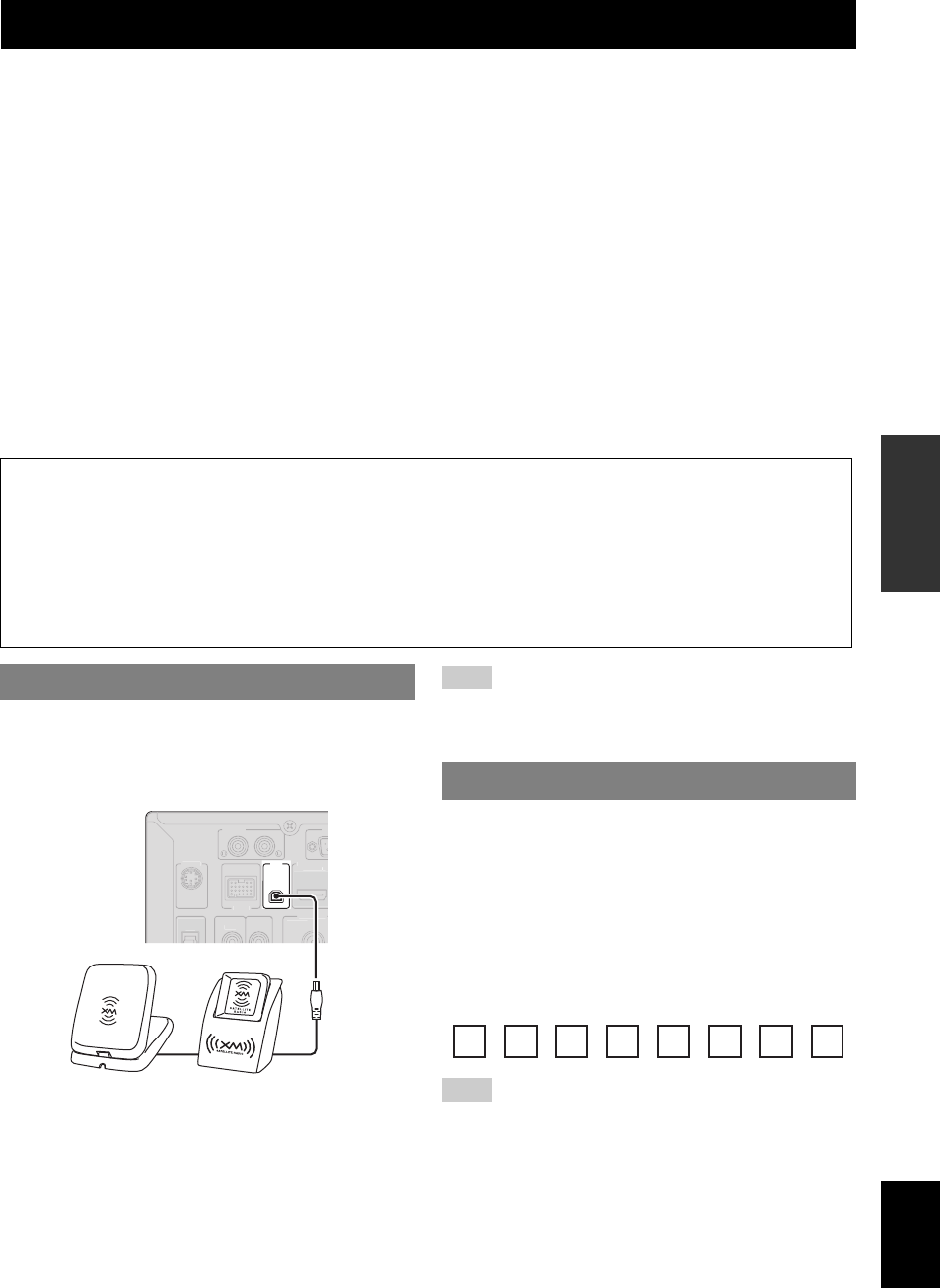
35 En
English
INTRODUCTION
ADDITIONAL
INFORMATION APPENDIX
PREPARATION
BASIC
OPERATION
ADVANCED
OPERATION
Listening to Satellite Radio
To listen to Satellite Radio, you’ll need to connect either a SIRIUS or XM Satellite Radio tuner (sold separately) to your
satellite-ready receiver. Satellite Radio is available to residents of the US (except Alaska and Hawaii).
Satellite Radio delivers a variety of commercial-free music from categories ranging from Pop, Rock, Country, R&B,
Dance, Jazz, Classical and many more plus coverage of all the top professional and college sports including play by play
games from select leagues and teams. Additional programming includes expert sports talk, uncensored entertainment,
comedy, family programming, local traffic and weather and news from your most trusted sources.
Whether you purchase a SIRIUS or XM tuner, you’ll need to activate and subscribe to begin enjoying the service. Easy to
follow installation and setup instructions are provided with the satellite tuners. Whichever service you choose, there are a
variety of programming packages available, including the option of adding “The Best of SIRIUS” programming to your
XM tuner or “The Best of XM” programming to your SIRIUS tuner, enabling you to enjoy the most popular
programming among both services. The “Best of” packages are not available to SIRIUS or XM Canada subscribers at
this time. Family friendly packages are also available to restrict channels featuring content that may be inappropriate for
children.
To subscribe to XM, U.S. customers should visit xmradio.com or call 1-800-XMRADIO (1-800-967-2346).
To subscribe to SIRIUS, U.S. customers can call 1-888-539-SIRI (1-888-539-7474) or visit sirius.com (US).
Connect XM Mini-Tuner and XM Mini-Tuner Home
Dock (sold separately) to the XM jack on the rear panel of
this unit. For details, see the operating instructions
provided with the XM Mini-Tuner Home Dock.
y
•To ensure optimal reception of the XM Satellite Radio signals, the XM
Mini-Tuner Home Dock must be placed at or near a southerly facing
window with no obstacles in the path to the sky. You can mount it indoors
or outdoors. Use the “Antenna” information on the front panel display or
on the GUI screen (page 38) to check the antenna reception level and
adjust the orientation of the antenna.
Note
•If “CHECK ANTENNA”, “CHECK XM TUNER” or “NO SIGNAL”
appears on the front panel display, the connection and setting of the
antenna, XM Mini-Tuner Home Dock, or XM Mini-Tuner may not be
correct.
Once you have installed the XM Mini-Tuner Home Dock,
inserted the XM Mini-Tuner, connected the XM Mini-
Tuner Home Dock to your XM Ready® home audio
system, and installed the antenna, you are ready to
subscribe and begin receiving XM programming. There
are three places to find your eight character XM Radio ID:
on the XM Mini-Tuner, on the XM Mini-Tuner package,
and on XM Channel 0. Record the XM Radio ID in the
following eight squares for reference.
Note
•The XM Radio ID does not use the letters “I”, “O”, “S” or “F”. Activate
your XM Satellite Radio service in the U.S. online at http://
activate.xmradio.com/ or call 1-800-XM-RADIO (1-800-967-2346). You
will need a major credit card. XM will send a signal from the satellites to
activate the full channel lineup. Activation normally takes 10 to 15
minutes, but during peak busy periods you may need to keep your XM
Ready home audio system on for up to an hour. When you can access the
full lineup on your XM Ready home audio system you are done.
XM® Satellite Radio tuning (U.S.A. model only)
SIRIUS XM Radio Legal
SIRIUS, XM and all related marks and logos are trademarks of Sirius XM Radio Inc. and its subsidiaries. All other
marks and logos are the property of their respective owners. All rights reserved. SIRIUS and XM subscriptions sold
separately. Taxes and a one-time activation fee may apply. XM tuners and home docks or SIRIUS tuners (each sold
separately) are required to receive the SIRIUS or XM satellite radio service. All programming and fees subject to
change. It is prohibited to copy, decompile, disassemble, reverse engineer, hack, manipulate or otherwise make
available any technology or software incorporated in receivers compatible with the SIRIUS or XM Satellite Radio
Systems. Service not available in Alaska and Hawaii.
Connecting XM Mini-Tuner Home Dock
XM
D
OC
K
PH
O
N
O
RS
CO
MP
O
NEN
T
VIDE
O
OUT
HDMI OUT
ANTENNA
FM
HD R
ad
i
o
(
H
DMI CONTR
OL
)
S
IRIUS
XM Mini-Tuner and XM Mini-Tuner Home Dock
(sold separately)
Activating XM Satellite Radio
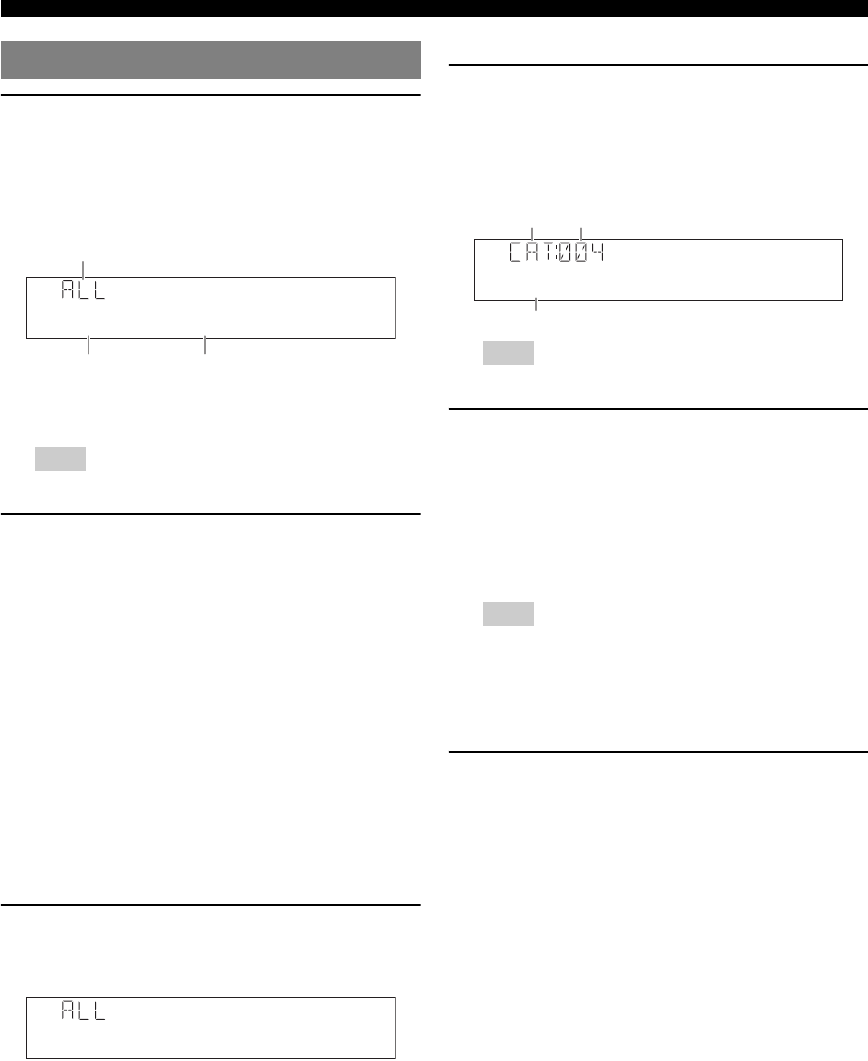
36 En
XM® Satellite Radio tuning (U.S.A. model only)
1Rotate the TINPUT selector (or press
dXM) to select “XM” as the input source.
The XM Satellite Radio information (such as channel
number, channel name, category, artist name, or song
title) for the currently selected channel appears on the
front panel display and GUI screen (page 38).
y
•When you select “XM” as the input source, this unit automatically
recalls the previously selected channel.
Note
•If a status message or an error message appears on the front panel
display or on the GUI screen, see “XM Satellite Radio” (page 80).
2Search for a channel by using one of the XM
Satellite Radio search modes.
•To select a channel from the all channel list, see
“All Channel Search mode” on this page.
•To select a channel by category, see “Category
Search mode” on this page.
•To select the desired channel directly by entering
the channel number, see “Direct number access” on
this page.
•To select a channel from the preset channels, see
“Calling a preset channel (Preset Search mode)”
(page 37).
y
•You can display the XM Satellite Radio information on the front
panel display or on the GUI screen (page 38).
•You can set the XM Satellite Radio preset channels (page 37).
■All Channel Search mode
Press ITUNING/CH l / h (or eTUN./CH k /
n) repeatedly to search for a channel within all
channels.
y
•You can search for a channel quickly by holding down
ITUNING/CH l / h (or eTUN./CH k / n).
•You can skip channels to the previous or next category by pressing
HCATEGORY (or eCATEGORY l / h).
■Category Search mode
1Press HCATEGORY (or eCATEGORY l /
h) to select the channel category.
“CAT” is displayed on the front panel display during
the channel category selection. When you select the
category, the first channel in the category is selected.
Note
•If you do not operate within 10 seconds, the category search mode
returns to “ALL” (All Channel Search).
2While “CAT” is displayed on the front panel
display, press ITUNING/CH l / h (or
eTUN./CH k / n) repeatedly to search for a
channel within the selected channel
category.
y
•You can search for a channel quickly by pressing and holding
ITUNING/CH l / h (or eTUN./CH k / n).
Note
•This unit skips the channels when this unit is in the All Channel
Search mode or Category Search mode in the following cases (it is
not malfunction of this unit):
–the channel is out of service.
–you do not subscribe to the channel.
■Direct number access
In the All Channel Search mode or Category
search mode, press the lNumeric keys to
enter the desired three-digit channel number.
For example, to enter the number 123, press the
lNumeric keys as “1”, “2” and “3”.
y
•To display the Radio ID number displayed on the front panel display,
select channel “0”.
•To enter a one-digit or two-digit channel number, press the lNumeric
keys on the remote control and then press lENT to confirm the input
number.
•Instead of pressing lENT to tune into the channel immediately, you
can wait a few seconds until this unit confirms the entered channel
number.
•If no key is pressed within a few seconds after you enter a one-digit or
two-digit number, this unit automatically confirms the entered channel
number.
•If the selected channel is not available, an advisory message may appear.
For details, see “XM Satellite Radio” (page 80).
XM Satellite Radio® operations
001Preview
XM
Search mode
Channel number Channel name
00880's
XM
Pop
XM
Category
search mode The first channel in the category
Category name

37 En
XM® Satellite Radio tuning (U.S.A. model only)
English
INTRODUCTION
ADDITIONAL
INFORMATION APPENDIX
PREPARATION
BASIC
OPERATION
ADVANCED
OPERATION
You can use this feature to store up to 40 XM Satellite
Radio channels. You can then recall any preset channel
easily by selecting the preset channel as described in
“Calling a preset channel (Preset Search mode)” on this
page.
1Search a channel you want to set as a preset
channel in one of the XM Satellite Radio
search modes.
For details, see “XM Satellite Radio operations”
(page 36).
2Press GMEMORY (or eMEMORY).
The indicator on the front panel display changes as
follows.
y
•By holding down GMEMORY (or eMEMORY) for more than
2 seconds, you can skip the following steps and automatically
register the selected channel to an empty preset number (next to the
lastly-registered preset number).
•To cancel the preset operation, press jRETURN.
3Press FPRESET l / h (or ePRESET k / n)
to select the stored preset station number.
y
•You can also select a preset number using the lNumeric
keys.
•If you select a preset number being used (currently registered
channel number appears next to the preset number), the current
preset channel will be overwritten.
4Press GMEMORY (or eMEMORY).
Prior to selecting a preset channel in the Preset Search
mode, you must preset XM channels. For details, see
“Registering preset channels” on this page.
Press FPRESET l / h (or ePRESET k / n)
repeatedly to change the preset channel number
(1 to 40).
y
•You can directly select a preset number by pressing a lNumeric key
while calling a preset channel.
You can clear the assignments of preset XM Satellite
Radio channels.
1Press sOPTION on the remote control.
The Option menu for “XM” is displayed.
2Press jCursor k / n repeatedly to select
“Clear Preset” and then press jENTER.
3Press jCursor k / n to select the preset
station number that you want to clear.
4Press jENTER to execute the clearing of
the selected preset channel.
To clear the registration of multiple preset numbers,
repeat steps 3 and 4.
5To exit the Option menu, press sOPTION.
Registering XM Satellite Radio
channels
Registering preset channels
00880's
XM
P01:---<<008
XM
Currently registered channel number
(or “---” if empty)
Channel number to be
registered
Preset number to which new
channel number is registered
Calling a preset channel (Preset Search
mode)
Clearing preset channels
00880's
XM
Preset channel number
008 80's
XM
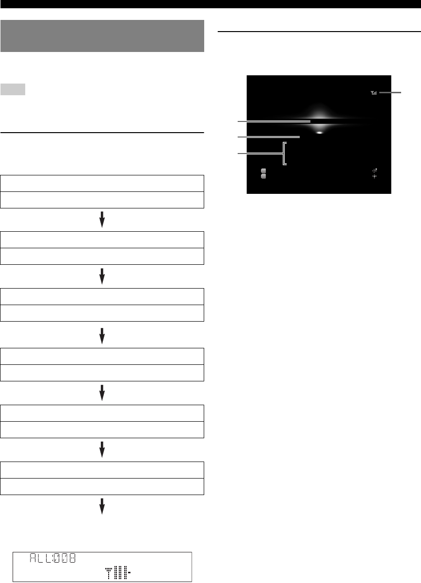
38 En
XM® Satellite Radio tuning (U.S.A. model only)
Use this feature to display the XM Satellite Radio information
on the front panel display or on the GUI screen.
Note
•If a status message or an error message appears on the front panel display
or GUI screen, see “XM Satellite Radio” (page 80).
■Front panel display
Press EINFO (or fINFO) repeatedly to toggle
the following XM Satellite Radio information
display modes.
Back to “Channel”
Display example (Antenna)
y
•You can configure the scroll setting of the front panel display with “Front
Panel Display Scroll” in the Setup menu (page 63).
•If the XM Satellite Radio information contains a character that cannot be
recognized by this unit, the character will be displayed with a space.
•When an information is unavailable, “––––” appears.
■GUI screen
Press uDISPLAY on the remote control to turn
on or off the information display.
The following information is displayed on the GUI screen.
aChannel number
bSearch mode (page 36)
cChannel name, channel category, artist name,
song title
dAntenna reception level
y
•To hold or release the displayed information, press jENTER. While it
is held, the “HOLD” icon appears on the GUI screen.
Displaying the XM Satellite Radio™
information
Channel
Channel number, channel name
Category
Channel category, channel number
Artist / Song
Artist name, song title, channel number
Antenna
Antenna reception level, channel number
DSP Program
Current sound field program (page 27), channel number
Audio Decoder
Current audio decoder (page 29), channel number
Antenna
XM
Ch 008
All Channel Search
Ch Name
Category
Artist
Song
80’s
Decades
Sanumemo
Road to India
Input
DSP
XM
Straight Enhancer
Option Menu
Hold Data
a
b
c
d
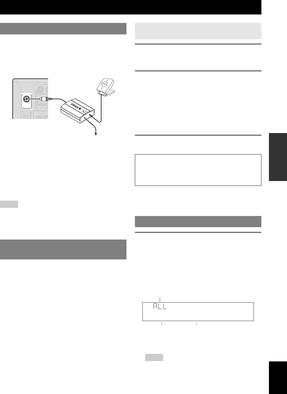
39 En
English
INTRODUCTION
ADDITIONAL
INFORMATION APPENDIX
PREPARATION
BASIC
OPERATION
ADVANCED
OPERATION
Connect the SiriusConnect tuner (sold separately) to the
SIRIUS jack on the rear panel of this unit. For details, see
the operating instructions provided with the SiriusConnect
tuner.
y
•To ensure optimal reception of the SIRIUS Satellite Radio signals, the
antenna of the SiriusConnect tuner must be placed at or near a window
with no obstacles in the path to the sky. The orientation of the antenna for
the best reception differs depending on the area. Refer to the instruction
manuals supplied with the SiriusConnect tuner for the installation of the
antenna. You can mount it indoors or outdoors.
•Use the “Antenna” information in the front panel or “SIRIUS
Information” screen on the GUI screen (page 43) to check the antenna
reception level and adjust the orientation of the antenna.
•You need to connect the SiriusConnect tuner to the AC wall outlet.
Notes
•If “CHECK SR TUNER” or “ANTENNA ERROR” appears on the front
panel display, the connection of the SiriusConnect tuner or antenna is
incorrect. In such cases, check the connection of the SiriusConnect tuner
and the antenna.
•If “NOT SUPPORTED” appears on the front panel display, this unit does
not support the connected SiriusConnect tuner.
Before using the SIRIUS Satellite Radio feature, you need
to activate your SIRIUS Satellite Radio subscription. To
activate the subscription you need the Sirius ID which is
uniquely assigned to the SiriusConnect tuner. Sirius ID is
12-digit number and it appears on the package of the
SiriusConnect tuner, on the label of the SiriusConnect
tuner, and when you tune into the SIRIUS Satellite Radio
channel “0” (see below).
1Rotate the TINPUT selector (or press
dSIRIUS) to select “SIRIUS” as the input
source.
2Press l0 and then lENT to display the
Sirius ID of your SiriusConnect tuner.
“000 Sirius ID” and “xxxxxxxxxxxx”
(“xxxxxxxxxxxx” indicates the 12-digit Sirius ID of
your SiriusConnect tuner) appears alternately on the
front panel display.
Write the Sirius ID below.
ID:________________________________________
3Contact SIRIUS Satellite Radio to activate
your subscription.
y
•Status messages appear on the front panel display or GUI screen
during the activation. For details, see “SIRIUS Satellite Radio”
(page 81). Once the activation is finished, “SUB UPDATED”
appears.
1Rotate the TINPUT selector (or press
dSIRIUS) to select “SIRIUS” as the input
source.
The SIRIUS indicator lights up on the front panel
display and the SIRIUS Satellite Radio information
(such as channel number, channel name, category,
artist name, or song title) for the currently selected
channel appears on the front panel display.
y
•When you select “SIRIUS” as the input source, this unit
automatically recalls the previously selected channel.
Notes
•When you have not activated your subscription yet, you can only
select “184” or “000”.
•If a status message or an error message appears on the front panel
display or on the GUI screen, see “SIRIUS Satellite Radio”
(page 81).
SIRIUS Satellite Radio™ tuning (U.S.A. model only)
Connecting the SiriusConnect™ tuner
Activating SIRIUS Satellite Radio™
subscription
SIRIUS
D
OC
K
PH
O
N
O
CO
MP
O
NENT
VIDEO
OUT
DC 5V
ANT
SiriusConnect Tuner and the antenna
(sold separately)
To the AC wall outlet
Displaying the Sirius ID of your
SiriusConnect tuner
SIRIUS Satellite Radio online information
Contact for activation
URL: https://activate.siriusradio.com/
Phone: 1-888-539-SIRIUS (1-888-539-7474)
SIRIUS Satellite Radio™ operations
184Weather
SIRIUS
Search mode
Channel number Channel name
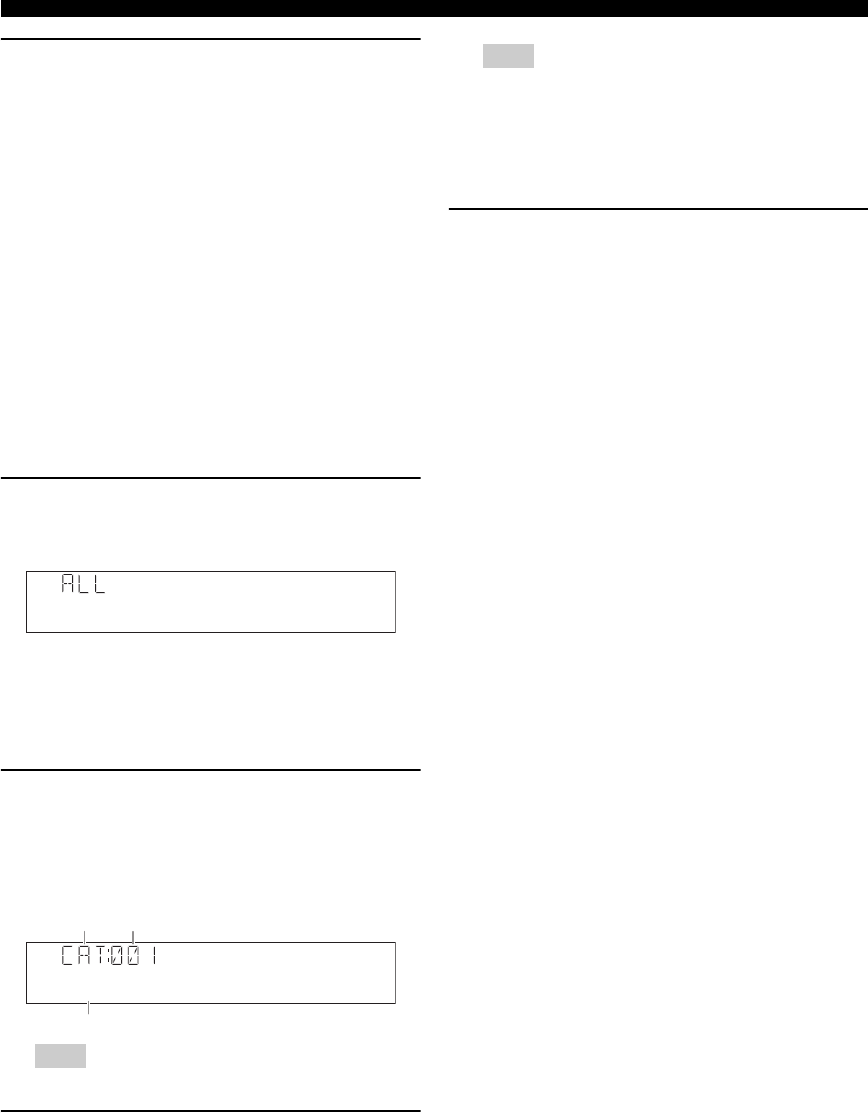
40 En
SIRIUS Satellite Radio™ tuning (U.S.A. model only)
2Search for a channel by using one of the
SIRIUS Satellite Radio search modes.
•To select a channel from the all channel list, see
“All Channel Search mode” on this page.
•To select a channel by category, see “Category
Search mode” on this page.
•To select the desired channel directly by entering
the channel number, see “Direct number access” on
this page.
•To select a channel from the preset channels, see
“Calling a preset channel (Preset Search mode)”
(page 41).
y
•You can display the SIRIUS Satellite Radio information on the
front panel display or on the GUI screen (page 43).
•If you tune into a channel that you do not subscribe, “CALL
SIRIUS” (on the front panel display) and “CALL 888-539-SIRIUS
TO SUBSCRIBE” (on the GUI screen) appear.
•You can set the SIRIUS Satellite Radio preset channels (page 41).
■All Channel Search mode
Press ITUNING/CH l / h (or eTUN./CH k /
n) repeatedly to search for a channel within all
channels.
y
•You can search for a channel quickly by holding down
ITUNING/CH l / h (or eTUN./CH k / n).
•You can skip channels to the previous or next category by pressing
HCATEGORY (or eCATEGORY l / h).
■Category Search mode
1Press HCATEGORY (or eCATEGORY l /
h) to select the channel category.
“CAT” is displayed on the front panel display during
channel category selection. When you select the
category, the first channel in the category is selected.
Note
•If you do not operate within 10 seconds, the category search mode
returns to “ALL” (All Channel Search).
2While “CAT” is displayed on the front panel
display, press ITUNING/CH l / h (or
eTUN./CH k / n) repeatedly to search for a
channel within the selected channel
category.
y
•You can search for a channel quickly by pressing and holding
ITUNING/CH l / h (or eTUN./CH k / n).
Note
•This unit skips the channels when this unit is in the All Channel
Search mode or Category Search mode in the following cases (it is
not malfunction of this unit):
–the channel is locked (page 42).
–the channel is out of service.
–you do not subscribe to the channel.
■Direct number access
In the All Channel Search mode or Category
search mode, press the lNumeric keys to
enter the desired three-digit channel number.
For example, to enter the number 123, press the
lNumeric keys as “1”, “2” and “3”.
y
•To display the Sirius ID number displayed on the front panel display,
select channel “0”.
•To enter a one-digit or two-digit channel number, press the lNumeric
keys on the remote control and then press lENT to confirm the input
number.
•Instead of pressing lENT to tune into the channel immediately, you
can wait a few seconds until this unit confirms the entered channel
number.
•If no key is pressed within a few seconds after you enter a one-digit or
two-digit number, this unit automatically confirms the entered channel
number.
•If the selected channel is locked, “PIN:___” appears on the front panel
display. Enter the four-digit Parental Lock code number by using the
lNumeric keys or press lENT to cancel (page 42).
•If the selected channel is not available, an advisory message may appear.
For details, see “SIRIUS Satellite Radio” (page 81).
001Hits1
SIRIUS
Pop
SIRIUS
Category
search mode The first channel in the category
Category name
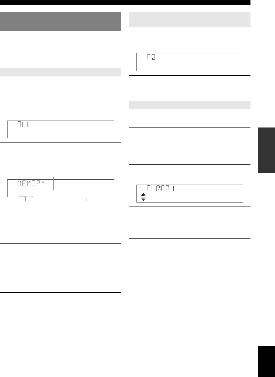
41 En
SIRIUS Satellite Radio™ tuning (U.S.A. model only)
English
INTRODUCTION
ADDITIONAL
INFORMATION APPENDIX
PREPARATION
BASIC
OPERATION
ADVANCED
OPERATION
You can use this feature to store up to 40 SIRIUS Satellite
Radio channels. You can then recall any preset channel
easily by selecting the preset channel group and number as
described in “Calling a preset channel (Preset Search
mode)” on this page.
1Search a channel you want to set as a preset
channel in one of the SIRIUS Satellite Radio
search modes.
For details, see “SIRIUS Satellite Radio operations”
(page 39).
2Press GMEMORY (or eMEMORY).
The indicator on the front panel display changes as
follows.
y
•By holding down GMEMORY (or eMEMORY) for more than
2 seconds, you can skip the following steps and automatically
register the selected channel to an empty preset number (next to the
lastly-registered preset number).
•To cancel the preset operation, press jRETURN.
3Press FPRESET l / h (or ePRESET k / n)
to select the stored preset station number.
y
•You can also select a preset number using the lNumeric
keys.
•If you select a preset number being used (currently registered
channel number appears next to the preset number), the current
preset channel will be overwritten.
4Press GMEMORY (or eMEMORY).
Prior to selecting a preset channel in the Preset Search
mode, you must preset SIRIUS channels. For details, see
“Registering preset channels” on this page.
Press FPRESET l / h (or ePRESET k / n)
repeatedly to change the preset channel number
(1 to 40).
You can clear the assignments of preset SIRIUS Satellite
Radio channels.
1Press sOPTION on the remote control.
The Option menu for “SIRIUS” is displayed.
2Press jCursor k / n repeatedly to select
“Clear Preset” and then press jENTER.
3Press jCursor k / n to select the preset
station number that you want to clear.
4Press jENTER to execute the clearing of
the selected preset channel.
To clear the registration of multiple preset numbers,
repeat steps 3 and 4.
5To exit the Option menu, press sOPTION.
Registering SIRIUS Satellite Radio™
channels
Registering preset channels
001Hits1
SIRIUS
P01:---<<001
SIRIUS
Currently registered channel number
(or “---” if empty)
Channel number to be
registered
Preset number to which new
channel number is registered
Calling a preset channel (Preset Search
mode)
Clearing preset channels
001Hits1
SIRIUS
001 Hits 1
SIRIUS
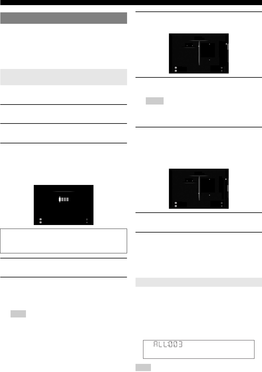
42 En
SIRIUS Satellite Radio™ tuning (U.S.A. model only)
You can use the Parental Lock feature to limit the access
to the desired SIRIUS Satellite channels. This unit
automatically skips the locked channels when this unit is
in the All Channel Search mode or Category Search mode
and you search a channel by pressing ITUNING/CH
l / h (or eTUN./CH k / n).
Use this feature to set the Parental Lock code number
(PIN) and select the channels to be locked.
1Press sOPTION on the remote control.
The Option menu for “SIRIUS” is displayed.
2Press jCursor k / n repeatedly to select
“Parental Lock” and then press jENTER.
3Use jCursor l / h (to select a digit to edit)
and jCursor k / n (to select a number) to
enter the desired 4-digit code number.
If you have entered a code number before, enter the
same code number.
4Press jENTER.
The confirmation screen appears.
5Press jENTER again to confirm the code
number.
“OK” and then the SIRIUS Satellite Radio channel
list appears.
Note
•If a code number is already registered and you enter the different
number, “Wrong” appears and the screen returns to step 3. Enter
the correct code number.
•If you forget the Parental lock code or want to change it, reset it
using “SR PIN” (page 73).
6Press jCursor l / h to select the category
of a channel you want to lock.
7Press jCursor k / n to select a channel you
want to lock.
Notes
•You can also select a channel by using eCATEGORY l / h or
eTUN./CH k / n.
•While the SIRIUS Satellite Radio channel list screen is displayed,
sound of the selected channel is output even the channel is locked.
8Press jENTER to lock the selected
channel.
A check mark appears next to the locked channel on
the GUI screen. You can toggle channel lock and
unlock as you press jENTER.
9Repeat steps 6 through 8 to lock all the
desired channels.
10 Press jRETURN repeatedly to exit the
“Parental Lock” screen.
This unit is tuned into the last channel you select in
the “Parental Lock” screen. If the channel is locked,
this unit is tuned into “184 Weather/Emergency” or
“000 Sirius ID”.
Tune into the channel with direct number access (page 40)
or Preset Search mode (page 41). When you tune into the
locked channel, “LOCKED” appears on the front panel
display and GUI screen, followed by the following
message. Enter the set Parental lock code by using the
lNumeric keys. To cancel this operation, press
lENT.
Note
•If an incorrect number is entered, “Wrong” appears on the front panel
display or the GUI screen and this unit is tuned into the previously
selected channel.
Setting the Parental Lock
Setting the code number and the locking
channels
The entered code number is needed for tuning in the
channel or unlocking the channel. Write it down below.
Code number: ________________________________
00 0 0
Input
DSP
Parental Lock
SIRIUS
7ch Enhancer Edit
Set
Enter New PIN
Tuning into the locked channels
Input
DSP
Channel
001 SIRIUS Hits 1
002 The Blend
003 SIRIUS XM Love
004 40s on 4
005 50s on 5
Parental Lock
Category
Pop
SIRIUS
7ch Enhancer
Select Cat / Ch
Lock / Unlock
9
Input
DSP
Channel
006 ’60s Vibrations
007 Totally ’70s
008 Big ’80s
009 The Pulse
010 The Bridge
Parental Lock
Category
Pop
SIRIUS
7ch Enhancer
Select Cat / Ch
Lock / Unlock
PIN:
SIRIUS
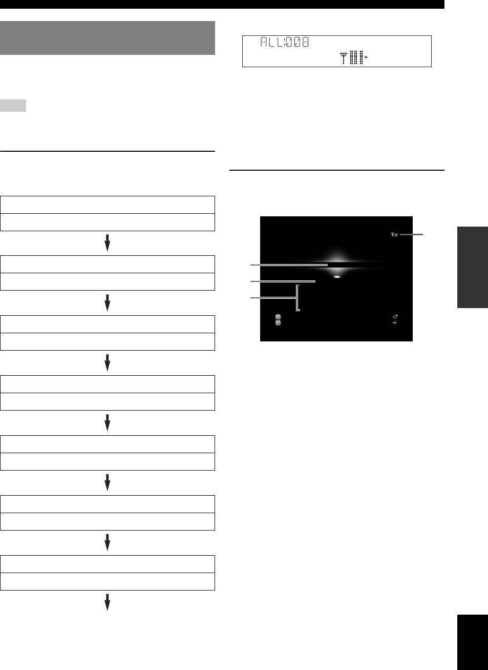
43 En
SIRIUS Satellite Radio™ tuning (U.S.A. model only)
English
INTRODUCTION
ADDITIONAL
INFORMATION APPENDIX
PREPARATION
BASIC
OPERATION
ADVANCED
OPERATION
Use this feature to display the SIRIUS Satellite Radio
information on the front panel display or on the GUI
screen.
Note
•If a status message or an error message appears on the front panel display
or GUI screen, see “SIRIUS Satellite Radio” (page 81).
■Front panel display
Press EINFO (or fINFO) repeatedly to toggle
the following SIRIUS Satellite Radio information
display modes.
Back to “Channel”
Display example (Antenna)
y
•You can configure the scroll setting of the front panel display with “Front
Panel Display Scroll” in the Setup menu (page 63).
•If the SIRIUS Satellite Radio information contains a character that
cannot be recognized by this unit, the character will be displayed with a
space.
•When the antenna of the SiriusConnect tuner cannot receive the signals,
“ACQUIRING” appears on the front panel display.
•When an information is unavailable, “––––” appears.
■GUI screen
Press uDISPLAY on the remote control to turn
on or off the information display.
The following information is displayed on the GUI screen.
aChannel number
bSearch mode (page 40)
cChannel name, channel category, artist name,
song title, composer name
dAntenna reception level
y
•To hold or release the displayed information, press jENTER. While it
is held, the “HOLD” icon appears on the GUI screen..
Displaying the SIRIUS Satellite
Radio™ information
Channel
Channel number, channel name
Category
Channel category, channel number
Artist/Song
Artist name, song title, channel number
Composer
Composer name, channel number
Antenna
Antenna reception level, channel number
DSP Program
Current sound field program (page 27)
Audio Decoder
Current audio decoder (page 29)
Antenna
SIRIUS
Ch 001
All Channel Search
Ch Name
Category
Artist
Song
Composer
SIRIUS Hits 1
Pop
Sanumemo
Road to India
Frankie Zipper
Input
DSP
SIRIUS
Straight Enhancer
Option Menu
Hold Data
a
b
c
d
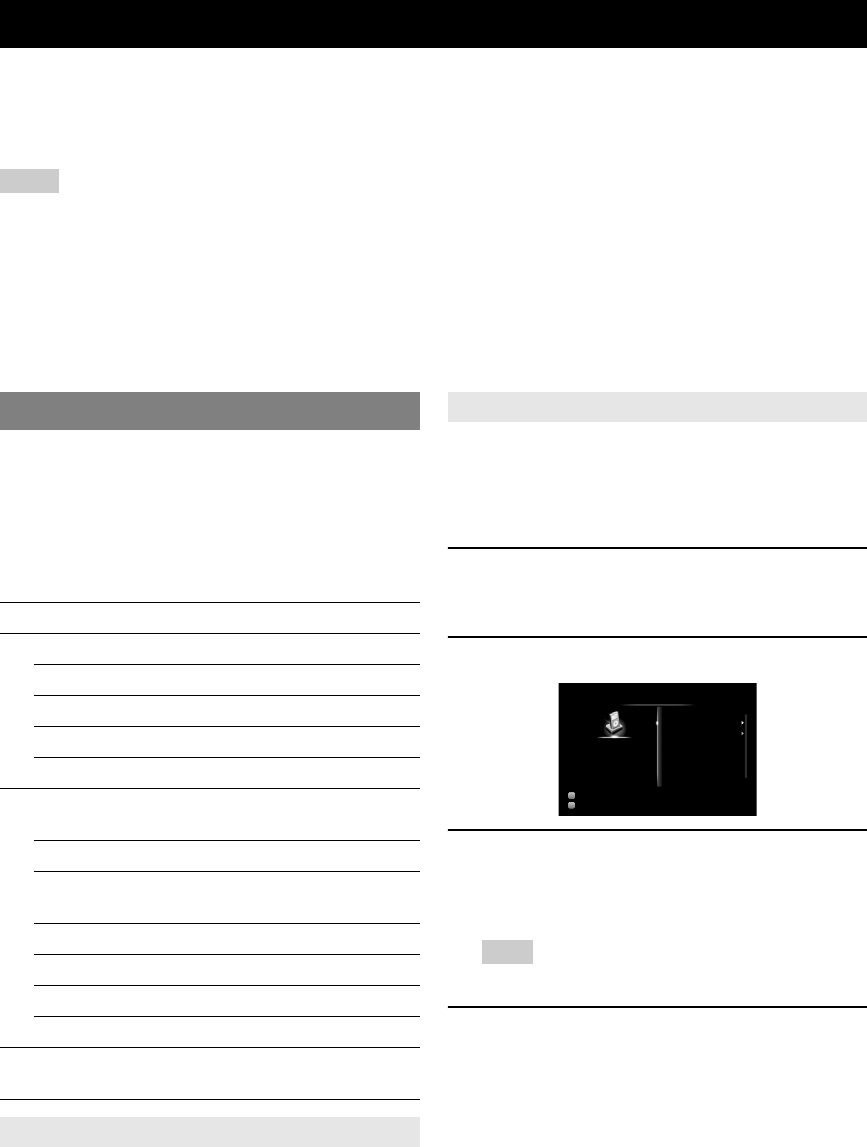
44 En
Once you have stationed your iPod in a Yamaha iPod universal dock (such as the YDS-11, sold separately) connected to
the DOCK terminal on the rear panel of this unit (page 18), you can enjoy playback of your iPod using the supplied
remote control or the menu displayed on the GUI screen. You can also use the Compressed Music Enhancer mode of this
unit to improve the sound quality of the compression artifacts (such as MP3 format) stored on your iPod (page 29).
Notes
•iPod touch, iPod (Click and Wheel including iPod classic), iPod nano, and iPod mini are supported.
•Some features may not be compatible depending on the model or the software version of your iPod.
•Some features may not be available depending on the model of Yamaha iPod universal dock. The following sections describe the procedure when using
the YDS-11.
y
•Once the connection between your iPod and this unit is complete, “iPod connected” appears on the front panel display.
•For a complete list of status messages that appear on the front panel display and GUI screen, see “iPod” (page 83).
•(U.S.A. model only)
Once the connection between an iPod that supports iTunes Tagging feature and this unit is complete, this unit transmits iTunes Tagging information to the
iPod (page 33).
You can control your iPod when you set it in the iPod
universal dock and switch the input source to DOCK. The
operations of your iPod can be done with the aid of the
video display (menu browse mode) or without it (simple
remote mode).
When you connect your iPod to this unit, you can perform
the following operations with the remote control.
You can perform basic iPod operations (play, stop, skip,
etc.) using the supplied remote control without displaying
the menu on the GUI screen. You can also directly control
your iPod in this mode.
You can browse song or video files stored on your iPod
using the GUI screen. You cannot directly control your
iPod in this mode.
y
•“_”(underscore) is displayed for characters that this unit cannot display.
1Rotate the TINPUT selector (or press
dDOCK) to select “iPod” (DOCK) as the
input source.
2Press uDISPLAY on the remote control.
3Press jCursor k / n to select “Music” or
“Videos” and then press jCursor h.
•Select “Music” to browse music files.
•Select “Videos” to browse video files.
Note
•The “Videos” menu does not appear unless the both your iPod and
Yamaha iPod universal dock support the video browsing feature.
4Press jCursor k / n / l / h to select a
menu item and then press jENTER to start
playback.
Using iPod™
Controlling iPod™
Key Function
j
ENTER Subsequent menu
kMenu up
nMenu down
lPrevious menu
hSubsequent menu
k
pPlay (Menu browse mode)
Play/Pause (Simple remote mode)
sStop
ePause (Menu browse mode)
Play/Pause (Simple remote mode)
wSearch backward (Press and hold)
fSearch forward (Press and hold)
bSkip backward
aSkip forward
uDISPLAY Switch between Menu browse mode and
Simple remote mode
Controlling iPod in simple remote mode
Controlling iPod in menu browse mode
Input
DSP
Music
Videos
iPod
DOCK
STRAIGHT
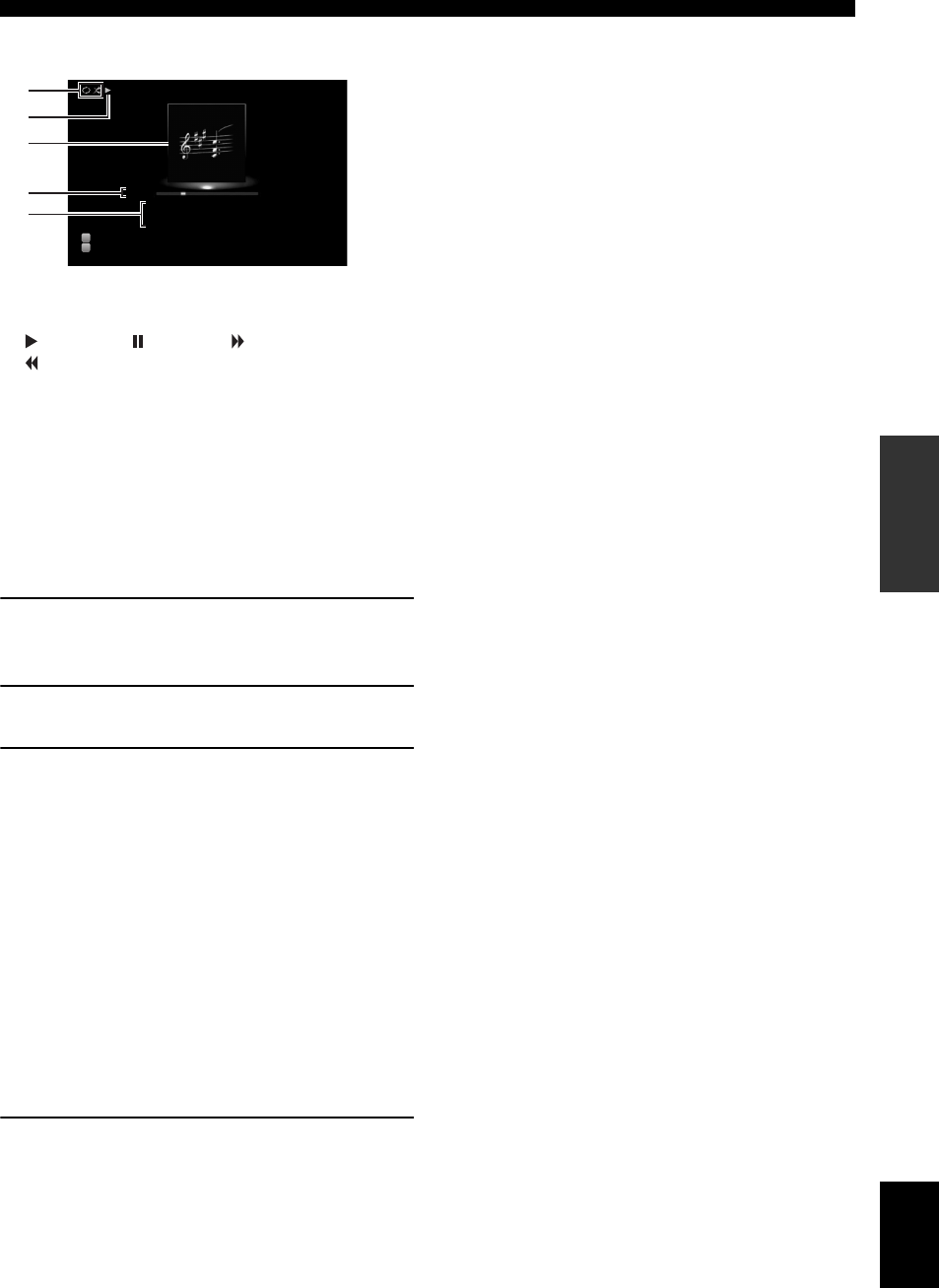
45 En
Using iPod™
English
INTRODUCTION
ADDITIONAL
INFORMATION APPENDIX
PREPARATION
BASIC
OPERATION
ADVANCED
OPERATION
■Play information display
a Shuffle and repeat icons
b (playback), (pausing), (search forward) and
(search backward)
c Album art (image of CD jacket, etc)
d Elapsed time, progress bar, remaining time
e Song title, artist name, album title
y
•You can switch the information displayed on the front panel display by
pressing EINFO (or fINFO).
•Album arts are available only when the file contains image data.
■Shuffle/repeat playback
When controlling iPod in simple remote mode, operate the
iPod directly to set the shuffle and repeat playback.
1Press uDISPLAY to switch to menu browse
mode while “DOCK” is selected as the input
source.
2Press sOPTION on the remote control.
The Option menu for “iPod” is displayed (page 54).
3Press jCursor k / n to select “Shuffle” or
“Repeat”, press jENTER and then press
jCursor l / h to select the desired
playback style.
Shuffle:
•Select “Off” if you do not want to play back in
random order.
•Select “Songs” to play back songs in random order.
•Select “Albums” to play back albums in random
order.
Repeat:
•Select “Off” if you do not want to play back
repeatedly.
•Select “One” to repeat each song.
•Select “All” to repeat all songs.
4To exit the Option menu, press sOPTION.
Input
DSP
a
c
b
e
dMade-to-order
Frankie Zipper
Road to India
Song
Artist
Album
01:04 –02:27
DOCK
Straight
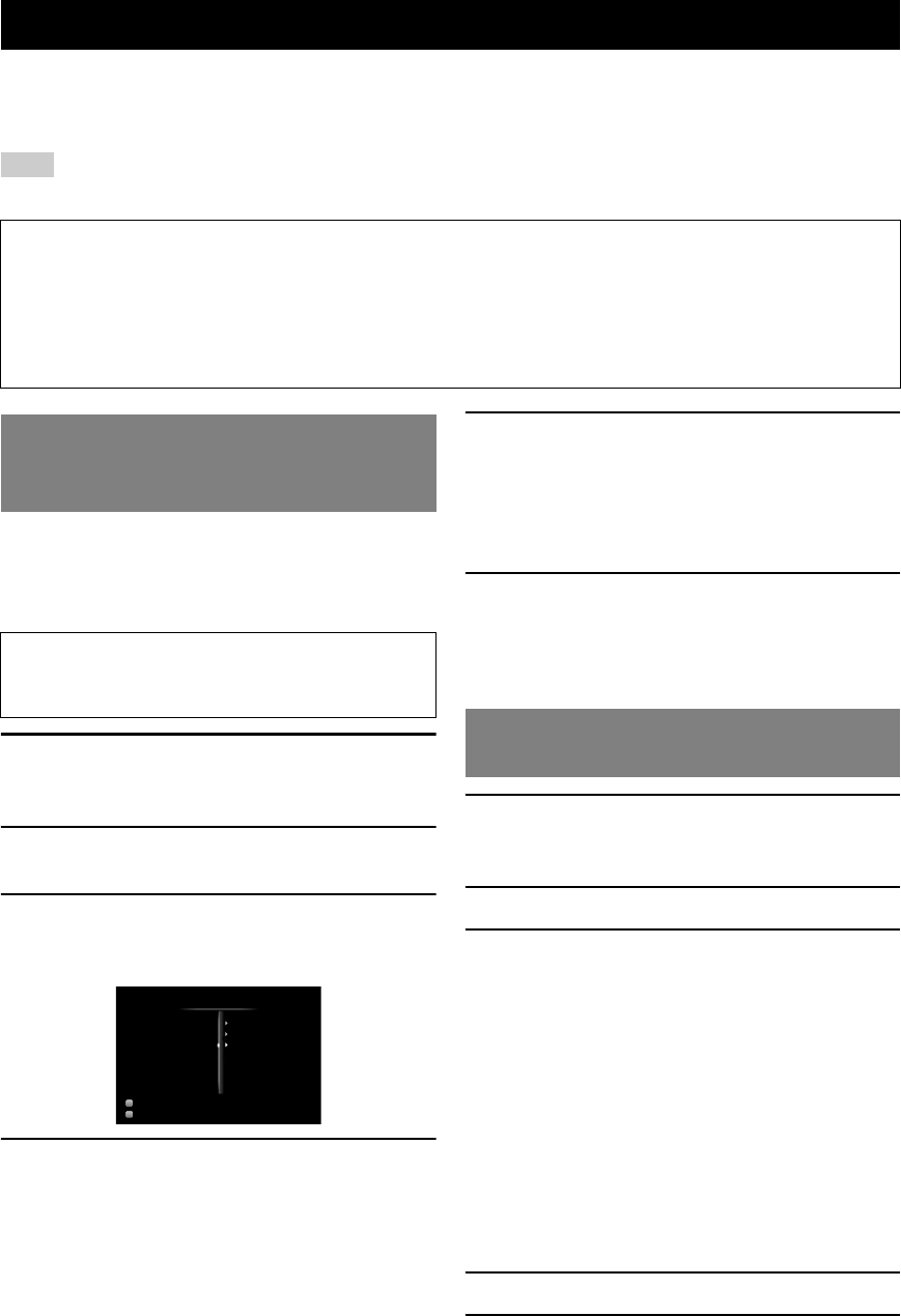
46 En
You can connect a Yamaha Bluetooth wireless audio receiver (such as YBA-10, sold separately) to the DOCK terminal of
this unit and enjoy the music contents stored in your Bluetooth component (such as a portable music player) without
wiring between this unit and the Bluetooth component.
Note
•This unit supports A2DP (Advanced Audio Distribution Profile) of the Bluetooth profile.
•For a complete list of status messages that appear on the front panel display and GUI screen, see “Bluetooth™” (page 83).
y
•If the pairing data has been cleared from the Bluetooth wireless audio
receiver or your Bluetooth component, you need to perform pairing
again.
•For details on operations on your Bluetooth component, refer to the
operating instruction of it.
1Rotate the TINPUT selector (or press
dDOCK) to select “BLUETOOTH” (DOCK)
as the input source.
2Turn on the Bluetooth component you want
to pair with and set it to pairing mode.
3Press sOPTION on the remote control.
The Option menu for “BLUETOOTH” is displayed
(page 54).
4Press jCursor n to select “Pairing” and
then press jENTER.
“Searching” appears and the pairing operation starts.
y
•To cancel pairing, press jRETURN.
•You can also start pairing operation by holding down
GMEMORY on the front panel.
5Make sure the Bluetooth component
recognizes the Bluetooth wireless audio
receiver.
If the Bluetooth component detects the Bluetooth
wireless audio receiver, “YBA-10 YAMAHA”
(example) appears in the Bluetooth device list.
6Select the Bluetooth wireless audio receiver
in the Bluetooth device list, and enter a pass
key “0000” into the Bluetooth component.
When pairing is complete, “Completed” appears on
the front panel display.
1Rotate the TINPUT selector (or press
dDOCK) to select “BLUETOOTH” (DOCK)
as the input source.
2Press sOPTION on the remote control.
3Press jCursor n to select “Connect” and
then press jENTER.
The Bluetooth connection is established between the
Bluetooth wireless audio receiver and your Bluetooth
component connected last time.
y
•If the Bluetooth wireless audio receiver cannot find the Bluetooth
component connected last time, “Not found” appears on the front
panel display.
•To disconnect the Bluetooth wireless audio receiver from the
Bluetooth component currently connected, select “Disconnect” and
then press jENTER or perform a disconnect operation on the
Bluetooth component.
•
To make a connection between the Bluetooth wireless audio receiver
and another Bluetooth component (already paired), perform a
connect operation on the Bluetooth component while no Bluetooth
connection is established on the Bluetooth wireless audio receiver.
4Start playback of the Bluetooth component.
5To exit the Option menu, press sOPTION.
Using Bluetooth™ components
About “Pairing”
Pairing (registration of the Bluetooth devices) must be performed when making Bluetooth connections between the
Yamaha Bluetooth wireless audio receiver and your Bluetooth components for the first time. Once pairing is complete,
you can select one of the Bluetooth components to connect to the Yamaha Bluetooth wireless audio receiver for playback.
y
•Yamaha Bluetooth wireless audio receiver YBA-10 can be paired with up to eight Bluetooth components. If ninth pairing data is registered, the pairing
data for the component least recently used is cleared.
Pairing the Bluetooth™ wireless audio
receiver and your Bluetooth
component
To ensure security, a time limit of 8 minutes is set for
the pairing operation. You are recommended to read
and fully understand all the instructions before starting.
Input
DSP
Volume Trim
Connect
Pairing
Option Menu
BLUETOOTH
7ch Enhancer
Playback of the Bluetooth™
component
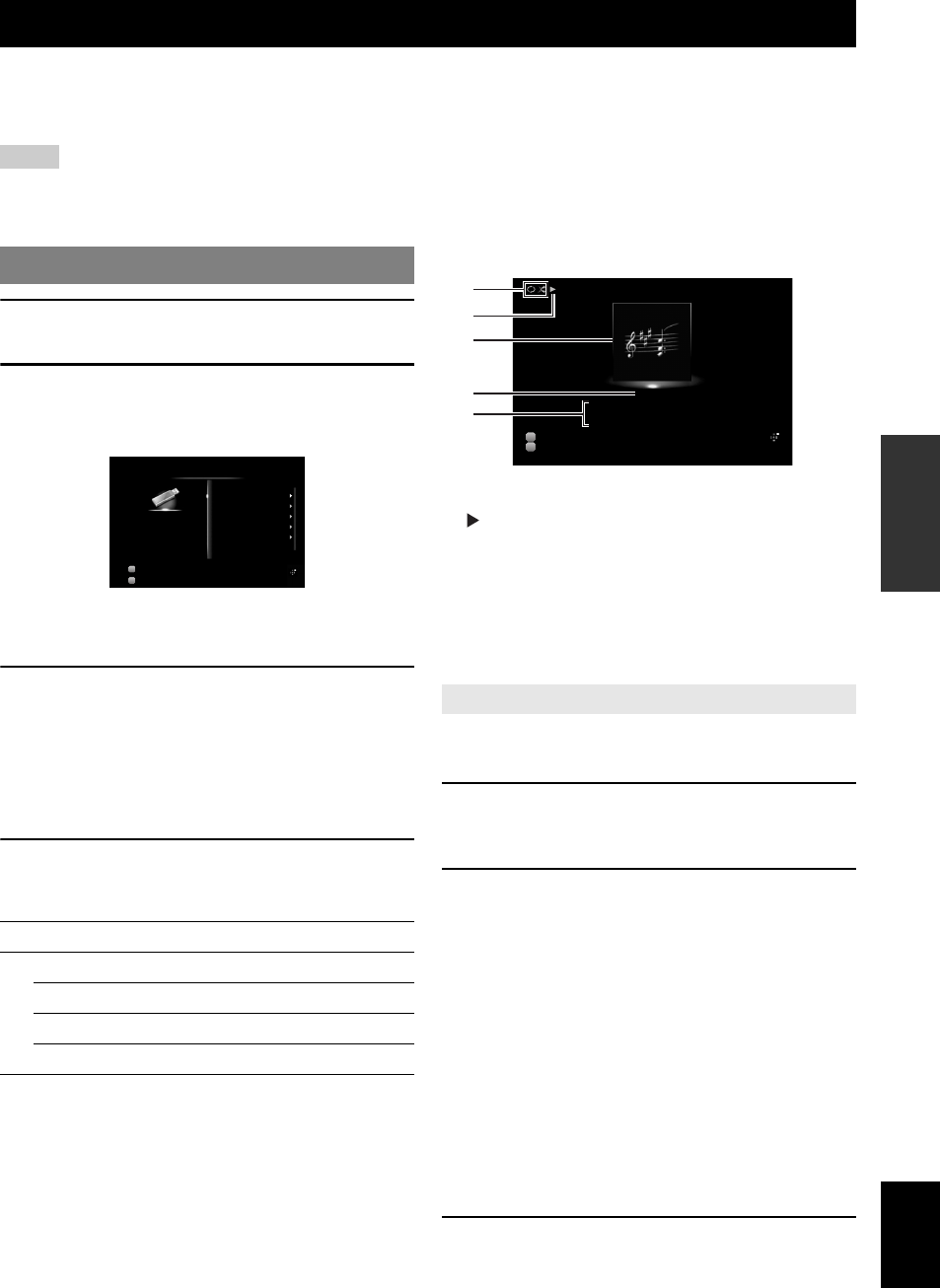
47 En
English
INTRODUCTION
ADDITIONAL
INFORMATION APPENDIX
PREPARATION
BASIC
OPERATION
ADVANCED
OPERATION
You can enjoy playback of WAV (PCM format only), MP3, WMA , MPEG-4 AAC and FLAC files stored on your USB
memory device or USB portable player connected to the USB port on the front panel of this unit. This unit supports USB
mass storage class devices (FAT 16 or FAT 32 format, except USB HDDs).
Notes
•You can play back only the files stored in the first partition.
•Some files may not be playable depending on models and types of USB storage devices.
•For a complete list of status messages that appear on the front panel display and GUI screen, see “USB and network” (page 84).
1Connect your USB storage device to the
NUSB port on the front panel (page 19).
2Rotate the TINPUT selector (or press
dUSB/NET and then xUSB) to select
“USB” as the input source.
If you have connected the USB storage device to this
unit before, playback of the music file played at the
last time automatically starts.
3Press jCursor k / n / l / h to select a
music file to play back.
•To select a file or folder, press jCursor k / n.
•To confirm the selection, press jCursor h or
jENTER.
•To return to the previous menu, press jCursor
l.
4Press jENTER to start playback.
You can also perform the following operations with
the remote control.
■Play information display
a Shuffle and repeat icons
b (playback)
c Album art (image of CD jacket, etc)
d Elapsed time
e Song title, artist name, album title
y
•You can switch the information displayed on the front panel display by
pressing EINFO (or fINFO) (page 26).
•Album arts are available only when the file contains image data.
y
•These settings are also reflected in playback of PC and Rhapsody®
contents.
1Press sOPTION on the remote control
while “USB” is selected as the input source.
The Option menu for “USB” is displayed (page 54).
2Press jCursor k / n to select “Shuffle” or
“Repeat”, press jENTER and then press
jCursor l / h to select the desired
playback style.
Shuffle:
•Select “Off” if you do not want to play back in
random order.
•Select “On” to play back music files in random
order.
Repeat:
•Select “Off” if you do not want to play back
repeatedly.
•Select “One” to repeat each music file.
•Select “All” to repeat all music files in the folder.
3To exit the Option menu, press sOPTION.
Using USB storage devices
Playback of the USB storage device
Key Function
k
pPlay
sStop
aSkip forward during playback
bSkip backward during playback
Input
DSP
Road to India
Symphony 01
Symphony 02
Symphony 03
Take–Hero
USB
USB
7ch Enhancer
Option Menu
Shuffle/repeat playback
Input
DSP
a
c
d
b
e
00:30
Made-to-order
Frankie Zipper
Road to India
Song
Artist
Album
USB
7ch Enhancer
Option Menu
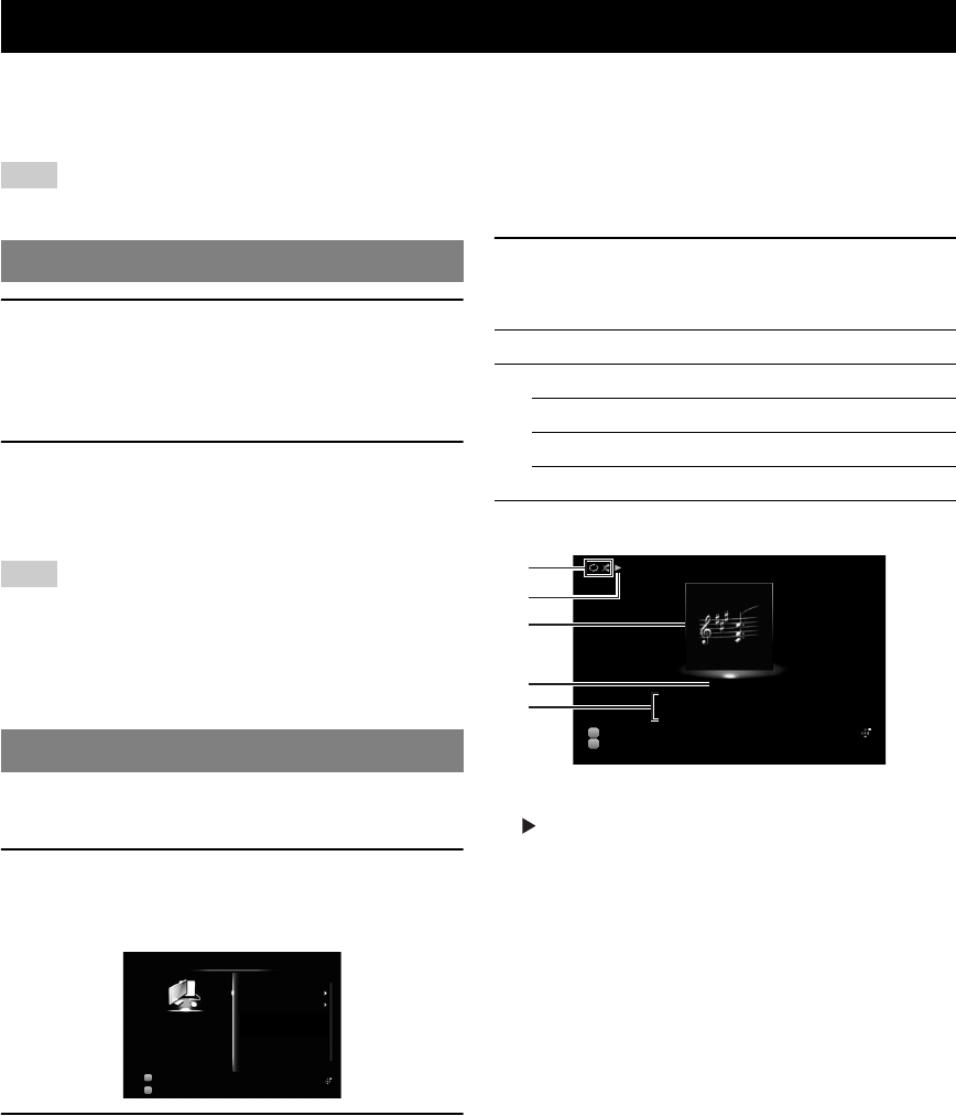
48 En
You can enjoy playback of audio files stored on PCs connected to this unit via your network. To play back audio files on
your PC, you need to install Windows Media Player 11 on the PC and configure the media sharing setting of Windows
Media Player 11.
Note
•If you do not use a DHCP server, configure the network parameters (IP address, etc) of this unit manually (page 64)
1Install Windows Media Player 11 on your PC.
You can download the installer of Windows Media
Player 11 from the Microsoft website, or use the
upgrade function of the installed Microsoft Windows
Media Player.
2Turn on your PC then allow media sharing.
Activate Windows Media Player 11 first, enable the
media sharing and then select this unit as a device to
which the media is shared.
Note
•If the operating system (OS) of your PC is Windows Vista, Windows
Media Player 11 is pre-installed (except some products).
•Some security software installed on your PC (anti-virus software,
firewall software, etc.) may block the access of this unit to your PC. In
such cases, configure the security software appropriately.
•You can connect this unit to up to 16 PC servers, and each server must be
connected to the same subnet as this unit.
y
•For a complete list of status messages that appear on the front panel
display and GUI screen, see “USB and network” (page 84).
1Rotate the TINPUT selector (or press
dUSB/NET and then xPC) to select “PC”
as the input source.
2Press jCursor k / n / l / h to select a PC
server and music file to play back.
•To select a PC server, folder or file, press
jCursor k / n.
•To confirm the selection, press jCursor h or
jENTER.
•To return to the previous menu, press jCursor
l.
y
•To update the PC server list displayed in the GUI screen, press
sOPTION, press jCursor k / n to select “Refresh” and then
press jENTER. To exit the Option menu, press sOPTION.
3Press jENTER to start playback.
You can also perform the following operations with
the remote control.
■Play information display
a Shuffle and repeat icons
b (playback)
c Album art (image of CD jacket, etc)
d Elapsed time
e Song title, artist name, album title
y
•You can switch the information displayed on the front panel display by
pressing EINFO (or fINFO) (page 26).
•Album arts are available only when the file contains image data.
Using PC servers
Windows Media Player 11 setup
Playback of PC music contents
Input
DSP
PC_SERVER01
PC_SERVER02
PC
PC
7ch Enhancer
Option Menu
Key Function
k
pPlay
sStop
aSkip forward during playback
bSkip backward during playback
Input
DSP
a
c
d
b
e
00:13
Made-to-order
Frankie Zipper
Road to India
Song
Artist
Album
PC
7ch Enhancer
Option Menu

49 En
Using PC servers
English
INTRODUCTION
ADDITIONAL
INFORMATION APPENDIX
PREPARATION
BASIC
OPERATION
ADVANCED
OPERATION
y
•These settings are also reflected in playback of USB and
Rhapsody® contents.
1Press sOPTION on the remote control
while “PC” is selected as the input source.
The Option menu for “PC” is displayed (page 54).
2Press jCursor k / n to select “Shuffle” or
“Repeat”, press jENTER and then press
jCursor l / h to select the desired
playback style.
Shuffle:
•Select “Off” if you do not want to play back in
random order.
•Select “On” to play back music files in random
order.
Repeat:
•Select “Off” if you do not want to play back
repeatedly.
•Select “One” to repeat each music file.
•Select “All” to repeat all music files in the folder.
3To exit the Option menu, press sOPTION.
Shuffle/repeat playback
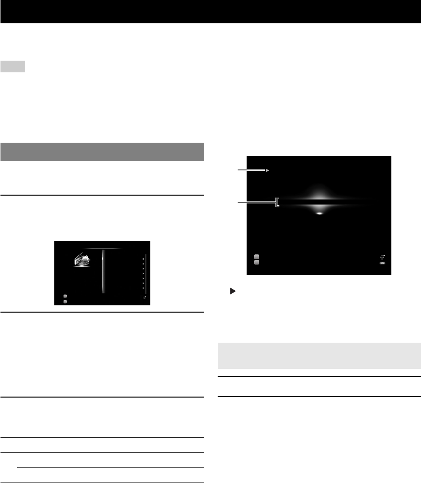
50 En
You can listen to Internet Radio stations using the vTuner Internet Radio station database service particularly customized
for this unit, providing a database of over 2000 radio stations. Also, you can store your favorite stations with bookmarks.
Note
•To use this feature, your network must be connected to the Internet.
•A narrowband Internet connection (i.e. 56K modem, ISDN) will not provide satisfactory results, and a broadband connection is strongly recommended
(i.e. a cable modem, an xDSL modem, etc.). For detailed information, consult with your ISP.
•If you do not use a DHCP server, configure the network parameters (IP address, etc) of this unit manually (page 64)
•Some security devices (such as firewall) may block the access of this unit to Internet Radio stations. In such cases, configure the security settings
appropriately.
•This service may be discontinued without notice.
•Some Internet Radio stations may not be played
y
•For a complete list of status messages that appear on the front panel
display and GUI screen, see “USB and network” (page 84).
1Rotate the TINPUT selector (or press
dUSB/NET and then xNET RADIO) to
select “NET RADIO” as the input source.
2Press jCursor k / n / l / h to select an
item to play back.
•To select an item, press jCursor k / n.
•To confirm the selection, press jCursor h or
jENTER.
•To return to the previous menu, press jCursor
l.
3Press jENTER to start playback.
You can also perform the following operations with
the remote control.
■Play information display
a (playback)
b Station name
y
•You can switch the information displayed on the front panel display by
pressing EINFO (or fINFO) (page 26).
1Select the desired Internet Radio station.
2Press eMEMORY.
The selected Internet Radio station is added to the
“Bookmarks” list in “NET RADIO” .
y
•To remove stations from the “Bookmarks” list, select the station under
“Bookmarks” and then press eMEMORY.
•You can also register your favorite Internet Radio stations on this unit by
accessing the website with the web browser on your PC. To use this
feature, you need the vTuner ID of this unit (page 65) and your e-mail
address to create your personal account. For details, refer to the help
information on the website. URL: http://yradio.vtuner.com/
Using the Internet Radio feature
Listening to Internet Radio
Key Function
k
pPlay
sStop
Input
DSP
Bookmarks
Locations
Genres
New Stations
Popular Stations
Podcasts
Help
NET RADIO
NET RADIO
7ch Enhancer
Option Menu
Storing your favorite Internet Radio
stations with bookmarks
1.fm 80s Euro
Input
DSP
NET RADIO
7ch Enhancer
Option Menu
Bookmark
a
b
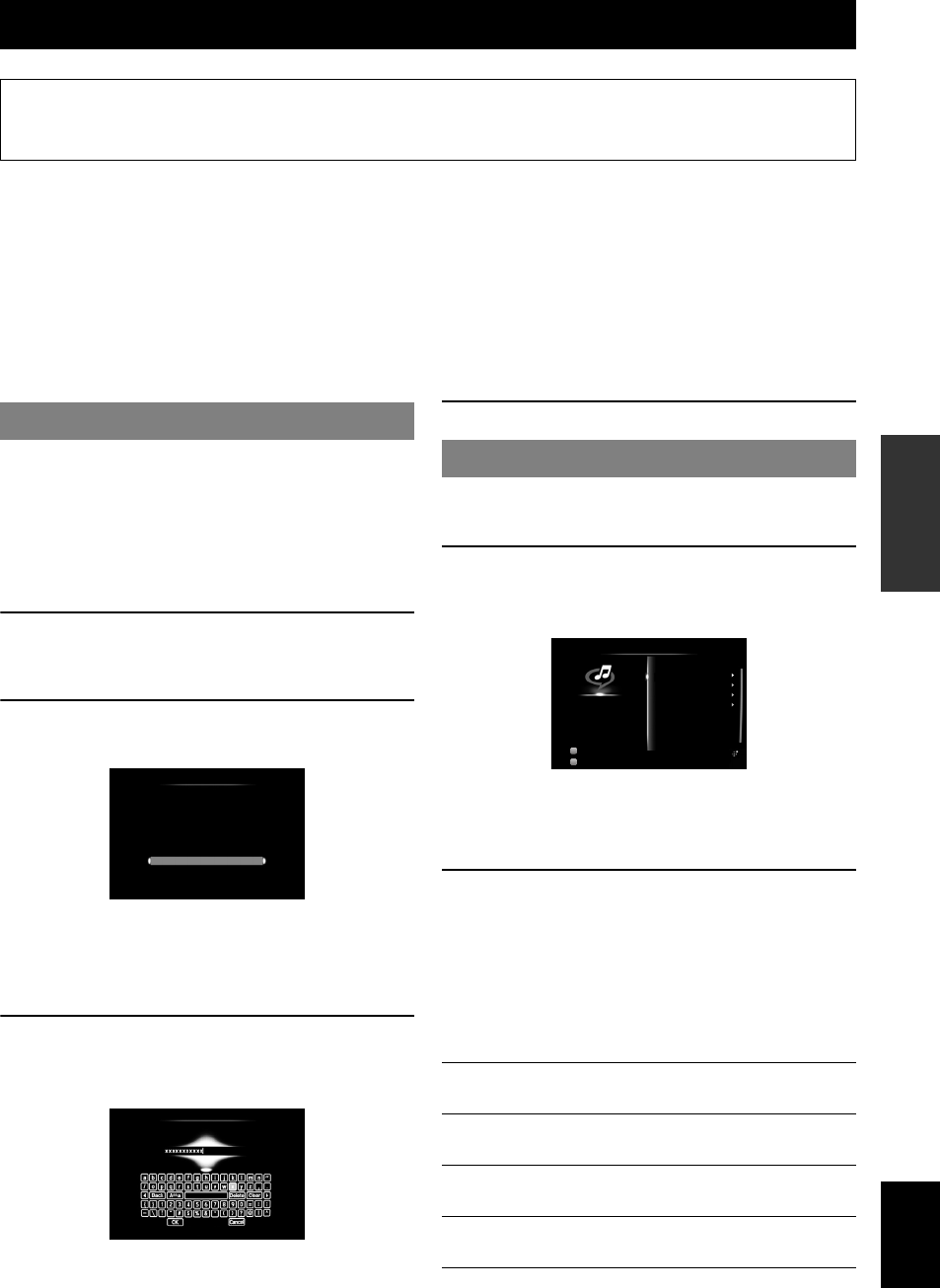
51 En
English
INTRODUCTION
ADDITIONAL
INFORMATION APPENDIX
PREPARATION
BASIC
OPERATION
ADVANCED
OPERATION
The Rhapsody® service is the power behind the Rhapsody® Media Player (the Rhapsody® player software that you can
download to your computer). Rhapsody® service supplies the music, keeps My Library up to date, provides you with
Rhapsody® channels, the Playlist Central online community, and manages your downloads. Your software connects to
Rhapsody® service through the internet. Because your account information and Rhapsody® content are on servers
instead of any individual computer, your music is infinitely portable. Much of what you see in the Display area comes
from Rhapsody® service. What you can do with Rhapsody® service depends on your subscription. You can use
Rhapsody® service for free, or get even more from a paid membership. The Rhapsody® service also brings you
Rhapsody® Online, a streamlined, internet version of Rhapsody® that you can access from almost anywhere. Just sign in
to your Rhapsody® account to start letting the Rhapsody® service work for you.
For more information, http://www.rhapsody.com/
When you select “Rhapsody” for the first time, the
account setup screen appears. Set up your Rhapsody®
account to start using the Rhapsody® service on this unit.
y
•You can view the account information or edit your Rhapsody® account
later with “Rhapsody Information” in the Setup menu (page 65).
•For a complete list of status messages that appear on the front panel
display and GUI screen, see “USB and network” (page 84).
1Rotate the TINPUT selector (or press
dUSB/NET and then xRHAPSODY) to
select “Rhapsody” as the input source.
2Press jCursor k / n to select “Sign In to
your account” and then press jENTER.
y
•To subscribe to the Rhapsody® service using 30-day free trial,
select “Start Free 30-day trial” in step 2 and then read the
description on the GUI screen. If you accept the terms and
conditions, select “Yes” to get started. In this case, you do not need
to follow steps 3 and 4.
3Use jCursor k / n / l / h and jENTER to
enter your user name and password (up to 64
characters each) and then select “OK” .
“Please wait” appears followed by the confirmation
screen.
4Press jENTER.
y
•For a complete list of status messages that appear on the front panel
display and GUI screen, see “USB and network” (page 84).
1Rotate the TINPUT selector (or press
dUSB/NET and then xRHAPSODY) to
select “Rhapsody” as the input source.
y
•If the remaining term of your free trial account is less than seven
days, the number of remaining days is displayed in the GUI screen.
To proceed to step 2 (with the free trial service), press jENTER.
To sign up for Rhapsody®, see “Rhapsody Information” (page 65).
2Press jCursor k / n / l / h to select an
item to play back.
•To select an item, folder or file, press jCursor k
/ n.
•To confirm the selection, press jCursor h or
jENTER.
•To return to the previous menu, press jCursor
l.
Using the Rhapsody® service (U.S.A. model only)
Prohibition
It is strictly prohibited to modify, reproduce, reverse-engineer or use this unit and/or built-in software for use other
than audiovisual purposes.
Account setup for Rhapsody®
From Rock, Pop, Cuntry, Jazz, Classical
- you name it-
Rhapsody lets you listen to it all.
Choose from millions of songs, tune into ad
free digital music channels and so much more.
Rhapsody
Sign In to your account
Start Free 30-day trial
Rhapsody User Name
Enter a string up to 64 characters
Playback of Rhapsody® contents
Rhapsody Music
Guide
Select a track from the lists organized by
category (artist, album, etc).
Rhapsody Channels Select a network radio channel from the lists
of the channels provided by Rhapsody®.
Search Use the software keyboard to search the
desired item (artist, album, etc) by keyword.
My Library Select a track from items (artist, album, etc)
added to “My Library” .
Input
DSP
Rhapsody Music Guide
Rhapsody Channels
Search
My Library
Rhapsody
Rhapsody
7ch Enhancer
Option Menu
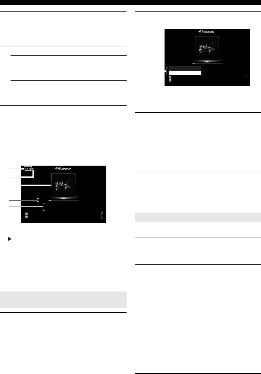
52 En
Using the Rhapsody® service (U.S.A. model only)
3Press jENTER to start playback.
You can also perform the following operations with the
remote control.
y
•To play back the currently selected item (track, album, channel or
playlist) directly, press kPOP-UP MENU, press jCursor k / n to
select “Play” and then press jENTER.
•To display the track list of the album that contains the currently selected
track, press kPOP-UP MENU, press jCursor k / n to select
“Show Album Page” and then press jENTER. (This menu is not
available when you have selected a track from the track list of an album).
■Play information display
a Shuffle and repeat icons
b (playback)
c Album art (image of CD jacket, etc) or channel logo
d Elapsed time, progress bar, total time
e Song title, artist name, album title
y
•You can switch the information displayed on the front panel display by
pressing EINFO (or fINFO) (page 26).
•Album arts or channel logos are available only when the selected service
provides image data.
1Select the desired Rhapsody® item.
2Press kPOP-UP MENU.
y
•Available pop-up menu items vary depending on the menu level or
selected item.
3Press jCursor k / n to select the desired
operation and then press jENTER.
•Select “Add Track to My Library” to add the
currently selected track to “My Library” .
•Select “Add Album to My Library” to add the
currently selected album to “My Library” .
•Select “Add Channel to My Library” to add the
currently selected channel to “My Library” .
4To exit the pop-up menu, press kPOP-UP
MENU.
y
•To remove items from “My Library” , select the item under “My Library”
, press kPOP-UP MENU, press jCursor k / n to select “Remove
from My Library” and then press jENTER.
y
•These settings are also reflected in playback of USB and PC contents.
1Press sOPTION on the remote control
while “Rhapsody” is selected as the input
source.
2Press jCursor k / n to select “Shuffle” or
“Repeat”, press jENTER and then press
jCursor l / h to select the desired
playback style.
Shuffle:
•Select “Off” if you do not want to play back in
random order.
•Select “On” to play back songs in the selected list
in random order.
Repeat:
•Select “Off” if you do not want to play back
repeatedly.
•Select “One” to repeat each song.
•Select “All” to repeat all songs in the selected list.
3To exit the Option menu, press sOPTION.
Key Function
k
pPlay
sStop (pause for “Rhapsody Channels” )
ePause (unavailable for “Rhapsody
Channels”)
aSkip forward
bSkip backward (unavailable for “Rhapsody
Channels” )
Adding your favorite Rhapsody® items to
“My Library”
Input
DSP
a
c
b
e
dMade-to-order
Frankie Zipper
Road to India
Title
Artist
Album
00:15 04:23
Rhapsody
7ch Enhancer
Option Menu
Pop-Up Menu Shuffle/repeat playback
Input
DSP
Made-to-order
Frankie Zipper
Road to India
Title
Artist
Album
00:15 04:23
Rhapsody
7ch Enhancer
Option Menu
Pop-Up Menu
Add Album to My Library
Add Track to My Library
Pop-up menu

53 En
English
INTRODUCTION
ADDITIONAL
INFORMATION APPENDIX
PREPARATION
BASIC
OPERATION
ADVANCED
OPERATION
Use this feature to select the HDMI OUT jack(s) to output
the input signals.
Press gHDMI OUT repeatedly to select the
active HDMI OUT jack(s).
•
y
•This unit automatically activates the HDMI OUT 1 jack when receiving
an HDMI control signal through the HDMI OUT 1 jack while the HDMI
OUT 1 jack is not selected.
You can operate the following functions of this unit with
the remote control of your TV when the TV (HDMI
control function supported) is connected to the HDMI
OUT 1 jack of this unit.
•Turning on this unit or to the standby (conjunction with
TV)
•Adjusting the volume
•Selecting a device to reproduce TV sounds (this unit or
TV)
y
•Even if your TV supports the HDMI control function, some functions
may not be available. For details, refer to the manual supplied with your
TV.
•If you connect this unit and Blu-ray player or DVD player (HDMI
control function supported) with HDMI, you can also control those
devices with the HDMI control function. For details, refer to the manual
supplied with each device.
•We suggest that you use products (TV, Blu-ray/DVD player, etc.) from
the same manufacturer.
•The HDMI control-compatible components include Panasonic VIERA
Link compatible TV, DVD player/recorder and Blu-ray Disc player.
(Steps 1 through 3 are required for the HDMI
control function setup.)
1Turn on all devices connected to this unit
with HDMI.
2Enable the HDMI control function on each
device.
For this unit, set “HDMI Control” to “On” (page 62).
For external devices, refer to the manual supplied
with each device.
3Turn off the TV and then turn on it again.
(Steps 4 through 6 are required for making the TV
learn linked devices. If the connections or
devices are switched, you need to carry out
these steps again.)
4Select this unit as the input source of the TV.
5Turn on the HDMI control device (Blu-ray or
DVD player) connected to this unit.
6Select the HDMI control device (Blu-ray or
DVD player) as the input source of this unit to
check the video input.
7Check if the HDMI control function works
(turn on this unit or adjust the volume level
using the remote control of the TV).
Note
<Note> •In case the HDMI control function does not work, check the
followings. Also, turning off (unplug) and turning on (plug) the TV
may be effective.
–The TV is connected to the HDMI OUT 1 jack of this unit.
–“HDMI Control” is set to “On” on this unit.
–The HDMI control function is enables on the TV.
y
•This unit automatically selects the TV scene (page 24) when you
select this unit as the device to reproduce TV sounds using the
remote control of your TV. That is, if you connect an audio output
jack of your TV to the AV 1 (OPTICAL) jack of this unit, you can
enjoy TV sounds with the specified sound field program soon.
The sleep timer is useful if you want to go to sleep while
this unit is playing or recording a source.
Press qSLEEP repeatedly to select the amount
of time.
The sleep timer setting changes as follows.
If the sleep timer is set, the SLEEP indicator on the front
panel display lights up.
To disable the sleep timer, select “Sleep Off”.
Other functions
Selecting the HDMI OUT jack
HDMI OUT1+2 Outputs the signals from both the HDMI
OUT 1 and HDMI OUT 2 jacks
simultaneously.
HDMI OUT 1 Outputs the signals from the HDMI OUT 1
jack.
HDMI OUT 2 Outputs the signals from the HDMI OUT 2
jack.
HDMI OFF Not to output any signals from the HDMI
OUT jacks. Select this setting when you do
not use the video monitor connected to one
of the HDMI OUT jacks.
Using the HDMI™ control function
HDMI OUT 1+2 HDMI OUT 1
HDMI OUT 2HDMI OUT OFF
Using the sleep timer
Sleep 120min. Sleep 90min.
Sleep 60min.Sleep 30min.Sleep Off
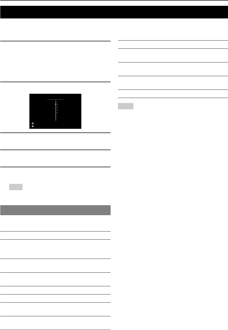
54 En
ADVANCED OPERATION
The Option menu allows users to configure various settings for each input source and reflect corresponding settings
automatically when an input source is switched. Also, you can view the signal information for certain input sources.
The procedure for setting the Option menu items is described below.
1Rotate the TINPUT selector (or press
dInput selection key) to select the
desired input source.
If you press dUSB/NET on the remote control,
press xSub-input selection key to select a
sub-input source.
2Press sOPTION on the remote control.
3Press jCursor k / n to select the desired
menu item and then press jENTER.
4Press jCursor k / n / l / h to select the
desired setting and then press jENTER
5To exit the Option menu, press sOPTION.
To return to the previous menu, press jRETURN.
Note
•In case jCursor k / n / l / h or other keys do not work after
closing the Option menu, press dInput selection key to
select the current input source again.
The following menu items are provided for each input
source.
Notes
*1 Only “Volume Trim” is available when no external device is connected
to the HDMI IN jack.
*2 “Shuffile” and “Repeat” are not available during the simple remote
mode.
Details of the menu items are as follows. The
configuration will be reflected to the input source
currently selected.
y
•The default settings are marked with “*”.
Volume Trim
Reduces any change in volume when switching input
sources by correcting volume differences between input
sources.
Decoder Mode
Selects DTS digital audio signals for reproduction.
Extended Surround
Selects whether to reproduce multi-channel (or 2-channel)
input signals in 6.1- or 7.1-channel when surround back
speakers are used.
Setting the option menu for each input source (Option menu)
Option menu items
Input source Menu items
HDMI1-4
AV1-4
V-AUX*1
Volume Trim, Decoder Mode,
Extended Surround, Signal Info
AV5-6
PHONO
Volume Trim
AUDIO1/2
MULTI CH
Volume Trim, Video Out
iPod (DOCK)*2 Volume Trim, Shuffle, Repeat
NET RADIO (USB/NET) Volume Trim, Signal Info
USB (USB/NET)
Rhapsody (USB/NET)
Volume Trim, Signal Info, Shuffle,
Repeat
PC (USB/NET) Volume Trim, Signal Info, Shuffle,
Repeat, Refresh
Input
DSP
Volume Trim
Decoder Mode
Extended Surround
Signal Info
Option Menu
HDMI 1
Straight
BLUETOOTH (DOCK) Volume Trim, Connect/Disconnect,
Pairing
TUNER Volume Trim, Audio Mode, Auto
Preset, Clear Preset
SIRIUS Volume Trim, Clear Preset, Parental
Lock
XM Volume Trim, Clear Preset
Input source: All
Adjustable range: –6.0dB to 0.0dB* to +6.0dB
(in 0.5 dB steps)
Input source: HDMI1-4, AV1-4, V-AUX
Choices: Auto*, DTS
Auto Automatically selects audio input signals.
DTS Selects DTS signals only. Other input signals
are not reproduced.
Input source: HDMI1-4, AV1-4, V-AUX
Choices: Auto*, PLIIxMovie, PLIIxMusic, EX/ES, Off
Auto Automatically selects the most suitable
decoder if a flag for reproducing surround back
channel is present, and reproduces the signals
in 6.1- or 7.1-channel.
Input source Menu items

55 En
Setting the option menu for each input source (Option menu)
English
INTRODUCTION
ADDITIONAL
INFORMATION APPENDIX
PREPARATION
BASIC
OPERATION
ADVANCED
OPERATION
Signal Info
Displays information on audio and video signals on the
GUI screen and front panel display. You can change items
to be displayed using jCursor k / n.
•Audio information
•
Notes
•“No Signal” is displayed when no signals are input and “---” is displayed
when signals that this unit cannot recognize are input.
•The bit rate may vary during playback.
•Video information
•
•HDMI error message
(appears only when an error has occurred)
•
Audio Mode
Sets FM (or HD Radio) broadcasting receiving mode.
Note
•(U.S.A. model only)
Select “Auto” to tune into HD Radio stations. When “Mono” is selected,
you can tune into analog stations only.
Auto Preset
Automatically detects FM radio stations and registers
them as preset stations (page 31).
y
•(U.S.A. model only)
Automatically detects FM and AM HD Radio stations and analog FM
radio stations and registers them as preset stations.
Clear Preset
Clears preset station (TUNER: page 32, XM: page 37,
SIRIUS: page 41).
Parental Lock
Set the Parental Lock (page 42).
Shuffle
Changes the shuffle playback style.
y
•This setting is shared among the USB/NET sub-input sources (USB, PC
and Rhapsody). For example, the playback style configured for “USB” is
also reflected in “PC” and “Rhapsody”.
Repeat
Changes the repeat playback style.
y
•This setting is shared among the USB/NET sub-input sources (USB, PC
and Rhapsody). For example, the playback style configured for “USB” is
also reflected in “PC” and “Rhapsody”.
PLIIx
Movie
Always reproduces signals in 7.1-channel
using the PLIIxMovie decoder whether or not
surround back channel signals are contained.
You can select this parameter when two
surround back speakers are connected.
PLIIx
Music
Always reproduces signals in 6.1- or 7.1-
channel using the PLIIxMusic decoder whether
or not surround back channel signals are
contained. You can select this parameter when
one or two surround back speakers are
connected.
EX/ES Automatically selects the most suitable
decoder for input signals whether or not the
flag for reproducing surround back channel is
present, and always reproduces signals in 6.1-
channel.
Off Always reproduces original signals whether or
not the flag for reproducing surround back
channel is present.
Input source: HDMI1-4, AV1-4, V-AUX, USB (USB/NET), NET
RADIO (USB/NET), PC (USB/NET), Rhapsody
(USB/NET)
Format Format of digital audio signals.
Channel The number of input signal channels
(front/surround/LFE).
For example, if input signal channels are
3 front channels, 2 surrounds and LFE,
“3/2/0.1” is displayed.
If a channel that cannot be expressed as
the above, a total number of channels
such as “5.1ch” may be displayed.
Sampling
Frequency
The sampling frequency per second in
analog-to-digital conversion.
Bitrate The bit rate of input signal per second.
Video In Format and resolution of video input
signal.
Video Out Format and resolution of video output
signal.
Message Error messages about HDMI signals and
HDMI components. See the following for
details of the error messages.
HDCP Error HDCP authentication failed.
Device Over The number of HDMI components
connected is over the limit.
Out of Res. The connected monitor is not compatible
with the video input signal.
Input source: TUNER
Choices: Auto*, Mono
Auto Receives in stereo mode by priority.
Mono Receives in monaural mode. You can get a
better reception in monaural mode.
Input source: TUNER
Input source: TUNER, XM, SIRIUS
Input source: SIRIUS
Input source: iPod (DOCK), USB (USB/NET), PC (USB/NET),
Rhapsody (USB/NET)
Choices: iPod (DOCK): Off*, Songs, Albums
USB (USB/NET), PC (USB/NET), Rhapsody
(USB/NET): Off*, On
Input source: iPod (DOCK), USB (USB/NET), PC (USB/NET),
Rhapsody (USB/NET)
Choices: Off*, One, All

56 En
Setting the option menu for each input source (Option menu)
Refresh
Updates the PC server list displayed in the GUI screen
(page 48).
Connect / Disconnect
Connects to or disconnects from a Bluetooth component
(page 46).
Pairing
Performs pairing of this unit and a Bluetooth component
(page 46).
Video Out
Specifies a video signal to be output during an audio
reproduction. For details, see “Selecting a video signal to
be output during an audio reproduction” on this page.
This function enables this unit to output video signals
when “AUDIO 1”, “AUDIO 2” or “MULTI CH” is
selected as the input source. Follow the procedure below
to select the video to be output during an audio
reproduction.
1Rotate the TINPUT selector (or press
dInput selection keys) to select “AUDIO
1”, “AUDIO 2” or “MULTI CH” as the input
source.
2Press sOPTION on the remote control.
The Option menu for the selected input source is
displayed.
3Press jCursor k / n to select “Video Out”
and then press jENTER.
4Press jCursor l / h to select a video input
jack to be used during an audio
reproduction.
–AV1-2 (COMPONENT VIDEO)
–AV3-6 (VIDEO)
–Off (no video output)
5To exit the Option menu, press sOPTION.
Input source: PC (USB/NET)
Input source: BLUETOOTH (DOCK)
Input source: BLUETOOTH (DOCK)
Input source: AUDIO 1/2, MULTI CH
Choices: AV 1 t o AV 6 , O f f *
Selecting a video signal to be output
during an audio reproduction
Video;;;;;;Off

57 En
English
INTRODUCTION
ADDITIONAL
INFORMATION APPENDIX
PREPARATION
BASIC
OPERATION
ADVANCED
OPERATION
You can call the Setup menu using the remote control and change the settings of various menus.
For details, read “Basic operation of the Setup menu” first, and see the respective pages.
Operating various settings for this unit (Setup menu)
Menu/Submenu Function Page
Speaker Setup Sets items for speakers. 59
Auto Setup (YPAO) Automatically adjusts output characteristics of speakers. 59
Manual Setup Manually adjusts output characteristics of speakers. 59
Speaker Configuration Sets speaker configurations, such as connection status of speaker and a size of the
connected speaker (sound reproduction capacity), suitable for the listening
environment.
59
Speaker Level Separately adjusts volume of each speaker. 61
Speaker Distance Adjusts timing at which each speaker outputs sound based on distances between
speakers and the listening position.
61
Equalizer Selects an equalizer that adjusts speaker output characteristics. 61
Test Tone Generates test tones. 61
Sound Setup Sets various items for sound outputs. 62
Dynamic Range Adjusts dynamic ranges of speakers and headphones. 62
Lipsync Adjusts delay in output timing between video signals and audio signals. 62
HDMI OUT1 Fine adjusts the delay time of automatic lipsync applied when only the HDMI
OUT 1 jack is used or when both the HDMI OUT 1 and HDMI OUT 2 jacks are
used.
62
HDMI OUT2 Fine adjusts the delay time of automatic lipsync applied when only the HDMI
OUT 2 jack is used.
62
ANALOG MONITOR OUT Adjusts the delay time applied when only the analog MONITOR OUT
(COMPONENT VIDEO or VIDEO) jacks are used.
62

58 En
Operating various settings for this unit (Setup menu)
Function Setup Sets various items for HDMI and display. 62
HDMI Sets various items for input sources. 62
HDMI Control Selects on or off of the HDMI control function when a component that supports
the HDMI control function is connected to the HDMI OUT 1 jack of this unit.
62
Standby Through Selects on or off of output of HDMI signals input from the HDMI 1-4 jacks or
HDMI IN (VIDEO AUX) jack to the active HDMI OUT jack(s) when this unit is
on standby.
62
Audio Output Selects this unit or a component connected to the HDMI OUT 1 jack of this unit
for reproducing sound signals.
62
Resolution Sets resolution of the HDMI output that is converted from analogy visual input
signals.
63
Aspect Set an aspect ratio of images reproduced by HDMI signals converted from analog
video input signals.
63
Display Sets items for a video monitor or the front panel display. 63
Dimmer Sets brightness of the front panel display. 63
Front Panel Display Scroll Selects the way to display characters on the front panel display. 63
GUI Position Adjusts top and bottom positions of the GUI screen displayed on the video
monitor.
63
Volume Sets items for volumes. 63
Adaptive DRC Adjusts the dynamic range (difference between the maximum volume and the
minimum volume) in conjunction with the volume level.
63
Max Volume Sets the maximum volume level so that the volume will not be accidentally
increased.
64
Initial Volume Sets the volume at the time this unit is turned on. 64
Input Rename Changes input source names to be displayed on the GUI screen or the front panel
display.
64
Zone Sets the maximum volume level and initial volume level of Zone2/3. 64
Zone2 Max Volume Sets the maximum volume level of Zone2. 64
Zone2 Initial Volume Sets the volume level of Zone2 applied when this unit is turned on. 64
Zone3 Max Volume Sets the maximum volume level of Zone3. 64
Zone3 Initial Volume Sets the volume level of Zone3 applied when this unit is turned on. 64
Network Sets items for network features. 64
IP Address Sets the network parameters (IP address, etc) manually. 64
MAC Address Filter Sets MAC address filter to restrict access to this unit via LAN. 64
Network Standby Selects whether or not to accept the commands via network when this unit is on
standby.
65
Information Displays network information. 65
Rhapsody Information Sets your Rhapsody® account. 65
Account Status Displays the registration status of your Rhapsody® account. 65
Sign In Registers your Rhapsody® account. 65
Rhapsody Free Trial Subscribes to the Rhapsody® service using 30-day free trial. 65
Remove Account Removes your Rhapsody® account. 65
DSP Parameter Sets parameters for the sound field programs. 65
Memory Guard Protects some settings against accidental alteration. 68
Menu/Submenu Function Page
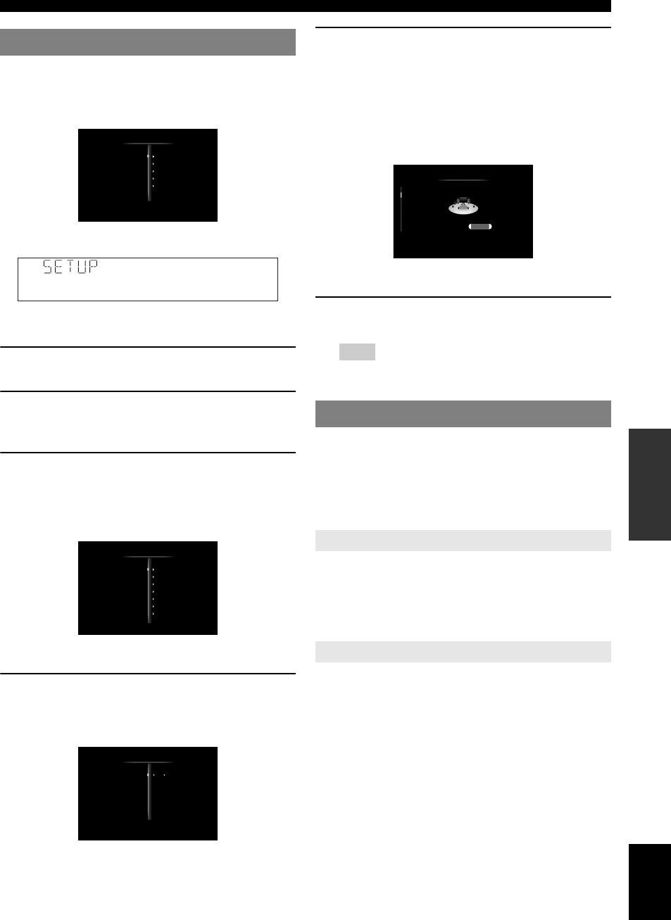
59 En
Operating various settings for this unit (Setup menu)
English
INTRODUCTION
ADDITIONAL
INFORMATION APPENDIX
PREPARATION
BASIC
OPERATION
ADVANCED
OPERATION
The Setup menu screen appears on both the GUI screen
and front panel display.
GUI screen
Front panel display
In this section, procedures of setting menus using the
video monitor are described.
1Press iON SCREEN on the remote control.
The GUI screen appears on the video monitor.
2Press jCursor n to select “Setup” and then
press jENTER.
The Setup menu appears on the video monitor.
3Press jCursor k / n to select the desired
menu then press jENTER.
Items of the selected menu are displayed.
Example (Function Setup)
y
•To return to the previous menu, press jRETURN.
4If necessary, press jCursor k / n to select
the desired submenu then press jENTER.
Example (Volume)
5Press jCursor k / n to select an item to edit
and then press jCursor l / h to change
the setting.
Some items in “Manual Setup” of “Speaker Setup”
take up a full screen. To display other items in
“Manual Setup”, press jCursor k / n.
Example (Speaker Configuration)
y
•To configure other items, repeat step 5.
6To turn off the GUI screen, press iON
SCREEN.
Note
•In case jCursor k / n / l / h or other keys do not work after
closing the Setup menu, press dInput selection key to
select the current input source again.
You can set various items for speakers. Two kinds of
adjustments are available. One is “Auto Setup” (YPAO)
for automatic adjustment and another is “Manual Setup”
for manual adjustment.
y
•The default settings are marked with “*”.
Automatically adjusts output characteristics of speakers to
obtain optimum balance for the output sound based on
positions and performances of the speakers and acoustic
characteristics or the room, which are automatically
measured. For details on operations, see page 21.
Adjusts output characteristics of speakers based on
manually set parameters.
After “Auto Setup” (YPAO) is performed, you can check
automatically adjusted parameters in the “Manual Setup”
menu. Fine adjust the parameters for your preference if
necessary.
■Speaker Configuration
Sets speaker configurations, such as connection status of
speaker and a size of the connected speaker (sound
reproduction capacity), suitable for the listening
environment.
y
•The speaker configuration includes items for defining a speaker size:
“Large” or “Small”. “Large” and “Small” refer to speakers with woofer
diameters 16 cm or larger and smaller than 16 cm, respectively.
Basic operation of the Setup menu
Speaker Setup
Sound Setup
Function Setup
DSP Parameter
Memory Guard
Setup Menu
;SpeakerSetup
HDMI
Display
Volume
Input Rename
Zone
Network
Rhapsody Information
Function Setup
Off
+16.5dB
Off
Volume
Adaptive DRC
Max Volume
Initial Volume
Speaker Setup
Auto Setup
Manual Setup
Speaker Configuration
Front Speaker
LargeSmall

60 En
Operating various settings for this unit (Setup menu)
Extra Speaker Assignment
Selects the application for the EXTRA SP (SP1/SP2)
terminals.
Note
•
When setting “Extra Speaker Assignment” to “Zone2” or “Presence”, surround
back channel signals for main unit are separately output from other channels.
•
When setting “Extra Speaker Assignment” to “Zone2 + Zone3”, surround and
surround back channel signals for main unit are separately output from other
channels.
LFE / Bass Out
Selects speaker(s) for outputting low-frequency
components of the LFE (low-frequency effect sound)
channel or other channels. The output status is as follows.
LFE channel signals
Low-frequency components of other channel signals
Front Speaker
Sets the sizes of front left and right speakers.
Note
•If “LFE / Bass Out” is set to “Front”, “Front Speaker” automatically
switches to “Large” even when it is set to “Small”.
Center Speaker
Sets the size of center speaker.
Surround Speaker
Sets sizes of left and right surround speakers.
y
•When “None” is selected, the sound field programs automatically enter
the Virtual CINEMA DSP mode.
Surround Back Speaker
Sets sizes of left and right surround back speakers.
Choices: Zone2*, Zone2 + Zone3, Presence, None
Zone2 Assigns the SP1 terminals for Zone2 speakers
and disables the SP2 terminals.
Zone2 +
Zone3
Assigns the SP1 terminals for Zone2 speakers
and SP2 terminals for Zone3 speakers.
Presence Assigns the SP1 terminals for presence
speakers and disables the SP2 terminals.
None Disables the EXTRA SP (SP1/SP2)
terminals.
Choices: Subwoofer, Front, Both*
Parameter Subwoofer Front
speakers
Other
speakers
Subwoofer Output Not output Not output
Front Not output Output Not output
Both Output Not output Not output
Parameter Subwoofer Front
speakers
Other
speakers
Subwoofer [1] [2] [2]
Front Not output [3] [2]
Both [3] [4] [2]
[1] Outputs low-frequency components of the channel of speaker,
the size of which is set to “Small”.
[2] Outputs low-frequency components when the sizes of speakers
are set to “Large”.
[3] Outputs low-frequency components of the front left and right
channels and the channel of speaker, the size of which is set to
“Small”.
[4] Outputs low-frequency components of the front left and right
channels.
Choices: Small, Large*
Small Select this when small speakers are
connected. Low-frequency components of the
front left and right channels are output from a
subwoofer.
Large Select this when large speakers are
connected.
Choices: None, Small*, Large
None Select this when no center speaker is
connected. Center channel signals are spread
to front left and right speakers.
Small Select this when a small center speaker is
connected. Low-frequency components of
center channel are output from a subwoofer.
If a subwoofer is not connected they are
output from front speakers.
Large Select this when a large center speaker is
connected.
Choices: None, Small*, Large
None Select this when no surround speakers are
connected. Surround channel signals are
spread to front left and right speakers.
“Surround Back Speaker” automatically
switches to “None” when this is selected.
Small Select this when small surround speakers are
connected. Low-frequency components of
surround channels are output from a
subwoofer. If a subwoofer is not connected
they are output from front speakers.
Large Select this when large surround speakers are
connected.
Choices: None, Large x 1, Small x 1, Large x 2, Small x 2*
None Select this when no surround back speaker
are connected. Surround back channel signals
are output from the surround L/R speakers
and subwoofer. If the subwoofer is disabled,
they are output from the surround L/R
speakers and front speakers.
Large x 1 Select this when one large surround back
speaker is connected.
Small x 1 Select this when one small surround back
speaker is connected.
Large x 2 Select this when two large surround back
speakers are connected.
Small x 2 Select this when two small surround back
speakers are connected.

61 En
Operating various settings for this unit (Setup menu)
English
INTRODUCTION
ADDITIONAL
INFORMATION APPENDIX
PREPARATION
BASIC
OPERATION
ADVANCED
OPERATION
y
•When “Surround Back Speaker” is set to “None”, “PLIIx Movie”,
“PLIIx Music” and “PLIIx Game” of the surround decode mode
(page 29) are not available.
Bass Crossover Frequency
Sets the lower limit of the low-frequency component
output from a speaker with a size set to “Small” (Small x
1, Small x 2) Sound with a frequency below that limit is
output from a subwoofer or front speakers.
If your subwoofer has a volume control or a crossover
frequency control, set the volume to half or the crossover
frequency at the maximum.
Subwoofer Phase
Sets the phase of your subwoofer if bass sounds are
lacking or unclear.
■Speaker Level
Separately adjusts volume of each speaker so that the
sounds form speakers are at the same volume at the
listening position. Items to be displayed vary depending
on the number of speakers connected.
y
•When only one surround back speaker is connected, “SB” appears
instead of “SBL” and “SBR”.
•You can adjust the volume listening to test tones when you set “Test
Tone” to “On” (on this page).
•If your subwoofer has a volume control or a crossover frequency control,
set the volume to half or the crossover frequency at the maximum.
■Speaker Distance
Adjusts timing at which each speaker outputs sound so
that sounds from speakers reach the listening position at
the same time. Set unit (Unit) first and set the distance of
each speaker.
Unit
FR.L / FR.R / CNTR / SUR.L / SUR.R / SBL / SBR /
SWFR / PR.L / PR.R
y
•Available items differ depending on the “Speaker Configuration” settings
(page 59).
•When only one surround back speaker is connected, “SB” appears
instead of “SBL” and “SBR”.
■Equalizer
Adjusts sound quality and tone using a parametric graphic
equalizer.
EQ Type Select
Selects an equalizer type.
GEQ
Adjusts sound quality of each speaker using a graphic
equalizer. The graphic equalizer of this unit can adjust
signal levels in 7 frequency ranges.
To adjust the signal level within each range, press
jCursor l / h to select the desired speaker while
“Channel” is selected, press jCursor k / n to select the
desired frequency band and then press jCursor l / h
to adjust the signal level.
■Test Tone
Switches between on and off of an oscillator that generates
test tones. When “On” is selected, you can adjust the
settings of “Manual Setup” while listening to a test tone.
Choices: 40Hz, 60Hz, 80Hz*, 90Hz, 100Hz, 110Hz, 120Hz,
160Hz, 200Hz
Choices: Normal*, Reverse
Normal Select this not to change the phase of your
subwoofer.
Reverse Select this to reverse the phase of your
subwoofer.
Adjustable range: –10.0dB to +10.0dB (0.5dB step)
Defaults: 0dB (FR.L, FR.R, SWFR, PR.L, PR.R)
–1.0dB (CNTR, SUR.L, SUR.R, SBL, SBR)
Choices: feet (ft)*, meters (m)
feet (ft) Displays the speaker distance in feet.
meters (m) Displays the speaker distance in meters.
Adjustable range: 0.30m to 24.00m (1.0ft to 80.0ft)
Defaults: 3.00m (10.0ft) (FR.L, FR.R, SWFR, PR.L,
PR.R)
2.60m (8.5ft) (CNTR)
2.40m (8.0ft) (SUR.L, SUR.R, SBL, SBR)
Choices: Auto PEQ, GEQ*, Off
Auto PEQ Uses a parametric equalizer selected in
“Auto Setup”. Characteristics of the
currently used parametric equalizer are
displayed below “Auto PEQ”.
GEQ Uses a graphic equalizer. Press jENTER
to adjust the characteristics of the graphic
equalizer.
Off Not use a graphic equalizer.
Channels Front Left, Front Right, Center, Surround Left,
Surround Right, Surround Back Left, Surround
Back Right
Choices: 63Hz, 160Hz, 400Hz, 1kHz, 2.5kHz, 6.3kHz,
16kHz
Adjustable range: –6.0dB to 0dB* to +6.0dB (0.5dB step)
Choices: Off*, On
Off Not generate test tones.
On Generates test tones.

62 En
Operating various settings for this unit (Setup menu)
You can set various items for sound outputs.
■Dynamic Range
Selects the dynamic range adjustment method for
reproducing bitstream signals.
■Lipsync
Adjusts delay between video output and audio output.
This unit automatically adjusts the delay (automatic
lipsync) when a TV that supports the automatic lipsync is
connected to the HDMI OUT 1 or HDMI OUT 2 jack of
this unit and HDMI signals are output only from the
corresponding HDMI OUT jack.
HDMI OUT1
Displays the delay time adjusted by automatic lipsync for
HDMI signals output from the HDMI OUT 1 jack. To fine
adjust the delay time, set an offset time in the “Offset”
field. This offset time is also applied to the signals output
from the HDMI OUT 2 jack when both the HDMI OUT 1
and HDMI OUT 2 jacks are active.
HDMI OUT2
Displays the delay time adjusted by automatic lipsync for
HDMI signals output from the HDMI OUT 2 jack. To fine
adjust the delay time, set an offset time in the “Offset”
field.
ANALOG MONITOR OUT
Adjusts the delay time applied when only the analog
MONITOR OUT (COMPONENT VIDEO or VIDEO)
jacks are used.
You can set various items for HDMI and display.
You can set items for HDMI.
■HDMI Control
Selects on or off of the HDMI control function when a
component that supports the HDMI control function is
connected to the HDMI OUT 1 jack of this unit. When this
parameter is set to “On”, this unit output signals input
from the HDMI 1-4 jacks or HDMI IN (VIDEO AUX)
jack to the video monitor even when this unit is on
standby.
y
•The BHDMI THROUGH indicator lights up in the following cases
while this unit is on standby.
–when the HDMI control function is on
–when the HDMI signal standby-through function is currently working
•When “HDMI Control” is set to “On”, this unit consumes 1 to 3 watts of
power depending on a condition of an HDMI signal passing through this
unit.
■Standby Through
Selects on or off of output of HDMI signals input from the
HDMI 1-4 jacks or HDMI IN (VIDEO AUX) jack to the
active HDMI OUT jack(s) when this unit is on standby.
When this parameter is set to “On”, this unit output signals
input from the HDMI 1-4 jacks or HDMI IN (VIDEO
AUX) jack to the video monitor(s) even when this unit is
on standby.
y
•This parameter is not available when “HDMI Control” is set to “On”.
•To enables HDMI signal standby-through output, any one of the input
sources connected to the HDMI 1-4 jacks or HDMI IN (VIDEO AUX)
jack must be selected before switching to standby.
•When “Standby Through” is set to “On”, the BHDMI THROUGH
indicator lights up. In this state, the amount of power consumption in the
standby mode increases.
■Audio Output
Selects this unit or a component connected to the HDMI
OUT 1 jack of this unit for reproducing sound signals
input from the HDMI 1-4 jacks or HDMI IN (VIDEO
AUX) jack.
Sound Setup
Choices: Min/Auto, STD, Max*
Min/Auto (Min) Sets the dynamic range suitable for
low volume or a quiet environment, such as
at night, for bitstream signals except for
Dolby TrueHD signals.
(Auto) Adjusts the dynamic range for Dolby
TrueHD signals based on input signal
information.
STD Sets the standard dynamic range
recommended for regular home use.
Max Outputs sound without adjusting the
dynamic range of the input signals.
Adjustable range: 0* to 240ms (1 ms step)
Adjustable range: 0* to 240ms (1 ms step)
Adjustable range: 0* to 240ms (1 ms step)
Function Setup
HDMI
Choices: On, Off*
On Enables the HDMI control function.
Off Disables the HDMI control function.
Choices: On, Off*
On Outputs the HDMI signals to the active
HDMI OUT jack(s)
Off Not output the HDMI signals to the HDMI
OUT 1/2 jacks.
Choices: Amplifier*, TV, Amplifier + TV
Amplifier Outputs HDMI sound signals form the
speakers connected to this unit.

63 En
Operating various settings for this unit (Setup menu)
English
INTRODUCTION
ADDITIONAL
INFORMATION APPENDIX
PREPARATION
BASIC
OPERATION
ADVANCED
OPERATION
Note
•Signal formats of audio and visual signals output from this unit to the TV
vary depending on specifications of the monitor.
y
•This parameter is not available when “HDMI Control” is set to “On”.
■Resolution
Upscales the resolution of HDMI output that is converted
from analog video input signals and output from the
HDMI OUT 1/2 jacks.
Notes
•Resolution of the HDMI output converted from 720p or 1080i analog
video signals cannot be upscaled.
•When a video monitor is connected to one of the HDMI OUT 1/2 jacks
and the corresponding HDMI OUT jack is selected (page 53), this unit
automatically detects a resolution that the monitor supports. An asterisk
(*) appears on the left of detected resolution.
•When a video monitor is connected to both of the HDMI OUT 1/2 jacks
and “HDMI OUT 1+2” is selected (page 53), this unit automatically
selects a resolution depending on the lower-resolution monitor.
•If this unit cannot detect the resolution that the monitor supports, set
“MON.CHK” in the advanced setup menu to “SKIP” (page 73) and try
again.
■Aspect
Sets a horizontal to vertical ratio (aspect ratio) of images
reproduced by HDMI signals output from the HDMI OUT
1/2 jacks when the HDMI signals are converted from
analog video input signals by a video conversion function.
Notes
•You cannot change the aspect ratio of the screen when “Resolution” is set
to “Through”.
•This setting is not effective for inputs with the aspect ratio other than 4:3.
•You cannot obtain an effect of the aspect ratio when visual signals are
input from the HDMI 1-4 jacks or HDMI IN (VIDEO AUX) jack or
when 720p, 1080i or 1080p signals are input.
You can set items for a video monitor and the front panel
display.
■Dimmer
Sets brightness of the front panel display. As the value is
lowered, the brightness of the front panel display is
darkened.
Note
•The brightness of display does not become bright in Pure Direct mode
even if the value is increased.
■Front Panel Display Scroll
Selects the way to scroll the screen when a total number of
characters exceed a display area of the front panel display.
■GUI Position
Adjusts the position of the GUI screen displayed on the
video monitor. To move the screen up (or to the right), set
this value larger. To move the screen down (or to the left),
set this value smaller.
You can set items for volumes.
■Adaptive DRC
Adjust the dynamic range in conjunction with the volume
level. This feature is useful when you are listening at
lower volumes or at night. When this function is enabled,
the dynamic range is adjusted as follows.
When the volume level is low: narrow the dynamic range
When the volume level is high: widen the dynamic range
y
•This setting is also effective for headphones.
TV Outputs HDMI sound signals from the
speakers of a TV connected to the HDMI
OUT 1/2 jacks of this unit. Sound output
from the speakers connected to this unit is
muted.
Amplifier +
TV
Outputs HDMI sound signals from the
speakers connected to this unit and the
speakers of a TV connected HDMI OUT 1/2
jacks of this unit.
Choices: Through*, 480p(576p), 720p, 1080i, 1080p
Choices: Through*, 16:9, Smart Zoom
Through Outputs the video signals without changing
the aspect ratio.
16:9 Outputs the video signals that displays 4:3
images on a 16:9 TV with black bands on
the right and left sides of the TV screen.
Smart Zoom Outputs the video signals that displays 4:3
images on a 16:9 TV by stretching right and
left of images to fit on the TV screen.
Display
Adjustable range: –4 to 0*
Choices: Continuous*, Once
Continuous Repeatedly displays all characters by
scrolling.
Once Displays all characters by scrolling once,
halts scrolling and then displays first 14
characters.
Adjustable range: –5 to 0* to +5 (vertical/horizontal direction)
Volume
Choices: Auto, Off*
Auto Adjusts the dynamic range automatically.
Off Not adjust the dynamic range automatically.
Volume : highVolume : low
Input levelInput level
Output level
Output level
Auto
Off Off
Auto

64 En
Operating various settings for this unit (Setup menu)
■Max Volume
Sets the maximum volume level so that the volume will
not be accidentally increased. For example, you can adjust
the volume between –80.0 dB and –5.0 dB (or Mute) when
you set this parameter to “–5.0dB”. The volume increases
to the maximum level when this parameter is set to +16.5
dB (default).
■Initial Volume
Sets the volume at the time this unit is turned on. When
this parameter is set to “Off”, the volume level used when
this unit was set to standby is applied.
Note
•When you set “Max Volume” and “Initial Volume” the setting of “Max
Volume” becomes effective. For example, when you set “Max Volume”
to “–30.0dB” and “Init. Volume” to “0.0dB”, the volume is
automatically set to “–30.0dB” at the next time this unit is turned on.
Changes input source names to be displayed on the front
panel display.
Selecting a name to be displayed from templates
Press jCursor k / n to select the input source name to
edit and then press jCursor l / h to select a new
name from the templates (Blu-ray, DVD, SetTopBox,
etc.).
Entering an original name
Press jCursor k / n to select the input source name to
edit and then press jENTER. Enter up to 9 characters
by selecting one character at a time with the following key
operations.
The following characters are available for input.
A to Z, 0 to 9, a to z, symbols (#, *, –, +, etc.) and space
Sets the maximum volume level and initial volume level
of Zone2/3.
y
•The menu items for Zone2 are available only when “Extra Speaker
Assignment” is set to “Zone2” or “Zone2 + Zone3” (page 60).
•The menu items for Zone3 are available only when “Extra Speaker
Assignment” is set to “Zone2 + Zone3” (page 60).
■Zone2/3 Max Volume
Sets the maximum volume level of Zone2/3, so that the
volume will not be accidentally increased. For example,
you can adjust the volume between –80.0 dB and –5.0 dB
when you set this parameter to “–5.0dB”.
■Zone2/3 Initial Volume
Use this feature to set the volume level of Zone2/3 when
the power of Zone2/3 unit is turned on. When this
parameter is set to “Off”, the volume level used at the time
when the Zone2/3 unit was set to standby is applied.
Note
•The “Zone2 Max Volume” or “Zone3 Max Volume” setting takes priority
over the “Zone2 Initial Volume” or “Zone3 Initial Volume” setting. For
example, if you set “Zone2 Max Volume” to “–30.0dB” and “Zone2
Initial Volume” to “0.0dB”, the volume is automatically set to “–30.0dB”
at the next time the Zone2 unit is turned on.
You can set items for network features.
■IP Address
Sets the network parameters (IP address, etc).
DHCP
Select whether or not this unit obtain the network
parameters (IP address, subnet mask, default gateway,
primary DNS server and secondary DNS server) from the
DHCP server of the connected network.
IP Address
Use this parameter to specify the IP address assigned to
this unit. This value must not be the same as the one used
for other devices in the target network.
Subnet Mask
Use this parameter to specify the subnet mask value
assigned to this unit.
Default Gateway
Use this parameter to specify the IP address of the default
gateway.
DNS Server (P) / DNS Server (S)
Use this parameter to specify the IP address of the primary
and secondary DNS (Domain Name System) servers.
y
•If you have only one DNS address, enter the DNS address in “DNS
Server (P)”. If you have two or more DNS addresses, enter one of them in
“DNS Server (P)” and another in “DNS Server (S)”.
■MAC Address Filter
Sets MAC address filter to restrict access to this unit via
LAN.
MAC Address Filter
Select whether or not to use the MAC address filter
function.
Adjustable range: –30.0dB to +15.0dB, +16.5dB* (5.0 dB step)
Adjustable range: Off*, Mute, –80.0dB to +16.5dB (0.5 dB step)
Input Rename
jCursor l / hSelects a character to edit.
jCursor k / nSelects a character to enter.
jENTER Enters a selected character.
Zone
Adjustable range: –30.0dB to +15.0dB, +16.5dB* (5.0 dB step)
Adjustable range: Off*, Mute, –80.0dB to +16.5dB (0.5 dB step)
Network
Choices: On*, Off
On Select this setting when this unit can obtain
the network parameters from the DHCP
server of the connected network.
Off Select this setting when you set the network
parameters manually.
Choices: Off*, On
Off Disables the MAC address filter function.

65 En
Operating various settings for this unit (Setup menu)
English
INTRODUCTION
ADDITIONAL
INFORMATION APPENDIX
PREPARATION
BASIC
OPERATION
ADVANCED
OPERATION
MAC Address 1-10
Specify MAC addresses of network devices that are
permitted to access to this unit when “MAC Address
Filter” is set to “On”.
■Network Standby
Selects whether or not to accept the commands via
network when this unit is on standby.
y
•When “Network Standby” is set to “On”, the amount of power
consumption in the standby mode increases.
■Information
Displays the network parameters (IP address, etc.) or
vTuner ID assigned to this unit.
You can set your Rhapsody® account.
For information about the Rhapsody® service and how to
play back Rhapsody® contents, see “Using the Rhapsody®
service” (page 51).
■Account Status
Displays the registration status of your Rhapsody®
account. If “Not Available” appears, check the network
settings.
■Sign In
Use this menu to register your Rhapsody® account with
your user name and password provided by Rhapsody®. To
start registration, follow steps 3 and 4 in “Account setup
for Rhapsody®”(page 51).
If an error message appears (page 84), confirm your user
name and password and then try again.
■Rhapsody Free Trial
Use this menu to subscribe to the Rhapsody® service
using 30-day free trial. To subscribe to the free-trial
service, read the description on the GUI screen and then
select “Yes” if you accept the terms and conditions.
If you have subscribed to the free trial service, the
remaining service days and account number (required for
receiving Rhapsody® support) appear on the GUI screen.
■Remove Account
Removes your Rhapsody® account.
Although the field sound programs would satisfy you as
they are with the default parameters, you can arrange
sound effect or decoders suitable for acoustical conditions
of sources or rooms by setting the parameters.
1Press jCursor k / n to select “DSP
Parameter” and then press jENTER.
2Press jCursor k / n to select “Program
Name” and then press jCursor l / h to
select a sound field program to edit.
3Press jCursor k / n to select a parameter to
edit and then press jCursor l / h to
change the setting.
y
•Repeat steps 2 and 3 to change other sound field program
parameters.
DSP Level
Fine adjusts an effect level (level of the sound field effect
to be added). You can adjust the level of the sound field
effect while checking sound levels. Adjust “DSP Level” as
follows.
•The effect sound is too soft.
•There are no differences between effects of the sound
field programs.
→Increase the effect level.
•The sound is dull.
•The sound field effect is added too much.
→Reduce the effect level.
On Permit access to this unit only from network
devices with the specified MAC addresses.
Choices: Off*, On
Off Not accept the commands via network.
On Accept the commands via network.
Rhapsody Information
DSP Parameter
To initialize the parameters of the selected sound field
program, press jCursor n repeatedly to select
“Initialize” and then press jCursor h. Then, press
jCursor h again to execute the initialization or
jCursor l to cancel it.
CINEMA DSP basic parameters
Adjustable range: –6dB to 0dB* to +3dB
Sci-Fi
PLIIx Movie
0dB
16ms
1.0
2ms
1.0
DSP Parameter
Program Name
Decode Type
DSP Level
P. Initial Delay
P. Room Size
Sur. Initial Delay
Sur. Room Size
Sound field parameters Set values
Sound field program
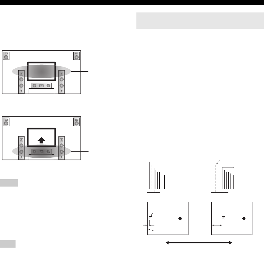
66 En
Operating various settings for this unit (Setup menu)
Dialogue Lift
Use this feature to adjust the vertical position of the
dialogues in movies. The ideal position of the dialogues is
at the center of the video monitor screen.
If the dialogues are heard at the lower position of the video
monitor screen, increase the value of “Dialogue Lift”.
When the value is set to zero, the position is at the lowest.
The position gets higher as you increase the value.
Notes
•This setting is available only when “Extra Speaker Assignment” is set to
“Presence” (page 60).
•You cannot move the dialogue position down from the initial dialogue
position.
3D DSP
When CINEMA DSP 3D is enabled, sets whether to use
sound field programs in 3D mode.
Note
•This setting is available only when “Extra Speaker Assignment” is set to
“Presence” (page 60).
■Parameters for adjusting early-reflected
sound
Initial Delay / P. Initial Delay / Sur. Initial Delay /
Sur. Back Initial Delay
Adjusts attenuation characteristics of early-reflected
sound. You can create a lively sound field (with a high
reverberant sound level) as you increase the value, and a
dead sound field (with a low reverberant sound level) as
you decrease the value. Creating either a lively sound field
or a dead sound field in an actual music hall is determined
by the acoustic absorption characteristics of reflection
surfaces. A dead sound field is created when the
attenuation time is short while a lively sound field is
created when the attenuation time is long.
y
•We recommended that you adjust the size of corresponding sound field
when you adjust the delay time.
■Parameters for specifying room size
Room Size / P. Room Size / Sur. Room Size / Sur.
Back Room Size
Produces different senses of sound expansion according to
room sizes specified. In a large size room such as a music
hall, the duration from when reflected sound is heard until
when the next reflected sound is heard is long. Thus,
different senses of sound expansion can be created by
changing the duration. 1.0 is the original room size. When
this parameter is set to 2.0, each side of the room is
defined as twice larger than the original room size.
Choices: 0* to 5
Choices: On*, Off
The ideal dialogue
position
Move up to the ideal
dialogue position
Sound field parameters for advanced
configurations
Adjustable range: 1 to 99ms (Initial Delay / P. Initial Delay), 1 to
49ms (Sur. Initial Delay / Sur. Back Initial
Delay)
Adjustable range: 0.1 to 2.0
Delay
Time
Level
Delay
Time
Level
Early-reflected
sound
Original source sound
Sound source
Reflecting
surface
Small = 1ms Large = 99ms
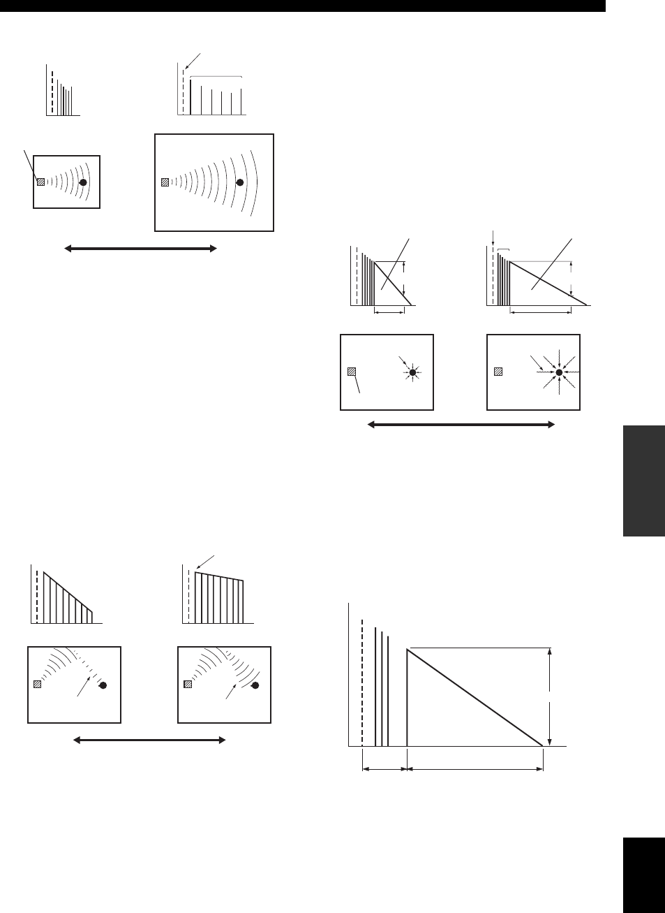
67 En
Operating various settings for this unit (Setup menu)
English
INTRODUCTION
ADDITIONAL
INFORMATION APPENDIX
PREPARATION
BASIC
OPERATION
ADVANCED
OPERATION
■Parameters for defining attenuation
characteristics of early-reflected sound
Liveness / P. Liveness / Sur. Liveness / Sur. Back
Liveness
Adjusts the attenuation of reflected sound. You can create
a lively sound field (with a high reverberant sound level)
as you increase the value, and a dead sound field (with a
low reverberant sound level) as you decrease the value.
Creating either a lively sound field or a dead sound field in
an actual music hall is determined by the acoustic
absorption characteristics of reflection surfaces. A dead
sound field is created when the attenuation time is short
while a lively sound field is created when the attenuation
time is long.
■Parameters for adjusting reverberant sound
Reverb Time
Reverb Time parameter adjusts the attenuation time of the
rear reverberant sound based on the time that about 1kHz
reverberant sound takes for 60dB of attenuation.
Reverberant sound attenuates faster as you decrease the
value. Reverb Time adjustment allows you to create a
natural reverberant sound, by setting the attenuation time
longer for a sound source or room with less echo, or
shorter for a sound source or room with more echo.
Reverb Delay
Reverb Delay parameter adjusts the time difference
between the beginning of the direct sound and the
beginning of the reverberation sound. The larger the value,
the later the reverberation sound begins. Increasing the
value of Reverb Delay allows you to create a reverberant
sound in a wider area for the same Reverb Time.
Adjustable range: 0 to 10
Time
Level
Level
Time
Early reflections
Source sound
Sound source
Small = 0.1 Large = 2.0
Time
Level
Small = 0 Large = 10
Time
Level
Source sound
Live
Dead
Large reflected
sound
Small reflected
sound
Adjustable range: 1.0 to 5.0s
Adjustable range: 0 to 250ms
Time Time
Small = 1.0s Large = 5.0s
Source sound
Rear reverberation Rear
reverberation
Early reflections
Short
reverberation
Long
reverberation
Sound source
Reverb Time Reverb Time
60dB 60dB
Time
Level
Source sound
Reverberation
(dB)
Reverb Delay Reverb Time
60dB

68 En
Operating various settings for this unit (Setup menu)
Reverb Level
Reverb Level parameter adjusts the reverberation sound
level. Increasing the value of Reverb Level makes the
reverbration sound level higher, which allows you to
create more echo.
■Parameter for MOVIE sound field programs
Decode Type
Selects the decoder type for use with the MOVIE sound
field programs.
Note
•You cannot select a decoder for the following MOVIE sound field
programs.
–Mono Movie
–Sports
–Action Game
–Roleplaying Game
■Parameter for 2ch Stereo
Direct
Automatically bypasses the DSP circuit and tone control
circuit when an analog sound source is selected as the
input source. You can enjoy a higher quality sound.
■Parameters for 7ch Stereo
Center Level / Surround L Level / Surround R
Level / Surround Back Level / Presence L Level /
Presence R Level
Adjusts the volume of the center, surround L/R, surround
back and presence L/R channels in the 7ch Stereo
program. The available parameters differ depending on the
setting of the speakers.
■Parameter for Straight Enhancer and 7ch
Enhancer
Effect Level
Adjusts the Compressed Music Enhancer effect level.
When the high-frequency signals of the source is
emphasized too much, set the effect level to “Low”. To
reduce the effect, set this parameter to “Low”.
You can customize decoder effects by setting the
following parameters. For details about the types of
decoders, see “Surround decode mode” (page 29).
■Parameter for PLIIx Music and PLII Music
Panorama
Adjusts the soundscape of the front sound field. Sends
stereo signals to the surround speakers as well as the front
speakers for a wraparound effect.
Dimension
Adjusts the difference in level between the front sound
field and the surround sound field. You can adjust the
difference in level created by the software being played
back to obtain the preferred sound balance. The surround
sound gets stronger as you make the value more negative
and the front sound gets stronger as you make the value
more positive.
Center Width
You can spread the center sound toward left and right
according to your preference. Set this parameter to 0 for
outputting the center sound from the center speaker only,
or to 7 for outputting it from the front left/right speaker.
■Parameter for Neo:6 Music
Center Image
Adjusts the front left and right channel output relative to
the center channel to make the center channel more or less
dominant as necessary.
Protects the Setup menu settings against accidental
alteration.
Note
•When this parameter is switched to “On”, “ ” appears at the top left
corner of the Setup menu screen.
Adjustable range: 0 to100%
Parameters for certain sound field
programs
Choices: PLIIx Movie (PLII Movie), Neo:6 Cinema
Choices: Auto*, Off
Auto Outputs sound by bypassing the DSP circuit and
tone control circuit when the “Bass” and “Treble”
tone controls are both set to 0 dB.
Off Do not bypass the DSP circuit and tone control.
Adjustable range: 0 to 100%
Time
Level
Source sound
Reverb Level
(dB)
Choices: High*, Low
Decoder parameters
Choices: Off*, On
Adjustable range: –3 to STD* to +3
Adjustable range: 0 to 3* to 7
Adjustable range: 0.0 to 0.3* to 1.0
Memory Guard
Choices: Off*, On
Off Not protect settings.
On Protects the Setup menu settings (except for
“Decode Type” in “DSP Parameter” and
“Memory Guard”).
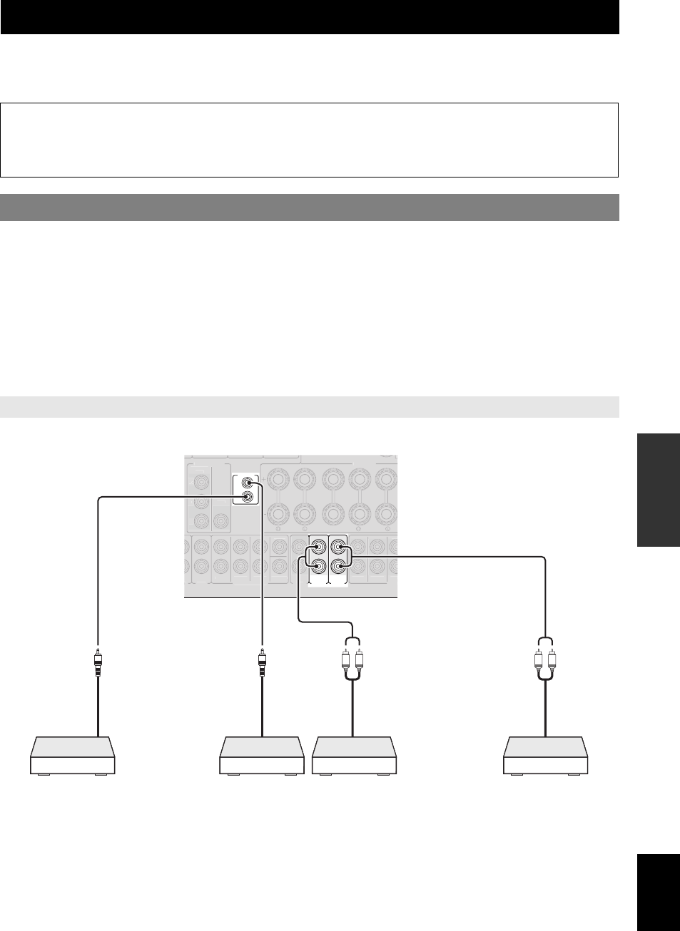
69 En
English
INTRODUCTION
ADDITIONAL
INFORMATION APPENDIX
PREPARATION
BASIC
OPERATION
ADVANCED
OPERATION
This unit allows you to configure a multi-zone audio system. This feature allows you to set this unit to reproduce separate
input sources in the main zone, second zone (Zone2) and third zone (Zone3). You can control this unit from the second
zone or third zone using the supplied remote control.
You need the following additional equipment to use the multi-zone functions of this unit:
•An infrared signal receiver in the second zone and/or third zone.
•An infrared signal emitter in the main zone. This emitter transmits infrared signals from the remote control to a CD
player or a DVD player, etc. in the main zone via the infrared signal receiver in the second zone and/or third zone.
•An amplifier and speakers in the second zone and/or third zone.
y
•Since there are many possible ways to connect and use this unit in a multi-zone configuration, we recommend that you consult with your nearest
authorized Yamaha dealer or service center about the Zone2/3 connections that best meet your requirements.
•Some Yamaha models can be directly connected to the REMOTE jacks of this unit. You may not need use an infrared signal emitter for these products. Up
to 6 components can be connected using monaural analog mini cables or via an IR flashers. For details about connections, see “Transmitting/receiving
remote control signals” (page 18).
Connect an amplifier/receiver in the second zone and/or third zone and other components to this unit as follows.
Using multi-zone configuration
Only analog signal can be sent to the second and third zones. If you want to output sounds to Zone2/3, connect an
external component to the AV5-6 or AUDIO1-2 jacks (by analog connection). For example, if you want to output
sound from an HDMI DVD player to the second zone, you must connect the HDMI DVD player to this unit by both
HDMI and analog connections.
Connecting Zone2/3
Using external amplifiers
ZONE3
OUT
ZONE2
OUT
IN
OUT
REMOTE
O
1AUDI
O
2
F
R
O
N
T
SU
RR
OU
N
D
SU
R.BA
C
K
SU
BW
OO
FER
MU
LTI
C
H INP
UT
A
U
DI
O
OUT
FR
O
NT
S
URR
O
UN
D
S
UR.
B
PRE
O
S
IN
G
VIDE
O
MONITOR OUT
SPEAKER
S
FR
O
NT
C
ENTE
R
S
URR
O
UN
D
Z
O
C
ENTER
P
R
P
B
Y
CO
MP
O
NENT
V
IDE
O
S
LR LR
IR flasher or
Yamaha component
(DVD player, etc)
Remote control in
Remote control out
Analog audio output
Zone2 amplifier
(Yamaha component)
Zone3 amplifier
Analog audio output
IR receiver
in Zone2
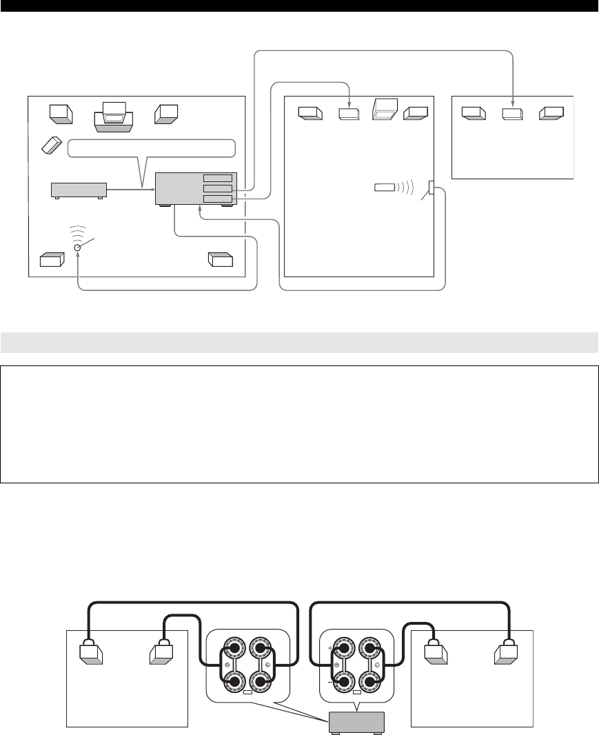
70 En
Using multi-zone configuration
If you want to use one internal amplifier of this unit
Connect the Zone 2 speakers directly to the SP1 terminals and then set “Extra Speaker Assignment” to “Zone2”
(page 60)
If you want to use two internal amplifiers of this unit
Connect the Zone 2 and Zone 3 speakers directly to the SP1 and SP2 terminals and then set “Extra Speaker Assignment”
to “Zone2 + Zone3” (page 60).
y
•You can use the speakers connected to EXTRA SP (SP1/SP2) terminals as the front speaker system of another zone.
•When you use the internal amplifiers for the Zone2/3 speakers, you can adjust the volume level and set the initial volume and maximum volume of the
Zone2/3 speakers (page 64).
Using the internal amplifiers of this unit
Important safety notice
The EXTRA SP terminals of this unit should not be connected to a Passive Loudspeaker Selector Box or more than
one loudspeaker per channel.
Connection to a Passive Loudspeaker Selector Box or multiple speakers per channel could create an abnormally low
impedance load resulting in amplifier damage. See this owner’s manual for correct usage.
Compliance with minimum speaker impedance information for all channels must be maintained at all times. This
information is found on the back panel of your unit.
MAIN
ZONE 2
ZONE 3
Infrared signal
emitter
DVD player etc.
Amplifier
Remote control
Infrared signal
receiver
Amplifier
Second zone
(Zone 2)
Third zone
(Zone 3)
Main zone
This unit
From the ZONE2 OUT jacks
From the ZONE3 OUT jacks
To the REMOTE IN jackFrom the REMOTE OUT jack
Analog audio signals only
ZONE2/PRESENCE
SP1
ZONE3
SP2
Zone3 speakers
This unit
Zone2 speakers

71 En
Using multi-zone configuration
English
INTRODUCTION
ADDITIONAL
INFORMATION APPENDIX
PREPARATION
BASIC
OPERATION
ADVANCED
OPERATION
You can select and control Zone2/3 by using the control
keys on the front panel or on the remote control. The
available operations are as follows:
•Selecting the input source.
•Tuning into the desired station (when “TUNER” is
selected as the input source)
•Tuning into the desired channel (when “XM” or
“SIRIUS” is selected as the input source) (U.S.A. model
only)
•Adjusting the volume of Zone2/3 (when Zone2/3
speakers are connected to the EXTRA SP terminals).
Before controlling Zone2/3 by using the control keys on
the front panel or on the remote control, follow the
procedure below to switch this unit to the Zone2/3
operation mode.
■To control Zone2/3 by using the front panel
control keys
Press DZONE CONTROLS repeatedly to select
the zone you want to control while the target
zone is turned on.
The zone indicator flashes on the front panel display for
approximately 10 seconds.
Note
•Complete each step while the zone indicator is flashing on the front panel
display. Otherwise, the Zone2 or Zone3 operation mode is automatically
canceled and this unit returns to the main zone operation mode.
■To control Zone2/3 by using the remote
control
Switch bZone selection switch to “ZONE2”
or “ZONE3” position.
■Turning on or set Zone2 to standby
Press AZONE2 ON/OFF (or pPOWER).
■Turning on or set Zone3 to standby
Press CZONE3 ON/OFF (or pPOWER).
■Operating Zone2/3
Rotate the TINPUT selector (or press dInput
selection key) to select the desired input
source.
If you press dUSB/NET on the remote control, press
xSub-input selection key to select a sub-input
source.
•Select “AV5”, “AV6”, “AUDIO1”, “AUDIO2” or
“PHONO” to listen to the input source in the selected
zone.
•Select “DOCK” to use the iPod features (page 44) or
Bluetooth features (page 46) in the selected zone.
•Select “TUNER” to use the FM/AM radio features
(page 31) in the selected zone.
•Select “SIRIUS” to use the SIRIUS Satellite Radio
features (page 39) in the selected zone.
•Select “XM” to use the XM Satellite Radio features
(page 35) in the selected zone.
•Select “USB” to use the USB features (page 47) in the
selected zone.
•Select “NET RADIO” to use the Internet Radio features
(page 50) in the selected zone.
•Select “PC” to use the PC features (page 48) in the
selected zone.
•Select “Rhapsody” to use the Rhapsody® features
(page 51) in the selected zone.
Note
•The sub-input source (USB, NET RADIO, PC and Rhapsody) for “USB/
NET” is shared among all zones (main, Zone2 and Zone3). You cannot
select different sub-input source for each zone.
Controlling Zone2/3
Switching to the Zone2/3 operation mode
ZONE
2
Flashes
or
ZONE
3
Flashes
Operations in the Zone2/3 operation mode

72 En
You can control external components for a selected input source with the remote control. The keys available for
controlling external components are as follows:
cSOURCE POWER
Turns on and off an external component.
jCursor, ENTER, RETURN
Operates the menus of external components.
kExternal component operation keys
Function as a recording or playback key of an external
component, or a menu display key.
lNumeric keys
Function as numeric keys of an external component.
mTV control keys
uDISPLAY
Switches between the screens of external components.
y
•You can use mTV control keys to control your TV regardless of a
selected input source if a remote control code for your TV is assigned to
dAV1, dAV4 or dPHONO (in the order of descending priorities).
•You need to set the remote control code first to control external
components.
•The remote control keys for controlling external components are
available only when the external components have corresponding control
keys.
The following remote control codes are assigned to input
sources as factory default settings.
■Default remote control code settings
“—” indicates no assignment
y
•An external component controlled by the remote control is automatically
selected according to selection of the scenes (page 24).
You can control other components by setting the
appropriate remote control codes. For a complete list of
available remote control codes, refer to “List of remote
control codes” at the end of this manual.
You should perform each step within 1 minute after the
previous step.
1Press oCODE SET on the remote control
using a pointed object such as the tip of a
ballpoint pen.
nTRANSMIT blinks twice.
2Press the desired dInput selection key.
To use mTV control keys to control your TV,
assign a remote control code for your TV to dAV1,
dAV4 or dPHONO.
3Press lNumeric keys to enter a remote
control code.
Once the remote control code is registered,
nTRANSMIT blinks twice. If it fails,
nTRANSMIT blinks six times. Repeat from
step 1.
You can reset all remote control codes to the factory
default settings.
1Press oCODE SET on the remote control
using a pointed object such as a tip of a
ballpoint pen.
nTRANSMIT blinks twice.
2Press iON SCREEN.
3Press lNumeric keys to enter “9981”.
Once the initialization is complete, nTRANSMIT
blinks twice. If it fails, nTRANSMIT blinks six
times. Repeat from step 1.
Controlling other components with the remote control
INPUT Switches visual inputs of TV
MUTE Mutes audio of TV
TV VOL +/– Controls the volume of TV
TV CH +/– Switches channels of TV
POWER Turns on and off TV
Input source Category Manufacturer Default
code
[HDMI 1] Blu-ray Disc Yamaha 2018
[HDMI 2] — — —
[HDMI 3] — — —
[HDMI 4] — — —
[AV 1] ———
[AV 2] ———
[AV 3] CD Yamaha 5013
[AV 4] ———
[AV 5] ———
[AV 6] ———
[AUDIO 1] — — —
[AUDIO 2] — — —
[V-AUX] — — —
[PHONO] — — —
[MULTI]———
[DOCK] DOCK Yamaha 5011 (fixed)
[TUNER] Tuner Yamaha 5007 (fixed)
[SIRIUS] Tuner Yamaha 5017 (fixed)
[XM] Tuner Yamaha 5009 (fixed)
[USB/NET] — Yamaha — (fixed)
Setting remote control codes
Resetting all remote control codes
Input source Category Manufacturer Default
code

73 En
English
INTRODUCTION
ADDITIONAL
INFORMATION APPENDIX
PREPARATION
BASIC
OPERATION
ADVANCED
OPERATION
In the advanced setup menu, you can set basic operations
of this unit, such as on and off of a bi-amp connection, or
initialize user settings.
1Set this unit to standby.
2While holding down QSTRAIGHT on the
front panel, press LMAIN ZONE ON/OFF.
Keep holding down QSTRAIGHT until
“ADVANCED SETUP” appears on the front panel
display.
3Rotate the PPROGRAM selector to select
the parameter you want to change.
The default setting are marked with “*”.
y
•Set values are placed in XXX of the following parameters on an
actual display screen.
SP IMP. -XXX
Selects output impedance of this unit according to
connected speakers. When you connect 4-ohm
speakers to the FRONT speaker terminals, set “SP
IMP.” to “6ΩMIN.”.
RS232C STBY -X
Selects whether or not to transmit data via the RS-
232C terminal when this unit is in the standby mode.
REMOTE ID -XXX
Sets a remote control ID. When using multiple
Yamaha AV receivers, you can operate them with a
single remote control by setting the receiver IDs to
the same setting.
SR PIN -XXX
Resets Parental lock cord when using SIRIUS
Satellite tuner.
BI AMP - XXX
Switches on and off of bi-amp connection of main
speakers. For bi-amp connection, see page 12.
SCENE IR -XXX
Selects whether or not to transmit the control signals
to an external component connected to the REMOTE
OUT jack on this unit when BD/DVD or CD SCENE
function is selected.
MON.CHK - XXXX
Adds upscaling limitation on output signals to a video
monitor connected to this unit via the HDMI OUT
jack.
INIT-XXXXXXXXX
Initializes various settings stored in this unit. You can
select an initialization method from the following.
DSP PARAM: All parameters of sound field
programs
VIDEO Video conversion settings (resolution/
aspect) in the Setup menu and the GUI
display position
NETWORK Network settings in the Setup menu
ALL All
CANCEL Cancellation of initialization
USB FirmUpdate
NET FirmUpdate
Updates the firmware of this unit. For details on how
to update the firmware, refer to information supplied
with updates.
Notes
•Do not use this feature unless you need to update the firmware.
•Be sure to read information supplied with updates before updating
the firmware.
VERXXX.XXX.XXX
Displays the firmware of this unit.
4Press OSTRAIGHT repeatedly to change
the selected parameter setting.
To change other settings, repeat steps 3 and 4.
5Press KMAIN ZONE ON/OFF to set this
unit to standby.
The settings you made are reflected next time you
turn on this unit.
Advanced setup
Choices: 6ΩMIN, 8ΩMIN*
Choices: Y (Yes)*, N (No)
Choices: ID1*, ID2
Choices: RESET, CANCEL*
Choices: ON, OFF*
Choices: ON*, OFF
ADVANCEDSETUP
Choices: YES*, SKIP
Choices: DSP PARAM, VIDEO, NETWORK, ALL,
CANCEL*

74 En
Advanced setup
Two IDs are provided for the remote control of this unit. If
another Yamaha amplifier is in the same room, setting a
different remote control ID to this unit prevents unwanted
operation of the other amplifier.
“ID1” is set for both the main unit and remote control by
default. If you have changed the remote control ID, make
sure that you select the same ID for the main unit in the
the advanced setup menu.
y
•For details on how to set the remote control ID of the simplified remote
control, see page 8.
1Press oCODE SET on the remote control
using a pointed object such as the tip of a
ballpoint pen.
nTRANSMIT blinks twice.
2Press iON SCREEN.
3Enter the desired remote control ID code.
To switch to ID1, press lNumeric keys to enter
“5019”.
To switch to ID2, press lNumeric keys to enter
“5020”.
Once the remote control code is registered,
nTRANSMIT blinks twice.
If it fails, nTRANSMIT blinks six times. Repeat
from step 1.
y
•If you initialize the settings of this unit, “REMOTE ID” (remote control
code of this unit) is set to “ID1”.
Setting a remote control ID

75 En
English
INTRODUCTION APPENDIX
PREPARATION
BASIC
OPERATION
ADVANCED
OPERATION
APPENDIX
Refer to the table below when this unit does not function properly. If the problem you are experiencing is not listed below
or if the instruction below does not help, turn off this unit, disconnect the power cable, and contact the nearest authorized
Yamaha dealer or service center.
Troubleshooting
General
Problem Cause Remedy See
page
This unit does not
operate properly.
The internal microcomputer is frozen due
to an external electric shock (such as
lightning or excessive static electricity) or
by a drop in power supply voltage.
Disconnect the power cable from the AC wall outlet,
wait about 30 seconds and then plug it in again.
—
This unit suddenly
enters the standby
mode
The internal temperature is too high and
the overheat protection circuitry has been
activated.
Wait about 1 hour for this unit to cool down and then
turn it back on.
—
The protection circuitry has been activated
because of a short circuit, etc.
Check that the speaker impedance setting is correct. 73
Check that the speaker wires are not touching each
other and then turn this unit back on.
—
The sleep timer has turned off this unit. Turn on this unit and play the source again. —
This unit fails to turn
on or enters the
standby mode soon
after the power is
turned on.
The power cable is not connected or the
plug is not completely inserted.
Connect the power cable properly to an AC wall
outlet.
20
The speaker impedance setting is
incorrect.
Set the speaker impedance to match your speakers. 73
(When this unit is turned back on and
“CHECK SP WIRES!” is displayed.) The
protection circuitry has been activated
because this unit was turned on while a
speaker cable was shorted.
Make sure that all speaker cables between this unit
and speakers are connected properly.
11
This unit cannot be
turned off.
The internal microcomputer is frozen due
to an external electric shock (such as
lightning or excessive static electricity) or
by a drop in power supply voltage.
Disconnect the power cable from the AC wall outlet,
wait about 30 seconds and then plug it in again.
—

76 En
Troubleshooting
No picture. An appropriate video input is not selected
on the video monitor.
Select an appropriate video input on the video
monitor.
—
An appropriate HDMI OUT jack is not
selected.
Select the HDMI OUT jack which your video
monitor is connected.
53
The external video component is
connected to one of the HDMI 1-4 jacks
or HDMI IN (VIDEO AUX) jack while
your video monitor is connected to the
MONITOR OUT (COMPONENT
VIDEO or VIDEO) jacks.
Connect the external video component to the video
input jacks other than the HDMI 1-4 jacks or connect
the video monitor to one of the HDMI OUT jacks or
HDMI IN (VIDEO AUX) jack.
14, 16
This unit outputs the video signals not
supported by the video monitor connected
to one of the HDMI OUT jacks.
Displays the advanced setup menu and select
“VIDEO” in “INIT” to reset the video parameters.
73
Displays the advanced setup menu and set
“MON.CHK” to “YES”.
73
Video signals are input from a game
console while your video monitor is
connected to one of the HDMI OUT jacks.
Connect the video monitor to the MONITOR OUT
(COMPONENT VIDEO) jacks.
14
Non-standard video signals are input. Connect the video monitor to the MONITOR OUT
(COMPONENT VIDEO or VIDEO) jacks.
14
The picture is
disturbed.
The video software is copy-protected.
No sound. Incorrect input or output cable
connections.
Connect the cables properly. If the problem persists,
the cables may be defective.
16
No appropriate input source has been
selected.
Rotate the TINPUT selector (or press dInput
selection key) to select the desired input source.
24
Speaker connections are not secure. Secure the connections. 11
The volume is turned down or muted. Turn up the volume. 24
Signals this unit cannot reproduce are
being input from a source component,
such as a CD-ROM.
Display “Signal Info” in the Option menu and check
the input signal format.
If “No Signal” is displayed, check if the playback
component is properly connected to this unit (or a
proper input source is selected).
If “___” is displayed, the input signal in that format
cannot be reproduced by this unit.
—
The HDMI components connected to this
unit do not support the HDCP copy
protection standards.
Connect HDMI components that support the HDCP
copy protection standards.
92
“Audio Output” in “HDMI” is set to
“TV”.
Set “Audio Output” (Function Setup → HDMI →
Audio Output) to the other setting.
62
A proper audio decoder is not selected. Display the Option menu and set “Decoder Mode” to
“Auto”.
54
Only the center
speaker outputs
substantial sound.
When a monaural source sound field
program is applied, sound of all channels
are output from the center speaker for
some surround decoders.
Try another sound field program. 27
The playback component or speakers are
not connected properly.
Connect the cables properly. If the problem persists,
the cables may be defective.
12, 16
Problem Cause Remedy See
page

77 En
Troubleshooting
English
INTRODUCTION APPENDIX
PREPARATION
BASIC
OPERATION
ADVANCED
OPERATION
No sound is output
from a specific
speaker.
Output from that speaker is disabled. Check the Speaker indicators on the front panel
display. If the corresponding indicator is turned off,
try the following.
1) Change the input source to another one.
2) With the selected sound field program, sound is not
output from that speaker. Select another sound field
program.
3) “None” may have been selected for that speaker on
this unit. Display “Speaker Setup” in the “Setup”
menu and enables output of that speaker.
6, 24, 27,
59
The volume of that speaker is set to
minimum in “Speaker Setup” in the
“Setup” menu.
Display “Speaker Setup” in the “Setup” menu and
adjust the volume (Manual Setup → Speaker Level).
61
This unit is in the straight decode mode. Press QSTRAIGHT (or rSTRAIGHT) to turn
off the straight decode mode.
30
Sound may not be output from certain
channels depending on input sources or
sound field programs.
Try another sound field program. 27
The speaker is malfunction. Check the speaker indicators on the front panel
display. If the corresponding indicator lights up,
connect another speaker and check if sound is output.
If sound is not output, this unit may be malfunction.
—
No sound is heard
from the subwoofer.
“LFE / Bass Out” is set to “Front” and a
Dolby Digital, DTS or AAC signals is
being played.
Set “LFE / Bass Out” to “Subwoofer” or “Both”. 60
“LFE / Bass Out” is set to “Subwoofer” or
“Front” and a 2-channel source is being
played.
Set “LFE / Bass Out” to “Both”. 60
The source does not contain low
frequency signals.
No sound is heard
from the surround
back speakers.
“Extended Surround” in the Option menu
is set to “Off”, or an input signal does not
contain a surround back flag with
“Extended Surround” set to “Auto”.
Set “Extended Surround” other than “Off” or “Auto”. 54
The audio input
sources cannot be
played in the desired
digital audio signal
format.
The connected component is not set to
output the desired digital audio signals.
Set the playback component properly referring to its
operating instructions.
—
Multi-channel
playback is not
available.
The connected component is set to output
2-ch or PCM signals.
Set the playback component properly referring to its
operating instructions.
—
“Audio Output” is set to “Amplifier +
TV”.
Set “Audio Output” to “Amplifier”. 62
Problem Cause Remedy See
page

78 En
Troubleshooting
Noise/hum noise is
heard.
Incorrect cable connection. Connect the audio cables properly. If the problem
persists, the cables may be defective.
—
A DTS-CD is being played back. 1) When only noise is output
If a DTS bitstream signal is not properly input to this
unit, only noise is output. Connect the playback
component to this unit by digital connection and play
back the DTS-CD. If the condition is not improved,
the problem may results from the playback
component. Consult the manufacturer of the playback
component.
2) When noise is output during playback or skip
operation
Before playing back the DTS-CD, display the Option
menu after selecting the input source and set
“Decoder Mode” to “DTS”.
16, 54
The volume level
cannot be increased,
or the sound is
distorted.
The component connected to the AUDIO
1/2 jacks of this unit is turned off.
Turn on the power of the component. 72
“Memory Guard!” is
displayed and the
setting cannot be
changed.
“Memory Guard” in “Set Menu” is set to
“On”.
Set “Memory Guard” to “Off”. 68
There is noise
interference from
digital or radio
frequency equipment.
This unit is too close to other digital or
radio frequency equipment.
Move this unit further away from such equipment. —
HDMI™
Problem Cause Remedy See
page
No picture or sound. The number of the connected HDMI
components is over the limit.
Disconnect some of the HDMI components. —
The connected HDMI component does not
support high-bandwidth digital copyright
protection (HDCP).
Connect an HDMI component that supports HDCP. 92
Problem Cause Remedy See
page

79 En
Troubleshooting
English
INTRODUCTION APPENDIX
PREPARATION
BASIC
OPERATION
ADVANCED
OPERATION
Tuner (FM/AM)
Problem Cause Remedy See
page
FM
FM stereo reception is
noisy.
You are too far from the station
transmitter or the input from the
antenna is weak.
Check the antenna connections. 20
Replace the outdoor antenna with a more
sensitive multi-element antenna.
—
Switch to monaural mode. 55
There is distortion, and
clear reception cannot
be obtained even with a
good FM antenna.
There is multi-path interference. Adjust the antenna height or orientation, or
place it in a different location.
—
The desired station
cannot be tuned into
with the automatic
tuning method.
You are in an area far from a station or
an input from the antenna is weak.
Replace an outdoor antenna with more
sensitive multi element antenna.
—
Tune in manually or by direct frequency
tuning.
31
AM
The desired station
cannot be tuned into
with the automatic
tuning method.
The signal is weak or the antenna
connections are loose.
Adjust the AM loop antenna orientation. 20
Use the manual tuning method. 31
There are continuous
crackling and hissing
noises.
Supplied AM loop antenna is not
connected.
Connect the AM loop antenna correctly even
if you use an outdoor antenna.
20
The noises may be caused by lightning,
fluorescent lamps, motors, thermostats
and other electrical equipment.
It is difficult to completely eliminate noise,
but it can be reduced by installing and
properly grounding an outdoor AM antenna.
20
There are buzzing and
whining noises.
A TV set is being used nearby. Move this unit away from the TV set. —
HD Radio™ Reception (U.S.A. model only)
Problem Cause Remedy See
page
This unit cannot
receive the HD Radio
signals of the
selected radio station.
The radio station provides analog FM/AM
radio service only.
Select other radio stations that provides the HD Radio
service.
33
The signal is too weak. Adjust the antenna position. —
Use a high-quality FM/AM antenna. —
“Audio Mode” in the Option menu is set
to “Mono”.
Set “Audio Mode” to “Auto”. 55
This unit cannot
select other audio
programs than the
main program.
The radio station provides one audio
program only.
HD Radio information
does not appear.
The radio station does not provide the
information.

80 En
Troubleshooting
If an operation takes longer than usual or an error occurs, one of the following messages may appear on the GUI screen.
In this case, read the cause and follow the corresponding remedies.
iTunes Tagging (U.S.A. model only)
Problem Cause Remedy See
page
Tag data cannot be
transferred to your
iPod when it is station
in the Yamaha iPod
universal dock (YDS-
10).
“YDS-10” does not support tag file
transfer.
Use “YDS-11” to transfer tag data from this unit to
your iPod.
—
Status message Cause Remedy See
page
Insufficient Data Tag data is not saved because of invalid
data.
The selected HR Radio program (or song being
played) does not support the iTunes Tagging feature.
—
Tag Already Stored Tag data for the same content has been
already saved.
Tag Storage full Tag data cannot be stored because the
internal memory of this unit is full.
Station your iPod in the Yamaha iPod universal dock
(YDS-11) connected to the DOCK terminal of this
unit.
—
iPod full
Tags cannot be stored
Tag data cannot be stored on your iPod
because the HDD space of your iPod is
full.
Delete unnecessary data from your iPod to make
room and try again.
—
Transferring Failed Tag data cannot be transferred to your
iPod.
Check if the iPod is stationed in the Yamaha iPod
universal dock (YDS-11) properly.
—
Storing Tag Tag data is being stored in the internal
memory of this unit.
Transferring Tag data is being transferred to your iPod.
Tag(s)Sent Tag data has been transferred to your
iPod.
XM Satellite Radio (U.S.A. model only)
Status message Cause Remedy See
page
CHECK XM TUNER The XM Mini-Tuner is not installed in the
XM Mini-Tuner Home Dock or the XM
Mini-Tuner Home Dock is not connected
to this unit.
Confirm the XM Mini-Tuner is fully seated in the
dock and check the XM Mini-Tuner Home Dock
cable is connected to this unit.
35
CHECK ANTENNA The XM antenna is not connected to the
XM Mini-Tuner Home Dock or the XM
antenna cable has become damaged.
Check that the XM antenna is securely connected to
the XM Mini-Tuner Home Dock and check the
antenna cable for damage. Replace the XM antenna if
the cable is damaged.
35
LOADING XM The XM Mini-Tuner is acquiring audio or
program information from the XM
satellite signal. This message can also
occur in weak XM signal conditions. Note
that this unit may not respond to some
operations while this message is
displayed.
This message should disappear in a few seconds in
good signal conditions. If you see this message often,
reposition the XM antenna to get better signal
reception. Use the “Antenna” information on the front
panel display or XM information on the GUI screen
to check the antenna reception level.
38

81 En
Troubleshooting
English
INTRODUCTION APPENDIX
PREPARATION
BASIC
OPERATION
ADVANCED
OPERATION
If an operation takes longer than usual or an error occurs, one of the following messages may appear on the GUI screen.
In this case, read the cause and follow the corresponding remedies.
NO SIGNAL The XM Mini-Tuner is not receiving the
XM satellite signal. Something may be
blocking the XM antenna’s view of the
satellites or the antenna is not properly
aimed.
Check for antenna obstructions and reposition the
XM antenna to get better signal reception. Use the
“Antenna” information on the front panel display or
XM information on the GUI screen to check the
antenna reception level. See instructions supplied
with the XM Mini-Tuner and Dock for antenna
installation information.
38
CHANNEL OFF AIR The XM channel you selected is not
currently broadcasting.
Check back at a later time; in the meantime, select
another channel.
—
CHANNEL NOT
AUTHORIZED
You may be attempting to tune to an XM
channel that is blocked or that you cannot
receive with your XM subscription
package.
Consult the latest channel guide at
http://www.xmradio.com/ for the current list of
channels. For information on receiving this channel,
visit http://www.xmradio.com/ or contact XM
Satellite Radio at 1-800-967-2346.
—
CHANNEL NOT
AVAILABLE
The selected channel is not available. The
channel may have been reassigned to a
different channel number. This message
may occur initially with a new XM Mini-
Tuner or an XM Mini-Tuner that has not
received XM’s signal for an extended
period.
Consult the latest channel guide at
http://www.xmradio.com/ for the current list of
channels. For cases of a new XM Mini-Tuner or an
XM Mini-Tuner that has not received XM’s signal for
an extended period, allow the XM Mini-Tuner to
receive the XM satellite signal for at least 5 minutes
and then try to select the channel again.
—
- - - - No artist name or song title is available for
this selection.
No action required. —
SIRIUS Satellite Radio (U.S.A. model only)
Status message Cause Remedy See
page
ANTENNA ERROR The antenna is not connected to the
SiriusConnect tuner properly.
Check the connection of the antenna and
SiriusConnect tuner.
39
SIRIUS LOADING This unit is communicating with the
SiriusConnect tuner.
The message disappears normally within several tens
of seconds.
—
CHECK SIRIUS
TUNER
The SiriusConnect tuner is not connected
to the SIRIUS jack of this unit correctly.
Check the connection of the SiriusConnect tuner and
this unit.
39
The SiriusConnect tuner is not connected
to the AC wall outlet.
Connect the power cable of the SiriusConnect tuner to
the AC wall outlet.
39
NOT SUPPORTED This unit does not support the connected
SIRIUS Satellite Radio tuner.
Connect the SiriusConnect tuner that this unit
supports,
39
ACQUIRING SIGNAL The signal is too weak. Adjust the orientation of the antenna of the
SiriusConnect tuner. Use the “Antenna” information
on the front panel display or SIRIUS information on
the GUI screen to check the antenna reception level.
43
UPDATING The SiriusConnect tuner is updating the
channel list.
Wait until the updating is complete. —
The period of the subscription is end. Contact SIRIUS Satellite Radio to renew the
subscription.
39
F/W UPDATING The SiriusConnect tuner is updating the
firmware.
Wait until the updating is complete. —
Status message Cause Remedy See
page

82 En
Troubleshooting
CALL 888-539-SIRIUS
TO SUBSCRIBE
The selected channel is not subscribed. Contact SIRIUS Satellite Radio to subscribe the
selected channel.
URL: https://activate.siriusradio.com/
Phone: 1-888-539-SIRIUS (1-888-539-7474)
39
Select another channel. 39
SUBSCRIPTION
UPDATED
The subscription information is updated.
INVALID CHANNEL The selected channel is currently out of
service.
Select another channel. 39
Not Available The operation you made is not available.
Remote control
Problem Cause Remedy See
page
The remote control
does not work or
function properly.
Wrong distance or angle. The remote control will function within a maximum
range of 6 m (20 ft) and no more than 30 degrees
offaxis from the front panel.
6
Direct sunlight or lighting (from an
inverter type of fluorescent lamp, strobe
light, etc.) is striking the remote control
sensor of this unit.
Adjust the lighting angle or reposition this unit. —
The batteries are weak. Replace all batteries. 6, 8
The remote control ID of the remote
control and this unit do not match.
Match the remote control ID of this unit and the
remote control.
74
The remote control code is not correctly
set.
Set the remote control code correctly using “List of
remote control codes” at the end of this manual.
72
Try setting another code of the same manufacturer
using “List of remote control codes” at the end of this
manual.
72
If this unit does not work when you press jCursor,
do the following.
When the key does not work during DVD disc menu
operation: press the dInput selection keys on
the remote control again.
When the key does not work during Option menu or
Setup menu operation: press the key applicable for
the current menu operation again.
—
Even if the remote control code is
correctly set, there are some models that
do not respond to the remote control.
Status message Cause Remedy See
page

83 En
Troubleshooting
English
INTRODUCTION APPENDIX
PREPARATION
BASIC
OPERATION
ADVANCED
OPERATION
Note
•In case of a transmission error without a status message appearing on the front panel display and GUI screen, check the connection of your iPod
(page 18).
iPod™
Status message Cause Remedy See
page
Loading... This unit is in the middle of recognizing
the connection with your iPod.
This unit is in the middle of acquiring
song lists from your iPod.
Connect error There is a problem with the signal path
from your iPod to this unit.
Turn off this unit and reconnect the Yamaha iPod
universal dock to the DOCK terminal of this unit.
18
Remove your iPod in the Yamaha iPod universal dock
and then place it back in the dock.
44
Unknown iPod The iPod being used is not supported by
this unit.
Use an iPod supported by this unit. —
iPod Connected Your iPod is properly placed in the
Yamaha iPod universal dock.
Disconnected Your iPod is removed from the Yamaha
iPod universal dock.
44
Unable to play This unit cannot play back the songs
currently stored on your iPod.
Check that the songs currently stored on your iPod
are playable.
—
Bluetooth™
Status message Cause Remedy See
page
Searching... The Bluetooth wireless audio receiver and
the Bluetooth component are in the
middle of the pairing.
The Bluetooth wireless audio receiver and
the Bluetooth component are in the
middle of establishing the connection.
Completed The pairing is completed.
Canceled The pairing is canceled.
BT Connected The connection between the Yamaha
Bluetooth wireless audio receiver and the
Bluetooth component is established.
Disconnected The Bluetooth component is disconnected
from the Yamaha Bluetooth wireless
audio receiver.
Not Found No Bluetooth components are found
during a pairing process.
Pairing must be performed on the both this unit and
your Bluetooth component at the same time. Check
whether your Bluetooth component is set to the
paring mode and then try again.
46
No Bluetooth components are found
during a Bluetooth connection.
Check whether your Bluetooth component is turned
on and then try again.
46
Locate your Bluetooth component within 10 meters
(33 feet) of this unit and then try again.
46

84 En
Troubleshooting
USB and network
Problem Cause Remedy See
page
The music files and
folders in the USB
storage device cannot
be browsed.
The music files and folders are stored the
locations other than the FAT area.
Place the music files and folders in the FAT area. —
You are attempting to browse directory
hierarchies of over 8 levels or a directory
with more than 500 files.
Modify the data structure on your USB storage
device.
—
This unit cannot recognize some
characters used in the file name or folder
name.
Edit the file name or folder name using a PC and then
try again.
—
The USB storage
device cannot be
recognized.
The USB storage device is not compatible
with mass storage class (except USB
HDDs).
Use a USB storage device that is compatible with
mass storage class (except USB HDDs).
—
This unit does not recognize the USB
storage device properly.
Turn this unit off and then turn on again. 20
The PC server/
Internet Radio/
Rhapsody® does not
function properly.
The network cable is not connected
properly.
Connect the network cable properly. 19
The IP address is not set properly. Set the DHCP server function of the router to ON.
Alternately, perform manual configuration according
to the current operating environment.
64
The music on the PC
server cannot be
played back.
The PC does not have Windows Media
Player 11 installed on it.
Install Windows Media Player 11 on the PC. —
The music is recorded in a format that
cannot be played on this unit. This unit
cannot play music formats other than
WAV (PCM format only), MP3, WMA,
MPEG-4 AAC or FLAC. Also note some
music files cannot be played regardless of
the file formats.
Play music recorded in a format that this unit is
compatible with.
—
Internet Radio
stations cannot be
played.
The firewall of the network device is
activated. Internet Radio stations can only
be played when the signal pass through
the port designated by the individual radio
stations. The port number varies from
station to station.
Check the firewall setting of the network device. —
Connection to the Internet is not available. Check the configuration of the network device and
contact your Internet service provider.
—
Skip forward
operation becomes
not available during
playback of a
Rhapsody® channel.
Skip forward works up to 30 times every 3
hours during playback of a Rhapsody®
channel.
—
Status message Cause Remedy See
page
USB Connected Your USB storage device is connected. —
USB Disconnected Your USB storage device has been
disconnected from the USB port of this
unit.
Check the connection between this unit and your
USB storage device.
—

85 En
Troubleshooting
English
INTRODUCTION APPENDIX
PREPARATION
BASIC
OPERATION
ADVANCED
OPERATION
Access Error
(ACCESS ERROR)
This unit cannot access your USB storage
device.
Try another USB storage device. —
There is a problem with the signal path
from your USB storage device to this unit.
Turn off this unit and reconnect your USB storage
device to the USB port of this unit.
19, 20
Try resetting your USB storage device. —
This unit cannot connect to the data server
due to network error, etc.
Check the network settings and contact your Internet
service provider.
64
Access Denied The PC you are attempting to connect has
denied connection.
Configure the sharing setting of Windows Media
Player 11 and select this unit as a device to which
music contents are shared.
48
Unable to play This unit cannot play back the songs
currently stored on your PC.
Make sure Windows Media Player 11 is installed on
your PC.
—
Play music recorded in a format that this unit is
compatible with (WAV (PCM format only), MP3,
WMA, MPEG-4 AAC or FLAC).
—
License unavailable You are attempting to play back expired
digital rights management (DRM)
encrypted content.
Select a file that is not protected by DRM —
Windows Media Player 11 does not
acquire the digital rights management
(DRM) license for the file.
Acquire the license to play back the file on Windows
Media Player 11.
—
LOGIN OK You have successfully logged into the
Rhapsody® account.
LOGIN FAILED Your attempt to log in to the Rhapsody®
account failed because of an incorrect user
name.
Retry with the correct user name. 51
WRONG PASSWORD Your attempt to log in to the Rhapsody®
account failed because of an incorrect
password.
Retry with the correct password. 51
x days left Your trial account will be expired in x
days.
Sign up for Rhapsody® to use the service
continuously.
For more information,
http://www.rhapsody.com/yamaha/go
65
Your account has
expired
Your account has already expired. Sign up for Rhapsody® to use the service
continuously.
For more information,
http://www.rhapsody.com/yamaha/go
65
No Contents No Rhapsody® items match your search
keyword.
Retry with another keyword. 51
No Rhapsody® items exist in “My
Library”.
Add your favorite Rhapsody® items to “My Library”. 52
Skip Limit Reached Skip forward works up to 30 times every 3
hours during playback of a Rhapsody®
channel.
It will be resumed in 3 hours or after once you stop
the playback.
51
Status message Cause Remedy See
page

86 En
Troubleshooting
Notes
•If the an error or warning message appears, resolve the problem and then run “Auto Setup” again.
•Warning message “W-2” or “W-3” indicates that the adjusted settings may not be optimal.
•Depending on the speakers, warning message “W-1” may appears even if the speaker connections are correct.
•If error message “E-10” occurs repeatedly, contact a qualified Yamaha service center.
Auto Setup (YPAO)
Before Auto Setup
Error message Cause Remedy See
page
Connect MIC! Optimizer microphone is not connected. Connect the supplied optimizer microphone to the
OPTIMIZER MIC jack on the front panel.
21
Unplug HP! Headphones are connected. Unplug the headphones. —
Memory Guard! The parameters of this unit are protected. Set “Memory Guard” to “Off”. 68
During Auto Setup
Error message Cause Remedy See
page
E-1:NO FRONT SP Front L/R channel signals are not
detected.
Check the front L/R speaker connections. 11
E-2:NO SUR. SP Only a signal from one of the surround
channels are detected.
Check the surround L/R speaker connections. 11
E-3:NO PRNS SP Only signals from one of the presence L/
R channels are detected.
Check the presence L/R speaker connections. 11
E-4:SBR->SBL Only right surround back channel signal
is detected.
If you connect only one surround back speaker,
connect it to the left SUR.BACK (SINGLE) jack.
11
E-5:NOISY Measurement cannot be performed
accurately due to loud ambient noise.
Try running “Auto Setup” in a quiet environment. —
Turn off noisy electric equipment like air
conditioners or move them away from the optimizer
microphone.
—
E-6:CHECK SUR. Surround back speakers are connected,
though surround L/R speakers are not.
When using surround back speakers, you need to
connect surround L/R speakers.
11
E-7:NO MIC The optimizer microphone was
unplugged during the “Auto Setup”
procedure.
Do not touch the optimizer microphone during “Auto
Setup”.
21
E-8:NO SIGNAL The optimizer microphone does not
detect test tones.
Check whether the microphone is properly placed. 21
Check whether the speakers are properly placed and
connected.
10, 11
The optimizer microphone or OPTIMIZER MIC
jack may be defective. Contact the nearest Yamaha
dealer or service center.
—
E-9:USER CANCEL “Auto Setup” was canceled due to an
inappropriate user operation.
Run “Auto Setup” again. 21
E-10:INTERNAL
ERROR
An internal error occurred. Run “Auto Setup” again. 21

87 En
Troubleshooting
English
INTRODUCTION APPENDIX
PREPARATION
BASIC
OPERATION
ADVANCED
OPERATION
After Auto Setup
Error message Cause Remedy See
page
W-1:OUT OF PHASE Speaker polarity is not correct. This
message may appear depending on the
speakers even when the speakers are
connected correctly.
Check the polarities (+, –) of the displayed speaker.
If they are correct, the speakers work properly even
when this message is displayed.
12
W-2:OVER 24m (80ft) The distance between the speaker and the
listening position is over 24 m (80 ft).
Bring the speaker within 24 m (80 ft.) area around
the listening position.
—
W-3:LEVEL ERROR The difference of volume level among
speakers is excessive.
Recheck the speaker positions and make sure all
speakers are placed in a similar environment.
—
Check the polarities (+, –) of the speakers. 12
We recommended that you use speakers with the
same or similar specifications.
—
Adjust the output volume of the subwoofer. —
W-4:CHECK PRNS Presence speakers were not detected
during measurement with “Extra Speaker
Assignment” set to “Presence”.
Check the presence speaker connections and perform
measurement again. If presence speakers are not
connected, set the “Extra Speaker Assignment” to
other than “Presence”.
11, 60

88 En
■Audio and video synchronization (lip sync)
Lip sync, an abbreviation for lip synchronization, is a technical term
that involves both a problem and a capability of maintaining audio and
video signals synchronized during post-production and transmission.
Whereas the audio and video latency requires complex end-user
adjustments, HDMI version 1.3 incorporates an automatic audio and
video syncing capability that allows devices to perform this
synchronization automatically and accurately without user interaction.
■Bi-amplification connection
A bi-amplification connection uses two amplifiers for a speaker.
One amplifier is connected to the woofer section of a loudspeaker
while the other is connected to the combined mid and tweeter section.
With this arrangement each amplifier operates over a restricted
frequency range. This restricted range presents each amplifier with a
much simpler job and each amplifier is less likely to influence the
sound in some way.
■Component video signal
With the component video signal system, the video signal is separated
into the Y signal for the luminance and the PB and PR signals for the
chrominance. Color can be reproduced more faithfully with this
system because each of these signals is independent. The component
signal is also called the “color difference signal” because the
luminance signal is subtracted from the color signal. A monitor with
component input jacks is required in order to output component
signals.
■Composite video signal
With the composite video signal system, the video signal is composed
of three basic elements of a video picture: color, brightness and
synchronization data. A composite video jack on a video component
transmits these three elements combined.
■Deep Color
Deep Color refers to the use of various color depths in displays, up
from the 24-bit depths in previous versions of the HDMI specification.
This extra bit depth allows HDTVs and other displays go from
millions of colors to billions of colors and eliminate on-screen color
banding for smooth tonal transitions and subtle gradations between
colors. The increased contrast ratio can represent many times more
shades of gray between black and white. Also Deep Color increases
the number of available colors within the boundaries defined by the
RGB or YCbCr color space.
■Dolby Digital
Dolby Digital is a digital surround sound system that gives you
completely independent multi-channel audio. With 3 front channels
(front L/R and center), and 2 surround stereo channels, Dolby Digital
provides 5 full-range audio channels. With an additional channel
especially for bass effects, called LFE (Low Frequency Effect), the
system has a total of 5.1-channels (LFE is counted as 0.1 channel). By
using 2-channel stereo for the surround speakers, more accurate
moving sound effects and surround sound environment are possible
than with Dolby Surround. The wide dynamic range from maximum
to minimum volume reproduced by the 5 full-range channels and the
precise sound orientation generated using digital sound processing
provide listeners with unprecedented excitement and realism.
With this unit, any sound environment from monaural up to a 5.1-
channel configuration can be freely selected for your enjoyment.
■Dolby Digital Surround EX
Dolby Digital EX creates 6 full-bandwidth output channels from 5.1-
channel sources.
For the best results, Dolby Digital EX should be used with movie
sound tracks recorded with Dolby Digital Surround EX. With this
additional channel, you can experience more dynamic and realistic
moving sound especially with scenes with “fly-over” and “fly-
around” effects.
■Dolby Digital Plus
Dolby Digital Plus is an advanced audio technology developed for
high-definition programming and media including HD broadcasts,
and Blu-ray Disc. Selected as an optional audio standard for Blu-ray
Disc, this technology delivers multichannel sound with discrete
channel output. Supporting bitrates up to 6.0 Mbps, Dolby Digital
Plus can carry up to 7.1 discreet audio channels simultaneously.
Supported by HDMI version 1.3 and designed for the optical disc
players and AV receivers/amplifiers of the future, Dolby Digital Plus
also remains fully compatible with the existing multichannel audio
systems that incorporate Dolby Digital.
■Dolby Pro Logic II
Dolby Pro Logic II is an improved technique used to decode vast
numbers of existing Dolby Surround sources. This new technology
enables a discrete 5-channel playback with 2 front left and right
channels, 1 center channel, and 2 surround left and right channels
instead of only 1 surround channel for conventional Pro Logic
technology. There are three modes available: “Music mode” for music
sources, “Movie mode” for movie sources and “Game mode” for
game sources.
■Dolby Pro Logic IIx
Dolby Pro Logic IIx is a new technology enabling discrete
multichannel playback from 2-channel or multi-channel sources.
There are three modes available: “Music mode” for music sources,
“Movie mode” for movie sources (for 2-channel sources only) and
“Game mode” for game sources.
■Dolby Surround
Dolby Surround is widely used with nearly all video tapes and laser
discs, and in many TV and cable broadcasts as well. Dolby Surround
uses a 4-channel analog recording system to reproduce realistic and
dynamic sound effects: 2 front left and right channels (stereo), a
center channel for dialog (monaural), and a surround channel for
special sound effects (monaural). The surround channel reproduces
sound within a narrow frequency range. The Dolby Pro Logic decoder
built into this unit employs a digital signal processing system that
automatically stabilizes the volume on each channel to enhance
moving sound effects and directionality.
■Dolby TrueHD
Dolby TrueHD is an advanced lossless audio technology developed
for high-definition disc-based media including Blu-ray Disc. Selected
as an optional audio standard for Blu-ray Disc, this technology
delivers sound that is bit-for-bit identical to the studio master, offering
a high-definition home theater experience.
Supporting bitrates up to 18.0 Mbps, Dolby TrueHD can carry up to 8
discrete channels of 24-bit/96 kHz audio simultaneously.
Dolby TrueHD also remains fully compatible with the existing
multichannel audio systems and retains the metadata capability of
Dolby Digital, allowing dialog normalization and dynamic range
control.
Glossary

89 En
Glossary
English
INTRODUCTION APPENDIX
PREPARATION
BASIC
OPERATION
ADVANCED
OPERATION
■DSD
Direct Stream Digital (DSD) technology stores audio signals on
digital storage media, such as Super Audio CDs. Using DSD, signals
are stored as single bit values at a high-frequency sampling rate of
2.8224 MHz, while noise shaping and oversampling are used to
reduce distortion, a common occurrence with very high quantization
of audio signals. Due to the high sampling rate, better audio quality
can be achieved than that offered by the PCM format used for normal
audio CDs. The frequency is equal to or higher than 100 kHz and the
dynamic range is 120 dB. This unit can transmit or receive DSD
signals input from the HDMI jack.
■DTS 96/24
DTS 96/24 offers an unprecedented level of audio quality for multi-
channel sound on DVD video, and is fully backward-compatible with
all DTS decoders. “96” refers to a 96 kHz sampling rate compared to
the typical 48 kHz sampling rate. “24” refers to 24-bit word length.
DTS 96/24 offers sound quality transparent to the original 96/24
master, and 96/24 5.1-channel sound with full-quality full-motion
video for music programs and motion picture soundtracks on DVD
video.
■DTS Digital Surround
DTS digital surround was developed to replace the analog soundtracks
of movies with a 5.1-channel digital sound track, and is now rapidly
gaining popularity in movie theaters around the world. DTS, Inc. has
developed a home theater system so that you can enjoy the depth of
sound and natural spatial representation of DTS digital surround in
your home. This system produces practically distortion-free 6-channel
sound (technically, front left and right, center, surround left and right,
and LFE 0.1 (subwoofer) channels for a total of 5.1 channels). This
unit incorporates a DTS-ES decoder that enables 6.1-channel
reproduction by adding the surround back channel to the existing 5.1-
channel format.
■DTS Express
This is an audio format for next-generation optical discs such as Blu-
ray discs. It uses optimized low bit rate signals for network streaming.
In the case of a Blu-ray disc, this format is used with secondary audio,
enabling you to enjoy the commentary of the movie producer via the
Internet while playing the main program.
■DTS-HD High Resolution Audio
DTS-HD High Resolution Audio is a high resolution audio
technology developed for high-definition disc-based media including
Blu-ray Disc. Selected as an optional audio standard for Blu-ray Disc,
this technology delivers sound that is virtually indistinguishable from
the original, offering a high-definition home theater experience.
Supporting bitrates up to 6.0 Mbps for Blu-ray Disc, DTS-HD High
Resolution Audio can carry up to 7.1 discrete channels of 24-bit/96
kHz audio simultaneously.
DTS-HD High Resolution Audio also remains fully compatible with
the existing multichannel audio systems that incorporate DTS Digital
Surround.
■DTS-HD Master Audio
DTS-HD Master Audio is an advanced lossless audio technology
developed for high-definition disc-based media including Blu-ray
Disc. Selected as an optional audio standard for Blu-ray Disc, this
technology delivers sound that is bit-for-bit identical to the studio
master, offering a high-definition home theater experience.
Supporting bitrates up to 24.5 Mbps for Blu-ray Disc, DTS-HD
Master Audio can carry up to 7.1 discrete channels of 24-bit/96 kHz
audio simultaneously. Supported by HDMI version 1.3 and designed
for the optical disc players and AV receivers/amplifiers of the future,
DTS-HD Master Audio also remains fully compatible with the
existing multichannel audio systems that incorporate DTS Digital
Surround.
■FLAC
This is a file format for lossless audio data compression. FLAC is
inferior to lossy compression formats in compression rate but provides
higher audio quality.
■HDMI
HDMI (High-Definition Multimedia Interface) is the first industry-
supported, uncompressed, all-digital audio/video interface. Providing
an interface between any source (such as a set-top box or AV receiver)
and an audio/video monitor (such as a digital television), HDMI
supports standard, enhanced or high-definition video as well as multi-
channel digital audio using a single cable. HDMI transmits all ATSC
HDTV standards and supports 8-channel digital audio, with
bandwidth to spare to accommodate future enhancements and
requirements.
When used in combination with HDCP (High-bandwidth Digital
Content Protection), HDMI provides a secure audio/video interface
that meets the security requirements of content providers and system
operators. For further information on HDMI, visit the HDMI website
at “http://www.hdmi.org/”.
■LFE 0.1 channel
This channel reproduces low-frequency signals. The frequency range
of this channel is from 20 Hz to 120 Hz. This channel is counted as
0.1 because it only enforces a low-frequency range compared to the
full-range reproduced by the other 5/6 channels in Dolby Digital or
DTS 5.1/6.1-channel systems.
■MP3
One of the audio compression methods used by MPEG. It employs the
irreversible compression method, which achieves a high compression
rate by thinning out the data of hardly audible part to the human ears.
It is said to be capable of compressing the data quantity by about 1/11
(128 kbps) while maintaining a similar audio quality to music CD.
■MPEG-4 AAC
An MPEG-4 audio standard. As it allows compression of data at a bit
rate lower than that of MPEG-2 AAC, it is used among others for
mobile telephones, portable audio players and other low-capacity
devices requiring high sound quality.
In addition to the above types of devices, MPEG-4 AAC is also used
to distribute contents on the Internet, and as such is supported by
computers, media servers and many other devices.
■Neural Surround
Neural Surround represents the latest advancement in surround
technology and has been adopted by XM Satellite Radio for digital
radio broadcast of surround recordings and live events in surround
sound. Neural Surround employs psychoacoustic frequency domain
processing which allows delivery of a more detailed sound stage with
superior channel separation and localization of audio elements.
System playback is scalable from 5.1 to 7.1 multi-channel surround
playback.
■Neo:6
Neo:6 decodes the conventional 2-channel sources for 6- channel
playback by the specific decoder. It enables playback with the full-
range channels with higher separation just like digital discrete signal
playback. There are two modes available: “Music mode” for music
sources and “Cinema mode” for movie sources.
■PCM (Linear PCM)
Linear PCM is a signal format under which an analog audio signal is
digitized, recorded and transmitted without using any compression.
This is used as a method of recording CDs and DVD audio. The PCM
system uses a technique for sampling the size of the analog signal per
very small unit of time. Standing for “Pulse Code Modulation”, the
analog signal is encoded as pulses and then modulated for recording.

90 En
Glossary
■Sampling frequency and number of
quantized bits
When digitizing an analog audio signal, the number of times the
signal is sampled per second is called the sampling frequency, while
the degree of fineness when converting the sound level into a numeric
value is called the number of quantized bits. The range of rates that
can be played back is determined based on the sampling rate, while
the dynamic range representing the sound level difference is
determined by the number of quantized bits. In principle, the higher
the sampling frequency, the wider the range of frequencies that can be
played back, and the higher the number of quantized bits, the more
finely the sound level can be reproduced.
■WAV
Windows standard audio file format, which defines the method of
recording the digital data obtained by converting audio signals. It does
not specify the compression (coding) method so a desired
compression method can be used with it. By default, it is compatible
with the PCM method (no compression) and some compression
methods including the ADPCM method.
■WMA
An audio compression method developed by Microsoft Corporation. It
employs the irreversible compression method, which achieves a high
compression rate by thinning out the data of hardly audible part to the
human ears. It is said to be capable of compressing the data quantity
by about 1/22 (64 kbps) while maintaining a similar audio quality to
music CD.
■“x.v.Color”
A color space standard supported by HDMI version 1.3. It is a more
extensive color space than sRGB, and allows the expression of colors
that could not be expressed before. While remaining compatible with
the color gamut of sRGB standards, “x.v.Color” expands the color
space and can thus produce more vivid, natural images. It is
particularly effective for still pictures and computer graphics.

91 En
English
INTRODUCTION APPENDIX
PREPARATION
BASIC
OPERATION
ADVANCED
OPERATION
■Elements of a sound field
What really creates the rich, full tones of a live instrument
are the multiple reflections from the walls of the room. In
addition to making the sound live, these reflections enable
us to tell where the player is situated as well as the size
and shape of the room in which we are sitting. There are
two distinct types of sound reflections that combine to
make up the sound field in addition to the direct sound
coming straight to our ears from the playerfs instrument.
Early reflections
Reflected sounds reach our ears extremely rapidly (50 ms
to 100 ms after the direct sound), after reflecting from one
surface only (for example, from a wall or the ceiling).
Early reflections actually add clarity to the direct sound.
Reverberations
These are caused by reflections from more than one
surface (for example, from the walls, and/or the ceiling) so
numerous that they merge together to form a continuous
sonic afterglow. They are nondirectional and lessen the
clarity of the direct sound.
■CINEMA DSP
Since the Dolby Surround and DTS systems were originally designed
for use in movie theaters, their effect is best felt in a theater having
many speakers designed for acoustic effects. Since home conditions,
such as room size, wall material, number of speakers, and so on, can
differ so widely, it is inevitable that there are differences in the sound
heard.
Based on a wealth of actually measured data, Yamaha CINEMA DSP
provides the audiovisual experience of a movie theater in the listening
room of your own home by using the Yamaha original sound field
technology combined with various digital audio systems.
■CINEMA DSP 3D
The actually measured sound field data contain the
information of the height of the sound images. CINEMA
DSP 3D feature achieves the reproduction of the accurate
height of the sound images so that it creates the accurate
and intensive stereoscopic sound fields in a listening
room.
■SILENT CINEMA
Yamaha has developed a natural, realistic sound effect DSP algorithm
for headphones. Parameters for headphones have been set for each
sound field so that accurate representations of all the sound field
programs can be enjoyed on headphones.
■Virtual CINEMA DSP
Yamaha has developed a Virtual CINEMA DSP algorithm that allows
you to enjoy DSP sound field surround effects even without any
surround speakers by using virtual surround speakers. It is even
possible to enjoy Virtual CINEMA DSP using a minimal two-speaker
system that does not include a center speaker.
■Compressed Music Enhancer
The Compressed Music Enhancer feature of this unit enhances your
listening experience by regenerating the missing harmonics in a
compression artifact. As a result, flattened complexity due to the loss
of high-frequency fidelity as well as lack of bass due to the loss of
low-frequency bass is compensated, providing improved performance
of the overall sound system.
Sound field program information
Direct sound, early reflections and subsequent
reverberations taken together help us to determine the
subjective size and shape of the room, and it is this
information that the digital sound field processor
reproduces in order to create sound fields.
If you could create the appropriate early reflections and
subsequent reverberations in your listening room, you
would be able to create your own listening
environment.
The acoustics in your room could be changed to those
of a concert hall, a dance floor, or a room with virtually
any size at all. This ability to create sound fields at will
is exactly what Yamaha has done with the digital sound
field processor.

92 En
■HDMI signal compatibility
Audio signals
y
•If the input source component can decode the bitstream audio signals of audio commentaries, you can play back the audio sources with the audio
commentaries mixed down by using the following connections:
–multi-channel analog audio input (page 18)
–digital input (OPTICAL or COAXIAL)
•Refer to the supplied instruction manuals of the input source component, and set the component appropriately.
Notes
•When CPPM copy-protected DVD-Audio is played back, video and audio signals may not be output depending on the type of the DVD player.
•This unit is not compatible with HDCP-incompatible HDMI or DVI components.
•To decode audio bitstream signals on this unit, set the input source component appropriately so that the component outputs the bitstream audio signals
directly (does not decode the bitstream signals on the component). Refer to the supplied instruction manuals for details.
•This unit is not compatible with the audio commentary features (for example, the special audio contents downloaded via Internet) of Blu-ray Disc or HD
DVD. This unit does not play back the audio commentaries of the Blu-ray Disc or HD DVD contents.
Video signals
This unit is compatible with the video signals of the following resolutions:
•480i/60 Hz
•576i/50 Hz
•480p/60 Hz
•576p/50 Hz
•720p/60 Hz, 50 Hz
•1080i/60 Hz, 50 Hz
•1080p/60 Hz, 50 Hz, 24 Hz
Information on HDMI™
Audio signal types Audio signal formats Compatible media
2ch Linear PCM 2ch, 32 to 192 kHz, 16/20/24 bit CD, DVD-Video, DVD-Audio, etc.
Multi-ch Linear PCM 8ch, 32 to 192 kHz, 16/20/24 bit DVD-Audio, Blu-ray Disc, HD DVD, etc.
DSD 2/5.1ch, 2.8224 MHz, 1 bit SA-CD, etc.
Bitstream Dolby Digital, DTS DVD-Video, etc.
Bitstream (High definition audio) Dolby TrueHD, Dolby Digital Plus, DTS-HD
Master Audio, DTS-HD High Resolution Audio,
DTS Express
Blu-ray Disc, HD DVD, etc.

93 En
English
INTRODUCTION APPENDIX
PREPARATION
BASIC
OPERATION
ADVANCED
OPERATION
AUDIO SECTION
• Minimum RMS Output Power for Front, Center, Surround,
Surround back
20 Hz to 20 kHz, 0.08% THD, 8 Ω...................................... 130 W
• Dynamic Power (IHF)
Front Speakers 8/6/4/2 Ω.................................160/200/260/330 W
• Maximum Useful Output Power (JEITA)
[General, China, Korea, Australia and Asia models]
1 kHz, 10% THD, 8 Ω.......................................................... 175 W
• Maximum Output Power [U.K, Europe and Russia models]
1 kHz, 0.7% THD, 4 Ω......................................................... 180 W
• Dynamic Headroom [U.S.A. and Canada models]
8 Ω........................................................................................ 0.9 dB
• IEC Output Power [U.K, Europe and Russia models]
Front Speakers 1 kHz, 0.08% THD, 8 Ω.............................. 130 W
• Damping Factor (IHF)
Front Speakers, 20 Hz to 20 kHz, 8 Ω......................... 100 or more
• Input Sensitivity/Input Impedance
PHONO ................................................................... 3.5 mV/47 kΩ
AV5, etc. ................................................................. 200 mV/47 kΩ
• Maximum Input Voltage
PHONO (1 kHz, 0.1% THD).................................. 60 mV or more
AV5, etc. (1 kHz, 0.5% THD) .................................. 2.3 V or more
• Rated Output Voltage/Output Impedance
AUDIO OUT ......................................................... 200 mV/1.2 kΩ
PRE OUT....................................................................1.0 V/1.2 kΩ
SUBWOOFER (2ch Stereo, Front Speaker: Small)
.................................................................................1.0 V/1.2 kΩ
ZONE2/3 OUT ...................................................... 200 mV/1.4 kΩ
• Headphone Jack Rated Output/Impedance
AV5, etc. (1 kHz, 50 mV, 8 Ω) ............................... 100 mV/470 Ω
• Frequency Response
AV5 to FRONT.................................. 10 Hz to 100 kHz, +0/–3 dB
• RIAA Equalization Deviation
PHONO ..........................................................................0 ± 0.5 dB
• Total Harmonic Distortion
PHONO to AUDIO OUT
(20 Hz to 20 kHz, 1 V) ........................................... 0.02% or less
AV5, etc. to FRONT, Pure Direct
(20 Hz to 20 kHz, 50 W, 8 Ω)................................. 0.06% or less
• Signal to Noise Ratio (IHF-A Network)
PHONO Input Shorted (5.0 mV to AUDIO OUT)
[U.S.A., Canada, General and China models] ......... 86 dB or more
[Other models] ......................................................... 81 dB or more
AV5, etc. Input Shorted (250 mV to Front Speakers)
............................................................................ 100 dB or more
• Residual Noise (IHF-A Network)
Front Speakers ......................................................... 150 µV or less
• Channel Separation (1 kHz/10 kHz)
PHONO (Input Shorted) ................................60 dB/55 dB or more
AV5, etc. (5.1 kΩ shortened) .........................60 dB/45 dB or more
• Volume Control...................................... Mute / –80 dB to +16.5 dB
• Tone Control (Front Speakers)
Bass Boost/Cut ..................................................... ±10 dB at 50 Hz
Bass Turnover Frequency .................................................... 350 Hz
Treble Boost/Cut................................................. ±10 dB at 20 kHz
Treble Turnover Frequency................................................. 3.5 kHz
• Filter Characteristics (fc=40/60/80/90/100/110/120/160/200 Hz)
H.P.F. (Front, Center, Surround, Surround back: Small)
..................................................................................... 12 dB/oct.
L.P.F. (Subwoofer).......................................................... 24 dB/oct.
VIDEO SECTION
• Video Signal Type (Gray Back)
[U.S.A., Canada, General and Korea models] ...................... NTSC
[Other models] ......................................................................... PAL
• Video Signal Type (Video Conversion)............................NTSC/PAL
• Signal Level
Composite ................................................................... 1 Vp-p/75 Ω
S-video [U.K., Europe and Russia models]
........................................1 Vp-p/75 Ω (Y), 0.286 Vp-p/75 Ω (C)
Component ..................... 1 Vp-p/75 Ω (Y), 0.7 Vp-p/75Ω (Cb/Cr)
• Maximum Input Level (Video Conversion: Off)
............................................................................. 1.5 Vp-p or more
• Signal to Noise Ratio .................................................. 50 dB or more
• Frequency Response [MONITOR OUT]
Component (Video Conversion: Off)
.................................................................5 Hz to 60 MHz, –3 dB
FM SECTION
• Tuning Range
[U.S.A. and Canada models]............................. 87.5 to 107.9 MHz
[General and Asia models]..........87.5/87.50 to 108.0/108.00 MHz
[Other models] .............................................. 87.50 to 108.00 MHz
• 50 dB Quieting Sensitivity (IHF)
Mono ...................................................................3.0 µV (20.8 dBf)
• Signal to Noise Ratio (IHF)
Mono/Stereo................................................................74 dB/70 dB
HD [U.S.A. model] ................................................................80 dB
• Harmonic Distortion (1 kHz)
Mono/Stereo......................................................................0.3/0.3%
HD [U.S.A. model] ...............................................................0.03%
• Antenna Input (unbalanced)....................................................... 75 Ω
AM SECTION
• Tuning Range
[U.S.A. and Canada models]................................ 530 to 1710 kHz
[General and Asia models]................... 530/531 to 1710/1611 kHz
[Other models] ..................................................... 531 to 1611 kHz
GENERAL
• Power Supply
[U.S.A. and Canada models]................................AC 120 V, 60 Hz
[General model] ................ AC 110/120/220/230–240 V, 50/60 Hz
[China model] ......................................................AC 220 V, 50 Hz
[Korea model] ......................................................AC 220 V, 60 Hz
[Australia model] .................................................AC 240 V, 50 Hz
[U.K., Europe and Russia models].......................AC 230 V, 50 Hz
[Asia model].....................................AC 220/230–240 V, 50/60 Hz
• Power Consumption
[U.S.A. and Canada models]................................... 450 W/560 VA
[Other models] ..................................................................... 450 W
• Standby Power Consumption (reference data)
(HDMI Control/Standby Through/Network Standby: Off,
RS232C STBY: No) ................................................ 0.2 W or less
(HDMI Control/Standby Through/Network Standby: On)
No Repeat................................................................ 5.6 W or less
Repeat.................................................................... 10.6 W or less
• Maximum Power Consumption
[General and Asia models]................................................... 680 W
• Dimensions (W x H x D) .................................. 435 x 171 x 365 mm
(17-1/8 x 6-3/4 x 14-3/8 in)
• Weight .................................................................... 12.4 kg (27.4 lbs)
* Specifications are subject to change without notice.
Specifications

94 En
■Numerics
2ch Stereo, sound field program .................... 28
5.1-channel speaker layout ............................ 10
6.1-channel speaker layout ............................ 10
7.1-channel speaker layout ............................ 10
7ch Enhancer, sound field program ............... 29
7ch Stereo, sound field program .................... 29
■A
AC IN, rear panel ............................................. 5
Account Status, Rhapsody Information,
Function Setup .......................................... 65
Action Game, sound field program ............... 28
Adaptive DRC, Volume, Function Setup ...... 63
Adjusting high frequency sound .................... 25
Adjusting low frequency sound ..................... 25
Advanced setup .............................................. 73
Adventure, sound field program .................... 27
All Channel Search mode,
SIRIUS Satellite Radio ............................. 40
All Channel Search mode,
XM Satellite Radio ................................... 36
AM antenna connection ................................. 20
AM tuning ..................................................... 31
Analog audio jack .......................................... 13
ANALOG MONITOR OUT, Lipsync,
Sound Setup .............................................. 62
ANTENNA terminal, rear panel ...................... 5
Aspect, HDMI, Function Setup ..................... 63
AUDIO 1/2 jack, rear panel ............................. 5
Audio and video player connection ............... 16
Audio jack ..................................................... 13
Audio Mode, Option menu ............................ 55
AUDIO OUT jack, rear panel .......................... 5
Audio Output, HDMI, Function Setup .......... 62
Audio player connection ................................ 17
Audio program, HD Radio ............................ 33
Auto Preset, Option menu ............................. 55
Auto Setup (YPAO), troubleshooting ........... 86
Auto Setup, Speaker Setup ............................ 59
Automatic setup ............................................. 21
AV 1-6 jack, rear panel .................................... 5
AV OUT jack, rear panel ................................. 5
■B
BAND (CATEGORY), front panel ................. 4
Bass Crossover Frequency, Manual Setup,
Speaker Setup ........................................... 61
BI AMP, advanced setup ............................... 73
Bi-amplification connection .......................... 12
Bluetooth component playback ..................... 46
Bluetooth wireless audio receiver
connection ................................................. 18
Bluetooth, troubleshooting ............................ 83
■C
Category Search mode,
SIRIUS Satellite Radio ............................. 40
Category Search mode,
XM Satellite Radio ................................... 36
Cellar Club, sound field program .................. 28
Center Image, DSP Parameter ....................... 68
Center Level, DSP Parameter ........................ 68
Center speaker ............................................... 10
Center Speaker, Manual Setup,
Speaker Setup ........................................... 60
Center Width, DSP Parameter ....................... 68
Chamber, sound field program ...................... 28
Changing information on the front panel
display ....................................................... 26
CINEMA DSP 3D ......................................... 30
CINEMA DSP 3D indicator,
front panel display ...................................... 6
CINEMA DSP indicator,
front panel display ...................................... 6
Clear Preset, Option menu ............................. 55
COAXIAL jack .............................................. 13
CODE SET, remote control ............................. 7
COMPONENT VIDEO jack ..........................13
Connect, Option menu ...................................56
Connecting AM antenna ................................20
Connecting audio and video player ................16
Connecting audio player ................................17
Connecting Bluetooth wireless audio
receiver ......................................................18
Connecting external amplifier ........................18
Connecting external decoder ..........................18
Connecting FM antenna .................................20
Connecting iPod universal dock ....................18
Connecting multi-format player .....................18
Connecting power cable .................................20
Connecting projector ......................................14
Connecting set-top box ..................................16
Connecting SiriusConnect tuner ....................39
Connecting speaker ........................................11
Connecting speaker cable ...............................12
Connecting to network ...................................19
Connecting TV monitor .................................14
Connecting USB storage device ....................19
Connecting XM Mini-Tuner Home Dock ......35
Connecting Zone2 ..........................................69
Connecting Zone3 ..........................................69
Connections ....................................................10
Controlling other component,
remote control ...........................................72
Controlling Zone2 ..........................................71
Controlling Zone3 ..........................................71
Cursor indicator, front panel display ................6
Cursor // /
knlh, remote control .................7
■D
Decode Type, DSP Parameter ........................68
Decoder Mode, Option menu .........................54
Dialogue Lift, DSP Parameter .......................66
DIGITAL AUDIO jack, rear panel ..................5
Dimension, DSP Parameter ............................68
Dimmer, Display, Function Setup ..................63
Direct number access,
SIRIUS Satellite Radio ..............................40
Direct number access, XM Satellite Radio ....36
Direct, DSP Parameter ...................................68
Disconnect, Option menu ...............................56
Display, Function Setup .................................63
DISPLAY, remote control ...............................7
DOCK terminal, rear panel ..............................5
Drama, sound field program ..........................28
DSP Level, DSP Parameter ............................65
DSP Parameter, Setup menu ..........................65
Dynamic Range, Sound Setup .......................62
■E
Effect Level, DSP Parameter .........................68
ENTER, remote control ...................................7
EQ Type Select, Manual Setup,
Speaker Setup ............................................61
Equalizer, Manual Setup, Speaker Setup .......61
Extended Surround, Option menu ..................54
External amplifier connection ........................18
External component operation key, remote
control ..........................................................7
Extra Speaker Assignment, Manual Setup,
Speaker Setup ............................................60
■F
FM antenna connection ..................................20
FM tuning .......................................................31
Frequency tuning ............................................31
Front left speaker ...........................................10
Front panel .......................................................4
Front panel display ...........................................6
Front Panel Display Scroll, Display,
Function Setup ...........................................63
Front panel display, front panel .......................4
Front Speaker, Manual Setup,
Speaker Setup ............................................60
Function Setup, Setup menu ..........................62
■G
General, troubleshooting ............................... 75
GEQ, Manual Setup, Speaker Setup .............. 61
GND terminal, rear panel ................................ 5
GUI Position, Display, Function Setup ......... 63
■H
Hall in Munich, sound field program ............ 28
Hall in Vienna, sound field program ............. 28
HD indicator, front panel display .................... 6
HD Radio ....................................................... 33
HD Radio audio program .............................. 33
HD Radio key, remote control ......................... 7
HD Radio reception, troubleshooting ............ 79
HDMI 1-4 jack, rear panel ............................... 5
HDMI control ................................................ 53
HDMI Control, HDMI, Function Setup ........ 62
HDMI indicator, front panel display ............... 6
HDMI information ......................................... 92
HDMI jack ..................................................... 13
HDMI OUT 1/2 jack, rear panel ...................... 5
HDMI OUT jack, select ................................. 53
HDMI OUT, remote control ............................ 7
HDMI OUT1, Lipsync, Sound Setup ............ 62
HDMI OUT2, Lipsync, Sound Setup ............ 62
HDMI THROUGH, front panel ....................... 4
HDMI, Function Setup .................................. 62
HDMI, troubleshooting ................................. 78
Headphones, use ............................................ 26
Hi-fi sound playback ..................................... 25
High frequency sound adjustment ................. 25
■I
INFO, front panel ............................................ 4
INFO, remote control ...................................... 7
Information, Network, Function Setup .......... 65
INIT, advanced setup ..................................... 73
Initial Delay, DSP Parameter ......................... 66
Initial Volume, Volume, Function Setup ....... 64
Input Rename, Function Setup ...................... 64
Input selection key, remote control ................. 7
INPUT selector, front panel ............................. 4
Installing batteries, remote control .................. 6
Internal signal flow ........................................ 17
Internet Radio content playback .................... 50
IP Address, Network, Function Setup ........... 64
iPod playback ................................................ 44
iPod universal dock connection ..................... 18
iPod, troubleshooting ..................................... 83
iTunes Tagging, HD Radio ............................ 33
iTunes Tagging, troubleshooting ................... 80
■L
LFE / Bass Out, Manual Setup,
Speaker Setup ........................................... 60
Lipsync, Sound Setup .................................... 62
Liveness, DSP Parameter .............................. 67
Low frequency sound adjustment .................. 25
■M
MAC Address Filter, Network,
Function Setup .......................................... 64
MAIN ZONE ON/OFF, front panel ................ 4
Manual Setup, Speaker Setup ........................ 59
Max Volume, Volume, Function Setup ......... 64
Memory Guard, Setup menu ......................... 68
MEMORY, front panel .................................... 4
MON.CHK, advanced setup .......................... 73
MONITOR OUT jack, rear panel .................... 5
Mono Movie, sound field program ................ 28
MULTI CH INPUT jack, rear panel ................ 5
Multi information display,
front panel display ...................................... 6
Multi-format player connection ..................... 18
Multi-zone configuration ............................... 69
Music Video, sound field program ................ 28
MUTE indicator, front panel display ............... 6
MUTE, remote control .................................... 7
Index

Index
95 En
English
INTRODUCTION APPENDIX
PREPARATION
BASIC
OPERATION
ADVANCED
OPERATION
Muting audio output .......................................25
■N
Neo:6 Cinema, sound field program ..............29
Neo:6 Music, sound field program .................29
NET FirmUpdate, advanced setup .................73
Network connection .......................................19
NETWORK port, rear panel ............................5
Network Standby, Network,
Function Setup ...........................................65
Network, Function Setup ...............................64
Network, trouble shooting ..............................84
Neural Sur., sound field program ...................29
Numeric key, remote control ............................7
■O
ON SCREEN, remote control ..........................7
Operation range, remote control ......................6
OPTICAL jack ...............................................13
OPTIMIZER MIC jack, front panel .................4
Option menu ...................................................54
OPTION, remote control ..................................7
OUT 1/OUT 2 indicator,
front panel display .......................................6
■P
P. Initial Delay, DSP Parameter .....................66
P. Liveness, DSP Parameter ...........................67
P. Room Size, DSP Parameter .......................66
Pairing Bluetooth component .........................46
Pairing, Option menu .....................................56
Panorama, DSP Parameter .............................68
Parental Lock, Option menu ..........................55
PC music content playback ............................48
PHONES jack, front panel ...............................4
PHONO jack, rear panel ..................................5
Placing speaker ...............................................10
PLII Game, sound field program ...................29
PLII Movie, sound field program ...................29
PLII Music, sound field program ...................29
PLIIx Game, sound field program .................29
PLIIx Movie, sound field program .................29
PLIIx Music, sound field program .................29
Power cable connection ..................................20
POWER, remote control ..................................7
PRE OUT jack, rear panel ................................5
Presence L Level, DSP Parameter .................68
Presence left speaker ......................................11
Presence R Level, DSP Parameter .................68
Presence right speaker ....................................11
PRESET l/h, front panel ..............................4
Preset Search mode,
SIRIUS Satellite Radio ..............................41
Preset Search mode,
XM Satellite Radio ....................................37
Preset tuning ...................................................31
Pro Logic, sound field program .....................29
PROGRAM selector, front panel .....................4
Projector connection .......................................14
PURE DIRECT, front panel .............................4
■R
Rear panel .........................................................5
Receiving remote control signal .....................18
Refresh, Option menu ....................................56
Registering SIRIUS Satellite Radio
channel ......................................................41
Registering XM Satellite Radio channel ........37
Remote control .................................................6
Remote control code resetting ........................72
Remote control code setting ...........................72
Remote control ID setting ..............................74
Remote control signal transmitter, remote
control ..........................................................7
Remote control, troubleshooting ....................82
REMOTE ID, advanced setup ........................73
REMOTE IN/OUT jack, rear panel .................5
Remove Account, Rhapsody Information,
Function Setup ...........................................65
Repeat, Option menu ......................................55
Replacing the battery,
simplified remote control ............................ 8
Resetting remote control code ....................... 72
Resolution, HDMI, Function Setup ............... 63
RETURN, remote control ................................ 7
Reverb Delay, DSP Parameter ....................... 67
Reverb Level, DSP Parameter ....................... 68
Reverb Time, DSP Parameter ........................ 67
Rhapsody content playback ........................... 51
Rhapsody Free Trial, Rhapsody Information,
Function Setup .......................................... 65
Rhapsody Information, Function Setup ......... 65
Roleplaying Game, sound field program ....... 28
Room Size, DSP Parameter ........................... 66
RS232C STBY, advanced setup .................... 73
RS-232C terminal, rear panel .......................... 5
■S
SCENE function ............................................ 24
SCENE IR, advanced setup ........................... 73
SCENE, front panel ......................................... 4
SCENE, remote control ................................... 7
Sci-Fi, sound field program ........................... 27
Selecting HDMI OUT jack ............................ 53
Selecting source on GUI screen ..................... 25
Selection SCENE ........................................... 24
Setting Parental Lock,
SIRIUS Satellite Radio ............................. 42
Setting remote control code ........................... 72
Setting remote control ID .............................. 74
Set-top box connection .................................. 16
Setup menu .................................................... 57
Setup menu, basic operation .......................... 59
Shuffle, Option menu ..................................... 55
Sign In, Rhapsody Information,
Function Setup .......................................... 65
Signal Info, Option menu .............................. 55
SILENT CINEMA ......................................... 30
Simplified remote control ................................ 8
SIRIUS indicator, front panel display ............. 6
SIRIUS jack, rear panel ................................... 5
SIRIUS Satellite Radio tuning ....................... 39
SIRIUS Satellite Radio, troubleshooting ....... 81
SiriusConnect tuner connection ..................... 39
SLEEP indicator, front panel display ..............6
Sleep timer ..................................................... 53
SLEEP, remote control .................................... 7
Sound field program ...................................... 27
Sound selection key, remote control ................ 7
Sound Setup, Setup menu .............................. 62
SOURCE POWER, remote control ................. 7
Source selection, GUI screen ......................... 25
SP IMP., advanced setup ............................... 73
Speaker cable connection .............................. 12
Speaker Configuration, Manual Setup,
Speaker Setup ........................................... 59
Speaker connection ........................................ 11
Speaker Distance, Manual Setup,
Speaker Setup ........................................... 61
Speaker indicator, front panel display ............. 6
Speaker layout ............................................... 10
Speaker Level, Manual Setup,
Speaker Setup ........................................... 61
Speaker placement ......................................... 10
Speaker Setup, Setup menu ........................... 59
SPEAKERS terminal, rear panel ..................... 5
Specifications ................................................. 93
Spectacle, sound field program ...................... 27
Sports, sound field program ........................... 28
SR PIN, advanced setup ................................ 73
Standard, sound field program ....................... 27
Standby Through, HDMI, Function Setup .... 62
Straight decode mode .................................... 30
Straight Enhancer, sound field program ........ 29
STRAIGHT, front panel .................................. 4
Sub-input selection key, remote control .......... 7
Subwoofer ...................................................... 10
Subwoofer Phase, Manual Setup,
Speaker Setup ........................................... 61
Sur. Back Initial Delay, DSP Parameter ........ 66
Sur. Back Liveness, DSP Parameter .............. 67
Sur. Back Room Size, DSP Parameter .......... 66
Sur. Initial Delay, DSP Parameter ................. 66
Sur. Liveness, DSP Parameter ....................... 67
Sur. Room Size, DSP Parameter ................... 66
Surround back left speaker ............................ 10
Surround Back Level, DSP Parameter .......... 68
Surround back right speaker .......................... 10
Surround back speaker .................................. 10
Surround Back Speaker, Manual Setup,
Speaker Setup ........................................... 60
Surround L Level, DSP Parameter ................ 68
Surround left speaker .................................... 10
Surround R Level, DSP Parameter ................ 68
Surround right speaker .................................. 10
Surround Speaker, Manual Setup,
Speaker Setup ........................................... 60
■T
TAG indicator, front panel display ................. 6
Test Tone, Manual Setup, Speaker Setup ..... 61
The Bottom Line, sound field program ......... 28
The Roxy Theatre, sound field program ....... 28
Tone control .................................................. 25
TONE CONTROL, front panel ....................... 4
TRANSMIT, remote control ........................... 7
Transmitting remote control signal ............... 18
TRIGGER OUT 1/2 jack, rear panel ............... 5
Tuner (FM/AM), troubleshooting ................. 79
Tuner indicator, front panel display ................ 6
Tuner key, remote control ............................... 7
Tuning, AM ................................................... 31
Tuning, FM .................................................... 31
TUNING/CH l/h ......................................... 4
Turning off .................................................... 20
Turning on ..................................................... 20
TV control key, remote control ....................... 7
TV monitor connection ................................. 14
■U
Unit, Manual Setup, Speaker Setup .............. 61
USB FirmUpdate, advanced setup ................ 73
USB port, front panel ...................................... 4
USB storage device connection ..................... 19
USB storage device playback ........................ 47
USB, troubleshooting .................................... 84
■V
VER, advanced setup .................................... 73
VIDEO AUX jack, front panel ........................ 4
VIDEO jack ................................................... 13
Video jack ..................................................... 13
Video Out, Option menu ............................... 56
Video/audio jack ........................................... 13
Virtual CINEMA DSP .................................. 30
VOLUME +/-, remote control ......................... 7
VOLUME control, front panel ........................ 4
VOLUME indicator, front panel display ......... 6
Volume Trim, Option menu .......................... 54
Volume, Function Setup ................................ 63
■X
XM indicator, front panel display ................... 6
XM jack, rear panel ......................................... 5
XM Mini-Tuner Home Dock connection ...... 35
XM Satellite Radio tuning ............................. 35
XM Satellite Radio, troubleshooting ............. 80
■Y
YPAO ............................................................ 21
■Z
ZONE CONTROLS, front panel ..................... 4
Zone selection switch, remote control ............. 7
Zone, Function Setup .................................... 64
Zone2 connection .......................................... 69
Zone2 Initial Volume, Zone,
Function Setup .......................................... 64
Zone2 Max Volume, Zone,
Function Setup .......................................... 64
ZONE2 ON/OFF, front panel .......................... 4

Index
96 En
ZONE2/3 OUT jack, rear panel ....................... 5
ZONE2/ZONE3 indicator,
front panel display ...................................... 6
Zone3 connection .......................................... 69
Zone3 Initial Volume, Zone,
Function Setup .......................................... 64
Zone3 Max Volume, Zone,
Function Setup .......................................... 64
ZONE3 ON/OFF, front panel .......................... 4
“LMAIN ZONE ON/OFF” or
“dHDMI” (example) indicates
the name of the parts on the front
panel or the remote control. Refer
to “Part names and functions” on
page 4.
i
Information about software
This product uses the following free software.
For information (copyright, etc) about each software, read the original sentences stated
below.
About curl
COPYRIGHT AND PERMISSION NOTICE
Copyright (c) 1996 - 2007, Daniel Stenberg, <daniel@haxx.se>.
All rights reserved.Permission to use, copy, modify, and distribute this software for any
purpose with or without fee is hereby granted, provided that the above copyright notice
and this permission notice appear in all copies.
THE SOFTWARE IS PROVIDED “AS IS”, WITHOUT WARRANTY OF ANY KIND,
EXPRESS OR IMPLIED, INCLUDING BUT NOT LIMITED TO THE
WARRANTIES OF MERCHANTABILITY, FITNESS FOR A PARTICULAR
PURPOSE AND NONINFRINGEMENT OF THIRD PARTY RIGHTS. IN NO
EVENT SHALL THE AUTHORS OR COPYRIGHT HOLDERS BE LIABLE FOR
ANY CLAIM, DAMAGES OR OTHER LIABILITY, WHETHER IN AN ACTION OF
CONTRACT, TORT OR OTHERWISE, ARISING FROM, OUT OF OR IN
CONNECTION WITH THE SOFTWARE OR THE USE OR OTHER DEALINGS IN
THE SOFTWARE.
Except as contained in this notice, the name of a copyright holder shall not be used in
advertising or otherwise to promote the sale, use or other dealings in this Software
without prior written authorization of the copyright holder.
Copyright (c) 1995, 1996, 1997, 1998, 1999 Kungliga Tekniska Högskolan (Royal
Institute of Technology, Stockholm, Sweden).
Copyright (c) 2004 - 2007 Daniel Stenberg
All rights reserved.
Redistribution and use in source and binary forms, with or without modification, are
permitted provided that the following conditions are met:
1 Redistributions of source code must retain the above copyright notice, this list of
conditions and the following disclaimer.
2 Redistributions in binary form must reproduce the above copyright notice, this list of
conditions and the following disclaimer in the documentation and/or other materials
provided with the distribution.
3 Neither the name of the Institute nor the names of its contributors may be used to
endorse or promote products derived from this software without specific prior written
permission.
THIS SOFTWARE IS PROVIDED BY THE INSTITUTE AND CONTRIBUTORS
“AS IS” AND ANY EXPRESS OR IMPLIED WARRANTIES, INCLUDING, BUT
NOT LIMITED TO, THE IMPLIED WARRANTIES OF MERCHANTABILITY AND
FITNESS FOR A PARTICULAR PURPOSE ARE DISCLAIMED. IN NO EVENT
SHALL THE INSTITUTE OR CONTRIBUTORS BE LIABLE FOR ANY DIRECT,
INDIRECT, INCIDENTAL, SPECIAL, EXEMPLARY, OR CONSEQUENTIAL
DAMAGES (INCLUDING, BUT NOT LIMITED TO, PROCUREMENT OF
SUBSTITUTE GOODS OR SERVICES; LOSS OF USE, DATA, OR PROFITS; OR
BUSINESS INTERRUPTION) HOWEVER CAUSED AND ON ANY THEORY OF
LIABILITY, WHETHER IN CONTRACT, STRICT LIABILITY, OR TORT
(INCLUDING NEGLIGENCE OR OTHERWISE) ARISING IN ANY WAY OUT OF
THE USE OF THIS SOFTWARE, EVEN IF ADVISED OF THE POSSIBILITY OF
SUCH DAMAGE.
About lwip
Copyright (c) 2001, 2002 Swedish Institute of Computer Science.
Copyright (c) 2001-2004 Leon Woestenberg <leon.woestenberg@gmx.net>
Copyright (c) 2001-2004 Axon Digital Design B.V., The Netherlands.
All rights reserved.
Redistribution and use in source and binary forms, with or without modification, are
permitted provided that the following conditions are met:
1 Redistributions of source code must retain the above copyright notice, this list of
conditions and the following disclaimer.
2 Redistributions in binary form must reproduce the above copyright notice, this list of
conditions and the following disclaimer in the documentation and/or other materials
provided with the distribution.
3 The name of the author may not be used to endorse or promote products derived from
this software without specific prior written permission.
THIS SOFTWARE IS PROVIDED BY THE AUTHOR “AS IS” AND ANY EXPRESS
OR IMPLIED WARRANTIES, INCLUDING, BUT NOT LIMITED TO, THE
IMPLIED WARRANTIES OF MERCHANTABILITY AND FITNESS FOR A
PARTICULAR PURPOSE ARE DISCLAIMED. IN NO EVENT SHALL THE
AUTHOR BE LIABLE FOR ANY DIRECT, INDIRECT, INCIDENTAL, SPECIAL,
EXEMPLARY, OR CONSEQUENTIAL DAMAGES (INCLUDING, BUT NOT
LIMITED TO, PROCUREMENT OF SUBSTITUTE GOODS OR SERVICES; LOSS
OF USE, DATA, OR PROFITS; OR BUSINESS INTERRUPTION) HOWEVER
CAUSED AND ON ANY THEORY OF LIABILITY, WHETHER IN CONTRACT,
STRICT LIABILITY, OR TORT (INCLUDING NEGLIGENCE OR OTHERWISE)
ARISING IN ANY WAY OUT OF THE USE OF THIS SOFTWARE, EVEN IF
ADVISED OF THE POSSIBILITY OF SUCH DAMAGE.
Copyright (c) 2002 CITEL Technologies Ltd. All rights reserved.
Redistribution and use in source and binary forms, with or without modification, are
permitted provided that the following conditions are met:
1 Redistributions of source code must retain the above copyright notice, this list of
conditions and the following disclaimer.
2 Redistributions in binary form must reproduce the above copyright notice, this list of
conditions and the following disclaimer in the documentation and/or other materials
provided with the distribution.
3 Neither the name of CITEL Technologies Ltd nor the names of its contributors may
be used to endorse or promote products derived from this software without specific
prior written permission.
THIS SOFTWARE IS PROVIDED BY CITEL TECHNOLOGIES AND
CONTRIBUTORS “AS IS” AND ANY EXPRESS OR IMPLIED WARRANTIES,
INCLUDING, BUT NOT LIMITED TO, THE IMPLIED WARRANTIES OF
MERCHANTABILITY AND FITNESS FOR A PARTICULAR PURPOSE ARE
DISCLAIMED. IN NO EVENT SHALL CITEL TECHNOLOGIES OR
CONTRIBUTORS BE LIABLE FOR ANY DIRECT, INDIRECT, INCIDENTAL,
SPECIAL, EXEMPLARY, OR CONSEQUENTIAL DAMAGES (INCLUDING, BUT
NOT LIMITED TO, PROCUREMENT OF SUBSTITUTE GOODS OR SERVICES;
LOSS OF USE, DATA, OR PROFITS; OR BUSINESS INTERRUPTION) HOWEVER
CAUSED AND ON ANY THEORY OF LIABILITY, WHETHER IN CONTRACT,
STRICT LIABILITY, OR TORT (INCLUDING NEGLIGENCE OR OTHERWISE)
ARISING IN ANY WAY OUT OF THE USE OF THIS SOFTWARE, EVEN IF
ADVISED OF THE POSSIBILITY OF SUCH DAMAGE.
Copyright (c) 2003 by Marc Boucher, Services Informatiques (MBSI) inc.
Copyright (c) 1997, 1998 by Global Election Systems Inc. All rights reserved.
Copyright (c) 2001 by Cognizant Pty Ltd.
The authors hereby grant permission to use, copy, modify, distribute, and license this
software and its documentation for any purpose, provided that existing copyright notices
are retained in all copies and that this notice and the following disclaimer are included
verbatim in any distributions. No written agreement, license, or royalty fee is required
for any of the authorized uses.
THIS SOFTWARE IS PROVIDED BY THE CONTRIBUTORS “AS IS” AND ANY
EXPRESS OR IMPLIED WARRANTIES, INCLUDING, BUT NOT LIMITED TO,
THE IMPLIED WARRANTIES OF MERCHANTABILITY AND FITNESS FOR A
PARTICULAR PURPOSE ARE DISCLAIMED. IN NO EVENT SHALL THE
CONTRIBUTORS BE LIABLE FOR ANY DIRECT, INDIRECT, INCIDENTAL,
SPECIAL, EXEMPLARY, OR CONSEQUENTIAL DAMAGES (INCLUDING, BUT
NOT LIMITED TO, PROCUREMENT OF SUBSTITUTE GOODS OR SERVICES;
LOSS OF USE DATA, OR PROFITS; OR BUSINESS INTERRUPTION) HOWEVER
CAUSED AND ON ANY THEORY OF LIABILITY, WHETHER IN CONTRACT,
STRICT LIABILITY, OR TORT (INCLUDING NEGLIGENCE OR OTHERWISE)
ARISING IN ANY WAY OUT OF THE USE OF THIS SOFTWARE, EVEN IF
ADVISED OF THE POSSIBILITY OF SUCH DAMAGE.
Copyright (c) 1993, 1994 The Australian National University. All rights reserved.
Redistribution and use in source and binary forms are permitted provided that the above
copyright notice and this paragraph are duplicated in all such forms and that any
documentation, advertising materials, and other materials related to such distribution
and use acknowledge that the software was developed by the Australian National
University. The name of the University may not be used to endorse or promote products
derived from this software without specific prior written permission.
THIS SOFTWARE IS PROVIDED “AS IS” AND WITHOUT ANY EXPRESS OR
IMPLIED WARRANTIES, INCLUDING, WITHOUT LIMITATION, THE IMPLIED
WARRANTIES OF MERCHANTIBILITY AND FITNESS FOR A PARTICULAR
PURPOSE.
Copyright (c) 1989 Carnegie Mellon University. All rights reserved.
Redistribution and use in source and binary forms are permitted provided that the above
copyright notice and this paragraph are duplicated in all such forms and that any
documentation, advertising materials, and other materials related to such distribution
and use acknowledge that the software was developed by Carnegie Mellon University.
The name of the University may not be used to endorse or promote products derived
from this software without specific prior written permission.
THIS SOFTWARE IS PROVIDED “AS IS” AND WITHOUT ANY EXPRESS OR
IMPLIED WARRANTIES, INCLUDING, WITHOUT LIMITATION, THE IMPLIED
WARRANTIES OF MERCHANTIBILITY AND FITNESS FOR A PARTICULAR
PURPOSE.
Copyright (c) 1991 Gregory M. Christy. All rights reserved.
Redistribution and use in source and binary forms are permitted provided that the above
copyright notice and this paragraph are duplicated in all such forms and that any
documentation, advertising materials, and other materials related to such distribution
and use acknowledge that the software was developed by Gregory M. Christy. The name
of the author may not be used to endorse or promote products derived from this software
without specific prior written permission.
THIS SOFTWARE IS PROVIDED “AS IS” AND WITHOUT ANY EXPRESS OR
IMPLIED WARRANTIES, INCLUDING, WITHOUT LIMITATION, THE IMPLIED
WARRANTIES OF MERCHANTIBILITY AND FITNESS FOR A PARTICULAR
PURPOSE.
Copyright (c) 1995 Eric Rosenquist, Strata Software Limited. http://
www.strataware.com/ All rights reserved.
Redistribution and use in source and binary forms are permitted provided that the above
copyright notice and this paragraph are duplicated in all such forms and that any
documentation, advertising materials, and other materials related to such distribution
and use acknowledge that the software was developed by Eric Rosenquist. The name of
the author may not be used to endorse or promote products derived from this software
without specific prior written permission.
THIS SOFTWARE IS PROVIDED “AS IS” AND WITHOUT ANY EXPRESS OR
IMPLIED WARRANTIES, INCLUDING, WITHOUT LIMITATION, THE IMPLIED
WARRANTIES OF MERCHANTIBILITY AND FITNESS FOR A PARTICULAR
PURPOSE.
Copyright (C) 1990, RSA Data Security, Inc. All rights reserved.
License to copy and use this software is granted provided that it is identified as the
“RSA Data Security, Inc. MD5 Message-Digest Algorithm” in all material mentioning
or referencing this software or this function.
License is also granted to make and use derivative works provided that such works are
identified as “derived from the RSA Data Security, Inc. MD5 Message-Digest
Algorithm” in all material mentioning or referencing the derived work.
RSA Data Security, Inc. makes no representations concerning either the merchantability
of this software or the suitability of this software for any particular purpose. It is
provided “AS IS” without express or implied warranty of any kind.
These notices must be retained in any copies of any part of this documentation and/or
software.
Copyright (c) 1989 Regents of the University of California. All rights reserved.
Redistribution and use in source and binary forms are permitted provided that the above
copyright notice and this paragraph are duplicated in all such forms and that any
documentation, advertising materials, and other materials related to such distribution
and use acknowledge that the software was developed by the University of California,
Berkeley. The name of the University may not be used to endorse or promote products
derived from this software without specific prior written permission.

ii
THIS SOFTWARE IS PROVIDED “AS IS” AND WITHOUT ANY EXPRESS OR
IMPLIED WARRANTIES, INCLUDING, WITHOUT LIMITATION, THE IMPLIED
WARRANTIES OF MERCHANTIBILITY AND FITNESS FOR A PARTICULAR
PURPOSE.
About OpenSSL
LICENSE ISSUES
The OpenSSL toolkit stays under a dual license, i.e. both the conditions of the OpenSSL
License and the original SSLeay license apply to the toolkit. See below for the actual
license texts. Actually both licenses are BSD-style Open Source licenses. In case of any
license issues related to OpenSSL please contact openssl-core@openssl.org.
OpenSSL License
Copyright (c) 1998-2007 The OpenSSL Project. All rights reserved.
Redistribution and use in source and binary forms, with or without modification, are
permitted provided that the following conditions are met:
1 Redistributions of source code must retain the above copyright notice, this list of
conditions and the following disclaimer.
2 Redistributions in binary form must reproduce the above copyright notice, this list of
conditions and the following disclaimer in the documentation and/or other materials
provided with the distribution.
3 All advertising materials mentioning features or use of this software must display the
following acknowledgment:
“This product includes software developed by the OpenSSL Project for use in the
OpenSSL Toolkit. (http://www.openssl.org/)”
4 The names “OpenSSL Toolkit” and “OpenSSL Project” must not be used to endorse
or promote products derived from this software without prior written permission. For
written permission, please contact openssl-core@openssl.org.
5 Products derived from this software may not be called “OpenSSL” nor may
“OpenSSL” appear in their names without prior written permission of the OpenSSL
Project.
6 Redistributions of any form whatsoever must retain the following acknowledgment:
“This product includes software developed by the OpenSSL Project for use in the
OpenSSL Toolkit (http://www.openssl.org/)”
THIS SOFTWARE IS PROVIDED BY THE OpenSSL PROJECT “AS IS” AND ANY
EXPRESSED OR IMPLIED WARRANTIES, INCLUDING, BUT NOT LIMITED TO,
THE IMPLIED WARRANTIES OF MERCHANTABILITY AND FITNESS FOR A
PARTICULAR PURPOSE ARE DISCLAIMED. IN NO EVENT SHALL THE
OpenSSL PROJECT OR ITS CONTRIBUTORS BE LIABLE FOR ANY DIRECT,
INDIRECT, INCIDENTAL, SPECIAL, XEMPLARY, OR CONSEQUENTIAL
DAMAGES (INCLUDING, BUT NOT LIMITED TO, PROCUREMENT OF
SUBSTITUTE GOODS OR SERVICES; LOSS OF USE, DATA, OR PROFITS; OR
BUSINESS INTERRUPTION) HOWEVER CAUSED AND ON ANY THEORY OF
LIABILITY, WHETHER IN CONTRACT, STRICT LIABILITY, OR TORT
(INCLUDING NEGLIGENCE OR OTHERWISE) ARISING IN ANY WAY OUT OF
THE USE OF THIS SOFTWARE, EVEN IF ADVISED OF THE POSSIBILITY OF
SUCH DAMAGE.
This product includes cryptographic software written by Eric Young
(eay@cryptsoft.com). This product includes software written by Tim Hudson
(tjh@cryptsoft.com).
Original SSLeay License
Copyright (C) 1995-1998 Eric Young (eay@cryptsoft.com)
All rights reserved.
This package is an SSL implementation written by Eric Young (eay@cryptsoft.com).
The implementation was written so as to conform with Netscapes SSL.
This library is free for commercial and non-commercial use as long as the following
conditions are aheared to. The following conditions apply to all code found in this
distribution, be it the RC4, RSA, lhash, DES, etc., code; not just the SSL code. The SSL
documentation included with this distribution is covered by the same copyright terms
except that the holder is Tim Hudson (tjh@cryptsoft.com).
Copyright remains Eric Young's, and as such any Copyright notices in the code are not
to be removed. If this package is used in a product, Eric Young should be given
attribution as the author of the parts of the library used. This can be in the form of a
textual message at program startup or in documentation (online or textual) provided with
the package.
Redistribution and use in source and binary forms, with or without modification, are
permitted provided that the following conditions are met:
1 Redistributions of source code must retain the copyright notice, this list of conditions
and the following disclaimer.
2 Redistributions in binary form must reproduce the above copyright notice, this list of
conditions and the following disclaimer in the documentation and/or other materials
provided with the distribution.
3 All advertising materials mentioning features or use of this software must display the
following acknowledgement:
“This product includes cryptographic software written by Eric Young
(eay@cryptsoft.com)”
The word ‘cryptographic’ can be left out if the rouines from the library being used are
not cryptographic related :-).
4 If you include any Windows specific code (or a derivative thereof) from the apps
directory (application code) you must include an acknowledgement:
“This product includes software written by Tim Hudson (tjh@cryptsoft.com)”
THIS SOFTWARE IS PROVIDED BY ERIC YOUNG “AS IS” AND ANY EXPRESS
OR IMPLIED WARRANTIES, INCLUDING, BUT NOT LIMITED TO, THE
IMPLIED WARRANTIES OF MERCHANTABILITY AND FITNESS FOR A
PARTICULAR PURPOSE ARE DISCLAIMED. IN NO EVENT SHALL THE
AUTHOR OR CONTRIBUTORS BE LIABLE FOR ANY DIRECT, INDIRECT,
INCIDENTAL, SPECIAL, EXEMPLARY, OR CONSEQUENTIAL DAMAGES
(INCLUDING, BUT NOT LIMITED TO, PROCUREMENT OF SUBSTITUTE
GOODS OR SERVICES; LOSS OF USE, DATA, OR PROFITS; OR BUSINESS
INTERRUPTION) HOWEVER CAUSED AND ON ANY THEORY OF LIABILITY,
WHETHER IN CONTRACT, STRICT LIABILITY, OR TORT (INCLUDING
NEGLIGENCE OR OTHERWISE) ARISING IN ANY WAY OUT OF THE USE OF
THIS SOFTWARE, EVEN IF ADVISED OF THE POSSIBILITY OF SUCH
DAMAGE.
The licence and distribution terms for any publically available version or derivative of
this code cannot be changed. i.e. this code cannot simply be copied and put under
another distribution licence [including the GNU Public Licence.]
About FLAC codec library
Copyright (C) 2000,2001,2002,2003,2004 Josh Coalson
Redistribution and use in source and binary forms, with or without modification, are
permitted provided that the following conditions are met:
–Redistributions of source code must retain the above copyright notice, this list of
conditions and the following disclaimer.
–Redistributions in binary form must reproduce the above copyright notice, this list of
conditions and the following disclaimer in the documentation and/or other materials
provided with the distribution.
–Neither the name of the Xiph.org Foundation nor the names of its contributors may
be used to endorse or promote products derived from this software without specific
prior written permission.
THIS SOFTWARE IS PROVIDED BY THE COPYRIGHT HOLDERS AND
CONTRIBUTORS “AS IS” AND ANY EXPRESS OR IMPLIED WARRANTIES,
INCLUDING, BUT NOT LIMITED TO, THE IMPLIED WARRANTIES OF
MERCHANTABILITY AND FITNESS FOR A PARTICULAR PURPOSE ARE
DISCLAIMED. IN NO EVENT SHALL THE FOUNDATION OR CONTRIBUTORS
BE LIABLE FOR ANY DIRECT, INDIRECT, INCIDENTAL, SPECIAL,
EXEMPLARY, OR CONSEQUENTIAL DAMAGES (INCLUDING, BUT NOT
LIMITED TO, PROCUREMENT OF SUBSTITUTE GOODS OR SERVICES; LOSS
OF USE, DATA, OR PROFITS; OR BUSINESS INTERRUPTION) HOWEVER
CAUSED AND ON ANY THEORY OF LIABILITY, WHETHER IN CONTRACT,
STRICT LIABILITY, OR TORT (INCLUDING NEGLIGENCE OR OTHERWISE)
ARISING IN ANY WAY OUT OF THE USE OF THIS SOFTWARE, EVEN IF
ADVISED OF THE POSSIBILITY OF SUCH DAMAGE.
About Vorbis library
Copyright (c) 2001, Xiphophorus
Redistribution and use in source and binary forms, with or without modification, are
permitted provided that the following conditions are met:
–Redistributions of source code must retain the above copyright notice, this list of
conditions and the following disclaimer.
–Redistributions in binary form must reproduce the above copyright notice, this list of
conditions and the following disclaimer in the documentation and/or other materials
provided with the distribution.
–Neither the name of the Xiphophorus nor the names of its contributors may be used to
endorse or promote products derived from this software without specific prior written
permission.
THIS SOFTWARE IS PROVIDED BY THE COPYRIGHT HOLDERS AND
CONTRIBUTORS “AS IS” AND ANY EXPRESS OR IMPLIED WARRANTIES,
INCLUDING, BUT NOT LIMITED TO, THE IMPLIED WARRANTIES OF
MERCHANTABILITY AND FITNESS FOR A PARTICULAR PURPOSE ARE
DISCLAIMED. IN NO EVENT SHALL THE REGENTS OR CONTRIBUTORS BE
LIABLE FOR ANY DIRECT, INDIRECT, INCIDENTAL, SPECIAL, EXEMPLARY,
OR CONSEQUENTIAL DAMAGES (INCLUDING, BUT NOT LIMITED TO,
PROCUREMENT OF SUBSTITUTE GOODS OR SERVICES; LOSS OF USE, DATA,
OR PROFITS; OR BUSINESS INTERRUPTION) HOWEVER CAUSED AND ON
ANY THEORY OF LIABILITY, WHETHER IN CONTRACT, STRICT LIABILITY,
OR TORT (INCLUDING NEGLIGENCE OR OTHERWISE) ARISING IN ANY WAY
OUT OF THE USE OF THIS SOFTWARE, EVEN IF ADVISED OF THE
POSSIBILITY OF SUCH DAMAGE.
Notice for Windows Media DRM
The Certified For Windows Vista logo, Windows Media and the Windows logo are
trademarks or registered trademarks of Microsoft Corporation in the United States
and/or other countries.
Content providers are using the digital rights management technology for
Windows Media contained in this device (WMDRM) to protect the integrity of
their content (Secure Content) so that their intellectual property, including
copyright, in such content is not misappropriated.
This device uses WM-DRM software to play Secure Content (WM-DRM
Software).
If the security of the WM-DRM Software in this device has been compromised,
owners of Secure Content (Secure Content Owners) may request that Microsoft
revoke the WM-DRM Software s right to acquire new licenses to copy, display
and/or play Secure Content. Revocation does not alter the WMDRM Software s
ability to play unprotected content. A list of revoked WM-DRM Software is sent
to your device whenever you download a license for Secure Content from the
Internet or from a PC. Microsoft may, in conjunction with such license, also
download revocation list onto your device on behalf of Secure Content Owners.

iii
List of remote control codes
TV
A.R. Systems 0274
Acme 0260
Acura 0261, 0273
ADC 0259
Admiral 0100, 0224, 0257,
0258, 0259, 0264,
0265
Advent 0204
Adventura 0107
Adyson 0260, 0327, 0328
Agashi 0327, 0328
Agazi 0259
Aiko 0260, 0261, 0273,
0274, 0327, 0328
Aim 0274
Aiwa 0028, 0297
Akai 0063, 0096, 0101,
0205, 0231, 0261,
0262, 0268, 0271,
0273, 0274, 0327,
0328
Akiba 0262, 0274
Akura 0259, 0262, 0273,
0274
Alaron 0327
Alba 0243, 0260, 0261,
0262, 0266, 0269,
0271, 0273, 0274,
0294, 0300, 0327
Albatron 0222
Alcyon 0249
Alleron 0105
Allorgan 0328
Allstar 0268, 0274
America Action
0225
AMOi 0326
Amplivision 0243, 0260, 0275,
0328
Amstrad 0259, 0261, 0262,
0273, 0274
Amtron 0104
Anam 0225, 0261
Anam National
0102, 0104
Anglo 0261, 0273
Anitech 0249, 0259, 0261,
0273, 0274
Ansonic 0243, 0250, 0261,
0263, 0273, 0274
AOC 0072, 0090, 0096,
0103
Apex 0061, 0117, 0139
Arcam 0327, 0328
Arcam Delta 0260
Aristona 0268, 0271, 0274
Arthur Martin 0275
ASA 0257, 0265
Asberg 0249, 0268, 0274
Astra 0261
Asuka 0259, 0260, 0262,
0327, 0328
Atlantic 0260, 0268, 0271,
0274, 0327
Atori 0261, 0273
Auchan 0275
Audiosonic 0243, 0260, 0261,
0262, 0268, 0271,
0274, 0328
AudioTon 0243, 0260, 0328
Audiovox 0104, 0144, 0225
Ausind 0249
Autovox 0249, 0257, 0259,
0260, 0328
Aventura 0097
Awa 0327, 0328
Axion 0206
Baird 0328
Bang & Olufsen
0230, 0257
Basic Line 0261, 0262, 0268,
0273, 0274, 0328
Bastide 0260, 0328
Baur 0271, 0274
Bazin 0328
Beko 0243, 0269, 0274,
0282, 0351, 0357,
0372, 0380
Belcor 0090
Bell & Howell
0065, 0100
Benq 0051, 0160, 0315
Beon 0268, 0271, 0274
Best 0243
Bestar 0243, 0268, 0274
Binatone 0260, 0328
Blue Sky 0262, 0274
Blue Star 0270
Boots 0260, 0328
BPL 0270, 0274
Bradford 0104, 0225
Brandt 0267, 0272
Brillian 0228
Brinkmann 0274
Brionvega 0257, 0268, 0271,
0274
Britannia 0260, 0327, 0328
Brockwood 0090
Broksonic 0063, 0225
Bruns 0257
BTC 0262
Bush 0261, 0262, 0264,
0266, 0268, 0270,
0271, 0273, 0274,
0282, 0286, 0294,
0300, 0328, 0329,
0351, 0388, 0394,
0413
Candle 0072, 0090, 0096,
0107
Capsonic 0259
Carena 0274
Carnivale 0096
Carrefour 0266
Carver 0088
Cascade 0261, 0273, 0274
Casio 0317
Cathay 0268, 0271, 0274
CCE 0229, 0328
Celebrity 0057, 0101
Celera 0117
Centurion 0268, 0271, 0274
Century 0257
CGE 0243, 0249
Changhong 0117
Chimei 0323
Cimline 0261, 0273
Citizen 0072, 0085, 0090,
0096, 0104
City 0261, 0273
Clarion 0225
Clarivox 0271
Clatronic 0243, 0249, 0259,
0260, 0261, 0262,
0268, 0269, 0273,
0274, 0328
CMS 0327
CMS Hightec 0328
Coby 0151
Colortyme 0072, 0090
Commercial Solutions
0071
Concerto 0072, 0090
Concorde 0261, 0273
Condor 0243, 0260, 0268,
0269, 0273, 0274,
0327
Contec 0225, 0260, 0261,
0266, 0273, 0327
Contec/Cony 0094, 0104
Continental Edison
0267
Cosmel 0261, 0273
Craig 0104, 0225
Crosley 0088, 0119, 0249,
0257
Crown 0104, 0225, 0243,
0249, 0261, 0268,
0269, 0271, 0273,
0274
CS Electronics
0260, 0262, 0327
CTC Clatronic
0263
CTX 0159
Curtis Mathes 0065, 0071, 0072,
0085, 0088, 0090,
0096, 0099, 0224
CXC 0104, 0225
Cybertron 0262
Cytron 0202
Daewoo 0072, 0085, 0090,
0103, 0119, 0245,
0260, 0261, 0268,
0273, 0274, 0281,
0285, 0303, 0321,
0327, 0328, 0344,
0361, 0387
Dainichi 0262, 0327
Dansai 0259, 0268, 0271,
0274, 0327, 0328
Dantax 0243, 0271
Dawa 0274
Daytron 0072, 0085, 0090,
0261, 0273
De Graaf 0264
Decca 0260, 0268, 0271,
0274, 0328
Dell 0167, 0195
Denver 0308, 0312
Desmet 0268, 0271, 0274
Diamant 0274
Diamond 0327
DiamondVision
0213, 0221
Dimensia 0099
Disney 0137
Dixi 0261, 0268, 0271,
0273, 0274, 0328
Dream Vision 0415, 0416
DTS 0261, 0273
Dual 0260, 0274, 0328
Dual-Tec 0260, 0261
Dumont 0076, 0090, 0108,
0257, 0260, 0263,
0328
Durabrand 0077, 0097, 0133,
0225
Dux 0271
Dwin 0224
Dynatron 0268, 0271, 0274
Dynex 0181, 0182
Elbe 0243, 0250, 0274,
0328
Elcit 0257
Electa 0270
ELECTRO TECH
0261
Electroband 0057, 0101
Electrograph 0226
Electrohome 0072, 0090, 0101,
0102
Element 0180
Elin 0260, 0268, 0271,
0273, 0274, 0327
Elite 0262, 0268, 0274
Elman 0263
Elta 0261, 0273, 0327
Emerson 0065, 0072, 0077,
0082, 0085, 0090,
0094, 0095, 0097,
0104, 0105, 0119,
0225, 0243, 0257,
0274
Emprex 0200
Envision 0072, 0090, 0096
Epson 0156, 0201, 0309
Erres 0268, 0271, 0274
ESA 0097
ESC 0328
Etron 0261
Eurofeel 0328
Euro-Feel 0259
Euroline 0271
Euroman 0243, 0327, 0328
Euromann 0259, 0260, 0268,
0274
Europhon 0260, 0263, 0268,
0274, 0327, 0328
Expert 0275
Exquisit 0274
Fenner 0261, 0273
Ferguson 0267, 0271, 0272
Fidelity 0260, 0264, 0274,
0327
Filsai 0328
Finlandia 0264
Finlux 0249, 0257, 0260,
0263, 0268, 0271,
0274, 0328
FIRST LINE 0260, 0261, 0268
Firstline 0273, 0274, 0327,
0328
Fisher 0065, 0243, 0257,
0260, 0266, 0269,
0328
Flint 0268, 0274
Formenti 0249, 0257, 0258,
0260, 0271, 0327
Formenti/Phoenix
0327
Fortress 0257, 0258
Fraba 0243, 0274
Friac 0243
Frontech 0259, 0261, 0264,
0265, 0273, 0328
Fujitsu 0023, 0024, 0025,
0105, 0328
Fujitsu General
0328
iv
Fujitsu Siemens
0425, 0426, 0427,
0428, 0429
Funai 0033, 0034, 0035,
0036, 0037, 0097,
0104, 0105, 0225,
0259
Futuretech 0104, 0225
Galaxi 0269, 0274
Galaxis 0243, 0274
Gateway 0163, 0226, 0227
GBC 0261, 0266, 0273
GE 0069, 0071, 0072,
0073, 0077, 0090,
0099, 0102, 0106,
0112, 0131
Geant Casino 0275
GEC 0260, 0265, 0268,
0271, 0274, 0328
Geloso 0261, 0264, 0273
General Technic
0261, 0273
Genexxa 0262, 0265, 0268,
0274
GFM 0177, 0210
Giant 0328
Gibralter 0076, 0090, 0096,
0108
GoldHand 0327
Goldline 0274
GoldStar 0072, 0077, 0085,
0090, 0094, 0096,
0103, 0243, 0260,
0261, 0264, 0268,
0271, 0273, 0274,
0327, 0328
Goodmans 0164, 0259, 0261,
0266, 0268, 0271,
0273, 0274, 0322,
0328, 0395, 0399,
0412
Gorenje 0243, 0269
GPM 0262
GPX 0211
Gradiente 0162
Graetz 0265
Granada 0249, 0260, 0264,
0266, 0268, 0271,
0274, 0275, 0328
Grandin 0261, 0262, 0270,
0271
Gronic 0328
Grundig 0242, 0243, 0249,
0274, 0356
Grunpy 0104, 0105, 0225
Haier 0187, 0207
Halifax 0259, 0260, 0327,
0328
Hallmark 0072, 0077, 0090
Hampton 0260, 0327, 0328
Hanseatic 0243, 0250, 0260,
0261, 0266, 0268,
0271, 0273, 0274,
0328
Hantarex 0261, 0273, 0274
Hantor 0274
Harman/Kardon
0088
Harvard 0104, 0225
Harwood 0273, 0274
Havermy 0224
HCM 0259, 0260, 0261,
0270, 0273, 0274,
0328
Hema 0273, 0328
Hewlett Packard
0146
Higashi 0327
HiLine 0274
Hinari 0261, 0262, 0266,
0268, 0271, 0273,
0274
Hisawa 0262, 0270, 0275
Hisense 0165
Hitachi 0006, 0014, 0015,
0016, 0042, 0072,
0090, 0094, 0173,
0254, 0255, 0256,
0260, 0264, 0265,
0266, 0274, 0285,
0300, 0319, 0328,
0348, 0349, 0385,
0402, 0410
Hornyphon 0268, 0274
Hoshai 0262
Huanyu 0260, 0327
Hygashi 0260, 0327, 0328
Hyper 0260, 0261, 0273,
0327, 0328
Hypson 0259, 0260, 0268,
0270, 0271, 0274,
0275, 0328
Hyundai 0223
Iberia 0274
ICE 0259, 0260, 0261,
0262, 0268, 0273,
0274, 0327, 0328
ICeS 0327
Ilo 0198, 0203
IMA 0104
Imperial 0243, 0249, 0265,
0268, 0269, 0274
Indiana 0268, 0271, 0274
Infinity 0088
InFocus 0168, 0277, 0313,
0397, 0430
Ingelen 0265
Ingersol 0261, 0273
Initial 0203
Inno Hit 0249, 0260, 0261,
0262, 0268, 0271,
0273, 0274, 0328
Innovation 0259, 0261
Insignia 0182, 0188, 0190,
0209
Inteq 0076
Interactive 0243
Interbuy 0261, 0273
Interfunk 0243, 0257, 0265,
0268, 0271, 0274
International 0327
Intervision 0243, 0259, 0260,
0263, 0274, 0328
Irradio 0249, 0261, 0262,
0268, 0271, 0273,
0274
Isukai 0262, 0274
ITC 0260, 0328
ITS 0262, 0268, 0270,
0274, 0327
ITT 0261, 0265
ITV 0261, 0271, 0274
Janeil 0107
JBL 0088
JC Penney 0072, 0073, 0085,
0090, 0099, 0103,
0106
JCB 0057, 0101
Jensen 0072, 0090
JVC 0017, 0018, 0019,
0092, 0093, 0094,
0106, 0251, 0252,
0266, 0268, 0293,
0360, 0379
Kaisui 0260, 0261, 0262,
0270, 0273, 0274,
0327, 0328
Kamosonic 0260
Kamp 0260, 0327
Kapsch 0265
Karcher 0243, 0260, 0261,
0271, 0274
Kawasho 0072, 0090, 0101,
0327
KEC 0225
Kendo 0243, 0263, 0264,
0274
Kenwood 0072, 0090, 0096
KIC 0328
Kingsley 0260, 0327
KLH 0117
Kloss Novabeam
0104, 0107
Kneissel 0243, 0250, 0274
Kolster 0268, 0274
Konka 0262
Korpel 0268, 0271, 0274
Korting 0243, 0257
Kosmos 0274
Koyoda 0261
KTV 0085, 0096, 0104,
0225, 0229, 0260,
0328
Kyoto 0327, 0328
Lasat 0243
Lenco 0261, 0273
Lenoir 0260, 0261, 0273
Leyco 0259, 0268, 0271,
0274
LG 0016, 0038, 0039,
0077, 0103, 0145,
0222, 0243, 0246,
0253, 0260, 0261,
0264, 0268, 0271,
0273, 0274, 0282,
0290, 0299, 0316,
0327, 0328, 0351,
0359, 0367, 0382,
0384, 0389, 0396
LG/GoldStar 0246
Liesenk 0271
Liesenkotter 0274
Life 0259, 0261
Lifetec 0259, 0261, 0273,
0274
Lloyds 0273
Loewe 0243, 0250, 0274,
0280, 0306, 0347
Loewe Opta 0257, 0268, 0271
Logik 0100
Luma 0264, 0271, 0273,
0274
Lumatron 0264, 0268, 0271,
0274, 0328
Lux May 0268
Luxman 0072, 0090
Luxor 0260, 0264, 0328
LXI 0061, 0065, 0071,
0072, 0073, 0077,
0088, 0099
M Electronic 0260, 0261, 0265,
0267, 0268, 0271
MAG 0050
Magnadyne 0257, 0263, 0271
Magnafon 0249, 0260, 0263,
0327
Magnavox 0072, 0088, 0090,
0091, 0095, 0096,
0098, 0114, 0115,
0129, 0134, 0176,
0178, 0189, 0210
Magnum 0259, 0261
Majestic 0100
Mandor 0259
Manesth 0259, 0260, 0268,
0271, 0274, 0328
Marantz 0072, 0088, 0090,
0096, 0158, 0268,
0271, 0274
Marelli 0257
Mark 0268, 0271, 0273,
0274, 0327, 0328
Masuda 0328
Matsui 0260, 0261, 0264,
0266, 0268, 0271,
0273, 0274, 0328,
0405
Matsushita 0067
Maxent 0193, 0226
Mediator 0268, 0271, 0274
Medion 0259, 0261, 0274
Megapower 0222
Megatron 0072, 0077
MElectronic 0273, 0274, 0327,
0328
Melvox 0275
Memorex 0065, 0072, 0077,
0100, 0103, 0133,
0219, 0261, 0273
Memphis 0261, 0273
Mercury 0273, 0274
Metz 0257
MGA 0072, 0077, 0090,
0096, 0103
Micromaxx 0259, 0261
Microstar 0259, 0261
Midland 0069, 0071, 0073,
0076, 0085, 0106,
0108
Minerva 0249
Minoka 0268, 0274
Mintek 0203
Mitsubishi 0006, 0015, 0016,
0048, 0072, 0077,
0090, 0103, 0196,
0224, 0257, 0266,
0268, 0274, 0298,
0371
Mivar 0243, 0249, 0250,
0260, 0327, 0328
Monivision 0222
Montgomery Ward
0100
Motion 0249
Motorola 0102, 0224
MTC 0072, 0090, 0096,
0103, 0243, 0327
Multi System 0271
Multitech 0104, 0225, 0229,
0243, 0260, 0261,
0263, 0264, 0266,
0271, 0273, 0274,
0327, 0328
Murphy 0260, 0327
NAD 0061, 0072, 0077
Naonis 0264
NEC 0026, 0053, 0072,
0090, 0096, 0102,
0103, 0266, 0328
v
Neckermann 0243, 0257, 0260,
0264, 0268, 0269,
0271, 0274, 0328
NEI 0268, 0271, 0274
Net-TV 0226
Neufunk 0273, 0274
New Tech 0261, 0268
New World 0262
NewTech 0273, 0274, 0328
Nicamagic 0260, 0327
Nikkai 0259, 0260, 0262,
0268, 0271, 0273,
0274, 0327, 0328
Nikko 0072, 0077, 0096
Nobliko 0249, 0260, 0263,
0327
Nokia 0265
Norcent 0155
Nordic 0328
Nordmende 0257, 0265, 0267,
0268
Nordvision 0271
Novatronic 0274
Oceanic 0265, 0275
Okano 0243, 0269, 0274
Olevia 0052, 0140, 0149,
0154, 0157
ONCEAS 0260
Onwa 0104, 0225
Opera 0274
Oppo 0208
Optimus 0065, 0067
Optoma 0194
Optonica 0224
Orbit 0268, 0274
Orion 0121, 0192, 0261,
0268, 0271, 0273,
0274, 0282, 0329
Orline 0274
Osaki 0259, 0260, 0262,
0274, 0328
Oso 0262
Otto Versand 0258, 0260, 0266,
0268, 0270, 0271,
0274, 0328
Pael 0260, 0327
Palladium 0243, 0260, 0269,
0274, 0328
Palsonic 0328
Panama 0259, 0260, 0261,
0273, 0274, 0327,
0328
Panasonic 0006, 0007, 0066,
0067, 0068, 0069,
0070, 0102, 0106,
0113, 0147, 0215,
0241, 0265, 0274,
0279, 0310, 0332,
0334, 0368, 0374
Panavision 0274
Pathe Cinema 0243, 0250, 0260,
0275, 0327
Pausa 0261, 0273
Penney 0061, 0069, 0071,
0077, 0096
Perdio 0274, 0327
Perfekt 0274
Philco 0072, 0088, 0090,
0091, 0094, 0096,
0102, 0103, 0243,
0249, 0257, 0274
Philharmonic 0260, 0328
Philips 0040, 0088, 0089,
0090, 0091, 0094,
0098, 0099, 0102,
0114, 0135, 0143,
0176, 0178, 0189,
0210, 0212, 0232,
0233, 0257, 0260,
0268, 0271, 0274,
0278, 0287, 0301,
0302, 0307, 0311,
0314, 0330, 0331,
0333, 0337, 0338,
0339, 0341, 0343,
0345, 0355, 0363,
0365, 0377, 0378,
0381, 0383, 0406,
0409, 0414
Philips Magnavox
0089, 0114, 0115
Phoenix 0243, 0257, 0268,
0271, 0274, 0327
Phonola 0257, 0268, 0271,
0274, 0327
Pilot 0085, 0090, 0096
Pioneer 0012, 0013, 0072,
0090, 0243, 0265,
0267, 0268, 0271,
0274, 0408
Plantron 0259, 0268, 0273,
0274
Playsonic 0328
Polaroid 0117, 0152, 0184,
0220
Poppy 0261, 0273
Portland 0072, 0085, 0090,
0103
Prandoni-Prince
0249, 0264
Precision 0260, 0328
Prima 0161, 0207, 0261,
0265, 0273
Princeton 0222
Prism 0069, 0106
Profex 0261, 0273
Profi-Tronic 0268, 0274
Proline 0268, 0274
Proscan 0071, 0073, 0099
Prosonic 0243, 0260, 0271,
0274, 0327, 0328
Protech 0259, 0260, 0261,
0263, 0268, 0271,
0328
Proton 0072, 0077, 0090,
0094
Protron 0150
PROVIEW 0050, 0164
Provision 0271, 0274
Pulsar 0076, 0090, 0108
Pye 0268, 0271, 0274,
0296, 0338
Pymi 0261, 0273
Quandra Vision
0275
Quasar 0067, 0069, 0102,
0106
Quelle 0259, 0260, 0268,
0271, 0274, 0328
Questa 0266
Radialva 0274
RadioShack 0065, 0071, 0077,
0096, 0225, 0274
RadioShack/Realistic
0072, 0085, 0090,
0094, 0099, 0104
Radiola 0268, 0271, 0274,
0328
Radiomarelli 0257, 0274
Radiotone 0243, 0268, 0273,
0274
Rank 0266
RCA 0071, 0072, 0073,
0074, 0075, 0090,
0099, 0102, 0103,
0109, 0120, 0179,
0218
Realistic 0065, 0077, 0096,
0225
Recor 0274
Redstar 0274
Reflex 0274
Revox 0243, 0268, 0271,
0274
Rex 0259, 0264, 0265
RFT 0243, 0250, 0257
Rhapsody 0327
R-Line 0268, 0271, 0274
Roadstar 0259, 0261, 0262,
0273
Robotron 0257
Rowa 0327, 0328
Royal Lux 0243
RTF 0257
Runco 0076, 0096, 0108
Saba 0257, 0265, 0267,
0272, 0376
Saisho 0259, 0260, 0261,
0273, 0328
Salora 0264, 0265
Sambers 0249, 0263
Sampo 0072, 0085, 0090,
0096, 0226
Samsung 0029, 0030, 0031,
0032, 0044, 0045,
0046, 0047, 0072,
0077, 0084, 0085,
0086, 0087, 0090,
0094, 0096, 0103,
0118, 0217, 0229,
0235, 0236, 0237,
0243, 0259, 0260,
0261, 0268, 0269,
0271, 0273, 0274,
0284, 0295, 0327,
0328, 0336, 0346,
0390, 0407
Sandra 0260, 0327, 0328
Sansui 0063, 0121, 0268,
0274
Sanyo 0020, 0021, 0022,
0049, 0065, 0090,
0141, 0191, 0243,
0250, 0260, 0266,
0273, 0291, 0327,
0328, 0370, 0373,
0391
SBR 0271, 0274
Sceptre 0166, 0185
Schaub Lorenz
0265
Schneider 0260, 0262, 0268,
0271, 0274, 0287,
0300, 0328, 0364,
0366
Scotch 0072, 0077
Scott 0072, 0077, 0090,
0094, 0104, 0105,
0199, 0225
Sears 0061, 0065, 0071,
0072, 0073, 0077,
0088, 0090, 0097,
0099, 0105
SEG 0259, 0260, 0263,
0266, 0271, 0273,
0274, 0300, 0327,
0328
SEI 0274
SEI-Sinudyne 0257, 0263, 0265
Seleco 0264, 0265, 0266
Sencora 0261, 0273
Sentra 0273
Serino 0327
Sharp 0009, 0010, 0011,
0072, 0080, 0081,
0082, 0083, 0085,
0090, 0094, 0110,
0148, 0183, 0216,
0224, 0247, 0248,
0258, 0266, 0288,
0304, 0324, 0325,
0340, 0358, 0362,
0369, 0386, 0392,
0398, 0400, 0401,
0403
Sheng Chia 0224
Shogun 0090
Siarem 0257, 0263, 0274
Sierra 0268, 0274
Siesta 0243
Signature 0100
Silva 0327
Silver 0266
Singer 0257, 0263, 0275
Sinudyne 0257, 0263, 0271,
0274
Skantic 0265
Solavox 0265
Sonitron 0243, 0328
Sonoko 0259, 0260, 0261,
0268, 0271, 0273,
0274, 0328
Sonolor 0265, 0275
Sontec 0243, 0268, 0271,
0274
Sony 0041, 0057, 0058,
0059, 0060, 0101,
0116, 0125, 0126,
0127, 0142, 0169,
0170, 0171, 0172,
0174, 0234, 0261,
0266, 0276, 0289,
0292, 0393, 0411
Sound & Vision
0262, 0263
Soundesign 0072, 0077, 0090,
0104, 0105, 0225
Soundwave 0268, 0271, 0274
Squareview 0097
SSS 0090, 0104, 0225
Standard 0260, 0261, 0262,
0268, 0273, 0274,
0328
Starlite 0104, 0225, 0271,
0273, 0274
Stenway 0270
Stern 0264, 0265
Strato 0273, 0274
Stylandia 0328
Sunkai 0261
Sunstar 0273, 0274
Sunwood 0261, 0268, 0273,
0274
Superla 0260, 0327, 0328
Superscan 0095, 0224
SuperTech 0273, 0274, 0327
Supra 0261, 0273
Supre-Macy 0107
Supreme 0057, 0101
Susumu 0262
Sutron 0261, 0273
SVA 0197
Sydney 0260, 0327, 0328

vi
Sylvania 0072, 0088, 0089,
0090, 0091, 0095,
0096, 0097, 0098,
0175, 0177, 0210
Symphonic 0097, 0104, 0108,
0133, 0210, 0225
Syntax 0149
Syntax-Brillian
0149
Sysline 0271
Sytong 0327
Tandy 0224, 0258, 0260,
0262, 0265, 0328
Tashiko 0260, 0264, 0266,
0327, 0328
Tatung 0102, 0227, 0260,
0268, 0271, 0274,
0328
TCM 0259, 0261
Teac 0274, 0328
Tec 0260, 0261, 0273,
0328
Technics 0067, 0069, 0106
TechniSat 0320, 0417, 0418,
0419
Techwood 0069, 0072, 0090,
0106
TEDELEX 0328
Teknika 0072, 0085, 0088,
0090, 0094, 0100,
0103, 0104, 0105,
0225
Teleavia 0267
Telecor 0274, 0328
Telefunken 0267, 0268, 0272,
0274
Telegazi 0274
Telemeister 0274
Telesonic 0274
Telestar 0274
Teletech 0261, 0271, 0273,
0274
Teleton 0260, 0328
Televideon 0327
Televiso 0275
Tensai 0261, 0262, 0268,
0273, 0274, 0328
Tesmet 0268
Tevion 0259, 0261
Texet 0260, 0273, 0327,
0328
Thomson 0238, 0239, 0240,
0260, 0267, 0268,
0272, 0274, 0335
Thorn 0271, 0274
TMK 0072, 0077, 0090
TNCi 0076
Tokai 0268, 0274, 0328
Tokyo 0260, 0327
Tomashi 0270
Toshiba 0027, 0043, 0053,
0054, 0061, 0062,
0063, 0064, 0065,
0122, 0123, 0124,
0128, 0130, 0132,
0139, 0214, 0244,
0266, 0283, 0305,
0328, 0329, 0342,
0350, 0352, 0353,
0354, 0375, 0404
Totevision 0085
Towada 0265, 0328
Trakton 0328
Trans Continens
0274, 0328
Transtec 0327
Trident 0328
Triumph 0274
Uher 0243, 0249, 0265,
0268, 0274
Ultravox 0257, 0260, 0263,
0274, 0327
Unic Line 0274
United 0271
Universum 0243, 0249, 0259,
0268, 0269, 0271,
0274, 0328
Univox 0274
Vector Research
0096
Vestel 0264, 0265, 0268,
0269, 0271, 0274,
0328
Vexa 0261, 0271, 0273,
0274
Victor 0093, 0266, 0268
VIDEOLOGIC
0327
Videologique 0260, 0262, 0327,
0328
VideoSystem 0268, 0274
Videotechnic 0327, 0328
Vidikron 0088
Vidtech 0072, 0077, 0090,
0103
Viewsonic 0153, 0186, 0226,
0318
Viking 0107
Viore 0198
Visiola 0260, 0327
Vision 0268, 0274, 0328
Vizio 0090, 0136, 0160,
0227, 0420, 0421,
0422, 0423, 0424
Vortec 0268, 0271, 0274
Voxson 0249, 0257, 0264,
0265, 0268, 0274
Waltham 0260, 0274, 0328
Wards 0072, 0077, 0088,
0090, 0091, 0096,
0098, 0099, 0100,
0103, 0105
Watson 0268, 0271, 0274
Watt Radio 0260, 0263, 0327
Waycon 0061
Wega 0257, 0266, 0274
Wegavox 0273
Weltblick 0268, 0271, 0274,
0328
Westinghouse 0057, 0138, 0142
White Westinghouse
0008, 0119, 0260,
0263, 0271, 0274,
0327
Wincom 0055, 0056
Xrypton 0274
Yamaha 0000, 0001, 0002,
0003, 0004, 0005,
0072, 0090, 0096,
0103
Yamishi 0274, 0328
Yokan 0274
Yoko 0243, 0259, 0260,
0261, 0262, 0268,
0271, 0273, 0274,
0327, 0328
Yorx 0262
Zanussi 0264, 0328
Zenith 0076, 0077, 0078,
0079, 0090, 0100,
0108, 0111
VCR
ABS 1066
Adventura 1023
Adyson 1090
Aiwa 1023, 1072, 1073,
1074
Akai 1071, 1073
Akiba 1079, 1090
Akura 1073, 1079, 1090
Alba 1074, 1075, 1076,
1079, 1090, 1091
Alienware 1066
Ambassador 1076
American High
1022
Amstrad 1072, 1090, 1091
Anitech 1079, 1090
Apex 1010
ASA 1077, 1078
Asha 1020
Asuka 1072, 1077, 1078,
1079, 1090
Audio Dynamics
1018
Audiosonic 1091
Audiovox 1021
Baird 1072, 1073, 1075,
1091
Bang & Olufsen
1067
Basic Line 1074, 1075, 1076,
1079, 1090, 1091
Baur 1078
Beaumark 1020
Bell & Howell
1019
Bestar 1075, 1076, 1091
Black Panther Line
1075, 1091
Blaupunkt 1078
Bondstec 1076, 1090
Broksonic 1054
Bush 1074, 1075, 1079,
1090, 1091, 1097,
1099, 1109, 1139
Calix 1021
Candle 1020, 1021
Canon 1022
Cathay 1091
Catron 1076
CGE 1072, 1073
Cimline 1074, 1079, 1090
CineVision 1058
Citizen 1020, 1021
Clatronic 1076, 1090
Colortyme 1018
Condor 1075, 1076, 1091
Craig 1020, 1021
Crown 1075, 1076, 1079,
1090, 1091
Curtis Mathes 1018, 1020, 1022
Cybernex 1020
CyberPower 1066
Daewoo 1023, 1075, 1076,
1091, 1116, 1141
Dansai 1079, 1090, 1091
Dantax 1074
Daytron 1075, 1091
DBX 1018
De Graaf 1078
Decca 1072, 1073, 1078
Dell 1066
Denko 1090
DiamondVision
1050
DigiFusion 1092
DIRECTV 1035, 1038, 1040,
1059, 1060, 1061,
1065
Dish Network 1064
Dishpro 1064
Dual 1073, 1078, 1091
Dumont 1072, 1078
Durabrand 1032
Dynatech 1023
Echostar 1064
Elbe 1091
Elcatech 1090
Electrohome 1021
Electrophonic 1021
Elsay 1090
Elta 1079, 1090, 1091
Emerson 1021, 1022, 1023,
1070, 1090
ESC 1075, 1091
Etzuko 1079, 1090
Expressvu 1064
Ferguson 1073
Fidelity 1072, 1090
Finlandia 1078
Finlux 1072, 1073, 1078
Firstline 1074, 1077, 1079,
1090
Fisher 1019
Flint 1074
Formenti/Phoenix
1078
Frontech 1076
Fuji 1022
Fujitsu 1072
Funai 1023, 1072
Galaxy 1072
Garrard 1023
Gateway 1066
GBC 1076, 1079
GE 1020, 1022
GEC 1078
Geloso 1079
General 1076
General Technic
1074
GOI 1064
GoldHand 1079, 1090
Goldstar 1018, 1021, 1072,
1077
Goodmans 1072, 1075, 1076,
1077, 1079, 1090,
1091
Gradiente 1023
Graetz 1073
Granada 1078
Grandin 1072, 1075, 1076,
1077, 1079, 1090,
1091
Grundig 1078, 1079
Hanseatic 1077, 1078, 1091
Harley Davidson
1023
Harman/Kardon
1018
Harwood 1090
HCM 1079, 1090
Headquarter 1019
Hewlett Packard
1066
Hinari 1074, 1079, 1090,
1091
Hisawa 1074
Hitachi 1072, 1073, 1078,
1089, 1108, 1124
HNS 1060
Howard Computers
1066
HP 1066
HTS 1064
Hughes 1035, 1040, 1061
Hughes Network Systems
1038, 1060
Humax 1035, 1060, 1094
Hush 1066
Hypson 1074, 1079, 1090,
1091

vii
iBUYPOWER 1066
Impego 1076
Imperial 1072
Inno Hit 1075, 1076, 1078,
1079, 1090, 1091
Innovation 1074
Instant Replay 1022
Interbuy 1077, 1090
Interfunk 1078
Intervision 1072, 1091
Irradio 1077, 1079, 1090
ITT 1073
ITV 1075, 1077, 1091
JC Penney 1018, 1019, 1020,
1021, 1022
JCL 1022
JVC 1011, 1012, 1013,
1014, 1015, 1016,
1017, 1018, 1019,
1028, 1035, 1064,
1073, 1085, 1117,
1130, 1131, 1133,
1134, 1135, 1136
Kaisui 1079, 1090
Karcher 1078
Kendo 1074, 1075, 1076,
1090
Kenwood 1018, 1019, 1073
Kodak 1021, 1022
Korpel 1079, 1090
Kyoto 1090
Lenco 1075
Leyco 1079, 1090
LG 1021, 1053, 1072,
1077, 1088, 1100,
1106, 1125, 1143
Lifetec 1074
Linksys 1066
Lloyd’s 1023
Loewe Opta 1077, 1078
Logik 1079, 1090
Lumatron 1075, 1091
Luxor 1090
LXI 1021
M Electronic 1072
Magnavox 1022, 1032, 1044,
1070
Magnin 1021
Manesth 1079, 1090
Marantz 1018, 1019, 1022,
1078
Mark 1091
Marta 1021
Matsui 1074, 1077
Matsushita 1022
Media Center PC
1066
Mediator 1078
Medion 1074
MEI 1022
Memorex 1019, 1020, 1021,
1022, 1023, 1032,
1048, 1069, 1072,
1077
Memphis 1079, 1090
MGN Technology
1020
Micromaxx 1074
Microsoft 1066
Microstar 1074
Migros 1072
Mind 1066
Mitsubishi 1029, 1072, 1078
Motorola 1022
MTC 1020
Multitech 1020, 1023, 1072,
1076, 1078, 1079,
1090
Murphy 1072
NEC 1018, 1019, 1073
Neckermann 1073, 1078
NEI 1078
Nesco 1079, 1090
Nikkai 1076, 1090, 1091
Nikko 1021
Niveus Media 1066
Noblex 1020
Nokia 1073, 1091
Nordmende 1073
Northgate 1066
Oceanic 1072, 1073
Okano 1074, 1090, 1091
Olympus 1022
Optimus 1021
Orion 1033, 1069, 1074,
1097, 1139
Orson 1072
Osaki 1072, 1077, 1079,
1090
Otto Versand 1078
Palladium 1073, 1077, 1079,
1090
Panasonic 1007, 1008, 1009,
1022, 1026, 1042,
1043, 1068, 1082,
1101, 1126, 1132
Pathe Marconi 1073
Perdio 1072
Philco 1022, 1090
Philips 1022, 1030, 1035,
1038, 1039, 1040,
1044, 1055, 1060,
1078, 1084, 1095,
1096, 1104, 1105,
1111, 1113, 1122,
1124, 1127, 1128,
1129
Philips Magnavox
1030
Phonola 1078
Pilot 1021
Pioneer 1078, 1118
Polaroid 1010, 1049
Portland 1075, 1076, 1091
Prinz 1072
Profex 1079
Proline 1072
Proscan 1065
Prosonic 1074, 1091
Pulsar 1032
Pye 1052, 1078
Quarter 1019
Quartz 1019
Quasar 1022
Quelle 1072, 1078
Radialva 1090
RadioShack 1021
RadioShack/Realistic
1019, 1020, 1021,
1022, 1023
Radiola 1078
Radix 1021
Randex 1021
RCA 1020, 1022, 1025,
1035, 1040, 1047,
1060, 1065
Realistic 1019, 1020, 1021,
1022, 1023
ReplayTV 1041, 1068
Rex 1073
RFT 1076, 1078, 1090
Ricavision 1066
Roadstar 1075, 1077, 1079,
1090, 1091
Royal 1090
Runco 1032
Saba 1073
Saisho 1074, 1079
Samsung 1006, 1020, 1038,
1040, 1046, 1060,
1080, 1107, 1110,
1112, 1121, 1123,
1140, 1142
Samurai 1076, 1090
Sanky 1032
Sansui 1033, 1056, 1069,
1073
Sanyo 1019, 1020, 1114
Saville 1091
SBR 1078
Schaub Lorenz
1072, 1073
Schneider 1072, 1074, 1075,
1076, 1077, 1078,
1079, 1090, 1091
Sears 1019, 1021, 1022
SEG 1079, 1090, 1091
SEI-Sinudyne 1078
Seleco 1073
Sentra 1076, 1090
Sentron 1079, 1090
Sharp 1031, 1045, 1057,
1081, 1115, 1137
Shintom 1079, 1090
Shivaki 1077
Shogun 1020
Siemens 1077
Silva 1077
Silver 1091
Singer 1022
Sinudyne 1078
Solavox 1076
Sonic Blue 1041, 1068
Sonneclair 1090
Sonoko 1075, 1091
Sontec 1077
Sony 1000, 1001, 1002,
1003, 1024, 1027,
1036, 1062, 1066,
1083, 1098, 1103,
1138
Stack 1066
Stack 9 1066
Standard 1075, 1091
Stern 1091
STS 1022
Sunkai 1074
Sunstar 1072
Suntronic 1072
Sunwood 1079, 1090
Superscan 1070
Sylvania 1022, 1023, 1044,
1052, 1070
Symphonic 1023, 1044, 1090
Systemax 1066
Tagar Systems 10 66
Taisho 1074
Tandberg 1091
Tandy 1019
Tashiko 1021, 1072
Tatung 1072, 1073, 1078
TCM 1074, 1093, 1120
Teac 1023, 1091
Tec 1076, 1090, 1091
Technics 1022
Teknika 1021, 1022, 1023
Teleavia 1073
Telefunken 1073
Teletech 1090, 1091
Tenosal 1079, 1090
Tensai 1072, 1077, 1079,
1090
Tevion 1074
Thomson 1073, 1087
Thorn 1073
Tivo 1035, 1036, 1037,
1039, 1040, 1060,
1061, 1062
TMK 1020
Tokai 1077, 1079, 1090
Tonsai 1079
Toshiba 1004, 1005, 1034,
1051, 1063, 1066,
1073, 1078, 1086,
1099, 1102, 1119,
1144
Totevision 1020, 1021
Touch 1066
Towada 1079, 1090
Towika 1079, 1090
TVA 1076
Uher 1077
UltimateTV 1065
Ultravox 1091
Unitech 1020
United Quick Star
1075, 1091
Universum 1072, 1077, 1078
Vector Research
1018
Video Concepts
1018
Videon 1074
Videosonic 1020
Viewsonic 1066
Voodoo 1066
Wards 1020, 1021, 1022,
1023
Weltblick 1077
XR-1000 1022, 1023
Yamaha 1018, 1019
Yamishi 1079, 1090
Yokan 1079, 1090
Yoko 1076, 1077, 1079,
1090
Zenith 1032
ZT Group 1066
DVD
4Kus 2097
Accurian 2220
Advent 2169, 2201
AEG 2312
Airis 2318
Aiwa 2272
Akai 2170, 2195, 2225,
2227
Akura 2310
Alba 2018, 2232, 2247,
2259, 2264
Alco 2199
Alize 2315
Allegro 2215
Amitech 2312
Amphion MediaWorks
2145
AMW 2145, 2313
Apex 2044, 2045, 2046,
2047, 2076, 2208,
2209
Apple 2163
Arrgo 2216
Asono 2318
Aspire 2140, 2202
Astar 2162
viii
ATACOM 2318
Audiovox 2111, 2199
Avious 2317
Awa 2313
Axion 2171
Bang & Olufsen
2210
Baze 2317
BBK 2318
Bellagio 2313
Best Buy 2309
Blaupunkt 2209
Blue Parade 2207
Boghe 2300
Brainwave 2312
Brandt 2198, 2238
Broksonic 2192, 2195
Bush 2018, 2060, 2248,
2264, 2301, 2308,
2317, 2350, 2368
California Audio Labs
2197
Cambridge Audio
2304
CAT 2306, 2307
CAVS 2146
Centrum 2307
CGV 2304, 2312
Changhong 2222
Cinetec 2313
CineVision 2191, 2215
Clatronic 2308, 2317
Coby 2077, 2124, 2314
Conia 2301
Continental Edison
2313
Crown 2312
C-Tech 2305
Curtis Mathes 2217
CVG 2299
CyberHome 2048, 2068, 2216,
2233, 2258
Cytron 2166
Daenyx 2313
Daewoo 2083, 2215, 2280,
2299, 2312, 2313,
2326, 2376
Daewoo International
2313
Dalton 2311
Dansai 2303, 2312
Daytek 2145, 2234, 2313
Dayton 2313
DEC 2308
Decca 2312
Denon 2105, 2147, 2197,
2286
Denver 2288, 2308, 2310,
2314
Denzel 2302
Desay 2159
Diamond 2304, 2305
DiamondVision
2179, 2186
Disney 2078, 2088
DK Digital 2257
Dmtech 2226
Dual 2302
Durabrand 2218
DVX 2305
Easy Home 2309
Eclipse 2304
E-Dem 2318
Electrohome 2312
Elin 2312
Elta 2263, 2312, 2315
Emerson 2196, 2211, 2219
Enterprise 2211
Enzer 2302
Epson 2165
ESA 2219
Finlux 2304, 2312, 2317
Fintec 2299
Fisher 2212
Funai 2219
Gateway 2097
GE 2079, 2206, 2209
Gericom 2269
GFM 2176
Giec 2300
Global Solutions
2305
Global Sphere 2305
Go Video 2135, 2215
Goodmans 2247, 2289, 2298,
2300, 2308, 2330,
2369
GPX 2177
Gradiente 2197
Graetz 2302
Greenhill 2209
Grundig 2271
Grunkel 2312, 2316
GVG 2299
H&B 2308
H_her 2318
Haaz 2304, 2305
Haier 2172
Harman/Kardon
2125, 2213
HiMAX 2309
Hitachi 2008, 2033, 2108,
2302, 2309, 2320,
2366
Hiteker 2208
Home Tech Industries
2318
Hyundai 2316
Ilo 2167
Initial 2167, 2209
Innovation 2228
Insignia 2080, 2175, 2219
Integra 2207
Irradio 2103
iSymphony 2164
JBL 2213
JVC 2049, 2050, 2051,
2052, 2053, 2054,
2055, 2056, 2057,
2070, 2242, 2261,
2275, 2276, 2277,
2278, 2339, 2340,
2341, 2342, 2386,
2387, 2389, 2390,
2391
Jwin 2148
Kansai 2314
Kawasaki 2199
Kennex 2312
Kenwood 2123, 2197, 2270
KeyPlug 2312
Kiiro 2312
Kingavon 2308
Kiss 2302
KLH 2199, 2209
Koda 2308
Koss 2095, 2198, 2204
KXD 2309
Landel 2221
Lasonic 2214
Lawson 2305
Lecson 2303
Lenco 2308, 2312, 2317
Lenoxx 2203, 2218
LG 2080, 2107, 2115,
2116, 2141, 2188,
2211, 2215, 2237,
2239, 2285, 2293,
2295, 2348, 2370
Life 2228
Lifetec 2228
Limit 2305
Liquid Video 2204
Liteon 2097, 2121, 2220
Loewe 2274
LogicLab 2305
Magnavox 2075, 2096, 2178,
2180, 2196, 2205,
2219, 2308
Magnex 2317
Majestic 2314
Marantz 2282
Marquant 2312
Matsui 2198, 2296
McIntosh 2149
Mecotek 2312
Medion 2228
Memorex 2078, 2184, 2195
MiCO 2300, 2304
Micromaxx 2228
Microsoft 2206
Microstar 2228
Minoka 2312
Minowa 2317
Mintek 2167, 2209
Mitsubishi 2081
Mizuda 2308, 2309
Monyka 2302
Mustek 2232
Mx Onda 2304
Mystral 2316
Naiko 2312
Nesa 2209
Neufunk 2302
Nevir 2312
Next Base 2221
Nexxtech 2161
NU-TEC 2301
Onkyo 2205, 2290
Oopla 2097
Oppo 2150, 2173
Optim 2303
Optimus 2230
Orava 2308
Orbit 2313
Orion 2027, 2060
Oritron 2198, 2204
P&B 2308
Pacific 2305
Panasonic 2015, 2016, 2017,
2036, 2037, 2038,
2039, 2040, 2041,
2042, 2043, 2074,
2089, 2104, 2108,
2112, 2120, 2131,
2132, 2197, 2205,
2244, 2245, 2246,
2253, 2254, 2255,
2292, 2321, 2324,
2327, 2328, 2329,
2331, 2383, 2388
Parasound 2151
peeKTON 2318
Philips 2026, 2061, 2062,
2075, 2090, 2094,
2096, 2097, 2103,
2110, 2126, 2180,
2193, 2205, 2231,
2235, 2241, 2251,
2252, 2256, 2260,
2268, 2282, 2332,
2333, 2343, 2344,
2345, 2367, 2371,
2373, 2380, 2382,
2385
Phonotrend 2317
Pioneer 2012, 2013, 2014,
2063, 2064, 2065,
2066, 2067, 2113,
2134, 2207, 2230,
2236, 2265, 2266,
2267, 2297, 2322,
2351, 2352, 2353,
2354, 2355, 2356,
2357, 2358, 2359,
2377
Pointer 2312
Polaroid 2047, 2133, 2185
Portland 2312
Powerpoint 2313
Prima 2174
Proceed 2208
Proscan 2206
Prosonic 2299, 2314
Protron 2152
Provision 2308
Pye 2194
Qwestar 2198
Raite 2302
RCA 2058, 2059, 2071,
2079, 2183, 2199,
2206, 2207, 2209
RedStar 2310, 2312, 2314
Regent 2203
Reoc 2305
Rimax 2315
Rio 2215
Roadstar 2281, 2308
Ronin 2313
Rotel 2153
Rowa 2200, 2301
Rownsonic 2307
Saba 2198, 2238
Sabaki 2305
Saivod 2312
Sampo 2223
Samsung 2031, 2032, 2033,
2034, 2035, 2082,
2127, 2137, 2138,
2154, 2182, 2197,
2283, 2319, 2325,
2346, 2347, 2349,
2372, 2381
Sansui 2027, 2195, 2304,
2305, 2312
Sanyo 2139, 2195, 2212,
2374
ScanMagic 2232
Schaub Lorenz
2312
Schneider 2226
Scientific Labs
2305
Scott 2243, 2311
Seeltech 2318
SEG 2240, 2302, 2305,
2313
Sharp 2009, 2010, 2084,
2122, 2142, 2143,
2144, 2181, 2190,
2228, 2262, 2375
Shinsonic 2167
Sigmatek 2309, 2318
Silva 2310
Singer 2304, 2305
Skymaster 2279, 2305
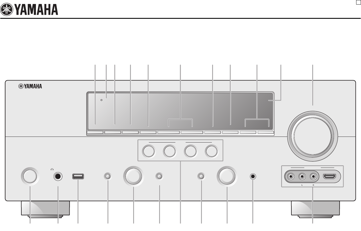
The letters in circles and the numbers in squares correspond to those in the Owner's Manual.
■Front panel
RX-V2065
U
ON/OFF
PHONES
MAIN ZONE
SILENT CINEMA
TONE CONTROL
PROGRAM
STRAIGHT PURE DIRECT
INPUT
OPTIMIZER MIC
VIDEO
HDMI IN
AUDIO
THROUGH
VIDEO
AUX
VOLUME
HDMI
EFFECT
BD/DVD
TV
CD
RADIO
SCENE
INFO
PRESET
lhlh
MEMORY
ZONE2
ON/OFF
ZONE
CONTROLS
ZONE3
ON/OFF
BAND
CATEGORY
TUNING/CH
USB
LPNSOQ T
ABC D E G HFIJK
UMR V
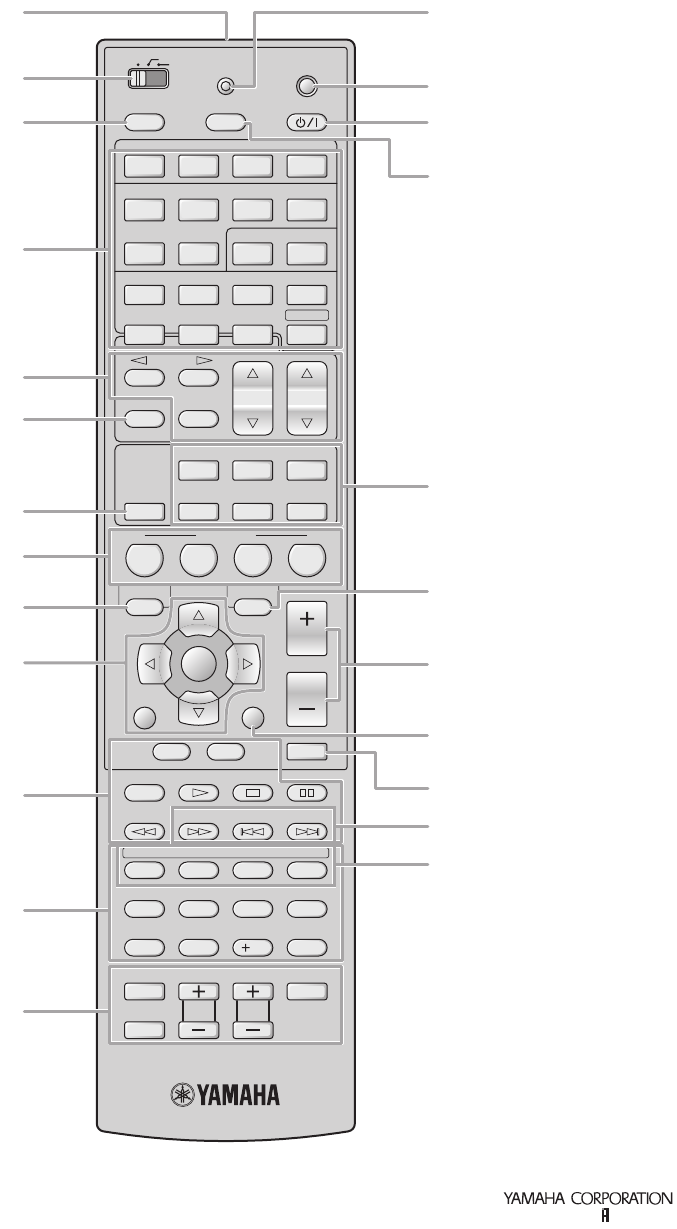
■Remote control
SLEEPSOURCE
USB/NET
1 2 3 4
1 2 3 4
5 6 1 2
PHONO
MULTI
DOCK
TUNER SIRIUS
XM
HDMI
V-AUX
CATEGORY
FM AM
INFO
MEMORY
PRESET
TUN./CH
MUSIC
SUR. DECODE
MOVIE
STRAIGHT
HDMI OUT
PURE DIRECT
BD
DVD TV
CD
RADIO
7 85 6
9 0
1 2 3 4
REC
ENT
POWER
INPUT
MUTE
ENTER
VOLUME
10
TV VOL TV CH
TAG PRG SELECT
MUTE
ENHANCER
STEREO
ON SCREEN OPTION
MAIN
POWER
USB NET RADIO PC RHAPSODY
POWER
TOP
MENU
SCENE
RETURN
TV
DISPLAY
POP-UP
MENU
HDMI
AUDIO
ZONE 2
ZONE 3
TRANSMIT
CODE SET
AV
a
cp
q
d
e
h
is
r
t
u
v
k
l
m
bo
n
j
f
g
w
x
Printed in Malaysia WS30800

ix
Skyworth 2310
Slim Art 2312
SM Electronic 2305
Sonic Blue 2215
Sontech 2316
Sony 2005, 2006, 2007,
2020, 2021, 2022,
2023, 2024, 2025,
2069, 2072, 2073,
2085, 2086, 2087,
2091, 2092, 2093,
2102, 2128, 2129,
2130, 2249, 2250,
2323, 2334, 2335,
2336, 2360, 2361,
2362, 2363, 2364,
2365, 2384
Soundmaster 2305
Soundmax 2305
Spectra 2313
Spectroniq 2155
Standard 2305
Star Cluster 2305
Starmedia 2308, 2318
Sungale 2158
Sunkai 2312
Superscan 2196
Supervision 2305
Sylvania 2094, 2180, 2189,
2196, 2219, 2224
Symphonic 2062, 2180
Synn 2305
T.D.E. Systems
2316
Tatung 2083, 2312
TCM 2228, 2379
Teac 2199, 2287, 2301,
2305
Tec 2310
Technics 2197
Technika 2312, 2317
Telefunken 2307
Tensai 2312
Tevion 2228, 2305, 2311
Theta Digital 2207
Thomson 2229, 2238, 2284,
2294
Tokai 2302, 2310
Top Suxess 2318
Toshiba 2004, 2026, 2027,
2028, 2029, 2030,
2098, 2099, 2100,
2101, 2114, 2117,
2118, 2119, 2136,
2187, 2195, 2205,
2291, 2337, 2338,
2378
TRANScontinents
2313, 2317
Transonic 2317
Trio 2312
Trutech 2160
TruVision 2309
TSM 2318
Umax 2315
United 2317
Urban Concepts
2205
US Logic 2167
Venturer 2199
Viewmaster 2318
Vocopro 2156
VocoStar 2157
Waitec 2318
Welltech 2300
Westinghouse 2109, 2168
Wharfedale 2304, 2305
Woxter 2315, 2318
Xbox 2206, 2229
Xlogic 2305, 2312
XMS 2312
Xoro 2300
Yamada 2097, 2313, 2315
Yamaha 2000, 2001, 2002,
2003, 2011, 2018,
2019, 2036, 2106,
2197, 2273
Yamakawa 2302, 2313
Yukai 2232
Zenith 2080, 2141, 2205,
2211, 2215
Blu-ray Disc
LG 2115
Panasonic 2089, 2131, 2132
Pioneer 2134
Samsung 2035, 2127
Sharp 2142, 2143, 2144
Sony 2025
Yamaha 2018
DVR
Bush 2060
Panasonic 2037, 2038, 2039,
2040, 2041, 2042
Philips 2061, 2062
Pioneer 2063, 2064, 2065,
2066, 2067
RCA 2059
Samsung 2035
Yamaha 2036
DVD Recorder
Aspire 2140
Astar 2162
Broksonic 2192
Go Video 2135
Hitachi 2108
Insignia 2080
Irradio 2103
JVC 2054, 2055, 2056,
2057
LG 2107, 2115, 2141,
2188
Liteon 2121
Panasonic 2037, 2038, 2039,
2041, 2042, 2043,
2089, 2104, 2108,
2112
Philips 2090, 2096, 2097,
2126, 2193
Pioneer 2067, 2113
Pye 2194
Samsung 2034, 2082, 2138
Sansui 2027
Sanyo 2139
Sony 2022, 2023, 2024,
2085, 2086, 2087,
2102, 2128, 2129,
2130
Sylvania 2189
Toshiba 2030, 2099, 2100,
2101, 2114, 2117,
2118, 2119
Yamaha 2106
Cable
ABC 3004, 3015, 3016,
3017, 3037, 3040,
3067, 3080, 3081
ADB 3070
Adelphia 3003
Alcatel 3066
Americast 3046
Amstrad 3048, 3068
Antronix 3019, 3020
Archer 3020
Arcon 3048
AT&T 3013
Axis 3048
Bell South 3046
Cable Vision 3014
Cabletenna 3019
Cabletime 3058
Cableview 3005
Clearmaster 3045
ClearMax 3045
Clyde Cablevision
3059
Colour Voice 3022
Comcast 3006, 3010, 3039
Comcrypt 3057
Comtronics 3023
Contec 3024
Coolmax 3045
COX 3006
Cryptovision 3060
Director 3006
Eastern 3025
Everquest 3041
Fidelity 3048
Filmnet 3057
Filmnet Cablecrypt
3061
Filmnet Comcrypt
3061
Finlux 3051
Focus 3044
Foxtel 3068
France Telecom
3054, 3055
Freebox 3069
GC Electronics
3020
GE 3015, 3016
GEC 3059
Gemini 3026, 3041
General Instrument
3006, 3008, 3016,
3039, 3050, 3067,
3075
Goldstar 3042
Gooding 3049
Grundig 3048, 3049
Hamlin 3027, 3028
Hirschmann 3051
Hitachi 3016
HomeChoice 3056
Humax 3001, 3002, 3071
ITT Nokia 3051
Jasco 3041
Jerrold 3006, 3008, 3016,
3026, 3037, 3041,
3050, 3064, 3067,
3075
JVC 3049
Kabel Deutschland
3043, 3073, 3074
Macab 3055
Magnavox 3029
Maspro 3049
Matsui 3049
MegaCable 3039
Memorex 3030, 3040
Minerva 3049
Mnet 3057
Motorola 3006, 3008, 3010,
3013, 3039, 3072,
3075
Movie Time 3031, 3063
Mr Zapp 3055
Multichoice 3057
Multitech 3045
NEC 3018
NET Brazil 3007
Nokia 3051
Noos 3055
NSC 3031
Oak 3024
Pace 3011, 3043, 3084
Palladium 3049
Panasonic 3034, 3036, 3040
Paragon 3040
Philips 3021, 3022, 3029,
3049, 3053, 3054,
3055
Pioneer 3012, 3032, 3038,
3042, 3048, 3083,
3084
Popular Mechanics
3044
Proscan 3015, 3016
Pulsar 3040
PVP Stereo Visual Matrix
3064
Quasar 3040
RadioShack 3041, 3045
RCA 3005, 3036, 3076,
3077
Realistic 3020
Recoton 3044
Regal 3028
Regency 3025
Rembrandt 3016
Runco 3040
Sagem 3055
Samsung 3011, 3023, 3032,
3042
SAT 3048
Scientific Atlanta
3003, 3004, 3011,
3012, 3013, 3062,
3078, 3079, 3080,
3081, 3082, 3083,
3084
Signal 3026, 3041
Signature 3016
Sony 3014, 3047
Sprucer 3036
Standard Component
3033
Starcom 3026, 3037, 3041,
3067
Stargate 3026, 3041
Starquest 3026, 3041
Supercable 3008
Supermax 3045
Tele+1 3057, 3061
Telepiu 3057
Thomson 3000, 3009
TIME WARNER
3006
Tocom 3017
Torx 3067
Toshiba 3040
Tristar 3045
Tudi 3052
Tusa 3026, 3041
TV86 3031
Unika 3019, 3020
United Cable 3037, 3064
Universal 3019, 3020
Universum 3049, 3051
V2 3045
Videoway 3065
View Star 3024, 3029, 3031

x
Viewmaster 3045
Vision 3045
Visiopass 3051, 3054, 3055
Vortex View 3045
Wittenberg 3048
Zenith 3035, 3040, 3046
Zentek 3044
Sattelite
AB Sat 4138, 4139
AccessHD 4058
ADB 4142
AGS 4138
Akai 4101, 4103
Alba 4083, 4084, 4085,
4086, 4108, 4139
Aldes 4085, 4087, 4088
Allsat 4098, 4101, 4103
Allsonic 4074, 4087, 4090
Alltech 4139
Alpha 4103
Alpha Digital 4058
Alphastar 4031
Amitronica 4139
Amstrad 4089, 4113, 4136,
4139
Anglo 4139
Ankaro 4074, 4087, 4090,
4139
Anttron 4083, 4086
Apollo 4083
Armstrong 4089, 4103
Artec 4054
Asat 4101, 4103
ASLF 4139
Astacom 4138
Astra 4089, 4091, 4100,
4137, 4139
Astro 4074, 4086, 4088,
4090, 4093, 4135,
4136, 4137
AudioTon 4086, 4098
Aurora 4140
Austar 4140
Axiel 4138
Axis 4074, 4090, 4091,
4096
Best 4074, 4090
Blaupunkt 4093
Blue Sky 4139
Boca 4089, 4100, 4105,
4139
Boston 4138
Brain Wave 4095
Broadcast 4094
Broco 4139
BSkyB 4113, 4123
BT 4138
Bubu Sat 4139
Bush 4084, 4127
Cambridge 4136
Canal Satellite 4135
Canal+ 4135
CaptiveWorks 4049
Channel Master
4060, 4085
Chaparral 4025
CHEROKEE 4138
Chess 4134, 4139
CityCom 4084, 4133, 4137
Clatronic 4095
CNT 4088
Comag 4000, 4001, 4002,
4003, 4004
Commlink 4087
Comtech 4096
Condor 4074, 4090, 4137
Connexions 4074, 4092
Conrad 4074, 4133, 4136,
4137
Conrad Electronic
4137, 4139
Contec 4096
Coolsat 4050
Cosat 4098
Coship 4063
Crown 4089
Daeryung 4092
Daewoo 4107, 4139
DDC 4085
Delega 4085
Dew 4096
Diamond 4097
Digiality 4137
Digital Stream 4059
DIRECTV 4017, 4018, 4020,
4021, 4022, 4024,
4037, 4038, 4040,
4041, 4043, 4045,
4057, 4106, 4143,
4144, 4145, 4146,
4147, 4148, 4149,
4150, 4151, 4152,
4153, 4154, 4155,
4156, 4157
Discoverer 4134
Discovery 4138
Diseqc 4138
Dish Network 4011, 4012, 4013,
4014, 4019, 4039,
4064
Dishpro 4039, 4064
Distrisat 4103
Ditristrad 4098
DNT 4092, 4101, 4103
Drake 4026
DStv 4140
Dune 4074
Echostar 4011, 4019, 4039,
4064, 4092, 4139
Einhell 4083, 4087, 4089,
4136, 4139
Elap 4138, 4139
Elekta 4088
Elsat 4139
Elta 4074, 4083, 4090,
4098, 4101, 4103
Emanon 4083
Emme Esse 4074, 4090
Engel 4139
Ep Sat 4084
EURIEULT 4077
Eurodec 4102
Europa 4103, 4136, 4137
Europhon 4137
Eurosat 4089
Eurosky 4074, 4089, 4090,
4133, 4136, 4137
Eurostar 4089, 4133, 4137
Eutelsat 4139
Exator 4083, 4086
Expressvu 4039
Fenner 4074, 4134, 4139
Ferguson 4084, 4102, 4132
Fidelity 4136
Finlandia 4084
Finlux 4084
FinnSat 4096, 4102
Flair Mate 4139
Foxtel 4140
Freecom 4083, 4099, 4136
FTEmaximal 4074, 4139
Fuba 4074, 4083, 4090,
4092, 4093, 4101,
4133
Galaxis 4074, 4087, 4090,
4091, 4096, 4098,
4133, 4140
GE 4015, 4016, 4061,
4151
General Instrument
4027, 4065
GMI 4089
GOI 4039
Goldbox 4135
GoldStar 4099
Goodmans 4079, 4080, 4084
Goodmind 4061
Grandin 4077
Grothusen 4083, 4099
Grundig 4084, 4086, 4093,
4113, 4129, 4136,
4140
Hänsel & Gretel
4137
Hantor 4083, 4095
Hanuri 4088
Hauppauge 4126
Heliocom 4137
Helium 4137
Hinari 4085
Hirschmann 4074, 4093, 4128,
4136, 4137, 4138
Hisawa 4095
Hisense 4066
Hitachi 4032, 4084, 4149,
4153
Homecast 4005, 4006, 4007
Houston 4098
HTS 4039
Hughes 4018, 4022, 4144,
4146, 4150, 4152
Hughes Network Systems
4021
Humax 4051, 4075, 4076,
4110
Huth 4087, 4089, 4094,
4095, 4096, 4098,
4137, 4141
Hypson 4077
Ilo 4066
Imex 4077
Innovation 4090
Insignia 4057
Intertronic 4089
Intervision 4098, 4137
ITT Nokia 4084
Jerrold 4065
Johansson 4095
JOK 4138
JSR 4098
JVC 4011, 4019, 4039,
4079
Kamm 4139
Kathrein 4093, 4101, 4103,
4109, 4112, 4120,
4133, 4138, 4139
Kathrein Eurostar
4133
Klap 4138
Konig 4137
Kosmos 4099
KR 4086
Kreiselmeyer 4093
K-SAT 4139
Kyostar 4083
L&S Electronic
4074
Lasat 4074, 4088, 4090,
4100, 4133, 4134,
4137
Lasonic 4062
Lenco 4074, 4083, 4099,
4133, 4137, 4139
Leng 4095
Lennox 4098
Lenson 4136
Lexus 4103
LG 4053, 4057, 4099
Lifesat 4074, 4090, 4134,
4139
Lifetec 4090
Lorenzen 4137
Lorraine 4099
Lupus 4074, 4090
Luxor 4136
Lyonnaise 4102
Macab 4102
Magnavox 4045, 4055
Manata 4077, 4138, 4139
Manhattan 4084, 4088, 4098,
4138
Marantz 4101
Mascom 4088
Maspro 4084, 4139
Matsui 4138
Max 4137
Mediabox 4135
Mediamarkt 4089
Mediasat 4091, 4135, 4136
Medion 4074, 4090, 4139
Medison 4139
Mega 4101, 4103
Memorex 4045
Metronic 4077, 4078, 4083,
4086, 4087, 4088,
4139
Metz 4093
Micro electronic
4136, 4137, 4139
Micro Technology
4139
MicroGem 4056
Micromaxx 4074, 4090
Microstar 4090
Microtec 4139
Minerva 4093
Mitsubishi 4084, 4093, 4152
Mitsumi 4100
Morgan’s 4089, 4100, 4101,
4103, 4139
Motorola 4008, 4009, 4010,
4065
Multichoice 4140
Multitec 4134
Muratto 4099
Mysat 4139
Navex 4095
Neuhaus 4091, 4098, 4136,
4137, 4139
Neusat 4139
Next Level 4065
NextWave 4141
Nikko 4089, 4139
Nokia 4084, 4122
Nordmende 4083, 4084, 4085,
4088, 4102
Nova 4140
Novis 4095
Oceanic 4097
Octagon 4083, 4086, 4096
Okano 4089
Optex 4098
Optus 4135, 4140, 4141

xi
Orbitech 4083, 4134, 4135,
4136
OSat 4086
Otto Versand 4093
Pace 4084, 4093, 4113,
4121, 4125, 4138
Pacific 4097
Packsat 4138
Palcom 4085
Palladium 4089, 4136
Palsat 4134, 4136
Panasat 4140
Panasonic 4043, 4044, 4046,
4084, 4113, 4118,
4143, 4148
Panda 4084, 4137
Pansat 4047
Patriot 4138
Paysat 4045
PCT 4060
Philco 4055
Philips 4021, 4022, 4045,
4084, 4101, 4103,
4111, 4115, 4135,
4138, 4150, 4152,
4153, 4155, 4156
Phoenix 4096
Phonotrend 4084, 4087, 4098
Pioneer 4124, 4135
Polsat 4102
Predki 4095
Premiere 4098, 4135
Priesner 4089
Primestar 4030
Profile 4138
Promax 4084
Prosat 4085, 4087
Proscan 4015, 4016, 4040,
4151
Protek 4097
Proton 4066
Provision 4088
Quadral 4074, 4085, 4087,
4090, 4138
Quelle 4093, 4133, 4137
Quiero 4102
RadioShack 4065
Radiola 4101, 4103
Radix 4092, 4119
Rainbow 4086
RCA 4015, 4016, 4034,
4035, 4036, 4037,
4038, 4040, 4151,
4157
Realistic 4028
Redpoint 4091
Redstar 4074, 4090
RFT 4087, 4101, 4103
Roadstar 4139
Roch 4077
Rover 4074, 4139
Saba 4088, 4133, 4137,
4138
Sabre 4084
Sagem 4069, 4102
Sakura 4096
Samsung 4018, 4021, 4023,
4041, 4042, 4081,
4082, 4083, 4114,
4150, 4154
SAT 4085, 4136
Sat Cruiser 4141
Sat Partner 4083, 4086, 4088,
4095, 4099, 4136
Sat Team 4139
Satcom 4094, 4137
Satec 4139
Satelco 4074
Satford 4094
Satmaster 4094
Satplus 4134
Schneider 4090, 4134, 4138
Schwaiger 4097, 4134, 4137
SCS 4133
Seemann 4089, 4091, 4092
SEG 4074, 4083, 4090,
4095
Seleco 4098
Servi Sat 4077, 4139
Siemens 4093
Silva 4099
Skantin 4139
Skardin 4091
Skinsat 4136
SKR 4139
Skymaster 4067, 4068, 4087,
4134, 4139
Skymax 4101, 4103
SkySat 4134, 4136, 4137,
4139
Skyvision 4098
SM Electronic 4134, 4139
Smart 4133, 4139
Sony 4017, 4020, 4135
SR 4089, 4100
Star Choice 4065
Starland 4139
Starring 4095
Start Trak 4083
Strong 4074, 4083, 4086,
4090, 4099, 4140
STS 4033
STVI 4077
Sumida 4089
Sunny Sound 4074
Sunsat 4139
Sunstar 4074, 4089, 4100
Supermax 4141
Tandberg 4102
Tandy 4086
Tantec 4084
TCM 4090
Techniland 4094
TechniSat 4071, 4072, 4073,
4092, 4103, 4116,
4117, 4134, 4135,
4136
Technology 4140
Technosat 4141
Technowelt 4137
Teco 4089, 4100
Telanor 4085
Telasat 4133, 4137
Telecom 4139
Telefunken 4067, 4083, 4138
Teleka 4086, 4089, 4092,
4136, 4137
Telemaster 4088
Telesat 4137
Telestar 4134, 4135, 4136
Televes 4084, 4136
Telewire 4098
Tempo 4141
Tevion 4090, 4139
Thomson 4070, 4084, 4102,
4104, 4130, 4133,
4135, 4137, 4138,
4139
Thorens 4097
Thorn 4084
Tivax 4058
Tivo 4150
Tokai 4103
Tonna 4084, 4094, 4098,
4136, 4139
Toshiba 4144, 4152, 4153
Triad 4099
Triasat 4136
Triax 4093, 4133, 4136,
4139
Turnsat 4139
Tvonics 4132
Twinner 4077, 4139
UEC 4140
Uher 4134
UltimateTV 4020
Uniden 4029, 4045
Unisat 4089, 4096, 4103
Unitor 4095
Universum 4093, 4133, 4137
US Digital 4066
Variosat 4093
Vega 4074
Ventana 4101, 4103
Viewsat 4048
Visiosat 4095, 4098, 4138,
4139
Voom 4065
Vortec 4083
Welltech 4134
WeTeKom 4134, 4136
Wevasat 4084
Wewa 4084
Winersat 4095
Wisi 4084, 4092, 4093,
4136, 4137
Woorisat 4088
Worldsat 4138
Xrypton 4074
XSat 4139
Zehnder 4074, 4088, 4090,
4131, 4133
Zenith 4052, 4057, 4145
Zodiac 4086
CD
Yamaha 5000, 5013
CD Recoder
Yamaha 5001
MD
Yamaha 5002, 5003, 5004
Tape
Yamaha 5005, 5006
Tuner
Yamaha 5007, 5008, 5009,
5010, 5014, 5015,
5016, 5017, 5018
USB
Yamaha 5012, 5021
DOCK
Yamaha 5011, 5022
LD
Yamaha 2002

© 2009 Yamaha Corporation All rights reserved. Printed in Malaysia WS30700
RX-V2065
RX-V2065
AV R e c e i ve r
OWNER’S MANUAL
U
00_RX-V2065_U_cv.fm Page 1 Wednesday, June 24, 2009 4:10 PM
Black process 45.0° 240.0 LPI
