Yamaha RX V867 Owner's Manual
User Manual: Yamaha RX-V867 Owner's Manual
Open the PDF directly: View PDF ![]() .
.
Page Count: 144 [warning: Documents this large are best viewed by clicking the View PDF Link!]
- INTRODUCTION
- CONNECTIONS
- Connecting speakers
- Connecting external components
- Jacks and cables
- Connecting a TV monitor
- Connecting BD/DVD players and other devices
- Connecting game consoles
- Connecting a multi-format player or an external decoder
- Connecting an external amplifier
- Connecting a SCENE link playback-compatible device
- Using the Trigger function to link external component power
- Connecting audio/video recording devices
- Connecting to the network
- Connecting the FM/AM antennas
- Setting up the speaker parameters automatically (YPAO)
- PLAYBACK
- Basic playback procedure
- Changing input settings with a single key (SCENE function)
- Enjoying favorite sound field effect
- Using the TV display to control this unit
- Configuring settings specific to an individual input source (Option menu)
- Confirming and operating input sources from the Content window
- FM/AM tuning
- Listening to SIRIUS Satellite Radio™
- Playing back tunes on the PC
- Listening to the Internet Radio
- Using the Rhapsody® service
- Listening to the SIRIUS Internet Radio
- Using shortcut function
- Playing back tunes from your iPod™/iPhone™
- Playing back tunes from Bluetooth™ components
- Changing the friendly name of this unit by using the web browser
- SETUP
- Configuring input sources (Input menu)
- Editing the SCENE function (SCENE menu)
- Setting sound program parameters (Sound Program menu)
- Setting various functions (Setup menu)
- Confirming information of this unit (Information menu)
- Controlling other components with the remote control
- Extended functionality that can be configured as needed (Advanced Setup menu)
- Displaying/Setting the Advanced Setup menu
- Setting the impedance of speakers
- Avoiding crossing remote control signals when using multiple Yamaha receivers
- Resetting the SIRIUS Satellite Radio™ parental lock code
- Changing TV format
- Removing HDMI video output up-scaling limits
- Initializing various settings for this unit
- Firmware update
- Firmware version
- Using the HDMI Control function
- Using multi-zone configuration
- APPENDIX

Owner’s Manual
AV Receiver English for U.S.A.

En 2
CONTENTS
INTRODUCTION
Features and capabilities ...................................................4
Using the TV OSD to operate the unit .............................5
View or modify content for the current input source
<Content window> ...........................................................5
Configuring settings for this unit
<ON SCREEN menu>......................................................5
Adjust settings for each input source
<Option menu>................................................................. 6
About this manual............................................................. 7
Supplied accessories......................................................... 7
Part names and functions..................................................8
Front panel........................................................................8
Rear panel.........................................................................9
Front panel display .........................................................10
Remote control ...............................................................11
On-screen display ........................................................... 12
CONNECTIONS
Connecting speakers ........................................................13
Speaker channels and functions...................................... 13
Speaker layout ................................................................14
Connecting speakers and subwoofers.............................17
Connecting external components....................................21
Jacks and cables.............................................................. 21
Connecting a TV monitor............................................... 22
Connecting BD/DVD players and other devices............25
Connecting game consoles ............................................. 29
Connecting a multi-format player
or an external decoder .................................................... 29
Connecting an external amplifier ................................... 30
Connecting a SCENE link
playback-compatible device ...........................................30
Using the Trigger function to link
external component power.............................................. 31
Connecting audio/video recording devices.....................31
Connecting to the network.............................................. 32
Connecting the FM/AM antennas .................................. 33
Setting up the speaker parameters automatically
(YPAO).............................................................................. 34
PLAYBACK
Basic playback procedure ............................................... 42
Changing input settings with a single key
(SCENE function) ............................................................ 44
Registering input sources/sound program/
HDMI OUT .................................................................... 44
Enjoying favorite sound field effect ............................... 44
Selecting sound programs and sound decoders.............. 44
Sound programs.............................................................. 48
Using the TV display to control this unit....................... 50
Basic operations via the TV screen display ................... 50
Configuring settings specific to an individual input
source (Option menu)...................................................... 52
Option menu display and setup ...................................... 52
Option menu................................................................... 53
Confirming and operating input sources
from the Content window ............................................... 56
Displaying the Content window on the TV screen......... 56
Switching the display between the Now Playing view
and the Browse view ...................................................... 56
FM/AM tuning ................................................................. 57
Selecting a frequency for reception (Normal tuning)..... 57
Navigating the FM/AM tuner
from the Content window............................................... 59
Listening to SIRIUS Satellite Radio™ .......................... 61
Connecting the SiriusConnect™ tuner .......................... 61
Activating SIRIUS Satellite Radio™ subscription ........ 62
SIRIUS Satellite Radio™ operations............................. 62
Registering and recalling the SIRIUS Satellite Radio™
channels.......................................................................... 63
Displaying the SIRIUS Satellite Radio™ information .. 64
Navigating the SIRIUS Satellite Radio™
from the Content window .............................................. 65
Playing back tunes on the PC......................................... 67
Windows Media Player setup......................................... 67
Playback of PC music contents...................................... 67
Listening to the Internet Radio ...................................... 69
Listening to Internet Radio ............................................ 69
Using the Rhapsody® service.......................................... 71
Rhapsody® account sign-in............................................ 71
Playback of Rhapsody® contents................................... 72
Listening to the SIRIUS Internet Radio........................ 75
SIRIUS Internet Radio account sign-in ......................... 75
Navigating the SIRIUS Internet Radio menu ................ 76
Using shortcut function................................................... 78
Playing back tunes from your iPod™/iPhone™........... 79
Connecting the Universal Dock for iPod ....................... 79
Controlling an iPod™/iPhone™ .................................... 79
Playing iPod/iPhone from the menu screen
(Menu browse control)................................................... 80
Operating basic playback functions
via the remote control (Simple remote control) ............. 81
Playing iPod™/iPhone™ with wireless connection ...... 81
Playing back tunes from Bluetooth™ components ...... 83
Connecting a Yamaha Bluetooth
wireless audio receiver................................................... 83
Pairing Bluetooth™ components ................................... 83
Using Bluetooth™ components ..................................... 84
Changing the friendly name of this unit
by using the web browser................................................ 85

En 3
SETUP
Configuring input sources (Input menu) .......................86
Configuring input sources ..............................................86
Input menu......................................................................87
Editing the SCENE function (SCENE menu) ...............90
Editing a scene................................................................ 90
SCENE menu..................................................................91
Setting sound program parameters
(Sound Program menu) ...................................................93
Editing sound programs..................................................93
CINEMA DSP parameters ............................................. 94
Parameters usable in certain sound programs ................96
Parameters usable in surround decoder .......................... 97
Setting various functions (Setup menu) .........................98
Operating the Setup menu ..............................................98
Setup menu .....................................................................99
Manages settings for speakers ........................................99
Setting the audio output function of this unit ............... 103
Setting this unit’s video output function....................... 104
Setting HDMI functions ...............................................105
Adjusting this unit’s network parameters.....................108
Setting this unit’s multi-zone function ......................... 109
Making the receiver easier to use ................................. 109
Language ...................................................................... 112
Confirming information of this unit
(Information menu) .......................................................113
Selecting information ...................................................113
Controlling other components
with the remote control.................................................. 115
Keys connecting external components .........................115
Default remote control code settings............................ 116
Registering remote control codes
for external component operations ...............................116
Resetting all remote control codes ............................... 117
Extended functionality that can be configured
as needed (Advanced Setup menu)............................... 118
Displaying/Setting the Advanced Setup menu............. 118
Setting the impedance of speakers .............................. 118
Avoiding crossing remote control signals
when using multiple Yamaha receivers ........................ 119
Resetting the SIRIUS Satellite Radio™
parental lock code......................................................... 119
Changing TV format .................................................... 120
Removing HDMI video output up-scaling limits......... 120
Initializing various settings for this unit....................... 120
Firmware update........................................................... 120
Firmware version.......................................................... 120
Using the HDMI Control function ............................... 121
Using multi-zone configuration .................................... 125
Connecting Zone2 ........................................................ 125
Controlling Zone2 ........................................................ 126
Using the party mode ................................................... 126
APPENDIX
Troubleshooting ............................................................. 127
General ......................................................................... 127
HDMI™ ....................................................................... 129
Tuner (FM/AM) ........................................................... 130
SIRIUS Satellite Radio™............................................. 130
Network........................................................................ 131
iPod™/iPhone™ .......................................................... 132
Bluetooth™ .................................................................. 133
Remote control ............................................................. 133
Glossary .......................................................................... 134
Audio information ........................................................ 134
Sound program information ......................................... 135
Video information ........................................................ 136
Video conversion .......................................................... 136
Information on HDMI™............................................... 137
About trademarks ......................................................... 138
Specifications.................................................................. 139
Index ............................................................................... 141
En 4
INTRODUCTION
■Built-in high-quality, high-power 7-channel amplifier
■6 HDMI input jacks (5 + 1 VIDEO AUX) supporting Audio Return Channel and 3D
video signal
■2 HDMI output jacks
–Selecting the HDMI OUT jack ................................................................................................................42
■1-button input/sound program switching (SCENE function)................................44
■Speaker connections for 2- to 7.1-channel configurations
–Speaker impedance configuration............................................................................................................18
–Speaker channels and functions ...............................................................................................................13
–Speaker layout..........................................................................................................................................14
–Speaker cable connection.........................................................................................................................17
–Subwoofer cable connection ....................................................................................................................20
–High quality playback using bi-amplification connections .....................................................................18
■Automatic settings for speaker acoustic parameters
(YPAO - Yamaha Parametric Room Acoustic Optimizer) ......................................34
■External component connection (max. 16 inputs) and playback
–External component connection...............................................................................................................21
–Protective cover for front panel jacks ........................................................................................................7
–Configuring the settings specific for each input source <Option menu> ................................................52
–Playback from external components........................................................................................................42
–Playback from an iPod/iPhone with wired connection............................................................................80
–Playback from an iPod/iPhone with wireless connection........................................................................81
–Playback from a Bluetooth component (Bluetooth and components sold separately) ............................83
■FM/AM tuner
–Receiving an FM/AM broadcast..............................................................................................................57
–Presetting stations ....................................................................................................................................57
–Simple preset tuning ................................................................................................................................57
–Changing Audio mode (Auto/Mono).......................................................................................................59
■SIRIUS Satellite Radio™
–Receiving a channel .................................................................................................................................62
–Presetting channels ..................................................................................................................................63
–Displaying information ............................................................................................................................64
■Playback and control via network
–Playback of music on the PC and DLNA server......................................................................................67
–Internet radio service playback ................................................................................................................69
–Control this unit via network (Web Browser Control).............................................................................85
■Multi-channel, multi-format playback
–Sound field effect selection......................................................................................................................44
–Playback without sound field effects .......................................................................................................45
–Stereo playback........................................................................................................................................45
–Compressed-music playback ...................................................................................................................47
■Front panel information display/on-screen display (OSD) on the TV screen
–Switching information on the front panel display ...................................................................................10
–Operating this unit using the on-screen display.......................................................................................12
■Volume adjustment functions
–Easy listening at low volumes < Adaptive DRC> ...................................................................................54
–Adjusting volume between input sources <Volume Trim> .....................................................................55
■Remote control operation
–External component operation with this unit’s remote control..............................................................115
■Playing back the audio source in another room
–Using the internal amplifier for playback ................................................................................................18
–Using the external amplifier for playback .............................................................................................125
–Configuring the settings for another room.............................................................................................125
–Controlling the external component in another room............................................................................126
■Other features
–Standby mode after a specific amount of time <Sleep timer>.................................................................11
–Charging the iPod/iPhone when this unit is in standby mode <iPod Standby Charge> ..........................89
Features and capabilities
Most of this unit’s functions can be operated by following instructions displayed on the TV screen.
Refer to “Using the TV OSD to operate the unit” on the following pages for information on
functions that can be controlled using the on-screen display.

INTRODUCTION
En 5
This unit features a sophisticated on-screen display (OSD) for the TV screen. The OSD is designed to enable visual guidance that simplifies operations. The OSD mainly displays the ON SCREEN and
Option menus, as well as the Content window that displays the content of current input sources.
■Select an input source, SCENE and sound program
–Select an input source ..............................................................................................................................50
–Select a SCENE .......................................................................................................................................51
–Select a sound program............................................................................................................................51
View or modify content for the current input source <Content
window>
■Operate the AM/FM tuner or SIRIUS Satellite Radio
–Display a list of preset stations/channels for selection ......................................................................60, 66
–Display information on the station/channel currently received .........................................................59, 65
–Perform operations such as searching for and registering stations/channels using the Utility
<Utility>.............................................................................................................................................59, 65
■Display the list of iPod music sources
–Display the list of iPod music sources for selection ................................................................................80
–Perform operations such as play, stop and pause using the TV screen <Menu browse control> ............80
Configuring settings for this unit <ON SCREEN menu>
■Configure an input source
–Select an input source ..............................................................................................................................50
–Play the audio/video signal from the selected input source.....................................................................42
–Change the input source name <Rename/Icon Select> ...........................................................................88
–Select the audio input jack separately from the video input jack <Audio In>.........................................88
–Specify a format for digital audio signals <Decoder Mode>...................................................................88
–Enhance the sound of compressed audio <Enhancer>.............................................................................89
–Output a video signal input from another input source
while playing a multi-channel audio signal <Video Out> .......................................................................89
–Charge the iPod/iPhone when this unit is in standby mode <Standby Charge>......................................89
■Customize a SCENE
–Register or clear settings for a selected SCENE <Save>, <Reset> .........................................................91
–Turn on a Yamaha BD/DVD player or CD player connected to this unit automatically
when a SCENE is selected <SCENE IR>................................................................................................91
■Adjust a sound program (sound program)
–Adjust sound program parameters ...........................................................................................................93
■Display settings information for this unit
–Display audio signal information <Audio Signal>................................................................................113
–Display video signal information <Video Signal> ................................................................................113
–Display HDMI signal information <HDMI - Monitor Info.>................................................................113
■Adjust acoustic parameters to match your speakers and listening environment
–Specify speaker acoustic parameters automatically
(Yamaha Parametric Room Acoustic Optimizer - YPAO).......................................................................34
–Set up this unit’s speaker configuration simply <Power Amp Assign> ..................................................99
–Specify settings for each speaker <Configuration>...............................................................................100
–Control volume control for each speaker <Level> ................................................................................101
–Apply speaker distance settings <Distance> .........................................................................................101
–Control equalizer sound quality <Parametric EQ>................................................................................102
–Adjust test tone speaker <Test Tone> ....................................................................................................102
■Adjust audio signals output from this unit
–Correct lag between audio and video signals <Lipsync> ......................................................................103
–Select a dynamic range adjustment method <Dynamic Range> ...........................................................103
–Specify the maximum volume <Max Volume>.....................................................................................103
–Specify the initial volume <Initial Volume>..........................................................................................104
–Adjust DSP effect and volume level <Adaptive DSP Level>................................................................104
■Adjust video signals output from this unit
–Convert analog video signal to another type of signal <Analog to Analog Conversion> .....................104
–Specify the resolution and aspect ratio of analog video signal converted to HDMI or specify
upscaling resolution for 480i/576i- or 480p/576p-HDMI output signal <Processing>.........................105
■HDMI settings
–Assign the audio input source for the TV <TV Audio Input>...............................................................106
–Listen to TV audio with HDMI cable connection <ARC (Audio Return Channel)>............................106
–Transmit HDMI audio/video to the TV during standby mode <Standby Through> .............................107
–Change the output destination of HDMI input audio signals <Audio Output>.....................................107
Using the TV OSD to operate the unit
Continues to the
next page

INTRODUCTION
Using the TV OSD to operate the unit
En 6
■Network settings
–Set the IP address of this unit <IP Address> .........................................................................................108
–Accept the commands via LAN network when this unit is in the standby mode
<Network Standby> ...............................................................................................................................108
–Set the mac address filter for this unit <MAC Address Filter> .............................................................108
■Enable listening in multiple rooms (multi-zone function)
–Adjust Zone2 volume <Zone2 Set>.......................................................................................................109
–Rename each zone <Zone Rename>......................................................................................................109
■Specify other functions for this unit
–Enter standby mode automatically when no operations are performed <Auto Power Down>..............110
–Adjust the brightness of the front panel display <Dimmer> .................................................................110
–Change the wall paper displayed on the TV screen <Wall Paper>........................................................110
–Specify the function of the TRIGGER OUT jack for controlling external components
<Trigger Output> ...................................................................................................................................111
–Prohibit changes to settings <Memory Guard> .....................................................................................112
■Select a language
–Change the language displayed on the TV screen <Language>............................................................112
Adjust settings for each input source <Option menu>
–Select the 5.1-channel signal playback method <Extended Surround>...................................................55
–Adjust bass and treble levels <Tone Control> .........................................................................................54
–Enable low-volume background music <Adaptive DRC>.......................................................................54
–Adjust the volume of input sources <Volume Trim>...............................................................................55
–Adjust the vertical position of dialogues <Dialogue Lift> ......................................................................54
En 7
INTRODUCTION
Using the TV OSD to operate the unit
About this manual
Supplied accessories
Check that you received all of the following parts.
•Remote control
•Batteries (AAA, R03, UM-4) x 2
•YPAO microphone
•AM loop antenna
•Indoor FM antenna
•VIDEO AUX input cover
•Some features are not available in certain regions.
•This manual is created prior to production. Design and
specifications are subject to change in part as a result of
improvements, etc. In case of differences between the manual and
product, the product has priority.
•“dHDMI1” (example) indicates the name of the parts on the
remote control. Refer to the “Remote control” (☞p. 11) for the
information about each position of the parts.
•J1 indicates that the reference is in the footnote. Refer to the
corresponding numbers on the bottom of the page.
•☞ indicates the page describing the related information.
•Click on the “ ” at the bottom of the page to display the
corresponding page in “Part names and functions.”
Front panel
Rear panel
Front panel display
Remote control
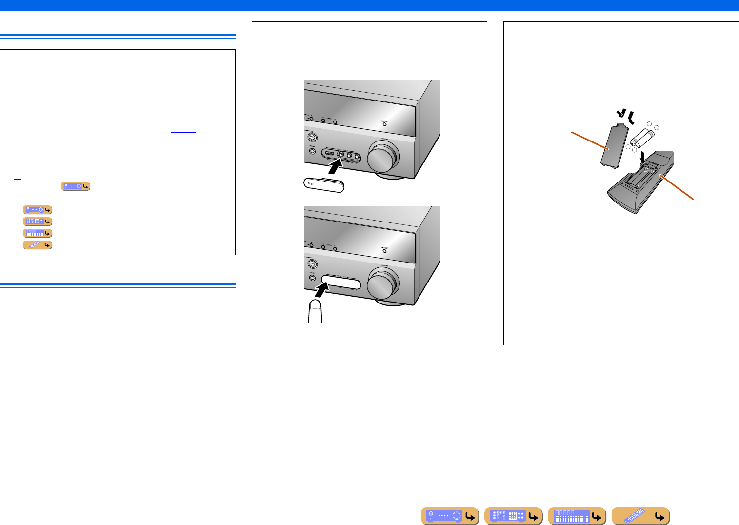
■Attaching the VIDEO AUX input cover (supplied)
To protect against dust, attach the supplied VIDEO AUX input
cover to the VIDEO AUX jacks when you do not use the jacks.
To remove the cover, push the left section of it.
Attach the cover
PUSH
Remove the cover
■Installing batteries in the remote control
When inserting batteries in the remote control, remove the
battery compartment cover from the reverse side of the remote
control, and insert two AAA batteries into the battery
compartment so that they match with the polarity markings (+
and -).
Replace the batteries with new ones if the remote control can
only be operated within a narrow range.
NOTE
If there are remote control codes for external components
registered to the remote control, removing the batteries for more
than 2 minutes, or leaving exhausted batteries in the remote
control, may clear the remote control codes. If this should occur,
replace the batteries with new ones, and set the remote control
codes.
ac
b
Battery compartment
cover
Battery compartment
INTRODUCTION
En 8
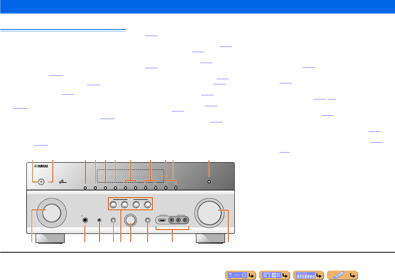
Front panel
aMAIN ZONE A (Power)
Switches this unit between on and standby mode.
bHDMI Through/iPod Charge indicator
Lights up in any of the following cases while the unit is in standby
mode.
• When the Standby Through function is enabled and audio/video from
an external component connected with HDMI is output to a TV
during standby mode (☞p. 107).
• When an iPod/iPhone, which is placed in the Universal Dock for iPod,
is charging while the unit is in standby mode (☞p. 81).
This indicator also lights up when the Yamaha Wireless System for
iPod is connected to this unit (☞p. 81).
• When the Network Standby function is enabled. This function allows
this unit to be turned on by receiving a command over a network
(☞p. 108).
cZONE2
Switches to enable/disable the audio output to Zone2 (☞p. 126).
dZONE CONTROL
Switches to Zone2 operation mode. This unit, or its remote control,
can be used to select input sources or adjust volume for an external
amplifier in another room or the built-in amplifier for speakers in
another room (☞p. 126).
eINFO
Changes the information displayed on the front panel display
(☞p. 10).
fMEMORY
Registers FM/AM stations as preset stations (☞p. 57) or SIRIUS
channels as preset channels (☞p. 63). J1
gPRESET j / i
Selects an FM/AM preset station (☞p. 59) or a SIRIUS preset channel
(☞p. 64). J1
hFM/AM (CATEGORY l / h)
Sets the FM/AM tuner band to FM or AM (☞p. 57). J1
Selects a channel category for a SIRIUS (☞p. 63).
iFront panel display
Displays information on this unit (☞p. 10).
jTUNING/CH jj / ii
Changes FM/AM tuner frequencies (☞p. 57) or SIRIUS Satellite
Radio channels (☞p. 63). J1
kPURE DIRECT
Switches this unit to Pure Direct mode (☞p. 47).
lINPUT selector
Selects an input source from which to playback. Rotate this selector to
cycle through the input sources in order.
mPHONES jack
For plugging headphones in. Sound effects applied during playback
can also be heard through the headphones.
nYPAO MIC jack
Connect the supplied YPAO microphone and adjust the speaker balance
automatically (☞p. 34).
oTONE CONTROL
Adjusts high-frequency/low-frequency output of speakers/headphones
(☞p. 43).
pSCENE
Switches the input source, the sound program, and the HDMI OUT
with a single button (☞p. 44, p. 90). When this unit is in standby
mode, press this key to switch on.
qPROGRAM selector
Selects a sound program (☞p. 44). Rotate this selector to cycle
through sound programs.
rSTRAIGHT
Changes a sound program to straight decoding mode (☞p. 45).
sVIDEO AUX jacks
For connecting game consoles to this unit temporarily (☞p. 29).
Attach the supplied VIDEO AUX input cover when not using this jack
(☞p. 7).
tVOLUME
Adjusts the volume level.
Part names and functions
VIDEO
AUX
PHONES
YPAO MIC
SILENT
CINEMA
TONE
CONTROL
STRAIGHT
VOLU ME
TV
BD
DVD
CD
RADIO
INPUT
PROGRAM
SCENE
VIDEO
AUDI O
HDMI IN
LR
INFO
ZONE
CONTROL
ZONE2
MAIN ZONE
MEMORY
PRESET
FM AM
CATEGORY
TUNING/CH
PURE DIRECT
rm n q
a
olts
ic f g ked h jb
p
J1 : Usable when you have selected TUNER or SIRIUS input.
En 9
INTRODUCTION
Part names and functions
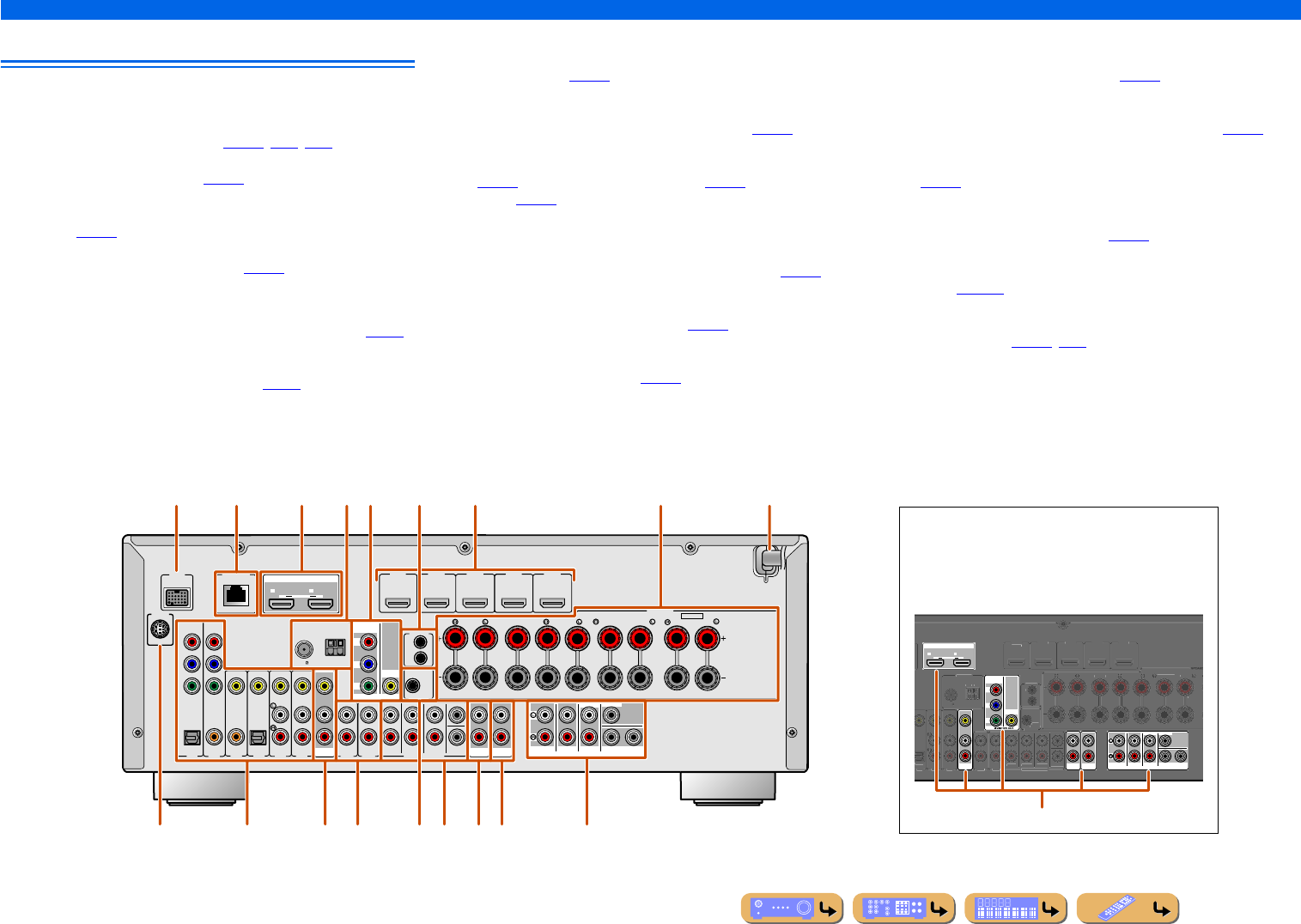
Rear panel
aDOCK jack
For connecting an optional Universal Dock for iPod (such as
YDS-12), Wireless System for iPod (YID-W10), or Bluetooth
wireless audio receiver (YBA-10) (☞p. 79, p. 81, p. 83).
bNETWORK port
For connecting to the network (☞p. 32).
cHDMI OUT 1-2 jacks
For connecting an HDMI - compatible TV to output audio/video
signals (☞p. 23).
dANTENNA jacks
For connecting AM and FM antennas (☞p. 33).
eMONITOR OUT jacks
fREMOTE IN/OUT jacks
For connecting an external component that supports the remote
control function (☞p. 30).
gHDMI1-5 jacks
For connecting external components equipped with HDMI-
compatible outputs to receive audio/video signals (☞p. 25).
hSPEAKERS terminals
For connecting the front, center, surround and surround back speakers
(☞p. 17). Connect the presence speakers (☞p. 17) or the speakers for
Zone2 (☞p. 18) to the EXTRA SP jacks.
iPower cable
For connecting this unit to an AC wall outlet.
jSIRIUS jack
For connecting a SiriusConnect tuner (sold separately) (☞p. 61).
kAV1-6 jacks
For connecting to external components equipped with audio/video
outputs to receive audio/video signals (☞p. 26).
lAV OUT jacks
For outputting audio/video signals received when analog inputs (AV3-
6 or AUDIO1-2) are selected (☞p. 31).
mAUDIO1-2 jacks
For connecting external components equipped with analog audio
outputs to input sound into this unit (☞p. 28).
nTRIGGER OUT jack
For connecting an external component that supports the trigger
function to operate it linked with operation of this unit (☞p. 31).
oMULTI CH INPUT jacks
For connecting a player that supports a multi-channel output
(☞p. 29).
pAUDIO OUT jacks
For outputting audio signals received when analog jacks, such as the
AV5-6 or AUDIO1-2 are selected (☞p. 31).
qZONE2 OUT jacks
Outputs sound of this unit to an external amplifier set in a different
room. (☞p. 125).
rPRE OUT terminals
For connecting a subwoofer with built-in amplifier or an external
power amplifier (☞p. 20, p. 30).
VIDEO jack For connecting a TV capable of receiving video
input, and outputting video signals to it (☞p. 23).
COMPONENT
VIDEO jacks
For connecting TV that are compatible with
component video signals, using three cables to
output video signal (☞p. 23).
AV
OUT
AUDIO
OUT ZONE2
OUT
SURROUND
SUR.BACK
PRE OUT
SUBWOOFER
1
2
FRONT
CENTERSINGLE
HDMI OUT
12
ARC ARC
SELECTABLE
COMPONENT
VIDEO
VIDEO
P
R
P
B
Y
(
TV
)
AV 4
AV 5
AV 6
AUDIO 1
AUDIO 2
MULTI CH INPUT
O
PTI
C
AL
HDMI 1
(
BD
/
DV
D
)
HDMI 2
HDMI
3
HDMI 4 HDMI 5
C
ENTER
SU
RR
OU
N
D
SU
RR
OU
ND BA
C
K
/
BI
-
AMP
S
INGL
E
F
R
O
N
T
SUBWOOFE
R
SU
R.BA
CK
SU
RR
OU
ND
TRIGGER OUT
+12V
0
.1
A
MAX.
FR
O
NT
CENTE
R
IN
REMOTE
O
U
T
S
PEAK
E
SPEAKE
ANTENNA
FM
75
G
ND
AM
Distinguishing the input and output jacks
The area around the audio/video output jacks is marked
in white to prevent connection errors. Use these jacks to
output audio/video signals to a TV or other external
component.
Output jacks
DOCK
( TV )
AV 3AV 4AV 5AV 6
AUDI O 1 AUD IO 2
MULTI CH INPUT
(CD)
COAXIAL OPTICAL
VIDEO
HDMI 1
(BD/DVD)
HDMI 2 HDMI 3
HDMI 4 HDMI 5
CENTER
SURROUND
SURROUND BACK/
BI-AMP
SINGLE
EXTRA SP
FRONT
AV
OUT
SUBWOOFER
AUDIO
OUT ZONE2
OUT
SUR.BACK
SURROUND SURROUND
SUR.BACK
PRE OUT
SUBWOOFER
1
2
FRONT
TRIGGER OUT
+12V
0.1A MAX.
FRONT
CENTER
IN
REMOTE
OUT
CENTERSINGLE
HDMI OUT
12
ARC ARC
SELECTABLE
SPEAKERSSPEAKERS
OPTICAL
AV 1AV 2
COAXIAL
COMPONENT
VIDEO
P
R
P
B
Y
SIRIUS
COMPONENT
VIDEO
VIDEO
MONITOR OUT
P
R
P
B
Y
ZONE2/PRESENCE
ANTENNA
FM
75
GND
AM
NETWORK
aecg ihf
pqjklmo r
db
n
En 10
INTRODUCTION
Part names and functions
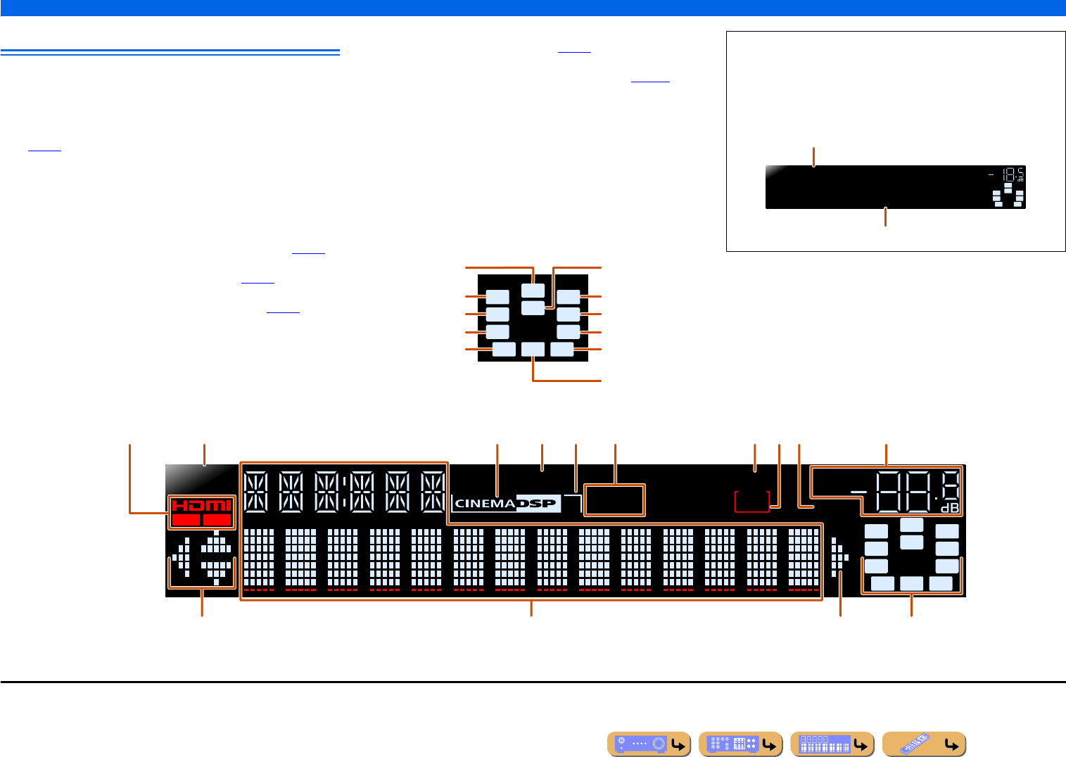
Front panel display
aHDMI indicator
Lights up when this unit detects the external component connected to
the HDMI1-5 jacks.
OUT 1/OUT 2 indicators
Indicate which HDMI OUT jack outputs audio/video signals
(☞p. 23).
bSIRIUS indicator
Lights up when a SiriusConnect tuner is selected as an input source.
cCINEMA DSP indicator
Lights up when a sound field effect that uses CINEMA DSP
technology is selected.
dENHANCER indicator
Lights up when the Compressed Music Enhancer is active (☞p. 47).
eCINEMA DSP 3D indicator
Lights up when CINEMA DSP 3D is activated (☞p. 46).
fTuner indicators
Light up according to the status of a received station (☞p. 57).
gSLEEP indicator
Lights up when the sleep timer is on (☞p. 11).
hZONE2 indicator
Lights up when the audio output to Zone2 is enabled (☞p. 126).
iMUTE indicator
Flashes when audio is muted.
jVOLUME indicator
Displays the current volume level.
kCursor indicators
Light up if corresponding cursors on the remote control are available
for operations.
lMulti information display
Displays a range of information on menu items and settings.
mSpeaker indicators
Indicate speaker terminals from which signals are output.
SW
C
LR
SL SR
SBL SBRSB
PR
PL
Front speaker L
Surround speaker L
Subwoofer
Front speaker R
Surround speaker R
Center speaker
Surround back
speaker L
Surround back
speaker R
Surround back
speaker J1
Presence speaker L Presence speaker
R
■Switching information on the front panel display
The front panel can display sound programs and surround
decoder names as well as the active input source.
Press fINFO repeatedly to cycle through displayed
informations. J2
SWSW
C
LR
SL SR
SBL SBR
STRAIGHT
HDMI1
VOL.
Input source name
Sound program (DSP program)
STEREO
SLEEP
VOL.
TUNED
SW
C
LR
SL SR
MUTE
ENHANCER
OUT 1 OUT 2
3
ZONE
2
SBL SBRSB
PR
PL
SIRIUS
kl mk
acdebfgjih
J1 : “SB” is displayed when using a 6.1-channel configuration only.
J2 : During FM/AM reception, the frequency is displayed instead of the input source. During SIRIUS Satellite Radio signals reception, the channel is displayed instead of the input source.
En 11
INTRODUCTION
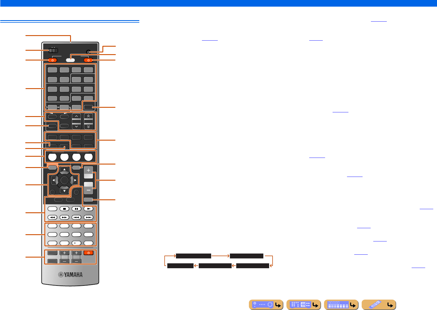
Part names and functions
Remote control aRemote control signal transmitter
Transmits infrared signals.
bMAIN/ZONE2
Switches the zone to be operated by the remote control between the
Main zone and Zone2 (☞p. 126).
cSOURCE A (SOURCE Power)
Switches an external component on and off.
dInput selector
Select an input source on this unit from which to playback.
eRadio control keys
Operates the FM/AM tuner. These keys are used when using the tuner
input.
fINFO
Cycles the information displayed on the front panel display (the name
of the currently selected input source, the sound program, the
surround decoder, the FM/AM tuner frequency, etc.).
gSLEEP
Switches this unit to standby mode automatically after a specified
period of time has elapsed (sleep timer). Press this key repeatedly to
set the time for the sleep timer function.
The SLEEP indicator lights up when the sleep timer is on.
hPARTY
Switches the party mode on and off (☞p. 126).
iSCENE
Switch the input source and the sound program with a single button
(☞p. 44). When this unit is in standby mode, press this key to switch on.
jON SCREEN
Turns on and off the ON SCREEN menu.
kCursor B / C / D / E, ENTER, RETURN
lExternal component operation keys
Operate recording, playback, and menu displays etc. for external
components (☞p. 115).
mNumeric keys
Enter numbers.
nTV control keys
Operate a monitor such as a TV.
oCODE SET
Sets remote control codes for external component operations
(☞p. 116).
pSOURCE/RECEIVER
Switches remote control key function to operate this unit or an
external component (☞p. 115). Operate an external component when
this key glows green, or this unit when this key glows orange.
qRECEIVER A (RECEIVER Power)
Switches this unit between on and standby mode.
rHDMI OUT
Switches the output jack connected to an HDMI compatible TV (☞p. 42).
sSound selection keys
Switch between the sound field effect (sound program) you are using
and the surround decoder (☞p. 44).
tOPTION
Turns on and off the Option menu (☞p. 52).
uVOLUME +/-
Adjust the volume level (☞p. 42).
vMUTE
Turns the mute function of the sound output on and off (☞p. 42).
SCENE
RETURN
VOLUME
ENHANCER SUR. DECODE
STRAIGHTSLEEP PURE DIRECT
HDMI
AV
AUDIO
1234
125
V-AU X
FM
INFO
MEMORY
AM
PRESET
PART Y
MOVIE MUSIC
BD
DVD TV
CD
RADIO
MUTE
ENTER
7856
90
10
1234
REC
ENT
TV
TV VOL TV CH
TOP
MENU
POP-UP
MENU
DISPLAY
SOURCE
MAIN
ZONE 2
RECEIVER
CODE SET
INPUT
MUTE
DOCK
HDMI OUT
MULTI
OPTION
ON SCREEN
5
1234
6
SIRIUSTUNER
TUN./CH
CATEGORY
HOLD
NET
a
c
b
e
i
jt
u
v
m
n
k
f
l
g
h
p
q
r
o
d
s
HDMI1-5 HDMI1-5 jacks
V-AUX Front panel VIDEO AUX jacks
AUDIO1-2 AUDIO1-2 jacks
AV1-6 AV1-6 jacks
NET Rhapsody service, SIRIUS internet radio, internet
radio, or a PC connected to the NETWORK port.
MULTI CH INPUT MULTI CH INPUT jacks
DOCK A Universal Dock for iPod, Wireless System for
iPod, or Bluetooth wireless audio receiver
connected to the DOCK jack.
TUNER FM/AM tuner
SIRIUS A SIRIUS tuner connected to the SIRIUS jack.
FM Sets the FM/AM tuner band to FM.
AM
(CATEGORY D / E)
Sets the FM/AM tuner band to AM.
Selects a channel category for a SIRIUS.
MEMORY Presets radio stations.
PRESET F / GSelects a preset station.
TUN./CH H / IChanges tuning frequencies or SIRIUS Satellite
Radio channels.
Sleep 120min. Sleep 90min.
Sleep 60min.Sleep 30min.Sleep Off
Cursor B / C / D / ESelect menu items and change settings when
menus, etc, are displayed.
ENTER Confirms a selected item.
RETURN Returns to the previous screen when menus are
displayed, or close the menu.
INTRODUCTION
Part names and functions
En 12
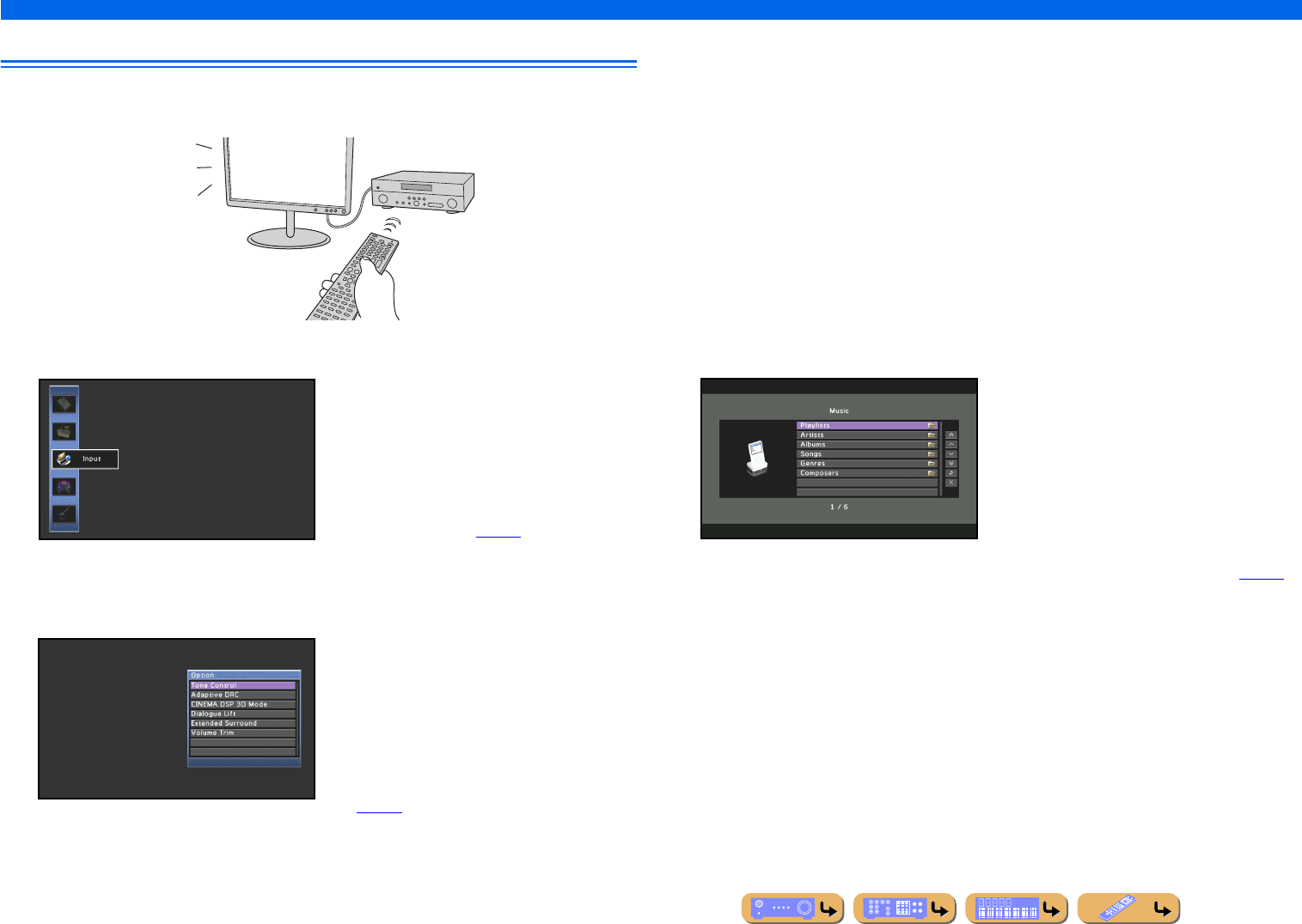
On-screen display
When a TV is connected to this unit, the supplied remote control can be used to specify and verify this
unit’s settings via menus and options displayed on the TV screen.
The following displays are available in the on-screen display.
ON SCREEN menu
Press jON SCREEN to display the ON
SCREEN menu.
Detailed settings for this unit can be
configured. Use this menu to select desired
settings, change their values, or check the
current status of this unit.
Refer to “SETUP” (☞p. 86) for details.
Option menu
Press tOPTION to display the Option menu.
Configure the optional settings for each input
source. Settings such as “Tone Control” and
“Volume Trim” are applied to this unit
regardless of the input source.
Refer to “Configuring settings specific to an
individual input source (Option menu)”
(☞p. 52) for details.
Content window
Press dInput selector to display the
Content window.
Includes the Browse view and the Now
Playing view. The Now Playing view displays
the status of the source from which music is
currently played back. Adjust settings for
music content from the Browse view.
Refer to “Confirming and operating input
sources from the Content window” (☞p. 56)
for details.
En 13
CONNECTIONS
This unit uses acoustic field effects and sound decoders to bring you the impact of a real movie theater or concert hall. These effects will be brought to you with ideal speaker positioning and
connections in your listening environment.
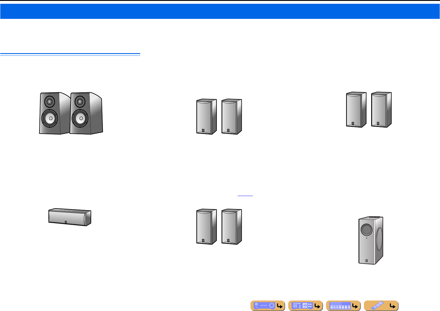
Speaker channels and functions
■
Front left and right speakers
The front speakers are used for the front channel sounds (stereo
sound) and effect sounds.
Front speaker layout:
Place these speakers at an equal distance from the ideal listening
position in the front of the room. When using a projector screen,
the appropriate top positions of the speakers are about 1/4 of the
screen from the bottom.
■
Center speaker
The center speaker is for the center channel sounds (dialog, vocals,
etc.).
Center speaker layout:
Place it halfway between the left and right front speakers. When
using a TV, place the speaker just above or just under the center of
the TV with the front surfaces of the TV and the speaker aligned.
When using a screen, place it just under the center of the screen.
■
Surround left and right speakers
The surround speakers are for effect and vocal sounds when
playing back a 5.1-channel source or higher. If used with no
surround back speaker when playing back a 6.1-channel source or
higher (including a surround back channel), the sound of the
surround back channel is distributed between the left and right
surround speakers.
Surround speaker layout:
Place the speakers at the rear of the room on the left and right sides
facing the listening position. They should be placed between 60
degrees and 80 degrees from the listening position and with the
speaker tops at a height of 4.9 – 5.9 ft. (1.5 – 1.8 m) from the floor.
■
Presence left and right speakers
The presence speakers are used for front effect sounds. When used
in combination with the sound programs (☞p. 44), a sound with a
richer and more spatial presence is possible.
Presence speaker layout:
Place the left and right presence speakers 1.6 – 3.3 ft. (0.5 – 1 m) to
the outside of the left and right front speakers respectively. The
tops of the presence speakers should be 5.9 ft. (1.8 m) above the
floor.
■
Surround back left and right speakers
The surround back speakers are for rear effect sounds when
playing back a 6.1-channel source or higher. If used with only one
surround back speaker when playing back a 7.1-channel source or
higher, the sound of the left and right surround back channel is
mixed and output from a single speaker.
Surround back speaker layout:
When used with 7.1ch sound, arrange the left and right speakers
towards the listening position, to the rear of the listening position.
Arrange the left and right speakers at least 1 ft. (30 cm) apart. The
same separation as with the front left and right speakers is optimum.
When used with 6.1ch sound, arrange these to the rear of the
listening position.
■
Subwoofer
The subwoofer speaker is used for bass sounds and low-frequency
effect (LFE) sounds included in Dolby Digital and DTS. Use a
subwoofer that is equipped with built-in amplifier.
Subwoofer speaker layout:
Place it to the outside of the front left and right speakers facing
slightly inward to reduce echoes from the wall. You can use one or
two subwoofers.
Connecting speakers
E.g.
E.g.
E.g.
E.g.
E.g.
E.g.
CONNECTIONS
Connecting speakers
En 14
Speaker layout
In addition to the 7.1-channel speaker layout, a variety of speaker configurations can be specified with
presence speaker connection, bi-amp connection or the Zone2 function.
And, this unit is equipped with “Power Amp Assign” function which can easily apply the appropriate
speaker setting to this unit according to your speaker configuration.
■
Connection of speakers
Connect the speakers to the appropriate jacks shown in the table for each speaker layout. Refer to
“Connecting speakers and subwoofers” (☞p. 17) for details on connecting speakers.
You can also use two subwoofers by connecting them to both SUBWOOFER1 and SUBWOOFER2
jacks. In this case, monaural sound of subwoofer channel is output from both speakers.
■
Assigning a speaker configuration
A speaker configuration must be assigned to this unit to activate the speakers. Use the Power Amp
Assign function to apply the appropriate settings shown in the table for each speaker layout. Refer to
“Power Amp Assign” (☞p. 99) for details on setting.
■
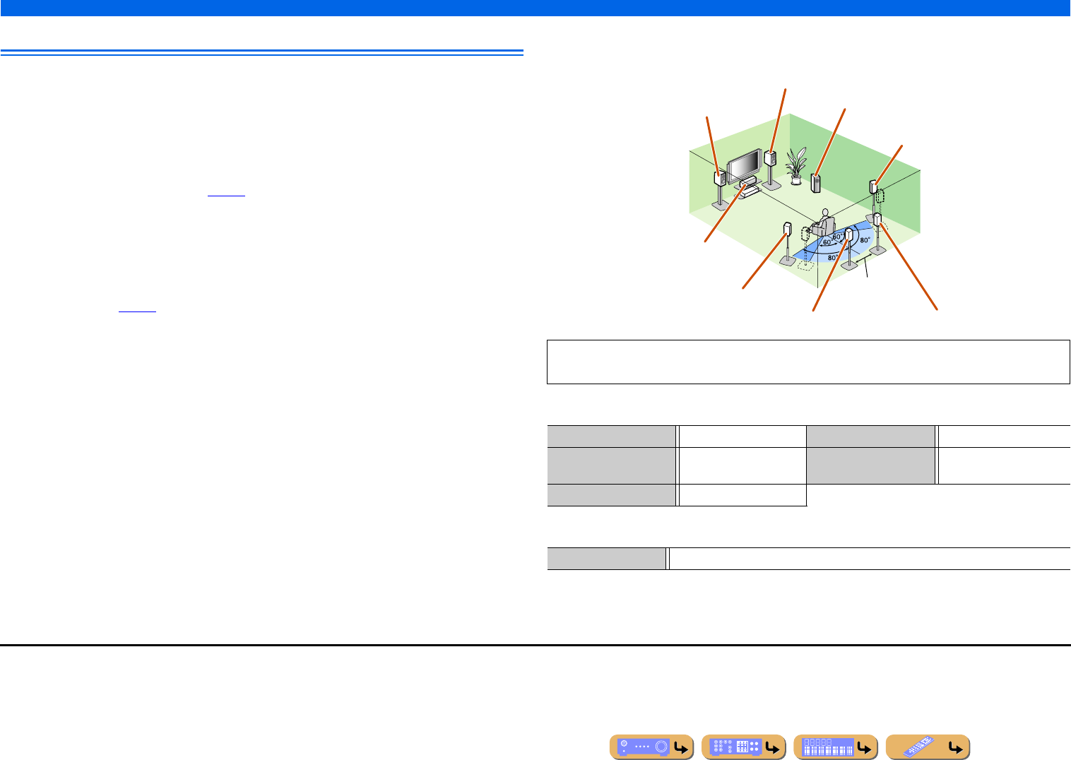
Enjoying the 7.1 channel audio source
■7.1-channel speaker layout (7 speakers + subwoofer)
■Connections of speakers
■Assigning a speaker configuration
Audio from a 7.1-channel audio source can be played back with no degradation with this speaker
configuration.
FRONT jacks Front L/R speakers SURROUND BACK jacks Surround back L/R speakers
CENTER jack Center speaker SUBWOOFER
(PRE OUT) jack
Subwoofer
SURROUND jacks Surround L/R speakers
Power Amp Assign 7ch Normal (Default)
Front L speaker
Front R speaker
Subwoofer
Center speaker
Surround L speaker
Surround R speaker
Surround back R speaker
Surround back L speaker J1
12 in (30 cm)
or more
J1 : The sound of surround back channel can also be output from a single surround back speaker. When only one surround back
speaker is used, connect it to the SURROUND BACK L (SINGLE) jack and place it directly behind the listening position.
CONNECTIONS
Connecting speakers
En 15
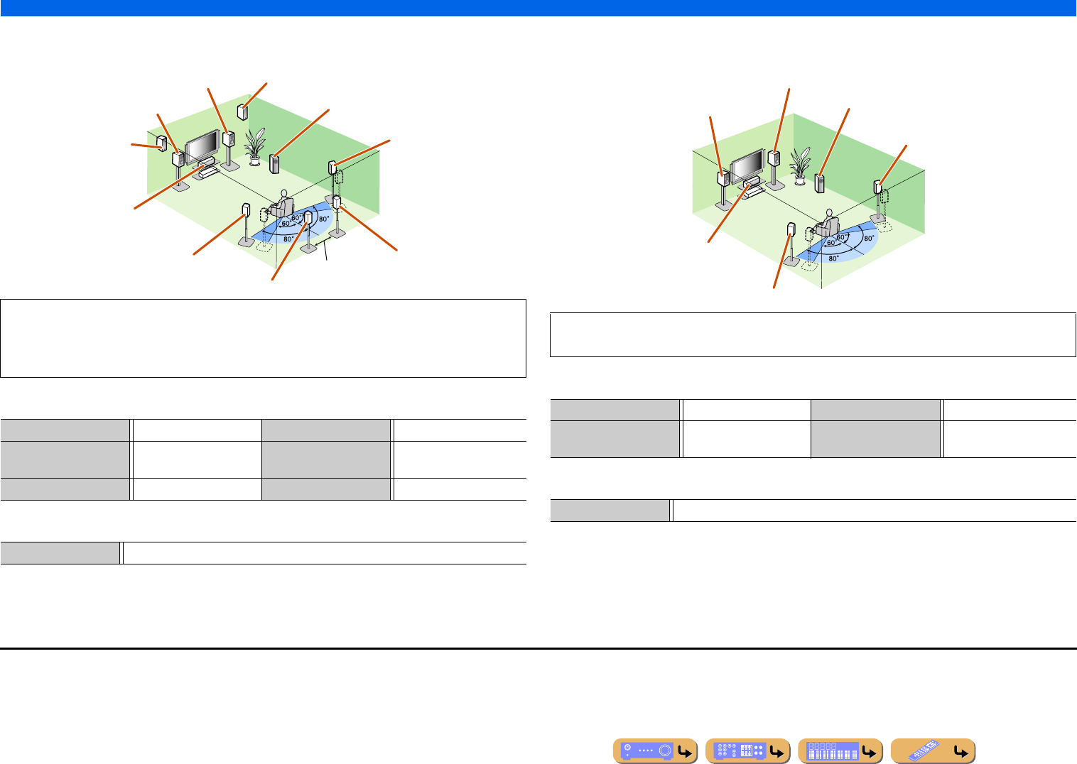
■
Adding the presence speakers for a richer sound field effect
■Presence speaker layout (7 speakers + subwoofer + presence speakers)
■Connections of speakers
■Assigning a speaker configuration
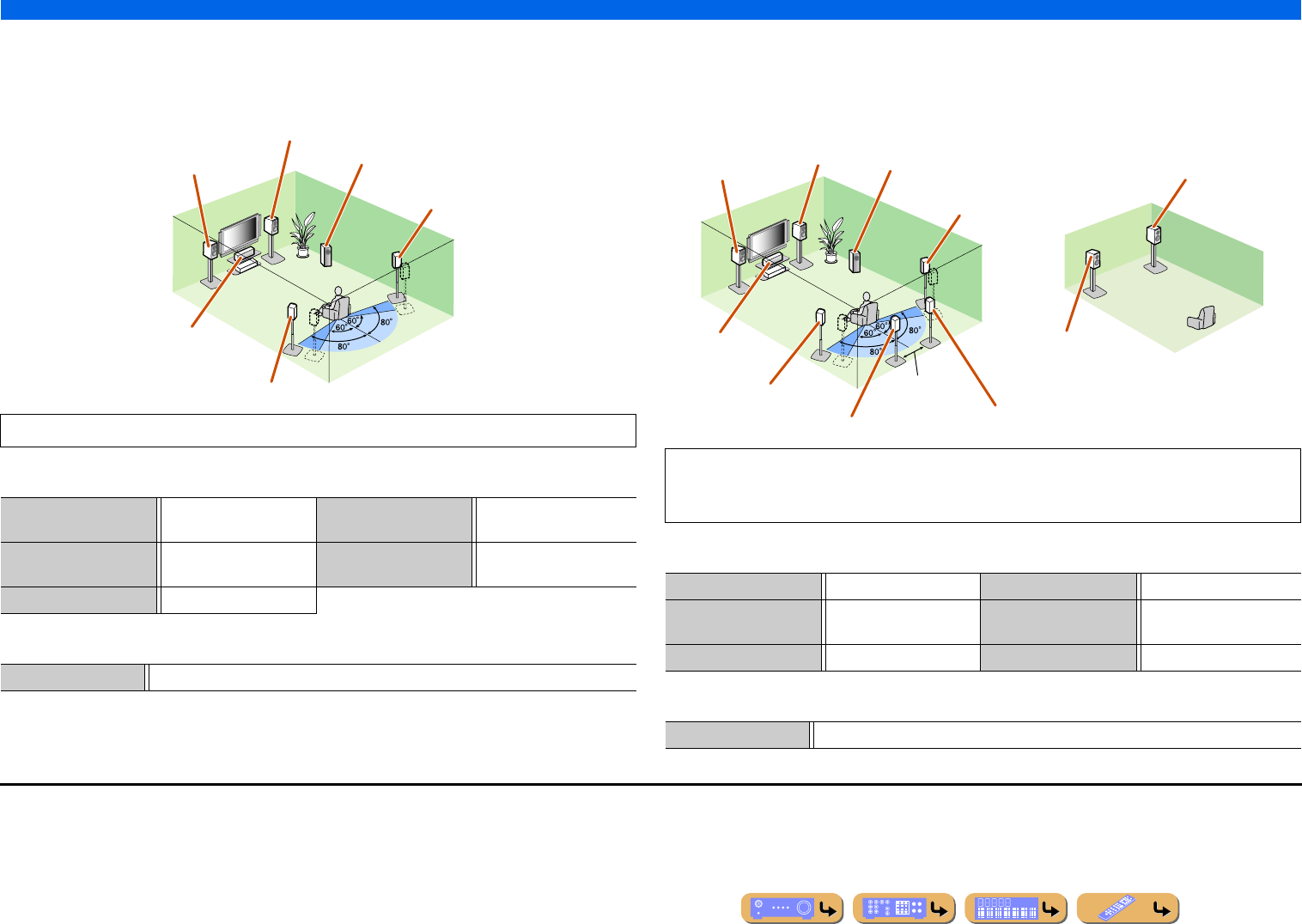
■
Enjoying the audio source without surround back speakers
■5.1-channel speaker layout (5 speakers + subwoofer)
■Connections of speakers
■Assigning a speaker configuration
This unit automatically selects the presence speakers or surround back speakers to output sounds
according to the selected sound program.
When the sound program is changed, the speakers that output the sound are switched between the
presence speakers and surround back speakers automatically. J2
FRONT jacks Front L/R speakers SURROUND BACK jacks Surround back L/R speakers
CENTER jack Center speaker SUBWOOFER
(PRE OUT) jack
Subwoofer
SURROUND jacks Surround L/R speakers EXTRA SP jacks Presence L/R speakers
Power Amp Assign 7ch Normal (Default)
Front L speaker
Front R speaker
Subwoofer
Center speaker
Surround L speaker
Surround R speaker
Presence R speaker
Presence L speaker
Surround back R speaker
Surround back L speaker J1
12 in (30 cm) or
more
This unit can mix 7.1-channel audio source down to 5.1-channel sound. This enables 7.1-channel
sound without surround back speakers.
FRONT jacks Front L/R speakers SURROUND jacks Surround L/R speakers
CENTER jack Center speaker SUBWOOFER
(PRE OUT) jack
Subwoofer
Power Amp Assign 7ch Normal (Default)
Front L speaker
Front R speaker
Subwoofer
Center speaker
Surround L speaker
Surround R speaker
J1 : The sound of surround back channel can also be output from a single surround back speaker. When only one surround back
speaker is used, connect it to the SURROUND BACK L (SINGLE) jack and place it directly behind the listening position.
J2 : Sound cannot be output from the surround back speakers when it is output from the speakers connected to the EXTRA SP
jacks.
CONNECTIONS
Connecting speakers
En 16
■
Using the front speakers that support bi-amp connections for a
high quality sound
■5.1-channel speaker layout (Front speakers (Bi-amp) + 3 speakers)
■Connections of speakers
■Assigning a speaker configuration
■
Using speakers in two rooms (Zone2 function)
■7.1-channel speaker layout + Zone2 (7 speakers (in main zone) + subwoofer (in
main zone) + front speakers (in secondary zone))
■Connections of speakers
■Assigning a speaker configuration
Using the front speakers that support bi-amp connections reproduces a high quality sound.
FRONT jacks Front L/R speakers
(bi-amp)
SURROUND BACK jacks Front L/R speakers (bi-amp)
CENTER jack Center speaker SUBWOOFER
(PRE OUT) jack
Subwoofer
SURROUND jacks Surround L/R speakers
Power Amp Assign 5ch BI-AMP
Front L speaker
(Bi-amp connection)
Front R speaker
(Bi-amp connection)
Center speaker
Surround L speaker
Surround R speaker
Subwoofer
In addition to the main room, speakers in another room can also be controlled.
When the built-in amplifier assigned to speakers in another room is turned on, sound output
automatically switches from the surround back speakers to the speakers in the other room. J2
FRONT jacks Front L/R speakers SURROUND BACK jacks Surround back L/R speakers
CENTER jack Center speaker SUBWOOFER
(PRE OUT) jack
Subwoofer
SURROUND jacks Surround L/R speakers EXTRA SP jacks Zone2 speakers
Power Amp Assign 7ch + 1ZONE
Front L speaker
Front R speaker
Center speaker
Subwoofer
Surround R speaker
Surround L speaker
Surround back L speaker J1Surround back R
speaker
12 in (30 cm)
or more
Front R speaker
Front L speaker
Main zone Zone2
J1 : The sound of surround back channel can also be output from a single surround back speaker. When only one surround back
speaker is used, connect it to the SURROUND BACK L (SINGLE) jack and place it directly behind the listening position.
J2 : Sound cannot be output from the surround back speakers when it is output from the speakers connected to the EXTRA SP
jacks.
CONNECTIONS
Connecting speakers
En 17
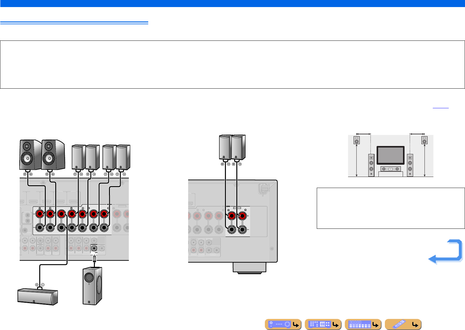
Connecting speakers and subwoofers
Connect your speakers to their respective terminals on the rear panel.
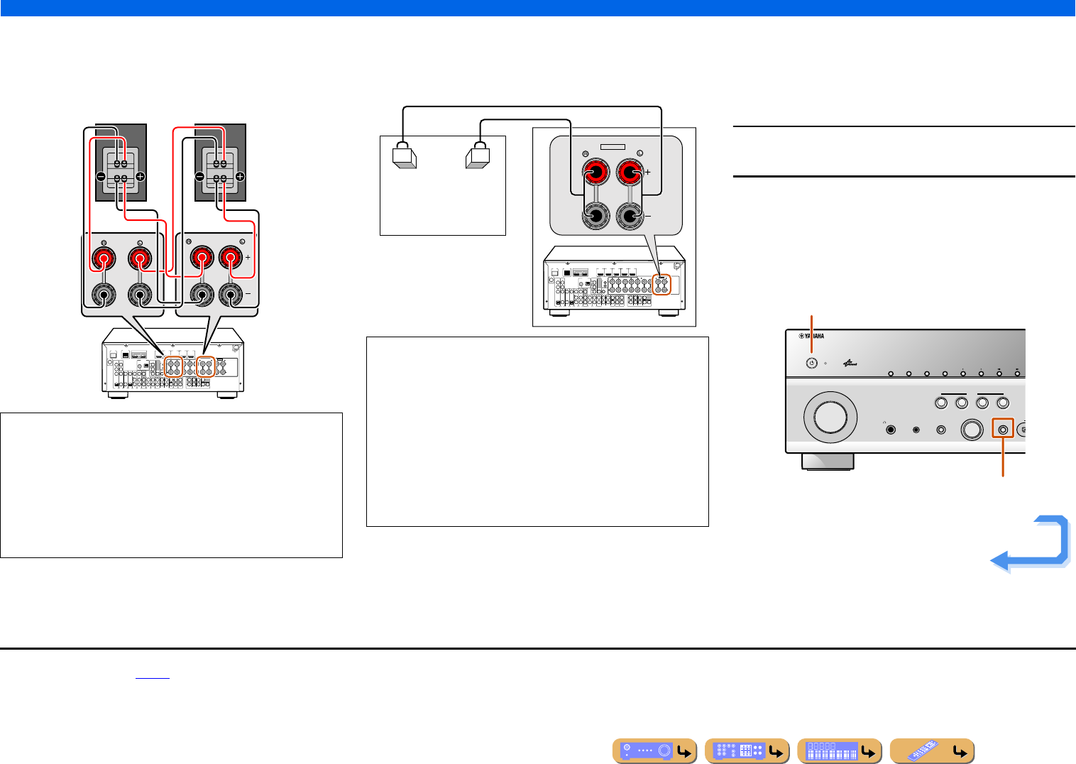
■Front/Center/Surround/Surround back speaker and
Subwoofer connection
When connecting only one surround back speaker, connect the
speaker to the SURROUND BACK L (SINGLE) jacks.
■Presence speaker connection
When using the presence speakers, connect the speakers to the
EXTRA SP jacks as shown in the diagram below.
The presence speakers (PL/PR) that output front effect sounds can
be connected to this unit. With the sound programs (☞p. 48),
sound with a richer and more spatial presence can be created.
CAUTION
•Remove the AC power cable of this unit from the power outlet before connecting the speakers.
•Generally speaker cables consist of two parallel insulated cables. One of these cables is a different color, or has a line running along it, to indicate different polarity. Insert the different colored (or lined) cable into the “+”
(positive, red) terminal on this unit and the speakers, and the other cable into the “–” (negative, black) terminal.
•Be careful that the core of the speaker cable does not touch anything or come into contact with the metal areas of this unit. This may damage this unit or the speakers. If the speaker cables short circuit, “CHECK SP
WIRES!” will appear on the front panel display when this unit is switched on.
CENTER
SURROUND
SURROUND BACK/
BI-AMP
SINGLE
FRONT
1
MULTI CH INPUT
MI 1
DVD
)
HDMI 2
H
DMI
3
HDMI 4 HDMI
5
SUBWOOFE
R
AUDI
O
OU
T
Z
ONE2
O
UT
S
UR.BA
C
K
S
URR
O
UND
SU
RR
OU
ND
SU
R.BA
C
K
PRE
OUT
WOO
FE
R
2
F
R
O
NT
T
RI
GG
ER
OUT
+12V
0
.1
A
MAX
.
CENTE
R
E
XTRA S
P
IN
REMOTE
OUT
C
ENTERSINGLE
SPEAKERS
SPEAKERS
ZONE2/PRESENC
E
SubwooferCenter speaker
Front speaker Surround
speaker
Surround back
speaker
RL
RL RL
EXTRA SP
ZONE2/PRESENCE
M
I
5
SU
RR
OU
N
D
S
URROUND BACK/
BI
-
AMP
S
IN
G
LE
S
URROUND
SUR.BACK
PRE
OU
T
S
UBWOOFE
R
1
2
C
ENTER
S
IN
G
LE
S
PE
A
SPEA
Presence speaker
RL
•Connection of presence speakers is recommended to take full
advantage of the effects of CINEMA DSP sound programs.
•Although you can connect both surround back speakers and
presence speakers to this unit, you cannot output sounds from
those speakers at the same time.
0.5 – 1 m 0.5 – 1 m
PL PR
FL FR
1.8 m 1.8 m
Continues to the
next page
CONNECTIONS
Connecting speakers
En 18
■Bi-amp connection
This unit can be connected to speakers that support bi-amp
connections. When connecting speakers, connect the FRONT jacks
and the SURROUND BACK/BI-AMP jacks as in the diagram
below. Configure the bi-amp settings to activate connections.
■Multi-zone audio system using the internal
amplifier of this unit
Connect the speakers in the second zone to the EXTRA SP jacks as
in the diagram below.
■
Changing speaker impedance
This unit is configured for 8 Ω speakers at the factory setting.
When connecting to 6 Ω speakers, carry out the following
procedure to switch to 6 Ω. When this unit is configured for 6 Ω
speakers, 4 Ω speakers can also be used as the front speakers.
1Switch this unit to the standby mode.
2Press MAIN ZONE A while pressing and holding
STRAIGHT on the front panel.
Release the keys when “ADVANCED SETUP” is displayed on
the front panel display.
After approximately a few seconds, the top menu item is
displayed. J1
NOTES
•Before making bi-amplification connections, remove any
brackets or cables that connect a woofer with a tweeter. Refer to
the instruction manuals of speakers for details. When not making
bi-amplification connections, make sure that the brackets or
cables are connected before connecting the speaker cables.
•If connecting a bi-amp, then surround back speakers cannot be
used.
DOCK
( TV )
AV 3AV 4AV 5AV 6
AUDIO 1 AUDI O 2
MULTI CH INPUT
(CD)
COAXIAL OPTICAL
VIDEO
HDMI 1
(BD/DVD)
HDMI 2 HDMI 3
HDMI 4 HDMI 5
CENTER
SURROUND
SURROUND BACK/
BI-AMP
SINGLE
EXTRA SP
FRONT
AV
OUT
SUBWOOFER
AUDIO
OUT ZONE2
OUT
SUR.BACK
SURROUND SURROUND
SUR.BACK
PRE OUT
SUBWOOFER
1
2
FRONT
TRIGGER OUT
+12V
0.1A MAX.
FRONT
CENTER
IN
REMOTE
OUT
CENTERSINGLE
HDMI OUT
12
ARC ARC
SELECTABLE
SPEAKERSSPEAKERS
OPTICAL
AV 1AV 2
COAXIAL
COMPONENT
VIDEO
P
R
P
B
Y
SIRIUS
COMPONENT
VIDEO
VIDEO
MONITOR OUT
P
R
P
B
Y
ZONE2/PRESENCE
NETWORK
ANTENNA
FM
75
GND
AM
FRONT
SINGLE
SURROUND BACK/
BI-AMP
CAUTION
The EXTRA SP jacks of this unit should not be connected to a
Passive Loudspeaker Selector Box or more than one loudspeaker
per channel.
Connection to a Passive Loudspeaker Selector Box or multiple
speakers per channel could create an abnormally low impedance
load resulting in amplifier damage. See this owner’s manual for
correct usage.
Compliance with minimum speaker impedance information for all
channels must be maintained at all times. This information is found
on the back panel of this unit.
DOCK
( TV )
AV 3AV 4AV 5AV 6
AUDIO 1 AUDI O 2
MULTI CH INPUT
(CD)
COAXIAL OPTICAL
VIDEO
HDMI 1
(BD/DVD)
HDMI 2 HDMI 3
HDMI 4 HDMI 5
CENTER
SURROUND
SURROUND BACK/
BI-AMP
SINGLE
EXTRA SP
FRONT
AV
OUT
SUBWOOFER
AUDIO
OUT ZONE2
OUT
SUR.BACK
SURROUND SURROUND
SUR.BACK
PRE OUT
SUBWOOFER
1
2
FRONT
TRIGGER OUT
+12V
0.1A MAX.
FRONT
CENTER
IN
REMOTE
OUT
CENTERSINGLE
HDMI OUT
12
ARC ARC
SELECTABLE
SPEAKERSSPEAKERS
OPTICAL
AV 1AV 2
COAXIAL
COMPONENT
VIDEO
P
R
P
B
Y
SIRIUS
COMPONENT
VIDEO
VIDEO
MONITOR OUT
P
R
P
B
Y
ZONE2/PRESENCE
NETWORK
ANTENNA
FM
75
GND
AM
ZONE2/PRESENCE
EXTRA SP
Zone2
PHONES
YPAO MIC
SILENT
CINEMA
TONE
CONTROL
STRAIGHT
TV
BD
DVD
CD
RADIO
INPUT
PROGRAM
SCENE
H
INFOZONE
CONTROL
ZONE2
MAIN ZONE
MEMORY
PRESET
FM AM
CATEGORY
MAIN ZONE A
STRAIGHT
Continues to the
next page
J1 : Refer to the “Extended functionality that can be configured as needed
(Advanced Setup menu)” (☞p. 118) for details on the Advanced Setup menu.
CONNECTIONS
Connecting speakers
En 19
3Check that “SP IMP.” is displayed on the front panel.
4Press STRAIGHT repeatedly to select a “6ΩMIN.”
5Switch this unit to the standby mode, and then
switch it on again.
The power turns on, when the settings you made has been
configured.
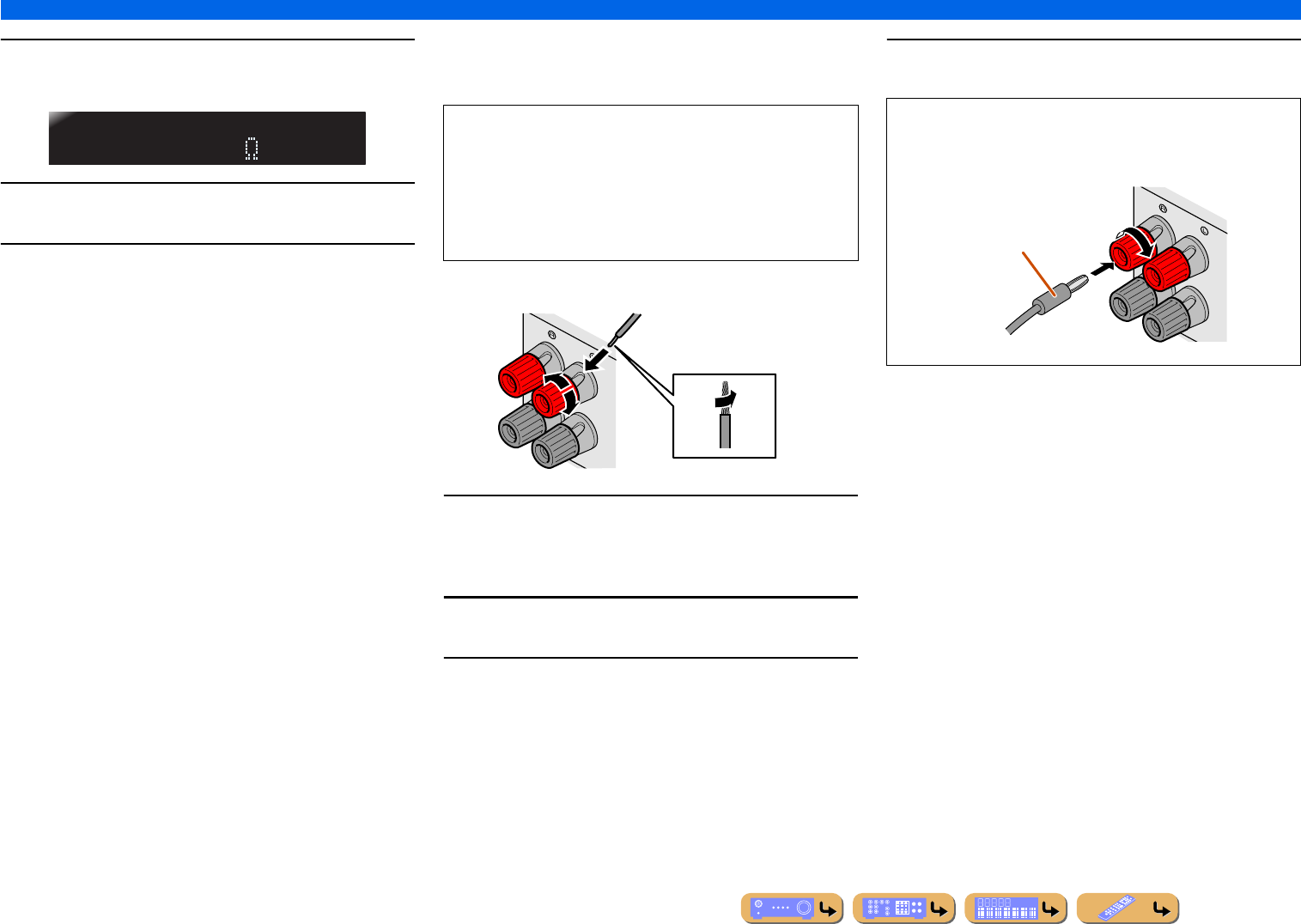
■
Connecting speakers
This type of jack can connect to the following speakers or
connection.
1Remove approximately 0.4 in. (10 mm) of insulation
from the ends of the speaker cables, and twist the
bare wires of the cables together firmly so that they
will not cause short circuits.
2Loosen the speaker terminals.
3Insert the bare wire of the speaker cable into the gap
on the side of the terminal.
4Tighten the terminal.
SPIMP.-8MIN
•Front L/R speakers
•Center speaker
•Surround L/R speakers
•Surround back L/R speakers
•Presence L/R speakers
•Zone2 speakers
•Bi-amp connection (Front L/R speakers)
FRONT
2
2
3
1
4
4
Connecting the banana plug
Tighten the knob, and then insert the banana plug into the end of
the terminal.
FRONT
Banana plug
CONNECTIONS
Connecting speakers
En 20
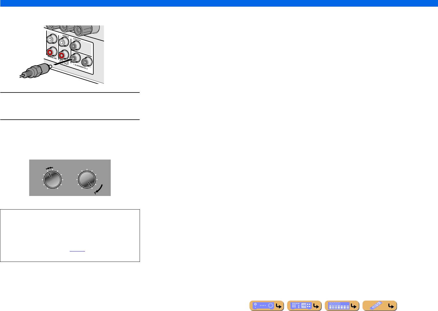
■
Connecting subwoofers
1Connect the subwoofer input jack to the
SUBWOOFER 1 or 2 jack on this unit with an audio
pin cable.
2Set the subwoofer volume as follows.
Volume: Set to approximately half volume (or slightly less than
half).
Crossover frequency (if available): Set to maximum.
NOTE
After connection, applying this setting to this unit is required to
activate all speaker connections. With using “Power Amp
Assign” function, you can easily apply the speaker
configuration.
Refer to “Power Amp Assign” (☞p. 99) for details on using
“Power Amp Assign” function.
VOLUME
MIN MAX
CROSSOVER/
HIGH CUT
MIN MAX
Subwoofer examples
CONNECTIONS
En 21
Jacks and cables
This unit is equipped with the following input/output jacks. Use jacks and cables appropriate for
components that you are going to connect.
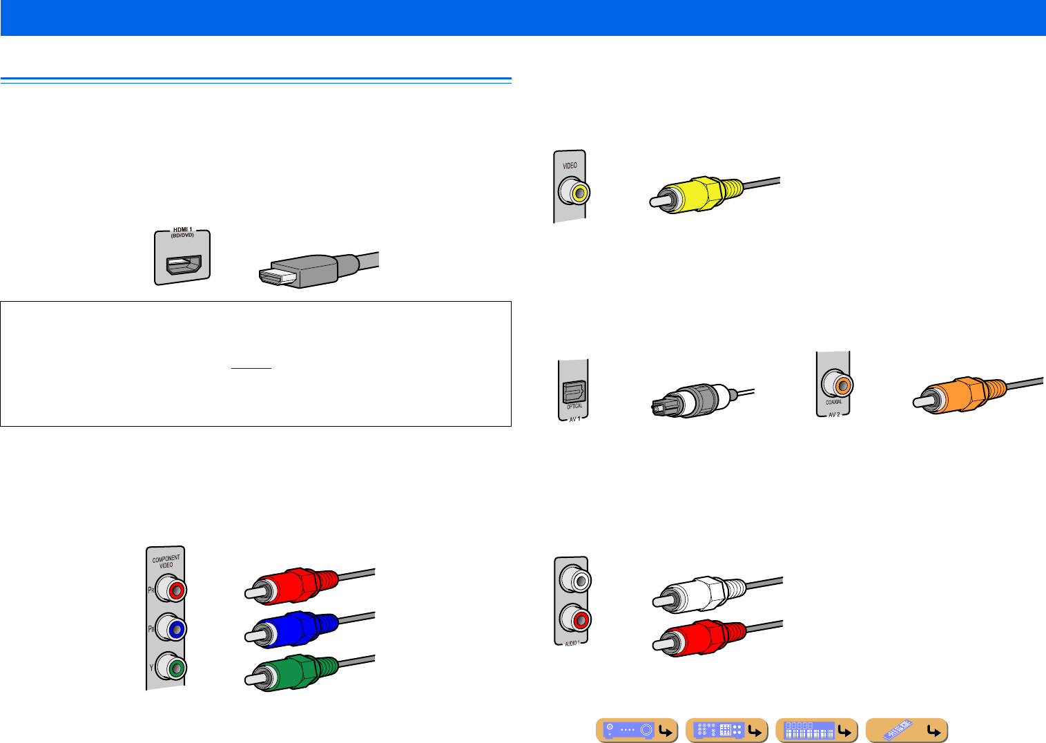
■
Audio/Video jacks
HDMI jacks
Digital video and digital sound are transmitted through a single jack.
Only use an HDMI cable.
■
Analog video jacks
■
Audio jacks
Connecting external components
•Use a 19-pin HDMI cable with the HDMI logo.
•We recommend using a cable less than 16.4 ft. (5.0 m) long to prevent signal quality degradation.
•When a TV that supports HDMI functions and Audio Return Channel function is connected, audio
output from the TV can be input to this unit (☞p. 123).
•When a player and TV that support the 3D video format are connected to this unit, 3D content can be
played back.
•If you connect this unit to a component that has a DVI jack, an HDMI/DVI-D cable is required.
COMPONENT VIDEO jacks
The signal is separated into three components:
luminance (Y), chrominance blue (PB), and chrominance red (PR).
Use component video pin cables with three plugs.
HDMI cable
Component video pin cable
VIDEO jacks
These jacks transmit conventional analog video
signals.
Use video pin cables.
OPTICAL jacks
These jacks transmit optical digital audio signals.
Use fiber-optic cables for optical digital audio
signals.
COAXIAL jacks
These jacks transmit coaxial digital audio signals.
Use pin cables for digital audio signals.
AUDIO jacks
These jacks transmit conventional analog audio
signals.
Use stereo pin cables, connecting the red plug to
the red R jack, and the white plug to the white L
jack.
Video pin cable
Digital audio fiber-optic cable Digital audio pin cable
Stereo pin cable
CONNECTIONS
Connecting external components
En 22
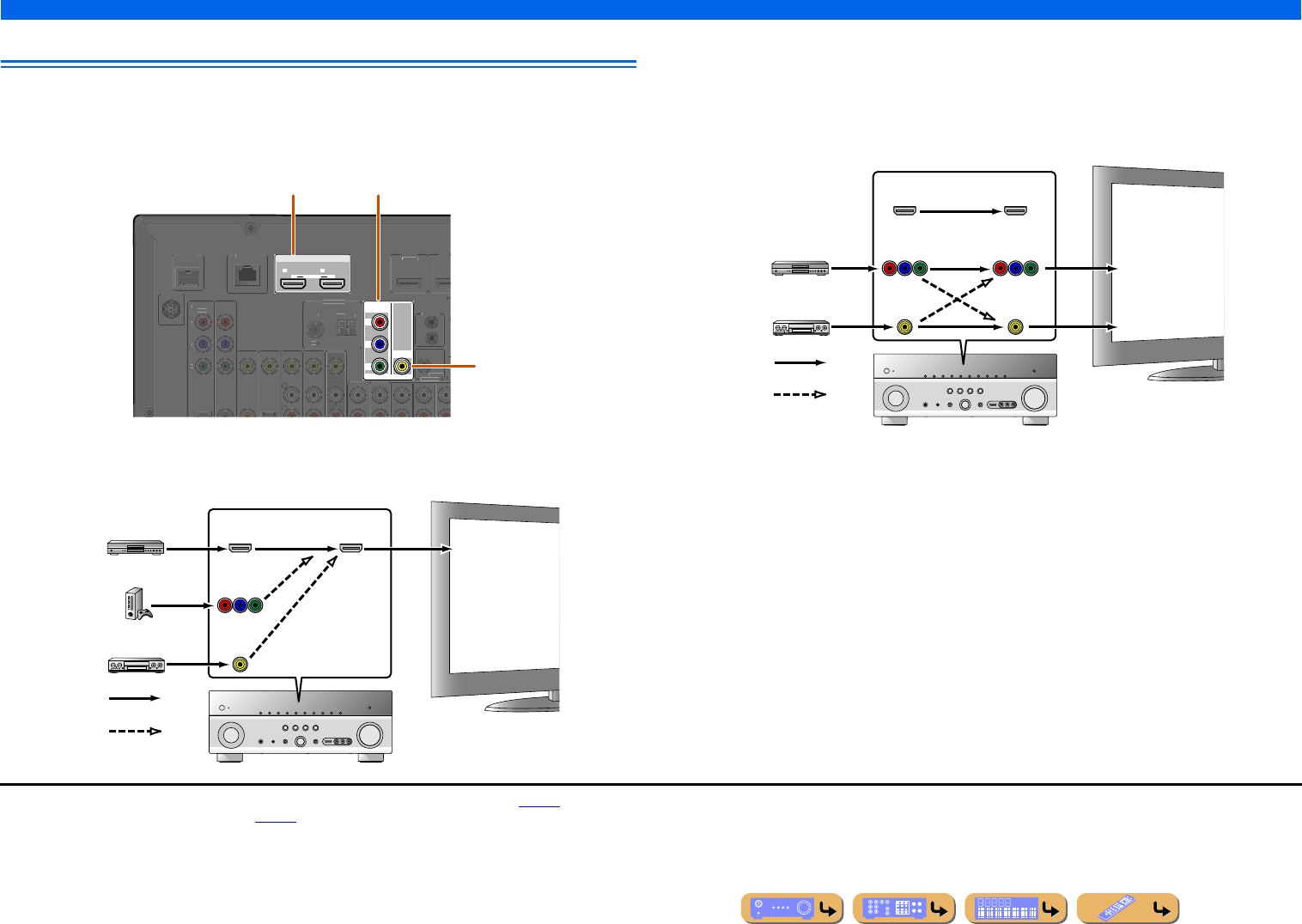
Connecting a TV monitor
This unit is equipped with the following three types of output jack for connection to a TV.
HDMI OUT 1-2, COMPONENT VIDEO or VIDEO. Select the proper connection according to the
input signal format supported by your TV.
When connecting to an HDMI compatible TV
Video signal such as component video and video received by this unit is converted to HDMI and output to
the TV. Just select HDMI input on the TV to view video from any external source connected to this unit. J1
When connecting to a non-HDMI compatible TV
Connect to the TV using the same type of connection that you used to connect to the external
component, and change the inputs on your TV to match that of the external component you are using
for playback. If the external component and TV are equipped with different types of analog video
jacks, this unit will convert the video signal to component video signal, or vice-versa, according to the
type of video input jacks used by the TV. J2,J3
HDMI OUT
12
ARC ARC
SELECTABLE
COMPONENT
VIDEO
VIDEO
MONITOR OUT
P
R
P
B
Y
D
OCK
VIDE
O
HDMI
1
(
B
D
/
DV
D
)
HDM
I
TRI
GG
ER
OUT
+
12
V
0
.1
A
MAX
.
IN
R
EM
O
T
E
OUT
COMPONENT
VIDE
O
P
R
P
B
Y
SIRIUS
ANTENNA
F
M
75
G
ND
A
M
NETW
O
RK
HDMI OUT 1-2 jacks
COMPONENT VIDEO jacks
(MONITOR OUT)
VIDEO jack
(MONITOR OUT)
HDMI
COMPONENT
VIDEO
HDMI
VIDEO
Input Output
HDMI input
Through
Converted
TV
COMPONENT
VIDEO
HDMI
VIDEO
COMPONENT
VIDEO
HDMI
VIDEO
Input Output
Video input
Through
Component
video input
TV
Converted
J1 : You can change the resolution and aspect ratio when converting to HDMI to suit your requirements (☞p. 105).
J2 : Set “Analog to Analog Conversion” to “On” (☞p. 104).
J3 : Analog to analog conversion is available only for 480i/576i-resolution video signal.
CONNECTIONS
Connecting external components
En 23
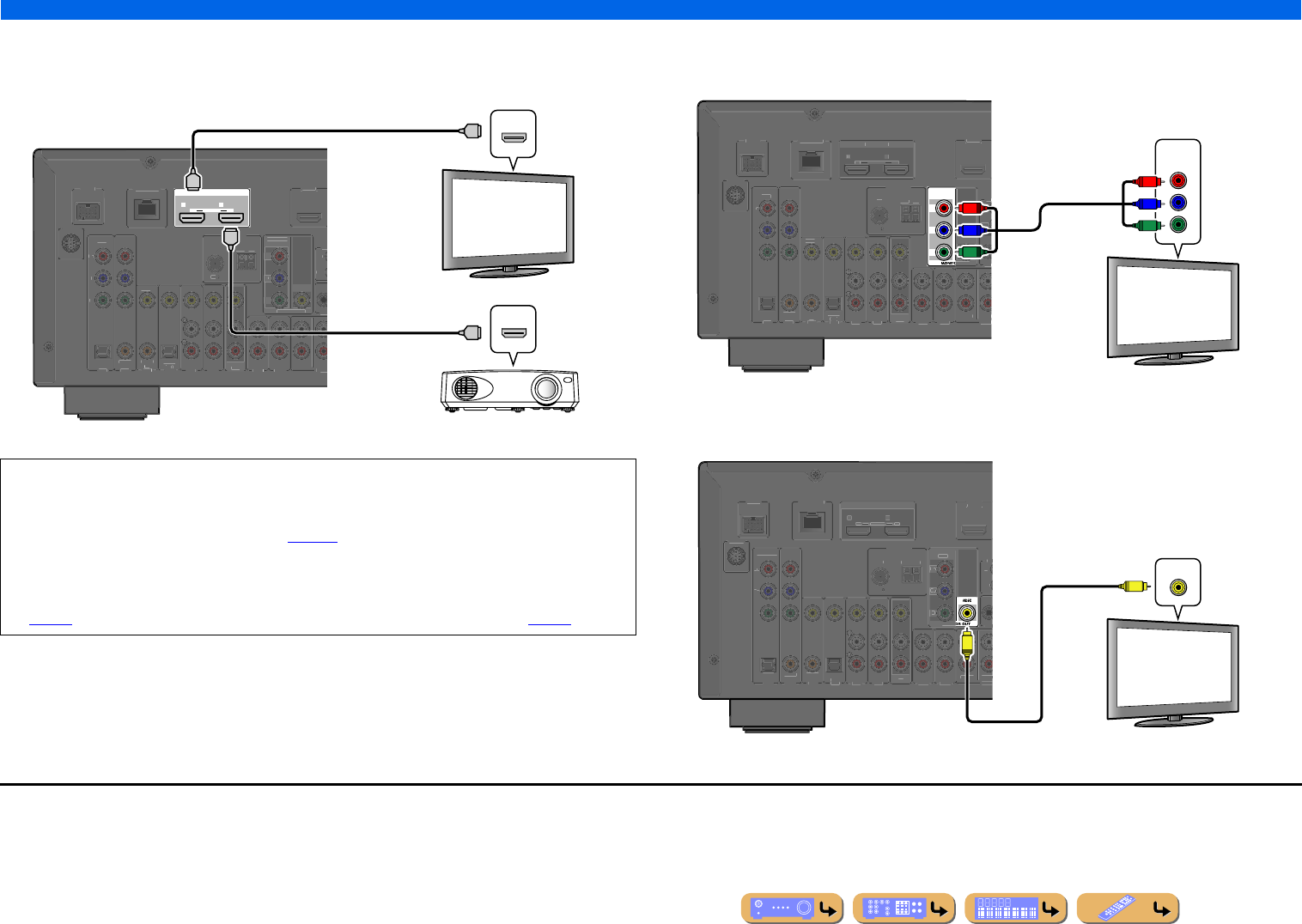
■
Connecting an HDMI video monitor
Connect the HDMI cable to one of the HDMI OUT 1-2 jacks.
■
Connecting a component video monitor
Connect the component video cable to the COMPONENT VIDEO (MONITOR OUT) jacks.
■
Connecting a video monitor
Connect the video pin cable to the VIDEO (MONITOR OUT) jack.
•Use a 19-pin HDMI cable with the HDMI logo.
•We recommend using a cable less than 16.4 ft. (5.0 m) long to prevent signal quality degradation.
•When a TV that supports the HDMI function and Audio Return Channel function is connected, audio
output from the TV can be input to this unit (☞p. 123).
•When a player and TV that support the 3D video format are connected to this unit, 3D content can be
played back.
•This unit is equipped with HDMI OUT 1 and 2 jacks. The active HDMI OUT jack(s) can be selected
(☞p. 42). The active HDMI OUT jack(s) can be registered with the SCENE function (☞p. 44).
HDMI OUT
12
ARC ARC
SELECTABLE
D
OC
K
(
TV
)
AV 3
AV 4
AV 5
AV 6
AUDIO 1
AUDIO 2
MULT
(
C
D
)
CO
AXIAL
O
PTICAL
V
IDEO
HDMI 1
(
B
D
/
DVD
)
AV
OUT
S
URRO
U
TRI
GG
FRON
T
IN
R
E
O
U
T
O
PTI
C
A
L
AV 1
AV 2
CO
AXIA
L
CO
MP
O
NEN
T
VIDE
O
P
R
P
B
Y
S
IRIU
S
CO
MP
O
NENT
VIDE
O
VIDE
O
M
O
NIT
O
R
O
U
T
P
R
P
B
Y
ANTENNA
FM
7
5
G
N
D
AM
NETW
O
RK
HDMI
HDMI
HDMI
HDMI
HDMI
HDMI
HDMI input
TV
Projector
J1
COMPONENT
VIDEO
P
R
P
B
Y
DOC
K
(
TV
)
AV 3
AV 4
AV 5
AV 6
AUDI O 1
AUDIO 2
MULT
(
C
D
)
CO
AXIA
L
O
PTI
C
A
L
V
IDE
O
HDMI 1
(
BD
/
DVD
)
AV
OUT
SU
RR
OU
T
RI
GG
F
R
O
NT
IN
RE
O
UT
H
DMI OUT
1
2
ARC
A
R
C
S
ELECTABLE
OPTICA
L
AV 1
AV 2
CO
AXIAL
CO
MP
O
NENT
V
IDE
O
P
R
P
B
Y
S
IRI
US
V
IDE
O
O
R
O
UT
ANTENNA
FM
75
G
N
D
AM
N
ETW
O
R
K
COMPONENT
VIDEO
Y
P
R
P
B
Y
P
R
P
B
Component video input
TV
J1
DOC
K
(
TV
)
AV 3
AV 4
AV 5
AV 6
AUDIO 1
AUDI O 2
MULT
(
C
D
)
CO
AXIA
L
O
PTI
C
AL
V
IDE
O
HDMI 1
(
BD
/
DVD
)
AV
O
UT
SU
RR
OU
T
RI
GG
FR
O
N
T
IN
R
E
O
UT
HDMI
O
U
T
1
2
A
RC AR
C
S
ELECTABL
E
OPTICA
L
AV 1
AV 2
CO
AXIA
L
CO
MP
O
NEN
T
V
IDE
O
P
R
P
B
Y
S
IRI
US
C
OMPONEN
T
VIDE
O
MO
NIT
O
P
R
P
B
Y
ANTENNA
FM
75
G
N
D
AM
N
ETW
O
R
K
VIDEO
V
V
Video input
TV
J1 : When connecting to a TV that supports HDMI input, the video signal for the COMPONENT VIDEO or VIDEO jacks is
converted and output from HDMI OUT 1-2 jacks. When connecting to a TV via the HDMI jack, you do not need to use these
jacks.
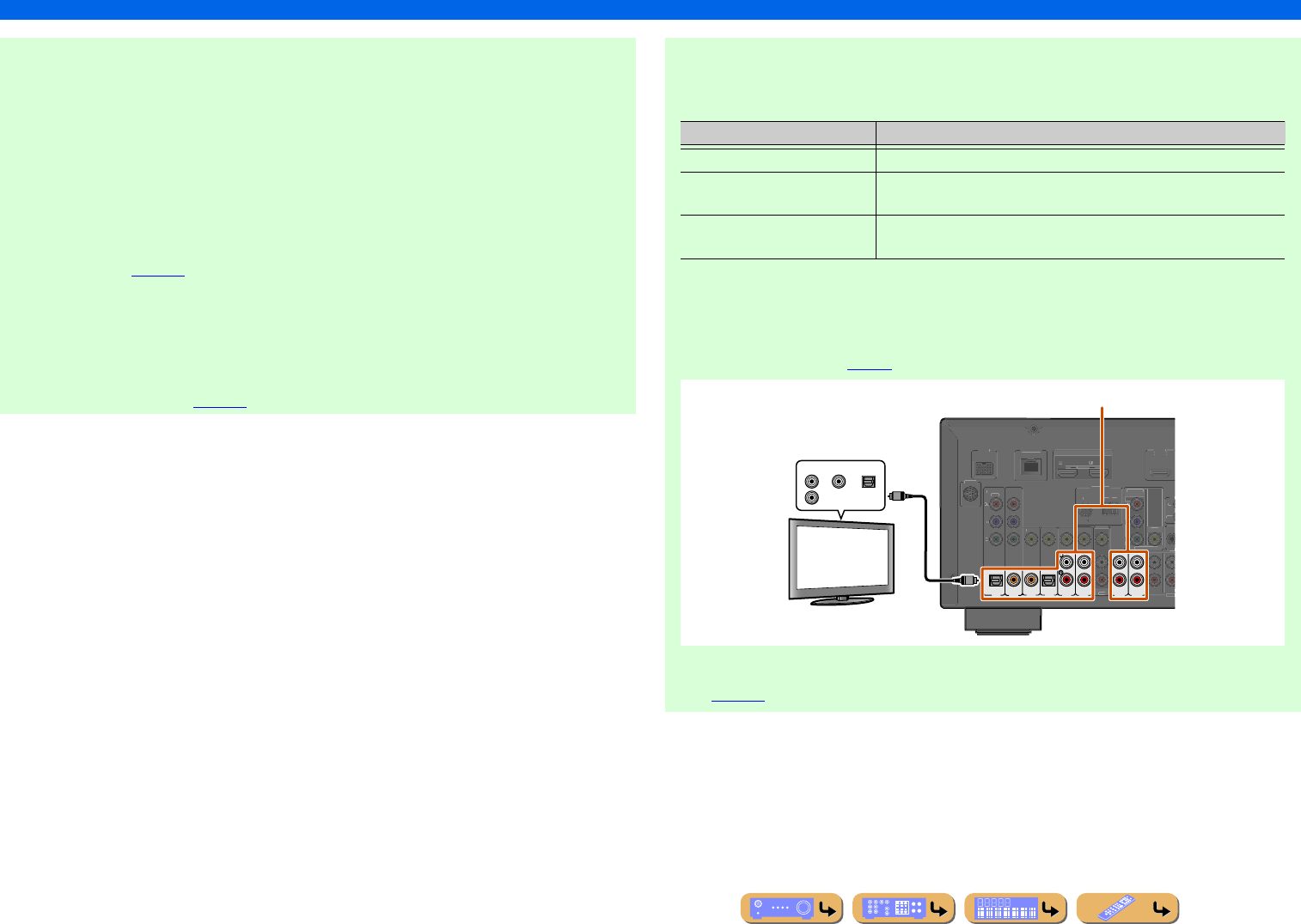
En 24
CONNECTIONS
Connecting external components
■Listening to TV audio
To transmit sound from the TV to this unit, connect as followings according to the TV:
When using a TV that supports the Audio Return Channel function and HDMI
Control function
When your TV supports both HDMI Control (e.g., Panasonic VIERA Link) and Audio Return
Channel functions, audio/video output from the unit to the TV and audio output from the TV to the
unit are possible using a single HDMI cable.
The input source is switched automatically to match operations carried out on the TV, and that
makes TV sound control easier to use.
For the connections and settings, refer to “Single HDMI cable input to TV audio with Audio Return
Channel function” (☞p. 123).
When using a TV that supports the HDMI Control functions
When using a TV that supports HDMI Control functions (e.g., Panasonic VIERA Link), if HDMI
Control functions are enabled on the unit, then input source can be switched automatically to match
operations carried out on the TV.
For the connections and settings, refer to “Switching the input source on this unit automatically
when listening to TV audio” (☞p. 122).
When using other TVs
To transmit sound from the TV to this unit, connect AV1-6 or AUDIO1-2 jacks to the TV’s audio
output jacks.
Select the input source connected via TV’s audio output jack to enjoy the TV sound.
If the TV supports optical digital audio output, we recommend that you connect the TV audio output
to the receiver’s AV4 jack.
Connecting to AV4 allows you to switch the input source to AV4 with just a single key operation
using the SCENE function (☞p. 44).
You can control your TV using the receiver’s remote control by entering the TV’s remote control
code (☞p. 116).
TV audio output Connection
Optical digital audio output Connect to the OPTICAL jack of the AV1 or AV4 with a fiber-optic cable.
Coaxial digital audio output Connect to the COAXIAL jack of the AV2 or AV3 with a digital audio pin
cable.
Analog stereo output Connect to one of the AV5, AV6, AUDIO1, or AUDIO2 with a stereo pin
cable.
( TV )
AV 3AV 4AV 5AV 6
AUDI O 1 AUDI O 2
(CD)
COAXIAL OPTICAL
OPTICAL
AV 1AV 2
COAXIAL
DOCK
MULT
V
IDE
O
H
DMI 1
(
B
D
/
DV
D
)
AV
OU
T
S
URR
OU
TRI
GG
FR
O
NT
IN
RE
OUT
H
DMI OU
T
1
2
A
R
C
A
R
C
S
ELE
C
TABL
E
CO
MP
O
NENT
V
IDE
O
P
R
P
B
Y
SIRIU
S
COMPONENT
VIDE
O
V
IDE
O
M
O
NIT
O
R
O
UT
P
R
P
B
Y
ANTENNA
FM
75
G
N
D
AM
N
ETWOR
K
OPTICALCOAXIALAUDIO
Audio output
(Optical, coaxial, or analog)
TV
Available input jacks
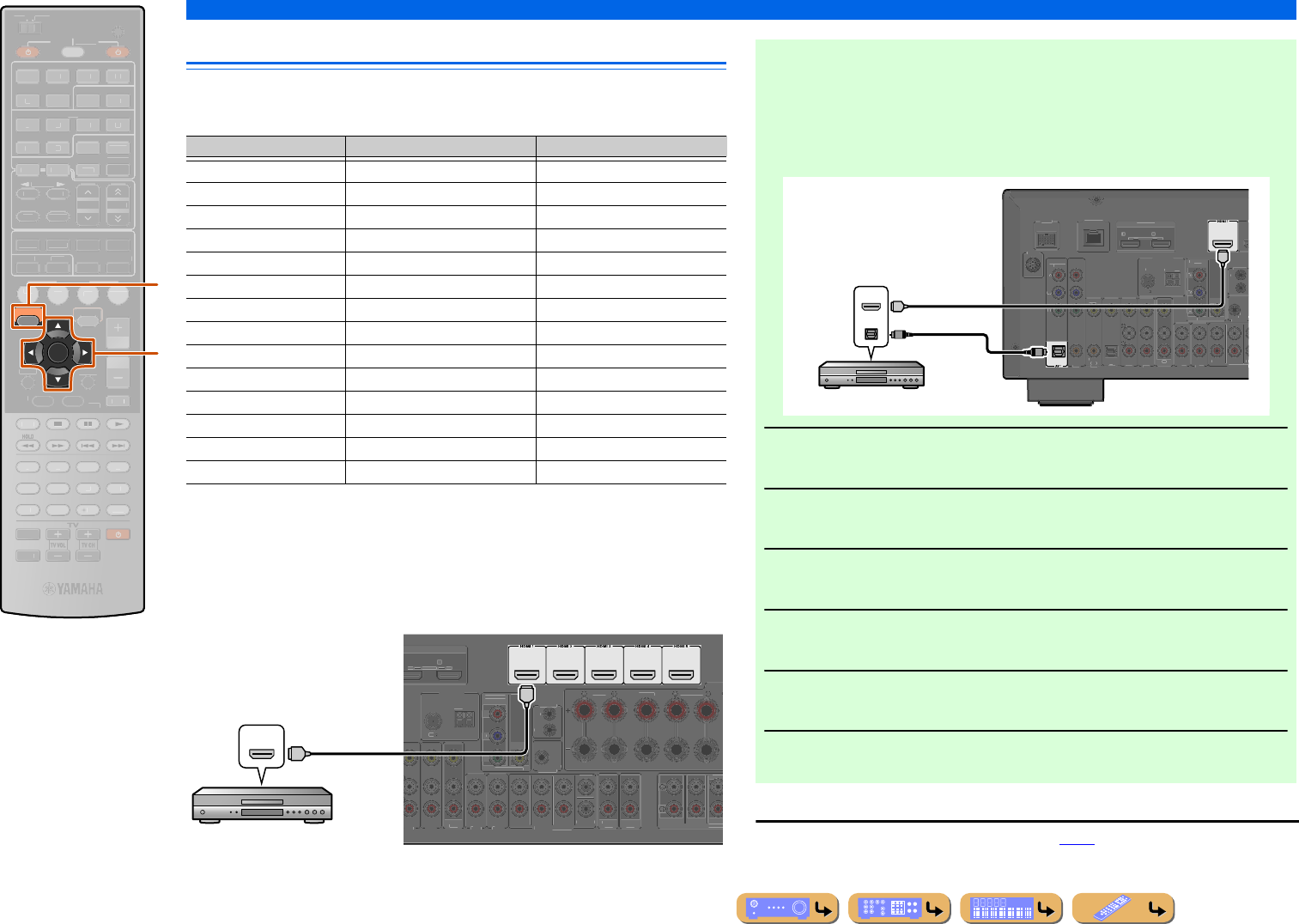
CONNECTIONS
Connecting external components
En 25
Connecting BD/DVD players and other devices
This unit has the following input jacks. Connect them to the appropriate output jacks on
the playback devices such as BD/DVD players.
■
Connecting BD/DVD players and other devices with
HDMI
Connect the device with an HDMI cable to one of the HDMI1-5 jacks. The HDMI IN
jack on the front panel can also be used.
Select the HDMI input (HDMI1-5 or VIDEO AUX) that the playback device is
connected to for playback.
ENTER
ON SCREEN
SCENE
RETURN
VO
L
U
ME
ENHANCE
R
S
UR. DE
CO
DE
STRAIGHTSLEEP
P
URE DIRECT
PART Y
M
OVI
E
M
USI
C
BD
DVD
TV
CD
RADI
O
M
U
T
E
7
8
5
6
9
0
10
1
2
3
4
R
EC
ENT
FM
I
NF
O
M
EM
O
RY
AM
P
RESET
H
DMI
AV
A
UDI
O
1
2
3
4
1
2
5
V
-
AUX
TOP
MENU
P
OP-U
P
M
EN
U
DI
S
PLAY
SO
UR
C
E
M
AIN
Z
O
NE 2
RE
C
EIVE
R
CODE SE
T
I
NP
U
T
MUTE
DOCK
HDMI
O
U
T
MULTI
O
PTION
5
1
2
3
4
6
NET
S
IRI
US
TU
NER
TUN./C
H
C
ATE
GO
R
Y
k
j
jON SCREEN
kCursor B / C / D / E
kENTER
Input Video input Audio input
HDMI1 HDMI HDMI
HDMI2 HDMI HDMI
HDMI3 HDMI HDMI
HDMI4 HDMI HDMI
HDMI5 HDMI HDMI
AV1 Component video Optical digital
AV2 Component video Coaxial digital
AV3 Video Coaxial digital
AV4 Video Optical digital
AV5 Video Analog (Stereo)
AV6 Video Analog (Stereo)
AUDIO1 — Analog (Stereo)
AUDIO2 — Analog (Stereo)
VIDEO AUX HDMI/Video HDMI/Analog (Stereo)
(BD/DVD)
AV 5
AV 6
AUDIO 1
AUDIO 2
MULTI CH INPUT
C
ENTER
SURROUN
D
F
RONT
A
V
OU
T
S
UBW
OO
FE
R
AU
DI
O
OUT
ZO
NE
2
OU
T
S
UR.BA
CK
S
URR
O
UND
S
URROUN
D
SUR.BA
C
P
RE
OU
FRONT
T
RIGGER OUT
+12
V
0
.1
A
MAX.
FR
O
N
T
CENTER
IN
REM
O
TE
OU
T
S
INGL
E
H
DMI
OU
T
2
AR
C
A
R
C
S
ELE
C
TABLE
CO
MP
O
NEN
T
VIDE
O
V
IDE
O
MO
NIT
O
R
OU
T
P
R
P
B
Y
A
NTENN
A
FM
75
G
ND
AM
HDMI
HDMI
HDMI
HDMI output
BD/DVD player
■Receiving video signals from the HDMI jack and audio signals
from a jack other than HDMI
This unit can use the AV1-6 or AUDIO1-2 input jacks to receive audio signals from
other input jacks.
For example, if a playback device cannot produce audio signals from an HDMI jack,
use the following method to change the audio input.
1Press jON SCREEN to display the ON SCREEN menu.
2Press kCursor B / C repeatedly to select “Input,” and then press
kENTER.J1
3Press kCursor D / E repeatedly to select the desired HDMI input
source, and then press kCursor B.
4Press kCursor C repeatedly to select “Audio In,” and then press k
ENTER.
5Press kCursor B / C to select the audio input source.
6Once you have completed the setup, press jON SCREEN to close
the menu.
J1 : Refer to the “Configuring input sources (Input menu)” (☞p. 86) for details on selecting the input source.
(BD/DVD)
OPTICAL
DOCK
(
TV
)
AV 3
AV 4
AV 5
AV 6
AUDIO 1
AUDIO 2
MULTI CH IN
(
CD
)
COAXIA
L
OPTICAL
V
IDE
O
H
AV
OU
T
SU
SU
RR
OU
N
D
TRI
GG
ER
O
U
T
+12V
0
.1A MA
X
FR
O
NT
I
N
REMOTE
OUT
H
DMI OUT
1
2
A
R
C
A
R
C
S
ELE
C
TABL
E
AV 2
CO
AXIAL
CO
MP
O
NENT
V
IDE
O
P
R
P
B
Y
S
IRIU
S
COMPONENT
V
IDE
O
V
IDE
O
MO
NIT
O
R
O
U
T
P
R
P
B
Y
ANTENNA
F
M
75
G
N
D
AM
N
ETWOR
K
HDMI
OPTICAL
HDMI
HDMI
O
O
HDMI/Audio (Optical)
output
BD/DVD player
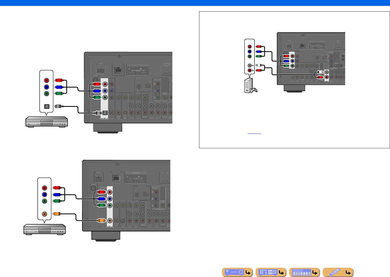
En 26
CONNECTIONS
Connecting external components
■
Connecting BD/DVD players and other devices with component
video cables
Connect the device with a component video cable to one of the AV1-2 input jacks.
Using optical digital audio output sources
Select the AV1 input to which the playback device is connected for playback.
Using coaxial digital audio output sources
Select the AV2 input to which the playback device is connected for playback.
OPTICAL
COMPONENT
VIDEO
P
R
P
B
Y
DOCK
(
TV
)
AV 3
AV 4
AV 5
AV 6
AUDIO 1
AUDIO 2
MULT
(
C
D
)
CO
AXIA
L
O
PTI
C
A
L
VIDE
O
HDMI 1
(
B
D
/
DV
D
)
AV
OU
T
SU
RR
OU
T
RI
GG
F
R
O
NT
IN
RE
O
U
T
HDMI
OUT
1
2
A
R
C
AR
C
S
ELE
C
TABL
E
AV 2
CO
AXIAL
S
IRI
US
C
OMPONEN
T
V
IDEO
V
IDE
O
M
O
NIT
O
R
O
U
T
P
R
P
B
Y
ANTENNA
FM
75
G
ND
AM
NETW
O
RK
COMPONENT
Y
P
R
P
B
Y
P
R
P
B
O
OPTICAL
O
Component video / Audio (Optical)
output
BD/DVD player
COAXIAL
DOC
K
(
TV
)
AV 3
AV 4
AV 5
AV 6
AUDIO 1
AUDIO 2
MULT
(
C
D
)
CO
AXIA
L
O
PTI
C
AL
V
IDE
O
HDMI 1
(
BD
/
DVD
)
AV
OUT
SU
RR
OU
T
RI
GG
FR
O
N
T
IN
R
E
O
UT
HDMI
OUT
1
2
A
R
C
AR
C
S
ELE
C
TAB L
E
OPTICA
L
AV 1
CO
MP
O
NEN
T
V
IDE
O
P
R
P
B
Y
S
IRI
US
C
OMPONENT
VIDE
O
VIDE
O
MO
NIT
O
R
O
UT
P
R
P
B
Y
ANTENNA
FM
75
G
N
D
AM
N
ETW
O
R
K
COMPONENT
VIDEO
COAXIAL
Y
P
R
C
P
B
Y
P
R
P
B
C
Component video / Audio (Coaxial)
output
BD/DVD player
■Component connections to analog audio output devices
The video input from the AV1-2 jacks can be used in combination with the audio input from other
AV inputs or AUDIO1-2.
When connecting these devices, select the AV input jacks or the AUDIO1-2 jacks as the audio input
for AV1 or AV2. Refer to “Receiving video signals from the HDMI jack and audio signals from a
jack other than HDMI” (☞p. 25) for detailed setup guidance.
For playback of the connected device, select the AV input source (AV1-2) to which the device is
connected with the component video cable.
COMPONENT
VIDEO
P
R
P
B
Y
D
OCK
(
TV
)
AV 3
AV4
AV 5
AV 6
AUDIO 2
MULTI CH IN
(
C
D
)
COAXIA
L
O
PTI
C
A
L
VIDE
O
HDMI 1
(
B
D
/
DV
D
)
H
AV
OUT
S
U
SURROUND
TRI
GG
ER
OU
T
+12V
0
.1
A
MAX
F
RON
T
I
N
REMOTE
OUT
H
DMI
OUT
1
2
AR
C
AR
C
S
ELE
C
TABLE
O
PTI
C
A
L
AV 1
AV 2
CO
AXIA
L
S
IRI
US
CO
MP
O
NEN
T
V
IDE
O
VIDE
O
MO
NIT
O
R
OUT
P
R
P
B
Y
ANTENNA
FM
75
G
ND
AM
N
ETW
O
RK
AUDIO
COMPONENT
VIDEO
R
L
R
LY
P
R
P
B
Y
P
R
P
B
Component video / Audio
output
Game console
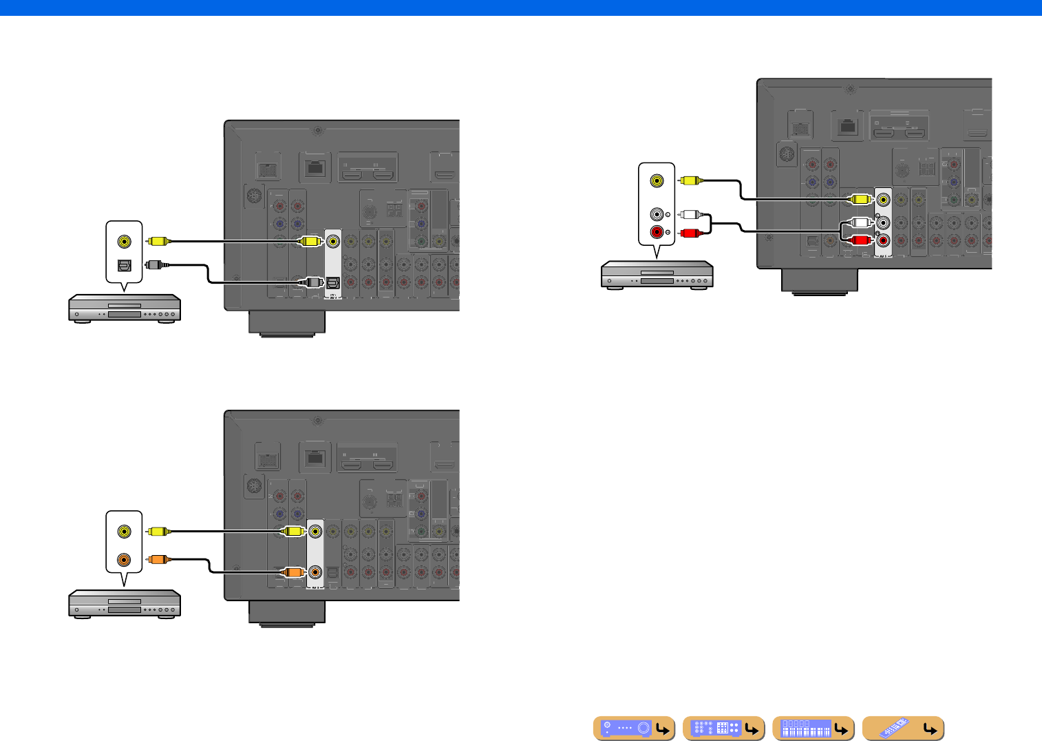
En 27
CONNECTIONS
Connecting external components
■
Connecting BD/DVD players and other devices with video cables
Connect the playback device with a video pin cable to one of the AV3-6 input jacks.
Using optical digital audio output sources
Select the AV4 input to which the playback device is connected for playback.
Using coaxial digital audio output sources
Select the AV3 input to which the playback device is connected for playback.
Using analog stereo audio output sources
Select the AV5 or AV6 input to which the playback device is connected for playback.
OPTICAL
DOCK
AV 3
AV 5
AV 6
AUDIO 1
AUDIO 2
MULT
(
C
D
)
CO
AXIA
L
VIDE
O
HDMI 1
(
B
D
/
DV
D
)
AV
OU
T
SU
RR
OU
TRI
GG
F
R
O
NT
IN
RE
O
U
T
H
DMI OUT
1
2
AR
C
ARC
SELECTABLE
O
PTICAL
AV 1
AV 2
CO
AXIAL
CO
MP
O
NENT
VIDE
O
P
R
P
B
Y
S
IRI
US
C
OMPONEN
T
V
IDEO
V
IDE
O
M
O
NIT
O
R
O
U
T
P
R
P
B
Y
ANTENNA
FM
75
G
ND
AM
NETW
O
RK
VIDEO
OPTICAL
VV
O
O
Video / Audio (Optical)
output
BD/DVD player
(CD)
COAXIAL
VIDEO
D
OC
K
(
TV
)
AV 4
AV 5
AV 6
AUDIO 1
AUDI O 2
MULT
O
PTI
C
AL
HDMI 1
(
BD
/
DVD
)
AV
O
UT
SU
RR
OU
T
RI
GG
FR
O
N
T
IN
R
E
O
UT
H
DMI OUT
1
2
ARC
A
R
C
S
ELECTABLE
OPTICA
L
AV 1
AV 2
CO
AXIA
L
CO
MP
O
NEN
T
V
IDE
O
P
R
P
B
Y
S
IRI
US
COMPONENT
VIDE
O
VIDE
O
MO
NIT
O
R
O
UT
P
R
P
B
Y
ANTENNA
FM
75
G
N
D
AM
NETW
O
RK
VIDEO
COAXIAL
VV
C
C
Video / Audio (Coaxial)
output
BD/DVD player
D
OC
K
(
TV
)
AV 3
AV 4
AV 6
AUDI O 1
AUDI O 2
MULT
(
C
D)
CO
AXIAL
O
PTI
C
AL
V
IDE
O
HDMI 1
(
B
D
/
DVD
)
AV
O
UT
SU
RR
OU
TRI
GG
FR
O
N
T
IN
R
E
O
UT
H
DMI
OU
T
1 2
ARC
A
R
C
S
ELECTABLE
OPTICA
L
AV 1
AV 2
CO
AXIA
L
CO
MP
O
NEN
T
V
IDE
O
P
R
P
B
Y
S
IRI
US
COMPONENT
VIDE
O
VIDE
O
MO
NIT
O
R
O
UT
P
R
P
B
Y
ANTENNA
FM
75
G
N
D
AM
NETW
O
RK
AUDIO
VIDEO
R
L
R
L
V
V
Video / Audio
output
BD/DVD player
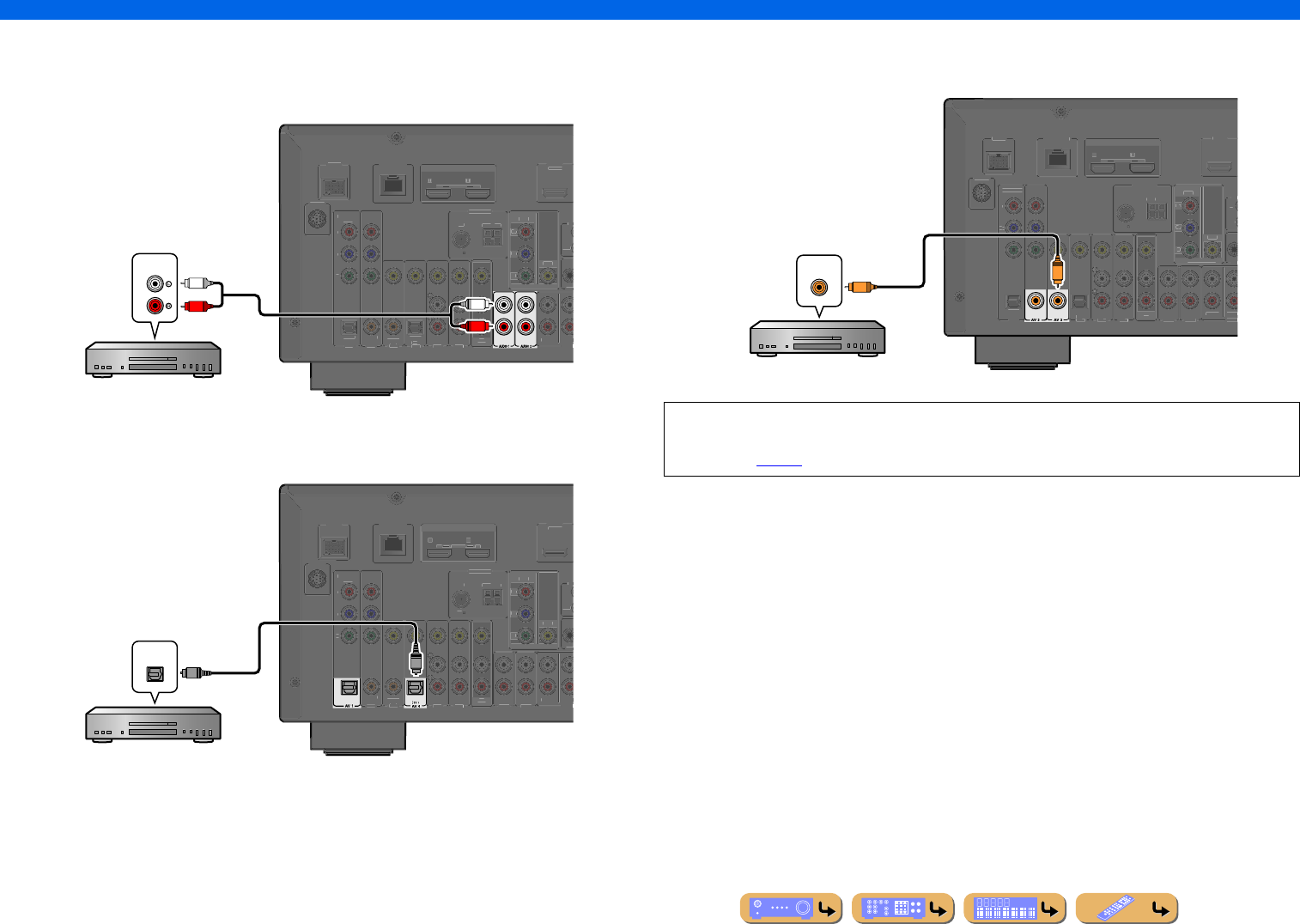
En 28
CONNECTIONS
Connecting external components
■
Connecting CD players and other audio devices
Using analog stereo output sources
Select the audio input (AUDIO1-2) to which the playback device is connected for playback.
Using optical digital output sources
Select the AV input (AV1 or AV4) to which the playback device is connected for playback.
Using coaxial digital output sources
Select the AV input (AV2 or AV3) to which the playback device is connected for playback.
D
OC
K
(
TV
)
AV 3
AV 4
AV 5
AV 6
MULT
(
C
D
)
CO
AXIAL
O
PTI
C
AL
V
IDE
O
HDMI 1
(
BD
/
DVD
)
AV
O
UT
SU
RR
OU
T
RI
GG
FR
O
N
T
IN
R
E
O
UT
H
DMI
O
UT
1
2
ARC
A
R
C
S
ELECTABLE
OPTICA
L
AV 1
AV 2
CO
AXIA
L
CO
MP
O
NEN
T
V
IDE
O
P
R
P
B
Y
S
IRI
US
COMPONENT
VIDE
O
VIDE
O
MO
NIT
O
R
O
UT
P
R
P
B
Y
ANTENNA
FM
75
G
N
D
AM
N
ETW
O
RK
AUDIO
R
L
R
L
Audio output
CD player
OPTICAL
OPTICAL
D
OC
K
AV 3
AV 5
AV 6
AUDIO 1
AUDI O 2
MULT
(
C
D
)
CO
AXIAL
V
IDE
O
HDMI 1
(
BD
/
DVD
)
AV
O
UT
SU
RR
OU
T
RI
GG
FR
O
N
T
IN
R
E
O
UT
HDMI
OUT
1
2
A
R
C
AR
C
S
ELE
C
TABL
E
AV 2
CO
AXIA
L
CO
MP
O
NEN
T
V
IDE
O
P
R
P
B
Y
S
IRI
US
COMPONENT
VIDE
O
VIDE
O
MO
NIT
O
R
O
UT
P
R
P
B
Y
ANTENNA
FM
75
G
N
D
AM
N
ETW
O
RK
O
O
OPTICAL
CD player
Audio (Optical) output
We recommend connecting audio devices with a coaxial digital output to the AV3 coaxial digital
jack on this unit. This connection allows you to switch to the AV input 3 just by pressing the “CD”
SCENE key (☞p. 44).
(CD)
COAXIAL
COAXIAL
D
OC
K
(
TV
)
AV 4
AV 5
AV 6
AUDI O 1
AUDI O 2
MULT
O
PTI
C
AL
V
IDE
O
HDMI 1
(
BD
/
DVD
)
AV
O
UT
SU
RR
OU
T
RI
GG
FR
O
N
T
IN
R
E
O
UT
H
DMI
OU
T
1
2
AR
C
A
R
C
S
ELE
C
TABLE
OPTICA
L
AV 1
CO
MP
O
NEN
T
V
IDE
O
P
R
P
B
Y
S
IRI
US
COMPONENT
VIDE
O
VIDE
O
MO
NIT
O
R
O
UT
P
R
P
B
Y
ANTENNA
FM
75
G
N
D
AM
N
ETW
O
RK
C
C
COAXIAL
Audio (Coaxial) output
CD player
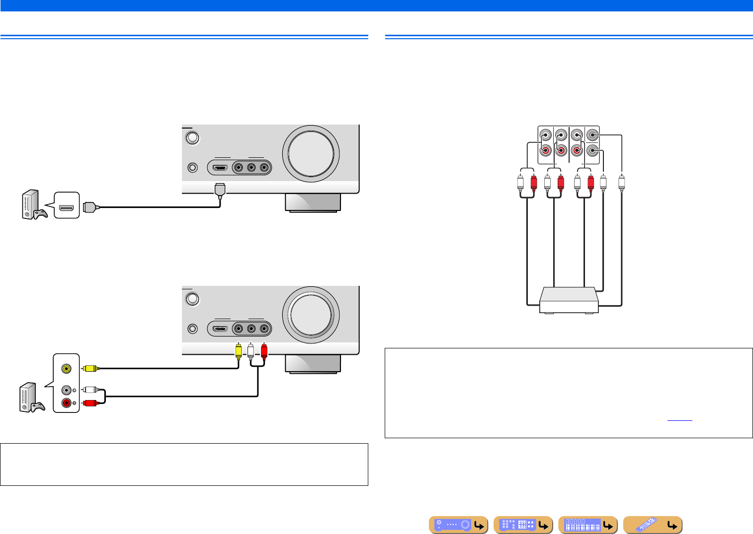
En 29
CONNECTIONS
Connecting external components
Connecting game consoles
Use the VIDEO AUX jacks on the front panel to temporarily connect devices such as a game console to
the receiver.
Select the V-AUX input to use these connected devices.
■
When connecting an HDMI compatible device
Connect the HDMI output of the device to the HDMI IN jack of this unit.
■
When connecting an non-HDMI compatible device
Connect the video and audio outputs of the device to the VIDEO and AUDIO jacks of this unit.
Connecting a multi-format player or an external decoder
This unit has 8 sets of input jacks (FRONT L/R, CENTER, SURROUND L/R, SUR. BACK L/R and
SUBWOOFER) to input multi-channel analog sound signals. If your playback component, such as a
DVD player or SACD player, has multi-channel analog output capability, you can enjoy up to 7.1-
channel multi-channel sound. To output multi-channel sound, connect the audio output jacks of your
playback component to the MULTI CH INPUT jacks of this unit, and set the input source of this unit to
“MULTI CH.”
•Be sure to turn down the volume when connecting this unit and the other devices.
•When both the HDMI connection and the analog video/audio connection are performed between the
HDMI compatible device and this unit, only the HDMI signal will be input.
VIDEO
AUX
STRAIGHT
RADIO
VIDEO
AUDIO
HDMI IN
LR
HDMI
HDMI
HDMI
HDMI output
Game console
VIDEO
AUX
STRAIGHT
RADIO
VIDEO
AUDIO
HDMI IN
LR
AUDIO
VIDEO
R
L
V
V
RL
Video output
Analog audio output
Game console
•When you select “MULTI CH” as the input source, the digital sound field processor and tone control are
automatically disabled.
•Since this unit does not redirect signals input at the MULTI CH INPUT jacks to accommodate for
missing speakers, connect at least a 5.1-channel speaker system when using this feature.
•When the input source is switched to “MULTI CH,” images input from a component connected to the
HDMI1-5, AV1-6, or VIDEO AUX jacks can be displayed on a video monitor (☞p. 89). If your DVD
player does not support multi-channel digital output, connect it to these input jacks.
MULTI CH INPUT
SUBWOOFER
SUR.BACK
SURROUND
FRONT
CENTER
RLRLRL
Surround out
Front out
Subwoofer out
Center out
Multi-format player/External decoder
(7.1-channel output)
Surround back out
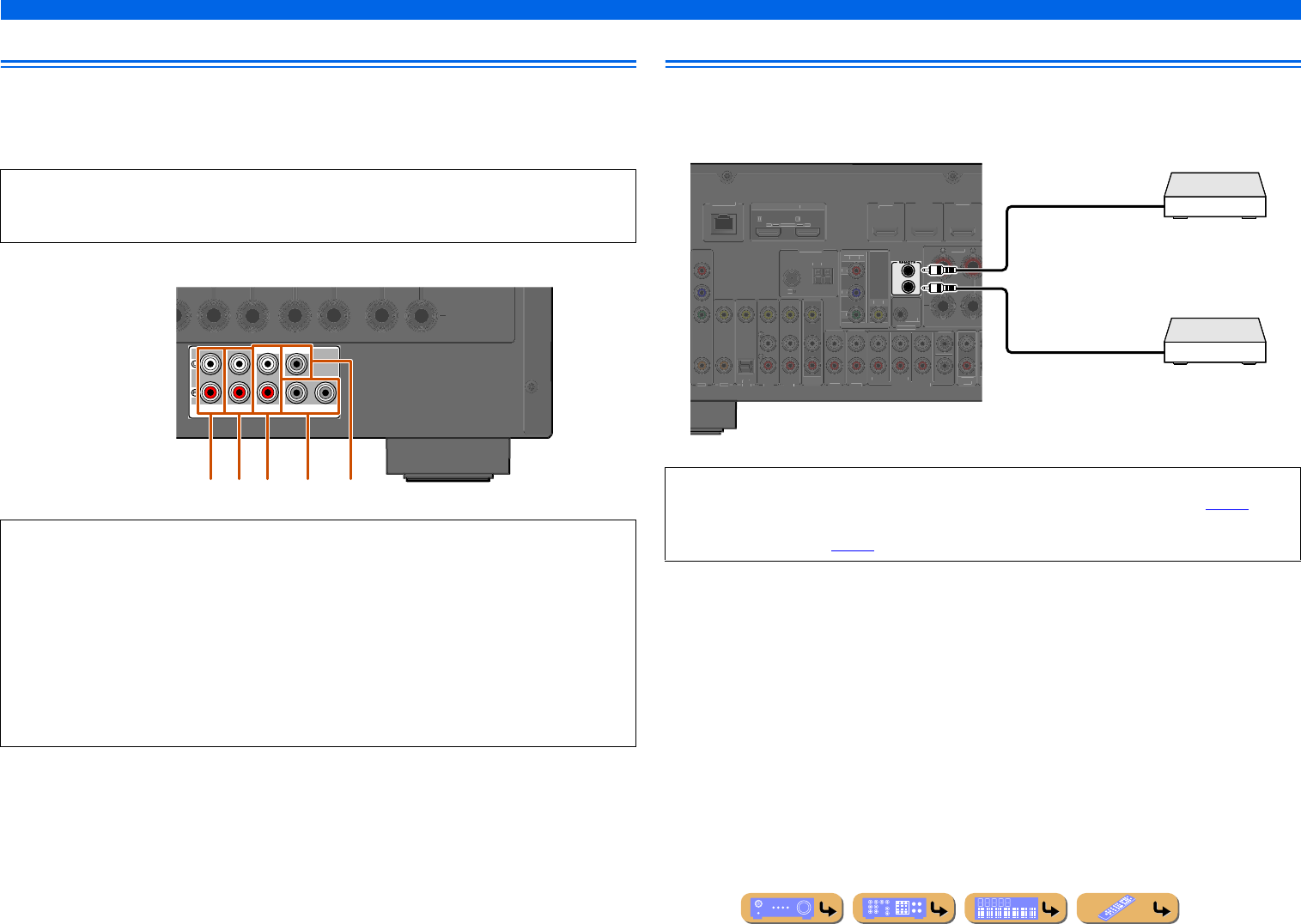
En 30
CONNECTIONS
Connecting external components
Connecting an external amplifier
The same channel signals are output from the jacks of the PRE OUT terminals as from their
corresponding SPEAKERS terminals. When connecting an external power amplifier (pre-main
amplifier) to enhance speaker output, connect the input terminals of the power amplifier to the PRE
OUT terminals of this unit.
Connecting a SCENE link playback-compatible device
When the components are the Yamaha products and have the capability of the transmission of the
remote control signals, connect the REMOTE IN and REMOTE OUT jacks to the remote control input
and output jack with the monaural analog mini cable as follows.
NOTE
When a component is connected to the PRE OUT terminals, do not connect speakers to the
SPEAKERS terminals corresponding to those PRE OUT terminals.
aFRONT (PRE OUT) jacks
Front channel output jacks.
bSURROUND (PRE OUT) jacks
Surround channel output jacks.
cSUR. BACK (PRE OUT) jacks
Surround back output jacks. When you only connect one external amplifier for the surround back channel,
connect it to the SUR. BACK (SINGLE) jack.
dSUBWOOFER (PRE OUT) 1/2 jack
Connect a subwoofer with a built-in amplifier. When two subwoofers are connected, the same sound is
output from them.
eCENTER (PRE OUT) jack
Center channel output jack.
SURROUND
SUR.BACK
PRE OUT
SUBWOOFER
1
2
FRONT
CENTERSINGLE
abc d e •When a Yamaha component that supports the SCENE link playback function is connected via the
REMOTE OUT jack, playback begins automatically when the SCENE function is used (☞p. 44).
•If the component connected to the REMOTE OUT jack is not a Yamaha product, set “SCENE IR” in the
SCENE menu to “Off” (☞p. 91).
IN
OUT
(
TV
)
AV 3
AV 4
AV 5
AV 6
AUDIO 1
AUDI O 2
MULTI CH INPUT
(
C
D
)
CO
AXIAL OPTICA
L
VIDEO
HDMI 1
(
B
D
/
DV
D
)
HDMI 2
HDMI
3
FR
O
N
T
A
V
OUT
SU
BW
OO
FER
A
U
DI
O
OUT
SUR.BACK
S
URROUN
D
TRI
GG
ER
OUT
+
12V
0
.1A MAX.
FRON
T
C
ENTE
R
HDMI
O
U
T
1
2
A
R
C
ARC
SELECTABL
E
AV 2
CO
AXIA
L
CO
MP
O
NENT
V
IDE
O
VIDE
O
M
O
NIT
O
R
O
U
T
P
R
P
B
Y
ANTENNA
FM
7
5
G
N
D
A
M
NETW
O
RK
Remote control out
Remote control in
Infrared signal receiver or
Yamaha component
Yamaha component
(CD or DVD player, etc.)
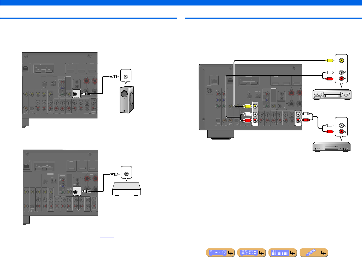
En 31
CONNECTIONS
Connecting external components
Using the Trigger function to link external component power
When this unit is connected to a Yamaha subwoofer that supports the system connection or the
component with TRIGGER IN jack, you can turn on and off the component by using this unit.
■
When connecting a Yamaha subwoofer
■
When connecting a component with the TRIGGER IN jack
Connecting audio/video recording devices
This receiver can transmit selected incoming analog audio/video signals to external components
through the AV OUT and AUDIO OUT jacks. You can record these input audio and video signals to
VCRs or similar devices, or send them to other TVs or external components.
Using the AV OUT jacks
Connect this jacks to the external component’s video input jack and analog audio input jacks.
Using the AUDIO OUT jacks
Connect this jack to the external component’s analog audio input jacks.
Functions of the TRIGGER OUT jack can be specified (☞p. 111).
+12V
0.1A MAX.
(
TV
)
AV 3
AV 4
AV 5
AV 6
AUDIO 1
AUDIO 2
MULTI CH INPUT
(
C
D
)
CO
AXIA
L
O
PTI
C
AL
V
IDE
O
HDMI 1
(
BD
/
DVD
)
HDMI 2
HDMI
3
F
R
O
NT
AV
OUT
SU
BW
OO
FE
R
A
UDIO
O
U
T
SU
R.BA
CK
SU
RR
OU
ND
F
R
O
NT
C
ENTER
IN
R
EMOTE
O
UT
H
DMI
O
UT
1
2
A
R
C
ARC
SELECTABL
E
C
OMPONEN
T
VIDE
O
V
IDE
O
MO
NIT
O
R
O
UT
P
R
P
B
Y
ANTENNA
FM
75
G
ND
AM
N
ETW
O
R
K
System connection input
Yamaha subwoofer
that supports the system
connection
+12V
0.1A MAX.
(
TV
)
AV 3
AV 4
AV 5
AV 6
AUDIO 1
AUDIO 2
MULTI CH INPUT
(
C
D
)
CO
AXIA
L
O
PTI
C
AL
V
IDE
O
HDMI 1
(
BD
/
DVD
)
HDMI 2
HDMI
3
F
R
O
NT
AV
OUT
SU
BW
OO
FE
R
A
UDIO
O
U
T
SU
R.BA
CK
SU
RR
OU
ND
F
R
O
NT
C
ENTER
IN
R
EMOTE
O
UT
H
DMI
OU
T
1
2
A
R
C
AR
C
S
ELE
C
TABL
E
C
OMPONEN
T
VIDE
O
V
IDE
O
MO
NIT
O
R
O
UT
P
R
P
B
Y
ANTENNA
FM
75
G
ND
AM
N
ETW
O
R
K
TRIGGER IN
Trigger input
Component with the
TRIGGER IN jack
(Power amplifier or
DVD player, etc.)
HDMI audio/video signals, component video signals, and digital audio signals cannot be transmitted
from these jacks.
AV
OUT
AUDIO
OUT
DOC
K
(
TV
)
AV 3
AV 4
AV 5
AV 6
AUDI O 1
AUDIO 2
MULTI CH INPUT
(
CD
)
CO
AXIA
L
O
PTICAL
V
IDE
O
HDMI 1
(
BD
/
DVD
)
HDMI 2
HDMI
3
F
R
O
NT
SU
BW
OO
FE
R
S
UR.BAC
K
SURROUND
T
RI
GG
ER
OU
T
+12
V
0.1A MAX
.
FRON
T
C
ENTER
IN
REMOTE
O
UT
H
DMI
OU
T
1
2
AR
C
A
R
C
S
ELE
C
TABLE
O
PTI
C
A
L
AV 1
AV 2
CO
AXIA
L
CO
MP
O
NEN
T
V
IDE
O
P
R
P
B
Y
S
IRIU
S
CO
MP
O
NENT
VIDE
O
VIDEO
MO
NIT
O
R
O
UT
P
R
P
B
Y
ANTENNA
FM
7
5
GN
D
A
M
N
ETW
O
R
K
AUDIO
VIDEO
R
L
V
AUDIO
R
L
R
L
V
R
L
Audio recorder
Audio input
VCR
Video / Audio
input
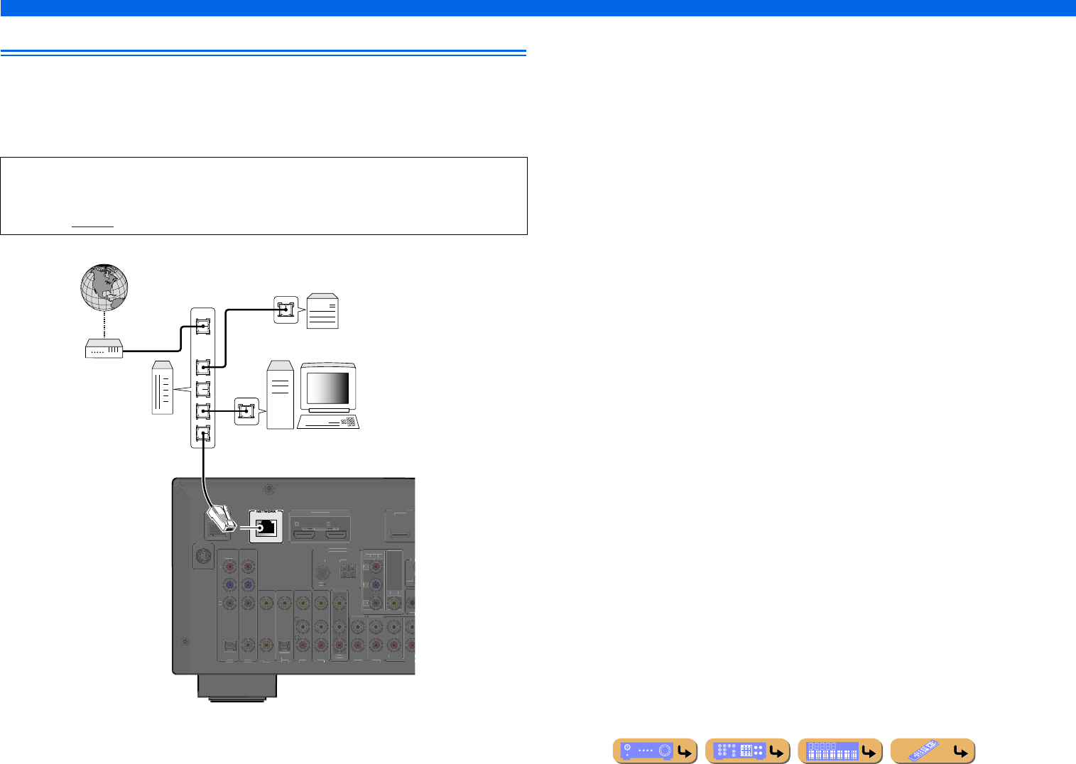
En 32
CONNECTIONS
Connecting external components
Connecting to the network
To connect this unit to your network, plug one end of a network cable (CAT-5 or higher straight cable)
into the NETWORK port of this unit, and plug the other end into one of the LAN ports on your router
that supports the DHCP (Dynamic Host Configuration Protocol) server function. To enjoy Internet
Radio or music files saved on PC and DLNA server such as NAS (Network Attached Storage), each
device must be connected properly in the network.
•Use an STP (shielded twisted pair) cable (commercially available) to connect a network hub or router
and this unit.
•If the DHCP server function on your router is disabled, you need to configure the network settings
manually (☞p. 108).
DOC
K
(
TV
)
AV 3
AV 4
AV 5
AV 6
AUDIO 1
AUDIO 2
MULT
(
CD
)
CO
AXIA
L
O
PTICAL
V
IDE
O
H
DMI 1
(
BD
/
DVD
)
A
V
OU
T
SURRO
U
T
RI
GG
FRON
T
IN
R
E
OU
T
H
DMI
OU
T
1
2
AR
C
A
R
C
S
ELE
C
TABLE
O
PTI
C
A
L
AV 1
AV 2
CO
AXIA
L
C
OMPONEN
T
V
IDEO
P
R
P
B
Y
S
IRIU
S
CO
MP
O
NENT
VIDE
O
VIDE
O
MO
NIT
O
R
OU
T
P
R
P
B
Y
ANTENN
A
F
M
7
5
G
N
D
AM
LAN
WAN
Network cable
Modem
Router
PC
Internet NAS
(Network Attached Storage)
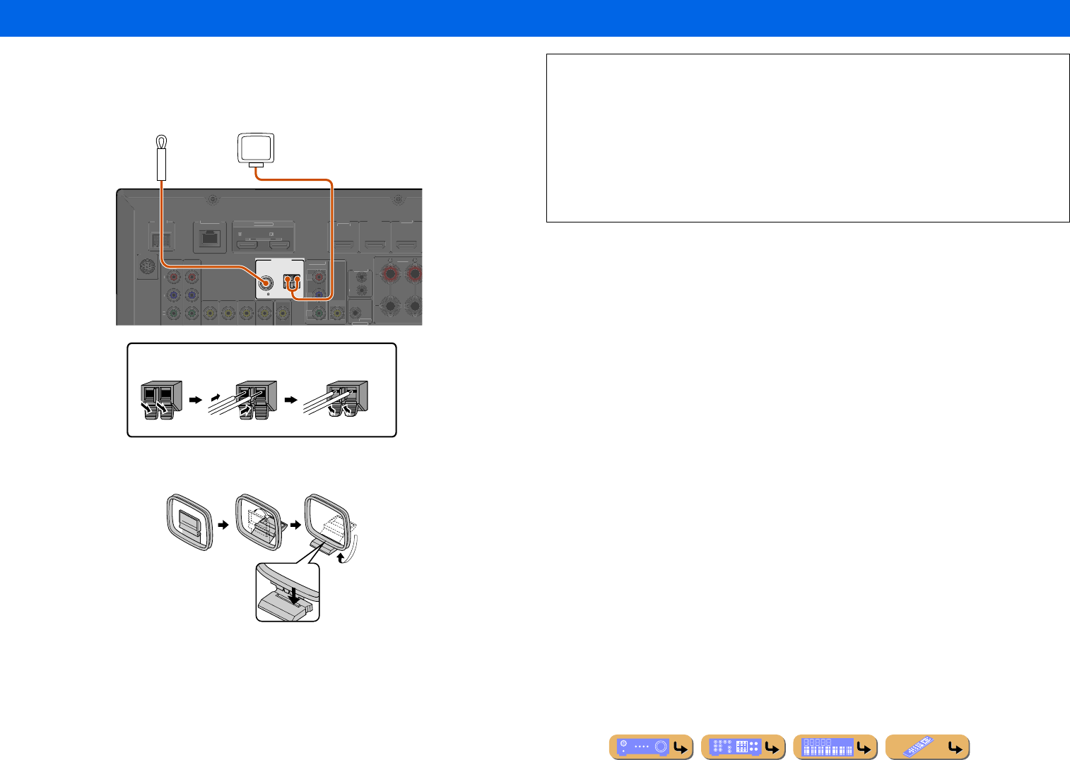
CONNECTIONS
En 33
An indoor FM antenna and an AM loop antenna are supplied with this receiver. Connect these antennas
properly to their respective jacks.
Assembling the AM loop antenna
Connecting the FM/AM antennas
ANTENNA
FM
75
GND
AM
D
OC
K
VIDEO
HDMI 1
(
B
D
/
DV
D
)
HDMI 2
HDMI
3
F
R
O
N
T
TRI
GG
ER
OUT
+12V
0
.1A MAX.
IN
REMOTE
O
U
T
HDMI
OUT
1
2
A
R
C
AR
C
S
ELE
C
TABL
E
CO
MP
O
NEN
T
VIDE
O
P
R
P
B
Y
S
IRIU
S
CO
MP
O
NENT
VIDE
O
VIDE
O
MO
NIT
O
R
O
UT
P
R
P
B
Y
NETW
O
RK
Indoor FM antenna
AM loop antenna
Position the AM antenna away from the receiver.
The wires of the AM antenna have no polarity.
You can connect either wire to the AM jack or the
GND jack.
Connecting the AM loop antenna
ReleaseInsertPress and hold
■Improving FM reception
We recommend using an outdoor antenna. For more information, consult the nearest authorized
dealer.
■Improving AM reception
Connect this unit to an outdoor antenna with a 16.4 – 32.8 ft. (5 – 10 m) vinyl-coated wire. Make
sure the AM loop antenna is still connected.
Connecting the GND jack can reduce noise. Connect the jack to a store-bought ground bar or copper
plate with a vinyl-covered wire and bury this new attachment in moist ground.
The GND jack is not to be connected to the ground socket of an electrical outlet.
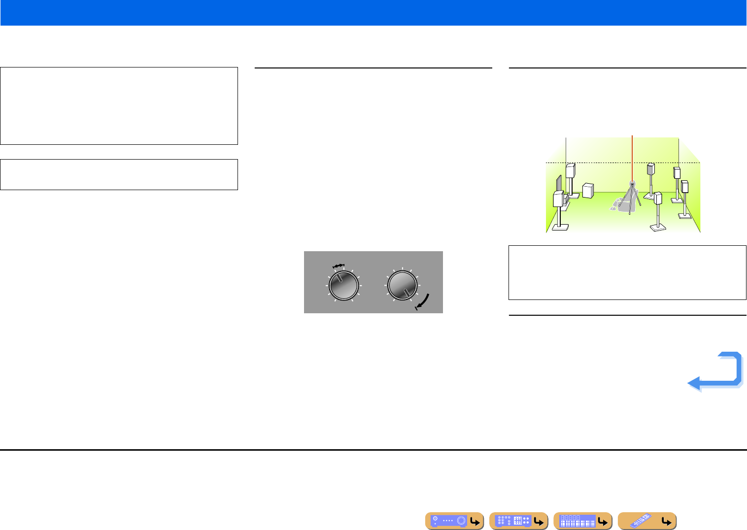
CONNECTIONS
En 34
This unit is equipped with a Yamaha Parametric Room Acoustic Optimizer (YPAO) that adjusts the configuration, size, and volume balance of the speakers in order to provide an optimal sound field.
Using YPAO allows you to automatically configure settings, such as adjusting speaker output and acoustic parameters to suit your listening room (the room in which this unit is placed). J1
1Check the following before using YPAO.
This unit
•The headphones are removed.
TV
•This unit is connected to the TV correctly.
•The power is turned on.
•The video input to which the video output from this unit has been
selected.
Subwoofer
•The power is turned on.
•Volume is set to approximately half, and the cross-over frequency (if
present) is set to maximum.
2Place the supplied YPAO microphone at ear height in
your listening position.
Face the head of the YPAO microphone upwards.
3Switch this unit on.
Setting up the speaker parameters automatically (YPAO)
The amount of time for measurement varies from about two to
ten minutes according to settings. Be aware of the following
when using YPAO.
•The test tone is output at high volume. Refrain from using this
function at night when it may be a nuisance to others.
•Take care that the test tone does not frighten small children.
YPAO operations can be viewed on the front panel display or
TV screen.
VOLUME
MIN MAX
CROSSOVER/
HIGH CUT
MIN MAX
Subwoofer examples
When positioning the microphone, we recommend that you use
equipment that allows you to adjust the height (such as a tripod)
as a microphone stand. When using a tripod, use the tripod
screws to fix the microphone in place.
YPAO microphone
Continues to the
next page
J1 : When you have changed the number of speakers or the locations in which they
are installed, first use YPAO to adjust the speaker balance.
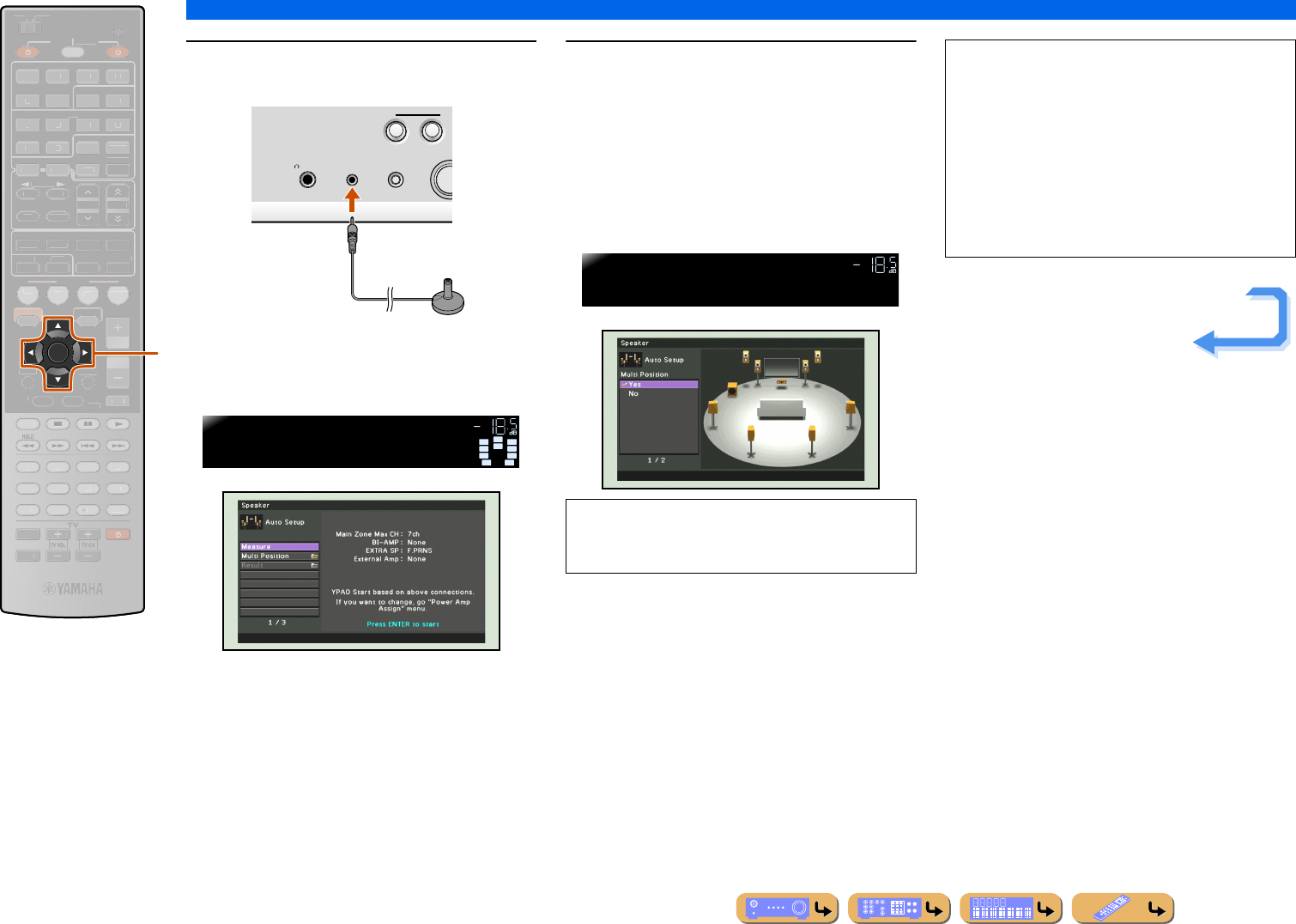
CONNECTIONS
Setting up the speaker parameters automatically (YPAO)
En 35
4Connect the YPAO microphone to the YPAO
MIC jack on the front panel.
“Mic On. View ON SCREEN” appears on the front
panel display, and the following display appears on the
front panel display or TV screen.
5Press kCursor B / C to select the “Multi
Position” and press kENTER to set the
number of listening positions to measure.
To measure at the multiple listening positions (up to 8),
press kCursor B / C to select “Yes” and press
kENTER.
To measure at one listening position, press
kCursor B / C to select “No” and press kENTER.
kCursor B / C
kENTER
ENTER
SCENE
RETURN
VO
L
U
ME
ENHANCE
R
S
UR. DE
CO
DE
STRAIGHTSLEEP
P
URE DIRECT
PART Y
M
OVI
E
M
USI
C
BD
DVD
TV
CD
RADI
O
M
U
T
E
7
8
5
6
9
0
10
1
2
3
4
R
EC
ENT
FM
I
NF
O
M
EM
O
RY
AM
P
RESET
H
DMI
AV
A
UDI
O
1
2
3
4
1
2
5
V
-
AUX
TOP
MENU
P
OP-U
P
M
EN
U
DI
S
PLAY
SO
UR
C
E
M
AIN
Z
O
NE 2
RE
C
EIVE
R
CODE SE
T
I
NP
U
T
MUTE
DOCK
HDMI
O
U
T
MULTI
O
PTION
O
N
SC
REE
N
5
1
2
3
4
6
NET
S
IRI
US
TU
NER
TUN./C
H
C
ATE
GO
R
Y
k
PHONES
YPAO MIC
SILENT
CINEMA
TONE
CONTROL
TV
BD
DVD
PROG
R
SCE
N
VOL.
SW
C
LR
SL SR
SBL SBR
PR
PL
ENTER to Start
YPAO VOL.
“Multi Position” is set to “Yes” at initial factory
settings. It is not necessary to perform step 5 when
measuring at the multiple listening positions.
VOL.
MLT.Position>
YPAO VOL.
This completes preparation. To achieve more accurate
results, take note of the following when measuring
acoustics.
•It takes a few minutes to accurately measure acoustics
for one position. Keep the room as quiet as possible
while acoustics are measured.
•Wait in a corner of the room, or leave it entirely, while
acoustics are measured to avoid creating an
obstruction between the speakers and the YPAO
microphone.
Continues to the
next page
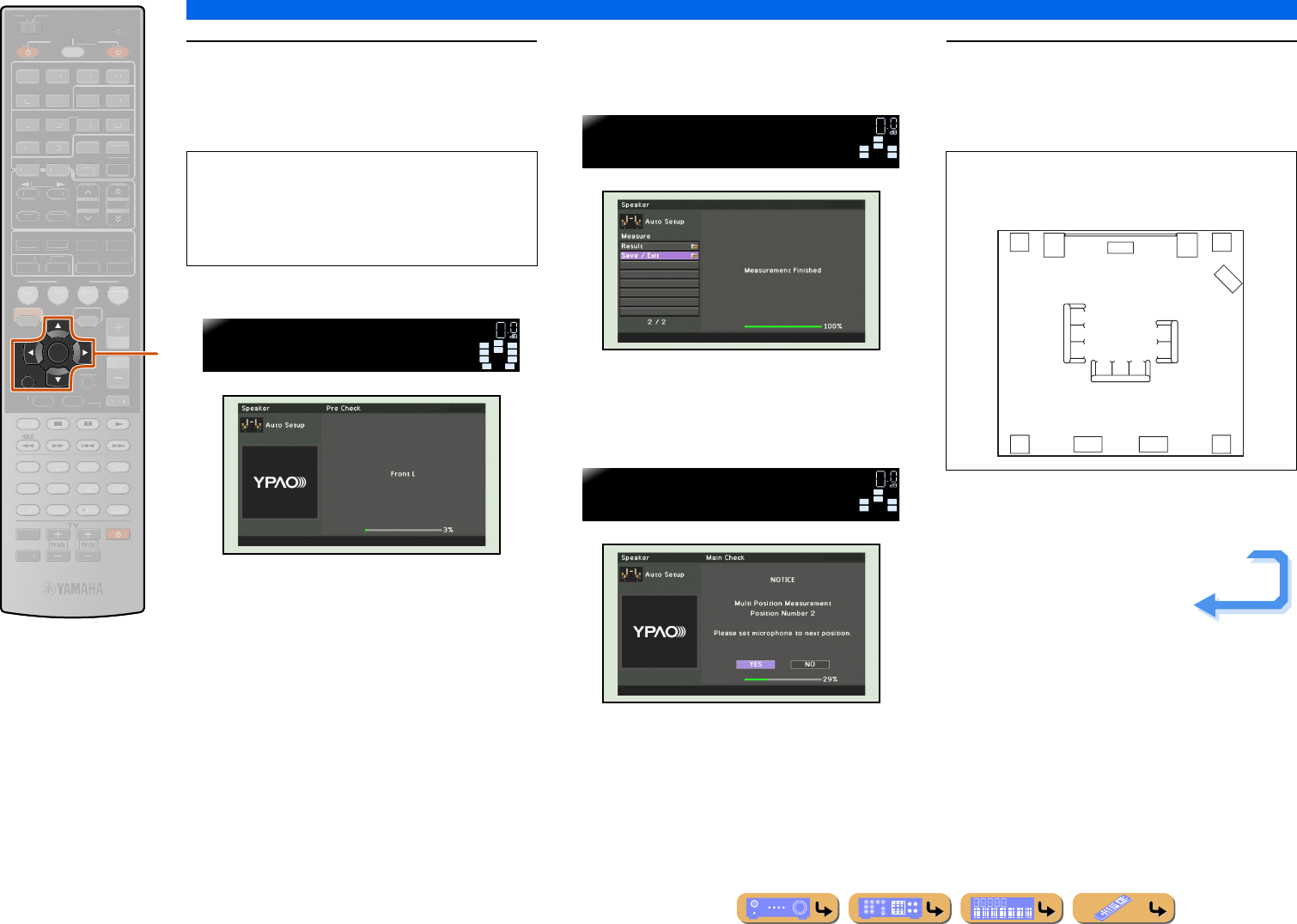
CONNECTIONS
Setting up the speaker parameters automatically (YPAO)
En 36
6Press kCursor B / C repeatedly to select
the “Measure” and press
kENTER to start measurement.
Auto measurement starts in 10 seconds.
Display during measurement
When “Multi Position” is set to “No” in step 5
The following display appears when measurement
finishes without any problems.
Go to step 8.
When “Multi Position” is set to “Yes” in step 5
The following display appears when measurement at the
first position finishes without any problems.
Go to step 7.
7Replace the optimizer microphone at your
choosing position and press kENTER to
restart the automatic measurement.
Auto measurement restarts in 10 seconds.
Repeat step 7 until the measurement at all listening
positions are made.
kCursor B / C
kENTER
kRETURN
RETURN
ENTER
SCENE
VO
L
U
ME
ENHANCE
R
S
UR. DE
CO
DE
STRAIGHTSLEEP
P
URE DIRECT
PART Y
M
OVI
E
M
USI
C
BD
DVD
TV
CD
RADI
O
M
U
T
E
7
8
5
6
9
0
10
1
2
3
4
R
E
C
ENT
TOP
MENU
P
OP-U
P
M
EN
U
D
I
S
PLA
Y
SO
UR
C
E
M
AIN
Z
O
NE 2
RE
C
EIVE
R
C
ODE SE
T
I
NP
U
T
MUTE
OPTION
O
N
SC
REE
N
FM
I
NF
O
M
EM
O
RY
AM
P
RESET
H
DMI
AV
A
UDI
O
1
2
3
4
1
2
5
V
-
AUX
DOCK
HDMI
O
U
T
MULTI
5
1
2
3
4
6
NE
T
S
IRI
US
TU
NER
TUN./C
H
C
ATE
GO
R
Y
k
•To start the measurement immediately, press
kENTER again.
•To cancel the automatic setup and return to the
previous screen, press kRETURN and then
kENTER.
VOL.
SW
C
LR
SL SR
SBL SBR
PR
PL
Progress 0%
YPAO VOL.
VOL.
SW
C
L
SL SR
R
Save/Exit
YPAO VOL.
SW
C
L
SL SR
R
>Yes No
YPAO VOL.
The following illustration shows how to place the
optimizer microphone to optimize the setup of this
unit for 8 listening positions for example.
6
8
7
4 5
12 3
Continues to the
next page
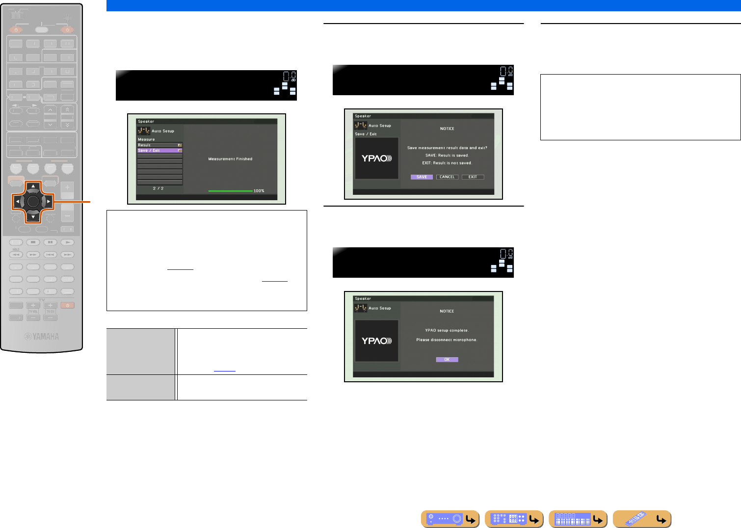
CONNECTIONS
Setting up the speaker parameters automatically (YPAO)
En 37
The following display appears again when
measurement at the last position finishes without any
problems. 8Press kCursor B / C to select “Save/Exit”
and press kENTER.
9Press kCursor D / E to select “SAVE”
and press kENTER.
10 Press kENTER.
Automatic setup is completed. Disconnect the
YPAO microphone.
kCursor B / C / D / E
kENTER
ENTER
SCENE
RETURN
VO
L
U
ME
ENHANCE
R
S
UR. DE
CO
DE
STRAIGHTSLEEP
P
URE DIRECT
PART Y
M
OVI
E
M
USI
C
BD
DVD
TV
CD
RADI
O
M
U
T
E
7
8
5
6
9
0
10
1
2
3
4
R
EC
ENT
FM
I
NF
O
M
EM
O
RY
AM
P
RESET
H
DMI
AV
A
UDI
O
1
2
3
4
1
2
5
V
-
AUX
TOP
MENU
P
OP-U
P
M
EN
U
DI
S
PLAY
SO
UR
C
E
M
AIN
Z
O
NE 2
RE
C
EIVE
R
CODE SE
T
I
NP
U
T
MUTE
DOCK
HDMI
O
U
T
MULTI
O
PTION
O
N
SC
REE
N
5
1
2
3
4
6
NET
S
IRI
US
TU
NER
TUN./C
H
C
ATE
GO
R
Y
k
NOTE
If a problem occurs, an error message or report is
displayed either during or after acoustic measurement.
Refer to “When an error message is displayed during
measurement” (☞p. 39), or “When a warning
message is displayed after measurement” (☞p. 39) to
resolve the problem and measure acoustics with
YPAO again.
Result Displays the results of automatic
acoustics measurement. Refer to
“Reviewing automatic setup parameters”
for details (☞p. 38).
Save/Exit Applies the result to the speaker setup and
finishes the automatic measurement.
VOL.
SW
C
L
SL SR
R
Save/Exit
YPAO VOL.
SW
C
L
SL SR
R
Select:Save
YPAO VOL.
SW
C
L
SL SR
R
Disconnect Mic
YPAO VOL.
The YPAO microphone is sensitive to heat. When you
have finished measuring, store the microphone out of
direct sunlight, and away from locations that may
experience high temperatures, such as on top of AV
equipment.
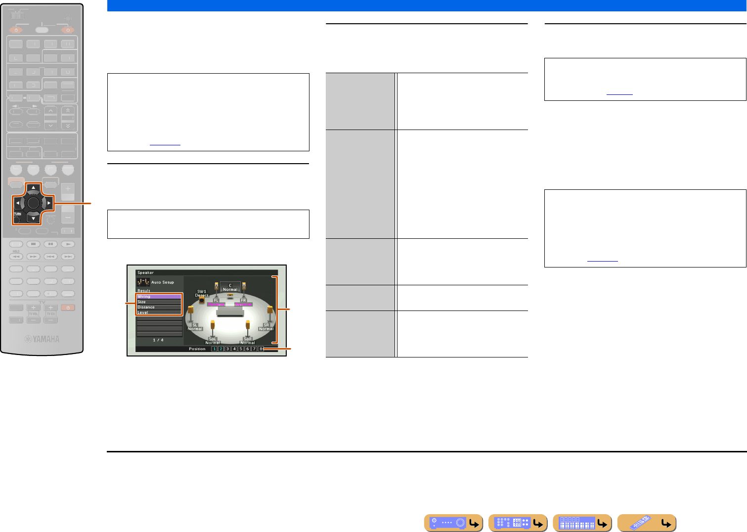
CONNECTIONS
Setting up the speaker parameters automatically (YPAO)
En 38
■
Reviewing automatic setup
parameters
The results of automatic acoustics measurement can be
reviewed once measurement is complete.
1Press kCursor B / C repeatedly to select
“Result” and press kENTER immediately
after the automatic measurement.
The results of acoustics measurement are displayed.
aList of menu items
Menu items available in the Result menu are displayed.
bNumber of measurement
Indicates the number of measurements for multiple
listening positions.
cDiagram
Shows the speaker setup and sound adjustment as diagram.
2Select the desired menu item (or enable a
function) using kCursor B / C / D / E and
kENTER.
3Press kRETURN to finish “Result” menu.
■
Reloading automatic setup
parameters
If you are not satisfied with the fine-adjustment of setup
parameters with Manual Setup, the result of automatic
setup saved on this unit can be reloaded. Select “Setup
Reload” in the Result menu.
kCursor B / C / D / E
kENTER
kRETURN
ENTER
SCENE
R
VO
L
U
ME
ENHANCE
R
S
UR. DE
CO
DE
STRAIGHTSLEEP
P
URE DIRECT
PART Y
M
OVI
E
M
USI
C
BD
DVD
TV
CD
RADI
O
M
U
T
E
7
8
5
6
9
0
10
1
2
3
4
R
EC
ENT
FM
I
NF
O
M
EM
O
RY
AM
P
RESET
H
DMI
AV
A
UDI
O
1
2
3
4
1
2
5
V
-
AUX
TOP
MENU
P
OP-U
P
M
EN
U
DI
S
PLAY
SO
UR
C
E
M
AIN
Z
O
NE 2
RE
C
EIVE
R
CODE SE
T
I
NP
U
T
MUTE
DOCK
HDMI
O
U
T
MULTI
O
PTION
O
N
SC
REE
N
5
1
2
3
4
6
NET
S
IRI
US
TU
NER
TUN./C
H
C
ATE
GO
R
Y
k
NOTE
When automatic setup parameters are reloaded,
manually configured settings are cleared. To save
manually configured settings before reloading
automatic setup parameters, see “Prohibiting setting
changes” (☞p. 112).
The Result menu can be viewed only by performing
the automatic measurement.
a
b
c
Wiring Displays the polarity of each connected
speaker.
•“Normal” is displayed when the
polarity of the connected speaker is
normal.
Size Displays the size of the connected
speakers.
•“Large” is displayed when the
connected speaker has the ability to
reproduce the low-frequency signals
effectively.
•“Small” is displayed when the
connected speaker does not have the
ability to reproduce the low-frequency
signals effectively.
Distance Displays the distance from the listening
position to speakers. The unit for distance
can be switched between “ft” (feet) and
“m” (meter) by pressing kCursor D / E.
Level Displays the result of the adjustment of
each connected speaker output level.
Setup Reload J1Clears the fine-adjustment with Manual
Setup and reloads the result of automatic
setup. For details, refer to “Reloading
automatic setup parameters.”
The result of automatic setup can be fine-tuned
manually by “Manual Setup.” Refer to “Manual
speaker setup” (☞p. 99) for details.
NOTE
When automatic setup parameters are reloaded,
manually configured settings are cleared. To avoid
clearing manually configured settings by reloading
automatic setup parameters, see “Prohibiting setting
changes” (☞p. 112).
J1 : This item is displayed after the fine-adjustment is performed with
“Manual Setup.” Use this item to return to the settings to the result
of automatic setup.
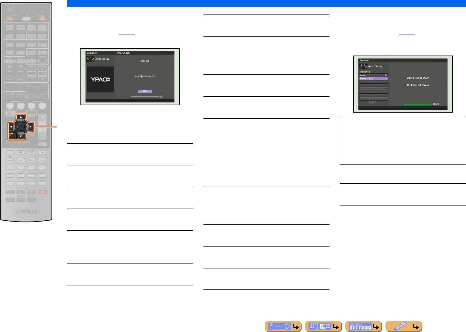
CONNECTIONS
Setting up the speaker parameters automatically (YPAO)
En 39
■
When an error message is
displayed during measurement
See “Error messages” (☞p. 40) for instructions on
resolving the problem and measure acoustics again.
Check the error code displayed and use YPAO to
measure acoustics again as described below.
When “E-1,” “E-2,” “E-3,” “E-4” or “E-6” is
displayed
1Press kENTER.
2Press kCursor E to select “EXIT.”
3Press kENTER to terminate YPAO, and
switch the unit to standby mode.
4Check that the speakers are properly
connected.
5Turn on the unit and use YPAO again.
When “E-7” or “E-8” is displayed
1Press kENTER.
2Check that the environment is suitable for
accurate measurement.
3Press kCursor E to select “RETRY.”
4Press kENTER to use YPAO again.
When “E-5” or “E-9” is displayed:
1Press kENTER.
2Check that the environment is suitable for
accurate measurement.
3Press kCursor D / E to select a option.
PROCEED:
When “E-5” is displayed, measurement can proceed.
However, the measurement in noisy environment may
reduce the accuracy.
When “E-9” is displayed, resume the aborted step.
RETRY:
Restart measurement from the beginning.
4Press kENTER to execute the selected
option.
When “E-10” is displayed:
1Press kENTER.
2Press kCursor E to select “EXIT.”
3Press kENTER to terminate YPAO, and
switch the unit to standby mode.
4Turn on the unit and use YPAO again.
■
When a warning message is
displayed after measurement
See “Warning messages” (☞p. 41) for instructions on
resolving the problem. The speaker causing the problem
can be confirmed from the TV screen display.
To exit YPAO with some options
1Use kCursor B / C to select “Save/Exit”
and press kENTER.
2Use kCursor D / E to select one of the
following options and press kENTER.
SAVE:
Exits YPAO applying the results of measurement.
CANCEL:
Returns to the previous screen (warning message
screen).
EXIT:
Exits YPAO without saving the results.
kCursor B / C / D / E
kENTER
kRETURN
ENTER
SCENE
R
VO
L
U
ME
ENHANCE
R
S
UR. DE
CO
DE
STRAIGHTSLEEP
P
URE DIRECT
PART Y
M
OVI
E
M
USI
C
BD
DVD
TV
CD
RADI
O
M
U
T
E
7
8
5
6
9
0
10
1
2
3
4
R
EC
ENT
FM
I
NF
O
M
EM
O
RY
AM
P
RESET
H
DMI
AV
A
UDI
O
1
2
3
4
1
2
5
V
-
AUX
TOP
MENU
P
OP-U
P
M
EN
U
DI
S
PLAY
SO
UR
C
E
M
AIN
Z
O
NE 2
RE
C
EIVE
R
CODE SE
T
I
NP
U
T
MUTE
DOCK
HDMI
O
U
T
MULTI
O
PTION
O
N
SC
REE
N
5
1
2
3
4
6
NET
S
IRI
US
TU
NER
TUN./C
H
C
ATE
GO
R
Y
k
NOTE
Although the results of acoustics measurement can be
applied when a warning message is displayed, optimal
sound will not be achieved. Resolving the problem
and using YPAO to measure acoustics again is
recommended.
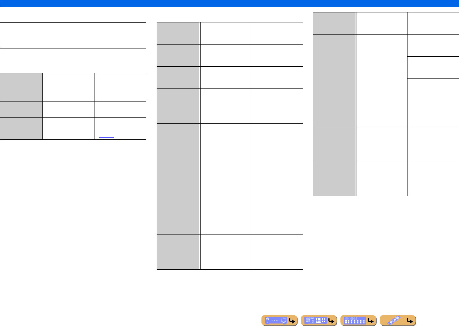
CONNECTIONS
Setting up the speaker parameters automatically (YPAO)
En 40
■
Message list
■When a warning message is displayed before
measurement
■Error messages
NOTE
If the following messages appear, resolve the problems that have
occurred and carry out the measurement process again.
Connect MIC! The YPAO microphone is
not connected.
Connect the YPAO
microphone to the YPAO
MIC jack on the front
panel.
Unplug HP! The headphones are
connected.
Remove the headphones.
Memory Guard! The settings of this unit
are protected.
Set “Memory Guard” in
the Setup menu to “Off”
(☞p. 112).
E-1:
No Front SP
The unit was not able to
find the front channel.
Check that the left and
right front speakers are
connected correctly.
E-2:
No Sur. SP
The unit was only able to
find one of side of the
surround channels.
Check that the left and
right surround speakers
are connected correctly.
E-3:
No F.PRNS SP
The unit was only able to
find one of side of the
presence channels.
Check that the left and
right presence speakers
are connected correctly.
E-4:
SBR→SBL
Only one surround back
speaker is connected and
only the right side
surround back channel
sound is detected.
When only one surround
back speaker is
connected, connect to the
left side (SINGLE)
terminal.
E-5:
Noisy
The noise is too loud,
preventing accurate
measurements from
being taken.
Measure again in quiet
surroundings. Turn off any
devices in the room that
may be emitting noise, or
place them further away
from the YPAO
microphone.
When this message is
displayed, selecting
“PROCEED” will allow
you to continue measuring.
However, we recommend
resolving the problem and
measuring again, as
continuing measurement
without doing so will not
give accurate results.
E-6:
Check Sur.
Even though surround
left and right speakers are
not connected, only the
surround back speakers
are connected.
When using surround back
speakers, connection of the
surround left/right
speakers is necessary.
E-7:
No MIC
The YPAO microphone
has been removed.
While measuring, take
care not to touch the
YPAO microphone.
E-8:
No Signal
The YPAO microphone
could not distinguish a
test tone.
Check that the YPAO
microphone has been
installed correctly.
Check that each speaker
has been connected and
installed correctly.
The YPAO microphone
or the YPAO MIC jack
may be broken. Inquire at
the retailer where you
purchased this unit, or the
nearest Yamaha service
center.
E-9:
User Cancel
You have carried out an
operation that has
cancelled the measuring
process.
Carry out the measuring
process again. Do not
operate this unit by, for
example, adjusting the
volume.
E-10:
Internal Error
An internal error has
occurred.
Carry out the measuring
process again. Contact a
Yamaha service center if
“E-10” is displayed
again.
CONNECTIONS
Setting up the speaker parameters automatically (YPAO)
En 41
■Warning messages
W-1:
Out of Phase
The speakers displayed
are connected with the
opposite polarity.
Depending on the type of
speakers you are using
and the environment in
which you have them
installed, this message
may occur even if the
speakers are connected
correctly.
Depending on the type of
speakers, “W-1” may
display even if the
speakers are connected
correctly.
Check that the speaker
polarity + (positive), and
- (negative) are correct. If
these are connected
correctly, you can use the
speakers normally even
this message appears.
W-2:
Over 24m/80ft
The speakers displayed
are separated from the
listening position by
more than 24 m, and
cannot be adjusted
correctly.
Install the speakers with
24 m of the listening
position.
W-3:
Level Error
Volume level varies
greatly for individual
channels, and cannot be
adjusted correctly.
Check that all speakers
are installed in the same
surroundings.
Check that the speaker
polarity + (positive), and
- (negative) are correct.
We recommend the same
speakers or speakers with
as similar specifications
as possible.
Adjust the volume of the
subwoofer.
If “W-2” or “W-3” appears, you can apply measurement results,
but they will not give optimal results. We recommend that you
resolve the problem and carry out the measurement process
again.
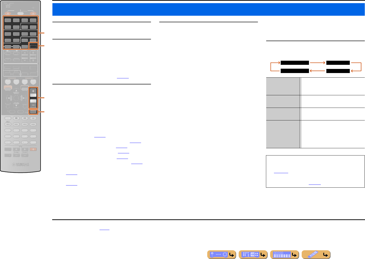
En 42
PLAYBACK
1Turn on external components (TV, DVD
player, etc.) connected to this unit.
2Use the dInput selector to select the input
source.
The name of the selected input source is displayed for
a few seconds. J1
When DOCK, TUNER, SIRIUS, or NET is selected,
the Content window is displayed (☞p. 56).
3Play the external component that you have
selected as the source input, or select a
radio station on the tuner.
Refer to the instruction manuals provided with the
external component for details on playback.
For details on the following operations, refer to the
corresponding pages:
•“FM/AM tuning” (☞p. 57)
•“Listening to SIRIUS Satellite Radio™” (☞p. 61)
•“Playing back tunes on the PC” (☞p. 67)
•“Listening to the Internet Radio” (☞p. 69)
•“Using the Rhapsody® service” (☞p. 71)
•“Listening to the SIRIUS Internet Radio” (☞p. 75)
•“Playing back tunes from your iPod™/iPhone™”
(☞p. 79)
•“Playing back tunes from Bluetooth™ components”
(☞p. 83)
4Press uVOLUME +/- to adjust the volume.
To mute the output.
Press vMUTE to mute the audio output.
Press vMUTE again to unmute.
■
Selecting the active HDMI OUT jack
Use this function to select the HDMI OUT jack(s) used
to output signal.
Press rHDMI OUT repeatedly to select setting.
The HDMI output setting changes as follows.
Basic playback procedure
dInput selector
rHDMI OUT
uVOLUME +/-
vMUTE
VOLUME
HDMI
AV
AUDIO
1234
125
V-AUX
MUTE
DOCK
HDMI OUT
MULTI
5
1234
6
NET
SIRIUSTUNER
SCENE
RETURN
ENHANCE
R
S
UR. DE
CO
DE
STRAIGHTSLEEP
P
URE DIRECT
PART Y
M
OVI
E
M
USI
C
BD
DVD
TV
CD
RADI
O
ENTER
7
8
5
6
9
0
10
1
2
3
4
R
E
C
ENT
TOP
MENU
P
OP-U
P
M
EN
U
DI
S
PLAY
SO
UR
C
E
M
AIN
Z
O
NE 2
RE
C
EIVE
R
CODE SE
T
I
NP
U
T
MUTE
O
PTION
O
N
SC
REE
N
FM
I
NF
O
M
EM
O
RY
AM
P
RESET
TUN./C
H
C
ATE
GO
R
Y
u
d
v
r
HDMI OUT 1+2 Outputs the signal at both the HDMI
OUT 1 and HDMI OUT 2 jacks
simultaneously.
HDMI OUT 1 Outputs the signals at the HDMI OUT 1
jack.
HDMI OUT 2 Outputs the signals at the HDMI OUT 2
jack.
HDMI OUT Off Any signals are not output at the HDMI
OUT 1 and HDMI OUT 2 jacks. Select
this setting when you do not use the video
monitor connected to one of the HDMI
OUT jacks.
•The HDMI OUT jack that utilizes the HDMI Control
function can be selected with “Control Select”
(☞p. 106).
•The active HDMI OUT jack(s) can be registered with
the SCENE function (☞p. 44).
HDMI OUT 1+2
HDMI OUT Off
HDMI OUT 1
HDMI OUT 2
J1 : You can change the input source name displayed on the front
panel display as necessary (☞p. 88).
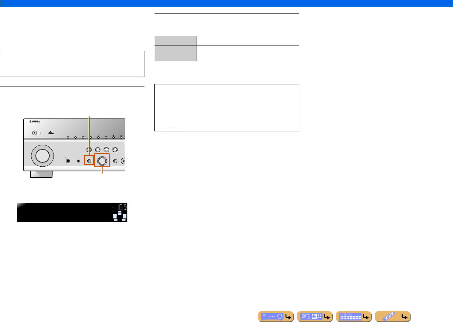
En 43
PLAYBACK
Basic playback procedure
■
Adjusting high/low-frequency sound
(Tone control)
You can adjust the balance of the high-frequency range (Treble)
and low-frequency range (Bass) of sounds output from the front
left and right speakers to obtain desired tone.
1Press TONE CONTROL on the front panel repeatedly
to select “Treble” or “Bass.”
The current setting is displayed on the front panel display.
2Rotate PROGRAM selector to adjust the output level
in those frequency ranges.
The display returns to the previous display soon after you release
the key.
The tone control of the speakers or headphones can be set
separately. Set the headphone tone control with the headphones
connected.
PHONES
YPAO MIC
SILENT
CINEMA
TONE
CONTROL
STRAIGHT
TV
BD
DVD
CD
RADIO
INPUT
PROGRAM
SCENE
H
INFOZONE
CONTROL
ZONE2
MAIN ZONE
MEMORY
PRESET
FM AM
CATEGORY
TONE CONTROL
PROGRAM selector
SW
C
L
SL SR
R
SBL SBR
SW
C
L
SL SR
R
Treble +0.5dB
TONE VOL.
Adjustable range -6.0 dB to +6.0 dB
Adjustment
increments
0.5 dB
•The tone control settings are not effective when this unit is in the
Pure Direct mode or “MULTI CH” is selected as an input source.
•If you set the balance extremely off, sounds may not match those
from other channels well.
•The tone control can also be adjusted in the Option menu
(☞p. 54).
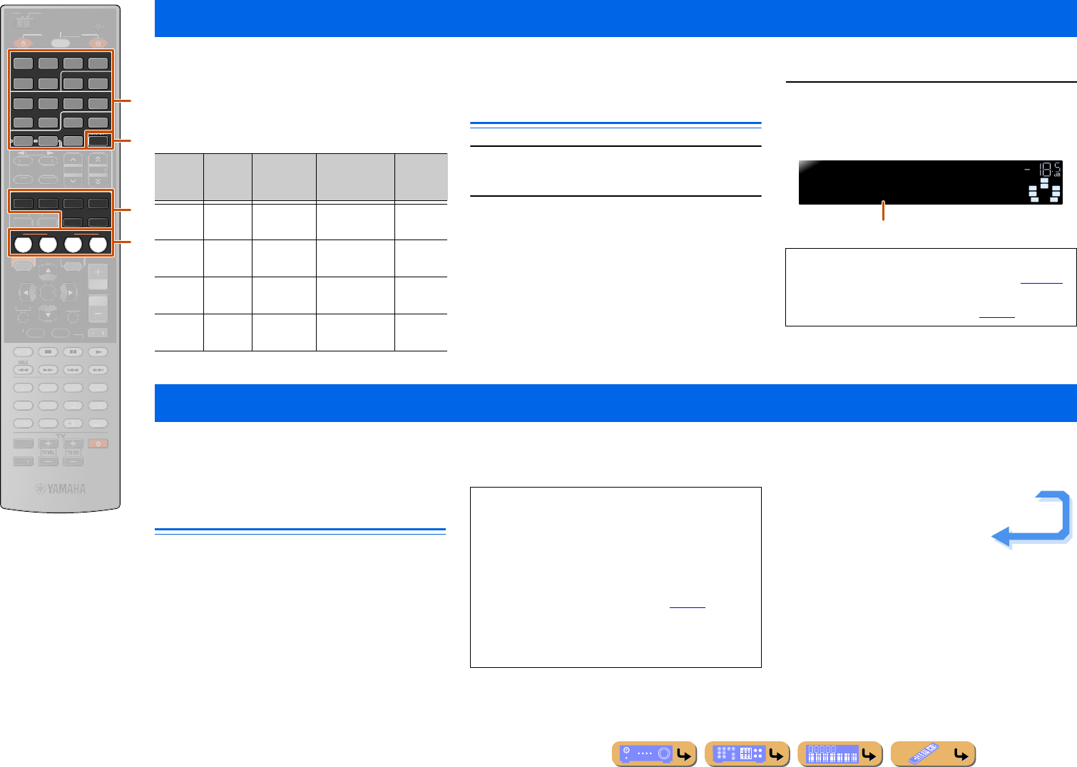
PLAYBACK
En 44
This unit has a SCENE function that allows you switch this unit on and change input sources, sound programs, and HDMI OUT with one key.
Four scenes are available for different uses, such as
playing movies or music. The following input sources,
sound programs, and HDMI OUT are provided as the
initial factory settings.
Registering input sources/sound
program/HDMI OUT
1Use dInput selector to select the input
source you want to register.
2Use the sSound selection keys or
rHDMI OUT to select the sound program,
Compressed Music Enhancer, or HDMI OUT
you want to register.
3Press the iSCENE key until “SET
Complete” appears on the front panel
display.
This unit is also equipped with a Yamaha digital sound field processing (DSP) chip. Multi-channel playback from almost any audio source can be enjoyed using a variety
of sound decoders and various sound field effect programs stored on the chip. Sound field effect programs built into this unit are called “sound programs.”
Selecting sound programs and
sound decoders
This unit offers sound programs in many different
categories suitable for movies, music and other uses.
Choose a sound program that sounds best with the
source you are playing back, rather than relying on the
name or explanation of the program.
Changing input settings with a single key (SCENE function)
dInput selector
iSCENE
rHDMI OUT
sSound selection keys
SCENE
ENHANCER SUR. DECODE
STRAIGHT PURE DIRECT
HDMI
AV
AUDIO
1234
125
V-AUX
MOVIE MUSIC
BD
DVD TV
CD
RADIO
DOCK
MULTI
5
1234
6
NET
SIRIUSTUNER
RETURN
VO
L
U
ME
SLEEP
PART Y
MU
T
E
ENTER
7
8
5
6
9
0
10
1
2
3
4
R
EC
ENT
TOP
MENU
P
OP-U
P
M
EN
U
DI
S
PLAY
SO
UR
C
E
M
AIN
Z
O
NE 2
RE
C
EIVE
R
CODE SE
T
I
NP
U
T
MUTE
OPTION
O
N
SC
REE
N
FM
I
NF
O
M
EM
O
RY
AM
P
RESET
HDMI OUT
TUN./C
H
C
ATE
GO
R
Y
d
r
i
s
SCENE Input Sound
program
Compressed
Music
Enhancer
HDMI
OUT
BD/
DVD
HDMI1 Drama Off HDMI
OUT 1+2
TV AV4 STRAIGHT On HDMI
OUT 1+2
CD AV3 STRAIGHT Off HDMI
OUT 1+2
RADIO TUNER STRAIGHT On HDMI
OUT 1+2
•When changing “SCENE,” also change the external
component that the remote control operates (☞p. 115).
•Selecting a scene and editing the scene function are
also available in the SCENE menu (☞p. 90).
SW
C
L
SL SR
R
SET Complete
SCENE1 VOL.
SBL SBR
Release the key when “SET Complete” is displayed
Enjoying favorite sound field effect
•Sound programs are stored for each input source.
When you change the input source, the sound program
previously selected for that input source is applied
again.
•When you playback DTS Express sources or audio
signals with sampling frequency of higher than
96 kHz, the straight decoding mode (☞p. 45) is
automatically selected.
•When you playback DTS-HD sources with CINEMA
DSP, the DTS decoder is automatically selected.
Continues to the
next page
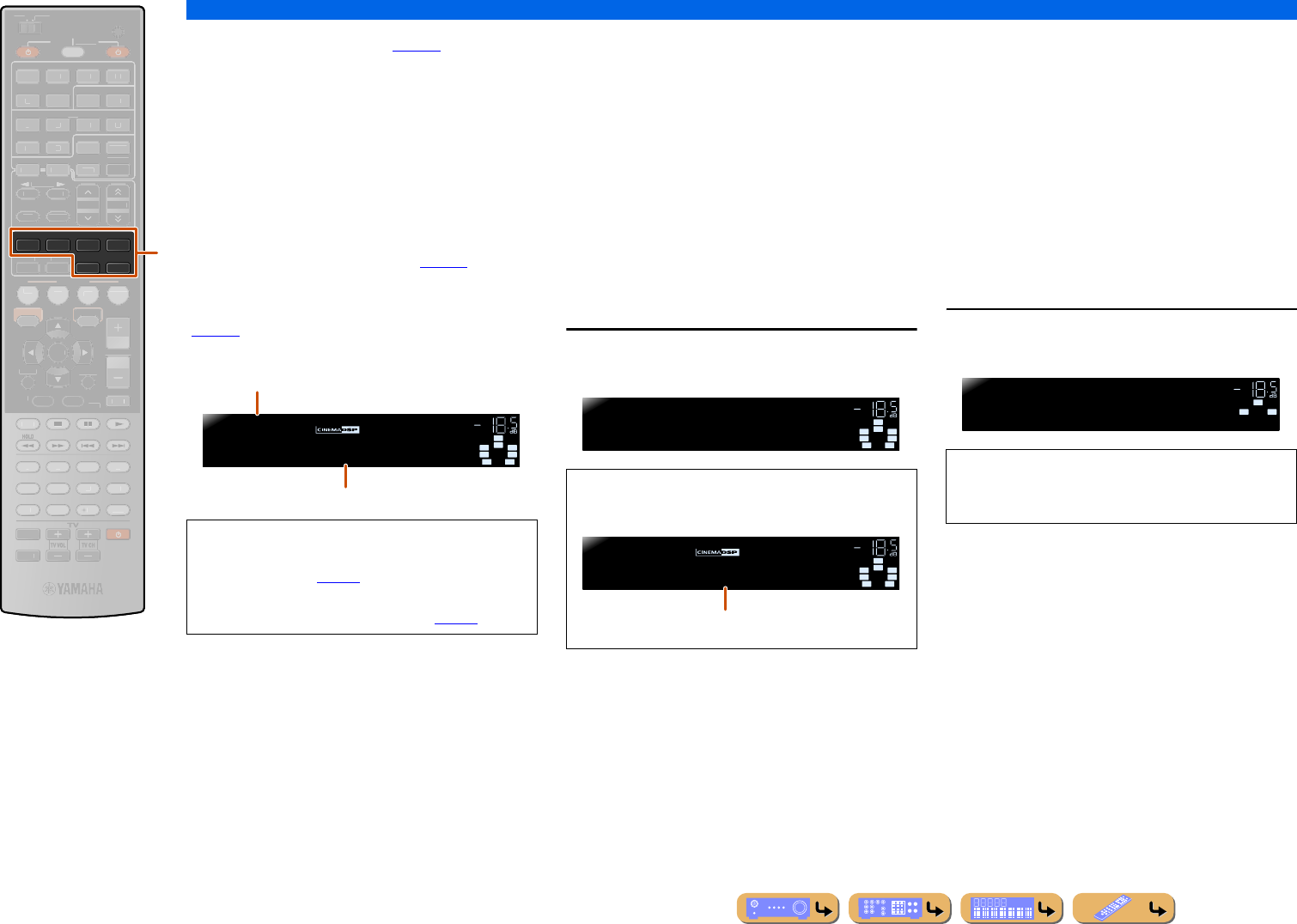
PLAYBACK
Enjoying favorite sound field effect
En 45
Selecting sound program (☞p. 48):
MOVIE category: Press sMOVIE repeatedly
MUSIC category: Press sMUSIC repeatedly
Selecting stereo reproduction:
Press sMUSIC repeatedly
Selecting surround decoder:
Press sSUR. DECODE repeatedly
Turning on Straight decoding mode:
Press sSTRAIGHT
Turning on Pure Direct mode (☞p. 47):
Press sPURE DIRECT
Turning on Compressed Music Enhancer
(☞p. 47):
Press sENHANCER repeatedly
■
Enjoying unprocessed playback
(Straight decoding mode)
Use straight decoding mode when you want to playback
sound without sound field processing. You can playback
as follows in straight decoding mode.
2-channel sources such as CD
Stereo sound plays through the front left and right
speakers.
Multi-channel playback sources such as BD/
DVD
Plays back audio from a playback source without
applying sound field effects, using an appropriate
decoder to split the signal into multiple channels.
Press sSTRAIGHT to enable the straight
decoding mode.
■
Enjoying stereo playback
Select “2ch Stereo” from the sound programs when you
want to playback 2-channel stereo sound (from the front
speakers only), regardless of the playback source.
Selecting “2ch Stereo” will playback as follows for the
playback of CD and BD/DVD sources.
2-channel sources such as CD
Stereo sound plays back through the front speakers.
Multi-channel sources such as BD/DVD
Playback channels other than the front channels in the
playback source are mixed with the front channels and
played back through the front speakers.
Press sMUSIC repeatedly to select “2ch
Stereo.”
sSound selection keys
sMOVIE
sMUSIC
sENHANCER
sSUR. DECODE
sSTRAIGHT
sPURE DIRECT
ENHANCER SUR. DECODE
STRAIGHT PURE DIRECT
MOVIE MUSIC
SCENE
RETURN
VO
L
U
ME
SLEEP
PART Y
BD
DVD
TV
CD
RADI
O
MU
T
E
ENTER
7
8
5
6
9
0
10
1
2
3
4
R
E
C
ENT
TOP
MENU
P
OP-U
P
M
EN
U
DI
S
PLAY
SO
UR
C
E
M
AIN
Z
O
NE 2
RE
C
EIVE
R
CODE SE
T
I
NP
U
T
MUTE
H
DMI
AV
A
UDI
O
1
2
3
4
1
2
5
V
-
AUX
DOC
K
HDMI
O
U
T
MULTI
OPTION
O
N
SC
REE
N
5
1
2
3
4
6
FM
I
NF
O
M
EM
O
RY
AM
P
RESET
NET
S
IRI
US
TU
NER
TUN./C
H
C
ATE
GO
R
Y
s
•You can use the speaker indicators on the front panel
display to check what speakers are currently
outputting sound (☞p. 10).
•You can adjust sound field elements (sound field
parameters) for each of the programs (☞p. 93).
SW
C
L
SL SR
R
Sci-Fi
MOVIE VOL.
SBL SBR
Sound program categories
Program To disable straight decoding mode, press
sSTRAIGHT again.
SW
C
L
SL SR
R
Straight
VOL.
SBL SBR
SW
C
L
SL SR
R
Sci-Fi
MOVIE VOL.
SBL SBR
Previously selected program
To disable stereo playback, press any of the
sSound selection keys to select a sound program
other than “2ch Stereo.”
SW
LR
2ch Stereo
MUSIC VOL.
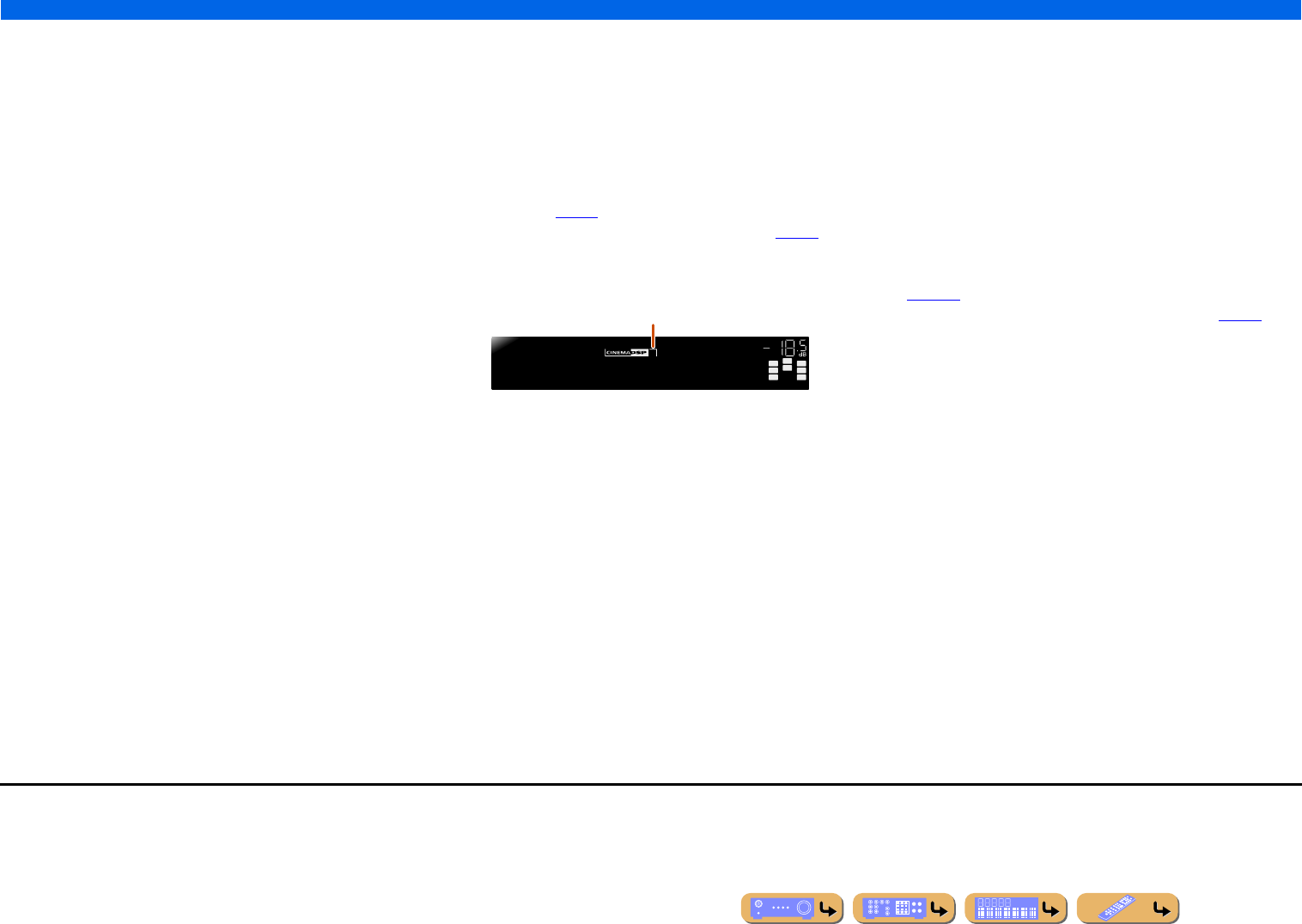
PLAYBACK
Enjoying favorite sound field effect
En 46
■
Enjoying sound programs without
surround speakers
This unit allows you to use virtual surround speakers to enjoy
sound field surround effects, even without any surround speakers
(Virtual CINEMA DSP mode). You can even enjoy surround sound
presence with just a minimal configuration of the front speakers
only.
This unit will switch to Virtual CINEMA DSP mode automatically
when surround speakers are unavailable. J1
■
Enjoying sound programs with
headphones
Even when headphones are connected, you can enjoy the
reproduction sound field presence with ease (SILENT CINEMA
mode). J2
■
Enjoying more spatial sound fields
(CINEMA DSP 3D mode)
CINEMA DSP 3D mode creates an intensive and accurate
stereoscopic sound field in the listening room.
Connection of presence speakers is recommended to take full
advantage of the effects of CINEMA DSP 3D mode. Do the
following steps. J3
•Connect the presence speakers to the EXTRA SP jacks and set the
speakers to use (☞p. 15).
•Enable CINEMA DSP 3D Mode in the Option menu (☞p. 53).
When a sound program runs in CINEMA DSP 3D mode, the
CINEMA DSP 3D indicator on the front panel lights up.
■
Enjoying sound programs without
presence speakers
This unit allows you to use virtual presence speakers to create an
intensive and accurate stereoscopic sound field, even when no
presence speakers are connected (Virtual CINEMA DSP 3D
mode). You can even enjoy surround sound presence with front
speakers, center speaker, and surround speakers.
This unit automatically switches to Virtual CINEMA DSP 3D
mode when presence speakers are not available.
Do the following steps.
•Connect the front speakers, center speaker, and surround speakers.
•Enable center speaker and surround speakers in “Configuration”
(☞p. 100).
•Enable CINEMA DSP 3D Mode in the Option menu (☞p. 53).
PL PR
SW
C
L
SL SR
R
3
Hall in Vienna
MUSIC VOL.
SBL SBR
Lights up
J1 : However, Virtual CINEMA DSP mode is not available under the following
conditions:
•When headphones are connected to this unit.
•When a “7ch Stereo” or “2ch Stereo” sound program is selected.
•When Pure Direct mode or straight decoding mode is selected.
J2 : However, SILENT CINEMA mode is not available under the following
conditions:
•When a “2ch Stereo” sound program is selected.
•When Pure Direct mode or straight decoding mode is selected.
J3 : However, CINEMA DSP 3D mode is not available under the following
conditions:
•When headphones are connected to this unit.
•When a “7ch Stereo” or “2ch Stereo” sound program is selected.
•When Pure Direct mode or straight decoding mode is selected.
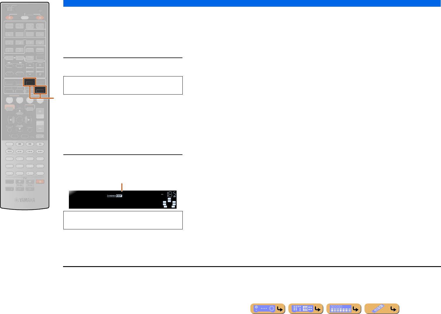
PLAYBACK
Enjoying favorite sound field effect
En 47
■
Enjoying Hi-Fi Sound Quality
(Pure Direct mode)
Use Pure Direct mode to enjoy the pure high fidelity
sound of the selected source. When Pure Direct mode is
enabled, this unit plays back the selected source with the
least circuitry. J1
Press sPURE DIRECT to turn Pure Direct mode
on. J2
■
Enjoying compressed music
source with better sound quality
(Compressed Music Enhancer)
Compressed Music Enhancer mode improves the sound
enhancer near to the original depth and width of
compression artifacts. J3
This mode can be used along with any other DSP modes.
Press sENHANCER to turn Compressed Music
Enhancer on.
sENHANCER
sPURE DIRECT
ENHANCER
PURE DIRECT
SCENE
RETURN
VO
L
U
ME
S
UR. DE
CO
DE
STRAIGHTSLEEP
PART Y
M
OVI
E
M
USI
C
BD
DVD
TV
CD
RADI
O
MU
T
E
ENTER
H
DMI
AV
A
UDI
O
1
2
3
4
1
2
5
V
-
AUX
7
8
5
6
9
0
10
1
2
3
4
R
E
C
ENT
TOP
MENU
P
OP-U
P
M
EN
U
DI
S
PLAY
SO
UR
C
E
M
AIN
Z
O
NE 2
RE
C
EIVE
R
CODE SE
T
I
NP
U
T
MUTE
DOC
K
HDMI
O
U
T
MULTI
OPTION
O
N
SC
REE
N
5
1
2
3
4
6
FM
I
NF
O
M
EM
O
RY
AM
P
RESET
NET
S
IRI
US
TU
NER
TUN./C
H
C
ATE
GO
R
Y
s
To disable Pure Direct mode, press
sPURE DIRECT again.
To disable Compressed Music Enhancer, press
sENHANCER again.
SW
C
L
SL SR
ENHANCER
R
Enhancer On
VOL.
SBL SBR
Lights up when Compressed Music Enhancer
is active
J1 : The following features are disabled in Pure Direct mode.
•sound program, tone control, YPAO PEQ, and Adaptive DRC
•displaying and operating the Option menu and Setup menu
J2 : While Pure Direct mode is on, the front panel display screen turns
off in order to reduce noise. When turning Pure Direct mode off,
the screen returns on.
J3 : However, Compressed Music Enhancer is not available in the
following audio:
•Signals of which sampling rate is over 48kHz
•High Definition stream
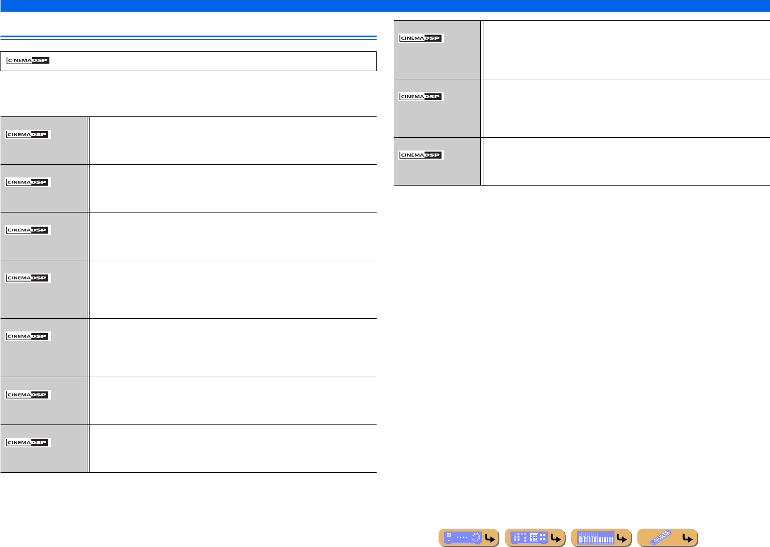
PLAYBACK
Enjoying favorite sound field effect
En 48
Sound programs
■
Category: MOVIE
Sound programs optimized for viewing video sources such as movies, TV programs, and games.
in the table indicates the sound program for CINEMA DSP.
Standard This program creates a sound field emphasizing the surround feeling without disturbing the
original acoustic positioning of multi-channel audio such as Dolby Digital and DTS. It has
been designed with the concept of an ideal movie theater, in which the audience is
surrounded by beautiful reverberations from the left, right and rear.
Spectacle This program represents the spectacular feeling of large-scale movie productions. It
reproduces a broad theater sound field that matches cinemascope and wider-screen movies
with an excellent dynamic range providing everything from very small sound effects to
large, impressive sounds.
Sci-Fi This program clearly reproduces the finely elaborated sound design of the latest science
fiction and special effects-featuring movies. You can enjoy a variety of cinematographically
created virtual spaces reproduced with clear separation between dialog, sound effects and
background music.
Adventure This program is ideal for precisely reproducing the sound design of action and adventure
movies. The sound field restrains reverberations but puts emphasis on reproducing a
powerful space expanded widely to the left and right. The reproduced depth is also
restrained relatively to ensure the separation between audio channels and the clarity of the
sound.
Drama This sound field features stable reverberations that match a wide range of movie genres from
serious dramas to musicals and comedies. The reverberations are modest but offer an
optimum 3D feeling, reproducing effects tones and background music softly but cubically
around clear words and center positioning in a way that does not fatigue the listener even
after long hours of viewing.
Mono Movie This program is provided for reproducing monaural video sources such as a classic movie in
an atmosphere of a good old movie theater. The program produces the optimum expansion
and reverberation to the original audio to create a comfortable space with a certain sound
depth.
Sports This program allows the listeners to enjoy stereo sport broadcasts and studio variety
programs with enriched live feeling. In sports broadcasts, the voices of the commentator and
sportscaster are positioned clearly at the center while the atmosphere of the stadium expands
in an optimal space to offer the listeners a feeling of presence in the stadium.
Action Game This sound field is suitable for action games such as car racing, fighting games and FPS
games. The reality of, and emphasis on, various effects makes the player feel like they are
right in the middle of the action, allowing for greater concentration.
Use this program in combination with Compressed Music Enhancer for a more dynamic and
strong sound field.
Roleplaying Game This sound field is suitable for role-playing and adventure games. This program adds depth
to the sound field for natural and realistic reproduction of background music, special effects
and dialogue from a wide variety of scenes.
Use this program in combination with Compressed Music Enhancer for a more clear and
spatial sound field.
Music Video This sound field offers an image of a concert hall for live performance of pop, rock and jazz
music. The listener can indulge oneself in a hot live space thanks to the presence sound field
that emphasizes the vividness of vocals and solo play and the beat of rhythm instruments,
and to the surround sound field that reproduces the space of a big live hall.
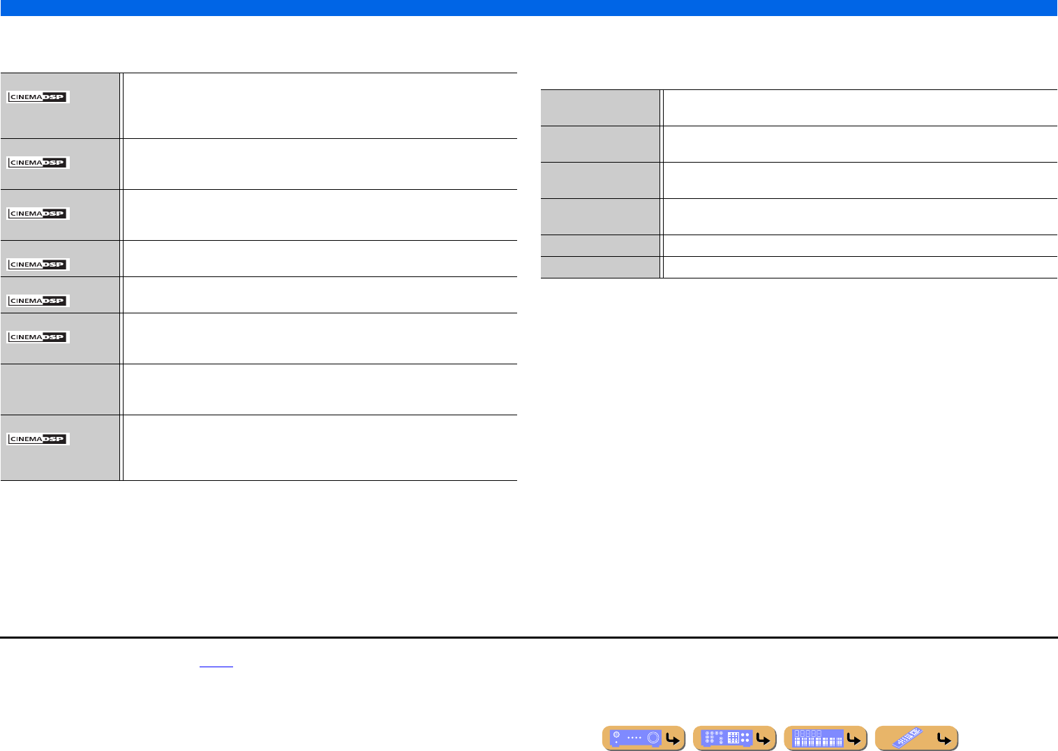
PLAYBACK
Enjoying favorite sound field effect
En 49
■
Category: MUSIC
This sound field is suitable when listening to music sources such as CDs.
■
Category: SUR.DEC (Surround decode mode)
Select this program to playback sources with selected decoders. You can playback 2-channel audio
sources in up to 7-channels using a surround decoder.
Hall in Munich This sound field simulates a concert hall with approximately 2500 seats in Munich, using
stylish wood for the interior finishing as normal standards for European concert halls. Fine,
beautiful reverberations spread richly, creating a calming atmosphere. The listener’s virtual
seat is at the center left of the arena.
Hall in Vienna This is an approximately 1700-seat, middle-sized concert hall with a shoebox shape that is
traditional in Vienna. Pillars and ornate carvings create extremely complex reflections from
all around the audience, producing a very full, rich sound.
Chamber This program creates a relatively wide space with a high ceiling like an audience hall in a
palace. It offers pleasant reverberations that are suitable for courtly music and chamber
music.
Cellar Club This program simulates a live house with a low ceiling and homey atmosphere. A realistic,
live sound field features powerful sound as if the listener is in a row in front of a small stage.
The Roxy Theatre This is the sound field of a rock music live house in Los Angeles, with approximately 460
seats. The listener’s virtual seat is at the center left of the hall.
The Bottom Line This is the sound field at stage front in The Bottom Line, a famous New York jazz club once.
The floor can seat 300 people to the left and right in a sound field offering real and vibrant
sound.
2ch Stereo Use this program to mix down multi-channel sources to 2-channels. When multi-channel
signals are input, they are down mixed to 2-channels and output from the front left and right
speakers.
7ch Stereo Use this program to output sound from all speakers. When you playback multi-channel
sources, this unit down-mixes the source to 2-channels, and then outputs the sound from all
speakers. This program creates a larger sound field and is ideal for background music at
parties, etc.
qPro Logic Reproduces sound using the Dolby Pro Logic decoder. This is suitable for all kinds of audio
sources.
qPLIIx Movie /
qPLII Movie
Reproduces sound using the Dolby Pro Logic IIx (or Dolby Pro Logic II) decoder. This is
suitable for movies. J1
qPLIIx Music /
qPLII Music
Reproduces sound using the Dolby Pro Logic IIx (or Dolby Pro Logic II) decoder. This is
suitable for music. J1
qPLIIx Game /
qPLII Game
Reproduces sound using the Dolby Pro Logic IIx (or Dolby Pro Logic II) decoder. This is
suitable for games. J1
Neo:6 Cinema Reproduces sound using the DTS Neo:6 decoder. This is suitable for movies.
Neo:6 Music Reproduces sound using the DTS Neo:6 decoder. This is suitable for music.
J1 : You cannot select the Dolby Pro Logic IIx decoder in the following conditions:
•When “Surround Back” is set to “None” (☞p. 100).
•When headphones are connected.
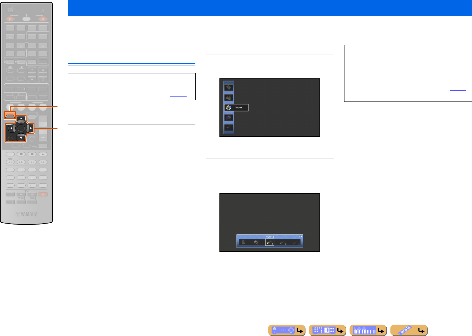
PLAYBACK
En 50
This unit features a sophisticated on-screen display (OSD) that helps you to control the amplifier function of this unit. With the OSD, you can view information of the
signals being input and the status of this unit. Visual guidance simplifies operations for menus.
Basic operations via the TV screen
display
This section describes basic operations for configuring
“Input,” “Scene” and “Sound Program” using the OSD.
Press jON SCREEN.
The ON SCREEN menu is displayed on the TV screen.
■
Selecting an input source
1Use kCursor B / C to select “Input” and
press kENTER.
Input source icons are displayed at the bottom of the
TV screen.
2Use kCursor D / E to select a Input source
press kENTER.
The input source is selected.
Using the TV display to control this unit
jON SCREEN
kCursor B / C / D / E
kENTER
kRETURN
RETURN
ENTER
ON SCREEN
SCENE
VO
L
U
ME
ENHANCE
R
S
UR. DE
CO
DE
STRAIGHTSLEEP
P
URE DIRECT
PART Y
M
OVI
E
M
USI
C
BD
DVD
TV
CD
RADI
O
M
U
T
E
7
8
5
6
9
0
10
1
2
3
4
R
E
C
ENT
FM
I
NF
O
M
EM
O
RY
AM
P
RESET
H
DMI
AV
A
UDI
O
1
2
3
4
1
2
5
V
-
AUX
TOP
MENU
P
OP-U
P
M
EN
U
DI
S
PLAY
SO
UR
C
E
M
AIN
Z
O
NE 2
RE
C
EIVE
R
CODE SE
T
I
NP
U
T
MUTE
DOCK
HDMI
O
U
T
MULTI
O
PTION
5
1
2
3
4
6
NET
S
IRI
US
TU
NER
TUN./C
H
C
ATE
GO
R
Y
k
j
A TV screen is required to display the ON SCREEN
or Option menu. Refer to “Connecting a TV monitor”
for instructions on connecting a TV screen (☞p. 22).
•Pressing kRETURN displays the previous menu
screen. Press kRETURN repeatedly to close the ON
SCREEN menu.
•In addition to selecting an input source, detailed
settings for each input source can be configured. Refer
to “Configuring input sources (Input menu)” (☞p. 86)
for details.
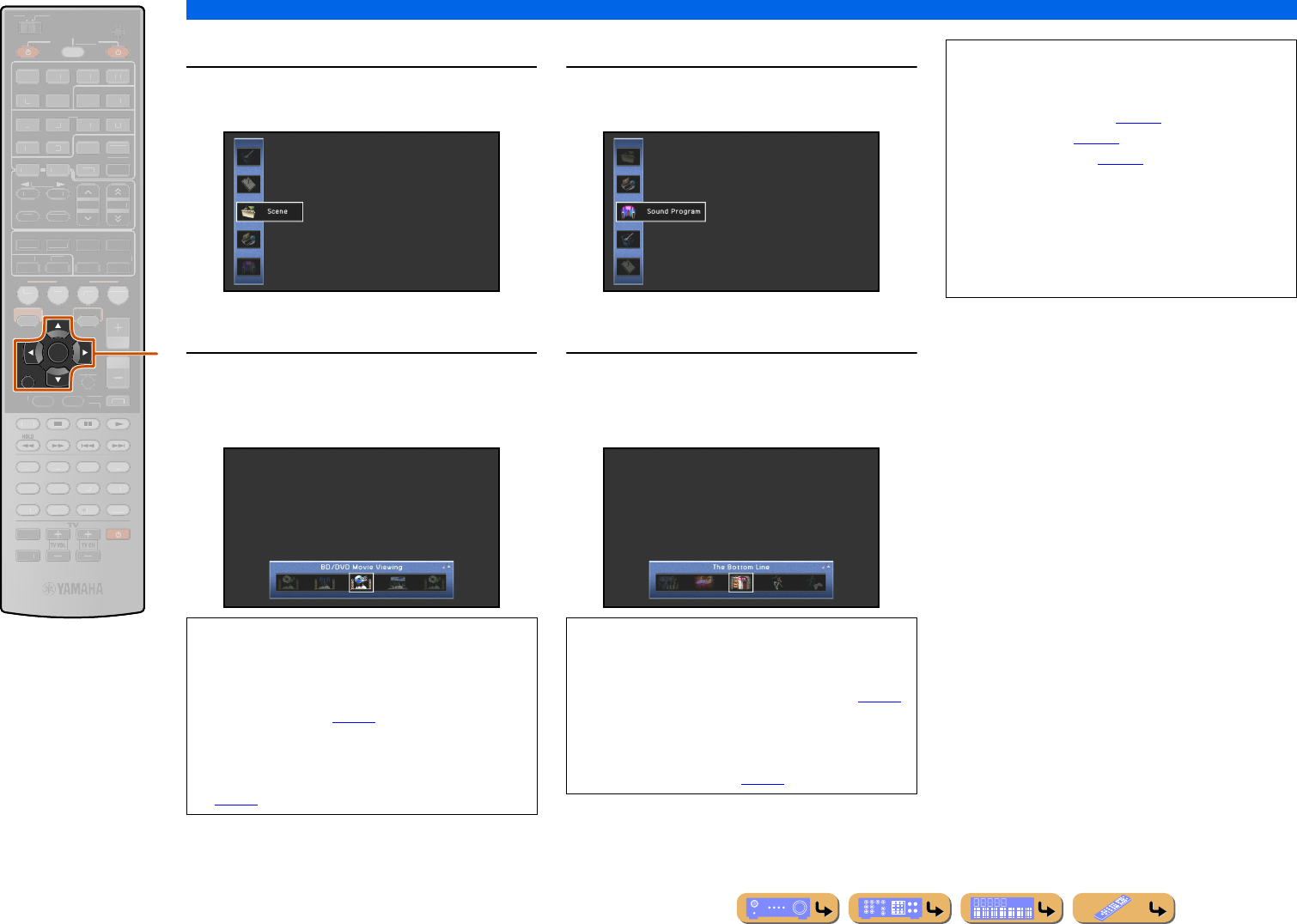
PLAYBACK
Using the TV display to control this unit
En 51
■
Selecting a scene
1Use kCursor B / C to select “Scene” and
press kENTER.
Scene icons are displayed at the bottom of the TV
screen.
2Use kCursor D / E to select a scene and
press kENTER.
The scene is selected.
■
Selecting a sound program
1Use kCursor B / C to select “Sound
Program” and press kENTER.
Sound program icons are displayed at the bottom of the
TV screen.
2Use kCursor D / E to select a sound
program and press kENTER.
The sound program is selected.
RETURN
ENTER
SCENE
VO
L
U
ME
ENHANCE
R
S
UR. DE
CO
DE
STRAIGHTSLEEP
P
URE DIRECT
PART Y
M
OVI
E
M
USI
C
BD
DVD
TV
CD
RADI
O
M
U
T
E
7
8
5
6
9
0
1
0
1
2
3
4
R
EC
ENT
TOP
MENU
PO
P-U
P
MENU
DI
S
PLAY
SO
UR
C
E
M
AIN
Z
O
NE 2
RE
C
EIVE
R
CODE SET
I
NP
U
T
MUTE
O
PTION
O
N
SC
REE
N
FM
I
NF
O
M
EM
O
RY
AM
P
RESET
H
DMI
AV
A
UDI
O
1
2
3
4
1
2
5
V
-
AUX
DOCK
HDMI
O
U
T
MULTI
5
1
2
3
4
6
N
ET
S
IRI
US
TU
NER
T
UN./C
H
C
ATE
GO
R
Y
k
kCursor B / C / D / E
kENTER
kRETURN
•Pressing kRETURN displays the previous menu
screen. Press kRETURN repeatedly to close the ON
SCREEN menu.
•Refer to “Changing input settings with a single key
(SCENE function)” (☞p. 44) for details on the default
scene settings.
•Detailed SCENE function settings can be edited. Refer
to “Editing the SCENE function (SCENE menu)”
(☞p. 90) for details.
•Pressing kRETURN displays the previous menu
screen. Press kRETURN repeatedly to close the ON
SCREEN menu.
•Refer to “Enjoying favorite sound field effect” (☞p. 44)
for various sound programs.
•You can configure the detailed settings for each sound
program. Refer to “Setting sound program parameters
(Sound Program menu)” (☞p. 93) for details.
NOTES
Menus can be operated and the status of this unit
confirmed from the following three main displays.
• ON SCREEN menu (☞p. 86)
•Option menu (☞p. 52)
• Content window (☞p. 56)
These menus and status features can be used to
configure more various functions in addition to
selecting “Input,” “Scene” and “Sound Program.”
Refer to each references for details on menus and
status.
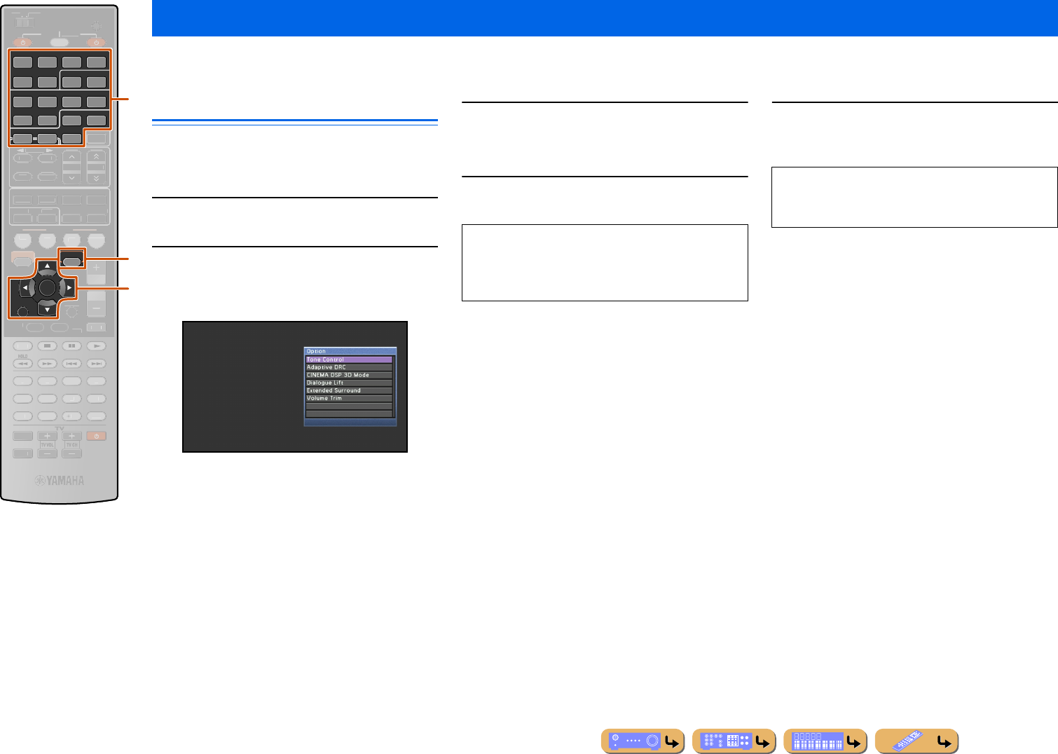
PLAYBACK
En 52
This unit has a unique Option menu for each input source. Option menus can be used to enable features such as volume trim for compatible input sources or to display
audio/video data.
Option menu display and setup
Option menu operations are displayed on the front panel
display or TV screen. TV display is used here to explain
operation.
1Use dInput selector to select an input
source to which options will be applied.
2Press tOPTION.
The Option menu is displayed.
The displayed Option menu settings differ depending
on the input source.
For more information, refer to the “Option menu” on
the next page.
3Use kCursor B / C to select the desired
setting and press kENTER.
Parameters of the selected item are displayed.
4Use kCursor B / C / D / E to select the
desired item (or enable a function).
5Press tOPTION to close the Option menu.
Configuring settings specific to an individual input source (Option menu)
dInput selector
kCursor B / C / D / E
kENTER
kRETURN
tOPTION
RETURN
HDMI
AV
AUDIO
1234
125
V-AUX
ENTER
DOCK
MULTI
OPTION
5
1234
6
NET
SIRIUSTUNER
SCENE
VO
L
U
ME
ENHANCE
R
S
UR. DE
CO
DE
STRAIGHTSLEEP
P
URE DIRECT
PART Y
M
OVI
E
M
USI
C
BD
DVD
TV
CD
RADI
O
MU
T
E
7
8
5
6
9
0
10
1
2
3
4
R
EC
ENT
TOP
MENU
P
OP-U
P
M
EN
U
DI
S
PLAY
SO
UR
C
E
M
AIN
Z
O
NE 2
RE
C
EIVE
R
CODE SE
T
I
NP
U
T
MUTE
O
N
SC
REE
N
HDMI
OUT
FM
I
NF
O
M
EM
O
RY
AM
P
RESET
TUN./C
H
C
ATE
GO
R
Y
t
d
k
Option menu
•Press kRETURN to display the previous screen or
close the Option menu.
•The Option menu may close automatically when some
functions are enabled.
The keys on the remote control may not respond for a
few seconds after the Option menu is closed. Should
this occur, select the input source again.
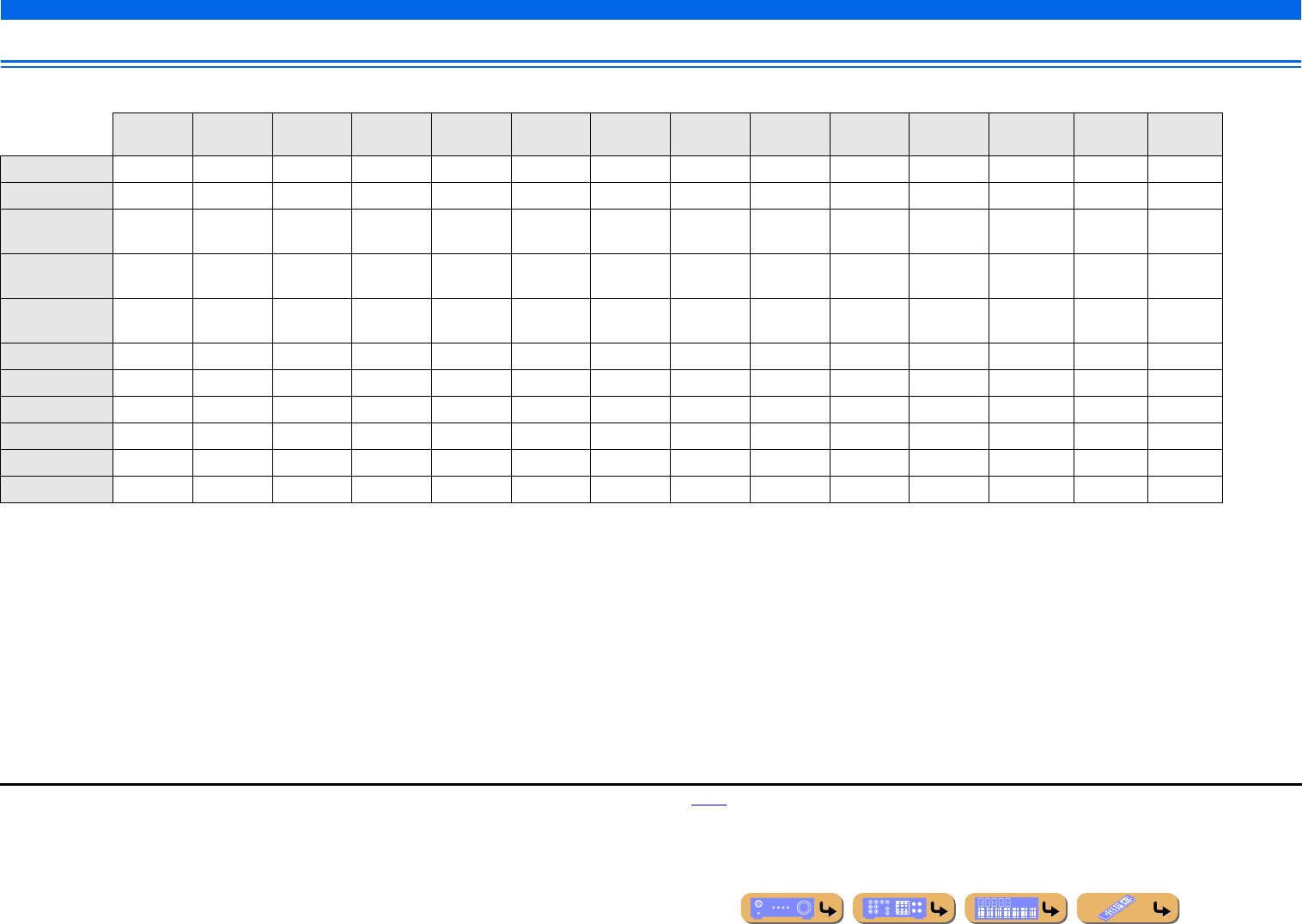
PLAYBACK
Configuring settings specific to an individual input source (Option menu)
En 53
Option menu
The following items are provided for each input source. “✓” indicates the available menu for each input source. J1
HDMI 1-5 AV1-4 AV5-6 AUDIO1-2 V-AUX MULTI CH PC NET
RADIO Rhapsody SIRIUS IR DOCK
(iPod)
DOCK
(Bluetooth) TUNER SIRIUS
Tone Control ✓✓✓✓✓ ✓✓✓✓✓ ✓✓✓
Adaptive DRC ✓✓✓✓✓ ✓✓✓✓✓ ✓✓✓
CINEMA DSP
3D Mode
✓✓✓✓✓ ✓✓✓✓✓ ✓✓✓
Dialogue
Lift J2
✓✓✓✓✓ ✓✓✓✓✓ ✓✓✓
Extended
Surround
✓✓ ✓
Volume Trim ✓✓✓✓✓✓✓✓✓✓✓ ✓✓✓
Shuffle ✓✓✓J3
Repeat ✓✓✓J3
Connect ✓
Disconnect ✓
Pairing ✓
J1 : When “Tone Control,” “Adaptive DRC,” “CINEMA DSP 3D Mode,”
“Dialogue Lift,” or “Extended Surround” is adjusted for an input source, the
same value is applied to other input sources and “ALL” is displayed on the
front panel display. When settings specific to a certain input source are
selected, the input source name is displayed on the front panel display. If the
name of the input source has been changed (☞p. 88), the original name of the
input source is displayed.
J2 : “Dialogue Lift” can be adjusted only when the presence speakers are available.
J3 : Not available for Yamaha Wireless System for iPod.
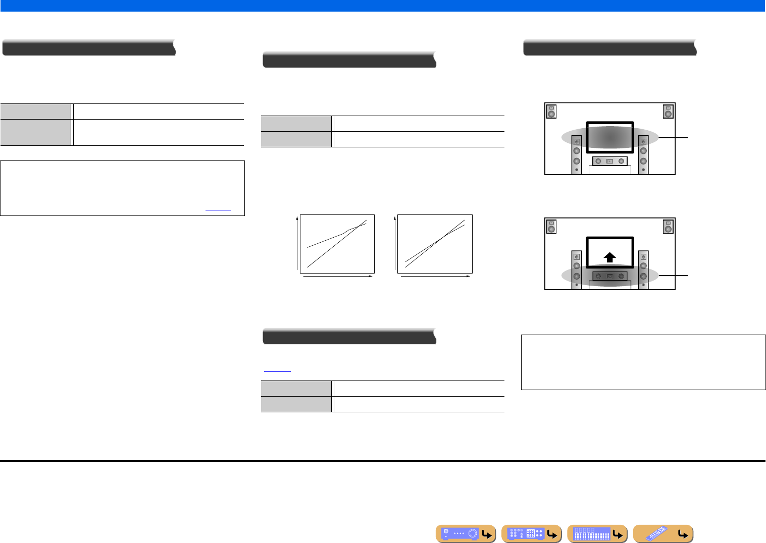
PLAYBACK
Configuring settings specific to an individual input source (Option menu)
En 54
■
Adjusting high/low-frequency sound
Tone Control
You can adjust the balance of the high-frequency range (Treble)
and low-frequency range (Bass) of sounds output from the front
left and right speakers to obtain desired tone.
■
Auto-adjusting the sound level to make
even low volumes more audible
Adaptive DRC
Adjusts the dynamic range in conjunction with the volume level
(from minimum to maximum). When you play audio at night or at
low volumes, it is a good idea to set parameter to “On.” J1
When “On” is selected, the dynamic range is adjusted as follows.
If the volume level is low, the dynamic range is narrow.
If the volume level is high, the dynamic range is wide.
■
Enjoying more spatial sound fields
CINEMA DSP 3D Mode
Set whether to use sound programs in CINEMA DSP 3D mode
(☞p. 46).
■
Adjusts the vertical position of dialogues
Dialogue Lift
Adjusts the vertical position of center sound such as dialogues
when presence speakers are used. Increasing this parameter raises
the position.
If the dialog seems to come out from a lower position than the
video monitor screen, increase this parameter.
“0” (default) corresponds to the lowest position and “5” to the
highest position.
Adjustable range -6.0 dB to +6.0 dB
Adjustment
increments
0.5 dB
•The tone control of the speakers or headphones can be set
separately. Set the headphone tone control with the headphones
connected.
•TONE CONTROL on the front panel can also be used (☞p. 43).
On Adjusts the dynamic range automatically.
Off (Default) Does not adjust the dynamic range automatically.
On (Default) Enables CINEMA DSP 3D mode.
Off Disables CINEMA DSP 3D mode.
On
Off
On
Off
Input Level Input Level
Volume: low Volume: high
Output Level
Output Level
•“Dialogue Lift” can be adjusted only when the presence speakers
are available.
•You cannot move the dialog position lower than the default
setting.
The ideal dialog
position
Move up to the ideal
dialog position
J1 : “Adaptive DRC” is also effective when you use headphones.
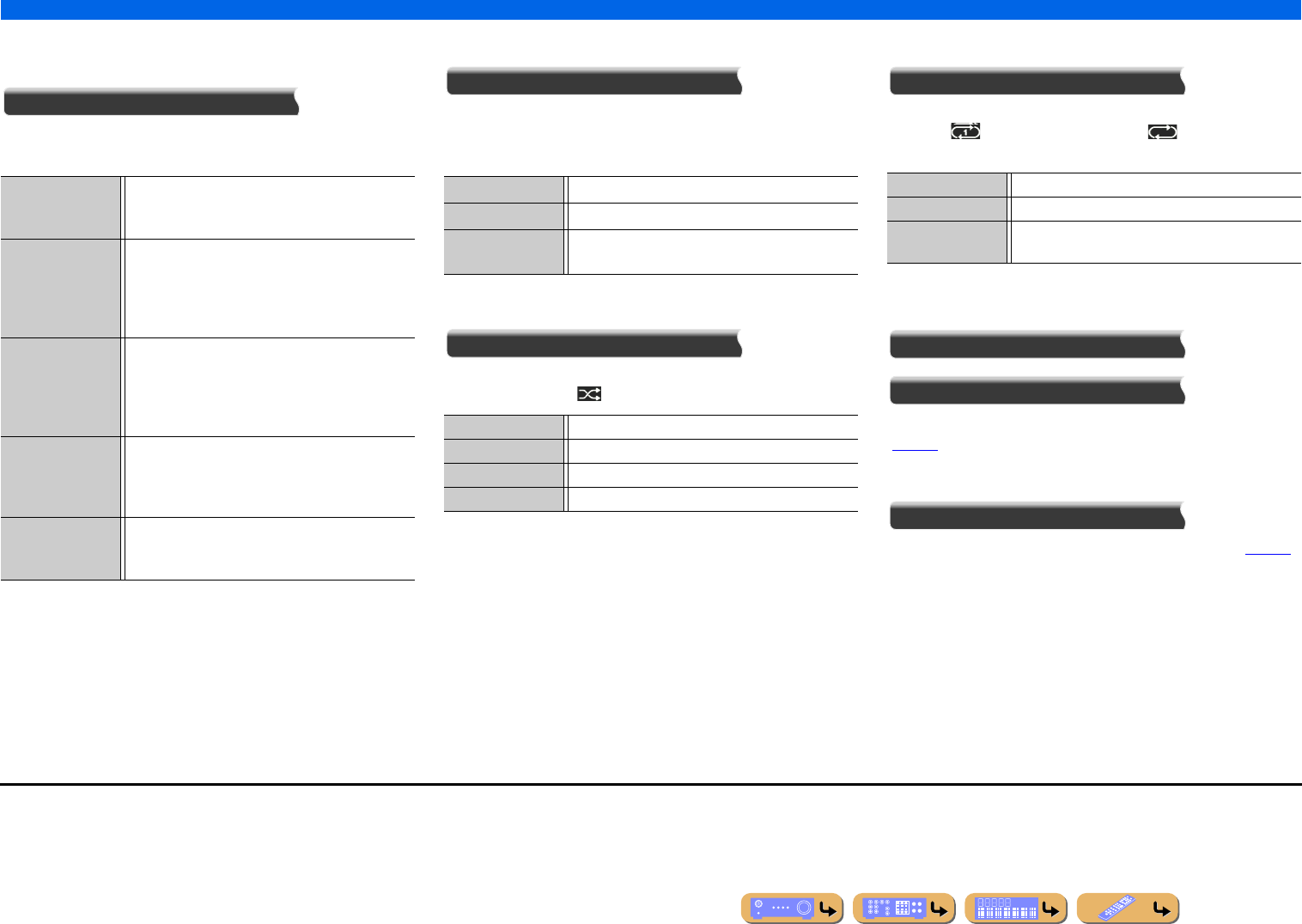
PLAYBACK
Configuring settings specific to an individual input source (Option menu)
En 55
■
Selecting the 5.1-channel signal playback
method
Extended Surround
Selects whether to reproduce 5.1-channel input signals in 6.1- or
7.1-channel when surround back speakers are used. J1
■
Adjusting volume between input sources
Volume Trim
Reduces any change in volume when switching between input
sources by correcting volume differences in each input source. You
can adjust this parameter for each input source.
■
Shuffle playback
Shuffle
Plays back songs or albums in random order. When the shuffle
function is enabled, “ ” appears on the TV screen. J2
■
Repeat playback
Repeat
Plays songs or albums repeatedly. When the repeat function is
enabled, “ (Single / One[iPod])” or “ (All)” appears on
the TV screen. J2
■
Connect / Disconnect Bluetooth
component
Connect
Disconnect
Switches communication with a Bluetooth component on and off
(☞p. 83).
■
Pairing Bluetooth component
Pairing
Performs pairing of this unit and a Bluetooth component (☞p. 83).
Auto (Default) Automatically selects the most suitable decoder if a
flag for reproducing surround back channel is present,
and reproduces the signals in 6.1- or 7.1-channel.
q PLIIx Movie Always reproduces signals in 7.1-channel using the
Dolby Pro Logic IIx Movie decoder whether or not
surround back channel signals are contained. You can
select this parameter when two surround back
speakers are connected.
q PLIIx Music Always reproduces signals in 6.1- or 7.1-channel
using the Dolby Pro Logic IIx Music decoder whether
or not surround back channel signals are contained.
You can select this parameter when one or two
surround back speakers are connected.
EX/ES Automatically selects the most suitable decoder for
input signals whether or not the flag for reproducing
surround back channel is present, and always
reproduces signals in 6.1-channel.
Off Always reproduces original channels whether or not
the flag for reproducing surround back channel is
present.
Adjustable range -6.0 dB to 0.0 dB to +6.0 dB
Default setting 0.0 dB
Adjustment
increments
0.5 dB steps
Off The shuffle function is turned off.
On J3The shuffle function is tuned on.
Songs J4Plays songs back in random order.
Albums J4Plays albums back in random order.
Off The repeat function is turned off.
Single / One[iPod] Plays a song back repeatedly.
All When all songs have completed playback, returns to
the start and repeats playback.
J1 : AV5-6 or AUDIO1-2 are also available when “Audio Return Channel” is on,
and the input source is used for “TV Audio Input.”
J2 : Not available for Yamaha Wireless System for iPod.
J3 : This item is displayed only when PC or Rhapsody is selected as input source.
J4 : This item is displayed only when DOCK (iPod) is selected as input source.
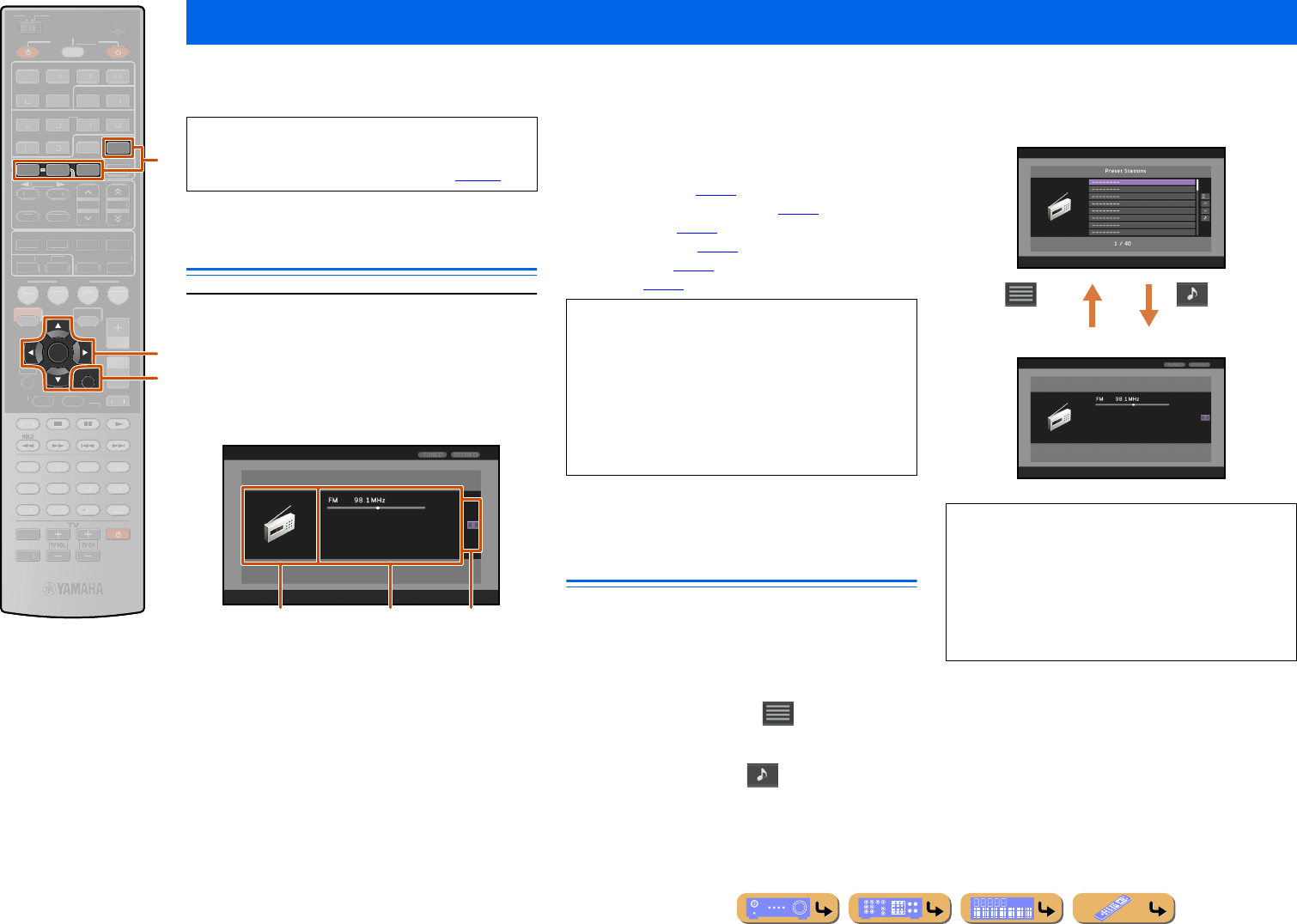
PLAYBACK
En 56
When NET, DOCK, TUNER, or SIRIUS is selected, the Content window is displayed on the TV screen. Playback style for iPod, functions for FM/AM tuner, SIRIUS
Satellite Radio tuner, Rhapsody, SIRIUS Internet Radio, Internet Radio, and PC can be set in the Content window.
Displaying the Content window on
the TV screen
Press dNET, dDOCK, dTUNER or dSIRIUS to
display the Content window.
The Content window consists of two main displays, the
Now Playing view and the Browse view.
Below is the example of the Now Playing view for TUNER.
aImage display
Icon for each input source or album art is displayed.
bInformation display
Information on the current input source is displayed.
cScreen button area
Buttons to operate each input source are displayed here.
These buttons vary depending on the selected input. For
details on operations for each input, see the following.
–FM/AM tuner (☞p. 59)
–SIRIUS Satellite Radio tuner (☞p. 61)
–PC servers (☞p. 68)
–Internet Radio (☞p. 74)
–Rhapsody (☞p. 71)
–iPod (☞p. 80)
Switching the display between the
Now Playing view and the Browse
view
You can switch the display between the Now Playing
view and the Browse view by the following methods.
•Press lDISPLAY to cycle between the Now Playing
view and the Browse view.
•In the Now Playing view, press kENTER and use
kCursor B / C to select the icon. Then press
kENTER to switch to the Browse view.
•In the Browse view, press kCursor E and use k
Cursor B / C to select the icon. Then press
kENTER to switch to the Now Playing view.
Confirming and operating input sources from the Content window
dDOCK
dTUNER
dSIRIUS
kCursor B / C / D / E
kENTER
kRETURN
lDISPLAY
ENTER
DISPLAY
DOCK
NET
SIRIUSTUNER
SCENE
RETURN
VO
L
U
ME
ENHANCE
R
S
UR. DE
CO
DE
STRAIGHTSLEEP
P
URE DIRECT
PART Y
M
OVI
E
M
USI
C
BD
DVD
TV
CD
RADI
O
MU
T
E
7
8
5
6
9
0
10
1
2
3
4
R
EC
ENT
TOP
MENU
P
OP-U
P
M
EN
U
SO
UR
C
E
M
AIN
Z
O
NE 2
RE
C
EIVE
R
CODE SE
T
I
NP
U
T
MUTE
H
DMI
AV
A
UDI
O
1
2
3
4
1
2
5
V
-
AUX
HDMI
O
U
T
MULTI
OPTION
O
N
SC
REE
N
5
1
2
3
4
6
FM
I
NF
O
M
EM
O
RY
AM
P
RESET
TUN./C
H
C
ATE
GO
R
Y
d
k
l
A TV screen is required to display the Content
window. Refer to “Connecting a TV monitor” for
instructions on connecting a TV monitor (☞p. 22).
bac
•In the Now Playing view, press kENTER and use
kCursor B / C to select the button. Then press
kENTER to execute the selection.
•In the Browse view, press kCursor E and use k
Cursor B / C to select the button. Then press k
ENTER to execute the selection.
•Press kRETURN repeatedly to exit from the
operation.
When selecting “DOCK (iPod)” as input source and
playing back video content of iPod/iPhone, the screen
switches as follows by pressing lDISPLAY
repeatedly.
Now Playing view → Browse view →
Video playback screen (content window disappears)
→ Now Playing view
Now Playing view
Browse view
or
lDISPLAY
or
lDISPLAY
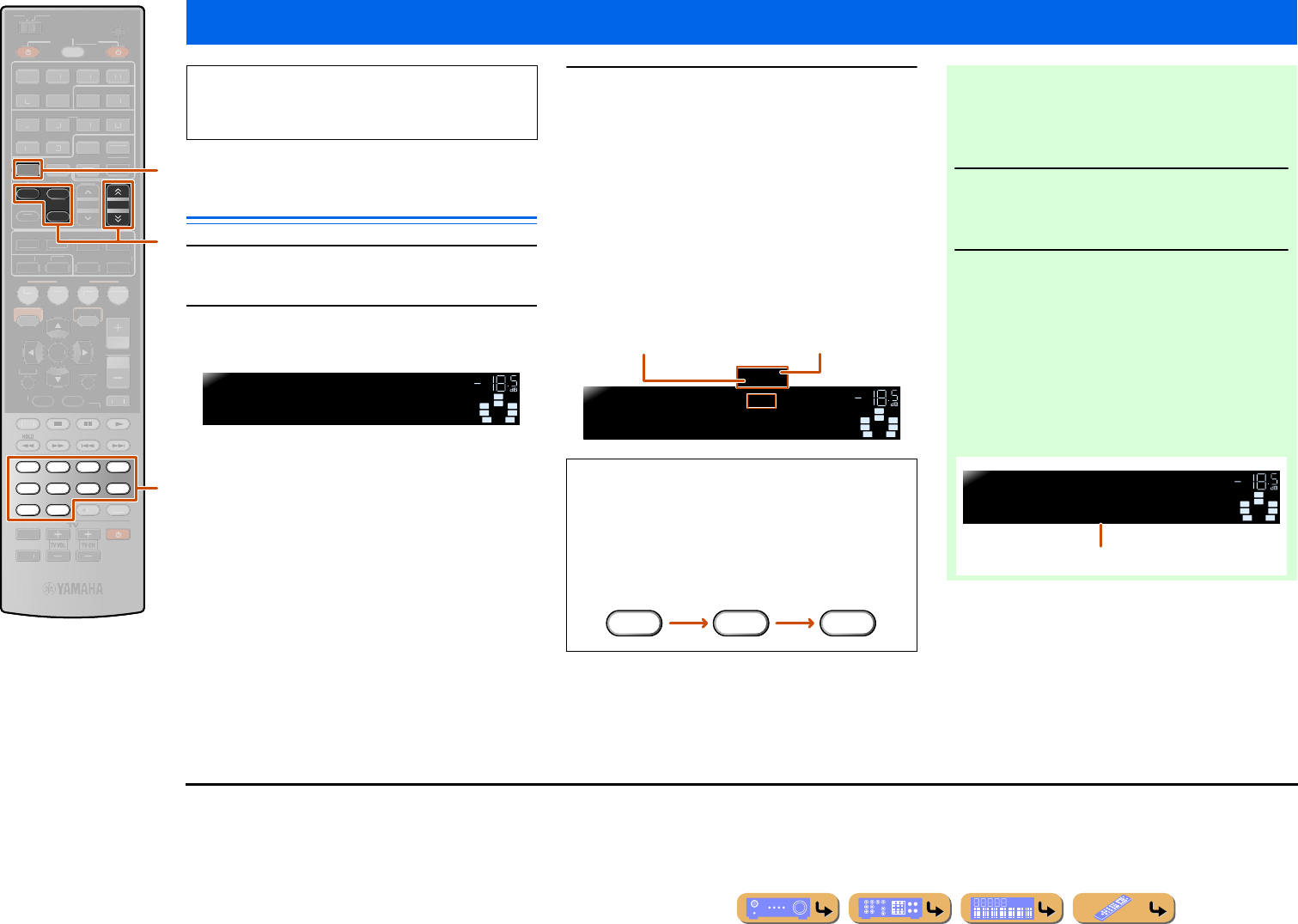
PLAYBACK
En 57
Selecting a frequency for reception
(Normal tuning)
1Press dTUNER to switch to the tuner input.
2Press eFM or eAM to select a band to
receive.
3Use eTUN./CH H / I to set a frequency to
receive.
eTUN./CH H
Increases the frequency. Press and hold this key for
longer than a second to search automatically for a station
on a higher frequency than the current one. J1
eTUN./CH I
Decreases the frequency. Press and hold this key for
longer than a second to search automatically for a station
on a lower frequency than the current one. J1
FM/AM tuning
dTUNER
eFM
eAM
eMEMORY
eTUN./CH H / I
mNumeric keys
FM
MEMORY
AM
7856
90
1234
TUNER
TUN./CH
SCENE
RETURN
VO
L
U
ME
ENHANCE
R
S
UR. DE
CO
DE
STRAIGHTSLEEP
P
URE DIRECT
PART Y
M
OVI
E
M
USI
C
BD
DVD
TV
CD
RADI
O
M
U
T
E
ENTER
10
R
EC
ENT
TOP
MENU
P
OP-U
P
M
EN
U
H
DMI
AV
A
UDI
O
1
2
3
4
1
2
5
V
-
AUX
DI
S
PLAY
SO
UR
C
E
M
AIN
Z
O
NE 2
RE
C
EIVE
R
CODE SE
T
I
NP
U
T
MUTE
DOCK
HDMI
O
U
T
MULTI
O
PTION
O
N
SC
REE
N
5
1
2
3
4
6
I
NF
O
P
RESET
NET
S
IRI
US
CATEGORY
d
m
e
When using the FM/AM tuner, adjust the direction of
the FM/AM antenna connected to this unit to get the
best reception.
SW
C
L
SL SR
R
FM87.5 MHz
VOL.
SBL SBR
■Entering a frequency number
In normal tuning mode, use the mNumeric keys to
enter a frequency. Leave the decimal point out when
entering a number. J2
For example, enter as follows to select a station on
98.5 MHz.
STEREO
TUNED
SW
C
L
SL SR
R
SBL SBR
FM98.5 MHz
STEREO
TUNED
VOL.
Lights up when a broadcast
is received from a station
Lights up when a stereo
broadcast is received
9 8 5
■Registering stations manually (Manual
Preset)
Select stations manually and register them as presets
individually.
1Tune in to the station you want to
register, referring to “Selecting a
frequency for reception (Normal tuning).”
2Use one of the following methods to
register the station you are currently
receiving.
■Registering to a preset number to which
no station is registered
Press eMEMORY for 3 seconds or longer.
The station will be registered automatically to the
lowest open preset number (or the next number after
the one registered most recently).
STEREO
TUNED
SW
C
L
SL SR
R
01:FM98.5 MHz
MEMORY VOL.
SBL SBR
Registered frequencies
J1 : When searching for a station, release the key once the search has
started.
J2 : “Wrong Station!” appears on the front panel display when you
enter a frequency that is out of receivable range. Make sure that
the frequency entered is correct.
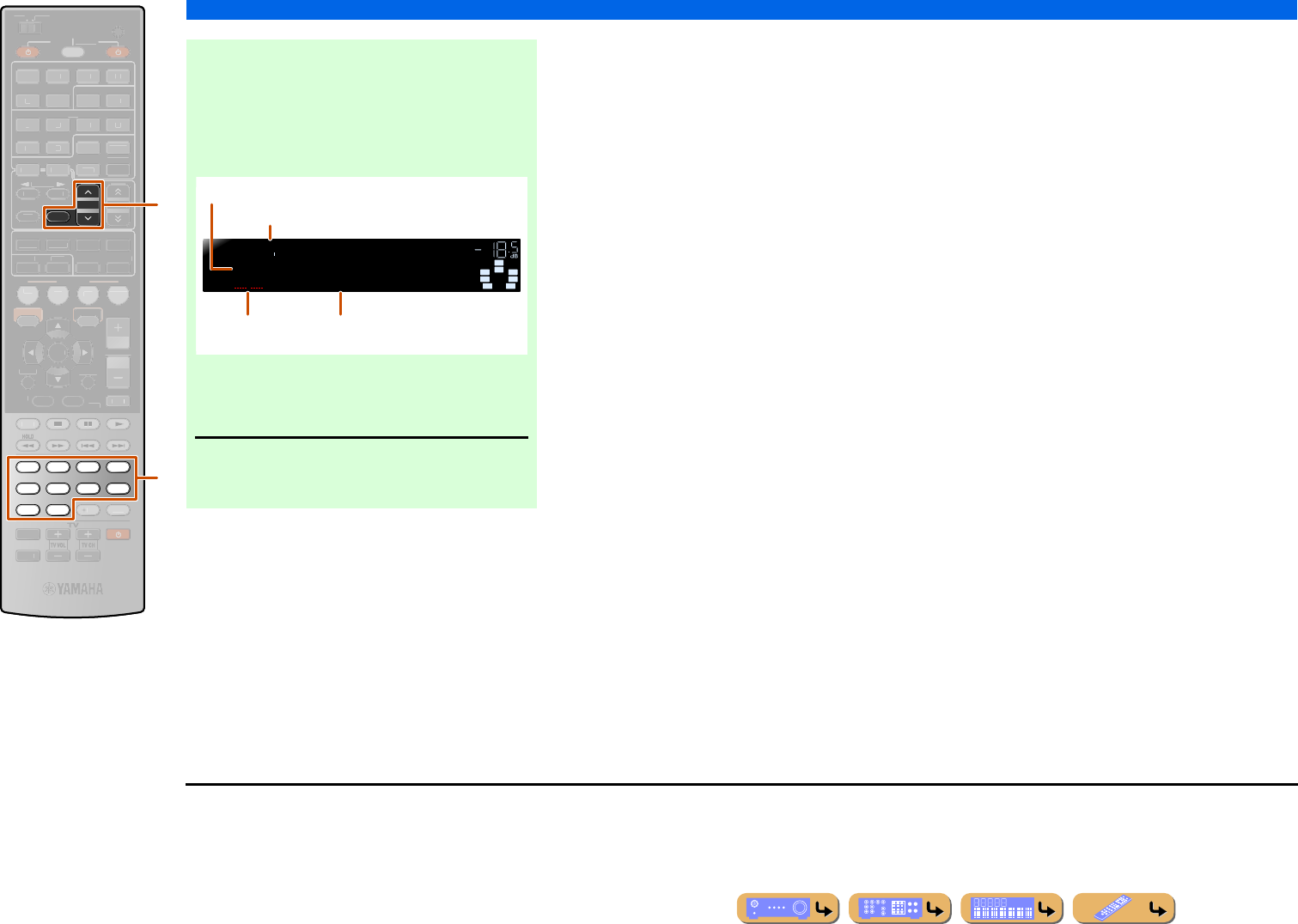
PLAYBACK
FM/AM tuning
En 58
eMEMORY
ePRESET F / G
mNumeric keys
MEMORY
PRESET
7856
90
1234
SCENE
RETURN
VO
L
U
ME
ENHANCE
R
S
UR. DE
CO
DE
STRAIGHTSLEEP
P
URE DIRECT
PART Y
M
OVI
E
M
USI
C
BD
DVD
TV
CD
RADI
O
MU
T
E
ENTER
10
R
EC
ENT
TOP
MENU
P
OP-U
P
M
EN
U
H
DMI
AV
A
UDI
O
1
2
3
4
1
2
5
V
-
AUX
DI
S
PLAY
SO
UR
C
E
M
AIN
Z
O
NE 2
RE
C
EIVE
R
CODE SE
T
I
NP
U
T
MUTE
DOC
K
HDMI
O
U
T
MULTI
O
PTION
O
N
SC
REE
N
5
1
2
3
4
6
FM
I
NF
O
AM
NET
S
IRI
US
TU
NER
TUN./C
H
C
ATE
GO
R
Y
m
e
■Designating a preset number for
registration
Press eMEMORY once, to display “Manual Preset”
on the front panel display. After a small wait, the
preset number that the station has been registered to
will appear.
Press ePRESET F / G to select the preset number
to register the station to, and then press eMEMORY
to register.
To select a registered station, press
ePRESET F / G to select the preset number
of the station. J1
STEREO
TUNED
SW
C
L
SL SR
R
01:Empty
985
VOL.
SBL SBR
Preset number
The newly registered frequency
Empty, or the frequency
registered most previously
Blinks
J1 : To select a station by selecting a preset number, use the
mNumeric keys to enter the preset number of the station you
want to listen. When an invalid number is entered, “Wrong Num.”
appears on the front panel display. Check that you have entered
the correct number.
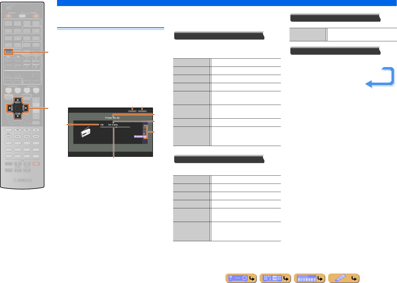
PLAYBACK
FM/AM tuning
En 59
Navigating the FM/AM tuner from
the Content window
The station currently received can be confirmed from the
menu displayed on the TV screen. Various FM/AM tuner
operations can be performed from the Content window
rather than controls on the front panel display. The
Content window is displayed when dTUNER is
pressed.
You can operate the FM/AM tuner from the Now Playing
view or the Browse view.
■
Operating from the Now Playing
view
aTuned indicator
Lights up when a station is received.
bStereo indicator
Lights up when a stereo broadcast is received. When
“Audio Mode” is set to “Mono,” the indicator does not
light.
cPreset number
The selected preset number is displayed.
dBand
The selected band (FM or AM) is displayed.
eFrequency
The frequency currently received is displayed.
fFrequency guide
The frequency currently received is displayed as a cursor
on the bar.
gScreen button area
Buttons for available operations are displayed. See
“Screen buttons on the Now Playing view” for details.
Screen buttons on the Now Playing view
To use these buttons, first press kENTER. Then select
the desired one with kCursor B / C and kENTER.
Manual Tuning
You can tune in to a desired FM/AM station by
specifying its frequency.
Preset Select
You can call preset stations.
Utility
Browse
Switches the display to the Browse view.
dTUNER
kCursor B / C
kENTER
ENTER
TUNER
SCENE
RETURN
VO
L
U
ME
ENHANCE
R
S
UR. DE
CO
DE
STRAIGHTSLEEP
P
URE DIRECT
PART Y
M
OVI
E
M
USI
C
BD
DVD
TV
CD
RADI
O
M
U
T
E
7
8
5
6
9
0
10
1
2
3
4
R
EC
ENT
TOP
MENU
P
OP-U
P
M
EN
U
DI
S
PLAY
SO
UR
C
E
M
AIN
Z
O
NE 2
RE
C
EIVE
R
CODE SE
T
I
NP
U
T
MUTE
O
PTION
O
N
SC
REE
N
H
DMI
AV
A
UDI
O
1
2
3
4
1
2
5
V
-
AUX
DOCK
HDMI
O
U
T
MULTI
5
1
2
3
4
6
FM
I
NF
O
M
EM
O
RY
AM
P
RESET
NET
S
IRI
US
TUN./C
H
C
ATE
GO
R
Y
d
ka b
e
f
d
c
g
FM Switches a band to FM.
AM Switches a band to AM.
Tuning - Decreases the frequency.
Tuning + Increases the frequency.
Auto - Automatically searches for a station on a
lower frequency than the current station.
Auto + Automatically searches for a station on a
higher frequency than the current station.
Direct Selects the frequency manually.
Memory Registers the station currently received as
a preset station. Up to 40 FM/AM stations
can be registered.
Preset - Selects the previous preset number.
Preset + Selects the next preset number.
Preset -8 Returns the previous page.
Preset +8 Goes to the next page.
Direct Selects a station directly by entering the
preset number.
Memory Registers the station currently received as
a preset station. Up to 40 FM/AM stations
can be registered.
FM Mode Selects “Stereo” or “Mono” when
receiving the FM station.
Continues to the
next page
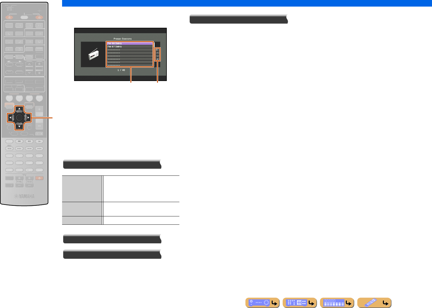
PLAYBACK
FM/AM tuning
En 60
■
Operating from the Browse view
aPreset station list
The list of preset stations is displayed.
bScreen button area
Buttons for available operations are displayed. See
“Screen buttons on the Browse view” for details.
Screen buttons on the Browse view
To use these buttons, first press kCursor E. Then
select the desired one with kCursor B / C and
kENTER.
Utility
1 Page Up
1 Page Down
Scrolls the list to the next or previous page.
Now Playing
Switches the display to the Now Playing view.
kCursor B / C / D / E
kENTER
ENTER
SCENE
RETURN
VO
L
U
ME
ENHANCE
R
S
UR. DE
CO
DE
STRAIGHTSLEEP
P
URE DIRECT
PART Y
M
OVI
E
M
USI
C
BD
DVD
TV
CD
RADI
O
M
U
T
E
FM
I
NF
O
M
EM
O
RY
AM
P
RESET
H
DMI
AV
A
UDI
O
1
2
3
4
1
2
5
V
-
AUX
7
8
5
6
9
0
10
1
2
3
4
R
EC
ENT
TOP
MENU
P
OP-U
P
M
EN
U
DI
S
PLAY
SO
UR
C
E
M
AIN
Z
O
NE 2
RE
C
EIVE
R
CODE SE
T
I
NP
U
T
MUTE
DOCK
HDMI
O
U
T
MULTI
O
PTION
O
N
SC
REE
N
5
1
2
3
4
6
NET
S
IRI
US
TU
NER
TUN./C
H
C
ATE
GO
R
Y
k
Auto Preset Detects stations with a strong signal and
automatically registers up to 40 stations,
beginning with the next number after the
current number.
Clear Preset Clears registration of the preset station
currently selected.
Clear All Preset Clears registration of all preset stations.
ab
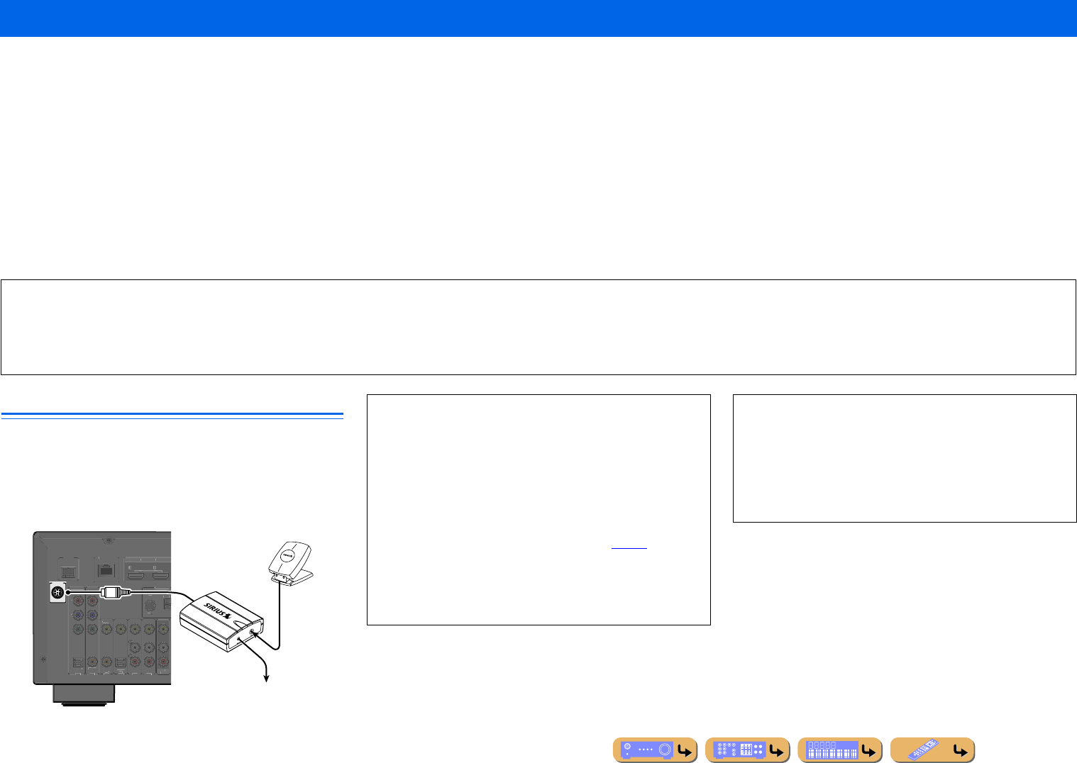
PLAYBACK
En 61
To listen to Satellite Radio, you’ll need to connect a SIRIUS Satellite Radio tuner (sold separately) to your SIRIUS-Ready receiver. SIRIUS Satellite Radio is available to residents of the US (except
Alaska and Hawaii) and Canada.
Satellite Radio delivers a variety of commercial-free music from categories ranging from Pop, Rock, Country, R&B, Dance, Jazz, Classical and many more plus coverage of all the top professional and
college sports including play by play games from select leagues and teams. Additional programming includes expert sports talk, uncensored entertainment, comedy, family programming, local traffic
and weather and news from your most trusted sources.
Once you’ve purchased a SIRIUS tuner you’ll need to activate it and subscribe to begin enjoying the service. Easy to follow installation and setup instructions are provided with the SIRIUS tuner. There
are a variety of programming packages available, including the option of adding “The Best of XM” programming to the SIRIUS service. The “Best of XM” service is not available to SIRIUS Canada
subscribers at this time. Please check with SIRIUS Canada for any updates using the numbers and web address below.
Family friendly packages are also available to restrict channels featuring content that may be inappropriate for children.
To subscribe to SIRIUS, U.S. and Canadian customers can call 1-888-539-SIRI (1-888-539-7474) or visit sirius.com (US) or siriuscanada.ca (Canada).
Connecting the SiriusConnect™ tuner
Connect the SiriusConnect tuner (sold separately) to the SIRIUS
jack on the rear panel of this unit. For details, see the instruction
manuals provided with the SiriusConnect tuner.
Listening to SIRIUS Satellite Radio™
SIRIUS Radio Legal
SIRIUS and all related marks and logos are trademarks of Sirius XM Radio Inc. and its subsidiaries. All other marks and logos are the property of their respective owners. All rights reserved. SIRIUS
subscription sold separately. Taxes and a one-time activation fee may apply. SIRIUS tuner required (sold separately) to receive the SIRIUS service. All programming and fees subject to change. It is prohibited
to copy, decompile, disassemble, reverse engineer, hack, manipulate or otherwise make available any technology or software incorporated in receivers compatible with the SIRIUS Satellite Radio System.
Service not available in Alaska or Hawaii.
SIRIUS
DOC
K
(
TV
)
AV 3
AV 4
AV 5
AV 6
(
CD
)
COAXIAL
O
PTI
C
AL
V
IDE
O
A
V
OU
T
H
DMI
OU
T
1
2
A
R
C
A
R
C
S
ELE
C
TABLE
O
PTI
C
A
L
AV 1
AV 2
CO
AXIAL
CO
MP
O
NEN
T
VIDEO
P
R
P
B
Y
ANTENN
A
F
M
75
G
N
D
N
ETWOR
K
SiriusConnect Tuner and the antenna
(sold separately)
To the AC wall outlet
•To ensure optimal reception of the SIRIUS Satellite Radio
signals, the antenna of the SiriusConnect tuner must be placed at
or near a window with no obstacles in the path to the sky. The
orientation of the antenna for the best reception differs depending
on the area. Refer to the instruction manuals provided with the
SiriusConnect tuner for the installation of the antenna. You can
mount it indoors or outdoors.
•Use the Antenna information on the front panel display or the
SIRIUS information screen on the TV screen (☞p. 65) to check
the antenna reception level and adjust the orientation of the
antenna.
•You need to connect the SiriusConnect tuner to the AC wall
outlet.
NOTES
•If “CHECK SR TUNER” or “ANTENNA ERROR” appears on
the front panel display, the connection of the SiriusConnect tuner
or antenna is incorrect. In such cases, check the connection of the
SiriusConnect tuner and the antenna.
•If “NOT SUPPORTED” appears on the front panel display, this
unit does not support the connected SiriusConnect tuner.
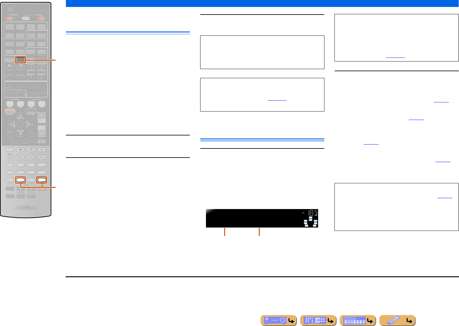
PLAYBACK
Listening to SIRIUS Satellite Radio™
En 62
Activating SIRIUS Satellite Radio™
subscription
Before using the SIRIUS Satellite Radio feature, you
need to activate your SIRIUS Satellite Radio
subscription. To activate the subscription you need the
SIRIUS ID which is uniquely assigned to the
SiriusConnect tuner. SIRIUS ID is 12-digit number
which is indicated on the package of the SiriusConnect
tuner and on the label of the SiriusConnect tuner.
SIRIUS ID is also configured on the front panel display
when you tune into the SIRIUS Satellite Radio channel
“0.”
■
Displaying the SIRIUS ID of your
SiriusConnect tuner
1Press dSIRIUS.
2Press m0 and then mENT to display the
SIRIUS ID of your SiriusConnect tuner.
“000 Sirius ID” and “xxxxxxxxxxxx”
(“xxxxxxxxxxxx” indicates the 12-digit SIRIUS ID of
your SiriusConnect tuner) appears alternately on the
front panel display.
Write down the SIRIUS ID in the space provided
below.
ID:________________________________________
3Contact SIRIUS Satellite Radio to activate
your subscription.
SIRIUS Satellite Radio™
operations
1Press dSIRIUS to select “SIRIUS” as the
input source.
The SIRIUS indicator lights up on the front panel
display and the SIRIUS Satellite Radio information
(such as channel number, channel name, category,
artist name, or song title) for the currently selected
channel appears on the front panel display. J1
2Search for a channel by using one of the
SIRIUS Satellite Radio search modes.
All channel search mode
Selects a channel from the all channel list (☞p. 63).
Category search mode
Selects a channel by category (☞p. 63).
Direct number access mode
Selects a channel directly by entering the channel
number (☞p. 63).
Preset search mode
Selects a channel from the preset channels (☞p. 64).
You can preset channels by registering them to specific
numbers, and later just select those numbers to tune in.
dSIRIUS
m0
mENT
0
ENT
SIRIUS
SCENE
RETURN
VO
L
U
ME
ENHANCE
R
S
UR. DE
CO
DE
STRAIGHTSLEEP
P
URE DIRECT
PART Y
M
OVI
E
M
USI
C
BD
DVD
TV
CD
RADI
O
M
U
T
E
ENTER
H
DMI
AV
A
UDI
O
1
2
3
4
1
2
5
V
-
AUX
7
8
5
6
9
10
1
2
3
4
R
EC
TOP
MENU
P
OP-U
P
M
EN
U
DI
S
PLAY
SO
UR
C
E
M
AIN
Z
O
NE 2
RE
C
EIVE
R
CODE SE
T
I
NP
U
T
MUTE
DOCK
HDMI
O
U
T
MULTI
O
PTION
O
N
SC
REE
N
5
1
2
3
4
6
FM
I
NF
O
M
EM
O
RY
AM
P
RESET
NET
TU
NER
TUN./C
H
C
ATE
GO
R
Y
d
m
SIRIUS Satellite Radio online information
Contact for activation
URL: https://activate.siriusradio.com/
Phone: 1-888-539-SIRIUS (1-888-539-7474)
Status messages appear on the front panel display and
the TV screen during the activation. For details, see
“SIRIUS Satellite Radio™” (☞p. 130). Once the
activation is finished, “SUB UPDATED” appears.
SW
C
L
SL SR
R
SIRIUS
184Weather
ALL VOL.
SBL SBR
Channel number Channel name
NOTES
•Before activating your subscription, you can only
select “184” or “000.”
•If a status message or an error message appears on the
front panel display or TV screen, refer to “SIRIUS
Satellite Radio™” (☞p. 130).
•SIRIUS Satellite Radio information can be displayed
on the front panel display and the TV screen (☞p. 65).
•If you tune into a channel that you do not subscribe,
“CALL SIRIUS on the front panel display” or “CALL
888-539-SIRIUS TO SUBSCRIBE” appears on the
TV screen.
J1 : When you select “SIRIUS” as the input source, this unit
automatically calls the previously selected channel.
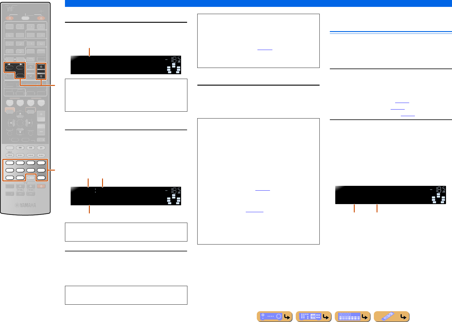
PLAYBACK
Listening to SIRIUS Satellite Radio™
En 63
■
All channel search mode
Press eTUN./CH H / I repeatedly to search for
a channel within all channels.
■
Category search mode
1Press eCATEGORY D / E to select the
channel category.
When you select the category, the first channel in the
category is selected.
2While “CAT” is displayed on the front panel
display, press eTUN./CH H / I repeatedly
to search for a channel within the selected
channel category.
■
Direct number access mode
Press the mNumeric keys to enter the desired
three-digit channel number.
For example, to enter the number 123, press “1,” “2” and
then “3” of the mNumeric keys.
Registering and recalling the
SIRIUS Satellite Radio™ channels
Up to 40 SIRIUS Satellite Radio channels can be
registered as preset channels.
■
Registering preset channels
1Search for a channel to be registered.
For details on searching channels, refer to the
following pages.
•All channel search mode (☞p. 63)
•Category search mode (☞p. 63)
•Direct number access mode (☞p. 63)
2Use one of the following methods to
register the channel currently received.
■Registering to a preset number for which
no channel has been registered
Press and hold eMEMORY for at least 2 second.
The channel will be automatically registered to the
lowest available preset number (or the next number after
the last to which a channel was registered).
eTUN./CH H / I
eCATEGORY D / E
eMEMORY
mNumeric keys
mENT
FM
MEMORY
AM
7856
90
1234
ENT
TUN./CH
CATEGORY
SCENE
RETURN
VO
L
U
ME
ENHANCE
R
S
UR. DE
CO
DE
STRAIGHTSLEEP
P
URE DIRECT
PART Y
M
OVI
E
M
USI
C
BD
DVD
TV
CD
RADI
O
M
U
T
E
ENTER
10
R
EC
TOP
MENU
P
OP-U
P
M
EN
U
DI
S
PLAY
SO
UR
C
E
M
AIN
Z
O
NE 2
RE
C
EIVE
R
CODE SE
T
I
NP
U
T
MUTE
H
DMI
AV
A
UDI
O
1
2
3
4
1
2
5
V
-
AUX
DOCK
H
DMI
O
UT
MULTI
O
PTION
O
N
SC
REE
N
5
1
2
3
4
6
I
NF
O
P
RESET
N
ET
S
IRI
US
TU
NER
e
m
•You can search for a channel quickly by pressing and
holding eTUN./CH H / I.
•You can skip channels to the previous or next category
by pressing eCATEGORY D / E.
If you don’t operate within 10 seconds, the category
search mode returns to “ALL (All Channel Search).”
You can search for a channel quickly by pressing and
holding eTUN./CH H / I.
SW
C
L
SL SR
R
SIRIUS
001Hits 1
ALL VOL.
SBL SBR
All channel search mode
SW
C
L
SL SR
R
SIRIUS
Pop
CAT001 VOL.
SBL SBR
Category
search mode The first channel in the category
Category name
NOTE
This unit skips the following channels in all channel
search mode or category search mode. This is not a
malfunction.
•channels that are locked (☞p. 65)
•channels that are not currently in service
•channels that you do not subscribe to
•When entering a one-digit or two-digit channel
number, enter the number using the mNumeric
keys and then press mENT to confirm your entry.
•This unit automatically accepts your entry if you do
not press mENT within a few seconds after entering
the number.
•If the selected channel is locked, “PIN:___” appears
on the front panel display. Enter the 4-digit Parental
Lock code number by using the mNumeric keys or
press mENT to cancel (☞p. 65).
•If the selected channel is not available, an advisory
message may appear. For details, refer to “SIRIUS
Satellite Radio™” (☞p. 130).
•If this unit is in preset search mode, a preset number is
selected instead of a channel number when you press
the mNumeric keys. To switch to direct number
access mode, press eTUN./CH H / I.
SW
C
L
SL SR
R
SIRIUS
P01:001Preset
MEMORY VOL.
SBL SBR
Preset number Registered channel
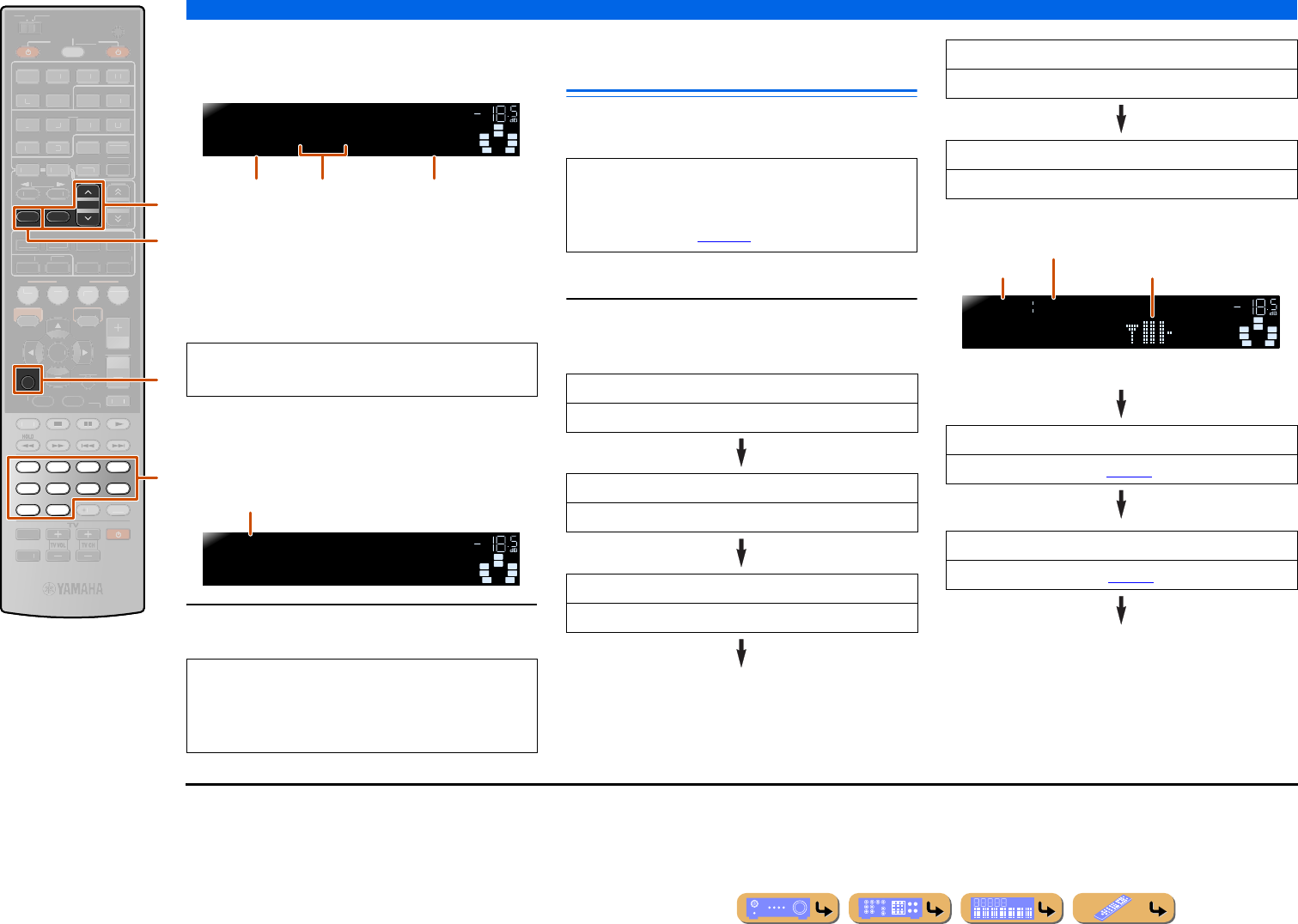
PLAYBACK
Listening to SIRIUS Satellite Radio™
En 64
■Designating a preset number for
registration
Press eMEMORY once.
Press ePRESET F / G to select the preset number to
which the channel will be registered and then press
eMEMORY to register.
■
Recalling a preset channel (Preset
Search mode)
Specify preset numbers to recall registered channels.
Press ePRESET F / G to change the preset
numbers (1 to 40).
Displaying the SIRIUS Satellite
Radio™ information
You can display the SIRIUS Satellite Radio information
on the front panel display. J1
■Front panel display
Press fINFO repeatedly to toggle the SIRIUS
Satellite Radio information display modes as
shown below.
Signal reception level
Signal reception is shown in four levels.
Back to “Channel”
eMEMORY
ePRESET F / G
fINFO
kRETURN
mNumeric keys
RETURN
INFO
MEMORY
PRESET
7856
90
1234
SCENE
VO
L
U
ME
ENHANCE
R
S
UR. DE
CO
DE
STRAIGHTSLEEP
P
URE DIRECT
PART Y
M
OVI
E
M
USI
C
BD
DVD
TV
CD
RADI
O
M
U
T
E
ENTER
10
R
EC
ENT
TOP
MENU
P
OP-U
P
M
EN
U
DI
S
PLAY
SO
UR
C
E
M
AIN
Z
O
NE 2
RE
C
EIVE
R
CODE SE
T
I
NP
U
T
MUTE
DOCK
HDMI
O
U
T
MULTI
H
DMI
AV
A
UDI
O
1
2
3
4
1
2
5
V
-
AUX
O
PTION
O
N
SC
REE
N
5
1
2
3
4
6
FM
AM
NET
S
IRI
US
TU
NER
TUN./C
H
C
ATE
GO
R
Y
k
f
e
m
To cancel registration, press kRETURN or do not
operate the remote control for about 30 seconds.
•Preset numbers to which no channel has been
registered are skipped.
•Preset numbers can also be selected by pressing
mNumeric keys.
SW
C
L
SL SR
R
SIRIUS
P01:--- << 001
MEMORY VOL.
SBL SBR
Preset number Channel to be
registered
Previously
registered channel
(or “---” if no
channel has been
registered)
SW
C
L
SL SR
R
SIRIUS
001Hits1
P01 VOL.
SBL SBR
Preset number
NOTE
If a status message or an error message appears on the
front panel display or TV screen, see “SIRIUS
Satellite Radio™” (☞p. 130).
Channel
Channel number, channel name
Category
Channel category, channel number
Artist/Song
Artist name, song title, channel number
Composer
Composer name, channel number
Antenna
Antenna reception level, channel number
DSP Program
Current sound program (☞p. 48), channel number
Audio Decoder
Current Audio Decoder (☞p. 44), channel number
SIRIUS
SW
C
L
SL SR
R
SBL SBR
Antenna
ALL008 VOL.
Signal reception level
Channel number
Search mode
J1 : If the SIRIUS Satellite Radio information contains a character
that cannot be recognized by this unit, the character will be
displayed with a space.
When an information is unavailable, “––––” appears.
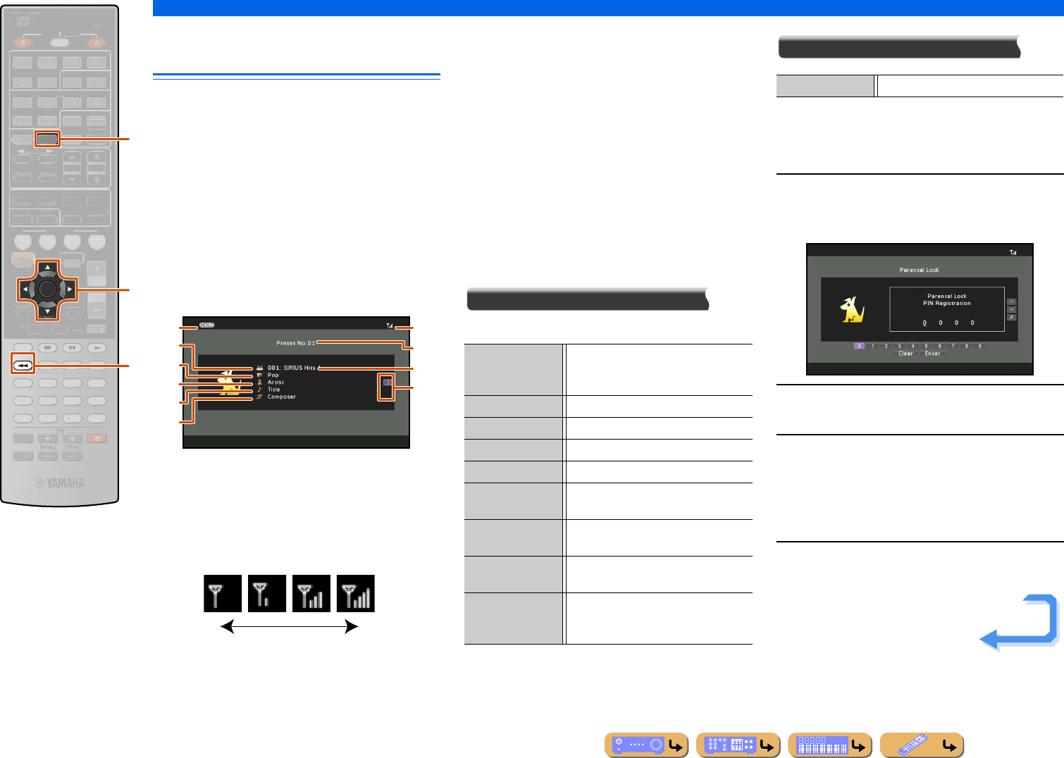
PLAYBACK
Listening to SIRIUS Satellite Radio™
En 65
Navigating the SIRIUS Satellite
Radio™ from the Content window
The SIRIUS channel currently received can be
confirmed from the menu displayed on the TV screen.
Various SIRIUS Satellite Radio operations can be
performed from the Content window rather than controls
on the front panel display. The Content window is
displayed when
dSIRIUS is pressed.
You can operate the SIRIUS Satellite Radio from the
Now Playing view or the Browse view.
■
Operating from the Now Playing
view
aHOLD indicator
Blinks when lHOLD is pressed to activate the hold
function. The artist name and song title currently received
will remain displayed. Press lHOLD again to cancel the
hold function.
bSignal reception level
Indicates the signal reception level.
cPreset number
The selected preset number is displayed.
dChannel number
The channel number currently received is displayed.
eChannel Name
The channel name currently received is displayed.
fChannel Category
The category of the channel is displayed.
gArtist Name
The artist name of the current song is displayed.
hSong Title
The title of the current song is displayed.
iComposer Name
The composer name of the current song is displayed.
jScreen button area
Buttons for available operations are displayed. See
“Screen buttons on the Now Playing view” for details.
Screen buttons on the Now Playing view
To use these buttons, first press kENTER. Then select
the desired one with kCursor B / C and kENTER.
Radio Control
Select a channel for reception.
Utility
When the parental lock function is enabled for a
particular channel, that channel is skipped in all channel
search mode and category search mode.
1Use kCursor D / E to select a number, and
press kENTER to enter the selected
number.
2Repeat step 1 to enter the desired 4-digit
code number.
3Use kCursor C to select “Enter,” and press
kENTER to confirm the 4-digit code
number.
Selecting “Clear” and pressing kENTER clears all
the code entered.
4Use kCursor B / C to select the category
and press kENTER.
dSIRIUS
kCursor B / C / D / E
kENTER
lHOLD
ENTER
SIRIUS
HOLD
SCENE
RETURN
VO
L
U
ME
ENHANCE
R
S
UR. DE
CO
DE
STRAIGHTSLEEP
P
URE DIRECT
PART Y
M
OVI
E
M
USI
C
BD
DVD
TV
CD
RADI
O
MU
T
E
7
8
5
6
9
0
10
1
2
3
4
R
EC
ENT
TOP
MENU
P
OP-U
P
M
EN
U
H
DMI
AV
A
UDI
O
1
2
3
4
1
2
5
V
-
AUX
DI
S
PLAY
SO
UR
C
E
M
AIN
Z
O
NE 2
RE
C
EIVE
R
CODE SE
T
I
NP
U
T
MUTE
DOC
K
HDMI
O
U
T
MULTI
OPTION
O
N
SC
REE
N
5
1
2
3
4
6
FM
I
NF
O
M
EM
O
RY
AM
P
RESET
NET
TU
NER
TUN./C
H
C
ATE
GO
R
Y
d
k
l
b
e
c
d
a
f
g
h
i
j
Weak signal Strong signal
Memory Register the current channel as a preset
number. Up to 40 channels can be
registered.
Preset - Select the previous preset number.
Preset + Select the next preset number.
CAT - Select the previous category.
CAT + Select the next category.
CH - Scan channels downwards from the
current channel.
CH + Scan channels upwards from the current
channel.
Direct Specify a specific channel by manually
entering the channel number.
Hold Activate the hold function. The artist
name and song title currently received
will remain displayed.
Parental Lock Restricts the access to specified channel.
Continues to the
next page
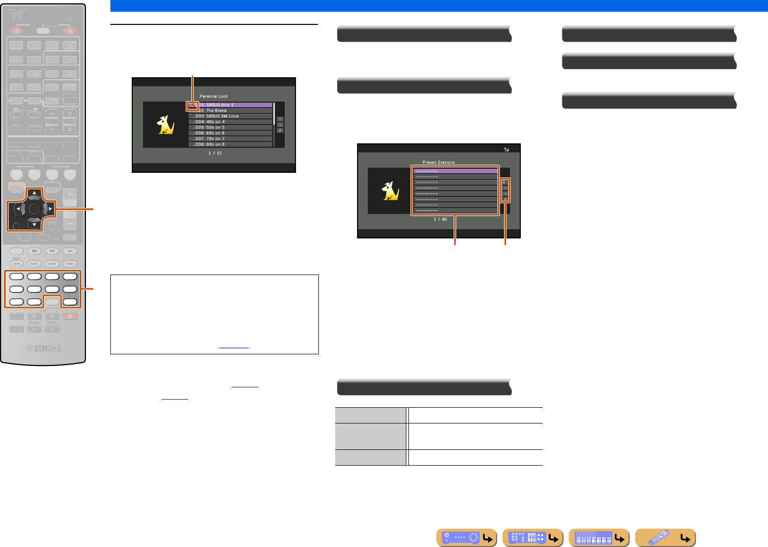
PLAYBACK
Listening to SIRIUS Satellite Radio™
En 66
5Use kCursor B / C to select the channel to
be locked and press kENTER.
When kENTER is pressed, the selected channel is
received for confirmation. Each time kENTER is
pressed after that, lock switches between on and off.
To lock channels in other categories, press
kRETURN to display the category selection screen,
and follow the procedure described above.
Receiving locked channels
Use direct number access mode (☞p. 63) or preset
search mode (☞p. 64) to receive locked channels. When
a locked channel is received, “LOCKED” is displayed
followed by the parental lock code input screen. Use
mNumeric keys to enter the 4-digit code number.
Scroll
Switches the scroll target (channel name, channel
category, artist name, song title, or composer name).
Browse
Switches the display to the Browse view.
■
Operating from the Browse view
aPreset station list
The list of preset stations is displayed.
bScreen button area
Buttons for available operations are displayed. See
“Screen buttons on the Browse view” for details.
Screen buttons on the Browse view
To use these buttons, first press kCursor E. Then
select the desired one with kCursor B / C and
kENTER.
Utility
1 Page Up
1 Page Down
Scrolls the list to the next or previous page.
Now Playing
Switches the display to the Now Playing view.
kCursor B / C / D / E
kRETURN
kENTER
mNumeric keys
mENT
RETURN
ENTER
7856
90
1234
ENT
SCENE
VO
L
U
ME
ENHANCE
R
S
UR. DE
CO
DE
STRAIGHTSLEEP
P
URE DIRECT
PART Y
M
OVI
E
M
USI
C
BD
DVD
TV
CD
RADI
O
M
U
T
E
10
R
EC
TOP
MENU
P
OP-U
P
M
EN
U
DI
S
PLAY
SO
UR
C
E
M
AIN
Z
O
NE 2
RE
C
EIVE
R
CODE SE
T
I
NP
U
T
MUTE
H
DMI
AV
A
UDI
O
1
2
3
4
1
2
5
V
-
AUX
DOCK
HDMI
O
U
T
MULTI
O
PTION
O
N
SC
REE
N
5
1
2
3
4
6
FM
I
NF
O
M
EM
O
RY
AM
P
RESET
NET
S
IRI
US
TU
NER
TUN./C
H
C
ATE
GO
R
Y
k
mNOTES
•If a code number is already registered and the different
code number is entered, “Wrong” appears. In this case,
start over from step 1.
•If you forget the parental lock code or want to change
it, reset it using “SR PIN” (☞p. 119).
Check mark
Parental Lock Restricts the access to specified channel.
Clear Preset Clears registration of the preset station
currently selected.
Clear All Preset Clears registration of all preset stations.
b
a
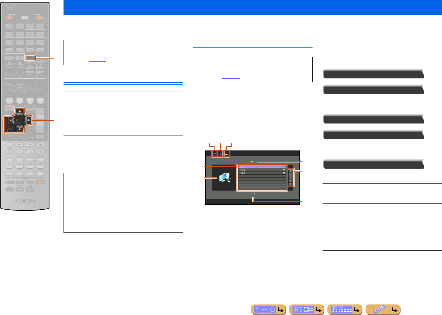
PLAYBACK
En 67
You can enjoy playback of audio files stored on PCs connected to this unit via your network. To play back audio files on your PC, you need to install Windows Media
Player on the PC and configure the media sharing setting of Windows Media Player.
Windows Media Player setup
1Install Windows Media Player on your PC.
You can download the installer of Windows Media
Player from the Microsoft website, or use the upgrade
function of the installed Microsoft Windows Media
Player.
2Turn on your PC then allow media sharing.
Activate Windows Media Player first, enable the media
sharing and then select this unit as a device to which
the media is shared.
Playback of PC music contents
The PC music contents can be operated from the menu
displayed on the TV screen.
You can operate the PC contents from the Now Playing
view or the Browse view.
■
Operating from the Browse view
aRepeat icon
bShuffle icon
cPlay icon
dCurrent directory name
eMenu items
fAlbum art / Input icon
gScreen button area
Buttons for available operations are displayed. See
“Screen buttons on the Browse view” for details.
hCurrent menu number / Number of all menu items
Screen buttons on the Browse view
To use these buttons, first press kCursor E. Then
select the desired one with kCursor B / C and
kENTER.
10 Pages Up
10 Pages Down
Goes to 10 pages forwards or backwards.
1 Page Up
1 Page Down
Scrolls the list to the next or previous page.
Now Playing
Switches the display to the Now Playing view.
1Press dNET repeatedly to select “PC” as
the input source.
2Press kCursor B / C to select a PC server
and music file to play back.
•To select a PC server, folder or file, press
kCursor B / C.
•To confirm the selection, press kENTER.
•To return to the previous menu, press kRETURN.
3Press kENTER to start playback.
The Now Playing view appears during playback.
Playing back tunes on the PC
RETURN
ENTER
NET
SCENE
VO
L
U
ME
ENHANCE
R
S
UR. DE
CO
DE
STRAIGHTSLEEP
P
URE DIRECT
PART Y
M
OVI
E
M
USI
C
BD
DVD
TV
CD
RADI
O
M
U
T
E
7
8
5
6
9
0
10
1
2
3
4
R
EC
ENT
TOP
MENU
P
OP-U
P
M
EN
U
DI
S
PLAY
SO
UR
C
E
M
AIN
Z
O
NE 2
RE
C
EIVE
R
CODE SE
T
I
NP
U
T
MUTE
O
PTION
O
N
SC
REE
N
FM
I
NF
O
M
EM
O
RY
AM
P
RESET
H
DMI
AV
A
UDI
O
1
2
3
4
1
2
5
V
-
AUX
DOCK
HDMI
O
U
T
MULTI
5
1
2
3
4
6
S
IRI
US
TU
NER
TUN./C
H
C
ATE
GO
R
Y
k
d
dNET
kCursor B / C / D / E
kENTER
kRETURN
If you do not use a DHCP server, configure the
network parameters (IP address, etc.) of this unit
manually (☞p. 108).
NOTES
•Some security software installed on your PC (anti-
virus software, firewall software, etc.) may block the
access of this unit to your PC. In such cases, configure
the security software appropriately.
•You can connect this unit to up to 16 PC servers, and
each server must be connected to the same subnet as
this unit.
For a complete list of status messages that appear on
the front panel display and GUI screen, see
“Network” (☞p. 131).
d
g
e
f
h
b ca
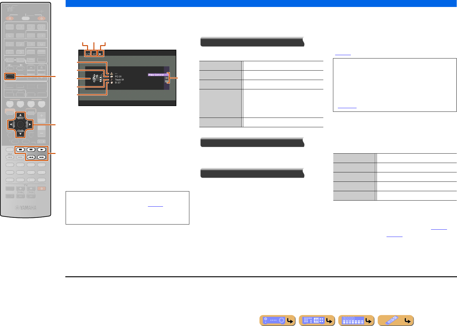
PLAYBACK
Playing back tunes on the PC
En 68
■
Operating from the Now Playing
view
aRepeat icon
bShuffle icon
cPlay icon
dAlbum art
eArtist name
fAlbum title
gScreen button area
Buttons for available operations are displayed. See
“Screen buttons on the Now Playing view” for details.
hSong title
iElapsed time
Screen buttons on the Now Playing view
To use these buttons, first press kENTER. Then select
the desired one with kCursor B / C and kENTER.
Play Control
Operates the basic playback functions of PC.
Scroll
Switches the scroll target (artist name, album title, or
song title).
Browse
Switches the display to the Browse view.
■
Compatibility of Digital Media
Controller
A DLNA-compliant Digital Media Controller (DMC)
device can also be used to control music playback. Refer
to “Using a PC to control this unit over a network”
(☞p. 88) for details. J1,J2
■
Operating basic playback functions
with the remote control
Use the following remote control keys to operate
(playback, stop, skip, etc.) your PC contents.
■
Shuffle/repeat playback
Use the Option menu to apply playback shuffle and
repeat settings. Refer to “Shuffle playback” (☞p. 55)
and “Repeat playback” (☞p. 55) for details.
INFO
ENTER
SCENE
RETURN
VO
L
U
ME
ENHANCE
R
S
UR. DE
CO
DE
STRAIGHTSLEEP
P
URE DIRECT
PART Y
M
OVI
E
M
USI
C
BD
DVD
TV
CD
RADI
O
MU
T
E
7
8
5
6
9
0
10
1
2
3
4
R
EC
ENT
TOP
MENU
P
OP-U
P
M
EN
U
DI
S
PLAY
SO
UR
C
E
M
AIN
Z
O
NE 2
RE
C
EIVE
R
CODE SE
T
I
NP
U
T
MUTE
DOC
K
HDMI
O
U
T
MULTI
H
DMI
AV
A
UDI
O
1
2
3
4
1
2
5
V
-
AUX
OPTION
O
N
SC
REE
N
5
1
2
3
4
6
FM
M
EM
O
RY
AM
P
RESET
NET
S
IRI
US
TU
NER
TUN./C
H
C
ATE
GO
R
Y
f
k
l
fINFO
kCursor B / C
kENTER
lp
ls
le
la
lb
•You can switch the information displayed on the front
panel display by pressing fINFO (☞p. 10).
•Album art is available only when the file contains
image data.
b ca
g
d
e
f
h
i
p (Play) Starts playback.
s (Stop) Stops playback.
e (Pause) Stops playback temporarily.
b (Skip -) Skips to the beginning of the currently
playing song. Press kENTER at the
beginning of the song to skip to a previous
song.
a (Skip +) Skips to the beginning of the next song.
CAUTION
When DMC controls are used to adjust volume,
playback volume may be unexpectedly loud. This
could result in damage to this unit or the speakers.
“Max Volume” can be used to specify the maximum
volume level to prevent excessively loud playback
(☞p. 103).
lpPlay
lsStop
leSwitches between playback and pause.
laSkip forward during playback
lbSkip backward during playback
J1 : A shortcut button cannot be registered when a DMC is used.
J2 : Set “DMC Control” to “Disable” to automatically play back the
last song played when this unit is turned on.
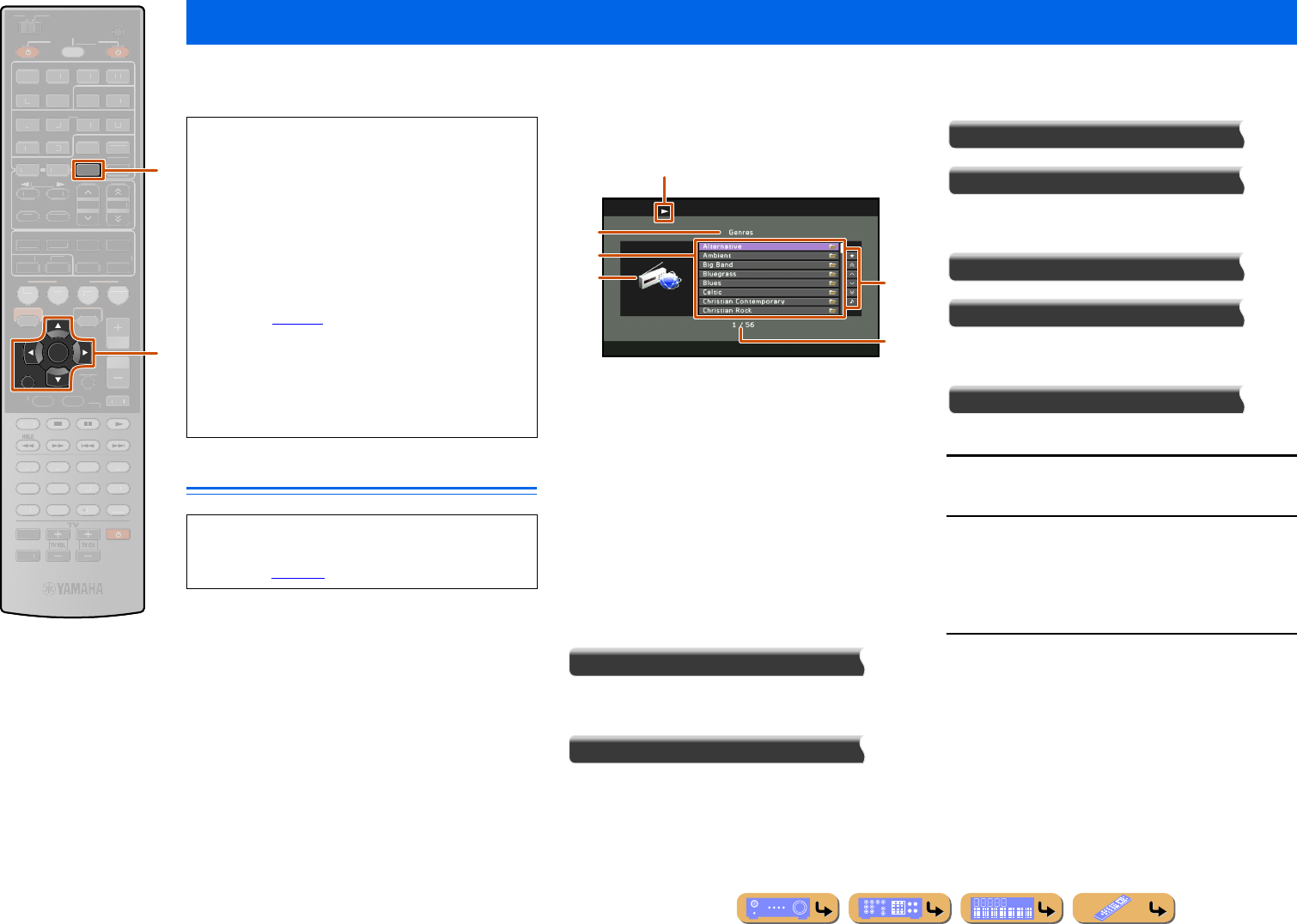
PLAYBACK
En 69
You can listen to Internet Radio stations using the vTuner Internet Radio station database service particularly customized for this unit, providing a database of over 2000
radio stations. Also, you can store your favorite stations with bookmarks.
Listening to Internet Radio
The Internet Radio can be operated from the menu
displayed on the TV screen.
You can operate the Internet Radio from the Now
Playing view or the Browse view.
■
Operating from the Browse view
aPlay icon
bCurrent directory name
cMenu items
dChannel art
eScreen button area
Buttons for available operations are displayed. See
“Screen buttons on the Browse view” for details.
fCurrent menu number / Number of all menu items
Screen buttons on the Browse view
To use these buttons, first press kCursor E. Then
select the desired one with kCursor B / C and
kENTER.
Bookmark On
The selected Internet Radio station is added to the
Bookmarks list in “NET RADIO.”
Bookmark Off
This item is displayed in the bookmark directory.
The selected Internet Radio station is removed from the
Bookmarks list.
10 Pages Up
10 Pages Down
Goes to 10 pages forwards or backwards.
1 Page Up
1 Page Down
Scrolls the list to the next or previous page.
Now Playing
Switches the display to the Now Playing view.
1Press dNET repeatedly to select “NET
RADIO” as the input source.
2Press kCursor B / C to select an item to
play back.
•To select an item, press kCursor B / C.
•To confirm the selection, press kENTER.
•To return to the previous menu, press kRETURN.
3Press kENTER to start playback.
The Now Playing view appears during playback.
Listening to the Internet Radio
RETURN
ENTER
NET
SCENE
VO
L
U
ME
ENHANCE
R
S
UR. DE
CO
DE
STRAIGHTSLEEP
P
URE DIRECT
PART Y
M
OVI
E
M
USI
C
BD
DVD
TV
CD
RADI
O
M
U
T
E
7
8
5
6
9
0
10
1
2
3
4
R
EC
ENT
TOP
MENU
P
OP-U
P
M
EN
U
DI
S
PLAY
SO
UR
C
E
M
AIN
Z
O
NE 2
RE
C
EIVE
R
CODE SE
T
I
NP
U
T
MUTE
O
PTION
O
N
SC
REE
N
FM
I
NF
O
M
EM
O
RY
AM
P
RESET
H
DMI
AV
A
UDI
O
1
2
3
4
1
2
5
V
-
AUX
DOCK
HDMI
O
U
T
MULTI
5
1
2
3
4
6
S
IRI
US
TU
NER
TUN./C
H
C
ATE
GO
R
Y
k
d
dNET
kCursor B / C / D / E
kENTER
kRETURN
•To use this feature, your network must be connected to
the Internet.
•A narrowband Internet connection (i.e. 56K modem,
ISDN) will not provide satisfactory results, and a
broadband connection is strongly recommended (i.e. a
cable modem, an xDSL modem, etc.). For detailed
information, consult with your ISP.
•If you do not use a DHCP server, configure the
network parameters (IP address, etc.) of this unit
manually (☞p. 108).
•Some security devices (such as firewall) may block the
access of this unit to Internet Radio stations. In such
cases, configure the security settings appropriately.
•This service may be discontinued without notice.
•Some Internet Radio stations may not be played.
For a complete list of status messages that appear on
the front panel display and GUI screen, see
“Network” (☞p. 131)
b
e
c
d
f
a
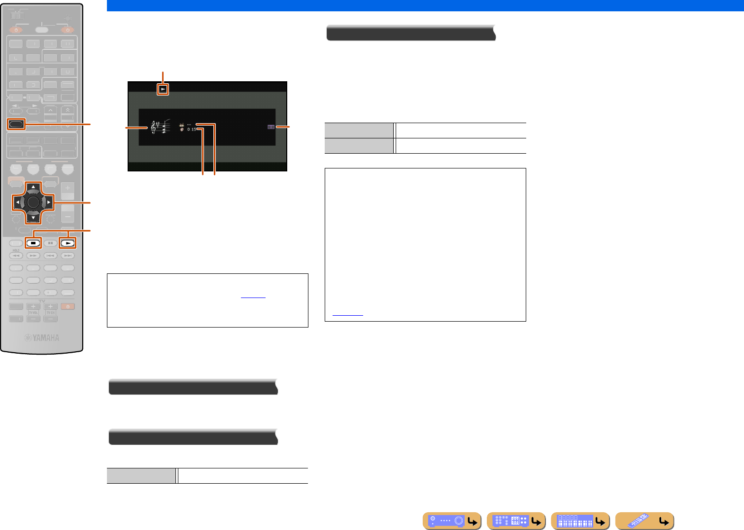
PLAYBACK
Listening to the Internet Radio
En 70
■
Operating from the Now Playing
view
aPlay icon
bChannel art
cElapsed time
dCurrent station name
eScreen button area
Buttons for available operations are displayed. See
“Screen buttons on the Now Playing view” for details.
Screen buttons on the Now Playing view
To use these buttons, first press kENTER. Then select
the desired one with kCursor B / C and kENTER.
Bookmark On
The station currently being played back is added to the
Bookmarks list in “NET RADIO.”
Play Control
The following operation is available.
Browse
Switches the display to the Browse view.
■
Operating basic playback functions
with the remote control
Use the following remote control keys to operate
(playback, stop) the Internet Radio.
INFO
ENTER
SCENE
RETURN
VO
L
U
ME
ENHANCE
R
S
UR. DE
CO
DE
STRAIGHTSLEEP
P
URE DIRECT
PART Y
M
OVI
E
M
USI
C
BD
DVD
TV
CD
RADI
O
MU
T
E
7
8
5
6
9
0
10
1
2
3
4
R
EC
ENT
TOP
MENU
P
OP-U
P
M
EN
U
H
DMI
AV
A
UDI
O
1
2
3
4
1
2
5
V
-
AUX
DI
S
PLAY
SO
UR
C
E
M
AIN
Z
O
NE 2
RE
C
EIVE
R
CODE SE
T
I
NP
U
T
MUTE
DOC
K
HDMI
O
U
T
MULTI
OPTION
O
N
SC
REE
N
5
1
2
3
4
6
FM
M
EM
O
RY
AM
P
RESET
NET
S
IRI
US
TU
NER
TUN./C
H
C
ATE
GO
R
Y
f
k
l
fINFO
kCursor B / C
kENTER
ls
lp
•You can switch the information displayed on the front
panel display by pressing fINFO (☞p. 10).
•Channel art is available only when the selected
channel contains image data.
s (Stop) Stops playback.
a
e
b
d
c
lpPlay
lsStop
You can also register your favorite Internet Radio
stations on this unit by accessing the website with the
web browser on your PC. To use this feature, you
need the vTuner ID of this unit and your e-mail
address to create your personal account. For details,
refer to the help information on the website.
URL: http://yradio.vtuner.com/
NOTE
To clear the personal account such as vTuner ID or e-
mail address, perform “NETWORK” of
“INITIALIZE” in the Advanced Setup menu
(☞p. 120).
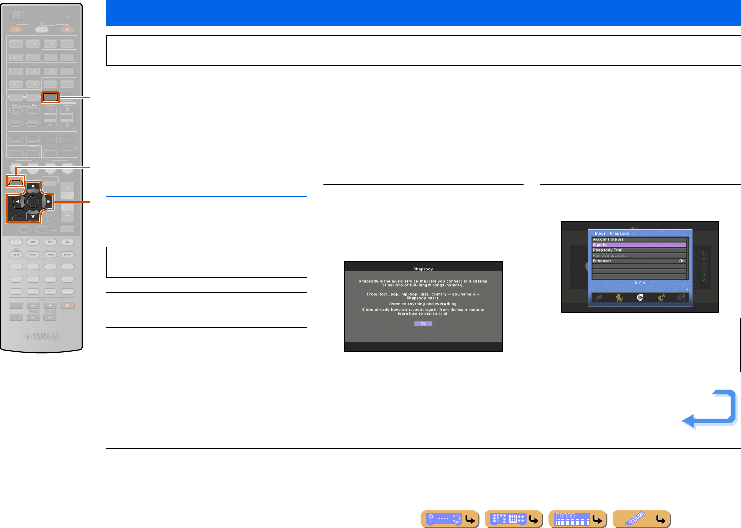
PLAYBACK
En 71
The Rhapsody® service is the power behind the Rhapsody® Media Player (the Rhapsody® player software that you can download to your computer). Rhapsody® service
supplies the music, keeps My Library up to date, provides you with Rhapsody® channels, the Playlist Central online community, and manages your downloads. Your
software connects to Rhapsody® service through the internet. Because your account information and Rhapsody® content are on servers instead of any individual computer,
your music is infinitely portable. Much of what you see in the Display area comes from Rhapsody® service. What you can do with Rhapsody® service depends on your
subscription. You can use Rhapsody® service for free, or get even more from a paid membership. The Rhapsody® service also brings you Rhapsody® Online, a
streamlined, internet version of Rhapsody® that you can access from almost anywhere. Just sign in to your Rhapsody® account to start letting the Rhapsody® service work
for you.
For more information, http://www.rhapsody.com/
Rhapsody® account sign-in
When you select “Rhapsody” for the first time, the sign-
in screen appears. Sign in to your Rhapsody® account to
start using the Rhapsody service on this unit.
1Press jON SCREEN.
2Use kCursor B / C to select “Input” and
press kENTER.
3Use kCursor D / E to select “Rhapsody”
and press kCursor B.
The following display appears when “Sign In” has not
been completed yet. Read the description and then
press kENTER.J1
4Press kCursor B / C to select “Sign In” and
then press kENTER.
Using the Rhapsody® service
Prohibition
It is strictly prohibited to modify, reproduce, reverse-engineer or use this unit and/or built-in software for use other than audiovisual purposes.
RETURN
ENTER
ON SCREEN
NET
SCENE
VO
L
U
ME
ENHANCE
R
S
UR. DE
CO
DE
STRAIGHTSLEEP
P
URE DIRECT
PART Y
M
OVI
E
M
USI
C
BD
DVD
TV
CD
RADI
O
M
U
T
E
7
8
5
6
9
0
10
1
2
3
4
R
EC
ENT
TOP
MENU
P
OP-U
P
M
EN
U
DI
S
PLAY
SO
UR
C
E
M
AIN
Z
O
NE 2
RE
C
EIVE
R
CODE SE
T
I
NP
U
T
MUTE
O
PTION
FM
I
NF
O
M
EM
O
RY
AM
P
RESET
H
DMI
AV
A
UDI
O
1
2
3
4
1
2
5
V
-
AUX
DOCK
HDMI
O
U
T
MULTI
5
1
2
3
4
6
S
IRI
US
TU
NER
TUN./C
H
C
ATE
GO
R
Y
k
d
j
dNET
jON SCREEN
kCursor B / C / D / E
kENTER
Use the Utility function later to view information for
your Rhapsody® account.
If “Rhapsody Trial” is selected, the URL for free 30-
day trial service content is displayed. You can get
started with a free trial by registering an account in
the specified website.
Continues to the
next page
J1 : When “Sign In” has not been completed yet, this description can
be directly displayed by pressing dNET repeatedly to select
“Rhapsody” as input source.
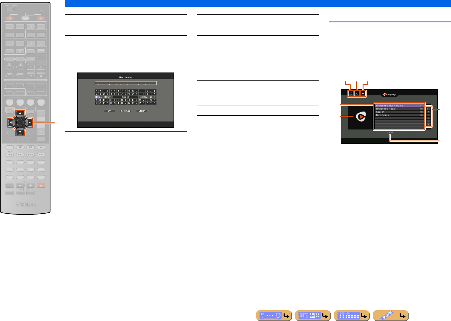
PLAYBACK
Using the Rhapsody® service
En 72
5Press kENTER to enter the User Name
entry screen.
6Use kCursor B / C / D / E and kENTER to
enter your user name password (up to
64 characters) and then select “OK” and
press kENTER.
7Press kENTER to enter the User Password
entry screen.
8Use kCursor B / C / D / E and kENTER to
enter your password (up to 64 characters)
and then select “OK” and press kENTER.
“Please wait” appears followed by the confirmation
screen.
9Press kENTER.
The Rhapsody Browse view is displayed.
Playback of Rhapsody® contents
The Rhapsody can be operated from the content window
on the TV screen.
You can operate the Rhapsody from the Now Playing
view or the Browse view.
■
Operating from the Browse view
aRepeat icon
bShuffle icon
cPlay icon
dMenu items
eAlbum art / Input icon
fScreen button area
Buttons for available operations are displayed. See
“Screen buttons on the Browse view” for details.
gCurrent menu number / Number of all menu items
ENTER
SCENE
RETURN
VO
L
U
ME
ENHANCE
R
S
UR. DE
CO
DE
STRAIGHTSLEEP
P
URE DIRECT
PART Y
M
OVI
E
M
USI
C
BD
DVD
TV
CD
RADI
O
MU
T
E
7
8
5
6
9
0
10
1
2
3
4
R
EC
ENT
FM
I
NF
O
M
EM
O
RY
AM
P
RESET
H
DMI
AV
A
UDI
O
1
2
3
4
1
2
5
V
-
AUX
TOP
MENU
P
OP-U
P
M
EN
U
DI
S
PLAY
SO
UR
C
E
M
AIN
Z
O
NE 2
RE
C
EIVE
R
CODE SE
T
I
NP
U
T
MUTE
DOC
K
HDMI
O
U
T
MULTI
OPTION
O
N
SC
REE
N
5
1
2
3
4
6
NET
S
IRI
US
TU
NER
TUN./C
H
C
ATE
GO
R
Y
k
kCursor B / C / D / E
kENTER
To clear the characters entered in step 6 and 8, select
“Clear” and press kENTER.
NOTE
If registration failed, the error message appears. In
this case, read the message and start all over again.
f
d
e
g
b ca
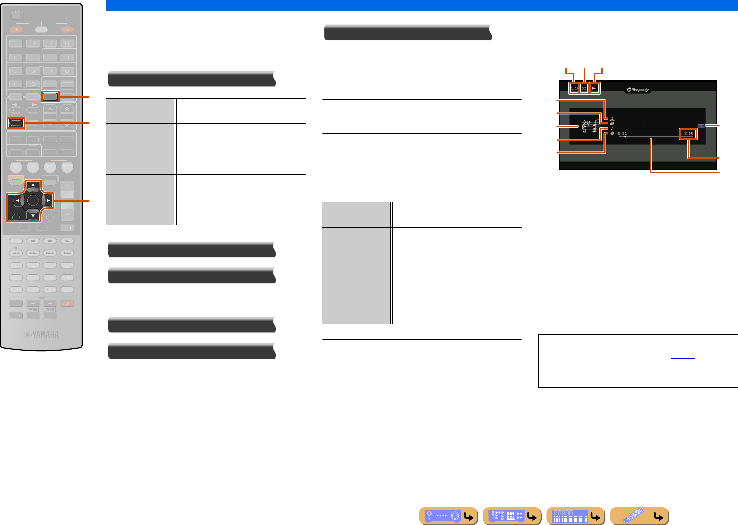
PLAYBACK
Using the Rhapsody® service
En 73
Screen buttons on the Browse view
To use these buttons, first press kCursor E. Then
select the desired one with kCursor B / C and
kENTER.
Utility
10 Pages Up
10 Pages Down
Goes to 10 pages forwards or backwards.
1 Page Up
1 Page Down
Scrolls the list to the next or previous page.
Now Playing
Switches the display to the Now Playing view.
You can navigate the Rhapsody menu with the following
remote control buttons.
1Press dNET repeatedly to select
“Rhapsody” as the input source.
2Press kCursor B / C to select an item to
play back.
•To select an item, folder or file, press kCursor B / C.
•To confirm the selection, press kENTER.
•To return to the previous menu, press kRETURN.
3Press kENTER to start playback.
The Now Playing view appears during playback.
■
Operating from the Now Playing
view
aRepeat icon
bShuffle icon
cPlay icon
dAlbum art
eArtist name
fAlbum title
gScreen button area
Buttons for available operations are displayed. See
“Screen buttons on the Now Playing view” for details.
hSong title
iTotal playback time
jProgress bar
kElapsed time
RETURN
INFO
ENTER
NET
SCENE
VO
L
U
ME
ENHANCE
R
S
UR. DE
CO
DE
STRAIGHTSLEEP
P
URE DIRECT
PART Y
M
OVI
E
M
USI
C
BD
DVD
TV
CD
RADI
O
M
U
T
E
7
8
5
6
9
0
10
1
2
3
4
R
EC
ENT
TOP
MENU
P
OP-U
P
M
EN
U
DI
S
PLAY
SO
UR
C
E
M
AIN
Z
O
NE 2
RE
C
EIVE
R
CODE SE
T
I
NP
U
T
MUTE
O
PTION
O
N
SC
REE
N
FM
M
EM
O
RY
AM
P
RESET
H
DMI
AV
A
UDI
O
1
2
3
4
1
2
5
V
-
AUX
DOCK
HDMI
O
U
T
MULTI
5
1
2
3
4
6
S
IRI
US
TU
NER
TUN./C
H
C
ATE
GO
R
Y
k
d
f
dNET
fINFO
kCursor B / C / D / E
kENTER
kRETURN
Play Plays back the song or album highlighted
in the list.
Add track to My
Library
Adds the track currently selected to “My
Library.”
Add album to My
Library
Adds the album currently selected to “My
Library.”
Add CH to My
Library
Adds the channel currently selected to
“My Library.”
Remove from My
Library
Removes the content currently selected
from “My Library.”
Rhapsody Music
Guide
Select a track from the lists organized by
category (artist, album, etc.).
Rhapsody Radio Select a network radio channel from the
lists of the channels provided by
Rhapsody.
Search Use the software keyboard to search the
desired item (artist, album, etc.) by
keyword.
My Library Select a track from items (artist, album,
etc.) added to “My Library.”
•You can switch the information displayed on the front
panel display by pressing fINFO (☞p. 10).
•Album art is available only when the album contains
image data.
b ca
g
d
e
f
h
k
j
i
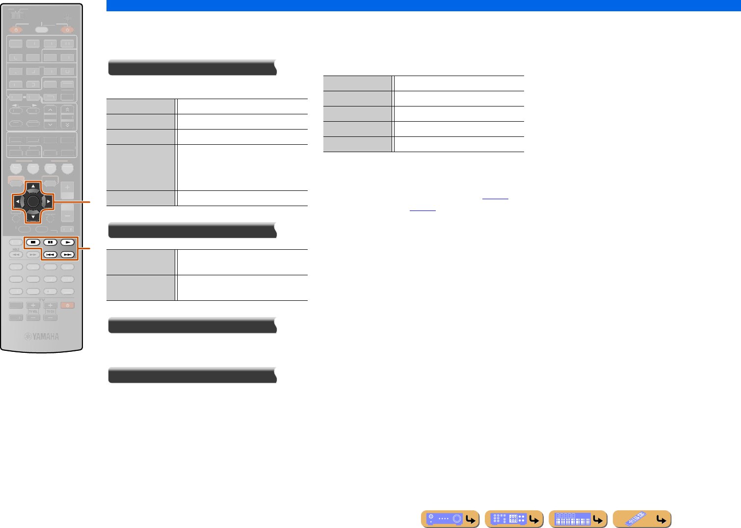
PLAYBACK
Using the Rhapsody® service
En 74
Screen buttons on the Now Playing view
To use these buttons, first press kENTER. Then select
the desired one with kCursor B / C and kENTER.
Play Control
Operates the basic playback functions of the Rhapsody.
Utility
Scroll
Switches the scroll target (artist name, album name, or
song name).
Browse
Switches the display to the Browse view.
■
Operating basic playback functions
with the remote control
Use the following remote control keys to operate the
Rhapsody.
■
Shuffle/repeat playback
Use the Option menu to apply playback shuffle and
repeat settings. Refer to “Shuffle playback” (☞p. 55)
and “Repeat playback” (☞p. 55) for details.
ENTER
SCENE
RETURN
VO
L
U
ME
ENHANCE
R
S
UR. DE
CO
DE
STRAIGHTSLEEP
P
URE DIRECT
PART Y
M
OVI
E
M
USI
C
BD
DVD
TV
CD
RADI
O
MU
T
E
7
8
5
6
9
0
10
1
2
3
4
R
EC
ENT
TOP
MENU
P
OP-U
P
M
EN
U
DI
S
PLAY
SO
UR
C
E
M
AIN
Z
O
NE 2
RE
C
EIVE
R
CODE SE
T
I
NP
U
T
MUTE
DOC
K
HDMI
O
U
T
MULTI
H
DMI
AV
A
UDI
O
1
2
3
4
1
2
5
V
-
AUX
OPTION
O
N
SC
REE
N
5
1
2
3
4
6
FM
I
NF
O
M
EM
O
RY
AM
P
RESET
NET
S
IRI
US
TU
NER
TUN./C
H
C
ATE
GO
R
Y
k
l
kCursor B / C
kENTER
lp
ls
le
la
lb
p (Play) Starts playback.
s (Stop) Stops playback.
e (Pause) Stops playback temporarily.
b (Skip -) Skips to the beginning of the currently
playing song. Press kENTER at the
beginning of the song to skip to a previous
song.
a (Skip +) Skips to the beginning of the next song.
Add track to My
Library
Adds the track currently selected to “My
Library.”
Add album to My
Library
Adds the album currently selected to “My
Library.”
lpPlay
lsStop
leSwitches between playback and pause.
laSkip forward during playback
lbSkip backward during playback
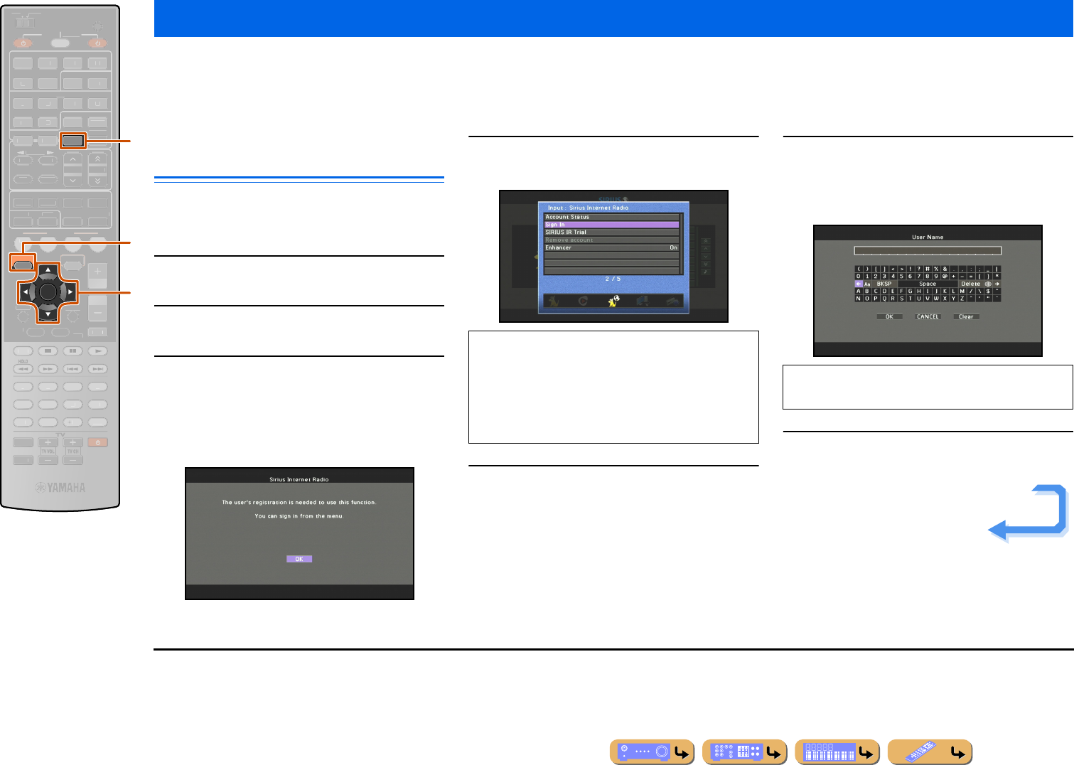
PLAYBACK
En 75
It’s easy to enjoy SIRIUS entertainment at home. Listen to over 80 channels of commercial-free music, plus sports talk, news and entertainment. It all comes through your
audio / video receiver and high-speed Internet connection.
If you’re not a SIRIUS subscriber, you can sign up today for a PREMIUM SIRIUS Internet Radio subscription at www.sirius.com <http://www.sirius.com/>.
Current subscribers can add a PREMIUM SIRIUS Internet Radio subscription to an existing account.
SIRIUS Internet Radio account sign-
in
When you use the SIRIUS Internet Radio service for the
first time, follow the procedure below to sign in to your
account for the service.
1Press jON SCREEN.
2Use kCursor B / C to select “Input” and
press kENTER.
3Use kCursor D / E to select “SIRIUS IR”
and press kCursor B.
The following display appears when “Sign In” has not
been completed yet. Read the description and then
press kENTER.J1
4Press kCursor B / C to select “Sign In” or
“SIRIUS IR Trial” and then press kENTER.
5Press kENTER to enter the User Name
entry screen.
6Use kCursor B / C / D / E and kENTER to
enter your user name password (up to
64 characters) and then select “OK” and
press kENTER.
7Press kENTER to enter the User Password
entry screen.
Listening to the SIRIUS Internet Radio
ENTER
ON SCREEN
NET
SCENE
RETURN
VO
L
U
ME
ENHANCE
R
S
UR. DE
CO
DE
STRAIGHTSLEEP
P
URE DIRECT
PART Y
M
OVI
E
M
USI
C
BD
DVD
TV
CD
RADI
O
M
U
T
E
7
8
5
6
9
0
10
1
2
3
4
R
EC
ENT
TOP
MENU
P
OP-U
P
M
EN
U
DI
S
PLAY
SO
UR
C
E
M
AIN
Z
O
NE 2
RE
C
EIVE
R
CODE SE
T
I
NP
U
T
MUTE
O
PTION
FM
I
NF
O
M
EM
O
RY
AM
P
RESET
H
DMI
AV
A
UDI
O
1
2
3
4
1
2
5
V
-
AUX
DOCK
HDMI
O
U
T
MULTI
5
1
2
3
4
6
S
IRI
US
TU
NER
TUN./C
H
C
ATE
GO
R
Y
d
j
k
dNET
jON SCREEN
kCursor B / C / D / E
kENTER
If “SIRIUS IR Trial” is selected, the confirmation
message and the URL regarding the terms of trial
service are displayed. Press kCursor D / E to select
“OK” to continue. If “Successfully logged into
account” is displayed, press kENTER to enable the
SIRIUS Internet Radio Browse view.
To clear the characters entered in step 6 and 8, select
“Clear” and press kENTER.
Continues to the
next page
J1 : When “Sign In” has not been completed yet, this description can
be directly displayed by pressing dNET repeatedly to select
“SIRIUS IR” as input source.
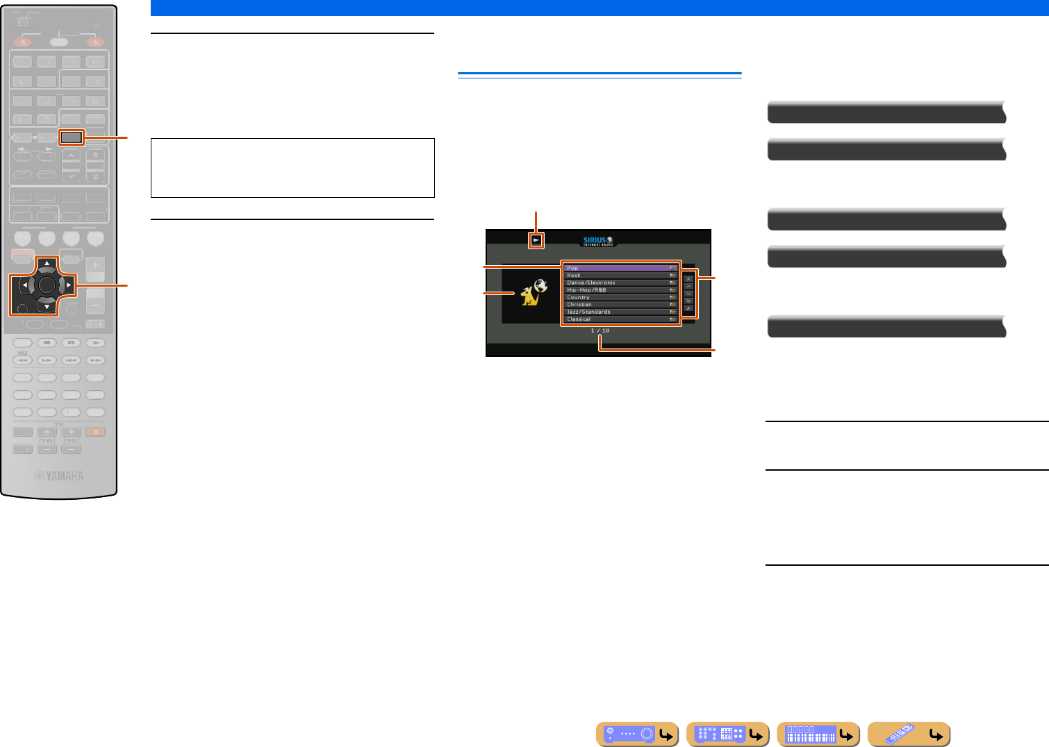
PLAYBACK
Listening to the SIRIUS Internet Radio
En 76
8Use kCursor B / C / D / E and kENTER to
enter your password (up to 64 characters)
and then select “OK” and press kENTER.
“Please wait...” is first displayed, followed by
confirmation screen.
9Press kENTER.
The SIRIUS Internet Radio Browse view is displayed.
Navigating the SIRIUS Internet
Radio menu
The SIRIUS Internet Radio tuner can be operated from
the content window on the TV screen.
You can operate the SIRIUS Internet Radio from the
Now Playing view or the Browse view.
■
Operating from the Browse view
aPlay icon
bMenu items
cChannel art
dScreen button area
Buttons for available operations are displayed. See
“Screen buttons on the Browse view” for details.
eCurrent menu number / Number of all menu items
Screen buttons on the Browse view
To use these buttons, first press kCursor E. Then
select the desired one with kCursor B / C and
kENTER.
10 Pages Up
10 Pages Down
Goes to 10 pages forwards or backwards.
1 Page Up
1 Page Down
Scrolls the list to the next or previous page.
Now Playing
Switches the display to the Now Playing view.
You can navigate the SIRIUS Internet Radio menu with
the following remote control buttons.
1Press dNET repeatedly to select “SIRIUS
IR.”
2Press kCursor B / C / D / E to select a
music file to play back.
•To select a file or folder, press kCursor B / C.
•To confirm the selection, press kENTER.
•To return to the previous menu, press kRETURN.
3Press kENTER to start playback.
The Now Playing view appears during playback.
RETURN
ENTER
NET
SCENE
VO
L
U
ME
ENHANCE
R
S
UR. DE
CO
DE
STRAIGHTSLEEP
P
URE DIRECT
PART Y
M
OVI
E
M
USI
C
BD
DVD
TV
CD
RADI
O
MU
T
E
7
8
5
6
9
0
10
1
2
3
4
R
EC
ENT
TOP
MENU
P
OP-U
P
M
EN
U
DI
S
PLAY
SO
UR
C
E
M
AIN
Z
O
NE 2
RE
C
EIVE
R
CODE SE
T
I
NP
U
T
MUTE
OPTION
O
N
SC
REE
N
FM
I
NF
O
M
EM
O
RY
AM
P
RESET
H
DMI
AV
A
UDI
O
1
2
3
4
1
2
5
V
-
AUX
DOC
K
HDMI
O
U
T
MULTI
5
1
2
3
4
6
S
IRI
US
TU
NER
TUN./C
H
C
ATE
GO
R
Y
k
d
dNET
kCursor B / C / D / E
kENTER
kRETURN
NOTE
If registration failed, the error message appears. In
this case, read the message and start all over again.
d
b
c
e
a
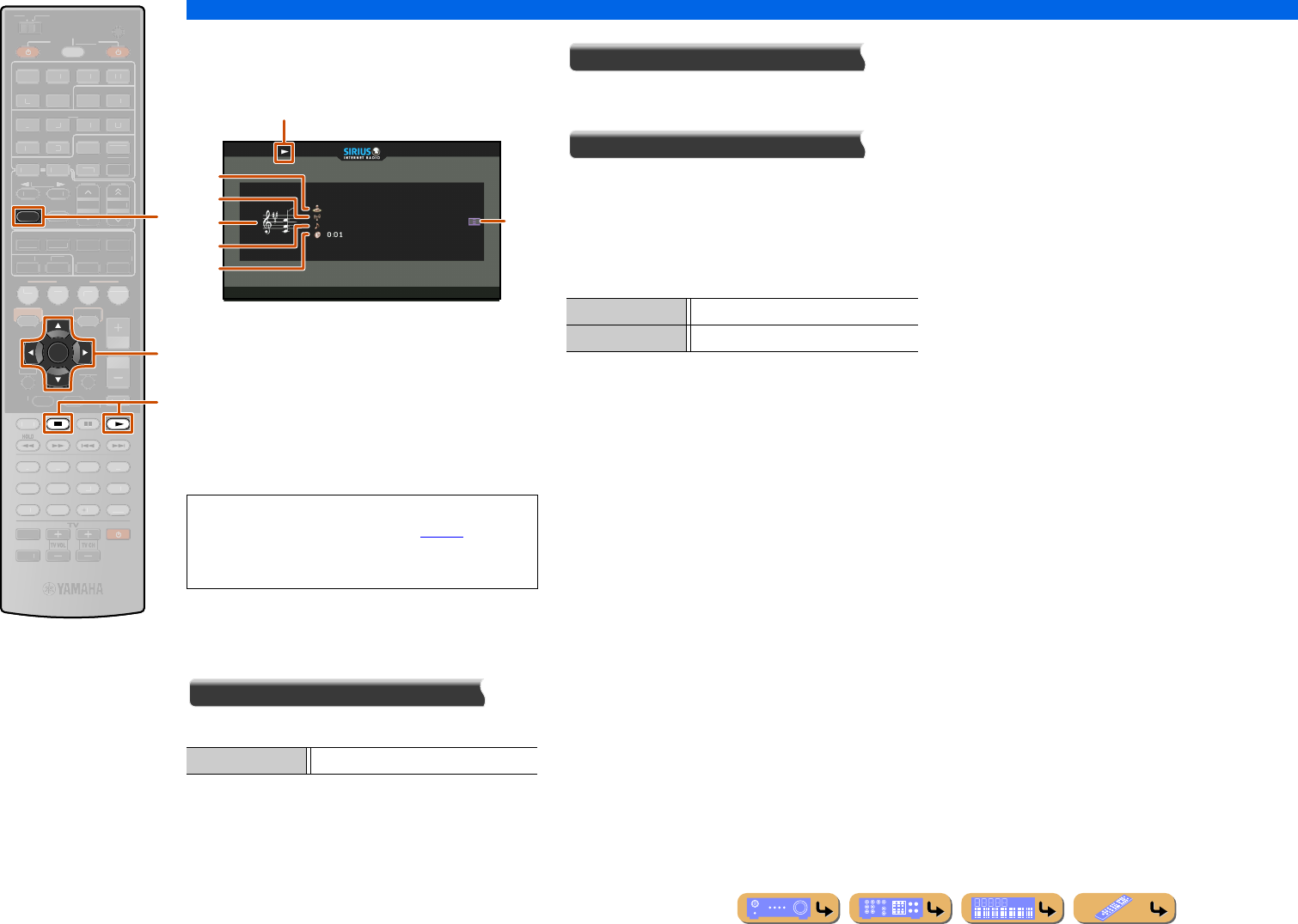
PLAYBACK
Listening to the SIRIUS Internet Radio
En 77
■
Operating from the Now Playing
view
aPlay icon
bChannel art
cArtist name
dChannel name
eScreen button area
Buttons for available operations are displayed. See
“Screen buttons on the Now Playing view” for details.
fSong title
gElapsed time
Screen buttons on the Now Playing view
To use these buttons, first press kENTER. Then select
the desired one with kCursor B / C and kENTER.
Play Control
Stops the current playback.
Scroll
Switches the scroll target (artist name, album name, or
song name).
Browse
Switches the display to the Browse view.
■
Operating basic playback functions
with the remote control
Use the following remote control keys to operate the
SIRIUS Internet Radio.
INFO
ENTER
SCENE
RETURN
VO
L
U
ME
ENHANCE
R
S
UR. DE
CO
DE
STRAIGHTSLEEP
P
URE DIRECT
PART Y
M
OVI
E
M
USI
C
BD
DVD
TV
CD
RADI
O
MU
T
E
7
8
5
6
9
0
10
1
2
3
4
R
EC
ENT
TOP
MENU
P
OP-U
P
M
EN
U
H
DMI
AV
A
UDI
O
1
2
3
4
1
2
5
V
-
AUX
DI
S
PLAY
SO
UR
C
E
M
AIN
Z
O
NE 2
RE
C
EIVE
R
CODE SE
T
I
NP
U
T
MUTE
DOC
K
HDMI
O
U
T
MULTI
OPTION
O
N
SC
REE
N
5
1
2
3
4
6
FM
M
EM
O
RY
AM
P
RESET
NET
S
IRI
US
TU
NER
TUN./C
H
C
ATE
GO
R
Y
f
k
l
fINFO
kCursor B / C
kENTER
ls
lp
•You can switch the information displayed on the front
panel display by pressing fINFO (☞p. 10).
•Channel art is available only when the selected
channel contains image data.
s (Stop) Stops playback.
a
e
b
c
d
f
g
lpPlay
lsStop
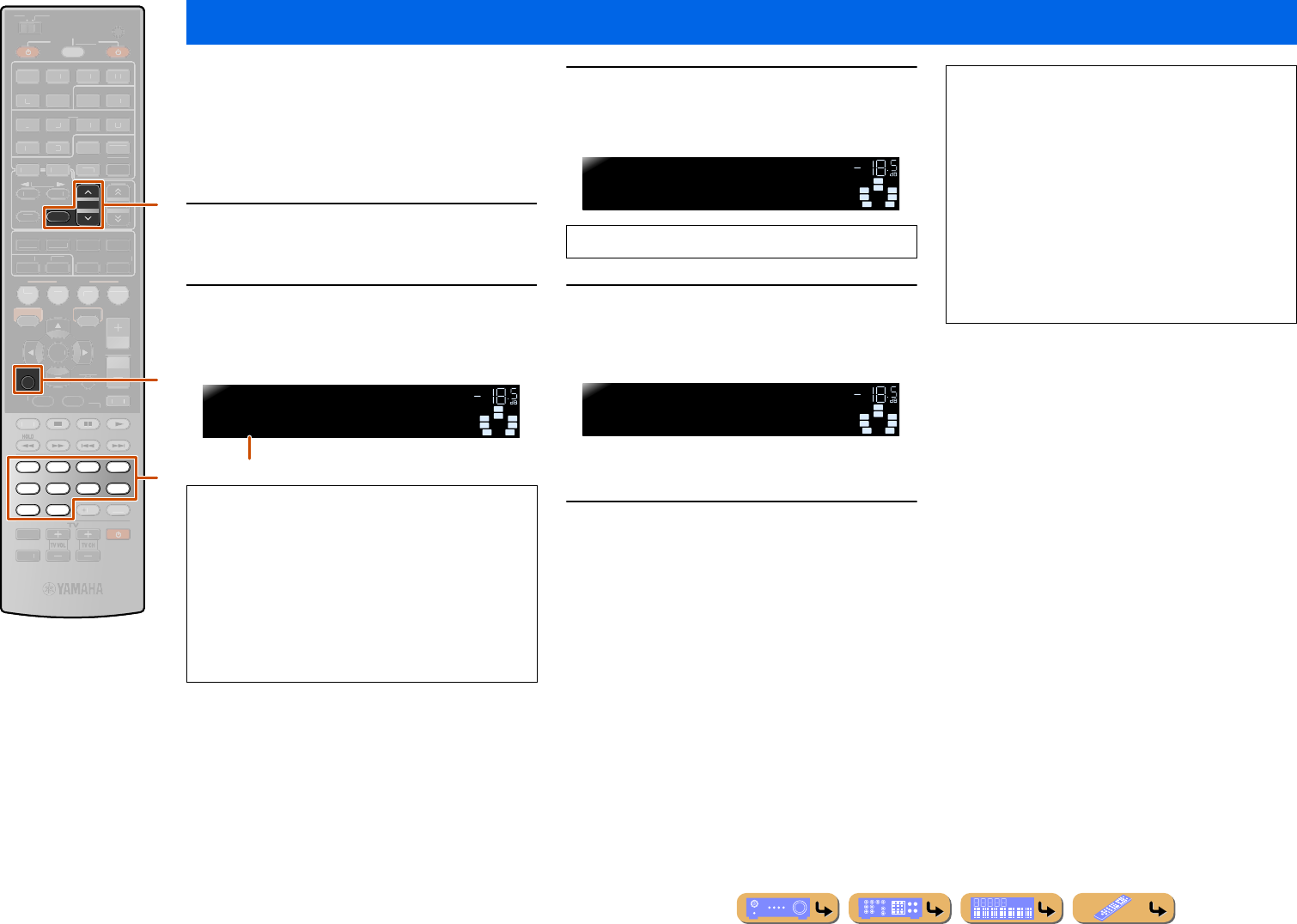
PLAYBACK
En 78
Use this feature to access the desired music sources
(WAV, MP3 and WMA files on the connected PC,
Internet Radio Stations, SIRIUS Internet Radio, and
Rhapsody® music contents) directly. You can preset up
to 40 items for above input sources.
■Assigning the items to the preset number
1Select a desired content you want to assign
to a preset number, and then play back the
content.
2Press eMEMORY.
This unit automatically selects an empty preset number
and the following display appears.
3Press ePRESET F / G or mNumeric keys
to select the preset number that you want to
assign.
4Press eMEMORY.
The following display appears on the front panel
display and the preset content is set.
■Selecting the item assigned to the preset
number
Press ePRESET F / G or mNumeric keys to
select the preset number to which the desired
item is assigned to select the item as the input
source.
This unit starts the playback of the source assigned to the
selected preset number.
This unit stores the relative position of the preset items
in a directory or playlist, and does not recall the correct
item by using mNumeric keys if you add or delete
music files to or from the same directory or playlist as
the preset items. In such cases, preset the desired item to
the preset numbers again.
We recommend the following methods:
PC server
Create playlists containing the desired content, and then
assign the top item of each playlist to a preset number.
To change the content assigned to preset numbers,
replace the content registered with a playlist with new
content without deleting the playlist.
Using shortcut function
RETURN
MEMORY
PRESET
7856
90
1234
SCENE
VO
L
U
ME
ENHANCE
R
S
UR. DE
CO
DE
STRAIGHTSLEEP
P
URE DIRECT
PART Y
M
OVI
E
M
USI
C
BD
DVD
TV
CD
RADI
O
MU
T
E
ENTER
10
R
EC
ENT
TOP
MENU
P
OP-U
P
M
EN
U
H
DMI
AV
A
UDI
O
1
2
3
4
1
2
5
V
-
AUX
DI
S
PLAY
SO
UR
C
E
M
AIN
Z
O
NE 2
RE
C
EIVE
R
CODE SE
T
I
NP
U
T
MUTE
DOC
K
HDMI
O
U
T
MULTI
O
PTION
O
N
SC
REE
N
5
1
2
3
4
6
FM
I
NF
O
AM
NET
S
IRI
US
TU
NER
TUN./C
H
C
ATE
GO
R
Y
m
e
k
eMEMORY
ePRESET F / G
kRETURN
mNumeric keys
•To automatically assign the selected content to an
empty preset number, press and hold eMEMORY for
at least 2 seconds with step 2. In this case, the
following steps are unnecessary.
•To cancel the preset, press kRETURN.
•When you do not complete each of the following steps
within 30 seconds, the memory preset mode is
automatically canceled. In this case, start over from
step 2.
SWSW
C
LR
SL SR
SBL SBR
01:Empty
MEMORY VOL.
Preset number (Blinks)
Valid numbers as the preset number are “01” to “40.”
SWSW
C
LR
SL SR
SBL SBR
09:Empty
MEMORY VOL.
SWSW
C
LR
SL SR
SBL SBR
09:Memorized
VOL.
NOTES
•“xx:Empty” appears on the front panel display when
you select the preset number to which no items are
assigned.
•This unit does not recall the correct item assigned to
the selected preset number in the following cases:
–the PC which stores the selected item is turned off
or disconnected from the network.
–the selected Internet Radio station, Rhapsody
service or SIRIUS Internet Radio is temporary
unavailable or out of service.
–the directory of the selected item has been changed.
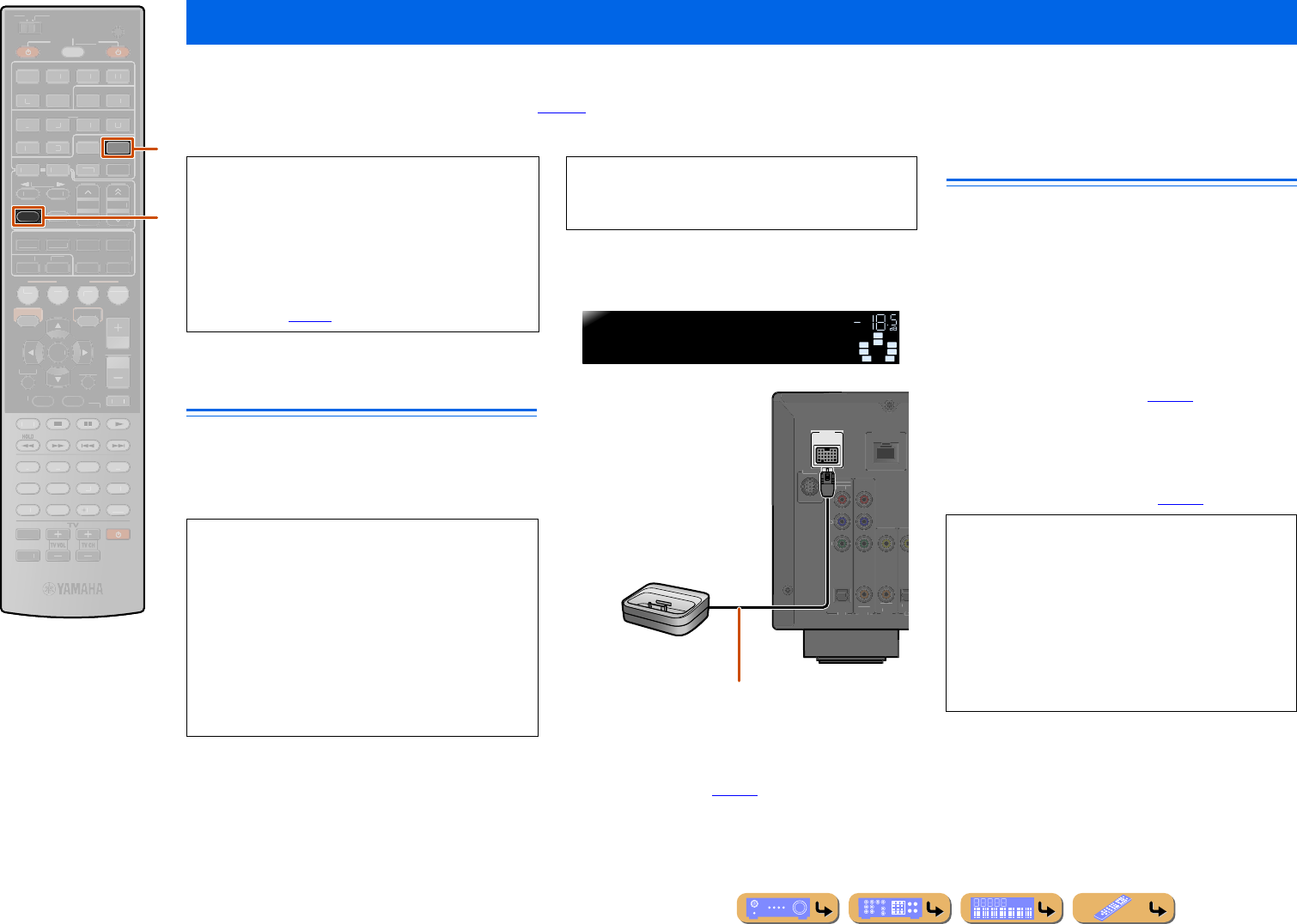
PLAYBACK
En 79
Once you have connected a Universal Dock for iPod (such as the YDS-12, sold separately) to this unit, you can enjoy playback of your iPod/iPhone using the remote
control supplied with this unit. When playing back from an iPod/iPhone, you can also use the compressed music enhancer sound programs to give compressed audio
formats such as MP3 a sharper, more dynamic sound (☞p. 47). A Yamaha iPod wireless system (YID-W10, sold separately) can also be connected to this unit to play back
iPod/iPhone with wireless connection.
Connecting the Universal Dock for
iPod
Use the dedicated cable to connect the dock to the
DOCK jack on the rear panel of this unit. Refer to the
operating instructions of the Universal Dock for iPod for
information on how to connect your iPod/iPhone.
Switch this unit on and place your iPod/iPhone in the
dock. The unit is now ready for playback.
When this unit is in standby mode, iPod/iPhone can be
charged automatically (☞p. 89).
Controlling an iPod™/iPhone™
After setting your iPod/iPhone in your dock, just press
dDOCK to switch to DOCK input to play your iPod/
iPhone.
The iPod/iPhone can be operated in the following two
ways.
Menu browse control:
Plays the iPod/iPhone while viewing the menu displayed
on the TV. Refer to “Playing iPod/iPhone from the menu
screen (Menu browse control)” (☞p. 80).
Simple remote control:
Plays audio and video through this unit while viewing
the menu displayed on the iPod/iPhone screen. Refer to
“Operating basic playback functions via the remote
control (Simple remote control)” (☞p. 81).
Playing back tunes from your iPod™/iPhone™
dDOCK
fINFO
INFO
DOCK
SCENE
RETURN
VO
L
U
ME
ENHANCE
R
S
UR. DE
CO
DE
STRAIGHTSLEEP
P
URE DIRECT
PART Y
M
OVI
E
M
USI
C
BD
DVD
TV
CD
RADI
O
M
U
T
E
ENTER
FM
M
EM
O
RY
AM
P
RESET
H
DMI
AV
A
UDI
O
1
2
3
4
1
2
5
V
-
AUX
7
8
5
6
9
0
10
1
2
3
4
R
EC
ENT
TOP
MENU
P
OP-U
P
M
EN
U
DI
S
PLAY
SO
UR
C
E
M
AIN
Z
O
NE 2
RE
C
EIVE
R
CODE SE
T
I
NP
U
T
MUTE
HDMI
O
U
T
MULTI
O
PTION
O
N
SC
REE
N
5
1
2
3
4
6
NET
S
IRI
US
TU
NER
TUN./C
H
C
ATE
GO
R
Y
d
f
• When playing back iPod/iPhone with wired
connection
Refer to “Connecting the Universal Dock for iPod.”
• When playing back iPod/iPhone with
wireless connection
Refer to “Playing iPod™/iPhone™ with wireless
connection” (☞p. 81).
•iPod touch, iPod (4th Gen/5th Gen/Classic), iPod
nano, iPod mini, iPhone, iPhone 3G, and iPhone 3GS
are supported (As of March 2010).
•When connecting iPhone, iPhone 3G and iPhone 3GS,
use a YDS-12.
•Some features may not be compatible depending on
the model or the software version of your iPod/iPhone.
•Some functions may not be available for some
Universal Dock for iPod models. This explanation
focuses on the YDS-12.
CAUTION
To prevent accidents, switch this unit to standby mode
before connecting the Universal Dock for iPod.
SW
C
L
SL SR
R
SBL SBR
iPodconnected
DOCK VOL.
DOCK
(
TV
AV 3
AV
(
C
D
)
CO
AXIAL OPTI
VIDEO
O
PTI
C
A
L
AV 1
AV 2
CO
AXIA
L
CO
MP
O
NEN
T
VIDE
O
P
R
P
B
Y
S
IRIU
S
NETW
O
RK
Universal Dock
for iPod
Locate the dock at the distance as far as from
the unit.
•Song information (artist, album, song) is displayed on
the front panel. Press fINFO repeatedly to display
subsequent/previous information.
•The Yamaha logo is displayed on the iPod screen
when iPod stationed in the Universal Dock for iPod
(does not apply to the iPod touch or iPhone).
•Manual control of the iPod/iPhone is not possible
while the iPod stationed in the Universal Dock for
iPod.
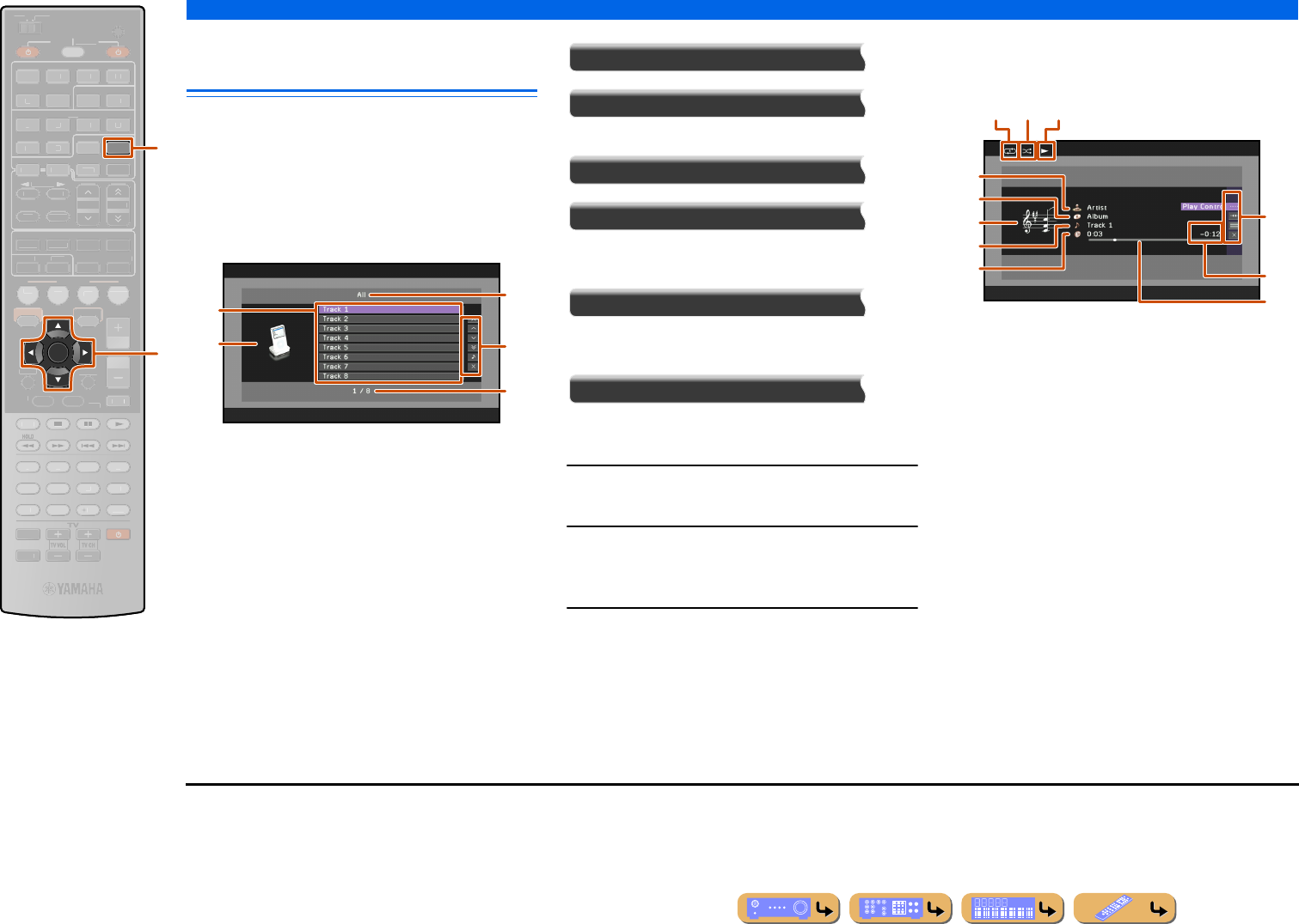
PLAYBACK
Playing back tunes from your iPod™/iPhone™
En 80
Playing iPod/iPhone from the menu
screen (Menu browse control)
The iPod/iPhone can be operated from the menu
displayed on the TV screen.
You can operate the iPod/iPhone from the Now Playing
view or the Browse view.
■
Operating from the Browse view
aInput name / List name
bMenu items
cInput icon
dScreen button area
Buttons for available operations are displayed. See
“Screen buttons on the Browse view” for details.
eCurrent menu number / Number of all menu items
Screen buttons on the Browse view
To use these buttons, first press kCursor E. Then
select the desired one with kCursor B / C and
kENTER.
10 Pages Up
10 Pages Down
Goes to 10 pages forwards or backwards.
1 Page Up
1 Page Down
Scrolls the list to the next or previous page.
Now Playing
Switches the display to the Now Playing view.
Close
Returns to the video playback, turning off the menu
display.
1Press dDOCK to switch to the DOCK input.
2Press kCursor B / C to select the content
(music or video) that you want to play, and
press kENTER.J1
3Press kCursor B / C to select iPod/iPhone
menu items, and press kENTER to play.
The Now Playing view appears during playback. J2
■
Operating from the Now Playing
view
aRepeat icon
bShuffle icon
cPlay icon
dAlbum image
eArtist name
fAlbum title
gScreen button area
Buttons for available operations are displayed. See
“Screen buttons on the Now Playing view” for details.
hSong title
iRemaining time
jProgress bar
kElapsed time
Screen buttons on the Now Playing view
To use these buttons, first press kENTER. Then select
the desired one with kCursor B / C and kENTER.
ENTER
DOCK
SCENE
RETURN
VO
L
U
ME
ENHANCE
R
S
UR. DE
CO
DE
STRAIGHTSLEEP
P
URE DIRECT
PART Y
M
OVI
E
M
USI
C
BD
DVD
TV
CD
RADI
O
M
U
T
E
7
8
5
6
9
0
10
1
2
3
4
R
EC
ENT
TOP
MENU
P
OP-U
P
M
EN
U
DI
S
PLAY
SO
UR
C
E
M
AIN
Z
O
NE 2
RE
C
EIVE
R
CODE SE
T
I
NP
U
T
MUTE
O
PTION
O
N
SC
REE
N
FM
I
NF
O
M
EM
O
RY
AM
P
RESET
H
DMI
AV
A
UDI
O
1
2
3
4
1
2
5
V
-
AUX
HDMI
O
U
T
MULTI
5
1
2
3
4
6
NET
S
IRI
US
TU
NER
TUN./C
H
C
ATE
GO
R
Y
d
k
dDOCK
kCursor B / C / D / E
kENTER
a
e
d
b
c
b ca
j
i
d
e
f
h
k
g
J1 : Videos will not be displayed when your iPod or Universal Dock
for iPod do not support the browser function for browsing video
files.
J2 : When selecting the video content, the following display is not
displayed.
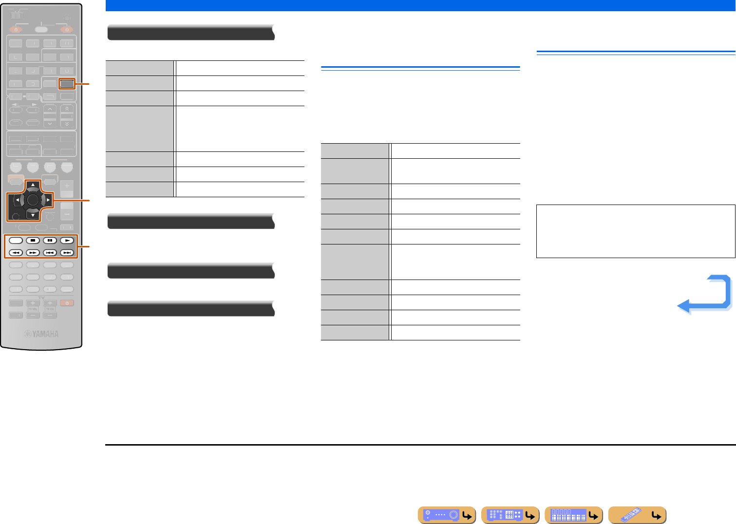
PLAYBACK
Playing back tunes from your iPod™/iPhone™
En 81
Play Control
Operates the basic playback functions of iPod/iPhone.
Scroll
Switches the scroll target (artist name, album name, or
song name).
Browse
Switches the display to the Browse view.
Close
Returns to the video playback, turning off the menu
display.
Operating basic playback functions
via the remote control (Simple
remote control)
Use the following remote control keys to operate
(playback, stop, skip, etc.) your iPod/iPhone.
Press lREC to enable the Simple remote control.
Press lREC again to return to the Menu browse
control.
Playing iPod™/iPhone™ with
wireless connection
A Yamaha iPod wireless system (YID-W10, sold
separately) can be connected to this unit to play back
iPod/iPhone with wireless connection. The iPod/iPhone
can be used as the remote control. J1
■
Connecting the Yamaha iPod
wireless transmitter and playing
back iPod/iPhone
Use the dedicated cable to connect the receiver of the
Wireless System for iPod to the DOCK jack on the rear
panel of this unit. Refer to the operating instructions of
the YID-W10 for more information.
dDOCK
kCursor B / C
kENTER
kRETURN
lREC
ls
le
lp
lw
lf
l b
la
RETURN
ENTER
REC
DOCK
HOLD
SCENE
VO
L
U
ME
ENHANCE
R
S
UR. DE
CO
DE
STRAIGHTSLEEP
P
URE DIRECT
PART Y
M
OVI
E
M
USI
C
BD
DVD
TV
CD
RADI
O
M
U
T
E
7
8
5
6
9
0
10
1
2
3
4
ENT
TOP
MENU
P
OP-U
P
M
EN
U
DI
S
PLAY
SO
UR
C
E
M
AIN
Z
O
NE 2
RE
C
EIVE
R
CODE SE
T
I
NP
U
T
MUTE
O
PTION
O
N
SC
REE
N
FM
I
NF
O
M
EM
O
RY
AM
P
RESET
HDMI
O
U
T
MULTI
H
DMI
AV
A
UDI
O
1
2
3
4
1
2
5
V
-
AUX
5
1
2
3
4
6
NET
S
IRI
US
TU
NER
TUN./C
H
C
ATE
GO
R
Y
d
l
k
p (Play) Starts playback.
s (Stop) Stops playback.
e (Pause) Stops playback temporarily.
b (Skip -) Skips to the beginning of the currently
playing song. Press kENTER at the
beginning of the song to skip to a
previous song.
a (Skip +) Skips to the beginning of the next song.
w (Scan -) Searches backwards.
f (Scan +) Searches forwards.
dDOCK Switches to the DOCK (iPod) input.
kCursor B / CMove the cursor up and down to different
fields.
kRETURN Returns to the previous menu.
kENTER Enables the selected menu.
lwSearches backwards while held down.
lfSearches forwards while held down.
lbSkips to the beginning of the currently
playing song. Pressing repeatedly skips
one song backwards with each press.
laSkips to the beginning of the next song.
lsStops playback.
leSwitches between playback and pause.
lpSwitches between playback and pause.
CAUTION
To prevent accidents, unplug the power cable of this
unit before connecting the receiver of the Wireless
System for iPod.
Continues to the
next page
J1 : Video signals cannot be transmitted wirelessly.
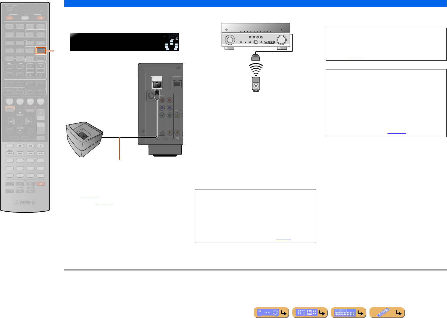
PLAYBACK
Playing back tunes from your iPod™/iPhone™
En 82
Place the iPod/iPhone in the wireless transmitter. Setup
is complete.
When this unit is in standby mode, iPod/iPhone can be
charged automatically, if “Standby Charge” is set to
“Auto” (☞p. 89) or “Power & Input” of “iPod Interlock”
is set to “On” (☞p. 89).
Use iPod/iPhone to start playback.
•This unit, which is placed in the main zone, functions as
follows when iPod/iPhone controls are used to start
playback.
–The input source switches to DOCK (iPod) when this
unit is turned on.
–When this unit is in standby mode when iPod/iPhone
playback starts, this unit turns on and the input source
switches to DOCK (iPod). J1
•This unit automatically enters standby mode when the
following operations are performed.
–iPod/iPhone is removed from the YID-W10
–iPod/iPhone is not operated for a while after playback
is stopped
•Adjusting volume control on the iPod/iPhone also adjusts
the volume (max 0.0 dB) of this unit.
dDOCK
DOCK
SCENE
RETURN
VO
L
U
ME
ENHANCE
R
S
UR. DE
CO
DE
STRAIGHTSLEEP
P
URE DIRECT
PART Y
M
OVI
E
M
USI
C
BD
DVD
TV
CD
RADI
O
MU
T
E
ENTER
FM
I
NF
O
M
EM
O
RY
AM
P
RESET
H
DMI
AV
A
UDI
O
1
2
3
4
1
2
5
V
-
AUX
7
8
5
6
9
0
10
1
2
3
4
R
E
C
ENT
TOP
MENU
P
OP-U
P
M
EN
U
DI
S
PLAY
SO
UR
C
E
M
AIN
Z
O
NE 2
RE
C
EIVE
R
CODE SE
T
I
NP
U
T
MUTE
HDMI
O
U
T
MULTI
O
PTION
O
N
SC
REE
N
5
1
2
3
4
6
NET
S
IRI
US
TU
NER
TUN./C
H
C
ATE
GO
R
Y
d
SW
C
L
SL SR
R
SBL SBR
iPodconnected
DOCK VOL.
DOCK
AV 3
(
C
D
)
CO
AXIA
L
O
VIDE
O
O
PTI
C
AL
AV 1
AV 2
CO
AXIAL
CO
MP
O
NENT
VIDE
O
P
R
P
B
Y
S
IRIU
S
NETW
O
RK
AB
123
Yamaha Wireless
System for iPod
Position the receiver as far as possible from the unit.
•Pressing dDOCK also switches the input source to
DOCK (iPod).
•When a menu is operated, this function is not
activated.
•When “iPod Interlock” → “Power & Input” in the
Input menu is set to “Off,” the power and the input
source do not switch automatically (☞p. 89).
When “iPod Interlock” → “Volume” in the Input
menu is set to “Off,” the volume of this unit is not
adjusted when iPod/iPhone volume controls are
adjusted (☞p. 89).
CAUTION
When iPod/iPhone controls are used to adjust volume,
playback volume may be unexpectedly loud. This
could result in damage to this unit or the speakers. If
the volume suddenly increases during playback,
immediately remove the iPod/iPhone from the
Universal Dock for iPod. “Max Volume” can be used
to specify the maximum volume level to prevent
excessively loud playback (☞p. 103).
J1 : This function is also activated when sound of application is
reproduced or ringtone is received.
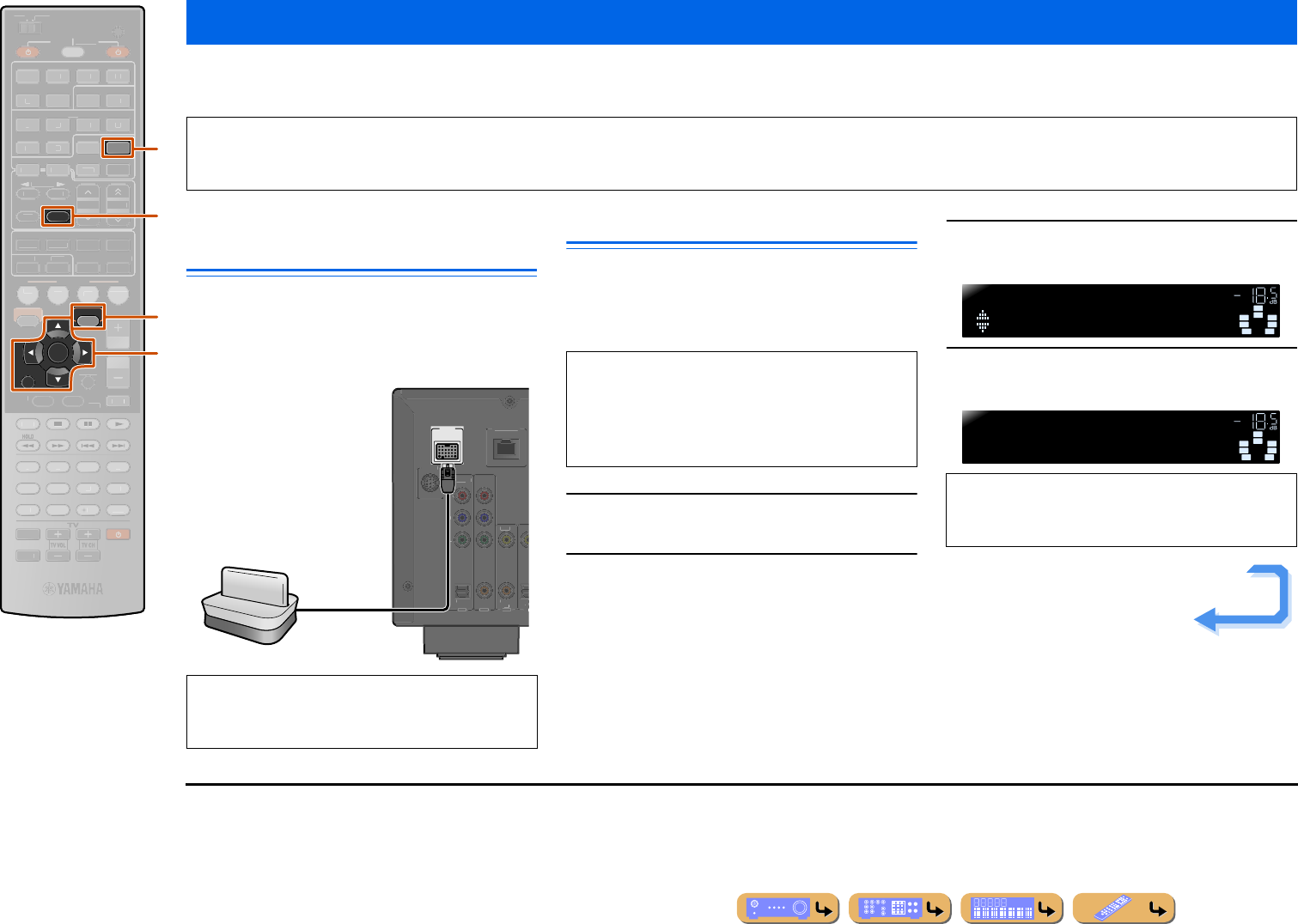
PLAYBACK
En 83
You can connect a Yamaha Bluetooth wireless audio receiver (such as the YBA-10, sold separately) to this unit and enjoy wireless playback from Bluetooth-compatible
portable music players. J1
Connecting a Yamaha Bluetooth
wireless audio receiver
Use the dedicated cable to connect the dock to the
DOCK jack on the rear panel of this unit.
The Bluetooth wireless audio receiver connection will be
complete when this unit is turned on.
Pairing Bluetooth™ components
Be sure to carry out pairing when connecting a Bluetooth
component for the first time, or when settings have been deleted.
Refer to the operating instructions of your Bluetooth
component as necessary when carrying out pairing.
1Press dDOCK to switch to the DOCK input.
2Turn on the Bluetooth component you want
to pair with and set it to pairing mode.
3Press tOPTION to display the Option menu
and use kCursor B / C to select “Pairing.”
4Press kENTER to start pairing.
Playing back tunes from Bluetooth™ components
NOTE
When playing back from a Bluetooth component for the first time, you must first pair the devices (register the Bluetooth components). When establishing a wireless connection
you must carry out pairing on both this unit and on the Bluetooth component.
dDOCK
eMEMORY
kCursor B / C
kENTER
kRETURN
tOPTION
RETURN
MEMORY
ENTER
DOCK
OPTION
SCENE
VO
L
U
ME
ENHANCE
R
S
UR. DE
CO
DE
STRAIGHTSLEEP
P
URE DIRECT
PART Y
M
OVI
E
M
USI
C
BD
DVD
TV
CD
RADI
O
M
U
T
E
7
8
5
6
9
0
10
1
2
3
4
R
EC
ENT
TOP
MENU
P
OP-U
P
M
EN
U
DI
S
PLAY
SO
UR
C
E
M
AIN
Z
O
NE 2
RE
C
EIVE
R
CODE SE
T
I
NP
U
T
MUTE
O
N
SC
REE
N
FM
I
NF
O
AM
P
RESET
H
DMI
AV
A
UDI
O
1
2
3
4
1
2
5
V
-
AUX
HDMI
O
U
T
MULTI
5
1
2
3
4
6
NET
S
IRI
US
TU
NER
TUN./C
H
C
ATE
GO
R
Y
k
d
e
t
CAUTION
To prevent accidents, switch this unit to standby mode
before connecting a Bluetooth wireless audio receiver.
DOCK
(
TV
AV 3
AV
(
C
D
)
CO
AXIAL OPTI
VIDEO
O
PTI
C
A
L
AV 1
AV 2
CO
AXIA
L
CO
MP
O
NEN
T
VIDE
O
P
R
P
B
Y
S
IRIU
S
NETW
O
RK
Yamaha Bluetooth
wireless audio receiver
The Yamaha Bluetooth wireless audio receiver can be
paired with up to eight Bluetooth components. When
the ninth device is paired, the pairing settings for the
device which has not been used for the longest period
of time will be deleted.
•To cancel pairing, press kRETURN.
•You can also press and hold eMEMORY on the
remote control to begin pairing.
SW
C
L
SL SR
R
SBL SBR
Pairing
OPTION VOL.
SW
C
L
SL SR
R
SBL SBR
Searching...
DOCK VOL.
Continues to the
next page
J1 : This unit supports A2DP (Advanced Audio Distribution Profile)
of the Bluetooth profile.
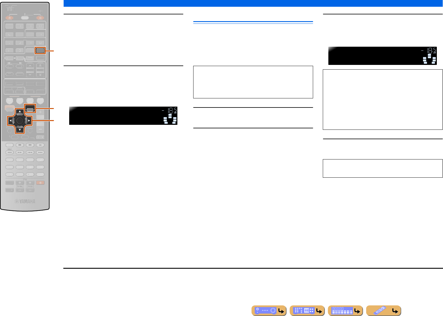
PLAYBACK
Playing back tunes from Bluetooth™ components
En 84
5Make sure the Bluetooth component
recognizes the Bluetooth wireless audio
receiver.
When the device is recognized, it will appear in the
Bluetooth component list, for example as “YBA-10
YAMAHA.”
6Select the Bluetooth wireless audio receiver
from the Bluetooth component list, and
enter a pass key “0000” into the Bluetooth
component. J1
Using Bluetooth™ components
When pairing is complete, perform the following
procedure to achieve a wireless connection between this
unit and the Bluetooth component. When the wireless
connection is complete, Bluetooth components can be
played back.
1Press dDOCK to switch to the DOCK input.
2Press tOPTION to display the Option
menu.
3Use kCursor B / C to select “Connect” and
press kENTER.J2
4Operate the Bluetooth component for
playback.
dDOCK
kCursor B / C
kENTER
tOPTION
ENTER
DOCK
OPTION
SCENE
RETURN
VO
L
U
ME
ENHANCE
R
S
UR. DE
CO
DE
STRAIGHTSLEEP
P
URE DIRECT
PART Y
M
OVI
E
M
USI
C
BD
DVD
TV
CD
RADI
O
M
U
T
E
7
8
5
6
9
0
10
1
2
3
4
R
EC
ENT
TOP
MENU
P
OP-U
P
M
EN
U
DI
S
PLAY
SO
UR
C
E
M
AIN
Z
O
NE 2
RE
C
EIVE
R
CODE SE
T
I
NP
U
T
MUTE
O
N
SC
REE
N
FM
I
NF
O
M
EM
O
RY
AM
P
RESET
H
DMI
AV
A
UDI
O
1
2
3
4
1
2
5
V
-
AUX
H
DMI
O
UT
MULTI
5
1
2
3
4
6
N
ET
S
IRI
US
TU
NER
TUN./C
H
C
ATE
GO
R
Y
d
t
k
SW
C
L
SL SR
R
SBL SBR
Completed
DOCK VOL.
When pairing occurs correctly
Depending on Bluetooth components, a wireless
connection is established automatically or by
operating the Bluetooth components. In that case, it is
not necessary to carry out the following procedure.
“Not found” is displayed when there is an error
connecting. Check that the following conditions have
been satisfied, and try to establish a wireless
connection again.
•Both this unit and the Bluetooth component are paired.
•The Bluetooth component is switched on.
•The Bluetooth component is within 32 ft. (10 m) of the
Bluetooth wireless audio receiver.
To disconnect a wireless connection, repeat the same
steps, and in step 3, select “Disconnect.”
SW
C
L
SL SR
R
SBL SBR
BTconnected
DOCK VOL.
When wireless connection is complete
J1 : Depending on Bluetooth components, wireless connection is
carried out right after the pairing. In this case, “BT connected” is
displayed instead of “Completed.”
J2 : “Disconnect” is displayed when a Bluetooth component has been
connected.
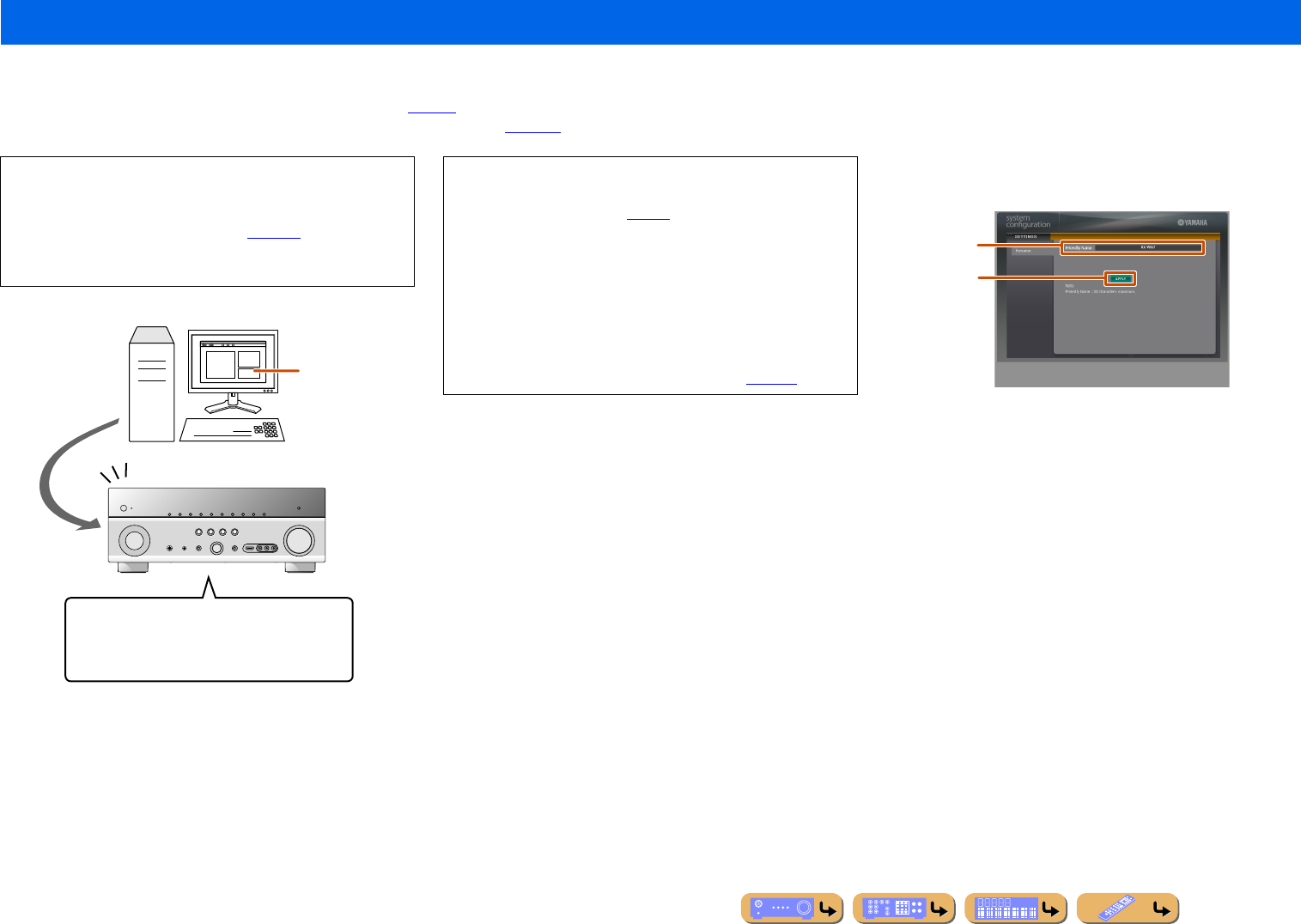
PLAYBACK
En 85
You can change the friendly name of this unit by using the graphical user interface that appears on the web browser.
Friendly name is the identification name informed to external components in the same network. For example, the icon indicating this unit may be easily recognized by the original friendly name when
the sharing media function of Windows Media Player is used (☞p. 67).
Check the IP address of this unit by using “IP Address” in “Network” menu (☞p. 108) in advance, and then enter the IP address to the web browser to access this unit to change the friendly name.
When your PC successfully accesses this unit, the following screen
is displayed on the web browser.
aFriendly Name
Enter your favorite friendly name in the box.
bAPPLY
Applies the friendly name entered to this unit.
Changing the friendly name of this unit by using the web browser
NOTE
When “Network Standby” is set to “On” in the Network menu,
the graphical user interface can be displayed on the web browser
even if this unit was in standby mode (☞p. 108). When
“Network Standby” is set to “Off,” we recommend that
“Network Standby” is set to “On.”
Changing the friendly name of this unit
E.g.,
[RX-V867] (default) → [YAMAHA AV Amplifier]
Web browser
PC
Access
•To use this feature, this unit and your PC must be connected
properly in the network. Refer to “Connecting to the network” for
details on the connections (☞p. 32).
•We recommend that you use Windows Internet Explorer 8 that is
installed on Windows XP or Windows 7 PC to access this unit.
•You can register the MAC address of the PCs you want to use to
control this unit and limit the PCs that can control this unit by
using the web browser. You can select that this unit allows the
access to this unit by the PCs whose MAC addresses are
registered to this unit or allows the access by any PCs by using
“MAC Address Filter” in the “Network” setup (☞p. 108).
a
b
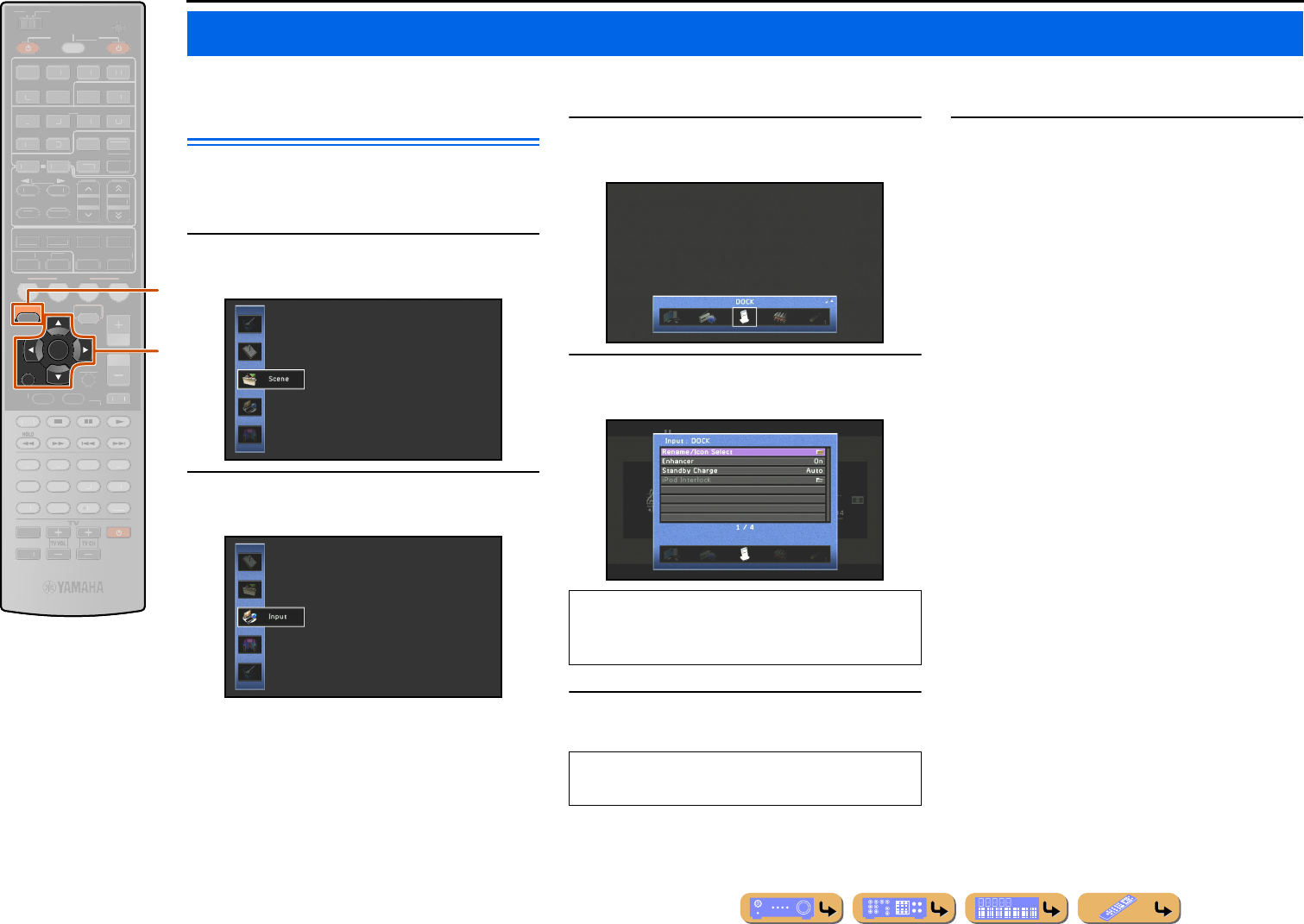
En 86
SETUP
Settings, such as the name of an input source or the icon displayed for an input source can be changed from the Input menu.
Configuring input sources
The name of an input source and its icon, as well as other
input source settings, can be changed from the Input
menu displayed on the TV screen.
1Press jON SCREEN.
2Use kCursor B / C to select “Input” and
press kENTER.
3Use kCursor D / E to select an input source
to be configured and press kCursor B.
4Use kCursor B / C to select an item and
press kENTER.
5Use kCursor B / C to adjust the setting.
6Press jON SCREEN to close the menu.
Configuring input sources (Input menu)
jON SCREEN
kCursor B / C / D / E
kENTER
kRETURN
RETURN
ENTER
ON SCREEN
SCENE
VO
L
U
ME
ENHANCE
R
S
UR. DE
CO
DE
STRAIGHTSLEEP
P
URE DIRECT
PART Y
M
OVI
E
M
USI
C
BD
DVD
TV
CD
RADI
O
M
U
T
E
7
8
5
6
9
0
10
1
2
3
4
R
EC
ENT
FM
I
NF
O
M
EM
O
RY
AM
P
RESET
H
DMI
AV
A
UDI
O
1
2
3
4
1
2
5
V
-
AUX
TOP
MENU
P
OP-U
P
M
EN
U
DI
S
PLAY
SO
UR
C
E
M
AIN
Z
O
NE 2
RE
C
EIVE
R
CODE SE
T
I
NP
U
T
MUTE
DOCK
HDMI
O
U
T
MULTI
O
PTION
5
1
2
3
4
6
NET
S
IRI
US
TU
NER
TUN./C
H
C
ATE
GO
R
Y
k
j
If the selected item contains additional items, use
kCursor B / C to select the desired item and press
kENTER.
Pressing kRETURN displays the previous menu
screen. Repeat steps 4 to 5 to adjust multiple settings.
SETUP
Configuring input sources (Input menu)
En 87
Input menu
The following items are provided for each input source. “✓” indicates the available menu for each input source.
HDMI 1-5 AV1-2 AV3-4 AV5-6 V-AUX AUDIO1-2 TUNER SIRIUS Rhapsody SIRIUS IR PC NET
RADIO
DOCK
(iPod)
DOCK
(Bluetooth) MULTI CH
Rename/Icon Select ✓✓✓✓✓✓ ✓✓✓
Audio In ✓✓
Decoder Mode ✓✓✓ ✓
Enhancer ✓✓✓✓✓✓✓✓✓✓✓✓✓✓
DMC Control ✓
Account Status ✓✓
Sign In ✓✓
Rhapsody Trial ✓
Remove Account ✓✓
SIRIUS IR Trial ✓
Standby Charge ✓
iPod Interlock ✓J1
Video Out ✓
J1 : Not available when playing back iPod/iPhone with wired connection.
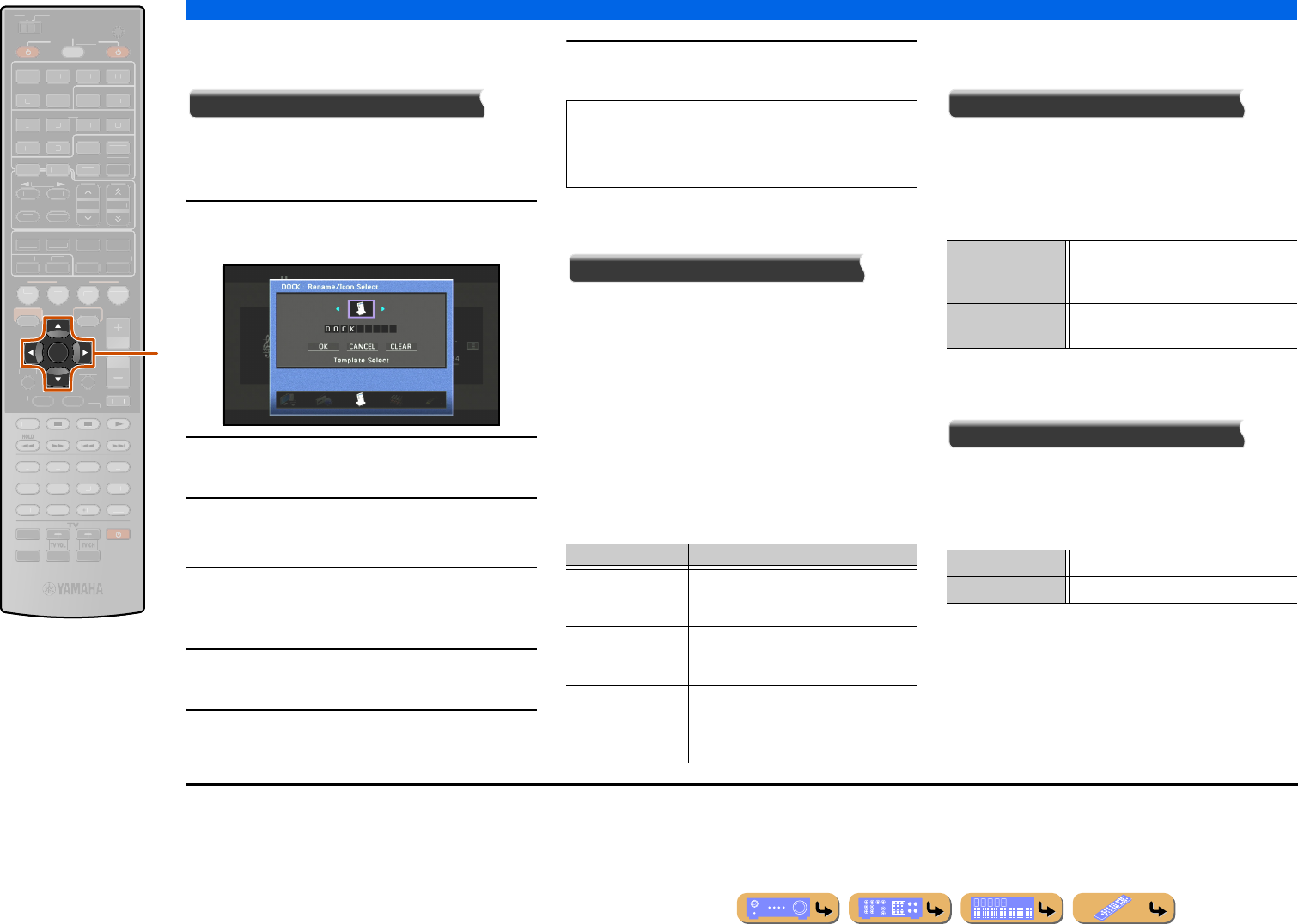
SETUP
Configuring input sources (Input menu)
En 88
■
Changing an input source name or
icon
Rename/Icon Select
Changes the input source name (up to nine characters)
and icon displayed on the front panel display or TV
screen.
1Use kCursor B / C repeatedly to select
“Rename/Icon Select” and press kENTER.
2Use kCursor D / E to choose an icon.
3Press kCursor C and kENTER.
Editing the name is available.
4Press kCursor B / C to select a character,
and press kCursor D / E to enter the
selected character.
5Repeat step 4 to enter the desired input
source name.
6Confirm the input source name by pressing
kENTER.
7Press kCursor C to select “OK” and press
kENTER to register the new input name.
■
Combining HDMI/AV1-2 input
source video and audio
Audio In
Combines video from HDMI or AV input sources with
analog/digital audio inputs in situations such as:
–an playback device is connected with an HDMI cable
but cannot transmit audio through HDMI
–an playback device with component video output and
analog audio output (such as certain game consoles)
are connected to the system
To change assignments, select an input source (HDMI1-5
or AV1-2) as the video input first, and then select audio
input jacks in this menu.
Set as follows according on the desired combination of
audio input jacks.
■
Setting the format of digital audio
signals
Decoder Mode
Sets the format of digital audio to playback to DTS. For
example, if the format is not automatically detected
correctly even during playback of DTS format audio,
this item can be used to set the playback format to
DTS. J1
■
Using a PC to control this unit over
a network
DMC Control
This unit can be operated via the DLNA compatible
controller (e.g., Windows Media Player, etc.) to the same
network of this unit.
DMC stands for “Digital Media Controller.”
kCursor B / C / D / E
kENTER
ENTER
SCENE
RETURN
VO
L
U
ME
ENHANCE
R
S
UR. DE
CO
DE
STRAIGHTSLEEP
P
URE DIRECT
PART Y
M
OVI
E
M
USI
C
BD
DVD
TV
CD
RADI
O
M
U
T
E
FM
I
NF
O
M
EM
O
RY
AM
P
RESET
H
DMI
AV
A
UDI
O
1
2
3
4
1
2
5
V
-
AUX
7
8
5
6
9
0
10
1
2
3
4
R
EC
ENT
TOP
MENU
P
OP-U
P
M
EN
U
DI
S
PLAY
SO
UR
C
E
M
AIN
Z
O
NE 2
RE
C
EIVE
R
CODE SE
T
I
NP
U
T
MUTE
DOCK
HDMI
O
U
T
MULTI
O
PTION
O
N
SC
REE
N
5
1
2
3
4
6
NET
S
IRI
US
TU
NER
TUN./C
H
C
ATE
GO
R
Y
k
•To cancel the operation without applying changes,
select “CANCEL” and then press kENTER.
•To clear the characters entered in step 5, select
“CLEAR” and press kENTER.
Audio inputs Settings method
Optical digital audio
input
Select AV1 or AV4. Connect the external
component audio cable to the optical digital
jack for the selected input.
Coaxial digital audio
input
Select AV2 or AV3. Connect the external
component audio cable to the coaxial digital
jack for the selected input.
Analog audio input Select one of AV5, AV6, AUDIO1, or
AUDIO2. Connect the external
component audio cable to the audio jack
for the selected input.
Auto (Default) The audio format is automatically
selected to match the format of the input
audio.
DTS Selects DTS signals only. Other input
signals are not reproduced.
Disable Disables the DMC control function.
Enable (Default) Enables the DMC control function.
J1 : AV5-6 or AUDIO1-2 are also available when “Audio Return
Channel” is on, and the input source is used for “TV Audio
Input.”
En 89
SETUP
Configuring input sources (Input menu)
■
Confirming the account of the Rhapsody
service or SIRIUS Internet Radio
Account Status
Displays the current account status of Rhapsody service or SIRIUS
Internet Radio.
■
Sign in to your account for the Rhapsody
service or SIRIUS Internet Radio
Sign In
Sign in to your account for the Rhapsody service or SIRIUS
Internet Radio (☞p. 71, p. 75).
Rhapsody Trial
Displays the URL for free 30-day trial service content. Create an
account in the specified website, sign in to your account with “Sign
In” to get started with a free trial.
SIRIUS IR Trial
Creates a temporary account for free 30-day trial and sign in to the
account automatically.
■
Removing your account from the
Rhapsody service or SIRIUS Internet
Radio
Remove Account
Removes an account registered with the Rhapsody service or
SIRIUS Internet Radio.
■
Selecting the sound program suitable for
listening to compressed audio, such as
MP3
Enhancer
Turns on/off the Compressed Music Enhancer.
■
Charging an iPod™/iPhone™ in standby
mode
Standby Charge
Charges an iPod/iPhone stationed in the Universal Dock for iPod /
iPhone or receiver of the Wireless System for iPod while the
receiver is in standby mode.
■
Setting the interlock functions with iPod/
iPhone (when a Yamaha Wireless System
for iPod is connected)
iPod Interlock
This unit can be automatically operated in conjunction with
operations on iPod when the receiver of the Wireless System for
iPod is connected to this unit.
■
Outputting a video signal input from
another input source while playing a
multi-channel audio signal
Video Out
When “MULTI CH” is selected as the input source, a video signal
input from another terminal can be output to the video monitor. For
example, even if an audio and video component such as a DVD
player that does not support a multi-channel digital audio output,
the video signal can be output to the video monitor while
reproducing a multi-channel analog audio signal.
Refer to “Rhapsody® account sign-in” (☞p. 71) or “SIRIUS
Internet Radio account sign-in” (☞p. 75) for details on signing
in to your account.
Off (Default) Turns off the Compressed Music Enhancer.
On Turns on the Compressed Music Enhancer.
Auto (Default) This unit charges iPod/iPhone when this unit is in
standby mode. While charging an iPod/iPhone, the
HDMI Through/iPod Charge indicator lights. When
HDMI Through function is off, the indicator goes out
after the charging is complete.
Off This unit does not charge iPod/iPhone.
Power & Input Starting playback of iPod/iPhone turns on this unit
and switches the input source to DOCK (iPod)
automatically when this item is set to “On.” This unit
automatically enters standby mode when iPod/iPhone
is not operated for a while after playback is stopped.
This interlock function is disable with “Off.”
Volume Adjusting the volume on the iPod/iPhone also adjusts
the volume of this unit when this item is set to “On.”
This interlock function is disable with “Off.”
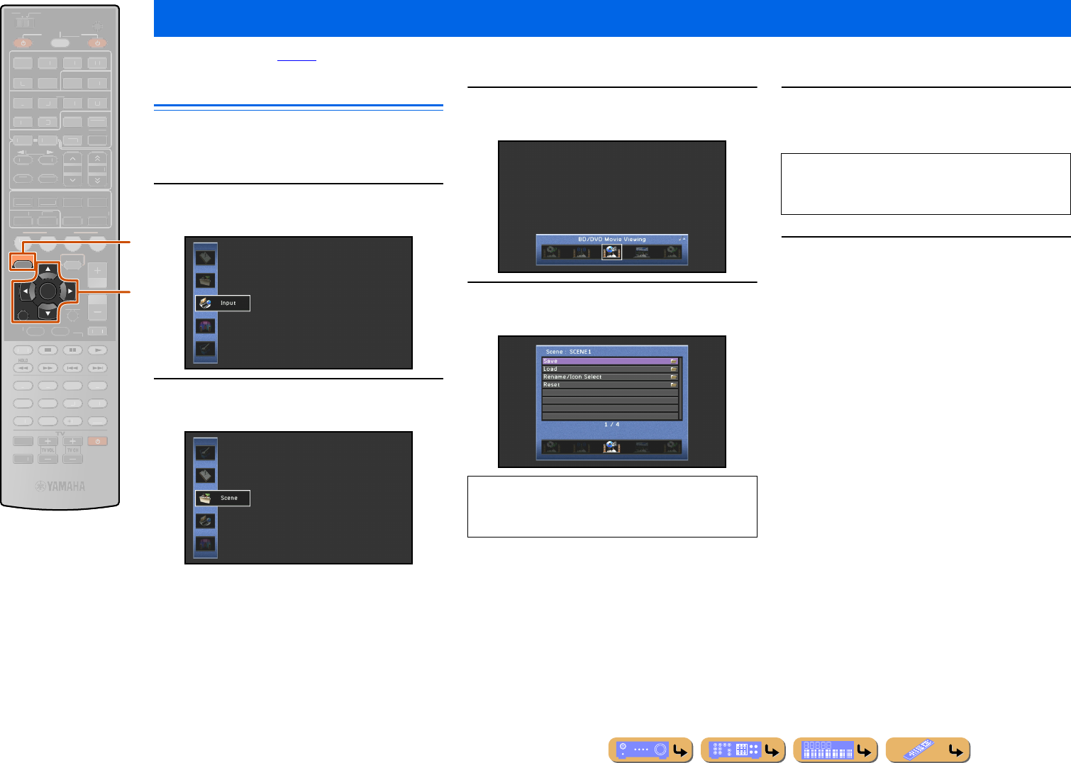
SETUP
En 90
The SCENE function (☞p. 44) can be edited from the SCENE menu displayed on the TV screen.
Editing a scene
Various settings, such as the name of a scene or the icon
displayed for a scene, can be changed from the SCENE
menu.
1Press jON SCREEN.
2Use kCursor B / C to select “Scene” and
press kENTER.
3Use kCursor D / E to select a scene to be
edited and press kCursor B.
4Use kCursor B / C to select an item and
press kENTER.
5Use kCursor B / C / D / E to adjust the
setting.
6Press jON SCREEN to close the menu.
Editing the SCENE function (SCENE menu)
jON SCREEN
kCursor B / C / D / E
kENTER
kRETURN
RETURN
ENTER
ON SCREEN
SCENE
VO
L
U
ME
ENHANCE
R
S
UR. DE
CO
DE
STRAIGHTSLEEP
P
URE DIRECT
PART Y
M
OVI
E
M
USI
C
BD
DVD
TV
CD
RADI
O
M
U
T
E
7
8
5
6
9
0
10
1
2
3
4
R
EC
ENT
FM
I
NF
O
M
EM
O
RY
AM
P
RESET
H
DMI
AV
A
UDI
O
1
2
3
4
1
2
5
V
-
AUX
TOP
MENU
P
OP-U
P
M
EN
U
DI
S
PLAY
SO
UR
C
E
M
AIN
Z
O
NE 2
RE
C
EIVE
R
CODE SE
T
I
NP
U
T
MUTE
DOCK
HDMI
O
U
T
MULTI
O
PTION
5
1
2
3
4
6
NET
S
IRI
US
TU
NER
TUN./C
H
C
ATE
GO
R
Y
k
j
When the Utility is available in the selected item, use
kCursor B / C to select the Utility and press
kENTER.
Pressing kRETURN displays the previous menu
screen. Repeat steps 4 and 5 to adjust multiple
settings.
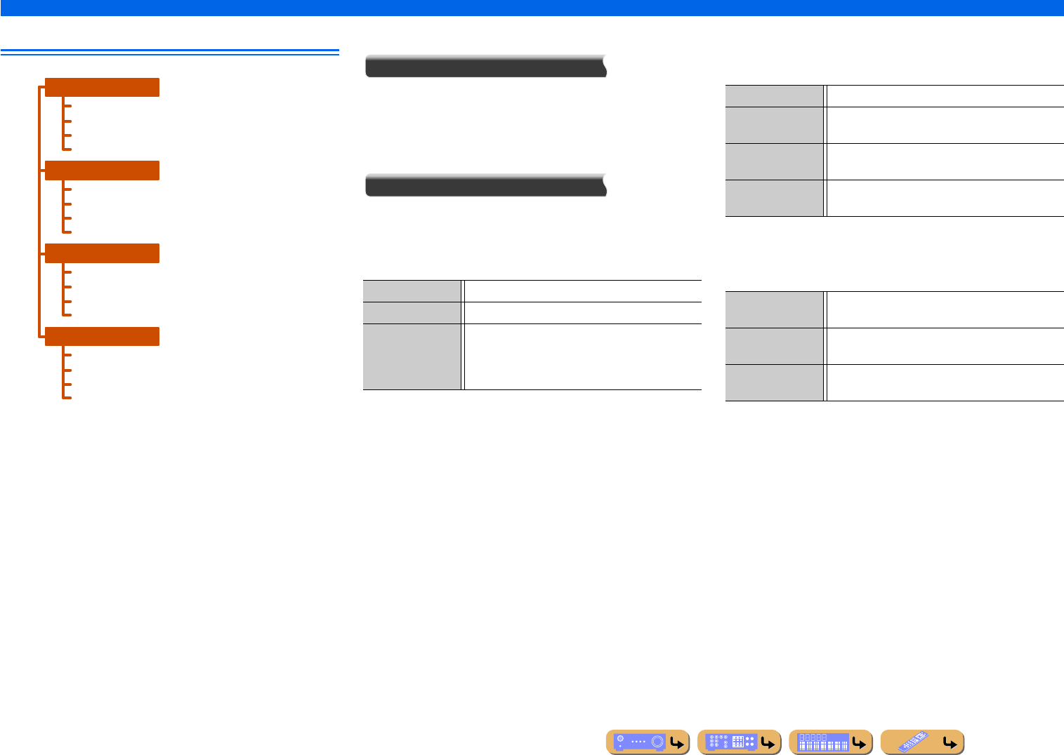
En 91
SETUP
Editing the SCENE function (SCENE menu)
SCENE menu
■
Registering SCENE function settings
Save
Registers the settings currently applied to this unit for each
SCENE.
■
Adjusting settings registered with the
SCENE function
Load
Loads input sources or sound programs that have been registered
with the SCENE function, or specifies whether or not an external
component registered as the input source is automatically turned on
when a scene is selected.
SCENE IR
Specify whether or not a Yamaha BD/DVD player or CD player
connected to this unit turns on automatically.
Detail
Display details of settings registered with the SCENE function.
Items indicated with a check mark in “Setting” are loaded.
SCENE1
SCENE2
SCENE3
SCENE4
Save
Load
Rename/Icon Select
Reset
Save
Load
Rename/Icon Select
Reset
Save
Load
Rename/Icon Select
Reset
Save
Load
Rename/Icon Select
Reset
Ok Loads items indicated with a check mark in “Setting.”
Cancel Cancels settings applied with “Setting.”
DETAIL Specifies “SCENE IR” function and displays settings
registered with the SCENE function in detail.
Foe more information, see “SCENE IR” and “Detail”
at right.
Off Disables the SCENE IR function.
Yamaha BD/DVD
Player1
Select this when a Yamaha BD/DVD player is
connected to this unit.
Yamaha BD/DVD
Player2
Select this if the player dose not turn on when
“Yamaha BD/DVD Player1” is selected.
Yamaha CD Player Select this when a Yamaha CD player is connected to
this unit.
Input Displays “Input” and “Audio Select” settings
registered with the SCENE function.
Mode Displays the sound program registered with the
SCENE function.
Enhancer Displays the “Enhancer” setting registered with the
SCENE function.
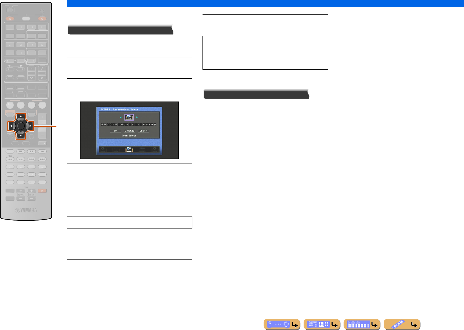
SETUP
Editing the SCENE function (SCENE menu)
En 92
■
Changing a scene name and icon
Rename/Icon Select
Changes the scene name and icon displayed on the front
panel display or TV screen.
1Use kCursor B / C repeatedly to select
“Rename/Icon Select” and press kENTER.
2Use kCursor D / E to choose an icon.
3Press kCursor C and kENTER.
Editing the name is available.
4Press kCursor B / C to select a character,
and press kCursor D / E to enter the
selected character.
5Repeat step 4 to enter the desired scene
name.
6Confirm the scene name by pressing
kENTER.
7Press kCursor C to select “OK” and press
kENTER to register the new input name.
■
Resetting a scene
Reset
Restores all settings for the selected scene to their
default values.
kCursor B / C / D / E
kENTER
ENTER
SCENE
RETURN
VO
L
U
ME
ENHANCE
R
S
UR. DE
CO
DE
STRAIGHTSLEEP
P
URE DIRECT
PART Y
M
OVI
E
M
USI
C
BD
DVD
TV
CD
RADI
O
M
U
T
E
FM
I
NF
O
M
EM
O
RY
AM
P
RESET
H
DMI
AV
A
UDI
O
1
2
3
4
1
2
5
V
-
AUX
7
8
5
6
9
0
10
1
2
3
4
R
EC
ENT
TOP
MENU
P
OP-U
P
M
EN
U
DI
S
PLAY
SO
UR
C
E
M
AIN
Z
O
NE 2
RE
C
EIVE
R
CODE SE
T
I
NP
U
T
MUTE
DOCK
H
DMI
O
UT
MULTI
O
PTION
O
N
SC
REE
N
5
1
2
3
4
6
N
ET
S
IRI
US
TU
NER
TUN./C
H
C
ATE
GO
R
Y
k
Scene names may consist of up to 20 characters.
•To cancel the operation without applying changes,
select “CANCEL” and then press kENTER.
•To clear the characters entered in step 4, select
“CLEAR” and press kENTER.
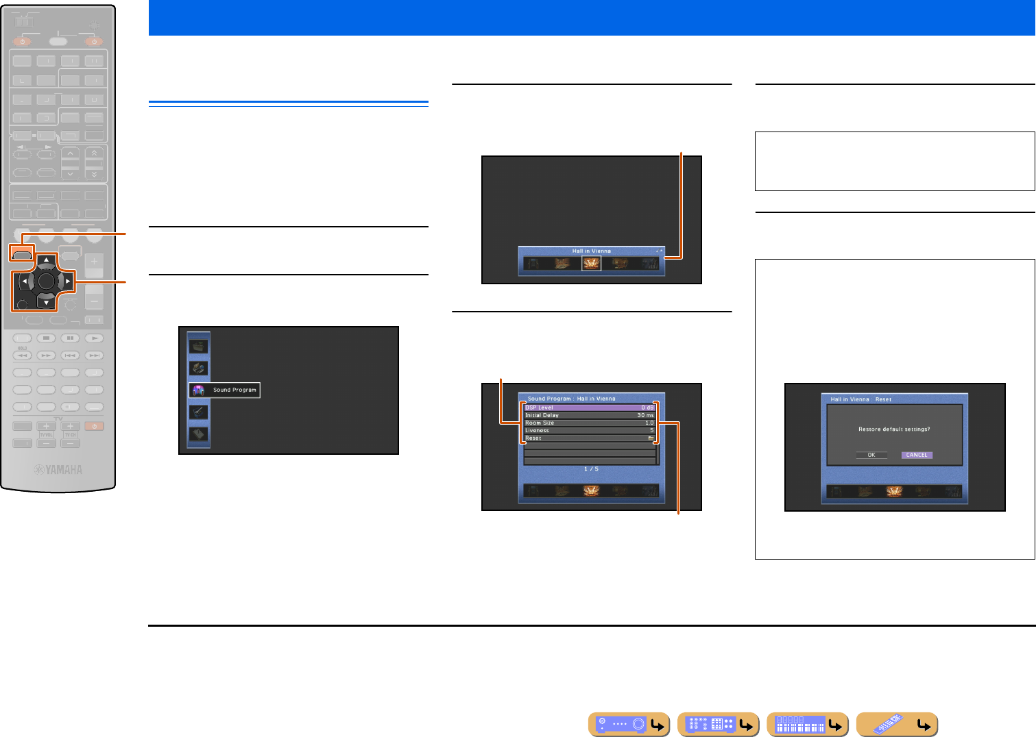
SETUP
En 93
Sound effects can be adjusted from the Sound Program menu.
Editing sound programs
Adjust sound field elements (sound program parameters)
to achieve sound effects suited to the acoustics of audio/
video sources or rooms if you are not satisfied with the
results achieved with default sound program settings.
Follow the procedure described below to adjust sound
program parameters.
1Press jON SCREEN.
2Press kCursor B / C repeatedly to select
“Sound Program” and press kENTER.
3Use kCursor D / E to select a sound
program and press kCursor B.
4Use kCursor B / C to select a parameter
and press kENTER.
5Use kCursor D / E to adjust the parameter
and press kRETURN.J1
6Press jON SCREEN to close the Sound
Program menu.
Setting sound program parameters (Sound Program menu)
jON SCREEN
kCursor B / C / D / E
kENTER
kRETURN
RETURN
ENTER
ON SCREEN
SCENE
VO
L
U
ME
ENHANCE
R
S
UR. DE
CO
DE
STRAIGHTSLEEP
P
URE DIRECT
PART Y
M
OVI
E
M
USI
C
BD
DVD
TV
CD
RADI
O
M
U
T
E
7
8
5
6
9
0
10
1
2
3
4
R
EC
ENT
FM
I
NF
O
M
EM
O
RY
AM
P
RESET
H
DMI
AV
A
UDI
O
1
2
3
4
1
2
5
V
-
AUX
TOP
MENU
P
OP-U
P
M
EN
U
DI
S
PLAY
SO
UR
C
E
M
AIN
Z
O
NE 2
RE
C
EIVE
R
CODE SE
T
I
NP
U
T
MUTE
DOCK
H
DMI
O
UT
MULTI
O
PTION
5
1
2
3
4
6
N
ET
S
IRI
US
TU
NER
TUN./C
H
C
ATE
GO
R
Y
k
j
Sound programs
Sound program parameters
Choices
When there are multiple parameters in the selected
sound program, repeat steps 4 and 5 to adjust other
parameters.
■To initialize sound program parameters
To set the parameters of the sound program back to
their default settings, use kCursor B / C repeatedly
to select “Reset” in step 4 and press kENTER.
When the following message is displayed, select
“OK” and press kENTER to initialize.
To cancel initializing, select “CANCEL” and press
kENTER when the message above is displayed.
J1 : An asterisk (*) appears on the left of the sound field parameter
name displayed on the TV when you change the parameter from
its default setting.
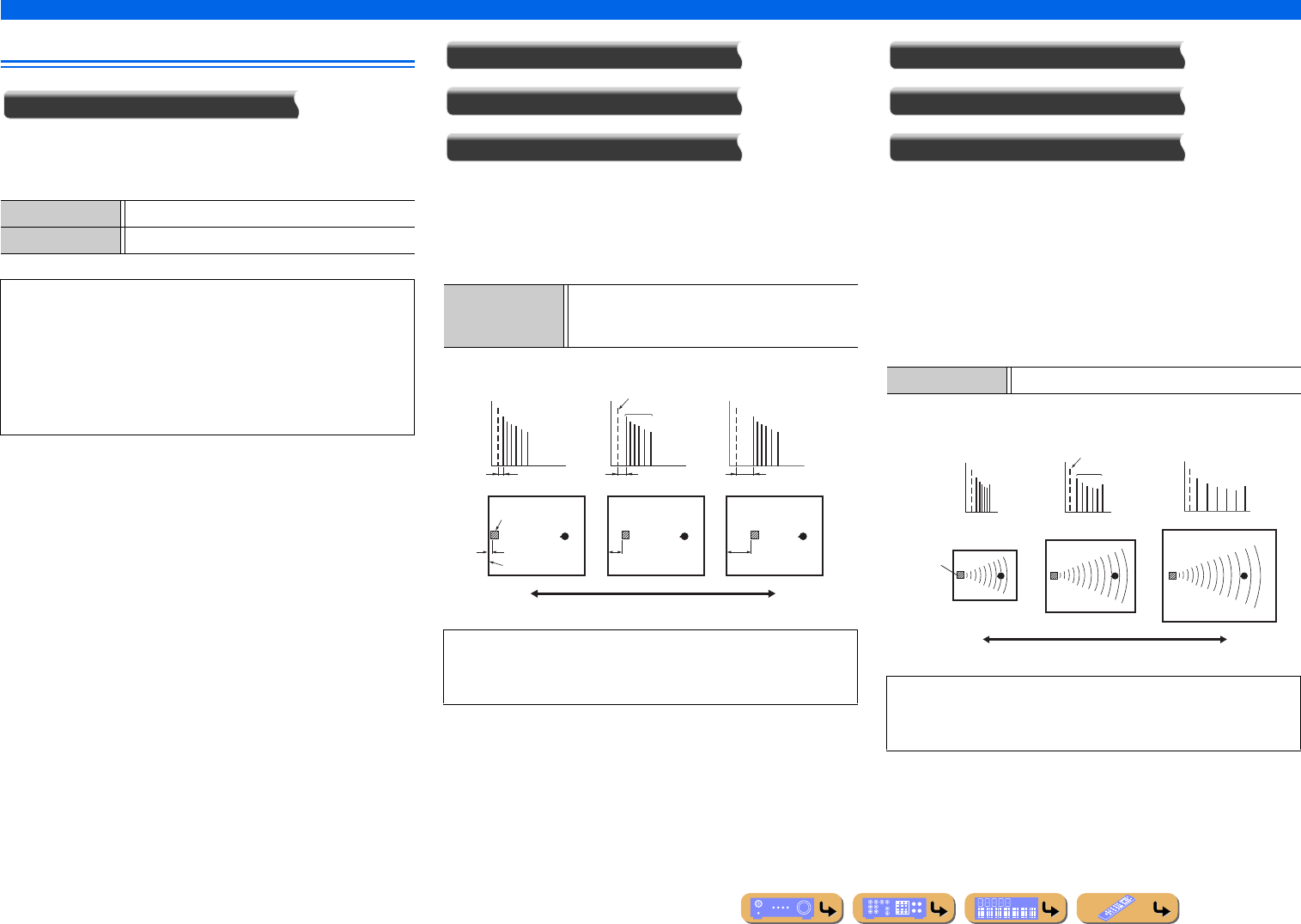
En 94
SETUP
Setting sound program parameters (Sound Program menu)
CINEMA DSP parameters
DSP Level
Change the effect level (level of the sound field effect to be added).
You can adjust the level of the sound field effect while checking the
sound effect.
Initial Delay
Surround Initial Delay
Surround Back Initial Delay
Initial delay. Presence, surround, and surround back sound field
initial delay. Changes the apparent size of the sound field by
adjusting the delay between the direct sound and the first reflection
heard by the listener. The smaller the value, the smaller the sound
field seems to the listener.
Room Size
Surround Room Size
Surround Back Room Size
Room size. Presence, surround, and surround back room size.
Adjusts the apparent size of the sound field. The larger the value,
the larger the surround sound field becomes. As the sound is
repeatedly reflected around a room, the larger the hall is, the longer
the time between the original reflected sound and the subsequent
reflections. By controlling the time between the reflected sounds,
you can change the apparent size of the virtual venue. Changing
this parameter from one to two doubles the apparent length of the
room.
Adjustable range -6 dB to +3 dB
Default setting 0 dB
Adjust “DSP Level” as follows:
•The effect sound is too soft.
•There are no differences between effects of the sound programs.
→ Increase the effect level.
•The sound is dull.
•The sound field effect is added too much.
→ Reduce the effect level.
Adjustable range 1 to 99 ms (Initial Delay)
1 to 49 ms (Surround Initial Delay and Surround Back
Initial Delay)
When you adjust the initial delay parameters, we also
recommend that you adjust the corresponding room size
parameters likewise.
Source sound
Delay
Audio source
Level
Early
reflections
Time
Large value = 99 ms
Reflection face
Time
Delay
Level
Time
Delay
Small value = 1 ms
Level
Adjustable range 0.1 to 2.0
When you adjust the room size parameters, we also recommend
that you adjust the corresponding initial delay parameters
likewise.
Level
Time
Level
Time
Level
Time
A
udio source
Early
reflections
Large value = 2.0Small value = 0.1
Source sound
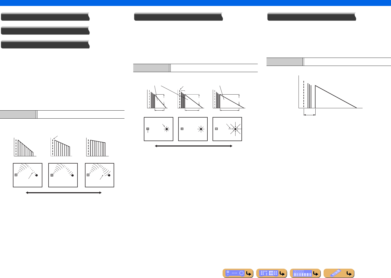
En 95
SETUP
Setting sound program parameters (Sound Program menu)
Liveness
Surround Liveness
Surround Back Liveness
Liveness. Surround and surround back liveness. Adjusts the
reflectivity of the virtual walls in the hall by changing the rate at
which the early reflections decay. The early reflections of an audio
source decay much faster in a room with acoustically absorbent
wall surfaces than in one which has highly reflective surfaces. A
room with acoustically absorbent surfaces is referred to as “dead,”
while a room with highly reflective surfaces is referred to as “live.”
This parameter lets you adjust the early reflection decay rate and
thus the “liveness” of the room.
Reverb Time
Reverberation time. Adjusts the amount of time taken for the
dense, subsequent reverberation sound to decay by 60 dB at 1 kHz.
This changes the apparent size of the acoustic environment over an
extremely wide range. Set a longer reverberation time to get more
sustaining reverberation sound, and set a shorter time to get
articulate sound.
Reverb Delay
Reverberation delay. Adjusts the time difference between the
beginning of the direct sound and the beginning of the
reverberation sound. The larger the value, the later the
reverberation sound begins. A later reverberation sound makes you
feel as if you are in a larger acoustic environment.
Adjustable range 0 to 10
Level
Time
Level
Time
Level
Time
Large value = 10
Small value = 0
Source sound
Small reflected
sound
Large reflected
sound
Dead
Live
Adjustable range 1.0 to 5.0 s
Small value = 1.0 s
Reverberation Reverberation
Source sound
Early reflections
60 dB 60 dB 60 dB
Rev. Time Rev. Time Rev. Time
Audio source
Short
reverberation
Long
reverberation
Large value = 5.0 s
Time Time Time
Adjustable range 0 to 250 ms
Rev. Delay
Source sound
(dB)
Reverberation
Level
Time
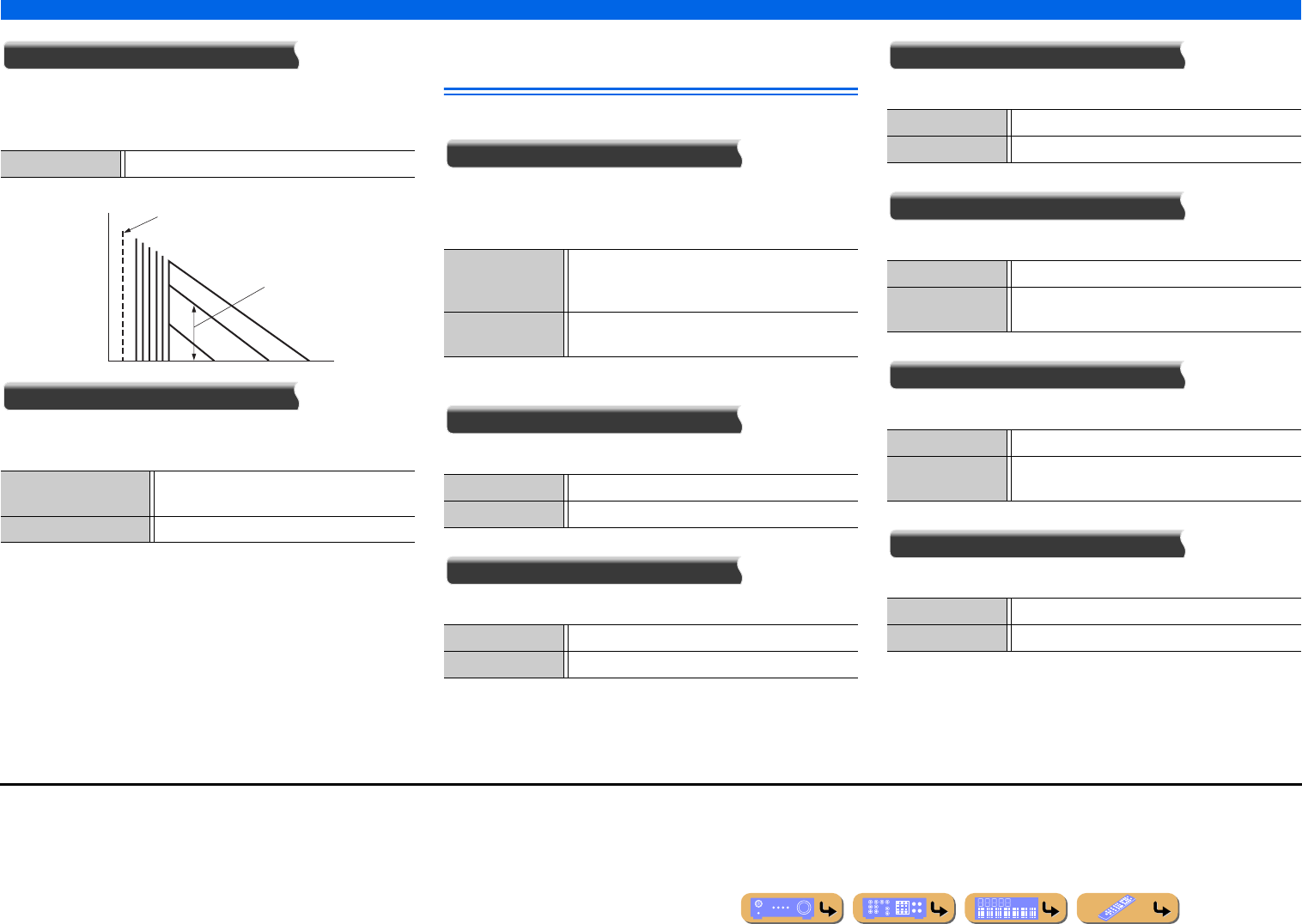
SETUP
Setting sound program parameters (Sound Program menu)
En 96
Reverb Level
Reverberation level. Adjusts the volume of the reverberation
sound. The larger the value, the stronger the reverberation
becomes.
Decode Type
Selects a surround decoder to be used with a sound program in the
MOVIE category. J1
Parameters usable in certain sound
programs
2ch Stereo only
Direct
Automatically bypasses the DSP circuit and tone control circuit
depending on the condition of tone control etc., when an analog
audio source is played back. You can enjoy a higher quality sound.
7ch Stereo only
Center Level
Adjusts the center channel volume. J2
Surround L Level
Adjusts the volume of the surround L channel. J2
Surround R Level
Adjusts the volume of the surround R channel. J2
Surround Back L Level
Adjusts the volume of the surround back L channel. J2
Surround Back R Level
Adjusts the volume of the surround back R channel. J2
Front Presence L Level
Adjusts the volume of the front presence L channel. J2
Adjustable range 0 to 100%
PLIIx Movie
PLII Movie
Selects the Dolby Pro Logic IIx Movie (or
Dolby Pro Logic II Movie) decoder.
Neo:6 Cinema Selects the Neo:6 (Cinema) decoder.
Level
Source sound
Time
Rev. Level
Auto (Default) Outputs sound by bypassing the DSP circuit and tone
control circuit when both tone controls of “Bass” and
“Treble” are set to 0 dB.
Off Does not bypass the DSP circuit and tone control
circuit.
Adjustable range 0 to 100%
Default setting 100%
Adjustable range 0 to 100%
Default setting 100%
Adjustable range 0 to 100%
Default setting 100%
Adjustable range 0 to 100%
Default setting 35% (7.1-channel configuration)
50% (6.1-channel configuration)
Adjustable range 0 to 100%
Default setting 35% (7.1-channel configuration)
50% (6.1-channel configuration)
Adjustable range 0 to 100%
Default setting 33%
J1 : Surround decoders cannot be changed when used with the following MOVIE
sound programs.
•Mono Movie
•Sports
•Action Game
•Roleplaying Game
J2 : Not displayed when speakers are set to be inactive.
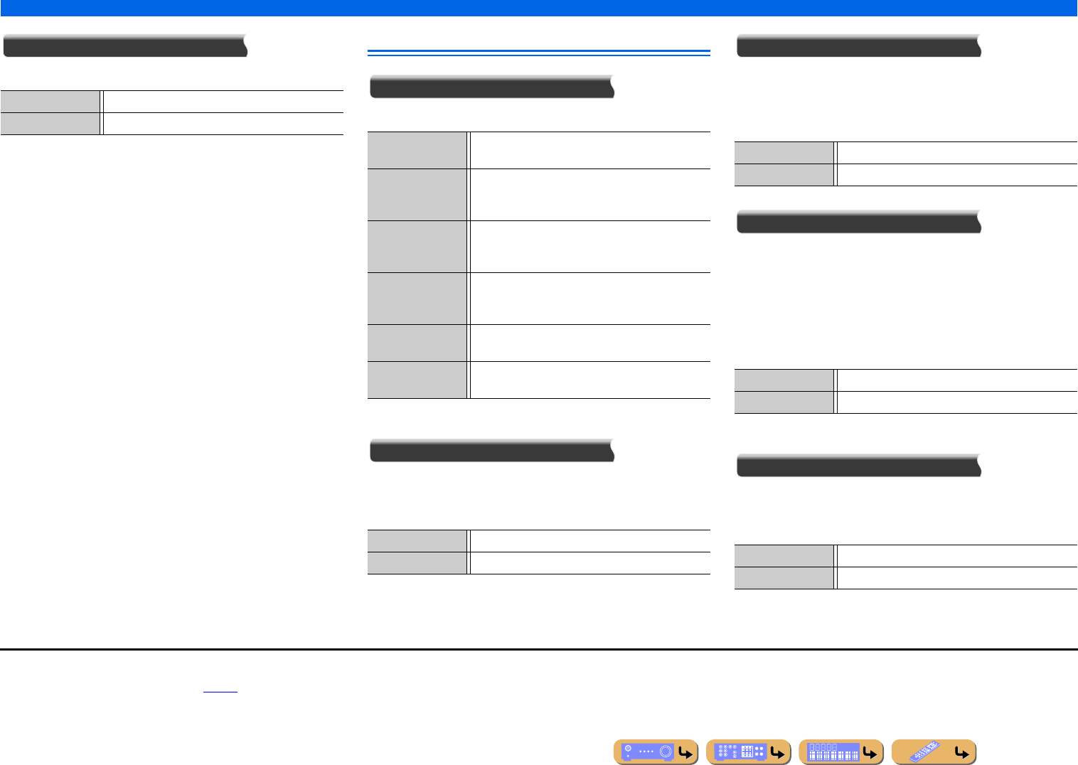
SETUP
Setting sound program parameters (Sound Program menu)
En 97
Front Presence R Level
Adjusts the volume of the front presence R channel. J1
Parameters usable in surround decoder
Decode Type
Selects a surround decoder.
Dolby PLIIx Music and Dolby PLII Music only
Panorama
Adjusts the soundscape of the front sound field. Sends front left/
right channels sounds to the surround speakers as well as the front
speakers for a wraparound effect.
Center Width
Spreads the center channel sound to the front left and right
speakers to suit your needs or preferences. Set this parameter to 0
for outputting the center sound from the center speaker only, or to 7
for outputting it from the front left/right speaker only.
Dimension
Adjusts the difference in level between the front sound field and
the surround sound field. You can adjust the difference in level
created by the software being played back to obtain the preferred
sound balance.
The surround sound gets stronger as you make the value more
negative, and the front sound gets stronger as you make the value
more positive.
When Neo:6 Music is selected
Center Image
Adjusts the front left and right channel output relative to the center
channel to make the center channel more or less dominant as
necessary.
Adjustable range 0 to 100%
Default setting 33%
Pro Logic Reproduces sound using the Dolby Pro Logic
decoder. This is suitable for all kinds of audio sources.
PLIIx Movie /
PLII Movie
Reproduces sound using the Dolby Pro Logic IIx (or
Dolby Pro Logic II) decoder. This is suitable for
movies. J2
PLIIx Music /
PLII Music
Reproduces sound using the Dolby Pro Logic IIx (or
Dolby Pro Logic II) decoder. This is suitable for
music. J2
PLIIx Game /
PLII Game
Reproduces sound using the Dolby Pro Logic IIx (or
Dolby Pro Logic II) decoder. This is suitable for
games. J2
Neo:6 Cinema Reproduces sound using the DTS Neo:6 decoder. This
is suitable for movies.
Neo:6 Music Reproduces sound using the DTS Neo:6 decoder. This
is suitable for music.
Off (Default) Disables the effect.
On Enables the effect.
Adjustable range 0 to 7
Default setting 3
Adjustable range -3 to +3
Default setting 0
Adjustable range 0.0 to 1.0
Default setting 0.3
J1 : Not displayed when speakers are set to be inactive.
J2 : You cannot select the Dolby Pro Logic IIx decoder in the following conditions:
•When “Surround Back” is set to “None” (☞p. 100).
•When headphones are connected.
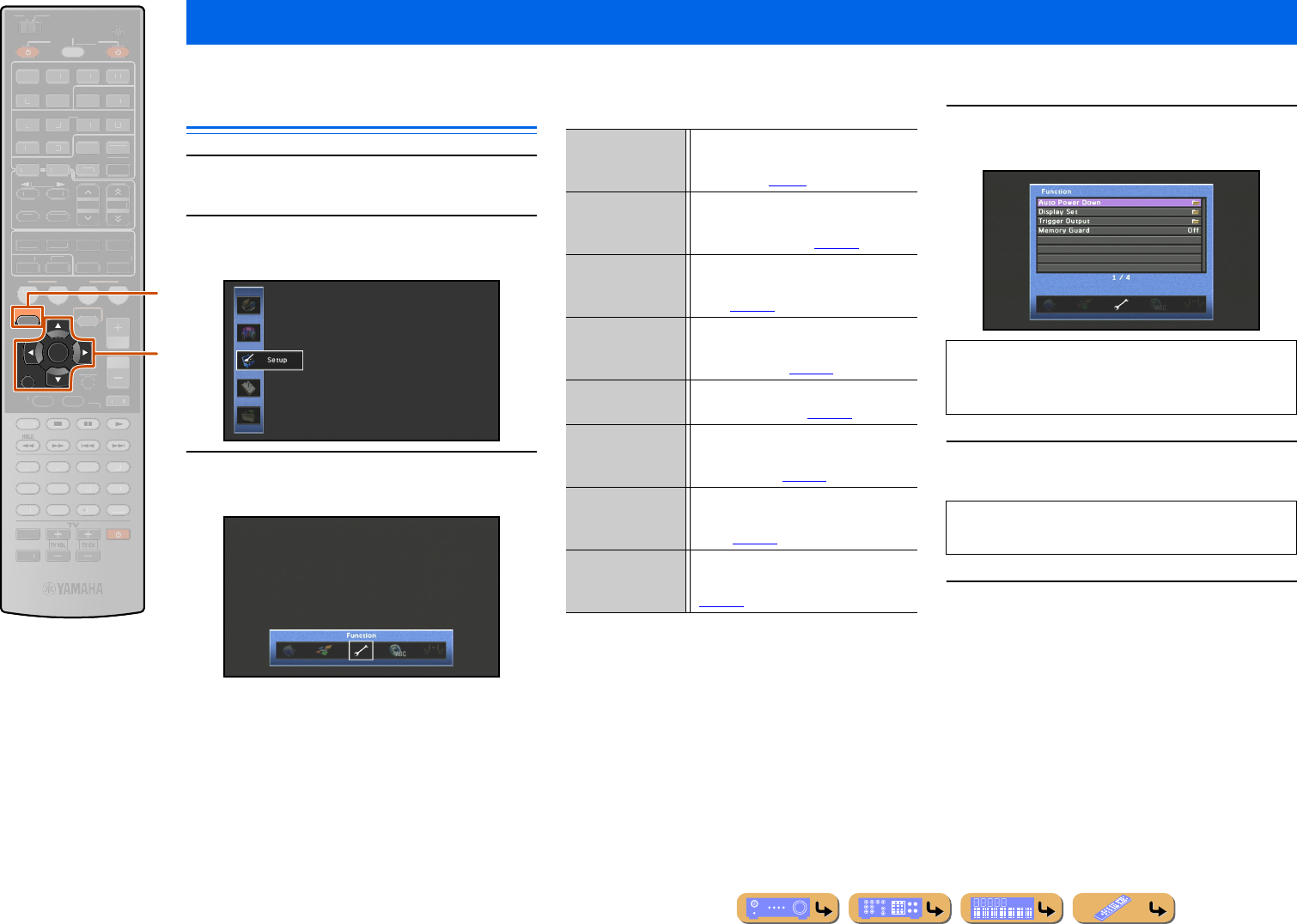
SETUP
En 98
Various settings, such as speaker volume or HDMI functions, can be changed from the Setup menu.
Operating the Setup menu
1Press jON SCREEN.
2Press kCursor B / C repeatedly to select
“Setup” and press kENTER.
3Use kCursor D / E to select a menu and
press kENTER.
Setup menu setting
4Use kCursor B / C to select an item and
press kENTER.
5Use kCursor B / C / D / E to adjust the
setting.
6Press jON SCREEN to close the menu.
Setting various functions (Setup menu)
jON SCREEN
kCursor B / C / D / E
kENTER
kRETURN
RETURN
ENTER
ON SCREEN
SCENE
VO
L
U
ME
ENHANCE
R
S
UR. DE
CO
DE
STRAIGHTSLEEP
P
URE DIRECT
PART Y
M
OVI
E
M
USI
C
BD
DVD
TV
CD
RADI
O
M
U
T
E
7
8
5
6
9
0
10
1
2
3
4
R
EC
ENT
FM
I
NF
O
M
EM
O
RY
AM
P
RESET
H
DMI
AV
A
UDI
O
1
2
3
4
1
2
5
V
-
AUX
TOP
MENU
P
OP-U
P
M
EN
U
DI
S
PLAY
SO
UR
C
E
M
AIN
Z
O
NE 2
RE
C
EIVE
R
CODE SE
T
I
NP
U
T
MUTE
DOCK
H
DMI
O
UT
MULTI
O
PTION
5
1
2
3
4
6
N
ET
S
IRI
US
TU
NER
TUN./C
H
C
ATE
GO
R
Y
k
j
Speaker Adjusts parameters for speakers, such as
speaker status, and volume adjustment for
each speaker (☞p. 99).
Sound Sets functions related to audio output,
such as adjustment of maximum volume
and of dynamic range (☞p. 103).
Video Sets video output functions, such as video
conversion settings (resolution and aspect
ratio) (☞p. 104).
HDMI Sets HDMI functions, such as the HDMI
Control function and output destination
for HDMI sound (☞p. 105).
Network Sets network status, such as IP Address or
MAC Address Filter (☞p. 108).
Multi Zone Sets multi-zone functions, such as
volume adjustment for speakers in the
secondary zone (☞p. 109).
Function Sets functions such as the Auto Power
Down function, that make the unit easier
to use (☞p. 109).
Language Selects the language of the menus and
messages displayed on TV screen
(☞p. 112).
When the selected item contains detailed ones, use
kCursor B / C to select the detailed item and press
kENTER.
Pressing kRETURN displays the previous menu
screen. Repeat steps 4 to 5 to adjust multiple settings.
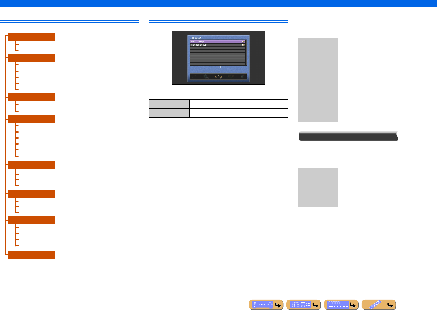
En 99
SETUP
Setting various functions (Setup menu)
Setup menu Manages settings for speakers
Speaker Setup items
■
Automatic speaker setup
Auto Setup
Optimizes the speaker configuration automatically using YPAO
(☞p. 34).
■
Manual speaker setup
Manual Setup
The following parameters can be specified manually.
Power Amp Assign
In addition to the 7.1-channel speaker connection, various speaker
configurations are possible using the presence speakers connection,
bi-amp connection or Zone2 function (☞p. 17, p. 18).
Auto Setup
Manual Setup
Lipsync
Dynamic Range
Max Volume
Initial Volume
Adaptive DSP Level
Analog to Analog Conversion
Processing
Zone2 Set
Party Mode Set
Zone Rename
Auto Power Down
Display Set
Trigger Output
Memory Guard
Speaker
Sound
Video
Multi Zone
Function
Language
HDMI Control
Control Select
ARC (Audio Return Channel)
TV Audio Input
Audio Output
Standby Through
HDMI
IP Address
Network Standby
MAC Address Filter
Network
Auto Setup Optimizes the speaker configuration automatically.
Manual Setup Manually adjusts parameters for speakers.
Power Amp Assign Adds the extra speakers to the 7.1-channel speaker
connection.
Configuration Manually manages speaker configuration, such as
speaker size (sound production capacity), and bass
audio processing.
Distance Manually adjusts the output of each speaker based on
distance to the listening position.
Level Manually adjusts the volume of each speaker.
Parametric EQ Selects an equalizer to adjust speaker output
characteristics.
Test Tone Generates test tones.
7ch Normal Enables the normal 7-channel speakers and front
presence speakers (☞p. 14).
7ch + 1ZONE Enables the normal 7-channel speakers and zone2
speakers (☞p. 16).
5ch BI-AMP Enables the bi-amp connection (☞p. 16).
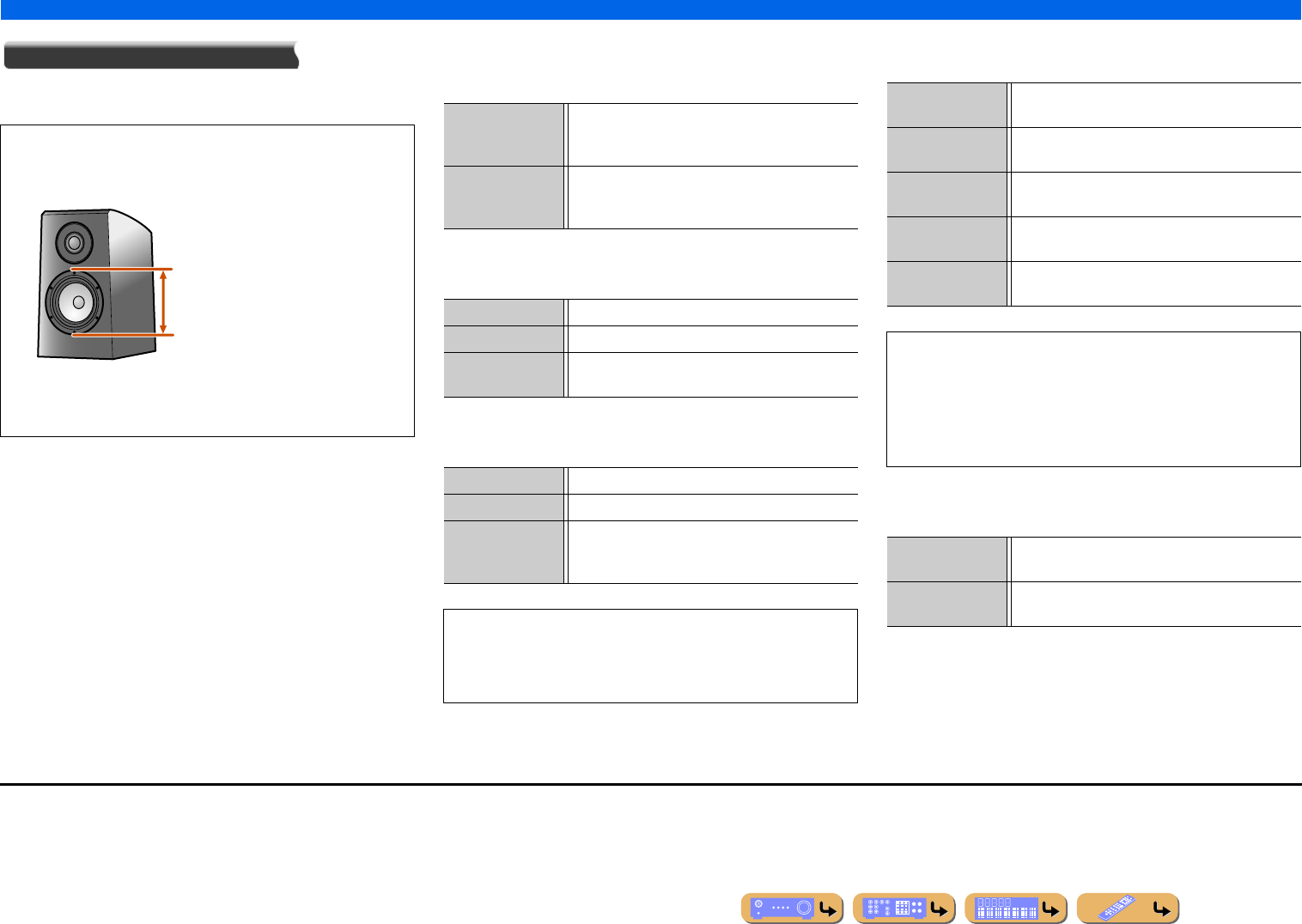
SETUP
Setting various functions (Setup menu)
En 100
Configuration
Adjusts the output characteristics of the speakers based on
manually set parameters.
Front
Selects the size (sound reproduction capacity) of the front
speakers. J1
Center
Selects the size of the center speakers.
Surround
Selects the size of the surround speakers.
Surround Back
Selects the size of the surround back speakers.
Front Presence
Specify connection of front presence speakers.
In the “Configuration,” you can select the speaker size
characteristic (Large or Small). Select the size (sound
reproduction capacity) that matches your speakers.
When speaker size is set to “Small,” low-frequency components
of the speakers that you configured are produced from the
subwoofer (or from the front speakers if there is no subwoofer).
Woofer diameter
• 6-1/4 in (16 cm) or larger → Large
• 6-1/4 in (16 cm) or smaller → Small
Large Select this for large speakers. The front speakers will
produce all of the front channel frequency
components.
Small (Default) Select this for small speakers. The subwoofer will
produce front channel low-frequency
components. J2
Large Select this when a large center speaker is connected.
Small (Default) Select this when a small center speaker is connected.
None Select this when there is no center speaker. The front
speakers will produce center channel audio.
Large Select this when the surround speakers are large.
Small (Default) Select this when the surround speakers are small.
None Select this when no surround speakers are connected.
The front speakers will produce surround channel
audio signals.
•When set to “None,” no sound is produced from the surround
back speaker even if that speaker is connected.
•When set to “None,” the sound programs will change to Virtual
CINEMA DSP mode.
Largex1 Select when one large surround back speaker is
connected.
Largex2 Select when two large surround back speakers are
connected.
Smallx1 Select when one small surround back speaker is
connected.
Smallx2 (Default) Select when two small surround back speakers are
connected.
None Select this when no surround back speakers are
connected.
•When there are no surround speakers are connected, the setting
will automatically change to “None.”
•You can set surround back audio signals, including from the
playback source, to be mixed down and produced from a single
speaker (6.1-channel layout) or produced from left and right
surround speakers (5.1-channel layout).
Use (Default) Select this when front presence speakers are
connected.
None Select this when front presence speakers are not
connected.
J1 : When “Subwoofer” is set to “None,” you can only choose “Large.” If the front
speaker setting is “Small” and you change “Subwoofer” to “None,” it will
automatically change to “Large.”
J2 : You can set the low-frequency components of audio signals transmitted from
the front speakers to the subwoofer by using “Bass Cross Over.”
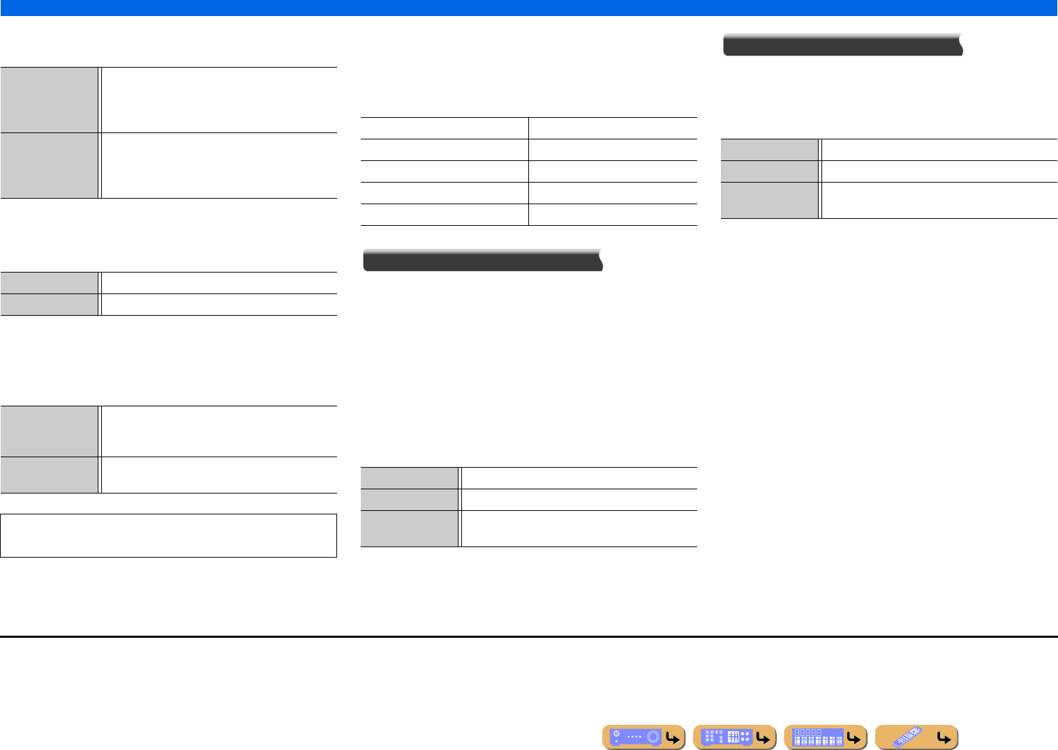
SETUP
Setting various functions (Setup menu)
En 101
Subwoofer
Confirms the subwoofer.
Phase
Sets the phase of the subwoofer if the bass audio is lacking or
unclear.
Extra Bass
Allows the front channel low-frequency components to be
produced exclusively by the subwoofer, or by both the subwoofer
and the front speakers.
Bass Cross Over
Sets the lower limit of low-frequency component which is
produced from speakers of which the size is set to “Small.”
A frequency sound which is lower than the specified frequency will
be produced from the subwoofer or the front speakers. J2
Distance
Adjusts the timing at which the speakers produce audio so that
sounds from the speakers reach the listening position at the same
time.
Selecting adjustment units
Use kCursor B / C to select the unit for distance (meters or
feet), and press kENTER.
Setting distances for each speaker
Use kCursor B / C to select the speaker you want to configure,
and press kENTER. Then use kCursor D / E to set the distance
from the speaker to your listening position.
Level
Separately adjusts the volume of each speaker.
Use kCursor B / C to select the desired speaker, and press
kENTER. Then use kCursor D / E to adjust the volume for the
selected speaker.
Use (Default) Select this when subwoofer is connected. During
playback, the subwoofer will produce audio from the
LFE (low-frequency effect) channel and bass audio
from other channels. J1
None Select this when subwoofer is not connected. The
front speakers will produce audio from the LFE (low-
frequency effect) channel and bass frequency audio
from other channels.
Normal (Default) Does not change the subwoofer phase.
Reverse Reverses the subwoofer phase.
Off (Default) Depending on the size of the front speakers, either the
front speakers or the subwoofer produce the front
channel low-frequency components.
On The subwoofer and the front speakers produce the
front channel low-frequency components.
When “Subwoofer” is set to “None” or “Front” is set to “Small,”
“Extra Bass” is disabled.
40Hz 110Hz
60Hz 120Hz
80Hz (Default) 160Hz
90Hz 200Hz
100Hz
Adjustable range 1.0 ft to 80.0 ft (0.30 m to 24.0 m)
Default setting 10.0 ft (3.00 m)
Adjustment
increments
0.2 ft (0.05 m)
Adjustable range -10.0 dB to +10.0 dB
Default setting 0.0 dB
Adjustment
increments
0.5 dB
J1 : Enabling “Extra Bass” allows both the subwoofer and the front speakers to
produce bass audio.
J2 : If your subwoofer has a volume control or a crossover frequency control, set
the crossover frequency to maximum and the volume to half (or slightly less).
SETUP
Setting various functions (Setup menu)
En 102
Parametric EQ
Adjusts sound quality of tone using a parametric
equalizer.
PEQ Select
Select an equalizer type.
PEQ Data Copy
Select 1 of the 3 parametric equalizer types acquired with
automatic setup and manually copy that information to the
manual adjustments.
Front L / Front R / Center / Surround L / Surround R /
Surround Back L / Surround Back R / Front Presence L /
Front Presence R
The parametric equalizer can be used to manually adjust
sound quality for individual speakers.
Set “PEQ Select” to “Manual” and use “PEQ Data
Copy” to copy information acquired with automatic
setup. This information can be used as a basis for
performing manual adjustments.
1Use kCursor B / C repeatedly to select
“Band / Gain,” “Freq. / Gain,” or “Q / Gain”
and press kENTER.
2Use kCursor D / E repeatedly to adjust the
parameter and use kCursor B / C
repeatedly to adjust the gain.
3Press kENTER to exit the edit window.
4Repeat steps 1 to 3 to configure other
parameters.
5Press jON SCREEN to close the menu.
Test Tone
Turns the test tone generator on or off.
ENTER
ON SCREEN
SCENE
RETURN
VO
L
U
ME
ENHANCE
R
S
UR. DE
CO
DE
STRAIGHTSLEEP
P
URE DIRECT
PART Y
M
OVI
E
M
USI
C
BD
DVD
TV
CD
RADI
O
M
U
T
E
7
8
5
6
9
0
10
1
2
3
4
R
EC
ENT
FM
I
NF
O
M
EM
O
RY
AM
P
RESET
H
DMI
AV
A
UDI
O
1
2
3
4
1
2
5
V
-
AUX
TOP
MENU
P
OP-U
P
M
EN
U
DI
S
PLAY
SO
UR
C
E
M
AIN
Z
O
NE 2
RE
C
EIVE
R
CODE SE
T
I
NP
U
T
MUTE
DOCK
HDMI
O
U
T
MULTI
O
PTION
5
1
2
3
4
6
NET
S
IRI
US
TU
NER
TUN./C
H
C
ATE
GO
R
Y
k
j
jON SCREEN
kCursor B / C / D / E
kENTER
Manual Manually adjust equalizer sound.
Flat Adjust individual speakers to achieve the
same characteristics. Select this option if
speakers offer the same quality.
Front Adjust individual speakers to achieve the
same characteristics as the front left and
right speakers. Select this option if front
left and right speakers offer significantly
greater quality than other speakers.
Natural Adjust all speakers to achieve a natural
sound. Select this if high-frequency
sounds seem too strong when “PEQ
Select” is set to “Flat.”
Through (Default) Disable the equalizer.
Flat > Manual Copy the “Flat” parametric equalizer
information acquired with automatic
setup.
Front > Manual Copy the “Front” parametric equalizer
information acquired with automatic
setup.
Natural > Manual Copy the “Natural” parametric equalizer
information acquired with automatic
setup.
To reset all parameter settings for the selected
speaker, select “Reset to Flat” and press kENTER.
Off (Default) Does not generate test tones.
On Generates test tones. While “On” is
selected, test tones are produced
constantly.
You can use the test tone in a variety of
circumstances. For example, you can adjust the
volume balance settings for each speaker, or whenever
you adjust the settings on the internal parametric
equalizer, you can listen to the actual effect while
operating this unit. Turn the test tone off when you
have finished making adjustments.
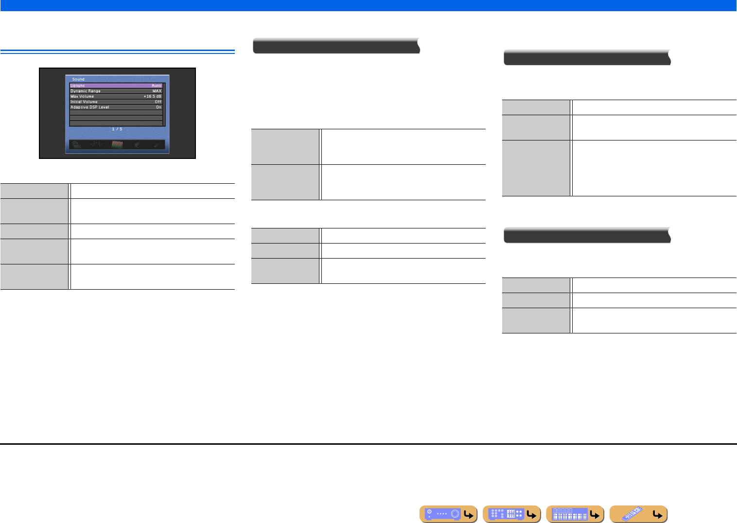
SETUP
Setting various functions (Setup menu)
En 103
Setting the audio output function of this
unit
Sound Setup items
■
Synchronizing audio/video output
Lipsync
Adjusts the delay between audio and video output (Lipsync
function).
Mode
Selects a compensation method for the delay between audio and
video output.
Delay
■
Auto-adjusting Dolby Digital and DTS
dynamic range
Dynamic Range
Selects the dynamic range adjustment method for audio bitstream
(Dolby Digital and DTS) signal playback.
■
Setting the maximum volume
Max Volume
Specify the maximum volume level so that sound is not too loud.
The default setting of +16.5 dB produces the highest volume.
Lipsync Adjusts the delay between video and audio output.
Dynamic Range Selects the dynamic range adjustment method for
Dolby Digital and DTS playback.
Max Volume Sets the maximum volume for this receiver.
Initial Volume Sets the initial volume for when this receiver is turned
on.
Adaptive DSP Level Adjusts the level of DSP effect in conjunction with the
volume level.
Auto (Default) J1When connecting to a TV via HDMI, automatically
adjusts output timing if the TV supports an automatic
lipsync function.
Manual Manually adjusts the correction time. Select this when
the monitor does not support the automatic lipsync
function.
Adjustable range 0 ms to +250 ms
Default setting 0 ms
Adjustment
increments
1 ms
MAX (Default) Produces audio without adjusting the dynamic range.
STD Adjusts the dynamic range for optimum volume for
regular home use.
MIN/AUTO (MIN) Sets the dynamic range suitable for low
volume or a quiet environment, such as at night, for
bitstream signals except for Dolby TrueHD signals.
(AUTO) Adjusts the dynamic range for Dolby
TrueHD signals based on input signal information.
Adjustable range -30.0 dB to +16.5 dB (maximum volume)
Default setting +16.5 dB
Adjustment
increments
5.0 dB
J1 : This setting is effective at the HDMI OUT jack selected by using
rHDMI OUT.
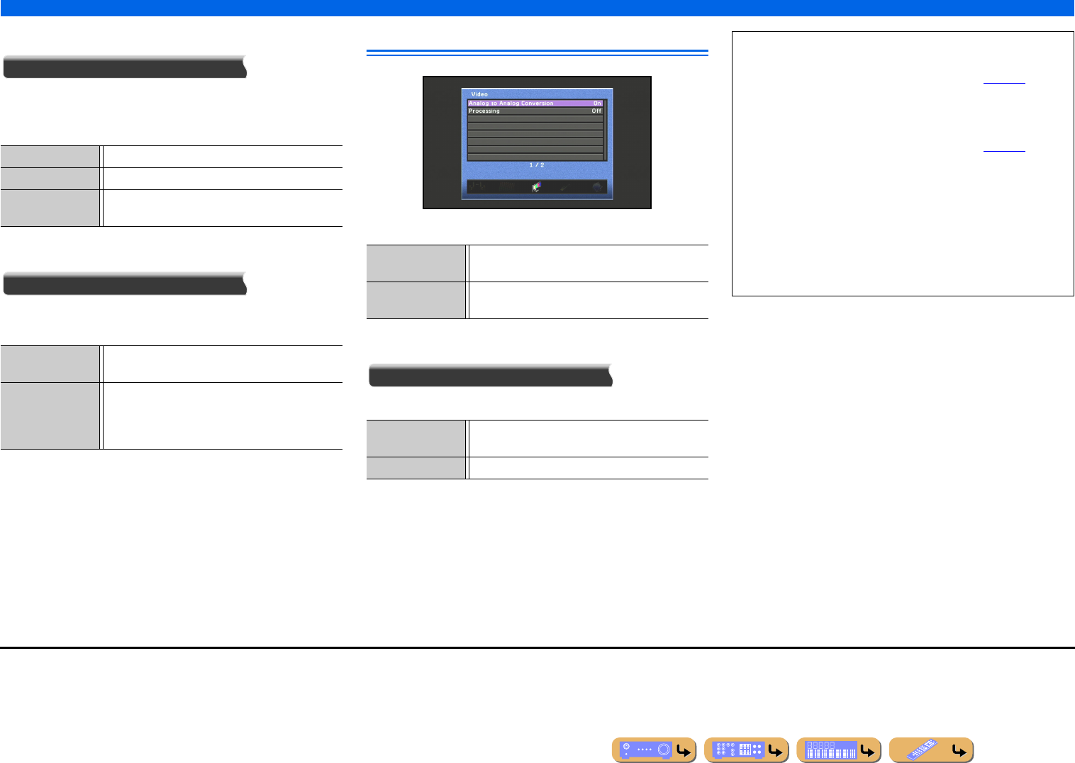
SETUP
Setting various functions (Setup menu)
En 104
■
Setting the startup volume
Initial Volume
Sets the initial volume for when this receiver is turned on. When
this parameter is set to “Off,” the volume is set at the level when the
receiver last entered standby mode. J1
■
Adjusting DSP effect and volume level
Adaptive DSP Level
Automatically adjust the level of DSP effect in conjunction with
the volume level.
Setting this unit’s video output function
Video Setup items
■
Analog-to-analog video conversion
Analog to Analog Conversion
Enables or disables video conversion between analog video jacks.
Adjustable range Off, Mute, -80 dB to +16.5 dB
Default setting Off
Adjustment
increments
0.5 dB
Off Disables automatic adjustment of the level of DSP
effect.
On (Default) Adjusts the degree of DSP effect in conjunction with
volume level. The higher the volume level, the less the
DSP effect applied. The lower the volume level, the
greater the DSP effect applied.
Analog to Analog
Conversion
Enable or disable video conversion between analog
video jacks.
Processing Enable or disable adjustment of resolution and aspect
ratio for video signal converted to HDMI video.
Off Disables video conversion between analog video
jacks.
On (Default) Enables video conversion between analog video jacks.
•Analog-to-HDMI video conversion is always possible unless
video signals are being input at the HDMI input jacks or 1080p-
resolution analog video signals are being input (☞p. 136).
•This unit does not convert 480 line video signals and 576 line
video signals interchangeably.
•480p-, 576p-, 1080i- and 720p-resolution video signals can not
be output at the VIDEO MONITOR OUT jack (☞p. 136).
•The converted video signals are only output at the MONITOR
OUT jacks.
•When composite video signals from a VCR are converted into
component video signals, the picture quality may suffer
depending on your VCR.
•Unconventional signals input at the composite video jacks cannot
be converted or may be output abnormally. In such cases, set
“Analog to Analog Conversion” to “Off.”
J1 : When you set “Max Volume” at a lower level than “Initial Volume,” “Max
Volume” has priority.
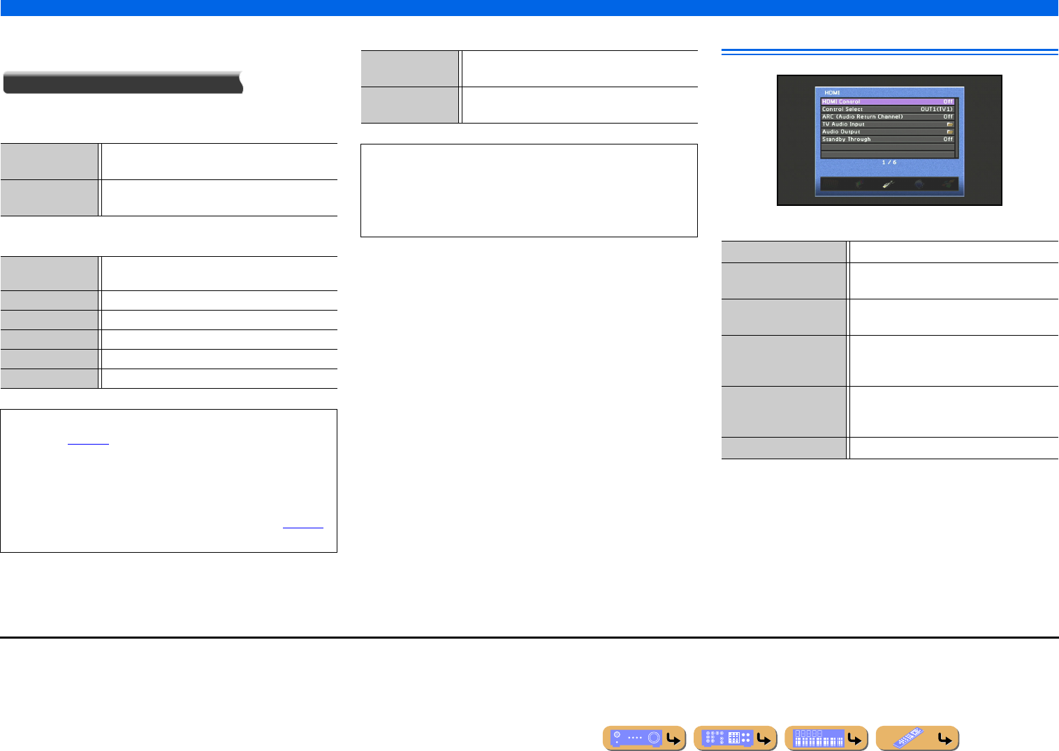
SETUP
Setting various functions (Setup menu)
En 105
■
Adjusting resolution and aspect ratio with
conversion of video signal to HDMI
Processing
Adjust resolution and aspect ratio with conversion of video input to
HDMI video (upscaling).
Resolution
Aspect Setting HDMI functions
HDMI Setup items
Off (Default) Resolution and aspect ratio are not adjusted with
processing.
On Resolution and aspect ratio are adjusted with
processing.
Auto (Default) Automatic upscaling in accordance with TV
resolution.
480p Upscaling to 480p (576p).
720p Upscaling to 720p.
1080i Upscaling to 1080i.
1080p Upscaling to 1080p.
Through No upscaling.
•The 720p-, 1080i- and 1080p-resolution video signals cannot be
upscaled (☞p. 136).
•When a TV is connected to this unit via the HDMI jack, this unit
automatically detects a resolution that the TV supports. Only the
detected resolution can be selected.
•If this unit cannot detect the resolution that the TV supports, set
“MON.CHK” in the Advanced Setup menu to “SKIP” (☞p. 120)
and try again.
Through (Default) The aspect ratio of HDMI video signal sources is not
adjusted.
16:9 Normal Transmits 4:3 aspect ratio video signals to a 16:9 TV
with black bands on either side of the screen.
•The Aspect setting is automatically disabled when “Resolution”
is set to “Through.”
•The Aspect setting is automatically disabled for video input with
aspect ratios other than 4:3.
•Changing the aspect ratio of 720p, 1080i, or 1080p has no effect.
HDMI Control Turns the HDMI Control on or off.
Control Select Choose an HDMI OUT jack on which HDMI
Control function is enabled.
ARC (Audio Return
Channel)
Turns the Audio Return Channel function on or
off.
TV Audio Input Chooses automatically selected audio input in
conjunction with TV operation when the
HDMI Control is turned on.
Audio Output Specifies whether or not audio signal is output
through this unit and a TV connected via the
HDMI OUT 1-2 jacks.
Standby Through J1Turns the Standby Through function on or off.
J1 : This item appears depending on “HDMI Control.”
SETUP
Setting various functions (Setup menu)
En 106
■
Receiver operation via TV (HDMI Control)
HDMI Control
Set the HDMI Control function to “On” to operate devices
connected via HDMI. If the TV or other external components
support HDMI Control (e.g., Panasonic VIERA Link), you can use
the remote controls of those devices to operate some of this unit’s
functions, and to synchronize this unit with the operation of those
devices.
Refer to “Using the HDMI Control function” (☞p. 121) for setting
instructions.
■
Selecting an HDMI OUT jack for the HDMI
Control function
Control Select
Select the HDMI OUT jack that utilizes the HDMI Control
function.
Refer to “Using the HDMI Control function” (☞p. 121) for setting
instructions.
■
Listening to TV audio via single HDMI
cable (Audio Return Channel)
ARC (Audio Return Channel)
You can enable or disable the Audio Return Channel function.
When using a TV that supports Audio Return Channel function and
the function is enabled, the TV’s audio output is transmit to this
unit via an HDMI cable.
The TV audio input to this unit is regarded as the input source
selected in “TV Audio Input.” J2
By means of this function, you do not need to connect the TV’s
audio output (digital audio output or analog audio output) to the
unit.
When the TV audio is input to the unit using Audio Return
Channel, “TV” is displayed on the front panel display.
■
Selecting an input source to assign audio
input for the TV
TV Audio Input
Select the input source that receives audio signals from TV while
the HDMI Control function is on.
When the TV is set to output sounds via this unit, the TV audio
input is automatically selected to the input source assigned
here. J2
TV1
TV2
Off (Default) Sets HDMI Control to “Off.”
On Sets HDMI Control to “On.” J1
If this unit is connected to HDMI devices that do not support the
HDMI Control function, these functions will not operate.
OUT1(TV1) Applies the HDMI Control function for the HDMI
OUT 1 jack.
OUT2(TV2) Applies the HDMI Control function for the HDMI
OUT 2 jack.
Off (Default) Sets the Audio Return Channel to “Off.”
On Sets the Audio Return Channel to “On.”
•“ARC (Audio Return Channel)” is enabled only for the HDMI
OUT 1 or 2 jack selected with “Control Select.”
•Refer to “Single HDMI cable input to TV audio with Audio
Return Channel function” (☞p. 123) for setting instructions.
SW
C
L
SL SR
R
SBL SBR
AV4
TV VOL.
Audio input AV1-6 or AUDIO1-2
Default setting AV 4
Audio input AV1-6 or AUDIO1-2
Default setting AV 1
•“TV Audio Input” is enabled only for the HDMI OUT 1 or 2 jack
selected with “Control Select.”
•Refer to “Switching the input source on this unit automatically
when listening to TV audio” (☞p. 122) for instructions.
J1 : When the HDMI Control is “On,” the Standby Through function is
automatically enabled. When this unit enters standby mode, the audio and
video signals from the last-selected HDMI input source will continue to be
transmitted to the TV. The HDMI input source can only be changed using the
remote control.
J2 : While the Audio Return Channel function is on, the jack selected for the input
source cannot be used.
En 107
SETUP
Setting various functions (Setup menu)
■
Specify whether or not audio signal is
output through this unit and a TV
Audio Output
Choose whether audio is played back through this unit or through a
TV.
Amp
Specify whether or not audio signal is output through this unit.
OUT1
Specify whether or not audio signal is output through a TV
connected via the HDMI OUT 1 jack.
OUT2
Specify whether or not audio signal is output through a TV
connected via the HDMI OUT 2 jack.
■
Transmitting HDMI audio/video to the TV
during standby mode (Standby Through)
Standby Through
This function allows audio/video signals from HDMI inputs to
continue to be transmitted to a TV when this unit is in standby
mode.
When the Standby Through function is “On,” audio/video signals
continue to be output to the TV from the last HDMI input source
before this unit enters standby mode. The HDMI input source can be
selected using dHDMI1-5 or dV-AUX in standby mode.
Off Audio is not output through this unit.
On (Default) Audio is output through this unit. When this setting is
selected, audio from the external component is output
in a format compatible with this unit.
Off (Default) Audio is not output through a TV connected via the
HDMI OUT 1 jack.
On Outputs audio through a TV connected via the HDMI
OUT 1 jack. When this setting is selected, audio from
the external component is output in a format
compatible with the TV.
Off (Default) Audio is not output through a TV connected via the
HDMI OUT 2 jack.
On Outputs audio through a TV connected via the HDMI
OUT 2 jack. When this setting is selected, audio from
the external component is output in a format
compatible with the TV.
When “HDMI Control” is set to “On,” the settings of “Amp”
and the output jack (OUT1 or OUT2) selected with Control
Select are interlocked with HDMI Control.
Off (Default) Sets Standby Through to “Off.”
On Transmits audio/video signals from the selected
HDMI input source to the TV.
•When “HDMI Control” is “On,” Standby Through function is
automatically enabled and “Standby Through” is not displayed.
•When the Standby Through function is on, the HDMI Through/
iPod Charge indicator on the front panel lights during the standby
mode. This unit consumes approximately 3 W of power.
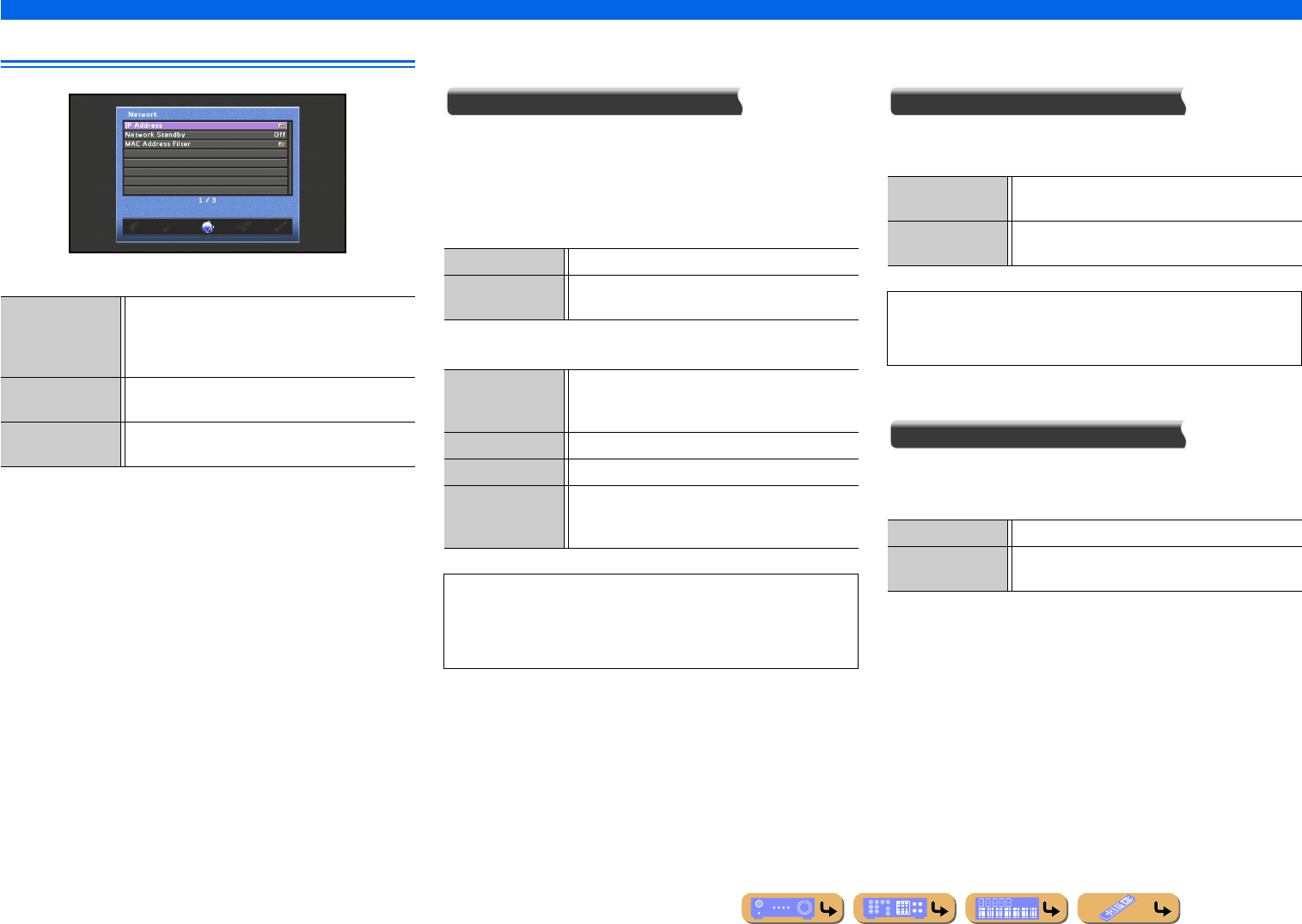
En 108
SETUP
Setting various functions (Setup menu)
Adjusting this unit’s network parameters
Network setup items
■
Setting the network parameters (IP
address, etc.)
IP Address
Selects whether or not this unit automatically acquires network
parameters (IP address, subnet mask, default gateway, primary
DNS server and secondary DNS server) from a network device
such as a router equipped with DHCP function.
DHCP
Manual Setup
■
Turning this unit on by the command over
the network when in the standby mode
Network Standby
Selects whether or not to turn this unit on by the command over the
network when in the standby mode.
■
Setting the MAC Address Filter
MAC Address Filter
Sets MAC address filter to restrict access to this unit via LAN.
Mode
Address Setup
Specifies the MAC addresses of network devices permitted to
access to this unit when “MAC Address Filter” is set to “On.”
IP Address Selects whether this unit acquires the network
parameters (IP address, etc.) from the network’s
DHCP server automatically, or whether these
parameters are specified manually.
Network Standby Selects whether or not commands are accepted over
the network when this unit is in standby mode.
MAC Address Filter Sets the MAC address filter to restrict network access
to this unit.
Off Select this setting to specify IP address manually.
On (Default) Select this setting to acquire IP address from the
network’s DHCP server automatically.
IP Address Specifies the IP address assigned to this unit. An IP
address used by another device on the same network
may not be used.
Subnet Mask Specifies the subnet mask assigned to this unit.
Default Gateway Specifies the IP address of the default gateway.
DNS Server
(Primary)/DNS
Server (Secondary)
Specifies the IP addresses of the primary and
secondary Domain Name System (DNS) servers.
If you have only one DNS address, enter the DNS address in
“DNS Server (Primary).” If the network has two or more DNS
addresses, enter one of the addresses in “DNS Server (Primary)”
and another in “DNS Server (Secondary).”
Off (Default) Disables to turn this unit on by the command over the
network.
On Enables to turn this unit on by the command over the
network.
When “Network Standby” is set to “On,” this unit can be
accessed from PC over a network during the standby mode with
the power consumption of about only 5 W.
Off (Default) Disables the MAC address filter function.
On Permits access to this unit only from network devices
with the specified MAC addresses.
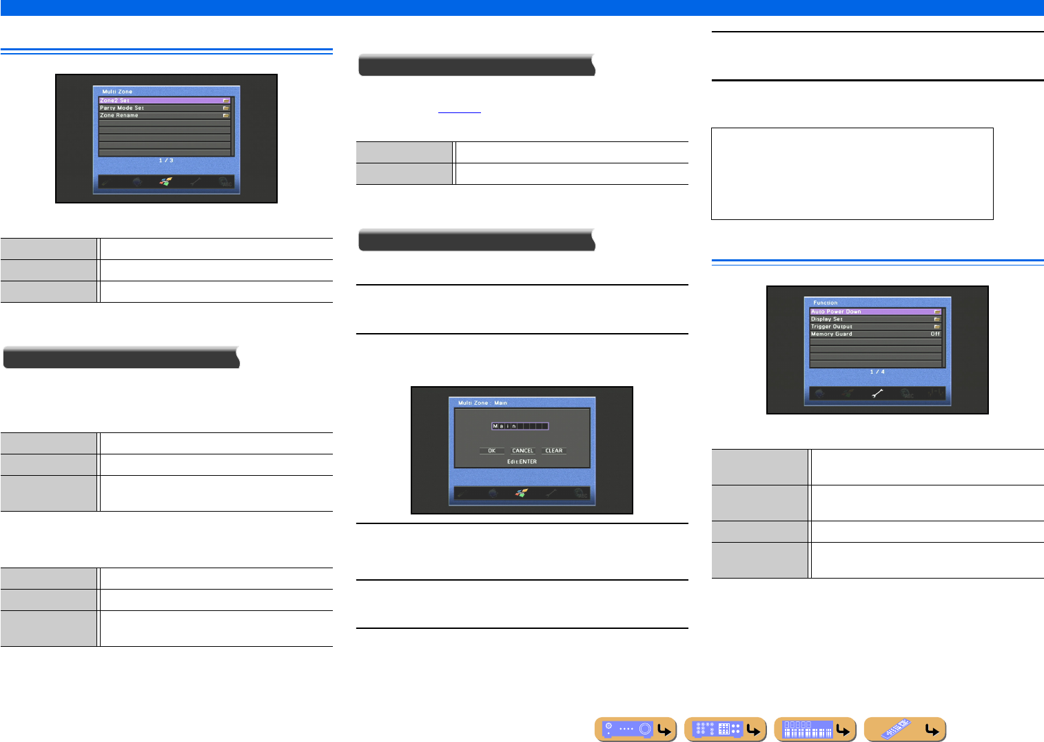
En 109
SETUP
Setting various functions (Setup menu)
Setting this unit’s multi-zone function
Multi Zone Setup items
■
Adjusting Zone2 volume
Zone2 Set
Max Volume
Specify the maximum volume level in Zone2 so that sound is not
too loud.
Initial Volume
Specify the initial volume level in Zone2 when this unit is turned on.
■
Setting the party mode
Party Mode Set
In party mode, the main zone sources can be played in Zone2
simultaneously (☞p. 126). Select “Zone2,” and then select
“Enable” or “Disable.”
■
Changing Zone name
Zone Rename
Editing the name of the selected zone.
1Use kCursor B / C repeatedly to select “Zone
Rename” and press kENTER.
2Press kCursor B / C to select a zone you want to
rename and press kENTER.
3Press kENTER.
Editing the name is available.
4Press kCursor B / C to select a character and press
kCursor D / E to enter the selected character.
5Repeat step 4 to enter the desired zone name.
6Confirm the zone name by pressing
kENTER.
7Press kCursor C to select “OK” and press
kENTER to register the new zone name.
Making the receiver easier to use
Function Setup items
Zone2 Set Adjusts Zone2 volume level.
Party Mode Set Enable or disable the party mode function.
Zone Rename Changes the name of each zone.
Adjustable range -30.0 dB to +16.5 dB (maximum volume)
Default setting +16.5 dB
Adjustment
increments
5.0 dB
Adjustable range Off, Mute, -80 dB to +16.5 dB
Default setting Off
Adjustment
increments
0.5 dB
Enable (Default) Enables the party mode function.
Disable Disables the party mode function.
•To cancel the operation without applying changes,
select “CANCEL” and press kENTER.
•To clear the characters entered in step 4, select
“CLEAR” and press kENTER.
•Zone names may consist of up to 9 characters.
Auto Power Down This unit enters standby mode if no operations are
performed.
Display Set Specifies menu items displayed on TV screen and the
front panel.
Trigger Output Specifies TRIGGER OUT jack function.
Memory Guard Protects some settings against accidental
modification.
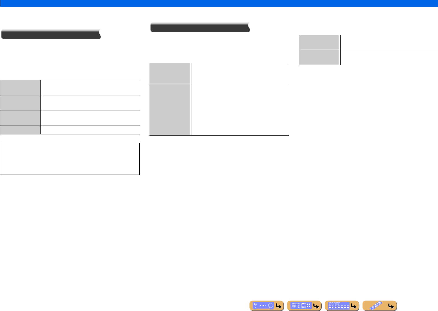
En 110
SETUP
Setting various functions (Setup menu)
■
Goes enter standby mode automatically
when you leave it without operating
Auto Power Down
If you do not operate this unit or use the remote control for an
extended period of time, it will automatically go into standby mode
(Auto Power Down function). This function’s default setting is
“Off.” When you want to enable this function, set the amount of
time to pass before this unit will enter standby.
■
Specifying menu display
Display Set
Specify front panel display brightness and TV screen wall paper.
Front Panel Display
Specify front panel display brightness and message scroll pattern.
Wall Paper
Specify the wall paper displayed on the TV screen when no video
signal is input. Select one that you prefer.
4hours Goes into standby mode, when you have not operated
this unit for four hours.
8hours Goes into standby mode, when you have not operated
this unit for eight hours.
12hours Goes into standby mode, when you have not operated
this unit for twelve hours.
Off (Default) Auto Power Down function is disabled.
This unit starts a countdown of 30 seconds before entering the
standby mode. Pressing any key of the remote control during the
countdown cancels entering the standby mode and reset the
timer.
Dimmer Adjustable range: -4 - 0
Reduce brightness of the front panel display. As the
value is lowered, the panel display darkens.
Scroll Selects the manner in which display scrolls when the
total number of characters exceeds the display area on
the front panel display.
Select “Continue” for continuous scrolling of all
characters.
Select “Once” to scroll through all characters once
and then halt scrolling for display of only the first 14
characters.
Picture 1-3 Displays an image on the TV screen when there is no
video signal.
Gray Displays a gray background on the TV screen when
there is no video signal.
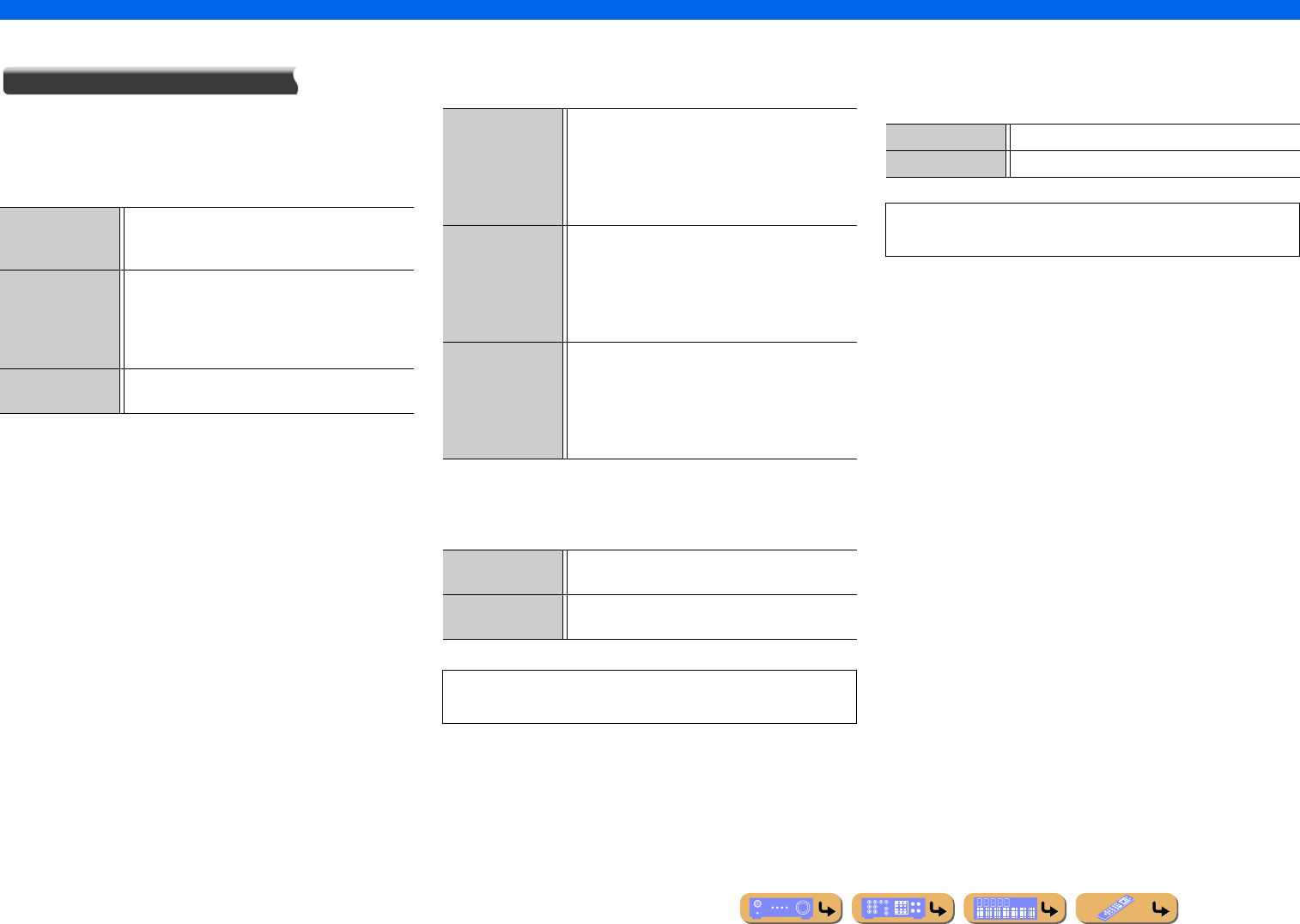
En 111
SETUP
Setting various functions (Setup menu)
■
Setting TRIGGER OUT functions
Trigger Output
Sets the TRIGGER OUT jack to function synchronized with power
status of each zone or input switching.
Trigger Mode
Specify the condition for the TRIGGER OUT jack to function.
Target Zone
Specify the zone with which the TRIGGER OUT jack functions
synchronized.
Target Source
Specify the output level of the electronic signal transmitted with
each input switching.
Manual
Manually switch the output level for electronic signal transmission.
This setting can also be used to confirm proper function of the
external component connected via the TRIGGER OUT jack.
Power (Default) The TRIGGER OUT jack functions synchronized
with the power status of the zone specified with
“Target Zone.”
Source The TRIGGER OUT jack functions synchronized
with the input switching in the zone specified with
“Target Zone.”
Electronic signal is transmitted according to the
setting made in “Target Source.”
Manual Select this to manually switch the output level for
electronic signal transmission with “Manual.”
Main (Default) When “Trigger Mode” is set to “Power,” electronic
signal transmission is synchronized with power status
of the main zone.
When “Trigger Mode” is set to “Source,” electronic
signal transmission is synchronized with input
switching in the main zone.
Zone2 When “Trigger Mode” is set to “Power,” electronic
signal transmission is synchronized with power status
of Zone2.
When “Trigger Mode” is set to “Source,” electronic
signal transmission is synchronized with input
switching in Zone2.
All When “Trigger Mode” is set to “Power,” electronic
signal transmission is synchronized with power status
of the main zone or Zone2.
When “Trigger Mode” is set to “Source,” electronic
signal transmission is synchronized with input
switching in the main zone or Zone2.
Low Stops the electronic signal transmission when you
switch to the input source specified in this option.
High (Default) Transmits the electronic signal when you switch to the
input source specified in this option.
This setting is available only when “Trigger Mode” is set to
“Source.”
Low Stops the electronic signal transmission.
High (Default) Transmits the electronic signal.
This setting is available only when “Trigger Mode” is set to
“Manual.”
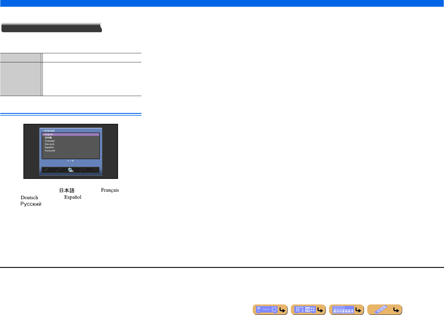
SETUP
Setting various functions (Setup menu)
En 112
■
Prohibiting setting changes
Memory Guard
Prohibits setting changes to prevent careless changes being made
to the settings on Setup menu.
Language
Select the language used for display of menus and messages. J1
Choices: English (English), (Japanese), (French),
(German), (Spanish),
(Russian)
Off (Default) Settings are not protected.
On Prohibits changes to the settings on Setup menu until
it is returned to “Off.”
While set to “On,” the unit displays “Memory
Guard!” when an attempt is made to change the
settings.
J1 : Content window information is displayed in the language in which that
information was released.
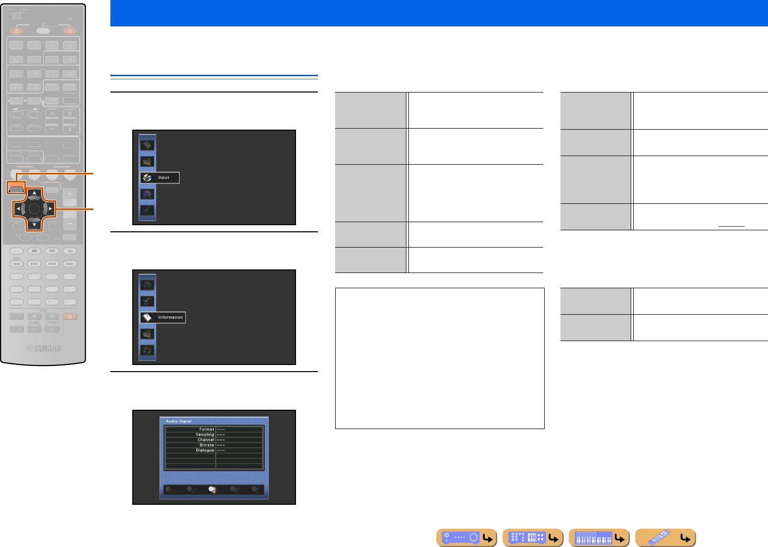
SETUP
En 113
A variety of information for this unit can be displayed.
Selecting information
1Press jON SCREEN.
2Use kCursor B / C to select “Information”
and press kENTER.
3Use kCursor D / E to select an Information
menu and press kENTER.
■
Audio information
Displays information on the current audio signal.
■
Video information
Displays information on the current video signal.
■
HDMI monitor
Displays information on the TV screen connected to this
unit’s HDMI OUT 1-2 jacks.
Confirming information of this unit (Information menu)
jON SCREEN
kCursor B / C / D / E
kENTER
ENTER
ON SCREEN
SCENE
RETURN
VO
L
U
ME
ENHANCE
R
S
UR. DE
CO
DE
STRAIGHTSLEEP
P
URE DIRECT
PART Y
M
OVI
E
M
USI
C
BD
DVD
TV
CD
RADI
O
MU
T
E
7
8
5
6
9
0
10
1
2
3
4
R
EC
ENT
FM
I
NF
O
M
EM
O
RY
AM
P
RESET
H
DMI
AV
A
UDI
O
1
2
3
4
1
2
5
V
-
AUX
TOP
MENU
P
OP-U
P
M
EN
U
DI
S
PLAY
SO
UR
C
E
M
AIN
Z
O
NE 2
RE
C
EIVE
R
CODE SE
T
I
NP
U
T
MUTE
DOC
K
HDMI
O
U
T
MULTI
OPTION
5
1
2
3
4
6
NET
S
IRI
US
TU
NER
TUN./C
H
C
ATE
GO
R
Y
k
j
Format Signal format. When this unit is unable to
detect a digital signal, it automatically
switches to analog input.
Sampling The number of samples taken per second
from a continuous signal to make a
discrete signal.
Channel The number of source channels in the
input signal (front/surround/LFE). For
example, a multi-channel soundtrack with
3 front channels, 2 surround channels and
LFE is displayed as “3/2/0.1”.
Bitrate The number of bits passing a given point
per second.
Dialogue The dialogue normalization level preset
to the current input bitstream signal.
•“---” is displayed when this unit cannot display the
corresponding information.
•Some high-definition audio bitstream contents may not
include the discrete surround back left and right
channel signals, but are encoded at a bitrate of 192
kHz.
•Even when direct bitstream output settings are applied,
some players convert the Dolby TrueHD or Dolby
Digital Plus bitstreams to the Dolby Digital bitstreams,
while converting DTS-HD Master Audio or DTS-HD
High Resolution Audio bitstreams to DTS bitstreams.
HDMI signal Source video signal type and video signal
output to this unit’s HDMI OUT 1-2
jacks.
HDMI Resolution Input signal (analog or HDMI) and output
signal (HDMI) resolution.
Analog Resolution Resolution of the source video signal and
the analog video signal output to this
unit’s COMPONENT MONITOR OUT
jacks.
HDMI Error Error message for HDMI sources or
connected HDMI devices (☞p. 127).
Interface Displays information on the current
connection interface.
Video Resolution Displays the frequency for each video
resolution of the TV currently connected.
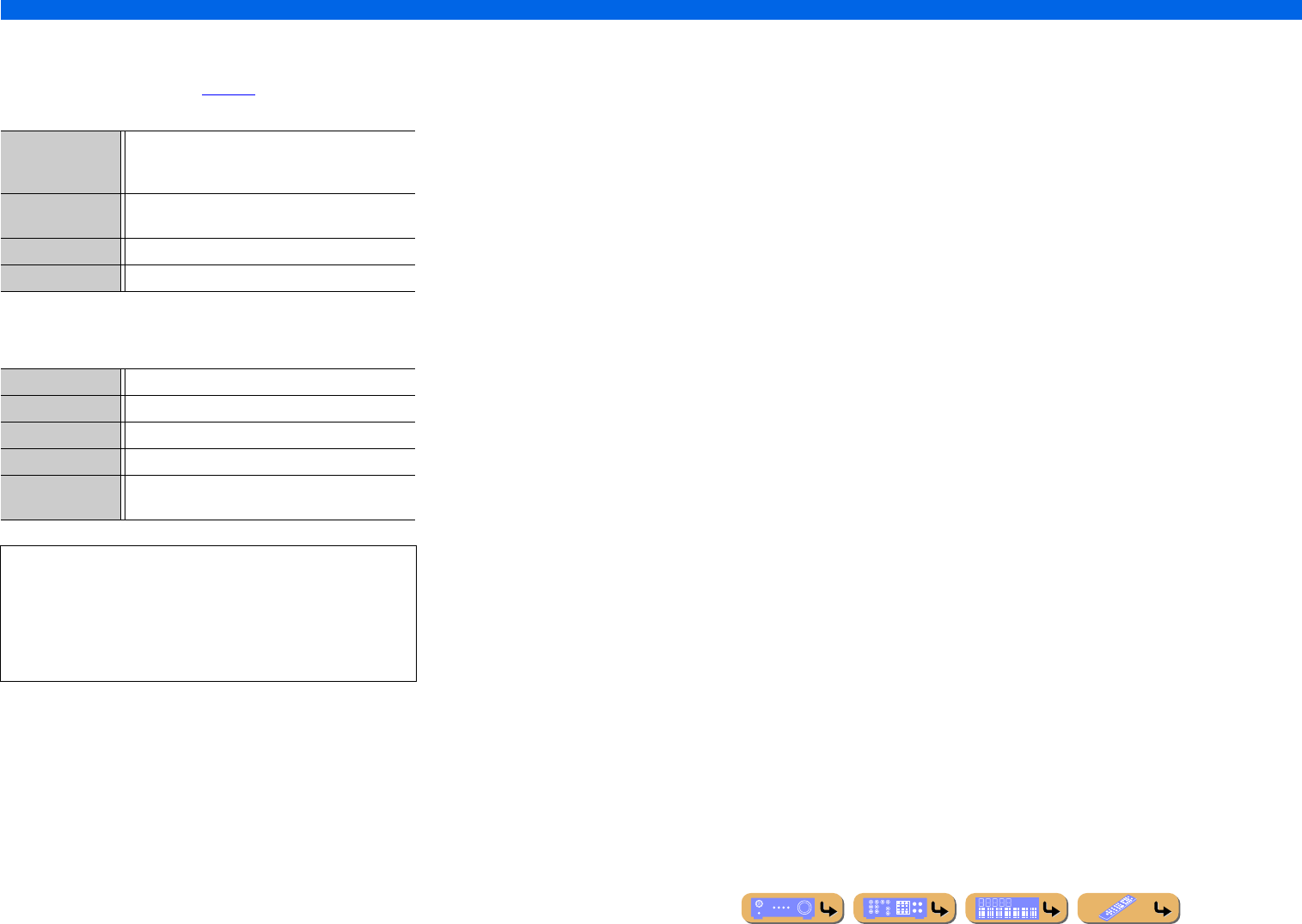
En 114
SETUP
Confirming information of this unit (Information menu)
■
Network information
Displays information on the network status. Refer to “Adjusting
this unit’s network parameters” (☞p. 108) for details on setting the
network status.
■
System information
Displays information on the current settings of the advanced setup.
■
Zone information
Displays information on the currently selected input and the
volume of Zone2.
IP Address /
Subnet Mask /
Default Gateway
Displays the status of the current IP address assigned
to this unit.
DNS Server (P) /
DNS Server (S)
Displays the IP address of the primary and secondary
DNS (Domain Name System) servers.
MAC Address Displays the MAC address filter set to this unit.
Status Displays the network status of this unit.
Remote ID Displays the Remote ID set to this unit.
TV Format Displays the TV format set to this unit.
Speaker Impedance Displays the speaker impedance set to this unit.
System ID Displays the system ID of this unit.
Firmware Version Displays the current version of the firmware installed
to this unit.
When detecting the latest firmware over a network:
–exclamation point appears on the Information menu icon
–message indicating that the latest firmware is released appears
in the System information
In this case, update the latest firmware by using “NETWORK”
of “FIRM UPDATE” in Advanced Setup menu.
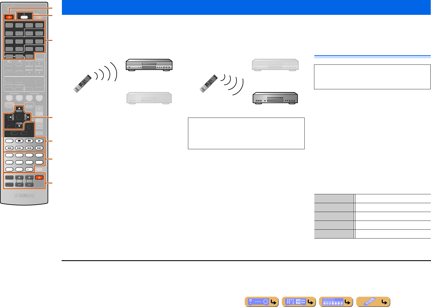
SETUP
En 115
You can operate an external component such as TV and DVD player with the remote control of this unit by setting the code for external component (remote control code).
The remote control code can be set for each input source. Individual setting allows you to switch external components seamlessly depending on the selected input source.
Selecting input source connected to DVD
player
Selecting input source connected to CD
player Keys connecting external
components
cSOURCE A
Switches an external component on and off.
kCursor, kENTER, kRETURN
Operates the menus of external components.
lDISPLAY
Switches an external component display.
lExternal component operation keys
Functions as a recording or playback key of an external
component, or a menu display key.
mNumeric keys
Functions as numeric keys of an external component.
nTV control keys J1
Controlling other components with the remote control
cSOURCE A
dInput selector
kCursor B / C / D / E
kENTER
kRETURN
lExternal component
operation keys
lDISPLAY
mNumeric keys
nTV control keys
nINPUT
nMUTE
nTV VOL +/-
nTV CH +/-
nA
pSOURCE/RECEIVER
RETURN
HDMI
AV
AUDIO
1234
125
V-AUX
ENTER
7856
90
10
1234
REC
TV
TV VOL TV CH
TOP
MENU
POP-UP
MENU
DISPLAY
SOURCE
RECEIVER
INPUT
MUTE
DOCK
MULTI
5
1234
6
NET
SIRIUSTUNER
HOLD
SCENE
VO
L
U
ME
ENHANCE
R
S
UR. DE
CO
DE
STRAIGHTSLEEP
P
URE DIRECT
PART Y
M
OVI
E
M
USI
C
BD
DVD
TV
CD
RADI
O
M
U
T
E
ENT
M
AIN
Z
O
NE 2
CODE SE
T
HDMI
OUT
O
PTION
O
N
SC
REE
N
FM
I
NF
O
M
EM
O
RY
AM
P
RESET
TUN./C
H
C
ATE
GO
R
Y
m
l
d
p
c
k
n
Playback/Stop
DVD player
CD player
If you are unable to operate this unit after operating
an external component, light up
pSOURCE/RECEIVER in orange by pressing it,
and then try operating the remote control again.
Playback/Stop
DVD player
CD player
The remote control keys for controlling external
components are available only when the external
components have corresponding control keys.
nINPUT Switches video inputs of TV.
nMUTE Mutes TV volume temporarily.
nTV VOL +/- Controls the volume of TV.
nTV CH +/- Switches TV channels.
nATurns on and off TV.
J1 : When remote control codes for external components are
registered with dInput selector or nA (nTV control
keys), the following operations are possible.
•When a TV remote control code is registered with dInput
selector, the kCursor, mNumeric keys and nTV
control keys can be used to control the TV selected with
dInput selector.
•When a remote control code for a device other than a TV is
registered with dInput selector, keys including the
kCursor and mNumeric keys can be used to control
external components, and the nTV control keys can be used
to control the TV registered with nA.
•When a TV remote control code is registered with nA, only
nTV control keys can be used to control the TV.
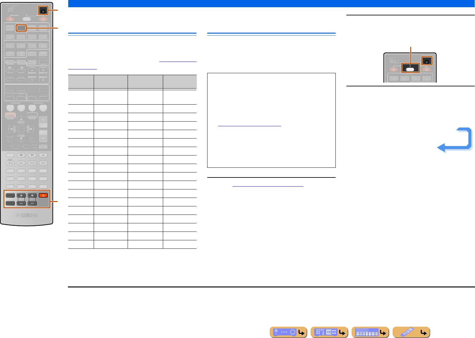
SETUP
Controlling other components with the remote control
En 116
Default remote control code
settings
The following remote control codes are assigned to input
sources as factory default settings. For a complete list of
available remote control codes, refer to “Remote Control
Code Search” in the CD-ROM.
Registering remote control codes
for external component operations
The following section describes how to register remote
control code using an example of the registration of the
remote control codes of a Yamaha BD player connected
to HDMI2 jack.
1Use “Remote Control Code Search” in the CD-
ROM to search the available remote control
codes from the category or manufacturer of
external components.
“2064” can be used for a Yamaha BD player.
2Press oCODE SET using a pointed object
such as the tip of a ballpoint pen.
3Press dHDMI2 to switch the input source to
HDMI2. J1
Perform the following steps to register the selected
input source here to the remote control code.
dHDMI2
nTV control keys
nA
oCODE SET
2
TV
TV VOL TV CH
CODE SET
INPUT
MUTE
SC
ENE
RET
U
R
N
V
OLUME
ENHAN
C
E
R
SU
R. DE
CO
DE
S
TRAI
G
HT
S
LEEP
PU
RE DIRE
C
T
P
ART
Y
MO
VI
E
MUS
I
C
BD
D
V
D
TV
CD
RADI
O
MUTE
ENTER
7
8
5
6
9
0
1
0
1
2
3
4
R
E
C
EN
T
TOP
MEN
U
PO
P-
UP
MENU
DI
S
PLAY
SOU
R
C
E
MAIN
ZONE 2
RECEIVE
R
O
PTI
O
N
ON SCREE
N
FM
I
NF
O
M
EMORY
AM
P
RE
S
ET
HDMI
AV
AU
DI
O
1
3
4
1
2
5
V
-A
UX
D
OC
K
H
DMI OUT
MU
LT
I
5
1
2
3
4
6
NET
SIRIU
S
TUNER
TUN.
/CH
C
ATE
GO
R
Y
o
n
d
Input Category Manufacturer Remote
control code
HDMI1 Blu-ray player/
recorder
Yamaha 2064
HDMI2 —— —
HDMI3 —— —
HDMI4 —— —
HDMI5 —— —
AV1 —— —
AV2 —— —
AV3 CD player Yamaha 5095
AV4 —— —
AV5 —— —
AV6 —— —
AUDIO1 —— —
AUDIO2 —— —
NET —— —
V-AUX —— —
DOCK —— —
TUNER —— —
SIRIUS —— —
•Perform each of the following steps within 1 minute.
Settings will be automatically stopped if more than 1
minute passes since the last operation. To reset, repeat
from step 2.
•Remote control code of an external component cannot
be set from the name or model number of a unit. Use
“Remote Control Code Search” in the CD-ROM to
search the available remote control codes from the
category or manufacturer of external components.
•If multiple remote control codes exist, first set the first
code in the list, if it does not work then try the other
codes.
SOURCE
RECEIVER
CODE SET
MAI
N
ZO
NE
2
HDM
I
1
2
3
4
blinks twice
Continues to the
next page
J1 : When you want to register a remote control code to the
nTV control keys, press nA (nTV control keys) in step
3.
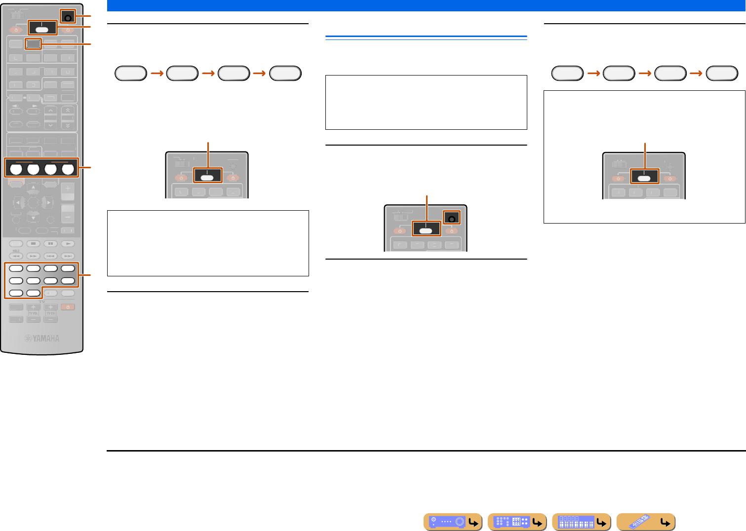
SETUP
Controlling other components with the remote control
En 117
4Enter a remote control code “2064” using
mNumeric keys.J1
Once the remote control code is registered successfully
pSOURCE/RECEIVER will blink twice.
5To switch between BD player linked to
scene selections, press iSCENE and at the
same time press dHDMI2 and hold it for
approximately 3 seconds.
Then you can operate the external components by
switching the input source to HDMI2, or selecting
HDMI2 in the registered scene.
Same steps for operating other external components,
press iSCENE and at the same time press the input
source key selected in step 3 and hold it for
approximately 3 seconds.
Resetting all remote control codes
Resetting all remote control codes for external
components to the initial factory settings.
1Press oCODE SET using a pointed object
such as the tip of a ballpoint pen.
2Press pSOURCE/RECEIVER on the remote
control.
3Enter “9981” using mNumeric keys.
dHDMI2
iSCENE
mNumeric keys
oCODE SET
pSOURCE/RECEIVER
SCENE
2
BD
DVD TV
CD
RADIO
7856
90
1234
SOURCE
RECEIVER
CODE SET
RETURN
V
OLUME
ENHAN
C
E
R
SU
R. DE
CO
DE
S
TRAI
G
HT
S
LEEP
PU
RE DIRE
C
T
P
ART
Y
MO
VI
E
MUS
I
C
MUTE
ENTER
1
0
R
EC
EN
T
TOP
MEN
U
PO
P-
UP
MENU
DI
S
PLAY
MAIN
ZONE 2
INPUT
MUTE
HDMI
AV
AU
DI
O
1
3
4
1
2
5
V
-A
UX
D
OC
K
H
DMI OUT
MU
LT
I
O
PTI
O
N
ON SCREE
N
5
1
2
3
4
6
FM
I
NF
O
M
EMORY
AM
P
RE
S
ET
NET
SIRIU
S
TUNER
TUN.
/CH
C
ATE
GO
R
Y
m
o
p
i
d
•If the registration fails, repeat from step 2.
•In case of an external component with multiple remote
control codes, the other remote control codes may be
supported. Repeat from step 2 with the other remote
control codes.
2 0 64
SOURCE
RECEIVER
MAI
N
ZO
NE
2
C
ODE SE
T
HDM
I
1
2
3
4
Registration successful: blinks twice
Registration failed: blinks 6 times
Perform each of the following steps within 1 minute.
Settings will be automatically stopped if more than 1
minute passes since the last operation. To reset, repeat
from step 1.
SOURCE
RECEIVER
CODE SET
MAI
N
ZO
NE
2
HDM
I
1
2
3
4
blinks twice
Once the remote control code is reset successfully
pSOURCE/RECEIVER will blink twice.
If setup fails, repeat from step 1.
9 9 81
SOURCE
RECEIVER
MAI
N
ZO
NE
2
C
ODE SE
T
HDM
I
1
2
3
4
Reset successful: blinks twice
Reset failed: blinks 6 times
J1 : When you want to register a remote control code to the
nTV control keys, enter the TV remote control code in step 4.
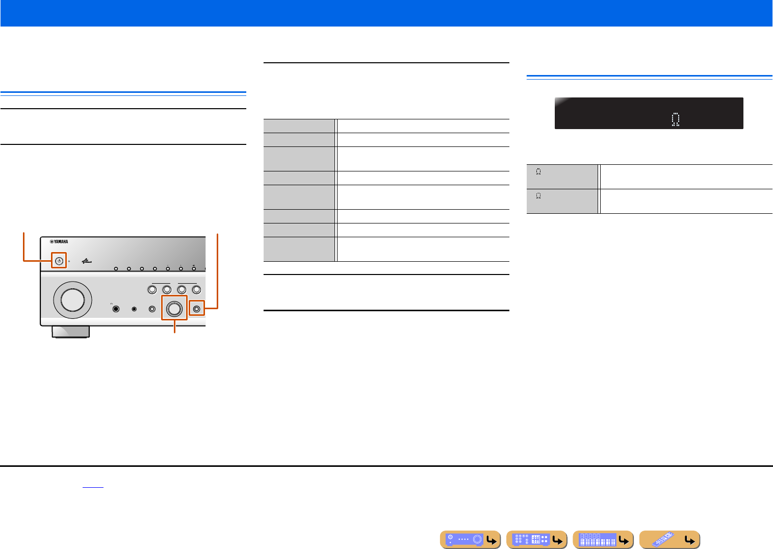
SETUP
En 118
The Advanced Setup menu can be used for unit initialization and other useful extended functions. The Advanced Setup menu can be operated as follows.
Displaying/Setting the Advanced Setup
menu
1Switch this unit to the standby mode.
2Press MAIN ZONE A while pressing and holding
STRAIGHT on the front panel.
Release STRAIGHT when “ADVANCED SETUP” is displayed
on the front panel display.
After a few seconds, the top menu items are displayed.
3Rotate PROGRAM selector to select the item to be
set from the following items.
In the Advanced Setup menu, you can set the following settings.
4Press STRAIGHT repeatedly to select the value you
want to change.
5Switch this unit to the standby mode, and then
switch it on again.
The settings become effective and the unit is powered on.
Setting the impedance of speakers
Changes the unit settings depending on the impedance of the
speakers connected. J1
Extended functionality that can be configured as needed (Advanced Setup menu)
PHONES
YPAO MIC
SILENT
CINEMA
TONE
CONTROL
STRAIGHT
TV
BD
DVD
CD
RADIO
INPUT
PROGRAM
SCENE
INFOZONE
CONTROL
ZONE2
MAIN ZONE
MEMORY
PRESET
FM AM
CATEGORY
STRAIGHT
PROGRAM selector
MAIN ZONE A
SP IMP. Sets the impedance of speakers.
REMOTE ID Changes the remote control ID of a receiver.
SR PIN Resets the parental lock code for the SIRIUS Satellite
Radio tuner.
TV FORMAT Specifies the TV’s color encoding format.
MON.CHK Removes the up-scaling limitation on HDMI video
output.
INIT Initializes various settings for this unit.
FIRM UPDATE Update the firmware of this unit.
VERSION Check the version of firmware currently installed on
this unit.
Select the impedance when 6 Ω speakers are
connected.
(Default) Select the impedance when speakers above 8 Ω are
connected.
SPIMP.-8MIN
6MIN
8MIN
J1 : For detailed procedures of speaker impedance settings, refer to “Changing
speaker impedance” (☞p. 18).
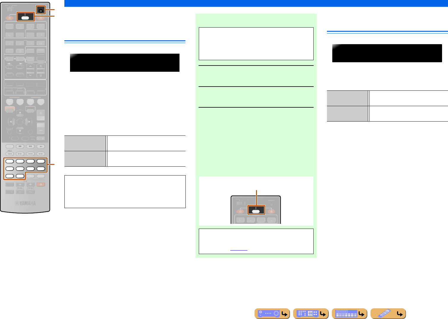
SETUP
Extended functionality that can be configured as needed (Advanced Setup menu)
En 119
Avoiding crossing remote control
signals when using multiple
Yamaha receivers
The remote control of the unit can only receive signals
from a receiver which has an identical ID (remote
control ID). When using multiple Yamaha AV receivers,
you can set each remote control with a unique remote
control ID for its corresponding receiver.
On the contrary, if you are setting the same remote
control ID for all receivers, you can use one remote
control to operate 2 receivers.
Resetting the SIRIUS Satellite
Radio™ parental lock code
Reset the SIRIUS Satellite Radio parental lock code to
the factory default setting. If you forget the code, it can
be reset.
mNumeric keys
oCODE SET
pSOURCE/RECEIVER
7856
90
1234
SOURCE
RECEIVER
CODE SET
SC
ENE
RETURN
V
OLUME
ENHAN
C
E
R
SU
R. DE
CO
DE
S
TRAI
G
HT
S
LEEP
PU
RE DIRE
C
T
P
ART
Y
MO
VI
E
MUS
I
C
BD
D
V
D
TV
CD
RADI
O
MUTE
ENTER
10
R
EC
EN
T
TOP
MEN
U
PO
P-
UP
MENU
FM
I
NF
O
M
EMORY
AM
P
RE
S
ET
HDMI
AV
AU
DI
O
1
2
3
4
1
2
5
V
-A
UX
DI
S
PLAY
MAIN
ZONE 2
INPUT
MUTE
D
OCK
HDMI OU
T
MU
LT
I
O
PTI
O
N
ON SCREE
N
5
1
2
3
4
6
NET
SIRIU
S
TUNER
TUN.
/CH
C
ATE
GO
R
Y
o
p
m
ID1 (Default) Receives the remote control signals set in
ID1.
ID2 Receives the remote control signals set in
ID2.
ID1 is set for both remote control and receiver by
default. To avoid crossing remote control, change the
remote control ID for both remote control and
receiver.
REMOTEID-ID1
■To change the remote control ID
1Press oCODE SET using a pointed
object such as the tip of a ballpoint pen.
2Press pSOURCE/RECEIVER.
3Enter the desired remote control ID code.
To switch to ID1:
Enter “5019” using mNumeric keys.
To switch to ID2:
Enter “5020” using mNumeric keys.
Once the remote control code is registered successfully
pSOURCE/RECEIVER will blink twice.
Perform each of the following steps within
1 minute. Settings will be automatically stopped if
more than 1 minute passes since the last operation.
To reset, repeat from step 1.
SOURCE
RECEIVER
MAI
N
ZO
NE
2
C
ODE SE
T
HDM
I
1
2
3
4
Registration successful: blinks twice
Registration failed: blinks 6 times
•If setup fails, repeat from step 1.
•Returns to ID1 after the remote control code is
initialized (☞p. 117).
RESET Resets the code to the factory default
setting.
CANCEL (Default) Cancels resetting of the parental lock
code.
SRPIN-CANCEL
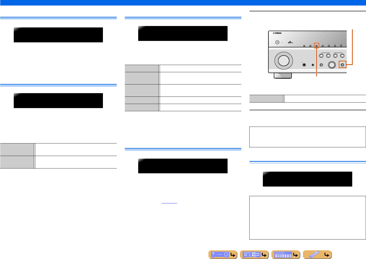
En 120
SETUP
Extended functionality that can be configured as needed (Advanced Setup menu)
Changing TV format
Change the color encoding format of OSD to PAL or NTSC
(default), to match the format used by the TV connected via the
HDMI OUT 1-2 or VIDEO (MONITOR OUT) jack.
Removing HDMI video output up-scaling
limits
Removes the up-scaling limitation on video resolution when this
unit and a TV are connected via HDMI jacks.
If a resolution supported by the monitor cannot be detected when
configuring the up-scaling settings, this setting will remove the
output limitation.
Initializing various settings for this unit
Initializes various settings stored in this unit and sets it back to
default.
Select the items to be initialized from the following.
When an option other than CANCEL is selected, the applicable
default settings will be restored when the unit switches to standby
mode.
Firmware update
Update the firmware of this unit. For details on updating the
firmware, refer to information supplied with updates.
When this unit detects the latest firmware over a network, the
message indicating that the firmware is released is displayed in the
System information (☞p. 114).
1Press STRAIGHT repeatedly to select “NETWORK.”
2Press INFO to start update with the selected option.
Firmware version
Check the version of firmware currently installed on this unit.
YES (Default) Video output signals of a resolution not supported by
the TV will not be transmitted.
SKIP This unit ignores the TV’s support capability and
transmits input video signals to the TV.
TVFORMAT-NTSC
MON.CHK-YES
DSP PARAM Initializes all parameters for the sound programs.
VIDEO Resets video conversion settings (resolution/aspect
ratio) in the Setup menu.
NETWORK Resets the settings of network such as IP address or
the account of vTuner.
ALL Resets this unit to default factory settings.
CANCEL (Default) Does not initialize.
INIT- CANCEL
FIRMUPDATE
NETWORK Updates the firmware of this unit via network.
•Do not use this feature unless the firmware must be updated.
•Be sure to read the information supplied with updates before
updating firmware.
About the latest firmware
When installing the latest firmware, the new functions or fix of
failure may be served.
•The latest firmware can be downloaded from our website.
•While displaying the ON SCREEN menu or “System” from
Information menu, the information on the latest firmware is
displayed via a network.
PHONES
YPAO MIC
SILENT
CINEMA
TONE
CONTROL
STRAIGHT
TV
BD
DVD
CD
RADIO
INPUT
PROGRAM
SCENE
INFOZONE
CONTROL
ZONE2
MAIN ZONE
MEMORY
PRESET
FM AM
CATEGORY
STRAIGHT
INFO
VERSIONX.XX
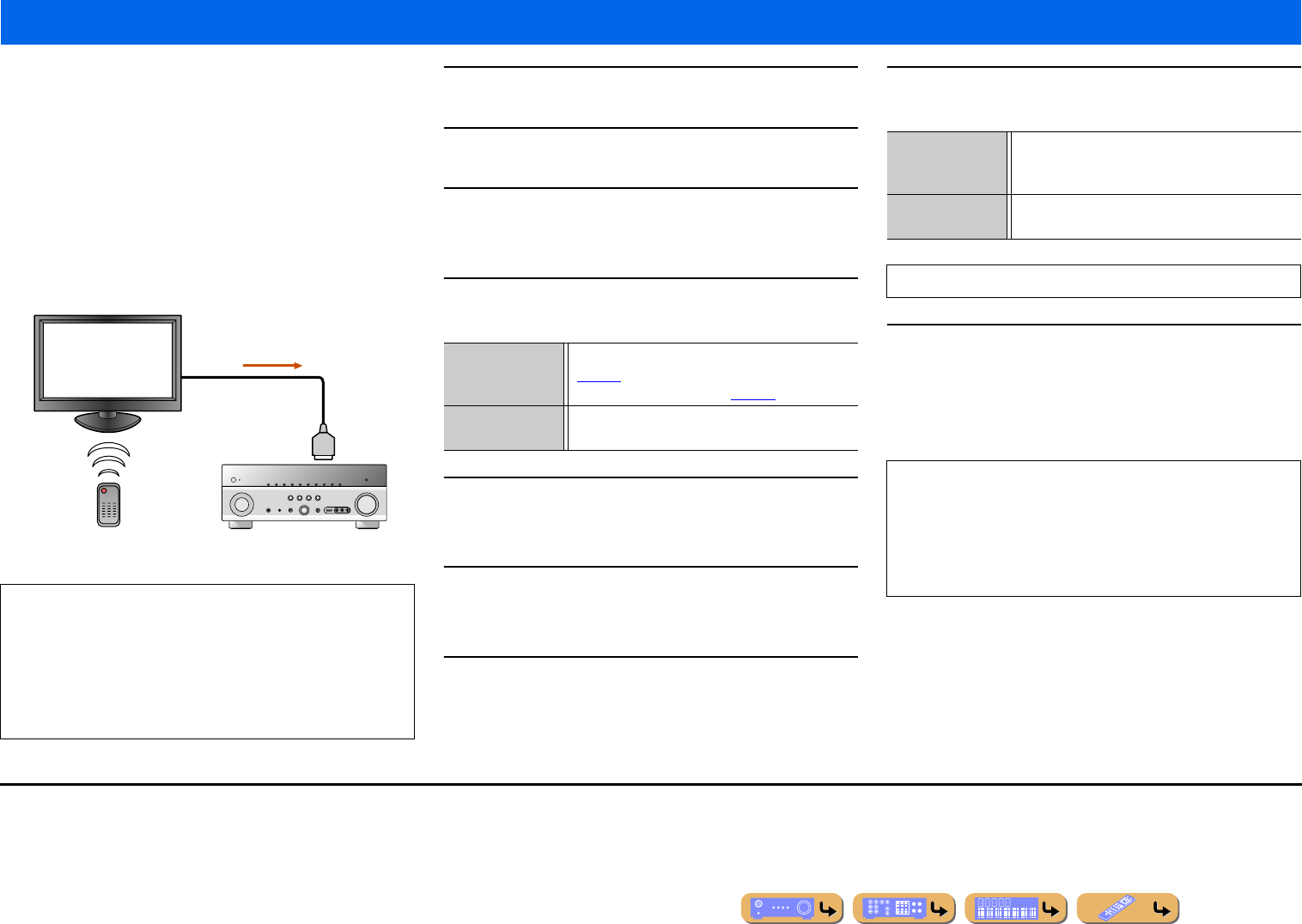
SETUP
En 121
This unit supports the HDMI Control function, which allows you to
operate external components via HDMI. If devices that support
HDMI Control (e.g., Panasonic VIERA Link-compatible TVs,
DVD/Blu-ray Disc players, etc.) are connected J1, remote
controls for those devices can be used to perform the following
operations:
–Power synchronization (on/standby)
–Volume control, including Mute
–Changing the volume of the audio output signal device (either the
TV or this unit)
1Connect the TV that supports the HDMI Control
function to this unit’s HDMI output jack.
2Connect the BD/DVD player that supports the HDMI
Control function to this unit’s HDMI input jack.
3Turn on the TV and this unit.
Refer to the TV’s instruction manual on how to operate external
components.
4Set the TV and this unit’s HDMI Control function to
“On.”
5Turn the TV off.
Other synchronized HDMI Control devices are turned off with the
TV. If they are not synchronized, turn them off manually.
6Turn the TV on.
Confirm that this unit has turned on in conjunction with the TV. If
it is still off, turn it on manually.
7Change the TV’s input setting to the input jack that
is connected to this unit (e.g., HDMI1).
8If BD/DVD player that supports the HDMI Control
function are connected to this unit, turn them on.
9Confirm that this unit is properly synchronized with
the TV through the following operations by using the
TV remote control.
•Power On/Off
•Volume Control
•Switching between audio output devices
Using the HDMI Control function
NOTE
The following is an example of how to connect this unit, a TV,
and a BD/DVD player. Follow the instructions in your TV and
BD/DVD player manuals, as well as the ones written below.
–Set the TV’s HDMI Control function to “On”
–Follow the AV amplifier connection instructions, and connect
this unit to the TV
HDMI
Control signal
(such as volume control)
Remote control of TV This unit
TV
HDMI connection
This unit Confirm that “HDMI Control” is set to “On”
(☞p. 106) and select the HDMI OUT jack connected
to the TV in “Control Select” (☞p. 106). J2
TV and BD/DVD
player
Check the instruction manuals for those devices.
This unit Confirm that the input source for the BD/DVD players
has been selected. If a different input source has been
selected, change it manually.
TV and BD/DVD
player
Confirm that the video signal from the player is being
properly received by the TV.
Operations 1-8 will not be required more than twice.
If this unit is not synchronized to the TV’s power operations,
check that the HDMI Control function is set to “On” for both
devices.
If they will not properly synchronize, unplugging and re-
plugging the devices and turning them on and off may solve the
problem.
J1 : We recommend that you use TVs and BD/DVD players from the same
manufacturer whenever possible.
J2 : The default setting for the HDMI Control function is “Off.”
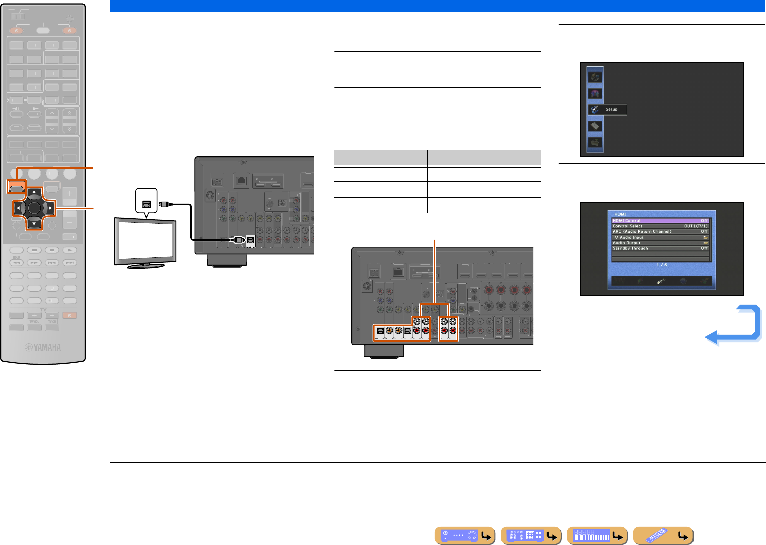
SETUP
Using the HDMI Control function
En 122
■
Switching the input source on this
unit automatically when listening
to TV audio
When the HDMI Control (☞p. 121) is operating
properly, the input source of this unit is automatically
changed to match operations carried out on the TV.
When the TV is connected with HDMI OUT 1, the
default input jack is AV4. If the AV4 optical digital jack
is connected to the TV’s audio output jack, then you can
enjoy TV sound through this unit right away.
When the TV is connected with HDMI OUT 2, the
default input jack is AV1. If the AV1 optical digital jack
is connected to the TV’s audio output jack, then you can
enjoy TV sound through this unit right away.
To use other jacks to input audio signals from TV, carry
out the following procedure.
1Connect this unit and the TV with an HDMI
cable.
2Connect TV’s audio output to this unit.
The input jacks listed below are available to input TV’s
audio signals. Use the same jack type as used for the
TV.
3Press jON SCREEN.J1
4Press kCursor B / C repeatedly to select
“Setup” and press kENTER.
5Press kCursor D / E repeatedly to select
“HDMI” and press kENTER.
jON SCREEN
kCursor B / C / D / E
kENTER
ENTER
ON SCREEN
SCENE
RETURN
VO
L
U
ME
ENHANCE
R
S
UR. DE
CO
DE
STRAIGHTSLEEP
P
URE DIRECT
PART Y
M
OVI
E
M
USI
C
BD
DVD
TV
CD
RADI
O
M
U
T
E
7
8
5
6
9
0
10
1
2
3
4
R
EC
ENT
FM
I
NF
O
M
EM
O
RY
AM
P
RESET
H
DMI
AV
A
UDI
O
1
2
3
4
1
2
5
V
-
AUX
TOP
MENU
P
OP-U
P
M
EN
U
DI
S
PLAY
SO
UR
C
E
M
AIN
Z
O
NE 2
RE
C
EIVE
R
CODE SE
T
I
NP
U
T
MUTE
DOCK
HDMI
O
U
T
MULTI
O
PTION
5
1
2
3
4
6
NET
S
IRI
US
TU
NER
TUN./C
H
C
ATE
GO
R
Y
k
j
OPTICAL
D
OC
K
AV 3
AV 5
AV 6
AUDIO 1
AUDIO 2
MU
(
CD
)
CO
AXIAL
V
IDE
O
HDMI
1
(
B
D
/
DVD
)
AV
OUT
S
URR
TR
F
R
O
N
T
IN
R
O
U
T
H
DMI
O
UT
1
2
ARC
A
R
C
SELECTABLE
O
PTICA
L
AV 1
AV 2
CO
AXIAL
COMPONENT
V
IDE
O
P
R
P
B
Y
S
IRIU
S
CO
MP
O
NEN
T
V
IDE
O
VIDE
O
MO
NIT
O
R
OU
T
P
R
P
B
Y
ANTENNA
FM
75
G
ND
AM
N
ETW
O
R
K
OPTICAL
O
O
Audio output
(Optical)
TV
TV output jack Input jack
Optical digital audio output AV1 or AV4 (Default)
Coaxial digital audio output AV2 or AV3
Analog stereo output AV5, AV6, AUDIO1, or AUDIO2
( TV )
AV 3AV 4AV 5AV 6
AUDIO 1 AUDIO 2
(CD)
COAXIAL OPTICAL
OPTICAL
AV 1AV 2
COAXIAL
D
OCK
MULTI CH INPUT
VIDE
O
HDMI 1
(
BD
/
DV
D
)
HDMI 2
HDMI
3
HDMI 4
HDMI 5
C
ENTER
SU
RR
O
FR
O
N
T
AV
OUT
S
UBWOOFE
R
AU
DI
O
OUT
ZO
NE2
O
UT
SU
R.BA
C
K
SU
RR
OU
ND
SUR
F
R
O
N
T
TRIGGER OUT
+12V
0
.1
A
MAX.
FR
O
NT
C
ENTE
R
IN
REMOTE
O
U
T
HDMI OU
T
1
2
A
R
C
A
R
C
S
ELE
C
TABL
E
C
OMPONENT
VIDEO
P
R
P
B
Y
S
IRI
US
CO
MP
O
NEN
T
V
IDE
O
VIDE
O
MO
NIT
O
R
OUT
P
R
P
B
Y
ANTENNA
FM
75
G
ND
AM
NETW
O
RK
Available input jacks
Continues to the
next page
J1 : Refer to the “Setting various functions (Setup menu)” (☞p. 98)
for details on the Setup menu.
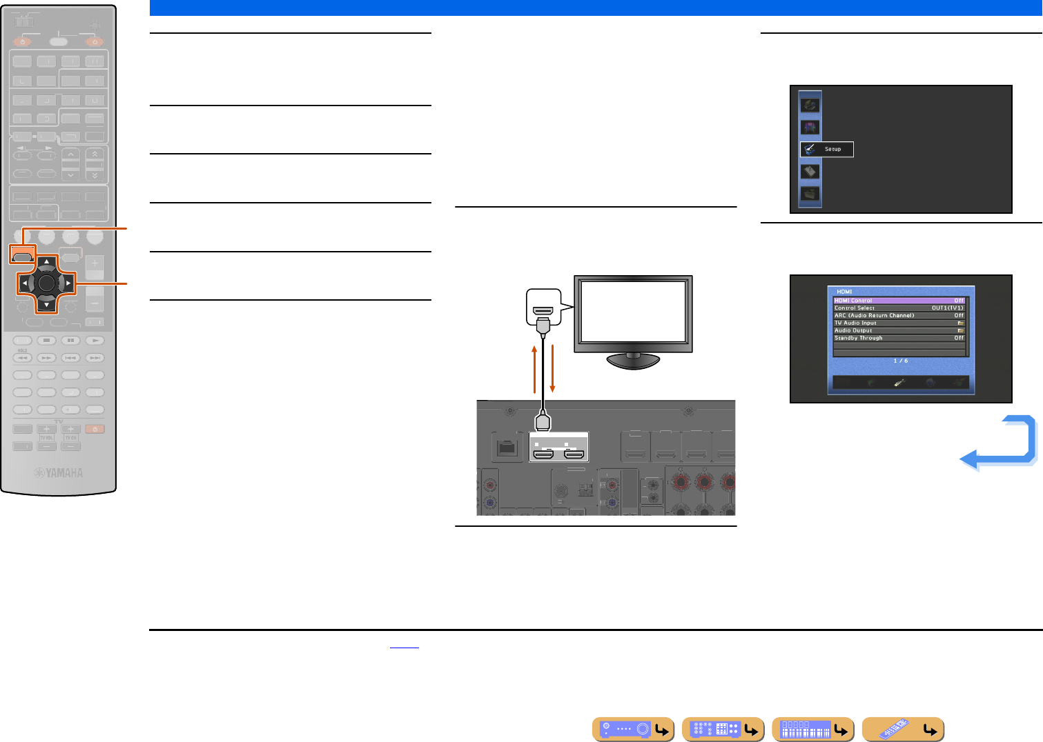
SETUP
Using the HDMI Control function
En 123
6Make sure that “HDMI Control” is “On”
When “HDMI Control” is set to “Off,” press
kENTER and kCursor B / C to set to “On.”
7Press kCursor C to select “Control Select”
and press kENTER.
8Use kCursor B / C to select the HDMI OUT
jack connected to the TV.
9Press kCursor C to select “TV Audio
Input” and press kENTER.
10 Use kCursor B / C to select the input
jack connected in step 2.
11 Press jON SCREEN when you have
finished changing the settings.
If the TV hereafter transmits audio output signals,
this unit will automatically switch to the input
source chosen in step 10.
■
Single HDMI cable input to TV
audio with Audio Return Channel
function
When using a TV that supports HDMI functions and
Audio Return Channel function, audio/video output
from this unit to the TV or audio output from the TV to
this unit can be transmitted through a single HDMI cable
(Audio Return Channel function). Audio signals
transmitted from the TV to this unit can be assigned to
any input source.
1Connect this unit and the TV with an HDMI
cable.
2Press jON SCREEN.J1
3Press kCursor B / C repeatedly to select
“Setup” and press kENTER.
4Press kCursor D / E repeatedly to select
“HDMI” and press kENTER.
jON SCREEN
kCursor B / C / D / E
kENTER
ENTER
ON SCREEN
SCENE
RETURN
VO
L
U
ME
ENHANCE
R
S
UR. DE
CO
DE
STRAIGHTSLEEP
P
URE DIRECT
PART Y
M
OVI
E
M
USI
C
BD
DVD
TV
CD
RADI
O
M
U
T
E
7
8
5
6
9
0
10
1
2
3
4
R
EC
ENT
FM
I
NF
O
M
EM
O
RY
AM
P
RESET
H
DMI
AV
A
UDI
O
1
2
3
4
1
2
5
V
-
AUX
TOP
MENU
P
OP-U
P
M
EN
U
DI
S
PLAY
SO
UR
C
E
M
AIN
Z
O
NE 2
RE
C
EIVE
R
CODE SE
T
I
NP
U
T
MUTE
DOCK
HDMI
O
U
T
MULTI
O
PTION
5
1
2
3
4
6
NET
S
IRI
US
TU
NER
TUN./C
H
C
ATE
GO
R
Y
k
j
HDMI OUT
12
ARC ARC
SELECTABLE
V
IDE
O
HDMI 1
(
B
D
/
DV
D
)
HDMI
2
HDMI 3
HDMI 4
C
ENTE
R
F
R
O
NT
IN
R
EM
O
TE
O
U
T
NT
CO
MP
O
NENT
V
IDE
O
V
IDE
O
P
R
P
B
ANTENNA
FM
7
5
G
ND
AM
NETW
O
R
K
HDMI
HDMI
HDMI
TV
TV audio
output
Video / Audio
output
Continues to the
next page
J1 : Refer to the “Setting various functions (Setup menu)” (☞p. 98)
for details on the Setup menu.
SETUP
Using the HDMI Control function
En 124
5Make sure that “HDMI Control” is “On.”
When “HDMI Control” is set to “Off,” press
kENTER and kCursor B / C to set to “On.”
6Press kCursor C to select “Control Select”
and press kENTER.
7Use kCursor B / C to select the HDMI OUT
jack connected to the TV.
8Press kCursor C to select “TV Audio
Input” and press kENTER.
9Use kCursor B / C to select the input
source to which the HDMI audio signals will
be assigned, and press kRETURN.
10 Press kCursor C to select “ARC (Audio
Return Channel)” and press
kENTER.J1
11 Press kCursor C to select “On.”
The Audio Return Channel function will turn on.
12 Press jON SCREEN to close the Setup
menu.
If the TV hereafter transmits audio output signals,
this unit will automatically switch to the input
source chosen in step 9.
jON SCREEN
kCursor B / C
kENTER
kRETURN
RETURN
ENTER
ON SCREEN
SCENE
VO
L
U
ME
ENHANCE
R
S
UR. DE
CO
DE
STRAIGHTSLEEP
P
URE DIRECT
PART Y
M
OVI
E
M
USI
C
BD
DVD
TV
CD
RADI
O
M
U
T
E
7
8
5
6
9
0
10
1
2
3
4
R
EC
ENT
FM
I
NF
O
M
EM
O
RY
AM
P
RESET
H
DMI
AV
A
UDI
O
1
2
3
4
1
2
5
V
-
AUX
TOP
MENU
P
OP-U
P
M
EN
U
DI
S
PLAY
SO
UR
C
E
M
AIN
Z
O
NE 2
RE
C
EIVE
R
CODE SE
T
I
NP
U
T
MUTE
DOCK
HDMI
O
U
T
MULTI
O
PTION
5
1
2
3
4
6
NET
S
IRI
US
TU
NER
TUN./C
H
C
ATE
GO
R
Y
j
k
J1 : While the Audio Return Channel function is on, the jack selected
for the input source cannot be used.
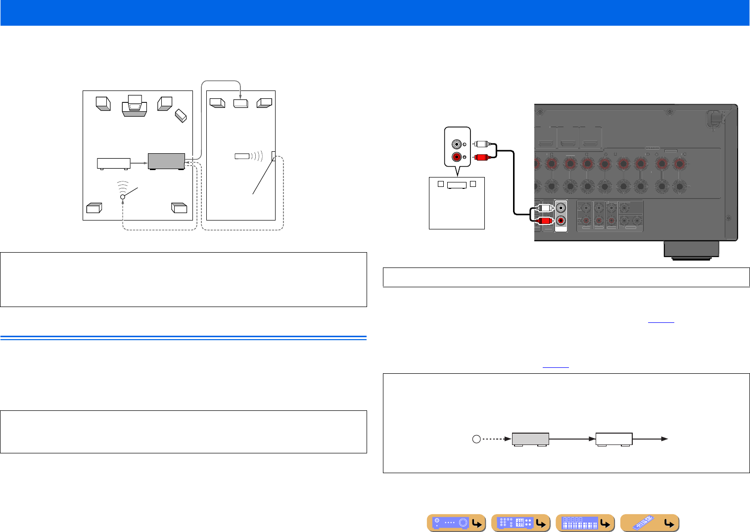
SETUP
En 125
This unit allows you to configure a multi-zone audio system. The Zone2 feature allows you to set this unit to reproduce separate input sources in the main zone and the second zone (Zone2). You can
control this unit from the second zone using the supplied remote control.
Connecting Zone2
You need the following additional equipment to use the multi-zone functions of this unit:
•An infrared signal receiver in the second zone.
•An infrared signal emitter in the main zone. This emitter transmits infrared signals from the remote control
to a CD player or a DVD player, etc. in the main zone via the infrared signal receiver in the second zone.
•An amplifier and speakers in the second zone.
■
Using the external amplifier
An amplifier located in the secondary zone can be connected to this unit as shown below.
■
Using the internal amplifier of this unit
Connect the speakers in the second zone to the EXTRA SP jacks directly (☞p. 18).
■
Using REMOTE IN/OUT jacks for multi-zone components
This unit is equipped with REMOTE IN and REMOTE OUT jacks. You can use these jacks to control
this unit and other components from Zone2 (☞p. 30).
Using multi-zone configuration
Only analog signal can be sent to Zone2. If you want to output sound from Zone2, connect an
external component to AV5-6, AUDIO1-2, or VIDEO AUX by analog connection. For example, if
you want to output sound from an HDMI DVD player in Zone2, you must connect the component to
this unit by both HDMI and analog connections.
Since there are many possible ways to connect and use this unit in a multi-zone configuration, we
recommend that you consult with your nearest authorized Yamaha dealer or service center about the
Zone2 connections that best meet your requirements.
To the REMOTE IN jack
Infrared signal
emitter
DVD player (etc.)
Amplifier
Remote control
Second zone
(Zone2)
This unit
From the ZONE2 OUT jacks
Infrared signal
receiver
From the REMOTE OUT jack
Main zone
To avoid unexpected noise, DO NOT USE the Zone2 feature with CDs encoded in DTS.
Some Yamaha models can be directly connected to the REMOTE jacks of this unit. These models
may not require an infrared signal emitter. Up to 6 Yamaha components can be connected as shown
below.
ZONE2
OUT
HDMI
3
HDMI 4
HDMI
5
C
ENTE
R
SU
RR
OU
ND
S
URROUND BACK
/
BI
-
AMP
S
IN
G
LE
FR
O
N
T
WOO
FER
AUDI
O
OU
T
SU
RR
OU
ND
SU
R.BA
C
K
PRE
OU
T
SU
BW
OO
FE
R
1
2
F
R
O
N
T
N
TE
R
EXTRA
SP
CENTERSINGLE
S
PEAKER
S
SPEAKERS
Z
ONE2/PRESENCE
AUDIO
R
L
R
L
Amplifier
Second Zone
(Zone2)
Audio input
REMOTE
IN
Infrared signal
receiver
This unit Yamaha
component
REMOTE
OUT IN
REMOTE
OUT
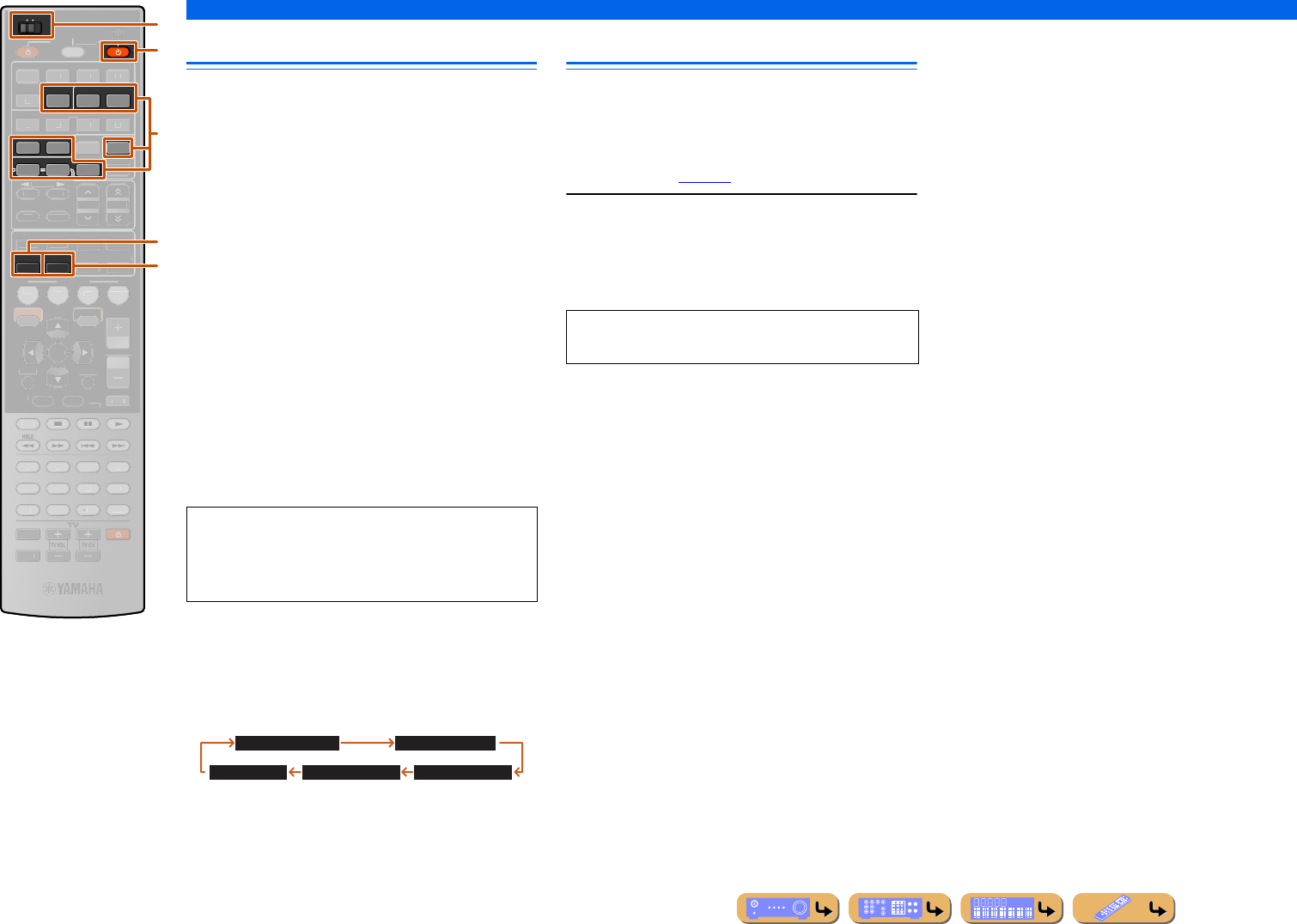
SETUP
Using multi-zone configuration
En 126
Controlling Zone2
The remote control can be used to select and control
Zone2 devices. The available operations are as follows:
•Selecting the input source of Zone2.
•Tuning into FM or AM when “TUNER” is selected as the
input source of Zone2.
•Tuning into SIRIUS Satellite Radio when “SIRIUS” is
selected as the input source of Zone2.
•Adjust the volume of Zone2 devices (when connected via
the built-in amplifier).
■
Activating the Zone2 operation
mode
Set bMAIN/ZONE2 to ZONE2 before attempting to
use the remote control to control Zone2 devices.
■
Operating Zone2
To enable and disable the audio output to Zone2
Press qRECEIVER A.
To select an input source for Zone2
Press dInput selector.
To enable the sleep timer for Zone2
Automatically switch the Zone2 device to standby mode
after a specified period of time has elapsed (sleep timer).
Press gSLEEP repeatedly to specify a time for the
sleep timer function.
Using the party mode
Use this feature to play main zone sources in Zone2
simultaneously. This feature is useful when you want to
play back main sources as background music in a home
party, etc. When using the party mode, set “Party Mode
Set” to “Enable” (☞p. 109).
Press hPARTY to turn on or off the party mode.
“PARTY MODE ON” or “PARTY MODE OFF” appears
on the front panel display or the TV screen.
While this unit is in the party mode, the ZONE2
indicators turn on in the front panel display.
bMAIN/ZONE2
dInput selector
gSLEEP
hPARTY
qRECEIVER A
SLEEP
AUDIO
12
V-AUX
PART Y
MAIN
ZONE 2
DOCK
56
NET
SIRIUSTUNER
SCENE
RETURN
VO
L
U
ME
ENHANCE
R
S
UR. DE
CO
DE
STRAIGHT
P
URE DIRECT
M
OVI
E
M
USI
C
BD
DVD
TV
CD
RADI
O
M
U
T
E
ENTER
7
8
5
6
9
0
10
1
2
3
4
R
EC
ENT
TOP
MENU
P
OP-U
P
M
EN
U
DI
S
PLAY
SO
UR
C
E
RE
C
EIVE
R
CODE SE
T
I
NP
U
T
MUTE
HDMI
O
U
T
MULTI
H
DMI
AV
1
2
3
4
5
O
PTION
O
N
SC
REE
N
1
2
3
4
FM
I
NF
O
M
EM
O
RY
AM
P
RESET
TUN./C
H
C
ATE
GO
R
Y
d
q
b
h
g
Only the following sources are available for
the Zone2.
V-AUX (only analog audio input), AUDIO1-2 (only
analog audio input), NET, DOCK, TUNER
Sleep 120min. Sleep 90min.
Sleep 60min.Sleep 30min.Sleep Off
Input audio signals are mixed down to 2ch Stereo and
output at the analog ZONE2 OUT jacks.
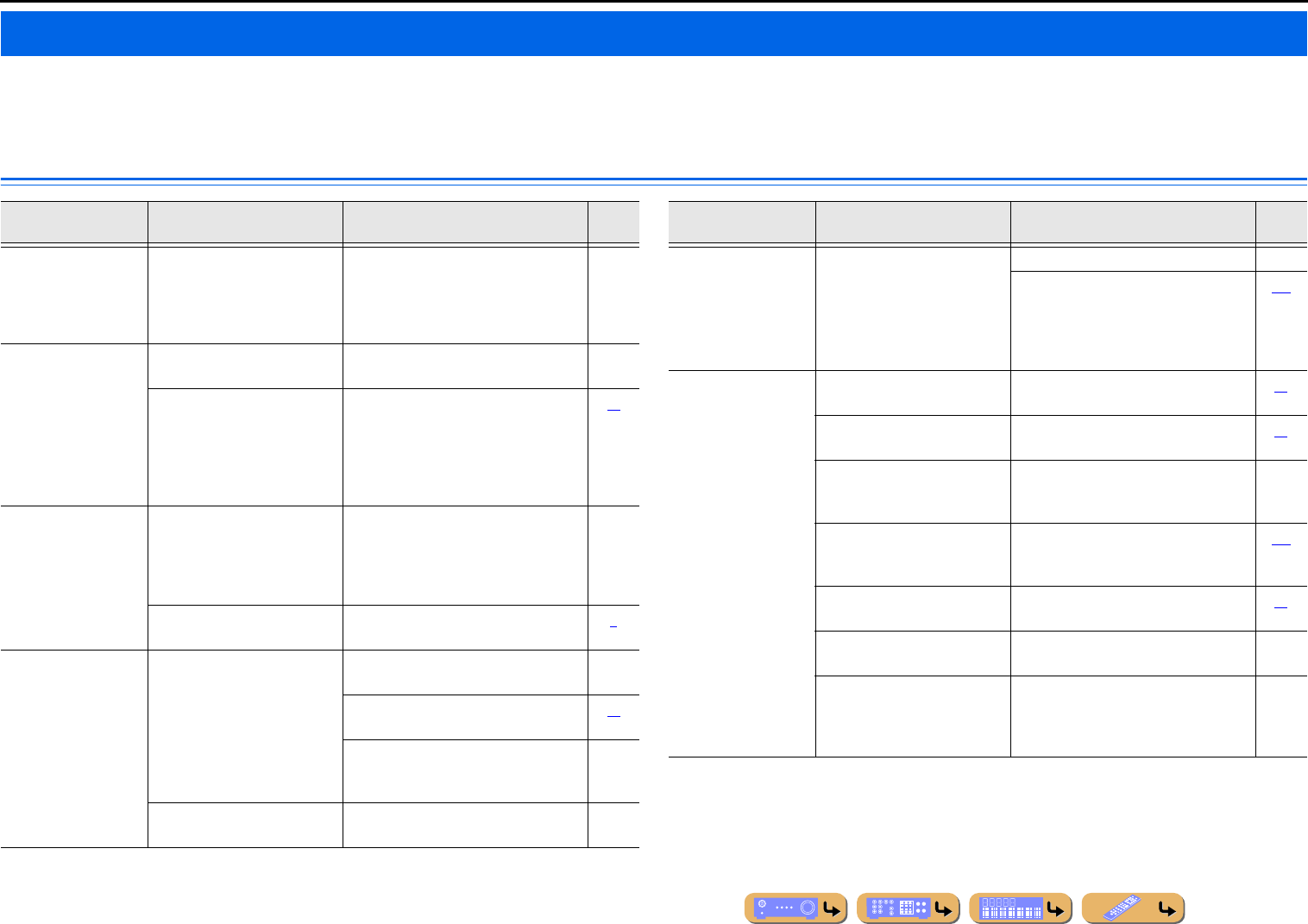
En 127
APPENDIX
Refer to the table below when this unit does not function properly.
If the problem you are experiencing is not listed below, or if the instructions below do not help, turn off this unit, disconnect the power cable, and contact the nearest authorized Yamaha dealer or service
center.
General
Troubleshooting
Problem Cause Remedy See
page
The power will not
turn on.
The protection circuitry operated
3 times consecutively.
As a safety precaution, when the protection
circuitry operates 3 times consecutively, the
capability to turn on the power is disabled.
Contact your nearest Yamaha dealer or
service center to request repair.
—
The unit enters
standby mode soon
after the power is
turned on.
The power cable is not completely
inserted.
Connect the power cable properly to an AC
wall outlet.
—
(When this unit is turned back on
and “CHECK SP WIRES!” is
displayed.) The protection
circuitry has been activated
because this unit was turned on
while a speaker cable was shorted.
Make sure that all speaker cables between
this unit and speakers are connected
properly.
19
This unit cannot be
turned off or does
not work properly.
The internal microcomputer is
hung-up due to an external electric
shock (such as lightning or
excessive static electricity) or by a
drop in power supply voltage.
Disconnect the power cable from the AC
wall outlet, wait about 30 seconds and then
plug it in again.
—
The batteries in the remote control
may have lost their charge.
Replace all batteries. 7
The unit enters
standby mode.
The protection circuitry has been
activated because of a short circuit,
etc.
Check that the speaker with an impedance
of at least 6 Ω.
—
Check that the speaker impedance settings
are correct.
18
Check that the speaker wires are not
touching each other, then turn the unit back
on.
—
The sleep timer has turned off the
unit.
Turn on the unit, and play the source again. —
After display of a
countdown on the
front panel, the unit
goes into standby
mode.
If you do not use take any action,
the Auto Power Down function
operates.
Turn on the unit, and play the source again. —
In the Setup menu “Auto Power Down”
(“Function” → “Auto Power Down”),
increase the time until switching to standby
mode, or turn off the Auto Power Down
function.
110
No sound. Incorrect input or output cable
connections.
Connect the cables properly. If the problem
persists, the cables may be defective.
25
Speaker connections are not
secure.
Secure the connections. 19
The HDMI components connected
to the unit do not support the
HDCP copy protection standards.
Connect HDMI components that support the
HDCP copy protection standards.
—
The audio input into the device is
set to playback through the TV.
In the Setup menu, set the “Amp” of “Audio
Output” (“HDMI” → “Audio Output” →
“Amp”) to “On.”
107
No appropriate input source has
been selected.
Select an appropriate input source with
Input selector.
42
The volume is turned down or
muted.
Turn up the volume. —
Signals that this unit cannot
reproduce are being input from a
source component, such as a CD-
ROM.
Use an input source that has signals that can
be reproduced on this unit.
—
Problem Cause Remedy See
page
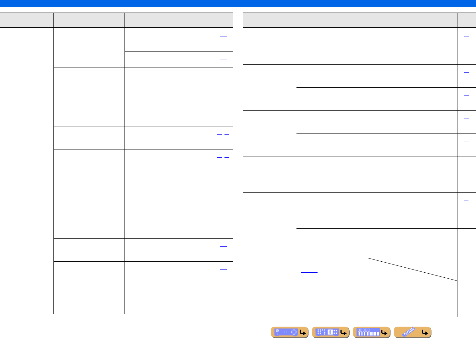
En 128
APPENDIX
Troubleshooting
No picture. The video signal output from this
unit is not supported by a monitor
connected to this unit via the
HDMI OUT 1-2 jacks.
Displays the Advanced Setup menu and
select “VIDEO” in “INIT” to reset the video
parameters.
120
Displays the Advanced Setup menu and set
“MON.CHK” to “YES.”
120
An appropriate video input is not
selected on the TV.
Select an appropriate video input on the TV. —
No sound is output
from a specific
speaker.
The speaker is malfunctioning.
Check the Speaker indicators on
the front panel display. If the
corresponding indicator lights up,
connect another speaker and check
if sound is output.
If sound is not output, the unit may be
malfunctioning.
10
The playback component or
speakers are not connected
properly.
Connect the cables properly. If the problem
persists, the cables may be defective.
19, 25
Output from that speaker is
disabled.
Check the Speaker indicators on the front
panel display. If the corresponding indicator
is turned off, try the following.
1) Change to a different input source.
2) With the selected sound program, sound
is not output from that speaker. Select
another sound program.
3) “None” may have been selected for that
speaker on this unit. Display “Speaker” in
the Setup menu, and set respective
parameters to enable output from that
speaker (“Speaker” → “Manual Setup” →
“Configuration”).
10, 99
The volume of that speaker is set
to the minimum in “Speaker” in
the Setup menu.
Display “Speaker” in the Setup menu and
adjust the volume (“Speaker” → “Manual
Setup” → “Level”).
101
(If hardly any sound comes from
one channel)
Speaker output balance is not set
correctly.
Balance the volume of each speaker from
“Level” in the Setup menu (“Speaker” →
“Manual Setup” → “Level”).
101
Sound may not be output from
certain channels, depending on the
input source or sound program.
Try another sound program. 44
Problem Cause Remedy See
page
Only the center
speaker outputs
substantial sound.
When a monaural source sound
program is applied, for some
surround decoders, sound from all
channels is output from the center
speaker.
Try another sound program. 44
No sound is heard
from the presence
speakers.
This unit is in straight decoding
mode and a monaural source is
being played back.
Press STRAIGHT to exit straight decoding
mode.
45
Sound may not be output from
certain channels depending on
input sources or sound programs.
Try another sound program. 44
No sound is heard
from the surround
back speakers.
“Extended Surround” in the
Option menu is set to “OFF,” or an
input signal does not contain a
surround back flag with “Extended
Surround” set to “Auto.”
Set “Extended Surround” other than “OFF”
or “Auto.”
55
No sound is heard
from the subwoofer.
A subwoofer is not connected, or it
is inactive.
Check that a subwoofer is connected
correctly, and from the Setup menu
“Subwoofer” (“Speaker” → “Manual
Setup” → “Configuration” →
“Subwoofer”), set the subwoofer to “Use.”
20,
101
The subwoofer is turned off. Turn the subwoofer power on.
If the subwoofer includes an Auto Power
Off function, then lower the Auto Power Off
sensitivity settings.
—
The source does not contain LFE
(☞p. 135) or low frequency
signals.
—
The right
combination of audio
/ video jacks to
connect cannot be
found.
Combine input connected to the
external component video output
with another input audio jack.
Display the Input menu for the connected
video output, select “Audio In” and select
the jack to use for audio input.
88
Problem Cause Remedy See
page
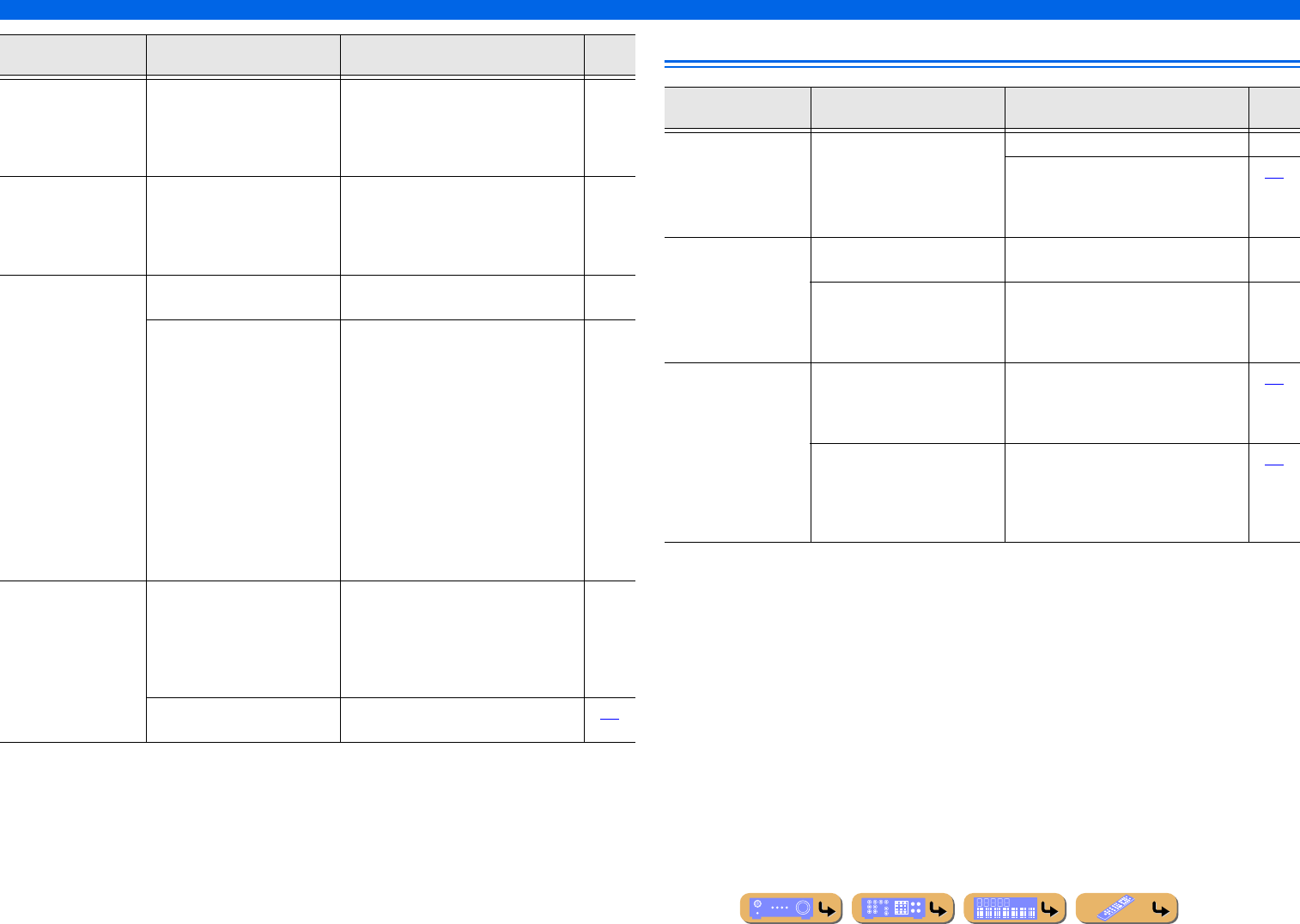
En 129
APPENDIX
Troubleshooting
HDMI™
The audio input
sources cannot be
played in the desired
digital audio signal
format.
The connected component is not
set to output the desired digital
audio signals.
Set the playback component properly
referring to its instruction manual.
—
There is noise
interference from
digital or radio
frequency
equipment.
This unit is too close to other
digital or radio frequency
equipment.
Move this unit further away from such
equipment.
—
Noise/hum noise is
heard.
Incorrect cable connection.
Connect the audio cables properly.
If the problem persists, the cables may be
defective.
—
A DTS-CD is being played back. 1) When only noise is output
If a DTS bitstream signal is not properly
input to this unit, only noise is output.
Connect the playback component to this
unit by digital connection and playback the
DTS-CD. If the condition is not improved,
the problem may results from the playback
component. Consult the manufacturer of the
playback component.
2) When noise is output during playback or
skip operation
Before playing back the DTS-CD, display
the Input menu after selecting the input
source and set “Decoder Mode” to “DTS.”
—
The volume cannot
be increased, or the
sound is distorted.
The component connected to the
output jacks of this unit is not
turned on.
When the component connected to the
output jacks of this unit is not turned on, the
sound may be distorted, or the volume may
decreased due to the nature of AV receivers.
Turn on all components connected to this
unit.
—
“Max Volume” is set to a low
value.
Set it to a higher value. 103
Problem Cause Remedy See
page
Problem Cause Remedy See
page
The front panel
display HDMI
indicator is flashing.
An error with the HDMI
connection has occurred.
Try re-inserting the HDMI cable. —
Confirm that HDMI video that is not
supported by the unit is not being input
(Information menu → “Video
information”).
113
No picture or sound. The number of components is over
the limit.
Disconnect some of the HDMI components. —
The connected HDMI component
does not support high-bandwidth
digital copyright protection
(HDCP).
Connect an HDMI component that supports
HDCP.
—
(When using HDMI
Control function)
TV sound is not
output from this unit
when operating the
remote control of the
TV.
The TV audio output is not
connected to this unit, or the
setting to match operations carried
out on TV is not set.
Connect the TV audio output to this unit,
and then select the connected input source
in “TV Audio Input” (Setup menu → HDMI
→ TV Audio Input).
106
(When using Audio Return
Channel function)
The Audio Return Channel
function is not working.
Make sure that your TV supports Audio
Return Channel.
Set the Audio Return Channel function to
on (Setup menu → HDMI → ARC (Audio
Return Channel)).
106
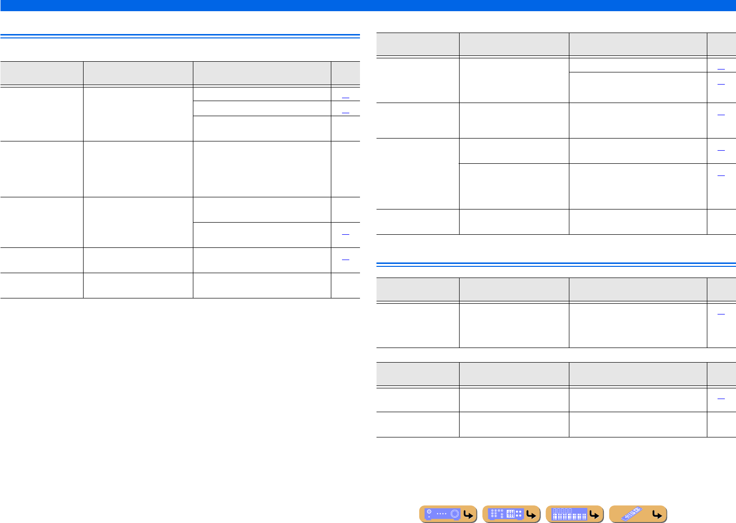
En 130
APPENDIX
Troubleshooting
Tuner (FM/AM)
FM
AM
SIRIUS Satellite Radio™
Problem Cause Remedy See
page
FM stereo reception
is noisy.
You are too far from the station
transmitter, or the input from the
antenna is weak.
Check the antenna connections. 33
Switch to monaural mode. 59
Replace the outdoor antenna with a more
sensitive multi-element antenna.
—
There is distortion,
and clear reception
cannot be obtained
even with a good FM
antenna.
There is multi-path interference. Adjust the antenna height or orientation, or
place it in a different location.
—
The desired station
cannot be tuned into
with the automatic
tuning method.
You are in an area far from a
station, or input from the antenna
is weak.
Replace the outdoor antenna with a more
sensitive multi element antenna.
—
Use TUN./CH H / I to manually select the
station.
57
“No Presets” is
displayed.
No preset stations are registered. Register stations you want to listen to as
preset stations before operation.
57
“Wrong Station” is
displayed.
An invalid FM/AM frequency has
been input.
Input a frequency that can be received. —
Problem Cause Remedy See
page
The desired station
cannot be tuned into
with the automatic
tuning method.
The signal is weak, or the antenna
connections are loose.
Adjust the AM loop antenna orientation. 33
Use the manual tuning method. 57
Automatic station
preset does not
work.
Automatic station preset is not
available for AM stations.
Use manual station preset. 57
Continuous
crackling and
hissing noises are
heard.
The supplied AM loop antenna is
not connected.
Connect the AM loop antenna correctly
even if you use an outdoor antenna.
33
The noises may be caused by
lightning, fluorescent lamps,
motors, thermostats, or other
electrical equipment.
It is difficult to completely eliminate noise,
but it can be reduced by installing and
properly grounding an outdoor AM antenna.
33
Buzzing and whining
noises are heard.
A TV set is being used nearby. Move this unit away from the TV set. —
Problem Cause Remedy See
page
SIRIUS Satellite
Radio information is
not displayed
properly.
The hold function is enabled. Press HOLD to disable the hold function. 65
Display Cause Remedy See
page
ANTENNA ERROR The antenna is not connected to
the SiriusConnect tuner properly.
Check the connection of the antenna and
SiriusConnect tuner.
61
SIRIUS LOADING This unit is communicating with
the SiriusConnect tuner.
The message disappears normally within
several tens of seconds.
—
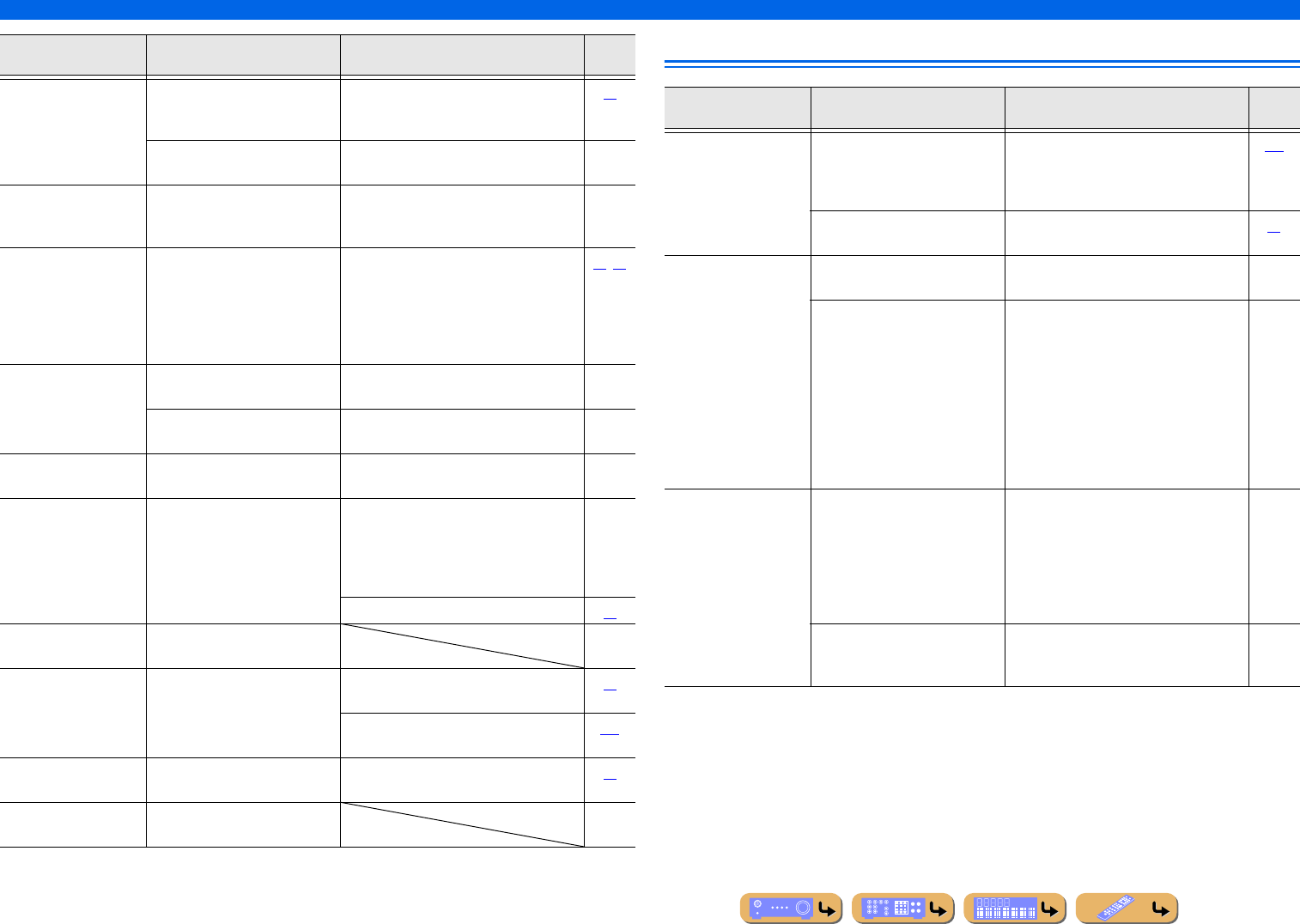
En 131
APPENDIX
Troubleshooting
Network
CHECK SR TUNER The SiriusConnect tuner is not
connected to the SIRIUS jack of
this unit correctly.
Check the connection of the SiriusConnect
tuner and this unit.
61
The SiriusConnect tuner is not
connected to the AC wall outlet.
Connect the power cable of the
SiriusConnect tuner to the AC wall outlet.
—
NOT SUPPORTED This unit does not support the
connected SIRIUS Satellite Radio
tuner.
Connect the SiriusConnect tuner that this
unit supports,
—
ACQUIRING The signal is too weak. Adjust the orientation of the antenna of the
SiriusConnect tuner. Check the antenna
reception level from the Antenna
information on the front panel display, or
the SIRIUS Information screen on the TV
screen.
64, 65
UPDATING The SiriusConnect tuner is
updating the channel list.
Wait until the updating is complete. —
The period of the subscription is
end.
Contact SIRIUS Satellite Radio to renew the
subscription.
—
F/W UPDATING The SiriusConnect tuner is
updating the firmware.
Wait until the updating is complete. —
CALL SIRIUS
(CALL 888-539-
SIRIUS TO
SUBSCRIBE)
The selected channel is not
subscribed.
Contact SIRIUS Satellite Radio to subscribe
the selected channel.
URL: https://activate.siriusradio.com/
Phone: 1-888-539-SIRIUS (1-888-539-
7474)
—
Select another channel. 62
SUB UPDATED The subscription information is
updated.
LOCK The parental lock function is
enabled.
Use Numeric keys to enter the 4-digit code,
select OK and then press ENT.
66
Reset the SIRIUS Satellite Radio parental
lock code to the factory default setting.
119
INVALID The selected channel is currently
out of service.
Select another channel. 62
Not Available The operation you made is not
available.
Display Cause Remedy See
page
Problem Cause Remedy See
page
The PC server/
Internet Radio does
not function
properly.
The IP address is not set properly. Set the DHCP server function of the router
to ON. Alternately, perform manual
configuration according to the current
operating environment.
108
The network cable is not
connected.
Connect it properly. 32
The music in the PC
server cannot be
played back.
The PC does not have Windows
Media Player installed in it.
Install Windows Media Player in the PC. —
The music is recorded in a format
that cannot be played on this unit.
This unit cannot play music
formats other than WMA, MP3,
MPEG-4 AAC, FLAC and WAV
(PCM format). Also note that it
cannot play certain music files
even if these are recorded in the
WMA, MP3, MPEG-4 AAC,
FLAC, or WAV format.
Play music recorded in a format that this
unit is compatible with.
—
The Internet Radio
cannot be played.
The firewall of the network device
is activated. The Internet Radio
can be played only when it passes
through the port designated by
each radio station. The port
number is variable depending on
radio station.
Check the firewall setting of the network
device.
—
Connection to the Internet is
disconnected.
Check the configuration of the network
device, and then contact the network
connection provider.
—
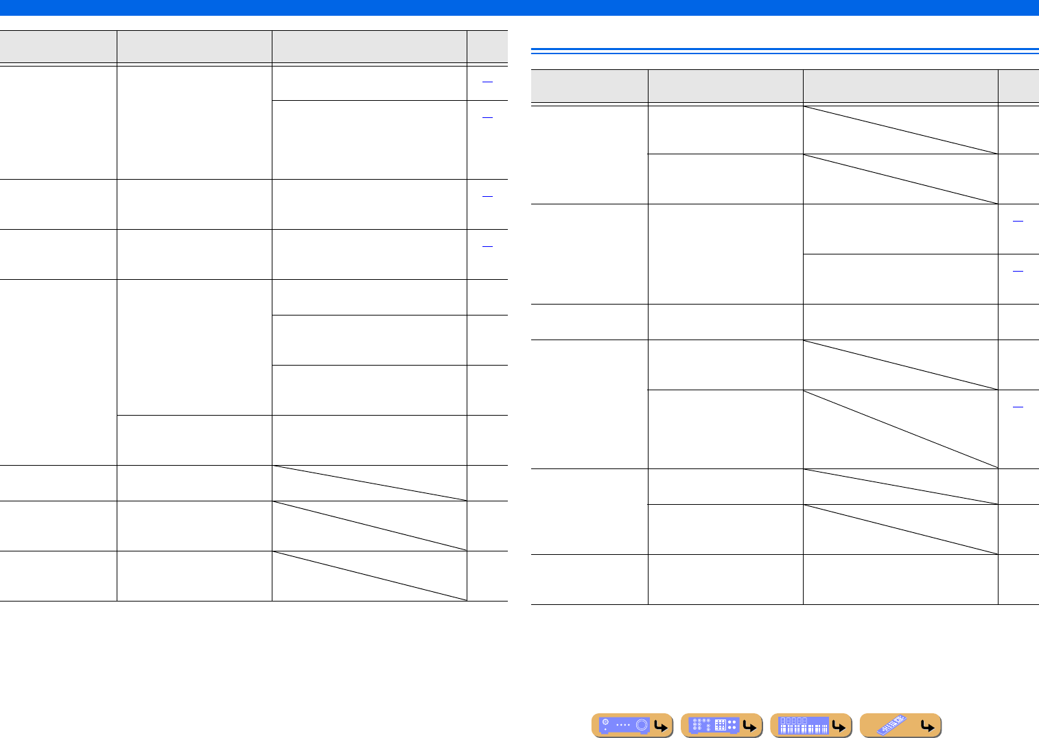
En 132
APPENDIX
Troubleshooting
iPod™/iPhone™
Display Cause Remedy See
page
Connect error There is a problem with the signal
path from your network to this
unit.
Check the connection between this unit and
the LAN port on your router or hub.
32
Make sure your router is properly connected
and turned on. Also, make sure your modem
is properly connected and turned on when
you are attempting to listen to Internet
Radio.
32
Disconnected The PC server previously
connected to this unit no longer
exists.
Connect this unit to the available PC server. 32
Access denied The PC you are attempting to
connect has denied connection.
Configure the sharing setting of Window
Media Player 11/12 and select this unit as a
device to which music contents are shared.
67
Unable to play This unit cannot play back the
songs currently stored on your PC.
Make sure Windows Media Player is
installed on your PC.
—
Check that the songs currently stored on
your PC are playable (MP3, WMA, MPEG-
4 AAC, and WAV).
—
Store some other playable music files (MP3,
WMA, MPEG-4 AAC, and WAV) on your
PC.
—
The network may be overloaded
with heavy traffic, and playback is
interrupted.
Try preparing a network exclusively for use
with this unit to separate it from general
network traffic.
—
List updated The list of the contents stored on
your PC server has been updated.
—
Bookmark On The desired Internet Radio station
has been added to the Bookmarks
list.
—
Bookmark Off The stored Internet Radio station
has been removed from the
Bookmarks list.
—
Display Cause Remedy See
page
Loading... The unit is in the process of
recognizing the connection with
your iPod/iPhone.
—
The unit is in the middle of
acquiring song lists from your
iPod/iPhone.
—
Connect error There is a problem with the signal
path from your iPod/iPhone to the
unit.
Turn off the unit and reconnect the
Universal Dock for iPod to the DOCK jack
of the unit.
79
Remove your iPod/iPhone from the
Universal Dock for iPod and then place it
back in the dock.
79
Unknown iPod The iPod/iPhone being used is not
supported by the unit.
Connect an iPod/iPhone supported by the
unit.
—
iPod connected Your iPod/iPhone is properly
placed in the Universal Dock for
iPod.
—
Your iPod/iPhone is properly
placed in the Yamaha iPod
wireless transmitter and connected
with this unit via wireless
transmission.
81
Disconnected Your iPod/iPhone is removed from
the Universal Dock for iPod.
—
Your iPod/iPhone is disconnected
with this unit via wireless
transmission.
—
Unable to play The unit cannot playback the
songs currently stored on your
iPod/iPhone.
Check that songs are currently stored on
your iPod/iPhone.
—
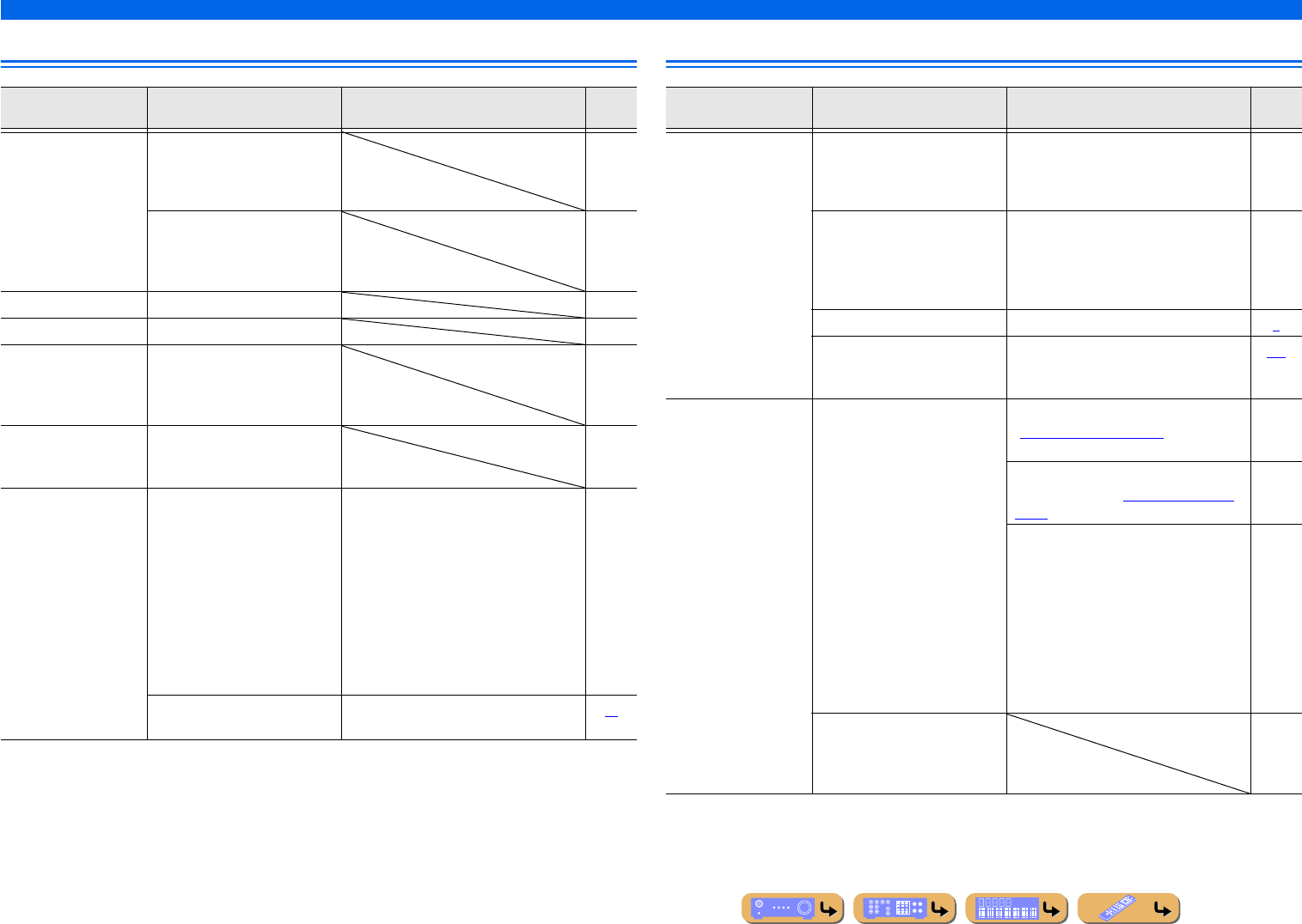
En 133
APPENDIX
Troubleshooting
Bluetooth™ Remote control
Display Cause Remedy See
page
Searching... The Yamaha Bluetooth wireless
audio receiver and the Bluetooth
component are in the process of
pairing.
—
The Yamaha Bluetooth wireless
audio receiver and the Bluetooth
component are in the process of
establishing a connection.
—
Completed The pairing is completed. —
Canceled The pairing is canceled. —
BT connected The connection between the
Yamaha Bluetooth wireless audio
receiver and the Bluetooth
component is established.
—
Disconnected The Bluetooth component is
disconnected from the Yamaha
Bluetooth wireless audio receiver.
—
Not found The Bluetooth component is not
found.
During pairing:
–pairing must be performed on the
Bluetooth component and this unit
simultaneously. Check if the Bluetooth
component is in pairing mode.
During connecting:
–check if the Bluetooth component is
turned on.
–check if the Bluetooth component is
within 32 ft. (10 m) of the Yamaha
Bluetooth wireless audio receiver.
—
Pairing may not have been
achieved.
Try pairing again. 83
Problem Cause Remedy See
page
The remote control
does not work or
function properly.
Wrong distance or angle. The remote control will function within a
maximum range of 20 ft. (6 m), and no
more than 30 degrees off-axis from the front
panel.
—
Direct sunlight or lighting (from
an inverter type of fluorescent
lamp, strobe light, etc.) is striking
the remote control sensor of this
unit.
Adjust the lighting angle, or reposition this
unit.
—
The batteries are weak. Replace all batteries. 7
The remote control ID of the
remote control and this unit do not
match.
Match the remote control ID of this unit and
the remote control.
116
External components
cannot be controlled
using the remote
control.
The remote control code is not
correctly set.
Set the remote control code correctly using
“Remote control code search” on the CD-
ROM.
—
Try setting another code for the same
manufacturer using “Remote control code
search” on the CD-ROM.
—
If this unit does not work when you press
Cursor B / C / D / E, do the following.
When the key does not work during DVD
disc menu operation: press the Input
selector again.
When there is no response with remote
control operation of the Option menu/Setup
menu: press SOURCE/RECEIVER (it
should glow orange) and try operating the
remote control again.
—
Even if the remote control code is
correctly set, there are some
models that do not respond to the
remote control.
—

APPENDIX
En 134
Audio information
Audio and video synchronization (Lipsync)
Lip sync, an abbreviation for lip synchronization, is a technical term that
involves both a problem, and the capability of maintaining audio and video
signals synchronized during post-production and transmission.
Whereas the audio and video latency requires complex end-user
adjustment, HDMI version 1.3 incorporates an automatic audio and video
syncing capability that allows devices to perform this synchronization
automatically and accurately without user interaction.
Bi-amplification connection (Bi-amp)
A bi-amplification connection uses two amplifiers for a speaker. One
amplifier is connected to the woofer section of a loudspeaker while the
other is connected to the combined mid and tweeter section. With this
arrangement each amplifier operates over a restricted frequency range. This
restricted range presents each amplifier with a much simpler job and each
amplifier is less likely to influence the sound in some way.
Dolby Digital
Dolby Digital is a digital surround sound system that gives you completely
independent multi-channel audio. With 3 front channels (front L/R and
center), and 2 surround stereo channels, Dolby Digital provides 5 full-range
audio channels. With an additional channel especially for bass effects,
referred to as LFE (Low-Frequency Effect), the system has a total of 5.1-
channels (LFE is counted as 0.1 channel). By using 2-channel stereo for the
surround speakers, more accurate moving sound effects and surround sound
environments are possible than with Dolby Surround. The wide dynamic
range from maximum to minimum volumes that are reproduced by the 5
full-range channels, and the precise sound orientation generated using
digital sound processing provides listeners with unprecedented excitement
and realism. With this unit, any sound environment from monaural up to a
5.1-channel configuration can be freely selected for your enjoyment.
Dolby Pro Logic II
Dolby Pro Logic II is an improved technique used to decode vast numbers
of existing Dolby Surround sources. This new technology enables a discrete
5-channel playback with 2 front left and right channels, 1 center channel,
and 2 surround left and right channels, instead of only 1 surround channel
for conventional Pro Logic technology. There are three modes available:
“Music mode” for music sources, “Movie mode” for movie sources, and
“Game mode” for game sources.
Dolby Pro Logic IIx
Dolby Pro Logic IIx is a new technology enabling discrete multichannel
playback from 2-channel or multi-channel sources. There are three modes
available: “Music mode” for music sources, “Movie mode” for movie
sources (for 2-channel sources only) and “Game mode” for game sources.
Dolby Surround
Dolby Surround uses a 4-channel analog recording system to reproduce
realistic and dynamic sound effects: 2 front left and right channels (stereo),
a center channel for dialog (monaural), and a surround channel for special
sound effects (monaural). The surround channel reproduces sound within a
narrow frequency range. Dolby Surround is widely used with nearly all
video tapes and laser discs, as well as in many TV and cable broadcasts.
The Dolby Pro Logic decoder built into this unit employs a digital signal
processing system that automatically stabilizes the volume on each channel
to enhance moving sound effects and directionality.
Dolby TrueHD
Dolby TrueHD is an advanced lossless audio technology developed for
high-definition disc-based media including Blu-ray Disc. Selected as an
optional audio standard for Blu-ray Disc, this technology delivers sound
that is bit-for-bit identical to the studio master, offering a high-definition
home theater experience. Supporting bitrates up to 18.0 Mbps, Dolby
TrueHD can carry up to 8 discrete channels of 24-bit/96 kHz audio
simultaneously. Dolby TrueHD also remains fully compatible with the
existing multichannel audio systems and retains the metadata capability of
Dolby Digital, allowing dialog normalization and dynamic range control.
DTS 96/24
DTS 96/24 offers an unprecedented level of audio quality for multichannel
sound on DVD video, and is fully backward-compatible with all DTS
decoders. “96” refers to a 96 kHz sampling rate compared to the typical
48 kHz sampling rate. “24” refers to 24-bit word length. DTS 96/24 offers
sound quality transparent to the original 96/24 master, and 96/24 5.1-
channel sound with full-quality full-motion video for music programs and
motion picture soundtracks on DVD video.
Dolby Digital Plus
Dolby Digital Plus is an advanced audio technology developed for high-
definition programming and Blu-ray Disc. Selected as an optional audio
standard for Blu-ray Disc, this technology delivers multichannel sound with
discrete channel output. Supporting bitrates up to 6.0 Mbps, Dolby Digital
Plus can carry up to 7.1 discreet audio channels simultaneously. Supported
by HDMI version 1.3 and designed for the optical disc players and AV
receivers/amplifiers of the future, Dolby Digital Plus also remains fully
compatible with the existing multichannel audio systems that incorporate
Dolby Digital.
DTS Digital Surround
DTS Digital Surround was developed to replace the analog soundtracks of
movies with a 5.1-channel digital sound track, and is now rapidly gaining
popularity in movie theaters around the world. DTS, Inc. has developed a
home theater system so that you can enjoy the depth of sound and natural
spatial representation of DTS Digital Surround in your home. This system
produces practically distortion-free 5.1-channel sound (technically, left,
right and center channels, 2 surround channels, plus an LFE 0.1 channel as
a subwoofer, for a total of 5.1-channels). This unit incorporates a DTS-ES
decoder that enables 6.1-channel reproduction by adding the surround back
channel to the existing 5.1-channel format.
DTS Express
This is an audio format for next-generation optical discs such as Blu-ray
discs. It uses optimized low bit rate signals for network streaming. In the
case of a Blu-ray disc, this format is used with secondary audio, enabling
you to enjoy the commentary of the movie producer via the Internet while
playing the main program.
DTS-HD High Resolution Audio
DTS-HD High Resolution Audio is a high resolution audio technology
developed for high-definition disc-based media including Blu-ray Disc.
Selected as an optional audio standard for Blu-ray Disc, this technology
delivers sound that is virtually indistinguishable from the original, offering
a high-definition home theater experience.
Supporting bitrates up to 6.0 Mbps for Blu-ray Disc, DTS-HD High
Resolution Audio can carry up to 7.1 discrete channels of 24-bit/96 kHz
audio simultaneously.
DTS-HD High Resolution Audio also remains fully compatible with the
existing multichannel audio systems that incorporate DTS Digital
Surround.
Glossary

APPENDIX
Glossary
En 135
DTS-HD Master Audio
DTS-HD Master Audio is an advanced lossless audio technology developed
for high-definition disc-based media including Blu-ray Disc. Selected as an
optional audio standard for Blu-ray Disc, this technology delivers sound
that is bit-for-bit identical to the studio master, offering a high-definition
home theater experience.
Supporting bitrates up to 24.5 Mbps for Blu-ray Disc, DTS-HD Master
Audio can carry up to 7.1 discrete channels of 24-bit/96 kHz audio
simultaneously. Supported by HDMI version 1.3 and designed for the
optical disc players and AV receivers/amplifiers of the future, DTS-HD
Master Audio also remains fully compatible with the existing multichannel
audio systems that incorporate DTS Digital Surround.
DSD
Direct Stream Digital (DSD) technology stores audio signals on digital
storage media, such as Super Audio CDs. Using DSD, signals are stored as
single bit values at a high-frequency sampling rate of 2.8224 MHz, while
noise shaping and oversampling are used to reduce distortion, a common
occurrence with very high quantization of audio signals. Due to the high
sampling rate, better audio quality can be achieved than that offered by the
PCM format used for normal audio CDs. The frequency is equal to or
higher than 100 kHz, with a dynamic range of 120 dB. This unit can
transmit or receive DSD signals via the HDMI jack.
FLAC
This is a file format for lossless audio data compression. FLAC is inferior to lossy
compression formats in compression rate but provides higher audio quality.
LFE 0.1 channel
This channel reproduces low-frequency bass signals, and has a frequency
range from 20 Hz to 120 Hz. This channel is counted as 0.1, because it only
enforces a low-frequency range compared to the full-range reproduced by
the other 5-channels in Dolby Digital or DTS 5.1-channel systems.
MP3
One of the audio compression methods used by MPEG. It employs the
irreversible compression method, which achieves a high compression rate
by thinning out the data of hardly audible part to the human ears. It is said
to be capable of compressing the data quantity by about 1/11 (128 kbps)
while maintaining a similar audio quality to music CD.
MPEG-4 AAC
An MPEG-4 audio standard. As it allows compression of data at a bit rate
lower than that of MPEG-2 AAC, it is used among others for mobile
telephones, portable audio players and other low-capacity devices requiring
high sound quality. In addition to the above types of devices, MPEG-4
AAC is also used to distribute contents on the Internet, and as such is
supported by computers, media servers and many other devices.
Neo:6
Neo:6 decodes the conventional 2-channel sources for 6-channel playback
by the specific decoder. It enables playback with the full-range channels
with higher separation just like digital discrete signal playback. There are
two modes available: “Music mode” for music sources and “Cinema mode”
for movie sources.
PCM (Linear PCM)
Linear PCM is a signal format under which an analog audio signal is
digitized, recorded and transmitted without using any compression. This is
used as a method of recording CDs and DVD audio. The PCM system uses
a technique for sampling the size of the analog signal per very small unit of
time. Standing for “Pulse Code Modulation,” the analog signal is encoded
as pulses and then modulated for recording.
Sampling frequency and number of quantized bits
When digitizing an analog audio signal, the number of times the signal is
sampled per second is called the sampling frequency, while the degree of
accuracy when converting the sound level into a numeric value is called the
number of quantized bits. The range of rates that can be played back is
determined based on the sampling rate, whereas the dynamic range
representing the sound level difference is determined by the number of
quantized bits. In principle, the higher the sampling frequency, the wider
the range of frequencies that can be played back, and the higher the number
of quantized bits, the more accurately the sound level can be reproduced.
WAV
Windows standard audio file format, which defines the method of recording
the digital data obtained by converting audio signals. It does not specify the
compression (coding) method so a desired compression method can be used
with it. By default, it is compatible with the PCM method (no compression)
and some compression methods including the ADPCM method.
WMA
An audio compression method developed by Microsoft Corporation. It
employs the irreversible compression method, which achieves a high
compression rate by thinning out the data of hardly audible part to the
human ears. It is said to be capable of compressing the data quantity by
about 1/22 (64 kbps) while maintaining a similar audio quality to music
CD.
Sound program information
CINEMA DSP
Since the Dolby Surround and DTS systems were originally designed for
use in movie theaters, their effect is best felt in a theater having many
speakers designed for acoustic effects. Since home conditions, such as
room size, wall material, number of speakers, and so on, can differ so
widely, it is inevitable that there are differences in the sound that is heard.
Based on a wealth of actually measured data, Yamaha CINEMA DSP uses
Yamaha’s original DSP technology to combine Dolby Pro Logic, Dolby
Digital, and DTS systems to provide the audiovisual experience of a movie
theater in the listening room of your own home.
CINEMA DSP 3D
The actually measured sound field data contain the information of the
height of the sound images. CINEMA DSP 3D feature achieves the
reproduction of the accurate height of the sound images so that it creates
the accurate and intensive stereoscopic sound fields in a listening room.
Compressed Music Enhancer
The Compressed Music Enhancer feature of this unit enhances your
listening experience by regenerating the missing harmonics in compression
artifacts. As a result, it compensates for flattened complexity due to the loss
of high-frequency fidelity as well as lack of bass due to the loss of low-
frequency bass, providing improved performance for the overall sound
system.
SILENT CINEMA
Yamaha has developed a natural, realistic sound effect DSP algorithm for
headphones. Parameters for headphones have been set for each sound
program, so that accurate representations of all the sound programs can be
enjoyed on headphones.
Virtual CINEMA DSP
Yamaha has developed a Virtual CINEMA DSP algorithm that allows you
to enjoy DSP surround effects even without any surround speakers, by
using virtual surround speakers. It is even possible to enjoy Virtual
CINEMA DSP using a minimal two-speaker system that does not include a
center speaker.
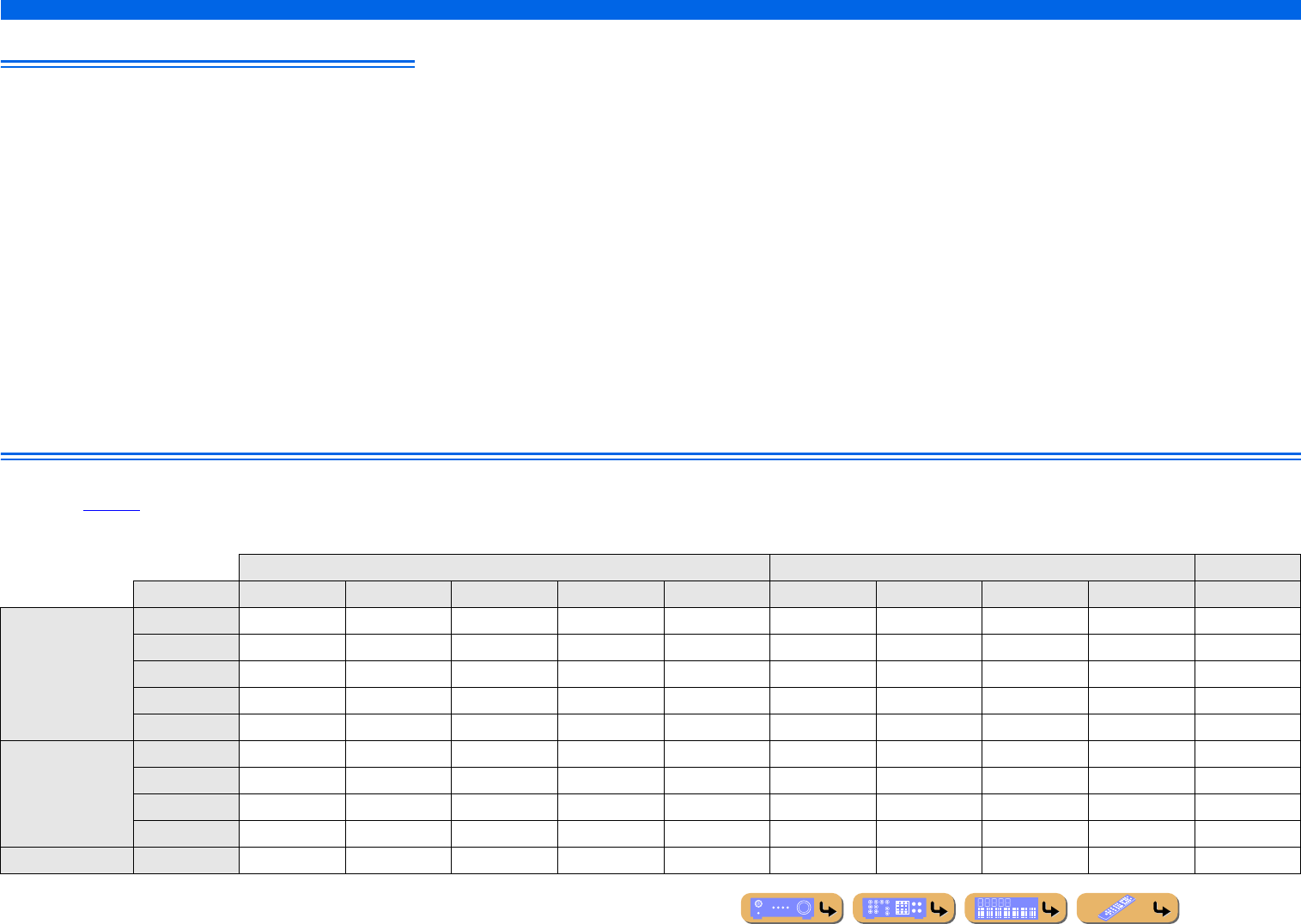
APPENDIX
Glossary
En 136
Video information
Component video signal
With the component video signal system, the video signal is separated into
the Y signal for luminance and the PB and PR signals for chrominance.
Color can be reproduced more faithfully with this system because each of
these signals is independent. The component signal is also called the “color
difference signal” because the luminance signal is subtracted from the color
signal. A monitor with component input jacks is required in order to output
component signals.
Composite video signal
With the composite video signal system, the video signal comprises the
three basic elements of a video picture: color, brightness and
synchronization data. A composite video jack on a video component
transmits these three elements combined.
Deep Color
Deep Color refers to the use of various color depths in displays, up from the
24-bit depths in previous versions of the HDMI specification. This extra bit
depth allows HDTVs and other displays increase from millions of colors to
billions of colors and eliminate on-screen color banding for smooth tonal
transitions and subtle gradations between colors. The increased contrast
ratio can represent many times more shades of gray between black and
white. Additionally, Deep Color increases the number of available colors
within the boundaries defined by the RGB or YCbCr color space.
HDMI
HDMI (High-Definition Multimedia Interface) is the first industry
supported, uncompressed, all-digital audio/video interface. Providing an
interface between any sources (such as set-top boxes or AV receivers) and
audio/video monitors (such as digital televisions), HDMI supports
standard, enhanced or high-definition video as well as multichannel digital
audio using a single cable. HDMI transmits all ATSC HDTV standards and
supports 8-channel digital audio, with bandwidth to spare to accommodate
future enhancements and requirements.
When used in combination with HDCP (High-bandwidth Digital Content
Protection), HDMI provides a secure audio/video interface that meets the
security requirements of content providers and system operators. For
further information on HDMI, visit the HDMI website at “http://
www.hdmi.org/.”
“x.v.Color”
A color space standard supported by HDMI version 1.3. It is a more
extensive color space than sRGB, and allows the expression of colors that
were not hitherto possible. While remaining compatible with the color
gamut of sRGB standards, “x.v.Color” expands the color space, and can
thus produce more vivid, natural images. It is particularly effective for still
pictures and computer graphics.
Video conversion
Analog-to-HDMI video conversion is performed according to resolution of video signals as shown below. Analog-to-analog video conversion is also possible when “Analog to Analog Conversion” is
set to “On” (☞p. 104).
✓: available conversion
HDMI output COMPONENT VIDEO output VIDEO output
Resolution 480i/576i 480p/576p 720p 1080i 1080p 480i/576i 480p/576p 720p 1080i 480i/576i
HDMI input
480i/576i ✓✓✓✓✓
480p/576p ✓✓✓✓
720p ✓
1080i ✓
1080p ✓
COMPONENT
VIDEO input
480i/576i ✓✓✓✓✓✓ ✓
480p/576p ✓✓✓✓ ✓
720p ✓ ✓
1080i ✓ ✓
VIDEO input 480i/576i ✓✓✓✓✓✓ ✓
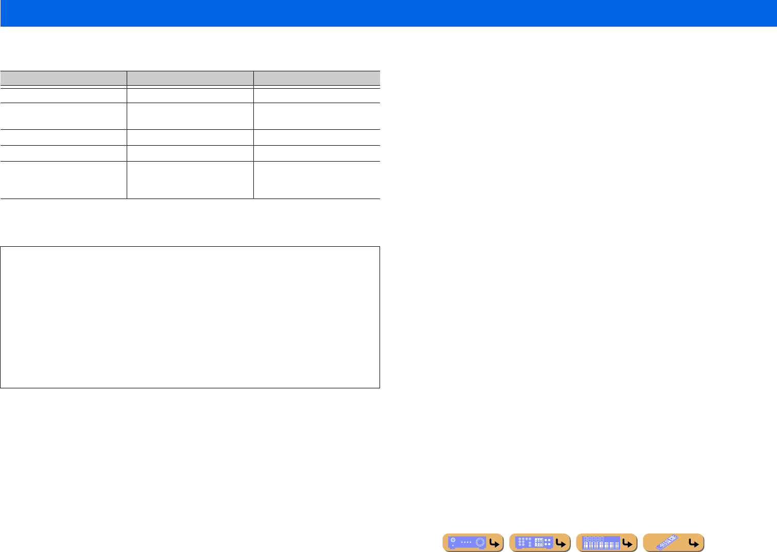
APPENDIX
En 137
■HDMI signal compatibility
Audio signals
•If the input source component can decode the bitstream audio signals of audio commentaries, you can playback the audio
sources with the audio commentaries mixed down by using the digital audio input (optical or coaxial) connections.
•Refer to the supplied instruction manuals of the input source component, and set the component appropriately.
Video signals
This unit is compatible with the video signals of the following resolutions:
Information on HDMI™
Audio signal types Audio signal formats Compatible media
2ch Linear PCM 2ch, 32-192 kHz, 16/20/24 bit CD, DVD-Video, DVD-Audio, etc.
Multi-ch Linear PCM 8ch, 32-192 kHz, 16/20/24 bit DVD-Audio, Blu-ray Disc, HD DVD,
etc.
DSD 2/5.1ch, 2.8224 MHz, 1 bit SACD, etc.
Bitstream Dolby Digital, DTS DVD-Video, etc.
Bitstream (High definition audio) Dolby TrueHD, Dolby Digital Plus,
DTS-HD Master Audio, DTS-HD
High Resolution Audio, DTS Express
Blu-ray Disc, HD DVD, etc.
NOTES
•When CPPM copy-protected DVD-Audio is played back, video and audio signals may not be output,
depending on the type of the DVD player.
•This unit is not compatible with HDCP-incompatible HDMI or DVI components.
•Refer to the supplied instruction manuals for details.
To decode audio bitstream signals on this unit, set the input source component appropriately so that the
component outputs the bitstream audio signals directly (does not decode the bitstream signals on the
component).
•This unit is not compatible with the audio commentary features (for example, the special audio contents
downloaded via Internet) of Blu-ray Disc or HD DVD. This unit does not playback the audio
commentaries of the Blu-ray Disc or HD DVD content.
–480i/60 Hz
–576i/50 Hz
–480p/60 Hz
–576p/50 Hz
–720p/60 Hz, 50 Hz
–1080i/60 Hz, 50 Hz
–1080p/60 Hz, 50 Hz, 24 Hz

APPENDIX
En 138
Manufactured under license from Dolby Laboratories. Dolby, Pro Logic and the double-D symbol are
trademarks of Dolby Laboratories.
Manufactured under license under U.S. Patent #’s:
5,451,942; 5,956,674; 5,974,380; 5,978,762; 6,226,616; 6,487,535; 7,212,872; 7,333,929; 7,392,195;
7,272,567 & other U.S. and worldwide patents issued & pending. DTS and the Symbol are registered
trademarks, & DTS-HD, DTS-HD Master Audio, and the DTS logos are trademarks of DTS, Inc.
Product includes software. © DTS, Inc. All Rights Reserved.
iPod™, iPhone™
“iPod” is a trademark of Apple Inc., registered in the U.S. and other countries. “iPhone” is a trademark
of Apple Inc.
MPEG Layer-3 audio coding technology licensed from Fraunhofer IIS and Thomson.
This receiver supports network connections.
Bluetooth™
Bluetooth is a registered trademark of the Bluetooth SIG and is used by Yamaha in accordance with a
license agreement.
“HDMI,” the “HDMI” logo and “High-Definition Multimedia Interface” are trademarks, or registered
trademarks of HDMI Licensing LLC.
x.v.Color™
“x.v.Color” is a trademark of Sony Corporation.
“SILENT CINEMA” is a trademark of Yamaha Corporation.
SIRIUS, XM and all related marks and logos are trademarks of Sirius XM Radio Inc. and its
subsidiaries. All rights reserved. Service not available in Alaska and Hawaii.
Rhapsody and the Rhapsody logo are registered trademarks of RealNetworks, Inc.
Windows XP, Windows Vista, Windows 7, Windows Media Audio, Windows Media Connect and
Windows Media Player are either registered trademarks or trademarks of Microsoft Corporation in the
United States and/or other countries.
About trademarks

APPENDIX
En 139
■Input
• Analog Audio
RCA .....................................5 (AV 5-6, AUDIO 1-2, VIDEO AUX)
MULTI CH INPUT...................................................................... 8ch
FRONT L/R, CENTER, SURROUND L/R,
SURROUND BACK L/R, SUBWOOFER
• Digital Audio
Optical .......................................................................2 (AV 1, AV 4)
Coaxial.......................................................................2 (AV 2, AV 3)
• Analog Video
Composite.................................................5 (AV 3-6, VIDEO AUX)
Component .......................................................................2 (AV 1-2)
•Other
DOCK.................................................. 1 (Audio, Composite Video)
■Output
• Analog Audio
SPEAKERS .................................................... 9ch (7ch + Extra 2ch)
FRONT L/R, CENTER, SURROUND L/R,
SURROUND BACK/BI-AMP L/R,
EXTRA SP (ZONE2/F.PRESENCE L/R)
PRE OUT..................................................................................... 9ch
FRONT L/R, CENTER, SURROUND L/R,
SURROUND BACK L/R, SUBWOOFER [Mono 2ch]
AV OUT...........................................................................................1
AUDIO OUT ...................................................................................1
ZONE2 OUT ................................................................................... 1
• Analog Video
MONITOR OUT
Composite ..................................................................................... 1
Component....................................................................................1
AV O U T
Composite ..................................................................................... 1
■HDMI
• Input .......................................................6 (HDMI 1-5, VIDEO AUX)
• Output .................................................................. 2 (HDMI OUT 1-2)
• HDMI Specification...........................HDMI Version 1.4a compatible
Deep Color, “x.v.Color,” Auto Lips Sync,
ARC (Audio Return Channel), 3D Video
•Audio Format
Dolby Digital, DTS, DSD 6ch, Dolby Digital Plus, Dolby TrueHD,
DTS-HD, PCM 2ch-8ch
• Content Protection .................................................. HDCP compatible
■Tuner
• Analog Tuner
FM/AM .......................................................................... 1 (TUNER)
• Satellite Radio Ready
SIRIUS Satellite Radio ................................................... 1 (SIRIUS)
■Network
• Ethernet (100Base-TX/10Base-TX) .................................................. 1
Internet Radio
Audio Format.............................................................. MP3, WMA
PC Server
Audio Format.............. MP3, WMA, WAV, MPEG-4 AAC, FLAC
Max Audio Support fs .............................................. 96 kHz/24 bit
Cover Art Format......................................................... PNG, JPEG
DLNA
Version ................................................1.5 (DMP & DMR support)
Audio Format.............. MP3, WMA, WAV, MPEG-4 AAC, FLAC
Max Audio Support fs .............................................. 96 kHz/24 bit
Cover Art Format......................................................... PNG, JPEG
Internet Music Service
Rhapsody, SIRIUS Internet Radio
Network Control
Web Browser Control (supporting Friendly Name only),
MusicCAST2 Commander Support, Yamaha Network Control
Support (YNC)
■Remote
• REMOTE IN.......................................................................................1
• REMOTE OUT...................................................................................1
• TRIGGER OUT .................................................................................1
■Compatible Decoding Format
• Decoding Format
Dolby TrueHD, Dolby Digital Plus, Dolby Digital,
Dolby Digital EX, DTS-HD Master Audio,
DTS-HD High Resolution, DTS Express, DTS,
DTS-ES Matrix 6.1, DTS-ES Discrete 6.1, DTS 96/24
• Post Decoding Format
Dolby Pro Logic, Dolby Pro Logic II Music,
Dolby Pro Logic II Movie, Dolby Pro Logic II Game,
Dolby Pro Logic IIx Music, Dolby Pro Logic IIx Movie,
Dolby Pro Logic IIx Game, DTS Neo:6 Music, DTS Neo:6 Cinema
Specifications
Continues to the
next page

APPENDIX
Specifications
En 140
■Audio Section
• Minimum RMS Output Power (20 Hz to 20 kHz, 0.09 % THD, 8 Ω)
FRONT L/R................................................................. 95 W + 95 W
CENTER................................................................................... 95 W
SURROUND L/R ........................................................ 95 W + 95 W
SURROUND BACK L/R ......................................................... 95 W
• Dynamic Power (IHF)
FRONT L/R, 8/6/4/2 Ω......................................130/165/195/240 W
• Dynamic Headroom
8Ω........................................................................................ 1.36 dB
• Damping Factor
FRONT L/R, 20 Hz to 20 kHz, 8 Ω.............................. 100 or more
• Input Sensitivity/Input Impedance
AV 5 etc. ....................................................................200 mV/47 kΩ
MULTI CH IN ...........................................................200 mV/47 kΩ
•Maximum Input Level
AV 5 etc. (1 kHz, 0.5 % THD) ................................... 2.3 V or more
• Output Level/Output Impedance
AV OUT....................................................................200 mV/1.2 kΩ
PRE OUT......................................................................1.0 V/1.2 kΩ
ZONE2 OUT ............................................................200 mV/1.2 kΩ
• Headphone Jack Rated Output/Impedance
AV 5 etc. (1 kHz, 50 mV, 8 Ω) ..................................100 mV/560 Ω
• Frequency Response
AV 5 etc. to FRONT L/R (10 Hz to 100 kHz) .....................+0/-3 dB
• Total Harmonic Distortion
AV 5 etc. (Pure Direct) to FRONT L/R
(20 Hz to 20 kHz, 50 W/8 Ω) ..................................... 0.06 % or less
• Signal to Noise Ratio (IHF-A Network)
AV 5 etc. (Pure Direct, input shorted, 250 mV)
to FRONT L/R .........................................................100 dB or more
• Residual Noise (IHF-A Network)
FRONT L/R................................................................150 µV or less
• Channel Separation (1 kHz/10 kHz)
AV 5 etc. (input 5.1 kΩ shorted)...................... 60 dB/45 dB or more
• Volume Control.........................................MUTE/-80 dB to +16.5 dB
• Tone Control Characteristics
Bass Boost/Cut ..............................................................±6 dB/50 Hz
Bass Turnover Frequency.......................................................350 Hz
Treble Boost/Cut .........................................................±6 dB/20 kHz
Treble Turnover Frequency ...................................................3.5 kHz
• Filter Characteristics (fc=40/60/80/90/100/110/120/160/200 Hz)
H.P.F.
(FRONT, CENTER, SURROUND,
SURROUND BACK: Small) ............................................12 dB/oct.
L.P.F. (SUBWOOFER) .....................................................24 dB/oct.
■Video Section
• Video Format (MONITOR OUT, Wall Paper/OSD) ................. NTSC
• Video Signal Type (Video Conversion) .............................NTSC/PAL
• Composite Video Signal Level ........................................ 1 Vp-p/75 Ω
• Component Video Signal Level
Y.................................................................................... 1 Vp-p/75 Ω
PB/PR.......................................................................... 0.7 Vp-p/75 Ω
• Maximum Input Level (Video Conversion Off) .......1.5 Vp-p or more
• Signal to Noise Ratio .................................................... 50 dB or more
• Monitor Out Frequency Response (Video Conversion Off)
Component ................................................... 5 Hz to 60 MHz, -3 dB
■FM Section
• Tuning Range ........................................................ 87.5 to 107.9 MHz
• 50 dB Quieting Sensitivity (IHF)
Mono..................................................................... 3.0 µV (20.8 dBf)
• Signal to Noise Ration (IHF)
Mono/Stereo ................................................................. 74 dB/70 dB
[U.S.A. model] HD .................................................................. 80 dB
• Harmonic Distortion (1 kHz)
Mono/Stereo ..................................................................0.3 %/0.3 %
• Antenna Input .........................................................75 Ω (unbalanced)
■AM Section
• Tuning Range ............................................................530 to 1710 kHz
■General
• Power Supply............................................................ AC 120 V, 60 Hz
• Power Consumption .....................................................400 W/500 VA
• Standby Power Consumption (Reference Data)
HDMI Control Off/Standby Through Off.....................0.2 W or less
HDMI Control On/Standby Through On
(Input: HDMI 1, no HDMI signal is input) .............. 2.7 W (typical)
NET Standby On....................................................... 4.5 W (typical)
• Dimensions (W x H x D)
................................ 435 x 171 x 363mm (17-1/8 x 6-3/4 x 14-1/2 in)
• Weight..................................................................... 11.3 kg (24.9 lbs.)
* Specifications are subject to change without notice.

APPENDIX
En 141
Numerics
5 channel speaker layout.............................................................. 16
5.1-channel speaker layout........................................................... 15
7.1-channel speaker connection ................................................... 17
7.1-channel speaker layout........................................................... 14
A
Account Status, Input menu......................................................... 88
Adaptive DRC, Option menu....................................................... 54
Advanced Setup menu ............................................................... 118
All channel search mode.............................................................. 63
AM antenna connection ............................................................... 33
AM tuning .................................................................................... 57
Analog to Analog Conversion, Video Setup.............................. 104
ARC (Audio Return Channel), HDMI Setup............................. 106
Aspect, Processing, Video Setup ............................................... 105
Audio information, Information menu....................................... 113
Audio Input, Input menu.............................................................. 88
AUDIO jack ................................................................................. 21
Audio Output, HDMI Setup....................................................... 107
Audio Return Channel function ................................................. 123
Auto Power Down, Function Setup ........................................... 110
Auto Preset................................................................................... 60
Auto Setup, Speaker Setup .......................................................... 99
B
BD player connection .................................................................. 25
Bi-amp connection, speaker......................................................... 18
Bluetooth™ component playback................................................ 83
Bookmark Off, Internet Radio ..................................................... 69
Bookmark On, Internet Radio...................................................... 69
Browse view................................................................................. 56
C
Cable plug .................................................................................... 21
Category search mode.................................................................. 63
Center Image, Sound Program menu ........................................... 97
Center Level, Sound Program menu............................................ 96
Center speaker............................................................................. 13
Center Width, Sound Program menu .......................................... 97
Changing speaker impedance...................................................... 18
CINEMA DSP 3D mode ............................................................. 46
CINEMA DSP 3D Mode, Option menu ..................................... 54
CINEMA DSP indicator ............................................................. 10
Clear All Preset ..................................................................... 60, 66
Clear Preset ........................................................................... 60, 66
COAXIAL jack ........................................................................... 21
COMPONENT VIDEO jack....................................................... 21
Compressed Music Enhancer ...................................................... 47
Configuration, Manual Setup, Speaker Setup ........................... 100
Connect, Option menu ................................................................ 55
Connecting speakers.................................................................... 17
Connecting to network ................................................................ 32
Connections................................................................................. 13
Content window .......................................................................... 56
Control Select, HDMI Setup ..................................................... 106
Cursor indicators ......................................................................... 10
D
Decode Type, Sound Program menu .................................... 96, 97
Decoder Mode, Input menu......................................................... 88
Dialogue Lift, Option menu ........................................................ 54
Dimension, Sound Program menu .............................................. 97
Direct number access mode ........................................................ 63
Direct, Sound Program menu...................................................... 96
Disconnect, Option menu............................................................ 55
Display Set, Function Setup ...................................................... 110
Distance, Speaker Setup............................................................ 101
DMC Control, Input menu .......................................................... 88
DSP Level, Sound Program menu .............................................. 94
DVD player connection............................................................... 25
Dynamic Range, Sound Setup................................................... 103
E
Enhancer, Input menu ................................................................. 89
Extended Surround, Option menu............................................... 55
External component connection .................................................. 21
External decoder connection ....................................................... 29
F
FIRM UPDATE, Advanced Setup menu .................................. 120
FM antenna connection ............................................................... 33
FM Mode..................................................................................... 59
FM tuning .................................................................................... 57
Front panel..................................................................................... 8
Front panel display ...................................................................... 10
Front Presence L Level, Sound Program menu........................... 96
Front Presence R Level, Sound Program menu .......................... 97
Front speaker ............................................................................... 13
Function Setup........................................................................... 109
G
Game connection......................................................................... 29
H
HDMI Control function............................................................. 121
HDMI Control, HDMI Setup .................................................... 106
HDMI indicator ........................................................................... 10
HDMI jack................................................................................... 21
HDMI monitor, Information menu............................................ 113
HDMI Setup .............................................................................. 105
High-frequency sound adjustment............................................... 43
I
Information menu ...................................................................... 113
INIT, Advanced Setup menu..................................................... 120
Initial Delay, Sound Program menu ............................................ 94
Initial Volume, Sound Setup ..................................................... 104
Input menu................................................................................... 86
Input menu list............................................................................. 87
Internet Radio .............................................................................. 69
IP Address, Network setup........................................................ 108
iPhone™ playback ...................................................................... 79
iPod Interlock, Input menu.......................................................... 89
Index

APPENDIX
Index
En 142
iPod wireless system .................................................................... 81
iPod™ playback........................................................................... 79
J
Jack .............................................................................................. 21
L
Language.................................................................................... 112
Level, Speaker Setup ................................................................. 101
Lipsync, Sound Setup ................................................................ 103
Liveness, Sound Program menu .................................................. 95
Load, SCENE menu..................................................................... 91
Low-frequency sound adjustment................................................ 43
M
MAC Address Filter, Network setup ......................................... 108
Manual Preset............................................................................... 57
Manual Setup, Speaker Setup ...................................................... 99
Manual Tuning............................................................................. 59
Max Volume, Sound Setup ........................................................ 103
Memory Guard, Function Setup ................................................ 112
Menu browse control ................................................................... 80
MON.CHK, Advanced Setup menu........................................... 120
Multi information display ............................................................ 10
Multi Zone ................................................................................. 109
Multi-format player connection ................................................... 29
Multi-zone function ................................................................... 125
MUTE indicator ........................................................................... 10
N
Network connection ..................................................................... 32
NETWORK port .......................................................................... 32
Network setup ............................................................................ 108
Network Standby, Network setup .............................................. 108
Network, Information menu....................................................... 114
Normal tuning .............................................................................. 57
Now Playing view........................................................................ 56
O
ON SCREEN menu..................................................................... 50
On-screen display........................................................................ 12
OPTICAL jack ............................................................................ 21
Option menu................................................................................ 52
Option menu list.......................................................................... 53
P
Pairing, Option menu .................................................................. 55
Panorama, Sound Program menu................................................ 97
Parametric EQ, Speaker Setup .................................................. 102
Party Mode Set, Multi Zone...................................................... 109
PC................................................................................................ 67
PHONES jack................................................................................ 8
Play Control, DOCK (iPod) ........................................................ 81
Play Control, Internet Radio ....................................................... 70
Play Control, PC.................................................................... 68, 74
Play Control, Rhapsody .............................................................. 74
Play Control, SIRIUS Internet Radio.......................................... 77
Portable audio player connection ................................................ 29
Power Amp Assign, Manual Setup, Speaker Setup .................... 99
PREOUT connection................................................................... 30
Presence speaker ......................................................................... 13
Presence speaker layout .............................................................. 15
Preset Select ................................................................................ 59
Pure Direct mode......................................................................... 47
R
Radio Control .............................................................................. 65
Rear panel...................................................................................... 9
Remote control ............................................................................ 11
Remote control battery installation ............................................... 7
Remote control connection ......................................................... 30
Remote control, Controlling other components........................ 115
REMOTE ID, Advanced Setup menu....................................... 119
Remove Account, Input menu..................................................... 89
Rename/Icon Select, Input menu ................................................ 88
Rename/Icon Select, Scene menu ............................................... 92
Repeat, Option menu................................................................... 55
Reset, Scene menu....................................................................... 92
Resolution, Processing, Video Setup ........................................ 105
Reverb Delay, Sound Program menu .......................................... 95
Reverb Level, Sound Program menu .......................................... 96
Reverb Time, Sound Program menu ........................................... 95
Rhapsody Trial, Input menu........................................................ 89
Rhapsody®................................................................................... 71
Room Size, Sound Program menu .............................................. 94
S
Satellite Radio ............................................................................. 61
Save, SCENE menu..................................................................... 91
SCENE function .......................................................................... 44
SCENE menu .............................................................................. 90
Setup menu .................................................................................. 98
Shortcut function ......................................................................... 78
Shuffle, Option menu .................................................................. 55
Sign In, Input menu ..................................................................... 89
SILENT CINEMA mode............................................................. 46
Simple remote control ................................................................. 81
SIRIUS Internet Radio ................................................................ 75
SIRIUS Satellite Radio................................................................ 61
SiriusConnect™ tuner ................................................................. 61
Sound program ............................................................................ 44
Sound Program menu .................................................................. 93
Sound Setup............................................................................... 103
SP IMP., Advanced Setup menu ............................................... 118
Speaker connection...................................................................... 13
Speaker indicators ....................................................................... 10
Speaker layout ............................................................................. 14
Speaker setting ............................................................................ 34
Speaker Setup .............................................................................. 99
SR PIN, Advanced Setup menu ................................................ 119
Standby Charge, Input menu....................................................... 89
Standby Through, HDMI Setup ................................................ 107
Straight Decoding Mode ............................................................. 45
Subwoofer ................................................................................... 13
Supplied accessories...................................................................... 7
Surround Back Initial Delay, Sound Program menu................... 94
Surround Back L Level, Sound Program menu .......................... 96

APPENDIX
Index
En 143
Surround Back Liveness, Sound Program menu ......................... 95
Surround Back R Level, Sound Program menu........................... 96
Surround Back Room Size, Sound Program menu...................... 94
Surround back speaker................................................................. 13
Surround Initial Delay, Sound Program menu............................. 94
Surround L Level, Sound Program menu .................................... 96
Surround Liveness, Sound Program menu................................... 95
Surround R Level, Sound Program menu .................................... 96
Surround Room Size, Sound Program menu ............................... 94
Surround speaker ......................................................................... 13
T
Test Tone, Speaker Setup .......................................................... 102
Tone control ................................................................................. 43
Tone Control, Option menu ......................................................... 54
Trigger connection ....................................................................... 31
Trigger Output, Function Setup ................................................. 111
Tuner indicators ........................................................................... 10
TV Audio Input, HDMI Setup ................................................... 106
TV FORMAT, Advanced Setup menu ...................................... 120
TV monitor connection ................................................................ 22
V
VERSION, Advanced Setup menu ............................................ 120
VIDEO AUX input cover .............................................................. 7
Video information, Information menu ....................................... 113
VIDEO jack ................................................................................. 21
Video Out, Input menu ................................................................ 89
Video Setup................................................................................ 104
Virtual CINEMA DSP 3D mode ................................................. 46
Virtual CINEMA DSP mode ....................................................... 46
VOLUME ...................................................................................... 8
VOLUME indicator ..................................................................... 10
Volume Trim, Option menu......................................................... 55
Y
YPAO........................................................................................... 34
Z
Zone Rename, Multi Zone setup............................................... 109
Zone2 Set, Multi Zone .............................................................. 109

© 2010 Yamaha Corporation YD000A0/OMEN
