Yamaha Rx Sl80 Owners Manual
Rx-Sl80-Owners-Manual yamaha-rx-sl80-owners-manual-133611
RX-SL80 to the manual 913e9dd9-2349-4976-be1e-731996d6bc21
2014-12-13
: Yamaha Rx-Sl80-Owners-Manual yamaha-rx-sl80-owners-manual-133611 pdf
Open the PDF directly: View PDF ![]() .
.
Page Count: 77
- CONTENTS
- INTRODUCTION
- PREPARATION
- BASIC OPERATION
- SOUND FIELD PROGRAMS
- ADVANCED OPERATION
- ADDITIONAL INFORMATION
- LIST OF REMOTE CONTROL CODES
- NS-P240.pdf
YAMAHA ELECTRONICS CORPORATION, USA
6660 ORANGETHORPE AVE., BUENA PARK, CALIF. 90620, U.S.A.
YAMAHA CANADA MUSIC LTD.
135 MILNER AVE., SCARBOROUGH, ONTARIO M1S 3R1, CANADA
YAMAHA ELECTRONIK EUROPA G.m.b.H.
SIEMENSSTR. 22-34, 25462 RELLINGEN BEI HAMBURG, F.R. OF GERMANY
YAMAHA ELECTRONIQUE FRANCE S.A.
RUE AMBROISE CROIZAT BP70 CROISSY-BEAUBOURG 77312 MARNE-LA-VALLEE CEDEX02, FRANCE
YAMAHA ELECTRONICS (UK) LTD.
YAMAHA HOUSE, 200 RICKMANSWORTH ROAD WATFORD, HERTS WD18 7GQ, ENGLAND
YAMAHA SCANDINAVIA A.B.
J A WETTERGRENS GATA 1, BOX 30053, 400 43 VÄSTRA FRÖLUNDA, SWEDEN
YAMAHA MUSIC AUSTRALIA PTY, LTD.
17-33 MARKET ST., SOUTH MELBOURNE, 3205 VIC., AUSTRALIA
©
2004 All rights reserved.
AV Receiver
Ampli-tuner audio-vidéo
RX-SL80
OWNER’S MANUAL
MODE D’EMPLOI
BEDIENUNGSANLEITUNG
BRUKSANVISNING
MANUALE DI ISTRUZIONI
MANUAL DE INSTRUCCIONES
GEBRUIKSAANWIJZING
GB
INPUT
VOLUME/SELECT
DSPTUNER
AUTO/MAN'L
PUSH-ENTER
STANDBY
/ON
SILENT CINEMA VIDEO AUDIO
VIDEO 2
PHONES
OPTICALL R
Printed in Malaysia WD87190
LIST OF REMOTE CONTROL CODES ELENCO CODICI DI TELECOMANDO
LISTE DES CODES DE COMMANDE LISTA DE CÓDIGOS DE MANDO A DISTANCIA
LISTE DER FERNBEDIENUNGSCODES LIJST MET AFSTANDSBEDIENINGSCODES
LISTA ÖVER FJÄRRKONTROLLKODER
TV
YAMAHA 299, 292
ADMIRAL 292, 293
AIWA 294, 276,
283, 284
AKAI 295, 296
ALBA 296
AOC 297
BELL&HOWELL 292
BESTAR 298
BLAUPUNKT 229, 222
BLUE SKY 298
BRANDT 223
BROCSONIC 297
BUSH 296
CLATRONIC 298
CRAIG 224
CROSLEX 225
CURTIS MATHIS 297, 226
DAEWOO 297, 298,
224, 227, 228
DAYTRON 239
DUAL 298
EMERSON 297, 224,
239, 232
FERGUSON 223, 265, 266
FIRST LINE 298
FUNAI 277, 278
FISHER 295, 233
FRABA 298
GE 293, 297,
234, 235, 236
LG/GOLDSTAR 297, 298,
239, 237
GOODMANS 296, 298, 223
GRUNDIG 229, 238, 249
HITACHI 297, 239,
242, 243, 285
ICE 296
IRRADIO 296
ITT/NOKIA 244,245
JC PENNY 293, 297,
234, 237
JVC 296, 246,
247, 286
KENDO 298
KTV 297, 239
LOEWE 298, 248
LXI 293, 297,
225, 226, 233
MAGNAVOX 297, 225, 239
MATSUI 295
MITSUBISHI 299, 297,
259, 287
NEC 297, 252, 282
NOKIA 244, 245
NOKIA OCEANIC 245
NORDMENDE 265, 266
ONWA 296
PANASONIC 234, 235,
236, 253,
288, 211
PHILCO 297, 225, 239
PHILIPS 225
PIONEER 226, 235,
254, 255, 268
PORTLAND 297, 256
QUASAR 234, 235
RADIO SHACK 299, 293, 297
RCA 293, 297,
234, 256,
257, 258
SABA 223, 269,
265, 266
SAMSUNG 297, 239,
248, 262, 275
SANYO 295, 233,
279, 272,
273, 274, 212
SCHNEIDER 296
SCOTT 297
SHARP 292, 239,
232, 213, 216
SIEMENS 229
SIGNATURE 292
SONY 263, 214
SYLVANIA 297, 225
TELEFUNKEN 269, 264,
265, 266
THOMSON 223, 266
TOSHIBA 292, 226,
267, 215
VIDECH 297, 242
WARDS 297, 239, 232
VCR
YAMAHA 399, 392,
393, 394
ADMIRAL 395
AIWA 396, 397,
398, 329, 339
AKAI 322, 323, 324
AUDIO DYNAMIC 392, 394
BELL&HOWELL 393
BLAUPUNKT 325, 326
BROCSONIC 327
BUSH 322
CANON 325, 328
CGM 396, 332
CITIZEN 396
CRAIG 396
CURTIS MATHIS 397, 328, 333
DAEWOO 3328, 334,
335
DBX 3392, 394
DIMENSIA 333
EMERSON 327, 334
FISHER 393, 336
FUNAI 397
GE 328, 333, 387
LG/GOLDSTAR 396, 388
GOODMANS 334, 337
GRUNDIG 332, 338
HITACHI 325, 333,
349, 342, 343
INSTANT REPLAY 325, 328
ITT/NOKIA 393
JC PENNY 392, 393,
394, 328,
333, 349
JVC 392, 394,
344, 345,
346, 347
KENDO 396
KENWOOD 392, 394, 396
LOEWE 396, 337
LUXOR 395
LXI 393, 396,
397, 336, 349
MAGNAVOX 325, 326, 328
MARANTZ 392, 394
MARTA 396
MATSUI 396
MEMOREX 328, 336
MINOLTA 333, 349
MITSUBISHI 399, 344,
348, 359,
352, 353
MULTITECH 397, 348, 354
NEC 392, 394,
344, 383
NOKIA 393, 395
NOKIA OCEANIC 395
OKANO 323
OLYMPIC 325, 328
ORION 327
PANASONIC 325, 328,
339, 355,
378, 384,
385, 386
PENTAX 333, 349
PHILCO 325, 328
PHILIPS 325, 326,
328, 337,
356, 357
PHONOLA 337
PIONEER 325
QUASAR 325, 328
RCA/PROSCAN 325, 326,
328, 333,
335, 349,
358, 369
REALISTIC 393, 397,
328, 336,
359, 362
SAMSUNG 354, 358,
363, 364,
365, 366
SANSUI 394
SANYO 393, 336, 367
SCHNEIDER 337
SCOTT 399, 335,
336, 348,
359, 352,
354, 358
SELECO 322
SHARP 395, 362, 382
SIEMENS 393
SIGNATURE 2000 395, 397
SONY 368, 379,
372, 373,
374, 375
SYLVANIA 397, 325,
326, 328
SYMPHONIC 397
TANDBERG 334
TASHIRO 396
TATUNG 392, 394
TEAC 392, 394, 397
TECHNICS 325, 328
TELEFUNKEN 376, 377
THORN 393, 396
TOSHIBA 335, 369, 389
UNIVERSUM 396, 327, 376
W.WHOUSE 396
WARDS 395, 396,
336, 362
DVD
YAMAHA 699, 622, 623
DENON 623, 624
FUNAI 625
HITACHI 626
JVC 627
KENWOOD 628
MITSUBISHI 629
ONKYO 632, 633, 634
PANASONIC 623, 635
PHILIPS 699, 647
PIONEER 636, 637, 638
RCA 639
SAMSUNG 642
SHARP 643
SONY 644
TOSHIBA 634, 648, 649
LG/GOLD STAR 645
THOMSON 646
RX-SL80
This product mainly uses lead-free solder.
Cet appareil utilise principalement de la soudure sans plomb.
Dieses Produkt verwendet hauptsächlich bleifreies Lot.
I den här produkten används huvudsakligen blyfri lödmetall.
Questo prodotto usa principalmente lega per saldatura senza piombo.
Este producto utiliza principalmente soldadura sin plomo.
Dit product maakt hoofdzakelijk gebruik van loodvrij soldeer.
RX-SL80_GB-cv.fm Page 1 Thursday, August 19, 2004 7:35 PM
CAUTION: READ THIS BEFORE OPERATING YOUR UNIT.
1 To assure the finest performance, please read this
manual carefully. Keep it in a safe place for future
reference.
2 Install this sound system in a well ventilated, cool,
dry, clean place — away from direct sunlight, heat
sources, vibration, dust, moisture, and/or cold.
Allow ventilation space of at least 5 cm on the top,
5 cm on the left and right, and 10 cm on the back of
this unit.
3 Locate this unit away from other electrical
appliances, motors, or transformers to avoid
humming sounds.
4 Do not expose this unit to sudden temperature
changes from cold to hot, and do not locate this unit
in a environment with high humidity (i.e. a room with
a humidifier) to prevent condensation inside this
unit, which may cause an electrical shock, fire,
damage to this unit, and/or personal injury.
5 Avoid installing this unit where foreign object may
fall onto this unit and/or this unit may be exposed to
liquid dripping or splashing. On the top of this unit,
do not place:
– Other components, as they may cause damage
and/or discoloration on the surface of this unit.
– Burning objects (i.e. candles), as they may cause
fire, damage to this unit, and/or personal injury.
– Containers with liquid in them, as they may fall
and liquid may cause electrical shock to the user
and/or damage to this unit.
6 Do not cover this unit with a newspaper, tablecloth,
curtain, etc. in order not to obstruct heat radiation. If
the temperature inside this unit rises, it may cause
fire, damage to this unit, and/or personal injury.
7 Do not plug in this unit to a wall outlet until all
connections are complete.
8 Do not operate this unit upside-down. It may
overheat, possibly causing damage.
9 Do not use force on switches, knobs and/or cords.
10 When disconnecting the power cord from the wall
outlet, grasp the plug; do not pull the cord.
11 Do not clean this unit with chemical solvents; this
might damage the finish. Use a clean, dry cloth.
12 Only voltage specified on this unit must be used.
Using this unit with a higher voltage than specified
is dangerous and may cause fire, damage to this
unit, and/or personal injury. YAMAHA will not be
held responsible for any damage resulting from use
of this unit with a voltage other than specified.
13 To prevent damage by lightning, disconnect the
power cord from the wall outlet during an electrical
storm.
14 Do not attempt to modify or fix this unit. Contact
qualified YAMAHA service personnel when any
service is needed. The cabinet should never be
opened for any reasons.
15 When not planning to use this unit for long periods
of time (i.e. vacation), disconnect the AC power plug
from the wall outlet.
16 Be sure to read the “TROUBLESHOOTING” section
on common operating errors before concluding that
this unit is faulty.
17 Before moving this unit, press STANDBY/ON to set
this unit in the standby mode, and disconnect the
AC power plug from the wall outlet.
■For U.K. customers
If the socket outlets in the home are not suitable for the
plug supplied with this appliance, it should be cut off and
an appropriate 3 pin plug fitted. For details, refer to the
instructions described below.
The plug severed from the mains lead must be destroyed, as a
plug with bared flexible cord is hazardous if engaged in a live
socket outlet.
■Special Instructions for U.K. Model
CAUTION: READ THIS BEFORE OPERATING YOUR UNIT.
WARNING
TO REDUCE THE RISK OF FIRE OR ELECTRIC
SHOCK, DO NOT EXPOSE THIS UNIT TO RAIN
OR MOISTURE.
This unit is not disconnected from the AC power source as
long as it is connected to the wall outlet, even if this unit itself
is turned off. This state is called the standby mode. In this
state, this unit is designed to consume a very small quantity of
power.
Note
IMPORTANT
THE WIRES IN MAINS LEAD ARE COLOURED IN
ACCORDANCE WITH THE FOLLOWING CODE:
Blue: NEUTRAL
Brown: LIVE
As the colours of the wires in the mains lead of this
apparatus may not correspond with the coloured
markings identifying the terminals in your plug,
proceed as follows:
The wire which is coloured BLUE must be connected
to the terminal which is marked with the letter N or
coloured BLACK. The wire which is coloured
BROWN must be connected to the terminal which is
marked with the letter L or coloured RED.
Making sure that neither core is connected to the earth
terminal of the three pin plug.

1
English
PREPARATION
INTRODUCTION
BASIC
OPERATION
SOUND FIELD
PROGRAMS ADVANCED
OPERATION
ADDITIONAL
INFORMATION
FEATURES............................................................. 2
GETTING STARTED............................................ 3
Supplied accessories .................................................. 3
Installing batteries in the remote control ................... 3
CONTROLS AND FUNCTIONS ......................... 4
Front panel ................................................................. 4
Remote control (AMP mode) .................................... 5
Using the remote control ........................................... 6
Front panel display .................................................... 7
SPEAKER SETUP ................................................. 8
Speaker placement ..................................................... 8
Speaker connections .................................................. 9
CONNECTIONS .................................................. 12
Before connecting components................................ 12
Connecting other components ................................. 13
Connecting the antennas.......................................... 14
Connecting the power.............................................. 15
Turning on the power............................................... 15
BASIC SETUP...................................................... 16
Using BASIC setup.................................................. 16
PLAYBACK.......................................................... 18
Basic operations....................................................... 18
Selecting sound field programs ............................... 20
TUNING ................................................................ 22
Automatic and manual tuning.................................. 22
Presetting stations .................................................... 24
Selecting preset stations........................................... 25
Receiving RDS stations ........................................... 26
Changing the RDS mode ......................................... 27
PTY SEEK function ................................................ 27
EON function........................................................... 28
RECORDING ....................................................... 29
Recording in standby mode
(SCART SET setting).......................................... 29
SOUND FIELD PROGRAM
DESCRIPTIONS...............................................30
For movie/video sources.......................................... 30
For music sources .................................................... 32
ADVANCED OPERATIONS ..............................33
Using the sleep timer ............................................... 33
Enjoying multi-channel software............................. 33
Enjoying 2-channel software ................................... 34
Virtual CINEMA DSP............................................. 35
Selecting input modes.............................................. 35
Manually adjusting speaker levels........................... 37
Using the test tone ................................................... 37
SET MENU ............................................................38
Changing parameter settings ................................... 39
1 SOUND MENU.................................................... 40
2 INPUT MENU...................................................... 43
3 OPTION MENU................................................... 44
REMOTE CONTROL FEATURES ...................46
Control area ............................................................. 46
Setting remote control codes ................................... 47
Controlling other components ................................. 48
EDITING SOUND FIELD PARAMETERS ......49
What is a sound field ............................................... 49
Sound field parameter descriptions ......................... 49
TROUBLESHOOTING .......................................51
GLOSSARY...........................................................55
Audio formats .......................................................... 55
Sound field programs............................................... 56
Audio information ................................................... 56
Video signal information ......................................... 56
SPECIFICATIONS...............................................57
CONTENTS
INTRODUCTION
PREPARATION
BASIC OPERATION
SOUND FIELD PROGRAMS
ADVANCED OPERATION
ADDITIONAL INFORMATION
FEATURES
2
Built-in 5-channel original Yamaha digital
power amplifier
◆Minimum RMS output power
(0.9% THD, 1 kHz, 6 Ω)
Front: 70 W + 70 W
Center: 70 W
Surround: 70 W + 70 W
Sound field features
◆Proprietary YAMAHA technology for the creation of
sound fields
◆Dolby Pro Logic/Dolby Pro Logic II decoder
◆Dolby Digital/Dolby Digital + Matrix 6.1 decoder
◆DTS/DTS + Matrix 6.1 decoder
◆DTS 96/24 decoder
◆Virtual CINEMA DSP
◆SILENT CINEMA™
Sophisticated AM/FM tuner
◆40-station random access preset tuning
◆Automatic preset tuning
Other features
◆96-kHz/24-bit D/A converter
◆“SET MENU” which provides you with items for
optimizing this unit for your audio/video system
◆Screen Menu display output to your TV monitor
◆Slim-line design
◆Optical and coaxial digital audio signal jacks
◆Sleep timer
◆Night listening mode
◆Remote control with preset remote control codes
•y indicates a tip for your operation.
• Some operations can be performed by using either the buttons on the main unit or on the remote control. In cases when the button
names differ between the main unit and the remote control, the button name on the remote control is given in parentheses.
• This manual is printed prior to production. Design and specifications are subject to change in part as a result of improvements, etc. In
case of differences between the manual and product, the product has priority.
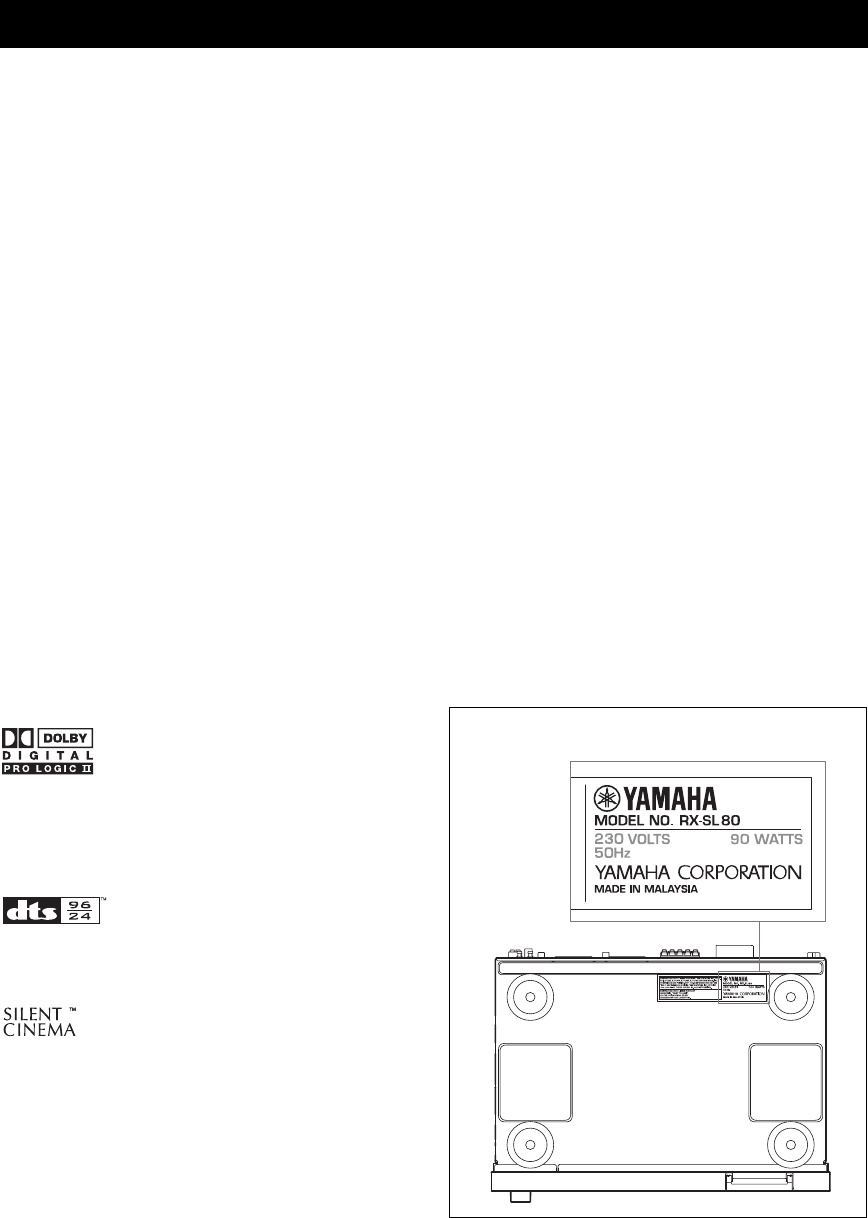
Manufactured under license from Dolby Laboratories.
“Dolby”, “Pro Logic”, and the double-D symbol are trademarks
of Dolby Laboratories.
“DTS” and “DTS 96/24” are trademarks of Digital Theater
Systems, Inc.
“SILENT CINEMA” is a trademark of YAMAHA
CORPORATION.
FEATURES
• The following name plate is located on the bottom of this unit.
GETTING STARTED
3
English
INTRODUCTION
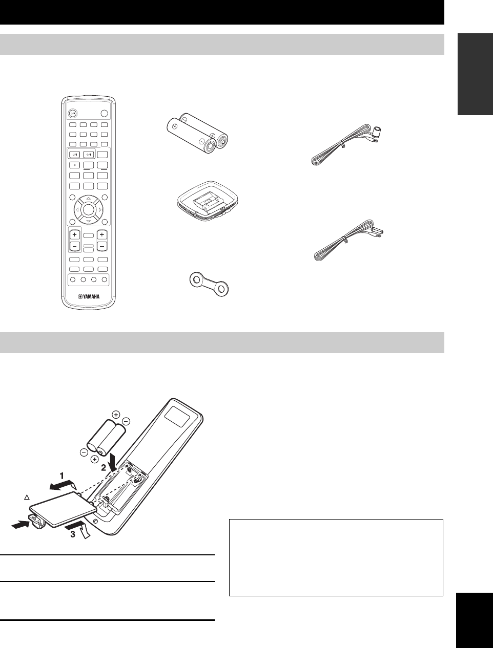
Please check that you received all of the following parts.
Insert the batteries in the correct direction by aligning the
+ and – marks on the batteries with the polarity markings
(+ and –) inside the battery component.
1Remove the back cover.
2Insert the two supplied batteries (AA, R6,
UM-3) into the battery compartment.
3Close the back cover.
Notes on batteries
• Change all of the batteries if you notice that the operation range
of the remote control has decreased.
• Do not use old batteries together with new ones.
• Do not use different types of batteries (such as alkaline and
manganese batteries) together. Read the packaging carefully as
these different types of batteries may have the same shape and
color.
• If the batteries ran out, immediately remove them from the
remote control to prevent an explosion or acid leak.
• Dispose of the batteries according to the regional regulations.
• If the batteries have leaked, dispose of them immediately. Avoid
touching the leaked material or letting it come into contact with
clothing, etc. Clean the battery compartment thoroughly before
installing new batteries.
GETTING STARTED
Supplied accessories
1
STEREO
2
HALL
3
JAZZ
4
ROCK
SLEEP
STANDBY/ON
5
MUSIC
6
ENTERTAIN
7
TV THTR
8
MOVIE
9
TV AV
CODE SET
REC FREQ/RDS
PTY SEEK
EON
sAUDIO
w
DISC SKIP MODE START
e f
b
A/B/C/D/E
TITLE
LEVEL
ENTER
CH
–
CH
+
p
d
MUTE
TV VOL VOLUME
AMP
VCRDVD/CD VIDEO 1
TUNERDTV/CBL VIDEO 2
PRESET
a
u
STANDARD
0
NIGHT
+10
EXTD SUR.
ENT
STRAIGHT
EFFECT
MUTE INPUT
–
CH
TV MODE
+
MENU
SET MENU
RETURN
TEST/
RETURN
DISPLAY
Remote control
Indoor FM antenna
(U.S.A., Canada, China, Asia
and General models)
(U.K., Europe, Australia
and Korea models)
Batteries (2)
(AA, R6, UM-3)
AM loop antenna
Remote control
Cable tags (5 pairs)
Installing batteries in the remote control
Check +/–
polarity
Press
If the remote control is without batteries for more than
3 minutes, or if exhausted batteries remain in the
remote control, the contents of the memory may be
cleared. When the memory is cleared, insert new
batteries, set up the remote control code and program
any acquired functions that may have been cleared.
CONTROLS AND FUNCTIONS
4
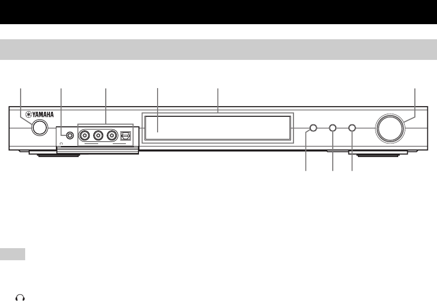
1STANDBY/ON
Turns on this unit or sets it to the standby mode. When you
turn on this unit, you will hear a click and there will be a 4
to 5-second delay before this unit can reproduce sound.
In standby mode, this unit consumes a small amount of power in
order to receive infrared-signals from the remote control.
2PHONES (SILENT CINEMA) jack
Outputs audio signals for headphones. When you connect
headphones, no signals are output to the speakers.
All Dolby Digital and DTS audio signals are mixed down
to the left and right headphone channels.
3VIDEO 2 jacks
Input audio and video signals from a portable external
source such as a game console. To reproduce source
signals from these jacks, select VIDEO 2 as the input
source.
4Remote control sensor
Receives signals from the remote control.
5Front panel display
Shows information about the operational status of this
unit.
6VOLUME/SELECT
Adjusts the volume and the tone control. Also selects
stations, sound field programs or input sources (etc.) when
used together with TUNER, DSP, INPUT. If no operation
is performed within 5 seconds of pressing TUNER, DSP,
INPUT, the VOLUME/SELECT function automatically
returns to volume.
7INPUT
Activates the input select mode.
Activates the AM, FM or preset tuning mode when
TUNER is selected as the input source.
8DSP
Switches between the DSP sound field, STEREO and
STRAIGHT modes.
9TUNER (AUTO/MAN’L)
Activates the tuning mode when TUNER is selected as the
input source. Press before turning VOLUME/SELECT to
tune in frequencies or preset radio stations.
Switches the AM/FM tuning mode between automatic
(“AUTO” indicator on) and manual (“AUTO” indicator
off) tuning.
CONTROLS AND FUNCTIONS
Front panel
INPUT
VOLUME/SELECT
DSPTUNER
AUTO/ MAN 'L
PUSH-ENTER
STANDBY
/ON
SILENT CINEMA
VIDEO AUDIO
VIDEO 2
PHONES
OPTICALL R
12 3 5 6
789
4
Note
CONTROLS AND FUNCTIONS
5
English
INTRODUCTION
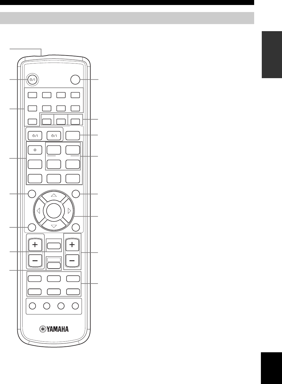
Make sure that the AMP mode is selected before starting
operation.
1Infrared window
Outputs infrared control signals. Aim this window at the
component you want to operate.
2STANDBY/ON
Switches the unit on and sets it in the STANDBY mode.
3DSP program / Numeric buttons
Use to select sound field programs or input numbers
according to the current control area.
4Operation buttons
Provide functions such as play, stop, skip, etc. for use
when operating other components.
5LEVEL
Selects the speaker channel to be adjusted and sets the
level.
6TEST/RETURN
Outputs the test tone to adjust the speaker levels.
Returns to the previous menu level when adjusting the
SET MENU parameters.
7MUTE
Mutes the sound. Press again to restore the audio output to
the previous volume level.
8AMP
Sets the remote control to the AMP mode for controlling
this unit (instead of the component selected using the
input selector buttons).
9SLEEP
Sets the sleep timer.
0NIGHT
Turns night listening mode on or off.
AEXTD SUR.
Switches on or off the Dolby Digital + Matrix 6.1 or DTS
+ Matrix 6.1 decoding mode.
BSTRAIGHT/EFFECT
Switches the sound fields off or on. When STRAIGHT is
selected, input signals (2-channel or multi-channel) are
output directly from their respective speakers without
effect processing.
CCODE SET
Used to set up remote control codes.
Remote control (AMP mode)
1
STEREO
2
HALL
3
JAZZ
4
ROCK
SLEEP
STANDBY/ON
5
MUSIC
6
ENTERTAIN
7
TV THTR
8
MOVIE
9
TV AV
CODE SET
REC FREQ/RDS EON
sAUDIO
w
DISC SKIP PTY SEEK
MODE START
e f
b
A/B/C/D/E
TITLE
LEVEL
ENTER
CH
–
CH
+
p
d
MUTE
TV VOL VOLUME
AMP
VCRDVD/CD VIDEO 1
TUNERDTV/CBL VIDEO 2
PRESET
a
u
STANDARD
0
NIGHT
+10
EXTD SUR.
ENT
STRAIGHT
EFFECT
MUTE INPUT
–
CH
TV MODE
+
MENU
SET MENU
RETURN
TEST/
RETURN
DISPLAY
1
2
3
5
6
7
8
9
F
0,A,B
C
D
E
G
H
4

CONTROLS AND FUNCTIONS
6
DSET MENU
Turns the SET MENU on or off.
EMulti control section
Use to select and adjust DSP program parameters or SET
MENU items.
FVOLUME +/–
Increases or decreases the volume level.
GInput selector buttons
Use to select the input source and change the control area.
■U.K. and Europe models only
HRDS tuning buttons
FREQ/RDS
Press this button when the unit is receiving an RDS station
to cycle the display between the PS mode, PTY mode, RT
mode, CT mode (if the station offers those RDS data
service) and/or the frequency display.
PTY SEEK MODE
Press this button to set the unit to the PTY SEEK mode.
PTY SEEK START
Press this button to begin searching for a station after the
desired program type has been selected in the PTY SEEK
mode.
EON
Press this button to select a radio program type (NEWS,
INFO, AFFAIRS, SPORT) to tune in automatically.
The remote control transmits a directional infrared beam.
Be sure to aim the remote control directly at the remote
control sensor on the main unit during operation.
■Handling the remote control
• Do not spill water or other liquids on the remote
control.
• Do not drop the remote control.
• Do not leave or store the remote control in the
following types of conditions:
– high humidity such as near a bath
– high temperature such as near a heater or stove
– extremely low temperature
– dusty places
Using the remote control
30 30
1
STEREO
2
HALL
3
JAZZ
4
ROCK
SLEEP
STANDBY/ON
5
MUSIC
6
ENTERTAIN
7
TV THTR
8
MOVIE
9
TV AV
CODE SET
REC FREQ/RDS EON
sAUDIO
w
DISC SKIP MODE
PTY SEEK
START
e f
b
A/B/C/D/E
TITLE
LEVEL
ENTER
CH
–
CH
+
p
d
MUTE
TV VOL VOLUME
AMP
VCRDVD/CD VIDEO 1
TUNERDTV/CBL VIDEO 2
PRESET
a
u
STANDARD
0
NIGHT
+10
EXTD SUR.
ENT
STRAIGHT
EFFECT
MUTE INPUT
–
CH
TV MODE
+
MENU
SET MENU
RETURN
TEST/
RETURN
DISPLAY
INPUT
VOLUME/SELECT
DSPTUNER
AUTO/MAN'L
PUSH-ENTER
STANDBY
/ON
SILENT CINEMA VIDEO AUDIO
VIDEO 2
PHONES
OPTICALL R
Approximately 6 m (20 ft)

CONTROLS AND FUNCTIONS
7
English
INTRODUCTION
1Processor indicators
When any of this unit’s decoders function, the respective
indicator lights up.
2NIGHT indicator
Lights up when you select NIGHT LISTENING mode.
3Headphones indicator
Lights up when headphones are connected.
4CINEMA DSP indicator
Lights up when you select a CINEMA DSP sound field
program.
5Input source indicators
A cursor lights to show the current input source.
6VOLUME level indicators
Indicate the volume level.
7MUTE indicator
Flashes while the MUTE function is on.
8SLEEP indicator
Lights up while the sleep timer is on.
9MEMORY indicator
Flashes to show a station can be stored in memory.
0Input channel indicators
Indicates the channel components of the input digital
signal.
ALFE indicator
Lights up when the input signal contains the LFE signal.
BAUTO indicator
Shows that this unit is in the automatic tuning mode.
CTUNED indicator
Lights up when this unit is tuned into a station.
DSTEREO indicator
Lights up when this unit is receiving a strong signal for an
FM stereo broadcast while the “AUTO” indicator is lit.
EHiFi DSP indicator
Lights up when you select a HiFi DSP sound field
program.
FMulti-information display
Shows the current sound field program name and other
information when adjusting or changing settings.
GSILENT CINEMA indicator
Lights up when headphones are connected and a sound
field program is selected (see page 19).
HVIRTUAL indicator
Lights up when Virtual CINEMA DSP is active (see
page 35).
IPCM indicator
Lights up when this unit is reproducing PCM (pulse code
modulation) digital audio signals.
JRDS indicators
(U.K. and Europe models only)
The name(s) of the RDS data offered by the currently
received RDS station light(s) up.
EON lights up when an RDS station that offers the EON
data service is being received.
PTY HOLD lights up while searching for stations in the
PTY SEEK mode.
Front panel display
VCR
STEREO TUNED
PS PTY RT CT PTY HOLD EON
AUTO MEMORY
MUTE
VOLUME
SLEEP
DIGITAL
PL
PL
MATRIX DISCRETE
PCM
VIRTUAL
NIGHT
SILENT
LFE
ft
mS
dB
L
L C R
SL SB SR
HiFi DSP
VIDEO 1 VIDEO 2
DTV/CBL
TUNER
DVD/CD
1234 5 678
IH G F A09BCDE
J
(U.K. and Europe models only)
SPEAKER SETUP
8
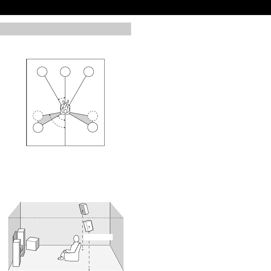
You can enjoy this unit with the following speaker setup to
obtain the best surround sound.
y
The speaker layout above shows the standard ITU-R* speaker
setting. ITU-R recommends that the front left and right speakers
be placed at 30° from the central listening position, and that the
surround left and right speakers be placed at between 60° and 80°
from the central listening position.
*ITU-R: for more information (see page 56).
Front speakers (FR and FL)
The front speakers are used for the main source sound plus
effect sounds. Place these speakers an equal distance from
the ideal listening position. The distance of each speaker
from each side of the video monitor should be the same.
Center speaker (C)
The center speaker is for the center channel sounds
(dialog, vocals, etc.). If for some reason it is not practical
to use a center speaker, you can do without it. Best results,
however, are obtained with the full system. Align the front
face of the center speaker with the front face of your video
monitor. Place the speaker centrally between the front
speakers and as close to the monitor as possible, such as
directly over or under it.
Surround speakers (SR and SL)
The surround speakers are used for effect and surround
sounds. Place these speakers behind your listening
position, facing slightly inwards, about 1.8 m (6 ft) above
the floor.
Subwoofer
The use of a subwoofer, such as the YAMAHA Active
Servo Processing Subwoofer System, is effective not only
for reinforcing bass frequencies from any or all channels,
but also for high fidelity reproduction of the LFE (low-
frequency effect) channel included in Dolby Digital and
DTS software. The position of the subwoofer is not so
critical, because low bass sounds are not highly
directional. But it is better to place the subwoofer near the
front speakers. Turn it slightly toward the center of the
room to reduce wall reflections.
SPEAKER SETUP
Speaker placement
60˚
30˚
FL
FR
C
SL
SR
SR
80˚
SL
1.8 m (6 ft)
9
English
SPEAKER SETUP
PREPARATION
Be sure to connect the left channel (L), right channel (R),
“+” (colored) and “–” (black) properly. If the connections
are faulty, no sound will be heard from the speakers, and if
the polarity of the speaker connections is incorrect, the
sound will be unnatural and lack bass.
• If you will use 6 ohm speakers, be sure to set this unit’s
speaker impedance setting to 6 ohms before using (see
“IMPEDANCE SELECTOR switch” on page 10).
• Before connecting the speakers, make sure that the
power of this unit is off.
• Do not let the bare speaker wires touch each other or do
not let them touch any metal part of this unit. This
could damage this unit and/or speakers.
• Use magnetically shielded speakers. If this type of
speakers still creates the interference with the monitor,
place the speakers away from the monitor.
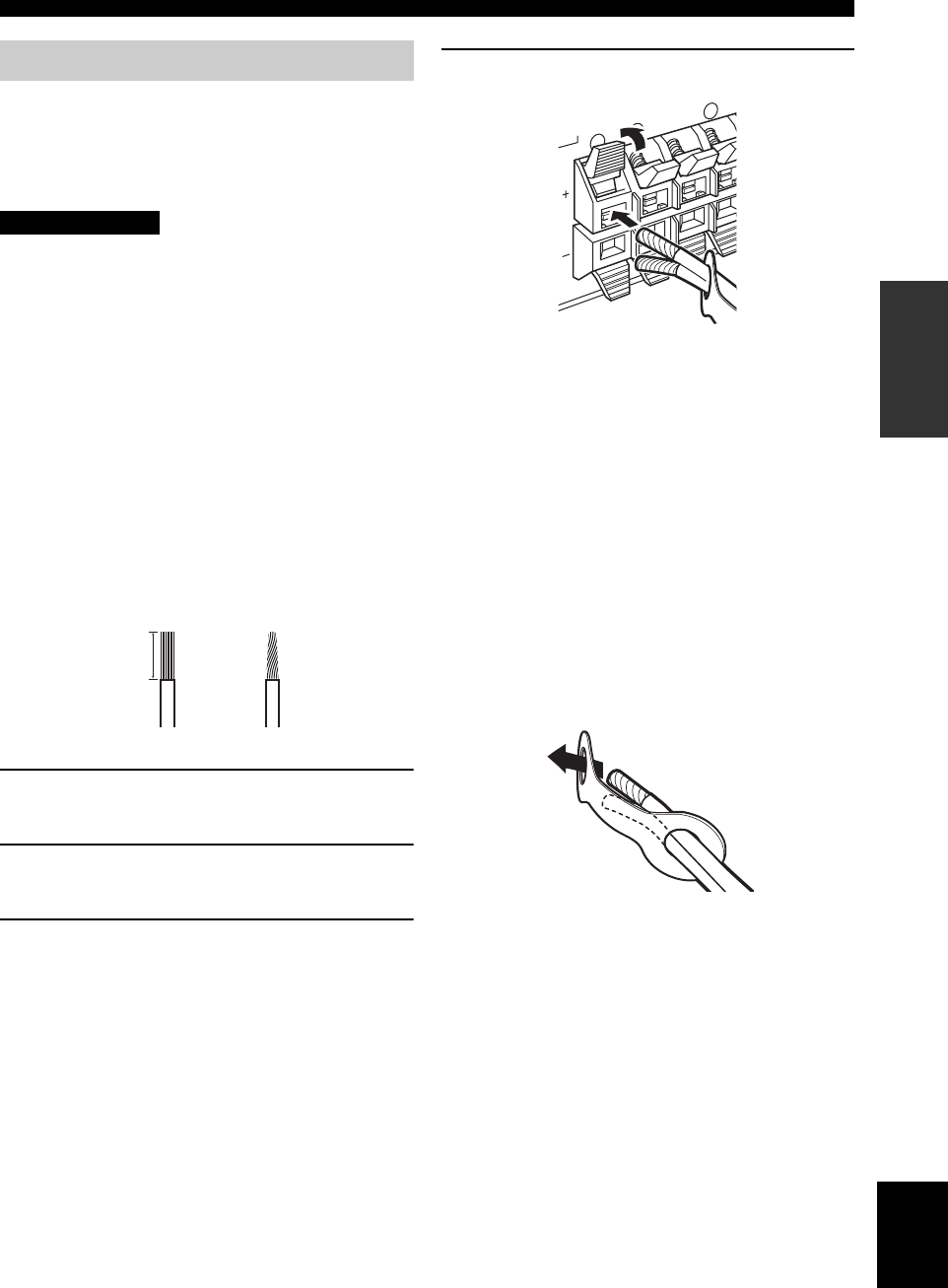
A speaker cord is actually a pair of insulated cables
running side by side. One cable is colored or shaped
differently, perhaps with a stripe, groove or ridges.
Connect the striped (grooved, etc.) cable to the “+”
(colored) terminals on this unit and your speaker. Connect
the plain cable to the “–” (black) terminals.
1Remove approximately 10 mm (3/8") of
insulation from each of the speaker cables.
2Twist the exposed wires of the cable together
to prevent short circuits.
3Press and hold the tab to insert the speaker
wire.
4Return the tab to secure the wire.
■Cable tags
5 pairs of different colored cable tags are provided with
this product. The colors of the cable tags and their
respective speaker cables are as follows:
• Red: Front right speaker cable
• White: Front left speaker cable
• Green: Center speaker cable
• Gray: Surround right speaker cable
• Blue: Surround left speaker cable
To make it easier to distinguish the various speaker cables,
attach the colored tags to the appropriate speaker cables as
shown below.
Speaker connections
CAUTION
10 mm (3/8")
12
R
RL
Colored: positive (+)
Black: negative (–)
10
SPEAKER SETUP
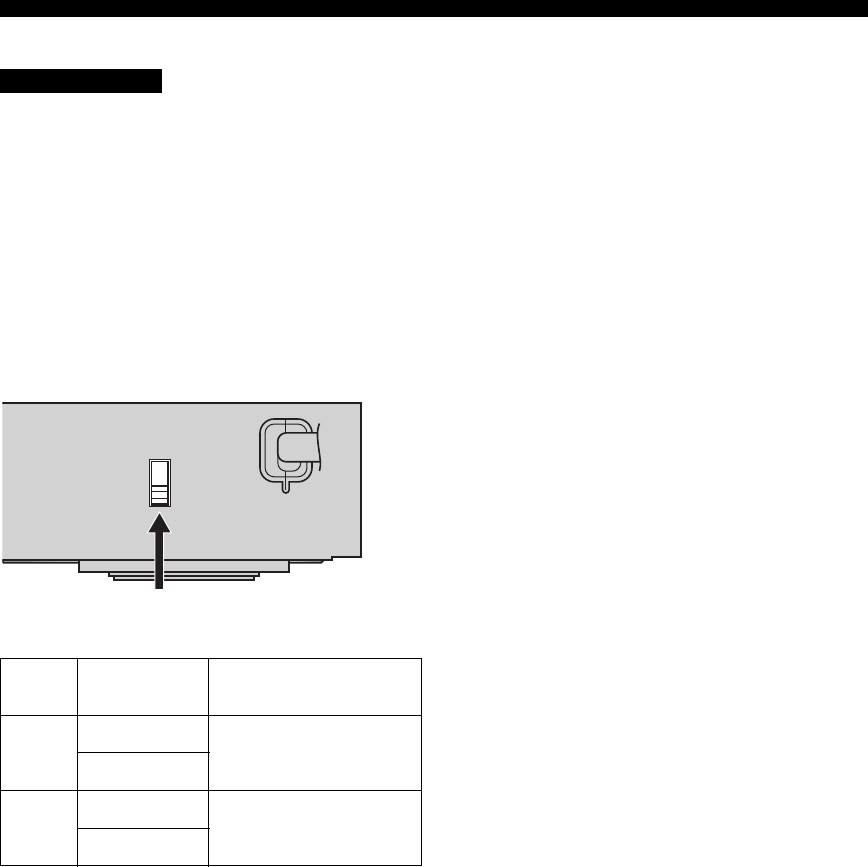
■IMPEDANCE SELECTOR switch
Do not change the setting of the IMPEDANCE
SELECTOR switch when the unit power is switched on,
as doing so may damage the unit.
If this unit fails to turn on when STANDBY/ON is pressed
on either the front panel or remote control, the
IMPEDANCE SELECTOR switch may not be fully slid to
either position. If this is the case, slide the switch all the
way to either position when this unit is in standby mode.
Be sure to move this switch only when this unit is in
standby mode.
Select the switch position (top or bottom) according to the
impedance of the speakers in your system.
Switch
position Speaker Impedance level
Top
Front The impedance of each speaker
must be 4 Ω or higher.
Center, Surround
Bottom
Front The impedance of each speaker
must be 6 Ω or higher.
Center, Surround
CAUTION
MAINS
IMPEDANCE SELECTOR switch
11
English
SPEAKER SETUP
PREPARATION
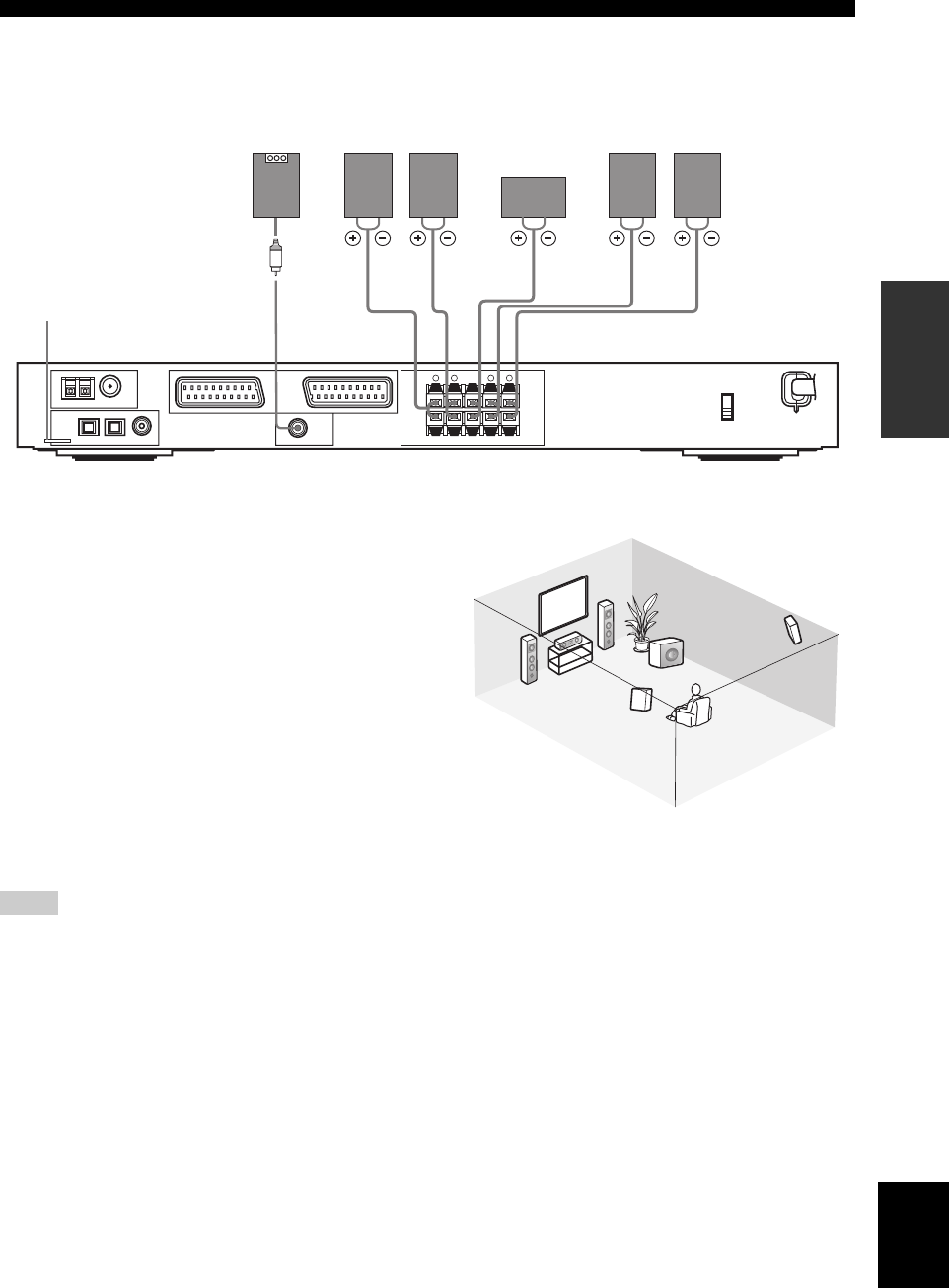
■Speaker connections
■FRONT terminals
Connect your speaker system to these terminals.
■SURROUND terminals
Connect surround speakers to these terminals.
■CENTER terminals
Connect a center speaker to these terminals.
■SUBWOOFER OUTPUT jack
Connect a subwoofer with built-in amplifier, such as the
YAMAHA Active Servo Processing Subwoofer System,
to this jack.
y
You can easily distinguish between the cable pairs by attaching a
supplied cable tag to each end of the respective speaker cable (see
page 9).
• If you are not using a subwoofer, allocate the signals to the front
left and right speakers by changing the setting item “LFE/Bass
Out” to FRONT on the SOUND menu (see page 41).
• Use the control on the subwoofer to adjust its volume level. You
can also adjust the volume level using this unit’s remote control
(see page 37).
AM ANT FM ANT
75Ω UNBAL
OPTICAL
DVD
/CD DTV
/CBL VIDEO 1
SUBWOOFER
FRONT
R
CENTER SURROUND
123
COAXIAL
GND
TUNER
EXT. IN/OUT
OUTPUT
TV IN/OUT
SPEAKERS
MAINS
DIGITAL
INPUT
L R L
–
+
–
+
61 2 435
Center
speaker
Front
speakers Surround
speakers
Subwoofer
with
built-in
amplifier Right LeftRight Left
This jack is reserved for factory use.
Do not connect any equipment to
this jack.
Notes
6
1
2
5
4
3
Speaker layout
CONNECTIONS
12
Do not connect this unit or other components to the mains
power until all connections between components are
complete.
• Make sure that all connections are made correctly - that
is to say, L (left) to L, R (right) to R, “+” to “+” and
“–” to “–”. Some components require different
connection methods and have different jack names.
Refer to the operating instructions for each component
you wish to connect to this unit.
• After you have completed all connections, check them
again to make sure they are correct.
• The jack names correspond to the names on the input
selector.
■Signal directions and cable indications
■Analog jacks
You can input analog signals from audio components by
connecting audio pin cable to the analog jacks on this unit.
Connect red plugs to the right jacks and white plugs to the
left jacks.
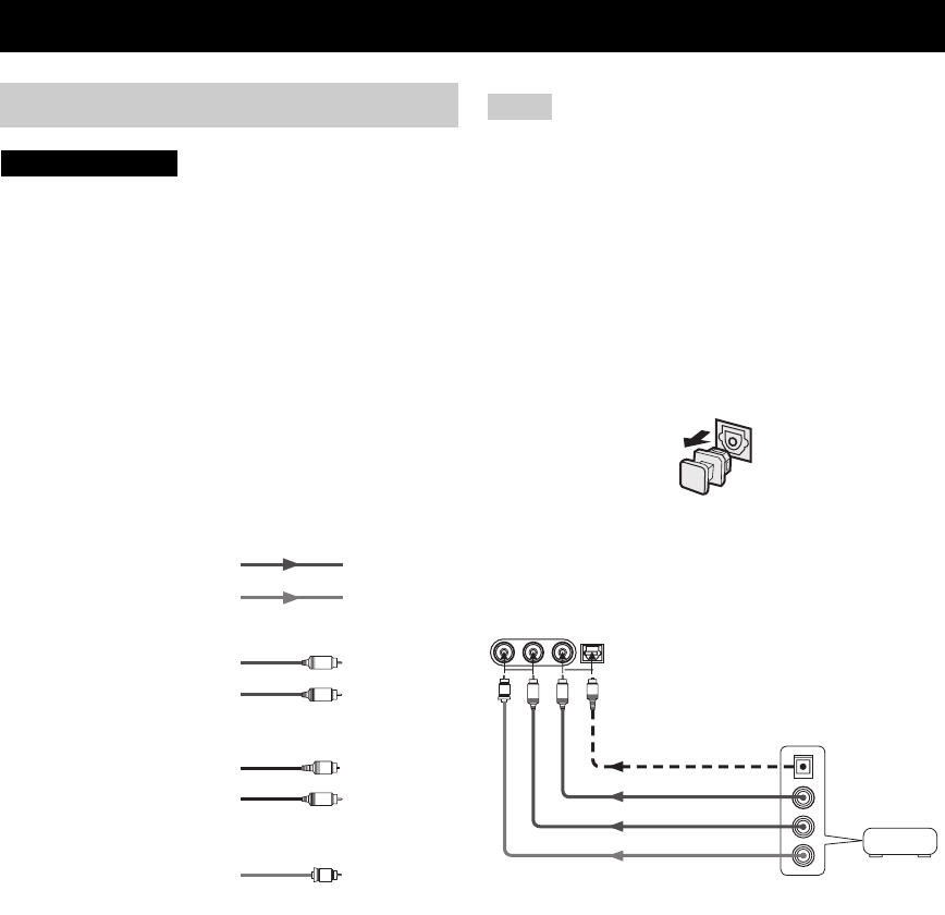
■Digital jacks
This unit has digital jacks for direct transmission of digital
signals through either coaxial or fiber optic cables. You
can use the digital jacks to input PCM, Dolby Digital and
DTS bitstreams. All digital input jacks are compatible
with 96-kHz sampling digital signals.
• This unit handles digital and analog signals independently. Thus
audio signals input to the digital (OPTICAL or COAXIAL)
jacks are not output to the analog VCR OUT (REC) jacks.
• The OPTICAL jacks on this unit conform to the EIA standard.
If you use a fiber optic cable that does not conform to this
standard, this unit may not function properly.
Dust protection cap
Pull out the cap from the optical jack before you connect
the fiber optic cable. Do not discard the cap. When you are
not using the optical jack, be sure to put the cap back in
place. This cap protects the jack from dust.
■VIDEO 2 jacks (on the front panel)
Use these jacks to connect any video source, such as a
game console or video camera, to this unit.
CONNECTIONS
Before connecting components
CAUTION
S
V
O
V
V
V
L
R
C
video signal direction
left analog cables
right analog cables
optical cables
coaxial cables
video cables
For analog signals
For digital signals
For video signals
audio signal direction
Notes
VIDEO AUDIO
VIDEO 2
OPTICALL R
O
V
L
R
Game
console or
video
camera
Video out
Audio out L
Audio out R
Optical out
13
English
CONNECTIONS
PREPARATION
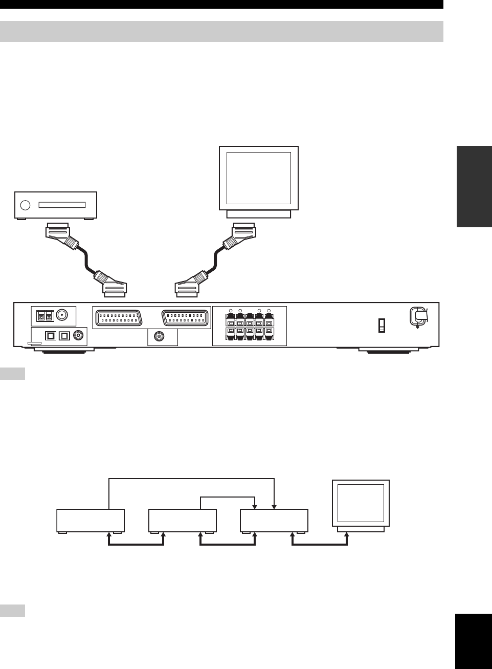
■Connecting a TV
Connect one end of the SCART cable to the TV/IN OUT connector on this unit and the other end to the SCART
connector on your TV.
■Connecting AV components
Connect one end of the SCART cable to the EXT. IN/OUT connector on this unit and the other end to the SCART
connector on your AV component. You can also daisy chain several SCART components together as shown in “Digital
audio connections” (page 13).
Use a SCART cable to make the above connections. The SCART cable, or “Euro AV cable”, supports IN/OUT signal transmission,
providing you with the best possible picture and sound.
■Digital audio connections
Connect the optical or coaxial digital output on your components to the corresponding DIGITAL INPUT jacks.
Use OPTICAL 1 (DVD/CD) to connect a DVD or CD player.
Use OPTICAL 2 (DTV/CBL) to connect a DTV or cable tuners.
y
You can assign components to this unit’s DIGITAL INPUT jacks using the INPUT and VOLUME/SELECT controls on the front panel
(or the input selector buttons on the remote control) (page 43).
You may experience some image distortion if your VCR is connected to this unit through your DVD player rather than being directly
connected to this unit.
Connecting other components
Note
AM ANT FM ANT
75Ω UNBAL
OPTICAL
DVD
/CD DTV
/CBL VIDEO 1
SUBWOOFER
FRONT
R
CENTER SURROUND
123
COAXIAL
GND
TUNER
EXT. IN/OUT
OUTPUT
TV IN/OUT
SPEAKERS
MAINS
DIGITAL
INPUT
L R L
–
+
–
+
AV component
(DVD player, cable tuner, etc.) TV
Optical out
Optical out
SCARTSCARTSCART
RX-SL80
DTV or
Cable tuner
DVD player
Note
14
CONNECTIONS
Both AM and FM indoor antennas are included with this
unit. In general, these antennas should provide sufficient
signal strength. Connect each antenna correctly to the
designated terminals.
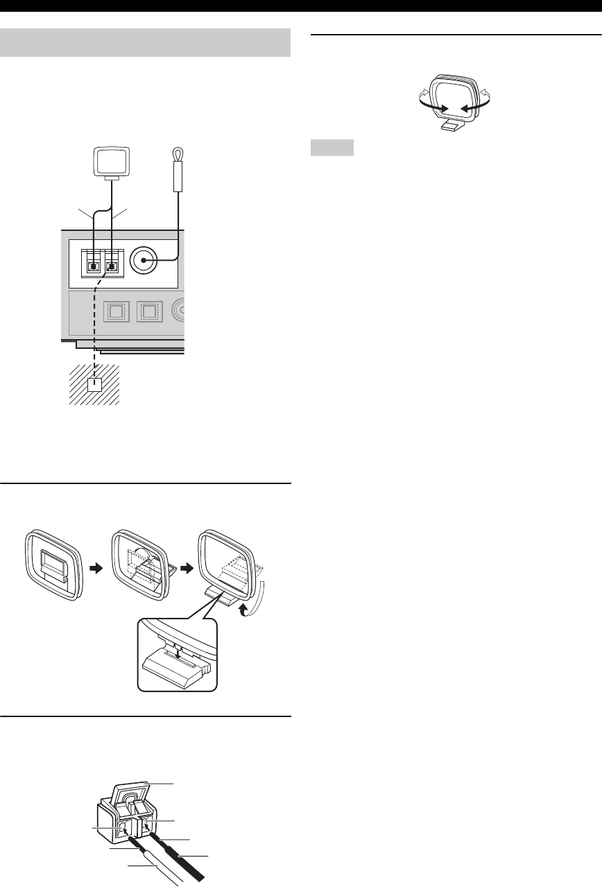
■Connecting the AM loop antenna
1Set up the AM loop antenna, then connect it
to the terminals on this unit.
2Lift up the tab and insert the white cord into
the AM ANT terminal and the black cord into
the GND terminal.
3Orient the AM loop antenna for the best
reception.
• The AM loop antenna should be placed away from this unit and
all speaker cords.
• The AM loop antenna should always be connected, even if an
outdoor AM antenna is connected to this unit.
• A properly installed outdoor antenna provides clearer reception
than an indoor one. If you experience poor reception quality, an
outdoor antenna may improve the quality. Consult the nearest
authorized YAMAHA dealer or service center about outdoor
antennas.
■Frequency Step (Asia and General
models only)
Because the interstation frequency spacing differs in
different areas, set the FREQUENCY STEP (using SET
MENU) according to the frequency spacing in your area
(see page 45).
• North, Central and South America: 100 kHz/10 kHz
• Other areas: 50 kHz/9 kHz
Connecting the antennas
AM ANT FM ANT
75Ω UNBAL
GND
TUNER
AM loop antenna
(included)
Ground (GND terminal)
For minimum interference, connect the
antenna GND terminal to a good earth
ground. A good earth ground is a metal
stake driven into moist earth.
Indoor FM antenna
(included)
Black
White
AM ANT
terminal
Tab
GND terminal
Cable wires
White Black
Cable wires
Notes
15
English
CONNECTIONS
PREPARATION
■Connecting the AC power
After all other connections are complete, plug the power
cord to an AC wall outlet.
■Memory back-up
The memory back-up circuit prevents the stored data from
being lost even if this unit is in the standby mode.
However if the power cord is disconnected from the AC
wall outlet, or the power supply is cut for more than one
week, the stored data will be lost.
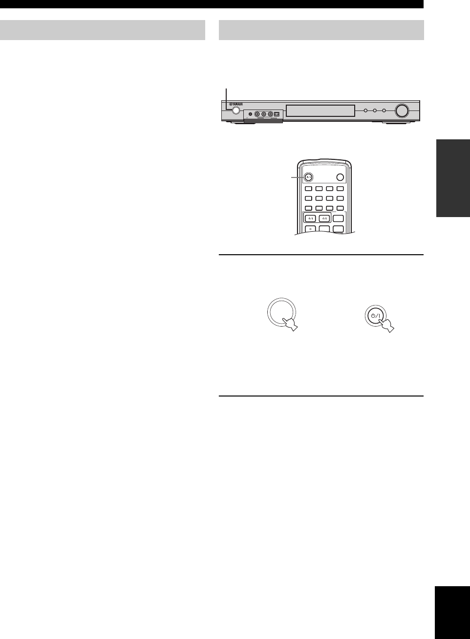
When all connections are complete, turn on the power of
this unit.
1Press STANDBY/ON on the front panel or
remote control to turn on the power of this
unit.
The level of the main volume, and then the current
sound field program name appear in the front panel
display.
2Turn on the video monitor connected to this
unit.
Connecting the power Turning on the power
INPUT
VOLUME/SELECT
DSPTUNER
AUTO/MA N'L
PUSH-ENTER
STANDBY
/ON
SILENT CINEMA VIDEO AUDIO
VIDEO 2
PHONES
OPTICALL R
1
1
STEREO
2
HALL
3
JAZZ
4
ROCK
SLEEP
STANDBY/ON
5
MUSIC
6
ENTERTAIN
7
TV THTR
8
MOVIE
9
TV AV
CODE SET
REC FREQ/RDS EON
sAUDIO
DISC SKIP MODE PTY SEEK START
STANDARD
0
NIGHT
+10
EXTD SUR.
ENT
STRAIGHT
EFFECT
1
or
STANDBY
/ON
STANDBY/ON
or
Front panel Remote control
BASIC SETUP
16
The BASIC setup feature is a useful way to set up your
system quickly and with minimal effort. The BASIC setup
items are displayed on both the front panel of this unit and
your video monitor. By using the Screen Menu on your
video monitor, you can easily make any necessary
settings.
y
• If you wish to configure the unit manually using more precise
adjustments, use the detailed parameters in SOUND MENU
(page 40) instead of using BASIC SETUP.
• Altering the parameters in BASIC SETUP may cause some of
the parameters in SOUND MENU to be overwritten.
• The explanations in this document are based on the Screen
Menu. The characters shown in the front panel display may
differ from those on the Screen Menu.
■Speaker set up
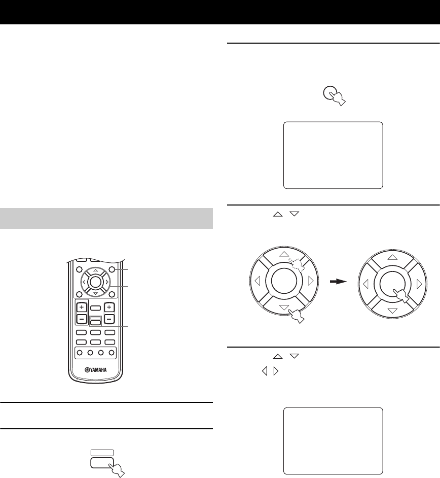
1Switch on the receiver and video monitor.
2Press AMP.
3Press SET MENU.
The top display appears on your video monitor.
4Press / to select BASIC SETUP, then
press ENTER.
5Press / repeatedly to select ROOM.
Use / to select the size of the room you have
installed your speakers in. Roughly speaking, the
room sizes are defined as follows:
[U.S.A. and Canada models]
S (small) 16 x 13 ft, 200 sq. ft
(4.8 x 4.0 m, 20 m2)
M (medium) 20 x 16 ft, 300 sq. ft
(6.3 x 5.0 m, 30 m2)
L (large) 26 x 19 ft, 450 sq. ft
(7.9 x 5.8 m, 45 m2)
[Other models]
S (small) 3.6 x 2.8 m, 10 m2
M (medium) 4.8 x 4.0 m, 20 m2
L (large) 6.3 x 5.0 m, 30 m2
BASIC SETUP
Using BASIC SETUP
b
TITLE
LEVEL
ENTER
CH
–
CH
+
p
MUTE
TV VOL VOLUME
AMP
VCRDVD/CD VIDEO 1
TUNERDTV/CBL VIDEO 2
a
MUTE INPUT
–
CH
TV MODE
+
MENU
SET MENU
RETURN
TEST/
RETURN
DISPLAY
3
4-9
2
AMP
MENU
SET MENU
SET MENU
.;BASICSETUP
;MANUALSETUP
[]/[]:Up/Down
[ENTER]:Enter
p
p
ENTER ENTER
; BASIC SETUP
.ROOM : )S M L
SWFR : YES)NONE
SPEAKERS;;;;5spk
SET )CANCEL
[]/[]:Up/Down
[<]/[>]:Select
p
p
17
English
BASIC SETUP
PREPARATION
6Press / repeatedly to select SWFR.
Use / to select YES or NONE.
YES If you have a subwoofer in your system.
NONE If you do not have a subwoofer in your
system.
7Press / repeatedly to select SPEAKERS.
Use / to select the number of speakers connected
to the unit. The choices vary as follows:
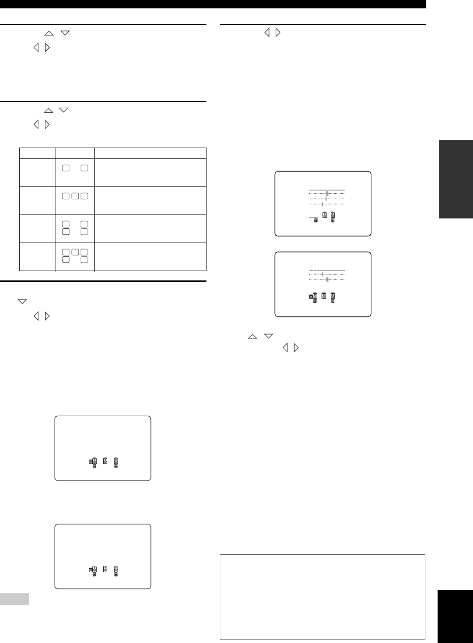
8After you have finished the settings, press
repeatedly to select SET CANCEL.
Use / to select SET or CANCEL, then press
ENTER.
SET To apply the changes and start the test
tone.
CANCEL To cancel the changes and return to
SET MENU.
Use the test tone to check the speaker levels.
If you selected SET, the display changes to:
and the unit outputs a test tone from each speaker in
turn.
When the test tone begins, the display changes to:
• The unit cycles the test tone around each of the speakers in turn
twice.
• The indicator of the speaker currently outputting the test tone
flashes in the front panel display.
9Press / repeatedly to select YES or NO,
then press ENTER.
If you want to change the speaker level after you hear
the test tone select “NO”.
YES To return to SET MENU.
NO To enter B)SPEAKER LEVEL.
■Speaker level B)SPEAKER LEVEL
Use this menu to compare and adjust the test tone
output from each speaker to the output from the left
front (or left surround) speaker so that the volume
level for all speakers is identical.
Press / to select a speaker and adjust the
balance using / .
The unit outputs the test tone from the selected speaker
and the left front (or left surround) speaker in turn. The
indicator of the speaker currently outputting the test tone
flashes in the front panel display.
FR adjusts the balance between the front left and right
speakers.
C adjusts the balance between the front left and center
speakers.
SL adjusts the balance between the front left and surround
left speakers.
SR adjusts the balance between the surround left and
surround right speakers.
SWFR adjusts the balance between the front left speaker
and the subwoofer.
y
You can also make test tone setting adjustments by pressing
TEST on the remote control.
Choices Display Speakers
2 spk Front L/R
3 spk Front L/R, Center
4 spk Front L/R, Surround L/R
5 spk Front L/R, Center, Surround L/R
Notes
LL CR
SL SB SR
LL CR
SL SB SR
LL CR
SL SB SR
LL C R
SL SB
SB
SR
; BASIC SETUP
ROOM : )S M L
SWFR : )YES NONE
SPEAKERS;;;;5spk
.CHECK: Test Tone
; BASIC SETUP
ROOM : )S M L
SWFR : )YES NONE
SPEAKERS;;;;5spk
.CHECK OK?;;;;YES
Memory back-up
The memory back-up circuit prevents the stored data
from being lost even if this unit is in the standby mode.
However, if the power cord is disconnected from the
AC outlet, or the power supply is cut for more than one
week, the stored data will be lost. If so, adjust the
items again.
-+
.FR
C
SL
B)SPEAKER
LEVEL
-+
.SR
SWFR
B)SPEAKER
LEVEL
PLAYBACK
18
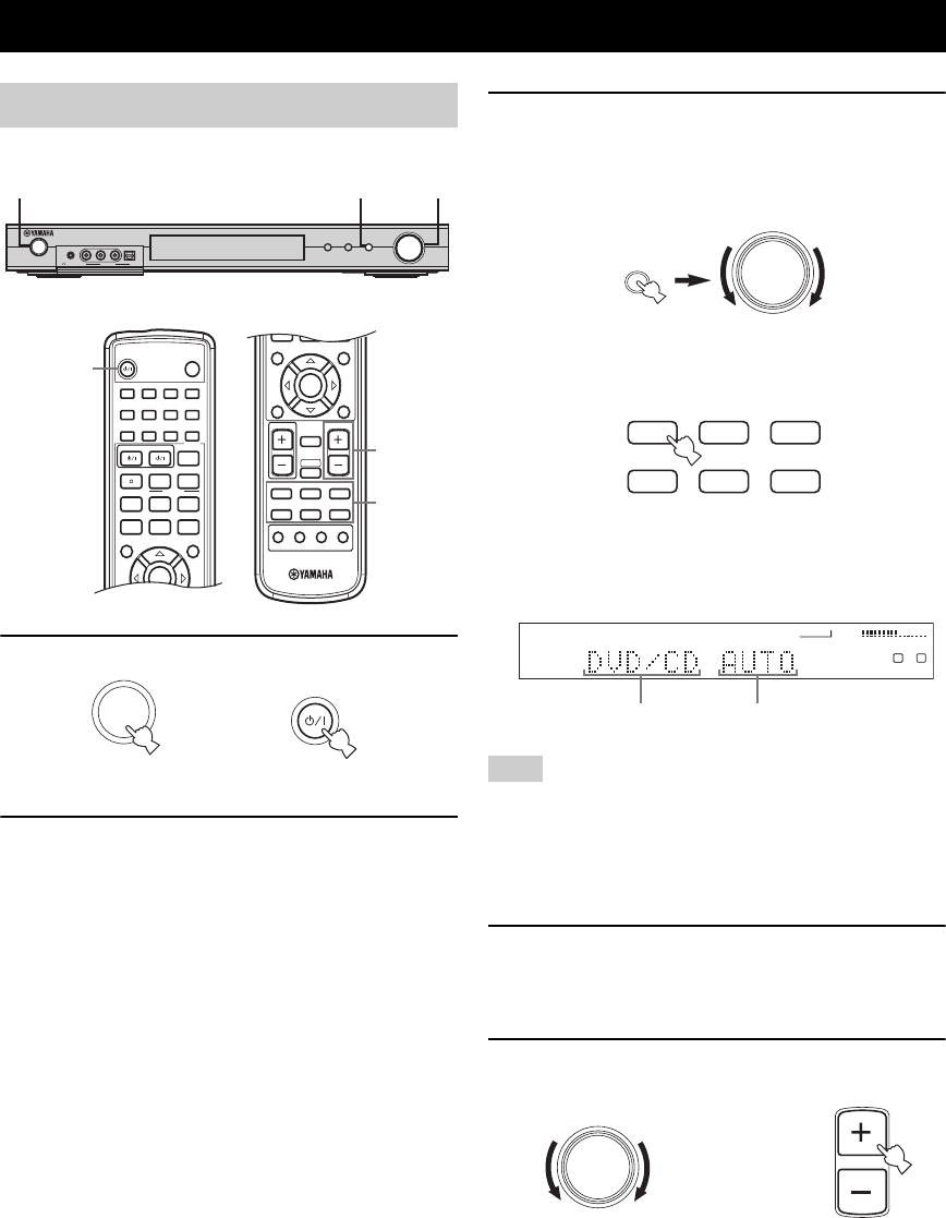
1Press STANDBY/ON to turn on the power.
2Turn on the video monitor connected to this
unit.
3Press INPUT, then rotate VOLUME/SELECT
within 5 seconds to select the input source
(or press an input selector button on the
remote control).
The current input source name and input mode appear
in the front panel display for a few seconds.
If no operation is performed within 5 seconds of pressing INPUT
or VOLUME/SELECT is pressed on the front panel, the function
of VOLUME/SELECT switches back to volume level adjustment.
If this happens, “VOLUME” appears in the front panel display for
a few seconds.
4Start playback or select a broadcast station
on the source component.
Refer to the operation instructions for the component.
5Adjust the volume to the desired output level.
PLAYBACK
Basic operations
INPUT
VOLUME/SELECT
DSPTUNER
AUTO/MA N'L
PUSH-ENTER
STANDBY
/ON
SILENT CINEMA VIDEO AUDIO
VIDEO 2
PHONES
OPTICALL R
3,5
3
1
1
STEREO
2
HALL
3
JAZZ
4
ROCK
SLEEP
STANDBY/ON
5
MUSIC
6
ENTERTAIN
7
TV THTR
8
MOVIE
9
TV AV
CODE SET
REC FREQ/RDS EON
sAUDIO
w
DISC SKIP MODE PTY SEEK START
e f
b
A/B/C/D/E
TITLE
LEVEL
ENTER
CH
–
CH
+
p
d
PRESET
a
u
STANDARD
0
NIGHT
+10
EXTD SUR.
ENT
STRAIGHT
EFFECT
MENU
SET MENU
RETURN DISPLAY
b
TITLE
LEVEL
ENTER
CH
–
CH
+
p
MUTE
TV VOL VOLUME
AMP
VCRDVD/CD VIDEO 1
TUNERDTV/CBL VIDEO 2
a
MUTE INPUT
–
CH
TV MODE
+
MENU
SET MENU
RETURN
TEST/
RETURN
DISPLAY
3
5
1
or
STANDBY
/ON
STANDBY/ON
Front panel Remote control
or
Note
VOLUME/SELECT
VCRDVD/CD VIDEO 1
TUNERDTV/CBL VIDEO 2
or
Front panel
Remote control
INPUT
VCR
VOLUME
L
L R
VIDEO 1 VIDEO 2
DTV/CBL
TUNER
DVD/CD
Selected input source Input mode
VOLUME/SELECT
VOLUME
or
Remote control
Front panel
19
English
PLAYBACK
BASIC
OPERATION
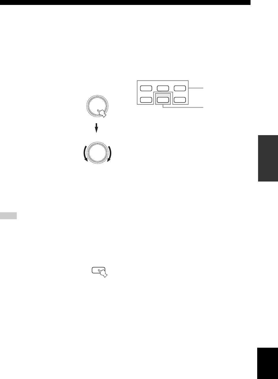
To listen with headphones (SILENT CINEMA)
The SILENT CINEMA mode allows you to enjoy multi-
channel music or movie sound, including Dolby Digital
and DTS surround, through ordinary headphones.
SILENT CINEMA activates automatically whenever you
connect headphones to the PHONES jack while listening
to DSP sound field programs. The SILENT CINEMA
indicator lights up in the front panel display.
“SILENT CINEMA” is not effective when the Direct
Stereo or 2ch Stereo program is selected, or in
STRAIGHT mode.
To adjust the tone
You can adjust the tonal quality
of your front left and right
speakers or headphones (when
connected).
Press VOLUME/SELECT on the
front panel repeatedly to select
TREBLE or BASS, then rotate to
the right or left to increase or
decrease.
• Select TREBLE to adjust the
high frequency response.
• Select BASS to adjust the low
frequency response.
To cancel the tone control setting,
press VOLUME/SELECT again, or press VOLUME +/–
on the remote control or operate nothing for 5 seconds.
y
Speaker and headphone adjustments are stored independently.
• If you increase or decrease the high-frequency or low-frequency
sound to an extreme level, the tonal quality of the surround
speakers may not match that of the front left and right speakers.
• TONE CONTROL is not effective with the Direct Stereo
program (page 34).
To mute the sound
Press MUTE on the remote control.
“MUTE” blinks in the front panel
display.
To resume the audio output, press
MUTE again (or press VOLUME
+/–). “MUTE” disappears from the display.
y
You can adjust the muting level (see page 43).
■Playing video sources in the
background
You can combine a video image from a video source with
sound from an audio source. For example, you can enjoy
listening to classical music while viewing beautiful
scenery from the video source on the video monitor.
Use the input selector buttons on the remote
control to select a video source, then select an
audio source.
Notes
VOLUME/SELECT
VOLUME/SELECT
Front panel
MUTE
Remote control
VCRDVD/CD VIDEO 1
TUNERDTV/CBL VIDEO 2
Video sources
Audio source
Remote control
20
PLAYBACK
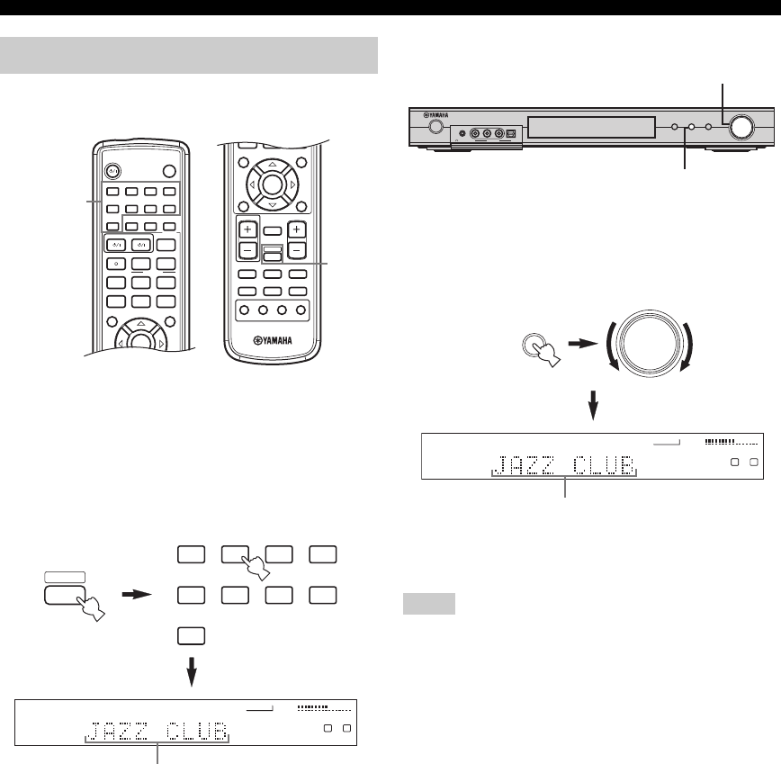
■Remote control operation
Press AMP to select the AMP mode, then press
one of the sound field program buttons
repeatedly to select the desired program.
The name of the selected program appears in the front
panel display.
■Front panel operation
Press DSP, then rotate VOLUME/SELECT within
5 seconds.
The name of the selected program appears in the front
panel display.
y
Choose a sound field program based on your listening preference,
and not on the name of the program.
• If no operation is performed within 5 seconds of pressing DSP
on the front panel, the function of VOLUME/SELECT switches
back to volume.
• After selecting a DSP program, press VOLUME/SELECT to
switch the function of VOLUME/SELECT back to “volume”.
• There are 9 programs with sub-programs available with this
unit. However, the selection depends on the input signal format
and not all sub-programs can be used with all input signal
formats.
• The acoustics of your listening room affect the sound field
program. Minimize the sound reflections in your room to
maximize the effect created by the program.
• When you select an input source, this unit automatically selects
the last sound field program used with that source.
• When you set this unit in standby mode, it stores the current
source and sound field program in memory and automatically
selects them when you turn on the power again.
• If the unit receives a Dolby Digital or DTS signal when the
input mode is set to AUTO, the CINEMA DSP sound field
programs automatically switches to the appropriate decoding
program.
• When the unit is reproducing a monaural source with PRO
LOGIC, PRO LOGIC Enhanced, PRO LOGIC II Game or PRO
LOGIC II Movie, no sound is output from the front and
surround speakers. Sound can only be heard from the center
speaker. (If CENTER SP in SPEAKER SET in the SOUND
menu is set to “None”, the center channel sound is output from
the front speakers.)
• Sampling frequencies higher than 48 kHz (except for DTS 96/
24 signals) will be sampled down to 48 kHz, then sound field
programs will be applied.
Selecting sound field programs
1
STEREO
2
HALL
3
JAZZ
4
ROCK
SLEEP
STANDBY/ON
5
MUSIC
6
ENTERTAIN
7
TV THTR
8
MOVIE
9
TV AV
CODE SET
REC FREQ/RDS EON
sAUDIO
w
DISC SKIP MODE START
PTY SEEK
e f
b
A/B/C/D/E
TITLE
LEVEL
ENTER
CH
–
CH
+
p
dPRESET
a
u
STANDARD
0
NIGHT
+10
EXTD SUR.
ENT
STRAIGHT
EFFECT
MENU
SET MENU
RETURN DISPLAY
b
TITLE
LEVEL
ENTER
CH
–
CH
+
p
MUTE
TV VOL VOLUME
AMP
VCRDVD/CD VIDEO 1
TUNERDTV/CBL VIDEO 2
a
MUTE INPUT
–
CH
TV MODE
+
MENU
SET MENU
RETURN
TEST/
RETURN
DISPLAY
AMP
Sound field
program
buttons
VCR
VOLUME
L
L R
HiFi DSP
VIDEO 1 VIDEO 2
DTV/CBL
TUNER
DVD/CD
1
STEREO
2
HALL
3
JAZZ
4
ROCK
5
MUSIC
6
ENTERTAIN
7
TV THTR
8
MOVIE
9
STANDARD
Program name
AMP
Notes
INPUT
VOLUME/SELECT
DSPTUNER
AUTO/MAN'L
PUSH-ENTER
STANDBY
/ON
SILENT CINEMA VIDEO AUDIO
VIDEO 2
PHONES
OPTICALL R
VOLUME/SELECT
DSP
VCR
VOLUME
L
L R
HiFi DSP
VIDEO 1 VIDEO 2
DTV/CBL
TUNER
DVD/CD
Program name
VOLUME/SELECT
DSP
21
English
PLAYBACK
BASIC
OPERATION
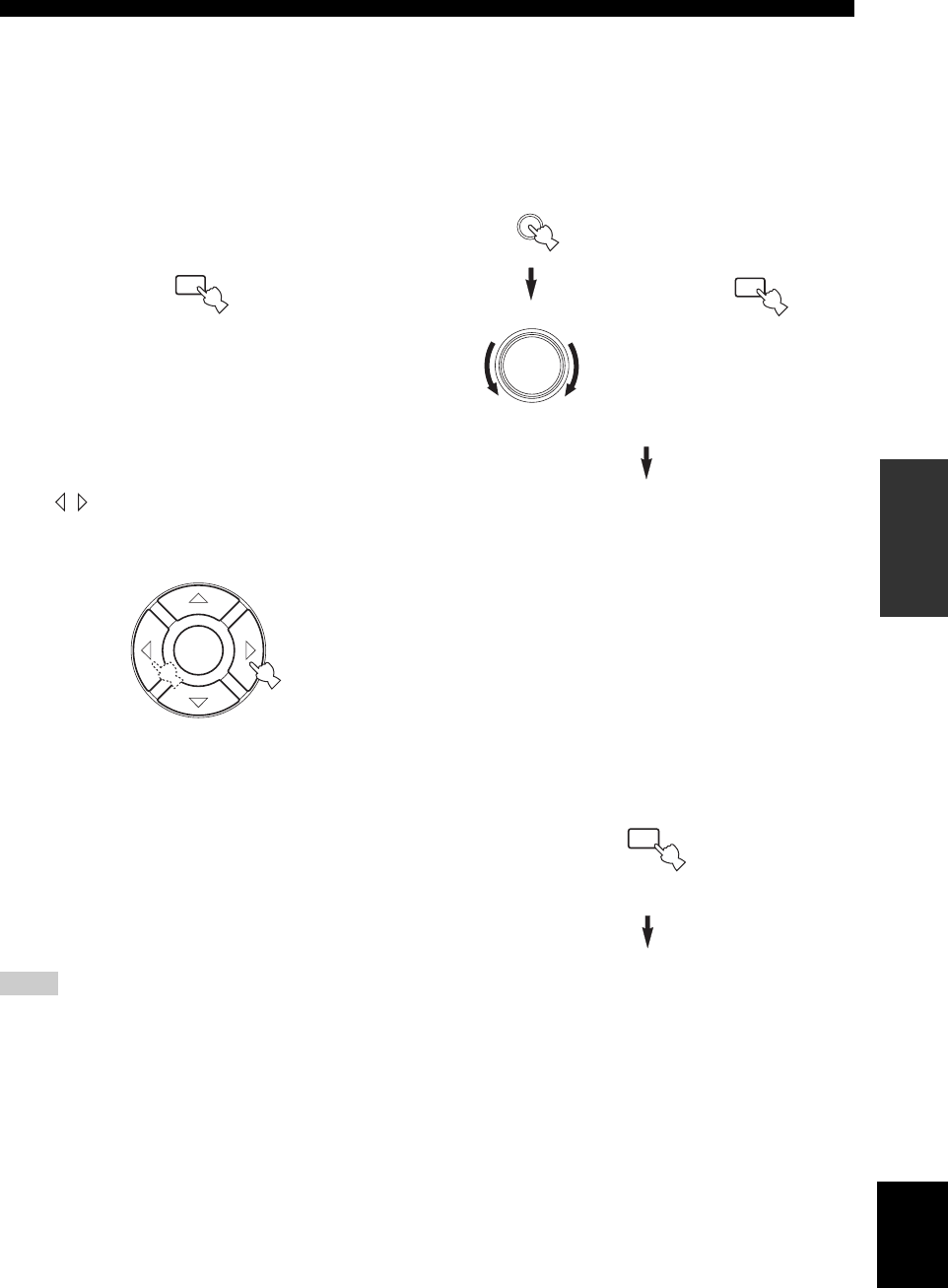
■Night listening modes
The night listening modes are designed to improve
listenability at lower volumes or at night. Choose either
NIGHT:CINEMA or NIGHT:MUSIC depending on the
type of material you are playing.
Press NIGHT on the remote control repeatedly to
select cinema or music.
When night listening is selected, the NIGHT indicator in
the front panel display lights up.
• Select NIGHT:CINEMA when watching films to reduce the
dynamic range of film soundtracks and make dialog easier to
hear at lower volumes.
• Select NIGHT:MUSIC when listening to music sources to
preserve ease-of-listening for all sounds.
• Select OFF if you do not want to use this function.
Press / to adjust the effect level while
NIGHT:CINEMA or NIGHT:MUSIC is displayed.
This adjusts the level of compression.
Effect.Lvl:MID
• Select MIN for minimum compression.
• Select MID for standard compression.
• Select MAX for maximum compression.
y
NIGHT:CINEMA and NIGHT:MUSIC adjustments are stored
independently.
• You cannot use the night listening modes with the Direct Stereo
program (even though the NIGHT indicator lights up when
Direct Stereo is selected).
• The night listening modes may vary in effectiveness depending
on the input source and surround sound settings you use.
■Downmixing to 2 channels
You can enjoy 2-channel stereo playback even from multi-
channel sources.
Press DSP, then rotate VOLUME/SELECT (or
press STEREO on the remote control) to select
2ch Stereo.
2ch Stereo
y
• You can use a subwoofer with this program when SWFR or
BOTH is selected in “BASS OUT”.
• You can enjoy pure high fidelity sound from 2-channel sources
when “Direct Stereo” is selected (see page 34).
■Listening to unprocessed input signals
In STRAIGHT mode, two channel stereo sources are
output from only the front left and right speakers. Multi-
channel sources are decoded straight into the appropriate
channels without any additional effect processing.
Press STRAIGHT/EFFECT to select STRAIGHT.
STRAIGHT
Press STRAIGHT/EFFECT again so that “STRAIGHT”
disappears from the display when you want to turn the
sound effect back on.
Notes
0
NIGHT
Remote control
ENTER
Remote control
VOLUME/SELECT
1
STEREO
Front panel
or
Remote control
DSP
ENT
STRAIGHT
EFFECT
Remote control
TUNING
22
There are 2 tuning methods; automatic and manual.
Automatic tuning is effective when station signals are
strong and there is no interference.
■Automatic tuning
1Press INPUT, then rotate VOLUME/SELECT
within 5 seconds to select TUNER.
If no operation is performed within 5 seconds of pressing INPUT
or VOLUME/SELECT is pressed on the front panel, the function
of VOLUME/SELECT switches back to volume level adjustment.
If this happens, “VOLUME” appears in the front panel display for
a few seconds.
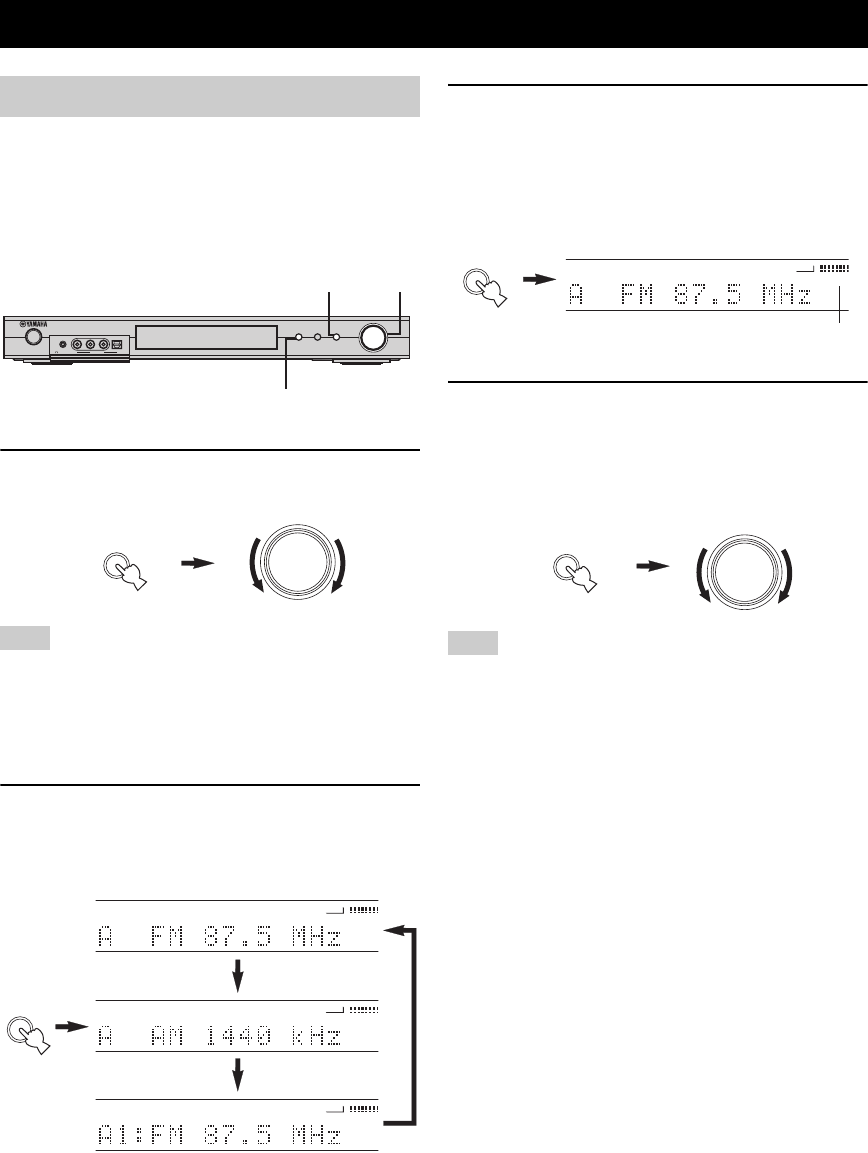
2Press INPUT repeatedly on the front panel to
select the reception band you want to tune.
“FM” or “AM” and the current frequency appear in
the front panel display.
3Hold down TUNER (AUTO/MAN’L) for more
than 1 second so that the “AUTO” indicator
lights up in the front panel display.
If “AUTO” is already lit up in the front panel display,
you do not need to perform this step. In this case, skip
to step 4.
4Press TUNER (AUTO/MAN’L), then rotate
VOLUME/SELECT within 5 seconds to begin
automatic tuning.
Rotate rightward to tune to a higher frequency, or
rotate leftward to tune to a lower frequency.
When tuned into a station, the “TUNED” indicator lights up and
the frequency of the received station is shown in the front panel
display.
TUNING
Automatic and manual tuning
Note
INPUT
VOLUME/SELECT
DSPTUNER
AUTO/MA N'L
PUSH-ENTER
STANDBY
/ON
SILENT CINEMA VIDEO AUDIO
VIDEO 2
PHONES
OPTICALL R
1,4
1,2
3,4
VOLUME/SELECT
INPUT
INPUT
VCR
TUNED
AUTO
VOLUME
VIDEO 1 VIDEO 2
DTV/CBL
TUNER
DVD/CD
VCR
AUTO
VOLUME
VIDEO 1 VIDEO 2
DTV/CBL
TUNER
DVD/CD
VCR
AUTO
VOLUME
VIDEO 1 VIDEO 2
DTV/CBL
TUNER
DVD/CD
Note
TUNER
AUTO/MAN'L
VCR
AUTO
VOLUME
VIDEO 1 VIDEO 2
DTV/CBL
TUNER
DVD/CD
Lights
TUNER
AUTO/MAN'L
VOLUME/SELECT
23
English
TUNING
BASIC
OPERATION
■Manual tuning
If the signal from the station you want to select is weak,
you must tune into it manually.
1Press INPUT, then rotate VOLUME/SELECT
within 5 seconds to select TUNER.
If no operation is performed within 5 seconds of pressing INPUT
or VOLUME/SELECT is pressed on the front panel, the function
of VOLUME/SELECT switches back to volume level adjustment.
If this happens, “VOLUME” appears in the front panel display for
a few seconds.
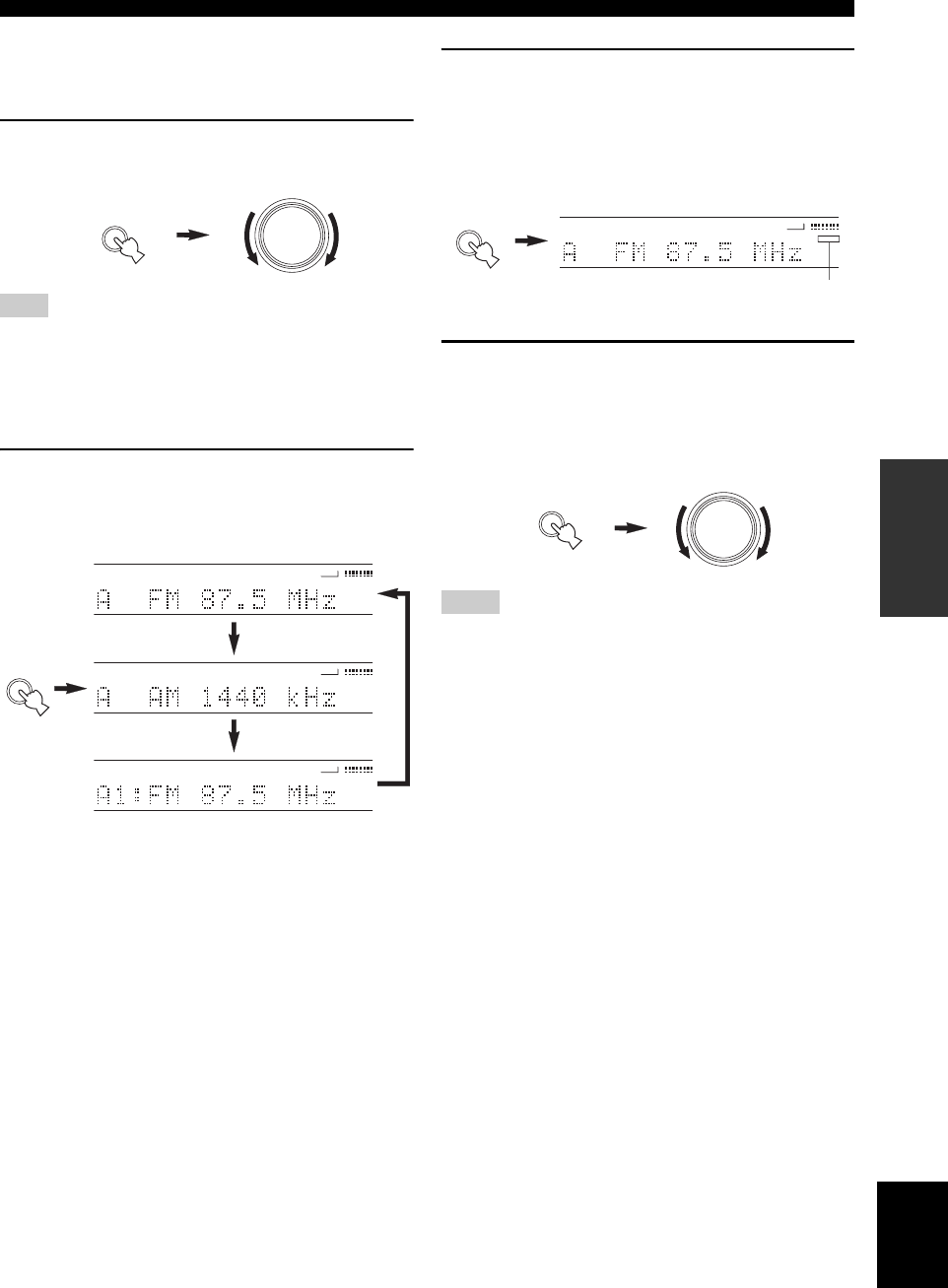
2Press INPUT repeatedly on the front panel to
select the reception band you want to tune.
“FM” or “AM” and the current frequency appear in
the front panel display.
3Hold down TUNER (AUTO/MAN’L) for more
than 1 second until the “AUTO” indicator
disappears from the front panel display.
If “AUTO” is not shown in the front panel display,
you do not need to perform this step. In this case, skip
to step 4.
4Press TUNER (AUTO/MAN’L), then rotate
VOLUME/SELECT within 5 seconds to tune
into the desired station manually.
Rotate rightward to tune to a higher frequency, or
rotate leftward to tune to a lower frequency.
• Manually tuning to FM stations will automatically change the
reception mode to monaural to increase the signal sensitivity.
• When tuned into a station, the “TUNED” indicator lights up and
the frequency of the received station is shown in the front panel
display.
Note
VOLUME/SELECT
INPUT
INPUT
VCR
TUNED
AUTO
VOLUME
VIDEO 1 VIDEO 2
DTV/CBL
TUNER
DVD/CD
VCR
AUTO
VOLUME
VIDEO 1 VIDEO 2
DTV/CBL
TUNER
DVD/CD
VCR
AUTO
VOLUME
VIDEO 1 VIDEO 2
DTV/CBL
TUNER
DVD/CD
Notes
TUNER
AUTO/MAN'L
VCR
VOLUME
VIDEO 1 VIDEO 2
DTV/CBL
TUNER
DVD/CD
Disappears
TUNER
AUTO/MAN'L
VOLUME/SELECT
24
TUNING
■Automatically presetting FM stations
You can use the automatic preset tuning feature to store
FM stations. This function enables this unit to
automatically tune in to FM stations with strong signals,
and to store up to 40 (8 stations x 5 groups) of those
stations in order. You can then recall any preset station
easily by selecting the preset station number.
1Press INPUT, then rotate VOLUME/SELECT
within 5 seconds to select TUNER.
If no operation is performed within 5 seconds of pressing INPUT
or VOLUME/SELECT is pressed on the front panel, the function
of VOLUME/SELECT switches back to volume level adjustment.
If this happens, “VOLUME” appears in the front panel display for
a few seconds.
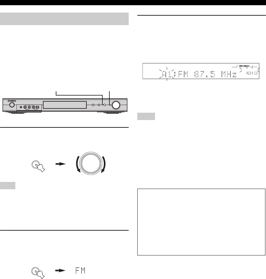
2Press INPUT repeatedly on the front panel to
select the FM band you want to preset.
“FM” appears in the front panel display.
3Hold down VOLUME/SELECT for more than
5 seconds.
The “AUTO” and “MEMORY” indicators flash in the
display and after about 5 seconds, automatic
presetting starts from the lowest frequency,
proceeding to higher frequencies.
When automatic preset tuning is completed, the front
panel display shows the frequency of the last preset
station.
• Any stored station data existing under a preset number is
cleared when you store a new station under that preset number.
• If the number of the received stations does not reach E8,
automatic preset tuning automatically stops after searching all
stations.
• Only FM stations with sufficient signal strength are stored
automatically by automatic preset tuning. If the station you
want to store is weak in signal strength, tune in to it manually in
the monaural mode, and store it by following the procedure in
“Manually presetting stations”.
Presetting stations
Note
INPUT
VOLUME/SELECT
DSPTUNER
AUTO/MA N'L
PUSH-ENTER
STANDBY
/ON
SILENT CINEMA VIDEO AUDIO
VIDEO 2
PHONES
OPTICALL R
VOLUME/SELECTINPUT
VOLUME/SELECT
INPUT
INPUT
Notes
Memory back-up
The memory back-up circuit prevents the stored data
from being lost even if this unit is set in the standby
mode, the power cord is disconnected from the AC
outlet, or the power supply is temporarily cut due to
power failure. However, if the power is cut for more
than one week, the preset stations may be cleared. If
so, store the stations again by using the presetting
station methods.
VCR
AUTO MEMORY
VOLUME
L
L R
VIDEO 1 VIDEO 2
DTV/CBL
TUNER
DVD/CD
25
English
TUNING
BASIC
OPERATION
■Manually presetting stations
You can also store up to 40 stations (8 stations x 5 groups)
manually.
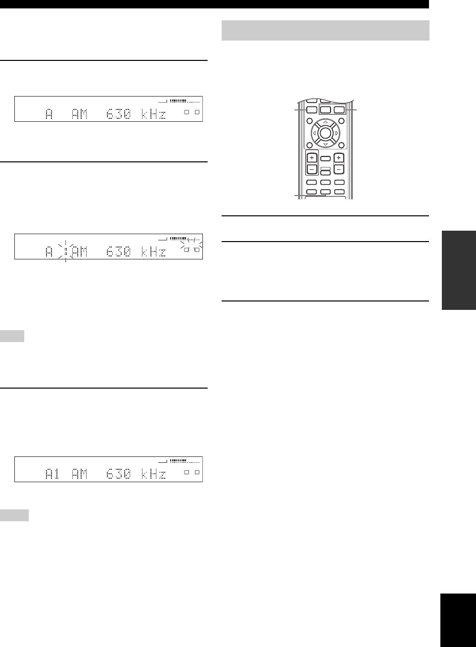
1Tune into a station.
See page 22 for tuning instructions.
When tuned into a station, the front panel display
shows the frequency of the station received.
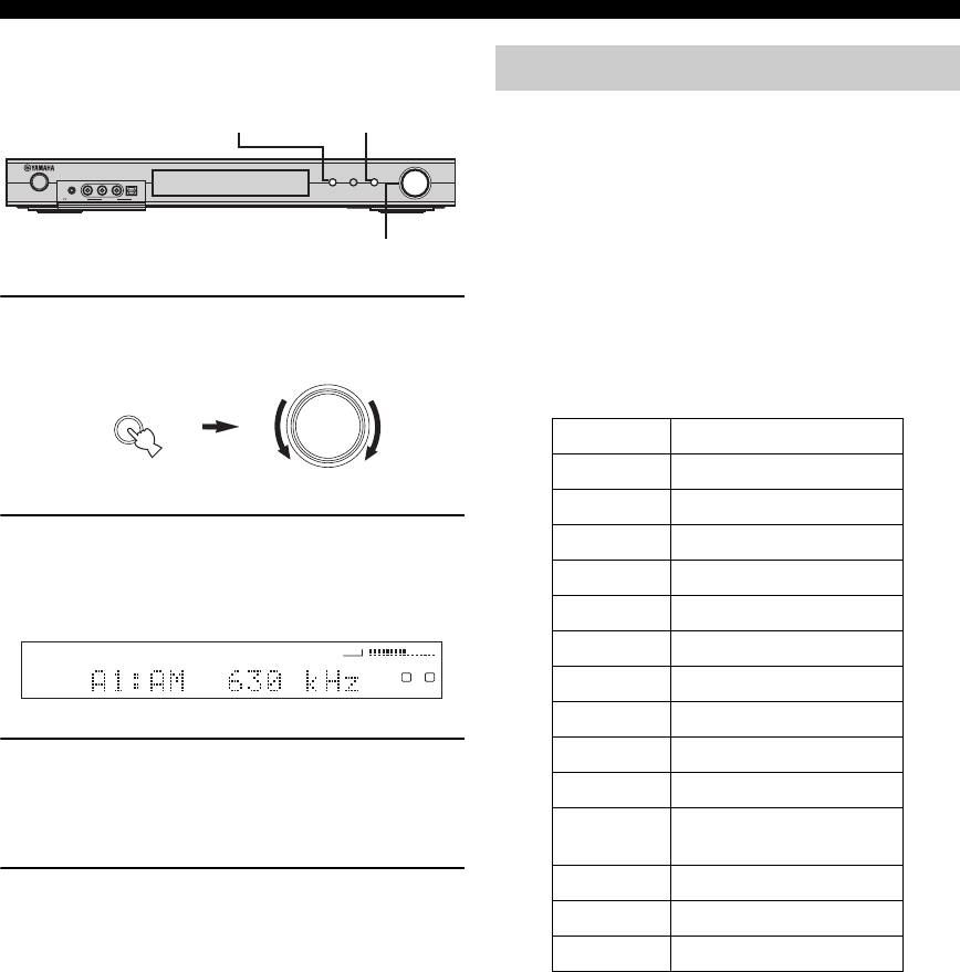
2Hold down VOLUME/SELECT for
approximately 3 seconds to activate the
manual preset station mode.
The colon (:) blinks and the “MEMORY” indicator
flashes in the display.
Rotate VOLUME/SELECT to select a preset station
number (A1 to E8) while “MEMORY” is flashing.
Rotate rightward to select a higher preset station
number, or rotate leftward to select a lower preset
station number.
When presetting an FM station, pressing VOLUME/SELECT for
an extended period activates the automatic preset tuning feature
(see page 24).
3Press VOLUME/SELECT to set the selected
preset station number.
The station band and frequency appear in the front
panel display with the preset group and number you
have selected.
Repeat steps 1 to 3 to store other stations.
• Any stored station data existing under a preset number is
cleared when you store a new station under that preset number.
• The reception mode (stereo or monaural) is stored along with
the station frequency.
You can tune into any desired station simply by selecting
the preset station number under which it was stored.
■Remote control operation
1Press TUNER to select TUNER.
2Press A/B/C/D/E to select the preset station
group.
The preset group letter appears in the front panel
display and changes each time you press the button.
3Press u PRESET d (or use the numeric
buttons) to select a preset station number.
The preset group and number appear in the front
panel display along with the station band, frequency
and the “TUNED” indicator lights up.
Note
Notes
VCR
TUNED
VOLUME
L
L R
VIDEO 1 VIDEO 2
DTV/CBL
TUNER
DVD/CD
VCR
TUNED
VOLUME
L
L R
VIDEO 1 VIDEO 2
DTV/CBL
TUNER
DVD/CD
MEMORY
VCR
TUNED
VOLUME
L
L R
VIDEO 1 VIDEO 2
DTV/CBL
TUNER
DVD/CD
Selecting preset stations
w e f
b
A/B/C/D/E
TITLE
LEVEL
ENTER
CH
–
CH
+
p
MUTE
TV VOL VOLUME
AMP
VCRDVD/CD VIDEO 1
TUNERDTV/CBL VIDEO 2
a
u
MUTE INPUT
– +
MENU
SET MENU
RETURN
TEST/
RETURN
DISPLAY
dPRESET
32
1
26
TUNING
■Front panel operation
1Press INPUT, then rotate VOLUME/SELECT
within 5 seconds to select TUNER.
2Press INPUT repeatedly to select preset
tuning mode.
A colon (:) appears in the front panel display in front
of the station band and frequency.
3Press TUNER (AUTO/MAN’L).
The “TUNER” indicator flashes for about 5 seconds,
and VOLUME/SELECT shifts to the preset number
selection mode.
4Rotate VOLUME/SELECT to select a preset
station while the “TUNER” indicator is
flashing.
RDS (Radio Data System) is a data transmission system
used by FM stations in many countries. The RDS function
is carried out among the network stations.
This unit can receive various RDS data such as PS
(Program Service name), PTY (Program Type), RT (Radio
Text), CT (Clock Time), EON (Enhanced Other
Networks) when receiving RDS broadcasting stations.
■PS (Program Service) mode:
The name of the RDS station being received is displayed.
■PTY (Program Type) mode:
There are 15 program types to classify RDS stations.
■RT (Radio Text) mode:
Information about the program (such as the title of the
song, name of the singer, etc.) on the RDS station being
received is displayed by a maximum of 64 alphanumeric
characters, including the umlaut symbol. If other
characters are used for RT data, they are displayed with
under-bars.
■CT (Clock Time) mode:
The current time is displayed and updated every minute.
If the data are accidentally cut off, “CT WAIT” may
appear.
■EON (Enhanced Other Networks):
See “EON function” on the following page.
INPUT
VOLUME/SELECT
DSPTUNER
AUTO/MA N'L
PUSH-ENTER
STANDBY
/ON
SILENT CINEMA VIDEO AUDIO
VIDEO 2
PHONES
OPTICALL R
TUNER
(AUTO/MAN’L)
VOLUME/SELECT
INPUT
VOLUME/SELECT
INPUT
VCR
TUNED
VOLUME
L
L R
VIDEO 1 VIDEO 2
DTV/CBL
TUNER
DVD/CD
Receiving RDS stations
NEWS News
AFFAIRS Current affairs
INFO General information
SPORT Sports
EDUCATE Education
DRAMA Drama
CULTURE Culture
SCIENCE Science
VARIED Light entertainment
POP M Pops
ROCK M Rock
M.O.R. M Middle-of-the-road music
(easy-listening)
LIGHT M Light classics
CLASSICS Serious classics
OTHER M Other music
27
English
TUNING
BASIC
OPERATION
The four modes are available in this unit for displaying
RDS data. The PS, PTY, RT and/or CT mode indicators
that correspond to the RDS data services offered by the
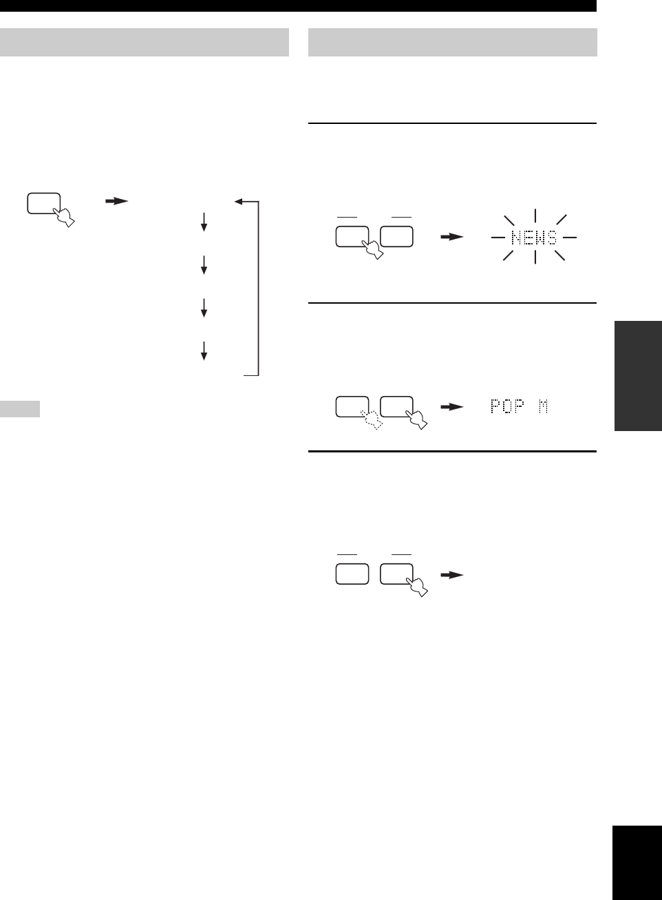
station light up in the front panel display. Press FREQ/
RDS on the remote repeatedly to change the display mode
among the RDS data offered by the transmitting station in
the order shown below.
• Do not press FREQ/RDS until one or more RDS mode
indicators light up in the front panel display. You cannot change
the mode if you press the button prior to this. This is because
this unit has not finished receiving all of the RDS data from the
station.
• RDS data not offered by the station cannot be selected.
• This unit cannot utilize the RDS data source if the signal
received is not strong enough. In particular, the RT mode
requires a large amount of data, so it is possible that the RT
mode may not be displayed even if other RDS modes (PS, PTY,
etc.) are displayed.
• RDS data may not be received under poor reception conditions.
In such cases, press TUNER (AUTO/MAN’L) so that the
“AUTO” indicator disappears from the front panel display.
Although this will change the reception mode to manual, RDS
data may be displayed when you change the display to RDS
mode.
• If the signal strength is weakened by external interference
during the reception of an RDS station, the RDS data service
may be cut off suddenly and “...WAIT” will appear in the front
panel display.
If you select the desired program type, this unit
automatically searches all preset RDS stations that are
broadcasting a program of the required type.
1Press PTY SEEK MODE to set this unit in the
PTY SEEK mode.
The program type of the station being received or
“NEWS” flashes in the front panel display.
2Press u PRESET d to select the desired
program type.
The selected program type appears in the front panel
display.
3Press PTY SEEK START to begin searching
all preset RDS stations.
The selected program type flashes and the “PTY
HOLD” indicator lights up in the front panel display
while searching for stations.
• The unit stops searching when it finds a station
broadcasting the selected type of program.
• If the found station is not the one you desire one,
press PTY SEEK START again. This unit resumes
searching for another station broadcasting the same
type of program.
To cancel this function
Press PTY SEEK MODE twice.
Changing the RDS mode
Notes
s
FREQ/RDS
PS
PTY
RT
CT
Frequency
display mode
PTY SEEK function
e
MODE PTY SEEK
f
START
Flashes
p
dPRESET
a
u
PTY HOLD
e
MODE PTY SEEK
f
START
Lights up
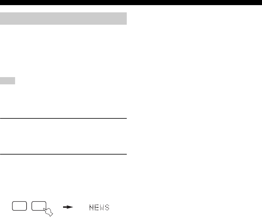
28
TUNING
This function uses the EON data service on the RDS
station network. If you select the desired program type
(NEWS, INFO, AFFAIRS or SPORT), this unit
automatically searches for all preset RDS stations that are
scheduled to broadcast the selected type of program and
switches from the station currently being received to the
new station when the broadcast starts.
This function can only be used when an RDS station that offers
the EON data service is being received. When such a station is
being received, the “EON” indicator lights up in the front panel
display.
1Check that the “EON” indicator is lit in the
front panel display.
If the “EON” indicator is not lit up, tune in to another
RDS station so that the “EON” indicator lights up.
2Press EON repeatedly to select the desired
program type (NEWS, INFO, AFFAIRS or
SPORT).
The selected program type name appears in the front
panel display.
• If a preset RDS station type starts broadcasting the
selected type of program, the unit automatically
switches from the program being received to that
program. (EON indicator flashes.)
• When broadcasting of the selected program ends,
the unit returns to the previous station (or another
program on the same station).
To cancel this function
Press EON repeatedly until no program type name is
shown in the front panel display.
EON function
Note
s
FREQ/RDS
AUDIO
EON
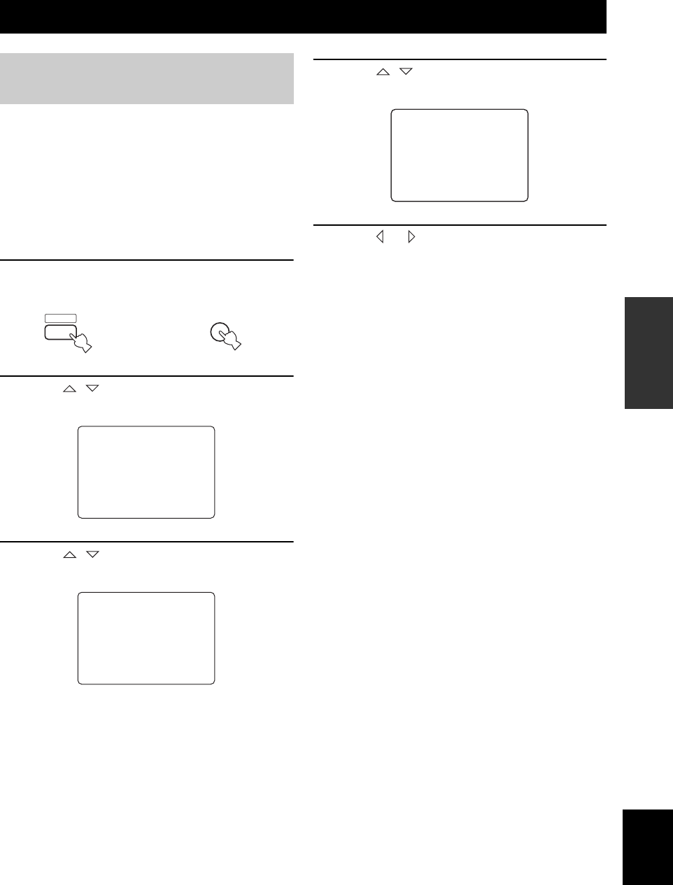
RECORDING
29
English
BASIC
OPERATION
When SCART SET is set to “ON”, signals can pass
through this unit’s SCART connectors even if this unit is
in the standby mode. This allows you to record between
the connected external components (see page 45).
If you experience difficulties recording through this unit’s
SCART connectors, do the following to make sure
SCART SET is set to “ON”.
■To change the SCART SET setting
1Press AMP, then press SET MENU on the
remote control.
2Press / to select MANUAL SETUP, then
press ENTER.
3Press / repeatedly to select OPTION
MENU, then press ENTER.
4Press / repeatedly to select SCART
SET, then press ENTER.
5Press or to select ON, then press
ENTER to complete the setting and return to
OPTION MENU.
Signals can pass through this unit via a SCART cable
whether it is turned on or set to the standby mode.
y
To stop signals on the SCART bus from passing though this unit
when it is in standby mode, select “OFF” in step 5.
RECORDING
Recording in standby mode
(SCART SET setting)
MENU
SET MENU
AMP then
SET MENU
.;BASICSETUP
.;MANUALSETUP
[]/[]:Up/Down
[ENTER]:Enter
p
p
; MANUAL SETUP
.1 SOUND MENU
2 INPUT MENU
.3 OPTION MENU
[]/[]:Up/Down
[ENTER]:Enter
p
p
A)DISPLAYSET
B)MEMORYGUARD
C)PARAM.INI
.D)SCARTSET
[]/[]:Up/Down
[ENTER]:Enter
3
OPTION
MENU
p
p
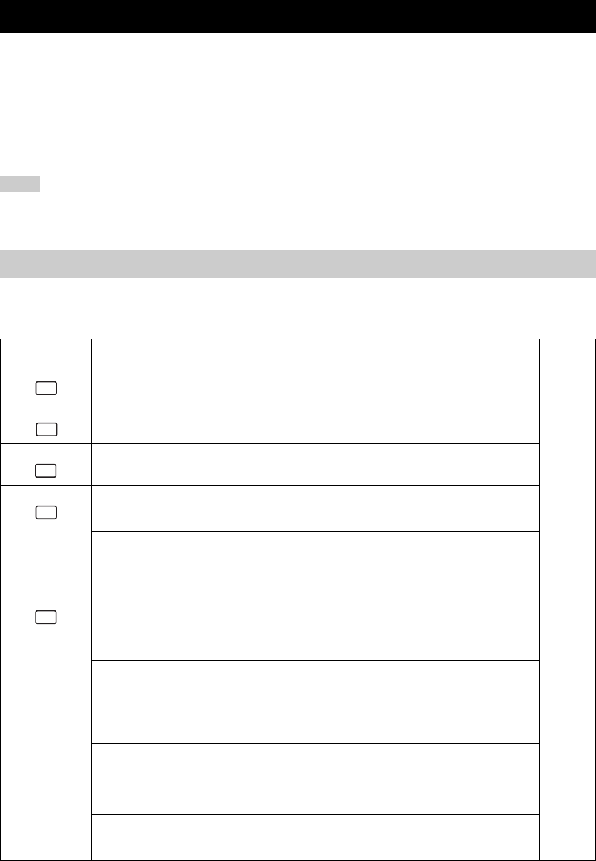
SOUND FIELD PROGRAM DESCRIPTIONS
30
This unit is equipped with a variety of precise digital decoders that allow you to enjoy multichannel playback from
almost any sound source (stereo or multichannel). This unit is also equipped with a YAMAHA digital sound field
processing (DSP) chip containing several sound field programs which you can use to enhance your playback experience.
Most of these sound field programs are precise digital recreations of actual acoustic environments found in famous
concert halls, music venues, and movie theaters.
y
The YAMAHA CINEMA DSP modes are compatible with all Dolby Digital, DTS, and Dolby Surround sources. Set the input mode to
AUTO (see page 35) to enable this unit to automatically switch to the appropriate digital decoder according to the input signal.
• This unit’s DSP sound field programs are recreations of real-world acoustic environments made from precise measurements taken in
the actual hall, etc. Thus you may notice variations in the strength of the reflections coming from the front, back, left and right.
• Feel free to choose a sound field program based on your listening preference, and not purely on the name of the program itself.
You can select from the following sound fields when playing movie or video sources. The sound fields marked “MULTI”
can be used with multi-channel sources, like DVD, digital TV, etc. Those marked “2-CH” can be used with 2-channel
(stereo) sources like TV programs, video tapes, etc.
SOUND FIELD PROGRAM DESCRIPTIONS
Notes
For movie/video sources
Remote button Program Features Sources
STEREO
2ch Stereo
Downmixes multi-channel sources to 2 channels (left and right) or plays
back 2-channel sources as is.
MULTI
2-CH
MUSIC VIDEO This program lends an enthusiastic atmosphere to the sound, giving you
the feeling you are at an actual jazz or rock concert.
ENTERTAINMENT
Game
This program adds a deep and spatial feeling to video game sounds.
TV THEATER
Mono Movie
This program is provided for reproducing monaural video sources (such
as old movies). The program produces the optimum reverberation to
create sound depth using only the presernce sound field.
TV THEATER
Variety/Sports
Though the presence sound field is relatively narrow, the surround sound
field employs the sound environment of a large concert hall. This effect
enhances the experience of watching various TV programs such as news,
variety shows, music programs or sports programs.
MOVIE THEATER
Spectacle
CINEMA DSP processing. This program creates the extremely wide
sound field of a 70-mm movie theater. It precisely reproduces the source
sound in detail, making both the video and the sound field incredibly real.
This is ideal for any kind of video source encoded with Dolby Surround,
Dolby Digital or DTS (especially large-scale movie productions).
MOVIE THEATER
Sci-Fi
CINEMA DSP processing. This program clearly reproduces dialog and
sound effects in the latest sound form for science fiction films, thus
creating a broad and expansive cinematic space amid silence. You can
enjoy science fiction films in a virtual-space sound field that includes
Dolby Surround, Dolby Digital and DTS-encoded software employing the
most advanced techniques.
MOVIE THEATER
Adventure
CINEMA DSP processing. This program is ideal for precisely
reproducing the sound design of the newest 70-mm and multichannel
soundtrack films. The sound field is made to be similar to that of the
newest movie theaters, so the reverberations of the sound field itself are
restrained as much as possible.
MOVIE THEATER
General
CINEMA DSP processing. This program is for reproducing sounds from
70-mm and multichannel soundtrack films, and is characterized by soft
and extensive sound field.
1
STEREO
5
MUSIC
6
ENTERTAIN
7
TV THTR
8
MOVIE

31
English
SOUND FIELD PROGRAM DESCRIPTIONS
SOUND FIELD
PROGRAMS
DOLBY DIGITAL
SUR. STANDARD
Standard 5.1-channel processing for Dolby Digital sources.
MULTI
DOLBY DIGITAL
SUR. ENHANCED
CINEMA DSP enhanced processing for Dolby Digital sources.
DTS
SUR. STANDARD
Standard 5.1-channel processing for DTS sources.
DTS 96/24
SUR. STANDARD
Standard 5.1-channel processing for 96-kHz/24-bit DTS sources.
DTS
SUR. ENHANCED
CINEMA DSP enhanced processing for DTS and 96-kHz/24-bit DTS
sources.
PRO LOGIC
SUR. STANDARD
Standard processing for Dolby Surround sources.
2-CH
PRO LOGIC
SUR. ENHANCED
CINEMA DSP enhanced processing for Dolby Surround sources.
PRO LOGIC II
PLII Movie
Dolby Pro Logic II processing for movie software.
PRO LOGIC II
PLII Game
Dolby Pro Logic II processing for game software.
Remote button Program Features Sources
9
STANDARD
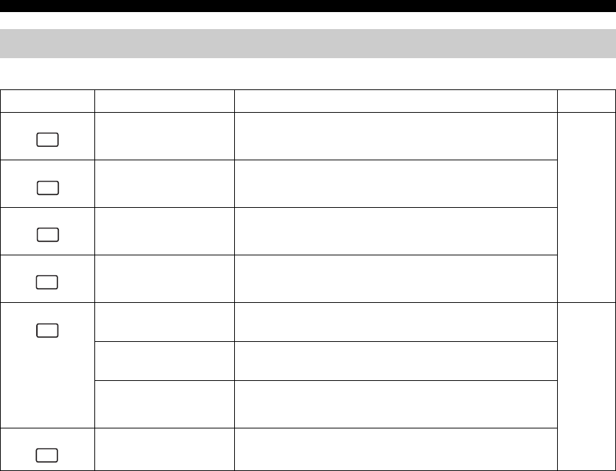
32
SOUND FIELD PROGRAM DESCRIPTIONS
You can select from the following sound fields when playing music sources, like CD, FM/AM broadcasting, tapes, etc.
For music sources
Remote button Program Features Sources
CONCERT HALL HiFi DSP processing. A classic shoe-box type concert hall with
approximately 1700 seats. Pillars and ornate carvings create extremely
complex reflections which produce a very full, rich sound.
MULTI
2-CH
JAZZ CLUB HiFi DSP processing. This is the sound field at stage front in “The Bottom
Line”, a famous New York jazz club. The floor can seat 300 people to the
left and right in a sound field offering a real and vibrant sound.
ROCK CONCERT HiFi DSP processing. The ideal program for lively, dynamic rock music.
The data for this program was recorded at LA’s “hottest” rock club. The
listener’s virtual seat is at the center-left of the hall.
ENTERTAINMENT
Disco
HiFi DSP processing. This program recreates the acoustic environment of
a lively disco in the heart of a big city. The sound is dense and highly
concentrated. It is also characterized by high-energy, “immediate” sound.
STEREO
2ch Stereo
2-channel (left and right) playback.
2-CH
STEREO
Direct Stereo
Use to output stereo sources to only the front left and right speakers
without any processing.
STEREO
5ch Stereo
Use to increase the output stereo sources (in stereo) from all speakers.
This provides a larger sound field and is ideal for background music at
parties, etc.
PRO LOGIC II
PLII Music
Dolby Pro Logic II processing for music software.
2
HALL
3
JAZZ
4
ROCK
6
ENTERTAIN
1
STEREO
9
STANDARD
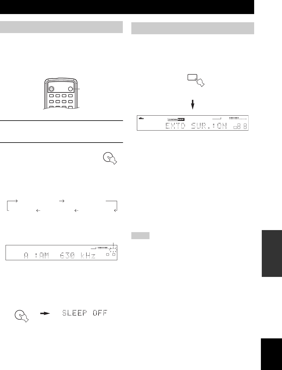
ADVANCED OPERATIONS
33
English
ADVANCED
OPERATION
Use this feature to automatically set this unit in the
standby mode after a certain amount of time. The sleep
timer is useful when you are going to sleep while this unit
is playing or recording a source.
■Setting the sleep timer
1Select a source and start playback on the
source component.
2Press SLEEP repeatedly on the
remote control to set the
amount of time.
Each time you press SLEEP, the front
panel display changes as shown below. The SLEEP
indicator flashes while switching the amount of time
for the sleep timer.
The “SLEEP” indicator lights up in the front panel
display after the sleep timer has been set.
■Canceling the sleep timer
Press SLEEP repeatedly on the remote control until
“SLEEP OFF” appears in the front panel display.
After a few seconds, “SLEEP OFF” disappears, and the
“SLEEP” indicator goes off.
y
The sleep timer setting can also be canceled by pressing
STANDBY on the remote control (or STANDBY/ON on the front
panel) to set this unit to the standby mode.
■Playing Dolby Digital Surround EX or
DTS-ES material
Press EXTD SUR. to turn on the Dolby Digital + Matrix
6.1 or DTS + Matrix 6.1 decoder.
The display changes AUTO → EXTD SUR.:ON → OFF
each time EXTD SUR. is pressed.
AUTO: Automatically switches Dolby Digital
+ Matrix 6.1 and DTS + Matrix 6.1
depending on the signal. Virtual
surround back speaker does not work
for 5.1- channel sources.
EXTD SUR.:ON: Produces 6-channel playback of the
input source using the Matrix 6.1
decoder. The virtual surround back
speaker can be used when playing a
5.1- channel source.
OFF: Virtual surround back speaker does
not work.
• Some 6.1-channel compatible discs do not have a signal (flag)
that this unit can automatically detect. Select “Matrix 6.1” to
play these kinds of discs with 6.1-channel sound.
• 6.1-channel playback is not possible even if you press EXTD
SUR. in the following cases:
– When effects are turned off.
– When the unit is reproducing a Dolby Digital KARAOKE
source.
– When headphones are connected to the PHONES jack.
• The decoding mode resets to AUTO when you turn the power of
the unit off.
ADVANCED OPERATIONS
Using the sleep timer
1
STEREO
2
HALL
3
JAZZ
4
ROCK
SLEEP
STANDBY/ON
5
MUSIC
6
ENTERTAIN
7
TV THTR
8
MOVIE
9
STANDARD
0
NIGHT
+10
EXTD SUR.
ENT
STRAIGHT
EFFECT
2
SLEEP
SLEEP 120min. SLEEP 90min.
SLEEP 60min.SLEEP 30min.SLEEP OFF
VCR
TUNED
VOLUME
SLEEP
L
L R
VIDEO 1 VIDEO 2
DTV/CBL
TUNER
DVD/CD
Lights
SLEEP
Enjoying multi-channel software
Notes
+10
EXTD SUR.
VCR
VOLUME
MATRIX
LFE
L
LR
SL SR
VIDEO 1 VIDEO 2
DTV/CBL
TUNER
DVD/CD
Remote control
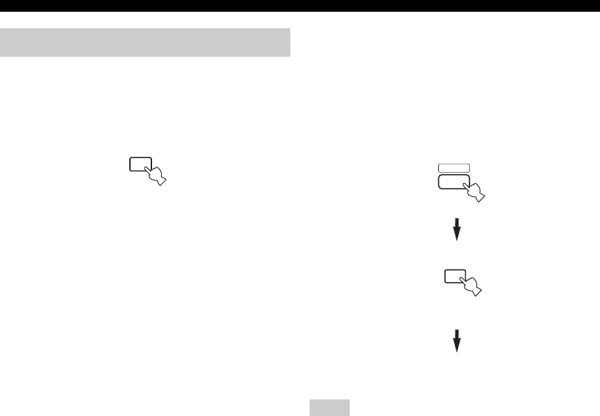
34
ADVANCED OPERATIONS
Signals input from 2-channel sources can also be played
back on multiple channels.
Press STANDARD on the remote control to select
the decoder.
You can select from the following modes depending on the
type of software you are playing and your personal
preference.
PRO LOGIC
Standard processing for Dolby Surround sources.
PRO LOGIC ENHANCED
CINEMA DSP enhanced processing for Dolby Surround
sources.
PRO LOGIC II Movie
Dolby Pro Logic II processing for movie sources.
PRO LOGIC II Music
Dolby Pro Logic II processing for music sources.
PRO LOGIC II Game
Dolby Pro Logic II processing for games.
■Listening to high fidelity stereo sound
(Direct Stereo)
Direct Stereo allows you to bypass this unit’s decoders and
DSP processors to enjoy pure high fidelity sound from 2-
channel PCM and analog sources.
Press AMP to select the AMP mode, then press
STEREO repeatedly to select “Direct Stereo”.
Direct Stereo
• To avoid unexpected noise, do not play DTS-encoded CDs in
this mode.
• When multi-channel signals (Dolby Digital and DTS) are input,
this unit automatically switches to the corresponding analog
input. (When DTS is selected as an input mode, no sound will
be heard.)
• No sound will be output from the subwoofer.
• TONE CONTROL (page 19) and SET MENU (page 38)
settings are not effective.
• The front panel display automatically dims.
y
You can enjoy 2-channel stereo playback from multi-channel
sources when “2ch Stereo” is selected (see page 21).
Enjoying 2-channel software
9
STANDARD
Remote control
Notes
AMP
1
STEREO
Remote control
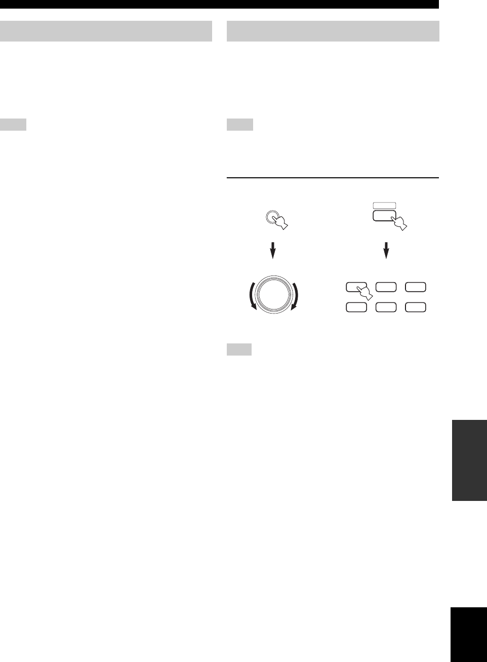
35
English
ADVANCED OPERATIONS
ADVANCED
OPERATION
Virtual CINEMA DSP allows you to enjoy DSP sound
field programs without surround speakers. It creates
virtual speakers to reproduce the natural sound field.
If SURR L/R SP in SPEAKER SET is set to “NONE”,
Virtual CINEMA DSP activates automatically whenever
you select a CINEMA DSP sound field program.
Virtual CINEMA DSP will not activate, even when Surround L/R
is set to “None” (see page 40), in the following cases:
– When the 5ch Stereo, 2ch Stereo, Direct Stereo, or
SUR. STANDARD program is selected.
– When the sound effect is turned off.
– When headphones are connected.
This unit comes with a variety of input jacks. Do the
following to select the type of input signals you want to
use.
Use this feature to designate the input mode for sources
connected to the DIGITAL INPUT jacks when you turn on
this unit (see page 44 for details about the input mode).
You cannot change the input mode when INPUT MODE of SET
MENU is set to “FIX”. In this case, change the setting to
“AUTO” or “LAST” (see page 44).
1Select the input source.
If no operation is performed within 5 seconds of pressing INPUT
or VOLUME/SELECT is pressed on the front panel, the function
of VOLUME/SELECT switches back to volume level adjustment.
If this happens, “VOLUME” appears in the front panel display for
a few seconds.
Virtual CINEMA DSP
Note
Selecting input modes
Note
Note
VOLUME/SELECT
INPUT
AMP
VCRDVD/CD VIDEO 1
TUNERDTV/CBL VIDEO 2
Front panel
or
(within 5 seconds)
Remote control
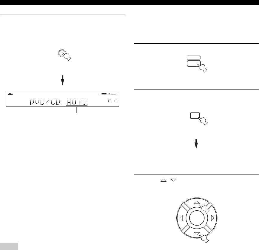
36
ADVANCED OPERATIONS
2Press INPUT repeatedly until the desired
input mode is shown in the front panel
display.
AUTO Automatically selects input signals in
the following order:
1) Digital signals*
2) Analog signals
DTS Selects only digital signals encoded in
DTS. If no DTS signals are input, no
sound is output.
ANALOG Selects only analog signals. If no
analog signals are input, no sound is
output.
* If this unit detects a Dolby Digital or DTS signal, the
decoder automatically switches to the appropriate sound
field program.
y
You can adjust the default input mode this unit selects when the
power is turned on with the SETTING parameter in INPUT
MODE (see page 44).
• When the SETTING parameter in INPUT MODE is set to
“FIX”, you cannot switch the input mode by pressing INPUT
(see page 44).
• When playing a disc encoded with Dolby Digital or DTS on
some LD or DVD players, there is a delay in sound output for a
moment when playback resumes after a search, because the unit
must select the digital signal again.
• When playing an LD source that has not been digitally
recorded, the unit may not output any sound for some LD
players. In this case, set the input mode to Analog.
• If you attempt to search (forward or backward) during playback
of a DTS-encoded disc, noise may occur periodically. If this
happens, set the input mode to DTS.
• When you play DTS-encoded CD/LDs with the input mode set
to AUTO, this unit automatically switches to the DTS decoding
mode. The unit remains in DTS mode (and the t indicator
may flash) for a few seconds after playback of the DTS source
is complete. To manually release the DTS mode, press INPUT
MODE to reselect AUTO.
• If the digital output data of the player has been processed in any
way, you may not be able to perform DTS decoding even if you
make a digital connection between this unit and the player.
■Displaying information about the input
source
You can display the type, format and sampling frequency
of the current input signal.
1Press AMP.
2Press STRAIGHT/EFFECT so that
“STRAIGHT” appears in the display.
STRAIGHT
3Press / to display the following
information about the input signal.
(Format) Signal format display. When the unit
cannot detect a digital signal it
automatically switches to analog input.
in Number of source channels in the input
signal. For example, a multi-channel
soundtrack with 3 front channels, 2
surround channels and LFE, is
displayed as “3/2/LFE”.
fs Sampling frequency. When the unit is
unable to detect the sampling
frequency “Unknown” appears.
rate Bit rate. When the unit is unable to
detect the bit rate “Unknown” appears.
flg Flag data encoded with DTS or Dolby
Digital signals that cue this unit to
automatically switch decoders.
Notes
VCR
VOLUME
L
L R
VIDEO 1 VIDEO 2
DTV/CBL
TUNER
DVD/CD
Input mode
INPUT
Front panel
AMP
Remote control
ENT
STRAIGHT
EFFECT
Remote control
ENTER
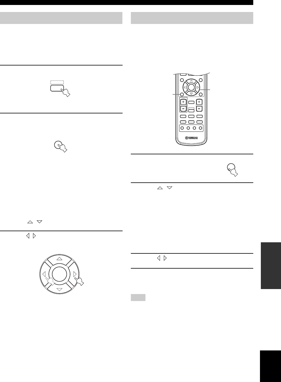
37
English
ADVANCED OPERATIONS
ADVANCED
OPERATION
You can adjust the output level of each speaker while
listening to a music source. Please note that this operation
will override the level adjustments made in the Speaker
Level section of BASIC SETUP (see page 17) and “Using
the test tone” (page 37).
1Press AMP to select the AMP mode.
2Press LEVEL repeatedly to select the
speaker you want to adjust.
FRONT L Front left speaker level
CENTER Center speaker level
FRONT R Front right speaker level
SUR.R Surround right speaker level
SUR.L Surround left speaker level
SWFR Subwoofer level
y
Once you press LEVEL, you can also select the speaker by
pressing / on the remote control.
3Press / to adjust the speaker output level
(Control range: –10 to +10 dB).
You can use the test tone feature to manually balance your
speaker levels. Please note that this operation will override
the level adjustments made in the Speaker Level section of
BASIC SETUP (page 17). Use the test tone to set speaker
levels so that the volume from each speaker is identical
when heard from your listening position.
1Press TEST/RETURN on the
remote control.
The unit will output a test tone.
2Press / repeatedly on the remote
control to select the speaker you want to
adjust.
TEST LEFT Front left speaker
TEST CENTER Center speaker
TEST RIGHT Front right speaker
TEST SUR. R Surround right speaker
TEST SUR. L Surround left speaker
TEST SUBWOOFER Subwoofer
3Press / to adjust speaker volumes.
4Press TEST/RETURN when you have
completed your adjustment.
The test tone stops.
You cannot enter test mode if headphones are connected to the
PHONES jack. Remove the headphones from the PHONES jack.
Manually adjusting speaker levels
AMP
Remote control
TITLE
LEVEL
Remote control
ENTER
Using the test tone
Note
b
TITLE
LEVEL
ENTER
CH
–
CH
+
p
MUTE
TV VOL VOLUME
AMP
VCRDVD/CD VIDEO 1
TUNERDTV/CBL VIDEO 2
a
MUTE INPUT
–
CH
TV MODE
+
MENU
SET MENU
RETURN
TEST/
RETURN
DISPLAY
1,4 2,3
RETURN
TEST/
RETURN

SET MENU
38
You can use the following parameters in SET MENU to adjust a variety of system settings and customize the way this
unit operates. Change the initial settings (indicated in bold under each parameter) to reflect the needs of your listening
environment.
■BASIC SETUP
Use to quickly setup basic system parameters (see page 16).
■MANUAL SETUP
Use to manually adjust speaker and system parameters.
1 SOUND MENU
Use to manually adjust any speaker setting, alter the quality and tone of the sound output by the system or compensate for
video signal processing delays when using LCD monitors or projectors.
y
Most of the parameters described in SOUND MENU are set automatically when you perform “BASIC SETUP” (see page 16). You can
use SOUND MENU to make further adjustments.
2 INPUT MENU
Use to reassign digital input and select the input mode.
3 OPTION MENU
Use to adjust the optional system parameters.
*a: D)TUNER SET is only available for Asia and General models.
*b: D)SCART SET is only available for U.K. and Europe models.
SET MENU
Item Features Page
A)SPEAKER SET Selects the size of each speaker, the speakers for low-frequency signal output, and the cross over
frequency. 40
B)SP LEVEL Adjusts the output level of each speaker. 41
C)SP DISTANCE Adjusts the delay time of each speaker. 42
D)CENTER GEQ Adjusts the tonal quality of the center speaker. 42
E)LFE LEVEL Adjusts the output level of the LFE channel for Dolby Digital or DTS signals. 42
F)D. RANGE Adjusts the dynamic range for Dolby Digital or DTS signals. 43
G)AUDIO SET Customizes the muting level and audio delay. 43
Item Features Page
A)INPUT ASSIGN Assigns jacks according to the component to be used. 43
B)INPUT MODE Selects the initial input mode of the source. 44
Item Features Page
A)DISPLAY SET Adjusts the brightness of the display and converts video signals. 44
B)MEMORY GUARD Locks sound field program parameters and other SET MENU settings. 45
C)PARAM. INI Initializes the parameters of a group of sound field programs. 45
D)TUNER SET Switches frequency spacing.*a 45
D)SCART SET Turns on this unit when a component connected using a SCART cable is turned on.*b 45
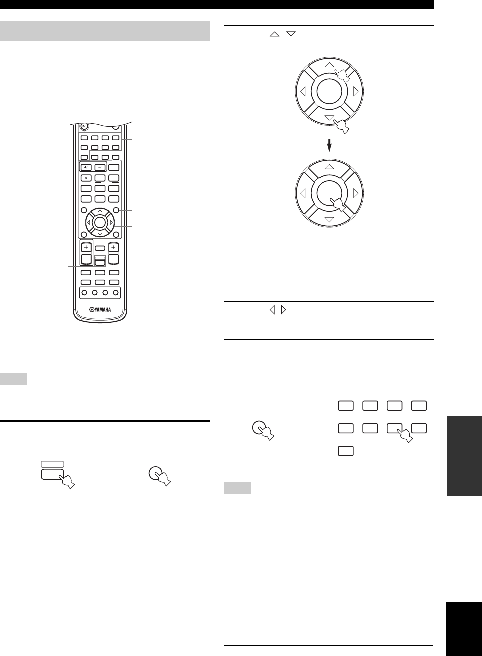
39
English
SET MENU
ADVANCED
OPERATION
You can enjoy good quality sound with the factory-set
parameters. Although you do not have to change the initial
settings, you can change some of the parameters to better
suit the input source or your listening room.
Use the remote control to access and adjust each
parameter.
y
You can change SET MENU parameters while the unit is
reproducing sound.
You cannot change some SET MENU parameters while the unit
is in either cinema or music night listening mode.
1Press AMP, then press SET MENU to enter
SET MENU.
“SET MENU” is displayed on both the monitor and
front panel of this unit.
The explanations in this document are based on the
Screen Menu. The characters shown in the front panel
display may differ from those on the Screen Menu.
2Press / repeatedly to select a menu,
then press ENTER.
• The number of levels each menu contains may
differ. If the menu you selected contains a sub
menu, press ENTER to enter the desired sub menu.
• Press TEST/RETURN to return to the upper level
menu.
3Press / repeatedly to change the setting
for the item you want to adjust.
4To exit, press SET MENU, or just press one of
the sound field program group buttons when
finished.
You cannot change parameter values when Memory Guard is set
to “ON”. If you want to change the parameter values, set Memory
Guard to “OFF” (see page 45).
Changing parameter settings
Note
1
STEREO
2
HALL
3
JAZZ
4
ROCK
5
MUSIC
6
ENTERTAIN
7
TV THTR
8
MOVIE
9
TV AV
CODE SET
REC FREQ/RDS EON
sAUDIO
w
DISC SKIP MODE START
PTY SEEK
e f
b
A/B/C/D/E
TITLE
LEVEL
ENTER
CH
–
CH
+
p
d
MUTE
TV VOL VOLUME
AMP
VCRDVD/CD VIDEO 1
TUNERDTV/CBL VIDEO 2
PRESET
a
u
STANDARD
0
NIGHT
+10
EXTD SUR.
ENT
STRAIGHT
EFFECT
MUTE INPUT
–
CH
TV MODE
+
MENU
SET MENU
RETURN
TEST/
RETURN
DISPLAY
1
2,3
1,4
4
MENU
SET MENU
AMP then
Note
Memory back-up
The memory back-up circuit prevents the stored data
from being lost even if this unit is set in the standby
mode, the power cord is disconnected from the AC
outlet, or the power supply is temporarily cut due to
power failure. However, if the power is cut for more
than one week, the parameter values will return to the
factory settings. If this happens, edit the parameter
value again.
ENTER
ENTER
1
STEREO
2
HALL
3
JAZZ
4
ROCK
5
MUSIC
6
ENTERTAIN
7
TV THTR
8
MOVIE
9
STANDARD
or
MENU
SET MENU
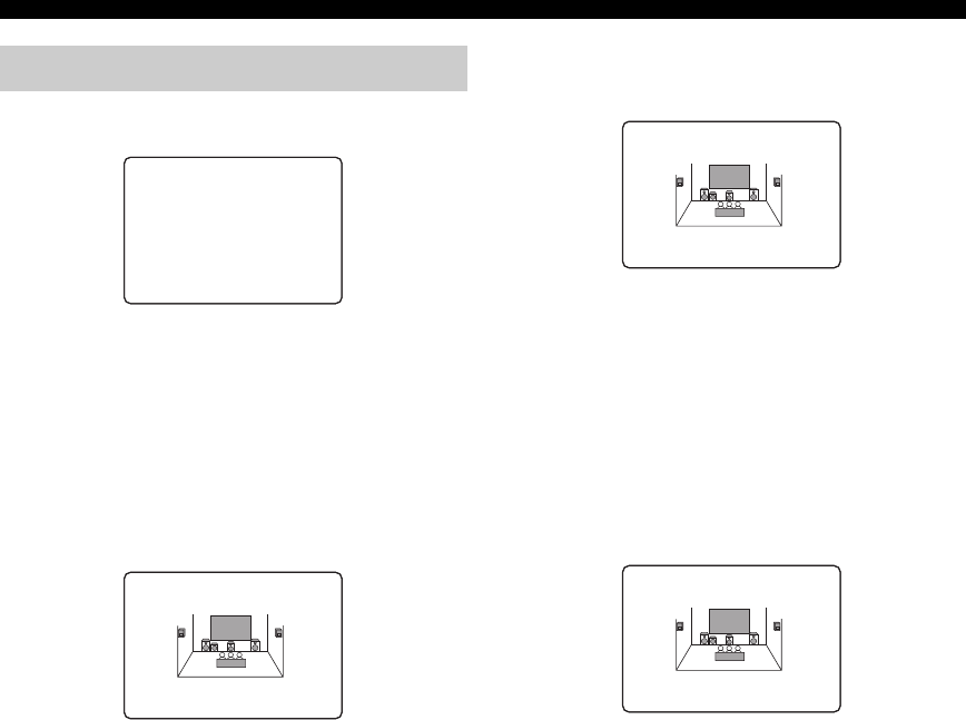
40
SET MENU
Use this menu to manually adjust any speaker setting.
■Speaker set A)SPEAKER SET
Use to manually adjust any speaker setting.
y
If you are not satisfied with the bass sounds from your speakers,
you can change these settings according to your preference.
Center speaker CENTER SP
Choices: NONE, SML, LRG
• Select NONE if you do not have a center speaker. The
unit directs all of the center channel signal to the front
left and right speakers.
• Select SML if you have a small center speaker. The
unit directs the low-frequency signals of the center
channel to the speakers selected with “LFE/BASS
OUT”.
• Select LRG if you have a large center speaker. The unit
directs the entire range of the center channel signal to
the center speaker.
Front speakers FRONT SP
Choices: SMALL, LARGE
• Select SMALL if you have small front speakers. The
unit directs the low-frequency signals of the front
channel to the speakers selected with “LFE/BASS
OUT”.
• Select LARGE if you have large front speakers. The
unit directs the entire range of the front left and right
channel signals to the front left and right speakers.
Surround left/right speakers SURR L/R SP
Choices: NONE, SML, LRG
• Select NONE if you do not have surround speakers.
This will set the unit to the Virtual CINEMA DSP
mode (see page 35).
• Select SML if you have small surround left and right
speakers. The low-frequency signals of the surround
channel are directed to the speakers selected with
“LFE/BASS OUT”.
• Select LRG if you have large surround left and right
speakers. The entire range of the surround channel
signal is directed to the surround left and right
speakers.
1 SOUND MENU
.A)SPEAKERSET
B)SPEAKERLEVEL
C)SPDISTANCE
D)CENTERGEQ
[]/[]:Up/Down
[ENTER]:Enter
p
p
1 SOUND
MENU 1/2
NONE)SMLLRG
CENTER SP
SMALL)LARGE
FRONT SP
NONE)SMLLRG
SURR L/R SP
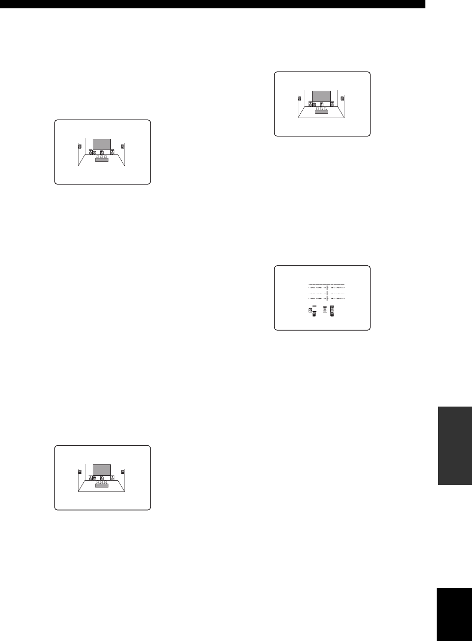
41
English
SET MENU
ADVANCED
OPERATION
Bass out LFE/BASS OUT
Low-frequency (bass) signals can be directed to the
subwoofer and/or the front left and right speakers
according to the characteristics of your system. This
setting also determines the routing of the LFE (low-
frequency effect) signals found in Dolby Digital or DTS
sources.
Choices: SWFR, FRNT, BOTH
• Select SWFR if you connect a subwoofer. LFE and
low-frequency signals from other channels are directed
to the subwoofer according to the speaker settings.
• Select FRNT if you do not use a subwoofer. LFE and
low frequency signals from other channels are directed
to the front speakers according to the speaker settings
(even if you have previously set front speakers to
SML).
• Select BOTH if you connect a subwoofer and you want
to output low-frequency signals from front channels to
both the front speakers and subwoofer. LFE and low-
frequency signals from other channels are also directed
to the subwoofer according to the speaker settings. Use
this function to reinforce low-frequency signals using
the subwoofer when playing back sources such as CDs.
Cross over CROSS OVER
Use this feature to select a cross-over (cut-off) frequency
for all low-frequency signals. All frequencies below the
selected frequency will be sent to the subwoofer.
Choices: 40Hz, 60Hz, 80Hz, 90Hz, 100Hz, 110Hz,
120Hz, 160Hz, 200Hz
Subwoofer phase SUBWOOFER PHASE
If bass sounds are lacking or unclear, use this feature to
switch the phase of your subwoofer.
Choices: NORMAL, REVERSE
• Select NORMAL if you do not want to reverse the
phase of your subwoofer.
• Select REVERSE to reverse the phase of your
subwoofer.
■Speaker level B)SPEAKER LEVEL
Use these settings to manually balance the speaker levels
between the front left or surround left speakers and each
speaker selected in SPEAKER SET (page 40).
Choices: –10 to +10 dB
•FR adjusts the balance of the front left and front right
speakers.
•C adjusts the balance of the front left and center
speakers.
•SL adjusts the balance of the front left and surround
left speakers.
•SR adjusts the balance of the surround left and
surround right speakers.
•SWFR adjusts the balance of the front left speaker and
subwoofer.
y
To calibrate, use the test tone feature (see page 37).
SWFRFRNT)BOTH
LFE/BASS OUT
FREQ;;;80Hz
CROSS OVER
)NORMALREVERSE
02ASUBWOOFER PHASE
-+
.FR
C
SL
B)SPEAKER
LEVEL
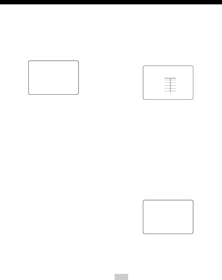
42
SET MENU
■Speaker distance C)SP DISTANCE
Use this feature to manually input the distance of each
speaker and adjust the delay applied to respective channel.
Ideally, each speaker should be the same distance from the
main listening position. However, this is not possible in
most home situations. Thus, a certain amount of delay
must be applied to the sound from each speaker so that all
sound will arrive at the listening position at the same time.
Unit UNIT
Choices: meters (m), feet (ft)
Initial setting:
U.S.A. and Canada models: feet (ft)
Other models: meters (m)
• Select meters to input speaker distances in meters.
• Select feet to input speaker distances in feet.
Speaker distances
Choices: 0.3 to 24.00 m (1 to 80 ft)
•FRONT L adjusts the distance of the front left speaker.
Initial setting: 3.0 m (10.0 ft)
•FRONT R adjusts the distance of the front right
speaker. Initial setting: 3.0 m (10.0 ft)
•CENTER adjusts the distance of the center speaker.
Initial setting: 3.0 m (10.0 ft)
•SURR L adjusts the distance of the surround left
speaker. Initial setting: 3.0 m (10.0 ft)
•SURR R adjusts the distance of the surround right
speaker. Initial setting: 3.0 m (10.0 ft)
•SWFR adjusts the distance of the subwoofer. Initial
setting: 3.0 m (10.0 ft)
■Center graphic equalizer D)CENTER GEQ
Use this feature to adjust the built-in 5-band graphic
equalizer for the center channel so that the tonal quality of
the center speaker matches that of the front speakers.
You can make adjustments listening to the currently
selected source component or a test tone.
You can adjust 5 frequency bands: 100Hz, 300Hz, 1kHz,
3kHz, 10kHz
Choices: –6 to +6 dB
• Select ON to output test tones from the front left and
center speakers, and adjust the tonal quality of the
center speaker.
• Select OFF to stop the test tone and output the
currently selected source component.
•Press u / d to select a frequency band.
•Press j / i to adjust the selected frequency band.
■Low-frequency effect level E)LFE LEVEL
Use to adjust the output level of the LFE (low-frequency
effect) channel according to the capacity of your
subwoofer or headphones. The LFE channel carries low-
frequency special effects which are only added to certain
scenes. This setting is effective only when this unit
decodes Dolby Digital or DTS signals.
Choices: –20 to 0 dB
Speaker SPEAKER
Select to adjust the speaker LFE level.
Headphone HEADPHONE
Select to adjust the headphone LFE level.
Depending on the settings of “LFE LEVEL”, some signals may
not be output from the SUBWOOFER OUTPUT jack.
.UNIT;;;;;;meters
FRONTL;;;;3.00m
FRONTR;;;;3.00m
CENTER;;;;;3.00m
[]/[]:Up/Down
[<]/[>]:Adjust
p
p
C)SP
DISTANCE
Note
.TEST)OFFON
-+
100Hz0dB
300Hz0dB
1kHz0dB
3kHz0dB
10kHz0dB
[]/[]:Up/Down
[<]/[>]:Adjust
D)CENTER GEQ
p
p
.SPEAKER;;;;;;0dB
HEADPHONE;;;;0dB
[]/[]:Up/Down
[<]/[>]:Adjust
p
p
E)LFE
LEVEL

43
English
SET MENU
ADVANCED
OPERATION
■Dynamic range F)DYNAMIC RANGE
Use to select the amount of dynamic range compression to
be applied to your speakers or headphones. This setting is
effective only when the unit is decoding Dolby Digital and
DTS signals.
Choices: MIN (minimum), STD (standard),
MAX (maximum)
Speaker SP
Select to adjust the speaker compression.
Headphone HP
Select to adjust the headphone compression.
• Select MIN if you regularly listen at low volume levels.
• Select STD for general use.
• Select MAX to preserve the greatest amount of
dynamic range.
■Audio set G)AUDIO SET
Use to customize this units overall audio settings.
Audio mute AUDIO MUTE
Use to adjust how much the mute function reduces the
output volume.
Choices: MUTE, –20 dB
• Select MUTE to completely halt all output of sound.
• Select –20 dB to reduce the current volume by 20 dB.
Audio delay AUDIO DELAY
Use to delay the sound output and synchronize it with the
video image. This may be necessary when using certain
LCD monitors or projectors.
Choices: 0 to 160 ms
Use this menu to manually adjust any input setting.
■Input assignment A)INPUT ASSIGN
You can assign jacks according to the component to be
used if this unit’s initial settings do not correspond to your
needs. Change the following parameters to reassign the
respective jacks and effectively connect more components.
Once the inputs have been reassigned, you can select the
corresponding component by using INPUT on the front
panel or the input selector buttons on the remote control.
For OPTICAL INPUT jacks 1 and 2
Choices: DVD/CD, VIDEO1, VCR, DTV/CBL
OPTICAL IN(2) cannot be assigned to an item already set to
OPTICAL IN(1). If you want to assign OPTICAL IN(2), change
the selection for OPTICAL IN(1). If the above settings are
incorrect, “– – –” appears in the display.
For COAXIAL INPUT jack 3
Choices: VIDEO1, VCR, DTV/CBL, DVD/CD
COAXIAL IN(3) cannot be assigned to an item already set to
OPTICAL IN(1) or OPTICAL IN(2). If you want to assign
COAXIAL IN(3), change the selection for OPTICAL IN(1) or
OPTICAL IN(2). If the above settings are incorrect, “– – –”
appears in the display.
.SP:MINSTD)MAX
HP:MINSTD)MAX
[]/[]:Up/Down
[<]/[>]:Select
p
p
F)DYNAMIC RANGE
.AUDIOMUTE;;MUTE
AUDIODELAY;;0ms
[]/[]:Up/Down
[<]/[>]:Selet
p
p
G)AUDIO SET
2 INPUT MENU
Note
Note
.A)INPUTASSIGN
B)INPUTMODE
[]/[]:Up/Down
[ENTER]:Enter
2
INPUT
MENU
p
p
.(1);;;;; DVD/CD
( DVD/CD)
(2);;;;;DTV/CBL
(DTV/CBL )
OPTICAL
IN
.(3);;;;; VIDEO1
( VIDEO1 )
COAXIAL
IN
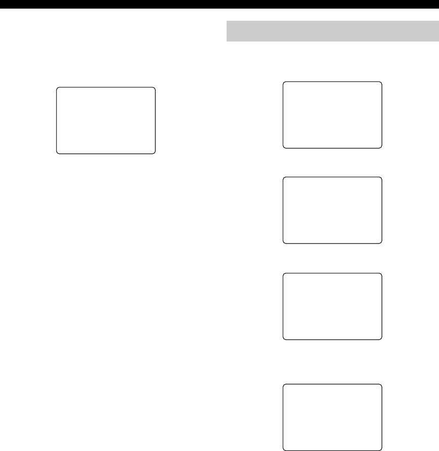
44
SET MENU
■Input mode B)INPUT MODE
Use this feature to designate the input mode for sources
connected to the DIGITAL INPUT jacks when you turn on
this unit (see page 35 for details about the input mode).
Choices: AUTO, LAST, FIX
• Select AUTO if you want “Auto” to be set whenever
you turn on this unit’s power.
• Select LAST to set this unit to automatically select the
last input mode used for that source.
• Select FIX to fix the input mode used for that source.
Use this menu to manually adjust the optional system
settings.
(Asia and General models)
(Europe and U.K. models)
■Display set A)DISPLAY SET
Dimmer DIMMER
Use to adjust the brightness of the front panel display.
Choices: –4 to 0
MENU shift MENU SHIFT
Use to adjust the vertical position of the Screen Menu.
Choices: –5 (upward) to +5 (downward)
• Press – to raise the position of the Screen Menu.
• Press + to lower the position of the Screen Menu.
)AUTOLASTFIX
[<]/[>]:Select
[ENTER]:Return
B)INPUT
MODE
3 OPTION MENU
.A)DISPLAYSET
B)MEMORYGUARD
C)PARAM.INI
[]/[]:Up/Down
[ENTER]:Enter
3
OPTION
MENU
p
p
A)DISPLAYSET
B)MEMORYGUARD
C)PARAM.INI
.D)TUNERSET
[]/[]:Up/Down
[ENTER]:Enter
3
OPTION
MENU
p
p
A)DISPLAYSET
B)MEMORYGUARD
C)PARAM.INI
.D)SCARTSET
[]/[]:Up/Down
[ENTER]:Enter
3
OPTION
MENU
p
p
.DIMMER;;;;;;;;;0
MENUSHIFT;;;;;0
[]/[]:Up/Down
[<]/[>]:Select
A)DISPLAY
SET
p
p

45
English
SET MENU
ADVANCED
OPERATION
■Memory guard B)MEMORY GUARD
Use this feature to prevent accidental changes to DSP
program parameter values and other system settings.
Choices: OFF, ON
Select ON to protect:
• DSP program parameters
• All SET MENU items
• All speaker levels
When “MEMORY GUARD” is set to ON, you cannot use the test
tone or select any other SET MENU items.
■Parameter initialization C)PARAM. INI
Use this feature to initialize the parameters for each sound
field program within a sound field program group. When
you initialize a sound field program group, all of the
parameter values within that group revert to their initial
settings.
Press the corresponding numeric button for the sound field
program that you want to initialize.
An asterisk (*) next to a program number means that the
parameter values have been changed from their initial
settings.
• You cannot automatically revert to the previous parameter
settings once you initialize a sound field program group.
• You cannot separately initialize individual sound field
programs.
• You cannot initialize any program groups when “MEMORY
GUARD” is set to ON.
■TUNER SET D)TUNER SET
Use this feature to adjust the frequency spacing for the
tuner. The new setting becomes active the next time the
power is turned on.
Choices: AM: 9kHz, FM: 50kHz and
AM: 10kHz, FM: 100kHz
• Select AM: 9kHz, FM: 50kHz to set the AM band to
9kHz and the FM band to 50kHz.
• Select AM: 10kHz, FM: 100kHz to set the AM band to
10kHz and the FM band to 100kHz.
This feature is only available when using Asia and General
models.
■SCART SET D)SCART SET
Use this feature to select whether you want signals carried
via SCART connections to pass through this unit when it
is set to the standby mode.
Choices: ON, OFF
• Select ON if you want to allow signals to pass through
this unit when it is in standby mode. (For example, if
this unit is connected via its SCART connectors
between your TV and VCR, the TV signals can pass
through to the VCR even when this unit is in the
standby mode.)
• Select OFF if you do not want signals to pass through
this unit when it is in standby mode.
This feature is only available when using Europe and U.K.
models.
Note
Notes
)OFFON
[<]/[>]:Select
[ENTER]:Return
B)MEMORY
GUARD
1234
567*8
9
C)PARAM.
INI
Note
Note
STEPAM9/FM50
[<]/[>]:Select
[ENTER]:Return
D)TUNER SET
STEPAM10/FM100
[<]/[>]:Select
[ENTER]:Return
D)TUNER SET
STANDBY ON
[<]/[>]:Select
[ENTER]:Return
D)SCART SET
STANDBY OFF
[<]/[>]:Select
[ENTER]:Return
D)SCART SET
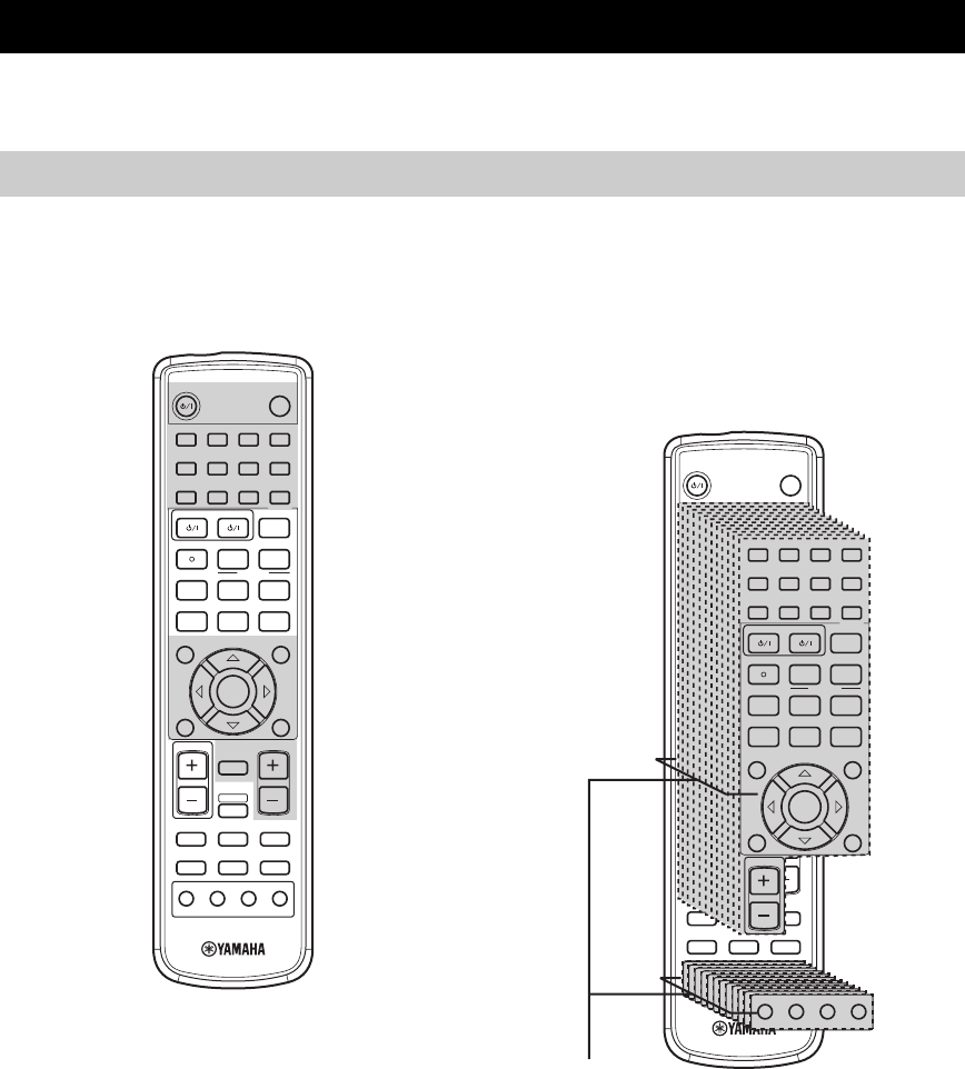
REMOTE CONTROL FEATURES
46
In addition to controlling this unit, the remote control can operate other A/V components made by YAMAHA and other
manufacturers. To control other components, set up the remote control with the appropriate remote control codes.
■Controlling this unit
The shaded areas below can be used to control this unit
when the AMP mode is selected. Press AMP to select the
AMP mode.
■Controlling other components
The shaded areas below can be used to control other
components. Each button has a different function
depending on the selected components. Select the
component you want to control by pressing an input
selector button. The name of the selected component
appears in the display window.
REMOTE CONTROL FEATURES
Control area
1
STEREO
2
HALL
3
JAZZ
4
ROCK
SLEEP
STANDBY/ON
5
MUSIC
6
ENTERTAIN
7
TV THTR
8
MOVIE
9
TV AV
CODE SET
REC FREQ/RDS EON
sAUDIO
w
DISC SKIP MODE START
PTY SEEK
e f
b
A/B/C/D/E
TITLE
LEVEL
ENTER
CH
–
CH
+
p
d
MUTE
TV VOL VOLUME
AMP
VCRDVD/CD VIDEO 1
TUNERDTV/CBL VIDEO 2
PRESET
a
u
STANDARD
0
NIGHT
+10
EXTD SUR.
ENT
STRAIGHT
EFFECT
MUTE INPUT
–
CH
TV MODE
+
MENU
SET MENU
RETURN
TEST/
RETURN
DISPLAY
1
HALL
2
JAZZ
3
ROCK
4
ENTERTAIN
SLEEP
STANDBY/ON
5
MUSIC
6
TV THTR
7
MOVIE 1
8
MOVIE 2
9
TV AV
CODE SET
REC
s
FREQ/RDS
AUDIO
EON
w
DISC SKIP
e
MODE PTY SEEK
f
START
b
A/B/C/D/E
TITLE
LEVEL
ENTER
CH
–
CH
+
p
d
MUTE
TV VOL VOLUME
AMP
VCRDVD/CD VIDEO 1
TUNERDTV/CBL VIDEO 2
PRESET
a
u
q/DTS
0
NIGHT
+10
EX/ES
ENT
STRAIGHT
EFFECT
MUTE INPUT
–
CH
TV MODE
+
RX-SL80
WD25800
MENU
SET MENU
RETURN
TEST
DISPLAY
MUTE INPUT
–
CH
TV MODE
+
MUTE INPUT
–
CH
TV MODE
+
MUTE INPUT
–
CH
TV MODE
+
MUTE INPUT
–
CH
TV MODE
+
MUTE INPUT
–
CH
TV MODE
+
MUTE INPUT
–
CH
TV MODE
+
MUTE INPUT
–
CH
TV MODE
+
MUTE INPUT
–
CH
TV MODE
+
MUTE INPUT
–
CH
TV MODE
+
MUTE INPUT
–
CH
TV MODE
+
MUTE INPUT
–
CH
TV MODE
+
MUTE INPUT
–
CH
TV MODE
+
1
STEREO
2
HALL
3
JAZZ
4
ROCK
5
MUSIC
6
ENTERTAIN
7
TV THTR
8
MOVIE
9
TV AV
CODE SET
REC FREQ/RDS EON
sAUDIO
w
DISC SKIP MODE START
PTY SEEK
e f
b
A/B/C/D/E
TITLE
LEVEL
ENTER
CH
–
CH
+
p
d
TV VOL
PRESET
a
u
STANDARD
0
NIGHT
+10
EXTD SUR.
ENT
STRAIGHT
EFFECT
MENU
SET MENU
RETURN
TEST/
RETURN
DISPLAY
Component
control area
You can control up to 11
different components by
setting appropriate remote
control codes (see
page 47).
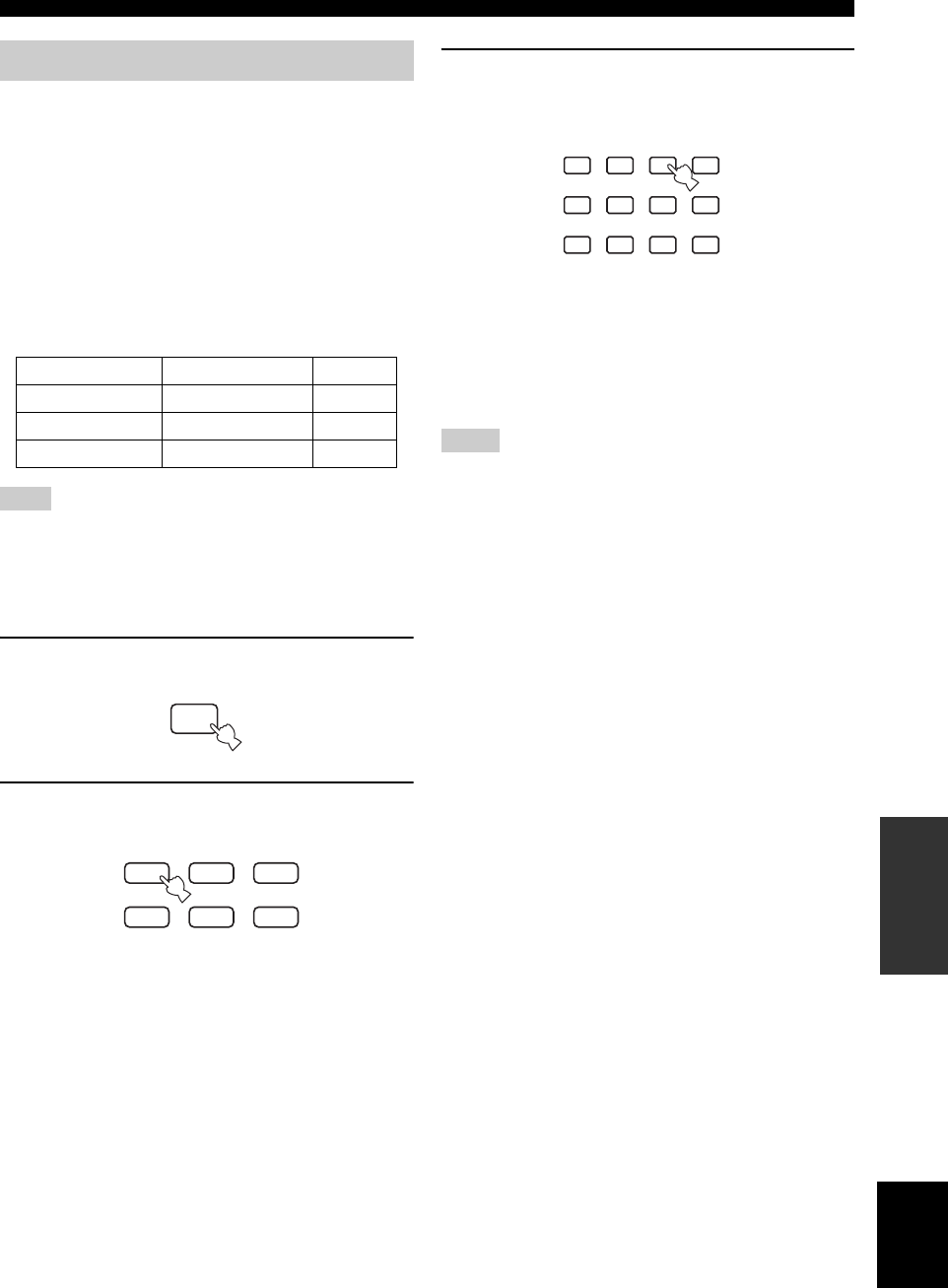
47
English
REMOTE CONTROL FEATURES
ADVANCED
OPERATION
Once you set the appropriate remote control codes, you
can use this remote to control your other components.
Note that some buttons may not correctly operate the
selected component. Use the input selector buttons to
select the component you want to operate. The remote
control automatically switches to the appropriate control
mode for that component.
■Default codes
The following table shows the default component
(Library: component category) and the remote control
code for each area.
You may not be able to operate your YAMAHA component even
if a YAMAHA remote control code is initially set as listed above.
In this case, try to set another YAMAHA remote control code.
■Setting a code
1Hold down CODE SET while doing steps 2
and 3.
2Press an input selector button to select the
source component you want to set up.
3Press the numeric buttons to enter the three-
digit remote control code for the component
to be used, then release CODE SET.
Refer to “LIST OF REMOTE CONTROL CODES” at the
end of this manual.
y
To reset an input area’s remote control code to the factory default,
input the default code (see “Default codes” above) in step 3.
• If the manufacturer of your component has more than one code,
try each of them until you find the correct one.
• If you wait for more than 10 seconds during step 3, the setup
process is canceled. If this happens, start over from step 2.
• Replace the batteries frequently. The settings may be lost after
two minutes without power supply.
• If the remote control code is successfully set, “Code Set OK”
appears in the front panel display of this unit. If the setting is
not successful, “Code Set NG” appears.
Setting remote control codes
Input area Manufacturer Code
TV (DTV/CBL) YAMAHA 299
VCR YAMAHA 399
DVD (DVD/CD) YAMAHA 699
Note
CODE SET
VCRDVD/CD VIDEO 1
TUNERDTV/CBL VIDEO 2
Notes
1
STEREO
2
HALL
3
JAZZ
4
ROCK
5
MUSIC
6
ENTERTAIN
7
TV THTR
8
MOVIE
9
STANDARD
0
NIGHT
+10
EXTD SUR.
ENT
STRAIGHT
EFFECT
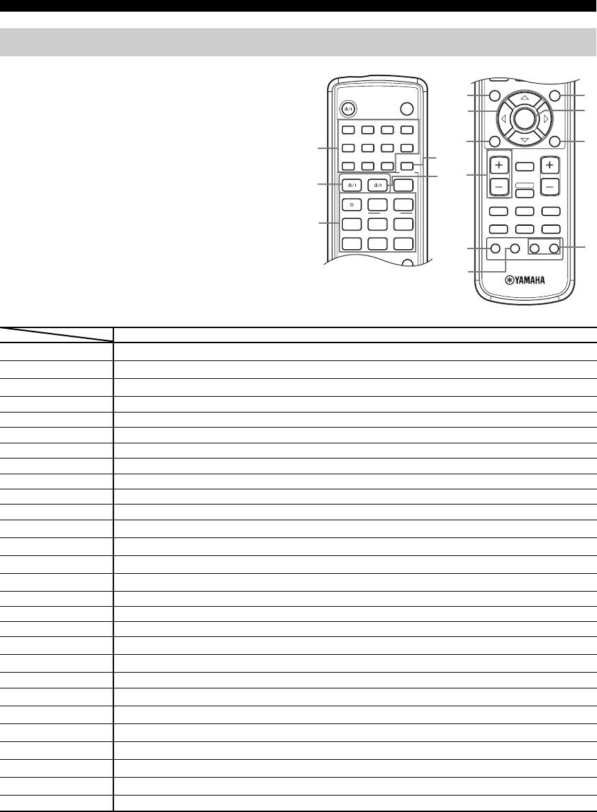
48
REMOTE CONTROL FEATURES
You can operate other components if you have set the
remote control code for your component in the remote
control. Please note that some buttons may not operate the
component as expected. When you select an input source,
the remote control automatically switches to the mode for
operating that component.
*1 This button functions only when the original remote control of the component has a POWER button.
*2 These buttons can operate your TV without switching the input if the remote control code is set in DTV/CBL.
*3 These buttons can operate your VCR without switching the input to VCR if the remote control code is set in VCR.
Controlling other components
1
STEREO
2
HALL
3
JAZZ
4
ROCK
SLEEP
STANDBY/ON
5
MUSIC
6
ENTERTAIN
7
TV THTR
8
MOVIE
9
TV AV
CODE SET
REC FREQ/RDS EON
sAUDIO
w
DISC SKIP MODE START
PTY SEEK
e f
b
A/B/C/D/E
TITLE
LEVEL
p
dPRESET
a
u
STANDARD
0
NIGHT
+10
EXTD SUR.
ENT
STRAIGHT
EFFECT
MENU
SET MENU
b
TITLE
LEVEL
ENTER
CH
–
CH
+
p
MUTE
TV VOL VOLUME
AMP
VCRDVD/CD VIDEO 1
TUNERDTV/CBL VIDEO 2
a
MUTE INPUT
–
CH
TV MODE
+
MENU
SET MENU
RETURN
TEST/
RETURN
DISPLAY
C
2
1
3
6
7
8
9
B
D
E
0
A
4
5
DVD player VCR TV, digital/cable TV Tuner
11-9, 0, +10 Numeric buttons Numeric buttons Numeric buttons Preset stations (1-8)
2TV TV power *2 TV power *2 TV power *2 TV power *2
3REC/DISC SKIP Disc skip Rec *3 VCR rec
pPlay Play *3 VCR play Preset down
wSearch backward Search backward *3 VCR search backward
fSearch forward Search forward *3 VCR search forward
AUDIO Audio
ePause Pause *3 VCR pause
aSkip forward Preset up
bSkip backward A/B/C/D/E
sStop Stop *3 VCR stop
4ENT Title/Index Enter/12
5AV Power *1 Power *1 VCR power
6TITLE Title
7kUp
nDown
CH +/hRight VCR channel up
CH –/lLeft VCR channel down
8RETURN Return
9TV VOL + TV volume up *2 TV volume up *2 TV volume up *2 TV volume up *2
TV VOL – TV volume down *2 TV volume down *2 TV volume down *2 TV volume down *2
0TV MUTE TV mute *2 TV mute *2 TV mute TV mute *2
ATV INPUT TV input *2 TV input *2 TV input TV input *2
BMENU Menu
CENTER Enter
DDISPLAY Display
ETV CH + TV channel up *2 TV channel up *2 TV channel up TV channel up *2
TV CH – TV channel down *2 TV channel down *2 TV channel down TV channel down *2
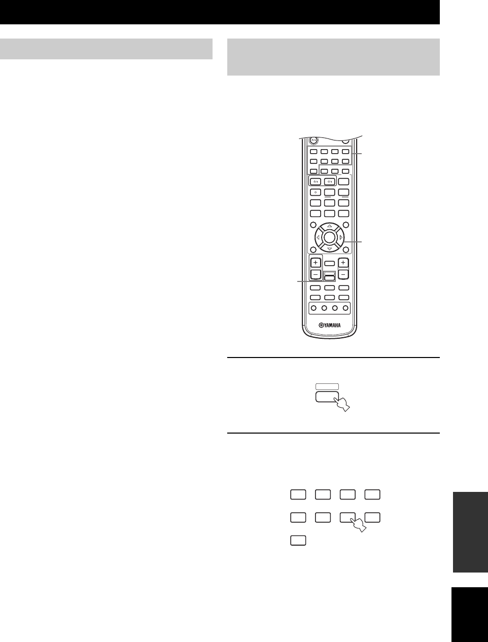
EDITING SOUND FIELD PARAMETERS
49
English
ADDITIONAL
INFORMATION
What really creates the rich, full tones of a live instrument
are the multiple reflections from the walls of the room. In
addition to making the sound “live”, these reflections
enable us to tell where the player is situated, and the size
and shape of the room in which we are sitting.
y
For details on how to change parameter settings, see page 39.
■Elements of a sound field
In any environment, in addition to the direct sound coming
straight to our ears from the player’s instrument, there are
two distinct types of sound reflections that combine to
make up the sound field:
Early reflections
Reflected sounds reach our ears extremely rapidly (50 ms
– 100 ms after the direct sound), after reflecting from one
surface only – for example, from the ceiling or a wall.
Early reflections actually add clarity to the direct sound.
Reverberations
These are caused by reflections from more than one
surface – walls, ceiling, the back of the room – so
numerous that they merge together to form a continuous
sonic “afterglow”. They are non-directional, and lessen
the clarity of the direct sound.
Direct sound, early reflections and subsequent
reverberation taken together help us to determine the
subjective size and shape of the room, and it is this
information that the digital sound field processor
reproduces in order to create sound fields.
If you could create the appropriate early reflections and
subsequent reverberations in your listening room, you
would be able to create your own listening environment.
The acoustics in your room could be changed to those of a
concert hall, a dance floor, or virtually any size room at
all. This ability to create sound fields at will is exactly
what YAMAHA has done with the digital sound field
processor.
You can adjust the values of certain digital sound field
parameters so the sound fields are recreated accurately in
your listening room. Not all of the following parameters
are found in every program.
1Press AMP on the remote control.
2Press one of the sound field program group
buttons to select the desired sound field
program.
EDITING SOUND FIELD PARAMETERS
What is a sound field Sound field parameter
descriptions
1
STEREO
2
HALL
3
JAZZ
4
ROCK
5
MUSIC
6
ENTERTAIN
7
TV THTR
8
MOVIE
9
TV AV
CODE SET
REC FREQ/RDS EON
sAUDIO
w
DISC SKIP MODE START
PTY SEEK
e f
b
A/B/C/D/E
TITLE
LEVEL
ENTER
CH
–
CH
+
p
d
MUTE
TV VOL VOLUME
AMP
VCRDVD/CD VIDEO 1
TUNERDTV/CBL VIDEO 2
PRESET
a
u
STANDARD
0
NIGHT
+10
EXTD SUR.
ENT
STRAIGHT
EFFECT
MUTE INPUT
–
CH
TV MODE
+
MENU
SET MENU
RETURN
TEST/
RETURN
DISPLAY
1
3,4
2
AMP
1
STEREO
2
HALL
3
JAZZ
4
ROCK
5
MUSIC
6
ENTERTAIN
7
TV THTR
8
MOVIE
9
STANDARD
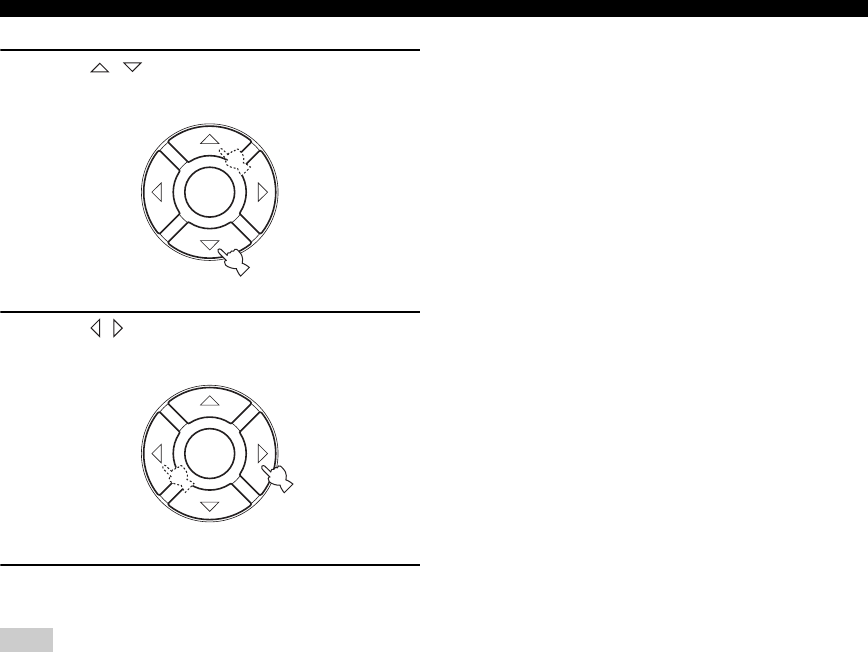
50
EDITING SOUND FIELD PARAMETERS
3Press / repeatedly to access the sound
field program parameters.
4Press / repeatedly to adjust the sound
field parameter.
5To change parameter values for a different
sound field, repeat steps 2 through 4.
You cannot change parameter values when Memory Guard is set
to “ON”. If you want to change the parameter values, set Memory
Guard to “OFF” (see page 45).
■DSP LEVEL
Function: This parameter adjusts the level of all the
DSP effect sounds within a narrow
range.
Description: Depending on the acoustics of you
listening room, you may want to increase
or decrease the DSP effect level relative
to the level of the direct sound.
Control range: –6 to +3 dB
■DELAY
Function: This parameter changes the apparent
distance from the source sound by
adjusting the delay between the direct
sound and the first reflection heard by
the listener.
Description: The smaller the value, the closer the
sound source seems to the listener. The
larger the value, the farther it seems. For
a small room, set to a small value. For a
large room, set to a large value.
Control range: 1 to 99 ms
For 5ch Stereo
Function: These parameter adjusts the volume level
for each channel in 5-channel stereo
mode.
Control Range: 0 to 100%
■CT LEVEL (Center level)
■SL LEVEL (Surround left level)
■SR LEVEL (Surround right level)
For PRO LOGIC II Music
■PANORAMA
Function: Extends the front stereo image to include
the surround speakers for wraparound
effect.
Choices: OFF/ON, initial setting is OFF.
■DIMENSION
Function: Gradually adjusts the sound field either
towards the front or towards the rear.
Control range: –3 (towards the rear) to +3 (towards the
front), initial setting is STD (standard).
■CT WIDTH (Center width)
Function: Adjusts the center image from all three
front speakers to varying degrees. A
larger value adjusts the center image
towards the front left and right speakers.
Control range: 0 (center channel sound is output only
from center speaker) to 7 (center channel
sound is output only from front left and
right speakers), initial setting is 3.
Note
ENTER
ENTER

TROUBLESHOOTING
51
English
ADDITIONAL
INFORMATION
Refer to the chart below when this unit does not function properly. If the problem you are experiencing is not listed below
or if the instruction below does not help, set this unit to the standby mode, unplug the power cord from the outlet, and
contact the nearest authorized YAMAHA dealer or service center.
■General
TROUBLESHOOTING
Problem Cause Remedy Refer to
page
This unit fails to turn
on when STANDBY/
ON is pressed, or
enters in the standby
mode soon after the
power has been
turned on.
The power cord is not connected or the
plug is not completely inserted.
Connect the power cord firmly. —
The impedance setting is incorrect. Set the impedance to match your speakers. 10
The protection circuitry has been
activated.
Make sure all speaker wire connections on this unit
and on all speakers are secure and that the wire for
each connection does not touch anything other than
its respective connection.
9, 11
This unit has been exposed to a strong
external electric shock (such as lightning
and strong static electricity).
Set this unit in the standby mode, disconnect the
power cord, plug it back in after 30 seconds, then use
it normally.
—
No sound Incorrect input or output cable
connections.
Connect the cables properly. If the problem persists,
the cables may be defective.
9, 12
Input Mode is set to DTS or ANALOG. Select AUTO. 35—36
No appropriate input source has been
selected.
Select an appropriate input source by pressing
INPUT, then rotating VOLUME/SELECT or using
the input selector buttons.
18
Speaker connections are not secure. Secure the connections. 9
The volume is turned down. Turn up the volume. —
The sound is muted. Press MUTE or any operation button on this unit to
cancel mute and adjust the volume.
19
If you are playing an LD source, the
player may not output digital signals if the
LD source was not digitally recorded.
Set the Input Mode to ANALOG. 35—36
The Input Mode is set to ANALOG while
playing a source encoded with a DTS
signal.
Set the Input Mode to AUTO or DTS. 35—36
Signals this unit cannot reproduce are
being received from a source component
e.g.: a CD-ROM.
Play a source whose signals this unit can reproduce. —
The sound suddenly
goes off.
The protection circuitry has been activated
because of a short circuit, etc.
Check the speaker wires are not touching each other
and then turn this unit back on.
—
The sleep timer has turned the unit off. Turn on the power, and play the source again. —
The sound is muted. Press MUTE to cancel a mute. 19
Only the speaker on
one side can be
heard.
Incorrect cable connections. Connect the cables properly. If the problem persists,
the cables may be defective.
9, 12
Incorrect balance settings in SET MENU. Adjust the SPEAKER LEVEL settings. 17, 41
Only the center
speaker outputs
substantial sound.
When playing a monaural source with a
CINEMA DSP program, the source signal
is directed to the center channel, and the
front and surround speakers output effect
sounds.

52
TROUBLESHOOTING
No sound from the
effect speakers.
The sound field programs are turned off. Press STRAIGHT/EFFECT to turn them on. 21
You are using a source or program
combination that does not output sound
from all channels.
Try another sound field program. 30
No sound from the
center speaker.
The output level of the center speaker is
set to minimum.
Raise the level of the center speaker. 17, 41
“CENTER SP” in SET MENU is set to
NONE.
Select the appropriate setting for the center speaker. 40
One of the Hi-Fi DSP programs (except
for 5ch Stereo) has been selected.
Try another sound field program. 30
No sound from the
surround speakers.
The output level of the surround speakers
is set to minimum.
Raise the output level of the surround speakers. 17, 41
“SURR L/R SP” in SET MENU is set to
NONE.
Select the appropriate setting for the surround left and
right speakers.
40
A monaural source is being played with
STRAIGHT.
Press STRAIGHT/EFFECT to turn on the sound
fields.
—
No sound from the
subwoofer.
“LFE/BASS OUT” in SET MENU is set
to FRNT when a Dolby Digital or DTS
signal is being played.
Select SWFR or BOTH. 41
“LFE/BASS OUT” in SET MENU is set
to SWFR or FRNT when a 2-channel
source is being played.
Select BOTH. 41
The source does not contain low bass
signals.
Dolby Digital or DTS
sources cannot be
played. (Dolby Digital
or DTS indicator in
the front panel
display does not light
up.)
The connected component is not set to
output Dolby Digital or DTS digital
signals.
Make an appropriate setting following the operations
instructions for your component.
—
Input Mode is set to ANALOG. Set Input Mode to AUTO or DTS. 35—36
A “humming” sound
can be heard.
Incorrect cable connections. Firmly connect the audio plugs. If the problem
persists, the cables may be defective.
—
The volume level
cannot be increased,
or the sound is
distorted.
The component connected to the EXT IN/
OUT connector of this unit is turned off.
Turn on the power to the component. —
The sound effect
cannot be recorded.
It is not possible to record the sound effect
with a recording component.
A source cannot be
recorded by a digital
recording component
connected to this
DIGITAL OUTPUT
jack.
The source component is not connected to
this unit’s DIGITAL INPUT jacks.
Connect the source component to the DIGITAL
INPUT jacks.
12
Some components cannot record the
Dolby Digital or DTS sources.
A source cannot be
recorded by an
analog component
connected to the TV
IN/OUT jacks.
The source component is not connected to
this unit’s analog TV IN/OUT jack.
Connect the source component to the analog TV IN/
OUT jack.
12
The sound field
parameters and some
other settings on this
unit cannot be
changed.
“MEMORY GUARD” in SET MENU is
set to ON.
Select OFF. 45
Problem Cause Remedy Refer to
page

53
English
TROUBLESHOOTING
ADDITIONAL
INFORMATION
■Tuner
This unit does not
operate properly.
The internal microcomputer has been
frozen by an external electric shock (such
as lightning or excessive static electricity)
or by a power supply with low voltage.
Disconnect the AC power cord from the outlet and
then plug it in again after about 30 seconds.
—
“CHECK SP WIRES”
appears in the front
panel display.
Speaker cables are short circuited. Make sure all speaker cables are connected correctly. 9
There is noise
interference from
digital or high-
frequency equipment,
or this unit.
This unit is too close to digital or high-
frequency equipment.
Move this unit further away from such equipment. —
The picture is
disturbed.
The video source uses scrambled or
encoded signals to prevent dubbing.
This unit suddenly
switches to the
standby mode.
The internal temperature became too high
and the overheat protection circuitry was
activated.
Wait until this unit cools down and then turn it back
on.
—
The whirring of the
fan can occassionally
be heard.
This unit is fitted with a fan for cooling
purposes. The fan automatically operates
when the temperature inside the unit
becomes too hot, or when the unit is
turned on.
Problem Cause Remedy Refer to
page
FM
FM stereo reception is
noisy.
The characteristics of FM stereo
broadcasts may cause this problem
when the transmitter is too far away or
the antenna input is poor.
Check the antenna connections.
Try using a high-quality directional FM
antenna.
14
Use the manual tuning method. 23
There is distortion, and
clear reception cannot
be obtained even with a
good FM antenna.
There is multipath interference. Adjust the antenna position to eliminate
multipath interference.
—
The desired station
cannot be tuned in with
the automatic tuning
method.
The station is too weak. Use a high-quality directional FM antenna. —
Use the manual tuning method. 23
Previously preset
stations can no longer
be tuned in.
This unit has been disconnected for a
long period.
Preset the stations again. 24
Problem Cause Remedy Refer to
page
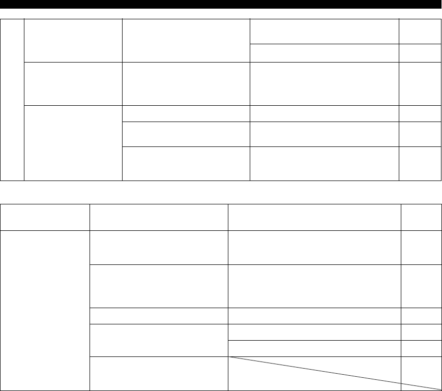
54
TROUBLESHOOTING
■Remote control
AM
The desired station
cannot be tuned in with
the automatic tuning
method.
The signal is weak or the antenna
connections are loose.
Tighten the AM loop antenna connections
and orient it for best reception.
—
Use the manual tuning method. 23
There are continuous
crackling and hissing
noises.
Noises result from lightning,
fluorescent lamps, motors,
thermostats and other electrical
equipment.
Use an outdoor antenna and a ground wire.
This will help somewhat, but it is difficult to
eliminate all noise.
—
There are buzzing and
whining noises
(especially in the
evening).
A TV set is being used nearby. Move this unit away from the TV. —
The AM loop antenna is placed near
the speaker cables.
Place the AM loop antenna away from the
speaker cables.
—
The AM ANT and GND cords are
inserted in the wrong terminal.
Make sure the white cord is inserted into the
AM ANT terminal and the black cord into
the GND terminal.
14
Problem Cause Remedy Refer to
page
The remote control
does not work or
function properly.
Wrong distance or angle. The remote control will function within a maximum
range of 6 m (20 ft) and no more than 30 degrees off-
axis from the front panel.
6
Direct sunlight or lighting (from an
inverter type of fluorescent lamp, etc.) is
striking the remote control sensor of this
unit.
Reposition this unit. —
The batteries are weak. Replace all batteries. 3
The remote control code was not correctly
set.
Set the remote control code correctly. 47
Try to set the other codes of the same manufacturer. 47
Even if the remote control code is
correctly set, some models may not
respond to the remote control.

GLOSSARY
55
English
ADDITIONAL
INFORMATION
■Dolby Digital
Dolby Digital is a digital surround sound system that gives
you completely independent multi-channel audio. With 3
front channels (left, center, and right), and 2 surround
stereo channels, Dolby Digital provides 5 full-range audio
channels. With an additional channel especially for bass
effects, called LFE (low frequency effect), the system has
a total of 5.1-channels (LFE is counted as 0.1 channel). By
using 2-channel stereo for the surround speakers, more
accurate moving sound effects and surround sound
environment are possible than with Dolby Surround. The
wide dynamic range (from maximum to minimum
volume) reproduced by the 5 full-range channels and the
precise sound orientation generated using digital sound
processing provide listeners with previously unheard of
excitement and realism.
With this unit, any sound environment from monaural up
to a 5.1-channel configuration can be freely selected for
your enjoyment.
■Dolby Pro Logic II
Dolby Pro Logic II is an improved technique used to
decode vast numbers of existing Dolby Surround software.
This new technology enables a discrete 5-channel
playback with 2 front left and right channels, 1 center
channel, and 2 surround left and right channels (instead of
only 1 surround channel for conventional Pro Logic
technology). Music and Game modes are also available for
2-channel sources in addition to the Movie mode.
■Dolby Surround
Dolby Surround uses a 4 channel analog recording system
to reproduce realistic and dynamic sound effects: 2 front
left and right channels (stereo), a center channel for dialog
(monaural), and a surround channel for special sound
effects (monaural). The surround channel reproduces
sound within a narrow frequency range.
Dolby Surround is widely used with nearly all video tapes
and laser discs, and in many TV and cable broadcasts as
well. The Dolby Pro Logic decoder built into this unit
employs a digital signal processing system that
automatically stabilizes the volume on each channel to
enhance moving sound effects and directionality.
■DTS 96/24
DTS 96/24 offers an unprecedented level of audio quality
for multi-channel sound on DVD-Video, and is fully
backward-compatible with all DTS decoders. “96” refers
to a 96 kHz sampling rate (compared to the typical 48 kHz
sampling rate). “24” refers to 24-bit word length. DTS 96/
24 offers sound quality transparent to the original 96/24
master, and 96/24 5.1-channel sound with full-quality full-
motion video for music programs and motion picture
soundtracks on DVD-video.
■DTS (Digital Theater Systems)
Digital Surround
DTS digital surround was developed to replace the analog
soundtracks of movies with a 6-channel digital sound
track, and is now rapidly gaining popularity in movie
theaters around the world. Digital Theater Systems Inc.
has developed a home theater system so that you can enjoy
the depth of sound and natural spatial representation of
DTS digital surround in your home. This system produces
practically distortion-free 6-channel sound (technically, a
left, right and center channels, 2 surround channels, plus
an LFE 0.1 channel as a subwoofer, for a total of 5.1-
channels). The unit incorporates a DTS-ES decoder that
enables 6.1- channel reproduction by adding the surround
back channel to existing 5.1-channel format.
GLOSSARY
Audio formats

56
GLOSSARY
■CINEMA DSP
Since the Dolby Surround and DTS systems were
originally designed for use in movie theaters, their effect
is best felt in a theater having many speakers and designed
for acoustic effects. Since home conditions, such as room
size, wall material, number of speakers, and so on, can
differ so widely, it’s inevitable that there are differences in
the sound heard as well. Based on a wealth of actually
measured data, YAMAHA CINEMA DSP uses
YAMAHA original sound field technology to combine
Dolby Pro Logic, Dolby Digital and DTS systems to
provide the visual and audio experience of movie theater
in the listening room of your own home.
■SILENT CINEMA
YAMAHA has developed a natural, realistic sound effect
DSP algorithm for headphones.
Parameters for headphones have been set for each sound
field so that accurate representations of all the sound field
programs can be enjoyed on headphones.
■Virtual CINEMA DSP
YAMAHA has developed a Virtual CINEMA DSP
algorithm that allows you to enjoy DSP sound field
surround effects even without any surround speakers by
using virtual surround speakers.
It is even possible to enjoy Virtual CINEMA DSP using a
minimal two-speaker system that does not include a center
speaker.
■ITU-R
ITU-R is the radio communication sector of the ITU
(International Telecommunication Union). ITU-R
recommends a standard speaker placement which is used
in many critical listening rooms, especially for mastering
purposes.
■LFE 0.1 channel
This channel is for the reproduction of low bass signals.
The frequency range for this channel is 20 Hz to 120 Hz.
This channel is counted as 0.1 because it only enforces a
low frequency range compared to the full-range
reproduced by the other 5/6 channels in Dolby Digital or
DTS 5.1/6.1-channel systems.
■PCM (Linear PCM)
Linear PCM is a signal format under which an analog
audio signal is digitized, recorded and transmitted without
using any compression. This is used as a method of
recording CDs and DVD audio. The PCM system uses a
technique for sampling the size of the analog signal per
very small unit of time. Standing for “pulse code
modulation”, the analog signal is encoded as pulses and
then modulated for recording.
■Sampling frequency and number of
quantized bits
When digitizing an analog audio signal, the number of
times the signal is sampled per second is called the
sampling frequency, while the degree of fineness when
converting the sound level into a numeric value is called
the number of quantized bits.
The range of rates that can be played back is determined
based on the sampling rate, while the dynamic range
representing the sound level difference is determined by
the number of quantized bits. In principle, the higher the
sampling frequency, the wider the range of frequencies
that can be played back, and the higher the number of
quantized bits, the more finely the sound level can be
reproduced.
■Composite video signal
With the composite video signal system, the video signal
is composed of three basic elements of a video picture;
color, brightness and synchronization data. A composite
video jack on a video component transmits these three
elements combined.
Sound field programs Audio information
Video signal information

SPECIFICATIONS
57
English
ADDITIONAL
INFORMATION
AUDIO SECTION
• Minimum RMS Output Power for Front, Center, Surround
1 kHz, 0.9% THD, 6 Ω............................................. 70 W + 70 W
• Maximum Power (EIAJ) for Front, Center, Surround
1 kHz, 10% THD, 6 Ω......................................................... 100 W
• Input Sensitivity/Input Impedance
EXT IN/OUT, etc. ................................................. 200 mV/47 kΩ
• Output Level/Output Impedance
EXT/TV ................................................................ 200 mV/1.0 kΩ
SUBWOOFER (FRONT SP: SMALL)..................... 2.0 V/1.2 kΩ
• Headphone Jack Rated Output/Impedance
EXT IN (DVD/CD, etc.)
1 kHz...................................................................... 100 mV/100 Ω
• Frequency Response
Front (EXT IN, etc.) ............................. 20 Hz to 50 kHz, 0/–3 dB
• Total Harmonic Distortion (FRONT SP OUT)
EXT IN (Effect Off), 1 kHz, 35 W/6 Ω.................... 0.04% or less
• Signal to Noise Ratio (IHF-A Network) (SP OUT)
EXT IN (Effect Off), Input shorted, 250 mV ....... 100 dB or more
• Residual Noise (IHF-A Network)
SP OUT, Front L/R................................................. 150 µV or less
• Channel Separation (1 kHz/10 kHz)
EXT IN, etc., Effect Off, VOL. –30 dB,
1 kHz/10 kHz, 5.1 kΩ terminated.............. 60 dB/45 dB or more
• Tone Control Characteristics
[Bass]
Boost/Cut .............................................................. ±10 dB/60 Hz
[Treble]
Boost/Cut ............................................................ ±10 dB/20 kHz
• Filter Characteristics
FRONT, CENTER, SURROUND SP SMALL (H.P.F.)
.............. fc = 40/60/80/90/100/110/120/160/200 Hz, 12 dB/oct.
SUBWOOFER (L.P.F.)
............... fc = 40/60/80/90/100/110/120/160/200 Hz, 24 dB/oct.
VIDEO SECTION
• Video Signal Type ........................................................... NTSC/PAL
• Video Signal Level........................................................ 1 Vp-p/75 Ω
• Maximum Input Level......................................................... 1.5 Vp-p
• Signal to Noise Ratio ................................................. 50 dB or more
• Frequency Response (MONITOR OUT) ..... 5 Hz to 10 MHz, –3 dB
FM SECTION
• Tuning Range
[U.S.A. and Canada models]............................ 87.5 to 107.9 MHz
[Asia and General models]......... 87.5/87.50 to 108.0/108.00 MHz
[Other models] ............................................. 87.50 to 108.00 MHz
• Quieting Sensitivity (IHF)
Mono (50 dB, 1 kHz, 100% MOD.)................... 2.8 µV (20.2 dBf)
• Signal to Noise Ratio (IHF)
Mono/Stereo............................................................... 73 dB/70 dB
• Harmonic Distortion (1 kHz)
Mono/Stereo................................................................. 0.5%/0.5%
• Antenna Input......................................................... 75 Ω unbalanced
AM SECTION
• Tuning Range
[U.S.A. and Canada models]............................... 530 to 1710 kHz
[Asia and General models].................. 530/531 to 1710/1611 kHz
[Other models] .................................................... 531 to 1611 kHz
• Antenna ....................................................................... Loop antenna
GENERAL
• Power Supply
[U.S.A. and Canada models]............................... AC 120 V, 60 Hz
[Australia model] ................................................ AC 240 V, 50 Hz
[China model]...................................................... AC 220 V, 50 Hz
[Korea model] ..................................................... AC 220 V, 60 Hz
[U.K. and Europe models] .................................. AC 230 V, 50 Hz
[Asia model]........................................... AC 220-240 V, 50/60 Hz
[General model] ..................................... AC 110-120 V, 50/60 Hz
• Power Consumption ................................................................. 90 W
• Standby Power Consumption
[U.S.A., Canada and General models] ................................. 0.8 W
[U.K. and Europe models] ......................................... 0.9 W/2.5 W
[Other models] ..................................................................... 0.9 W
• Dimension (W x H x D) .................................. 435 x 55.5 x 325 mm
(17-1/8” x 2-3/16” x 12-3/4”)
• Weight ..................................................................................... 6.4 kg
(14 lbs 2 oz.)
SPECIFICATIONS

LIST OF REMOTE CONTROL CODES
LISTE DES CODES DE FABRICANT
LISTE DER HERSTELLERCODES
LISTA ÖVER TILLVERKARKODER
LISTA DEI CODICI DEI FABBRICANTI
LISTA DE CÓDIGOS DE FABRICANTES
LIJST MET FABRIKANTENCODES
TV
YAMAHA 299, 292
ADMIRAL 292, 293
AIWA 294, 276,
283, 284
AKAI 295, 296
ALBA 296
AOC 297
BELL&HOWELL 292
BESTAR 298
BLAUPUNKT 229, 222
BLUE SKY 298
BRANDT 223
BROCSONIC 297
BUSH 296
CLATRONIC 298
CRAIG 224
CROSLEX 225
CURTIS MATHIS 297, 226
DAEWOO 297, 298,
224, 227,
228
DAYTRON 239
DUAL 298
EMERSON 297, 224,
239, 232
FERGUSON 223, 265,
266
FIRST LINE 298
FUNAI 277, 278
FISHER 295, 233
FRABA 298
GE 293, 297,
234, 235,
236
LG/GOLDSTAR 297, 298,
239, 237
GOODMANS 296, 298,
223
GRUNDIG 229, 238,
249
HITACHI 297, 239,
242, 243,
285
ICE 296
IRRADIO 296
ITT/NOKIA 244,245
JC PENNY 293, 297,
234, 237
JVC 296, 246,
247, 286
KENDO 298
KTV 297, 239
LOEWE 298, 248
LXI 293, 297,
225, 226,
233
MAGNAVOX 297, 225,
239
MATSUI 295
MITSUBISHI 299, 297,
259, 287
NEC 297, 252,
282
NOKIA 244, 245
NOKIA OCEANIC 245
NORDMENDE 265, 266
ONWA 296
PANASONIC 234, 235,
236, 253,
288, 211
PHILCO 297, 225,
239
PHILIPS 225
PIONEER 226, 235,
254, 255,
268
PORTLAND 297, 256
QUASAR 234, 235
RADIO SHACK 299, 293,
297
RCA 293, 297,
234, 256,
257, 258
SABA 223, 269,
265, 266
SAMSUNG 297, 239,
248, 262,
275
SANYO 295, 233,
279, 272,
273, 274,
212
SCHNEIDER 296
SCOTT 297
SHARP 292, 239,
232, 213,
216
SIEMENS 229
SIGNATURE 292
SONY 263, 214
SYLVANIA 297, 225
TELEFUNKEN 269, 264,
265, 266
THOMSON 223, 266
TOSHIBA 292, 226,
267, 215
VIDECH 297, 242
WARDS 297, 239,
232
VCR
YAMAHA 399, 392,
393, 394
ADMIRAL 395
AIWA 396, 397,
398, 329,
339
AKAI 322, 323,
324
AUDIO DYNAMIC 392, 394
BELL&HOWELL 393
BLAUPUNKT 325, 326
BROCSONIC 327
BUSH 322
CANON 325, 328
CGM 396, 332
CITIZEN 396
CRAIG 396
CURTIS MATHIS 397, 328,
333
DAEWOO 3328, 334,
335
DBX 3392, 394
DIMENSIA 333
EMERSON 327, 334
FISHER 393, 336
FUNAI 397
GE 328, 333,
387
LG/GOLDSTAR 396, 388
GOODMANS 334, 337
GRUNDIG 332, 338
HITACHI 325, 333,
349, 342,
343
INSTANT REPLAY 325, 328
ITT/NOKIA 393
JC PENNY 392, 393,
394, 328,
333, 349
JVC 392, 394,
344, 345,
346, 347
KENDO 396
KENWOOD 392, 394,
396
LOEWE 396, 337
LUXOR 395
LXI 393, 396,
397, 336,
349
MAGNAVOX 325, 326,
328
MARANTZ 392, 394
MARTA 396
MATSUI 396
MEMOREX 328, 336
MINOLTA 333, 349
MITSUBISHI 399, 344,
348, 359,
352, 353
MULTITECH 397, 348,
354
NEC 392, 394,
344, 383
NOKIA 393, 395
NOKIA OCEANIC 395
OKANO 323
OLYMPIC 325, 328
ORION 327
PANASONIC 325, 328,
339, 355,
378, 384,
385, 386
PENTAX 333, 349
PHILCO 325, 328
PHILIPS 325, 326,
328, 337,
356, 357
PHONOLA 337
PIONEER 325
QUASAR 325, 328
RCA/PROSCAN 325, 326,
328, 333,
335, 349,
358, 369
REALISTIC 393, 397,
328, 336,
359, 362
SAMSUNG 354, 358,
363, 364,
365, 366
SANSUI 394
SANYO 393, 336,
367
SCHNEIDER 337
SCOTT 399, 335,
336, 348,
359, 352,
354, 358
SELECO 322
SHARP 395, 362,
382
SIEMENS 393
SIGNATURE 2000 395, 397
SONY 368, 379,
372, 373,
374, 375
SYLVANIA 397, 325,
326, 328
SYMPHONIC 397
TANDBERG 334
TASHIRO 396
TATUNG 392, 394
TEAC 392, 394,
397
TECHNICS 325, 328
TELEFUNKEN 376, 377
THORN 393, 396
TOSHIBA 335, 369,
389
UNIVERSUM 396, 327,
376
W.WHOUSE 396
WARDS 395, 396,
336, 362
DVD
YAMAHA 699, 622,
623
DENON 623, 624
FUNAI 625
HITACHI 626
JVC 627
KENWOOD 628
MITSUBISHI 629
ONKYO 632, 633,
634
PANASONIC 623, 635
PHILIPS 699, 647
PIONEER 636, 637,
638
RCA 639
SAMSUNG 642
SHARP 643
SONY 644
TOSHIBA 634, 648,
649
LG/GOLD STAR 645
THOMSON 646

YAMAHA ELECTRONICS CORPORATION, USA
6660 ORANGETHORPE AVE., BUENA PARK, CALIF. 90620, U.S.A.
YAMAHA CANADA MUSIC LTD.
135 MILNER AVE., SCARBOROUGH, ONTARIO M1S 3R1, CANADA
YAMAHA ELECTRONIK EUROPA G.m.b.H.
SIEMENSSTR. 22-34, 25462 RELLINGEN BEI HAMBURG, F.R. OF GERMANY
YAMAHA ELECTRONIQUE FRANCE S.A.
RUE AMBROISE CROIZAT BP70 CROISSY-BEAUBOURG 77312 MARNE-LA-VALLEE CEDEX02, FRANCE
YAMAHA ELECTRONICS (UK) LTD.
YAMAHA HOUSE, 200 RICKMANSWORTH ROAD WATFORD, HERTS WD18 7GQ, ENGLAND
YAMAHA SCANDINAVIA A.B.
J A WETTERGRENS GATA 1, BOX 30053, 400 43 VÄSTRA FRÖLUNDA, SWEDEN
YAMAHA MUSIC AUSTRALIA PTY, LTD.
17-33 MARKET ST., SOUTH MELBOURNE, 3205 VIC., AUSTRALIA
©
2004 All rights reserved.
AV Receiver
Ampli-tuner audio-vidéo
RX-SL80
OWNER’S MANUAL
MODE D’EMPLOI
BEDIENUNGSANLEITUNG
BRUKSANVISNING
MANUALE DI ISTRUZIONI
MANUAL DE INSTRUCCIONES
GEBRUIKSAANWIJZING
GB
INPUT
VOLUME/SELECT
DSPTUNER
AUTO/MAN'L
PUSH-ENTER
STANDBY
/ON
SILENT CINEMA VIDEO AUDIO
VIDEO 2
PHONES
OPTICALL R
Printed in Malaysia WD87190
LIST OF REMOTE CONTROL CODES ELENCO CODICI DI TELECOMANDO
LISTE DES CODES DE COMMANDE LISTA DE CÓDIGOS DE MANDO A DISTANCIA
LISTE DER FERNBEDIENUNGSCODES LIJST MET AFSTANDSBEDIENINGSCODES
LISTA ÖVER FJÄRRKONTROLLKODER
TV
YAMAHA 299, 292
ADMIRAL 292, 293
AIWA 294, 276,
283, 284
AKAI 295, 296
ALBA 296
AOC 297
BELL&HOWELL 292
BESTAR 298
BLAUPUNKT 229, 222
BLUE SKY 298
BRANDT 223
BROCSONIC 297
BUSH 296
CLATRONIC 298
CRAIG 224
CROSLEX 225
CURTIS MATHIS 297, 226
DAEWOO 297, 298,
224, 227, 228
DAYTRON 239
DUAL 298
EMERSON 297, 224,
239, 232
FERGUSON 223, 265, 266
FIRST LINE 298
FUNAI 277, 278
FISHER 295, 233
FRABA 298
GE 293, 297,
234, 235, 236
LG/GOLDSTAR 297, 298,
239, 237
GOODMANS 296, 298, 223
GRUNDIG 229, 238, 249
HITACHI 297, 239,
242, 243, 285
ICE 296
IRRADIO 296
ITT/NOKIA 244,245
JC PENNY 293, 297,
234, 237
JVC 296, 246,
247, 286
KENDO 298
KTV 297, 239
LOEWE 298, 248
LXI 293, 297,
225, 226, 233
MAGNAVOX 297, 225, 239
MATSUI 295
MITSUBISHI 299, 297,
259, 287
NEC 297, 252, 282
NOKIA 244, 245
NOKIA OCEANIC 245
NORDMENDE 265, 266
ONWA 296
PANASONIC 234, 235,
236, 253,
288, 211
PHILCO 297, 225, 239
PHILIPS 225
PIONEER 226, 235,
254, 255, 268
PORTLAND 297, 256
QUASAR 234, 235
RADIO SHACK 299, 293, 297
RCA 293, 297,
234, 256,
257, 258
SABA 223, 269,
265, 266
SAMSUNG 297, 239,
248, 262, 275
SANYO 295, 233,
279, 272,
273, 274, 212
SCHNEIDER 296
SCOTT 297
SHARP 292, 239,
232, 213, 216
SIEMENS 229
SIGNATURE 292
SONY 263, 214
SYLVANIA 297, 225
TELEFUNKEN 269, 264,
265, 266
THOMSON 223, 266
TOSHIBA 292, 226,
267, 215
VIDECH 297, 242
WARDS 297, 239, 232
VCR
YAMAHA 399, 392,
393, 394
ADMIRAL 395
AIWA 396, 397,
398, 329, 339
AKAI 322, 323, 324
AUDIO DYNAMIC 392, 394
BELL&HOWELL 393
BLAUPUNKT 325, 326
BROCSONIC 327
BUSH 322
CANON 325, 328
CGM 396, 332
CITIZEN 396
CRAIG 396
CURTIS MATHIS 397, 328, 333
DAEWOO 3328, 334,
335
DBX 3392, 394
DIMENSIA 333
EMERSON 327, 334
FISHER 393, 336
FUNAI 397
GE 328, 333, 387
LG/GOLDSTAR 396, 388
GOODMANS 334, 337
GRUNDIG 332, 338
HITACHI 325, 333,
349, 342, 343
INSTANT REPLAY 325, 328
ITT/NOKIA 393
JC PENNY 392, 393,
394, 328,
333, 349
JVC 392, 394,
344, 345,
346, 347
KENDO 396
KENWOOD 392, 394, 396
LOEWE 396, 337
LUXOR 395
LXI 393, 396,
397, 336, 349
MAGNAVOX 325, 326, 328
MARANTZ 392, 394
MARTA 396
MATSUI 396
MEMOREX 328, 336
MINOLTA 333, 349
MITSUBISHI 399, 344,
348, 359,
352, 353
MULTITECH 397, 348, 354
NEC 392, 394,
344, 383
NOKIA 393, 395
NOKIA OCEANIC 395
OKANO 323
OLYMPIC 325, 328
ORION 327
PANASONIC 325, 328,
339, 355,
378, 384,
385, 386
PENTAX 333, 349
PHILCO 325, 328
PHILIPS 325, 326,
328, 337,
356, 357
PHONOLA 337
PIONEER 325
QUASAR 325, 328
RCA/PROSCAN 325, 326,
328, 333,
335, 349,
358, 369
REALISTIC 393, 397,
328, 336,
359, 362
SAMSUNG 354, 358,
363, 364,
365, 366
SANSUI 394
SANYO 393, 336, 367
SCHNEIDER 337
SCOTT 399, 335,
336, 348,
359, 352,
354, 358
SELECO 322
SHARP 395, 362, 382
SIEMENS 393
SIGNATURE 2000 395, 397
SONY 368, 379,
372, 373,
374, 375
SYLVANIA 397, 325,
326, 328
SYMPHONIC 397
TANDBERG 334
TASHIRO 396
TATUNG 392, 394
TEAC 392, 394, 397
TECHNICS 325, 328
TELEFUNKEN 376, 377
THORN 393, 396
TOSHIBA 335, 369, 389
UNIVERSUM 396, 327, 376
W.WHOUSE 396
WARDS 395, 396,
336, 362
DVD
YAMAHA 699, 622, 623
DENON 623, 624
FUNAI 625
HITACHI 626
JVC 627
KENWOOD 628
MITSUBISHI 629
ONKYO 632, 633, 634
PANASONIC 623, 635
PHILIPS 699, 647
PIONEER 636, 637, 638
RCA 639
SAMSUNG 642
SHARP 643
SONY 644
TOSHIBA 634, 648, 649
LG/GOLD STAR 645
THOMSON 646
RX-SL80
This product mainly uses lead-free solder.
Cet appareil utilise principalement de la soudure sans plomb.
Dieses Produkt verwendet hauptsächlich bleifreies Lot.
I den här produkten används huvudsakligen blyfri lödmetall.
Questo prodotto usa principalmente lega per saldatura senza piombo.
Este producto utiliza principalmente soldadura sin plomo.
Dit product maakt hoofdzakelijk gebruik van loodvrij soldeer.
RX-SL80_GB-cv.fm Page 1 Thursday, August 19, 2004 7:35 PM

i
NS-P240
NS-P246
(NS-P240/NS-P246: NX-S120 + NX-C120 + SW-P240)
NS-P240
HOME CINEMA 5.1CH SPEAKER SYSTEM
NS-P246
HOME CINEMA 6.1CH SPEAKER SYSTEM
OWNER’S MANUAL
NS-P240
NS-P246
(NS-P240 / NS-P246: NX-S120 + NX-C120 + SW-P240)
HOME CINEMA 5.1CH SPEAKER PACKAGE
HOME CINEMA 6.1CH SPEAKER PACKAGE
OWNER’S MANUAL
U
NSP240,246_U.book Page i Wednesday, October 22, 2003 3:29 PM
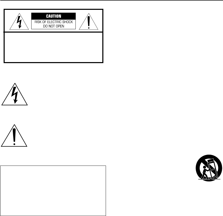
i
IMPORTANT SAFETY INSTRUCTIONS
• Explanation of graphic symbols:
The lightning flash with arrowhead
symbol within an equilateral triangle is
intended to alert you to the presence of
uninsulated “dangerous voltage” within
the product’s enclosure that may be of
sufficient magnitude to constitute a risk
of electric shock to persons.
The exclamation point within an
equilateral triangle is intended to alert
you to the presence of important
operating and maintenance (servicing)
instructions in the literature
accompanying the appliance.
1
Read these instructions.
2
Retain these instructions.
3
Heed all warnings.
4
Follow all instructions.
5
Do not use this apparatus near water.
6
Clean only with a dry cloth.
7
Do not block ventilation openings. Install in
accordance with the manufacturer’s instructions.
8
Do not install near heat sources such as radiators,
heat registers, stoves, or other heat-producing
apparatus (including amplifiers).
9
Do not defeat the safety purpose of the polarized or
grounding-type plug. A polarized plug has two
blades, one wider than the other. A grounding type
plug has two blades and a third grounding prong. The
wide blade or the third prong are provided for your
safety. If the provided plug does not fit into your
outlet, consult an electrician to replace the obsolete
outlet.
10
Protect the power cord from being walked on or
pinched, particularly at plugs, convenience
receptacles, or the point at which the power cord
exits the apparatus.
11
Use only attachments/accessories specified by the
manufacturer.
12
Use only with a cart, stand, tripod,
bracket, or table specified by the
manufacturer, or sold with the
apparatus. When a cart is used, use
caution when moving the cart/
apparatus combination to avoid
injury from tip-over.
13
Unplug this apparatus during lightning storms or
when unused for long periods of time.
14
Refer all servicing to qualified service personnel.
Servicing is required when the apparatus has been
damaged in any way, such as if the power supply
cord or plug is damaged, liquid has been spilled or
objects have fallen into the apparatus, the apparatus
has been exposed to rain or moisture, does not
operate normally, or has been dropped.
15
Be sure to allow a space of at least 20 cm above,
behind and on both sides of SW-P240.
16
Do not place the following objects on SW-P240:
A vessel containing liquid.
If the vessel falls due to vibration and the liquid spills,
the unit may be damaged, and/or you may receive an
electric shock.
IMPORTANT
Please record the serial number of this system in the
space below.
Model:
Serial No.:
The serial number is located on the rear of the unit.
Retain this Owner’s Manual in a safe place for future
reference.
CAUTION: TO REDUCE THE RISK OF
ELECTRIC SHOCK, DO NOT REMOVE COVER
(OR BACK). NO USER-SERVICEABLE PARTS
INSIDE. REFER SERVICING TO QUALIFIED
SERVICE PERSONNEL.
NSP240,246_U.book Page i Wednesday, October 22, 2003 3:29 PM

ii
We Want You Listening for a Lifetime
Yamaha and the Electronic Industries Association’s Con-
sumer Electronics Group want you to get the most enjoy-
ment out of your equipment by playing it at a safe level
— a level that lets the sound come through loud and
clear without annoying blaring or distortion — and, most
importantly, without damaging your sensitive hearing.
Since hearing damage from loud
sounds is often undetectable until it is
too late, Yamaha and the Electronic
Industries Association’s Consumer
Electronics Group recommend that
you avoid prolonged exposure to
excessive volume levels.
FCC INFORMATION (for US customers)
1. IMPORTANT NOTICE: DO NOT MODIFY THIS
UNIT!
This product, when installed as indicated in the
instructions contained in this manual, meets FCC
requirements. Modifications not expressly
approved by Yamaha may void your authority,
granted by the FCC, to use the product.
2. IMPORTANT:
When connecting this product to
accessories and/or another product, use only high
quality shielded cables. Cable(s) supplied with this
product MUST be used. Follow all installation
instructions. Failure to follow instructions could void
your FCC authorization to use this product in the
USA.
3. NOTE:
This product has been tested and found to
comply with the requirements listed in FCC
Regulations, Part 15 for Class “B” digital devices.
Compliance with these requirements provides a
reasonable level of assurance that your use of this
product in a residential environment will not result
in harmful interference with other electronic
devices.
This equipment generates or uses radio
frequencies and, if not installed and used in
accordance with the instructions in the user’s
manual, may cause interference harmful to the
operation of other electronic devices.
Compliance with FCC regulations does not guarantee
that interference will not occur in all installations. If this
product is found to be the source of interference, which
can be determined by turning the unit “OFF” and “ON,”
please try to eliminate the problem using one of the
following measures:
• Relocate either this product or the device that is being
affected by the interference.
• Utilize power outlets that are on different branch
circuits (circuit breaker or fuse) or install AC line
filter(s).
• In the case of radio or TV interference, relocate or
reorient the antenna. If the antenna lead-in is 300 ohm
ribbon lead, change the lead-in to a coaxial type cable.
If these corrective measures do not produce satisfactory
results, please contact the local retailer authorized to
distribute this product. If you cannot locate the
appropriate retailer, please contact Yamaha Electronics
Corp., U.S.A.; 6660 Orangethorpe Ave; Buena Park, CA
90620.
The above statements apply ONLY to those products
distributed by Yamaha Corporation of America or its
subsidiaries.
For Canadian Customers
To prevent electric shock, match wide blade of plug to
wide slot and fully insert.
This Class B digital apparatus complies with Canadian
ICES-003.
NSP240,246_U.book Page ii Wednesday, October 22, 2003 3:29 PM

iii
Precautions
•To assure the finest performance, please read this
manual carefully. Keep it in a safe place for future
reference.
• Install the speakers in a cool, dry, clean place – away
from windows, sources of heat, sources of excessive
vibration, dust, moisture or cold. Avoid sources of
electrical humming (e.g., transformers and motors).
To prevent fire or electric shock, do not expose the
speakers to rain or water.
•To prevent the enclosure from warping or discoloring,
do not expose the speakers to direct sunlight or exces-
sive humidity.
•Avoid installing the speakers where foreign objects
may fall onto them and/or where they may be
exposed to liquid dripping or splashing.
• Do not place the following objects on top of the
speakers:
• Other components, as they might damage or dis-
color the surface of the speakers;
•Burning objects (e.g., candles), as they might cause
fire, damage to the speakers or personal injury;
• Containers of liquid, as they might spill and cause
electric shock to the user or damage to the speak-
ers.
• Do not place the speakers where they are liable to be
knocked over or struck by falling objects. Stable
placement will also ensure better sound.
• Placing the speakers on the same shelf or rack as the
turntable can result in feedback.
• Secure placement or installation is the owner’s respon-
sibility. Yamaha is not liable for accidents caused by
improper placement or installation of speakers.
• If you note distortion, reduce the volume control on
your amplifier. Do not drive your amplifier to the
point of “clipping.” Otherwise, the speakers may be
damaged.
• When using an amplifier with a rated output power
higher than the nominal input power of the speakers,
care should be taken not to exceed the speakers’ max-
imum input.
• Do not clean the speakers with chemical solvents as
this might damage the finish. Use a clean, dry cloth.
•Do not attempt to modify or fix the speakers. Contact
qualified Yamaha service personnel when service is
needed. Do not open the cabinet under any circum-
stances.
• Please read the “Troubleshooting” section regarding
common operating errors before concluding that the
speakers are faulty.
For the SW-P240
• Do not operate this unit upside down. It may over-
heat, possibly causing damage.
• Do not use excessive force on switches, controls or
connection wires. When moving this unit, first dis-
connect the power plug and the wires connected to
other equipment. Never pull the wires themselves.
• Since this unit has a built-in power amplifier, heat
radiates from the rear panel. Place the unit away from
walls, allowing at least 20 cm of space above, behind
and on both sides of the unit to prevent fire or dam-
age. Furthermore, do not position the unit with the
rear panel facing down on the floor or other surfaces.
• When using a humidifier, be sure to avoid condensa-
tion inside this unit by allowing enough space around
the unit and avoiding excess humidification. Conden-
sation might cause fire, damage to the unit, or electric
shock.
• Do not cover the rear panel of this unit with a news-
paper, tablecloth, curtain, etc. to avoid obstructing
heat radiation. If the temperature inside the unit rises,
it may cause fire, damage to the unit, or personal
injury.
• Do not plug this unit into a wall outlet until all con-
nections are complete.
• The voltage to be used must match that specified on
the rear panel. Using this unit with a voltage higher
than specified is dangerous and may cause fire, dam-
age to the unit, or personal injury. Yamaha is not
responsible for damage resulting from use of this unit
with a voltage other than specified.
•To prevent damage from lightning, disconnect the AC
power plug during electric storms.
• Super-bass frequencies reproduced by this unit may
cause a turntable to generate audio feedback. In this
case, move the unit away from the turntable.
• This unit may be damaged if certain sounds are con-
tinuously output at high volume level. For example, if
20Hz–50Hz sine waves from a test disc or bass
sounds from an electronic instrument, etc. are contin-
uously output, or if a turntable stylus touches the sur-
face of a disc, reduce the volume level to prevent the
unit from being damaged.
• If you hear distorted noise (i.e., unnatural, intermit-
tent “rapping” or “hammering” sounds) from this
unit, reduce the volume level. Extremely loud movie
soundtrack low frequency, bass-heavy sounds, or sim-
ilarly loud popular music passages can damage the
speaker system.
•Vibration generated by super-bass frequencies may
distort images on a TV. In this case, move the unit
away from the TV set.
• When disconnecting the power cord from the wall
outlet, grasp the plug; do not pull the cord.
• When you plan not to use this unit for a long period
of time (i.e., vacation, etc.) disconnect the AC power
plug from the wall outlet.
• Do not place much pressure against the subwoofer
net. It may break the net or the unit may fall, resulting
in injury.
• Do not place anything fragile beside the subwoofer.
The air pressure produced by the subwoofer may
break the objects and cause malfunction or injury.
WARNING
TO REDUCE THE RISK OF FIRE OR ELECTRIC
SHOCK, DO NOT EXPOSE THIS UNIT TO RAIN
OR MOISTURE.
NSP240,246_U.book Page iii Wednesday, October 22, 2003 3:29 PM

1
Table of contents
Precautions . . . . . . . . . . . . . . . . . . . . . . . . . . . . . . . . . . . . . . . . . . . iii
Introduction . . . . . . . . . . . . . . . . . . . . . . . . . . . . . . . . . . . . . . . . . . . . 2
Package contents. . . . . . . . . . . . . . . . . . . . . . . . . . . . . . . . . . . . . . . . . . . . . . . . . . . . . . . . . 2
Setting up the speakers . . . . . . . . . . . . . . . . . . . . . . . . . . . . . . . . . . . .3
Positioning the front and surround speakers (NX-S120) . . . . . . . . . . . . . . . . . . . . . . . . . . . 3
Positioning the center speaker (NX-C120). . . . . . . . . . . . . . . . . . . . . . . . . . . . . . . . . . . . . . 4
Positioning the subwoofer (SW-P240) . . . . . . . . . . . . . . . . . . . . . . . . . . . . . . . . . . . . . . . . 4
Mounting the front and surround speakers . . . . . . . . . . . . . . . . . . . . . . . . . . . . . . . . . . . . . 5
Connections . . . . . . . . . . . . . . . . . . . . . . . . . . . . . . . . . . . . . . . . . . . .6
Basic connection example . . . . . . . . . . . . . . . . . . . . . . . . . . . . . . . . . . . . . . . . . . . . . . . . . . 6
Connecting speaker cables. . . . . . . . . . . . . . . . . . . . . . . . . . . . . . . . . . . . . . . . . . . . . . . . . . 7
Connecting components and the subwoofer to AC power . . . . . . . . . . . . . . . . . . . . . . . . . . 7
Using the subwoofer (SW-P240) . . . . . . . . . . . . . . . . . . . . . . . . . . . . . . 8
Pre-adjusting the subwoofer volume . . . . . . . . . . . . . . . . . . . . . . . . . . . . . . . . . . . . . . . . . . 8
Advanced Yamaha Active Servo Technology (on the SW-P240) . . . . . . . . . 9
Troubleshooting . . . . . . . . . . . . . . . . . . . . . . . . . . . . . . . . . . . . . . . . 10
Specifications . . . . . . . . . . . . . . . . . . . . . . . . . . . . . . . . . . . . . . . . . 11
Frequency characteristics . . . . . . . . . . . . . . . . . . . . . . . . . . . . . . . . . . . . . . . . . . . . . . . . . 11
NSP240,246_U.book Page 1 Wednesday, October 22, 2003 3:29 PM
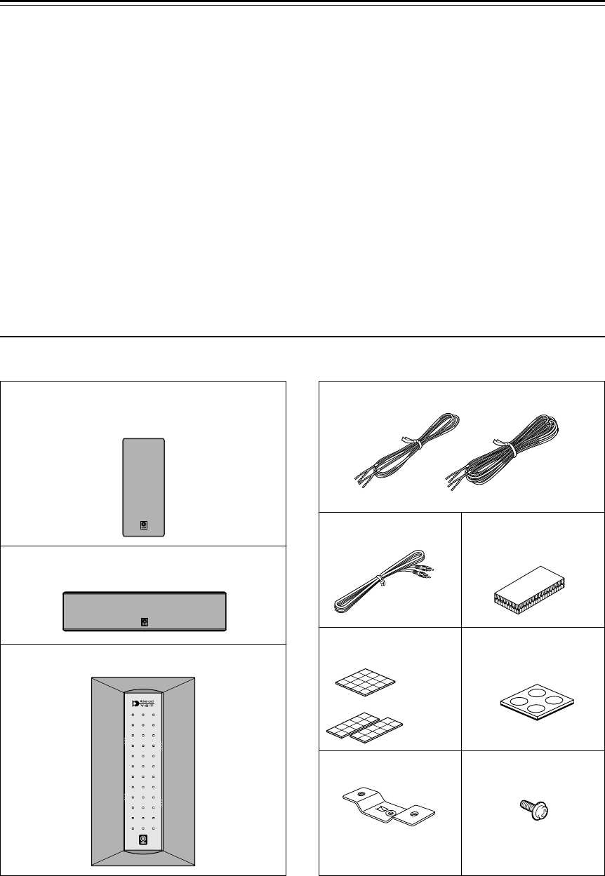
2
Introduction
Thank you for choosing a Yamaha NS-P240 or NS-P246 Home Cinema 5.1/6.1 Channel Speaker System.
Each of these systems include the following speakers:
• NX-S120
The NX-S120 are full-range acoustic-suspension speakers. Each system includes two (2) front and two
(2) surround speakers. In addition, the NS-P246 system includes an additional NX-S120 that serves as a
surround back speaker.
• NX-C120
The NX-C120 is a full-range acoustic-suspension center speaker.
•SW-P240
The SW-P240 is a subwoofer that features a built-in power amplifier. It utilizes Advanced Yamaha Active
Servo Technology to reproduce extremely high quality super-bass range sounds that add a rich, realistic
dimension to your home theater. (Refer to page 9 for detailed information on Advanced Yamaha Active
Servo Technology.)
Package contents
Please confirm that the following items are included in the package.
Front and surround speakers
(and surround back speaker in NS-P246)
Center speaker
Subwoofer
NX-S120
X 4 <NS-P240>
X 5 <NS-P246>
NX-C120
SW-P240
Speaker cables
Subwoofer cable Fasteners
(for NX-C120)
Non-skid pads
(for NX-S120)
Non-skid pads
(for SW-P240)
X 2
[4m]
<NS-P240>
<NS-P246>
X 2 <NS-P240>
X 3 <NS-P246>
[15m]
X 3
Mounting brackets
X 4 <NS-P240>
X 5 <NS-P246>
Screws for mounting
brackets
X 4 <NS-P240>
X 5 <NS-P246>
NSP240,246_U.book Page 2 Wednesday, October 22, 2003 3:29 PM
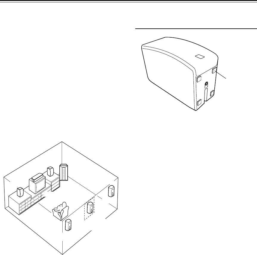
3
Setting up the speakers
Before you connect the speakers, place each
speaker in its respective location. Speaker position-
ing is very important as it affects the overall sound
quality of the system. Place the speakers in loca-
tions that will optimize the sound quality at your
listening position. Refer to the illustration below.
The position of the subwoofer is not as critical as
the position of the other speakers because low bass
tones are not highly directional. Refer to “Position-
ing the subwoofer (SW-P240)” on page 4 for more
information.
Note:
These speakers are magnetically shielded.
However, if you place them too close to a TV, they
may impair picture color. In this case, move the
speakers further away from the TV.
Positioning the front and surround
speakers (NX-S120)
Front speakers:
Place the two front speakers on
the left and right sides of the TV, at approximately
the same height as the TV, facing directly forward.
Surround speakers:
Place the left and right
surround speakers behind your listening position,
facing slightly inward, about 1.8 m (approx. 6 feet)
above the floor.
Surround back speaker (for NS-P246 sys-
tems only):
Position the surround back speaker
behind your listening position, precisely between
the surround speakers, about 1.8 m (approx. 6 feet)
above the floor.
You can set the front, surround, and surround back
speakers on tables or other supports, or mount
them on a wall or speaker stand. (For more infor-
mation, see “Mounting the front and surround
speakers” on page 5.)
Non-skid pads:
When placing the speakers on a
flat surface, attach the included non-skid pads to
the corners of the speaker bottoms, as shown
above. The non-skid pads will prevent the speakers
from sliding.
Center
Front R Subwoofer
TV-set
Front L
Surround back
(for NS-P246)
Surround R
Surround L
Non-skid pad
NSP240,246_U.book Page 3 Wednesday, October 22, 2003 3:29 PM
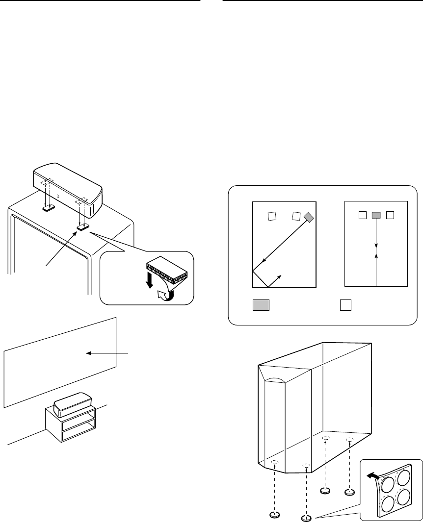
4
Positioning the center speaker
(NX-C120)
Place the center speaker precisely between the
front speakers, facing directly forward. You can
place the center speaker on top of a TV (if the top
of the TV is flat), on the floor beneath the TV, or in
an entertainment center. Be sure to place the
speaker in a stable location.
When placing the speaker on top of a TV, to pre-
vent the speaker from falling, attach the provided
fasteners at two points on the bottom of the speaker
and on top of the TV, as illustrated below.
Cautions:
•Do not place the center speaker on a TV that has a top
surface area smaller than the speaker bottom. Other-
wise, the speaker may fall and cause injury.
• Do not place the center speaker on a TV that has a
slanted or inclined top.
• Do not touch the adhesive surface of a fastener after
you peel off the seal, as this will weaken the adhesive
strength of the fastener.
• Thoroughly wipe to clean the surface where the fas-
tener is to be applied. Note that adhesive strength will
be weakened if the surface is dirty, oily or wet. Weak-
ened adhesive may cause the center speaker to fall.
Positioning the subwoofer
(SW-P240)
Although the placement of the subwoofer is not as
critical as that of the other speakers, it is best to
place the subwoofer outside either the right or left
front speaker. (See Figure
A
.)
The placement shown in Figure
B
is also accept-
able. However, in some cases, if you listen from
the center of the room, the super-bass range from
the subwoofer may sound weak. This is due to
“standing waves” that can develop between paral-
lel walls that effectively diminish or cancel the
bass sound. In this event, face the subwoofer
obliquely to the wall. It also may help to break up
the parallel surface by placing bookshelves or
other large objects along the wall.
Non-skid pads:
Place the included non-skid
pads at the four corners of the bottom of the sub-
woofer to prevent the subwoofer from sliding due
to vibration or minor impact.
Big screen
Fastener Peel off the
seal.
AB
: Subwoofer : Front speaker
NSP240,246_U.book Page 4 Wednesday, October 22, 2003 3:29 PM
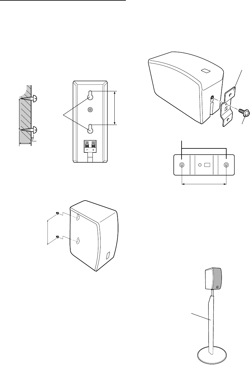
5
Mounting the front and surround
speakers
You can place the front and surround speakers (and
surround back speaker in an NS-P246 system) on a
shelf or rack, set them on the floor, or mount them
on a wall or speaker stand.
To mount the speakers on a wall:
1.
Affix screws to a firm wall or wall support as
shown below. (Use tapping screws 3.5 to 4mm
in diameter.)
2.
Suspend the speaker by mounting the holes in
the speaker’s back panels on the protruding
screws.
Cautions:
• Each front or surround speaker weighs 0.9 kg
(2.0 lbs.). Do not mount the speakers on thin plywood
or on a wall made of soft surface material. Otherwise,
the screws may pull out of the surface and the speak-
ers may fall, possibly damaging the speakers or caus-
ing personal injury.
• Do not affix the speakers to a wall using nails, adhe-
sives, or unstable hardware. Long term use and vibra-
tion may cause the speakers to fall.
•To avoid accidents resulting from tripping over loose
speaker cables, affix the cables to the wall.
• Mount the speakers in a wall location that will be
unlikely to result in injury to an individual’s head.
To attach to a bracket:
1.
Attach a bracket (part number AAX34790) to
the bottom of the speaker using a screw (part
number AAX12390) such that the convex part
of the bracket fits over the groove in the bottom
of the speaker, as shown below.
2.
Mount the speaker on the speaker stand by affix-
ing a pair of screws through the outside bracket
holes.
To mount the speakers on a speaker
stand:
You can mount the front, surround, and surround
back speakers on a speaker stand, such as the
optional Yamaha SPS-80. (For more information,
refer to the instruction manual for the SPS-80.)
Note:
The SPS-80 may be unavailable in certain
regions.
Holes
10 mm
Minimum
20 mm
70 mm
70 mm
Wall/ wall
support
Note: Make sure that the
screws are securely affixed in
the narrow part of the holes.
70 mm
Insert only M4 screws
through the outside holes.
Mounting
bracket
(AAX34790)
Screw
(AAX12390)
60 mm
Yamaha SPS-80
speaker stand
(optional)
NSP240,246_U.book Page 5 Wednesday, October 22, 2003 3:29 PM
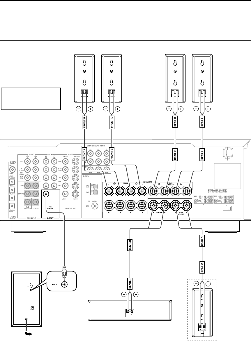
6
Connections
Caution: Plug the power cables for the subwoofer and other audio/video components into an AC out-
let only after you complete all other connections.
Basic connection example
To AC outlet
Center speaker
Surround back speaker
(in NS-P246 systems)
Subwoofer
Amplifier
Front speakers Surround speakers
Right RightLeft Left
Note: The rear panel of
various amplifiers may
differ in appearance.
NSP240,246_U.book Page 6 Wednesday, October 22, 2003 3:29 PM
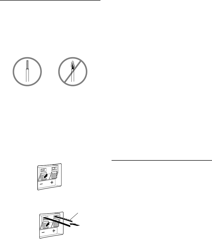
7
Connecting speaker cables
Keep the speaker cables as short as possible. Do
not bundle or roll up excess cable. If the connec-
tions are faulty, you will hear no sound from the
speakers.
Before connecting the cables:
Remove a small amount (about 10 mm) of insula-
tion coating from the end of each speaker cable.
One side of the included speaker cable is marked
with a broken white line; the other side is unlined.
Connect the (+) terminal on the speaker to the (+)
terminal on the amplifier using the cable side
marked with the broken white line. Connect the (–)
terminals on both components using the unlined
side of the speaker cable.
Inserting the cables:
1.
Press and hold the terminal tab, as shown in the
figure below.
2.
Insert the stripped wire core.
3.
Release your finger from the tab to allow it to
lock securely on the cable’s wire core.
4.
Test the security of the connection by pulling
gently on the cable at the terminal.
Note:
Do not let uninsulated speaker wires touch
each other as this could damage the speaker or the
amplifier.
Connections:
• Connect the front, center and surround speakers (and
surround back speaker for the NS-P246) to the
speaker output terminals on your amplifier using the
included speaker cables.
– The included speaker cables have labels marked
FRONT L, FRONT R, CENTER, REAR L, REAR
R (and REAR C for NS-P246). Connect each
speaker cable to the corresponding speaker as illus-
trated in the figure on page 6.
– Connect each speaker making sure not to reverse
the polarity (+, –). If the speaker is connected with
reversed polarity, the sound will be unnatural and
lack bass.
–For the front and surround speakers only, connect
one speaker to the left (marked L) terminals on
your amplifier, and the other speaker to the right
(marked R) terminals.
• Connect the subwoofer to the line output (pin jack)
terminal(s) on the amplifier.
–To connect to a Yamaha DSP amplifier (or AV
receiver), connect the SUBWOOFER (or LOW
PASS, etc.) terminal on the rear of the DSP ampli-
fier (or AV receiver) to the INPUT terminal on the
subwoofer.
Connecting components and the
subwoofer to AC power
After you complete all speaker and subwoofer con-
nections, plug the amplifier, other audio/video
components, and the subwoofer into an AC outlet
of appropriate voltage. Make sure the subwoofer’s
VOLUME control is set to 0 before proceeding to
adjust the speaker balance as described on page 8.
Red: positive (+)
Black: negative (–)
Red: positive (+)
Black: negative (–)
White broken line
NSP240,246_U.book Page 7 Wednesday, October 22, 2003 3:29 PM
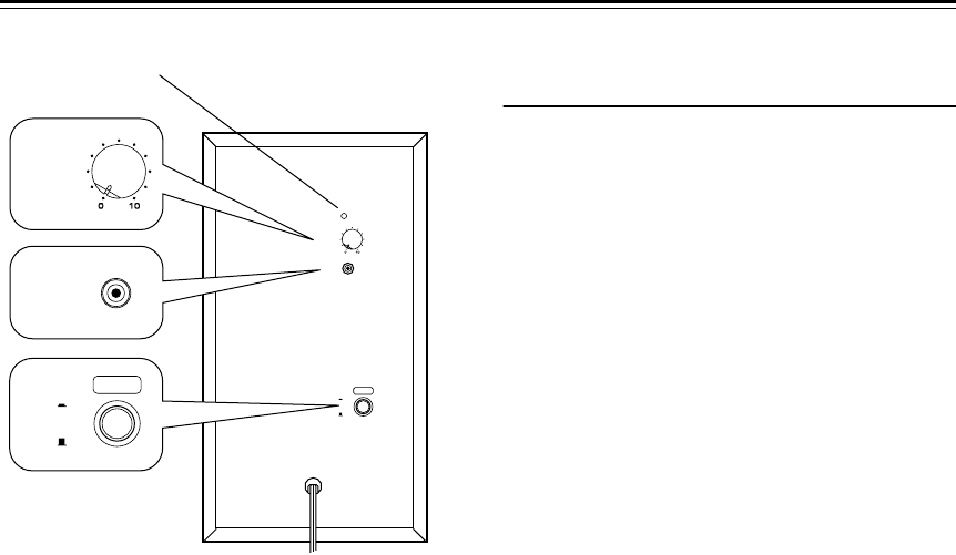
8
Using the subwoofer (SW-P240)
1
Power indicator
Lights up GREEN when the
POWER
switch
(
4
) is turned ON; turns off when the
POWER
switch is turned OFF.
2
VOLUME control
Adjusts the volume level. Turn the control
clockwise to increase the volume, and counter-
clockwise to decrease the volume.
3
INPUT terminal
Input terminal for line level signals from the
amplifier.
4
POWER switch
Press this switch to the ON position to turn on
the power to the subwoofer. When the power of
the subwoofer is on, the power indicator (
1
) on
the rear panel lights up green. Press this switch
again to set it to the OFF position to turn off the
power of the subwoofer.
Pre-adjusting the subwoofer vol-
ume
Before you use the subwoofer, first adjust the vol-
ume balance between the subwoofer and the front
speakers by following the procedure below.
1.
Set the
VOLUME
control to minimum (0).
2.
Turn on the power to all other components.
3.
Press the
POWER
switch to the ON position.
The power indicator on the rear panel lights up
green.
4.
Play a source that contains low-frequency
sounds. Adjust the amplifier’s volume control to
the desired listening level.
5.
Increase the volume gradually to adjust the vol-
ume balance between the subwoofer and the
front speakers. In most cases, set the control to a
level at which you hear slightly more bass than
when the subwoofer is not used.
6.
Adjust the volume of the entire sound system
using the amplifier’s volume control.
• If you replace the front speakers (NX-S120) with
other speakers, you must again balance the subwoofer
and surround speaker volume.
•For more information on adjusting the VOLUME
control, refer to “Frequency characteristics” on
page 11.
110V-120V VOLTAGE
SELECTOR
220V-240V
OFF
POWER
ON
VOLUME
INPUT
OFF
POWER
ON
4
VOLUME
2
1
3
INPUT
Rear panel
NSP240,246_U.book Page 8 Wednesday, October 22, 2003 3:29 PM
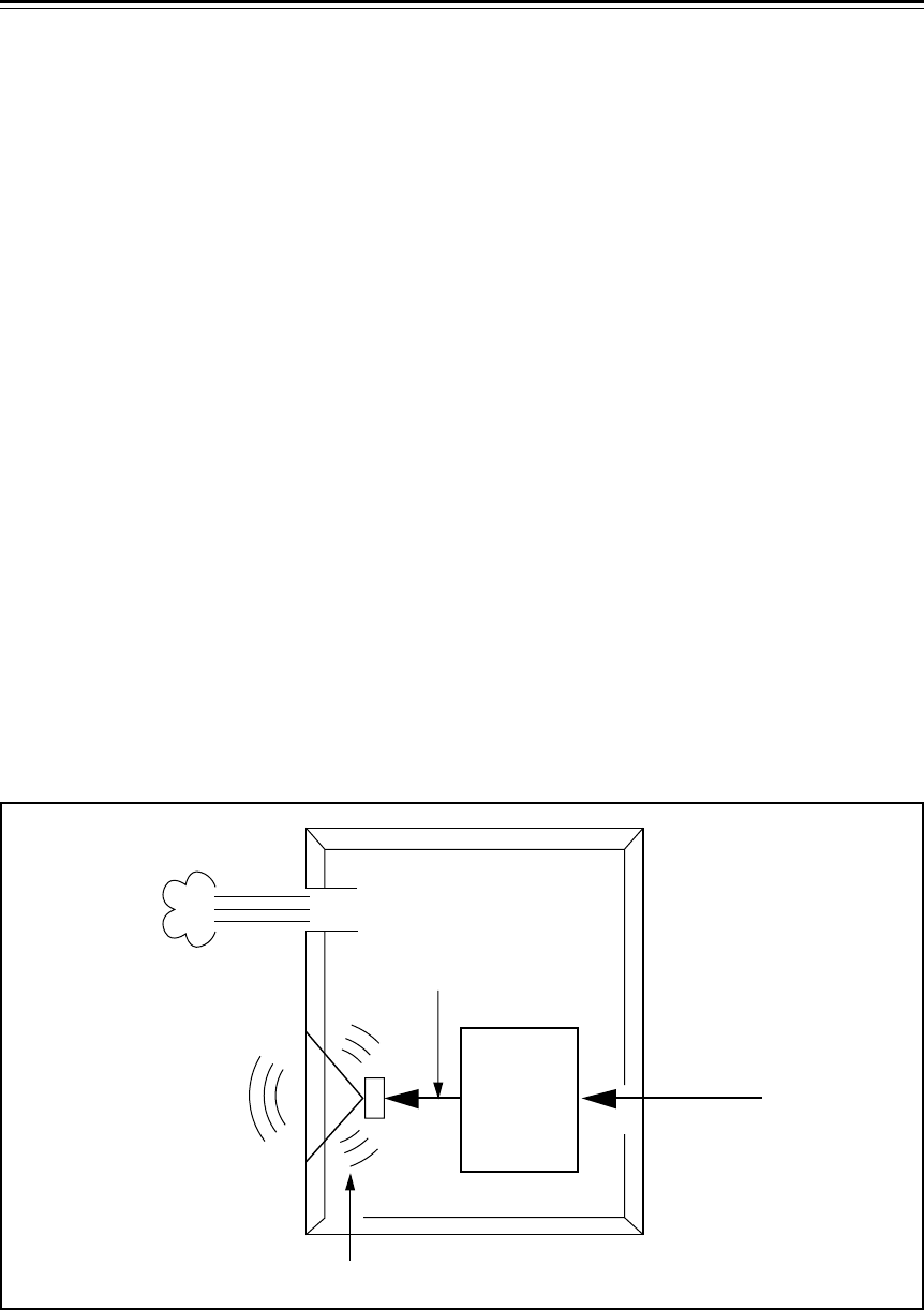
9
Advanced Yamaha Active Servo Technology (on the SW-P240)
The theory behind Yamaha Active Servo Technol-
ogy is based on two factors: the Helmholtz resona-
tor and negative-impedance drive. Active Servo
Processing speakers reproduce the bass frequen-
cies through an “air woofer,” which is a port or
opening in the speaker’s cabinet.
This opening is used instead of, and performs the
functions of, a woofer in a conventionally designed
speaker system.
Thus, signals of low amplitude within the cabinet
can, according to Helmholtz resonance theory, be
output from this opening as waves of great ampli-
tude if the size of the opening and the volume of
the cabinet are in proportion to satisfy a certain
ratio. In order to accomplish this, moreover, the
amplitudes within the cabinet must be both precise
and of sufficient power because these amplitudes
must overcome the “load” presented by the air in
the cabinet.
This problem is resolved by a design in which the
amplifier supplies special signals. If the electrical
resistance of the voice coil could be reduced to
zero, the movement of the speaker unit would
become linear with respect to signal voltage. To
accomplish this, the system utilizes a special nega-
tive-impedance output-drive amplifier that sub-
tracts the output impedance of the amplifier.
By employing negative-impedance drive circuits,
the amplifier is able to generate precise, low-ampli-
tude, low frequency waves with superior damping
characteristics.
These waves are then radiated from the cabinet
opening as high-amplitude signals. The system
can, therefore, by employing the negative-imped-
ance output drive amplifier and a speaker cabinet
featuring a Helmholtz resonator, reproduce an
extremely wide range of frequencies with out-
standing sound quality and low distortion.
The features described above combine to create the
fundamental structure of conventional Yamaha
Active Servo Technology.
Our new Active Servo Technology — Advanced
Yamaha Active Servo Technology — adopts
Advanced Negative Impedance Converter (ANIC)
circuits, which allow the conventional negative
impedance converter to dynamically vary to select
an optimum value for speaker impedance variation.
With these new ANIC circuits, Advanced Yamaha
Active Servo Technology provides a more stable
performance and improved sound pressure com-
pared to conventional Yamaha Active Servo Tech-
nology, resulting in more natural and dynamic bass
reproduction.
High-amplitude
bass sound
Cabinet
Port
Air woofer
(Helmholtz resonator)
Advanced Negative
impedance Converter
Active Servo
Processing
Amplifier
Signals of low amplitude
Signals
NSP240,246_U.book Page 9 Wednesday, October 22, 2003 3:29 PM
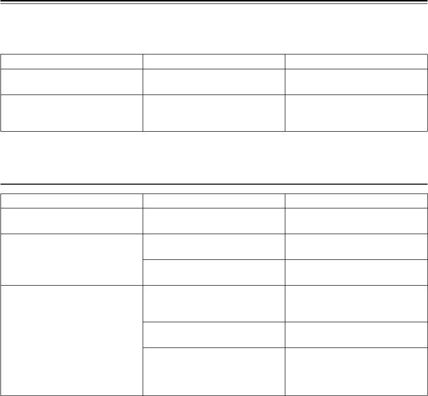
10
Troubleshooting
Refer to the chart below if the unit does not function properly. If the problem you are experiencing is not
listed, or if the instructions fail to help you resolve the problem, disconnect the power cord and contact your
authorized Yamaha dealer or service center.
For the Subwoofer (SW-P240) only
Problem Cause What to Do
No sound.
Speaker cables are not connected
securely.
Connect the speaker cables securely.
Sound level is too low.
Speaker cables are not connected
correctly.
Connect the speaker cables correctly:
L (left) to L, R (right) to R, “+” to “+”
and “–” to “–”.
Problem Cause What to Do
Power is not supplied even though the
POWER switch is set to the ON position.
The power plug is not securely
connected.
Turn the power switch OFF, then
connect the power plug securely.
No sound.
The VOLUME control is set to 0. Turn the VOLUME control to the
right (clockwise).
Speaker cables are not connected
securely.
Connect the speaker cables securely.
Sound level is too low.
Speaker cables are not connected
correctly.
Connect the speaker cables correctly:
L (left) to L, R (right) to R, “+” to “+”
and “–” to “–”.
You are playing a sound source that
includes inadequate bass frequencies.
Play a sound source that includes
more bass frequencies.
The sound level has been diminished
by standing waves.
Reposition the subwoofer, or break
up the parallel wall surface by
placing bookshelves or other large
objects along the wall.
NSP240,246_U.book Page 10 Wednesday, October 22, 2003 3:29 PM
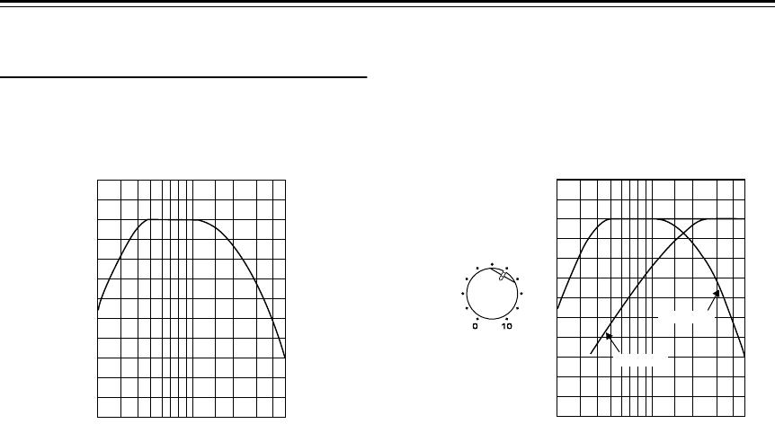
11
Specifications
Frequency characteristics
The following graph displays the frequency char-
acteristics of the SW-P240 subwoofer. The following graph displays the frequency char-
acteristics of the SW-P240 subwoofer combined
with NX-S120 speakers.
NX-S120/NX-C120
Type
........Full-range acoustic-suspension speaker
system
Magnetically shielded type
Driver
............5 cm (2") full-range cone speaker x 2
Nominal Input Power
..................................... 30 W
Maximum Input Power
................................. 100 W
Impedance
.........................................................6
Ω
Frequency Response
...100 Hz – 25 kHz (–10 dB)
Sensitivity
...................................... 86 dB/2.83 Vm
Dimensions (W x H x D)
<NX-S120> ............. 72 mm x 170 mm x 108 mm
(2-15/16" x 6-11/16" x 4-1/4")
<NX-C120> ..............300 mm x 72 mm x 105 mm
(11-13/16" x 2-15/16" x 4-1/8")
Weight
<NX-S120> .....................................0.9 kg (2 lbs.)
<NX-C120> ............................1.1 kg (2 lbs. 7 oz.)
SW-P240
Type
....... Advanced Yamaha Active Servo Tech-
nology
Magnetically shielded type
Driver
.............................. 16 cm (6.5") cone woofer
Output Power
......... 50 W (100 Hz, 5
Ω
at THD=10%)
Dynamic Power
.........................................100 W, 5
Ω
Input Impedance
......INPUT (1P RCA pin jack): 12 k
Ω
Input Sensitivity
............ INPUT (1P RCA
pin jack
):
30 mV (100 Hz, 5
Ω
at 50 W)
Power Supply
...............................AC 120 V, 60 Hz
Dimensions (W x H x D)
...............................200 mm x 365 mm x 390 mm
(7-7/8" x 14-3/8" x 15-3/8")
Weight
.....................................8.4 kg (18 lbs. 8 oz.)
Specifications are subject to change without notice.
20 50 100 200 500 Hz
40
50
60
70
80
90
100 dB
20 50 100 200 500 Hz
40
50
60
70
80
90
100 dB
SW-P240
NX-S120
VOLUME
NSP240,246_U.book Page 11 Wednesday, October 22, 2003 3:29 PM

2003 All rights reserved.
YAMAHA ELECTRONICS CORPORATION, USA
6660 ORANGETHORPE AVE., BUENA PARK, CALIF. 90620, U.S.A.
YAMAHA CANADA MUSIC LTD.
135 MILNER AVE., SCARBOROUGH, ONTARIO M1S 3R1, CANADA
YAMAHA ELECTRONIK EUROPA G.m.b.H.
SIEMENSSTR. 22-34, 25462 RELLINGEN BEI HAMBURG, F.R. OF GERMANY
YAMAHA ELECTRONIQUE FRANCE S.A.
RUE AMBROISE CROIZAT BP70 CROISSY-BEAUBOURG 77312 MARNE-LA-VALLEE CEDEX02, FRANCE
YAMAHA ELECTRONICS (UK) LTD.
YAMAHA HOUSE, 200 RICKMANSWORTH ROAD WATFORD, HERTS WD18 7GQ, ENGLAND
YAMAHA SCANDINAVIA A.B.
J A WETTERGRENS GATA 1, BOX 30053, 400 43 VÄSTRA FRÖLUNDA, SWEDEN
YAMAHA MUSIC AUSTRALIA PTY, LTD.
17-33 MARKET ST., SOUTH MELBOURNE, 3205 VIC., AUSTRALIA
Printed in China WC87650
©
IP
NSP240,246_U.book Page 12 Wednesday, October 22, 2003 3:29 PM
