Yamaha Xtz 125K Owners Manual ManualsLib Makes It Easy To Find Manuals Online! User 121929
2014-12-11
User Manual: Yamaha Xtz-125K-Owners-Manual
Open the PDF directly: View PDF ![]() .
.
Page Count: 97
II
II
IDENTIFICATION NUMBERS RECORD
1. FRAME SERIAL NUMBER:
Record the frame serial number and engine serial number in the spaces provided for assistance when
ordering spare parts from a Yamaha dealer or reference in case the vehicle is stolen.
2. ENGINE SERIAL NUMBER:
IDENTIFICATION NUMBERS RECORD
1. FRAME SERIAL NUMBER:
Record the frame serial number and engine serial number in the spaces provided for assistance when
ordering spare parts from a Yamaha dealer or reference in case the vehicle is stolen.
2. ENGINE SERIAL NUMBER:
Downloaded from www.Manualslib.com manuals search engine

III
III
XTZ 125K / XTZ 125E
OWNER’S MANUAL
© 2003 Yamaha Motor da Amazônia Ltda.
1st edition, April 2003
All rights reserved.
Any reprinting or unauthorized use
without the written permission of
Yamaha Motor da Amazônia Ltda.
is expressly prohibited.
Printed in Brazil.
XTZ 125K / XTZ 125E
OWNER’S MANUAL
© 2003 Yamaha Motor da Amazônia Ltda.
1st edition, April 2003
All rights reserved.
Any reprinting or unauthorized use
without the written permission of
Yamaha Motor da Amazônia Ltda.
is expressly prohibited.
Printed in Brazil.

IV
IV
INTRODUCTION
Congratulations on your purchase of the YAMAHA XTZ 125K / XTZ 125E. This model is the result of Yamaha’s vast
experience in the production of fine sporting, touring, and pacesetting racing machines. It represents the high degree of
craftmanship and reliability that have made Yamaha a leader in these fields.
This manual will give you an understanding of the operation, inspection, and basic maintenance of this motorcycle.
If you have any questions about the operation or maintenance of your motorcycle, please consult a Yamaha dealer.
YAMAHA MOTOR DA AMAZÕNIA LTDA.
INTRODUCTION
Congratulations on your purchase of the YAMAHA XTZ 125K / XTZ 125E. This model is the result of Yamaha’s vast
experience in the production of fine sporting, touring, and pacesetting racing machines. It represents the high degree of
craftmanship and reliability that have made Yamaha a leader in these fields.
anding of the operation, inspection, and basic maintenance of this motorcycle.
If you have any questions about the operation or maintenance of your motorcycle, please consult a Yamaha dealer.
YAMAHA MOTOR DA AMAZÕNIA LTDA.

V
V
This manual should be considered a permanent part of this machine and should remain with it even if the machine is subsequently
sold.
Yamaha continually seeks advancements in product design and quality. Therefore, while this manual contains the most current
product information available at the time of printing. There may be minor discrepancies between your machine and this manual.
If there is any question concerning this manual, please consult your Yamaha dealer.
NOTE:
Particularly important information is distinguished in this manual by the following notations:
NOTE: A NOTE provides key information to make procedures easier or clearer.
A CAUTION indicates special precautions that must be taken to avoid damage to the machine.
Failure to follow WARNING instructions could result in severe injury or death to the machine operator,
a bystander or a person inspecting or repairing the machine.
WARNING:
CAUTION:
This manual should be considered a permanent part of this machine and should remain with it even if the machine is subsequently
sold.
Yamaha continually seeks advancements in product design and quality. Therefore, while this manual contains the most current
product information available at the time of printing. There may be minor discrepancies between your machine and this manual.
If there is any question concerning this manual, please consult your Yamaha dealer.
NOTE:
Particularly important information is distinguished in this manual by the following notations:
NOTE: A NOTE provides key information to make procedures easier or clearer.
A CAUTION indicates special precautions that must be taken to avoid damage to the machine.
Failure to follow WARNING instructions could result in severe injury or death to the machine operator,
or a person inspecting or repairing the machine.
WARNING:
CAUTION:

VI
VI
WARNING:
PLEASE READ THIS MANUAL CAREFULLY AND COMPLETELY BEFORE OPERATING THIS MACHINE. DO NOT
ATTEMPT TO OPERATE THIS MOTORCYCLE UNTIL YOU HAVE ATTAINED A SATISFACTORY KNOWLEDGE OF
ITS CONTROLS AND OPERATING FEATURES AND UNTIL YOU HAVE BEEN TRAINED IN SAFE AND PROPER
RIDING TECHNIQUES. REGULAR INSPECTIONS AND CAREFUL MAINTENANCE, ALONG WITH GOOD RIDING
SKILLS WILL ENSURE THAT YOU SAFELY ENJOY THE CAPABILITIES AND THE RELIABILITY OF THIS
MOTORCYCLE.

VII
VII
SAFETY INFORMATION
TWO-WHEELED Machines ARE SINGLE TRACK VEHICLES. THEIR SAFE USE AND OPERATION ARE DEPENDENT
UPON THE USE OF PROPER RIDING TECHNIQUES AS WELL AS THE EXPERTISE OF THE OPERATOR.
EVERY OPERATOR SHOULD KNOW THE FOLLOWING REQUIREMENTS BEFORE RIDING. HE OR SHE SHOULD.
1. OBTAIN THOROUGH INSTRUCTIONS FORM A COMPETENT SOURCE ON ALL ASPECTS OF MACHINE
OPERATION.
2. OBSERVE THE WARNINGS AND MAINTENANCE REQUIREMENTS IN THE OWNER’S MANUAL.
3. OBTAIN QUALIFIED TRAINING IN SAFE AND PROPER RIDING TECHNIQUES.
4. OBTAIN PROFESSIONAL TECHNICAL SERVICE AS INDICATED BY THE OWNER’S MANUAL AND/OR WHEN
MADE NECESSARY BY MECHANICAL CONDITIONS.
SAFE RIDING
1. Always make pre-operation checks. Careful checks may help prevent an accident.
2. Many accidents involve inexperienced operators.
a. Know your skills and limits. Staying within your limits may help you to avoid an accident.
b. Only lend your machine to experienced operators.
3. Many machine accidents have been caused by machine operator errors. A typical error made by the operator is
veering wide on a turn due to EXCESSIVE SPEED or undercornering (insufficient lean angle for the speed). Never
travel faster than warranted by conditions.
4. Ride cautiously in unfamiliar areas. You may encounter hidden obstacles which could cause an accident.
5. The operator’s posture is important for proper control. The operator should keep both hands on the handlebars and
both feet on the operator footrests during operation to maintain control of the machine.
6. Never ride under the influence of alcohol or drugs.
SAFETY INFORMATION
TWO-WHEELED Machines ARE SINGLE TRACK VEHICLES. THEIR SAFE USE AND OPERATION ARE DEPENDENT
UPON THE USE OF PROPER RIDING TECHNIQUES AS WELL AS THE EXPERTISE OF THE OPERATOR.
EVERY OPERATOR SHOULD KNOW THE FOLLOWING REQUIREMENTS BEFORE RIDING. HE OR SHE SHOULD.
1. OBTAIN THOROUGH INSTRUCTIONS FORM A COMPETENT SOURCE ON ALL ASPECTS OF MACHINE
2. OBSERVE THE WARNINGS AND MAINTENANCE REQUIREMENTS IN THE OWNER’S MANUAL.
3. OBTAIN QUALIFIED TRAINING IN SAFE AND PROPER RIDING TECHNIQUES.
4. OBTAIN PROFESSIONAL TECHNICAL SERVICE AS INDICATED BY THE OWNER’S MANUAL AND/OR WHEN
MADE NECESSARY BY MECHANICAL CONDITIONS.
SAFE RIDING
1. Always make pre-operation checks. Careful checks may help prevent an accident.
2. Many accidents involve inexperienced operators.
a. Know your skills and limits. Staying within your limits may help you to avoid an accident.
b. Only lend your machine to experienced operators.
3. Many machine accidents have been caused by machine operator errors. A typical error made by the operator is
veering wide on a turn due to EXCESSIVE SPEED or undercornering (insufficient lean angle for the speed). Never
travel faster than warranted by conditions.
4. Ride cautiously in unfamiliar areas. You may encounter hidden obstacles which could cause an accident.
5. The operator’s posture is important for proper control. The operator should keep both hands on the handlebars and
both feet on the operator footrests during operation to maintain control of the machine.
6. Never ride under the influence of alcohol or drugs.
VIII
VIII
PROTECTIVE APPAREL
The majority of fatalities from machine accidents are the result of head injuries. The use of a safety helmet is the single
most critical factor in the prevention or reduction of head injuries.
1. Always wear an approved helmet.
2. Wear a face shield or goggles. Wind on your unprotected eyes could contribute to an impairment of vision which
could delay seeing a hazard.
3. The use of heavy boots, jacket, trousers, gloves, etc. is effective in preventing or reducing abrasions or lacerations.
4. Never wear loose fitting clothing. It could catch on the control levers, footrests, or wheels and cause injury or accident.
5. Never touch the engine or exhaust system during or after operation. They become very hot and can cause burns.
Always wear protective clothing that covers your legs, ankles and feet.
6. Always use clear clothes to make your visualization easier.
7. Items above must also be followed by pillion rider.
MODIFICATION
Modifications made to the machine not approved by Yamaha, or the removal of original equipment, may render your
machine unsafe for use and may cause severe personal injury. Modifications may also make your machine illegal to use.
PROTECTIVE APPAREL
The majority of fatalities from machine accidents are the result of head injuries. The use of a safety helmet is the single
most critical factor in the prevention or reduction of head injuries.
t.
2. Wear a face shield or goggles. Wind on your unprotected eyes could contribute to an impairment of vision which
could delay seeing a hazard.
3. The use of heavy boots, jacket, trousers, gloves, etc. is effective in preventing or reducing abrasions or lacerations.
4. Never wear loose fitting clothing. It could catch on the control levers, footrests, or wheels and cause injury or accident.
5. Never touch the engine or exhaust system during or after operation. They become very hot and can cause burns.
Always wear protective clothing that covers your legs, ankles and feet.
6. Always use clear clothes to make your visualization easier.
7. Items above must also be followed by pillion rider.
MODIFICATION
Modifications made to the machine not approved by Yamaha, or the removal of original equipment, may render your
machine unsafe for use and may cause severe personal injury. Modifications may also make your machine illegal to use.
IX
IX
ACCESSORIES AND LOADING
Adding accessories or cargo to your machine can adversely affect stability and handling if the weight distribution of the machine
is changed. To avoid the possibility of an accident, extreme caution should be used if adding cargo or accessories to your
machine.
Use extra care if riding a machine which has added cargo or acessories. Genuine Yamaha accessories have been specifically
designed for use on this machine. Since Yamaha cannot test all other accessories which may be available, you must personally
be responsible for the proper selection, installation and use of non-Yamaha accessories.
You should use extreme caution when selecting and installing any accessories. Keep in mind these guidelines for mounting
accessories in addition to those provided under “LOADING”.
1. Never install accessories or carry cargo that would impair the performance of your machine. Carefully inspect the accessory
before using it to make sure it does not in any way reduce ground clearance or cornering clearance, limit suspension travel,
steering travel or control operation, or obscure lights or reflectors.
a. Accessories fitted to the handlebar or the front fork area can create instability due to improper weight distribution or aerodynamic
changes. If accessories are added to the handlebar or front fork area, they must be as lightweight as possible and should be kept
to a minimum.
b. Bulky or large accessories may seriously affect the stability of the machine due to aerodynamic effects. Wind may attempt
to lift the machine, or the machine may become unstable in cross winds. These accessories may also cause instability when
being passed by or passing large vehicles.
c. Certain accessories can displace the operator from his or her normal riding position. This improper position limits the
freedom of movement of the operator and may limit control ability. Therefore such accessories are not recommended.
2. Caution must be used if adding electrical accessories. If these accessories exceed the capacity of the machine’s electrical
system, an electric failure could result, which could cause a dangerous loss of lights or engine power.
ACCESSORIES AND LOADING
Adding accessories or cargo to your machine can adversely affect stability and handling if the weight distribution of the machine
is changed. To avoid the possibility of an accident, extreme caution should be used if adding cargo or accessories to your
machine.
Use extra care if riding a machine which has added cargo or acessories. Genuine Yamaha accessories have been specifically
designed for use on this machine. Since Yamaha cannot test all other accessories which may be available, you must personally
nstallation and use of non-Yamaha accessories.
You should use extreme caution when selecting and installing any accessories. Keep in mind these guidelines for mounting
accessories in addition to those provided under “LOADING”.
1. Never install accessories or carry cargo that would impair the performance of your machine. Carefully inspect the accessory
before using it to make sure it does not in any way reduce ground clearance or cornering clearance, limit suspension travel,
steering travel or control operation, or obscure lights or reflectors.
a. Accessories fitted to the handlebar or the front fork area can create instability due to improper weight distribution or aerodynamic
changes. If accessories are added to the handlebar or front fork area, they must be as lightweight as possible and should be kept
to a minimum.
b. Bulky or large accessories may seriously affect the stability of the machine due to aerodynamic effects. Wind may attempt
to lift the machine, or the machine may become unstable in cross winds. These accessories may also cause instability when
being passed by or passing large vehicles.
c. Certain accessories can displace the operator from his or her normal riding position. This improper position limits the
freedom of movement of the operator and may limit control ability. Therefore such accessories are not recommended.
2. Caution must be used if adding electrical accessories. If these accessories exceed the capacity of the machine’s electrical
system, an electric failure could result, which could cause a dangerous loss of lights or engine power.
X
X
GASOLINE AND EXHAUST GAS
1. GASOLINE IS HIGHLY FLAMMABLE:
a. Always turn off the engine when refueling.
b. Take care not to spill any gasoline on the engine or exhaust system when refueling.
c. Never refuel while smoking or in the vicinity of an open flame.
2. Never start the engine or let it run for any length of time in a closed area. The exhaust fumes are poisonous and may cause
loss of consciousness and death within a short time. Always operate your motorcycle in an area that has adequate ventilation.
3. Always turn off the engine before leaving the machine unattended and remove the ignition key. When parking the machine,
note the following:
a. The engine and exhaust system may be hot. Park the machine in a place where pedestrians or children are not likely to
touch these hot areas.
b. Do not park the machine on a slope or soft ground; the machine may fall over.
c. Do not park the machine near a flammable source, e. g. a kerosene heater, or near an open flame. The machine could
catch fire.
4. When transporting the machine in another vehicle, be sure it is kept upright and that the fuel cock is turned to “ON” or “RES”
(for vacuum type) / “OFF” (for manual type).
If it should lean over, gasoline may leak out of the carburetor or fuel tank.
5. If you should swallow any gasoline, inhale a lot of gasoline vapor, or allow gasoline to get in your eyes, see your doctor
immediately. If any gasoline spills on your skin or clothing, immediately wash it off with soap and water and change your
clothes.
GASOLINE AND EXHAUST GAS
1. GASOLINE IS HIGHLY FLAMMABLE:
a. Always turn off the engine when refueling.
b. Take care not to spill any gasoline on the engine or exhaust system when refueling.
c. Never refuel while smoking or in the vicinity of an open flame.
or any length of time in a closed area. The exhaust fumes are poisonous and may cause
loss of consciousness and death within a short time. Always operate your motorcycle in an area that has adequate ventilation.
3. Always turn off the engine before leaving the machine unattended and remove the ignition key. When parking the machine,
note the following:
a. The engine and exhaust system may be hot. Park the machine in a place where pedestrians or children are not likely to
touch these hot areas.
b. Do not park the machine on a slope or soft ground; the machine may fall over.
c. Do not park the machine near a flammable source, e. g. a kerosene heater, or near an open flame. The machine could
catch fire.
4. When transporting the machine in another vehicle, be sure it is kept upright and that the fuel cock is turned to “ON” or “RES”
(for vacuum type) / “OFF” (for manual type).
If it should lean over, gasoline may leak out of the carburetor or fuel tank.
5. If you should swallow any gasoline, inhale a lot of gasoline vapor, or allow gasoline to get in your eyes, see your doctor
immediately. If any gasoline spills on your skin or clothing, immediately wash it off with soap and water and change your
clothes.

XI
XI
ÍNDICE
DESCRIPTION XTZ 125K ................................... 1-1
DESCRIPTION XTZ 125E ................................... 1-2
MACHINE IDENTIFICATION ................................2-1
Vehicle identification number .................... 2-1
Engine serial number ................................ 2-1
CONTROL FUNCTIONS ...................................... 3-1
Main switch ............................................... 3-1
Indicator lights........................................... 3-2
Speedometer ............................................ 3-3
Handlebar switches over left .................... 3-4
Handlebar switches over right .................. 3-5
Clutch lever ............................................... 3-6
Shift pedal ................................................. 3-6
Front brake lever ....................................... 3-7
Rear brake pedal ...................................... 3-7
Fuel tank cap ............................................ 3-8
Fuel cock .................................................. 3-9
Starter lever .............................................. 3-10
Kick Starter ............................................... 3-10
Steering lock ............................................. 3-11
Seat ........................................................... 3-12
Side covers ............................................... 3-13
Rear shock absorber ................................ 3-14
Clutch switch operation check .................. 3-15
PRE-OPERATION CHECKS ................................ 4-1
Brakes ....................................................... 4-3
Brake fluid leakage ................................... 4-4
Engine oil .................................................. 4-4
Tires .......................................................... 4-5
Clutch ........................................................ 4-8
Throttle grip ............................................... 4-8
Fitting/Fasteners ....................................... 4-8
Switches.................................................... 4-8
Wheels ...................................................... 4-8
Fuel ........................................................... 4-9
OPERATION AND IMPORTANT RIDING
POINTS ................................................................. 5-1
Starting a cold engine ............................... 5-2
Starting a warm engine ............................. 5-5
Warming up the engine ............................. 5-5
Shifting ...................................................... 5-6
Tips for reducing fuel consumption ........... 5-7
Engine Break-in ........................................ 5-7
Parking ...................................................... 5-8
PERIODIC MAINTENANCE AND MINOR
REPAIRS .............................................................. 6-1
ÍNDICE
DESCRIPTION XTZ 125K ................................... 1-1
DESCRIPTION XTZ 125E ................................... 1-2
MACHINE IDENTIFICATION ................................2-1
Vehicle identification number .................... 2-1
Engine serial number ................................ 2-1
................... 3-1
Main switch ............................................... 3-1
Indicator lights........................................... 3-2
Speedometer ............................................ 3-3
Handlebar switches over left .................... 3-4
Handlebar switches over right .................. 3-5
Clutch lever ............................................... 3-6
Shift pedal ................................................. 3-6
Front brake lever ....................................... 3-7
Rear brake pedal ...................................... 3-7
Fuel tank cap ............................................ 3-8
Fuel cock .................................................. 3-9
Starter lever .............................................. 3-10
Kick Starter ............................................... 3-10
Steering lock ............................................. 3-11
Seat ........................................................... 3-12
Side covers ............................................... 3-13
Rear shock absorber ................................ 3-14
Clutch switch operation check .................. 3-15
PRE-OPERATION CHECKS ................................ 4-1
Brakes ....................................................... 4-3
Brake fluid leakage ................................... 4-4
Engine oil .................................................. 4-4
Tires .......................................................... 4-5
Clutch ........................................................ 4-8
Throttle grip ............................................... 4-8
Fitting/Fasteners ....................................... 4-8
Switches.................................................... 4-8
Wheels ...................................................... 4-8
Fuel ........................................................... 4-9
OPERATION AND IMPORTANT RIDING
POINTS ................................................................. 5-1
Starting a cold engine ............................... 5-2
Starting a warm engine ............................. 5-5
Warming up the engine ............................. 5-5
Shifting ...................................................... 5-6
Tips for reducing fuel consumption ........... 5-7
Engine Break-in ........................................ 5-7
Parking ...................................................... 5-8
PERIODIC MAINTENANCE AND MINOR
REPAIRS .............................................................. 6-1

XII
XII
Tool kit ...................................................... 6-2
PERIODIC MAINTENANCE/LUBRICATION ........ 6-3
Torque specifications ................................ 6-5
Engine oil .................................................. 6-6
Oil pressure .............................................. 6-9
Air filter ...................................................... 6-10
Carburetor adjustment .............................. 6-12
Valve clearance adjustment...................... 6-12
Idle speed adjustment ............................... 6-13
Throttle cable adjustment ......................... 6-14
Spark plug inspection ............................... 6-15
Clutch adjustment ..................................... 6-16
Front brake adjustment ............................. 6-17
Rear brake adjustment ............................. 6-18
Brake light switch adjustment ................... 6-20
Checking the front brake pads and rear brake
shoes ........................................................ 6-20
Front brake ............................................... 6-21
Rear brake ................................................ 6-21
Inspecting the brake fluid level ................. 6-22
Brake fluid replacement ............................ 6-23
Drive chain slack check ............................ 6-24
Drive chain slack adjustment .................... 6-25
Drive chain lubrication .............................. 6-26
Cable inspection and lubrication ............... 6-26
Throttle cable and grip lubrication ............ 6-27
Brake and shift pedals .............................. 6-27
Brake and clutch levers ............................ 6-27
Rear suspension ....................................... 6-28
Sidestand .................................................. 6-28
Front fork inspection ................................. 6-29
Rear shock absorber adjustment.............. 6-30
Steering inspection ................................... 6-31
Wheel bearings ......................................... 6-31
Battery ...................................................... 6-32
Replenishing the battery fluid ................... 6-33
Storage the battery ................................... 6-34
Fuse replacement ..................................... 6-34
Headlight bulb replacement ...................... 6-35
Front wheel removal ................................. 6-37
Front wheel installation ............................. 6-38
Rear wheel removal .................................. 6-39
Rear wheel installation.............................. 6-40
Troubleshooting ........................................ 6-41
Troubleshooting chart ............................... 6-42
CLEANING AND STORAGE ................................ 7-1
Cleaning .................................................... 7-1
Storage ..................................................... 7-2
SPECIFICATIONS ................................................ 8-1
Tool kit ...................................................... 6-2
PERIODIC MAINTENANCE/LUBRICATION ........ 6-3
Torque specifications ................................ 6-5
Engine oil .................................................. 6-6
Oil pressure .............................................. 6-9
Air filter ...................................................... 6-10
.................... 6-12
Valve clearance adjustment...................... 6-12
Idle speed adjustment ............................... 6-13
Throttle cable adjustment ......................... 6-14
Spark plug inspection ............................... 6-15
Clutch adjustment ..................................... 6-16
Front brake adjustment ............................. 6-17
Rear brake adjustment ............................. 6-18
Brake light switch adjustment ................... 6-20
Checking the front brake pads and rear brake
shoes ........................................................ 6-20
Front brake ............................................... 6-21
Rear brake ................................................ 6-21
Inspecting the brake fluid level ................. 6-22
Brake fluid replacement ............................ 6-23
Drive chain slack check ............................ 6-24
Drive chain slack adjustment .................... 6-25
Drive chain lubrication .............................. 6-26
Cable inspection and lubrication ............... 6-26
Throttle cable and grip lubrication ............ 6-27
Brake and shift pedals .............................. 6-27
Brake and clutch levers ............................ 6-27
Rear suspension ....................................... 6-28
Sidestand .................................................. 6-28
Front fork inspection ................................. 6-29
Rear shock absorber adjustment.............. 6-30
Steering inspection ................................... 6-31
Wheel bearings ......................................... 6-31
Battery ...................................................... 6-32
Replenishing the battery fluid ................... 6-33
Storage the battery ................................... 6-34
Fuse replacement ..................................... 6-34
Headlight bulb replacement ...................... 6-35
Front wheel removal ................................. 6-37
Front wheel installation ............................. 6-38
Rear wheel removal .................................. 6-39
Rear wheel installation.............................. 6-40
Troubleshooting ........................................ 6-41
Troubleshooting chart ............................... 6-42
CLEANING AND STORAGE ................................ 7-1
Cleaning .................................................... 7-1
Storage ..................................................... 7-2
SPECIFICATIONS ................................................ 8-1
1-1
1-1
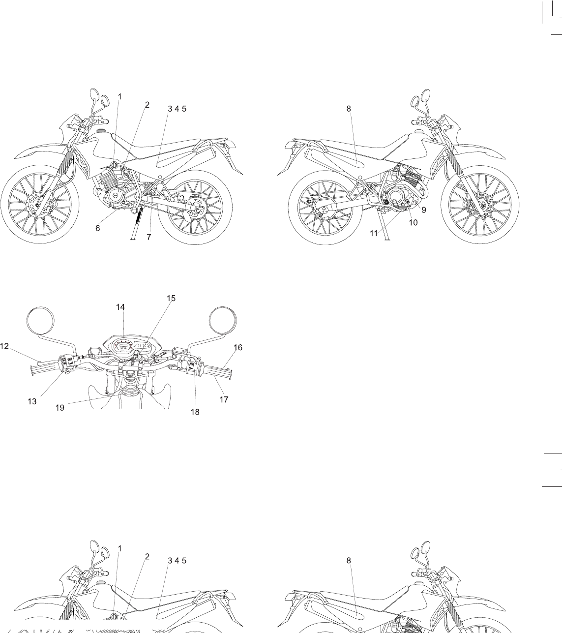
DESCRIPTION XTZ 125K
10. Dispstick
11. Rear brake pedal
12. Clutch lever
13. Handlebar switches over right
14. Speedometer
15. Main switch
16. Front brake lever
17. Throttle grip
18. Handlebar switches over left
19. Fuel tank cap
01. Fuel cock
02. Starter lever
03. Battery
04. Fusible
05. Tool kit
06. Shift pedal
07. Shock absorber
08. Air filter
09. Kick starter
1-2
1-2
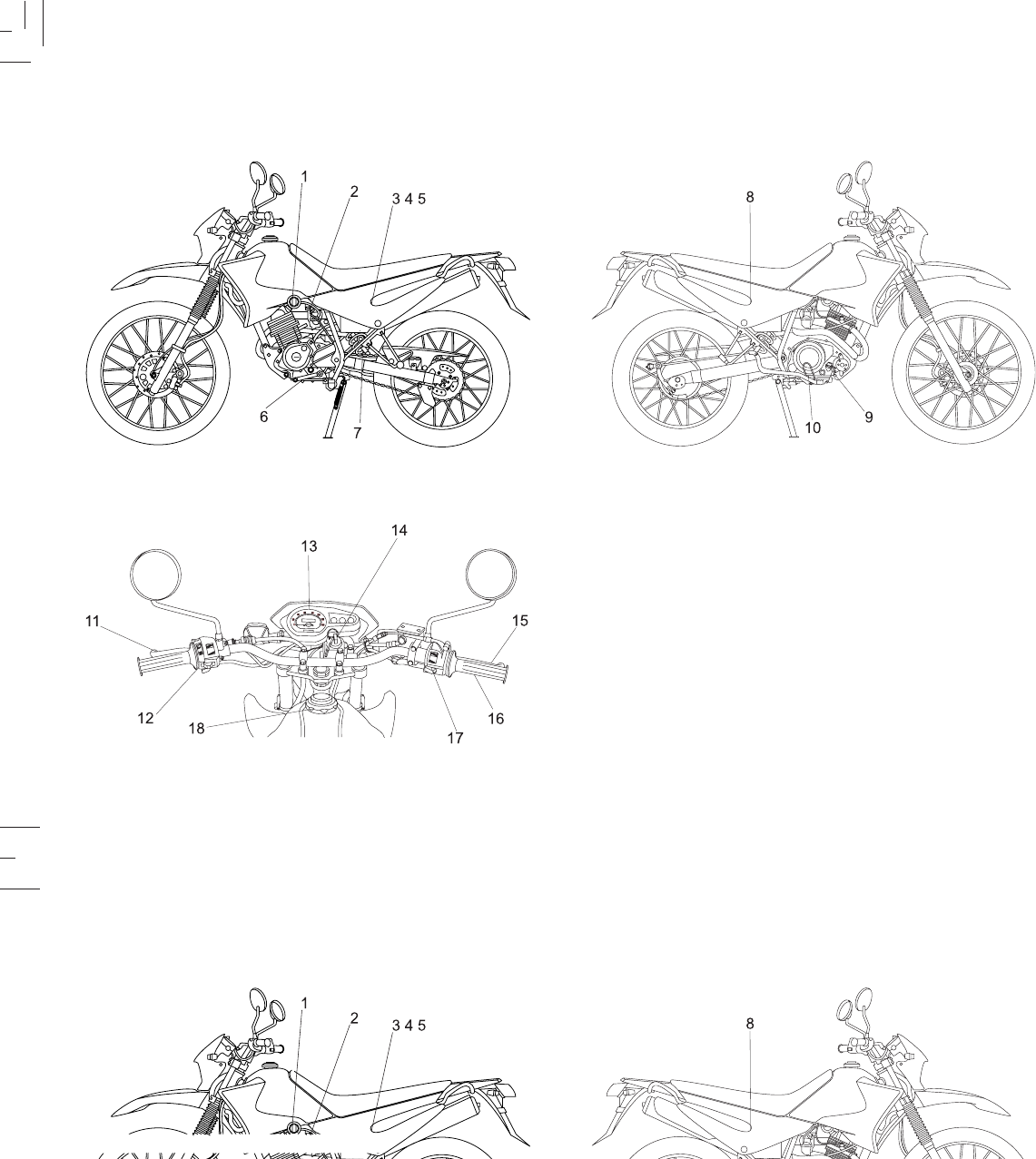
DESCRIPTION XTZ 125E
10. Rear brake pedal
11. Clutch lever
12. Handlebar switches over right
13. Speedometer
14. Main switch
15. Front brake lever
16. Throttle grip
17. Handlebar switches over left
18. Fuel tank cap
01. Fuel cock
02. Starter lever
03. Battery
04. Fusible
05. Tool kit
06. Shift pedal
07. Shock absorber
08. Air filter
09. Dispstick
2-1
2-1
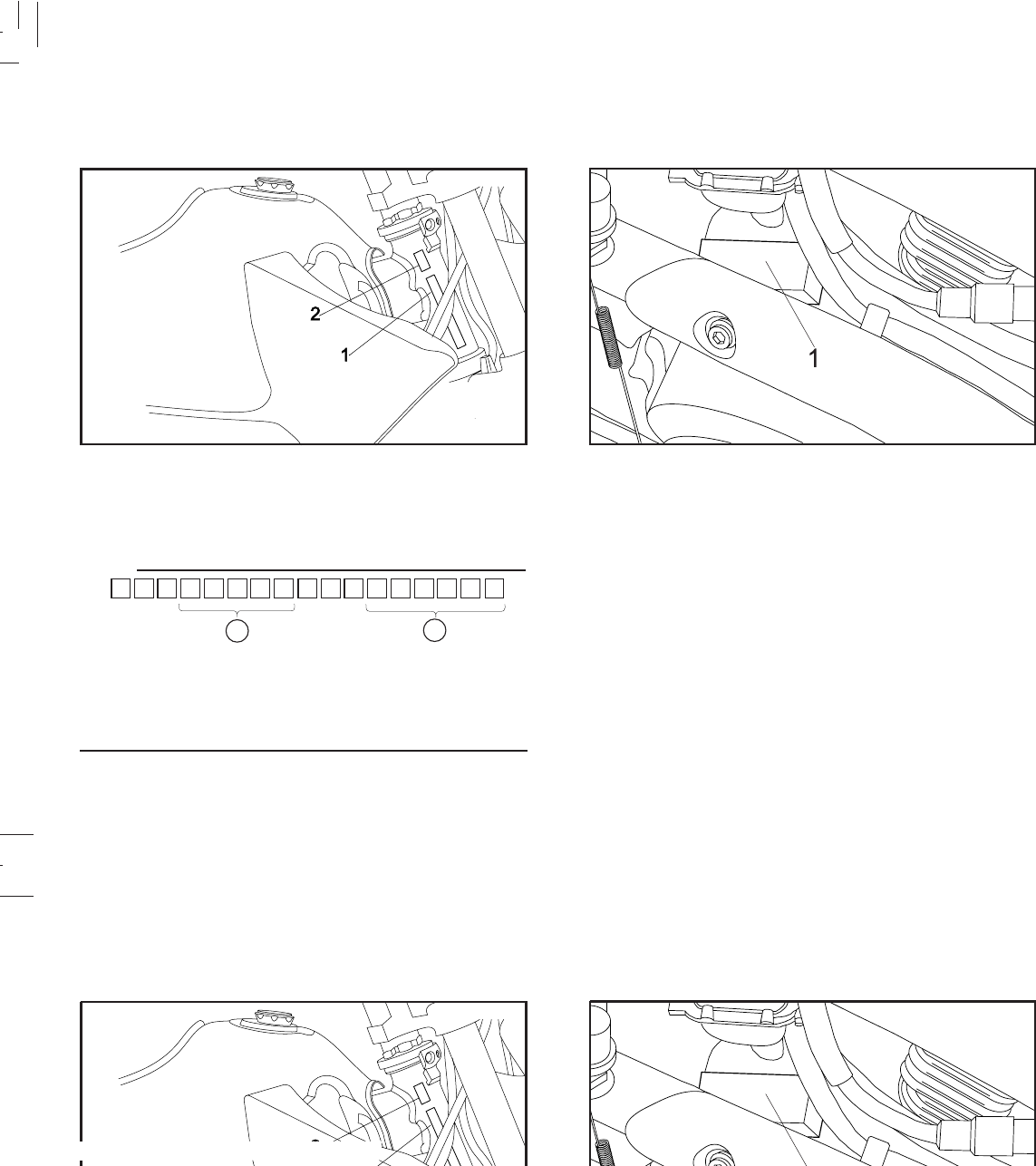
Vehicle identification number
1. Frame number 2. Production year
Engine serial number
1. Engine serial number
Model code is indicated by 4th to 8th ) digits and serial
number is indicated by 12th to 17th digits *. Record these
numbers for reference in case of ordering parts from a
Yamaha dealer.
AB
MACHINE IDENTIFICATION
The vehicle identification number is stamped into the
steering head pipe.Record this number in the space
provided.
The engine serial number is stamped on right-hand engine
crankcase.
NOTE:
3-1
3-1
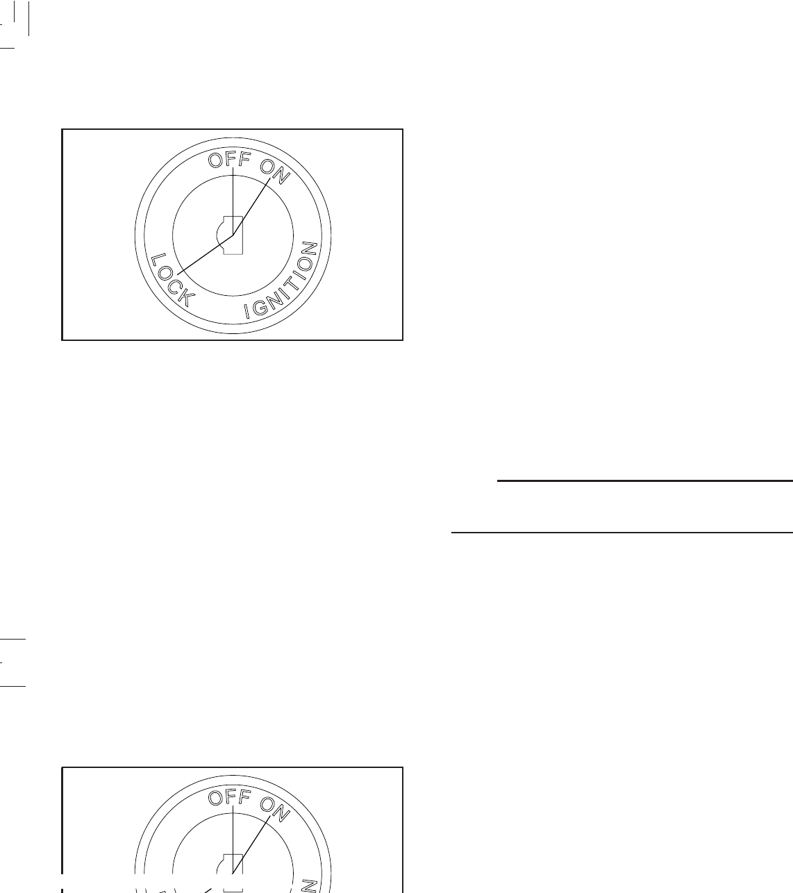
CONTROL FUNCTIONS
Main switch The main switch controls the ignition and the electrical
system. It’s operation is described below.
ON:
Electrical circuits are switched on. Engine can be started.
The key cannot be removed.
OFF:
All electrical circuits are switched off. The key can be
removed.
LOCK:
The steering is locked and all electrical circuits are switched
off. The key can be removed. Refer to page (3-11) “Steering
lock” for instructions.
NOTE:
Always turn the main switch to “OFF” or “LOCK” and
remove the key when the motorcycle is unattended.
3-2
3-2
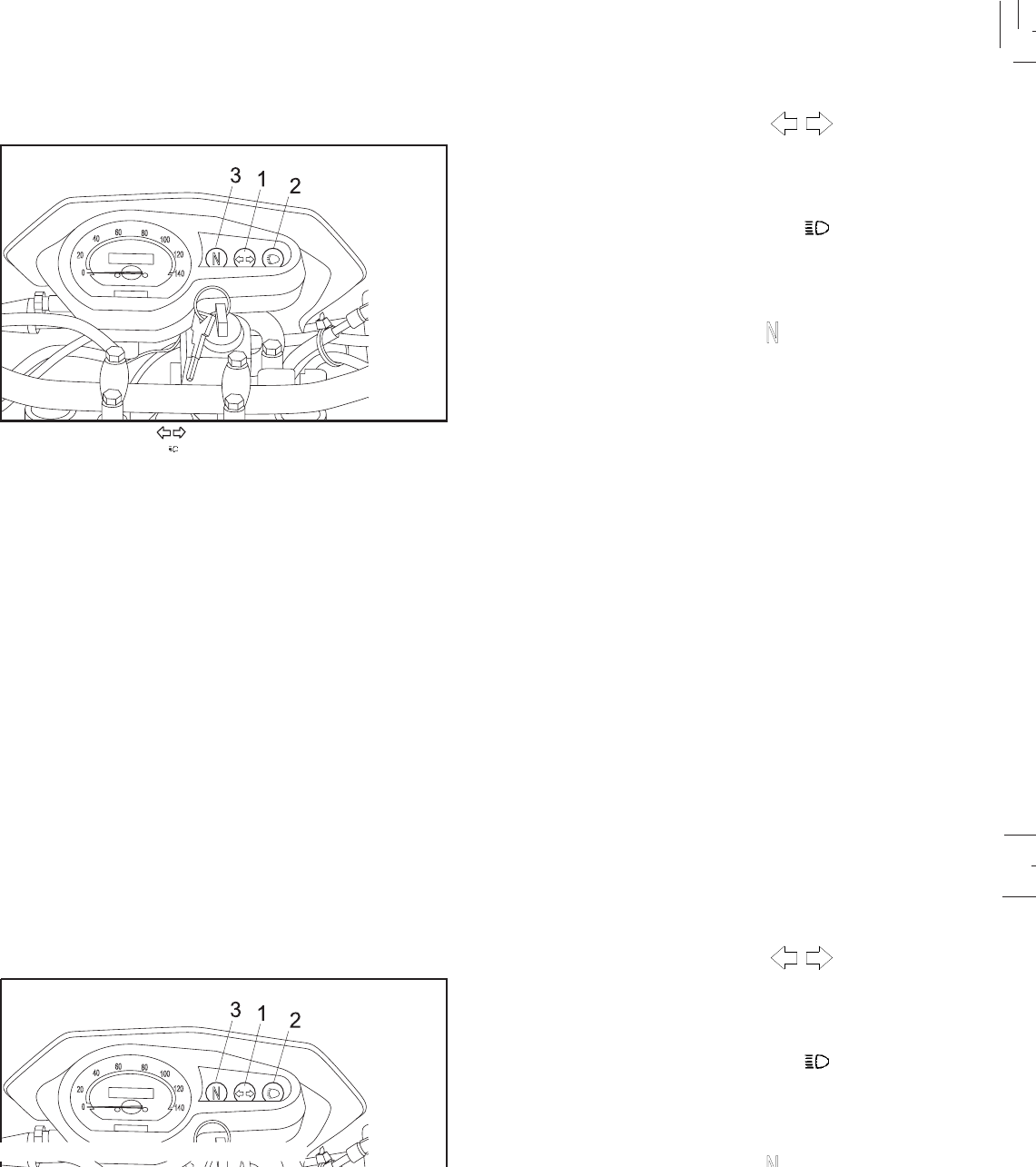
Indicator lights
1. Turn indicator lights " "
2. High beam indicator light " "
3. Neutral indicator light "N"
TURN INDICATOR LIGHTS " "
The corresponding indicator fhashes when the turn switch
is moved to the “ ç “ or “ è“.
HIGH BEAM INDICATOR LIGHT " "
This indicator comes on when the headlight high beam is
used.
NEUTRAL INDICATOR LIGHT " "
This indicator comes on when the transmission is in neutral.
3-3
3-3
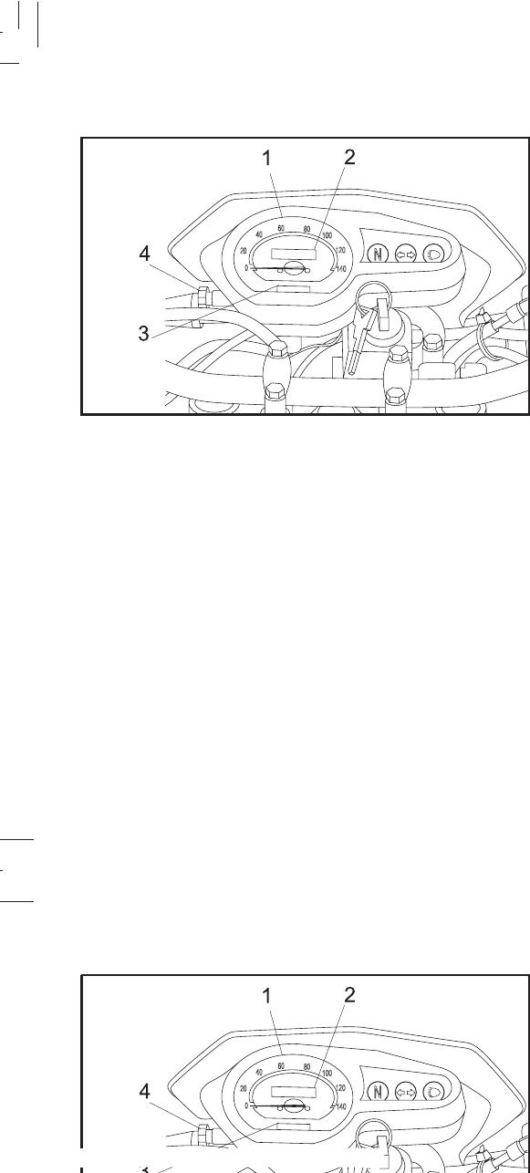
Speedometer The speedometer shows riding speed.
This speedometer is equipped with an odometer and a trip
meter.
The trip meter can be returned to zero by using the adjusting
knob.
Use the trip meter to estimate how for you can ride on a
tank of fuel.
This information will enable you to plan fuel stops in the
future.
1. Speedometer 2. Odometer
3. Trip meter 4. Adjusting knob
3-4
3-4
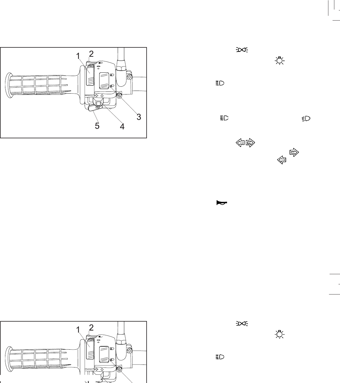
Handlebar switches over left:
1. Light switch
2. Pass switch
3. Dimmer switch
4. Turn signal switch
5. Horn switch
LIGHTS SWITCH
Turning the light switch to “ “, turns on the meter lights
and tail-lights. Turning the light switch to “ “, turns the
headlight on also.
PASS SWITCH " "
Press the switch to operate the passing light.
DIMMER SWITCH
Turn the switch to " " for the high beam and to " "
for the low beam.
TURN SIGNAL SWITCH " "
To signal a right-hand turn, push the switch to “ “ ; to
signal a left-hand turn, push the switch to “ “ .
Once the switch is released it will return to the center
position. To cancel the signal, push the switch in after it
has returned to the center position.
HORN SWITCH " "
Press the switch to sound the horn.
3-5
3-5
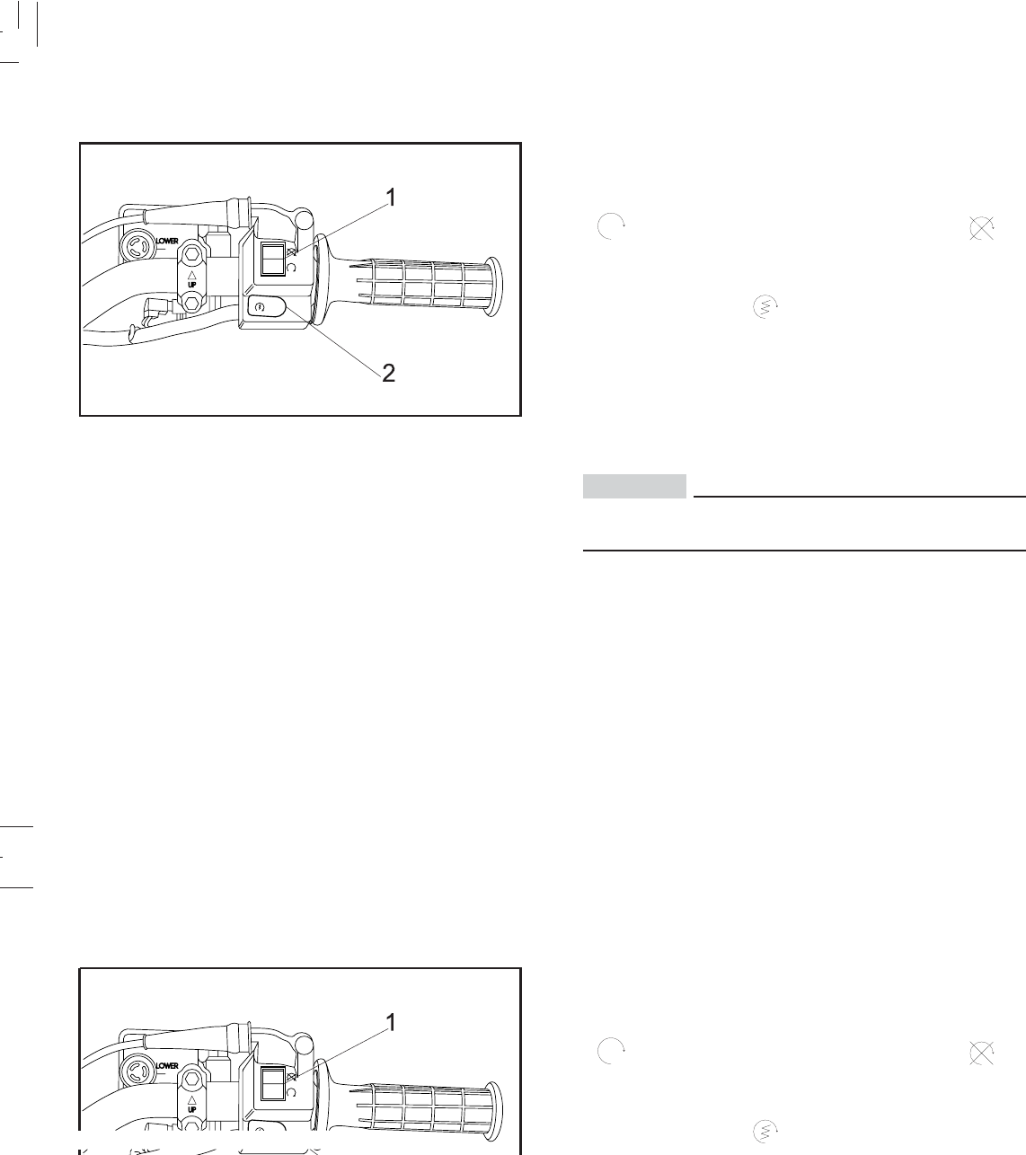
1. ENGINE STOP switch, shuts the engine off
2. Starter switch (XTZ 125E)
“ENGINE STOP” SWITCH
The engine stop switch is a safety device for use in an
emergency such as when the motorcycle overturns or if
trouble occurs in the throttle system. Turn the switch to
“ ” to start the engine, and turn the switch to “ ” to
stop the engine.
STARTER SWITCH “ ”
The starter motor cranks the engine when pushing the
starter switch.
CAUTION:
See starting instructions prior to starting the
engine.
Handlebar switches over right:
3-6
3-6
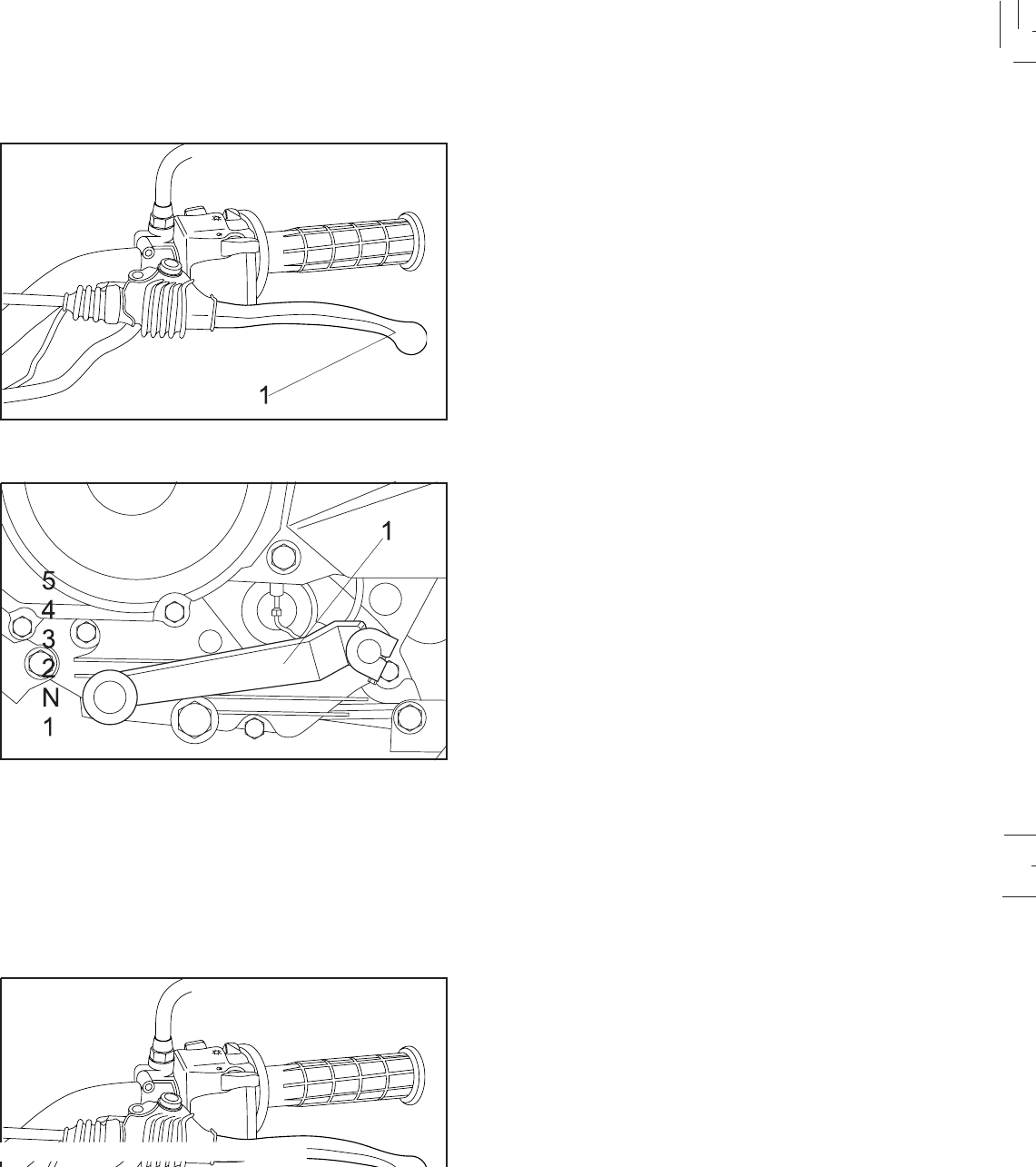
The clutch lever is located on the left handlebar, and the
starting circuit cut off switch is incorporated in the clutch
lever holder. Pull the clutch lever to the handlebar to
disengage the clutch, and release the lever to engage the
clutch. The lever should be pulled rapidly and released
slowly for smooth clutch operation.
This motorcycle is equipped with a constant-mesh 5-speed
transmission.
The shift pedal is located on the left side of the engine and
is used in combination with the clutch when shifting.
Clutch lever
Shift pedal
1. Clutch lever
1. Shift pedal
3-7
3-7
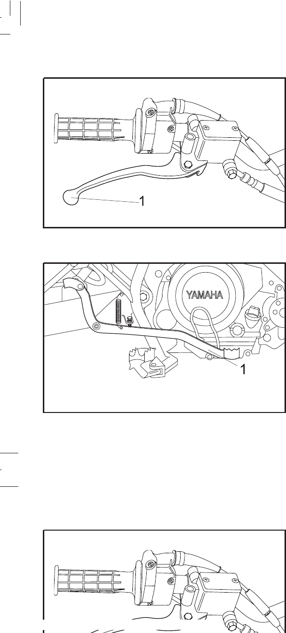
The front brake lever is located on the right handlebar. Pull
it toward the handlebar to apply the front brake.
The rear brake pedal is on the right side of the motorcycle.
Press down the brake pedal to apply the rear brake.
Front brake lever
1. Front brake lever
1.Rear brake pedal
Rear brake pedal
The front brake lever is located on the right handlebar. Pull
it toward the handlebar to apply the front brake.
The rear brake pedal is on the right side of the motorcycle.
Press down the brake pedal to apply the rear brake.
Front brake lever
1. Front brake lever
1.Rear brake pedal
Rear brake pedal
3-8
3-8
Fuel tank cap
Be sure the cap is properly installed and locked in place
before riding the motorcycle.
TO OPEN:
Insert the key and turn it 1/2 turn counterclockwise. The
lock will be released and the cap can be opened.
TO CLOSE:
Push the tank cap into position with the key inserted. To
remove the key, turn it clockwise to the original position.
WARNING:
3-9
3-9
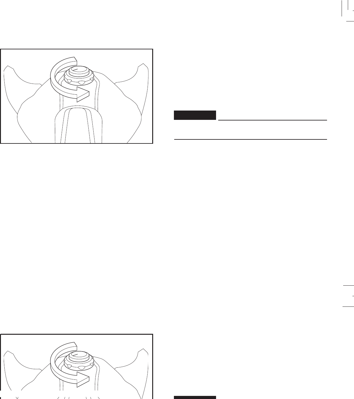
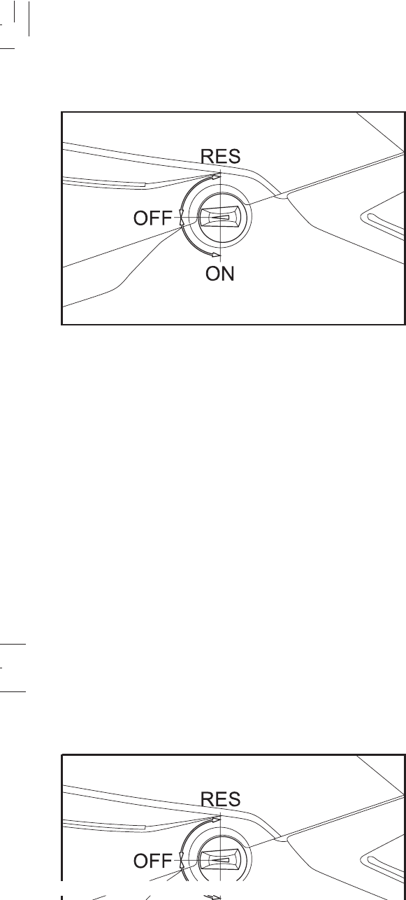
Fuel cock The fuel cock supplies fuel from the tank to the carburetor
while filtering it also.
The fuel cock has three positions:
OFF:
With the fuel cock in this position, fuel will not flow. Always
set the fuel cock to this position when the engine is not
running.
ON:
With the fuel cock in this position, fuel flows to the
carburetor. Set the fuel cock to this position when starting
the engine and while riding.
RES:
This indicates reserve. If you run out of fuel while riding,
set the fuel cock to this position.
Fill the tank at the first opportunity. Be sure to set fuel cock
back to “ON” after refueling!
3-10
3-10
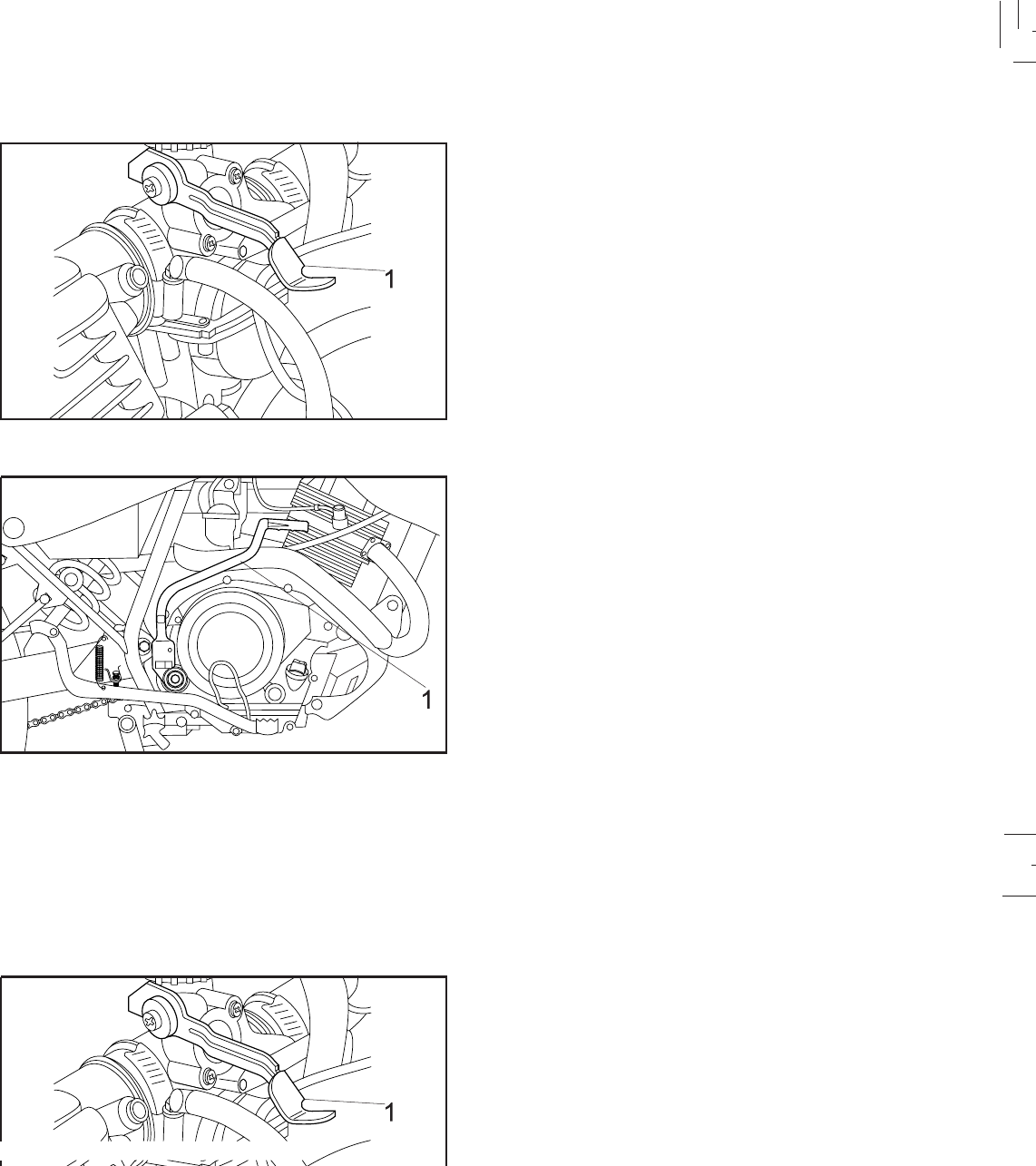
Starting a cold engine requires a richer air-fuel mixture. A
separate starter circuit supplies the mixture.
Pull the starter knob up to open the circuit for starting. When
the engine has warmed up, push the knob down to close
the circuit.
Starter lever
1. Starter lever
1. Kick starter (XTZ 125K)
Rotate the kick starter away from the engine. Push the
starter down lighty with your foot until the gears engage,
then kick smoothly and forcefully to start the engine.
Shift to neutral before starting.
Kick starter
3-11
3-11
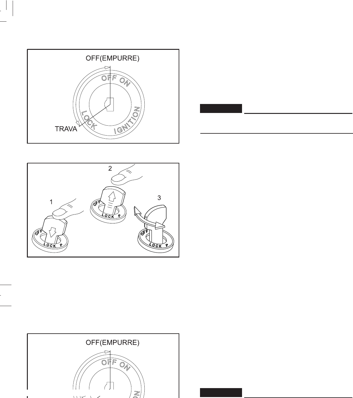
1. Push 2. Release 3. Turn
The steering is locked when the main switch is turned to
“LOCK”. To lock the steering, turn the handlebars all the
way to the left. With the key at “OFF” position, push it into
the main switch and release it, turn it counterclockwise to
“LOCK”, and remove the key. To release the lock, turn the
key to “OFF”.
WARNING:
Never turn the key to “LOCK” position when the
motorcycle is moving.
Steering lock
WARNING:
3-12
3-12
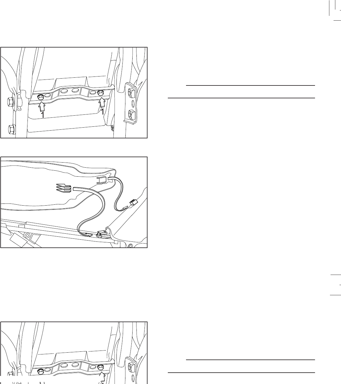
To remove the seat, remove the bolts.
To reinstall the seat, insert the lobes in to the receptacle on
the frame and fuel tank, then tighten the bolts.
Reinstall the side covers.
NOTE:
Make sure the seat is securely fitted.
Seat
1. Bolts
To remove the seat, remove the bolts.
To reinstall the seat, insert the lobes in to the receptacle on
the frame and fuel tank, then tighten the bolts.
Reinstall the side covers.
NOTE:
Make sure the seat is securely fitted.
Seat
1. Bolts
3-13
3-13
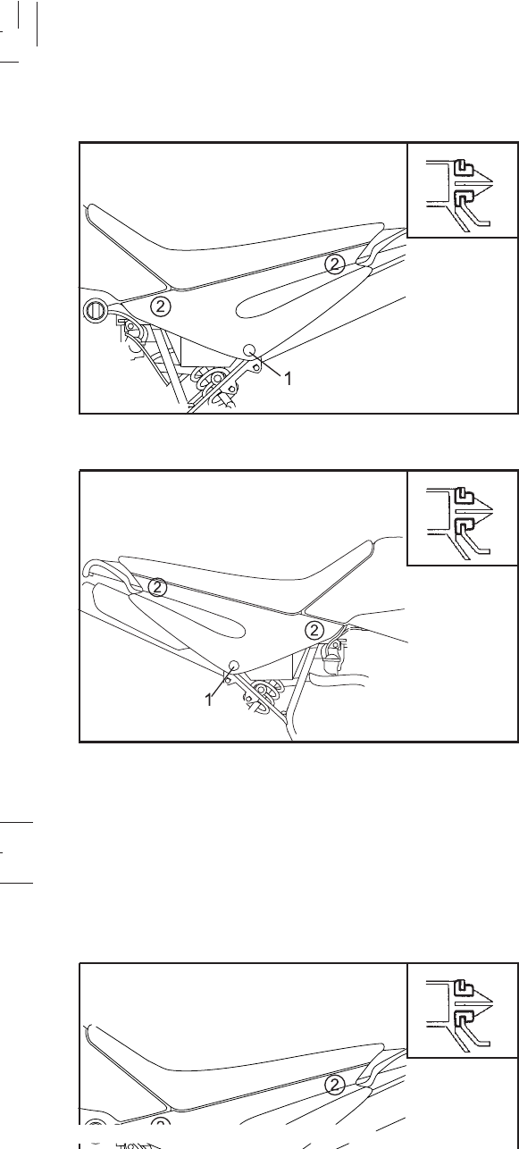
1. Screw 2. Pull 3. Pin
A
Side covers Insert the key and turn it 1/4 clockwise. Pull the cover to
release the pins.
To reinstall, reverse the removal procedures.
Remove the screw and then pull the cover to release the
pins
To reinstall, reverse the removal procedures.
1. Lock the side cover 2. Pull A. Pin
A
3-14
3-14
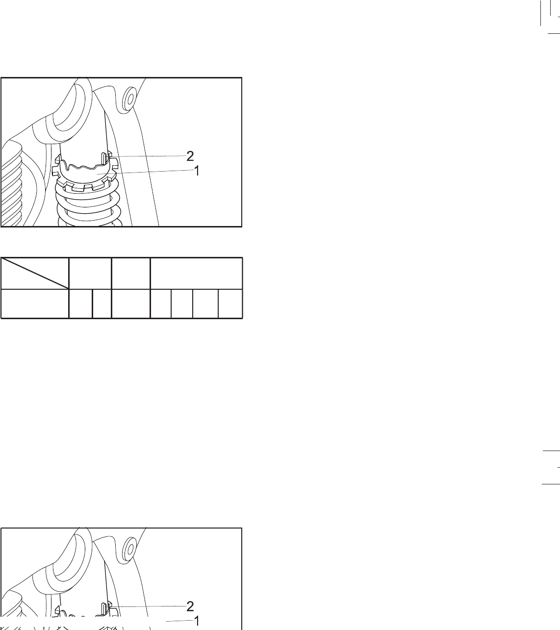
The spring prelod can be adjusted to suit the motorcycle’s
load (ex: optional accessories, etc.) and riding conditions.
Refer to page 6-30 for proper adjustment procedures.
Rear shock absorber
1. Spring preload adjusting ring
2.Position indicator
123456 7
Adjusting
position
Soft Standard Hard
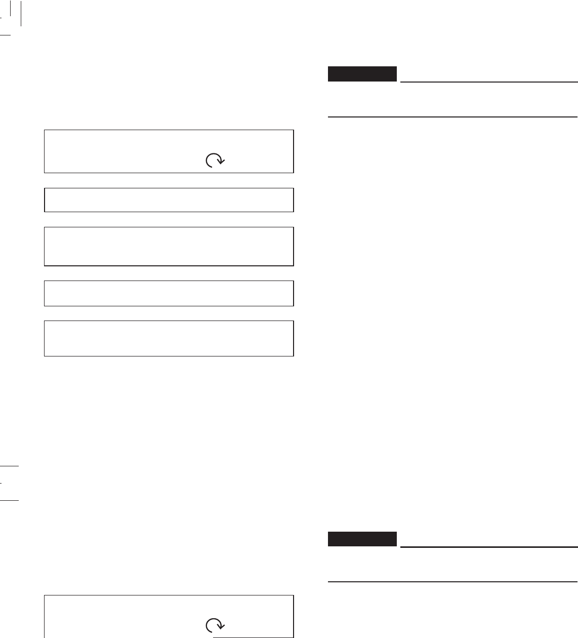
The spring prelod can be adjusted to suit the motorcycle’s
load (ex: optional accessories, etc.) and riding conditions.
Refer to page 6-30 for proper adjustment procedures.
Rear shock absorber
1. Spring preload adjusting ring
2.Position indicator
123456 7
Adjusting
position
Soft Standard Hard
3-15
3-15
If improper operation is noted, consult a Yamaha
dealer or other qualified mechanic immediately.
Check the operation of the clutch switch against the
information below.
TURN MAIN SWITCH TO “ON” AND ENGINE
STOP SWITCH TO “ ”.
TRANSMISSION IS IN GEAR.
PULL IN CLUTCH LEVER AND PUSH
STARTER SWITCH.
↓↓
↓↓
↓
↓↓
↓↓
↓
↓↓
↓↓
↓
ENGINE WILL START
* Clutch switch operation check
↓↓
↓↓
↓
CLUTCH SWITCH IS OK
WARNING:
* Obs.: XTZ 125E
If improper operation is noted, consult a Yamaha
dealer or other qualified mechanic immediately.
Check the operation of the clutch switch against the
information below.
TURN MAIN SWITCH TO “ON” AND ENGINE
STOP SWITCH TO “ ”.
TRANSMISSION IS IN GEAR.
PULL IN CLUTCH LEVER AND PUSH
STARTER SWITCH.
↓↓
↓↓
↓
↓↓
↓↓
↓
↓↓
↓↓
↓
ENGINE WILL START
* Clutch switch operation check
CLUTCH SWITCH IS OK
WARNING:
* Obs.: XTZ 125E
4-1
4-1
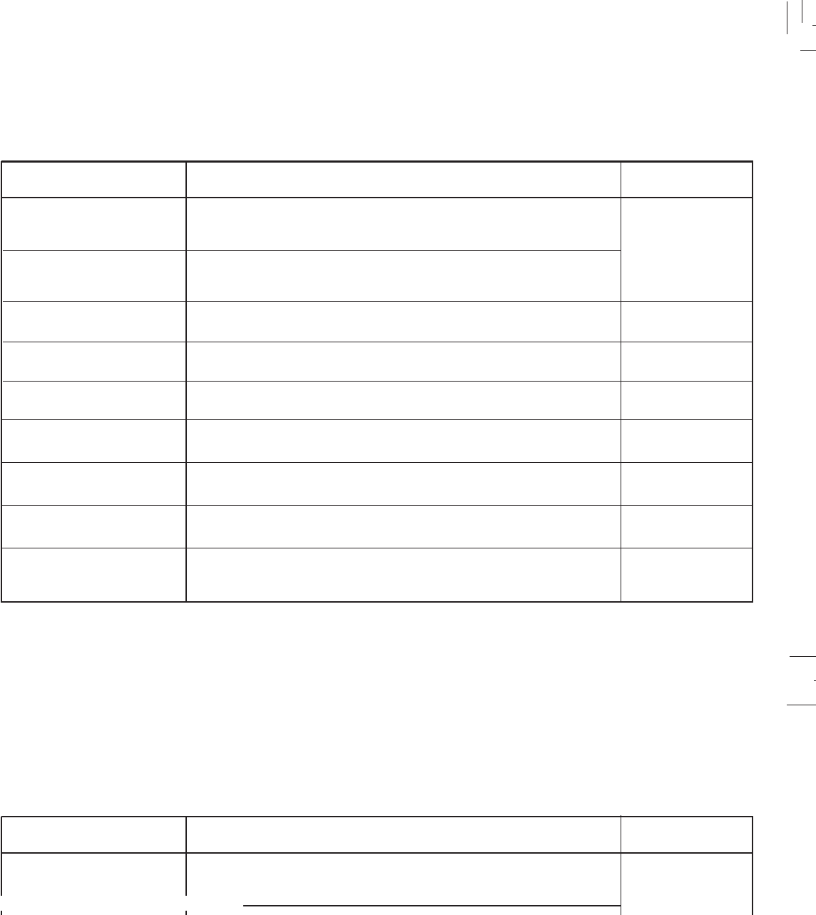
PRE-OPERATION CHECKS
Before using this motorcycle, check the following points:
ITEM ROUTINE PAGE
Front brake
Check operation, condition and free play.
Adjust if necessary
Clutch
Throttle grip / cable Check for smooth operation.
Lubricate / Adjust if necessary
Check oil level / add oil as necessary
Engine oil
Drive chain Check chain slack and condition. Lubricate if necessary
Adjust if necessary.
Air filter
Control and meter cable
Check tire pressure, wear, damage and spoke tightness
Check for smooth operation.
Lubricate if necessary
4-3 ~ 4-4
6-17 ~ 6-23
4-8 , 6-14 , 6-27
4-4 , 6-6 , 6-9
6-24 ~ 6-26
6-10 ~ 6-11
4-5 ~ 4-8
6-26
Check operation, condition and free play.
Adjust if necessary
Wheels / Tires
Clean and oil it frequently.
4-8 , 6-16
Rear brake
Check operation, free play, fluid level and fluid leakage.
Top-up with DOT #4 (or DOT #3) brake fluid if necessary.
4-2
4-2
NOTE:
Pre-operation checks should be made each time the motorcycle is used. Such an inspection can be thoroughly accomplished
in a very short time; and the added safety it assures is more than worth the time involved. If any maintenance service or
adjustment is needed, consult the chart above to refer to the pages in which the service or adjustment is described.
1. The engine, exhaust pipe, and muffler will be very hot after the engine has been run.
Be careful not to touch them or to allow any clothing item to contact them during inspection or repair.
2. If any item is not working properly, have it inspected and repaired before operating the motorcycle.
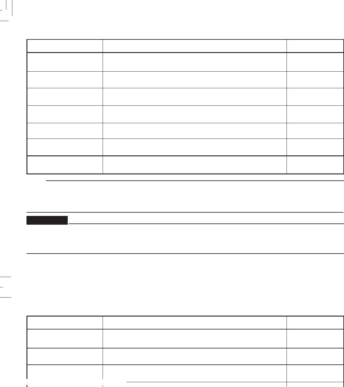
ITEM ROUTINE PAGE
Sidestand
Fittings / Fasteners Check all chassi fittings and fasteners.
Tighten / Adjust, if necessary
Check fuel level / top up as required.
Fuel tank
Lights, signals and switches
Battery Check electrolyte level.
Replenish with “distilled water” if necessary.
6-27
4-8 , 6-5
4-8 , 6-35 ~ 6-36
6-32 ~ 6-34
6-28
4-9
Check for proper operation
Front brake and clutch
lever pivots
Check for smooth operation.
Lubricate if necessary
Check for smooth operation.
Lubricate if necessary
6-27
Check for smooth operation.
Lubricate if necessary
Rear brake and shift pedal
shafts
WARNING:
NOTE:
Pre-operation checks should be made each time the motorcycle is used. Such an inspection can be thoroughly accomplished
in a very short time; and the added safety it assures is more than worth the time involved. If any maintenance service or
adjustment is needed, consult the chart above to refer to the pages in which the service or adjustment is described.
1. The engine, exhaust pipe, and muffler will be very hot after the engine has been run.
Be careful not to touch them or to allow any clothing item to contact them during inspection or repair.
2. If any item is not working properly, have it inspected and repaired before operating the motorcycle.
ITEM ROUTINE PAGE
Sidestand
Fittings / Fasteners Check all chassi fittings and fasteners.
Tighten / Adjust, if necessary
Check fuel level / top up as required.
Fuel tank
Lights, signals and switches
Battery Check electrolyte level.
Replenish with “distilled water” if necessary.
6-27
4-8 , 6-5
4-8 , 6-35 ~ 6-36
6-32 ~ 6-34
6-28
4-9
Check for proper operation
Front brake and clutch
lever pivots
Check for smooth operation.
Lubricate if necessary
Check for smooth operation.
Lubricate if necessary
6-27
Check for smooth operation.
Lubricate if necessary
Rear brake and shift pedal
shafts
WARNING:
4-3
4-3
Brakes (See page 6-17 for details)
1. Brake lever and brake pedal
Check for correct free play in the front brake lever and
rear brake pedal and adjust if necessary. Make sure
the brakes are working properly by checking at low
speed shortly after starting out.
A soft, spongy feeling in the brake lever indicates a
failure in the brake system. Do not operate the
motorcycle until the failure in the brake system is
corrected. Ask a Yamaha dealer or other qualified
mechanic for immediate repairs. A soft, spongy feeling
could indicate a hazardous condition in the brake
system.
NOTE:
If DOT #4 is not available, #3 can be used.
3. Check the disc pads.
Refer to page 6-20
4. Check the brake shoes.
Refer to page 6-20
When a brake service is necessary, consult a Yamaha
dealer or other qualified mechanic.
NOTE:
2. Brake fluid
Check the brake fluid level. Add fluid if necessary.
RECOMMENDED BRAKE FLUID: DOT #4
WARNING:
Downloaded from www.Manualslib.com manuals search engine
4-4
4-4
If brake fluid leakage is found, ask a Yamaha dealer or
other qualified mechanic for immediate repairs. Such
leakage could indicate a hazardous condition.
CAUTION:
Brake fluid may deteriorate painted surfaces or plastic
parts. Never spill any fluid. If spilled, clean it up
immediately.
Brake fluid leakage
Apply the brake for several seconds. Check to see if any
brake fluid leaks out from the pipe joints or the master
cylinder.
WARNING:
CAUTION:
OIL QUANTITY:
Total amount:
1.2 L ( 0.264 Imp gal, 0.317 US gal)
Periodic oil change:
1.0 L ( 0.220 Imp gal, 0.264 US gal)
Engine oil (See page 6-6 for details)
Make sure the engine oil is at the specified level. Add oil as
necessary.
Check the oil level in a daily manner and top it up if
necessary.
If brake fluid leakage is found, ask a Yamaha dealer or
other qualified mechanic for immediate repairs. Such
leakage could indicate a hazardous condition.
CAUTION:
Brake fluid may deteriorate painted surfaces or plastic
parts. Never spill any fluid. If spilled, clean it up
Brake fluid leakage
Apply the brake for several seconds. Check to see if any
brake fluid leaks out from the pipe joints or the master
cylinder.
WARNING:
CAUTION:
OIL QUANTITY:
Total amount:
1.2 L ( 0.264 Imp gal, 0.317 US gal)
Periodic oil change:
1.0 L ( 0.220 Imp gal, 0.264 US gal)
Engine oil (See page 6-6 for details)
Make sure the engine oil is at the specified level. Add oil as
necessary.
Check the oil level in a daily manner and top it up if
necessary.
4-5
4-5
Tires
To ensure maximum performance, long service, and safe
operation, note the following:
1. Tire air pressure
Always check and adjust the tire pressure before
operating the machine.
Tire inflation pressure should be checked and adjusted
when the temperature of the tire equals the ambient air
temperature.
Tire inflation pressure must be adjusted according to
total weight of cargo, rider, passenger and accessories
(fairing, saddlebags, etc. if approved for this model),
and vehicle speed.
WARNING:
Basic weight:
With oil and without fuel XTZ 125K 113 Kg ( 249 lb)
XTZ 125E 114 Kg ( 251 lb)
* Load is the total weght of cargo, rider, passenger and accessories.
Maximum load*:
Cold tire pressure:
up to 90 Kg (198 lb)
load*:
90 Kg (198 lb) ~
maximum load*:
150 Kg ( 330 kg)
Front
1.5 kg/cm2
22 PSI / 147 kpa
Rear
1.5 kg/cm2
22 PSI / 147Kpa
1.5 kg/cm2
22 PSI / 145 Kpa 2.0 kg/cm2
28 PSI / 200 Kpa
Tires
To ensure maximum performance, long service, and safe
operation, note the following:
1. Tire air pressure
Always check and adjust the tire pressure before
operating the machine.
Tire inflation pressure should be checked and adjusted
when the temperature of the tire equals the ambient air
temperature.
Tire inflation pressure must be adjusted according to
total weight of cargo, rider, passenger and accessories
(fairing, saddlebags, etc. if approved for this model),
and vehicle speed.
Basic weight:
With oil and without fuel XTZ 125K 113 Kg ( 249 lb)
XTZ 125E 114 Kg ( 251 lb)
* Load is the total weght of cargo, rider, passenger and accessories.
Maximum load*:
Cold tire pressure:
up to 90 Kg (198 lb)
load*:
90 Kg (198 lb) ~
maximum load*:
150 Kg ( 330 kg)
Front
1.5 kg/cm2
22 PSI / 147 kpa
Rear
1.5 kg/cm2
22 PSI / 147Kpa
1.5 kg/cm2
22 PSI / 145 Kpa 2.0 kg/cm2
28 PSI / 200 Kpa
4-6
4-6
Proper loading of your motorcycle is important for the
handling, braking, and other performance and safety
characteristics of your motorcyle. Do not carry loosely
packed items that can shift. Securely pack your heaviest
items close to the center of the motorcycle, and
distribute the weight evenly from side to side. Properly
adjust the suspension for your load, and check the
condition and pressure of your tires. NEVER
OVERLOAD YOUR MOTORCYCLE. Make sure the total
weight of the cargo, rider, passenger, and accessories
(fairing, saddlebags, etc. if approved for this model)
does not exceed the maximum load of the motorcycle.
Operation of an overloaded motorcycle could cause tire
damage, an accident, or even injury.
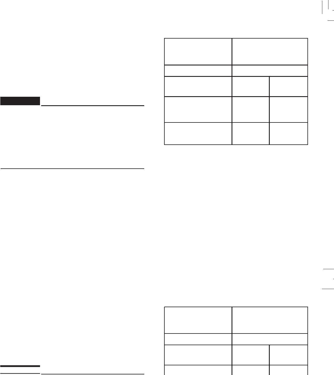
2. Tire inspection
Always check the tires before operating the motorcycle.
If a tire tread shows crosswise lines (minimum tread
depth), if the tire has a nail or glass fragments in it, or if
the side wall is cracked, contact a Yamaha dealer or
other qualified mechanic and have the tire replaced.
1.Tread depth 2. Side wall 3. wear indicator
WARNING:
Proper loading of your motorcycle is important for the
handling, braking, and other performance and safety
characteristics of your motorcyle. Do not carry loosely
packed items that can shift. Securely pack your heaviest
items close to the center of the motorcycle, and
distribute the weight evenly from side to side. Properly
d, and check the
condition and pressure of your tires. NEVER
OVERLOAD YOUR MOTORCYCLE. Make sure the total
weight of the cargo, rider, passenger, and accessories
(fairing, saddlebags, etc. if approved for this model)
does not exceed the maximum load of the motorcycle.
Operation of an overloaded motorcycle could cause tire
damage, an accident, or even injury.
2. Tire inspection
Always check the tires before operating the motorcycle.
If a tire tread shows crosswise lines (minimum tread
depth), if the tire has a nail or glass fragments in it, or if
the side wall is cracked, contact a Yamaha dealer or
other qualified mechanic and have the tire replaced.
1.Tread depth 2. Side wall 3. wear indicator
WARNING:
4-7
4-7
After extensive tests, the tires listed below have been
approved by Yamaha for this model. The front and rear
tires should always be by the same manufacturer and
of the same design. No guarantee concerning handling
characteristics can be given if a tire combination other
than one approved by Yamaha is used on this
motorcycle.
FRONT
REAR
Size
Manufacturer Type
Minimum tire tread depth
(from and rear) 0,8 mm (0.0315 in)
80/90 - 21PIRELLI 48T MT 60
110/80 - 18
PIRELLI 58T MT 60
1. It is dangerous to ride with a worn-out tire. When
the tire tread begin to show signs of wear, replace
the tire immediately. Brakes, tires and related wheel
parts should be left to a Yamaha dealer.
2. Patching a punctured tube is not recommended. If
it is absolutely necessary to do so, use great care
and replace the tube as soon as possible with a
good quality replacement.
WARNING:WARNING:
After extensive tests, the tires listed below have been
approved by Yamaha for this model. The front and rear
tires should always be by the same manufacturer and
of the same design. No guarantee concerning handling
characteristics can be given if a tire combination other
than one approved by Yamaha is used on this
FRONT
REAR
Size
Manufacturer Type
Minimum tire tread depth
(from and rear) 0,8 mm (0.0315 in)
80/90 - 21PIRELLI 48T MT 60
110/80 - 18
PIRELLI 58T MT 60
1. It is dangerous to ride with a worn-out tire. When
the tire tread begin to show signs of wear, replace
the tire immediately. Brakes, tires and related wheel
parts should be left to a Yamaha dealer.
2. Patching a punctured tube is not recommended. If
it is absolutely necessary to do so, use great care
and replace the tube as soon as possible with a
good quality replacement.
WARNING:WARNING:

4-8
4-8
Wheels
To ensure maximum performance, long service, and safe
operation, note the following:
1. Always inspect the wheels before a ride. Check for
cracks, bends, or warpage of the wheel; be sure the
spokes are tight and undamaged. If any abnormal
condition exists in a wheel, consult a Yamaha dealer or
other qualified mechanic. Do not attempt even small
repairs to the wheel. If a wheel is deformed or cracked,
it must be replaced.
2. Tires and wheels should be balanced whenever either
one is changed or replaced. Failure to have a wheel
balanced can result in poor performance, adverse
handling characteristics, and shortened tire life.
3. After installing a tire, ride conservatively to allow the
tire to seat itself on the rim properly. Failure to allow
proper seating may cause tire failure, resulting in
damage to the motorcycle and injury to the rider.
Clutch ( See page 6-16 for details)
Check the free play in the clutch lever, and make sure the
lever operates properly. If the free play is incorrect, adjust
it.
Throttle grip (See page 6-14 for details)
Turn the throttle grip to see if it operates properly, and check
the free play.
Make sure the grip returns by spring force when released.
Ask a Yamaha dealer or other qualified mechanic to make
any necessary adjustments.
Fitting/Fasteners
Alway check the tightness of chassis fittings and fasteners
before a ride. Use the chart on page 6-5 to find the correct
torque.
Switches
Check the operation of the starter switch, main switch,
“Engine Stop” switch.
Wheels
To ensure maximum performance, long service, and safe
operation, note the following:
1. Always inspect the wheels before a ride. Check for
cracks, bends, or warpage of the wheel; be sure the
spokes are tight and undamaged. If any abnormal
condition exists in a wheel, consult a Yamaha dealer or
other qualified mechanic. Do not attempt even small
repairs to the wheel. If a wheel is deformed or cracked,
it must be replaced.
2. Tires and wheels should be balanced whenever either
one is changed or replaced. Failure to have a wheel
balanced can result in poor performance, adverse
handling characteristics, and shortened tire life.
3. After installing a tire, ride conservatively to allow the
tire to seat itself on the rim properly. Failure to allow
proper seating may cause tire failure, resulting in
damage to the motorcycle and injury to the rider.
Clutch ( See page 6-16 for details)
Check the free play in the clutch lever, and make sure the
lever operates properly. If the free play is incorrect, adjust
it.
Throttle grip (See page 6-14 for details)
Turn the throttle grip to see if it operates properly, and check
Make sure the grip returns by spring force when released.
Ask a Yamaha dealer or other qualified mechanic to make
any necessary adjustments.
Fitting/Fasteners
Alway check the tightness of chassis fittings and fasteners
before a ride. Use the chart on page 6-5 to find the correct
torque.
Switches
Check the operation of the starter switch, main switch,
“Engine Stop” switch.
4-9
4-9
CAUTION:
Always wipe off spilled fuel immediately with a dry and
clean soft cloth. Fuel may deteriorate painted surfaces
or plastic parts.
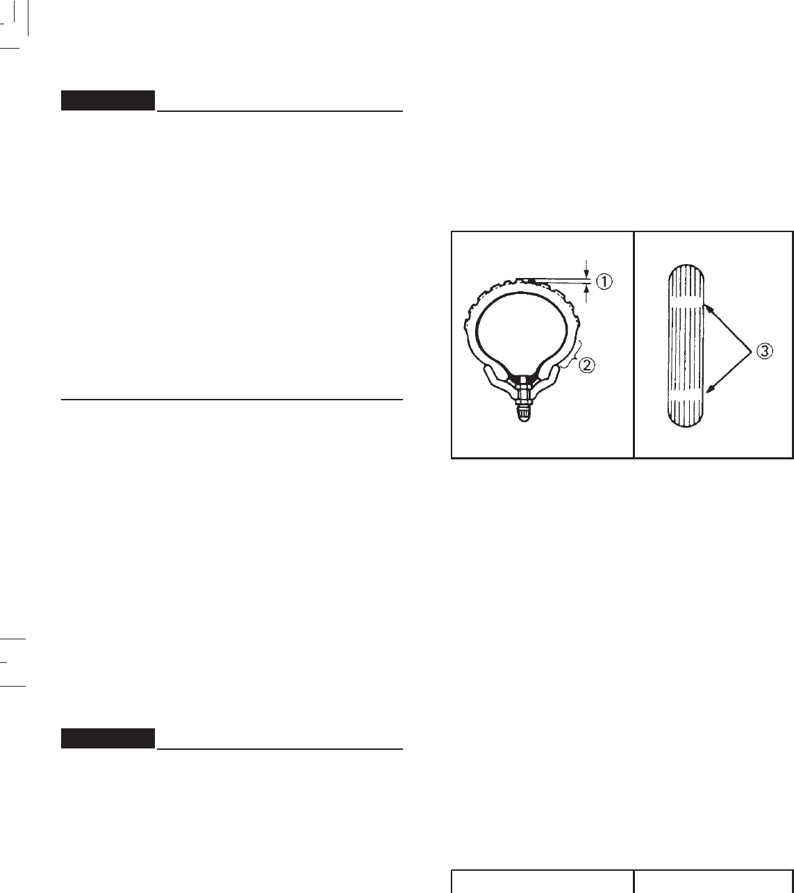
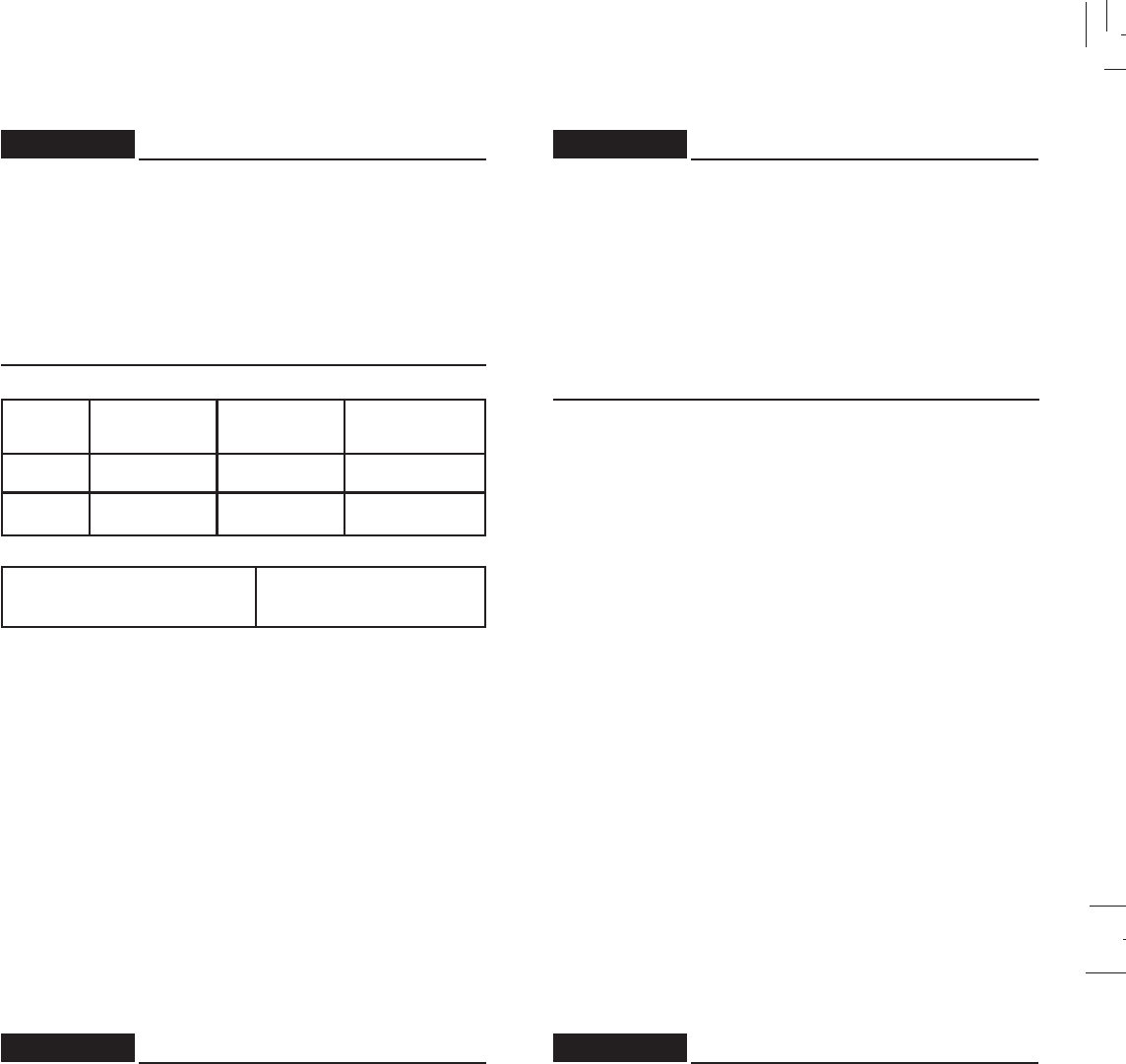
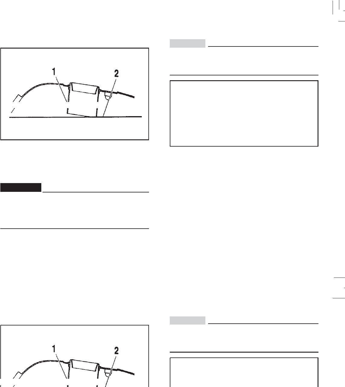
Fuel
1. Fuel level 2. Filler tube
Make sure there is sufficient fuel in the tank.
Do not overfill the fuel tank. Avoid spilling fuel on the
hot engine. Do not fill the fuel tank above the bottom of
the filler tube as shown in the illustration or it may
overflow when the fuel heats up later and expands.
Recommended fuel:
UNLEADED FUEL
Fuel tank capacity:
Total:
10.6 l ( 2.33 Imp gal, 2.80 US gal)
Reserve:
1.0 l ( 0.220 Imp gal, 0.264 Us gal)
Your Yamaha engine has been designed to use regular
unleaded gasoline with a pump octane number ([R+m]/2)
of 86 or higher, or research octane number of 91 or higher.
If knocking or pinging occurs, use a different brand of
gasoline or premium unleaded fuel. Unleaded fuel will give
you longer spark plug life and reduced maintenance cost.
If unleaded gasoline is not available, then leaded regular
gasoline can be used.
Gasohol
There are two types of gasohol; gasohol containing ethanol
and that containing methanol. Gasohol containing ethanol
can be used if ethanol content does not exceed 10%.
Gasohol containing methanol is not recommended by
Yamaha because it can cause fuel system damage or
vehicle performance problems.
WARNING:
CAUTION:
Always wipe off spilled fuel immediately with a dry and
clean soft cloth. Fuel may deteriorate painted surfaces
or plastic parts.
Fuel
1. Fuel level 2. Filler tube
Make sure there is sufficient fuel in the tank.
Do not overfill the fuel tank. Avoid spilling fuel on the
hot engine. Do not fill the fuel tank above the bottom of
the filler tube as shown in the illustration or it may
overflow when the fuel heats up later and expands.
Recommended fuel:
UNLEADED FUEL
Fuel tank capacity:
Total:
10.6 l ( 2.33 Imp gal, 2.80 US gal)
Reserve:
1.0 l ( 0.220 Imp gal, 0.264 Us gal)
Your Yamaha engine has been designed to use regular
unleaded gasoline with a pump octane number ([R+m]/2)
of 86 or higher, or research octane number of 91 or higher.
If knocking or pinging occurs, use a different brand of
gasoline or premium unleaded fuel. Unleaded fuel will give
you longer spark plug life and reduced maintenance cost.
If unleaded gasoline is not available, then leaded regular
gasoline can be used.
Gasohol
There are two types of gasohol; gasohol containing ethanol
and that containing methanol. Gasohol containing ethanol
can be used if ethanol content does not exceed 10%.
Gasohol containing methanol is not recommended by
Yamaha because it can cause fuel system damage or
vehicle performance problems.
WARNING:

5-1
5-1
OPERATION AND IMPORTANT RIDING POINTS
CAUTION:
1. Be very careful if you are carrying object while riding
the motorcycle
2. Be vareful not to put any object near battery
terminals.
Electrical failure or acid corrosion may occur.
CAUTION:
Before riding this motorcycle, become thoroughly
familiar with all operating controls and their functions.
Consult a Yamaha dealer regarding any control or
function that you do not thoroughly understand.
Never start your engine or let it run for any
length of time in a closed area.
The exhaust fumes are poisonous and can cause loss
of consciousness and death within a short time. Always
operate your machine in an area with adequate
ventilation.
Before starting out, always be sure the sidestand is
up. Failure to retract the sidestand completely can result
in a serious accident when you try to turn a corner.
OPERATION AND IMPORTANT RIDING POINTS
CAUTION:
1. Be very careful if you are carrying object while riding
the motorcycle
2. Be vareful not to put any object near battery
terminals.
Electrical failure or acid corrosion may occur.
CAUTION:
Before riding this motorcycle, become thoroughly
familiar with all operating controls and their functions.
Consult a Yamaha dealer regarding any control or
function that you do not thoroughly understand.
it run for any
length of time in a closed area.
The exhaust fumes are poisonous and can cause loss
of consciousness and death within a short time. Always
operate your machine in an area with adequate
ventilation.
Before starting out, always be sure the sidestand is
up. Failure to retract the sidestand completely can result
in a serious accident when you try to turn a corner.
5-2
5-2
Starting a cold engine
NOTE:
When the transmission is in neutral, the neutral indicator
light should be on. If the light does not come on, ask a
Yamaha dealer to inspect it.
XTZ 125K
1. Turn the fuel cock to “ON”.
2. Turn the main switch to “ON” and the engine stop switch
to “ “.
3. Shift transmission into neutral.
NOTE:
When the transmission is in neutral, the neutral indicator
light should be on. If the light does not come on, ask a
Yamaha dealer to inspect it.
4. Fully open the starter (CHOKE) and completely close
the throttle grip.
5. Start the engine by pushing the starter switch.
XTZ 125E
1. Turn the fuel cock to “ON”.
2. Turn the main switch to “ON” and the engine stop switch
to “ “.
3. Shift transmission into neutral.
7. After warming up the engine, turn back the starter
(CHOKE) completely.
NOTE:
The engine is warm when it responds normally to the throttle
with the starter turned off.
4. Fully open the starter (CHOKE) and completely close
the throttle grip.
5. Kick the kick start to start the engine.
6. After starting the engine, turn back the starter to an
intermediate position.
NOTE:
To obtain maximum engine life and service, do not ever
thoroughly accelerate it while the engine is cold.
Starting a cold engine
NOTE:
e neutral indicator
light should be on. If the light does not come on, ask a
Yamaha dealer to inspect it.
XTZ 125K
1. Turn the fuel cock to “ON”.
2. Turn the main switch to “ON” and the engine stop switch
to “ “.
3. Shift transmission into neutral.
NOTE:
When the transmission is in neutral, the neutral indicator
light should be on. If the light does not come on, ask a
Yamaha dealer to inspect it.
4. Fully open the starter (CHOKE) and completely close
the throttle grip.
5. Start the engine by pushing the starter switch.
XTZ 125E
1. Turn the fuel cock to “ON”.
2. Turn the main switch to “ON” and the engine stop switch
to “ “.
3. Shift transmission into neutral.
7. After warming up the engine, turn back the starter
(CHOKE) completely.
NOTE:
The engine is warm when it responds normally to the throttle
with the starter turned off.
4. Fully open the starter (CHOKE) and completely close
the throttle grip.
5. Kick the kick start to start the engine.
6. After starting the engine, turn back the starter to an
intermediate position.
NOTE:
To obtain maximum engine life and service, do not ever
thoroughly accelerate it while the engine is cold.

5-3
5-3
NOTE:
If the engine fails to start, release the starter switch, wait a
few seconds, then try again. Each attempt should be as
short as possible to preseve the battery. Do not crank the
engine more than 10 seconds on any one attempt.
This motorcycle is equipped with a starting and an ignition
circuit cut-off switch.
NOTE:
1. The engine can be started only under the following
conditions:
a. The transmission is in neutral.
b. The transmission is in gear and the clutch is disengaged.
2. The motorcycle must not be ridden when the sidestand
is down.
7. After warming up the engine, turn back the starter
(CHOKE) completely.
NOTE:
The engine is warm when it responds normally to the throttle
with the starter turned off.
6. After starting the engine, turn back the starter to an
intermediate position.
NOTE:
To obtain maximum engine life and service, do not ever
thoroughly accelerate it while the engine is cold.
NOTE:
If the engine fails to start, release the starter switch, wait a
few seconds, then try again. Each attempt should be as
short as possible to preseve the battery. Do not crank the
engine more than 10 seconds on any one attempt.
This motorcycle is equipped with a starting and an ignition
circuit cut-off switch.
NOTE:
1. The engine can be started only under the following
conditions:
a. The transmission is in neutral.
b. The transmission is in gear and the clutch is disengaged.
when the sidestand
is down.
7. After warming up the engine, turn back the starter
(CHOKE) completely.
NOTE:
The engine is warm when it responds normally to the throttle
with the starter turned off.
6. After starting the engine, turn back the starter to an
intermediate position.
NOTE:
To obtain maximum engine life and service, do not ever
thoroughly accelerate it while the engine is cold.
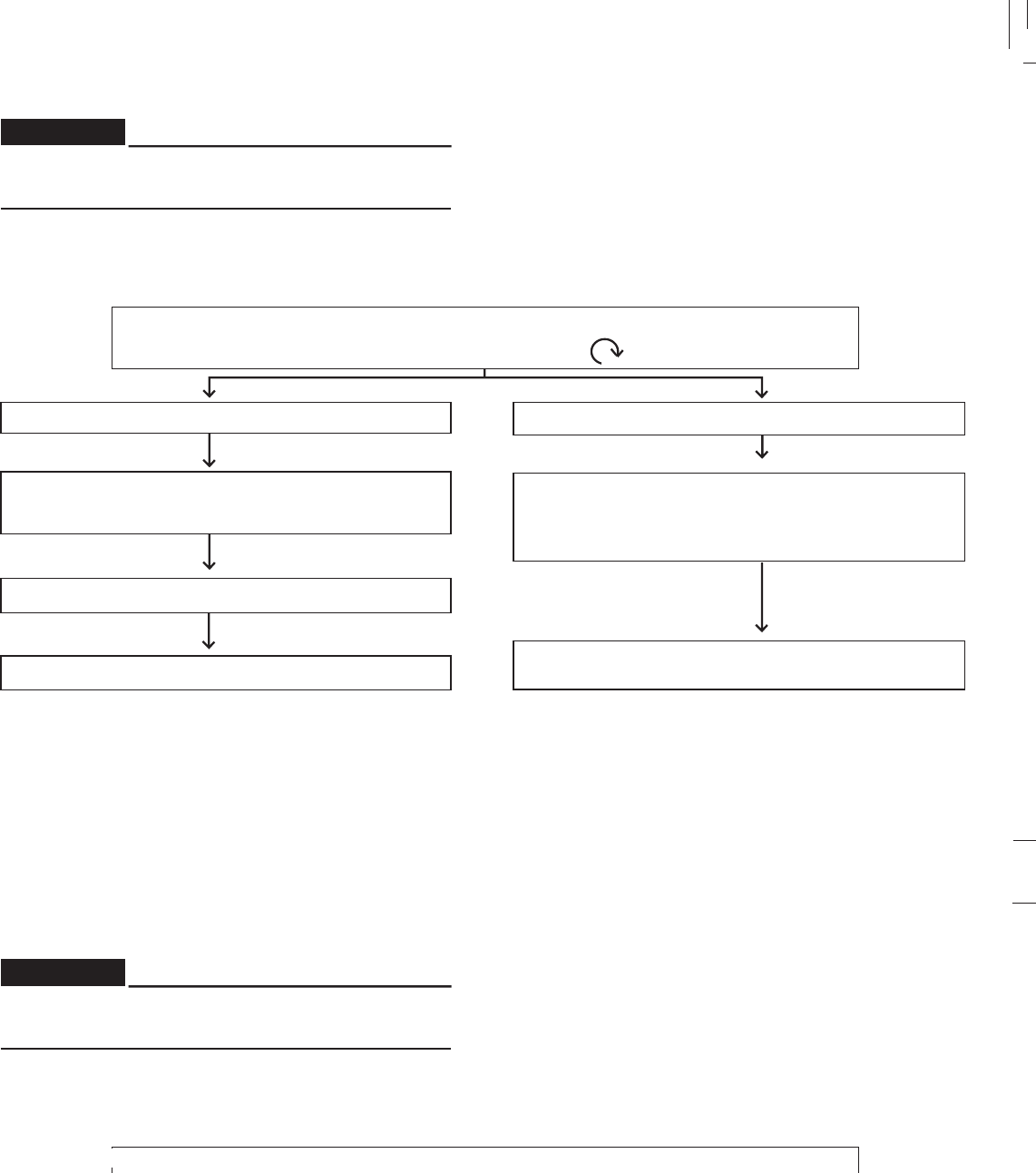
5-4
5-4
Before going through the following steps, check the
function of the clutch switch (See page 3-15)
TURN THE MAIN SWITCH TO “ON” AND
ENGINE STOP SWITCH TO “ ”
IF TRANSMISSION IS IN NEUTRAL IF TRANSMISSION IS IN GEAR
PULL IN CLUTCH LEVER
AND PUSH STARTER SWITCH; ENGINE WILL
START
PUT TRANSMISSION IN GEAR
MOTORCYCLE CAN BE RIDDEN MOTORCYCLE CAN BE RIDDEN
PUSH STARTER SWITCH; ENGINE WILL
START
WARNING:
* Obs.: XTZ 125E

5-5
5-5
Starting a warm engine
The starter lever is not required when the engine is warm.
If the engine fail to start with the procedures above, try to
start it again with the throttle grip opened 1/4 to 1/2.
Warming up the engine
For an extended engine life always warm the engine up
never accelerate hard while the engine is cold.
To check if engine temperature is normal, rev the engine
with the choke closed and check to see if it responds
normally.
CAUTION:
See the “Break-in section” prior to operating the
motorcycle for the first time.
CAUTION:

5-6
5-6
CAUTION:
1. Do not coast for long periods with the engine off,
and do not tow the motorcycle a long distance. Even
with gears in neutral, the transmission is only
properly lubricated when the engine is running.
Inadequate lubrication may damage the
transmission.
2. Always use the clutch when changing gears. The
engine, transmission, and driveline are not
designed to withstand the shock of forced shifting
and can be damaged by shifting without using the
clutch.
Shifting
The transmission lets you control the amount of power you
have available at a given speed for starting, accelerating,
climbing hills, etc. The use of shift pedal is shown in the
illustration (page 3-6).
To shift into NEUTRAL, depress the shift pedal repeatedly
until it reaches the end of its travel (you will feel a stop
when you are in first gear), then raise the pedal slightly.
Downloaded from www.Manualslib.com manuals search engine

5-7
5-7
Engine Break-in
There is never a more important period in the life of your
motorcycle than the period 1.000Km. For this reason we
ask that you carefully read the following material. Because
the engine is brand new, you must not put an excessive
load on it for the first several hours of running.
During this period, prolonged full throttle operation, or any
condition which might result in excessive heating of the
engine must be avoided.
1. 0 ~ 150 Km:
Avoid operation above 1/3 throttle. Stop the engine and
let it cool for 5 to 10 minutes after every hour of
operation. Vary the speed of the motorcycle from time
to time. Do not operate it at one set throttle position.
Your motorcycle’s fuel consumption depends to a large
extent on your riding style. The following tips can help
reduce fuel consumption.
1. Warm up the engine before riding.
2. Turn off the starter lever as soon as possible.
3. Shift up swiftly and avoid high engine speeds during
acceleration.
4. Do not double-clutch or rev the engine while shifting down
and avoid high engine speeds with no load engine.
5. Turn off the engine instead of letting it idle for an extended
lenght of time, i.e. in traffic jams, at traffic lights or railroad
crossings.
Tips for reducing fuel consumption
Engine Break-in
There is never a more important period in the life of your
motorcycle than the period 1.000Km. For this reason we
ask that you carefully read the following material. Because
the engine is brand new, you must not put an excessive
load on it for the first several hours of running.
During this period, prolonged full throttle operation, or any
condition which might result in excessive heating of the
engine must be avoided.
1. 0 ~ 150 Km:
Avoid operation above 1/3 throttle. Stop the engine and
let it cool for 5 to 10 minutes after every hour of
operation. Vary the speed of the motorcycle from time
to time. Do not operate it at one set throttle position.
Your motorcycle’s fuel consumption depends to a large
extent on your riding style. The following tips can help
reduce fuel consumption.
1. Warm up the engine before riding.
2. Turn off the starter lever as soon as possible.
3. Shift up swiftly and avoid high engine speeds during
4. Do not double-clutch or rev the engine while shifting down
and avoid high engine speeds with no load engine.
5. Turn off the engine instead of letting it idle for an extended
lenght of time, i.e. in traffic jams, at traffic lights or railroad
crossings.
Tips for reducing fuel consumption
5-8
5-8
2. 150 ~ 500 Km:
Avoid prolonged operation above 1/2 throttle. Allow the
machine to rev freely through the gears, but do not use
full throttle at any time.
3. 500 ~ 1,000 Km:
Avoid cruising speeds in excess of 3/4 throttle.
CAUTION:
After 1,000Km of operation, be sure to replace the
engine oil.
4. After 1,000 Km:
Avoid prolonged full throttle operation. Vary speeds
occasionally.
Parking
When parking the motorcycle, stop the engine and remove
the ignition key. Turn the fuel cock to “OFF” whenever
stopping the engine.
CAUTION:
If any engine trouble should occur during the break-in
period, consult a Yamaha dealer immediately.
The muffler and exhaust pipe are hot. Park the
motorcycle in a place where pedestrians or children
are not likely to touch the motorcycle. Do not park the
motorcycle on a slope or soft ground; the motorcycle
may fall over.
WARNING:

6-1
6-1
PERIODIC MAINTENANCE AND MINOR REPAIRS
Perodic inspection, adjustment, and lubrication will keep
your motorcycle in the safest and most efficient condition
possible. Safety is an OBLIGATION of the motorcycle
owner.
The maintenance and lubrication schedule chart should
be considered strictly as a guide to general maintenance
and lubrication intervals. YOU MUST TAKE INTO
CONSIDERATION THAT WEATHER, TERRAIN,
GEOGRAPHICAL LOCATIONS, AND A VARIETY OF
INDIVIDUAL USES ALL TEND TO DEMAND THAT EACH
OWNER ALTER THIS TIME SCHEDULE TO SHORTER
INTERVALS TO MATCH THE ENVIRONMENT.
The most important points of motorcycle inspection,
adjustment, and lubrication are explained in the following
pages.
CAUTION:
If you are not familiar with motorcycle service, this work
should be done by a Yamaha dealer.
PERIODIC MAINTENANCE AND MINOR REPAIRS
Perodic inspection, adjustment, and lubrication will keep
your motorcycle in the safest and most efficient condition
possible. Safety is an OBLIGATION of the motorcycle
owner.
The maintenance and lubrication schedule chart should
be considered strictly as a guide to general maintenance
UST TAKE INTO
HER, TERRAIN,
GEOGRAPHICAL LOCATIONS, AND A VARIETY OF
INDIVIDUAL USES ALL TEND TO DEMAND THAT EACH
OWNER ALTER THIS TIME SCHEDULE TO SHORTER
INTERVALS TO MATCH THE ENVIRONMENT.
The most important points of motorcycle inspection,
adjustment, and lubrication are explained in the following
pages.
CAUTION:
If you are not familiar with motorcycle service, this work
should be done by a Yamaha dealer.
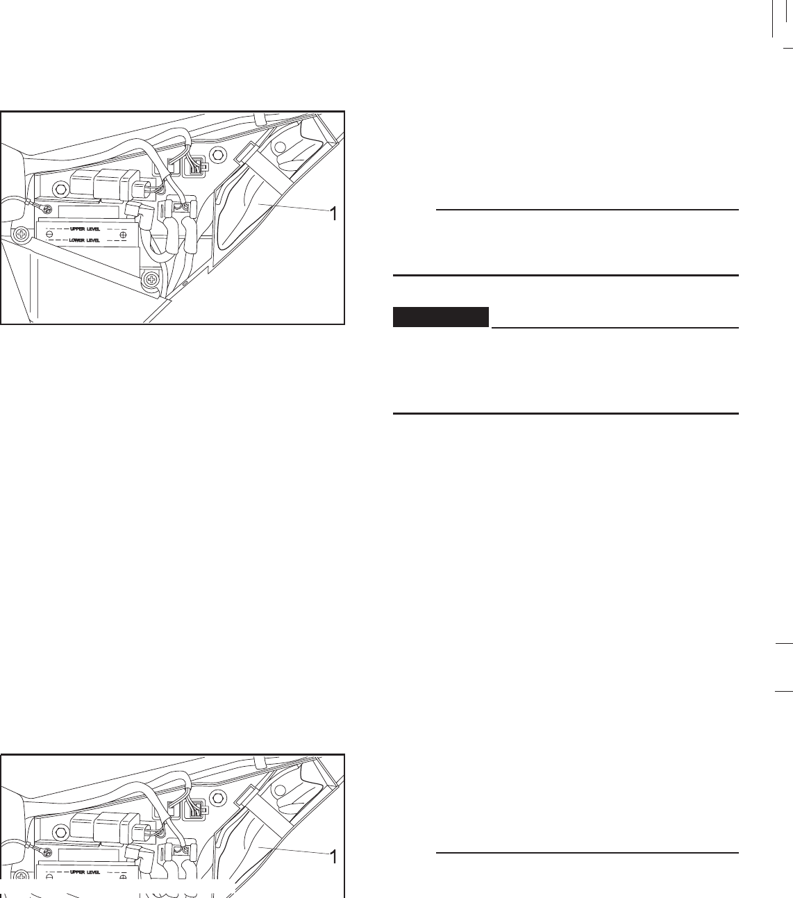
6-2
6-2
Tool kit The tools provided in the owner’s tool kit are to assist you
in the performance of periodic maintenance. However, some
other tools such as a torque wrench are also necessary to
perform the maintenance correctly.
1. Tool kit
NOTE:
If you do not have necessary tools required during a service
operation, take your motorcycle to a Yamaha dealer for
service.
Modifications to this motorcycle not approved by
Yamaha may cause loss of performance, excessive
emissions, and render it unsafe for use. Consult a
Yamaha dealer before attempting any changes.
WARNING:
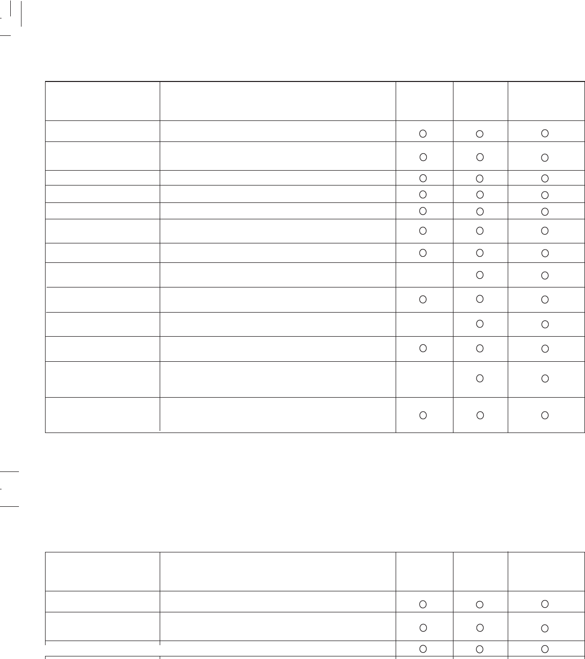
6-3
6-3
PERIODIC MAINTENANCE / LUBRICATION
Wheel bearings*
Battery
Check looseness and damage.
Check electrolyte level, routing breather pipe.
ITEM
How it sounds / Adjust if necessary.
REMARKS 1,000KM
Fuel line
Air filter
Carburetor*
Valves*
Muffler
Brakes*
Engine oil
Steering bearings*
Rear arm pivot*
Check fuel hose, for cracks or damage.
Clean or replace if necessary.
Adjust
Check damage, Retighten.
Check operation, adjust.
Grease the brake cam.
Replace / Check level
Check loosenes.
Repack every 12,000 km or 12 month.**
Check rear arm assembly for looseness.
Moderately repack.***
EVERY
3,000KM
OR ERERY
6 MONTHS
Wheels and tires Check tire pressure, runout and spoke tightness.
Spark plug Check condition and clean if necessary.
Replace if necessary every 12,000 Km.
3,000KM
PERIODIC MAINTENANCE / LUBRICATION
Wheel bearings*
Battery
Check looseness and damage.
Check electrolyte level, routing breather pipe.
ITEM
How it sounds / Adjust if necessary.
REMARKS 1,000KM
Fuel line
Carburetor*
Valves*
Muffler
Brakes*
Engine oil
Steering bearings*
Rear arm pivot*
Check fuel hose, for cracks or damage.
lace if necessary.
Adjust
Check damage, Retighten.
Check operation, adjust.
Grease the brake cam.
Replace / Check level
Check loosenes.
Repack every 12,000 km or 12 month.**
Check rear arm assembly for looseness.
Moderately repack.***
EVERY
3,000KM
OR ERERY
6 MONTHS
Wheels and tires Check tire pressure, runout and spoke tightness.
Spark plug Check condition and clean if necessary.
Replace if necessary every 12,000 Km.
3,000KM
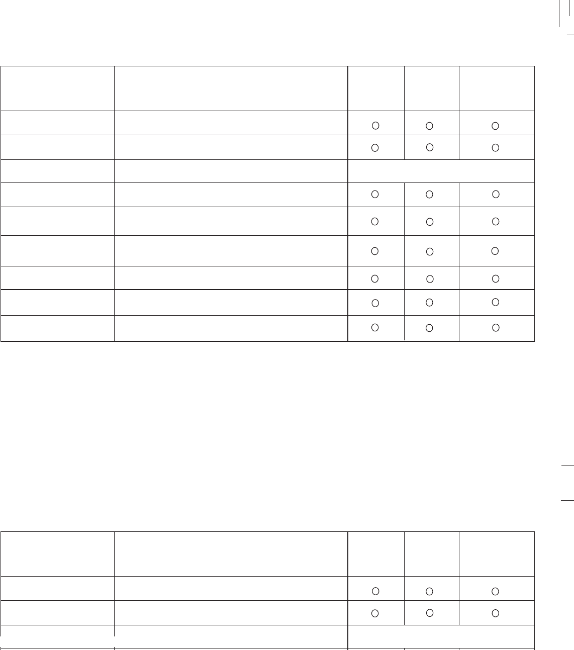
6-4
6-4
* : It is recommended that these items be serviced by a Yamaha dealer.
** : Molybdenum disulfide grease.
*** : Lithium soap based grease.
NOTE: ______________________________________________________________________________________________
Brake fluid replacement:
_______________________________________________________________________________________________________________________________________________________________________________________________________________________________________________________________
1. When disassembling the master cylinder or caliper cylinder, replace the brake fluid. Normally check the brake fluid level and add fluid as required.
2. On the inner parts of the master cylinder and caliper cylinder, replace the oil seals every two years.
3. Replace the brake hoses every four years, or if cracked or damaged.
ITEM
Front forks*
Sidestand
Control cables: throttle /
clutch / front brake
Rear shock absorber*
Drive chain
Fittings / fasteners
Check operation / oil leakage.
Check operation, looseness.
Adujst / Check operation
Lubricate every 12,000 Km.
Check chain slack / lubricate, adjust if necessary.
Check looseness.
REMARKS 1,000KM
Lights and flashers
Nuts and bolts
Motorcycle Aspect
Check operation.
Check tighten.
General Check
EVERY
3,000KM
OR EVERY
6 MONTHS
3,000KM
Check operation / oil leakage.
Every 500 Km
* : It is recommended that these items be serviced by a Yamaha dealer.
** : Molybdenum disulfide grease.
*** : Lithium soap based grease.
NOTE: ______________________________________________________________________________________________
Brake fluid replacement:
_______________________________________________________________________________________________________________________________________________________________________________________________________________________________________________________________
1. When disassembling the master cylinder or caliper cylinder, replace the brake fluid. Normally check the brake fluid level and add fluid as required.
2. On the inner parts of the master cylinder and caliper cylinder, replace the oil seals every two years.
3. Replace the brake hoses every four years, or if cracked or damaged.
ITEM
Front forks*
Sidestand
Control cables: throttle /
clutch / front brake
Rear shock absorber*
Fittings / fasteners
Check operation / oil leakage.
Check operation, looseness.
Adujst / Check operation
Lubricate every 12,000 Km.
slack / lubricate, adjust if necessary.
Check looseness.
REMARKS 1,000KM
Lights and flashers
Nuts and bolts
Motorcycle Aspect
Check operation.
Check tighten.
General Check
EVERY
3,000KM
OR EVERY
6 MONTHS
3,000KM
Check operation / oil leakage.
Every 500 Km
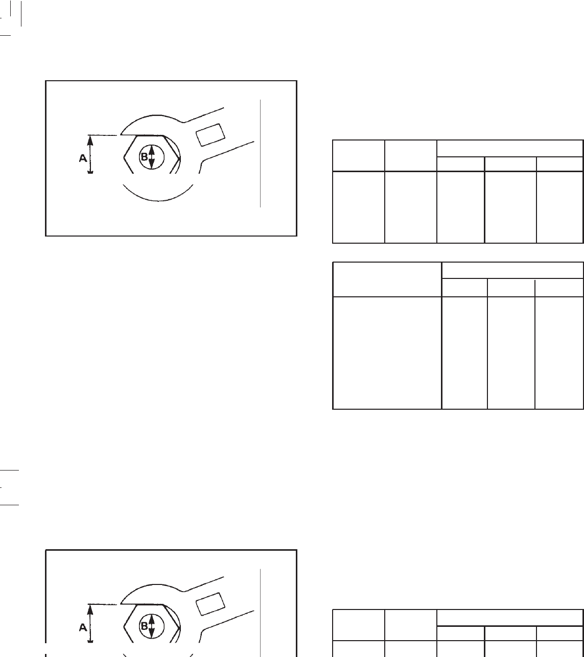
6-5
6-5
Spark plug 12.5 1.25 9.0
Engine oil drain plug 20 2.0 14.5
Oil check bolt 7 0.7 5.0
Front wheel axle nut 80 8.0 58
Rear wheel axle nut 80 8.0 58
Use a torque wrench to tighten these items. It is
recommended that these items be checked occasionally,
specially before a long trip. Always check the tightness of
these items whenever they are loosened for any reason.
A
(Nut)
10 mm
12 mm
14 mm
17 mm
19 mm
22 mm
B
(Bolt)
6 mm
8 mm
10 mm
12 mm
14 mm
16 mm
General torque especifications
Nm
6
15
30
55
85
130
kgf.m
0,6
1,5
3,0
5,5
8,5
13,0
lbf. ft
4,3
11
22
40
61
94
Torque specifications
Torque
Nm kgfm
Item Nm
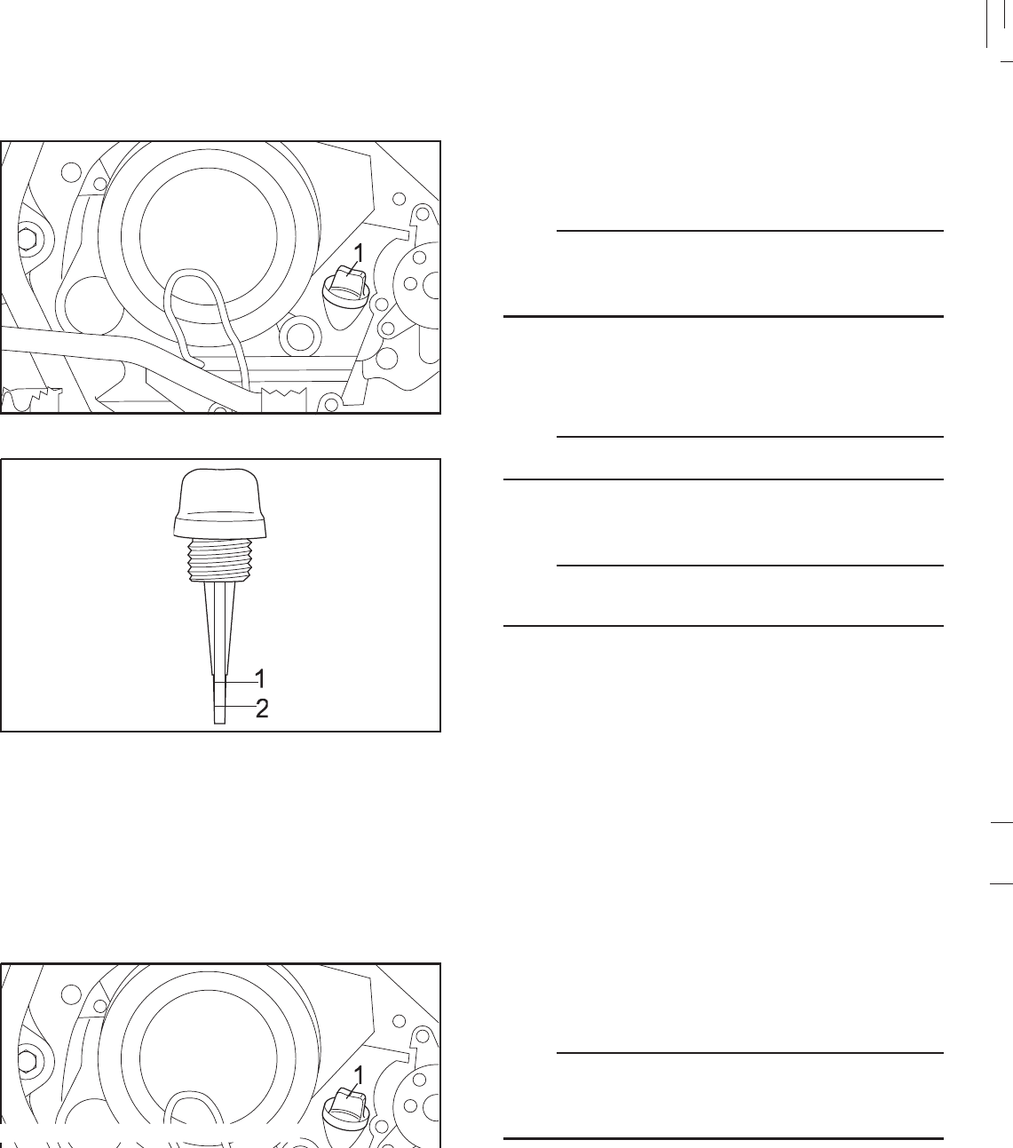
6-6
6-6
1. Engine oil filler cap
1. Maximum mark 2.Minimum mark
1. Oil level measurement
a. Place the motorcycle on a level place and hold it in an
upright position. Warm up the engine for several
minutes.
NOTE:
Be sure the motorcycle is positioned straight up when
checking the oil level. A slight tilt toward the side can result
in false readings.
b. With the engine stopped, with the engine stopped,
unscrew the oil filler cap/ dispstick and rest it on the
threads of the ok.
NOTE:
Wait a few minutes until the oil level settles before checking.
c. remove the oil filler cap/ dispstick, clean it with a dry
cloth and check the oil level.
NOTE:
To check the oil level the oil filler cap/ dispstick can not be
screwed, just lightly seated in place.
d. The oil level should be between the maximum and
minimum marks. If the level is low, add oil to raise it to
the indicated level, check for oil leakage.
Engine oil
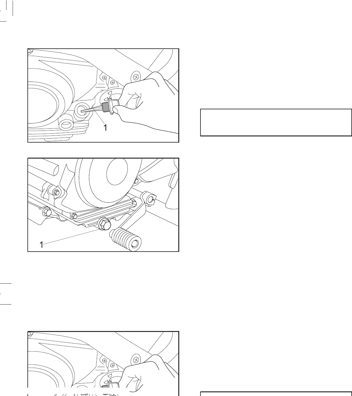
6-7
6-7
a. Warm up the engine for a few minutes.
b. Stop the engine. Place an oil pan under the engine and
remove the dipstick.
c. Remove the drain plug and drain the oil.
d. Reinstall the drain plug, check if the gasket is damaged
and lighten it to the specified torque.
1.Dipstick
1. Engine oil drain plug
2. Engine oil and filter replacement
Tightening torque:
Drain plug:
20 N.m (2.0 kgf.m, 14.5 lbf.t)
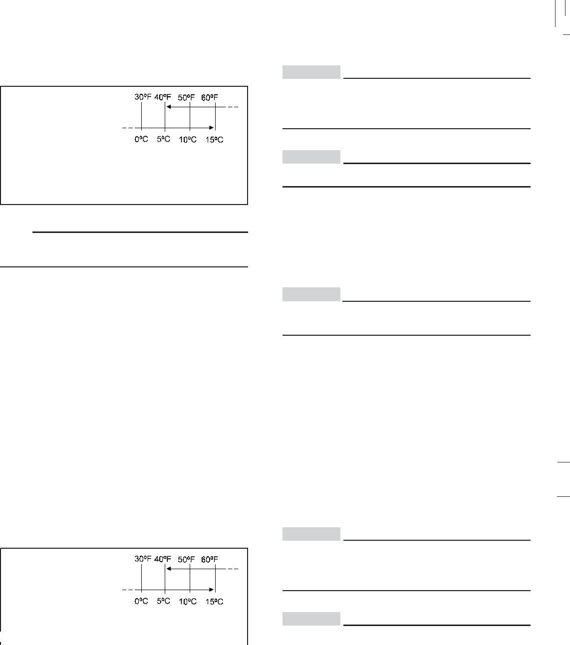
6-8
6-8
e.Fill engine with oil. Install the oil filter cap and tighten.
NOTE:
Recommended engine oil classification; API Service “SH”
type or equivalent
Recommended oil:
YAMALUBE 4
Oil quantity:
Total amount:
1.2 L ( 0.264 Imp gal, 0.317 US gal)
Periodic oil change:
1.0 L ( 0.220 Imp gal, 0.264 US gal)
f. Start the engine and warm up for a few minutes. While
warming up, check for oil leakage. If oil leakage is found,
stop the engine immediately, and check for the cause.
g. Stop the engine and check the oil level.
CAUTION:
Be sure no foreign material enters the crankcase.
CAUTION:
Do not put in any chemical additives. Engine oil also
lubricates the clutch and additives could cause clutch
slippage.
After replacing the engine oil, be sure to check the oil
pressure.
CAUTION:
e.Fill engine with oil. Install the oil filter cap and tighten.
NOTE:
Recommended engine oil classification; API Service “SH”
type or equivalent
Recommended oil:
YAMALUBE 4
Oil quantity:
Total amount:
1.2 L ( 0.264 Imp gal, 0.317 US gal)
1.0 L ( 0.220 Imp gal, 0.264 US gal)
f. Start the engine and warm up for a few minutes. While
warming up, check for oil leakage. If oil leakage is found,
stop the engine immediately, and check for the cause.
g. Stop the engine and check the oil level.
CAUTION:
Be sure no foreign material enters the crankcase.
CAUTION:
Do not put in any chemical additives. Engine oil also
lubricates the clutch and additives could cause clutch
slippage.
After replacing the engine oil, be sure to check the oil
pressure.
CAUTION:
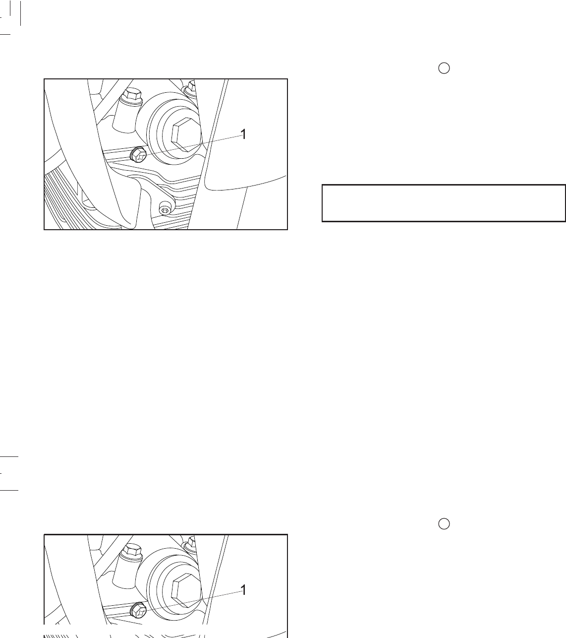
6-9
6-9
Oil pressure 1. Remove the check bolt 1 in the cylinder head.
2. Start the engine and keep it idling until oil flows out of
the bleed hole. If no oil comes out after one minute,
turn off the engine immediately so it will not seize. In
such a case go to the nearest Yamaha dealer or other
qualified mechanic for repairs.
3. After checking, tighten the check bolt to the specified
torque.
Check bolt torque:
7 N.m (0.7 Kgf.m, 5.0 lbf.ft)
1. Check bolt
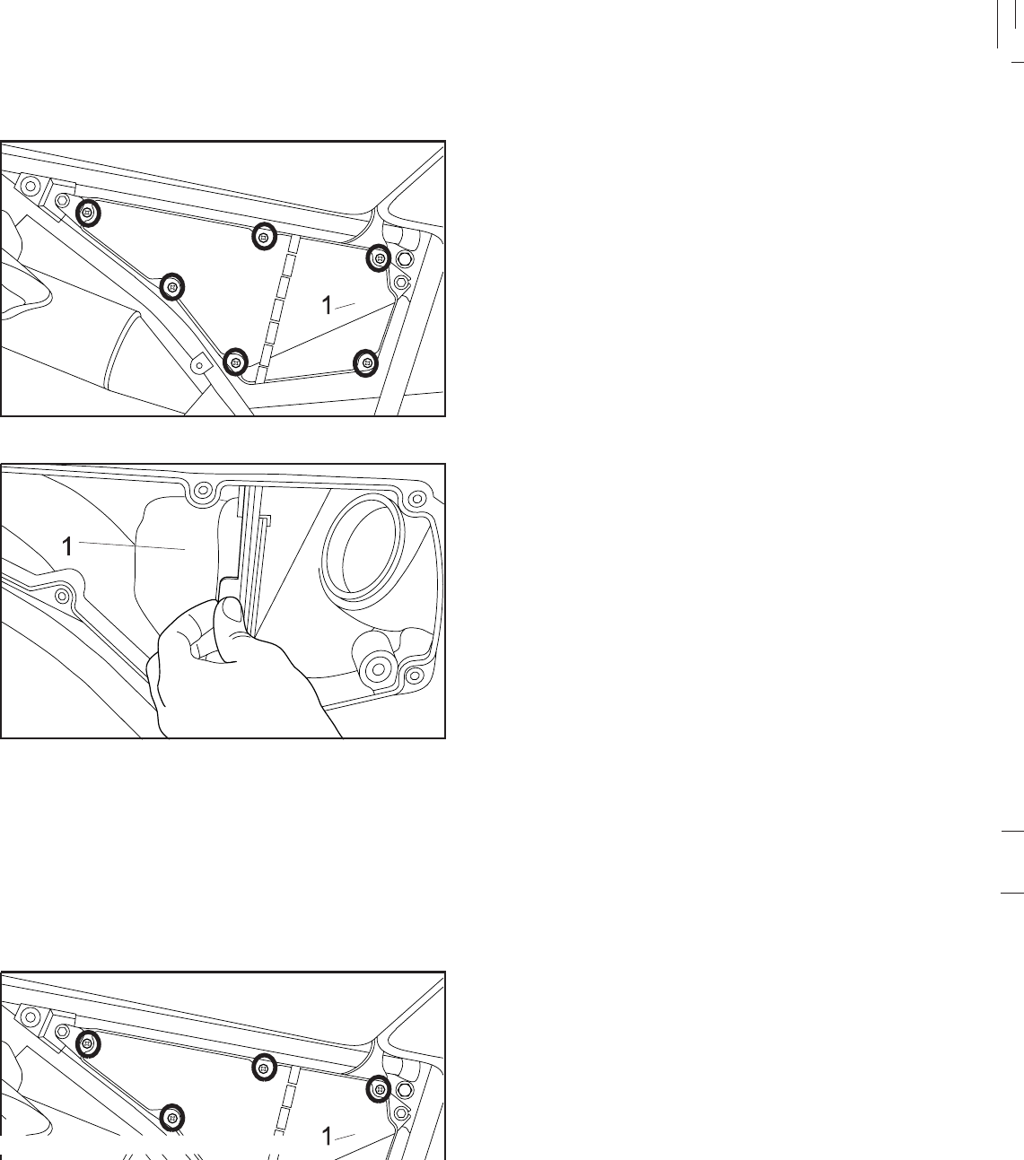
6-10
6-10
The air filter should be cleaned at the specified intervals.
It should be cleaned more frequently if you are riding in
unusually wet or dusty areas.
1. Remove the right side cover.(pag. 3-13)
2. Remove the air filter case cover by removing the bolts.
3. Remove the air filter from the case.
Air filter
1. Side cover 2. Bolts
1. Air filter
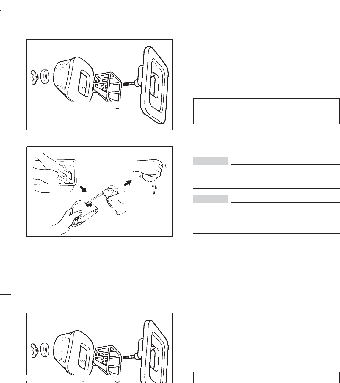
6-11
6-11
CAUTION:
Make sure the element is properly seated in the air filter
case.
CAUTION:
The engine should never be run without the air filter
element installed; excessive piston and/or cylinder wear
may result.
Recommended oil:
Engine oil 20W50
4. Remove the air filter element from the guide and clean
it with solvent. After cleaning, remove the remaining
solvent by squeezing the air filter
5. Apply recommended oil to the entire surface of the filter
and squeeze out the excess oil. The air filter should be
wet but not dripping.
6. Reinstall the air filter in its case.
7. Install the air filter case cover and the right side cover.
CAUTION:
Make sure the element is properly seated in the air filter
case.
CAUTION:
The engine should never be run without the air filter
element installed; excessive piston and/or cylinder wear
may result.
Recommended oil:
Engine oil 20W50
4. Remove the air filter element from the guide and clean
it with solvent. After cleaning, remove the remaining
solvent by squeezing the air filter
5. Apply recommended oil to the entire surface of the filter
and squeeze out the excess oil. The air filter should be
wet but not dripping.
6. Reinstall the air filter in its case.
7. Install the air filter case cover and the right side cover.

6-12
6-12
Valve clearance adjustment
The correct valve clearance changes with use, resulting in
improper fuel/air supply or engine noise. To prevent this,
valve clearance must be adjusted regularly. This adjustment,
however, should be left to a professional Yamaha service
technician.
Carburetor adjustment
The carburetor is a vital part of the engine. Adjusting should
be left to a Yamaha dealer who has the professional
knowledge, specialized data, and equipment to do so
properly. However, the following may be serviced by the
owner as part of routine maintenance.
CAUTION:
The carburetor was set at Yamaha factory after many
tests. If the settings are changed, poor engine
performance and damage may result.
Valve clearance adjustment
The correct valve clearance changes with use, resulting in
improper fuel/air supply or engine noise. To prevent this,
valve clearance must be adjusted regularly. This adjustment,
however, should be left to a professional Yamaha service
technician.
Carburetor adjustment
The carburetor is a vital part of the engine. Adjusting should
be left to a Yamaha dealer who has the professional
knowledge, specialized data, and equipment to do so
properly. However, the following may be serviced by the
owner as part of routine maintenance.
The carburetor was set at Yamaha factory after many
tests. If the settings are changed, poor engine
performance and damage may result.
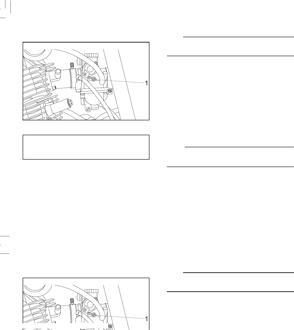
6-13
6-13
NOTE:
A diagnostic tachometer must be used for this
procedure.
Standard idle speed:
1,300 ~ 1,500 r/min NOTE:
If the specified idle speed cannot be obtained by performing
the above adjustment, consult a Yamaha dealer.
1. Throttle stop screw
Idle speed adjustment
1. Attach the tachometer. Start the engine and warm it up
for a few minutes (normally, 1 or 2 minutes) at
approximately 1,000 to 2,000 r/min. Occasionally rev
the engine to 4,000 to 5,000 r/min. The engine is warm
when it quickly responds to the throttle.
2. Set the idle to the specified engine speed by adjusting
the throttle stop screw; turn the screw in to increase
engine speed and out to decrease engine speed.
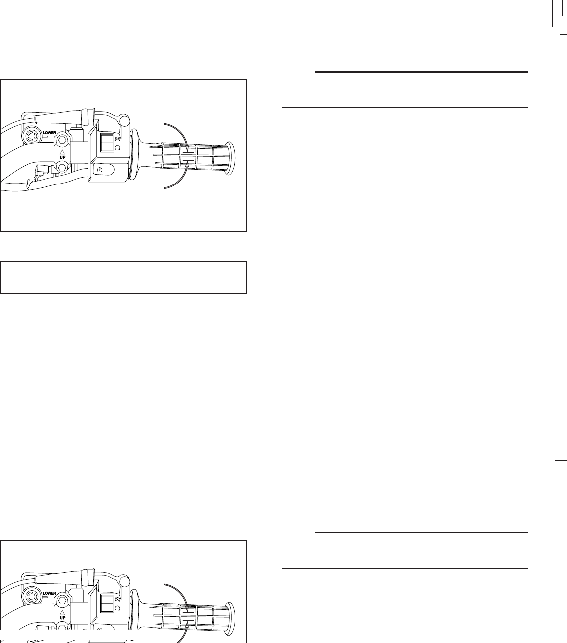
6-14
6-14
NOTE:
Before checking the throttle cable free play, the engine
idling speed should be adjusted.
Free play:
3 ~ 5 mm (0.12 ~ 0.19 in)
Throttle cable adjustment
The throttle cable should have an specified free play in the
turning direction at the grip flange. If the free play is incorrect,
1. Free play
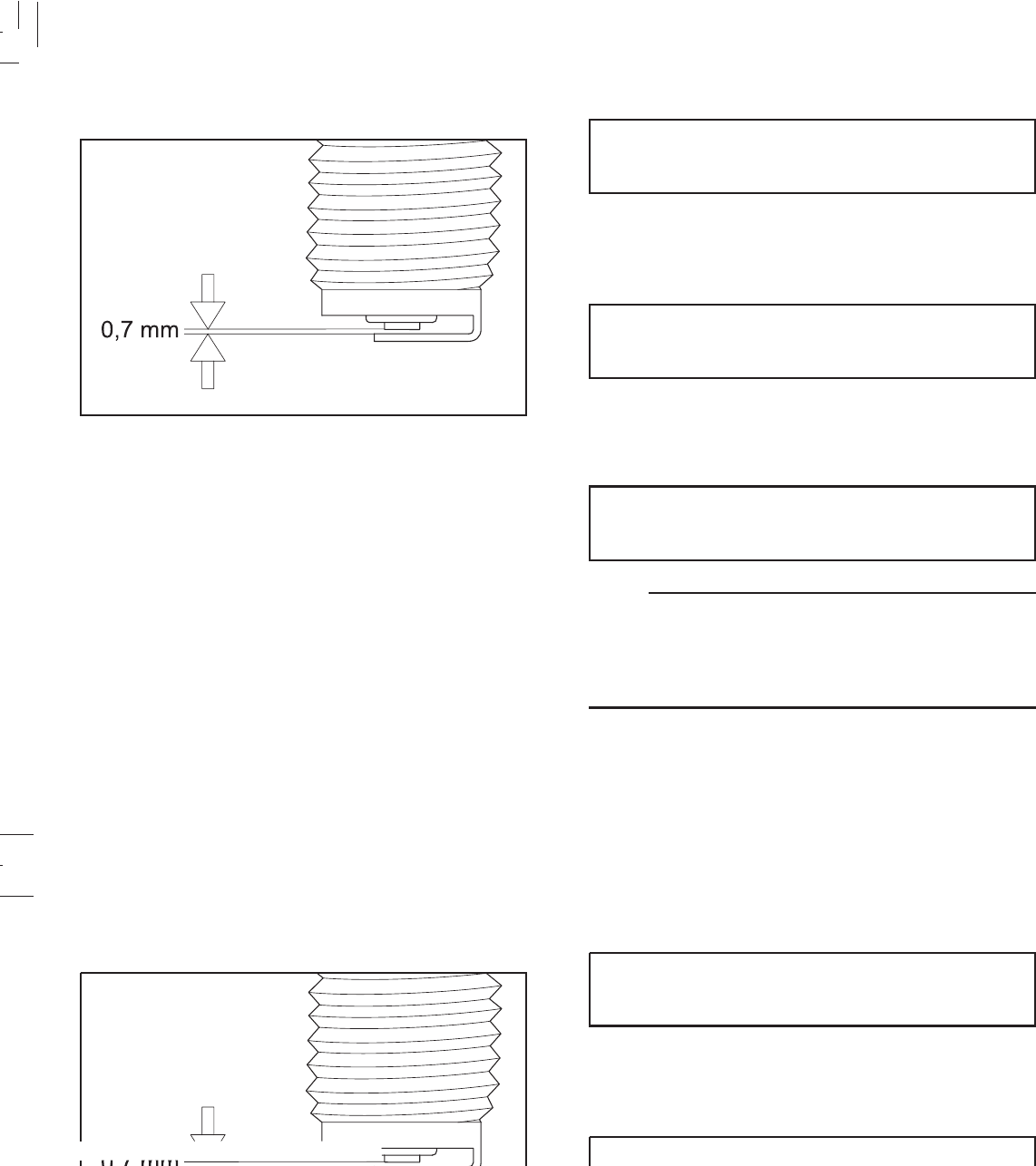
6-15
6-15
Before installing the spark plug, measure the electrode gap
with a wire thickness gauge and adjust the gap to
specification as necessary.
Standard spark plug:
CR7HSA (NGK) and U22FSR-U (DENSO)
1.Spark plug gap
Spark plug gap:
0.7 mm ( 0.028 in)
Spark plug inspection
The spark plug is an important engine component and is
easy to inspect. The condition of the spark plug can indicate
the condition of the engine.
The ideal color on the white porcelain insulator around the
center electrode is a medium to light tan color for a
motorcycle that is being ridden normally. Do not attempt to
diagnose any problems yourself. Instead, take the
motorcycle to a Yamaha dealer. You should periodically
remove and inspect the spark plug because heat and
deposits will cause the spark plug to slowly break down
and erode.
If electrode erosion becomes excessive, or if carbon and
other deposits are excessive, you should replace the spark
plug with the specified plug.
NOTE:
If a torque wrench is not available when you are installing a
spark plug, a good estimate of the correct torque is 1/4 to
1/2 turn past finger tight. Have the spark plug torqued to
the correct value as soon as possible with a torque wrench.
When installing the plug, always clean the gasket surface
and use a new gasket. Wipe off any grime from the threads,
and torque the spark plug properly.
Spark plug torque:
12.5 N.m (1.25 Kgf.m, 9 lbf.ft)
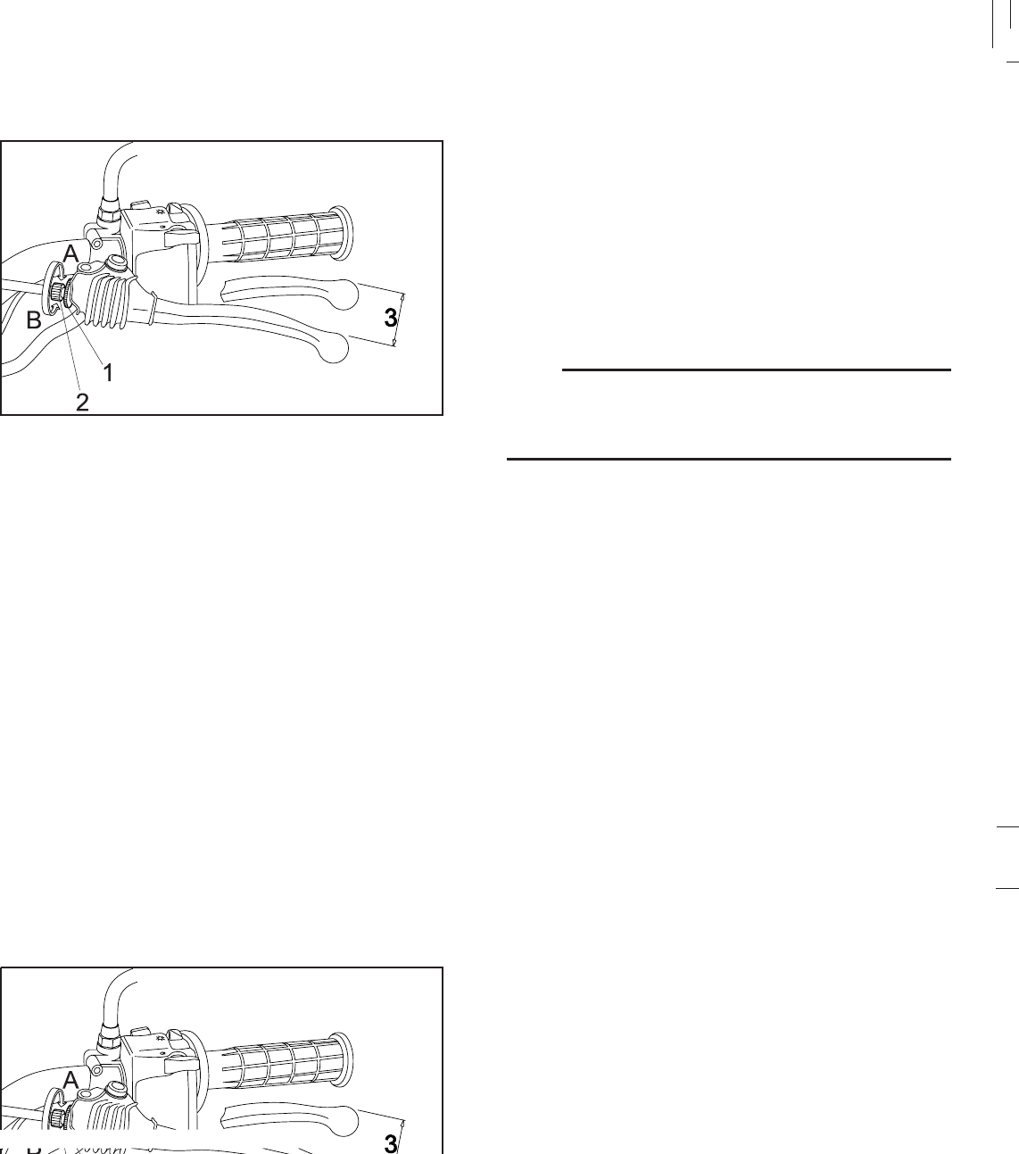
6-16
6-16
Clutch adjustment
1. Locknut 2. Adjuster a. Free play
The clutch lever free play should be adjusted to 10 ~ 15
mm (0.4 ~ 0.6 in) at the clutch lever end. If the free play is
incorrect, adjust as follows.
1. Loosen the locknut at the handlebar.
2. Turn the adjuster in (A) or out (B) until proper lever free
play is obtained.
3. Tighten the locknut.
4. If the free play is still incorrect, make an adjustment at
the crankcase side.
NOTE:
If proper adjustment cannot be obtained or the clutch does
not work correctly, ask a Yamaha dealer to inspect the
internal clutch mechanism.
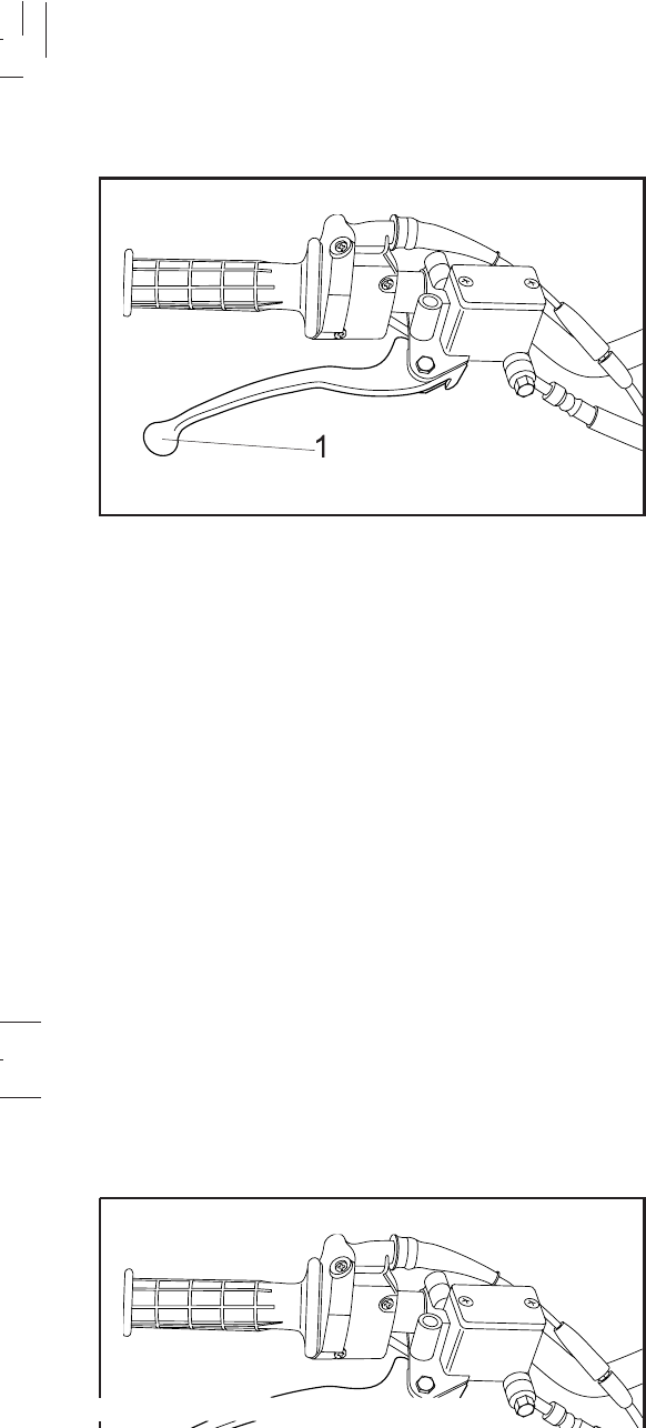
6-17
6-17
Front brake adjustment A soft or spongy feeling in the brake lever can indicate the
presence of air in the brake system. This air must be
removed by bleeding the brake system before the
motorcycle is operated. Air in the brake system will
considerably reduce braking performance and could result
in a loss of control and possibly an accident. Inspect and if
necessary, bleed the brake system.
1. Front lever
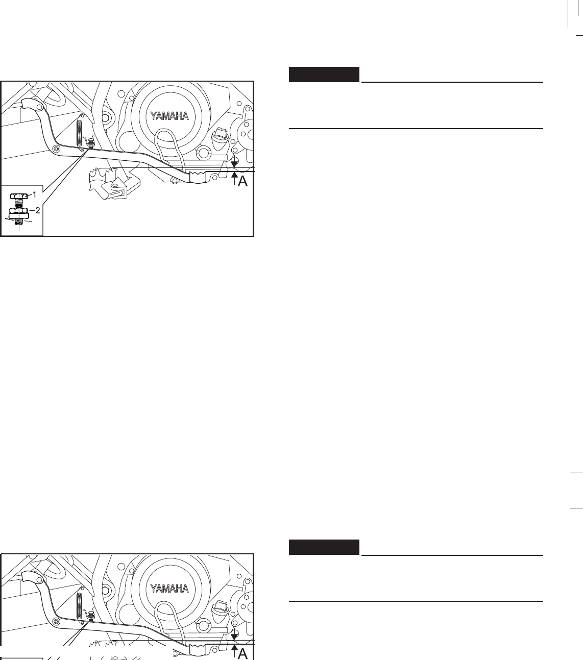
6-18
6-18
For brake pedal adjustment, be sure to proceed as
follows (it is advisable to have a Yamaha dealer make
this adjustment.)
1. Pedal height.
a. Loosen the locknut.
b. By turning the adjuster clockwise or counterclockwise
adjust the brake pedal position so that its top end is
approximatelly 2 mm (0.08 in) below the footrest top
end.
c. Tighten the locknut.
Rear brake adjustment
1. Adjusting nut 2. locknut
a. Pedal height: 2 mm( 0.08 in)
WARNING:
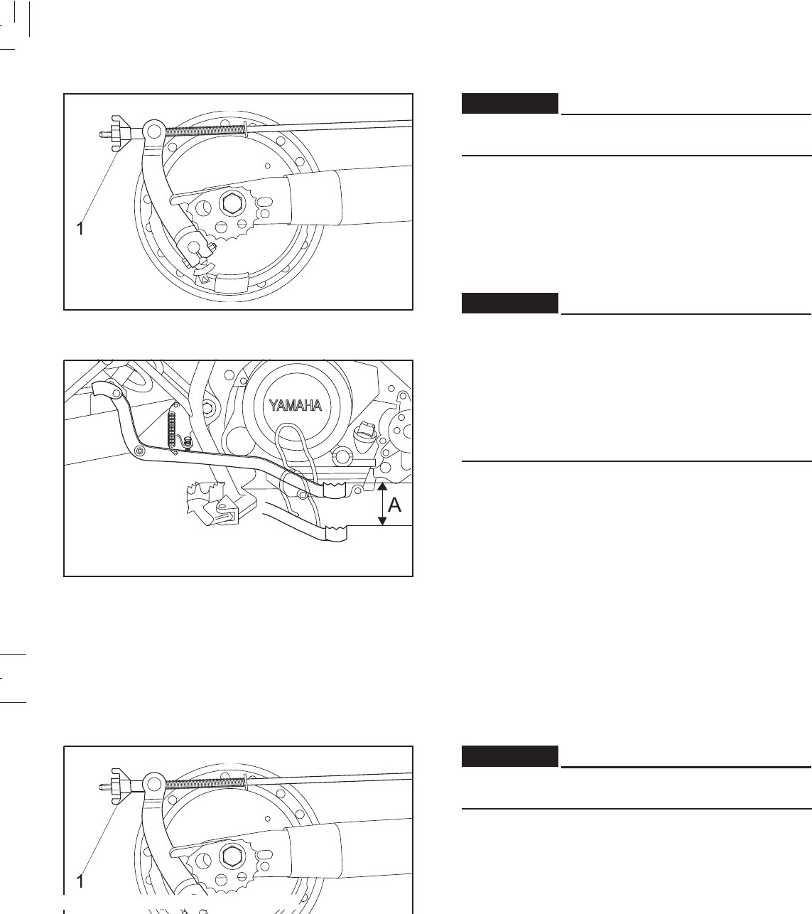
6-19
6-19
ADVERTENCIA
After adjusting the pedal height adjust brake pedal free
play.
2. Freeplay.
The rear brake pedal free play should be adjusted to
20 ~ 30 mm (0.8 ~ 1.2 in) at the brake pedal end. Turn
the adjuster on the brake rod clockwise to reduce play
or counterclockwise to increase play.
ADVERTENCIA
Brake pedal free play should be checked whenever the
chain is adjusted or the rear wheel is removed and then
reinstalled.
If it is impossible to make proper adjustment, consult
a Yamaha dealer.
Check the operation of the brake light after adjusting
the rear brake.
1. Adjuster
a.Free play: 20 ~ 30 mm ( 0.8 ~ 1.2 in)
WARNING:
WARNING:
ADVERTENCIA
After adjusting the pedal height adjust brake pedal free
play.
2. Freeplay.
The rear brake pedal free play should be adjusted to
20 ~ 30 mm (0.8 ~ 1.2 in) at the brake pedal end. Turn
the adjuster on the brake rod clockwise to reduce play
or counterclockwise to increase play.
ADVERTENCIA
Brake pedal free play should be checked whenever the
chain is adjusted or the rear wheel is removed and then
reinstalled.
If it is impossible to make proper adjustment, consult
a Yamaha dealer.
Check the operation of the brake light after adjusting
the rear brake.
1. Adjuster
a.Free play: 20 ~ 30 mm ( 0.8 ~ 1.2 in)
WARNING:
WARNING:
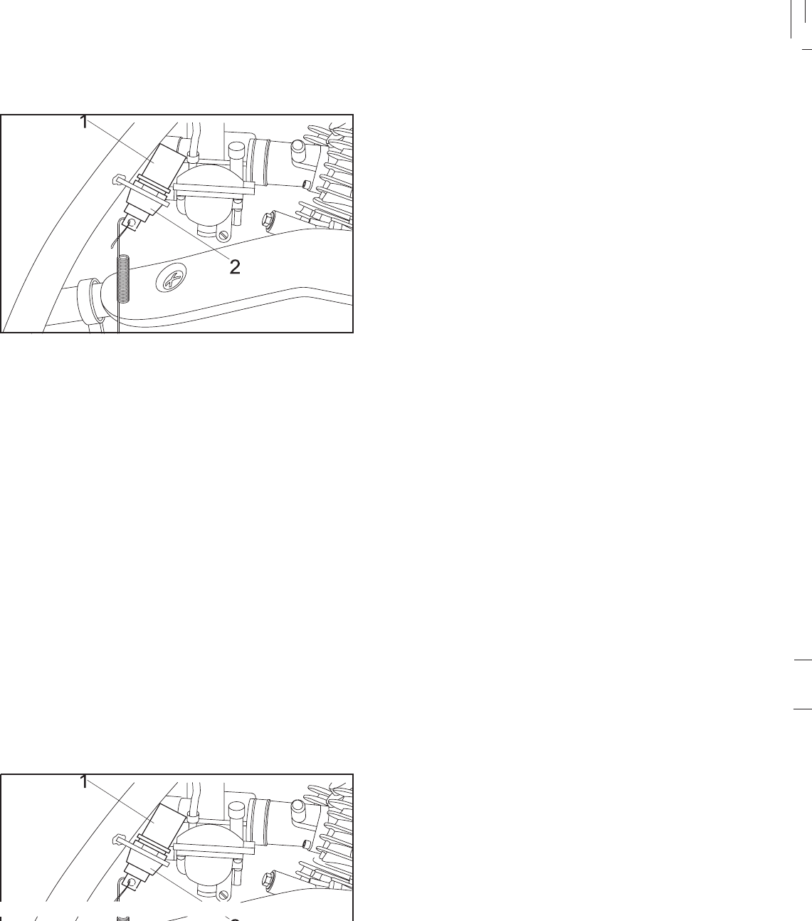
6-20
6-20
Brake light switch adjustment
The rear brake light switch is activated by the brake pedal
and is properly adjusted when the brake light comes on
just before braking takes effect. To adjust the rear brake
light switch, hold the switchbody so it does not rotate while
turning the adjusting nut.
Turn the adjusting nut in direction = to make the brake
light come on earlier.
Turn the adjusting nut in direction > to make the brake
light come on later.
Checking the front brake pads and rear brake shoes
A wear indicator is provided on each brake. This indicator
allows checking of brake pad/shoe wear without
disassembling the brake.
1. Brake light switch 2. Adjusting nut
=
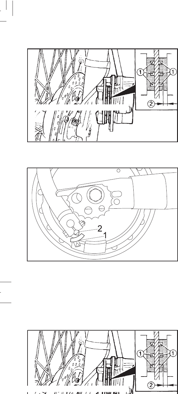
6-21
6-21
Apply the brake and inspect the wear indicator. If the
indicator reaches the wear limit line, ask a Yamaha dealer
to replace the shoes.
1. Wear indicator 2. Wear limit
Rear Brake
Apply the brake and inspect the wear indicator. If the wear
indicator is almost in contact with the disc plate, ask a
Yamaha dealer to replace the pads.
Front Brake
1. Wear limit line 2. Wear indicator
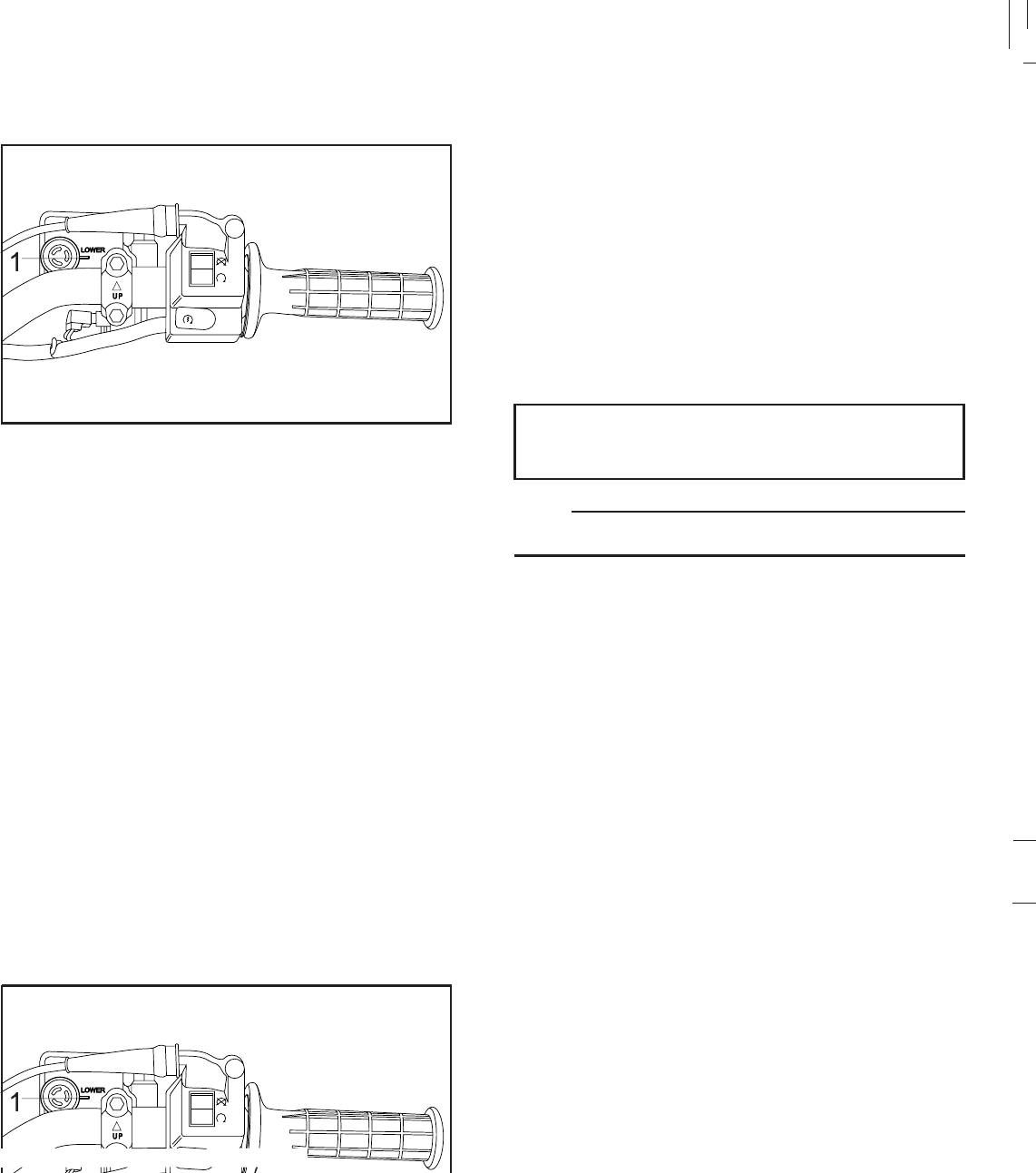
6-22
6-22
Inspecting the brake fluid level Insufficient brake fluid may let air enter the brake system,
possibly causing the brakes to become ineffective. Before
riding, check that the brake fluid is above the lower level
and replenish when necessary. Observe these precautions:
1. Lower level
1. When checking the fluid level, make sure the top of the
master cylinder is level by turning the handlebars.
2. Use only the designated quality brake fluid. Otherwise,
the rubber seals may deteriorate, causing leakage and
poor brake performance.
Recommended brake fluid:
DOT #4
NOTE:
If DOT #4 is not available, #3 can be used.

6-23
6-23
3. Refill with the same type of brake fluid. Mixing fluids
may result in a harmful reaction and lead to poor brake
performance.
4. Be careful that water does not enter the master cylinder
when refilling. Water will significantly lower the boiling
point of the fluid and may result in vapor lock.
5. Brake fluid may deteriorate painted surfaces or plastic
parts. Always clean up spilled fluid immediately.
6. Have a Yamaha dealer check the cause if the brake
fluid level goes down.
1. Complete fluid replacement should be done only by
trained service personnel.
2. Have a Yamaha dealer replace the following
components during periodic maintenance or when they
are damaged or leaking.
a. Replace all rubber seals every two years.
b. Replace all hoses every four years.
Brake fluid replacement
3. Refill with the same type of brake fluid. Mixing fluids
may result in a harmful reaction and lead to poor brake
performance.
4. Be careful that water does not enter the master cylinder
when refilling. Water will significantly lower the boiling
point of the fluid and may result in vapor lock.
5. Brake fluid may deteriorate painted surfaces or plastic
immediately.
6. Have a Yamaha dealer check the cause if the brake
fluid level goes down.
1. Complete fluid replacement should be done only by
trained service personnel.
2. Have a Yamaha dealer replace the following
components during periodic maintenance or when they
are damaged or leaking.
a. Replace all rubber seals every two years.
b. Replace all hoses every four years.
Brake fluid replacement
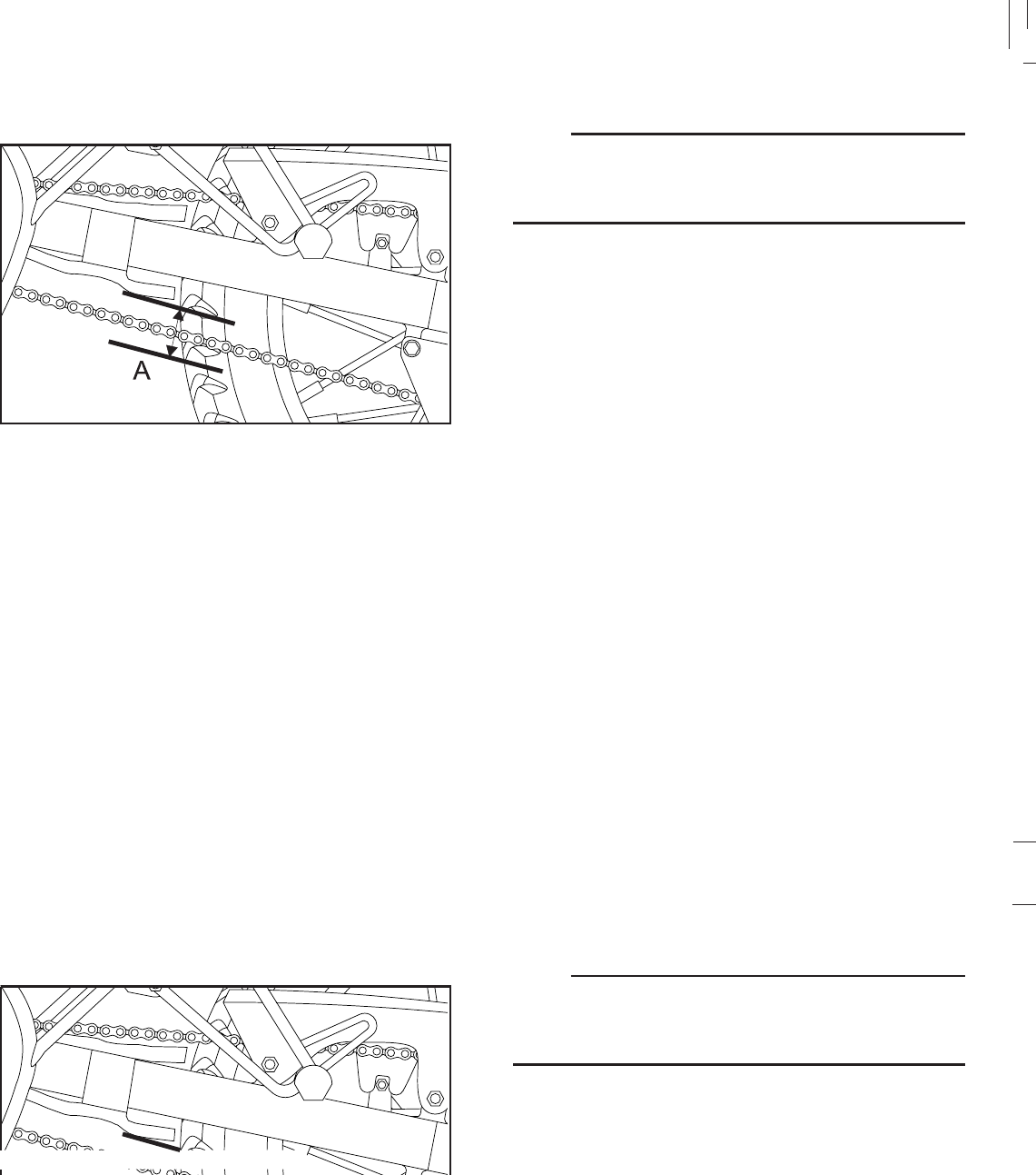
6-24
6-24
NOTE:
Spin the wheel several times and find the tightest position
of the chain. Check and/or adjust the chain slack while it is
in this tightest position.
To check the chain slack the motorcycle must be held
straight up with both wheels on the ground and without rider.
Check the slack at the position shown in the illustration.
Normal slack is approximately 40 ~ 55 mm (1,6 ~ 2,2 in). If
the slack exceeds 55 mm ( 2,2 in), adjust.
Drive chain slack check
a.Free play
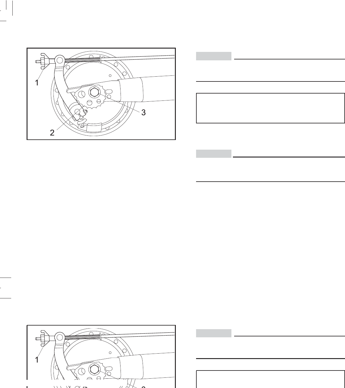
6-25
6-25
CAUTION:
Too little chain slack will overload the engine and other
vital parts. Keep the slack within the specified limits.
Axle nut torque:
80 N.m (8.0 Kgf.m, 58 lbf.ft)
5. Adjust the free play in the brake pedal.
CAUTION:
Check the operation of the brake light after adjusting
the rear brake.
1. Loosen the rear brake adjuster.
2. Loosen the axle nut.
3. Turn both left and right chain puller the same
amount.Make sure that they are in the same position
for proper wheel alignment.
Drive chain slack adjustment
1. Adjuster 2. Chain puller 3. Axle nut
4. After adjusting, be sure to tighten the axle nut.
CAUTION:
Too little chain slack will overload the engine and other
vital parts. Keep the slack within the specified limits.
Axle nut torque:
80 N.m (8.0 Kgf.m, 58 lbf.ft)
5. Adjust the free play in the brake pedal.
CAUTION:
Check the operation of the brake light after adjusting
the rear brake.
1. Loosen the rear brake adjuster.
2. Loosen the axle nut.
3. Turn both left and right chain puller the same
amount.Make sure that they are in the same position
for proper wheel alignment.
Drive chain slack adjustment
1. Adjuster 2. Chain puller 3. Axle nut
4. After adjusting, be sure to tighten the axle nut.
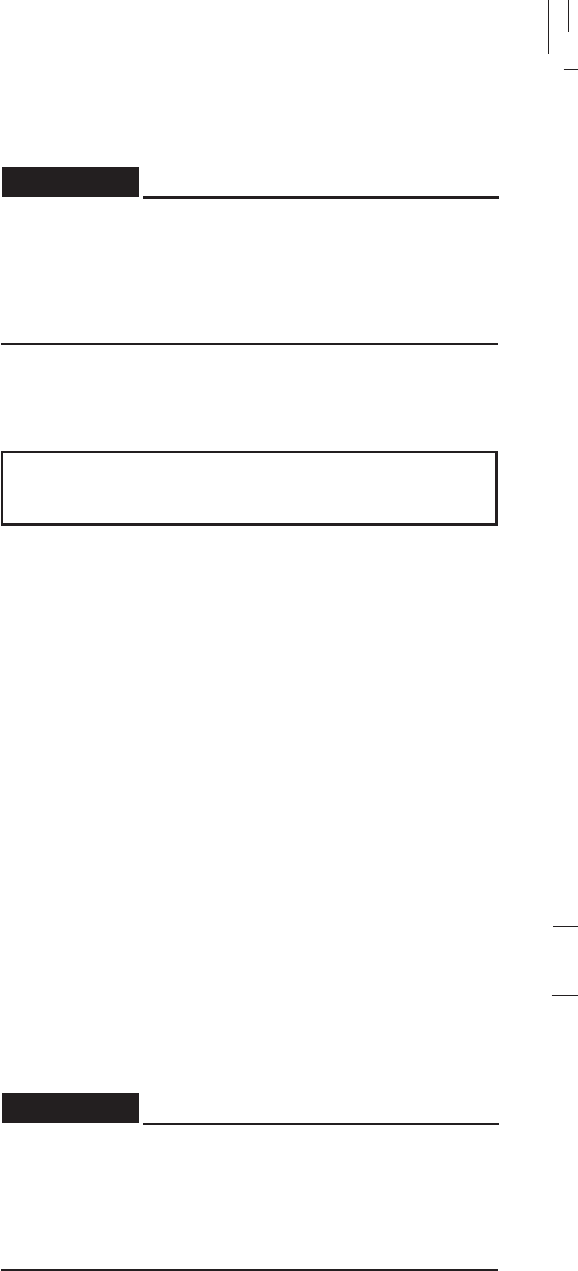
6-26
6-26
Cable inspection and lubricationDrive chain lubrication
The chain consists of many parts which work with each
other. If the chain is not maintained properly, it will wear out
quickly. Therefore, the chain must be serviced regularly.
This service is especially necessary when riding in dusty
areas.
1. Use Yamaha Chain and Cable Lube or any brands of
spray-type chain lubricant. First, remove all dirt and mud
from the chain with a brush or cloth, then spray lubricant
between both rows of side plates and on all center
rollers. The chain should be lubricated every 500 km
(300 mi).
2. To clean the chain, remove it from the machine, dip it
in solvent, and clean out as much dirt as possible. Take
the chain out of the solvent and dry it. Immediately
lubricate the chain to prevent it from rusting.
Damage to the outer housing of cables may allow
internal rusting and cause interfere with cable
movement. Replace damaged cables as soon as
possible to prevent unsafe conditions.
Lubricate the inner cable and the cable end. If it does not
operate smoothly, ask a Yamaha dealer to replace them.
RECOMMENDED LUBRICANT:
Engine oil SAE 20W50
WARNING:
Cable inspection and lubricationDrive chain lubrication
The chain consists of many parts which work with each
other. If the chain is not maintained properly, it will wear out
quickly. Therefore, the chain must be serviced regularly.
This service is especially necessary when riding in dusty
areas.
e or any brands of
spray-type chain lubricant. First, remove all dirt and mud
from the chain with a brush or cloth, then spray lubricant
between both rows of side plates and on all center
rollers. The chain should be lubricated every 500 km
(300 mi).
2. To clean the chain, remove it from the machine, dip it
in solvent, and clean out as much dirt as possible. Take
the chain out of the solvent and dry it. Immediately
lubricate the chain to prevent it from rusting.
Damage to the outer housing of cables may allow
internal rusting and cause interfere with cable
movement. Replace damaged cables as soon as
possible to prevent unsafe conditions.
Lubricate the inner cable and the cable end. If it does not
operate smoothly, ask a Yamaha dealer to replace them.
RECOMMENDED LUBRICANT:
Engine oil SAE 20W50
WARNING:
6-27
6-27
Brake and clutch levers
Lubricate the pivoting parts.
RECOMMENDED LUBRICANT:
Engine oil SAE 20W50
Throttle cable and grip lubrication
The throttle twist grip assembly should be greased at the
time the cable is lubricated, since the grip must be removed
to get at the end of the throttle cable.
After removing the screws, hold the end of the cable up in
the air and put in several drops of lubricant. With the throttle
grip disassembled, coat the metal surface of the grip
assembly with a suitable all-purpose grease.
Brake and shift pedals
Lubricate the pivoting parts.
RECOMMENDED LUBRICANT:
Engine oil SAE 20W50
Brake and clutch levers
Lubricate the pivoting parts.
RECOMMENDED LUBRICANT:
Engine oil SAE 20W50
Throttle cable and grip lubrication
The throttle twist grip assembly should be greased at the
time the cable is lubricated, since the grip must be removed
to get at the end of the throttle cable.
After removing the screws, hold the end of the cable up in
the air and put in several drops of lubricant. With the throttle
urface of the grip
ease.
Brake and shift pedals
Lubricate the pivoting parts.
RECOMMENDED LUBRICANT:
Engine oil SAE 20W50
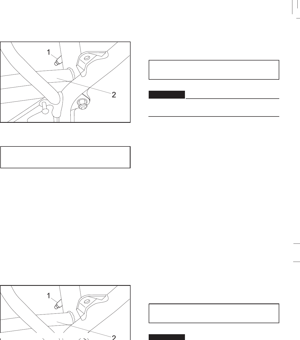
6-28
6-28
Rear suspension Sidestand
Lubricate the pivoting parts. Check to see that the sidestand
moves up and down smoothly.
RECOMMENDED LUBRICANT:
Engine oil SAE 20W50
If the sidestand does not move smoothly, consult a
Yamaha dealer.
Lubricate the rear suspension through the nipple.
RECOMMENDED LUBRICANT:
Molybdenum dissulfide grease
1.Nipple 2. Rear suspension
WARNING:
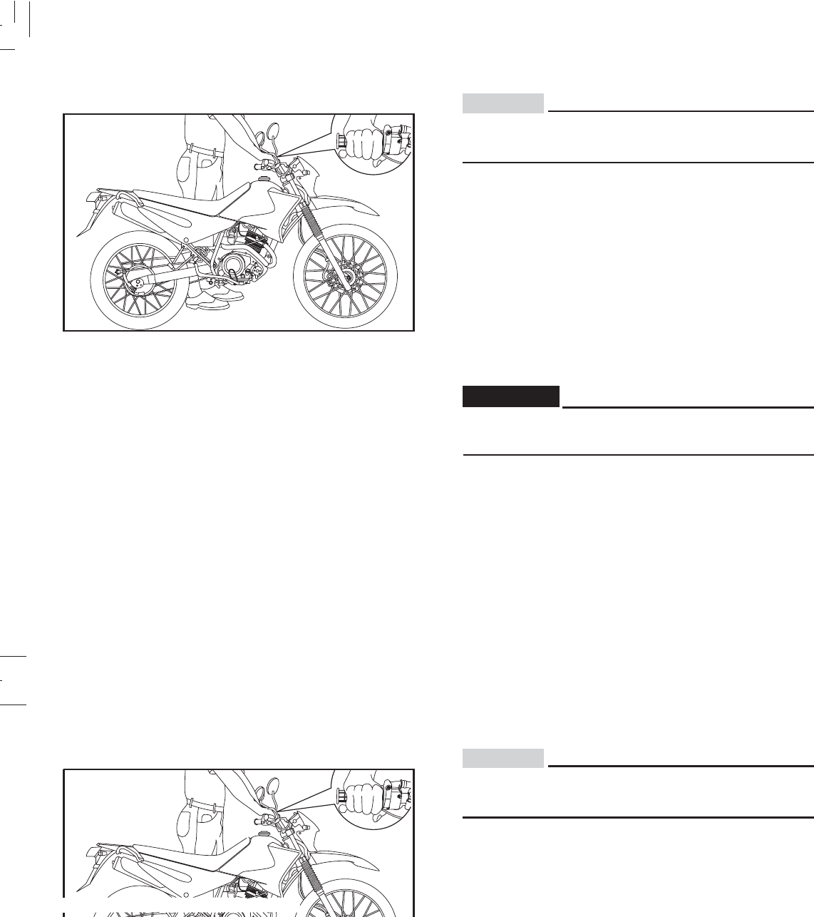
6-29
6-29
Front fork inspection
1. Visual check
Check for scratches or damage on the inner tube and
excessive oil leakage from the front fork.
2. Operation check
Place the motorcycle on a level place.
a. Hold the motorcycle in an upright position and apply
the front brake.
b. Push down hard several times and check if the fork
rebounds smoothly.
If any damage or unsmooth movement is found with
the front fork, consult a Yamaha dealer.
CAUTION:
Securely support the motorcycle so there is no danger
of it falling over.
WARNING:
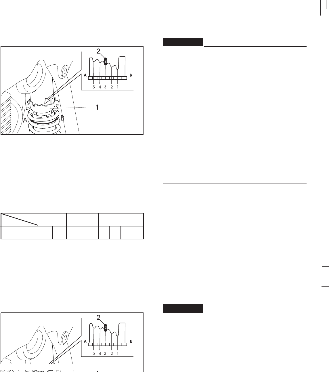
6-30
6-30
This shock absorber contains highly pressurized
nitrogen gas. Read and understand the following
information before handling the shock absorber. The
manufacturer cannot be held responsible for property
damage or personal injury that may result from improper
handling.
1. Do not tamper with or attempt to open the cylinder
assembly.
2. Do not subject the shock absorber to an open flame
or other high heat source. This may cause the unit
to explode due to excessive gas pressure.
3. Do not deform or damage the cylinder in any way.
Cylinder damage will result in poor damping
performance.
4. Take your shock absorber to a Yamaha dealer for
any service.
Rear shock absorber adjustment
The spring prelod of the rear shock absorber can be adjusted
to suit rider’s preference, weight and course condition.
Turn the adjusting ring in direction = to increase spring
preload and in direction > to decrease spring preload. Make
sure that the appropriate notch in the adjusting ring is aligned
with the position indicator on the rear shock absorber.
1. Spring preload adjusting ring 2.Position indicator
WARNING:
ADJUSTING
POSITION
SOFT STANDARD HARD
12 3 7654
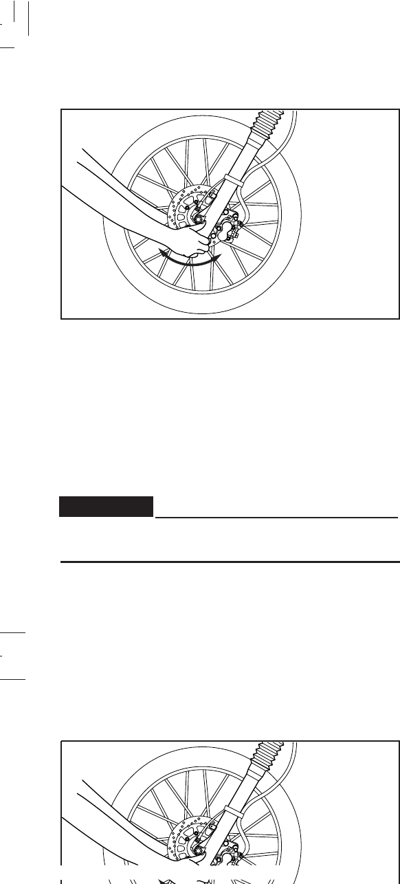
6-31
6-31
Wheel bearings
If there is play in the front or rear wheel hub or if the wheel
does not turn smoothly, have a Yamaha dealer inspect the
wheel bearings. The wheel bearings should be inspected
according to the Maintenance Schedule.
Steering inspection
Securely support the motorcycle so there is no danger
of it falling over.
Periodically inspect the condition of the steering. Worn out
or loose steering bearings may be dangerous. Place a stand
under the engine to raise the front wheel off the ground.
Hold the lower end of the front forks and try to move them
forward and backward. If any free play can be felt, ask a
Yamaha dealer to inspect and adjust the steering. Inspection
is easier if the front wheel is removed.
WARNING:
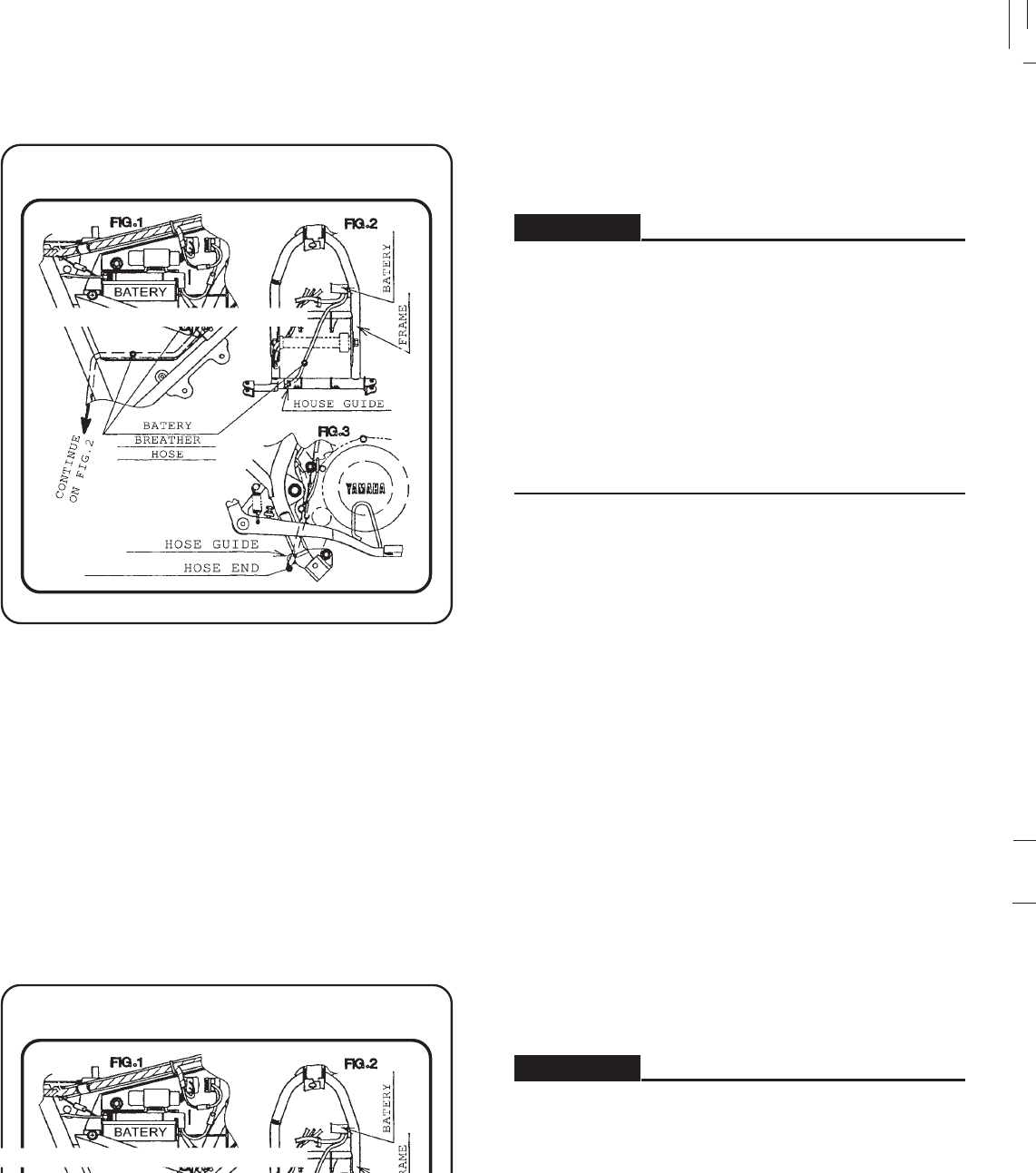
6-32
6-32
Battery
BATTERY BREATHER HOSE ROUTING
YAMAHA 5RM-F8179-00
Check the level of the battery electrolyte and make sure
that the terminals are tight. Add distilled water if the
electrolyte level is low.
1. When inspecting the battery, make sure that the
battery breather pipe routing is correct. If the
breather pipe touches painted parts, or if its end is
in such a position that may cause gas or electrolyte
leakage, it may cause structural or esthetic damages
to the motorcycle.
2. Take care not to spill battery fluid on the chain.
Battery fluid may weaken the chain causing shorter
chain life and possibly result in an accident.
WARNING:
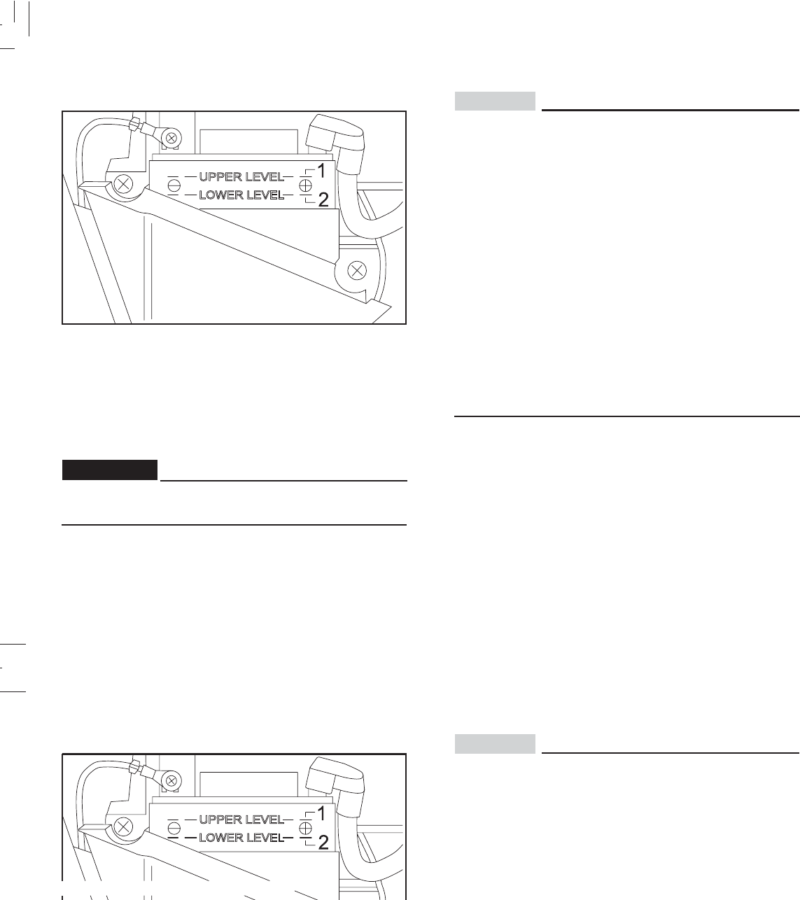
6-33
6-33
CAUTION:
Battery electrolyte is poisonous and dangerous,
causing severe burns, etc. It contains sulfuric acid.
Avoid contact with skin, eyes or clothing.
Antidote:
EXTERNAL: Flush with water.
INTERNAL: Drink large quantities of water or milk.
Follow with milk of magnesia, beaten egg, or vegetable
oil. Call a physician immediately.
EYES: Flush with water for 15 minutes and get prompt
medical attention.
Batteries produce explosive gases. Keep sparks, flame,
cigarrettes, etc., away. Ventilate when charging or using
it in an enclosed space. Always shield your eyes when
working near batteries.
KEEP OUT OF REACH OF CHILDREN.
Replenishing the battery fluid
1. Maximum marks 2. Minimum marks
Normal tap water contains minerals which are harmful
to a battery; therefore, refill only with “distilled water”.
A poorly maintained battery will corrode and discharge
quickly. The battery fluid should be checked at least once a
month.
The level should be between the minimum and maximum
marks. Use only “distilled water” if refilling is necessary.
WARNING:
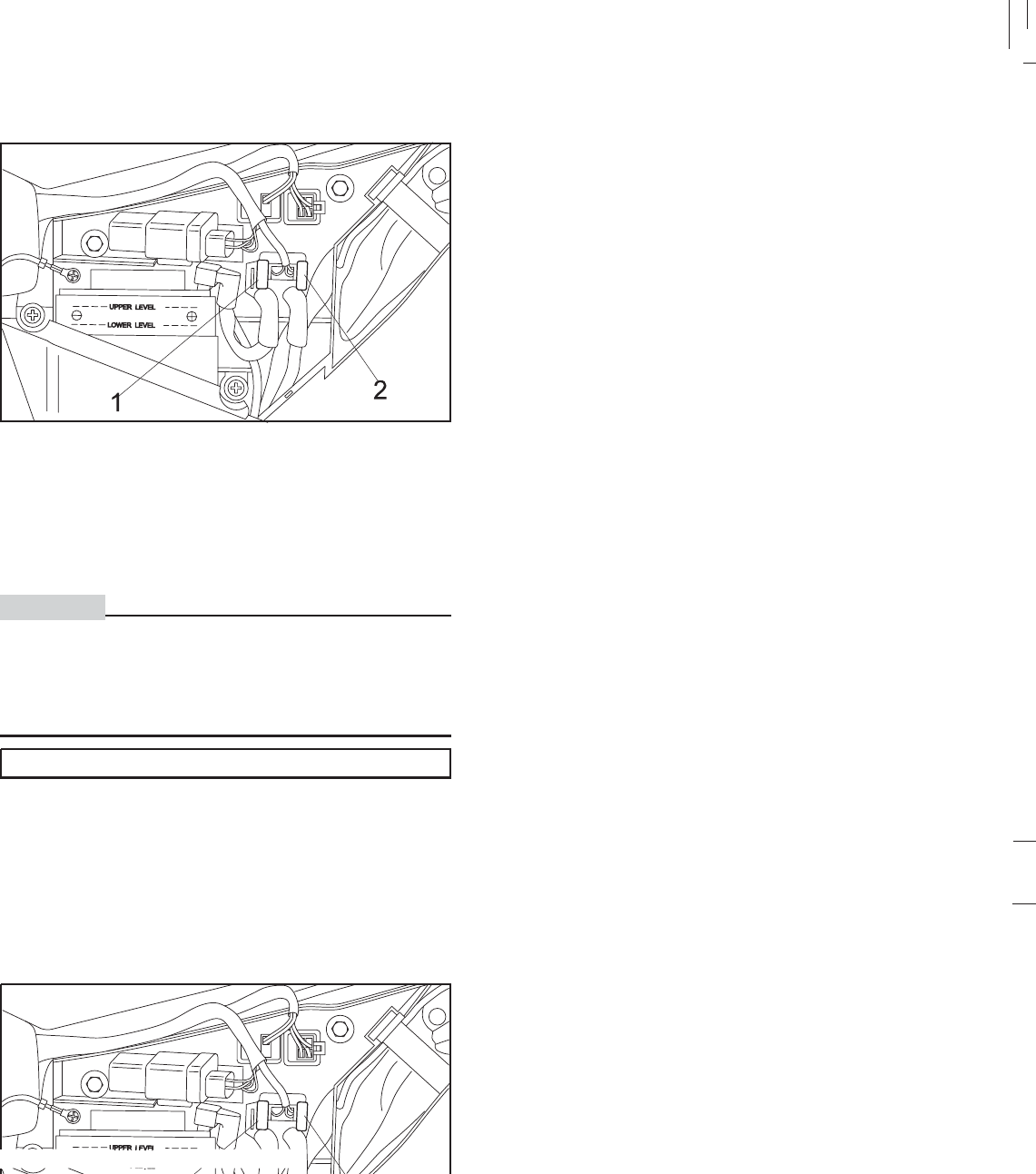
6-34
6-34
Storage the battery
1. When the motorcycle is not used for a month or longer,
remove the battery and store it in a cool, dark place.
Completely recharge the battery before reinstallation.
2. If the baterry needs to be stored for a longer period
than the period mentioned above, check the specific
gravity at least once a month, and recharge it when the
specific gravity is below normal.
3. Always make sure the connections are correct when
reinstalling the battery. The red (positive) lead is for the
+ terminal and the black (negative) lead is for the -
terminal. Always connect the red (positive) lead first,
then connect the black (negative) lead. Make sure that
the battery breather pipe is correctly routed, free of
obstructions, and in good condition.
FUSE CAPACITY:10 A
If a fuse is blown, turn off the ignition switch and the switch
of the circuit in question. Install a new fuse of proper
amperage. Turn on the switches and see if the electrical
device operates. If the fuse immediately blows again, consult
a Yamaha dealer.
1. Fuse 2. Reserve
CAUTION:
Do not use fuses of higher amperage rating than those
recommended. Substitution of a fuse of improper rating
can cause extensive electrical system damage and
possibly a fire.
Fuse replacement
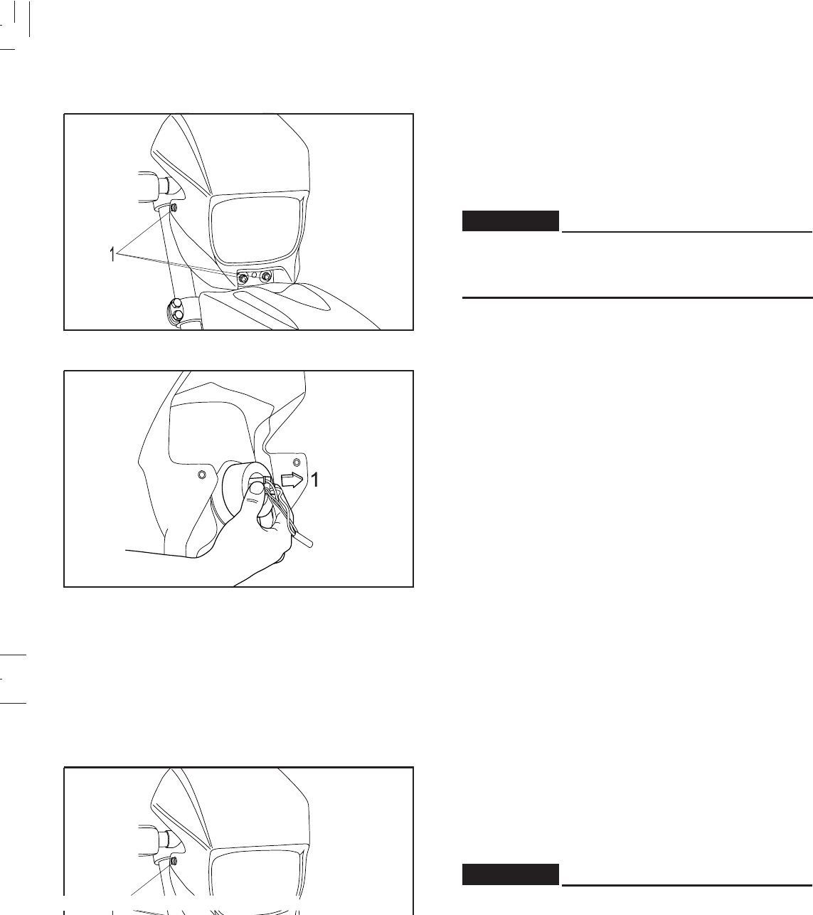
6-35
6-35
Headlight bulb replacement This motocycle this equipped with halogen bulb on its
headlight.
If the headlight bulb burns out, replace the bulb as follows:
1. Remove the cowling by loosing its bolts.
2. Loosen the bulb connectors.
ADVERTENCIA
Keep flammable products and your hands away from
the bulb while it is on, as it is hot. Do not touch the
bulb until it cools down
1. Screw
1. Bulb connectors
WARNING:
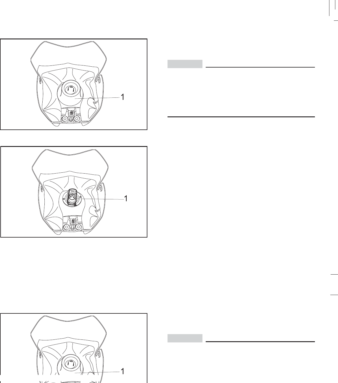
6-36
6-36
1. Rubber cover
1. Clip
3. Remove the rubber cover.
4. Remove the clip by pushing its tab dow.
CAUTION:
Avoid touching the glass part of the headlight bulb to keep
it free from oil, otherwise the transparency of the glass, the
life of the bulb and the luminous flux will be adversely
affected. If the headlight bulb gets soiled, thoroughly clean
it with a cloth moistened with alcohol or lacquer thinner.
5. Put a new bulb, install the socket and the bulb rubber
cover.
6. Reconnect the connectors.
7. Reinstall the headlight assy. If it is necessary to adjust
the headlight beam, please consult a Yamaha dealer.
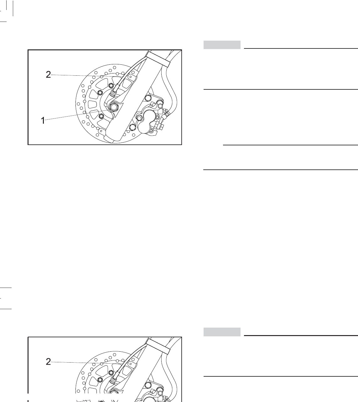
6-37
6-37
Front wheel removal
1. Axle nut 2. Speedometer cable
CAUTION:
It is advisable to have a Yamaha dealer service the
wheel.
Securely support the motorcycle so there is no danger
of it falling over.
1. Place a stand under the engine to raise the fornt wheel
off the ground.
2. Remove the speedometer cable.
3. Remove the axle nut and axle.
NOTE:
Do not depress the brake lever when the disc is off the
caliper as the brake pads will be forced shut.
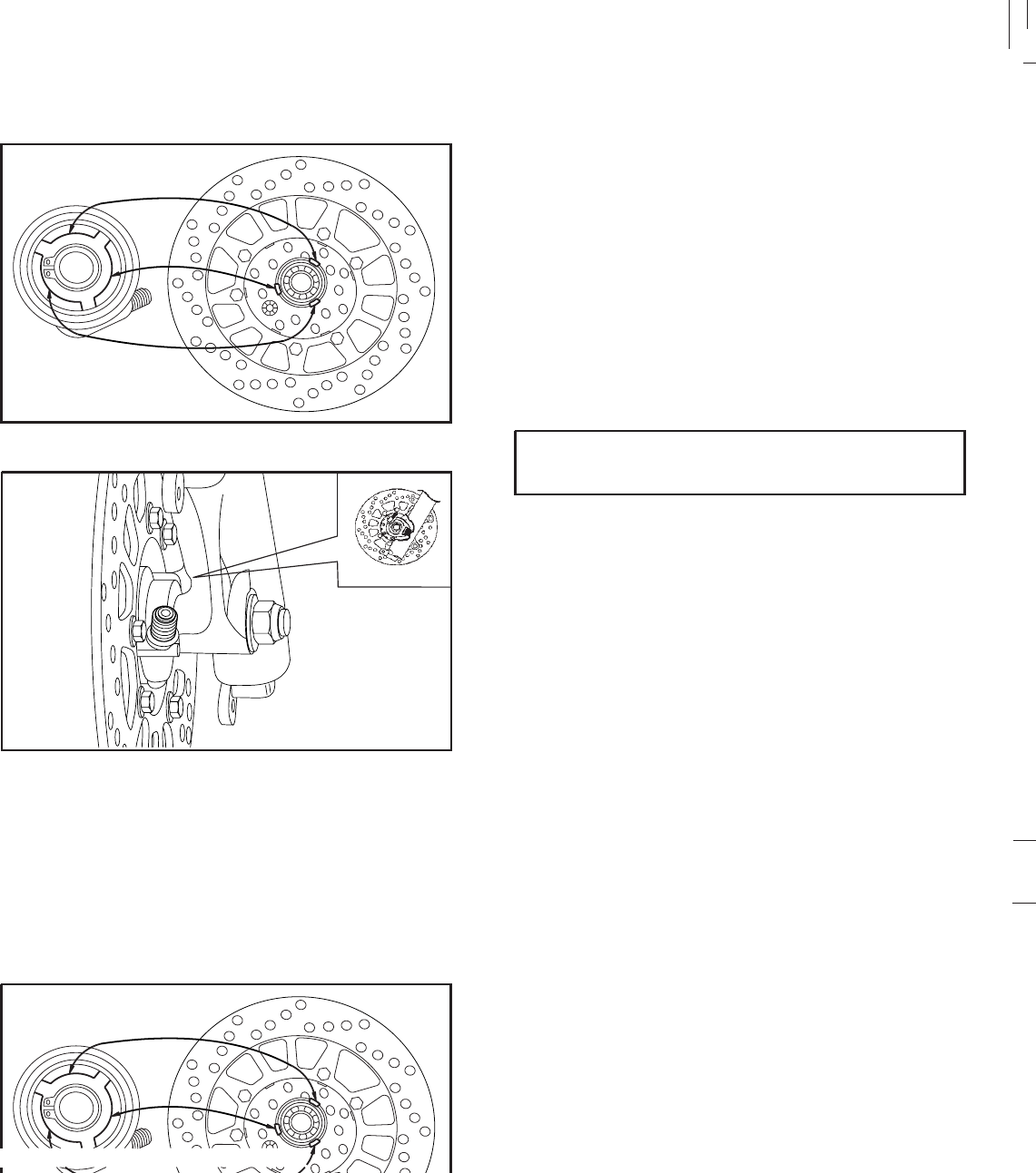
6-38
6-38
Front wheel installation When installing the front wheel, reverse the removal
procedures.
Pay attention to the following points:
1. Make sure that wheel boss and speedometer gear be
installed with their projection fitted on their respective
slits.
2. Make sure that front fork outer tub stopper is
correctily placed on speedometer gear.
3. Make sure the axle nut is properly torqued.
Axle nut torque:
80 N.m (8.0 Kgf.m, 58 lbf.ft)
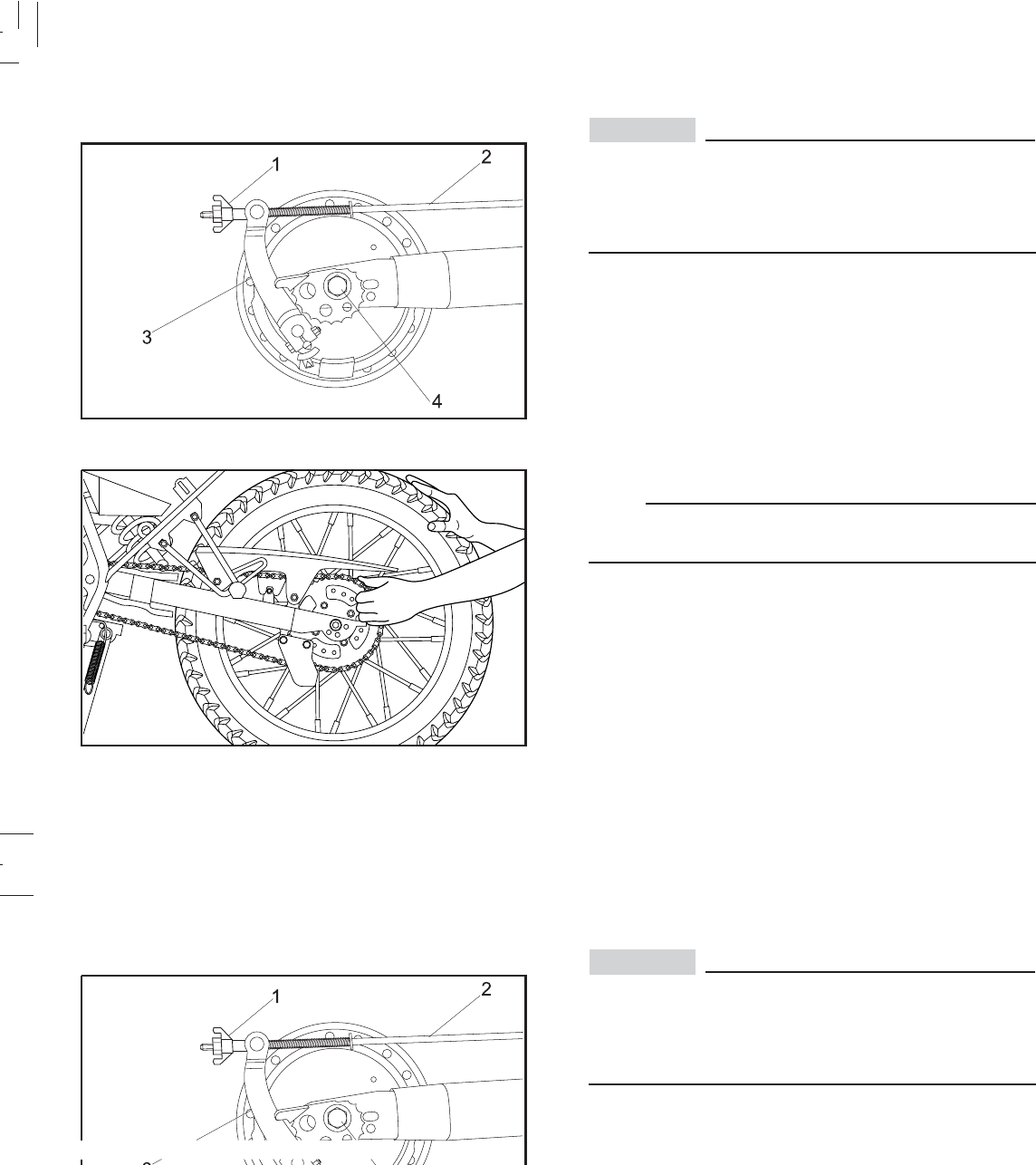
6-39
6-39
Rear wheel removal
1. Adjuster 2. Brake rod
3. Brake cam lever 4. Axle nut
It is advisable to have a Yamaha dealer service the
wheel.
Securely support the motorcycle so there is no danger
of it falling over.
1. Remove the brake adjuster.
2. Remove the brake rod from the brake cam lever.
3. Loosen the axle nut.
4. Elevate the rear wheel by placing a stand under the
engine.
5. Remove the axle nut.
6. Push the wheel forward and remove the drive chain.
NOTA:
There is no need of disassembling the drive chain to
remove or reinstall the rear wheel.
7. Pull out the axle and remove the wheel assembly by
pulling backward.
CAUTION:
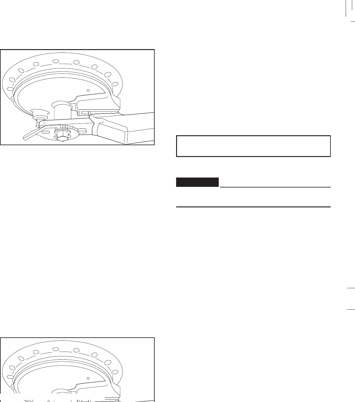
6-40
6-40
Rear wheel installation When installing the rear wheel, reverse the removal
procedures. Pay attention to the following points:
1. Be sure the slot in the brake shoe plate is fit over the
stopper on the rear arm.
2. Make sure the rear wheel axl is inserted from the right-
hand side and that the chain pullers are installed with
the punched side outward.
3. Adjust the drive chain.
4. Make sure the axle nut is properly torqued.
Axle nut torque:
80 N.m ( 8.0 Kgf.m, 58 lbf.ft)
5. Adjust the rear brake.(See page 6-18)
Check the operation of the brake light after adjusting
the rear brake
WARNING:

6-41
6-41
Troubleshooting
Although Yamaha motorcycles receive a rigid inspection
before shipment from the factory, trouble may occur during
operation. Any problem in the fuel, compression, or ignition
systems can cause poor starting and loss of power. The
troubleshooting chart describes a quick, easy, procedure
for making checks. If your motorcycle requires any repair,
bring it to a Yamaha dealer. The skilled technicians at a
Yamaha dealership have the tools, experience, and know-
how to properly service your motorcycle. Use only genuine
Yamaha parts on your motorcycle. Imitation parts may look
like Yamaha parts, but they are often inferior. Consequently,
they have a shorter service life and can lead to expensive
repair bills.
Troubleshooting
Although Yamaha motorcycles receive a rigid inspection
before shipment from the factory, trouble may occur during
operation. Any problem in the fuel, compression, or ignition
systems can cause poor starting and loss of power. The
troubleshooting chart describes a quick, easy, procedure
for making checks. If your motorcycle requires any repair,
d technicians at a
Yamaha dealership have the tools, experience, and know-
how to properly service your motorcycle. Use only genuine
Yamaha parts on your motorcycle. Imitation parts may look
like Yamaha parts, but they are often inferior. Consequently,
they have a shorter service life and can lead to expensive
repair bills.
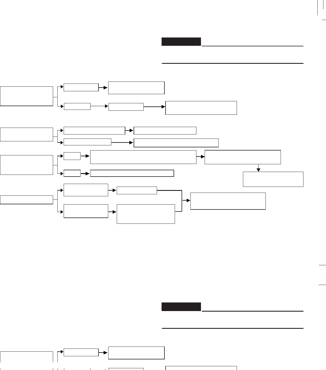
6-42
6-42
Troubleshooting chart ADVERTENC
Never check the fuel system while smoking or in the
vicinity of an open flame.
WARNING:
Check if there is
fuel in the fuel tank
Use electric
starter
Remove spark plug
and check
electrode
Use electric starter
1. Fuel
2. Compression
3. Ignition
4. Battery *
Enough fuel
No fuel
There is compression
No compression
Wet
Dry
Engine turns
over quickly
Engine turns
over slowly
Supply fuel
Go to ignition check
Ask Yamaha dealer to inspect
Wipe clean with dry cloth and correct
spark plug gap or replace spark plugs
Ask Yamaha dealer to inspect
Battery good
Check fluid, recharge
and check
connections
Go to compression
check
Engine doesn’t start, go to
compression check
Open the throttle hal-way
and start the engine
Engine doesn’t start, ask
Yamaha dealer to inspect.
Engine doesn’t start,
go to battery check
* Obs.: XTZ 125E
Troubleshooting chart ADVERTENC
Never check the fuel system while smoking or in the
vicinity of an open flame.
WARNING:
Check if there is
Use electric
starter
Remove spark plug
and check
electrode
Use electric starter
1. Fuel
2. Compression
3. Ignition
4. Battery *
Enough fuel
No fuel
There is compression
No compression
Wet
Dry
Engine turns
over quickly
Engine turns
over slowly
Supply fuel
Go to ignition check
Ask Yamaha dealer to inspect
Wipe clean with dry cloth and correct
spark plug gap or replace spark plugs
Ask Yamaha dealer to inspect
Battery good
Check fluid, recharge
and check
connections
Go to compression
check
Engine doesn’t start, go to
compression check
Open the throttle hal-way
and start the engine
Engine doesn’t start, ask
Yamaha dealer to inspect.
Engine doesn’t start,
go to battery check
* Obs.: XTZ 125E

7-1
7-1
A. Cleaning
Frequent, thorough cleaning of your motorcycle will not only
enhance its appearance but will improve its general
performance and extend the useful life of many components.
1. Before cleaning the motorcycle:
a. Block off the end of the exhaust pipe to prevent water
entry; a plastic bag and strong rubber band may be
used.
b. Make sure the spark plug and all filler caps are properly
installed.
2. If the engine case is excessively greasy, apply
degreaser with a paint brush. Do not apply degreaser
to the chain, sprockets, or wheel axles.
3. Rinse the dirt and degreaser off with a garden hose,
Use only enough pressure to do the job.
CAUTION:
Excessive hose pressure may cause water seepage and
deterioration of wheel bearings, front fork, brakes,
transmission seals and electrical parts.
Many expensive repair bills have resulted from
improper high pressure detergent applications such as
those available in coin-operated car washers.
4. Once the majority of the dirt has been hosed off, wash
all surfaces with warm water and mild, detergent-type
soap. An old toothbrush or bottle brush is handy for
hard-to-get-at places.
5. Rinse the motorcycle off immediately with clean water
and dry all surfaces with a chamois, clean towel, or
soft absorbent cloth.
6. Dry the chain and lubricate it to prevent rust.
7. Clean the seat with a vinyl upholstery cleaner to keep
the cover pliable and glossy.
8. Automotive-type wax may be applied to all painted and
chrome-plated surfaces. Avoid combination cleaner-
waxes. Many contain abrasives which may mar the paint
or protective finish. When finished, start the engine and
let it idle for several minutes.
CLEANING AND STORAGE
A. Cleaning
Frequent, thorough cleaning of your motorcycle will not only
enhance its appearance but will improve its general
performance and extend the useful life of many components.
1. Before cleaning the motorcycle:
a. Block off the end of the exhaust pipe to prevent water
ber band may be
used.
b. Make sure the spark plug and all filler caps are properly
installed.
2. If the engine case is excessively greasy, apply
degreaser with a paint brush. Do not apply degreaser
to the chain, sprockets, or wheel axles.
3. Rinse the dirt and degreaser off with a garden hose,
Use only enough pressure to do the job.
CAUTION:
Excessive hose pressure may cause water seepage and
deterioration of wheel bearings, front fork, brakes,
transmission seals and electrical parts.
Many expensive repair bills have resulted from
improper high pressure detergent applications such as
those available in coin-operated car washers.
4. Once the majority of the dirt has been hosed off, wash
all surfaces with warm water and mild, detergent-type
soap. An old toothbrush or bottle brush is handy for
hard-to-get-at places.
5. Rinse the motorcycle off immediately with clean water
and dry all surfaces with a chamois, clean towel, or
soft absorbent cloth.
6. Dry the chain and lubricate it to prevent rust.
7. Clean the seat with a vinyl upholstery cleaner to keep
the cover pliable and glossy.
8. Automotive-type wax may be applied to all painted and
chrome-plated surfaces. Avoid combination cleaner-
waxes. Many contain abrasives which may mar the paint
or protective finish. When finished, start the engine and
let it idle for several minutes.
CLEANING AND STORAGE

7-2
7-2
B. Storage
Long term storage (30 days or more) of your machine will
require some preventive procedures to guard against
deterioration. After thoroughly cleaning the machine,
prepare for storage as follows:
1. Drain the fuel tank, fuel lines, and carburetor float
bowl(s).
2. Remove the spark plug(s), pour about one tablespoon
of SAE 20W50 motor oil in the spark plug hole(s) and
reinstall the spark plug(s).
Crank the engine over several times (with the
ignition off) to coat the cylinder walls with oil.
3. Remove the drive chain. Clean it thoroughly with
solvent and lubricate it.
Reinstall the chain or store it in a plastic bag
(tied to frame for safe-keeping).
4. Lubricate all control cables.
5. Block up the frame to raise both wheels off the
ground.
6. Tie a plastic bag over the exhaust pipe outlet to
prevent moisture from entering.
7. If storing in a humid or salt-air atmosphere, coat
all exposed metal surfaces with a light film of
oil. Do not apply oil to any rubber parts or the
seat cover.
8. Remove the battery and charge it. Store it in a dry place
and recharge it once a month. Do not store the battery
in an excessively warm or cold place (less than 0ºC
(30ºF) or more than 30ºC (90ºF).
NOTE:
Make any necessary repairs before storing the machine.
B. Storage
Long term storage (30 days or more) of your machine will
require some preventive procedures to guard against
deterioration. After thoroughly cleaning the machine,
prepare for storage as follows:
1. Drain the fuel tank, fuel lines, and carburetor float
bowl(s).
out one tablespoon
of SAE 20W50 motor oil in the spark plug hole(s) and
reinstall the spark plug(s).
Crank the engine over several times (with the
ignition off) to coat the cylinder walls with oil.
3. Remove the drive chain. Clean it thoroughly with
solvent and lubricate it.
Reinstall the chain or store it in a plastic bag
(tied to frame for safe-keeping).
4. Lubricate all control cables.
5. Block up the frame to raise both wheels off the
ground.
6. Tie a plastic bag over the exhaust pipe outlet to
prevent moisture from entering.
7. If storing in a humid or salt-air atmosphere, coat
all exposed metal surfaces with a light film of
oil. Do not apply oil to any rubber parts or the
seat cover.
8. Remove the battery and charge it. Store it in a dry place
and recharge it once a month. Do not store the battery
in an excessively warm or cold place (less than 0ºC
(30ºF) or more than 30ºC (90ºF).
NOTE:
Make any necessary repairs before storing the machine.
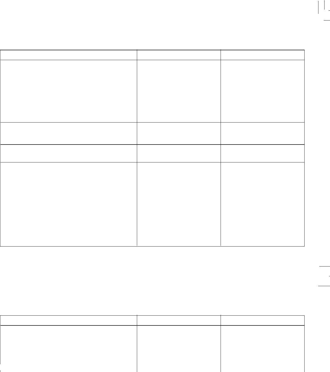
8-1
8-1
SPECIFICATIONS
MODEL
Dimension:
Overall length
Overall width
Overall height
Seat height
Wheet base
Minimum ground clearance
Basic weight:
With oil and without fuel:
Minimum turning radius:
Engine:
Type
Cylinder arrangement
Displacement
Bore x Stroke
Compression rate
Starting system
Lubrification system
103 Kg (227 lb)
113 Kg (249 lb)
2.090 mm (82.3 in)
810 mm (31.9 in)
1.125 mm (44.3 in)
840 mm (33.1 in)
1.340 mm (52.7 in)
265 mm (10.4 in)
2.100 mm (82.7 in)
XTZ 125K
Air cooled, 4-stroke
gasoline, SOHC
Single cylinder
123.7 cm3
54 x 54 mm (2.13 x 2.13 in)
10.0 : 1
Kick starter
Wet sump
104 Kg (229 lb)
114 Kg (251 lb)
2.090 mm (82.3 in)
810 mm (31.9 in)
1.125 mm (44.3 in)
840 mm (33.1 in)
1.340 mm (52.7 in)
265 mm (10.4 in)
2.100 mm (82.7 in)
XTZ 125E
Air cooled, 4-stroke
gasoline, SOHC
Single cylinder
123.7 cm3
54 x 54 mm (2.13 x 2.13 in)
10.0 : 1
Electric starter
Wet sump
SPECIFICATIONS
MODEL
Dimension:
Overall length
Overall width
Overall height
Wheet base
Minimum ground clearance
Basic weight:
With oil and without fuel:
Minimum turning radius:
Engine:
Type
Cylinder arrangement
Displacement
Bore x Stroke
Compression rate
Starting system
Lubrification system
103 Kg (227 lb)
113 Kg (249 lb)
2.090 mm (82.3 in)
810 mm (31.9 in)
1.125 mm (44.3 in)
840 mm (33.1 in)
1.340 mm (52.7 in)
265 mm (10.4 in)
2.100 mm (82.7 in)
XTZ 125K
Air cooled, 4-stroke
gasoline, SOHC
Single cylinder
123.7 cm3
54 x 54 mm (2.13 x 2.13 in)
10.0 : 1
Kick starter
Wet sump
104 Kg (229 lb)
114 Kg (251 lb)
2.090 mm (82.3 in)
810 mm (31.9 in)
1.125 mm (44.3 in)
840 mm (33.1 in)
1.340 mm (52.7 in)
265 mm (10.4 in)
2.100 mm (82.7 in)
XTZ 125E
Air cooled, 4-stroke
gasoline, SOHC
Single cylinder
123.7 cm3
54 x 54 mm (2.13 x 2.13 in)
10.0 : 1
Electric starter
Wet sump
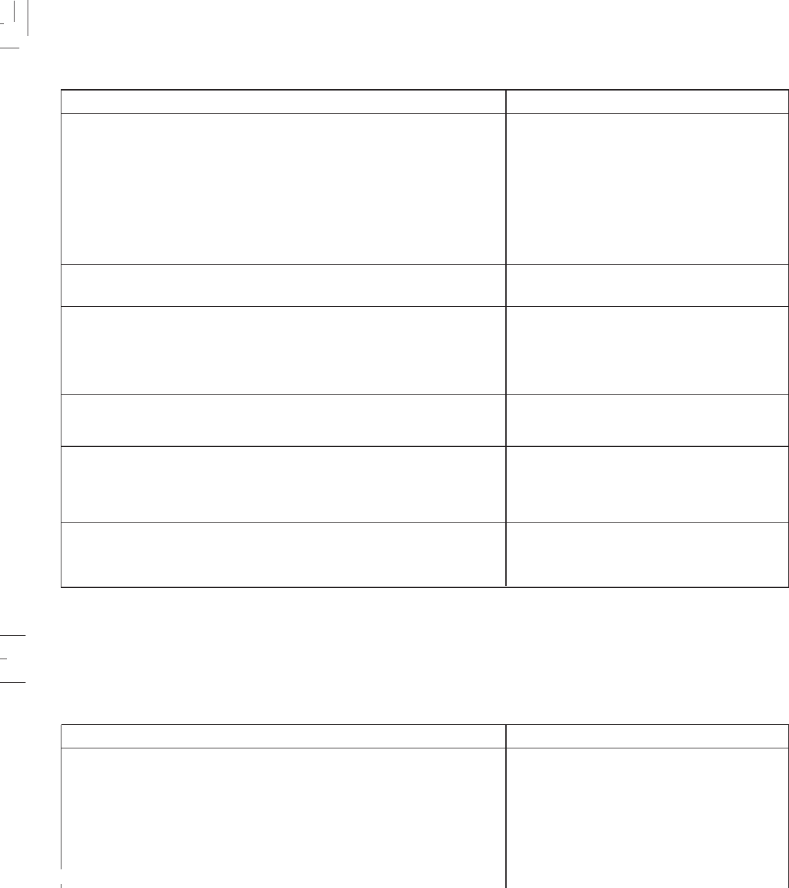
8-2
8-2
MODEL XTZ 125E and XTZ 125K
Engine oil:
Air filter:
Fuel:
Type
Tank capacity
Reserve amount
Carburetor:
Type / manufacturer
Spark plug:
Type / manufacturer
Gap
Clutch type:
Capacity:
Periódic oil change
Total amount
Type YAMALUBE 4 or SAE 20W50 type SH
Wet type element
CR7HSA / NGK or U22FSR-U / DENSO
0.7 mm (0.028 in)
Wet, multi-disc
Regular unleaded gasoline
10,6 l ( 2.33 Imp gal, 2.80 US gal)
1,0 l ( 0.220 Imp gal, 0.264 US gal)
1,0 l ( 0,220 Imp gal, 0.264 US gal)
1,2 l ( 0,264 Imp gal, 0.317 US gal)
VM 20SS / Mikuni
MODEL XTZ 125E and XTZ 125K
Engine oil:
Air filter:
Fuel:
Type
Tank capacity
Reserve amount
Carburetor:
Type / manufacturer
Spark plug:
Type / manufacturer
Gap
Clutch type:
Capacity:
Periódic oil change
Type YAMALUBE 4 or SAE 20W50 type SH
Wet type element
CR7HSA / NGK or U22FSR-U / DENSO
0.7 mm (0.028 in)
Wet, multi-disc
Regular unleaded gasoline
10,6 l ( 2.33 Imp gal, 2.80 US gal)
1,0 l ( 0.220 Imp gal, 0.264 US gal)
1,0 l ( 0,220 Imp gal, 0.264 US gal)
1,2 l ( 0,264 Imp gal, 0.317 US gal)
VM 20SS / Mikuni

8-3
8-3
MODEL XTZ 125E and XTZ 125K
Transmission:
Primary reducion system
Primary reduction rate
Secondary reduction system
Secondary reduction rate
Transmission type
Operatíon
Gear ratio 1st
2nd
3rd
4th
5th
Chassis:
Frame type
Caster angle
Trail
Tire:Type
Size: Front
Rear
Spur gear
68 / 20
Chain drive
48 / 14
Constant mesh 5-speed
Left foot operation
37 / 14
32 / 18
25 / 19
23 / 22
21 / 24
Diamond
26° 20’
106 mm (4,2 in)
With tube
80 / 90-21 48T
110 / 80-18 58T
MODEL XTZ 125E and XTZ 125K
Transmission:
Primary reducion system
Primary reduction rate
Secondary reduction system
Secondary reduction rate
Operatíon
Gear ratio 1st
2nd
3rd
4th
5th
Chassis:
Frame type
Caster angle
Trail
Tire:Type
Size: Front
Rear
Spur gear
68 / 20
Chain drive
48 / 14
Constant mesh 5-speed
Left foot operation
37 / 14
32 / 18
25 / 19
23 / 22
21 / 24
Diamond
26° 20’
106 mm (4,2 in)
With tube
80 / 90-21 48T
110 / 80-18 58T
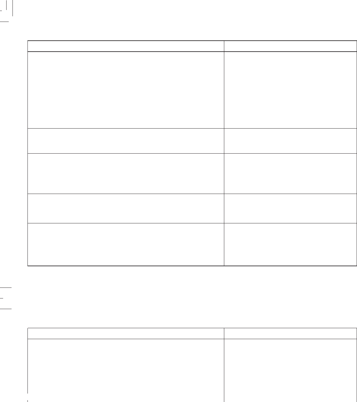
8-4
8-4
MODEL
Brakes:
Front brake type
Operation
Rear brake type
Operation
Shock absorber:
Front
Rear
Wheel travel
Front
Rear
Suspension:
Front
Rear
Electrical:
Ignition system
Generator system
Battery type / capacity
XTZ 125E and XTZ 125K
Coil spring, Oil damper
Gas, Coil spring. Oil damper
180 mm (7.1 in)
180 mm (7.1 in)
Telescopic fork
Swingarm (New monocross suspension)
C.D.I.
AC Magneto generator
YB5L-B/ 12V 5.0 Ah
Single, Disc brake
Right hand operation
Drum brake
Right foot operation
MODEL
Brakes:
Front brake type
Operation
Rear brake type
Operation
Shock absorber:
Front
Rear
Wheel travel
Front
Rear
Suspension:
Front
Rear
Electrical:
Ignition system
Generator system
Battery type / capacity
XTZ 125E
Coil spring, Oil damper
Gas, Coil spring. Oil damper
180 mm (7.1 in)
180 mm (7.1 in)
Telescopic fork
Swingarm (New monocross suspension)
C.D.I.
AC Magneto generator
YB5L-B/ 12V 5.0 Ah
Single, Disc brake
Right hand operation
Drum brake
Right foot operation
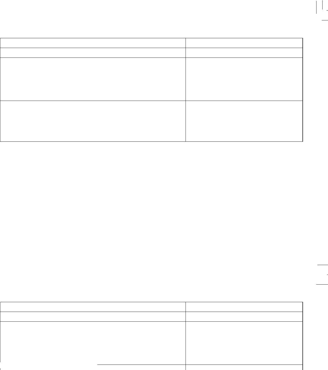
8-5
8-5
MODEL
Bulb wattage x quantity
Headlight
tail / Brake light
Flasher light
Indicator light wattage x quantity:
Panel
Neutral tamp
Headlight
Flasher light
Headlight type:
XTZ 125E and XTZ 125K
12V 35W/35W (1 Pc)
12V 5W/21W (1 Pc)
12V 10W (4 Pc)
12V x 3,4W (1 Pc)
12V x 1,7W (1 Pc)
12V x 1,7W (1 Pc)
12V x 1,7W (1 Pc)
Halogen bulb
MODEL
Bulb wattage x quantity
Headlight
tail / Brake light
Flasher light
Indicator light wattage x quantity:
Panel
Neutral tamp
Headlight
Flasher light
Headlight type:
XTZ 125E
12V 35W/35W (1 Pc)
12V 5W/21W (1 Pc)
12V 10W (4 Pc)
12V x 3,4W (1 Pc)
12V x 1,7W (1 Pc)
12V x 1,7W (1 Pc)
12V x 1,7W (1 Pc)
Halogen bulb