Yamaha AG06 Technical Specifications スペックシート Enforja Ts A0
User Manual: Yamaha AG06 スペックシート
Open the PDF directly: View PDF ![]() .
.
Page Count: 2
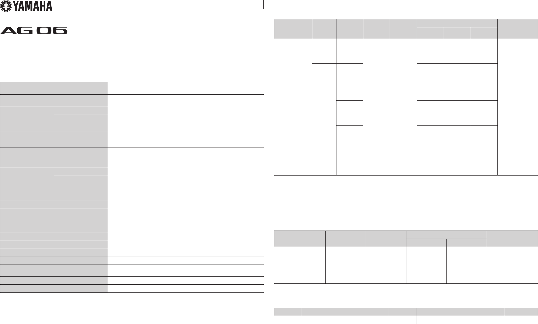
General Specifications
0 dBu = 0.775 Vrms, Output impedance of signal generator (Rs) = 150 Ω
All level controls are nominal if not specified.
Frequency Response Input (MIC) to MONITOR OUT
via USB IN/OUT
+0.5 dB/-1.5 dB (20 Hz to 48 kHz @ Fs = 192 kHz),
refer to the nominal output level @ 1 kHz, GAIN knob: Min, TO PC: DRY CH1-2
Total Harmonic Distortion *1
(THD+N) Input to MONITOR OUT 0.05% @ 0 dBu (20 Hz to 20 kHz), GAIN knob: Min
0.01% @ +4 dBu (1 kHz), GAIN knob: Min
Hum&Noise *2
(20 Hz to 20 kHz)
Equivalent Input Noise -128 dBu (Mono Input Channel, Rs: 150 Ω, GAIN knob: Max)
Residual Output Noise -103 dBu (MONITOR OUT, MONITOR knob: Min)
Crosstalk (1 kHz) *3 -80 dB
Input Channels
Mono (MIC/LINE): 2 including HEADSET MIC (Plug-in Power)
(CH1 MIC and HEADSET MIC cannot be used simultaneously.),
Stereo (LINE): 2, USB IN: 1, AUX IN: 1
Output Channels STEREO OUT: 1, MONITOR OUT: 1, PHONES: 2 including HEADSET PHONES
(PHONES and HEADSET PHONES cannot be used simultaneously.)
Bus Stereo: 1
Input Channel Function
(CH1, CH2)
PAD 26 dB
DSP
CH1: COMP/EQ, EFFECT (SPX Reverb)
CH2: AMP SIM, EFFECT (SPX Reverb)
PEAK LED LED turns on when the signal reaches 3 dB below clipping level.
Level Meter USB Output Level 2x2 point LED meter [PEAK, SIG]
USB Audio 2 IN / 2 OUT USB Audio Class 2.0 compliant, Sampling Frequency: Max 192 kHz, Bit Depth: 24-bit
Phantom Power Voltage +48 V
FOOT SW EFFECT Mute on/off
Power Requirements DC 5 V, 500 mA
Power Consumption Max. 2.5 W
Dimensions (WxHxD) 155 mm x 63 mm x 202 mm (6.1” x 2.5” x 8.0”)
Net Weight 1.0 kg (2.2 lbs)
Included Accessory USB Cable (1.5 m), CUBASE AI DOWNLOAD INFORMATION, Owner’s Manual,
Technical Specifications (this leaflet)
Optional Accessory Foot Switch: FC5, Mic Stand Adaptor: BMS-10A
Operating Temperature 0 to +40°C
*1 THD+N is measured with 22 kHz LPF.
*2 Noise is measured with A-weighting filter.
*3 Crosstalk is measured with 1 kHz band pass filter.
The contents of this manual apply to the latest specifications as of the printing date. Since Yamaha makes continuous improvements to the product, this manual may not apply to the speci-
fications of your particular product. To obtain the latest manual, access the Yamaha website then download the manual file. Since specifications, equipment or separately sold accessories
may not be the same in every locale, please check with your Yamaha dealer.
Analog Input Characteristics
0 dBu = 0.775 Vrms
Input Jack PAD
26 dB
GAIN
Trim/SW
Position
Actual
Load
Impedance
For Use with
Nominal
Input Level
Connector
Sensitivity *1 Nominal Max. Before
Clip
MIC/LINE 1 - 2
HEADSET MIC
OFF
10
3 kΩ
1.5 kΩ *4
50–600 Ω
Mics/Lines
-72 dBu
(0.195 mV)
-60 dBu
(0.775 mV)
-50 dBu
(2.451 mV)
Combo jack *2
(Balanced)
3.5 mm Phone jack
For CH1 HEADSET MIC
(Plug-in Power/
Unbalanced)
0-26 dBu
(38.84 mV)
-14 dBu
(154.6 mV)
-4 dBu
(489.0 mV)
ON
10 -46 dBu
(3.884 mV)
-34 dBu
(15.46 mV)
-24 dBu
(48.90 mV)
00 dBu
(775.0 mV)
+12 dBu
(3.085 V)
+22 dBu
(9.757 V)
INPUT CH2
GUITAR *5
OFF
10
1 MΩ -
-68 dBu
(3.085 mV)
-56 dBu
(1.228 mV)
-46 dBu
(3.884 mV)
Phone jack *3
(Unbalanced)
0-22 dBu
(61.56 mV)
-10 dBu
(245.1 mV)
0 dBu
(775.0 mV)
ON
10 -42 dBu
(6.153 mV)
-30 dBu
(24.51 mV)
-20 dBu
(77.5 mV)
0+4 dBu
(1.228 V) -+10 dBu
(2.451 V)
LINE
3/4, 5/6 -
HIGH
10 kΩ 600 Ω Lines
-20 dBu
(77.5 mV)
-8 dBu
(308.5 mV)
+2 dBu
(975.7 mV)
LINE 3/4 Phone jack *3
(Unbalanced)
LINE 5/6 RCA pin
(Unbalanced)
LOW -10 dBu
(245.1 mV)
+2 dBu
(975.7 mV)
+12 dBu
(3.085 V)
AUX - - 10 kΩ 600 Ω Lines -14 dBu
(154.6 mV)
-8 dBu
(308.5 mV)
+2 dBu
(975.7 mV) Stereo mini jack
*1 Sensitivity is the lowest level that will produce an output of +0 dBu (0.775 V) or the nominal output level when the unit is set to maximum gain.
(All level controls are at their maximum position.)
*2 1&Sleeve = GND, 2&Tip = HOT, 3&Ring = COLD
*3 Tip = Signal, Sleeve = GND
*4 For CH1, HEADSET MIC
*5 For CH2, GUITAR switch is ON
Analog Output Characteristics
0 dBu = 0.775 Vrms
Output Terminal Actual Source
Impedance
For Use with
Nominal
Output Level
Connector
Nominal Max. Before Clip
STEREO OUT [L, R] 150 Ω 10 kΩ Lines 0 dBu
(0.775 V)
+10 dBu
(2.451 V)
Phone jack *6
(Impedance Balanced)
MONITOR OUT [L, R] 150 Ω 10 kΩ Lines 0 dBu
(0.775 V)
+10 dBu
(2.451 V)
Phone jack *6
(Impedance Balanced)
PHONES 120 Ω 40 Ω Phones 1.5 mW + 1.5 mW 6 mW + 6 mW Stereo phone jack
Stereo mini jack
*6 Tip = HOT, Ring = COLD, Sleeve = GND
Digital Input / Output Characteristics
Terminal Format Data Length Sampling Frequency Connector
USB USB Audio Class 2.0/ Yamaha Steinberg USB Driver 24-bit 44.1 kHz, 48 kHz, 88.2 kHz, 96 kHz, 176.4 kHz, 192 kHz USB Standard-B
ZN24170
MIXING CONSOLE
Technical Specifications
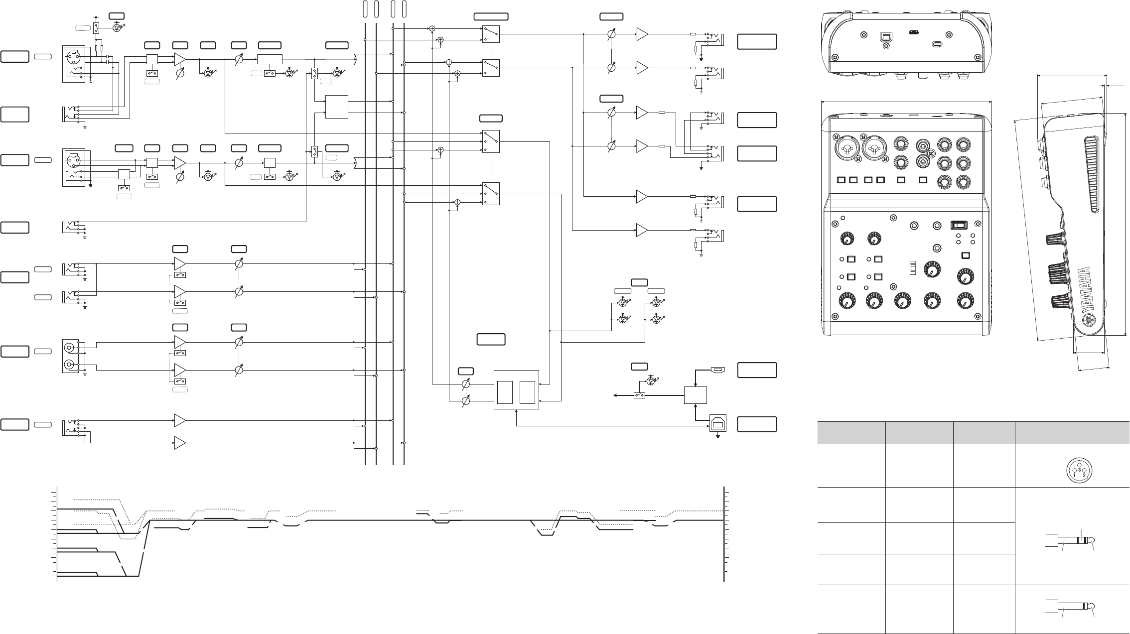
Block and Level Diagrams Dimensions
Manual Development Department
©2015 Yamaha Corporation
Published 01/2015 MWZC*.*-01A0
Printed in Indonesia
GAIN
INPUT 1
MONITOR
OUT (L/R)
PHONES
(L/R)
+30dBu
+20dBu
+10dBu
0dBu
-10dBu
-30dBu
-40dBu
-50dBu
-60dBu
-20dBu
+30dBu
+20dBu
+10dBu
0dBu
-10dBu
-30dBu
-40dBu
-50dBu
-60dBu
-20dBu
MONO INPUT MIC : [-60dBu] @GAIN=max
MONO INPUT LINE: [-34dBu] @GAIN=max
MONO INPUT LINE: [+12dBu] @GAIN=min
Maximum Input Level: [+22dBu]
Clip Level: [+10dBu]
Maximum Input Level:[-4dBu]
STEREO INPUT LINE:
[-8dBu]@GAIN=HIGH
Maximum Input Level: [+2dBu]
Maximum Output Level:
[+10dBu]
MONO INPUT MIC : [-14dBu] @GAIN=min
MONITOR
PHONES
PAD
[MIC/LINE]
PAD=off: -60 ~ -14dBu
PAD=on: -34 ~ +12dBu
[MONITOR OUT L/R]
Nominal Output: 0dBu (@10kΩ)
Maximum Output: +10dBu (@10kΩ)
[PHONES L/R]
Nominal Output: 1.5mW (@40Ω)
Maximum Output: 6.0mW (@40Ω)
26dB
POWER
+48V
PHONES Level Control
MONITOR Level Control
MONITOR OUTPUT: [ 0dBu]
PHONES: [1.5mW] @40Ω
Maximum Output Level: [6mW] @40Ω
HA
GAIN
GAIN
GAIN
HA
[LINE]
-8dBu/+2dBu
(L)
INPUT 2
[MIC/LINE]
PAD=off: -60 ~ -14dBu
PAD=on: -34 ~ +12dBu
[Hi-Z]
PAD=off: -56 ~ -10dBu
PAD=on: -30 ~ +12dBu
(R)
INPUT 3/4
L / MONO
R
INPUT 5/6 L / R
USB AUDIO
USB 2.0
26dB
Hi-Z
PAD
GUITAR
L
R
L
R
STEREO INPUT LINE:
[+2dBu] @GAIN=LOW
Maximum Input Level: [+12dBu]
5V DC
[LINE]
-8dBu/+2dBu
HEADSET
(Phones)
STEREO OUT
(L/R)
[STEREO OUT L/R]
Nominal Output: 0dBu (@10kΩ)
Maximum Output: +10dBu (@10kΩ)
HEADSET
(Mic)
AUX INPUT
[LINE]
-8dBu
L / R
+48V
OFF⇔ON
PEAK COMP/EQ
LEVEL
FOOT SW
[FOOT SW]
Fx On-Off
METER
[MIC (Plug in power)]
PEAK LEVEL
LEVEL
LEVEL
USB
L
R
[USB AUDIO]
from PC
EFFECT
Level Control
Clip Level: [+10dBu]
L R
MONITOR MUTE
STEREO OUTPUT: [ 0dBu]
AUX INPUT: [-8dBu]
PUSH
AMP SIM
Maximum Input
Level: [+2dBu]
DETECT
USB Audio Level Control
When use with“GUITAR”
Maximum Input Level:[+10dBu]
Clip Level: [+10dBu]
USB Audio
from PC: [+7dBu]
INPUT2 with“GUITAR”:[-10dBu]
INPUT2 with“GUITAR”: [-30dBu]
INPUT2 with“GUITAR”: [-56dBu]
[MONITOR MUTE]
CH1-2 MUTE
Maximum Output Level: [+10dBu]
POWER
[TO PC]
TOP: DRY CH1-2
MID: INPUT MIX
BOT: LOOPBACK
L
R
[METER]
PEAK
SIG
REVERB
HPF/COMP/EQ
AMP
SIM
PUSH
EFFECT
IN OUT
OFF⇔ON
OFF⇔ON
OFF⇔ON
HIGH⇔LOW
HIGH⇔LOW
PUSH
PUSH
LEVEL
TO PC
-26dB
-26dB
-14dB
+60dB
-2dB +10dB
-2dB
+8dB -6dB +6dB
-10dB
+3dB
-16dB +20dB
-2dB
-12dB -6dB +6dB
28
28
56
63
2.3
202
201
155
Unit: mm
Jack and Plug List
Jacks and Plugs Polarities Balanced/
Unbalanced Congurations
MIC/LINE
Pin 1: Ground
Pin 2: Hot (+)
Pin 3: Cold (-)
Balanced
XLR Jack
INPUT
MIC/LINE*
STEREO OUT*
MONITOR OUT*
Tip: Hot (+)
Ring: Cold (-)
Sleeve: Ground
Balanced
Ring
TipSleeve
TRS Phone Plug
HEADSET MIC
Tip: Signal
Ring: -
Sleeve: Ground
Unbalanced
PHONES
AUX
Tip: L
Ring: R
Sleeve: Ground
-
LINE 3/4
GUITAR
Tip: Signal
Sleeve: Ground Unbalanced
TipSleeve
TS Phone Plug
* These jacks also can be connected with TS phone plugs. If you use TS phone plugs, the connection will
be unbalanced.
