Yamaha DTXPRESS IV Owner's Manual Dtxp4 En Om D0
User Manual: Yamaha DTXPRESS IV Owner's Manual
Open the PDF directly: View PDF ![]() .
.
Page Count: 52
- SPECIAL MESSAGE SECTION
- Introduction
- Contents
- Controls and Functions
- 1 Connections
- 2 Time to Play
- 3 Playing Along With the Click
- 4 Playing Along With a Song
- 5 Using the Groove Check Function
- 6 Record Your Performance
- 7 Create Your Own Original Drum Kit
- 8 Trigger Setup Edit
- Error Messages
- Trobleshooting
- Index
- Appendix
DRUM TRIGGER MODULE
OWNER’S MANUAL
EN

PLEASE KEEP THIS MANUAL
This product utilizes batteries or an external power supply
(adapter). DO NOT connect this product to any power supply or
adapter other than one described in the manual, on the name
plate, or specifically recommended by Yamaha.
WARNING: Do not place this product in a position where anyone
could walk on, trip over ,or roll anything over power or connecting
cords of any kind. The use of an extension cord is not recom-
mended! If you must use an extension cord, the minimum wire size
for a 25’ cord (or less ) is 18 AWG. NOTE: The smaller the AWG
number ,the larger the current handling capacity. For longer exten-
sion cords, consult a local electrician.
This product should be used only with the components supplied
or; a cart, rack, or stand that is recommended by Yamaha. If a cart,
etc., is used, please observe all safety markings and instructions
that accompany the accessory product.
SPECIFICATIONS SUBJECT TO CHANGE:
The information contained in this manual is believed to be correct
at the time of printing. However, Yamaha reserves the right to
change or modify any of the specifications without notice or obliga-
tion to update existing units.
This product, either alone or in combination with an amplifier and
headphones or speaker/s, may be capable of producing sound lev-
els that could cause permanent hearing loss. DO NOT operate for
long periods of time at a high volume level or at a level that is
uncomfortable. If you experience any hearing loss or ringing in the
ears, you should consult an audiologist.
IMPORTANT: The louder the sound, the shorter the time period
before damage occurs.
Some Yamaha products may have benches and / or accessory
mounting fixtures that are either supplied with the product or as
optional accessories. Some of these items are designed to be
dealer assembled or installed. Please make sure that benches are
stable and any optional fixtures (where applicable) are well
secured BEFORE using.
Benches supplied by Yamaha are designed for seating only. No
other uses are recommended.
NOTICE:
Service charges incurred due to a lack of knowledge relating to
how a function or effect works (when the unit is operating as
designed) are not covered by the manufacturer’s warranty, and are
therefore the owners responsibility. Please study this manual care-
fully and consult your dealer before requesting service.
ENVIRONMENTAL ISSUES:
Yamaha strives to produce products that are both user safe and
environmentally friendly. We sincerely believe that our products
and the production methods used to produce them, meet these
goals. In keeping with both the letter and the spirit of the law, we
want you to be aware of the following:
Battery Notice:
This product MAY contain a small non-rechargeable battery which
(if applicable) is soldered in place. The average life span of this
type of battery is approximately five years. When replacement
becomes necessary, contact a qualified service representative to
perform the replacement.
This product may also use “household” type batteries. Some of
these may be rechargeable. Make sure that the battery being
charged is a rechargeable type and that the charger is intended for
the battery being charged.
When installing batteries, do not mix batteries with new, or with
batteries of a different type. Batteries MUST be installed correctly.
Mismatches or incorrect installation may result in overheating and
battery case rupture.
Warning:
Do not attempt to disassemble, or incinerate any battery. Keep all
batteries away from children. Dispose of used batteries promptly
and as regulated by the laws in your area. Note: Check with any
retailer of household type batteries in your area for battery dis-
posal information.
Disposal Notice:
Should this product become damaged beyond repair, or for some
reason its useful life is considered to be at an end, please observe
all local, state, and federal regulations that relate to the disposal of
products that contain lead, batteries, plastics, etc. If your dealer is
unable to assist you, please contact Yamaha directly.
NAME PLATE LOCATION:
The name plate is located on the bottom of the product. The model
number, serial number, power requirements, etc., are located on
this plate. You should record the model number, serial number, and
the date of purchase in the spaces provided below and retain this
manual as a permanent record of your purchase.
Model
Serial No.
Purchase Date
SPECIAL MESSAGE SECTION
92-BP (bottom)
3
DTXPRESS
IV
Owner’s Manual
Introduction
Thank you for purchasing the YAMAHA DTXPRESS IV.
The DTXPRESS IV is a compact drum trigger module that includes a wealth of rich, high-
quality drum voices and is compatible with snare pads equipped with a pad controller. It also
has a comprehensive variety of features that help you build your drumming and rhythm sec-
tion skills, a built-in sequencer for recording your own songs and performances, an effective
Groove Check function that helps you tighten your timing, and a versatile, multi-function
metronome for enhancing your practice sessions. Moreover, it provides a large selection of
preset songs that you can play along with and improve your ability in a variety of musical
styles.
To get the most out of your DTXPRESS IV, please read this manual carefully. After reading
through the manual, make sure to store it in a safe place so that you can refer back to it
again as needed.
Accessories
Yamaha AC power adaptor (PA-3C)*
Module stand
Module stand fastening screws x 2
Owner’s Manual (this book)
*May not be included depending on your particular area. Please check with your Yamaha dealer.
About the Descriptions and Conventions in this Manual
• [DRUM KIT], [CLICK], etc.
Panel buttons and controls are indicated with [ ] (brackets).
• [SHIFT] + [DRUM KIT], etc.
This means to simultaneously hold down the [SHIFT] button and press the [DRUM KIT] button.
•[
<<
<<
]/[>>
>>
], etc.
This means that you can use either the [<<
<<
] button or [>>
>>
] button in the operation.
• “Completed!”, etc.
Words in quotation marks indicate a message shown on the LCD display.
The illustrations and LCD screens as shown in this owner’s manual are for instructional purposes only, and may
appear somewhat different from those on your instrument.
■
About the pads
This Owner’s Manual described the model names of the drum pads which can be connected to the DTXPRESS IV. Note that these were the latest models at
the time this Owner’s Manual was produced. For details about more recently released models, refer to the following website.
http://www.yamaha.co.jp/english/product/drums/ed/
4
DTXPRESS
IV
Owner’s Manual
PRECAUTIONS
PLEASE READ CAREFULLY BEFORE PROCEEDING
* Please keep this manual in a safe place for future reference.
WARNING
Always follow the basic precautions listed below to avoid the possibility of serious injury or even death from electrical
shock, short-circuiting, damages, fire or other hazards. These precautions include, but are not limited to, the following:
• Only use the voltage specified as correct for the instrument. The required
voltage is printed on the name plate of the instrument.
• Use the specified adaptor (PA-3C, PA-130 or an equivalent recommended by
Yamaha) only. Using the wrong adaptor can result in damage to the instrument
or overheating.
•Check the electric plug periodically and remove any dirt or dust which may have
accumulated on it.
•Do not place the AC adaptor cord near heat sources such as heaters or radiators,
and do not excessively bend or otherwise damage the cord, place heavy objects
on it, or place it in a position where anyone could walk on, trip over, or roll
anything over it.
• Do not open the instrument or attempt to disassemble the internal parts or
modify them in any way. The instrument contains no user-serviceable parts. If it
should appear to be malfunctioning, discontinue use immediately and have it
inspected by qualified Yamaha service personnel.
• Do not expose the instrument to rain, use it near water or in damp or wet
conditions, or place containers on it containing liquids which might spill into
any openings. If any liquid such as water seeps into the instrument, turn off the
power immediately and unplug the power cord from the AC outlet. Then have
the instrument inspected by qualified Yamaha service personnel.
• Never insert or remove an electric plug with wet hands.
• Do not put burning items, such as candles, on the unit.
A burning item may fall over and cause a fire.
• If the AC adaptor cord or plug becomes frayed or damaged, or if there is a
sudden loss of sound during use of the instrument, or if any unusual smells or
smoke should appear to be caused by it, immediately turn off the Standby/On
switch, disconnect the adaptor plug from the outlet, and have the instrument
inspected by qualified Yamaha service personnel.
CAUTION
Always follow the basic precautions listed below to avoid the possibility of physical injury to you or others, or damage
to the instrument or other property. These precautions include, but are not limited to, the following:
• When removing the electric plug from the instrument or an outlet, always hold
the plug itself and not the cord.
• Unplug the AC power adaptor when not using the instrument, or during
electrical storms.
•Do not connect the instrument to an electrical outlet using a multiple-connector.
Doing so can result in lower sound quality, or possibly cause overheating in the
outlet.
•Do not expose the instrument to excessive dust or vibrations, or extreme cold or
heat (such as in direct sunlight, near a heater, or in a car during the day) to
prevent the possibility of panel disfiguration or damage to the internal
components.
• Do not use the instrument in the vicinity of a TV, radio, stereo equipment,
mobile phone, or other electric devices. Otherwise, the instrument, TV, or radio
may generate noise.
• Do not place the instrument in an unstable position where it might accidentally
fall over.
• Before moving the instrument, remove all connected adaptor and other cables.
• When setting up the product, make sure that the AC outlet you are using is
easily accessible. If some trouble or malfunction occurs, immediately turn off
the Standby/On switch and disconnect the plug from the outlet. Even when the
Standby/On switch is turned off, electricity is still flowing to the product at the
minimum level. When you are not using the product for a long time, make sure
to unplug the power cord from the wall AC outlet.
• Use only the stand/rack specified for the instrument. When attaching the stand
or rack, use the provided screws only. Failure to do so could cause damage to
the internal components or result in the instrument falling over.
•Do not place objects in front of the instrument's air vent, since this may prevent
adequate ventilation of the internal components, and possibly result in the
instrument overheating.
Power supply/AC power adaptor
Do not open
Water warning
Fire warning
If you notice any abnormality
Power supply/AC power adaptor
Location
(3)-11
1/2

5
DTXPRESS
IV
Owner’s Manual
• Before connecting the instrument to other electronic components, turn off the
power for all components. Before turning the power on or off for all
components, set all volume levels to minimum. Also, be sure to set the volumes
of all components at their minimum levels and gradually raise the volume
controls while playing the instrument to set the desired listening level.
• When cleaning the instrument, use a soft, dry cloth. Do not use paint thinners,
solvents, cleaning fluids, or chemical-impregnated wiping cloths.
•Never insert or drop paper, metallic, or other objects into the gaps on the panel.
If this happens, turn off the power immediately and unplug the power cord from
the AC outlet. Then have the instrument inspected by qualified Yamaha service
personnel.
•Do not place vinyl, plastic or rubber objects on the instrument, since this might
discolor the panel.
•Do not rest your weight on, or place heavy objects on the instrument, and do not
use excessive force on the buttons, switches or connectors.
• Do not use the instrument/device or headphones for a long period of time at a
high or uncomfortable volume level, since this can cause permanent hearing
loss. If you experience any hearing loss or ringing in the ears, consult a
physician.
• Never attempt to turn off the power while data is being written to Flash ROM
(while a "now storing..." message is shown). Turning the power off in this state
results in loss of all user data and may cause the system to freeze (due to
corruption of data in the Flash ROM). This means that this instrument may not
be able to start up properly, even when turning the power on next time.
Yamaha cannot be held responsible for damage caused by improper use or modifications to the instrument, or data that is lost or destroyed.
Always turn the power off when the instrument is not in use.
Even when the Standby/On switch is in the standby position, electricity is still flowing to the instrument at the minimum level. When you are not using the instrument for a
long time, make sure you unplug the AC power adaptor from the wall AC outlet.
•This product incorporates and bundles computer programs and contents in which Yamaha owns copyrights or with respect to which it has license to
use others’ copyrights. Such copyrighted materials include, without limitation, all computer software, style files, MIDI files, WAVE data, musical
scores and sound recordings. Any unauthorized use of such programs and contents outside of personal use is not permitted under relevant laws. Any
violation of copyright has legal consequences. DON'T MAKE, DISTRIBUTE OR USE ILLEGAL COPIES.
• Copying of the commercially available musical data including but not limited to MIDI data and/or audio data is strictly prohibited except for your
personal use.
• The company names and product names in this Owner’s Manual are the trademarks or registered trademarks of their respective companies.
Connections
Maintenance
Handling caution
Saving data
(3)-11
2/2

6
DTXPRESS
IV
Owner’s Manual
The DTXPRESS IV is equipped with a high-quality 32-polyphony tone generator that produces
realistic voices, includes a high-performance, multi-function metronome, a built-in sequencer
and a variety of songs—all combined into a compact, portable package. The DTXPRESS IV is an
exceptionally versatile instrument that can be used in a variety of situations such as live perfor-
mance, personal practice, and much more.
■
Drum Triggers
•Built into the unit are twelve trigger input jacks and a hi-hat controller jack. The instrument also features jacks that are
compatible with two-zone or three-zone pads (pads that transmit different signals depending on the area that is hit).
Moreover, the snare drum jack is compatible with pad-controller-equipped pads. This lets you adjust the ‘virtual’
snares and the tuning—just as you would with an acoustic snare drum. All in all, the DTXPRESS IV has the operabil-
ity, functionality and performance that is virtually equivalent to an acoustic drum kit.
•You can connect the DTXPRESS IV to an acoustic drum kit by using drum triggers such as Yamaha DT20. The setup
data such as the trigger input types and sensitivity can be customized to suit your playing preferences, style and partic-
ular setup.
•Also included in the unit are 50 preset drum kits which naturally contain acoustic drum kits, and cover a wide range of
music genres, such as rock, funk, jazz, reggae, Latin, etc. Moreover, User kit memory is available for storing 20 sets.
With this, you can set up your own original drum kits using the various drum voices.
* The word “trigger” refers to the means by which hitting a pad sends a signal to the DTXPRESS IV as to what sound to play on the
built-in tone generator and how loud the sound should be played.
■
Tone Generator
• The DTXPRESS IV is equipped with a high-quality, 16-bit AWM2 (PCM) tone generator with 32-voice polyphony
that produces dynamic voices or exceptional realism. The voices—totalling 427—cover a wide range sounds, such as
authentic acoustic drums, unique electronic percussion, sound effects, and much more. The instrument also features a
built-in high-quality digital reverb for enhancing the sound.
■
High-performance Metronome
• The DTXPRESS IV provides with a comprehensive, multi-function metronome, allowing various click settings for
each note value. Each note value can be assigned its own separate click sound and pitch. You can also set a timer that
will determine when the click stops and set breaks which how many measures the click will play and then be muted.
•The DTXPRESS IV also features a “Tap” function that lets you set the tempo for the song or click by tapping in tempo
on a pad to any tempo you like. This lets you set whatever tempo you desire for playing or practicing.
■
Sequencer
• The built-in sequencer contains a wide variety of 63 preset songs. Two functions that make the DTXPRESS IV great
for practice are the Drum Mute Function, which mutes a specific drum part, and the Bass Solo function, which lets you
play along with just the song’s bass part. The DTXPRESS IV also allows you to record your performance in real
time—and allows you to play along with your recorded performance data.
• In addition to one main song that is controlled from the panel, three pad songs can be individually controlled and
simultaneously played by trigger input from the pads.
■
Groove Check
•The Groove Check function monitors your playing and provides instant feedback on your rhythmic skills, providing a
powerful way to quickly improve your technique. It includes a Rhythm Gate function that produces sounds only if
your timing is accurate, and also has a Challenge mode that evaluates your playing, giving you a letter grade—and
makes mastering the drums easier and more fun than ever before.
■
Interface
•A MIDI OUT jack on the rear panel lets you connect other devices and play sounds from an external tone generator or
synchronize the metronome with an external sequencer. Also provided are an AUX IN jack, which lets you plug in and
play along with an external audio device, such as a CD player or MD player, and a headphones jack for convenient
practice without disturbing others.
Main Features

7
DTXPRESS
IV
Owner’s Manual
Introduction ............................................................3
Accessories...............................................................3
About the Descriptions and Conventions in
this Manual................................................................3
Main Features ...........................................................6
Controls and Functions.........................................8
Top Panel..................................................................8
Rear Panel ................................................................9
1 Connections ....................................................10
1 Connecting the Pads ..........................................10
DTXPRESS IV Standard Set...........................10
DTXPRESS IV Special Set .............................11
Setting up with Acoustic Drums.......................11
2 Setting Up the Power Supply..............................12
3 Connecting to Speakers or Headphones............12
4 Turning the Power On.........................................13
5 Selecting the Trigger Setup ................................14
2 Time to Play.....................................................15
Adjusting the Hi-hat.................................................16
Pad Controller Settings ...........................................17
3 Playing Along With the Click .........................18
Click Out Select.......................................................20
Tap Tempo Function ...............................................21
LED Display Setting ................................................21
4 Playing Along With a Song ............................22
Pad Function Settings .............................................23
5 Using the Groove Check Function ............... 24
Groove Check Mode............................................... 24
6 Record Your Performance............................. 26
Recording System .................................................. 26
7 Create Your Own Original Drum Kit ............. 28
Factory Set ............................................................. 35
8 Trigger Setup Edit .......................................... 36
Trigger Setup procedure......................................... 36
Explanations of Each Display Page........................ 37
Error Messages ................................................... 40
Trobleshooting .................................................... 40
Index..................................................................... 42
Appendix.............................................................. 43
MIDI Data Format ................................................... 43
LCD Displays .......................................................... 44
MIDI Implementation Chart..................................... 47
Drum Voice List ...................................................... 48
Preset Drum Kit List................................................ 49
Preset Song List ..................................................... 49
Specifications.......................................................... 50
Contents
8
DTXPRESS
IV
Owner’s Manual
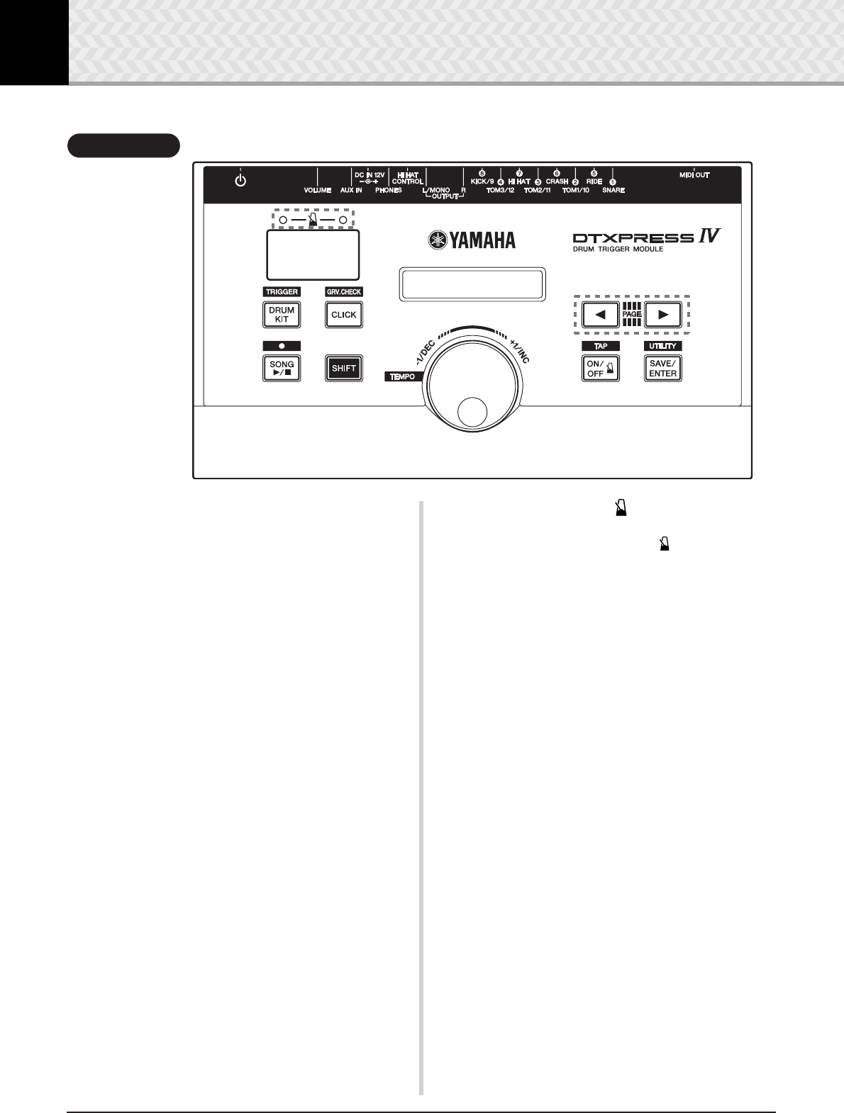
Controls and Functions
q
Drum Kit button (DRUM KIT)
•For entering the Drum Kit Select display
.
(p. 15)
•Hold the [SHIFT] button and press the [DRUM KIT] button to
enter the Trigger Setup Select page
.
(p. 14)
• This button can also be used to temporarily mute all sounds of
all voices.
w
Click button (CLICK)
•For entering the Click (Metronome) Setting page. (p. 18)
•Hold the [SHIFT] button and press the [CLICK] button to enter
the Groove Check Setting display
.
(p. 24)
e
Song button (SONG
>>
>>
/
■
)
•For entering the Song Select page
.
(p. 22)
•Hold the [SHIFT] button and press the [SONG >>
>>
/
■
] button to
enable recording standby mode for the DTXPRESS IV.
• Press this button to start/stop song playback or recording.
r
Shift button (SHIFT)
Holding this button and pressing another specific button switches
to the function printed above each button on the top panel.
t
Select buttons (
<<
<<
,
>>
>>
)
•For selecting an item you want to edit (the selected item
flashes). If there are multiple pages either before or after the
page currently displayed, the buttons are used to view the next
or previous page. Hold the button to continuously move the
flashing cursor.
• Press these two buttons together to scroll continuously back
and forth through the pages. Holding the [
<
] button first and
pressing the [
>
] button moves to the previous page while
holding the [
>
] button first and pressing the [
<
] button moves
to the next.
• Hold the [SHIFT] button and press the [
<
]/[
>
] buttons to
select the trigger input you want to edit.
y
Click ON/OFF button ( ON/OFF)
•For starting/stopping the click sound (metronome). (
p. 18
)
•Hold the [SHIFT] button and press the [ ON/OFF] button to
enter the Tap Tempo Setting page. (p. 21)
u
Save/Enter button (SAVE/ENTER)
•For saving data or executing an operation (Enter).
•Hold the [SHIFT] button and press the [SAVE/ENTER] button
to enter the Utility page, which is used to make overall settings
for operating the DTXPRESS IV.
i
Click lamp
The red lamp lights on the first beat of every measure when the
click or a song is playing. The other beats are indicated with a
green light.
o
LED display
For indicating the tempo, the number selected in the current page,
or the click timer depending on the setting made. (p. 21)
!0
LCD display
For displaying important information and data used in operating
the DTXPRESS IV.
!1
Jog dial
Rotate the jog dial to change the value selected with the cursor
(the flashed item to be edited) in the display. Rotate the dial to the
right (clockwise) to increase the value, and to the left to decrease.
The jog dial can also be used to change the layer (A/B) and for
Drum mute.
Hold the [SHIFT] button and rotate the knob to change the cur-
rent tempo.
~~~~~YAMAHA ~~~~
~~~DTXPRESS IV~~
8.8.8.
q
o
i
w
er yu
t
!0
!1
Top Panel
Controls and Functions
9
DTXPRESS
IV
Owner’s Manual
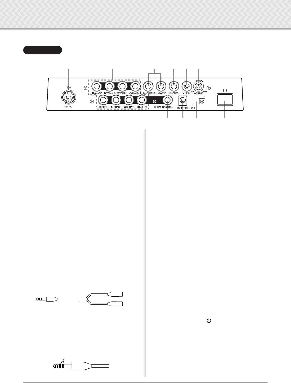
!2
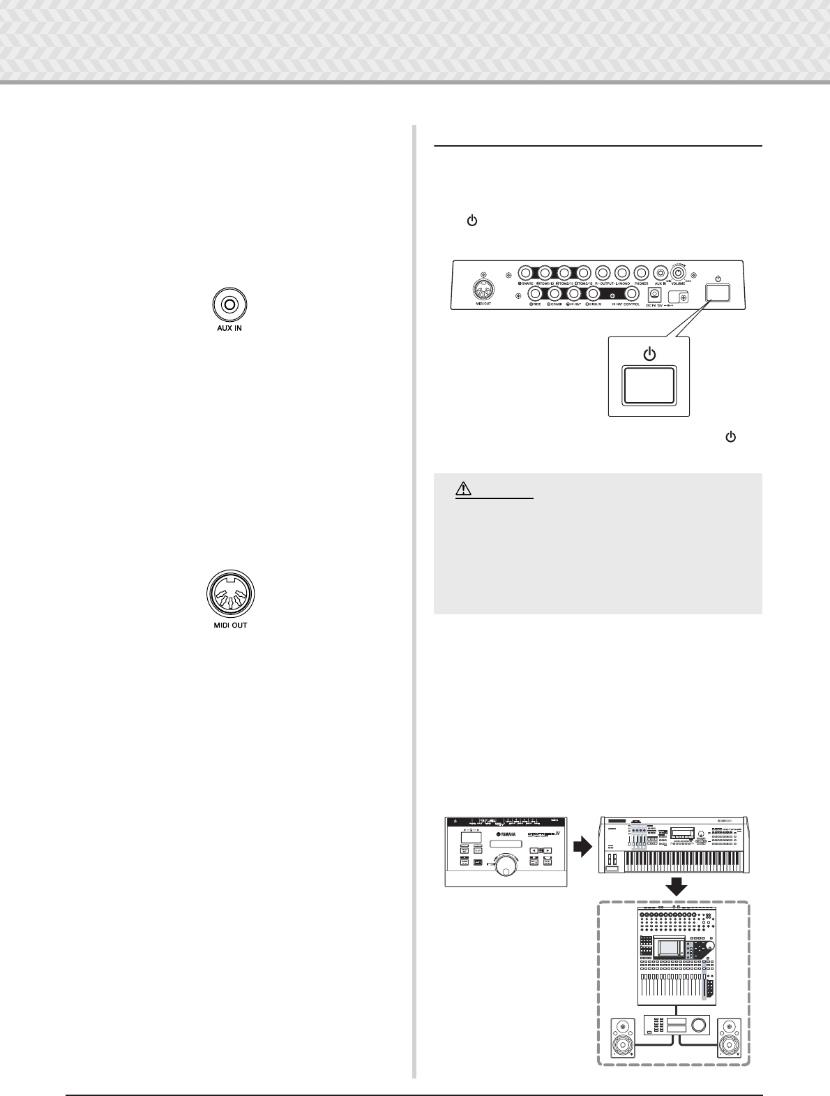
MIDI OUT jack
For sending data from the DTXPRESS IV to an external MIDI
device. With this jack, you can use the DTXPRESS IV as a con-
trol device to trigger voices from an external tone generator, or
synchronize song playback or the click of the DTXPRESS IV
with the playback of an external sequencer. (p. 13)
!3
Trigger Input jacks (
1
SNARE thru
8
KICK/9)
For connecting pads or drum triggers (Yamaha DT20, etc.) to
receive trigger signals.
Connect external pads such as a snare, tom, etc., according to the
indication below each input. (p. 10, 11)
1
SNARE ..................... Compatible with three-zone pads and the pad
controller.
2
TOM1/10,
3
TOM2/11,
4
TOM3/12,
8
KICK/9
.............................. Mono x 2 inputs
A Y-shaped cable (stereo plug—mono jack x
2; refer to the illustration below) can be used to
trigger inputs 9, 10, 11, and 12 (monaural pad).
Also, if the KP125/65 kick pad is connected to
this jack with a stereo cable, the external pad
input jack on the KP125/65 can be used as the
input for input jacks 9, 10, 11, or 12.
5
RIDE,
6
CRASH .....Compatible with three-zone pads.
7
HI HAT ..................... Compatible with stereo pads (with switches)
!4
Hi-hat controller jack (HI HAT CONTROL)
For connecting a hi-hat controller. (p. 10, 11)
* Use a cable with a stereo plug (shown below) when connect-
ing a hi-hat controller.
!5
Output jacks (OUTPUT L/MONO, R)
For connecting the DTXPRESS IV to an external amplifier, mixer,
etc.
For mono playback use the L/MONO jack. For stereo playback
connect both L and R jacks. (p. 12)
!6
Headphones jack (PHONES)
Connect a set of stereo headphones to this jack to monitor the
DTXPRESS IV. (p. 12)
!7
AUX IN jack
Connect the output of an external audio device, etc., to this jack
(stereo mini jack). (p. 13)
This is convenient for playing along with music from a CD
player, etc.
* Use the volume control on the external device to adjust the
volume balance.
!8
Master Volume (VOLUME)
Adjusts the DTXPRESS IV’s overall volume (output level of the
signal sent via the OUTPUT jacks and PHONES jack). Rotate the
knob clockwise to increase the volume, or counter-clockwise to
decrease it.
!9
Power supply jack (DC IN 12V)
Connect the supplied AC power adaptor to this jack. To prevent
the adaptor from becoming unplugged, secure the cable to the
cable clip.
@0
Cable clip
Prevents the power cord from accidentally becoming unplugged.
(p. 12)
@1
Standby/On switch ( )
The power is turned on when the button is set to this position:
(
>
). The power is off when set this way: (
?
).
!2 !3 !6 !7 !8!5
!4 !9 @0 @1
Rear Panel
Stereo phone plug
Mono phone jack
Mono phone jack
● Y-shaped cable
Double insulator
10 DTXPRESS IV Owner’s Manual
1Connections
In this chapter, you’ll learn how to set up the DTXPRESS IV. Read these instructions carefully
and in the following order to ensure that the instrument sounds and operates properly:
1 Connecting the Pads → 2 Setting Up the Power Supply (p. 12) → 3 Connecting to Speakers or Head-
phones (p. 12) → 4 Turning the Power On (p. 13) → 5 Selecting the Trigger Setup (p. 14)
1 Connecting the Pads
Referring to the illustration below, connect the output cable from each pad to each Trigger Input jack located on the rear panel of the DTX-
PRESS IV. All Trigger Input jacks are conveniently labeled (1 SNARE, etc.), so make sure each pad is connected to its corresponding
Trigger Input jack.
!! IMPORTANT !!
You’ll need to change the Trigger Settings of the DTXPRESS IV according to the type of drum set you are using
(Standard Set/Special Set/Acoustic Drums, etc.). If the setting is not appropriate, problems may occur—such
as improper sound, or inappropriate volume balance among the pads.
Refer to the “Selecting the Trigger Setup” section on page 14 on how to select the appropriate setup.
To prevent electric shock and damage to the devices, make sure the power is switched OFF on the DTXPRESS
IV and all related devices before making any connections to the DTXPRESS IV’s input and output jacks.
CAUTION
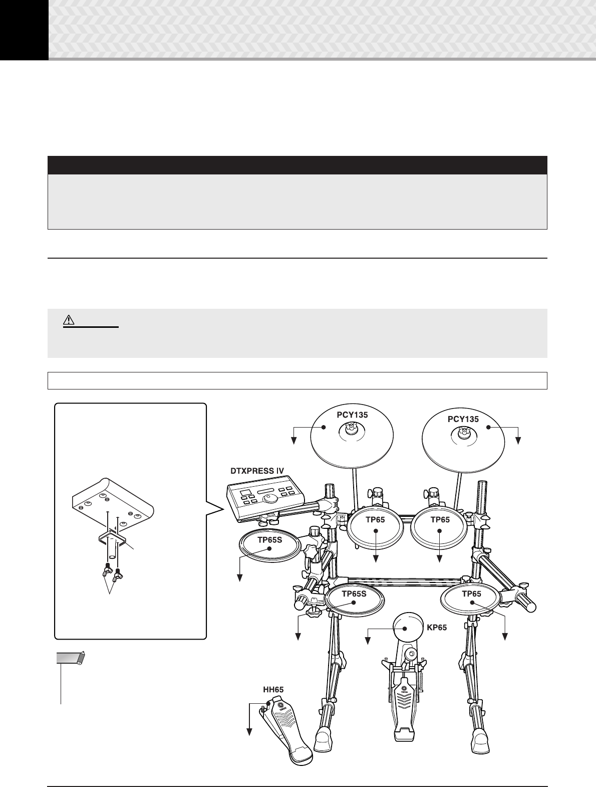
DTXPRESS IV Standard Set
•The hi-hat pad can also be attached to the
pipe to which the DTXPRESS IV is
attached.
NOTE
Attaching the Module Stand
Attach the included module stand to
the DTXPRESS IV using the module
stand fastening screws.
To 1SNARE To 8KICK
To 2TOM1 To 3TOM2
To 4TOM3
To HI HAT
CONTROL
To 7HI HAT
To 6CRASH To 5RIDE
DTXPRESS IV
Module stand
(included)
Module stand fastening
screws (2; included)
* Be sure to use the included screws.
*Foot pedal is not included
in the Standard Set.
1 Connections
11
DTXPRESS IV Owner’s Manual
The DTXPRESS IV can be played from an acoustic drum kit if the kit is fitted with an optional set of drum triggers (such as Yamaha DT20
Drum Triggers) and the triggers are properly connected to the input jacks of the DTXPRESS IV.
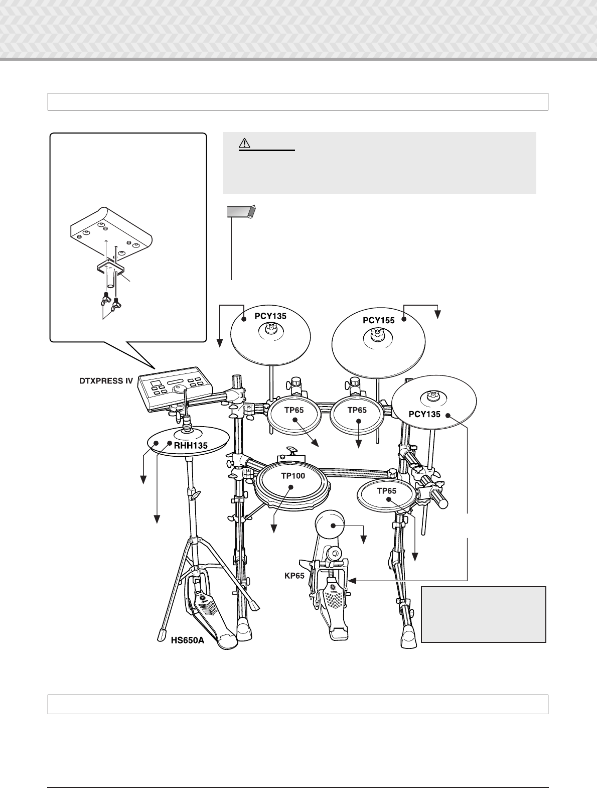
DTXPRESS IV Special Set
Setting up with Acoustic Drums
Attaching the Module Stand
Attach the included module stand to the
DTXPRESS IV using the module stand
fastening screws.
* Be sure to use the included screws.
When assembling the Special Set, the legs of the rack must be slid
backwards to maintain proper balance of the set. For details, refer
to the assembly instructions of the rack system.
CAUTION
To 1SNARE
To 8KICK
To 2TOM1 To 3TOM2
To 4TOM3
To HI HAT
CONTROL
To 6CRASH
To 5RIDE
DTXPRESS IV
Module stand
(included)
Module stand fastening
screws (2; included)
* First, connect the RHH135’s [PAD]
output jack to the 7 HI HAT jack on
the DTXPRESS IV, then connect the
RHH135’s [HI HAT CONTROL] out-
put jack to the HI HAT CONTROL
jack on the DTXPRESS IV.
To the external pad input
jack of KP65 (kick pad)
To 7HI HAT
*Foot pedal is not included in the
Special Set.
•The pad models described in the illustrations were included in the Standard Set/Special
Set at the moment this Owner’s Manual was produced. Keep in mind that the model names
of your Standard Set or Special Set may be different from the ones illustrated here. For
details about the latest information on Yamaha drum pads, refer to the following website.
http://www.yamaha.co.jp/english/product/drums/ed/
NOTE
* The sound produced by the
edge and cup section of
PCY135 connected to KP65’s
external pad input will not be
produced.
1 Connections
12
DTXPRESS
IV
Owner’s Manual
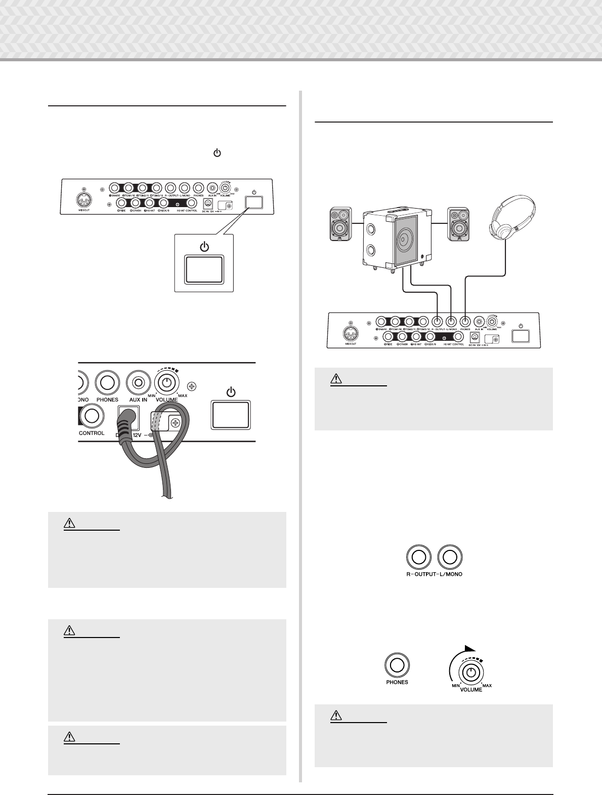
2 Setting Up the Power Supply
A special power source adaptor supplies power to the DTX-
PRESS IV.
2-1.
Make sure that the Standby/On switch ( ) of the DTX-
PRESS IV is set to the standby (
?
) position.
2-2.
Connect the DC plug of the included AC power adaptor to
the DC IN jack on the rear panel.
To prevent the cord from being unplugged accidentally,
wrap the cord around the cable clip and secure it.
2-3.
Connect the other end of the power cord to an AC outlet.
3 Connecting to Speakers or
Headphones
Since the DTXPRESS IV has no built-in speakers, you’ll need an
external audio system or a set of stereo headphones to properly
monitor it.
●
OUTPUT L/MONO, R jacks (standard mono phone)
These jacks allow you to connect the DTXPRESS IV to an exter-
nal amplifier + speakers and produce full, amplified sound, or
connect the DTXPRESS IV to audio recording equipment for
recording your own performance.
* Use the DTXPRESS IV’s OUTPUT L/MONO jack when
connecting to a device with a mono input.
●
PHONES jack (standard stereo phone jack)
Use the VOLUME knob on the rear panel to adjust the headphone
volume.
Make sure that the power adaptor’s cord is not
bent at an extreme angle when wrapping the
cord around the clip. Doing this can damage or
sever the cord and create a fire hazard.
•Please use the included AC power adaptor. The
use of any other adaptors may cause irregular
operation or damage to the device.
• Only use the voltage specified as correct for
the DTXPRESS IV. The required voltage is
printed on the name plate of the DTXPRESS IV.
•Unplug the AC Power Adaptor when not using
the DTXPRESS IV, or during electrical storms.
CAUTION
WARNING
CAUTION
Whenever making connections, make sure that
the plug on the cable being used corresponds to
the type of jack on the device.
Do not use the DTXPRESS IV at a high volume
level for a long period of time, or your hearing
may be damaged.
Headphones
Monitor system for the DTX series
MS100DRJ, MS50DRJ, etc.
OUTPUT L/MONO and R jacks PHONES jack
CAUTION
CAUTION
1 Connections
13
DTXPRESS
IV
Owner’s Manual
●
AUX IN jack (stereo mini phone jack)
The audio output from a MP3 player or CD player connected to
the AUX IN jack can be mixed with the sound of the DTXPRESS
IV and transmitted via the OUTPUT jacks or PHONES jack. This
jack can be used when you want to play along with your favorite
songs.
* Use the volume control on the external device (MP3 player,
etc.) to adjust the volume balance.
●
MIDI OUT jack
The MIDI functions on the DTXPRESS IV lets you play voices
on an external tone generator with the pads of the DTXPRESS
IV, or synchronize the DTXPRESS IV’s song or click playback
with the playback of an external sequencer.
About MIDI
MIDI (Musical Instrument Digital Interface) is a worldwide standard
that enables you to connect instruments and computers—of different
manufacturers and different types—and transmit performance and
other data among them.
* Also, use a MIDI cable that is not more than 15 meters in
length. Using a longer cable may result in irregular operation
and other problems.
4Turning the Power On
4-1.
Make sure the volume settings of the DTXPRESS IV and
external devices are turned down to the minimum.
4-2.
Turn the power on (
>
) by pressing the Standby/On switch
() on the rear panel of the DTXPRESS IV, then turn on
the power of the amplifiers.
4-3.
To turn off the power, press the Standby/On switch ( )
again.
●
Connecting a Mixer or MIDI Devices
Make sure that all volume settings are turned down all the way to
the minimum. Then turn on the every device in your setup in the
order of MIDI masters (controllers), MIDI slaves (receivers),
then audio equipment (mixers, amplifiers, speakers, etc.).
When powering down the setup, first turn down the volume for
each audio devices, then switch off each device in the reverse
order (first audio equipment, then MIDI).
Even when the instrument is turned off, electric-
ity is still flowing to the instrument at the mini-
mum level. When you are not using the
DTXPRESS IV for a long time, make sure to
unplug the AC power adaptor from the wall AC
outlet.
CAUTION
MUSIC PRODUCTION SYNTHESIZER
*~~DTXPRESS~IV~*
*~~~Welcome!~~~*
8.8.8.
3
Audio equipment
(first mixer, then amplifier)
1
DTXPRESS IV (MIDI Master)
2
MIDI slave
1 Connections
14 DTXPRESS IV Owner’s Manual
5 Selecting the Trigger Setup
This setting lets you select the Trigger Setup that most closely
matches the trigger output levels and functions of your pads.
Select an appropriate Trigger Setup for your drum kit from the
pre-programmed Trigger Setups in the DTXPRESS IV.
Use the operation described below to select the Trigger Setup you
want to use.
●Procedure
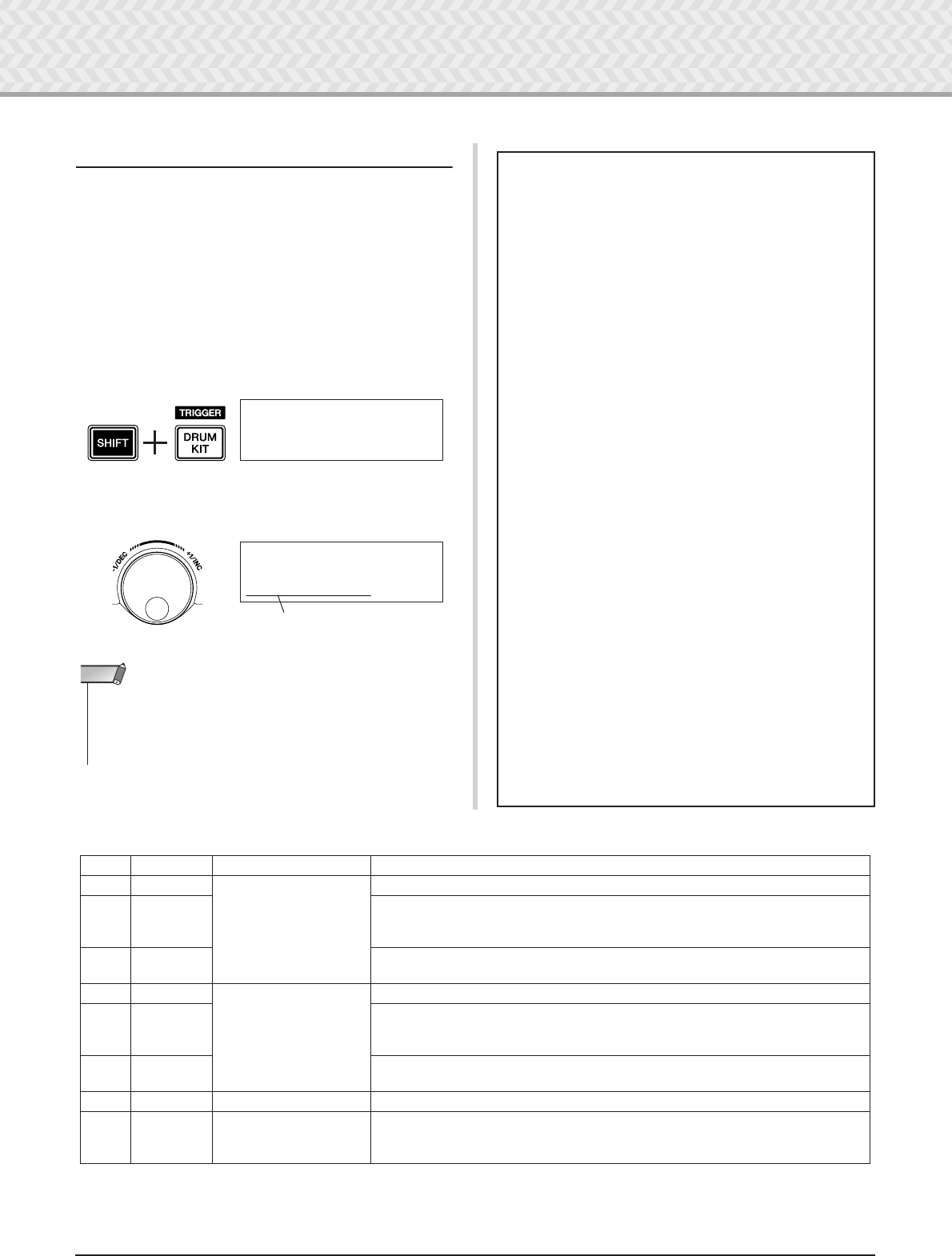
5-1. Press the [SHIFT] + [DRUM KIT] buttons to view Page 1 in
the Trigger Setup Select display (TRG1).
5-2. Rotate the jog dial to select the Trigger Setup that matches
the drum kit you are using.
●Trigger Setup List
TRG1~~~ååååååååå
1~:SP~Med~~~~~~‚
Tr igger Setup
TRG1~~~ååååååååå
4~:STD~Med~~~~~‚
•If you want to replace some of the pads from the DTXPRESS IV
Standard Set / Special Set, refer to the operation on page 36 (Trig-
ger Setup Edit) after the above setting is done, to make sure that
the settings (such as sensitivity) are appropriate for each pad.
NOTE
●About Connecting Pads
• The DTXPRESS IV’s input jack parameters are preset with
settings suitable for pads when an appropriate Trigger Setup
is selected. If you intend to connect any other type of pad or
a drum trigger (Yamaha DT20, etc.) to the input jack, that
jack’s parameters (sensitivity, etc.) should be changed to set-
tings that suit the particular pad. Pad sensitivity is set in the
Trigger Setup Select display’s Page 3 [TRG3 Gain] setting
(p. 38).
•Pad-controller-equipped pads like the TP120SD, TP100,
etc., can be connected to Trigger Input jack 1SNARE.
• Three-zone pads like the TP65S, PCY155/150S, PCY135/
130SC, etc., can be connected to Trigger Input jacks
5RIDE and 6CRASH.
•7HI HAT is a stereo input type jack. Pads equipped with
trigger switches like the TP65S, PCY65S, PCY130S, etc.
can be connected to this jack.
• The 2TOM1/10, 3TOM2/11, 4TOM3/12 jacks corre-
spond to a two-trigger input that uses a stereo jack for L and
R. A Y-shaped cable (stereo plug—mono jack x 2) can be
used to input two trigger signals.
• The 8KICK/9 jack accepts a two-trigger input using a ste-
reo cable and jack for L and R signals. A Y-shaped cable
(stereo plug—mono jack x 2) can be used to input two trig-
ger signals.
Also, if the KP125/65 kick pad is connected to the DTX-
PRESS IV’s input jack 9 with a stereo cable, the external
pad input jack on the KP125/65 can be used as the input for
Input jack 9.
• In addition to the 8KICK/9 jack, the 2TOM1/10,
3TOM2/11, and 4 TOM3/12 jacks can be used to connect
a second bass drum pedal to create a double-bass drum set.
* In the default setting, "1. SP Med" for Special Drum Set is selected.
No. Name Features
1 SP Med
for Special Drum Set
Normal setting
2 SP Dyna
Wide dynamic range. This setting is designed for maximum expressive control, allow-
ing performance subtleties over a wide dynamic range. Excessive vibration however,
may result in crosstalk (sound being produced by other pads).
3 SP Easy Controlled dynamic range delivers stable trigger detection. This setting is designed
for producing a smoother, more uniform sound with reduced volume fluctuations.
4 STD Med
for Standard Drum Set
Normal setting
5 STD Dyna
Wide dynamic range. This setting is designed for maximum expressive control, allow-
ing performance subtleties over a wide dynamic range. Excessive vibration however,
may result in crosstalk (sound being produced by other pads).
6 STD Easy Controlled dynamic range delivers stable trigger detection. This setting is designed
for producing a smoother, more uniform sound with reduced volume fluctuations.
7 DT10/20 — Use for DT10/20 drum trigger systems applied to acoustic drums.
8
|
11
UserTrig — Allows creation of custom trigger setups. (
→
Settings are made using Trigger Setup
Edit on page 36.)
15
DTXPRESS IV Owner’s Manual
2 Time to Play
Now that your DTXPRESS IV is properly connected, it’s time to make some music!
1
Play the DTXPRESS IV
While hitting the pads, turn the VOLUME knob on the rear
panel to raise the overall volume to a comfortable level.
The trigger input level will be displayed in the bar graph in
the upper right corner of the display. The bar graph indicates
the input levels of the following input jacks.
2
Select a Drum Kit
A ‘Drum Kit’ is a collection of drum sounds (or voices) that
play when you hit the pads. Try selecting some of the Drum
Kits (1–50) and enjoy the variety of sounds and drum setups
available.
* Preset Drum Kit List (p. 49)
Rotate the jog dial to select a Drum Kit.
Try out the different drum kits and select one drum kit you
like.
* Some Drum Kits have pad songs and drum loops that start
playback when the corresponding pad is hit.
3
Change the Volume for Each Pad
Change the volume for each pad and adjust the overall bal-
ance of the Drum Kit.
Press the [>] button once in the previous Drum Kit Select
page.
The following display appears and the flashing cursor is at
“˙” in the LCD.
Press the [>] button again to move the flashing cursor to the
“S” position, the first character of “S01:OakCustom”.
Press the [>] button twice to view the KIT 3 page.
Use the [<]/[>] buttons in this manner to select the desired
item (the cursor flashes). When the page only contains a sin-
gle item, pressing the [<]/[>] buttons will select the next or
previous page.
*The “‚” mark on the lower right side of the display indicates
that a succeeding page is available. Likewise, the “”” mark
on the lower left side of the display indicates that a previous
page is available.
In the KIT 3 page, hit the pad for which you want to change
the volume. The selected pad (input jack) is shown in the
upper half of the display.
Rotate the jog dial to adjust the volume (the value is flashing)
of the pad.
*Some drum voices have two voices in a layer (in other words,
two voices sound at the same time when a pad is hit). In case
of two-layer voices, select the ˙ or ¶ mark in the upper right
side of the display (press the [<]/[>] buttons so that the
mark flashes, and use the jog dial to select) then adjust each
volume.
Bar graph (from left) Corresponding input jacks
1
2
3
4
5
6
7
8
9
1 SNARE
2 TOM1/10
3 TOM2/11
4 TOM3/12
5 RIDE
6 CRASH
7 HI HAT
8 KICK
8 PAD9
Bar graph
KIT1~~~∑åååååø¥å
1~:Oak~Custom~~‚
KIT1~~~ååååååååå
1~:Oak~Custom~~‚
Drum kit Number Drum kit Name
KIT2~~~ƒsnare~~˙
”S01:OakCustom~‚
KIT2~~~ƒsnare~~˙
”S01:OakCustom~‚
KIT3~~~ƒsnare~~
”~~Volume=120~~‚
KIT3~~~™tom1~~~˙
”~~Volume=120~~‚
Volume (0–127)
Pad (Input jack)
Layer (˙/¶)
2 Time to Play
16 DTXPRESS IV Owner’s Manual
4
Change the Output Sound Quality
Use the Master Equalizer found on Utility Page 5 to change
the output sound quality. Overall settings for the DTXPRESS
IV are set in the Utility pages.
First, press the [SHIFT] + [SAVE/ENTER] buttons to view
the Utility pages.
Press the [>] button five times to view Utility Page 5.
Now use the Master Equalizer (two-band shelving type) set-
ting to change the sound quality.
“Lo=” is for the low-range gain setting (+0dB to +12dB) and
“Hi=” for the high-range gain setting (+0dB to +12dB).
Press the [<]/[>] buttons to move the flashing cursor to the
item you want to set, then rotate the jog dial to set its value.
You can also adjust or set the individual pad voices,
tuning, reverb type/level, and other settings that fine
tune the DTXPRESS IV (p. 28).
An asterisk “*” will appear next to “KIT3” in the
display once the volume is changed, indicating
that the kit has been edited. This asterisk will
disappear after the Store operation (p. 34) is car-
ried out. If a different drum kit is selected, etc.,
before carrying out the Store operation, the cur-
rent settings will return to their original condi-
tion. If you want to keep changes made to the
data, make sure you carry out the Store opera-
tion.
CAUTION
KIT3*~~™tom1~~~˙
”~~Volume=110~~‚
Utility (Page 1)
UTIL1~Hi-hat
HHofs=~~0~T=~~5‚
UTIL5~MasterEQ
”Lo=+~2~Hi=+~2~‚
UTIL5~MasterEQ
”Lo=+~8~Hi=+~0~‚
Adjusting the Hi-hat
Hi-hat adjustment is used to determine the point at which
the hi-hat closes when the hi-hat pedal (foot controller) is
pressed. You can also set the threshold at which foot
‘splashes’ are produced.
* This setting is only valid when a foot controller is con-
nected to the HI HAT CONTROL jack. The setting has no
effect on a foot controller connected to any other jack.
Operation
1. Press the [SHIFT] + [SAVE/ENTER] buttons to view
Utility Page 1.
Use this display to adjust the hi-hat.
2. To set the point at which the hi-hat closes, move the
flashing cursor to the “HHofs=” value then use the
jog dial to adjust the value.
The range of adjustment is -32 to 0 to +32. Smaller
values produce a shallower closing point.
To set the ease at which foot splashes are produced,
move the flashing cursor to the “T=” value then use
the jog dial to adjust the value.
Settings include “off” and a range of 1 to 127. Larger
values make foot splashes that are long and easier to
produce. When this is set to “off,” foot splashes are
not produced.
*Too high a value will make foot splashes too easy to pro-
duce, resulting in the continuous production of foot
splashes when the pedal is held down continuously.
UTIL1~Hi-hat
HHofs=~~0~T=~~5‚
UTIL1~Hi-hat
HHofs=-12~T=~~5‚
UTIL1~Hi-hat
HHofs=-12~T=~20‚
2 Time to Play
17
DTXPRESS IV Owner’s Manual
Pad Controller Settings
When a pad-controller-equipped pad (TP100, etc.) is connected, you can adjust the snares setting and tightness, tuning, or
tempo by rotating the pad controller knob of the pad.
Operation (for Special Set users)
In the default setting, you can adjust the snares setting
and tightness using the pad controller of the TP100 (the
snare drum pad). To use functions other than the snares
adjustment, change the setting as follows.
1. Press the [DRUM KIT] button to enter the Drum Kit
Select display.
2. Next, continue pressing the [>] button until Page 22
of the Drum Kit Select pages is called up.
3. Rotate the jog dial to change the value for
“PadCtl=”. You can select from the following func-
tions.
off .......... No function is assigned.
snares .... Adjusting the snares setting and tight-
ness (also affects the open rim sound)
tuning
.... Tuning adjustment (also affects the open
rim sound)
tempo ...... Adjusting the tempo
Operation (Replacing the pad with one equipped
with pad controller)
Here’s how you can use the pad with pad controller
(TP100) as a snare drum.
1. Use the TP100’s supplied cable to connect the TP100
with trigger input 1SNARE on the DTXPRESS IV.
*Use ONLY the TP100’s supplied cable. If another cable is
used, the pad controller or the pad may not perform prop-
erly.
*The other trigger input jacks other than the 1SNARE are
not compatible with pad-controller-equipped pads. The
pad controller will not work if this type of pad is connected
to a trigger input jack other than 1SNARE.
2. Press the [SHIFT] + [DRUM KIT] buttons to view the
Tr igger Setup display.
3. Next, press the [>] button once to view the following
display (pad type).
Hit the snare pad to view “ƒsnare” in the upper half
of the display, then rotate the jog dial to set
“Type=~TP1/Snr.”
4. Now you are ready to use the pad-controller-
equipped pad.
See the section “Operation (for Special Set users)” in
the left column to change the function you want to
use for the pad controller.
KIT1~~~_________
1~:Oak~Custom~~‚
KIT22*
”PadCtl=tuning~‚
An asterisk “*” will appear next to “KIT22”
in the display if the data has been changed.
This asterisk will disappear after the Store
operation (p. 34) is carried out. If a different
drum kit is selected or the power is turned
off before carrying out the Store operation,
the current settings will return to their origi-
nal condition. If you want to keep changes
made to the data, make sure to carry out the
Store operation.
CAUTION
TRG1~~~ååååååååå
4~:STD~Med~~~~~‚
TRG2*~ƒsnare~~0%
”Type=~TP1/Snr~‚
An asterisk “*” will appear next to “TRG2” in
the display if the data has been changed.
This asterisk will disappear after the Store
operation (p. 36) is carried out. If a different
drum kit is selected or the power is turned
off before carrying out the Store operation,
the current settings will return to their origi-
nal condition. If you want to use the selected
pad again, make sure to carry out the Store
operation.
CAUTION
18 DTXPRESS IV Owner’s Manual
3 Playing Along With the Click
Play the DTXPRESS IV along with the click (metronome).
The DTXPRESS IV is equipped with a high-performance metronome that gives you a compre-
hensive variety of settings and allows you to create complex rhythms.
1
Start the Click (Metronome)
Press the [ ON/OFF] button to start the click sound. The
left lamp lights in red on the first beat of every measure when
the click is playing. Other beats are indicated with the right
lamp in green. The click tempo (q=) is also indicated on the
LED display. Press the [ ON/OFF] button again to stop.
*If tempo is not shown, change the LED display setting (p.
21) to “Disp=tempo.”
2
Set the settings for Click Set, Tempo, Beat,
etc.
By fine tuning the different note value clicks that are shown
in the illustration below, the DTXPRESS IV can be used to
create a variety of click patterns. The patterns you set are
called Click Sets, and you can save up to 30 original patterns
in the DTXPRESS IV’s memory.
Example: Beat timings used when Beat=4
Press the [CLICK] button to view Click Setting Page 1.
Use this display to select the desired Click Set, and then set
the beat, tempo, timer, and the click sound’s overall volume.
Press the [<]/[>] buttons to move the flashing cursor to the
item you want to set, then rotate the jog dial to set its value.
• Click Set Number [Range] 1 to 30
Selects the Click Set to be used.
• Beat [Range] 1 to 9
Determines the click’s time signature.
•Tempo [Range] 30 to 300
Determines the click’s tempo (q=).
* The tempo can also be set using the Tap Tempo Func-
tion. This function lets you set the song or click’s tempo
by tapping in tempo on a pad. With this, you can set the
tempo to one that feels best to you. Refer to page 21 for
more information.
• Click Timer [Range] 0 to 600 seconds (in 30-second
steps)
This function is used to automatically stop the click at the
time set in this setting.
*The value (the remaining number of seconds) of the Click
Timer can be shown in the LED display. Refer to page 21
for more information.
• Click Master Volume [Range] 0 to 16
Determines the click’s overall volume.
* When the flashing cursor is not positioned here, the
speaker icon will be displayed.
123
1st beat (red) Other beats (green)
CLK1~~~~∫~B=4~÷ç
1~:User~~~⁄=123‚
An asterisk “*” will appear next to “CLK1” in the
display if settings for beat and tempo are
changed. This asterisk will disappear after the
Store operation (p. 20) is carried out. If a differ-
ent Click Set is selected, etc., before carrying
out the Store Operation, the current settings will
return to their original condition. If you want to
keep changes made to the data, make sure to
carry out the Store Operation.
Tempo
Click Setting display (page 1)
Click Timer
Click Master Volume
Click Set Number:
Click Set Name
Beat
CLK1~~~~∫~B=4~÷ç
1~:User~~~⁄=123‚
CAUTION
CLK1*~~~∫~B=4~÷ç
1~:User~~~⁄=130‚
3 Playing Along With the Click
19
DTXPRESS IV Owner’s Manual
3
Create Your Own Original Click Set
Press the [>] button to view Click Setting Page 2.
Use this display to set the individual volume levels (0 to 9)
for each of the five click beats. Set the volume level to “0” if
you don’t want the beat to sound. Use this page to create your
own original click set.
*For details about the five click beats, see the illustration
example “Beat timings used when Beat=4” in step 2 on page
18.
4
Set the Click Measure Break
Press the [>] button to view Click Setting Page 3.
The Click Measure Break puts a muted “break” for the num-
ber of measures decided with the “Brk” setting (off, 1 to 9)
after the click has played for the number of measures deter-
mined by the “Meas” setting (1 to 9). When values are set as
above, the click is played for a measure then muted for 3
measures.
* Decide the number of measures to be muted at “Brk=” then
the number of measures to be played at “Meas=.”
* If the setting “Brk=off” is used, the click will not be muted.
5
Set the Click Sound Set
Press the [>] button to view page 4 in the Click Setting dis-
play.
The Click Sound Set is used to assign the five different click
sounds that are produced by the metronome. The sounds are
changed as a group.
[Range] Metronome, Wood Block, Percussion,
Agogo, Stick, Pulse, UserClick
With the “UserClick” setting you can use the CLK5 and
CLK6 pages to fine-tune the click sound settings.
6
Set the User Click Sounds
Press the [>] button to view Click Setting Page 5.
You can assign a different drum voice to each of the five click
voices.
* This setting is only available if “UserClick” is selected in
the CLK4 page.
First, select the click value type (A˘, ⁄, ‹, ßß, Œ) in the
upper half of the display, then move the flashing cursor to the
lower half of the display and select the voice you want to
assign to the click.)
First, select the voice category.
● Voice Category
K : Kick
S : Snare
T : Tom
C : Cymbal
H : Hi-hat
P : Percussion
E : Effect
Next, select the voice number and voice name. If the voice
number is set to “
00
,” the indication “
NoAssign
” is shown
for the voice name and no sound will be produced.
7
Tuning the User Click Sounds
Press the [>] button to view Click Setting Page 6.
You can individually tune each of the five click sounds.
* This setting is only available if “UserClick” is selected in
the CLK4 page.
First, select the click value type in the upper half of the dis-
play, and then move the flashing cursor to the lower half of
the display and set the tuning value in semitones (-24.0 to 0 to
+ 24.0).
CLK2*~A˘=9~⁄=9
”~‹=6~ßß=4~Œ=2~‚
CLK3*MeasBreak
”Meas=1~Brk=3~~‚
CLK4*Sound
”~1:Metronome~~‚
Voice Category/Voice Number: Voice Name
CLK5*Sound=¤
”E20:Click1~~~~‚
Click Value Type
Click Value Type
Tuning
CLK6*Sound=¤
”~~Tune=+~0.0
3 Playing Along With the Click
20 DTXPRESS IV Owner’s Manual
8
Save an Original Click Set
After creating your own original Click Set, save it in the
DTXPRESS IV’s memory using the Store Operation
described below.
8-1. Press the [SAVE/ENTER] button. The following dis-
play will appear.
8-2. Rotate the jog dial to select the destination memory
number (1 to 30) to which you want to store the Click
Set.
8-3. If you want to change the Click Set name, press the
[<]/[>] buttons to move the flashing cursor to the
character you want to edit, then rotate the jog dial to
select the desired character. A Click Set name can con-
tain a maximum of six characters, and these can be
selected from the following list.
8-4. Press the [SAVE/ENTER] button again. A prompt
appears asking you to confirm the Store operation.
8-5. Press the [SAVE/ENTER] button to actually execute
the Store operation.
*To cancel the Store operation, press any button
except for the [SAVE/ENTER] and [SHIFT] buttons.
(When “Are you sure?” appears in the display, the jog
dial will also cancel the operation.)
The following display appears after the Store opera-
tion is complete.
Any changes made to the data will be lost if
another Click Set is selected before carrying out
the store operation. If you want to keep settings
or changes, make sure to carry out the Store
Operation.
CAUTION
Click Set Name
CLK~save~to~1
:[User~~]
Store Destination
space
!"#$%&'()*+,-./0123456789:;<=>?@
ABCDEFGHIJKLMNOPQRSTUVWXYZ[\]^_`
abcdefghijklmnopqrstuvwxyz{|}≥≤
CLK~save~to~1
~Are~you~sure~?
~~~Completed!
Click Out Select
The DTXPRESS IV lets you select from which output jack
the signal of the click (metronome) is sent. Click output
and performance output can be routed to separate out-
puts.
Operation
1. First, press the [SHIFT] + [SAVE/ENTER] buttons to
call up the Utility display.
2. Next, press the [>] button twice to call up the follow-
ing display.
3. Rotate the jog dial to select the output from the out-
puts listed below.
mix This is the standard output setting. The click sig-
nal is output from both the OUTPUT L and R
jacks.
clickL The click signal is output from the OUTPUT L
jack only. All drum performance and song play-
back are output in mono via the OUTPUT R jack.
clickR The click signal is output from the OUTPUT R
jack only. All drum performance and song play-
back are output in mono via the OUTPUT L jack.
* The PHONES jack outputs the same signal as the OUT-
PUT jacks. The settings in this section would then also be
applied to the PHONES jack’s stereo L and R.
•You can use the Factory Set operation to reset the click sets 1
through 30 to their original factory condition. However,
please proceed with caution because carrying out this opera-
tion will rewrite the DTXPRESS IV’s entire contents (all
Click Sets, User Trigger Setups 8–11, User Drum Kits 51–70,
User Songs 64–83, Utility settings) with the data that was set
in the unit’s memory when it was shipped from the factory (p.
35).
NOTE
UTIL1~Hi-hat
HHofs=~~0~T=~~5‚
UTIL2~Click
”OutSel=mix~~~~‚
3 Playing Along With the Click
21
DTXPRESS IV Owner’s Manual
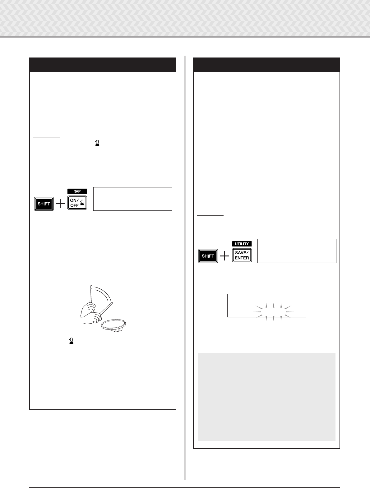
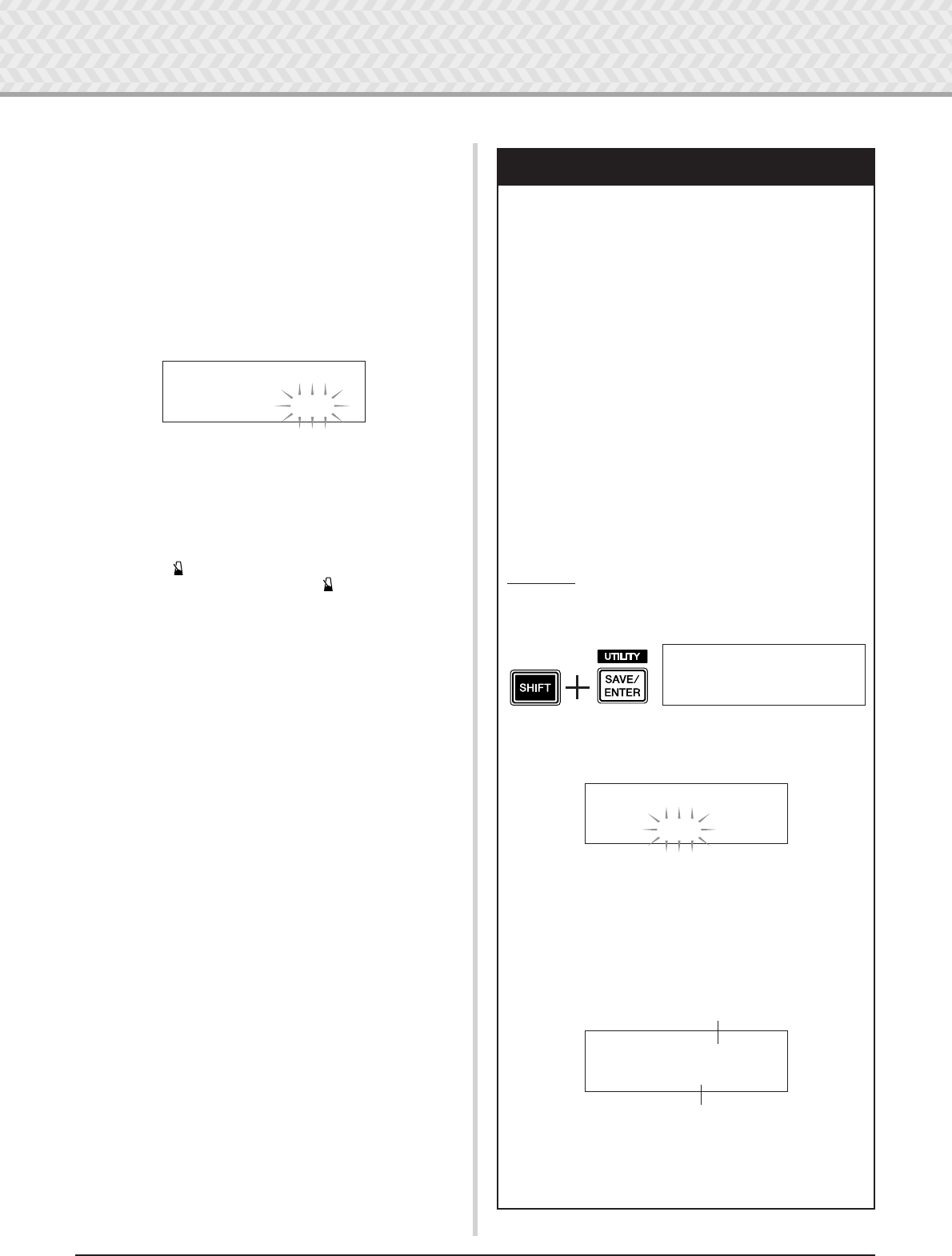
Tap Tempo Function
With the Tap Tempo Function, you can set the song or
click’s tempo by manually tapping in the tempo on a pad.
This lets you set the tempo to one that is most comfortable
for you.
The [<<
<<]/[>>
>>] buttons can also be used to set the tempo
instead of tapping on a pad.
Operation
1. Press the [SHIFT] + [ ON/OFF] button.
The Tap Tempo Setting display shown below will
appear.
* The Tap Tempo function can even be used during song
playback or while the click is sounding.
2. Tap on the pad at the tempo in which you want to play
the song. (Or use the [<]/[>] buttons.) Tap on the pad
steadily and repeatedly—as many times as there are
circles (≠ªªªª) in the display. Every time you tap a
circle disappears, and the resulting tempo value is set
and shown in the LED display.
*Any pad will do.
* The jog dial can also be used to change the tempo value.
3. Press the [ ON/OFF] button to hear your newly set
tempo.
4. Press the [DRUM KIT], [CLICK], or [SONG >/■] but-
ton to exit from the Tap Tempo page. In the Click Set-
ting page and Song Select page, the tempo is set to
the newly selected tempo. If the song or click is play-
ing, the tempo will immediately change to the new
tempo.
TAP~TEMPO
¤=123~≠ªªªª
LED Display Setting
Generally, the tempo is shown in the LED display. You can
change the value to be displayed to one of the following
three types.
tempo ..... Shows the current tempo.
mode........ • When pressing the [DRUM KIT] button:
Drum kit Number
• When pressing the [SHIFT] + [DRUM KIT]
buttons: Trigger Setup Number
• When pressing the [SONG] button: Song
Number
• When pressing the [CLICK] button: Click
Set Number
• When pressing the [SHIFT] + [SAVE/
ENTER] buttons: Shows nothing.
• Others: Shows the current tempo.
timer ......Shows the current click timer (p. 18).
Operation
1. First, press the [SHIFT] + [SAVE/ENTER] buttons to
call up the Utility pages.
2. Next, press the [>] button four times to call up the fol-
lowing page.
3. Rotate the jog dial to select the type you want to dis-
play.
UTIL1~Hi-hat
HHofs=~~0~T=~~5‚
UTIL4~LED
”~Disp=tempo~~~‚
Even though a parameter value other than “tempo”
is shown in the LED display, when tempo is
changed by one of the operations below, the new
tempo briefly appears in the LED after the change is
made.
• When the tempo is changed by holding the
[SHIFT] button and rotating the jog dial.
• When operating a pad controller (p. 17) whose
function is set to “tempo.”
• When hitting a specific pad whose pad function
(p. 23) is set to “inc tempo” or “dec tempo.”
22 DTXPRESS IV Owner’s Manual
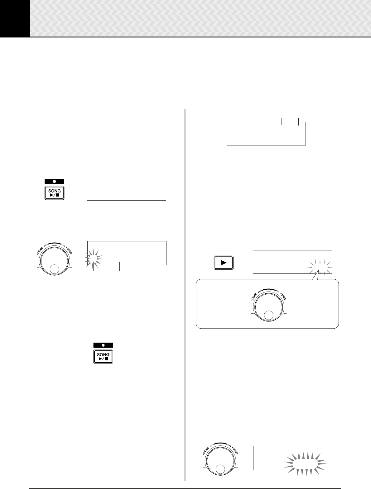
4 Playing Along With a Song
The DTXPRESS IV contains a wide variety of 63 preset songs. Try selecting among these and
play along with them—they are effective tools that help you learn how to drum and master
drumming techniques. The DTXPRESS IV conveniently lets you mute the drum part of a song
and have only the bass part sound during playback, so you can play the drum part yourself.
1
Select a Song
Select one of the DTXPRESS IV’s songs and listen. The
DTXPRESS IV contains 63 preset songs that, in addition to
drums, include accompaniment with keyboard, brass, and
other voices.
* “Preset Song List” (p. 49)
Press the [SONG >/■] button to view the Song Select dis-
play.
Make sure the song number is flashing, then use the jog dial
to select a song number (1 to 63) you want to listen to.
* When a different song is selected, the drum kit changes to
one that matches the song.
2
Listen to the Song
Press the [SONG >/■] button and after the count, the song
will start playback from the beginning.
After the song has played to the end, it will automatically
start playing from the beginning again.
Press the [SONG >/■] button to stop playback.
* If you’ve changed the song’s tempo or its voices and want to
return to the original, re-select the song.
* If a different song is selected during song playback, the new
song will start playback from the beginning.
3
Adjust the Song’s Volume and Tempo
Use the [<]/[>] buttons to select the tempo value (the value
flashes), and then use the jog dial to set the song’s playback
tempo (q = 30–300).
Next, press the [>] button to move the flashing cursor to the
right. The speaker icon will change to a numeric value and
flash. This determines the volume (range: 0–16) for parts
other than the drum. Rotate the jog dial and adjust the balance
between the song accompaniment and your performance.
* The tempo can also be set using the Tap Tempo function.
This lets you set the song or click’s tempo by tapping in
tempo on a pad. With this, you can conveniently set the
tempo to one that feels best to you. Refer to page 21 for more
information.
4
Mute the Drum Part
Try playing along with the song.
Press the [>] button several times so that the “∞¢” mark
flashes in the lower right side of the display.
Next, rotate the jog dial clockwise to change the mark to
“˚¡” in the lower right side of the display, to mute the drum
part of the song during playback.
Now play the drum part yourself.
To cancel the Drum Mute function and hear the original
drums, rotate the jog dial counterclockwise to change the
“˚¡” mark to “∞¢” again.
* The Drum Mute setting can also be changed during song
playback.
5
Adjust the Tuning
The song’s tuning can be adjusted in increments of 10 cents.
The Tuning setting is found in the Utility pages.
First, press the [SHIFT] + [SAVE/ENTER] buttons to call up
the Utility pages. Next, press the [>] button 7 times to view
the Master Tuning page shown below, then use the jog dial to
adjust the tuning in semitones (-24.0 to 0 to +24.0).
SONG1~~~⁄=123~÷ç
1~:Demo~1~~~~∞¢‚
Song Number
SONG1~~~⁄=123~÷ç
1~:Demo~1~~~~∞¢‚
Song Name
Tempo Song Volume
SONG1~~~⁄=130~11
1~:Demo~1~~~~∞¢‚
SONG1~~~⁄=130~÷›
1~:Demo~1~~~~∞¢‚
Rotate the jog dial
clockwise.
˚¡
Mute
(The drum part
doesn’t play.)
Rotate the jog dial
counterclockwise.
∞¢
Cancel the mute
function.
(The drum part plays.)
UTIL6~MasterTune
”~~Tune=+18.0~~‚
4 Playing Along With a Song
23
DTXPRESS IV Owner’s Manual
6
Play Along with Bass Solo
The useful Bass Solo function lets you isolate just the bass
part during playback and play along with it. Since this func-
tion mutes the other accompaniment parts, it lets you concen-
trate on mastering the important technique of ‘locking in’
with the bass and forming a tight rhythm section.
First, press the [SHIFT] + [SAVE/ENTER] buttons to call up
the Utility pages.
Next, press the [>] button three times to call up the follow-
ing page. Rotate the jog dial and select “BassSolo=on.”
With this set, press the [SONG >/■] button to start play-
back—only the bass part will be heard.
*You may find that with the drum part muted or the bass solo,
it may be a little difficult to keep time. In this case, use the
click along with the song. Using the click sound as a refer-
ence will make it easier to play along with the song.
Press the [ ON/OFF] button to have the click play in tempo
along with song playback. Press the [ ON/OFF] button
again to stop.
* Changing the song will normally change the drum kit to the
kit that is pre-assigned to the song.
If you want to use a different drum kit when playing along with
the song, press the [DRUM KIT] button to enter the Drum Kit
Select display, and then select another drum kit number.
If a different song is selected while Drum Mute is active, the
drum kit will not change when a different song is selected.
UTIL3~Song
”~BassSolo=off~‚
Pad Function Settings
The DTXPRESS IV conveniently lets you execute impor-
tant operations by hitting a specific pad—without having
to press buttons on the panel. You can assign the following
functions to the pads.
off ................... Normal operation.
inc~kitNo..... Increases the drum kit number by 1
(increment).
dec~kitNo..... Decreases the drum kit number by 1
(decrement).
inc~clkNo..... Increases the click set number by 1
(increment).
dec~clkNo..... Decreases the click set number by 1
(decrement).
inc~tempo..... Increases the value of the tempo by 1
(increment).
dec~tempo..... Decreases the value of the tempo by 1
(decrement).
clkOn/Off..... Switches the click sound on/off.
Operation
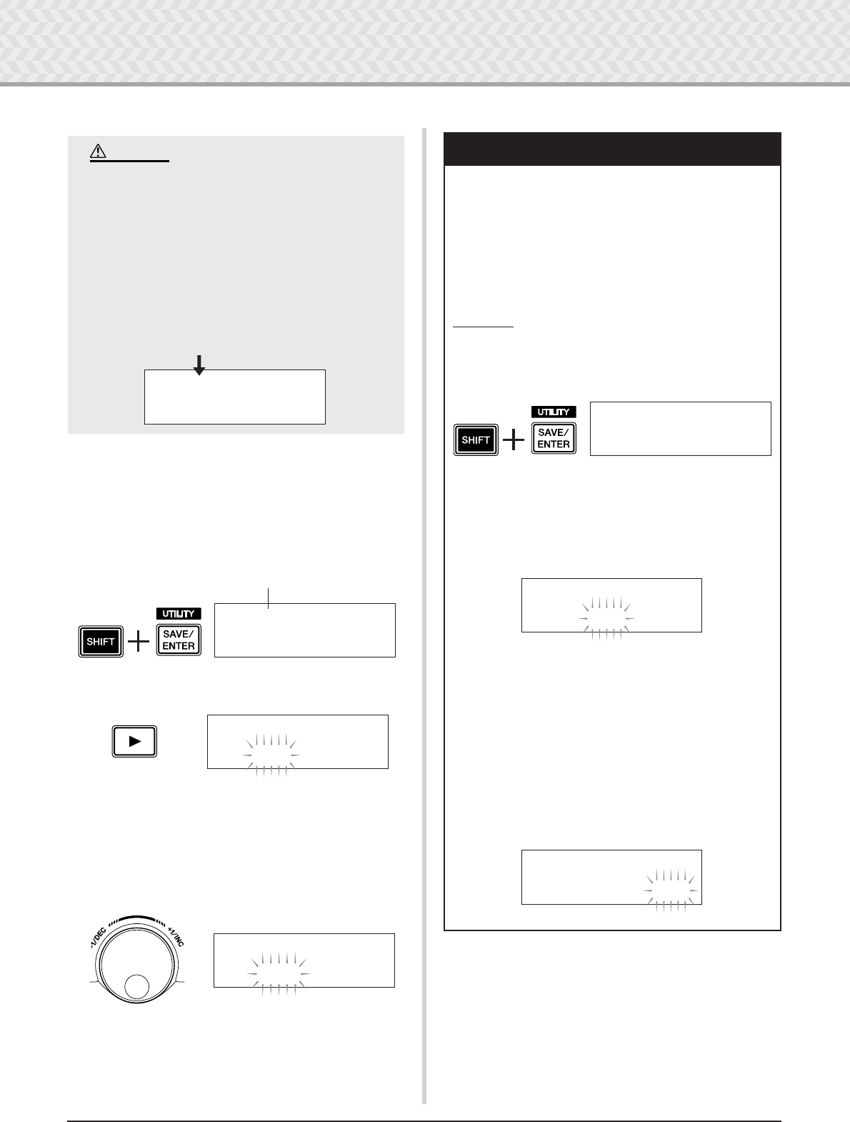
1. First, press the [SHIFT] + [SAVE/ENTER] buttons to
call up the Utility pages.
2. Press the [>] button several times to call up the
UTIL7 page.
3. To select the pad (Trigger Input Source) to which you
want to assign a function, simply hit the target pad, or
press the [SHIFT] + [<]/[>] buttons.
4. Rotate the jog dial to select the desired function.
In the above setting, the click sound can be switched
ON/OFF by hitting the tom1 pad which is connected
to the 2TOM1/10 jack.
UTIL1~Hi-hat
HHofs=~~0~T=~~5‚
UTIL7~~ƒsnare
”Func=off~~~~~~‚
UTIL7~~™tom1
”Func=clkOn/Off‚
Pad (trigger input source) to which
a pad function is assigned
Function assigned to the pad
24 DTXPRESS IV Owner’s Manual
5 Using the Groove Check Function
Another highly useful feature of the DTXPRESS IV is the Groove Check function. As you play
along with a song or the click, Groove Check compares your timing with the song or click play-
back and lets you know how accurate your playing is.
The related Rhythm Gate function—in which the sound is cancelled if your timing is off—also
offers you a great way to improve your technique.
Groove Check Mode
The Groove Check function has the following two modes.
●Numeric Display Mode
In this mode, the accuracy of your drum hits is shown in
numeric display.
The aspects shown in the numeric display are the average
inaccuracy in the timing of each hit and the deviation in tim-
ing inaccuracy of all hits. To use this mode, select one of the
modes other than “Challenge” from the Rhythm Gate set-
tings in the GRV2 page.
* Hit timing display
If your timing is slow or you’re dragging the beat, the
mark will move to the right side of the display. If your
timing is fast or you’re pushing the beat, the mark will
move to the left.
*Rhythm Gate range
With the Rhythm Gate function, sound is produced only
if the hit is within the specified range, and sound is not
produced if the hit is outside this range. The range of
Rhythm Gate can be selected from three levels according
to the degree of difficulty and if this is set to off, sound is
always produced, no matter what your timing is. The
selected range is shown in the lower side of the upper half
of the display.
*Tempo
The jog dial can be used to adjust the tempo for the song
or click from 30 to 300.
* Inaccurate timing display
The average inaccuracies in timing as compared to the
note value set in page GRV4 are shown in numeric dis-
play. Range: 0 (perfectly accurate), 1–9 (in units of 1/24
of a 16th note)
The deviation in timing inaccuracy is 0.0 to 9.9. Of
course, the smaller this value is, more “in the pocket”
your playing is.
●Challenge Mode
The DTXPRESS IV automatically evaluates the accuracy of
100 times hits over six grade levels from A to F and sets the
range of Rhythm Gate according to the result. The tolerance
automatically narrows if your hits are accurate and widens if
your hits are inaccurate.
This mode can be used by selecting “Challenge” from the
Rhythm Gate settings in the GRV2 page.
* Hit timing display
Just as with the Numeric Display mode, your timing is
displayed with an icon.
*Rhythm gate range
The set range of the Rhythm Gate is shown in the lower
side of the upper half of the display.
After a pad (pads) is hit a specific number of times, the
DTXPRESS IV evaluates the accuracy of the hits and sets
the range of Rhythm Gate automatically.
●Hit accuracy evaluation
In the lower half of the display, the number of remaining
hits and the current evaluation result (%) are shown.
The current level (evaluation) and the status change dur-
ing playback. If your playing accuracy result (%) was
90% or more, the level is raised one step, and if accuracy
is 60% or less, the level is lowered one step.
• Current level (evaluation): A (best) to F (worst)
• The icon and the meaning of evaluation
Ã: Increases the strictness (as you continue playing in
the same way)
≥:Maintains the same strictness (as you continue play-
ing in the same way)
À:Decreases the strictness (as you continue playing in
the same way)
*Tempo
Tempo is not shown in the Challenge mode display. To
change the tempo, hold the [SHIFT] button and rotate the
jog dial. You can adjust the tempo for the song or click
from 30 to 300 (the tempo is shown in the LED display).
Now let’s use the Groove Check function.
Your hit
Deviation in timing
inaccuracy (0.0 to 9.9)
Tempo Average inaccuracy
in timing (-9 to +9)
GRV1~--æ√æ’æææ--
⁄=130~Gr=-2œ0.0‚ Rhythm gate range
Perfect timing
•The level (evaluation) when the challenge mode begins is set to D.
NOTE
Status display for evaluation
Ã, ≥, À
Remaining
number of hits
The percentage in which
sound is produced
GRV1~--æ√æ’æææ--
80Hits/~16%(DÀ)‚ Rhythm gate range
Current level (evaluation)
A (best) to F (worst)
Your hit Perfect timing
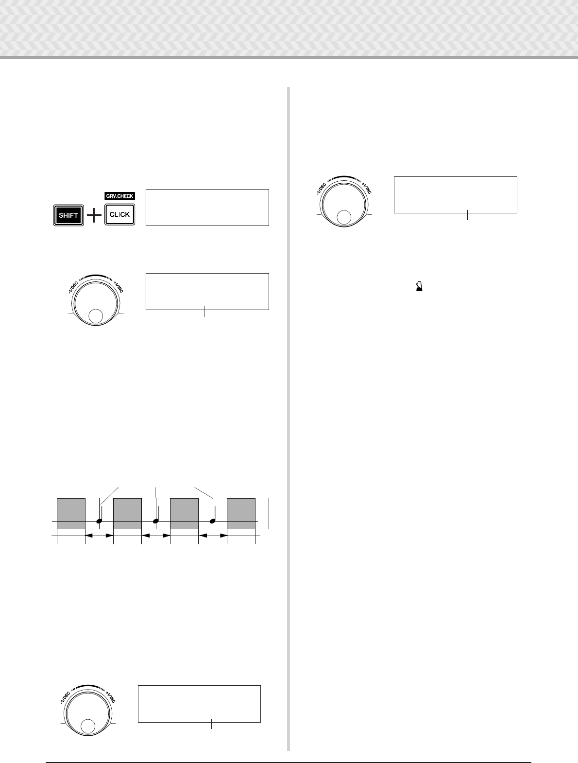
5 Using the Groove Check Function
25
DTXPRESS IV Owner’s Manual
1
Select a Song or a Click Set
First, select the song or click set that you want to play along
with.
2
Set the Rhythm Gate (select a mode)
Press the [SHIFT] + [CLICK] buttons to call up page 1
(GRV1) in the Groove Check Setting pages.
Next, press the [>] button once to call up the GRV2 page,
then rotate the jog dial to set the Rhythm Gate.
●Rhythm Gate settings
off .................Sound is always produced
easy...............Wide tolerance for sound production
(easy)
normal ..........Mid-level tolerance for sound production
(average)
pro .................Narrow tolerance for sound production
(difficult)
challenge...Tolerance changes by automatic evalua-
tion (Challenge mode)
3
Select the Pad
Press the [>] button to call up the GRV3 page, then rotate the
jog dial to select the pad (Trigger Input Source) that you want
to check. The “ALL” setting selects all pads.
[Range] ƒsnare, ™tom1, ... ƒ™pad12, all
4
Set the Timing (note value)
Press the [>] button to view page GRV4, then rotate the jog
dial to select the note value of the timing you want to check.
[Range] Accent A˘, quarter note ⁄(4),
eighth note Ö(8), sixteenth note Ü(16),
eighth note triplet Ö3
5
Start the Groove Check
After setup is complete, start playback of the song ([SONG
>/■]) or the click sound ([ ON/OFF]) and go back to the
Groove Check’s main menu (the GRV1 page).
Groove Check begins as soon as you hit the pad specified in
the GRV3 page.
6
Play as accurately as possible
Listen to the song or click and concentrate on playing the
pads accurately. The jog dial can be used to adjust the tempo
for the song or click.
If the Numeric Display mode is selected, stop the song or
click and check the results. Change the Rhythm Gate setting,
pad type, or note value as you like and enjoy practicing.
* The Groove Check’s results are reset the next time song or
click starts playing.
If the Challenge mode is selected, when the remaining hits
become zero, the final evaluation is displayed in six levels
from A to F. With this evaluation, the range over which the
sound is produced is set automatically. The higher the evalua-
tion (A is the highest and F the lowest), the narrower the tol-
erance becomes.
* The Groove Check’s results are reset the next time song or
click starts playing. The current level (evaluation) and the
range over which sound is produced are also reset.
GRV1~--æææ’æææ--
⁄=123~Gr=~0œ0.0‚
GRV2~RhythmGate
”Mode=easy
Rhythm Gate setting
AAABBB B
Note value set in GRV4 page
A: Range within which sound is produced. (The gate narrows
as the setting changes from “easy” to “normal” to “pro.”)
B: Range within which sound will not be produced even though
the pad is struck.
GRV3
”~Input=ƒsnare~‚
Pad (Trigger Input Source)
GRV4
”~~Note=⁄(4)
Timing (Note value)
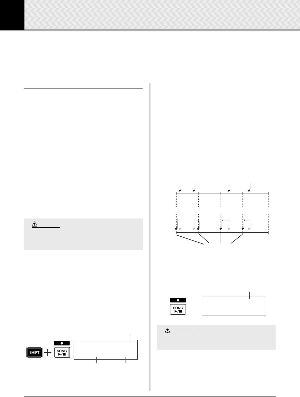
26 DTXPRESS IV Owner’s Manual
6 Record Your Performance
In this section, you’ll learn how to record your performance to the DTXPRESS IV’s built-in
sequencer. In the song data you record, you can switch Drum Kits, change the tempo and play-
back in the same way as with Preset Songs.
Recording System
• Recording can be done with any of the User Songs (64–83).
However, you cannot record to Preset Songs (1–63).
•A recorded song doesn’t contain recordings of the audio
‘sounds’ of the drums, but rather the performance ‘informa-
tion’ or data of precisely when and how each pad was hit. This
information is called sequence data. Unlike audio data,
sequence data can be freely used to change the tempo, select
the voice or drum kit during playback.
Now, let’s start recording…
1
Select the Song you want to record
Press the [SONG] button to display the Song Select display,
select a User Song number (64–83).
If you want to play along with a Preset Song and record it,
select the desired song (1–63). In this case, the lowest num-
bered empty User Song will automatically be selected for
recording.
2
Set the Recording Conditions
Simultaneously hold down the [SHIFT] button and press the
[SONG >/■] button to call up the following Recording Con-
ditions setting page.
*If a Preset Song is selected for recording and all User Songs
already contain data, the error message “Memory full” is
shown. Use the Song Clear function (p. 27) to prepare an
empty User Song, then set the recording conditions.
In this display set the click tempo, beat, and quantize.
Press the [<]/[>] buttons to move the flashing cursor to the
item you want to set, then rotate the jog dial to set its value.
•Tempo [Range] 30 to 300
Sets the click’s tempo (q=) when recording.
• Beat [Range] 1 to 9
Sets the click’s beat when recording.
• Quantize [Range] ⁄, ⁄3, Ö (eighth note), Ö3 (eighth
note triplet), Ü (sixteenth note), Ü3 (sixteenth note trip-
let), no
The Quantize function can be applied during recording
and is used to align the timing of your performance with
that of the nearest specified beat. The accuracy of quanti-
zation is assigned with a note value.
*A setting of “no” results in no quantization.
3
Start Recording
Press the [SONG >/■] button and after the count, recording
will start. Record while listening to the click sound.
If a User Song containing data is selected, any
recorded data previously existing is overwritten
and lost.
CAUTION
Quantize
Tempo
Beat
REC~~~~~~~~⁄=130
Beat=4~Quant=⁄3
Never attempt to turn off the power during
recording. All User Song data may be lost.
●How Quantize Works (an example)
Recorded notes were not played in time.
The Quantize Function aligns the timing.
Perfect timing
REC~~Meas=~10
~Now~Recording.
Current measure number during recording
CAUTION
6 Record Your Performance
27
DTXPRESS IV Owner’s Manual
4
Finish recording
Press the [SONG >/■] button to finish recording. A
“now~storing~...” message is shown for a short time.
When saving is complete, a “completed!” message is
shown and the Song Select page will reappear.
Even if the power is switched off, the com-
pleted song will be stored.
5
Listen to the Song
Following recording, the User Song number you recorded
flashes in the Song Select page.
Press the [SONG >/■] button, and playback of the song you
just recorded will start from its beginning.
*You can change the Drum Kit used for the recorded song. To
change Drum Kits, press the [DRUM KIT] button to enter the
Drum Kit Select display (KIT1 page) and rotate the jog dial to
select a different kit.
6
Give the User Song a name
The song name of the recorded User Song is shown as the
song name of the Preset Song or “Untitled.” Enter your
own original name for the recorded User Song.
* The song names of the Preset Songs cannot be edited.
6-1. Press the [SAVE/ENTER] button in the Song Select
page. The Song Name setting page is shown.
6-2. Press the [<]/[>] buttons to move the flashing cursor
to the character you want to edit, then rotate the jog
dial to select a character. A User Song name can con-
tain a maximum of eight characters, and these can be
selected from the following list.
6-3. Press the [SAVE/ENTER] button again. A prompt
appears asking you to confirm the Store operation.
6-4. Press the [SAVE/ENTER] button once more to actu-
ally execute the Store operation.
*To cancel the Store operation, press any button
except for the [SAVE/ENTER] and [SHIFT] buttons.
(When “Are you sure?” appears in the display, the jog
dial will also cancel the operation.)
When saving is complete, a “completed!” message
appears and the Song Select page will reappear. The
song name is confirmed.
7
Clearing a User Song
If you want to clear any unneeded User Songs, follow the
operation below.
* Preset Songs cannot be deleted.
7-1. In the Song Select page, move the flashing cursor to
the song number, and use the jog dial to select the
User Song you want to delete.
7-2. Press the [>] button twice to view the SONG2 page.
7-3. Press the [SAVE/ENTER] button. A “now~clear-
ing~...” message is shown for a short time.
7-4. When clearing data is complete, a “completed!”
message is shown and the SONG1 page will reappear.
Never attempt to turn off the power while the
“now storing ...” message is shown; all User
Song data may be lost.
~now~storing~...
CAUTION
SONG~save~name
:[Untitled]
space
!"#$%&'()*+,-./0123456789:;<=>?@
ABCDEFGHIJKLMNOPQRSTUVWXYZ[\]^_`
abcdefghijklmnopqrstuvwxyz{|}≥≤
Never attempt to turn off the power while the
message “now clearing...” is shown; all User
Song data may be lost.
SONG~save~name
~Are~you~sure~?
SONG2~Clear
”Are~You~Sure~?
CAUTION
•If the Factory Set operation is executed, all User Songs (64–
83) will be lost. Please proceed with caution, since executing
this operation will also rewrite the entire memory contents of
the DTXPRESS IV (all Click Sets, User Trigger Setups 8–11,
User Drum Kits 51–70, Utility data) with the data that was set
in the unit’s memory when it was shipped from the factory (p.
35).
NOTE
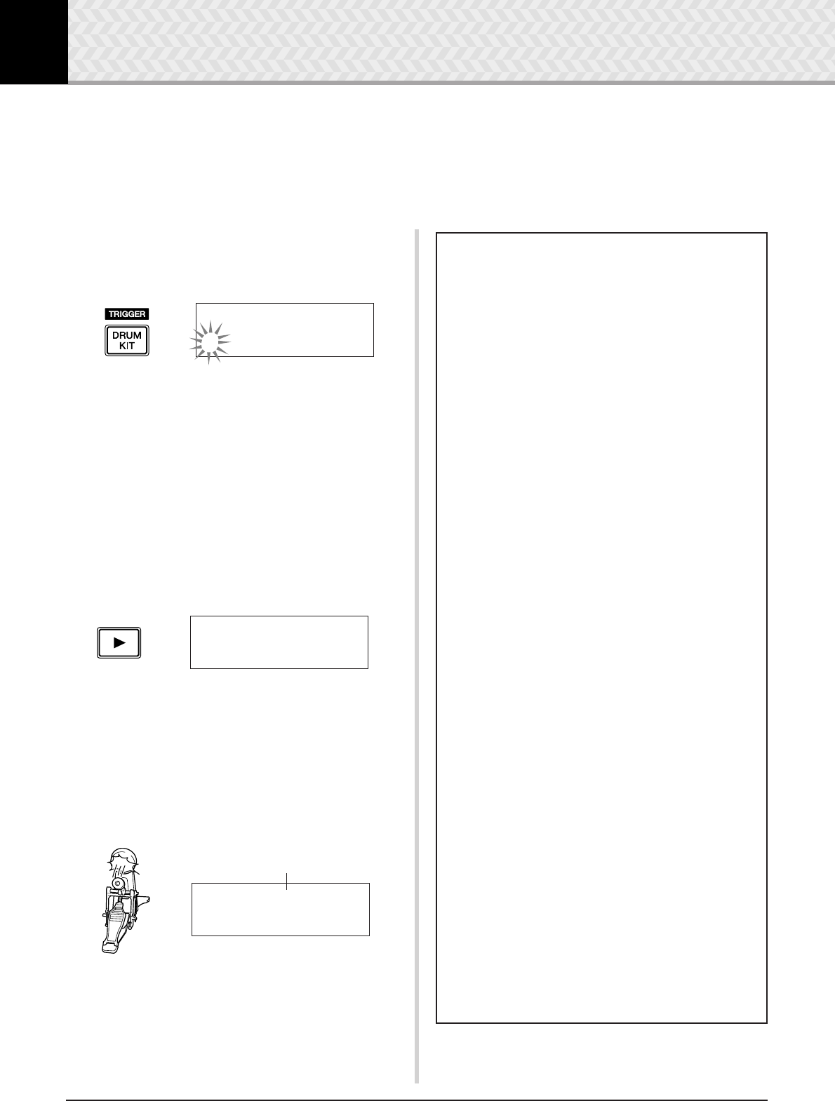
28 DTXPRESS IV Owner’s Manual
7 Create Your Own Original Drum Kit
The DTXPRESS IV lets you create your own original Drum Kit by assigning your favorite Drum
Voice to each pad and setting its tuning, pan, decay, reverb, etc.
*Drum Voice: Mainly individual percussion/drum sounds that are assigned to each of the pads.
*Drum Kit: A collection of Drum Voices assigned to pads.
1
Select a Drum Kit
Press the [DRUM KIT] button to view the Drum Kit Select
display (KIT1).
Rotate the jog dial to select the Drum Kit you want to use as a
starting point for your original Drum Kit. A good idea is to
select a Drum Kit that is close in sound to the type of kit you
intend to create.
* Preset Drum Kits (1–50) and user Drum Kits (51–70) can be
used for editing as well.
2
Assign Drum Voices
In this example, we’ll create a bass drum (kick) sound.
2-1. Press the [>] button to view the Drum Voice Select
page (KIT2).
2-2. To select the pad (trigger input source) you want to
edit, simply hit the pad you want to edit or use the
[SHIFT] + [<]/[>] buttons.
Step on the kick pedal or press the [SHIFT] + [<]/
[>] buttons and select “äkick.” Now the pad that is
connected to the 8KICK Trigger Input Jack is
selected. In other words, the kick pedal’s pad input is
selected.
KIT1~~~ååååååååå
1~:Oak~Custom~~‚
KIT2~~~ƒsnare~~˙
”S01:OakCustom~‚
Pad to be edited
KIT2~~~äkick~~~˙
”K01:OakCustom~‚
●About the Trigger Input Sources
The Input Source indicates the trigger data that is transmitted by the pads
or drum triggers (Yamaha DT20, etc.) that are connected to trigger input
jacks 1SNARE to 8KICK/9 of the DTXPRESS IV.
When mono pads TP65, KP125/65, PCY65/130, DT10/20, etc. are used,
one Input Source is assigned to one input jack. When stereo pads
RHH135/130, PCY65S, etc. are used, two Input Sources (pad input and
rim switch input or 2 kinds of pad inputs, etc.) are assigned to one input
jack.
When three-zone pads TP65S, TP120SD/100, PCY155/150S/135/130SC,
etc., are used, three Input Sources (pad input and two rim switch inputs,
etc.) will be assigned to one input jack.
Each Input Source is defined as follows.
ƒsnare Pad input for 1SNARE jack.
ƒsnrOp Open rim switch input for 1SNARE jack.
ƒsnrCl Closed rim switch input for 1SNARE jack.
ƒsnrOff Pad input for 1SNARE jack with the snares off.
ƒsnrOfOp Open rim switch input for 1SNARE jack with the
snares off.
ƒsnrOfCl Closed rim switch input for 1SNARE jack with the
snares off.
™tom1 Pad input for 2TOM1 jack.
£tom2 Pad input for 3TOM2 jack.
Ωtom3 Pad input for 4TOM3 jack.
•ride Pad input for 5RIDE jack.
•rideE Edge rim switch input for 5RIDE jack.
•rideC Cup switch input for 5RIDE jack.
öcrash Pad input for 6CRASH jack.
öcrashE Edge rim switch input for 6CRASH jack.
öcrashC Cup switch input for 6CRASH jack.
ühhOp Pad input for 7HI HAT jack when the hi-hat controller
is open.
ühhOpE Edge rim switch input for 7HI HAT jack when the hi-
hat controller is open.
ühhCl Pad input for 7HI HAT jack when the hi-hat controller
is closed.
ühhClE Edge rim switch input for 7HI HAT jack when the hi-
hat controller is closed.
ühhFtCl Input when the hi-hat controller is pressed (foot close).
ühhSplsh Foot splash input of the hi-hat controller.
äkick Pad input for 8KICK jack.
“pad9 Pad input for 8PAD9 jack.
ƒπpad10 Pad input for 2PAD10 jack.
ƒƒpad11 Pad input for 3PAD11 jack.
Īpad12 Pad input for 4PAD12 jack.
* Mono pads do not have a rim switch function.
7 Create Your Own Original Drum Kit
29
DTXPRESS IV Owner’s Manual
2-3. The letter “˙” displayed next to “äkick” indicates
layer number 1, and “¶” indicates layer number 2.
Two voices can be output (in a layer) through one
input source. Select the voice to be edited here.
2-4. Next, decide the Drum Voice category. Drum Voice
categories are the same as those used in the user click
sound setting (p. 19).
●Voice Category
K: Kick
S: Snare
T: Tom
C: Cymbal
H: Hi-hat
P: Percussion
E: Effect
Here, select “K: Kick”. Press the [<]/[>] buttons to
move the flashing cursor to the Voice Category and
rotate the jog dial to select “K”.
2-5. Next, let’s select a Drum Voice.
Press the [<]/[>] buttons so that the voice number
flashes, then rotate the jog dial and assign a Drum
Voice. The voice number and voice name will be dis-
played.
Here, select “
K02:MapleCustm
.”
*If the voice number is set to “00,” “NoAssign” is dis-
played as the voice name and no sound will be pro-
duced.
Now you’ve selected the Drum Voice that will
be used as the base for your original Drum
Voice.
Next, let’s edit this Drum Voice and create
your original bass Drum Voice.
Select and set the display that you want to be edited from
page 3 to page 25 in the KIT screen.
3
Change the Volume
This determines the volume of the Drum Voice that is output
when the pad is hit. Use this to adjust the volume balance
among the other pads.
Use the [>] button to call up the KIT3 page, then rotate the
jog dial to set the volume (0–127).
4
Change the Tuning (Pitch)
This determines the tuning (pitch) of the Drum Voice.
Use the [>] button to call up the KIT4 page, then rotate the
jog dial to set the tuning in semitones (-24.0 to 0 to +24.0).
5
Change the Pan
This determines the Drum Voice’s pan setting (the voice’s
position within the stereo field).
Use the [>] button to call up the page KIT5, then rotate the
jog dial to set the voice’s pan position.
The range is from “L64” (hard left) to “C” (center) to “R63”
(hard right). As you rotate the dial, notice the voice change its
position within the stereo field according to the setting.
An asterisk “*” will appear next to “KIT” in the
display if data is changed. This asterisk will dis-
appear after the Store operation (p. 34) is carried
out. If a different Drum Kit is selected, etc.,
before carrying out the Store operation, the cur-
rent settings will return to their original condi-
tion. If you want to keep changes made to the
data, make sure to carry out the Store operation.
KIT2~~~äkick~~~˙
”K01:OakCustom~‚
Layer number
CAUTION
KIT2*~~äkick~~~˙
”K02:MapleCustm‚
•When Drum Voices are set for both layers 1 and 2, layer icon
˙ or ¶ is shown in the upper right hand corner of the KIT3 to
KIT10 displays. Move the flashing cursor to this icon (if nec-
essary) and rotate the jog dial to change the layer to be edited.
•When a Drum Voice is assigned to either of the layers 1 and 2
(the other is set to “NoAssign”), the layer icon is not shown
in the KIT3 to KIT10 displays. The layer which has a Drum
Voice is the target layer for editing.
•When Drum Voices are not assigned for either layer 1 or 2
(“NoAssign”), “---” will be shown in the KIT3 to KIT18
displays and the settings cannot be made.
NOTE
Store the data when you change the settings!
Make sure to store the data after any settings
have been changed.
For information about how to save, see steps 26.
If a different drum kit is selected, etc., before carrying
out the Store Operation, the current settings will
return to their original condition. If you want to keep
changes made to the data, make sure to carry out
the Store Operation.
KIT3*~~äkick~~~˙
”~~Volume=120~~‚
KIT4*~~äkick~~~˙
”~~Tune=-~3.0~~‚
KIT5*~~äkick~~~˙
”~~~~Pan=L~5~~~‚
7 Create Your Own Original Drum Kit
30 DTXPRESS IV Owner’s Manual
6
Change the Decay
This determines the Drum Voice’s decay time (the time it
takes the sound to fade out after being produced).
Use the [>] button to call up the KIT6 page, then rotate the
jog dial to set the decay (-64–0–+63). Positive values produce
a crisper sound.
7
Change the Voice Character (Filter Set-
ting)
This determines the filter’s cutoff frequency to change the
Drum Voice’s character (brightness).
Use the [>] button to call up the KIT7 page, then rotate the
jog dial to set the cutoff frequency (-64–0–+63). Positive val-
ues produce a brighter sound.
8
Set the MIDI Note Number
This determines the MIDI Note Number that is transmitted
when a signal is received from the input source. This affects
which particular percussion or drum sound of a voice will
play on a connected MIDI device.
Use the [>] button to call up the KIT8 page, then rotate the
jog dial to set the MIDI Note Number (0–127). Displays the
note number and note name (C-2–G8).
* When the selected MIDI Note Number has already been
assigned to another input source, an asterisk “*” will be dis-
played next to “Note=.”
* If the same MIDI Note Number is set to more than one pad
within the same Drum Kit, the lowest numbered Input Source
will take priority. In the case of the duplicate input sources,
the same voice will be output.
If the setting is not available because of an already assigned
MIDI note number, “(Note# in use)” or “(# in
use)” is shown in the lower half of the display.
9
Set the MIDI Channel
This determines the MIDI Transmit Channel for the MIDI
note on data that is transmitted when a signal is received from
the input source. This affects which particular channel will be
used when playing a voice on a connected MIDI device.
Use the [>] button to call up the KIT9 page, then rotate the
jog dial to set the MIDI Transmit Channel (1–16).
10
Set the Gate Time of the MIDI Output
This determines the Gate Time (the length of time from Key
On to Key Off) for the MIDI note on data.
Use the [>] button to call up the KIT10 page, then rotate the
jog dial to set the Gate Time (0.0s–9.9s).
11
Set the MIDI Key On/Off
This determines whether to recognize MIDI Key Off events
or not.
*This setting affects both layers ˙ and ¶. The ˙/¶ indication is
not shown in the upper right corner of the display.
Use the [>] button to call up the KIT11 page, then rotate the
jog dial to set Key On/Key Off.
enable............ Recognizes Key Off events.
disable .........Does not recognize Key Off events.
*When this is set to “disable,” some voices may sound continu-
ously. Press the [DRUM KIT] button to stop the sound.
12
Set the Hold Mode
Every time the pad is hit, Key On and Key Off messages are
alternately sent. This means that one hit of the pad turns the
sound on and the next turns it off.
*This setting affects both layers ˙ and ¶. The ˙/¶ indication is
not shown in the upper right corner of the display.
Use the [>] button to call up the KIT12 page, then rotate the
jog dial to set the Hold Mode.
KIT6*~~äkick~~~˙
”~~Decay=+~8~~~‚
KIT7*~~äkick~~~˙
”CutOffFreq=+~4‚
KIT8*~~äkick~~~˙
”Note=~~32/G#0~‚
KIT9*~~äkick~~~˙
”~~MIDI~Ch=10~~‚
KIT10*~äkick~~~˙
”GateTime=0.3s~‚
KIT11*~äkick
”KeyOff=disable‚
KIT12*~äkick
”~HoldMode=off~‚
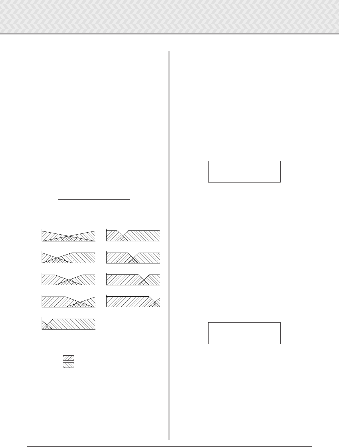
7 Create Your Own Original Drum Kit
31
DTXPRESS IV Owner’s Manual
on................... Each time the pad is hit, either a MIDI Key
On or MIDI Key Off event will be transmitted
alternately.
off................. Normal operation. When a pad is hit, only a
MIDI Key On event will be transmitted. After
the decay time elapses, a Key Off event will
be transmitted automatically.
* When this is set to “on,” you should also set the Key Assign
Mode to “high” in the KIT15 page.
13
Set the Cross Fade
This determines the Velocity Cross Fade between the layer
voices ˙ and ¶.
*This setting affects both layers ˙ and ¶. The ˙/¶ indication is
not shown in the upper right corner of the display.
Use the [>] button to call up the KIT13 page, then rotate the
jog dial to set the Cross Fade type.
●Cross Fade Type
0.........Cross Fade function is not in effect.
14
Set the Alternate Group
This function allows you to assign different voices to the
same alternate group, so that the playing of one sound in the
group will automatically cancel others in the same group. A
practical example of this is with the open and closed hi-hat
voices. When you play an actual hi-hat—first open, then
closed—the closed hi-hat naturally mutes the ringing open
sound. Likewise, when the open and closed hi-hat voices are
assigned to the same alternate group, the playing of one
mutes the other.
*This setting has no affect on two-layer input sources. The ˙/
indication is not shown in the upper right corner of the dis-
play.
Use the [>] button to call up the KIT14 page, then rotate the
jog dial to set the Alternate Group.
off .................No cancellation
HH~pad ..........For the voice (ühhOp, ühhOpE, etc.) that is
played when the hi-hat pad is hit.
HH~pdl ..........For the voice (ühhFtCl, ühhSplsh,
ühhCl, ühhClE, etc.) that is played when
the hi-hat pedal is pressed.
1–9..................Alternate group number. Assigns the same
group number for voices that you do not want
to be output simultaneously.
15
Set the Key Assign Mode
This defines the sound output rules when multiple voices that
are assigned to the same MIDI note number are simulta-
neously output.
*This setting affects both layers ˙ and ¶. The ˙/¶ indication is
not shown in the upper right corner of the display.
Use the [>] button to call up the KIT15 page, then rotate the
jog dial to set the key assign mode.
poly ...............Voices are output simultaneously.
semi ...............Up to three voices for this note number can
be produced at one time. When a fourth voice
is triggered, one of the first two voices will be
muted (cancelled).
mono ...............One voice can be delivered at one time, and
the previous voice will be muted (cancelled).
high ...............One voice can be delivered at one time, and
the previous voice will be muted (cancelled).
However, even if the maximum number of 32
notes is exceeded, the note number selected
here will not be muted.
KIT13*~äkick
”~~VelXFade=0~~‚
1
2
3
4
5
˙
˙
˙
˙
˙
˙
˙
˙
˙
6
7
8
9
Vertical axis: Balance between layers ˙ and 
Horizontal axis: Velocity
Layer ˙
Layer 
KIT14*~äkick
”~AltGrp=off~~~‚
KIT15*~äkick
”KeyAssign=semi‚
7 Create Your Own Original Drum Kit
32 DTXPRESS IV Owner’s Manual
16
Set the Pad Song
When the pad is hit, the assigned pad song will start play-
back. In addition to one main song that is selected in the Song
Select display, a maximum of three Pad Songs can be individ-
ually set for a Drum Kit.
*This setting affects both layers ˙ and ¶. The ˙/¶ indication is
not shown in the upper right corner of the display.
Use the [>] button to call up the KIT16 page, then rotate the
jog dial to set the Song Number to be assigned, the Repeat
function, and the Playback mode.
●Song Number
off, 45–63... Assigns the Song Number that is assigned to
the pad
●Repeat Playback
áé................... Repeats playback of the song (when the song
reaches the end it will start again from the
beginning, continuously).
-≥................... Normal playback.
●Playback Mode
play .............. When the pad is hit, playback of the assigned
pad song will start/stop.
chse .............. When the pad is hit, one measure of the
assigned pad song will start playback then
pause.
ctof .............. When the pad is hit, playback of the assigned
pad song will start/stop. However, if the pad
song is set to “ctof,” the pad song will stop
when another pad song with the “ctof” setting
is started. This function allows only one
“ctof” pad song to be played at a time.
* Up to three pad songs can be set for each Drum Kit. To
assign a pad song for other pads, hit the target pad, or press
the [SHIFT] + [<]/[>] buttons, so that the target pad name
(trigger input source) is shown in the upper half of the display.
However, when three pad songs are set, “Song=off” is shown
and the settings cannot be made.
* The tempo of the pad song is the same as that of the main
song that is found in the Song Select display or the Click Set-
ting display.
* If a function is already assigned in the UTIL7 page to the
input source that the pad song is assigned, “Song=(in
use!)” is shown and the setting in the UTIL7 takes priority.
(p. 23)
* When multiple pad songs are assigned and played back in
combination, the voices within the songs may change unex-
pectedly or sound different than intended.
17
Set the Rim to Pad
This function is effective only when the input source is from
a rim switch. When the rim is hit, pad events triggered from
the same pad (trigger input jack) can be simultaneously trans-
mitted with rim switch events. With this setting, a snare pad’s
sound can be triggered at the same time as the snare’s rim
shot.
*This setting affects both layers ˙ and ¶. The ˙/¶ indication is
not shown in the upper right corner of the display.
* When an input other than the rim switch is selected for the
input source, “RimToPad=---” will be displayed and the
settings cannot be made. The following display appears
when “ƒsnrOp” is selected for the input source.
Use the [>] button to call up the KIT17 page, then rotate the
jog dial to set the Rim to Pad.
off.....................Only transmits rim switch event.
on........................ Transmits both rim switch event and pad event.
18
Change the Reverb Level (1)
This determines the Reverb Send Level for the voices (layers
1, 2) triggered by the input source. This effectively allows
you to adjust the reverb depth.
*This setting affects both layers ˙ and ¶. The ˙/¶ indication is
not shown in the upper right corner of the display.
* The actual Reverb Send Level is determined by adding the
Send Level set here to the Drum Reverb Send Level set in
the KIT19 page.
Use the [>] button to call up the KIT18 page, then rotate the
jog dial to set the Reverb Send Level (0–127).
19
Change the Reverb Level (2)
This determines the Overall Reverb Send Level of the Drum
Voice.
*This setting affects the entire Drum Voice. The ˙/¶ indication
is not shown in the upper right corner of the display.
Use the [>] button to call up the KIT19 page, then rotate the
jog dial to set the Drum Reverb Send Level (0–127).
KIT16*~äkick
”Song=~45áéplay‚
Song Number
Repeat
Playback mode
KIT17*~ƒsnrOp
”~RimToPad=off~‚
KIT18*~äkick
”~RevSend=~30~~‚
KIT19*
”~RevSendDr=~40‚
7 Create Your Own Original Drum Kit
33
DTXPRESS IV Owner’s Manual
20
Change the Reverb Type
This determines the Type of Reverb effect for each Drum Kit.
The same Reverb Type is applied to the entire Drum Kit.
*This setting affects the entire Drum Voice. The ˙/¶ indication
is not shown in the upper right corner of the display.
Use the [>] button to call up the KIT20 page, then rotate the
jog dial to set the Reverb Type.
none .............. No reverb (same as thru).
hall1–5....... Simulates the reverb in a hall.
room1–5....... Simulates the reverb in a room.
stage1–5..... Simulates the ambience of a stage.
plate............ Simulates a steel plate reverb.
white............ A special short reverb effect.
tunnel ......... Simulates the reverb of a tunnel.
bsemnt ......... Simulates the reverb of a basement.
* The hall, room, or stage types with larger values produce a
more pronounced reverb effect.
21
Change the Reverb Level (3)
This determines the Signal Return Level from the reverb
effect for every Drum Kit. The same reverb type is applied to
the entire Drum Kit.
By setting the level, you can adjust the reverb effect for the
overall DTXPRESS IV system.
*This setting affects the entire Drum Voice. The ˙/¶ indication
is not shown in the upper right corner of the display.
Use the [>] button to call up the KIT21 page, then rotate the
jog dial to set the Reverb Master Return level (0–127).
22
Set the Pad Controller
This is effective only when a pad equipped with pad control-
ler is connected to the 1SNARE jack, and also when
“Type=TP1/Snr” is assigned in the TRG2 page (pad type)
of the Trigger Setup pages.
The following settings can be made by rotating the pad con-
troller knob.
off .................No function is assigned.
snares ..........Adjusting the snares (also effective for the
open rim sound)
tuning ..........Adjusting the tuning (also effective for the
open rim sound)
tempo.............Adjusting the tempo
* The ˙/¶ indication is not shown in the upper right corner of
the display.
Use the [>] button to call up the page KIT22, then rotate the
jog dial to set the Pad Controller function.
23
Set the Snares
This adjusts the snares effect (the characteristic sound of the
coiled wires on the bottom of an actual snare drum) of the
pad connected to the 1SNARE jack.
This also applies to pads not having a pad controller.
* The ˙/¶ indication is not shown in the upper right corner of
the display.
Use the [>] button to call up the KIT23 page, then rotate the
jog dial to set the Snares adjustment level.
off .................Snares off (reproduces the sound with the
snares lifted off the drum)
1–24 ...............Snares are applied to the sound; the higher
the value, the tighter the snares sound. (A
value of “1” is the “loosest” snares setting.)
* When you change this setting, the decay setting (KIT6) for
the input sources “ƒsnare” and “ƒsnrOp” also changes.
KIT20*
”RevType=hall1~‚
KIT21*
”RevMastRet=~64‚
For users of the DTXPRESS IV Special Set, set the Trigger
Setup to “1 :SP Med” (p. 14) to enable this function.
Depending on the Drum Kit you use, the default setting that
can be adjusted by the pad controller varies.
KIT22*
”PadCtl=snares~‚
KIT23*
”~~Snares=24~~~‚
7 Create Your Own Original Drum Kit
34 DTXPRESS IV Owner’s Manual
24
Set the Program Change and Bank Select
When a Drum Kit is selected, this function sets the MIDI Pro-
gram Change Number and the Bank Select MSB and LSB
that will be transmitted. This can be set for each MIDI chan-
nel.
By transmitting a program change message, you can have the
voice of an external MIDI device automatically change when
switching the Drum Kit on the DTXPRESS IV.
* The ˙/¶ indication is not shown in the upper right corner of
the display.
Use the [>] button to call up the KIT24 page, then rotate the
jog dial to make the following settings.
* When the Program Change Transmit On/Off is set to “off,”
values for PC, M and L will be “---” and the settings cannot
be made.
●MIDI Channel
1–16............... Target MIDI channel for the Program Change
●Program Change Transmit On/Off
on................... Transmits.
off................. Does not transmit.
●Program Change Number
001–128 ....... Transmitted program change number.
●Bank Select MSB, LSB
000–127 ....... Bank select MSB number, LSB number
*For more information on Bank Select MSB and LSB, refer to
the Voice List and MIDI Data Format documents, etc. of the
particular external MIDI device you are using.
25
Set MIDI Volume and Pan—Control
Change
This function sets the MIDI Control Change Volume and Pan
values that will be transmitted when a Drum Kit is selected.
This can be set independently for each MIDI channel.
This lets you automatically change the voice Volume and Pan
on an external MIDI device when you switch the Drum Kit of
the DTXPRESS IV.
* The ˙/¶ indication is not shown in the upper right corner of
the display.
Use the [>] button to call up the KIT25 page, then rotate the
jog dial to make the following settings.
* When the Control Change Transmit On/Off is set to “off,”
values for Vol and Pan will show “---” and the settings can-
not be made.
●MIDI Channel
1–16 ...............Target MIDI channel for Control Change
messages
●Control Change Transmit On/Off
on....................Transmits.
off .................Does not transmit.
●Volume
0–127 .............Sets the Volume Control Change data value
that will be transmitted.
●Pan
0–127 .............Sets the Pan Control Change data value that
will be transmitted.
26
Save the Original Voice
To save the Drum Voice you created, use the Store operation
described below and save it to the DTXPRESS IV’s memory.
Original kits can be saved as a Drum Kit to the User Drum
Kit (51–70) memory locations.
26-1. Press the [SAVE/ENTER] button. The following dis-
play will appear.
26-2. Rotate the jog dial to select the destination user Drum
Kit number (51–70) that you want to store.
*Data cannot be stored to the Preset Drum Kits (1–50).
*You can save data to a User Drum Kit number that
already contains data. However, be careful when
doing this, since the previous data will be overwritten
with the new data.
KIT24*PC~Ch1=on
”PC003~M000L003‚
Program Change Number
Bank Select MSB
Program Change
Transmit On/Off
MIDI Channel
Bank Select LSB
If you select a different Drum Kit before perform-
ing the Store operation, all changes you have
made to the data will be lost. If you want to keep
settings or changes, make sure to perform the
Store operation.
KIT25*CC~Ch1=on
”Vol=127~Pan=~64
Control Change
Transmit On/Off
MIDI Channel
Volume Pan
CAUTION
Edited Drum Kit name
KIT~save~to~51
:[Oak~Custom~~]
Store destination
7 Create Your Own Original Drum Kit
35
DTXPRESS IV Owner’s Manual
26-3. If you want to change the Drum Kit name, press the
[<]/[>] buttons to move the flashing cursor to the
character you want to edit, then rotate the jog dial to
select a character. A Drum Kit name can contain a
maximum of 12 characters, and these can be selected
from the following list.
26-4. Press the [SAVE/ENTER] button again. A prompt
appears asking you to confirm the Store operation.
26-5. Press the [SAVE/ENTER] button once more to actu-
ally execute the Store operation.
*To cancel the Store operation, press any button except
for the [SAVE/ENTER] and [SHIFT] buttons. (When
“Are you sure?” appears in the display, the jog dial will
also cancel the operation.)
When the Store operation is complete, the following
display appears.
With this operation, you have now created a
Drum Kit that has an original bass Drum
Voice.
Use the same procedure to create Drum
Voices for the other pads (input sources) and
create a complete custom Drum Kit of your
own.
space
!"#$%&'()*+,-./0123456789:;<=>?@
ABCDEFGHIJKLMNOPQRSTUVWXYZ[\]^_`
abcdefghijklmnopqrstuvwxyz{|}≥≤
KIT~save~to~51
~Are~you~sure~?
~~~Completed!
Factory Set
This operation returns all of the DTXPRESS IV’s internal
settings back to their original factory defaults.
Operation
1. First, press the [SHIFT] + [SAVE/ENTER] buttons to
call up the Utility pages.
2. Press the [>] button several times to call up the
UTIL8 page.
3. From the page shown above, press the [SAVE/
ENTER] button to call up the prompt shown below,
asking for confirmation of the Factory Set operation.
*To cancel the Factory Set operation, press any button
except for the [SAVE/ENTER] and [SHIFT] buttons (the
jog dial can also be used to cancel the operation).
4. Once again, press the [SAVE/ENTER] button to pro-
ceed with the operation.
Please proceed with caution, since executing
this operation will also rewrite the entire mem-
ory contents of the DTXPRESS IV (all Click Sets,
User Trigger Setups 8–11, User Drum Kits 51–70,
User Songs 64–83, Utility data) with the data that
was set in the unit’s memory when it was
shipped from the factory.
UTIL1~Hi-hat
HHofs=~~0~T=~~5‚
UTIL8
”~Factory~Set
All~data~will~be
lost.AreYouSure?
~All~Memory
~Initializing...
36 DTXPRESS IV Owner’s Manual
8 Trigger Setup Edit
Trigger Setup Edit contains various settings related to trigger input signals received from pads
or drum triggers (Yamaha DT20, etc.) that are connected to the trigger input jacks. These set-
tings let you optimize the DTXPRESS IV for best operation and response to these signals.
If you are using drum triggers attached to acoustic drums, or pads other than those that came
with the DTXPRESS IV set, you’ll need to adjust the sensitivity. This section also has settings
that help prevent crosstalk* and double triggering*.
* Crosstalk: The interference between trigger signals of physically adjacent pads, producing unexpected notes.
* Double triggering: The condition where a single pad hit causes multiple (usually two) triggers.
Trigger Setup procedure
If you are using pads or drum triggers other than those that came
with your DTXPRESS IV Set (Standard Set/Special Set), or if
you need to solve problems with double triggering or crosstalk,
the Trigger Setup provides more detailed settings—such as
changing the preset’s trigger setup—for individual pads.
If you’ve created a custom setup for these reasons or others, that
setup can be saved to one of the Trigger Setup locations (8–11).
1
Press the [SHIFT] + [DRUM KIT] buttons to call up the Trig-
ger Setup Select page (TRG1). The currently selected Trigger
Setup is indicated in the display.
* If you want to edit a different trigger setup, use the jog dial
and select the setup here.
2
Use pages TRG2 through TRG8 to edit the Trigger Setup.
Press the [<]/[>] buttons to change pages and move the
flashing cursor to the parameter you want to set.
* Refer to pages 37 to 39 for more information on individual
parameters.
To select the Trigger Input (input jack) you want to edit, sim-
ply hit the pad you want to edit or use the [SHIFT] + [<]/
[>] buttons.
3
Rotate the jog dial to change the setting.
*An asterisk “*” will appear next to “TRG” in the display if data
is changed. This asterisk will disappear after the Store opera-
tion is carried out.
* The Trigger Input Level produced when a pad is hit is shown
on the upper right side of the display. When setting the gain,
use this level as a guide to measure how hard a pad is being
hit.
4
To save changes you’ve made to the data, use the procedure
described below to store them to a User Trigger Setup (8–11).
4-1. Press the [SAVE/ENTER] button. The following dis-
play will appear.
4-2. Rotate the jog dial to select the destination trigger
setup number (8–11).
4-3. If you want to change the Trigger Setup name, press
the [<]/[>] buttons to move the flashing cursor to the
character you want to edit, then rotate the jog dial to
select a character. A Trigger Setup name can contain a
maximum of eight characters, and these can be
selected from the following list.
Tr igger Setup Select display (page 1)
Tr igger Setup Number: Setup Name
TRG1~~~ååååååååå
1~:SP~Med~~~~~~‚
Tr igger Input to be edited
Next page icon
Previous page icon
Flashing cursor (parameter)
TRG2~ ƒsnare~~0%
”Type=~TP1/Snr~‚
If a different trigger setup is selected before exe-
cuting the Store operation, all changes you have
made to the data will be lost. If you want to keep
settings or changes, make sure to carry out the
Store operation.
Tr igger Input Level
TRG2* ƒsnare~~0%
”Type=DT~Snare~‚
CAUTION
Tr igger Setup name
TRG~save~to~8
:[SP~Med~~]
Store destination
space
!"#$%&'()*+,-./0123456789:;<=>?@
ABCDEFGHIJKLMNOPQRSTUVWXYZ[\]^_`
abcdefghijklmnopqrstuvwxyz{|}≥≤
8 Trigger Setup Edit
37
DTXPRESS IV Owner’s Manual
4-4. Press the [SAVE/ENTER] button again. A prompt
appears asking you to confirm the Store operation.
4-5. Press the [SAVE/ENTER] button once more to actu-
ally execute the Store operation.
*To cancel the Store operation, press any button
except for the [SAVE/ENTER] and [SHIFT] buttons.
(When “Are you sure?” appears in the display, the jog
dial will also cancel the operation.)
The following display appears after the Store opera-
tion is complete.
Explanations of Each Display Page
The following explanations cover the available parameters in the
pages TRG1 through TRG8. To save the edited data, refer to step
4 on page 36.
[Range] 1–11
Selects the Trigger Setup Type (p. 14)
Sets the type of pad that is connected to the input jack assigned in
the upper half of the display ([1SNARE] in the example shown
above).
*Values set in [TRG3 Gain, MVl (Mininimum Velocity)] (p. 38)
and [TRG5 RejTime (Self Rejection Time)] (p. 38) will auto-
matically changed to the proper values for the pad type you
set here.
Pad types are defined as follows.
KP KP125/80S/80/65/60
TP1/Snr TP100/120SD
TP2/SnrA TP65S/65 (mainly used as a snare pad) *1
TP2/SnrB TP65S/65 (mainly used as a snare pad) *1, *2
TP2/Tom TP65S/65 (mainly used as a tom pad) *1
TP3-A TP80S/80/65/60 *3
TP3-B TP80S/80/65/60 *3
PCY1 PCY155/150S
PCY2 PCY135/PCY130SC
PCY3 PCY130S/130
PCY4 PCY80S/80/65/60/10
RHH RHH135/130
RHP~Pad RHP120SD/120/100/80 (pad side) *4
RHP~Rim RHP120SD/120/100/80 (rim side) *4
RHP~Kick KP120
BP BP80 *5
DT~Snare DT series drum trigger (for a snare drum)
DT~HiTom DT series drum trigger (for small toms)
DT~LoTom DT series drum trigger (for large toms)
DT~Kick DT series drum trigger (for a bass drum)
misc~1–6Other manufacturer’s pads 1 to 6
Never attempt to turn off the power while the
message “now storing...” is shown. All Trig-
ger Setup data may be lost.
TRG~save~to~8
~Are~you~sure~?
~~~Completed!
CAUTION
TRG1 Trigger Setup Select
TRG2 Type (Pad Type)
TRG1~~~ååååååååå
1~:SP~Med~~~~~~‚
TRG2~ ƒsnare~~0%
”Type=TP1/Snr~~‚
8 Trigger Setup Edit
38 DTXPRESS IV Owner’s Manual
*1 Three-zone function (pad voice x 1, rim
voice x 2) is available if a three-zone
compatible pad such as the TP65S, etc.
is connected to the 1SNARE, 5RIDE,
or 6CRASH input.
For producing closed rim shots, the
“TP2/SnrA” has a high sensitivity set-
ting on rim 1, while the “TP2/SnrB” has
a high sensitivity setting on rim 2.
The same voice is assigned to “TP2/
Tom” and “TP2/SnrA” and the left and
right rim sensitivities are set to the same level.
*2 Rim1 and rim2 sounds on the “TP2/SnrB” are reversed from
those on “TP2/SnrA”. This provides left-handed drummers
with a proper setting when using a left-handed setting.
*3 When a stereo pad such as the TP80S is connected to the
1SNARE, 5RIDE, or 6CRASH input, “TP3-A” will produce
the sound that is assigned to rim 1, and “TP3-B” will produce
the sound assigned to rim 2 (p. 28)
*4 When using an RHP series stereo pad, connect the pad to
Input 2TOM1/10, 3TOM2/11, 4TOM3/12, or 8KICK/9,
and set the pad type in “™tom1”, “£tom2”, “Ωtom3”, or
“äkick” input to “RHP~pad” and the pad type in “ƒπpad10”,
“ƒƒpad11”, “ƒ™pad12”, or ““pad9” to “RHP~rim.”
*5 To use the BP80 as a stereo pad, connect the pad to Input
2TOM1/10, 3TOM2/11, 4TOM3/12, or 8KICK/9.
Gain [Range] 0–99
Adjusts the input gain (sensitivity) for the input jack assigned in
the upper half of the page.
Setting a larger value lets a smaller input level from the pad cre-
ate sound.
* This value will be automatically set after the appropriate pad
type is set in [TRG2 Type (Pad Type)]. Some fine-tuning of the
value will be necessary.
* Some pads are equipped with a sensitivity adjustment knob.
For details, refer to the owner’s manual that came with the
particular pad.
MVI [Range] 1–127
Sets the MIDI Velocity (volume) that is transmitted when the pad
is hit the softest. Large values will produce a high volume level
even if the pad is hit softly. However, this will result in a narrow
volume range making it difficult to adequately produce wider
dynamic levels.
The Trigger Input Level will be displayed in percentage in the
upper right hand corner of the display. The maximum velocity
(input level 99 percent) will be 127. The lower the level is when
the pad is hit the weakest, the wider the potential dynamic range
will be.
* This value is automatically set after the appropriate pad type
is set in [TRG2 Type (Pad Type)]. Some fine-tuning of the
value will be necessary.
Sets the Input Velocity Curve for the input jack assigned in the
upper half of the page.
[Range] 0–9
Prevents double triggering from occurring in the input jack
assigned in the upper half of the page. After an event is detected,
further events will be automatically muted for a certain length of
time. The larger the value, the longer time events will be muted.
[Range] 0–9
Prevents crosstalk from occurring in the input jack assigned in
the upper half of the page. Events triggered by other pads (input
jacks) that are of a lower input value than what is set here will not
be triggered for a certain length of time. Larger values require a
greater input level in order to produce a trigger event.
RejLvl [Range] 0–9
Frm [Range] 1–6, 56 (5 and 6), 7–12
This setting is used to prevent crosstalk between the input jack
assigned in the upper half of the page and the input jack assigned
in the “Frm=” setting.
TRG3 Gain, MVI (Minimum Velocity)
Rim 1Rim 2
TRG3~ ƒsnare~~0%
”Gain=65MVl=~12‚
TRG4 VelCurve (Velocity Curve)
TRG5 RejTime (Self Rejection Time)
TRG6 RejLvlAll (Rejection Level)
TRG7 RejLvl (Specified Rejection Level)
TRG4~ ƒsnare~~0%
”VelCurve=norm~‚
norm loud2 loud1 hard1 hard2
Velocity →
Strength of hit →
TRG5 ~ƒsnare~~0%
”~~RejTime=1~~~‚
TRG6 ~ƒsnare~~0%
”~RejLvlAll=2~~‚
TRG7~ ƒsnare~~0%
”RejLv1=3Frm=56‚
8 Trigger Setup Edit
39
DTXPRESS IV Owner’s Manual
After an triggering event occurs from the pad that is assigned in
the “Frm=” setting, the pad assigned in the upper half of the dis-
play will not sound for a certain length of time unless the input
level is greater than the value set here. Larger values will require
a greater input level in order to produce a trigger event.
A “Frm=56” setting assigns both trigger input jacks 5 and 6.
This function allows you to copy all data settings in pages [TRG2
Type (Pad Type)] through [TRG7 RejLvl (Specified Rejection
Level)] to another input jack.
Operation
1. Hit a pad to select the copy source (input jack) from
which the data will be copied.
Rotate the jog dial and assign the copy destination (input
jack).
2. Press the [SAVE/ENTER] button. A prompt appears ask-
ing confirmation of the Copy operation.
3. Press the [SAVE/ENTER] button to actually execute the
Copy operation.
*To cancel the Copy operation, press any button except for the
[SAVE/ENTER] and [SHIFT] buttons (the jog dial can also be
used to cancel the operation).
The following display appears after the Copy operation is
complete.
TRG8 CopyToInput (Trigger Setup Copy)
When the Trigger Setup Copy operation is car-
ried out, the Trigger Setup data will be replaced
with the settings of the copy source.
TRG8 ~ƒsnare
”CopyToInput=~2‚
CAUTION
Copy source (input jack)
Copy destination (input jack)
TRG8~ ƒsnare
”CopyToInput=~2‚
Input~Copy~to~2
~Are~you~sure~?
~~~Completed!
40
DTXPRESS
IV
Owner’s Manual
Error Messages
The DTXPRESS IV displays error messages when incorrect settings have been made or invalid
operations have been detected, or when any abnormal operation or malfunction occurs.
If an error message appears, check the list below and make the appropriate corrections.
This message appears just after the power is switched on and the device cannot correctly
read the data due to the Factory Reset operation being active.
The backup ROM data may have been damaged. Contact the nearest Yamaha Service Cen-
ter or the dealer where you purchased the device.
You have exceeded the memory capacity of the user song.
Delete unused songs to make more memory available and try recording again.
Writing data to the backup ROM has failed.
Trobleshooting
The DTXPRESS IV does not produce sound, or does
not recognize trigger inputs.
●
Are the pads or drum triggers (Yamaha DT20, etc.) properly
connected to the DTXPRESS IV’s trigger input jacks? (p. 10,
11)
●
Is the DTXPRESS IV properly connected to headphones or an
external audio device such as an amplifier, speaker, etc.? (p.
12)
●
Check the position of the Standby/On switches and volume
levels of any connected external audio devices, such as an
amplifier, speaker, etc.
●
The volume knob on the rear panel may be turned down (p.
15).
●
Is the gain set too low? (p. 38 [TRG3 Gain, MVI (Minimum
Velocity)])
●
The volume setting on the Drum Kit Select display’s “KIT3 Vol-
ume” page (p. 29) may be set to “0.”
●
Is there a problem with the cable you are using?
●
The drum voices for both layers
˙
and
may be set to
“
00:NoAssign
.” (p. 29 Step2: [KIT2])
The external tone generator does not produce sound.
●
Is the MIDI cable (connector) properly connected? (p. 13)
●
Is the correct MIDI connector being used? (p. 13)
●
Are the MIDI note number values appropriate?
(p. 30 Steps 8 to 10: [KIT8], [KIT9], [KIT10])
●
The drum voices for both layers
˙
and
may be set to
“
00:NoAssign
.” (p. 29 Step2: [KIT2])
A voice other than the set voice is produced.
●
Is the transmitting MIDI channel set to a channel that is not
used for the drum voice (ch=10)? (p. 30, Step 9: [KIT9])
●
Are two-layer voices set in the voice setting on the Drum Kit
Select display? (p. 29 Step 2: [KIT2])
Produces sound but the sensitivity is too low (volume
is low).
●
Is the gain set too low? (p. 38: [TRG3 Gain, MVI (Minimum
Velocity)])
●
Pads with a level adjustment knob should be adjusted
(increased).
●
Is the minimum velocity set too low? (p. 38: [TRG3 Gain, MVI
(Minimum Velocity)])
●
Are you using a proper velocity curve? (p. 38: [TRG4 VelCurve
(Velocity Curve)])
●
Is the volume of the voice you want to use too low? (p. 29 Step
3: [KIT3])
ERROR
Data~Initialized
ERROR
Memory~full
ERROR
Can'tWriteMemory

Trobleshooting
41
DTXPRESS IV Owner’s Manual
The trigger sound is not stable. (For acoustic drums)
●Check the entry “Produces sound but the sensitivity is too low
(volume is low)” above.
●Tr y selecting a larger pad type setting (DT snare → DT HiTom
→ DT LoTom → DT Kick). (p. 37: [TRG2 Type (Pad Type)])
●Is the Drum Trigger (Yamaha DT20, etc.) improperly attached
with duct tape? (Is there any old adhesive remaining on the
head?)
●Is the cable securely connected to the drum trigger (Yamaha
DT20, etc.) jack?
Double triggering is produced.
●Pads with a level adjustment knob should be adjusted (low-
ered).
●Is the gain set too high? (p. 38: [TRG3 Gain, MVI (Minimum
Velocity)])
●Use the self-rejection setting. (p. 38: [TRG5 RejTime (Self
Rejection Time)])
●(KP65) Is the pad type for the input jack to which the KP65 is
connected set to Kick Pad? (p. 37: [TRG2 Pad Type])
●Are you using drum triggers (trigger sensors) made by other
manufacturers? Too large a signal can result in double trigger-
ing.
●Is the head causing irregular vibrations? It may be necessary
to mute the head.
●When using acoustic drums, make sure the Drum Trigger is
attached near the rim (above the bearing) and not near the
center of the head.
●When using acoustic drums, make sure that nothing is touch-
ing the Drum Trigger.
Crosstalk (trigger interference from different inputs) is
produced.
●Is the gain set too high? (p. 38: [TRG3 Gain, MVI (Minimum
Velocity)])
●Tr y increasing the rejection parameter. However, avoid setting
this value too high since that may cause the sound to not be
produced when another pad (trigger input) is hit at the same
time. (p. 38: [TRG6 RejLvlAll (Rejection Level)])
●If crosstalk is produced with a specific trigger input, try using
specific rejection. (p. 38: [TRG7 RejLvl (Specified Rejection
Level)])
●When using acoustic drums, place the Drum Trigger away from
any nearby drum.
Sounds are cut when you play continuously.
●The maximum polyphony of 32 voices might be exceeded. In
the Drum Kit Select dispaly’s “KIT15 Key Assign Mode” page
(p. 31), set the “KeyAssign” value to “semi” or “mono.”
When two pads (drums) are played only one sound is
heard.
●Raise the gain setting of the pad (trigger input) that is not pro-
ducing sound. (p. 38: [TRG3 Gain, MVI (Minimum Velocity)])
●Lower the rejection setting of the pad (trigger input) that is not
producing sound. (p. 38: [TRG6 RejLvlAll (Rejection Level)])
●Lower the specified rejection setting of the pad (trigger input)
that is not producing sound (p. 38: [TRG7 RejLvl (Specified
Rejection Level)])
●Are both pads (trigger inputs) set to the same alternate group?
(p. 31 Step 14: [KIT14])
The sound is always loud.
●Is the minimum velocities minimum value set too high? (p. 38:
[TRG3 Gain, MVI (Minimum Velocity)])
●Are you using an appropriate velocity curve? (p. 38: [TRG4
VelCurve (Velocity Curve)])
●Are you using a pad made by another manufacturer? Depend-
ing upon the manufacturer, output levels might be too large.
The DTXPRESS IV does not receive any switch or trig-
ger signals.
●If you can access the Utility display, perform the Factory Set
operation. The DTXPRESS IV will reset to its factory settings.
(p. 35: [UTIL8 Factory Set])
●Turn the power off then on while holding the [<] and [>] but-
tons together. The DTXPRESS IV will reset to its factory set-
tings.
The sound does not stop.
●Some voices have very long release times when the “key off”
parameter is set to “disable.” (p. 30 Step 11: [KIT11])
Press the [DRUM KIT] button to temporarily stop the sound.
The pad controller function does not work
●Have you connected a pad equipped with a pad controller,
such as the TP100 or TP120SD?
●Are the pad controller settings properly set? (p. 17)
The Closed Hi-Hat voice is not produced.
●Is the proper pad type selected? If the RHH135/130 is used as
a hi-hat controller, the pad type must be set to “RHH.” (
p. 37
:
[TRG2 Pad Type])
The edge or cup sections of the cymbal pad do not pro-
duce sound when struck. The choke functions do not
work.
●Is the proper pad type selected? Select the appropriate pad
type for the kind of cymbal pad you are using. (
p. 37
: [TRG2
Pad Type])
●The sound produced by the edge and cup section will not be
produced when a pad equipped with a rim switch (PCY135/
155 etc.) is connected to the Input jack 9– @.
Foot Splashes are not produced.
●Is the foot controller connected to the HI HAT CONTROL jack?
●Adjust the detection time of foot splashes. (p. 16: Adjusting the
Hi-hat)
I need to restore the original factory settings of the
instrument.
●Use the Factory Set function (p. 35) to reset the DTXPRESS IV
internal settings to the initial factory settings.

42
DTXPRESS
IV
Owner’s Manual
Symbols
”
.................................... 15
‚
.................................... 15
[
<
], [
>
] ............................ 8
[ ON/OFF] ..............8, 18
*
.................16, 17, 18, 29
˙
,
.............................. 15
˚¡
,
∞¢
......................... 22
A
Accessories ..................... 3
Acoustic drums .......11, 41
Alternate group ............. 31
AUX IN ......................9, 13
B
Bank select ................... 34
Bass solo ...................... 23
Beat ............................... 18
C
Cable clip ..................9, 12
Challenge mode ............24
Clear ............................. 27
[CLICK] ........................... 8
Click .............................. 18
Click lamp ....................... 8
Click master volume ...... 18
Click measure break ..... 19
Click out select ..............20
Click set ..................18, 19
Click set name .............. 20
Click sound set .............. 19
Click timer ...............18, 21
Closed rim shot .............38
Closing point ................. 16
Connections .................. 10
Control change .............. 34
Copy .............................. 39
CopyToInput ................. 39
Cross fade ..................... 31
Crosstalk .......... 36, 38, 41
D
DC IN 12V .................9, 12
Decay ............................ 30
Double triggering
...................... 36, 38, 41
Double-bass drum set ...14
[DRUM KIT] ..................... 8
Drum kit ...................15, 28
Drum kit list ................... 49
Drum kit name ............... 35
Drum voice ....................28
Drum voice list ...............48
DT20 .................14, 36, 41
E
Error messages .............40
F
Factory set .....................35
Filter ..............................30
Foot controller ...............16
Foot splashes ......... 16, 41
G
Gain ...............................38
Gate time .......................30
Groove check ................24
H
Headphones ............. 9, 12
HI HAT CONTROL ..........9
Hi-hat controller ...............9
Hi-hat pedal ...................16
Hold mode .....................30
I
Input level ......................15
J
Jog dial ............................8
K
Key assign mode ...........31
Kick pad .........................14
L
Layer ................15, 29, 31
LCD display .............. 8, 44
LED display .............. 8, 21
M
Master equalizer ............16
Metronome ....................18
MIDI ...............................13
MIDI channel .................30
MIDI data format ............43
MIDI implementation chart
...................................47
MIDI key on/off ..............30
MIDI note number ..........30
MIDI OUT ................. 9, 13
Minimum velocity ...........38
Module stand .......... 10, 11
Mute ....................... 19, 22
MVI ................................38
N
Numeric display mode .. 24
O
OUTPUT ...................9, 12
P
Pad ............................... 28
Pad controller
.................9, 14, 17, 33
Pad function .................. 23
Pad song .................15, 32
Pad type ........................ 37
Pad with switch .........9, 14
Pan .........................29, 34
PHONES ...................9, 12
Playback mode ............. 32
Power supply ..... 9, 12, 13
Program change ........... 34
Q
Quantize ....................... 26
R
Rear panel ...................... 9
Record .......................... 26
Rejection level .............. 38
RejLvl ............................ 38
RejLvlAll ........................ 38
RejTime ........................ 38
Repeat playback ........... 32
Reverb ....................32, 33
Reverb type .................. 33
Rhythm gate ...........24, 25
Rim shot ........................ 32
Rim to pad .................... 32
S
Save ................. 20, 34, 36
[SAVE/ENTER] ............... 8
Self rejection time ......... 38
Sensitivity ......... 14, 38, 40
[SHIFT] ........................... 8
Snares ....................17, 33
[SONG
>
/
■
] .............8, 22
Song ............................. 22
Song list ........................ 49
Song name ................... 27
Sound quality ................ 16
Speaker ........................ 12
Special set ..............11, 14
Specifications ................ 50
Specified rejection level
.................................. 38
Standard set ........... 10, 14
Standby/On switch ..........9
Stereo pad ................ 9, 38
Stereo plug ......................9
Store operation
......................20, 34, 36
T
Tap tempo .....................21
Tempo ........17, 18, 21, 22
Three-zone pad ..9, 14, 38
Top panel ........................8
Trigger input jacks ...........9
Trigger input source ......28
Trigger setup ....14, 36, 37
Trigger setup copy ........39
Trigger setup name .......36
Tuning
Click ...........................19
Drum voice .................29
Pad controller .............17
Song ..........................22
Type ..............................37
U
User click sound ............19
User drum kit .................34
User song ......................27
User trigger setup ..........36
Utility .............................16
V
VelCurve .......................38
Velocity curve ................38
Voice category
......................19, 29, 48
Voice character .............30
VOLUME .................. 9, 15
Volume
Click ...........................18
Control change ..........34
Drum voice .................29
Headphone ................12
Overall .................. 9, 15
Pad ............................15
Song ..........................22
Y
Y-shaped cable ........ 9, 14
Index

43
DTXPRESS
IV
Owner’s Manual
Appendix
MIDI Data Format
1. Channel Messages
The channel messages described below are sent from the drum triggers only. Other messages are sent from both the drum
triggers and the sequencer.
1.1 Key On, Key Off
Note range: 0 (C-2)–127 (G8)
Velocity range: 0–127
1.2 Control Change
1.2.1 Bank select MSB, LSB–0, 32
data = 0–127
1.2.2 Foot controller–4 (Ch. 10 only)
1.2.3 Main volume–7
1.2.4 Pan–10 (left 0, right 127)
1.3 Program Change
2. System Exclusive Messages
2.1 Parameter Change
2.1.1 GM system ON
$F0 $7E $7F $09 $01 $F7 (hexadecimal)
Sets all messages (except MIDI master tuning) to their initial values.
3. System Realtime Message
3.1 Timing clock
Sends data.
3.2 Start, Stop
Sends data.
3.3 Active sensing
Sends the messages within an interval of approximately 300 msec.
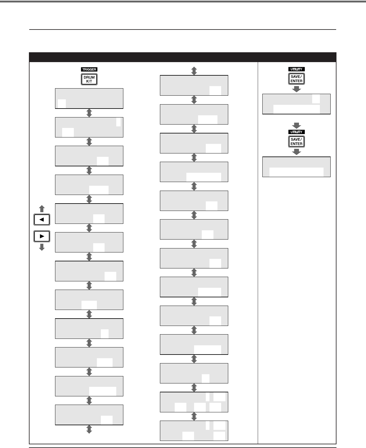
44 DTXPRESS IV Owner’s Manual
Appendix
LCD Displays
* The above “LCD Displays” charts show you the pages available in each display.
Keep in mind that the actual displays on the instrument may be different from those shown here.
Drum Kit Settings
KIT1 ååååååååå
1:Oak Custom ‚
KIT2 ƒsnare ˙
”S01:OakCustom ‚
KIT3 ƒsnare
” Volume=127 ‚
KIT4 ƒsnare
” Tune=+ 0.0 ‚
KIT5 ƒsnare
” Pan= C ‚
KIT6 ƒsnare
” Decay= 0 ‚
KIT7 ƒsnare
”CutOffFreq= 0‚
KIT8 ƒsnare
”Note= 32/G#0 ‚
KIT9 ƒsnare
” MIDI Ch=10 ‚
KIT10 ƒsnare
”GateTime=0.3s ‚
KIT11 ƒsnare
”KeyOff=disable‚
KIT12 ƒsnare
” HoldMode=off ‚
(Page 15)
(Page 28)
(Page
15, 29)
(Page 29)
(Page 29)
(Page 30)
(Page 30)
(Page 30)
(Page 30)
(Page 30)
(Page 30)
(Page 30)
KIT14 ƒsnare
” AltGrp=off ‚
KIT15 ƒsnare
”KeyAssign=poly‚
KIT13 ƒsnare
” VelXFade=0 ‚
KIT16 ƒsnare
”Song= 45áéplay‚
KIT17 ƒsnare
” RimToPad=--- ‚
KIT18 ƒsnare
” RevSend= 75 ‚
KIT23
” Snares=32 ‚
KIT24 PC Ch1=on
”PC001 M000L001‚
KIT25 CC Ch1=on
”vol=127 Pan= 64
KIT19
” RevSendDr= 40‚
KIT20
”RevType=hall2 ‚
KIT21
”RevMastRet= 64‚
KIT22
”PadCtl=snares ‚
(Page 31)
(Page 31)
(Page 32)
(Page 32)
(Page 32)
(Page 32)
(Page 33)
(Page 33)
(Page
17, 33)
(Page 33)
(Page 34)
(Page 34)
(Page 31)
KIT save to 51
:[Oak Custom ]
KIT save to 51
Are you sure ?
(Page 34)
(Page 35)
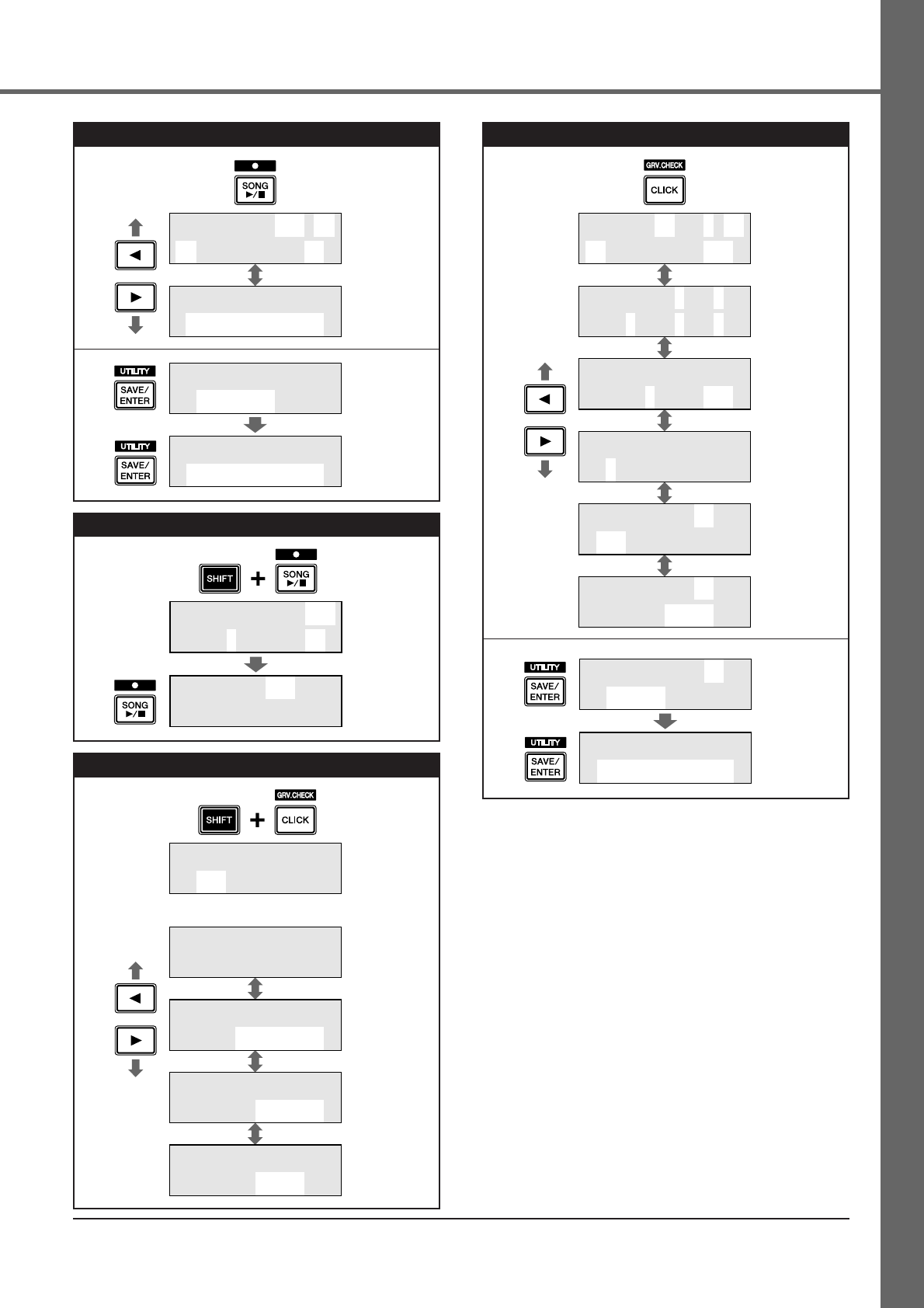
45
DTXPRESS IV Owner’s Manual
Appendix
Song Selection
Song Recording
Groove Check Function
SONG1 ⁄=123 ÷›
1 :Demo 1 ∞¢‚
SONG2 Clear
”Are You Sure ?
(Page 22)
(Page 27)
*Displayed when
a user song is
selected.
(Page 27)
(Page 27)
SONG save name
:[Untitled]
SONG save name
Are you sure ?
REC ⁄=120
Beat=4 Quant=⁄
REC Meas= 10
Now Recording.
(Page 26)
(Page 26)
GRV1 --æ√æ’æææ--
⁄=130 Gr=-2œ0.0‚
GRV2 RhythmGate
”Mode=challenge‚
GRV3
” Input=ƒsnare ‚
GRV4
” Note=⁄(4)
GRV1 --æ√æ’æææ--
80Hits/ 16%(DÀ)‚
(Page 24)
(Page 24)
(Page 25)
(Page 25)
(Page 25)
Challenge Mode
Click Settings
CLK1 ∫ B=4 ÷›
1 :User ⁄=130‚
CLK2 A˘=9 ¤=9
” ‹=6 ßß=4 Œ=2 ‚
CLK3 MeasBreak
”Meas=1 Brk=3 ‚
CLK4 Sound
” 1:Metronome ‚
CLK5 Sound=¤
”E20:Click1 ‚
CLK6 Sound=¤
” Tune=+ 0.0
(Page 18)
(Page 19)
(Page 19)
(Page 19)
(Page 19)
(Page 19)
CLK save to 1
:[User ]
CLK save to 1
Are you sure ?
(Page 20)
(Page 20)
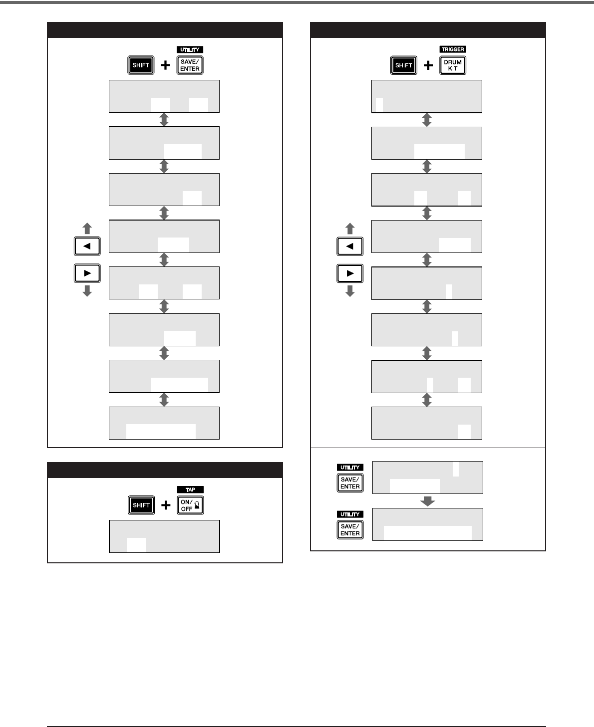
46 DTXPRESS IV Owner’s Manual
Appendix
Utility Settings
Tap Tempo Function
UTIL1 Hi-hat
HHofs=-13 T=112‚
UTIL2 Click
”OutSel=clickR ‚
UTIL3 Song
” BassSolo=off ‚
UTIL4 LED
” Disp=tempo ‚
UTIL5 MasterEQ
”Lo=+ 4 Hi=+ 0 ‚
UTIL6 MasterTune
” Tune=+15.7 ‚
UTIL7 ƒsnare
”Func=off ‚
UTIL8
” Factory Set
(Page 16)
(Page 20)
(Page 23)
(Page 21)
(Page 16)
(Page 22)
(Page 23)
(Page 35)
TAP TEMPO
¤=123 ≠ªªªª (Page 21)
Trigger Setup Edit
TRG1 ååååååååå
1 :SP Med ‚
TRG2 ƒsnare 0%
”Type=TP1/Snr ‚
TRG3 ƒsnare 0%
”Gain=65MVl= 12‚
TRG4 ƒsnare 0%
”VelCurve=norm ‚
TRG5 ƒsnare 0%
” RejTime=1 ‚
TRG6 ƒsnare 0%
” RejLvlAll=2 ‚
TRG7 ƒsnare 0%
”RejLvl=3Frm=56‚
TRG8 ƒsnare
”CopyToInput= 1
(Page 14, 36)
(Page 17, 37)
(Page 38)
(Page 38)
(Page 38)
(Page 38)
(Page 38)
(Page 39)
TRG save to 8
:[SP Med ]
TRG save to 8
Are you sure ?
(Page 36)
(Page 37)
47
DTXPRESS IV Owner’s Manual
MIDI Implementation Chart
Transmitted Recognized Remarks
Function ...
Mode 1 : OMNI ON, POLY Mode 2 : OMNI ON, MONO o : Yes
Mode 3 : OMNI OFF, POLY Mode 4 : OMNI OFF, MONO x : No
Notes:
:
All Sound Off
xx
Aux :
Reset All Cntrls
ox
:
Local ON/OFF
xx
Mes- :
All Notes OFF
xx
sages:
Active Sense
ox
:
Reset
xx
System :Clock o x
Real Time :Commands o x
: Song Pos. x x
Common : Song Sel. x x
: Tune x x
System Exclusive o x
Prog o 0 - 127 x
Change : True # ************** x
0,32 o x Bank Select
4,7,10 o x
1,2,5,6,8,11,12,13 x x
16-19 x x
Control 33-63 x x
64-84 x x
Change 91-95 x x
96-101 x x
Pitch Bender x x
After Key's x x
Touch Ch's x x
Velocity Note ON o 9nH,v=1-127 x
Note OFF x 9nH,v=0 x
Note 0 - 127 x
Number : True voice ************** x
Default x x
Mode Messages x x
Altered ************** x
Basic Default 1 - 16 x memorized
Channel Changed 1 - 16 x
YAMAHA [ DRUM TRIGGER MODULE ] Date:27-Mar-2006
Model DTXPRESS IV MIDI Implementation Chart Version : 1.0
48 DTXPRESS IV Owner’s Manual
Appendix
Drum Voice List
Voice Category
K : Kick
S : Snare
T : Tom
C : Cymbal
H : Hi-hat
P : Percussion
E : Effect
1 OakCustom
2 MapleCustm
3 MapleVintg
4 Beech
5 BirchDry
6 BirchJazz
7DryDeep
8DryTight 1
9DryTight 2
10 SoTight
11 2Head
12 BigSofty
13 RockAmb 1
14 RockAmb 2
15 BD Room 1
16 BD Room 2
17 GateKick1
18 GateKick2
19 T8 Kick
20 T9 Kick
21 CR Kick
22 T9 HrdAtk
23 T9 Long
24 Sm Kick
25 T8 Down
26 T9 Dist
27 TechKick1
28 TechKick2
29 TechKick3
30 BreakKick1
31 BreakKick2
32 BreakKick3
33 BreakKick4
34 BreakKick5
35 BreakKick6
36 VoxKick
37 KickBass
38 ResoKick1
39 ResoKick2
40 DidgerKick
41 ReversBD
1 OakCustom
2 OakCusOpRm
3 OakCusClRm
4 OakCusOff
5 OakCusOffO
6 OakCusOffC
7 MapleCustm
8 MapCusOpRm
9 MapCusClRm
10 MplCusOff
11 MplCusOffO
12 MplCusOffC
13 Beech
14 BeechOpRim
15 BeechClRim
16 BeechOff
17 BeechOffOR
18 BeechOffCR
19 Metal
20 MetalOpRim
21 MetalClRim
22 MetalOff
23 MetalOffOp
24 MetalOffCl
25 MapleVtg
26 MapleVtgR
27 Loosy
28 LoosyRim
29 LiteWood
30 LiteWoodRm
31 RockAmb 1
32 RockAmb 2
33 RockAmb R
34 BirchDeep
35 BirchDeepR
36 Studio
37 StudioRim
38 MapleLite
39 MapleLiteR
40 DryMute
41 Brush
42 BrushRim
43 BrushOff
44 BrshOffRim
45 SnareRoll*
46 GateSnare1
47 GateSnare2
48 GateSnare3
49 GateSnare4
50 GateSnare5
51 T8 Snare1
52 T8 Snare2
53 T8 Rim
54 T9 Rim
55 Tek Snare
56 LoBitSnare
57 Sm Snare1
58 Sm Snare2
59 SynSnare
60 BreakSnr 1
61 BreakSnr 2
62 BreakSnr 3
63 BreakSnr 4
64 DB Snare1
65 DB Snare2
66 DB Snare3
67 DB Snare4
68 DB Snare5
69 DB Snare6
70 Snappy
71 R&BSnare1
72 R&BSnare2
73 R&BSnare3
74 VoxSnare1
75 VoxSnare2
76 GunSnare
77 ResoSnare1
78 ResoSnare2
1 OakCustomH
2 OakCustomM
3 OakCustomL
4 MapleCus H
5 MapleCus M
6 MapleCus L
7 BeechCus H
8 BeechCus M
9 BeechCus L
10 Studio H
11 Studio M
12 Studio L
13 RockAmb H
14 RockAmb M
15 RockAmb L
16 MapleAmb H
17 MapleAmb M
18 MapleAmb L
19 JazzTom H
20 JazzTom M
21 JazzTom L
22 BrushTom H
23 BrushTom M
24 BrushTom L
25 T8 Tom1 H
26 T8 Tom1 M
27 T8 Tom1 L
28 T8 Tom2 H
29 T8 Tom2 M
30 T8 Tom2 L
31 T9 Tom1 H
32 T9 Tom1 M
33 T9 Tom1 L
34 T9 Tom2 H
35 T9 Tom2 M
36 T9 Tom2 L
37 Sm Tom1 H
38 Sm Tom1 M
39 Sm Tom1 L
40 Sm Tom2 H
41 Sm Tom2 M
42 Sm Tom2 L
43 PulseTom H
44 PulseTom M
45 PulseTom L
46 VoxTom
47 E.BendTom
48 E.Talking
49 DidgeriTom
50 ReverseTom
1Bright18
2Bright18Eg
3Bright18Cp
4Warm16
5Warm16Edge
6Warm16Cup
7 Dark18
8 Dark18Edge
9 Dark18Cup
10 CrCustom17
11 CrLight17
12 CrFast16
13 CrFast14
14 Bright20
15 Bright20Eg
16 Bright20Cp
17 Warm20
18 Warm20Edge
19 Warm20Cup
20 Dark20
21 Dark20Edge
22 Dark20Cup
23 RideCool
24 RideCoolCp
25 RideDry
26 RideDryCup
27 SizzleRide
28 SizzRideEg
29 SizzRideCp
30 ChinaHi
31 ChinaLoCtr
32 ChinaLoEg
33 Splash 1
34 Splash 2
35 Trash 1
36 Trash 2
37 T8 Crash
38 T9 Crash
39 T8 Ride
40 T9 Ride
41 ElecCymbal
42 NoiseCym1
43 NoiseCym2
44 VoxCymbal1
45 VoxCymbal2
46 ReverseCym
1 Dark14 Opn
2 Dark14 OpE
3 Dark14 Cls
4 Dark14 ClE
5 Dark14 Ft
6 Dark14 Sp
7 Dark13 Opn
8 Dark13 OpE
9 Dark13 Cls
10 Dark13 ClE
11 Dark13 Ft
12 Dark13 Sp
13 Bright14Op
14 Bright14OE
15 Bright14Cl
16 Bright14CE
17 Bright14Ft
18 Bright14Sp
19 Warm13Opn
20 Warm13OpE
21 Warm13Cls
22 Warm13ClE
23 Warm13Ft
24 Warm13Sp
25 Tight12Opn
26 Tight12OpE
27 Tight12Cls
28 Tight12ClE
29 Tight12Ft
30 Tight12Sp
31 T8 HH Opn
32 T8 HH Cls
33 T9 HH Opn
34 T9 HH Cls
35 CR HH Opn
36 CR HH Cls
37 Break HHOp
38 Break HHCl
39 Brack HHFt
40 NoiseHHOpn
41 NoiseHHCls
1 CongaHiOpn
2 CongaHiSlp
3 CongaHiOSw
4 CongaHiTip
5 CongaHiHel
6 CongaLoOpn
7 BongoHi
8 BongoLo
9 TimbalHi
10 TimbalLo
11 PailaHi
12 PailaLo
13 SurdoOpn
14 SurdoMt
15 SurdoHO
16 SurdoSw
17 PandieroOp
18 PandieroMt
19 PandieroSl
20 Tambarin1
21 Tambarin2
22 Tambarin3
23 Cowbell 1
24 Cowbell 2
25 Cowbell 3
26 Cowbell3Mt
27 Cowbell 4
28 Cowbell4Mt
29 Claves
30 Maracas
31 Vibraslap
32 Castanet
33 TriangleOp
34 TriangleCl
35 TriangleHO
36 TriangleSw
37 GuiroShort
38 GuiroLong
39 Agogo Hi
40 Agogo Lo
41 WoodBlockH
42 WoodBlockL
43 Shaker1
44 Shaker2
45 Caxixi1
46 Caxixi2
47 DjembeOpen
48 DjembeSlap
49 DjembeMute
50 CajonLo
51 CajonHi
52 CajonSlp
53 TalkDrOp
54 TalkDrMt
55 TalkDrSlp
56 TalkDrBend
57 PotDrOpn
58 PotDrCls
59 PotDrMute
60 PotDrBody
61 TablaOpen1
62 TablaOpen2
63 TablaMute
64 TablaSlp
65 BayaOpn
66 BayaMute
67 BayaBend
68 CuicaHi
69 CuicaLo
70 WhistleH
71 WhistleL
72 SleighBell
73 BellTree
74 WindChime
75 TimpaniF#2
76 Timpani B1
77 Timpani E1
78 ConctBDop
79 ConctBDmt
80 HandCymOp
81 HandCymMt
82 Gong
83 ChinaGong
84 Odaiko
85 OdaikoRim
86 Yagura
87 YaguraRim
88 Shimedaiko
89 ShimeRim
90 Atarigane
91 AtariganeM
92 AnaConga
93 AnaCowbell
94 AnaMaracas
95 AnaShaker1
96 AnaShaker2
KK
KK :::: KK
KKiiiicc
cckk
kk
SS
SS :::: SS
SSnn
nnaa
aarr
rree
ee
TT
TT :::: TT
TToo
oomm
mm
CC
CC :::: CC
CCyy
yymm
mmbb
bbaa
aallll
HH
HH :::: HH
HHiiii--
--HH
HHaa
aatttt
PP
PP :::: PP
PPee
eerr
rrcc
ccuu
uuss
ssss
ssiiiioo
oonn
nn
49
DTXPRESS
IV
Owner’s Manual
Appendix
Preset Drum Kit List
Preset Song List
1 StickHit1
2 StickHit2
3 FingerSnap
4 E.Clap1
5 E.Clap2
6 E.Clap3
7 NoiseHit
8 Metal1
9 Metal2
10 Metal3
11 AmbShot
12 Tunnel
13 HiQ
14 Noise 1
15 Noise 2
16 Pulse
17 Zap
18 MetrBell 1
19 MetrBell 2
20 Click1
21 Click2
22 Vo Go!
23 Vo Hoo!
24 Vo Yoo!
25 Vo Ha!
26 Vo Uh!
27 Vo aYeah!
28 Scratch1
29 Scratch2
30 Scratch3
31 Scratch4
32 Scratch5
33 Scratch6
34 Scratch7
35 OrchHit1
36 OrchHit2
37 R&BHit1
38 R&BHit2
39 BrassHit
40 ScratchHit
41 Industry
42 CompuVoice
43 Radio
44 Thunder
45 Tire
46 Crash
47 Glass
48 GunShot1
49 GunShot2
50 Bomb
51 ResoNzClap
52 Strike
53 AmbientCym
54 SFXCymbal1
55 SFXCymbal2
56 SFXCymbal3
57 NzAmbient
58 LoDroneAmb
59 NzEcho
60 Vel-Decay1
61 Vel-Decay2
62 DlyScratch
63 Boyon
64 P!
65 E.Bass
66 SlapBass
67 Turntable*
68 Train*
69 Helicoptr*
70 Applause*
71 Police*
72 Ring*
73 FX Pad*
74 Didgerido*
75 VinylMan*
* Loop
EE
EE :::: EE
EEffffffffee
eecc
cctttt
No. Name
1 Oak Custom
2 Maple Custom
3 Beech Custom
4 Rock Kit
5 Gate Kit
6 Hip Hop
7 Break Kit
8 Street Beat
9Brazil Kit
10 Sm Kit
11 Studio Kit
12 Dry Beat
13 SessionMastr
14 T8 Kit
15 T9 Kit
16 Drum&Bass
17 Electro
18 Percuss Kit
19 Social Cuban
20 SE Kit
21 Funky Men
22 Power Kit
23 Resonance
24 Industry
25 Jazz Kit
26 Brush Kit
No. Name
27 Matsuri
28 AsianGypsy
29 LoopLoop
30 Scratch
31 VOX Kit
32 Vintage Kit
33 Room Kit
34 Afro Kit
35 Latin Club
36 Drum Corps
37 Orchestra
38 See View
39 Boyon
No. Name
40 WikkidPocket
41 Reggae Kit
42 BrokenFunk
43 GoGo1988
44 Re-0
45 Elec 5/4
46 Backbone
47 Groove Kit
48 8/8 Craze
49 Bs.@Base
50 GM Standard
No. Name
No. Genre Name
1 Demo Demo 1
2 Demo 2
3 Demo 3
4 Rock Rock 1
5 Rock 2
6 Rock 3
7 Rock 4
8 Rock 5
9 Rock 6
10 Shuffle Shuffle 1
11 Shuffle 2
12 Shuffle 3
13 Funk Funk 1
14 Funk 2
15 Funk 3
16 Blues Blues 1
17 Blues 2
18 Hip Hop HipHop 1
19 HipHop 2
20 R&B R&B 1
21 R&B 2
22 Dance Dance 1
23 Dance 2
24 Pops Pops 1
25 Pops 2
26 Pop Rock PopRock1
27 PopRock2
28 Jazz Jazz 1
29 Jazz 2
30 Bossa Nova Bossa 1
31 Bossa 2
32 Fusion Fusion 1
33 Fusion 2
34 Samba Samba 1
35 Samba 2
36 Samba 3
37 Latin Latin 1
38 Latin 2
39 Reggae Reggae
40 Soul Soul
41 Ballad Ballad 1
42 Ballad 2
No. Genre Name
43 Second Line 2ndLine
44 Ska Ska
45 Pad Song 8Craze A
46 8Craze B
47 BassGrv
48 HornGrv
49 Jko?Naa
50 PadBass
51 GoGo Tp
52 GoGo Br
53 GoGo Lp
54 Re-O
55 BFunk A
56 BFunk B
57 BFunk C
58 Elec5/4A
59 Elec5/4B
60 Elec5/4C
61 Backb Ld
62 Backb St
63 Backb Pf
No. Genre Name
50
DTXPRESS
IV
Owner’s Manual
Appendix
Specifications
* Specifications and descriptions in this owner’s manual are for information purposes only. Yamaha Corp. reserves the right to
change or modify products or specifications at any time without prior notice. Since specifications, equipment or options may
not be the same in every locale, please check with your Yamaha dealer.
Tone Genera-
tor block
Tone Generator AWM2
Maximum Polyphony 32
Voices 427 Drum, Percussion Voices
22 Keyboard Voices
Drum Kits Preset: 50
User: 20
Effects Reverb x 19 types, Master EQ
Trigger
Tr igger Setups Preset: 7
User: 4
Pad Controller Snares adjustment, Tuning, Tempo
Pad Functions Drum Kit INC/DEC, Click Set INC/DEC, Tempo INC/DEC, Click ON/OFF
Pad Songs Start/Stop, Chase, Cut Off
3 songs (max.) can be played simultaneously.
Sequencer
Note Capacity Approx. 16,000 notes
Note Resolution 96 parts per quarter note
Recording Type Real Time Replace
Track 1
Songs 3 Demo Songs
41 Practice Songs
19 Pad Songs
20 User Songs
Metronome
Tempo 30–300 beats/minute, Tap Tempo function
Beat 1–9
Timing Accent, Quarter note, Eighth note, Sixteenth note, Triplet
Click Sound Sets Preset: 6
User: 1
Click Sets 30
Click Timer 0–600 seconds (in 30-second steps)
Training Functions Measure Break, Groove Check, Rhythm Gate
Others
Controls Buttons: DRUMKIT, CLICK, SONG
>
/
■
, SHIFT,
<
,
>
, ON/OFF, SAVE/ENTER
Controllers: Volume, Jog Dial
Displays 16 characters x 2 lines backlit LCD, 7-segment LED (3-digit), Tempo LED x 2
Connectors Trigger inputs 1, 5, 6, 7 (stereo phone jack L: trigger input, R: rim switch)
Tr igger inputs 2, 3, 4, 8 (stereo phone jack L: trigger input, R: trigger input)
HI HAT CONTROL (stereo phone jack)
OUTPUT L/MONO, R (mono phone jack)
PHONES (stereo phone jack), AUX IN (stereo mini jack)
MIDI OUT, DC IN
Power Consumption 8.0W(DTXP4), 13.0W(DTXP4 and AC power adapter)
Dimensions (W x D x H) 252 x 147 x 52 mm (9-15/16" x 5-13/16" x 2-1/16")
Weight 898 g (2 lbs.)

1. IMPORTANT NOTICE: DO NOT MODIFY THIS UNIT!
This product, when installed as indicated in the instructions con-
tained in this manual, meets FCC requirements. Modifications not
expressly approved by Yamaha may void your authority, granted
by the FCC, to use the product.
2. IMPORTANT:
When connecting this product to accessories
and/or another product use only high quality shielded cables.
Cable/s supplied with this product MUST be used. Follow all
installation instructions. Failure to follow instructions could void
your FCC authorization to use this product in the USA.
3. NOTE:
This product has been tested and found to comply with
the requirements listed in FCC Regulations, Part 15 for Class “B”
digital devices. Compliance with these requirements provides a
reasonable level of assurance that your use of this product in a
residential environment will not result in harmful interference with
other electronic devices. This equipment generates/uses radio
frequencies and, if not installed and used according to the
instructions found in the users manual, may cause interference
harmful to the operation of other electronic devices. Compliance
* This applies only to products distributed by YAMAHA CORPORATION OF AMERICA. (class B)
with FCC regulations does not guarantee that interference will not
occur in all installations. If this product is found to be the source of
interference, which can be determined by turning the unit “OFF”
and “ON”, please try to eliminate the problem by using one of the
following measures:
Relocate either this product or the device that is being affected by
the interference.
Utilize power outlets that are on different branch (circuit breaker
or fuse) circuits or install AC line filter/s.
In the case of radio or TV interference, relocate/reorient the
antenna. If the antenna lead-in is 300 ohm ribbon lead, change
the lead-in to co-axial type cable.
If these corrective measures do not produce satisfactory results,
please contact the local retailer authorized to distribute this type
of product. If you can not locate the appropriate retailer, please
contact Yamaha Corporation of America, Electronic Service Divi-
sion, 6600 Orangethorpe Ave, Buena Park, CA90620
The above statements apply ONLY to those products distributed
by Yamaha Corporation of America or its subsidiaries.
FCC INFORMATION (U.S.A.)
IMPORTANT NOTICE FOR THE UNITED KINGDOM
Connecting the Plug and Cord
IMPORTANT. The wires in this mains lead are coloured in accordance with the following code:
BLUE : NEUTRAL
BROWN : LIVE
As the colours of the wires in the mains lead of this apparatus may not correspond with the coloured makings identifying the terminals in
your plug proceed as follows:
The wire which is coloured BLUE must be connected to the terminal which is marked with the letter N or coloured BLACK.
The wire which is coloured BROWN must be connected to the terminal which is marked with the letter L or coloured RED.
Making sure that neither core is connected to the earth terminal of the three pin plug.
• This applies only to products distributed by Yamaha-Kemble Music (U.K.) Ltd. (2 wires)
Yamaha Drums global web site:
http://www.global.yamaha.com/products/music/drums.html
Yamaha Manual Library
http://www.yamaha.co.jp/manual/
U.R.G., Pro Audio & Digital Musical Instrument Division, Yamaha Corporation
© 2006 Yamaha Corporation
WR29770 8??POAP?.?-04D0
Printed in China
For details of products, please contact your nearest Yamaha
representative or the authorized distributor listed below.
Pour plus de détails sur les produits, veuillez-vous adresser à Yamaha ou
au distributeur le plus proche de vous figurant dans la liste suivante.
Die Einzelheiten zu Produkten sind bei Ihrer unten aufgeführten
Niederlassung und bei Yamaha Vertragshändlern in den jeweiligen
Bestimmungsländern erhältlich.
Para detalles sobre productos, contacte su tienda Yamaha más cercana
o el distribuidor autorizado que se lista debajo.
CANADA
Yamaha Canada Music Ltd.
135 Milner Avenue, Scarborough, Ontario,
M1S 3R1, Canada
Tel: 416-298-1311
U.S.A.
Yamaha Corporation of America
6600 Orangethorpe Ave., Buena Park, Calif. 90620,
U.S.A.
Tel: 714-522-9011
MEXICO
Yamaha de México S.A. de C.V.
Calz. Javier Rojo Gómez #1149,
Col. Guadalupe del Moral
C.P. 09300, México, D.F., México
Tel: 55-5804-0600
BRAZIL
Yamaha Musical do Brasil Ltda.
Rua Joaquim Floriano, 913 - 4' andar, Itaim Bibi,
CEP 04534-013 Sao Paulo, SP. BRAZIL
Tel: 011-3704-1377
ARGENTINA
Yamaha Music Latin America, S.A.
Sucursal de Argentina
Olga Cossettini 1553, Piso 4 Norte
Madero Este-C1107CEK
Buenos Aires, Argentina
Tel: 011-4119-7000
PANAMA AND OTHER LATIN
AMERICAN COUNTRIES/
CARIBBEAN COUNTRIES
Yamaha Music Latin America, S.A.
Torre Banco General, Piso 7, Urbanización Marbella,
Calle 47 y Aquilino de la Guardia,
Ciudad de Panamá, Panamá
Tel: +507-269-5311
THE UNITED KINGDOM/IRELAND
Yamaha Music U.K. Ltd.
Sherbourne Drive, Tilbrook, Milton Keynes,
MK7 8BL, England
Tel: 01908-366700
GERMANY
Yamaha Music Europe GmbH
Siemensstraße 22-34, 25462 Rellingen, Germany
Tel: 04101-3030
SWITZERLAND/LIECHTENSTEIN
Yamaha Music Europe GmbH
Branch Switzerland in Zürich
Seefeldstrasse 94, 8008 Zürich, Switzerland
Tel: 01-383 3990
AUSTRIA
Yamaha Music Europe GmbH Branch Austria
Schleiergasse 20, A-1100 Wien, Austria
Tel: 01-60203900
CZECH REPUBLIC/SLOVAKIA/
HUNGARY/SLOVENIA
Yamaha Music Europe GmbH Branch Austria
Schleiergasse 20, A-1100 Wien, Austria
Tel: 01-602039025
POLAND
Yamaha Music Europe GmbH
Branch Sp.z o.o. Oddzial w Polsce
ul. 17 Stycznia 56, PL-02-146 Warszawa, Poland
Tel: 022-868-07-57
THE NETHERLANDS/
BELGIUM/LUXEMBOURG
Yamaha Music Europe Branch Benelux
Clarissenhof 5-b, 4133 AB Vianen, The Netherlands
Tel: 0347-358 040
FRANCE
Yamaha Musique France
BP 70-77312 Marne-la-Vallée Cedex 2, France
Tel: 01-64-61-4000
ITALY
Yamaha Musica Italia S.P.A.
Combo Division
Viale Italia 88, 20020 Lainate (Milano), Italy
Tel: 02-935-771
SPAIN/PORTUGAL
Yamaha Música Ibérica, S.A.
Ctra. de la Coruna km. 17, 200, 28230
Las Rozas (Madrid), Spain
Tel: 91-639-8888
GREECE
Philippos Nakas S.A. The Music House
147 Skiathou Street, 112-55 Athens, Greece
Tel: 01-228 2160
SWEDEN
Yamaha Scandinavia AB
J. A. Wettergrens Gata 1, Box 30053
S-400 43 Göteborg, Sweden
Tel: 031 89 34 00
DENMARK
YS Copenhagen Liaison Office
Generatorvej 6A, DK-2730 Herlev, Denmark
Tel: 44 92 49 00
FINLAND
F-Musiikki Oy
Kluuvikatu 6, P.O. Box 260,
SF-00101 Helsinki, Finland
Tel: 09 618511
NORWAY
Norsk filial av Yamaha Scandinavia AB
Grini Næringspark 1, N-1345 Østerås, Norway
Tel: 67 16 77 70
ICELAND
Skifan HF
Skeifan 17 P.O. Box 8120, IS-128 Reykjavik, Iceland
Tel: 525 5000
RUSSIA
Yamaha Music (Russia)
Office 4015, entrance 2, 21/5 Kuznetskii
Most street, Moscow, 107996, Russia
Tel: 495 626 0660
OTHER EUROPEAN COUNTRIES
Yamaha Music Europe GmbH
Siemensstraße 22-34, 25462 Rellingen, Germany
Tel: +49-4101-3030
Yamaha Corporation,
Asia-Pacific Music Marketing Group
Nakazawa-cho 10-1, Naka-ku, Hamamatsu,
Japan 430-8650
Tel: +81-53-460-2312
TURKEY/CYPRUS
Yamaha Music Europe GmbH
Siemensstraße 22-34, 25462 Rellingen, Germany
Tel: 04101-3030
OTHER COUNTRIES
Yamaha Music Gulf FZE
LOB 16-513, P.O.Box 17328, Jubel Ali,
Dubai, United Arab Emirates
Tel: +971-4-881-5868
THE PEOPLE’S REPUBLIC OF CHINA
Yamaha Music & Electronics (China) Co.,Ltd.
2F, Yunhedasha, 1818 Xinzha-lu, Jingan-qu,
Shanghai, China
Tel: 021-6247-2211
HONG KONG
Tom Lee Music Co., Ltd.
11/F., Silvercord Tower 1, 30 Canton Road,
Tsimshatsui, Kowloon, Hong Kong
Tel: 2737-7688
INDIA
Yamaha Music India Pvt. Ltd.
5F Ambience Corporate Tower Ambience Mall Complex
Ambience Island, NH-8, Gurgaon-122001, Haryana, India
Tel: 0124-466-5551
INDONESIA
PT. Yamaha Music Indonesia (Distributor)
PT. Nusantik
Gedung Yamaha Music Center, Jalan Jend. Gatot
Subroto Kav. 4, Jakarta 12930, Indonesia
Tel: 21-520-2577
KOREA
Yamaha Music Korea Ltd.
8F, 9F, Dongsung Bldg. 158-9 Samsung-Dong,
Kangnam-Gu, Seoul, Korea
Tel: 080-004-0022
MALAYSIA
Yamaha Music Malaysia, Sdn., Bhd.
Lot 8, Jalan Perbandaran, 47301 Kelana Jaya,
Petaling Jaya, Selangor, Malaysia
Tel: 3-78030900
PHILIPPINES
Yupangco Music Corporation
339 Gil J. Puyat Avenue, P.O. Box 885 MCPO,
Makati, Metro Manila, Philippines
Tel: 819-7551
SINGAPORE
Yamaha Music Asia Pte., Ltd.
#03-11 A-Z Building
140 Paya Lebor Road, Singapore 409015
Tel: 747-4374
TAIWAN
Yamaha KHS Music Co., Ltd.
3F, #6, Sec.2, Nan Jing E. Rd. Taipei.
Taiwan 104, R.O.C.
Tel: 02-2511-8688
THAILAND
Siam Music Yamaha Co., Ltd.
4, 6, 15 and 16th floor, Siam Motors Building,
891/1 Rama 1 Road, Wangmai,
Pathumwan, Bangkok 10330, Thailand
Tel: 02-215-2626
OTHER ASIAN COUNTRIES
Yamaha Corporation,
Asia-Pacific Music Marketing Group
Nakazawa-cho 10-1, Naka-ku, Hamamatsu,
Japan 430-8650
Tel: +81-53-460-2317
AUSTRALIA
Yamaha Music Australia Pty. Ltd.
Level 1, 99 Queensbridge Street, Southbank,
Victoria 3006, Australia
Tel: 3-9693-5111
NEW ZEALAND
Music Works LTD
P.O.BOX 6246 Wellesley, Auckland 4680,
New Zealand
Tel: 9-634-0099
COUNTRIES AND TRUST
TERRITORIES IN PACIFIC OCEAN
Yamaha Corporation,
Asia-Pacific Music Marketing Group
Nakazawa-cho 10-1, Naka-ku, Hamamatsu,
Japan 430-8650
Tel: +81-53-460-2312
NORTH AMERICA
CENTRAL & SOUTH AMERICA
EUROPE
AFRICA
MIDDLE EAST
ASIA
OCEANIA
HEAD OFFICE Yamaha Corporation, Pro Audio & Digital Musical Instrument Division
Nakazawa-cho 10-1, Naka-ku, Hamamatsu, Japan 430-8650
Tel: +81-53-460-2445
SY49
