Yamaha MRX Setup Manual Sm En D0
User Manual: Yamaha MRX Setup Manual
Open the PDF directly: View PDF ![]() .
.
Page Count: 203 [warning: Documents this large are best viewed by clicking the View PDF Link!]
- Cover
- Introduction
- Setup workflow
- Example 1) Ballroom where the Room Combiner can be used
- Example 2) Remote conferencing system that also uses Speech Privacy
- Using the Device Configuration Wizard to create your device setup
- Configuring the settings on the MRX
- Making EXT. I/O settings
- Connecting the equipment
- Powering-on the MRX
- Powering-on the amp
- Specifying the computer’s TCP/IP address
- Sending the Speech Privacy environmental sound
- Taking MTX-MRX Editor online
- Verifying that the settings were applied
- Example 3) A paging system using the PGM1
- Using the Device Configuration Wizard to create your device setup
- Specifying the MRX configuration
- Making EXT. I/O settings
- Connecting the equipment
- Powering-on the PoE-equipped gigabit network switch
- Specifying the MCP1’s UNIT ID
- Power-on equipment other than amps and powered speakers
- Power-on amps and powered speakers
- Specifying the computer’s TCP/IP address
- Taking MTX-MRX Editor online
- Verifying that the settings were applied
- Q&A
- Uninstalling the software (Removing the application)

MRX Setup Manual 1
This manual serves as an introduction to possible installation methods and application examples
for the MRX series of DSP processors used in conjunction with MTX-MRX Editor control soft-
ware.
Please refer to the owner’s manual on a device about the details of MRX, and refer to the “MTX-
MRX Editor User Guide” (PDF file) about the details of MTX-MRX Editor.
Information
• The software and this manual are the exclusive copyrights of Yamaha Corporation.
• Copying of the software or reproduction of this manual in whole or in part by any means is expressly forbidden without the written consent of
the manufacturer.
• Yamaha makes no representations or warranties with regard to the use of the software and documentation and cannot be held responsible for
the results of the use of this manual and the software.
• Future upgrades of application and system software and any changes in specifications and functions will be announced at the following web-
site.
http://www.yamahaproaudio.com/
• The screen displays as illustrated in this manual are for instructional purposes, and may appear somewhat different from the screens which
appear on your computer.
• Copying of the commercially available musical data including but not limited to MIDI data and/or audio data is strictly prohibited except for your
personal use.
• Ethernet is trademarks of Xerox Corporation.
• Windows is a registered trademark of Microsoft® Corporation in the United States and other countries.
• iPad, Bonjour, AirDrop and iTunes are trademarks of Apple Inc., registered in the U.S. and other countries.
• The SDHC and SD logos are trademarks of SD-3C, LLC.
• The company names and product names in this manual are the trademarks or registered trademarks of their respective companies.
MRX Setup Manual
MRX Setup Manual
EN
MRX Setup Manual 2
The MRX Setup Manual explains how to create setups using the MRX and MTX-MRX Editor.
As examples, we will provide simple explanations of the typical setups described below.
For detailed parameter settings, refer to “MTX-MRX Editor User Guide” and “MRX Designer User Guide”.
When you install MTX-MRX Editor, the three example files described here will be found in the following folders.
-32-bit operating system
C:\Program Files\Yamaha\MTX-MRX Editor\V*.*\ProjectFile
-64-bit operating system
C:\Program Files(x86)\Yamaha\MTX-MRX Editor\V*.*\ProjectFile
*.* will be the version of the installed MTX-MRX Editor.
Example 1 : MRX7-D Ballroom-*.mtx
Example 2 : MRX7-D Conference-*.mtx
Example 3 : MRX7-D+PGM1+MCP1 Fitness-*.mtx
-* is a management number. In some cases, there will be no -*.
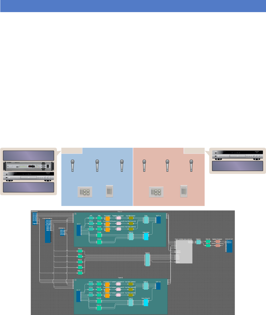
Example 1) Ballroom where the Room Combiner can be used
This is an example where the sections of the room can be split or combined, as in a ballroom.
This example assumes that you’re using the following equipment.
The number of speakers is not specified; choose amplifiers that are suitable for your speaker setup. You will also
need to provide the appropriate number of cables.
Introduction
Wireless
Microphone Receiver
AUX IN
Room A
Rack
Microphone
Ch=1
Microphone
Ch=2
Microphone
Ch=3
Microphone
Ch=4
Microphone
Ch=5
Microphone
Ch=6
DCP ID=0 DCP ID=1 DCP ID=2 DCP ID=3
Room B Rack
AUX IN
•MRX7-D × 1
• MY8-ADDA96 × 1
• DCP4V4S × 2
• DCP4S × 2
• Amplifier
(two channels of amplification)
• Speakers (the number needed)
• SD memory card × 1
• Background music source such as a Blu-ray
player × 2
• Stereo input ports such as an AUX IN × 2
• Wireless microphone receivers (6 channels)
• Wireless microphones × 6
Introduction
MRX Setup Manual 3
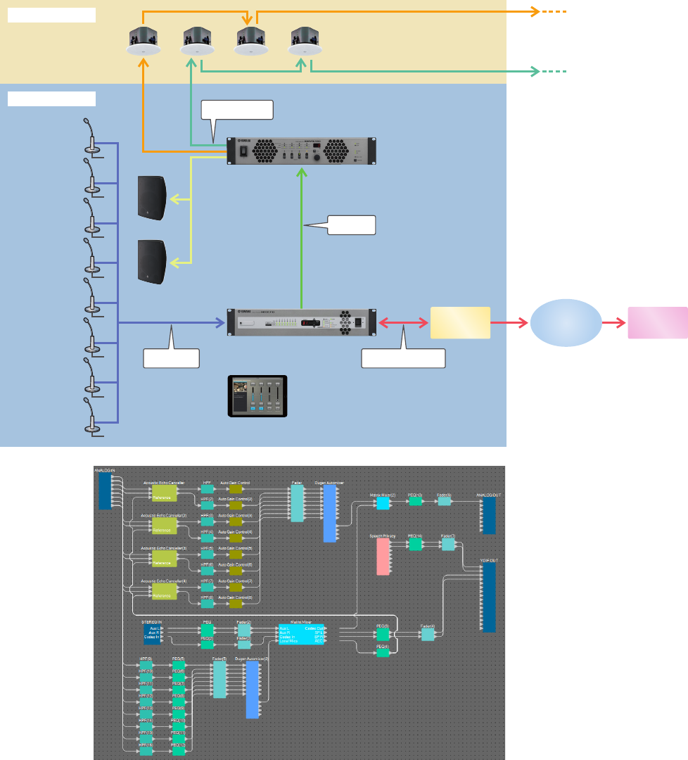
Example 2) Remote conferencing system that also uses Speech Privacy
This is an example where Speech Privacy is used to prevent the discussion content from being leaked outside of the
remote conferencing system room and other external rooms. We’ll assume that there is a single remote location, and
that there are eight mics in the conference room.
This example assumes that you’re using the following equipment.
The number of speakers is not specified. You will also need to provide the appropriate number of cables.
XMV4280
MRX7-D
Analog OUT
Corridor
Meeting room
Microphone 1
Microphone 2
Microphone 3
Microphone 4
Microphone 5
Microphone 6
Microphone 7
Microphone 8
Analog IN
YDIF
Analog IN/OUT
CODEC
etc. Network Remote A
Main R
Main L
•MRX7-D × 1
• XMV4280 × 1
• iPad with ProVisionaire Touch installed × 1
• CODEC × 1
• Speakers (the number needed)
• SD memory card × 1
• Stereo input ports such as an AUX IN × 2
• Microphones × 8
Introduction
MRX Setup Manual 4
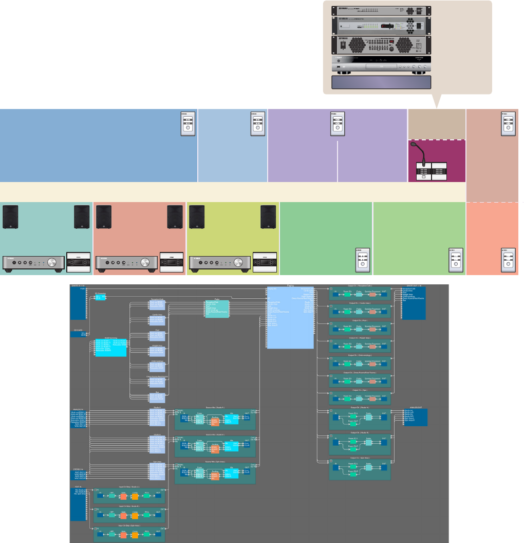
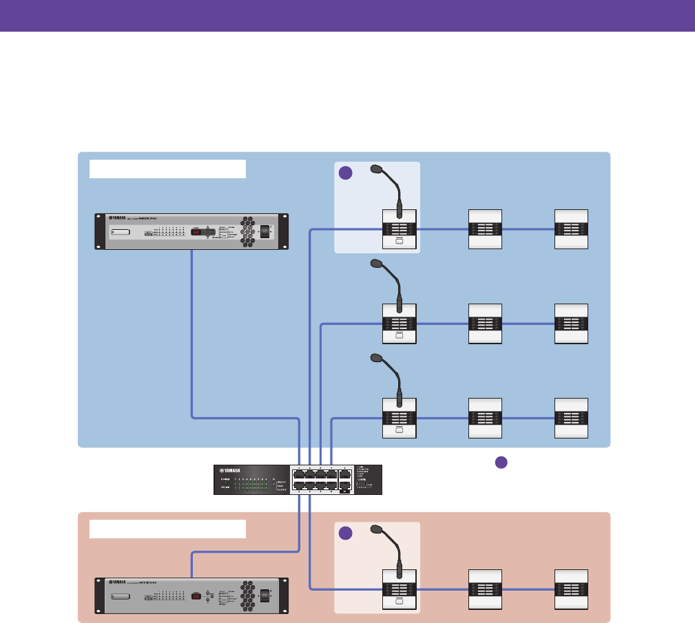
Example 3) A paging system using the PGM1
This example envisions a paging system using the PGM1 installed in a space such as a fitness club, and using the
MCP1 to switch the background music.
Powered speakers such as the DBR15 are placed in spaces that require high volume.
This example assumes that you’re using the following equipment.
The number of speakers is not specified; choose amplifiers that are suitable for your speaker setup. You will also
need to provide the appropriate number of cables.
EXi8 ID=01
MRX7-D ID=02
XMV ID=30
BGM
Pool Spa Dress Room Rest Room
Rack Office
Cafe
DCP
ID=00
DCP
ID=05
DCP
ID=06
DCP
ID=02
Studio A Studio B Spin Weight Cardio Child-minding
PGM1
ID=60
WXC-50
MCP1
ID=90 WXC-50
MCP1
ID=91 WXC-50
MCP1
ID=92 DCP
ID=03
DCP
ID=01
DCP
ID=04
Reception
•MRX7-D × 1
• EXi8 × 1
• XMV8280-D × 1
• DCP1V4S × 7
• MCP1 × 3
• PGM1 × 1
• PGX1 × 1
• PoE-compatible gigabit network switch
such as the SWR2100P-5G × 1
• WXC-50 × 3
• Powered speakers such as the DBR15 × 6
• XLR (male) output jacks × 6
(for powered speakers)
• Speakers (the required number)
• SD memory card × 1
• Background music sources such as a Blu-
ray player × 3
• Wireless mic receivers (for three channels)
• Headset mics for wireless use × 3
MRX Setup Manual 5
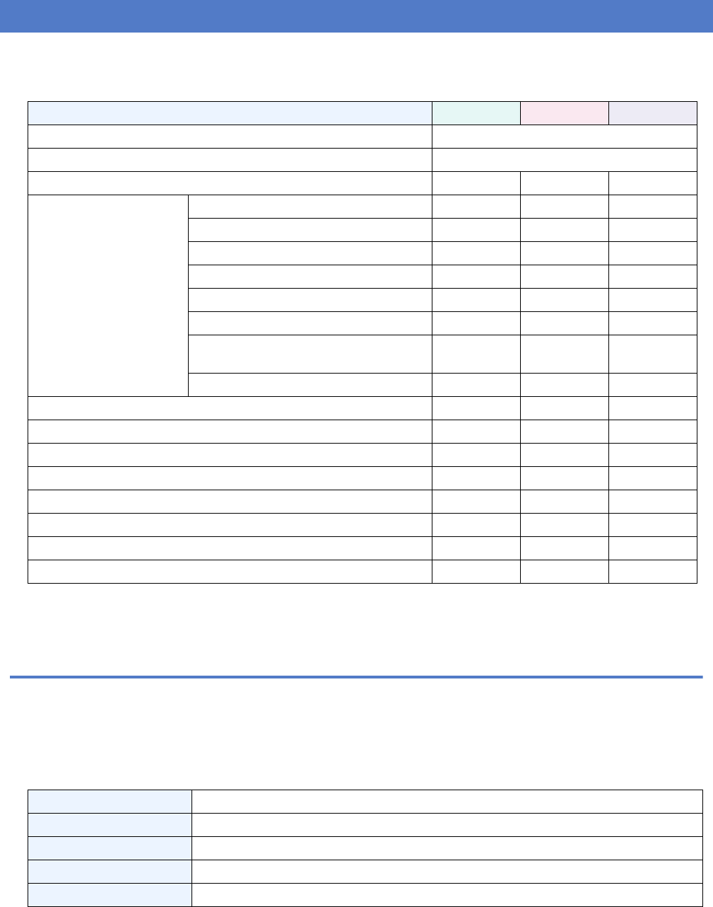
The following table shows the workflow for connecting equipment such as MTX series signal processors and XMV series
power amplifiers to your computer, and making settings in MTX-MRX Editor.
For details on PGM1 settings, refer to page 142.
Installing MTX-MRX Editor
In order to connect MRX series devices to your computer, you’ll need to download MTX-MRX Editor from the “down-
load” page of the Yamaha Pro Audio website.
http://www.yamahaproaudio.com/
System Requirements
Example 1 Example 2 Example 3
Installing MTX-MRX Editor Page 5
Starting up MTX-MRX Editor Page 6
Using the Device Configuration Wizard to create your device setup Page 7 Page 65 Page 110
Configuring the settings on
the MRX
Placing and connecting the components Page 13 Page 71 Page 117
Compiling Page 32 Page 88 Page 161
Specifying snapshots Page 33 — —
Setting a parameter link group Page 38 Page 89 Page 162
Making the DCP settings Page 42 — Page 166
Making MCP1 settings — — Page 176
Creating the Remote Control Setup List
used by ProVisionaire Touch — Page 93 —
Storing presets Page 53 Page 97 Page 185
Making EXT. I/O settings — Page 99 Page 190
Connecting the equipment Page 61 Page 104 Page 198
Powering-on the MRX Page 62 Page 105 —
Powering-on the amp Page 62 Page 105 —
Specifying the computer’s TCP/IP address Page 62 Page 105 Page 199
Sending the Speech Privacy environmental sound — Page 106 —
Taking MTX-MRX Editor online Page 63 Page 107 Page 200
Verifying that the settings were applied Page 64 Page 108 Page 201
OS Windows 10 (32bit/64bit)
CPU Core i3/i5 or better
Memory 4 GB or more
H.D.D. 230 MB or more free (When you install, need 480 MB or more free.)
Other Bonjour must be installed, Ethernet (1000BASE-T or higher)
NOTE
The System Requirements described above are applied to the MTX-MRX Editor version 4.0.0. You can check the latest version infor-
mation of each program and its system requirements at the following website
http://www.yamahaproaudio.com/
The system requirements may differ slightly depending on the particular computer.
Setup workflow

Setup workflow
MRX Setup Manual 6
Follow the steps below to install MTX-MRX Editor.
1. After decompressing the downloaded file, double-click “setup.exe” in the decompressed
file location.
The MTX-MRX Editor setup wizard will appear.
2. Proceed with the installation as directed by the instructions in the screen.
Starting up MTX-MRX Editor
Follow the steps below to start up MTX-MRX Editor.
1. Double-click the MTX-MRX Editor icon on the desktop.
2. If the “Network Setup” dialog box appears, click [OK] or [Cancel].
You’ll be performing the setup during the step “Specifying the computer’s TCP/IP address”
3. The “Startup” dialog box will appear; click [New file] and then click [OK].
The “Device Configuration Wizard” will start up. Now you can proceed to make basic settings.
We will use specific examples to explain “Using the Device Configuration Wizard to create your device setup” and subse-
quent steps.
NOTE
If the computer you’re using does not have Bonjour installed, a screen asking you to install Bonjour will appear during the installa-
tion.
If you are asked to install Bonjour, download Bonjour from the Yamaha Pro Audio website, and install it. Then install MTX-MRX Edi-
tor again.
http://www.yamahaproaudio.com/
NOTE
The “User Account Control” dialog box may appear. Click [Continue] or [Yes].
MRX Setup Manual 7
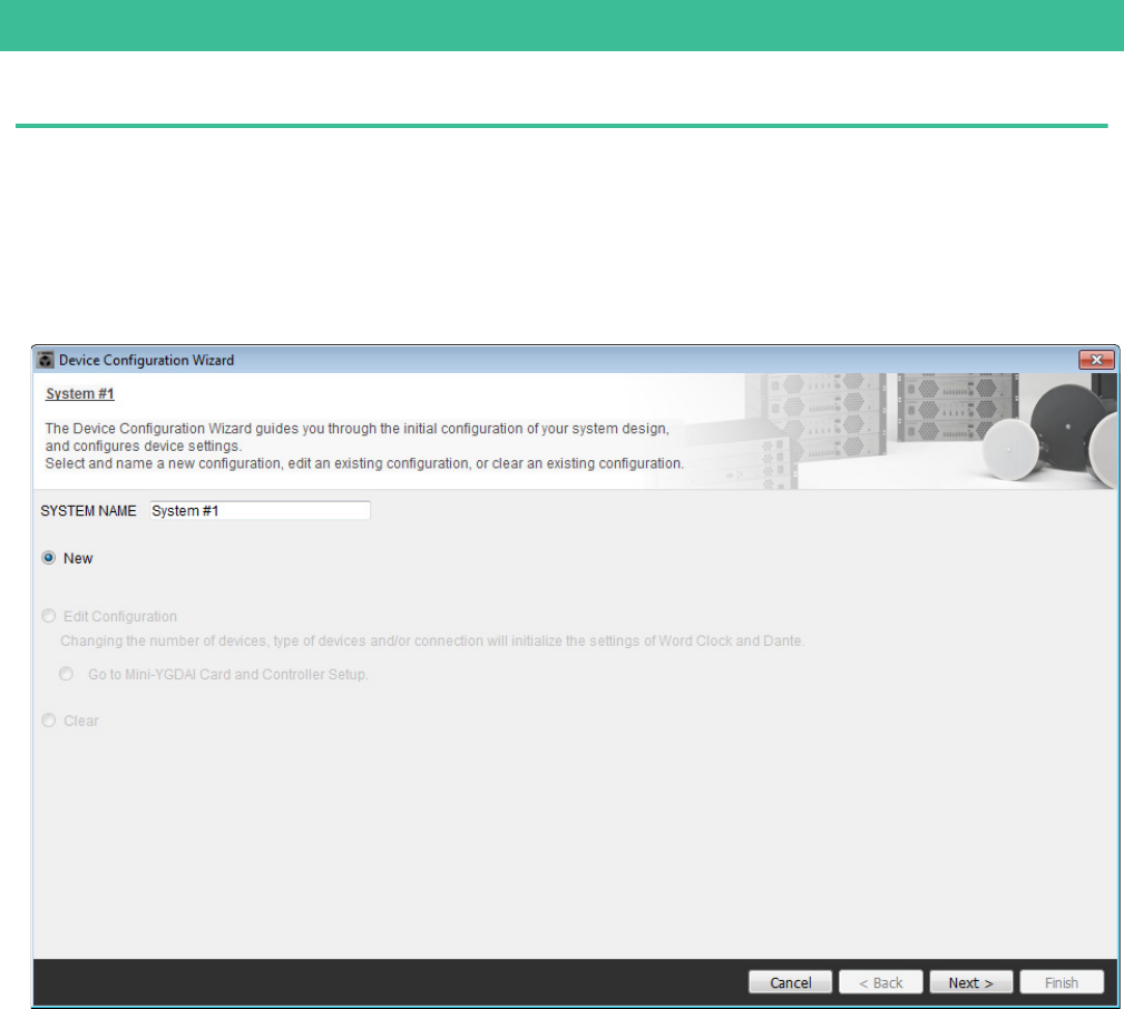
Using the Device Configuration Wizard to create your device setup
Before setting the internal configuration on the MRX, use the wizard on the MTX-MRX Editor to create a configuration for
the device.
After you’ve made basic settings, you’ll be able to print information about system cabling and ID numbers.
Use the following procedure to make basic settings.
1. Type a name for the MTX/MRX System you’ll be constructing, and click [Next>].
Example 1) Ballroom where the Room Combiner can be used
Example 1) Ballroom where the Room Combiner can be used
MRX Setup Manual 8
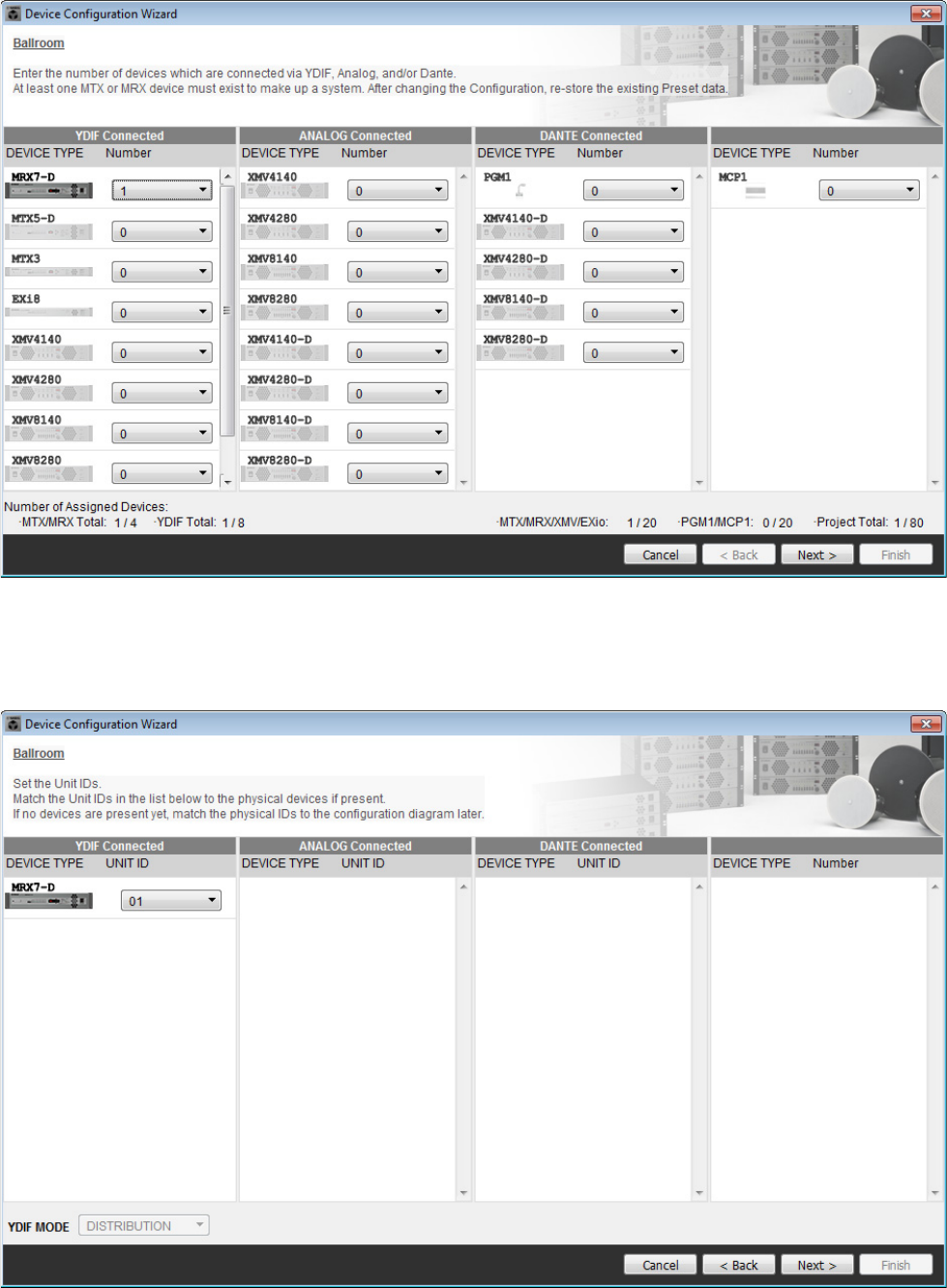
2. Specify the number of units that will be connected in your MTX/MRX System, and click
[Next>].
In “YDIF Connected,” specify 1 as the number of MRX7-D units.
3. Verify that the MRX’s UNIT ID is 1, and then click [Next>].
Unless you have specific reasons for doing so, use the UNIT ID that is assigned.
Example 1) Ballroom where the Room Combiner can be used
MRX Setup Manual 9
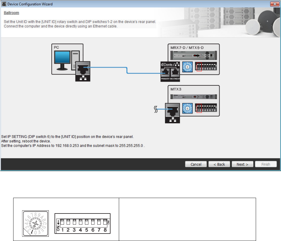
4. Set the MRX’s [UNIT ID] rotary switch and DIP switch.
You will set the computer’s IP address after completing the wizard, in “Specifying the computer’s TCP/IP address.”
If the MRX is not nearby, make settings during the step “Connecting the equipment.”
Make the following settings.
5. When you’ve finished setting the MRX’s [UNIT ID] rotary switch and DIP switch, click
[Next>].
MRX7-D
UNIT ID = 01
[UNIT ID] rotary switch = 1
DIP switches are all OFF (upward)
Example 1) Ballroom where the Room Combiner can be used
MRX Setup Manual 10
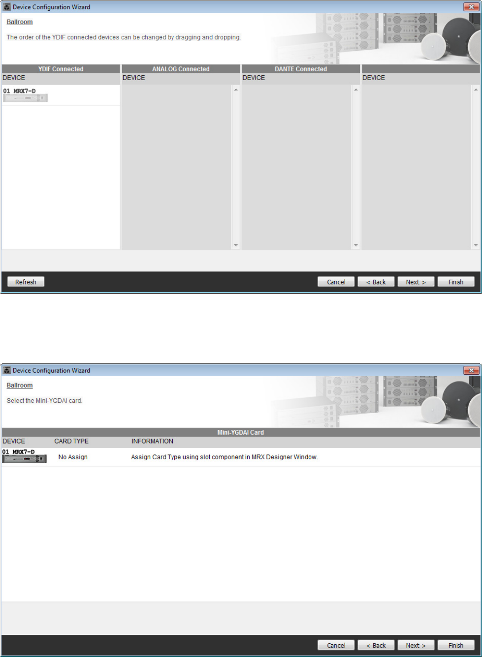
6. Verify that the MRX is shown, and click [Next>].
7. Click [Next>].
On the MRX Designer of the MRX, select the Mini-YGDAI card.
Example 1) Ballroom where the Room Combiner can be used
MRX Setup Manual 11
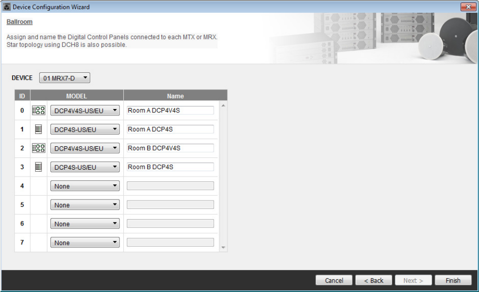
8. Choose the model of DCP that is connected to the MRX, enter a device name, and click
[Finish].
One DCP4S and one DCP4V4S will be placed respectively in each room, allocated as follows: ID=0 is DCP4V4S in
Room A, ID=1 is DCP4S in Room A, ID=2 is DCP4V4S in Room B, ID=3 is DCP4S in Room B.
Example 1) Ballroom where the Room Combiner can be used
MRX Setup Manual 12
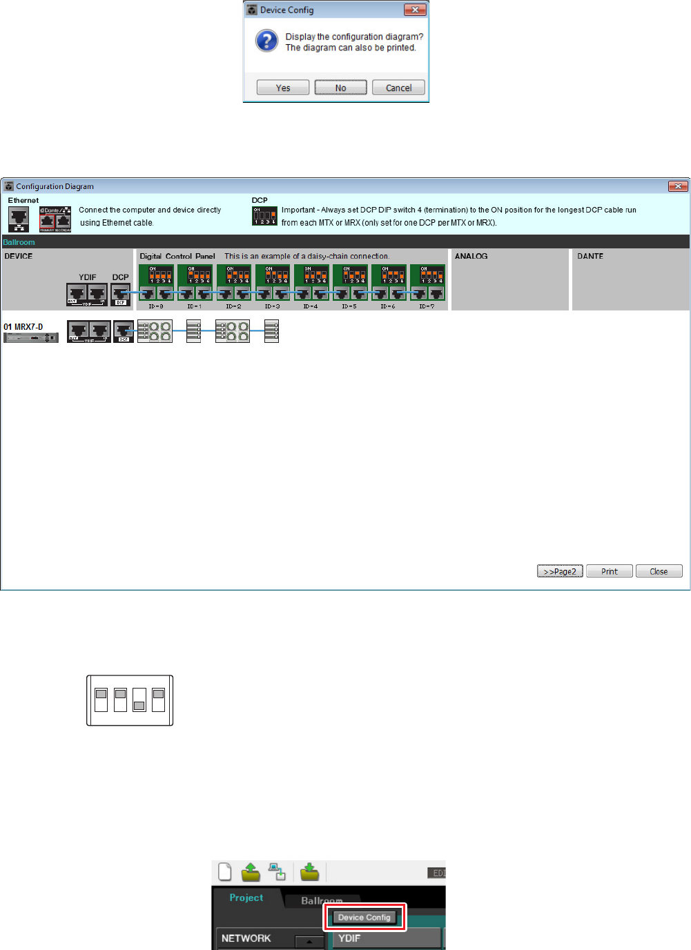
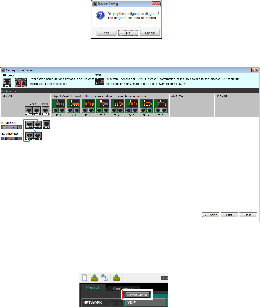
9. When you see the dialog box “Display the configuration diagram? The diagram can also
be printed.” click [Yes].
A cabling diagram will appear. If you want, click [Print] to print the diagram.
To close the screen, click [Close].
Set the DIP switches of the DCP units as shown in the “Digital Control Panel” section of the schematic diagram.
For the last DCP (ID=3), set DIP switch 4 ON (upward).
If you want to use the Device Configuration Wizard to change the device configuration, click the [Device Config] but-
ton in the Project screen.
NOTE
If you want to view the cabling diagram again, do so by choosing [File] menu → [Print Configuration Diagram].
1
ON
2 3 4
Example 1) Ballroom where the Room Combiner can be used
MRX Setup Manual 13
Configuring the settings on the MRX
Use the MRX Designer to set an internal configuration on the MRX.
When you have finished each setting, we recommend that you save the configuration from the [File] menu → [Save].
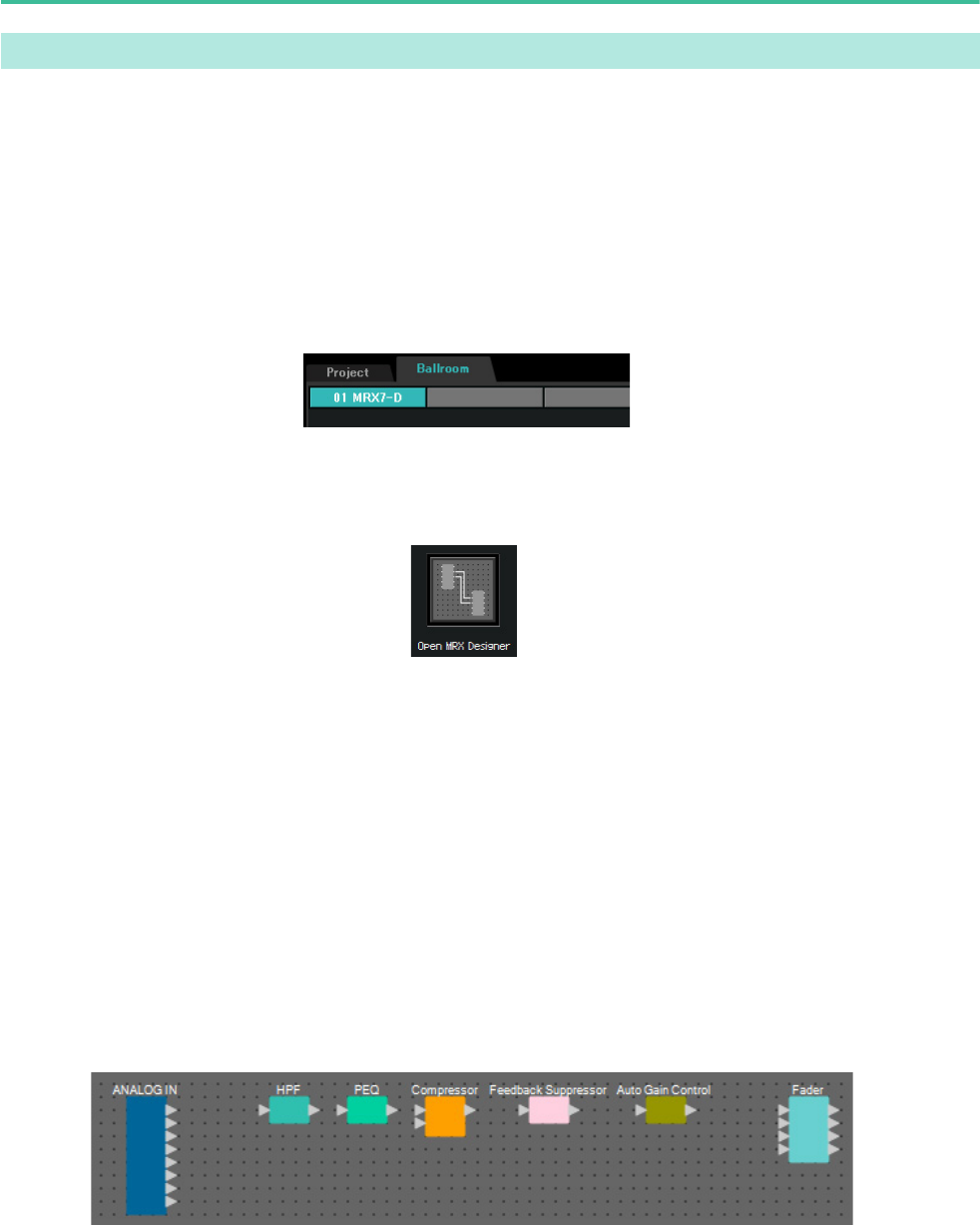
Starting the MRX Designer
Click the tab for the system name that you set in step 1 of “Using the Device Configuration Wizard to create your
device setup” to go to the settings screen.
After going to the settings screen, click the “Open MRX Designer” button to start the MRX Designer.
Placing and connecting the components related to the mics in Room A
Here we will place and connect the components related to the mics in Room A.
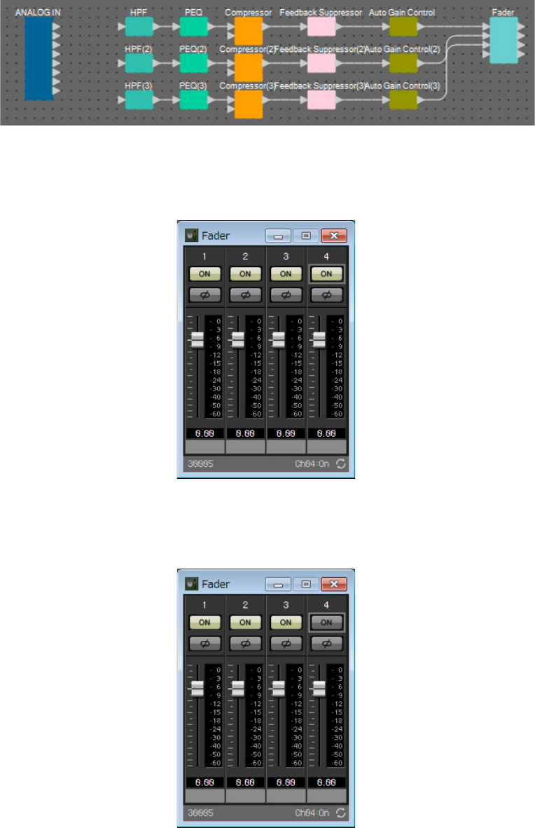
1. Place the components shown below by dragging them from the “Components” area
and dropping them into the Design sheet.
• “ANALOG IN”
• “HPF” (MONO)
• “PEQ” (MONO, 4 BAND)
• “Compressor” (MONO)
• “Notch FBS”(Feedback Suppressor)
• “Auto Gain Control” (MONO)
• “Fader” (4 CH)
Placing and connecting the components
NOTE
The “User Account Control” dialog box may display. Click either [Continue] or [Yes].
Example 1) Ballroom where the Room Combiner can be used
MRX Setup Manual 14
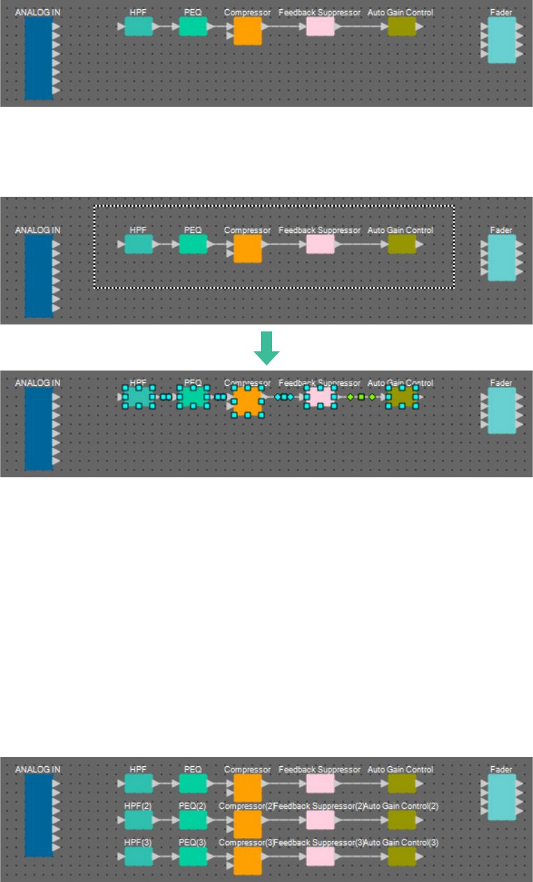
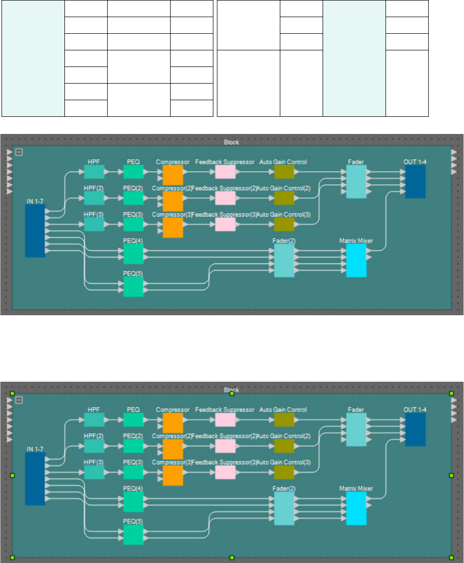
2. Connect the space between the ports from “HPF” to “Auto Gain Control” by dragging
and dropping.
3. Select the area between “HPF” and “Auto Gain Control”, so that the components and
wires are selected.
4. Copy the selected components and wires and paste twice, or drag and drop the
selected components and wires while holding down <Ctrl>.
Change the placement of the components as need be.
Here’s how to copy:
• <Ctrl> + <C>
• Right-click and select [Copy] from the context menu
• Select [Copy] from the [Edit] menu
Here’s how to paste:
• <Ctrl> + <V>
• Right-click and select [Paste] from the context menu
• Select [Paste] from the [Edit] menu
Example 1) Ballroom where the Room Combiner can be used
MRX Setup Manual 15
5. Connect each Auto Gain Control to the Faders.
6. Double-click “Fader.”
The “Fader” component editor will appear.
7. Turn channel 4 (which has not been connected) off, and click the [×] button at the top
right-hand corner to close the component editor.
Example 1) Ballroom where the Room Combiner can be used
MRX Setup Manual 16
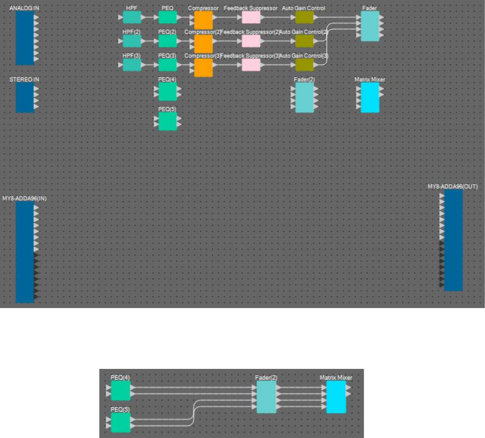
Placing and connecting the components not related to the mics in Room A
Place and connect the components related to the Blu-Ray player and input from AUX IN in Room A.
1. Place the components shown below by dragging them from the “Components” area
and dropping them into the Design sheet.
• “STEREO IN”
• “SLOT” (MY8-ADDA96)
• “PEQ” (STEREO, 4 BAND) × 2
• “Fader” (4 CH)
• “Matrix Mixer” (IN=4, OUT=2)
2. Connect the space between the ports from “PEQ” to “Matrix Mixer” by dragging and
dropping.
Example 1) Ballroom where the Room Combiner can be used
MRX Setup Manual 17
3. Double-click “Fader(2).”
The “Fader” component editor will appear.
4. Turn channels 3 and 4 off.
Register whether the [ON] button will switch to AUX or BD in the parameter link group. This will turn fader
channels 3/4 off when channels 1/2 are on, and fader channels 3/4 on when channels 1/2 are off. Do not make any
changes from this point on.
5. Click the [×] button at the top right-hand corner to close the component editor.
Example 1) Ballroom where the Room Combiner can be used
MRX Setup Manual 18
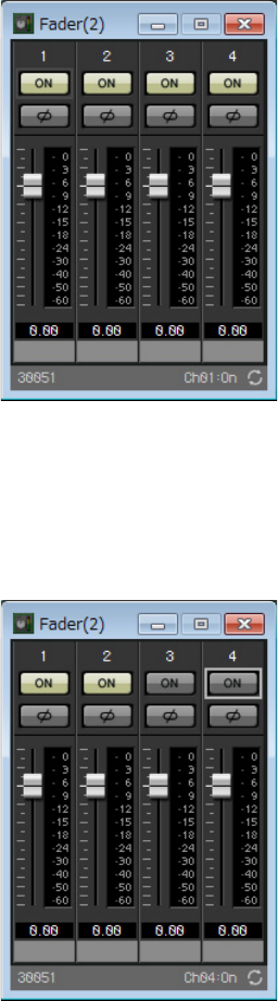
Encapsulating the Room A components as a block
Since the same components are to be connected for Room B, we’ll use the User Defined Block function to make work
easier, encapsulating the components as a block.
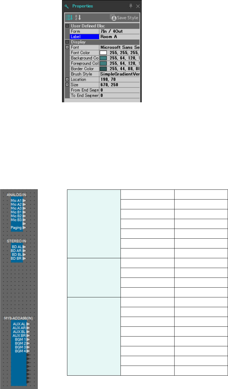
1. Select the area outside of the input/output components, and select the components
and wires.
2. Select [Create User Defined Block] in the [Edit] menu. Change the IN value to “7” and
the OUT value to “4” in the dialog box, and click [OK].
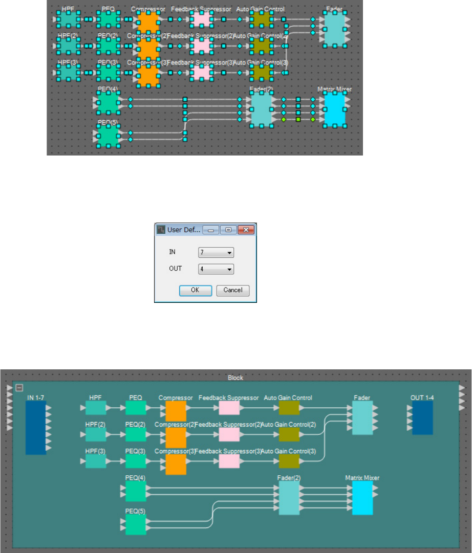
3. Change the position and size of the User Defined Block and the components as neces-
sary.
Example 1) Ballroom where the Room Combiner can be used
MRX Setup Manual 19
4. Make the following connections with the User Defined Block.
5. Click somewhere besides the User Defined Block components and wires, and select the
User Defined Block.
IN
1HPF1
Fader
1
OUT
1
2HPF(2)1 2 2
3HPF(3)1 3 3
4
PEQ(4)
1L
Matrix Mixer 1 4
51R
6
PEQ(5)
1L
71R
Example 1) Ballroom where the Room Combiner can be used
MRX Setup Manual 20
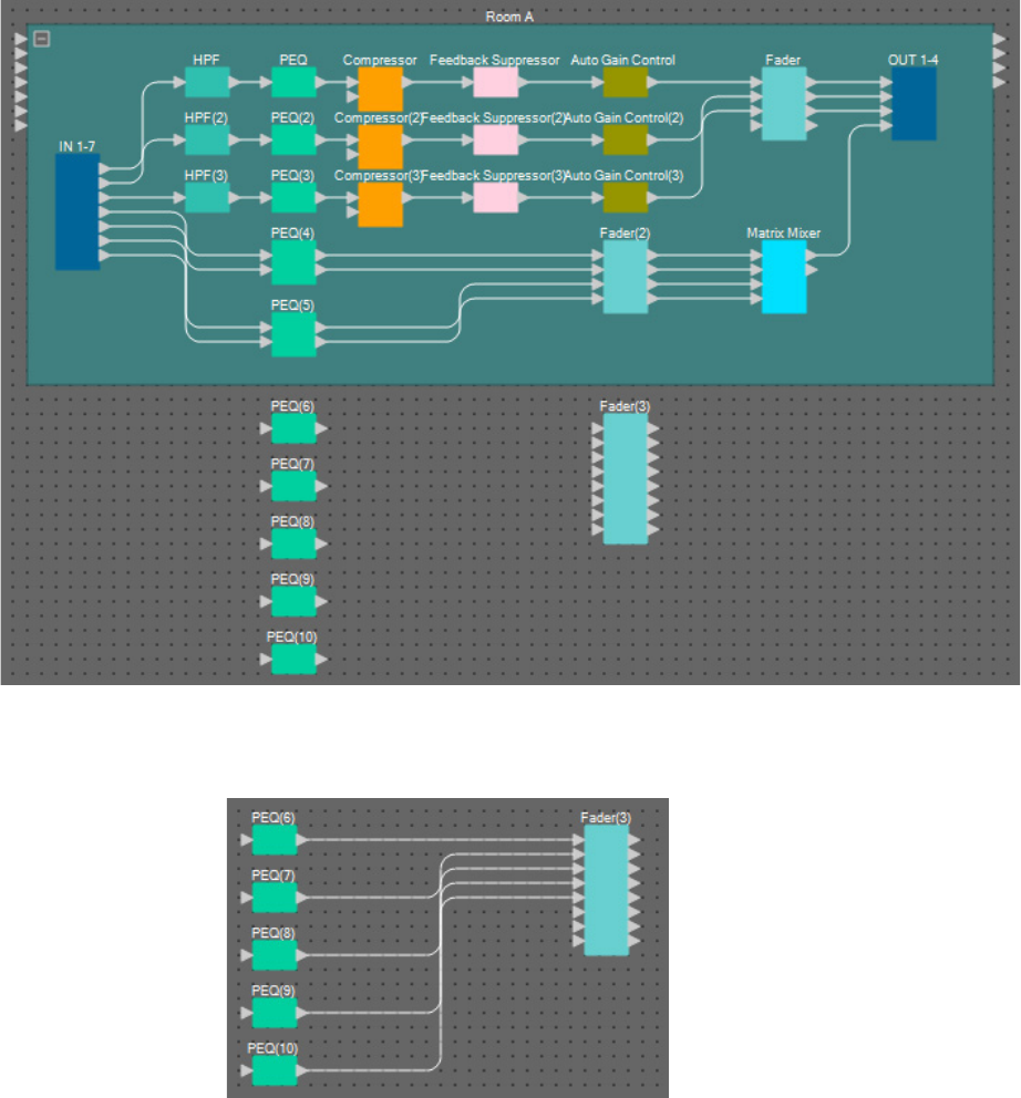
6. Change the name of the User Defined Block using [Label] in the “Properties” area to
“Room A.”
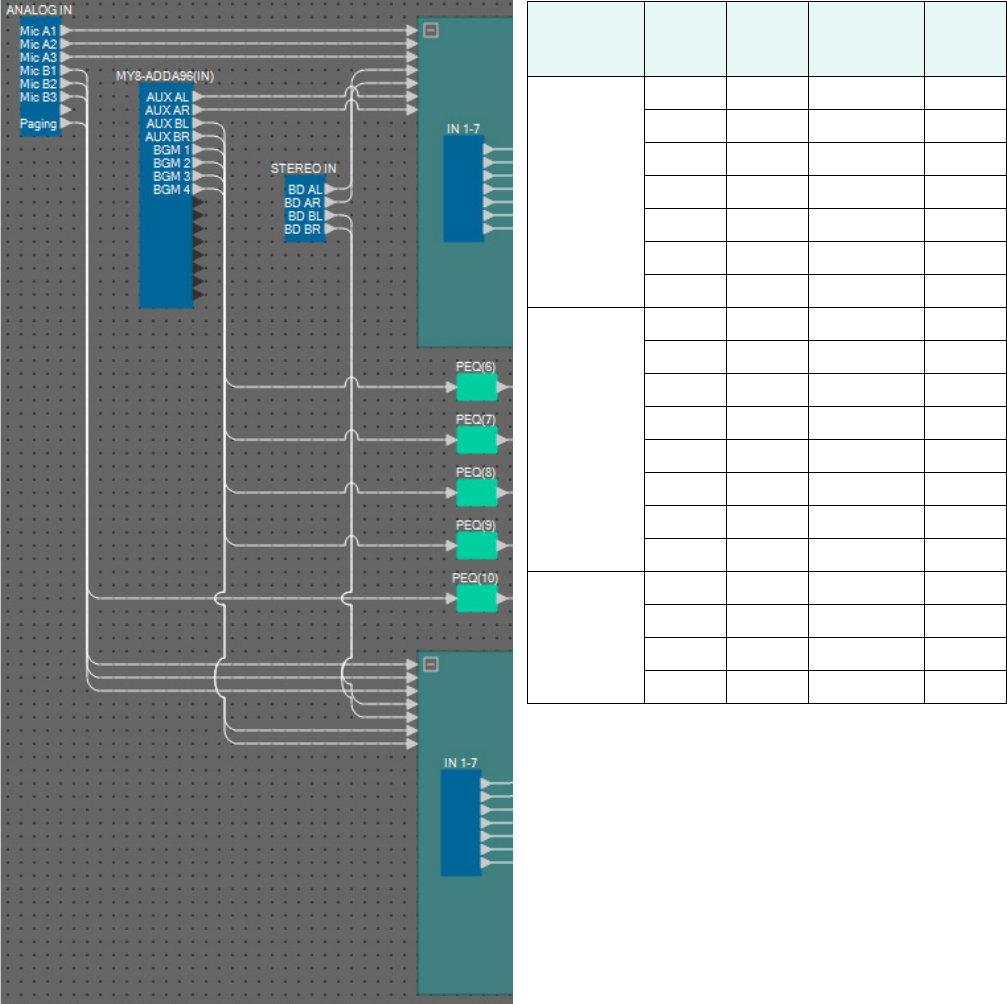
Displaying the port name in the input component
To eliminate confusion when making further connections, enter the port name in the “Port Name” dialog box. To open
the “Port Name” dialog box, click a port of an input component, and click the button that’s located at the right of the
edit area for [Label] in the “Properties” area.
The port names for ANALOG IN can be inputted by double-clicking the component to display the “ANALOG IN”
component editor.
In this example, we have used the following port names.
ANALOG IN
1Mic A1
2Mic A2
3Mic A3
4Mic B1
5Mic B2
6Mic B3
8Paging
STEREO IN
1L BD AL
1R BD AR
2L BD BL
2R BD BR
MY8-ADDA96(IN)
1AUX AL
2AUX AR
3AUX BL
4AUX BR
5BGM 1
6BGM 2
7BGM 3
8BGM 4
Example 1) Ballroom where the Room Combiner can be used
MRX Setup Manual 21
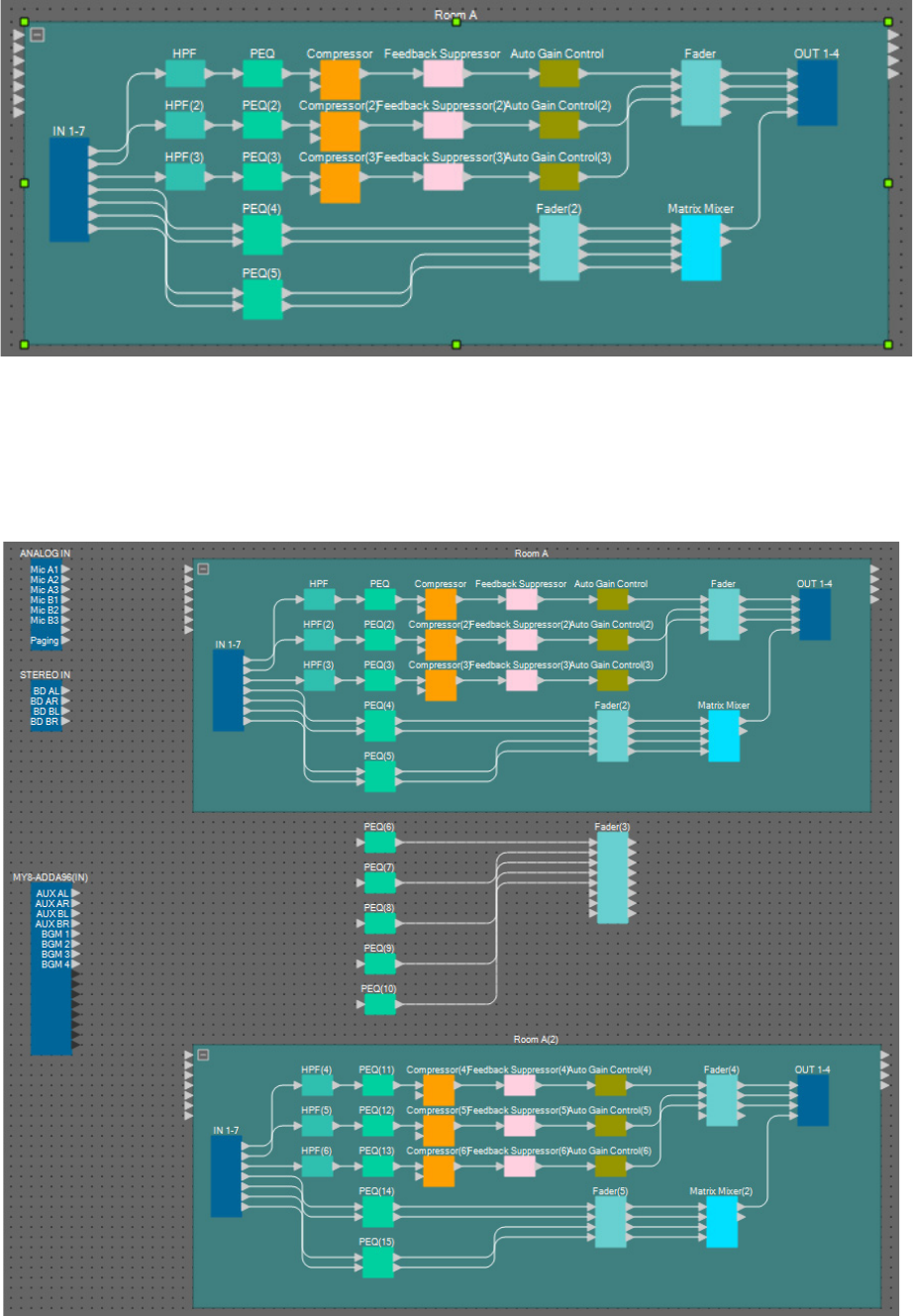
Placing and connecting the input-related components that are common to
Rooms A/B
Here we will place and connect the components related to BGM and the paging mic.
1. Place the components shown below by dragging them from the “Components” area
and dropping them into the Design sheet.
• “PEQ” (MONO, 4 BAND) × 5
• “Fader” (8 CH)
2. Connect each PEQ and fader.
Example 1) Ballroom where the Room Combiner can be used
MRX Setup Manual 22
Creating Room B
Copy the User Defined Block for Room A to create Room B.
1. Click somewhere besides the User Defined Block components and wires of Room A,
and select the User Defined Block.
2. Drag and drop a User Defined Block while holding down <Ctrl>.
The User Defined Block will be copied to the place where it is dropped.
3. Change the position and size of the User Defined Block as necessary.
Example 1) Ballroom where the Room Combiner can be used
MRX Setup Manual 23
4. Change the name of the User Defined Block that you pasted to “Room B”, by using
[Label] in the “Properties” area.
Connecting to the input components
The input components are connected to other components as shown below.
Input
components
Port
number
Port
name
Destination
component/
block
Port
number
ANALOG IN
1 Mic A1 Room A 1
2 Mic A2 Room A 2
3 Mic A3 Room A 3
4 Mic B1 Room B 1
5 Mic B2 Room B 2
6 Mic B3 Room B 3
8 Paging PEQ(10) 1
MY8-
ADDA96(IN)
1 AUX AL Room A 6
2 AUX AR Room A 7
3 AUX BL Room B 6
4 AUX BR Room B 7
5BGM 1PEQ(6) 1
6BGM 2PEQ(7) 1
7BGM 3PEQ(8) 1
8BGM4PEQ(9) 1
STEREO IN
1 BD AL Room A 4
2 BD AR Room A 5
3 BD BL Room B 4
4 BD BR Room B 5
Example 1) Ballroom where the Room Combiner can be used
MRX Setup Manual 24
Placing and connecting the “Room Combiner plus Automixer” component
Place and connect the “Room Combiner plus Automixer” component, which manages the division and combining of
rooms.
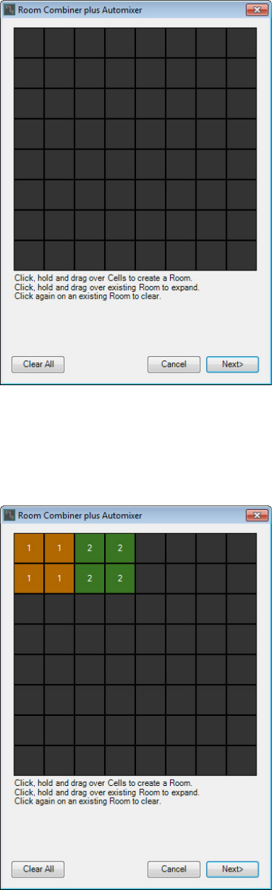
1. From the “Components” area, drag the “Room Combiner plus Automixer” component
and drop it on the design sheet.
The room design dialog box will appear.
2. Drag the cells to create a room, and then click the [Next] button.
This time, we will create two rooms, since we have both Room A and Room B. In this example, each room will
take up four cells.
Example 1) Ballroom where the Room Combiner can be used
MRX Setup Manual 25
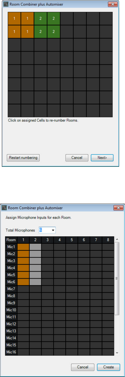
3. Click the rooms and change the numbers as necessary, and then click the [Next] but-
ton.
4. Set the [Total Microphones] to [6].
Example 1) Ballroom where the Room Combiner can be used
MRX Setup Manual 26
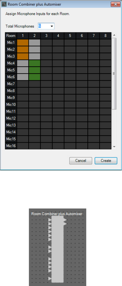
5. Click the spaces to allocate Mic4, Mic5, and Mic6 to Room 2.
6. Click the [Create] button.
“Room Combiner plus Automixer” is placed in the design sheet.
Example 1) Ballroom where the Room Combiner can be used
MRX Setup Manual 27
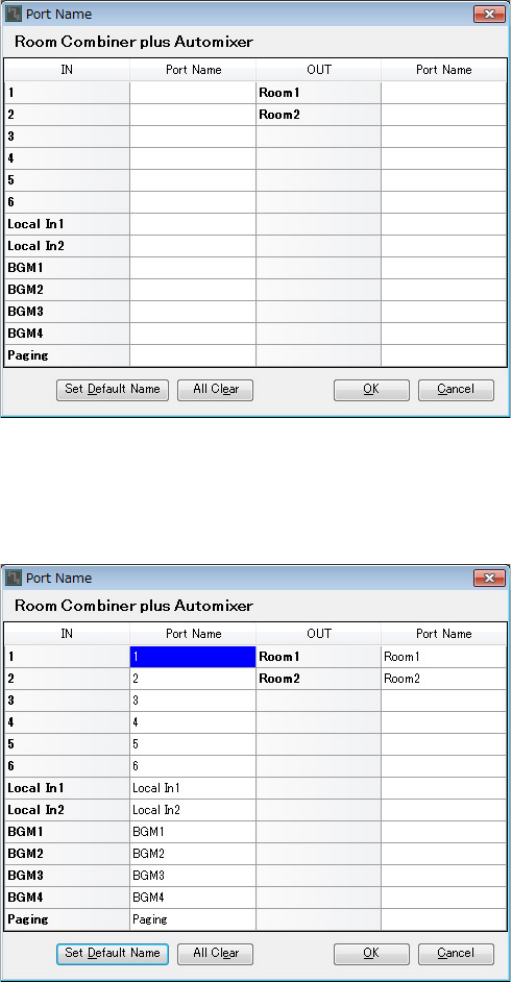
7. Click the “Room Combiner plus Automixer” port, and click the button that’s located at
the right of the edit area in “Properties.”
The “Port Name” dialog box will appear.
8. Click the [Set Default Name] button.
A default name is entered as the port name.
Example 1) Ballroom where the Room Combiner can be used
MRX Setup Manual 28
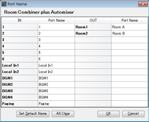
9. Change the Room 1 port name to Room A, change the Room 2 port name to Room B,
and click the [OK] button.
Example 1) Ballroom where the Room Combiner can be used
MRX Setup Manual 29
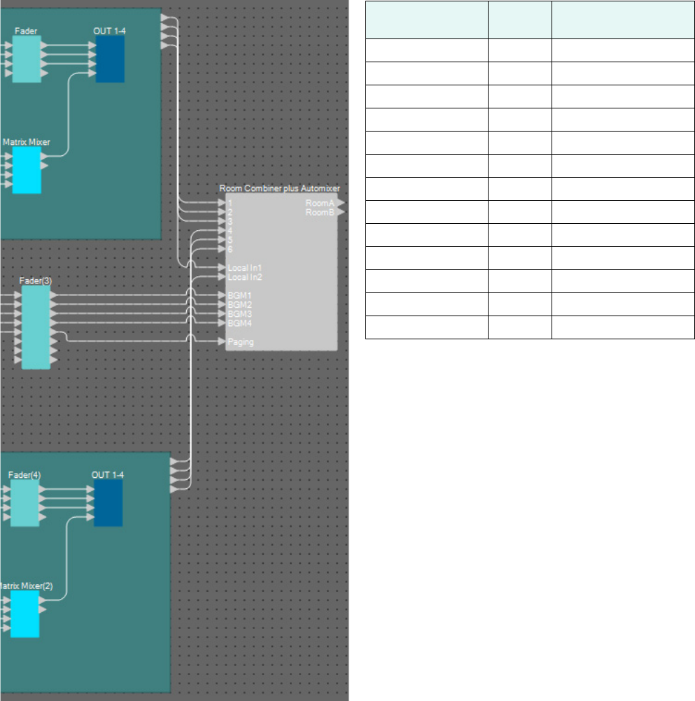
10. Make the input connections to the “Room Combiner plus Automixer” as shown below.
Source component/
block
Port
number
Room Combiner plus
Automixer input port
Room A 1 1
Room A 2 2
Room A 3 3
Room B 1 4
Room B 2 5
Room B 3 6
Room A 4 Local In1
Room B 4 Local In2
Fader(3) 1 BGM1
Fader(3) 2 BGM2
Fader(3) 3 BGM3
Fader(3) 4 BGM4
Fader(3) 5 Paging
Example 1) Ballroom where the Room Combiner can be used
MRX Setup Manual 30
Placing and connecting components from “Room Combiner plus Automixer”
to analog outputs
Here we will place and connect the necessary components from the “Room Combiner plus Automixer” to the analog
outputs.
1. Place the components shown below by dragging them from the “Components” area
and dropping them into the Design sheet.
• “Fader” (2 CH)
• “PEQ” (MONO, 6 BAND) × 2
• “Speaker Processor” (1 Way) × 2
• “ANALOG OUT”
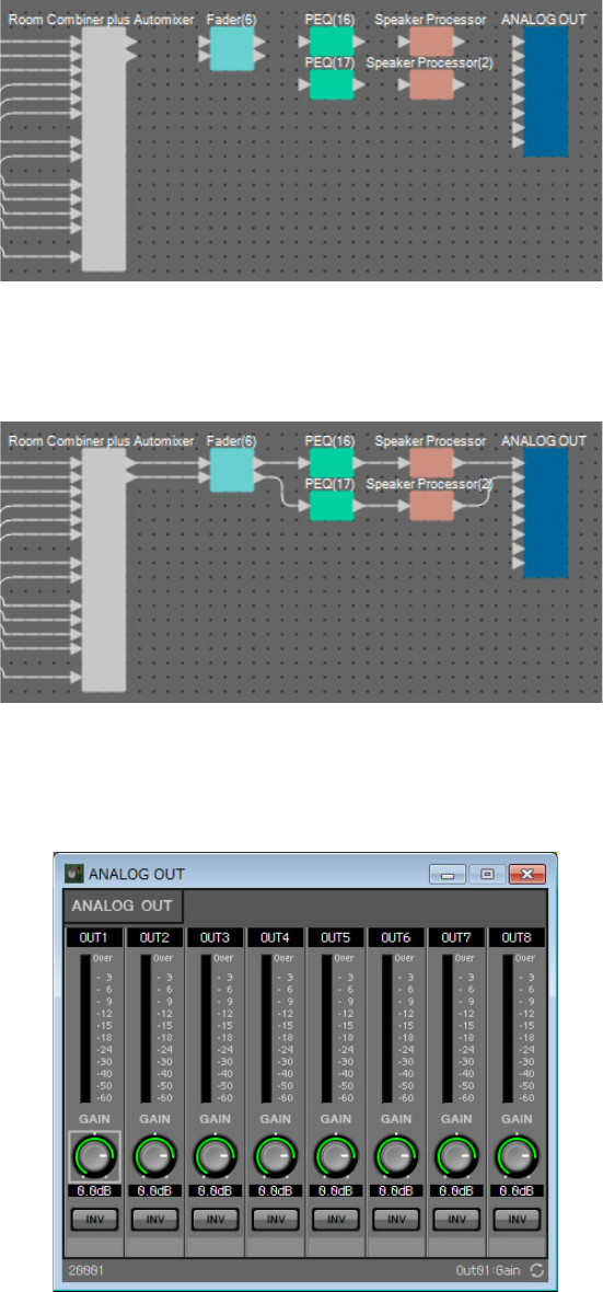
2. Make the connections from the “Room Combiner plus Automixer” to the “ANALOG
OUT.”
3. Double-click “ANALOG OUT.”
The “ANALOG OUT” component editor will appear.
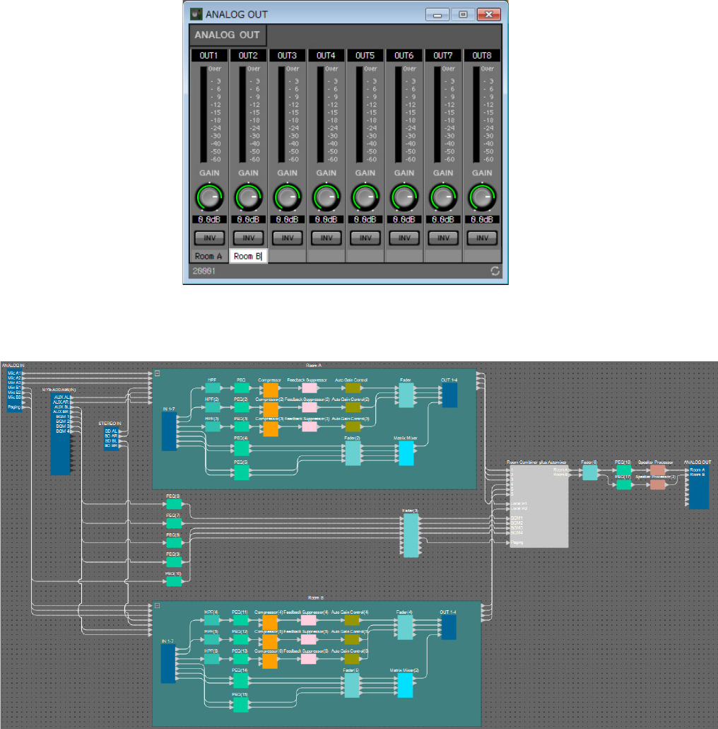
Example 1) Ballroom where the Room Combiner can be used
MRX Setup Manual 31
4. Set the port name of OUT 1 to “Room A”, and the port name of OUT 2 to “Room B.”
5. Click the [×] button at the top right-hand corner to close the component editor.
Now you’re finished placing and connecting the components. Change the placement of the components and change the wir-
ing as need be.
Example 1) Ballroom where the Room Combiner can be used
MRX Setup Manual 32
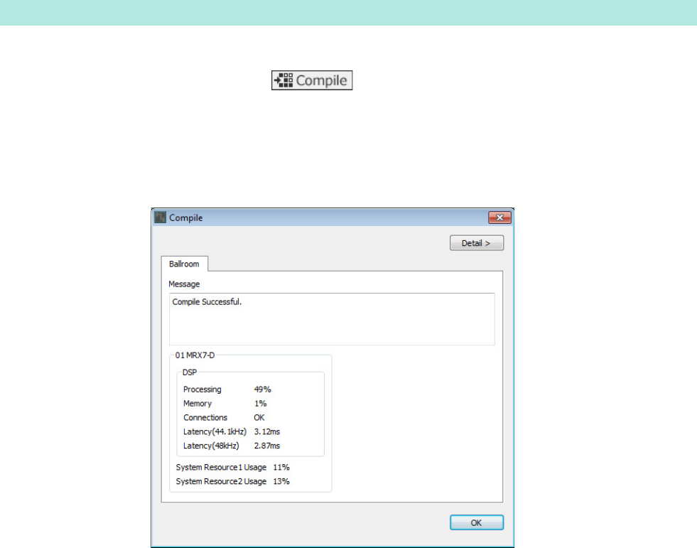
This analyzes the placement and wiring of the components in the MRX, to determine whether there are any problems.
1. Click the [Compile] tool button ( ).
Start the analysis.
2. Confirm the analysis results.
If the message “Completed successfully” is displayed in the “Message” field, there were no problems.
If a problem was detected, click the [Detail] button to check how to solve the problem and to correct it.
Now you’re finished compiling.
Compiling
Example 1) Ballroom where the Room Combiner can be used
MRX Setup Manual 33
In this example, we’ll operate a DCP switch to switch between split and combined rooms. Although you can simply recall
the presets for split rooms and for combined rooms respectively, you can make quicker changes to the settings just by turn-
ing the Combine button in the “Room Combiner plus Automixer” editor on and off, rather than recalling all of the parame-
ters.
Now, we’ll explain how to create a snapshot.
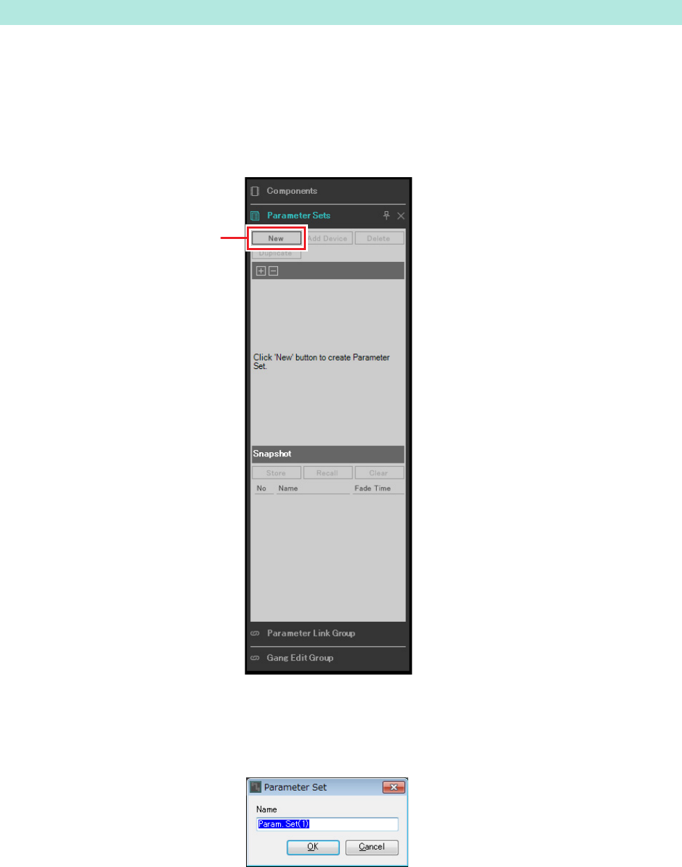
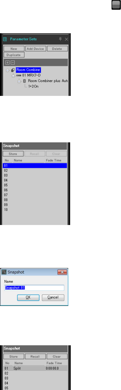
1. Open the “Parameter Sets” area on the left side of the MRX Designer.
2. Click the [New] button.
A dialog box for setting the parameter set name will appear.
Specifying snapshots
Step 2
Example 1) Ballroom where the Room Combiner can be used
MRX Setup Manual 34
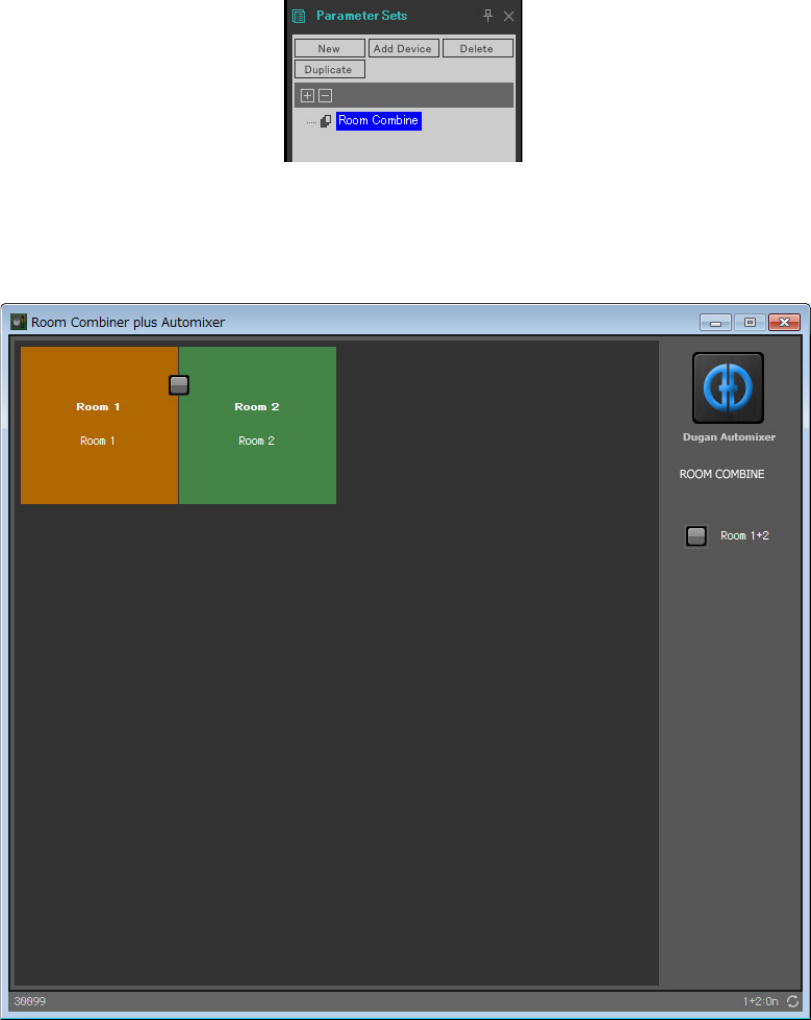
3. Input [Room Combine] and click the [OK] button.
A parameter set named “Room Combine” will display in the “Parameter Sets” area.
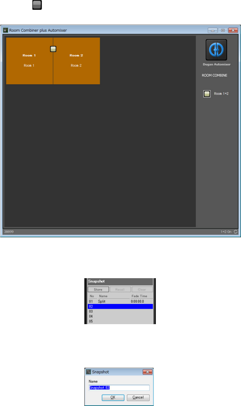
4. Double-click “Room Combiner plus Automixer.”
The “Room Combiner plus Automixer” component editor will appear.
Example 1) Ballroom where the Room Combiner can be used
MRX Setup Manual 35
5. While holding down <Ctrl>, drag and drop the [Room 1+2] button ( ) into [Room Com-
bine] in the “Parameter Sets” area.
The parameters for 1+2 will be registered in the “Room Combine” parameter set.
6. To create a snapshot of the split rooms with the Room Combiner, click on “Snapshot”
number 01, while the rooms are two different colors in the “Room Combiner plus Auto-
mixer” component editor.
7. Click the [Store] button.
A dialog box for setting the snapshot name will appear.
8. Input [Split] and click the [OK] button.
A snapshot named [Split] will display in “Snapshot.”
Example 1) Ballroom where the Room Combiner can be used
MRX Setup Manual 36
9. To create a snapshot of the combined rooms with the Room Combiner, click the [Room
1+2] button ( ) in the “Room Combiner plus Automixer” component editor.
The rooms will be combined.
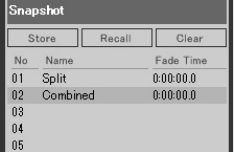
10. Click on “Snapshot” number 02, while the rooms are the same color in the “Room Com-
biner plus Automixer” component editor.
11. Click the [Store] button.
A dialog box for setting the snapshot name will appear.
Example 1) Ballroom where the Room Combiner can be used
MRX Setup Manual 37
12. Input [Combined] and click the [OK] button.
A snapshot named [Combined] will display in “Snapshot.”
Now you’re finished setting the snapshots. When you recall the [Split] snapshot, the room will be split; and when you recall
the [Combined] snapshot, the rooms will be combined.
Example 1) Ballroom where the Room Combiner can be used
MRX Setup Manual 38
In this example, we’ll see how we can avoid the unnecessary use of DCP switches and knobs, such as by assigning a single
fader to a stereo pair of inputs (such as a Blu-Ray player or AUX In), or by making a single ON button for both L and R.
Here we’ll create a parameter link group that links multiple parameters such as levels or ON/OFF, so that we can change
multiple parameters at the same time with a DCP knob or button.
As with snapshots, parameter link groups are registered by dragging and dropping while holding down <Ctrl>. However, in
this example we will use a different method, since there are a total of 24 parameters to change. The same operation can be
used with snapshots.
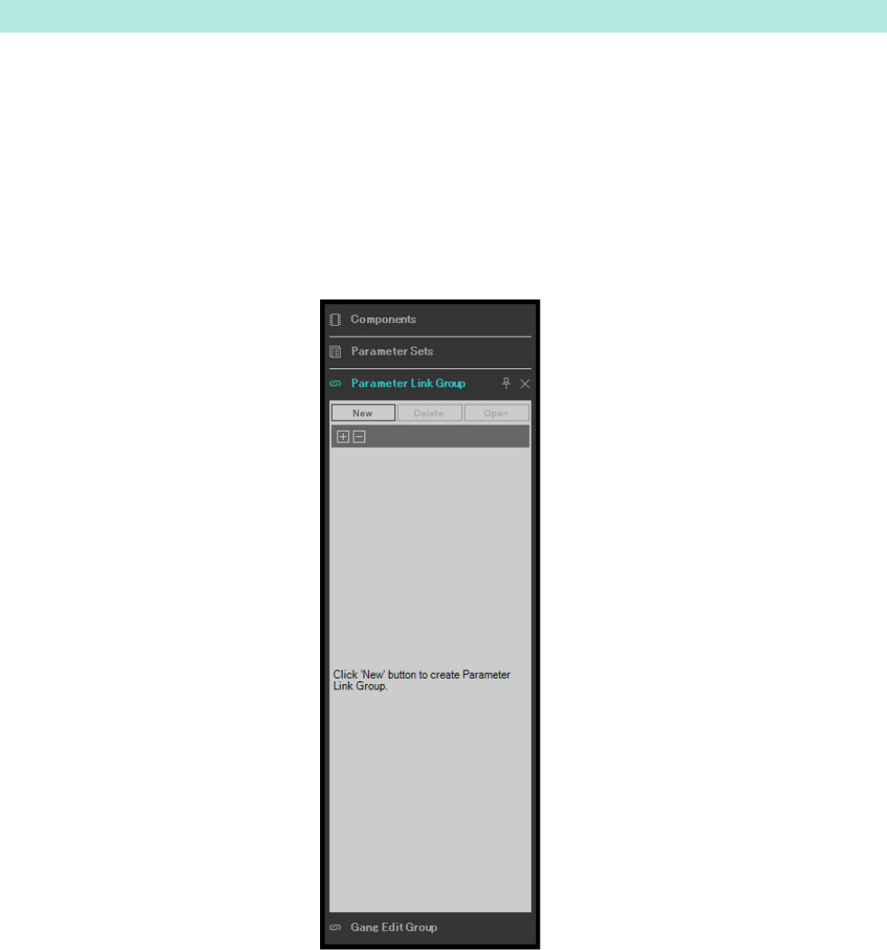
1. Open the “Parameter Link Group” area on the left side of the MRX Designer, in order to
check the parameters that are registered.
Setting a parameter link group
Example 1) Ballroom where the Room Combiner can be used
MRX Setup Manual 39
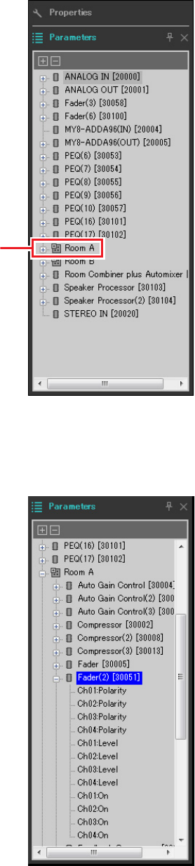
2. Open the “Parameter” area on the right side of the MRX Designer.
3. Since the AUX level of Room A is adjusted using “Fader(2)” of Room A, open [Room A] →
[Fader(2)] in the “Parameters” area.
Step 3
Example 1) Ballroom where the Room Combiner can be used
MRX Setup Manual 40
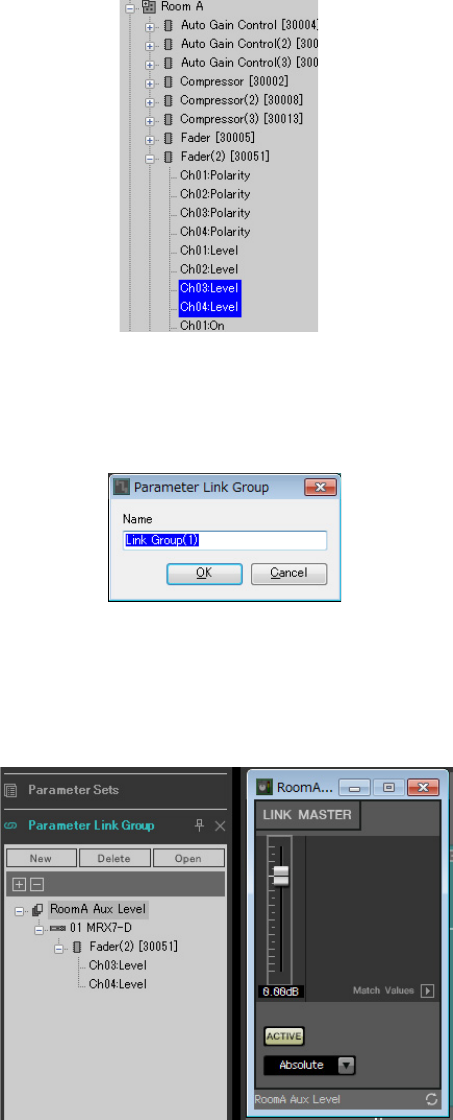
4. After clicking [Ch03:Level], hold down <Ctrl> and click [Ch04:Level].
You can select multiple items while holding down <Ctrl> and clicking.
To select continuous parameters, click the start parameter, hold down the <Shift> and then click on the end parameter.
5. Do a right-click and select [Add to Parameter Link Group] → [Add New Group].
A dialog box for setting the parameter link group name will appear.
6. Input [RoomA Aux Level] and click the [OK] button.
The [Room A Aux Level] group will be generated in the “Parameter Link Group” area, and the Link Master editor
will appear.
7. Select [Absolute] on the Link Master editor combo box.

Example 1) Ballroom where the Room Combiner can be used
MRX Setup Manual 41
8. Double-click “Fader(2)” for Room A.
The “Fader(2)” component editor will appear.
9. Move the fader in the Link Master editor, and confirm that channels 3 and 4 in the
“Fader(2)” component editor are linked together.
10. Click the [×] buttons at the top right-hand corner of the Link Master editor and the
“Fader(2)” component editor to close the editor and component editor.
Repeat step 2 through 10 to create the following parameter link groups.
This parameter link group switches [Room BD-AUX On/Off] to either AUX or BD. This will turn fader channels 3/4 off
when channels 1/2 are on, and fader channels 3/4 on when channels 1/2 are off.
Now you’re finished setting the parameter link group.
Parameter link group name Components Parameters Link Master editor
combo box settings
RoomA BD Level [Room A] → [Fader(2)]
Ch01:Level
Absolute
Ch02:Level
RoomA BD-AUX On/Off [Room A] → [Fader(2)]
Ch01:On
Opposite
Ch02:On
Ch03:On
Ch04:On
RoomA Matrix On/Off [Room A] → [Matrix Mixer]
In01Out01:On
Equal
In02Out01:On
In03Out01:On
In04Out01:On
RoomB Aux Level [Room B] → [Fader(5)]
Ch03:Level
Absolute
Ch04:Level
RoomB BD Level [Room B] → [Fader(5)]
Ch01:Level
Absolute
Ch02:Level
RoomB BD-AUX On/Off [Room B] → [Fader(5)]
Ch01:On
Opposite
Ch02:On
Ch03:On
Ch04:On
RoomB Matrix On/Off [Room B] → [Matrix Mixer(2)]
In01Out01:On
Equal
In02Out01:On
In03Out01:On
In04Out01:On

Example 1) Ballroom where the Room Combiner can be used
MRX Setup Manual 42
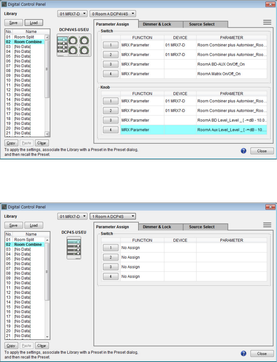
Allocates parameters to the DCP4V4S and DCP4S in each room, so that they can be changed by operating a switch or
knob.
Set the library name to “Room Split” if the room is split, and to “Room Combine” if the rooms are combined.
Allocate the following parameters to the switches and knobs. (The steps for allocating parameters will be explained later.)
-“Room Split” parameters
* The preset has not been configured at this time, so only the preset number is displayed. By recalling the preset, you will be able to
tell which preset was recalled by looking at the indicator on the DCP4S switch. (When using the DCP switch to switch the Combine
button on and off, you won’t be able to tell whether it is on or off just by looking at the DCP.)
For the “Room Combine” parameters, use the “Room Split” parameters, but change the red characters to “1” or “A.”
Now, we’ll explain how to set the parameters for switch 1 (parameter) of the DCP4V4S, and for switch 1 (preset) of the
DCP4S in Room A. This time, we’ll explain how to do this by dragging and dropping the parameters while holding <Ctrl>
using the component editor and so on; but you can also drag and drop from the “Parameters” area while holding <Ctrl>.
Making the DCP settings
DCP Switch/knob Component, snapshot, or parameter link group
that includes the set parameter Parameters
DCP4V4S for
Room A
Switch 1 Room Combiner plus Automixier Mics [ON] button for Room 1
Switch 2 Room Combiner plus Automixer BGM [ON] button for Room 1
Switch 3 RoomA BD-AUX On/Off for parameter link group [ON] button for Link Master
Switch 4 RoomA Matrix On/Off for parameter link group [ON] button for Link Master
Knob 1 Room Combiner plus Automixier Mics knob for Room 1
Knob 2 Room Combiner plus Automixier BGM knob for Room 1
Knob 3 RoomA BD Level for parameter link group Link Master fader
Knob 4 RoomA Aux Level for parameter link group Link Master fader
DCP4S for
Room A
Switch 1 Preset 01 Split *
Switch 2 Preset 02 Combine *
Switch 3 Room Combiner plus Automixier Room 1 BGM list (Inc/Upper Limit=4)
Switch 4 Room Combiner plus Automixier Room 1 BGM list (Dec)
DCP4V4S for
Room B
Switch 1 Room Combiner plus Automixier Mics [ON] button for Room 2
Switch 2 Room Combiner plus Automixier BGM [ON] button for Room 2
Switch 3 RoomB BD-AUX On/Off for parameter link group [ON] button for Link Master
Switch 4 RoomB Matrix On/Off for parameter link group [ON] button for Link Master
Knob 1 Room Combiner plus Automixier Mics knob for Room 2
Knob 2 Room Combiner plus Automixier BGM knob for Room 2
Knob 3 RoomB BD Level for parameter link group Link Master fader
Knob 4 RoomB Aux Level for parameter link group Link Master fader
DCP4S for
Room B
Switch 1 Preset 01 Split *
Switch 2 Preset 02 Combine *
Switch 3 Room Combiner plus Automixier Room 2 BGM list (Inc/Upper Limit=4)
Switch 4 Room Combiner plus Automixier Room 2 BGM list (Dec)
Example 1) Ballroom where the Room Combiner can be used
MRX Setup Manual 43
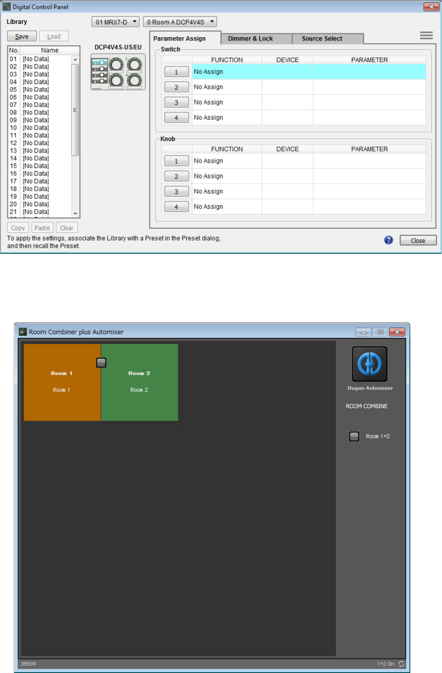
1. Select [Digital Control Panel] from the [Controller] menu.
The “Digital Control Panel” dialog box will appear.
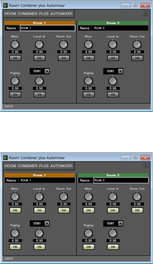
2. Double-click “Room Combiner plus Automixer.”
The “Room Combiner plus Automixer” editor will appear.
Example 1) Ballroom where the Room Combiner can be used
MRX Setup Manual 44
3. Double-click “Room 1” or “Room 2.”
The Combiner parameter setting window will appear.
4. Turn all of the [ON] buttons on.
Since the buttons are off by default, you will not be able to hear any sound.
Example 1) Ballroom where the Room Combiner can be used
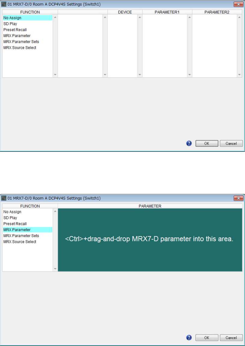
MRX Setup Manual 45
5. Click the “Switch” [1] button on the “Digital Control Panel” dialog box.
The “Settings” dialog box will appear.
6. Click [MRX Parameter] under “FUNCTION.”
The screen changes to a screen where you can register the [MRX Parameter].
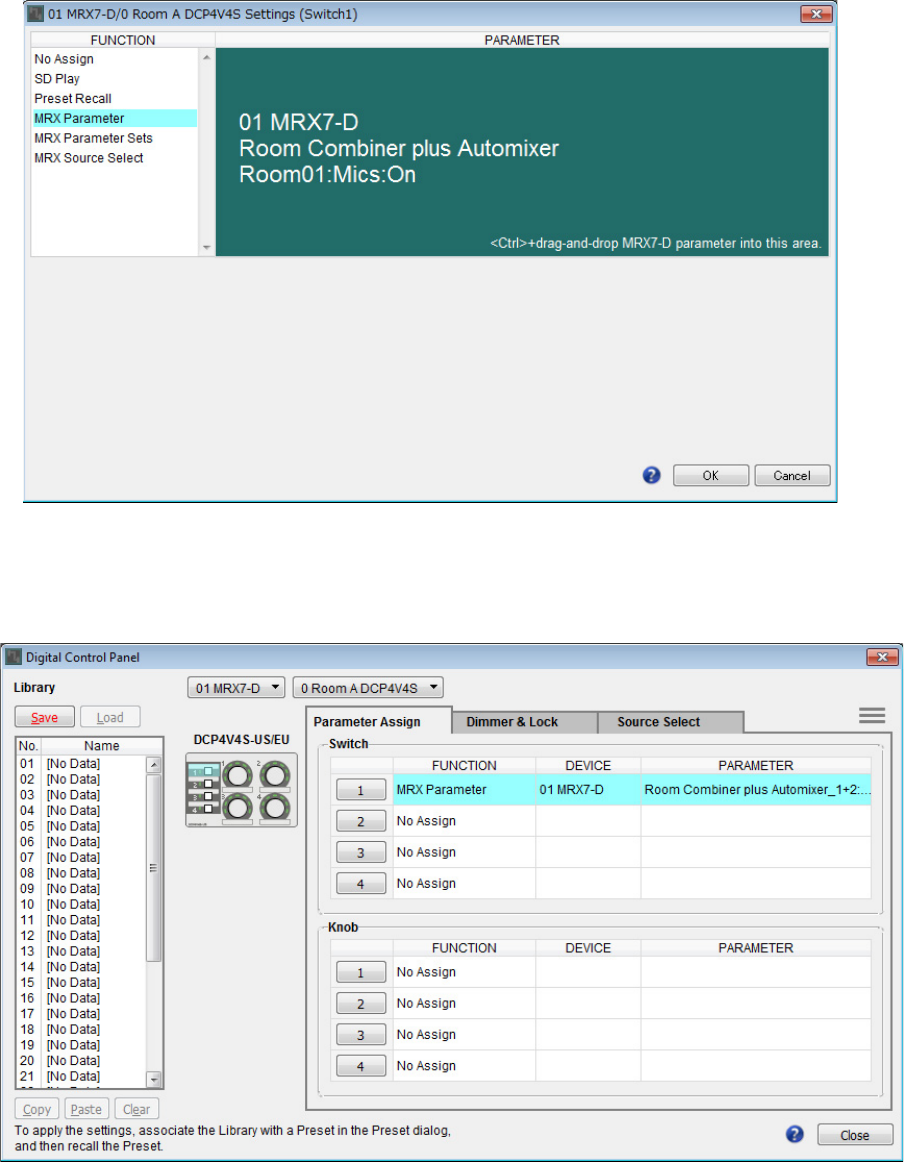
Example 1) Ballroom where the Room Combiner can be used
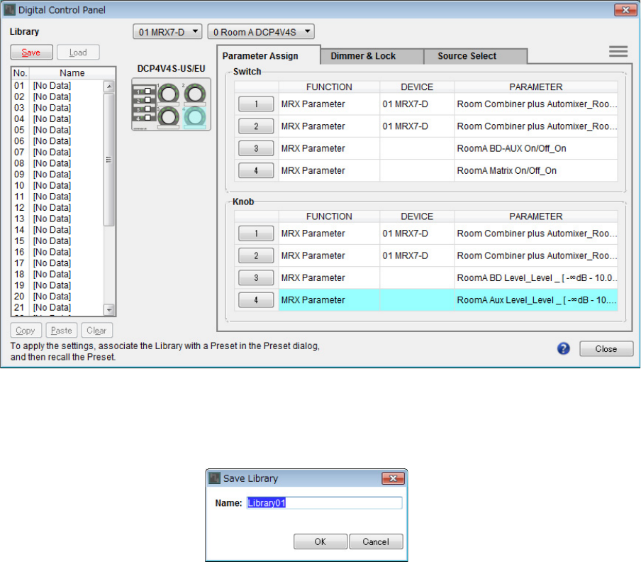
MRX Setup Manual 46
7. Drag and drop the Mics [ON] button for Room 1 in the Combiner parameter settings win-
dow to the “PARAMETER” area in the “Settings” dialog box, while holding down <Ctrl>.
This will register the Mics [ON] button for Room 1.
8. Click the [OK] button.
The “Digital Control Panel” dialog box will be displayed, with the Mics [ON] button for Room 1 registered.
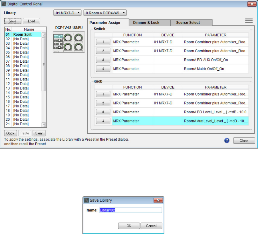
Example 1) Ballroom where the Room Combiner can be used
MRX Setup Manual 47
9. Register the other parameters as shown in steps 2 through 7.
The Link Master editor for the parameter link group can be displayed by right-clicking on the parameter link group
and selecting [Open Link Master] from the context menu.
10. Click No. 01 in the “Library”, and then click the [Save] button.
The “Save Library” dialog box will appear.
Example 1) Ballroom where the Room Combiner can be used
MRX Setup Manual 48
11. Input [Room Split] and click the [OK] button.
The data will be registered in No. 01 of the “Library.”
12. Since “Room Split” and “Room Combine” are the same for the DCP in Room A, click No.
02 in the “Library”, and then click the [Save] button.
The “Save Library” dialog box will appear.
Example 1) Ballroom where the Room Combiner can be used
MRX Setup Manual 49
13. Input [Room Combine] and click the [OK] button.
The data will be registered in No. 02 of the “Library.”
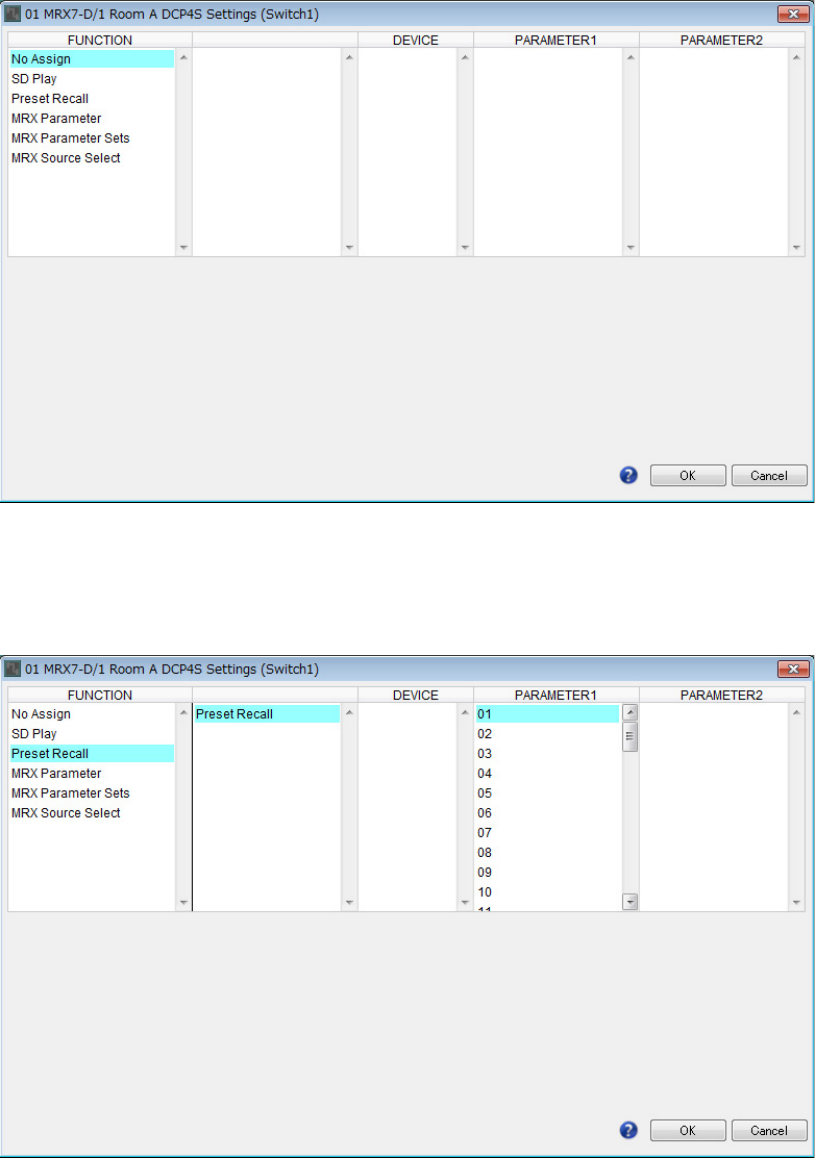
14. Select [1 Room A DCP4S] using the DCP selection list box.
The screen will change to the Room A DCP4S settings screen for ID=1.
Example 1) Ballroom where the Room Combiner can be used
MRX Setup Manual 50
15. Click the “Switch” [1] button on the “Digital Control Panel” dialog box.
The “Settings” dialog box will appear.
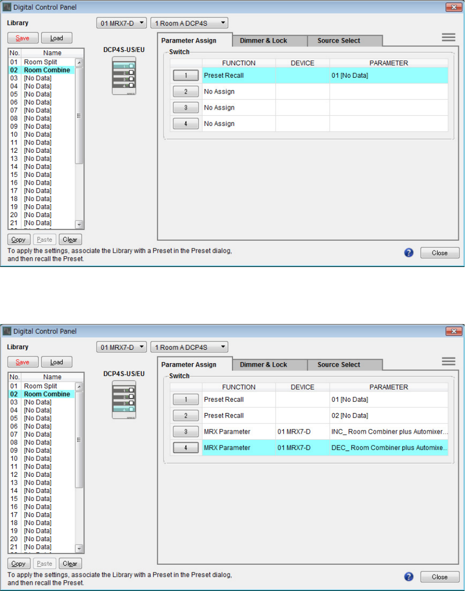
16. Click [Preset Recall] under “FUNCTION.”
The screen changes to a screen where you can register the preset to recall.
Example 1) Ballroom where the Room Combiner can be used
MRX Setup Manual 51
17. Click [01] in “PARAMETER 1”, and then click the [OK] button.
The “Digital Control Panel” dialog box will be displayed, with the 01 in the presets registered.
18. Register the presets and parameters to the other switches in the same way.
Example 1) Ballroom where the Room Combiner can be used
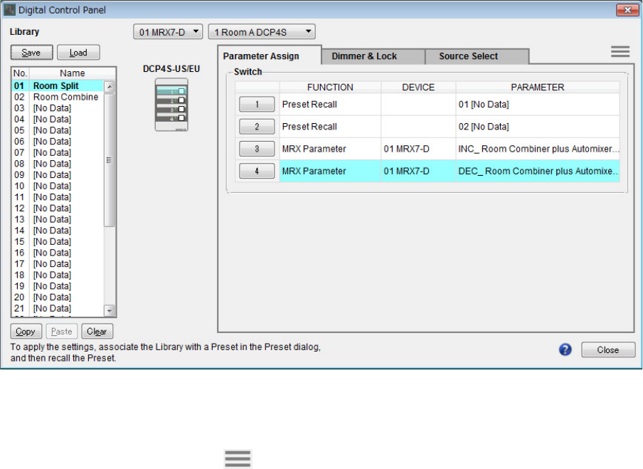
MRX Setup Manual 52
19. Select both No. 01 and No. 02 in the “Library”, and then click the [Save] button.
The settings for the DCP4S in Room A are overwritten.
20. Set the DCP for Room B in the same way.
The “Room Combine” settings for Room B are the same as the “Room Combine” settings for Room A. Click the
menu button for the DCP of Room A ( ) and select [Copy], switch to the DCP of Room B, and then select
[Paste] from the menu button. Afterwards, if you save this by overwriting as “Room Combine”, the work will be eas-
ier.
Example 1) Ballroom where the Room Combiner can be used
MRX Setup Manual 53
Set the preset that will be recalled from the DCP4S.
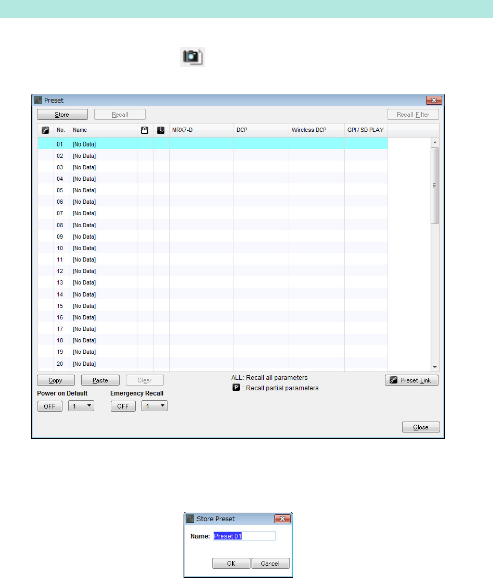
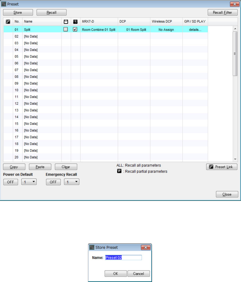
1. Click the [Preset] tool button ( ).
The [Preset] dialog box will appear.
2. Click No. 01 and then click the [Store] button.
The “Store Preset” dialog box will appear.
Storing presets
Example 1) Ballroom where the Room Combiner can be used
MRX Setup Manual 54
3. Input [Split] and click the [OK] button.
The current state will be registered as a preset named “Split.”
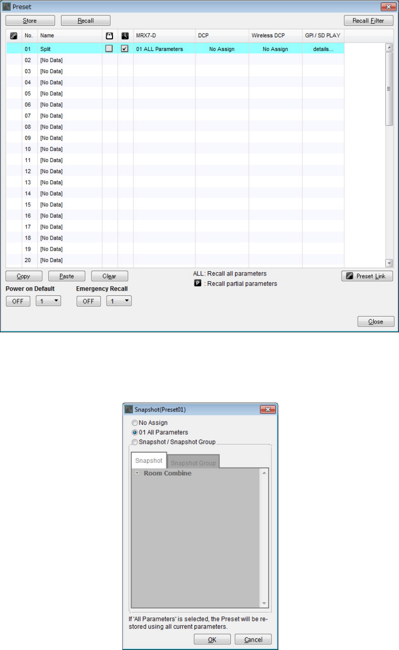
4. Click on the [MRX7-D] field in No. 01.
The “Snapshot” dialog box will appear.
Example 1) Ballroom where the Room Combiner can be used
MRX Setup Manual 55
5. Select [Snapshot/Snapshot Group].
The screen changes to the snapshot registration screen.
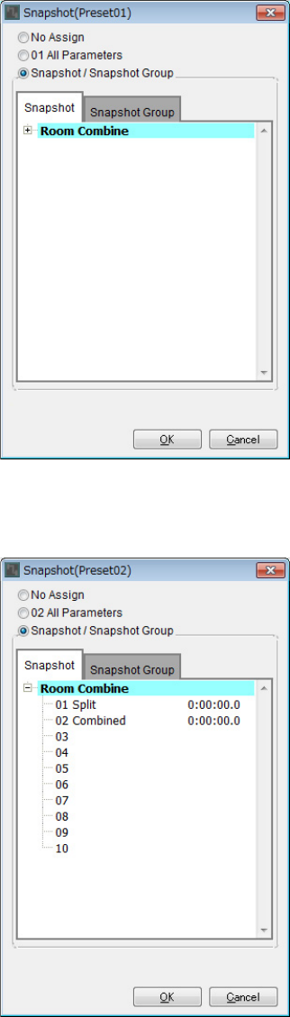
6. Click [+] to expand the snapshot list.
Example 1) Ballroom where the Room Combiner can be used
MRX Setup Manual 56
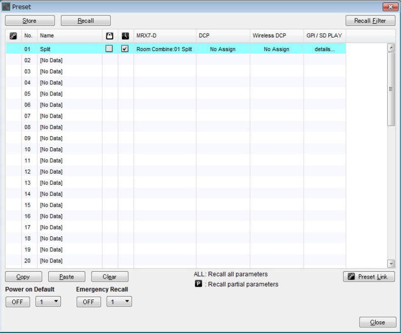
7. Click [01 Split] and then click the [OK] button.
When the preset is recalled, the snapshots will also be recalled.
Example 1) Ballroom where the Room Combiner can be used
MRX Setup Manual 57
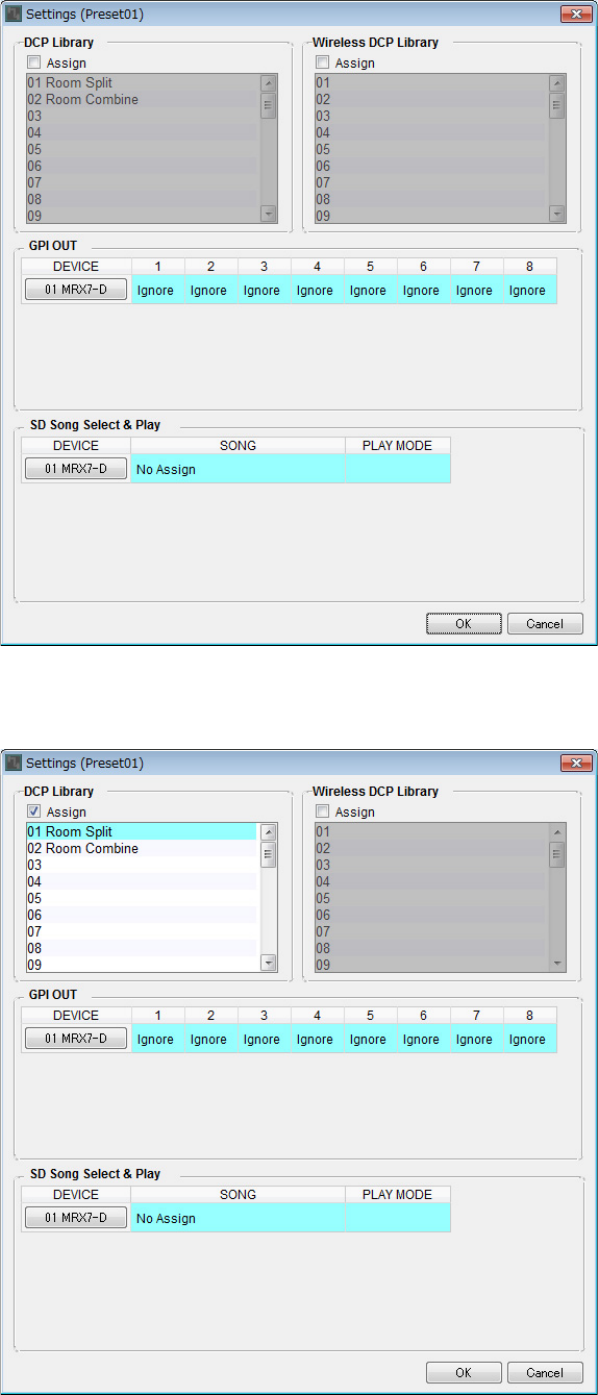
8. Double-click the [DCP] field in No. 01.
The “Settings” dialog box will appear.
9. Select the [Assign] check box in “DCP Library.”
Example 1) Ballroom where the Room Combiner can be used
MRX Setup Manual 58
10. Click [01 Room Split] and then click the [OK] button.
When the preset is recalled, the library will also be loaded.
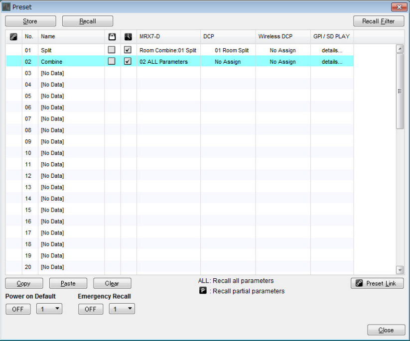
11. Click No. 02 and then click the [Store] button.
The “Store Preset” dialog box will appear.
Example 1) Ballroom where the Room Combiner can be used
MRX Setup Manual 59
12. Input [Combine] and click the [OK] button.
The current state will be registered as a preset named “Combine.”
Example 1) Ballroom where the Room Combiner can be used
MRX Setup Manual 60
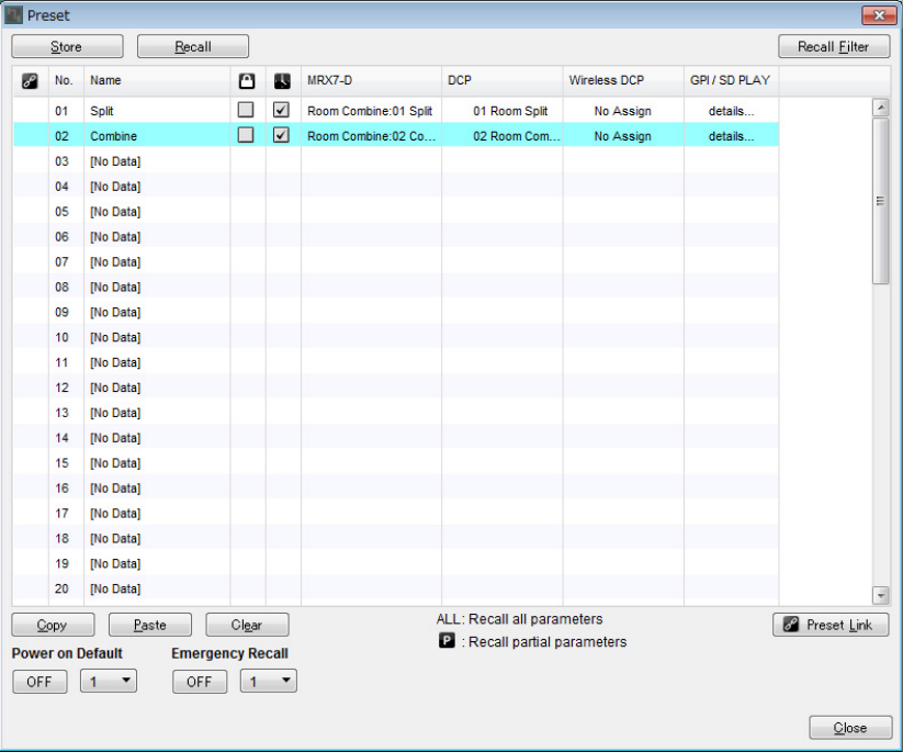
13. Set the “Combine” preset in the same way.
For the MRX7-D, set the [02 Combined] snapshot; and for the DCP, set the [02 Room Combine] library.
14. Click the [Close] button.
The “Preset” dialog box is closed.
This completes settings in the offline state. Save the settings once again.
Example 1) Ballroom where the Room Combiner can be used
MRX Setup Manual 61
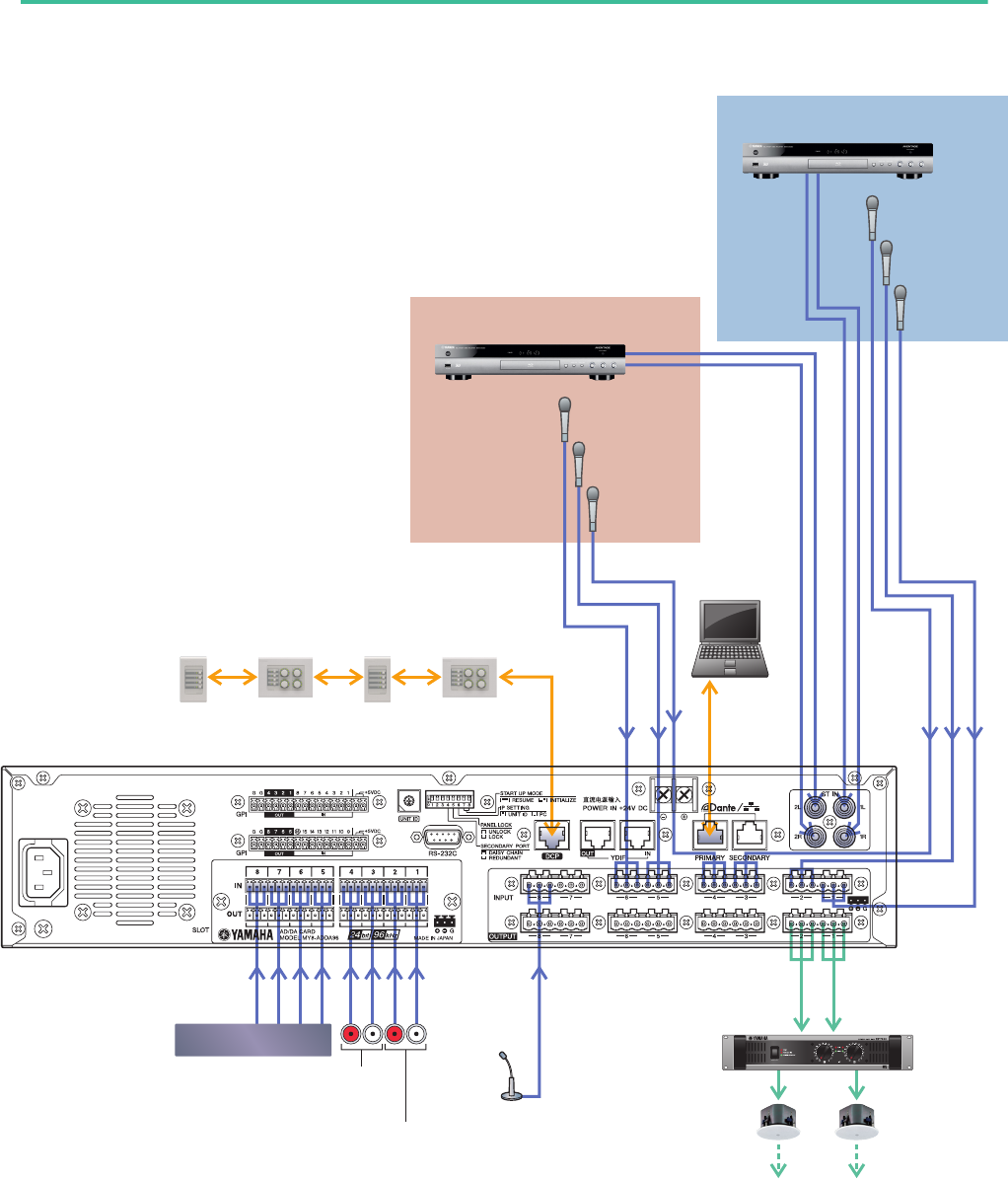
Connecting the equipment
After you’ve rack-mounted the MRX and your other equipment, connect the MRX and the other equipment as shown
below. If you’ve copied audio sources to an SD memory card, insert the card into the MRX now.
Room B
Room A
DCP
ID=3
DCP
ID=2
DCP
ID=1
DCP
ID=0
BD Player
Microphone
A3
Microphone
A2
Microphone
A1
Microphone
B3
Microphone
B2
Microphone
B1
Computer
MRX7-D
BGM Player
Room B
AUX IN
Room A
AUX IN
Paging
Power Amp
Room A Room B
Example 1) Ballroom where the Room Combiner can be used
MRX Setup Manual 62
Powering-on the MRX
Turn on the power of the MRX.
Turn off the amplifier before you power-off the MRX.
Powering-on the amp
Turn on the power of the amplifier.
To prevent unwanted sound from being output, we recommend that you turn down the attenuator settings of all channels on
the amp itself before you turn it on.
Specifying the computer’s TCP/IP address
To allow the MRX and the computer to communicate, specify the computer’s TCP/IP as follows.
1. Select [Network Setup] in the [System] menu of the MTX-MRX Editor.
The “Network Setup” dialog box will appear.
2. Click [Open Network Connection].
“Network Connections” will appear.
3. Right-click the adapter to which the MRX is connected, and choose [Properties].
The “Local Area Connection Properties” dialog box will appear.
4. Choose [Internet Protocol Version 4 (TCP/IPv4)], and then click [Properties].
The “Internet Protocol Version 4 (TCP/IPv4) Properties” dialog box will appear.
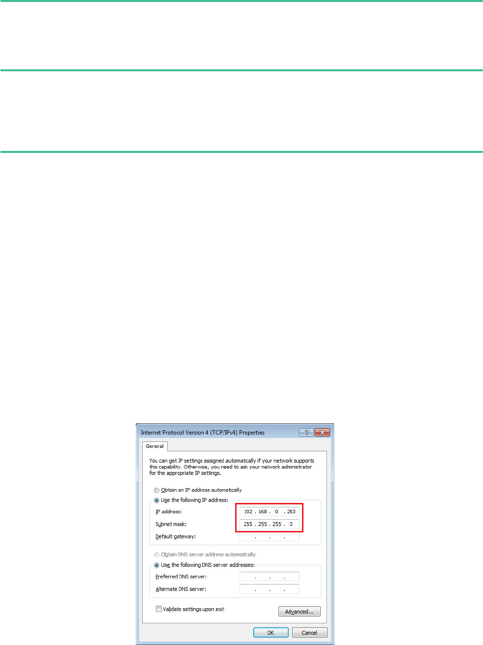
5. Click [Use the following IP address (S)].
6. In the [IP address] box, enter “192.168.0.253”; in the [Subnet mask] box, enter
“255.255.255.0.”
7. Click [OK].
NOTE
The IP address of the MRX7-D is set to “192.168.0.1.”
NOTE
In some cases, Windows firewall may block MTX-MRX Editor when you make this setting. Select the [Private Network] check box,
and click [Allow Access].
Example 1) Ballroom where the Room Combiner can be used
MRX Setup Manual 63
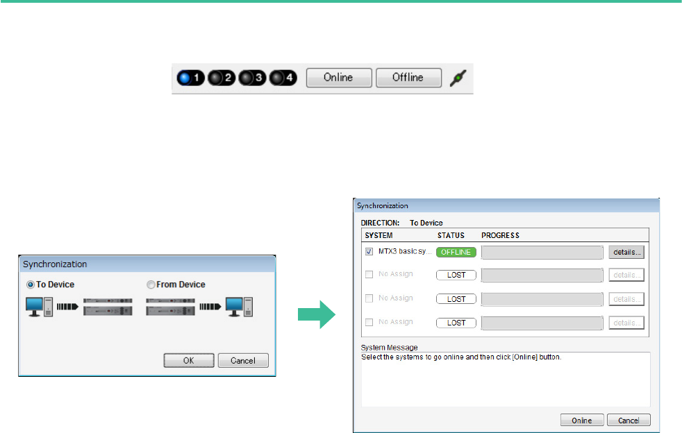
Taking MTX-MRX Editor online
In the upper right of MTX-MRX Editor, click the [Online] button. When the unit has successfully come online, the indica-
tor 1 will light blue.
When the “Synchronization” dialog box appears, select “To Device,” and click the [OK] button. When the indication in the
dialog box has switched, select the system that you want to place online, and click the [Online] button.
The project created in MTX-MRX Editor will be sent to the MRX.

Example 1) Ballroom where the Room Combiner can be used
MRX Setup Manual 64
Verifying that the settings were applied
The main items to verify are listed below. For details on each parameter setting, refer to “MTX-MRX Editor User Guide”
and “MRX Designer User Guide.”
1. Push switch 1 of the DCP4S to recall the “Split” preset.
2. Connect an audio signal such as BGM, a Blu-Ray disc player, or AUX IN to the inputs of the
MRX7-D, and adjust the input levels.
Individually adjust the BGM input levels using “Fader(3).” The overall BGM sound can be adjusted using knob 2 on
the DCP4V4S. Individually adjust the input levels of the Blu-Ray disc player and AUX IN using “Fader(2)” and
“Fader(5).”
3. Individually adjust the output levels using “Fader(6).”
4. Adjust the input level of the mic using the “ANALOG IN” editor.
Turn the [+48V] button on as necessary.
5. Adjust the other inputs and outputs.
6. Press switch 2 of the DCP4S to recall the “Combine” preset.
Check the input and output levels.
When you need to make settings for “Split” and “Combine” but cannot operate the parameters from the DCP, register
the parameters in the “Room Combine” parameter set, storing the state before changing parameters as “Split”, and the
state after changing parameters as “Combine.”
7. Confirm the DCP settings.
Check whether the DCP is operating according to the settings.
When you have finished making all settings, save the project and switch MTX-MRX Editor offline.
This completes the settings for example 1.
NOTE
When adjusting the Blu-Ray disc player and AUX IN, make sure that the Matrix Mixer is on. Also, since the input signal that will be
accepted is based on whether the fader is on/off, use switch 3 on the DCP4V4S to switch between the two when making adjust-
ments.
NOTICE
Be sure to leave this button off if you do not need phantom power.
Follow the important precautions below, in order to prevent noise and possible damage to external devices as well as the
unit when you operate this switch.
• Be sure to leave this button off when you connect a device that does not support phantom power to [INPUT] connector.
• Do not connect/disconnect a cable to/from [INPUT] connector while this button is on.
• Down the output level to the minimum before operating this button.
NOTE
There is no master switch. To avoid malfunctions, be sure to set this appropriately for the equipment that is connected.
MRX Setup Manual 65
Glossary
Here we’ll explain the terminology used for the remote conferencing system.
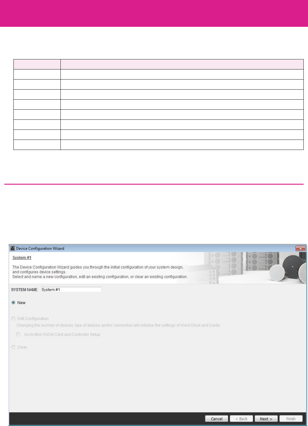
Using the Device Configuration Wizard to create your device setup
Before setting the internal configuration on the MRX, use the wizard on the MTX-MRX Editor to create a configuration for
the device.
After you’ve made basic settings, you’ll be able to print information about system cabling and ID numbers.
Use the following procedure to make basic settings.
1. Type a name for the MTX/MRX System you’ll be constructing, and click [Next>].
Gossary Description
Local Your own meeting room within the remote conferencing system. Also called “near-end.”
Remote The other party’s meeting room within the remote conferencing system. Also called “far-end.”
From Far-end The input signal from the remote location (the other party.)
Far-end Voice The signal from the remote location reproduced via your local speakers.
Near-end Mic. The input signal from the microphone(s) of the remote location.
Near-end Voice The signal from the local microphone(s) reproduced via the local speakers.
To Far-end The signal of the local microphone(s), processed by echo cancellation and sent to the remote location.
CODEC A device for transmitting and receiving data via a digital communication network.
Example 2) Remote conferencing system that also uses Speech
Privacy
Example 2) Remote conferencing system that also uses Speech Privacy
MRX Setup Manual 66
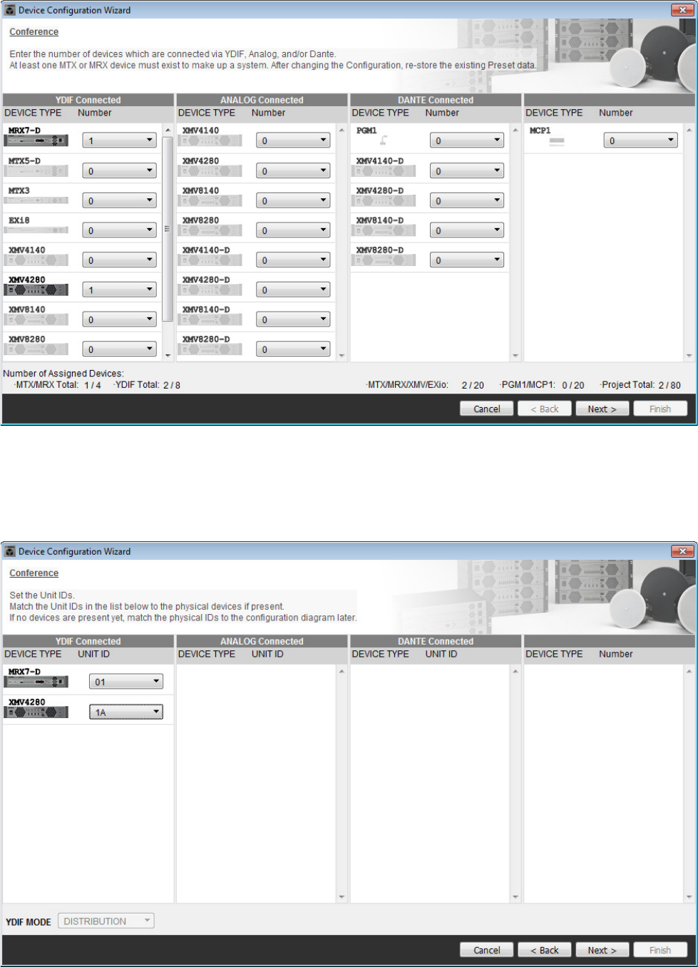
2. Specify the number of units that will be connected in your MTX/MRX System, and click
[Next>].
Specify “1” as the number of MRX7-D units in “YDIF Connected,” and specify “1” as the number of XMV4280 units
to be connected.
3. Specify the UNIT ID of each device, and click [Next>].
Unless you have specific reasons for doing so, use the UNIT ID that is assigned. In this example, set the XMV’s
UNIT ID to 1A so that we can explain how to change the UNIT ID.
Example 2) Remote conferencing system that also uses Speech Privacy
MRX Setup Manual 67
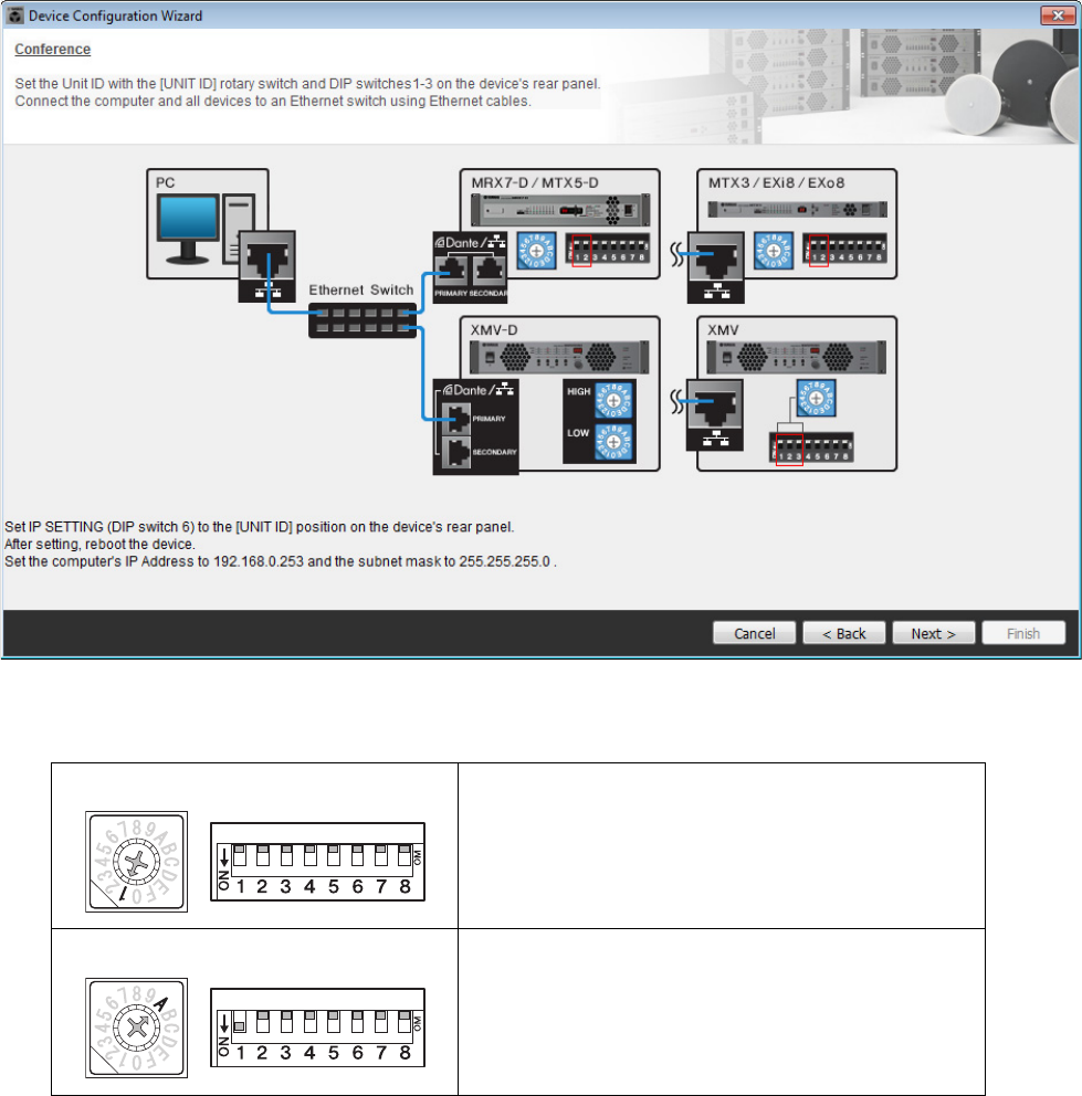
4. Set the [UNIT ID] rotary switch and DIP switch of the MRX and XMV.
You will set the computer’s IP address after completing the wizard, in “Specifying the computer’s TCP/IP address.”
If the MRX and XMV are not nearby, you can set them during the step “Connecting the equipment.”
Make the following settings.
5. When you have finished setting the [UNIT ID] rotary switch and DIP switch of the MRX and
the XMV, click [Next>].
MRX7-D
UNIT ID = 01
[UNIT ID] rotary switch = 1
DIP switches are all OFF (upward)
XMV
UNIT ID = 1A
[UNIT ID] rotary switch = A
DIP switch 1 is ON (downward), others are OFF (upward)
Example 2) Remote conferencing system that also uses Speech Privacy
MRX Setup Manual 68
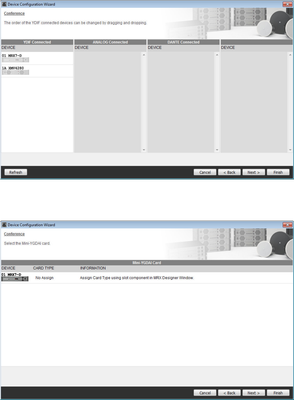
6. Verify that the MRX and XMV are shown in the screen, and click [Next>].
Since there is only one MRX unit and one XMV unit, there’s no need to change the order.
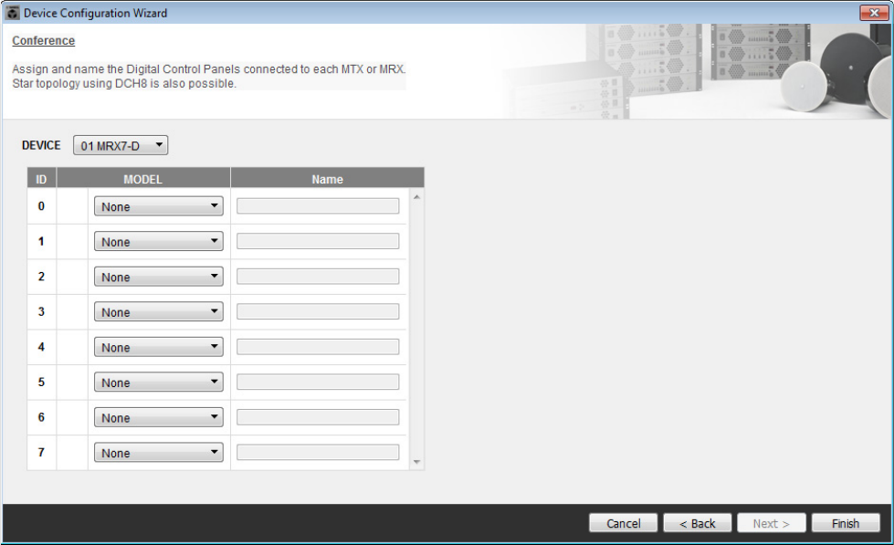
7. Click [Next>].
On the MRX Designer of the MRX, select the Mini-YGDAI card.
Example 2) Remote conferencing system that also uses Speech Privacy
MRX Setup Manual 69
8. Choose the model of DCP that is connected to the MRX, enter a device name, and click
[Finish].
For this example, we will use ProVisionaire Touch, and we will not make any settings on the DCP.
Example 2) Remote conferencing system that also uses Speech Privacy
MRX Setup Manual 70
9. When you see the dialog box “Display the configuration diagram? The diagram can also
be printed.” click [Yes].
A cabling diagram will appear. If you want, click [Print] to print the diagram.
To close the screen, click [Close].
If you want to use the Device Configuration Wizard to change the device configuration, click the [Device Config] but-
ton in the Project screen.
NOTE
If you want to view the cabling diagram again, do so by choosing [File] menu → [Print Configuration Diagram].
Example 2) Remote conferencing system that also uses Speech Privacy
MRX Setup Manual 71
Configuring the settings on the MRX
Use the MRX Designer to set an internal configuration on the MRX.
When you’ve finished making settings, you should save them by clicking [File] menu, then [Save].
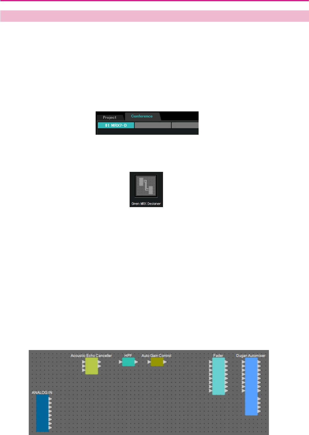
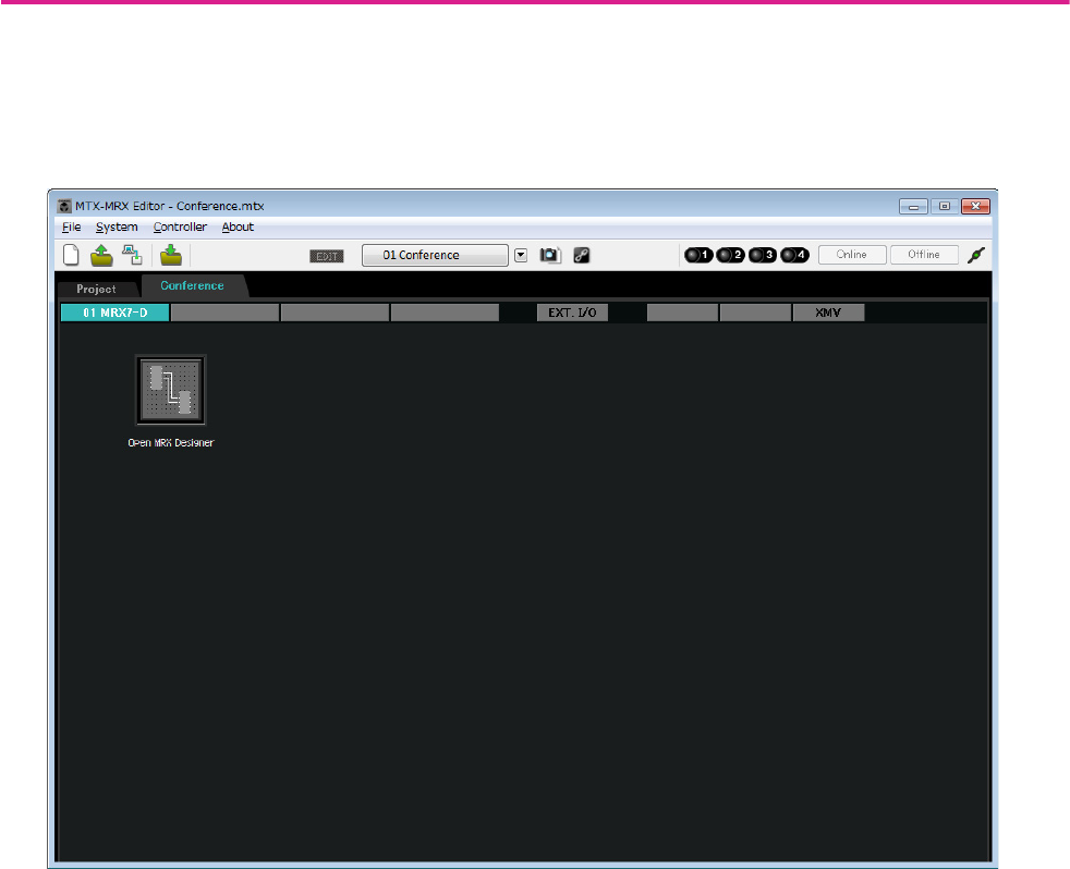
Starting the MRX Designer
Click the tab for the system name that you set in step 1 of “Using the Device Configuration Wizard to create your
device setup” to go to the settings screen.
After going to the settings screen, click the [Open MRX Designer] button to start the MRX Designer.
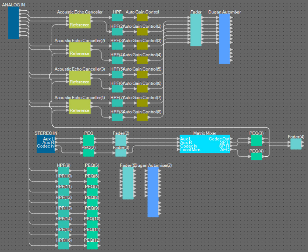
Placing and connecting the components related to the mics in the local loca-
tion that send audio to far-end
Place and connect the components that will send the input signals from the mics in the local location to the remote loca-
tion.
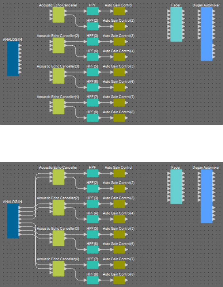
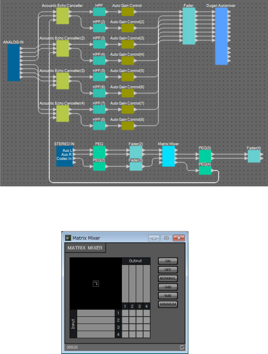
1. Place the components shown below by dragging them from the “Components” area
and dropping them into the Design sheet.
• “ANALOG IN”
• “Acoustic Echo Canceller”
• “HPF” (MONO)
• “Auto Gain Control” (MONO)
• “Fader” (8CH)
• “Dugan Automixer” (8CH)
Placing and connecting the components
NOTE
The “User Account Control” dialog box may appear. Click [Continue] or [Yes].
Example 2) Remote conferencing system that also uses Speech Privacy
MRX Setup Manual 72
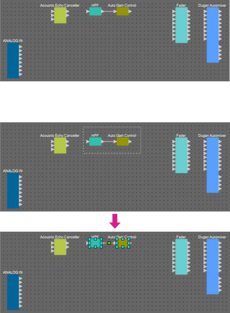
2. Drag and drop the components between the “HPF” and “Auto Gain Control” ports to
connect them.
3. Select the area between “HPF” and “Auto Gain Control”, so that the components and
wires are selected.
Example 2) Remote conferencing system that also uses Speech Privacy
MRX Setup Manual 73
4. Copy the selected components and wires and paste once, or drag and drop the
selected components and wires while holding down <Ctrl>.
Change the placement of the components as need be.
Here’s how to copy:
• <Ctrl> + <C>
• Right-click and select [Copy] from the context menu
• Select [Copy] from the [Edit] menu
Here’s how to paste:
• <Ctrl> + <V>
• Right-click and select [Paste] from the context menu
• Select [Paste] from the [Edit] menu
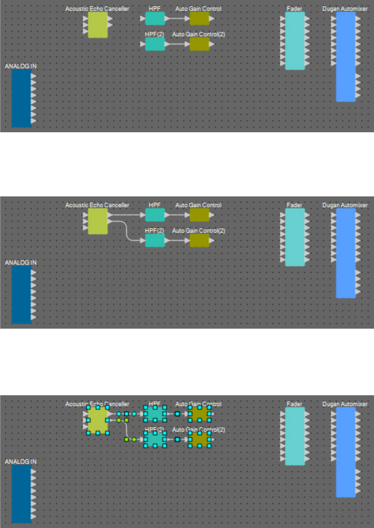
5. Drag and drop the components between the “Acoustic Echo Canceller”, “HPF” and
“HPF(2)” ports to connect them.
6. Select the area between “Acoustic Echo Canceller” and “Auto Gain Control”, so that the
components and wires are selected.
Example 2) Remote conferencing system that also uses Speech Privacy
MRX Setup Manual 74
7. Copy the selected components and wires and paste four times, or drag and drop the
selected components and wires while holding down <Ctrl>.
Change the placement of the components as need be.
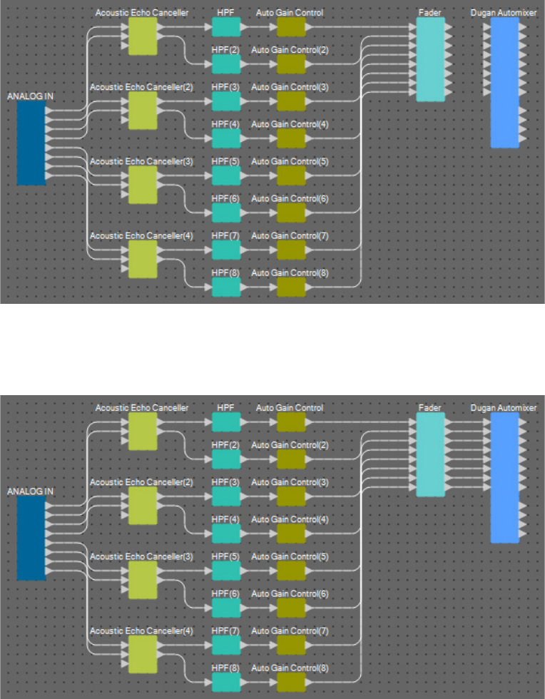
8. Connect the “ANALOG IN” 1 through 8 ports and the Mic In 1/2 port for each “Acoustic
Canceller” by dragging and dropping.
Example 2) Remote conferencing system that also uses Speech Privacy
MRX Setup Manual 75
9. Drag and drop between the “Auto Gain Control” output ports and the “Fader” input
ports to connect them.
Select the “Auto Gain Control” output port area, and drag and drop them all at once to the “Fader” input ports to
connect them.
10. Drag and drop between the “Fader” output ports and the “Dugan Automixer” input
ports to connect them.
Example 2) Remote conferencing system that also uses Speech Privacy
MRX Setup Manual 76
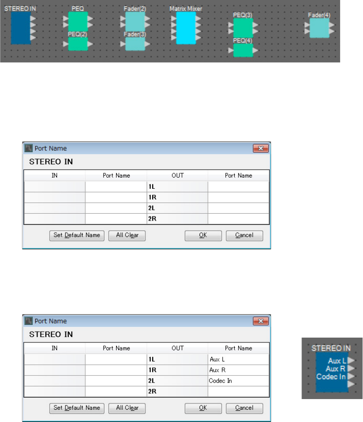
Placing and connecting the components not related to the mics in the local
location that send audio to far-end
Now we’ll bring the audio signal inputs from the AUX L/R and remote location to the MRX7-D [ST-IN] connectors.
1. Place the components shown below by dragging them from the “Components” area
and dropping them into the Design sheet.
• “STEREO IN”
• “PEQ” (STEREO, 3BAND)
• “PEQ” (MONO, 3BAND)
• “Fader” (2CH) × 2
• “Fader” (1CH)
• “Matrix Mixer” (IN=4, OUT=4)
• “PEQ” (STEREO, 4BAND)
• “PEQ” (MONO, 4BAND)
2. Click the “STEREO IN” port, and click the button that’s located at the right of the edit
area in “Properties.”
The “Port Name” dialog box will appear.
3. Enter the port name, and click the [OK] button.
In this example, 1L is named as “Aux L”, 1R as “Aux R”, and 2L as “Codec In”.
Example 2) Remote conferencing system that also uses Speech Privacy
MRX Setup Manual 77
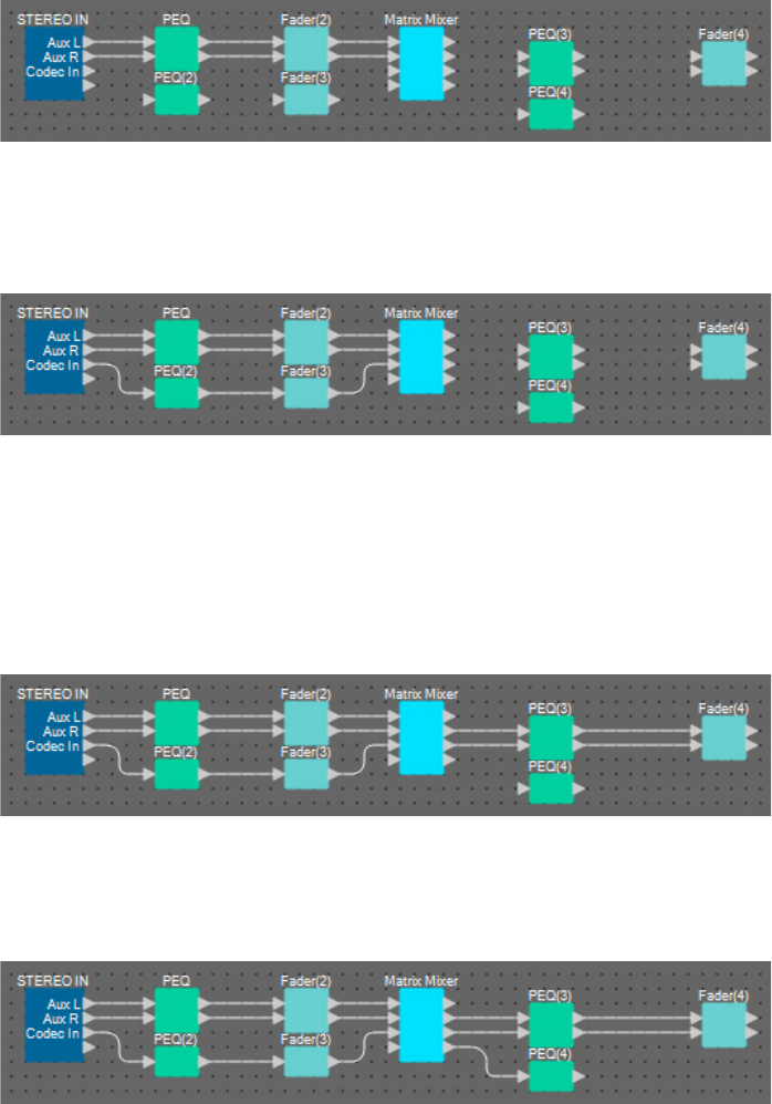
4. Connect the space between “STEREO IN” output ports 1/2 to the “Matrix Mixer” input
ports 1/2 by dragging and dropping.
5. Connect the space between “STEREO IN” output port 3 to the “Matrix Mixer” input port
3 by dragging and dropping.
6. Connect the space between “Matrix Mixer” output ports 2/3 to “Fader(4)” input ports 1/
2 by dragging and dropping.
Output port 1 of the “Matrix Mixer” will be used to send the Aux signal to the remote location. Output ports 2/3 of
the “Matrix Mixer” will be used to output to the speakers in the local location. Output port 4 of the “Matrix
Mixer” will be used as an input to the AEC reference.
7. Connect the space between the “Matrix Mixer” output port and the “PEQ(4)” input port
1 by dragging and dropping.
Example 2) Remote conferencing system that also uses Speech Privacy
MRX Setup Manual 78
8. Connect the output port of “PEQ(4)” to each Reference port of the “Acoustic Echo Can-
celler” by dragging and dropping.
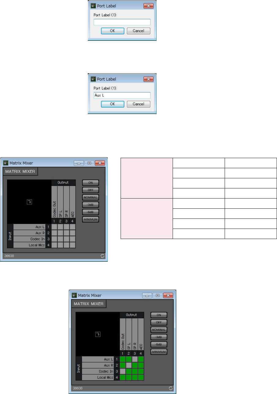
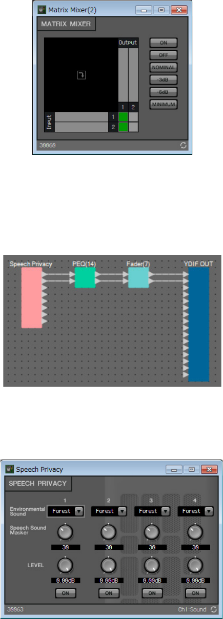
9. Double-click the “Matrix Mixer.”
The “Matrix Mixer” component editor will appear.
Example 2) Remote conferencing system that also uses Speech Privacy
MRX Setup Manual 79
10. Double-click the area where the Input 1 port name is displayed.
The “Port Label” dialog box will appear.
11. Input [Aux L] and click the [OK] button.
12. Repeat steps 10 and 11 to input the names for the other ports.
In this example, we’ve used the following names.
13. Click the spaces to turn the sends on, as shown in the image below.
14. Click the [×] button at the top right-hand corner to close the component editor.
Input
1Aux L
2Aux R
3 Codec In
4 Local Mics
Output
1 Codec Out
2SP L
3SP R
4AEC
Example 2) Remote conferencing system that also uses Speech Privacy
MRX Setup Manual 80
Placing and connecting the components related to the mics for the Near-end
voice
Set the input from the mics so that they will output to the speakers at the local location.
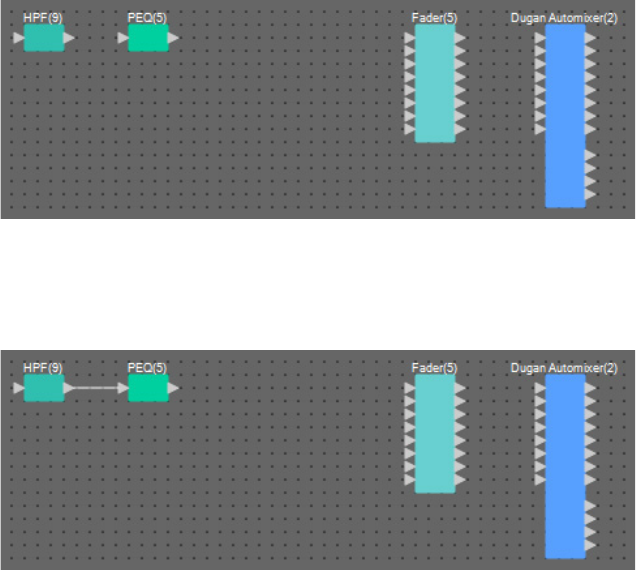
1. Place the components shown below by dragging them from the “Components” area
and dropping them into the Design sheet.
• “HPF” (MONO)
• “PEQ” (MONO, 4BAND)
• “Fader” (8CH)
• “Dugan Automixer” (8CH)
2. Drag and drop the components between the “HPF(9)” and “PEQ(5)” ports to connect
them.
Example 2) Remote conferencing system that also uses Speech Privacy
MRX Setup Manual 81
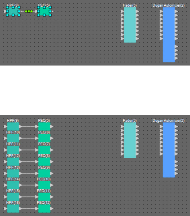
3. Select the area between “HPF(9)” and “PEQ(5)”, so that the components and wires are
selected.
4. Copy the selected components and wires and paste seven times, or drag and drop the
selected components while holding down <Ctrl>.
Change the placement of the components as need be.
Example 2) Remote conferencing system that also uses Speech Privacy
MRX Setup Manual 82
5. Connect the “ANALOG IN” 1 through 8 ports and each “HPF” input port by dragging
and dropping.
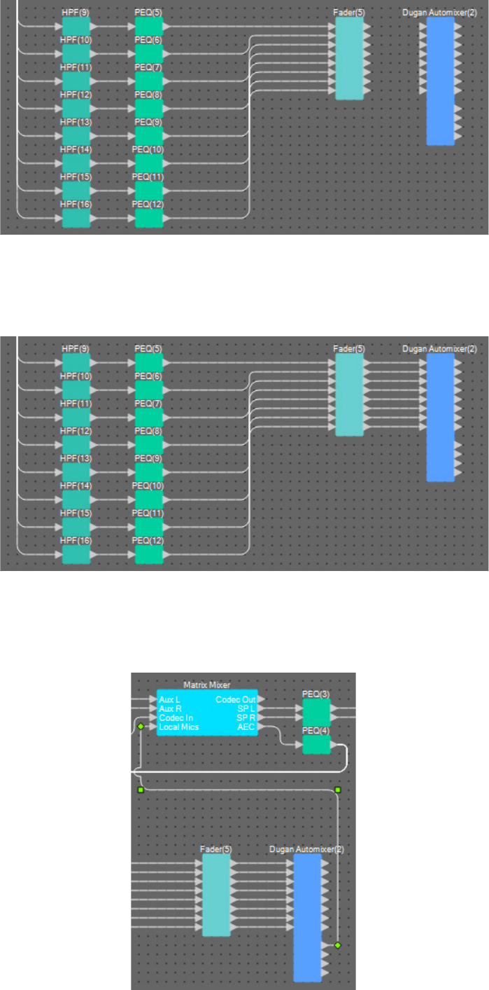
Example 2) Remote conferencing system that also uses Speech Privacy
MRX Setup Manual 83
6. Drag and drop between each “PEQ” output port and the “Fader” input ports to connect
them.
7. Drag and drop between the “Fader(5)” output ports 1 through 8 and the “Dugan Auto-
mixer” input ports 1 through 8 to connect them.
8. Drag and drop between “Dugan Automixer(2)” output port a and the “Matrix Mixer”
input port 4 to connect them.
Example 2) Remote conferencing system that also uses Speech Privacy
MRX Setup Manual 84
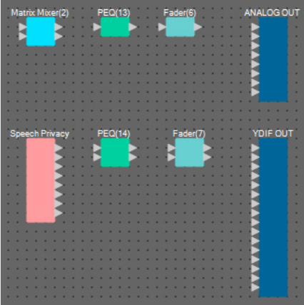
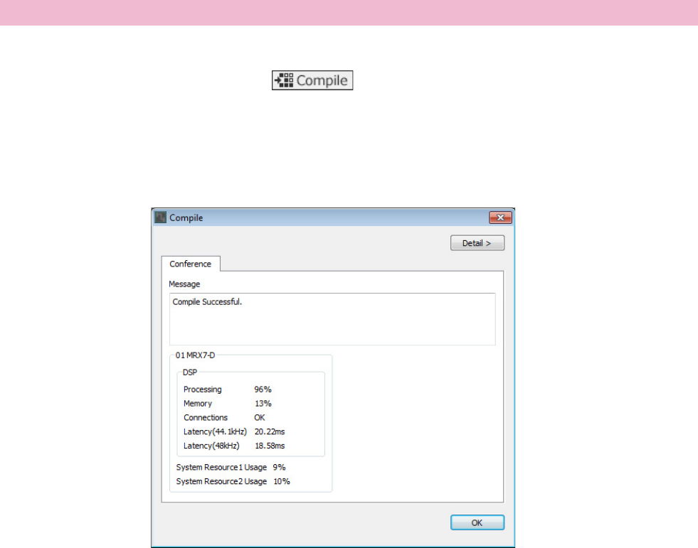
Placing and connecting the components related to the mics for output
Here we will place and connect the components related to the conference room speakers, the hallway speakers, and out-
put to CODEC.
Allocate the “ANALOG OUT” 1 to CODEC, the “YDIF OUT” 1 and 2 to speech privacy (hallway speakers), and the
“YDIF OUT” 3 and 4 to the conference room speakers.
1. Place the components shown below by dragging them from the “Components” area
and dropping them into the Design sheet.
• “Matrix Mixer” (IN=2, OUT=2)
• “PEQ” (MONO, 4BAND)
• “Fader” (1CH)
• “Speech Privacy”
• “PEQ” (STEREO, 4BAND)
• “Fader”(2CH)
• “ANALOG OUT”
• “YDIF OUT”
Example 2) Remote conferencing system that also uses Speech Privacy
MRX Setup Manual 85
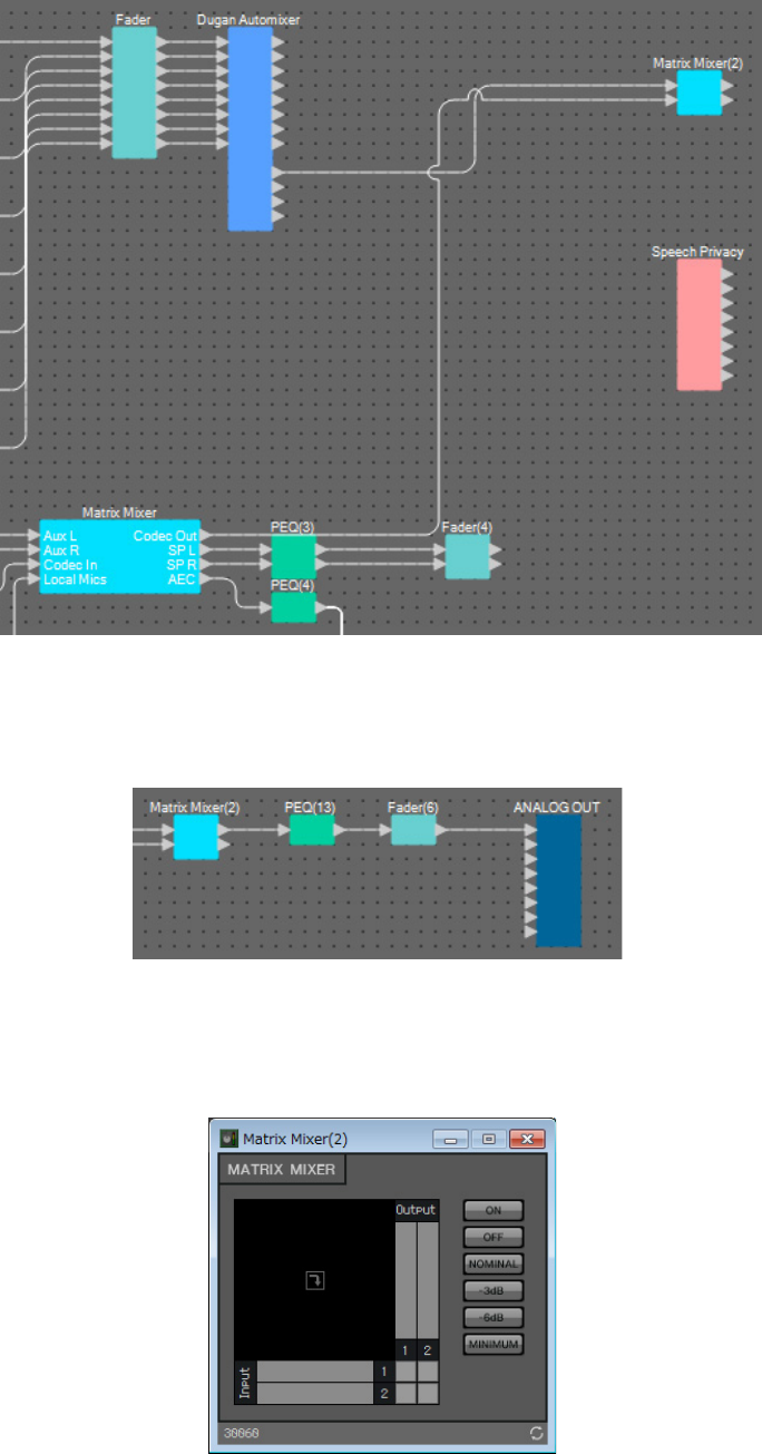
2. Drag and drop between the “Dugan Automixer” output port a and the “Matrix Mixer(2)”
input port 1 to connect them. Drag and drop between the “Matrix Mixer” output port 1
(Codec Out) and the “Matrix Mixer(2)” input port 2 to connect them.
3. Drag and drop between the “Matrix Mixer(2)” output port 1 and the “ANALOG OUT”
input port 1 to connect them.
4. Double-click the “Matrix Mixer(2).”
The Matrix Mixer component editor will appear.
Example 2) Remote conferencing system that also uses Speech Privacy
MRX Setup Manual 86
5. Click the spaces to turn the sends on, as shown in the image below.
6. Click the [×] button at the top right-hand corner to close the component editor.
7. Drag and drop from between the “Speech Privacy” output port 1 and the 1W/Offset to
the “YDIF OUT” input ports 1 and 2 to connect them.
8. Double-click “Speech Privacy.”
The Speech Privacy component editor will appear.
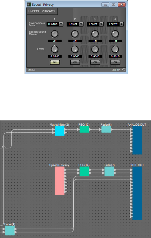
Example 2) Remote conferencing system that also uses Speech Privacy
MRX Setup Manual 87
9. Select “Building” on the [Environmental Sound] list box for source 1, and click the [ON]
button for source 1 to turn it on.
Set the environmental sound to “Building” (air-conditioner sound) to send speech privacy sounds through the hall-
way speakers.
10. Click the [×] button at the top right-hand corner to close the component editor.
11. Drag and drop from between the “Fader(4)” output ports 1 and 2 to the “YDIF OUT”
input ports 3 and 4 to connect them.
Now you’re finished placing and connecting the components. Change the placement of the components and change the wir-
ing as need be.
Example 2) Remote conferencing system that also uses Speech Privacy
MRX Setup Manual 88
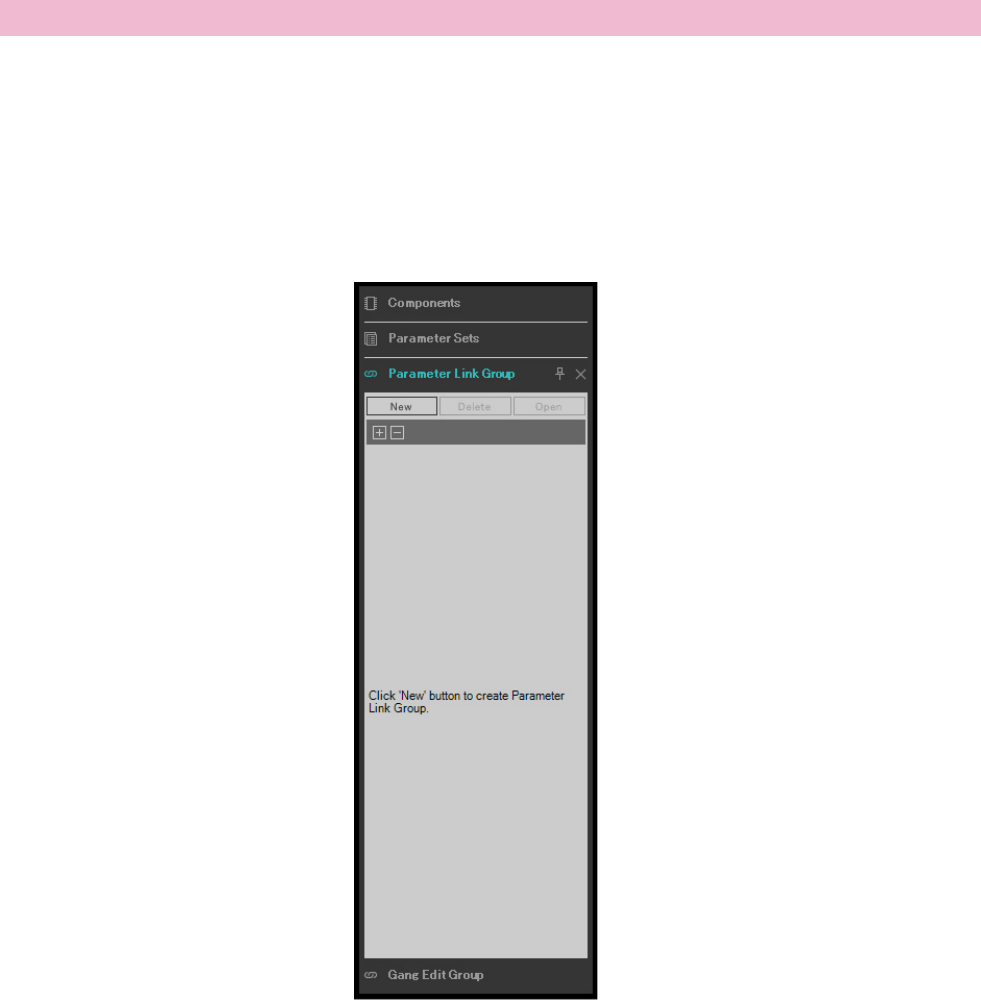
This analyzes the placement and wiring of the components in the MRX, to determine whether there are any problems.
1. Click the [Compile] tool button ( ).
Start the analysis.
2. Confirm the analysis results.
If the message “Completed successfully” is displayed in the “Message” field, there were no problems.
If a problem was detected, click the [Detail] button to check how to solve the problem and to correct it.
Now you’re finished compiling.
Compiling
Example 2) Remote conferencing system that also uses Speech Privacy
MRX Setup Manual 89
In this example, we’ll see how to make it easier to operate in ProVisionaire Touch, such as by assigning a single fader to
two faders for stereo output to conference room speakers, or by assigning a single button to activate all of the mic ON but-
tons.
Here we’ll create a parameter link group that links multiple parameters such as levels or ON/OFF, so that we can change
multiple parameters at the same time with a ProVisionaire Touch fader or button.
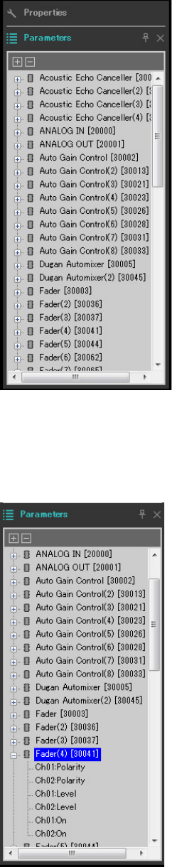
1. Open the “Parameter Link Group” area on the left side of the MRX Designer, in order to
check the parameters that are registered.
Setting a parameter link group
Example 2) Remote conferencing system that also uses Speech Privacy
MRX Setup Manual 90
2. Open the “Parameter” area on the right side of the MRX Designer.
3. Since the conference room speaker levels are adjusted using “Fader(4)”, open [Fader(4)] in
the “Parameters” area.
Example 2) Remote conferencing system that also uses Speech Privacy
MRX Setup Manual 91
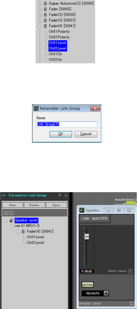
4. After clicking [Ch01:Level], hold down <Ctrl> and click [Ch02:Level].
You can select multiple items while holding down <Ctrl> and clicking.
To select continuous parameters, click the start parameter, hold down the <Shift> key and then click on the end
parameter.
5. Do a right-click and select [Add to Parameter Link Group] → [Add New Group].
A dialog box for setting the parameter link group name will open.
6. Input [Speaker Level] and click the [OK] button.
The [Speaker Level] group will be generated in the “Parameter Link Group” area, and the Link Master editor will
appear.
7. Select [Absolute] on the Link Master editor combo box.

Example 2) Remote conferencing system that also uses Speech Privacy
MRX Setup Manual 92
8. Double-click “Fader(4).”
The “Fader(4)” component editor will appear.
9. Move the fader in the Link Master editor, and confirm that the “Fader(4)” component editor
faders are linked together.
10. Click the [×] button at the top right-hand corner of the “Fader(4)” component editor to
close the component editor.
Now open the Link Master editor, as we will be using it to register the Remote Control Setup List.
Repeat step 2 through 10 to create the following parameter link groups.
Now you’re finished setting the parameter link group.
Parameter link
group name Components Parameters Link Master editor
combo box settings
Mics On/Off [Fader(5)]
Ch01:On
Absolute
Ch02:On
Ch03:On
Ch04:On
Ch05:On
Ch06:On
Ch07:On
Ch08:On
Example 2) Remote conferencing system that also uses Speech Privacy
MRX Setup Manual 93
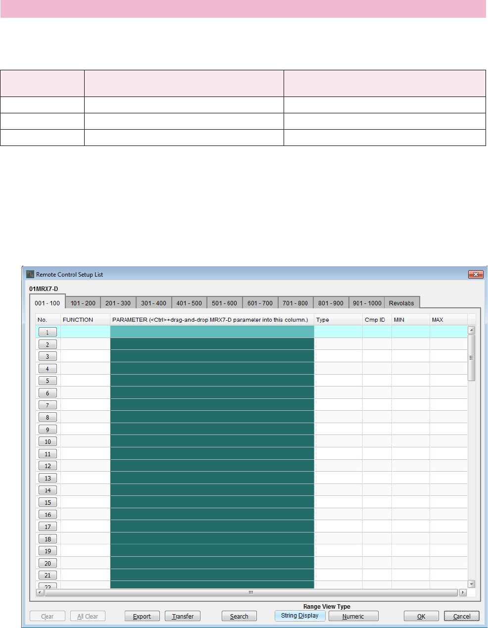
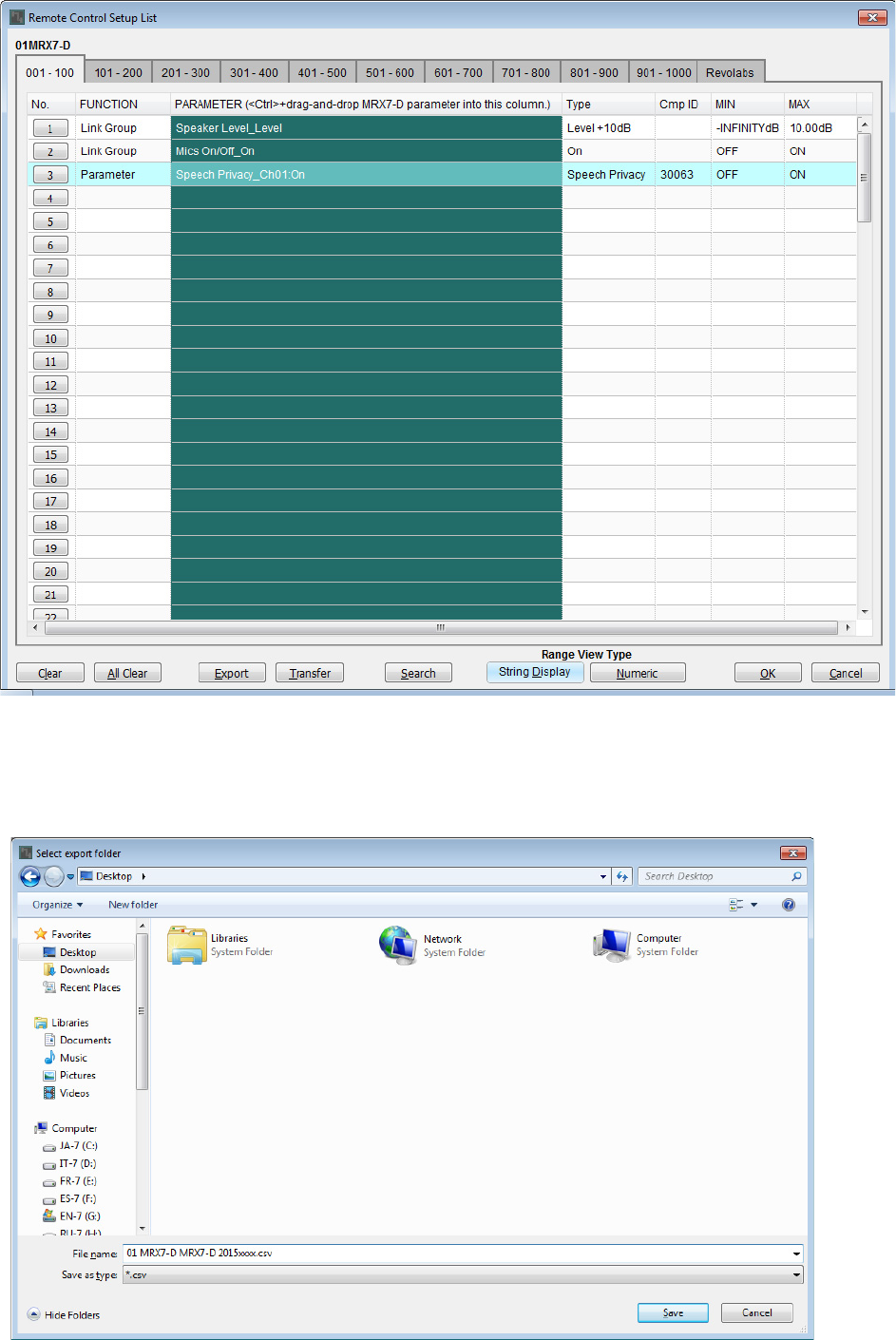
To change the parameters by operating the ProVisionaire Touch, register the parameters in the Remote Control Setup List,
and output the file. Add the outputted rcsl file as a document to ProVisionaire Touch on the iPad.
Register the following parameters in the Remote Control Setup List. The steps for registering will be explained later.
Now we’ll explain how to register the Remote Control Setup List. This time, we’ll explain how to do this by dragging and
dropping the parameters while holding <Ctrl> using the component editor and so on; but you can also drag and drop from
the “Parameters” area.
1. Select [Remote Control Setup List] in the [Tools] menu.
The “Remote Control Setup List” dialog box will appear.
Creating the Remote Control Setup List used by ProVisionaire Touch
No. Component or parameter link group that
includes the registered parameters Parameters
001 Speaker Level Link Master fader
002 Mics On/Off [ON] button for Link Master
003 Speech Privacy Source 1 [ON] button
Example 2) Remote conferencing system that also uses Speech Privacy
MRX Setup Manual 94
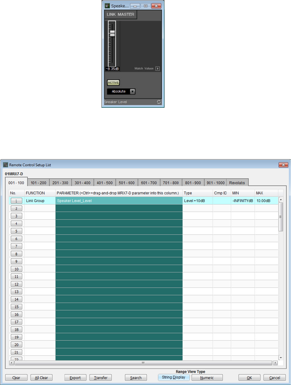
2. Click the Link Master editor for the “Speaker Level.”
The focus will move to the Link Master editor for the “Speaker Level.” If the Link Master editor is closed, right-click
on “Speaker Level” in the parameter link group area and select [Open Link Master] from the context menu to display
it.
3. Drag and drop the Link Master editor fader to the “PARAMETER” area in line No.001 of the
“Remote Control Setup List” dialog box, while holding down <Ctrl>.
The “Speaker Level” fader will be registered.
Example 2) Remote conferencing system that also uses Speech Privacy
MRX Setup Manual 95
4. Register the other parameters as shown in steps 2 through 3.
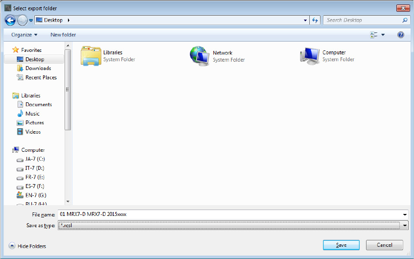
5. Click the [Export] button.
The file save dialog box will appear.
Example 2) Remote conferencing system that also uses Speech Privacy
MRX Setup Manual 96
6. Change the “File type” to “rcsl.”
The file extension will change to “rcsl.”
7. Select the desired folder and change the file name as desired, and click the [Save] button.
The Remote Control Setup List used by ProVisionaire Touch will be saved.
8. Click the [OK] button on the “Remote Control Setup List” dialog box.
The “Remote Control Setup List” dialog box is closed.
9. Click the [×] buttons at the top right-hand corner of the Link Master editor and the compo-
nent editor to close the editor and component editor.
Now you’ve finished registering the Remote Control Setup List. Refer to the “ProVisionaire Touch Setup Guide” to learn
how to use ProVisionaire Touch.
The created file can be transmitted with “File Transfer” application. Refer to the “MRX Designer User Guide” for how to
use application.
Example 2) Remote conferencing system that also uses Speech Privacy
MRX Setup Manual 97
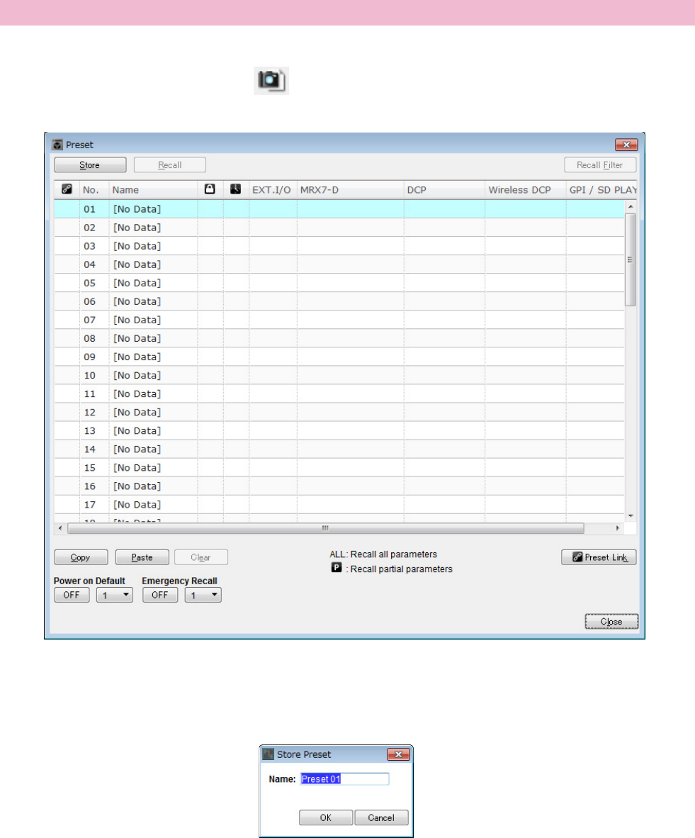
You’ll need to set which preset will be recalled when the MRX is started up.
1. Click the [Preset] tool button ( ).
The “Preset” dialog box will appear.
2. Click No. 01 and then click the [Store] button.
The “Store Preset” dialog box will appear.
Storing a preset
Example 2) Remote conferencing system that also uses Speech Privacy
MRX Setup Manual 98
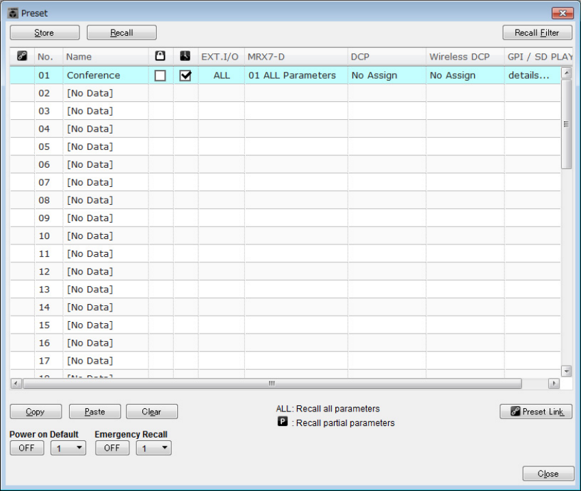
3. Input [Conference] and click the [OK] button.
The current state will be registered as a preset named “Conference.”
4. Click the [Close] button.
The “Preset” dialog box is closed.
Example 2) Remote conferencing system that also uses Speech Privacy
MRX Setup Manual 99
Making EXT. I/O settings
Now we’ve set the audio output to YDIF channels 1 through 4 of the MRX in MRX Designer. Here, we’ll set which XMV
channels will receive the audio signals from YDIF channels 1 through 4.
We’ll make these settings in the MTX-MRX Editor.
1. Switch to the MTX-MRX Editor display.
Example 2) Remote conferencing system that also uses Speech Privacy
MRX Setup Manual 100
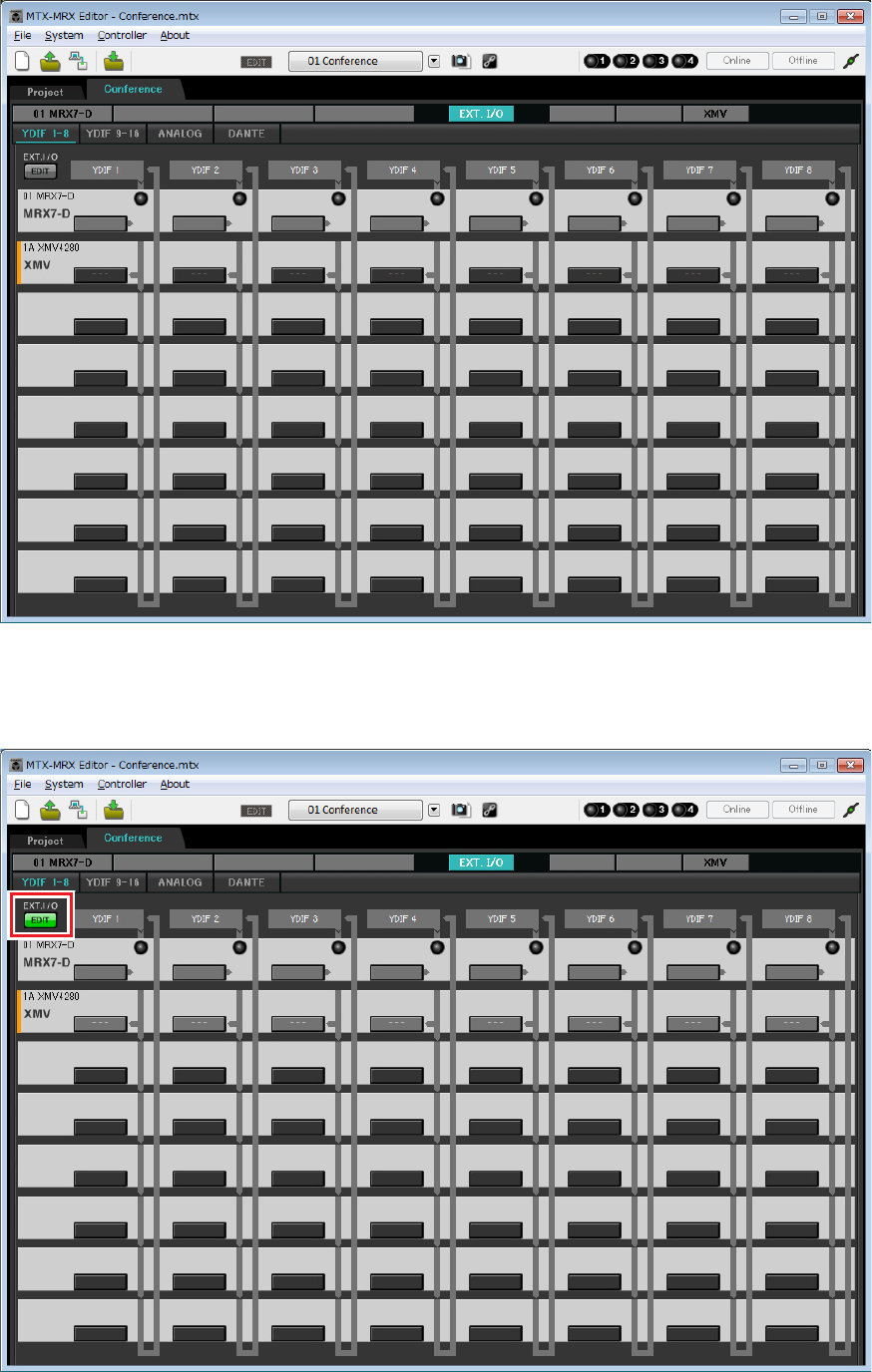
2. Click the [EXT. I/O] button.
The “EXT. I/O” screen will appear.
3. Click the [EDIT] button.
Now you can specify the inputs from the XMV unit’s YDIF 1–8.
Example 2) Remote conferencing system that also uses Speech Privacy
MRX Setup Manual 101
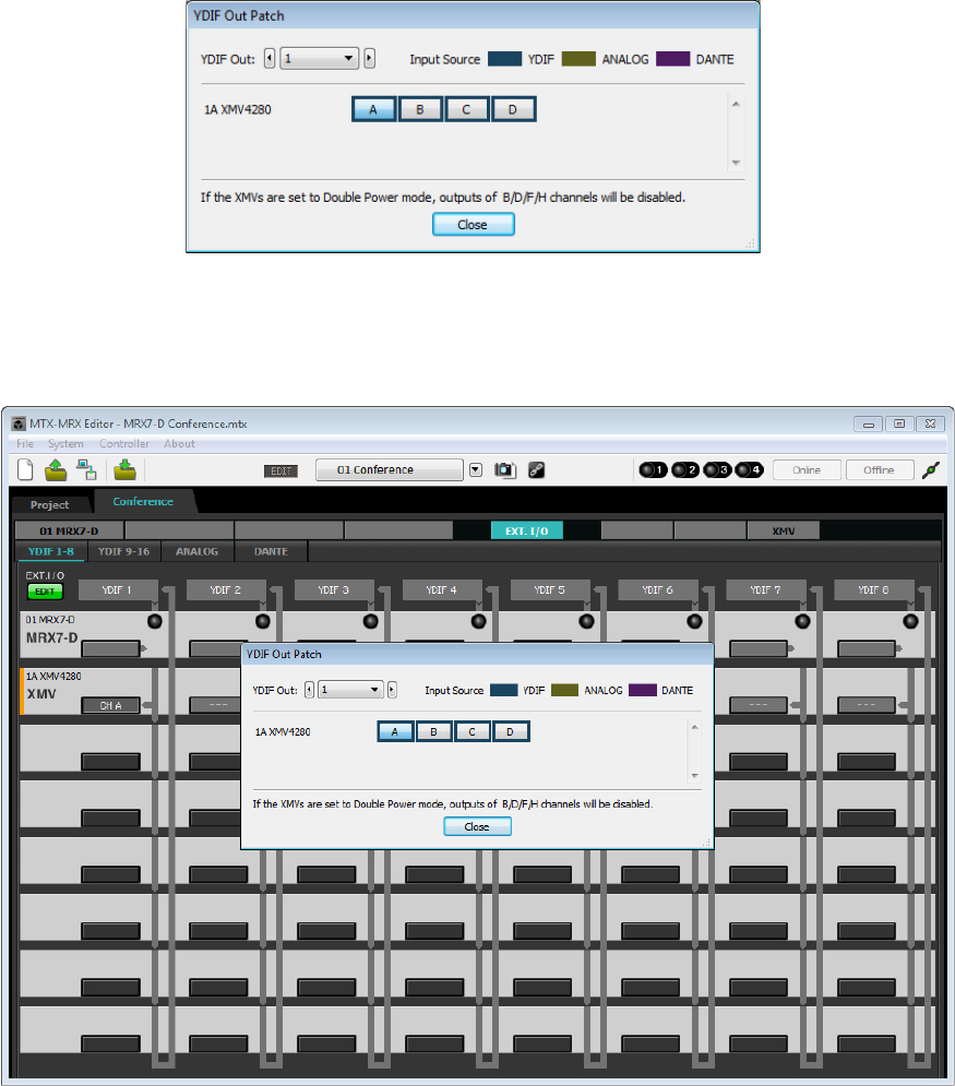
4. Click the XMV’s output routing select button for “YDIF 1.”
The “YDIF Out Patch” dialog box will appear.
5. For CHANNEL, click [A] button.
Output the YDIF 1 audio signal from the XMV’s A channel.

Example 2) Remote conferencing system that also uses Speech Privacy
MRX Setup Manual 102
6. Switch to channel 2 using the [YDIF Out:] list box.
The editing target will switch to channel 2.
7. Click the [B] button to output the YDIF 2 audio signal from the XMV’s B channel.
8. Allocate channels 3/4 to C/D, as shown in steps 6 through 7.
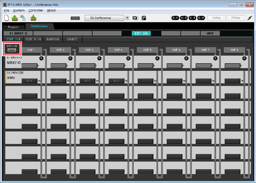
9. Click the [Close] button.
The “YDIF Out Patch” dialog box is closed.
Example 2) Remote conferencing system that also uses Speech Privacy
MRX Setup Manual 103
10. Click the [EDIT] button to disable the YDIF output routing select buttons.
This completes settings in the offline state. Save the settings once again.
Example 2) Remote conferencing system that also uses Speech Privacy
MRX Setup Manual 104
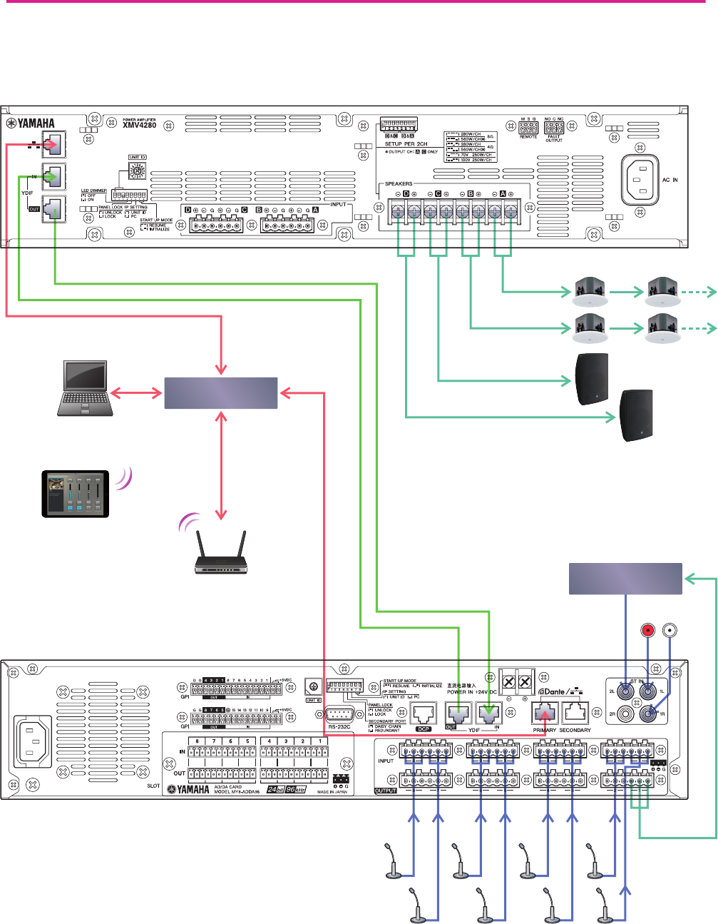
Connecting the equipment
After you’ve rack-mounted the MRX and your other equipment, connect the MRX and the other equipment as shown
below. If you’ve copied audio sources to an SD memory card, insert the card into the MRX now.
Computer
XMV4280
Network Switch
CODEC
MRX7-D
Tablet device (iPad) with
ProVisionaire Touch installed
Wi-Fi access point
Wireless LAN
connection
Example 2) Remote conferencing system that also uses Speech Privacy
MRX Setup Manual 105
Powering-on the MRX
Turn on the power of the MRX.
Turn off the amplifier before you power-off the MRX.
Powering-on the amp
Turn on the power of the amplifier.
To prevent unwanted sound from being output, we recommend that you turn down the attenuator settings of all channels on
the amp itself before you turn it on.
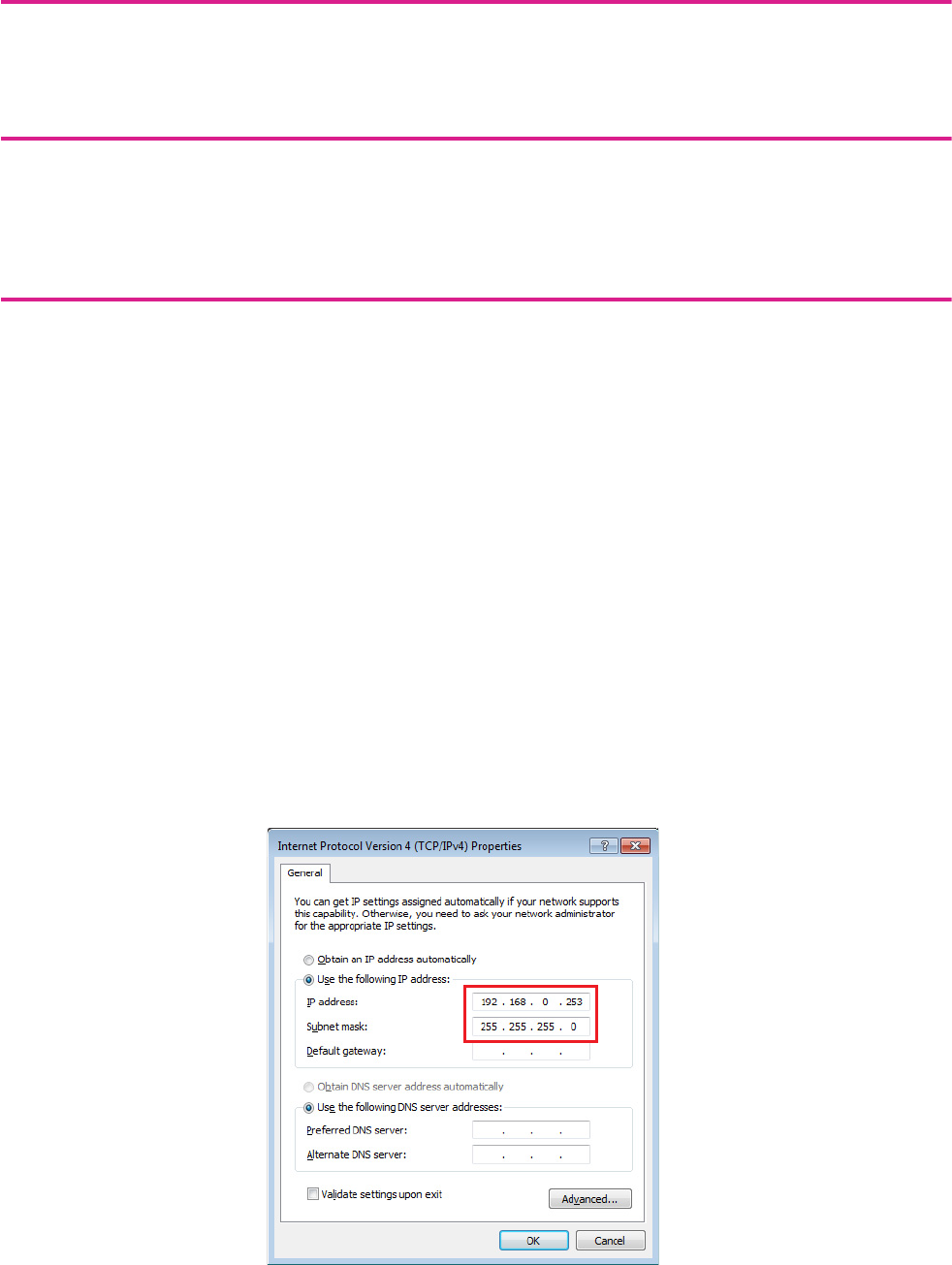
Specifying the computer’s TCP/IP address
To allow the MRX and the computer to communicate, specify the computer’s TCP/IP as follows.
1. Select [Network Setup] in the [System] menu of the MTX-MRX Editor.
The “Network Setup” dialog box will appear.
2. Click [Open Network Connection].
“Network Connections” will appear.
3. Right-click the adapter to which the MRX is connected, and choose [Properties].
The “Local Area Connection Properties” dialog box will appear.
4. Choose [Internet Protocol Version 4 (TCP/IPv4)], and then click [Properties].
The “Internet Protocol Version 4 (TCP/IPv4) Properties” dialog box will appear.
5. Click [Use the following IP address (S)].
6. In the [IP address] box, enter “192.168.0.253”; in the [Subnet mask] box, enter
“255.255.255.0.”
7. Click [OK].
NOTE
The IP address of the MRX7-D is set to “192.168.0.1.”
NOTE
In some cases, Windows firewall may block MTX-MRX Editor when you make this setting. Select the [Private Network] check box,
and click [Allow Access].
Example 2) Remote conferencing system that also uses Speech Privacy
MRX Setup Manual 106
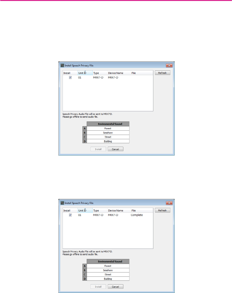
Sending the Speech Privacy environmental sound
Before going online, send the environmental sound to be used for Speech Privacy to the MRX.
1. Start up the MRX Designer.
2. Select [Install Speech Privacy File] from the [File] menu.
The “Install Speech Privacy File” dialog box will appear.
If “Installed” is displayed in the “File” field, the environmental sound has already been installed in the MRX, so there
is no need to send it.
3. Select the checkbox in the “Install” field, and click the [Install] button.
A dialog box will appear, indicating that this may take a while. Click the [Yes] button to continue.
4. When “Complete” is displayed in the “File” field, close the dialog box.
Example 2) Remote conferencing system that also uses Speech Privacy
MRX Setup Manual 107
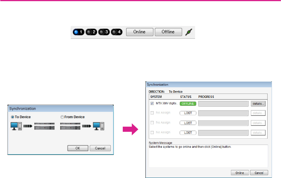
Taking MTX-MRX Editor online
In the upper right of MTX-MRX Editor, click the [Online] button. When the unit has successfully come online, the indica-
tor 1 will light blue.
When the “Synchronization” dialog box appears, select “To Device,” and click the [OK] button. When the indication in the
dialog box has switched, select the system that you want to place online, and click the [Online] button.
The project created in MTX-MRX Editor will be sent to the MRX.

Example 2) Remote conferencing system that also uses Speech Privacy
MRX Setup Manual 108
Verifying that the settings were applied
The main items to verify are listed below. For details on each parameter setting, refer to “MTX-MRX Editor User Guide”
and “MRX Designer User Guide.”
1. Input an audio signal such as AUX IN to the inputs of the MRX7-D, and adjust the input lev-
els.
Adjust the AUX IN input levels using “Fader(2).” You can use ProVisionaire Touch to adjust the level of sound com-
ing from the room speakers.
2. Adjust the Speech Privacy output level using “Fader(7).”
3. Adjust the input level of the mic using the “ANALOG IN” editor.
Turn the [+48V] button on as necessary.
4. Adjust the other inputs and outputs.
5. Confirm the settings on the ProVisionaire Touch.
Check whether the ProVisionaire Touch is operating according to the settings.
When you have finished making all settings, save the project and switch MTX-MRX Editor offline.
This completes the settings for example 2.
NOTICE
Be sure to leave this button off if you do not need phantom power.
Follow the important precautions below, in order to prevent noise and possible damage to external devices as well as the
unit when you operate this switch.
• Be sure to leave this button off when you connect a device that does not support phantom power to [INPUT] connector.
• Do not connect/disconnect a cable to/from [INPUT] connector while this button is on.
• Down the output level to the minimum before operating this button.
NOTE
There is no master switch. To avoid malfunctions, be sure to set this appropriately for the equipment that is connected.
MRX Setup Manual 109
Place the “Paging” components, and assign broadcast destinations (zones, zone groups) or pre-recorded messages to the
zone/message select buttons of the PGM1 units.
You can use the buttons to select the broadcast destination (multiple selections are allowed) and play back pre-recorded
messages from the SD card.
On the SD card that you’ll insert into the MRX, save the audio files for the Opening Chime, Closing Chime, and messages.
Up to four PGM1 units can be connected to an MTX/MRX system that includes an MRX. One PGM1 unit can control one
MRX, and this PGM1 together with the MRX are collectively called a Paging Device Group. One of the PGM1 units
within the Paging Device Group is the 1st Priority Mic; this unit can broadcast taking priority over the other PGM1 units.
There are three ways to use the PGM1.
Broadcast from the mic.
1. Use the zone/message select buttons to select the broadcast area.
2. Press the PTT button.
If specified, the Opening Chime is heard.
3. When the status indicator is lit red, speak into the mic.
4. When you finish speaking, press the PTT button.
If specified, the Closing Chime is heard.
Example 3) A paging system using the PGM1
P
P
PGX1
ID=0
PGX1
ID=1
PGM1
ID=60
PGX1
ID=0
PGX1
ID=1
PGM1
ID=61
PGX1
ID=0
PGX1
ID=1
PGM1
ID=62
MRX7-D ID=01
MTX5-D ID=02
PGX1
ID=0
PGX1
ID=1
PGM1
ID=63
SWR2100P-10G
Paging Device Group 1
Paging Device Group 2
=Priority microphone
P
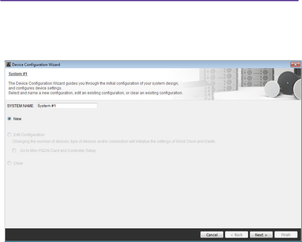
Example 3) A paging system using the PGM1
MRX Setup Manual 110
Play back a pre-recorded message from SD card
1. Use the zone/message select buttons to select the broadcast area.
2. Use the zone/message select buttons to select the message that you want to play back.
3. Press the PTT button.
If specified, the Opening Chime is heard.
The message plays, and the status indicator is lit red.
When message playback is completed, PTT automatically turns off.
If specified, the Closing Chime is heard.
Use the scheduler to play back a pre-recorded message from SD card
By issuing a Paging event, the specified message is played back to the specified zone or zone group.
Using the Device Configuration Wizard to create your device setup
Before you specify the internal configuration of the MRX, use MTX-MRX Editor’s wizard to create the device configura-
tion.
After you’ve made basic settings, you’ll be able to print information about the cabling and ID numbers.
Use the following procedure to make basic settings.
1. Type a name for the MTX/MRX system you’ll be constructing, and click [Next>].
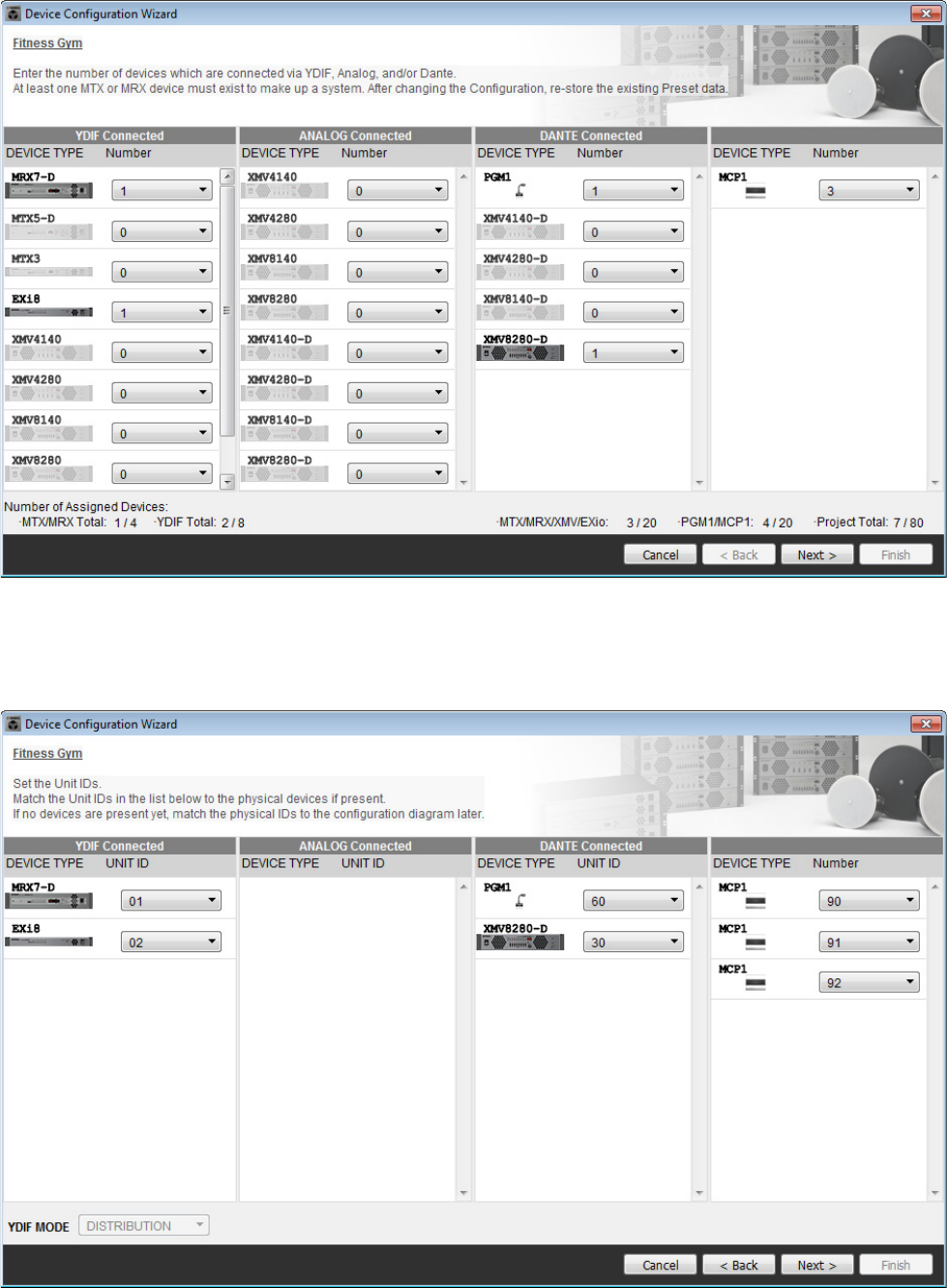
Example 3) A paging system using the PGM1
MRX Setup Manual 111
2. Specify the number of units that will be connected in your MTX/MRX system, and click
[Next>].
Set the number of “YDIF Connected” MRX7-D units to 1, the number of EXi8 units to 1, the number of “DANTE
Connected” PGM1 units to 1, the number of XMV8280-D units to 1, and in the far right row set the number of MCP1
units to 3.
3. Specify the UNIT ID of each device, and click [Next>].
Unless you have specific reasons for doing otherwise, use the UNIT ID that is assigned.
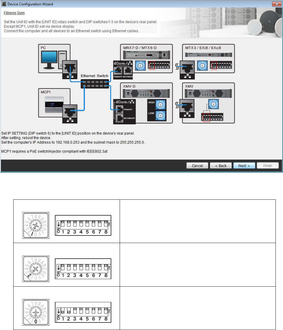
Example 3) A paging system using the PGM1
MRX Setup Manual 112
4. Set the [UNIT ID] rotary switch and DIP switch of the devices.
Set the computer’s IP address after completing the wizard, in “Specifying the computer’s TCP/IP address.”
If the device is not nearby, you can set it during the step “Connecting the equipment.”
You’ll set the MCP1’s UNIT ID during the step “Connecting the equipment.”
Make the following settings. The method of setting the PGM1’s UNIT ID is explained in step 8.
5. When you’ve finished setting the device’s [UNIT ID] rotary switch and DIP switch, click
[Next>].
EXi8
UNIT ID = 01
[UNIT ID] rotary switch =1
DIP switches = all OFF (upward)
MRX7-D
UNIT ID = 02
[UNIT ID] rotary switch =2
DIP switches = all OFF (upward)
XMV
UNIT ID = 30
[UNIT ID] rotary switch =0
DIP switch = 1 and 2 are ON (downward), others are OFF (upward)
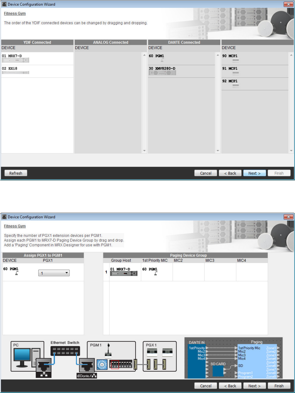
Example 3) A paging system using the PGM1
MRX Setup Manual 113
6. Verify that the devices are shown in the screen, and click [Next>].
Do not change the order.
7. Set the number of PGX1 units to 1.
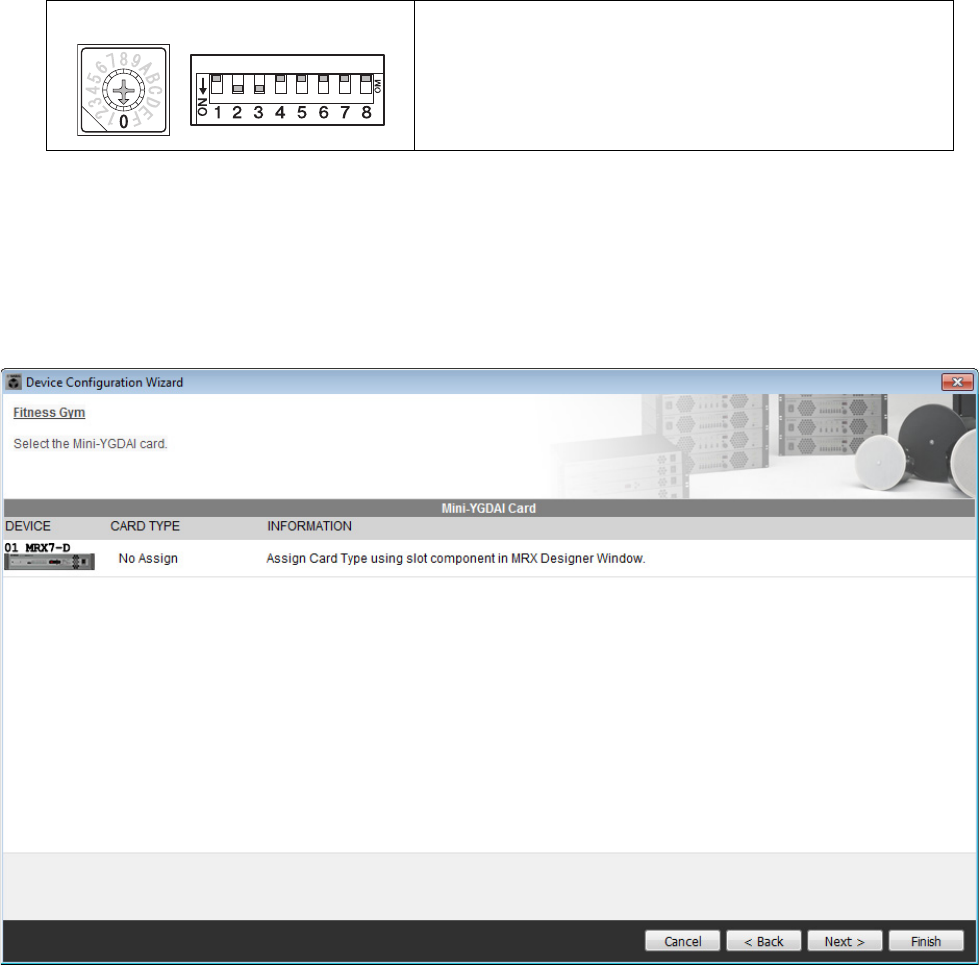
Example 3) A paging system using the PGM1
MRX Setup Manual 114
8. Set the PGM1’s [UNIT ID] rotary switch and DIP switch.
If the device is not nearby, you can set it during the step “Connecting the equipment.”
Make the following settings.
9. When you’ve finished setting the PGM1’s [UNIT ID] rotary switch and DIP switch, click
[Next>].
10. Click [Next>].
For the MRX, use MRX Designer to select the Mini-YGDAI card.
PGM1
UNIT ID = 60
[UNIT ID] rotary switch =0
DIP switch = 2 and 3 are ON (downward), others are OFF (upward)
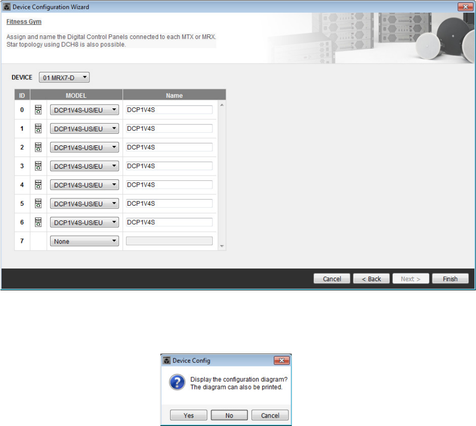
Example 3) A paging system using the PGM1
MRX Setup Manual 115
11. Choose the model of DCP that will be connected to the MRX, enter a device name, and
click [Finish].
In this example, specify seven DCP1V4S units.
12. When you see the dialog box “Display the configuration diagram? The diagram can also
be printed.” click [Yes].
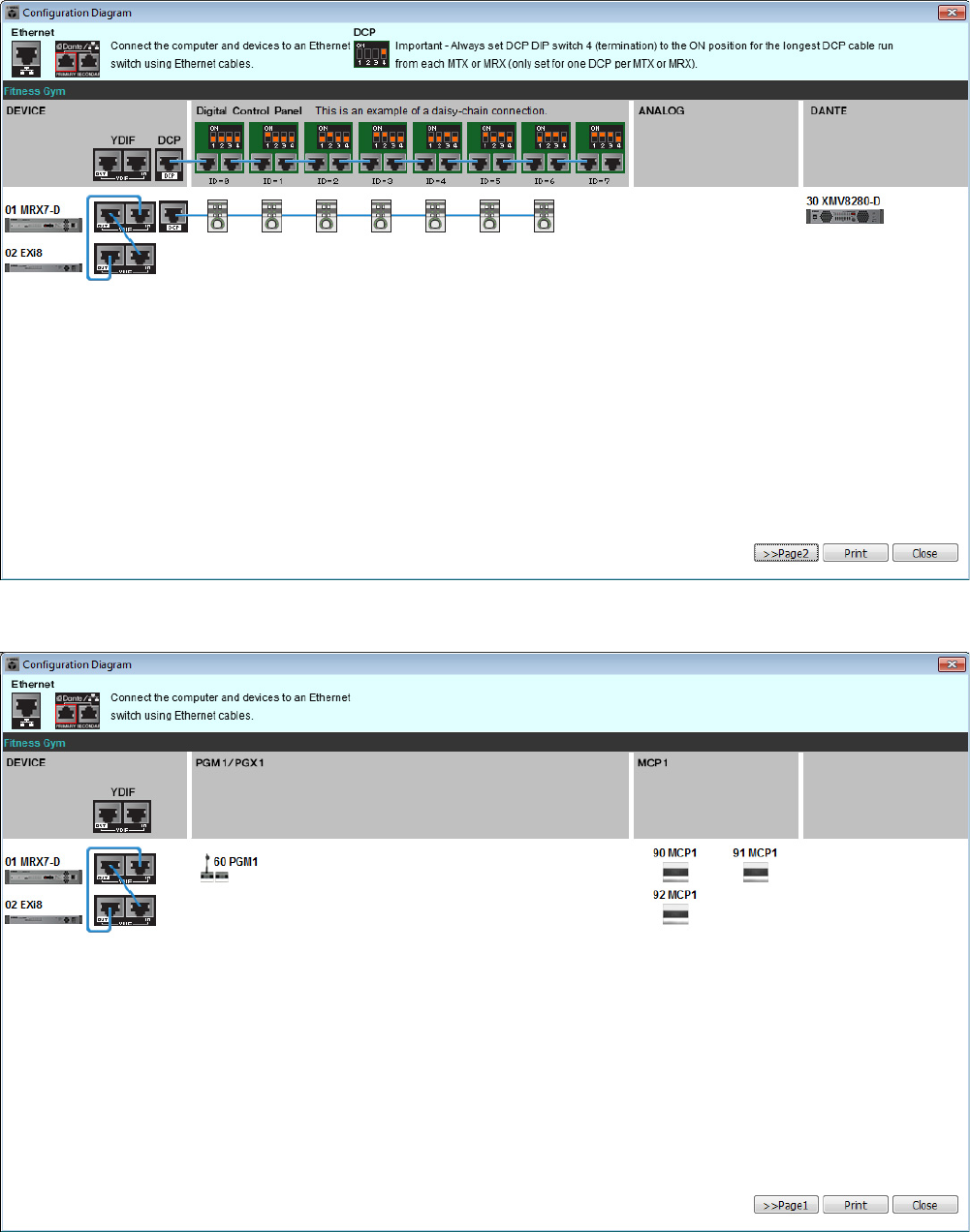
Example 3) A paging system using the PGM1
MRX Setup Manual 116
A cabling diagram will appear. If you want, click [Print] to print the diagram.
You can click the [>>Page2]/[>>Page1] buttons to switch pages.
To close the screen, click [Close].
Page 1
Page 2
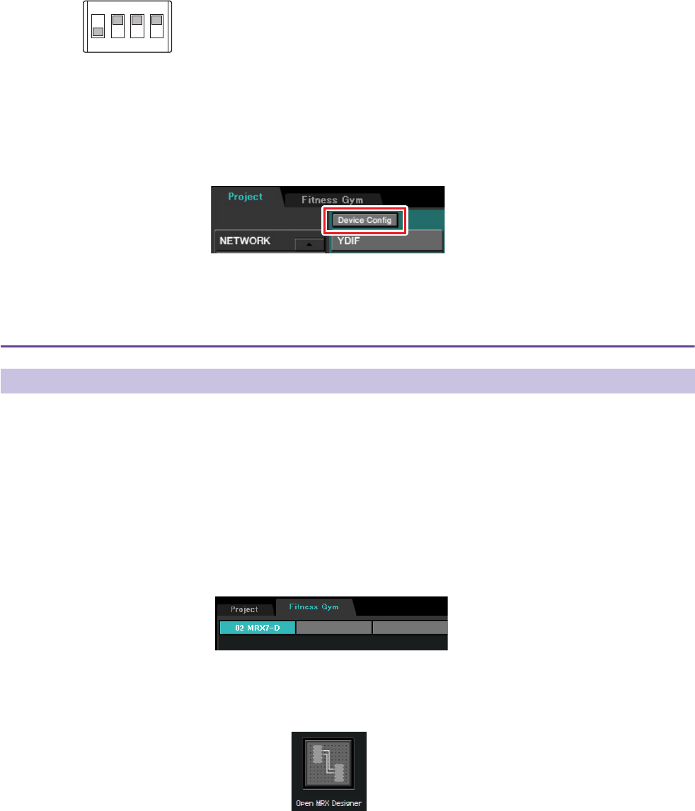
Example 3) A paging system using the PGM1
MRX Setup Manual 117
Set the DIP switches of the DCP units as directed in “Digital Control Panel” of the cabling diagram.
For the last DCP (ID=6), set DIP switch 4 upward.
If you want to use the Device Configuration Wizard to change the device configuration, click the [Device Config] but-
ton in the Project screen.
Specifying the MRX configuration
Use MRX Designer to specify the internal configuration of the MRX.
When you’ve finished making settings, you should save them by clicking [File] menu, then [Save].
Starting MRX Designer
Move to the setting screen by clicking the tab of the system name you specified in step 1 of “Using the Device Config-
uration Wizard to create your device setup.”
After you’ve moved to this screen, click the “Open MRX Designer” button to start MRX Designer.
NOTE
If you want to view the cabling diagram again, choose [File] menu → [Print Configuration Diagram].
Placing and connecting the components
NOTE
The “User Account Control” dialog box may appear. Click [Continue] or [Yes].
1
ON
2 3 4
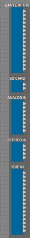
Example 3) A paging system using the PGM1
MRX Setup Manual 118
Placing the input components
Here you’ll place the input components that you will use.
From the “Components” area, drag and drop the following components onto the design
sheet.
• “DANTE IN 1–16”
• “SD CARD”
• “ANALOG IN”
• “STEREO IN”
• “YDIF IN”
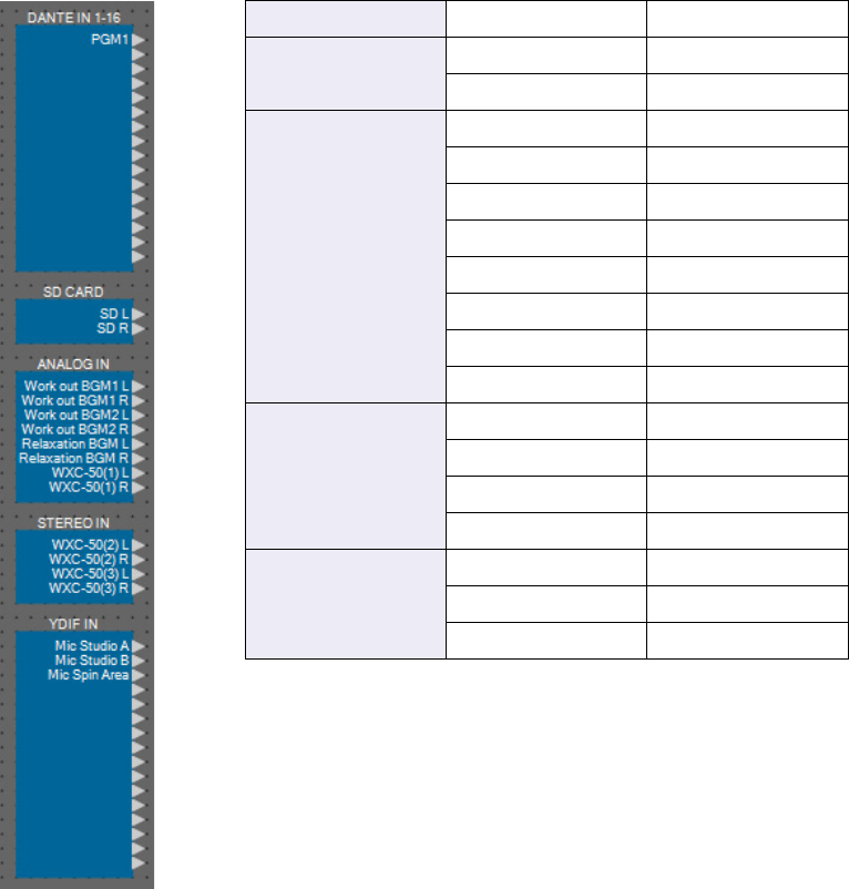
Example 3) A paging system using the PGM1
MRX Setup Manual 119
Showing port names for the input components
To avoid subsequent confusion when connecting the cabling, use the “Port Name” dialog box to enter the port names.
To access the “Port Name” dialog box, click the button located at the right of the [Label] editing area in the “Proper-
ties” area.
For “ANALOG IN,” you can also enter the port name using the “ANALOG IN” component editor that appears when
you double-click the component.
In this example, enter the port names as follows.
DANTE IN 1–16 1PGM1
SD CARD
1L SD L
1R SD R
ANALOG IN
1 Work out BGM1 L
2Work out BGM1 R
3 Work out BGM2 L
4Work out BGM2 R
5 Relaxation BGM L
6 Relaxation BGM R
7 WXC-50(1) L
8 WXC-50(1) R
STEREO IN
1L WXC-50(2) L
1R WXC-50(2) R
2L WXC-50(3) L
2R WXC-50(3) R
YDIF IN
1Mic Studio A
2Mic Studio B
3 Mic Spin Area
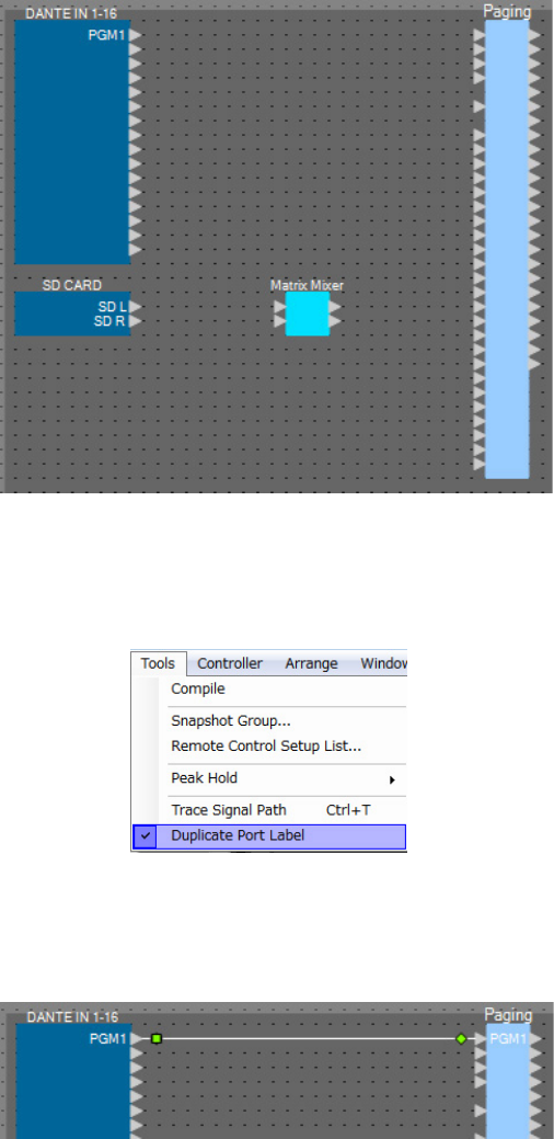
Example 3) A paging system using the PGM1
MRX Setup Manual 120
Placing and cabling the PGM1-related components in Reception
Here we will place and cable the components related to the PGM1 in Reception.
1. From the “Components” area, drag and drop the following components onto the design
sheet.
• “Matrix Mixer” (2In/2Out)
• “Paging”
2. On the [Tools] menu, click [Duplicate Port Label].
This causes the port name to be carried over when you make the connection.
3. Drag and drop to connect port 1 of “DANTE IN 1–16” to the 1st Priority Mic port of “Pag-
ing.”
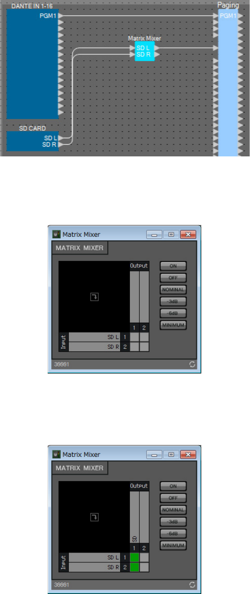
Example 3) A paging system using the PGM1
MRX Setup Manual 121
4. Drag and drop to connect the “SD CARD” ports with the input ports of the “Matrix
Mixer,” and drag and drop to connect output port 1 of the “Matrix Mixer” to the SD port
of “Paging.”
5. Double-click the “Matrix Mixer.”
The “Matrix Mixer” component editor opens.
6. Make settings so that Input 1 and 2 are output to Output 1, enter “SD” for Output 1, and
then click the [×] button in the upper right to close the component editor.
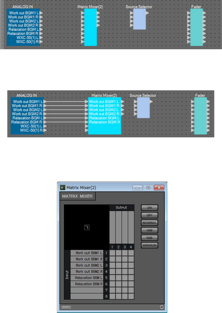
Example 3) A paging system using the PGM1
MRX Setup Manual 122
Placing and connecting the components related to BGM (monaural) input
Here we place and connect the components related to the input of the background music (monaural) that is broadcast to
the facility.
1. From the “Components” area, drag and drop the following components onto the design
sheet.
• “Matrix Mixer” (8In/4Out)
• “Source Selector” (4Source/1Ch)
• “Fader” (8Ch)
2. Drag and drop to connect “ANALOG IN” ports 1 through 6 to “Matrix Mixer(2)” input
ports 1 through 6.
3. Double-click “Matrix Mixer(2).”
The “Matrix Mixer” component editor opens.
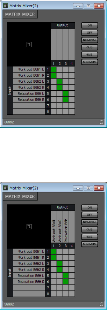
Example 3) A paging system using the PGM1
MRX Setup Manual 123
4. Make settings so that Input 1 and 2 are sent to Output 1, Input 3 and 4 to Output 2, and
Input 5 and 6 to Output 3.
5. Enter “Work out BGM1” for Output 1, enter “Work out BGM2” for Output 2, and enter
“Relaxation BGM” for Output 3; then click the [×] button in the upper right to close the
component editor.
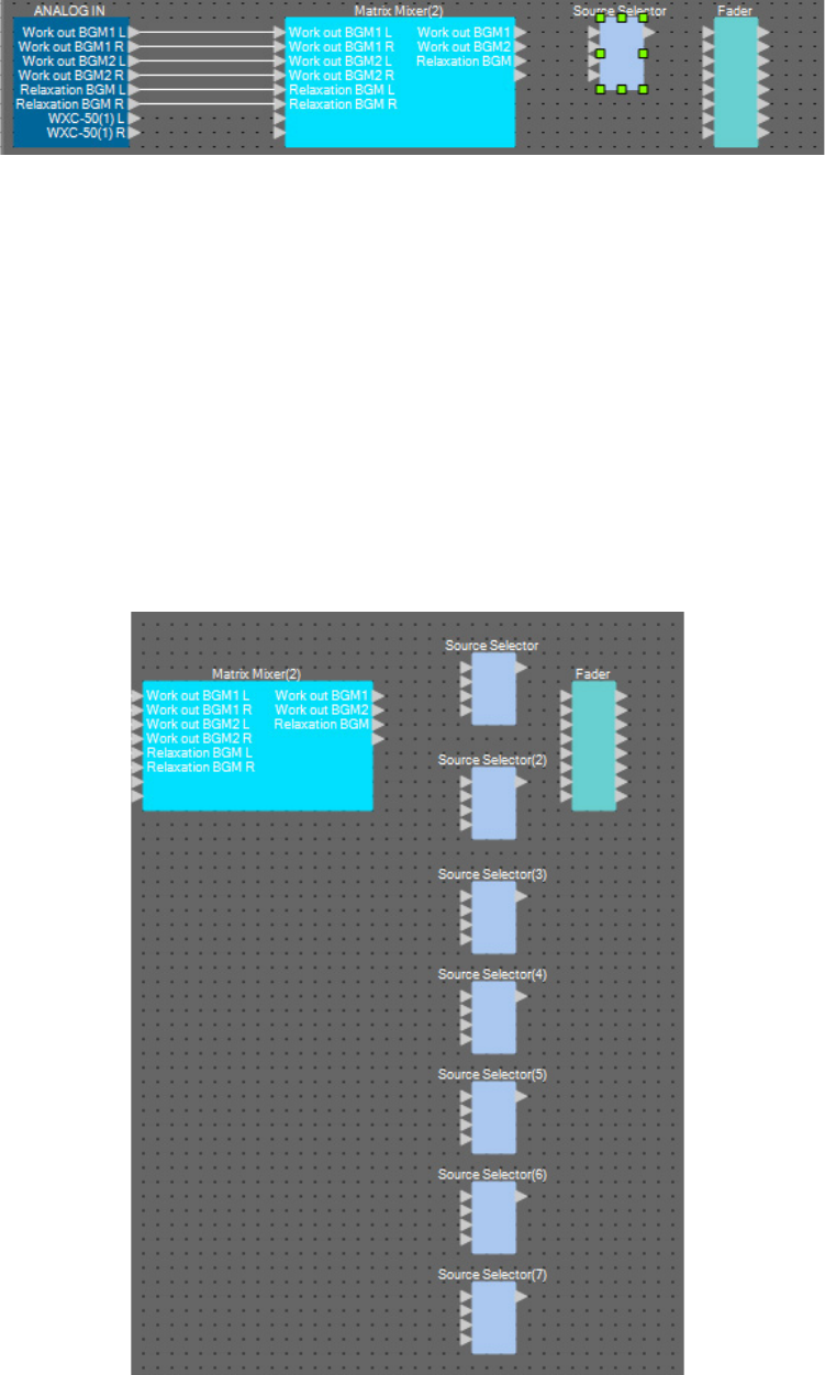
Example 3) A paging system using the PGM1
MRX Setup Manual 124
6. Click “Source Selector” to select it.
7. Copy the selected component, and paste it six times. Alternatively, drag and drop the
selected component while holding down <Ctrl>.
Change the location of the components as necessary.
You can copy in any of the following ways.
• <Ctrl> + <C>
• Right-click, and choose the context menu item [Copy]
• On the [Edit] menu, choose [Copy]
You can paste in any of the following ways.
• <Ctrl> + <V>
• Right-click, and choose the context menu item [Paste]
• On the [Edit] menu, choose [Paste]
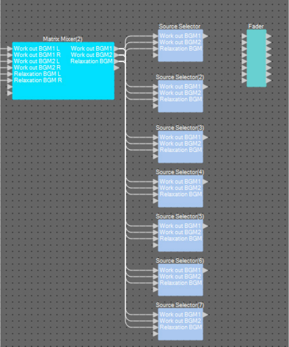
Example 3) A paging system using the PGM1
MRX Setup Manual 125
8. Drag and drop to connect “Matrix Mixer(2)” output ports 1 through 3 to “Source Selec-
tor” input ports 1 through 3.
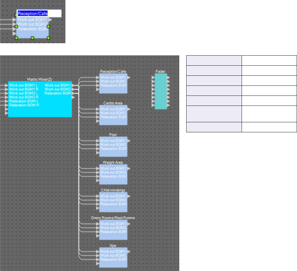
Example 3) A paging system using the PGM1
MRX Setup Manual 126
9. Assign a label to each “Source Selector” so that it can be easily distinguished.
Click the label area of each “Source Selector” component to edit it.
Source Selector Reception/Cafe
Source Selector(2) Cardio Area
Source Selector(3) Pool
Source Selector(4) Weight Area
Source Selector(5) Child-mindings
Source Selector(6) Dress Rooms/
Rest Rooms
Source Selector(7) Spa
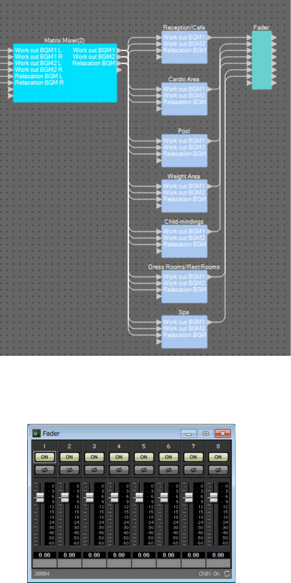
Example 3) A paging system using the PGM1
MRX Setup Manual 127
10. Drag and drop to connect output port 1 of each “Source Selector” to “Fader” input
ports 1 through 7.
11. Double-click “Fader.”
The “Fader” component editor opens.
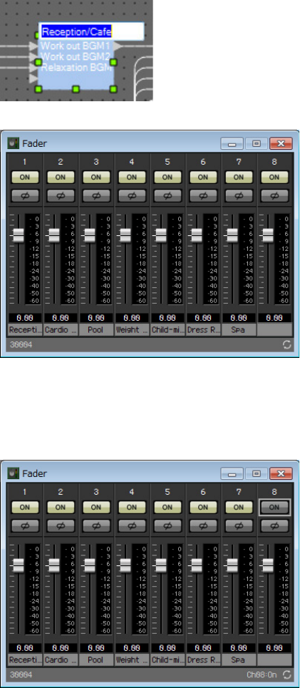
Example 3) A paging system using the PGM1
MRX Setup Manual 128
12. Assign a name to channels 1 through 7.
Clicking the label area of each “Source Selector” component makes it editable; copy this to make the process eas-
ier.
13. Turn off channel 8, and then click the [×] button in the upper right to close the compo-
nent editor.
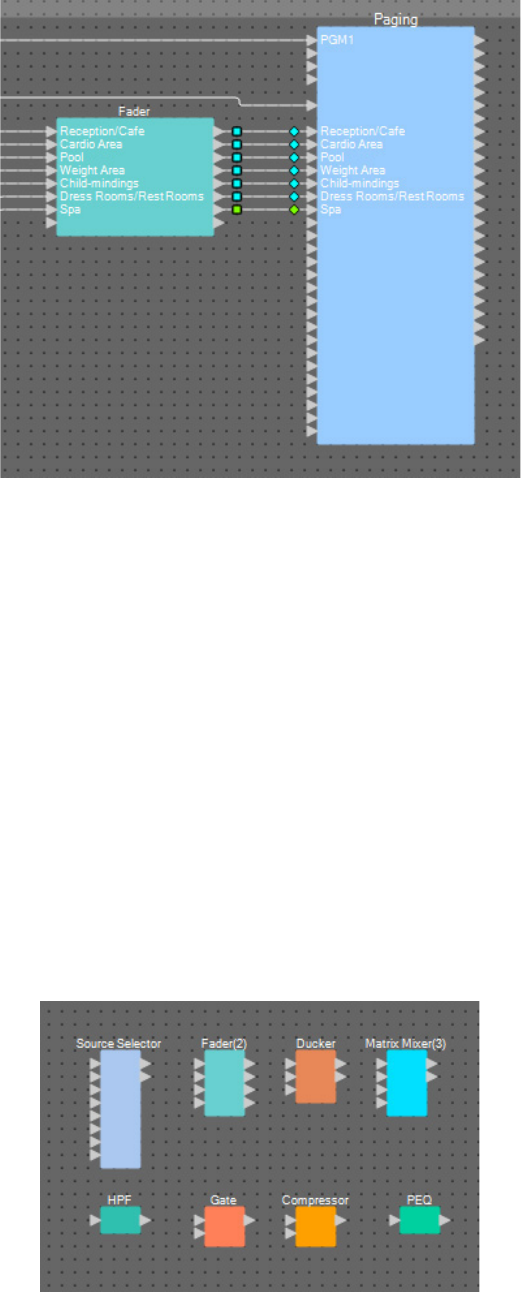
Example 3) A paging system using the PGM1
MRX Setup Manual 129
14. Drag and drop to connect “Fader” output ports 1 through 7 to “Paging” Program 1
through 7.
Placing and connecting the components related to BGM (stereo) and wireless
mic input
Here you’ll place and connect the components related to the background music (stereo) and wireless mic input that is
broadcast to Studio A/B and the Spin Area.
1. From the “Components” area, drag and drop the following components onto the design
sheet.
• “Source Selector” (4Source/2Ch)
• “Fader” (4Ch)
• “Ducker” (Stereo)
• “Matrix Mixer” (4In/2Out)
• “HPF” (Mono)
• “Gate” (Mono)
• “Compressor” (Mono)
• “PEQ” (Mono/3Band)
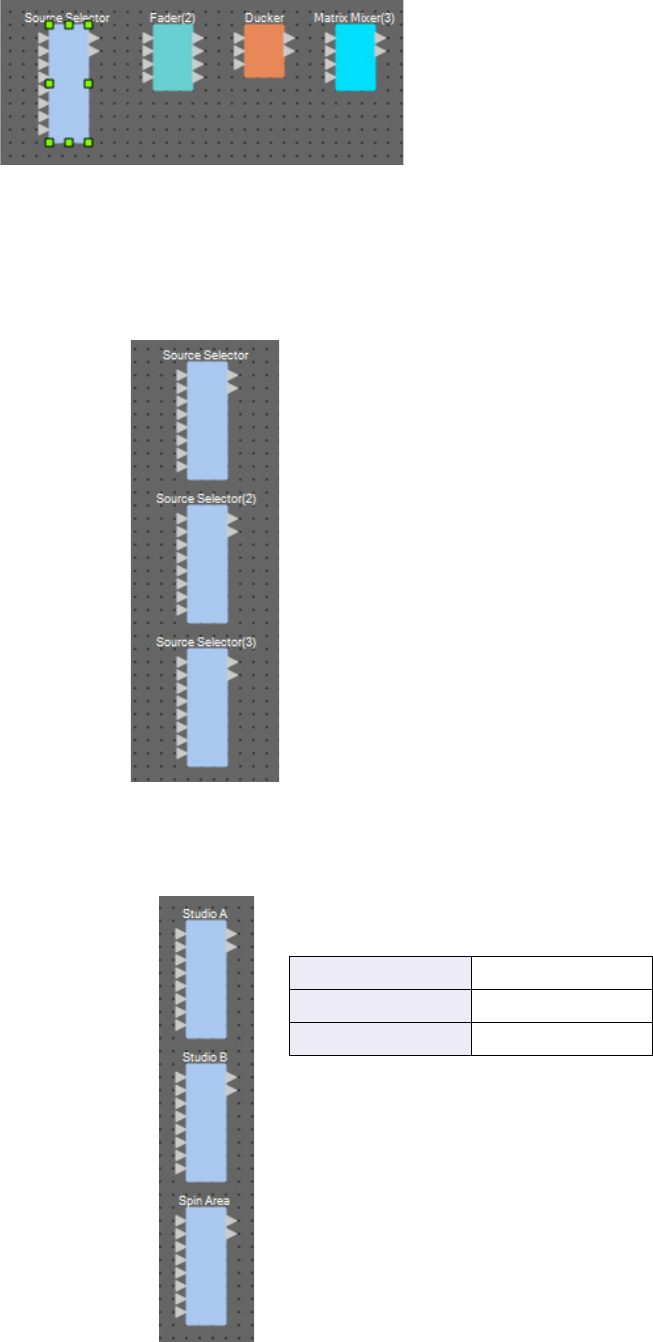
Example 3) A paging system using the PGM1
MRX Setup Manual 130
2. Click “Source Selector” to select it.
3. Copy the selected component, and paste it two times. Alternatively, drag and drop the
selected component while holding down <Ctrl>.
Change the location of the components as necessary.
4. Assign a label to each “Source Selector” so that it can be easily distinguished.
Source Selector Studio A
Source Selector(2) Studio B
Source Selector(3) Spin Area
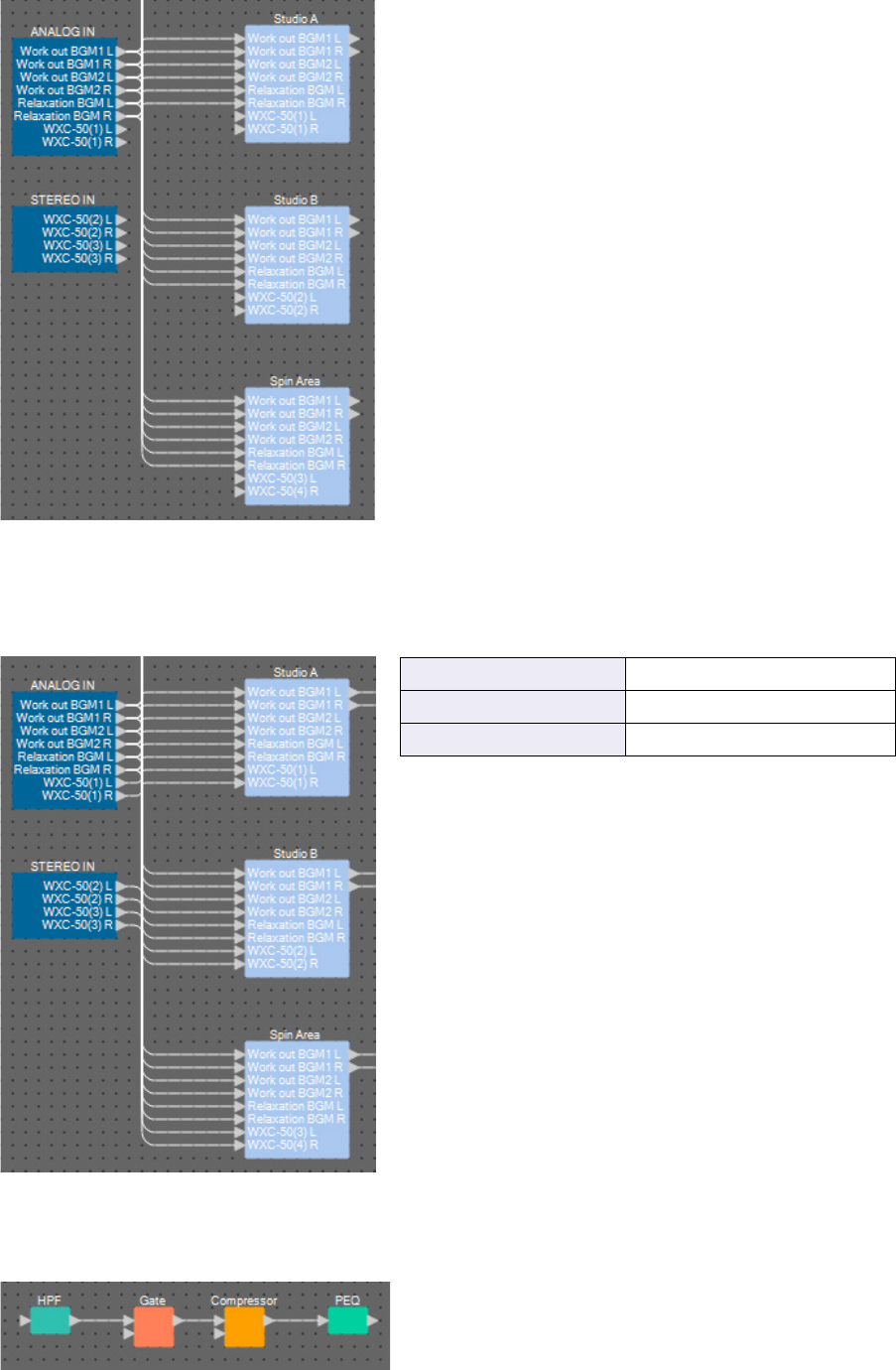
Example 3) A paging system using the PGM1
MRX Setup Manual 131
5. Drag and drop to connect “ANALOG IN” output ports 1 through 6 to each “Source
Selector” Src1-1 through Src3-2.
6. Drag and drop to connect the WXC-50’s outputs to each “Source Selector” Src4-1 and
Src4-2.
7. Drag and drop to connect between the ports from “HPF” to “PEQ.”
ANALOG IN 7 and 8Studio A Src4-1 and Src4-2
STEREO IN 1L and 1R Studio B Src4-1 and Src4-2
STEREO IN 2L and 2R Spin Area Src4-1 and Src4-2
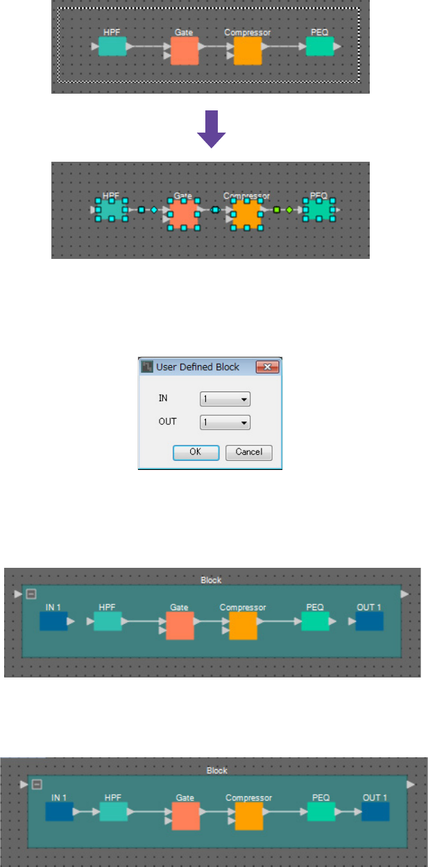
Example 3) A paging system using the PGM1
MRX Setup Manual 132
8. Select the area from “HPF” through “PEQ,” so that the components and wires are
selected.
9. On the [Edit] menu, choose [Create User Defined Block]; in the dialog box, set IN as 1,
set OUT as 1, and click the [OK] button.
10. As necessary, change the position, size, and arrangement of the components in the
User Defined Block.
11. Drag and drop to connect the ports “IN 1” to “HPF” and “PEQ” to “OUT 1.”
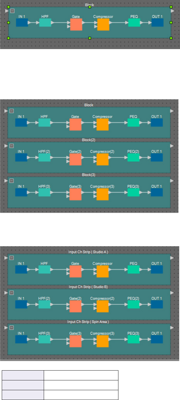
Example 3) A paging system using the PGM1
MRX Setup Manual 133
12. Click somewhere other than a component or wire in the User Defined Block, so that the
User Defined Block is selected.
13. Copy the selected User Defined Block, and paste it two times. Alternatively, drag and
drop the selected User Defined Block while holding down <Ctrl>.
Change the location of the User Defined Block as necessary.
14. Name the label of each User Defined Block so that it can be easily distinguished.
Block Input Ch Strip (Studio A)
Block(2) Input Ch Strip (Studio B)
Block(3) Input Ch Strip (Spin Area)
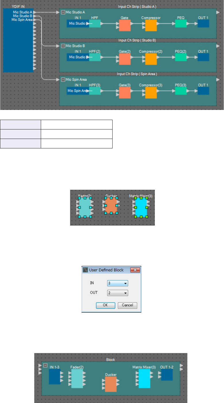
Example 3) A paging system using the PGM1
MRX Setup Manual 134
15. Drag and drop to connect “YDIF IN” output ports 1 through 3 to the input port of each
User Defined Block.
16. Select the area from “Fader(2)” through “Matrix Mixer(3),” so that the components are
selected.
17. On the [Edit] menu, choose [Create User Defined Block]; in the dialog box, set IN as 3,
set OUT as 2, and click the [OK] button.
18. As necessary, change the position, size, and arrangement of the components in the
User Defined Block.
YDIF IN 1 Input Ch Strip (Studio A)
YDIF IN 2 Input Ch Strip (Studio B)
YDIF IN 3 Input Ch Strip (Spin Area)
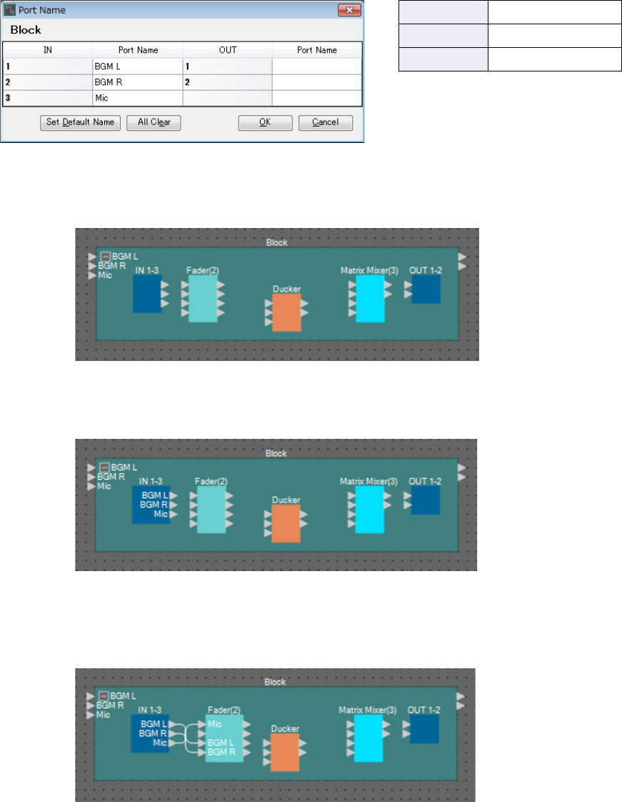
Example 3) A paging system using the PGM1
MRX Setup Manual 135
19. Assign a name to the input ports of the User Defined Block.
Enter the port names in the “Port Name” dialog box. To access the “Port Name” dialog box, click the port, and
then click the button located at the right of the [Label] editing area in the “Properties” area.
The output port names are automatically entered during a subsequent step.
20. After you’ve entered the port names, click the [OK] button.
21. Also enter a port name for the User Defined Block’s “IN.”
22. Drag and drop to connect “IN” output ports 1 and 2 to “Fader(2)” input ports 3 and 4;
connect “IN” output port 3 to “Fader(2)” input port 1.
IN 1 BGM L
IN 2 BGM R
IN 3 Mic
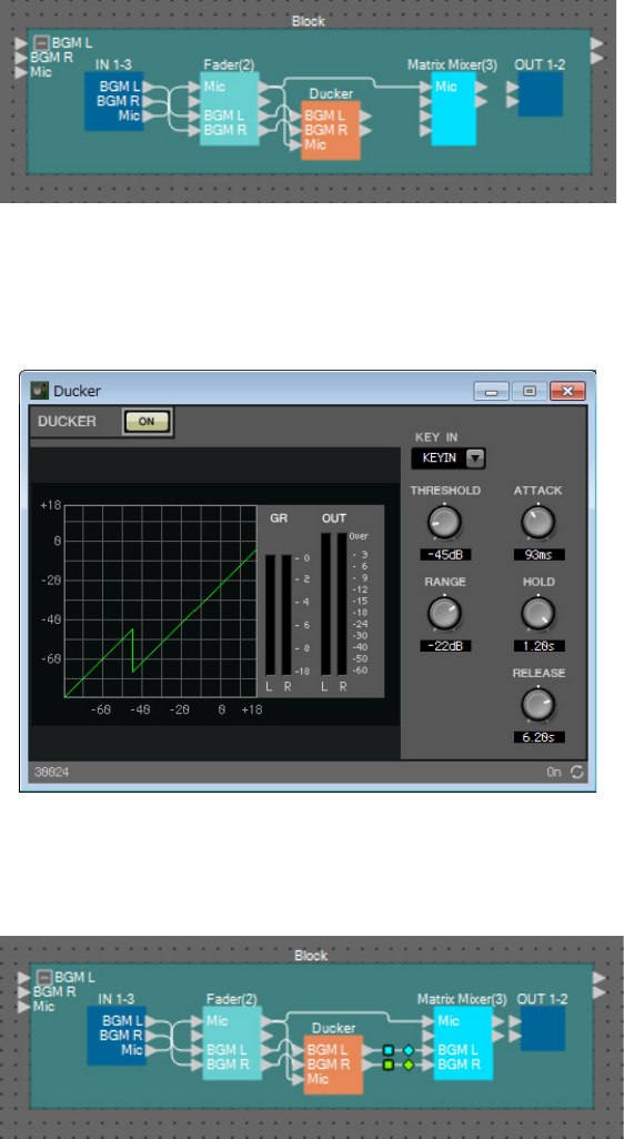
Example 3) A paging system using the PGM1
MRX Setup Manual 136
23. Drag and drop to connect “Fader(2)” output port 1 to “Ducker” KeyIN and “Matrix
Mixer(3)” input port 1; connect “Fader(2)” output ports 3 and 4 to input “Ducker” ports
1 and 2.
24. Double-click “Ducker”; verify that KEY IN is set to KEYIN, and then close the compo-
nent editor.
25. Drag and drop to connect “Ducker” 1L and 1R to “Matrix Mixer(3)” input ports 3 and 4.
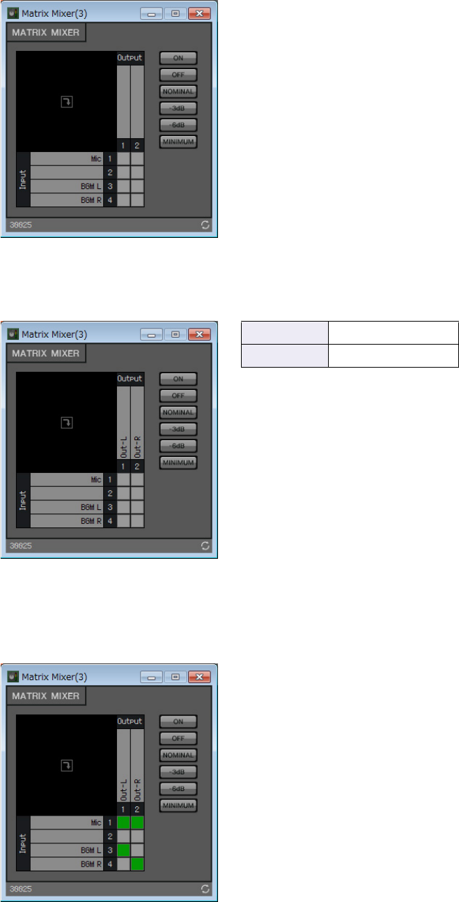
Example 3) A paging system using the PGM1
MRX Setup Manual 137
26. Double-click “Matrix Mixer(3).”
The “Matrix Mixer” component editor appears.
27. Enter port names for Output.
28. Enable Mic for Out-L and Out-R, enable BGM L for Out-L and BGM R for Out-R; then
click the [×] button in the upper right to close the component editor.
Output 1 Out-L
Output 2 Out-R
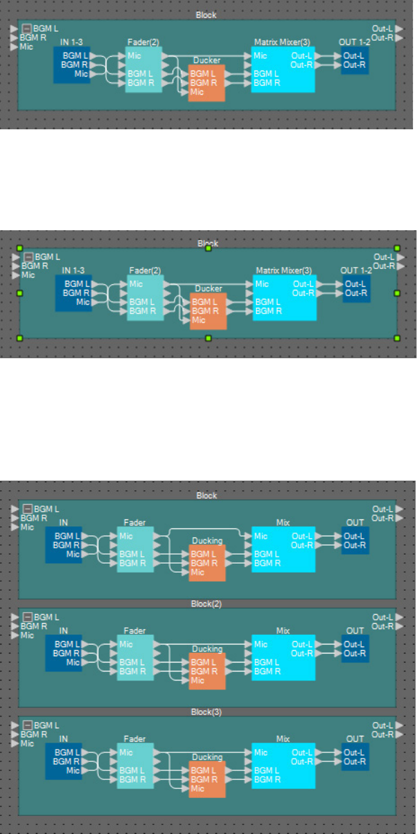
Example 3) A paging system using the PGM1
MRX Setup Manual 138
29. Drag and drop to connect the “Matrix Mixer(3)” output ports to the “OUT” input ports.
30. Click somewhere other than a component or wire in the User Defined Block, so that the
User Defined Block is selected.
31. Copy the selected User Defined Block, and paste it two times. Alternatively, drag and
drop the selected User Defined Block while holding down <Ctrl>.
Change the location of the User Defined Block as necessary.
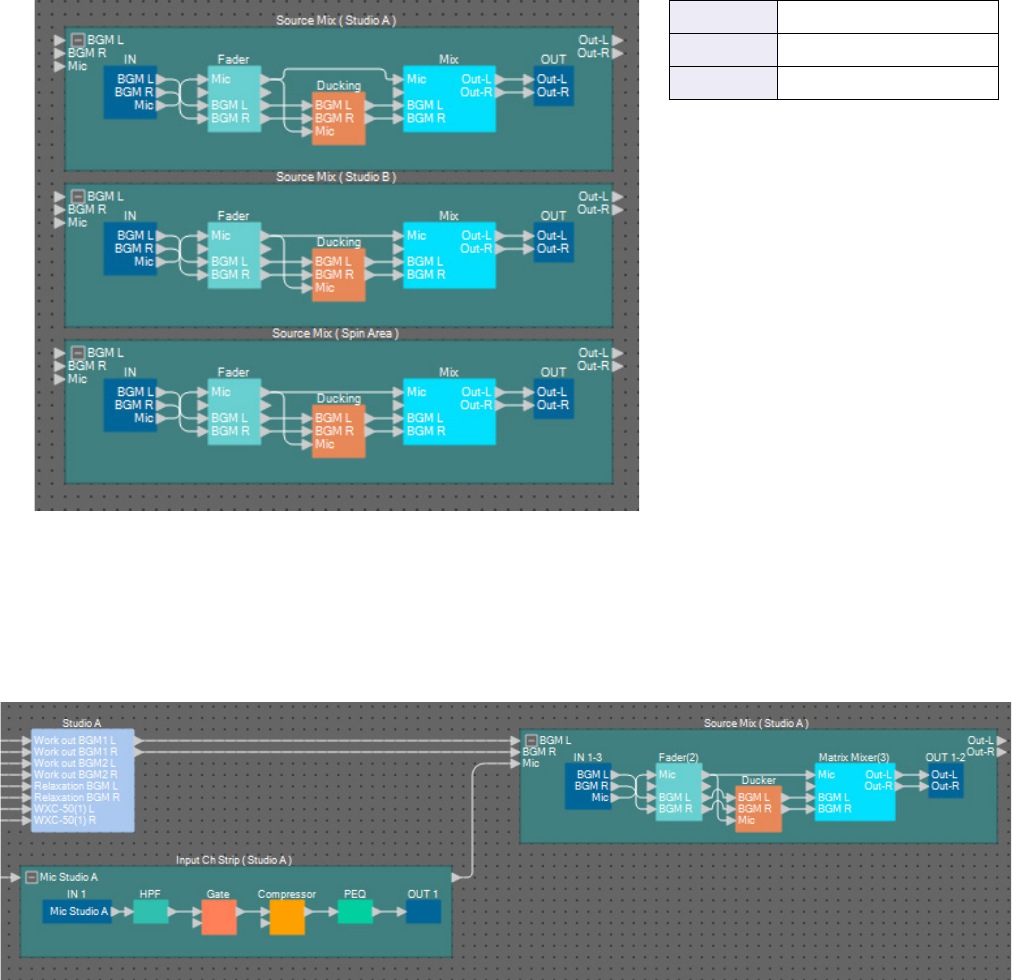
Example 3) A paging system using the PGM1
MRX Setup Manual 139
32. Name the label of each User Defined Block so that it can be easily distinguished.
33. Drag and drop to connect “Studio A” (Source Selector) output ports 1 and 2 to “Source
Mix Studio A” (User Defined Block) input ports 1 and 2; connect the “Input Ch Strip
(Studio A)” (User Defined Block) output port to “Source Mix Studio A” (User Defined
Block) input port 3.
Block Source Mix (Studio A)
Block(2) Source Mix (Studio B)
Block(3) Source Mix (Spin Area)
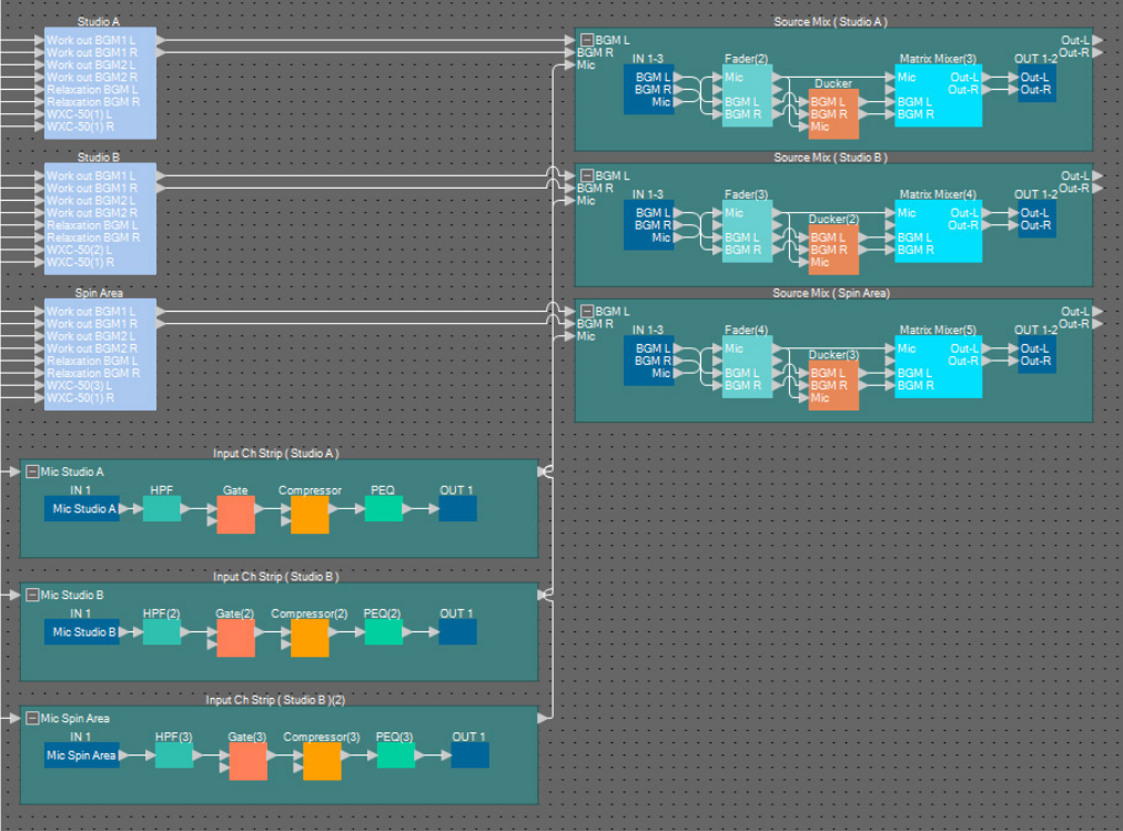
Example 3) A paging system using the PGM1
MRX Setup Manual 140
34. Connect Studio B and Spin Area in the same way.
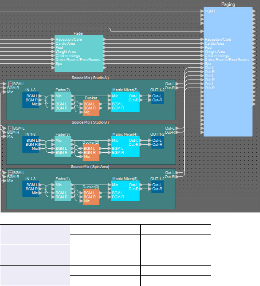
Example 3) A paging system using the PGM1
MRX Setup Manual 141
35. Drag and drop to connect each Source Mix output jack to “Paging” Program 8 through
13.
Source Mix (Studio A)
Out-L Program 8
Out-R Program 9
Source Mix (Studio B)
Out-L Program 10
Out-R Program 11
Source Mix (Spin Area)
Out-L Program 12
Out-R Program 13
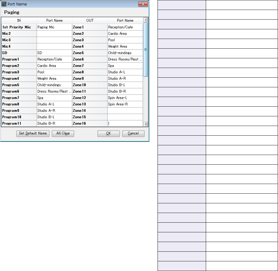
Example 3) A paging system using the PGM1
MRX Setup Manual 142
Making settings for Paging
Here you’ll make settings for the “Paging” component.
1. Assign the “Paging” input/output port names.
Enter the port names in the “Port Name” dialog box. To access the “Port Name” dialog box, click the port, and
then click the button located at the right of the [Label] editing area in the “Properties” area.
After you’ve entered the input port names, you can proceed efficiently by clicking the listed port name, and then
copying and pasting it to the output port name field.
1sr Priority Mic Paging Mic
SD SD
Program1 Reception/Cafe
Program2 Cardio Area
Program3 Pool
Program4 Weight Area
Program5 Child-mindings
Program6 Dress Rooms/Rest Rooms
Program7 Spa
Program8Studio A-L
Program9 Studio A-R
Program10 Studio B-L
Program11 Studio B-R
Program12 Spin Area-L
Program13 Spin Area-R
Zone1 Reception/Cafe
Zone2 Cardio Area
Zone3 Pool
Zone4 Weight Area
Zone5 Child-mindings
Zone6 Dress Rooms/Rest Rooms
Zone7 Spa
Zone8Studio A-L
Zone9 Studio A-R
Zone10 Studio B-L
Zone11 Studio B-R
Zone12 Spin Area-L
Zone13 Spin Area-R
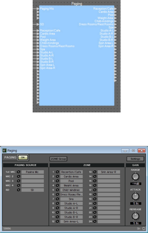
Example 3) A paging system using the PGM1
MRX Setup Manual 143
2. After you’ve entered the port names, click the [OK] button.
3. Double-click “Paging.”
The “Paging” component editor opens.
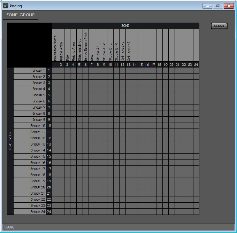
Example 3) A paging system using the PGM1
MRX Setup Manual 144
4. To create a zone group, click the [ZONE Group] button.
The “Zone Group” window appears.
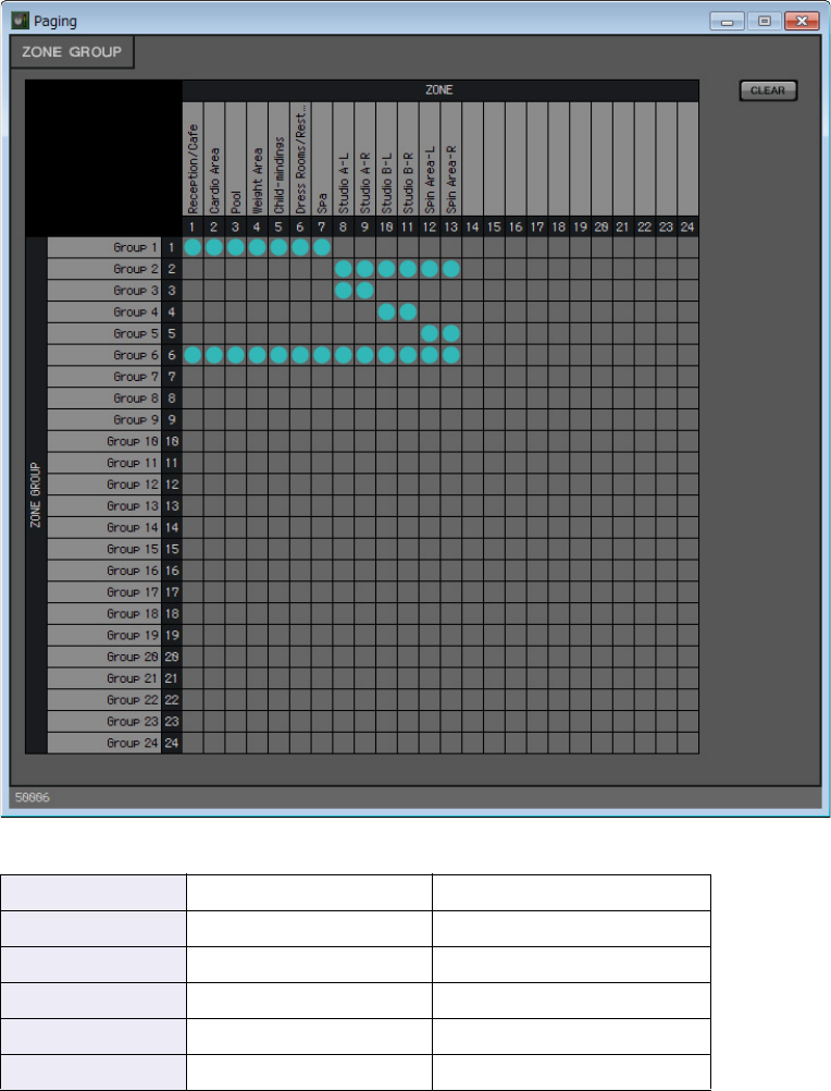
Example 3) A paging system using the PGM1
MRX Setup Manual 145
5. Click within the zone group matrix to create zone groups.
In this example, create zone groups as follows.
Group 1 ZONE 1 through 7 All monaural broadcast areas
Group 2 ZONE 8 through 13 All stereo broadcast areas
Group 3 ZONE 8 and 9 STUDIO A
Group 4 ZONE 10 and 11 STUDIO B
Group 5 ZONE 12 and 13 Spin Area
Group 6 ZONE 1 through 13 Broadcast to entire facility
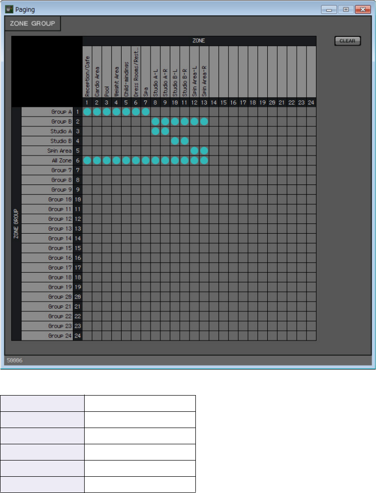
Example 3) A paging system using the PGM1
MRX Setup Manual 146
6. Enter the zone group names.
Double-click the name of each ZONE GROUP and edit it.
Group 1 Group A
Group 2 Group B
Group 3 Studio A
Group 4 Studio B
Group 5 Spin Area
Group 6 All Zone
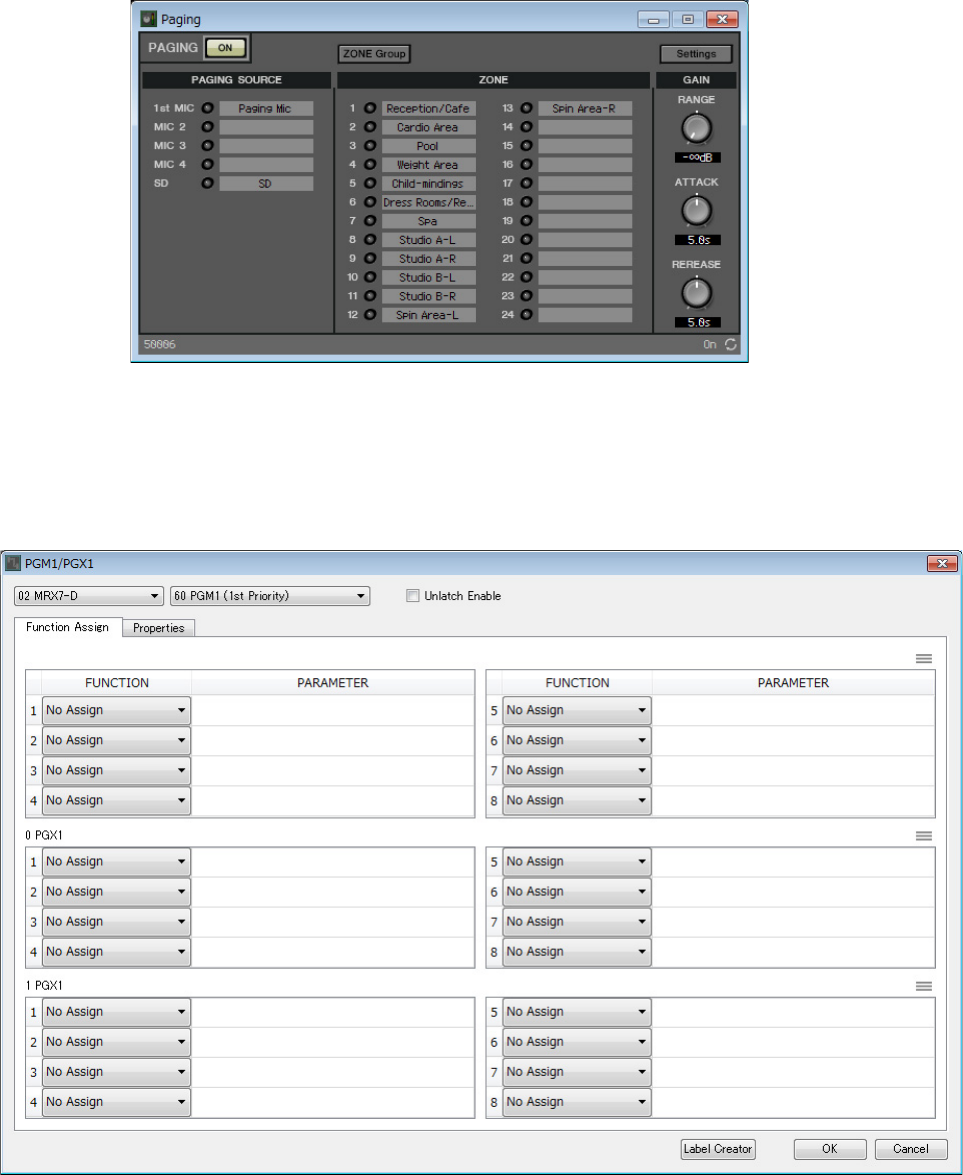
Example 3) A paging system using the PGM1
MRX Setup Manual 147
7. Click the [×] button in the upper right to close the window.
8. To make assignments for the zone/message select buttons of the PGM1/PGX1, click the
[Settings] button.
The “PGM1/PGX1” dialog box appears.
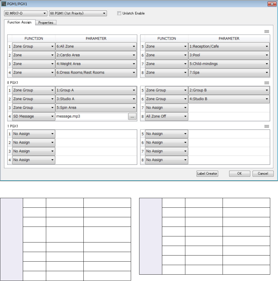
Example 3) A paging system using the PGM1
MRX Setup Manual 148
9. Make assignments to zone/message select buttons.
In this example, make the following assignments.
PGM1
1 Zone Group All Zone
2 Zone Cardio Area
3 Zone Weight Area
4Zone Dress Rooms/
Rest Rooms
5 Zone Reception/Cafe
6 Zone Pool
7 Zone Child-mindings
8Zone Spa
PGX1
1 Zone Group Group A
2 Zone Group Studio A
3 Zone Group Spin Area
4 SD Message any desired file
5 Zone Group Group B
6 Zone Group Studio B
7 No Assign
8 All Zone Off
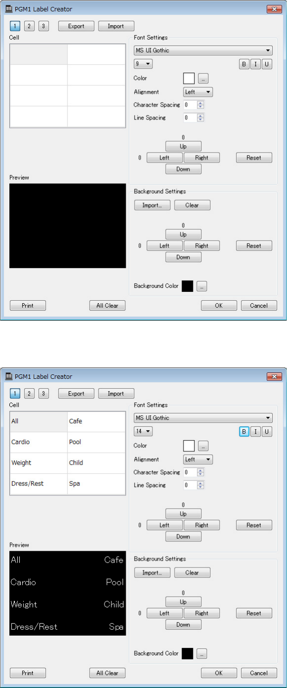
Example 3) A paging system using the PGM1
MRX Setup Manual 149
10. If necessary, click the [Label Creator] button to create labels for the PGM1/PGX1.
“PGM Label Creator” starts.
11. Design the label that you want to print.
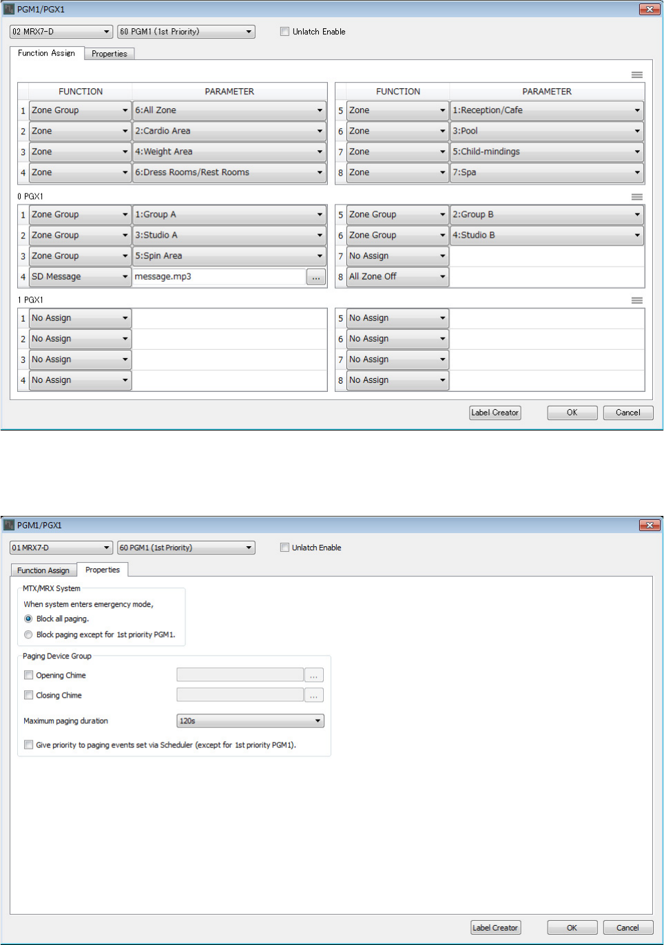
Example 3) A paging system using the PGM1
MRX Setup Manual 150
12. Click the [Print] button to print, or click the [Export] button to save as a file; then click
the [OK] button.
13. Click the [Properties] tab.
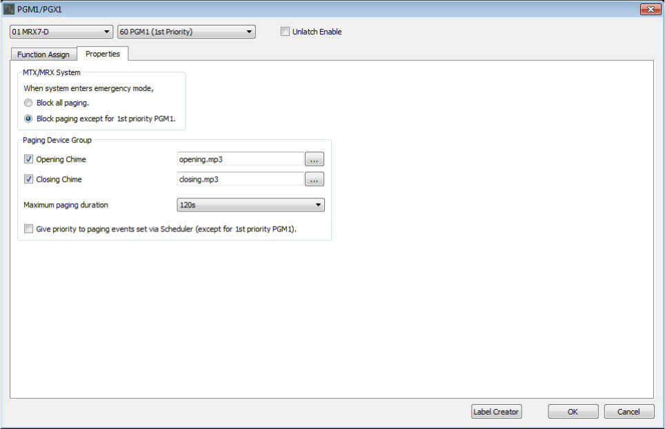
Example 3) A paging system using the PGM1
MRX Setup Manual 151
14. Make common settings for the PGM1 units in the MTX/MRX system or the Paging
Device Group.
Here you’ll specify that paging broadcast is possible only for the 1st Priority Mic when in emergency mode, and
that a chime will sound before and after the broadcast.
With these settings, pressing the PTT button of the 1st Priority Mic when in emergency mode will not sound a
chime, and ATTACK and RELEASE will be 0 seconds.
15. Click the [OK] button to close the dialog box.

Example 3) A paging system using the PGM1
MRX Setup Manual 152
Placing and connecting the components related to BGM (monaural) output
Here you’ll place and connect the components related to the output of the background music (monaural) that is broad-
cast to the facility.
This is output to the XMV units connected via DANTE.
1. From the “Components” area, drag and drop the following components onto the design
sheet.
• “PEQ” (8Band/Mono)
• “Fader” (1Ch)
• “Speaker Processor” (1Way)
• “DANTE OUT 1-16”
2. Drag and drop to connect between the ports from “PEQ(4)” to “Speaker Processor.”
3. Select the area from “PEQ(4)” through “Speaker Processor,” so that the components
and wires are selected.
4. On the [Edit] menu, choose [Create User Defined Block]; in the dialog box, set IN as 1,
set OUT as 1, and click the [OK] button.
5. As necessary, change the position, size, and arrangement of the components in the
User Defined Block.
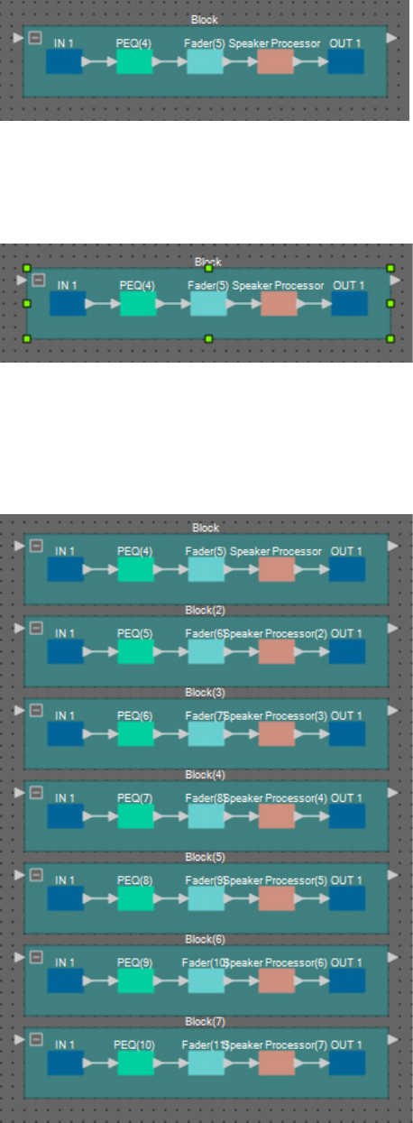
Example 3) A paging system using the PGM1
MRX Setup Manual 153
6. Drag and drop to connect the ports “IN 1” to “PEQ(4),” and “Speaker Processor” to
“OUT 1.”
7. Click somewhere other than a component or wire in the User Defined Block, so that the
User Defined Block is selected.
8. Copy the selected User Defined Block, and paste it six times. Alternatively, drag and
drop the selected User Defined Block while holding down <Ctrl>.
Change the location of the User Defined Block as necessary.
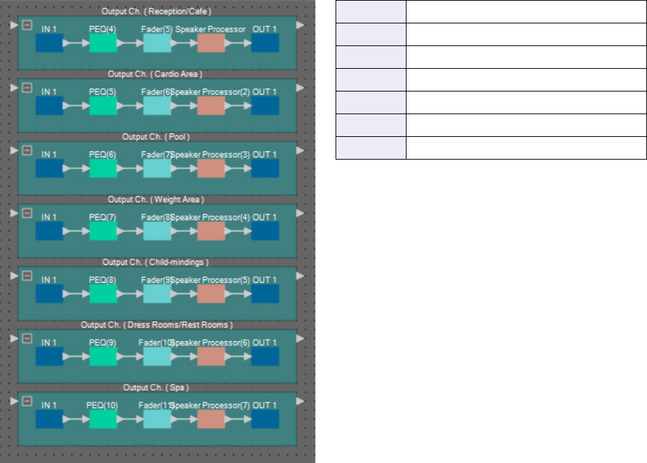
Example 3) A paging system using the PGM1
MRX Setup Manual 154
9. Name the label of each User Defined Block so that it can be easily distinguished.
Block Output Ch. (Reception/Cafe)
Block(2) Output Ch. (Cardio Area)
Block(3) Output Ch. (Pool)
Block(4) Output Ch. (Weight Area)
Block(5) Output Ch. (Child-mindings)
Block(6) Output Ch. (Dress Rooms/Rest Rooms)
Block(7) Output Ch. (Spa)
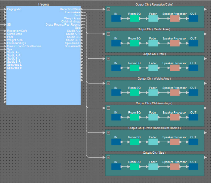
Example 3) A paging system using the PGM1
MRX Setup Manual 155
10. Drag and drop to connect “Paging” Zone 1 through 7 to the input ports of each User
Defined Block.
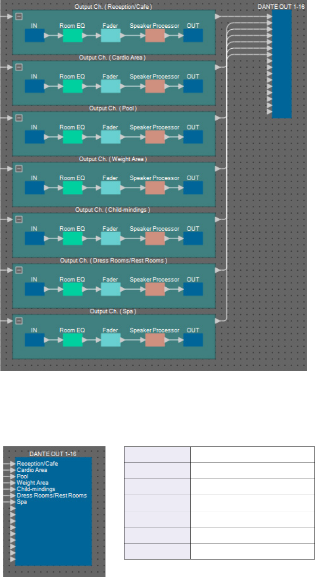
Example 3) A paging system using the PGM1
MRX Setup Manual 156
11. Drag and drop to connect the output port of each User Defined Block to “DANTE OUT
1–16” input ports 1 through 7.
12. Name each label of the “DANTE OUT 1–16” input ports so that they can be easily distin-
guished.
1Reception/Cafe
2Cardio Area
3Pool
4Weight Area
5Child-mindings
6Dress Rooms/Rest Rooms
7Spa
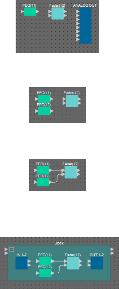
Example 3) A paging system using the PGM1
MRX Setup Manual 157
Placing and connecting the components related to BGM (stereo) output
Here you’ll place and connect the components related to the output of the background music (monaural) that is broad-
cast to the facility.
This is output to the analog output of the MRX7-D.
1. From the “Components” area, drag and drop the following components onto the design
sheet.
• “PEQ” (8Band/Mono)
• “Fader” (2Ch)
• “ANALOG OUT”
2. Copy and paste “PEQ(11)” once.
3. Drag and drop to connect the output port of each “PEQ” to the “Fader(12)” input ports.
4. Specify “PEQ” and “Fader” as a 2IN/2OUT User Defined Block.
As necessary, change the position, size, and arrangement of the components in the User Defined Block.
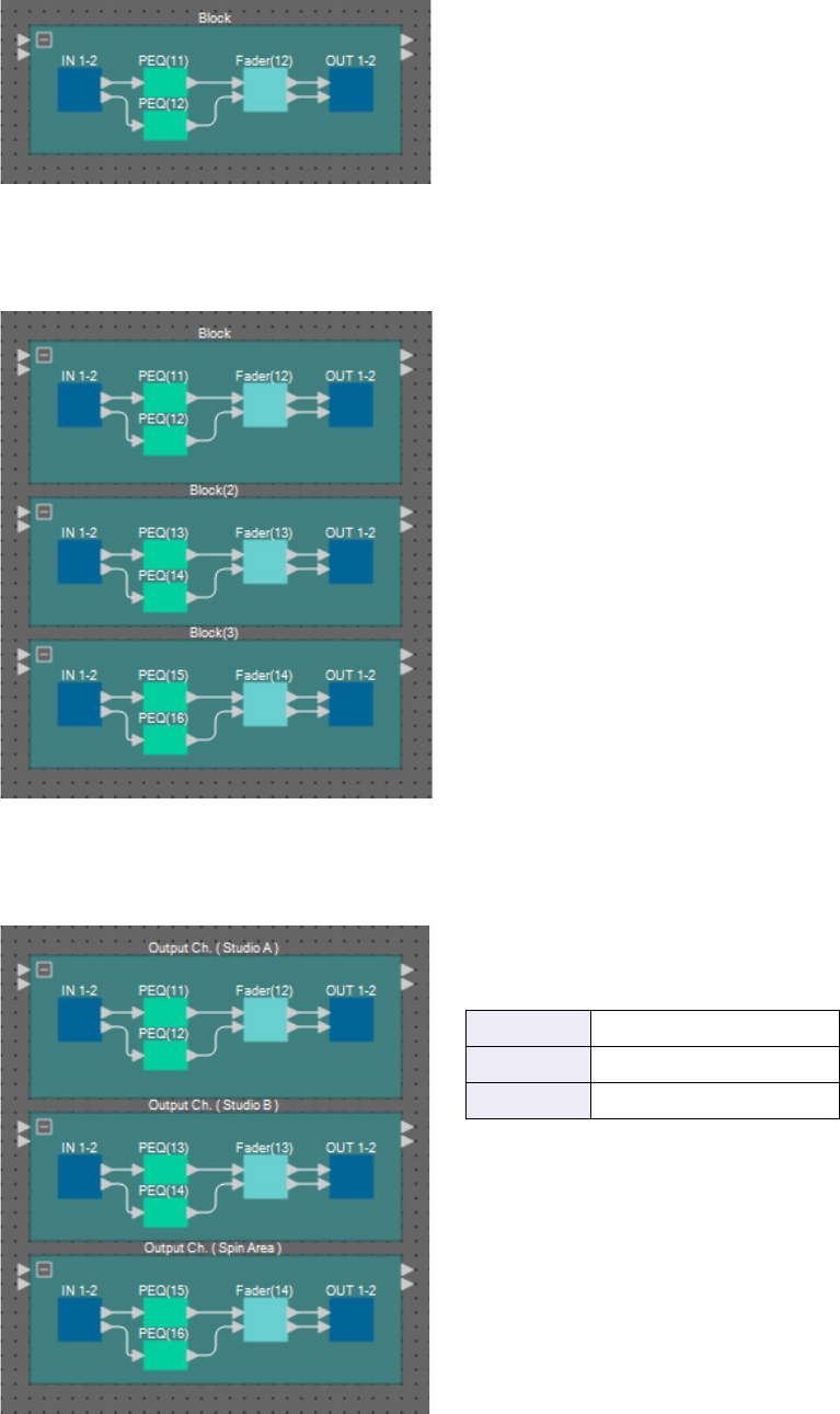
Example 3) A paging system using the PGM1
MRX Setup Manual 158
5. Drag and drop to connect the ports “IN 1–2” to each “PEQ,” and “Fader(12)” to “OUT
1–2.”
6. Copy the User Defined Block, and paste it two times.
7. Name the label of each User Defined Block so that it can be easily distinguished.
Block Output Ch. (Studio A)
Block(2) Output Ch. (Studio B)
Block(3) Output Ch. (Spin Area)
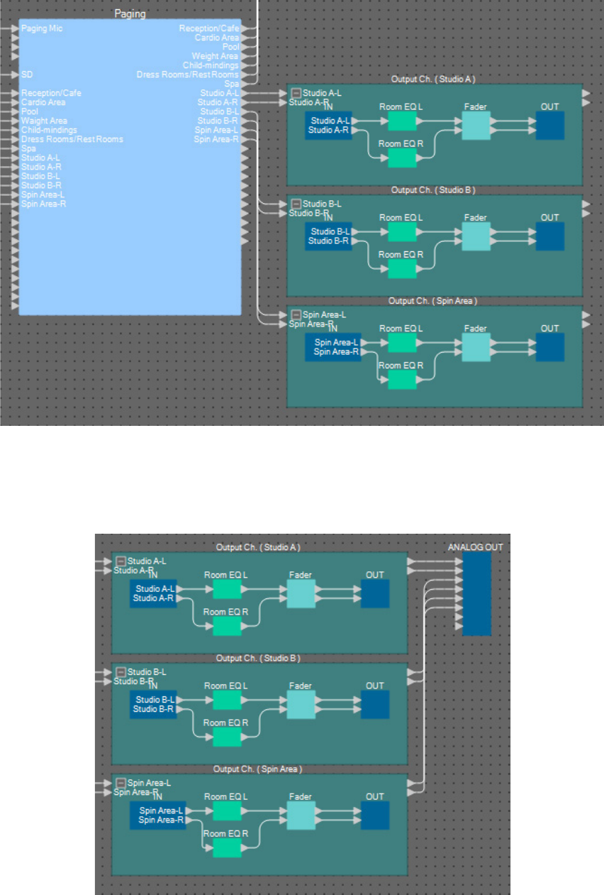
Example 3) A paging system using the PGM1
MRX Setup Manual 159
8. Drag and drop to connect “Paging” Zone 8 through 13 to the input ports of each User
Defined Block.
9. Drag and drop to connect the output port of each User Defined Block to “ANALOG
OUT” input ports 1 through 6.
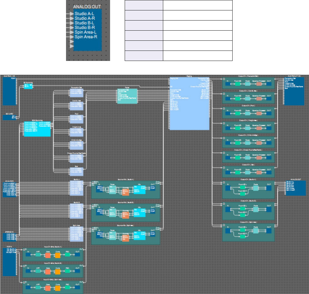
Example 3) A paging system using the PGM1
MRX Setup Manual 160
10. Name each label of the “ANALOG OUT” input ports so that they can be easily distin-
guished.
This completes placement and connections for the components. As necessary, move the position of the compo-
nents, or change the connections of the wires.
1Studio A-L
2Studio A-R
3Studio B-L
4Studio B-R
5Spin Area-L
6Spin Area-R
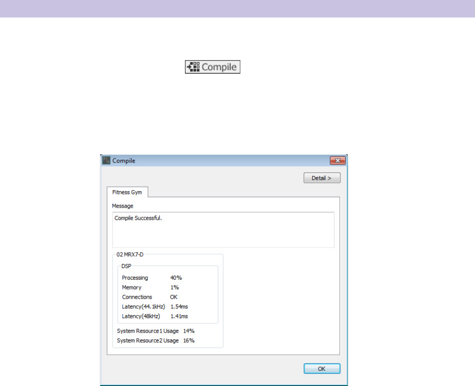
Example 3) A paging system using the PGM1
MRX Setup Manual 161
This performs an analysis to determine whether there are any problems with the placement and wiring of the components in
the MRX.
1. Click the [Compile] tool button ( ).
Analysis begins.
2. Note the results of analysis.
If the message “Completed successfully” is displayed in the “Message” field, there were no problems.
If there is a problem, click the [Detail] button and proceed as directed.
This completes the compiling process.
Compiling
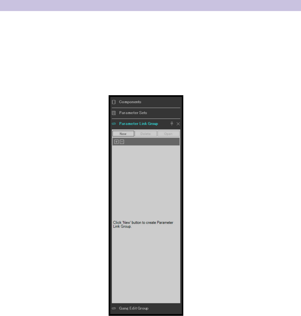
Example 3) A paging system using the PGM1
MRX Setup Manual 162
In this example, we’ll do various things to make the best use of the MCP1’s switches, such as combining two faders of a
stereo output into a single fader, and combining the L/R ON buttons into a single button.
We’ll create parameter link groups that combine multiple level-type or on/off-type parameters, so that a switch of the
MCP1 can control multiple parameters simultaneously.
As for a snapshot, you can register parameters by holding down <Ctrl> while you drag and drop, but since there are a total
of 24 parameters to be registered for this example, we’ll use a different method to register them.
1. In the left side of MRX Designer, open the “Parameter Link Group” area.
This is opened in order to check the parameters that have been registered.
Setting a parameter link group
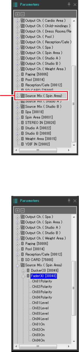
Example 3) A paging system using the PGM1
MRX Setup Manual 163
2. In the right side of MRX Designer, open the “Parameters” area.
3. Since the level of the background music in the Spin Area is adjusted by Source Mix (Spin
Area) “Fader(4),” open “Parameters” area [Source Mix (Spin Area)] → [Fader(4)].
Step 3
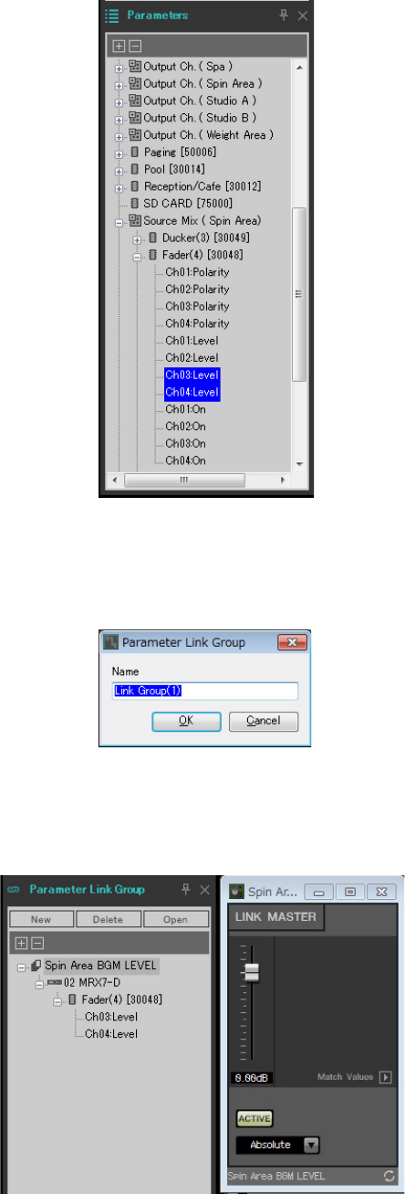
Example 3) A paging system using the PGM1
MRX Setup Manual 164
4. Click [Ch03:Level]; then hold down <Ctrl> and click [Ch04:Level].
By clicking while you hold down <Ctrl>, you can select multiple items.
To select multiple adjacent parameters, click the first parameter, then hold down <Shift> and click the last parameter.
5. Right-click, and choose [Add to Parameter Link Group] → [Add New Group].
A dialog box opens, allowing you to specify a parameter link group name.
6. Enter [Spin Area BGM LEVEL], and click the [OK] button.
In the “Parameter Link Group” area, a [Spin Area BGM LEVEL] group is created, and the Link Master editor opens.

Example 3) A paging system using the PGM1
MRX Setup Manual 165
7. In the Link Master editor’s combo box, choose [Absolute].
8. In Source Mix (Spin Area), double-click “Fader(4).”
The “Fader(4)” component editor opens.
9. Operate the fader in the Link Master editor, and verify that the faders of channels 3 and 4 in
the “Fader(4)” component editor are linked.
10. Click the [×] buttons located in the upper right of the Link Master editor and the “Fader(4)”
component editor to close the editor and the component editor.
Repeat steps 2 through 10 to create the following parameter link groups.
This completes parameter link group settings.
Parameter link group name Component Parameter Setting of the Link Master
editor’s combo box
Spin Area BGM ON [Source Mix (Spin Area)] → [Fader(4)]
Ch03:On
Equal
Ch04:On
Spin Area Master LEVEL [Output Ch. (Spin Area)] → [Fader(14)]
Ch01:Level
Absolute
Ch02:Level
Spin Area Master ON [Output Ch. (Spin Area)] → [Fader(14)]
Ch01:On
Equal
Ch02:On
Studio A BGM LEVEL [Source Mix (Studio A)] → [Fader(2)]
Ch03:Level
Absolute
Ch04:Level
Studio A BGM ON [Source Mix (Studio A)] → [Fader(2)]
Ch03:On
Equal
Ch04:On
Studio A Master LEVEL [Output Ch. (Studio A)] → [Fader(12)]
Ch01:Level
Absolute
Ch02:Level
Studio A Master ON [Output Ch. (Studio A)] → [Fader(12)]
Ch01:On
Equal
Ch02:On
Studio B BGM LEVEL [Source Mix (Studio B)] → [Fader(3)]
Ch03:Level
Absolute
Ch04:Level
Studio B BGM ON [Source Mix (Studio B)] → [Fader(3)]
Ch03:On
Equal
Ch04:On
Studio B Master LEVEL [Output Ch. (Studio B] → [Fader(13)]
Ch01:Level
Absolute
Ch02:Level
Studio B Master ON [Output Ch. (Studio B)] → [Fader(13)]
Ch01:On
Equal
Ch02:On
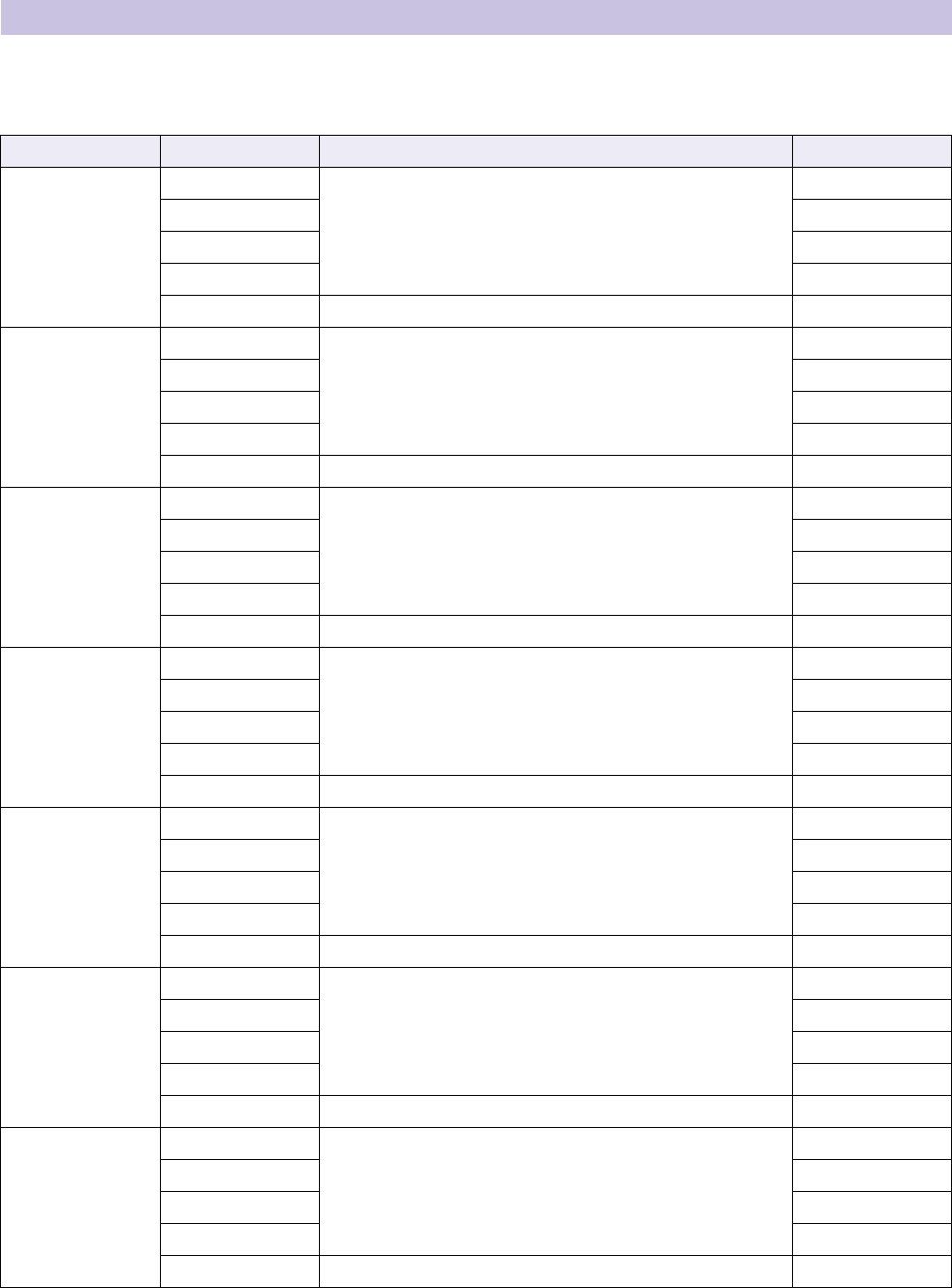
Example 3) A paging system using the PGM1
MRX Setup Manual 166
Here you’ll assign parameters to the DCP1V4S control panels that are located in each area, so that the parameters can be
controlled by the switches and knobs of the control panels.
We’ll assign the following parameters to the switches and knobs. The assignment procedure is described later.
Switch 4 of each control panel is used when background music is not desired.
Here we explain how to assign parameters to the Reception/Cafe DCP1V4S’s switch 1 (source select) and knob (parame-
ter). Although in this example we explain the method of holding down <Ctrl> and dragging parameters from the compo-
nent editor, you can also hold down <Ctrl> and drag and drop from the “Parameters” area.
Making DCP settings
Area Switch/Knob Component that includes the parameter to be assigned Parameter
Reception/Cafe
Switch 1
Reception/Cafe’s Source Selector
1
Switch 2 2
Switch 3 3
Switch 4 4
Knob Fader Channel 1 level
Cardio Area
Switch 1
Cardio Area’s Source Selector
1
Switch 2 2
Switch 3 3
Switch 4 4
Knob Fader Channel 2 level
Pool
Switch 1
Pool’s Source Selector
1
Switch 2 2
Switch 3 3
Switch 4 4
Knob Fader Channel 3 level
Weight Area
Switch 1
Weight Area’s Source Selector
1
Switch 2 2
Switch 3 3
Switch 4 4
Knob Fader Channel 4 level
Child-mindings
Switch 1
Child-mindings’ Source Selector
1
Switch 2 2
Switch 3 3
Switch 4 4
Knob Fader Channel 5 level
Dress Rooms/
Rest Rooms
Switch 1
Dress Rooms/Rest Rooms’ Source Selector
1
Switch 2 2
Switch 3 3
Switch 4 4
Knob Fader Channel 6 level
Spa
Switch 1
Spa’s Source Selector
1
Switch 2 2
Switch 3 3
Switch 4 4
Knob Fader Channel 7 level
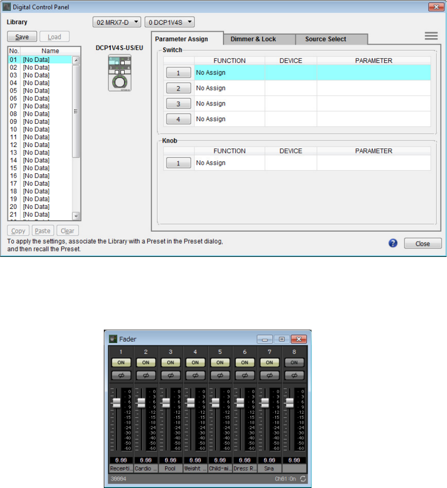
Example 3) A paging system using the PGM1
MRX Setup Manual 167
1. Select [Controller] menu → [Digital Control Panel].
The “Digital Control Panel” dialog box opens.
2. Double-click the “Fader” component.
The “Fader” component editor opens.
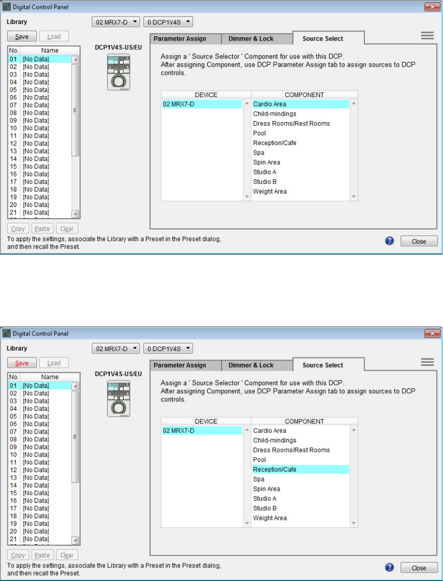
Example 3) A paging system using the PGM1
MRX Setup Manual 168
3. In the “Digital Control Panel” dialog box, click the “Source Select” tab.
The Source Select screen appears.
4. In [COMPONENT], select [Reception/Cafe].
The Source Selector component of Reception/Cafe is assigned to PARAMETER 1 of MRX Source Select.
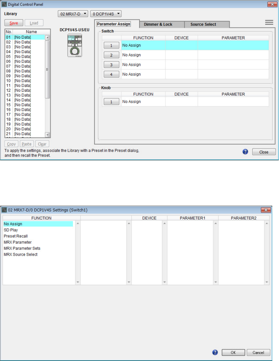
Example 3) A paging system using the PGM1
MRX Setup Manual 169
5. Click the “Parameter Assign” tab.
The Parameter Assign screen appears.
6. Click the “Switch” [1] button.
The “Settings” dialog box appears.
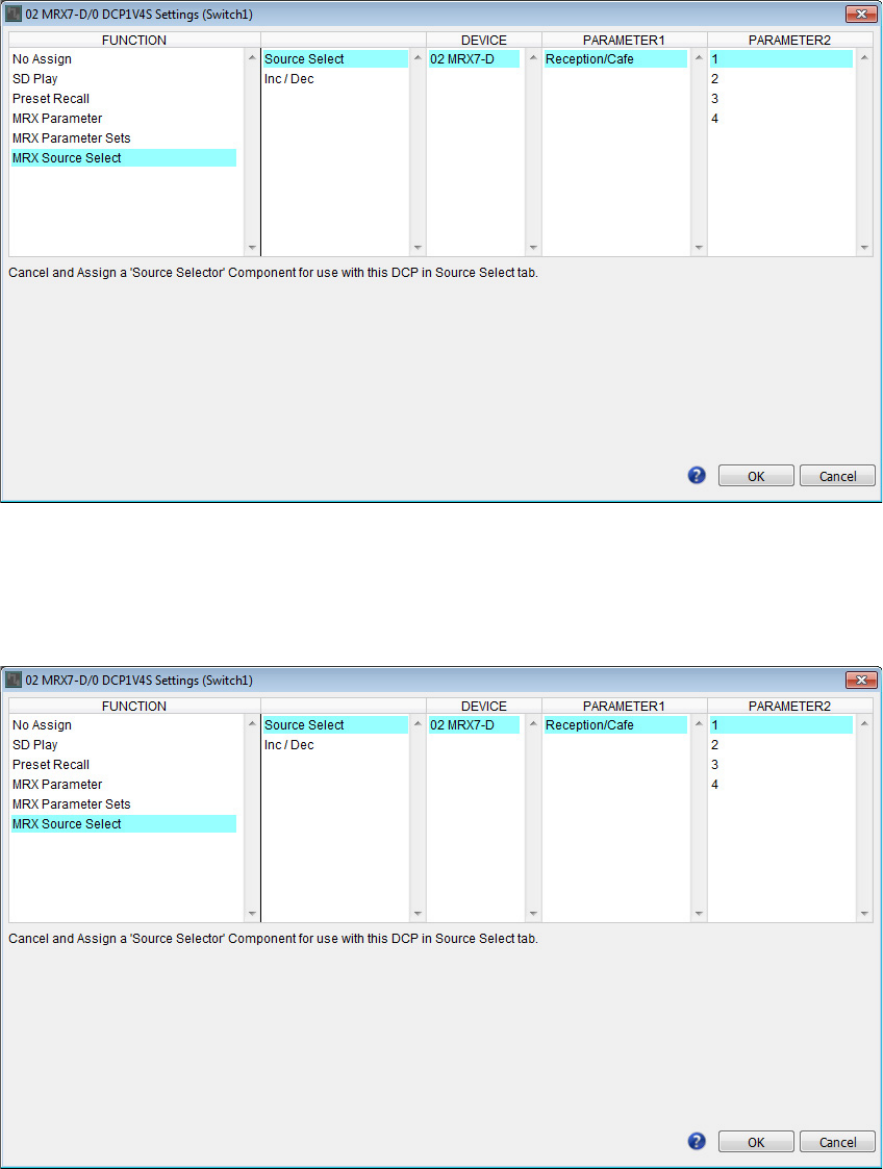
Example 3) A paging system using the PGM1
MRX Setup Manual 170
7. In “FUNCTION,” click [MRX Source Select].
The [MRX Source Select] registration screen appears.
8. In “PARAMETER2,” choose [1].
When you press the DCP’s switch 1, the Work out BGM1 audio will play.
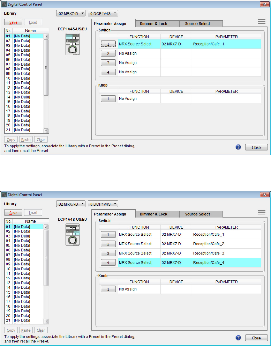
Example 3) A paging system using the PGM1
MRX Setup Manual 171
9. Click the [OK] button.
The “Digital Control Panel” dialog box appears, with Reception/Cafe’s Source Selector [1] button assigned.
10. Assign other parameters to the switches as described in steps 6 through 9.
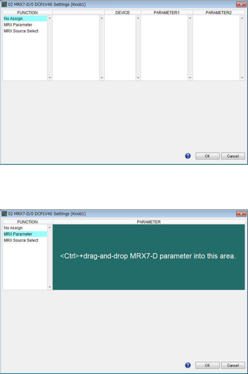
Example 3) A paging system using the PGM1
MRX Setup Manual 172
11. Click the “Knob” [1] button.
The “Settings” dialog box appears.
12. In “FUNCTION,” click [MRX Parameter].
The [MRX Parameter] registration screen appears.
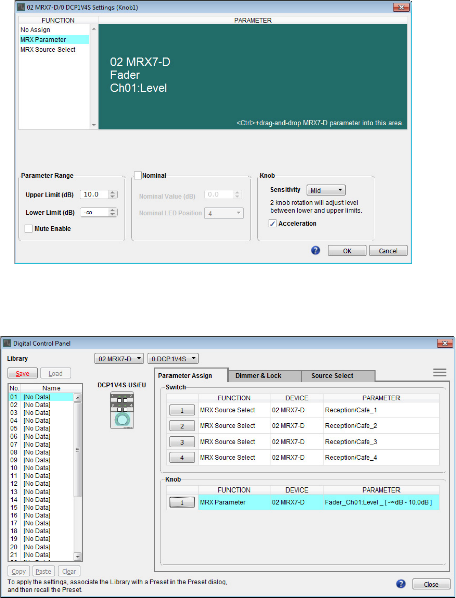
Example 3) A paging system using the PGM1
MRX Setup Manual 173
13. While holding down the <Ctrl>, drag and drop the channel 1 fader of the “Fader” compo-
nent editor into the “PARAMETER” area of the “Settings” dialog box.
The fader of “Fader” channel 1 is registered.
14. Click the [OK] button.
The “Digital Control Panel” dialog box appears, with the Fader channel 1 fader assigned to the knob.
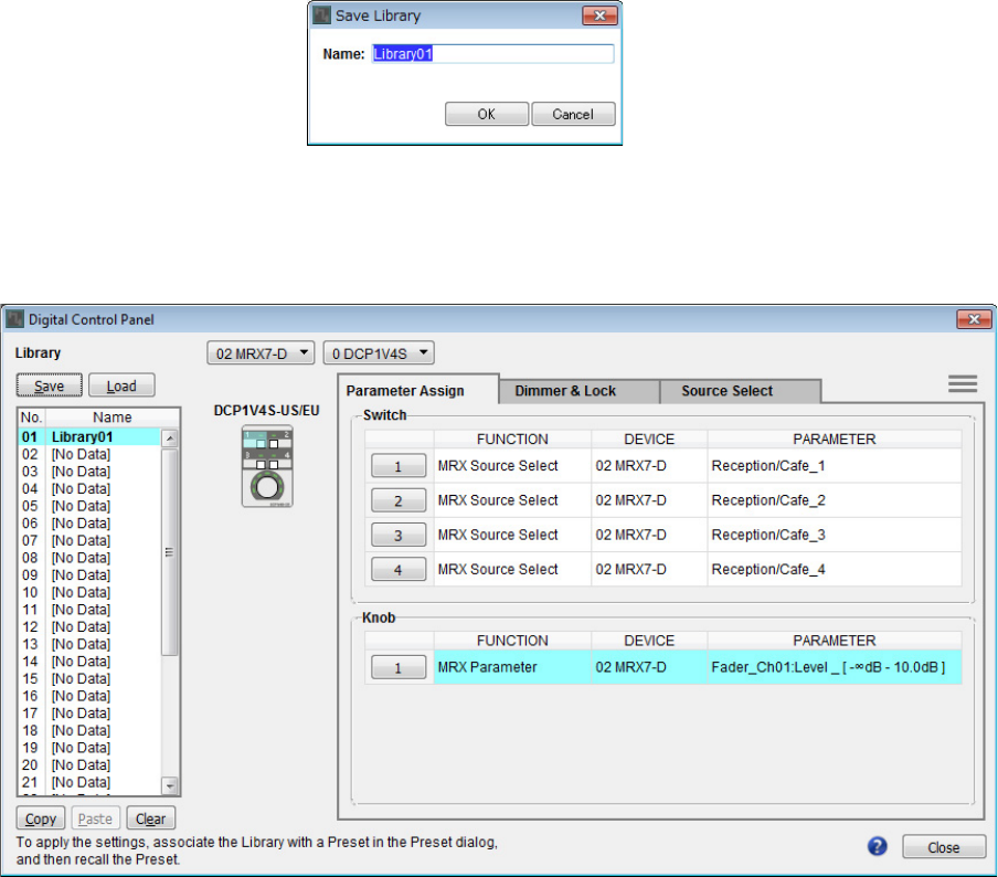
Example 3) A paging system using the PGM1
MRX Setup Manual 174
15. Click “Library” No. 01, and then click the [Save] button.
The “Save Library” dialog box appears.
16. Click the [OK] button.
The settings are registered as “Library” No. 01.
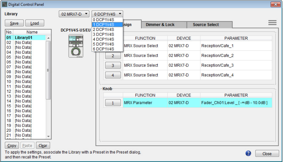
Example 3) A paging system using the PGM1
MRX Setup Manual 175
17. In the DCP selection list box, select another DCP unit and make settings for it as described
in steps 3 through 16.
18. When you’ve made settings for all DCP units, click the [Close] button.
The “Digital Control Panel” dialog box closes.
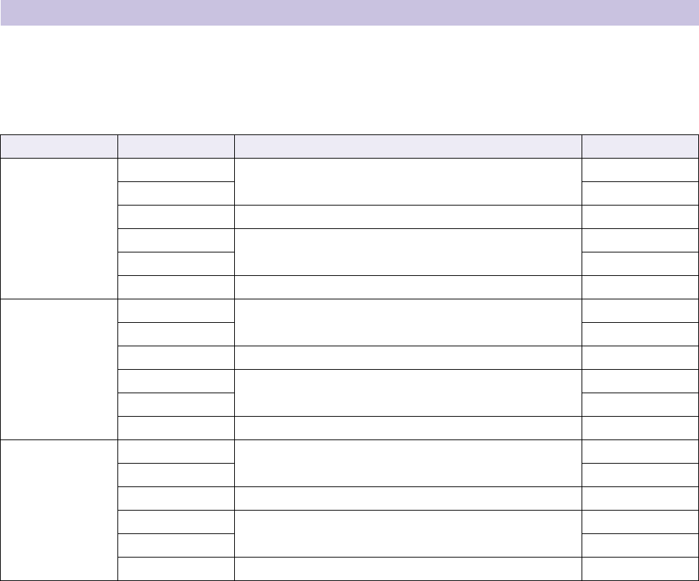
Example 3) A paging system using the PGM1
MRX Setup Manual 176
Here you’ll assign parameters to the MCP1 units located in Studio and Spin Area, so that parameters can be controlled by
switches.
We’ll assign the following parameters to the switches of the home page. The method of making Source Selector and Fader
assignments is essentially the same as for the DCP. The methods for assigning parameter link groups and designing the
screen are described later.
Each L3 switch is used to adjust the mic level.
We’ll explain how to design Studio A’s R3 switch (parameter link group) and screen.
Making MCP1 settings
Area Switch Component that includes the parameter to be assigned Parameter
Studio A
L1
Studio A’s Source Selector
1
L2 3
L3 Source Mix (Studio A) Fader (2) Channel 1 level
R1
Studio A’s Source Selector
2
R2 4
R3 Parameter link group’s Studio A BGM LEVEL Link master level
Studio B
L1
Studio B’s Source Selector
1
L2 3
L3 Source Mix (Studio B) Fader (3) Channel 1 level
R1
Studio B’s Source Selector
2
R2 4
R3 Parameter link group’s Studio B BGM LEVEL Link master level
Spin Area
L1
Spin Area’s Source Selector
1
L2 3
L3 Source Mix (Spin Area) Fader (4) Channel 1 level
R1
Spin Area’s Source Selector
2
R2 4
R3 Parameter link group’s Spin Area BGM LEVEL Link master level
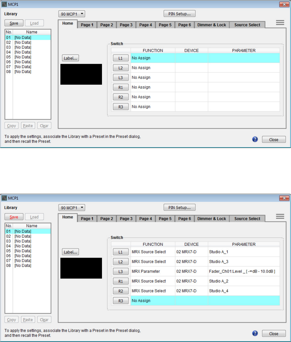
Example 3) A paging system using the PGM1
MRX Setup Manual 177
1. Choose [Controller] menu → [MCP1].
The “MCP1” dialog box appears.
2. In the “Source Select” tab, specify the applicable Source Selector, and then make settings
for the L1/2/3 and R1/2 switches.
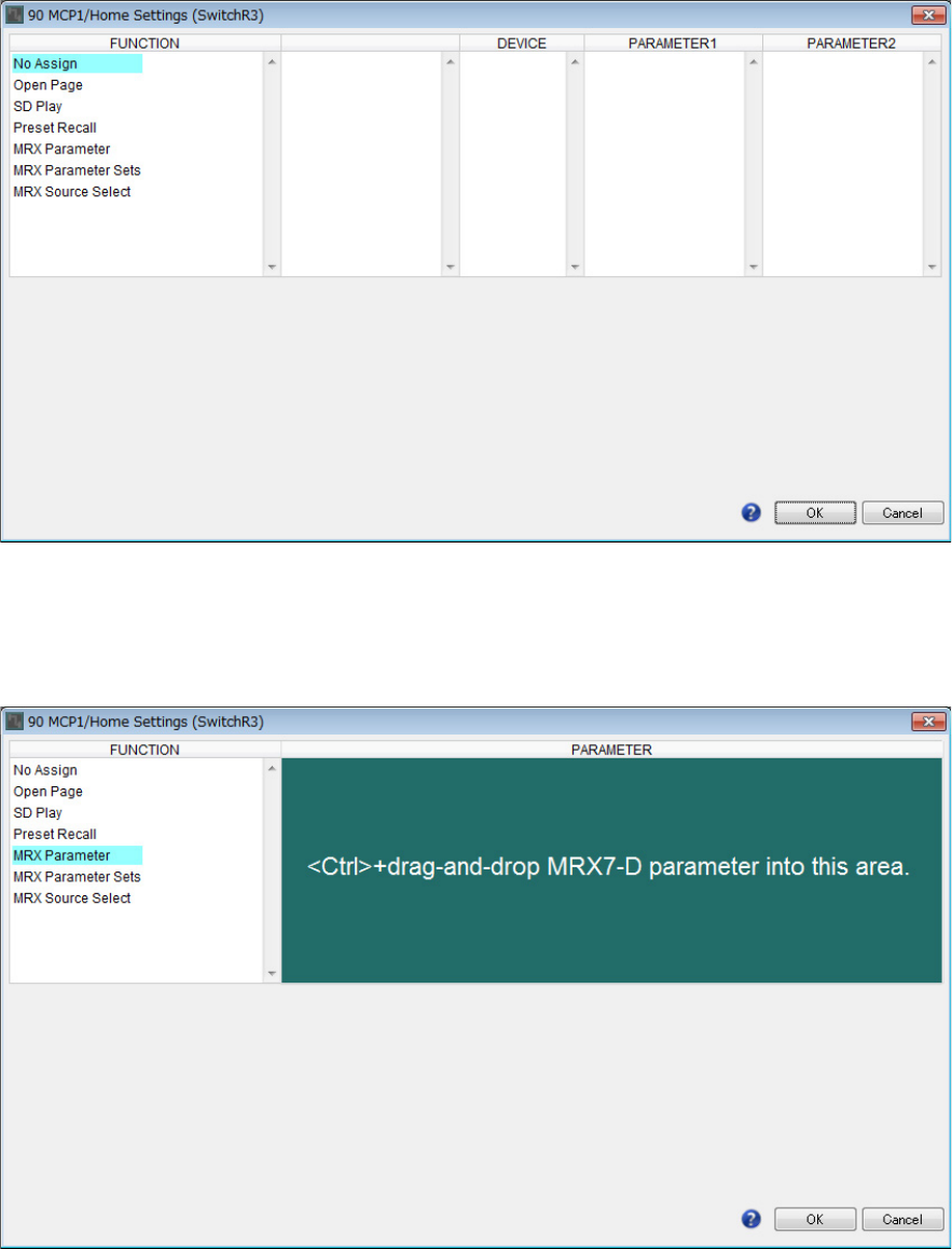
Example 3) A paging system using the PGM1
MRX Setup Manual 178
3. Click the “Switch” [R3] button.
The “Settings” dialog box appears.
4. In “FUNCTION,” click [MRX Parameter].
The [MRX Parameter] registration screen appears.
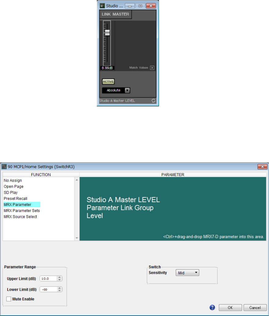
Example 3) A paging system using the PGM1
MRX Setup Manual 179
5. In the “Parameter Link Group” area, right-click [Studio A Master LEVEL] and choose [Open
Link Master].
The Link Master Editor for Studio A Master LEVEL opens.
6. While holding down <Ctrl>, drag and drop the fader of the Studio A Master LEVEL Link
Master editor into the “PARAMETER” area of the “Settings” dialog box.
The fader of the Link Master editor for Studio A Master LEVEL is registered.
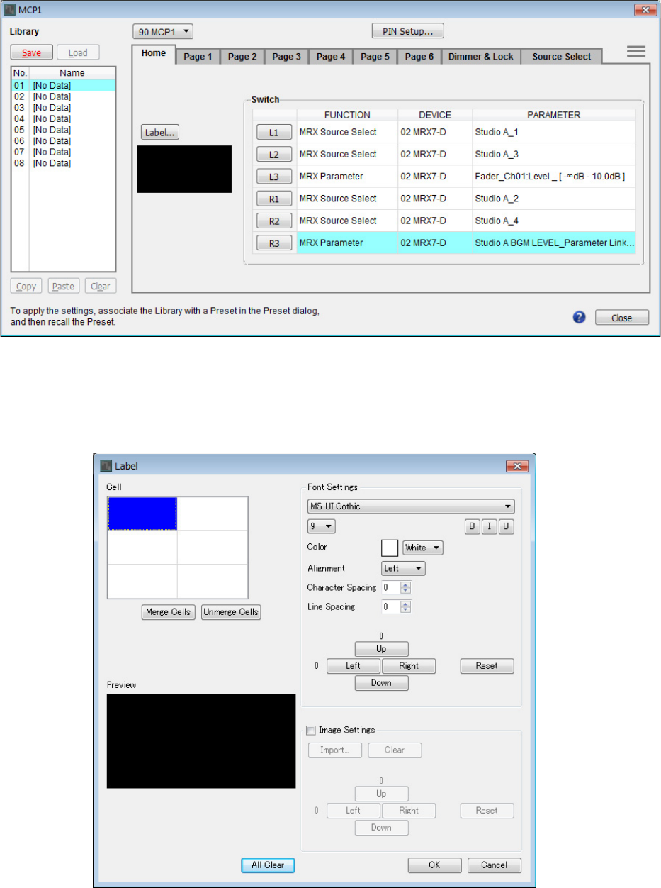
Example 3) A paging system using the PGM1
MRX Setup Manual 180
7. Click the [OK] button.
The “MCP1” dialog box appears, with the fader of the Studio A Master LEVEL Link Master editor assigned to the R3
switch.
8. To create the screen that will be shown in the MCP1’s display, click the [Label] button.
The “Label” dialog box appears.
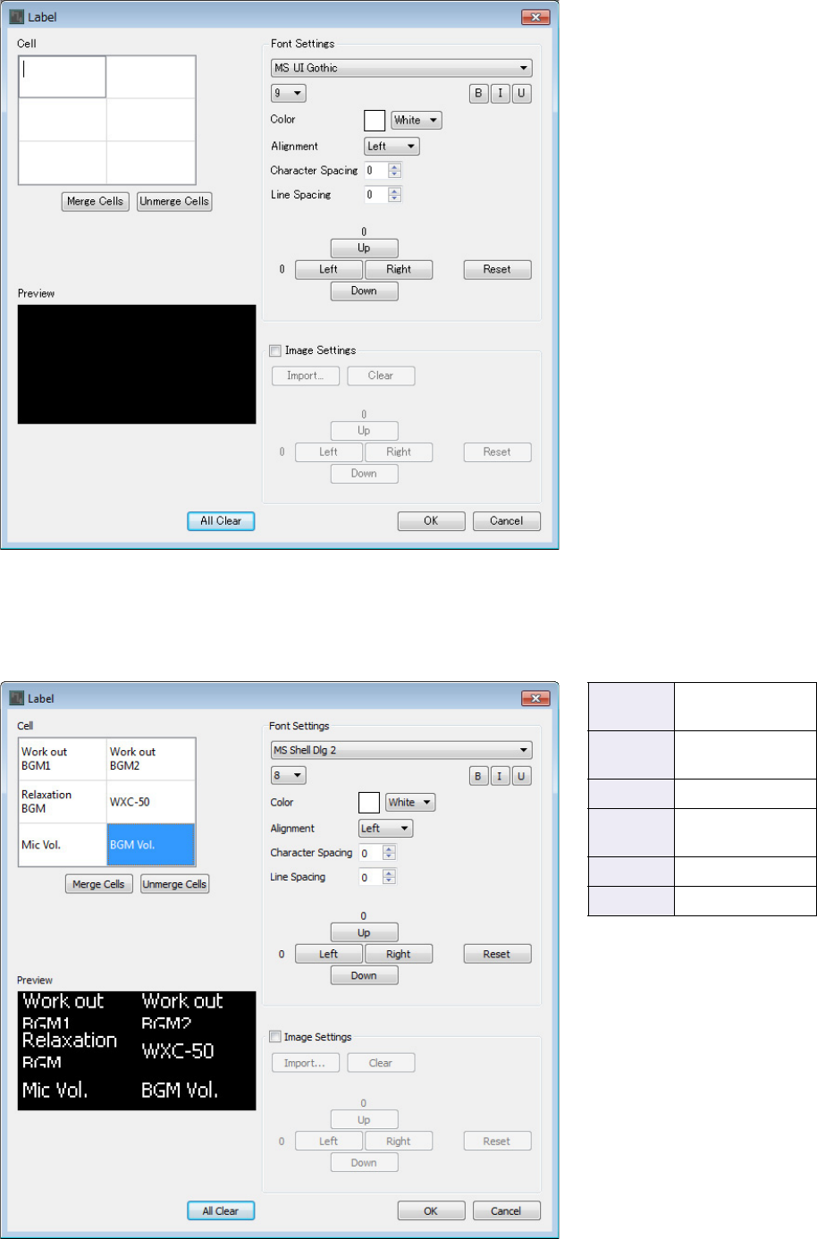
Example 3) A paging system using the PGM1
MRX Setup Manual 181
9. Double-click the [Cell] in which you want to enter a character string, making it editable.
You can also select a cell and then press <F2> to make it editable.
10. Enter a character string.
To start a new line within a cell, hold down <Alt> and press <Enter>.
L1 Work out
BGM1
L2 Relaxation
BGM
L3 Mic Vol.
R1 Work out
BGM2
R2 WXC-50
R3 BGM Vol.
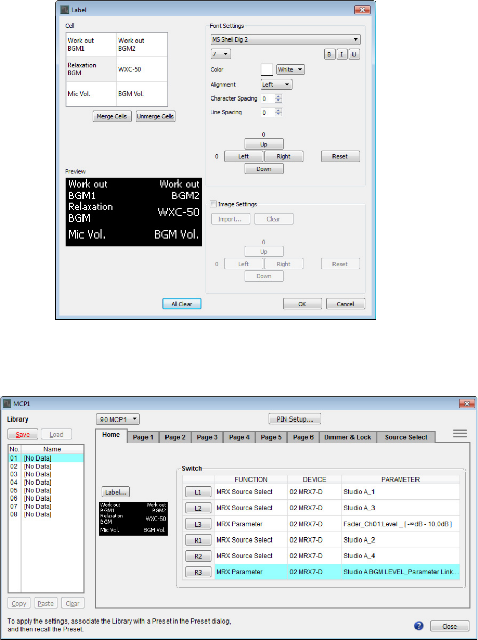
Example 3) A paging system using the PGM1
MRX Setup Manual 182
11. Use [Font Settings] to make adjustments to the display of each cell while watching [Pre-
view] to see the result.
12. When you’ve finished making settings, click the [OK] button.
The “MCP1” dialog box appears with the label preview shown.
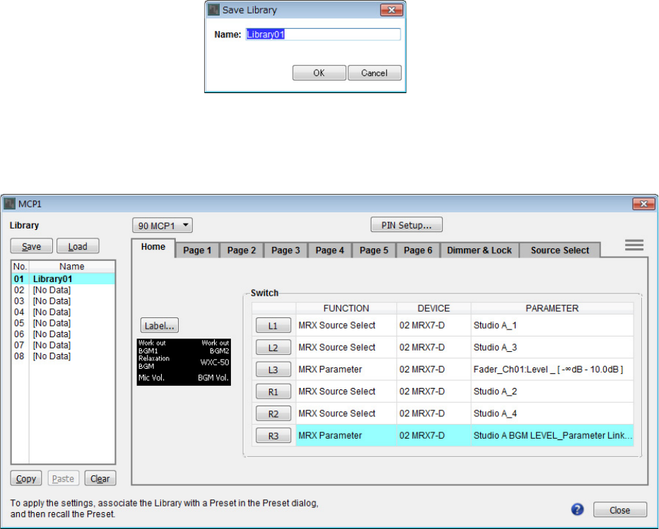
Example 3) A paging system using the PGM1
MRX Setup Manual 183
13. Click “Library” No. 01, and then click the [Save] button.
The “Save Library” dialog box appears.
14. Click the [OK] button.
The settings are registered as “Library” No. 01.
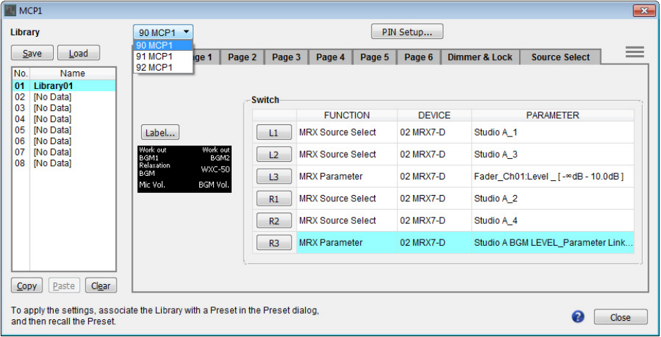
Example 3) A paging system using the PGM1
MRX Setup Manual 184
15. In the MCP1 selection list box, select another MCP1 and make settings for it as described
in steps 2 through 14.
16. When you’ve made settings for all MCP1 units, click the [Close] button.
The “MCP1” dialog box closes.

Example 3) A paging system using the PGM1
MRX Setup Manual 185
For the MRX, you’ll need to specify the preset that is recalled when the unit starts.
1. Click the [Preset] tool button ( )
The “Preset” dialog box appears.
2. Click No. 01, and then click the [Store] button.
The “Store Preset” dialog box appears.
Storing a preset

Example 3) A paging system using the PGM1
MRX Setup Manual 186
3. Click the [OK] button.
The current state is registered as a preset with the name “Preset 01.”
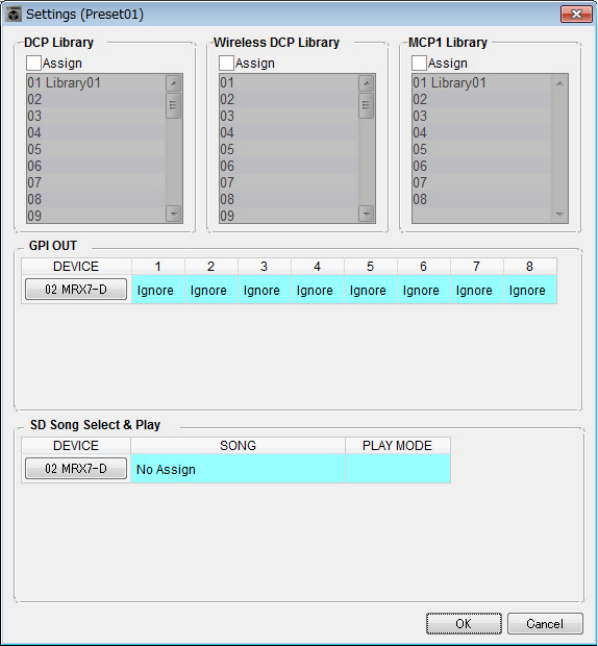
Example 3) A paging system using the PGM1
MRX Setup Manual 187
4. In the “DCP” column, double-click the cell that is shown as [No Assign].
The “Settings” dialog box appears.
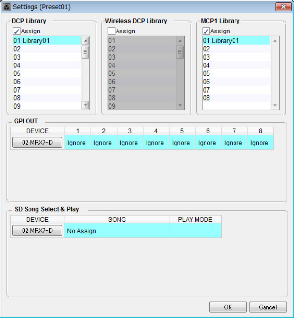
Example 3) A paging system using the PGM1
MRX Setup Manual 188
5. Select the [Assign] check boxes for “DCP Library” and “MCP1 Library.”
Now you can select the library items that are recalled when the MRX7-D starts.
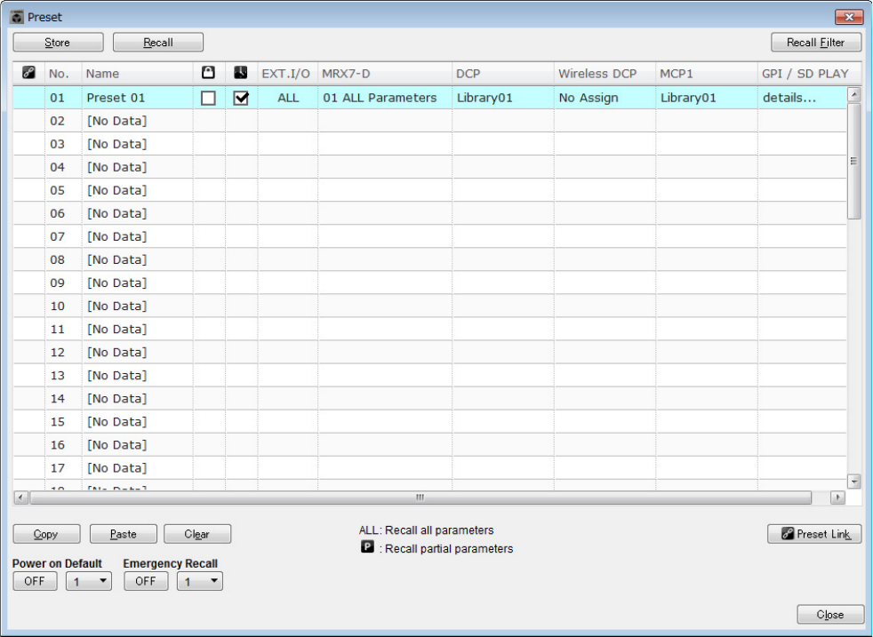
Example 3) A paging system using the PGM1
MRX Setup Manual 189
6. Select [01 Library01] for “DCP Library” and for “MCP1 Library,” and click the [OK] button.
The “Preset” dialog box appears, with “01 Library01” assigned to “DCP Library” and “MCP1 Library.”
7. Click the [Close] button.
The “Preset” dialog box closes.

Example 3) A paging system using the PGM1
MRX Setup Manual 190
Making EXT. I/O settings
Here you’ll make settings in MRX Designer for using digital input/output. In this example, you’ll make YDIF settings and
DANTE settings.
These settings are made using MTX-MRX Editor.
1. Switch the display to MTX-MRX Editor.
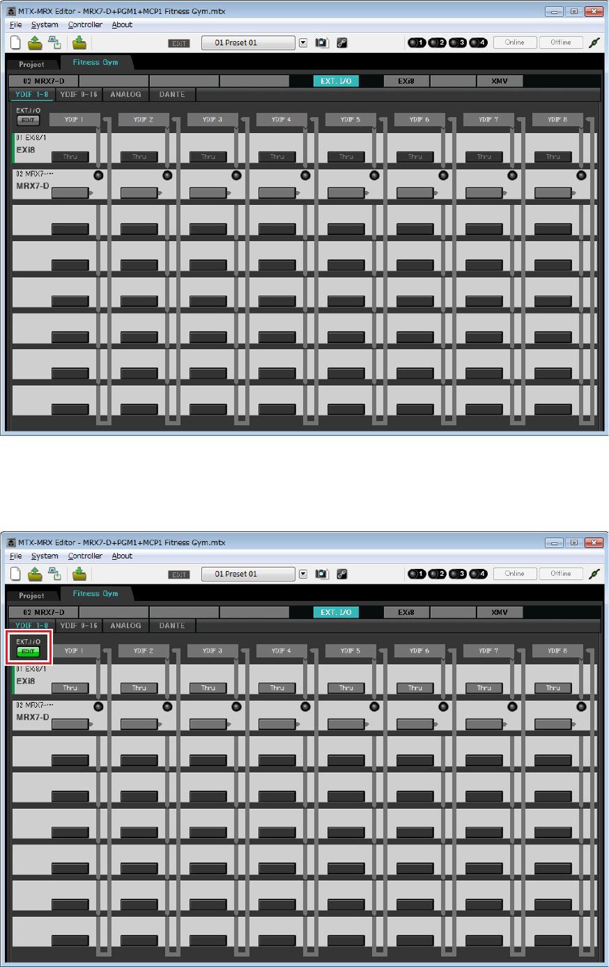
Example 3) A paging system using the PGM1
MRX Setup Manual 191
2. Click the [EXT. I/O] button.
The “EXT. I/O” screen appears.
3. Click the [EDIT] button.
Now you can specify the output from YDIF 1–8 of the EXi8.
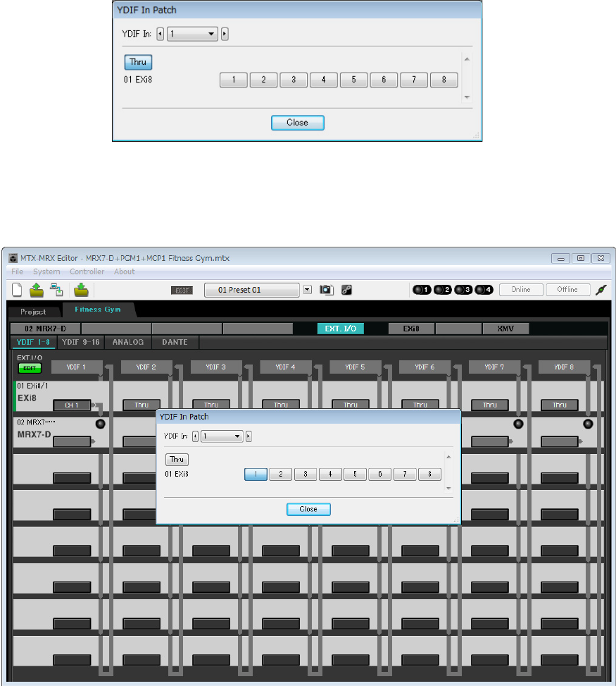
Example 3) A paging system using the PGM1
MRX Setup Manual 192
4. Click the EXi8 input routing select button for “YDIF 1.”
The “YDIF In Patch” dialog box appears.
5. Click the [1] button.
The audio signal from the EXi8’s [INPUT] jack 1 is output to YDIF 1.
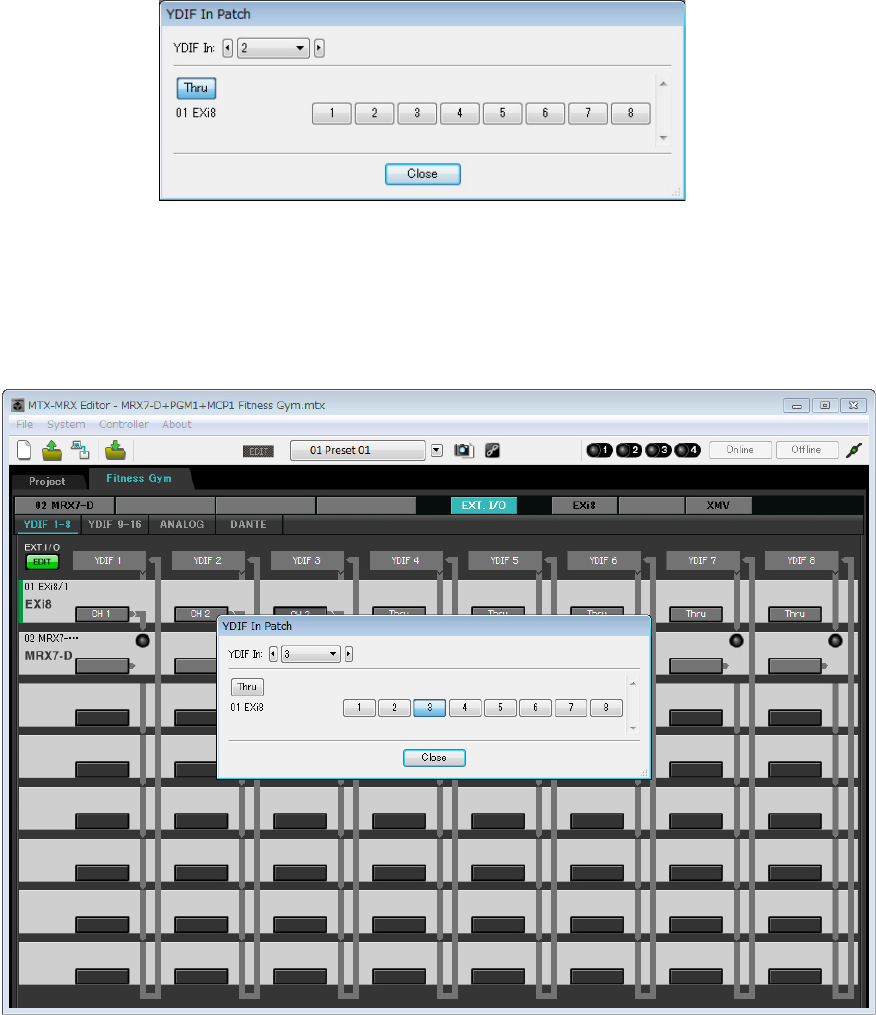
Example 3) A paging system using the PGM1
MRX Setup Manual 193
6. In the [YDIF In:] list box, switch the channel to 2.
The object of editing changes to channel 2.
7. Click the [2] button.
The audio signal from the EXi8’s [INPUT] jack 2 is output to YDIF 2.
8. As described in steps 6 through 7, assign channel 3 to 3.
9. Click the [Close] button.
The “YDIF In Patch” dialog box closes.
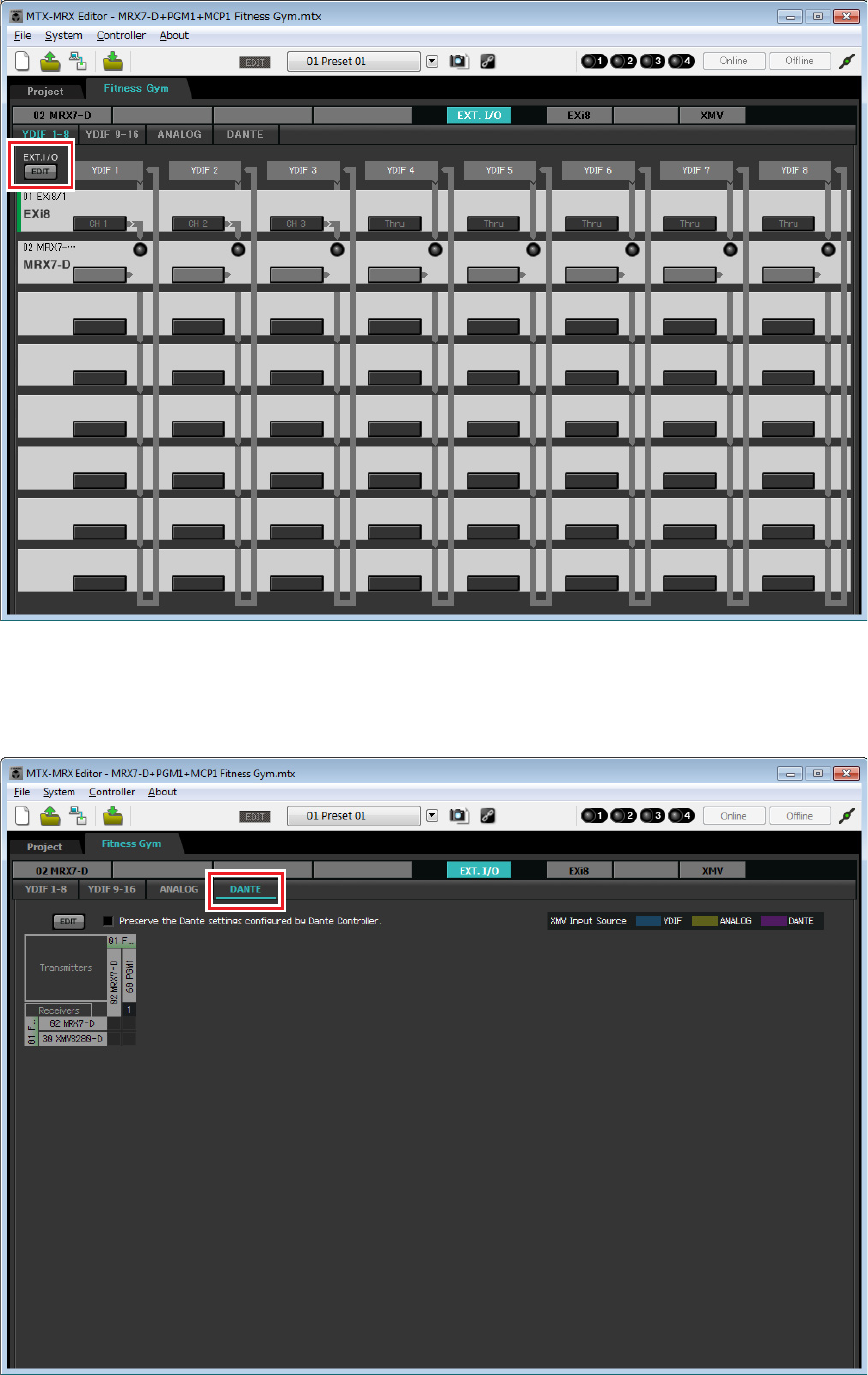
Example 3) A paging system using the PGM1
MRX Setup Manual 194
10. Click the [EDIT] button.
The YDIF input routing select button is disabled.
11. Click the [DANTE] button.
The Dante setting screen appears.
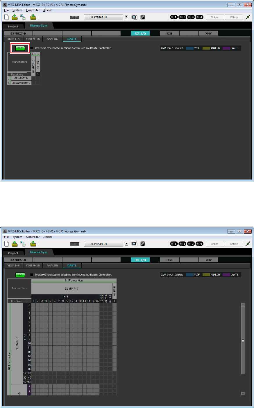
Example 3) A paging system using the PGM1
MRX Setup Manual 195
12. Click the [EDIT] button.
Now you can specify Dante input/output settings.
13. Click [1–16] for MRX7-D in [Receivers] and [Transmitters], and click XMV8280-D in [Receiv-
ers], so that the indications are expanded.
If they are already expanded, leave them as they are.
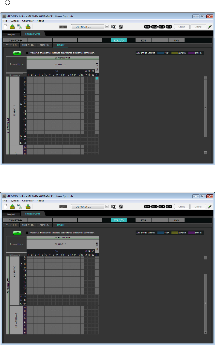
Example 3) A paging system using the PGM1
MRX Setup Manual 196
14. Click the location where the “1” of the PGM1 and MRX7-D intersect.
A appears in the grid.
15. Scroll so that the XMV inputs are visible.
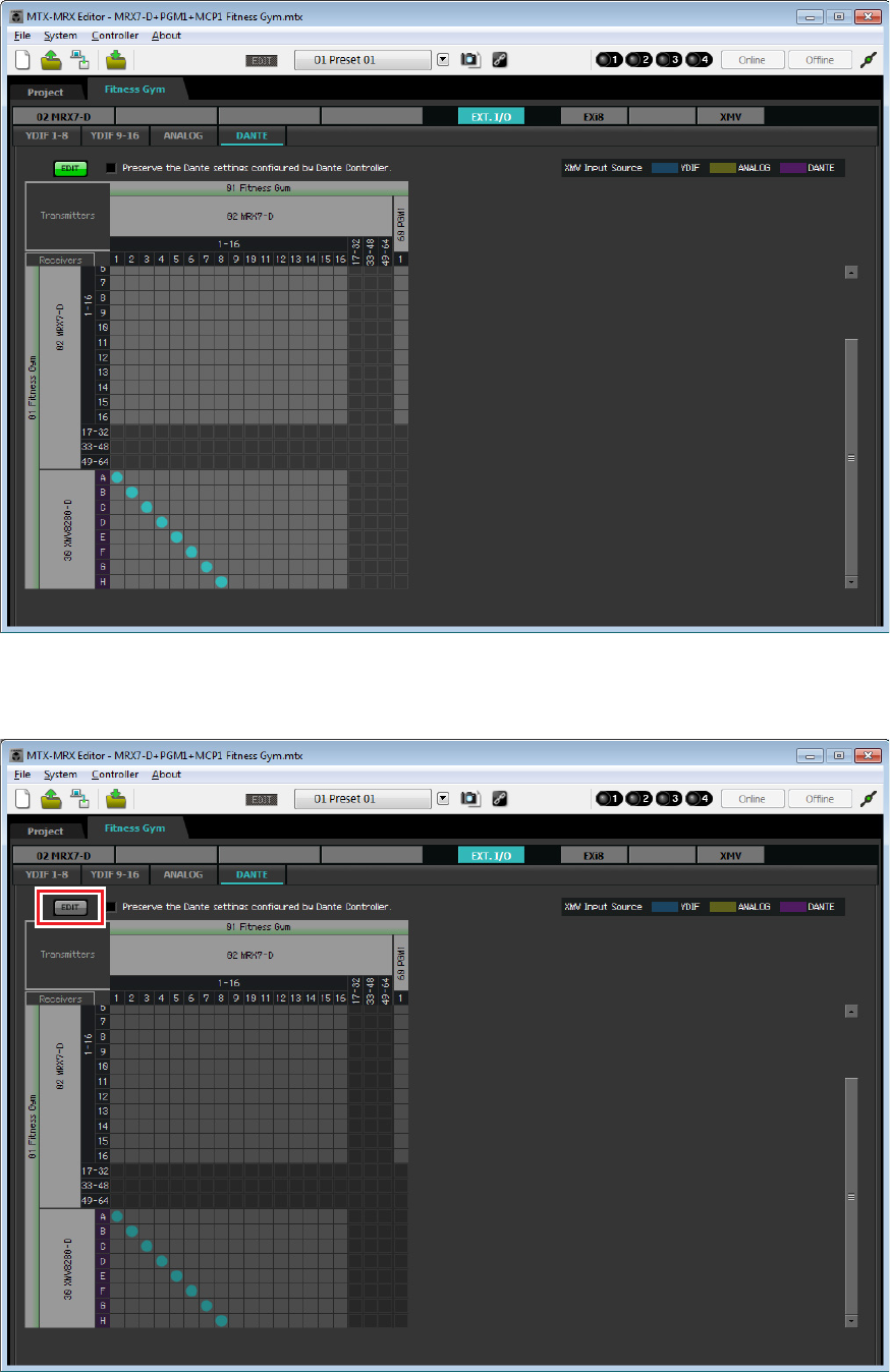
Example 3) A paging system using the PGM1
MRX Setup Manual 197
16. Click the intersections between the XMV’s inputs and the MRX’s outputs, so that A inter-
sects with 1, B with 2, C with 3, and so on until H intersects with 8.
17. Click the [EDIT] button to lock the settings.
This completes settings in the offline state. Save the settings once again.
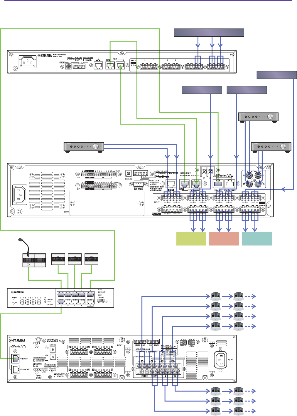
Example 3) A paging system using the PGM1
MRX Setup Manual 198
Connecting the equipment
After you’ve rack-mounted the MRX and your other equipment, connect the MRX and the other equipment as shown
below. Insert the SD memory card into the MRX at this time.
WXC-50 (Studio A)
EXi8
Wireless Microphone Receiver
MRX7-D
PGM1
MCP1
SWR2100P-10G
XMV8280-D
Relaxation BGM Work out BGM2
Work out BGM1
WXC-50 (Spin Area)
WXC-50 (Studio B)
Spin Area Studio B Studio A
Weight Area
Pool
Cardio Area
Reception/Cafe
Child-mindings
Dress Rooms/
Rest Rooms
Spa

Example 3) A paging system using the PGM1
MRX Setup Manual 199
Powering-on the PoE-equipped gigabit network switch
The PGM1 and MCP1 units start.
Specifying the MCP1’s UNIT ID
Long-touch the MCP1’s home switch to access the utility page.
Choose [Settings] → [Unit ID] and set Studio A to a UNIT ID of 90, Studio B to 91, and Spin Area to 92.
After making the settings, touch the return switch.
For details on UNIT ID settings, refer to “Specifying the UNIT ID” in “MCP1 Installation Manual.”
Power-on equipment other than amps and powered speakers
Power-on equipment other than amps and powered speakers.
When powering-off equipment other than amps and powered speakers, start by powering-off the amps and powered speak-
ers.
Power-on amps and powered speakers
Power-on amps and powered speakers.
To prevent unwanted sound from being output, we recommend that you minimize the attenuator settings of all channels on
the amp or powered speaker itself before you turn it on.
Specifying the computer’s TCP/IP address
To allow the MRX and the computer to communicate, specify the computer’s TCP/IP as follows.
1. On MTX-MRX Editor’s [System] menu, click [Network Setup].
The “Network Setup” dialog box will appear.
2. Click [Open Network Connection].
“Network Connections” will appear.
3. Right-click the adapter to which the MRX is connected, and choose [Properties].
The “Local Area Connection Properties” dialog box will appear.
4. Choose [Internet Protocol Version 4 (TCP/IPv4)], and then click [Properties].
The “Internet Protocol Version 4 (TCP/IPv4) Properties” dialog box will appear.
5. Click [Use the following IP address (S)].
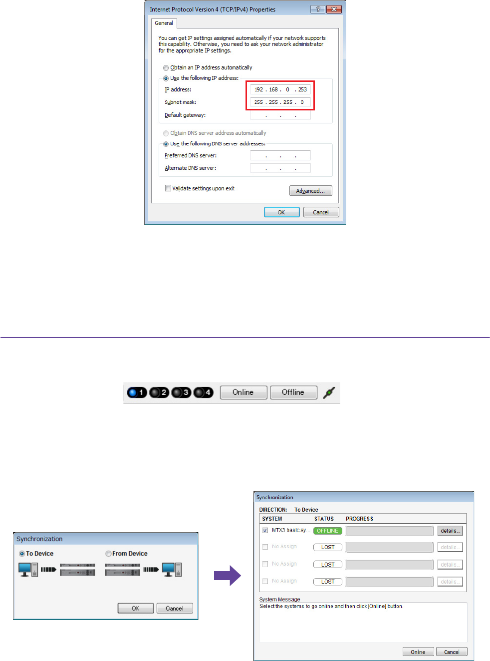
Example 3) A paging system using the PGM1
MRX Setup Manual 200
6. In the [IP address] box, enter “192.168.0.253”; in the [Subnet mask] box, enter
“255.255.255.0.”
7. Click [OK].
Taking MTX-MRX Editor online
In the upper right of MTX-MRX Editor, click the [Online] button. When the unit has successfully come online, indicator 1
at the left will light blue.
When the “Synchronization” dialog box appears, select “To Device,” and click the [OK] button. When the indication of the
dialog box has changed, select the check box(es) of the system(s) that you want to bring online, and then click the [Online]
button.
The project created in MTX-MRX Editor will be sent to the MRX.
NOTE
The IP address of the MRX7-D is set to “192.168.0.2.”
NOTE
When you make these settings, the Windows firewall might block MTX-MRX Editor. Select the [Private Network] check box, and
click [Allow Access].

Example 3) A paging system using the PGM1
MRX Setup Manual 201
Verifying that the settings were applied
The main items to verify are listed below. For details on each parameter’s settings, refer to “MTX-MRX Editor User’s
Guide” and “MRX Designer User’s Guide.”
1. In “Output Ch.” User Defined Block, set “Speaker Processor” to a value appropriate for the
speaker.
2. Input audio signals from the analog inputs and stereo inputs into the MRX7-D, and adjust
the input levels.
To check the input levels, you can use the “Fader” component editor and the “Fader” component editor within the
“Source Mix” User Defined Block.
3. Adjust the EQ using the “PEQ” located inside the “Output Ch.” User Defined Block.
Since the Studio and Spin Area use mics, make adjustments while inputting sound to the mics.
4. While inputting sound to the mic, adjust the parameters of the components in the “Input
Ch. Strip” User Defined Block.
5. Operate the PGM1 to verify that paging broadcast occurs correctly.
6. Operate the DCP and MCP1 units to verify that they work correctly.
When you have finished making all settings, save the project and switch MTX-MRX Editor offline.
This completes the settings for example 3.

MRX Setup Manual 202
Q: How do you send the rcsl file to the iPad?
A: In order to send the rcsl file from a computer to the iPad, you can either share the file using iTunes, send the file via e-
mail to the iPad, send it via AirDrop, or send it via the File Transfer application. Here we’ll explain how to send the
file using iTunes.
1. Connect your iPad to the computer.
Start up iTunes. If iTunes does not start up automatically, start the application manually.
2. Click the Device (iPad) button, and then click [Apps].
3. Under “File Sharing”, click “P.V. Touch.”
“File Sharing” is located further down the screen, so you may need to scroll down to see it.
4. Click the “Add...” button, and select the rscl file.
Q: I don’t hear the Speech Privacy sound.
A: The environmental sound may not have been sent to the MRX. Follow the steps in example 2 (“Sending the Speech
Privacy environmental sound”) to send the sound to the MRX.
Q&A

MRX Setup Manual 203
Use “Settings” to uninstall the software.
Right click [Start]→[Settings]→[Apps], select the item you want to uninstall, and then click [Uninstall].
A dialog box will appear; follow the instructions in the screen to uninstall the software.
If the “User Account Control” dialog box appears, click [Continue] or [Yes].
Uninstalling the software (Removing the application)
Manual Development Group
© 2015 Yamaha Corporation
Published 05/2020 PO-D0
