Yamaha MTX MRX Editor User Guide User's Manual [English] En Ug L0
User Manual: Yamaha MTX-MRX Editor User's Manual [English]
Open the PDF directly: View PDF ![]() .
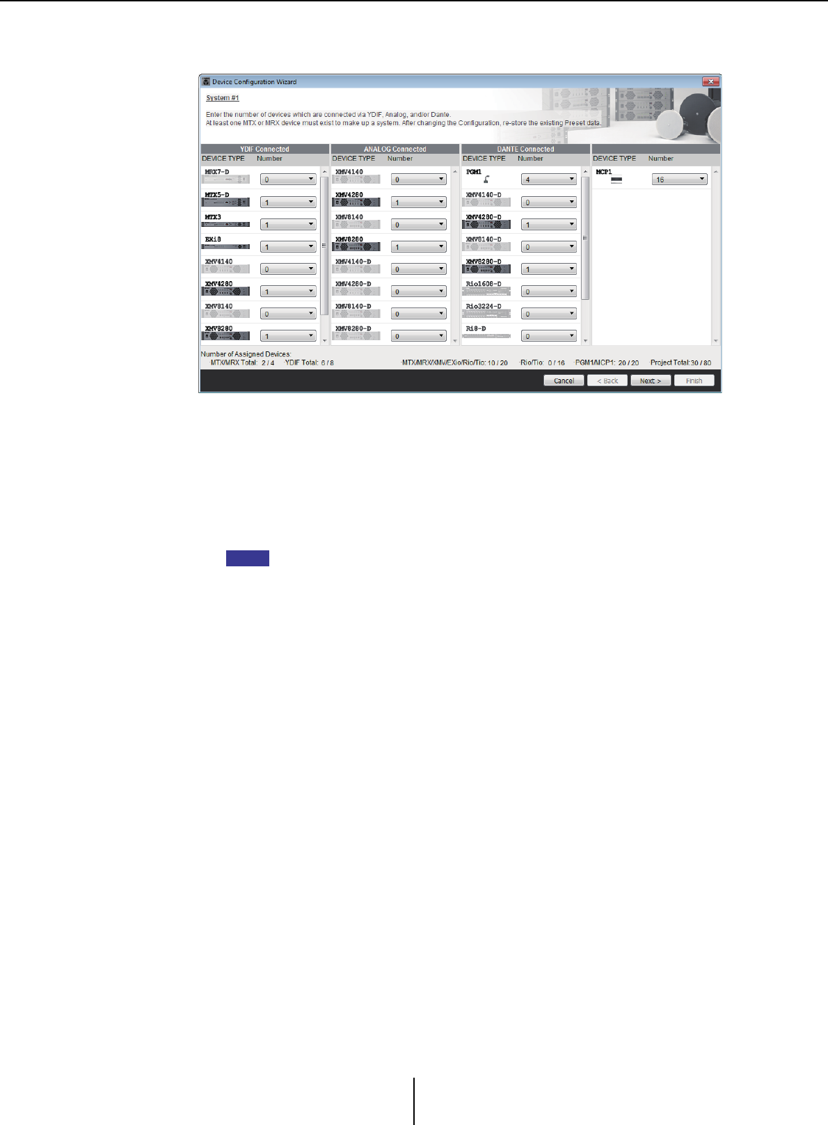
.
Page Count: 276 [warning: Documents this large are best viewed by clicking the View PDF Link!]
- Notice regarding data copyright
- Notice regarding the content of this user guide
- Contents
- Chapter 1. An overview of MTX-MRX Editor
- An audio system control network
- Terms used in this user guide
- Data handled by MTX-MRX Editor
- Connection requirements for an MTX/MRX system
- MTX/MRX system configuration examples
- What are YDIF connections? (Cascade mode and Distribution mode)
- What are Dante connections? (Daisy-chain connection and Star connection)
- Patching
- Workflow
- About the screens
- Moving between screens
- Chapter 2. Menu bar and tool buttons
- Chapter 3. Project screen
- Chapter 4. System screen
- Chapter 5. Online and Synchronization
- Chapter 6. Presets
- Chapter 7. Dialog boxes/Software applications
- “Startup” dialog box
- “Network Setup” dialog box
- “Device Information” dialog box
- “Match Device by IP Address” dialog box
- “MTX Configuration” dialog box
- “Dante Information” dialog box
- “Word Clock” dialog box
- “Clock” dialog box
- “Daylight Saving Time” dialog box
- “Scheduler” dialog box
- “Remote Control” dialog box
- “External Events” dialog box
- “Digital Control Panel” dialog box
- “Wireless DCP” dialog box
- “MCP1” dialog box
- “PIN Setup” dialog box
- “Label” dialog box
- “Re-size Image” dialog box
- “PGM1/PGX1” dialog box
- “PGM1 Label Creator” application
- “GPI” dialog box
- “GPI Calibration” dialog box
- “Security Settings” dialog box
- “Project Information” dialog box
- “Configuration Diagram” dialog box
- “Get Log” dialog box
- “Sampling Rate Converter” dialog box
- “Input Source/Redundant” dialog box
- Appendix

MTX-MRX Editor User Guide
1
MTX-MRX Editor
User Guide
MTX-MRX Editor is software for connecting, constructing, and controlling a system that uses MTX
series, MRX series, XMV series, EXi8/EXo8, R series (AD/DA), and Tio1608-D units. The settings you
make in MTX-MRX Editor are sent to the MTX series, MRX series, XMV series, EXi8/EXo8, R series
(AD/DA), and Tio1608-D units that are connected via Ethernet.
After the settings have been sent, the system will operate without a computer.
The control panel of a DCP series unit or an MCP1 can also be used to control the system in real time.
A paging system can be constructed using PGM1/PGX1 units.
If you’re using the MRX, refer also to the “MRX Designer User Guide.”
Notice regarding data copyright
The unauthorized copying or reuse of commercially sold music/sound data without permission
from the rights holder is forbidden by law, with the exception of uses that are permitted by
copyright law. Before using this data, please obtain permission from the copyright owner, or consult
a copyright specialist.
Notice regarding the content of this user guide
●All copyrights for this software and user guide are the property of Yamaha Corporation.
●Unauthorized copying or modification of this software or user guide in part or in whole is
prohibited.
●Please be aware that Yamaha Corporation accepts no responsibility for any results or
consequences that may follow from the use of this software and user guide.
●All of the illustrations and screen shots in this user guide are provided for the purpose of
explaining the operation. For this reason, they may differ from the actual specifications.
●Changes in the system software, the functionality, and the specifications that may result from
updates to the application will be dealt with in a separate leaflet or manual.
●Ethernet is a trademark of the Xerox Corporation.
●Windows is a registered trademark of Microsoft Corporation USA in the United States and in
other countries.
●iPad and Bonjour are trademarks of Apple Inc. registered in the United States and in other
countries.
●iOS is a trademark or registered trademark of Cisco Inc. in the United States and in other
countries, and is used under license.
●The SDHC logo and the SD logo are trademarks of SD-3C, LLC.
●Company names and product names appearing in this document are the trademarks or
registered trademarks of their respective owners.

MTX-MRX Editor User Guide
2
Contents
Notice regarding data copyright .................1
Notice regarding the content of
this user guide............................................1
Chapter 1. An overview of MTX-MRX Editor ....4
An audio system control network ...............4
Terms used in this user guide ......................4
Data handled by MTX-MRX Editor.............. 6
Connection requirements for
an MTX/MRX system................................. 7
MTX/MRX system configuration
examples.................................................... 9
What are YDIF connections?
(Cascade mode and Distribution mode) ..10
What are Dante connections?
(Daisy-chain connection and
Star connection).......................................13
❏Daisy-chain connection....................................... 13
❏Star connection.................................................... 13
❏About redundant networks................................. 14
Patching .................................................... 15
Workflow .................................................. 18
About the screens ......................................26
❏Project screen ...................................................... 26
❏System screen ...................................................... 26
Moving between screens............................27
Chapter 2. Menu bar and tool buttons...........28
Title bar......................................................28
Menu bar ....................................................28
Tool buttons.............................................. 32
Chapter 3. Project screen................................34
❏System selection tabs ...........................................34
❏HIDE/SHOW button...........................................34
Network devices .........................................35
MTX/MRX system.......................................36
❏“Device Configuration Wizard” dialog box........37
❏YDIF-connected devices......................................47
❏Digital control panel, PGM1/PGX1 ....................49
❏Analog-connected devices ...................................50
❏DANTE-connected devices..................................51
❏MCP1 ...................................................................52
[System] tab .............................................. 53
[Device] tab ............................................... 54
[Alert] tab ................................................. 56
Chapter 4. System screen................................57
“MAIN” screen............................................60
❏“Input Patch” dialog box.....................................71
❏“Output Patch” dialog box ..................................72
“INPUT” screens ........................................ 73
“MATRIX” screen....................................... 86
“ZONE” screen........................................... 90
“ROUTER” screen ....................................... 98
“OUTPUT” screens ................................... 100
“EFFECT” screen....................................... 108
“DCA” screen............................................110
“I/O” screen ............................................ 112
“MY4-AEC” screen ................................... 114
❏“To Far-end” screen...........................................117
❏“Near-end Voice” screen ...................................118
❏“Mic” screen.......................................................119

Contents
MTX-MRX Editor User Guide
3
“EXT. I/O” screen .................................... 120
❏“YDIF” screen (Distribution mode)................. 120
❏“YDIF In Patch” dialog box.............................. 123
❏“YDIF Out Patch” dialog box ........................... 123
❏“Channel Select” dialog box.............................. 124
❏“YDIF” screen (Cascade mode) ........................ 125
❏“ANALOG” screen ............................................ 126
❏“Line Out Patch” dialog box ............................. 127
❏“DANTE” screen ............................................... 128
“EXi8” screen........................................... 130
❏“EXi8 Patch” dialog box.................................... 131
“R/Tio” screen......................................... 132
“EXo8” screen.......................................... 134
❏“EXo8 Patch” dialog box................................... 135
“XMV” screen .......................................... 136
❏“XMV Patch” dialog box................................... 138
Chapter 5. Online and Synchronization........139
Online .......................................................139
❏“Synchronization” dialog box........................... 139
❏“Go online – From devices” dialog box ............ 142
Synchronization ...................................... 143
Chapter 6. Presets .........................................145
❏“Preset” dialog box............................................ 145
“Settings” dialog box......................................... 150
■“GPI Out” dialog box .....................................................152
■“SD Play” dialog box.......................................................154
Recall Filter setting screen ................................ 157
Chapter 7. Dialog boxes/Software
applications..............................................164
❏“Startup” dialog box.......................................... 164
❏“Network Setup” dialog box ............................. 165
❏“Device Information” dialog box ..................... 166
“Update Firmware” dialog box ......................... 168
“IP Address” dialog box.................................... 170
“Auto-Assign IP Address” dialog box .............. 173
❏“Match Device by IP Address” dialog box ........174
❏“MTX Configuration” dialog box .....................177
❏“Dante Information” dialog box.......................180
❏“Word Clock” dialog box ..................................181
❏“Clock” dialog box .............................................183
❏“Daylight Saving Time” dialog box...................185
❏“Scheduler” dialog box ......................................187
❏“Remote Control” dialog box............................197
❏“External Events” dialog box.............................198
❏“Digital Control Panel” dialog box...................201
❏“Wireless DCP” dialog box ...............................206
❏“MCP1” dialog box ............................................208
❏“PIN Setup” dialog box .....................................213
❏“Label” dialog box..............................................214
❏“Re-size Image” dialog box ...............................216
❏“PGM1/PGX1” dialog box.................................217
❏“PGM1 Label Creator” application...................221
❏“GPI” dialog box................................................224
❏“GPI Calibration” dialog box............................226
❏“Security Settings” dialog box...........................228
❏“Project Information” dialog box .....................229
❏“Configuration Diagram” dialog box ...............230
❏“Get Log” dialog box..........................................231
❏“Sampling Rate Converter” dialog box.............232
❏“Input Source/Redundant” dialog box .............233
Appendix ..................................................235
List of settings in “Settings”
dialog boxes ...........................................235
■DCP/Wireless DCP/MCP1 ........................................... 235
■GPI Input......................................................................... 251
■GPI Output...................................................................... 257
Workflow for paging settings ................ 262
Settings for controlling devices across
subnets .................................................. 265
Alert list .................................................. 268
Troubleshooting...................................... 274

MTX-MRX Editor User Guide
4
Chapter 1.
An overview of MTX-MRX Editor
An audio system control network
When multiple MTX series, MRX series, XMV series, EXi8/EXo8, R series (AD/DA), and Tio1608-D
units are connected to an Ethernet network, they will operate together as a single audio system.
This is
called an “MTX/MRX system,” and a space containing multiple MTX/MRX systems is called a
“project.” If a computer is connected to the network, the computer can control the MTX/MRX system
via the MTX/MRX.
Terms used in this user guide
●YDIF
This is a digital audio transmission format that uses Ethernet cables to send and receive
up to 16 channels of audio and word clock. YDIF makes it easy to connect MTX units
to share buses and expand the number of input/output channels (Cascade mode), or to
connect MRX and XMV/EXi8/EXo8 units so that digital audio signals can be conveyed
without deterioration (Distribution mode).
* If the MRX is part of an MTX/MRX system, only Distribution mode is available.
This format does not include control signals. To send and receive control signals, you
must separately connect the NETWORK connectors.
●Dante
This is a digital audio transmission format developed by the Audinate Corporation that
uses Ethernet cables to send and receive up to 1024 channels of audio together with
word clock and control signals. An MTX/MRX system can use up to 64 channels, and
there can be a maximum of 256 channels for the entire project.
●UNIT ID
This is a unique ID that is assigned to the MTX/MRX, XMV, EXi8, EXo8, PGM1,
MCP1, R series (AD/DA), and Tio1608-D.
The unit ID is specified on the rear panel of each unit. On the MCP1, this is specified
in the utility screen of the unit.
●Panel ID
This is a unique ID assigned to a DCP. It must not conflict between DCP units that are
connected to the same MTX/MRX.
The panel ID is specified for each DCP.
●Components and parameters
Audio processing modules such as equalizers and compressors are called
“components.”
Editable elements of a component are called “parameters.”
●Configuration
This is the basic group of parameters, which you will set first in MTX-MRX Editor.
Here you will specify how audio is patched between the MTX/MRX and the other
external devices.

Terms used in this user guide Chapter 1. An overview of MTX-MRX Editor
MTX-MRX Editor User Guide
5
These settings are not included in a preset file.
●Preset
A preset is a set of parameters. Presets can be recalled from a DCP unit, a wireless DCP,
or an MCP1 unit, via GPI, from an MTX unit or MRX unit, or from MTX-MRX Editor.
Fifty presets can be stored in an MTX/MRX system.
●Emergency mode
If the “Preset” dialog box’s [Emergency Recall] setting is [ON], the MTX/MRX will
enter this mode when it receives an EMG (Emergency) signal from an external device,
or when the input to the +24V [GPI IN] pin (IN 8 for the MTX3, and IN 16 for the
MTX5-D and MRX7-D) falls below 2.5V. In this mode, the unit will operate as follows.
• The current state will be remembered. This remembered state is used to return to the
original state when the unit exits Emergency mode.
• The preset specified by the “Preset” dialog box’s [Emergency Recall] setting will be
recalled.
• Operations from an external controller such as a DCP will no longer be received. (On
the MCP1, only the utility page can be operated.)
• If [Block all paging] is selected in the “PGM1/PGX1” dialog box, the entire paging
system including the scheduler will stop.
• The unit will be taken offline from MTX-MRX Editor.
• All MTX/MRX units in the same MTX/MRX system will enter Emergency mode.

Data handled by MTX-MRX Editor Chapter 1. An overview of MTX-MRX Editor
MTX-MRX Editor User Guide
6
Data handled by MTX-MRX Editor
Even if you modify the configuration, the changes will not be reflected in previously-stored
presets. After modifying a configuration, you must (if necessary) recall the preset and then
store it again.
Project file (.mtx)
Configuration
Device structure*1
The type and number of devices, their UNIT ID, and YDIF connection order
MTX/MRX system settings*2
YDIF mode
Device name
“Preset” dialog box
“Security Setting” dialog box ([File] menu)
“Project Information” dialog box ([File] menu)
Contents of “Set IP Address” in the “Device Information” dialog box ([System]
menu)
“MTX Configuration” dialog box ([System] menu)
“Daylight Saving Time” dialog box ([System] menu)
“Scheduler” dialog box ([System] menu)
“GPI” dialog box ([System] menu)
“Remote Control” dialog box ([System] menu)
“External Events” dialog box ([Controller] menu)
Library of the “Digital Control Panel” dialog box ([Controller] menu)
Library of the “Wireless DCP” dialog box ([Controller] menu)
Function Assign of the “PGM1/PGX1” dialog box ([Controller] menu)
Dimmer on/off and Input Source/Redundant settings ([Device] tab)
Patching in the “EXT. I/O” screen between the MTX/MRX and external devices
(YDIF connections, analog connections, Dante connections)
Pilot Tone setting in the [I/O] screen
*1 Synchronization is not possible if the device configuration is different.
*2 This will not change even if the preset is switched.
Preset
MTX/MRX sources for YDIF in the “EXT. I/O” screen
Parameters*3 for MTX/MRX components
Assignments to DCP library presets
Assignments to Wireless DCP library presets
Assignments to MCP1 library presets
GPI Out status
[SD Song Select & Play]
Parameters of the EXi8/EXo8/XMV/R series (AD/DA)/Tio1608-D
MY4-AEC parameters (except for AES/EBU)
*3 The MRX’s component parameters are managed as snapshots of parameter sets.
They are associated with presets by registering a snapshot in a preset. For more
about snapshots, refer to “MRX Designer User Guide.”
Speaker Processor Library (.ce3)
NOTE

Connection requirements for an MTX/MRX system Chapter 1. An overview of MTX-MRX Editor
MTX-MRX Editor User Guide
7
Connection requirements for an MTX/MRX system
The requirements for an MTX/MRX system are as follows.
A maximum of 80 devices such as MTX/MRX/EXi/EXo/XMV/R series (AD/DA)/Tio1608-D/
MCP1/PGM1 units can belong to one project.
Overall MTX/MRX system (1 in diagram below)
• The XMV/R series (AD/DA)/Tio1608-D is controlled from MTX-MRX Editor via
the MTX/MRX
•
A maximum of 20 devices such as MTX/MRX/EXi/EXo/XMV/R series (AD/DA)/
Tio1608-D units can belong to one MTX/MRX system
• A maximum total of 20 devices such as PGM1/MCP1 units can belong to one MTX/
MRX system
• Only one computer at a time can access the MTX/MRX system
Devices connected to each other via YDIF connection (
2
in diagram below)
• Maximum total of eight units (maximum of four MTX/MRX units)
• At least one MTX/MRX unit must be included
Control panels connected to the
MTX/MRX
(3 in diagram below)
• For each MTX/MRX unit, there can be a maximum of eight digital control panels
(DCP) belonging to the MTX/MRX system
• For each MTX/MRX unit, there can be a maximum of eight wireless DCP units
belonging to the MTX/MRX system
• A maximum of four PGM1 units can belong to one MTX/MRX system
XMV connected via analog to the MTX/MRX (4 in diagram below)
•
A maximum of 20 units for the entire MTX/MRX system, including the XMV units included here
Devices connected to the MTX/MRX via Dante (5 in diagram below)
• A maximum of 20 units for the entire MTX/MRX system, including the XMV units
included here
• A maximum of eight R series (AD/DA) and Tio1608-D units can belong to one
MTX/MRX system
MCP1 units connected to the MTX/MRX (6 in diagram below)
• Up to a total of 16 units
• All MTX/MRX units within the MTX/MRX system can be controlled
Connection requirements for an MTX/MRX system Chapter 1. An overview of MTX-MRX Editor
MTX-MRX Editor User Guide
8
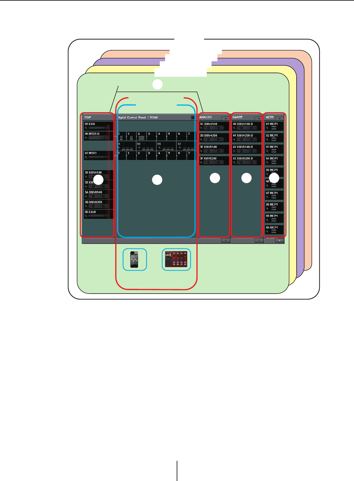
The following diagram shows these requirements applied in MTX-MRX Editor’s Project
screen.
1
4 5 6
3
2
Project
MTX/MRX system
MTX/MRX system
Audio connections
(up to a total of 20 units)
DCP/PGM1
Control panel
Line
(analog)
connections
YDIF connections
(up to 4 MTX/MRX
units, up to a total
of 8 units)
MTX/MRX system
MTX/MRX system
Dante
connections
Wireless DCP ProVisionaire
To u c h
MCP1
MTX/MRX system configuration examples Chapter 1. An overview of MTX-MRX Editor
MTX-MRX Editor User Guide
9
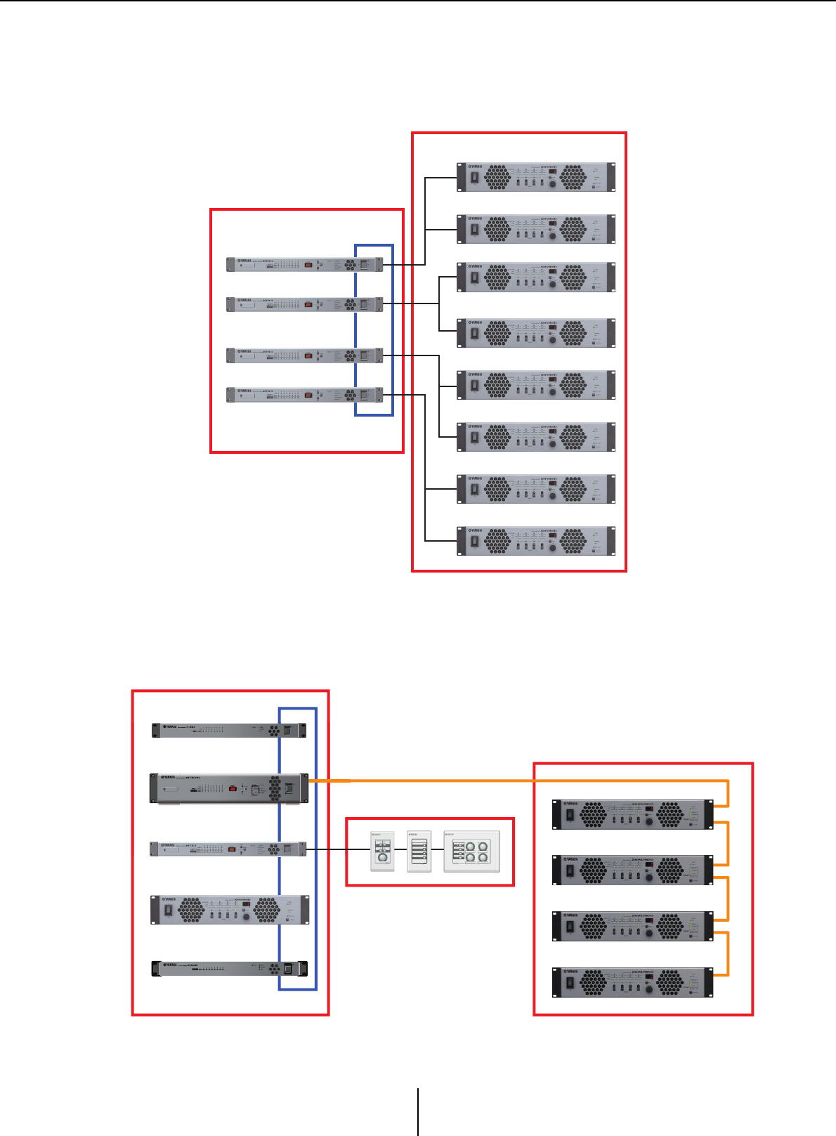
MTX/MRX system configuration examples
Example 1
Example 2
MTX3
MTX3
MTX3
MTX3
YDIF
XMV
YDIF connections
(diagram 2on previous page)
Analog connections
(diagram 4on previous page)
EXi8
MTX3
MTX5-D
XMV
EXo8
YDIF
YDIF connections
(diagram 2on previous page)
DCP connections
(diagram
3
on previous page)
Dante connections
(diagram 5 on previous page)

What are YDIF connections? (Cascade mode and Distribution mode) Chapter 1. An overview of MTX-MRX Editor
MTX-MRX Editor User Guide
10
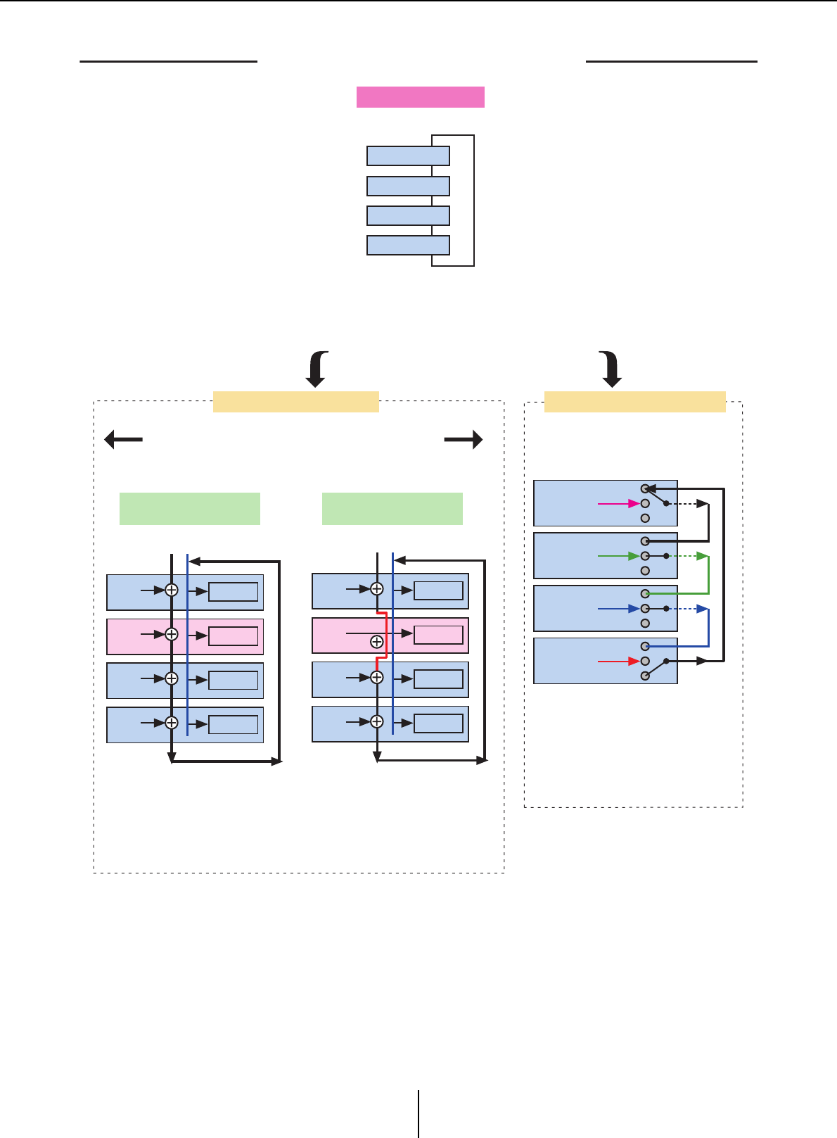
What are YDIF connections?
(Cascade mode and Distribution mode)
An MTX/MRX system has the following two connection modes. When connecting multiple YDIF
devices (when making YDIF connections), you must choose one of these modes. In either case, the
system can easily be expanded at low cost.
Use the “Device Configuration Wizard” dialog box to switch modes.
●Cascade mode
This allows up to eight channels of matrix buses to be shared between multiple MTX
units. Mic inputs can be expanded to a maximum of 32 channels, and eight mixes can
be created.
In cascade mode, YDIF is used as the internal bus; this means that an EXi8 on the input
side and an EXo8/XMV on the output side cannot be connected via YDIF.
Cascade mode cannot be selected if the MTX/MRX system includes an MRX unit.
●Distribution mode
This is used when inputting audio signals from an EXi8 to an MTX/MRX, when
inputting/outputting between MTX/MRX units, and when outputting from an MTX/
MRX to an XMV/EXo8. This allows a single audio signal to be distributed to multiple
output destinations. An MTX/MRX and XMV can be digitally connected via YDIF to
easily construct a high-quality system.
NOTE
What are YDIF connections? (Cascade mode and Distribution mode) Chapter 1. An overview of MTX-MRX Editor
MTX-MRX Editor User Guide
11
01 MTX3
02 MTX3
03 MTX3
04 MTX3
YDIF1
YDIF1
YDIF1’
01 MTX3
Matrix1 ZONE1
02 MTX3
Matrix1 ZONE1
03 MTX3
Matrix1 ZONE1
04 MTX3
Matrix1 ZONE1
YDIF1 YDIF1’
01 MTX3
Matrix1 ZONE1
02 MTX3
Matrix1 ZONE1
03 MTX3
Matrix1 ZONE1
04 MTX3
Matrix1 ZONE1
01 MTX3 OUT
OUT
OUT
OUT
IN
IN
IN
IN
02 MTX3
03 MTX3
04 MTX3
Up to four MTX units can be connected. Connections can be in any order.
Eight channels of signals can be
shared by the buses.
Shared signals are used as inputs
to the zones.
Eight channels of signals can be
shared by the buses.
If CASCADE mode is off, the unit’s
own mix is used as the input to the zone
(this can be specified for each unit).
No output
No output
No output
No output
02 MTX3 : Matrix1
CASCADE MODE = OFF
Connection
YDIF MODE = DISTRIBUTION
YDIF MODE = CASCADE
To switch the settings of the two modes,
click the [System] menu command
“MTX Configuration” and make settings for each matrix.
Cascade mode cannot be selected if there is an MRX unit in the
MTX/MRX system.
RING connection
If only MTX units are connected
Use the [Device Configuration Wizard]
to switch both settings.
There are 16 channels of audio signal
in Distribution mode.
The audio will circulate, but an
intermediary MTX/MRX unit can replace
the signal.
Through
Through
Through
Through
02 MTX3 : Matrix1
CASCADE MODE=ON
YDIF patching is done
in the
“
EXT. I/O” screen.
What are YDIF connections? (Cascade mode and Distribution mode) Chapter 1. An overview of MTX-MRX Editor
MTX-MRX Editor User Guide
12
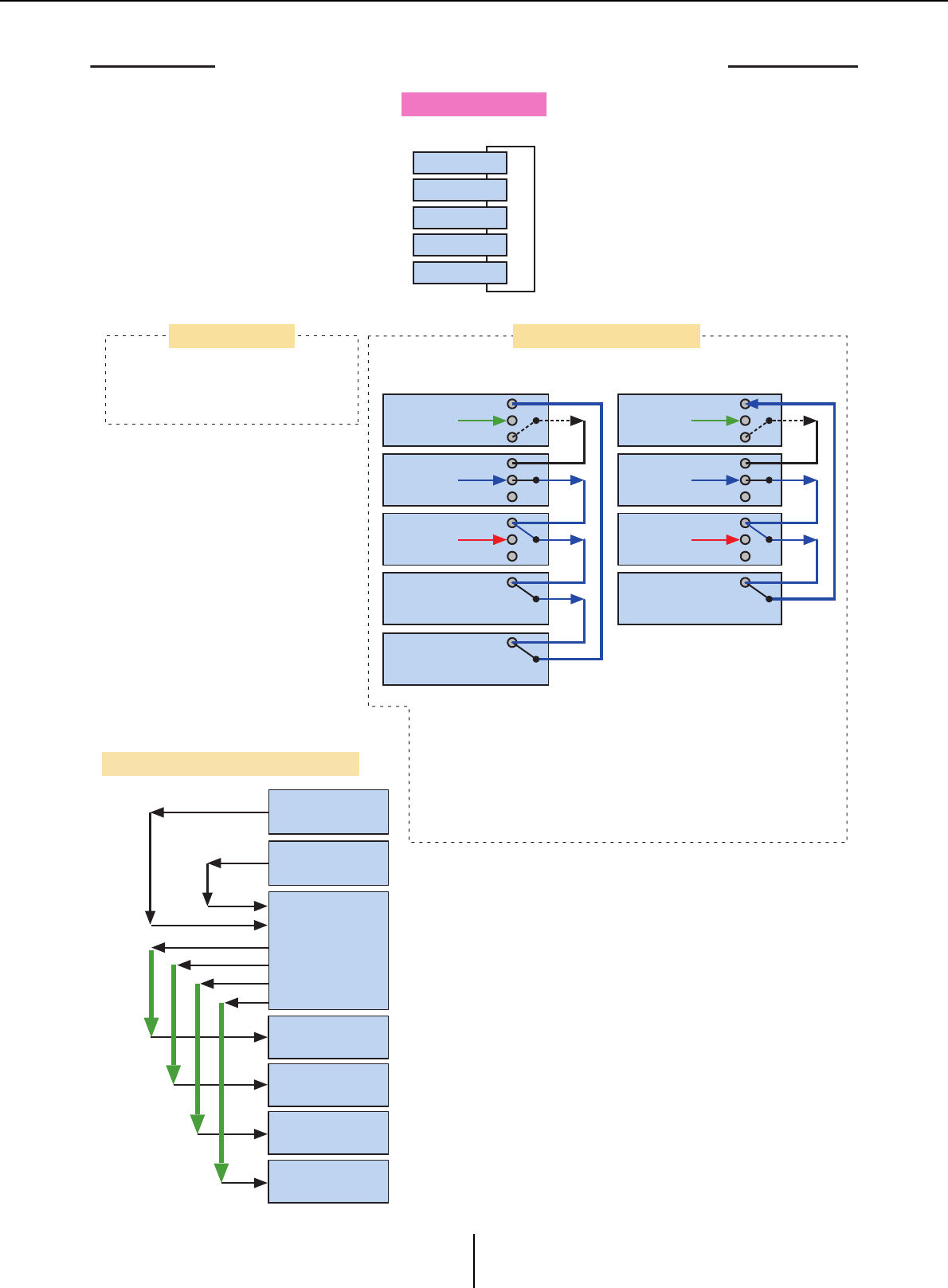
RING connection
01 EXi8
02 MTX5-D
03 MTX3
04 XMV4280
05 EXo8
YDIF1
01 MTX3 OUT
OUT
OUT
OUT
IN
IN
IN
IN
02 MTX3
03 MTX3
04 XMV4280
YDIF1
01 EXi8 OUT
OUT
OUT
OUT
IN
IN
IN
IN
02 MTX5-D
03 MTX3
04 XMV4280
MTX3
EXi8
EXi8
4CH
YDIF1–4
YDIF5–8
YDIF9–12
YDIF13–16
4CH
4CH
4CH
4CH
4CH
4CH
4CH
XMV
XMV
XMV
XMV
05 EXo8
8CH
8CH
8CH
8CH
YDIF1–8
YDIF9–16
There are 16 channels of audio signal in Distribution mode.
The audio will circulate, but an intermediary MTX/MRX unit can replace
the signal.
The XMV is only able to receive.
When connected via YDIF, the XMV will send the audio signals without
change to the EXi8/EXo8 or the MTX/MRX. The audio signal will loop
unless the EXi8/MTX/MRX unit outputs a different signal or the output
is stopped.
If MTX/MRX units and other YDIF units are connected
YDIF patching is done in the “EXT. I/O” screen.
<Example of using Distribution mode>
Cascade mode Distribution mode
Connection
Through
Through
Through
Through
Through
Through
Through
Through
Through
Up to eight units can be connected via YDIF. Connections can be in any order.
No output
No output
No output
No output
No output
No output
If a device other than an MTX is
connected, it is not possible to
select Cascade mode.
What are Dante connections? (Daisy-chain connection and Star connection) Chapter 1. An overview of MTX-MRX Editor
MTX-MRX Editor User Guide
13
What are Dante connections?
(Daisy-chain connection and Star connection)
A Dante network can be connected in two ways.
Set the DIP switches of the devices as appropriate for the type of connection.
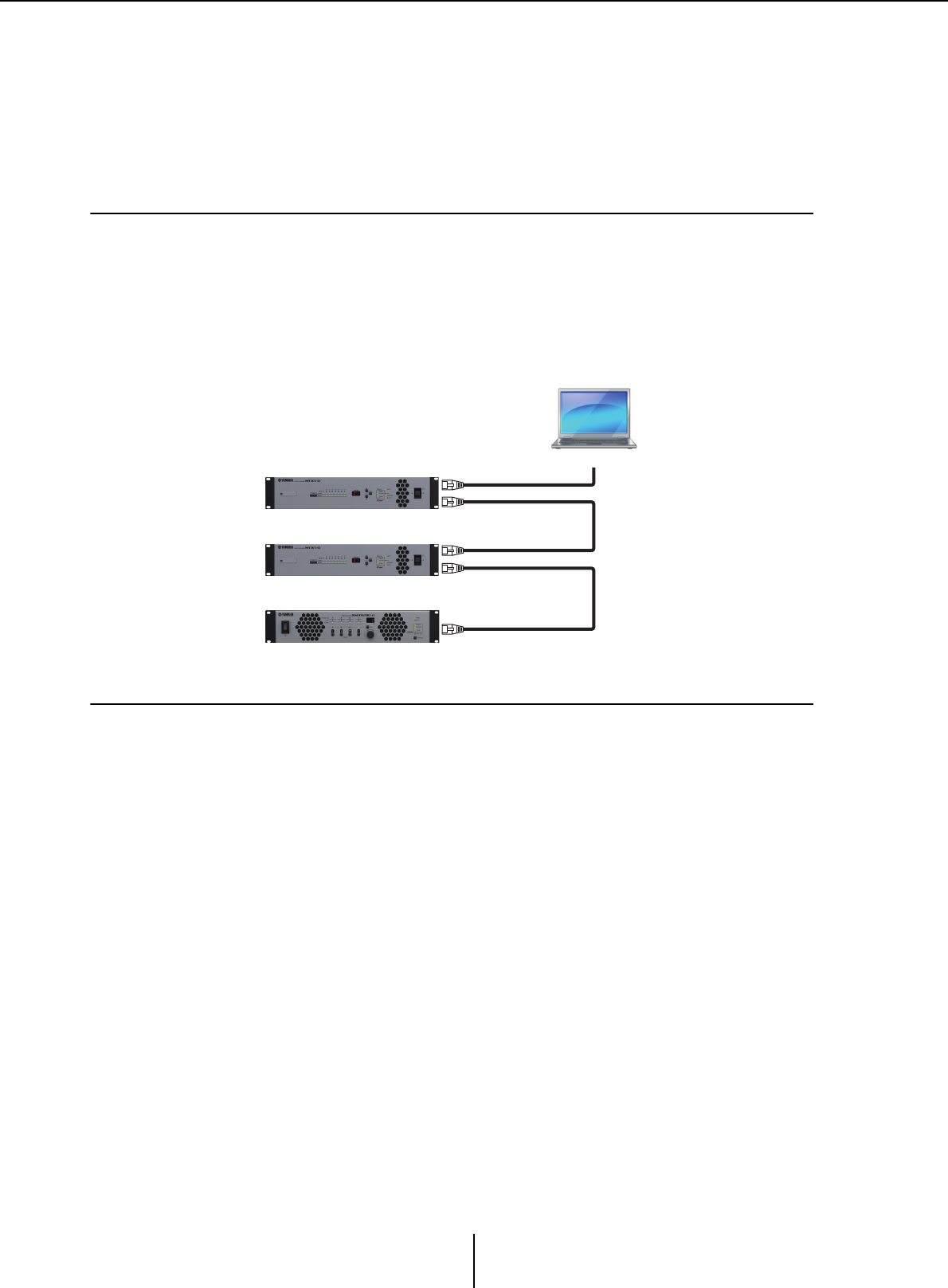
❑Daisy-chain connection
In a daisy-chain connection, each device is connected to the next device, in a chain. This method
makes it simple to construct a network, and does not require a network switch. Use this method for
simple systems in which a relatively small number of units are to be connected.
As the number of connected units increases, you will need to increase the latency. Also, if a problem
such as a broken cable occurs, the network will be disconnected at that point, and communication
with units beyond that point will be impossible.
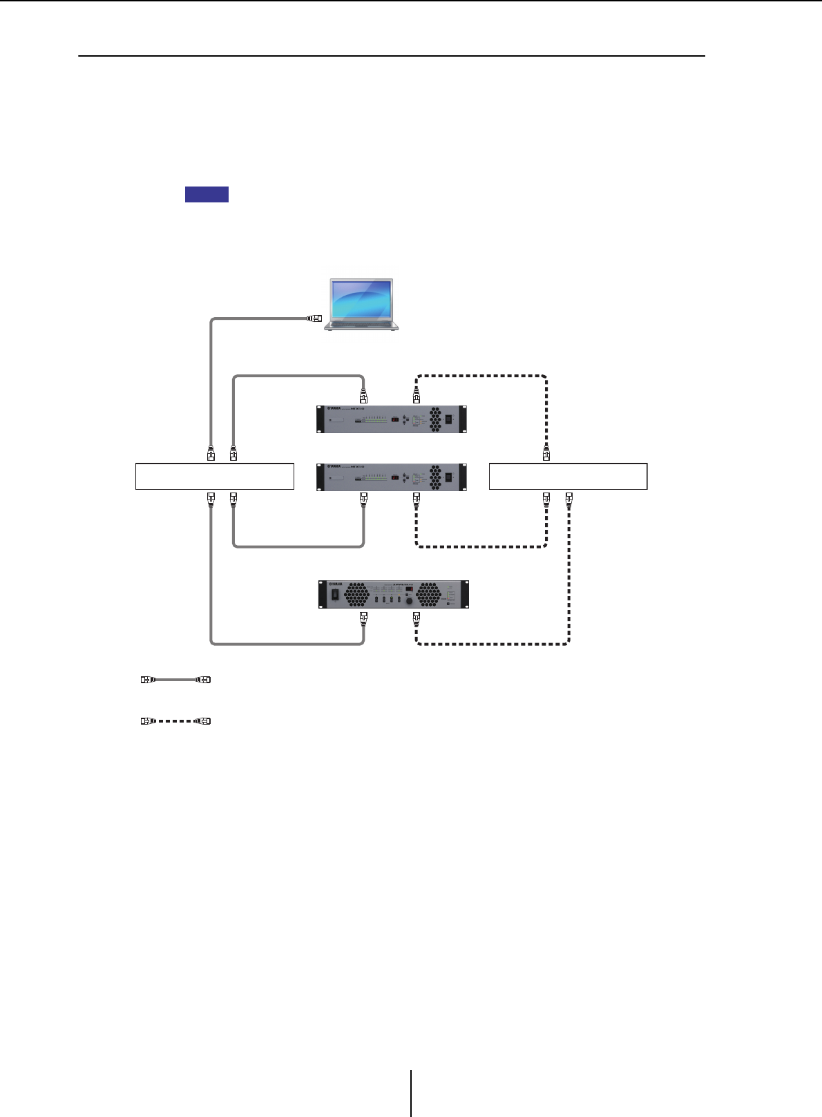
❑Star connection
In a star connection, devices are connected with a network switch at their center. By using a network
switch that supports gigabit Ethernet, you can create even large-scale networks that require high
bandwidth. We recommend that you use a network switch that supports functionality for
controlling and monitoring the network (e.g., QoS, which gives priority to clock synchronization
and audio transmission for specified data routings).
With this type of connection, it is typical to create a redundant network so that audio will continue
being conveyed even if a problem occurs with the network.
SECONDARY
PRIMARY
PRIMARY
SECONDARY
PRIMARY
Computer
What are Dante connections? (Daisy-chain connection and Star connection) Chapter 1. An overview of MTX-MRX Editor
MTX-MRX Editor User Guide
14
❑About redundant networks
A redundant network is a network consisting of two circuits: a primary circuit and a secondary
circuit. Normally, communication occurs on the primary circuit, but if a problem such as a broken
cable occurs on the primary circuit, communication will automatically switch to the secondary
circuit. By using this type of connection with a star connection, you can construct an environment
that is more resistant to network problems than a daisy-chained network.
In order to communicate with MTX-MRX Editor or a Wireless DCP when operation has
switched to the secondary Dante connection, you must re-connect the computer or Wi-Fi
access point to the secondary Dante network switch.
NOTE
Network switch A Network switch B
PrimaryDante
SecondaryDante
Patching Chapter 1. An overview of MTX-MRX Editor
MTX-MRX Editor User Guide
15
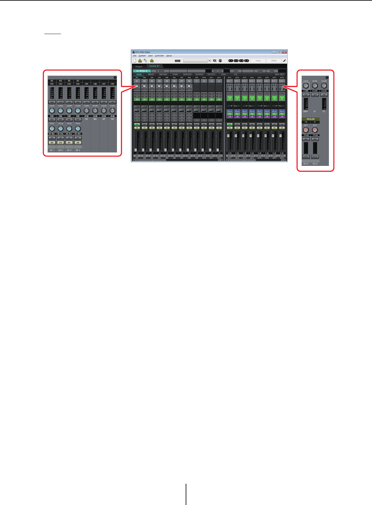
Patching
In a digital audio network such as YDIF or Dante that comprises the MTX/MRX system, you will
make settings on the transmitting device to specify “which output channel/bus’s signals will be sent
to which channels of the digital audio network,” and make settings on the receiving device to specify
“which channels of the digital audio network will be received on which input channels.”
This type of patching mechanism allows the signal of one channel of the digital audio network to
be received by multiple devices.
In MTX-MRX Editor, settings for transmission/reception within the MTX unit are made in the
“MAIN” screen, settings for transmission/reception within the MRX unit are made in the “MRX
Designer” window, and settings for transmission/reception with external devices such as the XMV
or EXi8 are made in the “EXT. I/O” screen.
Settings for connecting the MTX/MRX’s analog output to the XMV’s analog input are also made in
the “EXT. I/O” screen.
By making patching settings for the MTX and external devices in the “EXT. I/O” screen, the
parameters of an external device can be edited in the parameter edit screen that appears when you
click the port/external device parameter recall button in the “MAIN” screen of the MTX.
External device settings can also be edited in the “EXi8,” “EXo8,” “XMV,” and “R/Tio” screens.
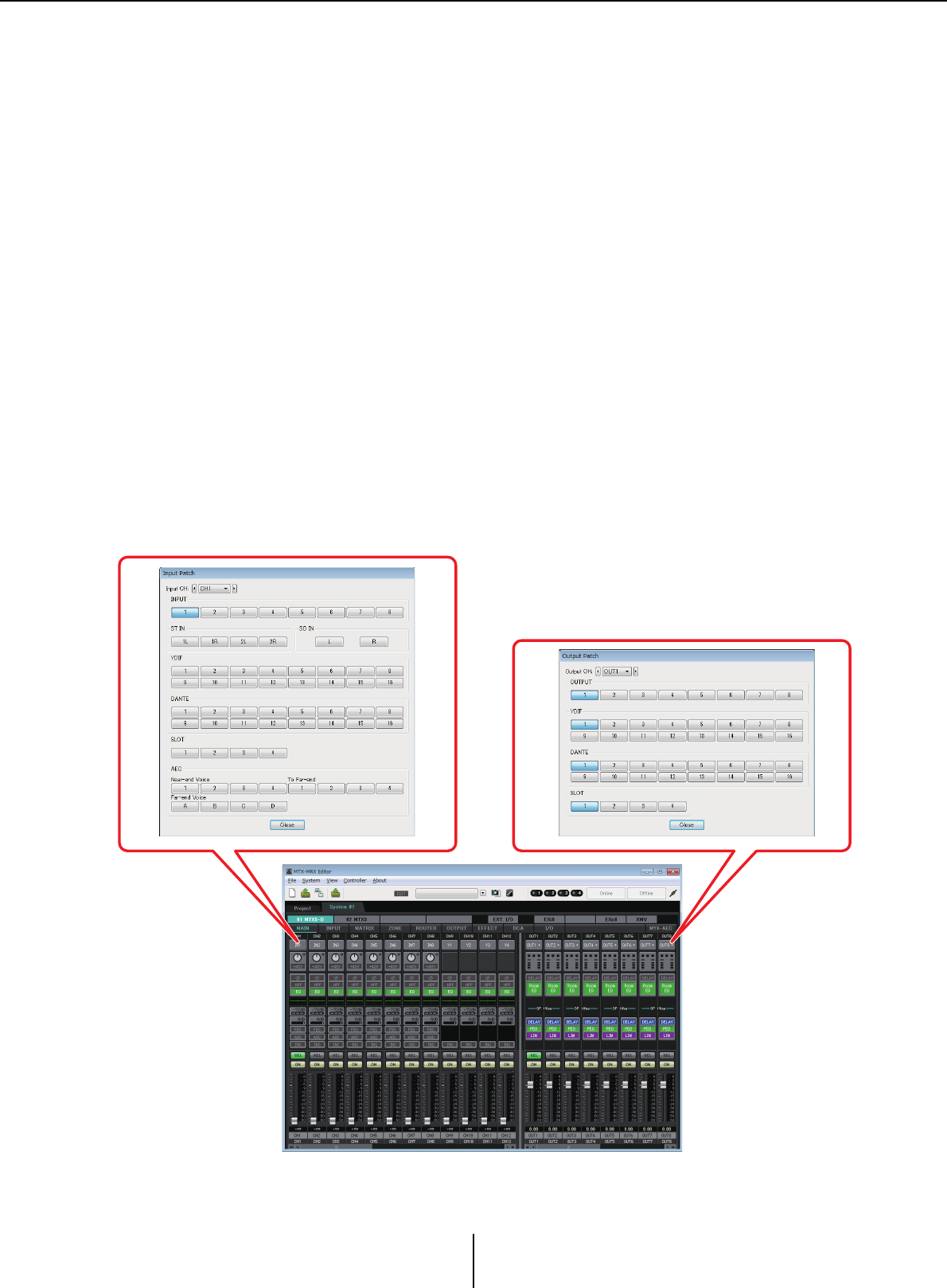
• Settings on the MTX unit itself (the screen of the MTX5-D is shown)
Input to the MTX
Output from the MTX
Patching Chapter 1. An overview of MTX-MRX Editor
MTX-MRX Editor User Guide
16
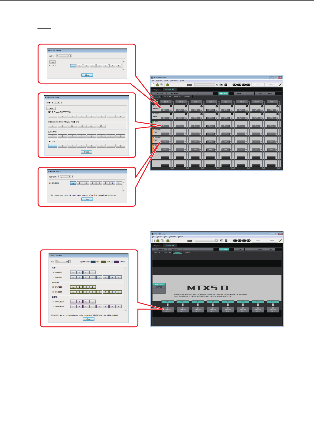
• Settings for external devices such as the XMV or EXi8
YDIF
Analog
Transmission from an external device to YDIF
Transmission from YDIF to an external device
Transmission from the MTX to YDIF
Settings for the analog connectors
of the XMV
Workflow Chapter 1. An overview of MTX-MRX Editor
MTX-MRX Editor User Guide
18
Workflow
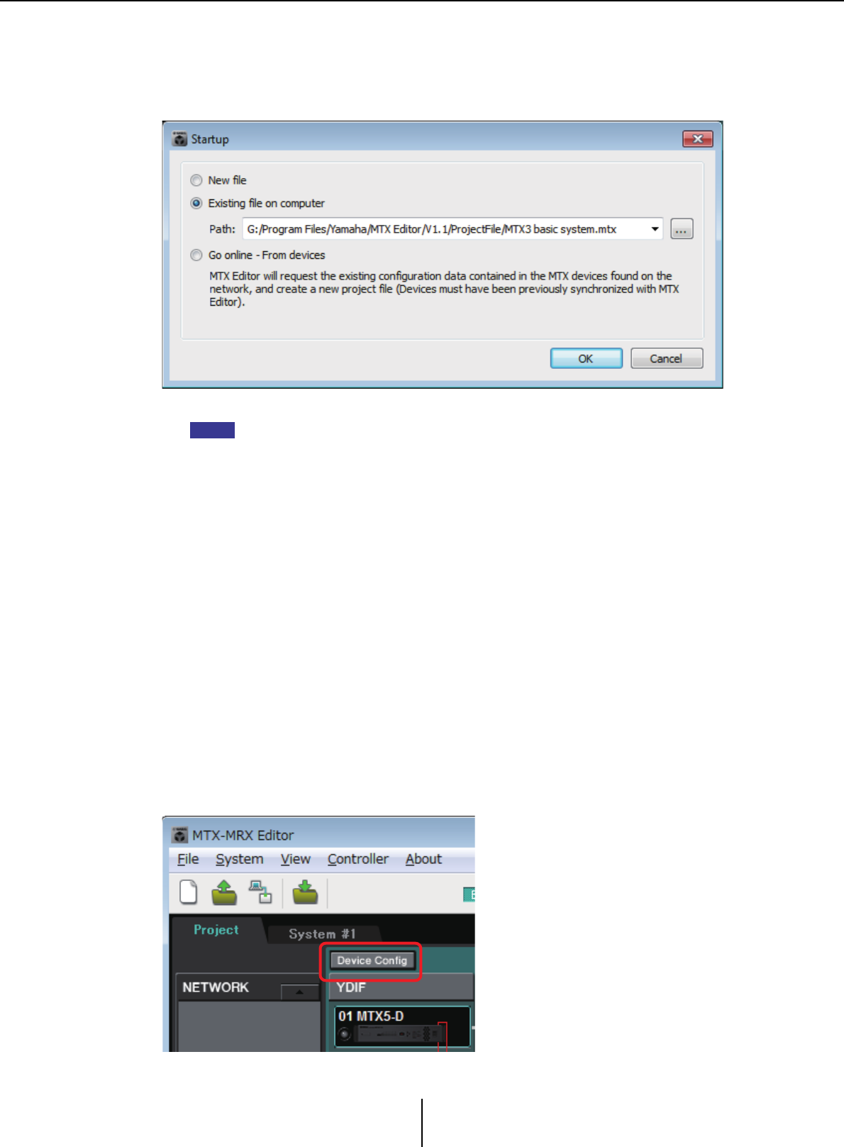
Start MTX-MRX Editor.
The “Startup” dialog box will appear.
When you select [New file], the “Device Configuration Wizard” dialog box will appear.
When you install MTX-MRX Editor, a project file linked with the “MTX Setup Manual” and “MRX
Setup Manual” is installed in the following folder.
● For a 32-bit OS
C:/Program Files/Yamaha/MTX-MRX Editor/V*.*/ProjectFile
● For a 64-bit OS
C:/Program Files(x86)/Yamaha/MTX-MRX Editor/V*.*/ProjectFile
*.* will be the version of the installed MTX-MRX Editor.
You can also select and use this file by selecting [Existing file on computer].
Follow the screens of the “Device Configuration Wizard” dialog box to specify the
configuration of the MTX/MRX system.
For details about the “Device Configuration Wizard” dialog box when creating a new
configuration, refer to the “MTX Setup Manual” or the “MRX Setup Manual.”
Specify the configuration of the MTX/MRX system as directed in the screens. The device
configuration will be shown in the Project screen. You’ll be able to print a configuration
diagram at the end of the wizard.
If you canceled the procedure before completing the “Device Configuration Wizard,” or if
you want to change the configuration of the MTX/MRX system, click the [Device Config]
button. The “Device Configuration Wizard” dialog box will appear once again.
NOTE
Project screen
Workflow Chapter 1. An overview of MTX-MRX Editor
MTX-MRX Editor User Guide
19
For details, refer to Project screen.
Change the functions of the MTX.
To change the functions of input ports and stereo input channels, use the “MTX
Configuration” dialog box, which can be opened from the [System] menu.
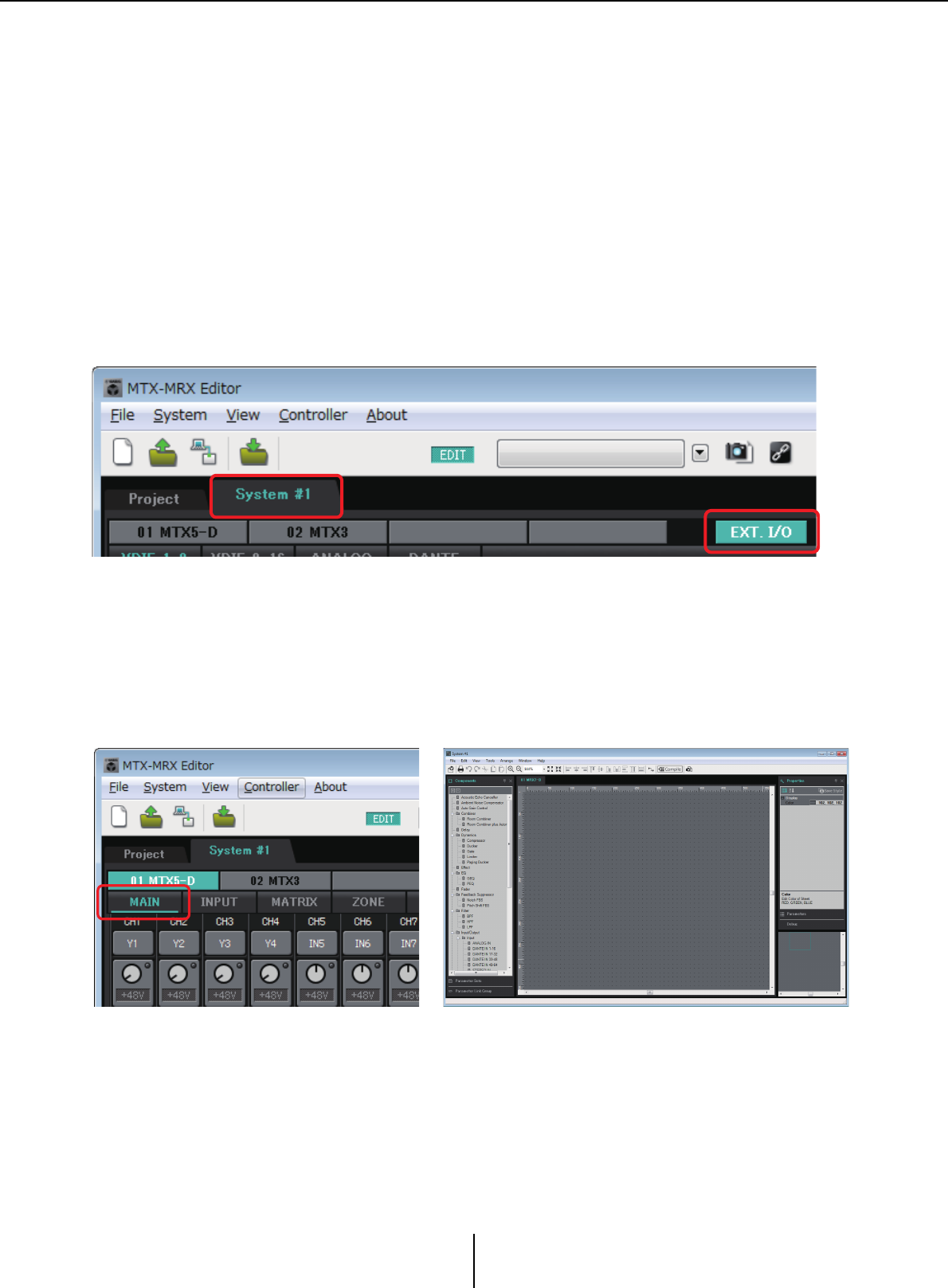
Specify the patching between the MTX/MRX and the peripheral devices.
You’ll make these settings in the “EXT. I/O” screen. To access the “EXT. I/O” screen, click
the [EXT. I/O] button in the System screen.
For the MRX, only DANTE can be specified. For YDIF, make settings in the component
editor of the “MRX Designer” window.
For the MTX, click the [MAIN] button in the System screen to access the “MAIN”
screen.
For the MRX, click the [Open MRX Designer] button in the System screen to access the
“MRX Designer” window.
The subsequent workflow is explained using the MTX as an example.
For the MRX, make settings in the “MRX Designer” window, and then proceed to “Store
the preset.”
EXT. I/O screen
MTX: MAIN screen MRX: MRX Designer window
For details, refer to “MAIN” screen. For details, refer to “MRX Designer User Guide”.
Workflow Chapter 1. An overview of MTX-MRX Editor
MTX-MRX Editor User Guide
20
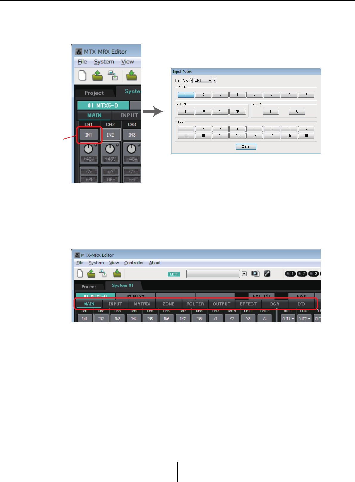
Specify the MTX’s input channel settings.
Use the “Input Patch” dialog box to assign ports to input channels. To open the “Input
Patch” dialog box, click a port select button in the MAIN screen.
For details, refer to “Input Patch” dialog box.
In the same way, use the “Output Patch” dialog box to assign ports to output channels.
Edit the component parameters.
To access each component editing screen, click the buttons indicated below.
For details on each component, refer to the following screens.
“INPUT” screens
“MATRIX” screen
“ZONE” screen
“ROUTER” screen
“OUTPUT” screens
“EFFECT” screen
“DCA” screen
“I/O” screen
“Input Patch” dialog box
Port select
buttons
Workflow Chapter 1. An overview of MTX-MRX Editor
MTX-MRX Editor User Guide
21
Make DCP, Wireless DCP, MCP1, PGM1/PGX1, GPI, and Scheduler settings.
You’ll make these settings in the following dialog boxes.
DCP settings: “Digital Control Panel” dialog box
(On the [Controller] menu, click [Digital Control Panel].)
Wireless DCP settings: “Wireless DCP” dialog box
(On the [Controller] menu, click [Wireless DCP].)
MCP1 settings: “MCP1” dialog box
(On the [Controller] menu, click [MCP1].)
PGM1/PGX1 settings: In the “ZONE” screen, [PAGING] and the “PGM1/PGX1”
dialog box
(On the [Controller] menu, click [PGM1/PGX1].)
GPI settings: “GPI” dialog box or “GPI Calibration” dialog box
(On the [System] menu, click [GPI] or [GPI Calibration].)
Schedule settings: “Scheduler” dialog box
(On the [System] menu, click [Scheduler])
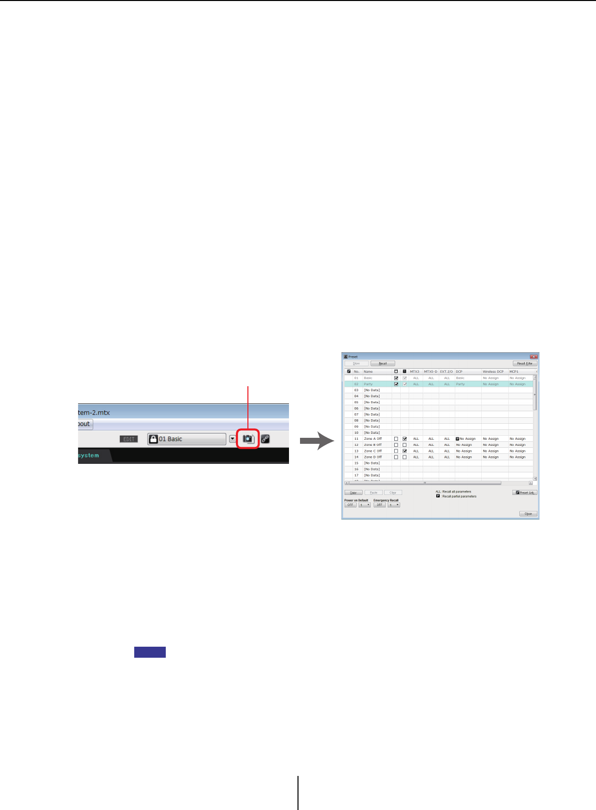
Store the preset.
You’ll use the “Preset” dialog box to store the preset. To open the “Preset” dialog box, click
the preset button.
For details on the DCP library, Wireless DCP library, MCP1 library, and audio file settings
that are recalled at the same time as a preset, refer to “Preset” dialog box.
Connect your devices as shown in the configuration diagram you printed.
Turn off the power of each device, and set the UNIT ID on the rear panel of the
MTX/MRX, XMV, EXi8/EXo8, and PGM1 units. For the MCP1, turn on the power
before setting the UNIT ID.
You can also print the configuration diagram by clicking [Print Configuration Diagram] on the
[File] menu.
First make sure that DIP switch 6 (IP SETTING) on the unit’s rear panel is set to [UNIT
ID]. If it is set to [PC], change it to [UNIT ID] and then restart the device.
“Preset” dialog box
Preset button
NOTE
Workflow Chapter 1. An overview of MTX-MRX Editor
MTX-MRX Editor User Guide
22
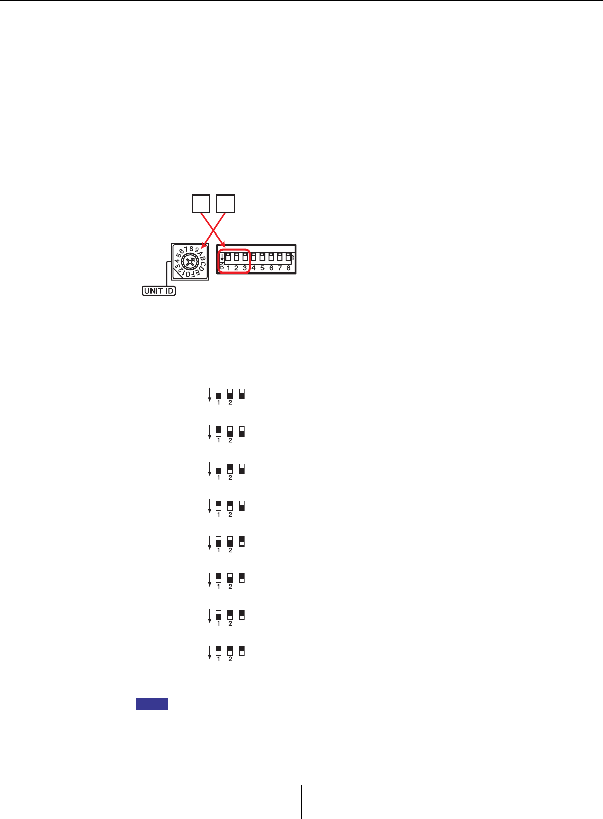
Use the rear panel [UNIT ID] rotary switch and DIP switches to set the UNIT ID of each
device. In MTX-MRX Editor, the UNIT ID is shown as a hexadecimal number. Use the
DIP switches (switches 1–2 on the MTX/MRX and EXi8/EXo8, switches 1–3 on PGM1
and YDIF-equipped models of XMV) to specify the upper digit, and use the [UNIT ID]
rotary switch to specify the lower digit. On Dante-equipped models of XMV, use the
[UNIT ID] rotary switch [HIGH] to specify the upper digit, and use [LOW] to specify the
lower digit.
For details on the R series (AD/DA) or the Tio1608-D, refer to their respective owner’s
manuals.
Do not set the UNIT ID to 00.
Example setting) Setting the UNIT ID to [0A] on YDIF-equipped models of XMV
Use the DIP switch combinations shown below to specify the upper digit of the UNIT ID.
If you want to use a DHCP server or operate the device with a fixed IP address, refer to “IP
Address” dialog box. To open the “Set IP Address” dialog box, use the “Device Information”
dialog box which you can access from the [System] menu.
Upper digit is 0
Upper digit is 1
Upper digit is 2
Upper digit is 3
Upper digit is 4
Upper digit is 5
Upper digit is 6
Upper digit is 7
0A
DIP switch
[UNIT ID]
Rotary Switch
3
3
3
3
3
3
3
3
ON
3
3
3
3
3
3
3
3
ON
3
3
3
3
3
3
3
3
ON
3
3
3
3
3
3
3
3
ON
3
3
3
3
3
3
3
3
ON
3
3
3
3
3
3
3
3
ON
3
3
3
3
3
3
3
3
ON
3
3
3
3
3
3
3
3
ON
NOTE
Workflow Chapter 1. An overview of MTX-MRX Editor
MTX-MRX Editor User Guide
23
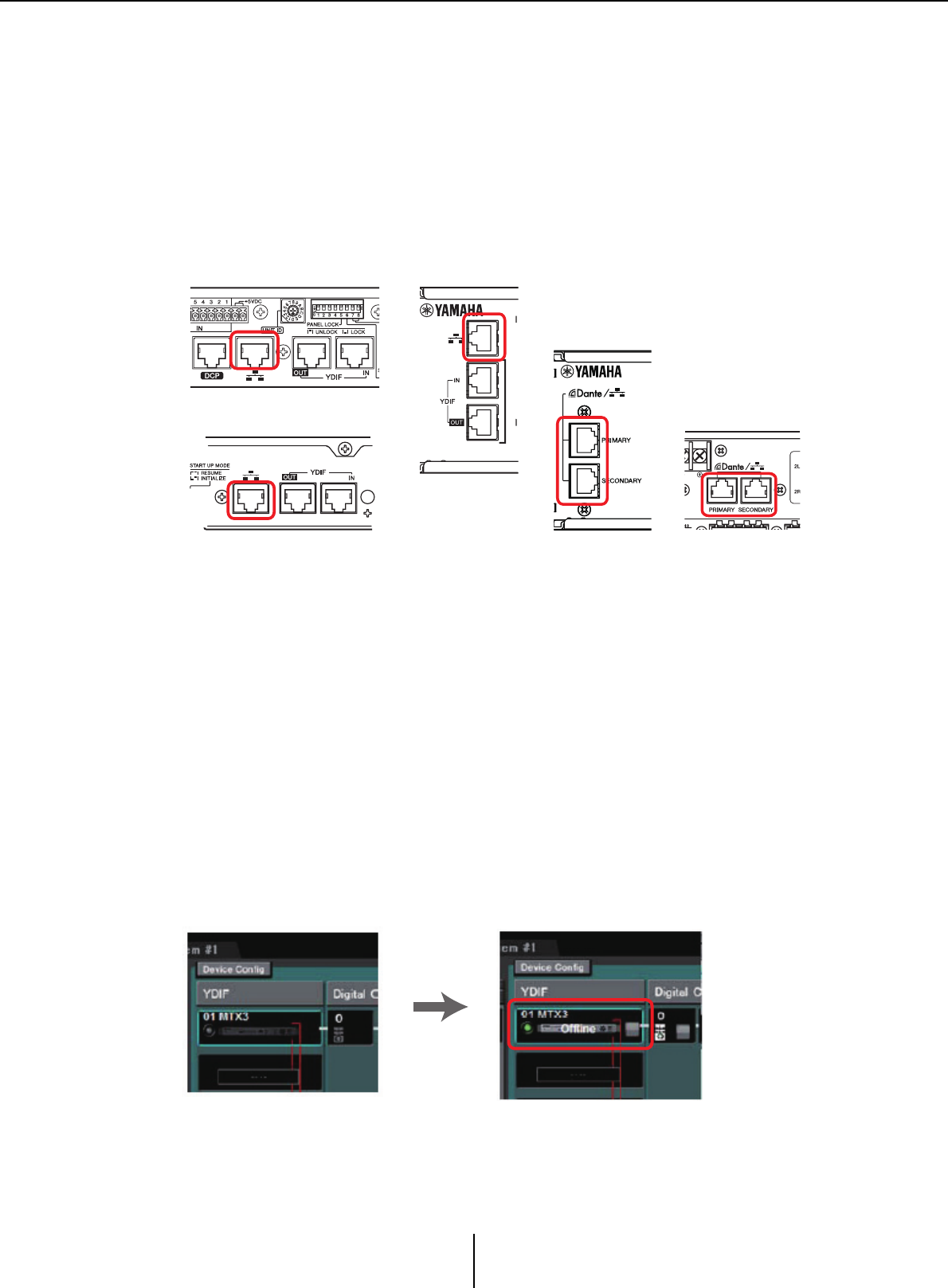
Connect the devices and your computer as shown in the configuration diagram.
Connect the device to the computer using its [Dante] connector for a Dante-equipped unit
or its NETWORK connector for an MCP1 and YDIF-equipped unit. Normally you will
connect the devices to the computer via a network switch. Only in the case of Dante-
equipped models when using a daisy-chain connection, you will connect the units to the
computer in a daisy-chain. If there is only one MTX/MRX unit, you can also connect the
computer directly to the MTX/MRX. If connecting the MCP1 and PGM1, you will need
an IEEE802.3af compliant PoE network switch or PoE injector. For details, refer to the
respective installation manual.
Turn on the power of the device.
In the MCP1’s settings page, verify that IP Setting is set to [UNIT ID], and set the
UNIT ID.
Select the network card and specify the IP address of the computer.
To select the network card, use the “Network Setup” dialog box which you can access from
the [System] menu. Set the network card’s IP address to 192.168.0.x (x is a number other
than 0, 255, or the unit’s UNIT ID) and the subnet mask to 255.255.255.0. The IP address
setting for the network card is made in Control Panel “Network Connections.” You can
access “Network Connections” by clicking the [Open Network Connections] button in the
“Network Setup” dialog box.
When connections have been established between the computer and the devices, the
device icons shown in the Project screen will change.
NETWORK connector of
the MTX3
NETWORK connector of a
YDIF-equipped model of XMV
[Dante] connector of a Dante-
equipped model of XMV
[Dante] connector of
the MTX5-D/MRX7-D
NETWORK connector of
the EXi8/EXo8
Connections with the
devices has succeeded
Workflow Chapter 1. An overview of MTX-MRX Editor
MTX-MRX Editor User Guide
24
Verify that the firmware versions of the devices are compatible with
MTX-MRX Editor.
For details, refer to the “Device Information” dialog box which you can access from
the [System] menu.
For information about firmware compatibility with MTX-MRX Editor, refer to the
Yamaha Pro Audio website.
http://www.yamahaproaudio.com/japan/ja/
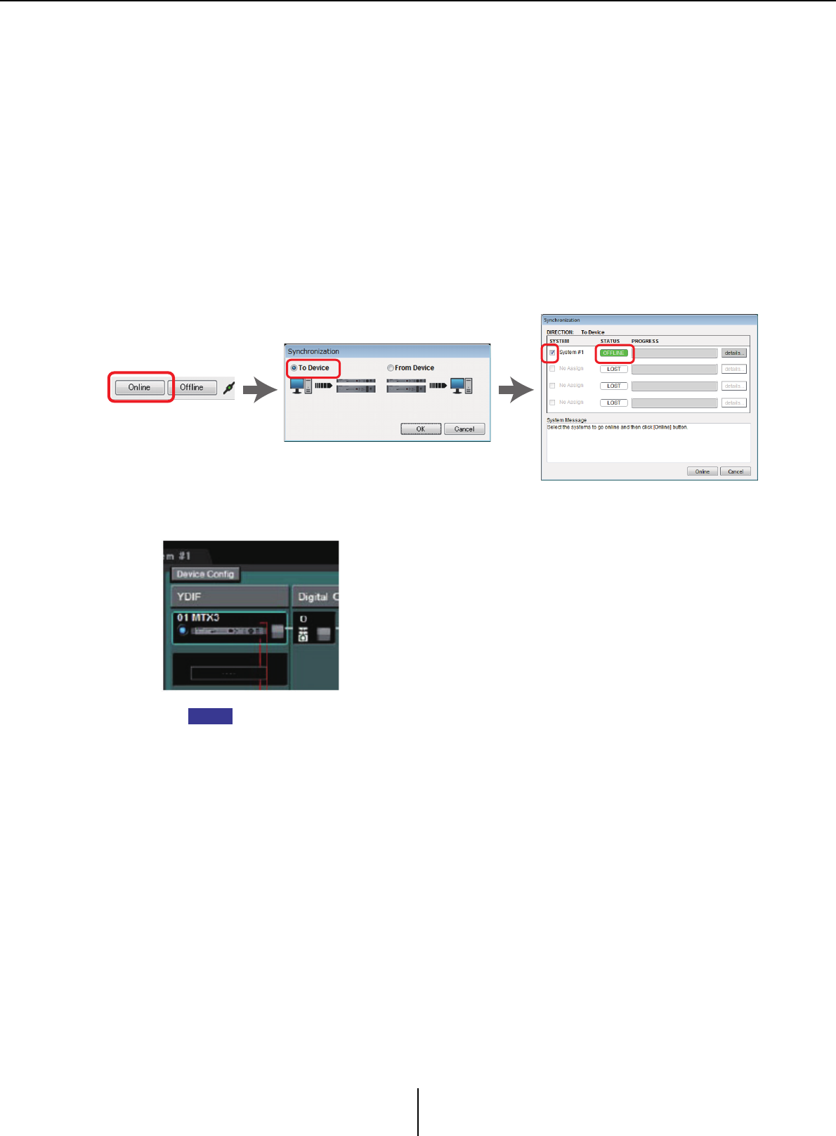
Synchronize your computer and the devices (put them in the online state).
Click the [Online] button in the toolbar to open the “Synchronization” dialog box, check
“To Device”, and click the [OK] button.
When the dialog box indication has switched, select the check box of the system that you
want to place online, and click the [Online] button.
The contents of the MTR-MRX Editor’s settings are sent to each device. In the online state,
the indicator will light blue as shown below.
• When online, the computer’s time will be sent to each device.
• The Daylight Saving Time setting will reflect the “Date and Time” settings of the computer
that was used to first create the applicable project file. If you want to change the Daylight
Saving Time settings of a project file that was created on a computer for which Daylight
Saving Time was not enabled, or a computer with a different time zone setting, open the
“Daylight Saving Time” dialog box from the [System] menu and change the settings.
NOTE

Workflow Chapter 1. An overview of MTX-MRX Editor
MTX-MRX Editor User Guide
25
Edit the MTX’s ports and the XMV’s parameters
If you assigned channels of an external device or ports of an MTX unit to channels when
making internal MTX patch settings as described above, you can click the parameter recall
button of that port or external device to open an edit screen for those parameters.
For details, refer to “MAIN” screen if you’re using the MTX. If you’re using the MRX, refer
to the “MRX Designer User Guide.”
Save the project file.
On the [File] menu, click [Save] or [Save As] to save the project file.
If you want to apply security settings to the file, you can specify a PIN code in the “Security
Settings” dialog box which you can open from the [File] menu.
About the screens Chapter 1. An overview of MTX-MRX Editor
MTX-MRX Editor User Guide
26
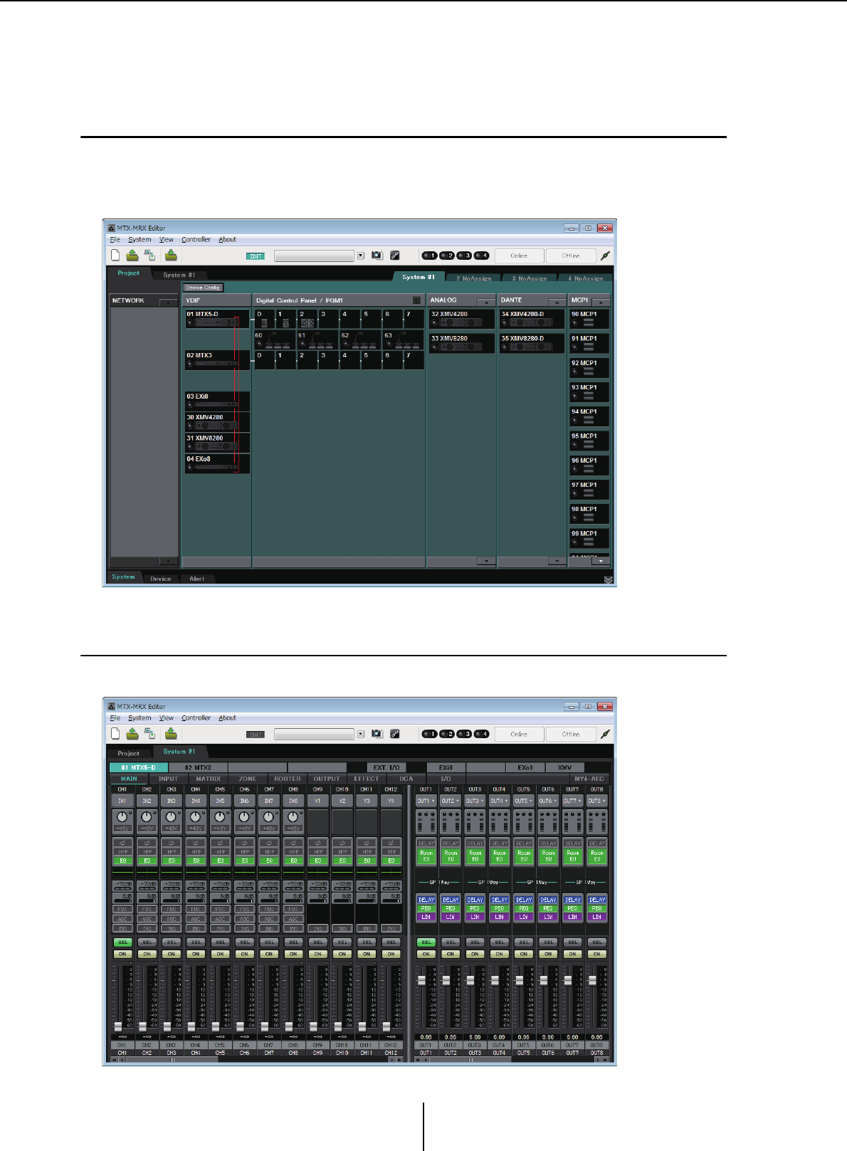
About the screens
MTX-MRX Editor consists mainly of the Project screen and the System screen.
❑Project screen
In this screen you can manage the MTX/MRX system. You can check the status of the MTX and
XMV units, and make device-related settings. You can also check devices that have generated an
alert.
❑System screen
In this screen you can make channel, matrix, and effect settings.
Moving between screens Chapter 1. An overview of MTX-MRX Editor
MTX-MRX Editor User Guide
27
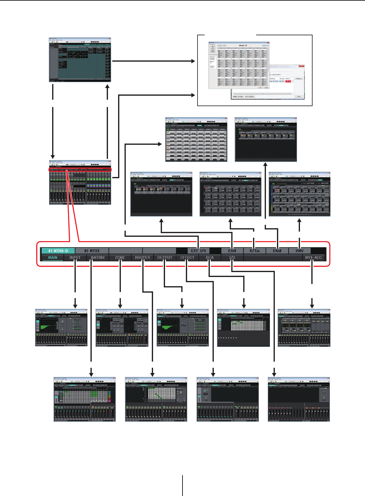
Moving between screens
(*1)The “Device Configuration Wizard” dialog box can be opened only from the Project screen.
(*2)Not shown if the MRX is not selected in the “Device Configuration Wizard” dialog box. For
details about this screen, refer to “MRX Designer User Guide.”
(*3)Not shown if the MY4-AEC is not selected for the MTX5-D in the “Device Configuration
Wizard” dialog box.
Project screen
System screen
(“MAIN”
screen or
“MRX
Designer”
window) (*2)
SYSTEM tab [Project] tab
Toolbar or menu
Dialog boxes (*1)
[EXT. I/O] button
“EXT. I/O” screen
[MATRIX] button
[INPUT] button
[ROUTER] button [EFFECT] button
[DCA] button
“MATRIX” screen
“INPUT” screens “ZONE” screen
“ROUTER” screen “EFFECT” screen
“DCA” screen
Toolbar or menu
“EXo8” screen
“XMV” screen
[EXi8] button [EXo8] button
[MY4-AEC]
button (*3)
“MY4-AEC” screen“OUTPUT” screens
[ZONE] button [OUTPUT] button
“EXi8” screen
[XMV] button
“I/O” screen
[I/O] button
[R/Tio] button
“R/Tio” screen
MTX-MRX Editor User Guide
28
Chapter 2. Menu bar and tool buttons
This chapter provides an overview of the menu bar and the tool buttons. For details on the various
dialog boxes, see the linked references.
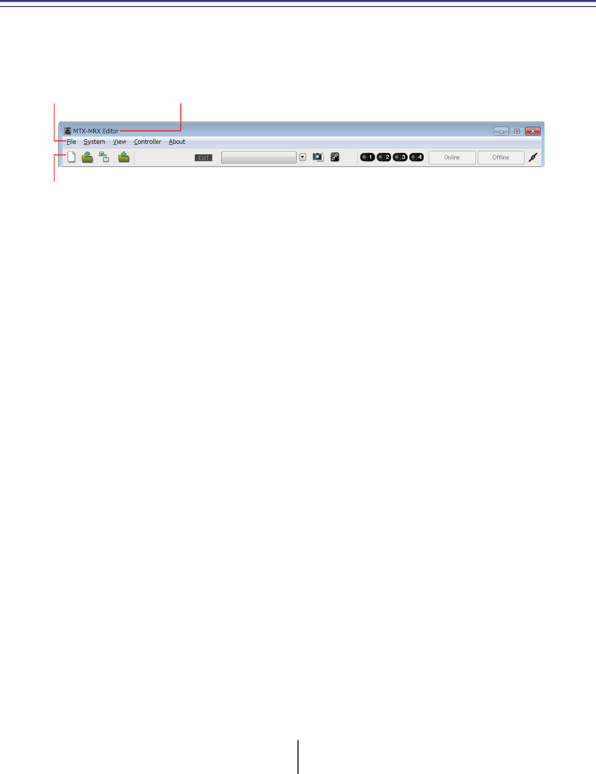
Title bar
This will indicate “MTX-MRX Editor.”
The name of the currently open project file is shown at the right of this. If you have opened a new
project file or if the project file has never been saved, nothing will be shown here.
Menu bar
The commands that can be executed by MTX-MRX Editor can be found here, grouped by category.
Click here to see a list of commands.
Tool buttons
Title barMenu bar

Menu bar Chapter 2. Menu bar and tool buttons
MTX-MRX Editor User Guide
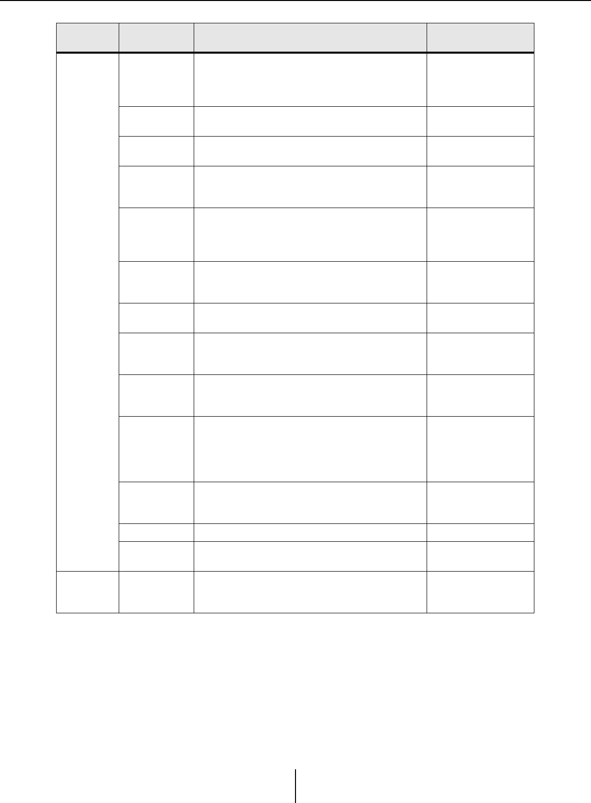
29
Menu Command Summary Dialog box that
appears
[File]
[New]
Creates a new project file.
If you are currently editing a project file, a
confirmation message will appear.
This command is not available while online.
“Device Configuration
Wizard” dialog box
[Open]
Opens a saved project file.
If you are currently editing a project file, a
confirmation message will appear.
This command is not available while online.
“Open File” dialog box
[Go Online –
From Devices]
Loads the settings of the MTX/MRX system into
MTX-MRX Editor.
You can use this command if you have lost the setup
file of the MTX/MRX system.
If you are currently editing a project file, a
confirmation message will appear.
This command is not available while online.
“Go online – From
devices” dialog box
[Save]
Saves the project file (overwriting the previous
version of the file).
The first time you save, the “Save File” dialog box will
appear; specify a name for the file and save it.
–
[Save As]
Saves the project file as a different file. When you
choose this command, the “Save File” dialog box will
appear.
“Save File” dialog box
[Security]
Specifies security settings to prevent another user
from making and saving changes to the system.
These settings are saved in the project file.
“Security Settings”
dialog box
[Project
Information]
Allows you to include a memo in the project file to
record property information or contact information.
“Project Information”
dialog box
[Print
Configuration
Diagram]
Displays a diagram that shows how devices such as
the MTX/MRX, XMV, and DCP are connected. The
configuration diagram can be printed.
“Configuration
Diagram” dialog box
[PGM1 Label
Creator]
Starts the “PGM1 Label Creator” application to
create labels for the PGM1/PGX1.
“PGM1 Label Creator”
application
[Recently
Opened Files]
Lists up to five most recently used project files,
allowing you to open them.
This command is not available while online.
–
[Exit]
Exits MTX-MRX Editor.
If the project file has been edited, a confirmation
message will appear.
This command is not available while online.
–
Menu bar Chapter 2. Menu bar and tool buttons
MTX-MRX Editor User Guide
30
[System]
[Network
Setup]
Selects the computer’s network adapter that will be
used to communicate with the MTX/MRX.
You can also change the IP address of the network
adapter.
“Network Setup”
dialog box
[Device
Information]
Lists the devices on the network, allowing you to
update their firmware and change their IP address.
“Device Information”
dialog box
Match Device
by IP Address
Makes settings for devices that are on a different
subnet than the computer.
“Match Device by IP
Address” dialog box
[Install Speech
Privacy File]
Transmits to the MRX a file used when using the
“Speech Privacy” component on the MRX.
For details, refer to “MRX Designer User Guide.”
“Install Speech Privacy
File” dialog box
[MTX
Configuration]
Here you can specify input/output settings for each
device, such as MTX input ports, output channels,
and matrix buses.
This command is not available in the Project screen.
“MTX Configuration”
dialog box
[Dante
Information]
Indicates the Dante settings and firmware version.
Here you can also make settings for bit rate and
latency.
“Dante Information”
dialog box
[Word Clock] Specify the project’s word clock master and word
clock settings.
“Word Clock” dialog
box
[Clock]
Regardless of the online/offline state, the time and
date will be updated for all devices connected to the
same network.
“Clock” dialog box
[Daylight
Saving Time]
Regardless of the online/offline state, the daylight
saving time setting is specified for all devices
connected to the same network.
“Daylight Saving Time”
dialog box
[Scheduler]
Switches presets or plays back a song or sound
effect from an SD memory card at a previously
specified date and time. Each such setting is called
an “Event.” You can make event settings in the
“Scheduler” dialog box.
“Scheduler” dialog box
[GPI
Calibration]
Calibrates the input voltage detection range for the
[GPI] connector of the MTX/MRX unit. (Available
only when online.)
“GPI Calibration”
dialog box
[GPI] Makes GPI input/output settings. “GPI” dialog box
[Remote
Control] Makes settings for the [RS-232C] connector. “Remote Control”
dialog box
View [Large Scale
View]
Sets MRX Designer’s component editor and MTX-
MRX Editor to a vertical and horizontal display
magnification of 200%.
–
Menu Command Summary Dialog box that
appears
Menu bar Chapter 2. Menu bar and tool buttons
MTX-MRX Editor User Guide
31
[Controller]
[External
Events]
Enables you to configure the commands to be
transmitted so that you can control peripheral
devices via the network to which the Dante
connector or NETWORK connector is connected.
“External Events”
dialog box
[Digital Control
Panel] Makes settings for the digital control panel (DCP). “Digital Control Panel”
dialog box
[Wireless DCP]
Makes settings for the “Wireless DCP” iOS
application.
Except for templates, the items that can be set are
the same as for “Digital Control Panel.”
“Wireless DCP” dialog
box
[MCP1] Makes MCP1 settings. “MCP1” dialog box
[PGM1/PGX1] Makes PGM1/PGX1 settings. “PGM1/PGX1” dialog
box
[About]
[Shortcut Keys] Shows a list of shortcut keys.
“Shortcut Keys” window
[Operation
Manual] Displays basic operations. “Operation Manual”
window
[About MTX-
MRX Editor]
Displays details such as the software version of
MTX-MRX Editor. –
Menu Command Summary Dialog box that
appears
Tool buttons Chapter 2. Menu bar and tool buttons
MTX-MRX Editor User Guide
32
Tool buttons
Related
tools Buttons etc. Summary Dialog box that appears
File
[New]
Creates a new project file.
If you are currently editing a project file, a
confirmation message will appear.
This button is not available while online.
“Device Configuration
Wizard” dialog box
[Open]
Opens a saved project file.
If you are currently editing a project file, a
confirmation message will appear.
This button is not available while online.
“Open File” dialog box
[Go Online – From
Devices]
Loads the settings of the currently operating
MTX/MRX system into MTX-MRX Editor.
You can use this command if you have lost the
setup file of the MTX/MRX system.
If you are currently editing a project file, a
confirmation message will appear.
This button is not available while online.
“Go online – From
devices” dialog box
[Save]
Saves the project file (overwriting the previous
version of the file).
The first time you save, the “Save File” dialog
box will appear; specify a name for the file and
save it.
–
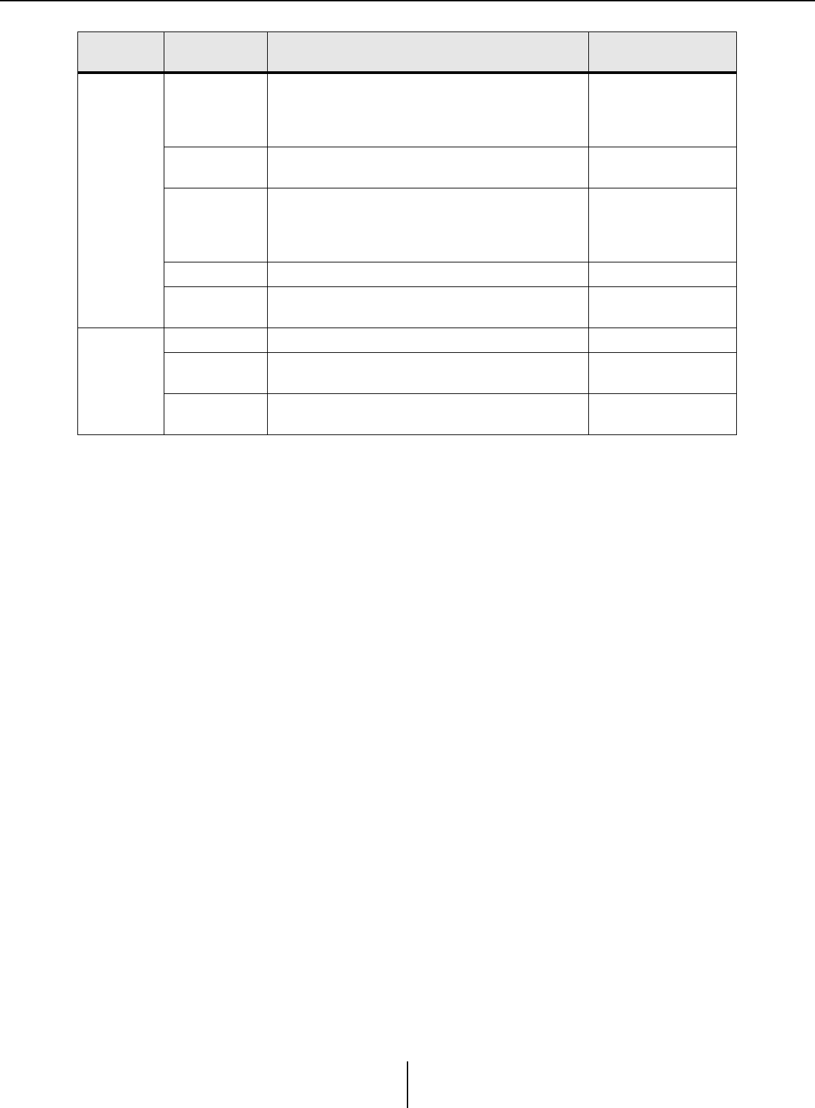
Preset
[EDIT] indicator
This indicator will light if you edit a parameter or
setting. In this case, store the preset as
necessary.
–
Preset select box
The stored presets will be displayed as shown
below. (Empty presets are not shown.) The
preset you select here will be recalled.
You can overwrite-store by clicking the name of
a stored preset.
When you click the ▼ at right, a pulldown menu
appears, allowing you to recall the selected
preset.
–
[Preset] Allows you to make preset-related settings. “Preset” dialog box
[Preset Link]
Allows you to specify the preset number that will
be linked when preset recall is linked between
MTX/MRX systems.
“Preset Link” dialog box
File-related tools Preset-related tools Synchronization-related tools
Preset name
Preset number
Shown only if recall
filter is specified
A chain icon is shown if preset recall is linked.
A lock icon is shown if the preset is locked.
Tool buttons Chapter 2. Menu bar and tool buttons
MTX-MRX Editor User Guide
33
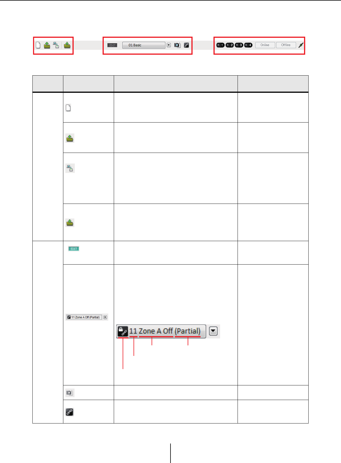
Synchro-
nization
Online
indicator
This will light if the devices and the computer
are online. The color of the indicator will change
according to the status. The indicator is shown
for each MTX/MRX system.
Blue ......when all devices assigned in the MTX/
MRX system are online.
Yellow ....when at least one of the devices
assigned in the MTX/MRX system is
offline
Unlit ......when all devices are offline.
–
[Online]
When you click this, the “Synchronization”
dialog box will appear, allowing you to choose
the direction of synchronization. If you click this
when online, devices that are offline will be re-
detected, and synchronization will begin.
Nothing will happen for devices that are already
online.
If an MTX/MRX that has been assigned in
the “Device Configuration Wizard” dialog
box is not actually connected to the
network, the [Online] button will not be
available.
“Synchronization” dialog
box
[Offline]
When you click this, a dialog box will appear,
allowing you to choose which MTX/MRX system
will be taken offline.
If an MTX/MRX that has been assigned in
the “Device Configuration Wizard” dialog
box is not actually connected to the
network, the [Offline] button will not be
available.
[Connection]
Switches the status of the connection between
MTX-MRX Editor and the network. Even in the
offline state, if this status is connected, MTX-
MRX Editor will send data to the network, for
example to search for devices. Set this to the
unconnected status if you don’t want
unnecessary data to be transmitted, for
example if you’re connected to an office LAN.
Connected.
Unconnected.
Related
tools Buttons etc. Summary Dialog box that appears
NOTE
NOTE
MTX-MRX Editor User Guide
34
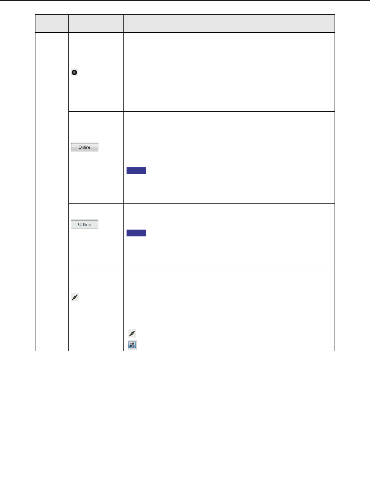
Chapter 3. Project screen
In this screen you can manage projects. When MTX-MRX Editor starts up, this screen will appear first.
Use the tabs to switch between the Project screen and the System screen.
❑System selection tabs
Use these to select the MTX/MRX system that will be controlled by MTX-MRX Editor.
If you want to construct a new MTX/MRX system, click the “No Assign” tab, then click the [Device
Config] button and specify the configuration of the MTX/MRX system.
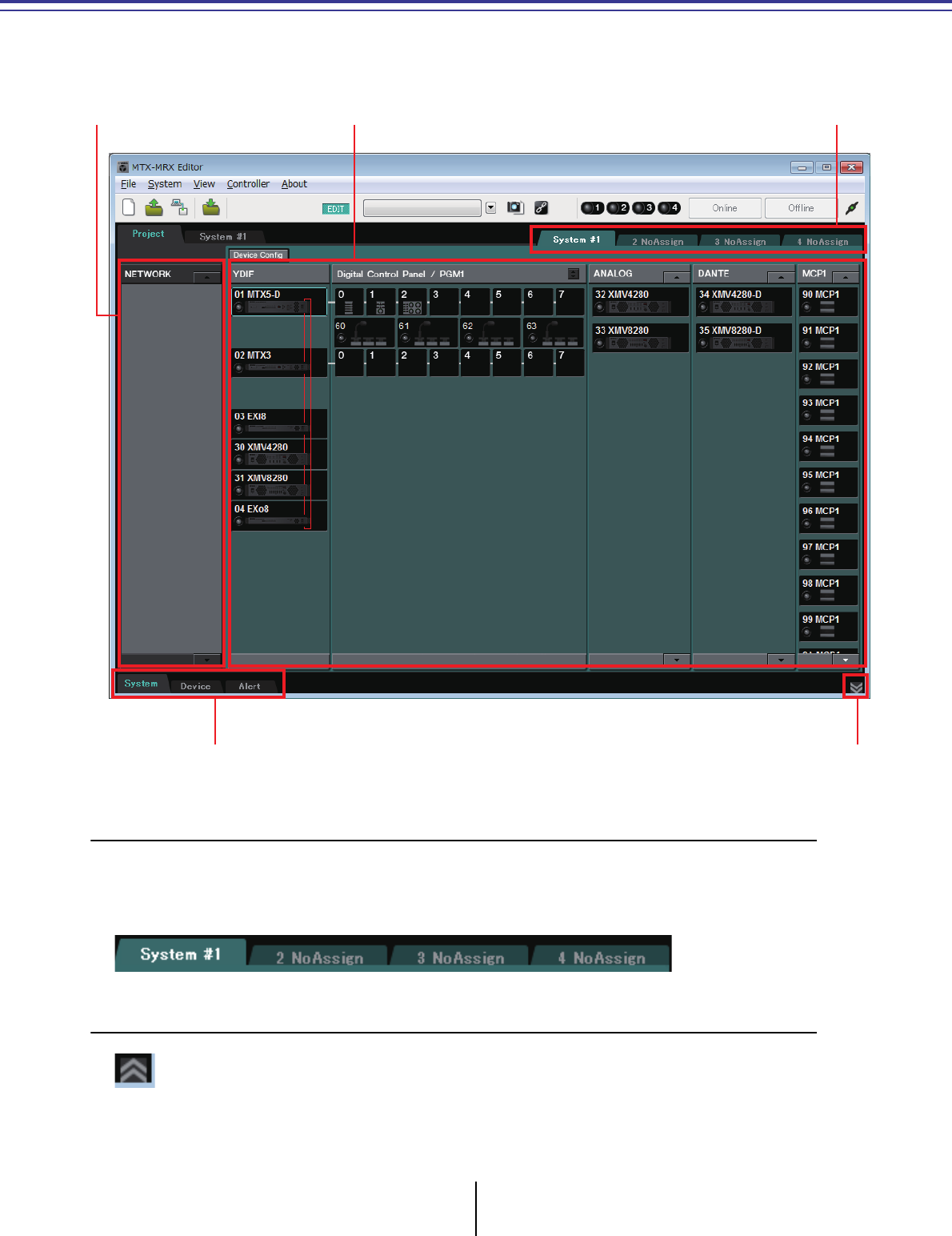
❑HIDE/SHOW button
Hides/shows the [System] tab, [Device] tab, and [Alert] tab.
Network devices MTX/MRX system
[System] tab, [Device] tab, [Alert] tab
System selection tabs
HIDE/SHOW button
Network devices Chapter 3. Project screen
MTX-MRX Editor User Guide
35
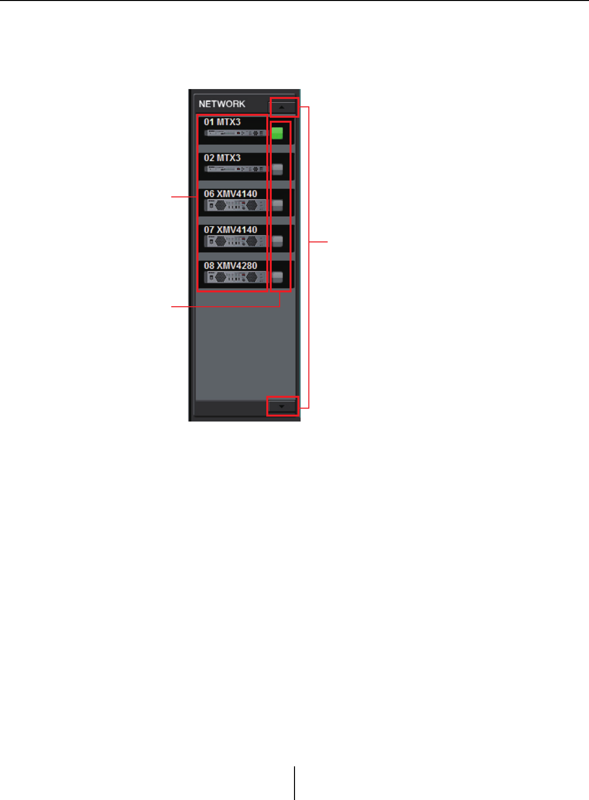
Network devices
This lists the devices existing on the same network as the computer. (Devices assigned to the MTX/
MRX system are not shown.)
List of network devices
These are the devices existing on the same network. The UNIT ID, device name, and a
graphic of the device are shown.
Identify button
When you click this, the indicator of the corresponding device will flash for approximately
five seconds, allowing you to identify the device.
Scroll buttons
Use these to scroll the display up or down.
List of network devices
Identify button
Scroll buttons
MTX/MRX system Chapter 3. Project screen
MTX-MRX Editor User Guide
36
MTX/MRX system
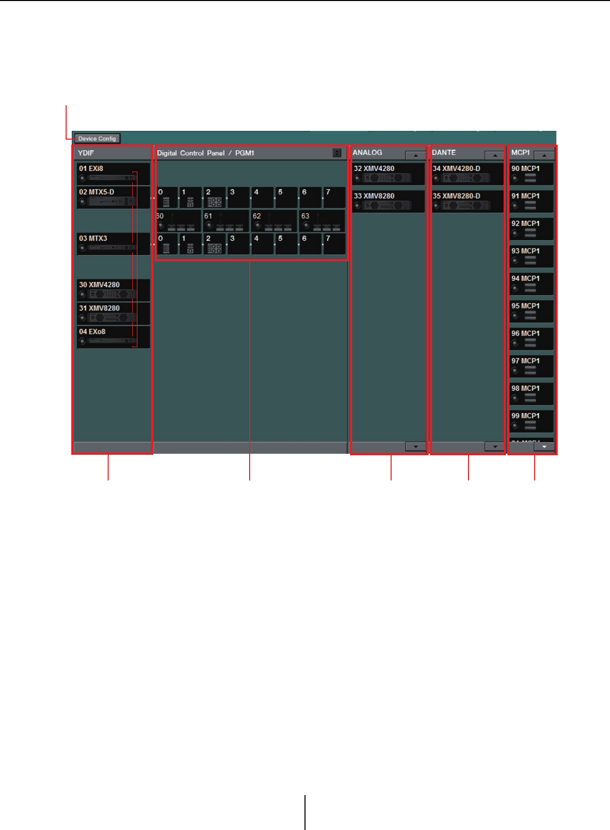
[Device Config] button
When you click this, the “Device Configuration Wizard” dialog box will appear.
[Device Config] button
Digital control panel
and PGM1/PGX1
YDIF-
connected
devices
Analog-
connected
devices
DANTE-
connected
devices
MCP1
“Device Configuration Wizard” dialog box Chapter 3. Project screen
MTX-MRX Editor User Guide
37
❑“Device Configuration Wizard” dialog box
In this dialog box, you’ll use the wizard to create or edit the configuration (structure) of the MTX/
MRX system. You can easily specify or edit the type of devices and the order in which they are
connected.
Here we will explain the dialog box that appears when you click the [Device Config] button in the
Project screen. For details on how the wizard will proceed if you select the [New] option button,
refer to “MTX Setup Manual” or “MRX Setup Manual.”
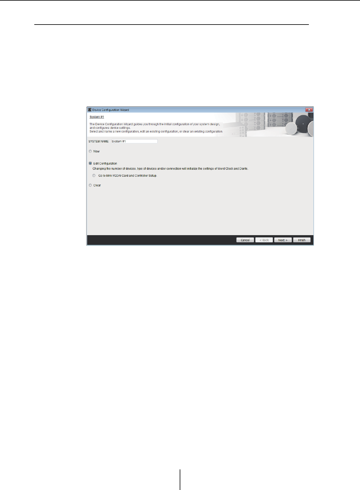
1. When you click the [Device Config] button, the “Device Configuration
Wizard” dialog box will appear.
Choose whether you want to create a new MTX/MRX system or to edit an existing
one.
• [New] option button
A new configuration will be created.
Enter the desired system name in the [SYSTEM NAME] input box.
• [Edit Configuration] option button
An existing configuration will be edited. If no devices have been assigned, this
option will be unavailable.
Select the radio button located below and click the [Next>] button to proceed to an
editing screen for the Mini-YGDAI card or controller.
• [Clear] option button
The configuration will be cleared. If no devices have been assigned, this option will
be unavailable.
•[Cancel] button
Cancels the operation and exits the wizard.
• [< Back] button
This button will be dimmed and unavailable.
• [Next >] button
Proceeds to the next screen.
“Device Configuration Wizard” dialog box Chapter 3. Project screen
MTX-MRX Editor User Guide
38
• [Finish] button
This can be selected if you have selected something other than the [New] option
button. When you click this, a confirmation message will appear; click the [Yes]
button to clear the data and end the wizard. If you click the [No] button, the
operation will be cancelled, and you will return to the previous dialog box.
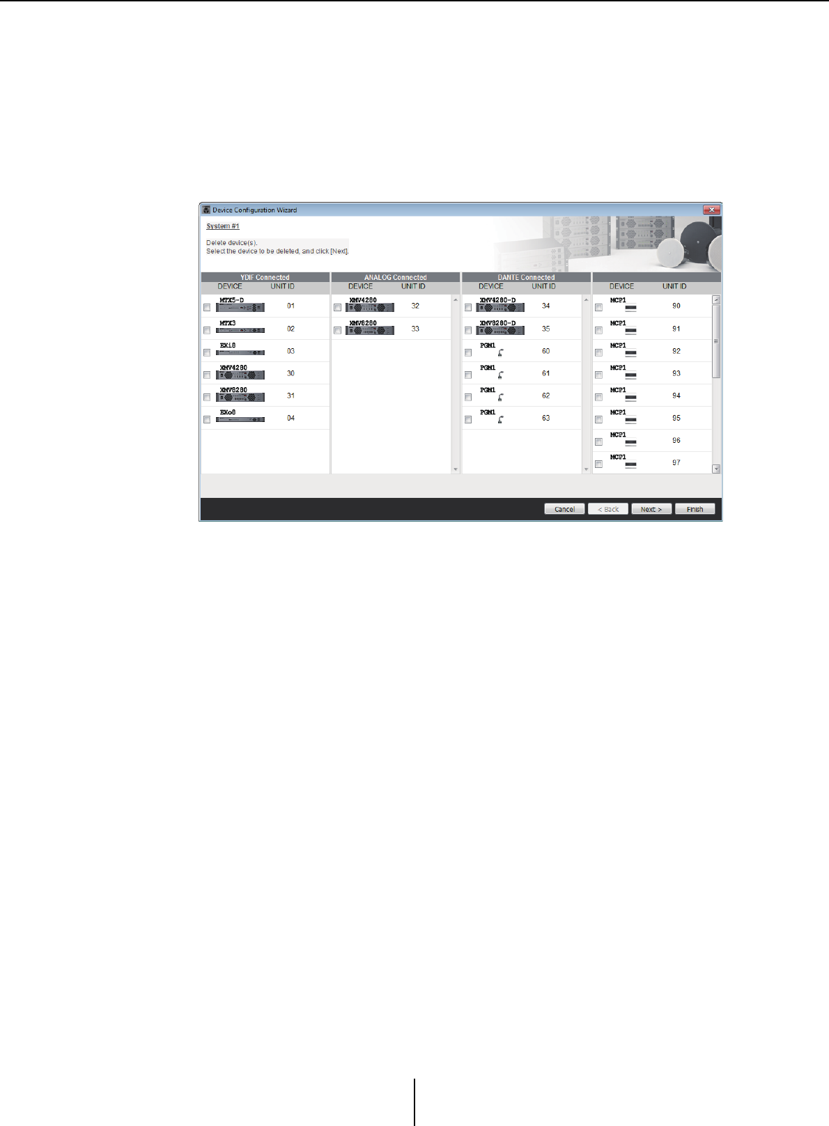
2. From the devices that have already been assigned, delete any that you
do not need. (Only if you selected [Edit Configuration] in step 1.)
Delete unneeded devices from those that have already been assigned. Select the
check box located at the left of each device that you want to delete.
•[Cancel] button
Cancels the operation and exits the wizard.
• [< Back] button
This button will be dimmed and unavailable.
• [Next >] button
Applies the changes and proceeds to the next screen.
When you select devices and click the [Next >] button, a confirmation message will
appear. If you click the [Yes] button, the changes will be applied and you will proceed
to the next screen. If you click the [No] button, the operation will be cancelled, and
you will return to the previous dialog box.
• [Finish] button
When you select devices and click the [Finish] button, a confirmation message will
appear. If you click the [Yes] button, the changes will be applied and the wizard will
close. If you click the [No] button, the operation will be cancelled, and you will
return to the previous dialog box.
If you click the [Finish >] button without selecting a device, a message will ask
whether you want to view a configuration diagram. If you click the [Yes] button, the
configuration diagram (“Configuration Diagram” dialog box) will appear (→step 10).
If you click the [No] button, the wizard will close without displaying the
configuration diagram.
“Device Configuration Wizard” dialog box Chapter 3. Project screen
MTX-MRX Editor User Guide
39
3. Specify the type and number of devices that will be assigned to the
MTX/MRX system.
Determine the number of devices that will be connected via cable, other than digital
control panels.
If you selected [Edit Configuration] in the first screen of the wizard, the currently-
assigned number of devices is shown. In this case, it is not possible to change the
number of units to less than this number or to greater than Connection
requirements for an MTX/MRX system.
Devices whose number of units is set to 0 will be dimmed and unavailable.
On the Tio1608-D, the UNIT ID range is narrower. When using the Tio1608-D, avoid
using UNIT ID settings 01–0C for other devices in the next screen.
• [Number] box
Specifies the number of devices.
•[Cancel] button
Cancels the operation and exits the wizard.
• [< Back] button
This button will be dimmed and unavailable.
• [Next >] button
Applies the changes and proceeds to the next screen.
• [Finish] button
This button will be dimmed and unavailable.
NOTE
“Device Configuration Wizard” dialog box Chapter 3. Project screen
MTX-MRX Editor User Guide
40
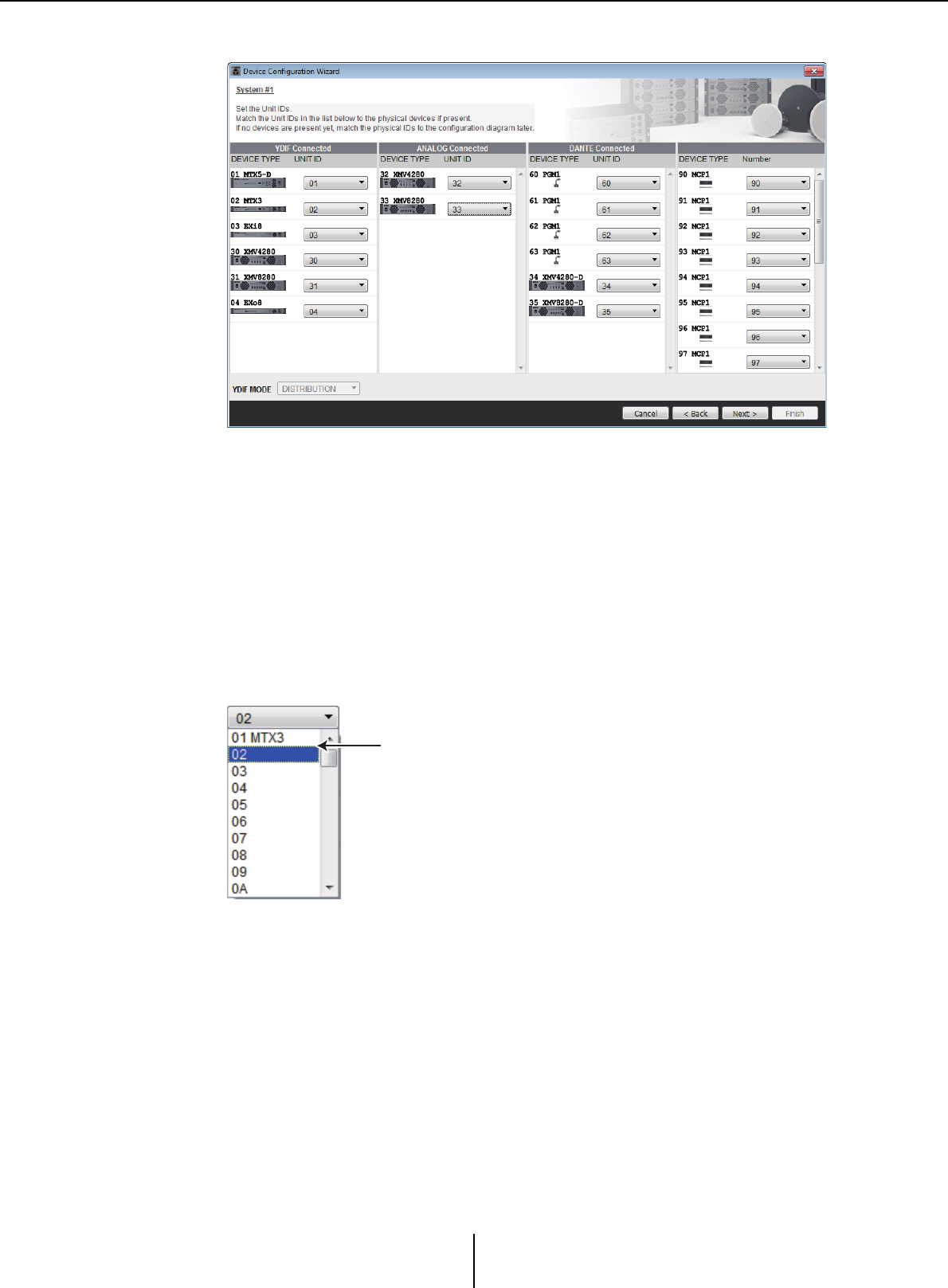
4. Specify the UNIT ID of each device.
Specify the UNIT ID of each assigned device. Set the UNIT ID so that there is no
conflict between devices.
If you selected [New] in the first screen of the wizard, the devices will be numbered
automatically starting from the lowest UNIT ID. If you selected [Edit
Configuration], the currently-specified UNIT ID will be shown. In either case you
are free to make changes.
• [UNIT ID] box
Specify the UNIT ID of the device.
When you click the [UNIT ID] box, the model name of each device of the same type
existing on the network is shown beside its UNIT ID. For devices that do not exist
on the network, only the UNIT ID is shown.
•[YDIF MODE]
Select either [CASCADE] or [DISTRIBUTION] as the connection mode for YDIF
devices.
If there are any YDIF-connected devices other than the MTX, [DISTRIBUTION]
will be selected automatically, and cannot be changed. If there is a single MTX unit,
or if an MRX unit is part of the MTX/MRX system, this will be dimmed and cannot
be changed.
•[Cancel] button
Cancels the operation and exits the wizard.
• [< Back] button
Returns to the previous screen.
Model name is shown
“Device Configuration Wizard” dialog box Chapter 3. Project screen
MTX-MRX Editor User Guide
41
• [Next >] button
Applies the changes and proceeds to the next screen.
• [Finish] button
This button will be dimmed and unavailable.
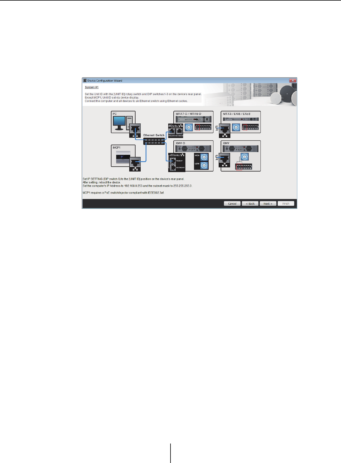
5. View a configuration diagram that shows the connections necessary for
control via MTX-MRX Editor.
Make settings for the device as directed by the dialog box.
•[Cancel] button
Cancels the operation and exits the wizard.
• [< Back] button
Returns to the previous screen.
• [Next >] button
Proceeds to the next screen.
• [Finish] button
This button will be dimmed and unavailable.
“Device Configuration Wizard” dialog box Chapter 3. Project screen
MTX-MRX Editor User Guide
42
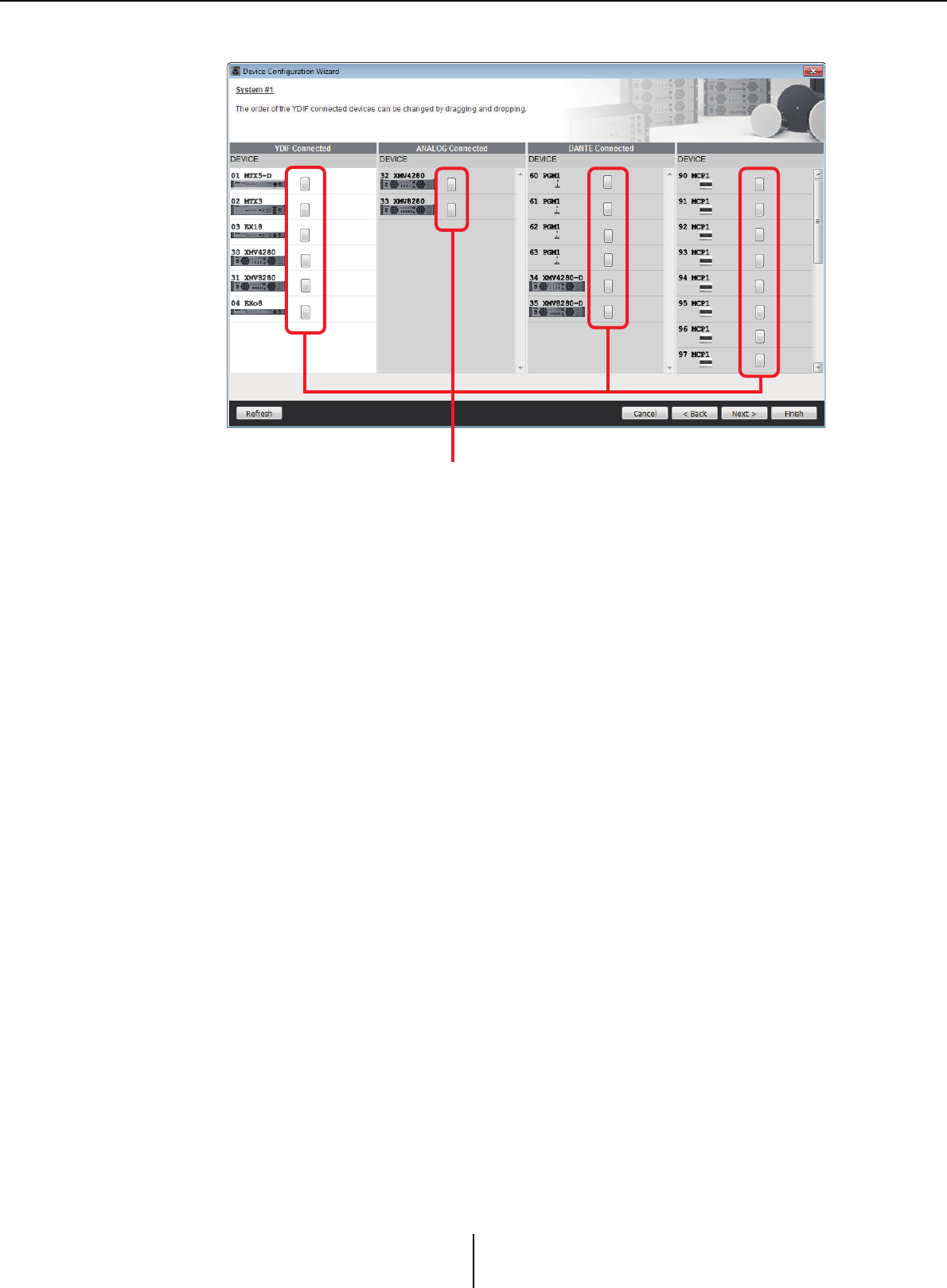
6. Specify the order of the YDIF-connected devices.
You can drag and drop to change the connection order of the YDIF-connected
devices.
• [Identify] button
When you click this, the indicator of the corresponding device will flash for
approximately five seconds, allowing you to identify the device.
This is not shown if no device is connected.
•[Refresh] button
Searches again for devices on the network. Newly-connected devices and deleted
devices will be re-detected.
•[Cancel] button
Cancels the operation and exits the wizard.
• [< Back] button
Returns to the previous screen.
• [Next >] button
Proceeds to the next screen.
• [Finish] button
Applies the changes and closes the wizard. A confirmation message will ask whether
you want to view a configuration diagram. If you click the [Yes] button, the
configuration diagram (“Configuration Diagram” dialog box) will appear (→step 10).
If you click the [No] button, the wizard will close without displaying the
configuration diagram.
Identify button
“Device Configuration Wizard” dialog box Chapter 3. Project screen
MTX-MRX Editor User Guide
43
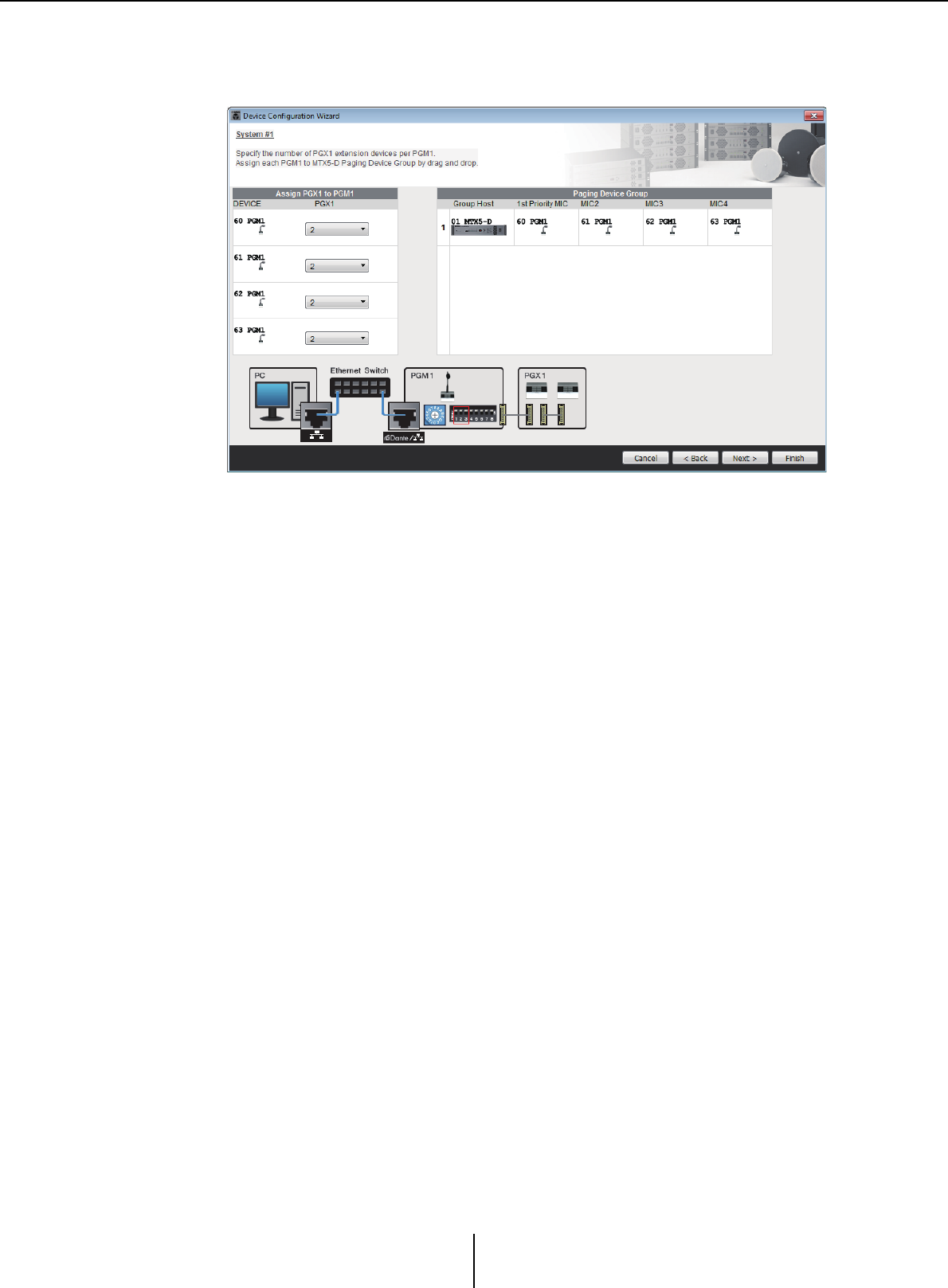
7. Specify the number of PGX1 units, and associate MTX5-D/MRX7-D and
PGM1 units.
(If PGM1 is set to other than 0 in step 3.)
Here you can specify the number of PGM1 units which are extension units of the
PGM1. You can also associate MTX5-D or MRX7-D units with PGM1 units, and
specify the mic that is assigned as the 1st Priority Mic for the associated MTX5-D or
MRX7-D.
• [PGX1] list box
Selects the number of PGX1 units that are connected to the PGM1.
• [Paging Device Group] area
Drag and drop to associate MTX5-D or MRX7-D units with PGM1 units.
The PGM1 unit that is dropped on the [1st Priority Mic] row will be the 1st Priority
Mic.
As the 1st Priority Mic, assign the PGM1 unit that needs to interrupt even if another
mic is broadcasting, such as for an emergency broadcast.
•[Cancel] button
Cancels the operation and exits the wizard.
• [< Back] button
Returns to the previous screen.
• [Next >] button
Proceeds to the next screen.
• [Finish] button
Applies the changes and closes the wizard. A confirmation message will ask whether
you want to view a configuration diagram. If you click the [Yes] button, the
configuration diagram (“Configuration Diagram” dialog box) will appear
(→step 10). If you click the [No] button, the wizard will close without displaying the
configuration diagram.
“Device Configuration Wizard” dialog box Chapter 3. Project screen
MTX-MRX Editor User Guide
44
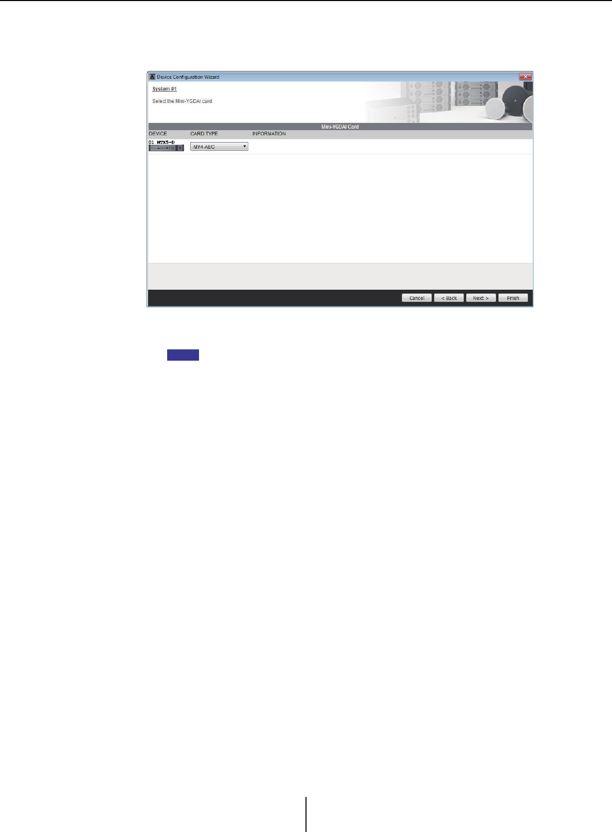
8. Select the Mini-YGDAI card that is inserted in the slot. (Only if a device
that has a slot is included in the MTX/MRX system.)
In the case of the MRX, use MRX Designer to assign a SLOT component.
• Card selection box
Select the Mini-YGDAI card that is inserted in the slot.
If the inserted Mini-YGDAI card is being operated in emulation mode, select the card
that is being emulated.
•[Cancel] button
Cancels the operation and exits the wizard.
• [< Back] button
Returns to the previous screen.
• [Next >] button
Applies the changes and proceeds to the next screen.
• [Finish] button
Applies the changes and closes the wizard. A confirmation message will ask whether
you want to view a configuration diagram. If you click the [Yes] button, the
configuration diagram (“Configuration Diagram” dialog box) will appear
(→step 10). If you click the [No] button, the wizard will close without displaying the
configuration diagram.
NOTE
“Device Configuration Wizard” dialog box Chapter 3. Project screen
MTX-MRX Editor User Guide
45
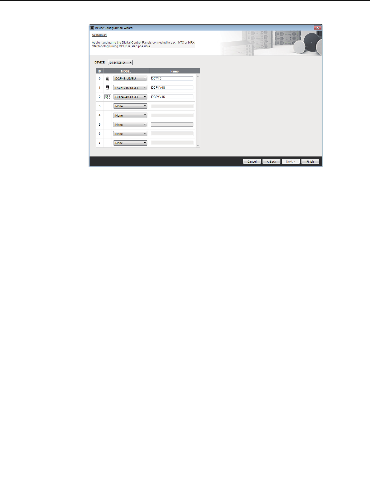
9. Make configuration settings for digital control panels (DCP).
Select the DCP units that you want to connect to the MTX/MRX. You’ll make
settings individually for each MTX/MRX unit. As desired, you can assign a name to
each DCP unit.
DCP units can also be connected in a star topology by using the Yamaha DCH8
digital controller hub.
• [Device] box
Select the MTX/MRX unit to which you want to connect DCP units.
• [Model] box
Select the model of DCP. A graphic of the DCP is shown at the left.
• [Name] box
Assign the desired name to each DCP.
•[Cancel] button
Cancels the operation and exits the wizard.
• [< Back] button
Returns to the previous screen.
• [Next >] button
This button will be dimmed and unavailable.
• [Finish] button
Applies the changes and closes the wizard. A confirmation message will ask whether
you want to view a configuration diagram. If you click the [Yes] button, the
configuration diagram (“Configuration Diagram” dialog box) will appear (→step 10).
If you click the [No] button, the wizard will close without displaying the
configuration diagram.
“Device Configuration Wizard” dialog box Chapter 3. Project screen
MTX-MRX Editor User Guide
46
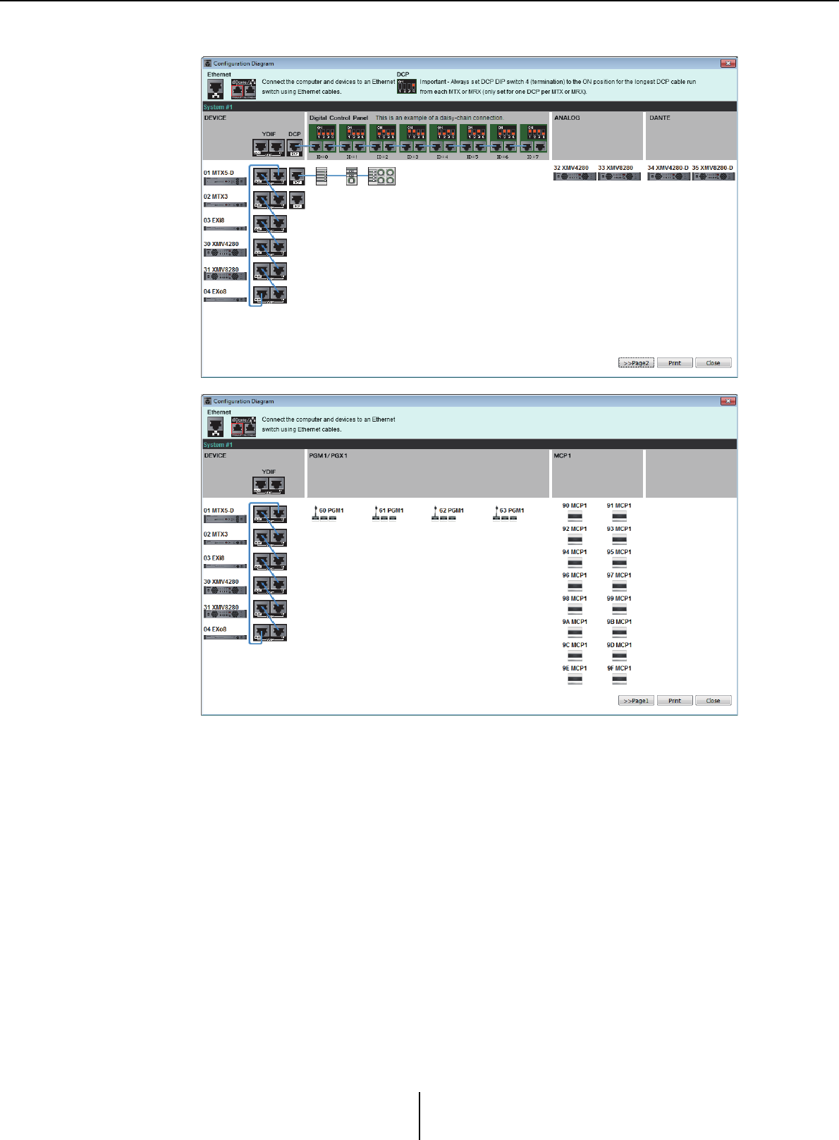
10. The “Configuration Diagram” dialog box will appear.
A configuration diagram of the system you constructed using the wizard is shown.
Following the directions in the dialog box, connect each device and specify the panel
ID of each DCP.
You can use the [Print] button to print this configuration diagram for convenient
reference when you’re working at the actual location. This dialog box will also
appear if you choose [Print Configuration Diagram] from the [File] menu.
• [>>Page2]/[>>Page1] buttons
Switch the page to display.
• [Print] button
Prints the configuration diagram.
• [Close] button
Closes the dialog box.
YDIF-connected devices Chapter 3. Project screen
MTX-MRX Editor User Guide
47
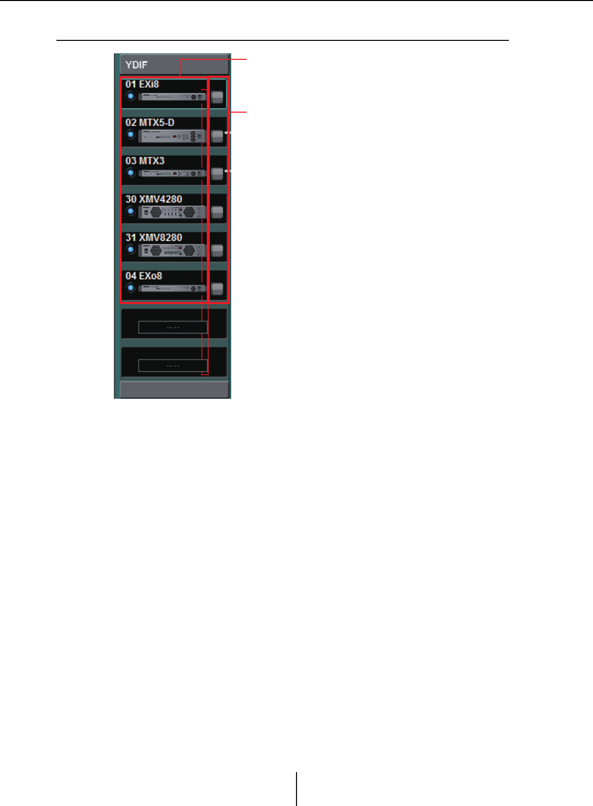
❑YDIF-connected devices
List of YDIF-connected devices
These are the YDIF-connected devices within the MTX/MRX system. An online indicator,
the UNIT ID, the device type, and a graphic of the device are shown.
If you double-click the graphic of a device, the description of the DIP switches (or the
device setting DIP switches for the XMV) will be shown. If you double-click the device
graphic when MTX-MRX Editor has recognized a device, the current DIP switch setting
(or for the XMV, both device setting DIP switches and [SPEAKERS] DIP switches) will
appear. If you double-click an XMV graphic while online, the current settings of the DIP
switches are shown, allowing you to make HPF settings for each channel.
The online indicator and the device graphic show the online status and whether an alert
has occurred. For more about alerts, refer to [Alert] tab and “Alert list.”
List of YDIF-connected devices
Identify button
YDIF-connected devices Chapter 3. Project screen
MTX-MRX Editor User Guide
48
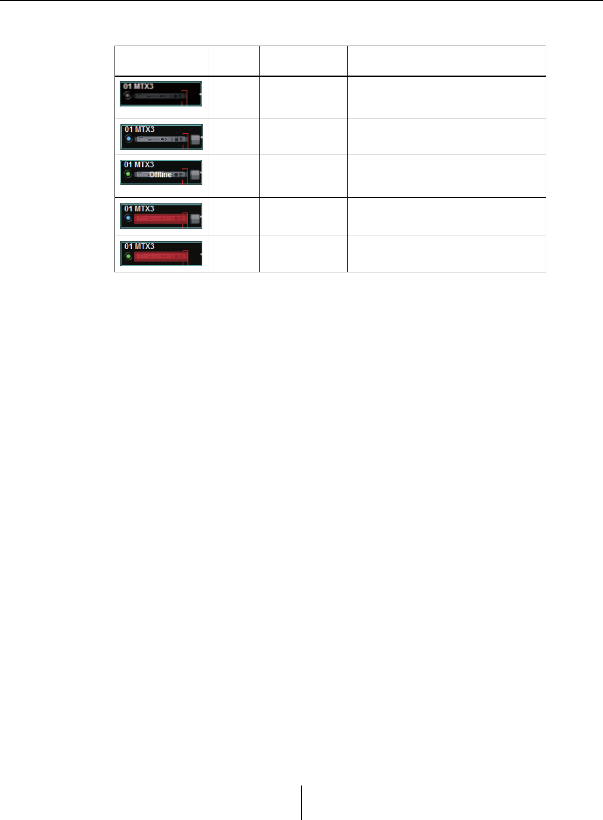
The currently-selected device is enclosed by a blue border.
(*) The red state will be cleared when you click the device icon or close the automatically-displayed popup.
Identify button
When you click this, the indicator of the corresponding device will flash for approximately
five seconds, allowing you to identify the device.
Indication Online
indicator Device icon Status
Unlit Dimmed
Does not exist on the network, or is not
connected to the computer (MTX-MRX
Editor).
Lit blue Indication Exists on the network, and is synchronized
with MTX-MRX Editor (online status).
Lit green “Offline” indicated
on the icon
Exists on the network, but is not
synchronized with MTX-MRX Editor (offline
status).
Lit blueRed
(*)
Synchronized with MTX-MRX Editor (online
status), and an alert has occurred.
Lit green Red (*) Not synchronized with MTX-MRX Editor
(offline status), and an alert has occurred.
Digital control panel, PGM1/PGX1 Chapter 3. Project screen
MTX-MRX Editor User Guide
49
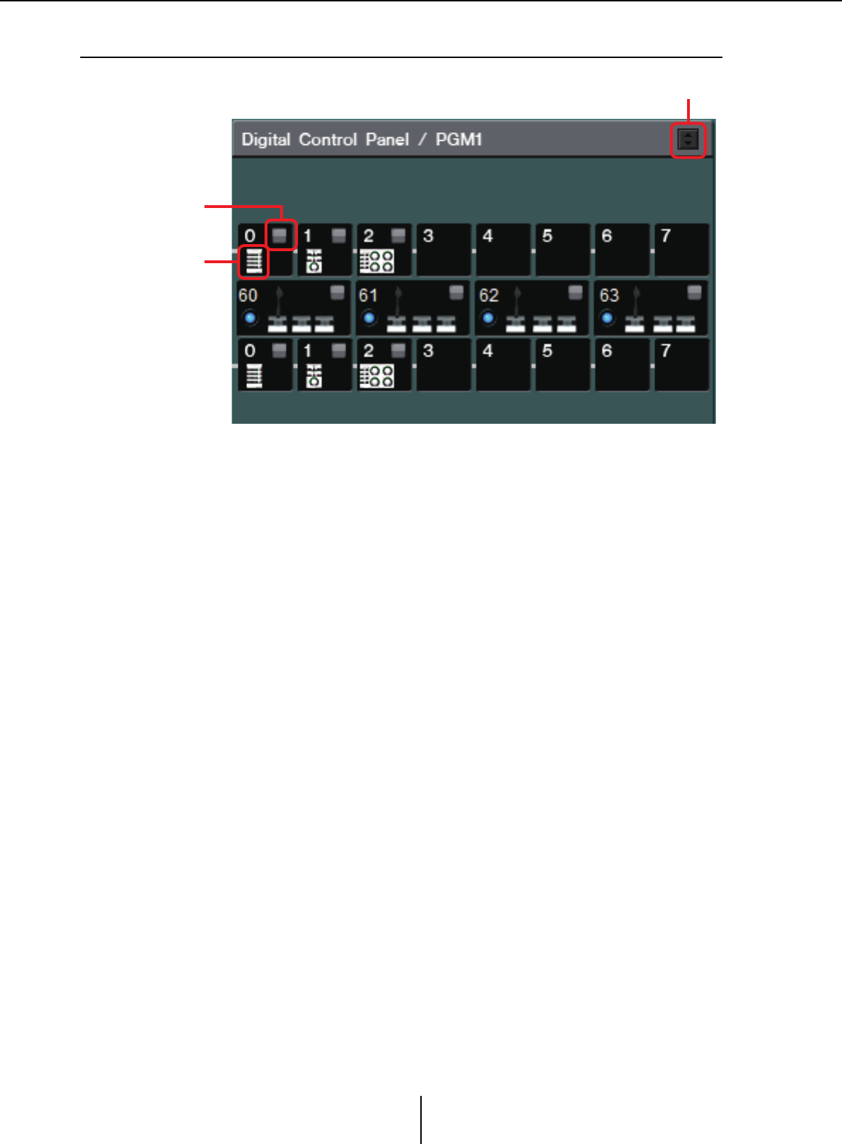
❑Digital control panel, PGM1/PGX1
This area shows an illustration and panel ID for each of the digital control panel (DCP) units and
PGM1/PGX1 units assigned by the wizard. Up to eight DCP units can be connected to one MTX/
MRX unit.
Up to four PGM1 units can be connected to one MTX/MRX system. The PGM1 can control only
a single MTX5-D/MRX7-D unit. The left-most PGM1 is the 1st Priority Mic. For more about the
1st Priority Mic, refer to “ZONE” screen.
Digital Control Panel/PGM1 switching button
Selects whether to show the Digital Control Panel or the PGM1.
This is available when the [System] tab/[Device] tab/[Alert] tab is expanded.
List of connected devices
This shows the digital control panels and PGM1/PGX1 units that are connected to MTX/
MRX units in the MTX/MRX system.
If you double-click the graphic of a PGM1, an explanation of the device setting DIP
switches will be shown. If you double-click the graphic of a PGM1 when online, the
current setting of the DIP switches will be shown.
Identify button
When you click this, the indicator of the corresponding device will flash for approximately
five seconds, allowing you to identify the device.
Identify button
Digital Control Panel/PGM1 switching button
List of connected
devices
Analog-connected devices Chapter 3. Project screen
MTX-MRX Editor User Guide
50
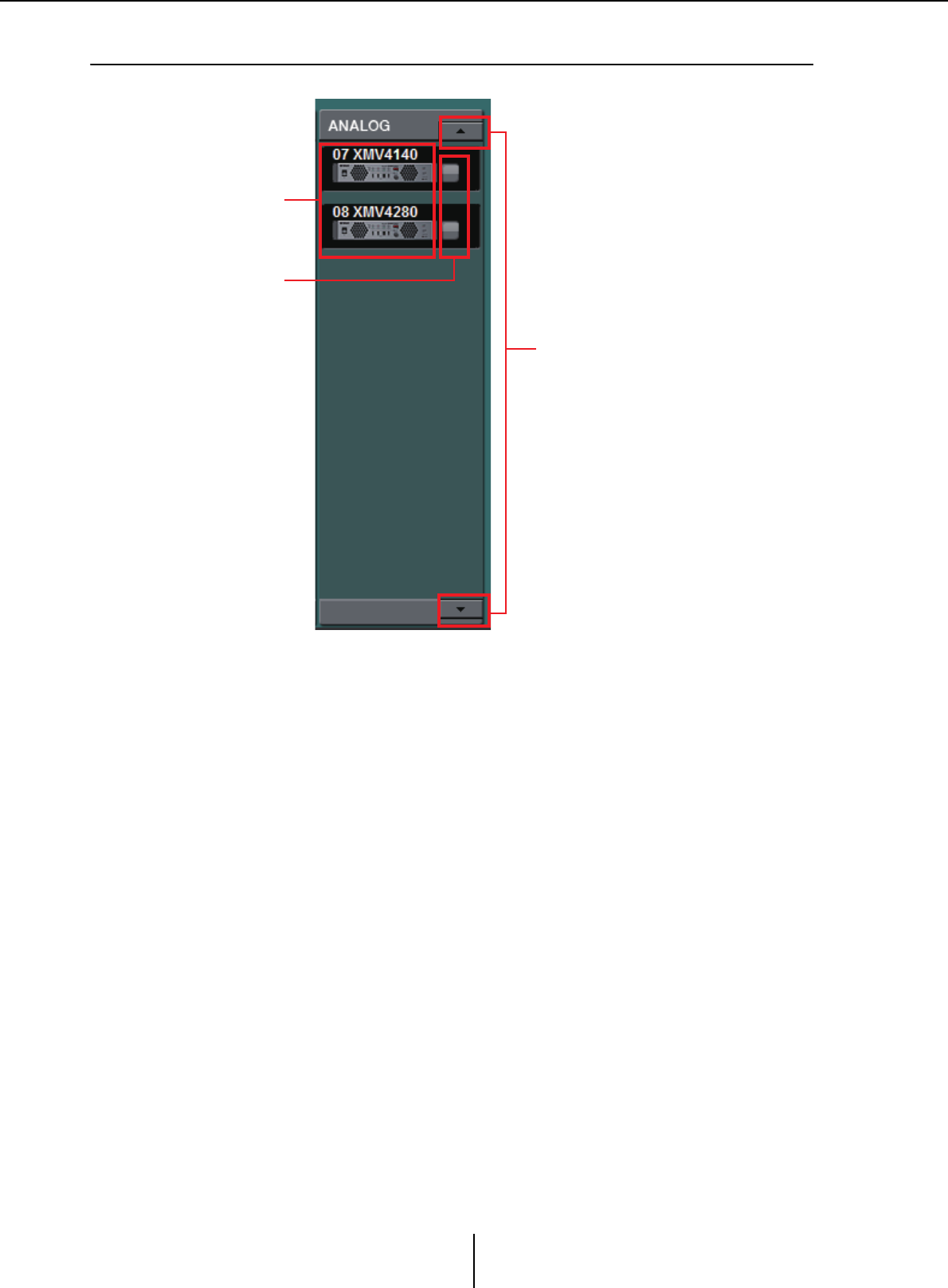
❑Analog-connected devices
Of the devices controlled by MTX-MRX Editor, this area shows the devices whose audio signals are
connected via analog.
List of analog-connected devices
This shows the XMV units within the MTX/MRX system that are connected to the MTX/
MRX via an analog connection.
If you double-click the device graphic, a description of the device setting DIP switches will
appear. If you double-click the device graphic when MTX-MRX Editor has recognized a
device, the current settings both of the device setting DIP switches and of the [SPEAKERS]
DIP switches are shown. If you double-click the graphic of a device while online, the
current settings of the DIP switches are shown, allowing you to make HPF settings for each
channel.
Identify button
When you click this, the indicator of the corresponding device will flash for approximately
five seconds, allowing you to identify the device.
Scroll buttons
Use these to scroll the display up or down.
List of analog-
connected devices
Identify button
Scroll buttons
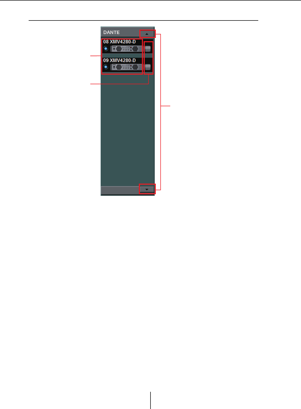
DANTE-connected devices Chapter 3. Project screen
MTX-MRX Editor User Guide
51
❑DANTE-connected devices
Of the devices controlled by MTX-MRX Editor, the Dante units other than the MTX/MRX or
PGM1 are shown here.
List of Dante-connected devices
These are the Dante units within the MTX/MRX system, except for the MTX/MRX and
PGM1. An online indicator, the UNIT ID, the device type, and a graphic of the device are
shown. If you double-click the graphic of a device, the description of the DIP switches (or
the device setting DIP switches for the XMV) will be shown. If you double-click the device
graphic when MTX-MRX Editor has recognized a device, the current DIP switch setting
(or for the XMV, both device setting DIP switches and [SPEAKERS] DIP switches) will
appear. If you double-click the graphic of a device while online, the current settings of the
DIP switches are shown, allowing you to make HPF settings for each channel on the XMV.
For more about the online indicators, refer to “YDIF-connected devices.”
Identify button
When you click this, the indicator of the corresponding device will flash for approximately
five seconds, allowing you to identify the device.
Scroll buttons
Use these to scroll the display up or down.
List of DANTE-
connected devices
Identify button
Scroll buttons
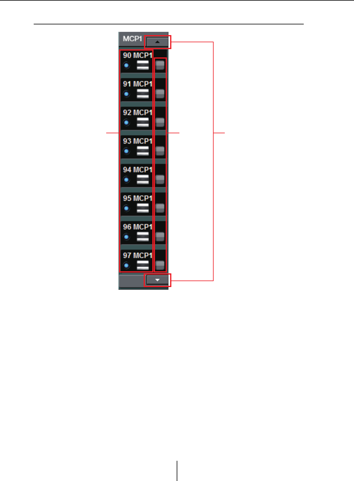
MCP1 Chapter 3. Project screen
MTX-MRX Editor User Guide
52
❑MCP1
Of the devices controlled by MTX-MRX Editor, the MCP1 units are shown here.
MCP1 list
These are the MCP1 units that are connected within the MTX/MRX system. An online
indicator, the UNIT ID, the device type, and a graphic of the device are shown.
For details on the online indicator, refer to YDIF-connected devices.
Identify button
When you click this, the UNIT ID is shown on the display of the corresponding device,
and its switches will flash for approximately five seconds, allowing you to identify the
device.
Scroll buttons
Use these to scroll the display up or down.
MCP1 list Identify
button
Scroll buttons
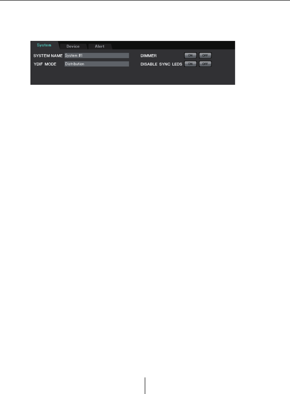
[System] tab Chapter 3. Project screen
MTX-MRX Editor User Guide
53
[System] tab
This shows information about the MTX/MRX system.
●[SYSTEM NAME]
This shows the system name that you entered in the [SYSTEM NAME] input box of the
“Device Configuration Wizard” dialog box. If you want to change this, click the [Device
Config] button and make changes in the “Device Configuration Wizard” dialog box.
●[YDIF MODE]
This shows the YDIF connection mode that you specified as the [YDIF MODE] in the
“Device Configuration Wizard” dialog box. If you want to change this, click the [Device
Config] button and make changes in the “Device Configuration Wizard” dialog box.
●[DIMMER]
If you click the [ON] button, the indicators of all devices in the MTX/MRX system will
be dimmed simultaneously. When you click the [OFF] button, they will return to their
original brightness.
This does not function on the R series (AD/DA) or the Tio1608-D.
●[DISABLE SYNC LEDS]
If you click the [ON] button, the [SYNC] indicators of the Dante devices in the MTX/
MRX system will no longer light. When you click the [OFF] button, they will be able to
light.
This does not function on the R series (AD/DA) or the Tio1608-D.
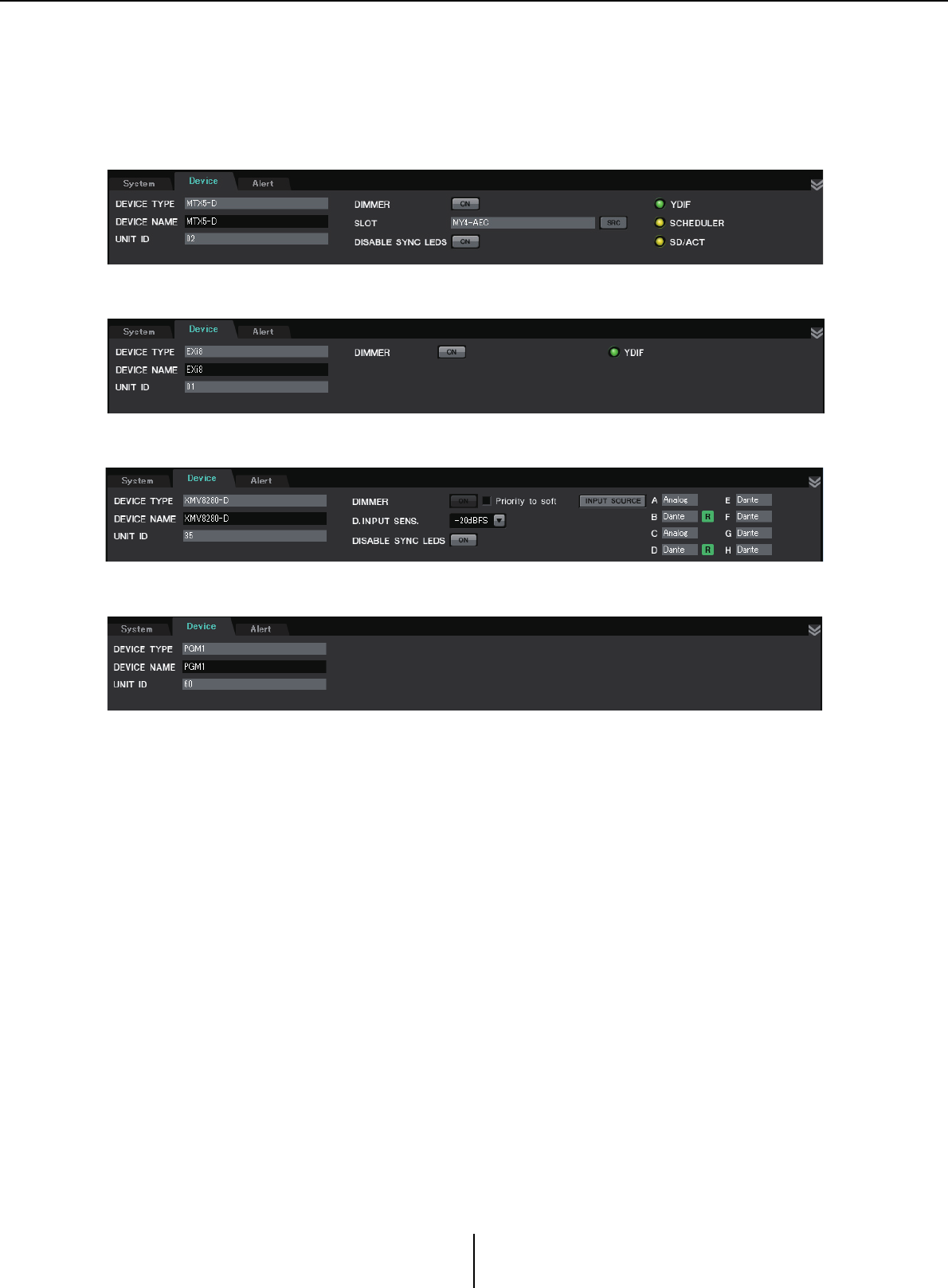
[Device] tab Chapter 3. Project screen
MTX-MRX Editor User Guide
54
[Device] tab
When you click a device other than a digital control panel, information for that device is shown.
●[DEVICE TYPE]
Indicates the type of device.
●[DEVICE NAME]
Indicates the device name. You are free to assign a desired name.
●[UNIT ID]
Indicates the UNIT ID.
●[DIMMER]
If you click the [ON] button to make it light, the indicators of the corresponding device
will be dimmed. When you click the [ON] button once again, the indicators will return
to their original brightness.
The XMV’s [DIMMER] is enabled when you select the [Priority to soft] check box. In
this case, the setting from MTX-MRX Editor will take priority over the settings of the
DIP switches on the device itself.
This setting is transmitted and received when the device is synchronized with MTX-
MRX Editor. It is synchronized with the device only when online.
For the EXi8/EXo8
For an XMV
For the MTX3/MTX5-D/MRX7-D
For the PGM1/MCP1/R series (AD/DA)/Tio1608-D

[Device] tab Chapter 3. Project screen
MTX-MRX Editor User Guide
55
●[SLOT] (MTX5-D/MRX7-D only)
Indicates the Mini-YGDAI card specified in the “Device Configuration Wizard” dialog
box. The [SRC] button is shown if an MY4-AEC or MY8-AE96S is selected. Click this
to open the “Sampling Rate Converter” dialog box.
●[INPUT SOURCE] button (XMV only)
For each channel, this indicates whether the input is analog or digital. When you click
this, the “Input Source/Redundant” dialog box will appear. An “R” symbol is shown
beside a digital input that is specified as Redundant. The “R” symbol turns yellow if the
input has switched from digital to analog.
●[D.INPUT SENS.] (XMV only)
This specifies the input sensitivity from YDIF or Dante. If you select “–20 dBFS,” the
input sensitivity will be the same as the analog connectors.
If you change from [–3 dBFS] to [–20 dBFS], the output from the XMV will be louder for the
same attenuator value. If you want to change this, lower the level and attenuator value before
you make the change.
●[YDIF] indicator (YDIF-enabled models only)
When online, this indicator is lit green if the rear panel [YDIF IN] jack is correctly
connected to another device’s [YDIF OUT] jack.
●[SCHEDULER] indicator (MTX/MRX only)
When online, this indicator is lit yellow if an event has been set in the Scheduler, and
will flash one minute prior to the event.
●[SD/ACT] indicator (MTX/MRX only)
When online, this indicator is lit yellow if an SD memory card is inserted into the SD
memory card slot and is recognized correctly. The indicator will flash if the unit is
accessing the SD memory card.
●[DISABLE SYNC LEDS] (MTX/MRX/XMV Dante-enabled models only)
If you click the [ON] button to make it light, the [SYNC] indicator of the device will no
longer light. When you click the [ON] button once again to turn it off, the indicator will
be able to light.
NOTE

[Alert] tab Chapter 3. Project screen
MTX-MRX Editor User Guide
56
[Alert] tab
Alert notifications from a device are shown by a popup window in MTX-MRX Editor (see “Alert list”).
Even if you close this popup window, you can use this tab to view alerts that have occurred in the past.
The R-series (AD/DA) and Tio1608-D are excluded.
●[Show alert popup] check box
If this is selected, a popup window will appear when alert notifications are received
from a device.
●[Get Log From Devices] button
The “Get Log” dialog box will appear.
●[CLEAR] button
Clears the currently-shown alert list.
●Alert list
•[Alert]
Shows the contents of the alert and an icon.
If you click the blue button, the “Solution” dialog box will appear, showing a solution
if one exists.
•[Alert No.]
Shows the alert number.
•[Status]
Shows the status of the event. In the case of an alert, this will indicate “Occurred”
when the alert occurs. There are two types of alert: momentary and continuing. In
the case of a continuing alert, this will indicate “Resolved” when the condition has
ended.
•[System]
This indicates the name of the MTX/MRX system in which the device is installed.
•[Type]
Indicates the type of device.
•[Unit ID]
Indicates the UNIT ID of the device.
•[Time]
Indicates the date and time that the alert occurred.
•[Count]
Indicates the total number of times that the same event occurred.
• The contents of the alert list will be deleted if you exit the project file that’s being edited or
if you reload a new file. If you want to view a past alert list, use “Get Log” dialog box to
receive the log.
• The alert list is saved within the device, but if the allowable memory size is exceeded, the
alerts will be overwritten starting with the oldest.
• When you use the [Get Log From Devices] button, alert lists produced by devices other
than the MTX/MRX will also be obtained.
NOTE
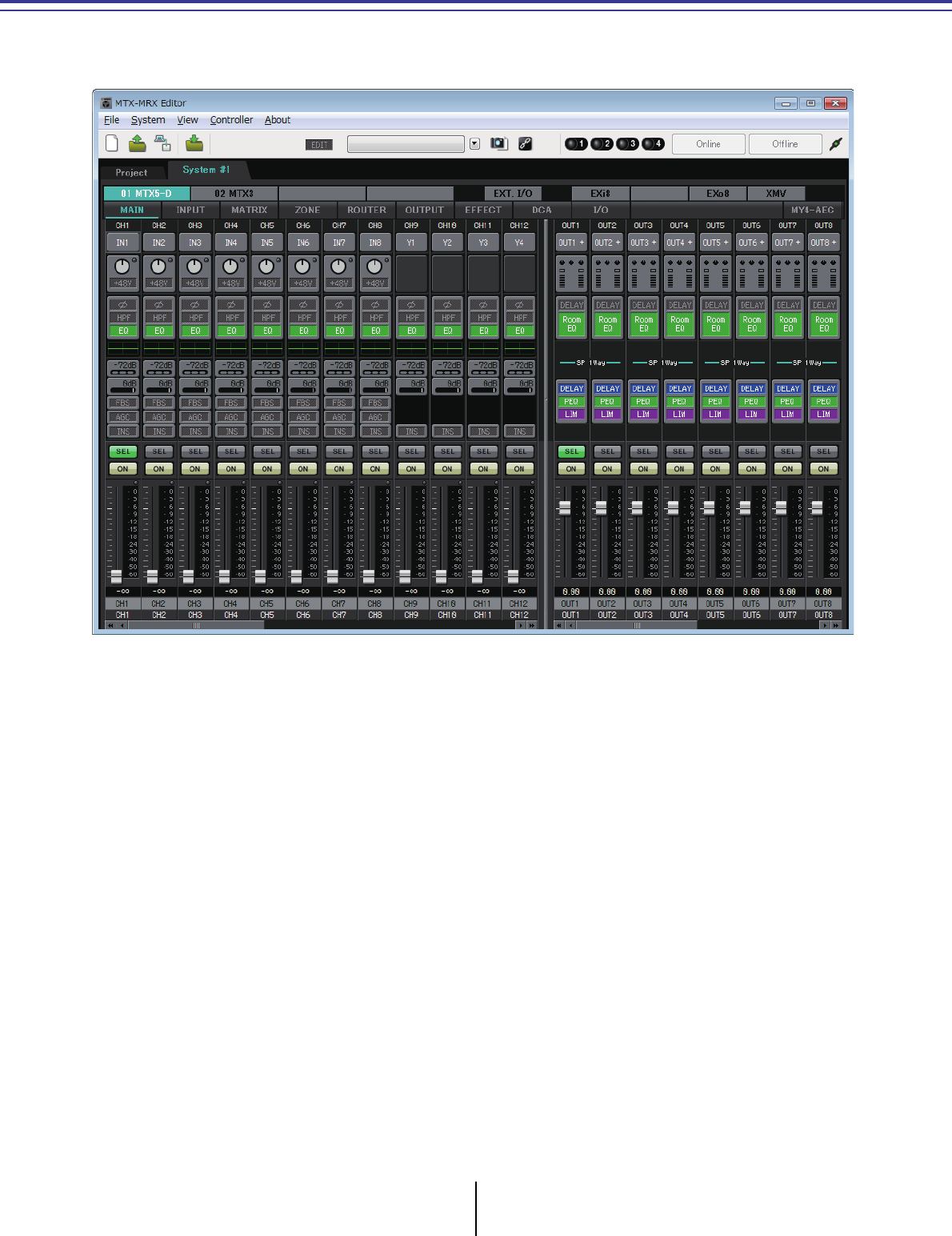
MTX-MRX Editor User Guide
57
Chapter 4. System screen
This screen shows the audio signal flow within the MTX/MRX system. From this screen you can move
to other editing screens.

Screen select buttons Chapter 4. System screen
MTX-MRX Editor User Guide
58
Screen select buttons
Use these buttons to switch between units in the MTX/MRX system and to access various
functions.
●[MTX]/[MRX] buttons
Use these buttons to select the MTX/MRX unit whose settings you want to edit. The
button shows the UNIT ID and device name. There will be one [MTX]/[MRX] button
for each MTX/MRX unit in the MTX/MRX system.
In the “MRX” screen, click the [Open MRX Designer] button to access the “MRX
Designer” window. For details, refer to “MRX Designer User Guide.”
•[MAIN] button
Displays the “MAIN” screen.
• [INPUT] button
Displays the “INPUT” screens.
• [MATRIX] button
Displays the “MATRIX” screen.
•[ZONE] button
Displays the “ZONE” screen.
• [ROUTER] button
Displays the “ROUTER” screen.
•[OUTPUT] button
Displays the “OUTPUT” screens.
• [EFFECT] button
Displays the “EFFECT” screen.
• [DCA] button
Displays the “DCA” screen.
• [I/O] button
Displays the “I/O” screen.
•[MY4-AEC] button
Displays the “MY4-AEC” screen.
●[EXT. I/O] button
Displays the “EXT. I/O” screen.
●[EXi8] button
Displays the “EXi8” screen.
●[R/Tio] button
Displays the “R/Tio” screen.
●[EXo8] button
Displays the “EXo8” screen.
●[XMV] button
Displays the “XMV” screen.
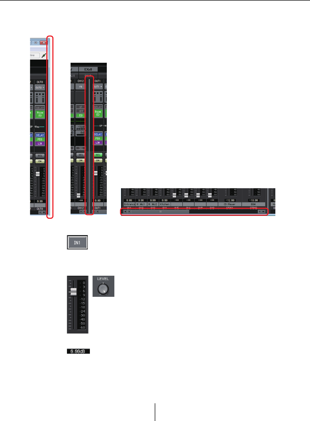
Explanation of basic operation Chapter 4. System screen
MTX-MRX Editor User Guide
59
Explanation of basic operation
Changing the screen size
●Focus
The currently selected item is enclosed by a flashing border (this area is
subsequently referred to as the “focus”). Use the <Tab> key to move the focus
(<Shift>+<Tab> will move in the opposite direction). Left-clicking a button
has the same effect as pressing the <Enter> key while focus is on that item.
●Faders/knobs
Drag upward to increase the value, or downward to decrease the
value. If focus is on the fader or knob, you can also use the mouse
wheel or the <><> keys.
By holding down the <Alt> key and clicking the knob or fader,
you can set it to the nominal value. You can right-click a fader and
select an input value.
●Numeric box
Drag upward to increase the value, or downward to decrease the value.
If focus is on the fader or knob, you can also use the mouse wheel or the
<><> keys.
You can double-click to enter edit mode and specify a numeric value. In edit mode, you
can use <Ctrl>+C (hold down the <Ctrl> key and press the <C> key) to Copy,
<Ctrl>+<V> to Paste, and press the <Enter> key to confirm the value.
By dragging the right edge of the screen you can change the horizontal width of the
screen. If you’re using a large monitor, this is a convenient way to view numerous
channel strips simultaneously.
By dragging the scroll bar in the center of the screen to the left or
right, you can change the proportion of input channel faders and
output channel faders that are shown.
If stereo input channels and direct input channels are hidden,
drag the scroll bar at the bottom of the screen to left or right to
make these channels visible.
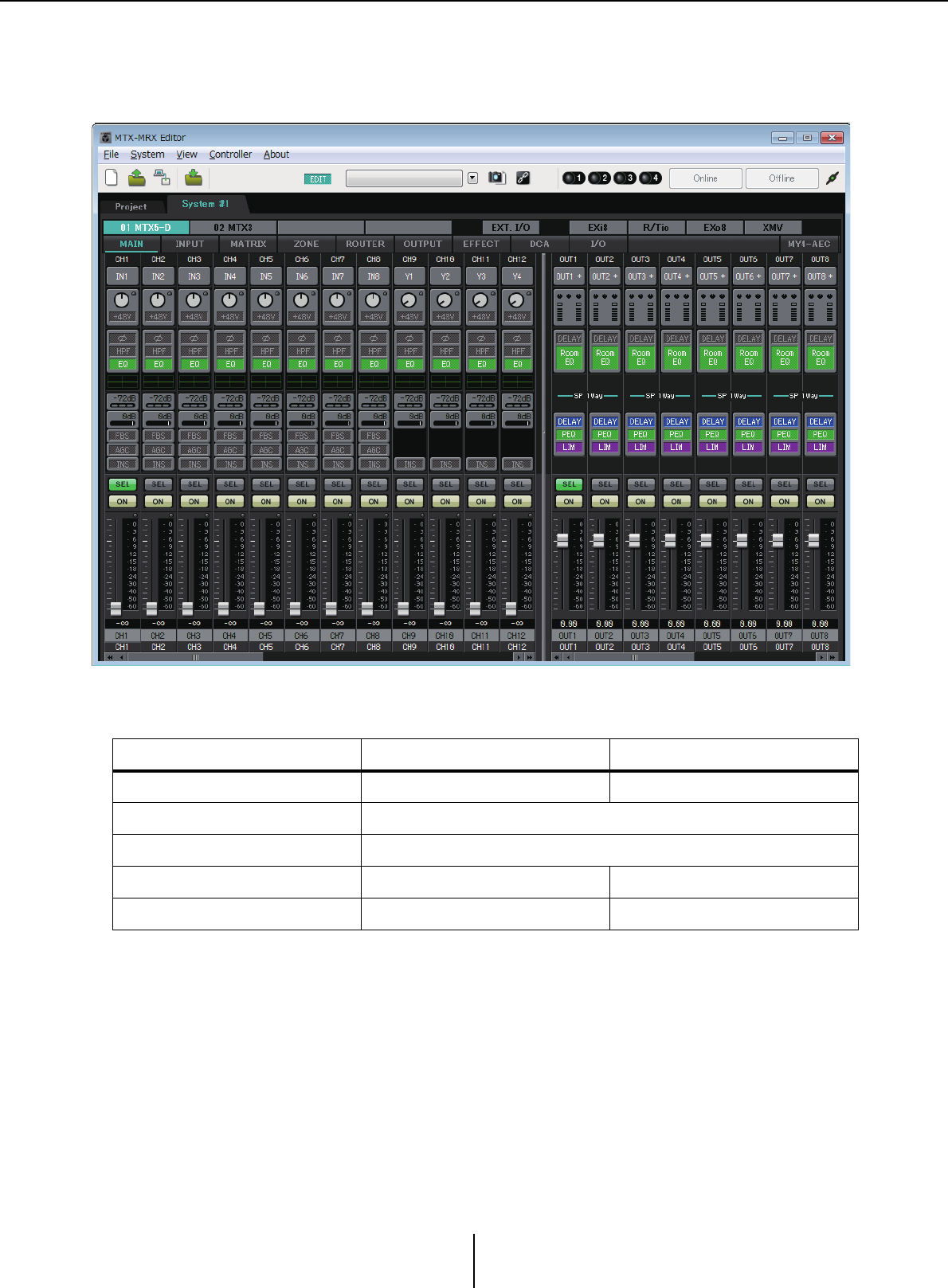
“MAIN” screen Chapter 4. System screen
MTX-MRX Editor User Guide
60
“MAIN” screen
This screen shows the input/output channels. From here you can access various editing screens.
The types of channel and the number of channels are as follows.
MTX5-D MTX3
Input channels CH1–CH16 CH1–CH8
Stereo input channels STIN1L, STIN1R, STIN2L, STIN2R, STIN3L, STIN3R
Effect return channels Fx RTN1, Fx RTN2
Direct input channels CH17–CH24 CH9–CH16
Output channels OUT1–OUT16 OUT1–OUT8
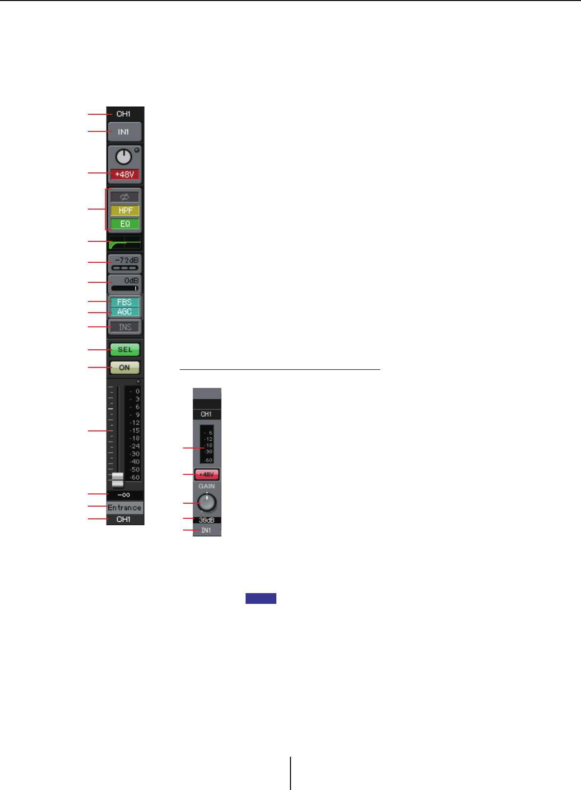
Input channels Chapter 4. System screen
MTX-MRX Editor User Guide
61
Input channels
Input channel settings are made in the [INPUT CHANNEL SETUP] section of the “MTX
Configuration” dialog box.
The description in this section assumes that two mono channels are used. If stereo
channels are used, some settings will be shared between channels.
1Channel index
Shows the MTX’s input channel number.
2Port select button
Opens the “Input Patch” dialog box. The button shows the currently
selected port.
3Port/external device parameter access button
This button displays a popup screen where you can edit the parameters of
the MTX’s input connector and the parameters of the external device that
is associated those channels, eight channels at a time.
•Indicator
This will light green when the port signal input reaches a certain level
(–40 dBFS), and will light red when it clips (–3 dBFS or higher).
•GAIN
Shows the output gain of the port.
•[48V]
Shows the +48V (phantom power) on/off status.
Parameter edit screen (for the MTX)
1
1
2
3
4
5
6
7
9
8
0
A
B
C
D
E
A
C
B
D
E
AMeter
Shows the input signal level.
B[+48V] button
Turns the HA phantom power (+48V) on/off.
Notice
Be sure to leave this button off if you do not need phantom
power.
Follow the important precautions below, in order to prevent
noise and possible damage to external devices as well as the
unit when you operate this switch.
• Be sure to leave this button off when you connect a device
that does not support phantom power to [INPUT] connector.
• Do not connect/disconnect a cable to/from [INPUT]
connector while this button is on.
• Down the output level to the minimum before operating this
button.
There is no master switch. To avoid malfunctions, be sure to
set this appropriately for the equipment that is connected.
C[GAIN] knob
Adjusts the analog gain of the HA (head amp)
DHA analog gain
Shows the HA analog gain setting.
EChannel index
Indicates the name and number of the device’s input
connector.
NOTE
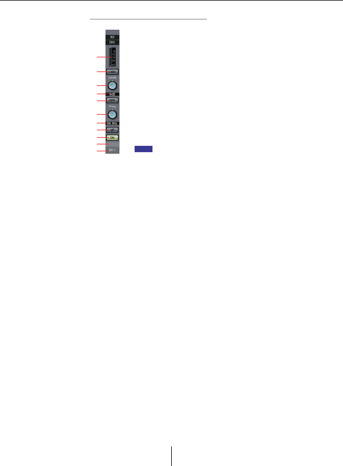
Input channels Chapter 4. System screen
MTX-MRX Editor User Guide
62
Parameter edit screen (for the EXi8)
A
C
B
D
E
F
G
H
I
K
J
AMeter
Shows the input signal level.
B[+48V] button
Turns the HA phantom power (+48V) on/off.
Notice
Be sure to leave this button off if you do not need phantom power.
Follow the important precautions below, in order to prevent noise
and possible damage to external devices as well as the unit when
you operate this switch.
• Be sure to leave this button off when you connect a device that
does not support phantom power to [INPUT] connector.
• Do not connect/disconnect a cable to/from [INPUT] connector
while this button is on.
• Down the output level to the minimum before operating this
button.
There is no master switch. To avoid malfunctions, be sure to set
this appropriately for the equipment that is connected.
C[GAIN] knob
Adjusts the analog gain of the HA (head amp)
DHA analog gain
Shows the HA analog gain setting.
E[HPF] button
Switches the HPF (High Pass Filter) on/off.
F[Freq] knob
Specifies the cutoff frequency of the HPF.
GCutoff frequency
Indicates the cutoff frequency of the HPF.
H[Ø] button
Switches the phase of the input signal.
I[ON] button
Switches the input channel on/off.
JChannel name
Indicates the channel name of the EXi8. You can double-click
this and edit it.
KChannel index
Indicates the number of the device’s input connector. If you
place the cursor here, a popup will show the UNIT ID and the
name of the external device.
NOTE
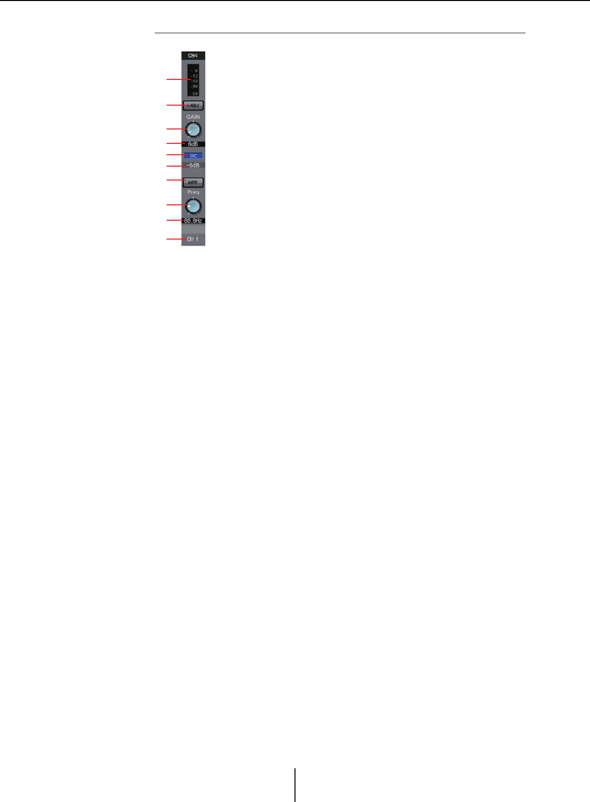
Input channels Chapter 4. System screen
MTX-MRX Editor User Guide
63
Parameter edit screen (for the R series (AD/DA) except the Ro8-D)
A
C
B
D
E
F
G
H
I
J
AMeter
Shows the input signal level.
B[+48V] button
Turns the HA phantom power (+48V) on/off.
Notice
Be sure to leave this button off if you do not need phantom power.
When turning phantom power on, you must observe the
precautions below in order to prevent noise and possible damage
to the unit and to external devices.
• Leave this button off if a device that does not support phantom
power is connected to the [INPUT] connector.
• Do not connect/disconnect a cable to/from the [INPUT]
connector while this button is on.
• Lower the output level to the minimum before turning phantom
power on/off.
C[GAIN] knob
Adjusts the analog gain of the HA (head amp).
DHA analog gain
Shows the HA analog gain setting.
E[GC] indicator
Indicates the gain compensation on/off status.
FCompensation gain value
Indicates the gain value fixed by the gain compensation. This is
not shown if gain compensation is off.
G[HPF] button
Switches the HPF (High Pass Filter) on/off.
H[Freq] knob
Specifies the cutoff frequency of the HPF.
ICutoff frequency
Indicates the cutoff frequency of the HPF.
JChannel index
Indicates the number of the device’s input jack. If you place the
cursor here, a popup will show the UNIT ID and the name of
the external device.
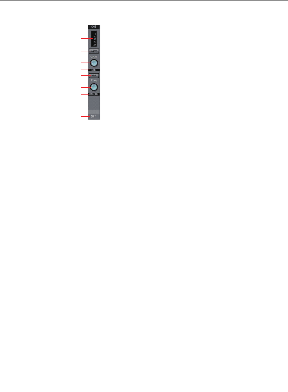
Input channels Chapter 4. System screen
MTX-MRX Editor User Guide
64
Parameter edit screen (for the Tio1608-D)
A
C
B
D
E
F
G
H
AMeter
Shows the input signal level.
B[+48V] button
Turns the HA phantom power (+48V) on/off.
Notice
Be sure to leave this button off if you do not need phantom power.
When turning phantom power on, you must observe the
precautions below in order to prevent noise and possible damage
to the unit and to external devices.
• Leave this button off if a device that does not support phantom
power is connected to the [INPUT] connector.
• Do not connect/disconnect a cable to/from the [INPUT]
connector while this button is on.
• Lower the output level to the minimum before turning phantom
power on/off.
C[GAIN] knob
Adjusts the analog gain of the HA (head amp).
DHA analog gain
Shows the HA analog gain setting.
E[HPF] button
Switches the HPF (High Pass Filter) on/off.
F[Freq] knob
Specifies the cutoff frequency of the HPF.
GCutoff frequency
Indicates the cutoff frequency of the HPF.
HChannel index
Indicates the number of the device’s input jack. If you place the
cursor here, a popup will show the UNIT ID and the name of
the external device.

Input channels Chapter 4. System screen
MTX-MRX Editor User Guide
65
4“GAIN/HPF/EQ” screen access button
Switches to the “GAIN/HPF/EQ” screen. The button also shows the on/off
status.
5EQ/HPF indication
This shows a miniature (non-editable) version of the graph that is shown in
the “GAIN/HPF/EQ” screen. This is not shown if HPF and EQ are off.
6“GATE” screen access button
7“COMP” screen access button
Switches to the “GATE/COMP” screen. The button also shows the current
value and on/off status.
8“FBS” screen access button
9“AGC” screen access button
Switches to the “FBS/AGC” screen. The button also shows the on/off status.
In the case of the MTX3, this will be only CH1 through CH4.
;[INS] button (MTX5-D only)
This button displays a popup screen where you can edit the insert on/off
setting eight channels at a time. If this is on, the audio signal will be sent
from POST ON to the Mini-YGDAI card installed in [SLOT].
If no Mini-YGDAI card is installed, or if the installed Mini-YGDAI card does not
support insertion, there will be no audio output if this is turned on.
A[SEL] button
Selects the channel that you want to edit.
B[ON] button
Switches the input channel on/off. The button also shows the on/off status.
CFader/meter
Adjusts the input level. You can right-click the fader to access the popup
menu, and select [0 dB] or [–Infinity].
If you right-click the input channel meter, a popup menu will appear,
allowing you to choose [EQ OUT] or [POST ON]. If you choose
[EQ OUT], the indicator above the meter will light.
DInput channel volume
Edits/indicates the level of the input channel.
EChannel name
Indicates the channel name. You can double-click this and edit it.
Some of the channel parameters can be copied and pasted.
NOTE
HINT
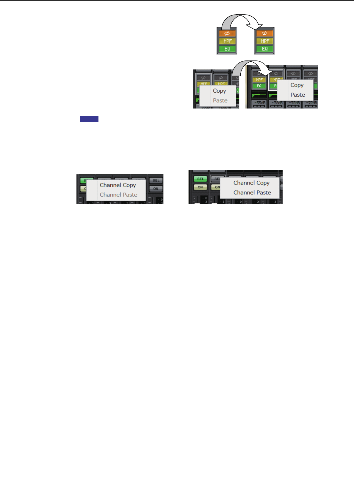
Input channels Chapter 4. System screen
MTX-MRX Editor User Guide
66
●Component copy
Drag (left-click and move) the
component that you want to copy, and
drop it (release the right-click) on the
desired channel.
Alternatively, you can right-click a
component to access a menu. Select
[Copy] and then select [Paste] for the
desired channel.
The following components can be copied: GAIN/HPF/EQ, GATE/COMP, AGC, GAIN/EQ,
COMP/AGC, DELAY/ROOM EQ, and SPEAKER PROCESSOR. However of [GAIN/HPF/EQ],
[Ø] is not copied.
●Channel copy
Right-click the [SEL] button to access the menu. Select [Channel Copy] and then select
[Channel Paste] for the desired channel. All parameters of the channel will be pasted.
NOTE
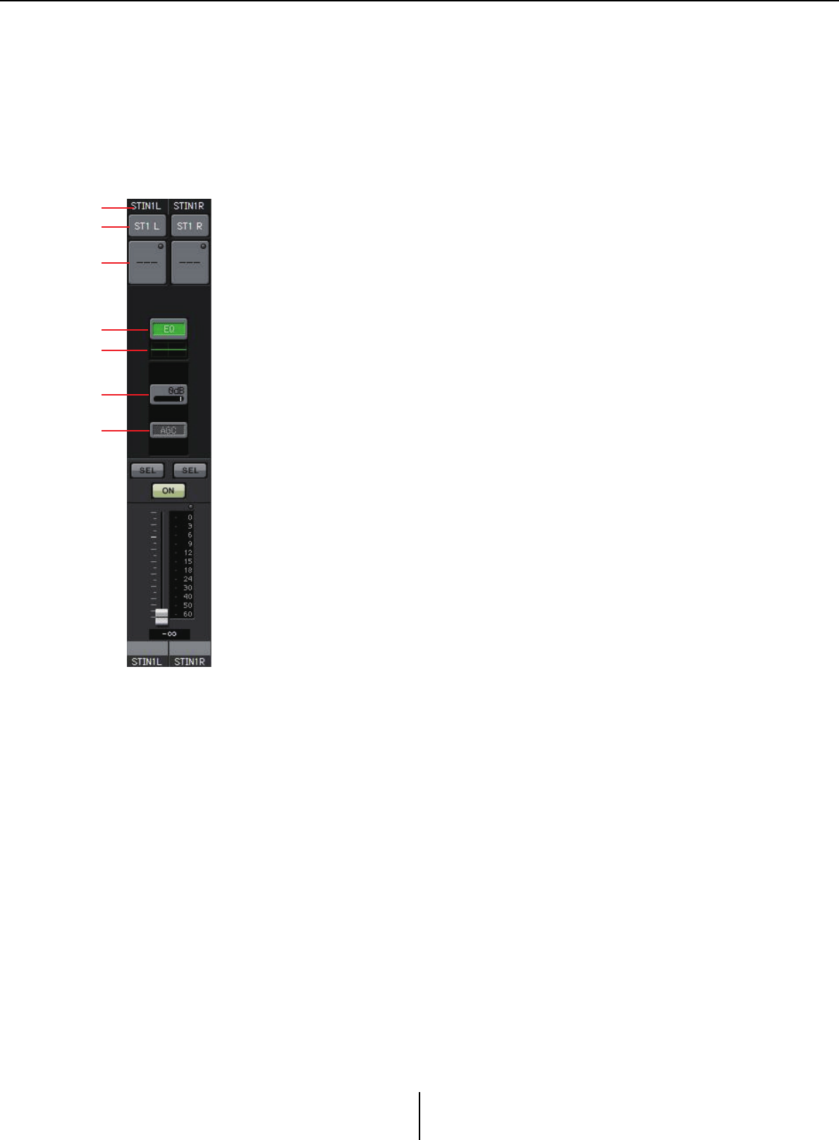
Stereo input channels Chapter 4. System screen
MTX-MRX Editor User Guide
67
Stereo input channels
Stereo input channel settings are made in the [INPUT PORT SETUP] section of the “MTX
Configuration” dialog box.
Input channel settings are made in the [INPUT CHANNEL SETUP] section of the “MTX
Configuration” dialog box.
The description in this section assumes that STEREO channels are used.
1Channel index
Shows the MTX’s input channel number.
2Port select button
Opens the “Input Patch” dialog box. The button shows the currently
selected port.
3Port/external device parameter access button
For details, refer to Input channels.
4“GAIN/EQ” screen access button
Switches to the “GAIN/EQ” screen. The button also shows the on/off status.
This is not shown if HPF and EQ are off.
5EQ indication
This shows a miniature (non-editable) version of the graph that is shown in
the “GAIN/EQ” screen. This is not shown if HPF and EQ are off.
6“COMP” screen access button
Switches to the “COMP/AGC” screen. The button also shows the current
value and on/off status. STIN3 does not provide the capability of specifying
COMP or AGC.
7“AGC” screen access button
Switches to the “COMP/AGC” screen. The button also shows the on/off
status. In the case of the MTX3, this will be only STIN1 and STIN2.
For details on adjusting the following parameters, refer to Input channels.
• [SEL] button
•[ON] button
• Fader/meter
• Input channel volume
•Channel name
1
2
3
4
5
6
7
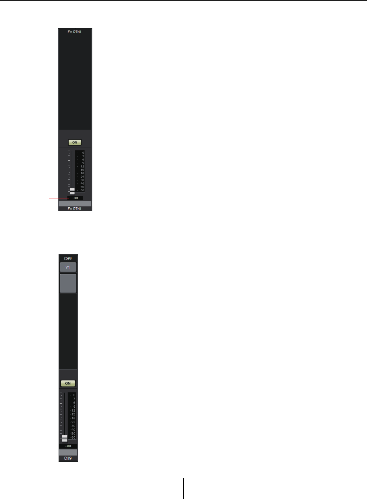
Effect return channels Chapter 4. System screen
MTX-MRX Editor User Guide
68
Effect return channels
1Effect return volume
This parameter specifies the amount of audio signal processed by the effect
that will be returned.
For details on adjusting the following parameters, refer to Input channels.
• Channel index
•[ON] button
• Fader/meter
•Channel name
Direct input channels
Direct input channel settings are made in the [INPUT CHANNEL SETUP] section on the
[INPUT] tab of the “MTX Configuration” dialog box.
For details on adjusting the following parameters, refer to Input channels.
• Channel index
• Port select button
• Port/external device parameter access button
•[ON] button
• Fader/meter
• Input channel volume
•Channel name
1
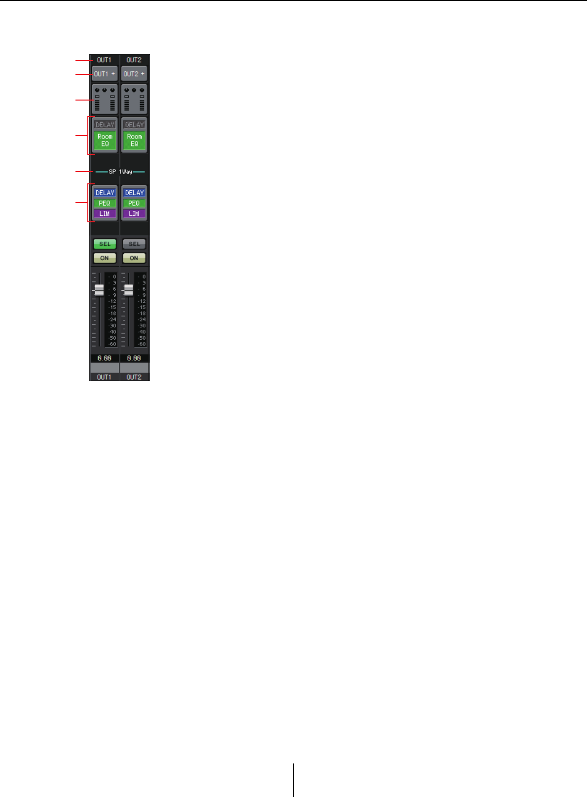
Output channels Chapter 4. System screen
MTX-MRX Editor User Guide
69
Output channels
1Channel index
Indicates the number of the MTX’s output channel.
2Port select button
Opens the “Output Patch” dialog box. The button shows the currently
selected port. If more than one port is assigned, a [+] is shown at the end of
the port name.
3Port/external device parameter access button
This button displays a Parameter editing screen where you can edit the
parameters of the MTX’s output connector and the parameters of the
external device that is associated with that channel.
4“DELAY/ROOM EQ” screen access button
Switches to the “DELAY/ROOM EQ” screen. The button also shows the on/
off status.
5SP 1way/SP 2way indication
Indicates the signal type of the output channel. Output channel settings are
made in [OUTPUT CHANNEL SETUP] of the “MTX Configuration”
dialog box.
6“SPEAKER PROCESSOR” screen access button
Switches to the “SPEAKER PROCESSOR” screen. The button also shows
the on/off status.
For details on adjusting the following parameters, refer to Input channels.
• [SEL] button
•[ON] button
• Fader/meter
•Output channel volume
•Channel name
1
2
3
5
4
6
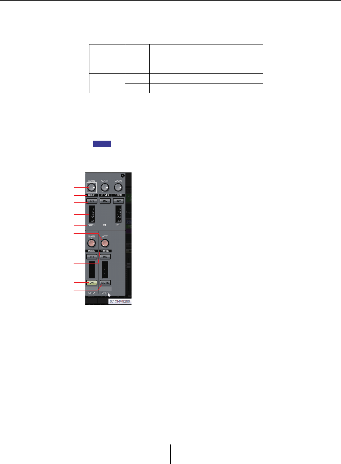
Output channels Chapter 4. System screen
MTX-MRX Editor User Guide
70
Parameter editing screen
An output can be assigned to more than one device.
In the explanatory screens shown here, the assignments are as follows.
The popup shows the MTX [OUTPUT] connector parameters if OUTPUT is
selected in the “Output Patch” popup.
Parameters other than the MTX’s [OUTPUT] connector parameters will appear
in the popup if a device has been assigned to the output route in the “EXT I/O”
screen and the corresponding output is selected in the “Output Patch” popup.
If digital connections and analog connections coexist, we recommend that you set the
XMV’s input sensitivity to [–20 dBFS] in the [Device] tab of the Project screen. If this is
set to [–20 dBFS], the digital connections and analog connections will have the same
input sensitivity.
Upper line
Left MTX [OUTPUT] connector parameters
Center MTX [DANTE] parameters
Right MTX [SLOT] parameters
Lower line Left EXo8 parameters
Right XMV parameters
NOTE
A
C
B
D
E
F
G
H
I
A[GAIN] knob (for other than the XMV)
Adjusts the output gain.
BOutput gain (for other than the XMV)
Shows the output gain setting.
CPOLARITY button
Switches the polarity of the output signal.
DMeter (for other than Dante)
Shows the output signal level.
EChannel index
Indicates the connector number.
In the case of an external device, you can place the cursor
here to see a popup that shows the UNIT ID and the name
of the external device.
F[ON] button (EXo8 only)
Switches the output channel on/off.
G[ATT] knob (XMV only)
Adjusts the XMV’s output attenuator.
HOutput attenuator (XMV only)
Shows the XMV’s output attenuator setting.
I[MUTE] button (XMV only)
Switches mute on/off for the output channel.
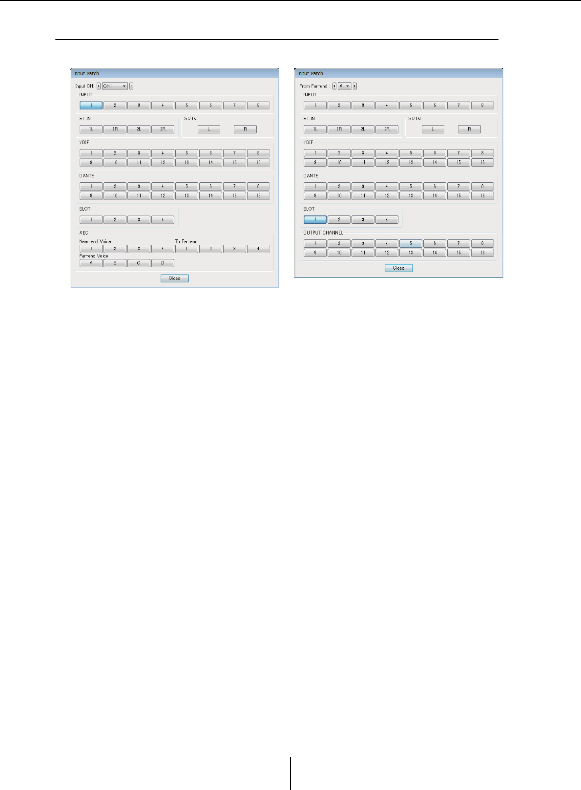
“Input Patch” dialog box Chapter 4. System screen
MTX-MRX Editor User Guide
71
❑“Input Patch” dialog box
Here you can specify the connector or channel whose signal will be assigned to each input channel.
• [Input CH] box
Selects the input source channel.
•INPUT
These are the MTX’s [INPUT] connectors.
•ST IN
These are the MTX’s [ST IN] connectors.
•SD IN
This is the MTX’s SD memory card.
•YDIF
This is the MTX’s [YDIF] connector.
• DANTE (MTX5-D only)
This is the MTX5-D’s [Dante] connector.
•SLOT (MTX5-D only)
This is the MTX5-D’s [SLOT].
• AEC (MTX5-D only)
These are the signals processed by the MY4-AEC installed in the MTX5-D’s [SLOT].
These are not shown if the MY4-AEC is not installed. For details, refer to “MY4-
AEC Owner’s Manual.”
• OUTPUT CHANNEL (only for the MY4-AEC’s Near-end Mic. and From Far-end)
These are the MTX5-D’s output channels.
• [Close] button
Closes the “Input Patch” dialog box.
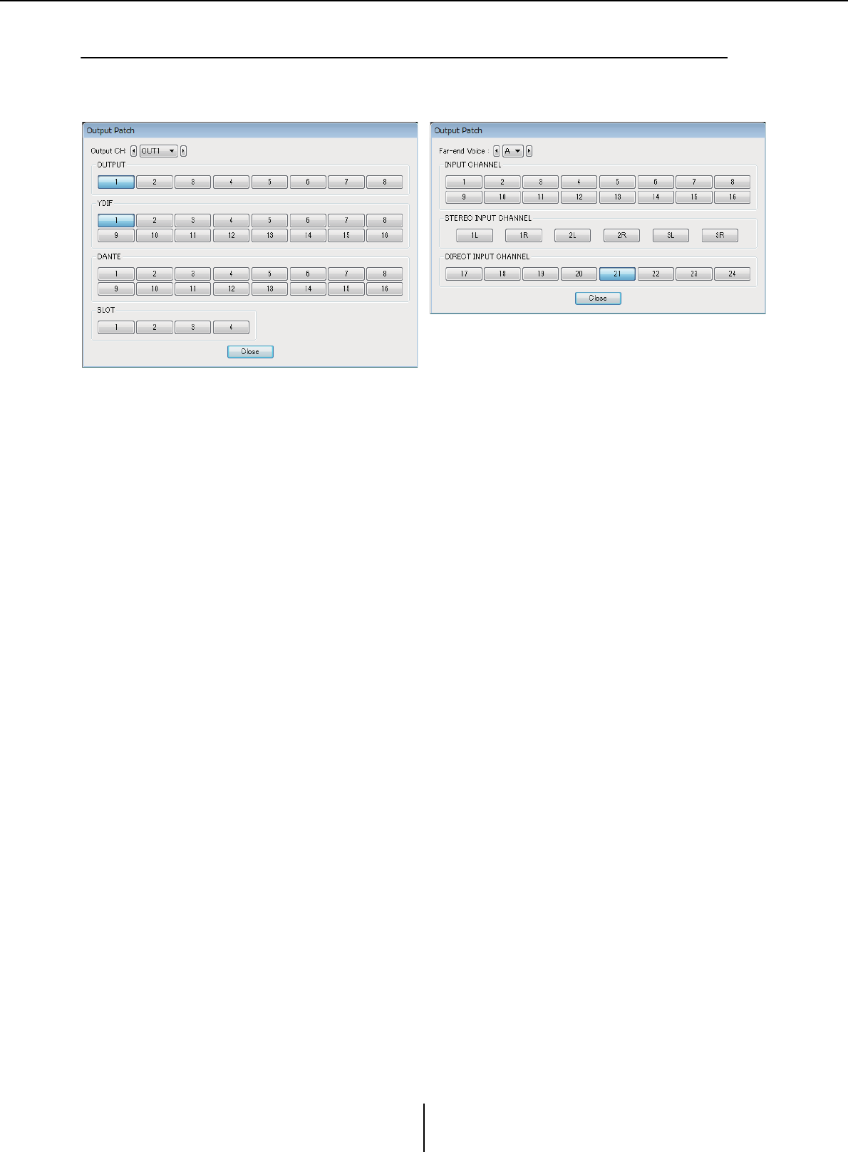
“Output Patch” dialog box Chapter 4. System screen
MTX-MRX Editor User Guide
72
❑“Output Patch” dialog box
Here you can choose how the output channels will be assigned to connectors or channels.
You can select multiple output connectors (except for Far-end Voice, and To Far-end).
• [Output CH] box
Selects the output channel.
•OUTPUT
These are the MTX’s [OUTPUT] connectors.
•YDIF
There are the channels that the MTX will output as YDIF.
They are available only in Distribution mode.
• DANTE (MTX5-D only)
This is the MTX5-D’s [Dante] connector.
•SLOT (MTX5-D only)
This is the MTX5-D’s [SLOT].
• INPUT CHANNEL (MY4-AEC’s Far-end Voice and To Far-end only)
These are the input channels of the MTX5-D.
• STEREO INPUT CHANNEL (MY4-AEC’s Far-end Voice and To Far-end only)
These are the stereo input channels of the MTX5-D.
• DIRECT INPUT CHANNEL (MY4-AEC’s Far-end Voice and To Far-end only)
These are the input channels of the MTX5-D.
• [Close] button
Closes the “Output Patch” dialog box.
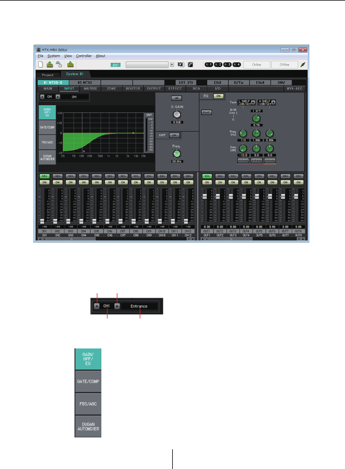
“INPUT” screens Chapter 4. System screen
MTX-MRX Editor User Guide
73
“INPUT” screens
In these screens you can apply signal processing to the input channels.
In this screen you can apply signal processing to the input channels. You can apply GAIN/HPF/EQ,
GATE/COMP, FBS/AGC, and Dugan Automixer.
●Channel selection
Use the left or right button to select the channel
to which you want to apply signal processing.
●Screen selection
Click the appropriate button to select the screen that includes the channel
processing you want to apply.
Left button Right button
Channel index Channel name
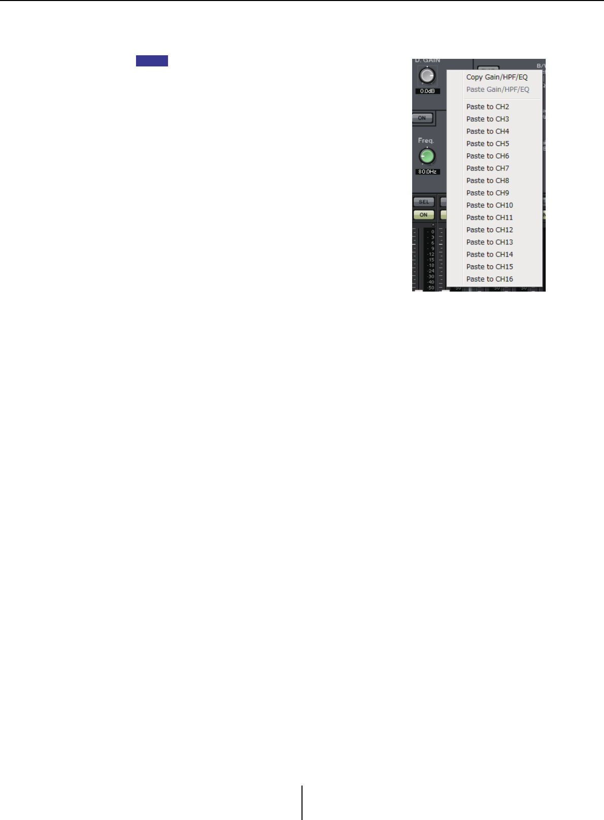
“INPUT” screens Chapter 4. System screen
MTX-MRX Editor User Guide
74
●Operations common to the “INPUT” screens
For details on the knobs and numeric boxes, refer to Explanation of basic operation.
You can copy channel settings to other channels. When
you right-click within the area, a list box will appear. Select
a channel, and paste the settings (the Phase setting of an
input channel will not be copied).
HINT
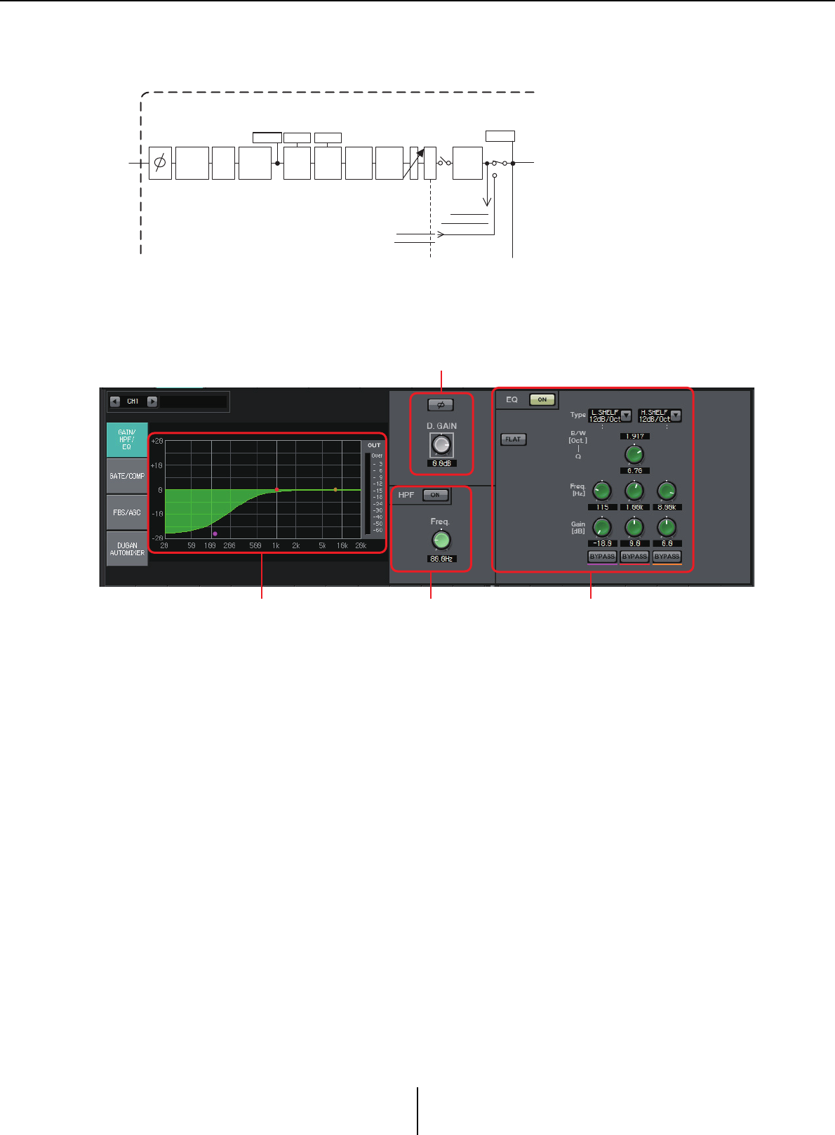
“GAIN/HPF/EQ” screen Chapter 4. System screen
MTX-MRX Editor User Guide
75
Input channels
Signal flow
“GAIN/HPF/EQ” screen
In this screen you can edit the GAIN, HPF, and EQ parameters.
1EQ graph and OUT meter
The effect of the equalizer is shown as a graph. You can drag a control point to edit the
parameters.
An OUT meter is shown at the right of the graph.
2GAIN setting area
•[Ø] button
Switches the phase of the input signal.
•[D.GAIN] knob
Adjusts the digital gain of the input signal.
3HPF setting area
•HPF [ON] button
Switches the HPF (High Pass Filter) on/off.
• [Freq.] knob
Specifies the cutoff frequency of the HPF.
METER
POST ON
ON
HPF
DIGITAL
GAIN
3BAND
EQ
METER
EQ OUT
INPUT CHANNEL(CH1-16)
LEVEL
* CH 1-8 only
D
C
A
GATE
GR
COMP
GR
FBS* AGC*
From SLOT IN
INSERT INPUT
To SLOT OUT
INSERT OUTPUT
INSERT
A.Mixer*
* CH 1-8 only
1 3 4
2

“GAIN/HPF/EQ” screen Chapter 4. System screen
MTX-MRX Editor User Guide
76
4EQ setting area
• EQ [ON] button
Switches the EQ on/off.
• [FLAT] button
Resets the EG gain (0 dB). A confirmation message will appear. Click the [Yes]
button to execute.
• [Type] list box
Select the type of EQ.
The frequency response is shown by the EQ graph.
PEQ (Parametric Equalizer)
The volume in the region of the specified frequency will be boosted or cut according
to the specified Q.
L.SHELF (Low Shelf)
The volume of the entire low-frequency region below the specified frequency will be
boosted or cut. Use this for purposes such as bass boost. [6dB/Oct] and [12dB/Oct]
specify the amount of attenuation per octave.
H.SHELF (High Shelf)
The volume of the entire high-frequency region above the specified frequency will
be boosted or cut. Use this for purposes such as high boost. [6dB/Oct] and
[12dB/Oct] specify the amount of attenuation per octave.
HPF (High Pass Filter)
The region below the specified frequency will be cut.
LPF (Low Pass Filter)
The region above the specified frequency will be cut.
• [B/W] box/[Q] knob
Specifies the width of each frequency region. The [B/W] box specifies the setting in
Octave units.
• [Freq.] knob
Specifies the frequency of each frequency region.
The variable range depends on the band. The Low (left) region has a lower limit of
20 Hz, and the Mid (center) and High (right) regions have a lower limit of 100 Hz.
•[Gain] knob
Specifies the amount of boost or cut that will be applied to the frequency.
• [BYPASS] button
Temporarily turns off the EQ.
NOTE
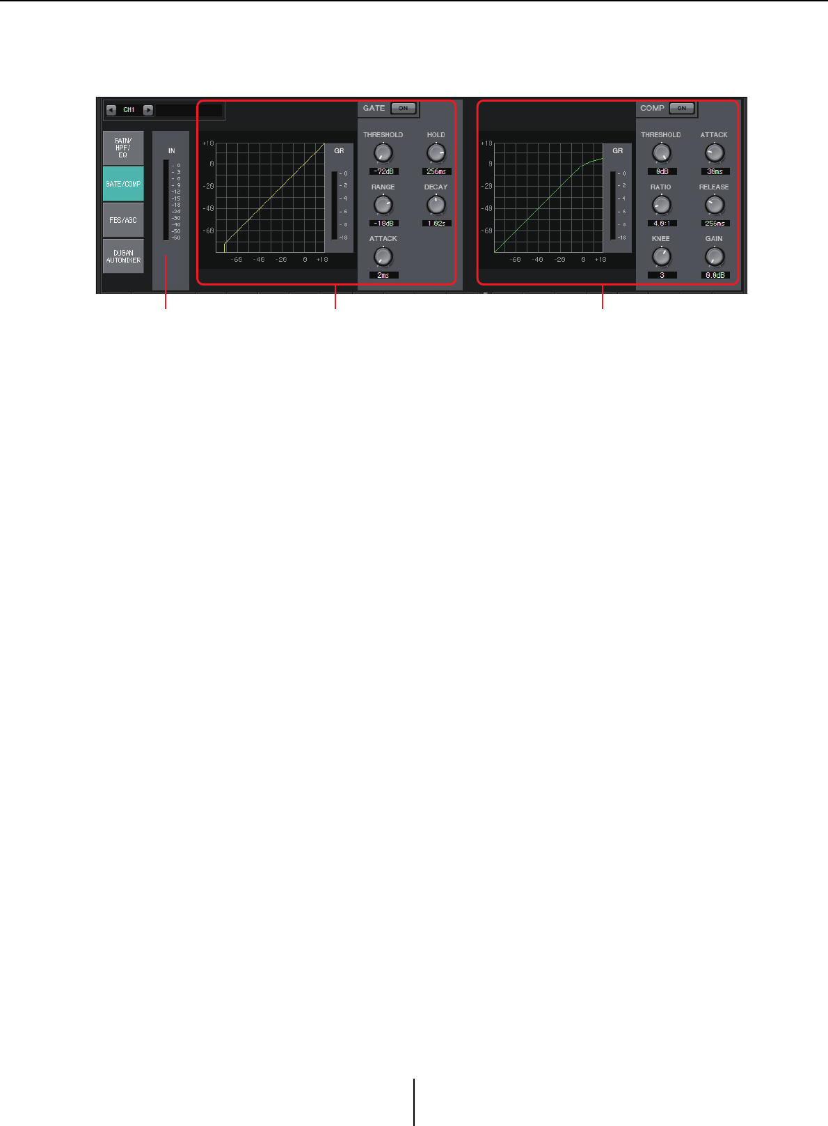
“GATE/COMP” screen Chapter 4. System screen
MTX-MRX Editor User Guide
77
“GATE/COMP” screen
In this screen you can adjust the GATE and COMP (Compressor) parameters.
1IN meter
This is the input meter for the gate.
2GATE setting area
This type of signal processing passes the audio signal only while it exceeds a specified
volume. Use this to cut low-level noise, such as when there is no input from a mic, or
when the input is below a specified level (the threshold value).
•GATE graph
The effect of the gate is shown by this graph. The horizontal axis is the input level,
and the vertical axis is the output level.
• GR meter
Indicates the amount of gain reduction.
• GATE [ON] button
Turns the gate on/off.
•[THRESHOLD] knob
Specifies the threshold level at which the gate will take effect.
•[RANGE] knob
Specifies the amount of attenuation applied when the gate is active.
•[ATTACK] knob
Specifies the attack time (the time from when the input signal exceeds the threshold
until the gate opens).
•[HOLD] knob
Specifies the hold time (the time from when the input signal falls below the
threshold until the gate begins to close).
•[DECAY] knob
Specifies the decay time (the time over which the gate closes after the hold time has
elapsed).
1 2 3

“GATE/COMP” screen Chapter 4. System screen
MTX-MRX Editor User Guide
78
3COMP setting area
This type of signal processing compresses the dynamic range. Use this to prevent
problems that can occur in the sound if the input exceeds a certain level (threshold).
•COMP graph
The effect of the compressor is shown by this graph. The horizontal axis is the input
signal level, and the vertical axis is the output level.
• GR meter
Indicates the amount of gain reduction.
• COMP [ON] button
Turns the compressor on/off.
•[THRESHOLD] knob
Specifies the threshold level at which the compressor will take effect.
• [RATIO] knob
Specifies the compression ratio.
When the threshold level is exceeded, the output signal will be adjusted at the ratio
specified by “input signal : output signal.”
For example with a setting of 4:1, the portion of the signal that exceeds the threshold
value will be compressed to 1/4th.
• [KNEE] knob
Specifies how compression will be applied.
With the [HARD] setting, compression will operate like a limiter. If the [HARD]
setting produces an unnatural impression, raise the value. However, raising the value
excessively will increase the amount of compression for the portion below the
threshold level.
•[ATTACK] knob
Specifies the attack time (the time from when the input signal exceeds the threshold
until the maximum compression is reached).
•[RELEASE] knob
Specifies the release time (the time from when the input signal falls below the
threshold until compression is no longer applied).
•[GAIN] knob
Adjusts the output gain.
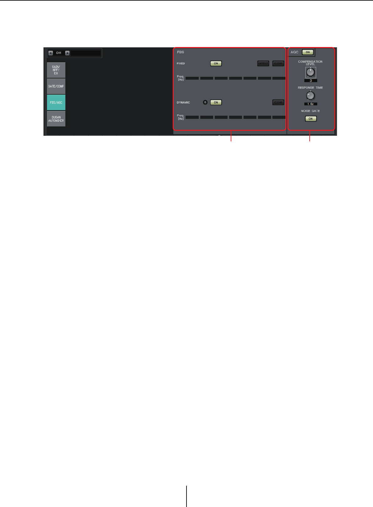
“FBS/AGC” screen Chapter 4. System screen
MTX-MRX Editor User Guide
79
“FBS/AGC” screen
In this screen you can edit the “FBS (Feed Back Suppressor)” and “AGC (Auto Gain
Controller)” parameters.
1FBS setting area
FBS (Feed Back Suppressor) is a function that prevents the unpleasant acoustic
feedback that occurs when sound from a speaker is picked up by a mic and re-
amplified. In addition to being unpleasant, acoustic feedback places a strain on the
speakers, and can damage them. To prevent such feedback, place the speakers so that
their sound will not be picked up by the mic and amplified. If acoustic feedback still
occurs, you can use FBS to improve the feedback margin.
FIXED
After the speakers and mics have been installed, and while the MTX series settings are
being made, this method proactively finds feedback points in the current sound system,
and applies the appropriate filters. This is effective for mics whose position is fixed.
•[ON] button
Applies the detection result.
•[DETECT] button
Displays the Detection start screen. This is available only when online.
• [CLEAR] button
Clears the filter settings. A confirmation message will appear. Click the [Yes] button
to execute.
•[Freq.]
Displays the frequencies of the filters that were applied. Up to seven filters will be
applied.
DYNAMIC
This method continually finds the changing feedback points while the MTX series unit
is in use, and updates the filter settings accordingly. This is effective for wireless mics
whose location is not fixed, and which can be used in a variety of positions.
•[ON] button
Turns the DYNAMIC function on/off. FBS operation will begin when you turn this on.
• [CLEAR] button
Clears the filter settings. A confirmation message will appear. Click the [Yes] button
to execute.
•[Freq.]
Displays the frequencies of the filters that were applied. Up to seven filters will be
applied.
1 2
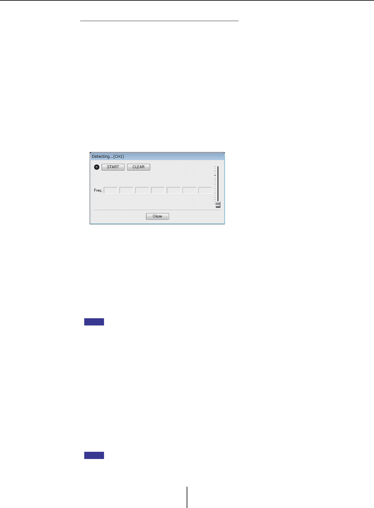
“FBS/AGC” screen Chapter 4. System screen
MTX-MRX Editor User Guide
80
Performing FBS detection for the FIXED type
In order to obtain good results, you should set up the mics, speakers, and other sound
equipment, and adjust the output EQ settings before performing detection. If you want,
FIXED can also be used in conjunction with DYNAMIC.
1. Adjust the power amp output volume.
While vocalizing into the mic, gradually raise the power amp output to the volume
at which the system will be operated in actual use. In addition, clap your hands and
verify that feedback does not occur.
2. Maintain silence in the space for which you want to suppress feedback.
3. Select the input channels in MTX-MRX Editor.
4. Click the [FBS/AGC] button.
5. Click the FIXED [DETECT] button to open the detection start screen.
6. Click the [START] button in the detection start screen. Detection will
start.
Raise the faders little by little during detection. You can make fine adjustments by
operating the mouse wheel.
Feedback will occur, but the MTX will immediately detect that frequency and insert
a filter. Repeat this operation. When you have obtained a satisfactory result, click the
[STOP] button to end the procedure.
7. After detection has ended, click the [CLOSE] button to close the screen.
• The indicator will light when the following occurs.
-When a frequency is displayed
-When a currently-displayed frequency is rewritten
• If you don’t notice any result, it may be that detection has failed. Click the [CLEAR] button
to discard the detection result. If you want to make the settings once again, adjust the
position of the mics and speakers, adjust the volume, and try the above procedure once
again from step 1.
In some cases, detection will not occur correctly if the overall volume is raised excessively,
or if the mics and speakers are too close, or if sound from a speaker is directly entering a
mic.
• When using FIXED, calculation will continue repeatedly even after all seven filters have
been displayed, for example to combine the frequencies that are closest to each other.
However when using DYNAMIC, if all seven filters are already displayed but new feedback
is found, the filter that was specified first and that will have the least effect on the audio
quality will be discarded, and replaced by the newly-specified filter. A filter will be
discarded automatically after a certain length of time has elapsed since it was applied.
• It is not possible to completely eliminate all feedback in all environments.
• If feedback increases when you raise a fader, and is not automatically suppressed, lower
the fader to prevent the speakers from being damaged.
The MTX cannot detect multiple feedback points simultaneously. Settings will be easier if you
raise the fader slowly so that feedback occurs gradually.
NOTE
HINT
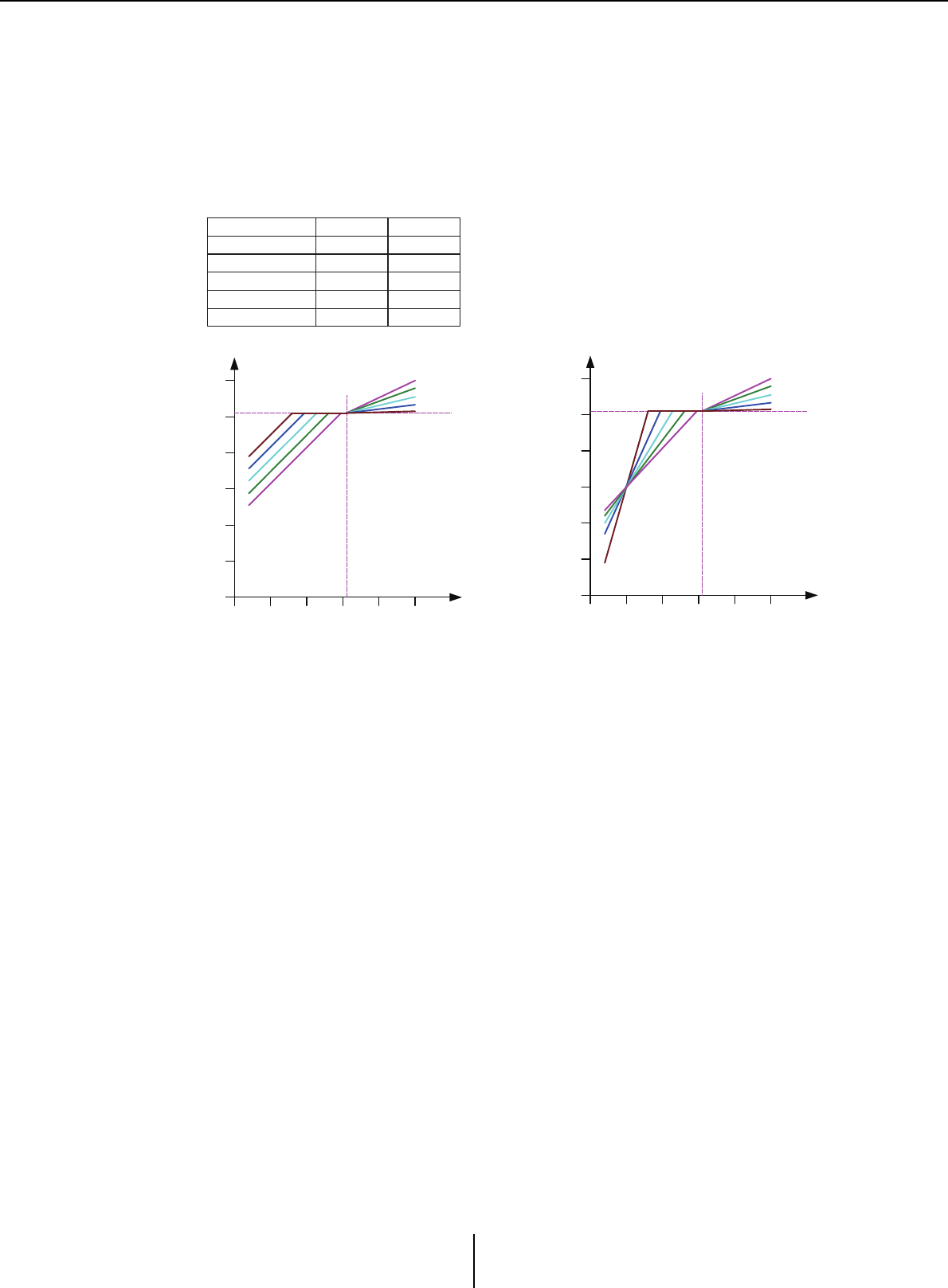
“FBS/AGC” screen Chapter 4. System screen
MTX-MRX Editor User Guide
81
2AGC setting area
AGC (Auto Gain Controller) is a function that automatically compensates the gain
according to the input level, keeping a constant output level for an incoming signal
whose level is changing. For example, differences in how closely and how loudly a
person is speaking into a mic can make their amplified voice vary in volume, making it
less intelligible. In such cases, the volume will be automatically adjusted within a fixed
range.
• AGC [ON] button
Turns AGC on/off.
• [COMPENSATION LEVEL] knob
Specifies the amount of gain compensation. Higher settings will produce more
compensation.
• [RESPONSE TIME] knob
Specifies the response speed for gain compensation. This applies to compensation
that raises the gain; it is the time required for a 6 dB increase.
• [NOISE GATE] button
Turns the noise gate on/off.
Compensation Level
1
2
3
4
5
Threshold
-21
Compensation Level5
Compensation Level4
Compensation Level3
Compensation Level2
Compensation Level1
Noise Gate : OFF
-27.75
-34.5
-41.25
-48
Ratio
1
1.3
2
4
20
-80 -60 -40 -20 -10 0
-120
-100
-80
-60
-40
-20
0
-18dB
-18dB
Output(dB)
Input(dB)
Noise Gate : ON
-80 -60 -40 -20 -10 0
-120
-100
-80
-60
-40
-20
0
-18dB
-18dB
Output(dB)
Input(dB)
If the input is below the Threshold value, the
output is adjusted so that the output is –18 dB
when it reaches the Threshold value.
If the input is above the Threshold value and
below –18 dB, the output is set to –18 dB.
If the input is above the Threshold value and
above –18 dB, the output level is adjusted by
the Ratio value.
If the noise gate is on, the volume is
adjusted so that input and output are the
same level at –60 dB, and then adjusted so
that the output is –18 dB when it reaches the
Threshold value.
If the input is above the Threshold value and
below –18 dB, the output is set to –18 dB.
If the input is above the Threshold value and
above –18 dB, the output level is adjusted by
the Ratio value.
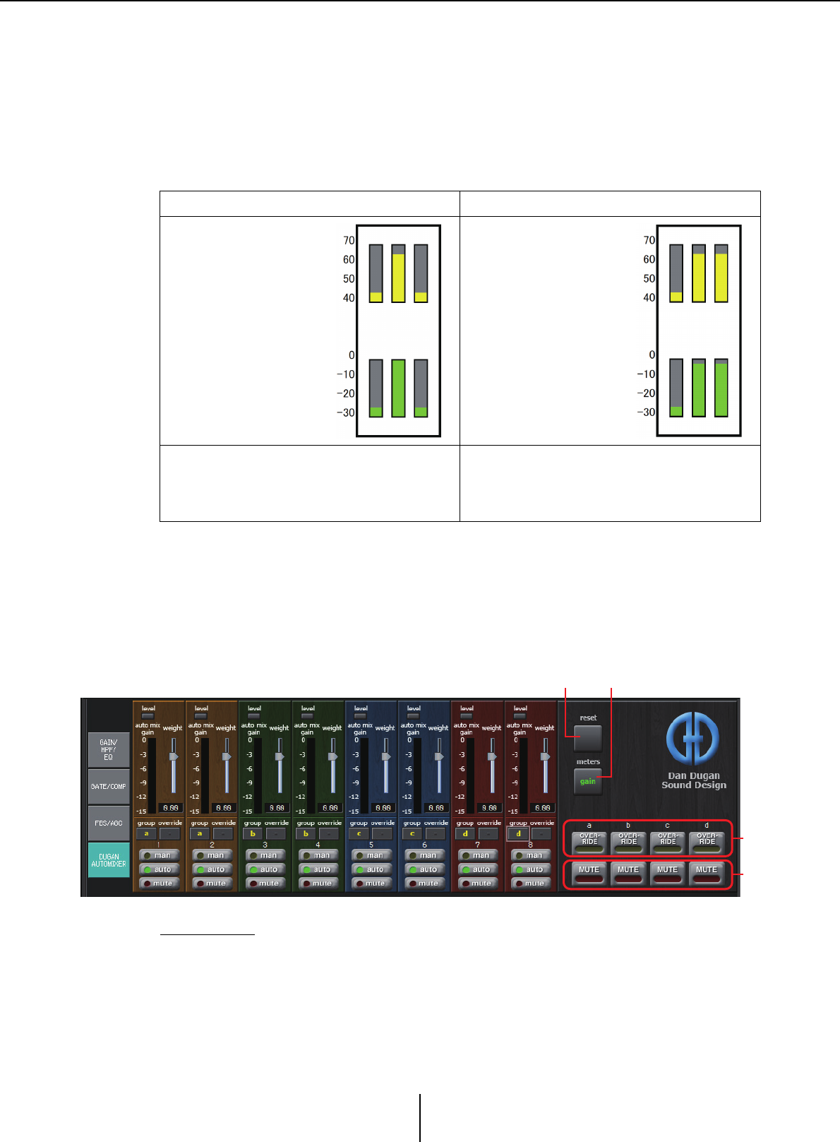
“DUGAN AUTOMIXER” screen Chapter 4. System screen
MTX-MRX Editor User Guide
82
“DUGAN AUTOMIXER” screen
In a system used for unscripted speech, the automixer detects the mics that are in use and
automatically optimizes the gain distribution, maintaining a consistent system gain
between multiple mics without requiring an engineer to be constantly adjusting the faders.
The Dugan Automixer provided by the MTX automatically adjusts the automix gain of
input channels 1–4 on the MTX3 or input channels 1–8 on the MTX5-D.
In this explanation, we describe using the Dugan Automixer with three mics.
The Dugan Automixer differs from the functionality of a limiter or an auto level controller.
When multiple people are speaking, the engineer can use the faders to adjust individual
levels as usual. Even when nobody is speaking, the mic audio level is detected and the gain
is distributed automatically, so the faders can be left raised.
The automixing algorithm is only complete when all the channels in an automixing group
are summed.
Master field
1[reset] button
Resets the various parameters to their default values.
When one person is speaking When two people are speaking
Mic input audio (dB)
Automix gain (dB)
Mic input audio (dB)
Automix gain (dB)
When one person speaks, the gain of that mic
instantly rises, and the gain of the other mics
decreases. The same thing happens when a
different person speaks.
When two people speak simultaneously, the
gain is automatically distributed between the
two mics so that the total gain remains constant,
and the gain of the remaining mic decreases.
12
3
4
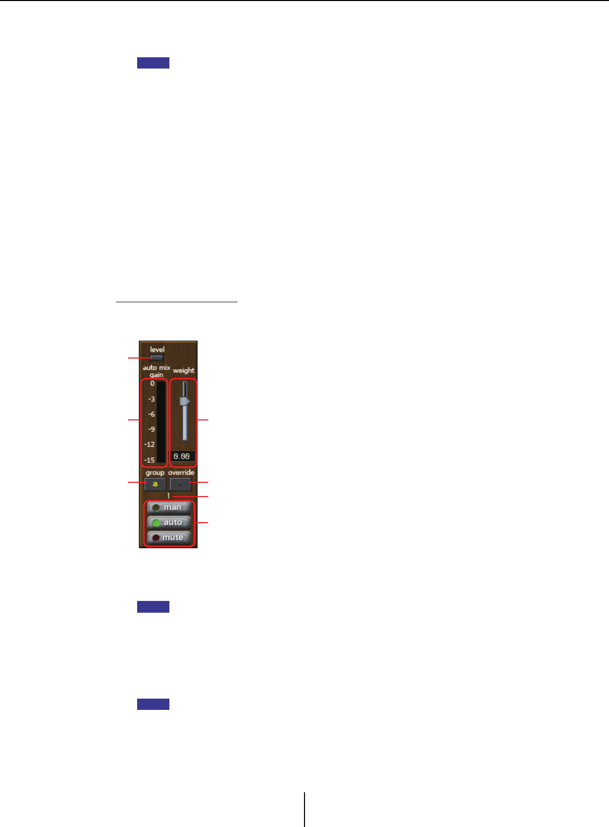
“DUGAN AUTOMIXER” screen Chapter 4. System screen
MTX-MRX Editor User Guide
83
2[meters] button
Switches the meter display of the channel control field between gain/input/output.
When using [weight] to adjust the relative sensitivity between the input channels, switching
the meter display to “gain” lets you use the channel control field to adjust the gain amount,
providing better visibility.
3[OVERRIDE] button
This function instantly mutes all mics except for a specific mic, such as the mic of the
chair or head.
If this is on, channels whose [override] button is on are set to “man,” and channels
whose [override] button is off are set to “mute.”
For the specified mic, such as of the chair or head, click the [override] button in the
channel strip to make it light yellow. Press the button once again to return to the
previous setting.
4[MUTE] button
Turns mute on/off for all mics in the group.
Channel control field
This is color-coded by group.
Channels of the same group are mixed.
1[level] indicator
This lights green when the audio reaches the appropriate level for automixing.
• If the [level] indicator goes dark, raise the mic input gain.
• If the [level] indicator lights red, lower the mic input gain.
2Meter
The meter provides three display modes: gain (green: automix gain) /input (yellow:
input level) /output (blue: output level). The display mode switches each time you press
the [meters] button in the master field.
Normally you will leave this in the “gain” display mode.
NOTE
1
2
4
3
5
6
7
NOTE
NOTE

“DUGAN AUTOMIXER” screen Chapter 4. System screen
MTX-MRX Editor User Guide
84
3[weight] slider
Adjusts the relative sensitivity between input channels. Set the meter display to “gain,”
and adjust the weight setting so that the meters are at approximately the same level
when there is no input. For example if noise is heard near a certain mic (e.g., air
conditioner wind noise), lowering the weight value of that channel will reduce the
noise.
The automixer calculates the proportion of a specific channel’s input level relative to the
mix of all inputs in the group. The following examples describe how weight control
works.
❍If the weight setting value is raised on one channel
• The automix gain value of that channel increases, and the value of other channels
decreases.
• Channels with a high weight setting will more easily obtain automix gain in
comparison to other channels.
❍If the weight setting value is lowered on one channel
• The automix gain value of that channel decreases, and the value of other channels
increases.
• If people speak simultaneously into multiple mics, it will be more difficult to
differentiate them from the other mics.
4[group] button
Selects the group to which each channel belongs. Click the button to switch the group.
Two groups can be specified on the MTX3, or four groups on the MTX5-D.
5[override] button
When the master field’s [OVERRIDE] button is on, the setting of this button
determines whether the corresponding channel switches to “man” mode or “mute”
mode.
• If you turn on the [OVERRIDE] button of the master field when the [override] button
of the channel control field is on, the channel mode changes to “man.”
• If you turn on the [OVERRIDE] button of the master field when the [override] button
of the channel control field is off, the channel mode changes to “mute.”
• When the [OVERRIDE] button of the master field is turned off, that channel returns to
its previous mode.
6Input channel number
Indicates the input channel number.
7[man]/[auto]/[mute] buttons
These buttons toggle the channel between man/auto/mute.
man : The audio is passed through without modifying the gain. Select this mode
if singing into the mic.
auto : The automixer is turned on. Select this mode for conversation.
mute : The channel is muted.
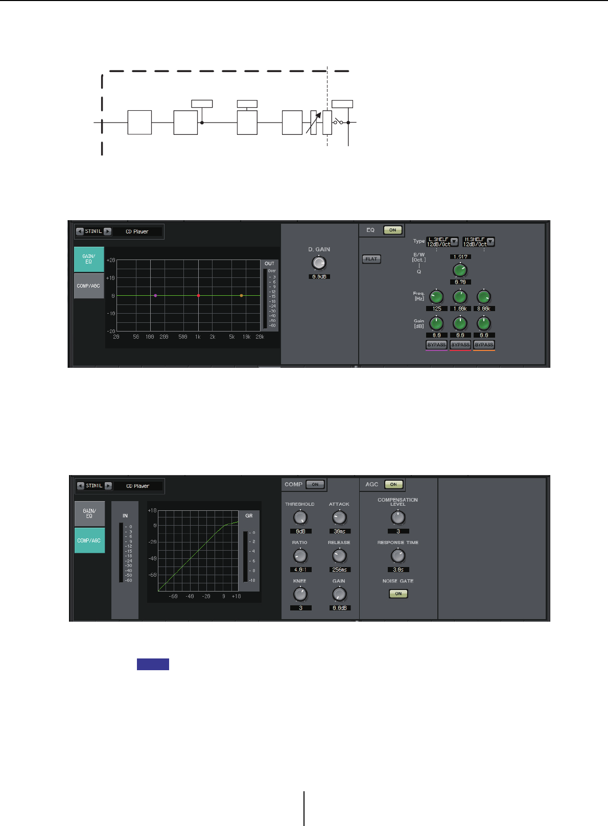
Stereo input channels Chapter 4. System screen
MTX-MRX Editor User Guide
85
Stereo input channels
Signal flow
“GAIN/EQ” screen
In this screen you can adjust the GAIN and EQ parameters. For details on these
parameters, refer to “GAIN/HPF/EQ” screen.
“COMP/AGC” screen
In this screen you can adjust the COMP and AGC parameters. For details on these
parameters, refer to “GATE/COMP” screen and “FBS/AGC” screen.
If you are playing a CD and the recorded level differs between songs to an unpleasant extent,
it is effective to use the AGC function to adjust the levels.
METER
POST ON
ON
3BAND
EQ
METER
POST EQ
LEVEL
* CH 1L-2R only
COMP*
GR
AGC*
STEREO INPUT CHANNEL(STIN1L-3R)
D
C
A
DIGITAL
GAIN
HINT
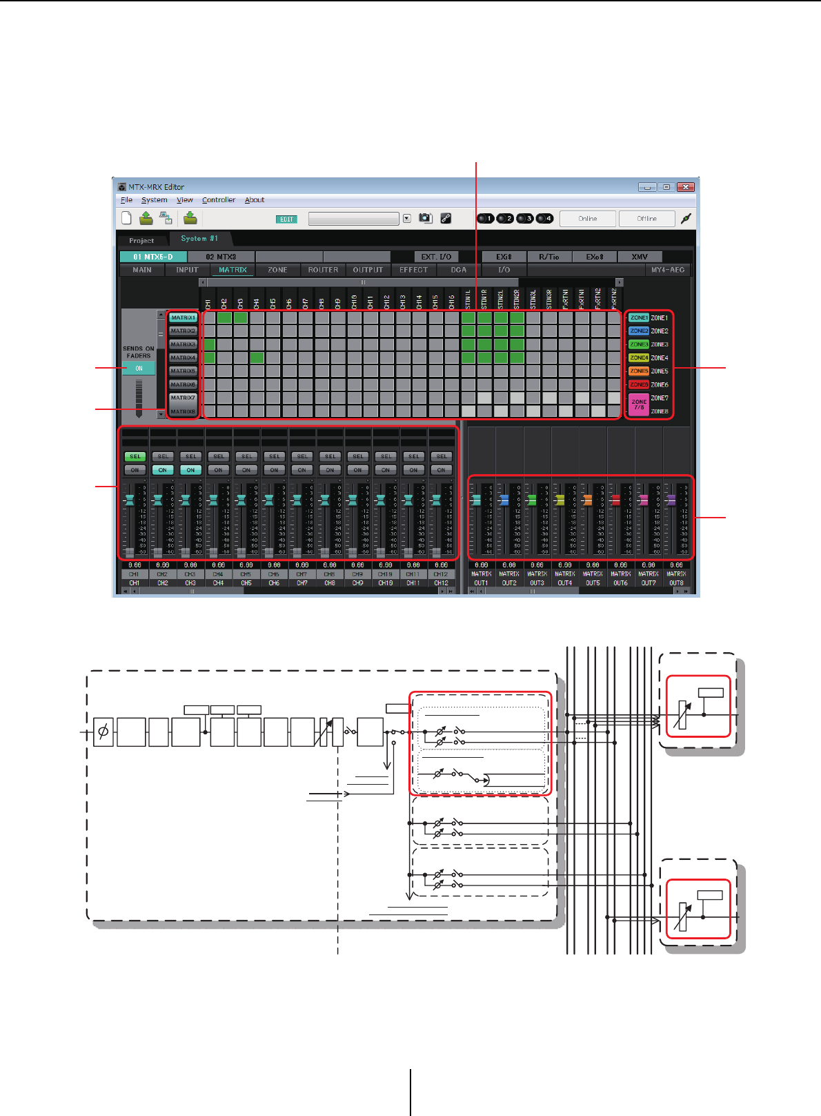
“MATRIX” screen Chapter 4. System screen
MTX-MRX Editor User Guide
86
“MATRIX” screen
This screen mixes and sends the input channel signals.
In SENDS ON FADER mode, you can use the input channel faders to adjust the amount of the input
channels that is sent to the matrix bus.
Signal flow
1SENDS ON FADERS [ON] button
Turns SENDS ON FADER mode on/off. If this is off, the input channel faders will
adjust the input levels.
14
2
5
6
3
METER
POS T ON
ON
HPF
DIGITAL
GAIN
3BAND
EQ
METER
EQ OUT
INPUT CHANNEL(CH1-16)
L EVE L
To Y DIF OUTPUT PATCH
To PRIORITY/AMBIENT SOURCE
To M ATRIX(MONO)
To M ATRIX1,3...15
To M ATRIX2,4...16
ON
L EVE L
To M ATRIX(STEREO)
ON
L EVE L To M ATRIX1,3...15
To M ATRIX2,4...16
ON
L EVE L
MATRIX CROSS POINT
EFFECT SEND
To FX 1
To FX 2
ON
L EVE L
ANC SEND
To A NC1
To A NC2
* CH 1-8 only
D
C
A
PA N
GATE
GR
COMP
GR
FBS* AGC *
MATRIX
12 7 16
... 158... 1212
ANCFX
ZONE 1-8
ZONE 9-16
From SLOT I N
INSERT INPUT
To S LOT OUT
INSERT OUTPUT
INSERT
A.Mixer*
* CH 1-8 only
LEVEL
LEVEL
METER
MA TRIX OUT
METER
MATRIX OUT
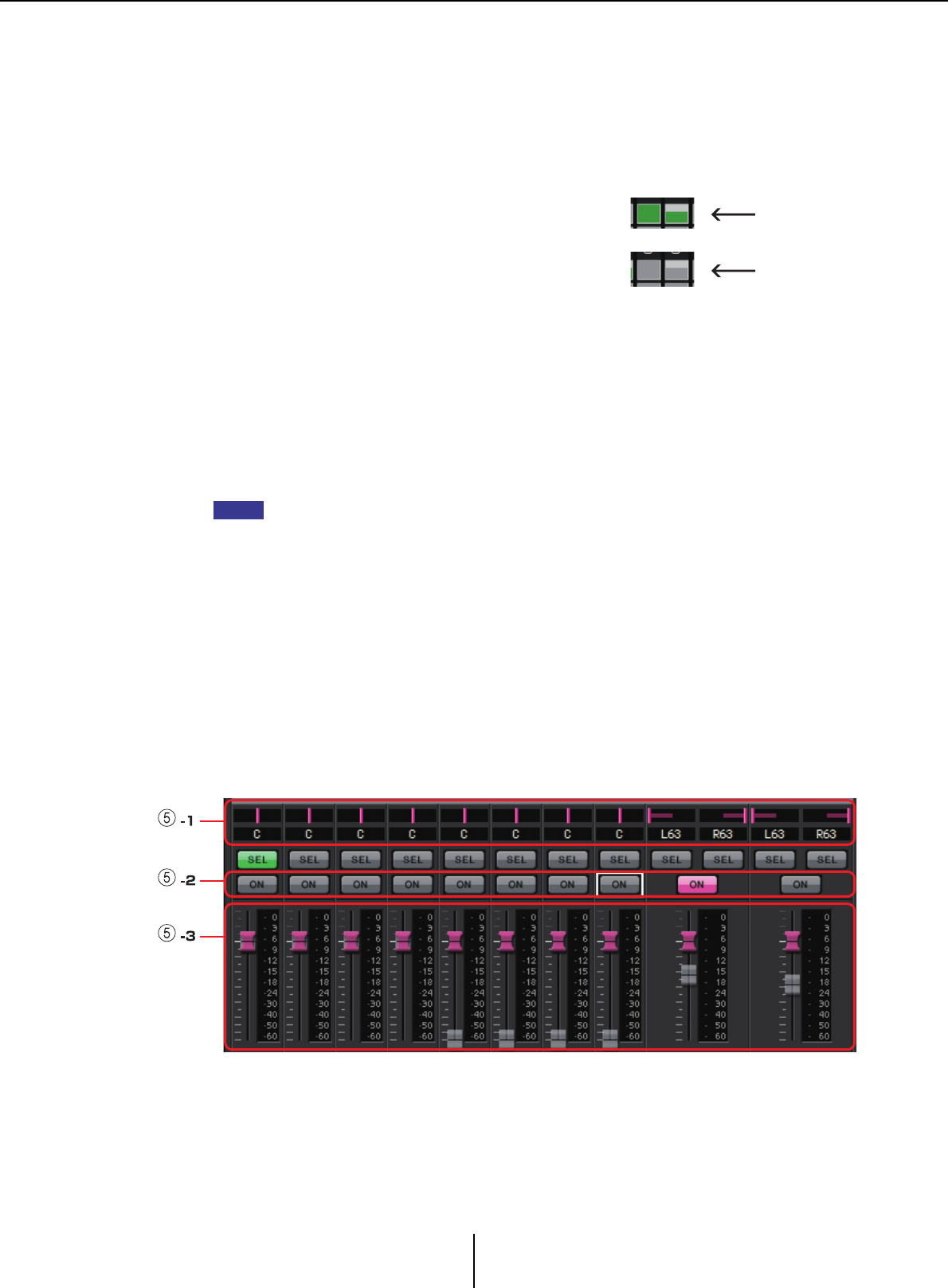
“MATRIX” screen Chapter 4. System screen
MTX-MRX Editor User Guide
87
2Matrix bus select buttons
Select the matrix bus to which the signal will be sent. A pair of channels that are
assigned as stereo is shown by a single button.
If you right-click the button, you’ll be able to set all send levels to the matrix bus in a
single operation by choosing 0 dB, –3 dB, –6 dB, or –Infinity.
3Input channel matrix
Shows the send level of each channel. The
horizontal axis indicates the input channels,
and the vertical axis indicates the send-
destination matrix buses. The PAN or Blend
settings are included in the send levels. Click
here to turn send on/off. If you drag with the mouse, the send on/off settings over which
the cursor passes will change to the state of the location from which you began
dragging.
If a name has been assigned to the input channel or zone, the name is shown at the top
or right of the matrix.
You can right-click a cross point and make multiple send on/off settings in a single
operation by choosing Matrix ON (all horizontal axis on), Matrix OFF (all horizontal
axis off), All ON (all on), or All OFF (all off).
• Do not turn on the input channel matrix for an input channel that is connected to a PGM1
unit.
• You can use the vertical and horizontal scroll bars to select ANC buses or other channels
that are hidden.
4[ZONE] button
Indicate the zones that are the matrix output destinations. Click a button to access the
“ZONE” screen. A pair of channels that are assigned as stereo is shown by a single
button.
ZONE 9 through ZONE 16 are only displayed; they have no buttons.
5Input channel faders
When SENDS ON FADER mode is on, the faders and [ON] buttons are shown in the
same color as the send-destination matrix bus select buttons.
5-1 PAN (controller and numeric box)
The controller and numeric value are shown only if the matrix bus is stereo,
allowing the setting to be edited.
Far left is 63L, center is C, and far right is 63R.
On:
Off:
Send level
Send level
NOTE
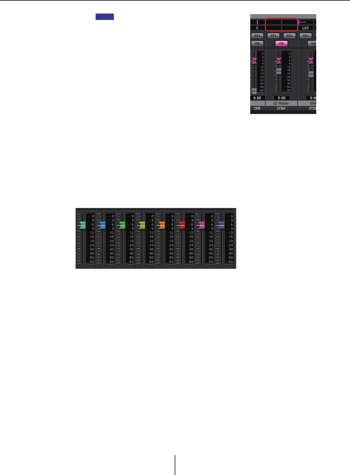
“MATRIX” screen Chapter 4. System screen
MTX-MRX Editor User Guide
88
• When sending from a stereo input to a stereo bus, you can
use “MTX Configuration” dialog box in the “Advanced
Settings” dialog box to switch between PAN and Blend. If
Blend is selected, the controller and numeric value are not
shown (illustration at right).
• In the numeric box, enter [L63] or [l63] to pan fully left; enter
[R63] or [r63] to pan fully right. Enter [C] or [c] to pan to the
center.
5-2 [ON] buttons
Switch send on/off when SENDS ON FADERS mode is on.
5-3 Faders
Adjust the send level of the input channels.
You can right-click a fader and set the send level by selecting 0 dB, –3 dB, –6 dB,
or –Infinity. A grayed-out fader is shown at the position of the input level (this
cannot be edited).
6Matrix out faders
The colors of the faders are linked with the colors of the matrix bus select buttons.
•Faders
Adjust the matrix out level.
You can right-click a fader and set the level by selecting 0 dB or –Infinity.
NOTE
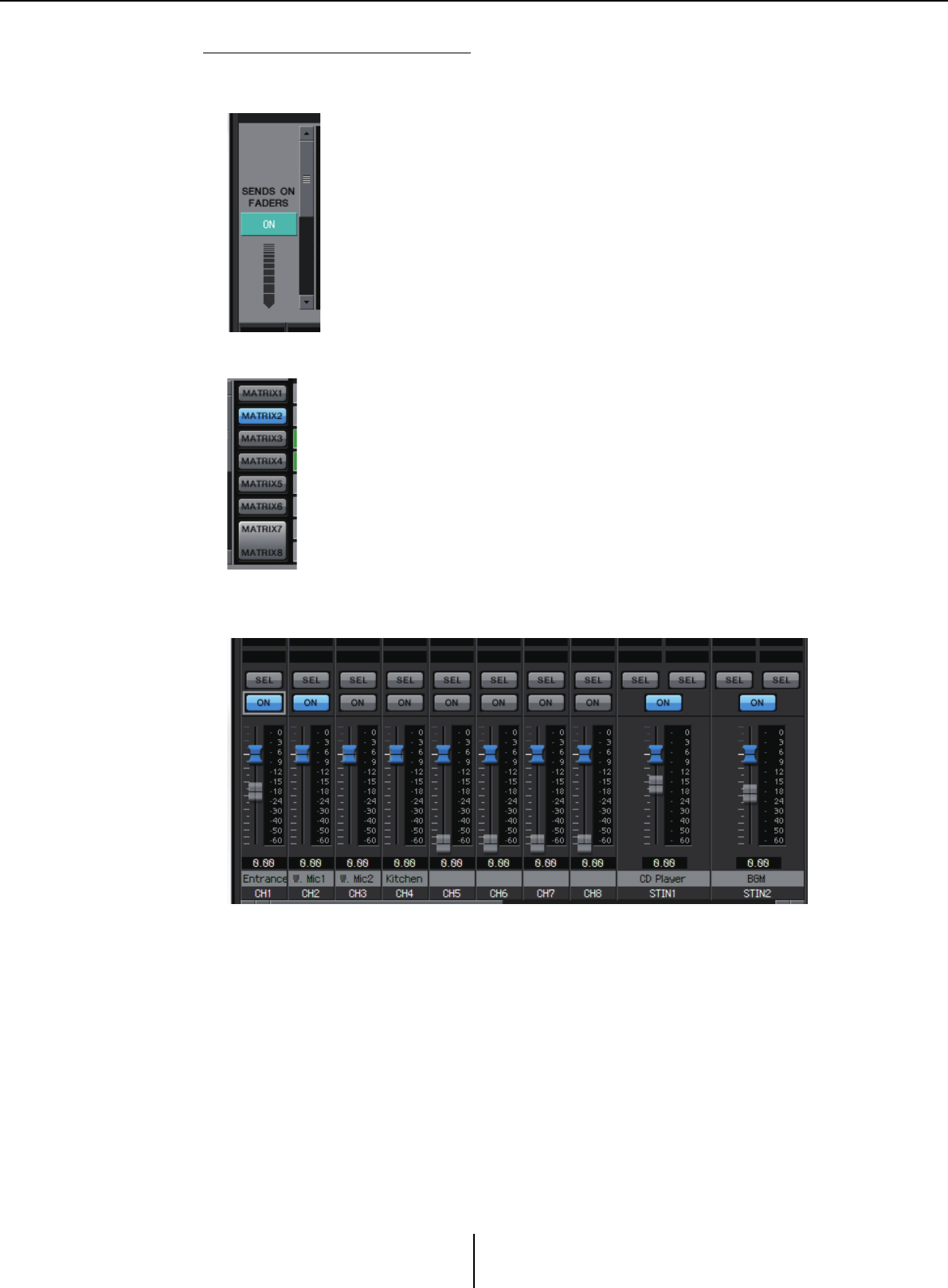
“MATRIX” screen Chapter 4. System screen
MTX-MRX Editor User Guide
89
Setting the input channel mix
1. Click the [SENDS ON FADERS] button.
2. Click a send-destination select button to select a send-destination bus.
3. Adjust the send level of each input channel. You can use the [ON]
button to switch send on/off.
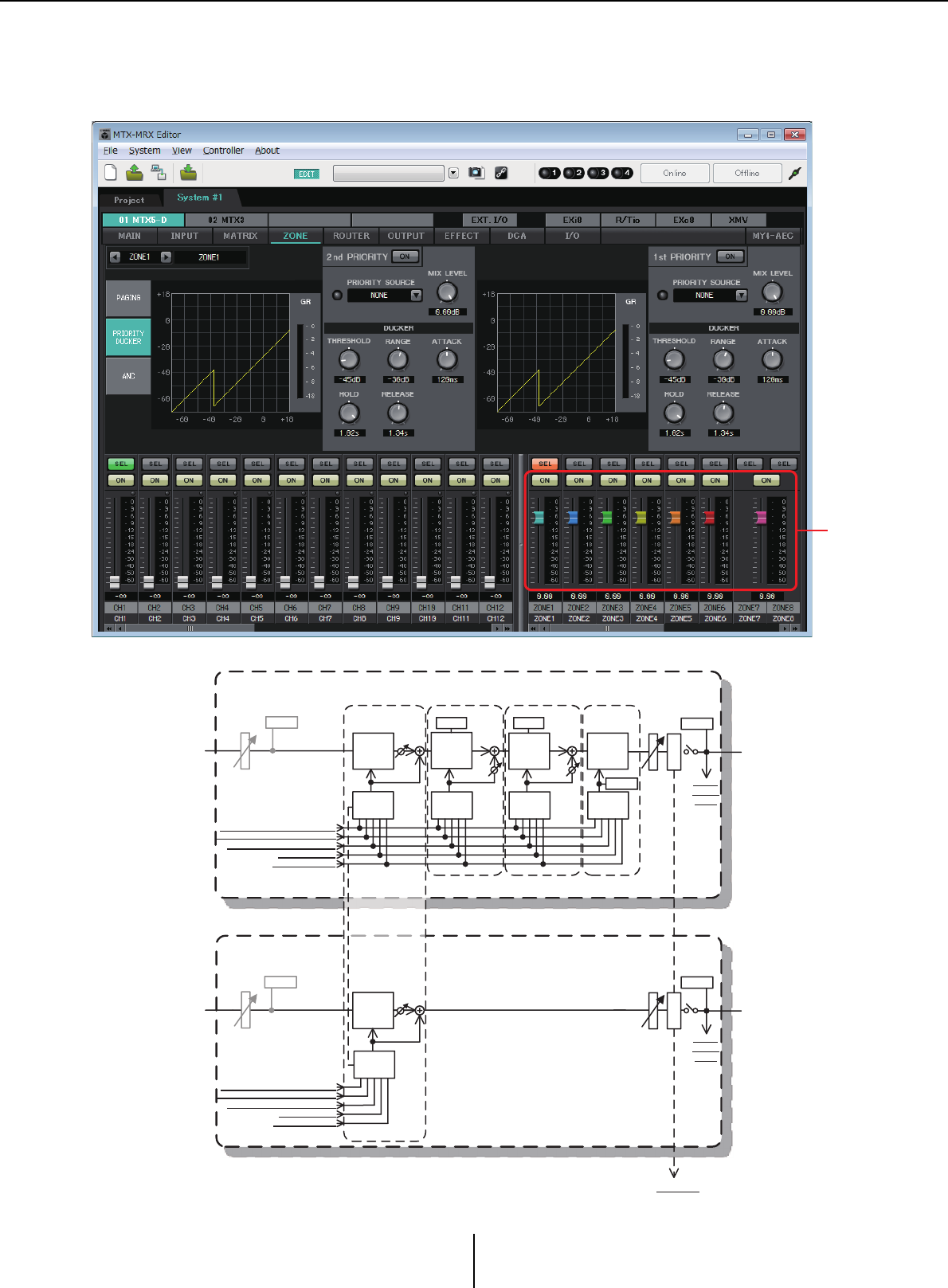
“ZONE” screen Chapter 4. System screen
MTX-MRX Editor User Guide
90
“ZONE” screen
In this screen you can specify settings for the PGM1, and how input signal priority will control output
signals.
Signal flow
1
PRIORITY
DUCKER ANC
AMBIENT
SOURCE
From I NPUT CHANNEL PO ST ON 1-16
*1 Fr om Y DIF I N 1-16
From ANC BUS 1-2
From STEREO INPUT CHANNEL POST O N 1L-3R
ZONE 1-8
ZONE OUT
To Y DIF
OUT PUT
PATCH
MIXMIX
2n d PR I ORIT Y 1s t PRI ORI TY A N C
PRIORITY
SOURCE
PRIORITY
SOURCE
From DI RECT INPUT POST O N 9-16
PRIORITY
DUCKER
METER
ON
D
C
A
MA STE R
LEVEL
GR GR
AMBIENT
ZONE OUT
METER
ON
MA STE R
LEVEL
ZONE 9-16
D
C
A
METER
To Y DIF
OUT PUT
PATCH
To oth er MT Xs
*1 DISTRIBUTION MODE only
PAGING
PA GI NG
DUCKER MIX
PA GI NG
SOURCE
PA GI NG
DUCKER MIX
PA GI NG
SOURCE
From I NPUT CHANNEL POST ON 1-16
*1 Fr om YDIF I N 1-16
From ANC BUS 1-2
From STEREO INPUT CHANNEL POST O N 1L-3R
From DI RECT I NPUT POST ON 9-16
*1 DISTRIBUTIO N MODE only
L EVE L
L EVE L
METER
MA TR IX OUT
METER
MATRIX OUT
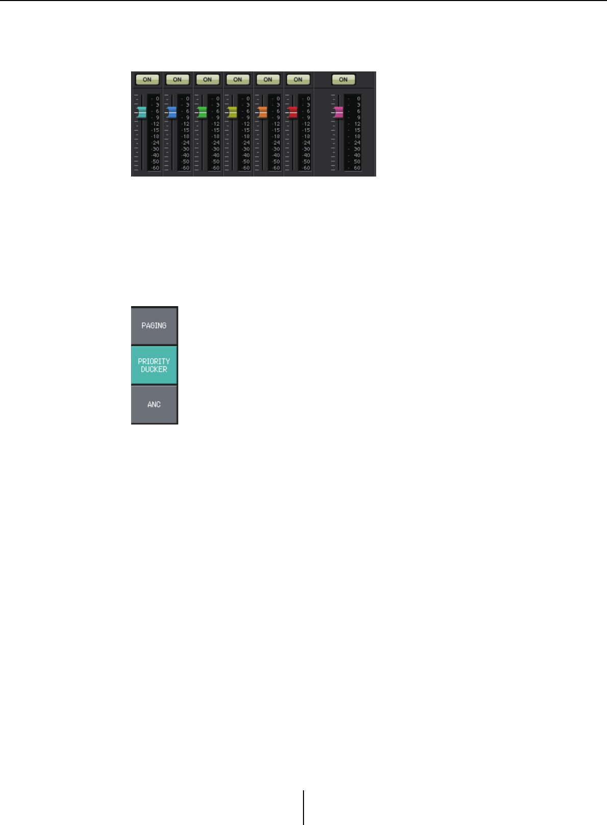
“ZONE” screen Chapter 4. System screen
MTX-MRX Editor User Guide
91
1Output channel faders
The colors of the faders are linked with the colors of the [ZONE] buttons in the
“MATRIX” screen.
• [ON] buttons
Turn ZONE OUT on/off.
•Faders
Adjust the ZONE OUT level.
You can right-click a fader knob and set the send level by selecting 0 dB or -Infinity.
●Screen selection
By clicking a button, you can switch to the screen for making various
settings.
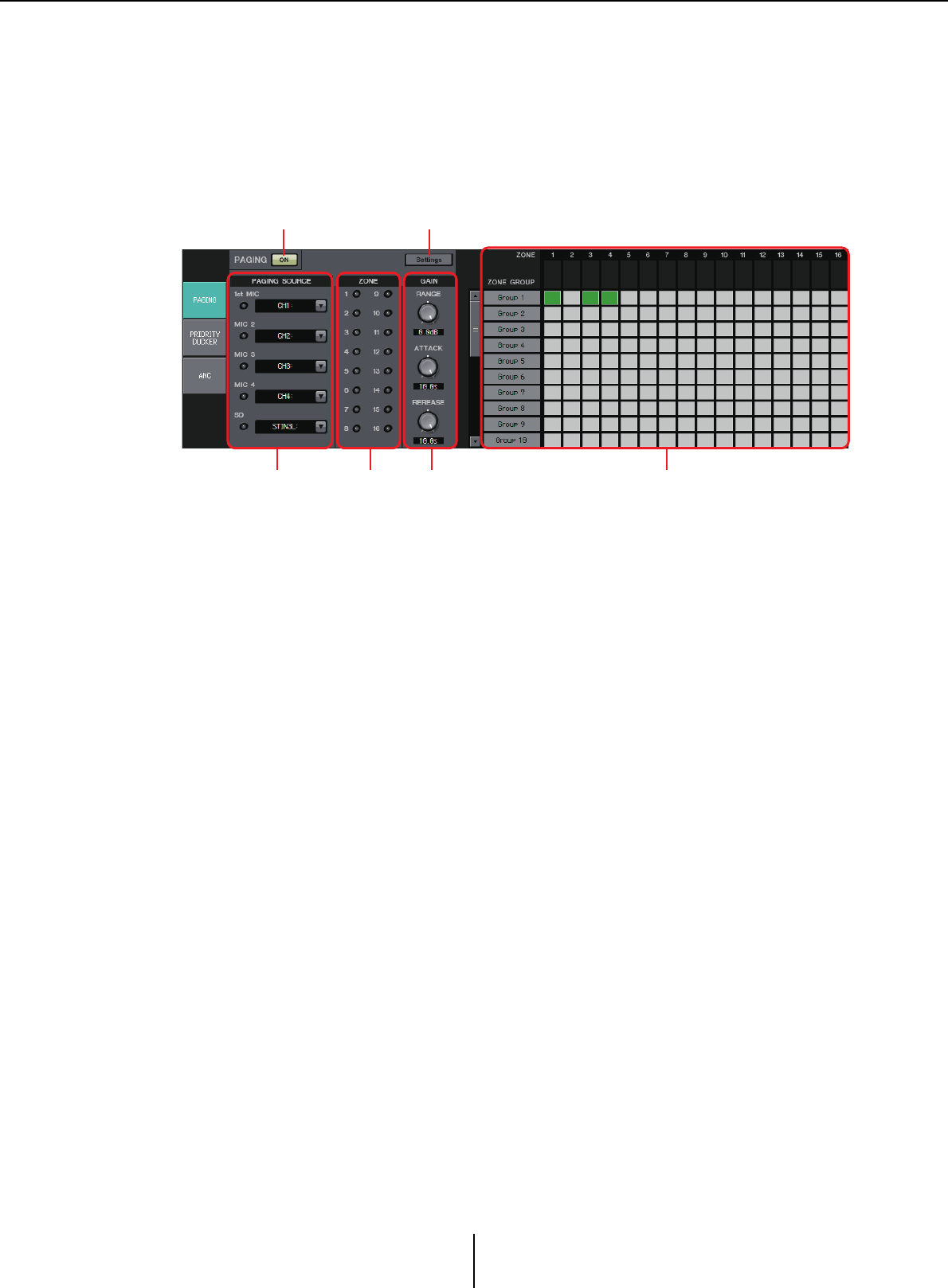
“PAGING” screen (MTX5-D only) Chapter 4. System screen
MTX-MRX Editor User Guide
92
“PAGING” screen (MTX5-D only)
In this screen you can make settings for the PGM1 paging station microphone.
Paging refers to the function of broadcasting an announcement.
For the workflow of making settings, refer to “Workf low for paging settings” in the
appendix, or the “MTX Setup Manual.”
The SD messages referred to here are standard-format announcements saved on the SD
card of the MTX.
1PAGING [ON] button
Turns the paging function on/off.
2[Settings] button
When you click this, the “PGM1/PGX1” dialog boxwill appear.
3PAGING SOURCE settings area
•Indicator
This is lit if there is a currently-broadcasting PGM1 or SD.
• Channel list box
Selects the paging source. Select the input channel to which a PGM1 or SD is
connected. Specify 1st Mic for the input channel of the PGM1 that is specified as 1st
Priority.
4ZONE area
•Indicator
This is lit if there is a zone that is currently broadcasting using a PGM1 or SD
message.
1 2
3 645
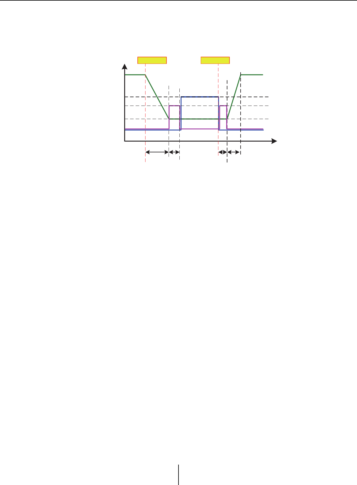
“PAGING” screen (MTX5-D only) Chapter 4. System screen
MTX-MRX Editor User Guide
93
5GAIN setting area
Each knob resets to the default value if you click it while holding down the <Alt> key.
In this area, you can make settings related to the line shown in green in the flow
depicted below.
•[RANGE] knob
Specifies the Program value while the chime is sounding or while the PGM1 is
broadcasting.
•[ATTACK] knob
Specifies the time from when the PGM1’s PTT turns on until the program decreases
to the RANGE value.
•[RELEASE] knob
Specifies the time from when the broadcast or the closing chime finishes playing
until the program returns to its original level.
6ZONE GROUP area
•Zone name
Indicates the zone name specified for the OUTPUT fader below.
•Group name
Indicates the group name. You can double-click this and edit it.
• ZONE GROUP matrix
Specify a zone group if you want a single zone/message select button of a PGM1/
PGX1 to broadcast to multiple zones. Click an intersection in the matrix to turn it
on/off. Zones that are colored green belong to a zone group. You can specify up to
24 zone groups.
Program Output
0dB
Mic/SD Output
–∞
ReleaseAttack
Range
Mic Input
time
level
SD Input
Opening
Chime
Closing
Chime
PTT : On PTT : Off
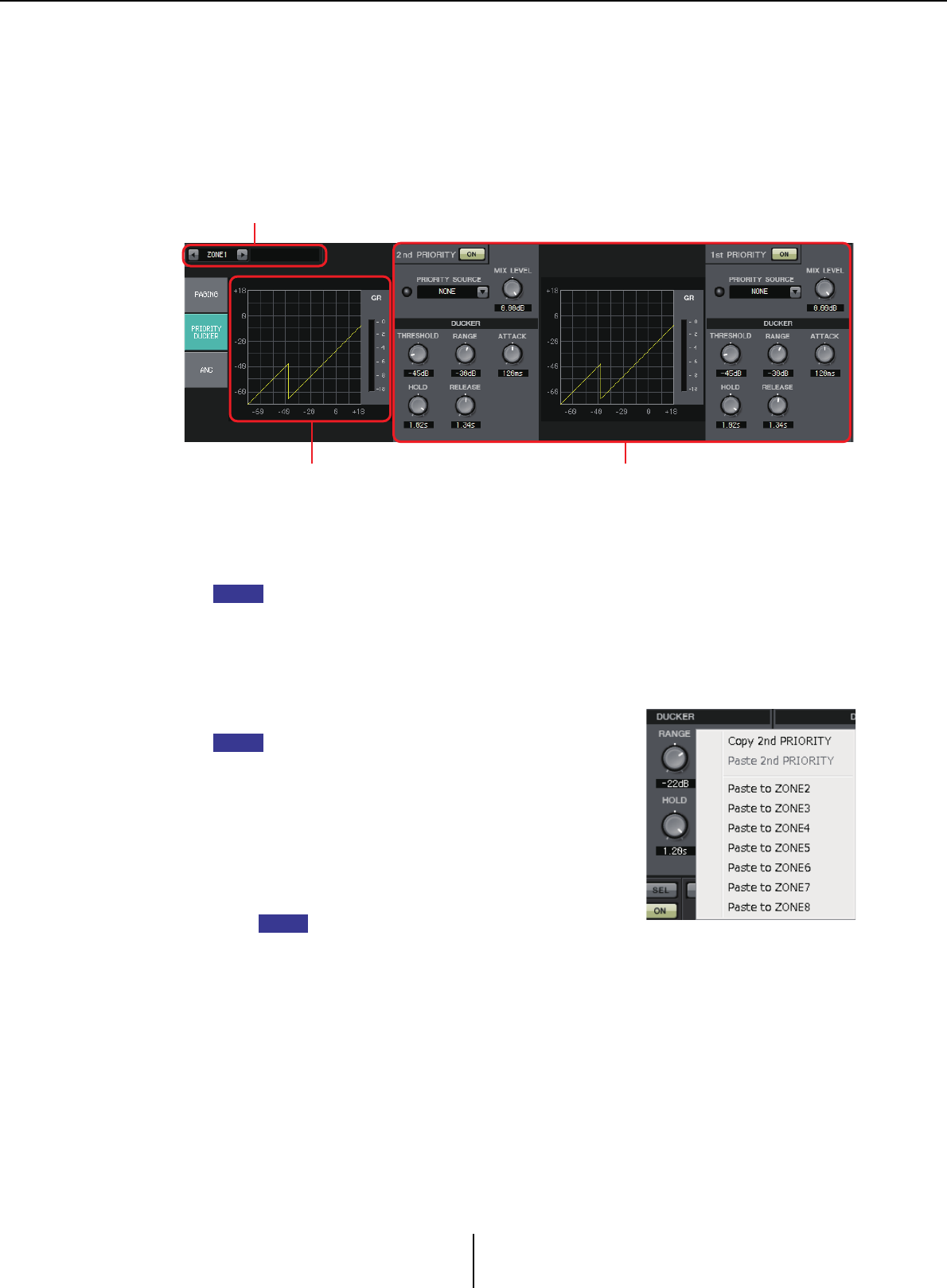
“PRIORITY DUCKER” screen Chapter 4. System screen
MTX-MRX Editor User Guide
94
“PRIORITY DUCKER” screen
In this screen you can make ducker settings.
The ducker is a function that temporarily reduces the input from one channel when an
audio signal is input to another specified input channel, allowing the audio from the
specified channel to be heard clearly. The priority order is as follows: “PRIORITY
SOURCE” of the “1st PRIORITY” > “PRIORITY SOURCE” of the “2nd PRIORITY” >
MATRIX Out signal.
1ZONE select buttons
Use the left and right buttons to select the zone for which to make settings.
The name of the zone is shown at the right.
You can also use the output channel [SEL] buttons to select a zone.
2Graph and GR meter
This graph shows the ducker settings. The amount of gain reduction applied by the
ducker is shown at the right of the graph.
3Ducker setting area
Ducker settings can be copied between 1st/2nd, or to
another zone.
When you right-click within the copy-source settings
area, a list will appear.
• DUCKER [ON] button
Turns the ducker on/off.
• [PRIORITY SOURCE] list
Selects the input signal for the ducker.
Select [ANC Bus] if you want the mixed signal to
be the high-priority audio. The mix of audio
signals to the ANC bus can be created in the
“MATRIX” screen.
•DUCKER indicator
When the ducker operates, the indicator will light green to indicate operation.
• [MIX LEVEL] knob
Adjusts the amount by which the signal selected in the [PRIORITY SOURCE] list
will be mixed into the ducker’s output.
•[THRESHOLD] knob
Specifies the threshold level at which the ducker will take effect.
1
2 3
NOTE
HINT
NOTE
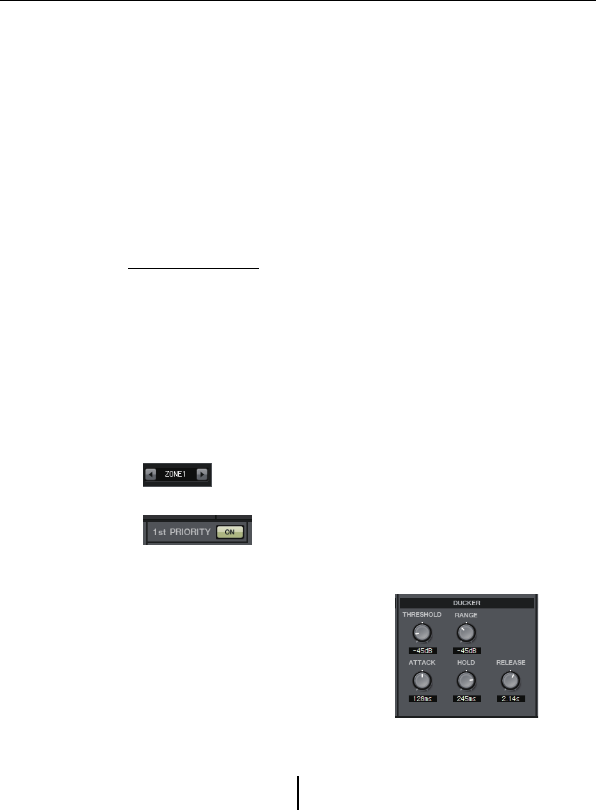
“PRIORITY DUCKER” screen Chapter 4. System screen
MTX-MRX Editor User Guide
95
•[RANGE] knob
Specifies the amount of attenuation applied when the ducker is active.
This amount specifies how much of the main audio will remain, or whether it will
be silenced.
•[ATTACK] knob
Specifies the time from when the priority source input signal exceeds the
THRESHOLD until the ducker for the main signal reaches the amount of
attenuation specified by the [RANGE] knob.
•[HOLD] knob
Specifies the time from when the input signal falls below the THRESHOLD until the
signal begins returning to its original level.
•[RELEASE] knob
Specifies the duration of the wait from when the HOLD time has elapsed until the
ducker no longer affects the input signal.
Making ducker settings
Examples of use
Example 1: If there is input from a mic while background music is playing, the volume
of the background music will automatically decrease.
Example 2: In a conference, the voice of a participant is suppressed when there is
input from the mic of the chairperson.
1. Patch the background music and the lowest-priority mics to the desired
zone.
The volume of this sound will be attenuated when the ducker operates.
The sound being input as the priority source is not patched to the input of the zone.
2. In the ZONE screen, select the zone for which you want to make ducker
settings.
3. Click the DUCKER [ON] button.
4. In the PRIORITY SOURCE list, select the sound that will have a higher
priority than the sounds you patched in step 1.
5. Use [RANGE] to adjust the amount of
ducking.
Specify a smaller value if you want some sound to
remain as (for example) background music, or
specify a high value such as –70 dB if you want the
sound to be entirely silenced.
6. Adjust other parameters as necessary.
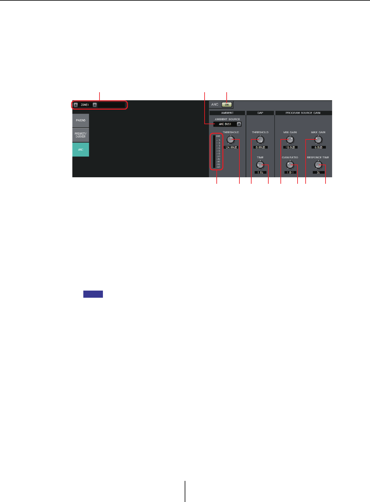
“ANC” screen Chapter 4. System screen
MTX-MRX Editor User Guide
96
“ANC” screen
In this screen you can make settings for the “Ambient Noise Compensator” (subsequently
called “ANC”).
ANC is a function that boosts or attenuates the output signal from the MTX according to
the level that is being input via an ambient noise detection mic. The ANC function
provided by the MTX is a gap-type ANC that detects silent intervals such as between
songs, detects the noise level during those intervals, and varies the level accordingly.
1ZONE select buttons
Use the left and right buttons to select the zone for which to make settings.
The name of the zone is shown at the right.
You can also use the output channel [SEL] buttons to select a zone.
2ANC [ON] button
Turns ANC on/off.
3[AMBIENT SOURCE] list
Selects the channel to which the ambient noise detection mic is connected.
The mix of audio signals to the ANC bus can be created in the “MATRIX” screen.
4[ANC] level meter
Shows the level of ambient noise.
5[AMBIENT THRESHOLD] knob
Specifies the average level of ambient noise.
6GAP [THRESHOLD] knob
Specifies the threshold level for the input signal. If the input signal level remains below
the threshold for a specified time, it will be interpreted as a gap.
7[TIME] knob
Specifies the time required for a gap to be detected.
8[MIN GAIN] knob
Specifies the minimum amount by which the input signal level will be compensated.
9[GAIN RATIO] knob
Specifies the ratio by which the input signal level will be compensated.
1 23
5 76 98 A04
NOTE
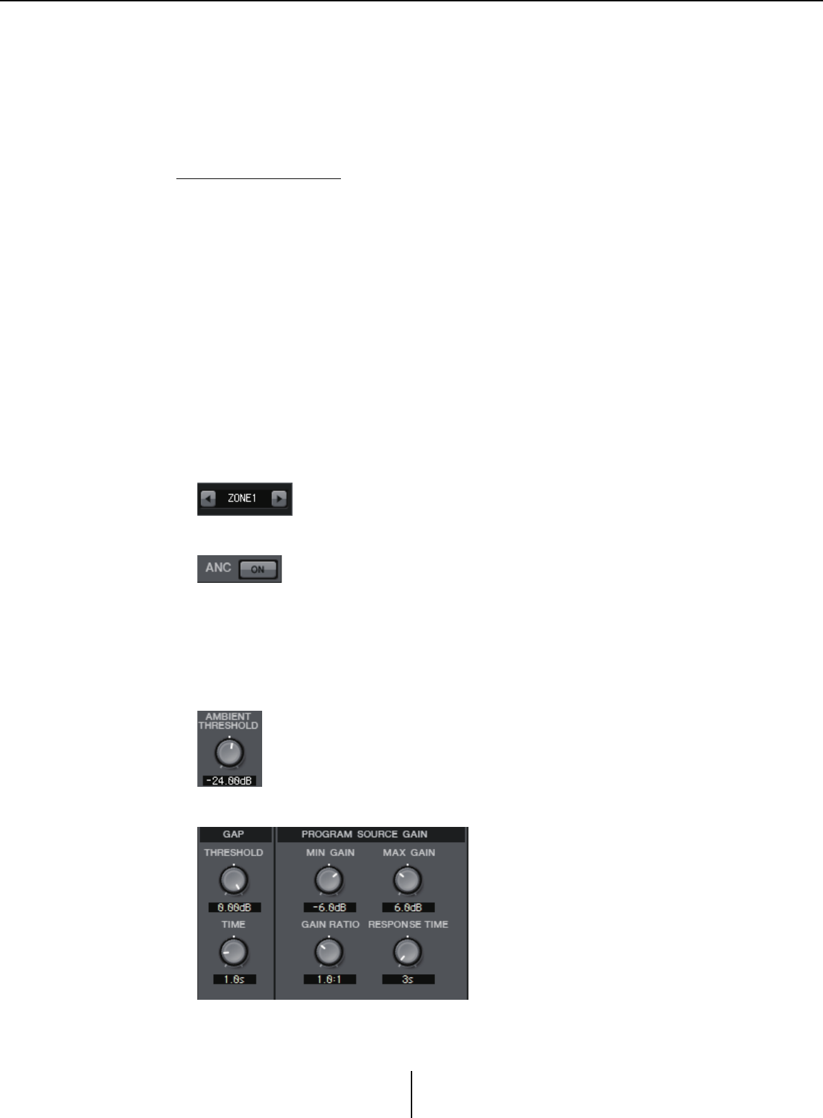
“ANC” screen Chapter 4. System screen
MTX-MRX Editor User Guide
97
0[MAX GAIN] knob
Specifies the maximum amount by which the input signal level will be compensated.
A[RESPONSE TIME] knob
Specifies the response speed for level compensation.
Making ANC settings
Examples of use
Example 1: In a location where a speech is being given, automatically adjust the
volume of the zone up or down according to the level of ambient noise
(e.g., crowd noise).
Example 2: In a restaurant, adjust the background music according to the noise of the
surrounding conversation in order to maintain privacy.
1. Set up a mic in a position where it can detect the ambient noise at an
appropriate level.
Place the ambient noise detection mic in a location where it will not receive direct
sound from the speakers but will be close to the source of the ambient noise, such as
on the ceiling in the middle of the room above the crowd or audience, and at a
distance from the speakers.
2. Select a zone.
3. Click the ANC [ON] button.
4. In the AMBIENT SOURCE list, select the input signal from the ambient
noise detection mic.
If you’ve connected more than one mic for detecting ambient noise, select [ANC
BUS1/2].
5. Adjust the ANC threshold setting.
6. Adjust the parameters.
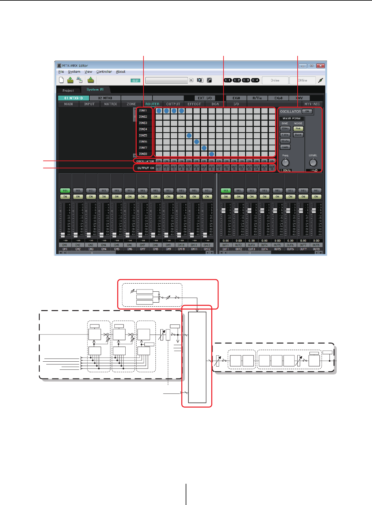
“ROUTER” screen Chapter 4. System screen
MTX-MRX Editor User Guide
98
“ROUTER” screen
In this screen you can assign zone outputs to output channels.
Signal flow
You’ll assign zone outputs, YDIF input signals in Distribution mode, and oscillator signals to the
output channels.
1Input signals to the router
This area shows zone outputs and YDIF signals.
125
3
4
8
From YDIF IN 1-16
16
*DISTRIBUTION MODE only
ROUTER
16
ROOM EQ/DELAY SPEAKER PROCESSOR
MUTE
OUTPUT CHANNEL 1-8 (1way)
DELAY 4BAND
EQ X-OVER DELAY 6BAND
EQ
LEVEL
LIMITER
OUTPUT
LEVEL
ON
OSCILLATOR
Sine Wave
ON
LEVEL
OUTPUT
METER
GR
FREQ.
Pink Noise
Burst Noise
PRIORITY
DUCKER ANC
AMBIENT
SOURCE
From INPUT CHANNEL POST ON 1-16
*1 From YDIF IN 1-16
*1 DISTRIBUTION MODE only
From ANC BUS 1-2
From STEREO INPUT CHANNEL POST ON 1L-3R
ZONE 1-8
ZONE OUT
To YDIF
OUTPUT
PATCH
MIXMIX
2nd PRIORITY 1st PRIORITY ANC
PRIORITY
SOURCE
PRIORITY
SOURCE
From DIRECT INPUT POST ON 9-16
PRIORITY
DUCKER
METER
ON
D
C
A
MASTER
LEVEL
GR GR
AMBIENT
METER

“ROUTER” screen Chapter 4. System screen
MTX-MRX Editor User Guide
99
2Router
This router distributes the signals. Click a square in the grid to switch the output on/
off. If you right-click, a context menu will appear, allowing you to choose [All OFF] to
turn all outputs off.
It is not possible to mix multiple zone outputs for output to a single output channel.
3OSCILLATOR [ON] button
If this is on, a oscillator signal will be output to the corresponding channel.
However, no signal will be output unless the OSCILLATOR [ON] button at the right is
turned on.
4OUTPUT CH [OUT] button
Accesses the CHANNEL EDIT screen of the output-destination channel.
5OSCILLATOR setting area
• OSCILLATOR [ON] button
If this is on, a oscillator signal will be output.
•WAVE FORM
[SINE] signal frequency setting buttons
Specify the frequency of the sine wave that is output by the oscillator.
Choose [100Hz], [1 kHz], [10kHz], or [VARI].
Sine wave signal [Freq] setting knob
Adjusts the output frequency of the sine wave. This is available if you click the sine
wave [VARI] button.
[NOISE] signal setting buttons
Choose [Pink] noise or [Burst] noise.
• Output [LEVEL] knob
Adjusts the level of the signal that is output from the oscillator.
On: Off:
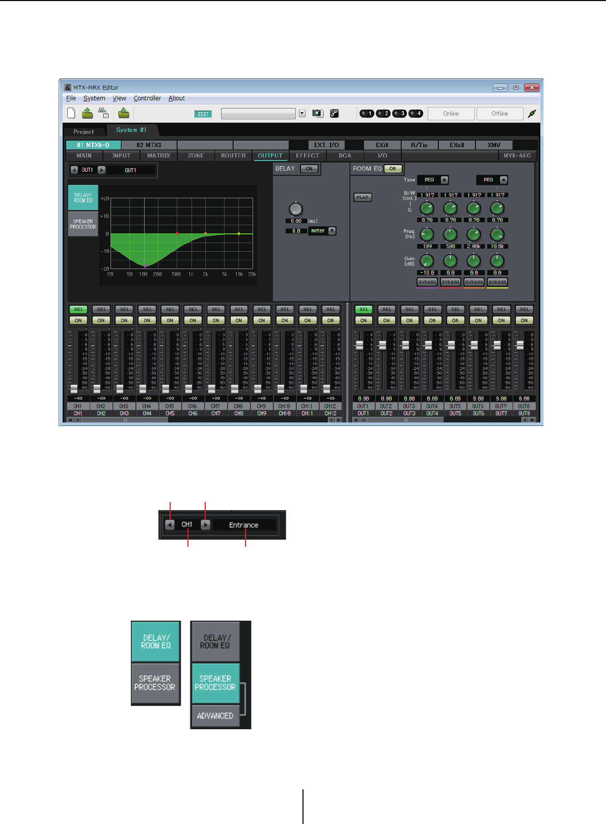
“OUTPUT” screens Chapter 4. System screen
MTX-MRX Editor User Guide
100
“OUTPUT” screens
In these screens you can apply signal processing to the output channels.
In this screen you can apply signal processing to the output channels. You can apply DELAY/
ROOM EQ, and SPEAKER PROCESSOR.
●Channel selection
Use the left or right button to select the channel to which you want to apply signal
processing.
●Screen selection
Click the appropriate button to select the screen that includes the channel processing
you want to apply.
Left button Right button
Channel index Channel name
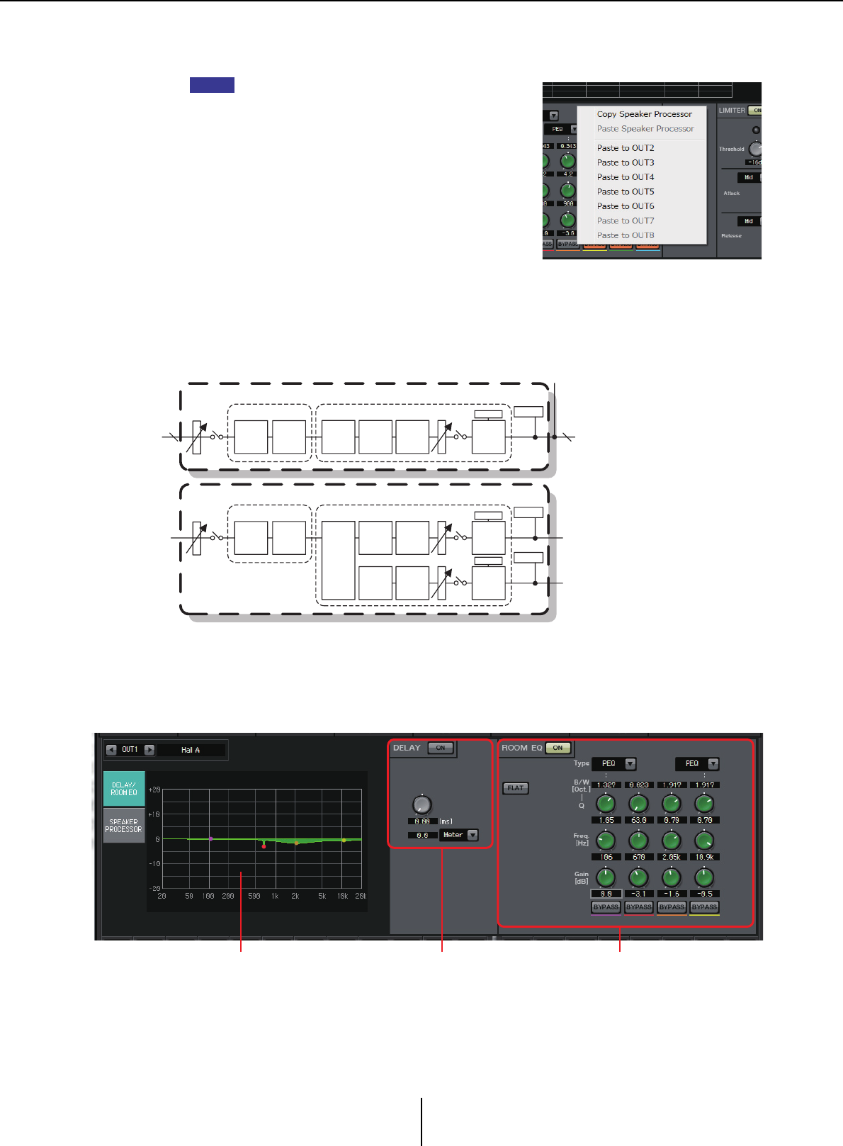
“DELAY/ROOM EQ” screen Chapter 4. System screen
MTX-MRX Editor User Guide
101
●Operations common to the “OUTPUT” screens
For details on the knobs and numeric boxes, refer to Explanation of basic operation.
You can copy channel settings to other channels.
When you right-click within the area, a list box will
appear. Select a channel, and paste the settings.
The signal from the router is processed by ROOM EQ
and SPEAKER PROCESSOR.
Depending on the OUTPUT CHANNEL SETUP setting (1WAY or 2WAY) in the “MTX
Configuration” dialog box, the signal routing will differ as follows. If this is set to 2WAY,
you will be unable to set “DELAY” or “ROOM EQ” in the screens of even-numbered
channels.
“DELAY/ROOM EQ” screen
In this screen you can adjust the DELAY and ROOM EQ parameters.
1ROOM EQ graph
The effect of the room EQ is shown by this graph. You can drag a control point to edit
the parameters.
HINT
16
ROOM EQ/DELAY SPEAKER PROCESSOR
MUTE
OUTPUT CHANNEL 1-8 (1way)
DELAY 4BAND
EQ X-OVER DELAY 6BAND
EQ
LEVEL
16
LIMITER
OUTPUT
LEVEL
ON
ROOM EQ/DELAY SPEAKER PROCESSOR
MUTE
OUTPUT CHANNEL 1-8 (2way)
DELAY 4BAND
EQ
X-OVER
DELAY 6BAND
EQ
LEVEL
OUTPUT
LEVEL
ON
LIMITER
MUTE
DELAY 6BAND
EQ
LEVEL
OUTPUT
METER
OUTPUT
METER
OUTPUT
METER
LIMITER
GR
GR
GR
21 3
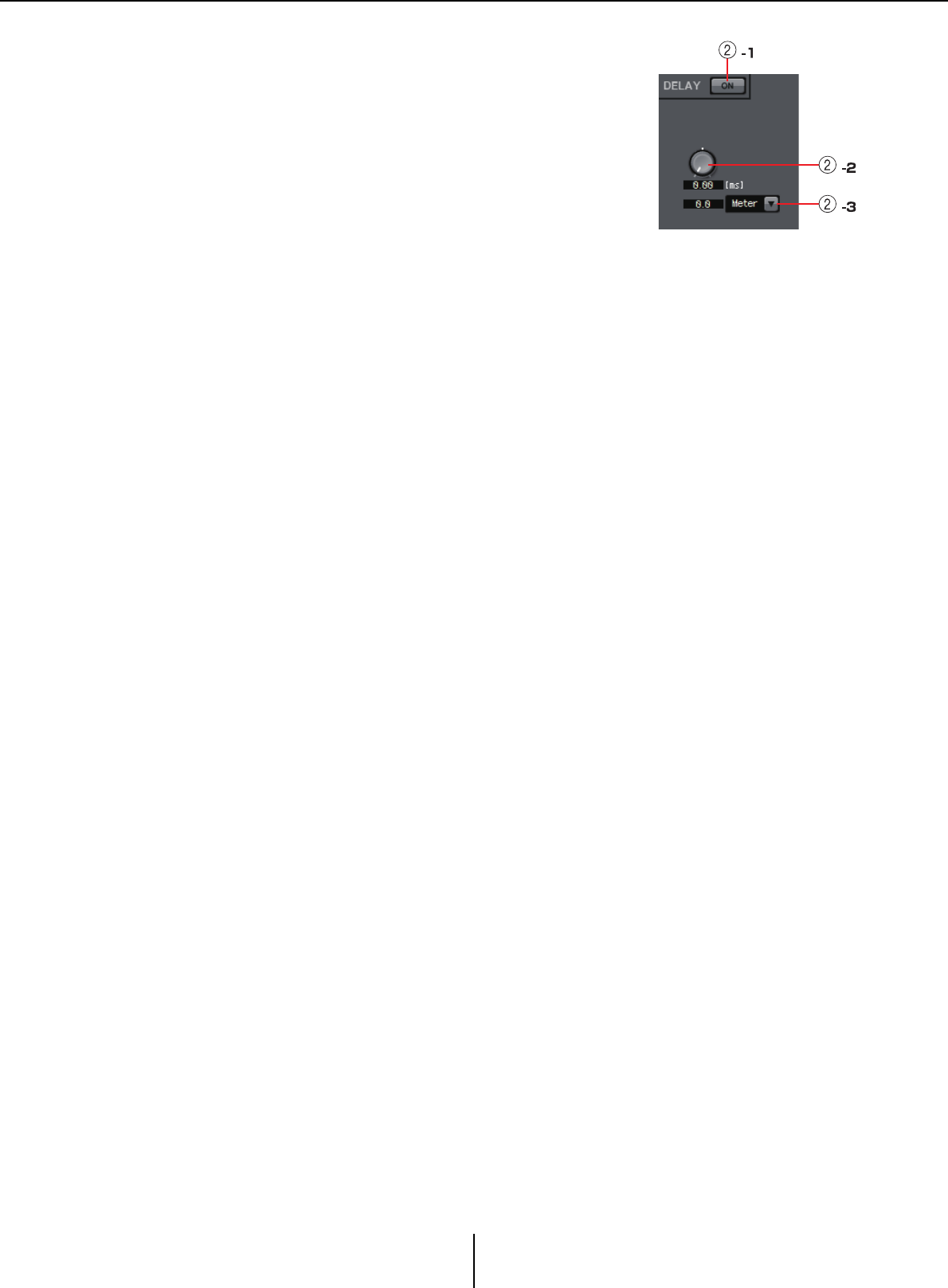
“DELAY/ROOM EQ” screen Chapter 4. System screen
MTX-MRX Editor User Guide
102
2DELAY setting area
In a sound system that includes multiple speaker units, it
may appear to a listener that the voice of the person talking
is originating from a nearby speaker unit, rather than from
the person themself. In such cases, you can correct the
perceived localization by delaying the audio to the distant
speaker unit according to the distance between the speaker
unit and the person who is talking.
If sound from different speaker units is mutually
interfering, adding a slight delay to one of the audio signals will shift the interfering
frequencies, lessening the unnatural sensation.
2-1 DELAY [ON] button
Turns delay on/off.
2-2 Delay Time knob
Specifies the delay time.
2-3 Type list box
The delay time specified by the Delay Time knob is converted into the units you
select, and shown at the left.
ms ................. Milliseconds
Sample ......... Number of samples (the range will depend on the sampling
frequency setting)
Meter............ Meters/second
Feet............... Feet/second
3ROOM EQ setting area
The sound from the speakers is affected by the materials of the walls, ceiling, and floor,
and by the position of the speakers and how they are attached. This four-band EQ lets
you compensate for such changes. It cannot compensate for dips in the frequency
response that are caused by the shape of the room.
•ROOM EQ [ON] button
Turns the ROOM EQ on/off.
For details on adjusting the following parameters, refer to EQ in “GAIN/HPF/EQ”
screen.
• [FLAT] button
•[Type] list box
•[B/W] box
•[Q] knob
•[Freq.] knob
•[Gain] knob
• [BYPASS] button
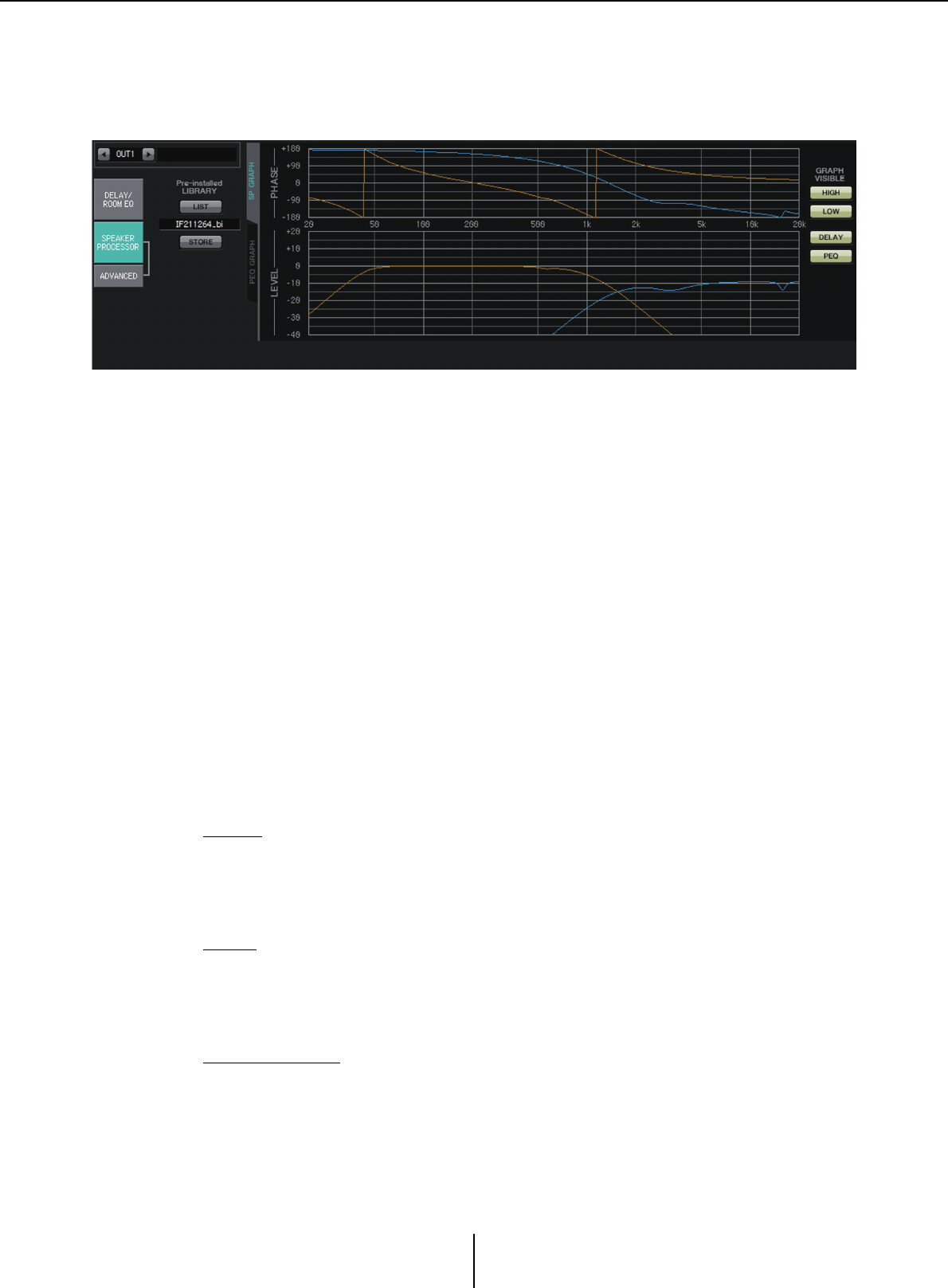
“SPEAKER PROCESSOR” screen Chapter 4. System screen
MTX-MRX Editor User Guide
103
“SPEAKER PROCESSOR” screen
In this screen you can view the response of the “SPEAKER PROCESSOR” parameters that
are provided for adjusting the speakers; these parameters include APF (All Pass Filter),
Horn EQ, and limiter. These parameters can be edited in the “ADVANCED” screen.
■Pre-installed LIBRARY
In the libraries that are preinstalled with MTX-MRX Editor, the limiter’s threshold value
is the value when using a power amp whose voltage gain is 26 dB.
As necessary, you should adjust settings such as the MTX’s limiter settings and output
level, and the power amp’s voltage gain and attenuator.
For example if you’re using a power amp with a voltage gain of 30 dB, you should either
lower the power amp’s attenuator value by 4 dB, or lower the MTX’s limiter threshold value
by 4 dB.
The voltage gain will differ depending on the type and settings of the XMV. For details,
refer to the XMV’s user manual.
•[LIST] button
Selects and shows library items.
• [STORE] button
Saves the current state as a library item (file extension [.ce3]).
■[SP GRAPH] tab
PHASE
Displays a crossover phase response curve. This display takes into account the response
of the PEQ and the Delay.
If the signal type is 2-way, High and Low are displayed separately in different colors.
LEVEL
Displays a crossover amplitude response curve. This display takes into account the
response of the PEQ and the Output Level.
If the signal type is 2-way, High and Low are displayed separately in different colors.
GRAPH VISIBLE
• [HIGH] button (shown only if the signal type is 2-way)
Switches the High graph between visible and hidden.
• [LOW] button (shown only if the signal type is 2-way)
Switches the Low graph between visible and hidden.
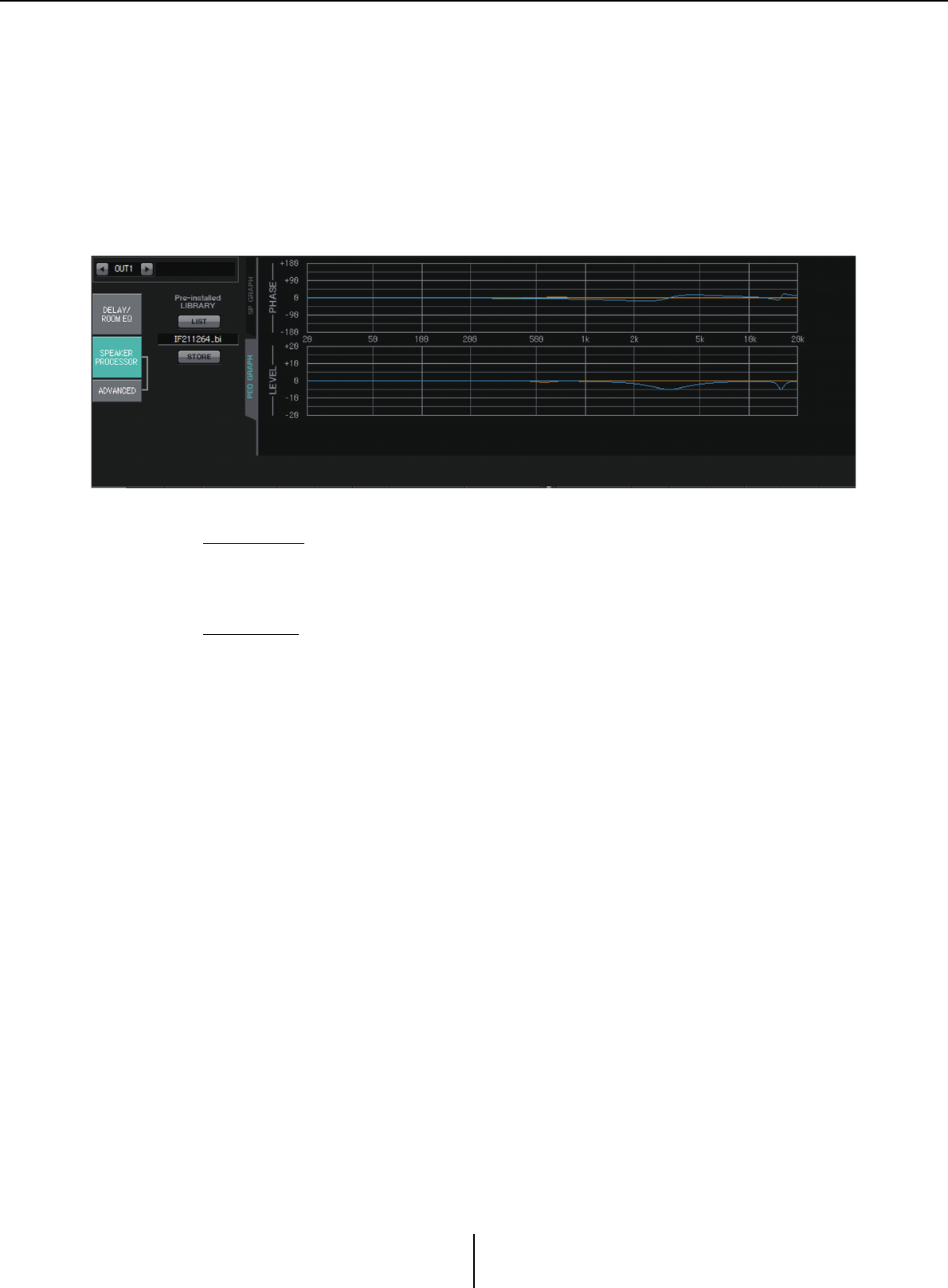
“SPEAKER PROCESSOR” screen Chapter 4. System screen
MTX-MRX Editor User Guide
104
• [DELAY] button
Includes or removes the effect of the delay response from the crossover curve that is
displayed.
• [PEQ] button
Includes or removes the effect of the PEQ response from the crossover curve that is
displayed.
■[PEQ GRAPH] tab
PHASE PEQ
Displays the PEQ phase response curve.
If the signal type is 2-way, High and Low are displayed separately in different colors.
LEVEL PEQ
Displays the PEQ amplitude response curve.
If the signal type is 2-way, High and Low are displayed separately in different colors.
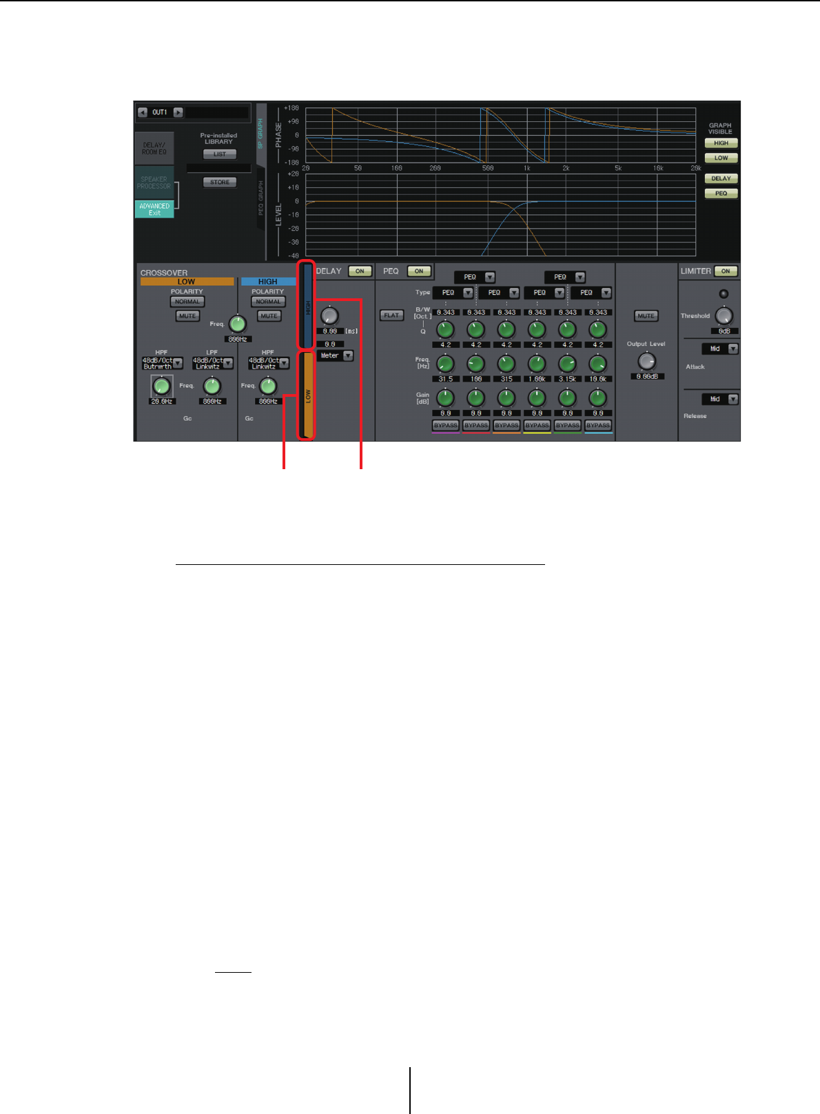
“ADVANCED” screen Chapter 4. System screen
MTX-MRX Editor User Guide
105
“ADVANCED” screen
In this screen you can make detailed “SPEAKER PROCESSOR” settings. If the signal type
is 2-way, the parameters are displayed separately for HIGH and LOW.
In the “ADVANCED” screen, control points are shown on the LEVEL PEQ amplitude
response curve of the “PEQ GRAPH.”
About the LEVEL PEQ amplitude response curve
If the signal type is 2-way, the High and Low graph displays are linked with your
switching between the [HIGH] tab and [LOW] tab.
■CROSSOVER
• POLARITY button
Inverts the phase of the signal that is output from each output channel. Switch
between NORMAL/INVERTED.
• [MUTE] button
Mutes the output of each output channel.
• [Freq.] knob
Specifies the crossover frequency of each output channel. If an output channel is
muted, its crossover graph is shown as a dotted line.
• HPF/LPF type list box
Specifies the amount of attenuation and the filter type. A menu will appear when you
click the list box. You can combine six slopes with four filter types. [6dB/Oct],
[12dB/Oct], [18dB/Oct], [24dB/Oct], [36dB/Oct], and [48dB/Oct] specify the
amount of attenuation per octave. Lower values apply more gentle attenuation;
higher values apply steeper attenuation.
Thru
No filter will be applied. There will be no attenuation; the response will be the
same at all frequencies.
[HIGH] tab [LOW] tab

“ADVANCED” screen Chapter 4. System screen
MTX-MRX Editor User Guide
106
AdjustGc (Adjustable Gc)
Adjusts the Gc (gain at the cutoff frequency) in a range of –6 – +6dB.
Setting this to –3dB will produce a Butterworth filter, and setting this to –6dB will
produce a Linkwitz-Riley filter. The Gc knob will appear when you select this.
Butrwrth (Butterworth)
This is the most common response. The passed region is flat, and the gain at the
cutoff frequency is –3 dB.
Bessel
This curve emphasizes the phase response; the attenuation is more gradual than
Butterworth, but the waveform will not be distorted when a square wave is passed
through it.
Linkwitz (Linkwitz-Riley)
The order of this filter will be a power of two; the summed voltage of the LPF and
HPF outputs will produce a gain of 0 dB across the entire frequency range. The
passed region is flat, and the gain at the cutoff frequency is –6 dB.
• HPF/LPF [Freq.] knob
Specifies the cutoff frequency of the HPF/LPF.
• HPF/LPF [Gc] knob (shown only if filter type is set to [AdjustGc])
Specifies the gain at the cutoff frequency.
■[HIGH] tab/[LOW] tab
Use the [HIGH] tab and [LOW] tab to switch the [DELAY], [PEQ], [Output Level],
[MUTE], and [LIMITER] display.
■DELAY
For details on adjusting the following parameters, refer to “GAIN/HPF/EQ” screen.
•DELAY [ON] button
•Delay Time knob
•[Type] list box
■PEQ
For details on adjusting the following parameters, refer to “GAIN/HPF/EQ” screen.
•PEQ [ON] button
• [FLAT] button
•[B/W] box
•[Q] knob
•[Freq.] knob
•[Gain] knob
• [BYPASS] button
• [Type] list box
Selects the PEQ type.
The frequency response is shown in PEQ GRAPH.
For details on the following types, refer to “GAIN/HPF/EQ” screen.
•PEQ
•L.SHELF (Low Shelf)
•H.SHELF (High Shelf)
•HPF
•LPF

“ADVANCED” screen Chapter 4. System screen
MTX-MRX Editor User Guide
107
APF (All Pass Filter)
This filter passes the signals of the entire frequency range, affecting only the
phase. It is used mainly to correct the phase of the crossover region.
For APF 1st, the phase will be rotated 90° at the specified frequency, and will be
rotated in the range 0° to 180° when seen over the entire frequency range. For
APF 2nd, the phase will be rotated 180° at the specified frequency, and will be
rotated in the range 0° to 360° when seen over the entire frequency range.
Horn EQ
A directional horn speaker is characterized by a high frequency level roll-off.
Horn EQ is an equalizer that compensates for this characteristic. For this reason,
Gain is restricted to 0 dB or higher and Freq. is restricted to 500 Hz or higher.
• [MUTE] button
Mutes the output.
• [Output Level] knob
Specifies the output level.
■LIMITER
•[ON] button
Turns the limiter on/off. If the button is off, the limiter will be bypassed.
• Gain Reduction indicator
This will light when the threshold value is exceeded.
• [Threshold] knob
Specifies the threshold.
• [Attack]
Specifies the speed at which the limiter will take effect. If Manual is selected, a knob
is shown, allowing you to specify the setting in msec units. If Fast/Mid/Slow is
selected, the following settings will be made automatically according to the
crossover’s HPF cutoff frequency in the Speaker Processor settings.
Fast ....................................1/4 wavelength of the cutoff frequency
Mid ....................................1/2 wavelength of the cutoff frequency
Slow...................................1 wavelength of the cutoff frequency
•[Release]
Specifies the speed at which the limiter will release. If Manual is selected, a knob is
shown, allowing you to specify the setting in msec units. If Fast/Mid/Slow is selected,
the following settings will be made automatically according to the crossover’s HPF
cutoff frequency in the Speaker Processor settings.
Slow...................................4 wavelengths of the cutoff frequency
Mid ....................................8 wavelengths of the cutoff frequency
Slow...................................16 wavelengths of the cutoff frequency
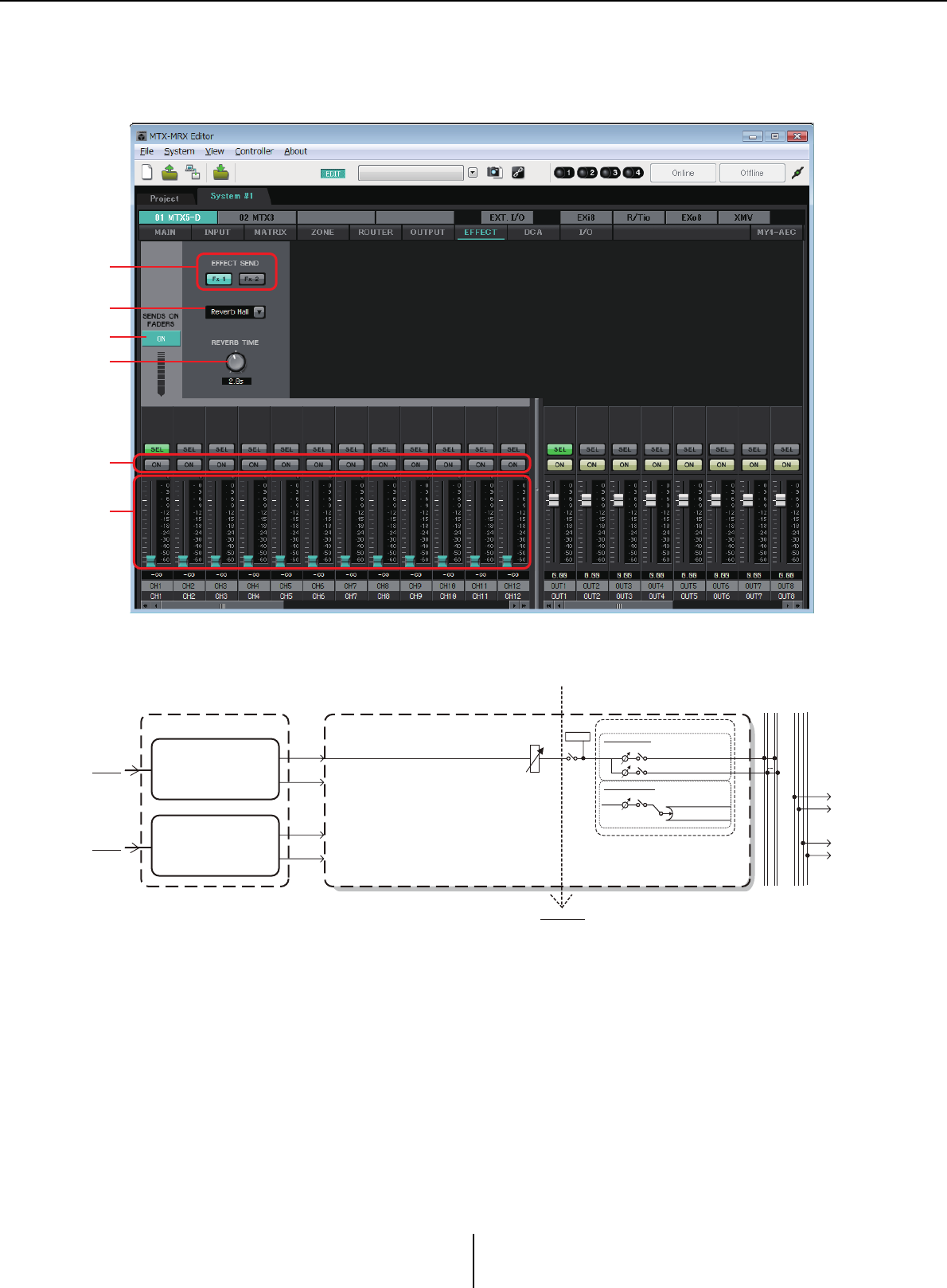
“EFFECT” screen Chapter 4. System screen
MTX-MRX Editor User Guide
108
“EFFECT” screen
In this screen you can change the effect type and edit the effect parameters.
This screen lets you edit the effect that is sent from the input channels to the effect bus. You can
specify the type (e.g., reverb or echo), the parameter value for that type, and the send level.
1SENDS ON FADERS [ON] button
Turns SENDS ON FADER mode on/off. If this is off, the input channel faders will
adjust the input levels.
2
[EFFECT SEND] buttons (available only if SENDS ON FADER mode is on)
These buttons select the bus to which the effect will be sent. You can select buses [Fx1]
or [Fx2].
If you right-click the button, you’ll be able to set all send levels in a single operation by
choosing 0 dB, –3 dB, –6 dB, or –Infinity.
1
5
6
4
3
2
EFFECT EFFECT RETURN 1L-2R (FX RTN 1L-2R) MATRIX CROSS POINT
EFFECT 1
From FX1
EFFECT 2
From FX2
To other MTXs
LEVEL
LEVEL
ON ON
POST ON
METER To MATRIX(MONO)
To MTRIX1,3...7
To MTRIX1,3...7
To MTRIX2,4...8
To MTRIX2,4...8
To MATRIX(STEREO) EFFECT
Signal flow
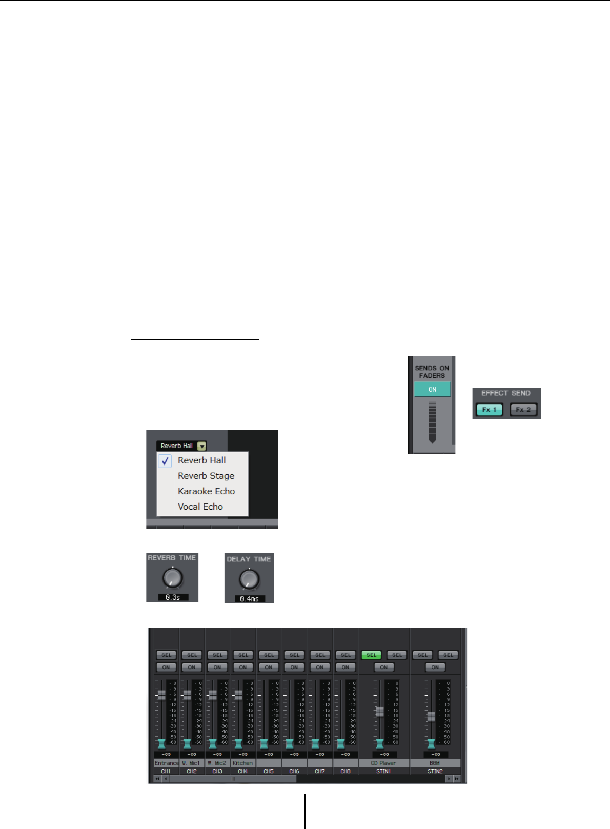
“EFFECT” screen Chapter 4. System screen
MTX-MRX Editor User Guide
109
3Effect type (shown only if SENDS ON FADER mode is on)
This selects the effect type for each bus. You can choose one of the following four types.
Reverb Hall ........... Reverb that simulates an expansive space such as a concert hall.
Reverb Stage ......... Reverb that simulates a broad stage.
Karaoke Echo ....... Echo designed for karaoke use.
Vocal Echo ............ Echo designed specifically for stage vocals.
4Effect parameter (shown only if SENDS ON FADER mode is on)
Adjusts the parameter of the effect. This will be [REVERB TIME] if the effect type is
reverb, and “DELAY TIME” if the effect type is echo.
5[ON] button
Turns the effect send on/off.
6Faders
When SENDS ON FADER mode is on, these adjust the effect send levels that are sent
from the input channels.
You can right-click a fader knob and set the send level by selecting 0 dB, –3 dB, –6 dB,
or –Infinity.
A grayed-out fader is shown at the position of the input level (this cannot be edited).
Making effect settings
1. Click the SENDS ON FADERS [ON]
button to turn it on.
2. Select the bus ([Fx1] or [Fx2] button) to
which the effect will be sent.
3. Select the effect type from the list.
4. Adjust the effect parameter ([REVERB TIME] or [DELAY TIME]).
5. Use the faders to adjust the send level.
12
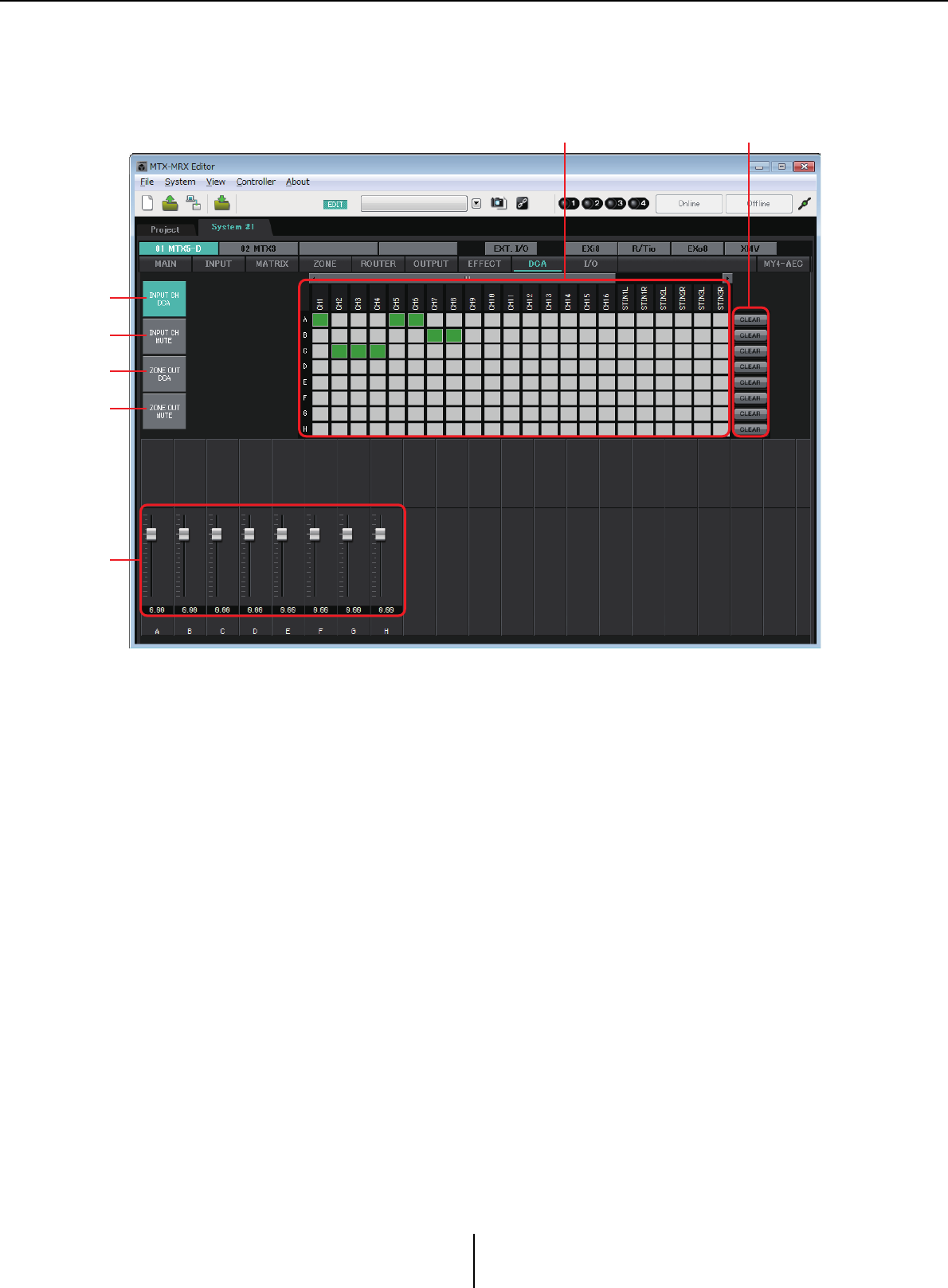
“DCA” screen Chapter 4. System screen
MTX-MRX Editor User Guide
110
“DCA” screen
In this screen you can adjust the levels and mute settings of multiple channels.
In this screen, input channels can be assigned to eight DCA groups and eight mute groups, and zone
outputs can be assigned to eight DCA groups and eight mute groups.
DCA groups allow you to use a single fader to control the input levels or output levels of multiple
channels. Mute groups allow you to switch multiple channels on/off together.
Fader settings for DCA groups and [MUTE] group master button settings for mute groups are
shared by MTX units within the same MTX/MRX system. For example if you make these settings
for the MTX3 whose ID=1, they will automatically be applied to MTX3 units of other ID numbers.
This is not shared with MRX units.
1[INPUT CH DCA] button
This button selects input channel DCA groups.
2[INPUT CH MUTE] button
This button selects input channel mute groups.
3[ZONE OUT DCA] button
This button selects zone output DCA groups.
4[ZONE OUT MUTE] button
This button selects zone output mute groups.
1
2
3
4
8
6 7
1

“DCA” screen Chapter 4. System screen
MTX-MRX Editor User Guide
111
5[MUTE] group master buttons (shown only if
the [INPUT CH MUTE] button or
[ZONE OUT MUTE] button is selected)
These buttons turn each mute group on/off.
6Assignment channel matrix
This matrix lets you assign channels to DCA groups or
mute groups.
The group names are shown on the vertical axis, and the
names of the channels that can be assigned are shown on
the horizontal axis. Click an intersection to assign a
channel to a group.
7[CLEAR] button
This button clears all channels assigned to the corresponding group.
8Faders (shown only if the [INPUT CH DCA] button or
[ZONE OUT DCA] button is selected)
Adjust the level of each DCA group.
On: Off:
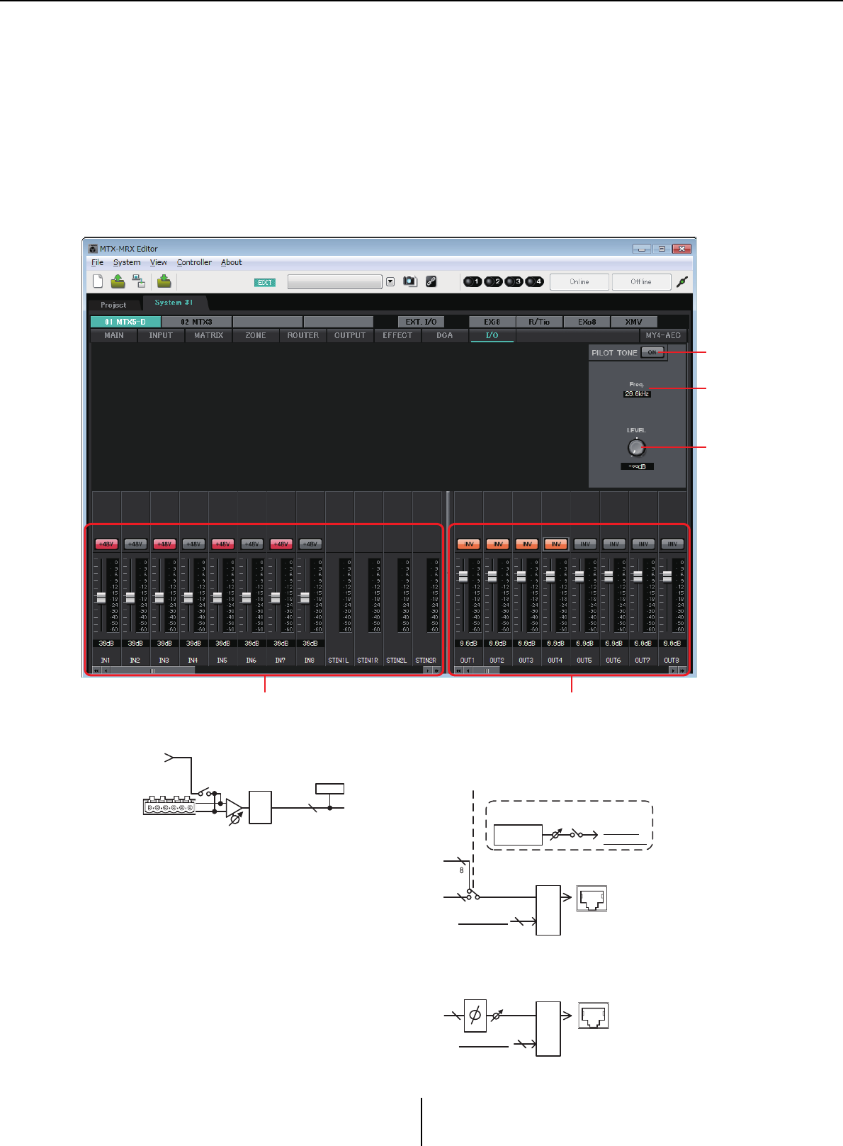
“I/O” screen Chapter 4. System screen
MTX-MRX Editor User Guide
112
“I/O” screen
In this screen you can make settings related to the HA (head amp) of the MTX’s analog input, and for
the MTX’s digital output.
You can also make settings to specify whether a pilot tone is output from digital output.
When the PILOT TONE [ON] button is on, a pilot tone is output to channels whose digital output’s
[PT] button is on.
To specify the XMV units that receive the pilot tone, access the “Project” screen > [Device] tab, and
click the [INPUT SOURCE] button to make settings for redundancy.
Signal flow
1
2
3
45
INPUT
1-8
+48V
AD
+
-
+48V
GAIN
ME TER
INPUT
8
16
16
YDIF MODE
CASCADE MODE
or DISTRIBUTION MODE
YDIF
OUT
PILOT TONE
ON
LEVEL
Sine Wave
20.0kHz
To YDIF OUT
To DANT E O UT
From PILO T TONE
SUM
16
DANTE
OUTPUT
GAIN
POL A RITY
SUM
From PILO T TONE
16

“I/O” screen Chapter 4. System screen
MTX-MRX Editor User Guide
113
1PILOT TONE [ON] button
Turns the pilot tone function on/off. If this is off, a pilot tone is not output even if the
[PT] button is on.
2Freq.
Indicates the center frequency of the pilot tone. This is fixed at 20 kHz.
3[LEVEL] knob
Specifies the level of the pilot tone.
4Analog input settings area
Here you can make settings for the HA (head amp) of the MTX’s analog input. These
settings are linked with the input channel parameter editing screen of the “MAIN”
screen.
• [+48V] button
Turns the phantom power (+48V) of the HA (head amp) on/off.
Notice
Be sure to leave this button off if you do not need phantom power.
Follow the important precautions below, in order to prevent noise and possible damage to
external devices as well as the unit when you operate this switch.
• Leave this button off if a device that does not support phantom power is connected to the
[INPUT] connector.
• Do not connect/disconnect a cable to/from the [INPUT] connector while this button is
on.
• Lower the output level to the minimum before turning phantom power on/off.
There is no master switch. To avoid malfunctions, be sure to set this appropriately for the
equipment that is connected.
• Fader/meter
Adjusts the analog gain of the HA.
You can right-click a fader knob and set the analog gain by selecting 0 dB or –6 dB.
5Digital output settings area
Here you can make settings related to the MTX’s digital output. These settings are
linked with the output channel parameter editing screen of the “MAIN” screen.
• [PT] button
Turns the pilot tone output on/off. When the PILOT TONE [ON] button is on, a
pilot tone is output to channels whose [PT] button is on.
• POLARITY button
Switches the polarity of the output signal.
• Fader/meter
Adjusts the output gain.
You can right-click a fader knob and set the output gain by selecting 0 dB or –96 dB.
NOTE
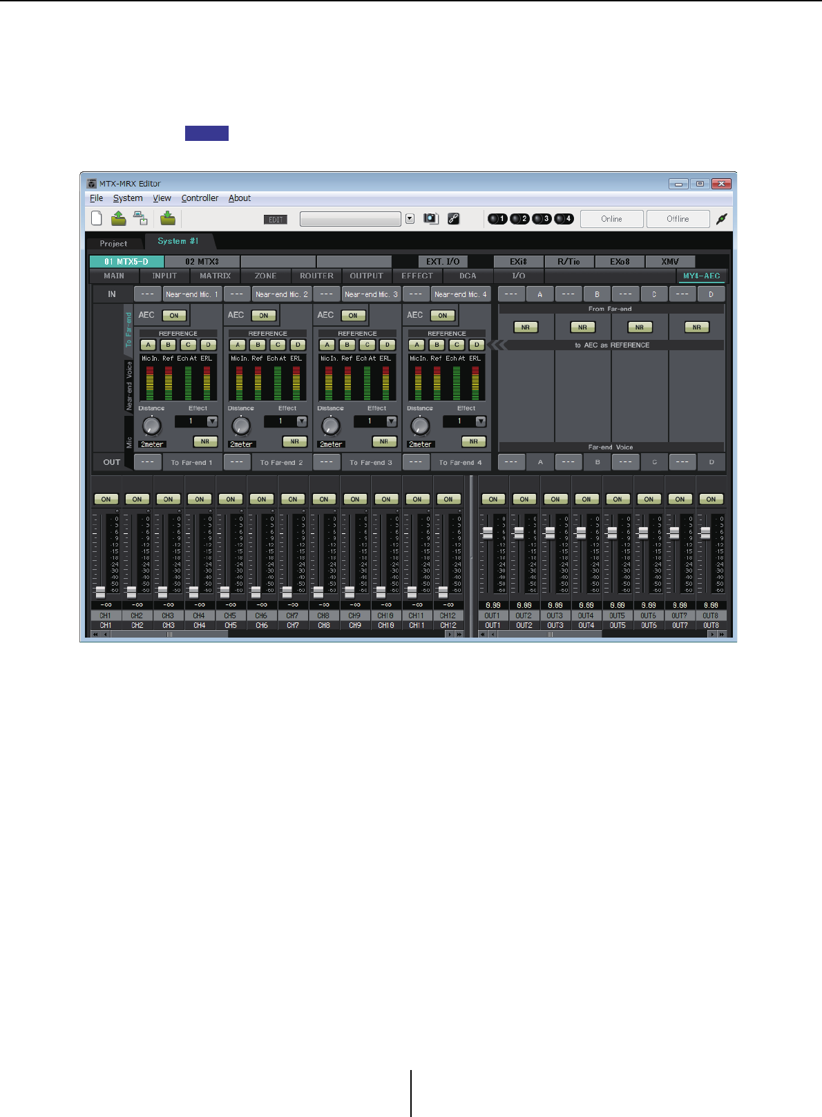
“MY4-AEC” screen Chapter 4. System screen
MTX-MRX Editor User Guide
114
“MY4-AEC” screen
In this screen you can make settings for the MY4-AEC installed in the MTX5-D’s [SLOT]. This screen
will not appear if any other card is installed or if no card is installed.
For example settings, refer to “MTX5-D/MY4-AEC System Setup Manual.”
In this screen you can make settings for the signals of the MY4-AEC.
In a teleconferencing system, the local and remote environments are respectively called the Near-
end and Far-end.
The MY4-AEC’s acoustic echo canceller (AEC) determines the echo component included in the
mic input signal by using the signal from the Far-end as the reference signal, and subtracts only the
echo component of the Far-end from the mic input signal. This allows clear audio from the Near-
end to be transmitted to the other party.
The MY4-AEC’s signals can be specified using the following choices and screens.
NOTE
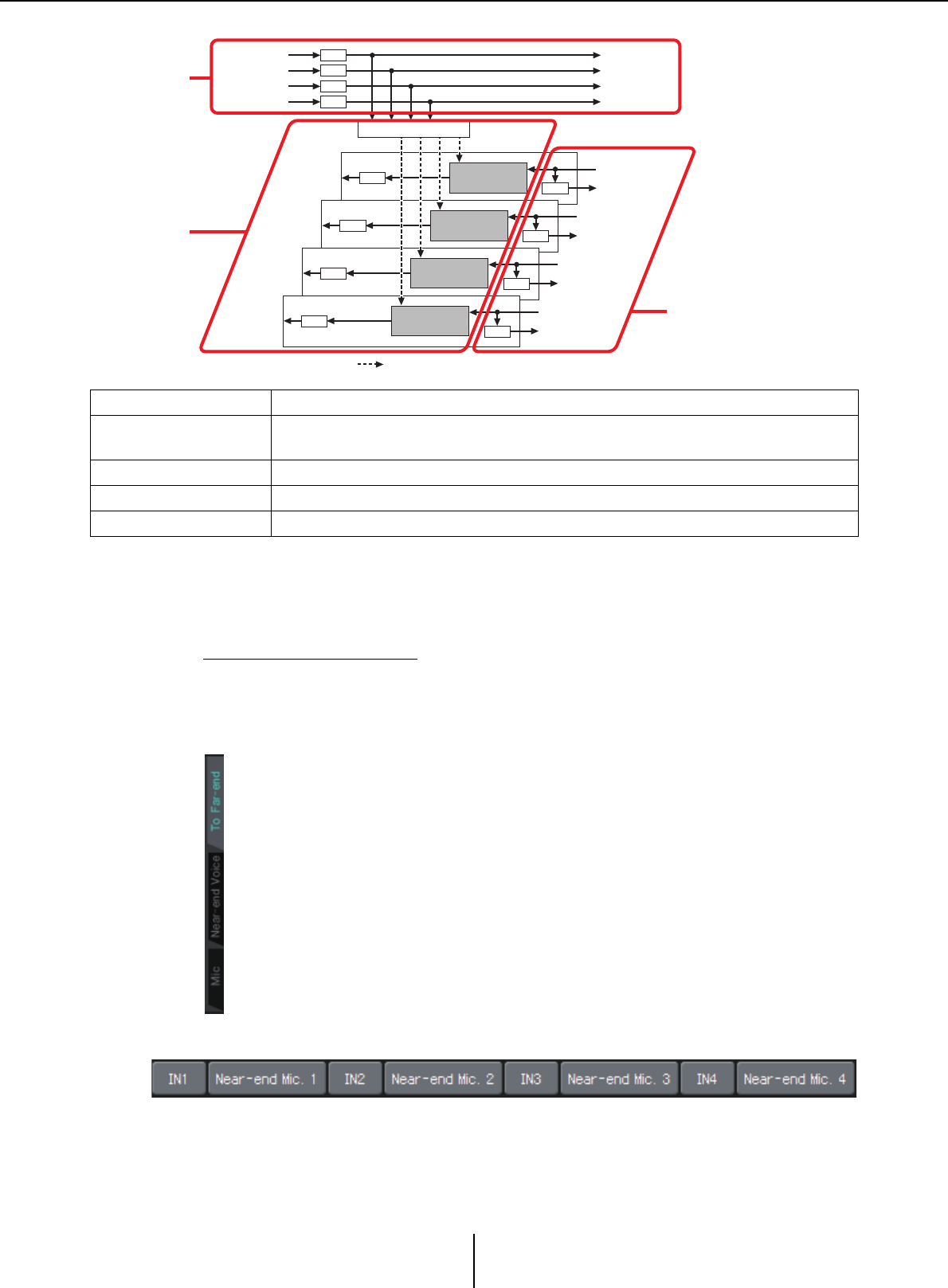
Common items Chapter 4. System screen
MTX-MRX Editor User Guide
115
Common items
Here we explain items that do not change even when the screen changes.
About input and output
The MY4-AEC inputs audio signals from the ports or output channels of the MTX5-D.
The MY4-AEC outputs audio signals to the input channels of the MTX5-D.
●Screen selection
Click the appropriate tab to select the screen that includes the channel processing
you want to apply.
●Near-end Mic selection
Here you can select the ports for the local mics (Near-end Mic). When you click a port
select button, the “Input Patch” dialog box will appear. The button shows the currently
selected port.
When you click the button located at the right of a port select button, a Parameter edit
screen will appear as a pop-up.
From Far-end Input signals from the remote location (the other party)
Far-end Voice Signals from the remote location reproduced by the speakers of the local location
(your side)
Near-end Mic. Input signals from local mics
Near-end Voice Signals from local mics reproduced by local speakers
To Far-end Echo-cancelled signals of local mics sent to the remote location
From Far-end A Far-end Voice A
NR
From Far-end B Far-end Voice B
NR
From Far-end C Far-end Voice C
NR
From Far-end D Far-end Voice D
NR
To Far-end 4
Near-end Mic. 4
Near-end Voice 4
NR
FBS
To Far-end 3
Near-end Mic. 3
Near-end Voice 3
NR
FBS
To Far-end 2
Near-end Mic. 2
Near-end Voice 2
NR
FBS
To Far-end 1
Near-end Mic. 1
Near-end Voice 1
NR
FBS
AEC
AEC
AEC
AEC
REFERENCE ON/OFF
Reference signal FBS: Feedback suppressor NR: Noise reduction
From Far-end
selection
“To Far-end”
screen
Near-end Mic selection
“Near-end Voice” screen
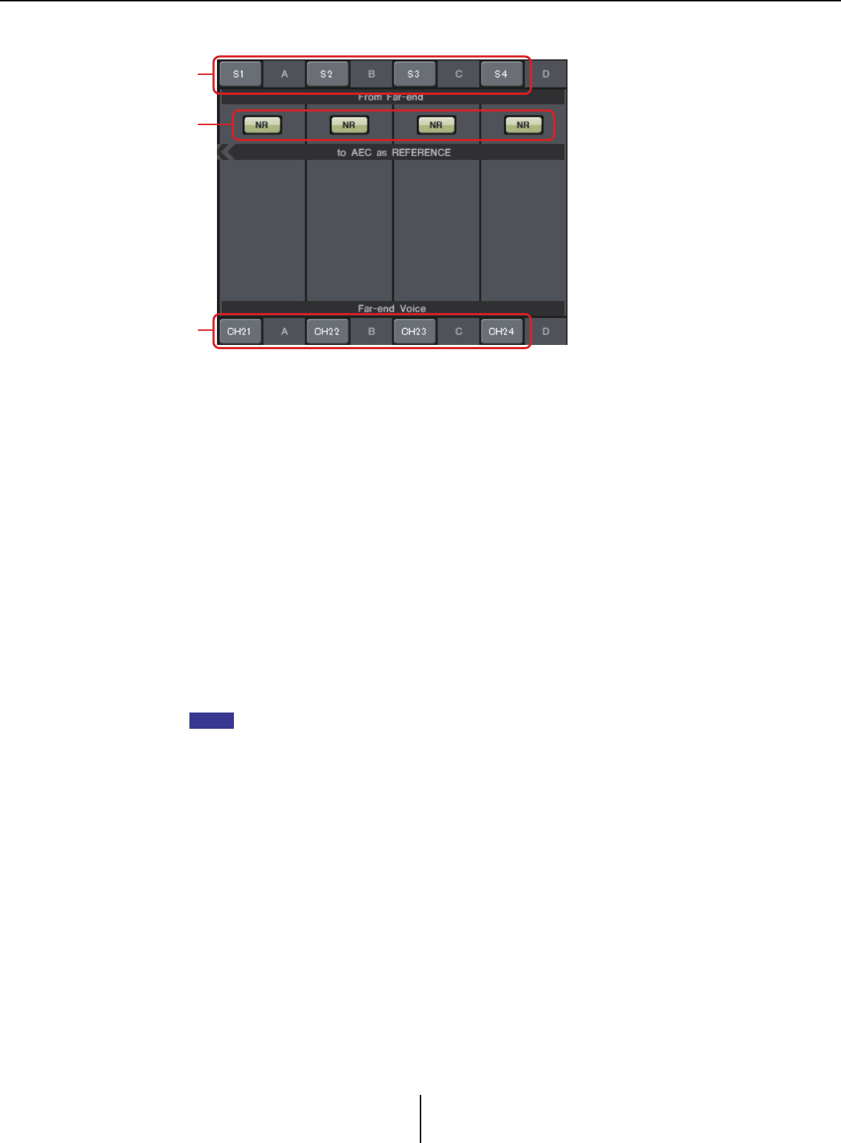
Common items Chapter 4. System screen
MTX-MRX Editor User Guide
116
●From Far-end selection
Here you can select the channels to which input signals from the remote location will
be output.
1[From Far-end] signal selection buttons
These open the “Input Patch” dialog box, where you can select the audio signals from
the remote location (From Far-end). The button shows the currently selected port or
channel.
2[NR] button
These are on/off switches for the noise reduction function which removes steady-state
noise such as produced by a projector or air conditioner in the remote location. We
recommend that you leave these on. The audio signal after noise reduction will be the
reference signal (REFERENCE).
3[Far-end Voice] selection buttons
These buttons select the output destinations for the audio signals that are output to the
speakers of the local location. Click a button to open the “Output Patch” dialog box. The
button shows the currently selected channel.
It is assumed that the Far-end Voice will be mixed with the Near-end Mic and output from the
speakers. Therefore as seen from the MY4-AEC, the Far-end Voice is output to an input
channel of the MTX.
1
2
3
NOTE
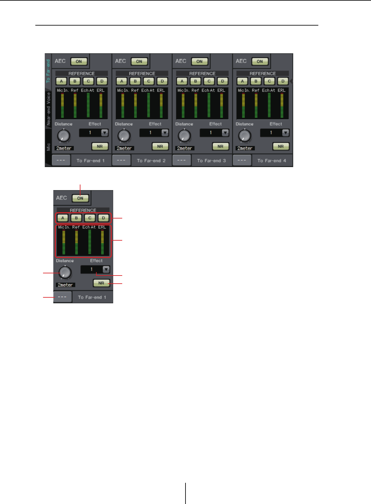
“To Far-end” screen Chapter 4. System screen
MTX-MRX Editor User Guide
117
❑“To Far-end” screen
In this screen you can make echo-cancel settings for the mics.
The mic signal after echo-cancellation is output to the remote location.
4[Effect] box
Specifies the amount of echo cancellation. Higher numeric values allow more echoes to
be cancelled. However, the audio quality will decrease correspondingly, so you should
consider the balance between these factors as you make the adjustment.
5[NR] button
These are on/off switches for the noise reduction function which removes steady-state
noise such as produced by a projector or air conditioner in the local location. We
recommend that you leave these on.
1
2
5
3
4
6
7
1AEC [ON] button
Switches the echo canceller function on/off.
2REFERENCE [A][B][C][D] buttons
These buttons select whether the signal specified by the From
Far-end selection will be used as the AEC reference signal
(REFERENCE).
If multiple signals are selected, they will be mixed.
3Meters
Mic In. meter ........ Indicates the level of the signal that is
input from your own mic (Near-end Mic).
Ref In. meter......... Indicates the level of the reference signal.
The most effective echo cancellation will
be obtained with a level at which the
yellow indicators light occasionally.
Echo Attn. meter.. Indicates the amount of echo cancellation
for each channel. Higher levels indicate
that the echo canceller is working.
ERL meter.............. Indicates the ERL (Echo Return Loss = the
level of the audio that is output from the
speaker and re-input to the mic). Echo
cancellation will work most effectively if
you adjust the position of the speaker and
mic so as to minimize this level.
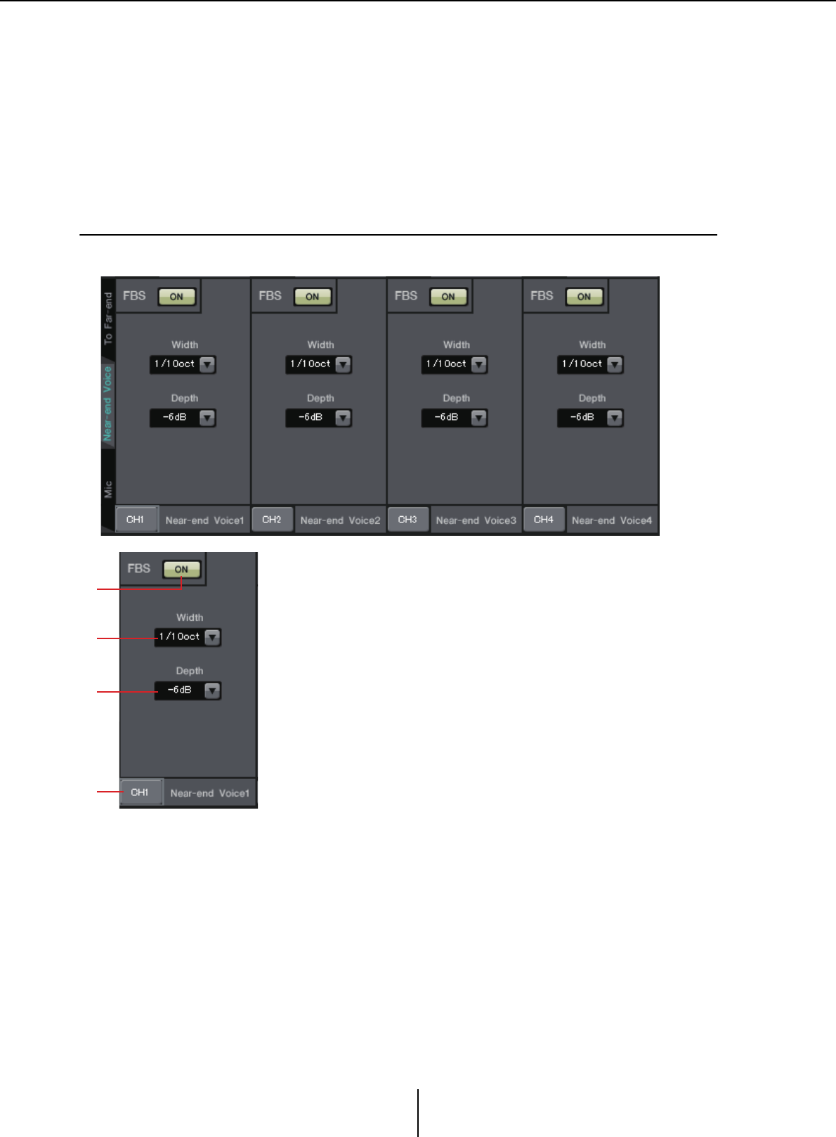
“Near-end Voice” screen Chapter 4. System screen
MTX-MRX Editor User Guide
118
6[Distance] knob
This specifies the distance between the installed mic and speaker in units of meters. If
multiple mics and speakers are connected, specify the distance between the mic and
speaker that are closest to each other. If the distance is 2 m or less, set this to 2.
7[To Far-end] channel select button
This button selects the output destination for the audio signals that are output to the
remote location (Far-end). Click the button to open the “Output Patch” dialog box.
❑“Near-end Voice” screen
In this screen you can make settings for the FBS (Feed Back Suppressor) that is built into the MY4-AEC.
4
2
1
3
1FBS [ON] button
This turns the feedback suppressor function on/off.
The FBS of the MY4-AEC uses the dynamic method of finding the
constantly changing feedback points and updating the filter settings
accordingly.
This is reset when the MTX5-D is powered-off, and will return to a
state in which no notch filter is inserted.
2[Width] box
Here you can specify the rejection width of the notch filter that is
inserted at the frequency where feedback is detected. Choose a
narrower rejection width if the feedback suppressor causes unwanted
changes in the character of the sound. A setting of “1/93” is the
narrowest setting for the notch filter. However in this case, the
feedback suppressor may be less effective.
3[Depth] box
Here you can specify the amount of rejection applied by the notch filter
that is inserted at the frequency where feedback is detected. A setting
of “–18” produces the strongest suppression of feedback. However in
this case, you may notice more change in the character of the sound.
4[Near-end Voice] channel select button
This button selects the output destination for the audio signal that is
output locally (Near-end Voice). Click the button to open the
“Output Patch” dialog box.
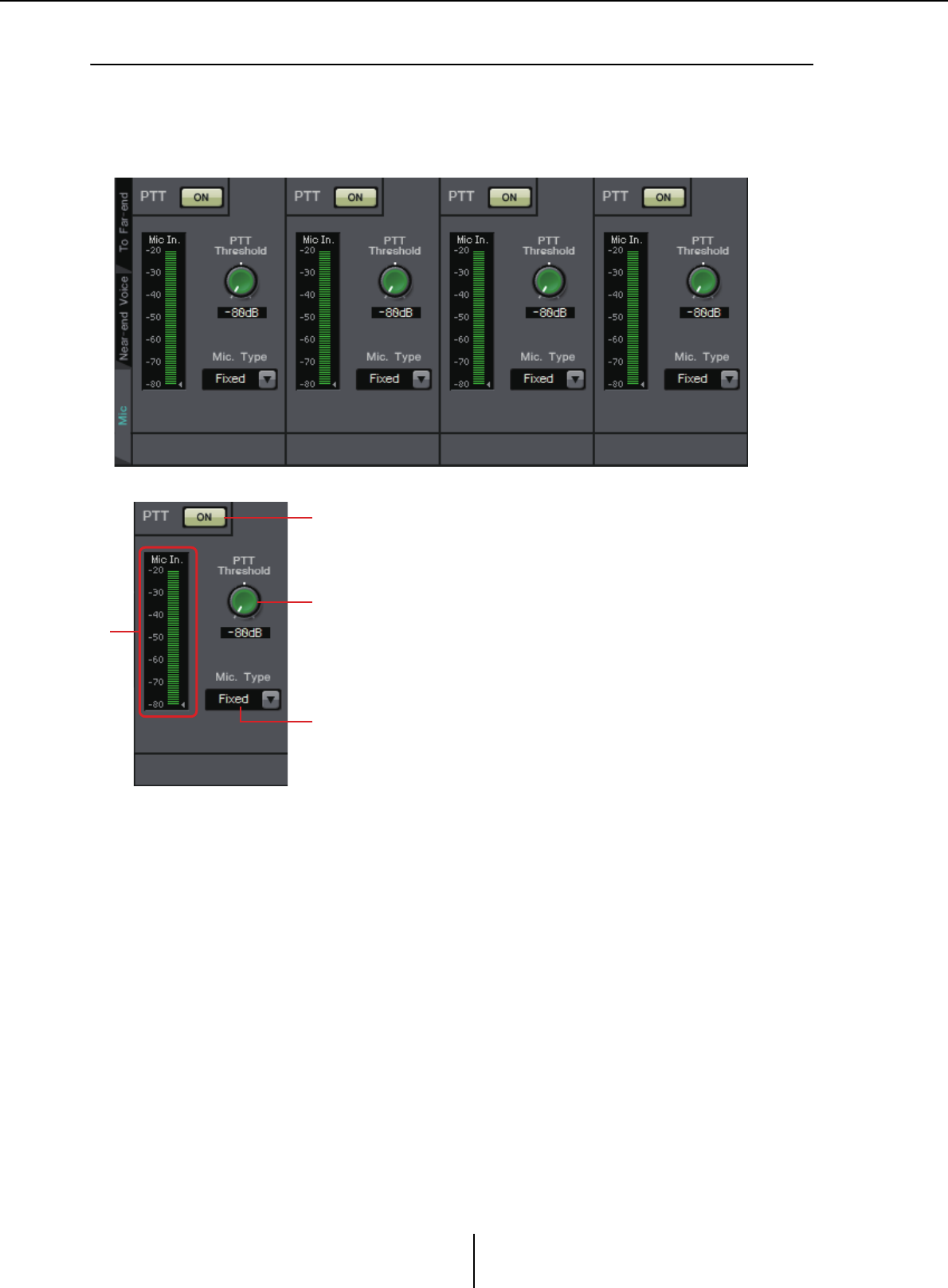
“Mic” screen Chapter 4. System screen
MTX-MRX Editor User Guide
119
❑“Mic” screen
When using a mic equipped with a PTT (Push To Talk) switch, a small amount of noise may be
heard while the PTT switch is off. If this noise is input to the AEC, the AEC will mistakenly learn
the noise, causing an echo when the PTT switch is turned on to resume speaking. In this screen you
can make settings and specify the type of mic to prevent this from occurring.
3
1
4
2
1PTT [ON] button
If this is on, and the input level from the local mic (Near-end
Mic) falls below the value specified in PTT Threshold, the
system will determine that the PTT switch of the local mic has
been turned off, and will stop AEC learning. We recommend
that you leave this on.
2Mic In. meter
This indicates the level of the signal that is input from the local
mic (Near-end Mic). This meter will also indicate the level of
the noise that occurs when the PTT button of the mic is off.
3[PTT Threshold] knob
This knob sets the reference level for AEC learning. If the PTT
[ON] button is on, AEC learning will stop when the input
signal to the local mic (Near-end Mic) falls below this level;
learning will resume when the input signal exceeds this level.
The Mic In. meter indicates the level of the input signal.
4[Mic. Type] box
Specify the type of mic that is connected.
Choose “Fixed” for an environment in which the distance
between the mic and speaker is fixed, or “Moving” for an
environment in which this distance changes, such as when a
hand mic is used. Even in an environment in which the
distance between the mic and speaker is fixed, choose
“Moving” if the echo is obtrusive.
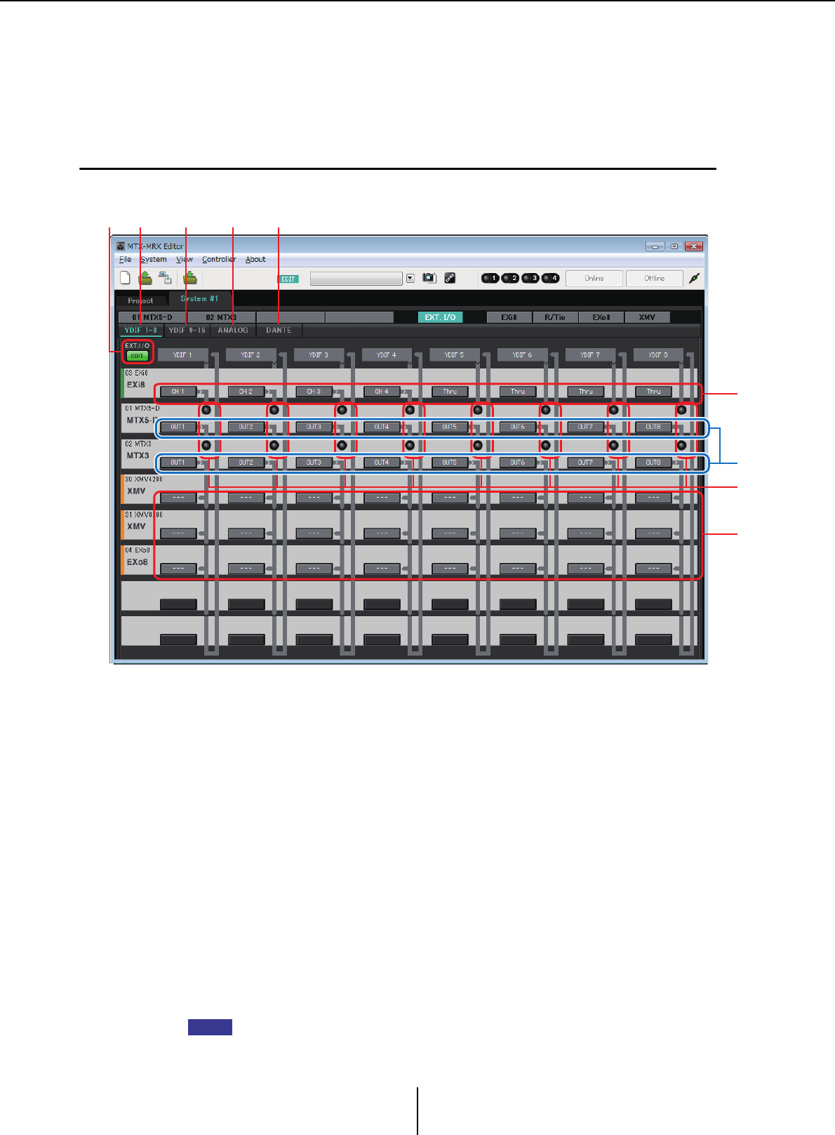
“EXT. I/O” screen Chapter 4. System screen
MTX-MRX Editor User Guide
120
“EXT. I/O” screen
Here you can select the signal routing for the MTX series and MRX series unit’s YDIF connectors and
analog connectors.
❑“YDIF” screen (Distribution mode)
This screen appears in Distribution mode.
1[YDIF 1-8] button
Displays the “YDIF1-8” screen. Here you can specify the routing for YDIF channels
1–8.
2[YDIF 9-16] button
Displays the “YDIF9-16” screen.
Here you can specify the routing for YDIF channels 9–16.
3[ANALOG] button
Displays the “ANALOG” screen.
4[DANTE] button
Displays the “DANTE” screen.
5[EDIT] button
Enables the input routing select buttons / output routing select buttons of a device other
than an MTX/MRX unit.
The [EDIT] button is available only in Distribution mode when a device other than an MTX/
MRX unit is connected via YDIF and the system is offline.
12345
7
8
6
9
NOTE

“YDIF” screen (Distribution mode) Chapter 4. System screen
MTX-MRX Editor User Guide
121
6Input routing select buttons
These buttons open the “YDIF In Patch” dialog box, where you can select the input
source device and channels for the YDIF signal.
To enable these buttons, click the [EDIT] button.
• These settings are not included in the preset. For this reason, they can be edited only after
clicking the [EDIT] button, in order to prevent the settings from being changed casually.
• This is available only in Distribution mode when the EXi8 is connected via YDIF and the
system is offline.
7Selection buttons for output signals from the MTX to YDIF
These buttons open the “Channel Select” dialog box where you can select which signals
of the MTX will be output to YDIF channels. These settings are included in the preset.
8YDIF IN input indicators
These indicators show YDIF input signals for the MTX/MRX unit.
9Output routing select buttons
These buttons open the “YDIF Out Patch” dialog box where you can select the device
and channels to which the YDIF signal will be output.
To enable these buttons, click the [EDIT] button.
• These settings are not included in the preset. For this reason, they can be edited only after
clicking the [EDIT] button, in order to prevent the settings from being changed casually.
• This is available only in Distribution mode when the XMV is connected via YDIF and the
system is offline.
NOTE
NOTE
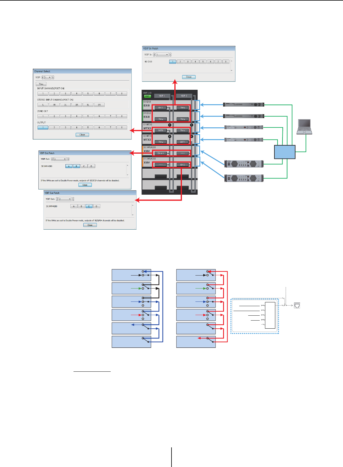
How the settings in each dialog box relate to the “YDIF” screen Chapter 4. System screen
MTX-MRX Editor User Guide
122
How the settings in each dialog box relate to the “YDIF”
screen
About YDIF
When connected via YDIF, the XMV will send the audio signals without change to the
EXi8/EXo8 or the MTX/MRX. The audio signal will loop unless the EXi8/MTX/MRX
unit outputs a different signal or the output is stopped.
8
YDIF
OUTPUT
PATCH
From INPUT CHANNEL POST ON 1-8
From THRU 1-16
From ZONE OUT 1-8
From STEREO INPUT CHANNEL POST ON 1L-3R
16
8
*DISTRIBUTION MODE only
*CASCADE MODE only
YDIF OUT
YDIF OUT
YDIF MODE
CASCADE MODE
or DISTRIBUTION MODE
8
6
8
16
YDIF
OUT
YDIF2
YDIF1
#03 EXi8
CH1
OUT
OUT
OUT
OUT
OUT
OUT OUT
IN
IN
IN
IN
IN
IN IN
#04 EXi8
#01 MTX3
#02 MTX3
#30 XMV
#31 XMV
#03 EXi8 OUT
OUT
OUT
OUT
OUT
IN
IN
IN
IN
IN
#04 EXi8
#01 MTX3
#02 MTX3
#30 XMV
#31 XMV
OUT8
CH A&B
MTX3 ID=02
MTX3 ID=01
XMV4280 ID=31
XMV4280 ID=30
EXi8 ID=03
EXi8 ID=04
Network
Swich
No output No output
No output
No output
Through
Through
Through
Through
Through
Through
Through
Through
Through
Through
CH C
OUT1
“YDIF Out Patch” dialog box
“Channel Select” dialog box
“YDIF In Patch” dialog box
YDIF signal flow with the settings shown above
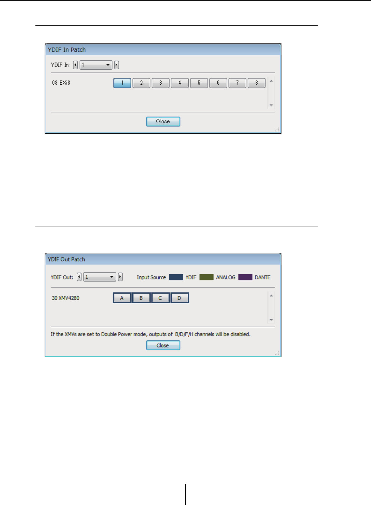
“YDIF In Patch” dialog box Chapter 4. System screen
MTX-MRX Editor User Guide
123
❑“YDIF In Patch” dialog box
Here you can select the input channel for the YDIF signal.
• [YDIF In:] box
Select the YDIF channel that you want to edit.
• Channel select buttons
These buttons select the input channel. The device ID and model name of the input
source are shown at the left.
• [Close] button
Closes the “YDIF In Patch” dialog box.
❑“YDIF Out Patch” dialog box
Here you can select the channels to which the YDIF signal will be output. You can select multiple
output destinations.
• [YDIF Out:] box
Select the YDIF channel that you want to edit.
• Channel select buttons
These buttons select the output channel. The device ID and model name of the
output destination are shown at the left.
The color of the button’s edge changes to match what is specified for INPUT
SOURCE in the [Device] tab of the “Project” screen.
• [Close] button
Closes the “YDIF Out Patch” dialog box.
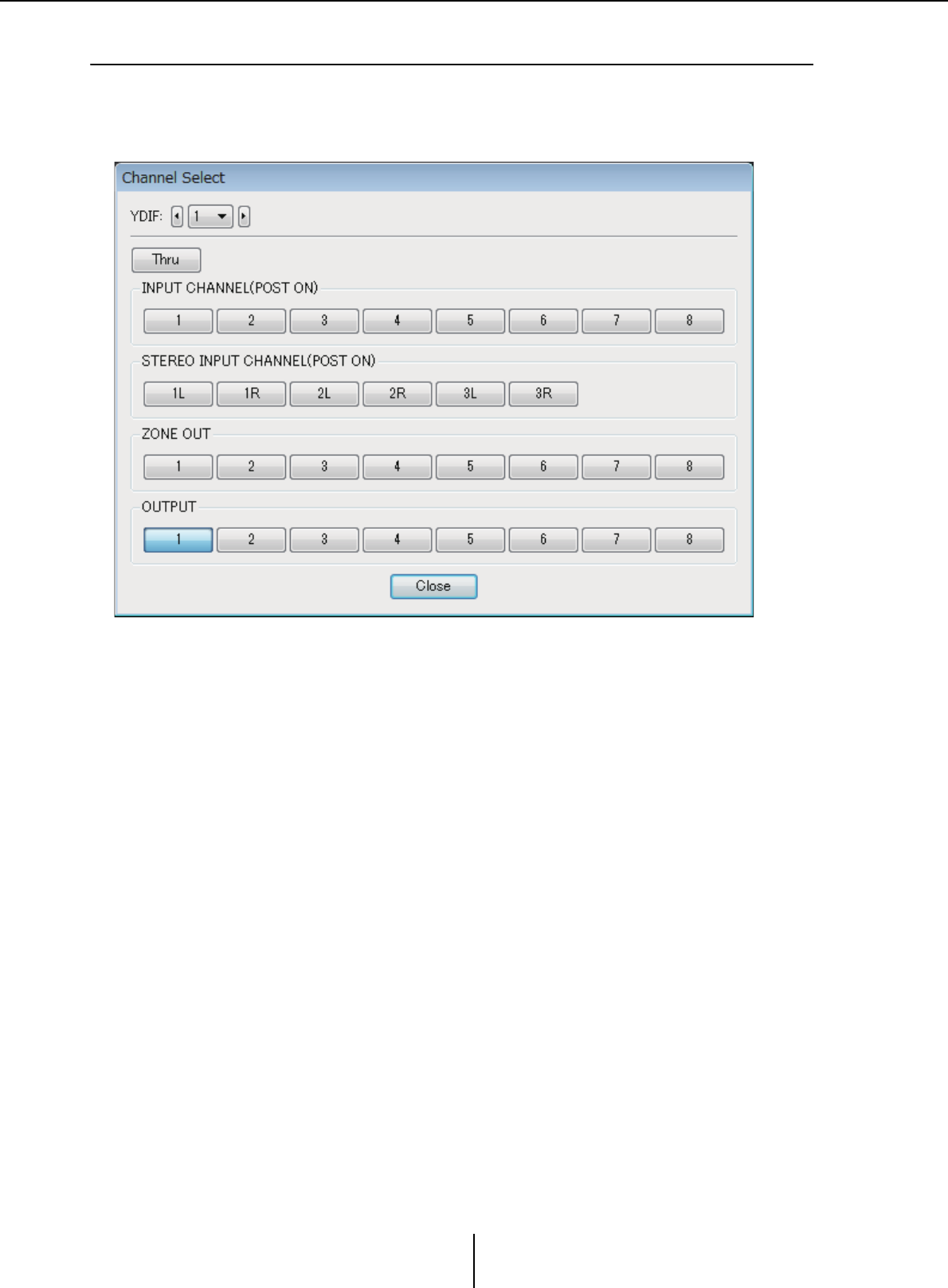
“Channel Select” dialog box Chapter 4. System screen
MTX-MRX Editor User Guide
124
❑“Channel Select” dialog box
Here you can select the signals that are output from the MTX to YDIF.
If nothing is selected, the signal will not be output to YDIF.
For the MRX, the connection lines in the “MRX Designer” window determine the destination.
• [YDIF:] box
Select the YDIF channel that you want to edit.
•[Thru] button
The signals coming into YDIF input will be sent to the same YDIF channel without
change.
• INPUT CHANNEL (POST ON)
The input channel’s POST signal (after MUTE switching) will be sent to the YDIF
channel.
• STEREO INPUT CHANNEL (POST ON)
The stereo input channel’s POST signal (after MUTE switching) will be sent to the
YDIF channel.
• ZONE OUT
The signal of the zone output will be sent to the YDIF channel.
• OUTPUT CHANNEL
The signal of the output channel will be sent to the YDIF channel.
• [Close] button
Closes the “Channel Select” dialog box.
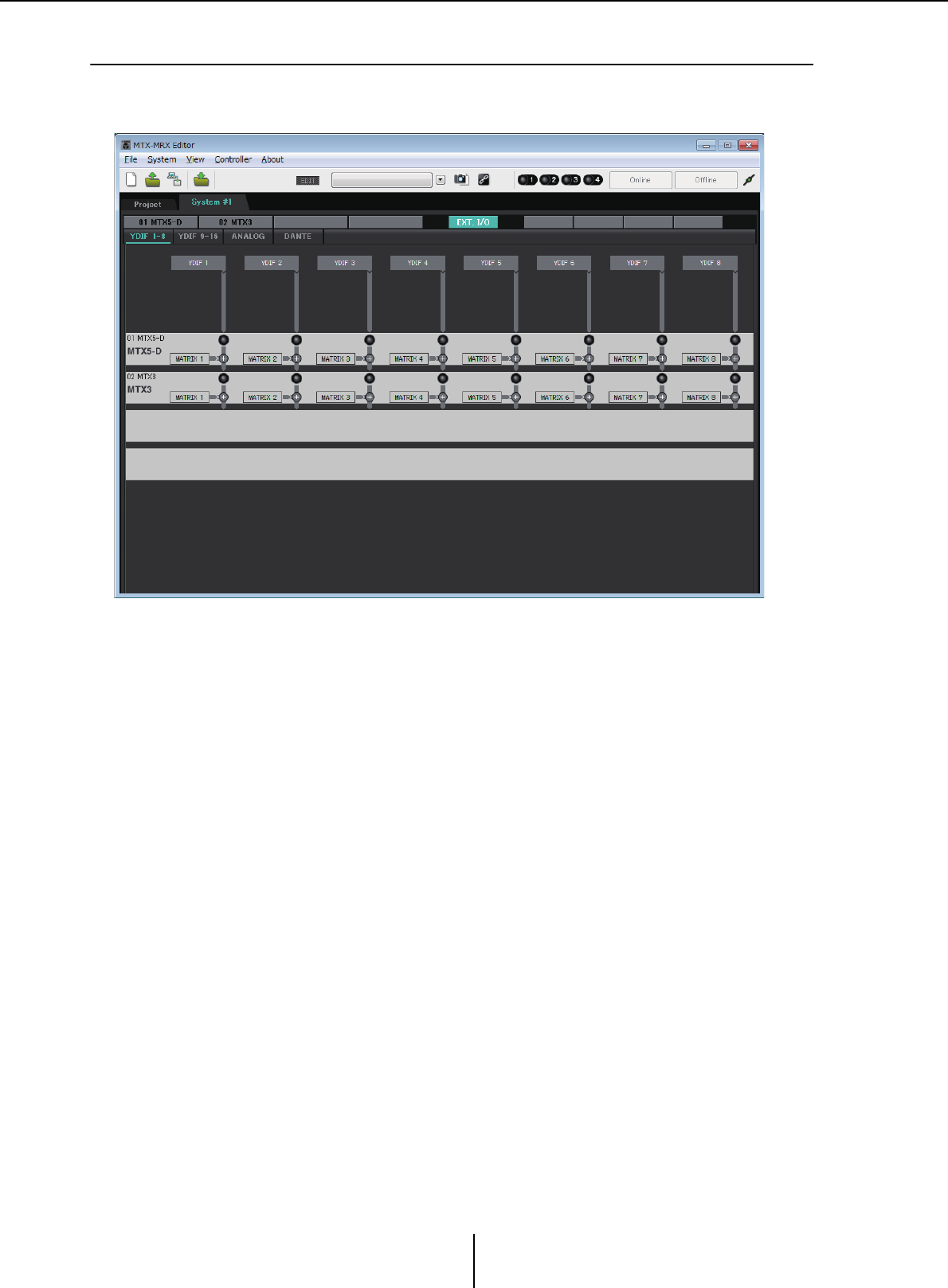
“YDIF” screen (Cascade mode) Chapter 4. System screen
MTX-MRX Editor User Guide
125
❑“YDIF” screen (Cascade mode)
This screen appears in Cascade mode. It indicates which MTX MATRIX bus is routed to which
YDIF output.
You can turn the YDIF outputs on or off in the [CASCADE MODE] section on the [OUTPUT] tab
of the “MTX Configuration” dialog box.
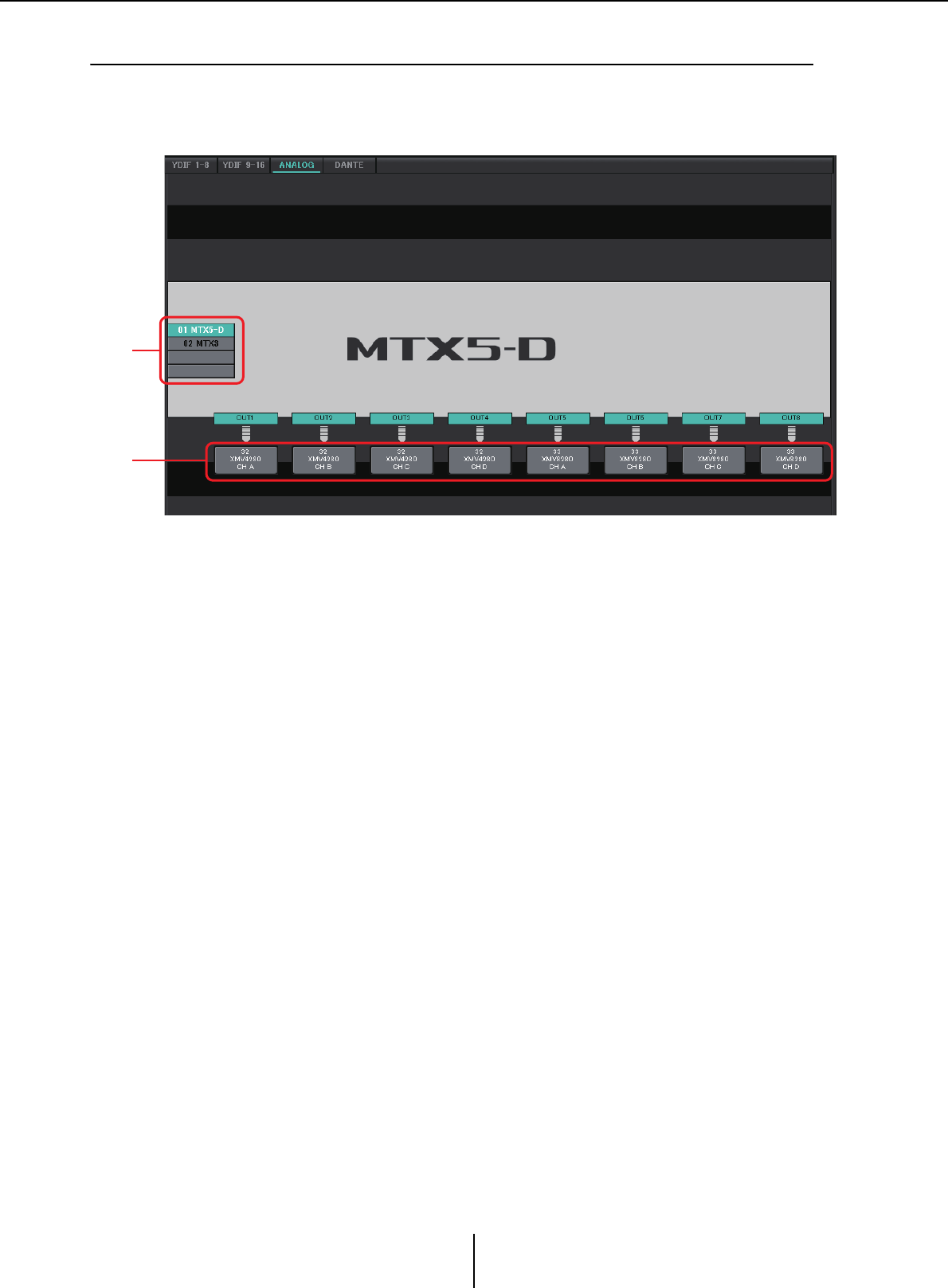
“ANALOG” screen Chapter 4. System screen
MTX-MRX Editor User Guide
126
❑“ANALOG” screen
Here you can select the XMV unit and the channels of the unit that will input analog audio signals.
These settings let you control the parameters of analog-connected XMV units from the Parameter
editing screen. However, audio routing settings cannot be made.
1MTX/MRX select buttons
Use these buttons to select the MTX/MRX unit that you want to edit.
2Output routing select buttons
These open the “Line Out Patch” dialog box where you can select the output routing.
1
2
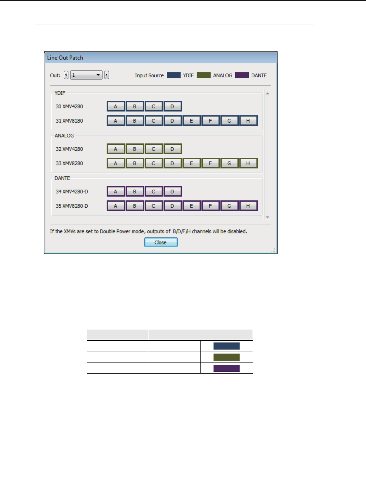
“Line Out Patch” dialog box Chapter 4. System screen
MTX-MRX Editor User Guide
127
❑“Line Out Patch” dialog box
Here you can specify the output destination device and channel for analog signal output from the
MTX/MRX unit. You can select multiple output destinations.
• [Out:] box
Select the output channel that you want to edit.
• Channel select buttons
These buttons select the output destination device and channel. The device ID and
model name of the output destination are shown at the left.
The color of the button’s edge changes to match what is specified for INPUT
SOURCE in the [Device] tab of the “Project” screen.
• [Close] button
Closes the “Line Out Patch” dialog box.
INPUT SOURCE Button edge color
YDIF Dark blue
Analog Ocher
DANTE Purple
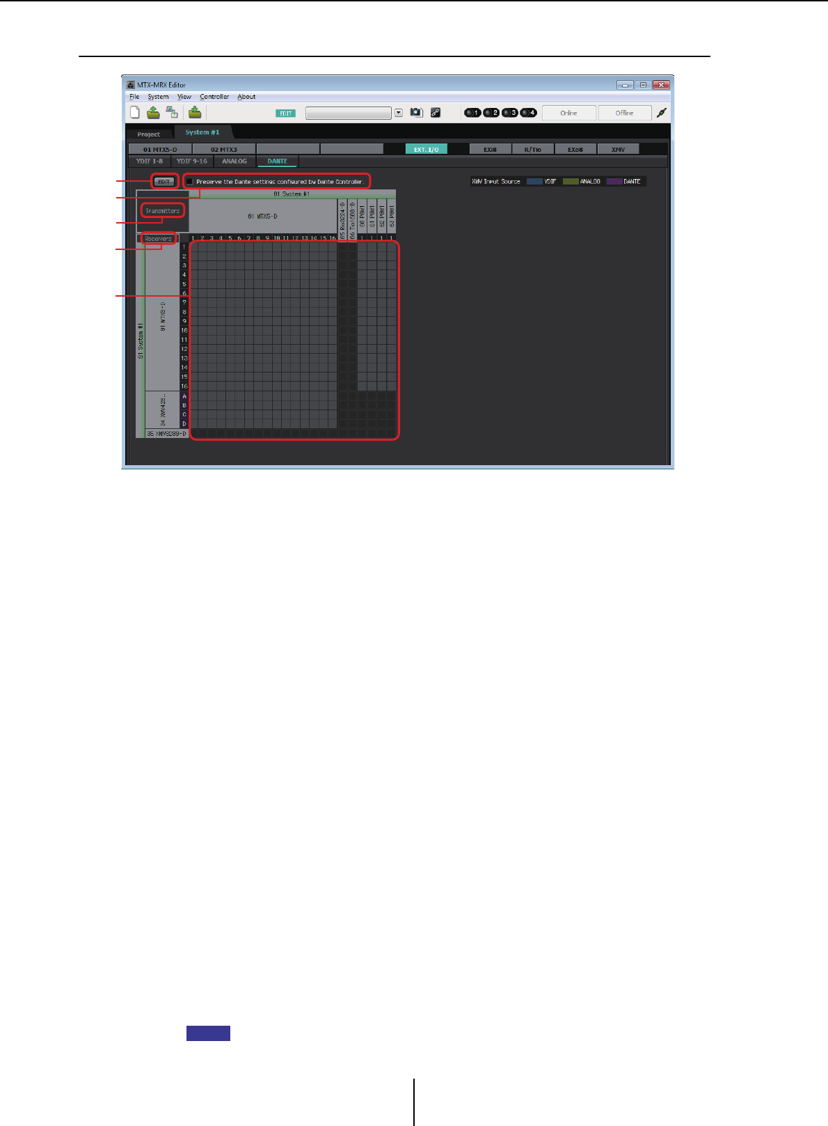
“DANTE” screen Chapter 4. System screen
MTX-MRX Editor User Guide
128
❑“DANTE” screen
1[EDIT] button
Turn this on to enable editing.
2[Use the settings of Dante Controller] check box
Select this check box if you’re using Audinate Corporation’s Dante Controller to set up
the Dante network. The settings of Dante Controller will take priority over the settings
made in MTX-MRX Editor. If this check box is cleared, you’ll be able to use MTX-MRX
Editor to make Dante network settings within the project.
3[Transmitters]
This shows the transmitting devices and channels. You can click in the device name
column to expand or hide the view. In the case of the MRX, after expanding the view,
you can click a range of channels to expand or hide the channel view in 16-channel units.
You can drag and drop the device name to change its order.
Move the cursor to a device to view its associations.
4[Receivers]
This shows the receiving devices and channels. You can click in the device name
column to expand or shrink the display. In the case of the MRX, after expanding the
view, you can click a range of channels to expand or hide the channel view.
The edge color for XMV channels changes to match what is specified for INPUT
SOURCE in the [Device] tab of the “Project” screen. For details on the colors, refer to
the preceding page.
You can drag and drop the device name to change its order.
Move the cursor to a device to view its associations.
Use Dante Controller to make settings for how the R series (AD/DA) or Tio1608-D
receive signals.
Receiving devices can receive signals from up to 24 units.
2
1
3
4
5
NOTE

“DANTE” screen Chapter 4. System screen
MTX-MRX Editor User Guide
129
5Matrix
Change the transmission/reception assignments by clicking the location at which an
input channel and output channel intersect. The connection is on when the ● symbol
is displayed. Devices for which Device Lock is specified by Dante Controller cannot be
changed.
If you execute Update Device Information which appears when you right-click, the
Device Lock status and the Rio/Tio’s Dante Device Name are updated.
In the matrix you can use the following operations to move the view.
• Use the cursor keys of the keyboard to move up/down/left/right
• Use the mouse wheel to move up/down
• Hold down <Shift> on the keyboard and use the mouse wheel to move left/right
●AES67
The MTX5-D, MRX7-D, and XMV series Dante-enabled models support AES67
starting with V3.20.
Use Dante Controller to set a device to AES67 mode. Use Dante Controller to specify
routing for AES67-enabled devices and MTX5-D, MRX7-D, and XMV series Dante-
enabled models.
If an MTX5-D, MRX7-D, or XMV series Dante-enabled model is receiving a signal
from any AES67-enabled device, the [Transmitters] area indicates “AES67,” and the
patching information is shown in the matrix.
Although patching with an AES67-enabled device can be deleted in MTX-MRX Editor,
it cannot be re-specified.
●Device Lock
The MTX5-D, MRX7-D, and XMV series Dante-enabled models support Device Lock
starting with V3.2.
Use Dante Controller to lock a device. Locked devices are shown in red.
NOTE
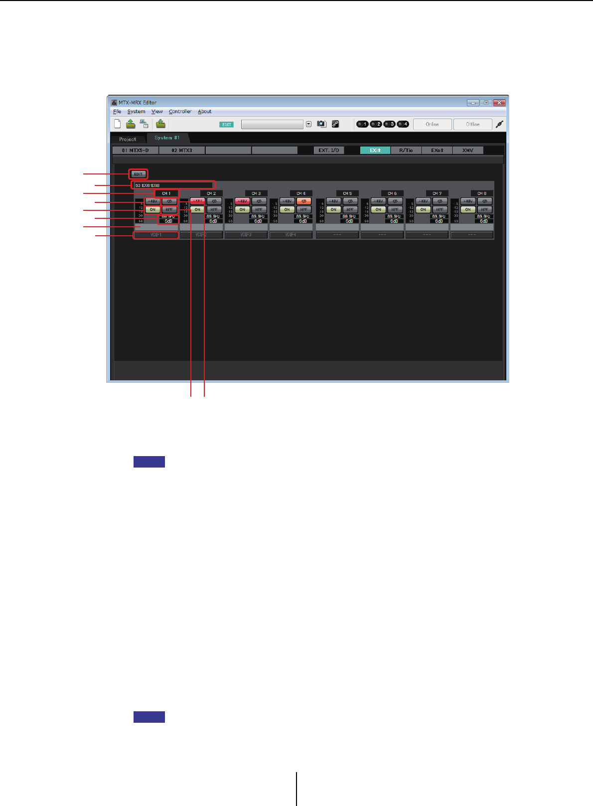
“EXi8” screen Chapter 4. System screen
MTX-MRX Editor User Guide
130
“EXi8” screen
Here you can view and edit the parameters of the EXi8 units in the MTX/MRX system. When you
right-click on the display area of a desired EXi8, a context menu appears, allowing you to copy and
paste settings between devices.
1[EDIT] button
This enables the EXi8 output routing select buttons.
The [EDIT] button is available only in the offline state.
2EXi8 identification area
Shows the UNIT ID, model type, and model name of the corresponding EXi8 unit.
3Channel index
Indicates the channel number of the EXi8.
4[+48V] button
Turns the HA phantom power (+48V) on/off.
Notice
Be sure to leave this button off if you do not need phantom power.
When turning phantom power on, you must observe the precautions below in order to
prevent noise and possible damage to the unit and to external devices.
• Leave this button off if a device that does not support phantom power is connected to the
[INPUT] connector.
• Do not connect/disconnect a cable to/from the [INPUT] connector while this button is
on.
• Lower the output level to the minimum before turning phantom power on/off.
There is no master switch. To avoid malfunctions, be sure to set this appropriately for the
equipment that is connected.
57
1
3
6
90
2
4
8
NOTE
NOTE
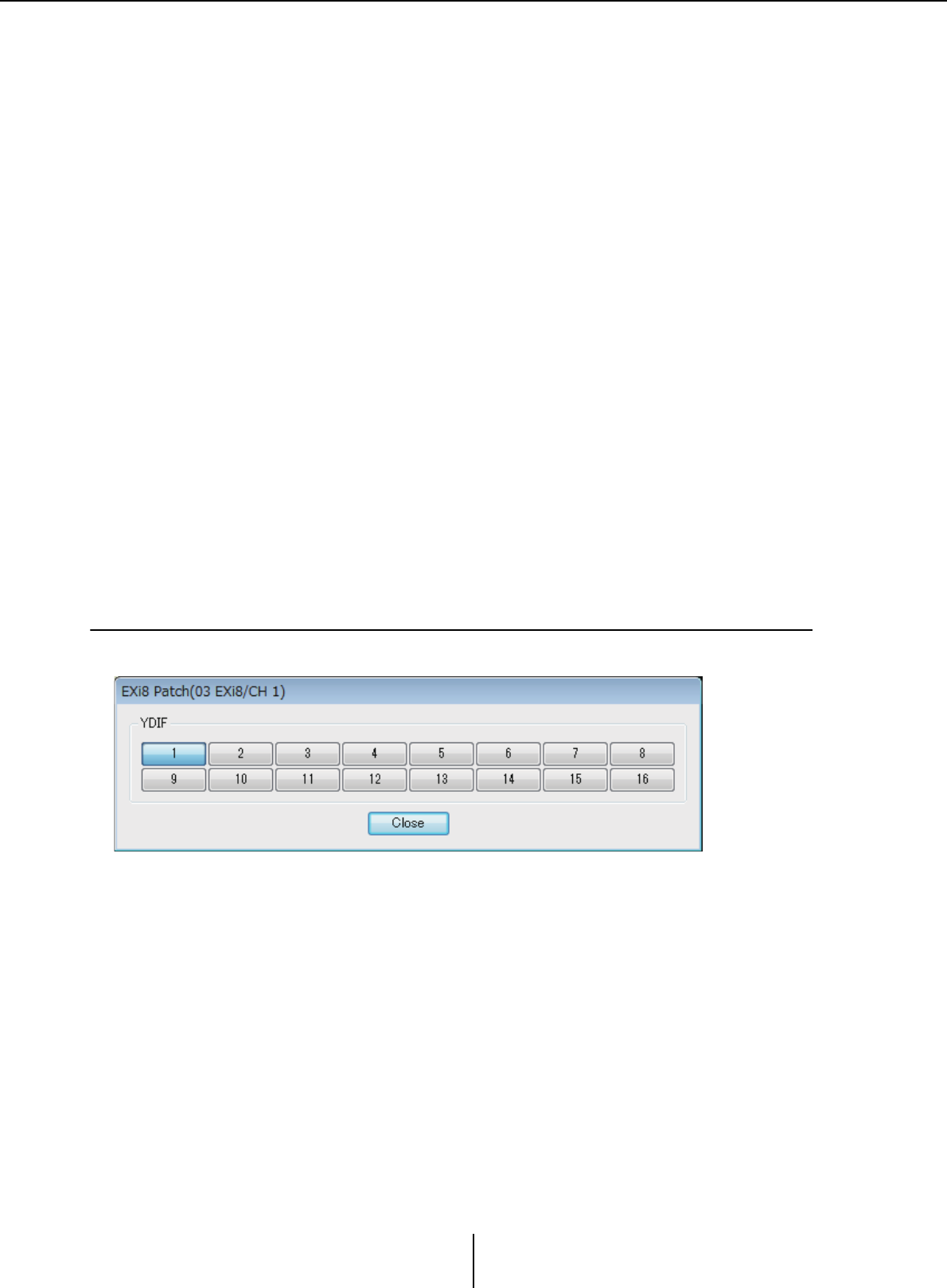
“EXi8 Patch” dialog box Chapter 4. System screen
MTX-MRX Editor User Guide
131
5[Ø] button
Switches the phase of the input signal.
6[ON] button
Switches the input channel on/off.
The button also shows the on/off status.
7[HPF] button/Cutoff frequency
The [HPF] button switches the HPF (High Pass Filter) on/off.
The cutoff frequency is shown below the [HPF] button.
You can double-click the cutoff frequency to edit it.
8HA analog gain
Shows the HA analog gain setting.
You can double-click this and edit it.
9Channel name
Indicates the channel name.
You can double-click this and edit it.
0Output routing select button
This button opens the “EXi Patch” dialog box, where you can select the output
destination channels for the audio signal.
To enable this button, click the [EDIT] button.
❑“EXi8 Patch” dialog box
Here you can select the output destination channels for the audio signals of the EXi8 unit.
1[YDIF] buttons
Select the output destination channels.
2[Close] button
Closes the “EXi8 Patch” dialog box.
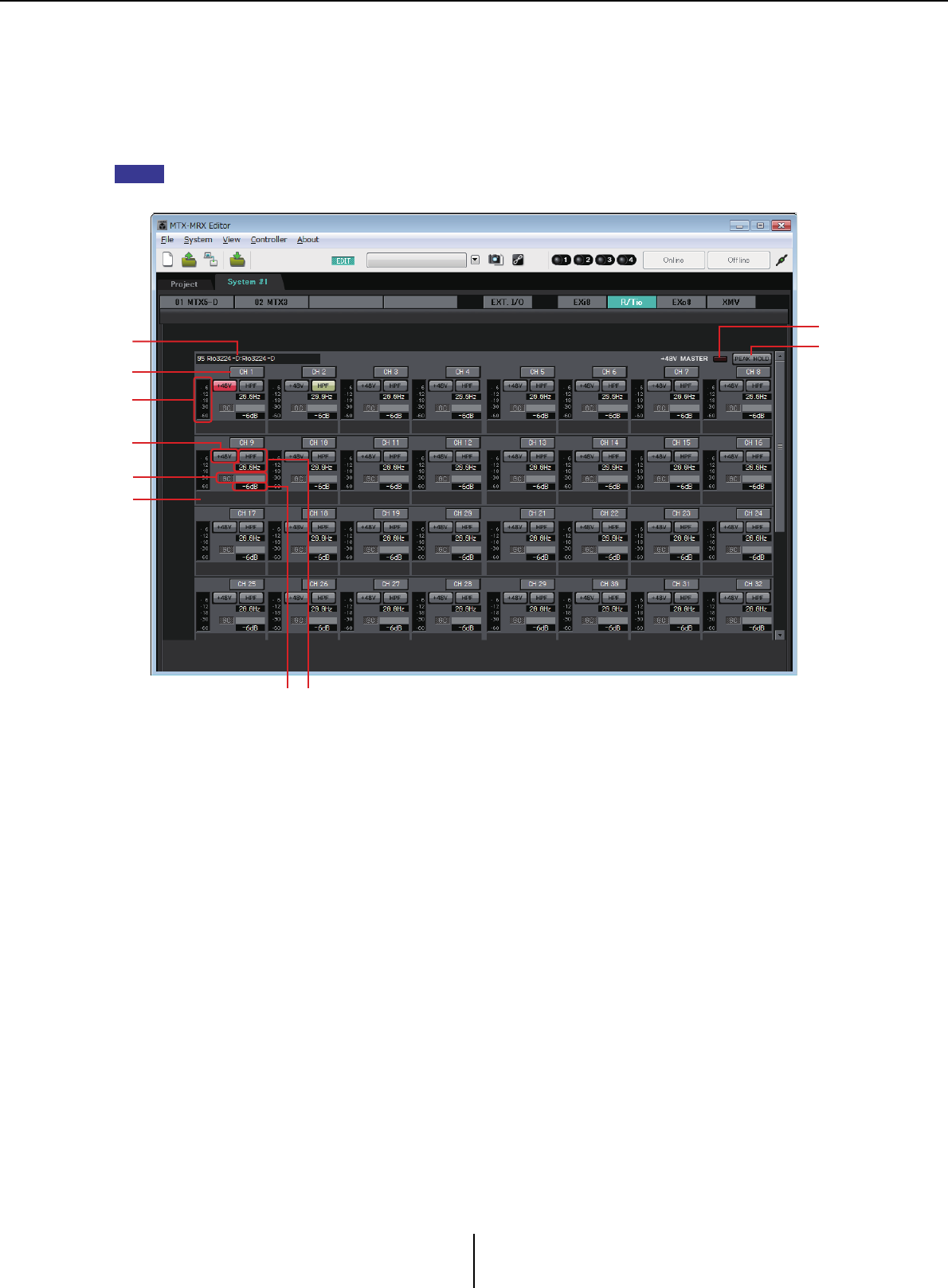
“R/Tio” screen Chapter 4. System screen
MTX-MRX Editor User Guide
132
“R/Tio” screen
Here you can view and edit the parameters for the analog input jacks of an R series (AD/DA) or
Tio1608-D unit. When you right-click on the display area of a desired R series (AD/DA) or Tio1608-
D, a context menu appears, allowing you to copy and paste settings between devices.
Since the Ro8-D has no analog input jacks, it is not shown.
1Device identification field
Shows the DEVICE NAME that is specified in the [Device] tab of the “Project” screen.
2“+48V MASTER” indicator
Indicates the on/off status of the device’s master phantom power.
3[PEAK HOLD] button
If this button is on, the peaks of each level meter are held. When this button is turned
off, the held peaks are cleared.
4Channel button
Indicates the [INPUT] jack number of the device. When you click this, the indicator of
the corresponding jack will flash for approximately five seconds, allowing you to
identify the jack.
5Level meter
Shows the input signal level.
6[+48V] button
Turns the HA phantom power (+48V) on/off. This is valid if the unit’s master phantom
power is on.
NOTE
4
1
6
8
0
5
2
3
79

“R/Tio” screen Chapter 4. System screen
MTX-MRX Editor User Guide
133
7[HPF] button / Cutoff frequency
The [HPF] button switches the HPF (High Pass Filter) on/off.
The cutoff frequency is shown below the [HPF] button. You can double-click the cutoff
frequency to edit it.
8“GC” indicator / gain value
Indicates the on/off status of the R series (AD/DA) unit’s gain compensation. If gain
compensation is on, the gain value fixed by gain compensation is shown.
9HA analog gain
Shows the HA analog gain setting. You can double-click this and edit it.
0Channel name
Indicates the channel name. You can double-click this and edit it.
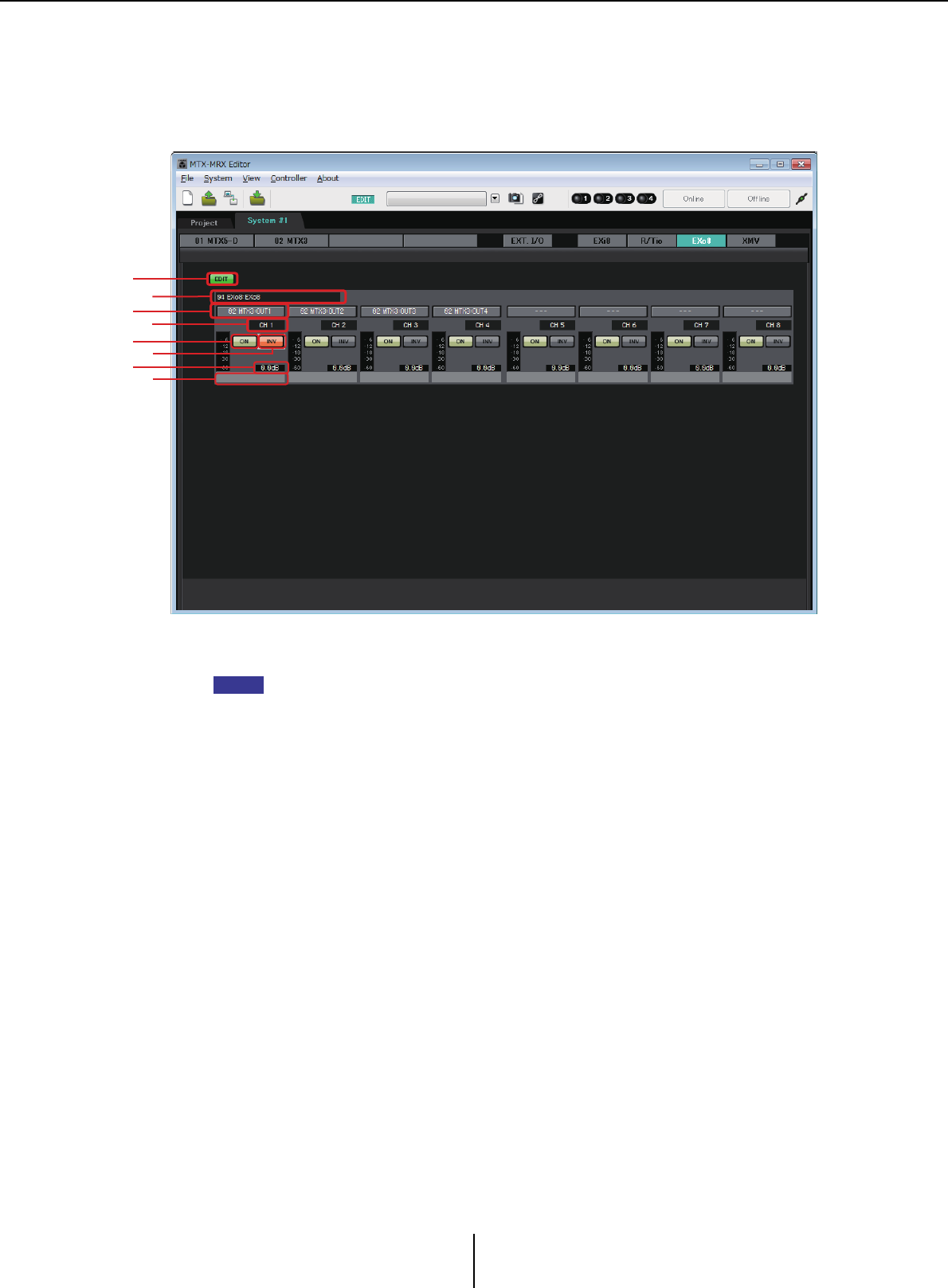
“EXo8” screen Chapter 4. System screen
MTX-MRX Editor User Guide
134
“EXo8” screen
Here you can view and edit the parameters of the EXo8 units in the MTX/MRX system. When you
right-click on the display area of a desired EXo8, a context menu appears, allowing you to copy and
paste settings between devices.
1[EDIT] button
This enables the EXo8 input routing select buttons.
The [EDIT] button is available only in the offline state.
2EXo8 identification area
Shows the UNIT ID, model type, and model name of the corresponding EXo8 unit.
3Input routing select buttons
These buttons open the “EXo8 Patch” dialog box where you can select the audio signal
output source device and channels.
To enable these buttons, click the [EDIT] button.
4Channel index
Indicates the channel number of the EXo8.
5[ON] button
Switches the output channel on/off. The button also shows the on/off status.
6POLARITY button
Switches the polarity of the output signal.
7Attenuator
Shows the EXo output attenuator setting.
You can double-click this and edit it.
8Channel name
Indicates the channel name. You can double-click this and edit it.
3
5
7
1
2
4
6
8
NOTE
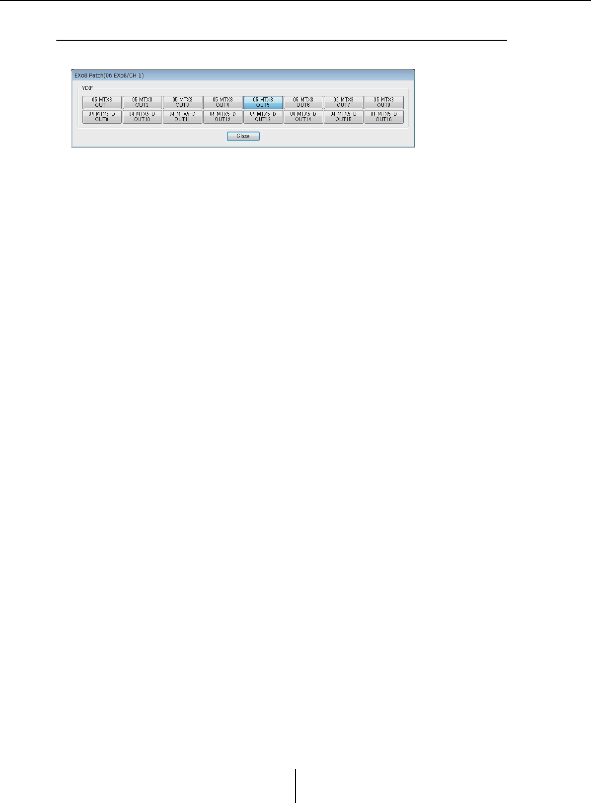
“EXo8 Patch” dialog box Chapter 4. System screen
MTX-MRX Editor User Guide
135
❑“EXo8 Patch” dialog box
Here you can select the output source channels for the audio signals of the EXo8 unit.
• [YDIF] buttons
Select the output source channel.
• [Close] button
Closes the “EXo8 Patch” dialog box.
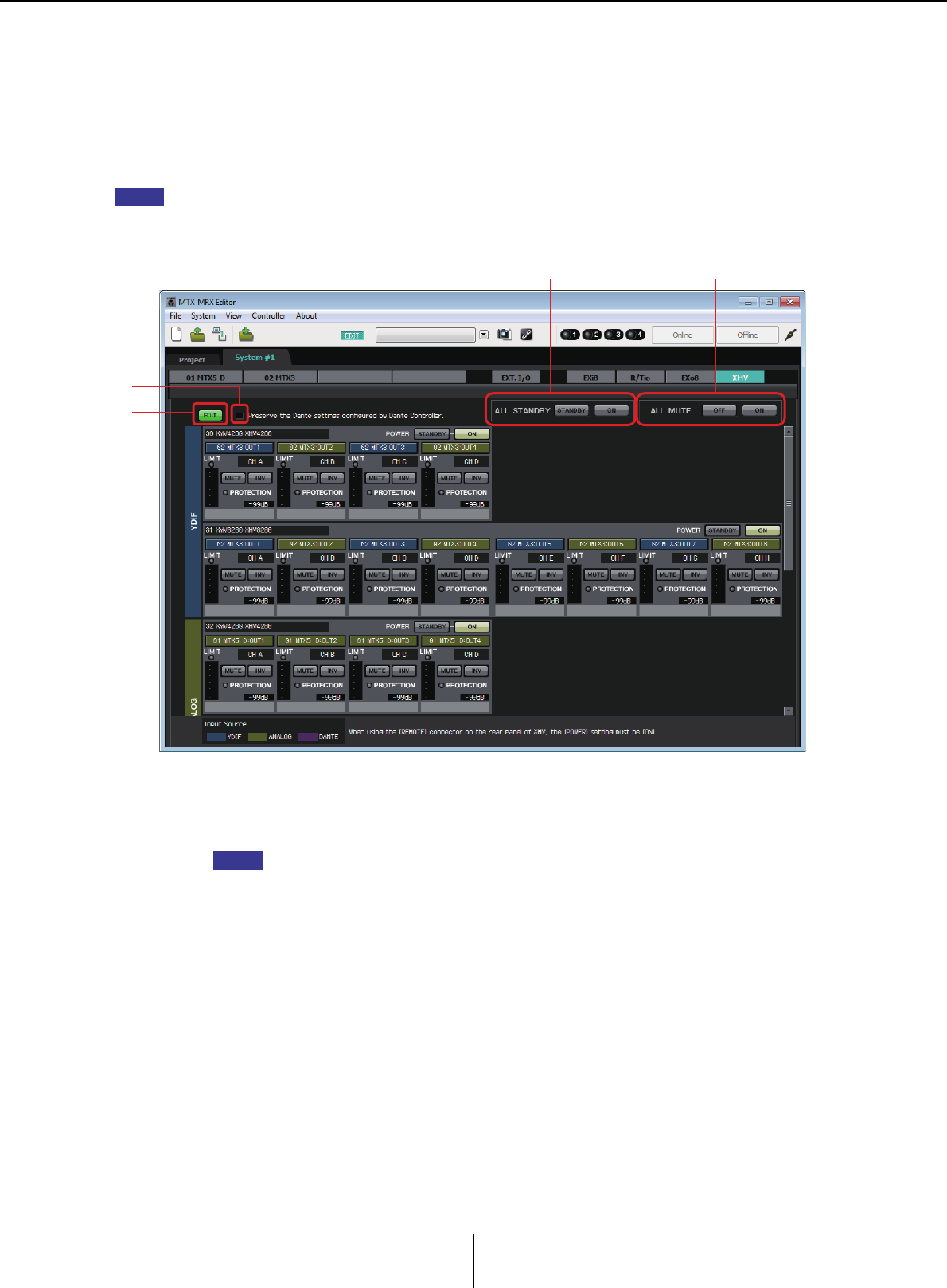
“XMV” screen Chapter 4. System screen
MTX-MRX Editor User Guide
136
“XMV” screen
Here you can view and edit the parameters of the XMV units in the MTX/MRX system. The units are
grouped according to how they are connected: YDIF-connected, analog-connected, or Dante-
connected. When you right-click on the display area of a desired XMV, a context menu appears,
allowing you to copy and paste settings between devices.
If digital connections and analog connections coexist, we recommend that you set the XMV’s input sensitivity
to [–20 dBFS] in the [Device] tab of the Project screen. If this is set to [–20 dBFS], the digital connections and
analog connections will have the same input sensitivity.
1[EDIT] button
This button enables the input routing select buttons for YDIF-connected and Dante-
connected XMV units.
The [EDIT] button is available only in the offline state.
2[Preserve the Dante settings configured by Dante Controller]
check box
Select this check box if you’re using Audinate Corporation’s Dante Controller to set up
the Dante network. The settings of Dante Controller will take priority over the settings
made in MTX-MRX Editor.
3[ALL STANDBY]
If you click the [STANDBY] button, the power of all XMV units in the MTX/MRX
system will be switched to standby. If you click the [ON] button, the power of all XMV
units in the MTX/MRX system will be turned on.
4[ALL MUTE]
If you click the [OFF] button, mute will be defeated for all XMV units in the MTX/MRX
system. If you click the [ON] button, all XMV units in the MTX/MRX system will be
muted.
NOTE
1
2
34
NOTE
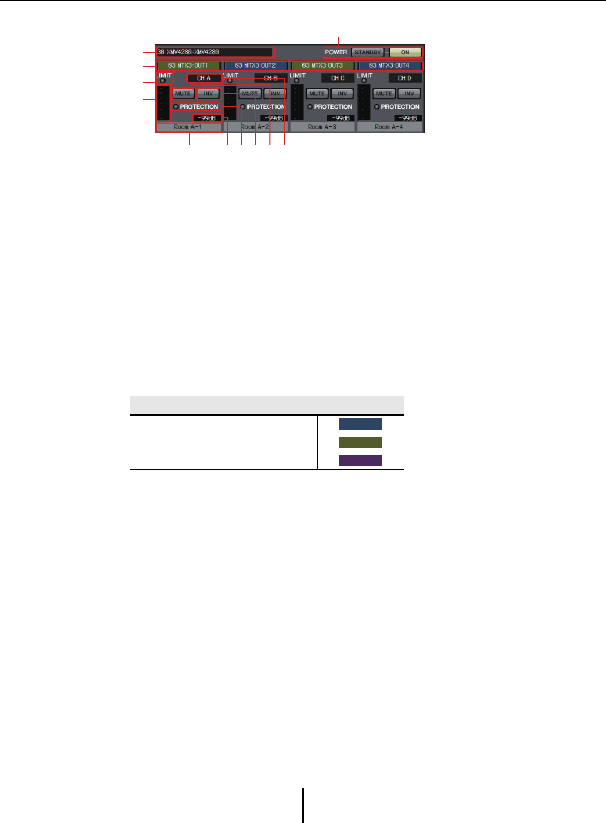
“XMV” screen Chapter 4. System screen
MTX-MRX Editor User Guide
137
5XMV identification area
Shows the UNIT ID, model type, and model name of the corresponding XMV unit.
6[POWER]
If you click the [STANDBY] button, the power of the corresponding XMV unit will be
switched to standby. If you click the [ON] button, the power of the corresponding XMV
unit will be switched on.
7Input routing select buttons
These buttons open the “XMV Patch” dialog box where you can select the audio signal
output source device and channels.
To enable these buttons for a YDIF-connected or Dante-connected XMV unit, click the
[EDIT] button.
The color of the button’s edge changes to match what is specified for INPUT SOURCE
in the [Device] tab of the “Project” screen.
8[LIMIT] indicator
This will light if the limiter of the XMV unit itself is operating.
9Meter
Shows the output signal level.
0Channel index
Indicates the channel number of the XMV.
A[MUTE] button
Switches mute on/off for the output channel.
BPOLARITY button
Switches the polarity of the output signal.
C[PROTECTION] indicator
This will light if the protection function of the XMV unit itself is operating.
INPUT SOURCE Button edge color
YDIF Dark blue
Analog Ocher
DANTE Purple
5
7
8
9
6
<ABCED
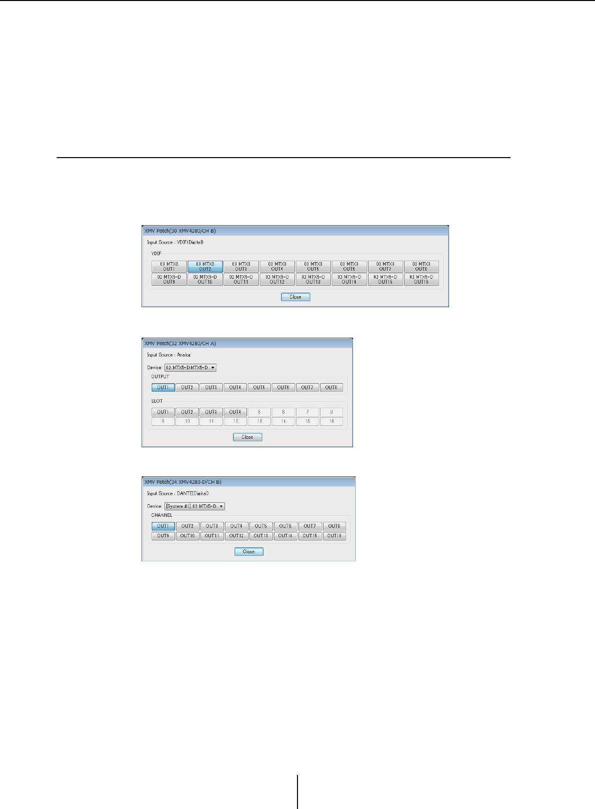
“XMV Patch” dialog box Chapter 4. System screen
MTX-MRX Editor User Guide
138
DAttenuator
Shows the XMV’s output attenuator setting.
You can double-click this and edit it.
EChannel name
Indicates the channel name. You can double-click this and edit it.
❑“XMV Patch” dialog box
Here you can select the output destination device and channels for the audio signals of the XMV
unit. The items shown will depend on the type of connections.
•Input Source
Indicates what is specified as INPUT SOURCE in the [Device] tab of the “Project”
screen.
• [Device:] box (for other than YDIF)
Selects the output source device.
• Channel buttons
Select the output source channel.
• [Close] button
Closes the “XMV Patch” dialog box.
YDIF
Analog
DANTE
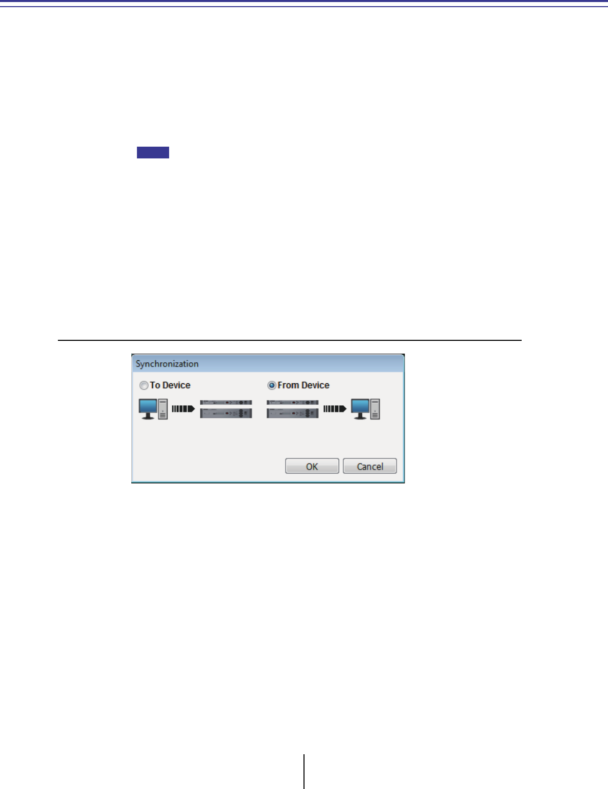
MTX-MRX Editor User Guide
139
Chapter 5. Online and Synchronization
You can connect the MTX/MRX to your computer and send the settings created using MTX-MRX
Editor to the MTX/MRX, or synchronize the MTX/MRX with MTX-MRX Editor and edit the
settings. You can also load data from the MTX/MRX into MTX-MRX Editor.
The state in which the MTX/MRX and MTX-MRX Editor operate in synchronization is called the
“online state.” The action of bringing them into this state is called “Synchronization.”
Synchronization will match the settings of MTX-MRX Editor and the MTX/MRX itself; when the
settings of both are in a matching state, they will go online, allowing the MTX/MRX to be
controlled in real time.
If emergency mode occurs, the system will go offline. It is not possible to synchronize with an
MTX/MRX system that is in emergency mode.
Online
To go online with MTX-MRX Editor, you can either click the [Online] tool button to access the
“Synchronization” dialog box, or choose the [File] menu command [Go Online – From Devices] to
access the “Go Online – From devices” dialog box. For details on when each method is appropriate,
refer to Synchronization.
❑“Synchronization” dialog box
• [To Device] option button
Choose this if you want the settings of MTX-MRX Editor to be applied to the MTX/
MRX system.
• [From Device] option button
Choose this if you want the settings of the MTX/MRX system to be applied to MTX-
MRX Editor.
• [OK] button
Click this to switch to a display that lets you choose the system that will be
synchronized.
•[Cancel] button
Click this to close the dialog box without synchronizing.
NOTE
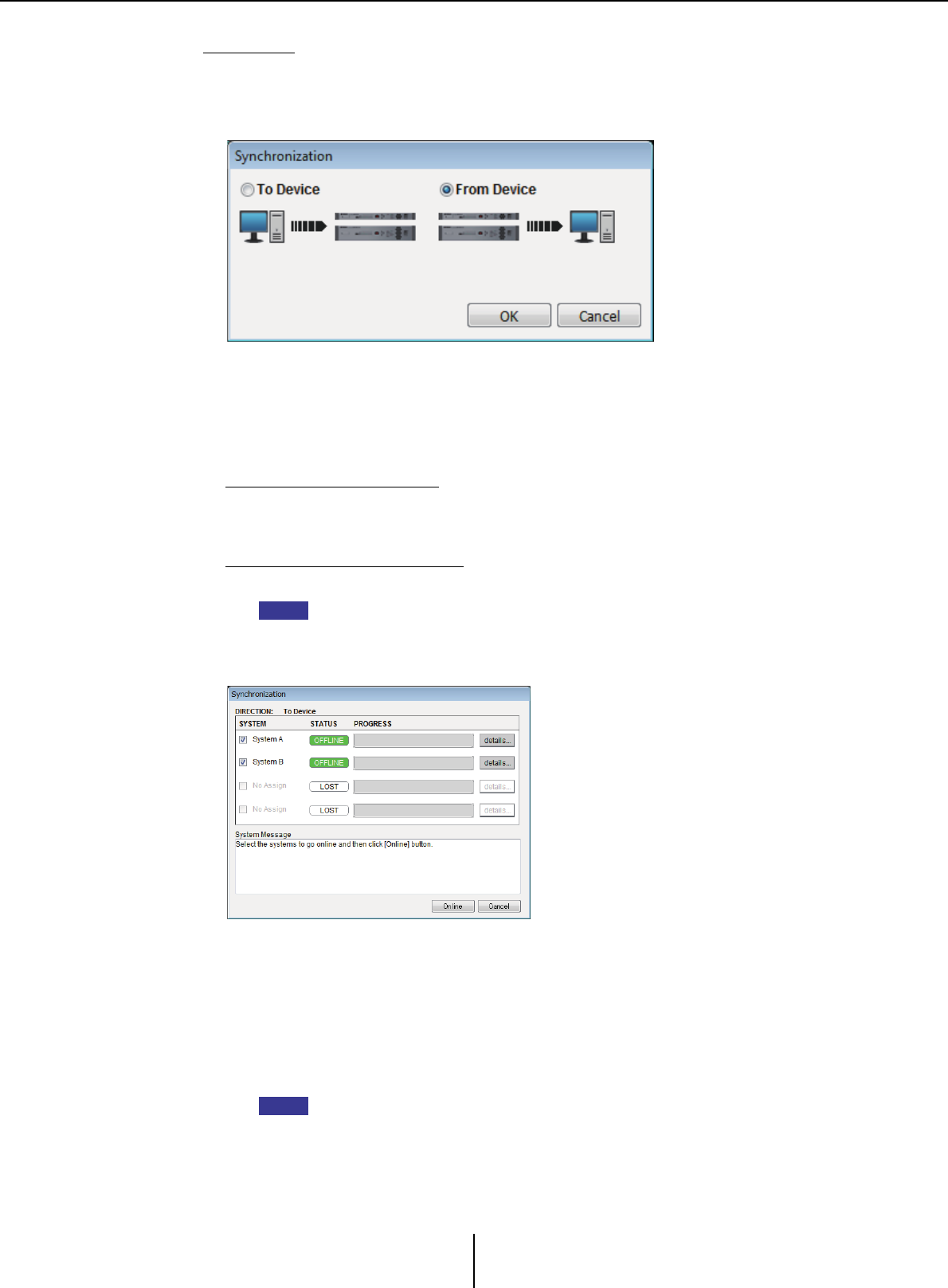
Online Chapter 5. Online and Synchronization
MTX-MRX Editor User Guide
140
Procedure
1. In the toolbar, click the [Online] button.
The “Synchronization” dialog box will appear, allowing you to choose the direction
of synchronization.
2. Choose either [To Device] or [From Device] to specify the direction in
which synchronization will occur.
Click the [OK] button to switch to a display that lets you choose the system that will
be synchronized. If you click the [Cancel] button, the operation will be cancelled.
If you chose [To Device]
The settings of MTX-MRX Editor will be transmitted to the devices, overwriting
their settings.
If you chose [From Device]
The settings of the devices will be loaded into MTX-MRX Editor.
If the PIN code differs between MTX-MRX Editor’s project file and the devices, a PIN
code entry dialog box will appear. Enter the correct PIN code to go online.
3. Select the MTX/MRX system that you want to place online.
• [Detail] button
Displays the progress, synchronization status, and error messages for the devices in
each MTX/MRX system.
4. Click the [Online] button.
Synchronization will begin. If you click the [Cancel] button, the operation will be
cancelled.
If an MRX is assigned to the MTX/MRX system that is being brought online, but
compile has not yet been executed, compile is executed automatically. If compile fails
or if the memory usage exceeds 100%, the “Compile” dialog box appears, and
synchronization is stopped.
NOTE
NOTE
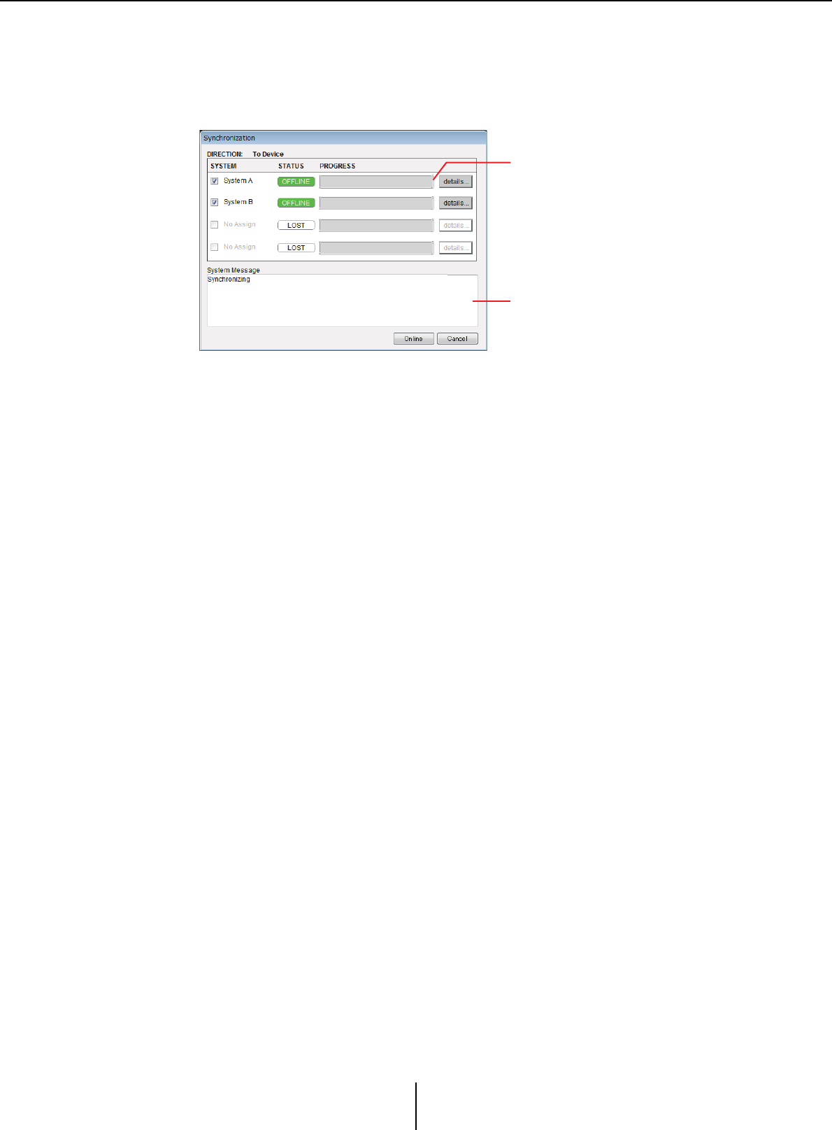
Online Chapter 5. Online and Synchronization
MTX-MRX Editor User Guide
141
5. The synchronization progress is displayed.
If you click the [Abort] button, the operation will be halted. This can be a useful way
to save time, for example if you’ve noticed a mistake during synchronization and
want to edit a parameter. The settings will have been partially transmitted, so after
you’ve made changes, be sure to complete synchronization to the end.
• Progress bar
Shows the status of synchronization.
• Message area
Details are shown in this area if you click the [Abort] button to stop the process or if
an error occurs.
• [Abort] button
Click this to stop synchronization.
• [Online] button
When you click this, MTX-MRX Editor will begin synchronizing with the selected
MTX/MRX system.
• [Close] button
Cancels synchronization and closes the dialog box.
This cannot be clicked during synchronization.
6. When synchronization has ended successfully, the progress screen will
close automatically.
Progress bar
Message area
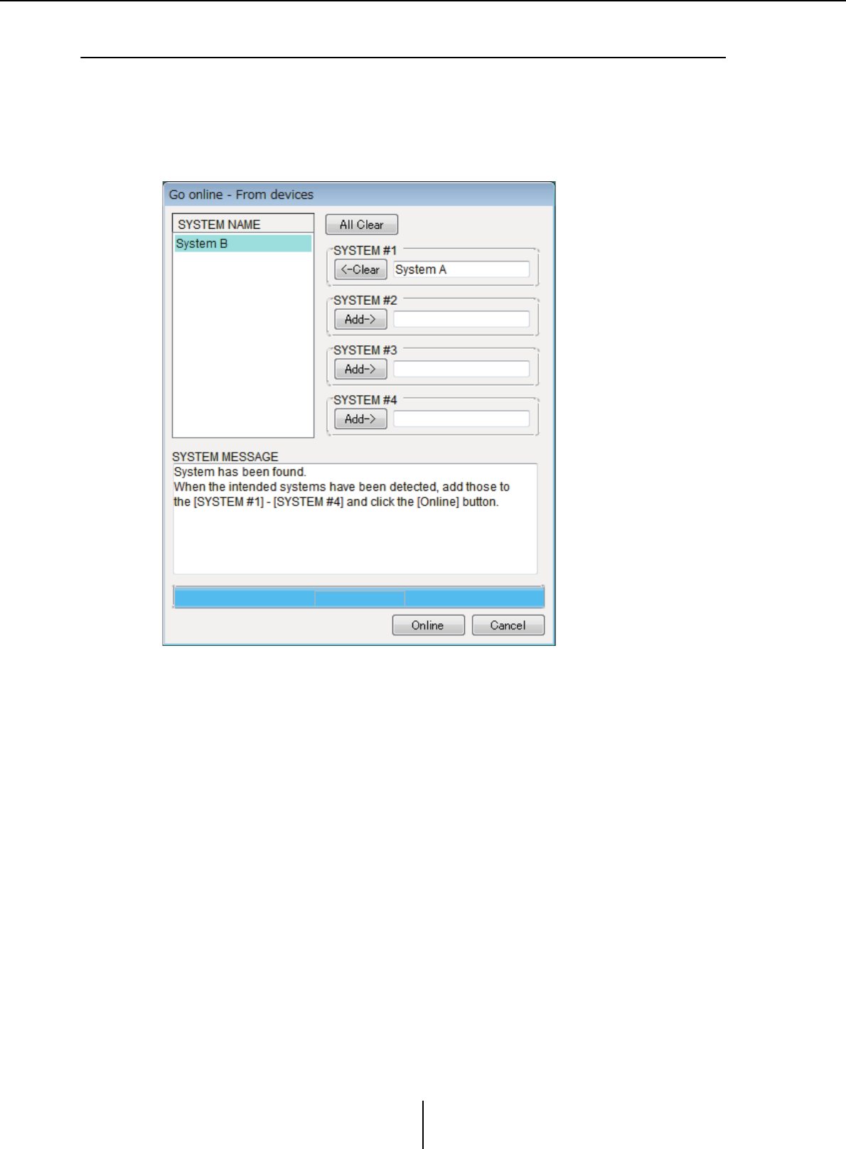
Online Chapter 5. Online and Synchronization
MTX-MRX Editor User Guide
142
❑“Go online – From devices” dialog box
The settings (configuration and parameters) of the MTX/MRX are loaded into MTX-MRX Editor.
In order to execute this, the MTX/MRX whose settings are to be obtained must have been online
with MTX-MRX Editor using the To Device setting.
In this dialog box, you can specify how multiple MTX/MRX systems that are found will be assigned
to SYSTEM #1 through #4.
• [SYSTEM NAME] list
The system name will be displayed if you use the [All Clear] button or the [Clear]
button to clear an MTX/MRX system that was found.
• [All Clear] button
Moves all MTX/MRX systems that are assigned as SYSTEM #1 through #4 to the
[SYSTEM NAME] list.
•[Clear]/[Add] toggle buttons
If you click the [Clear] button, the specified MTX/MRX system will be moved to
the [SYSTEM NAME] list. If you click the [Add] button, the MTX/MRX system
selected in the [SYSTEM NAME] will be assigned.
The name of the assigned MTX/MRX system is shown at the right of the button.
• [Online] button
When you click this, the settings of the MTX/MRX systems that are assigned as
SYSTEM #1 through SYSTEM #4 will start being loaded. When loading is
completed, you will be online.
•[Cancel] button
Click this to close the dialog box without synchronizing.
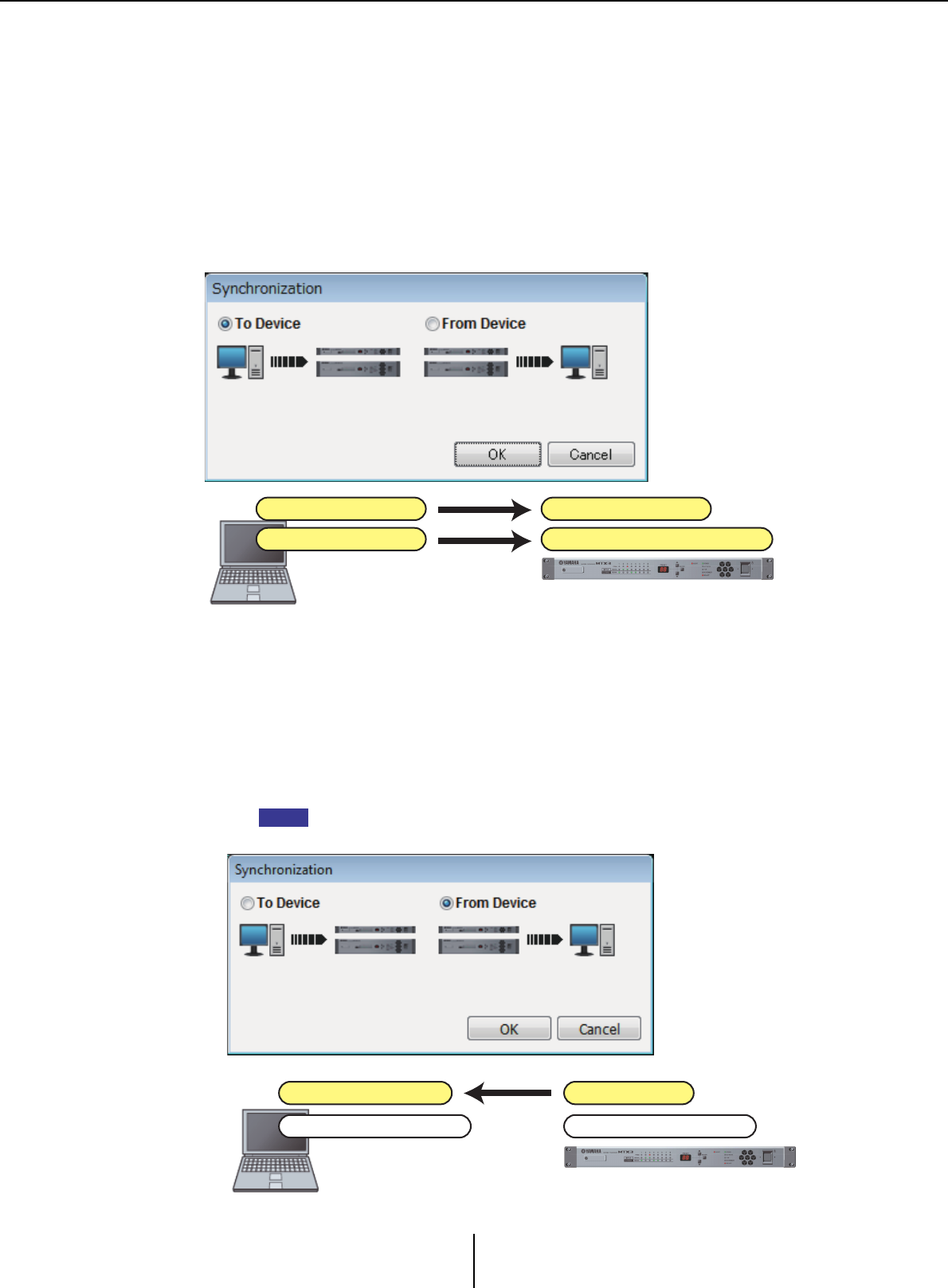
Synchronization Chapter 5. Online and Synchronization
MTX-MRX Editor User Guide
143
Synchronization
Synchronization includes the following three operations.
1) Synchronizing from the computer (MTX-MRX Editor) to the MTX/MRX unit itself
The settings (configuration and parameters) of MTX-MRX Editor are sent to the MTX/
MRX.
Use this method when you have prepared a file beforehand, and want to send those
settings to the MTX/MRX on-site.
In the “Synchronization” dialog box, choose [To Device].
2) Synchronizing from the MTX/MRX unit to the computer (MTX-MRX Editor)
•Case 1
The MTX/MRX’s parameters are loaded into MTX-MRX Editor. Use this method
when a DCP or Wireless DCP has been used to modify the settings of the MTX/MRX
unit, and you want to go back online to modify or view these changes.
Choose [From Device] in the “Synchronization” dialog box.
Synchronization is not possible if there are differences between the MRX unit and
MTX-MRX Editor’s component type or cabling between components.
Parameters
Configuration
Computer
Overwrite parameters
Overwrite configuration
MTX/MRX
NOTE
Overwrite parameters
Configuration
Computer
Parameters
Configuration
MTX/MRX
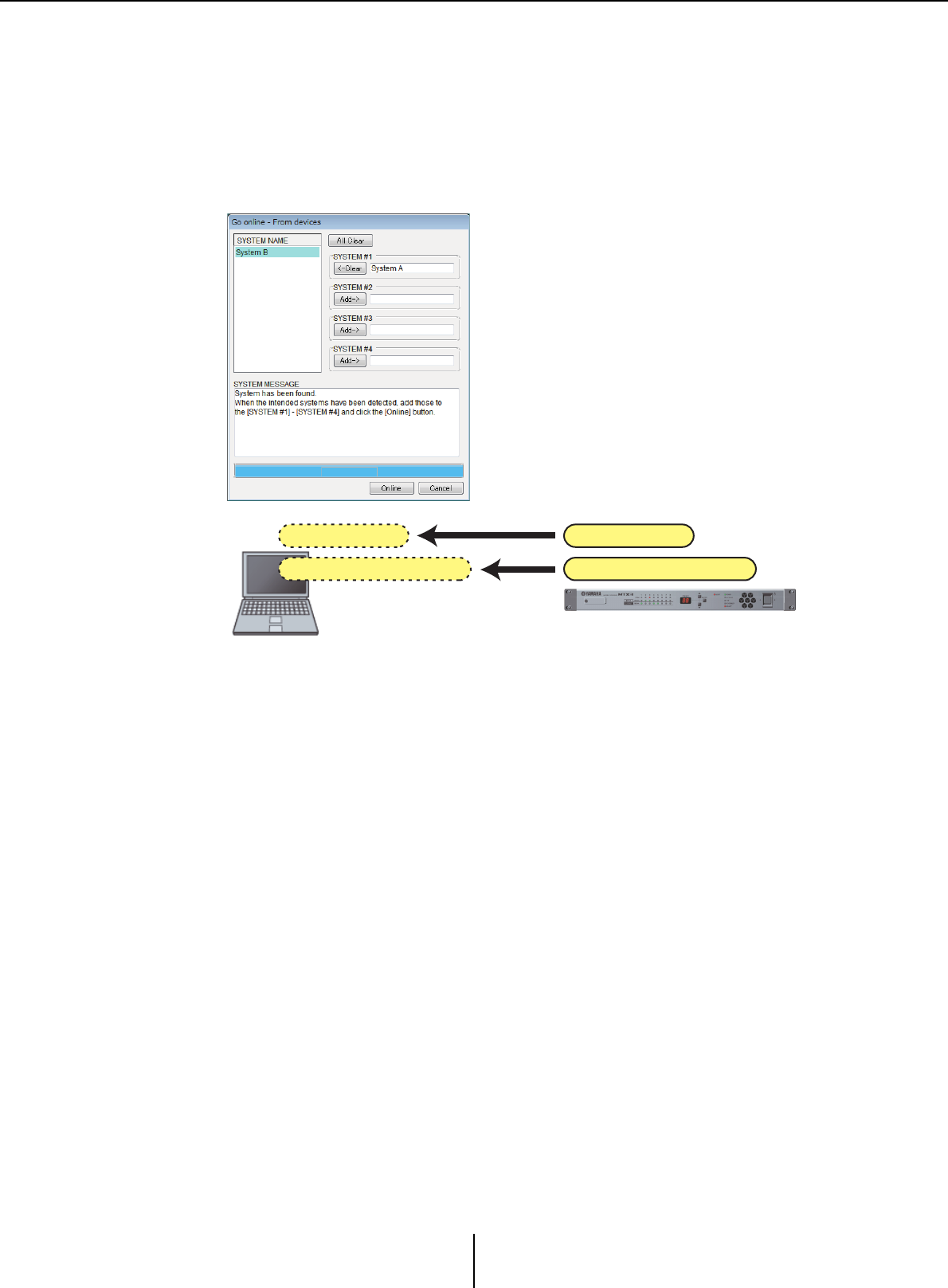
Synchronization Chapter 5. Online and Synchronization
MTX-MRX Editor User Guide
144
•Case 2
The settings (configuration and parameters) of the MTX/MRX are loaded into
MTX-MRX Editor. In order to execute this, the MTX/MRX whose settings are to be
obtained must have been online with MTX-MRX Editor using the To Device setting.
If there is no settings file in MTX-MRX Editor, you can use this method to obtain all
of the configuration and parameter data from the MTX/MRX, and use MTX-MRX
Editor to edit or check the parameters.
On the [File] menu, click [Go Online – From Devices].
Computer
Parameters
Configuration
MTX/MRX
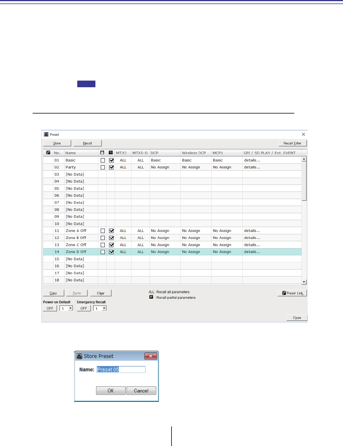
MTX-MRX Editor User Guide
145
Chapter 6. Presets
This chapter explains the presets which allow you to change multiple parameters in a single operation.
Preset settings are made in the “Preset” dialog box which you can access by clicking the preset button
in the toolbar. In this dialog box you can store the settings of multiple parameters as a preset, or recall
a stored preset to apply its parameters to the current settings. The parameters of the preset that is
applied are called the “current parameters.” You can also copy a stored preset to create a new preset, or
delete an unwanted preset.
Presets are made separately for each MTX/MRX system.
If you add devices to the MTX/MRX system, you’ll need to store the existing presets once
again.
❑“Preset” dialog box
Here you can make settings for the presets of the selected MTX/MRX system.
●[Store] button
This button stores a preset. The “Store Preset” dialog box will appear.
NOTE
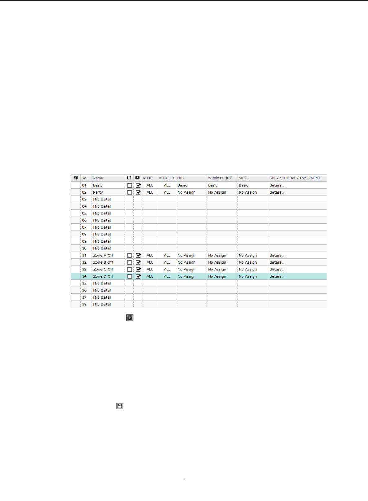
“Preset” dialog box Chapter 6. Presets
MTX-MRX Editor User Guide
146
•[Name:]
Input the name of the preset. By default, this will be “Preset + preset number.” You
cannot enter a blank preset name.
• [OK] button
This stores the preset and closes the dialog box.
•[Cancel] button
This cancels the preset store operation, and closes the dialog box.
●[Recall] button
When you click this button, the currently selected preset will be recalled (loaded) as the
current parameters. The number and name of the recalled preset are shown in the
Preset select combo box.
●[Recall Filter] button
This displays the Recall Filter setting screen.
●Preset list
This displays a list of the presets. Up to 50 presets can be stored.
•Preset link ( )
A check mark is shown for presets whose recall is linked with the presets of another
MTX/MRX system.
•[No.]
Shows the preset number (01–50). This cannot be changed.
•[Name]
Shows the preset name. If you select a stored preset and click this area, you’ll be able
to edit the name.
This will indicate [No Data] for empty presets.
•Protect ( )
If this check box is selected, the preset will be protected so that it cannot be edited.
You can prevent unintended changes by protecting a preset that you don’t want to be
overwritten or modified.

“Preset” dialog box Chapter 6. Presets
MTX-MRX Editor User Guide
147
•Scheduler ( )
If this check box is selected, the scheduler function will be enabled when the preset
is recalled.
If the scheduler is disabled, the [SCHEDULER] indicator of the MTX/MRX unit itself will
flash rapidly when the event time occurs.
• [MTX3]/[MTX5-D]
If even one item is specified in the Recall Filter setting screen as excluded from
recall, this area will indicate “ .”
• [EXT. I/O]
If even one item is specified in the Recall Filter setting screen as excluded from
recall, this area will indicate “ .”
R series (AD/DA) and Tio1608-D are also included in [EXT. I/O].
• [MRX7-D] (only if there is an MRX assigned in the MTX/MRX system)
When you execute Store, the screen indicates “ALL Parameters,” and the current
parameters of all components are stored.
The MRX7-D has functions that let you recall only specified parameters (snapshots,
snapshot groups).
For details about these functions, refer to “MRX Designer User Guide.”
• [DCP]/[Wireless DCP]/[MCP1]/[GPI/SD PLAY/Ext. EVENT]
DCP, Wireless DCP, and MCP1 show the library items that will be recalled
simultaneously with the preset. For GPI/SD PLAY/Ext. EVENT, this always shows
“details...” You can change this setting in the “Settings” dialog box that appears when
you select a stored preset and click this area. However if the preset is protected, the
“Settings” dialog box will appear but you won’t be able to make changes.
If no DCP, Wireless DCP, or MCP1 library item is selected, this will indicate “No
Assign.” If a “No Assign” preset is recalled, DCP, Wireless DCP, and MCP1 units will
be in a state in which parameters have not been assigned. If you want the parameters
prior to recall to be maintained, remove them as recall targets in the Recall Filter
setting screen.
SD Play will maintain the settings from before the recall occurred.
If library data differs between devices, this is indicated by red characters. Store the
corresponding library item once again in the “Digital Control Panel” dialog box, the
“Wireless DCP” dialog box, or the “MCP1” dialog box.
Simply editing the [DCP]/[Wireless DCP]/[MCP1]/[GPI/SD PLAY/Ext. EVENT] settings
in the “Settings” dialog box will not apply your changes to the current parameters. In
order to apply the settings, you must recall that preset in the appropriate dialog box.
●[Copy] button
This button copies the selected preset.
The Copy command is not available while online.
●[Paste] button
This button pastes the copied preset to the preset that’s currently selected in the list.
The Paste command is not available while online.
●[Clear] button
This button clears the contents of the preset that’s currently selected in the list.
The Clear command is not available while online.
NOTE
NOTE

“Preset” dialog box Chapter 6. Presets
MTX-MRX Editor User Guide
148
●[Preset Link] button
This displays the “Preset Link” dialog box where you can make settings for linking
preset recall between MTX/MRX systems.
●[Power on Default]
This specifies the preset that will be recalled when you turn on the power of the MTX/
MRX.
If you want the unit to start up with the same settings each time, resetting any changes
that were made, turn this on so that the preset you specified will be recalled at start-up.
Turn this off if the state at the previous shut-down is important, or if the same operator
will be using the system, or if you expect that the power may be turned off during use.
• [OFF]/[ON] toggle button
This is an on/off switch for preset recall at startup.
• Preset select box
This selects the number of the preset that will be recalled when you turn on the
power of the MTX/MRX.
●[Emergency Recall]
This specifies the preset that will be recalled when the MTX/MRX receives an EMG
(Emergency) signal from an external device or when the input to the +24V [GPI IN]
pin (IN 8 for the MTX3, and IN 16 for the MTX5-D and MRX7-D) falls below 2.5V.
• [OFF]/[ON] toggle button
Switches recall on/off. Turn this off if +24V is not being applied to the +24V [GPI
IN] pin.
• Preset box
Selects the preset number that will be recalled.
●[Close] button
Closes the “Preset” dialog box.
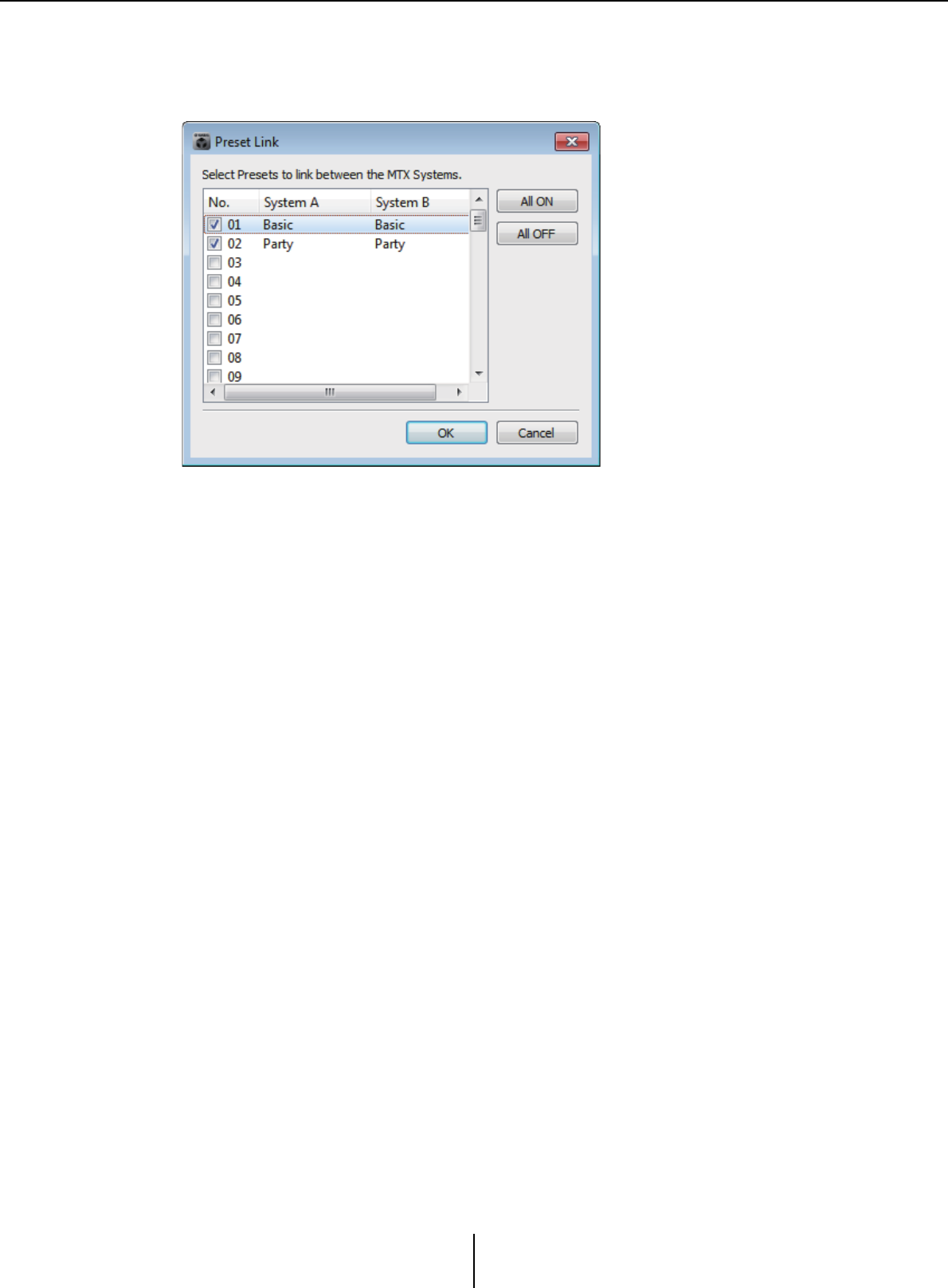
“Preset” dialog box Chapter 6. Presets
MTX-MRX Editor User Guide
149
“Preset Link” dialog box
Here you can make settings for linking preset recall between MTX/MRX systems.
Linking does not occur between MTX/MRX systems that have different subnets.
• Preset list
This lists the preset names for each MTX/MRX system in the project. Select the
check boxes of presets for which you want preset recall to be linked.
• [All ON] button
Selects the check boxes of all presets.
• [All OFF] button
Clears the check boxes of all presets.
• [OK] button
Specifies the preset recall link settings and closes the dialog box.
•[Cancel] button
Cancels the preset recall link settings and closes the dialog box.
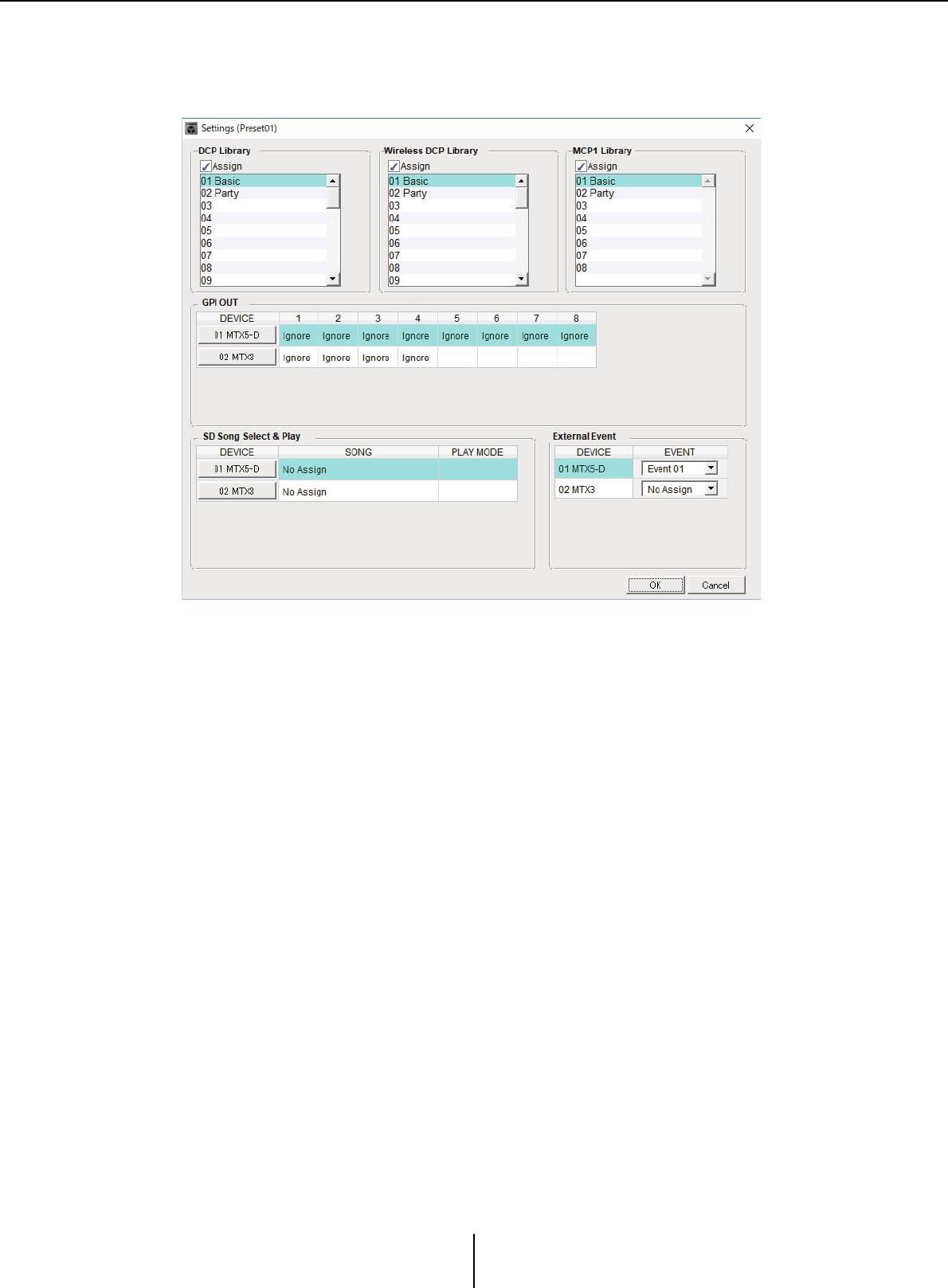
“Settings” dialog box Chapter 6. Presets
MTX-MRX Editor User Guide
150
“Settings” dialog box
Here you can specify the DCP library, Wireless DCP library, MCP1 library, GPI OUT, and
SD memory card settings that will be recalled when the preset is recalled.
[DCP Library]/[Wireless DCP Library]/[MCP1 Library]
Here you can specify the library that will be recalled when the preset is recalled. If the
[Assign] check box is selected, you’ll be able to select a library item. If the [Assign]
check box is cleared, operation from a DCP, Wireless DCP, or MCP1 will not be
possible.
If library data differs between devices, this is indicated by red characters. Store the
corresponding library item once again in the “Digital Control Panel” dialog box, the
“Wireless DCP” dialog box, or the “MCP1” dialog box.
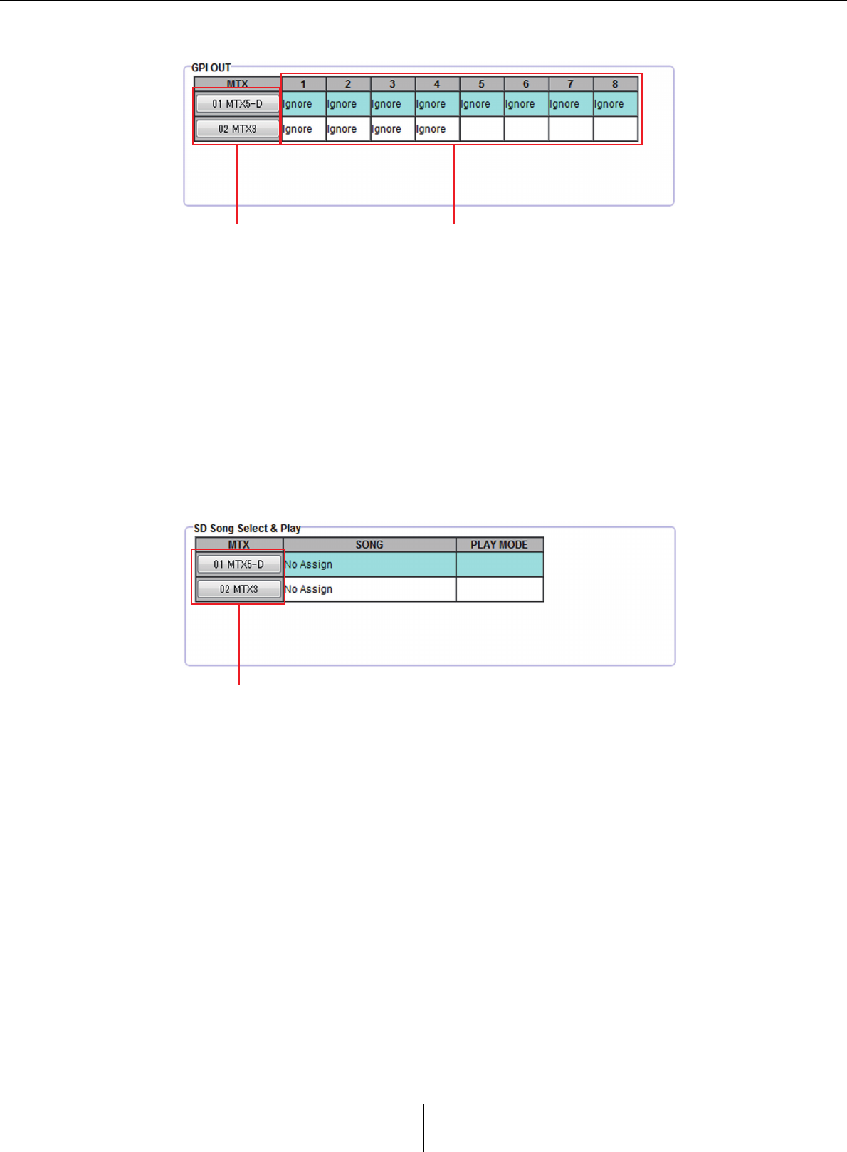
“Settings” dialog box Chapter 6. Presets
MTX-MRX Editor User Guide
151
[GPI OUT]
Here you can specify the GPI OUT settings that will be output when the preset is
recalled. You can use GPI OUT output to control a device that’s connected to this unit’s
[GPI OUT] connectors.
• MTX/MRX select buttons
Select the button of the MTX/MRX unit whose settings you want to change. (Each
button shows the UNIT ID and device name.)
This displays the “GPI Out” dialog box.
• [GPI OUT] pin number and status
This shows the pin numbers of the [GPI OUT] connector, and the status that is
specified in the “GPI Out” dialog box.
[SD Song Select & Play]
Here you can specify a file that will be played when the preset is recalled. Each MTX/
MRX unit can play one file or play all files in the same folder in ascending alphabetical
order. If four MTX/MRX units are connected via YDIF, up to four files can be played
simultaneously.
If you want multiple songs to play, open the “SD Play” dialog box, click [Folder/File],
choose [Play all songs in a folder], and specify the folder that contains the songs. If you
frequently need to change the songs that will be played, create an identically-named
folder on another SD memory card, and save each set of songs on its own SD memory
card. This way, you can play back the other songs simply by exchanging SD memory
cards, without having to change settings in MTX-MRX Editor.
• MTX/MRX select buttons
Select the button of the MTX/MRX unit whose settings you want to change. (Each
button shows the UNIT ID and device name.)
The “SD Play” dialog box will appear.
•SONG
This shows the file name or folder name you specified in the “SD Play” dialog box.
MTX/MRX select buttons [GPI OUT] pin number and status
MTX/MRX select buttons
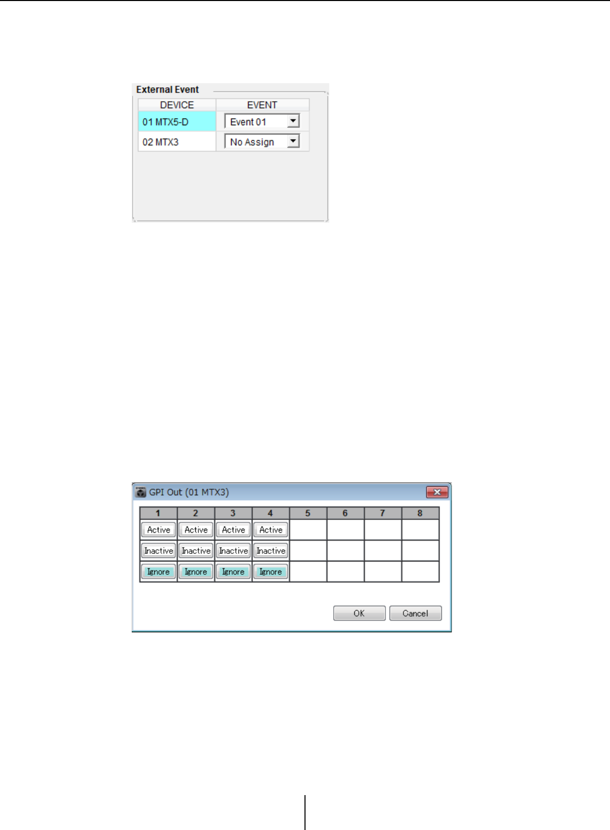
“Settings” dialog box Chapter 6. Presets
MTX-MRX Editor User Guide
152
•PLAY MODE
The [Play Mode] setting of the “SD Play” dialog box is shown.
[External Event]
Here you can specify an event to be output when a preset is recalled. An event is output
from the unit's NETWORK connector, or Dante [PRIMARY] or [SECONDARY]
connector, or the communication circuit during the redundancy operation.
If you specify an event for which [Event Mode] is set to [On/Off] in the “External
Events” dialog box, a command that is set to [On] will be output.
• [EVENT] list box
Select an event to be output.
• [OK] button
Saves the settings and closes the dialog box.
•[Cancel] button
Closes the dialog box without saving the changes.
■“GPI Out” dialog box
Here you can specify the GPI OUT settings that will be output when the preset is recalled.
You can use GPI OUT output to control a device that’s connected to this unit’s [GPI OUT]
connector.
●[Active]/[Inactive]/[Ignore] buttons
Specify whether the GPI OUT connector’s output will be enabled (Active), enabled with
the OUTPUT TYPE inverted (Inactive), or ignored (Ignore).
If in the “Settings” dialog box accessed by the “System” menu command [GPI], the
[OUTPUT TYPE] setting is set to [Pulse] or [Pulse Inv.], the only available choices will
be [Active] and [Ignore].
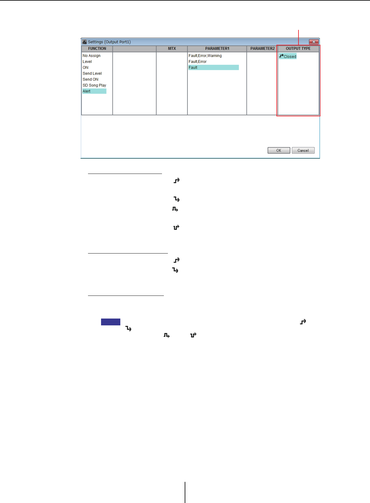
“Settings” dialog box Chapter 6. Presets
MTX-MRX Editor User Guide
153
If [Active] is specified
When [OUTPUT TYPE] is [ Closed], the [GPI OUT] pin will be closed
(connected to ground).
When [OUTPUT TYPE] is [ Open], the [GPI OUT] pin will be open.
When [OUTPUT TYPE] is [ Pulse], the [GPI OUT] pin will be closed (connected
to ground) for approximately 250 ms.
When [OUTPUT TYPE] is [ Pulse Inv.], the [GPI OUT] pin will be open for
approximately 250 ms.
If [Inactive] is specified
When [OUTPUT TYPE] is [ Closed], the [GPI OUT] pin will be open.
When [OUTPUT TYPE] is [ Open], the [GPI OUT] pin will be closed (connected
to ground).
If [Ignore] is specified
There will be no change in the output. Use this setting if a different function is
assigned to GPI OUT and you don’t want that function to be affected by preset recall.
If the GPI “Settings (Output Port)” dialog box [OUTPUT TYPE] is set to [ Closed] or
[ Open], and you then specify [Inactive], it will automatically be changed to [Ignore]
if you switch to [ Pulse]/[ Pulse Inv.].
• [OK] button
Saves the settings and closes the dialog box.
•[Cancel] button
Closes the dialog box without saving the changes.
“Settings (Output Port)” dialog box for “GPI” [OUTPUT TYPE]
NOTE
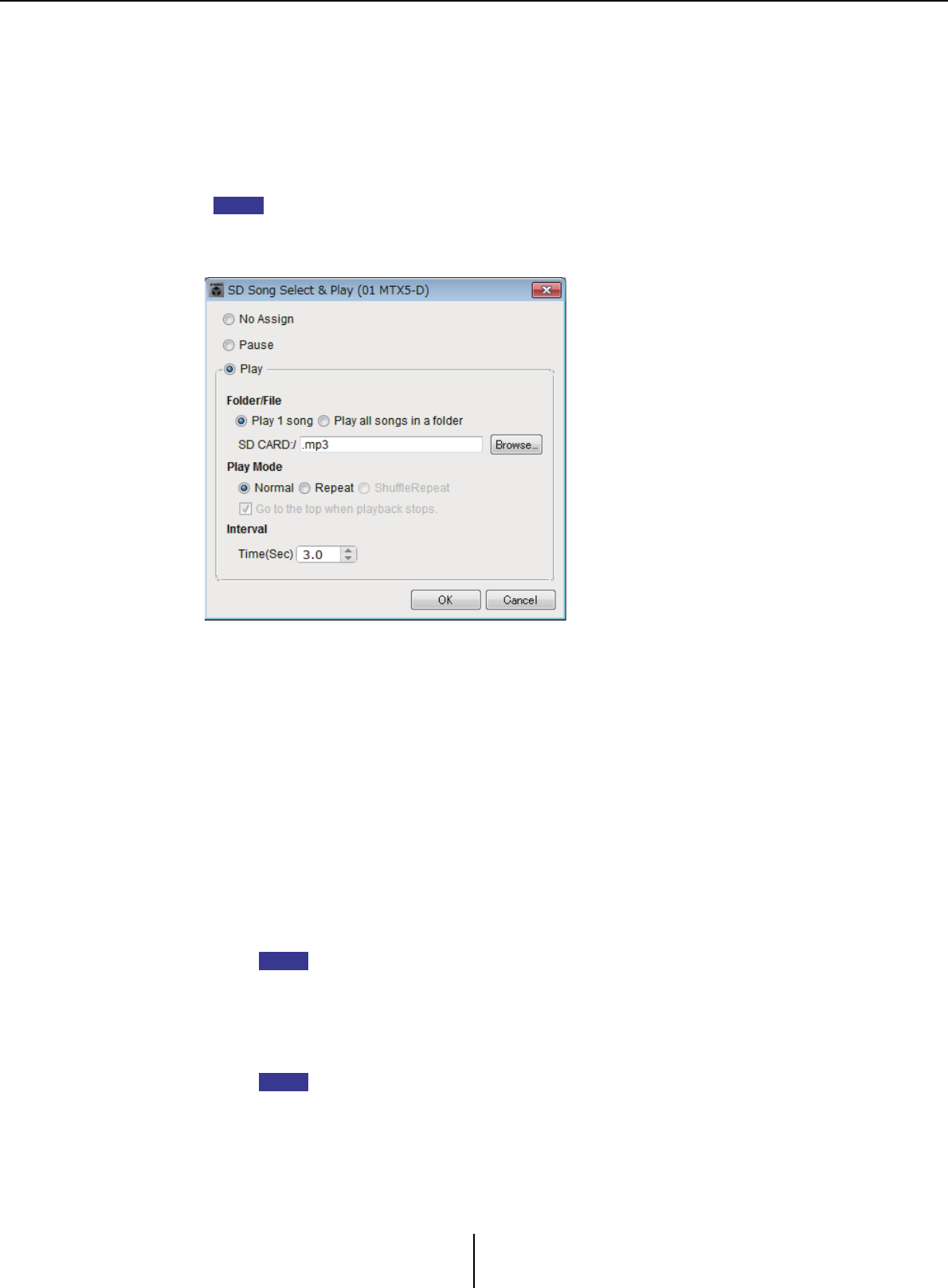
“Settings” dialog box Chapter 6. Presets
MTX-MRX Editor User Guide
154
■“SD Play” dialog box
Here you can specify a file that will be played when the preset is recalled. Each MTX/MRX
unit can play one file or play all files in the same folder. If four MTX/MRX units are
connected via YDIF, each MTX/MRX unit can play one file; i.e., a total of up to four files
can be played by the system.
If you want multiple songs to play, choose [Play all songs in a folder] in the [Folder/File]
area, and specify the folder that contains those songs.
If you frequently need to change the files that will be played, create an identically-named
folder on another SD memory card, and save each set of songs on its own SD memory card.
This way, you can play back the other files simply by exchanging SD memory cards, without
having to change settings in MTX-MRX Editor.
❍[No Assign] option button
Choose this if you don’t want preset recall operations to change any setting. If a file
was being played by the previous preset, playback will continue.
❍[Pause] option button
Choose this if you want the currently-playing file to pause.
❍[Play] option button
A file will play. Make detailed settings below for the file that will be played.
✦Folder/File
• [Play 1 song]/[Play all songs in a folder]
If you choose [Play 1 song], only the file currently selected in [SD CARD:/] will
play.
If you choose [Play all songs in a folder], all files in the folder currently selected
in [SD CARD:/] will play.
Up to 100 audio files will be played in ascending order of their file name.
✦[SD CARD:/]
This shows the name of the file or folder that will be played. You can change the
name, or enter it directly.
You can also enter Japanese.
HINT
NOTE
NOTE

“Settings” dialog box Chapter 6. Presets
MTX-MRX Editor User Guide
155
If [Play 1 song] is selected
Only the file currently selected in [SD CARD:/] will play.
The following file and folder formats can be shown.
• (folder name)\(file name).mp3
• (folder name)\(file name).wav
•(file name).mp3
•(file name).wav
If [Play all songs in a folder] is selected
All files saved in the folder currently selected in [SD CARD:/] will play.
The following folder formats can be shown.
•(folder name)
•blank
- Only first-level folders are valid.
- If the folder name is blank, all the files that exist in the root level of the SD memory
card will be played (folders below the root level will not be included).
✦[Browse] button
When you click this, a screen will appear, allowing you to select the file or folder
to be played.
If [Play 1 song] is selected, choose a file.
If [Play all songs in a folder] is selected, choose a folder.
- Only first-level folders are valid.
- If the folder name is blank, all the files that exist in the root level of the SD memory
card will be played (folders below the root level will not be included).
❍Play Mode
✦[Normal]/[Repeat]/[Shuffle Repeat]
This specifies the play mode for the file or files.
If you choose [Normal], the specified file or files in the folder will play once.
If you choose [Repeat], the specified file or files in the folder will play repeatedly.
If you choose [Shuffle Repeat], the files in the specified folder will play repeatedly
in random order. If you choose [Play 1 song] in [Folder/File], the [Shuffle Repeat]
setting will be unavailable.
✦[Go to the top when playback stops.]
This is always on; playback will always start from the beginning of the song or the
first song in the folder. (This is unchangeable only for preset recall.)
• [Interval Time]
This specifies the playback spacing when files are played consecutively.
• [OK] button
Saves the settings and closes the dialog box.
•[Cancel] button
Closes the dialog box without saving the changes.
NOTE
NOTE

“Settings” dialog box Chapter 6. Presets
MTX-MRX Editor User Guide
156
Main usage method
1. Prepare the SD memory card.
Copy the files that you want to play into the SD memory card. If you want to play
multiple files, place them in a folder no deeper than the first level.
2. Insert the SD memory card you prepared in step 1 into the computer.
3. In [SD Song Select & Play], click the MTX/MRX select button for the unit
into which you intend to insert the SD memory card.
The “SD Play (MTX)” dialog box will appear.
4. Click the [Browse] button, and select a file or folder.
5. Insert the SD memory card into the MTX/MRX.
6. Synchronize MTX-MRX Editor with the MTX/MRX (refer to “Online and
Synchronization”), sending the settings of MTX-MRX Editor to the
MTX/MRX.
7. Recall the preset.
The file or files in the SD memory card inserted in the MTX/MRX unit you selected
in step 2 will play.
If you specified a folder, you can replace the files in the folder and the result will be
the same.
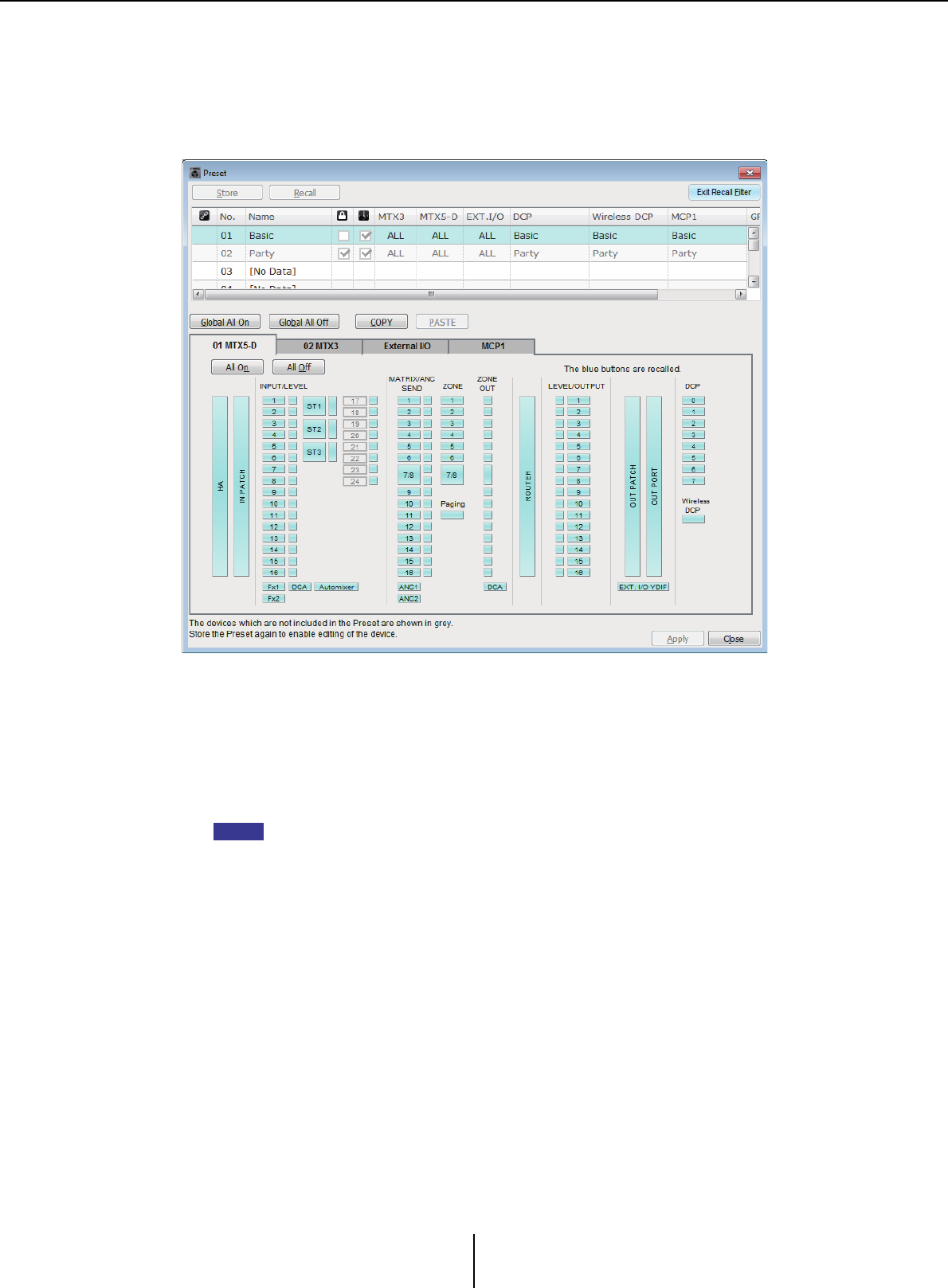
Recall Filter setting screen Chapter 6. Presets
MTX-MRX Editor User Guide
157
Recall Filter setting screen
Here you can specify which parameters will be recalled when you recall a preset. For
example if the input/output levels do not change for any of the presets, you can exclude the
INPUT LEVEL and OUTPUT LEVEL from recall, so that the level settings can stay the
same without your having to re-specify the levels for each preset.
■[Exit Recall Filter] button
Closes the Recall Filter setting screen, and returns to the “Preset” dialog box.
■Preset list
Here you can choose the preset for which to make Recall Filter settings.
• You cannot select an empty preset.
• You cannot edit a preset that is protected.
■[Global All On] button
Turns on (blue) all of the buttons in all tabs. All parameters of all devices will be recalled.
■[Global All Off] button
Turns off (white) all of the buttons in all tabs. No parameters of any device will be recalled.
■[COPY] button
Copies the Recall Filter settings of the selected preset.
The Copy command is not available while online.
NOTE
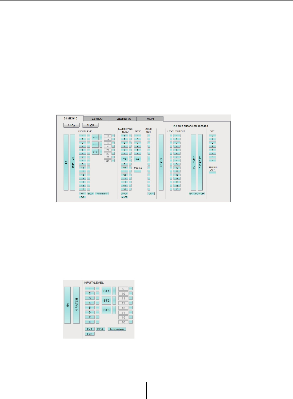
Recall Filter setting screen Chapter 6. Presets
MTX-MRX Editor User Guide
158
■[PASTE] button
Pastes the copied Recall Filter settings to the currently selected preset.
The Paste command is not available while online.
■[Apply] button
Applies the currently-edited Recall Filter settings. If the settings have not been edited, this
button will be unavailable and cannot be clicked.
■[Close] button
Closes the dialog box.
■[MTX]/[MRX] tab
Here you can choose the MTX/MRX unit for which to make Recall Filter settings. The tab
shows the UNIT ID and device name.
●[All On] button
Turns on (blue) all of the buttons of the currently selected tab. All parameters will be
recalled.
●[All Off] button
Turns off (white) all of the buttons of the currently selected tab. None of the parameters
will be recalled.
●Parameter select buttons
For the MRX, only the [DCP] button and [Wireless DCP] button are shown.
• [HA] button
If this is on, the HA gain and phantom power (+48V) settings of the input ports will
be recalled.
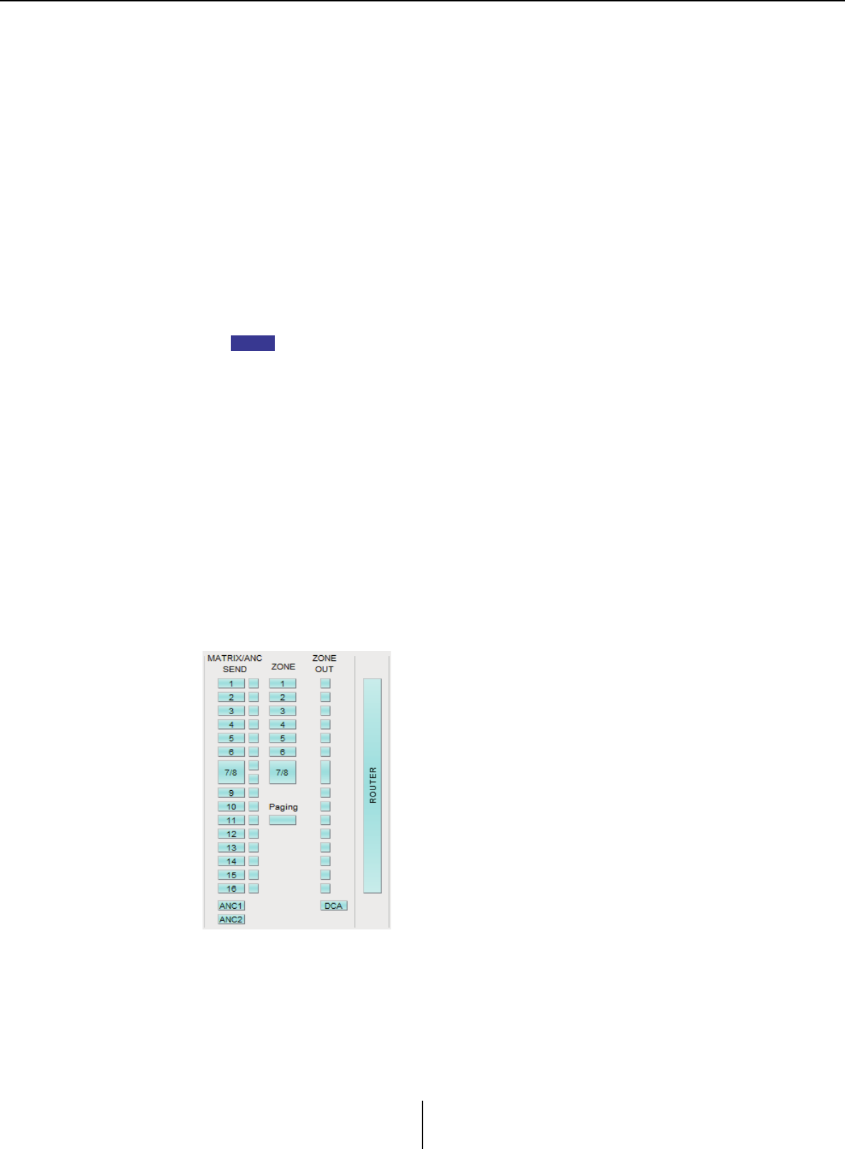
Recall Filter setting screen Chapter 6. Presets
MTX-MRX Editor User Guide
159
• [IN PATCH] button
If this is on, the input patch settings and input channel names will be recalled.
These buttons include patching to the MY4-AEC input channels From Far-end, Far-
end Voice, Near-end Mic., Near-end Voice, and To Far-end.
• [INPUT]/[LEVEL] buttons
If the [INPUT] button is on, the following input channel settings will be recalled.
Input channels: Phase, HPF, Digital Gain, PEQ, COMP, GATE, AGC,
FBS, Insert on/off (*)
Stereo input channels: Digital Gain, PEQ, AGC, COMP
(*) Insert on/off is only for the MTX5-D.
If the [LEVEL] button is on, the input channel level and on/off (mute) settings will
be recalled.
These can be specified individually for each channel.
In the “MTX Configuration” dialog box, if [INPUT PORT SETUP] is changed from
“MONO x2” to “STEREO,” the settings of the [INPUT]/[LEVEL] buttons will follow the
“L” side.
• [Fx1]/[Fx2] buttons
If these buttons are on, the effect type and the following settings will be recalled.
• Send level from the input channel to the effect bus, send on/off
• Effect return level, on/off (mute)
•Effect return name
• [DCA] button (INPUT side)
If this is on, the following settings will be recalled.
• The input channel’s assignment to DCA or mute group
• Master level of the DCA group
• Master mute of the mute group
• [Automixer] button
If this is on, the settings of the Dugan Automixer will be recalled.
NOTE
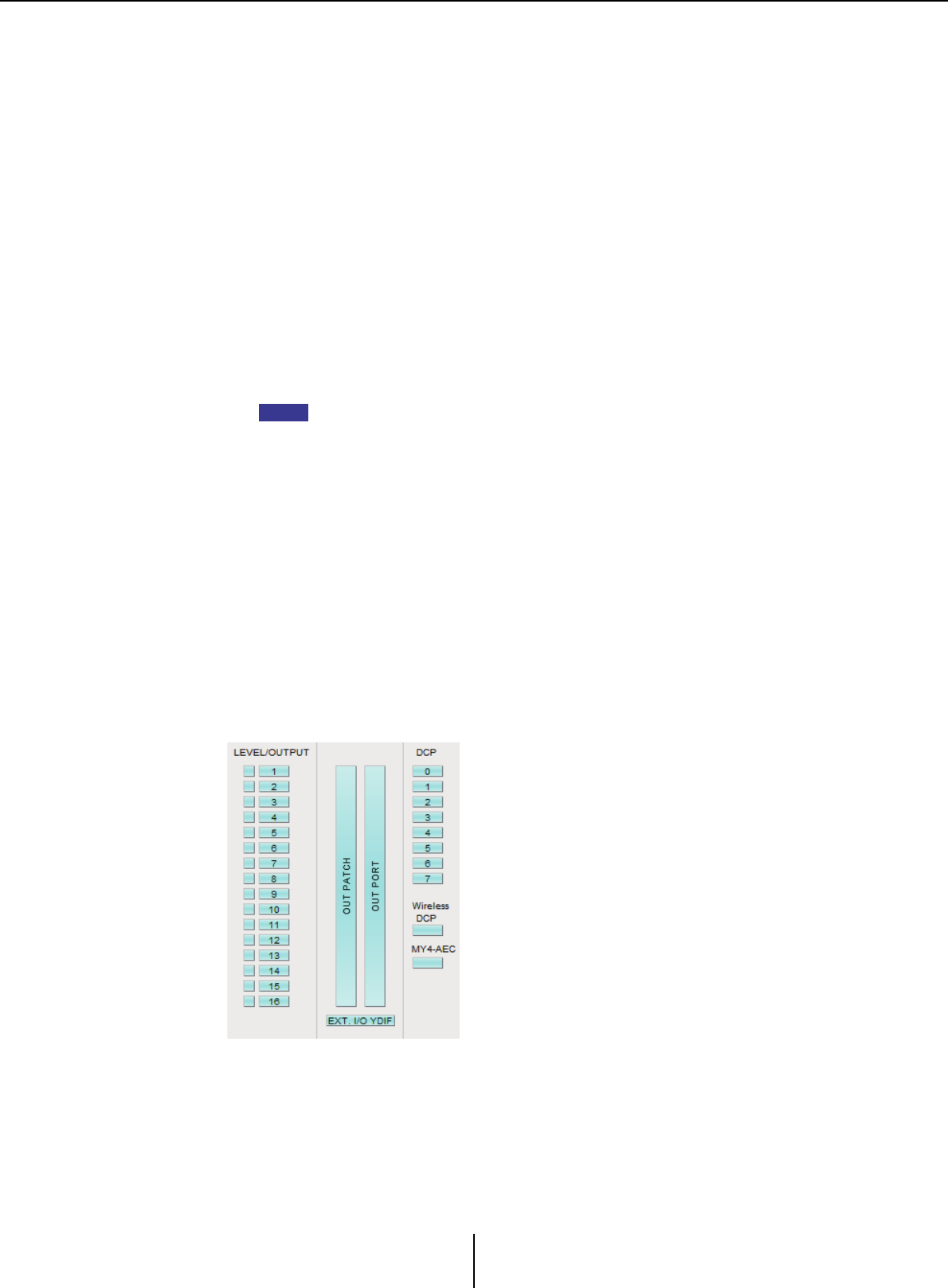
Recall Filter setting screen Chapter 6. Presets
MTX-MRX Editor User Guide
160
• [MATRIX SEND] button
If the button at the left is on, the following settings will be recalled.
• Send level from the input channel to the matrix bus, send on/off, and stereo channel
pan
• Send level from effect return to the matrix bus, send on/off, and stereo channel pan
If the button at the right is on, the matrix out level will be recalled.
• [ANC1 SEND]/[ANC2 SEND] buttons
If these buttons are on, the send level from the input channel to the ANC bus and
the send on/off status will be recalled.
•[ZONE] button
If this is on, the following settings will be recalled.
• 1st Priority’s Priority Source, Mix Level, and Ducker
• 2nd Priority’s Priority Source, Mix Level, and Ducker
•ANC
•Zone name
In the “MTX Configuration” dialog box, if [INPUT PORT SETUP] is changed from
“MONO x2” to “STEREO,” the setting of the [ZONE] button will follow the odd-
numbered zone.
• [PAGING] button
Turning this on recalls the setting of the PAGING [ON] button.
• [ZONE OUT] button
If this is on, the ZONE Out Level and on/off (mute) will be recalled.
• [DCA] button (ZONE side)
If this is on, the following settings will be recalled.
• ZONE Out’s channel assignment to DCA or mute group
• Master level of the DCA group
• Master mute of the mute group
• [ROUTER] button
If this is on, the router settings will be recalled.
NOTE

Recall Filter setting screen Chapter 6. Presets
MTX-MRX Editor User Guide
161
• [LEVEL]/[OUTPUT] buttons
If the [LEVEL] button is on, the output channel level and on/off (mute) settings will
be recalled.
If the [OUTPUT] button is on, the Room EQ, Delay, and Speaker Processor settings
will be recalled.
These can be specified individually for each channel.
• [OUT PATCH] button
If this is on, the output patch settings and output channel names will be recalled.
• [OUT PORT] button
If this is on, the output port’s output gain and polarity settings will be recalled.
• [EXT. I/O YDIF] button
If this is on, settings for the audio that is output from the MTX/MRX to YDIF when
in Distribution mode will be recalled.
• [DCP] button
If this is on, the parameter assignments of the DCP (digital control panel) unit
connected to the MTX/MRX will be recalled. The button shows the ID of the DCP.
• [Wireless DCP] button
If this is on, the settings of the Wireless DCP will be recalled. If eight Wireless DCP
units are connected, eight units will be affected by the on/off setting.
•[MY4-AEC] button
If this is on, the settings of the MY4-AEC installed in the MTX5-D will be recalled.
This is not shown if the MY4-AEC is not selected in the “Device Configuration
Wizard.”
The following settings are outside the recall settings of the [MY4-AEC] button.
• From Far-end, Far-end Voice, Near-end Mic., Near-end Voice, and To Far-end
(included in the [IN PATCH] button range)
•SRC
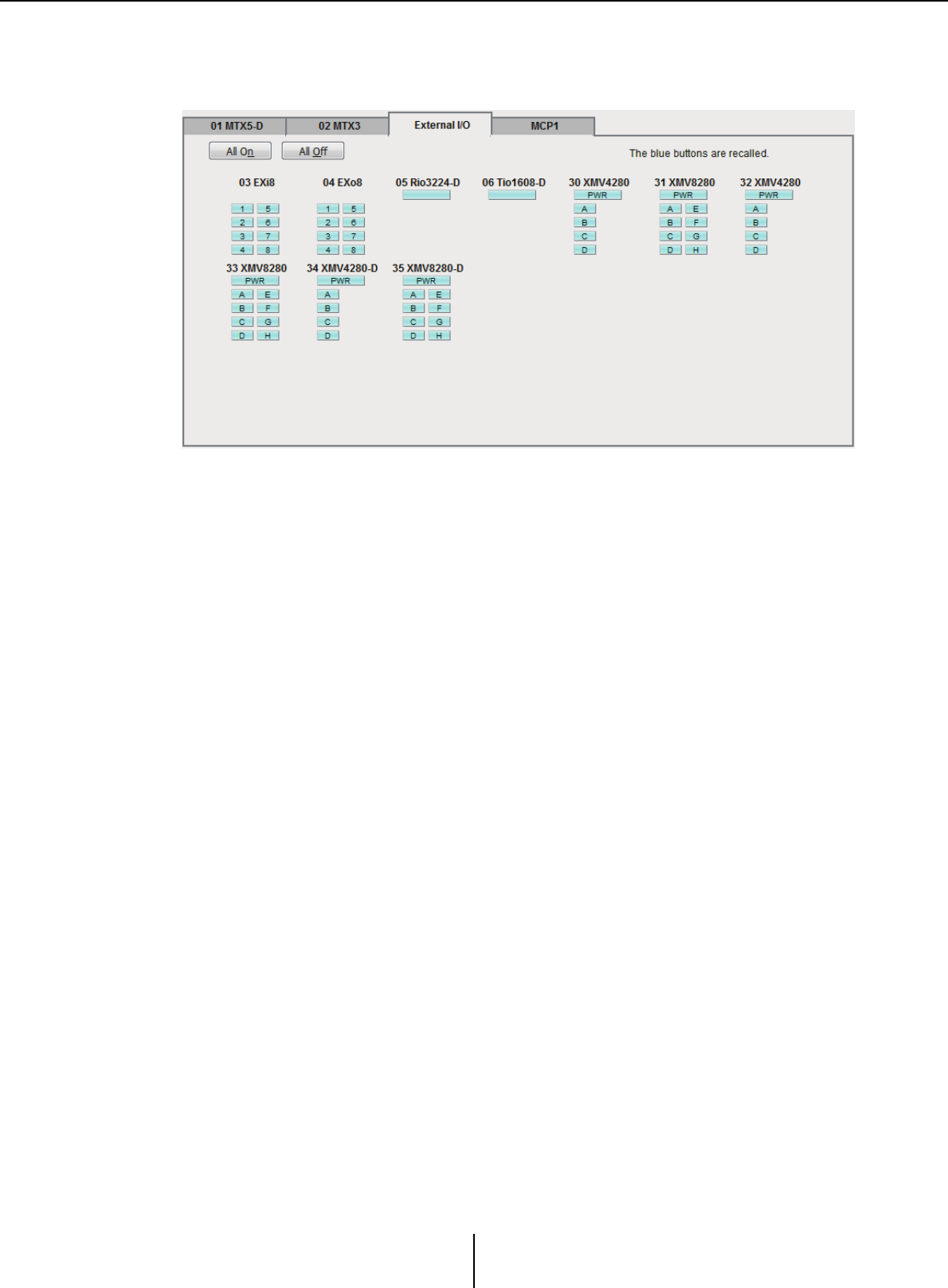
Recall Filter setting screen Chapter 6. Presets
MTX-MRX Editor User Guide
162
■[External I/O] tab
Here you can choose the external device parameters for which to make Recall Filter
settings.
●[All On] button
Turns on (blue) all of the buttons of the currently selected tab. All parameters will be
recalled.
●[All Off] button
Turns off (white) all of the buttons of the currently selected tab. None of the parameters
will be recalled.
●Parameter select buttons
The parameter select buttons are shown for each device (UNIT ID, device name). If
these buttons are on, the parameters included in the buttons will be recalled for each
channel. The [PWR] button corresponds to the power on/standby status of the device,
and the alphabetical or numeric buttons correspond to the channels of each device.
In the case of the R series (AD/DA) or Tio1608-D, turning the button on will recall the
HA parameters for each unit.
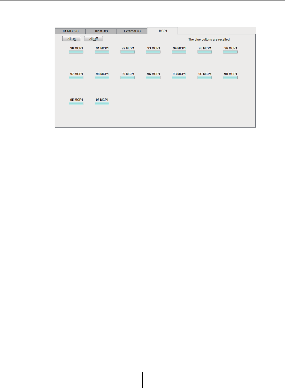
Recall Filter setting screen Chapter 6. Presets
MTX-MRX Editor User Guide
163
■[MCP1] tab
Here you can choose the MCP1 unit for which to make Recall Filter settings.
●[MCP1] button
If this is on, the parameter assignments of the MCP1 connected to the MTX will be
recalled.
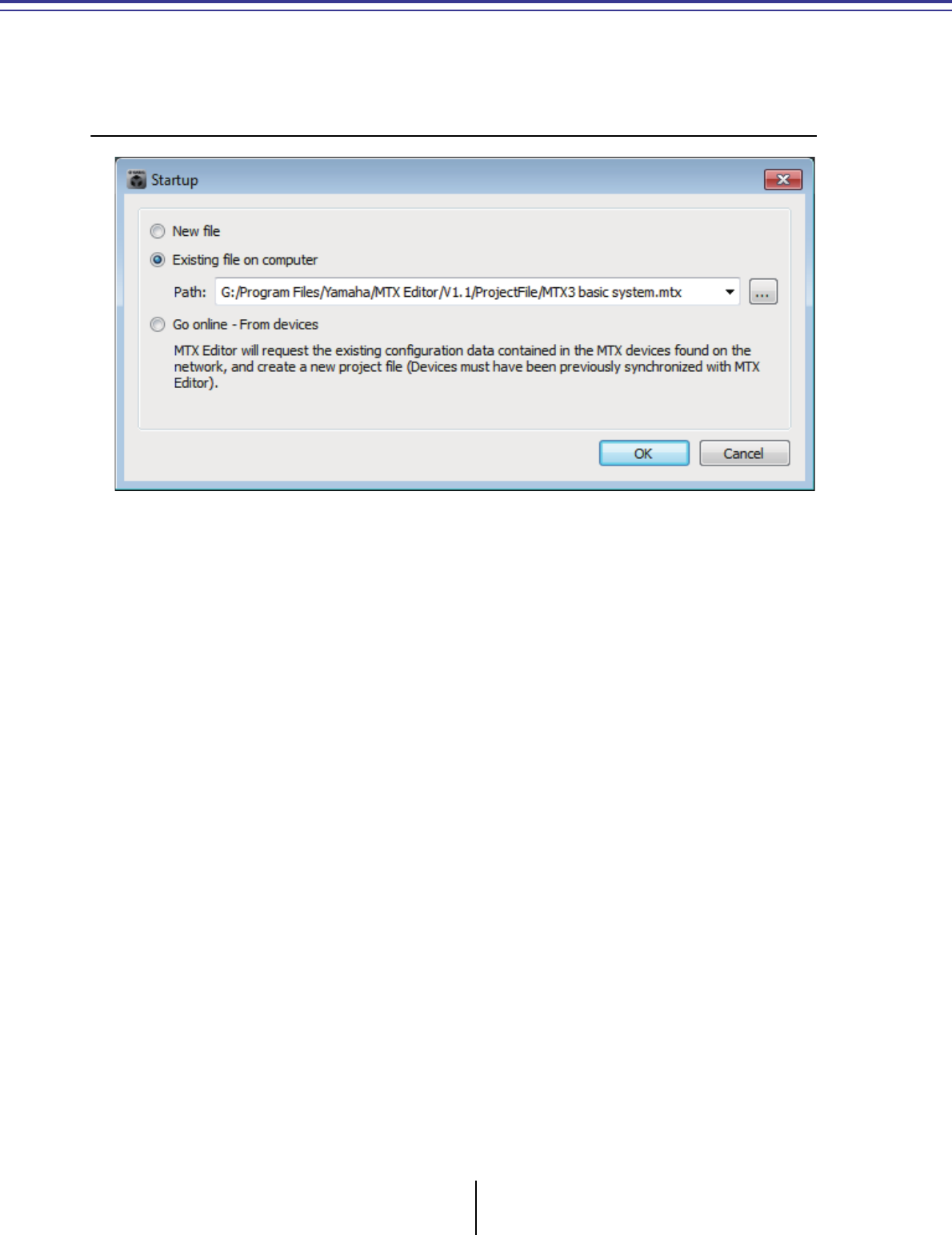
MTX-MRX Editor User Guide
164
Chapter 7.
Dialog boxes/Software applications
This chapter explains the dialog boxes and applications that you can open from the menu bar or tool
bar.
❑“Startup” dialog box
This will appear when you start MTX-MRX Editor.
●[New file] option button
When you click the [OK] button, the “Device Configuration Wizard” dialog box will
appear.
●[Existing file on computer] option button
When you click the [OK] button, the selected file will open. If a PIN code has been
assigned, you will be asked to enter the PIN code.
●[Go online – From devices] option button
When you click the [OK] button, the MTX/MRX system settings will be loaded from
the currently-operating MTX/MRX units in the network, allowing you to create a
project file.
In order for the settings to be loaded, you must be connected to an MTX/MRX unit
with which MTX-MRX Editor has previously been “online.” If a PIN code has been
assigned to the device, you will be asked to enter the PIN code.
●[OK] button
Executes the operation that is selected by the option button.
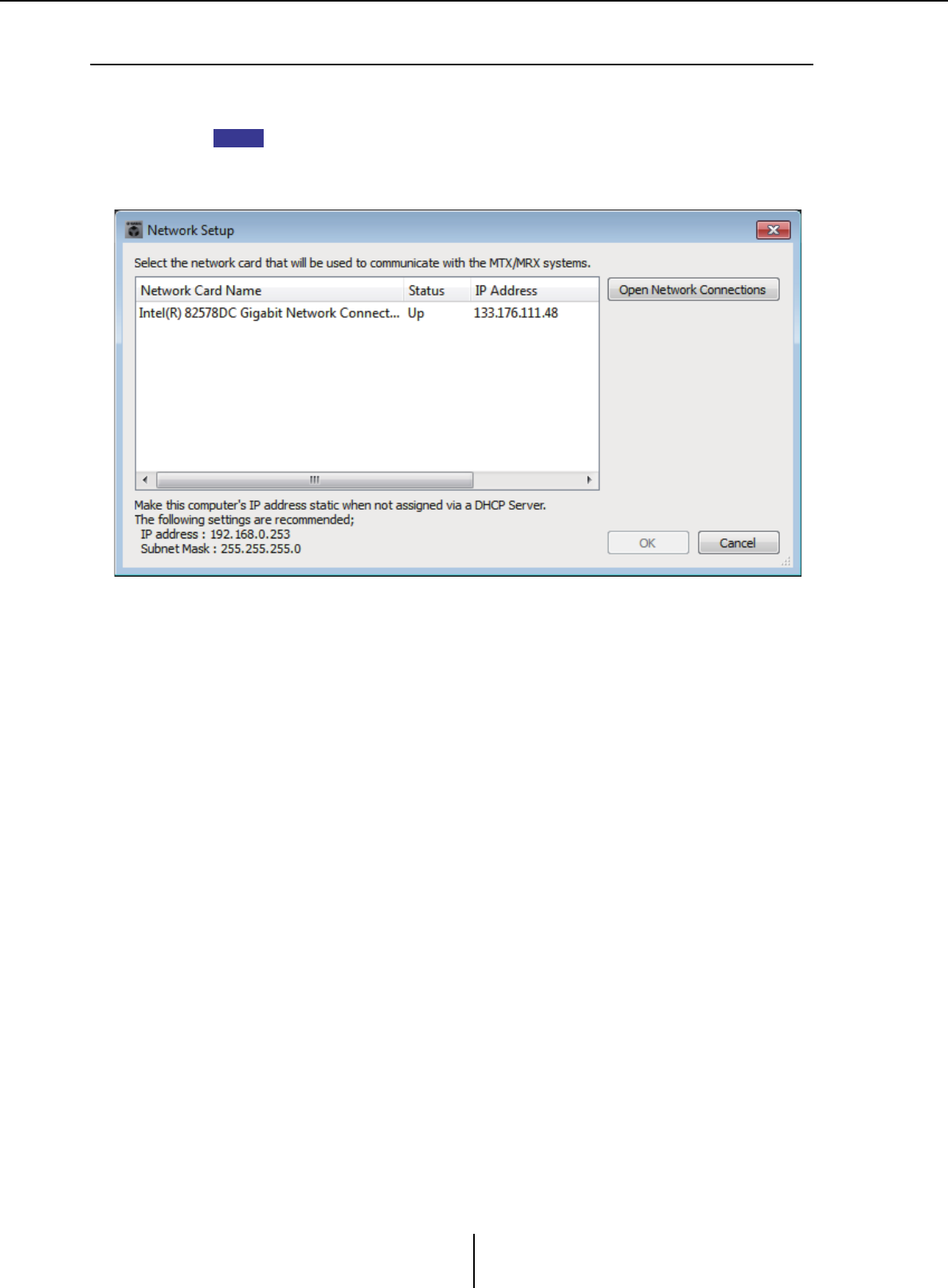
“Network Setup” dialog box Chapter 7. Dialog boxes/Software applications
MTX-MRX Editor User Guide
165
❑“Network Setup” dialog box
Here you can select the network interface card of the computer that will be used to communicate
with the MTX/MRX (subsequently called “the network card”).
If you’re not using a DHCP server, fix the IP address of your computer’s network card. We
recommend the following settings.
IP address: 192.168.0.253
Subnet mask: 255.255.255.0
If you are not connected to the network, click the [Cancel] button to close the dialog box.
●Network Card Name
Shows the name of the network card.
●Status
Shows the status of the network card (Up or Down).
A network card for which this shows “Down” cannot be selected.
●IP Address and Subnet Mask
Shows the IP address and subnet mask assigned to the network card.
If there is no DHCP server and the IP address has not been assigned even though the
setting of the network card is “Obtain IP address automatically,” this will show “0.0.0.0”.
This will also show “0.0.0.0” if the network card is not physically connected.
●[Open Network Connections] button
Opens the control panel “Network Connections.” Use this when you want to change the
IP address of the network card.
●[OK] button
Updates the settings and closes the dialog box.
●[Cancel] button
Closes the dialog box without updating the settings.
NOTE
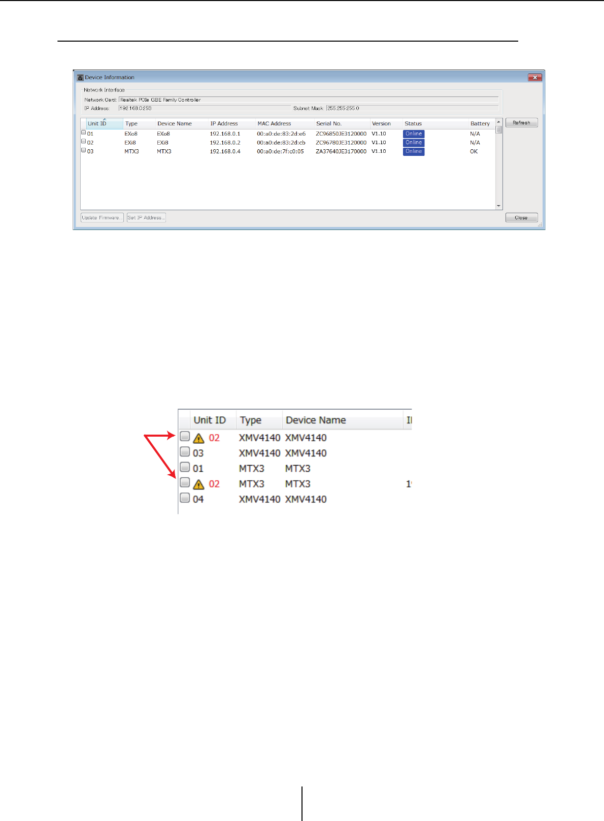
“Device Information” dialog box Chapter 7. Dialog boxes/Software applications
MTX-MRX Editor User Guide
166
❑“Device Information” dialog box
Lists the devices on the network, allowing you to update their firmware and change their IP address.
●Network Interface
Shows the name/IP address/subnet mask of the network card currently selected in the
“Select Network Interface Card” dialog box.
●Device list
• Identify button
When you press this button located at the left of the UNIT ID, the indicators of the
corresponding device will flash for five seconds.
•Unit ID
Shows the UNIT ID of the device.
If there is a UNIT ID conflict, this is indicated as follows.
•Type
Shows the model name of the device (except for digital control panels).
• Device Name
Shows the device name. This name can be edited in DEVICE NAME, which is
located in the [Device] tab at the bottom of the Project screen.
• IP Address/MAC Address
Shows the IP address and MAC address that are specified for the device.
•Serial No.
Shows the serial number of the device.
•Version
Shows the firmware version.
• Status
Shows the online or offline status.
When updating a device, the progress is shown.

“Device Information” dialog box Chapter 7. Dialog boxes/Software applications
MTX-MRX Editor User Guide
167
•Battery
Shows the remaining battery amount for a device that contains a battery.
EMPTY: The remaining amount is 0–0.5V. Immediately stop using the unit, and
contact a Yamaha service center.
Low: The remaining amount is 0.5–2.5V. Contact a Yamaha service center as
soon as possible.
OK: The remaining amount is 2.5–3.5V. There is no problem.
N/A: The device does not contain a battery.
●[Update Firmware] button
Updates the firmware.
Click this button to open the “Update Firmware” dialog box.
• If the “Select Folder” dialog box opens, select the folder that contains the update file, then
click the [OK] button.
• To update the firmware of the R series (AD/DA) or Tio1608-D, use the Windows software
application R Remote.
●[Set IP Address] button
Specifies the device’s IP address and subnet mask.
When you click this button, the “IP Address” dialog box will appear.
●[Refresh] button
Searches again for devices on the network.
This cannot be clicked while an update is in progress.
●[Close] button
Closes the dialog box.
This cannot be clicked while an update is in progress.
NOTE
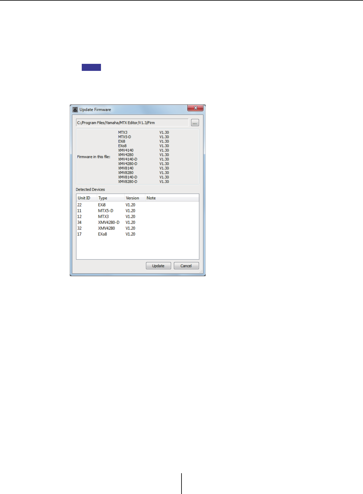
“Update Firmware” dialog box Chapter 7. Dialog boxes/Software applications
MTX-MRX Editor User Guide
168
“Update Firmware” dialog box
This dialog box lets you update the firmware of a unit such as an MTX/MRX or XMV.
For Dante units such as the MTX5-D and the XMV8280-D, there may be cases in which
the Dante firmware needs to be updated. For details on how to update the Dante firmware,
refer to the “MTX/MRX system Firmware Update Guide.”
• In some cases, updating may cause data to no longer be compatible. Save the latest
project file before you update. After you update, use the most recent version of MTX-MRX
Editor to open the latest project file.
• To update the firmware of the R series (AD/DA) or Tio1608-D, use the Windows software
application R Remote.
●File
Displays the .fup files that are in the folder containing the update file shown in the
“Firmware in this file” section.
●[...] button
Click this button to select an update file. Click this button to select an update file.
Clicking this button opens the “Select Folder” dialog box; select an .fup file.
●Firmware in this file
Shows firmware versions resident in the folder for each device.
●Detected Devices
Shows detected devices.
Unit ID................... Shows the UNIT ID of the device.
Type ........................ Shows the model name of the device.
Version ................... Shows the firmware version of the device.
NOTE

“Update Firmware” dialog box Chapter 7. Dialog boxes/Software applications
MTX-MRX Editor User Guide
169
●[Update] button
Executes the update.
If an update file does not exist in the selected folder, this button will be dimmed and
unavailable.
●[Cancel] button
Cancels the update and closes the dialog box.
■Update procedure
All applicable devices can be updated at the same time.
If there is an MTX/MRX unit with an assigned PIN code that differs from the project,
you’ll need to enter the PIN code.
1. For all applicable devices in the MTX/MRX system, turn DIP switches 7
and 8 OFF (RESUME mode).
2. Turn on the power of all applicable devices in the MTX/MRX system.
3. In the “Device Information” dialog box, click the [Update Firmware]
button.
If the “Select Folder” dialog box opens, select a folder that contains the update file,
then click the [OK] button.
4. The “Update Firmware” dialog box will appear.
This shows the firmware versions resident in the folder. If you select the other folder,
click the [...] button.
5. Click the [Update] button to execute the update.
During the update, the indicators of the devices will flash.
Do not turn off the power of the devices while the update is being executed.
6. When the update is completed, the indicators of the applicable devices
will light.
When the update is completed, the devices will restart automatically.
If the [ALERT] indicators of the applicable devices are flashing, the update has failed
due to an error. The front panel [PRESET} display will show an error number; refer to
the alert list in the appendix, and take the appropriate action.
7. Close the “Device Information” dialog box.
When the update has ended successfully, the devices will restart, and the devices in
the MTX/MRX system will reappear in MTX-MRX Editor’s Project window.
NOTE
NOTE
NOTE
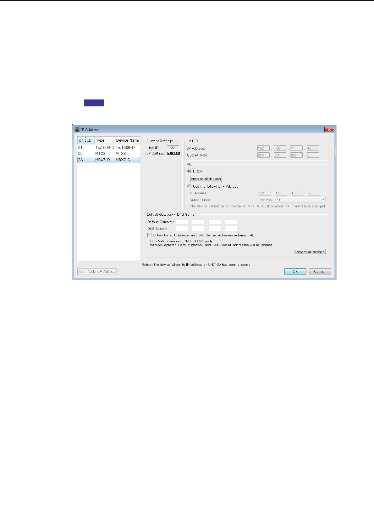
“IP Address” dialog box Chapter 7. Dialog boxes/Software applications
MTX-MRX Editor User Guide
170
“IP Address” dialog box
Here you can set the device’s IP settings.
As the device’s settings, we recommend that you set “IP SETTINGS” to “UNIT ID” or
“STATIC IP (Auto),” and set the computer’s IP address to “192.168.0.253” and its subnet
mask to “255.255.255.0.”
Editing is not possible while online.
In order to use MTX-MRX Editor to control MTX/MRX systems of differing subnets, it is
necessary to operate the devices using unique IP addresses. For details, refer to “Settings
for controlling devices across subnets”.
If a PIN code has been assigned, you will be asked to enter the PIN code. Devices whose
PIN could not be unlocked do not appear in the device list, and their settings cannot be
edited.
If you want to fix the device’s IP address and subnet mask, make the following settings in
this dialog box.
1. Set the computer’s IP address to “192.168.0.253” and the subnet mask
to “255.255.255.0”.
2. As the device’s settings, set “IP SETTINGS” to “UNIT ID” or “STATIC (IP)
(Auto),” set the UNIT ID of all devices to something other than FD so
that none of the devices conflict, and then power-on the devices.
3. From the list in the left of the “IP Address” dialog box, select the device
that you want to edit.
4. In the “IP Address” dialog box, select the [Use the following IP Address]
option button (specify a fixed IP address for the device).
5. Specify values for [IP Address] and [Subnet Mask].
6. Click the [OK] button.
7. As the device’s setting, specify either PC mode or STATIC IP (MANUAL).
8. Power-off the device, wait about ten seconds, and then turn the power
on.
NOTE

“IP Address” dialog box Chapter 7. Dialog boxes/Software applications
MTX-MRX Editor User Guide
171
9. In the “Device Information” dialog box, click the [Refresh] button.
Verify that the device’s IP address has been changed.
If you want to change the setting of multiple devices, repeat steps 3 through 5, and then
proceed to step 6 and following.
●Device list
Shows the devices on the network. When you click this, the settings of the current
device are shown in the right, allowing you to edit them.
●Current Settings
Shows the UNIT ID and IP Setting that are specified for the unit.
●Unit ID/Static IP(Auto)
If the unit’s IP Setting is “UNIT ID” or “STATIC IP (Auto),” the IP address and subnet
mask are shown.
●PC/Static IP(Manual)
❍[DHCP] option button (MTX/MRX system devices only)
Choose this if you want the DHCP server to set the IP address.
If there is no DHCP server, the IP address will be set to [0.0.0.0]. To solve this
problem, check that the DHCP server is connected. Alternatively, use the rear panel
DIP switches of the unit to set IP Setting to [UNIT ID] (the mode in which the IP
address will be generated from the UNIT ID].
❍[Apply to all the devices] button (MTX/MRX system devices only)
Sets all devices shown in the device list to DHCP mode.
❍[Use the following IP Address] option button (MTX/MRX system devices only)
If you choose this, the IP address and subnet mask specified here will be used.
❍IP Address/Subnet Mask
Here you can specify the device’s IP address and subnet mask.
Set the IP address so that it does not conflict with the IP address of the computer or
of any other device.
The following IP addresses cannot be specified.
192.168.0.0 - Use is prohibited because it conflicts with the network address
192.168.0.255 - Use is prohibited because it conflicts with the broadcast address
HINT
NOTE

“IP Address” dialog box Chapter 7. Dialog boxes/Software applications
MTX-MRX Editor User Guide
172
The following subnet masks can be selected.
❍Default Gateway (other than MTX/MRX system devices)
Specifies the IP address of the default gateway.
●Default Gateway / DNS Server (MTX/MRX system devices only)
❍Default Gateway
Specifies the IP address of the default gateway.
❍DNS Server
Specifies the IP address of the DNS server.
❍[Obtain Default Gateway and DNS Server address automatically] check box
If this is checked, the IP addresses of the default gateway and DNS server are
obtained automatically. The above IP address settings for the default gateway and
DNS server are ignored.
❍[Apply to all devices] button
Specifies the same default gateway and DNS server settings for all devices shown in
the device list.
●[Auto-Assign IP Addresses] button
Click this to open the “Auto-Assign IP Address” dialog box.
●[OK] button
Transmits the settings to the device, and closes the dialog box.
If the device’s IP Setting is [PC] and you’ve changed the IP address, communication will
be temporarily interrupted.
●[Cancel] button
Discards the settings and closes the dialog box.
If the device’s “IP SETTINGS” is set to “UNIT ID” or “STATIC IP (Auto),” communication will not
be not possible if the network address settings differ between the computer and the unit.
Be sure to set the computer’s network address to match the network address of the unit.
If you don’t know the network address of the unit, we recommend that you use the unit’s rear
panel DIP switch to set IP Setting to [UNIT ID].
128.0.0.0 255.255.128.0
192.0.0.0 255.255.192.0
224.0.0.0 255.255.224.0
240.0.0.0 255.255.240.0
248.0.0.0 255.255.248.0
252.0.0.0 255.255.252.0
254.0.0.0 255.255.254.0
255.0.0.0 255.255.255.0 (default value)
255.128.0.0 255.255.255.128
255.192.0.0 255.255.255.192
255.224.0.0 255.255.255.224
255.240.0.0 255.255.255.240
255.248.0.0 255.255.255.248
255.252.0.0 255.255.255.252
255.254.0.0
255.255.0.0
NOTE
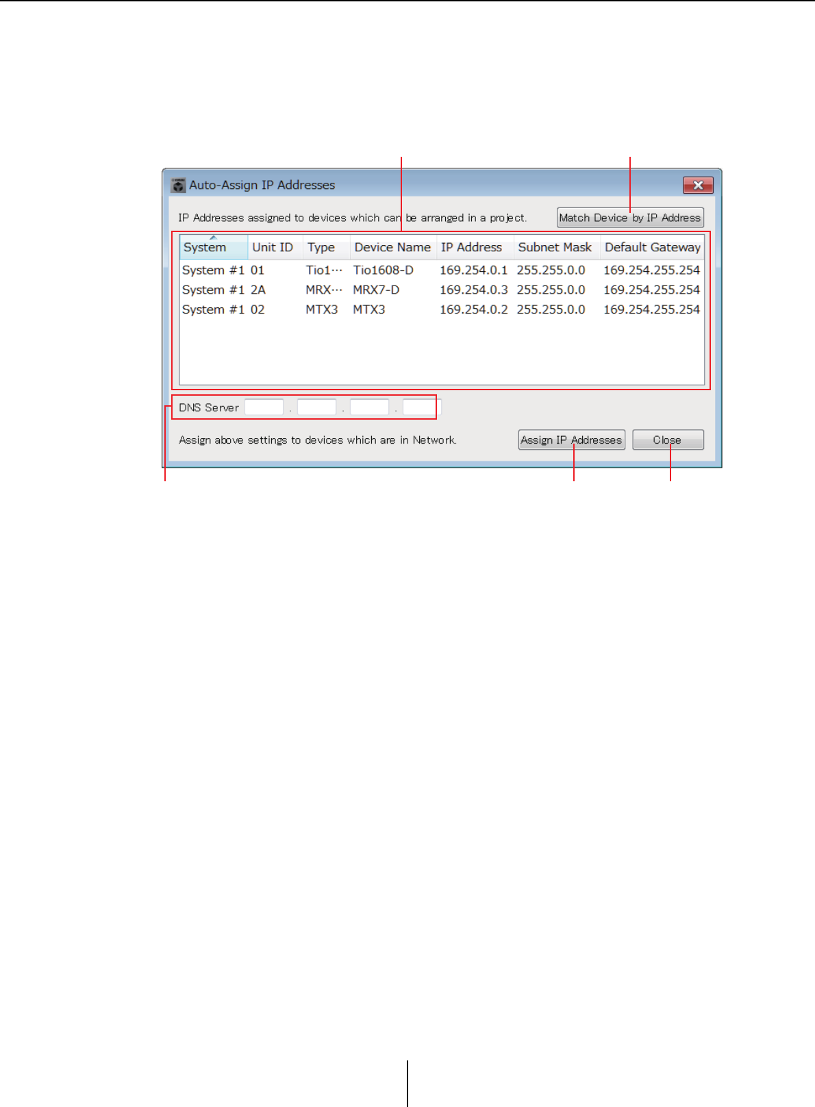
“Auto-Assign IP Address” dialog box Chapter 7. Dialog boxes/Software applications
MTX-MRX Editor User Guide
173
“Auto-Assign IP Address” dialog box
Information such as the IP address assigned to devices placed in MTX-MRX Editor using
the “Match Device by IP Address” dialog box is applied to the “IP Address” dialog box in
a single operation.
For details, refer to “Settings for controlling devices across subnets” in the appendix.
1[Match Device by IP Address] button
Click this to open the “Match Device by IP Address” dialog box.
2Device list
This shows information for the IP settings that are specified for the devices placed in
MTX-MRX Editor using the “Match Device by IP Address” dialog box.
3DNS Server
Specifies the DNS server.
4[Assign IP Address] button
Applies the information shown in the device list and the DNS Server settings to the
“IPAddress” dialog box. Even if the [DHCP] option button is selected in the “IP
Address” dialog box, the [Use the following IP Address] option button is switched to
the selected state.
5[Cancel] button
Closes the dialog box.
12
453
“Match Device by IP Address” dialog box Chapter 7. Dialog boxes/Software applications
MTX-MRX Editor User Guide
174
❑“Match Device by IP Address” dialog box
Switches to a mode in which MTX-MRX Editor identifies devices on the network by their IP
address.
If you want to control an MTX/MRX system that is on a different subnet than MTX-MRX Editor,
make settings here.
For details on the procedure for settings, refer to “Settings for controlling devices across subnets”.
The following things are not possible for devices that are on different subnets.
•Preset Link
• Dante audio communication
Set the IP addresses so that they are unique for the entire communication path. If devices of the
same IP address exist on the communication path, they might not be distinguishable.
Router A
WAN 192.168.0.1
192.168.0.254LAN
MTX
192.168.0.3
MTX
192.168.0.4
MTX
192.168.0.1
MTX
192.168.0.2
PC
192.168.0.253
Router B
WAN 192.168.0.2
192.168.0.254LAN
Network Switch
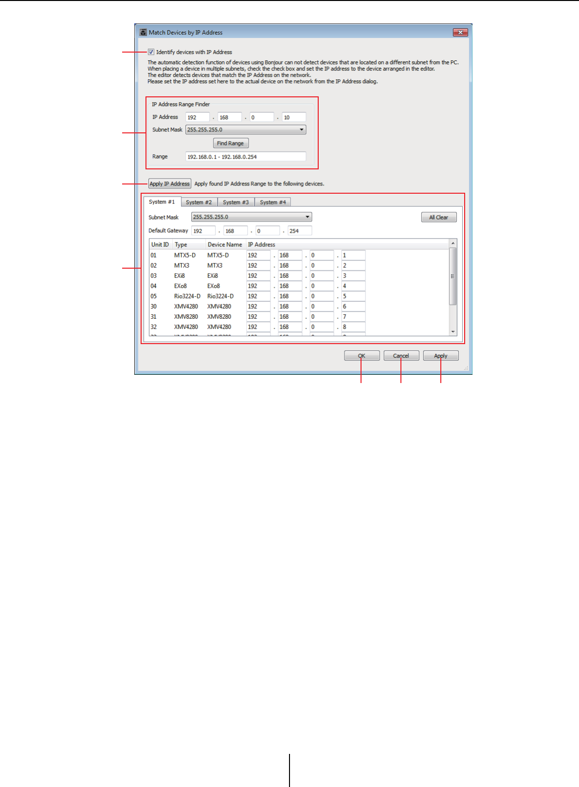
“Match Device by IP Address” dialog box Chapter 7. Dialog boxes/Software applications
MTX-MRX Editor User Guide
175
1[Distinguish devices by IP Address] check box
If this check box is selected, devices are distinguished by their IP address, not their
UNIT ID.
2“IP Address Range Finder” area
If it is OK for the IP addresses to be consecutive, you can use this to calculate the
IP addresses for assignment.
• [IP Address]
Enter the IP address that you want to use.
• [Subnet Mask]
Select the subnet mask. For the subnet masks that can be selected, refer to the
“IP Address” dialog box.
• [Find Range] button
When you click this, the range that can be specified is calculated from the IP address
and subnet mask that you input.
•“Range”
Shows the calculated range of IP addresses.
3[Apply IP Address] button
When you click this, the IP address calculated in the “IP Address Range Finder” area is
applied to the devices in the system tab.
1
2
3
4
5 6 7

“Match Device by IP Address” dialog box Chapter 7. Dialog boxes/Software applications
MTX-MRX Editor User Guide
176
4System tabs
Here you can view and edit the settings of the devices in the system.
• [Subnet Mask]
Select the subnet mask. For the subnet masks that can be selected, refer to the
“IP Address” dialog box.
• [Default Gateway]
Enter the IP address of the default gateway within the subnet.
• Device list
Enter the IP address of the devices in the system.
• [All Clear] button
Deletes the IP address information of the devices.
5[OK] button
Updates the settings and closes the dialog box.
6[Cancel] button
Closes the dialog box without updating the settings.
7[Apply] button
Updates the settings.
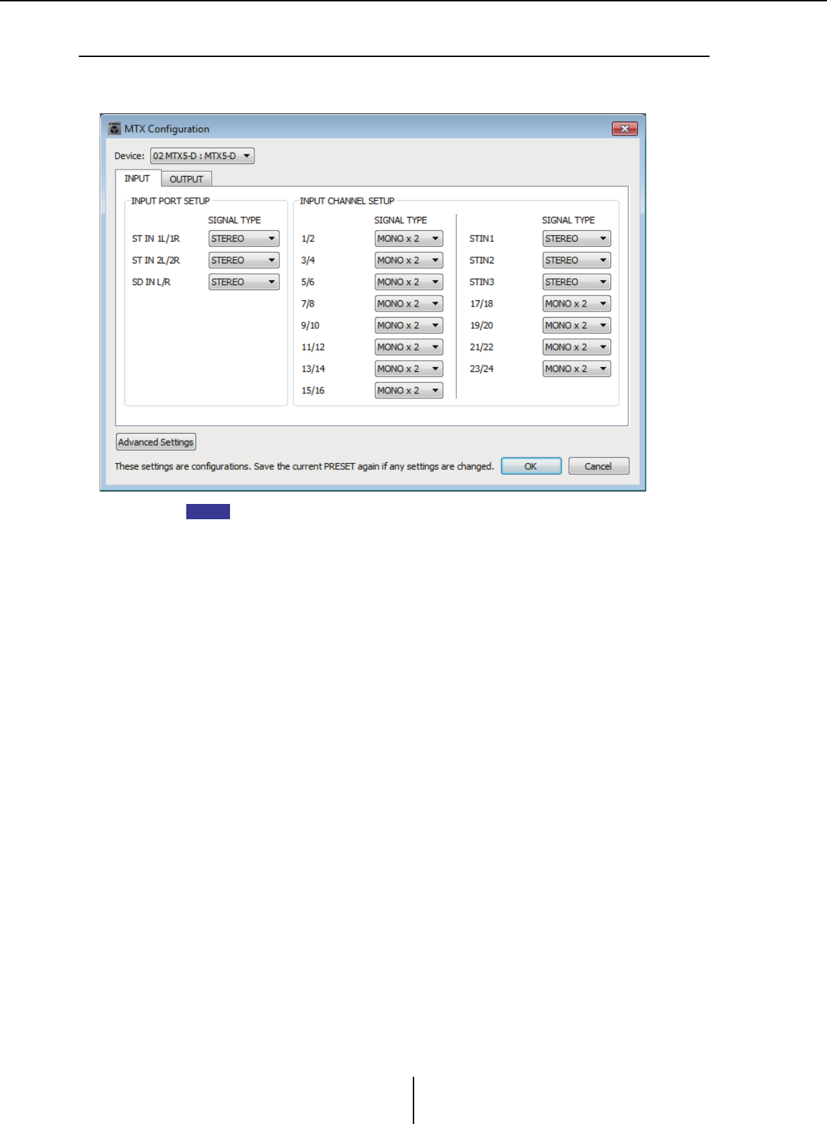
“MTX Configuration” dialog box Chapter 7. Dialog boxes/Software applications
MTX-MRX Editor User Guide
177
❑“MTX Configuration” dialog box
Here you can specify input/output settings for each device, such as MTX/MRX input ports, output
channels, and matrix buses.
Since these settings are not included in a preset, they cannot be changed via the Preset
Recall function.
●Device:
Selects an MTX unit within the MTX/MRX system.
From the left, this shows the “UNIT ID,” “Type (model name of the device),” and
“Device Name (name of the device).”
●[Advanced Settings] button
The “Advanced Settings” dialog box will appear.
●[OK] button
Saves the settings and closes the dialog box.
●[Cancel] button
Discards the settings and closes the dialog box.
●[INPUT] tab
In this tab, you can make settings related to inputs.
• INPUT PORT SETUP
Here you can specify the inputs to the stereo input ports.
STEREO .................The stereo signal will be input without change.
SUM ........................The L and R inputs will be summed to a single channel.
There will be one input to the input patch.
• INPUT CHANNEL SETUP
Here you can make settings for the input channels. The settings here will affect the
input channel strip of the “MAIN” screen.
MONO x2...............The input channels will be treated as two monaural channels.
STEREO .................The input channels will be treated as a single stereo pair.
NOTE
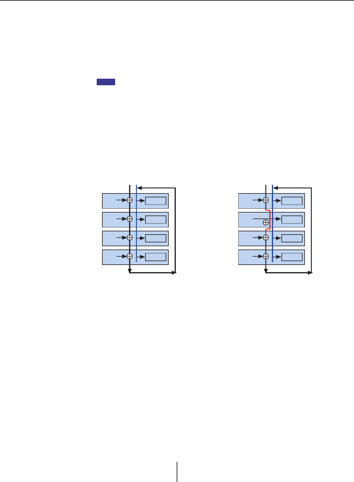
“MTX Configuration” dialog box Chapter 7. Dialog boxes/Software applications
MTX-MRX Editor User Guide
178
●[OUTPUT] tab
In this tab, you can make settings related to outputs.
•MATRIX BUS SETUP
Here you can make settings for the matrix buses. These settings will affect the
“MATRIX” screen.
MONO x2...............The input channels will be treated as two monaural channels.
STEREO .................The input channels will be treated as a single stereo pair.
If the MTX/MRX system’s YDIF mode is Cascade mode, the parameters will be shared
in common by all MTX units in the MTX/MRX system.
• CASCADE MODE
Here you can specify the zone input source for each matrix. This setting cannot be
made in Distribution mode.
• OUTPUT CHANNEL SETUP
Here you can specify the type of output channel speaker processor (1WAYx2 or
2WAY). The settings here will affect the channel strip of the “MAIN” screen.
On Off
The matrix out of all MTX units will
be mixed for each matrix. That mixed
signal will be used as the input to the
zone.
Instead of using the mix from the bus,
the matrix out will be used as the
input for the zone.
NOTE
BUS1 BUS2
01 MTX3
Matrix1 ZONE1
02 MTX3
Matrix1 ZONE1
03 MTX3
Matrix1 ZONE1
04 MTX3
Matrix1 ZONE1
BUS1 BUS2
01 MTX3
Matrix1
Local Mix
ZONE1
02 MTX3
Matrix1 ZONE1
03 MTX3
Matrix1 ZONE1
04 MTX3
Matrix1 ZONE1
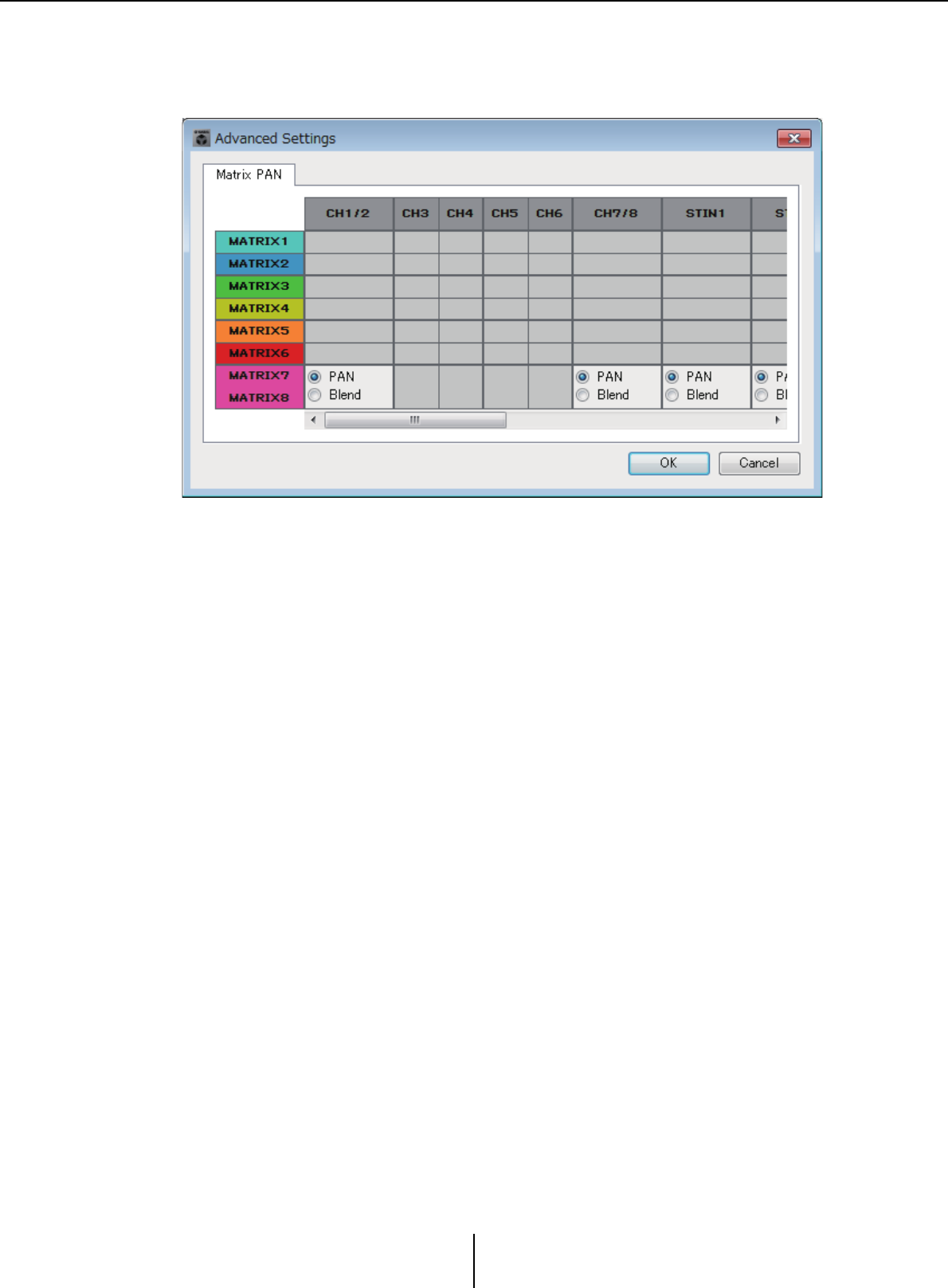
“MTX Configuration” dialog box Chapter 7. Dialog boxes/Software applications
MTX-MRX Editor User Guide
179
“Advanced Settings” dialog box
Here you can specify the matrix pan mode (PAN or Blend). For both input and output, this
can be specified only for stereo.
If you choose [Blend], the right and left channels of the stereo audio will be mixed while
preserving the sense of stereo. For example in some old stereo recordings, completely
different audio is recorded on the left and right channels; if such audio is played via a stereo
background music system, it may produce the impression that different music is playing
in different areas. “Blend” is effective in mitigating this.
●[OK] button
Saves the settings and closes the dialog box.
●[Cancel] button
Discards the settings and closes the dialog box.
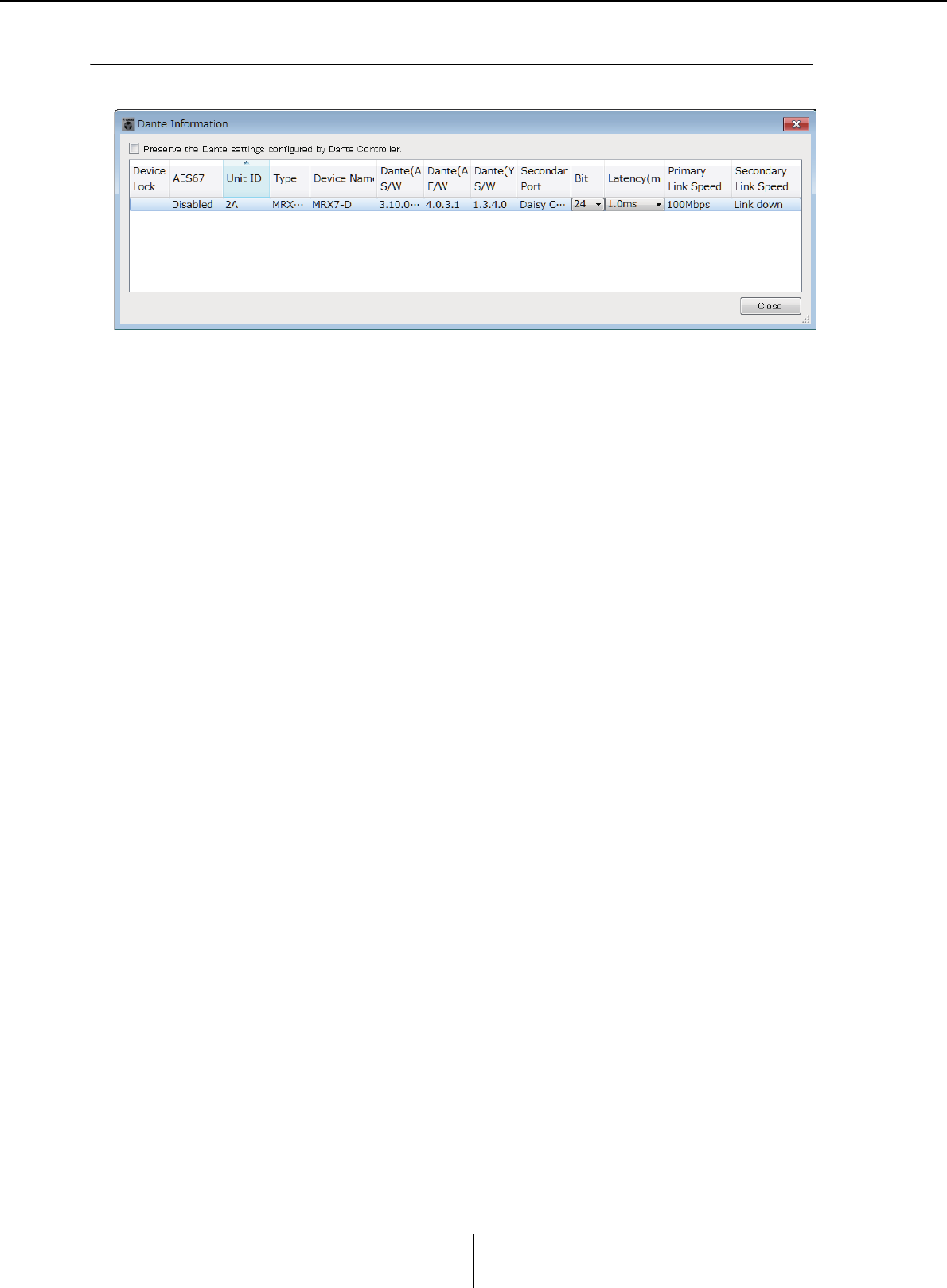
“Dante Information” dialog box Chapter 7. Dialog boxes/Software applications
MTX-MRX Editor User Guide
180
❑“Dante Information” dialog box
This shows Dante-related settings for Dante units such as the MTX5-D or XMV8280-D.
●[Preserve the Dante settings configured by Dante Controller]
check box
Select this check box if you’re using Audinate Corporation’s Dante Controller to set up
the Dante network. The settings of Dante Controller will take priority over the settings
made in MTX-MRX Editor. If this check box is cleared, you’ll be able to use MTX-MRX
Editor to make Dante network settings within the project.
●[Device Lock]
If the unit is set to Device Lock by Dante Controller, a lock icon is shown, and the unit
is excluded from editing.
●[AES67]
This indicates “Enabled” if the device is in AES67 mode.
●[UNIT ID]
Indicates the UNIT ID of the device.
●[Type]
Indicates the model name of the device.
●[Device Name]
Shows the device name. This name can be edited in DEVICE NAME, which is located
in the [Device] tab at the bottom of the Project screen.
●[Dante(A) S/W]/[Dante(A) F/W]/[Dante(Y) S/W]
Shows the version of the Dante firmware.
●[Secondary Port]
Shows the [SECONDARY PORT] settings of the DIP switch.
●[Bit]
Indicates the bit rate. The setting can be changed when offline.
●[Latency (ms)]
Indicates the latency in millisecond units. The setting can be changed when offline.
●[Primary Link Speed]/[Secondary Link Speed]
Indicates the communication speed settings of the Dante ports. If no other device is
connected to a port, or if the cable is broken, this will indicate “Link Down.”
●[Close] button
Closes the dialog box.
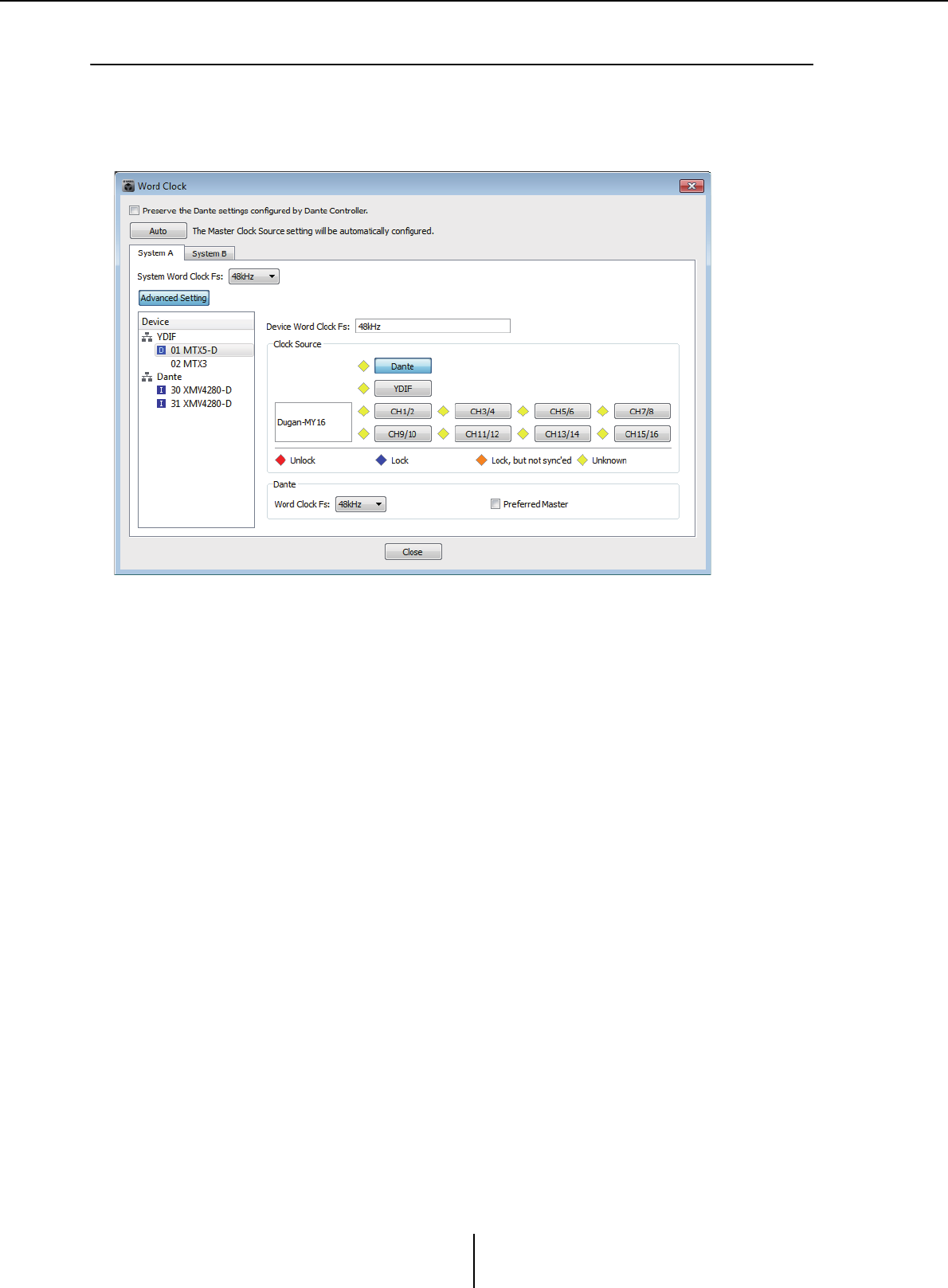
“Word Clock” dialog box Chapter 7. Dialog boxes/Software applications
MTX-MRX Editor User Guide
181
❑“Word Clock” dialog box
Here you can edit the word clock settings of the MTX/MRX system. Normally, these will be set to
the optimal values when you use the “Device Configuration Wizard” dialog box to create the
configuration. If you want to specify a Mini-YGDAI card as the word clock master etc., make
settings in this dialog box.
●[Preserve the Dante settings configured by Dante Controller]
check box
Select this check box if you’re using Audinate Corporation’s Dante Controller to set up
the Dante network. The settings of Dante Controller will take priority over the settings
made in MTX-MRX Editor. If this check box is cleared, you’ll be able to use MTX-MRX
Editor to make Dante network settings within the project.
●[Auto] button
Sets the word clock and master clock for all MTX/MRX systems in the project. This is
available only when offline.
●System select tabs
These select the MTX/MRX system whose word clock you will set.
●[System Word Clock Fs:] box
This specifies the word clock of the MTX/MRX system.
●[Advanced Setting] button
This switches the display to a screen where you can make advanced settings. The
illustration above shows the state when the [Advanced Setting] button has been clicked.
●[Device] list
This lists the devices whose word clock can be changed. Click the device whose detailed
word clock settings you want to edit; the edit screen for that device will appear. The icon
at the left of the UNIT ID indicates what is specified as the clock source.
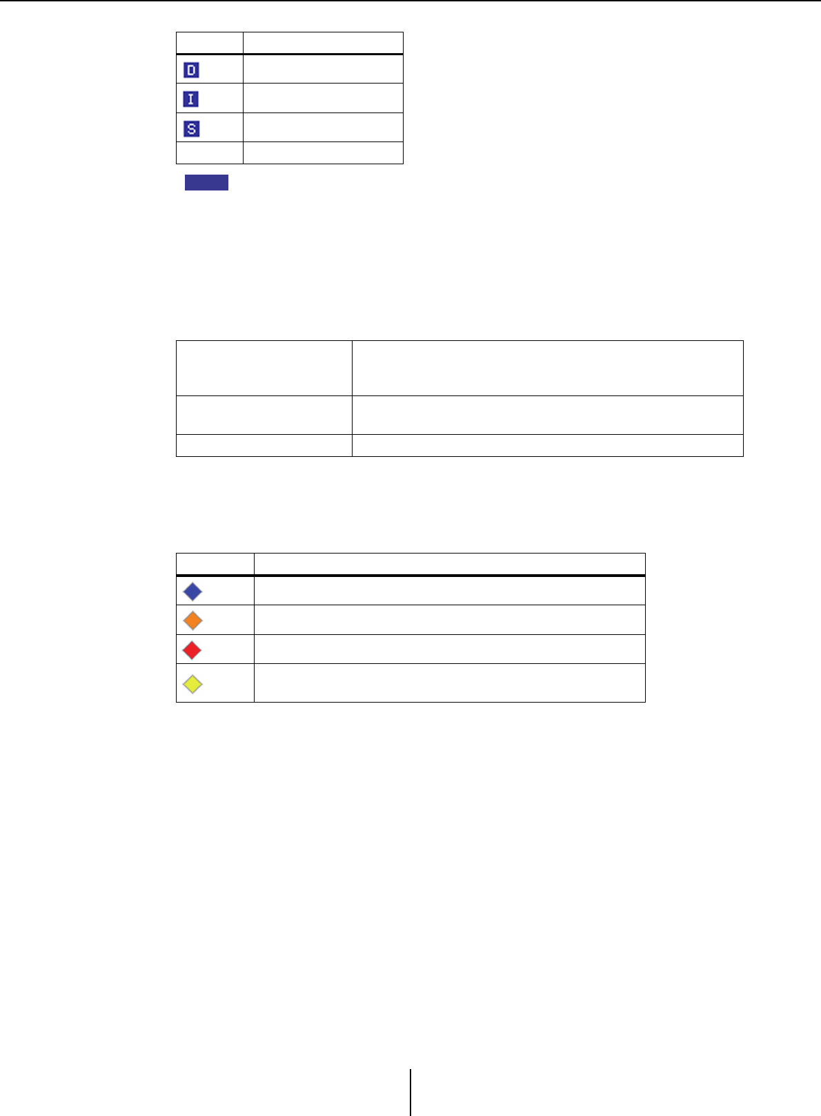
“Word Clock” dialog box Chapter 7. Dialog boxes/Software applications
MTX-MRX Editor User Guide
182
The following devices are not shown.
• EXi8
•Exo8
• XMV units connected via YDIF
• XMV units connected via analog
●[Device Word Clock Fs:]
This indicates the word clock of the device. When online, this indicates the word clock
value for the device. When offline, the indication will be as follows.
●[Clock Source]
Use these buttons to select the word clock source. A indicator showing the status is
displayed at the left of buttons that can be selected. When offline the status cannot be
detected, so all indicators will be yellow.
●[Dante]
Specifies the Dante word clock. If the device is set to Device Lock by Dante Controller,
a lock icon is shown, and settings cannot be made.
• [Word Clock Fs:] box
Indicates/specifies the word clock of the device. If the unit is set to Device Lock by
Dante Controller, a lock icon is shown, and the unit is excluded from editing. If the
unit is set to AES67 mode by Dante Controller, this indicates “48kHz,” and the unit
is excluded from editing.
• [Preferred Master] check box
Selecting this check box will increase the probability that the device will become the
clock master within the Dante network. Use this when the MTX/MRX system
includes a Dante device that is not supported by MTX-MRX Editor, and you want
to use the MTX/MRX system device as the clock master. If the unit is set to Device
Lock by Dante Controller, the unit is excluded from editing.
●[Close] button
Closes the dialog box.
Icon Clock source
Dante
Internal
Mini-YGDAI card
None YDIF
MTX5-D/MRX7-D
If DANTE is specified as the word clock source, this indicates
the value specified by Dante [Word Clock Fs:].
Otherwise, this indicates “---”.
MTX3 If Internal 44.1 kHz or 48 kHz are selected, that value is shown.
If YDIF is selected, this indicates “---”.
Dante-compatible XMV This indicates “48 kHz”.
Indicator Status
Locked.
Locked but not synchronized.
Unlocked.
The clock status cannot be detected because an external
device is not connected or because there is no valid clock input.
NOTE
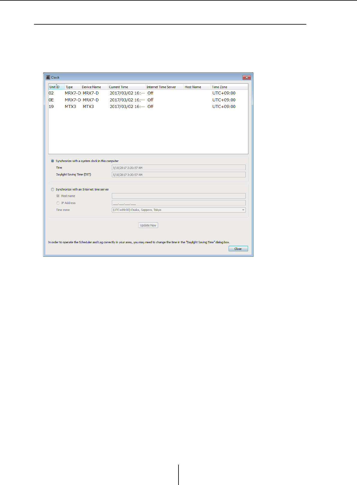
“Clock” dialog box Chapter 7. Dialog boxes/Software applications
MTX-MRX Editor User Guide
183
❑“Clock” dialog box
The date and time of the computer are transmitted to each device connected to the MTX/MRX
system every time it goes online, automatically updating the internal clock of each device. If you
transmit the computer’s date and time information from this dialog box, the date and time will be
updated on an MTX/MRX unit that is connected to the same network, regardless of online/offline
status. The internal clock in devices other than the MTX/MRX will be updated by the MTX/MRX.
●Unit ID
Indicates the UNIT ID.
●Type
Indicates the type of device.
●Device Name
Indicates the device name.
●Current Time
Indicates the time information of the device.
●Internet Time Server
This is shown as On if the device is set to obtain time information from a time server;
it is shown as Off if the device is set to not use a time server.
●Host Name
This shows the time server’s host name or IP address if the device is set to obtain time
information from a time server.
●Time Zone
Indicates the time zone of the device.

“Clock” dialog box Chapter 7. Dialog boxes/Software applications
MTX-MRX Editor User Guide
184
●[Synchronize with a system clock in this computer] option button
If you select this option, the date and time of the computer’s system clock will be sent
out each time the system comes online, and the internal clock on the MTX/MRX will
be automatically updated.
•[Time]
Shows the date and time of the computer system clock, ignoring the daylight saving
time setting.
If this indication matches the date and time of the internal clock on the MTX/MRX,
the time information on the MTX/MRX will synchronize with that of the computer.
• [Daylight Saving Time(DST)]
Shows the daylight saving time used on the computer. If daylight saving time has not
been programmed, this field will display the message “Daylight Saving Time has not
been executed.”
●[Synchronize with an Internet time server]
If you select this and click the [Update Now] button, the internal clock of the MTX/
MRX is updated using the time information from the specified time server. After this
setting is made, the internal clock will synchronize with the time server every 24 hours.
If any required field is not completed, time information may not be obtained. Be sure
to enter an appropriate value in all non-grayed fields.
Notice
If you plan to specify an external time server, configure an Internet connection, and in the
IP Address dialog box, specify the [DNS server address] and [Default gateway] as
appropriate for the connection environment.
If you specify an external time server, make sure that the server is reliable. If you specify an
unreliable server, you may be exposed to certains risks, such as an infection by a computer
virus.
•[Host name]
If you select this option, enter the host name of the time server.
• [IP Address]
If you select this option, enter the IP address of the time server.
•[Time zone]
Set the local time difference from Greenwich Mean Time. The default setting is the
computer’s time zone.
• [Update Now] button
When you click this, the device’s internal clock is updated according to the settings.
●[Close] button
Closes the dialog box.
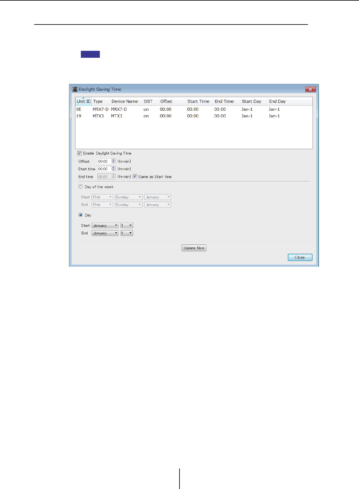
“Daylight Saving Time” dialog box Chapter 7. Dialog boxes/Software applications
MTX-MRX Editor User Guide
185
❑“Daylight Saving Time” dialog box
This specifies the daylight saving time setting of the MTX/MRX devices connected to the same
network, regardless of their online/offline state.
• Events that are assigned within two hours before or after the beginning or end of daylight
saving time in the “Scheduler” dialog box will not be executed correctly.
• When you create a new project, the daylight saving time setting from the computer’s “Date
and Time” settings will be automatically shown in this dialog box.
●Unit ID
Indicates the UNIT ID.
●Type
Indicates the type of device.
●Device Name
Indicates the device name.
●DST
This indicates On if daylight saving time is specified for the device; it indicates Off if
daylight saving time is not specified.
●Offset
Indicates the amount of time by which the device’s daylight saving time is earlier than
standard time.
●Start Time
Indicates the time at which daylight saving time starts for the device.
●End Time
Indicates the time at which daylight saving time ends for the device.
NOTE

“Daylight Saving Time” dialog box Chapter 7. Dialog boxes/Software applications
MTX-MRX Editor User Guide
186
●Start Day
Indicates the date on which daylight saving time starts for the device.
●End Day
Indicates the date on which daylight saving time ends for the device.
●[Enable Daylight Saving Time] check box
Daylight saving time will be enabled if this check box is selected.
If the “Automatically adjust daylight saving time” check box is selected in the computer’s
“Date and Time” settings, you must also select the [Enable Daylight Saving Time] check box
in the “Daylight Saving Time” dialog box.
•Offset
Specifies the amount of time by which daylight saving time is earlier than standard
time.
• Start time
Specifies the time when daylight saving time begins.
For example if you set Offset as 01:00 and Start time as 12:00, the clock will be set to
13:00 when the time reaches 12:00 of the day on which daylight saving time begins.
•End time
Specifies the time when daylight saving time ends. If this is the same as the start
time, select [Same as Start time].
For example if you set Offset as 01:00 and End time as 12:00, the clock will be set to
11:00 when daylight saving time reaches 12:00 on the last day of daylight saving
time. If the [Same as Start time] check box is selected, daylight saving time will
automatically be cancelled and revert to standard time on the last day of daylight
saving time at the time specified by the Start time.
●Day of the week
If this is on, the term of daylight saving time will be specified as a day of the week. Use
Start and End to specify which day of which week will be the start and end of daylight
saving time. For example to specify the first Sunday in April, choose “First,” “Sunday,”
and “April”; to specify the last Sunday in October, choose “Last,” “Sunday,” and “October.”
●Day
If this is on, the term of daylight saving time will be specified as a day of a month. Use
Start and End to specify the dates that will be the start and end of daylight saving time.
●[Update Now] button
When you click this, the device’s internal clock is updated according to the settings.
●[Close] button
Closes the dialog box.
NOTE
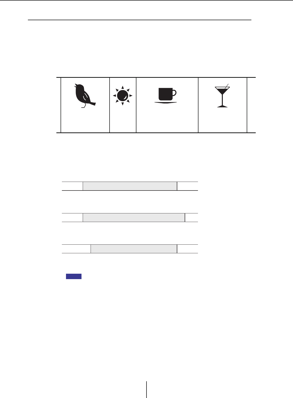
“Scheduler” dialog box Chapter 7. Dialog boxes/Software applications
MTX-MRX Editor User Guide
187
❑“Scheduler” dialog box
You can switch presets or play back a song or sound effect from an SD memory card at a previously
specified date and time. Each such setting is called an “Event.”
<Usage example 1>
Switching background music by time period
Here’s how you could switch the type of background music according to the time period,
for example in a commercial establishment.
<Usage example 2>
Switching background music by day of the week
Here’s how you could switch the type of background music according to the day of the
week or the times of business, for example in a commercial establishment.
You can also specify exceptions, such as playing seasonal background music at Christmas,
or stopping playback on days when the establishment is not operating.
• If an event has been assigned, the [SCHEDULER] indicator on the MTX/MRX front panel
will be lit yellow. One minute before the event occurs, the indicator will flash.
• If more than one event is assigned at the same time, all events will run with one second of
space between them. During this time, the [SCHEDULER] of the MTX/MRX’s front panel will
continue flashing.
• If the [Enable Daylight Saving Time] check box is selected in the “Daylight Saving Time”
dialog box, events that have been scheduled within two hours before or after the start or
end of daylight saving time will not be executed correctly.
22:00 9:00 12:00 14:00 18:00
Refreshing
background music
Energetic
background
music
Peaceful
background music
Atmospheric
background music
22:00
20:00 10:00
10:00
20:00 12:00
•Monday–Friday
•Saturday
•Sunday
Background music pattern 1
Background music pattern 2
Background music pattern 3
NOTE
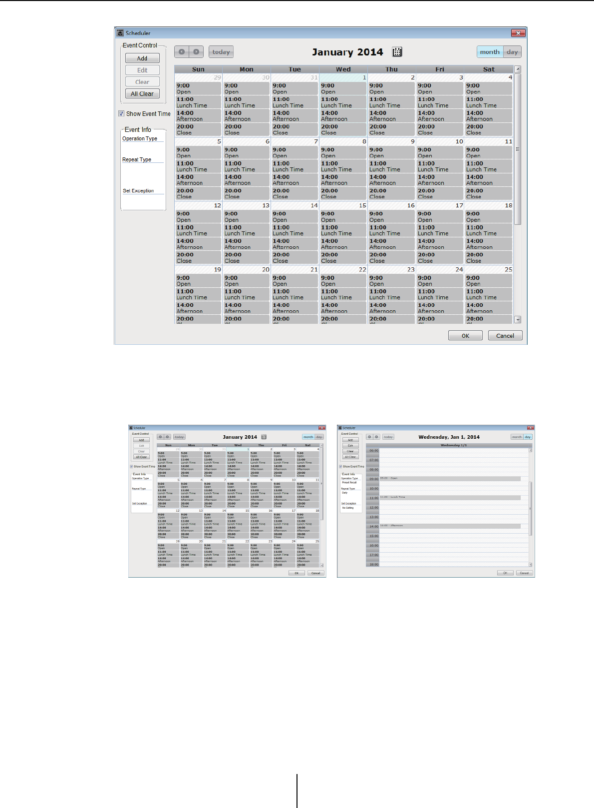
“Scheduler” dialog box Chapter 7. Dialog boxes/Software applications
MTX-MRX Editor User Guide
188
You can assign up to 50 events and 50 exceptions.
●[Month] button/[Day] button
Switch the calendar between month or day views.
• In the calendar, double-click the date you want; the “Add Event” dialog box will
appear, letting you add an event.
• Events other than repeating events can be moved by dragging and dropping them (in
the month display you can move between days, and in the day display you can move
between hours).
• In the month display, you can click the calendar icon to access a year/month selection
screen.
●[Today] button
For the month view, displays this month’s calendar.
For the day view, displays today’s schedule.
Month view Day view

“Scheduler” dialog box Chapter 7. Dialog boxes/Software applications
MTX-MRX Editor User Guide
189
●[ < ]/[ > ] buttons
For the month view, displays the previous or next month’s calendar.
For the day view, displays the previous or next day’s schedule.
●Event Control
• [Add] button
The “Add Event” dialog box will appear.
Here you can add an event.
• [Edit] button
The “Edit Event” dialog box will appear.
Here you can edit the contents of the currently selected event. If no event is selected,
the button is dimmed.
•[Clear] button
Deletes the currently selected event. If no event is selected, the button is dimmed.
• [All Clear] button
Deletes all registered events.
●[Show Event Time] check box
If this is selected, the time of the event is shown in the month display.
●Event Info
This shows the information that was specified in the “Add Event” dialog box or “Edit
Event” dialog box for the selected event.
• OperationType
Indicates the operation that will be executed when the event occurs.
•RepeatType
Indicates the frequency with which the event will occur.
•SetException
Indicates a date and time for which, as an exception, the event will not occur.
●[OK] button
Saves the settings and closes the dialog box.
●[Cancel] button
Closes the dialog box without saving the changes.
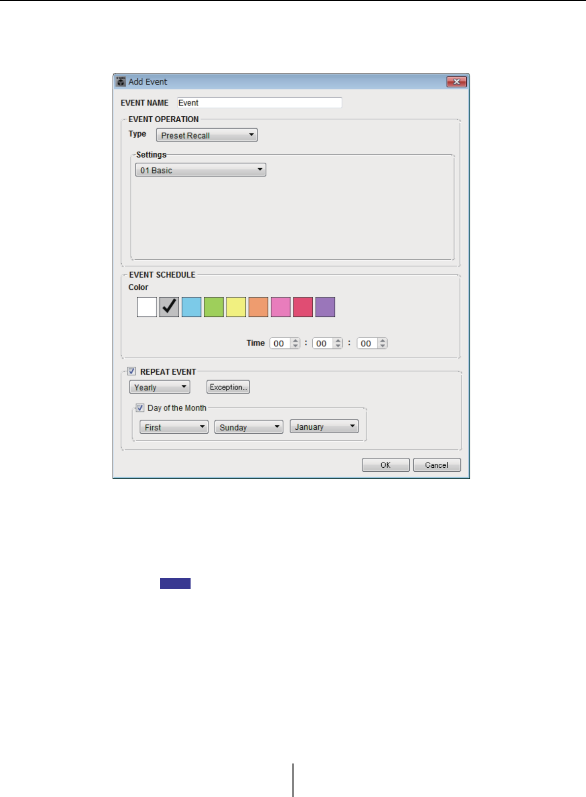
“Scheduler” dialog box Chapter 7. Dialog boxes/Software applications
MTX-MRX Editor User Guide
190
“Add Event” dialog box / “Edit Event” dialog box
For details about settings that are unique to the MRX series, refer to “MRX Designer User
Guide.”
●EVENT NAME
Enter the name of the event.
●EVENT OPERATION
• [Type] box
Choose the operation that will be executed when the event occurs.
In the “Preset” dialog box operations such as GPI Out or SD Song Select & Play can
be included in the preset. Choose GPI Out if you want to control an external device via
[GPI OUT] without recalling a preset, or choose SD Song Select & Play if you want to
change the audio file that will play.
Preset Recall ......................A preset will be recalled.
GPI Out.............................. The [GPI OUT] connector will be controlled.
SD Song Select & Play .....An audio file saved on the SD memory card will play or
stop.
Snapshot Recall.................Recalls the MRX7-D’s parameters. For details, refer to
“MRX Designer User Guide.”
Paging .................................An audio message saved on the SD memory card will be
played for the specified broadcast destination (ZONE).
NOTE
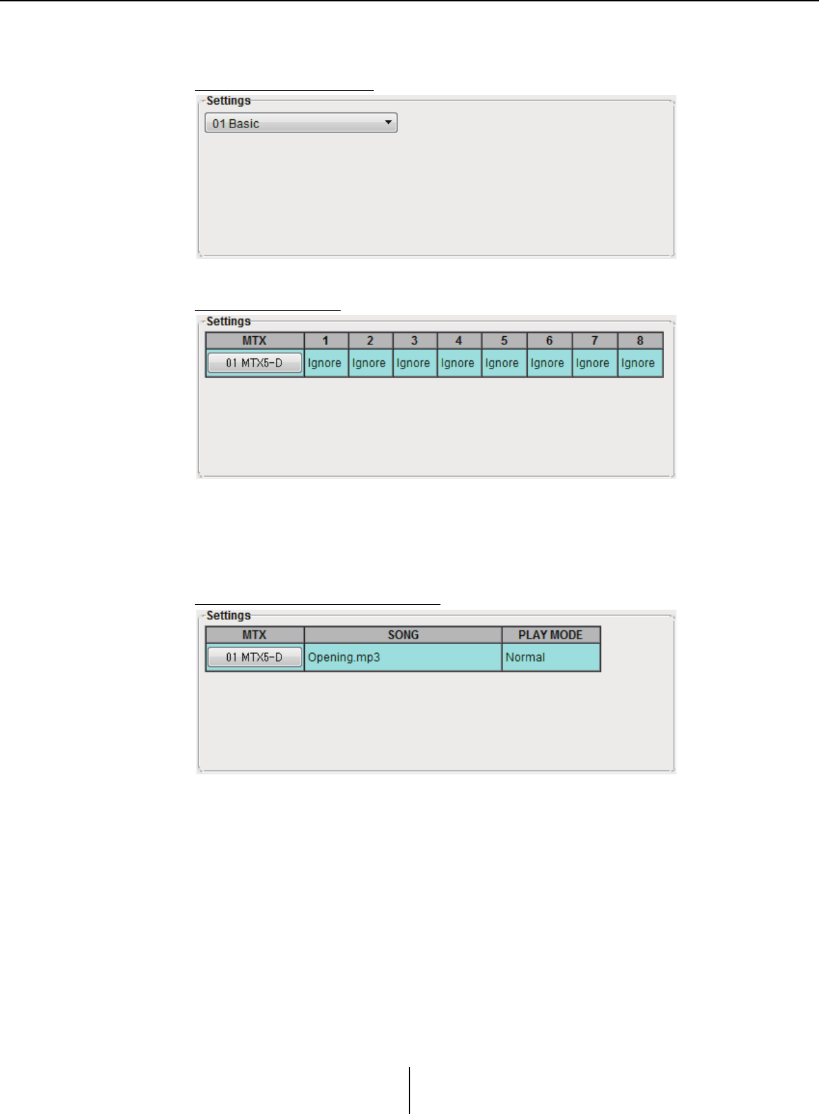
“Scheduler” dialog box Chapter 7. Dialog boxes/Software applications
MTX-MRX Editor User Guide
191
• Settings
The contents will change depending on the event you chose in [Type] box.
If you chose Preset Recall
Select the preset that you want to recall.
If you chose GPI Out
Specify the state of the GPI OUT connector when the event occurs for each MTX/
MRX unit.
Click the button of the MTX/MRX unit that you want to set; the “GPI Out” dialog
box will appear. Make settings in the same way as in the “Settings” dialog box of the
“Preset” dialog box.
If you chose SD Song Select & Play
For each MTX/MRX unit, specify how the audio files saved on the SD memory card
will play or stop when the event occurs.
Click the button of the MTX/MRX unit that you want to set; the “SD Play” dialog
box will appear. Make settings in the same way as in the “Settings” dialog box of the
“Preset” dialog box.
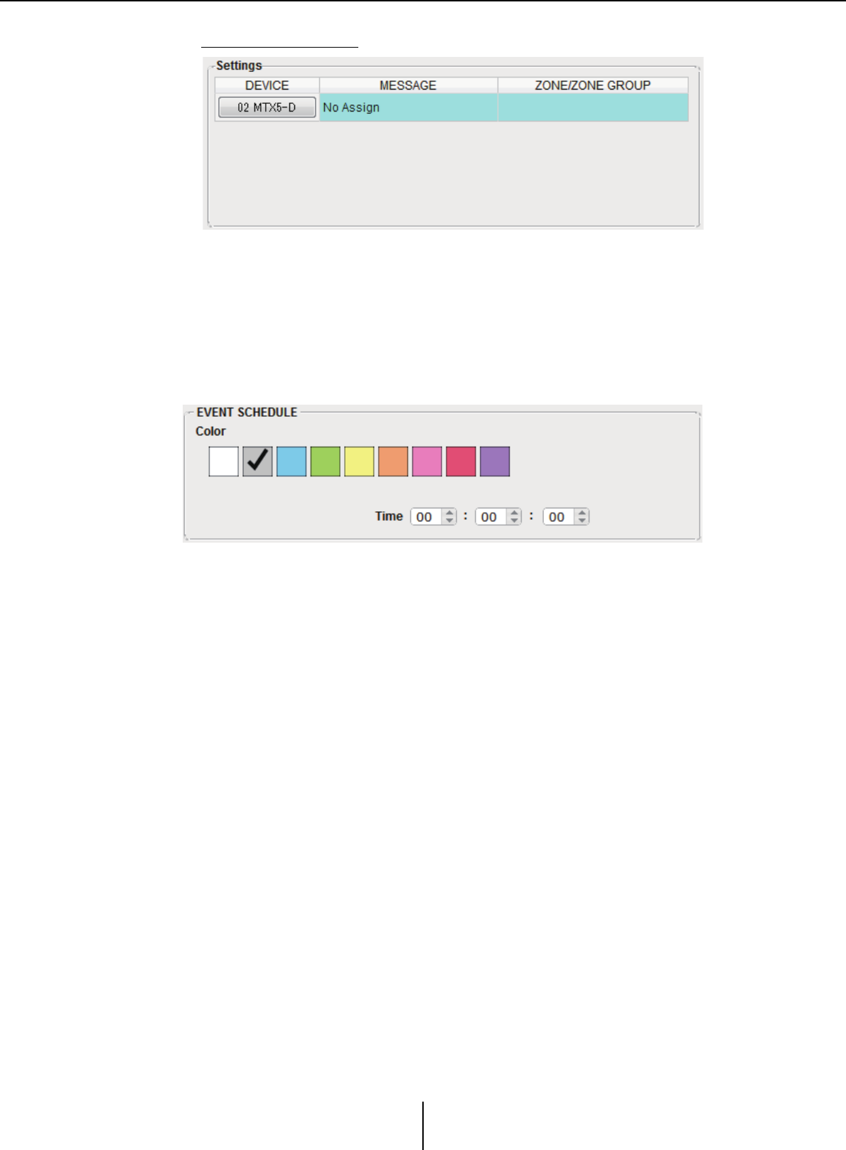
“Scheduler” dialog box Chapter 7. Dialog boxes/Software applications
MTX-MRX Editor User Guide
192
If you chose Paging
For each MTX/MRX unit, specify the ZONE/ZONE GROUP to which message files
saved on the SD memory card will be broadcast when the event occurs.
Click the button of the MTX/MRX unit that you want to set; the “SD Message Select”
dialog box will appear.
To use the Paging function, use the “ZONE” screen to specify the Paging and Zone
Group, and use the “PGM1/PGX1” dialog box to specify chime and other settings.
●EVENT SCHEDULE
Specify the date and time at which the event will occur.
• [Color] select switches
Choose the color of the event shown in the calendar. By specifying a color, you can
make it easier to distinguish certain types of event.
•[Date]
Specifies the date on which the event will occur. (year/month/day)
You can change the date either by inputting it directly or by clicking the calendar that
appears when you click the calendar icon at the right.
Depending on the REPEAT EVENT setting described below, this might not be
shown.
•[Time]
Specifies the time at which the event will occur. (hour:minute:second, in 24-hour
time)
Click the hour/minute/second that you want to specify, and use the spin box or enter
a value directly.
If you select REPEAT EVENT and specify the event frequency as “Hourly,” you’ll
only be able to set the minutes and seconds.
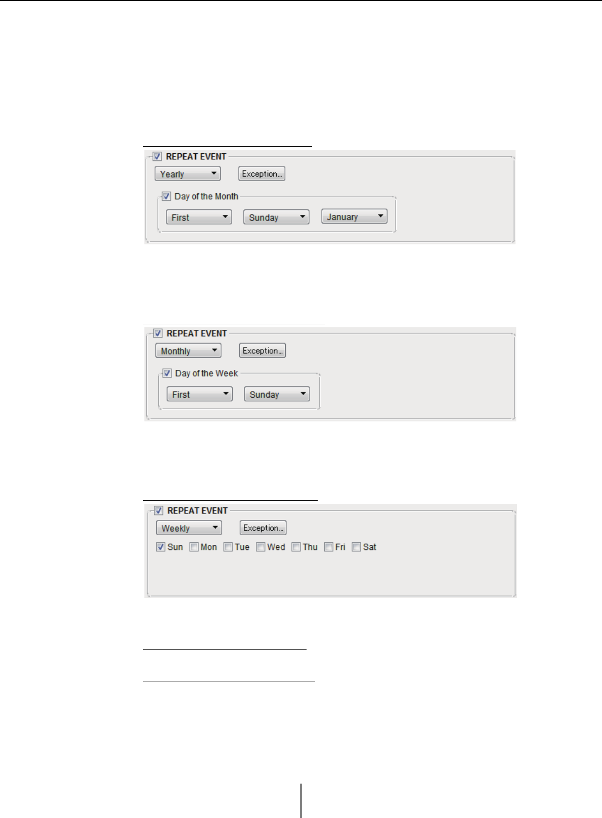
“Scheduler” dialog box Chapter 7. Dialog boxes/Software applications
MTX-MRX Editor User Guide
193
●[REPEAT EVENT]
By selecting this check box you can specify a repeating event.
• [Yearly]/[Monthly]/[Weekly]/[Daily]/[Hourly] boxes
Specify the frequency with which the event will occur.
• Event start date and time
Specify the date and time at which the event will occur repeatedly. The items that
you can specify will depend on the frequency of the event.
If the event frequency is [Yearly]
If [Day of the Month] is on, the event will occur each year at the date and time
specified by “-month,” “1st/2nd/3rd/4th,” “day of the week,” and [Time].
If [Day of the Month] is off, the event will occur each year on the day selected in the
calendar (shown in [Date]) at the time selected in [Time].
If the event frequency is [Monthly]
If [Day of the Week] is on, the event will occur each month at the date and time
specified by “1st/2nd/3rd/4th,” “day of the week,” and [Time].
If [Day of the Week] is off, the event will occur each month on the day selected in
the calendar (shown in [Date]) at the time selected in [Time].
If the event frequency is [Weekly]
The event will occur each week on the selected day of the week at the time specified
by [Time].
If the event frequency is [Daily]
The event will occur each day at the time (hour:minute:second) specified by [Time].
If the event frequency is [Hourly]
The event will occur each hour at the time (minute:second) specified by [Time].
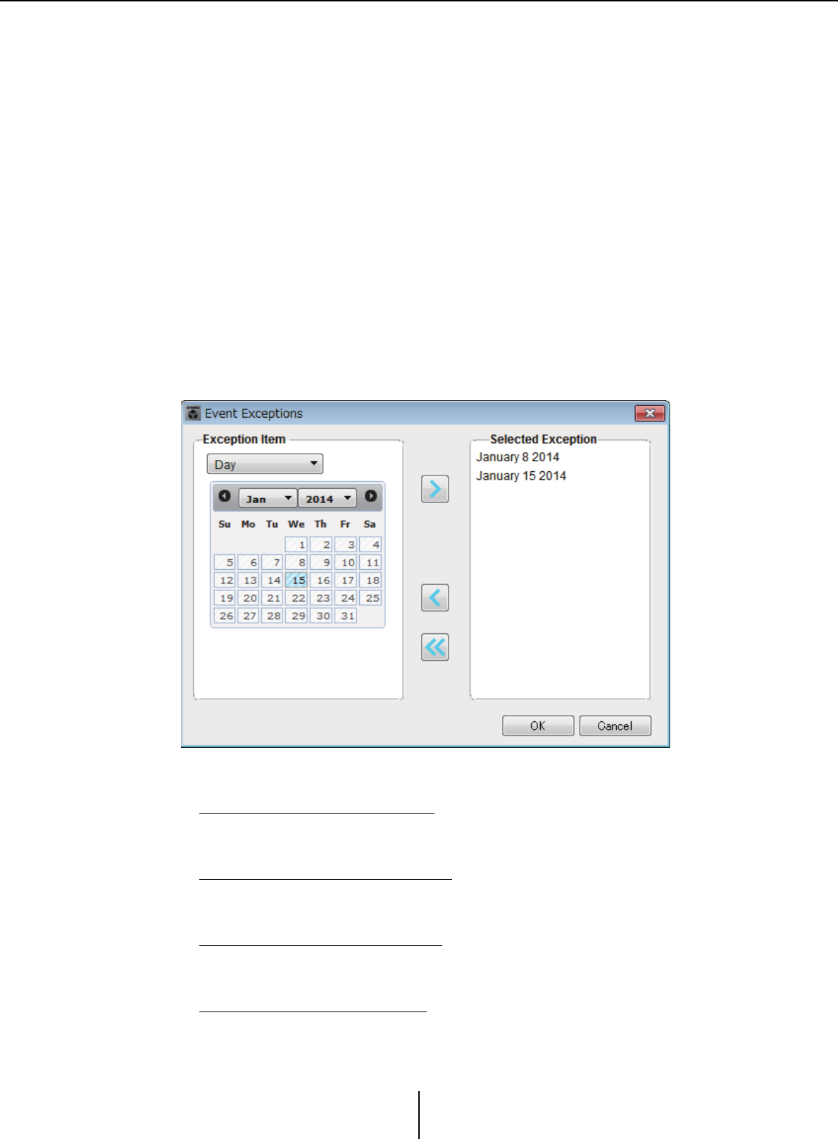
“Scheduler” dialog box Chapter 7. Dialog boxes/Software applications
MTX-MRX Editor User Guide
194
●[Exception] button
The “Event Exception” dialog box will appear.
Here you can specify a date and time for which, as an exception, the repeating event will
not occur.
●[OK] button
Saves the settings and closes the dialog box.
●[Cancel] button
Closes the dialog box without saving the changes.
■“Event Exception” dialog box
Here you can specify a date and time for which, as an exception, the repeating event will
not occur. The items that you can specify will depend on the frequency of the event.
Example) - Don’t play background music on Wednesday, when the establishment is
closed.
- Play special background music only for the event that occurs on the third
Sunday of every month.
●Exception Item
If the event frequency is [Yearly]
Specify the year for which the event will not occur.
Only the [Year] can be specified.
If the event frequency is [Monthly]
Specify the month or day for which the event will not occur.
Only the [Month] and [Day] can be specified.
If the event frequency is [Weekly]
Specify the month, week, or day for which the event will not occur.
Only the [Month], [Week], and [Day] can be specified.
If the event frequency is [Daily]
Specify the month, week, day, or day of the week for which the event will not occur.
Only the [Month], [Week], [Day], and [Day of the week] can be specified.
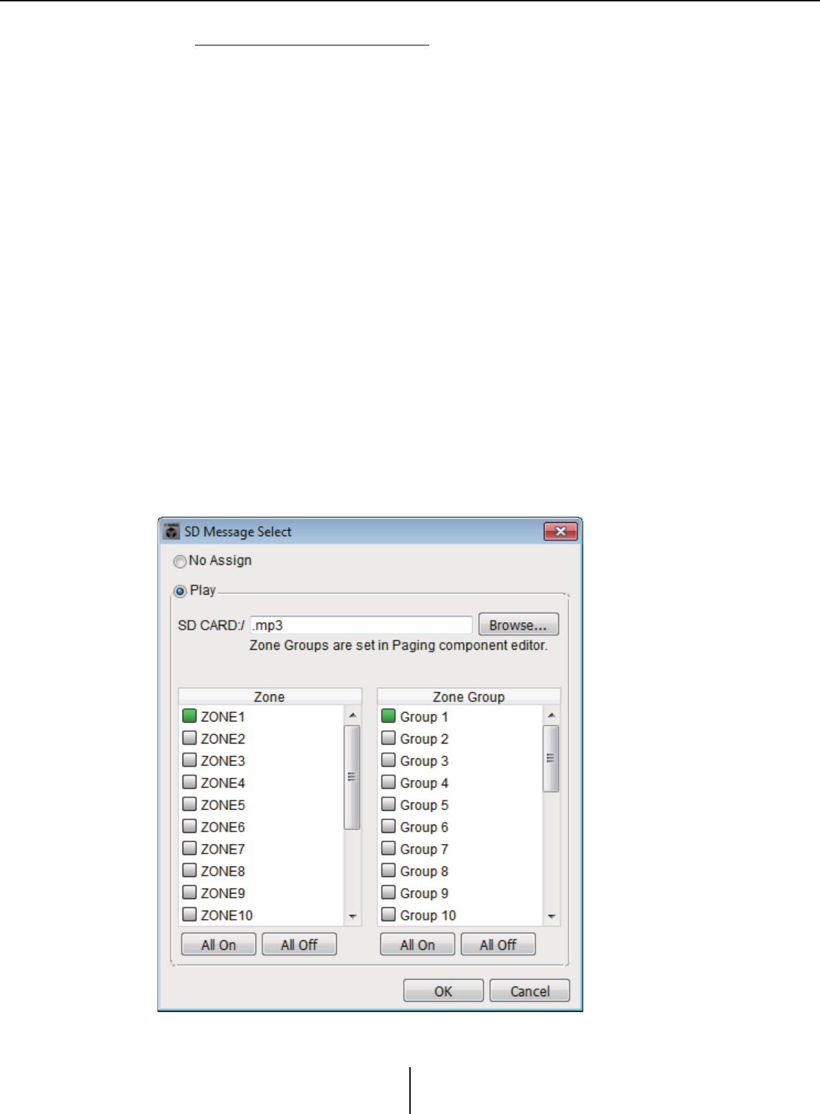
“Scheduler” dialog box Chapter 7. Dialog boxes/Software applications
MTX-MRX Editor User Guide
195
If the event frequency is [Hourly]
Specify the month, week, day, day of the week, or time (in hours) for which the event
will not occur.
The [Month], [Week], [Day], [Day of the week], and [Hour] can be specified.
●[>] button
Adds a date and time that you want to specify as an exception to the list at the right.
●[<] button
Removes a date and time that you specified as an exception from the list at the right.
●[<<] button
Removes all dates and times that you specified as exceptions from the list at the right.
●[OK] button
Saves the settings and closes the dialog box.
●[Cancel] button
Closes the dialog box without saving the changes.
■“SD Message Select” dialog box
Here you can select the message file from the SD memory card that will be broadcast by
the scheduler, and the Zone and Zone Group to which it will be broadcast.
If you want to use a Zone Group or a chime, make settings in the “PGM1/PGX1” dialog
box.

“Scheduler” dialog box Chapter 7. Dialog boxes/Software applications
MTX-MRX Editor User Guide
196
●[No Assign] option button
If this is selected, no broadcast is made when the event occurs.
●[Play] option button
If this is selected, a broadcast is made when the event occurs.
●SD CARD:/
This indicates the selected message file.
●[Browse] button
When you click this, a screen will appear, allowing you to select a message file.
●[Zone]/[Zone Group]
These specify the Zone(s) and Zone Group(s) to which the broadcast is made. Click
each square to turn it on (green) or off (white).
●[All On]/[All Off] buttons
Clicking these buttons turns all Zones or Zone Groups on or off.
●[OK] button
Click this to save the settings and close the dialog box.
●[Cancel] button
Click this to close the dialog box without saving the settings.
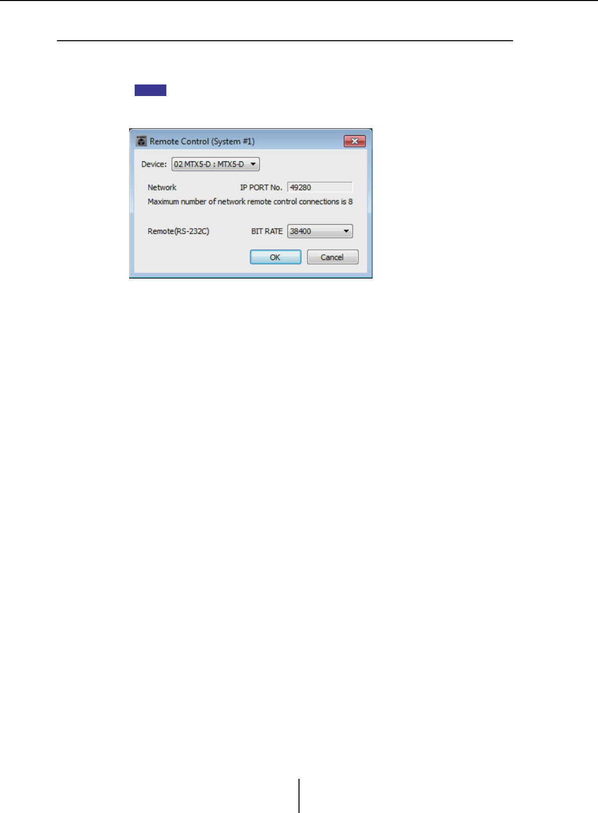
“Remote Control” dialog box Chapter 7. Dialog boxes/Software applications
MTX-MRX Editor User Guide
197
❑“Remote Control” dialog box
Here you can check the port numbers for connecting an external controller, or make settings for
connecting an external controller to RS-232C.
• A total of nine external controllers and wireless DCP units can be connected to a single
MTX/MRX.
• The IP address of the MTX/MRX can be viewed in the “Device Information” dialog box.
●[Device:] box
Select the MTX/MRX unit for which you want to make settings. The UNIT ID, device
type, and device name are shown.
●[Network IP PORT No.]
This shows the port number of the MTX3’s NETWORK connector or the MTX5-D/
MRX7-D’s Dante [PRIMARY]/[SECONDARY] connectors. You can connect up to
eight external controllers or wireless DCP to the port.
●[Remote(RS-232C) BIT RATE] box
Selects the RS-232C communication speed. You can select “38400” bps or
“115200” bps. You can connect one external controller to the RS-232C.
●[OK] button
Saves the settings and closes the dialog box.
●[Cancel] button
Closes the dialog box without saving the changes.
NOTE
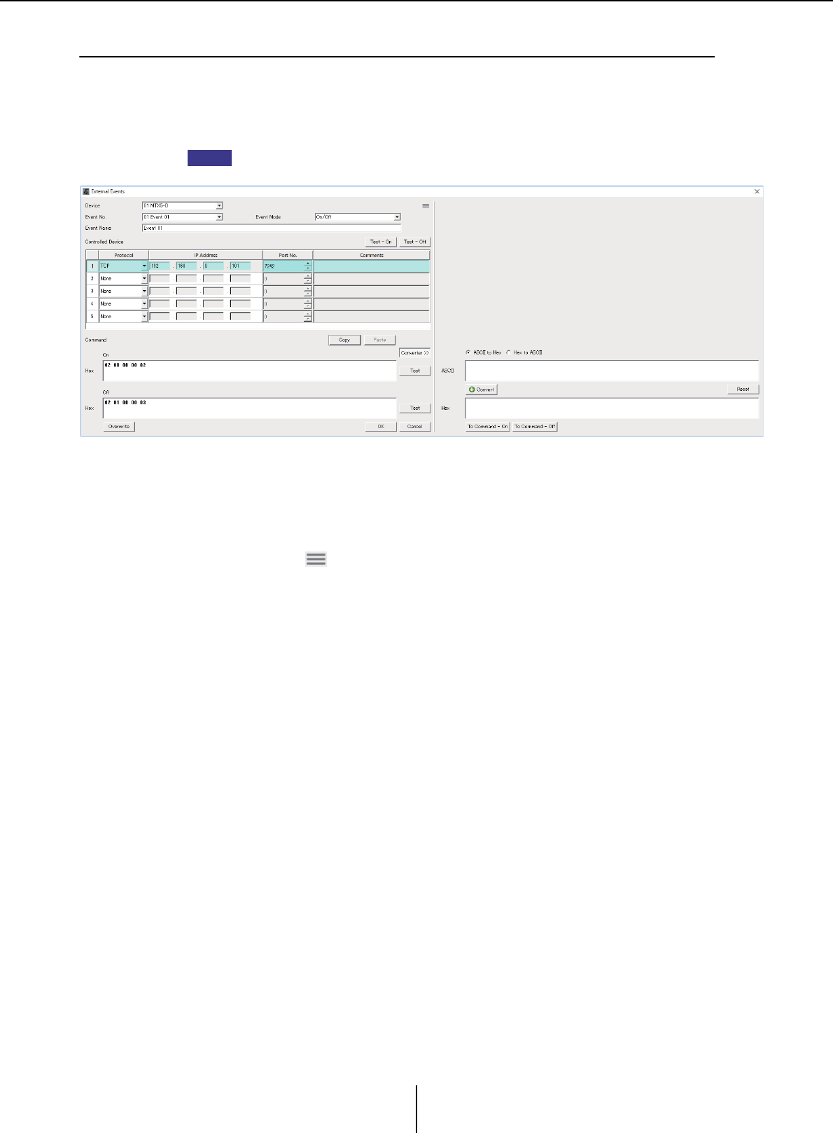
“External Events” dialog box Chapter 7. Dialog boxes/Software applications
MTX-MRX Editor User Guide
198
❑“External Events” dialog box
Here you can make settings for a command that will be transmitted to the network to which the
Dante connector or NETWORK connector is connected. This command can be triggered by
recalling a preset on the MTX/MRX; or by input from GIP IN; or by operation of an external device
such as a DCP unit.
Only commands are transmitted, and any reply to the commands will be discarded.
You can set up to 20 events per device. You can set up to 5 commands per event.
●[Device] list box
Select the MTX/MRX that will send commands. The list box shows units in order of the
UNIT ID and the name of the MTX/MRX.
●Menu button ( )
Click this button to execute the following functions.
• [Copy Event]
Copies the contents of the selected event to the copy buffer.
• [Copy All Event]
Copies the contents of all events to the copy buffer.
• [Paste Event]
Overwrites the event settings in the copy buffer.
• [Clear Event]
Initializes the contents of the selected event.
• [Clear All Event]
Initializes the contents of all events.
●[Event No.] list box
Specify the event number.
NOTE

“External Events” dialog box Chapter 7. Dialog boxes/Software applications
MTX-MRX Editor User Guide
199
●[Event Mode] list box
Specify whether the triggered command is the [On/Off] or [1shot] type.
When an event is assigned to the button on an external device, such as a DCP unit, each
command type will cause the following operation:
•[On/Off]
Pressing the assigned button repeatedly will cause the MTX/MRX to transmit the
On command and Off command alternately.
•[1shot]
Pressing the assigned button will cause the MTX/MRX to transmit the programmed
command.
●[Event Name] text box
Specify the name of the event.
●[Test - On]/[Test – Off] button
MTX-MRX Editor will directly transmit commands specified in the “Controlled
Device” table in numerical order. If [1shot] has been selected in the [Command Type]
list box, the [Test - Off] button will be disabled.
You can execute command transmission on-line or off-line.
●“Controlled Device” table
Specify information for the device that will receive commands. When the device
receives a trigger signal, it will transmit commands in numerical order, as shown in the
table.
For details on settings for the receiving device, refer to the documentation for the
corresponding device regarding commands.
• [Protocol] list box
Select the protocol supported by the device that receives the commands.
• [IP Address] text box
Specify the IP address of the device that receives commands.
• [Port No.] text box
Specify the port number of the device that receives commands.
• [Comments] text box
You can enter up to 32 bytes of text. This text could be a device name that would help
you identify the device.
●[Copy] button
Copies the information for the selected command specified in the “Controlled Device”
table and Command text box to the copy buffer.
●[Paste] button
Pastes (and overwrites) the information from the copy buffer into the “Controlled
Device” table and Command text box.
●[Test] button
MTX-MRX Editor will directly transmit commands that are entered in the Command
text box.
●[Overwrite] / [Insert] button
Click this button repeatedly to toggle between Overwrite and Insert. While the [Insert]
button is displayed, you can insert a hexadecimal number at the beginning or in the
middle of the text in the Command text box.
NOTE

“External Events” dialog box Chapter 7. Dialog boxes/Software applications
MTX-MRX Editor User Guide
200
●Command text box
If [On/Off] has been selected in the [Event Mode] list box, repeatedly pressing the
button on an external device, such as a DCP unit, will cause the MTX/MRX to transmit
the On command and Off command alternately. If [1shot] has been selected in the
[Event Mode] list box, repeatedly pressing the button on an external device, such as a
DCP unit, will cause the MTX/MRX to transmit the programmed commands.
Commands should be hexadecimal numbers, and entered in the format of XX.
If a command for controlling an external device is expressed by a text string in the
relevant specification document, use the Converter area to convert the text string into
a hexadecimal number.
The maximum command length is 128 bytes.
●[Converter>>] button
Displays an area where you can convert a text string into a hexadecimal number.
●[ASCII to Hex]/[Hex to ASCII] option button
Select whether you want to convert a text string to a hexadecimal number or vice versa.
●[ASCII]/[Hex] text box
The upper text box name will be ASCII or Hex, depending on the selection of the
[ASCII to Hex]/[Hex to ASCII] radio buttons.
Click the [Convert] button to display the conversion result in the lower text box.
●[Reset] button
Erases the contents in the [ASCII]/[Hex] text boxes.
●[To Command] button
Displays the hexadecimal command (that has been converted from the text string) in
the Command text box.
If you selected [On/Off] in the [Command Type] list box, the [Command - On] button
and [Command - Off] button will appear to let you choose which button the command
should be applied to.
●[OK] button
Updates the settings and closes the dialog box. If the IP address or the command format
is invalid, an error message will appear and the dialog box will not close.
●[Cancel] button
Closes the dialog box without updating the settings.
NOTE
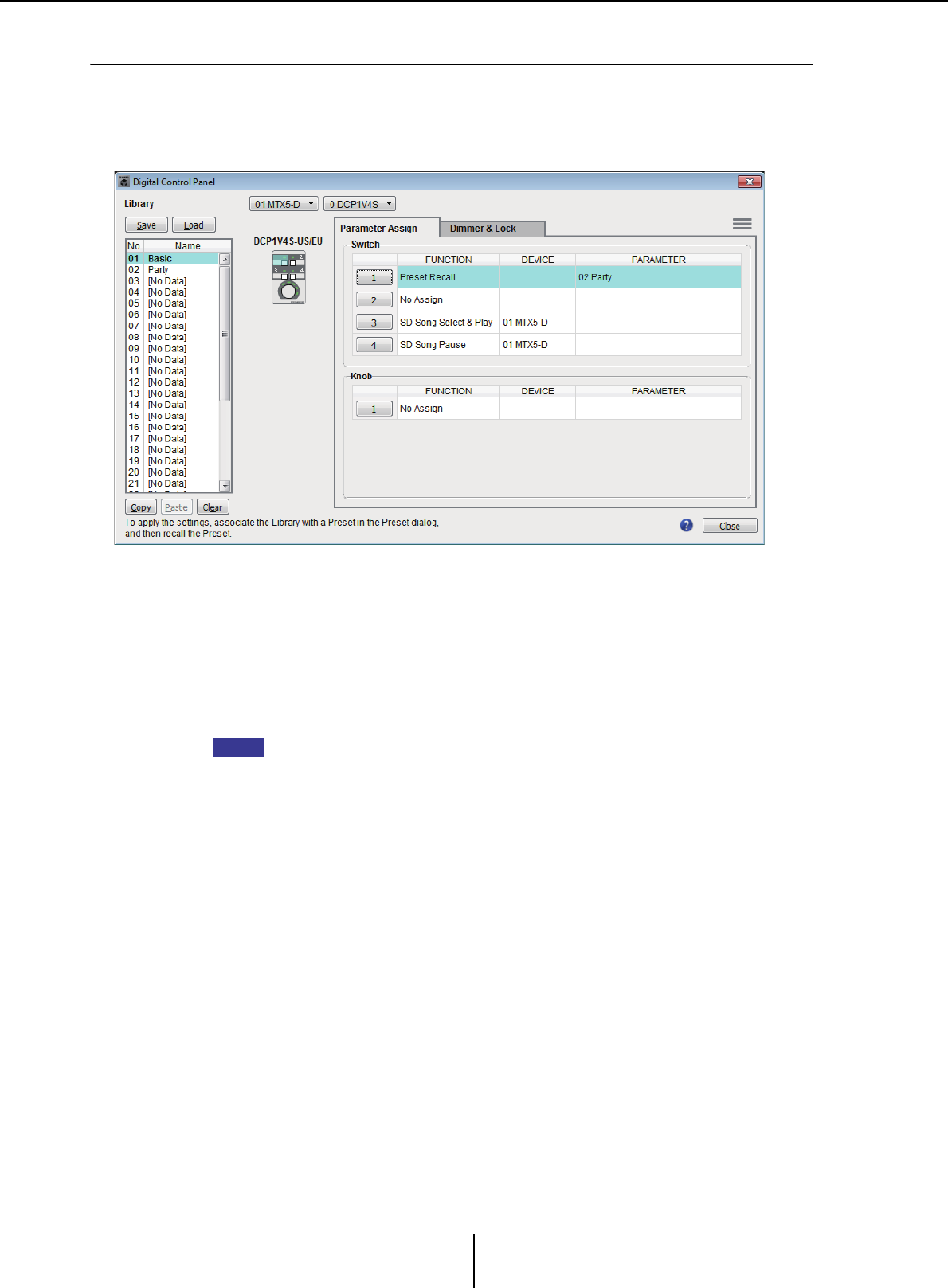
“Digital Control Panel” dialog box Chapter 7. Dialog boxes/Software applications
MTX-MRX Editor User Guide
201
❑“Digital Control Panel” dialog box
Here you can assign the MTX/MRX’s parameters to the controls of a digital control panel (DCP)
such as the DCP1V4S so that they can be operated from the DCP. You can also make settings for
the brightness of the DCP unit’s LEDs, as well as panel lock settings. You can’t make settings while
online. (Settings can only be viewed.)
You can store 32 sets of DCP settings in the Library. You can also associate library items with presets
for recall.
After editing in a tab such as [Parameter Assign]/[Dimmer & Lock]/[Source Select], click the item
in the [Library] list to which you want to save, and then click the [Save] button to save the item to
the library.
In the [Library] list, click the library item that you want to load, and then click the [Load] button to
load the library item; the settings will be applied to tabs such as [Parameter Assign]/[Dimmer &
Lock]/[Source Select].
• If you associate a saved library item with a preset, the parameter assignments for all DCP
units (up to 32 units) connected to the MTX/MRX system will be recalled/stored in a single
action when you recall that preset. If you want to recall only a specific DCP, open the
“Preset” dialog box and make [Recall Filter] settings.
• You must use the “Device Configuration Wizard” dialog box to assign the MTX/MRX and
DCP units and specify their ID settings beforehand. If you have not made these settings yet,
you won’t be able to open the “Digital Control Panel” dialog box; an alert will be displayed.
• The [Source Select] tab is shown if there is an MRX unit in the MTX/MRX system. For details,
refer to “MRX Designer User Guide.”
●MTX/MRX selection box
Selects the MTX/MRX to which the target DCP unit is connected. The box will list
units in order of UNIT ID, followed by the name of the MTX/MRX.
●DCP selection box
Select the DCP unit for which you want to make settings. All DCP units that are
connected to the MTX/MRX (which is selected in the MTX/MRX selection box) are
listed in order of UNIT ID and the name of the DCP unit.
The model and graphic for the selected DCP are shown below the DCP selection box.
The control selected in the [Parameter Assign] tab will be highlighted.
NOTE
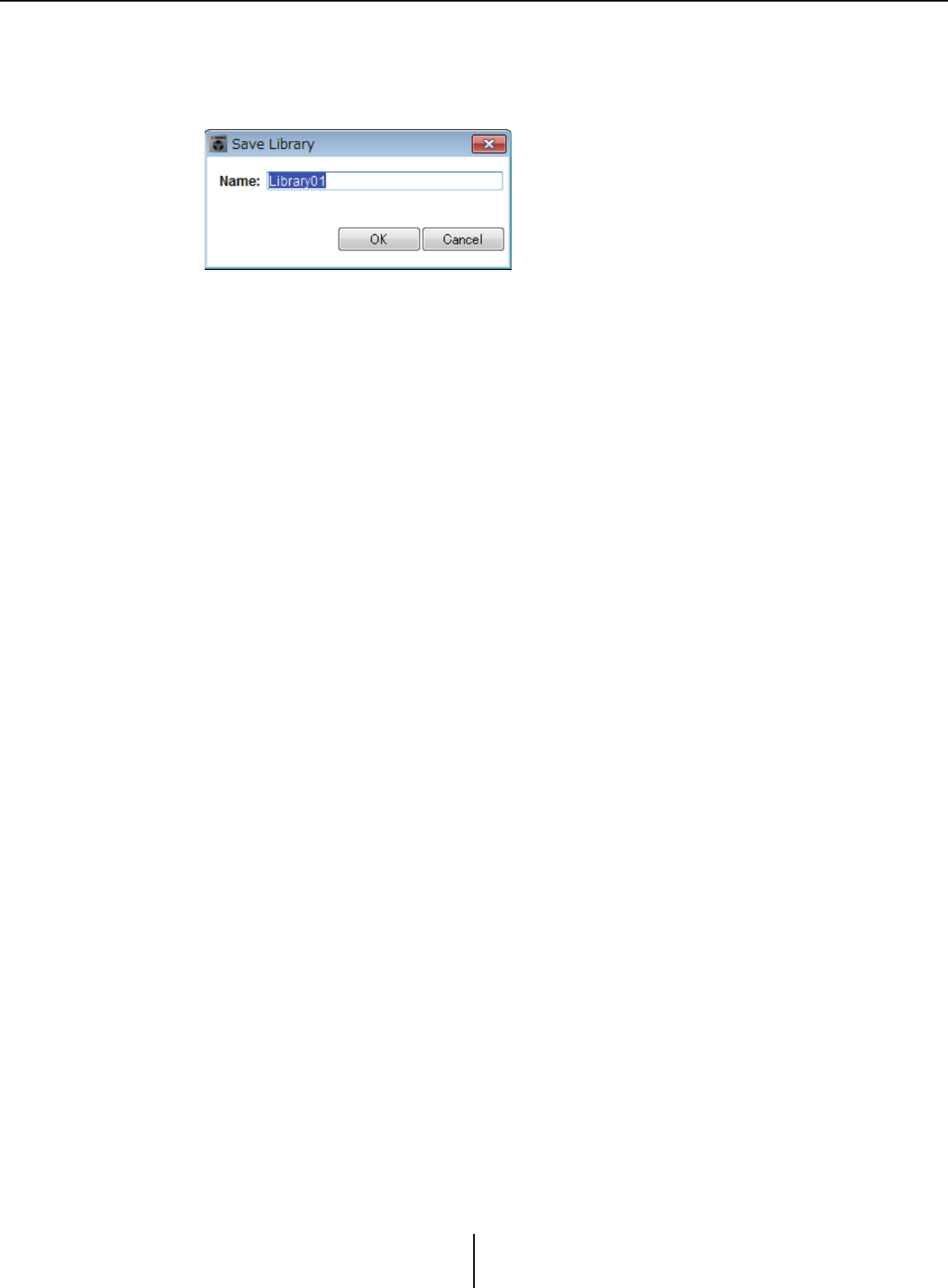
“Digital Control Panel” dialog box Chapter 7. Dialog boxes/Software applications
MTX-MRX Editor User Guide
202
●[Save] button
This button stores an item in the library. The “Save Library” dialog box will appear. If
you edit the parameters of the loaded library item, the text will turn red. The text will
turn black when you save or load the library item.
•[Name:]
Enter a name for the library item.
You can’t enter the name of an existing library item, nor can you enter a blank name.
• [OK] button
Saves the library item and closes the dialog box.
•[Cancel] button
Closes the dialog box without creating a library item.
●[Recall] button
When you click this button, the currently selected library item will be recalled (loaded)
as the current parameters.
●[Library] list
Select the library item that you want to save or load. The currently-loaded library item
is shown in bold characters.
By double-clicking a previously-saved library item, you can edit its name.
• [Copy] button
This button copies the selected library item.
The Copy command is not available while online.
•[Paste] button
This button pastes the copied library item to the library item that’s currently selected
in the list.
The Paste command is not available while online.
•[Clear] button
This button clears the contents of the library item that’s currently selected in the list.
The Clear command is not available while online.
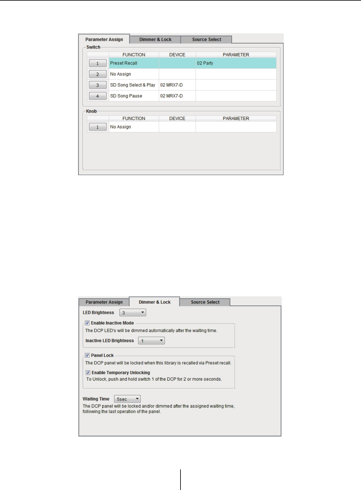
“Digital Control Panel” dialog box Chapter 7. Dialog boxes/Software applications
MTX-MRX Editor User Guide
203
●[Parameter Assign] tab
Here you can assign the MTX/MRX’s parameters to the various controls.
The currently-selected control is highlighted.
The corresponding control is also highlighted in the graphic that’s shown at the left of
the tab.
❍Control select buttons
When you click a button, the “Settings” dialog box will appear, letting you make
settings for the controls.
Specify the device or parameter that will be controlled by the control.
❍[FUNCTION]/[DEVICE]/[PARAMETER]
These show the items specified in the “Settings” dialog box.
●[Dimmer & Lock] tab
Here you can make settings for the brightness of the DCP unit’s LEDs, as well as settings
for its inactive state.

“Digital Control Panel” dialog box Chapter 7. Dialog boxes/Software applications
MTX-MRX Editor User Guide
204
• [LED Brightness] box
Specifies the brightness of the DCP unit’s LEDs. Higher values will make the LEDs
brighter.
• [Enable Inactive Mode] check box
If the check box is selected, the unit automatically enters inactive mode after a time
duration specified in [Waiting Time].
[Inactive LED Brightness] specifies the brightness of the LEDs when inactive.
If the check box is cleared, the drop-down menu is grayed-out and you will be unable
to set the brightness.
• [Panel Lock] check box
If this check box is selected, the DCP panel will be locked when the preset library is
recalled.
If the [Enable Temporary Unlocking] check box is selected, pressing and holding
down DCP switch 1 for two seconds will unlock the panel.
•[Waiting Time]
Specifies the time from the last operation until the unit enters inactive mode or the
panel is locked.
●Menu button ( )
Click this button to execute the following functions.
•[Copy]
Copies the Parameter Assign, Dimmer & Lock, and Source Select of the displayed
DCP to the copy buffer.
•[Paste]
Overwrites the Parameter Assign, Dimmer & Lock, and Source Select settings of the
same model from the copy buffer onto the displayed DCP.
It is only possible to paste settings that were copied within the same MTX/MRX
system.
• [Initialize]
Initializes the Parameter Assign, Dimmer & Lock, and Source Select settings of the
displayed DCP.
• [Clear [Parameter Assign]]
Initializes the Parameter Assign settings of the displayed DCP.
●[Close] button
Closes the dialog box.
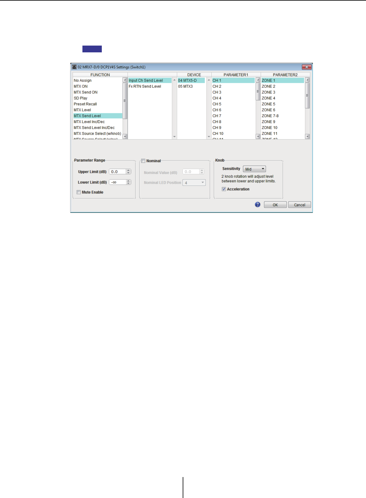
“Digital Control Panel” dialog box Chapter 7. Dialog boxes/Software applications
MTX-MRX Editor User Guide
205
“Settings” dialog box
You can access this dialog box from the “Digital Control Panel” dialog box, the “Wireless
DCP” dialog box, or the “GPI” dialog box.
For details on the “Settings” dialog box that is accessed from the “Preset” dialog box and the
“Scheduler” dialog box, refer to “Settings” dialog box in chapter 6.
●[FUNCTION] list
Selects the function to be controlled. If you select [No Assign], no function will be assigned.
The available range in [FUNCTION] and the contents of [DEVICE], [PARAMETER1],
and [PARAMETER2] will depend on the function that you selected. The options
shown in the lower half will also change.
For details on the functions and the display, refer to List of settings in “Settings” dialog
boxes.
●[DEVICE] list
Select the device that you want to change. These are shown in order of UNIT ID and
model name.
●[PARAMETER1] list / [PARAMETER2] list
Specify the parameters of the function.
For details on these parameters, refer to List of settings in “Settings” dialog boxes.
●[OK] button
Saves the settings and closes the dialog box.
●[Cancel] button
Closes the dialog box without saving the changes.
NOTE
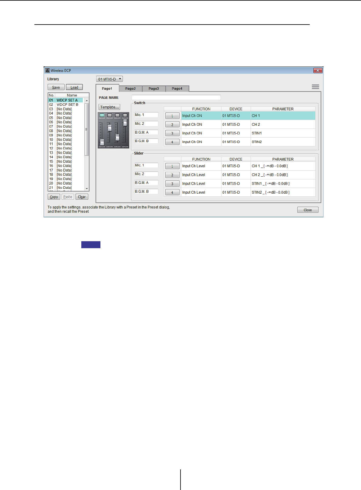
“Wireless DCP” dialog box Chapter 7. Dialog boxes/Software applications
MTX-MRX Editor User Guide
206
❑“Wireless DCP” dialog box
Here you can assign the parameters of the MTX/MRX to controls of the “Wireless DCP” iOS app
so that they can be operated from Wireless DCP. You can’t make settings while online. (Settings can
only be viewed.)
For details on Wireless DCP, refer to the “Wireless DCP User’s Manual.”
You can store 32 sets of Wireless DCP settings in the Library. You can also associate library
items with presets for recall.
• Associate the saved library item with a preset. If it is not associated, the Wireless DCP
settings will not be applied.
• The [Source Select] tab is shown if there is an MRX unit in the MTX/MRX system. For details,
refer to “MRX Designer User Guide.”
For details on the following settings, refer to “Digital Control Panel” dialog box.
• [Save] button
• [Load] button
•[Library] list
• [Copy] button
•[Paste] button
• [Clear] button
• Control select buttons
• [FUNCTION]/[DEVICE]/[PARAMETER]
•“Settings” dialog box
• [Close] button
●MTX/MRX selection box
Here you can select the MTX/MRX to which the iPhone or other mobile device that
you want to specify is connected. These are shown in order of UNIT ID and model
name.
●[Page] tabs
Select the page tab that you want to edit.
NOTE
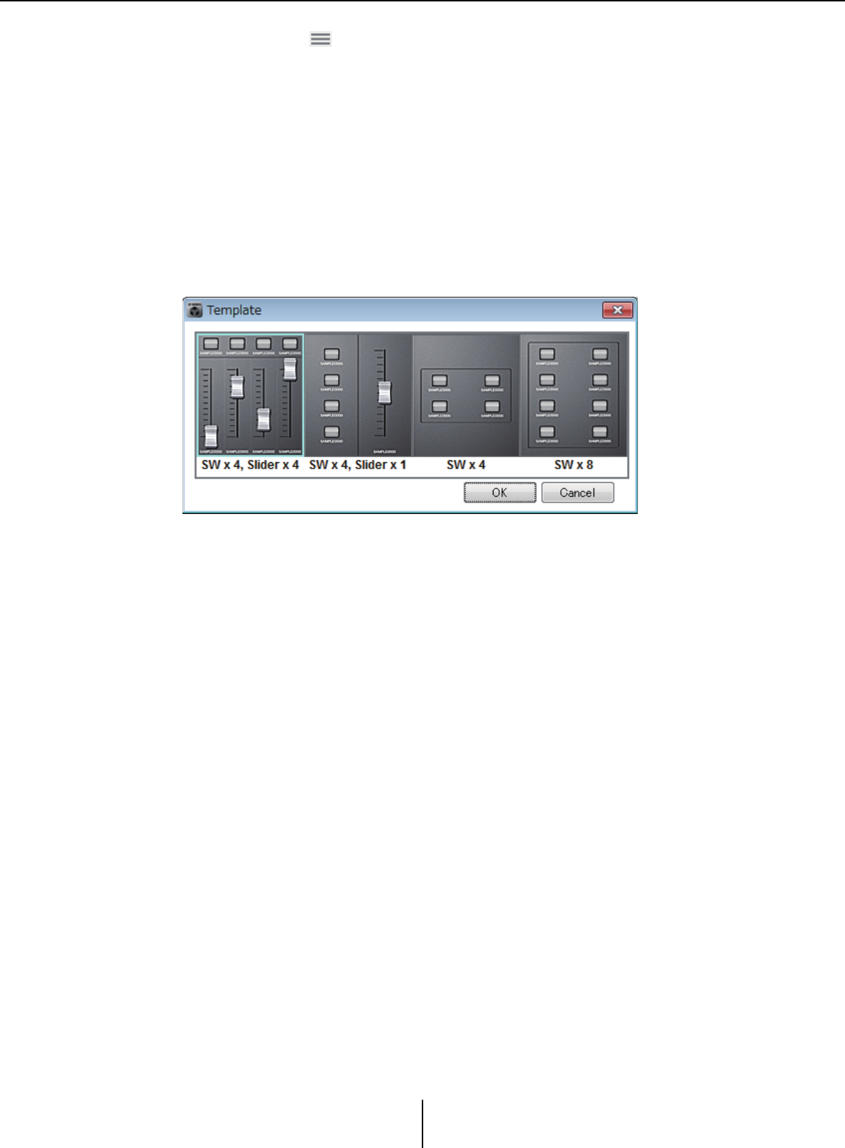
“Wireless DCP” dialog box Chapter 7. Dialog boxes/Software applications
MTX-MRX Editor User Guide
207
●Menu button ( )
Click this button to execute the following functions.
•[Clear Page]
Initializes the displayed page.
•[Clear All Pages]
Initializes the Wireless DCP settings of the selected MTX/MRX.
●[PAGE NAME]
Assign a name to the page. The name in the Wireless DCP “Page select” screen is shown.
●[Template] button
Click this to open the “Template” dialog box. Select the controls that will be shown in
“Wireless DCP.”
Click the template that you want to use.
• [OK] button
Saves the selected template and closes the dialog box.
•[Cancel] button
Cancels the template selection and closes the dialog box.
●Control label
Assign a name to the control.
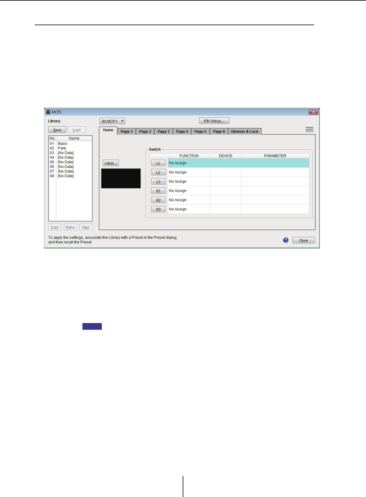
“MCP1” dialog box Chapter 7. Dialog boxes/Software applications
MTX-MRX Editor User Guide
208
❑“MCP1” dialog box
Up to 16 MCP1 units can be connected to one MTX/MRX system.
Using Ethernet cables, connect the MTX/MRX unit’s [NETWORK] port or Dante port to a PoE
network switch, and connect the PoE network switch to the MCP1.
If the network switch does not support PoE, connect a PoE injector between the network switch and
the MCP1.
Some PSE units (PoE network switches or PoE injectors) might have some ports that supply power
and other ports that do not supply power. Connect the MCP1 to a port that supplies power.
In this dialog box you can make settings for the MCP1’s L1/2/3 and R1/2/3 switches and display.
You can store 8 sets of MCP1 settings in the Library. You can also associate library items
with presets for recall.
After editing in a tab such as [Home]/[Page 1]–[Page 6]/[Dimmer & Lock]/[Source
Select], click the item in the [Library] list to which you want to save, and then click the
[Save] button to save the item to the library.
In the [Library] list, click the library item that you want to load, and then click the [Load]
button to load the library item; the settings will be applied to tabs such as [Home]/[Page
1]–[Page 6]/[Dimmer & Lock]/[Source Select].
• If you associate a saved library item with a preset, the parameter assignments of [HOME]
and [Page 1] through [Page 6] for all MCP1 units (up to 16 units) connected to the MTX/
MRX system will be recalled/stored in a single action when you recall that preset. If you want
to recall only a specific MCP1 unit, open the “Preset” dialog box and make [Recall Filter]
settings.
• You must use the “Device Configuration Wizard” dialog box to assign the MTX/MRX and
MCP1 units and specify their ID settings beforehand. If you have not made these settings
yet, you won’t be able to open the “MCP1” dialog box; an alert will be displayed.
• The [Source Select] tab is shown if there is an MRX unit in the MTX/MRX system. For details,
refer to “MRX Designer User Guide.”
●MCP1 select list box
Select the MCP1 unit for which you want to make settings. All MCP1 units that are
connected to the MTX/MRX system are listed in order of UNIT ID and the name of the
MCP1 unit.
●[PIN Setup] button
This button shows the “PIN Setup” dialog boxwhere you can specify three types of PIN.
NOTE

“MCP1” dialog box Chapter 7. Dialog boxes/Software applications
MTX-MRX Editor User Guide
209
●[Save] button
This button saves an item in the library. The “Save Library” dialog box will appear. If
you edit the parameters of the loaded library item, the text will turn red. The text will
turn black when you save or load the library item.
•[Name:]
Enter a name for the library item.
You can’t enter the name of an existing library item, nor can you enter a blank name.
• [OK] button
Saves the library item and closes the dialog box.
•[Cancel] button
Closes the dialog box without creating a library item.
●[Load] button
When you click this button, the currently selected library item will be loaded as the
current parameters.
●[Library] list
Select the library item that you want to save or load. The currently-loaded library item
is shown in bold characters.
By double-clicking a previously-saved library item, you can edit its name.
• [Copy] button
This button copies the selected library item.
The Copy command is not available while online.
•[Paste] button
This button pastes the copied library item to the library item that’s currently selected
in the list.
The Paste command is not available while online.
•[Clear] button
This button clears the contents of the library item that’s currently selected in the list.
The Clear command is not available while online.
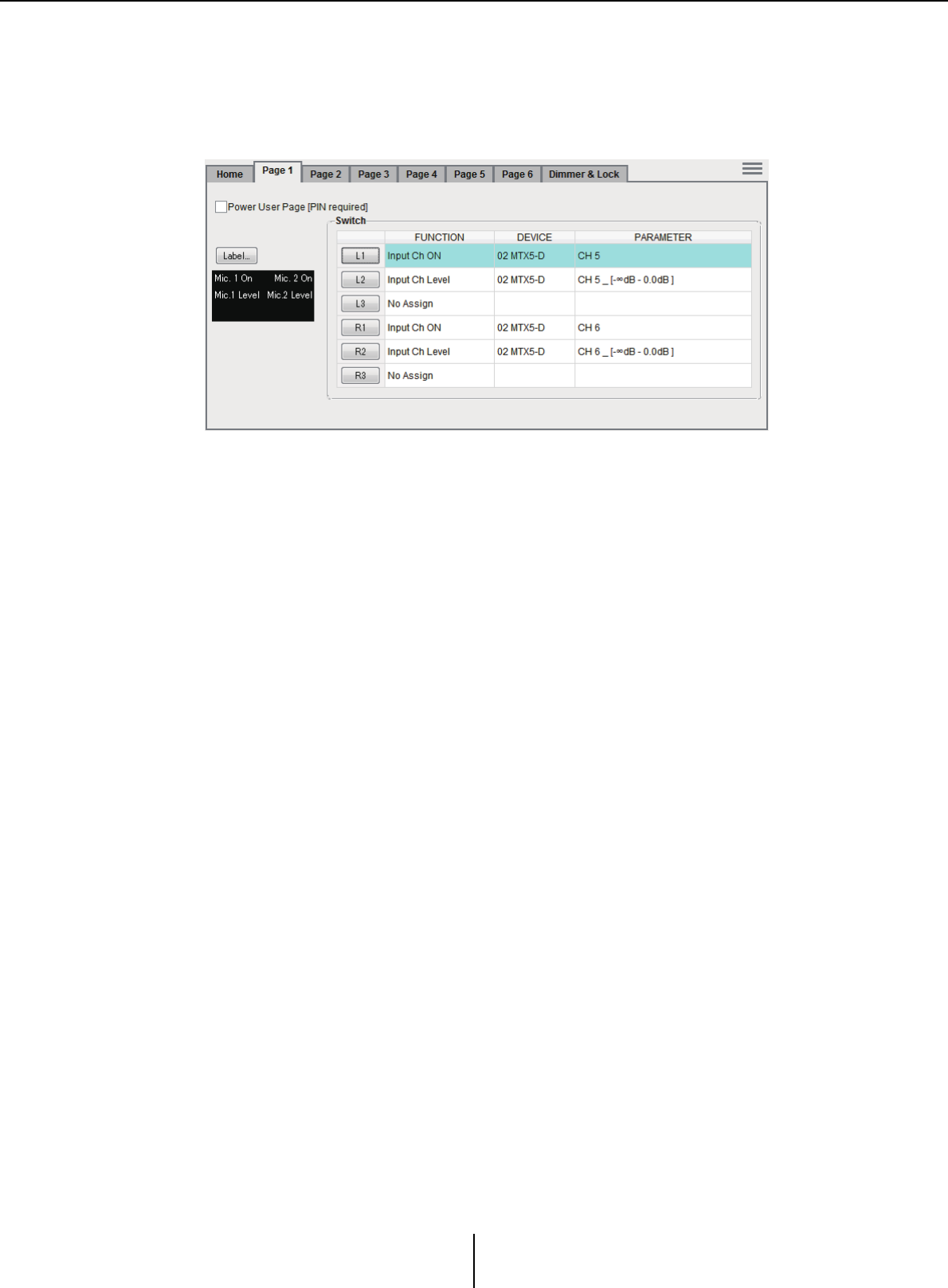
“MCP1” dialog box Chapter 7. Dialog boxes/Software applications
MTX-MRX Editor User Guide
210
●[Home]/[Page 1]–[Page 6] tabs
Here you can make settings related to the MCP1 page. The home page is the page that
appears at start-up, or when you touch the MCP1’s home switch.
In the home page, you can switch pages by assigning [Open Page] to a switch. Here we
explain using the [Page 1] tab.
The currently-selected switch is highlighted.
❍[Power User Page [PIN required]] check box (other than the [Home] page)
If this check box is selected, the PIN code specified in the [Power User PIN:] field of
the “PIN Setup” dialog box must be entered on the MCP1 when the page is opened.
❍[Label] button
When you click this button, the “Label” dialog box appears, allowing you to create
an image for the display. The currently specified image is shown below the button.
❍Switch select buttons
When you click a button, the “Settings” dialog box will appear, letting you make
settings for each switch.
Specify the device or parameter that will be controlled by the switch.
❍[FUNCTION]/[DEVICE]/[PARAMETER]
These show the items specified in the “Settings” dialog box.
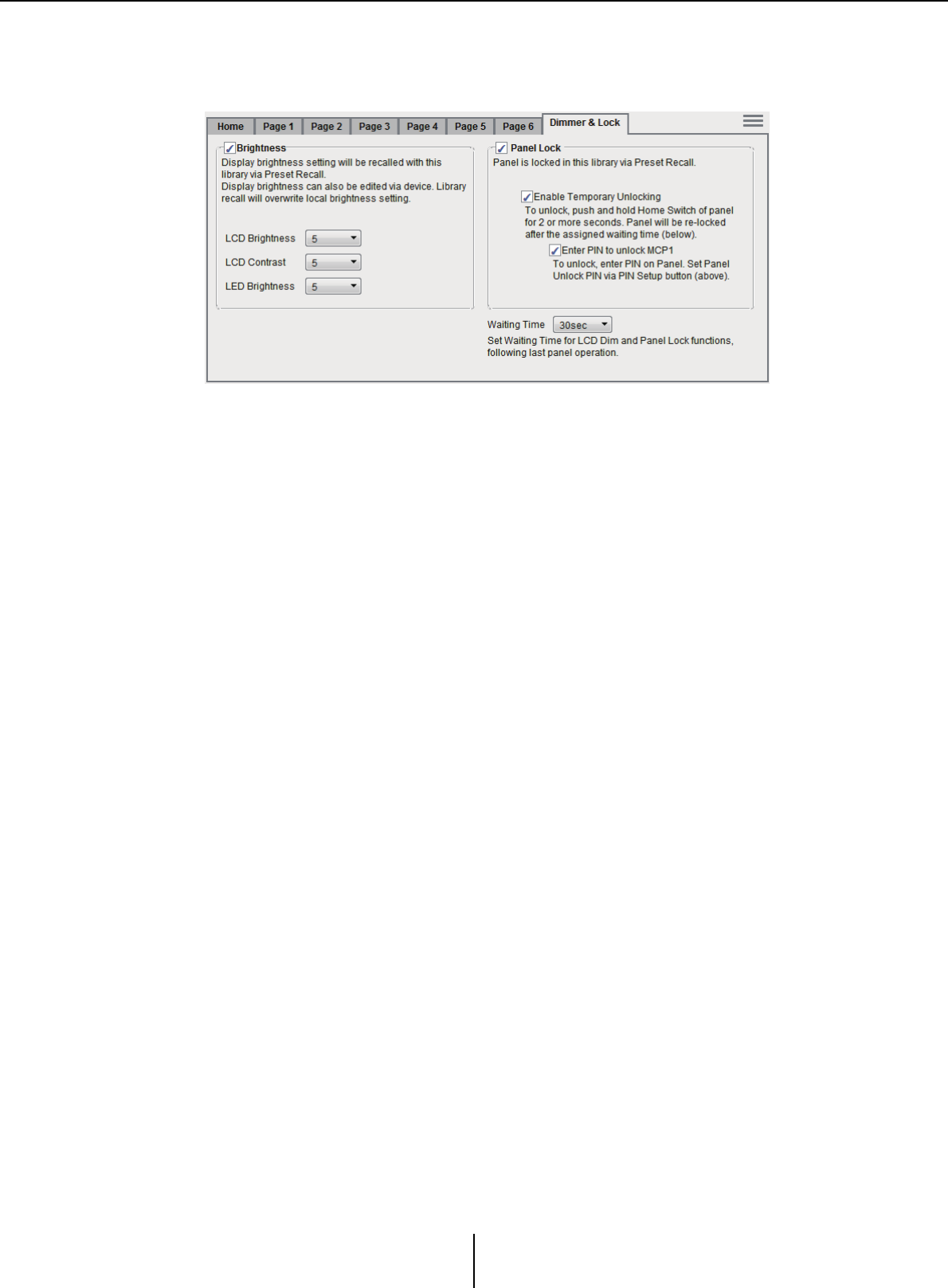
“MCP1” dialog box Chapter 7. Dialog boxes/Software applications
MTX-MRX Editor User Guide
211
●[Dimmer & Lock] tab
Here you can make settings for the brightness of the MCP1’s display and switches, and
for panel lock.
• [Brightness] check box
If this check box is selected, the brightness and contrast of the display, and the
brightness of the switches, can be changed when a preset recalls the currently-edited
library item.
[LCD Brightness] specifies the brightness of the display. Higher values will make the
display brighter.
[LCD Contrast] specifies the display’s contrast. Higher values produce a greater
difference between light and dark.
[LED Brightness] specifies the brightness of the switches. Higher values will make
the switches brighter.
If the check box is cleared, the drop-down menu is grayed out and you will be unable
to set the brightness.
• [Panel Lock] check box
If this check box is selected, the MCP1 panel will be locked when the library item is
recalled by a preset.
If the [Enable Temporary Unlocking] check box is selected, pressing and holding
down the MCP1’s home switch for two seconds or longer will unlock the panel.
If the [Enter PIN to unlock MCP1] check box is selected, pressing and holding down
the MCP1’s home switch for two seconds or longer will then require the PIN code
specified in [Panel Unlock PIN:] of the “PIN CODE” dialog box to be entered on the
MCP1.
•[Waiting Time]
Specifies the time from the last operation until the unit enters inactive mode or the
panel is locked.

“MCP1” dialog box Chapter 7. Dialog boxes/Software applications
MTX-MRX Editor User Guide
212
●Menu button ( )
Click this button to execute the following functions.
•[Copy]
Copies the Home, Page 1–Page 6, Dimmer & Lock, and Source Select settings of the
displayed MCP1 to the copy buffer.
•[Paste]
Overwrites the Home, Page 1–Page 6, Dimmer & Lock, and Source Select settings
from the copy buffer onto the displayed MCP1.
It is only possible to paste settings that were copied within the same MTX/MRX
system.
• [Initialize]
Initializes the Home, Page 1–Page 6, Dimmer & Lock, and Source Select settings of
the displayed MCP1.
•[Clear Page]
Initializes the Home or Page 1–Page 6 settings that are displayed.
•[Clear All Page]
Initializes all of the Home and Page 1–Page 6 settings of the displayed MCP1.
● button
Click this to view help for MCP1 settings.
●[Close] button
Closes the dialog box.
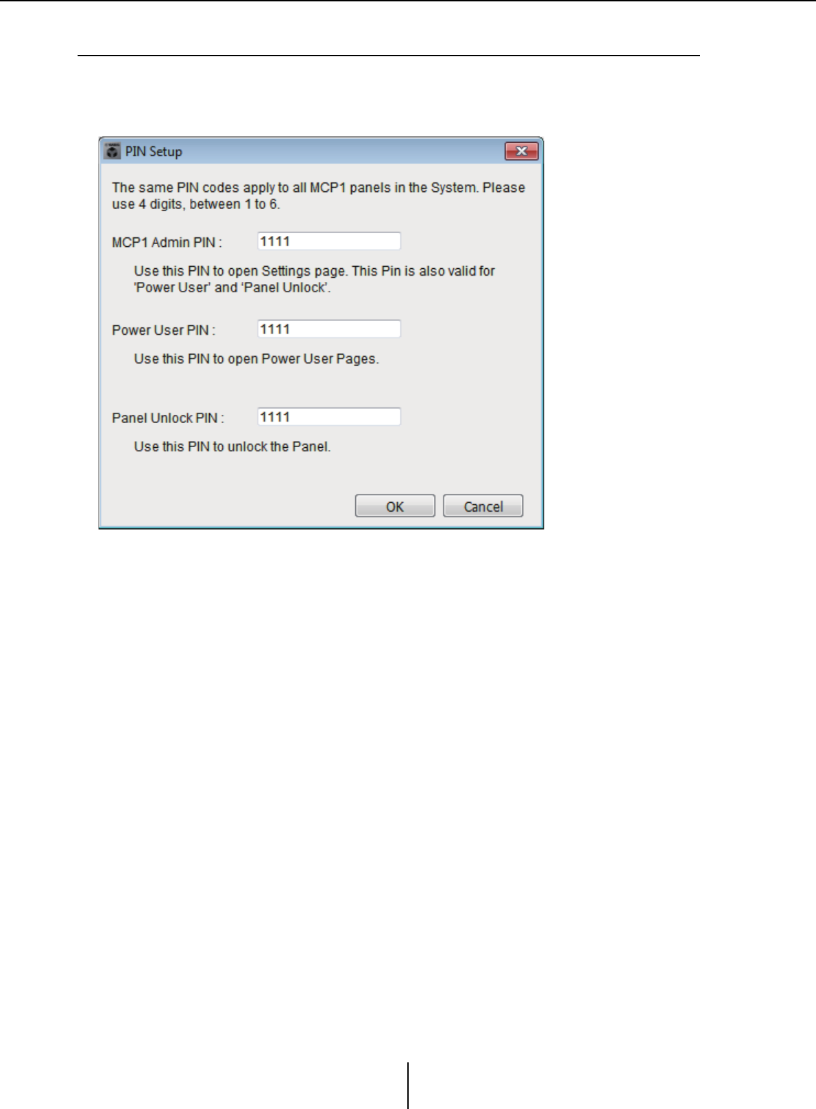
“PIN Setup” dialog box Chapter 7. Dialog boxes/Software applications
MTX-MRX Editor User Guide
213
❑“PIN Setup” dialog box
Here you can specify PIN codes for all MCP1 units within the MTX/MRX system.
A PIN code is specified if the system goes online with the MCP1 even once. If this has not been
specified, use 1111 to unlock.
●[MCP1 Admin PIN:] text box
This is the PIN code for opening the MCP1’s Settings page.
It can also be used as the “Power User PIN” or the “Panel Unlock PIN.”
●[Power User PIN:] text box
This is the PIN code for opening pages for which the [Power User Page [PIN required]]
check box is selected in a [Page 1]–[Page 6] tab of the “MCP1” dialog box.
●[Panel Unlock PIN:] text box
This is the PIN code for defeating panel lock if the [Enter PIN to unlock MCP1] check
box is selected in the [Dimmer & Lock] tab of the “MCP1” dialog box.
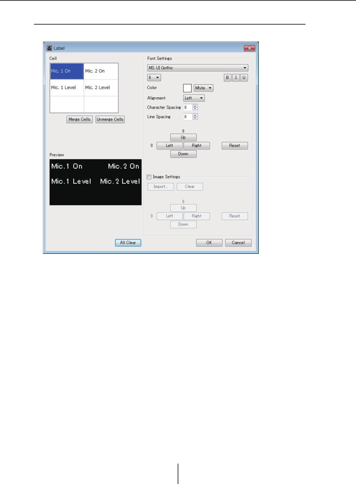
“Label” dialog box Chapter 7. Dialog boxes/Software applications
MTX-MRX Editor User Guide
214
❑“Label” dialog box
Here you can create a page image to show in the MCP1’s display.
●[Cell]
Edit the page image.
To edit the text string, select a cell and double-click or press the <F2> key. To confirm,
press the <Enter> key or use the mouse to select another cell.
To insert an image, select the cell, then select the [Image Settings] check box and press
the [Import] button and select an image file.
To move between cells, you can use not only mouse operations but also the cursor keys,
<Tab> key, or <Enter> key. By holding down the <Shift> key while moving between
cells, you can select a region.
●[Merge Cells] button
Select multiple cells and click this button to merge the cells.
●[Unmerge Cells] button
Select a merged cell and click this button to unmerge the cells.
●“Font Settings” area
Here you can specify the font for the selected cell. The “Preview” area shows how the
settings will appear.
• Font list box
Selects a font for the text string. You can choose from the fonts that are installed in
the computer.

“Label” dialog box Chapter 7. Dialog boxes/Software applications
MTX-MRX Editor User Guide
215
• Font size list box
Selects the font size for the text string.
• [B]/[I]/[U] buttons
Click these buttons to apply bold, italic, or underlined character styles to the text
string in the cell.
•“Color”
Indicates the color of the text string in the cell. Click this button to switch between
white and black.
• [Alignment] list box
Selects the position at which the text string is displayed in the cell.
• [Character Spacing] spin buttons
Specify the spacing of the characters in the cell.
• [Line Spacing] spin buttons
Specify the spacing of the lines in the cell.
• [Up]/[Left]/[Right]/[Down]/[Reset] buttons
Adjusts the position of the characters in the cell. The amount of movement is shown
numerically. Click the [Reset] button to restore the initial settings.
●“Image Settings”
If this check box is selected, you can make settings regarding a background image for
the selected cell.
• [Import] button
Click this to open the “Open File” dialog box. Select image data, and then click the
[OK] button to open the “Re-size Image” dialog box, where you can choose how the
image is placed in the cell. You can select images that have a file extension of *.png,
*.bmp, or *.jpg.
•[Clear] button
Click this to delete the background image.
• [Up]/[Left]/[Right]/[Down]/[Reset] buttons
Adjust the position of the background image in the cell. The amount of movement
is shown numerically. Click the [Reset] button to restore the initial settings.
●“Preview”
Shows the page image.
●[All Clear] button
Initializes all settings of the cell.
●[OK] button
Saves the settings and closes the dialog box.
●[Cancel] button
Discards the settings and closes the dialog box.
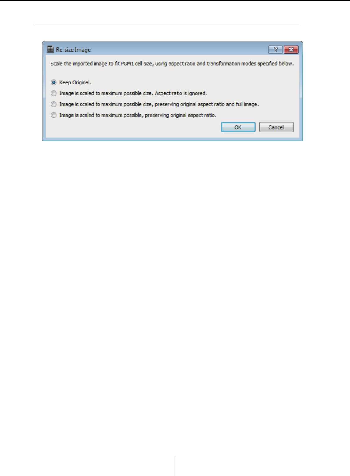
“Re-size Image” dialog box Chapter 7. Dialog boxes/Software applications
MTX-MRX Editor User Guide
216
❑“Re-size Image” dialog box
Here you can select how the image is placed.
●Option buttons
From above, the following choices are provided.
• Keep Original
• Image is scaled to maximum possible size. Aspect ratio is ignore.
• Image is scaled to maximum possible size, preserving original aspect ratio and full
image.
• Image is scaled to maximum possible, preserving original aspect ratio.
●[OK] button
Assigns the image to the cell and closes the dialog box.
●[Cancel] button
Closes the dialog box without assigning the image to the cell.
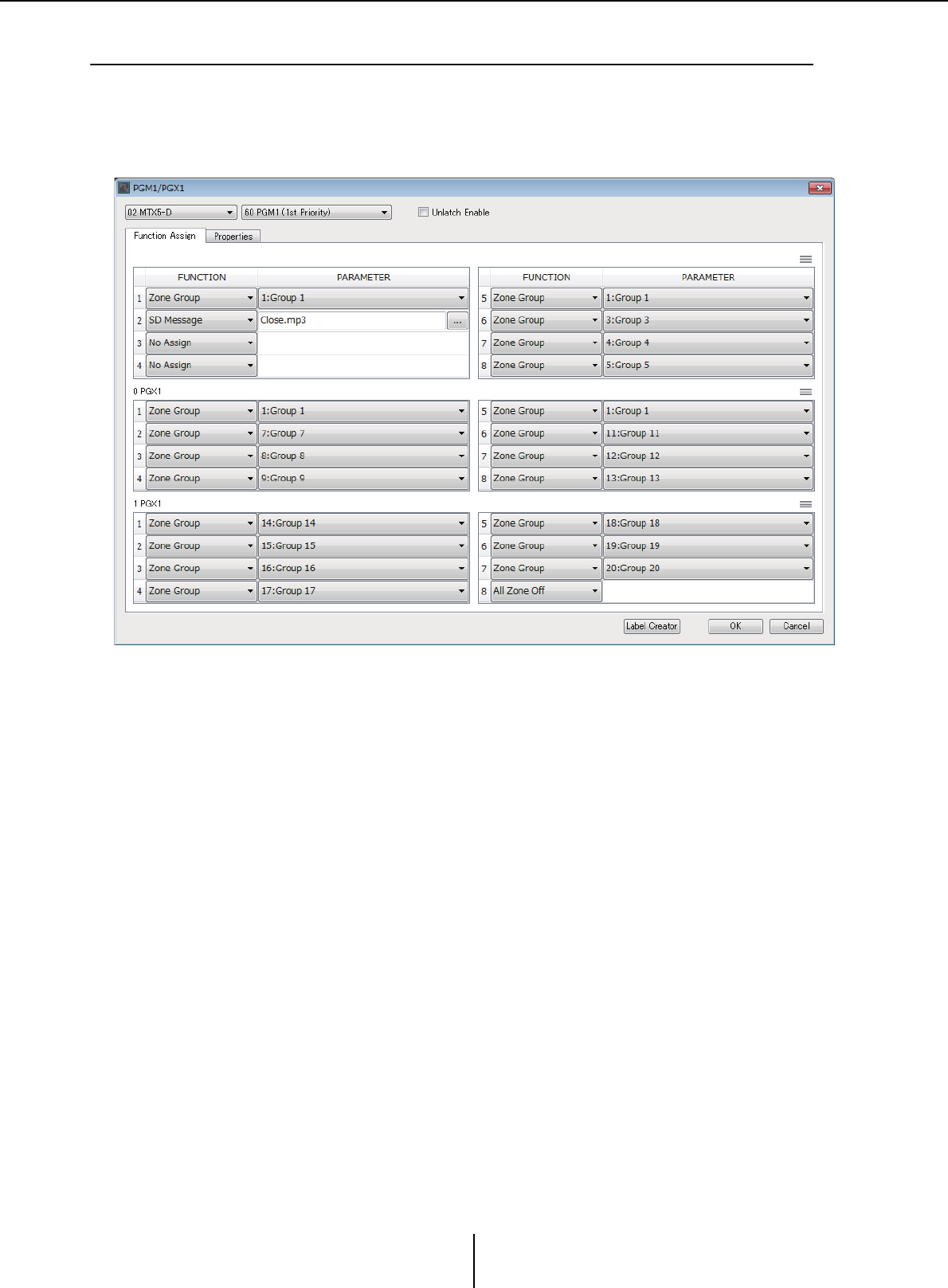
“PGM1/PGX1” dialog box Chapter 7. Dialog boxes/Software applications
MTX-MRX Editor User Guide
217
❑“PGM1/PGX1” dialog box
Here you can make assignments for the zone/message select buttons of the PGM1 and PGX1, and
make settings for the PTT button.
This dialog box can shown only for the MTX5-D or MRX7-D. If using the PGM1 with the
MRX7-D, use MRX Designer to place the “Paging” component.
●MTX/MRX select list box
Selects the MTX/MRX to which the PGM1 unit for which you want to make settings is
connected. The list box shows units in order of UNIT ID and the name of the MTX/
MRX.
●PGM1 select list box
Select the PGM1 unit for which you want to make settings. All PGM1 units that are
connected to the MTX/MRX selected in the MTX/MRX selection box are listed in
order of UNIT ID and the name of the PGM1 unit.
●[Unlatch Enable] check box
If this check box is selected, the PTT button of the selected PGM1 operates both as
latched and unlatched. If this check box is not selected, the PTT button operates as
latched.
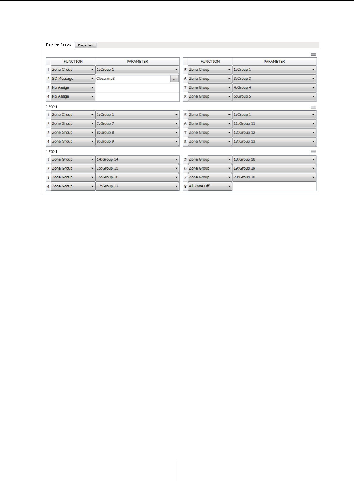
“PGM1/PGX1” dialog box Chapter 7. Dialog boxes/Software applications
MTX-MRX Editor User Guide
218
●[Function Assign] tab
Here you can assign functions to the zone/message select buttons of the PGM1 or
PGX1.
“FUNCTION” provides the following choices.
• [No Assign]
No function is assigned to the button.
•[Zone]
Selects/de-selects the zone to broadcast.
When selected, the zone/message indicator is lit.
•[Zone Group]
Selects/de-selects multiple zones to broadcast in a single operation.
Make zone group settings for the MTX5-D in “PAGING” of the “ZONE” screen, or
for the MRX7-D in the “Zone Group” window of the “Paging” component.
The zone/message indicator is lit when broadcast is possible to all zones that are
registered in the group.
•[Zone Group (Legacy)]
Selects multiple zones to broadcast in a single operation. De-selection is not
possible.
Make zone group settings for the MTX5-D in “PAGING” of the “ZONE” screen, or
for the MRX7-D in the “Zone Group” window of the “Paging” component.
• [SD Message]
Selects the file of the message to play.
• [All Zone Off]
De-selects all zones/zone groups.
This does not affect the selection status for the zones/zone groups of other PGM1/
PGX1 units.

“PGM1/PGX1” dialog box Chapter 7. Dialog boxes/Software applications
MTX-MRX Editor User Guide
219
• [All Zone On/Off]
Selects/de-selects all zones/zone groups.
This does not affect the selection status for the zones/zone groups of other PGM1/
PGX1 units.
The zone/message indicator is lit when broadcast is possible to all zones/zone
groups.
•Menu button ( )
Click the menu button to execute the following functions.
-[Copy]
Copies the FUNCTION and PARAMETER settings of the corresponding
device to the copy buffer.
-[Paste]
Pastes the FUNCTION and PARAMETER settings from the copy buffer,
overwriting them onto the corresponding device.
-[Clear]
Initializes the FUNCTION and PARAMETER settings of the corresponding
device.
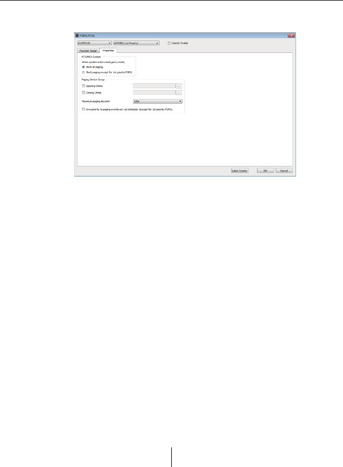
“PGM1/PGX1” dialog box Chapter 7. Dialog boxes/Software applications
MTX-MRX Editor User Guide
220
●[Properties] tab
Here you can make settings for the operation of the PCM1.
• [Stop all broadcast.] option button
If this is selected, paging broadcast including the scheduler will be stopped when the
MTX/MRX system is in emergency mode.
• [Stop broadcast except for 1st Priority PGM1] option button
If this is selected, paging broadcast will be possible only for the 1st Priority PGM1
when the MTX/MRX system is in emergency mode.
• [Opening Chime]/[Closing Chime] check boxes
If these check boxes are selected, you can make settings for the opening chime and/
or closing chime. Click the button at right to specify the chime file that will play. This
setting is shared by the PGM1 (Paging Device Group) units that are connected to the
same MTX/MRX.
• [Maximum paging duration] list box
Selects the time after PTT is turned on until it is automatically turned off. If a
message is being played back, it will not turn off even if the specified time is
exceeded. This setting is shared by the PGM1 units that are connected to the same
MTX/MRX.
• [The scheduler’s paging events are broadcast with higher priority than PGM1.
Paging events have a lower priority than 1st Priority PGM1.] check box
If this check box is selected, the priority order will be “1st Priority PGM1 > events >
normal PGM1.” If this check box is cleared, the priority order will be “1st Priority
PGM1 > normal PGM1 > events.”
●[Label Creator] button
Click this button to start the “PGM1 Label Creator” application.
●[OK] button
Saves the settings and closes the dialog box.
●[Cancel] button
Discards the settings and closes the dialog box.
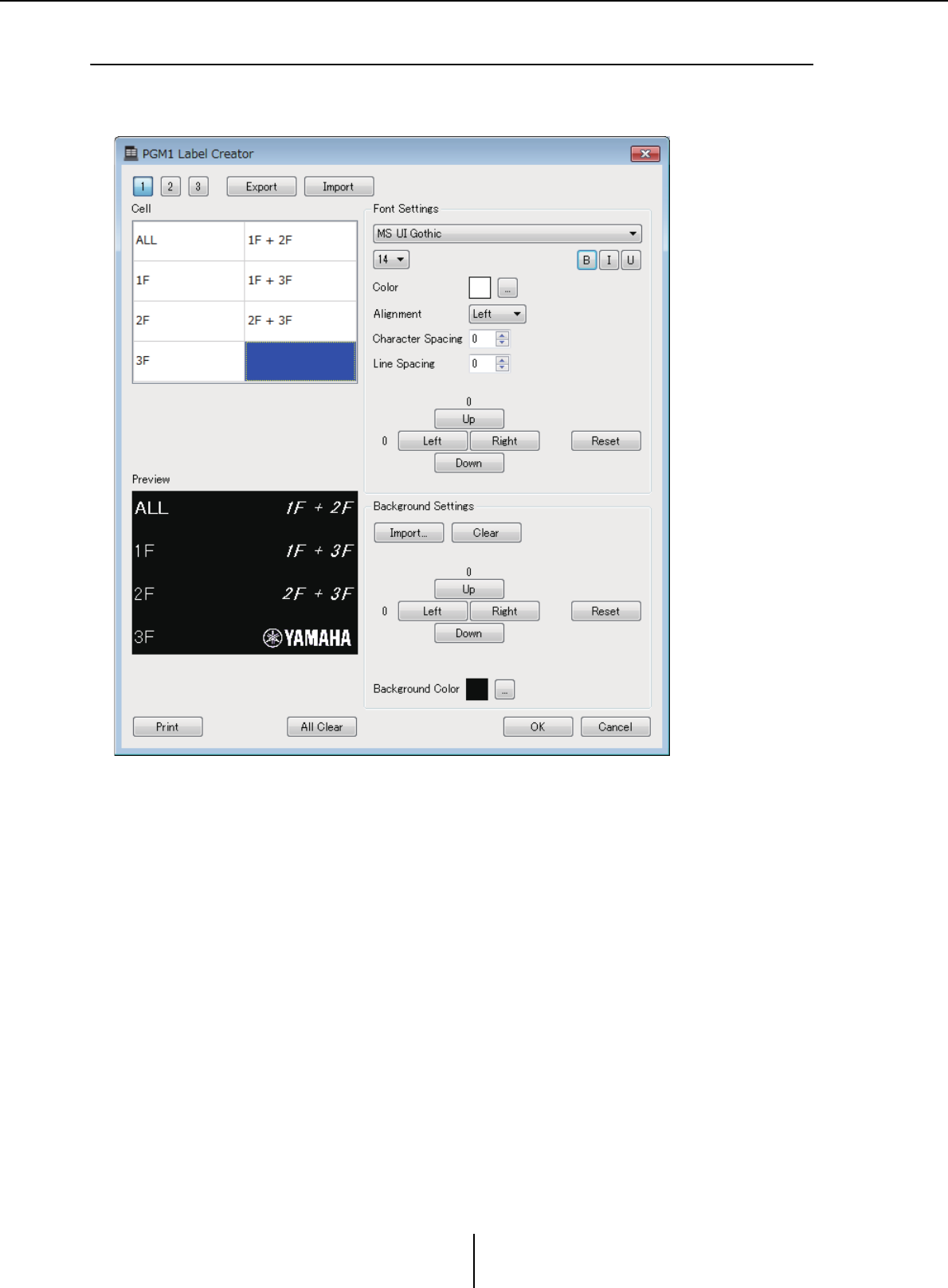
“PGM1 Label Creator” application Chapter 7. Dialog boxes/Software applications
MTX-MRX Editor User Guide
221
❑“PGM1 Label Creator” application
Here you can create a printable label image for the PGM1 or PGX1.
To print the label, connect a printer to the computer.
●Pattern select buttons
Select the label pattern. PGM1 Label Creator can store up to three patterns on one
computer.
●[Export] button
Saves the settings to a file. Click this to open the “Save File” dialog box. The file
extension is *.plc.
●[Import] button
Loads settings from a *.plc file. Click this to open the “Load File” dialog box.
●[Cell]
Here you can edit the label.
To edit the text string, select a cell and double-click or press the <F2> key. To confirm,
press the <Enter> key or use the mouse to select another cell.
To insert an image, select the cell, then press the [Import] button in the “Background
Settings” area, and select an image file.

“PGM1 Label Creator” application Chapter 7. Dialog boxes/Software applications
MTX-MRX Editor User Guide
222
To move between cells, you can use not only mouse operations but also the cursor keys,
<Tab> key, or <Enter> key. By holding down the <Shift> key while moving between
cells, you can select a region.
●“Font Settings” area
Here you can specify the font for the selected cell. The “Preview” area shows how the
settings will appear.
• Font list box
Selects a font for the text string. You can choose from the fonts that are installed in
the computer.
• Font size list box
Selects the font size for the text string.
• [B]/[I]/[U] buttons
Click these buttons to apply bold, italic, or underlined character styles to the text
string in the cell.
•“Color”
Indicates the color of the text string in the cell. When you click this button, the
“Select Color” dialog box will appear, allowing you to select a color.
• [Alignment] list box
Selects the position at which the text string is displayed in the cell.
• [Character Spacing] spin buttons
Specify the spacing of the characters in the cell.
• [Line Spacing] spin buttons
Specify the spacing of the lines in the cell.
• [Up]/[Left]/[Right]/[Down]/[Reset] buttons
Adjusts the position of the characters in the cell. The amount of movement is shown
numerically. Click the [Reset] button to restore the initial settings.
●“Background Settings”
Here you can specify settings for the background image of the selected cell.
• [Import] button
Click this to open the “Open File” dialog box. Select image data, and then click the
[OK] button to open the “Re-size Image” dialog box, where you can choose how the
image is placed in the cell. You can select images that have a file extension of *.png,
*.bmp, or *.jpg.
•[Clear] button
Click this to delete the background image.
• [Up]/[Left]/[Right]/[Down]/[Reset] buttons
Adjust the position of the background image in the cell. The amount of movement
is shown numerically. Click the [Reset] button to restore the initial settings.
•“Background Color”
Indicates the background color of the cell. When you click this button, the “Select
Color” dialog box will appear, allowing you to select a color.
●“Preview”
Shows the print image.
●[Print] button
Click this to open the Print dialog box.

“PGM1 Label Creator” application Chapter 7. Dialog boxes/Software applications
MTX-MRX Editor User Guide
223
●[All Clear] button
Initializes all cell settings for the selected pattern.
●[OK] button
Saves the settings and closes the application. Since the settings are not saved in the
MTX-MRX Editor project file, you should click the [Export] button and save the file if
you want to reuse the settings.
●[Cancel] button
Discards the settings and closes the application.
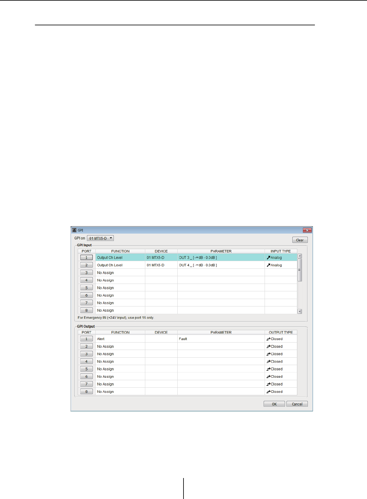
“GPI” dialog box Chapter 7. Dialog boxes/Software applications
MTX-MRX Editor User Guide
224
❑“GPI” dialog box
GPI stands for General Purpose Interface. By using the GPI input/output, you can remotely control
the MTX/MRX via custom-made controllers or external devices. A controller that is connected to
the GPI input connector can be used to switch presets on the MTX/MRX or to control the
parameters of components. GPI input/output settings are made individually for each device.
Display devices such as LEDs and lamps or external control equipment made by other
manufacturers can be connected to the GPI output connector, letting you control the external
device according to the state of presets or parameters.
For hardware-related details such as how to connect the [GPI] connector, refer to the owner’s guide
of each unit.
<Usage example 1>
Using a home-made switch panel to switch presets
Connect a momentary switch to each of the MTX/MRX’s [GPI IN-1] through [GPI IN-3]
connectors, and make settings so that they will recall Preset1–3.
<Usage example 2>
Controlling the volume of the MTX/MRX
Connect a variable resistor to one of the MTX/MRX’s [GPI IN] connectors, and assign
Output Ch Level to the GPI Input Port so that the volume will be controlled.
<Usage example 3>
Controlling the volume of multiple MTX/MRX units
Connect a variable resistor to one of the MTX/MRX’s [GPI IN] connectors, and assign
ZONE Out DCA Group to the GPI Input Port so that the zone volume of multiple
MTXMRX units will be controlled in tandem.
This dialog box can be edited only while offline.

“GPI” dialog box Chapter 7. Dialog boxes/Software applications
MTX-MRX Editor User Guide
225
●[GPI on] box
From the list, choose the MTX/MRX unit whose settings you want to specify. The list
shows the UNIT ID and device name of the MTX/MRX units that are assigned to the
MTX/MRX system.
●[Clear] button
Initializes the settings of all ports.
●PORT select buttons
These buttons open the “Settings” dialog box where you can make settings for each
port.
For details on these parameters, refer to List of settings in “Settings” dialog boxes.
●[OK] button
Saves the settings and closes the dialog box.
●[Cancel] button
Closes the dialog box without saving the changes.
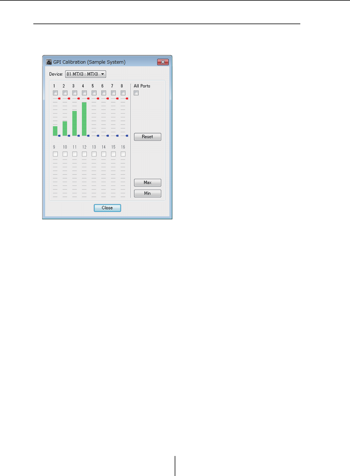
“GPI Calibration” dialog box Chapter 7. Dialog boxes/Software applications
MTX-MRX Editor User Guide
226
❑“GPI Calibration” dialog box
Here you can calibrate the input voltage detection range for the [GPI] connector of the MTX/MRX
unit. (Available only when online.) These settings adjust the detection range in order to stabilize the
input voltage of the [GPI] connector.
●[Device:] box
Selects an MTX/MRX unit within the MTX/MRX system.
From the left, this shows the “UNIT ID,” “Type (model name of the device),” and
“Device Name (name of the device).”
●Channel select check boxes
Calibration will be applied to the channels whose boxes are selected.
●[All Ports] check box
Selects the check boxes of all channels.
●Calibration data
The input voltage is shown in real time as a graph.
●[Reset] button
Calibration will be reset for the channels whose boxes are selected.
●[Max] button
Sets the current input voltage of the selected channels to the maximum value.
The maximum value you set is shown by a red bar.
●[Min] button
Sets the current input voltage of the selected channels to the minimum value.
The minimum value you set is shown by a blue bar.
●[Close] button
Closes the dialog box.

“GPI Calibration” dialog box Chapter 7. Dialog boxes/Software applications
MTX-MRX Editor User Guide
227
Calibration procedure
1. Connect your external device to the MTX/MRX’s [GPI] connector.
2. Select the check box of the channel numbers for which you want to
perform calibration.
If you want to select all channels, select the [All Ports] check box.
3. To specify the detection range, increase the input from the external
device to the maximum and click the [Max] button; then decrease the
input to the minimum and click the [Min] button.
This lets you specify the optimal detection range as appropriate for voltage drop
caused by wiring or due to the specifications of your devices.
• The threshold for on/off switching will be the center value between the maximum and
minimum input voltage values (the sum of the maximum value and minimum value,
divided by 2). To prevent malfunctions, you should allow plenty of range for
detection.
• If the voltage has dropped because of cable length or noise, adjust the maximum
and minimum input voltage values. Since voltage may become unstable, configure
and set up your external circuit to ensure that there is ample distance between the
maximum and minimum values.
NOTE
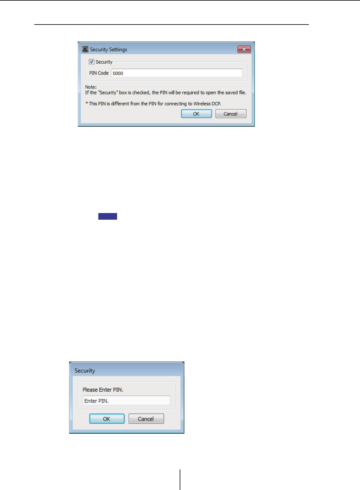
“Security Settings” dialog box Chapter 7. Dialog boxes/Software applications
MTX-MRX Editor User Guide
228
❑“Security Settings” dialog box
On the MTX/MRX system, you can specify a PIN code (numeric password) for security.
●[Security] check box
If this check box is selected, the “Security” dialog box will appear when the project file
starts.
If this check box is cleared, all users will be able to make changes in MTX-MRX Editor.
●[PIN Code]
If the [Security] check box is selected, enter the PIN code (four single-byte numerals).
You cannot enter anything other than single-byte numerals, nor can you enter a blank
PIN code.
• The PIN code can be viewed in this dialog box. Make sure that it is not seen by
another user.
• If you forget the PIN code, you will be unable to open the corresponding project file.
●[OK] button
Updates the settings and closes the dialog box.
If you are online, these settings will be transmitted to all MTX/MRX units in the
project.
If you are offline, they will be transmitted when you go online.
●[Cancel] button
Closes the dialog box without updating the settings.
“Security” dialog box
When you open a project file for which a PIN code has been specified, the “Security”
dialog box appears.
Enter the PIN code, and click the [OK] button.
NOTE
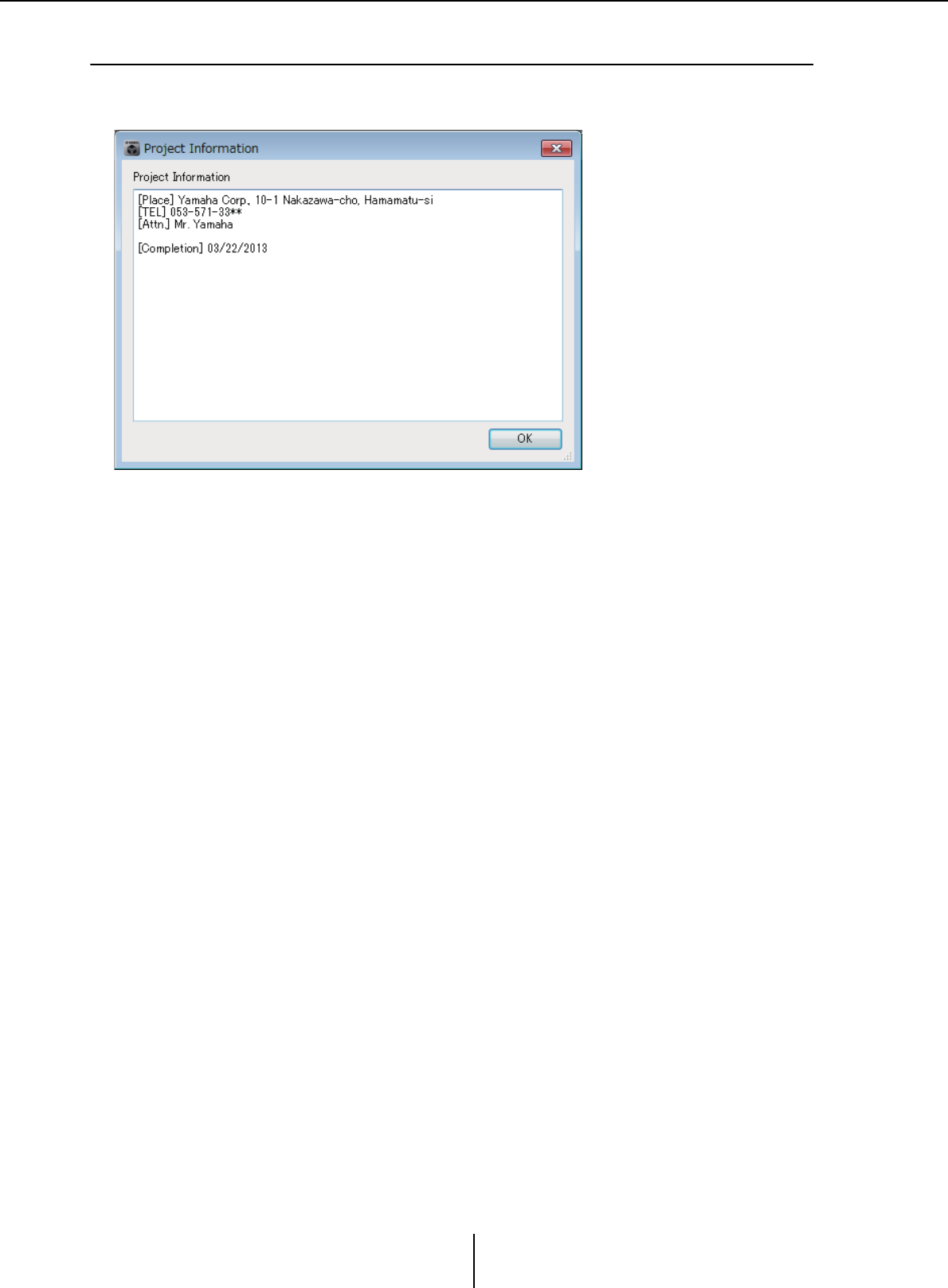
“Project Information” dialog box Chapter 7. Dialog boxes/Software applications
MTX-MRX Editor User Guide
229
❑“Project Information” dialog box
Allows you to include a memo in the project file to record property information or contact
information.
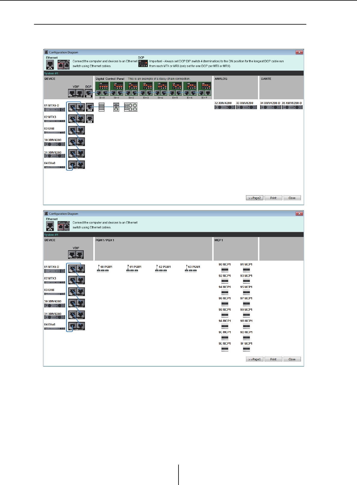
“Configuration Diagram” dialog box Chapter 7. Dialog boxes/Software applications
MTX-MRX Editor User Guide
230
❑“Configuration Diagram” dialog box
Displays a diagram that shows how devices such as the MTX/MRX, XMV, and DCP are connected.
The configuration diagram can be printed.
●[>>Page 2]/[>>Page 1] buttons
Switch between configuration diagram screens.
●[Print] button
Starts printing the configuration diagram.
●[Close] button
Closes the dialog box without printing the configuration diagram.
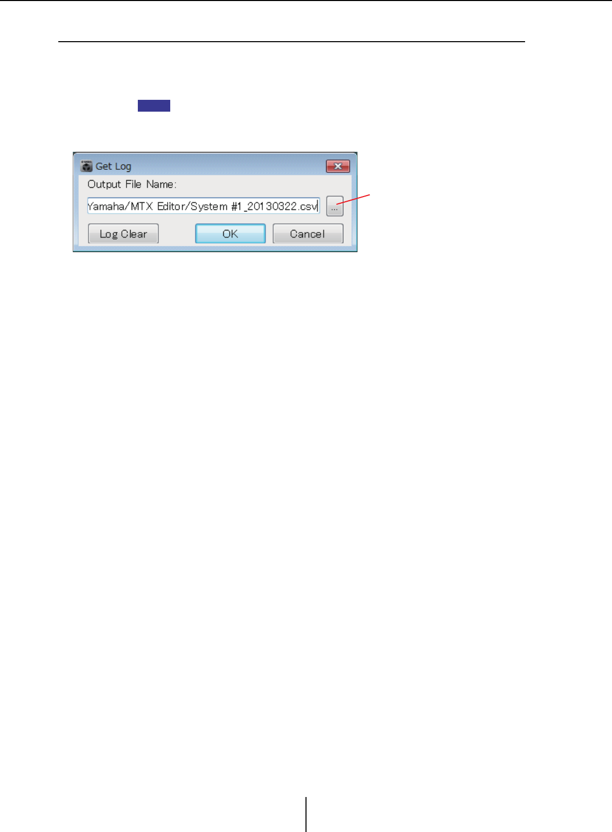
“Get Log” dialog box Chapter 7. Dialog boxes/Software applications
MTX-MRX Editor User Guide
231
❑“Get Log” dialog box
A record of the MTX/MRX system’s operation is stored as a “log” in the MTX/MRX’s internal
memory. In this dialog box you can output the logs of all MTX/MRX units existing on the subnet
to which your computer is connected, and save them as a file. The log file is in “.csv” format.
• The Project screen’s [Alert] tab does not show the information listed in the alert list, but this
is captured in the log.
• The MCP1 and PGM1/PGX1 are not subject to capture in the log.
●[Output File Name] box
Shows the location (absolute path) in which the log file is saved. You can also enter this
directly.
●Browse button
Opens the file browser and selects the file that will be output as the log.
●[Log Clear] button
Deletes the log for all MTX/MRX units existing on the subnet.
When you click this button, a confirmation message will appear. If you click the [Yes]
button, the log will be deleted. If you click the [No] button, the operation will be
cancelled and the dialog box will close. You may be asked to enter the PIN code.
●[OK] button
Outputs the log file and closes the dialog box.
●[Cancel] button
Cancels log file output and closes the dialog box.
NOTE
Browse button
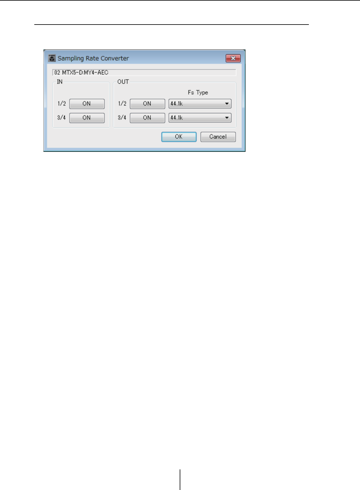
“Sampling Rate Converter” dialog box Chapter 7. Dialog boxes/Software applications
MTX-MRX Editor User Guide
232
❑“Sampling Rate Converter” dialog box
Here you can turn on/off the SRC (Sampling Rate Converter) of the MY4-AEC or MY8-AE96S that
is installed in the device’s slot, and specify the word clock setting of the output.
●[ON] button
Switches the SRC on/off. The button also shows the on/off status.
●[Fs Type] box (MY4-AEC only)
This selects the word clock that will be output from the MY4-AEC when SRC is on.
If you select AES/EBU_IN_CH1/2, the word clock that is received at input 1/2 of the
MY4-AEC will be output. If you select AES/EBU_IN_CH3/4, the word clock that is
received at input 3/4 of the MY4-AEC will be output.
●[OK] button
Applies the settings and closes the dialog box.
●[Cancel] button
Closes the dialog box without applying the settings.
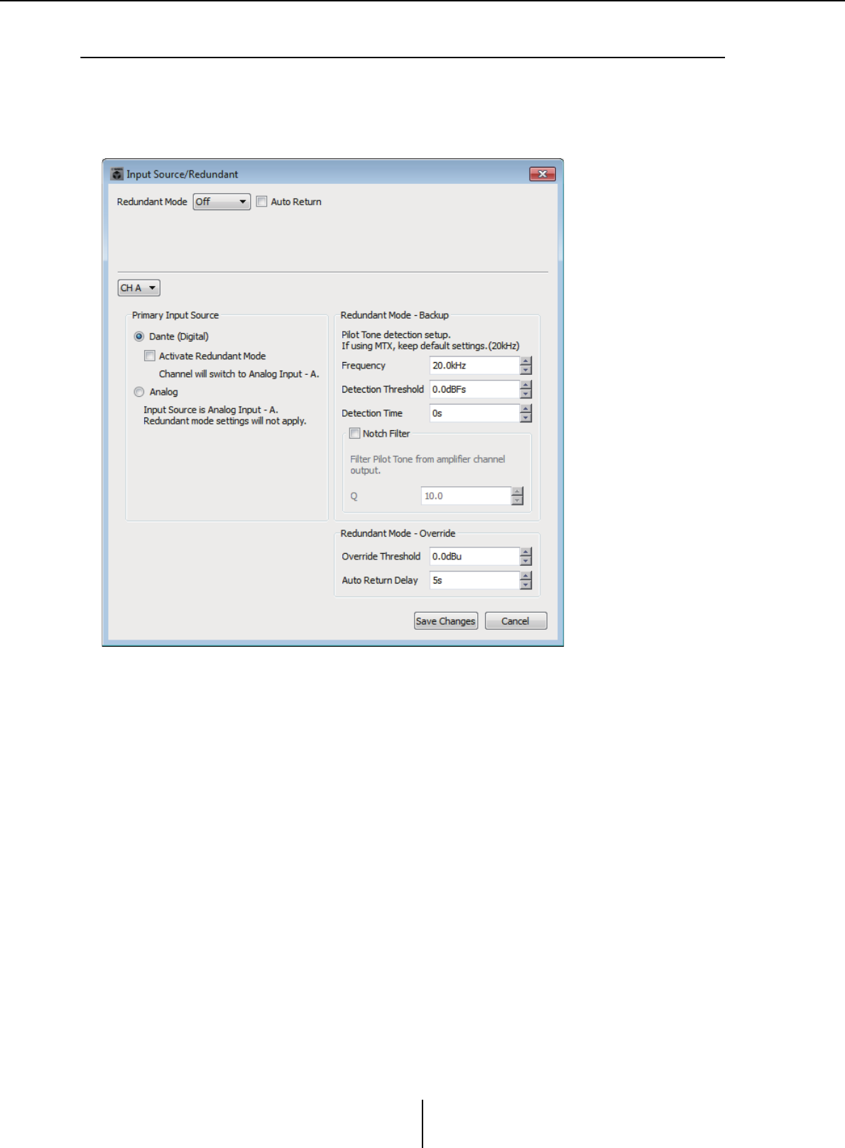
“Input Source/Redundant” dialog box Chapter 7. Dialog boxes/Software applications
MTX-MRX Editor User Guide
233
❑“Input Source/Redundant” dialog box
Here you can specify for each channel whether the input source to the XMV will be digital or
analog. If the input source is specified as digital, you can specify that the input source will switch
from digital to analog when a pilot tone or analog input is detected. Here we explain the screen for
when the digital input is YDIF.
●[Redundant Mode] list box
Selects the redundancy method.
•[Off]
Redundancy is not used.
•[Backup]
Switch to analog input when the pilot tone of the digital input is interrupted due to
a broken connection or other problem.
•[Override]
Switch the digital input to the prescribed analog input when analog audio is
detected.
●[Auto Return] check box
If this check box is selected, operation will be as follows.
•In the case of Backup mode
When the digital input returns, the input source is switched to digital.
• In the case of Override mode
When the analog input falls below the threshold value, the input source is returned
from analog to digital.

“Input Source/Redundant” dialog box Chapter 7. Dialog boxes/Software applications
MTX-MRX Editor User Guide
234
●Channel list box
Selects the input channel for which to make settings.
●“Primary Input Source” area
Here you can specify for each channel whether the input will be digital or analog.
• [YDIF (Digital)]/[Dante (Digital)] option button
The signal of the corresponding channel is taken from YDIF or Dante.
Use the “EXT.I/O” screen to specify the YDIF or Dante patching.
• [Redundant] check box
If this check box is selected, the redundancy function is enabled.
The [Redundant Mode] list box determines the redundancy mode. If [Off] is
selected, the redundancy function is disabled even if this check box is selected.
• [Analog] option button
The signal is taken from the analog input jack of the same name as the
corresponding channel.
●“Redundant Mode - Backup” area
Here you can specify how the pilot tone is detected for each channel. Specify 20.0 kHz
if you’re using the pilot tone of the MTX5-D.
• [Frequency] spin box
Specifies the center frequency of the pilot tone.
• [Detection Threshold] spin box
Specifies the input level threshold value for the pilot tone. Input that exceeds the
threshold value is considered to be the pilot tone.
• [Detection Time] spin box
Specifies the detection time for the pilot tone. If the pilot tone can not be detected
for the specified time interval, it is determined that the input has ceased.
• [Notch Filter] check box
If this check box is selected, a notch filter is enabled to eliminate the frequency
component of the pilot tone so that the pilot tone is not output from the amp.
• [Q] spin box
Specifies the width of the frequency band for the notch filter.
●“Redundant Mode - Override” area
Here you can specify the conditions under which each channel will switch to the analog
input in Override mode.
• [Override Threshold] spin box
Specifies the threshold value for the analog input. When the threshold value is
exceeded, the input source will switch to analog.
• [Auto Return Delay] spin box
If the [Auto Return] check box is selected, this specifies the time after the analog
input falls below the threshold value until the input is switched back to the digital
input.
●[Save Changes] buttons
Saves the settings and closes the dialog box.
●[Cancel] button
Discards the changes and closes the dialog box.
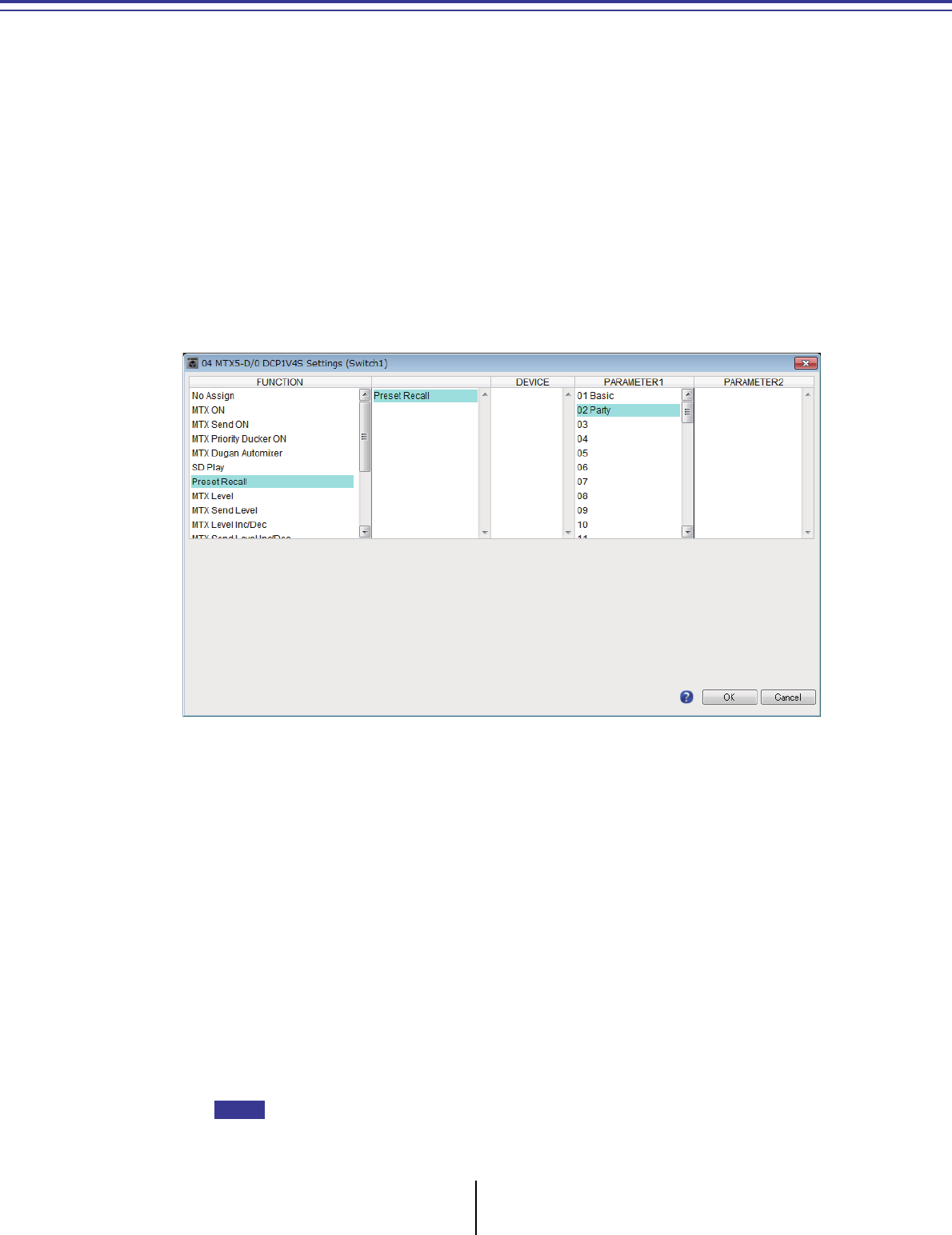
MTX-MRX Editor User Guide
235
Appendix
List of settings in “Settings” dialog boxes
This section explains the settings in the following “Settings” dialog boxes.
For details about settings that are unique to the MRX series, refer to “MRX Designer User Guide.”
• DCP/Wireless DCP/MCP1
•GPI Input
• GPI Output
■DCP/Wireless DCP/MCP1
Settings for the switches and knobs/sliders of the DCP, the Wireless DCP, or MCP1 are
explained here.
●If [FUNCTION] is [No Assign]
Use this setting if you don’t want the switch or the knob/slider of the controller to
change any setting. This is unavailable for [DEVICE] and for [PARAMETER 1/2].
●If [FUNCTION] is [Open Page] (only for the HOME page of the MCP1)
The switch of the MCP1 changes pages of the MCP1.
●If [FUNCTION] is [MTX ON] (switch only)
The switch turns the parameter on/off.
Select one of the following parameter types, and then make the appropriate setting.
•Input Ch ON
•Fx RTN ON
• ZONE Out ON
•Output Ch ON
• Input Ch Mute Group
•ZONE Out Mute Group
In the case of Input Ch Mute Group and ZONE Out Mute Group, the unit’s LED is unlit when
mute is on.
NOTE

List of settings in “Settings” dialog boxes Appendix
MTX-MRX Editor User Guide
236
❍[DEVICE]
Select the device that you want to change. These are shown in order of UNIT ID and
model name.
❍[PARAMETER1]
Specify the channel that will control the on/off setting of the parameter.
●If [FUNCTION] is [MTX Send ON] (switch only)
The switch turns the send on/off.
Select one of the following parameter types, and then make the appropriate setting.
•Input Ch Send ON
•Fx RTN Send ON
❍[DEVICE]
Select the device that you want to change. These are shown in order of UNIT ID and
model name.
❍[PARAMETER1][PARAMETER2]
Specify the channel that will control send on/off.
●If [FUNCTION] is [MTX Priority Ducker ON] (switch only)
The switch turns the zone’s Ducker on/off.
Select one of the following parameter types, and then make the appropriate setting.
•1st Priority
•2nd Priority
❍[DEVICE]
Select the device that you want to change. These are shown in order of UNIT ID and
model name.
❍[PARAMETER 1]
Select the ZONE that will control Ducker on/off.
●If [FUNCTION] is [MTX Dugan Automixer] (switch only)
The switch turns the parameter on/off.
Select one of the following parameter types, and then make the appropriate setting.
•Override (master)
•Mute (master)
•override (Ch)
❍[DEVICE]
Select the device that you want to change. These are shown in order of UNIT ID and
model name.
❍[PARAMETER 1]
For Override (master) and Mute (master), select the group that controls on/off. For
override (Ch), select the channel that controls on/off.
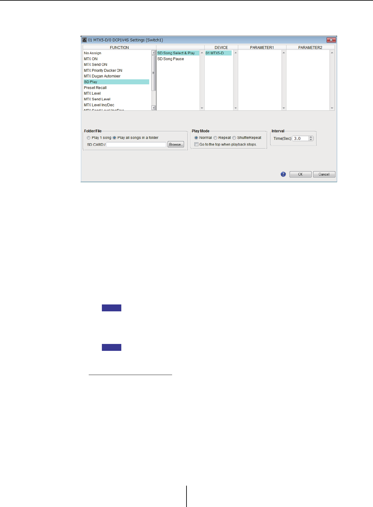
List of settings in “Settings” dialog boxes Appendix
MTX-MRX Editor User Guide
237
●If [FUNCTION] is [SD Play] (switch only)
Play/stop the audio file that is specified by the switch.
Select one of the following parameter types, and then make the appropriate setting.
•SD Song Select & Play
•SD Song Pause
❍[DEVICE]
Select the device that you want to change. These are shown in order of UNIT ID and
model name.
❍[Folder/File] (only if parameter type is [SD Song Select & Play])
Here you can select the song or folder that you want to play from the SD memory card.
✦[Play 1 song]/[Play all songs in a folder]
If you choose [Play 1 song], only the song currently selected in [SD CARD:/] will play.
If you select [Play all songs in a folder], all songs saved in the folder selected by [SD
CARD:/] will play.
Up to 100 songs will be played in ascending order of their file name.
✦[SD CARD:/] box
This shows the name of the song that will be played, or the name of the folder. You can
change the name, or enter it directly.
You can also enter Japanese.
✦[Browse] button
If [Play 1 song] is selected
Select the file shown in [SD CARD:/].
The following file and folder formats can be shown.
• (folder name)\(file name).mp3
• (folder name)\(file name).wav
•(file name).mp3
•(file name).wav
NOTE
NOTE

List of settings in “Settings” dialog boxes Appendix
MTX-MRX Editor User Guide
238
If [Play all songs in a folder] is selected
Select the folder shown in [SD CARD:/]. Up to 100 songs saved in the currently
selected folder will play.
The following folder formats can be shown.
•(folder name)
•blank
- Only first-level folders are valid.
- If the folder name is blank, the songs that exist in the root level of the memory card
will be played (folders below the root level will not be included).
❍[Play Mode] (only if parameter type is [SD Song Select & Play])
✦[Normal]/[Repeat]/[Shuffle Repeat]
This specifies the play mode for the song or songs.
If you choose [Normal], the specified song or songs in the folder will play once.
If you choose [Repeat], the specified song or songs in the folder will play repeatedly.
If you choose [Shuffle Repeat], the songs in the specified folder will play repeatedly in
random order. If you choose [Play 1 song] in [Folder/File], the [Shuffle Repeat]
setting will be unavailable.
✦[Go to the top when playback stops.]
When you stop song playback, this specifies whether the song will pause at the
location where you stopped or will return to the beginning of the song.
If this is on, playback will begin from the beginning of the song or the first song in the
folder the next time you start playback.
If this is off, playback will begin from the location at which you stopped the next time
you start playback.
●If [FUNCTION] is [Preset Recall] (switch only)
The preset specified by the switch will be recalled.
❍[PARAMETER1]
Selects the preset number that will be recalled.
●If [FUNCTION] is [MTX Level] or [MTX Send Level]
In the case of Knob/Slider/MCP1
The knob, slider, or MCP1 switch controls the level or send level.
Select one of the following parameter types, and then make the appropriate setting.
In the case of MTX Level
•Input Ch Level
•Fx RTN Level
•Matrix Out Level
•ZONE Out Level
•Output Ch Level
•1st Priority Mix Level
•2nd Priority Mix Level
•Input Ch DCA Group
•ZONE Out DCA Group
If you want to control multiple input channels, use [Input Ch DCA Group] or [ZONE Out DCA
Group].
In the case of MTX Send Level
•Input Ch Send Level
•Fx RTN Send Level
NOTE
NOTE

List of settings in “Settings” dialog boxes Appendix
MTX-MRX Editor User Guide
239
❍[DEVICE]
Select the device that you want to change. These are shown in order of UNIT ID and
model name.
❍[PARAMETER1]/[PARAMETER2]
Specify the channel whose level will be controlled.
❍[Parameter Range]
Use [Upper Limit] and [Lower Limit] to specify the range in which the level can be
varied.
If [Mute Enable] is on, the mute state (–∞ dB) will be enabled if the level is lowered
below the value specified by [Lower Limit].
• If the nominal value specified by the following [Nominal Value] is higher than the
[Upper Limit], the [Upper Limit] will rise in tandem with the [Nominal Value].
Conversely, if the nominal value goes below the [Lower Limit], the [Lower Limit] will
fall in tandem with the [Nominal Value].
• By using [Parameter Range] you can limit the range in which the user can control
the volume. For example you can use this to specify the maximum volume of
background music, or use a controller to make fine volume adjustments in a narrow
range of –6 dB – +6 dB.
❍[Nominal] check box (DCP only)
Here you can make settings for the Nominal function.
By specifying the nominal value, you can assign a specific LED position as the
normal volume setting. For example by specifying the center LED as the volume
setting for normal use and setting the maximum value to the maximum volume that
is allowable for the system, you can prevent damage to the system that might occur
if the volume of the background music were raised during a noisy time.
If the check box is selected, the Nominal function will be on.
[Nominal Value] specifies the nominal value.
[Nominal LED Position] specifies the LED position that will light when the level
reaches the nominal value.
If the check box is cleared (Nominal function off), both parameters will be grayed-
out and unavailable.
❍[Knob] (DCP only)
Here you can make settings for the DCP’s knobs.
[Sensitivity] specifies the sensitivity at which the parameter will change when the
DCP’s knob is rotated.
If [Acceleration] is on, the parameter will change faster if the knob is rotated more
rapidly. If [Fast] is selected as the [Sensitivity], the [Acceleration] setting is dimmed
and unavailable.
❍[Switch] (MCP1 only)
Here you can make settings for the MCP1’s switches.
[Sensitivity] specifies the sensitivity at which the parameter will change when the
MCP1’s switch is touched.
In the case of a switch (DCP1V4S–US/EU only)
Use the switch to change what will be controlled by the knob.
Choose this if you want the knob to have more than one function.
If the switch is set to [MTX Level] or [MTX Send Level], the knob operation select
button will be dimmed, and you won’t be able to make knob settings.
For details on the various settings, refer to the case for knobs/sliders described above.
NOTE
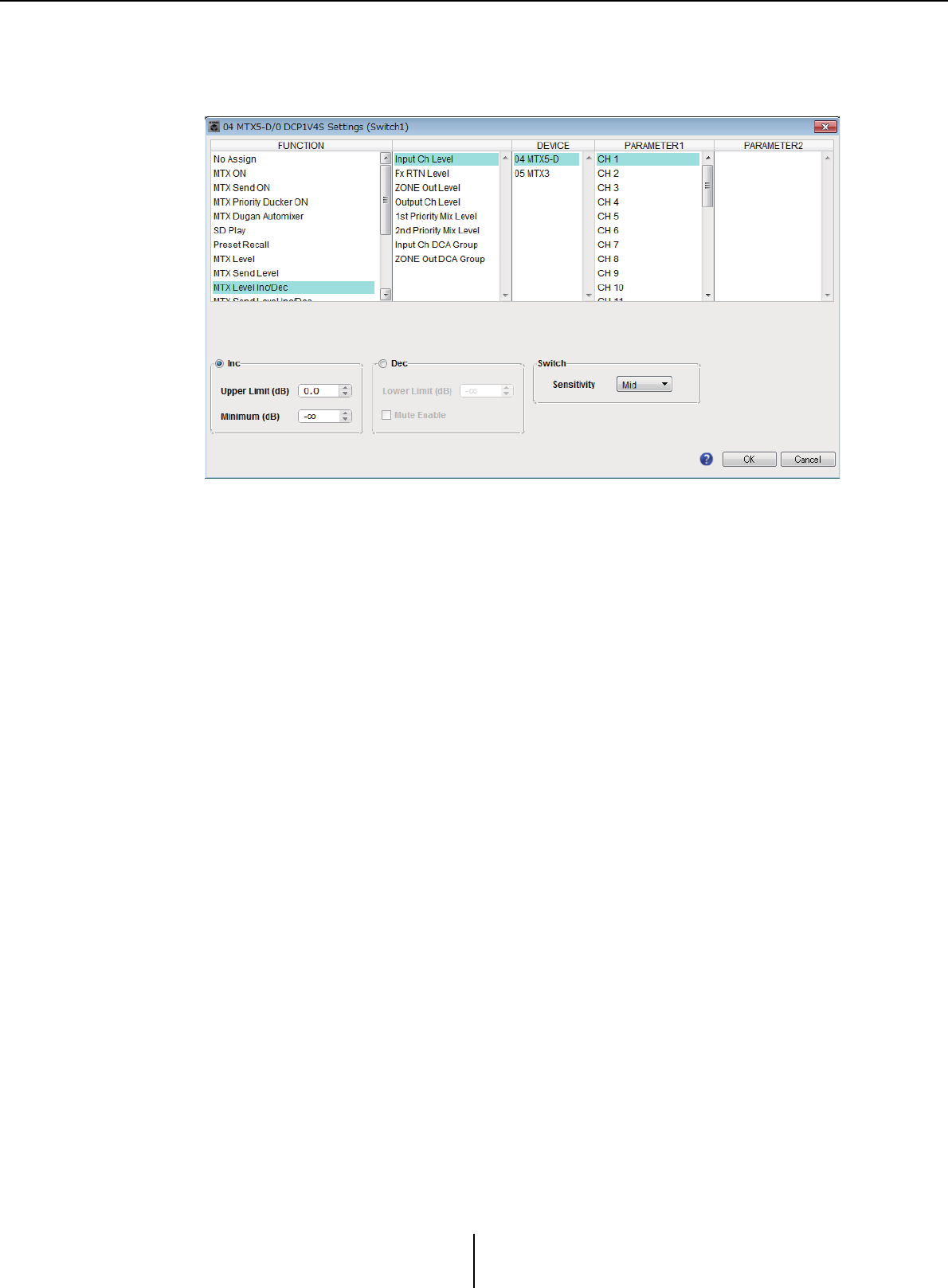
List of settings in “Settings” dialog boxes Appendix
MTX-MRX Editor User Guide
240
●If [FUNCTION] is [MTX Level Inc/Dec] or [MTX Send Level Inc/Dec]
(DCP switches only)
Use the switch to change the level or send level.
Select one of the following parameter types, and then make the appropriate setting.
If [FUNCTION] is [MTX Level Inc/Dec]
•Input Ch Level
•Fx RTN Level
•Matrix Out Level
•ZONE Out Level
•Output Ch Level
•1st Priority Mix Level
•2nd Priority Mix Level
•Input Ch DCA Group
•ZONE Out DCA Group
If [FUNCTION] is [MTX Send Level Inc/Dec]
•Input Ch Send Level
•Fx RTN Send Level
❍ [DEVICE]
Select the device that you want to change. These are shown in order of UNIT ID and
model name.
❍[PARAMETER1]/[PARAMETER2]
Specifies the channel for which the level or send level will be raised or lowered. If
[FUNCTION] is [Send Level Inc/Dec], use [PARAMETER2] to set ZONE, Fx, and
ANC.
❍[Inc]
If you select this option, pressing the switch repeatedly will raise the level or the send
level.
✦[Upper Limit]
Specifies the maximum level achieved when you press the switch.
✦[Minimum]
If the current parameter value is lower than the value specified here, pressing the
switch once will set the parameter to this value.

List of settings in “Settings” dialog boxes Appendix
MTX-MRX Editor User Guide
241
❍[Dec]
If you select this option, pressing the switch repeatedly will lower the level or the
send level.
✦[Lower Limit]
Specifies the minimum level to be achieved when you press the switch.
✦[Mute Enable] check box
If this option is selected, the Mute state (–∞ dB) will be enabled if the level is lowered
below the value specified by [Lower Limit].
❍[Switch]
Allows you to make switch-related settings.
[Sensitivity] specifies the point at which the parameter will change when the switch
is pressed.
●If [FUNCTION] is [MTX Source Select] (DCP/Wireless DCP)
The switch that is assigned to [Input Ch Send ON] will select the send point of the
Matrix, and the switch/knob/slider that is assigned to [Input Ch Send Level] will adjust
the level of the send point.
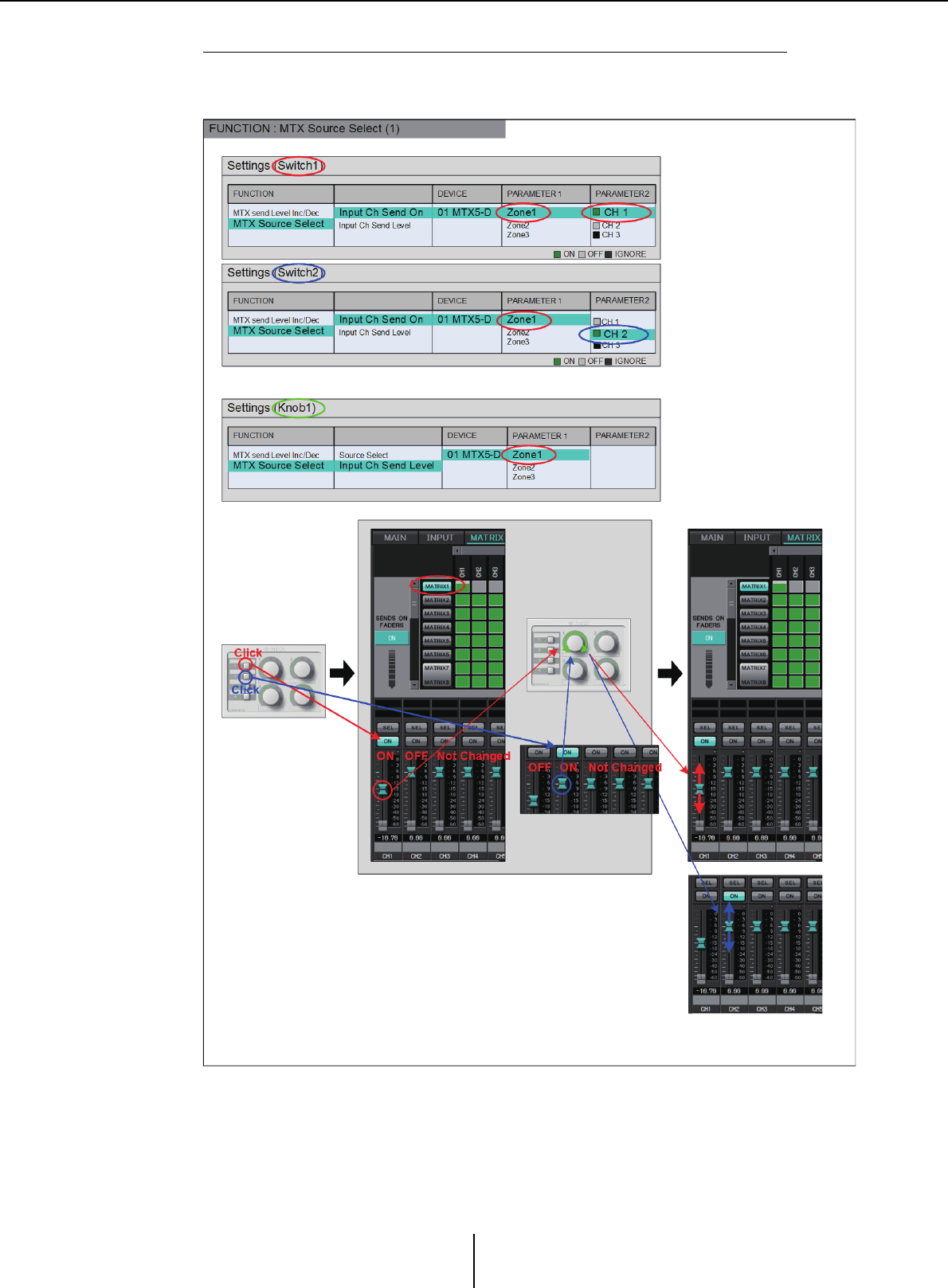
List of settings in “Settings” dialog boxes Appendix
MTX-MRX Editor User Guide
242
Using a knob/slider to adjust the send level (other than DCP4S–EU/US)
Shown below is an example of using a switch to turn send on/off and using a knob/
slider to adjust the send level.
The switch settings and knob/slider settings for this example are explained below.

List of settings in “Settings” dialog boxes Appendix
MTX-MRX Editor User Guide
243
Switch settings
Select the following parameter type to be controlled by the switch, and then make the
appropriate settings.
•Input Ch Send On
❍[DEVICE]
Select the device that you want to change. These are shown in order of UNIT ID and
model name.
❍[PARAMETER1]/[PARAMETER2]
In the [PARAMETER1] column, select the target ZONE.
In the [PARAMETER2] column, click ? on the left of the channel name to select ON,
OFF, or IGNORE for the desired channels. “On” can be specified only for one
channel.
Knob/Slider settings
❍[DEVICE]
Select the device that you want to change. These are shown in order of UNIT ID and
model name.
❍[PARAMETER1]
In the [PARAMETER1] column, select the target ZONE.
❍[Parameter Range]
Use [Upper Limit] and [Lower Limit] to specify the range in which the level can be
varied.
If [Mute Enable] is on, the Mute state (–∞ dB) will be enabled if the level is lowered
below the value specified by [Lower Limit].
- If the nominal value specified by the following [Nominal Value] is higher than the
[Upper Limit], the [Upper Limit] will rise in tandem with the [Nominal Value].
Conversely, if the nominal value goes below the [Lower Limit], the [Lower Limit] will
fall in tandem with the [Nominal Value].
- By using [Parameter Range] you can limit the range in which the user can control the
volume. For example you can use this to specify the maximum volume of background
music, or use the controller to make fine volume adjustments in a narrow range of –
6 dB – +6 dB.
❍[Nominal] check box (DCP only)
Here you can make settings for the Nominal function.
By specifying the nominal value, you can assign a specific LED position as the
normal volume setting. For example by specifying the center LED as the volume
setting for normal use and setting the maximum value to the maximum volume that
is allowable for the system, you can prevent damage to the system that might occur
if the volume of the background music were raised during a noisy time.
If the check box is selected, the Nominal function will be on.
[Nominal Value] specifies the nominal value.
[Nominal LED Position] specifies the LED position that will light when the level
reaches the nominal value.
If the check box is cleared (Nominal function off), both parameters will be grayed-
out and unavailable.
❍[Knob] (DCP only)
Here you can make settings for the DCP’s knobs.
[Sensitivity] specifies the sensitivity at which the parameter will change when the
knob is rotated.
If [Acceleration] is on, the parameter will change faster if the knob is rotated more
rapidly. If [Fast] is selected as the [Sensitivity], the [Acceleration] setting is dimmed
and unavailable.
NOTE
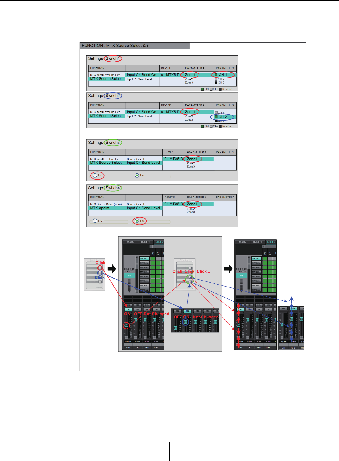
List of settings in “Settings” dialog boxes Appendix
MTX-MRX Editor User Guide
244
Using switches to adjust the send level
Shown below is an example of using switches to turn send on/off and to adjust the
send level.
The switch settings for this example are explained below.

List of settings in “Settings” dialog boxes Appendix
MTX-MRX Editor User Guide
245
Switch settings
Select the following parameter types to be controlled by the switches, and then make
the appropriate settings.
•Input Ch Send On
•Input Ch Send Level
❍[DEVICE]
Select the device that you want to change. These are shown in order of UNIT ID and
model name.
❍[PARAMETER1]/[PARAMETER2]
In the [PARAMETER1] column, select the target ZONE.
For Input Ch Send On, click the ? at the left of the channel name in the
[PARAMETER2] column to select ON, OFF, or IGNORE for the desired channels.
“On” can be specified only for one channel.
For Input Ch Send Level, set the following parameters as well.
❍[Inc]
If you select this option, pressing the switch each time will raise the level or the send
level.
✦[Upper Limit]
Specifies the maximum level achieved when you press the switch.
✦[Minimum]
If the current parameter value is lower than the value specified here, pressing the
switch once will set the parameter to this value.
❍[Dec]
If you select this option, pressing the switch each time will lower the level or the send
level.
✦[Lower Limit]
Specifies the minimum level achieved when you press the switch.
✦[Mute Enable] check box
If this is on, the Mute state (–∞ dB) will be enabled if the level is lowered below the
value specified by [Lower Limit].
❍[Switch]
Allows you to make switch-related settings.
[Sensitivity] specifies the sensitivity at which the parameter will change when the
switch is pressed.
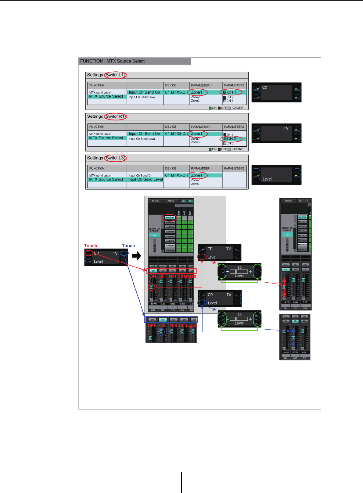
List of settings in “Settings” dialog boxes Appendix
MTX-MRX Editor User Guide
246
●If [FUNCTION] is [MTX Source Select] (MCP1)
The switch that is assigned to [Input Ch Send ON] will select the send point of the
Matrix, and the switch/knob/slider that is assigned to [Input Ch Send Level] will adjust
the level of the send point.
We will explain the switch settings in this example.

List of settings in “Settings” dialog boxes Appendix
MTX-MRX Editor User Guide
247
Select the following parameter types to be operated by the switches, and then make
various settings.
•Input Ch Send On
•Input Ch Send Level
❍[DEVICE]
Select the device that you want to change. These are shown in order of UNIT ID and
model name.
❍[PARAMETER1]/[PARAMETER2]
In the [PARAMETER1] column, select the target ZONE.
In the case of Input Ch Send On, click the ? located at the left in [PARAMETER2],
to specify the channel’s state as ON/OFF/IGNORE. OFF can be specified only for
one channel.
In the case of Input Ch Send Level, set the following parameters as well.
❍[Parameter Range]
✦[Upper Limit]
Specifies the maximum level achieved by pressing the switch.
✦[Lower Limit]
Specifies the minimum level achieved when you press the switch.
✦[Mute Enable] check box
If this check box is selected, the Mute state (–∞ dB) will be enabled if the level falls
below the value specified by [Lower Limit].
❍[Switch]
Allows you to make switch-related settings.
[Sensitivity] specifies the sensitivity at which the parameter will change when the
switch is touched.
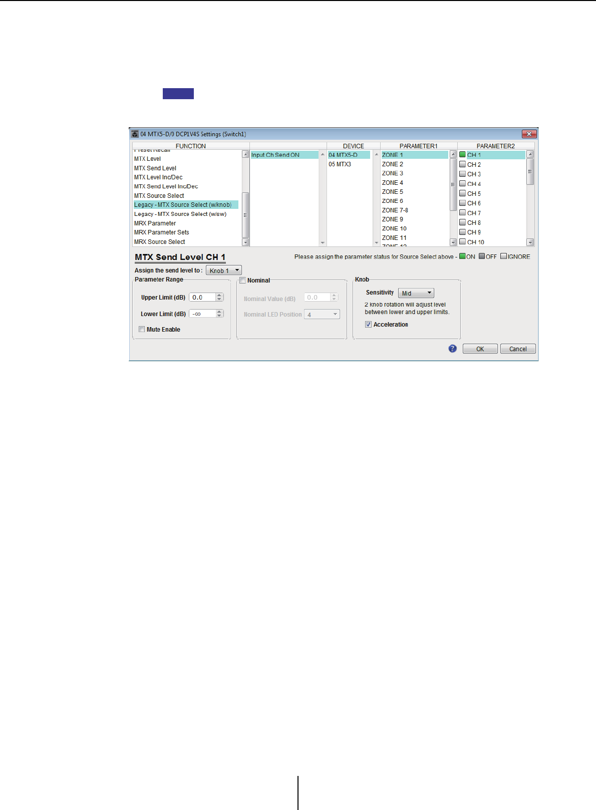
List of settings in “Settings” dialog boxes Appendix
MTX-MRX Editor User Guide
248
●If [FUNCTION] is [Legacy - MTX Source Select w/knob]
(only for switches of a DCP equipped with knobs)
You can control the send on/off for multiple channels via switches, and control the send
level for any channel via knobs.
If you assign the same source to multiple DCP units and then change the settings on
one of the DCP units, the changes will not be updated on other DCP units. Each DCP
unit will retain the settings (LED status and knob assignments) that were made on it.
❍[DEVICE]
Select the device that you want to change. These are listed in order of UNIT ID and
model name.
❍[PARAMETER1]/[PARAMETER2]
In the [PARAMETER1] column, select the target ZONE.
In the [PARAMETER2] column, click to the left of the channel name to select
ON, OFF, or IGNORE for the desired channels. The ON/OFF/IGNORE setting can
be applied to multiple channels simultaneously. If you select an ON channel, the
bottom half of the dialog box will display parameter fields related to the knobs.
❍[Assign the send level to:] box
Enables you to select a knob that will control the send level of the currently-selected
channel.
Only one channel can be assigned to a knob.
❍[Parameter Range]/[Nominal]/[Knob]
Enable you to make a setting for the knob that has been specified in the [Assign the
send level to:] box. For details about the settings, refer to If [FUNCTION] is [MTX
Level] for knobs/sliders.
NOTE
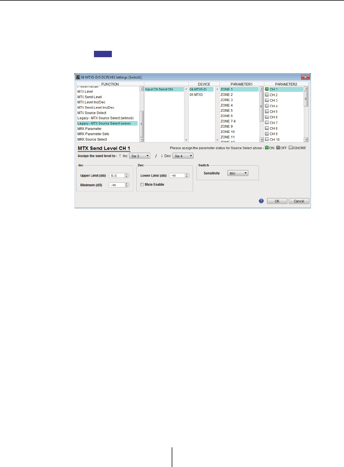
List of settings in “Settings” dialog boxes Appendix
MTX-MRX Editor User Guide
249
●If [FUNCTION] is [Legacy - MTX Source Select w/sw]
(DCP switches only)
You can control the send on/off for multiple channels via switches, and the send level
for any channel via switches.
If you assign the same source to multiple DCP units and then change the settings on
one of the DCP units, the changes will not be updated on other DCP units. Each DCP
unit will retain the settings (LED status and knob assignments) that were made on it.
❍[DEVICE]
Select the device that you want to change. These are listed in order of UNIT ID and
model name.
❍[PARAMETER1]/[PARAMETER2]
In the [PARAMETER1] column, select the target ZONE.
In the [PARAMETER2] column, click to the left of the channel name to select
ON, OFF, or IGNORE for the desired channels. The ON/OFF/IGNORE setting can
be applied to multiple channels simultaneously. If you select an ON channel, the
bottom half of the dialog box will display the switch-related setting items.
❍[Assign the send level to:] box
Enables you to assign a function that raises or lowers the send level of the selected
channels to other switches.
❍[Inc]/[Dec]/[Switch]
Enable you to make settings for the switches specified in the [Assign the send level
to:] box. For details about the settings, refer to If [FUNCTION] is [MTX Send Level
Inc/Dec] for switches.
NOTE
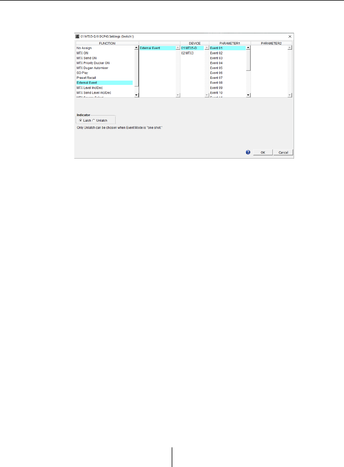
List of settings in “Settings” dialog boxes Appendix
MTX-MRX Editor User Guide
250
●If [FUNCTION] is [External Event] (switch only)
A switch will be used to output commands specified in the “Event” dialog box.
❍[DEVICE]
Select a device to output commands. These are shown in order of UNIT ID and
model name.
❍[PARAMETER1]
Select an event to be executed.
❍[Indicator]
Select whether the switch indicator will display the on/off status (Latch), or light
only when the switch is pressed (Unlatch).
Please note that you can select only [Unlatch] if you selected the event for which
[Event Mode] is set to [1shot] in the “External Events” dialog box.
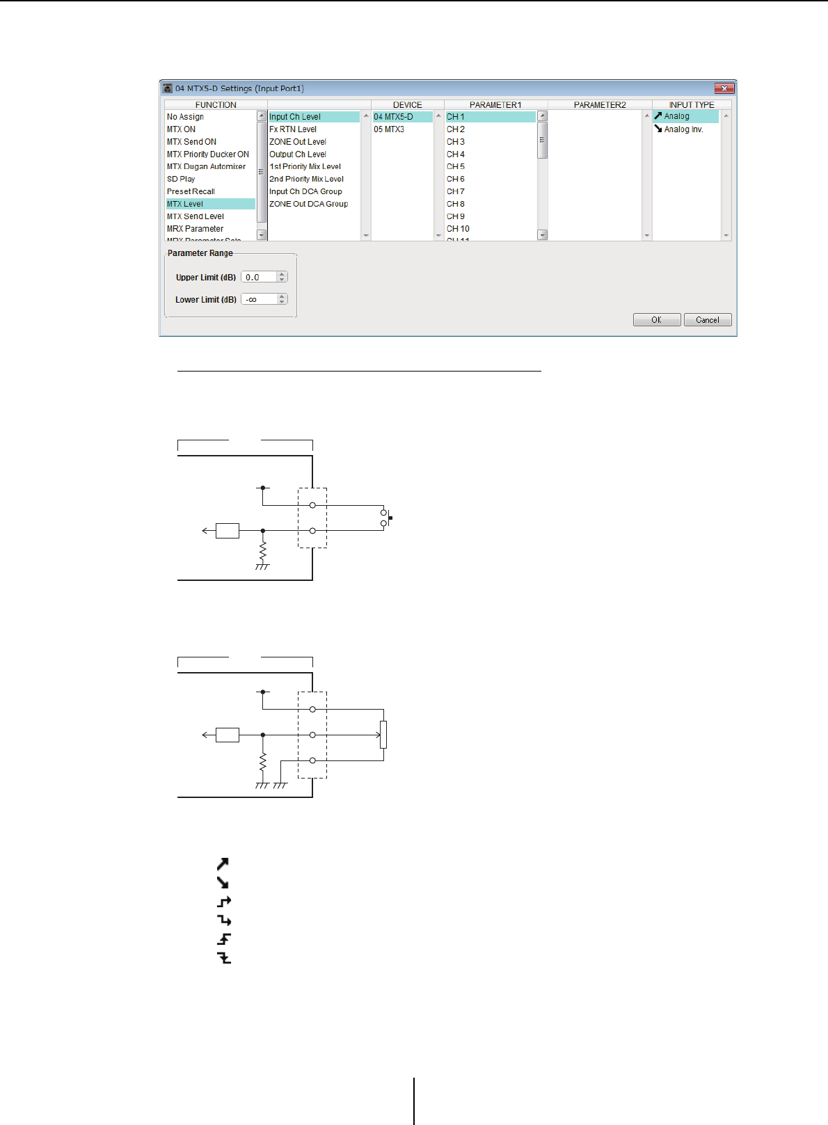
List of settings in “Settings” dialog boxes Appendix
MTX-MRX Editor User Guide
251
■GPI Input
This section explains settings for the [GPI IN] connector of the device itself.
Connection examples using the [GPI IN] connector
About [INPUT TYPE]
[INPUT TYPE] allows the following settings.
• Analog
• Analog Inv.
• High Active
• Low Active
• Rising Edge
• Falling Edge
IN
+V
+5VDC
A/D
CPU
100k
MTX3
Connection example 1:
Controlling the MTX/MRX with a switch
IN
+V
+5VDC
GND
A/D
CPU
100k
MTX3
Connection example 2:
Controlling the MTX/MRX with a 10kΩ B-curve variable resistor
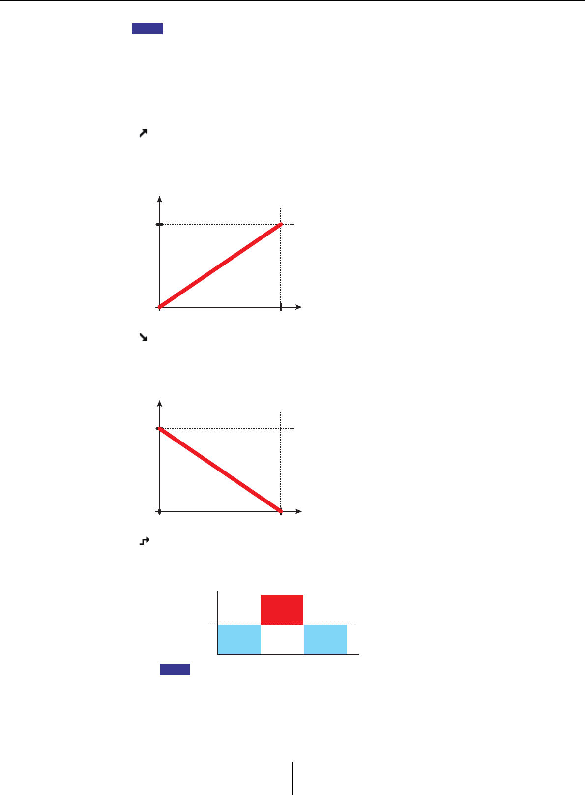
List of settings in “Settings” dialog boxes Appendix
MTX-MRX Editor User Guide
252
• The threshold value at which on/off switching will occur will be the middle value between
the maximum and minimum input voltage values (the value equal to the sum of the
maximum and minimum values divided by two). To prevent malfunctions, you should allow
plenty of room for detection (see “GPI Calibration” dialog box).
• If the voltage has dropped because of cable length or noise, use the “GPI Calibration”
dialog box to adjust the maximum and minimum input voltage values. Since voltage may
become unstable, configure and set up your external circuit to ensure that there is ample
distance between the maximum and minimum values.
• You can indicate the on/off status by assigning ON to one of the GPI Output ports.
❍ Analog
Use this if you selected [Level] or [Send Level] as the [FUNCTION].
The level will be at the maximum value when the input voltage to the GPI IN is at
maximum (5V), and at the minimum value when the input voltage is at minimum
(0V).
❍ Analog Inv.
Use this if you selected [Level] or [Send Level] as the [FUNCTION].
The level will be at the minimum value when the input voltage to the GPI IN is at
maximum (5V), and at the maximum value when the input voltage is at minimum
(0V).
❍ High Active
Use this if you selected [ON] or [Send ON] as the [FUNCTION].
The function will turn on when the input voltage to GPI IN rises above the center
voltage, and will turn off when it falls below the center voltage.
If you’ve selected [Input Ch Mute Group] or [Zone Out Mute Group] as the parameter
type, mute on/off will be switched.
NOTE
0V
MAX
MIN
Level
+5V
0V
MAX
MIN
Level
+5V
ON
ON
OFF OFF
OFF OFF
Center voltage
GPI IN input
voltage max.
GPI IN input
voltage min.
NOTE
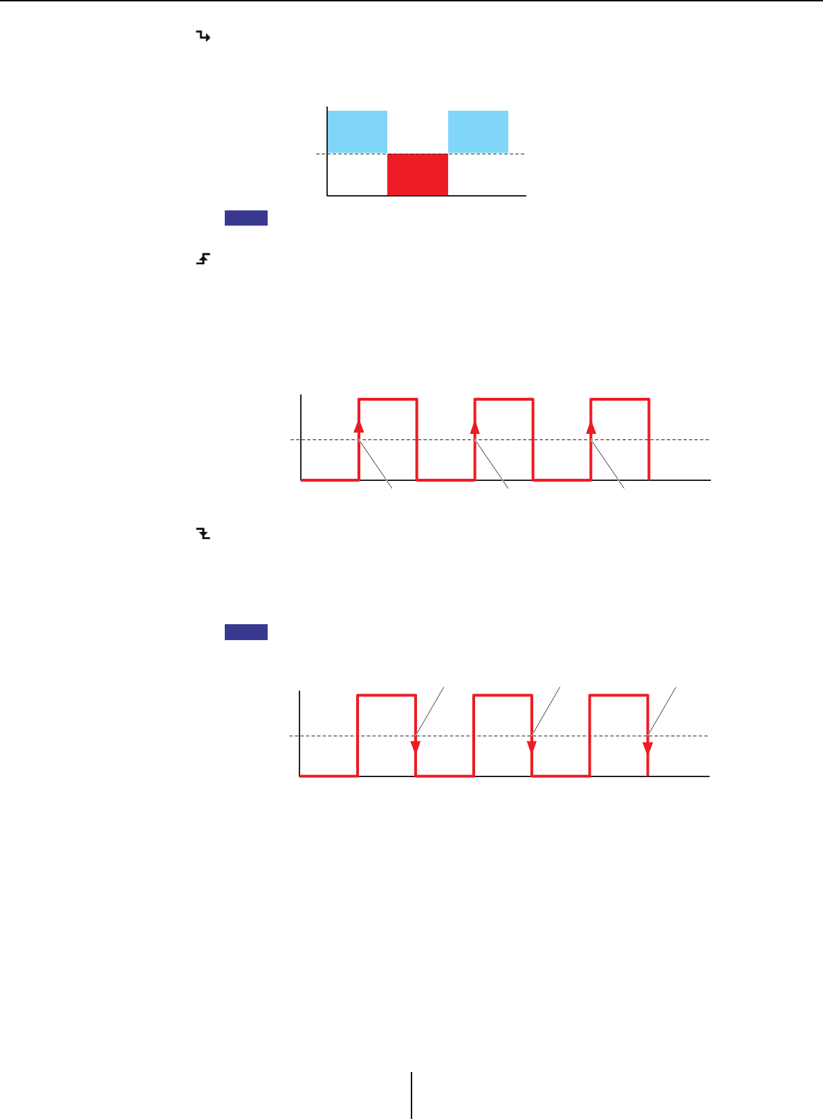
List of settings in “Settings” dialog boxes Appendix
MTX-MRX Editor User Guide
253
❍ Low Active
Use this if you selected [ON] or [Send ON] as the [FUNCTION].
The function will turn off when the input voltage to GPI IN rises above the center
voltage, and will turn on when it falls below the center voltage.
If you’ve selected [Input Ch Mute Group] or [Zone Out Mute Group] as the parameter
type, mute on/off will be switched.
❍ Rising Edge
Use this if you selected [ON]/[Send ON]/[SD Play]/[Preset Recall] as the
[FUNCTION].
The parameter will alternately turn on/off or play/stop etc. when the input voltage
to GPI IN changes from below the center voltage to above it.
[Preset Recall] will recall the specified preset when the input voltage changes from
below the center voltage to above it.
❍ Falling Edge
Use this if you selected [ON]/[Send ON]/[SD Play]/[Preset Recall] as the
[FUNCTION].
The parameter will alternately turn on/off or play/stop etc. when the input voltage
to GPI IN changes from above the center voltage to below it.
[Preset Recall] will recall the specified preset when the input voltage changes from
below the center voltage to above it.
●If [FUNCTION] is [No Assign]
With this setting, no function will be operated by the signal that is input from the [GPI
IN] connector. [DEVICE], [PARAMETER1/2], and [INPUT TYPE] will be
unavailable.
GPI IN input
voltage max.
GPI IN input
voltage min.
ON
ON
OFF OFF
OFF OFF
Center voltage
NOTE
GPI IN input
voltage max.
GPI IN input
voltage min.
Center
voltage
ON/play OFF/stop ON/play
NOTE
GPI IN input
voltage max.
GPI IN input
voltage min.
Center
voltage
ON/play OFF/stop ON/play

List of settings in “Settings” dialog boxes Appendix
MTX-MRX Editor User Guide
254
●If [FUNCTION] is [MTX Dugan Automixer]
The input voltage to the [GPI IN] connector will turn the parameter on/off.
Select one of the following parameter types, and then make the appropriate setting.
•Override (master)
•Mute (master)
•override (Ch)
❍[DEVICE]
Select the device that you want to change. These are shown in order of UNIT ID and
model name.
❍[PARAMETER 1]
For Override (master) and Mute (master), select the group that controls on/off. For
override (Ch), select the channel that controls on/off.
❍[INPUT TYPE]
Specifies how the input voltage to GPI IN will be applied to the parameter.
You can choose [High Active], [Low Active], [Rising Edge], or [Falling Edge].
●If [FUNCTION] is [MTX Level] (Cannot be set for PORT8)
The input voltage to the [GPI IN] connector will control the level of the channel.
If the maximum level cannot be reached because of the length of the cable, adjust the
maximum and minimum input voltage values in the “GPI Calibration” dialog box.
Select one of the following parameter types, and then make the appropriate setting.
•Input Ch Level
•Fx RTN Level
•Matrix Out Level
•ZONE Out Level
•Output Ch Level
•1st Priority Mix Level
•2nd Priority Mix Level
•Input Ch DCA Group
•ZONE Out DCA Group
❍[DEVICE]
Select the device that you want to change.
❍[PARAMETER1]
Specifies the channel whose level you want to control.
❍[INPUT TYPE]
Specifies how the level to GPI IN will be applied to the parameter.
You can select [Analog] or [Analog Inv.].
❍[Parameter Range]
Use [Upper Limit] and [Lower Limit] to specify the range in which the level can be
varied.
By using [Parameter Range] you can limit the range in which the user can control the
volume. For example you can use this to specify the maximum volume of background
music, or use a controller to make fine volume adjustments in a narrow range of –6 dB
– +6 dB.
NOTE

List of settings in “Settings” dialog boxes Appendix
MTX-MRX Editor User Guide
255
●If [FUNCTION] is [MTX ON]
Controls the on/off setting of the parameter.
Select one of the following parameter types, and then make the appropriate setting.
•Input Ch ON
•Fx RTN ON
• ZONE Out ON
•Output Ch ON
• Input Ch Mute Group
•ZONE Out Mute Group
❍[DEVICE]
Select the device that you want to change.
❍[PARAMETER1]
Specify the channel that will control the on/off setting of the parameter.
❍[INPUT TYPE]
Specifies how the input voltage to GPI IN will be applied to the parameter.
You can choose [High Active], [Low Active], [Rising Edge], or [Falling Edge].
●If [FUNCTION] is [MTX Send Level] (Cannot be set for PORT8)
The input voltage to the [GPI IN] connector will control the send level of the channel.
If the maximum level cannot be reached because of the length of the cable, adjust the
maximum and minimum input voltage values in the “GPI Calibration” dialog box.
Select one of the following parameter types, and then make the appropriate setting.
•Input Ch Send Level
•Fx RTN Send Level
For details on these settings, refer to If [FUNCTION] is [MTX Level].
●If [FUNCTION] is [MTX Send ON]
The input voltage to the [GPI IN] connector will control the send on/off of the channel.
Select one of the following parameter types, and then make the appropriate setting.
•Input Ch Send ON
•Fx RTN Send ON
For details on these settings, refer to If [FUNCTION] is [MTX ON].
●If [FUNCTION] is [MTX Priority Ducker ON]
The input voltage to the [GPI IN] connector will turn the zone’s Ducker on/off.
Select one of the following parameter types, and then make the appropriate setting.
•1st Priority
•2nd Priority
For details on these settings, refer to If [FUNCTION] is [MTX Priority Ducker ON]
(switch only).

List of settings in “Settings” dialog boxes Appendix
MTX-MRX Editor User Guide
256
●If [FUNCTION] is [SD Play]
The input voltage to the [GPI IN] connector will play the specified audio file.
Select one of the following parameter types, and then make the appropriate setting.
•SD Song Select & Play
•SD Song Pause
For details on settings other than [INPUT TYPE], refer to If [FUNCTION] is [SD Play]
(switch only) for switches.
❍[INPUT TYPE]
Specifies how the input voltage to GPI IN will be applied to the parameter.
You can choose [Rising Edge] or [Falling Edge].
●If [FUNCTION] is [Preset Recall]
The input voltage to the [GPI INPUT] connector will recall the specified preset.
❍[PARAMETER1]
Select the preset number that you want to recall.
❍[INPUT TYPE]
Specifies how the input voltage from GPI IN will be applied to the parameter.
You can choose [Rising Edge] or [Falling Edge].
●If [FUNCTION] is [External Event]
Input voltage to the [GPI IN] connector will trigger the output of the commands
specified in the “External Events” dialog box.
❍[DEVICE]
Select a device that will output commands. These are shown in order of UNIT ID
and model name.
❍[PARAMETER1]
Select the name of the event to be executed.
❍[INPUT TYPE]
Specifies how the input voltage to GPI IN will be applied to the parameter.
You can choose [High Active], [Low Active], [Rising Edge], or [Falling Edge].
If you selected [On/Off] for the [Command Type], the following action will occur:
[High Active]: If the input voltage is high, the command assigned to
[Command - On] will be transmitted. If the input voltage is low,
the command assigned to [Command - Off] will be transmitted.
[Low Active]: If the input voltage is low, the command assigned to
[Command - On] will be transmitted. If the input voltage is high,
the command assigned to [Command - Off] will be transmitted.
[Rising Edge]: Each time the input voltage becomes high, the command
assigned to [Command - On] and the command assigned to
[Command - Off] will be transmitted alternately.
[Falling Edge]: Each time the input voltage becomes low, the command assigned
to [Command - On] and the command assigned to
[Command - Off] will be transmitted alternately.
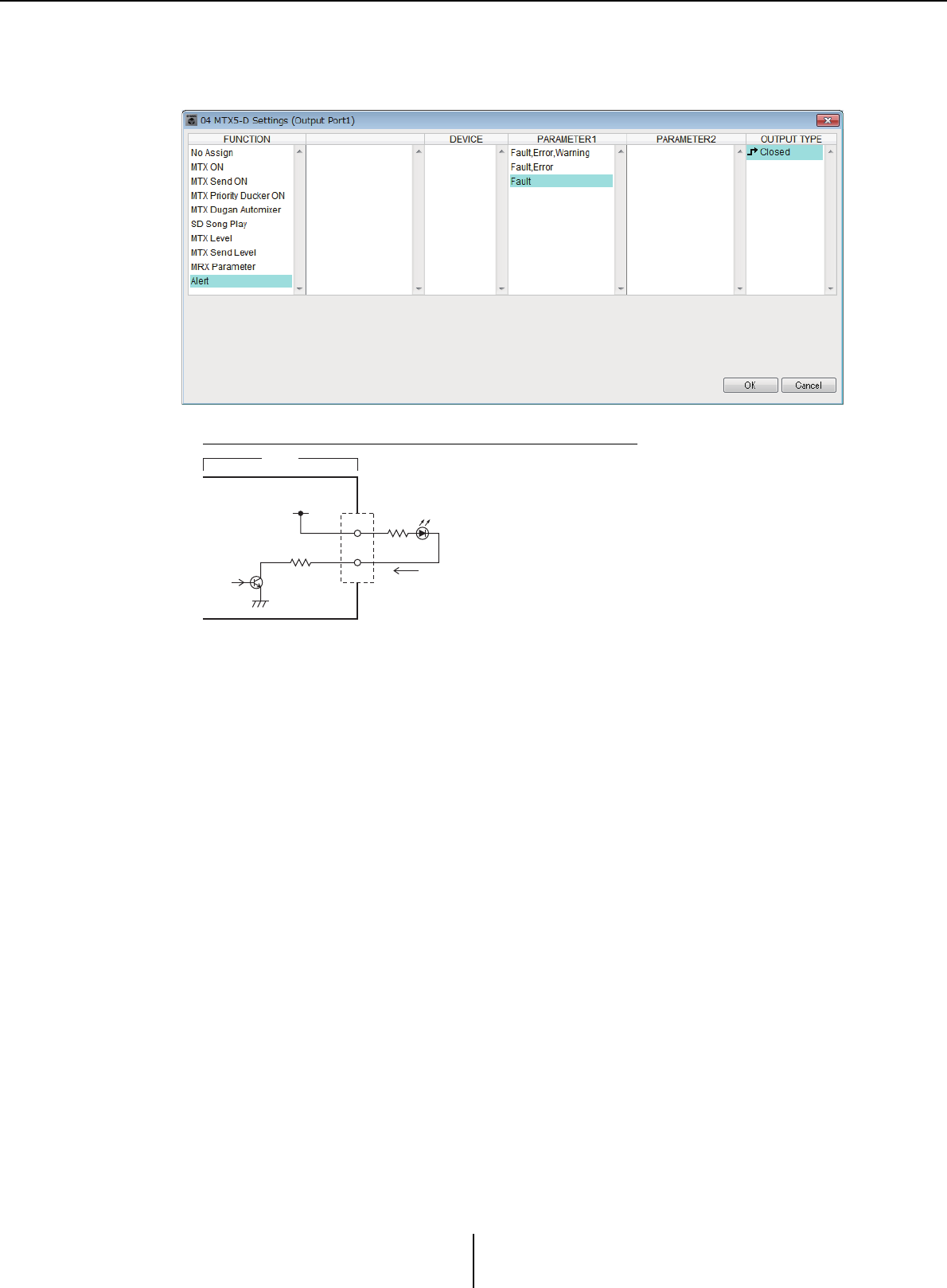
List of settings in “Settings” dialog boxes Appendix
MTX-MRX Editor User Guide
257
■GPI Output
This section explains settings for the [GPI OUT] connector of the device itself. To make
[GPI OUTPUT] connector settings by recalling a preset, start with “Preset” dialog box.
Connection examples using the [GPI OUT] connector
OUT
+V
+5VDC
CPU
10
MTX3
Maximum 75 mA

List of settings in “Settings” dialog boxes Appendix
MTX-MRX Editor User Guide
258
About [OUTPUT TYPE]
[OUTPUT TYPE] allows the following settings.
• Closed
• Open
• Pulse
• Pulse Inv.
❍ Closed
When the selected [FUNCTION] state occurs, the contact will be closed.
In the case of a parameter for which [Threshold] is specified, the contact will be
closed when the threshold value is exceeded.
❍ Open
When the selected [FUNCTION] state occurs, the contact will be opened.
In the case of a parameter for which [Threshold] is specified, the contact will be
opened when the threshold value is exceeded.
If the [FUNCTION] is [Alert], this cannot be selected.
❍ Pulse
If the [Direction] is [Upward], the contact will change from open to closed for
approximately 250 ms when the selected [FUNCTION] state occurs. In the case of a
parameter for which [Threshold] is specified, the contact will change from open to
closed for approximately 250 ms when the threshold value is exceeded.
If the [Direction] is [Downward], the contact will change from open to closed for
approximately 250 ms when the selected [FUNCTION] state is cleared. In the case
of a parameter for which [Threshold] is specified, the contact will change from open
to closed for approximately 250 ms when the value falls below the threshold.
If the [FUNCTION] is [SD Song Play] and [Alert], this cannot be selected.
❍ Pulse Inv.
If the [Direction] is [Upward], the contact will change from closed to open for
approximately 250 ms when the selected [FUNCTION] state occurs. In the case of a
parameter for which [Threshold] is specified, the contact will change from closed to
open for approximately 250 ms when the threshold value is exceeded.
If the [Direction] is [Downward], the contact will change from closed to open for
approximately 250 ms when the selected [FUNCTION] state is cleared. In the case
of a parameter for which [Threshold] is specified, the contact will change from
closed to open for approximately 250 ms when the value falls below the threshold.
If the [FUNCTION] is [SD Song Play] and [Alert], this cannot be selected.
●If [FUNCTION] is [No Assign]
[OUTPUT TYPE] specifies the polarity of the output signal when an alert occurs. No
other function are specified; they will be the default.
❍[OUTPUT TYPE]
Controls the GPI OUT when a preset is recalled or when a Scheduler event is
executed.
NOTE
NOTE
NOTE

List of settings in “Settings” dialog boxes Appendix
MTX-MRX Editor User Guide
259
●If [FUNCTION] is [MTX Dugan Automixer]
Parameter on/off operations will control the GPI Output.
Select one of the following parameter types, and then make the appropriate setting.
•Override (master)
•Mute (master)
•override (Ch)
❍[DEVICE]
Select the device that you want to change. These are shown in order of UNIT ID and
model name.
❍[PARAMETER 1]
For Override (master) and Mute (master), select the group that controls on/off. For
override (Ch), select the channel that controls on/off.
❍[OUTPUT TYPE]
Specifies how output will occur from the [GPI OUT] connector.
●If [FUNCTION] is [MTX Level]
Controls the GPI Output according to the level (volume changes) of each channel. You
can use this to fader-start a CD player, or to light an indicator when high volume
occurs.
Select one of the following parameter types, and then make the appropriate setting.
•Input Ch Level
•Fx RTN Level
•Matrix Out Level
•ZONE Out Level
•Output Ch Level
•1st Priority Mix Level
•2nd Priority Mix Level
•Input Ch DCA Group
•ZONE Out DCA Group
❍[DEVICE]
Select the device that you want to change.
❍[PARAMETER1]
Specify the channel that will be used to control the [GPI OUT] connector.
❍[OUTPUT TYPE]
Specifies how output will occur from the [GPI OUT] connector.
❍[Threshold]
Specifies the threshold value of the parameter. The values that can be specified will
depend on the type of parameter.
❍[Direction]
Specifies the direction of change for the parameter that will control the [GPI OUT]
connector.

List of settings in “Settings” dialog boxes Appendix
MTX-MRX Editor User Guide
260
●If [FUNCTION] is [MTX ON]
Parameter on/off operations on the specified device will control the GPI Output.
Select one of the following parameter types, and then make the appropriate setting.
•Input Ch ON
•Fx RTN ON
• ZONE Out ON
•Output Ch ON
• Input Ch Mute Group
•ZONE Out Mute Group
❍[DEVICE]
Select the device that you want to change.
❍[PARAMETER1]
Specifies the channel whose on/off operations will control the [GPI OUT}
connector.
❍[OUTPUT TYPE]
Specifies how output will occur from the [GPI OUT] connector.
❍[Threshold]
Indicates the threshold value of the parameter. This is fixed at 0.5.
❍[Direction]
Specifies the direction of change for the parameter that will control the [GPI OUT]
connector. This is shown if [OUTPUT TYPE] is set to [Pulse] or [Pulse Inv.].
●If [FUNCTION] is [MTX Send Level]
Controls the GPI Output according to the send level (volume changes) of each channel.
You can use this to fader-start a CD player, or to light an indicator when high volume
occurs. Select one of the following parameter types, and then make the appropriate
setting.
•Input Ch Send Level
•Fx RTN Send Level
For details on these settings, refer to If [FUNCTION] is [MTX Level].
●If [FUNCTION] is [MTX Send ON]
Send on/off operations will control the GPI Output.
Select one of the following parameter types, and then make the appropriate setting.
•Input Ch Send ON
•Fx RTN Send ON
For details on these settings, refer to If [FUNCTION] is [MTX ON].
●If [FUNCTION] is [MTX Priority Ducker ON]
On/off operations of the zone’s Ducker will control the GPI Output.
Select one of the following parameter types, and then make the appropriate setting.
•1st Priority
•2nd Priority
For details on these settings, refer to If [FUNCTION] is [MTX Priority Ducker ON]
(switch only).

List of settings in “Settings” dialog boxes Appendix
MTX-MRX Editor User Guide
261
●If [FUNCTION] is [SD Song Play]
The status of audio file playback will be output to the [GPI OUT] connector.
❍[DEVICE]
Select the device that you want to change.
❍[OUTPUT TYPE]
Specifies how output will occur from the [GPI OUT] connector.
●If [FUNCTION] is [Alert]
A signal will be output to the [GPI OUT] connector when an alert occurs.
❍[DEVICE]
Selects the device whose [GPI OUT] connector will output the alert.
❍[PARAMETER1]
Select the type of alert from the following.
•Fault, Error, Warning
•Fault, Error
•Fault
For details on the type of alert that is output, refer to “Alert list”.
❍[OUTPUT TYPE]
Only Closed can be selected. If an alert is occurring, the [GPI OUT] connector will
be closed. The closed state will continue until the alert has been cleared.
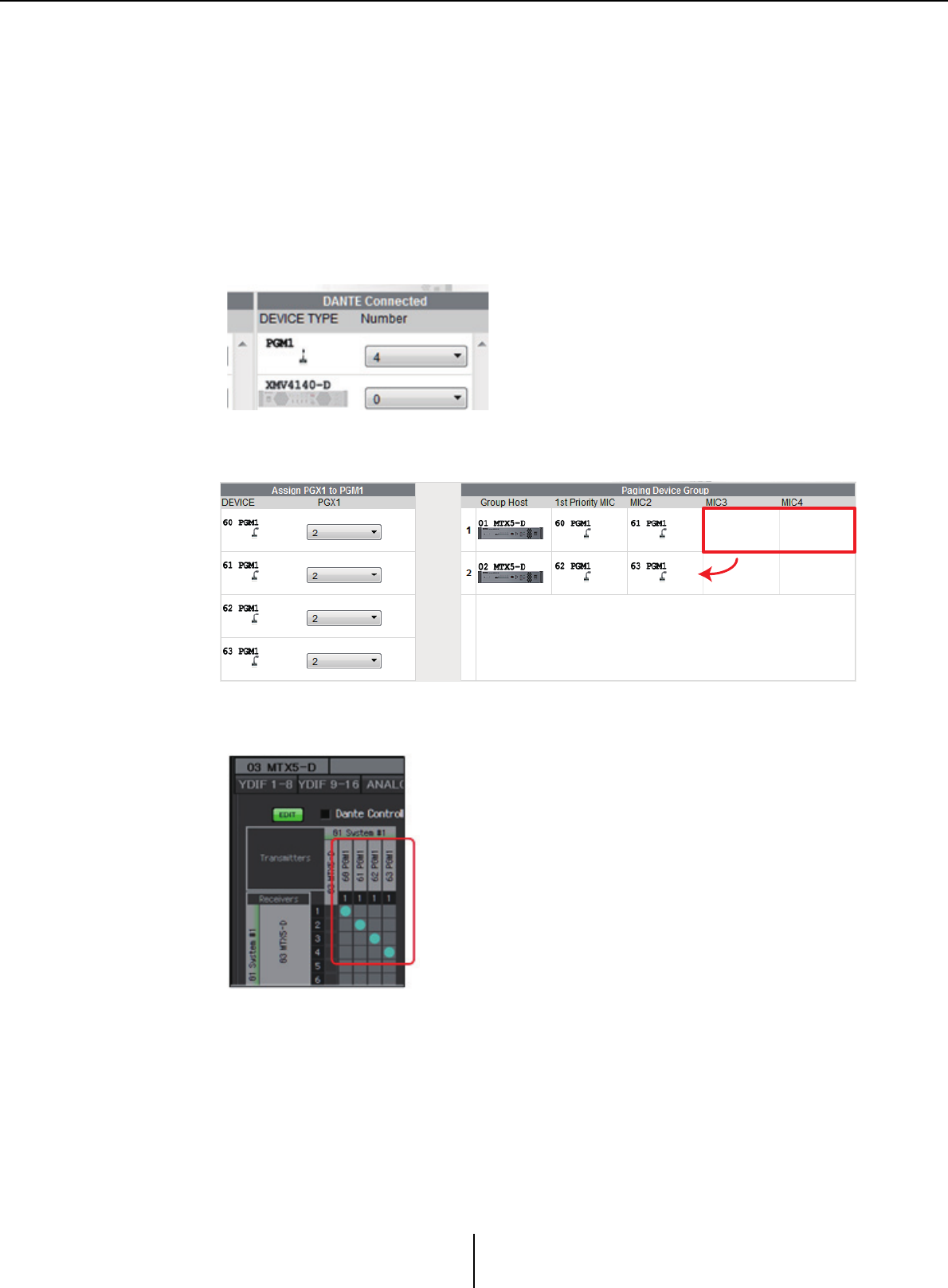
Workflow for paging settings Appendix
MTX-MRX Editor User Guide
262
Workflow for paging settings
The workflow for making paging settings is as follows. For specific settings, refer to “MTX Setup
Manual.”
Notice
Input channels to which audio signals from a PGM1 are assigned should not be mixed in the “MATRIX”
screen. If these signals are mixed, the input from the PGM1 units will be output to the zone even if PTT
is off.
1. In the “Device Config Wizard” dialog box, configure the PGM1.
2. In the “Device Config Wizard” dialog box, specify which PGM1 unit will
be the 1st Priority Mic, and expand PGX1 units as necessary.
3. In the [DANTE] screen of the [EXT. I/O] screen, patch the PGM1’s
output to the input of the MTX5-D.
Drag&Drop
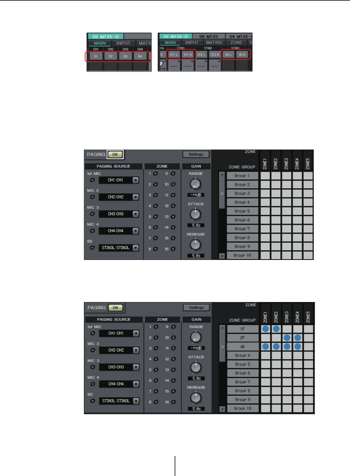
Workflow for paging settings Appendix
MTX-MRX Editor User Guide
263
4. In the input channel port selection screen of the “MAIN” screen, assign
the input from the PGM1 to an input channel.
Notice
Input channels to which audio signals from a PGM1 are assigned should not be mixed
in the “MATRIX” screen. If these signals are mixed, the input from the PGM1 units will
be output to the zone even if PTT is off.
5. In the “PAGING” screen of the “ZONE” screen, assign the input from
the 1st Priority Mic specified in step 2 to 1st MIC.
In this example, CH1 is assigned to 1st Mic, CH2 to Mic2, CH3 to Mic3, CH4 to
Mic4, and STIN3L to SD.
6. As necessary, specify zone groups (collections of zones) in the right side
of the “PAGING” screen of the “ZONE” screen.
By assigning a Zone Group to a single zone/message select button of the PGM1, you
can lower the Program volume for multiple zones and broadcast using the PGM1.
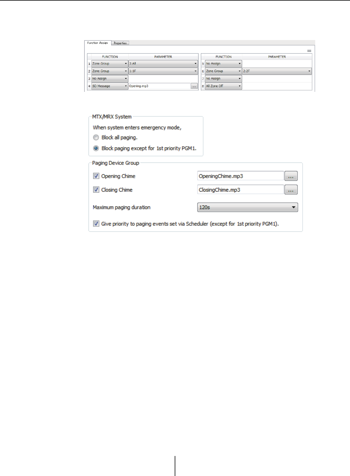
Workflow for paging settings Appendix
MTX-MRX Editor User Guide
264
7. In the “PAGING” screen of the “ZONE” screen, click the [Settings]
button, and in the [Function Assign] tab, assign functions to the zone/
message select buttons of the PGM1/PGX1.
8. In the [Properties] tab, make settings for the opening chime, etc.
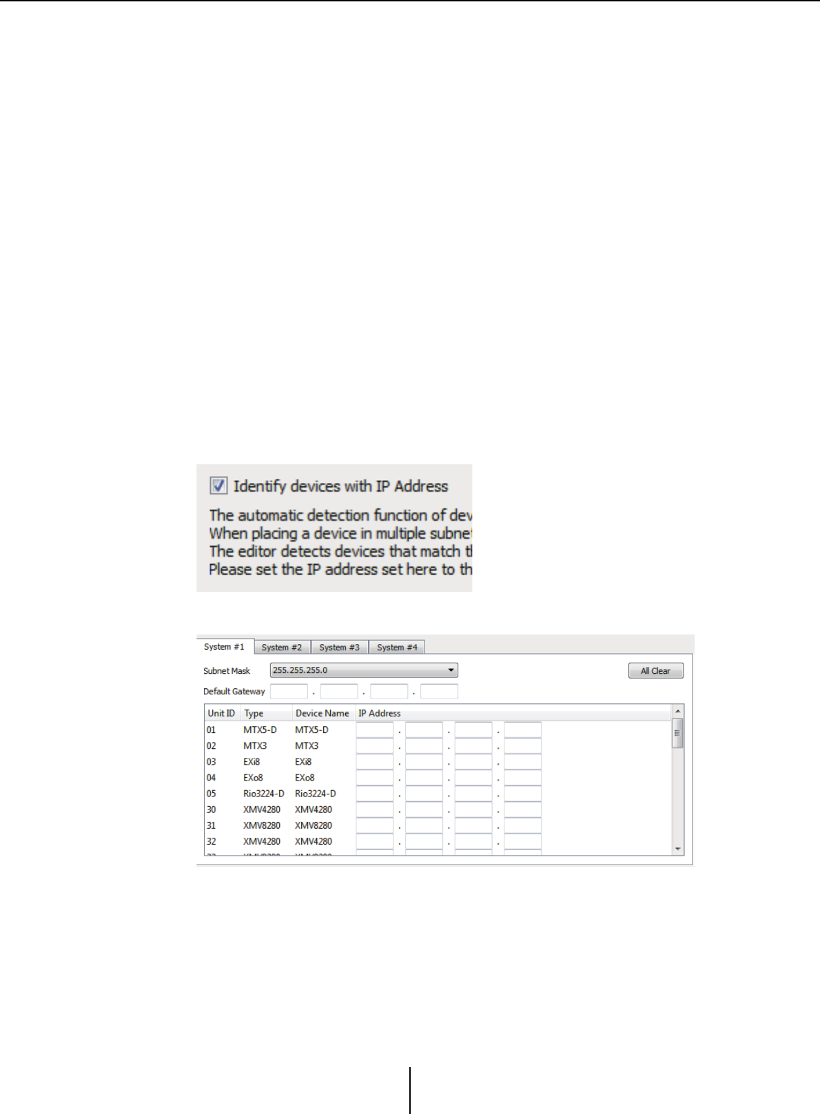
Settings for controlling devices across subnets Appendix
MTX-MRX Editor User Guide
265
Settings for controlling devices across subnets
If you are controlling devices on a subnet that is different than that of MTX-MRX Editor, all devices
are distinguished by their IP address.
For this reason, it is necessary to make settings so that the IP settings of devices placed in MTX-
MRX Editor (these are called virtual devices) match the IP settings of devices on the network (these
are called real devices).
The IP settings of virtual devices are made in the “Match Device by IP Address” dialog box, and the
IP settings of real devices are made in the “IP Address” dialog box.
The following things are not possible between real devices that are assigned to different subnets.
•Preset Link
• Dante audio communication
Set the IP addresses so that they are unique for the entire communication path. If devices of the
same IP address exist on the communication path, they might not be distinguishable.
First, use the “Match Device by IP Address” dialog box to specify IP addresses for the virtual devices.
1.
In MTX-MRX Editor’s [System] menu, click [Match Device by IP Address].
The “Match Device by IP Address” dialog box opens.
2. Select the [Distinguish devices by IP Address] check box.
3. Click the tab of the system for which you want to specify IP addresses.
4. Specify the system’s subnet mask and default gateway, and the IP
address of each device.
If it is OK for the IP addresses to be consecutive, proceed as follows.
4 -1. In the “IP Address Range Finder” area’s IP Address field, enter the
IP address that you want to use.
4 -2. In the [Subnet Mask] list box, select the subnet mask.
4 -3. Click the [Find Range] button.
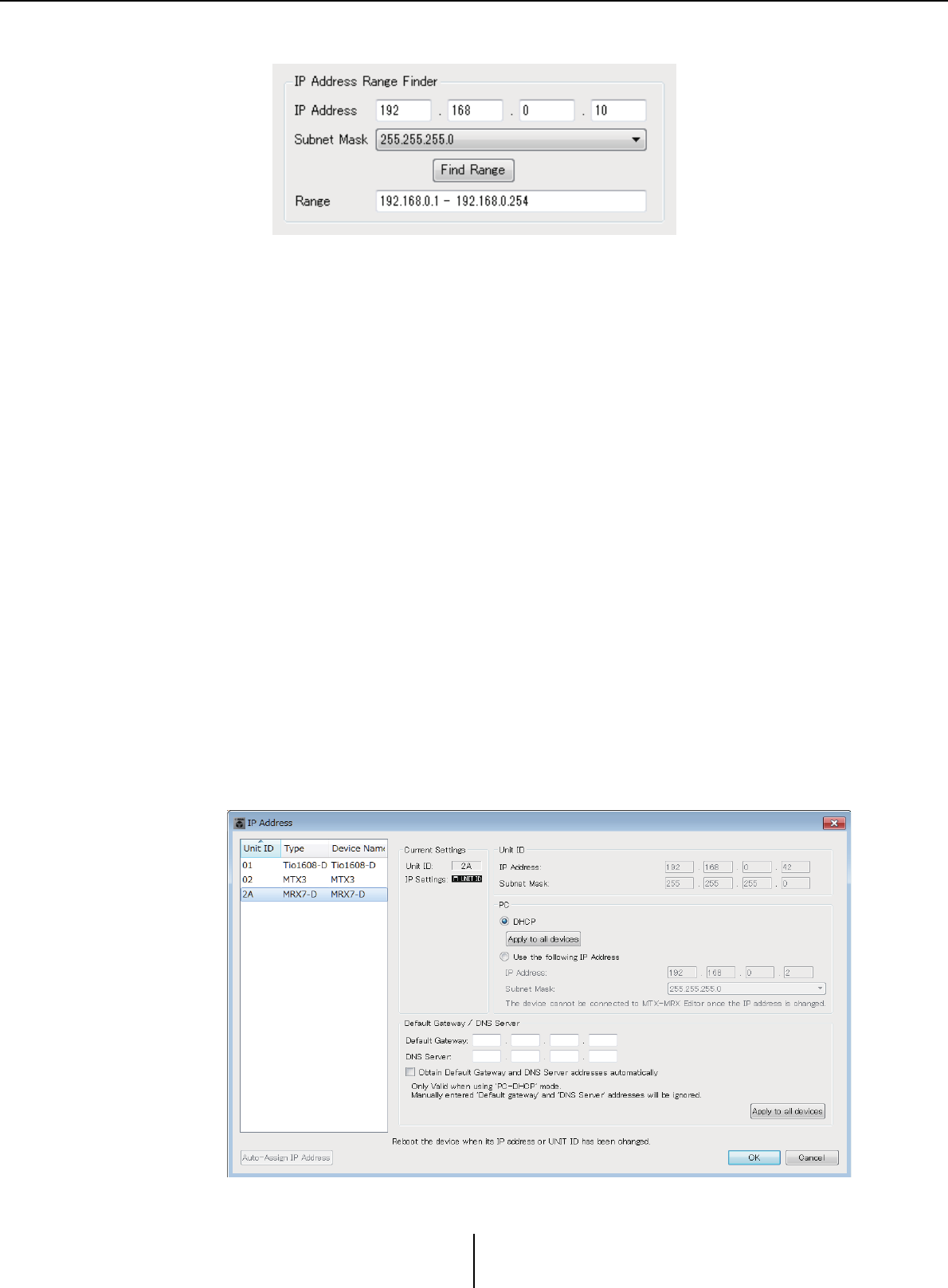
Settings for controlling devices across subnets Appendix
MTX-MRX Editor User Guide
266
“Range” shows the IP address setting range.
4 -4. Click the [Apply IP Address] button.
IP addresses are automatically assigned to the virtual devices in the system.
5. Click the [Apply] button.
6. Repeat steps 3 through 5 to assign IP addresses to all virtual devices.
7. When you have finished making settings, click the [OK] button.
Next, use the “IP Address” dialog box to specify IP addresses for the real devices.
When doing so, make settings that match the IP addresses of the virtual devices that were specified
in the “Match Device by IP Address” dialog box.
1. Set the computer’s IP address to “192.168.0.253” and the subnet mask
to “255.255.255.0”.
2. As the device’s settings, set IP SETTINGS to [UNIT ID] or set IP SELECT
MODE / IP Address Mode to [STATIC (IP) (Auto)], set the UNIT ID of all
devices to something other than FD so that none of the devices conflict,
and then power-on the devices.
3. While still offline, click MTX-MRX Editor’s [System] menu item [Device
Information].
The “Device Information” dialog box opens.
4. When all devices are shown in the “Device Information” dialog box,
click the [IP Address] button.
The “IP Address” dialog box opens.
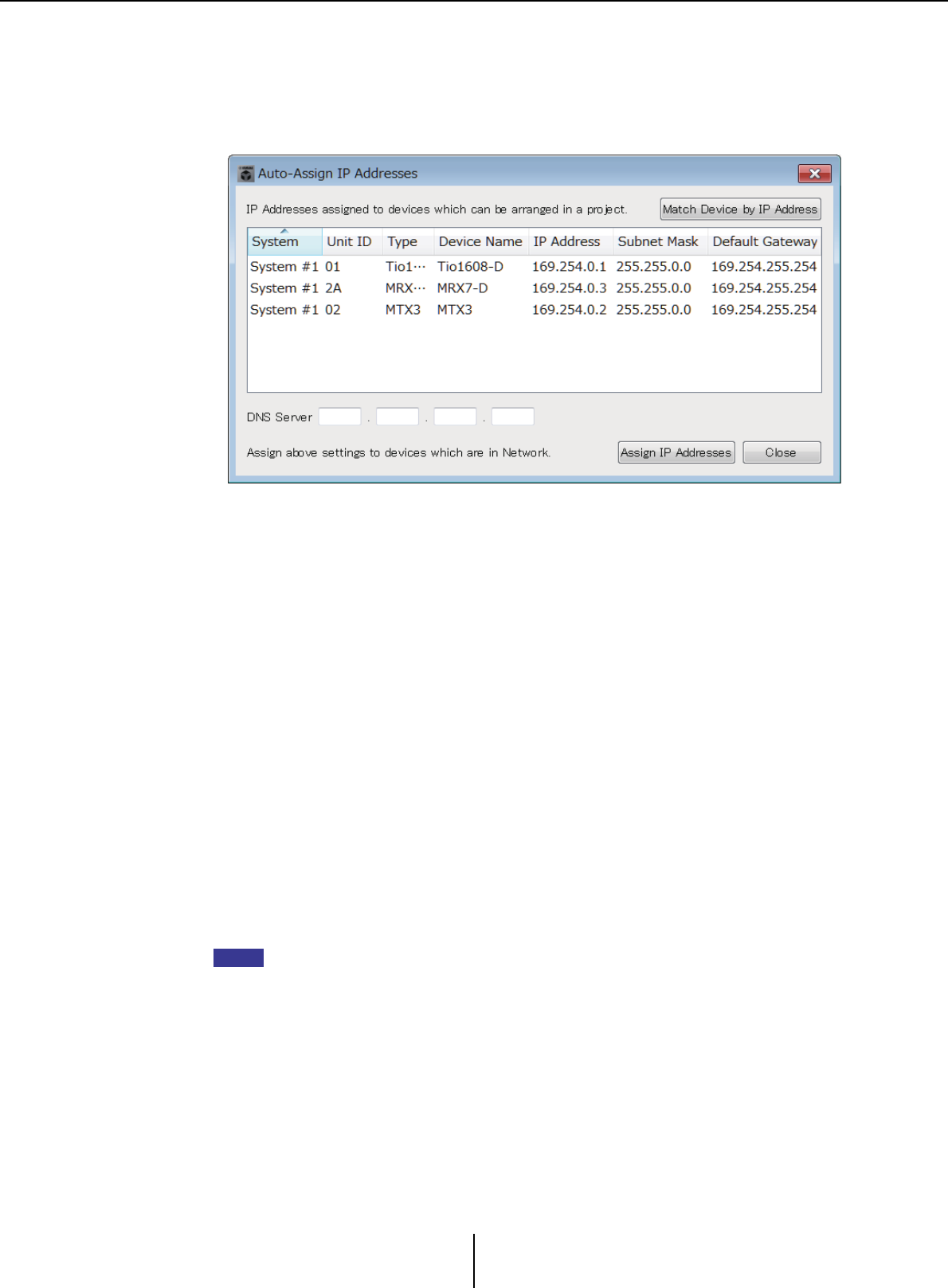
Settings for controlling devices across subnets Appendix
MTX-MRX Editor User Guide
267
5. Click the [Auto-Assign IP Addresses] button so that the virtual device IP
settings specified in the “Match Device by IP Address” dialog box are
applied to the “IP Address” dialog box.
The “Auto-Assign IP Addresses” dialog box opens.
The IP settings of the virtual devices are shown.
6. If you need to connect to a DNS server, specify the [DNS Server] setting.
7. If there are no problems with the IP settings of all devices, click the
[Assign IP Addresses] button.
The settings are applied to the “IP Address” dialog box.
If there is a problem or if you want to change the settings, click the [Match Device
by IP Address] button, make the settings in the “Match Device by IP Address” dialog
box, and then click the [Assign IP Addresses] button once again.
You can also make IP settings for the real devices manually while referring to the IP
settings of the virtual devices. In this case, in the “IP Address” dialog box, select the
[Use the following IP Address] option button, and then enter the [IP Address] and
[Subnet Mask].
8. In the “IP Address” dialog box, select the device and click the [OK]
button.
The settings are applied to the real device.
9. In the device’s settings, set IP SETTINGS to [PC] or set IP SELECT MODE
/ IP Address Mode to [STATIC IP (MANUAL)], and then restart.
This completes the settings.
If the “Match Device by IP Address” dialog box’s [Match Device by IP Address] check box is
selected, use the IP address to associate the virtual device and real device. If the IP
addresses of the virtual device and the real device are different, the devices are shown both
in the Project screen’s network device area and in the MTX/MRX system’s area, even if the
UNIT ID is the same.
NOTE
Alert list Appendix
MTX-MRX Editor User Guide
268
Alert list
The alerts generated by the MTX/MRX and the XMV, and their significance and the appropriate
actions, are listed below.
The number is shown as two digits on the MTX/MRX unit, and as three digits on the XMV unit.
A single alert is shown when the event occurs. A continuing alert is shown when the event occurs and
when it ends.
Some alerts and information are shown in MTX-MRX Editor but not shown on the unit itself.
If the problem is not solved, please contact a Yamaha service center listed at the end of the device’s
owner’s manual.
Number Content Action Type Single/
Continuing
Device abnormality
1–9 The device has not started up
correctly.
Turn the power off, then turn on after waiting at
least 6 seconds. If this does not solve the
problem, please initialize the memory. Should
this also fails, contact your Yamaha dealer.
Fault Continuing
10
The internal backup battery is
completely exhausted, or is not
installed.
When you turn off the power, the current
settings will be lost, and will return to the
default values. Please stop use immediately,
and contact your Yamaha dealer.
Fault Continuing
11
The internal backup battery
has run extremely low, and it is
possible that the internal
memory has been cleared.
When you turn off the power, the current
settings will be lost, and will return to the
default values. Please stop use immediately,
and contact your Yamaha dealer.
Error Continuing
12
The internal backup battery
has only a small amount of
power remaining.
This does not affect the operation of the
device. However, if you continue using the
device, the settings may be lost and reset to
the default values. Contact your Yamaha
dealer as soon as possible.
Warning Single
13
A problem has occurred with
the internal clock, and it has
been initialized (January 1,
2000, 0:00).
If this occurs each time you turn on the power,
it is possible that the internal backup battery
has run down or that the device has
malfunctioned. Contact your Yamaha dealer.
If this occurs only once, an abnormality was
detected with the clock setting and it was
initialized; use MTX-MRX Editor to set the
time.
Fault Continuing
14 The current preset saved in
internal memory has been lost.
Recall the preset. If this does not solve the
problem, contact your Yamaha dealer. Fault Continuing
15 The settings saved in internal
memory have been lost.
Either the internal backup battery has run low,
or the device has malfunctioned. Contact your
Yamaha dealer.
Fault Continuing
16 A memory problem has
occurred. Contact your Yamaha dealer. Fault Continuing
19 The device has not started up
correctly. Contact your Yamaha dealer. Fault Continuing
20
An unsupported Mini-YGDAI
card is inserted in the slot, or
the inserted Mini-YGDAI card
has malfunctioned.
Replace the card with a supported Mini-
YGDAI card or check that the supported Mini-
YGDAI card is working correctly in another
Host.
Fault Continuing

Alert list Appendix
MTX-MRX Editor User Guide
269
21 The word clock master has
become unlocked.
Make sure that the word clock signal is being
input correctly. Error Continuing
22
The digital signal being input to
the [YDIF IN] connector is not
synchronized to the word clock
of this device. Make sure that YDIF cables are properly
connected.
Use cables that meet the required
specifications.
Error Single
23
The digital signal being input to
the [YDIF IN] connector is not
continuously synchronized to
the word clock of this device.
Error Continuing
24
The digital signal being input to
the slot is not synchronized to
the word clock of this device.
Either input a signal that is synchronized, or
specify the slot as the word clock master.
Warning Single
25
The digital signal being input to
the slot is not continuously
synchronized to the word clock
of this device.
Warning Continuing
26
The digital signal being input to
the Dante connector is not
synchronized to the word clock
of this device. Either input a signal that is synchronized, or
specify the Dante connectors as the word
clock master.
Warning Single
27
The digital signal being input to
the Dante connector is not
continuously synchronized to
the word clock of this device.
Warning Continuing
30
There is a problem with the
connection of the [YDIF IN]
connector.
Make sure that YDIF cables are properly
connected.
Use cables that meet the required
specifications.
Error Continuing
40 Duplicate IP addresses. Change the IP addresses so that there are no
duplicates. Error Continuing
41 IP address was not set within
60 seconds of startup.
Please check rear panel DIP switch 6 (IP
Setting). If DIP switch 6 is set to “PC,” use
MTX-MRX Editor or DHCP server to specify
the device IP address.
Warning Continuing
42
A device within the MTX/MRX
system was not found on the
network.
Power-on all devices in the system, and make
sure that they are correctly connected to the
network.
Error Continuing
43 Too many devices are
connected to the network.
Reduce the number of devices connected to
the network. Error Single
44
A timeout has occurred in
synchronization to the time
server or the server reply is
invalid.
Check the time server condition or set another
time server. Error Single
45
The host name of the time
server can not be resolved by
DNS server.
Check the setting of the time server, DNS
server address or make sure that the DNS
server works correctly.
Error Single
46 Dante received flow count
exceeded the limit.
Maximum Dante Flow rate exceeded. Try
changing parts of transmission flows to
Multicast using Dante Controller.
Error Single
Number Content Action Type Single/
Continuing

Alert list Appendix
MTX-MRX Editor User Guide
270
47 Event [**] could not be
transmitted.
Check the devices that are connected to the
network. Error Single
50 The UNIT ID is set to “00.” Set the UNIT ID to something other than “00.” Error Continuing
51
Devices with identical UNIT IDs
were found connected within
the same network.
Change the UNIT ID so that there are no
duplicates. Error Continuing
52
A communication error
occurred with the [DCP]
connection.
• If an error was shown in the DCP panel,
refer to the DCP owner’s manual and take
the appropriate action.
• Ensure that the panel ID of the DCP units
do not conflict.
• Verify that the cables are correctly
connected and are within the specified
length.
Error Single
53
The DCP[*] connected to the
[DCP] connector has been
configured differently from the
project settings.
• Check that the required DCP is connected.
• Check whether a different model of DCP
might be connected.
Error Continuing
56 SD memory card was not
recognized.
Use an SD memory card that complies with
the specifications. Error Continuing
58 Unable to play the specified file
or folder in the SD player.
Verify that the specified audio file or folder
exists in the SD memory card. There must be
at least one playable audio file in the specified
folder.
Warning Single
60 A preset recall attempt has
failed.
Initialize the memory of the device (use rear
panel DIP switches 7 and 8). If this does not
solve the problem, contact your Yamaha
dealer.
Error Continuing
61
The recall could not be
executed because the preset to
be recalled when the MTX/
MRX starts up was not found.
Specify a preset that exists. No sound will be
output unless an appropriate preset is
recalled.
Error Continuing
62 A snapshot/snapshot group
recall attempt has failed.
Initialize the memory of the device (use rear
panel DIP switches 7 and 8). If this does not
solve the problem, contact your Yamaha
dealer.
Error Continuing
63 The snapshot/snapshot group
could not be recalled.
• The Snapshot selected for recall cannot be
recalled as no data has been stored to it.
• Another device may have been added after
snapshots were stored. Please synchronize
and check all snapshots/snapshot groups
using Editor, edit as necessary and store
again.
Warning Single
64 The preset could not be
recalled.
• The Preset selected for recall cannot be
recalled as no data has been stored to it.
• Another device may have been added after
presets were stored. Please synchronize
and check all presets using MTX-MRX
Editor, edit as necessary and store again.
Warning Continuing
65 Invalid parameters set for GPI
IN.
Check the GPI IN settings and perform
synchronization again. Error Continuing
66 Invalid parameters set for GPI
OUT.
Check the GPI OUT settings and perform
synchronization again. Error Continuing
Number Content Action Type Single/
Continuing
Alert list Appendix
MTX-MRX Editor User Guide
271
67 Invalid parameters set for
DCP[*].
Check the DCP[*] settings and perform
synchronization again. Error Continuing
70
Synchronization has not been
completed. It may be that
synchronization was halted
before completion.
Perform synchronization again using MTX-
MRX Editor. If this does not solve the problem,
initialize the memory of the device and
synchronize again. If this also fails, contact
your Yamaha dealer.
Error Continuing
71
The UNIT ID settings when
synchronization was performed
do not match the current UNIT
ID settings.
Do not change any UNIT ID’s after performing
synchronization. If you’ve changed any UNIT
ID’s, perform synchronization again.
Error Continuing
72
Because this device has Dante
Device Lock enabled, the
settings of device DIP switches
and MTX - MRX Editor do not
match current Dante settings.
To solve the mismatch, please review device
DIP switch settings and MTX - MRX Editor’s
Dante settings, and edit as necessary to
match the current situation. Or please disable
Device Lock using Dante Controller.
Error Continuing
80 Speech Privacy Audio File not
installed. Install the Speech Privacy Audio File. Warning Continuing
Amp problems
100
The power supply was shut
down because d.c. was
detected on a speaker output.
It is likely that the device has malfunctioned;
immediately stop using the device and contact
your Yamaha dealer.
Fault Continuing
101
The power supply was shut
down because its temperature
exceeded the allowed limit.
Turn the power off, let the power supply cool
down, then turn the power on again.
Continuous high-power output will cause high
temperatures, so please lower the output
level. If the temperature is still high, check
whether dirt or a foreign object could have
clogged the cooling fan, and clean the fan if
necessary.
Fault Continuing
103
Protection has been activated,
and the power supply was shut
down.
Continuous high-power output may have
activated protection; lower the output level.
For details on the reason that protection was
activated, refer to the owner’s manual.
Error Continuing
104 Protection has been activated,
and muted.[ch*] Error Continuing
105
A short circuit was detected in
the speaker output
connector[ch*], so the output
signal has been muted.
It may be that the speaker output connector’s
“+” and “–” are shorted, or that the connected
speaker has malfunctioned.
Fault Single
106
The temperature of the amp
section (heat sink) has
changed, and the speaker
output is now ****.
Continuous high-power output will cause high
temperatures, so please lower the input level
or attenuator. If the temperature is still high,
check whether dirt or a foreign object could
have clogged the cooling fan’s air intake, and
clean it if necessary.
Warning Single
Device information
200 The power to the device has
been turned on. –Information Single
201 The power to the device has
been turned off. –Information Single
Number Content Action Type Single/
Continuing

Alert list Appendix
MTX-MRX Editor User Guide
272
202 The firmware update has been
completed. –Information Single
203 Initialization has been
executed. –Information Single
204 Panel lock has been disabled. –Information Single
205 The IP address has been
established. –Information Single
206
The network IP address has
been allocated from the DHCP
server.
–Information Single
207
The network IP address has
been released by the DHCP
server.
–Information Single
208
An EMG (Emergency) signal
was received, and the device
switched to EMG mode.
–Information Continuing
209 The setting of the internal clock
has been changed. –Information Single
210 The event has been executed
using the scheduler. –Information Single
211 MTX-MRX Editor began
synchronisation. –Information Single
213
A login failure has occurred
from an external remote
controller via the remote control
protocol.
–Information Single
214
A login authentication has been
successfully completed from an
external remote controller via
the remote control protocol.
–Information Single
215 The SD memory card has been
mounted properly. –Information Single
216
The SD memory card was
removed while the MTX was
turned on.
–Information Single
217 Preset number ** was recalled. –Information Single
218 Preset number ** was stored. –Information Single
220
The clock has been
successfully synchronized by
the time server.
–Information Single
221 Preset number ** was edited. –Information Single
222 A snapshot/snapshot group
was recalled. –Information Single
223 Snapshot was stored. –Information Single
224 Snapshot was edited. –Information Single
225 Snapshot group was edited. –Information Single
Number Content Action Type Single/
Continuing
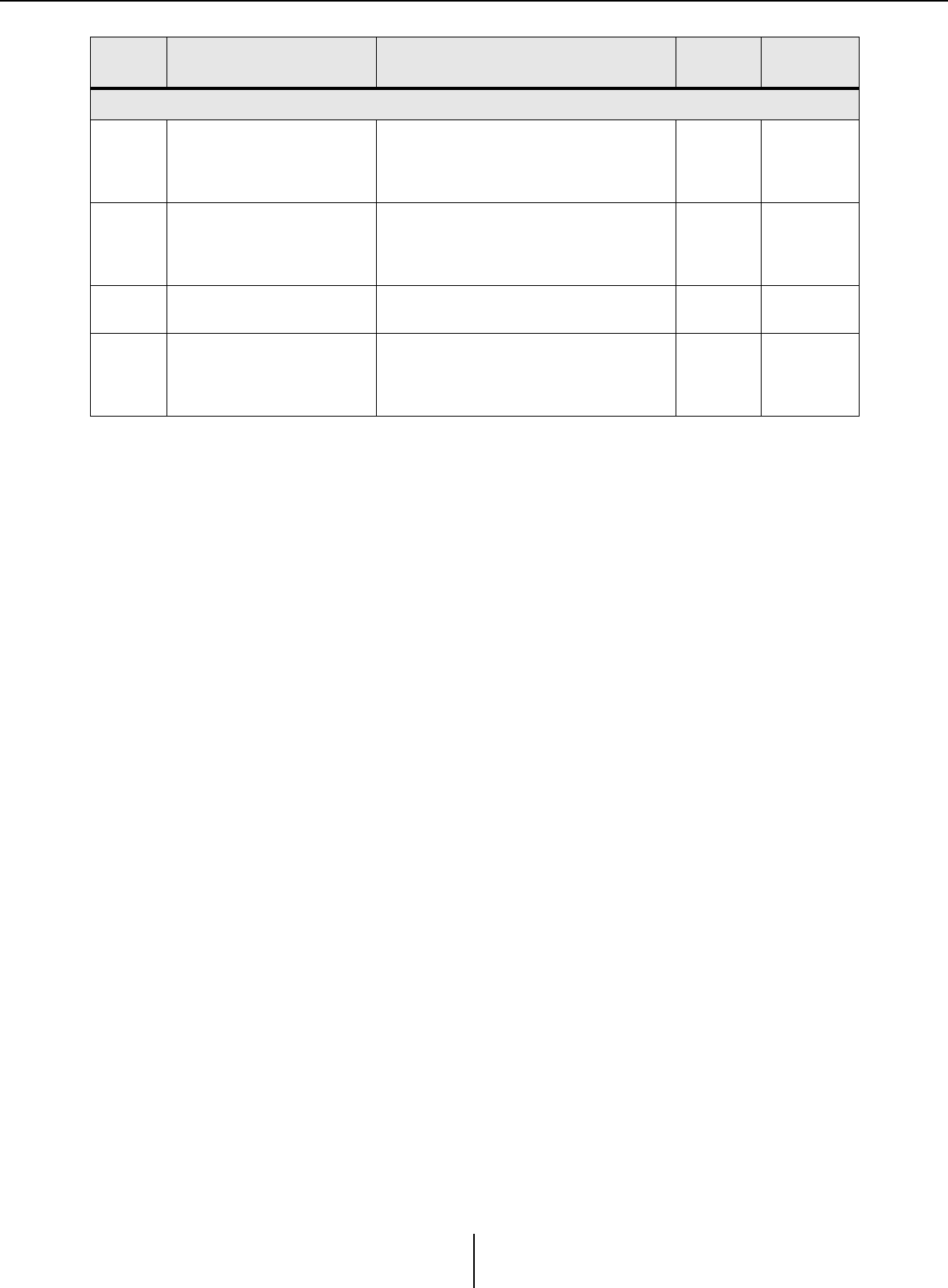
Alert list Appendix
MTX-MRX Editor User Guide
273
Amp information
102
Protection has been activated,
and the limiter[ch*] is in
operation.
Continuous high-power output may have
activated protection; lower the output level.
For details on the reason that protection was
activated, refer to the owner’s manual.
Information Continuing
110
The Redundant Backup
function has operated, and
channel * has switched to
analog input.
There is a problem with the digital signal.
Check the connection of the digital circuit, and
check whether a Pilot Tone signal is being
input.
Error Continuing
219 The Power Amp Mode was
changed. –Information Single
226
The Redundant Override
function has operated, and
channel * has switched to
analog input.
–Information Continuing
Number Content Action Type Single/
Continuing
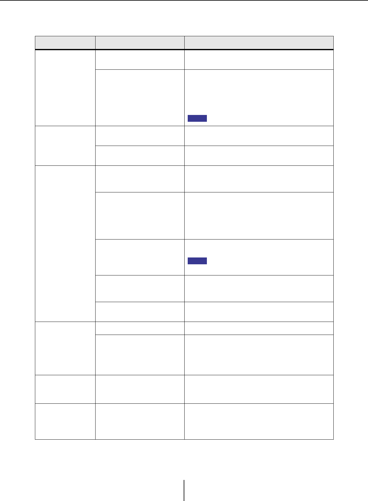
Troubleshooting Appendix
MTX-MRX Editor User Guide
274
Troubleshooting
Problem Possible cause Action
MTX-MRX Editor
can’t communicate
with the device.
The IP address setting of the
computer is incorrect.
Refer to “MTX Setup Manual” or “MRX Setup Manual,” and
specify the IP address of the computer.
A firewall is blocking
communication.
Right-click [Start]¦[Control Panel]¦[System and
Security]¦[Allow an App through Windows Firewall];
then click the [Change settings] button, and select the
check boxes for “Bonjour service” and “MTX-MRX Editor.”
If MTX-MRX Editor is not in the list, click the [Allow another
app] button, add MTX-MRX Editor, and select its check box.
Set the control panel view to [Category].
Can’t specify the
device’s IP
address from the
DHCP server.
The device was started up before
the DHCP server. Start up the DHCP server before you start up the device.
The device’s IP SETTING is set to
UNIT ID. Use the device’s DIP switch to set IP SETTING to PC.
A device is not
shown in the
Project window.
The device or the network switch is
not powered-on.
Power-on the device and the network switch.
Also, it will take several seconds after the device is
powered-on until it is shown in the Project window.
IP addresses conflict between
devices on the network.
If IP SETTING is set to UNIT ID, set the UNIT ID of the
devices in the network so that they do not conflict.
If IP SETTING is set to PC, use the “IP Address” dialog box
to specify an IP address that does not conflict. UNIT ID
conflicts can be viewed in the “Device Information” dialog
box.
The upper three numbers of the
computer’s IP address do not
match the upper three numbers of
the device’s IP address.
In the “IP Address” dialog box, set the IP address so that the
upper three numbers match.
If the subnet mask is set to 255.255.0.0, set the
upper two numbers to match.
The device is connected to
something other than the
NETWORK connector.
Connect the device to the NETWORK connector.
An incorrect network card is
selected.
In the “Network Setup” dialog box, select the network card
that is connected to the device.
Can’t monitor or
control the device.
The system is offline. In the toolbar, click the [Online] button to go online.
In the Project window, the device is
in the list of network devices.
There is an inconsistency between the settings of MTX-
MRX Editor and the settings of the device. Either use the
“Device Configuration Wizard” dialog box to change the
settings in MTX-MRX Editor, or change the settings of the
device.
Preset data saved
in the MTX/MRX
has disappeared.
The power supply was stopped
while MTX/MRX data was being
saved.
Synchronize once again with MTX-MRX Editor and send
the settings data.
Can’t go online in
the “Go Online –
From devices”
dialog box.
The MTX/MRX has never been
online with MTX-MRX Editor in To
Device.
Using the applicable project, use To Device to put the MTX/
MRX and MTX-MRX Editor online.
NOTE
NOTE
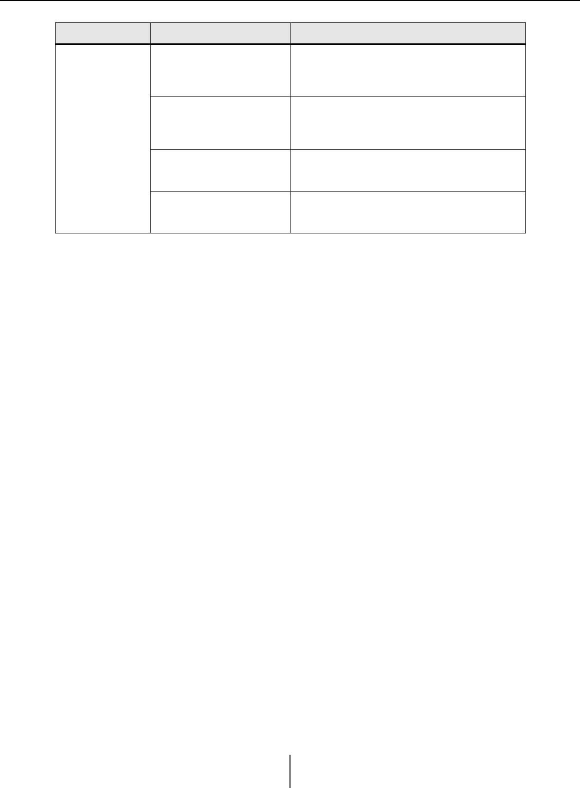
Troubleshooting Appendix
MTX-MRX Editor User Guide
275
No sound is
output.
A cable is broken or disconnected.
Check whether the cables between each device are
connected correctly. If the cables are connected correctly,
check whether they might be broken, and replace any that
are broken.
The DIP switches on the unit are
set incorrectly.
Check the setting of the DIP switches on the unit. In
particular if START UP MODE is set to INIT., there will be no
sound unless the unit synchronizes with MTX-MRX Editor
each time the power is turned on.
The settings in MTX-MRX Editor
are incorrect.
Check the settings of MTX-MRX Editor. In particular for
YDIF, make sure that the “EXT. I/O” settings match the port
settings of the input/output channels.
The XMV is in double power mode.
In double power mode, the B/D/F/H channel output is
disabled. Either cancel double power mode, or use the
Editor to specify a different channel.
Problem Possible cause Action

Manual Development Group
© 2013 Yamaha Corporation
Published 05/2020 IP-L0
