Yamaha Block_diagram PX Block Diagram
User Manual: Yamaha PX Block Diagram
Open the PDF directly: View PDF ![]() .
.
Page Count: 1
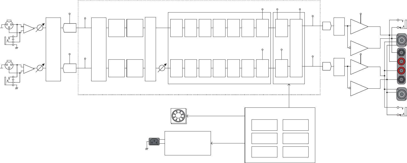
Block diagram
CLIP
OUTPUT
METER,
SIGNAL
INPUT B
HA
Volume
Balance
Protection Logic
Speaker Processor
INPUT A
HA
D-Contour
FOH/MAIN
MONITOR
Delay
D-Contour
FOH/MAIN
MONITOR
Delay
Volume
HPF LPF Polarity
6-band
PEQ *
Speaker
Delay *
Level Limiter
Protection Block
Limiter
Amplifier ClipOutput Voltage
Output Current
Integral Output
Power
DC
Temperature
AC IN
Shutdown
Limit,
Mute
DACMute
A
B
A
B
A
B
1+
FAN x 2
SPEAKERS
1-
2+
2-
1+
1-
2+
2-
Input
Sensitivity/
Gain
+4dBu
+14dBu
26dB
32dB
Input
Router
DUAL
PARALLEL
SINGLE
SUM
Router
Mute
A:POSITIVE
A:NEGATIVE
B:NEGATIVE
DSP
LIMIT PROTECT
OUTPUT
METER,
SIGNAL
INPUT
METER
ADC
CLIP
ADC
CLIP
INPUT
METER
LIMIT
HPF LPF Polarity
6-band
PEQ *
Speaker
Delay *
Level Limiter Limiter
LIMIT LIMIT
B:POSITIVE
AMP
AMP
CLIP
AMP
AMP
DACMute
Power Supply
* Can be set only from speaker
preset parameters.
