Yamaha RS100 Owner's Manual En
Yamaha Corporation RS100 Owner's Manual rs100_en Yamaha Corporation - RS100 - Owner's Manual
Yamaha Corporation RS100 Owner's Manual rs100_en Yamaha Corporation - RS100 - Owner's Manual
User Manual: Yamaha RS100 Owner's Manual
Open the PDF directly: View PDF ![]() .
.
Page Count: 6
H
G
電子ドラムラックシステム RS100 組立説明書
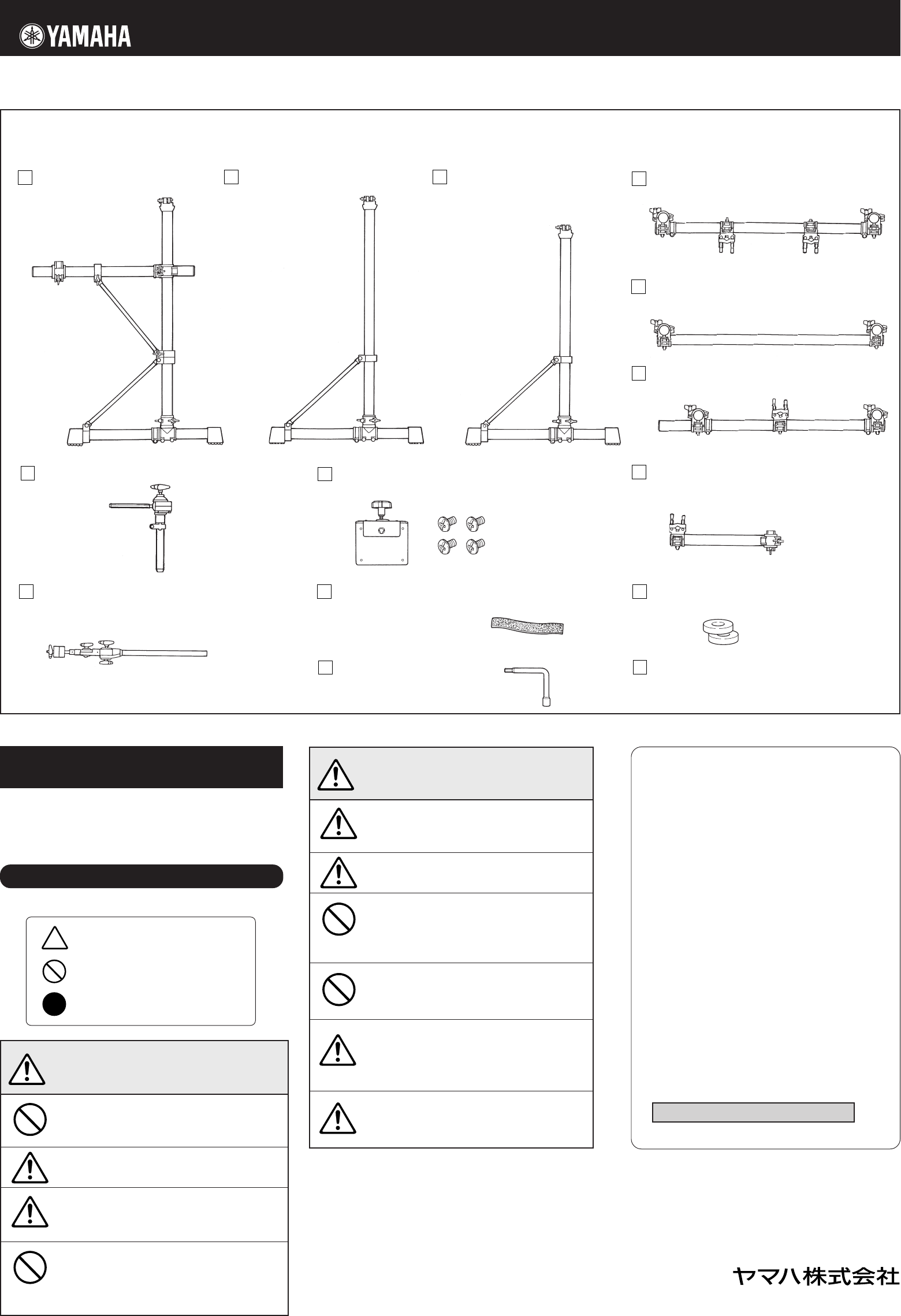
■ RS100 梱包内容 ※ ラックを組み立てる前に、すべての部品が
そろっていることを確認してください。
サイド集成 A(x1) サイド集成 B(x1)
このたびはヤマハ電子ドラムラックシステム RS100 をお買い上げいただきまして、まことにありがとうございます。
お使いになる前に、この組立説明書をよくお読みになり、安全に正しくお使いくださいますようお願い申し上げます。
モジュールホルダー(x1)
* +−トラスコネジ 5 × 8 4 本付属
モジュールホルダークランプ(x1)
M
L
K
J
ケーブルバンド(x10)
チューニングキー(x1) 組立説明書(本紙)
フェルトワッシャー(x2)
サイド集成 C(x1)
F
サイドアーム(x1)
E
D
センターパイプ集成 A(x1)
センターパイプ集成 B(x1)
I
シンバルホルダー(x2)
タムホルダー(x5)
N
* 仕様および外観は改良のため予告なく変更する場合があります。
安全へのこころがけ
ご使用の前に、この『安全へのこころがけ』を
よくお読みのうえ正しくお使いください。
特にお子様には、最初にご家族の方、
または指導者から取扱い方法の指導をお願いいたします。
設置場所は床面が平らで丈夫な所にしてくだ
さい。床が傾いていたり、段差がありますと不
安定となり、転倒する恐れがあります。
固定用ネジはしっかり締め付けてください。
転倒、落下等によりけがの原因となります。
高さや角度の調整をおこなう際、急にネジを
緩めないでください。パッドが落下したり、
ラック、パイプが滑り落ちて手や指を挟む等
けがの原因となります。
ラックに腰かけたり踏み台にしないでくださ
い。転倒したり壊れたりして、けがの原因とな
ります。
小さなお子様が触ったり、近づく場合は注意
してください。多くのパイプやアームが並び
ますので、動きによっては体をぶつけたりし
て、けがをする恐れがあります。
パッドやモジュールのセッティングの際は、
ケーブルの引きまわしに注意してください。
足を引っかけて転倒する恐れがあります。
この表示を無視して誤った取扱いを
すると、人が死亡又は重傷を負う危
険の恐れがある内容を示しています。
警告
フットスイッチやフットペダルの下に、手や足
を入れないでください。
挟まれてけがの原因となります。
クランプを調節する際、指に注意してくださ
い。指が挟まれてけがをする恐れがあります。
パイプの端面や内面及びネジの先端にご注意く
ださい。尖った部分等で指にけがをする恐れが
あります。
電子ドラムラックには、アコースティックドラ
ムを取り付けないでください。クランプの破損
や、ドラムの落下などで、けがをする恐れがあ
ります。
この表示を無視して誤った取扱いをすると、
人が傷害を負ったり、財産が損害を受ける
危険の恐れがある内容を示しています。
注意
人身傷害の危険を防止するには
∼以下の指示を必ず守ってください∼
注意(危険・警告を含む)を促す
内容があることを告げるものです。
禁止の行為を告げるものです。
行為を強制したり指示する
内容を告げるものです。
弦打楽器事業部 国内営業部 ギタードラム営業課
〒430-8650 浜松市中沢町10-1 TEL 053 (460) 2433
■ ヤマハ株式会社 EM 営業統括部
各地区お問い合わせ先
●北海道営業所
〒 064-8543 札幌市中央区南 10 条西 1 丁目 1-50
TEL 011 (512) 6113
●仙台営業所
〒 980-0804 仙台市青葉区大町 2-2-10
TEL 022 (222) 6147
●東京・営業推進課
〒 108-8568 東京都港区高輪 2-17-11
TEL 03 (5488) 5476
●名古屋営業所
〒 460-8588 名古屋市中区錦 1-18-28
TEL 052 (201) 5199
●大阪営業所
〒 542-0081 大阪市中央区南船場 3-12-9
TEL 06 (6252) 5231
●九州営業所
〒 812-8508 福岡市博多区博多駅前 2-11-4
TEL 092 (472) 2130
ホームページ http://www.yamaha.co.jp/
C
B
A
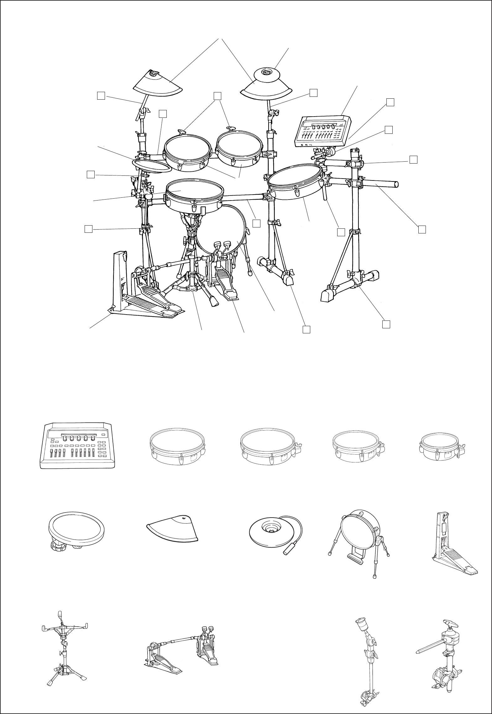
■ RS100 +パッド類:セットアップ例
● パッド、ドラムトリガーモジュール類(別売品)
yTP80S/TP80
ドラムパッド
uPCY80S/PCY80
シンバルパッド
oKP120
キックパッド
!0HH80A
ハイハットコントロールペダル
iPCY10
トリガーパッド
!2 フットペダル
※ DFP-880 など
!1 スネアスタンド
※ SS-642 など
tRHP80
リアルヘッドパッド
(8 インチ)
rRHP100
リアルヘッドパッド
(10 インチ)
eRHP120
リアルヘッドパッド
(12 インチ)
wRHP120SD
スネア用リアルヘッドパッド
(12 インチ)
qDTXTREME
ドラムトリガーモジュール
* スネア用パッドのセッティングにはスネアスタンドを使用ください。
● TPCL100
タムホルダー
● CYAT100
シンバルアタッチメント
■ パッドを増設される場合にお使いください。
q
w
u
r
y
!2
!1
e
D
E
F
G
J
J
o
I
G
G
G
H
!0
i
A
B
C
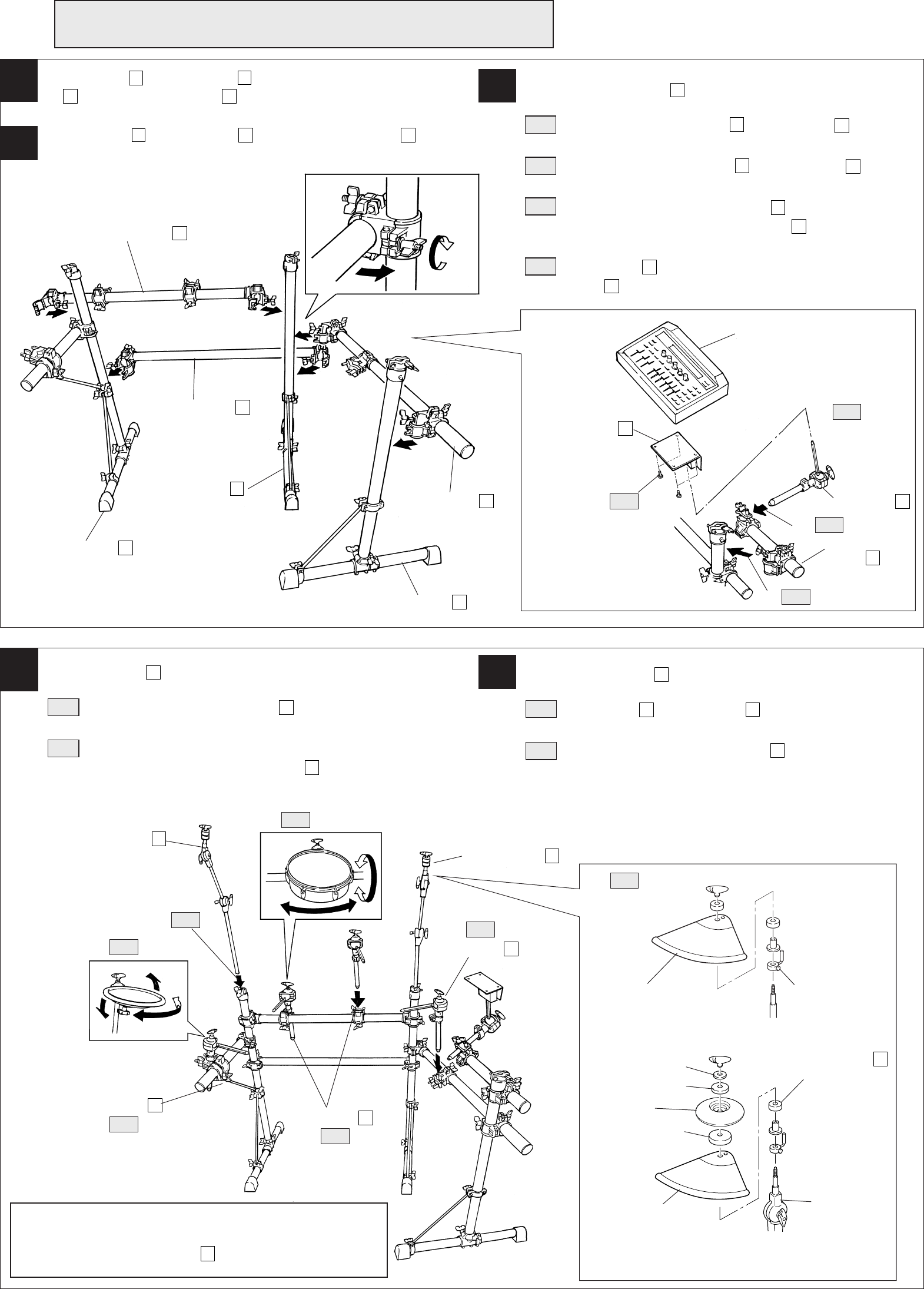
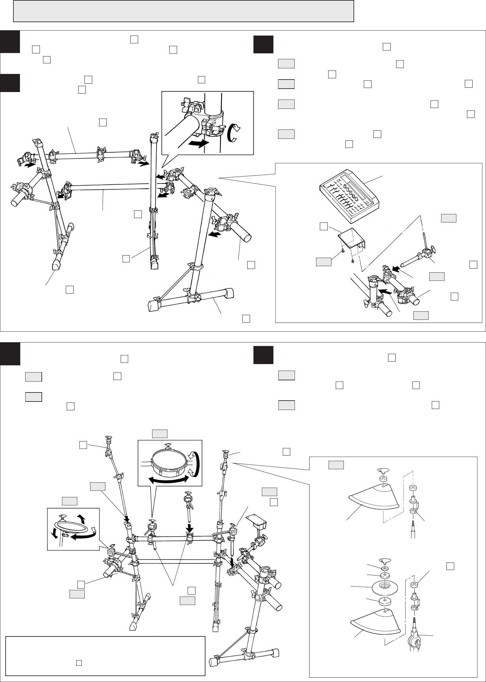
■ RS100 組み立て手順
※ 組み立てに際して、ドライバー(+またはー)をご用意ください。
1サイド集成A
A
とサイド集成B
B
のパイプにセンターパイプ集成
A
D
とセンターパイプ集成B
E
を取り付けます。 3モジュールホルダー
H
の取付け
3-1 モジュールホルダークランプ
I
をサイド集成C
C
のパイプに
取り付けます。
3-2 モジュールホルダークランプ
I
にタムホルダー
G
を差し込
み、固定ネジを締め付けます。
3-3 DTXTREMEをモジュールホルダー
H
に取り付けます。ドラ
イバーを使って、モジュールホルダー
H
に付属のネジで、
DTXTREMEの底面のネジ穴へ固定します。
3-4 タムホルダー
G
に、DTXTREMEを取り付けたモジュールホ
ルダー
H
を取り付けます。
2サイド集成B
B
とサイド集成C
C
のパイプにサイドアーム
F
を
取り付けます。
クランプやパッドなど各部の固定ネジはしっかりと締め付けてください。
緩かったり締めすぎたりすると、落下や破損の原因となります。ご注意ください。
組み立てが完成したら、キックパッド、ハイハットコントロールペ
ダルなどをセットし、結線します。各ケーブルは、演奏のじゃまに
ならないように、ケーブルバンド
K
でパイプに固定しましょう。
センターパイプ集成 A
D
サイド集成 A
A
サイド集成 B
B
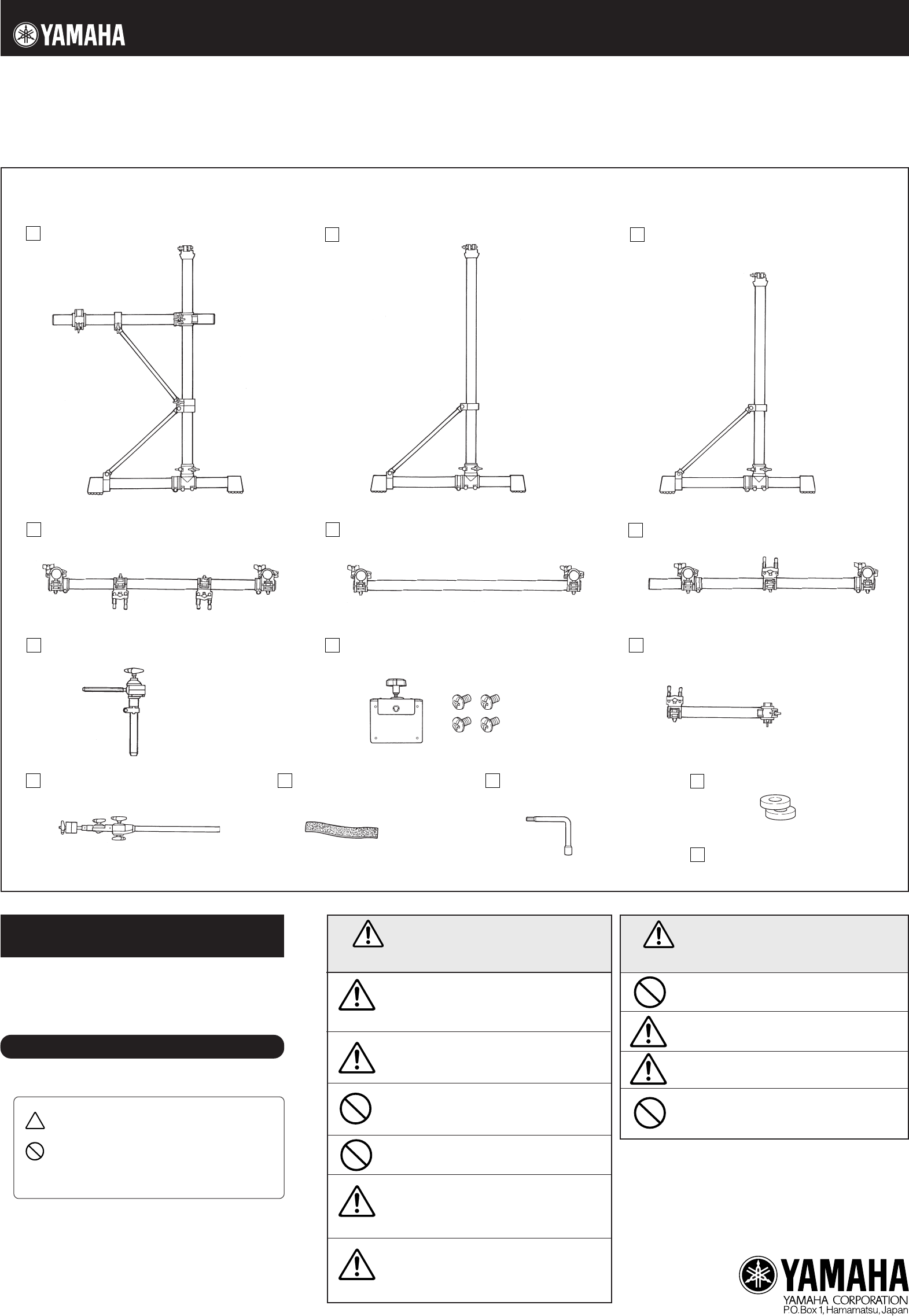
4タムホルダー
G
の取付け
4-1 ホルダークランプにタムホルダー
G
を差し込み、向きを調整
して固定ネジを締め付けます。
4-2 ポジションを確認し(セットアップ例を参照ください。)、リ
アルヘッドパッドなどをタムホルダー
G
に取り付け、向きを
調整し、固定します。(取付方法はリアルヘッドパッドの取扱
説明書をご参照ください。)
5シンバルホルダー
J
の取付け
5-1 サイド集成A
A
とサイド集成B
B
のパイプ上面にあるシンバ
ル固定用アダプターに差し込み、固定ネジで締め付けます。
5-2 シンバルパッドをシンバルホルダー
J
に取り付け、向きを調
整し、固定します。
また、PCY10を使用する場合は、図のようにPCY10付属
の部品を使用します。(取付方法はシンバルパッドの取扱説
明書をご参照ください。)
シンバル
パッド
手順 5-2
● PCY10 使用の場合
センターパイプ集成 B
E
サイド集成 C
C
DTXTREME
サイドアーム
F
タムホルダー
G
モジュールホルダー
クランプ
I
手順 3-3
手順 3-1
モジュールホルダー
H
手順 3-2
手順 3-4
タムホルダー
G
タムホルダー
G
タムホルダー
G
手順 4-2
手順 4-1
手順 4-1
手順 4-1
手順 4-2
手順 5-1
シンバルホルダー
J
シンバルホルダー
J
PCY10
シンバル
パッド
フェルト(小)*
※ * 印はPCY10付属品です。
※ PCY10に同梱のチルターへの交換は必要ありません。
フェルト(大)*
ワッシャ*
チルター
回り止め金具
(PCY80/80Sに付属)
フェルトワッシャ
L
に交換してください。
締める
H
G
Electronic Drum Rack System
RS100
Assembly Instruction
Side Assembly A (x1)
M
L
K
J
F
E
D
I
N
* Specifications are subject to change without notice.
PRECAUTIONS
Before using, please read this “Assembly Instruction” sheet,
and use this product in a safe and proper manner.
Especially for children, parents or an instructor should teach the
children the proper manner in which to use the device.
To prevent against accidents and injury
Please follow the cautions listed below
Caution (including danger, or warning). This mark indicates
cautions in which you should pay close attention to.
Acts indicated with this icon are prohibited and should not
be attempted.
This icon indicates acts that you are urged to follow.
●
Thank you for purchasing the Yamaha Electronic Drum Rack System RS100.
Before using, thoroughly read this assembly manual, and use this product safely and correctly.
■
RS100 Rack Stand Parts
* Before assembling the rack stand, make sure all of the parts shown below are included.
Side Assembly B (x1) Side Assembly C (x1)
Center Pipe Assembly A (x1) Center Pipe Assembly B (x1) Side Arm (x1)
Tom Holder (x5) Module Holder (x1)
(4 screws included)
Module Holder Clamp (x1)
Assembly Instruction
(this sheet)
Tuning Key (x1)
Cable Band
(x10)
Cymbal Holder (x2) Felt Washer (x2)
* Specifications are subject to change without notice.
Always set the instrument on a flat and solid surface.
Placement on a sloping, unstable surface or on steps
may result in the instrument being unstable and over-
turning.
Make sure all bolts are tightened firmly. Loose bolts
may result in the rack overturning or parts dropping
causing injury.
When adjusting the height or angle, do not suddenly
loosen the bolt. The pad may drop, the rack or pipes
may slip, pinching or causing injury to hands or fingers.
Do not sit or step on the rack. The rack may overturn
or be damaged resulting in injury.
Please be careful when children are close to or touch-
ing the product. The product has many pipes and arms
so careless movement around the product may result
in injury.
When setting the pads and modules, please pay close
attention in regards to the handling and setting of
cables. Feet may become entangled in the cables re-
sulting in falls.
If this symbol is ignored and the equipment is
used improperly, fatal injury to persons or se-
rious damage could occur.
Do not put your hands or feet under the foot pedal or
foot switch. They may be pinched resulting in injury.
Watch your fingers when adjusting clamps. They may
become pinched resulting in injury.
Be careful around pipe ends, inside the pipe and screw
ends. Metal shavings, etc. may injure your fingers.
Do not attach acoustic drums to the electronic drum
rack. Clamps may be damaged and drums may drop,
causing injury.
If this symbol is ignored and the equipment is
used improperly, there is a danger of injury to
persons handling the equipment, and material
damage could occur.
CAUTION
WARNING
C
B
A
Printed in Taiwan

■
RS100+Pad Grouping: Setup Example
● Pad and Drum Trigger Grouping (option)
q
w
u
r
y
!2
!1
e
D
E
F
G
J
J
o
I
G
G
G
H
!0
i
qDTXTREME
Drum Trigger Module
yTP80S/TP80
Drum Pad
!1Snare Stand
*SS-642 etc.
uPCY80S/PCY80
Cymbal Pad
iPCY10
Trigger Pad
!2Foot Pedal
*DFP-880 etc.
oKP120
Real Head Kick Pad
!0HH80A
Hi-hat Control Pedal
●TPCL100
Tom Holder
●CYAT100
Cymbal Attachment
tRHP80
Real Head Pad (8inch)
rRHP100
Real Head Pad (10inch)
eRHP120
Real Head Pad (12inch)
wRHP120SD
Snare Type Real Head Pad
(12inch)
■ Please use for additional pads.
* Please use a snare stand for setting the snare drum pad.
Includes Holder Clamp Assembly.
C
B
A
■
RS100 Assembly
* A screw driver (+ or -) is necessary to complete the assembly.
13
2
45
DTXTREME
Tilter
Center Pipe Assembly A
D
Tighten
Side Assembly C
C
Side Arm
F
Side Assembly B
B
Center Pipe Assembly B
E
Side Assembly A
A
Tom Holder
G
Module Holder
Clamp
I
Module Holder
H
Step 3-4
Step 3-3
Step 3-2
Step 3-1
After the above assembly is complete, set the Kick Pad, Hi-Hat
Control pedal, etc. into position and connect the necessary
cables. To keep cable out of the way while playing, use the
supplied Cable Bands
K
to hold the cables to the rack system's
pipes.
Step 4-1
Step 4-1
Tom Holder
G
Tom Holder
G
Cymbal Pad
Tom Holder
G
Cymbal Holder
J
PCY10
Step 4-2
Step 5-1 Step 4-1
Step 4-2
Step 5-2
Cymbal Pad
Felt (Small)*
Felt (Large)*
Cymbal Holder
J
Washer*
Please make sure that the fixing bolts on each part, such as clamps, pads, etc. are firmly tightened.
Bolts that are too tight or too loose may result in damage to the part or the part dropping. Please use caution.
Attach the Center Pipe Assembly A
D
and the Center Pipe Assembly
B
E
to the upright pipes of the Side Assembly A
A
and Side Assem-
bly B
B
.
Attach the Side Arm
F
to the pipes of the side Assembly B
B
and the
Side Assembly C
C
.
Attach the Module Holder
H
3-1 Attach the Module Holder Clamp
I
to the pipe of the Side As
sembly C
C
.
3-2 Insert the Tom Holder
G
into the Module Holder Clamp
I
,
and tighten the fixing screw.
3-3 Attach the DTXTREME to the Module Holder
H
. Using a screw
driver and the supplied screws, attach the Module Holder
H
to
the screw holes on the bottom of the DTXTREME.
3-4 Attach the Module Holder
H
, with the DTXTREME attached, to
the Tom Holder
G
.
Attach the Tom Holders
G
4-1 Insert the Tom Holders
G
into the Holder Clamps, align and
tighten the fixing screws.
4-2 Check the position and attach the Real Head Pad, etc. to the Tom
Holder
G
. Align the pads and secure. (Refer to the Real Head
Pad’s Owner’s Manual on how to attach the pads.)
Attach the Cymbal Holders
J
5-1 Insert the Cymbal Attachments into the upright pipes of the Side
Assembly A
A
and Side Assembly B
B
, and tighten the wing
bolts.
5-2 Attach the Cymbal Pad to the Cymbal Holder
J
, align the pad
and secure.
Also, when the PCY10 is used, please use the parts shown in the
diagram below. (Refer to the Cymbal Pad’s Owner’s Manual on
how to attach the Cymbal Pad.)
Anti-swivel brace
(supplied with the
PCY80/80S)
Change to the felt
washer
L
.
● When the PCY10 is used.
* The * indicates parts supplied with the PCY10.
* It is not necessary to use the tilter that is supplied with
the PCY10.
