Yifang Digital Technology VR300W Back-Up Camera User Manual Part2
Shenzhen Yifang Digital Technology Co., Ltd. Back-Up Camera Users Manual Part2
Contents
- 1. Users Manual Part1
- 2. Users Manual Part2
Users Manual Part2
These instructions do not apply to all vehicles. They are meant as only
as a general guide due to the number of different makes & models. For
vehicle specific questions, contact your vehicleʼs manufacturer.
Monitor Installation
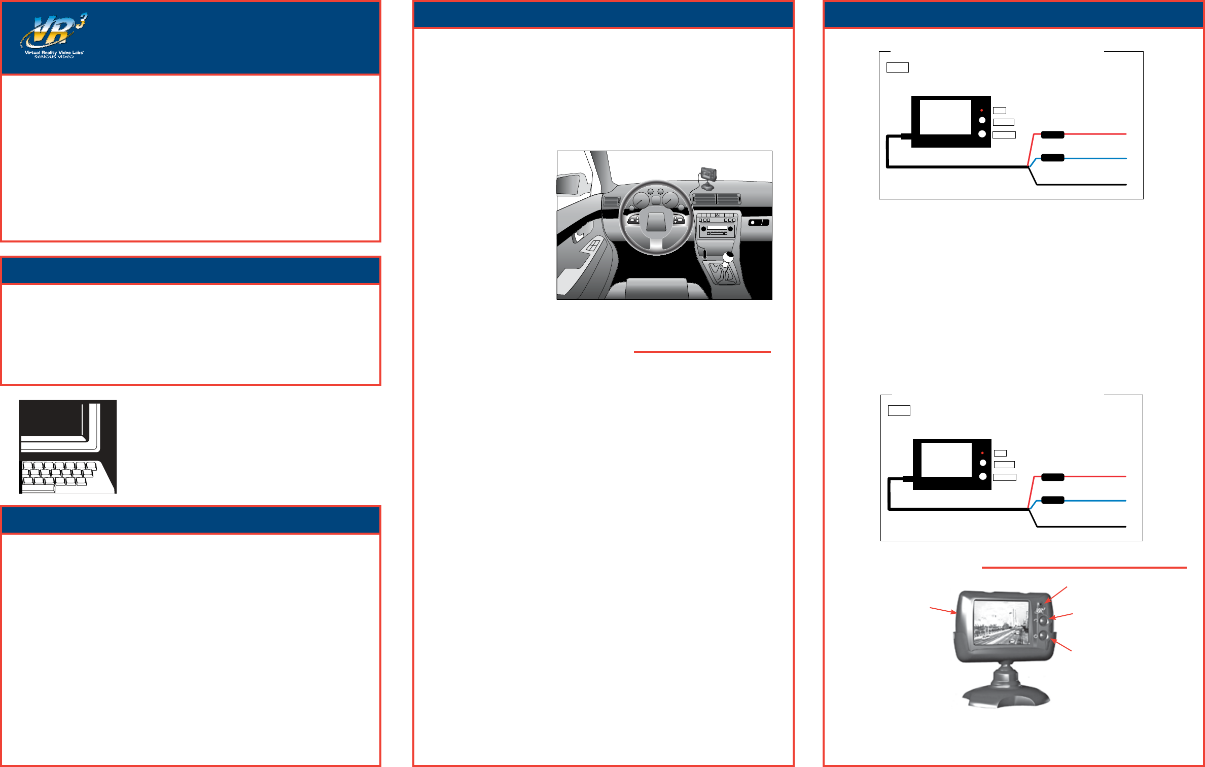
When choosing a location to mount the monitor, make sure the monitor is in an area that will
not obstruct your vision while driving. It can be placed on the dashboard, or on the windshield
depending on the angle.
1. Temporarily place the moni-
tor stand in the location that
you have chosen. Make sure
the driverʼs vision is not ob-
structed in any way or any of
the vehicleʼs
2. Route the monitorʼs power
cable to the vehicleʼs fuse
block/box or cigarette lighter
socket/12V power outlet de-
pending on the cable you are
using
3. If you are satisfied with the
location of the monitor and
the cable route you have
chosen, attach the monitor or
stand with the supplied Velcro.
MONITOR POWER CONNECTION
There are two ways to supply the monitor with power, one uses a 12 Volt cigarette lighter
adaptor plugged into the vehicleʼs cigarette lighter socket, and the other uses a wiring
harness hard wired to the vehicleʼs fuse box.
12 Volt Cigarette Lighter Adaptor Using the Monitorʼs ON/OFF Button
1. Choose a route for the cable from the monitor to the cigarette lighter socket. It can be a direct
route with the wire exposed or a route around the dashboard hidden under the vehicleʼs inte-
rior trim. When using a direct route for the power cable make sure the power cable is secured
and will not interfere with the operation of the vehicle. When routing the power cable behind
the vehicleʼs interior trim be careful not to cut the wire on and sharp edges or pinch and dam-
age the cable when re-installing the trim.
2. Plug the end of the power cable into the monitor,
3. Plug the 12 Volt cigarette lighter adaptor into the cigarette lighter socket.
4. Press the ON/OFF button to turn the monitor.
Hard Wired to Fuse Box Using the Monitorʼs ON/OFF Switch (Fig. 1)
1. Remove the negative battery cable from the vehicleʼs negative battery terminal.
2. Remove the fuses from both of the in-line fuse holders.
3. Connect the Red wire to the 12 Volt +/ACC terminal in the vehicleʼs fuse box. See vehicleʼs
ownerʼs manual for fuse box diagram.
4. For the ground cable locate an area of metal on the vehicleʼs body/firewall that does not have
any vehicle components behind it. Sand off any paint to reveal bare metal, this area will be
your chassis ground.
5. Drill a hole for the supplied self tapping sheet metal screw. Make sure there are not any ve-
hicle components on the other side of where you are drilling the hole.
6. Attach the grounding cable to the chassis ground with the self-tapping sheet metal screw.
7. Plug the power cord into the monitor.
8. Press the ON/OFF button to turn the monitor.
Automotive video equipment installations can be difficult at times, even to the most expe-
rienced of installation technicians. If you are not confident working with electrical wiring,
removing and reinstalling interior panels, carpeting, dashboards or other components of your
vehicle, please call our Toll-Free Help Line 1-800-445-1797 and our in-house technical ser-
vice team will answer your installation questions.
If you have vehicle specific questions, contact the vehicleʼs manufacturer, or consider having
the VRBCS300W professionally installed.
VRBCS300W
Back-Up Camera
and Monitor
Before You Install
Parts
Installation Installation
1 - Back Up Camera
1- TFT LCD Monitor
1 - Monitor Mounting Stand
1 - Monitor Power Cable with 12 Volt Adaptor
1 - Monitor Power Cable with 12V+, 12V-, and Remote Wire
2 - Sets of Velcro
2 - License Plate Screws
2 - License Plate Bolts & Nuts
4 - Wedge Shaped Mounting shims
4 - In-Line Wire Connectors
1 - Sheet Metal Screw
1 - Grommet
6 - Cable ties
GIVE US A CALL, WE'LL HELP YOU INSTALL.
1-800-445-1797
PLEASE DO NOT RETURN PRODUCT TO STORE.
Visit us on the WEB
www.vr-3.com
For Information and Technical Assistance,
Call Toll-Free in U.S.A. and Canada.
Hard Wired Using Vehicleʼs Reverse Light Circuit for ON/OFF (Fig. 2)
1. Remove the negative battery cable from the vehicleʼs negative battery terminal.
2. Remove the fuses from both of the in-line fuse holders.
3. Connect the Red wire to the 12 Volt +/ACC terminal in the vehicleʼs fuse box. See vehicleʼs
ownerʼs manual for fuse box diagram.
4. For the ground cable locate an area of metal on the vehicleʼs body/firewall that does not have
any vehicle components behind it. Sand off any paint to reveal bare metal, this area will be
your chassis ground.
5. Drill a hole for the supplied self tapping sheet metal screw. Make sure there are not any ve-
hicle components on the other side of where you are drilling the hole.
6. Attach the grounding cable to the chassis ground with the self-tapping sheet metal screw.
7. Next you will need to locate the vehicleʼs reverse light circuit and splice the blue wire into
it using the supplied in-line wire connectors. For help locating the vehicleʼs reverse light
circuit contact your vehicleʼs manufacturer for vehicle specific wiring diagrams.
LED Power Indictor
Image Orientation Button
Power ON/OFF Button
Power Input Jack
(on side of monitor)
MONITOR CONTROLS
Dear Customer,
CONGRATULATIONS. The VRBCS300W Vehicle Reverse Gear Video Camera, when used as
described, will give you years of dependable service in your car, truck, RV, or mini-van. We
have taken numerous measures in quality control to ensure that your product arrives in top
condition, and will perform to your satisfaction. In the rare event that your VRBCS300W
Vehicle Reverse Gear Video Camera contains a damaged or missing item, does not perform as
specified, requires warranty service, or you have an installation problem, DO NOT RETURN
THIS PRODUCT TO THE STORE. PLEASE CALL OUR TOLL FREE NUMBER FROM
THE U.S.A. AND CANADA 1-800-445-1797 and ask to speak with a member of our technical
service team, or submit your questions by e-mail to customerservice@vr-3.com and a member
of our technical service team will respond by e-mail to your questions. Our in-house technical
service team will expedite delivery of your part, advise you on installation, or help troubleshoot
a problem with you. If your product needs warranty service, our technical service team repre-
sentative will help you obtain the fastest remedy possible under the warranty.
Using the Monitor with the 12 Volt Cigarette Lighter Adaptor
To Fuse Box +12 VDC Acc
To Fuse Box +12 VDC Acc
To Chassis Ground
2.4 GHz WIRELESS MONITOR
MONITOR POWER CABLE
RED
BLUE
BLACK
POWER
A
NGLE
LED
POWER
PLUG
NOTE: When the blue wire is connected to the vehicle’s reverse light circuit
the monitor will come on when the vehicle is put into reverse gear.
FIG. 1
This Schematic is for hard wiring the monitor directly to the vehicle’s fuse box.
In-Line Fuse
In-Line Fuse
To Fuse Box +12 VDC Acc
To +12 VDC Reverse Light Circuit
To Chassis Ground
2.4 GHz WIRELESS MONITOR
MONITOR POWER CABLE
RED
BLUE
BLACK
POWER
A
NGLE
LED
POWER
PLUG
NOTE: When the blue wire is connected to the vehicle’s reverse light circuit
the monitor will come on only when the vehicle is put into reverse gear.
FIG. 2
This Schematic is for hard wiring the monitor directly to the vehicle’s fuse box.
In-Line Fuse
In-Line Fuse
WARNING: Cell Phones and Blue Tooth Products Can Cause Interference.
7. If you are going to drill a hole, choose a location as close to the camera where the power
cable comes out of it. BEFORE YOU DRILL A HOLE YOU MUST CHECK AND SEE
WHAT IS BEHIND WHERE YOU ARE DRILLING
.
If there are any vehicles compo-
nents, such as electrical parts or fuel system components behind where you are drilling,
you must take whatever precaution is necessary not to damage them. Remove the license
plate and camera before drilling.
8. After you have drilled a hole, insert the supplied grommet(Fig.5), then pass the power
cable through the grommet into the vehicle (Fig.6). You must use the grommet to prevent
the metal edge of the hole from cutting the power cable.
©2005 Virtual Reality Video Labs®. All designs, logos and images are the exclusive property of Virtual Reality Video Labs ® and/or its affiliates.
Patent Pending. All rights reserved. 032006 Printed in China 01010.
10. Once you have located the reverse light circuit
you will have to route the cameraʼs power cable to
that location. You must sucurely fasten the power
cable to prevent it from being caught on any ve-
hicle component such as the trunk hinge. Never
route the cable on the outside of the vehicle.
11. The sockets for most vehicleʼs reverse lights have
two wires connected to them. One is positive and
one is negative, to determine which is positive
you will need at least a 12V test light available at
any auto parts store, or a multi-meter. Using the
test light, attach the negative lead to a spot on the
vehicle that has a chassis ground, with the reverse
light on touch the other lead to one of the wires on the reverse light socket. When you
touch one of the wires and the test light comes on that wire is the positive wire, if the test
light doesnʼt come on, that wire is the negative wire.
12. After determining which wire is the positive and which is the negative, turn off the igni-
tion key, then remove the batteryʼs negative cable.
13. Following the Scotch-Lok® instructions, splice the one end of the in-line fuse holder
using the supplied in-line Scotch-Lok® wire connectors to the reverse lightʼs positive(+)
wire, then splice the red wire of the cameraʼs power cable to the other end of the in-line
fuse holder.
14. Next splice the black wire of the cameraʼs power cable to the reverse lightʼs negative(-)
wire. Secure all wires with cable ties or electrical tape.
1. Reattach the vehicleʼs negative battery cable.
2. Reinstall the in-line fuses.
3. Turn the ignition key to the accessory position, do not start the vehicle.
4. Engage the parking brake, then put the shifter in the reverse position.
5. Turn the monitor ON by pressing the ON/OFF button on the monitor.
6. Look at the monitor, if the image does not match your rear view mirror press the top button
on the monitor to correct the image.
There are four different views for the monitor, each time the button is pressed the image will
change.
These different views allow you to mount the camera and/or monitor either right side up or
upside down and still display the image correctly on the monitor.
After testing the unit and you are satisfied with the route you have chosen for the cabling, you
must permanently install it.
Fully tighten the license plate bolts.
Route all wires behind interior panels or under carpeting so they are hidden.
Use supplied cable ties to neatly gather all excess wire.
+A
Mirror
A+
Forward
Upside Down
A+
Forward
A+
Mirror
Upside Down
Installation
Camera’s
Power Cable
Installation
Reverse Light Circuit 12V + Push Down with Pliers
Close Lock
Back-up Camera 12V +
SCOTCH-LOK® INSTRUCTIONS
Installation
CAMERA WIRING DIAGRAM
1. Remove the license plate bolts/screws from the
rear license plate. (Fig.1)
2. Put the license plate bolts through the holes on the
cameraʼs mounting bracket.
3. Place the supplied wedges over the bolts, then put
the bolts through the holes on the license plate
that will line up with the holes on the vehicle. The
wedges should angle the camera down. (Fig.2)
4. Temporarily tighten the license plate bolts/screws.
5.
The cameraʼs power cable will have to be routed
through the vehicleʼs body to an area where the
reverse light circuit is. Some vehicleʼs may have a
hole available to pass the wire through, you can use an existing opening
(Fig.3)
like where
a license plate light is mounted, or drill a hole close to where the power cable is attached
to the camera.
(Fig.4)
CAMERA INSTALLATION
You may mount the camera using the license plateʼs top or bottom mounting bolts or
screws. When mounting the camera you must make sure that itʼs field of view is not
obstructed. Depending on the vehicle, you may mount the camera on the top or bottom
of the license plate. To adjust the angle that the camera is mounted to the vehicle use the
supplied wedge shaped shims.
License Plate Camera ScrewWedge
Using an Existing Opening for Access Drilling an Access Hole
6.
If you able to use an exsiting opening tighten the license plate bolts, then route the power
cable into the vehicle. Skip the next two steps.
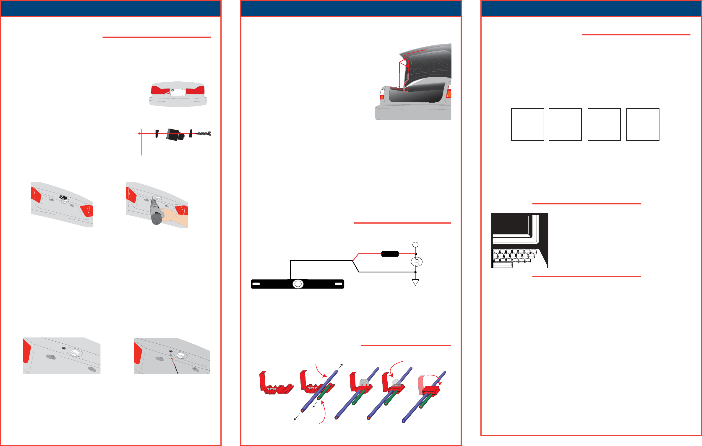
9. Next youʼll need to find the vehicleʼs reverse lights. Turn the vehicleʼs ignition key to
the accessory position, engage the parking brake and put the car in reverse. Look at the
vehicleʼs tail lights to see where the reverse lights are located.
To locate the reverse lightʼs 12V+ wire it will be necessary to gain access to the rear of
the vehicleʼs tail light.
For help locating the vehicleʼs reverse light circuit contact your vehicleʼs manufacturer
for vehicle specific wiring diagrams.
Fig.1
Fig.2
Fig.3 Fig.4
Fig.5 Fig.6
Reverse Lamp
2.4 GHz WIRELESS CAMERA
BLACK
RED
+12 VDC REV LAMP
GROUND
In-Line Fuse
TESTING THE SYSTEM
GIVE US A CALL, WE'LL HELP YOU INSTALL.
1-800-445-1797
PLEASE DO NOT RETURN PRODUCT TO STORE.
Visit us on the WEB
www.vr-3.com
For Information and Technical Assistance,
Call Toll-Free in U.S.A. and Canada.
VIRTUAL REALITY VIDEO LABS ® warrants, to the original purchaser, that its products are free from defects in material and workmanship
for 30 days from the date of original purchase, as part of our commitment to product excellence. VIRTUAL REALITY VIDEO LABS ® and/or
itʼs affiliates routinely improves the designs, materials or production methods of its existing products. Because it is impractical to publicize all
changes in every product, we reserve the right to make such changes without notice.
CONDITIONS OF WARRANTY:
If during the 30 day warranty period your new product is found to be defective, VIRTUAL REALITY VIDEO LABS ® will repair such defect,
or replace the product, without charge for parts or labor subject to the following conditions:
1. All repairs must be performed by VIRTUAL REALITY VIDEO LABS ® and/or itʼs affiliates in Eatontown, New Jersey.
2. The equipment must not have been altered or been damaged through negligence, accident, or improper operation.
3. The replacement of parts are exempted from this warranty when replacement is necessary due to normal wear and tear.
4. All warranty claims must be accompanied by a copy of the sales receipt or bill of sale.
5. Repair or replacement parts supplied by VIRTUAL REALITY VIDEO LABS ® under this warranty are protected only for the unexpired
portion of the original warranty.
6. In the case of car stereos, this warranty does not extend to the elimination of car static or motor noise; correction of antenna problems; costs
incurred for the removal or reinstallation of the product; damage to tapes, speakers, accessories or car electrical systems.
7. VIRTUAL REALITY VIDEO LABS ® will not be responsible for any charge incurred for installation.
OWNERʼS RESPONSIBILITIES:
VIRTUAL REALITY SOUND LABS® will make every effort to provide warranty service within a reasonable period of time.
SHOULD YOU HAVE ANY QUESTIONS ABOUT SERVICE RECEIVED, OR IF YOU WOULD LIKE ASSISTANCE IN OBTAINING
SERVICE, PLEASE CALL TOLL FREE 1-800-445-1797, 8:30am - 4:30pm EST.
In order to provide you with the proper warranty service, we request that you adhere to the following procedure:
1. Include a copy of your sales receipt or bill of sale with your unit when it is returned for warranty service.
2. If it is necessary to return your product for service, please return it securely packed, preferably in the original shipping carton, and freight
and insurance prepaid to the following address: VIRTUAL REALITY VIDEO LABS, Service Department, 41 James Way, Eatontown, New
Jersey 07724.
3. Please include a detailed explanation of the problem you are having.
4. If your product is found by VIRTUAL REALITY VIDEO LABS ® to have a defect in material or workmanship, within the warranty period,
it will be repaired or replaced at no charge and returned to you prepaid. Where permitted by Iaw VIRTUAL REALITY VIDEO LABS ® li-
ability shall be limited to that set forth in this warranty. This warranty shall be the exclusive remedy of the purchaser.
VIRTUAL REALITY VIDEO LABS ® makes no other warranty of any kind, expressed or implied; and all implied warranties, are hereby
disclaimed by VIRTUAL REALITY VIDEO LABS ® and excluded from this warranty, VIRTUAL REALITY VIDEO LABS® and/or itʼs
affiliates, the manufacturer, distributor and seller shall not be liable for any injury, loss or damage, incidental or consequential, arising out of
the use or intended use of the product.
NOTE: On newer vehicles that have their lights ON at all times you may splice the camera
into the license plate light circuit. The camera will come on when the vehicle is started
when wired this way.