Yoko Technology 00RYKIPCB021WA 720P WIFI Cube Camera User Manual Exhibit 08 revised
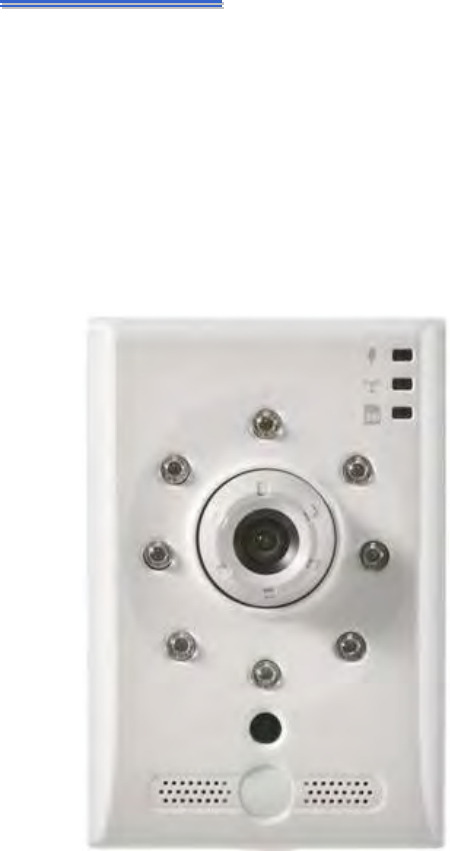
YOKO TECHNOLOGY CORP. 720P WIFI Cube Camera Exhibit 08 revised
Exhibit 08 User manual revised
- 1 -
C
CB
B0
02
21
1W
W
C
Cu
ub
be
e
N
Ne
et
tw
wo
or
rk
k
C
Ca
am
me
er
ra
a
User’s Manual
- 2 -
CAUTION
RISK OF ELECTRIC SHOCK.
DO NOT OPEN!
CAUTION :
TO REDUCE THE RISK OF ELECTRICAL SHOCK,
DO NOT OPEN COVERS (OR BACK).
NO USER SERVICEABLE PARTS INSIDE.
REFER SERVICING TO QUALIFIED
SERVICE PERSONNEL.
WA RN IN G: This symbol is intended to alert the user to the presence of un-insulated “dangerous
voltage”.
CAUTION: This symbol is intended to alert the user to presence of important operating and
maintenance (Servicing) instructions in the literature accompanying the appliance.
Disposal of Old Electrical & Electronic Equipment (Applicable in the European Union and
other European countries with separate collection systems).\
This symbol on the product or on its packaging indicates that this product shall not be treated as household
waste. Instead it shall be handed over to the applicable collection point for the recycling of electrical and
electronic equipment. By ensuring this product is disposed of correctly, you will help prevent potential
negative consequences for the environment and human health, which could otherwise be caused by
inappropriate waste handling of this product. The recycling of materials will help to conserve natural
resources. For more detailed information about recycling of this product, please contact your local city
office, your household waste disposal service or the shop where you purchased the product. The power cord
is the main power connection. Therefore, constantly plug and unplug of the power cord might result in
malfunction of the product.
CE / FCC Mark.
This apparatus is manufactured to comply with radio interference requirement.
Do not install the product in an environment where the humidity is high.
Unless the product is waterproof or weatherproof, otherwise it can cause the image quality to be poor.
Do not drop the product or subject them to physical shocks.
Except for vandal-proof or shockproof product, otherwise it will result malfunctions to occur.
Never keep the product to direct strong light.
It can damage the product.
Do not spill liquid of any kind on the product.
If it gets wet, wipe it dry immediately. Alcohol or beverage can contain minerals that corrode the
electronic components.
Do not expose to extreme temperatures.
Use the product at temperatures within 0℃ ~ 50℃.
It is advised to read the Safety Precaution Guide through carefully before
operating the product, prevent any possible danger.
- 3 -
Table of Contents
ProductFeature..........................................................................................................................‐ 5‐
CHAPTER1PhysicalDescription..................................................................................................‐ 6‐
1.1FrontPanel.............................................................................................................................‐6‐
1.2SidePanel...............................................................................................................................‐8‐
1.3RearPanel..............................................................................................................................‐9‐
CHAPTER2Installation.............................................................................................................‐ 10‐
2.1LANConnection....................................................................................................................‐10‐
2.1.1NetworkSetting.......................................................................................................................................‐ 10‐
2.1.2Utility.......................................................................................................................................................‐ 11‐
2.1.3InstallActiveX.........................................................................................................................................‐ 13‐
2.2WirelessConnection:UsingtheWPSButton.........................................................................‐15‐
2.2.1Wirelessnetworkconnectionillustration...............................................................................................‐ 15‐
2.2.2WPSSetting.............................................................................................................................................‐ 15‐
2.3SoftwareInstallation............................................................................................................‐18‐
2.3.1InstallUtility............................................................................................................................................‐ 18‐
2.4RecommendedComputerEquipment...................................................................................‐20‐
CHAPTER3LiveViewPage.......................................................................................................‐ 21‐
3.1UserLogin.............................................................................................................................‐21‐
3.2LiveViewPage.....................................................................................................................‐23‐
3.2.1Profile......................................................................................................................................................‐ 23‐
3.2.2ProtocolType...........................................................................................................................................‐ 23‐
3.2.3ControlPanel...........................................................................................................................................‐ 24‐
3.2.4StatusIcon...............................................................................................................................................‐ 25‐
CHAPTER4DeviceSetting.........................................................................................................‐ 26‐
4.1CameraSetting.....................................................................................................................‐27‐
4.1.1Image.......................................................................................................................................................‐27‐
4.1.2VideoSetting...........................................................................................................................................‐ 32‐
4.1.3Audio.......................................................................................................................................................‐ 34‐
4.1.4OSDSetting..............................................................................................................................................‐ 35‐
4.1.5PrivacyMask............................................................................................................................................‐ 36‐
4.2NetworkSetting....................................................................................................................‐37‐
4.2.1GeneralSetting........................................................................................................................................‐37‐
4.2.2WirelessSetting.......................................................................................................................................‐ 39‐
4.2.3WPS.........................................................................................................................................................‐ 42‐
4.2.4PPPoE.......................................................................................................................................................‐ 43‐
4.2.5RTSPSetting.............................................................................................................................................‐ 43‐
- 4 -
4.2.6HTTPSetting............................................................................................................................................‐ 45‐
4.2.7DDNS.......................................................................................................................................................‐ 48‐
4.2.8UPnP........................................................................................................................................................‐ 48‐
4.2.9Onvif........................................................................................................................................................‐51‐
4.3Security................................................................................................................................‐52‐
4.3.1UserManagement...................................................................................................................................‐52‐
4.3.2IPAddressFilter.......................................................................................................................................‐53‐
4.4Event....................................................................................................................................‐54‐
4.4.1EventSetting............................................................................................................................................‐ 55‐
4.4.2MotionDetection....................................................................................................................................‐ 58‐
4.4.3DigitalI/O................................................................................................................................................‐ 59‐
4.5EventServer.........................................................................................................................‐60‐
4.5.1FTPSetting...............................................................................................................................................‐ 60‐
4.5.2EmailSetting............................................................................................................................................‐ 60‐
4.5.3MediaSetting..........................................................................................................................................‐ 61‐
4.6Record..................................................................................................................................‐62‐
4.6.1RecordingSetting.....................................................................................................................................‐ 62‐
4.6.2StorageDevice.........................................................................................................................................‐ 64‐
4.7System..................................................................................................................................‐66‐
4.7.1Deviceinformation..................................................................................................................................‐ 66‐
4.7.2Timesetting.............................................................................................................................................‐67‐
4.7.3Logs..........................................................................................................................................................‐ 68‐
4.7.4Maintenance............................................................................................................................................‐ 70‐
AppendixA–
3GPPoniPhone...................................................................................................‐ 71‐
AppendixB–
3GPPonAndroid.................................................................................................‐ 74‐
AppendixC–Specifications.......................................................................................................‐ 77‐
- 5 -
Product Feature
1 Megapixel image; resolution is up 1280x720.
Support H.264 / MJPEG codec, video quality is adjustable, video type can be divided
into Profile 1、Profile 2、Profile 3.
Support Onvif Profile S version 2.3.
Built-in speaker, easier to broadcast through camera directly.
Easy Configuration and Installtaion
Support G.711and PCM codec, two ways audio is supported.
Support high performance network transmission algorism, provide low-latency video and
audio stream.
Support event and schedule recording.
Support motion detection; detection area and sensitivity are adjustable.
Video stream bit rate, frame rate and resolution are adjustable.
Support user management and password protect in order to provide the highest security.
Support Micro SD Card for pre-event and post-event recording , schedule recording ,
network disconnect recordin.
Support remote setup, live view, recording, snapshot, firmware upgrade by web page .
Provide Utility for searching and network setting up supportive device in LAN.
Network protocol supported: HTTP, UPnP, DNS, DDNS, RTSP, RTP, RTCP, RTSP over HTTP,
TCP/IP, UDP/IP, DHCP, PPPoE, FTP, NTP, SMTP, Bonjour,
Support auto re-connecting after network or power shortage.
Free bundle 64 channel surveillance software. Support maximum 64 channels live view and
16 channels playback simultaneously.
- 6 -
CHAPTER 1
Physical Description
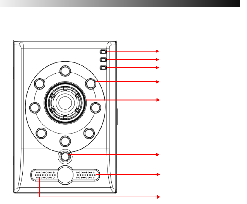
1.1 Front Panel
Power / Network / SD Card Status LED
Network camera status LED indicate power/ network/ SD card status. Detailed alert
description and LED status is listed as below table 1-1.
IR LED
When the device enable night mode, it will trigger IR LED to enhance image higher
illumination
Adjustable focal Lens
Manually adjust lens holder for video focusing
Light Sensor
Detect incoming light sensor. While the incoming light is too low, image will display in
monochrome automatically.
Power Status LED
Network Status LED
SD Card Status LED
IR LED
Adjustable focal Lens
Microphone
Light Sensor
Speaker

- 7 -
Speaker
Built-in speaker; audio output to speaker and audio out device at the same time when user
uses broadcast function.
Microphone
Built-in microphone.
LED Indicators
Alert description LED status
Power Status Booting up Solid Red
Device complete boot-up Solid Green
Network (Ethernet)
Normal Solid Green
Off-line off
Video & Date transmitting blinking Green
Network(Wireless)
Normal Solid orange
Search for WPS blinking Red
Off-line off
Video or Date transmitting blinking orange
SD Card status
SD card is reading/ writing blinking Green
SD card failure Solid Red
SD card is writing / reading abnormally Solid orange
No SD card off
SD card inside Solid Green
Lighting and system status table:Table1-1
- 8 -
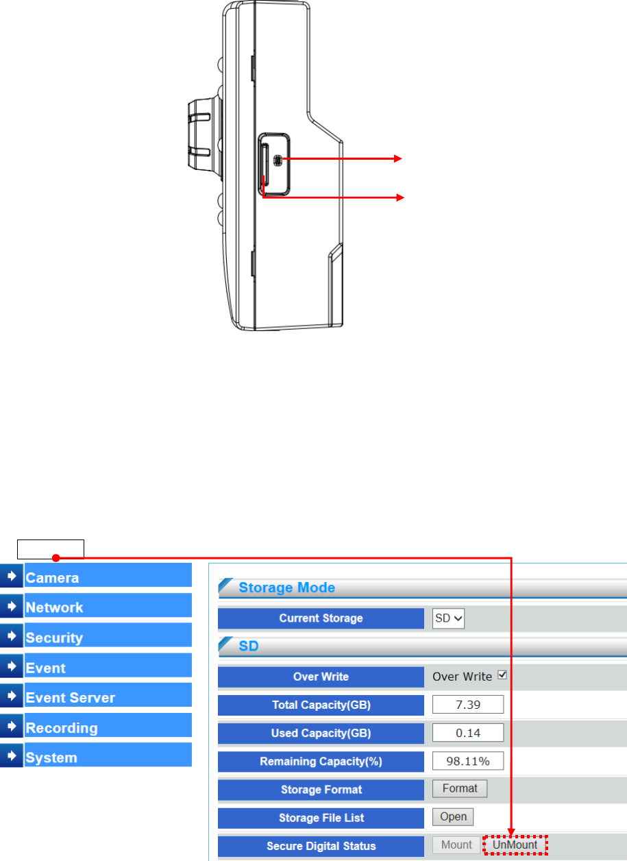
1.2 Side Panel
Reset Button (Hardware Reset)
The reset button is used to reset the system or restore the factory default settings. Sometimes
resetting the system can return the camera to normal operation.
Press and hold the recessed reset button until the status LED rapidly blinks orange.
Note that all settings will be restored to factory default
Micro SD Card Slot
This network camera is compliant with Micro SD/SDHC/SDXC of 8, 16, 32GB,
capacity SD cards.To prevent corruption of recordings, the SD card should be unmounted before
removal. To unmount, go to SetupRecordingStorage DeviceSecure Digital Status and click
UnMount.
Reset Button
Micro SD Card Slot
- 9 -
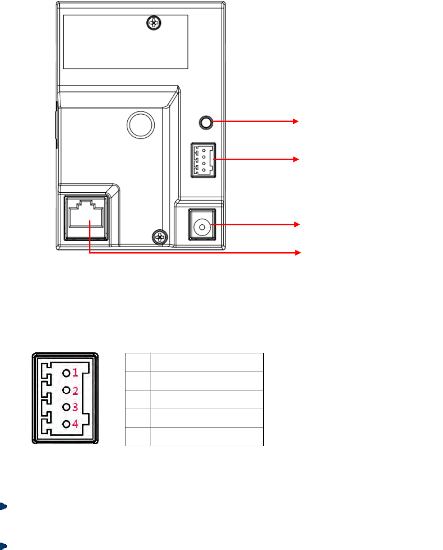
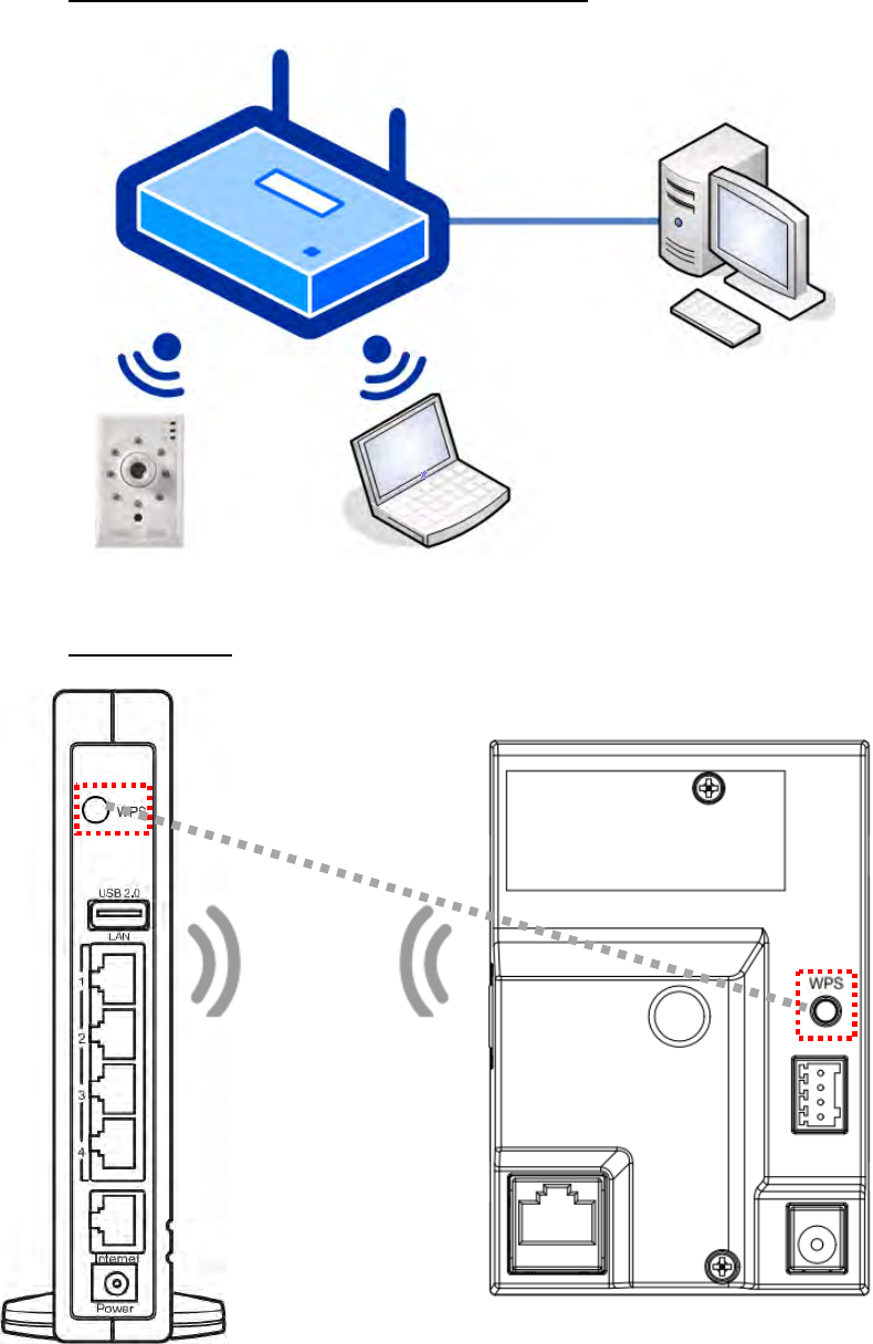
1.3 Rear Panel
WPS Button
For easy connecting to an access point through push button configuration (PBC)
Alarm I/O Terminal Block
To connect external alarm I/O devices, please refer to below for Alarm I/O pin definition.
Pin Function
1 Digital Output (DO-)
2 Digital Output (DO+)
3 Digital Input (DI-)
4 Digital Input (DI+)
Use in applications for e.g. motion detection, event triggering and alarm notifications, the I/O
terminal connector provides the interface to :
Digital input– An alarm input for connecting devices that can toggle between an open
and closed circuit, for example: PIRs, door/window contacts, glass break detectors, etc.
Digital output– For connecting external devices such as relaysand LEDs
Power Cord Socket
Connect to 5V DC power adapter.
WPS Button
Alarm I/O Terminal Block
Power Cord Socket
Ethernet 10/100 RJ45 Socket
- 10 -
CHAPTER 2
Installation
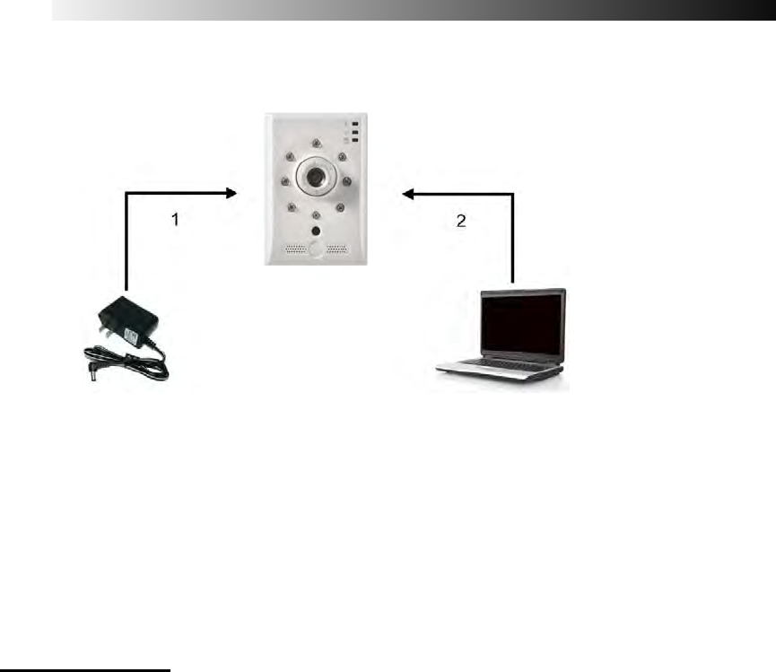
2.1 LAN Connection
Figure2-1
(1) Connect the 5V DC adaptor to the power jack on the rear panel of the network camera.
(2) Connect the camera output of the analog camera through the coaxial cable to the video
input of the network camera.
(3) Use Ethernet cable to make connection from the Ethernet 10/100 RJ45 socket on the
network camera to the PC.
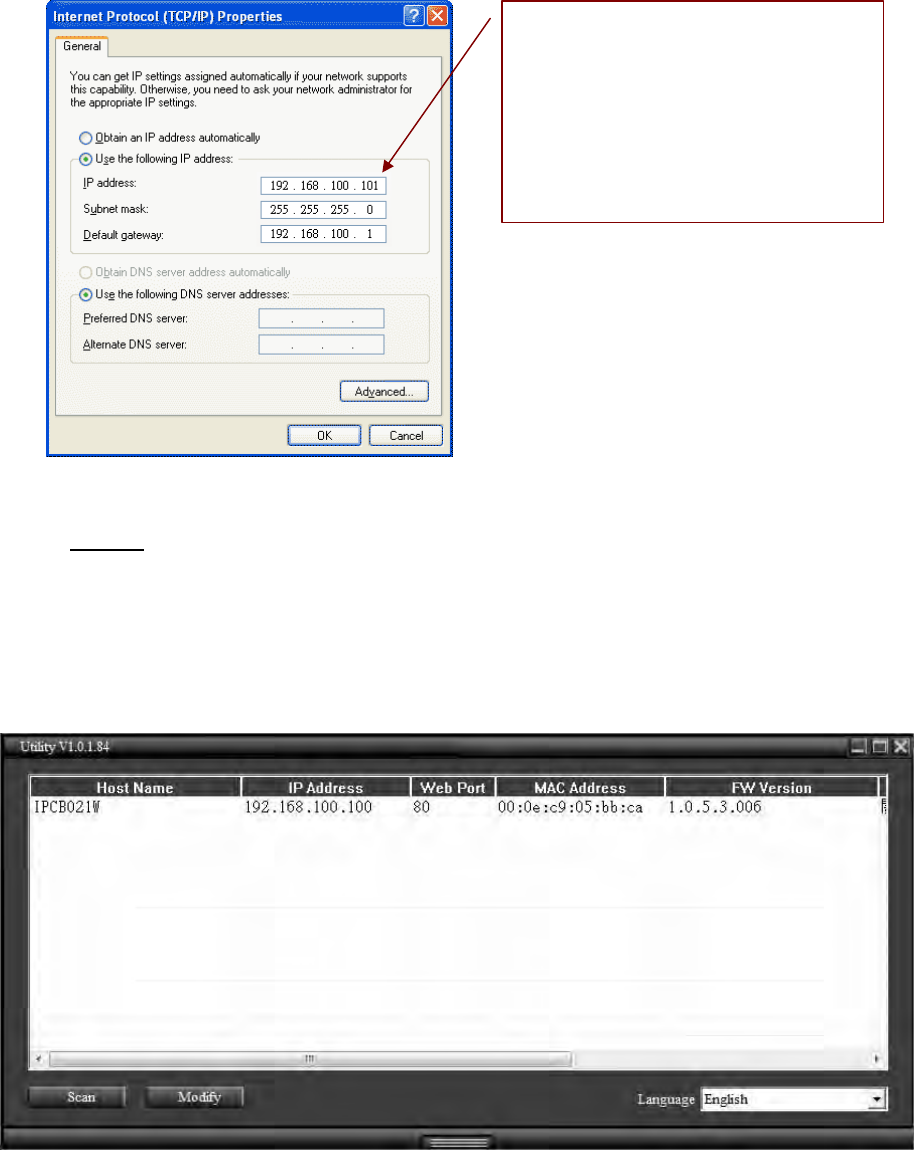
2.1.1 Network Setting
After completing the basic hardware connection, make sure that the PC and the network
camera IP address are both in the same network segment. Example: Setup preset Network
camera IP to 192.168.100.100 and configure your desktop IP address as the Figure 2-2
below.
- 11 -
Figure2-2
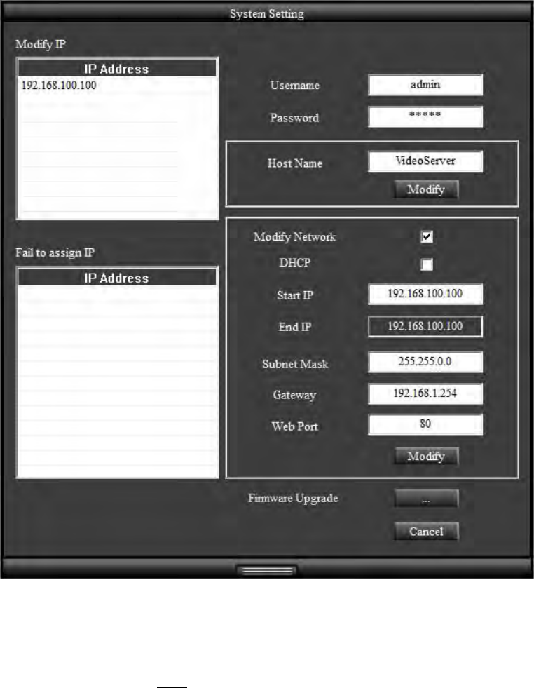
2.1.2 Utility
(1) Please install Utility from the product CD. (Please refer to chapter 2.3.1 for installation
procedures.)
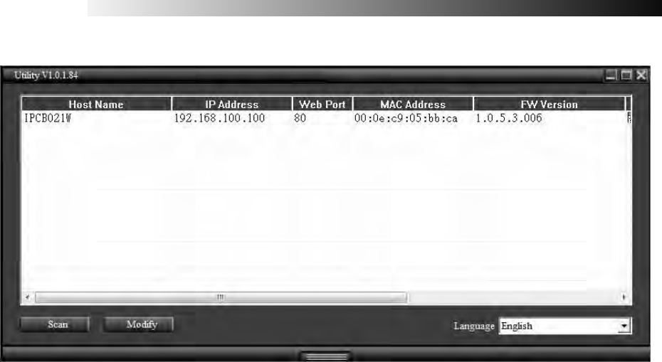
(2) Start Utility.
(3) After starting Utility, the program will automatically search and display supportive devices
in local LAN.
(4) Choose which device you would like to access, the default IP address on the device is
192.168.100.100
(5) Double click on the IP address, will automatically open the selected device web image.
Setup format:
IP Address:192.168.100.xxx
Subnet Mask:255.255.255.0
Default Gateway192.168.100.1
- 12 -
(6) Please select on the device you would like to modify its setting and click “Modify”.
Enter username and password. (Default username and password is admin/ admin)
User can manually modify system setting: host name ,connection type , IP address ,and
web port. Please click “Save” button before complete change.
Utility provides firmware upgrade, please click on firmware upgrade checkbox, and
select new firmware (.img) in pop-up window. System will automatically start firmware
upgrade.
(7) Click “Scan” to refresh searching supportive devices in local LAN.
(8) If there is no DHCP server in local LAN, Utility can automatically assign IP address
for connected network device. When Utility searches network device which IP address is
192.168.100.100 in LAN, system will automatically assign an IP address of which is the same
network segment as client PC. To enable this function, please “Enable” on Auto Assign IP item.
Please notice that DO NOT enable this function when there is already a DHCP server in LAN in
case of IP conflict issues.
- 13 -
(9) The same models firmware can be upgraded together through utility.
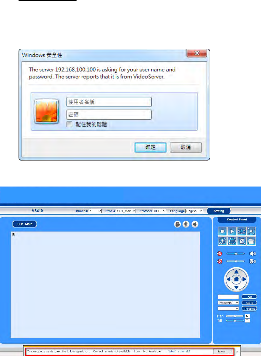
2.1.3 Install Active X
Once you have logged in, you will see a pop-up information bar requiring your attention for
installing ActiveX Control, use mouse right click to install ActiveX control.
(1) Device default ID and password is admin/admin. Key in default ID and passwords when
log-in.
(2) Once you have logged in the first time, you will see a pop-up information bar requiring your
attention for installing ActiveX Control, use mouse right click ”allow” to install ActiveX control.
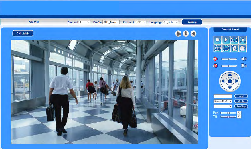
- 14 -
(3) Once Active X installation complete, you will see the live viewing page.
- 15 -
2.2 Wireless Connection: Using the WPS Button
2.2.1 Wireless network connection illustration
2.2.2 WPS Setting
- 16 -
1. Make sure your AP (Access Point) support WPS (Wi-Fi Protected Setup) functions. WPS
enables easy setup with compatible APs.
1. The network camera support WPS 2.0. Make sure the AP authentication method WPA2and the
encyrption. configure AES ,then the network connectivity will be established with AP by WPS.
. 2. Make sure SSID configuration is NOT “hidden”. It will cause the network camera cannot search
the AP SSID.
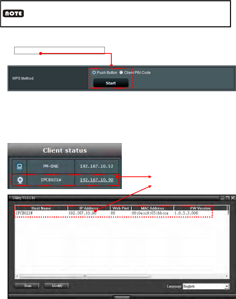
2. Press the WPS button for 1 second. The network status LED should blink red.
3. Press and hold down the WPS button on your AP (some router/AP will have a
virtual button on their management UI) Refer to your AP's documentation for details using
its WPS functions.
4. When WPS configuration is done, wireless connectivity will be established and the
security encryption, such as WEP or WPA-PSK, will be synchronized with the AP.
The user can check wireless connectivity from the management UI of AP/router. If the user
can search the network camera IP address by utility and AP, it means wireless connectivity
is established. Refer as below figures:
AP assi
g
n IP to network camera
The utility can search the IP which the
AP assigned

- 17 -
1. After pressing WPS button on the network camera, it will take 2 munities to search for AP. In the
mean time, press the WPS button on AP within 2 munities. The network camera will stop pairing if
connectivity is not established..
2. When WPS activated, the network camera will be automatically set DHCP mode.
- 18 -
2.3 Software Installation
Please install following software from product CD.
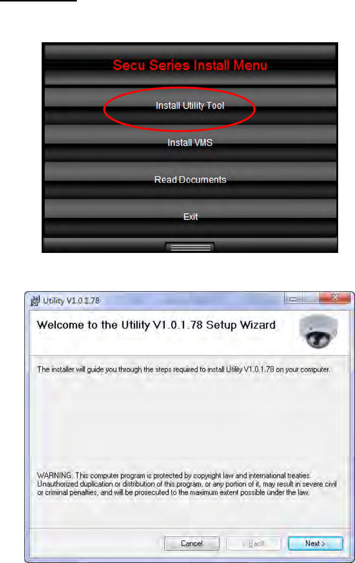
2.3.1 Install Utility
(1) Click Install Utility Tool
(2) Click Next.
- 19 -
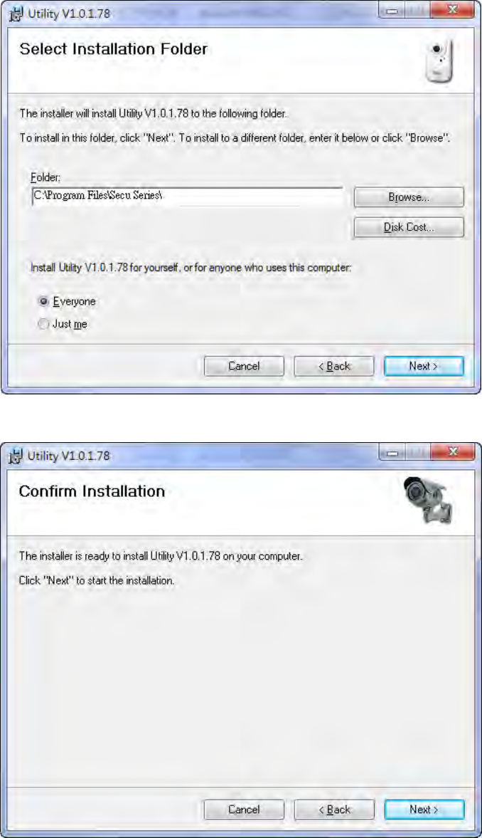
(3) Select Installation Folder.
(4) Confirm Installation, please click Next.
- 20 -
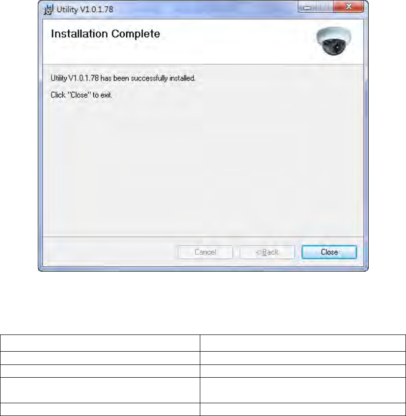
(5) Installation complete, please click Close to exit.
2.4 Recommended Computer Equipment
CPU Intel® Core 2 Due E7200 or above
RAM 1GB or above
Audio Card Needed
Operation System Windows 2000, Windows XP SP2 and
above, Windows Vista, Windows 7
Browse
r
IE6 SP2 and above
- 21 -
CHAPTER 3
Live View Page
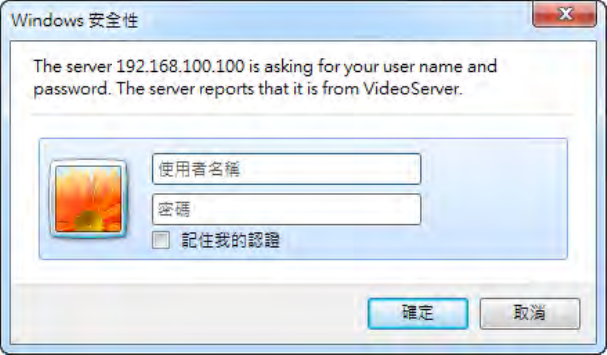
3.1 User Login
Figure4-1
One minute after the device is powered on, please start Utility. The program will automatically
search and display all of the IP Camera devices on local LAN, please see the Figure4-1. Please
click on the device you would like to access, and then enter login page of the device, please see
Figure4-2.
- 22 -
Figure4-2
Please key in default username and password, and then click on “confirm” to continue
a. Default username:admin
b. Default password:admin
- 23 -
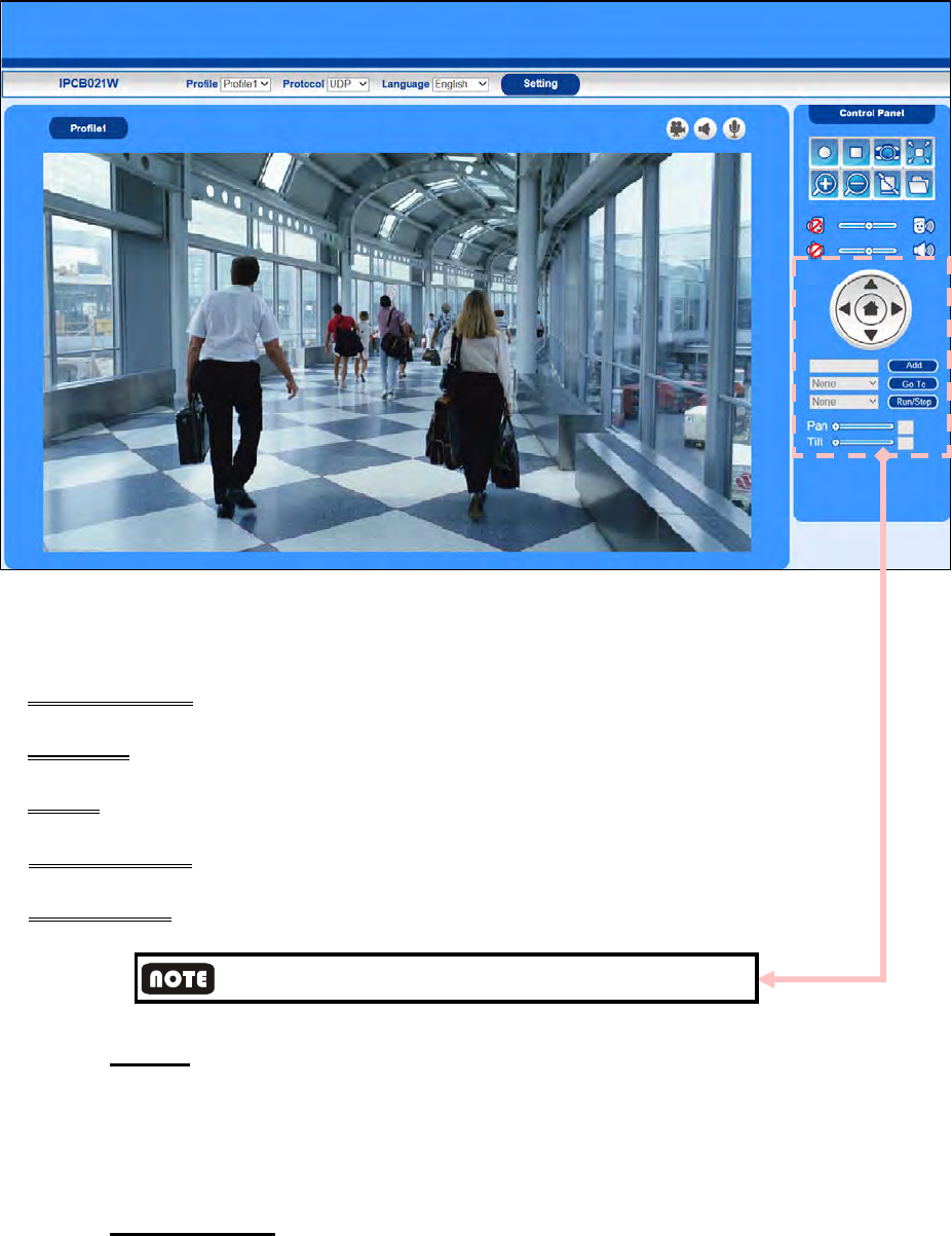
3.2 Live View Page
Figure4-3
The user enter live view page after log-in successfully. The live view page includes:
- Live view image: the default image is profile 1(1280x720 resolution).
- Functions: the user can select Profile, Protocol, Language from drop down menu.
- Setting: the user can enter setting page by click on setting.
- Live view status: display the live view page status: recording, Microphone, or Speaker on/off.
- Control Panel: depending the network camera configuration.
Currently, only Video server supports P / T /Z Control function
3.2.1 Profile
Profile stands for video streaming. The device offers two streamings: main and sub in each
channel.
The video streaming can be determined by video compression, resolution, frame rate, and
bitrate configuration. Please refer to 4.1.2 video setting for further configuration
3.2.2 Protocol Type
Select image streaming transmission protocol.

- 24 -
TCP
Choose this item while the network is under low bandwidth. Video and audio streaming
transmits through network TCP layer. If no confirmation message is received, the source
port will send that packet again. TCP guarantees the complete delivery of streaming data
and thus provides better video quality. Nevertheless, its real-time effect is inferior to UDP.
UDP
Choose this item to get smooth live streaming. Video and audio streaming
transmits through network UDP layer. A UDP (User Datagram Protocol) source port sends
out packets continuously and does not require the destination port to return a confirmation
message, allowing for more real-time audio and video streams. However, the packets may
be lost due to network burst traffic and images may be broken.UDP connection is mainly
used for time-sensitive responses and when the video quality is less important
RTSP over HTTP
Video and audio streaming transmits through network TCP layer via HTTP port. HTTP
allows the same quality as TCP protocol without needing to open specific ports for
streaming under some network environments. Firewalls are commonly configured to allow
the HTTP protocol, thus allowing RTP to be tunneled. Users inside a firewallcanutilize this
protocol to allow streaming data to come through.
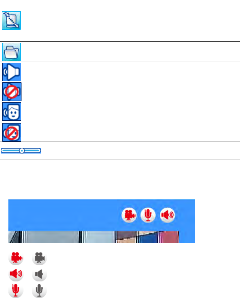
3.2.3 Control Panel
Device Control
Icon Function
Recording –Click on the button to start recording
Recording stop –Click on the button to stop recording.
Streaming stop –Click on the button to stop streaming.
Streaming Play –Play the live view video.
Snapshot– Capture and save still images.
Full Screen–Switch to full screen mode. Press the “Esc” key to return to
normal screen
Zoom in– Click on the button to zoom in image. Image can zoom in 8 times
maximum. To return to normal image size, please click on zoom out button
Zoom out– Click on the button to zoom out image. Zoom out function has no
effect when the image has returned to original size already.
- 25 -
Buffer– Due to possible occurrences of unsteady network transmission, live
streaming may lag and not be very smoothly. If you enable this option, the
live streaming will be stored on the client PC’s cache memory for a few
seconds(300ms) before being played on the client computer’s live view
window.
Folder– Configure the live view snapshot and video clip saved file folders.
Microphone– Turn on the sound. Click on the button to stop audio.
Mute– Turn off the sound. Click on the button to play audio.
Broadcast– To communicate through the camera using the computer MIC.
Click on the button to stop Speaker.
Mute– Turn off the broadcast. Click on the button to start broadcast.
Volume bar– Drag the slider bar to adjust the microphone and
broadcast volume
Table 3-1 Control Panel Function
3.2.4 Status Icon
/ Recording on/off - Displays the status of recording video
/ Microphone on /off - Displays the status of the MIC volume
/ Speaker on/off - Displays the status of the Speaker
- 26 -
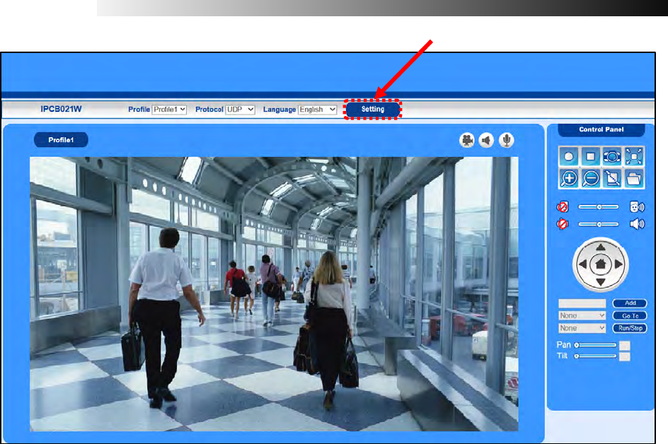
CHAPTER 4
Device Setting
Click < setting button > on the main page to configure the camera settings pages
- 27 -
4.1 Camera Setting
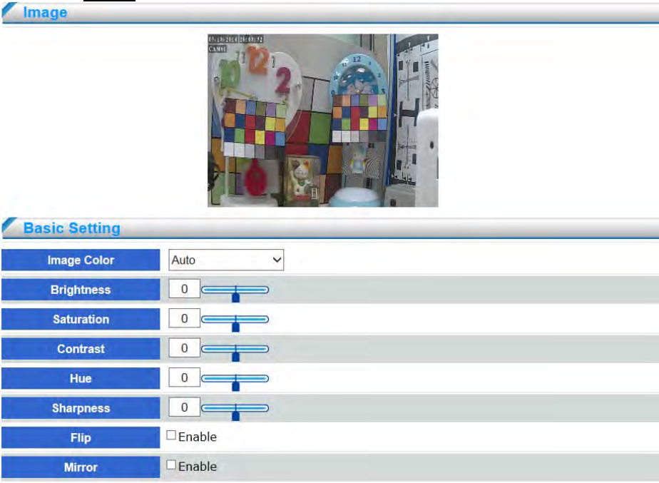
4.1.1 Image
Brightness
Drag the slider bar to adjust the image brightness level from 0 to 100, default setting is 50.
Saturation
Drag the slider bar to adjust the image saturation level from 0 to 100, default setting is 50.
Contrast
Drag the slider bar to adjust the image contrast level from 0 to 100, default setting is 50.
Hue
Drag the slider bar to adjust the image hue level from 0 to 100, default setting is 50.
Sharpness
Drag the slider bar to adjust the image sharpness level from 0 to 100, default setting is 50.
Flip
Enable to vertically reflect the display of the live video.
- 28 -
Mirror
Enable to horizontally reflect the display of the live video.
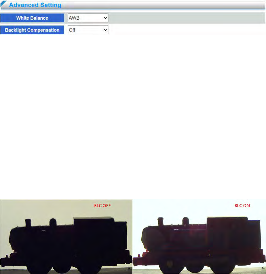
White Balance
White balance is used to make colors in the image appear the same regardless of the color
temperature of the light source. The device can be set to automatically identify the
light source and compensate for its color. Alternatively, select the type of light
source from the drop-down list.
Choose Current White Balance Way; default setting is Auto White Balance。
◎ AWB (Color Temperature 2800~6500K)
◎ ATW (Color Temperature 2500~8000K)
◎ Outdoor (Color Temperature 6500K)
◎ Indoor (Color Temperature 3200K)
◎ Lamp (Color Temperature 2800K)
Backlight Compensation
Set to enhance the backlight brightness of image. When the user enable backlight
compensation, the brightness will be enhanced in whole image, some bright part of the image
will possibly be over-exposure. Therefore, the user can conditionally consider to disable the
backlight compensation to reach better image quality. Refer to below figures showing the
difference based on BLC on and BLC off.
- 29 -
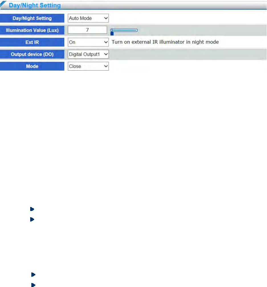
Day/ Night is set for controlling ICR(IR cut filter remove) switching, the default setting is auto
mode.
Day/Night Setting
◎ Auto mode: ICR automatically switch to night mode according to light sensor measure
the illumination volume. The default setting is 7 Lux. When the illumination volume
less than configured volume, ICR will switch to night mode and live image switches to
mono.
◎ Illumination value: Adjust illumination value for ICR switch to night mode.
◎ Day: ICR switches to day mode, live image always is color.
◎ Night: ICR switches to night mode, live image always is mono.
◎ Digital input: The Network Camera automatically removes the IR cut filter when DI is
triggered. Some external housing may come with its light sensor and IR lights, and has a
pin signal to tell the camera to switch off its IR cut filter. When D/N Setting set
“Synchronize with digital input” , the “Alarm In” of event trigger will be disabled.
Input device: Select the DI device to detect.
Mode: Select digital input status “high” or “low” to determine the network camera
switch to night mode or not.
◎ Ext IR: Select this to turn on an external IR illuminator (connected via Digital
Output lines) when the camera detects low light condition and enters the night mode.
.When Ext IR set On, the “Alarm Out” of event trigger will be disabled.
Output device: Select the external DO device and enable the IR illuminator.
Mode: When the IR illuminator is activated, the DO status will be changed to “Open”
or “Close”.
- 30 -
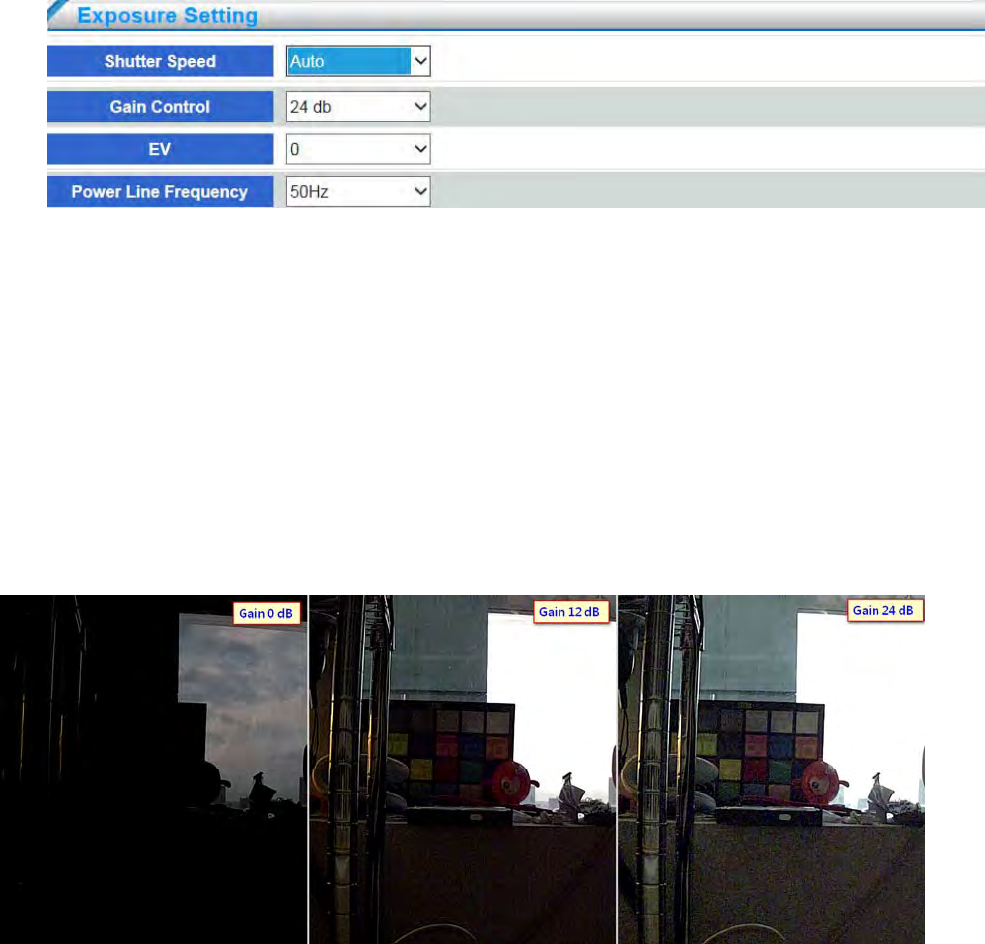
Shutter Speed
Select “ Auto” or “ Manual” to determine exposure time. The longer exposure time
determines the longer time when light can enter. The image will have better brightness
performance but easily delay. The shorter exposure time determines the shorter time when
light can enter. The image will be darker but have better capture performance. Please adjust
the shutter speed according to the environment. The default setting is (1/30~1/20). The user
can manually set from 1/7.5 ~ 1/ 100000.
Gain Control
Select to adjust gain value according to camera installation environment. The higher gain
value can lighten the video image; however, the noise will get more. Refer to below figures
showing the difference based on 0dB, 12dB, and 24dB gain value. The user can adjust from
0~24dB. The default setting is 24dB.
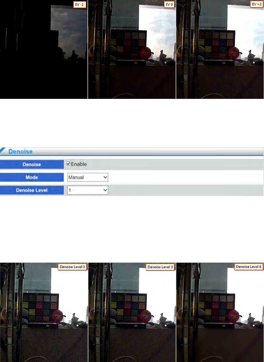
EV (Exposure Value)
Select exposure value from -2 to +2 to adjust video image lightness or darkness. Refer to
below figures showing the difference based on -2, 0, and +2 exposure value. The user can
adjust the exposure value depending on the installation environment.
- 31 -
Power Line Frequency
Select the power line frequency (50 Hz or 60 Hz) used at the location of the network
camera. Selecting the wrong frequency may cause image flicker if the product is used in
fluorescent light environments. When using 50 Hz, the maximum frame rate is limited to 25
fps.
Denoise
Enable Denoise to reduce noise on the video image under low Lux. The user can select
“Auto” or “Manual” to adjust denoise level. The denoise level by manual mode is from 1 to 6.
Select higher denoise level can reduce more noise; however, the sharpness of the video image
will decrease and the image quality may not be as good as expected. To reach the best image
quality, please adjust the denoise level according to the installation environment. Refer to
below figures showing the difference based on 1, 3, and 6 denoise level.
- 32 -
4.1.2 Video Setting
The network camera provide multiple video streaming with different resolutions, frame rates and
bitrates simultaneously. For example, the network camera can transmit the video based on
1920x1080 resolution for recording, in the mean time, also can provide the video to VMS or NVR
based on D1 resolution for live view, and also can provide the video to mobile based on CIF
resolution. The user can flexibly and simultaneously use different streaming for different video
setting. The network camera supports up to 3 streamings.
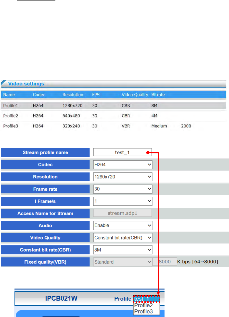
Overview
Below table are showing the codec, resolution, FPS, video quality, bitrate infos of profile
1、2、3 of the network camera
Stream Setting
Stream profile name
Create a name that will be displayed on the profile menu of the live video.

- 33 -
Resolution
For configuring video resolution, the higher the resolution, the better image quality, the
bigger image size, the available resolution range is from 176x768 to 960x480.
Frame rate
Select the frame rate from drop-down menu from 1~30 fps. Set a higher frame rate for
smoother video quality.
I Frame /s
The composition of the H.264 video stream which consists of 2 image formats, I-images
and P-images. An I-image is a complete image, whereas a P-image is only the
differences in the image as compared with the previous image.
The I-Frame determines how many seconds send one I-image. If the i-frame/s is set 3, it
means every 3 secs will send 1 pcs I-image, 89pcs P-frame. Set the I-Frame/s higher value
increases the video quality, but if there is congestion on the network,
there may be noticeable decay in the video quality.
Audio
Select to enable or disable audio to determine the streaming transmission with audio or not.
If enable the audio, the streaming will be transmit with audio when live view or recording.
Stream profile.
Video Quality
◎ CBR mode : A complex scene generally produces a larger file size, meaning
that higher bandwidth will be needed for data transmission. The bandwidth utilization is
configurable to match a selected level, resulting in mutable video quality performance.
The bit rates are selectable at the following rates: 32Kbps, 64Kbps, 128Kbps, 512Kbps,
768Kbps, 1Mbps, 2Mbps, 3Mbps, 4Mbps, 6Mbps and 8Mbps. Set the bitrates higher for
better quality.
◎ VBR mode: transmit video streaming with float bit rate depending on video
environment complexity. The video quality options is selectable as follows: Bad、
Medium、Standard、Good、Excellent; Setting the higher video quality will achieve
higher throughput. The user also can configure the maximum bitrate limitation based
on each video quality. The default setting is 8000Kbits. For example as below figure,
the bitrate of excellent quality will be not more than 8000Kbits. video quality.
- 34 -
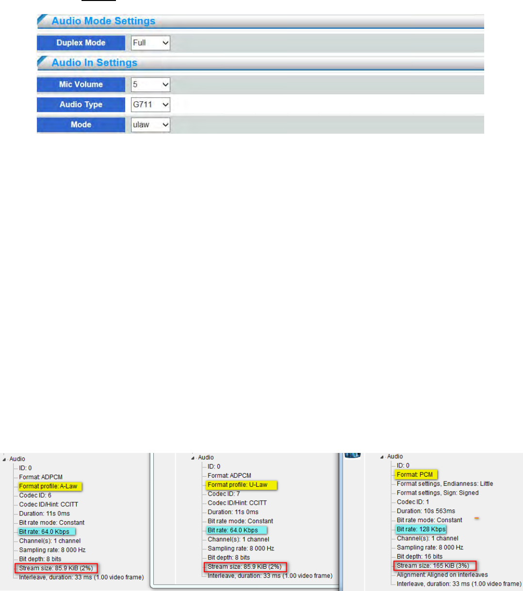
4.1.3 Audio
Duplex Mode
Select full duplex or half duplex mode, default setting is full duplex. Select duplex mode
depending on the environment. Half duplex mode is suggested to be selected for avoiding
echo occurs; however, the mode cannot support two way audio.
Mic Volume
Select the gain of the build-in microphone according to ambient conditions, select the
microphone volume from drop-down menu, the volume range is 0~10, when number goes
high, the volume louder
Audio Type
Select audio codec G711 or PCM
◎ PCM(Pulse Code Modulation): an audio codec transferring from analog convert digital
signal. PCM has better audio quality due to it will not be compressed after convert
digital singal from analog. Therefore the data will be bigger than G.711. The bitrate is
128Kbps
◎ G.711 G.711, also known as PCM, is a very commonly used waveform codec.G.711 is
an ITU-T standard for audio companding. It is primarily used in telephony.Sampling
frequency 8 kHz and 64 kbit/s bitrate. Network camera provides G.711μ-law audio
format, μ-law is used primarily in North America and A-law, which is in use in most
other countries outside North America. The bitrate is 64Kbps
- 35 -
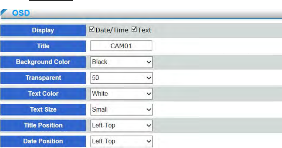
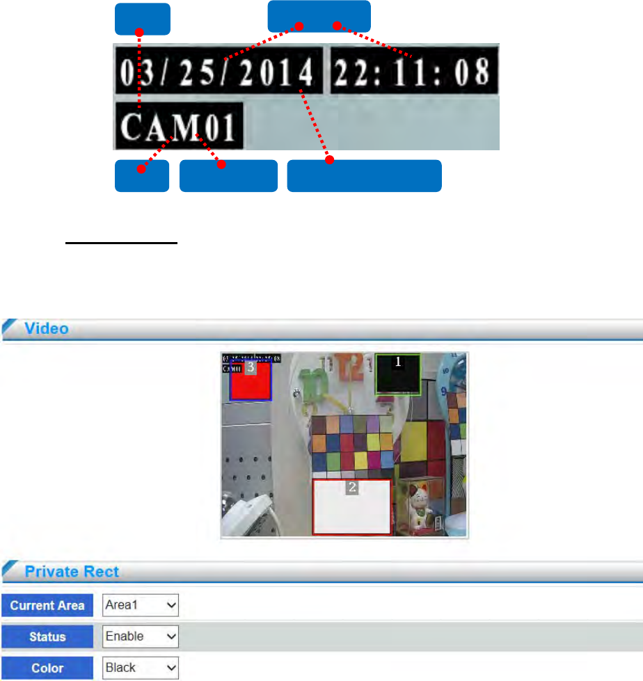
4.1.4 OSD Setting
Display
Enable date /time or text for displaying on the live-view screen
Tile
Create a name that will be displayed on the screen of the live video.
Background Color
Select OSD background color in drop-down menu: White, Black, Red, Green, Blue and
Yellow
Transparent
Select OSD background transparent in drop-down menu from 0~100,
Set lower value for more obvious image background
Text Color
Select OSD font color in drip-down menu : White, Black, Red, Green, Blue and Yellow
Text Size
Select OSD font color in drop-down: Small and Big
Title /Date Position
Select the placement for OSD title and Date: Top-Left, Top-Right, Bottom-Left and
Bottom-Right on the screen.
- 36 -
4.1.5 Privacy Mask
A privacy mask is an area of solid color that prohibits users from viewing parts of the monitored
area. Each Channel have three privacy masks area can be configured.
Privacy masks configured on each channel will be displayed on the screen.
Current Area
Select current area in drop-down menu: Area 1、Area 2 and Area 3.
To edit a privacy mask, select the mask and reshape or move as needed.
Status
Select in drop down menu: Enable or Disable
Color
To configure the Privacy mask color, select the new color from the drop-down menu: Black,
White, and Red
Title Text Color Background Color
Date/ Time
Text
- 37 -
4.2 Network Setting
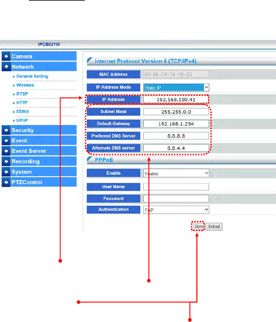
4.2.1 General Setting
Three configuration types are available for wired network connection: STATIC, DHCP
IP Address Mode Address Static IP
MAC Address
MAC Address of device NIC is displayed
IP Address
Display and modify device IP address.
Subnet Mask/ Gateway/ Preferred DNS / Alternate DNS
Display and modify Subnet, Gateway, and Default DNS.
Always click [Save] to save changes in a particular page.
Reboot will be automatically triggered after clicking [Save]. The page will be refreshed
automatically and return to the initial login page.
- 38 -
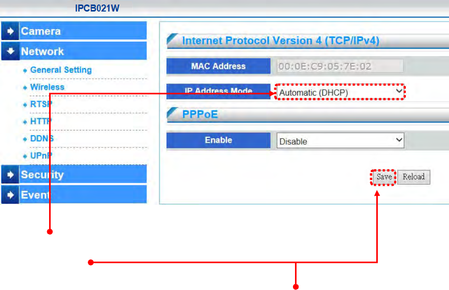
IP Address Mode Address Automatic (DHCP)
If DHCP server is on LAN and you want to allocate Dynamic IP address, use DHCP.
Click [Save].
Reboot will be automatically triggered after clicking [Save]. The page will be refreshed
automatically and return to the initial login page.
- 39 -
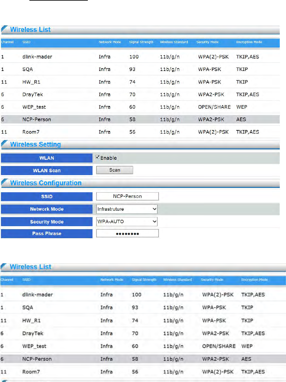
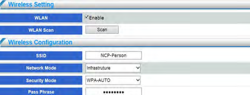
4.2.2 Wireless Setting
The network camera can connect to network by build-in wireless card (support 2.4G802.11.b/g/n ).
This device doesn't support 5G wireless Access point
The status of wireless networks list is the result of the network scan and provides the following
information:

- 40 -
Channel
14 available channels of wireless standard 802.11, the value is from 1 to 14.
SSID
SSID of wireless AP
Network Mode
BSS network modes: Ad-Hoc and Infrastructure.
Signal Strength
Signal strength of wireless AP, value is from 1 to 100. Higher value stands for the stronger
signal; and vice versa.
Wireless Standard
Wireless standard of AP can support 802.11 b/g/n.
Security Mode
Security mode of AP, OPEN、WEP、WPA-AUTO
OPEN : Communicates the key across the network
WEP : Wired Equivalent Privacy (WEP) is a basic encryption method which
transmits network broadcast messages using radio signals
WPA-AUTO : Network camera will select WPA method automatically. The security
method WPA-/WPA2–PSK is designed for small networks and does not require an
authentication server. The key can be entered either as manual hex — a 64hexdecimal
number (0–9, A-F) — or a passphrase using 8–63
ASCII characters. The longer the passphrase, the more secure is the key
Encryption Mode
Encryption mode of AP. The list below is security mode corresponding to encryption
mode.
Encryption
Security NONE WEP TKIP AES
OPEN ●
WEP(SHARED)
●
WPA-Auto(WPA-PSK) ● ●
WPA-Auto (WPA2-PSK) ● ●
- 41 -
WLAN Enable
Enable wireless network function
WLAN Scan
Click the “scan” button for surveying the local area for available wireless networks
Double click the selected wireless list of AP, the following infos will be automatically displayed
on wireless configuration (except for PassPhrase). And the user can select by the drop-down
menu accordingly.
SSID
SSID of the selected AP.
Network Mode
Network mode of the selected AP.
Security Mode
Security mode of the selected AP.
Encryption Mode
Encryption mode of the selected AP.
PassPhrase
Enter Pass phrase of the selected AP .
WEP Key Index
Select different WEP Key if Security Mode is WEP.
Please configure the related wireless parameters manually if no available AP be connected. The
related parameters, please refer to the configurations provided by AP.
- 42 -
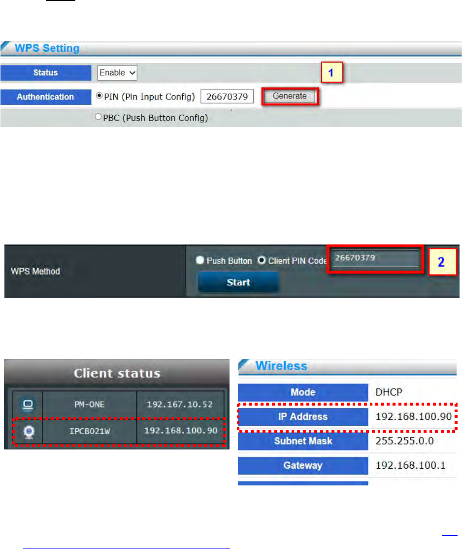
4.2.3 WPS
WPS means Wi-Fi Protected Setup. It mainly used for easy set up wireless network connectivity and
encryption configuration by pairing WPS function between network camera and wireless AP/router.
Select enable or disable to determine WPS status. The network camera provide two WPS
authentication methods:
PIN (Pin Input Config) :
By entering PIN code to establish the wireless connectivity withAP.
(1) Select PIN and click ”generate” button to create PIN code.
(2) Enter the PIN code in the column of wireless AP and press “start” to enable pairin
(3) If IP address will be shown on device information on network camera and wireless AP, it
means wireless connectivity is established with AP.
PBC(Push Button Config) :
By pressing WPS button to establish wireless connectivity with AP. Please refer to 2-2
Wireless Connection: Using the WPS Button for the relate configuration and connectivity.
Access Point Network Camera
- 43 -
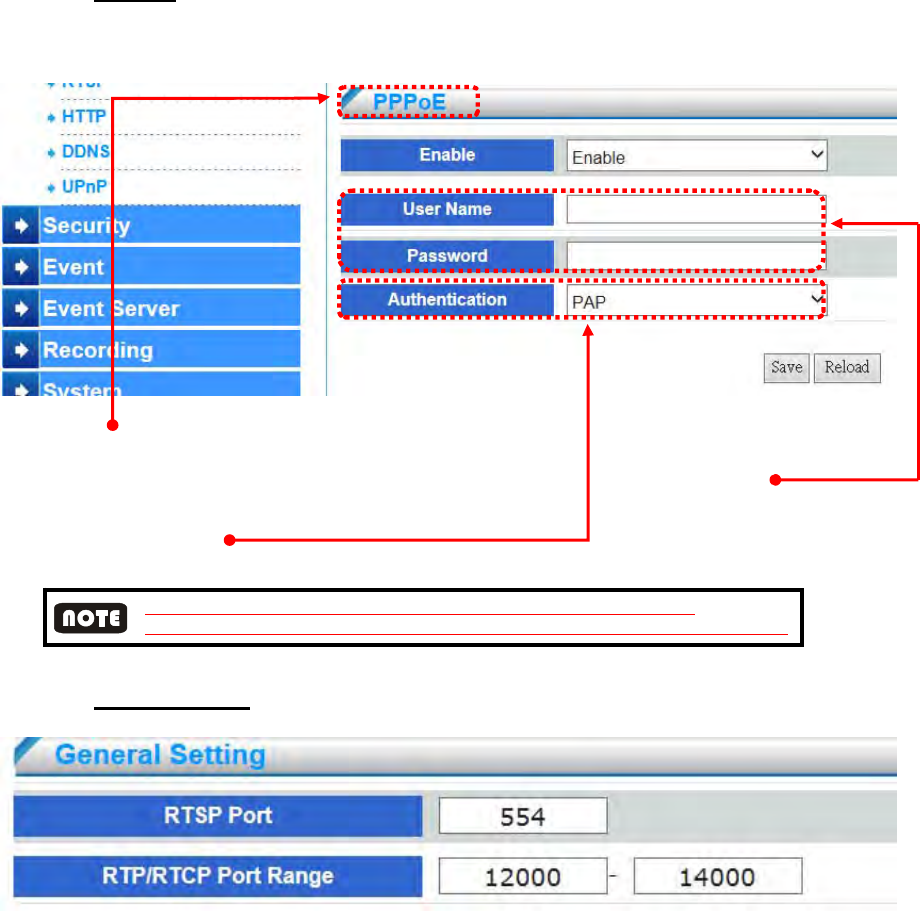
4.2.4 PPPoE
PPPoE Enable
PPPoE is used in case network supports PPPoE like xDSL
Request ISP [Internet Service Provider] for PPPoE Username / Password
Authentication
Select the ISP PPPoE connection authentication, RAP or CHAP, before PPPoE connection.
CHAP authentication has encryption function, will be more secure than PAP;
however, most of internet service provider prefer PAP authentication, will be by default PAP
4.2.5 RTSP Setting
RTSP Port
RTSP (Real-Time Streaming Protocol) controls the delivery of streaming media.
The port number default setting is 554.
RTP/ RTCP Port Range
The RTP (Real-time Transport Protocol) is used to deliver video and audio data to the
The RTCP (Real-time Transport Control Protocol) allows the network camera to
transmit the data by monitoring the Internet traffic volume
.The port range default value is set between 12000 and 14000. When the user live view
by UDP protocol and find that the server firewall block the network by the port range, the
user can change RTP/RTCP Port Rang for UDP normal transmission.
- 44 -
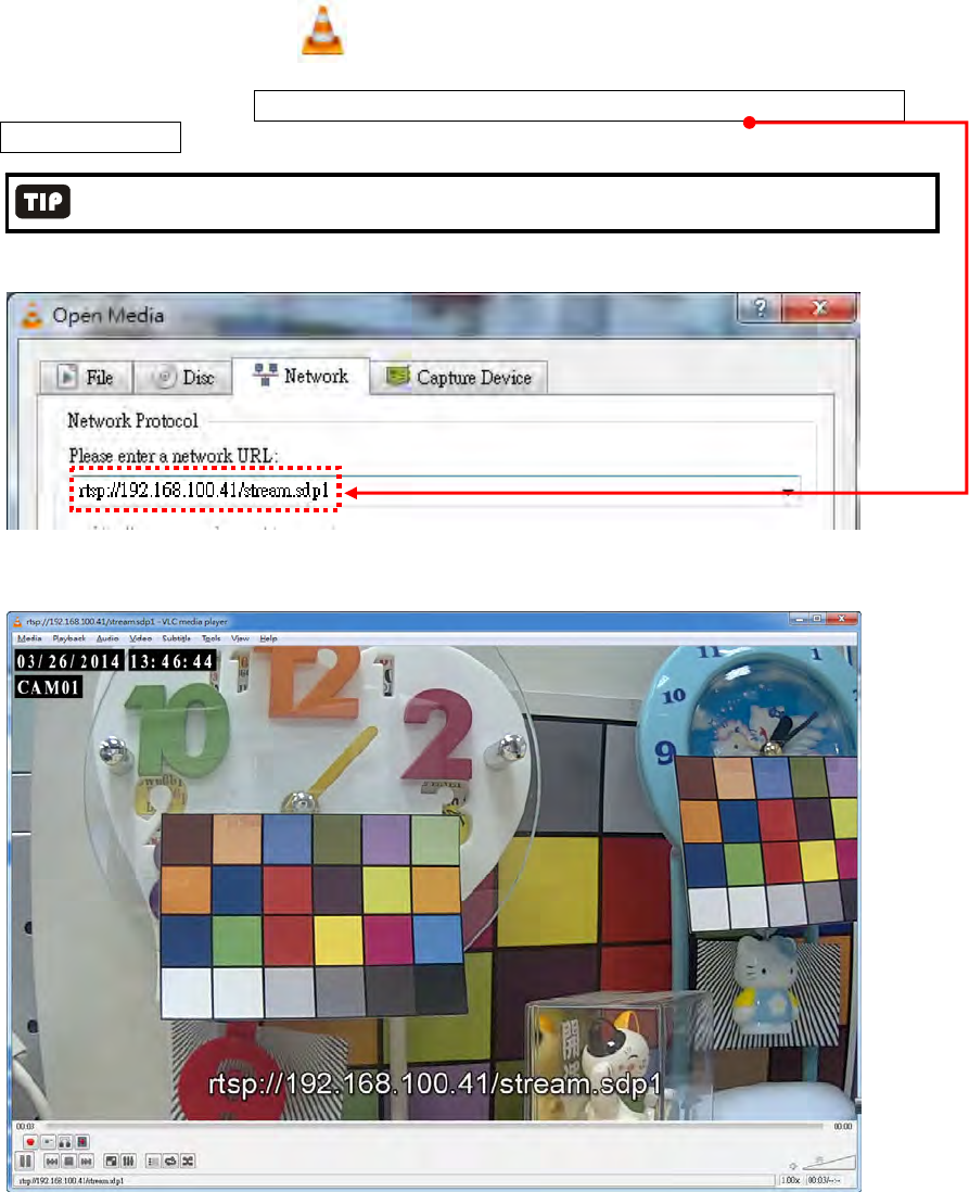
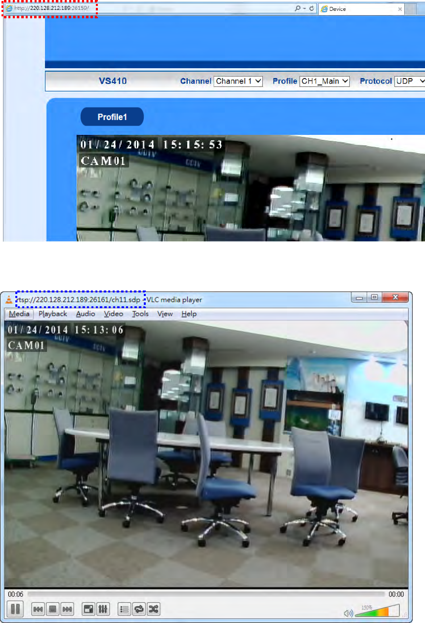
RTSP URL
You can use VLC player to view RTSP streaming. Follow the steps below to
view video streaming:
(1) Launch the VLC player
(2) Select MediaOpen Network Stream A URL dialog box will pop up
(3) he address format is rtsp://<ip address>/<RTSP streaming access name for stream1
or stream2>.
For more information on how to see the RTSP access name, please refer to chapter 4.7.1 Device Information.
For example :
(4) The live video will be displayed in your player
- 45 -
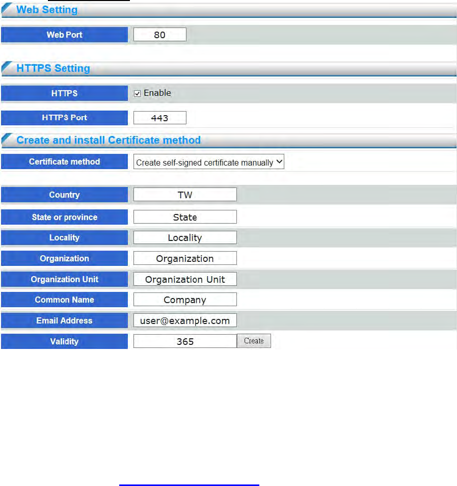
4.2.6 HTTP Setting
Web Port
(HyperText Transfer Protocol) - This protocol allows for TCP protocol quality without having
to open specific ports for streaming. Users inside a firewall can utilize this protocol to allow
streaming data through.
Setup device web port number, default is 80. To change to another port number, take 8080 for
instance, set hyperlink format as below:
http://192.168.100.100:8080
Do not duplicate web port with advanced ports. Recommended setting range is from
1000 to 65535.
HTTPS Setting
(Hypertext Transfer Protocol over SSL) - This protocol allows authentication and
encrypted communication over SSL (Secure Socket Layer). It helps protect streaming data
transmission over the Internet on a higher security level than HTTP.
.
- 46 -
Create and install certificate method
Before using HTTPS for communication with the Network Camera, a Certificate must be
created first.There are two ways to create and install a certificate
:
Create self-signed certificate manually
(1) Click “Enable” to enable HTTPS service.
(2) Click Create certificate to generate a certificate..
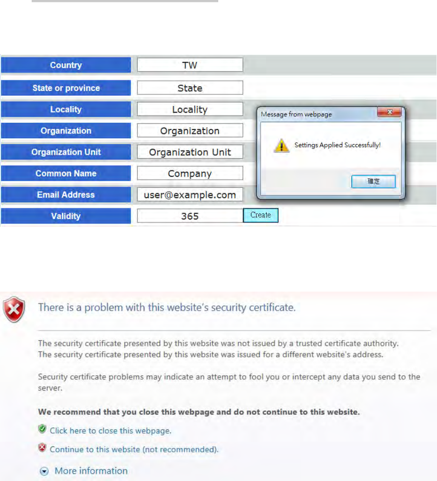
(3) Click OK to preserve your configuration as shown below
(4) Change the URL address from “http://” to “https://“ in the address bar and press
Enter on your keyboard
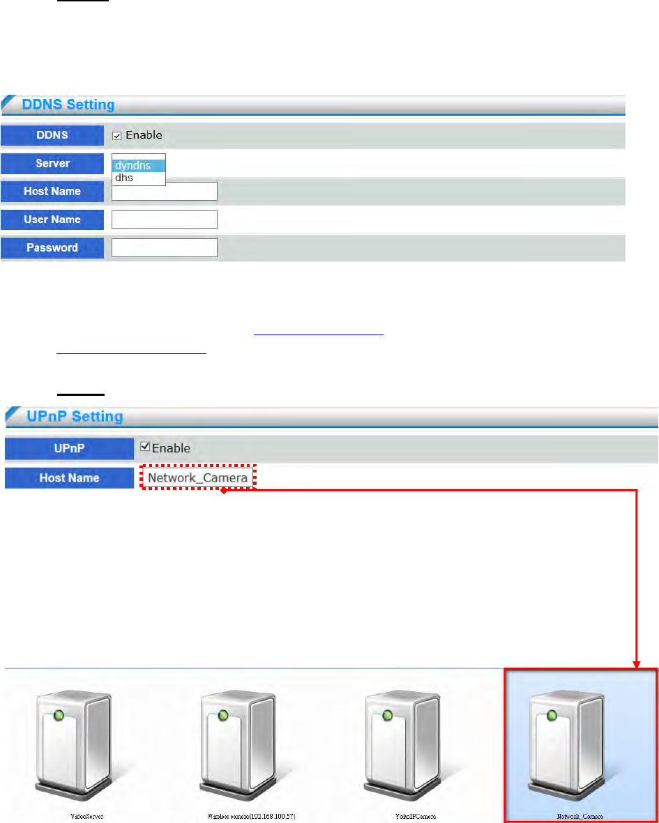
(5) Click “Continue to this website” to install.

- 47 -
(6) Enter the User name and Password of the device.
(7) Click “Certificate Error” on the top right corner of the window to view the certificate
(8) Click “Install Certificate” and follow the steps to finish the installation
- 48 -
4.2.7 DDNS
DDNS links a domain name to an IP address, allowing users to easily access their camera even with a
changing IP address. DDNS is a service that allows your network camera, especially when assigned
with a dynamic IP address, to have a fixed host and domain name. Network camera are compatible
with two DDNS service providers (1) DynDNS, (2)dhs
(1) Check “Enable” and select a server out of available two
(2) Both services are required to register some items on each DDNS service site
(3) For use of “ddns.nu” register at http://www.dhs.org/ and for dyndns find the information
at http://www.dyndns.org.
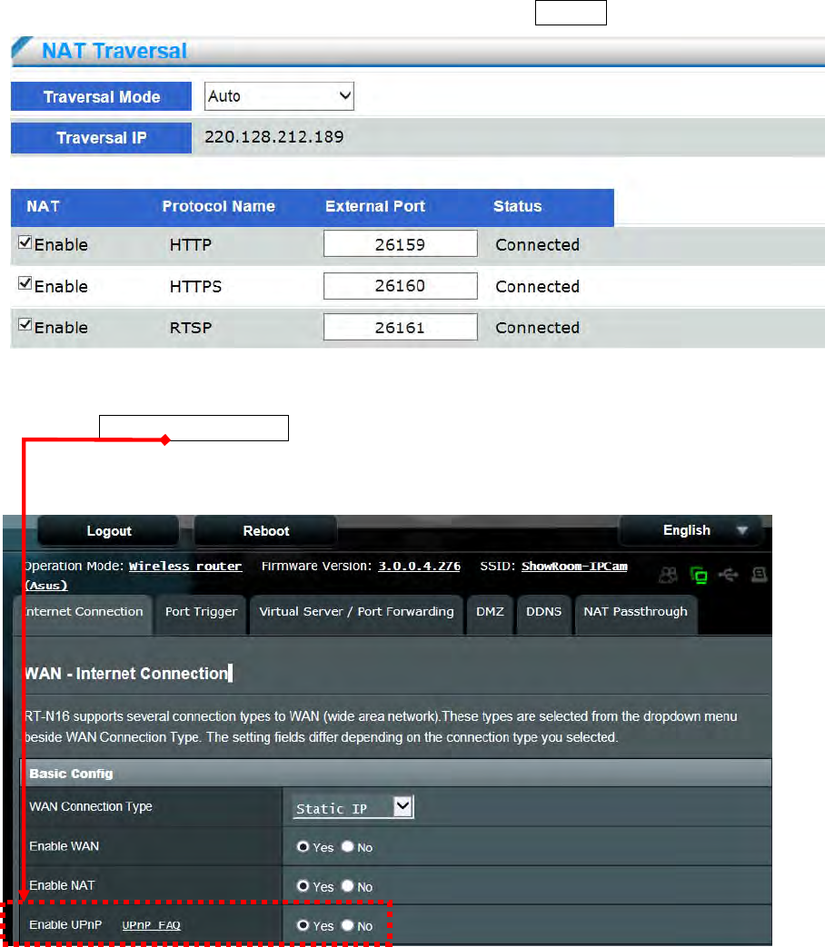
4.2.8 UPnP
UPNP
Universal Plug and Play (UPnP) simplifies the process of adding a camera to a local area
network. Once connected to a LAN, the camera will automatically appear on the intranet.
Check this option to enable UPnP presentation for your network camera so that whenever a
Network Camera is presented to the LAN, shortcuts of connected network camera will be listed
in My Network Places as show below picture. You can click the shortcut to link to the web
browser.
- 49 -
NAT Traversal
To access the network camera from the Internet, select this option to allow the network
camera to open ports on the router automatically so that video streams can be sent out from a
LAN.
To utilize of this feature, make sure that your router supports UPnP™ and it is activated.
Please follow the steps below to set a NAT Traversal:
(1) Select Traversal mode in the drop-down menu.
(2) Enable UPnP port forwarding function with the Router.
(3) Make sure if external port of HTTP、HTTPS、RTSP will be automatically mapping. If yes, the
status will show “Connected”
- 50 -
(4) Enter the Traversal IP address and External Port on the web to confirm the video streaming.
(5) Enter the RTSP URL with traversal IP address and external Port on the VLC to confirm the
video streaming.
- 51 -
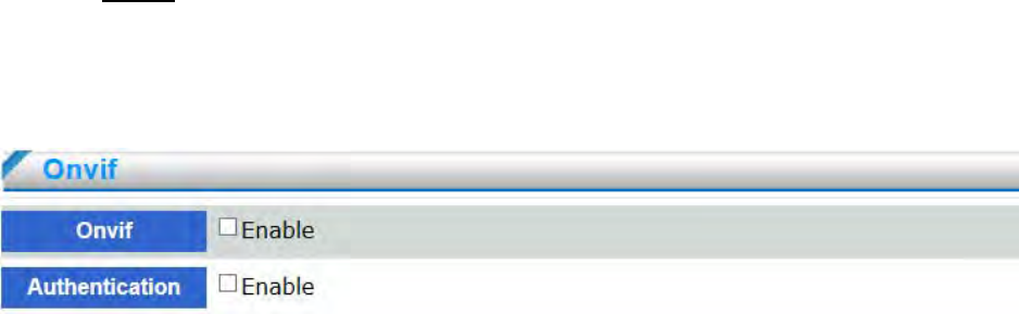
4.2.9 Onvif
ONVIF (Open Network Video Interface Forum) is a global interface standard that makes it easier for
end users, integrators, consultants ,and manufacturers to take advantage of the possibilities offered by
network video technology.
Enable : Enable the Onvif function to be compatible with NVR, VMS, CMS and relate software
by onvif. In other words, the network camera can be searched by the NVR software and the user
can see the video image based on the NVR platform.
Authentication : Enable Authentication to allow ID and password authentication when the
connectivity is established by Onvif between the network camera and NVR software. If disable it,
the connectivity will be established between the network camera and NVR software without ID
and password authentication. Disabling the authentication will be conditionally increase the
compatibility between camera and software.
- 52 -
4.3 Security
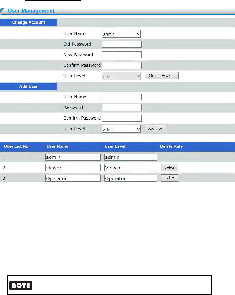
4.3.1 User Management
Change Password
Enter the original password and new password, click on “change account” button to finish
password change.
Password of operator and guest accounts are not changeable, if user wants to change the
password of operator and guest accounts, please login as administrator, and delete operator
or guest account, and create new accounts.
Add User
Enter username and password, select the user level and click on “add user” button. The
maximum users can be set up to 15. The account name characters should follow the
restrictions below:
Enter user name and password; the characters can be Arabic alphabet 0~9, capitalized or
non-capitalized English alphabet, and symbol“-”, “_”and “.”. The maximum inputs are 32
characters. English upper and lower case are seen as different character.
- 53 -
Admin is unique. Admin can create operator and viewer level users. Operator and guest level
users have no right to add user.
User List
List all users in the table. Click on “Delete” button to delete user.
User Security Level
System provides three levels users; please refer to below table for each level’s permission.
User Level Live View
Ima
g
e Control
Panel PTZ Broadcast Setting User
Mana
g
ement
Administrator ◎ ◎ ◎ ◎ ◎ ◎
Operator ◎ ◎ ◎ ◎
View ◎ ◎
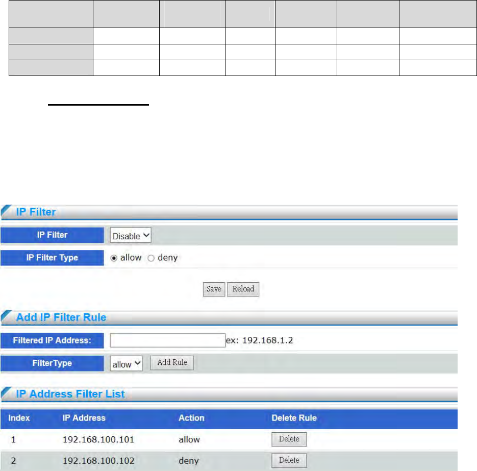
4.3.2 IP Address Filter
Filter IP addresses and select to receive or refuse requirements from IP
IP Filter Type allow : Allow all the IP addresses connect to the device, the user can filter
specific IP address by setting “deny” in IP Address Filter List.
IP Filter Type deny : Deny all the IP addresses connect to the device, at least reserve 1set
IP address to enable the function.
Add IP Filter Rule : Enter allowed or filtered IP address or IP segments
- 54 -
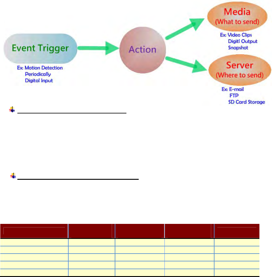
4.4 Event
When an event (such as unauthorized movement) occurs, the camera can be scheduled to
perform certain actions. An Trigger is a set of parameters that defines these actions.
As illustrated on the right, an event can be triggered by many sources, such as motion detection or
external digital input devices. When an event is triggered, you can specify what type of action that
will be performed. You can configure the network camera to send snapshots
or videos to your email address or FTP site
Events triggered by network camera
1. Motion Detection
2. Digital Input
3. Periodic Timer
4. Network Fail
5. Schedule Record
Actions supported by network camera
1. Digital Output
2. FTP Notification
3. E-mail Notification
4. Record to SD
Event Rule
D
igital
Output
F
TP
Notification
E
mai
l
Notification Record to SD
Motion Detection
Di
g
ital In
p
ut
Periodic Timer
Network Fail
Schedule Record
- 55 -
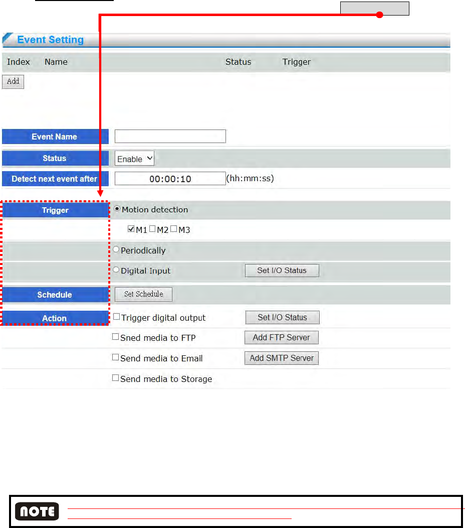
4.4.1 Event Setting
Click Add to open the Event setting page. On this page, you can arrange three elements -- Trigger,
Schedule, and Action to set an event. A total of 3 event settings can be configured.
Event Name : Enter a name for the event setting.
Status : Select to enable the event setting.
Detect next event after : Configure event-trigger duration from previous to next event, This
can prevent event-related actions to be too frequently. Device only support motion detection
and digital input event-trigger type.
A complete process of event trigger alarm depending on video successful access. The next event trigger alarm
will be enabled after the previous event video successful access.
An event is an action initiated by a user-defined trigger source; it is the causal arrangement of the
following three elements: Trigger, Event Schedule, and Action.
Trigger : This is the cause or stimulus which defines when to trigger the network camera.
The trigger source can be configured to use the network camera’s built-in motion detection
mechanism or external digital input devices. There are several choices of trigger sources as
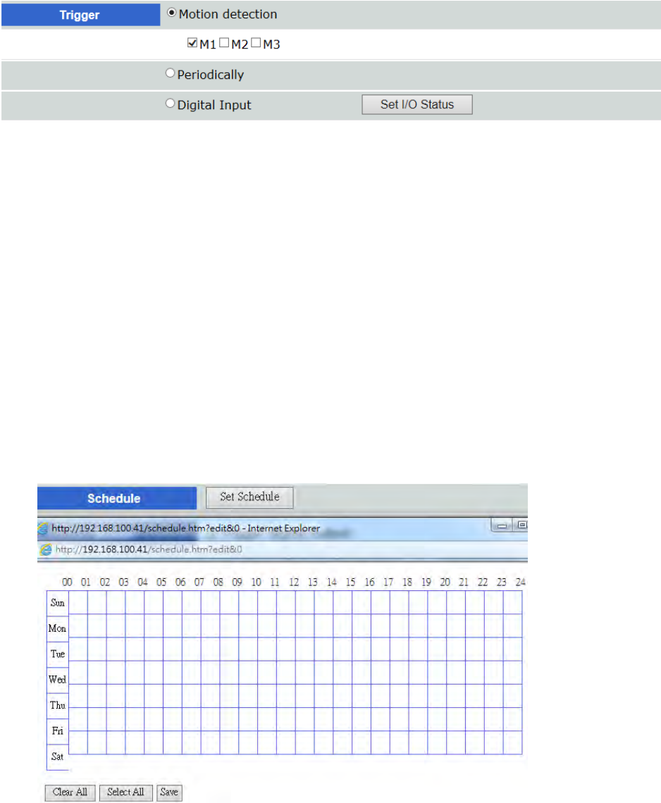
- 56 -
shown below.
◎ Motion detection :
Select M1, M2, or M3 of normal part to enable motion detection event trigger. M1 is
Motion Area 1、M2 is Motion Area 2、M3 is Motion Area 3. Please configure motion
detection setting before event trigger setting.
◎ Periodically
This option allows the Network Camera to trigger periodically for every other defined
minute. Up to 999 minutes are allowed.
◎ Digital input:
This option allows the network camera to use an external digital input device or sensor as
a trigger source. Depending on your application, there are many choices with digital input
devices on the market which help detect changes in temperature, vibration, sound, light,
etc.
Schedule: This is the cause or stimulus which defines when to trigger the network camera.
The trigger source can be configured
◎ Select all : Click to select all the schedule to do event-trigger alarm
◎ Clear all : Click to clear all the schedule to do event-trigger alarm
- 57 -
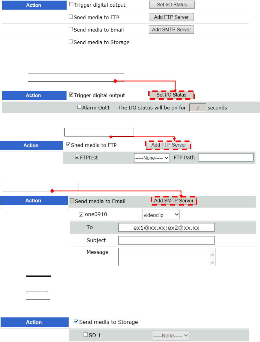
Action: Select the Actions that will occur when the event is triggered. There are four
choices of server types available: Digital Output, FTP ,SMTP(E-mail) ,and Storage
Device(SD Card & USB disk storage). Select the item to display the detailed configuration
options. You can configure either one or all of them.
◎ Trigger digital output : Check the desired DO to turn on the external digital output
device when a trigger is activated. Specify the length (seconds) of the trigger interval in the
text box. Please click “Set I/O” Status button, you can configure digital output status as
OPEN or Close before checking “Alarm Out”.
◎ Send media to FTP: Select to send the video clip to an FTP server when a trigger is
activated. Please click “Add FTP Server” button before check FTP action.
◎ Send media to Email : Select to send the video clip via email when a trigger is activated.
When <Send to Email> is selected, the following page will be shown. Please click
“Add SMTP Server” button before check SMTP action.
Email To : Enter the email address of the sender (five mails addresses the
maximum)
Subject : Enter in e-mail subject
Message : E-mail content
◎ Send media to Storage: Select to send the video clip to SD Card when a trigger is activated.
- 58 -
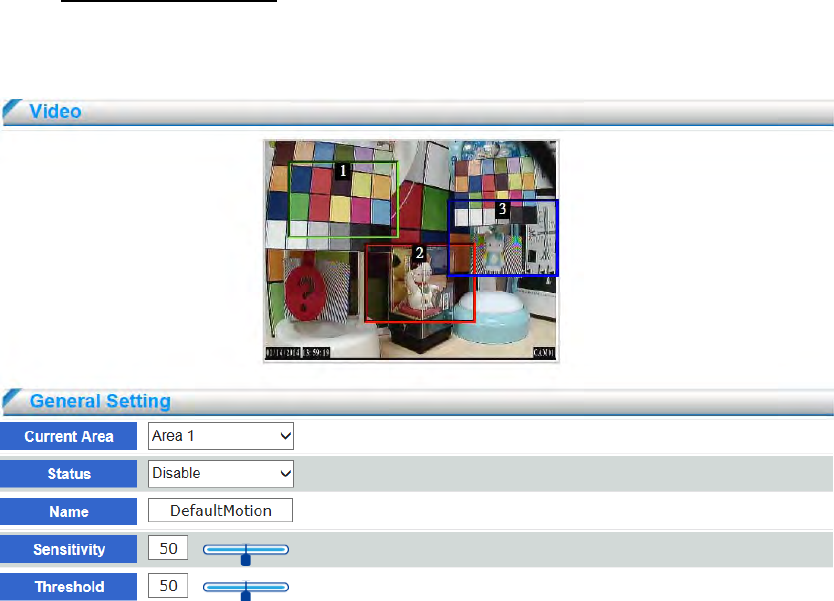
4.4.2 Motion Detection
Motion can be detected by measuring changes in the speed or vector of an object or objects
in the monitored area. This section explains how to configure the network camera to enable
motion detection.
Configuring Motion Detection: Use this setting to enable and define the motion detection
window. The user can define up to three areas on the live view window in each channel. Use
mouse to resize or move the motion detection window.
(1) Select the channel
(2) Select the area <Area 1>, <A rea 2>, or <Area 3>
(3) Check “Enable” Status to enable motion detection.
(4) Enter the area name and use the mouse to resize or move the motion detection
window.
(5) Adjust the “Sensitivity” level, range from 0~100, the higher value, the
higher sensitivity.
(6) Adjust the “Threshold” to change the threshold level. The higher the
threshold, the larger objects need to be to trigger an event.
(7) Click Save to enable the settings.
- 59 -
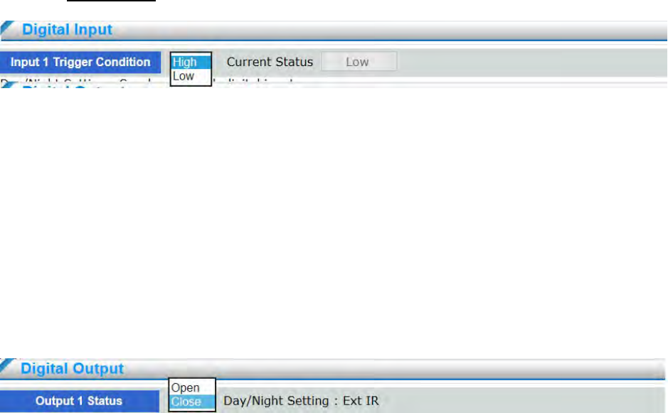
4.4.3 Digital I/O
The DI socket allows the video server to receive input from an external device. The external device
should have the ability to drive voltage on the connected DI wire to the triggering voltage level in
order to notify the IP camera of any event of interest. The network camera will then process the event
notification according to the specific event rules
Digital input: Connect a DI device to the camera's push-in type terminal block, the camera will
automatically detect the current connection state as pulled-high or pulled-low. You may then
define the triggering condition.
Current Status: Report camera the current signal status as High or Low to determine the
signal’s Normal status during operation.
The DO socket allows the IP camera to send output to an external device. While executing the
DO notification action, the IP camera drives voltage on the connected DO wire to the
triggering voltage . The connected external device will then be triggered.
Digital output: Select OPEN or Close to define normal status for the digital output according to
the specification of their external device
- 60 -
4.5 Event Server
Use the tools in this section to specify what type of notification will be sent when an
event occurs. The network camera can send buffered image to an FTP server, Email.
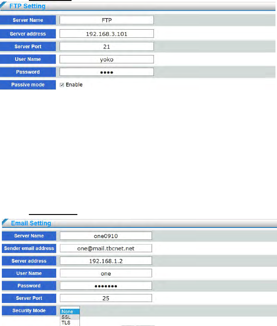
4.5.1 FTP Setting
Server address: Enter the domain name or IP address of the FTP server
Server port : By default, the FTP server port is set to 21. It can also be assigned to another port
number between1025 and 6553
User name: Enter the login name of the FTP account.
Password: Enter the password of the FTP account
Passive mode : Most firewalls do not accept new connections initiated from external requests. If
the FTP server supports passive mode, select this option to enable passive mode FTP and allow
data transmission to pass through the firewall.
4.5.2 Email Setting
- 61 -
Server name: Enter the server name
Server email address: Enter the email address of the sender
Server address: Enter the domain name or IP address of the email server
User name: Enter the user name of the email account if necessary
Password: Enter the password of the email account if necessary
Server port: The default mail server port is set to 25. User can also manually set another port
Security Mode : Select security mode SSL or TLS, the default setting is none. If your SMTP
server requires a secure connection (SSL), check this server if provide the secure connection
(SSL) function.
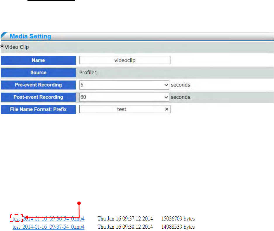
4.5.3 Media Setting
Click Media on the Event Settings page to open the Media Settings page. On this page, you can
specify the type of media that will be sent when a trigger is activated. A total of 5 media settings can
be configured.
Name: Enter a Media name.
Source: Select the source of video clip ,only stream 1 (profile 1) available in current stage.
Pre-event Recording : The network camera has a buffer area; it temporarily holds data up to a
certain limit. Enter a number to decide the duration of recording before a trigger is activated. Up
to 5 seconds of video can be recorded.
Post-event Recording : Images can be stored internally on the server from the time
immediately following the trigger. Enter the desired length of time, range from 5~60 seconds.
File Name Format Prefix: Enter the text that will be appended to the front of the video file
name.
- 62 -
4.6 Record
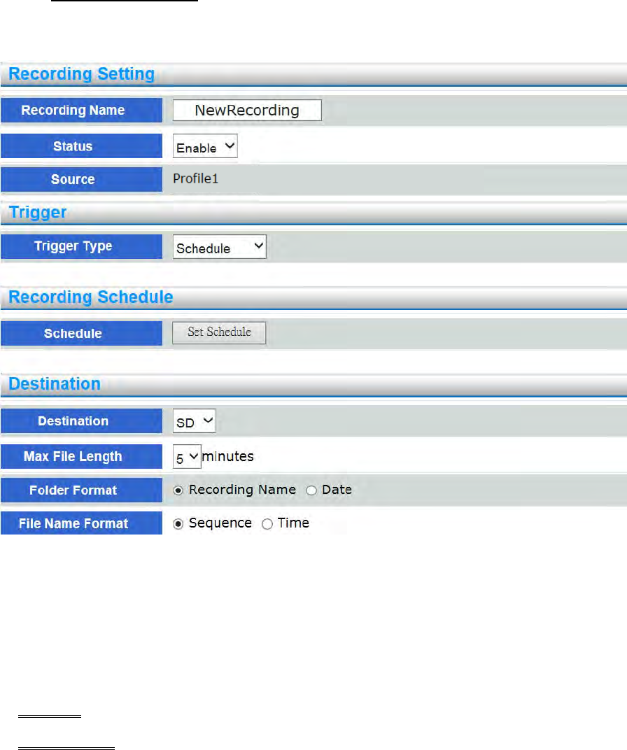
4.6.1 Recording Setting
Configure it for recording video by schedule and network failure, which are both saved in SD
Card.
Name: Enter a Recording name.
Source: Select stream for the recording source. only stream 1 (profile 1) available in current
stage
Status: Select this option to enable the recording setting
Trigger Type : You can either select Schedule or Network Fail as the trigger type
Schedule: The server to start recording files onto local storage.(SD Card)
Network Fail : Recording video by network failure, network camera will start recording
from 5 seconds before network failure. When network recovery , it will stop recording, and the
files will be saved in storage (SD Card).
- 63 -
Destination: Select SD card to store the recorded videos.
Max File length: This determines the length of each recorded video time, applicable from 1 to 6
minutes.
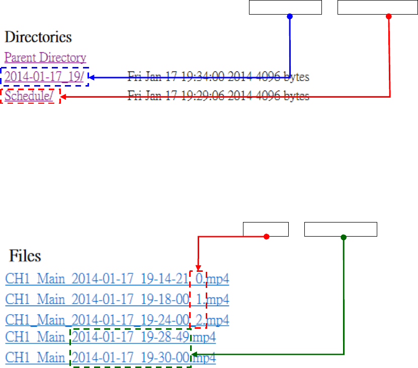
Folder Format: Folder of video recording format, Date And Time or Recording Name.
Recording Name : Folder is named the same as recording name. EX: If Recording Name is
configure “schedule”, the folder will be named “schedule”.
Date And Time : Folder is named by date and time. The format is yyyy-mm-dd_hh. EX:
Recording time is at 18:00 o’clock on June 21, 2013. The folder name will be
2013-06-21_18.
File Name Format: Recording file name format, Sequence or Date And Time.
Sequence: File is named by date and time. The format is yyyy-mm-dd_hh_mm_ss_number,
serial number will be added in the end of file name. EX: Recording time is at 00secs, 25mins,
18:00 on June 21, 2013. The file name will be 2013-06-21_18-25-00_0, the next file name
will be 2013-06-21_18-26-00_1.
Date And Time : File is named by date and time. The format is yyyy-mm-dd_hh_mm_ss.
Recording time is at 53secs, 04mins, 18:00 on June 21, 2013. The file name will be
2013-06-21-18-04-53.
- 64 -
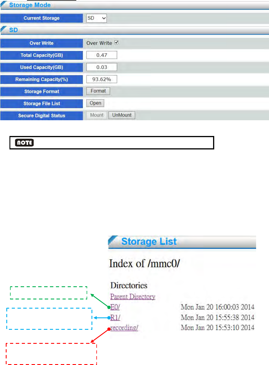
4.6.2 Storage Device
Network camera support SD card for local storage.
It is suggested that the SD Card format as FAT32 system when using for the first time.
Current Storage: Display the storage information of SD Card.
Over Write: Check this item if you want to enable cyclic recording. When recording uses up all
capacity, the oldest file will be overwritten by the latest file.
Format: If a SD Card needs to be formatted click the Format button. to format a drive as
FAT32.
OPEN: Click OPEN and the recorded data corresponding to the search criteria will be listed in
Storage List windows.
Event recordin
g
folder
Network Fail or Schedule
recording folder
Temporarily folder for holds
stream up to a certain limit
- 65 -
Mount: If network camera cannot detect SD card , please click Mount bottom connect to
network camera
UnMount: If taking off SD card is needed during recording, please click UnMount bottom take
off SD card from network camera.
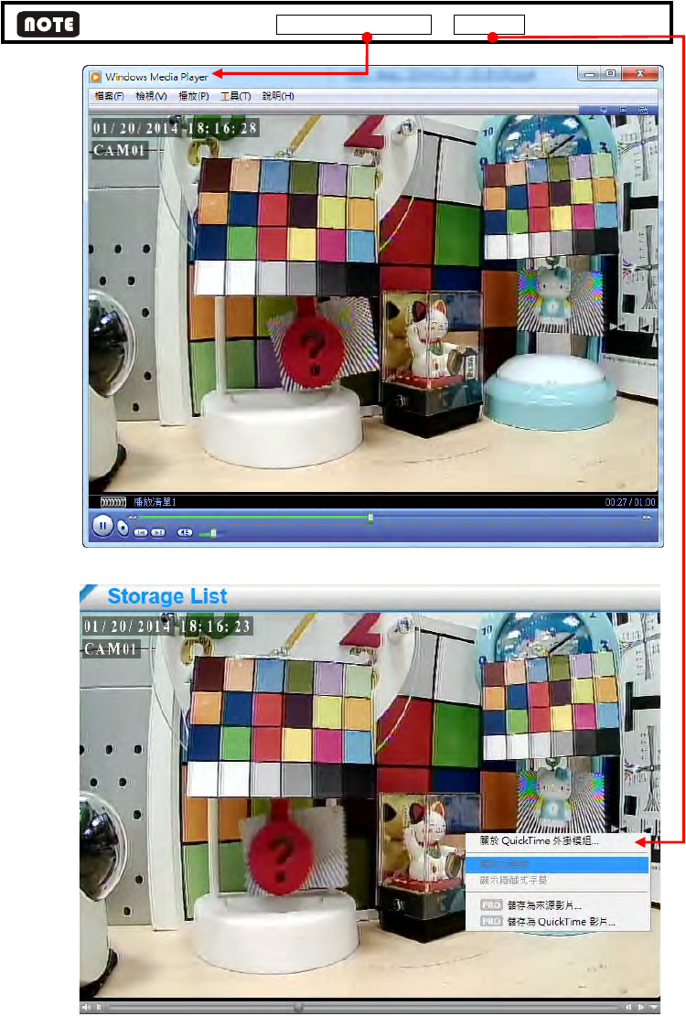
The user may need to install Windows Media Player or QuickTime to play the video clips..
- 66 -
4.7 System
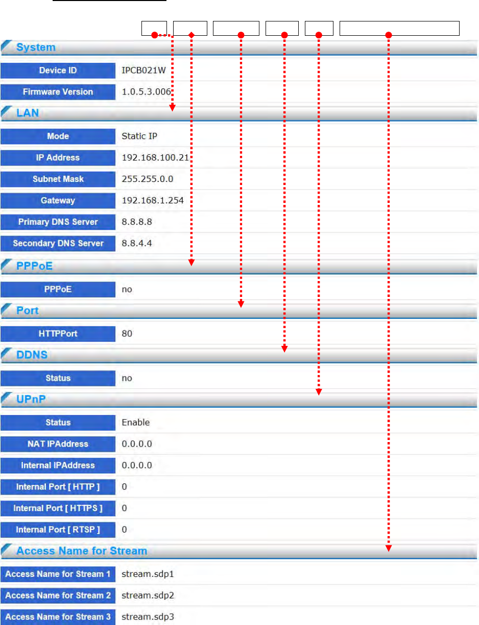
4.7.1 Device information
This page will display the device status information, string field displayed information includes the
configuration of the system, LAN, PPPoE, Web Port, DDNS, UPnP, Access Name for Stream.
- 67 -
4.7.2 Time setting
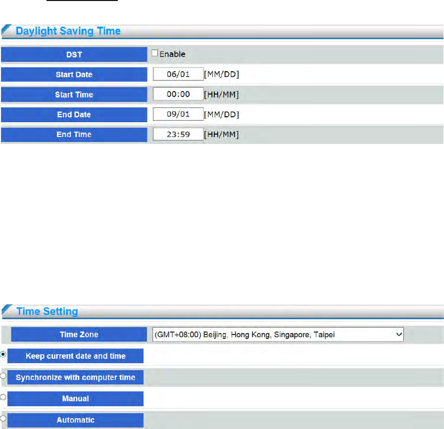
Daylight Saving Time
DST: Enable this item to activate day light saving function.
Start Date: Enter the start date of DST, the format should be: mm/dd.
Start Time: Enter the start time of DST, the format should be: mm/dd.
End Date: Enter the end date of DST, the format should be: mm/dd.
End Time: Please enter the day light saving end time, the format should be: hh:mm.
Daylight Saving Time
Time Zone: Select the appropriate time zone from the list.
Keep current date and time: Select this option to preserve the current date and time of the
network camera. The network camera’s internal real-time clock maintains the date and time
even when the power of the system is turned off.
Synchronize with computer time: The network camera will sync with the time, date and time
zone of the computer used to modify the network camera settings.
Manual: Allows you to manually set date and time.
Automatic: The Network Time Protocol is a protocol which synchronizes computer clocks by
periodically querying an NTP Serve.
- 68 -
NTP Server: Assign the IP address or domain name of the time-server. Network camera provide
two NTP server configuration charts. Network camera will synchronize the 1st NTP server by
default. If the 1st NTP server is invalid, network camera will synchronize the 2nd NTP server.
Select the NTP server address from below lists which is Asia (including Taiwan), America,
Europe.
time.stdtime.gov.tw
asia.pool.ntp.org
tw.pool.ntp.org
us.pool.ntp.org
europe.pool.ntp.org
oceania.pool.ntp.org
south-america.pool.ntp.org
Updating interval: Enable to synchronize time with NTP server every hour.
4.7.3 Logs
Log is the complete operation record of network camera. If any trouble of network camera, users can
review and check it to find the failure root cause.
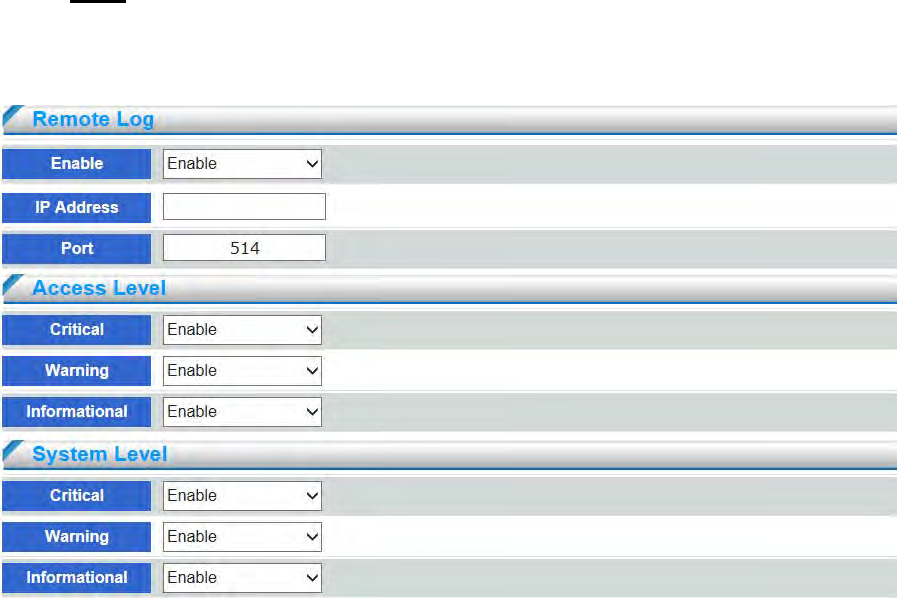
Remote Log: The user can configure the network camera to send the system log file to a remote
server as a log backup. Follow the steps below to set up the remote log. Before utilizing this
feature, it is suggested that the user install a log-recording tool to receive system log messages
from the network camera. An example is 3CDaemon.
- 69 -
Follow the steps below to set up the remote log:
1. Click to enable remote log and enter the IP address of the remote server.
2. Enter the port number of the remote server
3. When completed, click Save to enable the setting
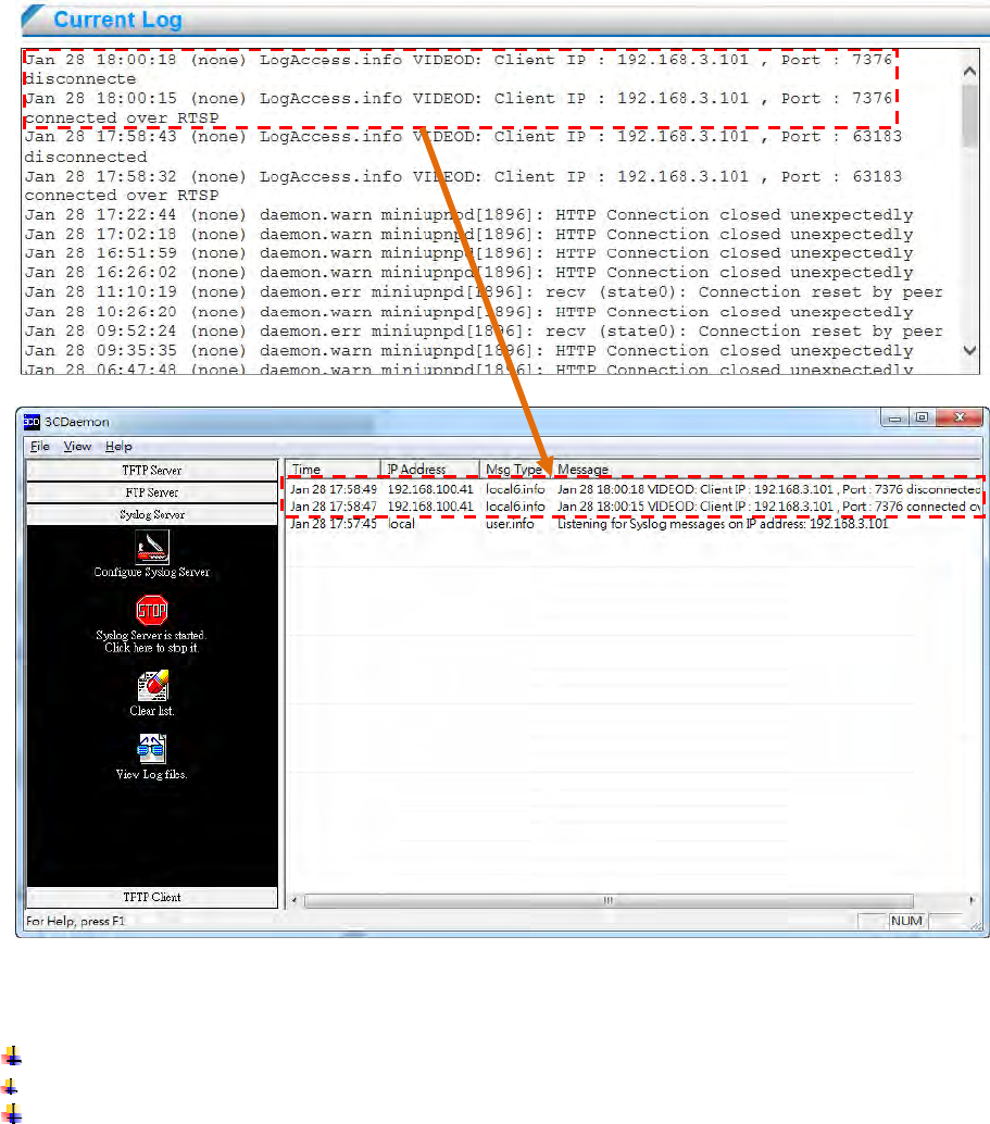
Current Log: The user can review all log file in current log. If the user enable remote log server,
the log file will be synchronized up to server shown in the figure below.
Network camera provide two types of levels: Access level or System level
Access Level: User network access relate information
Critical: Video stream init fail etc
Warning: Video lost, audio lost etc
Information: User client IP address, port information etc
- 70 -
System Level: System operation or device process relate information.
Critical: Device driver init fail, thread create fail etc
Warning: Device no response, process socket create fail etc
Information: Event on/off, add or delete event, ptz operation etc
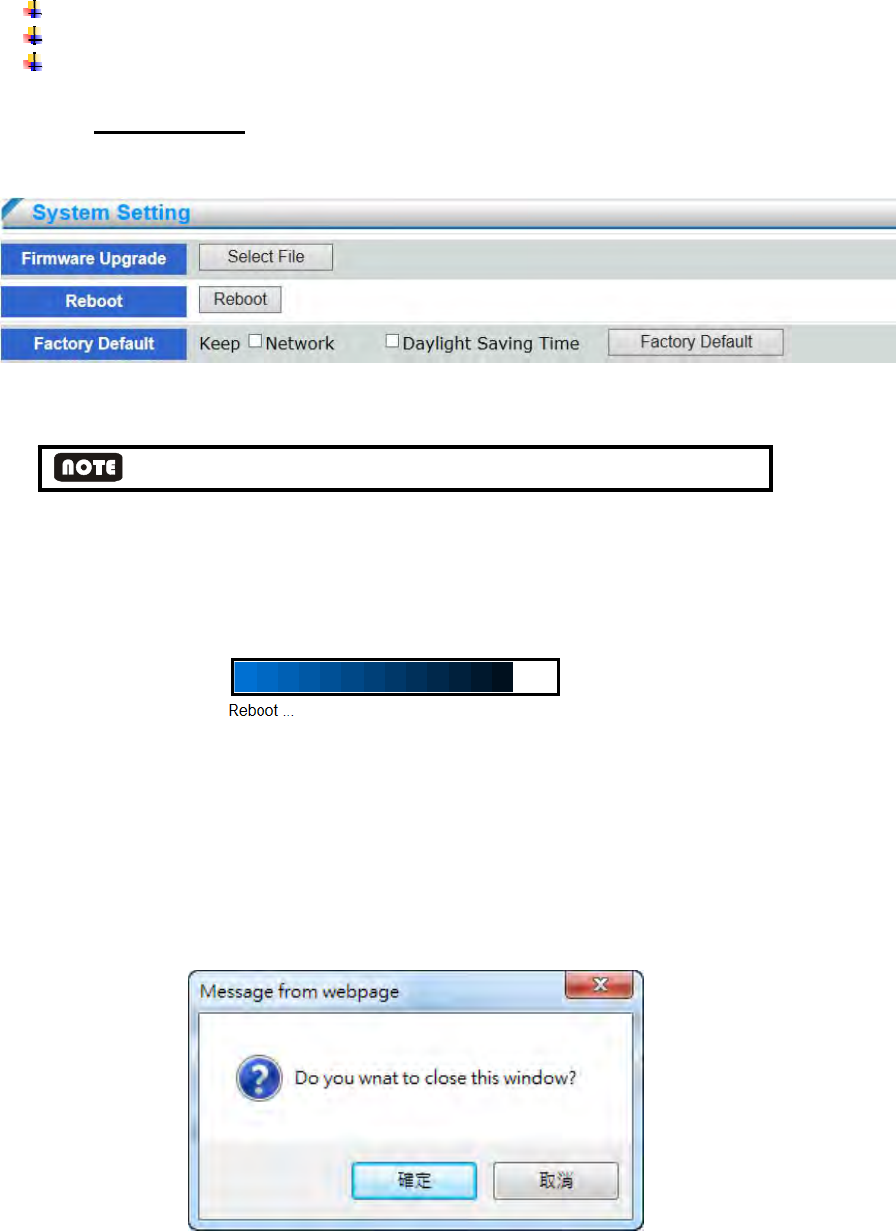
4.7.4 Maintenance
This chapter explains how to restore the network camera to factory default, upgrade firmware,
version, etc.
Firmware Upgrade: This feature allows the user to upgrade the network camera firmware. It
will take a few minutes to complete the process.
DO not power off device during firmware upgrade in case system malfunction occur
Reboot: This feature allows you to reboot the network camera, which takes about one minute to
complete. When completed, the live video page will be displayed in your browser. The
following message will be displayed during the reboot process.
If the connection fails after rebooting, manually enter the IP address of the network camera in
the address field to resume the connection.
Factory Default: This feature allows you to restore the network camera to factory default
settings. Check the boxes to preserve the Network Setting, Daylight Saving Time.
If none of the options is selected, all settings will be restored to factory default. The following
message is prompted. You can choose weather close web page or not.
- 71 -
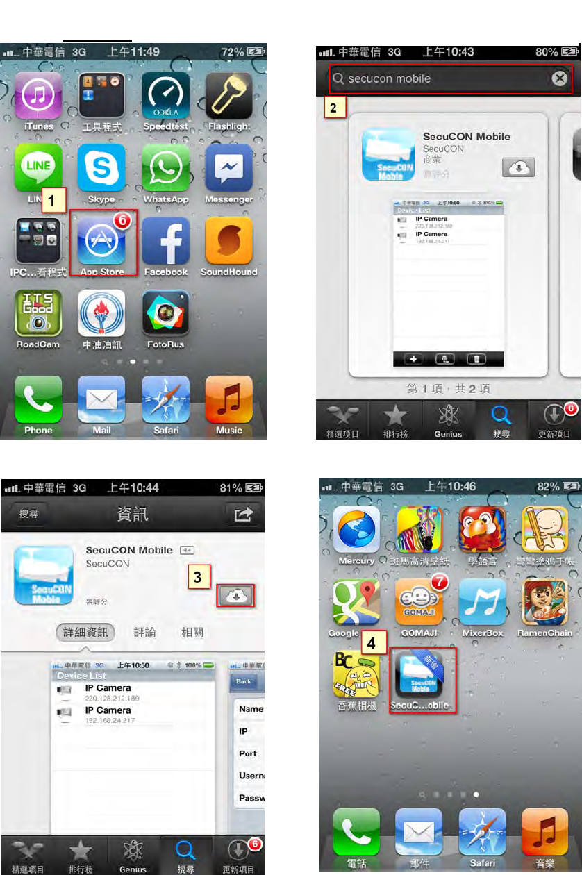
Appendix A – 3GPP on iPhone
※ IP cameras provide free bundled APP for live viewing, the steps as follows:
(3) Download and install it in your iphone (4) Click on Mobile icon
(1) Please click on the main screen
of the App Store icon。 (2) Click on "Search" icon and
search for『SecuCON Mobile
』
。
- 72 -
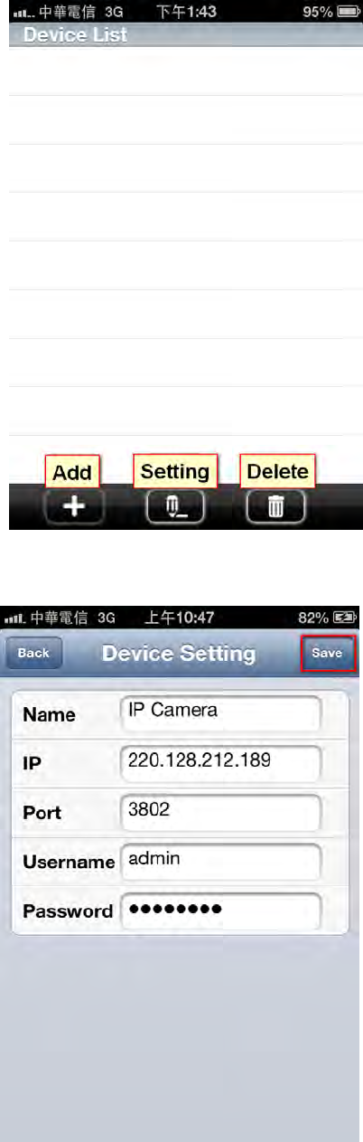
(5) Click on【+】button to add IP cameras
(6) Configure IP address, port number (default 554), username, and password of IP camera
and click on【Save】button
- 73 -
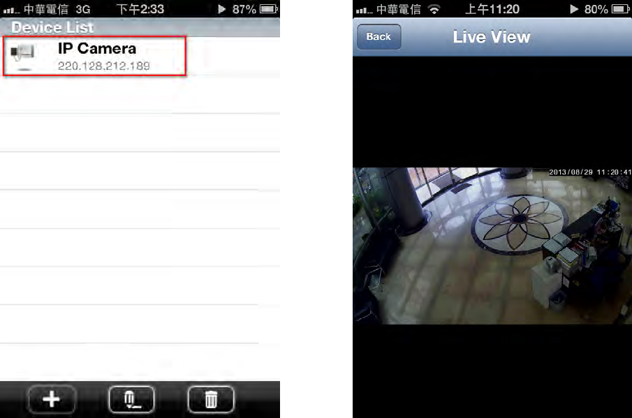
(7) Click on the configured IP camera (8) Live view IP camera
※NOTE: APP captures the 2nd stream of IP camera. For more smooth video quality, the
suggested configuration is that the resolution is 640x480, bitrate 1M, and frame rate 30fps.
- 74 -
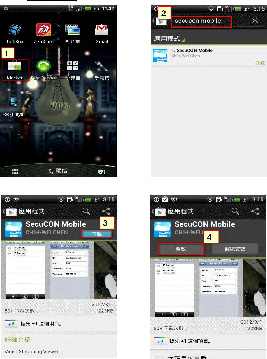
Appendix B – 3GPP on Android
※ IP cameras provide free bundled APP for live viewing, the steps as follows:
(3) Download and install it in your iphone (4) Click on Mobile icon
(1) Please click on the main screen
of the Android Market icon. (2) Click on "Search" icon and
search for『SecuCON Mobile』。
- 75 -
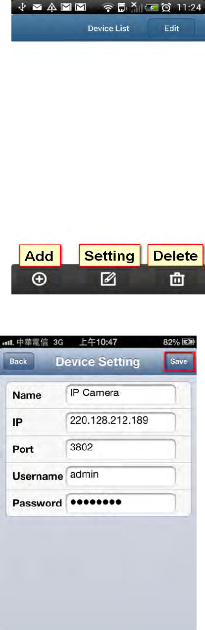
(5) Click on【+】button to add IP cameras.
(6) Configure IP address, port number (default 554), username, and password of IP camera
and click on【Save】button.
- 76 -
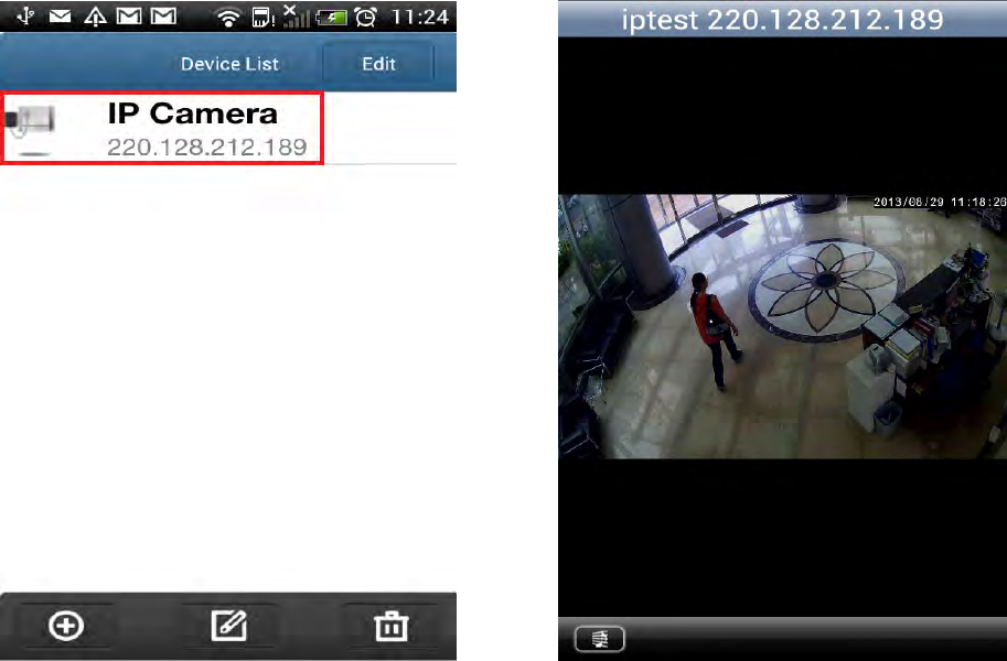
(7) Click on the configured IP camera. (8) Live view IP camera.
※NOTE: APP captures the 2nd stream of IP camera. For more smooth video quality, the
suggested configuration is that the resolution is 640x480, bitrate 1M, and frame rate 30fps.

- 77 -
Appendix C –Specifications
Model No. RYK-IPCB021W
IMAGE
Sensor 1/4” Progressive CMOS
Resolution 1 Mega
Picture Elements 1280 x 720
Frame Rates 30fps
Shutter Speed Automatic, Manual (1/7.5 ~ 1/10000 sec)
White Balance Automatic, ATW, Outdoor, Indoor, Lamp
Minimum Illumination 1Lux @ F2.0 (Color), 0 Lux with IR
Gain Control Auto, Manual (0~24db)
Back Light Comp. Yes
DNR 3D Noise Filter
IR-Cut filter Removable Yes
Day & Night Yes
LENS
Lens Board Lens f=3.6mm, F2.0 (6mm,12mm option)
Mount M12
IR Illumination Distance Max. 10M
VIDEO
Video Compression H.264 & M-JPEG
Video Streaming 3 Streaming
Flip & Mirror Yes
Privacy Mask 3 areas
Motion Detection 3 areas
AUDIO
Audio Compression G.711/PCM
2way Audio Yes
Audio In/Out Built-in Speaker
Microphone Built-in Microphone
NETWORK
Ethernet 10/100 Base T Ethernet (RJ-45)
Protocol
HTTP, HTTPs, DHCP, PPPoE, DDNS, SMTP, FTP server, FTP client, NTP,
Bonjour
Password Protection Yes

- 78 -
Live Viewing User 10
Wireless Yes (802.11 b/g/n)
Applications
Network Storage VMS, SD Card Network Fail Recording, SD Card Schedule Recording
Live Viewing IE, VMS, Mobile App (iOS, Android)
GENERAL
SD Card Slot Micro SD Card (Support class 10 above)
Alarm 1 x DI, 1 x DO(Dry Contact) (Option)
Integrate Document CGI /SDK
Power DC5V / 1.2A
Power over Ethernet 802.3af PoE Module (Optional)
Dimension (W x H x D) 94.88 x 64.59 x 44.30 (mm)
Weight 240g (including bracket)
Operating Condition 0 °C ~ 50 °C / 32 °F ~ 122 °F
Humidity 0% ~ 90% RH
Certificate SRRC, CE, FCC
- 79 -
FEDERAL COMMUNICATIONS COMMISSION INTERFERENCE STATEMENT
This equipment has been tested and found to comply with the limit s for a Class B
digital device, pursuant to Part 15 of the FCC Rules. These limits are designed to
provide reasonable protection against harmful interference in a residential
installation. This equipment generates, uses and can radiate radio frequency energy
and, if not installed and used in accordance with the instructions, may cause harmful
interference to radio communications. However, there is no guarantee that
interference will not occur in a particular installation. If this equipment does cause
harmful interference to radio or television reception, which can be determined by
turning the equipment of f and on, the user is encouraged to try to correct the
interference by one or more of the following measures:
-- Reorient or relocate the receiving antenna.
-- Increase the separation between the equipment and receiver.
-- Connect the equipment into an outlet on a circuit different from that to which the
receiver is connected.
-- Consult the dealer or an experienced radio/TV technician for help.
CAUTION:
Any changes or modifications not expressly approved by the p arty responsible for
compliance could void the user's authority to operate the equipment.
This device complies with part 15 of the FCC Rules. Operation is subject to the following two
conditions: (1) This device may not cause harmful interference, and (2) this device must accept any
interference received, including interference that may cause undesired operation.
FCC RF Radiation Exposure Statement:
1. This Transmitter must not be co-located or operating in conjunction with any other antenna or transmitter.
2. This equipment complies with FCC RF radiation exposure limits set forth for an uncontrolled environment.
This equipment should be installed and operated with a minimum distance of 20 centimeters between
the radiator and your body.