York 36 Users Manual Y TG, Single Package Gas/Elec Units And Sgl Pkg AC, S
48 to the manual a1018208-1c59-49bd-b1fa-b9822b1fe488
2015-02-02
: York 36-Users-Manual york-36-users-manual-455027 york pdf
Open the PDF directly: View PDF ![]() .
.
Page Count: 44
255040-YTG-A-0506
FOR DISTRIBUTION USE ONLY - NOT TO BE USED AT POINT OF RETAIL SALE
SINGLE PACKAGE GAS/ELECTRIC UNITS
AND SINGLE PACKAGE
AIR CONDITIONERS
D(CE, CG) 036, 048, 060 & 072
3, 4, 5 & 6 NOMINAL TONS
10.0 SEER (3, 4, & 5 Ton), 9.0 EER (6 Ton)
®
TECHNICAL GUIDE
DESCRIPTION
YORK Sunline 2000™ units are convertible single package
air conditioners with a common cabinet and a common roof
curb for the 3, 4, 5 and 6 ton sizes. The units were designed
for light commercial and commercial applications. They can
easily be installed on a roof curb, slab, roof jack or frame.
All units include:
• Powder Paint finish that meets ASTM-B-117 1000 hour
salt spray standards
• Permanently lubricated motors
• Bottom or side air discharge configuration capability
(field convertible)
• Manufactured under the quality standards of ISO9001
• Copper tube/aluminum fin coils
• Easy access to all components
• Rigging holes in base rails for lifting
• Fork lift slots on three sides
• Single point power connection
• Complete factory package - tested, charged and wired
• CSA agency listing on all units
WARRANTY
• Factory Limited Parts Warranty
• One-year parts warranty
• A Five-year parts warranty on the compressor and
electric heat elements.
• Ten-year parts warranty on the gas-fired heat
exchangers.

255040-YTG-A-0506
2Unitary Products Group
TABLE OF CONTENTS
DESCRIPTION . . . . . . . . . . . . . . . . . . . . . . . . . . . . . 1
PRODUCT NOMENCLATURE . . . . . . . . . . . . . . . . . 3
FEATURES . . . . . . . . . . . . . . . . . . . . . . . . . . . . . . . . 4
FACTORY-INSTALLED OPTIONS . . . . . . . . . . . . . . 5
FIELD-INSTALLED ACCESSORIES . . . . . . . . . . . . 5
GUIDE SPECIFICATIONS . . . . . . . . . . . . . . . . . . . 39
LIST OF FIGURES
Fig. # Pg. #
1 UNIT CUTAWAY . . . . . . . . . . . . . . . . . . . . . . . . . . . . . . 5
2 TYPICAL FIELD POWER & CONTROL WIRING . . . . 23
3 UNIT DIMENSIONS (3 - 6 TON COOLING ONLY/
ELECTRIC HEAT) FRONT VIEW . . . . . . . . . . . . . . . . 24
4 UNIT DIMENSIONS (3 - 6 TON COOLING/GAS HEAT)
FRONT VIEW . . . . . . . . . . . . . . . . . . . . . . . . . . . . . . . . 24
5 UNIT WITH ECONOMIZER RAINHOOD . . . . . . . . . . . 25
6 UNIT WITH FIXED OUTDOOR AIR/MOTORIZED
DAMPER RAINHOOD . . . . . . . . . . . . . . . . . . . . . . . . . 25
7 UNIT DIMENSIONS (REAR VIEW) . . . . . . . . . . . . . . . 26
8 DISCONNECT/BLOWER ACCESS LOCATION . . . . . 26
9 TYPICAL APPLICATIONS . . . . . . . . . . . . . . . . . . . . . . 27
10 FOUR AND SIX POINT LOADING . . . . . . . . . . . . . . . . 28
11 ROOF CURB DIMENSIONS . . . . . . . . . . . . . . . . . . . . 29
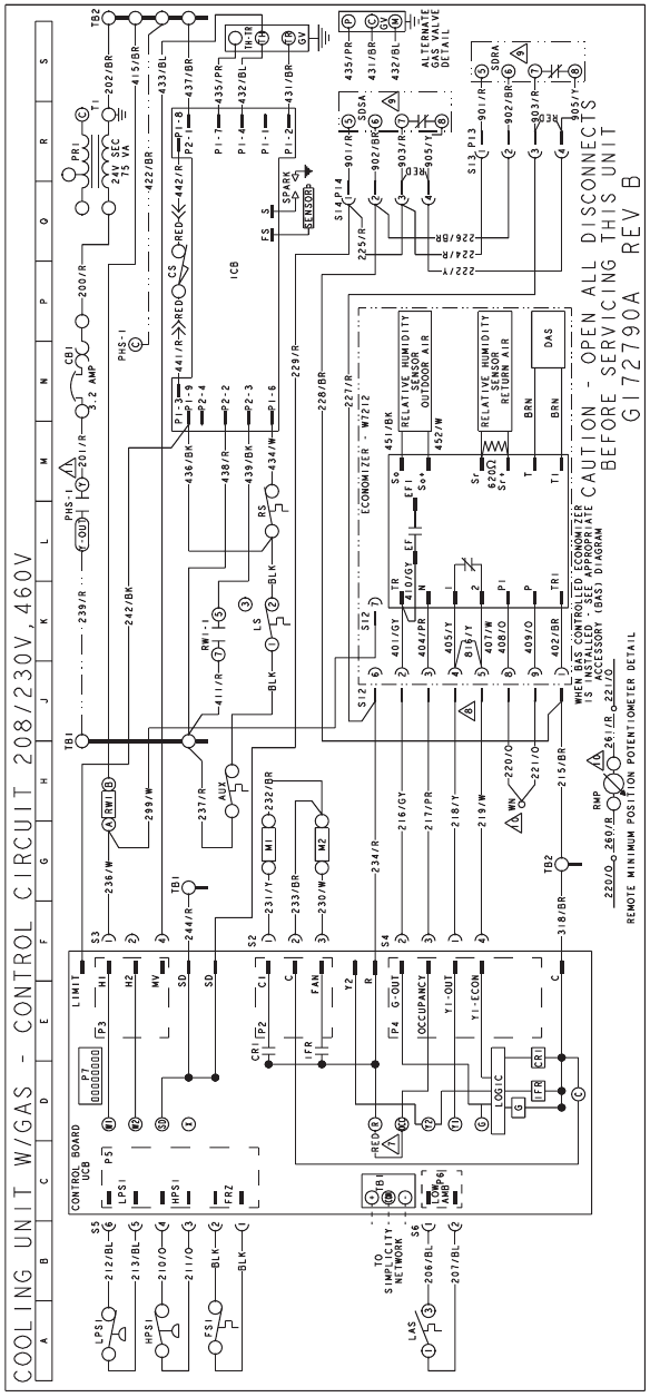
12 COOLING UNIT WITH GAS HEAT CONTROL CIRCUIT
208/230V AND 460V DIAGRAM . . . . . . . . . . . . . . . . . 30
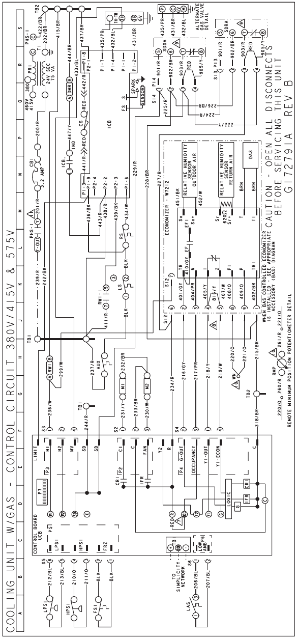
13 COOLING UNIT WITH GAS HEAT CONTROL CIRCUIT
575 VOLT DIAGRAM . . . . . . . . . . . . . . . . . . . . . . . . . .31
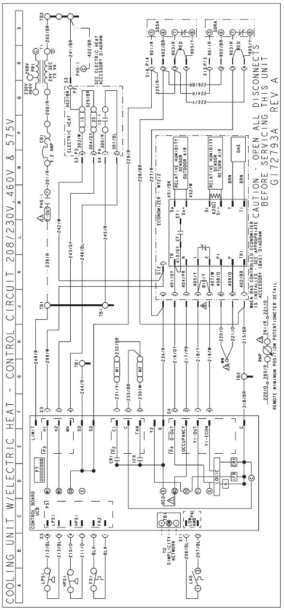
14 COOLING UNIT WITH ELECTRIC HEAT CONTROL
CIRCUIT 208/230V, 460V AND 575V DIAGRAM . . . . 32
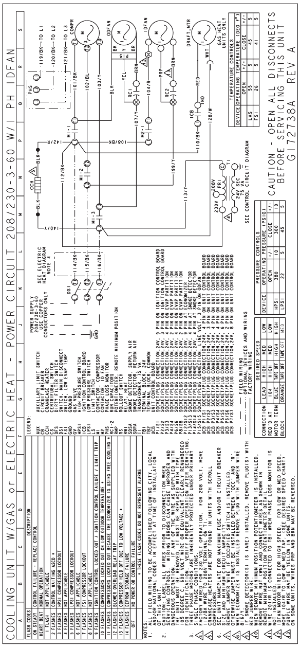
15 COOLING UNIT POWER CIRCUIT 208/230-3-60
DIRECT DRIVE INDOOR BLOWER DIAGRAM . . . . . 33
16 COOLING UNIT POWER CIRCUIT 208/230-3-60 BELT
DRIVE INDOOR BLOWER DIAGRAM . . . . . . . . . . . . . 34
17 COOLING UNIT POWER CIRCUIT 460-3-60 DIRECT
DRIVE INDOOR BLOWER DIAGRAM . . . . . . . . . . . . . 35
18 COOLING UNIT POWER CIRCUIT 460-3-60 BELT
DRIVE INDOOR BLOWER DIAGRAM . . . . . . . . . . . . . 36
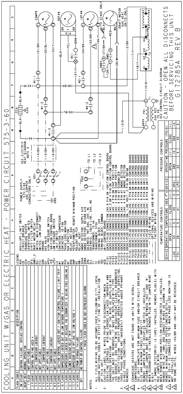
19 COOLING UNIT POWER CIRCUIT 575-3-60 DIRECT
DRIVE INDOOR BLOWER DIAGRAM . . . . . . . . . . . . . 37
20 COOLING UNIT POWER CIRCUIT 575-3-60 BELT
DRIVE INDOOR BLOWER DIAGRAM . . . . . . . . . . . . . 38
LIST OF TABLES
Tbl. # Pg. #
1 SOUND POWER RATING . . . . . . . . . . . . . . . . . . . . . . . 7
2 CAPACITY RATINGS - (ARI 210/240) . . . . . . . . . . . . . 7
3 GAS HEAT RATINGS . . . . . . . . . . . . . . . . . . . . . . . . . . 7
4 D(CE, CG)036 COOLING CAPACITIES (3 TON) . . . . . 8
5 D(CE, CG)048 COOLING CAPACITIES (4 TON) . . . . . 9
6 D(CE, CG)060 COOLING CAPACITIES (5 TON) . . . . 10
7 D(CE, CG)072 COOLING CAPACITIES (6 TON) . . . . 11
8 SUPPLY AIR BLOWER PERFORMANCE (3 TON BELT
DRIVE) - SIDE DUCT APPLICATION . . . . . . . . . . . . . 12
9 SUPPLY AIR BLOWER PERFORMANCE (4 TON BELT
DRIVE) - SIDE DUCT APPLICATION . . . . . . . . . . . . . 13
10 SUPPLY AIR BLOWER PERFORMANCE (5 TON BELT
DRIVE) - SIDE DUCT APPLICATION . . . . . . . . . . . . . 14
11 SUPPLY AIR BLOWER PERFORMANCE (6 TON BELT
DRIVE) - SIDE DUCT APPLICATION . . . . . . . . . . . . . 15
12 SUPPLY AIR BLOWER PERFORMANCE (3 - 6 TON
DIRECT DRIVE) - SIDE DUCT APPLICATION . . . . . 16
13 BELT DRIVE BLOWER MOTOR AND DRIVE DATA . 16
14 STATIC RESISTANCES . . . . . . . . . . . . . . . . . . . . . . . 17
15 ELECTRIC HEATER CFM LIMITATIONS . . . . . . . . . . 17
16 ELECTRICAL DATA - D(CE, CG)036-072
DIRECT DRIVE . . . . . . . . . . . . . . . . . . . . . . . . . . . . . . 18
17 ELECTRICAL DATA - D(CE, CG)036-072
BELT DRIVE . . . . . . . . . . . . . . . . . . . . . . . . . . . . . . . . 20
18 PHYSICAL DATA . . . . . . . . . . . . . . . . . . . . . . . . . . . . 22
19 ELECTRIC HEAT CORRECTION FACTORS . . . . . . . 22
20 VOLTAGE LIMITATIONS . . . . . . . . . . . . . . . . . . . . . . 22
21 UTILITIES ENTRY . . . . . . . . . . . . . . . . . . . . . . . . . . . . 26
22 MINIMUM CLEARANCES . . . . . . . . . . . . . . . . . . . . . . 26
23 D(CE, CG) 4 AND 6 POINT LOADS WEIGHT
DISTRIBUTION . . . . . . . . . . . . . . . . . . . . . . . . . . . . . . 28
24 CENTER OF GRAVITY . . . . . . . . . . . . . . . . . . . . . . . . 28
25 OPERATING WEIGHTS (LBS.) . . . . . . . . . . . . . . . . . . 29
255040-YTG-A-0506
Unitary Products Group 3
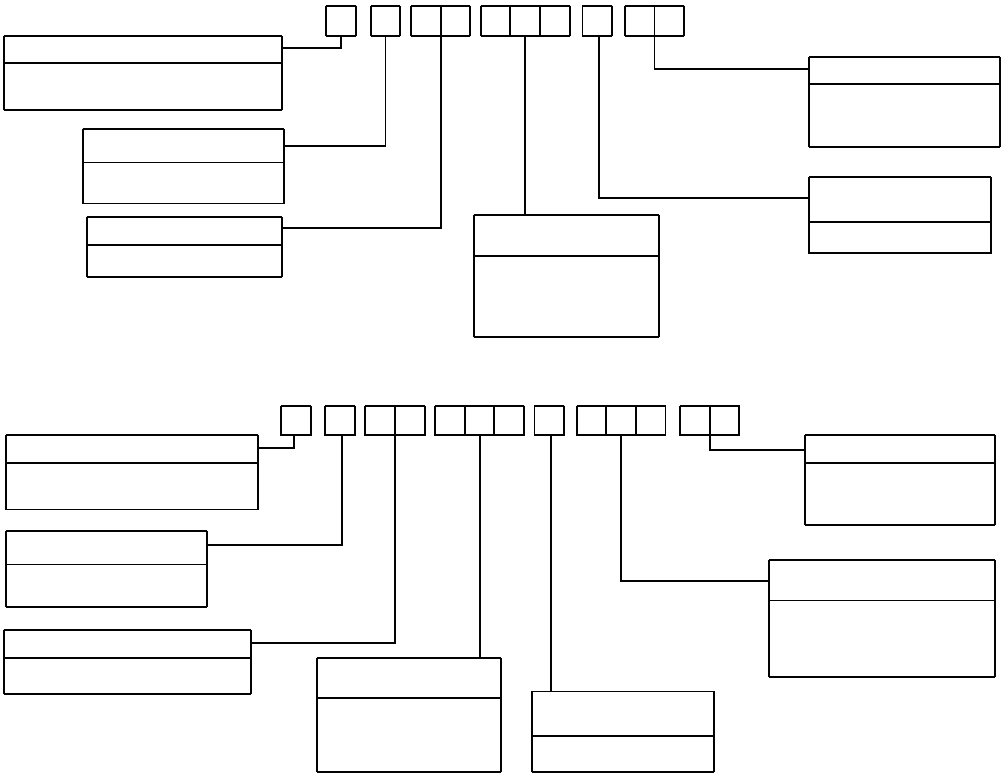
PRODUCT NOMENCLATURE
D 5 C E A
PRODUCT GENERATION
3 = 3rd Generation
5 = 5th Generation
PRODUCT CATEGORY
D = Single Package Air Conditioner
(Air Cooled)
PRODUCT IDENTIFIER
CE = Cooling
VOLTAGE CODE
25 = 208/230-3-60
46 = 460-3-60
58 = 575-3-60
036 = 3 Ton
048 = 4 Ton
060 = 5 Ton
072 = 6 Ton
30 6 2 5
NOMINAL COOLING
CAPACITY
FACTORY INSTALLED
HEAT
A = Cooling Only
D 8 C G 4N
PRODUCT GENERATION
3 = 3rd Generation
8 = 8th Generation
PRODUCT CATEGORY
D = Single Package Air Conditioner
(Air Cooled)
PRODUCT IDENTIFIER
CG = Gas/Electric
VOLTAGE CODE
25 = 208/230-3-60
46 = 460-3-60
58 = 575-3-60
NOMINAL GAS HEATING
OUTPUT CAPACITY
036 = 3 Ton
048 = 4 Ton
060 = 5 Ton
072 = 6 Ton
0 030 6 2 5
FACTORY INSTALLED
HEAT
N = Gas Heat Installed
NOMINAL COOLING
CAPACITY
040 = 40 MBH
060 = 60 MBH
079 = 79 MBH
099 = 99 MBH
255040-YTG-A-0506
4Unitary Products Group
FEATURES
All units are self-contained and assembled on full perimeter
base rails with forklift holes on three sides and holes for over-
head rigging. Every unit is completely piped, wired, charged
and tested at the factory to simplify the field installation and to
provide years of dependable operation.
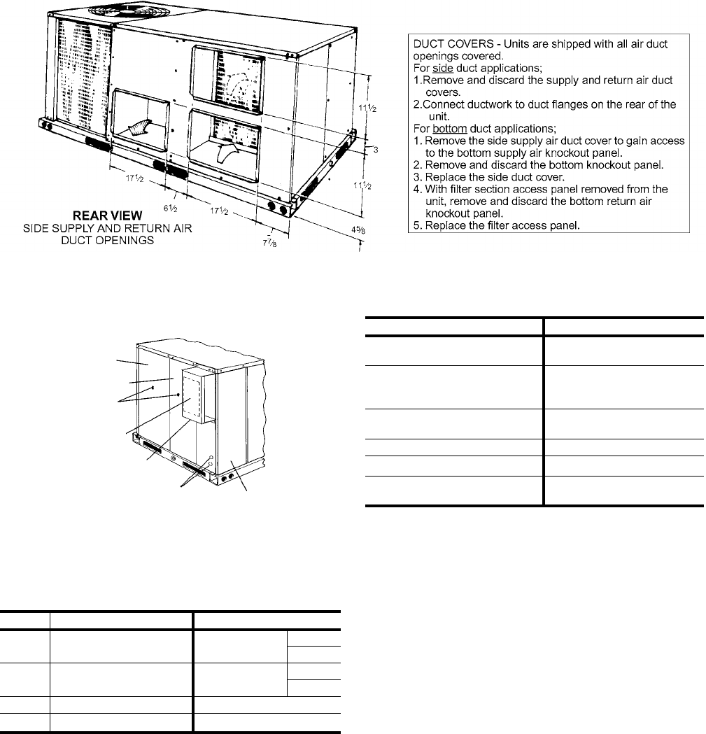
All models (including those with an economizer) are suitable for
either bottom or horizontal duct connections. For bottom duct,
remove the sheet metal panels from the supply and return air
openings through the base of the unit. For horizontal duct,
remove the supply and return air panels on the rear of the unit.
All models are available with the “factory mounted” outdoor
air damper option:
• Single enthalpy economizer
Supply air blowers are equipped with either a direct drive or a
belt drive that can be adjusted to meet the exact require-
ments of the job.
All compressors are equipped with internal pressure relief.
Every refrigerant circuit includes a liquid line filter-drier, a high
pressure switch and a suction line with a freezestat and low
pressure/loss of charge switch to protect all system compo-
nents.
• Control boards have standardized a number of features
previously available only as options or by utilizing addi-
tional controls.
•Low Ambient - An integrated low-ambient control
allows all units to operate in the cooling mode down
to 0ºF outdoor ambient without additional assis-
tance. Optionally, the control board can be pro-
grammed to lockout the compressors when the
outdoor air temperature is low or when free cooling
is available.
•Anti-Short Cycle Protection - To aid compressor
life, an anti-short cycle delay is incorporated into the
standard controls. Compressor reliability is further
ensured by programmable minimum run times. For
testing, the anti short cycle delay can be temporarily
overridden with the push of a button.
•Fan Delays - Fan on and fan off delays are fully pro-
grammable and are independent of one another. All
units are programmed with default values based
upon their configuration of cooling and heat.
•Safety Monitoring - The control board monitors the
high and low-pressure switches, the freezestats, the
gas valve, if applicable, and the temperature limit
switch on gas heat units. The unit control board will
alarm on ignition failures, compressor lockouts and
repeated limit switch trips.
•Nuisance Trip Protection- To prevent nuisance
trouble calls, the control board uses a “three strikes,
you’re out” philosophy. The high and low-pressure
switches and the freezestats must trip three times
within two hours before the unit control board will
lock out the compressor.
•On Board Diagnostics - Each alarm will energize a
trouble light on the thermostat, if so equipped, and
flash an alarm code on the control board LED. Each
high and low-pressure switch alarm as well as each
freezestat alarm has its own flash code. The control
board saves the five most recent alarms in memory,
and these alarms can be reviewed at any time.
Alarms and programmed values are retained
through the loss of power.
All units have long lasting powder paint cabinets with 1000
hour salt spray test approval under ASTM-B117 procedures.
All models are CSA listed.
•Warranty - All models include a one-year limited parts
warranty on the complete unit. Compressors and electric
heater elements carry a five-year warranty. Gas heat
exchangers carry a 10-year parts warranty.
•Gas Heat Operation - All single phase models with gas
heat have minimum annual fuel utilization efficiency
(AFUE) of 80%. All three phase models with gas heat
have minimum steady state efficiency of 80%. Each sec-
tion includes a durable heat exchanger with aluminized
steel, a redundant gas valve, spark ignition, power vent-
ing, an ignition module for 100% shut-off and all of the
safety controls required to meet the latest ANSI stan-
dards.
The gas supply piping can be routed into the heating
compartment through a hole in the base pan of the unit
or through a knockout in the piping panel on the front of
the unit.
•Electric Heat Operation - All electric heat models are
wired for a single power source and include a bank of
nickel chromium elements mounted at the discharge of
the supply air blower to provide a high velocity and uni-
form distribution of air across the heating elements.
Every element is fully protected against excessive tem-
perature by thermal limit switches.
The power supply wiring can be routed into the control
box through a threaded pipe connection (field supplied)
in the base pan of the unit or through a knockout in the
wiring panel on the side of the unit.
255040-YTG-A-0506
Unitary Products Group 5
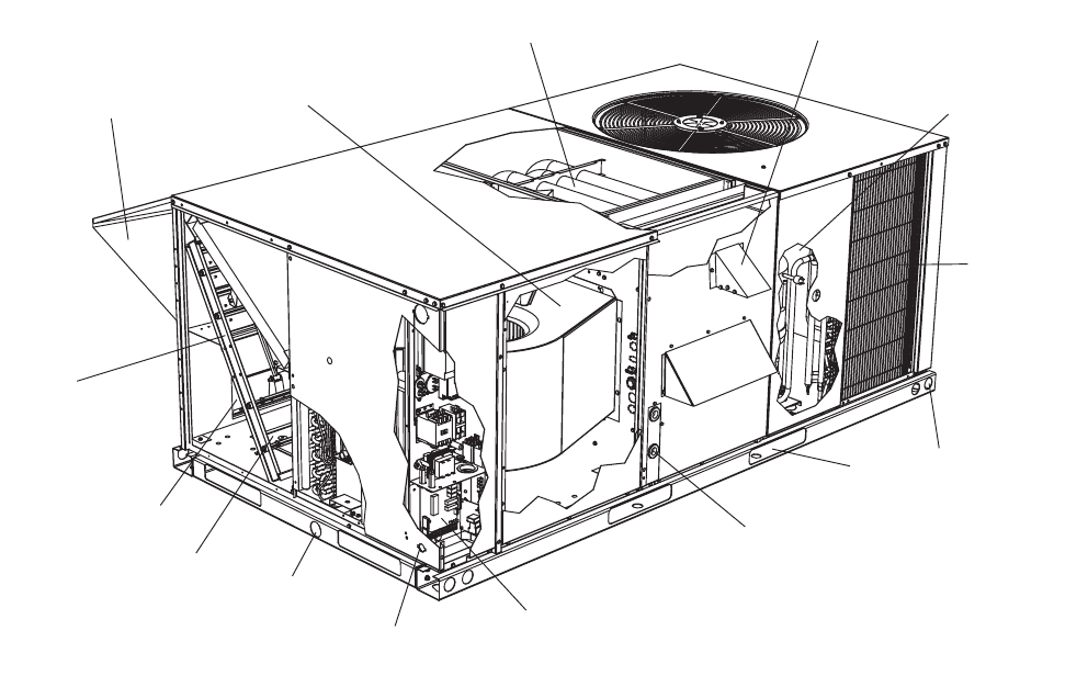
FIGURE 1 - UNIT CUTAWAY
FACTORY-INSTALLED OPTIONS
•SINGLE INPUT ELECTRONIC ENTHALPY ECONO-
MIZERS - Includes a slide-in / plug-in damper assembly
with fully modulating spring-return motor actuator capa-
ble of introducing up to 100% outdoor air with nominal
1% leakage type dampers.
The enthalpy system contains one sensor that monitors
the outdoor air and determines when the air is cool
enough and dry enough to provide free cooling.
The rainhood is painted to match the basic unit and must
be field-assembled before installing.
•PHENOLIC COATED CONDENSER COILS - Special
coating process that utilizes Technicoat 10-1TM pro-
cesses. Coating is applied by total immersion of the com-
plete coil for maximum protection.
•BELT DRIVE INDOOR FAN - Includes belt drive indoor
fan and motor with unit access for belt adjustment and
service.
FIELD-INSTALLED ACCESSORIES
•SINGLE INPUT ELECTRONIC ENTHALPY ECONO-
MIZERS - Includes a slide-in / plug-in damper assembly
with fully modulating spring-return motor actuator capa-
ble of introducing up to 100% outdoor air with nominal
1% leakage type dampers.
The enthalpy system contains one sensor that monitors
the outdoor air and determines when the air is cool
enough and dry enough to provide free cooling.
The rainhood is painted to match the basic unit and must
be field-assembled before installing.
•MOTORIZED OUTDOOR AIR INTAKE DAMPER -
Includes a slide-in / plug-in damper assembly with a 2-
position, spring return motor actuator which opens to
some pre-set position whenever the supply air blower is
operating and will drive fully closed when the blower unit
shuts down.
The rain hood is painted to match the basic unit and
must be field assembled before installing.
SLIDE-IN
ECONOMIZER
SIDE RETURN
AIR DUCT OPENING
BOTTOM
RETURN
AIR DUCT
OPENING
3/4” PVC FEMALE
CONDENSATE DRAIN
KNOCKOUTS FOR
SIDE POWER AND
CONTROL ENTRY
LOW VOLTAGE CONTROL
BOARD
KNOCKOUT FOR SIDE
GAS SUPPLY ENTRY
FULL PERIMETER
BASE RAILS WITH
FORKLIFT SLOTS
AND LIFTING HOLES
COPPER TUBE/
ALUMINUM FIN
CONDENSING
COIL
HIGH EFFICIENCY
COMPRESSOR
POWER VENTOR MOTOR
WITH POST PURGE CYCLE
20 GAUGE ALUMINIZED
STEEL TUBULAR HEAT
EXCHANGER
DIRECT OR
BELT DRIVE
BLOWER
ECONOMIZER
HOOD
255040-YTG-A-0506
6Unitary Products Group
•ELECTRIC HEATERS wired for single point power sup-
ply. These nickel chromium heater elements are pro-
vided with limit and automatic reset capability to prevent
operation at excessive temperatures.
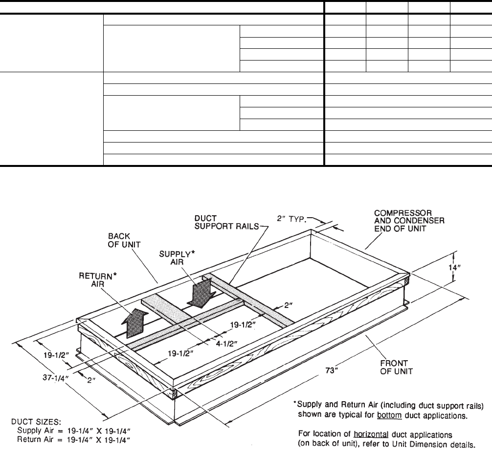
•ROOF CURBS - Eight and fourteen-inch high roof curbs
provide a water-tight seal between the unit and the finished
roof. These full perimeter curbs meet the requirements of
the National Roofing Contractors Association (NRCA) and
are shipped knocked-down for field assembly.
Roof curbs are designed to fit inside the base rails of the
unit and include both a wood nailing strip and duct
hanger supports.
•HIGH ALTITUDE NATURAL GAS - Burner orifices and
pilot orifices are provided for proper furnace operation at
altitudes up to 6,000 feet.
•PROPANE - Burner orifices, pilot orifices and gas valve
parts are provided to convert a natural gas furnace to
propane.
•HIGH ALTITUDE PROPANE - Burner orifices and pilot
orifices are provided for proper furnace operation at alti-
tudes up to 6,000 feet. This accessory supplements the
basic propane conversion kit.
•LOW NOX KIT- Required to reduce the emission of
nitrogen oxides below 40 nanograms per joule.
•POWER EXHAUST - Our single input economizer
options are available with power exhaust. Whenever the
outdoor air intake dampers are opened for free cooling,
the exhaust fan will be energized to prevent the condi-
tioned space from being over-pressurized during econo-
mizer operation.
The power exhaust option can only be used on bot-
tom duct configurations.
•BAROMETRIC RELIEF DAMPER - This damper acces-
sory can be used to relieve internal building air pressure
on units with an economizer without power exhaust. This
accessory includes a rain hood, a bird screen and a fully
assembled damper. With bottom duct connections, the
damper should be mounted over the opening in the
return air panel. With horizontal ductwork, the accessory
should be mounted on the return air duct.
•ENTHALPY ACCESSORY CONTROL KIT - This kit
contains the required components to convert a single
enthalpy economizer to dual enthalpy.
•BURGLAR BARS - Mount in the supply and return
openings to prevent entry into the duct work.
•FLUE EXHAUST EXTENSION KIT - In locations with
wind or weather conditions which may interfere with
proper exhausting of furnace combustion products, this
kit can be installed to prevent the flue exhaust from
entering nearby fresh air intakes.
•COIL GUARD - Customers can purchase a coil guard kit
to protect the condenser coil from damage. This is not a
hail guard kit.
•HAIL GUARD -Hail Guard Kit is available to prevent unit
from hail damage. This is a sloped hood that fits above
the condenser coil.
•GAS PIPING KIT - This kit supplies all necessary fittings
and shut off valve.
255040-YTG-A-0506
Unitary Products Group 7
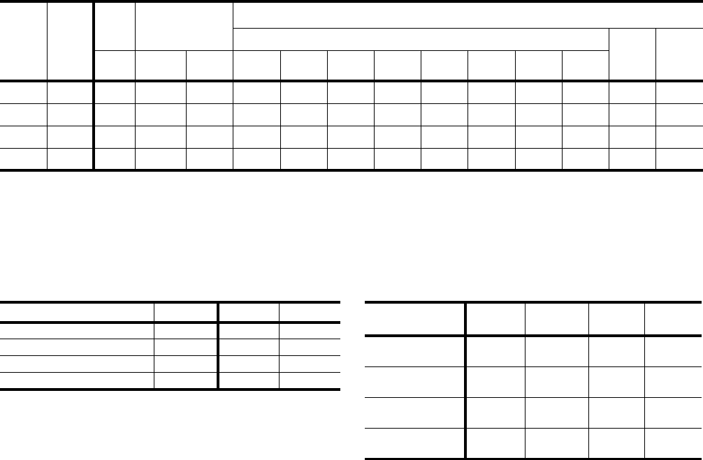
TABLE 1: SOUND POWER RATING1
UNIT
SIZE CFM
ESP BLOWER SOUND POWER (db 10-12 Watts)
Octave Band Centerline Frequency (Hz) SWL
dB(A)
dB(A)
@
10Ft.2
IWG SPEED KW 63 125 250 500 1,000 2,000 4,000 8,000
036 1,200 0.6 LOW 0.60 84 84 74 67 69 62 57 52 74 41
048 1,600 0.55 HIGH 0.80 85 85 75 68 70 63 58 53 75 42
060 2,000 0.45 HIGH 1.00 86 86 76 69 71 64 59 54 76 43
072 2,2000.3HIGH1.3587877770726560557744
1. These values have been accessed using a model of sound propagation from a point source into the hemispheric\free field. The
dBA values provided are to be used for reference only. Calculation of dBA values cover matters of system design and the fan
manufacture has no way of knowing the details of each system. This constitutes and expectation to any specification or guaran-
tee requiring a dBA value or sound data in any other form than sound power level ratings.
2. At a distance of 10 feet from the blower.
TABLE 2: CAPACITY RATINGS - (ARI 210/240)1
1. 80/67°F Indoor and 95°F outdoor.
MODEL MBH EER2
2. EER = Energy Efficiency Ratio at full load - the cooling
capacity in Btu’s per hour (Btuh) divided by the power
input in watts, expressed in Btuh per watt (Btuh/watt).
SEER3
3. SEER = Seasonal Energy Efficiency Ratio.
D(CE, CG)036 36.0 9.1 10.0
D(CE, CG)048 47.4 9.0 10.0
D(CE, CG)060 59.0 9.1 10.0
D(CE, CG)072 72.0 9.0 -
TABLE 3: GAS HEAT RATINGS1
1. All units are single-stage heating.
MODEL MBH
INPUT MBH
OUTPUT AFUE
(%) TEMP
RISE ºF
DCG036N040
DCG036N079 50
100
40
80
80.9
80.5
15 - 45
40 - 70
DCG048N060
DCG048N099 75
125
60
100
80.9
80.3
25 - 55
45 - 75
DCG060N079
DCG060N099 100
125
80
100
80.5
80.3
25 - 55
35 - 65
DCG072N079
DCG072N099 100
125
80
100
80.5
80.3
25 - 55
35 - 65

255040-YTG-A-0506
8Unitary Products Group
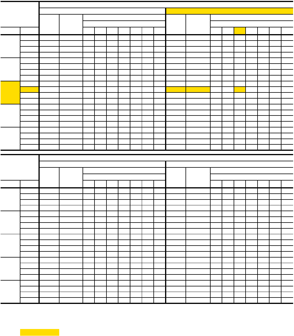
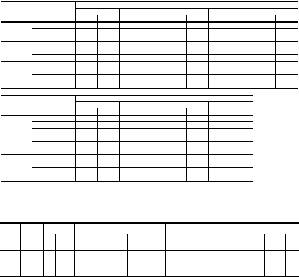
TABLE 4: D(CE, CG)036 COOLING CAPACITIES (3 TON)
CFM WB °F 86 83 80 77 74 71 68 86 83 80 77 74 71 68
72 45 3.1 35 30 26 21 17 - - 43 3.3 35 30 26 21 17 - -
67 43 3.0 43 38 34 29 25 20 16 41 3.3 41 38 34 29 25 21 16
62 39 3.0 39 39 39 34 30 25 21 36 3.3 36 36 36 32 27 23 18
57 40 2.9 40 40 40 35 31 26 22 38 3.2 38 38 38 33 29 24 20
72 44 3.1 31 28 24 20 16 - - 42 3.3 31 27 23 20 16 - -
67 41 3.0 39 35 31 27 23 19 16 39 3.3 37 35 31 27 23 19 15
62 38 3.0 38 38 37 33 29 25 21 36 3.3 36 36 35 31 27 23 19
57 39 2.9 39 39 39 35 31 27 23 37 3.2 37 37 36 32 28 25 21
72 42 3.1 28 25 22 18 15 - - 41 3.3 28 24 21 18 14 - -
67 40 3.0 35 32 28 25 22 18 15 38 3.2 34 31 28 25 21 18 15
62 36 3.0 36 36 35 31 28 25 21 35 3.3 35 35 34 30 27 24 20
57 37 2.9 37 37 37 34 31 27 24 36 3.2 36 36 35 32 28 25 22
72 41 3.1 26 23 20 17 14 - - 39 3.2 26 23 20 17 14 - -
67 38 3.0 32 30 27 24 21 18 15 37 3.2 32 29 26 23 20 17 14
62 35 3.0 35 35 33 30 27 24 21 33 3.2 33 33 31 28 25 22 20
57 36 2.9 36 36 35 32 29 26 23 34 3.2 34 34 32 30 27 24 21
72 39 3.1 24 21 19 16 14 - - 38 3.2 23 21 18 16 13 - -
67 37 3.0 30 27 25 22 20 17 15 36 3.2 29 26 24 21 19 16 14
62 34 3.0 34 33 30 28 25 23 20 32 3.2 32 31 29 26 24 21 19
57 34 2.9 34 34 33 30 27 25 22 33 3.1 33 33 30 27 25 22 20
CFM WB °F 86 83 80 77 74 71 68 86 83 80 77 74 71 68
72 41 3.7 34 29 25 20 16 - - 39 4.1 33 28 24 19 15 - -
67 38 3.7 38 37 33 28 24 19 15 36 4.0 36 36 32 27 23 18 14
62 34 3.7 34 34 34 30 25 21 16 32 4.0 32 32 32 27 23 18 14
57 35 3.6 35 35 35 31 26 22 17 33 4.0 33 33 33 28 24 19 15
72 40 3.7 30 26 23 19 15 - - 38 4.1 30 26 22 18 14 - -
67 37 3.6 36 34 30 26 22 18 14 35 4.0 34 33 29 25 21 17 13
62 33 3.7 33 33 33 29 25 21 17 31 4.0 31 31 31 27 23 19 15
57 34 3.6 34 34 34 30 26 22 18 32 4.0 32 32 32 28 24 20 16
72 39 3.7 27 24 20 17 14 - - 37 4.1 26 23 20 16 13 - -
67 36 3.6 34 30 27 24 20 17 14 34 4.0 33 30 26 23 20 16 13
62 32 3.6 32 32 32 29 25 22 19 30 4.0 30 30 30 27 24 20 17
57 33 3.6 33 33 33 29 26 23 19 31 3.9 31 31 31 27 24 21 17
72 37 3.6 25 22 19 16 13 - - 36 4.1 24 21 18 15 12 - -
67 35 3.6 31 28 25 22 19 16 13 32 4.0 30 27 24 21 18 15 12
62 31 3.6 31 31 29 27 24 21 18 29 4.0 29 29 28 25 22 19 16
57 32 3.5 32 32 30 27 24 21 18 30 3.9 30 29 28 25 22 19 16
72 36 3.6 22 20 17 15 12 - - 34 4.0 21 19 16 14 11 - -
67 33 3.6 28 25 23 20 18 15 13 31 4.0 27 24 22 19 17 14 11
62 30 3.6 30 29 27 24 22 19 17 28 4.0 28 28 25 22 20 17 15
57 31 3.5 31 30 28 25 22 20 17 28 3.9 28 28 25 23 20 17 15
NOMINAL RATING
900
1050
85°F
POWER
INPUT2 kW
95°F
SENSIBLE CAPACITY1
ENTERING DRY BULB, °F
1750
1475
1200
SENSIBLE CAPACITY1
ENTERING DRY BULB, °F
AIR ON
EVAPORATOR
COIL
TEMPERATURE OF AIR ON CONDENSER COIL
1050
POWER
INPUT2 kW
ENTERING DRY BULB, °F ENTERING DRY BULB, °F
AIR ON
EVAPORATOR
COIL
TEMPERATURE OF AIR ON CONDENSER COIL
105°F 115°F
SENSIBLE CAPACITY1SENSIBLE CAPACITY1
900
TOTAL
CAP.1
MBH
POWER
INPUT2 kW
TOTAL
CAP.1
MBH
TOTAL
CAP.1
MBH
POWER
INPUT2 kW
TOTAL
CAP.1
MBH
1750
1475
1200
1. These capacities are gross ratings. For net capacity, determine the kW of the supply air blower motor from the SUPPLY AIR BLOWER PERFORMANCE
Table, multiply this value by 3.415 MBH/kW to determine the motor heat, and deduct this heat from the gross capacity of the unit.
2. These ratings include the compressor and the condenser fan motors but not the supply air blower motor. The total condenser fan motor power input
is 0.36kW. Refer to the SUPPLY AIR BLOWER PERFORMANCE Table for the kW of the supply air blower motor.
255040-YTG-A-0506
Unitary Products Group 9
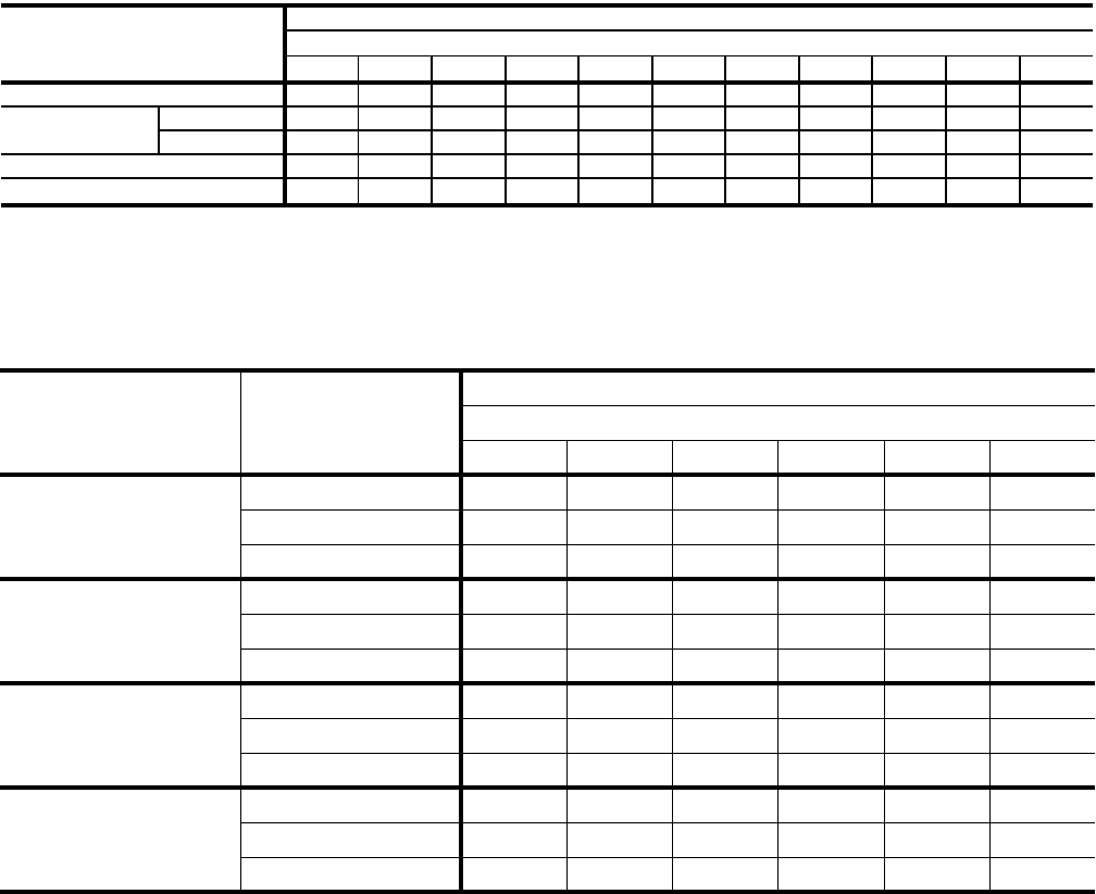
TABLE 5: D(CE, CG)048 COOLING CAPACITIES (4 TON)
CFM WB °F 86 83 80 77 74 71 68 86 83 80 77 74 71 68
72 60 4.1 44 39 33 28 23 - - 60 4.5 44 39 33 28 23 - -
67 55 4.1 53 48 42 37 32 26 21 52 4.5 52 47 42 36 31 25 20
62 51 4.0 51 51 51 45 40 34 29 48 4.4 48 48 48 42 37 32 26
57 49 3.9 49 49 49 44 39 33 28 47 4.3 47 47 47 42 36 31 26
72 58 4.1 41 36 31 26 21 - - 57 4.5 41 36 31 26 21 - -
67 53 4.1 49 45 40 35 30 25 20 50 4.5 49 44 39 34 29 24 19
62 49 4.0 49 49 48 43 38 33 28 46 4.4 46 46 46 41 36 31 26
57 47 3.9 47 47 47 43 38 33 28 45 4.3 45 45 45 40 36 31 26
72 56 4.1 38 34 29 25 20 - - 55 4.6 38 33 29 24 20 - -
67 51 4.1 46 41 37 32 28 24 19 48 4.5 45 40 36 31 27 23 18
62 47 4.0 47 47 45 41 36 32 27 44 4.4 44 44 44 40 35 31 26
57 46 3.9 46 46 46 41 37 32 28 44 4.4 44 44 44 39 35 30 26
72 54 4.1 35 31 27 23 19 - - 53 4.5 35 31 27 23 19 - -
67 49 4.1 42 38 34 30 26 22 19 47 4.5 41 38 34 30 26 22 18
62 45 4.0 45 45 42 38 34 30 26 43 4.4 43 43 41 37 33 29 25
57 44 3.9 44 44 43 39 35 31 27 42 4.3 42 42 41 37 33 29 25
72 52 4.1 32 29 25 22 18 - - 51 4.5 32 28 25 21 18 - -
67 47 4.1 39 35 32 28 25 21 18 45 4.4 38 35 31 28 24 21 17
62 43 4.0 43 43 39 36 32 29 25 41 4.3 41 41 38 35 31 28 24
57 42 3.9 42 42 39 36 32 29 25 41 4.3 41 41 38 34 31 27 24
CFM WB °F 86 83 80 77 74 71 68 86 83 80 77 74 71 68
72 56 5.1 42 37 31 26 21 - - 53 5.6 40 35 29 24 19 - -
67 49 5.0 49 46 40 35 29 24 19 46 5.5 46 44 39 33 28 23 17
62 45 4.9 45 45 45 39 34 28 23 41 5.4 41 41 41 36 30 25 20
57 44 4.9 44 44 44 39 33 28 22 41 5.4 41 41 41 35 30 25 19
72 55 5.0 39 34 29 24 20 - - 52 5.5 38 33 28 23 18 - -
67 48 5.0 47 43 38 33 28 23 18 45 5.4 45 42 37 32 27 22 17
62 43 4.9 43 43 43 38 33 28 23 40 5.4 40 40 40 35 30 26 21
57 43 4.9 43 43 43 38 33 28 23 40 5.4 40 40 40 35 30 25 20
72 53 5.0 36 32 28 23 19 - - 51 5.5 35 31 26 22 17 - -
67 46 4.9 44 40 35 31 26 22 17 44 5.4 44 39 35 30 26 21 17
62 42 4.9 42 42 42 37 33 28 24 39 5.3 39 39 39 35 30 26 21
57 41 4.8 41 41 41 37 32 28 23 39 5.3 39 39 39 34 30 25 21
72 51 5.0 33 29 26 22 18 - - 48 5.5 32 28 24 20 16 - -
67 44 4.9 41 37 33 29 25 21 17 42 5.3 40 36 32 28 24 20 16
62 40 4.8 40 40 39 35 31 27 23 37 5.3 37 37 36 32 28 24 20
57 40 4.8 40 40 38 34 30 26 22 37 5.3 37 37 36 32 28 24 20
72 49 4.9 30 27 23 20 16 - - 46 5.4 29 26 22 19 15 - -
67 42 4.9 37 34 30 27 23 20 16 39 5.3 36 33 29 26 22 19 15
62 38 4.8 38 38 36 32 29 25 22 35 5.3 35 35 33 29 26 22 19
57 38 4.8 38 38 35 32 28 25 21 35 5.3 35 35 33 29 26 22 19
NOMINAL RATING
1200
1400
85°F
POWER
INPUT2 kW
95°F
SENSIBLE CAPACITY1
ENTERING DRY BULB, °F
2000
1800
1600
SENSIBLE CAPACITY1
ENTERING DRY BULB, °F
AIR ON
EVAPORATOR
COIL
TEMPERATURE OF AIR ON CONDENSER COIL
1400
POWER
INPUT2 kW
ENTERING DRY BULB, °F ENTERING DRY BULB, °F
AIR ON
EVAPORATOR
COIL
TEMPERATURE OF AIR ON CONDENSER COIL
105°F 115°F
SENSIBLE CAPACITY1SENSIBLE CAPACITY1
1200
TOTAL
CAP.1
MBH
POWER
INPUT2 kW
TOTAL
CAP.1
MBH
TOTAL
CAP.1
MBH
POWER
INPUT2 kW
TOTAL
CAP.1
MBH
2000
1800
1600
1. These capacities are gross ratings. For net capacity, determine the kW of the supply air blower motor from the SUPPLY AIR BLOWER PERFORMANCE
Table, multiply this value by 3.415 MBH/kW to determine the motor heat, and deduct this heat from the gross capacity of the unit.
2. These ratings include the compressor and the condenser fan motors but not the supply air blower motor. The total condenser fan motor power input
is 0.36kW. Refer to the SUPPLY AIR BLOWER PERFORMANCE Table for the kW of the supply air blower motor.

255040-YTG-A-0506
10 Unitary Products Group
TABLE 6: D(CE, CG)060 COOLING CAPACITIES (5 TON)
CFM WB °F 86 83 80 77 74 71 68 86 83 80 77 74 71 68
72 68 4.9 50 44 38 32 25 - - 65 5.6 50 43 37 31 24 - -
67 62 4.8 62 56 50 43 37 31 24 60 5.3 60 54 48 42 35 29 23
62 57 4.7 57 57 57 51 44 38 32 53 5.3 53 53 53 47 41 34 28
57 55 4.7 55 55 55 48 42 36 29 51 5.4 51 51 51 44 38 32 25
72 67 4.9 48 42 36 30 24 - - 65 5.4 47 41 35 29 23 - -
67 62 4.8 59 53 47 41 35 30 24 59 5.2 57 51 45 40 34 28 22
62 56 4.7 56 56 56 50 45 39 33 53 5.2 53 53 53 47 41 35 29
57 54 4.7 54 54 54 48 42 36 31 50 5.3 50 50 50 44 39 33 27
72 66 4.9 45 39 34 29 23 - - 64 5.3 44 39 33 28 22 - -
67 61 4.8 55 50 44 39 34 28 23 58 5.1 54 48 43 38 32 27 22
62 55 4.7 55 55 55 50 45 39 34 52 5.1 52 52 52 47 42 36 31
57 53 4.6 53 53 53 48 42 37 32 50 5.2 50 50 50 44 39 34 28
72 63 4.8 41 36 31 27 22 - - 61 5.4 40 35 31 26 21 - -
67 58 4.7 51 46 41 36 32 27 22 56 5.1 49 44 39 35 30 25 21
62 53 4.6 53 53 51 47 42 37 32 50 5.2 50 50 48 43 39 34 29
57 51 4.6 51 51 49 44 40 35 30 47 5.2 47 47 46 41 36 32 27
72 60 4.8 37 33 29 25 21 - - 58 5.4 36 32 28 24 20 - -
67 56 4.7 46 42 38 34 30 26 21 53 5.2 44 40 36 32 28 24 20
62 51 4.6 51 51 47 43 39 35 31 47 5.2 47 47 44 40 36 32 27
57 49 4.6 49 49 45 41 37 33 29 45 5.3 45 45 42 38 34 29 25
CFM WB °F 86 83 80 77 74 71 68 86 83 80 77 74 71 68
72 61 6.1 48 41 35 29 22 - - 57 6.7 46 39 33 27 20 - -
67 55 5.9 55 52 46 39 33 27 20 50 6.6 50 50 43 37 31 24 18
62 49 5.9 49 49 49 42 36 30 23 44 6.5 44 44 44 38 31 25 19
57 47 5.9 47 47 47 40 34 28 21 42 6.5 42 42 42 36 30 23 17
72 61 6.0 45 39 33 28 22 - - 57 6.6 43 38 32 26 20 - -
67 54 5.9 53 49 44 38 32 26 20 50 6.5 50 47 42 36 30 24 18
62 48 5.8 48 48 48 42 37 31 25 44 6.4 44 44 44 38 32 26 20
57 46 5.8 46 46 46 40 35 29 23 42 6.4 42 42 42 36 31 25 19
72 60 6.0 42 37 32 26 21 - - 57 6.6 41 36 30 25 20 - -
67 54 5.8 52 47 41 36 31 25 20 50 6.5 50 45 40 34 29 24 18
62 48 5.7 48 48 48 43 37 32 27 44 6.4 44 44 44 38 33 28 22
57 46 5.8 46 46 46 41 35 30 25 42 6.3 42 42 42 37 32 26 21
72 57 6.0 38 34 29 24 19 - - 53 6.5 37 32 27 23 18 - -
67 51 5.8 47 42 38 33 28 24 19 46 6.4 45 41 36 31 26 22 17
62 45 5.7 45 45 44 39 34 30 25 41 6.3 41 41 39 35 30 25 21
57 43 5.8 43 43 42 37 32 28 23 39 6.3 39 39 38 33 29 24 19
72 54 6.0 34 30 26 22 18 - - 49 6.5 33 28 24 20 16 - -
67 48 5.8 42 38 34 30 26 22 18 43 6.4 40 36 32 28 24 20 16
62 43 5.7 43 43 39 35 31 27 23 38 6.3 38 38 35 31 27 23 19
57 41 5.8 41 41 38 34 30 26 21 37 6.2 37 37 34 30 26 22 18
NOMINAL RATING
1500
1750
85°F
POWER
INPUT2 kW
95°F
SENSIBLE CAPACITY1
ENTERING DRY BULB, °F
2500
2250
2000
SENSIBLE CAPACITY1
ENTERING DRY BULB, °F
AIR ON
EVAPORATOR
COIL
TEMPERATURE OF AIR ON CONDENSER COIL
1750
POWER
INPUT2 kW
ENTERING DRY BULB, °F ENTERING DRY BULB, °F
AIR ON
EVAPORATOR
COIL
TEMPERATURE OF AIR ON CONDENSER COIL
105°F 115°F
SENSIBLE CAPACITY1SENSIBLE CAPACITY1
1500
TOTAL
CAP.1
MBH
POWER
INPUT2 kW
TOTAL
CAP.1
MBH
TOTAL
CAP.1
MBH
POWER
INPUT2 kW
TOTAL
CAP.1
MBH
2500
2250
2000
1. These capacities are gross ratings. For net capacity, determine the kW of the supply air blower motor from the SUPPLY AIR BLOWER PERFORMANCE
Table, multiply this value by 3.415 MBH/kW to determine the motor heat, and deduct this heat from the gross capacity of the unit.
2. These ratings include the compressor and the condenser fan motors but not the supply air blower motor. The total condenser fan motor power input
is 0.36kW. Refer to the SUPPLY AIR BLOWER PERFORMANCE Table for the kW of the supply air blower motor.

255040-YTG-A-0506
Unitary Products Group 11
TABLE 7: D(CE, CG)072 COOLING CAPACITIES (6 TON)
CFM WB °F 86 83 80 77 74 71 68 86 83 80 77 74 71 68
72 80 5.7 63 55 47 40 32 - - 77 6.3 63 55 47 40 32 - -
67 80 5.7 76 68 60 53 45 37 30 77 6.3 75 68 60 53 45 37 30
62 70 5.5 70 70 70 62 55 47 39 71 6.3 71 71 71 63 56 48 40
57 68 5.6 68 68 68 60 52 45 37 71 6.3 71 71 71 63 56 48 40
72 82 5.7 60 53 46 38 31 - - 76 6.3 60 53 46 39 31 - -
67 82 5.7 73 65 58 51 43 36 29 76 6.3 73 66 58 51 44 36 29
62 71 5.5 71 71 70 62 55 48 41 70 6.3 70 70 69 62 55 48 40
57 69 5.6 69 69 69 62 55 47 40 70 6.3 70 70 70 62 55 48 40
72 83 5.7 58 51 44 37 30 - - 75 6.3 58 51 44 37 30 - -
67 83 5.7 70 63 56 49 42 35 28 75 6.3 70 64 57 50 43 36 29
62 73 5.5 73 73 70 63 56 49 42 69 6.3 69 69 68 61 54 47 40
57 71 5.6 71 71 71 64 57 50 43 69 6.3 69 69 68 61 54 47 40
72 79 5.7 54 48 41 35 29 - - 73 6.3 53 47 41 35 29 - -
67 79 5.7 65 59 53 47 40 34 28 73 6.3 65 59 52 46 40 34 28
62 69 5.5 69 69 66 60 54 47 41 67 6.3 67 66 63 57 51 45 38
57 67 5.6 67 67 67 61 54 48 42 67 6.3 67 66 63 57 51 45 39
72 74 5.6 50 44 39 34 28 - - 71 6.3 49 43 38 33 27 - -
67 74 5.6 60 55 50 44 39 34 28 71 6.3 59 54 48 43 38 32 27
62 65 5.4 65 65 62 57 51 46 41 65 6.2 65 63 58 53 47 42 37
57 63 5.5 63 63 63 58 52 47 42 65 6.3 65 63 58 53 47 42 37
CFM WB °F 86 83 80 77 74 71 68 86 83 80 77 74 71 68
72 76 7.1 61 53 45 38 30 - - 75 7.9 59 51 43 36 28 - -
67 71 7.1 70 66 58 50 43 35 27 65 7.8 65 64 56 48 41 33 25
62 64 7.0 64 64 64 56 49 41 34 57 7.8 57 57 57 50 42 34 27
57 64 7.0 64 64 64 56 49 41 34 57 7.7 57 57 57 50 42 34 27
72 76 7.1 59 51 44 37 29 - - 76 7.9 57 49 42 35 27 - -
67 71 7.1 69 64 56 49 42 34 27 66 7.9 66 61 54 47 40 32 25
62 64 7.0 64 64 64 56 49 42 35 58 7.8 58 58 58 51 43 36 29
57 64 7.0 64 64 64 56 49 42 34 58 7.7 58 58 58 50 43 36 29
72 75 7.1 56 49 43 36 29 - - 76 8.0 55 48 41 34 27 - -
67 70 7.1 68 61 54 48 41 34 27 66 7.9 66 59 52 45 38 32 25
62 64 7.0 64 64 63 56 49 42 35 59 7.8 59 59 59 52 45 38 31
57 64 7.0 64 64 63 56 49 42 35 59 7.7 59 59 58 51 44 37 30
72 73 7.1 52 45 39 33 27 - - 73 7.9 50 44 37 31 25 - -
67 68 7.1 63 56 50 44 38 32 26 63 7.8 61 54 48 42 36 30 24
62 61 7.0 61 61 58 52 46 40 34 56 7.7 56 56 54 48 42 35 29
57 61 7.0 61 61 58 52 46 40 34 56 7.7 56 56 53 47 41 35 29
72 70 7.1 47 41 36 31 25 - - 69 7.8 45 40 34 29 23 - -
67 65 7.0 57 51 46 41 35 30 25 60 7.8 55 49 44 39 33 28 23
62 59 7.0 59 58 54 48 43 38 32 53 7.7 53 53 49 44 39 33 28
57 59 6.9 59 58 53 48 43 37 32 53 7.6 53 53 49 44 38 33 27
NOMINAL RATING
1800
2100
85°F
POWER
INPUT2 kW
95°F
SENSIBLE CAPACITY1
ENTERING DRY BULB, °F
2700
2550
2400
SENSIBLE CAPACITY1
ENTERING DRY BULB, °F
AIR ON
EVAPORATOR
COIL
TEMPERATURE OF AIR ON CONDENSER COIL
2100
POWER
INPUT2 kW
ENTERING DRY BULB, °F ENTERING DRY BULB, °F
AIR ON
EVAPORATOR
COIL
TEMPERATURE OF AIR ON CONDENSER COIL
105°F 115°F
SENSIBLE CAPACITY1SENSIBLE CAPACITY1
1800
TOTAL
CAP.1
MBH
POWER
INPUT2 kW
TOTAL
CAP.1
MBH
TOTAL
CAP.1
MBH
POWER
INPUT2 kW
TOTAL
CAP.1
MBH
2700
2550
2400
1. These capacities are gross ratings. For net capacity, determine the kW of the supply air blower motor from the SUPPLY AIR BLOWER PERFORMANCE
Table, multiply this value by 3.415 MBH/kW to determine the motor heat, and deduct this heat from the gross capacity of the unit.
2. These ratings include the compressor and the condenser fan motors but not the supply air blower motor. The total condenser fan motor power input
is 0.36kW. Refer to the SUPPLY AIR BLOWER PERFORMANCE Table for the kW of the supply air blower motor.
255040-YTG-A-0506
12 Unitary Products Group
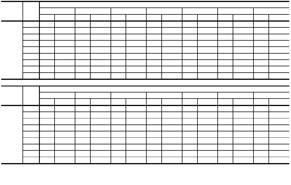
TABLE 8: SUPPLY AIR BLOWER PERFORMANCE (3 TON BELT DRIVE) - SIDE DUCT APPLICATION
RPM WATTS RPM WATTS RPM WATTS RPM WATTS RPM WATTS RPM WATTS RPM WATTS
1700 835 705 880 745 923 795 969 860 1013 970 ----
1600 811 655 854 695 898 740 942 790 986 840 1029 900 - -
1500 782 610 827 650 871 685 917 730 960 775 1003 825 1046 905
1400 - - 798 595 844 640 889 680 932 720 975 765 1018 790
1300 ----816590862635907675951715995750
1200 ------834585881630927665970705
1100 ------809550855590900625942665
1000 ------782510829545872858919625
900--------797500843540890580
RPM WATTS RPM WATTS RPM WATTS RPM WATTS RPM WATTS RPM WATTS RPM WATTS
1700 --------------
1600 --------------
1500 --------------
1400 1055 875 ------------
1300 1036 780 1066 850 ----------
1200 1011 735 1047 765 1075 800 --------
1100 987 690 1028 720 1060 750 1084 775 ------
1000 963 655 1005 680 1040 695 1068 715 1089 735 ----
900 936 615 980 645 1020 660 1050 670 1053 680 1090 690 - -
0.60 0.70 0.80
AVAILABLE EXTERNAL STATIC PRESSURE-IWG
3
0.20 0.30 0.40 0.50
UNIT
TONNAGE
AIR
FLOW
CFM
3
1,2
UNIT
TONNAGE
AIR
FLOW
CFM
3
1, 2
AVAILABLE EXTERNAL STATIC PRESSURE-IWG
3
0.90 1.00 1.10 1.20 1.30 1.40 1.50
1. 230/460/575 Volts
2. For 208 Volts multiply values by 0.95.
3. Includes allowances for a wet evaporator coil, 1” filters, and the heat exchangers. Refer to STATIC RESISTANCE Table
for resistance values on a
pp
lications other than
g
as / electric units with side duct airflows.

255040-YTG-A-0506
Unitary Products Group 13
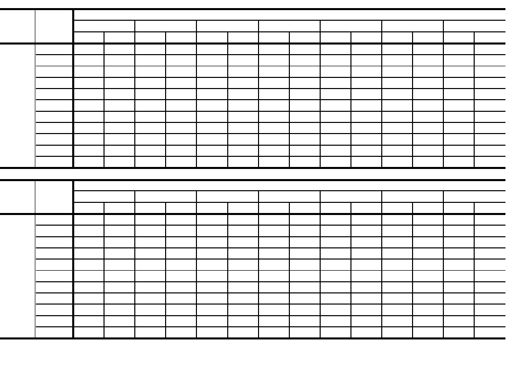
TABLE 9: SUPPLY AIR BLOWER PERFORMANCE (4 TON BELT DRIVE) - SIDE DUCT APPLICATION
RPM WATTS RPM WATTS RPM WATTS RPM WATTS RPM WATTS RPM WATTS RPM WATTS
2000 843 860 880 925 919 1005 956 1065 993 1145 1030 1195 1067 1235
1900 817 775 854 850 893 920 930 995 970 1065 1008 1125 1046 1170
1800 790 700 828 760 867 840 906 905 944 980 985 1040 1025 1100
1700 - - 802 670 840 745 881 815 920 900 961 970 1001 1030
1600 ----818665858740898820940890980950
1500 ------842695882755922835962895
1400 ------833650867705904765942820
1300 --------858665893725932785
1200 --------847640880680916730
RPM WATTS RPM WATTS RPM WATTS RPM WATTS RPM WATTS RPM WATTS RPM WATTS
2000 1103 1270 ------------
1900 1085 1210 ------------
1800 1064 1145 1102 1180 ----------
1700 1040 1075 1081 1115 1121 1140 --------
1600 1020 1005 1060 1050 1100 1085 --------
1500 1003 945 1044 995 1086 1035 --------
1400 982 880 1024 920 1067 965 1107 1000 ------
1300 970 835 1010 870 1053 920 1099 960 ------
1200 953 780 992 815 1034 855 1080 905 ------
0.60 0.70 0.80
AVAILABLE EXTERNAL STATIC PRESSURE-IWG
3
0.20 0.30 0.40 0.50
UNIT
TONNAGE
AIR
FLOW
CFM
41, 2
UNIT
TONNAGE
AIR
FLOW
CFM
41, 2
AVAILABLE EXTERNAL STATIC PRESSURE-IWG
3
0.90 1.00 1.10 1.20 1.30 1.40 1.50
1. 230/460/575 Volts
2. For 208 Volts multiply values by 0.95.
3. Includes allowances for a wet evaporator coil, 1” filters, and the heat exchangers. Refer to STATIC RESISTANCE Table for
resistance values on applications other than gas / electric units with side duct airflows.
255040-YTG-A-0506
14 Unitary Products Group
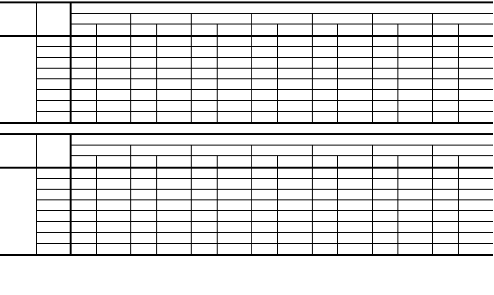
TABLE 10: SUPPLY AIR BLOWER PERFORMANCE (5 TON BELT DRIVE) - SIDE DUCT APPLICATION
RPM WATTS RPM WATTS RPM WATTS RPM WATTS RPM WATTS RPM WATTS RPM WATTS
2500 1059 1560 1077 1590 1095 1630 1114 1650 1134 1660 1158 1685 1181 1720
2400 1032 1405 1054 1470 1074 1525 1094 1560 1116 1595 1140 1620 1167 1640
2300 1005 1260 1024 1275 1049 1370 1069 1440 1090 1475 1116 1505 1142 1535
2200 980 1160 1002 1170 1022 1190 1044 1250 1066 1350 1090 1410 1117 1440
2100 930 1060 957 1070 983 1080 1010 1100 1039 1160 1064 1260 1092 1340
2000 877 950 908 975 941 1000 976 1020 1009 1050 1040 1100 1070 1225
1900 ----8948859409409809801014 1020 1047 1095
1800 ----8558159038609509059889401022 970
1700 ------8848159258509648801001 910
1600 ------864770908805948835987870
1500 --------882740926780965830
RPM WATTS RPM WATTS RPM WATTS RPM WATTS RPM WATTS RPM WATTS RPM WATTS
2500 --------------
2400 1193 1665 ------------
2300 1170 1580 1202 1620 ----------
2200 1148 1480 1180 1530 ----------
2100 1121 1385 1155 1425 1190 1475 --------
2000 1100 1285 1133 1340 1169 1385 1205 1445 ------
1900 1079 1180 1110 1240 1143 1280 1178 1330 1222 1375 ----
1800 1058 1060 1090 1135 1122 1190 1158 1240 1196 1295 ----
1700 1035 960 1071 1030 1103 1100 1134 1140 1164 1175 1197 1205 - -
1600 1020 900 1056 965 1088 1035 1118 1065 1145 1105 1170 1130 1198 1150
1500 1004 860 1038 880 1070 925 1101 980 1130 1045 1158 1075 1184 1110
51, 2
AVAILABLE EXTERNAL STATIC PRESSURE-IWG
3
0.90 1.00 1.10 1.20 1.30 1.40 1.50
UNIT
T
ONNAGE
AIR FLOW
CFM
51, 2
UNIT
T
ONNAGE
AIR FLOW
CFM
0.60 0.70 0.80
AVAILABLE EXTERNAL STATIC PRESSURE-IWG
3
0.20 0.30 0.40 0.50
1. 230/460/575 Volts
2. For 208 Volts multiply values by 0.95.
3. Includes allowances for a wet evaporator coil, 1” filters, and the heat exchangers. Refer to STATIC RESISTANCE Table for
resistance values on applications other than gas / electric units with side duct airflows.
255040-YTG-A-0506
Unitary Products Group 15
TABLE 11: SUPPLY AIR BLOWER PERFORMANCE (6 TON BELT DRIVE) - SIDE DUCT APPLICATION
RPM WATTS RPM WATTS RPM WATTS RPM WATTS RPM WATTS RPM WATTS RPM WATTS
3200 1150 2325 1182 2425 1212 2525 --------
3000 1100 2010 1129 2090 1157 2150 1185 2225 1215 2290 1242 2360 - -
2800 1045 1700 1074 1780 1102 1850 1131 1940 1160 2025 1190 2075 1217 2130
2600 985 1425 1015 1475 1045 1540 1075 1630 1103 1715 1135 1760 1163 1825
2400 930 1240 958 1300 990 1350 1020 1400 1051 1430 1081 1490 1111 1600
2200 - - 905 1070 933 1160 965 1210 997 1250 1028 1285 1060 1325
2000 ------9191025 950 1100 982 1130 1014 1160
1800 --------9099259391005 968 1030
RPM WATTS RPM WATTS RPM WATTS RPM WATTS RPM WATTS RPM WATTS RPM WATTS
3200 --------------
3000 --------------
2800 1245 2190 ------------
2600 1193 1920 1222 1990 1250 2060 --------
2400 1142 1675 1173 1730 1205 1800 1234 1885 ------
2200 1090 1380 1124 1450 1155 1550 1186 1640 1217 1710 1249 1775 - -
2000 1045 1175 1077 1200 1109 1275 1140 1360 1170 1460 1205 1545 1235 1600
1800 998 1050 1028 1060 1058 1060 1087 1075 1118 1150 1148 1250 1176 1360
0.60 0.70 0.80
AVAILABLE EXTERNAL STATIC PRESSURE-IWG
3
0.20 0.30 0.40 0.50
UNIT
TONNAGE
AIR
FLOW
CFM
6
1, 2
UNIT
TONNAGE
AIR
FLOW
CFM
6
1, 2
AVAILABLE EXTERNAL STATIC PRESSURE-IWG
3
0.90 1.00 1.10 1.20 1.30 1.40 1.50
1. 230/460/575 Volts
2. For 208 Volts multiply values by 0.95.
3. Includes allowances for a wet evaporator coil, 1” filters, and the heat exchangers. Refer to STATIC RESISTANCE Table for
resistance values on applications other than gas / electric units with side duct airflows.
255040-YTG-A-0506
16 Unitary Products Group
TABLE 12: SUPPLY AIR BLOWER PERFORMANCE (3 - 6 TON DIRECT DRIVE) - SIDE DUCT APPLICATION
CFM WATTS CFM WATTS CFM WATTS CFM WATTS CFM WATTS
HI ----1699 825 1650 785 1570 755
MED 1684 800 1631 780 1582 750 1524 720 1410 690
LOW 1487 710 1464 690 1421 670 1367 650 1315 620
HI 1996 960 1933 936 1868 910 1795 880 1722 845
MED 1804 838 1765 810 1714 785 1650 765 1589 735
LOW 1681 760 1640 738 1604 715 1541 695 1490 670
HI 2400 1155 2338 1125 2274 1095 2167 1045 2096 1010
MED 2290 1105 2214 1065 2145 1030 2071 990 1990 950
LOW 2150 1020 2100 990 2029 950 1965 910 1905 880
61HI 2461 1480 2402 1440 2361 1395 2260 1350 2178 1305
CFM WATTS CFM WATTS CFM WATTS CFM WATTS
HI 1430 725 1360 700 1280 680 1180 655
MED 1324 650 1260 630 1185 610 1100 590
LOW 1246 605 1185 590 1110 570 1020 545
HI 1635 820 1544 790 1419 765 1300 740
MED 1508 705 1407 675 1306 645 1195 625
LOW 1416 645 1337 620 1230 595 1120 575
HI 1990 980 1887 945 1771 905 1629 855
MED 1911 920 1828 885 1724 835 1604 798
LOW 1816 838 1724 800 1644 770 1531 710
61HI 2101 1260 2000 1205 1914 1155 1830 1110
51
0.600.20 0.30 0.40 0.50
UNIT
TONNAGE MOTOR SPEED
UNIT
TONNAGE) MOTOR SPEED
31
41
51
AVAILABLE EXTERNAL STATIC PRESSURE-IWG
2
AVAILABLE EXTERNAL STATIC PRESSURE-IWG
2
0.900.80 1.00
31
41
0.70
1. Side Duct application (230/460/575 Volts)
2. Includes allowances for a wet evaporator coil, 1” filters, and the heat exchangers. Refer to STATIC RESISTANCES Table for resistance
values.
TABLE 13: BELT DRIVE BLOWER MOTOR AND DRIVE DATA
MODEL
SIZE
BLOWER
RANGE
(RPM)
MOTOR1ADJUSTABLE MOTOR PULLEY FIXED BLOWER PULLEY BELT
(NOTCHED)
HP FRAME DESIG-
NATION
OUTSIDE
DIA.
(IN.)
PITCH
DIA.
(IN.)
BORE
(IN.) DESIG-
NATION
OUTSIDE
DIA.
(IN.)
PITCH
DIA.
(IN.)
BORE
(IN.) DESIG-
NATION
PITCH
LENGTH
(IN.) QTY.
3 TON 790/1120 1 1/2 56 1VL40 2.7-3.7 2.4-3.4 5/8 AK61 5.9 5.7 1 A36 37.3 1
4 TON 790/1120 1 1/2 56 1VL40 2.7-3.7 2.4-3.4 5/8 AK61 5.9 5.7 1 A36 37.3 1
5 TON 850/1220 1 1/2 56 1VL40 2.7-3.7 2.4-3.4 5/8 AK56 5.4 5.2 1 A36 37.3 1
6 TON 900/1250 1 1/2 56 1VL44 3.1-4.1 2.8-3.8 7/8 AK56 5.4 5.2 1 A36 37.3 1
1. All motors have solid bases and are inherently protected. these motors can be selected to operate into their service factor because they are located
in the moving air, upstream of any heating device.
255040-YTG-A-0506
Unitary Products Group 17
TABLE 14: STATIC RESISTANCES
1000 1200 1400 1600 1800 2000 2200 2400 2600 2800 3000
0.07 0.08 0.09 0.11 0.13 0.15 0.17 0.20 0.23 0.26 0.30
7-15KW 0.04 0.05 0.06 0.07 0.08 0.10 0.12 0.14 0.16 0.19 0.22
20-30KW 0.06 0.07 0.08 0.09 0.11 0.13 0.15 0.17 0.20 0.23 0.26
0.06 0.07 0.08 0.09 0.10 0.11 0.12 0.14 0.16 0.19 0.22
0.08 0.10 0.12 0.14 0.16 0.18 0.20 0.23 0.26 0.29 0.32
COOLING ONLY2
RESISTANCE, IWG
CFM
DESCRIPTION
ECONOMIZER1 3
BOTTOM DUCT CONNECTIONS1
ELECTRIC
HEATERS1
1. Deduct these resistance values from the available external static pressure shown in SUPPLY AIR BLOWER PERFORMANCE Tables.
3. The pressure through the economizer is greater for 100% outdoor air than for 100% return air. If the resistance of the return air
duct system is less than 0.25 IWG, the unit will deliver less CFM during full economizer operation.
2. Add these resistance values to the available static resistance values on SUPPLY AIR BLOWER PERFORMANCE Tables.
TABLE 15: ELECTRIC HEATER CFM LIMITATIONS
UNITMODEL SIZE NOMINAL
TONS VOLTAGE
MINIMUM SUPPLY AIR CFM
HEATER SIZE NOMINAL KW
5 7 10 15 20 30
3
208/230-3-60 1100 1100 1200 1200 1300 -
460-3-60 - 1100 1200 1200 1300 -
575-3-60 - - 1200 1200 1300 -
4
208/230-3-60 1300 1300 1300 1300 1300 -
460-3-60 - 1300 1300 1300 1300 -
575-3-60 - - 1300 1300 1400 -
5
208/230-3-60 1600 1600 1600 1600 1600 1600
460-3-60 - 1600 1600 1600 1600 1600
575-3-60 - 1600 1600 1600 1600 1800
6
208/230-3-60 1800 1800 1800 1800 1800 1800
460-3-60 - 1800 1800 1800 1800 1800
575-3-60 - - 1800 1800 1800 1800
255040-YTG-A-0506
18 Unitary Products Group
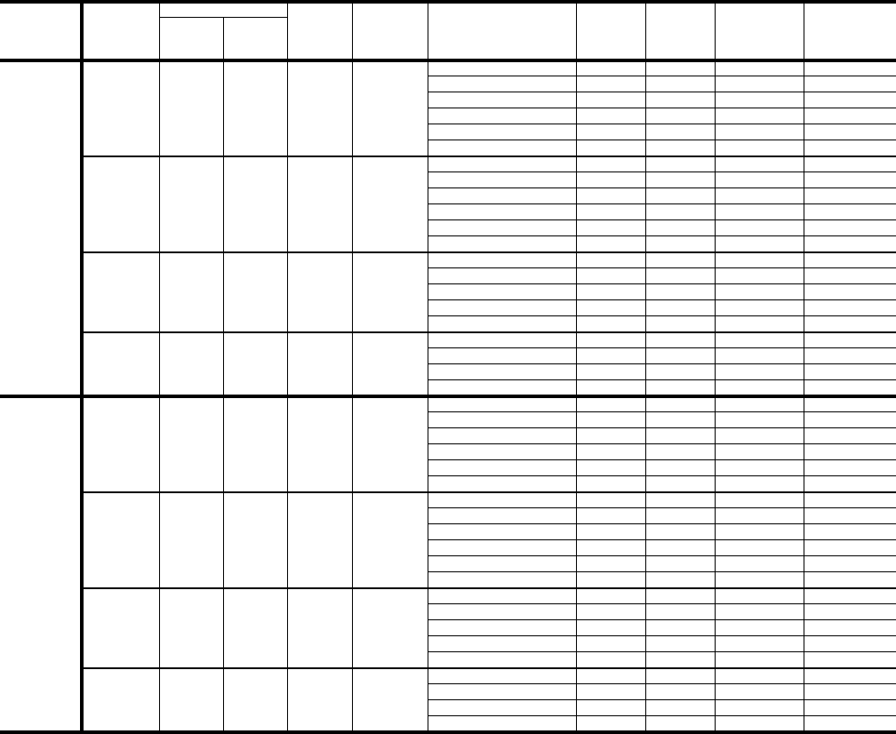
TABLE 16: ELECTRICAL DATA - D(CE, CG)036-072 DIRECT DRIVE
MODEL
TONNAGE VOLTAGE
COMPRESSORS OD FAN
MOTOR
FLA
ID
BLOWER
MOTOR
FLA
ELECTRIC HEATER
MODEL NO. HEATER
KW HEATER
AMPS
MIN.
CIRCUIT
AMPACITY
(AMPS)
MAX. FUSE/
BRKR1
SIZE
(AMPS)
RLA
EACH LRA
EACH
D(CE, CG)
036
(3.0)
208-3-60 11.4 90.0 1.3 4.4
None -- -- 19.9 25
2CE0451052524 11.1 19.9 25
2CE0451072525.6 15.5 24.9 30
2CE04511025 8 22.2 33.3 35
2CE04511525 11.9 33.0 46.8 50
2CE04512025 15.9 44.1 60.7 70
230-3-60 11.4 90.0 1.3 4.4
None -- -- 19.9 25
2CE0451052525.3 12.7 21.4 30
2CE0451072527.5 18.0 28.1 30
2CE04511025 10.6 25.5 37.4 40
2CE04511525 15.9 38.2 53.3 60
2CE04512025 21.2 51.0 69.2 70
460-3-60 6.2 45.0 0.8 2.2
None -- -- 10.8 15
2CE0451074626.8 8.2 13 15
2CE04511046210.1 12.1 17.9 20
2CE04511546213.6 16.4 23.2 25
2CE04512046219.5 23.5 32.1 35
575-3-60 5.0 36.0 0.8 2.2
None -- -- 8.7 15
2CE04511058 10.6 10.2 14.9 15
2CE04511558 15.9 15.3 21.3 25
2CE04512058 21.2 20.4 27.7 30
D(CE, CG)
048
(4.0)
208-3-60 14.1 105.0 1.3 5.0
None -- -- 23.9 30
2CE0451052524 11.1 23.9 30
2CE0451072525.6 15.5 25.7 35
2CE04511025 8 22.2 34 35
2CE04511525 11.9 33.0 47.5 50
2CE04512025 15.9 44.1 61.4 70
230-3-60 14.1 105.0 1.3 5.0
None -- -- 23.9 30
2CE0451052525.3 12.7 23.9 30
2CE0451072527.5 18.0 28.8 35
2CE04511025 10.6 25.5 38.1 40
2CE04511525 15.9 38.2 54.1 60
2CE04512025 21.2 51.0 70 70
460-3-60 7.1 55.0 0.8 2.2
None -- -- 11.9 15
2CE0451074626.8 8.2 13 15
2CE04511046210.1 12.1 17.9 20
2CE04511546213.6 16.4 23.2 25
2CE04512046219.5 23.5 32.1 35
575-3-60 5.8 44.0 0.8 2.2
None -- -- 9.7 15
2CE04511058 10.6 10.2 14.9 15
2CE04511558 15.9 15.3 21.3 25
2CE04512058 21.2 20.4 27.7 30

255040-YTG-A-0506
Unitary Products Group 19
MODEL
TONNAGE VOLTAGE
COMPRESSORS OD FAN
MOTOR
FLA
ID
BLOWER
MOTOR
FLA
ELECTRIC HEATER
MODEL NO. HEATER
KW HEATER
AMPS
MIN.
CIRCUIT
AMPACITY
(AMPS)
MAX. FUSE/
BRKR1
SIZE
(AMPS)
RLA
EACH LRA
EACH
D(CE, CG)
060
(5.0)
208-3-60 16.0 125.0 1.3 6.6
None -- -- 27.9 35
2CE0451052524 11.1 27.9 35
2CE0451072525.6 15.5 27.9 35
2CE04511025 8 22.2 36 40
2CE04511525 11.9 33.0 49.5 50
2CE04512025 15.9 44.1 63.4 70
2CE04513025 22.2 61.6 85.3 90
230-3-60 16.0 125.0 1.3 6.6
None -- -- 27.9 35
2CE0451052525.3 12.7 27.9 35
2CE0451072527.5 18.0 30.8 40
2CE04511025 10.6 25.5 40.1 45
2CE04511525 15.9 38.2 56.1 60
2CE04512025 21.2 51.0 72 80
2CE04513025 29.6 71.2 97.3 100
460-3-60 8.0 66.5 0.8 3.3
None -- -- 14.1 20
2CE0451074626.8 8.2 14.3 20
2CE04511046210.1 12.1 19.3 20
2CE04511546213.6 16.4 24.6 25
2CE04512046219.5 23.5 33.4 35
2CE04513046228.8 34.6 47.4 50
575-3-60 6.4 50.0 0.8 3.3
None -- -- 11.3 15
2CE04511058 10.6 10.2 16 20
2CE04511558 15.9 15.3 22.4 25
2CE04512058 21.2 20.4 28.8 30
2CE04513058 30.4 29.3 39.9 40
D(CE, CG)
072
(6.0)
208-3-60 18.9 146.0 1.3 6.8
None -- -- 31.7 40
2CE0451052524 11.1 31.7 40
2CE0451072525.6 15.5 31.7 40
2CE04511025 8 22.2 36.3 50
2CE04511525 11.9 33.0 49.8 50
2CE04512025 15.9 44.1 63.7 70
2CE04513025 22.2 61.6 85.5 90
230-3-60 18.9 146.0 1.3 6.8
None -- -- 31.7 40
2CE0451052525.3 12.7 31.7 40
2CE0451072527.5 18.0 31.7 40
2CE04511025 10.6 25.5 40.4 50
2CE04511525 15.9 38.2 56.3 60
2CE04512025 21.2 51.0 72.2 80
2CE04513025 29.6 71.2 97.5 100
460-3-60 9.5 73.0 0.8 3.6
None -- -- 16.3 25
2CE0451074626.8 8.2 16.3 25
2CE04511046210.1 12.1 19.7 25
2CE04511546213.6 16.4 24.9 25
2CE04512046219.5 23.5 33.8 35
2CE04513046228.8 34.6 47.8 50
575-3-60 7.6 58.4 0.8 3.6
None -- -- 13 15
2CE04511058 10.6 10.2 16.3 20
2CE04511558 15.9 15.3 22.7 25
2CE04512058 21.2 20.4 29.1 30
2CE04513058 30.4 29.3 40.2 40
1. HACR Type per NEC.
2. These electric heaters do not include a fuse box. If a fuse box is required to meet a local code (i.e. Chicago), the fuse block
accessories 2FB04700825 and 2FB04700846 are available for field installation.
TABLE 16: ELECTRICAL DATA - D(CE, CG)036-072 DIRECT DRIVE (CONT.)

255040-YTG-A-0506
20 Unitary Products Group
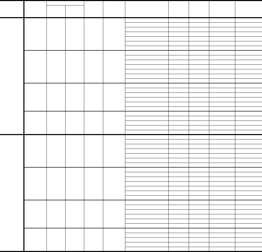
TABLE 17: ELECTRICAL DATA - D(CE, CG)036-072 BELT DRIVE
MODEL
TONNAGE VOLTAGE
COMPRESSORS OD FAN
MOTOR
FLA
ID
BLOWER
MOTOR
FLA
ELECTRIC HEATER
MODEL NO. HEATER
KW HEATER
AMPS
MIN.
CIRCUIT
AMPACITY
(AMPS)
MAX. FUSE/
BRKR1
SIZE
(AMPS)
RLA
EACH LRA
EACH
D(CE, CG)
036
(3.0)
208-3-60 11.4 90.0 1.3 5.2
None -- -- 20.8 30
2CE0451052524 11.1 20.8 30
2CE0451072525.6 15.5 25.9 30
2CE04511025 8 22.2 34.3 35
2CE04511525 11.9 33.0 47.8 50
2CE04512025 15.9 44.1 61.7 70
230-3-60 11.4 90.0 1.3 5.2
None -- -- 20.8 30
2CE0451052525.3 12.7 22.4 30
2CE0451072527.5 18.0 29.1 30
2CE04511025 10.6 25.5 38.4 40
2CE04511525 15.9 38.2 54.3 60
2CE04512025 21.2 51.0 70.2 80
460-3-60 6.2 45.0 0.8 2.6
None -- -- 11.1 15
2CE0451074626.8 8.2 13.5 15
2CE04511046210.1 12.1 18.4 20
2CE04511546213.6 16.4 23.7 25
2CE04512046219.5 23.5 32.6 35
575-3-60 5.0 36.0 0.8 2.0
None -- -- 8.9 15
2CE04511058 10.6 10.2 15.2 20
2CE04511558 15.9 15.3 21.6 25
2CE04512058 21.2 20.4 28 30
D(CE, CG)
048
(4.0)
208-3-60 14.1 105.0 1.3 5.2
None -- -- 24.1 35
2CE0451052524 11.1 24.1 35
2CE0451072525.6 15.5 25.9 35
2CE04511025 8 22.2 34.3 35
2CE04511525 11.9 33.0 47.8 50
2CE04512025 15.9 44.1 61.7 70
230-3-60 14.1 105.0 1.3 5.2
None -- -- 24.1 35
2CE0451052525.3 12.7 24.1 35
2CE0451072527.5 18.0 29.1 35
2CE04511025 10.6 25.5 38.4 40
2CE04511525 15.9 38.2 54.3 60
2CE04512025 21.2 51.0 70.2 80
460-3-60 7.1 55.0 0.8 2.6
None -- -- 12.3 15
2CE0451074626.8 8.2 13.5 15
2CE04511046210.1 12.1 18.4 20
2CE04511546213.6 16.4 23.7 25
2CE04512046219.5 23.5 32.6 35
575-3-60 5.8 44.0 0.8 2.0
None -- -- 9.9 15
2CE04511058 10.6 10.2 15.2 20
2CE04511558 15.9 15.3 21.6 25
2CE04512058 21.2 20.4 28 30
255040-YTG-A-0506
Unitary Products Group 21
MODEL
TONNAGE VOLTAGE
COMPRESSORS OD FAN
MOTOR
FLA
ID
BLOWER
MOTOR
FLA
ELECTRIC HEATER
MODEL NO. HEATER
KW HEATER
AMPS
MIN.
CIRCUIT
AMPACITY
(AMPS)
MAX. FUSE/
BRKR1
SIZE
(AMPS)
RLA
EACH LRA
EACH
D(CE, CG)
060
(5.0)
208-3-60 16.0 125.0 1.3 5.2
None -- -- 26.5 35
2CE0451052524 11.1 26.5 35
2CE0451072525.6 15.5 26.5 35
2CE04511025 8 22.2 34.3 40
2CE04511525 11.9 33.0 47.8 50
2CE04512025 15.9 44.1 61.7 70
2CE04513025 22.2 61.6 83.5 90
230-3-60 16.0 125.0 1.3 5.2
None -- -- 26.5 35
2CE0451052525.3 12.7 26.5 35
2CE0451072527.5 18.0 29.1 40
2CE04511025 10.6 25.5 38.4 40
2CE04511525 15.9 38.2 54.3 60
2CE04512025 21.2 51.0 70.2 80
2CE04513025 29.6 71.2 95.5 100
460-3-60 8.0 66.5 0.8 2.6
None -- -- 13.4 20
2CE0451074626.8 8.2 13.5 20
2CE04511046210.1 12.1 18.4 20
2CE04511546213.6 16.4 23.7 25
2CE04512046219.5 23.5 32.6 35
2CE04513046228.8 34.6 46.6 50
575-3-60 6.4 50.0 0.8 2.0
None -- -- 10.6 15
2CE04511058 10.6 10.2 15.2 20
2CE04511558 15.9 15.3 21.6 25
2CE04512058 21.2 20.4 28 30
2CE04513058 30.4 29.3 39.1 40
D(CE, CG)
072
(6.0)
208-3-60 18.9 146.0 1.3 5.0
None -- -- 29.9 40
2CE0451052524 11.1 29.9 40
2CE0451072525.6 15.5 29.9 40
2CE04511025 8 22.2 34 45
2CE04511525 11.9 33.0 47.5 50
2CE04512025 15.9 44.1 61.4 70
2CE04513025 22.2 61.6 83.3 90
230-3-60 18.9 146.0 1.3 5.0
None -- -- 29.9 40
2CE0451052525.3 12.7 29.9 40
2CE0451072527.5 18.0 29.9 40
2CE04511025 10.6 25.5 38.1 45
2CE04511525 15.9 38.2 54.1 60
2CE04512025 21.2 51.0 70 70
2CE04513025 29.6 71.2 95.3 100
460-3-60 9.5 73.0 0.8 2.5
None -- -- 15.2 20
2CE0451074626.8 8.2 15.2 20
2CE04511046210.1 12.1 18.3 20
2CE04511546213.6 16.4 23.6 25
2CE04512046219.5 23.5 32.4 35
2CE04513046228.8 34.6 46.4 50
575-3-60 7.6 58.4 0.8 2.0
None -- -- 12.1 15
2CE04511058 10.6 10.2 15.2 20
2CE04511558 15.9 15.3 21.6 25
2CE04512058 21.2 20.4 28 30
2CE04513058 30.4 29.3 39.1 40
1. HACR Type per NEC.
2. These electric heaters do not include a fuse box. If a fuse box is required to meet a local code (i.e. Chicago), the fuse block
accessories 2FB04700825 and 2FB04700846 are available for field installation.
TABLE 17: ELECTRICAL DATA - D(CE, CG)036-072 BELT DRIVE (CONT.)
255040-YTG-A-0506
22 Unitary Products Group
TABLE 18: PHYSICAL DATA
MODELS D(CE, CG)
036 048 060 072
EVAPORATOR
BLOWER
Centrifugal Blower (Dia. x Wd. in.) 12 X 10 12 X 10 12 X 10 12 X 11
Fan Motor HP (Direct Drive) 1/2 3/4 1 1
Fan Motor HP (Belt Drive) 1 1/2 1 1/2 1 1/2 1 1/2
EVAPORATOR
COIL
Rows Deep 3 3 3 4
Fins Per Inch 13 13 13 13
Face Area (Sq. Ft.) 3.6 4.3 5.1 5.1
CONDENSER
FANS
Propeller Dia. (in.) 24 24 24 24
Fan Motor Hp 1/4 1/4 1/4 1/4
Nom. CFM 3400 3400 3400 3400
CONDENSER
COILS
Rows Deep 1 1 1 2
Fins Per Inch 16 16 22 16
Face Area (Sq. Ft.) 17.1 17.1 17.1 16.7
COMPRESSOR
(Qty. Per Unit) Scroll Type 1111
AIR
FILTERS
Quantity Per Unit (15” X 20” X 1” or 2“) 2 2 2 2
Quantity Per Unit (14” X 25” X 1” or 2“) 1 1 1 1
Total Face Area (sq. ft.) 6.3 6.3 6.3 6.3
CHARGE Refrigerant 22
(lbs./oz.) 5/8 6/8 6/8 10/0
TABLE 19: ELECTRIC HEAT CORRECTION FACTORS
NOMINAL VOLTAGE VOLTAGE kW CAP. MULTI-
PLIER
208 208 0.75
240 230 0.92
480 460 0.92
600 575 0.92
TABLE 20: VOLTAGE LIMITATIONS1
1. Utilization Range “A” in accordance with ARI Standard
110.
POWER SUPPLY VOLTAGE
MIN. MAX.
208/230-3-60 187 253
460-3-60 414 506
575-3-60 540 630
255040-YTG-A-0506
Unitary Products Group 23
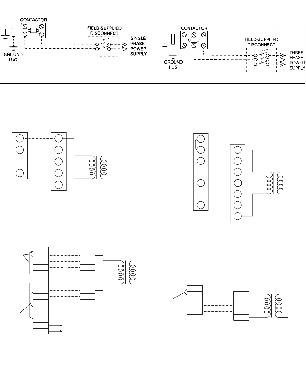
FIGURE 2 - TYPICAL FIELD POWER & CONTROL WIRING
REFER TO THE ELECTRICAL DATA
TABLES TO SIZE THE DISCONNECT
SWITCH, OVERCURRENT PROTEC-
TION AND WIRING.
RC
RH
Y1
Y2
W1
W2
G
LED 1
LED 2
COM
A1
A2
T
T
B
R
Y1
Y2
G
C
X
OCC
W2
W1
THERMOSTAT1
TERMINALS UNIT TERMINAL
STRIP TB1 24 VOLT
TRANSFORMER
TO REMOTE SENSOR
2TH040702224 IF USED
NOT
USED
ADD
JUMPER
ADD
JUMPER
4
4
3
2
1 ELECTRONIC PROGRAMMABLE THERMOSTAT 2ET04700224 (INCLUDES SUBBASE).
2 SECOND STAGE COOLING IS NOT REQUIRED ON UNITS LESS ECONOMIZER.
3 SECOND STAGE HEATING IS ONLY REQUIRED ON UNITS WITH A TWO STAGE
ELECTRIC HEATER.
4
REMOVE JUMPER J2 FROM TERMINALS 4 AND 9 ON JUMPER PLUG CONNECTOR
P6 ON UNITS WITH ECONOMIZER. TERMINALS A1 AND A2 PROVIDE A RELAY
OUT-PUT TO CLOSE THE OUTDOOR ECONOMIZER DAMPERS WHEN THE
THERMOSTAT SWITCHES TO THE SET-BACK POSITION.
COOLING / HEATING (ELECTRONIC THERMOSTAT)
MULTI STAGE
RH
RC
Y
W
G
R
Y1
W1
C
G
ADD
JUMPER
THERMOSTAT
1
TERMINALS UNIT TERMINAL
STRIP TB1
24 VOLT
TRANSFORMER
1
ELECTRONIC PROGRAMMABLE THERMOSTAT 2ET07701024 (INCLUDES SUBBASE).
TO CONTROL THE ECONOMIZER ON SECOND STAGE COOLING, USE THERMOSTAT
2TH04700224.
COOLING / HEATING (ELECTRONIC THERMOSTAT)
SINGLE STAGE
RV
YC
GF
R
Y1
C
Y2
THERMOSTAT
1
TERMINALS
UNIT TERMINAL
STRIP TB1
24 VOLT
TRANSFORMER
1
24 VOLT THERMOSTAT 2TH07701024. TO CONTROL THE ECONOMIZER
ON SECOND STAGE COOLING, USE THE THERMOSTAT 2TH0401224.
G
COOLING ONLY (24 VOLT THERMOSTAT)
RC
Y
R
Y1
Y2
W1
W
W2
G
C
G
RH
THERMOSTAT
TERMINALS
UNIT TERMINAL
STRIP TB1
24 VOLT
TRANSFORMER
ADD
JUMPER
1
24 VOLT THERMOSTAT 2ET07701024. TO CONTROL THE ECONOMIZER ON THE SECOND
STAGE COOLING OR TO HAVE AN ELECTRIC HEAT ACCESSORY WITH TWO STAGES OF
HEAT, USE THERMOSTAT 2TH0471024.
1
COOLING / HEATING (24 VOLT THERMOSTAT)
TYPICAL POWER WIRING
TYPICAL CONTROL WIRING
255040-YTG-A-0506
24 Unitary Products Group
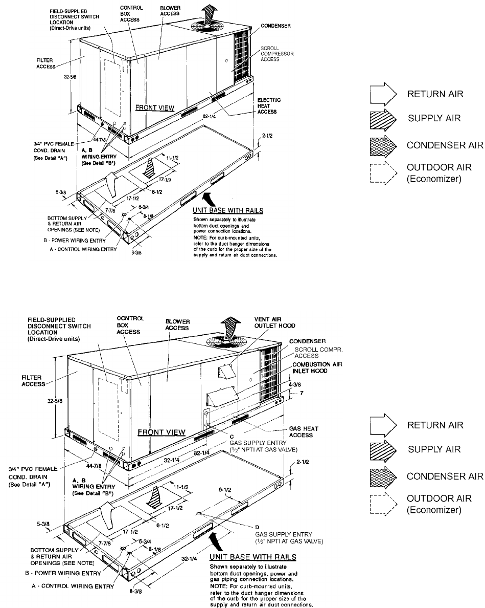
FIGURE 3 - UNIT DIMENSIONS (3 - 6 TON COOLING ONLY/ELECTRIC HEAT) FRONT VIEW
FIGURE 4 - UNIT DIMENSIONS (3 - 6 TON COOLING/GAS HEAT) FRONT VIEW
255040-YTG-A-0506
Unitary Products Group 25
FIGURE 5 - UNIT WITH ECONOMIZER RAINHOOD
DETAIL “A”
FIGURE 6 - UNIT WITH FIXED OUTDOOR AIR/MOTORIZED DAMPER RAINHOOD
DETAIL “B”
255040-YTG-A-0506
26 Unitary Products Group
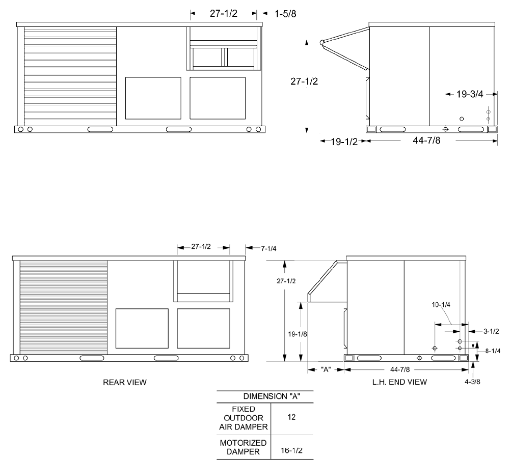
FIGURE 7 - UNIT DIMENSIONS (REAR VIEW)
FIGURE 8 - DISCONNECT/BLOWER ACCESS LOCA-
TION
TABLE 21: UTILITIES ENTRY
HOLE OPENING SIZE (DIA.) USED FOR
A7/8” KO1Control Wiring2Side
Bottom
B2” KO1Power Wiring Side
Bottom
C1-5/8” KO Gas Piping (Front)
D1-1/2” KO Gas Piping (Bottom)
1. Opening in the bottom to the unit can be located by the
side in the insulation.
2. Do not remove the 2” knockout ring.
DISCONNECT SWITCH LOCATION
AND MOTOR ACCESS PANEL FOR
UNIT WITH “BELT-DRIVE” OPTION
CONTROL BOX
ACCESS
A,B
WIRING ENTRY
(See Detail “B”)
MOUNTING BRACKET
FOR DICONNECT SWITCH
(Shipped attached to the
blower housing inside
the blower compartment)
FIELD-SUPPLIED
DISCONNECT SWITCH
LOCATION
BLOWER MOTOR
ACCESS
FILTER
ACCESS
DOT PLUGS
TABLE 22: MINIMUM CLEARANCES
LOCATION CLEARANCE
Front 24” (Cooling/Electric Heat)
32” (Gas Heat)
Rear 12” (Less Economizer)
36” (With Economizer or Fixed
Air/Motorized Damper)
Left Side (Filter Access) 24” (Less Economizer)
36” (With Economizer)
Right Side (Cond. Coil) 24”
Below Unit10”
Above Unit272” (For
Condenser Air Discharge)
1. Units may be installed on combustible floors made
from wood or class A, B, or C roof covering material.
2. Units must be installed outdoors. Overhanging struc-
tures or shrubs should not obstruct condenser air dis-
charge outlet.
255040-YTG-A-0506
Unitary Products Group 27
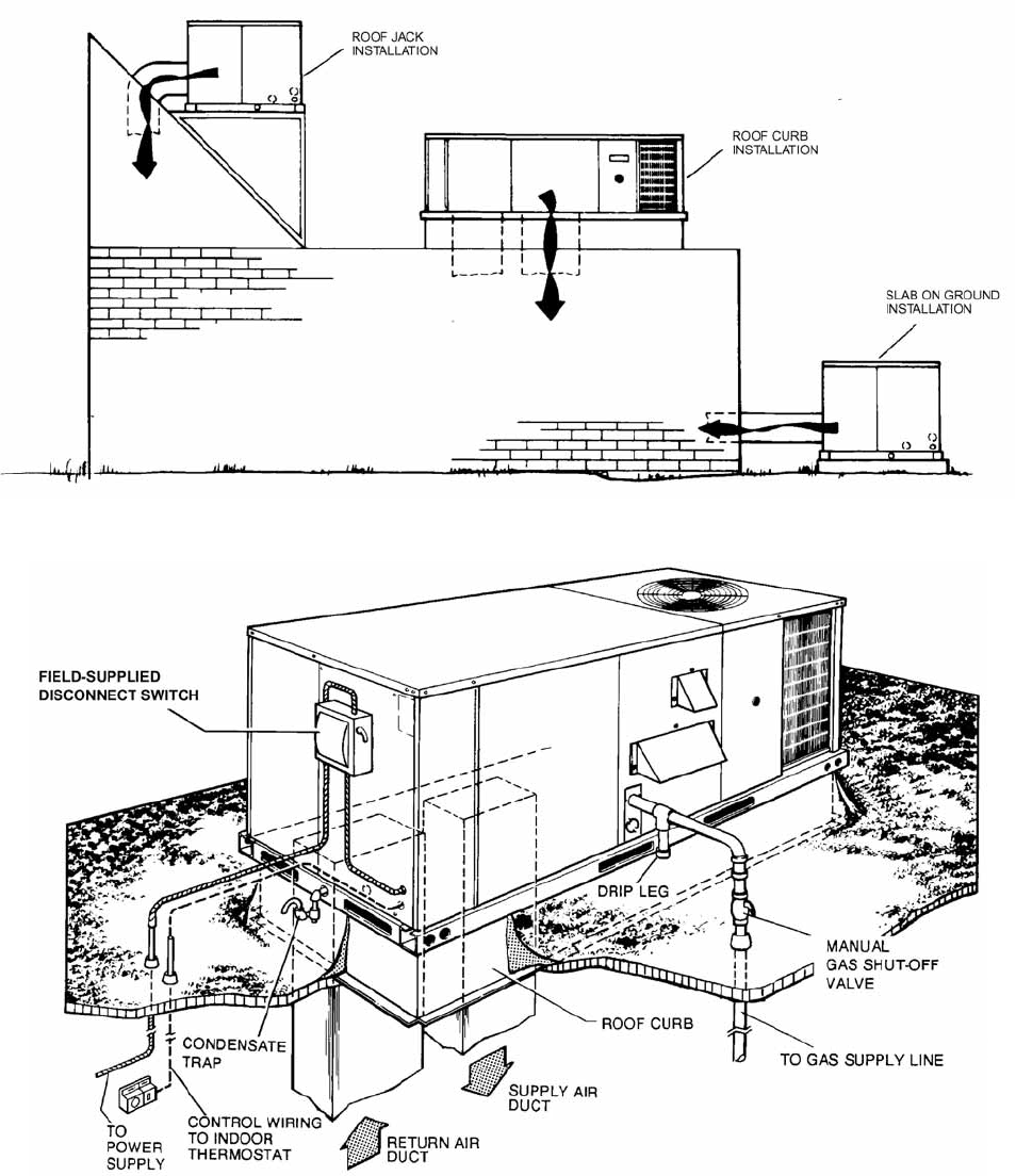
FIGURE 9 - TYPICAL APPLICATIONS
255040-YTG-A-0506
28 Unitary Products Group
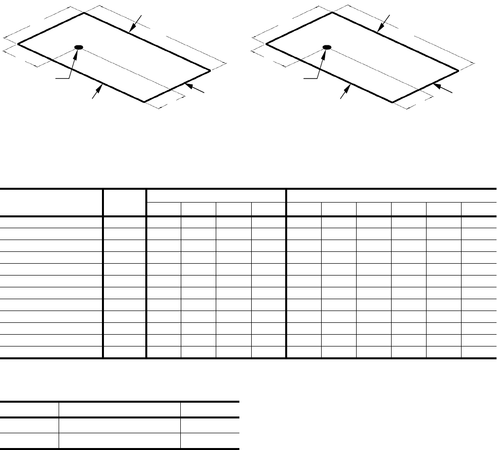
FIGURE 10 - FOUR AND SIX POINT LOADING
447/8
821/4
Y
X
A
B
C
D
CONDENSER COIL
END OF UNIT
FRONT OF UNIT
APPROXIMATE
CENTER OF GRAVITY
BACK OF UNIT
44
7
/
8
82
1
/
4
Y
X
A
B
C
D
E
F
CONDENSER COIL
END OF UNIT
FRONT OF UNIT
APPROXIMATE
CENTER OF GRAVITY
BACK OF UNIT
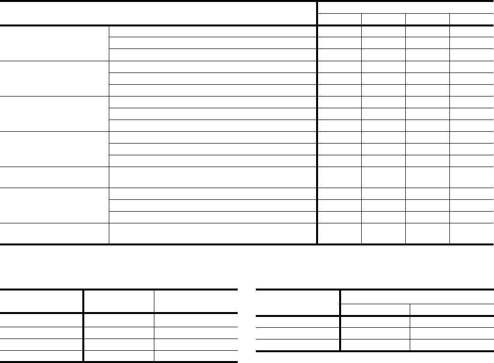
TABLE 23: D(CE, CG) 4 AND 6 POINT LOADS WEIGHT DISTRIBUTION
UNIT TOTAL 4-Point Loading (lb) 6-Point Loading (lb)
ABCDABCDEF
DCE036 Cooling/ Electric 565 125 123 157 160 84 83 82 104 105 107
DCG036N040 605 134 132 168 171 90 89 88 112 113 114
DCG036N079 625 139 136 173 177 93 92 91 115 117 118
DCE048 Cooling/ Electric 615 137 134 171 174 91 90 89 113 115 116
DCG048N060 665 148 145 184 188 99 98 96 123 124 126
DCG048N099 685 152 149 190 194 102 100 99 126 128 129
DCE060 Cooling/ Electric 640 142 140 178 181 95 94 93 118 119 121
DCG060N079 700 155 153 194 198 104 103 101 129 131 132
DCG060N099 710 158 155 197 201 105 104 103 131 132 134
DCE072 Cooling/ Electric 720 160 157 200 203 107 106 104 133 134 136
DCG072N079 780 173 170 216 220 116 114 113 144 146 147
DCG072N099 790 175 172 219 223 117 116 114 146 147 149
TABLE 24: CENTER OF GRAVITY
DIMENSION 3 - 5 TON 6 TON
X40-¾” 44”
Y19-¾” 22”
255040-YTG-A-0506
Unitary Products Group 29
TABLE 25: OPERATING WEIGHTS (LBS.)
MODEL SIZE 3 TON 4 TON 5 TON 6 TON
BASIC
UNIT
DCE (Cooling Only) 565 615 640 720
DCG
(Gas/Electric)
N040 605 - - -
N060 - 665 - -
N079 625 - 700 780
N099 - 685 710 790
OPTIONS
OR
ACCY.
Economizer 50
Motorized Damper 26
Electric Heater
5 - 7 kW 18
10 - 15 kW 23
20 - 30 kW 28
Roof Curb 92
Barometric Relief / Fixed Air Damper 10
Belt-Drive Blower 5
FIGURE 11 - ROOF CURB DIMENSIONS
255040-YTG-A-0506
30 Unitary Products Group
FIGURE 12 - COOLING UNIT WITH GAS HEAT CONTROL CIRCUIT 208/230V AND 460V DIAGRAM
255040-YTG-A-0506
Unitary Products Group 31
FIGURE 13 - COOLING UNIT WITH GAS HEAT CONTROL CIRCUIT 575 VOLT DIAGRAM
255040-YTG-A-0506
32 Unitary Products Group
FIGURE 14 - COOLING UNIT WITH ELECTRIC HEAT CONTROL CIRCUIT 208/230V, 460V AND 575V
DIAGRAM
255040-YTG-A-0506
Unitary Products Group 33
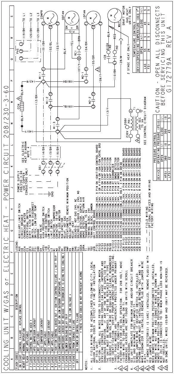
FIGURE 15 - COOLING UNIT POWER CIRCUIT 208/230-3-60 DIRECT DRIVE INDOOR BLOWER DIAGRAM
255040-YTG-A-0506
34 Unitary Products Group
FIGURE 16 - COOLING UNIT POWER CIRCUIT 208/230-3-60 BELT DRIVE INDOOR BLOWER DIAGRAM
255040-YTG-A-0506
Unitary Products Group 35
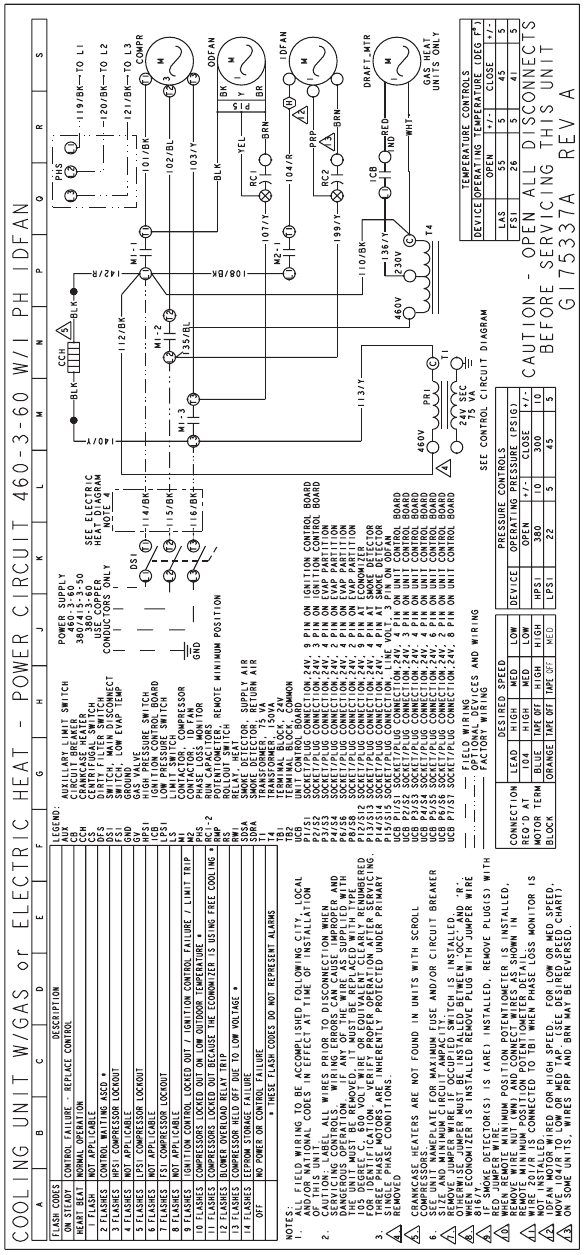
FIGURE 17 - COOLING UNIT POWER CIRCUIT 460-3-60 DIRECT DRIVE INDOOR BLOWER DIAGRAM
255040-YTG-A-0506
36 Unitary Products Group
FIGURE 18 - COOLING UNIT POWER CIRCUIT 460-3-60 BELT DRIVE INDOOR BLOWER DIAGRAM
255040-YTG-A-0506
Unitary Products Group 37
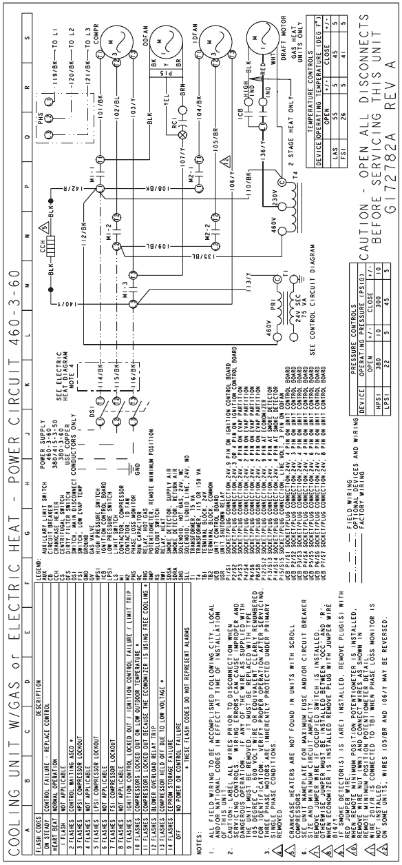
FIGURE 19 - COOLING UNIT POWER CIRCUIT 575-3-60 DIRECT DRIVE INDOOR BLOWER DIAGRAM
255040-YTG-A-0506
38 Unitary Products Group
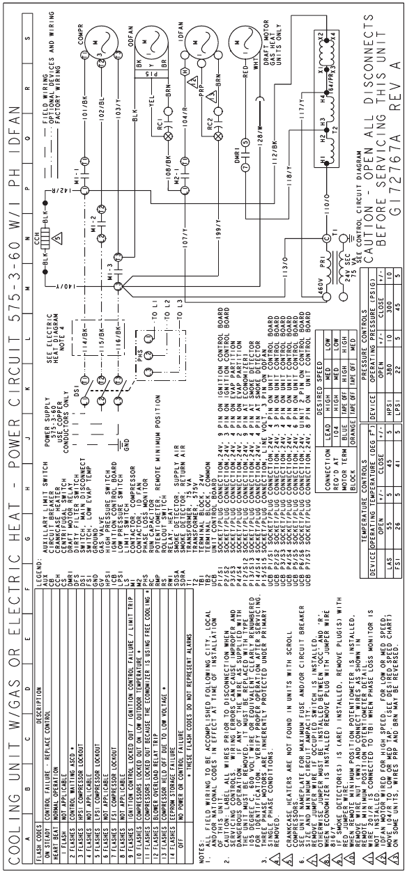
FIGURE 20 - COOLING UNIT POWER CIRCUIT 575-3-60 BELT DRIVE INDOOR BLOWER DIAGRAM
255040-YTG-A-0506
Unitary Products Group 39
GUIDE SPECIFICATIONS
GENERAL
Units shall be manufactured by York International Unitary
Products Group in an ISO 9001 certified facility.
York's Sunline 2000TM units are convertible single package-
units. Although the units are primarily designed for curb
mounting on a roof, they can also be slab-mounted at ground
level or set on steel beams above a finished roof. Cooling
only and cooling with gas heat models are available with a
wide variety of factory-mounted options and field-installed
accessories to make them suitable for almost every applica-
tion. All units are self-contained and assembled on full perim-
eter base rails with holes in the four corners for overhead
rigging. Every unit is completely piped, wired, charged and
tested at the factory to simplify the field installation and to
provide years of dependable operation. All models (including
those with an economizer) are suitable for either bottom or
horizontal duct connections. Models with power exhaust are
suitable for bottom duct connections only. For bottom duct,
remove the sheet metal panels from the supply and return air
openings through the base of the unit. For horizontal duct,
remove the supply and return air panels on the rear of the
unit.
All non-Scroll compressors include crankcase heaters and all
compressors have internal pressure relief. Every refrigerant
circuit includes a liquid line filter-drier, a discharge line high
pressure switch and a suction line with a freezestat and low
pressure/loss of charge switch.The unit control circuit
includes a 75 VA transformer, a 24-volt circuit breaker and a
relay board with a compressor lockout circuit, a terminal strip
for thermostat wiring, plus an additional set of pin connectors
to simplify the interface of additional field controls. All units
have long lasting powder paint cabinets with 1000 hour salt
spray test approval under ASTMB117 procedures. All models
are CSA listed. All models include a 1-year limited warranty
on the complete unit. Compressors and electric heater ele-
ments carry a 5-year warranty. Aluminized steel tubular heat
exchangers carry a 10-year warranty.
DESCRIPTION
Units shall be factory-assembled, single packaged, Electric
Cooling/Gas Heat, Electric Cooling/Optional Electric Heat
and designed for outdoor mounted installation.
The 3 thru 5 ton units shall have SEER ratings of 10.0 and
the 6 ton unit shall have minimum EER ratings of 9.0. They
shall have built-in field convertible duct connections for down
discharge supply/return or horizontal discharge supply/return,
and be available with factory installed options or field installed
accessories. The units shall be factory wired, piped, charged
with R-22 refrigerant and factory tested prior to shipment. All
unit wiring shall be both numbered and color coded. All units
the cooling performance shall be rated in accordance with
DOE and ARI test procedures. Units shall be CSA listed,
classified to ANSI Z21.47, UL 1995/CSA No. 236 standards.
UNIT CABINET
Unit cabinet shall be constructed of G90 galvanized steel,
with exterior surfaces coated with a non-chalking, powdered
paint finish, certified at 1000 hours salt spray test per
ASTMB117 standards. Indoor blower section shall be insu-
lated with a minimum 1/2” thick insulation, coated on the air-
side. Aluminum foil faced insulation shall be used in the
furnace compartment and be fastened with ridged fasteners
to prevent insulation from entering the air stream. Cabinet
panels shall be “large” size, easily removable for servicing
and maintenance. Full perimeter base rails shall be provided
to assure reliable transit of equipment, overhead rigging and
proper sealing on roof curb applications. Disposable 1" filters
shall be furnished and be accessible through a removable
access door, sealed airtight. Units filter track shall be
designed to accommodate either 1” or 2” filters. Fan perfor-
mance measuring ports shall be provided on the outside of
the cabinet to allow accurate air measurements of evaporator
fan performance without removing panels or creating air by-
pass of the coils. Condensate pan shall be internally sloped
and conform to ASHRAE 62-89 self-draining standards. Con-
densate connection shall be a minimum of 3/4” I.D. female
and be a ridged mount connection.
INDOOR (EVAPORATOR) FAN ASSEMBLY
The indoor fan shall be direct drive, multi-speed, or a factory
installed belt drive assembly that includes an adjustable pitch
motor pulley. Job site selected brake horsepower (B.H.P.) shall
not exceed the motors nameplate horsepower rating, plus the
service factor. Units shall be designed not to operate above
service factor. Fan wheel shall be double-inlet type with for-
ward-curved blades, dynamically balanced to operate
smoothly throughout the entire range of operation. Airflow
design shall be constant air volume. Bearings shall be sealed
and permanently lubricated for longer life and no maintenance.
OUTDOOR (CONDENSER) FAN ASSEMBLY
The outdoor fan shall be of the direct-driven propeller type,
discharge air vertically, have aluminum blades riveted to a
corrosion resistant steel spider bracket and shall be dynami-
cally balanced for smooth operation. The outdoor fan motor
shall be totally enclosed with permanently lubricated bear-
ings, internally protected against overload conditions and
staged independently.
REFRIGERANT COMPONENTS
Compressor:
a. Shall be internally protected with internal high-pres-
sure relief and over temperature protection.
b. Shall have internal spring isolation and sound muf-
fling to minimize vibration and noise, and be exter-
nally isolated on a dedicated, independent
mounting.
Coils:
a. Evaporator and condenser coils shall have alumi-
num plate fins mechanically bonded to seamless
255040-YTG-A-0506
40 Unitary Products Group
internally enhanced copper tubes with all joints
brazed. Special Phenolic coating shall be available
as a factory option.
b. Evaporator and Condenser coils shall be of the
direct expansion, draw-thru, design.
Refrigerant Circuit and Refrigerant Safety Components shall
include:
a. Independent fixed-orifice expansion devices.
b. Filter drier/strainer to eliminate any moisture or for-
eign matter.
c. Accessible service gage connections on both suc-
tion and liquid lines to charge, evacuate, and mea-
sure refrigerant pressure during any necessary
servicing or troubleshooting without losing charge.
d. The refrigeration system shall provide at least 15°F
of sub-cooling at design conditions.
UNIT CONTROLS
a. Unit shall be complete with self-contained low-volt-
age control circuit protected by a resetable circuit
breaker on the 24-volt transformer side.
b. Unit shall incorporate a lockout circuit which pro-
vides reset capability at the space thermostat or
base unit, should any of the following standard
safety devices trip and shut off compressor.
c. Loss-of-charge/Low-pressure switch.
d. High-pressure switch.
e. Freeze-protection thermostat, evaporator coil.
f. If any of the above safety devices trip, a LED (light-
emitting diode) indicator shall flash a diagnostic
code that indicates which safety switch has tripped.
g. Unit shall incorporate “AUTO RESET” compressor
over temperature, over current protection.
h. Unit shall operate with conventional thermostat
designs and have a low voltage terminal strip for
easy hook-up.
i. Unit control board shall have on-board diagnostics
and fault code display.
j. Standard controls shall include anti-short cycle and
low voltage protection, and permit cooling operation
down to 0°F.
k. Control board shall monitor each refrigerant safety
switch independently.
l. Control board shall retain last 5 fault codes in non
volatile memory, which will not be lost in the event of
a power loss.
GAS HEATING SECTION
Shall be designed with induced draft combustion with post
purge logic, energy saving direct spark ignition, and redun-
dant main gas valve. Venter wheel shall be constructed of
stainless steel for corrosion resistance. The heat exchanger
shall be of the tubular type, constructed of T1-40 aluminized
steel for corrosion resistance and allowing minimum mixed
air entering temperature of 25°F. Burners shall be of the
inshot type, constructed of aluminum coated steel and con-
tain air mixture adjustments. All gas piping shall enter the unit
cabinet at a single location through either the side or curb,
without any field modifications. Integrated control boards
shall provide timed control of evaporator fan functioning and
burner ignition. Heating section shall be provided with the fol-
lowing minimum protection:
a. Primary and auxiliary high-temperature limit
switches.
b. Induced draft motor speed sensor.
c. Flame roll out switch (manual reset).
d. Flame proving controls.
e. If any of the above safety devices trip, a LED (light-
emitting diode) indicator shall flash a diagnostic
code that indicates which safety switch has tripped.
ELECTRIC HEATING SECTION
An electric heating section, with nickel chromium elements,
shall be provided in a range of 5 thru 30 KW, offering two
stages of capacity - 16 KW and above on 208/230 volt heat-
ers and 20 KW and above on 460 and 575 volt heaters. The
heating section shall have a primary limit control(s) and auto-
matic reset to prevent the heating element system from oper-
ating at an excessive temperature. The heating section
assembly shall slide out of the unit for easy maintenance and
service. Units with Electric Heating shall be wired for a single
point power supply with branch circuit fusing (where
required).
UNIT OPERATING CHARACTERISTICS
a. Unit shall be capable of starting and running at
125°F outdoor temperature, exceeding maximum
load criteria of ARI Standard 210/240.
b. The compressor, with standard controls, shall be
capable of operation down to 0°F outdoor tempera-
ture.
c. Unit shall be provided with fan time delay to prevent
cold air delivery before heat exchanger warms up
(Gas heat only).
ELECTRICAL REQUIREMENTS
All unit power wiring shall enter unit cabinet at a single factory
provided location and be capable of side or bottom entry, to
minimize roof penetrations and avoid unit field modifications.
Separate side and bottom openings shall be provided for the
control wiring.
255040-YTG-A-0506
Unitary Products Group 41
STANDARD LIMITED WARRANTIES
• Compressor 5 Years
• Heat Exchanger 10 Years
• Electric Heat Element 5 Years
• Other Parts 1 Year
OPTIONAL OUTDOOR AIR (Shall be made available by
either/or):
•ELECTRONIC ENTHALPY AUTOMATIC ECONO-
MIZER- Outdoor and return air dampers that are inter-
locked and positioned by a fully-modulating, spring
return damper actuator. The maximum leakage rate for
the outdoor air intake dampers shall not exceed 2%
when dampers are fully closed and operating against a
pressure differential of 0.5 IWG. A unit-mounted potenti-
ometer shall be provided to adjust the outdoor and return
air damper assembly to take in CFM of outdoor air to
meet the minimum ventilation requirement of the condi-
tioned space during normal operation. During econo-
mizer operation, a mixed-air temperature control shall
modulate the outdoor and return air damper assembly to
prevent the supply air temperature from dropping below
55°F. Changeover from compressor to economizer oper-
ation shall be provided by an integral electronic enthalpy
control that feeds input into the basic module. The out-
door intake opening shall be covered with a rain hood
that matches the exterior of the unit. Water eliminator/fil-
ters shall be provided. Simultaneous economizer/com-
pressor operation is also possible. Dampers shall fully
close on power loss.
OTHER PRE-ENGINEERED ACCESSORIES AVAILABLE
•ROOF CURB - 14"and 8” high, full perimeter curb with
wood nailer (shipped knocked-down).
•BAROMETRIC RELIEF DAMPER - Contains a rain
hood, air inlet screen, exhaust damper and mounting
hardware. Used to relieve internal air pressure through
the unit.
•PROPANE CONVERSION KIT - Contains new orifices
and gas valve parts to convert from natural to L.P. gas.
One per unit required.
•HIGH ALTITUDE - NATURAL GAS - Contains orifices
required for applications between 2000 and 6000 feet
altitude.
•HIGH ALTITUDE - PROPANE GAS - Contains orifices
required for applications between 2000 and 6000 feet
altitude. Must be used with propane conversion kit.
•LOW NOX - Required to reduce the emission of nitrogen
oxides below 40 nanograms per joule.
•GAS PIPING - Contains 1/2” pipe nipples, fittings and
gas cock (including panel assess gaskets) required for
bottom gas supply connection with external shut off.
•POWER EXHAUST OPTION - To work in conjunction
with economizers.
• ELECTRIC HEATERS
•ECONOMIZER/MOTORIZED DAMPER RAIN HOOD -
Contains all hood panels and the hardware for assem-
bling.
• MANUAL OUTDOOR AIR DAMPER
•COIL GUARD KIT - Guard for condenser coil.
• HAIL GUARD
• FLUE EXHAUST EXTENSION
• TECHNICOAT PHENOLIC COATED CONDENSER
COIL
• ELECTRONIC SINGLE ENTHALPY ECONOMIZER
255040-YTG-A-0506
42 Unitary Products Group
255040-YTG-A-0506
Unitary Products Group 43

Subject to change without notice. Printed in U.S.A. 255040-YTG-A-0506
Copyright © 2006 by Unitary Products. All rights reserved. Supersedes: 530.18-TG1Y (500)
Unitary 5005 Norman
Products York O
K
Group Drive 73069
