York 480 Users Manual TG LA300,LB360,480 & 600 Split Sys Air Cooler/evap Blower
LB360 to the manual df659b34-215a-4476-8217-b7b0f5c0a7a6
2015-02-02
: York 480-Users-Manual york-480-users-manual-455254 york pdf
Open the PDF directly: View PDF ![]() .
.
Page Count: 24
036-21335-002-A-1102
FOR DISTRIBUTION USE ONLY - NOT TO BE USED AT POINT OF RETAIL SALE
TECHNICAL GUIDE
SPLIT-SYSTEM AIR-COOLED
EVAPORATOR BLOWER
25, 30, 40 & 50 TON
LA300, LB360, 480 & 600
®
1
This product was manufactured in
a plant whose quality system is
certified/registered as being
in conformity with ISO9001.
PROVEN PERFORMANCE
GENERAL
The LA/LB line is a flexible performer. LA300, LB360 & 480
canbepositionedinupto12differentpositionsandsus-
pended in various positions. The LB600 can be positioned in
up to 7 different arrangements and suspended also. The LA/
LB line will give you the power to condition large amounts of
building space and the ability to conform to almost any situa-
tion.
FEATURING
• EASE OF SERVICE
•PUMP-OUTONSTART-UP
• BASE SECTIONS (25, 30 & 40 Ton only)
• SUSPENSION PACKAGES
• HOT WATER COILS
• STEAM COILS (LA300 & LB360 only)
• WIDE RANGE OF BLOWER MOTORS
• A VARIETY OF DRIVE PACKAGES
• CONTROL BOX WITH LOW VOLTAGE TRANS-
FORMER AND MOTOR STARTER (motor, motor drive
kit and motor overloads sold separately).

036-21335-002-A-1102
2Unitary Products Group
TABLE OF CONTENTS
DESCRIPTION .............................4
MODULARDESIGN .........................4
FACTORY-MOUNTEDCOMPONENTS ..........4
ACCESSORIES.............................4
GUIDESPECIFICATIONS ...................23
LIST OF FIGURES
Fig. Pg.
1 PRODUCTNOMENCLATURE .................3
2 UNITINSTALLATION ........................4
3 DETAILS FOR SECURING BOTTOM MOUNTING
SUPPORTS ................................6
4 LA300/LB360 WEIGHT DISTRIBUTION . . . . . . . . . 6
5 UNIT DIMENSIONS - LA300, LB360 & LB480 . . . . 11
6 25 TON LIQUID LINE SOLENOID
WIRING ..................................11
7 30, 40 & 50 TON LIQUID LINE
SOLENOIDWIRING ........................11
8 LA300PIPINGCONNECTIONS ...............12
9 LB360PIPINGCONNECTIONS ...............12
10 LB480PIPINGCONNECTIONS ...............12
11 UNITDIMENSIONS-LB600..................13
12 LB600 PIPING CONNECTIONS - END PANEL
DETAIL...................................13
13 HOTWATERCOILDIMENSIONS .............14
14 STEAMCOILDIMENSIONS..................14
15 BASE SECTION DIMENSIONS . . . . . . . . . . . . . . . 14
16 BLOWER CURVE LA300 & LB360 . . . . . . . . . . . . . 19
17 BLOWER CURVE LB480 . . . . . . . . . . . . . . . . . . . . 21
18 BLOWER CURVE LB600 . . . . . . . . . . . . . . . . . . . . 22
LIST OF TABLES
Tbl. Pg.
1 STATIC RESISTANCES FOR UNIT ACCESSORIES . 5
2 UNITMOUNTINGDIMENSIONS.................5
3 CORNERWEIGHTS...........................7
4 ACCESSORY OPERATING WEIGHT DISTRIBUTION
(LBS) .....................................7
5 UNITBLOWERMOTORDATA ..................7
6 UNITDRIVEDATA ...........................8
7 MOTOROVERLOADELEMENTS................8
8 HOT WATER COIL CAPACITIES. . . . . . . . . . . . . . . . . 9
9 CAPACITY CORRECTION & PRESSURE DROP
VSGPM ...................................9
10 STEAM COIL CAPACITIES (LA300 & LB360 ONLY) 10
11 CORRECTION FACTORS FOR HIGH STEAM . . . . . 10
12 UNIT DIMENSIONS - LA300, LB360 & LB480 . . . . . 11
13 HOTWATERCOILDIMENSIONS...............14
14 STEAMCOILDIMENSIONS ...................14
15 BASE SECTIONS DIMENSIONS . . . . . . . . . . . . . . . . 15
16 PHYSICALDATA ............................16
17 ELECTRICALDATA..........................17
18 FAN PERFORMANCE DATA (25 TON) . . . . . . . . . . . 18
19 FAN PERFORMANCE DATA (30 TON) . . . . . . . . . . . 18
20 FAN PERFORMANCE DATA (40 TON) . . . . . . . . . . . 20
21 FAN PERFORMANCE DATA (50 TON) . . . . . . . . . . . 20
036-21335-002-A-1102
Unitary Products Group 3
NOTE: LB600 matches with both HB480 and HB600
Outdoor Condensing Units for maximum effi-
ciency.
NOTE: LB480 Indoor and HB480 Outdoor Units do
match up, but do not meet ASHRAE 90.1 stan-
dards for efficiency.
YORK SPLIT INDOOR PRODUCT NOMENCLATURE
LA300 C00 A 6 A AA 1 A
Model # Model Number
Description Options
L Product Category L = Air Handling Unit - Cooling F = Air Handling Unit - Heat Pump
A Product Identifier A = R-22 Standard Efficiency 2-Pipe
B = R-22 Standard Efficiency 4-Pipe
300 Nominal Cooling
Capacity
MBH
300 = 25 Ton
360 = 30 Ton
480 = 40 Ton
600 = 50 Ton
C Heat Type C = Cooling Only
00 Nominal Heating
Capacity 00 = No Heat Installed
A Airflow Options A=None
6 Voltage 0=None
5 = 575-3-60 6 = 208/230-460-3-60
A Factory Options A=None
AA Special Options AA = None
1 Product Generation 1 = First Generation 2 = Second Generation
FIGURE 1: PRODUCT NOMENCLATURE
036-21335-002-A-1102
4Unitary Products Group
DESCRIPTION
Evaporator blower units are designed with two distinct mod-
ules to provide maximum application flexibility. The 25, 30
and40tonunitsareshippedassinglepackageswiththe
blower module mounted on top of the coil module, The
blower module can be repositioned in the field to meet almost
any installation requirement. Blower and coil modules for the
50 ton units are shipped separately to simplify handling.
These modules can be connected in the field with the same
flexibility as the smaller units.
The blower module includes the blower wheels and room for
a field-mounted motor and drive. The coil module includes
direct expansion coils, 2 in. throwaway filters, liquid line sole-
noid valves for both capacity reduction and pumpdown, ther-
mal expansion valves, distributors and a condensate drain
pan.
Every evaporator coil is pressurized with air to 325 psig and
leak tested under water. After the headers are brazed onto
the coil and the coil is installed in the unit, the coil is pressur-
ized with a combination of Refrigerant-22 and nitrogen to 150
psig for pressure testing and additional leak testing. After the
coil is evacuated and dehydrated, it is pressurized with a
holding charge of Refrigerant-22 for storage and/or shipping.
Steam coils, hot water coils, base sections, suspension hard-
ware, blower motors and drive packages are available as
field-installed accessories to provide additional application
flexibility.
These evaporator blowers, combined with condensing units,
provide years of quiet, efficient and dependable operation.
These units are manufactured under ISO 9001 Quality Sys-
tem Certification.
For Indoor Unit Installation details, please see document 035-
18496-000.
MODULAR DESIGN
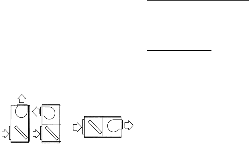
These evaporator blowers can be arranged for a variety of air
discharge patterns in either the horizontal or vertical position.
Figure 2 shows three of the common installation arrange-
ments. Refer to the unit installation instructions for other pos-
sibilities.
Units may be bottom-supported or ceiling-suspended and
can be arranged to meet almost any space or duct require-
ments. Each unit is available with a choice of blower motors,
drive packages and other accessories to make them suitable
for most applications.
FACTORY-MOUNTED COMPONENTS
PART LOAD OPERATION These evaporator blowers have
multiple coils with pre-piped distributors, expansion valves
and solenoid valves. Field modifications are not required for
part load operations. Capacity reduction not only provides
economical operation, but also maintains more even temper-
ature and humidity levels in the conditioned space.
EASY SERVICE Serviceable expansion valves are provided
on every unit. These superior valves are factory-installed to
provide many years of trouble-free operation. If service is
required, it is not necessary to unbraze any joints.
PUMP-OUT Evaporator blowers include a solenoid valve for
non-recycling pump-out. When a cooling requirement in the
conditioned space is needed, the refrigerant is pumped into
the high side of the system before unit start-up.
ACCESSORIES
BASE SECTIONS (25, 30 and 40 ton only: Base sections
can be used to elevate units above the floor. If desired, out-
door air may be introduced through these sections by cutting
an access opening to accommodate the outdoor air duct con-
nection. These bases have a durable finish to match the
evaporator blower unit. They may have to be insulated for
certain applications.
SUSPENSION PACKAGES: These accessories can be used
to suspend horizontal units from above without interfering
with access to the unit. They can also be used for elevating a
floor-mounted unit (either horizontal or vertical) to provide
additional height for the installation of a trap at the conden-
sate drain connection. All suspension packages can be used
with vibration isolators.
HOT WATER COILS: Drainable water coils are available for
field installation between the blower and the coil modules of
both horizontal and vertical units. Since their casings match
the dimensions and the finish of the basic units, they become
an integral part of the unit after installation. The coils slide out
of their casings for easy installation. Coils have copper tubes
that have been mechanically expanded into aluminum fins.
Both headers are located on the same end of the coil. Coils
are leak-tested at 325 psig under water and dried before their
connections are capped for storage and shipping.
FIGURE 2: UNIT INSTALLATION
036-21335-002-A-1102
Unitary Products Group 5
STEAM COILS (LA300 & LB360 only): A steam coil is avail-
able on the 25 & 30 Ton for installation between the blower
and coil modules of both horizontal and vertical units. Since
the casing matches the dimensions and the finish of the basic
unit, it becomes an integral part of the unit after installation.
The coil slides out of the casings for easy installation and is
pitched in the casings to facilitate condensate drainage. The
coil has copper tubes that have been mechanically expanded
into aluminum fins. Both headers are located on the same
end of the coil. The coil is leak-tested at 325 psig and dried
before the connections are capped for storage and shipping.
BLOWER MOTORS: Different HP motors are available for
each unit to meet almost any air delivery requirement. All
motors are UL approved, have permanently lubricated ball
bearings and are field-mounted within the insulated cabinet of
the units to minimize the transmission of sound to the sur-
rounding space. 5 HP motors are inherently protected. 7.5
HP - 15 HP require motor overload protection.
DRIVE PACKAGES: Different size pulleys and belts are
available for each unit to provide a blower RPM range to
meet almost any air delivery requirement. Variable pitch
motorpulleyscanbeadjustedtoprovidetheproperblower
RPM. All drive packages are rated at least 25% above the
nominal HP rating of the blower motor. Two-groove pulleys
and two belts are provided on every drive package rated at 5
HP and above.
STARTERS AND HEATER ELEMENTS (7.5 - 15 HP): The
blower motors that are available for the units do not have
inherent protection and require external motor overload pro-
tection. See details in Table 7.
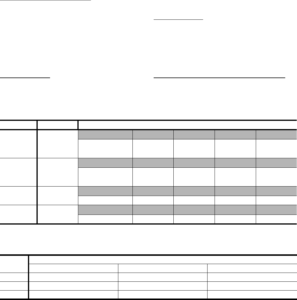
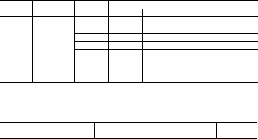
TABLE 1: STATIC RESISTANCES FOR UNIT ACCESSORIES
UNIT MODEL ACCESSORY CFM
LA300
8,000 9,000 10,000 11,000 12,000
Hot Water Coil 0.06 0.07 0.08 0.09 0.10
Steam Coil 0.11 0.14 0.17 0.20 0.23
LB360
10,000 11,000 12,000 13,000 14,000
Hot Water Coil 0.08 0.09 0.10 0.12 0.14
Steam Coil 0.17 0.20 0.23 0.27 0.31
LB480 12,800 14,400 16,000 17,600 19,200
Hot Water Coil 0.11 0.13 0.15 0.17 0.20
LB600 16,000 18,000 20,000 22,000 24,000
Hot Water Coil 0.15 0.18 0.21 0.24 0.28
TABLE 2: UNIT MOUNTING DIMENSIONS1
LA/LB
UNIT
DIMENSIONS, INCHES
AX BX CX
300 69-1/4 49-1/16 26-5/8
360 69-1/4 49-1/16 26-5/8
480 84 50-9/16 34
1. See Figure 4 for dimensions AX, BX and CX.
036-21335-002-A-1102
6Unitary Products Group
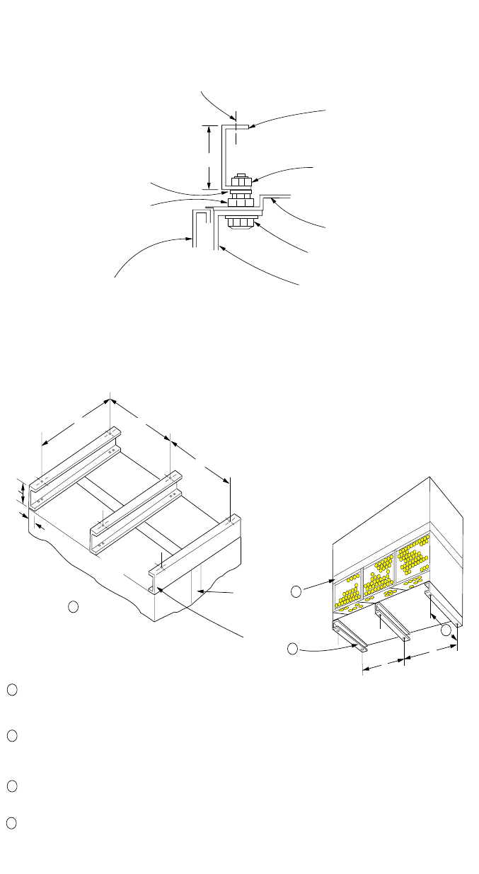
FIGURE 3 : DETAILS FOR SECURING BOTTOM MOUNTING SUPPORTS
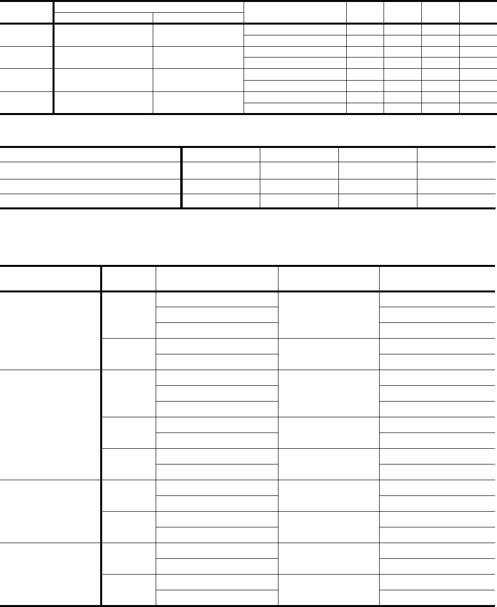
FIGURE 4 : LA300/LB360 WEIGHT DISTRIBUTION
3
NOTE: The following illustration shows how the channels
should be secured to the unit using the hardware
provided with the suspension accessory.
(2) 9/16 HOLES FOR 1/2
HANGER RODS
SUSPENSION
CHANNEL
5/16 NUT,
LOCKWASHER,
FLATWASHER
UNIT PANEL
5/16 BOLT,
FLAT-WASHER
UNIT ANGLE
SIDE
PANEL
5/16 NUT,
FLATWASHER
3/8 NUT (USED
AS SPACER)
AX
3
1-1/2
EVAP. C OIL
S E C T IO N
BLOWER
S E C T IO N
HOR IZONTAL
LE U360 O R 480
UNIT S US PE NDE D
FR OM ABOVE
HE AT IN G C OIL 2
SUSPENSION
ANG LE S 1
BLOWER
S E C T IO N
EVAP.
COIL
S E C T IO N
CX
1
2
3
3
The s ame c hannels can be us ed in e ither position. W hen us ed to
support at vertical unit, th es e c hannels s hould be c ut to match the
bottom dimens ion of the e vaporator coil s ection.
The s uspens ion c hannels have two s ets of mounting holes to
accommodate horizontal units with or without a heating coil. O n
a horizontal unit without a heating coil, th e s uspens ion c hannels
will extend 3" beyond both ends of the unit.
The s ame channels c an be us ed to s upport a horizontal, fl oor-
mounted unit from below.
4
After these bottom c hannels a re c ut per Note 1 , a new hole will have
to be drilled a t the c ut end if the unit is to be mounted on isolators.
4
VERTICAL LA300, LB360, LB480
UNIT SUPPORTED FROM BELOW
D
B
C
A
D
C
B
A
AX BX
BX
BX
BX
036-21335-002-A-1102
Unitary Products Group 7
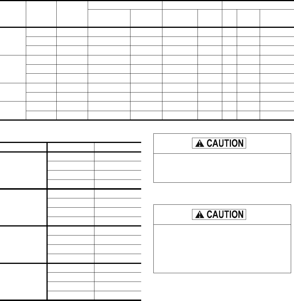
TABLE 3: CORNER WEIGHTS
UNIT-
MODEL
Unit Weight
Configuration A B C DShipping Operation
LA300 1180 1125 HORIZONTAL 276 317 285 247
VERTICAL 262 301 301 262
LB360 1180 1146 HORIZONTAL 281 323 290 252
VERTICAL 266 307 307 266
LB480 1510 1426 HORIZONTAL 348 414 361 303
VERTICAL 292 348 427 359
LB600 1572 1640 HORIZONTAL 451 386 370 433
VERTICAL 484 414 342 400
TABLE 4: ACCESSORY OPERATING WEIGHT DISTRIBUTION (LBS)1
ACCESSORY LA300 LB360 LB480 LB600
BASE225 25 30 45
HOT WATER COIL 35 35 45 35
STEAM COIL 1 ROW 30 30 35 50
1. These weights should be added to each point load in table 3.
2. This accessory can only be applied on units installed in the vertical position.
TABLE 5: UNIT BLOWER MOTOR DATA
UNIT MODEL HP MOTOR KIT
MODEL NUMBER FRAMESIZE VOLTAGE
(3PH-60HZ)
LA300
5
2LR04605032
184
230/460
2LR04605023 208
2LR04605158 575
7.5 2LP04607133 213 230/460
2LP04607158 575
LB360
5
2LR04605032
184
230/460
2LR04605023 208
2LR04605158 575
7.5 2LP04607133 213 208/230/460
2LP04607158 575
10 2LP04610133 215 208/230/460
2LP04610158 575
LB480
7.5 2LP04607133 213 208/230/460
2LP04607158 575
10 2LP04610133 215 208/230/460
2LP04610158 575
LB600
10 2LP04610133 215 208/230/460
2LP04610158 575
15 2LP04615133 254 208/230/460
2LP04615158 575
036-21335-002-A-1102
8Unitary Products Group
Note: Three elements required per unit.
TABLE 6: UNIT DRIVE DATA
UNIT
MODEL
DRIVE KIT
MODEL
NUMBER
BLOWER
RPM
RANGE
ADJUSTABLE MOTOR PULLEY FIXED BLOWER PULLEY BELTS
PITCH DIA.
(IN.) BORE
(IN.) PITCH DIA.
(IN.) BORE
(IN.) QTY.
PITCH
LENGTH
(IN.) DESIGNATION
LA300
1LD0440 600 - 750 4.0 - 5.0 1 1/8 12.0 1 3/16 2 63.3 A62
1LD0407 700 - 850 4.2 - 5.2 1 3/8 11.0 1 3/16 2 63.3 A62
1LD0442 780 - 940 5.3 - 6.3 1 3/8 12.0 1 3/16 2 63.3 A62
LB360
1LD0415 636 - 795 4.0 - 5.0 1 1/8 11.0 1 3/16 2 63.3 A62
1LD0407 668 - 827 4.2 - 5.2 1 3/8 11.0 1 3/16 2 63.3 A62
1LD0408 827 - 986 5.3 - 6.3 1 3/8 11.0 1 3/16 2 59.7 A59
LB480 1LD0409 607 - 776 4.3 - 5.5 1 3/8 12.4 1 3/16 2 85.1 B84
1LD0410 776 - 917 5.4 - 6.6 1 3/8 12.4 1 3/16 2 86.8 B85
LB600 1LD0411 692 - 833 4.8 - 6.0 1 3/8 12.4 1 3/16 2 78.6 B78
1LD0412 762 - 931 5.4 - 6.6 1 5/8 12.4 1 3/16 2 76.8 B75
TABLE 7: MOTOR OVERLOAD ELEMENTS1
1. These units are equipped from the factory with a cor-
rectly sized motor starter; overload elements are not
factory supplied.
MOTOR HP VOLTAGE MODEL NUMBER
5
208 2MP04704600
230 2MP04704600
460 2MP04704900
575 2MP04705000
7.5
208 2MP04703700
230 2MP04704500
460 2MP04704300
575 2MP04704000
10
208 2MP04701600
230 2MP04704100
460 2MP04704200
575 2MP04704300
15
208 2MP04704400
230 2MP04701700
460 2MP04704500
575 2MP04704600
Do not operate the supply air blower motor above
its nominal HP rating when a unit is equipped with
a hot water coil accessory. Do not use steam in hot
water coils.
Do not operate the supply air blower above its
nominal HP rating when a unit is equipped with a
steam coil accessory.
Although these coils are suitable for a much higher
pressure, steam above 25 psig provides too much
heat that could damage the blower motor.
036-21335-002-A-1102
Unitary Products Group 9
TABLE 8: HOT WATER COIL CAPACITIES1
UNIT
MODEL HOT WATER
COIL MODEL GPM CFM ENTERING WATER TEMPERATURE MINUS ENTRY AIR TEMPERATURE °F.
70 90 110 130 150
LA300
1HW0406
50
6,000 204 263 325 384 443
8,000 236 304 372 440 508
10,000 265 341 416 492 568
12,000 291 374 457 540 623
LB360 50
8,000 236 304 372 440 508
10,000 265 341 416 492 568
12,000 291 374 457 540 623
14,000 315 405 495 585 675
LB480
1HW0407
75
12,800 348 447 547 646 746
16,000 389 500 611 722 833
19,200 425 547 668 790 911
LB600 75
16,000 389 500 611 722 833
20,000 436 561 686 810 935
24,000 473 610 746 882 1,019
1. These capacities do not include any blower motor heat.
NOTE: Temperature Water Drop (ºF) = (2 X MBH) / GPM.
TABLE 9: HOT WATER COIL CAPACITY CORRECTION AND PRESSURE DROP VS GPM1
HOT WATER COIL MODEL GPM PRESSURE DROP
PSI CAPACITY CORRECTION
FACTOR
1HW0406
25 0.4 0.79
50 1.0 1.00
75 1.8 1.04
100 3.4 1.07
1HW0407
50 1.0 0.95
75 1.5 1.00
100 2.4 1.03
125 3.5 1.05
1. For pressure drop in feet (water), multiply these values by 2.31.
036-21335-002-A-1102
10 Unitary Products Group
NOTE: Steam Rate = (lbs/Hr.) = 1.025 x MBH
TABLE 10: STEAM COIL CAPACITIES1,MBH@2PSIG
2
UNIT
MODEL STEAM COIL
MODEL CFM DRY BULB TEMPERATURE OF AIR ENTERING COIL (°F)
10 30 50 70
LA300
1NF0454
6,000 471 424 380 330
8,000 535 483 432 380
10,000 592 535 478 422
12,000 642 580 518 456
LB360
8,000 535 483 432 380
10,000 592 535 478 422
12,000 642 580 518 456
14,000 687 621 555 489
1. These capacities do not include any blower motor heat.
2. Multiply these capacities by the factors in Table 11 to correct for higher steam pressure.
TABLE 11: CORRECTION FACTORS FOR HIGH STEAM
STEAM PRESSURE (PSIG) 5101520 25
CAPACITY CORRECTION FACTOR 1.05 1.12 1.19 1.25 1.30
036-21335-002-A-1102
Unitary Products Group 11
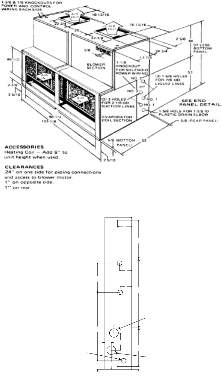
FIGURE 5: UNIT DIMENSIONS - LA300, LB360 & LB480
AIR
OUT
AIR
OUT
AIR
IN
AIR
IN
5/8
5/8
5/8 PANEL
5/8 BOTTOM
PANEL
7/8 KNOCKOUTS FOR POWER
AND CONTROL WIRING
M
C
AB
EVAPORATOR
COIL SECTION
D
D
D
E
LESS
BOTTOM
PANEL
{
BLOWER
SECTION
J
L
K
K
See detailed drawings for piping
and drain connections
on following pages.
EVAPORATOR
SECTION
TABLE 12: UNIT DIMENSIONS - LA300, LB360, LB480
MODEL A BCDEFGH J KLM
LA300 100-1/8 95-5/8 33-1/4 36-5/8 74 2-1/2 18-7/8 16-1/2 15-13/16 21-7/8 18 22-9/16
LB360 100-1/8 95-5/8 33-1/4 36-5/8 74 2-1/2 18-7/8 16-1/2 15-13/16 21-7/8 18 22-9/16
LB480 103-1/8 95-5/8 40-5/8 44 88-5/8 2-1/2 18-7/8 23-7/8 20-11/16 21-7/8 18 22-11/16
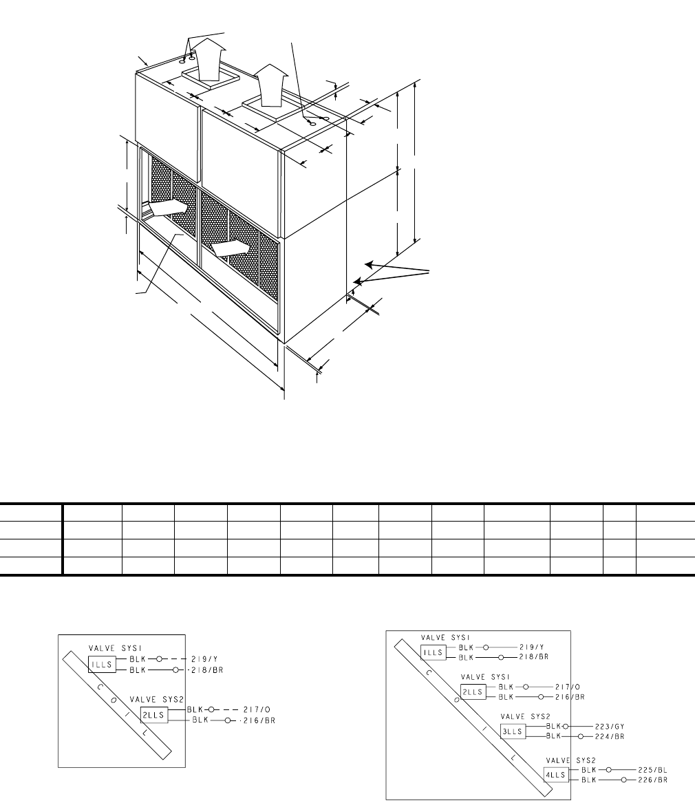
FIGURE 6: 25 TON LIQUID LINE SOLENOID
WIRING FIGURE 7: 30, 40 & 50 TON LIQUID LINE
SOLENOID WIRING
036-21335-002-A-1102
12 Unitary Products Group
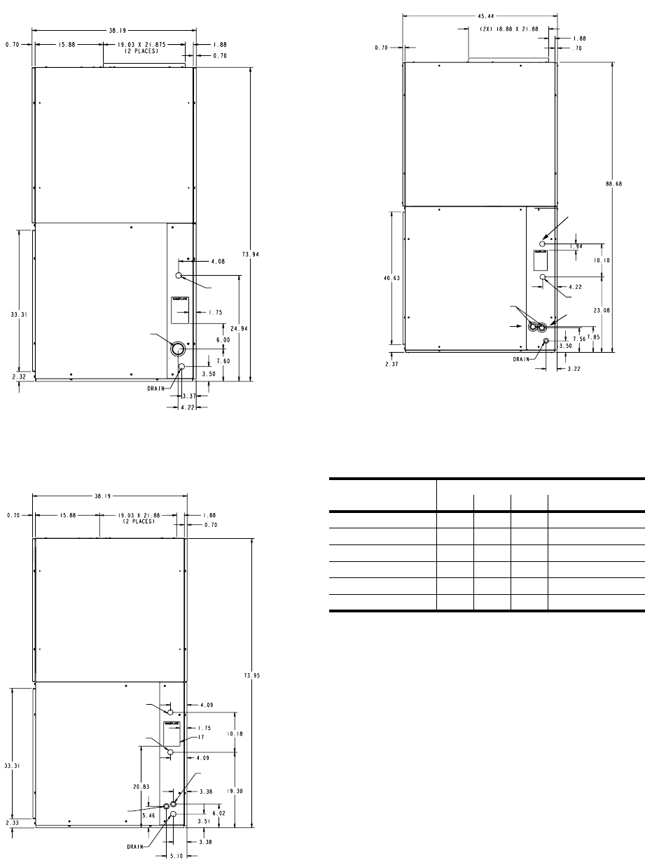
FIGURE 8: LA300 PIPING CONNECTIONS
FIGURE 9: LB360 PIPING CONNECTIONS
SUCTION
LIQUID
LIQUID (SYS. #1)
LIQUID (SYS. #2)
SUCTION
(SYS. #2)
SUCTION
(SYS. #1)
FIGURE 10: LB480 PIPING CONNECTIONS
TABLE 13: UNIT CONNECTION SIZES
Connection Entry Connection Size
LA300 LB360 LB480 LB600 + M2CX600
Suction Line Sys # 1 2 1/8 1-1/8 1-3/8 2-1/8
Suction Line Sys # 2 N/A 1-1/8 1-3/8 2-1/8
Liquid Line Sys # 1 7/8 7/8 7/8 7/8
Liquid Line Sys # 2 N/A 7/8 7/8 7/8
Power Wiring 7/8 (2) 7/8 (2) 7/8 (2) 1-3/8
Control Wiring 7/8 (2) 7/8 (2) 7/8 (2) 7/8 (2)
LIQUID
SYS. #1
LIQUID
SYS. #2
SYS. #1
SYS. # 2
SUCTION
036-21335-002-A-1102
Unitary Products Group 13
FIGURE 11: UNIT DIMENSIONS - LB600
FIGURE 12: LB600 PIPING CONNECTIONS - END PANEL DETAIL
6.7"
13.5"
6.0"
2.1"
3.0"
10.1"
23.86"
3.0"
3.8"
Liquid
Line
Sys. #2
4.0"
24.0"
13.5"
4.7"
Liquid
Line
Sys. #1
Condensate
Drain Suction
Line
Sys. #1
Suction
Line
Sys. #2
036-21335-002-A-1102
14 Unitary Products Group
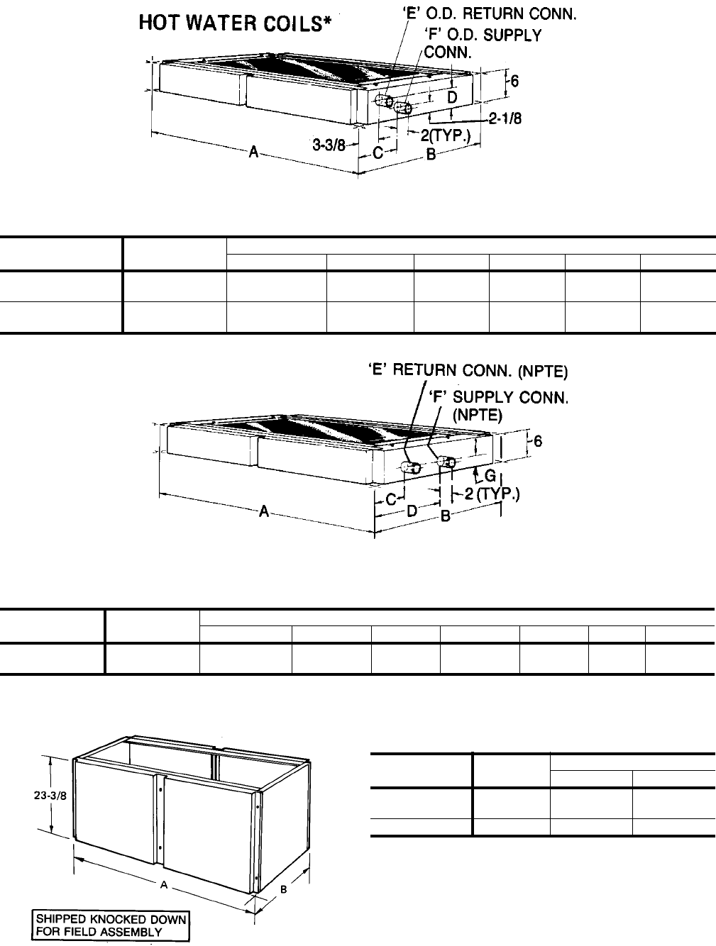
FIGURE 13: HOT WATER COIL DIMENSIONS
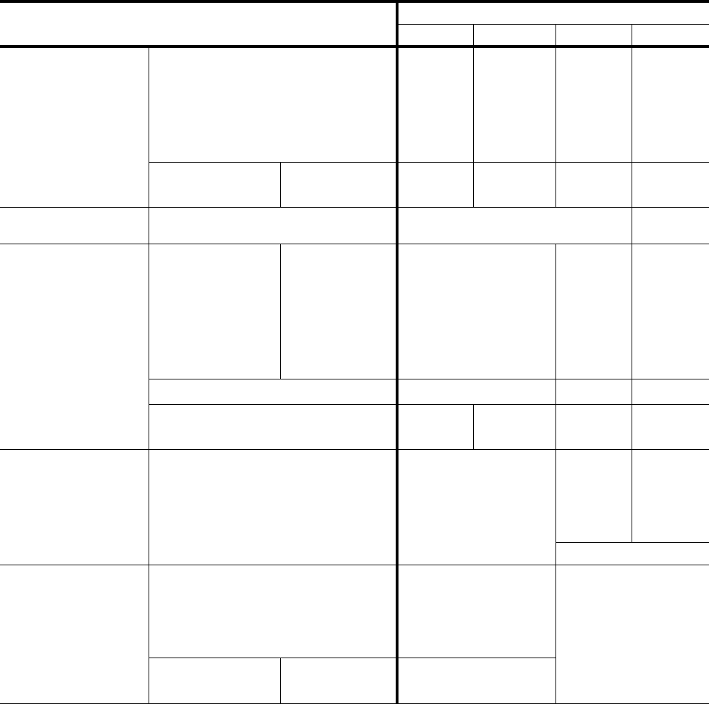
TABLE 14: HOT WATER COIL DIMENSIONS
COIL
MODEL UNIT
MODEL
DIMENSIONS
ABCDEF
1HW0406 LA300
LB360 100-1/8 37-7/8 6-3/4 3-7/8 1-3/8 1-3/8
1HW0407 LB480
LB600 103-1/8 45-1/4 6-1/2 4 1-5/8 1-5/8
FIGURE 14: STEAM COIL DIMENSIONS
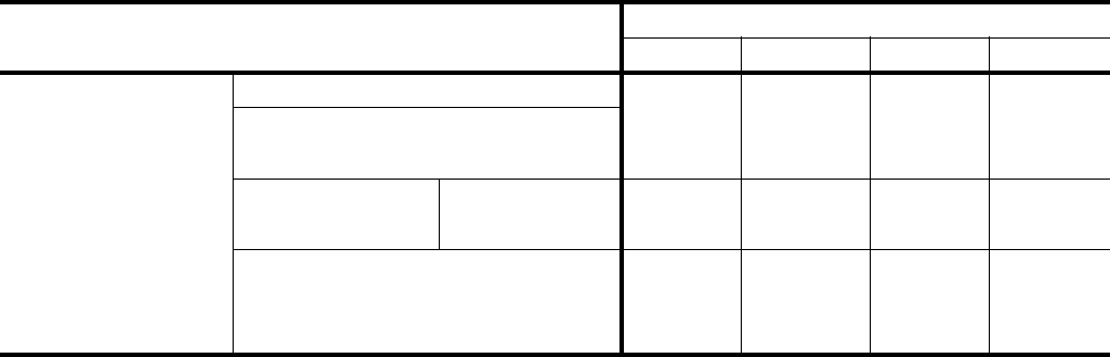
TABLE 15: STEAM COIL DIMENSIONS1
COIL
MODEL UNIT
MODEL
DIMENSIONS
A BCDEFG
1NF0454 LA300
LB360 100-1/8 37-7/8 4-3/8 18-3/8 1-1/2 2 2-1/2
1. Coils are field-installed between the evaporator coil and the blower section of the unit.
FIGURE 15: BASE SECTION DIMENSIONS
TABLE16:BASESECTIONSDIMENSIONS
1
1. Ventilation air can be brought into the unit through the
base section providing the base section is fully insu-
latedinthefield.
BASE
MODEL UNIT
MODEL
DIMENSIONS
AB
1BS0406 LA300
LB360 100-1/8 37-7/8
1BS0407 LB480 103-1/8 45-1/4
036-21335-002-A-1102
Unitary Products Group 15
TABLE 17: PHYSICAL DATA
DESCRIPTION MODEL
LA300 LB360 LB480 LB600
EVAPORATOR
COIL
Rows Deep X Rows High 4 x 40 4 x 40 4 x 50 4 x 62
Finned Length, Inches 93 93 96 96
Face Area, Feet225.8 25.8 33.3 41.3
Tube (copper) OD, Inches 3/8 3/8 3/8 3/8
Fins (Aluminum) per 1 inch 16 16 16 16
Piping Connections,
Inches
Liquid, Inches 7/8 7/8 7/8 7/8
Suction, Inches 2 1/8 1 1/8 1 3/8 2 1/8
CENTRIFUGAL
BLOWERS (2 PER UNIT) Diameter X Width, Inches (Forward Curved) 18 x 18 20 x 18
FILTERS (THROWAWAY)
Size and Quantity Per
Model, Inches
16 x 20 x 2 - 6 -
20 x 20 x 2 - 3 -
20 x 22 x 2 - - -
16 x 25 x 2 - - 6
20 x 25 x 2 10 6 3
25 x 25 x 2 - - 6
Total Face Area / feet234.7 42.6 53.1
OPERATING CHARGE
(LBS R-22)
System 1 49.65 30.08 37.83 46.59
System 2 - 30.08 37.83 46.59
DRAINABLE HOT WATER
COIL ACCESSORY
Tube (copper) OD, Inches 1/2 1/2 1/2
Rows Deep 2 2 2
Fins (Aluminum) per 1 inch 12 12 8
Face Area, Feet221.2 27.2 27.2
Connections (Supply & Return), Inches 1 3/8 OD (Copper) 1 5/8 OD (Copper)
NON-FREEZE, STEAM
DISTRIBUTING COIL
ACCESSORY
Tube (copper) OD, inches 1 (Outside) 5/8 (Inside)
N/A
Rows Deep 1
Fins (Aluminum) per 1 inch 8
Face Area, feet218.2
Connection, (Brass)
Inches (NPTE)
Inlet 2
Outlet 1-1/2
036-21335-002-A-1102
16 Unitary Products Group
COMPONENT WEIGHT
Basic Unit (Less Motor & Drive) 980 980 1260 1474
Shipping Weight (lbs) 1180 1180 1510 1572
Operating Weight (lbs) 1125 1146 1426 1640
Accessories Hot Water Coil 150 150 190 190
Steam Coil 160 160 - -
Blower Motor (1750 RPM)
117 (5hp) 117 (5hp) - -
120 (7.5hp) 120 (7.5hp) 120 (7.5hp) 141 (10hp)
- 141 (10hp) 141 (10hp) 217 (15hp)
TABLE 17: PHYSICAL DATA
DESCRIPTION MODEL
LA300 LB360 LB480 LB600

036-21335-002-A-1102
Unitary Products Group 17
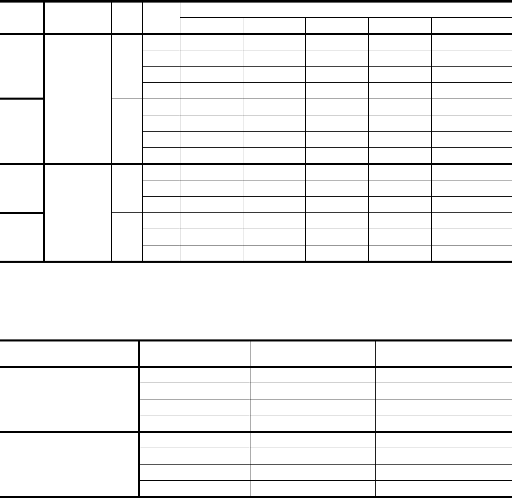
TABLE 18: ELECTRICAL DATA
UNIT MODEL HP FLA VOLTAGE
(3PH-60HZ) MIN. CIRCUIT AMPACITY MAX. FUSE SIZE
(Amps)
LA300
5
16.7 208 21 35
15.2 230 19 30
7.6 460 10 15
6.1 575 8 15
7.5
24.2 208 30 50
22 230 28 45
11 460 14 20
9 575 11 20
LB360
5.0
16.7 208 21 35
15.2 230 19 30
7.6 460 10 15
6.1 575 8 15
7.5
24.2 208 30 50
22 230 28 45
11 460 14 20
9 575 11 20
10
30.8 208 39 60
28 230 35 60
14 460 18 30
11 575 14 20
LB480
7.5
24.2 208 30 50
22 230 28 45
11 460 14 20
9 575 11 20
10
30.8 208 39 60
28 230 35 60
14 460 18 30
11 575 14 20
LB600
10
30.8 208 39 60
28 230 35 60
14 460 18 30
11 575 14 20
15
46.2 208 58 100
42 230 53 90
21 460 26 45
17 575 21 35
036-21335-002-A-1102
18 Unitary Products Group
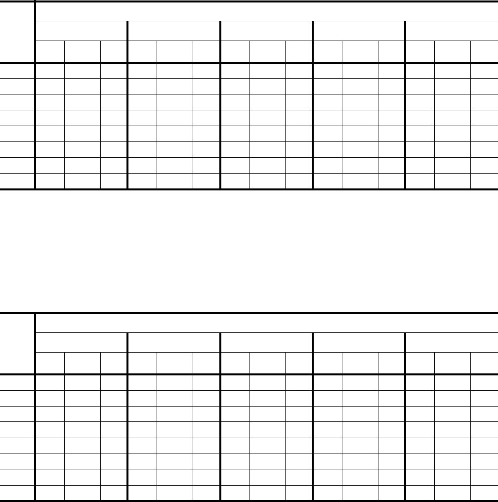
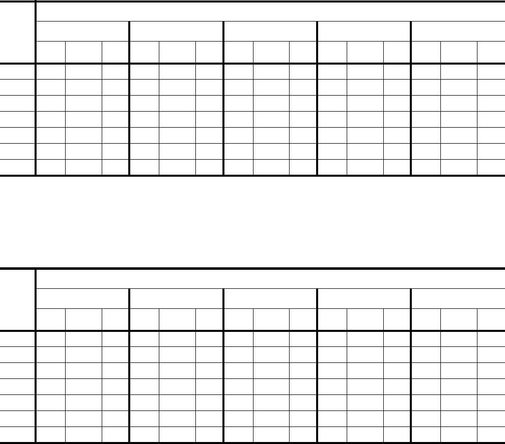
TABLE 19: FAN PERFORMANCE DATA - 25 TON1
RPM
CFM
8,000 9,000 10,000 11,000 12,000
SP2BHP3KWSP2BHP3KWSP2BHP3KWSP2BHP3KWSP2BHP3KW
600 - - - 0.30 2.5 2.3 0.20 3.1 2.9 0.02 3.6 3.4 - - -
635 0.56 2.4 2.3 0.43 2.7 2.6 0.31 3.3 3.1 0.13 3.8 3.5 - - -
700 0.80 3.0 2.8 0.68 3.3 3.1 0.54 3.7 3.5 0.38 4.2 3.9 0.20 4.8 4.5
775 1.12 3.7 3.4 1.00 4.0 3.7 0.85 4.4 4.1 0.70 4.8 4.5 0.54 5.3 5.0
800 1.23 3.9 3.7 1.11 4.3 4.0 0.97 4.7 4.4 0.82 5.1 4.8 0.66 5.6 5.2
875 1.60 4.8 4.5 1.48 5.1 4.8 1.34 5.6 5.2 1.19 6.0 5.7 1.04 6.6 6.2
900 1.73 5.1 4.8 1.61 5.5 5.1 1.47 5.9 5.5 1.33 6.4 6.0 1.17 7.0 6.5
940 1.95 5.6 5.2 1.82 6.0 5.6 1.70 6.5 6.1 - - - - - -
1. Unit resistance is based on a dry evaporator coil and clean filters.
2. Available static pressure in IWG to overcome the resistance of the duct system and any accessories added to the unit. Refer to
the blower motor and drive table and the accessory static resistance table for additional information.
3. Motors can be selected to operate into the service factor because they are located in the moving air stream, upstream of any heat-
ing device. units with steam or hot water coils are the only exception. On these units, the BHP must not exceed the nominal HP
rating of the motor.
TABLE 20: FAN PERFORMANCE DATA - 30 TON1
RPM
CFM
10,000 11,000 12,000 13,000 14,000
SP2BHP3KWSP2BHP3KWSP2BHP3KWSP2BHP3KWSP2BHP3KW
600 0.20 3.1 2.9 0.02 3.6 3.4 - - - - - - - - -
635 0.31 3.3 3.1 0.13 3.8 3.5 - - - - - - - - -
700 0.54 3.7 3.5 0.38 4.2 3.9 0.20 4.8 4.5 0.03 5.3 5.0 - - -
775 0.85 4.4 4.1 0.70 4.8 4.5 0.54 5.3 5.0 0.39 5.8 5.5 0.20 6.4 6.0
800 0.97 4.7 4.4 0.82 5.1 4.8 0.66 5.6 5.2 0.52 6.1 5.7 0.35 6.7 6.3
875 1.34 5.6 5.2 1.19 6.0 5.7 1.04 6.6 6.2 0.93 7.1 6.6 0.77 7.7 7.2
900 1.47 5.9 5.5 1.33 6.4 6.0 1.17 7.0 6.5 1.07 7.5 7.0 0.90 8.2 7.6
940 1.70 6.5 6.1 1.55 7.0 6.6 1.40 7.7 7.2 1.31 8.3 7.8 1.09 9.0 8.4
1. Unit resistance is based on a dry evaporator coil and clean filters.
2. Available static pressure in IWG to overcome the resistance of the duct system and any accessories added to the unit. Refer to
the blower motor and drive table and the accessory static resistance table for additional information.
3. Motors can be selected to operate into the service factor because they are located in the moving air stream, upstream of any heat-
ing device. units with steam or hot water coils are the only exception. On these units, the BHP must not exceed the nominal HP
rating of the motor.
036-21335-002-A-1102
Unitary Products Group 19
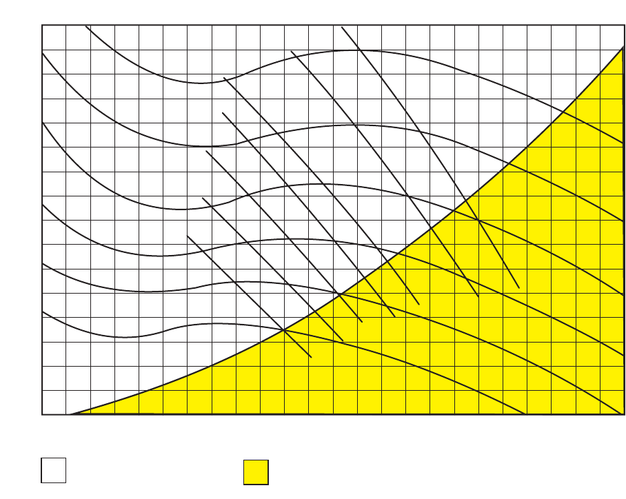
FIGURE 16: BLOWER CURVE LA300 & LB360
3.2
3.0
2.8
2.6
2.4
2.2
2.0
1.8
1.6
1.4
1.2
1.0
0.8
0.6
0.4
0.2
0010 20 30 40 50 60 70 80 90 100 110 120 130 140 150 160 170 180 190 200 210 220 230
LA300 & LB360
Available external static pres-
sure for unit accessories and
the duct system.
Internal unit resistance based
on a dry coil plus 2"
throwaway filters.
CFM (X 100)
TOTAL STATIC PRESSURE, IWG
1000 RPM
900 RPM
800 RPM
700 RPM
600 RPM
500 RPM
10 BHP
8 BHP
6 BHP
5 BHP
4 BHP
3 BHP
2 BHP
036-21335-002-A-1102
20 Unitary Products Group
TABLE 21: FAN PERFORMANCE DATA - 40 TON1
RPM
CFM
12,800 14,400 16,000 17,600 19,200
SP2BHP KWSP2BHP KWSP2BHP KWSP2BHP KWSP2BHP KW
600 0.20 4.3 3.7 - - - - - - - - - - - -
640 0.38 4.8 4.1 0.19 5.6 4.8 - - - - - - - - -
700 0.65 5.5 4.7 0.47 6.4 5.5 0.28 7.2 6.2 - - - - - -
775 0.99 6.5 5.6 0.84 7.4 6.4 0.66 8.4 7.2 0.46 9.4 8.1 0.23 10.4 9.0
800 1.11 6.8 5.9 0.96 7.8 6.7 0.79 8.8 7.6 0.59 9.8 8.4 0.36 10.8 9.3
900 1.65 8.1 7.0 1.52 9.3 8.0 1.36 10.5 9.0 - - - - - -
915 1.73 8.3 7.2 1.60 9.5 8.2 1.44 10.7 9.2 - - - - - -
1. Unit resistance is based on a dry evaporator coil and clean filters.
2. Available static pressure in IWG to overcome the resistance of the duct system and any accessories added to the unit. Refer to
the blower motor and drive table and the accessory static resistance table for additional information.
TABLE 22: FAN PERFORMANCE DATA - 50 TON1
RPM
CFM
16,000 18,000 20,000 22,000 24,000
SP2BHP KWSP2BHP KWSP2BHP KWSP2BHP KWSP2BHP KW
600 0.82 6.0 5.2 0.59 7.2 6.2 0.35 8.4 7.2 0.08 9.7 8.4 - - -
660 1.17 7.3 6.3 0.96 8.5 7.3 0.73 9.8 8.5 0.45 11.2 9.7 0.14 12.7 11.0
700 1.40 8.2 7.1 1.21 9.4 8.1 0.98 10.7 9.2 0.70 12.2 10.5 0.40 13.7 11.8
760 1.76 9.5 8.2 1.59 10.8 9.3 1.38 12.3 10.6 1.11 13.8 11.9 0.81 15.6 13.5
800 2.00 10.4 9.0 1.85 11.8 10.2 1.64 13.3 11.5 1.38 14.9 12.9 1.09 16.9 14.6
900 2.60 12.8 11.0 2.49 14.5 12.5 2.35 16.0 13.8 - - - - - -
930 2.78 13.5 11.6 2.68 15.3 13.2 - - - - - - - - -
1. Unit resistance is based on a dry evaporator coil and clean filters.
2. Available static pressure in IWG to overcome the resistance of the duct system and any accessories added to the unit. Refer to
the blower motor and drive table and the accessory static resistance table for additional information.
036-21335-002-A-1102
Unitary Products Group 21
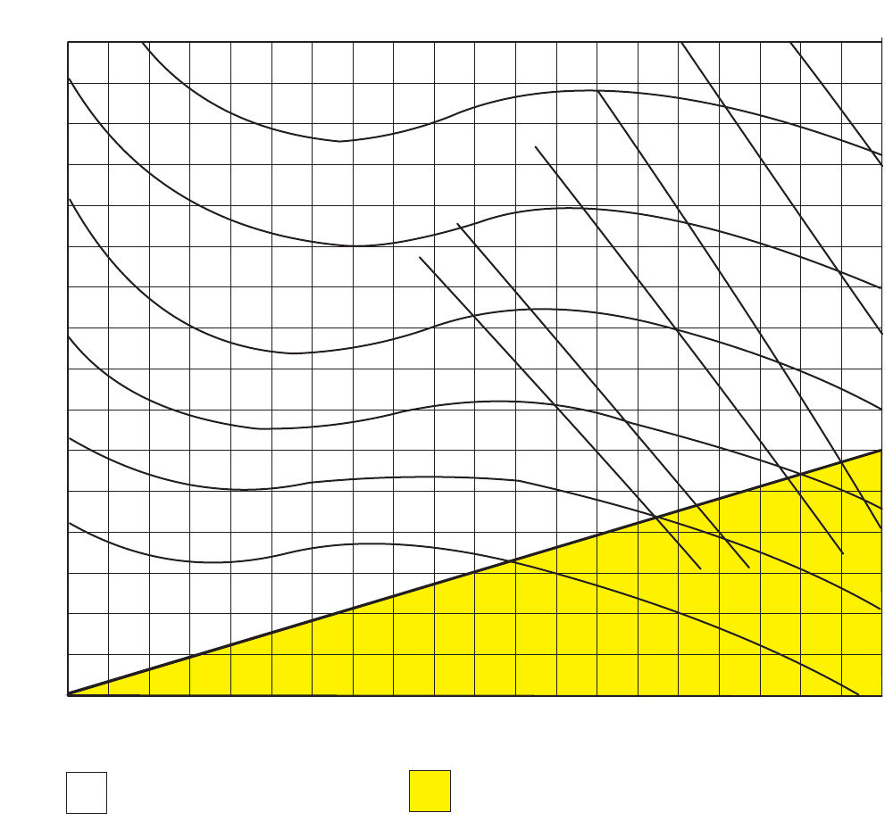
FIGURE 17: BLOWER CURVE LB480
Available external static pres-
sure for unit accessories and
the duct system.
Internal unit resistance based
on a dry coil plus 2"
throwaway filters.
010 20 30 40 50 60 70 80 90 100 110 120 130 140 150 160 170 180 190 200
3.2
3.0
2.8
2.6
2.4
2.2
2.0
1.8
1.6
1.4
1.2
1.0
0.8
0.6
0.4
0.2
0
LB480
1000 RPM
900 RPM
800 RPM
700 RPM
600 RPM
500 RPM
15 BHP
12-1/2 BHP
10 BHP
8 BHP
6 BHP
5 BHP
CFM (X 100)
TOTAL STATIC PRESSURE, IWG
036-21335-002-A-1102
22 Unitary Products Group
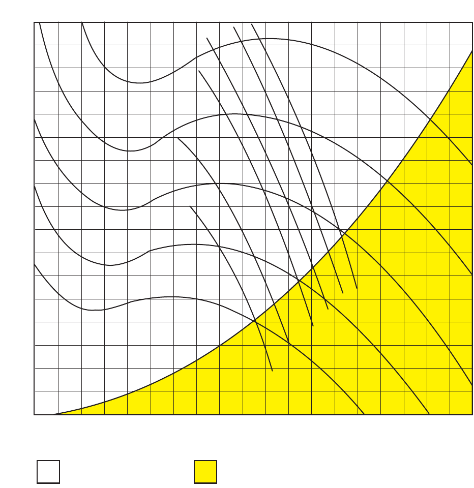
FIGURE 18: BLOWER CURVE LB600
LB600
020 40 60 80 100 120 140 160 180 200 220 240 260 280 300 320 340 360
16 BHP
14 BHP
12 BHP
10 BHP
8 BHP
6 BHP
500 RPM
600 RPM
700 RPM
800 RPM
900 RPM
3.2
3.0
2.8
2.6
2.4
2.2
2.0
1.8
1.6
1.4
1.2
1.0
0.8
0.6
0.4
0.2
0
AvaIlable external static pres-
sure for unit accessories and
the duct system.
Internal unit resistance based
on a dry coil plus 1"
throwaway filters.
CFM (X 100)
TOTAL STATIC PRESSURE, IWG
036-21335-002-A-1102
Unitary Products Group 23
GUIDE SPECIFICATIONS
EACH UNIT SHALL BE:
•Covered by a 1-year limited parts warranty on the com-
plete unit.
•In current production with published literature available
to check performance, limitations, specifications, power
requirements, dimensions, operation and appearance;
also equipped with a V-belt drive option that:
a. Will permit the blower RPM to be adjusted to meet
the exact CFM requirement of the system.
EACH UNIT ENCLOSURE SHALL HAVE:
•A steel angle frame to provide the rigid support required
for shipping, rigging and years of dependable operation.
•Exterior panels of 18 gauge steel, finished with baked
enamel to provide a long lasting quality appearance
•Removable panels to provide easy access to the internal
components for maintenance and service, and,
•A filter rack with 2”filters.
THE DIMENSIONS OF EACH UNIT SHALL NOT
EXCEED THOSE SPECIFIED.
THE BLOWER MOTOR SHALL:
•Be mounted within the insulated cabinet to minimize the
transmission of sound to the surrounding space, and
•Have a service factor of 1.15.
THE EVAPORATOR COIL SHALL:
•Consist of copper tubes arranged in staggered rows,
mechanically expanded into aluminum fins,
•Be draw-through, and
•Include factory-mounted distributors, expansion valves
and solenoid valves for both capacity reduction and
pumpdown.
THE BLOWER WHEELS SHALL:
•Be dynamically balanced to minimize the levels of sound
and vibration generated by the unit.

Subject to change without notice. Printed in U.S.A. 036-21335-002-1-1102
Copyright ©by Unitary Products Group 2002. All rights reserved. Supersedes: 036-21335-001-B-0202
Unitary 5005 Norman
Products York OK
Group Drive 73069
