York Ap Air Handler Technical Guide 1055230 YTG D 0514
2015-09-09
: York Ap-Air-Handler-Technical-Guide york-ap-air-handler-technical-guide-811885 york pdf
Open the PDF directly: View PDF ![]() .
.
Page Count: 12
TECHNICAL GUIDE
SINGLE PIECE AIR HANDLERS
FOR USE WITH SPLIT-SYSTEM
COOLING & HEAT PUMPS
MODELS: AHR18 THRU 60*
Due to continuous product improvement,
specifications are subject to change without notice.
Visit us on the web at:
www.upgnet.com and www.york.com
Additional rating information can be found at:
www.ahridirectory.org
WARRANTY
Standard 5-year limited parts warranty.
Extended 10-year limited parts warranty when product is regis-
tered online within 90 days of purchase for replacement or
closing for new home construction.
ISO 9001
Certified Quality
Management System
1055230-YTG-D-0514
FOR DISTRIBUTION USE ONLY - NOT TO BE USED AT POINT OF RETAIL SALE
DESCRIPTION
This fan coil line offers the ultimate in application flexibility. This unit
may be used for upflow, downflow, horizontal right, or horizontal left
applications.
All JCI Unitary Products air handlers and coils use a TXV to provide our
customers with the optimum performance and refrigerant control. Air
handlers are shipped with “Flex-coils” without a factory installed meter-
ing device. For added flexibility, an R-22 or R-410A TXV or orifice can
be field installed to meet your refrigerant choice.
FEATURES
Thermal Expansion Valve - Provides the ultimate refrigerant con-
trol required for today’s high efficient product. The UPG bolt-on TXV
provides the added flexibility to convert the air handler to the required
refrigerant. The UPG TXV is a true bolt-on which does not require braz-
ing to replace or install.
Insulated Cabinet - All air handler cabinets are thermally insulated
with 3/4” foil faced insulation to prevent sweating.
Factory Sealed - Achieves 2% or less total airflow leakage rate at
duct blaster field test conditions for system airflow verification.
Durable Finish Inside and Out - Air handler casings are made of
pre-painted galvanized steel which provides a better paint to steel bond
that resists corrosion and rust creep. All internal coil sheet metal parts
are made of G60 galvanized or prepainted G30 galvanized.
Filters - All models have internal filter racks provided for use with 1”
thick standard size filters.
Electric Heat Kits - 6HK series of field installed electric heat kits are
available for installation friendly and easy service applications.
1055230-YTG-D-0514
2Johnson Controls Unitary Products
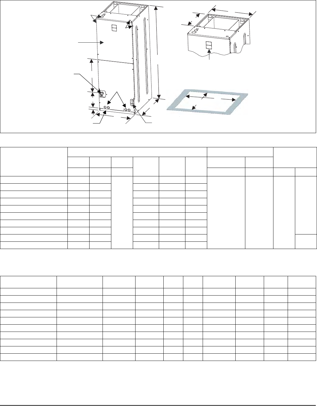
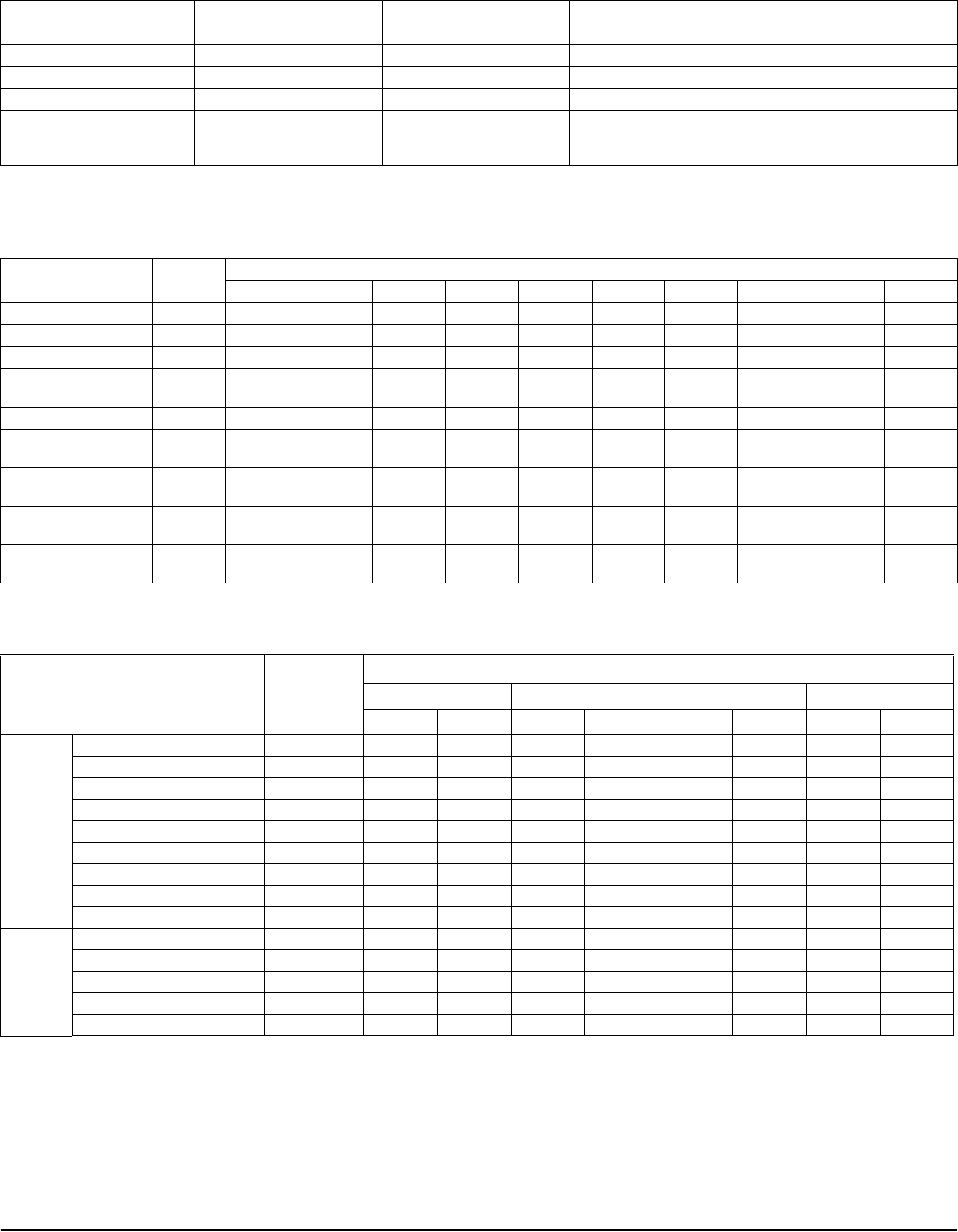
DIMENSIONS & DUCT CONNECTION DIMENSIONS
J
D
Blower
Compartment
Service
Disconnect
Panel
Drain Pan Connections
for Horizontal Applications
Refrigerant
Connections Drain Connections
for Upflow
Applications
7-11/32”
B
A
K
C
1-1/2”
Top Outlet
Dimensions
Filter
Access
20-5/16” E
Bottom Inlet
Dimensions
13”
F
A024-001
Dimensions1
Models
Dimensions Wiring Knockouts2Refrigerant
Connections
Line Size
ABC DEF JK
Height Width Depth Power Control Liquid Vapor
AHR18B3XH21 46 17-1/2
21-1/2
16-/2 13-29/32 16-1/2
7/8 (1/2)
1-3/8(1)
1-23/32 (1-1/4)
7/8 (1/2) 3/8
3/4
AHR22B3XH21 46 17-1/2 16-/2 13-29/32 16-1/2
AHR24B3XH21 46 17-1/2 16-/2 13-29/32 16-1/2
AHR30B3XH21 46 17-1/2 16-/2 13-29/32 16-1/2
AHR36B3XH21 46 17-1/2 16-/2 13-29/32 16-1/2
AHR29C3XH21 52 21 21-1/2 17-13/32 20
AHR34C3XH21 52 21 21-1/2 17-13/32 20
AHR42C3XH21 52 21 21-1/2 17-13/32 20
AHR48D3XH21 57 24-1/2 26 20-29/32 23-1/2 7/8
AHR60D3XH21 57 24-1/2 26 20-29/32 23-1/2
1. All dimensions are in inches.
2. Actual size (conduit size).
COIL TECHNICAL DATA
Models Application Refrig.
Conn. Types Face Area
(Sq. Ft.) Rows
Deep Fins
Per In. Coil Size Tube
Geometry Tube
Dia. Fin
Type
AHR18B Cooling /Heat Pump Sweat 3.4 2 14 (2) 14 x 17.5 1 x 0.866 3/8 Enhanced
AHR22B Cooling /Heat Pump Sweat 3.9 2 14 (2) 16 x 17.5 1 x 0.866 3/8 Enhanced
AHR24B Cooling /Heat Pump Sweat 3.9 3 12 (2) 16 x 17.5 1 x 0.866 3/8 Enhanced
AHR29C Cooling /Heat Pump Sweat 4.4 2 14 (2) 18 x 17.5 1 x 0.866 3/8 Enhanced
AHR30B Cooling /Heat Pump Sweat 3.9 3 12 (2) 16 x 17.5 1 x 0.866 3/8 Enhanced
AHR34C Cooling /Heat Pump Sweat 3.4 3 14 (2) 14 x 17.5 1 x 0.866 3/8 Enhanced
AHR36B Cooling /Heat Pump Sweat 4.9 3 12 (2) 20 x 17.5 1 x 0.866 3/8 Enhanced
AHR42C Cooling /Heat Pump Sweat 5.4 3 12 (2) 22 x 17.5 1 x 0.866 3/8 Enhanced
AHR48D Cooling /Heat Pump Sweat 5.8 3 11 (2) 24 x 17.5 1 x 0.866 3/8 Enhanced
AHR60D Cooling /Heat Pump Sweat 6.8 3 12 (2) 28 x 17.5 1 x 0.866 3/8 Enhanced
1055230-YTG-D-0514
Johnson Controls Unitary Products 3
COOLING CAPACITY1
Models Rated CFM2Entering Air
Dry/Wet Bulb
(°F)
MBH@ Evap. Temp. and Corresponding R-410A Pressure (°F/PSIG)
35/107.9 40/118.9 45/130.7 50/143.3
AHR18B 665
85/72 40.7 35.6 30.5 24.1
80/67 35.0 29.5 23.9 18.6
75/62 27.9 22.7 18.1 12.4
70/57 22.1 19.8 16.9 14.1
AHR22B 800
85/72 47.7 42.6 35.3 30.3
80/67 40.1 34.7 28.9 22.8
75/62 32.7 27.1 24.7 19.1
70/57 25.7 23.5 20.5 17.1
AHR24B 740
85/72 47.9 42.4 36.8 29.9
80/67 40.9 35.2 29.0 22.6
75/62 33.6 28.0 21.7 15.5
70/57 26.2 23.0 19.9 16.9
AHR29C 1000
85/72 38.9 35.4 31.6 27.6
80/67 33.9 30.3 26.8 23.0
75/62 27.3 23.7 22.5 18.0
70/57 22.6 20.1 17.5 14.8
AHR30B 1115
85/72 65.8 60.4 50.7 41.5
80/67 58.0 49.5 39.9 31.2
75/62 47.1 38.9 30.4 21.1
70/57 37.1 33.1 28.2 23.9
AHR34C 1000
85/72 35.0 31.8 28.4 24.7
80/67 32.2 29.1 25.7 22.3
75/62 26.4 23.4 21.0 17.1
70/57 21.4 18.6 20.2 12.1
AHR36B
1060
85/72 71.1 62.4 51.5 44.3
80/67 59.2 51.0 42.0 32.7
75/62 48.0 39.6 30.8 21.8
70/57 37.3 32.8 28.3 24.0
1245
85/72 83.2 66.7 60.1 48.9
80/67 66.0 59.5 47.8 37.1
75/62 55.0 45.2 35.5 24.8
70/57 42.9 38.1 32.6 27.6
AHR42C
1230
85/72 68.2 72.9 62.8 51.6
80/67 66.3 59.7 48.6 38.4
75/62 56.4 45.4 36.1 25.5
70/57 43.7 38.3 33.3 28.3
1485
85/72 69.8 86.0 74.0 59.1
80/67 68.5 69.5 56.6 44.2
75/62 65.3 54.1 42.0 29.8
70/57 51.0 45.4 39.1 32.8
AHR48D
1320
85/72 87.5 75.9 64.4 51.7
80/67 71.2 59.9 49.8 37.2
75/62 56.5 46.6 35.4 23.3
70/57 43.5 39.5 34.0 28.4
1610
85/72 102.3 90.1 76.1 60.5
80/67 83.7 71.5 57.3 43.6
75/62 67.0 54.0 41.2 27.0
70/57 50.9 46.6 39.8 33.4
(For notes see page 4.)
1055230-YTG-D-0514
4Johnson Controls Unitary Products
KW & MBH CONVERSIONS - FOR TOTAL POWER INPUT REQUIREMENT
For a power distribution voltage that is different than the provided nominal voltage, multiply the kW and MBH data from the table by
the conversion factor in the following table.
AHR60D
1350
85/72 93.7 82.0 70.0 57.4
80/67 76.5 65.5 54.1 41.4
75/62 60.9 50.3 38.4 26.2
70/57 46.6 41.6 35.5 29.8
1620
85/72 70.8 96.4 82.4 66.2
80/67 89.9 76.0 62.8 47.3
75/62 71.4 58.3 44.8 29.9
70/57 55.0 48.4 41.9 34.9
1870
85/72 126.4 110.6 92.8 74.5
80/67 102.1 86.3 70.0 53.1
75/62 81.5 65.6 50.0 34.1
70/57 62.1 55.3 47.1 39.4
1. Actual capacity varies with the outdoor AC or HP that is used with the system.
2. Airflow is calculated for each system tonnage.
COOLING CAPACITY1 (Continued)
Models Rated CFM2Entering Air
Dry/Wet Bulb
(°F)
MBH@ Evap. Temp. and Corresponding R-410A Pressure (°F/PSIG)
35/107.9 40/118.9 45/130.7 50/143.3
APPLICATION FACTORS - RATED CFM VS. ACTUAL CFM
% Of Rated Airflow (CFM) 80% 90% 100% 110% 120%
Capacity Factor 0.96 0.98 1.00 1.02 1.03
PHYSICAL & ELECTRICAL DATA - COOLING ONLY
Models AHR18B AHR22B AHR24B AHR29C AHR30B AHR34C AHR36B AHR42C AHR48D AHR60D
Blower - Diameter x
Width 10 x 8 10 x 8 10 x 8 10 x 10 10 x 8 10 x 10 10 x 8 10 x 10 10X10 10X10
Motor
HP 1/4 HP 1/3 HP 1/4 HP 1/2 HP 3/4 HP 1/2 HP 3/4 HP 3/4 HP 3/4 HP 3/4 HP
Nominal
RPM 1075 1039 1075 1075 1075 1075 1075 1075 1075 1075
Voltage 208/230 208/230 208/230 208/230 208/230 208/230 208/230 208/230 208/230 208/230
Full Load Amps
@230V 1.4 2.2 1.4 2.3 3.0 2.3 3.0 3.0 3.0 3.0
Filter1
Type DISPOSABLE OR PERMANENT
Size 16 x 20 x 1 16 x 20 x 1 16 x 20 x 1 20 x 20 x 1 16 x 20 x 1 20 x 20 x 1 16 x 20 x 1 20 x 20 x 1 22 x 20 x 1 22 x 20 x 1
Permanent
Type Kit 1PF0601BK 1PF0601BK 1PF0601BK 1PF0602BK 1PF0601BK 1PF0602BK 1PF0601BK 1PF0602BK 1PF0603BK 1PF0603BK
Shipping / Operat-
ing Weight (lbs.) 112/100 112/100 117/102 131/116 117/105 132/117 122/110 148/133 165/147 168/150
1. Field Supplied.
DISTRIBUTION POWER NOMINAL VOLTAGE CONVERSION FACTOR
208V 240V 0.75
220V 240V 0.84
230V 240V 0.92
1055230-YTG-D-0514
Johnson Controls Unitary Products 5
ELECTRICAL DATA - COOLING ONLY
Models Motor FLA1Minimum Circuit
Ampacity MOP2Minimum Wire Size (AWG)3
AHR18B / AHR24B 1.4 1.8 15 14
AHR22B 2.2 2.8 15 14
AHR29C/AHR34C 2.3 2.9 15 14
AHR30B / AHR36B /
AHR42C / AHR48D /
AHR60D 3.0 3.8 15 14
1. FLA = Full Load Amps
2. MOP = Maximum Overcurrent Protection device; must be HACR type circuit breaker or time delay fuse.
3. 75C, copper wire only. If wire other than non-plated, 75C ambient, copper wire is used, consult applicable tables of the NEC and local codes.
ELECTRICAL HEAT: MINIMUM FAN SPEED
Heater Kit Models1,2 Nom. kW
@240V
Air Handler Models
AHR18B AHR22B AHR24B AHR29C AHR30B AHR34C AHR36B AHR42C AHR48D AHR60D
6HK(0,1)6500206 2.4kW Low Med Low Med Low Med Low Low Low Low
6HK(0,1)6500506 4.8kW Med Med Low Med Low Med Low Low Low Low
6HK(0,1)6500806 7.7kW Med High Med High Med Med Med Med Low Low
6HK(0,1)6501006
6HK06501025 9.6kW Med High High High Med High High Med Med Med
6HK(1,2)6501306 12.5kW – High High High High High High High Med Med
6HK(1,2)6501506
6HK06501525 14.4kW – High High High High High High High Med Med
6HK(1,2)6501806
6HK06501825 17.3kW––––––High–MedMed
6HK(1,2)6502006
6HK16502025 19.2kW––––––High–HighHigh
6HK(1,2)6502506
6HK16502525 24kW–––––––––High
1. (0,1) - 0 = no circuit breaker OR 1 = with circuit breaker.
2. (1,2) - 1 = with circuit breaker, no breaker jumper bar OR 2 = with circuit breaker & breaker jumper bar.
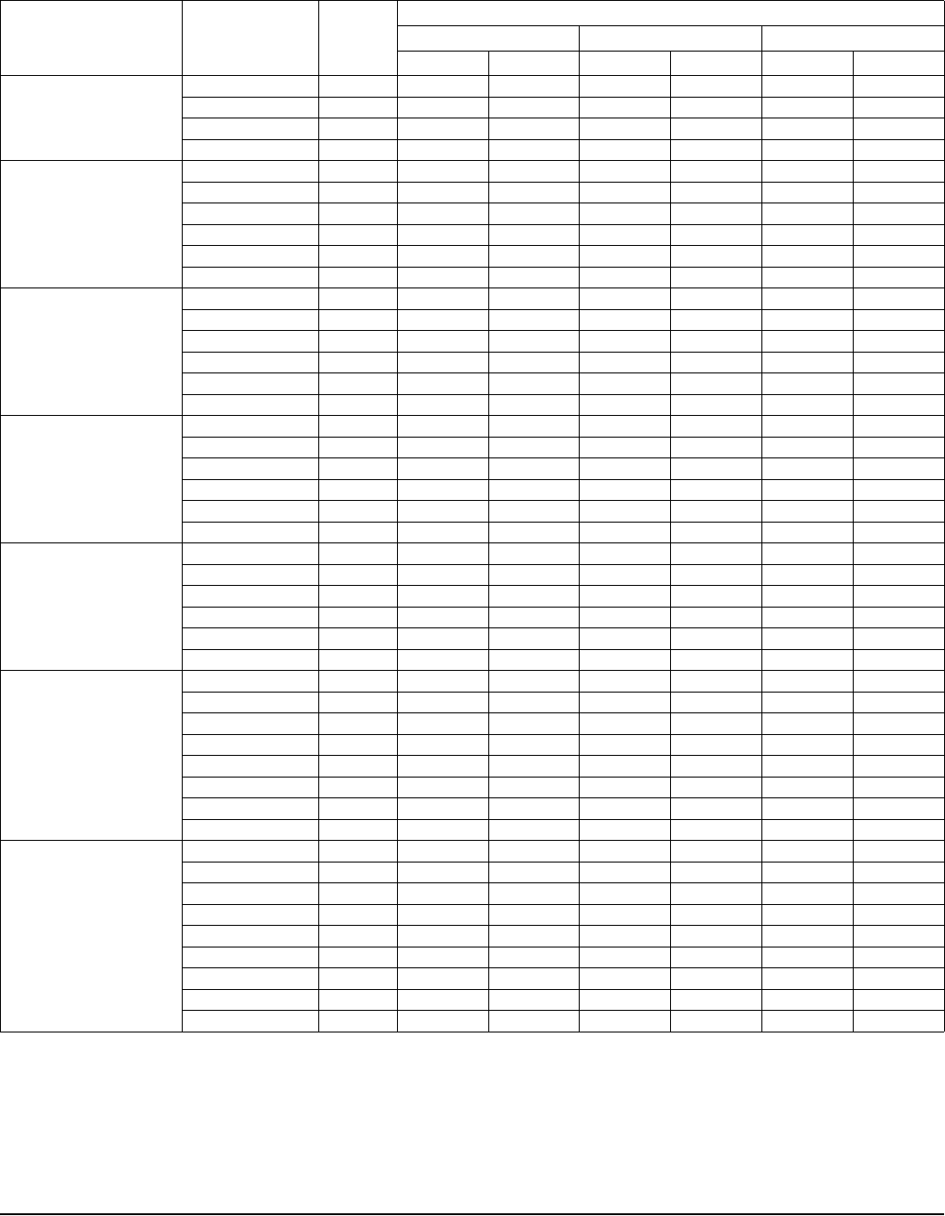
ELECTRIC HEAT PERFORMANCE DATA: 208/230-1-60 & 208/230-3-60
Heater
Models1,2 Nominal kW
@240V
Total Heat3kW Staging
kW MBH W1 Only W1 + W2
208V 230V 208V 230V 208V 230V 208V 230V
1PH
6HK(0,1)6500206 2.4 1.8 2.2 6.2 7.5 1.8 2.2 1.8 2.2
6HK(0,1)6500506 4.8 3.6 4.4 12.3 15.0 3.6 4.4 3.6 4.4
6HK(0,1)6500806 7.7 5.8 7.1 19.7 24.1 5.8 7.1 5.8 7.1
6HK(0,1)6501006 9.6 7.2 8.8 24.6 30.1 7.2 8.8 7.2 8.8
6HK(1,2)6501306 12.5 9.4 11.5 32.0 39.2 3.1 3.8 9.4 11.5
6HK(1,2)6501506 14.4 10.8 13.2 36.9 45.1 3.6 4.4 10.8 13.2
6HK(1,2)6501806 17.3 13.0 15.9 44.3 54.2 6.5 7.9 13.0 15.9
6HK(1,2)6502006 19.2 14.4 17.6 49.2 60.2 7.2 8.8 14.4 17.6
6HK(1,2)6502506 24.0 18.0 22.0 61.5 75.2 7.2 8.8 18.0 22.0
3PH
6HK06501025 9.6 7.2 8.8 24.6 30.1 7.2 8.8 7.2 8.8
6HK06501525 14.4 10.8 13.2 36.9 45.1 10.8 13.2 10.8 13.2
6HK06501825 17.3 13.0 15.9 44.3 54.2 13.0 15.9 13.0 15.9
6HK16502025 19.2 14.4 17.6 49.2 60.2 7.2 8.8 14.4 17.6
6HK16502525 24.0 18.0 22.0 61.5 75.2 9.0 11.0 18.0 22.0
1. (0,1) - 0 = no circuit breaker OR 1 = with circuit breaker.
2. (1,2) - 1 = with circuit breaker, no breaker jumper bar OR 2 = with circuit breaker & breaker jumper bar.
3. For different power distributions, see conversion table on Page 4.
1055230-YTG-D-0514
6Johnson Controls Unitary Products
ELECTRICAL DATA FOR SINGLE SOURCE POWER SUPPLY: 208/230-1-60
Air Handler Models Heater
Models1,2
Heater
Amps
@240V
Field Wiring
Min. Circuit Ampacity MOP.3Min Wire Size (AWG)4
208V 230V 208V 230V 208V 230V
AHR18B
6HK(0,1)6500206 10.0 12.6 14.3 15 15 12 12
6HK(0,1)6500506 20.0 23.4 26.8 25 30 10 10
6HK(0,1)6500806 32.0 36.4 41.8 40 45 8 8
6HK(0,1)6501006 40.0 45.1 51.8 50 60 8 6
AHR22B
6HK(0,1)6500206 10 13.5 15.3 15 20 12 12
6HK(0,1)6500506 20 24.3 27.8 25 30 10 10
6HK(0,1)6500806 32 37.3 42.8 40 45 8 8
6HK(0,1)6501006 40 46.0 52.8 50 60 6 6
6HK(1,2)6501306 52 59.0 67.8 60 70 6 4
6HK(1,2)6501506 60 67.7 77.8 70 80 4 4
AHR24B
6HK(0,1)6500206 10.0 12.6 14.3 15 15 12 12
6HK(0,1)6500506 20.0 23.4 26.8 25 30 10 10
6HK(0,1)6500806 32.0 36.4 41.8 40 45 8 8
6HK(0,1)6501006 40.0 45.1 51.8 50 60 8 6
6HK(1,2)6501306 52.0 58.1 66.8 60 70 6 4
6HK(1,2)6501506 60.0 66.8 76.8 70 80 4 4
AHR29C
AHR34C
6HK(0,1)6500206 10.0 13.8 15.4 15 20 12 12
6HK(0,1)6500506 20.0 24.6 27.9 25 30 10 10
6HK(0,1)6500806 32.0 37.6 42.9 40 45 8 8
6HK(0,1)6501006 40.0 46.3 52.9 50 60 6 6
6HK(1,2)6501306 52.0 59.3 67.9 60 70 6 4
6HK(1,2)6501506 60.0 68.0 77.9 70 80 4 4
AHR30B
AHR42C
6HK(0,1)6500206 10.0 14.6 16.3 15 20 12 12
6HK(0,1)6500506 20.0 25.4 28.8 30 30 10 10
6HK(0,1)6500806 32.0 38.4 43.8 40 45 8 8
6HK(0,1)6501006 40.0 47.1 53.8 50 60 6 6
6HK(1,2)6501306 52.0 60.1 68.8 70 70 6 4
6HK(1,2)6501506 60.0 68.8 78.8 70 80 4 4
AHR36B
AHR48D
6HK(0,1)6500206 10.0 14.6 16.3 15 20 12 12
6HK(0,1)6500506 20.0 25.4 28.8 30 30 10 10
6HK(0,1)6500806 32.0 38.4 43.8 40 45 8 8
6HK(0,1)6501006 40.0 47.1 53.8 50 60 8 6
6HK(1,2)6501306 52.0 60.1 68.8 70 70 6 4
6HK(1,2)6501506 60.0 68.8 78.8 70 80 4 4
6HK(1,2)6501806 72.0 81.8 93.8 90 100 4 3
6HK(1,2)6502006 80.0 90.4 103.8 100 110 3 2
AHR60D
6HK(0,1)6500206 10.0 14.6 16.3 15 20 12 12
6HK(0,1)6500506 20.0 25.4 28.8 30 30 10 10
6HK(0,1)6500806 32.0 38.4 43.8 40 45 8 8
6HK(0,1)6501006 40.0 47.1 53.8 50 60 8 6
6HK(1,2)6501306 52.0 60.1 68.8 70 70 6 4
6HK(1,2)6501506 60.0 68.8 78.8 70 80 4 4
6HK(1,2)6501806 72.0 81.8 93.8 90 100 4 3
6HK(1,2)6502006 80.0 90.4 103.8 100 110 3 2
6HK(1,2)6502506 100.0 112.1 128.8 125 150 2 1
1. (0,1) - maybe 0 (no circuit breaker) or 1 (with circuit breaker).
2. (1,2) maybe 1 (with circuit breaker, no breaker jumper bar) or 2 (with circuit breaker & breaker jumper bar).
3. MOP = Maximum Overcurrent Protection device; must be HACR type circuit breaker or time delay fuse.
4. Stated sizes are for 75°C, copper wire only. If wire other than non-plated, 75°C ambient, copper wire is used, consult applicable tables of the NEC and local codes.
1055230-YTG-D-0514
Johnson Controls Unitary Products 7
d
ELECTRICAL DATA FOR MULTI-SOURCE POWER SUPPLY: 208/230-1-60
Air
Handlers
Models
Heater
Models
Total
Heater
Amps
@240V
Min. Circuit Ampacity MOP1Min. Wire Size (AWG)2
208V230V208V230V208V230V
Circuit Circuit Circuit
1st32nd 3rd 1st32nd 3rd 1st32nd 3rd 1st32nd 3rd 1st32nd 3rd 1st32nd 3rd
AHR22B 6HK16501306 52 21.2 37.6 – 24.4 43.3 – 25 40 – 25 45 – 10 8 – 10 8 –
6HK16501506 60 22.8 43.3 – 27.8 50.0 – 25 45 – 30 50 – 10 8 – 10 8 –
AHR24B 6HK16501306 52.0 20.6 37.6 – 23.4 43.3 – 25 40 – 25 45 – 10 8 – 10 8 –
6HK16501506 60.0 23.5 43.3 – 26.8 50.0 – 25 45 – 30 50 – 10 8 – 10 8 –
AHR29C
AHR34C
6HK16501306 52.0 21.3 37.6 – 24.5 43.3 – 25 40 – 25 45 – 10 8 – 10 8 –
6HK16501506 60.0 24.2 43.3 – 27.9 50.0 – 25 45 – 30 50 – 10 8 – 10 8 –
AHR30B
AHR42C
6HK16501306 52.0 22.6 37.6 – 25.4 43.3 – 25 40 – 30 45 – 10 8 – 10 8 –
6HK16501506 60.0 25.5 43.3 – 28.8 50.0 – 30 45 – 30 50 – 10 8 – 10 8 –
AHR36B
AHR48D
6HK16501306 52.0 22.6 37.6 – 25.4 43.3 – 25 40 – 30 45 – 10 8 – 10 8 –
6HK16501506 60.0 25.5 43.3 – 28.8 50.0 – 30 45 – 30 50 – 10 8 – 10 8 –
6HK16501806 72.0 42.8 39.0 – 48.8 45.0 – 45 40 – 50 45 –88–88–
6HK16502006 80.0 47.1 43.3 – 53.8 50.0 – 50 45 – 60 50 –88–68–
AHR60D
6HK16501306 52.0 22.6 37.6 – 25.4 43.3 – 25 40 – 30 45 – 10 8 – 10 8 –
6HK16501506 60.0 25.5 43.3 – 28.8 50.0 – 30 45 – 30 50 – 10 8 – 10 8 –
6HK16501806 72.0 42.8 39.0 – 48.8 45.0 – 45 40 – 50 45 –88–88–
6HK16502006 80.0 47.1 43.3 – 53.8 50.0 – 50 45 – 60 50 –88–68–
6HK16502506 100 47.1 43.3 21.7 53.8 50.0 25.0 50 45 25 60 50 25 6 6 10 6 8 10
1. MOP = Maximum Overcurrent Protection device; must be HACR type circuit breaker or time delay fuse.
2. Stated sizes are for 75°C, copper wire only. If wire other than non-plated, 75°C ambient, copper wire is used, consult applicable tables of the NEC and local codes.
3. 1st Circuit includes the blower motor amps.
ELECTRICAL DATA FOR SINGLE SOURCE POWER SUPPLY - 208/230-3-60
Air Handler Models Heater
Models
Heater
Amps
@ 240V
Field Wiring
Min. Circuit Ampacity MOP1Min. Wire Size (AWG)2
208V 230V 208V 230V 208V 230V
AHR18B 6HK06501025 23.1 26.8 30.7 30 35 10 10
AHR24B 6HK06501025 23.1 26.8 30.7 30 35 10 10
6HK06501525 34.6 39.2 45.0 40 45 8 8
AHR30B
AHR42C
6HK06501025 23.1 28.8 32.7 30 35 10 8
6HK06501525 34.6 41.2 47.0 45 50 8 8
AHR36B
AHR48D
6HK06501025 23.1 28.8 32.7 30 35 10 8
6HK06501525 34.6 41.2 47.0 45 50 8 8
6HK06501825 41.6 48.8 55.8 50 60 8 6
6HK16502025346.2 53.8 61.5 60 70 6 6
AHR60D
6HK06501025 23.1 28.8 32.7 30 35 10 8
6HK06501525 34.6 41.2 47.0 45 50 8 8
6HK06501825 41.6 48.8 55.8 50 60 8 6
6HK16502025346.2 53.8 61.5 60 70 6 6
6HK16502525357.7 66.3 75.9 70 80 4 4
1. MOP = Maximum Overcurrent Protection device; must be HACR type circuit breaker or time delay fuse.
2. Stated sizes are for 75°C, copper wire only. If wire other than non-plated, 75°C ambient, copper wire is used, consult applicable tables of the NEC and local codes.
3. The 20kW and 25kW heater models (6HK16502025 and 6HK16502525) come with circuit breakers standard. Single source power MCA and MOP requirements are
given here only for reference if used with field installed single point power modification.
1055230-YTG-D-0514
8Johnson Controls Unitary Products
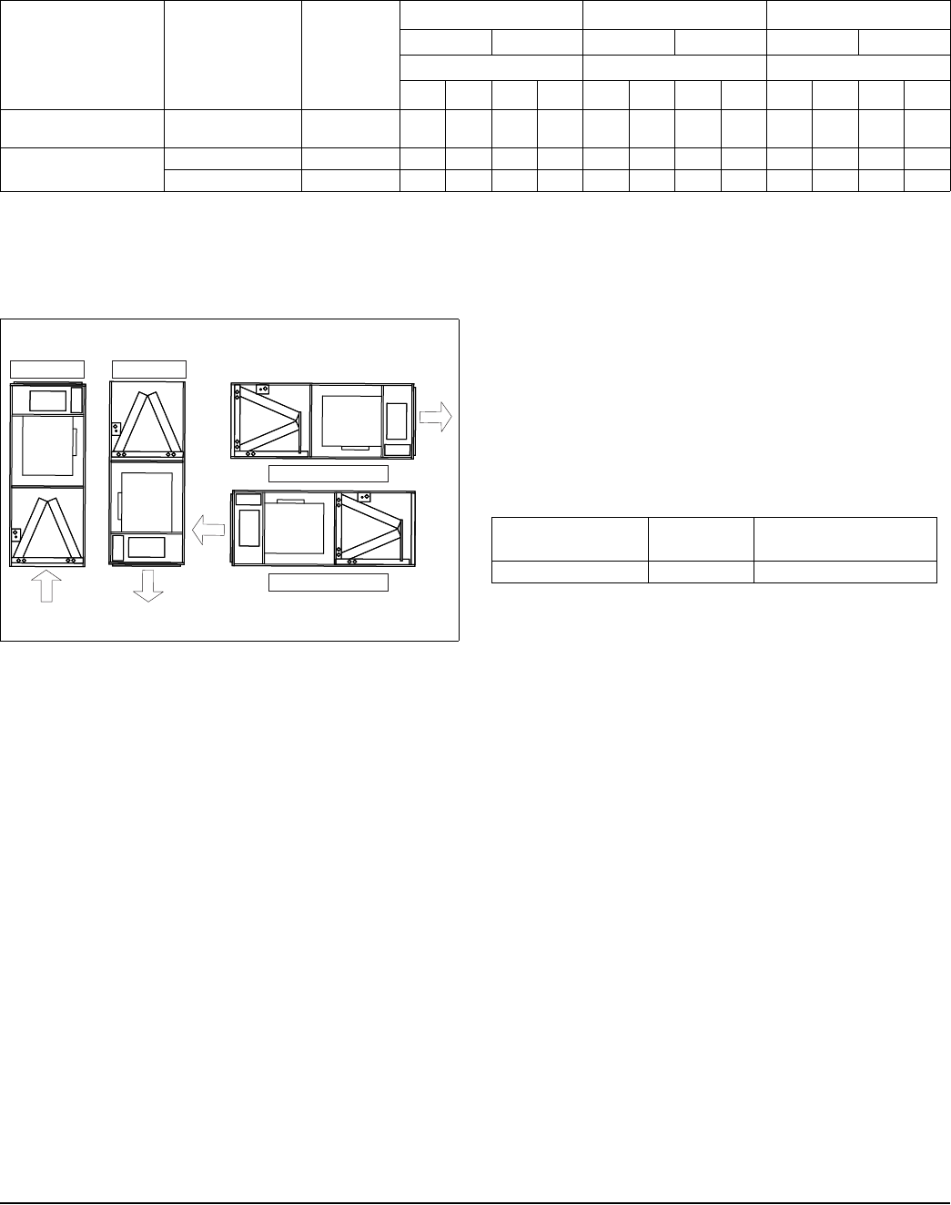
TYPICAL APPLICATIONS ACCESSORIES
Refer to Price Manual for specific model numbers.
TXV Kits - TXV kits are available for “Flex-coil” applications and con-
verting R22 to R410A or as a service replacement. All kits are bolt-on
and require no brazing to install.
Electric Heaters - 6HK models shown under electrical data include
sequential operation and temperature dual limit switches for safe, effi-
cient operation. Circuit breakers are provided where shown.
LIMITATIONS
These units must be wired and installed in accordance with all national
and local safety codes.
Voltage limits are as follows:
Airflow must be within the minimum and maximum limits approved for
electric heat, evaporator coils and outdoor units.
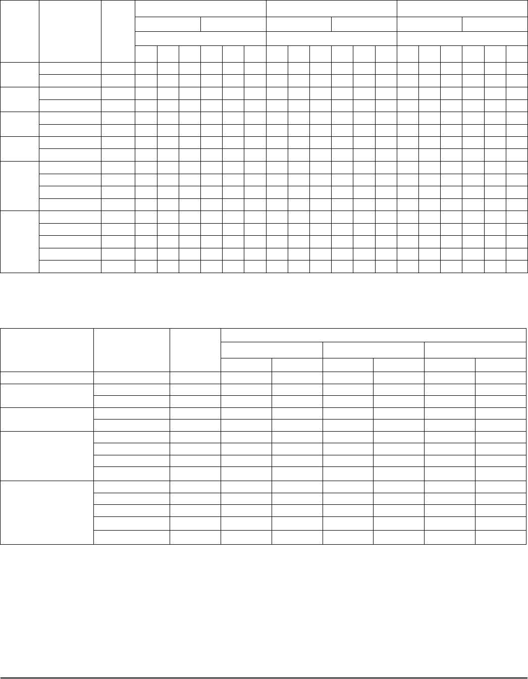
ELECTRICAL DATA FOR MULTI-SOURCE POWER SUPPLY: 208/230-3-60
Air Handler Models Heater
Models
Total Heater
Amps
@ 240V
Min. Circuit Ampacity MOP1 Min. Wire Size (AWG)2
208V 230V 208V 230V 208V 230V
Circuit Circuit Circuit
1st32nd 1st32nd 1st32nd 1st32nd 1st32nd 1st32nd
AHR36B
AHR48D 6HK16502025 46.2 28.8 25.0 32.6 28.9 30 25 35 30 10 10 8 10
AHR60D 6HK16502025 46.2 28.8 25.0 32.6 28.9 30 25 35 30 10 10 8 10
6HK16502525 57.7 35.0 31.3 39.8 36.1 35 35 40 40 8888
1. MOP = Maximum Overcurrent Protection device; must be HACR type circuit breaker or time delay fuse.
2. Stated sizes are for 75°C, copper wire only. If wire other than non-plated, 75°C ambient, copper wire is used, consult applicable tables of the NEC and local codes.
3. 1st Circuit includes the blower motor amps.
UPFLOW
HORIZONTAL RIGHT
HORIZONTAL LEFT
HEAT
HEAT
HEAT
DOWNFLOW
HEAT
Air Handler
Voltage Voltage
code
Normal Operating
Voltage Range1
1. Rated in accordance with ARI Standard 110, utilization range “A”.
208/230-1-60 06 187-253
1055230-YTG-D-0514
Johnson Controls Unitary Products 9
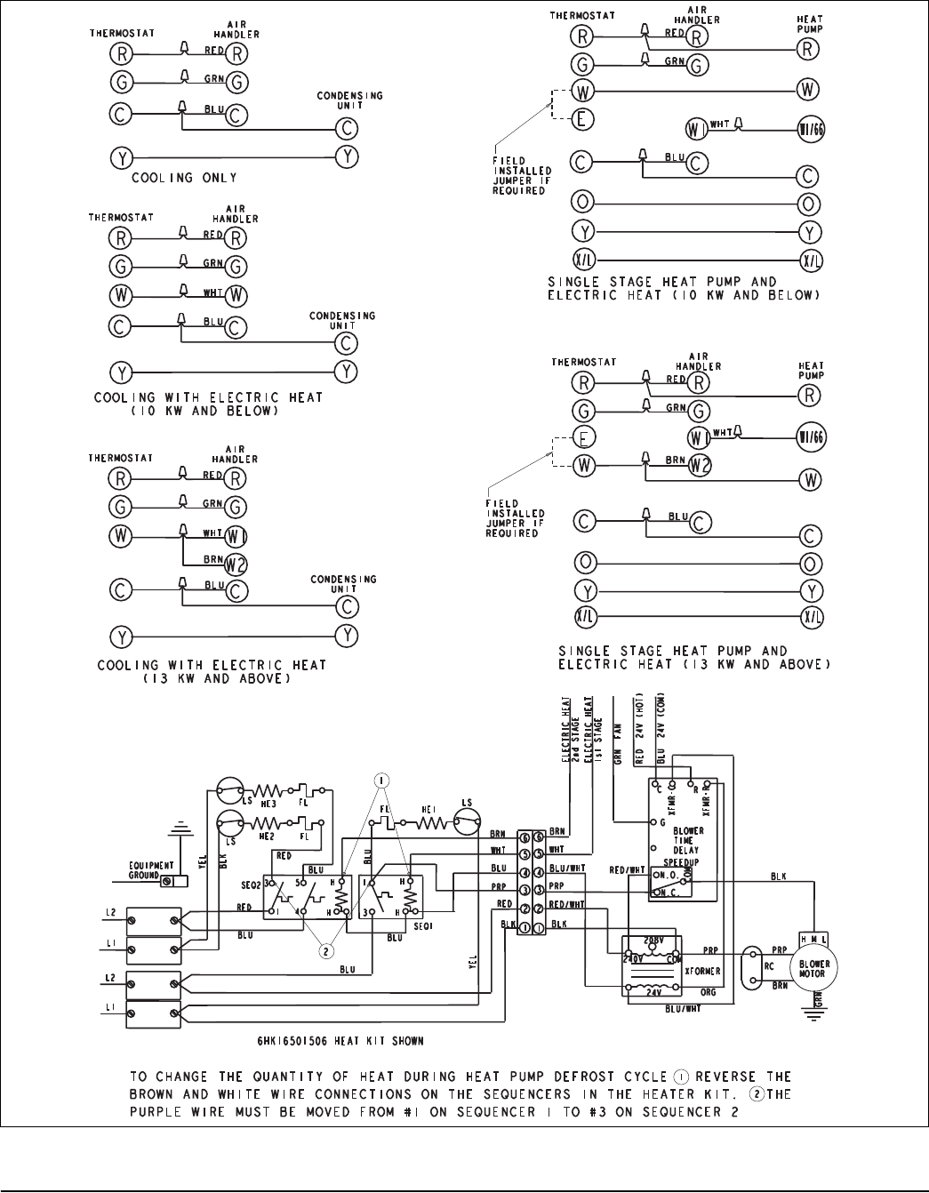
TYPICAL THERMOSTAT CONNECTIONS
1055230-YTG-D-0514
10 Johnson Controls Unitary Products
AIR FLOW DATA (CFM)
1
Models Blower
Motor Speed
External Static Pressure (in. wc.)
0.10 0.20 0.30 0.40 0.50 0.60 0.70
208 Volt
AHR18B
High 1024 1000 970 930 860 810 NA
Medium 756 731 700 670 620 550 NA
Low 557 531 495 445 375 315 195
AHR22B
High 1214 1177 1136 1071 1019 951 828
Medium 705 684 661 592 548 404 266
Low 534 512 460 394 261 167 125
AHR24B
High 995 970 935 900 925 795 645
Medium 820 810 780 745 695 545 485
Low 715 695 640 405 370 375 220
AHR29C
High 1605 1548 1486 1420 1356 1159 913
Medium 981 960 921 815 756 697 614
Low 769 717 654 561 510 451 389
AHR30B
High 1380 1315 1245 1160 1075 990 885
Medium 1060 1040 1005 955 890 860 820
Low 1035 980 910 825 770 685 485
AHR34C
High 1496 1423 1328 1217 1105 1041 942
Medium 976 907 843 815 742 686 582
Low 729 687 647 602 498 447 366
AHR36B
High 1410 1335 1270 1190 1110 990 820
Medium 1215 1170 1115 1050 935 850 740
Low 950 935 895 855 NA NA NA
AHR42C
High 1800 1725 1645 1545 1360 1200 1050
Medium 1535 1480 1415 1280 1155 1010 870
Low 1225 1195 1095 1025 925 825 680
AHR48D
High 1890 1830 1755 1650 1565 1450 1285
Medium 1515 1480 1450 1380 1295 1115 985
Low 1170 1165 1140 1100 965 860 745
AHR60D
High 1911 1841 1757 1668 1564 1439 1233
Medium 1556 1507 1450 1388 1266 1246 989
Low 1211 1181 1151 1062 992 911 827
230 Volt
AHR18B
High 1145 1100 1055 1005 930 845 725
Medium 755 750 725 665 605 485 435
Low 680 655 625 585 540 395 300
AHR22B
High 1294 1254 1189 1133 1064 996 907
Medium 803 785 763 729 645 585 422
Low 615 600 566 492 447 284 183
AHR24B
High 1305 1285 1225 1175 920 915 835
Medium 930 920 890 845 705 760 505
Low 735 730 700 670 545 470 NA
AHR29C
High 1711 1665 1598 1513 1435 1309 1088
Medium 1134 1111 1068 998 909 813 735
Low 887 861 792 695 649 576 486
AHR30B
High 1450 1380 1300 1215 1130 1030 910
Medium 1330 1280 1205 1135 1050 975 780
Low 1160 1120 1065 1005 930 825 635
AHR34C
High 1579 1511 1399 1273 1145 1068 978
Medium 1108 1057 987 924 849 770 703
Low 849 802 756 712 630 527 170
AHR36B
High 1470 1390 1325 1245 1155 1045 880
Medium 1325 1265 1205 1125 1025 965 840
Low 1115 1075 1025 950 NA NA NA
(For notes see page 11.)

1055230-YTG-D-0514
Johnson Controls Unitary Products 11
Models Blower
Motor Speed
External Static Pressure (in. wc.)
0.10 0.20 0.30 0.40 0.50 0.60 0.70
230 Volt
AHR42C
High 1750 1670 1570 1477 1260 1125 935
Medium 1590 1520 1435 1277 1150 1010 870
Low 1330 1280 1200 1083 980 850 NA
AHR48D
High 2005 1940 1850 1755 1650 1530 1405
Medium 1705 1665 1605 1510 1425 1340 1185
Low 1355 1330 1300 1245 1170 990 980
AHR60D
High 2034 1955 1858 1753 1640 1522 1296
Medium 1733 1672 1609 1527 1431 1272 1220
Low 1388 1359 1313 1255 1133 1004 912
1. Air handler units have been tested to UL 1995 / CSA 22.2 standards up to 0.30" wc. external static pressure.
Dry coil conditions only, tested without filters.
For optimal performance, external static pressures of 0.2" to 0.5" are recommended. Applications above 0.6" are not recommended.
Airflow data shown is from testing performed at 230V. AHE units use a X13 motor, and there is minimal variation of airflow at other distribution voltage values. The
above data can be used for airflow at other distribution voltages.
AIR FLOW DATA (CFM)
1 (Continued)

Subject to change without notice. Published in U.S.A. 1055230-YTG-D-0514
Copyright © 2014 by Johnson Controls, Inc. All rights reserved. Supersedes: 1055230-YTG-C-0214
York International Corp.
5005 York Drive
Norman, OK 73069
NOTES
