York Eco R 407C Users Manual Form 100.50 EG1(201), Eco2 Packaged Rooftop Air Conditioning Units, Engineering Guide
R-407C to the manual 9d2aebea-ff5e-47fe-8486-3c620bef97ae
2015-02-02
: York Eco-R-407C-Users-Manual york-eco-r-407c-users-manual-455090 york pdf
Open the PDF directly: View PDF ![]() .
.
Page Count: 44
Packaged Rooftop
Air Conditioning Units
R-407C OPTIMIZED
50 THROUGH 65 TONS
FORM 100.50-EG1 (201)
00406VIP

YORK INTERNATIONAL
2
TABLE OF CONTENTS
PAGE
Nomenclature .........................................................................................................3
Introduction .............................................................................................................4
Physical Data ..........................................................................................................7
Application Data ......................................................................................................9
Cooling Performance Data....................................................................................12
Fan Performance ..................................................................................................20
Electrical Data.......................................................................................................24
Controls ................................................................................................................26
Power Wiring ........................................................................................................ 31
Field Control Wiring ..............................................................................................34
General Arrangement Drawing .............................................................................35
Curb Layout Drawing ............................................................................................ 37
Mechanical Specifications..................................................................................... 38
TABLES
1 Physical Data ............................................................................................. 7
2 Cooling Performance Data – 50 Ton Model.............................................. 12
3 Cooling Performance Data – 55 Ton Model.............................................. 14
4 Cooling Performance Data – 60 Ton Model.............................................. 16
5 Cooling Performance Data – 65 Ton Model.............................................. 18
6 50 Through 65 Ton Supply Fan Data........................................................ 20
7 50 Through 65 Ton Exhaust Fan Data...................................................... 21
8 Component Static Pressure Drops ........................................................... 22
9 Compressors ........................................................................................... 24
10 Supply and Exhaust Fan Motor Electrical Data ........................................ 25
11 Condenser Fan Motors ............................................................................ 25
12 Controls and Convenience Outlet............................................................. 25
FORM 100.50-EG1
3
YORK INTERNATIONAL
NOMENCLATURE
PAGE
FIGURES
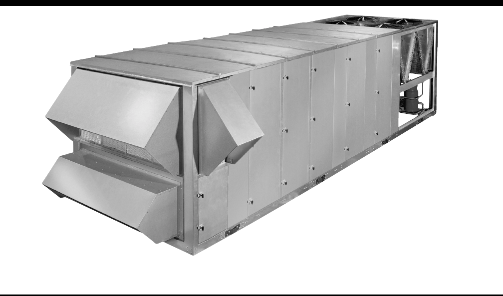
1 Packaged Rooftop Air Conditioning Unit .................................................. 4
2 Single-Point Power Supply Wiring .......................................................... 31
3 Single-Point Power Supply Wiring with Non-Fused Disconnect ............. 32
4 Dual-Point Power Supply Wiring ............................................................ 33
5 Field Control Wiring ............................................................................... 34
6 General Arrangement Drawing – Bottom Return, Bottom Supply ........... 35
7 General Arrangement Drawing – Rear Return, Left or Right Supply ...... 36
8 Curb Layout Drawing.............................................................................. 37
BASIC MODEL NUMBER
: 50-ton
: 55-ton
: 60-ton
: 65-ton
: Rev. Level A
: Std. Product
: Special
: R-407C
: YORK
: Packaged
Rooftop
: Air-Cooled
: Scroll
1 2 3 4 5 6 7 8 9 10 11 12 13 14 15 16
BASE PRODUCT TYPE NOMINAL CAPACITY APPLICATION REFRIGERANT VOLTAGE DUCT LOCATIONS DESIGN SPECIAL
Y050 B17BA
P055 28L S
060 4 6 R X
A065 58 B
F
L S
CC
V
B
: 200 / 3 / 60
: 230 / 3 / 60
: 460 / 3 / 60
: 575 / 3 / 60
: Cooling Only
: Constant Volume
: VAV, VFD
: VAV, VFD w/ Manual Bypass
: Bottom Supply
: Left Supply
: Right Supply
: Bottom Return
: Front Return
: Side Return
YORK INTERNATIONAL
4
FEATURES/BENEFITS
Ecological and Economical Design
• First packaged RTU with 407C optimized design
•Cooling and Heating – Superior operating perfor-
mance provides lower operating costs. Smaller
steps of cooling capacity provide tighter control of
building environment and occupant comfort while
optimizing energy efficiency.
•Indoor Air Quality (IAQ) – Outside air economiz-
ers provide energy savings in free cooling mode,
and can provide a healthier and more comfortable
building environment by introducing fresh outside air
into the building as needed. Indoor Air Quality (IAQ)
requirements for building ventilation and comfort are
controlled through the microprocessor control panel.
Optional air flow measurement provides an accu-
rate means of tracking air quality and alerting the
occupants or building owner to unhealthy situations.
•High-Efficiency Motors – High-efficiency motors are
available for optimum energy efficiency. All motors
used on the eco2 packaged rooftop air conditioner
meet U.S. EPACT 1992 minimum requirements.
Indoor Air Quality (IAQ)
•Double-sloped stainless steel drain pan – This
double-sloped inclined stainless steel drain pan fa-
cilitates removal of evaporator condensate. Sloped
in two directions conforming to ASHRAE 62n, this
drain pan swiftly minimizes any condensate within
the unit. Best of all, the drain pan is accessible for
periodic cleaning required by IAQ standards.
•Smart ventilation – YORK maintains the leader-
ship role in IAQ products with adaptive ventilation
control. The OptiLogicTM controls provide continu-
ous monitoring of air quality and take action by open-
ing the outside air dampers, bringing in the right
amount of fresh air before air impurities reach un-
comfortable or even dangerous levels.
•Air flow measurement – Precise measurement
of ventilation air flow is possible using an air flow
measurement station which can be installed in the
economizer section. Proper ventilation air flow is
required to ensure sufficient fresh air is in the build-
ing. A myriad of air flow measurement options are
available from minimum air flow to high-accuracy
full air flow capabilities. The complete system is
designed as an integrated component of the
OptiLogicTM control system to ensure optimum sys-
tem performance.
•Double-wall construction – Rigid double-wall
construction throughout provides ease of clean-
ing and protects against insulation fiber entrain-
ment in the breathable air. Double-wall construc-
tion also helps improve the acoustical character-
istics of the air handling unit.
Introduction
FIG. 1 –PACKAGED ROOFTOP AIR CONDITIONING UNIT
00406VIP

FORM 100.50-EG1
5
YORK INTERNATIONAL
•Enhanced filtration – The Eco2 unit gives design-
ers the flexibility to meet various IAQ requirements
with a full range of rigid and throwaway filters at
various efficiency levels.
Reliable Scroll Compressor Technology
Reliable, efficient, trouble-free operation is the true mea-
sure of a packaged rooftop’s value. That’s why YORK
Eco2 Packaged Rooftop Air Conditioners use estab-
lished scroll-compressor technology to deliver depend-
able, economical performance in a wide range of appli-
cations. With the Eco2 Packaged Rooftop, you get the
latest generation of compressor enhancements added
to the scroll’s inherent strengths. The simplicity of a
hermetic scroll compressor allows the use of fewer
moving parts to minimize breakdown. YORK also em-
ploys the latest sealing technology to avoid metal-to-
metal contact. Axial sealing is accomplished with float-
ing tip seals, while radial sealing utilizes a microcushion
of oil. The result: a maintenance-free compressor pro-
viding minimum wear and maximum runtime.
A scroll compressor operates with two scroll members—
a fixed scroll and an identical orbiting scroll turned 180
degrees, like two hands curled and interlocked together.
As the orbiting scroll oscillates against the fixed scroll,
it traps and compresses suction gas inside involute
pockets. As the orbiting scroll moves, the gas is com-
pressed into the central area, where it is discharged as
compressed gas. High efficiency is achieved through a
precisely controlled orbit and the use of advanced scroll
geometry. There is no wasted motion. All rotating parts
are statically and dynamically balanced to ensure opti-
mal performance over the long haul.
Balanced components and precision machining also
ensure that smooth compression occurs in all involute
pockets simultaneously. When compression forces are
equally distributed over the entire scroll surface, equal
forces in opposing directions cancel one another, mini-
mizing any imbalance. Consequently, compression is
smooth, continuous, and quiet. Vibration isolators on
each compressor handle normal vibration. For extra
quiet operation, acoustic sound blankets for each com-
pressor are available as options.
Serviceability
•OptiLogicTM – fully-integrated factory-packaged
controls are standard on every unit and include a
display unit with a 4x20 character LCD display.
OptiLogicTM continually monitors all control setpoints
and configurations. If a unit or control component,
or sensor fails, the controller notifies the user of a
problem. If desired, YORK service can provide re-
mote monitoring and automatically schedule a ser-
vice technician to make the repair and maintain your
comfort.
•Access doors – full-sized access doors provide
easy access into the unit for routine maintenance
and inspection.
•Suction & discharge service valves – oversized
service valves to provide isolation and quick recla-
mation and charging of system refrigerant are avail-
able to minimize downtime and simplify the service
and repair task.
•VFD Fan Motor Control with Manual Bypass –
Optional manual VFD bypass reduces time required
for troubleshooting, commissioning and system
balancing.
•Convenience Outlet – for maintenance tasks re-
quiring power tools, an optional 110V GFCI power
supply can power lights, drills or any other power
hand tool needed.
•Filter Maintenance Alarm – An optional filter main-
tenance alarm indicates when a filter becomes dirty
and requires replacement or cleaning.
Install with Ease and Safety
•Factory run-tested – Each unit is subjected to a
series of quality assurance checks as well as an
automated quality control process before being run-
tested. Fans and drives are balanced at the factory
during testing. The factory run-test ensures safe,
proper operation when the unit is installed and re-
duces installation and commissioning time.
•Single-point power connection – Single-point
power connection reduces installation time by pro-
viding a single point for incoming power, including

YORK INTERNATIONAL
6
Introduction
the optional convenience outlet. All incoming power
is connected in one location, reducing the cost of
field-supplied and installed power wiring.
•Factory-mounted and wired controls – All con-
trol points within the unit are factory-installed, wired
and tested. The OptiLogicTM controls can commu-
nicate with BACNet IP.
•Non-fused disconnect – A factory-installed non-
fused disconnect switch simplifies unit installation
and serviceability by reducing installed labor costs.
The disconnect switch is interlocked with the power
cabinet ensuring that all power to the unit has been
disconnected before servicing.
Design Flexibility
•Low Ambient Operation – Head-pressure control
is accomplished via a VFD motor controller rather
than an inefficient and noisy condenser fan damper.
By varying the speed of the condenser fan, better
control and quieter operation is obtained during the
colder months. Low ambient controls are available
on all systems offering higher rooftop cooling ca-
pacity than competitive units.
•Hot Gas Bypass – Optional on constant volume units,
hot gas bypass reduces the cycling of compressors
which helps prolong the life of the equipment.
•Supply Air Openings – Side supply connections
are available on select configurations, offering more
flexibility for duct layout and improving sound trans-
mission characteristics.
•Compressor Sound Blankets – For applications
in sound-sensitive areas, compressor sound blan-
kets are available to reduce sound emitted from
the rooftop unit.
•Fan Spring Isolators – One-inch spring isolation
is used to prevent vibration transmission from the
rooftop unit’s supply fan to the building. Two-inch
spring isolation is also available.
•Harsh Environments – A variety of coil coating and
materials are available as well as hail guards to pro-
tect coils from weather damage. Seismic and hurri-
cane duty curbs and fan restraints are available.

FORM 100.50-EG1
7
YORK INTERNATIONAL
Physical Data
TABLE 1 – PHYSICAL DATA
MODEL SIZE 50 55 60 65
GENERAL DATA
Length (Inches) 336 336 336 336
Width (Inches) 92 92 92 92
Height (Inches) 82 82 82 82
Operating Weights (Lbs.) (base unit, no options)
Cooling Only (Rigging & Refrigerant) 8,080 8,290 8,530 8,740
Rigging Weights (Lbs.) (base unit, no options)
Cooling Only 8,010 8,210 8,440 8,640
Option Weights (Lbs.)
Power Exhaust (Blower, motor, fan skid & mod damper) 647 647 647 647
Power Exhaust (Blower, motor, fan skid, VFD & baro damper) 654 654 654 654
100% AMS (Measurement Station & Mounting) 110 110 110 110
25/75% AMS (Measurement Station & Mounting) 130 130 130 130
Min. AMS (Measurement Station & Mounting) 40 40 40 40
Barometric only 36 36 36 36
Condenser Hail Guard 32 32 32 32
Copper Condenser Coils 617 617 793 793
Copper Evaporator Coils 262 320 400 500
Roof Curb Weights (Lbs.)
14" Full Perimeter Roof Curb 787 787 787 787
14" Open Condenser Roof Curb 555 555 555 555
Compressor Data
Quantity / Size (Nominal Tons ) 4/13 4/13 4/15 4/15
Type Scroll Scroll Scroll Scroll
Capacity Steps (%) 25, 50, 75, 100 25, 50, 75, 100 25, 50, 75, 100 25, 50, 75, 100
Supply Fan and Drive
Quantity 1111
Type FC FC FC FC
Size 25-22 25-22 25-22 25-22
Motor Size Range (min. to max. HP) 7.5-40 7.5-40 7.5-40 7.5-40
Air Flow Range (min. to max. cfm) 10000-22500 12000-24000 14000-27000 14000-27000
Static Pressure Range (min. to max. ESP) 0-4" 0-4" 0-4" 0-4"
Exhaust Fan
Quantity 2222
Type FC FC FC FC
Size 15-15 15-15 15-15 15-15
Motor Size Range (min. to max. HP) 5-20 5-20 5-20 5-20
Air Flow Range (min. to max. cfm) 0-20000 0-20000 0-20000 0-20000
Static Pressure Range (min. to max. ESP) 0-1" 0-1" 0-1" 0-1"
Evaporator Coil
Size (square feet) 48.8 48.8 48.8 48.8
Number of rows/fins per inch 3/8 4/8 4/12 5/10
Tube Diameter/Surface 1/2"/enhanced 1/2"/enhanced 1/2"/enhanced 1/2"/enhanced
Condenser Coil (Aluminum Fins)
Size (square feet) 121.3 121.3 121.3 121.3
Number of rows/fins per inch 3/14 3/14 3/18 3/18
Tube Diameter 3/8" 3/8" 3/8" 3/8"
Condenser Coil (Copper Fins – Opt)
Size (square feet) 121.3 121.3 121.3 121.3
Number of rows/fins per inch 3/14 3/14 3/18 3/18
Tube Diameter 3/8" 3/8" 3/8" 3/8"
YORK INTERNATIONAL
8
Physical Data (continued)
TABLE 1 – PHYSICAL DATA (Cont’d)
MODEL SIZE 50 55 60 65
GENERAL DATA
Condenser Fans
Quantity 4444
Type Prop. Prop. Prop. Prop.
Diameter (inches) 36 36 36 36
Filters – 2" throwaway
Quantity 8 12 8 12 8 12 8 12
Size (length x width) (in.) 25x16 25x20 25x16 25x20 25x16 25x20 25x16 25x20
Total Filter Face Area (square feet) 63.9 63.9 63.9 63.9
Filters – 2" cleanable
Quantity 8 12 8 12 8 12 8 12
Size (length x width) (in.) 25x16 25x20 25x16 25x20 25x16 25x20 25x16 25x20
Total Filter Face Area (square feet) 63.9 63.9 63.9 63.9
Filters – 2" pleated (30% efficient)
Quantity 8 12 8 12 8 12 8 12
Size (length x width) (in.) 25x16 25x20 25x16 25x20 25x16 25x20 25x16 25x20
Total Filter Face Area (square feet) 63.9 63.9 63.9 63.9
Filters – 12" rigid 65%, 2" 30% prefilter
Quantity 149149149149
Size (length x width) (in.) 16x20 25x16 25x20 16x20 25x16 25x20 16x20 25x16 25x20 16x20 25x16 25x20
Total Filter Face Area (square feet) 44.6 44.6 44.6 44.6
Filters – 12" rigid 95%, 2" 30% prefilter
Quantity 149149149149
Size (length x width) (in.) 16x20 25x16 25x20 16x20 25x16 25x20 16x20 25x16 25x20 16x20 25x16 25x200
Total Filter Face Area (square feet) 44.6 44.6 44.6 44.6
Filters – 2" carbon (30% efficient)
Quantity 8 12 8 12 8 12 8 12
Size (length x width) (in.) 25x16 25x20 25x16 25x20 25x16 25x20 25x16 25x20
Total Filter Face Area (square feet) 63.9 63.9 63.9 63.9
Refrigerant HFC-407C HFC-407C HFC-407C HFC-407C
Minimum OA Temp. for Mech. Clg. (°F) 45 45 45 45
Low Ambient Option Min. OA Temp. (°F) 0000

FORM 100.50-EG1
9
YORK INTERNATIONAL
Application Data
LOCATION
Of the many factors that can affect the acoustical char-
acteristics of a rooftop installation, one of the most im-
portant is the unit location. Ideally, the rooftop unit should
be installed away from sound-sensitive areas, such as
conference rooms, auditoriums and executive offices.
Possible locations could be above storage areas, hall-
ways, mechanical or utility rooms, or bathrooms.
The eco2 air conditioning units are designed for out-
door installation. When selecting a site for installation,
be guided by the following conditions:
• Unit must be installed on a level surface.
• For the outdoor location of the unit, select a place
having a minimum sun exposure and an adequate
supply of fresh air for the condenser.
• Also avoid locations beneath windows or between
structures.
• Optional condenser coil protection should be used
for seashore locations or other harsh environments.
• The unit should be installed on a roof that is struc-
turally strong enough to support the weight of the
unit with a minimum of deflection. Extreme caution
should be taken when the unit is mounted on a wood
structured roof. It is recommended that the unit(s)
be installed not more than 15 feet from a main sup-
port beam to provide proper structural support and
to minimize the transmission of sound and vibra-
tion. Ideally, the center of gravity should be located
over a structural support or building column.
• Location of unit(s) should also be away from build-
ing flue stacks or exhaust ventilators to prevent pos-
sible reintroduction of contaminated air through the
outside air intakes.
• Be sure the supporting structures will not obstruct
the duct, gas or wiring connections.
• Proper service clearance space of 6-feet around
the perimeter of the unit and 12-feet to any adja-
cent units is required to eliminate cross contami-
nation of exhaust and outdoor air, and for mainte-
nance tasks such as coil pull and cleaning. No ob-
structions should be above the condensing unit
section.
RIGGING
Proper rigging and handling of the equipment is man-
datory during unloading and setting it into position to
retain warranty status.
Spreader bars must be used to prevent damage to the
unit casing. All lifting lugs must be used when lifting the
rooftop unit.
Care must be taken to keep the unit in the upright posi-
tion during rigging and to prevent damage to the water-
tight seams in the unit casing. Avoid unnecessary jar-
ring or rough handling.
Ground Level Locations
It is important that the units be installed on a substan-
tial base that will not settle, causing strain on the refrig-
erant lines and sheet metal and resulting in possible
leaks. A one-piece concrete slab with footers extended
below the frost line is highly recommended. Addition-
ally, the slab should not be tied to the main building
foundation as noises may be transmitted into the build-
ing structure.
For ground level installations, precautions should be
taken to protect the unit from tampering by, or injury to,
unauthorized persons. Erecting a fence around the unit
is another common practice.
ECONOMIZER
The economizer section is used for ventilation of the
conditioned space to maintain indoor air quality, and
also to reduce energy consumption by using outdoor
air cooling in lieu of mechanical cooling. If outdoor air
is appropriate for cooling, but not sufficient for the cool-
ing demand, mechanical cooling will stage on as nec-
essary until the cooling load is met.
Comparative enthalpy operation is the most accurate and
efficient means of economizer operation. The OptiLogicTM
control monitors the return and outside air energy con-
tent, and selects the lower of the two for operation.
VAV SUPPLY AIR PRESSURE CONTROL
Traditional packaged rooftop systems use inlet guide
vanes (IGVs) for duct static pressure control. These con-
trol supply duct pressure by modulating dampers (intro-
ducing losses and inefficiencies) on the intlet of the fan,
open and closed. Variable frequency drives (VFDs) of-
fer superior fan speed control and quieter, energy effi-
cient operation.
IGV inefficiency can be compared to the operation of a
car. Modulating air flow with an IGV is like pressing on
the gas to drive the car, but modulating the speed of the
car by simultaneously pressing on the brake. VFD modu-
lation is speed modulation by using just the gas pedal.

YORK INTERNATIONAL
10
For VAV applications, the YORK eco2 unit uses a VFD
to modulate fan speed and maintain a constant duct
static pressure. VFDs offer superior control over the
operation of the unit at part load, and offer the addi-
tional benefits of quieter and more efficient operation
when compared to IGV.
HARSH ENVIRONMENTS – CONDENSER AND
EVAPORATOR COIL PROTECTION
For harsh environmental conditions such as seashore
applications, YORK offers three types of coil protec-
tion: copper fin material, black fin and Technicoat coat-
ings. YORK recommends that for corrosive environ-
ments that copper fins be used to protect the evapora-
tor and/or condenser coils. In areas where chemicals
that can corrode copper are present, such as ammo-
nia, YORK recommends that the black fin or Technicoat
coating be used for maximum protection.
Copper Fin Condenser Coil
Copper fins can be used instead of aluminum for addi-
tional corrosion protection, however it is not suitable
for areas that are subject to acid rain or exposed to
ammonia.
Pre-Coated Condenser Fins
Black fin coating (yellow fin for evaporator fins) is pre-
coated application epoxy on aluminum fin stock to guard
from corrosive agents and insulate against galvanic po-
tential. It is used for mild seashore or industrial loca-
tions. This can provide corrosion resistance comparable
to copper fin coils in typical seashore locations.
Post-Coated Condenser Fins
Technicoat (a post-coated application of epoxy) can be
used for seashore and other corrosive applications with
the exception of strong alkalides, oxidizers, wet bro-
mide, chlorine and fluorine in concentrations greater
than 100 ppm.
Any of the above suitable options should be selected
based on the particular project design parameters and
related environmental factors. The application should
be further reviewed and approved by the consulting en-
gineer or owner based on their knowledge of the job
site conditions.
BUILDING EXHAUST SYSTEMS
Building exhaust systems are often necessary when
economizers are used to bring in outdoor air. Without
proper building exhaust, the building may become over-
pressurized. The exhaust system maintains the proper
building pressure by expelling the appropriate amount
of air from the building. Exhaust systems are typically
designed to exhaust approximately 10% less air than
what is entering the building. This provides a slight posi-
tive pressure on the building.
100% modulating exhaust with building static
pressure sensing and control
The 100% exhaust system can be configured with ei-
ther control actuated dampers or VFDs for modulating
control. The unit controller monitors the building pres-
sure using a differential pressure transducer and main-
tains the required building static pressure by modulat-
ing the exhaust control. If the building has other means
of exhaust or building pressure is not important, on/off
or barometric control may be used.
100% modulating exhaust with fan on/off control
The 100% exhaust system can be configured for on/off
operation eliminating the expense of the damper ac-
tuators or VFDs. This exhaust system can be controlled
by either the outside air damper position, or a building
static pressure sensor.
Barometric exhaust
Barometric exhaust can be used when smaller amounts
of air at low static pressure variations within the build-
ing or other means of building exhaust are employed.
Barometric exhaust is commonly used where there are
only small fluctuations in building pressure or where
building static pressure control is not necessary.
ROOF CURB
Optional 14-inch full-perimeter or open condenser roof
curbs can be provided if necessary for mounting to
the building roof. These curbs come disassembled and
require installation in the field. For bottom supply and
return duct openings, the curbs have matching con-
nections to ease installation. A pipe chase that
matches the rooftop unit is also included in the curb
footprint for through-the-curb utility connections.
Application Data (continued)

FORM 100.50-EG1
11
YORK INTERNATIONAL
The curb should be located according to the location
recommendations above, and properly sealed to pre-
vent moisture and air leakage into and out of the duct
system. Flexible collars should be used when connect-
ing the duct work to prevent unit noise transmission
and vibration into the building.
Duct work should be supported independently of the
unit.
ACOUSTICAL CONSIDERATIONS
The eco2 unit is designed for lower sound levels than
competitive units by using flexible fan connections, fan
spring isolators, double-wall construction, and lower
speed and horsepower fans. For VAV applications,
VFDs are used instead of inlet guide vanes. Additional
sound attenuation can be obtained using compressor
sound blankets and field-supplied sound attenuators
when necessary.
Even with these equipment design features, the acous-
tical characteristics of the entire installation must never
be overlooked. Additional steps for the acoustical char-
acteristics of a rooftop installation should be addressed
during the design phase of a project to avoid costly al-
terations after the installation of the equipment. During
the design phase of a project, the designing engineer
should consider, at a minimum, the impact of the equip-
ment location, rooftop installation, building structure,
and duct work.
SELECTION PROCEDURE
Given:
Required total cooling capacity of 600 mbh and sen-
sible cooling capacity of 450 mbh with evaporator en-
tering air conditions of 83°F dry bulb and 67°F wet bulb.
Design ambient temperature is 95°F dry bulb. Supply
air requirements are 17500 cfm of air at 2.25 IWG ex-
ternal static pressure. Power supply is 460V/3ph/60Hz
and the unit requires a modulating economizer, 2-inch
pleated filters, bottom supply and bottom return air open-
ings and is constant volume.
Select Unit:
1. Determine the internal static pressure drop of the
cabinet by referencing Table 8.
Wet evaporator coil 0.54
Bottom supply opening 0.14
Bottom return opening 0.13
2-inch pleated filters 0.10
Economizer openings 0.24
Modulating economizer dampers 0.31
Total 1.46 IWG
2. Determine the total static pressure by adding the
internal to the external static pressure.
TSP = 1.46 IWG + 2.25 IWG
= 3.71 IWG total static pressure
3. Determine the BHP of the supply fan from Table 6
using the supply air flow and total static pressure.
From the table, we interpolate to get 15.1 BHP. As-
suming a drive loss of 3% and a motor efficiency of
90%, we can calculate the heat rejection of the sup-
ply fan motor as:
(2545 x 15.1)/(0.90 x (1-0.03)) = 44.0 mbh
Required Cooling Capacities:
Total = 600 + 44.0 = 644 mbh
Sensible = 450 + 44.0 = 494 mbh
4. Required total and sensible capacities are 644 mbh
and 494 mbh, respectively. Using the Cooling Per-
formance Data starting with Tables 2, locate the
table with the correct ambient air temperature. Next,
trace the 83°F entering air dry bulb temperature to
match the 17,500 cfm and 67°F entering wet bulb
temperature condition. The resulting conditions are,
from the table, 645 mbh total cooling capacity and
497 mbh sensible cooling capacity. Thus, a 50-ton
unit is selected.

YORK INTERNATIONAL
12
Cooling Performance Data – 50 Ton Model
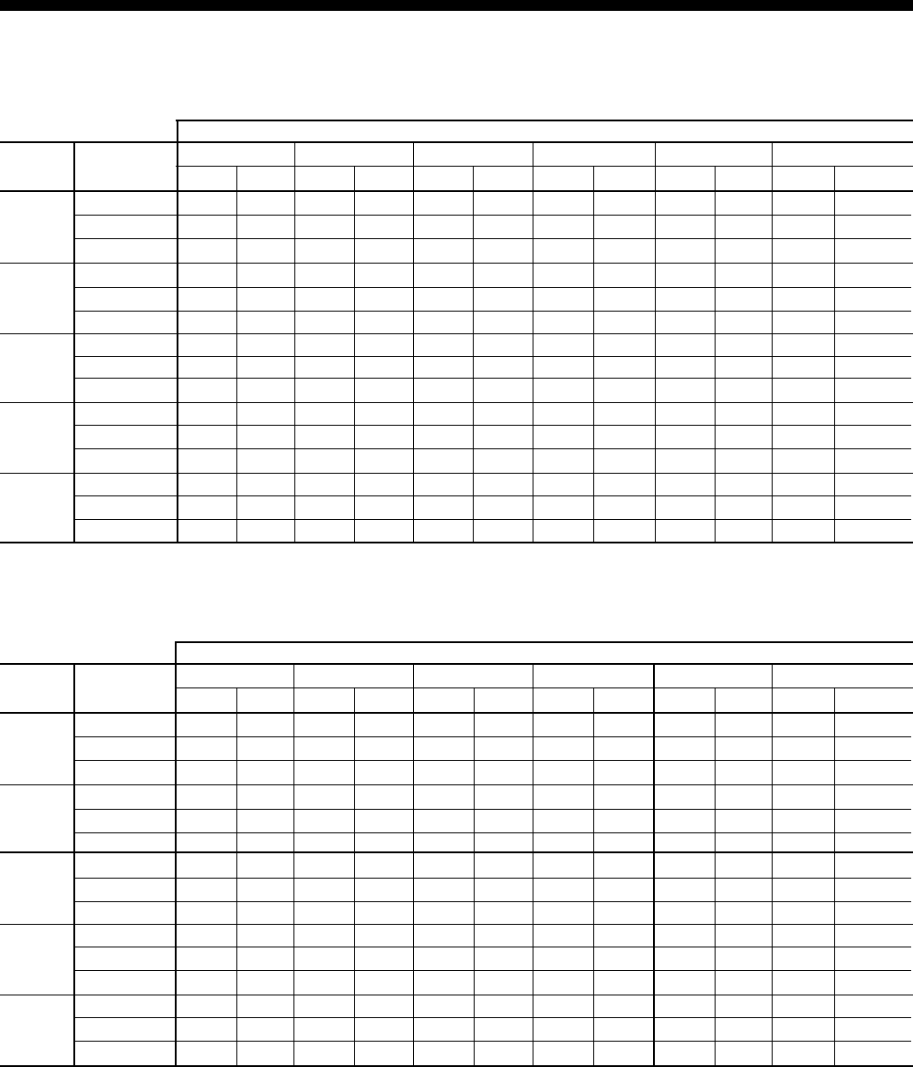
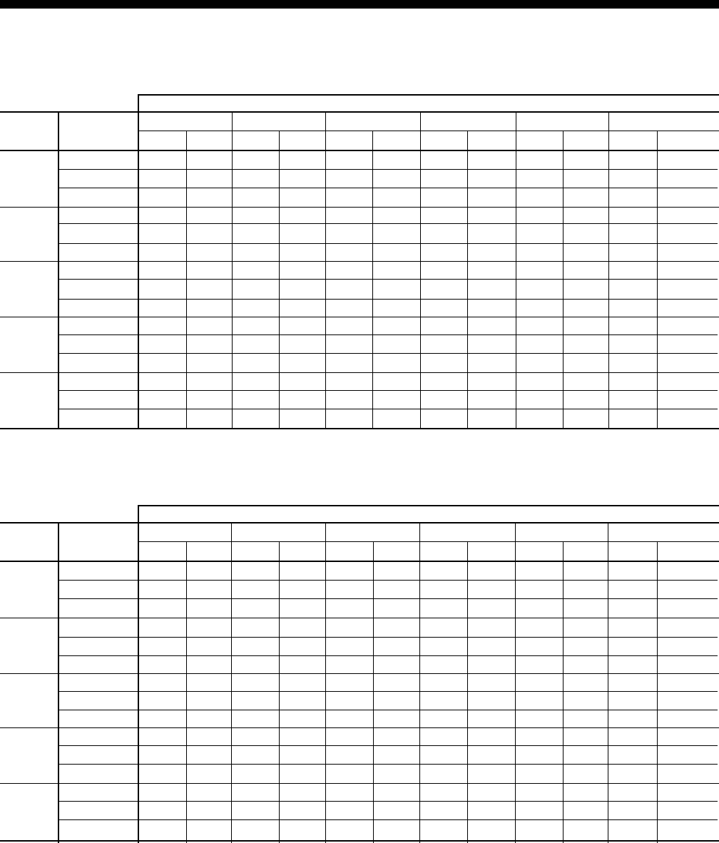
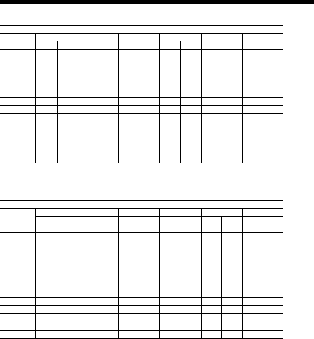
TABLE 2 –COOLING PERFORMANCE DATA – 50 TON MODEL
CAPACITY (MBH) AT ENTERING DRY BULB (°F)
CFM ENTERING 90 86 83 80 77 74
WB (°F) CAP SHC CAP SHC CAP SHC CAP SHC CAP SHC CAP SHC
72 700 477 700 431 695 387 692 353 691 311 ——
10000 67 653 548 646 500 635 454 637 416 632 377 626 343
62 640 640 608 608 590 583 582 562 569 514 574 455
72 711 500 708 445 705 399 701 360 699 316 ——
14000 67 665 581 656 523 647 474 647 431 643 388 637 349
62 654 654 625 625 606 606 594 547 583 498 585 439
72 729 536 721 467 719 418 715 370 712 324 ——
17500 67 684 634 672 558 666 505 663 454 660 406 653 359
62 680 680 652 652 632 625 612 550 606 497 603 438
72 749 576 736 492 736 439 732 382 726 333 ——
20000 67 705 695 689 597 686 540 680 479 679 425 672 370
62 710 710 682 682 661 661 633 582 631 523 622 467
72 758 595 742 504 743 449 739 388 732 338 ——
22500 67 715 715 697 616 696 557 689 492 688 435 680 376
62 715 715 696 610 674 549 643 486 643 429 631 370
* Rated performance is at sea level. Cooling capacities are gross cooling capacity.
85° AIR ON CONDENSER COIL
CAPACITY (MBH) AT ENTERING DRY BULB (°F)
CFM ENTERING 90 86 83 80 77 74
WB (°F) CAP SHC CAP SHC CAP SHC CAP SHC CAP SHC CAP SHC
72 673 468 673 416 669 375 667 340 664 301 ——
10000 67 628 536 630 494 615 445 616 404 609 383 605 331
62 618 618 590 590 569 513 571 481 562 435 562 390
72 684 491 682 432 678 388 676 348 673 306 ——
14000 67 642 569 638 515 627 465 625 419 619 382 615 338
62 635 635 607 607 586 541 580 500 572 453 571 407
72 701 526 696 458 693 407 690 360 686 315 ——
17500 67 665 625 651 547 645 497 640 443 635 382 630 348
62 661 661 634 634 612 587 594 531 588 481 586 433
72 720 565 712 486 709 429 705 373 701 325 ——
20000 67 691 691 665 582 665 532 656 470 653 382 647 360
62 691 691 663 663 641 641 609 565 606 511 602 462
72 729 584 720 500 717 439 712 380 708 329 ——
22500 67 703 703 672 599 674 549 664 483 661 382 655 366
62 704 704 675 658 655 629 617 556 614 488 610 447
* Rated performance is at sea level. Cooling capacities are gross cooling capacity.
95° AIR ON CONDENSER COIL

FORM 100.50-EG1
13
YORK INTERNATIONAL
TABLE 2 –COOLING PERFORMANCE DATA – 50 TON MODEL (CONT’D)
CAPACITY (MBH) AT ENTERING DRY BULB (°F)
CFM ENTERING 90 86 83 80 77 74
WB (°F) CAP SHC CAP SHC CAP SHC CAP SHC CAP SHC CAP SHC
72 649 464 650 409 645 365 644 330 644 290 ——
10000 67 590 513 596 478 589 434 591 390 593 354 589 318
62 597 597 573 573 536 498 549 460 544 429 542 384
72 658 483 658 424 653 378 651 338 650 295 ——
14000 67 609 550 608 501 600 454 600 406 601 366 597 326
62 614 614 589 589 556 527 557 483 553 446 550 397
72 673 512 670 447 667 397 663 350 661 303 ——
17500 67 638 607 625 537 618 485 615 432 613 384 609 337
62 641 641 614 614 587 571 570 520 567 472 563 419
72 689 545 684 472 682 419 677 364 672 311 ——
20000 67 670 670 645 577 638 520 631 461 626 404 623 350
62 670 670 642 642 621 621 584 561 582 500 576 443
72 696 560 690 485 690 430 683 371 678 315 ——
22500 67 686 695 654 596 647 537 639 475 632 414 629 356
62 684 684 655 655 637 644 591 580 590 514 583 455
* Rated performance is at sea level. Cooling capacities are gross cooling capacity.
105° AIR ON CONDENSER COIL
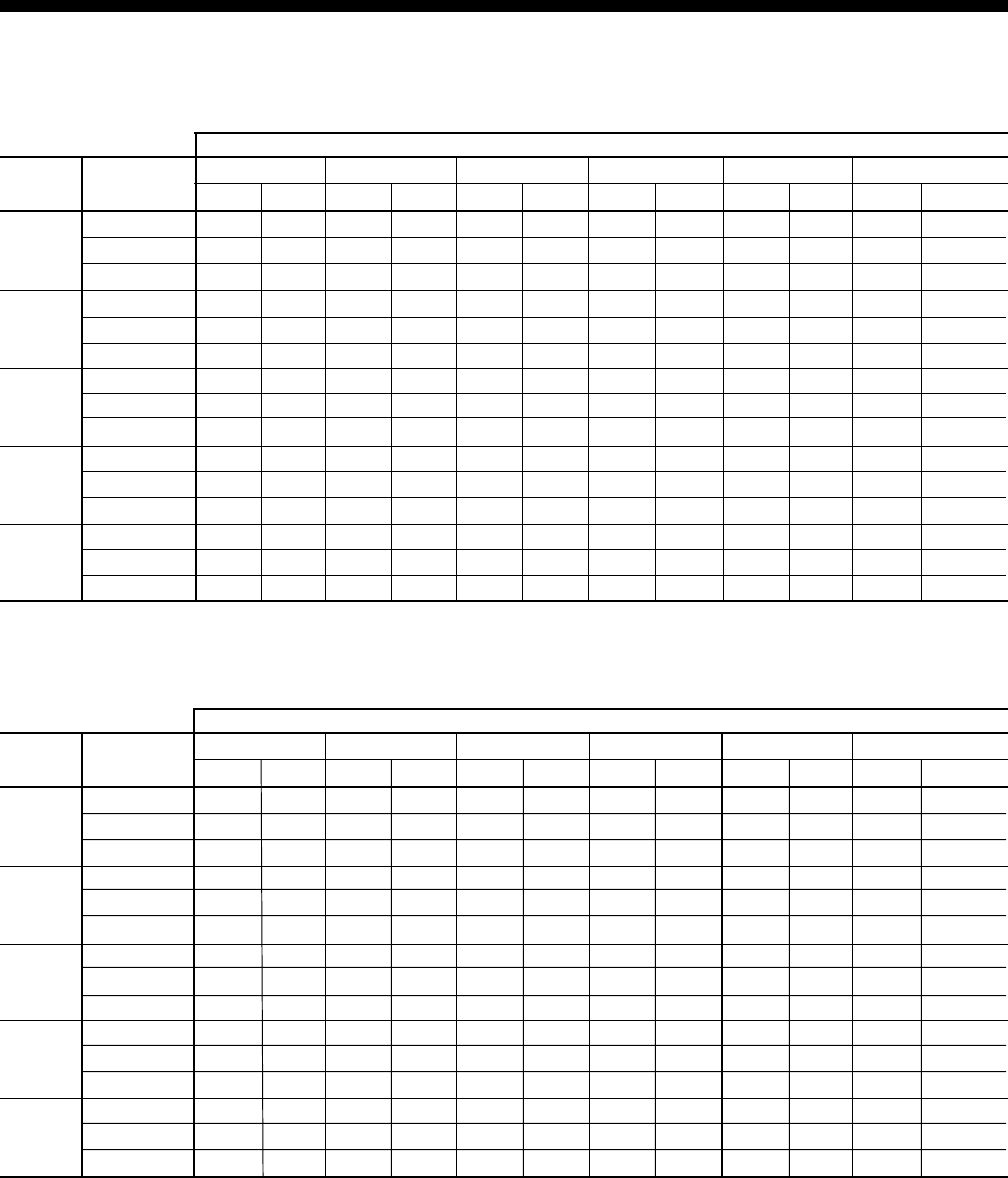
CAPACITY (MBH) AT ENTERING DRY BULB (°F)
CFM ENTERING 90 86 83 80 77 74
WB (°F) CAP SHC CAP SHC CAP SHC CAP SHC CAP SHC CAP SHC
72 563 368 562 318 567 286 558 258 563 233 ——
10000 67 494 424 524 387 514 349 515 313 514 281 518 254
62 498 498 501 501 442 424 458 349 467 343 467 306
72 592 432 588 370 589 325 585 286 583 246 ——
14000 67 548 509 545 449 541 406 539 359 536 317 537 276
62 550 550 533 533 498 488 494 434 491 395 489 349
72 608 465 603 397 600 346 600 300 594 253 ——
17500 67 577 555 557 481 555 435 552 383 548 336 547 288
62 578 578 550 550 527 522 513 478 504 422 500 371
72 625 503 618 427 613 368 616 316 606 261 ——
20000 67 609 609 570 517 571 468 566 410 562 357 558 301
62 609 609 568 568 560 560 534 528 518 452 513 396
72 633 520 626 441 619 379 623 324 611 265 ——
22500 67 624 624 576 534 579 484 572 423 568 367 563 307
62 624 624 577 577 575 578 544 548 525 467 520 408
* Rated performance is at sea level. Cooling capacities are gross cooling capacity.
115° AIR ON CONDENSER COIL

YORK INTERNATIONAL
14
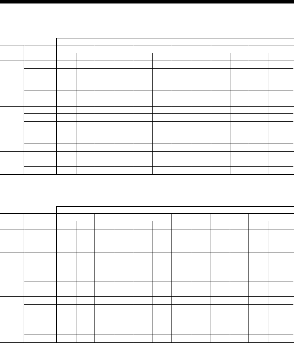
TABLE 3 –COOLING PERFORMANCE DATA – 55 TON MODEL
Cooling Performance Data – 55 Ton Model
CAPACITY (MBH) AT ENTERING DRY BULB (°F)
CFM ENTERING 90 86 83 80 77 74
WB (°F) CAP SHC CAP SHC CAP SHC CAP SHC CAP SHC CAP SHC
72 732 488 704 437 700 393 696 356 695 313 ——
12000 67 677 564 651 511 641 463 642 423 637 382 631 346
62 660 648 616 616 598 598 588 564 576 515 579 456
72 743 512 712 452 709 405 706 363 703 319 ——
16000 67 693 598 661 535 653 484 652 438 649 394 642 353
62 680 661 634 634 615 587 600 531 591 481 591 421
72 767 564 731 485 731 433 727 378 722 331 ——
19250 67 728 677 684 586 680 530 675 472 673 419 666 367
62 725 701 673 673 652 652 627 572 624 515 616 458
72 781 592 741 502 742 448 738 387 731 337 ——
22000 67 750 713 695 613 694 554 688 490 687 433 679 375
62 750 713 694 613 672 554 642 490 641 433 630 375
72 786 604 746 510 747 454 743 390 736 340 ——
24000 67 758 720 701 625 701 565 693 497 692 439 685 378
62 760 720 701 602 681 534 648 473 649 416 636 357
* Rated performance is at sea level. Cooling capacities are gross cooling capacity.
85° AIR ON CONDENSER COIL
CAPACITY (MBH) AT ENTERING DRY BULB (°F)
CFM ENTERING 90 86 83 80 77 74
WB (°F) CAP SHC CAP SHC CAP SHC CAP SHC CAP SHC CAP SHC
72 706 479 678 424 673 381 671 344 668 303 ——
12000 67 651 554 634 504 621 454 621 411 613 382 610 334
62 641 626 598 598 577 527 575 490 567 444 566 398
72 716 502 687 441 683 394 680 352 677 309 ——
16000 67 668 585 643 525 633 476 630 427 624 382 620 341
62 661 644 616 616 594 554 585 511 577 462 576 415
72 738 554 708 478 704 422 700 369 696 322 ——
19250 67 707 671 661 572 659 521 651 462 647 382 642 357
62 705 682 654 654 633 625 605 555 600 502 598 453
72 751 581 719 497 715 438 711 379 707 328 ——
22000 67 728 701 671 597 673 546 663 481 660 382 654 365
62 730 703 675 675 653 653 616 578 613 524 609 473
72 756 593 723 506 720 444 715 383 711 331 ——
24000 67 737 709 675 607 678 556 667 489 665 382 659 369
62 740 709 675 607 662 556 620 489 618 382 614 369
* Rated performance is at sea level. Cooling capacities are gross cooling capacity.
95° AIR ON CONDENSER COIL
FORM 100.50-EG1
15
YORK INTERNATIONAL
TABLE 3 –COOLING PERFORMANCE DATA – 55 TON MODEL (CONT’D)
* Rated performance is at sea level. Cooling capacities are gross cooling capacity.
CAPACITY (MBH) AT ENTERING DRY BULB (°F)
CFM ENTERING 90 86 83 80 77 74
WB (°F) CAP SHC CAP SHC CAP SHC CAP SHC CAP SHC CAP SHC
72 642 473 654 416 649 371 647 334 647 292 ——
12000 67 593 531 602 489 594 443 595 397 597 359 593 322
62 592 605 581 581 546 512 553 471 549 437 546 390
72 661 493 662 432 658 384 655 342 654 297 ——
16000 67 619 569 613 513 606 464 605 415 605 372 601 330
62 618 623 598 598 566 542 561 496 558 454 554 405
72 701 535 679 465 678 413 673 360 669 308 ——
19250 67 679 651 639 565 632 510 626 452 622 398 619 346
62 679 661 634 634 611 606 580 549 578 492 572 436
72 723 558 689 483 689 428 682 370 677 314 ——
22000 67 711 696 653 593 645 534 637 473 631 412 628 355
62 711 682 653 653 635 641 590 577 588 512 582 453
72 733 567 693 490 693 435 686 374 681 317 ——
24000 67 724 693 659 605 651 545 642 481 635 418 632 359
62 725 691 661 661 645 656 594 590 593 521 586 460
105° AIR ON CONDENSER COIL
CAPACITY (MBH) AT ENTERING DRY BULB (°F)
CFM ENTERING 90 86 83 80 77 74
WB (°F) CAP SHC CAP SHC CAP SHC CAP SHC CAP SHC CAP SHC
72 657 460 624 400 618 357 613 321 610 284 ——
12000 67 606 535 579 477 571 435 566 390 563 350 559 312
62 598 581 557 567 528 517 519 458 517 425 512 381
72 665 482 633 417 627 371 623 330 619 288 ——
16000 67 623 562 588 498 582 454 577 406 573 362 570 319
62 617 600 572 578 547 539 534 487 528 443 523 395
72 682 529 653 455 647 399 645 350 640 297 ——
19250 67 660 632 606 544 605 496 599 440 595 388 592 335
62 659 639 602 602 589 587 565 551 552 481 547 426
72 692 554 663 476 658 414 657 360 651 302 ——
22000 67 680 660 617 568 617 518 611 458 607 402 603 343
62 682 660 616 614 611 613 582 585 565 501 559 443
72 696 565 668 484 663 421 662 365 656 304 ——
24000 67 689 668 621 578 622 527 617 466 613 408 608 347
62 692 669 622 620 621 624 589 589 570 510 565 450
* Rated performance is at sea level. Cooling capacities are gross cooling capacity.
115° AIR ON CONDENSER COIL
YORK INTERNATIONAL
16
TABLE 4 –COOLING PERFORMANCE DATA – 60 TON MODEL
Cooling Performance Data – 60 Ton Model
CAPACITY (MBH) AT ENTERING DRY BULB (°F)
CFM ENTERING 90 86 83 80 77 74
WB (°F) CAP SHC CAP SHC CAP SHC CAP SHC CAP SHC CAP SHC
72 804 495 804 461 801 277 798 383 792 344 ——
14000 67 736 586 728 522 729 339 727 440 725 408 723 377
62 689 689 663 663 658 442 656 543 647 493 654 424
72 846 609 840 538 837 410 833 426 827 372 ——
18000 67 795 720 773 632 771 504 769 519 767 468 761 415
62 771 771 740 740 725 617 704 630 700 572 699 502
72 867 666 858 576 855 477 851 448 845 386 ——
21000 67 824 787 795 687 792 587 790 558 787 498 780 434
62 813 813 779 779 759 705 728 673 726 611 722 541
72 888 722 876 614 872 544 868 470 862 401 ——
24000 67 854 854 818 742 814 670 810 598 808 528 799 453
62 854 854 817 817 792 792 752 716 752 651 744 580
72 897 748 884 632 880 574 876 480 870 407 ——
27000 67 867 867 828 767 823 708 820 616 818 541 808 461
62 873 873 835 835 808 817 763 736 764 669 755 598
* Rated performance is at sea level. Cooling capacities are gross cooling capacity.
85° AIR ON CONDENSER COIL
CAPACITY (MBH) AT ENTERING DRY BULB (°F)
CFM ENTERING 90 86 83 80 77 74
WB (°F) CAP SHC CAP SHC CAP SHC CAP SHC CAP SHC CAP SHC
72 773 491 771 442 769 336 769 368 763 331 ——
14000 67 723 527 692 464 703 397 703 432 699 437 696 363
62 671 671 645 645 631 474 642 505 655 416 673 318
72 814 599 808 524 804 434 802 414 797 361 ——
18000 67 775 678 752 570 745 529 742 508 736 455 732 402
62 750 750 719 719 699 620 684 604 682 550 681 494
72 834 652 827 565 822 482 819 438 814 376 ——
21000 67 802 753 783 623 766 594 761 546 755 463 751 421
62 789 789 756 756 732 693 706 653 696 616 685 582
72 854 706 846 607 840 531 835 461 831 391 ——
24000 67 828 828 813 675 788 660 780 584 774 472 769 441
62 828 828 793 793 766 766 727 703 709 683 689 670
72 864 730 854 626 848 553 843 471 838 397 ——
27000 67 840 863 827 699 797 691 789 601 782 476 778 450
62 846 846 810 810 782 788 737 726 716 714 690 710
* Rated performance is at sea level. Cooling capacities are gross cooling capacity.
95° AIR ON CONDENSER COIL
FORM 100.50-EG1
17
YORK INTERNATIONAL
TABLE 4 –COOLING PERFORMANCE DATA – 60 TON MODEL (CONT’D)
CAPACITY (MBH) AT ENTERING DRY BULB (°F)
CFM ENTERING 90 86 83 80 77 74
WB (°F) CAP SHC CAP SHC CAP SHC CAP SHC CAP SHC CAP SHC
72 753 500 744 438 741 392 741 357 737 319 ——
14000 67 690 469 676 304 672 458 681 416 681 384 678 350
62 652 652 627 627 587 554 616 489 632 454 624 412
72 782 588 778 514 774 457 771 403 767 347 ——
18000 67 745 635 718 508 713 550 715 494 711 442 708 389
62 726 726 697 697 664 648 658 589 655 536 655 480
72 797 633 794 551 790 490 787 425 782 361 ——
21000 67 773 718 739 610 734 597 732 533 727 471 723 409
62 763 763 732 732 702 694 679 639 667 576 670 515
72 811 677 811 589 806 522 802 448 798 375 ——
24000 67 801 801 761 712 754 643 750 572 742 500 738 428
62 800 800 767 767 741 741 700 690 679 617 686 549
72 818 697 818 606 814 537 809 459 804 382 ——
27000 67 814 839 771 759 764 664 757 589 749 514 744 437
62 817 817 783 783 758 759 710 709 684 636 693 565
* Rated performance is at sea level. Cooling capacities are gross cooling capacity.
105° AIR ON CONDENSER COIL
CAPACITY (MBH) AT ENTERING DRY BULB (°F)
CFM ENTERING 90 86 83 80 77 74
WB (°F) CAP SHC CAP SHC CAP SHC CAP SHC CAP SHC CAP SHC
72 726 485 711 413 702 376 698 345 689 309 ——
14000 67 629 574 647 512 647 447 643 411 635 370 633 338
62 626 626 607 622 562 543 561 467 582 447 574 404
72 749 572 742 496 736 440 732 389 726 335 ——
18000 67 700 673 688 603 683 537 680 484 673 429 669 376
62 699 699 666 673 639 629 625 578 620 524 617 472
72 760 615 758 538 754 473 749 411 744 349 ——
21000 67 736 722 708 648 701 582 699 521 692 458 687 395
62 735 735 695 698 677 672 657 634 640 563 638 505
72 772 658 774 580 771 505 766 433 763 362 ——
24000 67 772 772 728 693 718 627 717 558 711 487 706 414
62 772 772 724 724 715 715 690 690 659 602 659 539
72 777 678 781 599 779 520 773 443 771 368 ——
27000 67 788 788 737 714 727 647 726 574 719 501 714 423
62 788 788 737 735 732 733 704 706 668 619 669 555
* Rated performance is at sea level. Cooling capacities are gross cooling capacity.
115° AIR ON CONDENSER COIL
YORK INTERNATIONAL
18
TABLE 5 –COOLING PERFORMANCE DATA – 65 TON MODEL
Cooling Performance Data – 65 Ton Model
CAPACITY (MBH) AT ENTERING DRY BULB (°F)
CFM ENTERING 90 86 83 80 77 74
WB (°F) CAP SHC CAP SHC CAP SHC CAP SHC CAP SHC CAP SHC
72 810 572 808 504 806 454 802 405 798 357 ——
14000 67 767 658 747 593 743 542 744 491 740 443 737 393
62 733 733 704 704 676 631 686 581 682 530 680 477
72 822 603 820 528 817 473 813 419 809 365 ——
18000 67 782 699 759 625 756 570 755 513 751 460 748 406
62 756 756 726 726 699 664 697 610 694 556 691 500
72 844 656 839 569 836 505 832 442 827 380 ——
21000 67 800 768 781 681 777 618 774 551 770 489 766 426
62 797 797 764 764 737 720 717 661 714 600 710 538
72 866 709 858 610 855 537 850 464 844 394 ——
24000 67 837 837 802 737 798 665 793 589 788 519 784 447
62 837 837 802 802 776 776 737 712 734 644 729 577
72 875 733 867 629 863 552 859 475 852 401 ——
27000 67 854 854 812 762 807 687 801 606 797 532 792 456
62 854 854 812 753 794 674 746 592 743 518 738 441
* Rated performance is at sea level. Cooling capacities are gross cooling capacity.
95° AIR ON CONDENSER COIL
CAPACITY (MBH) AT ENTERING DRY BULB (°F)
CFM ENTERING 90 86 83 80 77 74
WB (°F) CAP SHC CAP SHC CAP SHC CAP SHC CAP SHC CAP SHC
72 840 584 839 516 836 467 833 418 828 368 ——
14000 67 785 669 774 605 771 554 772 502 768 456 764 406
62 754 754 724 724 695 640 710 589 707 542 706 492
72 853 615 851 540 848 486 844 431 840 377 ——
18000 67 802 713 788 638 784 582 784 525 780 473 776 418
62 779 779 748 748 719 676 723 620 719 568 717 513
72 876 668 871 582 868 518 864 454 859 392 ——
21000 67 827 788 810 694 806 630 804 563 800 502 796 439
62 821 821 787 787 760 739 745 674 741 612 737 548
72 899 721 892 623 888 550 884 477 878 407 ——
24000 67 862 862 833 750 828 678 824 601 820 531 815 460
62 862 862 827 827 801 801 767 727 762 656 757 584
72 909 745 901 642 898 564 893 488 887 413 ——
27000 67 878 878 843 776 838 700 833 619 829 544 824 469
62 878 878 843 765 820 686 777 604 772 530 766 455
* Rated performance is at sea level. Cooling capacities are gross cooling capacity.
85° AIR ON CONDENSER COIL

FORM 100.50-EG1
19
YORK INTERNATIONAL
TABLE 5 –COOLING PERFORMANCE DATA – 65 TON MODEL (CONT’D)
CAPACITY (MBH) AT ENTERING DRY BULB (°F)
CFM ENTERING 90 86 83 80 77 74
WB (°F) CAP SHC CAP SHC CAP SHC CAP SHC CAP SHC CAP SHC
72 780 560 777 493 774 442 771 393 768 342 ——
14000 67 737 646 717 581 714 529 714 476 711 430 708 381
62 710 710 682 682 650 621 658 565 655 516 653 466
72 792 591 788 516 785 461 781 406 777 351 ——
18000 67 753 683 730 613 726 556 725 499 721 447 718 393
62 732 732 703 703 672 650 669 595 666 542 663 486
72 812 643 805 555 802 493 798 429 794 365 ——
21000 67 771 746 752 668 746 604 744 538 738 476 734 413
62 771 771 739 739 711 700 689 647 685 586 681 522
72 831 696 822 595 820 524 816 452 810 379 ——
24000 67 809 809 774 722 766 651 762 576 756 505 751 433
62 809 809 774 774 750 750 709 698 704 630 699 558
72 840 720 830 613 828 539 823 462 817 386 ——
27000 67 826 826 784 747 775 673 770 594 763 518 759 442
62 826 826 791 791 767 772 718 721 712 650 707 574
* Rated performance is at sea level. Cooling capacities are gross cooling capacity.
105° AIR ON CONDENSER COIL
CAPACITY (MBH) AT ENTERING DRY BULB (°F)
CFM ENTERING 90 86 83 80 77 74
WB (°F) CAP SHC CAP SHC CAP SHC CAP SHC CAP SHC CAP SHC
72 748 548 744 478 742 429 738 378 735 330 ——
14000 67 708 639 690 570 686 517 684 463 681 417 678 368
62 681 681 664 664 621 608 625 550 628 503 625 452
72 759 578 754 502 752 448 748 392 744 338 ——
18000 67 724 671 700 599 696 544 694 486 690 434 687 380
62 704 704 679 679 644 634 642 583 638 528 635 473
72 776 629 771 543 768 479 766 415 759 352 ——
21000 67 741 725 716 650 714 591 711 523 706 462 703 400
62 741 741 706 706 682 678 669 640 655 571 651 508
72 794 680 789 584 784 511 784 438 774 366 ——
24000 67 779 779 732 700 732 637 728 561 722 491 718 419
62 779 779 732 732 721 721 697 697 672 615 668 543
72 802 703 797 603 791 525 792 449 781 372 ——
27000 67 796 796 740 723 740 658 736 578 729 504 725 428
62 796 796 740 717 738 648 710 563 680 490 676 414
* Rated performance is at sea level. Cooling capacities are gross cooling capacity.
115° AIR ON CONDENSER COIL
YORK INTERNATIONAL
20
Fan Performance
TABLE 6 –50 THROUGH 65 TON SUPPLY FAN DATA
TABLE 6 –50 THROUGH 65 TON SUPPLY FAN DATA (CONT’D)
TOTAL STATIC PRESSURE (inches of water column)
CFM 3.50 4.00 4.50 5.00 5.50 6.00
STD. AIR RPM HP RPM HP RPM HP RPM HP RPM HP RPM HP
10000 –– –– –– –– –– –– –– –– –– –– –– ––
12000 –– –– –– –– –– –– –– –– –– –– –– ––
14000 585 10.5 –– –– –– –– –– –– –– –– –– ––
16000 587 12.5 622 13.8 663 15.4 700 17.0 –– –– –– ––
17500 595 14.5 629 15.9 664 17.3 697 18.8 549 15.9 575 17.3
18000 597 15.2 631 16.6 664 18.0 696 19.5 732 21.2 766 23.0
19250 605 17.1 638 18.6 670 20.1 702 21.6 734 23.3 765 25.0
20000 609 18.2 642 19.8 674 21.4 705 22.9 735 24.5 764 26.1
21000 617 19.9 649 21.6 681 23.3 710 24.9 740 26.6 769 28.2
22000 624 21.7 655 23.4 688 25.3 715 26.9 744 28.6 773 30.4
22500 628 22.7 659 24.4 691 26.3 719 28.0 748 29.8 776 31.5
24000 640 25.7 671 27.5 700 29.4 729 31.4 759 33.4 783 35.1
26000 656 30.2 687 32.2 716 34.2 742 36.1 769 38.2 798 40.5
27000 665 32.7 693 34.6 723 36.8 751 38.9 778 41.0 802 43.1
TOTAL STATIC PRESSURE (inches of water column)
CFM 0.50 1.00 1.50 2.00 2.50 3.00
STD. AIR RPM HP RPM HP RPM HP RPM HP RPM HP RPM HP
10000 249 1.7 321 2.5 382 3.3 –– –– –– –– –– —
12000 269 2.5 335 3.4 392 4.4 443 5.3 493 6.4 –– —
14000 290 3.6 352 4.7 405 5.8 454 6.9 497 8.0 540 9.1
16000 312 5.1 371 6.3 421 7.5 467 8.7 510 10.0 549 11.2
17500 329 6.3 386 7.7 435 9.0 478 10.4 519 11.7 558 13.1
18000 334 6.8 391 8.2 439 9.6 482 10.9 522 12.3 561 13.8
19250 348 8.1 404 9.6 451 11.1 493 12.5 532 14.0 570 15.5
20000 357 8.9 412 10.5 458 12.1 499 13.5 538 15.1 575 16.6
21000 370 10.1 423 11.9 468 13.5 510 15.1 547 16.7 583 18.3
22000 383 11.4 434 13.3 478 15.0 520 16.7 555 18.3 591 20.0
22500 387 12.0 440 14.1 484 15.8 524 17.6 560 19.2 595 20.9
24000 398 13.9 458 16.6 500 18.4 537 20.2 574 22.1 607 23.8
26000 417 16.8 478 20.2 520 22.3 559 24.4 593 26.3 626 28.3
27000 429 18.6 490 22.3 533 24.6 572 26.8 602 28.6 638 30.9
FORM 100.50-EG1
21
YORK INTERNATIONAL
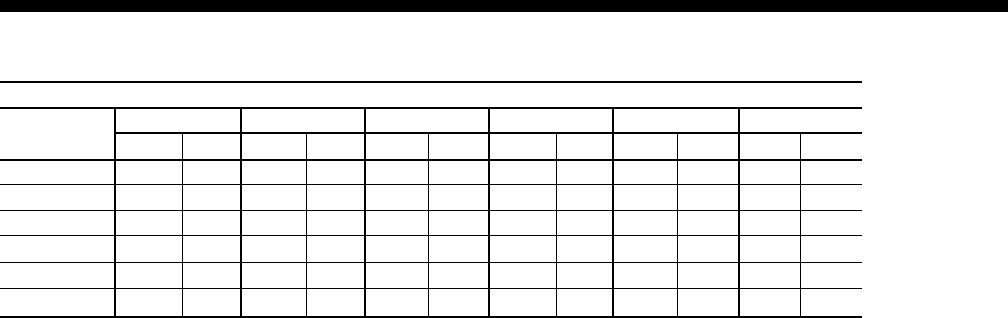
TABLE 7 – 50 THROUGH 65 TON EXHAUST FAN DATA
TOTAL STATIC PRESSURE (inches of water column)
CFM 0.50 1.00 1.50 2.00 2.50 3.00
STD. AIR RPM HP RPM HP RPM HP RPM HP RPM HP RPM HP
10000 674 3.30 801 4.18 –– ––– –– –– –– –– –– ––
12000 713 4.84 823 5.82 929 6.87 –– –– –– –– –– ––
14000 762 6.84 858 7.98 952 9.12 1043 10.32 1132 11.62 –– ––
16000 819 9.36 904 10.73 988 12.04 1070 13.33 1150 14.69 1229 16.10
18000 879 12.42 957 14.04 1032 15.56 1107 17.02 1179 18.48 –– ––
20000 943 16.18 1014 18.04 –– –– –– –– –– –– –– ––
YORK INTERNATIONAL
22
50 10000 0.22 0.15 0.04 0.08 0.08 0.04 0.06 0.04 0.05 0.01 0.04 0.08
12000 0.30 0.21 0.06 0.11 0.11 0.06 0.09 0.06 0.07 0.02 0.06 0.11
14000 0.38 0.27 0.09 0.15 0.15 0.08 0.12 0.09 0.09 0.03 0.07 0.14
16000 0.47 0.35 0.11 0.20 0.20 0.11 0.15 0.11 0.11 0.04 0.09 0.16
17500 0.54 0.41 0.14 0.24 0.24 0.13 0.18 0.14 0.12 0.05 0.10 0.19
18000 0.57 0.44 0.14 0.25 0.25 0.13 0.19 0.14 0.13 0.05 0.10 0.19
20000 0.67 0.53 0.18 0.31 0.31 0.17 0.24 0.18 0.15 0.06 0.12 0.22
21000 0.72 0.58 0.20 0.35 0.35 0.18 0.26 0.20 0.16 0.07 0.13 0.24
22000 0.78 0.63 0.21 0.38 0.38 0.20 0.29 0.21 0.17 0.08 0.14 0.26
22500 0.80 0.66 0.22 0.40 0.40 0.21 0.30 0.22 0.17 0.08 0.15 0.26
55 12000 0.30 0.21 0.06 0.11 0.11 0.06 0.09 0.06 0.07 0.02 0.06 0.11
14000 0.38 0.27 0.09 0.15 0.15 0.08 0.12 0.09 0.09 0.03 0.07 0.14
16000 0.47 0.35 0.11 0.20 0.20 0.11 0.15 0.11 0.11 0.04 0.09 0.16
18000 0.57 0.44 0.14 0.25 0.25 0.13 0.19 0.14 0.13 0.05 0.10 0.19
19250 0.63 0.49 0.16 0.29 0.29 0.15 0.22 0.16 0.14 0.06 0.12 0.21
20000 0.67 0.53 0.18 0.31 0.31 0.17 0.24 0.18 0.15 0.06 0.12 0.22
22000 0.78 0.63 0.21 0.38 0.38 0.20 0.29 0.21 0.17 0.08 0.14 0.26
24000 0.89 0.74 0.25 0.45 0.45 0.24 0.34 0.25 0.19 0.09 0.16 0.29
60 14000 0.38 0.27 0.09 0.15 0.15 0.08 0.12 0.09 0.09 0.03 0.07 0.14
16000 0.47 0.35 0.11 0.20 0.20 0.11 0.15 0.11 0.11 0.04 0.09 0.16
18000 0.57 0.44 0.14 0.25 0.25 0.13 0.19 0.14 0.13 0.05 0.10 0.19
20000 0.67 0.53 0.18 0.31 0.31 0.17 0.24 0.18 0.15 0.06 0.12 0.22
21000 0.72 0.58 0.20 0.35 0.35 0.18 0.26 0.20 0.16 0.07 0.13 0.24
22000 0.78 0.63 0.21 0.38 0.38 0.20 0.29 0.21 0.17 0.08 0.14 0.26
24000 0.89 0.74 0.25 0.45 0.45 0.24 0.34 0.25 0.19 0.09 0.16 0.29
26000 1.01 0.86 0.30 0.53 0.53 0.28 0.40 0.30 0.21 0.11 0.19 0.32
27000 1.07 0.92 0.32 0.57 0.57 0.30 0.43 0.32 0.23 0.12 0.20 0.34
65 14000 0.38 0.27 0.09 0.15 0.15 0.08 0.12 0.09 0.09 0.03 0.07 0.14
16000 0.47 0.35 0.11 0.20 0.20 0.11 0.15 0.11 0.11 0.04 0.09 0.16
18000 0.57 0.44 0.14 0.25 0.25 0.13 0.19 0.14 0.13 0.05 0.10 0.19
20000 0.67 0.53 0.18 0.31 0.31 0.17 0.24 0.18 0.15 0.06 0.12 0.22
21000 0.72 0.58 0.20 0.35 0.35 0.18 0.26 0.20 0.16 0.07 0.13 0.24
22000 0.78 0.63 0.21 0.38 0.38 0.20 0.29 0.21 0.17 0.08 0.14 0.26
24000 0.89 0.74 0.25 0.45 0.45 0.24 0.34 0.25 0.19 0.09 0.16 0.29
26000 1.01 0.86 0.30 0.53 0.53 0.28 0.40 0.30 0.21 0.11 0.19 0.32
27000 1.07 0.92 0.32 0.57 0.57 0.30 0.43 0.32 0.23 0.12 0.20 0.34
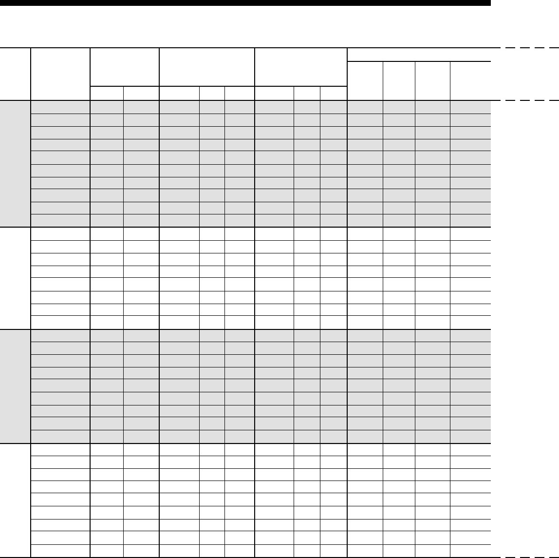
FILTERS
SIZE AIR FLOW EVAPORATOR SUPPLY RETURN AIR 2" 2" 2" 2"
CFM STD. AIR COILS OPENING OPENING THROW- CLEAN- PLEAT- CARBON
WET DRY BOTTOM LEFT RIGHT BOTTOM REAR SIDES AWAY ABLE ED
Fan Performance (continued)
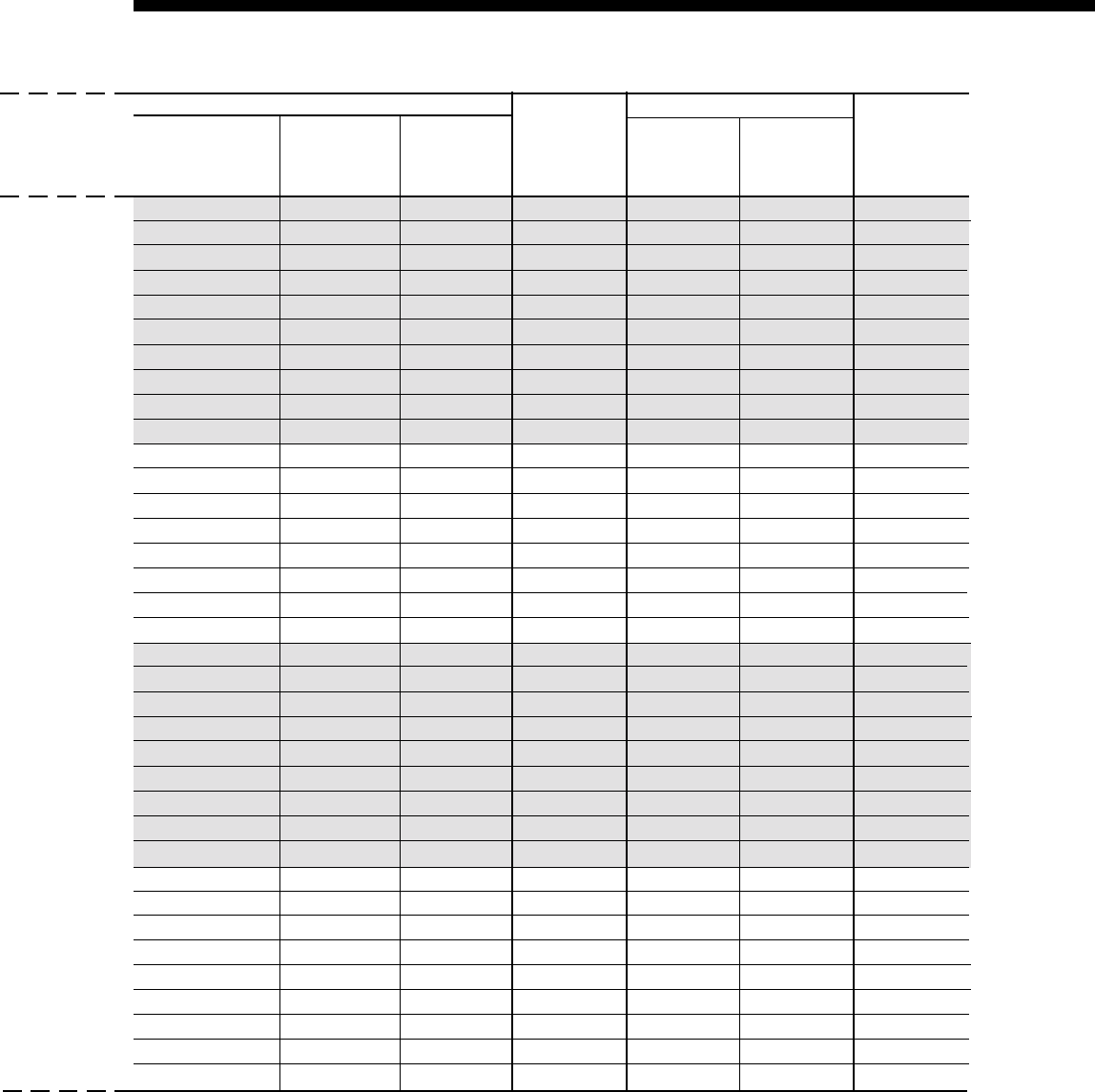
TABLE 8 –COMPONENT STATIC PRESSURE DROPS (INCHES OF WATER COLUMN)
*For Aluminum Fins Only
FORM 100.50-EG1
23
YORK INTERNATIONAL
0.05 0.21 0.30 0.07 0.05 0.11 0.08
0.07 0.28 0.38 0.11 0.08 0.16 0.11
0.09 0.34 0.46 0.15 0.11 0.21 0.15
0.11 0.42 0.55 0.20 0.14 0.26 0.20
0.12 0.47 0.62 0.24 0.17 0.31 0.24
0.13 0.49 0.65 0.25 0.18 0.32 0.25
0.15 0.58 0.74 0.31 0.22 0.39 0.31
0.16 0.62 0.79 0.35 0.24 0.42 0.34
0.17 0.66 0.84 0.38 0.27 0.46 0.37
0.17 0.68 0.87 0.40 0.28 0.48 0.39
0.07 0.28 0.38 0.11 0.08 0.16 0.11
0.09 0.34 0.46 0.15 0.11 0.21 0.15
0.11 0.42 0.55 0.20 0.14 0.26 0.20
0.13 0.49 0.65 0.25 0.18 0.32 0.25
0.14 0.54 0.71 0.29 0.20 0.36 0.29
0.15 0.58 0.74 0.31 0.22 0.39 0.31
0.17 0.66 0.84 0.38 0.27 0.46 0.37
0.19 0.75 0.95 0.46 0.32 0.54 0.45
0.09 0.34 0.46 0.15 0.11 0.21 0.15
0.11 0.42 0.55 0.20 0.14 0.26 0.20
0.13 0.49 0.65 0.25 0.18 0.32 0.25
0.15 0.58 0.74 0.31 0.22 0.39 0.31
0.16 0.62 0.79 0.35 0.24 0.42 0.34
0.17 0.66 0.84 0.38 0.27 0.46 0.37
0.19 0.75 0.95 0.46 0.32 0.54 0.45
0.21 0.84 1.06 0.55 0.37 0.62 0.52
0.23 0.89 1.11 0.59 0.40 0.67 0.56
FILTERS ECONOMIZER DAMPERS
RIGID FILTER 12" RIGID 12" RIGID
ECONOMIZER
MANUAL OR 0 - 100% POWERED
RACK NO. 65%* 95%*
FRESH AIR
2-POSITION MODULATION EXHAUST
MEDIA OPENINGS
YORK INTERNATIONAL
24
Electrical Data
ELECTRICAL SERVICE SIZING
In order to use the electrical service required for the
cooling only Eco2 rooftop, use the appropriate calcula-
tions listed below from U.L. 1995. Based on the operat-
ing mode and configuration of the rooftop, the calcula-
tions will yield different MCA (minimum circuit ampac-
ity), and MOP (maximum overcurrent protection).
Using the following load definitions and calculations,
determine the correct electrical sizing for your unit. All
concurrent load conditions must be considered in the
calculations, and you must use the highest value for
any combination of loads.
Load Definitions:
•LOAD1 is the current of the largest motor – com-
pressor or fan motor.
•LOAD2 is the sum of the remaining motor currents
that may run concurrently with LOAD1 (i.e., exhaust
fan motor).
•LOAD3 is the current of the electric heaters – zero
for cooling only units.
•LOAD4 is the sum of any remaining currents
greater than or equal to 1.0 amp
Use the following calculations to determine MCA
and MOP for units supplied with a single-point power
connection:
MCA = (1.25 x LOAD1) + LOAD2 + LOAD4
MOP = (2.25 x LOAD1) + LOAD2 + LOAD4
If the MOP does not equal a standard current rating of
an overcurrent protective device, then the marked maxi-
mum rating is to be the next lower standard rating. How-
ever, if the device selected for MOP is less than the
MCA, then select the lowest standard maximum fuse
size greater than or equal to the MCA.
TABLE 9 – COMPRESSORS
COMPRESSOR NOMINAL VOLTAGE
QUANTITY
MODEL 208V 230V 460V 575V
MODEL PER
UNIT RLA* LRA* RLA* LRA* RLA* LRA* RLA* LRA*
50 4 SZ160 54.0 265.0 48.8 265.0 24.2 135.0 19.4 120.0
55 4 SZ160 54.0 265.0 48.8 265.0 24.2 135.0 19.4 120.0
60 4 SZ185 62.3 380.0 56.3 380.0 27.9 175.0 22.3 140.0
65 4 SZ185 62.3 380.0 56.3 380.0 27.9 175.0 22.3 140.0
* Values shown are per compressor

FORM 100.50-EG1
25
YORK INTERNATIONAL
TABLE 10 –SUPPLY AND EXHAUST FAN MOTOR (ODP OR TEFC)
TABLE 11 –CONDENSER FAN MOTORS / EACH
NOMINAL VOLTAGE
MOTOR 208V 230V 460V 575V
HP FLA FLA FLA FLA
5.0 14.0 13.4 6.7 5.3
7.5 22.2 21.6 10.8 8.2
10.0 28.5 28.4 14.2 11.4
15.0 44.8 39.0 19.5 16.0
20.0 61.0 50.0 25.0 20.0
25.0 74.0 60.0 30.0 24.2
30.0 87.0 76.0 38.0 30.3
40.0 113.0 95.6 47.8 38.0
High Efficiency
NOMINAL VOLTAGE
MOTOR 208V 230V 460V 575V
HP FLA FLA FLA FLA
5.0 14.9 13.6 6.8 5.5
7.5 22.5 20.0 10.0 7.9
10.0 29.2 25.8 12.9 10.3
15.0 41.5 36.0 18.0 14.5
20.0 55.0 48.0 24.0 19.3
25.0 71.0 61.0 30.5 24.5
30.0 85.5 74.0 37.0 30.0
40.0 109.0 96.0 48.0 38.0
Premium Efficiency
NOMINAL VOLTAGE
NOMINAL 208V 230V 460V 575V
TONS FLA FLA FLA FLA
50 7.5 6.8 3.4 2.7
55 7.5 6.8 3.4 2.7
60 7.5 6.8 3.4 2.7
65 7.5 6.8 3.4 2.7
TABLE 12 –CONTROLS AND CONVENIENCE
OUTLET
NOMINAL VOLTAGE
DESCRIPTION 208V 230V 460V 575V
AMPS AMPS AMPS AMPS
Control Transformer 3.6 3.3 1.6 3.3
Convenience Outlet 9.6 8.7 4.3 3.5

YORK INTERNATIONAL
26
Controls
GENERAL
The control system for the YORK eco2 Packaged Roof-
top Unit is fully self-contained and based around an
OptiLogic™ rooftop unit controller. To aid in unit setup,
maintenance, and operation, the OptiLogic™ rooftop
unit controller is equipped with a user interface that is
based around a 4 line x 20 character backlit LCD dis-
play. The LCD displays plain language text in a menu-
driven format to facilitate use. In addition to the display,
the OptiLogic™ user interface is also equipped with an
LED indicator light, which will warn of any abnormal
operation of the equipment or communication failures.
For the maximum in system flexibility, the YORK ECO2
Packaged Rooftop Unit can be operated by either a
typical 7-wire thermostat (2 cool / 2 heat), a space tem-
perature sensor, or stand-alone (VAV only). Note, a field
wiring terminal block is provided to facilitate unit setup
and installation.
In lieu of the hard-wired control options, the OptiLogic™
rooftop unit controller can be connected to and oper-
ated by a Building Automation System (BAS). If re-
quired, the OptiLogic™ rooftop unit controller can be
equipped with an optional BACNet IP communication
card, which allows communication, via Ethernet, to a
BACNet IP based BAS.
UNOCCUPIED / OCCUPIED SWITCHING
Depending on application, the unit can be indexed be-
tween unoccupied and occupied modes of operation
by one of three methods, hard-wired input, internal time
clock, or BAS. A contact-closure input is provided for
hard-wiring to an external indexing device such as a
central time clock, thermostat with built in scheduling,
or a manual switch. The unit controller is also equipped
with a built in 7-day time clock which can be used, in
lieu of the contact closure input, to switch the unit be-
tween Unoccupied and Occupied modes of operation.
The internal time clock is fully configurable via the user
interface and includes Holiday scheduling. In addition
to the hard-wired input or the internal time clock, the
unit can also be indexed between unoccupied and oc-
cupied modes of operation via a BAS command.
Note a unit operated from a space sensor can be
equipped to temporarily override an unoccupied mode
of operation. This Unoccupied Override feature is fully
configurable via the OptiLogic™ user interface.
ECONOMIZER OPERATION
The unit can be equipped with one of three types of
optional economizers, dry bulb, single enthalpy, or com-
parative enthalpy. When the unit controller determines
that Outside Air is suitable for economizing, the unit
controller will control the outside air damper(s) open to
provide economizer cooling. If economizer cooling alone
is insufficient for the cooling load, the unit controller
shall stage up compressors, one at a time, to meet
demand.
The control logic for the three types of economizers is
as follows:
Dry Bulb Economizer
The dry bulb economizer is the default economizer con-
trol scheme. With the dry bulb economizer, the unit con-
troller monitors the Outside Air temperature only and
compares it to a reference temperature setting. Outside
Air is deemed suitable for economizing when the Out-
side Air temperature is determined to be less than the
reference temperature setting. This method of econo-
mizing is effective, but is prone to some changeover in-
efficiencies due to the fact that this method is based on
sensible temperatures only and does not take Outside
Air moisture content into consideration.
Single Enthalpy Economizer
With the optional single enthalpy economizer, the unit
controller monitors the Outside Air enthalpy in addition
to the Outside Air temperature and compares it to a
reference enthalpy setting and a reference tempera-
ture setting. Outside Air is deemed suitable for econo-
mizing when the Outside Air enthalpy is determined to
be less than the reference enthalpy setting and the Out-
side Air temperature is less than the reference tem-
perature setting. This method of economizing allows
the reference temperature setting to be set higher than
the DB Economizer and is consequently a more effi-
cient packaged rooftop economizer.
Comparative Enthalpy Economizer
With the optional comparative enthalpy economizer, the
unit controller monitors and compares the Outside Air
and Return Air enthalpies in addition to comparing the
Outside Air temperature to the reference temperature
setting. Outside Air is deemed suitable for economiz-
ing when the Outside Air enthalpy is determined to be
CONTROL SEQUENCES FOR ALL UNITS

FORM 100.50-EG1
27
YORK INTERNATIONAL
less than the Return Air enthalpy and the Outside Air
temperature is less than the reference temperature set-
ting. This method of economizing is the most accurate
and provides the highest degree of energy efficiency
for a packaged rooftop economizer.
VENTILATION CONTROL SEQUENCES
Minimum OA Damper Position (CV Units)
When the unit goes into the Occupied mode of opera-
tion, the unit controller shall open the Outside Air
Damper to a fixed minimum position. The damper shall
remain at this position as long as the unit is in the occu-
pied mode. The minimum position may be overridden
more open by the unit controller when Outside Air con-
ditions are suitable for economizing.
Minimum OA Damper Position (VAV Units)
With Variable Air Volume units, there are two Minimum
OA Damper Positions, one when the unit is at full speed
and the second when the unit is at approximately half
speed. These two points allow the control to linearly
reset the position of the OA damper in response to fan
speed.
When the unit goes into the Occupied mode of opera-
tion, the unit controller shall monitor the speed of the
supply fan and open the Outside Air damper to a calcu-
lated minimum position based on the fan speed. This
minimum position shall vary as the speed of the fan
changes. The damper shall remain at this calculated
position as long as the unit is in the occupied mode.
The minimum position may be overridden more open
by the unit controller when Outside Air conditions are
suitable for economizing.
Air Measurement Stations
When the unit is equipped with an air measurement
station, the unit controller shall control the Outside Air
damper to a measured flow rate through the Air Mea-
surement Station.
When the unit goes into the Occupied mode of opera-
tion, the unit controller shall control the Outside Air
damper to maintain the Minimum AirFlow Setpoint
through the Air Measurement Station. The unit control-
ler shall control the Outside Air damper to this flow rate
as long as the unit is in the Occupied mode. The Out-
side Air damper may be overridden more open by the
unit controller when Outside Air conditions are suitable
for economizing.
Demand Ventilation
If an optional CO2 sensor is connected to the unit, the
unit controller can reset the minimum OA damper
position(s) or minimum flow rate based on demand.
The unit controller shall monitor the CO2 level within the
building. If the CO2 level rises above the CO2 setpoint,
the controller will temporarily increase the Minimum OA
Damper Position or Minimum OA flow rate to increase
ventilation. If the CO2 level drops below the CO2 set-
point, the controller will decrease the Minimum OA
Damper Position or Minimum OA flow rate to decrease
ventilation.
Demand Ventilation shall remain active as long as the
unit is in the Occupied mode of operation.
EXHAUST CONTROL SEQUENCES
Barometric
The optional barometric exhaust system consists of a
lightweight barometric relief damper installed on the end
of the unit in the Return Air section. As more outside air
is introduced into the controlled zone due to Econo-
mizer and Ventilation control sequences, the pressure
inside the building rises. This increase in building pres-
sure forces the barometric relief damper open to allow
exhaust air to escape. Because this type of exhaust
system is not powered, it is limited to small amounts of
exhaust.
Powered Fixed Volume Exhaust Based on
Outside Air Damper Position
This optional fixed volume powered exhaust system
consists of a fixed speed fan that is controlled ON and
OFF based on the position of the Outside Air Damper.
During operation, when the Outside Air Damper opens
to a selected turn-on point, the Exhaust Fan is cycled
ON. The fan remains on as long as the Outside Air
damper is above a selected turn-off point. If the Out-
side Air Damper closes to the selected turn-off point,
the Exhaust Fan is cycled OFF. The turn-on and turn-
off points are user selectable from the OptiLogic™ User
Interface panel.
Powered Fixed Volume Exhaust Based on
Building Pressure
This optional fixed volume powered exhaust system
consists of a fixed speed fan that is controlled ON and
OFF based on the pressure inside the building. During

YORK INTERNATIONAL
28
operation, the pressure within the building in monitored
by the OptiLogic™ controller. If the pressure rises to or
above a selected turn-on pressure, the Exhaust Fan is
cycled ON. The fan shall remain on as long as the pres-
sure within the building remains above a selected turn-
off pressure. If the building pressure falls to or below
the selected turn-off pressure, the Exhaust Fan is cycled
OFF. The turn-on and turn-off pressure setpoints are
user selectable from the OptiLogic™ User Interface.
Powered Variable Volume Exhaust-Discharge
Damper Controlled
This optional variable volume powered exhaust system
consists of a fixed speed fan configured with a propor-
tionally controlled discharge damper. The OptiLogic™
controller monitors the pressure inside the building and
controls the Exhaust Damper and the Exhaust Fan. If
the Building Pressure rises, the Exhaust Damper is pro-
portionally controlled open and the Exhaust Fan is con-
trolled ON. If the Building Pressure falls, the Exhaust
Damper is proportionally controlled closed and the Ex-
haust Fan is controlled OFF. The position of the Ex-
haust Damper in which the Exhaust Fan is controlled
ON and OFF as well as the Building Pressure setpoint
is user selectable from the OptiLogic™ User Interface.
Powered Variable Volume Exhaust-VFD
Controlled
This optional variable volume powered exhaust system
consist of an Exhaust Fan driven by a Variable Fre-
quency Drive (VFD), which is controlled by the
OptiLogic™ controller. The OptiLogic™ controller moni-
tors the pressure within the building. As the pressure
rises, the VFD is controlled to increase Exhaust Fan
speed. As the pressure falls, the VFD is controlled to
decrease Exhaust Fan speed. The Building Pressure
Setpoint is user selectable from the OptiLogic™ User
Interface.
LOW AMBIENT OPERATION
The OptiLogic™ controller continuously monitors the
outside air temperature to determine if mechanical cool-
ing should be allowed. As a safety, if the Outside Air
temperature falls to or below the Low Ambient Lockout
temperature, mechanical cooling is prevented from op-
erating. For units with economizers, the Low Ambient
Lockout temperature is typically low enough that me-
chanical cooling will rarely be required. However, for
some applications mechanical cooling is required when
the Outside Air temperature is lower than the Low Am-
bient Lockout temperature.
For these applications, the unit can be equipped with
optional Low Ambient controls. For optional Low Ambi-
ent operation, the OptiLogic™ controller monitors the
refrigeration system discharge pressure and controls
the speed of the condenser fans. If the discharge pres-
sure falls, the speeds of the condenser fans are re-
duced to maintain acceptable condensing pressures in
the refrigeration system. With the optional Low Ambi-
ent controls, mechanical cooling is allowed down to
Outside Air temperatures of 0°F.
SMOKE PURGE SEQUENCES
General
As a convenience, for when buildings catch fire or the
building is inundated with smoke or fumes from manu-
facturing processes, etc., the OptiLogic™ control sys-
tem provides one of five ventilation override control se-
quences for building purge. The five selectable purge
sequences are, Shutdown, Pressurization, Exhaust,
Purge and Purge with duct pressure control. Note, when
any of the purge sequences are activated, cooling and
heating modes are disabled. A contact closure is pro-
vided which indexes the OptiLogic™ controller into the
selected purge sequence.
Shutdown
When this purge sequence is selected and activated,
the supply and exhaust fans are controlled OFF and
the Outside Air damper is overridden closed. This idle
state is maintained until the purge input is deactivated
and the unit returns to normal operation.
Pressurization
When this purge sequence is selected and activated,
the exhaust fan is controlled OFF and the Supply Fan
is controlled ON. The Outside Air damper is opened
full and the Return Air Damper is closed full. If the unit
is a VAV unit, the VAV boxes are also driven full open to
prevent duct over-pressurization. This mode is main-
tained until the smoke purge input is deactivated and
the unit returns to normal operation.
Exhaust
When this purge sequence is selected and activated,
the Supply Fan is controlled OFF and the Exhaust Fan
is controlled ON (Exhaust Damper driven full open).
This mode is maintained until the smoke purge input is
deactivated and the unit returns to normal operation.
Controls (continued)

FORM 100.50-EG1
29
YORK INTERNATIONAL
Purge
When this purge sequence is selected and activated,
the Supply Fan is controlled ON and the Exhaust Fan
is controlled ON. The Outside Air damper is opened
full and the Return Air damper is closed full. If the unit
is a VAV unit, the VAV boxes are also driven full open to
prevent duct over-pressurization. This mode is main-
tained until the smoke purge input is deactivated and
the unit returns to normal operation.
Purge With Duct Pressure Control (VAV Only)
When this purge sequence is selected and activated,
the Supply Fan is cycled ON and controlled to maintain
the duct static pressure setpoint. The Exhaust Fan is
also controlled ON (Exhaust Damper driven full open)
and the Outside Air Damper is driven full open. This
mode is maintained until the smoke purge input is de-
activated and the unit returns to normal operation.
VAV SPECIFIC SEQUENCES
Supply fan operation
For VAV units, the supply fan is controlled ON and OFF
based on the occupancy state or the G input from a
Thermostat (Unit must be configured for Thermostat
operation to respond to the G input). When the unit
goes into the Occupied mode of operation (or “G” is
called) the Supply Fan will be controlled ON. The
OptiLogic™ controller will monitor the static pressure
within the supply duct system and control the speed of
the supply fan to maintain a specified Duct Static Pres-
sure setpoint. A Variable Frequency Drive (VFD) is used
on all VAV units to vary the speed of the supply fan.
Note, the use of a VFD in lieu of inlet guide vanes pro-
vides for higher energy efficiency for the unit by elimi-
nating the losses (air pressure drop) typical of inlet guide
vane systems.
COOLING OPERATION
Thermostat Control
When a VAV unit is configured for thermostat opera-
tion, the OptiLogic™ controller will command the Sup-
ply Fan to start when the unit goes into the Occupied
mode or a thermostat “G” signal is received by the con-
trol. With no thermostat calls for cooling, the unit shall
remain idle with the Supply Fan operating as required.
When a Cooling Stage 1 call (“Y1”) is received, and the
unit is equipped with an economizer, the OptiLogic™
controller will check the Outside Air conditions to de-
termine if conditions are suitable for economizing and
modulate the outside air damper and or stage up com-
pressors as required to maintain the VAV High Supply
Air Temperature Setpoint. This setpoint is user select-
able at the OptiLogic™ User Interface. The OptiLogic™
controller will control to this setpoint as long as Cooling
Stage 1 (“Y1”) remains active.
When a Cooling Stage 2 call (“Y2”) is received, and the
unit is equipped with an economizer, the OptiLogic™
controller will check the Outside Air conditions to de-
termine if conditions are suitable for economizing and
modulate the outside air damper and or stage up com-
pressors as required to maintain the VAV Low Supply
Air Temperature Setpoint. This setpoint is user select-
able at the OptiLogic™ User Interface. The OptiLogic™
controller will control to this setpoint as long as Cooling
Stage 2 (“Y2”) remains active.
The VAV High SAT Setpoint is always greater than the
VAV Low SAT Setpoint and because of this essentially
makes this control sequence a Supply Air Tempera-
ture Reset algorithm based on Zone Temperature.
Zone Sensor Control
When a VAV unit is configured for Zone Sensor opera-
tion, the OptiLogic™ controller will monitor a reference
Zone Temperature and command the Supply Fan to
start when the unit goes into the Occupied mode.
If the zone temperature is above the VAV Setpoint for
SAT Reset, the OptiLogic™ controller will modulate the
outside air damper (Economizer available and condi-
tions suitable) and/or stage compressors up and down,
as required, to maintain the VAV High Supply Air Tem-
perature Setpoint.
If the zone temperature is below or falls below the VAV
Setpoint for SAT Reset, the OptiLogic™ controller will
modulate the Outside Air Damper (Economizer avail-
able and conditions suitable) and/or stage compres-
sors up and down, as required, to maintain the VAV
Low Supply Air Temperature Setpoint.
As with thermostat operation, this sequence is also a
Supply Air Temperature Reset algorithm based on Zone
Temperature.

YORK INTERNATIONAL
30
Stand Alone Control
If the unit is not configured for Thermostat or Zone Sen-
sor operation, the unit will operate in Stand Alone Mode.
In Stand Alone Mode, the OptiLogic™ Controller will
monitor only the Occupied/Unoccupied state. When the
unit is commanded into the Occupied Mode of opera-
tion, the OptiLogic™ Controller will start the Supply Fan.
If the unit is equipped with an Economizer, the Control-
ler will check to see if Outside Air conditions are suit-
able for Economizing. The controller will then use Out-
side Air (when available and suitable) and/or stage com-
pressors up and down, as required, to maintain the VAV
Low SAT Setpoint.
CV SPECIFIC SEQUENCES
Cooling Operation
Thermostat Control
If a 7-wire thermostat (2 Cool/2Heat) controls the unit,
all zone temperature setpoint control is maintained at
the thermostat. With this operation, the unit remains
idle until it receives a stage call from the Thermostat. If
“G” is called from the thermostat, the Supply Fan will
start and all occupied functions (if equipped), i.e. venti-
lation, economizer, etc. will be allowed to operate.
Stage 1 (“Y1”) Call
If Y1 is called and the unit is equipped with an econo-
mizer, the control will check to see if the Outside Air is
suitable for economizing. If conditions are suitable for
economizing, the control will control the economizer and
stage up compressors, as required, to maintain a high
SAT setpoint. If conditions are not suitable for econo-
mizing or not equipped with an economizer, the control
will stage up 50% of the compressors. This shall be
maintained until Stage 1 is deactivated or Stage 2 is
called.
Stage 2 (“Y2”) Call
If Y2 is called and the unit is equipped with an econo-
mizer, the control will check to see if the Outside Air is
suitable for economizing. If conditions are suitable for
economizing, the control will control the economizer and
stage up compressors, as required, to maintain a LOW
SAT setpoint. If conditions are not suitable for econo-
mizing or not equipped with an economizer, the control
will stage up 100% of the compressors. This shall be
maintained until Stage 2 is deactivated.
Zone Sensor Control
If a zone sensor controls the unit, the OptiLogic™ con-
troller shall maintain all zone temperature setpoints.
These setpoints are user selectable at the OptiLogic™
User Interface.
When a zone sensor is used for control, the OptiLogic™
unit controller will monitor the temperature within the
space and control the unit accordingly. A closed-loop
staging algorithm is used to stage compressors up and
down as required to maintain the desired zone tempera-
ture setpoint. If the unit is equipped with an economizer,
Outside Air conditions are continuously monitored by the
control to determine if conditions are suitable for econo-
mizing. If conditions are suitable for economizing, the
OptiLogic™ controller will modulate the Outside Air
damper in addition to staging compressors up and down
to maintain the zone temperature setpoint.
Controls (continued)
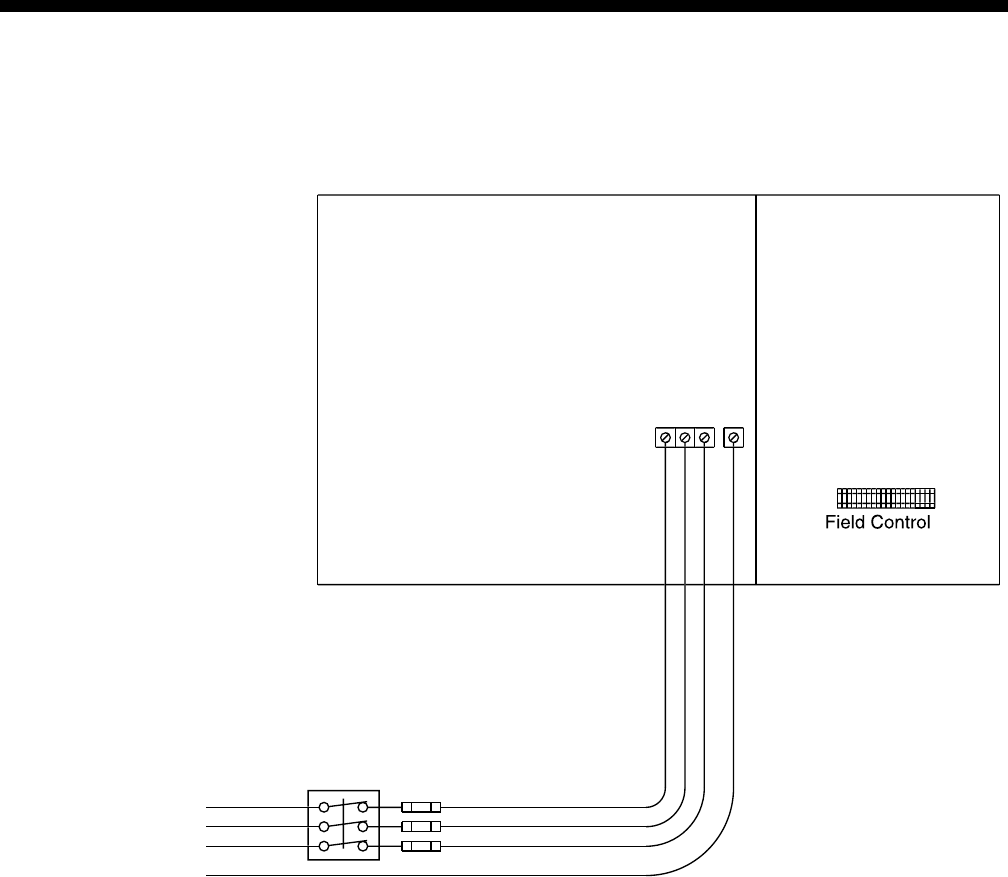
FORM 100.50-EG1
31
YORK INTERNATIONAL
Power Wiring
SINGLE-POINT POWER SUPPLY WIRING
FIG. 2 –SINGLE-POINT POWER SUPPLY WIRING
P
ower
S
id
e
Fi
e
l
d
Pow
e
r
S
uppl
y
E
a
rth
G
roun
d
Line
3
Lin
e
2
Lin
e
1
Wirin
g
Terminal
Blo
ck
C
ontrol
S
id
e
1L1
1L2
1
L
3
G
ND
Electrical
/
C
ontrols Bo
x
TB1
NOTES:
1. All field wiring must be provided through a field-supplied fused disconnect switch to the unit terminals (or optional molded
disconnect switch).
2. All electrical wiring must be made in accordance with all N.E.C. and/or local code requirements.
3. Minimum Circuit Ampacity (MCA) is based on U.L. Standard 1995, Section 36.14 (N.E.C. Section 440.34).
4. Maximum Dual Element Fuse size is based on U.L. Standard 1995, Section 36.15 (N.E.C. Section 440.22)
5. Use copper conductors only.
6. On units with an optional disconnect switch, the supplied disconnect switch is a “Disconnecting Means” as defined in the N.E.C. Section
100, and is intended for isolating the unit from the available power supply to perform maintenance and troubleshooting. This disconnect
switch is not intended to be a Load Break Device.
LD06414
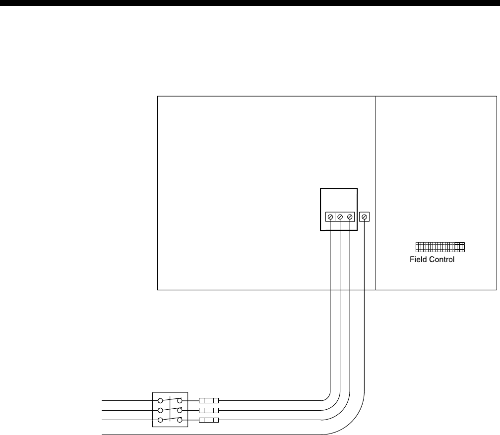
YORK INTERNATIONAL
32
SINGLE-POINT POWER SUPPLY WIRING
WITH NON-FUSED DISCONNECT
FIG. 3 –SINGLE-POINT POWER SUPPLY WIRING WITH NON-FUSED DISCONNECT
Power Wiring (continued)
Power
S
id
e
Fi
e
l
d
Pow
e
r
Suppl
y
E
a
rth
G
roun
d
Line
3
Lin
e
2
Lin
e
1
Wirin
g
Terminal
Blo
ck
C
ontrol
S
id
e
1L1
1L2
1
L
3
G
ND
Electrical
/
C
ontrols Bo
x
Mol
ded
Case
Di
sc
onn
ect
S
witc
h
NOTES:
1. All field wiring must be provided through a field-supplied fused disconnect switch to the unit terminals (or optional molded
disconnect switch).
2. All electrical wiring must be made in accordance with all N.E.C. and/or local code requirements.
3. Minimum Circuit Ampacity (MCA) is based on U.L. Standard 1995, Section 36.14 (N.E.C. Section 440.34).
4. Maximum Dual Element Fuse size is based on U.L. Standard 1995, Section 36.15 (N.E.C. Section 440.22)
5. Use copper conductors only.
6. On units with an optional disconnect switch, the supplied disconnect switch is a “Disconnecting Means” as defined in the N.E.C. Section
100, and is intended for isolating the unit from the available power supply to perform maintenance and troubleshooting. This disconnect
switch is not intended to be a Load Break Device.
LD06415
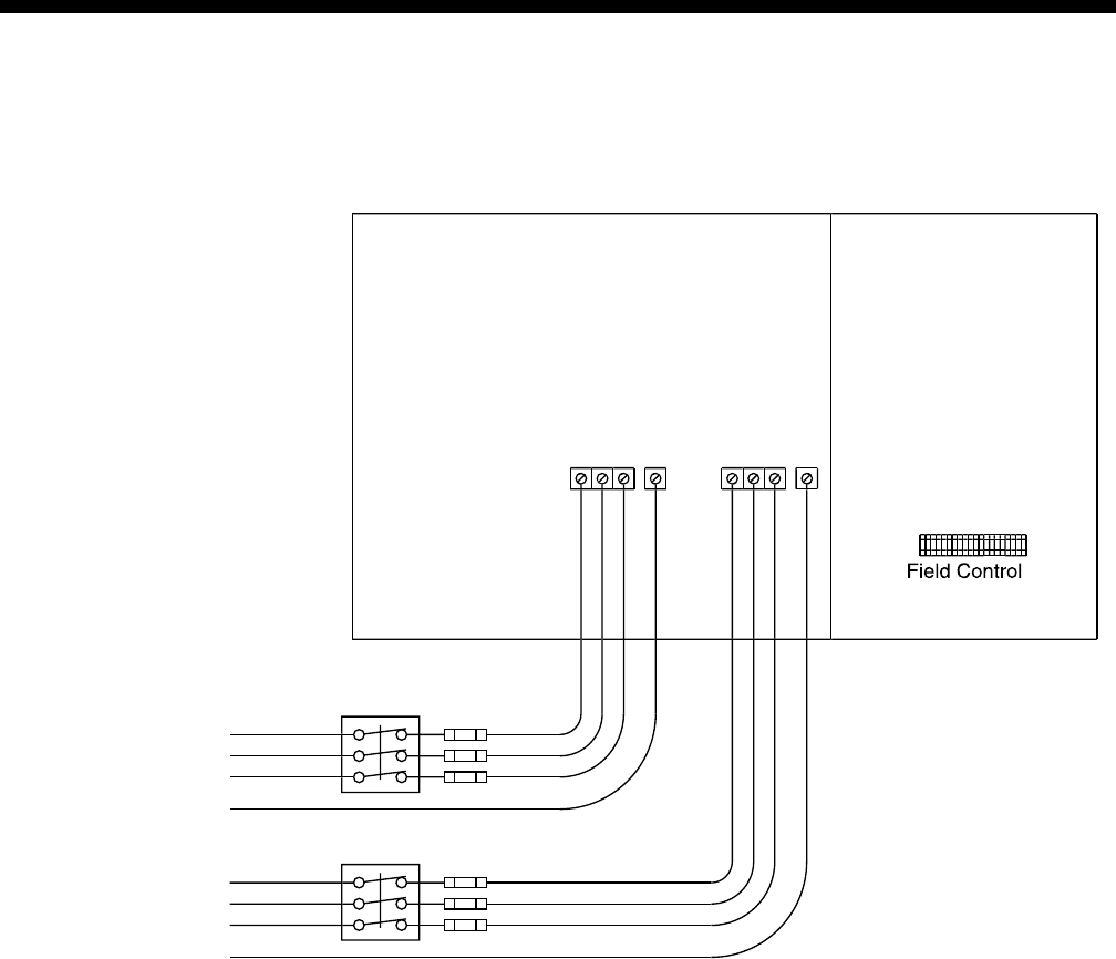
FORM 100.50-EG1
33
YORK INTERNATIONAL
DUAL-POINT POWER SUPPLY WIRING
FIG. 4 – DUAL-POINT POWER SUPPLY WIRING
NOTES:
1. All field wiring must be provided through a field-supplied fused disconnect switch to the unit terminals (or optional molded
disconnect switch).
2. All electrical wiring must be made in accordance with all N.E.C. and/or local code requirements.
3. Minimum Circuit Ampacity (MCA) is based on U.L. Standard 1995, Section 36.14 (N.E.C. Section 440.34).
4. Maximum Dual Element Fuse size is based on U.L. Standard 1995, Section 36.15 (N.E.C. Section 440.22)
5. Use copper conductors only.
6. On units with an optional disconnect switch, the supplied disconnect switch is a “Disconnecting Means” as defined in the N.E.C. Section
100, and is intended for isolating the unit from the available power supply to perform maintenance and troubleshooting. This disconnect
switch is not intended to be a Load Break Device.
Fi
e
l
d
Pow
e
r
Supply #
2
Fi
e
l
d
Pow
e
r
Suppl
y
#1
E
a
rth
G
roun
d
E
a
rth
G
roun
d
Line
3
Lin
e
2
Lin
e
1
C
ontrol
S
id
e
Wirin
g
Terminal
Blo
ck
Line
3
Lin
e
2
Lin
e
1
Power
S
id
e
2L2
2L1
G
ND
2
L
3
1L1
1L2
G
ND
1
L
3
Electrical
/
C
ontrols Bo
x
TB
2
TB
1
LD06416
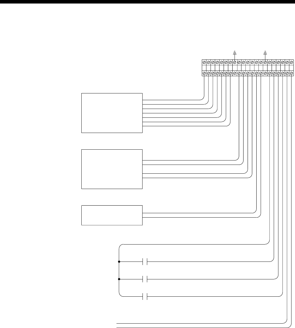
YORK INTERNATIONAL
34
Field Control Wiring
* Use Shielded Wire
* Use Shielded Wire
* Use Shielded Wire
3. Maximum power available from the 24 VAC
1. Wiring shown indicates typical wiring.
Closed = Smoke Purge
Closed = Shutdown
Open = Unoccupied
Closed = Occupied
1.5K Adjust Signal
cause equipment damage.
power source external of the unit may
sourced from the unit. Use of another
Note, 24VAC switch voltage must be
Relay Output
VAV Heat
Smoke Purge Input
Shutdown Input
Unoccupied Input
Occupied /
to open full.
command the VAV boxes
output shall be used to
Note: VAV Heat Relay
Common
24 VAC Signal
Open = Normal
Potentiometer Common
0-5V Output
Sensor
Common
Signal
CO
Open = Normal
4. Use shielded wire where shown.
terminal is 40 VA.
2. All wiring is Class 2, low voltage.
Wiring Notes:
Common
Signal
Space Sensor
7 Wire Thermostat
G (Fan)
Y2 (Cool Stage 2)
Y1 (Cool Stage 1)
R (24VAC)
COMMON
RTD Sensor
1K Nickel
IAQ-
IAQ+
COM
SSA-
SSA+
SS-
SS+
R (24 VAC)
31 2 4 5
SHIELD
86 7 9 10
SHIELD
13
11 12 14 15
Y1
Y2
G
COM
HR
SMK
R (24 VAC)
SD
OCC
1816 17 19 20 21
2
FIG. 5 –FIELD CONTROL WIRING
LD06158
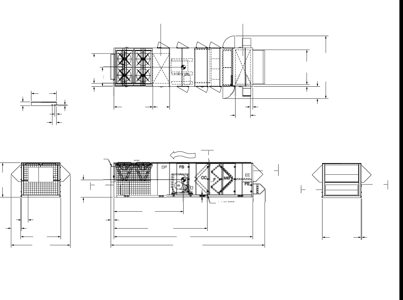
FORM 100.50-EG1
35
YORK INTERNATIONAL
(
LEFT SIDE
)
T
O
P VIE
W
R
I
A
FR
O
NT VIE
W
REAR
CO
CO
NTR
O
L PANEL DETAIL
L
F
S
IDE VIE
W
O
W
FR
O
N
T
REAR VIEW
S
ID
E
S
ID
E
CO
=
C
ondenser
S
ectio
n
DP = Dischar
g
e Plenu
m
CC = Coolin
g
Coil
s
FS = Suppl
y
Fa
n
_F = Filter Se
g
ment
MB = Mixin
g
Bo
x
FE = F
a
n Exh
aust
EE = E
c
onomiz
er
S
E
C
TI
O
N DE
SC
RIPTI
O
N
S
CP
1-1/2" FPT
COU
PLIN
G
DRAIN
CO
NN
.
N
O
TE
S:
2.
O
NLY
O
NE AD
J
A
C
ENT WALL
C
AN EX
C
EED
U
NIT HEI
G
HT
.
5. ECONOMIZER AND EXHAUST HOODS
,
WHERE APPLICABLE
,
ARE FOLDE
D
IN
S
IDE
U
NIT F
O
R
S
HIPMENT
.
6
. DIM. I
S
T
O
OU
T
S
IDE
O
FLIFTIN
G
L
UGS
(
SEE NOTE 6
)
C
P =
C
ontrol Pane
l
17
9"
3
44
"
2
36
-1
/
1
6"
7-
3/
1
6"
1
06
-7
/
1
6"
4
0"
5
-
3/
4
"
35
-
3/
4
"
1
6
-1
/
1
6"
24-
5/
1
6"
14
0
-
3/
4
"
95
-1
/
4
"
53"
3
1-7
/8"
36
-7
/8"
1-
9/
1
6"
9
2-
3/
1
6"
3
7
9
-
9/
1
6"
4
1
3/
1
6
"
46"
7
-
3/8
"
7
1-
3/
1
6
"
8
2-
3/8
"
9
-1
/
4"
6
"
1
4
9
-
5/
1
6
"
28
-
5/8
"
4
-
5/8
"
83
"
3
-
9/
1
6
"
SU
PPLY
O
PENIN
G
RET
U
RN
O
PENIN
G
72"
10'
72"
72
"
72
"
1. 1
0
'
C
LEARAN
C
E MINIMAL
O
VER THE T
O
P
O
F THE
CO
NDEN
S
IN
G
U
NIT
.
3. 12' CLEARANCE RE
Q
UIRED TO ADJACENT UNITS
.
4.
8
'
S
ERVI
C
E A
CC
E
SS
RE
CO
MMENDED
O
N
O
NE
S
IDE
.
(
LEFT SIDE
)
General Arrangement Drawing
LD06417
FIG. 6 – GENERAL ARRANGEMENT DRAWING
BOTTOM RETURN
BOTTOM SUPPLY
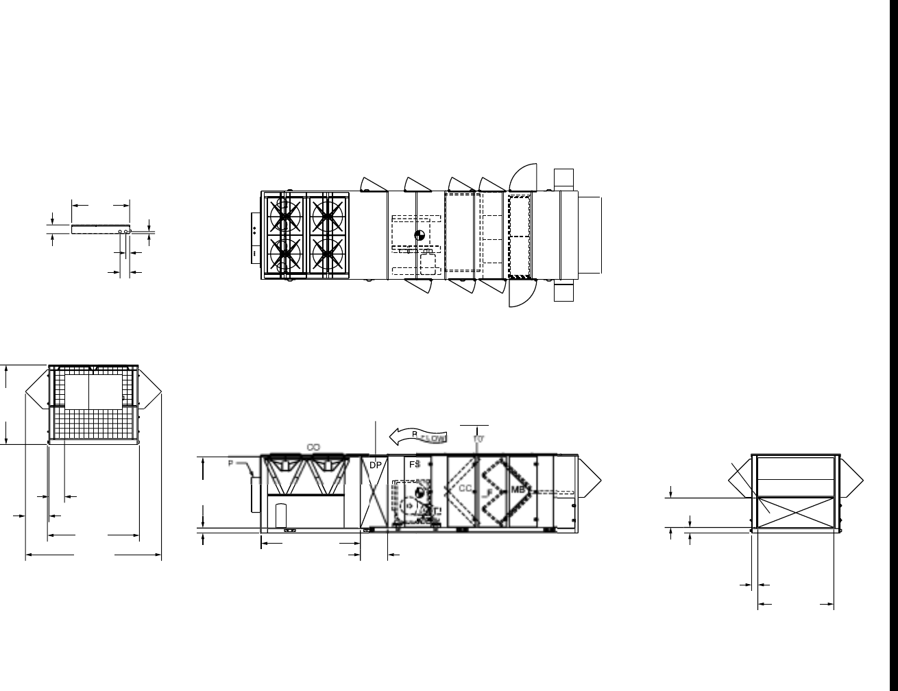
YORK INTERNATIONAL
36
C
P =
C
ontrol Pane
l
FE
IN
S
IDE
U
NIT F
O
R
S
HIPMENT
.
5. ECONOMIZER AND EXHAUST HOODS
,
WHERE APPLICABLE
,
ARE FOLDE
D
2.
O
NLY
O
NE AD
J
A
C
ENT WALL
C
AN EX
C
EED
U
NIT HEI
G
HT
.
N
O
TE
S:
C
S
E
C
TI
O
N DE
SC
RIPTI
O
N
S
EE = E
c
onomiz
er
FE = F
a
n Exh
aust
MB = Mixin
g
Bo
x
_F = Filter Se
g
men
t
FS = Suppl
y
Fa
n
CC = Coolin
g
Coil
s
DP = Dischar
g
e Plenu
m
CO
=
C
ondenser
S
ectio
n
REAR VIEW
EE
S
IDE VIE
W
F
L
A
I
T
O
P VIE
W
(
LEFT
S
IDE
)
74
"
5
-1
/8
"
30
-11
/
1
6
"
5
-1
3/
1
6
"
2
8
-1
/
2
"
117-7
/
1
6"
6
-1
/
2
"
7
9
-1
/8"
SU
PPL
Y
O
PENIN
G
RET
U
R
N
O
PENIN
G
FR
O
NT VIE
W
CO
NTR
O
L PANEL DETAI
L
(
SEE NOTE 6
)
1
6
-1
/
1
6"
24-
5/
1
6"
14
0
-
3/
4
"
95
-1
/
4
"
53"
3
1-7
/8"
36
-7
/8"
8
2-
3/8
"
9
-1
/
4"
6
"
4.
8
'
S
ERVI
C
E A
CC
E
SS
RE
CO
MMENDED
O
N
O
NE
S
IDE.
3. 12' CLEARANCE RE
Q
UIRED TO ADJACENT UNITS
.
1. 1
0
'
C
LEARAN
C
E MINIMAL
O
VER THE T
O
P
O
F THE
CO
NDEN
S
IN
G
U
NIT
.
LD06418
FIG. 7 – GENERAL ARRANGEMENT DRAWING
General Arrangement Drawing (continued)
REAR RETURN
LEFT OR RIGHT SUPPLY
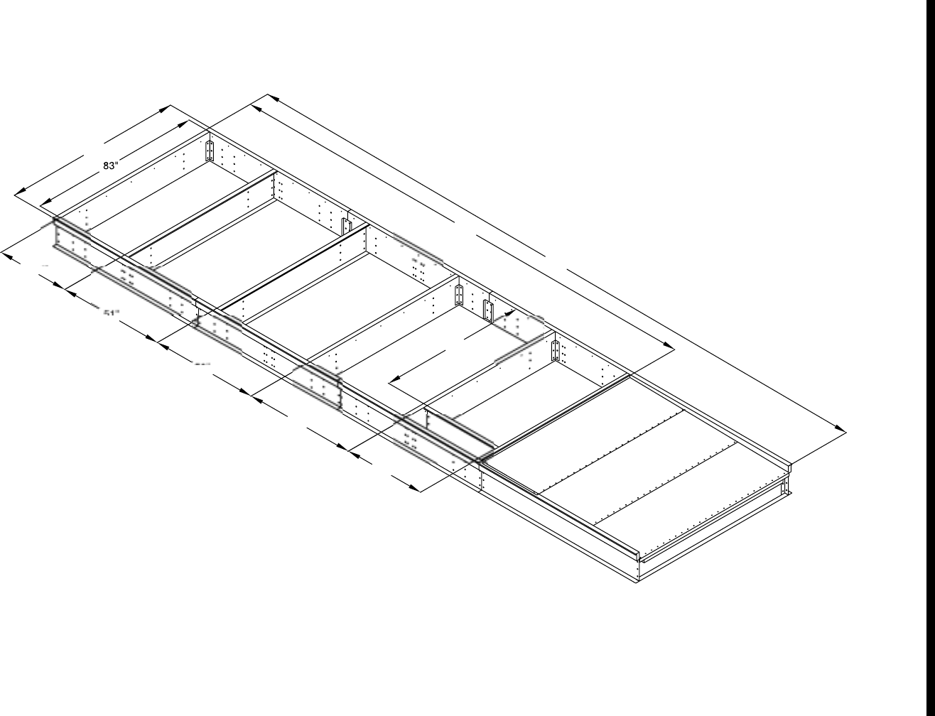
FORM 100.50-EG1
37
YORK INTERNATIONAL
Curb Layout Drawing
LD06419
FIG. 8 –CURB LAYOUT DRAWING
4. CURB MATERIAL IS 14 GAUGE GALVANIZED
,
NOT PAINTED
.
3. ROOF CURB MUST BE INSTALLED S
Q
UARE AND LEVEL
.
2. R
OO
F
CU
RB
S
HIPPED IN PIE
C
E
S
F
O
R FIELD A
SS
EMBLY
.
O
THER PART
S
ARE F
U
RNI
S
HED AND IN
S
TALLED "BY
O
THER
S
"
.
1. CURB
,
NAILER & GASKET ONLY
,
FURNISHED BY YORK. AL
L
N
O
TE
S:
5
.
CU
RB IN
SU
LATED WITH 1.
5
"-
3
# IN
SU
LATI
O
N
.
SUPPLY
RETURN
2
3
7
"
339"
8
7
"
71-
3/5"
4
0"
53
-
3/
4
"
52"
51
35-3/4"

YORK INTERNATIONAL
38
Guide Specifications
GENERAL
Units shall be designed for outdoor rooftop installation
on a roof curb. Units shall be rated according to ARI
360. Units shall be shipped in a single package, fully
charged with HFC-407C refrigerant. The manufactur-
ing facility shall be registered under ISO 9001 Quality
Standards for Manufacturing. All units shall be com-
pletely factory assembled and run tested.
Units shall be ETL listed and be tested according to UL
1995. Tags and decals to aid in the service or indicate
caution areas shall be provided. Installation, operation
and maintenance manuals shall be supplied with each
unit.
Units shall be capable of providing mechanical cooling
down to 45° F (0°F with a low ambient kit). Unit shall be
capable of starting and running at 120° F. Unit electric
and gas connections shall be either through the curb or
the side of the unit.
CONSTRUCTION
Base
The base rail shall be constructed of 12 gauge galva-
nized steel, extending the full perimeter of the unit. All
components shall be supported from the base, and the
base shall include integral lifting lugs. The unit base
rail shall overhang the roof curb for water runoff and
shall have a fabricated recess with a continuous flat
surface to seat on the roof curb gasket, providing a
positive, weather tight seal between the unit and the
curb.
Casing
The unit cabinet shall be double wall construction to
provide both maximum resistance to bacterial growth
in the air stream and superior structural integrity. All
sheet metal shall be G90 mill galvanized sheet metal,
formed and reinforced to provide a rigid assembly. Cabi-
net shall be coated with baked on powder paint which,
when subject to ASTM B117, 500 hour, 5% salt spray
test, yields minimum ASTM 1654 rating of “6”. The unit
shall be insulated with 1-1/2,” 1 pound fiberglass insu-
lation between the two sheet metal skins. Insulation shall
meet NFPA-90A regulations for smoke and flame
spread ratings. Single-wall units, or foil-faced insula-
tion in the air stream shall be not acceptable.
The cabinet corner post and the intermediate side sup-
ports shall be a minimum of 16-gauge steel. All access
doors shall be a minimum of 18 gauge on the exterior
surfaces, and 20 gauge on the interior. Interior floor
panels shall be 18 gauge.
All serviceable sections shall have hinged access doors
with latches on both sides of the unit. All access doors
shall be constructed of 20-gauge steel on the outside,
with 24 gauge on the inside. Each door shall seal against
PVC gaskets to prevent air and water leakage.
The roof shall be double wall, with 18 gauge on the
external surface and 24 gauge on the interior. The roof
shall be formed with a 45 degree “drip lip” overhanging
the side walls to prevent precipitation drainage from
streaming down the side of the unit. Roof sections shall
be connected together via integral channels fastened
with screws and sealed with gasketing. Each fastened
seam shall be further protected by a sheet metal chan-
nel covering the full length of the gasket surface, mak-
ing a completely water tight seal.
SUPPLY AIR SYSTEM
Supply Air Fan
Fans shall be centrifugal type, statically and dynami-
cally balanced in the factory. Fan wheels shall be de-
signed for continuous operation at the maximum rate
of fan speed and motor HP. Fans shall be double-width,
double-inlet with forward curved blades.
The fan and motor assembly shall be mounted on a
common base to allow consistent belt tension with no
relative motion between the fan and motor shafts. The
entire assembly shall be isolated from the unit base
with 1" deflection springs. The fan discharge shall be
connected to the cabinet through a reinforced neoprene
flexible connection to eliminate vibration transmission
from the fan to the unit casing.
BEARINGS AND DRIVES
Bearings shall be self-aligning pillow-block re-greasable
ball bearings with an average life expectancy L10 of
40,000 hours. Grease fittings shall be accessible
through access doors.
Fan motors shall be NEMA designed, Standard effi-
ciency ball bearing type with electrical characteristics
and horsepower as specified. Motors shall be 1750
RPM, open drip proof type. The motor shall be located
within the unit on an adjustable, heavy steel base.

FORM 100.50-EG1
39
YORK INTERNATIONAL
All fan motor drives shall be selected for a minimum
service factor of 1.2 and have fixed pitched sheaves.
AIR FILTERING SYSTEM
All filter holding frames shall be of heavy-duty construc-
tion designed for industrial applications. All filters shall
be either side accessible via access doors on both sides
of the filter section.
All filter media shall be Class II listed under UL Stan-
dard 900. Filter efficiencies shall be rated in accordance
with ASHRAE Standard 52-76
Two-inch throwaway filters in an angled filter rack shall
be standard. On units with rigid filters, two-inch prefilters
shall be installed upstream of the rigid filters.
AIR INLET SYSTEM
General
A factory installed outside air rain hood permanently
attached to the cabinet to prevent windblown precipita-
tion from entering the unit shall cover inlet openings.
The rain hoods on the sides of the unit shall be rotated
into the cabinet and secured for shipment so that upon
installation they need only be rotated upwards and
screwed into place. The outside air hood shall contain
a removable and cleanable filter.
All damper assemblies shall be of low leak design.
Damper blades shall be fabricated from a minimum of
16 gauge galvanized steel.
REFRIGERATION SYSTEM
Units shall have four compressors for maximum load-
matching capability. Each refrigerant circuit shall be
controlled with a thermal expansion valve for maximum
control at low load conditions.
Evaporator Coils
Evaporator coils shall be direct expansion. Coil tubes
shall be 3/8” OD copper, with internally enhanced tubes.
Fins shall be enhanced aluminum mechanically ex-
panded to bond with the copper tubes. Coil casing shall
be fabricated from heavy gauge galvanized steel.
A stainless steel double-sloped drain pan shall be pro-
vided under the entire width of the evaporator coil, in-
cluding all return bends. The main drain pan shall be
sloped a total of 1/4” per foot towards the drainage point
according to ASHRAE 62 guidelines. Main drain pan
shall be accessible and cleanable in the field. The con-
densate drain opening shall be flush with the bottom of
the drain pan to allow complete drainage. Coils in ex-
cess of 48” high shall have an intermediate drain pan,
extending the entire width of the coil to provide better
water drainage.
Compressors
Compressors shall be hermetic, scroll-type, including
tip seals to provide efficient axial sealing while prevent-
ing scroll tip to base contact, controlled orbit design for
radial sealing to incorporate minimum flank-to-flank con-
tact for long service life, refrigerant cooled motors, large
suction side free volume and oil sump to provide liquid
handling capability, annular discharge check valve and
reverse vent assembly to provide low pressure drop,
silent shutdown and reverse rotation protection, initial
oil charge, oil level sight glass, vibration isolator mounts
for compressors, and brazed-type connections for fully
hermetic refrigerant circuits.
Condenser Coils
Condenser coils shall have 3/8” seamless copper tubes,
arranged in staggered rows, mechanically expanded into
aluminum fins. Coils shall be protected from hail dam-
age with a “V” configuration, with individual flat coils ro-
tated from the vertical plane for each condensing circuit.
Condenser Fans and Motors
Condenser fans shall be direct drive, propeller type,
discharging vertically. Condenser fan motors shall be
3-phase, totally enclosed air over (TEAO). Thermal
overload protection shall be provided for each con-
denser fan motor.
Refrigerant Piping
All interconnecting piping between refrigeration com-
ponents shall be copper tubing with brazed joints.
Each refrigerant circuit shall be equipped with liquid line
filter drier, and moisture indicating sight glass. Each
circuit shall also have both high and low pressure
switches installed on either side of the compressor and
include access fittings for replacement of the pressure
switches without removing charge.
Polyurethane sleeves shall protect all small diameter
distributor tubing to the evaporator coil to prevent the
tubes from copper-to-copper contact during shipment
or operation.
POWER SUPPLY
Unit power supply shall be 460V 3-phase 60Hz (208,
230 and 575V optional) single-point power connections
with terminal block connections.

YORK INTERNATIONAL
40
CONTROLS
A factory-mounted unit controller with a 4x20 character
alphanumeric display and user keypad shall be included
as standard. The controller and keypad shall be housed
inside the low-voltage compartment of the control/power
panel. On units with supply or exhaust VFDs, the VFD
keypads shall be located inside the same panel as the
unit controller and interface keypad. Control operating
data, setpoints, unit setup, configuration, service and
history shall all be accessible via a single key. A sys-
tem alarm LED shall indicate failures to the operator
with more detail provide in the menu screens. The user
interface shall function with a simple menu-driven dis-
play for easy access to unit data with integral time clock
for weekly and holiday scheduling. The unit keypad
shall include password protection to prevent unautho-
rized access and tampering with unit setpoints and con-
figuration.
A single terminal strip shall be provided for all thermo-
stat and customer hard-wired field connections.
Unit controls shall be completely factory packaged and
compatible with a room thermostat. Constant volume
units shall operate with a two (2) cool/two (2) heat ther-
mostat. Staging decisions shall be based upon the de-
viation of space temperature from set point and the rate
of change of the space temperature.
VAV units shall operate with a sensor in the supply air
stream for cooling operation. Staging decisions shall
be based upon the deviation of supply air temperature
from set point and the rate of change of the supply air
temperature.
Controllers shall have the following safeties (both VAV
and CV):
•High and low pressure cut-outs (one each refriger-
ant circuit)
•Minimum on time for compressors
•Delay between compressor stages
•Anti-short cycle delays (minimum off time) for com-
pressors and supply fan
•Cooling lockout at 40° F; 0° F if equipped for low
ambient operation
•Air flow proving switch requiring proper air flow for
cooling operation
ACCESSORIES AND OPTIONS
Full perimeter and partial perimeter roof curbs - 14”
high roof curb with wood nailer. Roof curb covers the
entire perimeter of the unit (full curb) or that portion of
the unit that has airflow (partial curb).
Supply Fan VFD Manual Bypass – provides full air-
flow in the event of a VFD failure.
Power Supply Connections – single-point power with
manual disconnect, and dual-point power wiring options
are available for various applications.
Supply air setpoint reset by outside air or space air
temperature - Allows VAV supply air setpoint to float
upward (saving energy) if the outdoor air temperature
or the space temperature is sufficiently low.
Supply Fan Isolation – the entire supply fan assem-
bly shall be isolated from the unit base with 2" deflec-
tion springs.
Supply and Exhaust Fan Motors – high efficiency
ODP, and standard and high efficiency TEFC motors
are available all meeting the Energy Policy Act of 1992
(EPACT).
Low Ambient Operation – a low ambient kit is avail-
able to control compressor head pressure via VFD con-
denser fan speed control. Head pressure control is
accomplished by monitoring head pressure with suc-
tion and discharge line pressure transducers rather than
less accurate temperature control.
ECONOMIZERS
Manual Damper Economizer – economizer is avail-
able with a manual damper adjustable between 0-25
percent.
Two-Position Damper Economizer – economizer is
available with a two-position damper with the open po-
sition adjustable between 0-25 percent. The operation
of the two-position economizer shall be based on oc-
cupancy; occupied is open, unoccupied is closed.
Guide Specifications (continued)

FORM 100.50-EG1
41
YORK INTERNATIONAL
Modulating Damper Economizer – economizer is
available with a modulating damper arrangements.
Modulating damper economizers shall have outdoor air
and return air dampers that are interlocked and posi-
tioned by fully modulating, solid state damper actua-
tors. The actuators shall be spring loaded so that the
outside air damper will close when power to the unit is
interrupted. The operation of the modulating economizer
shall be fully integrated into the cooling control system.
The modulating economizer control shall be via a dry
bulb sensor, single or dual enthalpy sensors.
Airflow Measurement – airflow measurement is avail-
able for the Modulating Damper Economizer option
listed above. Three options exist for airflow measure-
ment; minimum airflow and 100% air flow. Minimum
airflow measures airflow between 0 and the minimum
ventilation airflow up to 25% outside air. 100% airflow
measurement measures air flow from 0-100% of the
outside airflow.
RELIEF SYSTEM
Barometric Relief - building air exhaust shall be ac-
complished through barometric relief dampers installed
in the return air plenum. The dampers will open relative
to the building pressure.
Exhaust Air Fans - two (2) forward curved centrifugal
fans shall be installed in the return air plenum for posi-
tive power exhaust. Fan impellers shall be on a com-
mon shaft, driven by a single motor. The fans, motors
and drives shall be of the same quality and design as
specified for the supply air fan, except the fans shall be
Class I. Exhaust control options are on/off, modulating
discharge damper, or VFD fan speed control. On units
with non-modulating exhaust a barometric relief damper
is included to prevent outside air from entering in the
off cycle. Fans shall cycle on and off with building pres-
sure. On units with modulating exhaust and two posi-
tion control based on building pressure, a field-installed
static pressure sensor mounted in the conditioned
space or return air duct is required for damper and VFD
modulation.
EVAPORATOR COIL PROTECTION
Copper Fins – provided in lieu of aluminum fins.
Pre-Coated Fins – an epoxy-coated aluminum fin stock
to guard from corrosive agents and insulate against gal-
vanic potential. Used for mild seashore or industrial
locations.
CONDENSER COIL PROTECTION
Copper Fins – provided in lieu of aluminum fins.
Pre-Coated Fins – an epoxy-coated aluminum fin stock
to guard from corrosive agents and insulate against gal-
vanic potential. Used for mild seashore or industrial
locations.
Post-Coated Fins – Technicoat coil-coating process
used on condenser coils for seashore and other corro-
sive applications (with the exception of strong alkalis,
oxidizers, wet bromide, chlorine and fluorine in concen-
trations greater than 100ppm).
Hot Gas Bypass (Optional on Constant Volume;
Standard on VAV) – permits continuous, stable opera-
tion at capacities below the minimum step of unloading
by introducing an artificial load on the evaporator.
BACNet Communications Card – for BAS commu-
nications, a BACNet card is available with Ethernet
connection.
Compressor Sound Blankets – compressor acoustic
sound blankets for sound sensitive applications.
CO2 Sensors – carbon dioxide sensors for occupied
space that operate demand ventilation control opening
outside air dampers to ventilate building.
Suction and Discharge Pressure Transducers – moni-
tor and readout of suction and discharge pressures.

YORK INTERNATIONAL
42
NOTES

FORM 100.50-EG1
43
YORK INTERNATIONAL
NOTES

Proud Sponsor
of the 2002
U.S. Olympic Team
36USC380
P.O. Box 1592, York, Pennsylvania USA 17405-1592 Subject to change without notice. Printed in USA
Copyright © by York International Corporation 2001 ALL RIGHTS RESERVED
Form 100.50-EG1 (201)
New Release
Tele. 800-861-1001
www.york.com
