York Hc Users Manual 258920 YTG A 0606
HC to the manual 72327af1-75ac-4238-911f-8248ea8f921f
2015-02-02
: York Hc-Users-Manual york-hc-users-manual-455332 york pdf
Open the PDF directly: View PDF ![]() .
.
Page Count: 16
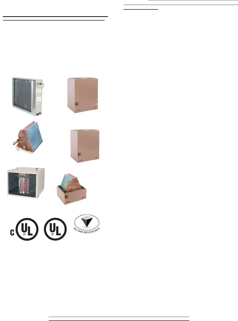
ADD - ON COILS
FOR USE WITH SPLIT-SYSTEM
COOLING & HEAT PUMPS
MODELS: MC, PC, FC, HD, HC, UC
600 - 2000 CFM 1.5 - 5 TON COILS
Due to continuous product improvement, specifications
are subject to change without notice.
Visit us on the web at www.york.com for the most
up-to-date technical information.
Additional rating information can be found at
www.ariprimenet.org.
HORIZONTAL CASED
HC
FULL CASED
MULTI-POSITION
MC
UPFLOW
PARTIAL CASED
PC
HORIZONTAL
DUCT
HD
UPFLOW UNCASED
UC
UPFLOW/DOWNFLOW
FULL CASED
FC
ISO 9001
Certified Quality
Management System
258931-BTG-A-0606
FOR DISTRIBUTION USE ONLY - NOT TO BE USED AT POINT OF RETAIL SALE
TECHNICAL
GUIDE
TECHNICAL
GUIDE
DESCRIPTION
These cooling and heat pump coils are designed to be installed with
UPG furnaces and to be matched with UPG cooling and heat pump
outdoor units. All UPG coils utilize a TXV to provide our customers
with the optimum performance and refrigerant control required for
13+ SEER systems. Coils can be ordered with a R22 TXV factory
installed that can be easily converted to R410A by changing the bolt-
on TXV.
“Flex-coils” are also available without a factory installed metering
device. For added application flexibility a R22 or R410A TXV is
installed, on “Flex-coils”, in the field to meet your refrigerant choice.
Upflow/Downflow Coils Full Cased and Partial Cased
Coils –
Designed for high-efficiency to match any system, full cased
in the upflow or downflow and the partial cased in the upflow only
application
.
Multi-Position Coils -
Designed for high-efficiency like the
upflow/downflow coil but with the added flexibility that allows it to be
installed any position, upflow, downflow, horizontal right or left. This
coil can be easily applied to our furnace and modular air handler in
any configuration.
Horizontal Duct Coils -
Available for both cooling and heat pump
dedicated horizontal, slab coil, applications. Field transition may be
required
.
Dedicated Horizontal Cased Coils –
These coils are cooling
only or heat pump approved for horizontal furnace or modular air
handler applications. Unlike the horizontal duct coils these cased
coils match the dimensions of the furnace or modular blower
.
FEATURES
Thermal Expansion Valve -
Provides flexibility to convert any
coil to R22 or R410A refrigerant. A true bolt-on TXV, valve assembly
and equalizer tube are bolt-on, no brazing required. TXV and sens-
ing bulb are mounted inside the cased coil cabinet. (Must be field
supplied for all “Flex-coils”)
MicroBlue™ Coated Fins -
All coils are treated with a
MicroBlue™ Hydrophilic coating to enhance the removal of conden-
sate during the refrigeration cycle and reduce the possibility of water
blow-off. The MicroBlue™ coating also reduces the growth of germ
causing microbes.
Insulated Cabinet -
All evaporator coil cabinets are thermally
insulated with foil faced insulation to prevent sweatin
g.
Internally Clean -
All evaporator coils are factory leak-tested,
dehydrated, sealed and shipped with a holding charge. The suction
and liquid lines are sealed with rubber plugs, no cutting of connection
stubs to attach line set
.
Durable Finish Inside and Out -
Coil casings are made of pre-
painted steel. The pre-treated flat galvanized steel provides a better
paint to steel bond, which resists corrosion and rust creep. All inter-
nal metal parts are made of G90 pre-painted steel i.e. triangular
plates, top plates, horizontal supports etc. (Coil header plates are
non-painted due to the brazing process during production.)
Optimum Heat Transfer -
Using the latest in heat transfer tech-
nology, staggered rows of copper tubes are mechanically expanded
into aluminum fins to provide optimum air to surface contact for
ample moisture removal as well as high performance ratings.
ACCESSORIES
Refer to Price Manual for specific model numbers.
TXV Kits -
Thermal expansion valve kits are available for “Flex-coil”
applications and converting R22 to R410A refrigerant or as a service
replacement. All TXV kits are non-braze
,
all connections are bolt-on
including the valve assembly and equalizer tube. (No orifice or any
other metering device is to used in conjunction with the TXV).
Coil Casing Without Coil –
Coil casings are available in each
width that can be installed with the furnace or modular air handler
during initial installation. This option is available to allow the installer
the flexibility to install the coil at a later date without duct modifica-
tions.

258931-BTG-A-0606
2 Unitary Products Group
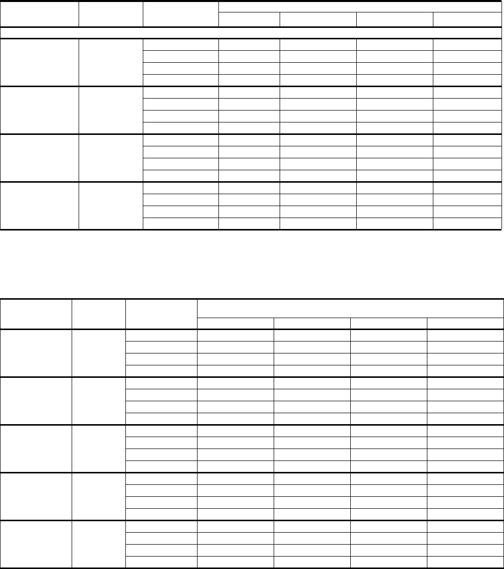
COOLING CAPACITY - Coil Only
*
Model Rated
CFM
Entering
Air °F
(Wet Bulb)
MBH @ Evaporator Temperature and Corresponding Pressure °F / PSIG
35 / 61.5 40 / 68.5 45 / 76.0 50 / 84.0
UPFLOW "A" TYPE
FC18A
PC18A 675
72 25.3 23.1 20.6 17.9
67 23.4 21.1 18.7 16.1
62 19.2 12.0 18.7 12.4
57 15.6 13.5 11.3 8.8
FC18B
PC18B 850
72 28.1 25.7 22.9 19.9
67 26.0 23.5 20.8 17.9
62 21.3 18.9 16.4 13.7
57 17.3 15.0 12.6 9.8
FC24A
PC24A 675
72 35.6 32.5 29.0 25.2
67 32.9 29.7 26.3 22.7
62 27.0 23.9 20.7 17.4
57 21.9 19.0 15.9 12.4
FC24B
PC24B 850
72 35.6 32.5 29.0 25.2
67 32.9 29.7 26.3 22.7
62 27.0 23.9 20.7 17.4
57 21.9 19.0 15.9 12.4
FC30A
PC30A
FC30B
PC30B
1025
72 38.9 35.4 31.6 27.6
67 33.9 30.3 26.8 23.0
62 27.3 23.7 22.5 18.0
57 22.6 20.1 17.5 14.8
FC35B
PC35B
FC35C
PC35C
1025
72 46.1 41.9 37.4 33.0
67 36.9 32.6 28.6 24.3
62 28.9 24.2 26.4 19.7
57 24.7 22.9 21.1 19.7
FC36A
PC36A 1150
72 46.0 41.9 37.4 32.9
67 36.8 32.5 28.5 24.2
62 28.8 24.1 26.4 19.6
57 24.7 22.9 21.1 19.6
FC36B
PC36B
FC36C
PC36C
1250
72 51.1 46.5 41.5 36.6
67 40.9 36.1 31.7 26.9
62 32.0 26.8 29.3 21.8
57 27.4 25.4 23.4 21.8
FC42B
PC42B
FC42C
PC42C
1400
72 86.6 74.5 62.0 49.0
67 69.4 58.2 47.4 36.3
62 54.1 43.0 35.1 29.3
57 46.5 40.7 35.1 29.3
FC48C
PC48C 1620
72 99.4 85.5 71.2 56.2
67 79.6 66.8 54.4 41.6
62 62.1 49.4 40.2 33.7
57 53.3 46.7 40.2 33.7
FC60C
PC60C
FC60D
PC60D
1850
72 118.7 100.0 81.1 61.5
67 95.0 78.4 61.9 45.4
62 74.0 58.0 45.7 36.7
57 63.6 54.8 45.7 36.7
* - See Condensing Unit or Heat Pump Technical Guide for Total Cooling Capacity and Sensible Capacity.

258931-BTG-A-0606
Unitary Products Group 3
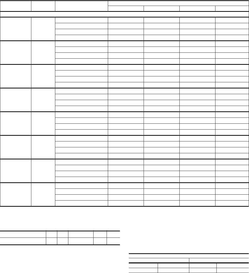
COOLING CAPACITY - COIL ONLY
*
Model Coil Rated CFM Entering Air °F
(Wet Bulb)
MBH@ Evaporator Temperature and Corresponding Pressure °F / PSIG
35 / 61.5 40 / 68.5 45 / 76.0 50 / 84.0
FULL-CASED “A” TYPE MULTI-POSITION
MC18A 550
72 25.8 23.5 21.0 18.2
67 23.7 21.5 19.0 16.4
62 19.5 17.3 14.9 12.6
57 15.8 13.5 11.5 9.0
MC18B 650
72 28.7 26.1 23.3 20.2
67 26.4 23.9 21.1 18.2
62 21.6 19.2 16.6 14.0
57 17.5 15.2 12.8 10.0
MC24A
MC24B 850
72 36.3 33.0 29.5 25.6
67 33.4 30.2 26.7 23.1
62 27.4 24.3 21.0 17.7
57 22.2 19.3 16.2 12.6
MC30A
MC30B 1025
72 41.5 37.8 33.7 29.5
67 36.2 32.4 28.6 24.5
62 29.1 25.3 24.0 19.2
57 24.1 21.5 18.7 15.8
MC35B
MC35C 1025
72 46.9 42.7 38.2 33.6
67 37.6 33.2 29.1 24.7
62 29.3 24.6 26.9 20.0
57 25.2 23.3 21.5 20.0
MC36A 1150
72 46.8 42.6 38.1 33.6
67 37.5 33.1 29.1 24.7
62 29.3 24.6 26.8 20.0
57 25.1 23.2 21.4 20.0
MC36B 1250
72 52.0 47.3 42.3 37.3
67 41.7 36.8 32.3 27.4
62 32.5 27.3 29.8 22.2
57 27.9 25.8 23.8 22.2
MC36C 1250
72 53.4 48.6 43.4 38.3
67 42.8 37.8 33.1 28.2
62 33.4 28.1 30.6 22.8
57 28.7 26.5 24.5 22.8
MC42B
MC42C 1400
72 88.4 76.0 63.3 50.0
67 70.8 59.4 48.4 37.0
62 55.2 43.9 35.8 29.9
57 47.4 41.5 35.8 29.9
MC48C
MC48D 1650
72 100.5 86.4 72.0 56.8
67 80.4 67.5 55.0 42.1
62 62.7 49.9 40.7 34.0
57 53.9 47.2 40.7 34.0
MC60D 1825
72 119.9 101.0 80.0 62.2
67 96.0 79.2 62.6 45.8
62 74.8 58.6 46.2 37.0
57 64.3 55.4 46.2 37.0
MC61D 2000
72 124.8 105.2 85.3 64.7
67 99.9 82.5 65.2 47.7
62 77.9 61.1 48.1 38.6
57 66.9 57.7 48.1 38.6
* See Condensing Unit or Heat Pump Technical Guide for Total Cooling Capacity and Sensible Capacity.
258931-BTG-A-0606
4 Unitary Products Group
Notes:
• MC coils available with a factory installed horizontal drain pan option (H).
COOLING CAPACITY - Coil Only
*
MODEL RATED
CFM
ENTERING
AIR °F
(Wet Bulb)
MBH @ Evaporator Temperature and Corresponding Pressure °F/ PSIG
35 / 61.5 40 / 68.5 45 / 76.0 50 / 84.0
HORIZONTAL DUCT TYPE
HD24A 815
72 35.3 32.4 28.7 24.9
67 32.6 29.4 26.0 22.5
62 26.7 23.7 20.5 17.2
57 21.7 18.8 15.7 12.3
HD36B 1192
72 57.9 52.7 47.1 41.5
67 46.4 41.1 35.9 30.4
62 36.2 30.4 26.5 24.7
57 31.1 28.7 26.5 24.7
HD48C 1610
72 83.4 71.7 59.7 47.1
67 66.8 56.1 45.6 34.9
62 52.1 41.5 33.7 28.3
57 44.7 39.2 33.7 28.3
HD60D 2100
72 133.0 112.4 90.9 69.2
67 106.5 87.9 69.4 50.0
62 83.0 65.0 51.3 41.1
57 71.2 61.4 51.3 41.1
* See Condensing Unit or Heat Pump Technical Guide for Total Cooling Capacity and Sensible Capacity.
COOLING CAPACITY - COIL ONLY
*
Model Rated
CFM
Entering Air °F
(Wet Bulb)
MBH @ EVAPORATOR TEMPERATURE AND
CORRESPONDING PRESSURE °F / PSIG
35/61.5 40/68.5 45/76.0 50/84.0
HC18A 600
72 26.4 24.0 21.5 18.6
67 24.3 22.0 19.4 16.8
62 20.0 17.7 15.3 12.9
57 16.1 14.0 11.8 9.2
HC30A 1000
72 42.7 38.9 34.7 30.6
67 34.3 30.3 26.5 22.5
62 26.7 22.5 24.5 19.8
57 22.9 21.2 19.6 18.3
HC36B 1200
72 73.4 63.1 52.5 41.5
67 58.8 49.3 40.2 30.7
62 45.8 36.4 29.7 24.8
57 39.3 34.4 28.1 23.2
HC42C 1400
72 84.9 73.0 60.1 48.1
67 68.0 58.9 46.5 35.6
62 53.1 42.2 34.4 28.8
57 45.5 40.0 32.0 26.7
HC60C 1800
72 112.8 95.0 77.0 58.4
67 90.3 74.5 58.8 43.1
62 70.3 55.1 43.4 34.9
57 60.4 52.1 40.4 31.9
* See Condensing Unit or Heat Pump Technical Guide for Total Cooling Capacity and Sensible Capacity.
258931-BTG-A-0606
Unitary Products Group 5
NOTE:Do not exceed minimum/maximum CFM limits shown under Air
Flow Data.
APPLICATION LIMITATIONS
These units must be installed in accordance with all national and
local safety codes.
Air flow must be within the minimum and maximum limits approved
for electric heat, evaporator coils and outdoor units.
COOLING CAPACITY - COIL ONLY
*
Model Coil Rated CFM Entering Air °F (Wet Bulb) MBH@ Evaporator Temperature and Corresponding Pressure °F / PSIG
35 / 61.5 40 / 68.5 45 / 76.0 50 / 84.0
uncased upflow
UC18A
UC18B 60
72 23.3 21.3 19.0 17.5
67 21.5 19.5 17.3 14.9
62 17.7 15.6 13.5 11.4
57 14.4 12.4 10.4 8.0
UC24A
UC24B 800
72 27.4 25.0 22.3 19.4
67 25.3 22.9 20.3 17.5
62 20.8 18.4 15.9 13.4
57 16.9 14.6 12.2 9.4
UC30A
UC30B 1000
72 35.2 32.0 28.6 24.8
67 32.4 28.6 25.3 21.9
62 26.6 23.6 21.5 18.7
57 25.2 22.7 20.2 17.6
UC36A 1150
72 46.8 42.7 37.9 33.0
67 43.1 39.2 34.9 30.4
62 35.3 32.1 28.6 24.9
57 33.3 26.9 26.9 23.4
UC36B
UC36C 1200
72 49.3 44.9 39.9 34.7
67 45.4 41.3 36.7 32.0
62 37.2 33.8 30.1 26.2
57 35.0 28.3 28.3 24.6
UC42B
UC42C 1400
72 86.7 73.0 59.2 44.9
67 69.4 57.2 45.2 33.1
62 54.0 42.3 33.4 26.8
57 46.4 40.0 33.4 26.8
UC48C
UC48D 1600
72 62.4 56.8 50.5 44.4
67 57.4 53.2 46.5 40.5
62 47.1 42.8 38.1 33.2
57 44.3 40.3 35.8 31.2
UC60C
UC60D 1800
72 95.4 82.1 68.4 54.0
67 76.4 64.1 52.2 39.9
62 59.6 47.4 38.6 32.4
57 51.2 44.8 38.6 32.4
* See Condensing Unit or Heat Pump Technical Guide for Total Cooling Capacity and Sensible Capacity.
APPLICATION FACTOR-RATED CFM VS. ACTUAL CFM
% OF RATED AIR FLOW 80% 90% RATED CFM 110% 120%
CAPACITY FACTOR 0.96 0.98 1.00 1.02 1.03
Entering Air Temperature Limits
Wet Bulb Temp. ºF Dry Bulb Temp. ºF
Min. Max. Min. Max.
57 72 65 95
258931-BTG-A-0606
6 Unitary Products Group
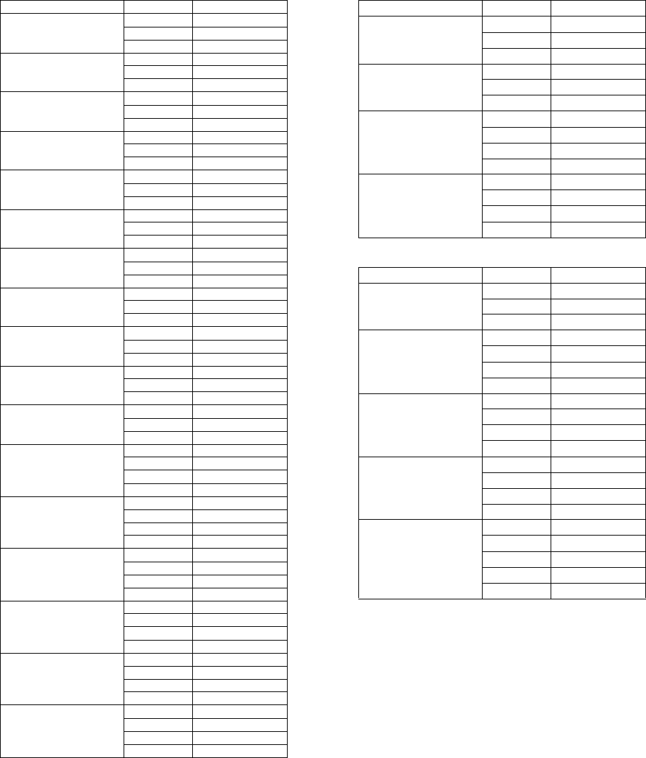
STATIC PRESSURE VS. AIRFLOW (BASED ON WET COIL)
UPFLOW CASED "A" TYPE
Model Airflow Wet Coil
FC18A
PC18A
600 0.16
800 0.23
1000 0.30
FC18B
PC18B
600 0.14
800 0.20
1000 0.26
FC24A
PC24A
600 0.15
800 0.21
1000 0.27
FC24B
PC24B
600 0.13
800 0.18
1000 0.23
FC30A
PC30A
800 0.21
1000 0.27
1200 0.33
FC30B
PC30B
800 0.18
1000 0.23
1200 0.29
FC35B
PC35B
800 0.16
1000 0.22
1200 0.29
FC35C
PC35C
800 0.14
1000 0.20
1200 0.27
FC36A
PC36A
1000 0.24
1200 0.32
1400 0.40
FC36B
PC36B
1000 0.15
1200 0.22
1400 0.28
FC36C
PC36C
1000 0.10
1200 0.15
1400 0.20
FC42B
PC42B
1200 0.21
1400 0.28
1600 0.34
1800 0.40
FC42C
PC42C
1200 0.14
1400 0.19
1600 0.24
1800 0.28
FC48C
PC48C
1600 0.29
1800 0.35
2000 0.40
2200 0.46
FC48D
PC48D
1600 0.25
1800 0.30
2000 0.35
2200 0.40
FC60C
PC60C
1600 0.28
1800 0.33
2000 0.38
2200 0.43
FC60D
PC60D
1600 0.21
1800 0.27
2000 0.32
2200 0.38
HORIZONTAL - DUCT TYPE
Model Airflow Wet Coil
HD24A
600 0.02
800 0.09
1000 0.19
HD36B
1000 0.19
1200 0.28
1400 0.38
HD48C
1200 0.14
1400 0.19
1600 0.25
1800 0.32
HD60D
1600 0.16
1800 0.20
2000 0.25
2200 0.30
HORIZONTAL CASED
Model Airflow Wet Coil
HC18A
600 0.07
800 0.12
1000 0.19
HC30A
800 0.21
900 0.25
1150 0.30
1200 0.31
HC36B
1000 0.20
1100 0.24
1200 0.27
1300 0.30
HC42C
1400 0.25
1500 0.28
1550 0.30
1600 0.33
HC60C
1700 0.25
1800 0.28
1850 0.30
1900 0.31
2000 0.34

258931-BTG-A-0606
Unitary Products Group 7
CASED "A" TYPE MULTI-POSITION
Model Airflow Wet Coil
MC18A
600 0.22
800 0.29
1000 0.36
MC18B
600 0.20
800 0.26
1000 0.32
MC24A
600 0.21
800 0.27
1000 0.33
MC24B
600 0.19
800 0.24
1000 0.29
MC30A
600 0.21
800 0.27
1000 0.33
MC30B
600 0.19
800 0.24
1000 0.29
MC35B
600 0.22
800 0.26
1000 0.34
MC35C
600 0.20
800 0.24
1000 0.32
MC36A
800 0.22
1000 0.30
1200 0.38
MC36B
800 0.15
1000 0.21
1200 0.28
MC36C
1000 0.16
1200 0.21
1400 0.26
MC42B
1200 0.27
1400 0.34
1600 0.40
MC42C
1200 0.20
1400 0.25
1600 0.30
1800 0.34
MC48C
1200 0.24
1400 0.30
1600 0.35
1800 0.41
MC48D
1200 0.20
1400 0.26
1600 0.31
1800 0.36
MC60D
1600 0.27
1800 0.33
2000 0.38
2200 0.44
MC61D
1600 0.24
1800 0.29
2000 0.35
2200 0.40
UNCASED UPFLOW - “A” TYPE
Model Airflow Wet Coil
UC18A
600 0.16
800 0.23
1000 0.30
UC18B
600 0.14
800 0.20
1000 0.26
UC24A
600 0.15
800 0.21
1000 0.27
UC24B
600 0.13
800 0.18
1000 0.23
UC30A
800 0.21
1000 0.27
1200 0.33
UC30B
800 0.18
1000 0.23
1200 0.29
UC36A
1000 0.24
1200 0.32
1400 0.40
UC36B
1000 0.15
1200 0.22
1400 0.28
UC36C
1000 0.10
1200 0.15
1400 0.20
UC42B
1200 0.21
1400 0.28
1600 0.34
UC42C
1200 0.14
1400 0.19
1600 0.24
1800 0.28
UC48C
1200 0.18
1400 0.24
1600 0.29
1800 0.35
UC48D
1200 0.14
1400 0.20
1600 0.25
1800 0.30
UC60C
1600 0.28
1800 0.33
2000 0.38
2200 0.43
UC60D
1600 0.21
1800 0.27
2000 0.32
2200 0.38
258931-BTG-A-0606
8 Unitary Products Group
PHYSICAL DATA
CASED (FC) AND PARTIAL CASED (PC) UPFLOW “A” TYPE
Model Application
Refrig.
Conn.
Types
Face
Area
(Sq. Ft.)
Rows
Deep
Fin
Per
In.
Coil Size Tube
Geometry
Tube
Dia.
Fin
Type TXV
Operating
Weight
(Lbs.)
FC18A3XN1
PC18A3XN1
Cooling/
Heat Pump Sweat
3.4 2 14 (2) 14 x 17.5
1 x 0.866 3/8 Enhanced
None 42
36
FC18A2AN1
PC18A2AN1 3.4 2 14 (2) 14 x 17.5 2A 42
36
FC18B3XN1
PC18B3XN1 3.4 2 14 (2) 14 x 17.5 None 44
37
FC18B2AN1
PC18B2AN1 3.4 2 14 (2) 14 x 17.5 2A 44
37
FC24A3XN1
PC24A3XN1 4.38 2 14 (2) 18 x 17.5 None 46
40
FC24A2AN1
PC24A2AN1 4.38 2 14 (2) 18 x 17.5 2A 46
40
FC24B3XN1
PC24B3XN1 4.38 2 14 (2) 18 x 17.5 None 50
42
FC24B2AN1
PC24B2AN1 4.38 2 14 (2) 18 x 17.5 2A 50
42
FC30A3XN1
PC30A3XN1 4.38 2 14 (2) 18 x 17.5 None 46
40
FC30A2AN1
PC30A2AN1 4.38 2 14 (2) 18 x 17.5 2A 46
40
FC30B3XN1
PC30B3XN1 4.38 2 14 (2) 18 x 17.5 None 50
42
FC30B2AN1
PC30B2AN1 4.38 2 14 (2) 18 x 17.5 2A 50
42
FC35B3XN1
PC35B3XN1 3.9 3 12 (2) 16 x 17.5 None 53
45
FC35C3XN1
PC35C3XN1 3.9 3 12 (2) 16 x 17.5 None 55
46
FC36A3XN1
PC36A3XN1 4.86 2 14 (2) 20 x 17.5 None 51
44
FC36A2AN1
PC36A2AN1 4.86 2 14 (2) 20 x 17.5 2A 51
44
FC36B3XN1
PC36B3XN1 4.86 2 14 (2) 20 x 17.5 None 53
45
FC36B2AN1
PC36B2AN1 4.86 2 14 (2) 20 x 17.5 2A 53
45
FC36C3XN1
PC36C3XN1 4.86 2 14 (2) 20 x 17.5 None 55
46
FC36C2AN1
PC36C2AN1 4.86 2 14 (2) 20 x 17.5 2A 55
46
FC42B3XN1
PC42B3XN1 5.83 2 14 (2) 24 x 17.5 None 62
50
FC42B2CN1
PC42B2CN1 5.83 2 14 (2) 24 x 17.5 2C 62
50
FC42C3XN1
PC42C3XN1 5.83 2 14 (2) 24 x 17.5 None 64
54
FC42C2CN1
PC42C2CN1 5.83 2 14 (2) 24 x 17.5 2C 64
54
FC48C3XN1
PC48C3XN1 5.35 3 12 (2) 22 x 17.5 None 65
56
FC48C2CN1
PC48C2CN1 5.35 3 12 (2) 22 x 17.5 2C 65
56
FC48D3XN1
PC48D3XN1 5.35 3 12 (2) 22 x 17.5 None 73
58
FC48D2CN1
PC48D2CN1 5.35 3 12 (2) 22 x 17.5 2C 73
58
FC60C3XN1
PC60C3XN1 5.83 3 12 (2) 24 x 17.5 None 65
58
FC60C2CN1
PC60C2CN1 5.83 3 12 (2) 24 x 17.5 2C 65
58
FC60D3XN1
PC60D3XN1 5.83 3 12 (2) 24 x 17.5 None 78
60
FC60D2CN1
PC60D2CN1 5.83 3 12 (2) 24 x 17.5 2C 78
60
258931-BTG-A-0606
Unitary Products Group 9
HORIZONTAL - DUCT TYPE
Model Application
Refrig.
Conn.
Types
Face
Area
(Sq. Ft.)
Rows
Deep
Fin
Per
In.
Coil Size Tube
Geometry
Tube
Dia.
Fin
Type TXV
Operating
Weight
(Lbs.)
HD24A3XH1
Cooling /
Heat Pump Sweat
3.67 3 12 22 x 24
1 x 0.866 3/8 Enhanced
None 40
HD24A2AH1 2A
HD36B3XH1 3.67 3 12 22 x 24 None 40
HD36B2AH1 2A
HD48C3XH1 4.33 3 12 26 x 24 None 46
HD48C2CH1 2C
HD60D3XH1 5.83 3 12 28 x 30 None 54
HD60D2CH1 2C
UNCASED UPFLOW - “A” TYPE
Model Application
Refrig.
Conn.
Types
Face
Area
(Sq. Ft.)
Rows
Deep
Fin
Per
In.
Coil Size Tube
Geometry
Tube
Dia.
Fin
Type TXV
Operating
Weight
(Lbs.)
UC18A3XN1
Cooling /
Heat Pump Sweat
3.67 2 14 (2) 16 x 16.5
1 x 0.866 3/8 Enhanced
None 18
UC18A2AN1 2A
UC18B3XN1 3.67 2 14 (2) 16 x 16.5 None 20
UC18B2AN1 2A
UC24A3XN1 4.58 2 14 (2) 20 x 16.5 None 22
UC24A2AN1 2A
UC24B3XN1 4.58 2 14 (2) 20 x 16.5 None 23
UC24B2AN1 2A
UC30A3XN1 4.58 2 14 (2) 20 x 16.5 None 22
UC30A2AN1 2A
UC30B3XN1 4.58 2 14 (2) 20 x 16.5 None 23
UC30B2AN1 2A
UC36A3XN1 5.04 2 14 (2) 22 x 16.5 None 25
UC36A2AN1 2A
UC36B3XN1 5.04 2 14 (2) 22 x 16.5 None 28
UC36B2AN1 2A
UC36C3XN1 5.04 2 14 (2) 22 x 16.5 None 30
UC36C2AN1 2A
UC42B3XN1 5.96 2 14 (2) 26 x 16.5 None 34
UC42B2CN1 2C
UC42C3XN1 5.96 2 14 (2) 26 x 16.5 None 36
UC42C2CN1 2C
UC48C3XN1 5.50 3 12 (2) 24 x 16.5 None 38
UC48C2CN1 2C
UC48D3XN1 5.50 3 12 (2) 24 x 16.5 None 42
UC48D2CN1 2C
UC60C3XN1 5.96 3 12 (2) 26 x 16.5 None 42
UC60C2CN1 2C
UC60D3XN1 5.96 3 12 (2) 26 x 16.5 None 45
UC60D2CN1 2C
258931-BTG-A-0606
10 Unitary Products Group
FULL CASED “A” TYPE MULTI-POSITION
Model Application
Refrig.
Conn.
Types
Face
Area
(Sq. Ft.)
Rows
Deep
Fin
Per
In.
Coil Size Tube
Geometry
Tube
Dia.
Fin
Type TXV
Operating
Weight
(Lbs.)
MC18A3XH1
Cooling /
Heat Pump Sweat
3.40 2 14 (2) 14 x 17.5
1 x 0.866 3/8 Enhanced
None 53
MC18A2AH1 2A
MC18B3XH1 3.40 2 14 (2) 14 x 17.5 None 53
MC18B2AH1 2A
MC24A3XH1 4.38 2 14 (2) 18 x 17.5 None 56
MC24A2AH1 2A
MC24B3XH1 4.38 2 14 (2) 18 x 17.5 None 56
MC24B2AH1 2A
MC30A3XH1 4.38 2 14 (2) 18 x 17.5 None 56
MC30A2AH1 2A
MC30B3XH1 4.38 2 14 (2) 18 x 17.5 None 56
MC30B2AH1 2A
MC35B3XH1 3.9 3 12 (2) 16 x 17.5 None 65
MC35C3XH1 None
MC36A3XH1 4.86 2 14 (2) 20 x 17.5 None 64
MC36A2AH1 2A
MC36B3XH1 4.86 2 14 (2) 20 x 17.5 None 65
MC36B2AH1 2A
MC36C3XH1 4.86 2 14 (2) 20 x 17.5 None 65
MC36C2AH1 2A
MC42B3XH1 5.83 2 14 (2) 24 x 17.5 None 72
MC42B2CH1 2C
MC42C3XH1 5.83 2 14 (2) 24 x 17.5 None 72
MC42C2CH1 2C
MC48C3XH1 5.35 3 12 (2) 22 x 17.5 None 82
MC48C2CH1 2C
MC48D3XH1 5.35 3 12 (2) 22 x 17.5 None 82
MC48D2CH1 2C
MC60D3XH1 5.83 3 12 (2) 24 x 17.5 None 86
MC60D2CH1 2C
MC61D3XH1 6.80 3 12 (2) 28 x 17.5 None 98
MC61D2CH1 2C
Note: MC coils available with a factory installed horizontal drain pan option (H).
HORIZONTAL CASED TYPE
Model Application
Refrig.
Conn.
Types
Face
Area
(Sq. Ft.)
Rows
Deep
Fin
Per
In.
Coil Size Tube
Geometry
Tube
Dia.
Fin
Type TXV
Operating
Weight
(Lbs.)
HC18A3XH1
Cooling /
Heat Pump Sweat
3.40 2 14 (2) 14 x 17.5
1 x 0.866 3/8 Enhanced
None 40
HC18A2AH1 2A
HC30A3XH1 3.40 3 12 (2) 14 x 17.5 None 49
HC30A2AH1 2A
HC36B3XH1 3.88 3 12 (2) 16 x 17.5 None 54
HC36B2AH1 2A
HC42C3XH1 4.86 3 12 (2) 20 x 17.5 None 66
HC42C2CH1 2C
HC60D3XH1 5.83 3 12 (2) 24 x 17.5 None 76
HC60D2CH1 2C
258931-BTG-A-0606
Unitary Products Group 11
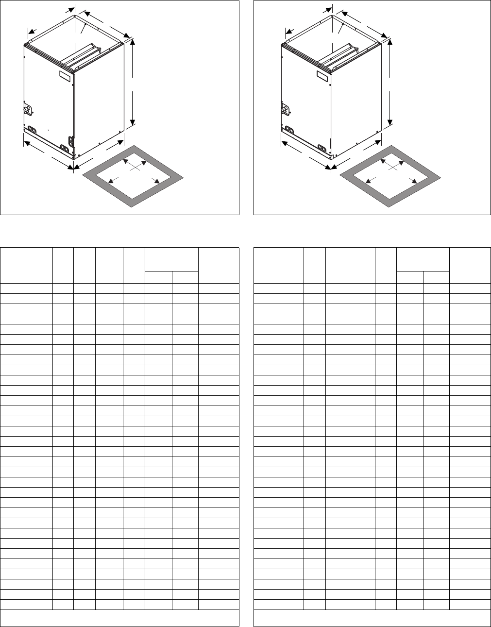
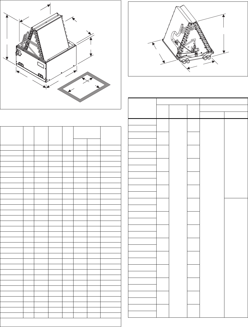
DIMENSIONS
Coil - MC
Dimensions - MC Coils
Model A B C D
Refrigerant
Line Size
*
* Refrigerant line sizes may require larger lines for extended line lengths.
See York bulletin #690.01-AD1V for details.
Factory
Installed
TXV (R22)
Liquid Vapor
MC18A2AH1 14.5 22 13 3/8 13.5 3/8 3/4 2A
MC18A3XH1 14.5 22 13 3/8 13.5 3/8 3/4 None
MC18B2AH1 17.5 22 16 3/8 16.5 3/8 3/4 2A
MC18B3XH1 17.5 22 16 3/8 16.5 3/8 3/4 None
MC24A2AH1 14.5 26.5 13 3/8 13.5 3/8 3/4 2A
MC24A3XH1 14.5 26.5 13 3/8 13.5 3/8 3/4 None
MC24B2AH1 17.5 26.5 16 3/8 16.5 3/8 3/4 2A
MC24B3XH1 17.5 26.5 16 3/8 16.5 3/8 3/4 None
MC30A2AH1 14.5 26.5 13 3/8 13.5 3/8 3/4 2A
MC30A3XH1 14.5 26.5 13 3/8 13.5 3/8 3/4 None
MC30B2AH1 17.5 26.5 16 3/8 16.5 3/8 3/4 2A
MC30B3XH1 17.5 26.5 16 3/8 16.5 3/8 3/4 None
MC35B3XH1 17.5 22 16 3/8 16.5 3/8 3/4 None
MC35C3XH1 21 26.5 19 7/8 20 3/8 3/4 None
MC36A2AH1 14.5 26.5 13 3/8 13.5 3/8 7/8 2A
MC36A3XH1 14.5 26.5 13 3/8 13.5 3/8 7/8 None
MC36B2AH1 17.5 26.5 16 3/8 16.5 3/8 7/8 2A
MC36B3XH1 17.5 26.5 16 3/8 16.5 3/8 7/8 None
MC36C2AH1 21 26.5 19 7/8 20 3/8 7/8 2A
MC36C3XH1 21 26.5 19 7/8 20 3/8 7/8 None
MC42B2CH1 17.5 32 16 3/8 16.5 3/8 7/8 2C
MC42B3XH1 17.5 32 16 3/8 16.5 3/8 7/8 None
MC42C2CH1 21 32 19 7/8 20 3/8 7/8 2C
MC42C3XH1 21 32 19 7/8 20 3/8 7/8 None
MC48C2CH1 21 32 19 7/8 20 3/8 7/8 2C
MC48C3XH1 21 32 19 7/8 20 3/8 7/8 None
MC48D2CH1 24.5 32 23 3/8 23.5 3/8 7/8 2C
MC48D3XH1 24.5 32 23 3/8 23.5 3/8 7/8 None
MC60D2CH1 24.5 32 23 3/8 23.5 3/8 7/8 2C
MC60D3XH1 24.5 32 23 3/8 23.5 3/8 7/8 None
MC61D2CH1 24.5 36 23 3/8 23.5 3/8 7/8 2C
MC61D3XH1 24.5 36 23 3/8 23.5 3/8 7/8 None
All MC coils include a factory installed horizontal drain pan.
(3X) = Models require field installed TXV.
20 3/8”
(Opening)
A
C
3/4”Flange
B
22”
BOTTOM
OPENING
DIMENSIONS
D
201/4”
Coil - FC
Dimensions - FC Coils
Model A B C D
Refrigerant
Line Size
*
* Refrigerant line sizes may require larger lines for extended line lengths.
See York bulletin #690.01-AD1V for details.
Factory
Installed
TXV (R22)
Liquid Vapor
FC18A2AN1 14.5 18 13 3/8 13.5 3/8 3/4 2A
FC18A3XN1 14.5 18 13 3/8 13.5 3/8 3/4 None
FC18B2AN1 17.5 18 16 3/8 16.5 3/8 3/4 2A
FC18B3XN1 17.5 18 16 3/8 16.5 3/8 3/4 None
FC24A2AN1 14.5 22 13 3/8 13.5 3/8 3/4 2A
FC24A3XN1 14.5 22 13 3/8 13.5 3/8 3/4 None
FC24B2AN1 17.5 22 16 3/8 16.5 3/8 3/4 2A
FC24B3XN1 17.5 22 16 3/8 16.5 3/8 3/4 None
FC30A2AN1 14.5 22 13 3/8 13.5 3/8 3/4 2A
FC30A3XN1 14.5 22 13 3/8 13.5 3/8 3/4 None
FC30B2AN1 17.5 22 16 3/8 16.5 3/8 3/4 2A
FC30B3XN1 17.5 22 16 3/8 16.5 3/8 3/4 None
FC35B3XN1 17.5 22 16 3/8 16.5 3/8 3/4 None
FC35C3XN1 21 24.5 19 7/8 20 3/8 3/4 None
FC36A2AN1 14.5 24.5 13 3/8 13.5 3/8 7/8 2A
FC36A3XN1 14.5 24.5 13 3/8 13.5 3/8 7/8 None
FC36B2AN1 17.5 24.5 16 3/8 16.5 3/8 7/8 2A
FC36B3XN1 17.5 24.5 16 3/8 16.5 3/8 7/8 None
FC36C2AN1 21 24.5 19 7/8 20 3/8 7/8 2A
FC36C3XN1 21 24.5 19 7/8 20 3/8 7/8 None
FC42B2CN1 17.5 28 16 3/8 16.5 3/8 7/8 2C
FC42B3XN1 17.5 28 16 3/8 16.5 3/8 7/8 None
FC42C2CN1 21 28 19 7/8 20 3/8 7/8 2C
FC42C3XN1 21 28 19 7/8 20 3/8 7/8 None
FC48C2CN1 21 28 19 7/8 20 3/8 7/8 2C
FC48C3XN1 21 28 19 7/8 20 3/8 7/8 None
FC48D2CN1 24.5 28 23 3/8 23.5 3/8 7/8 2C
FC48D3XN1 24.5 28 23 3/8 23.5 3/8 7/8 None
FC60C2CN1 21 28 19 7/8 20 3/8 7/8 2C
FC60C3XN1 21 28 19 7/8 20 3/8 7/8 None
FC60D2CN1 24.5 28 23 3/8 23.5 3/8 7/8 2C
FC60D3XN1 24.5 28 23 3/8 23.5 3/8 7/8 None
FC coils are not available with a factory installed horizontal drain pan.
(3X) = Models require field installed TXV.
20 3/8”
(Opening)
A
C
3/4”Flange
B
22”
BOTTOM
OPENING
DIMENSIONS
D
201/4”
258931-BTG-A-0606
12 Unitary Products Group
Coil - PC
Dimensions - PC Coils
Model A B C D
Refrigerant
Line Size
*
* Refrigerant line sizes may require larger lines for extended line lengths.
See York bulletin #690.01-AD1V for details.
Factory
Installed
TXV (R22)
Liquid Vapor
PC18A2AN1
14.5 17 3/4 13 3/8 13.5 3/8 3/4 2A
PC18A3XN1
14.5 17 3/4 13 3/8 13.5 3/8 3/4 None
PC18B2AN1
17.5 17 16 3/8 16.5 3/8 3/4 2A
PC18B3XN1
17.5 17 16 3/8 16.5 3/8 3/4 None
PC24A2AN1
14.5 21 7/8 13 3/8 13.5 3/8 3/4 2A
PC24A3XN1
14.5 21 7/8 13 3/8 13.5 3/8 3/4 None
PC24B2AN1
17.5 21 3/8 16 3/8 16.5 3/8 3/4 2A
PC24B3XN1
17.5 21 3/8 16 3/8 16.5 3/8 3/4 None
PC30A2AN1
14.5 21 7/8 13 3/8 13.5 3/8 3/4 2A
PC30A3XN1
14.5 21 7/8 13 3/8 13.5 3/8 3/4 None
PC30B2AN1
17.5 21 3/8 16 3/8 16.5 3/8 3/4 2A
PC30B3XN1
17.5 21 3/8 16 3/8 16.5 3/8 3/4 None
PC35B3XN1
17.5 18 7/8 16 3/8 16.5 3/8 3/4 None
PC35C3XN1
21 18 3/4 19 7/8 20 3/8 3/4 None
PC36A2AN1
14.5 23 7/8 13 3/8 13.5 3/8 7/8 2A
PC36A3XN1
14.5 23 7/8 13 3/8 13.5 3/8 7/8 None
PC36B2AN1
17.5 23 1/8 16 3/8 16.5 3/8 7/8 2A
PC36B3XN1
17.5 23 1/8 16 3/8 16.5 3/8 7/8 None
PC36C2AN1
21 22 7/8 19 7/8 20 3/8 7/8 2A
PC36C3XN1
21 22 7/8 19 7/8 20 3/8 7/8 None
PC42B2CN1
17.5 27 5/8 16 3/8 16.5 3/8 7/8 2C
PC42B3XN1
17.5 27 5/8 16 3/8 16.5 3/8 7/8 None
PC42C2CN1
21 27 1/8 19 7/8 20 3/8 7/8 2C
PC42C3XN1
21 27 1/8 19 7/8 20 3/8 7/8 None
PC48C2CN1
21 25 3/8 19 7/8 20 3/8 7/8 2C
PC48C3XN1
21 25 3/8 19 7/8 20 3/8 7/8 None
PC48D2CN1
24.5 24 5/8 23 3/8 23.5 3/8 7/8 2C
PC48D3XN1
24.5 24 5/8 23 3/8 23.5 3/8 7/8 None
PC60C2CN1
21 27 1/2 19 7/8 20 3/8 7/8 2C
PC60C3XN1
21 27 1/2 19 7/8 20 3/8 7/8 None
PC60D2CN1
24.5 26 7/8 23 3/8 23.5 3/8 7/8 2C
PC60D3XN1
24.5 26 7/8 23 3/8 23.5 3/8 7/8 None
PC coils are not available with a factory installed horizontal drain pan.
(3X) = Models require field installed TXV.
20 3/8”
(Opening)
A
C
(Opening)
12”
B
22”
BOTTOM
OPENING
DIMENSIONS
201/4” D
COIL - UC
Dimensions - UC Coils
Model
Dimensions — Inches Refrigerant Connections
A B C Line Size
Liquid Vapor
UC18A3XN1 13
19.875
17
3/8
3/4
UC18A2AN1
UC18B3XN1 16 16.5
UC18B2AN1
UC24A3XN1 13 21
UC24A2AN1
UC24B3XN1 16 20.5
UC24B2AN1
UC30A3XN1 13 21
UC30A2AN1
UC30B3XN1 16 20.5
UC30B2AN1
UC36A3XN1 13 23.5
7/8
UC36A2AN1
UC36B3XN1 16 22.5
UC36B2AN1
UC36C3XN1 19.5 22
UC36C2AN1
UC42B3XN1 16 26.5
UC42B2CN1
UC42C3XN1 19.5 25.5
UC42C2CN1
UC48C3XN1 19.5 23.5
UC48C2CN1
UC48D3XN1 23 23
UC48D2CN1
UC60C3XN1 19.5 25.5
UC60C2CN1
UC60D3XN1 23 25
UC60D2CN1
B
C
A
258931-BTG-A-0606
Unitary Products Group 13
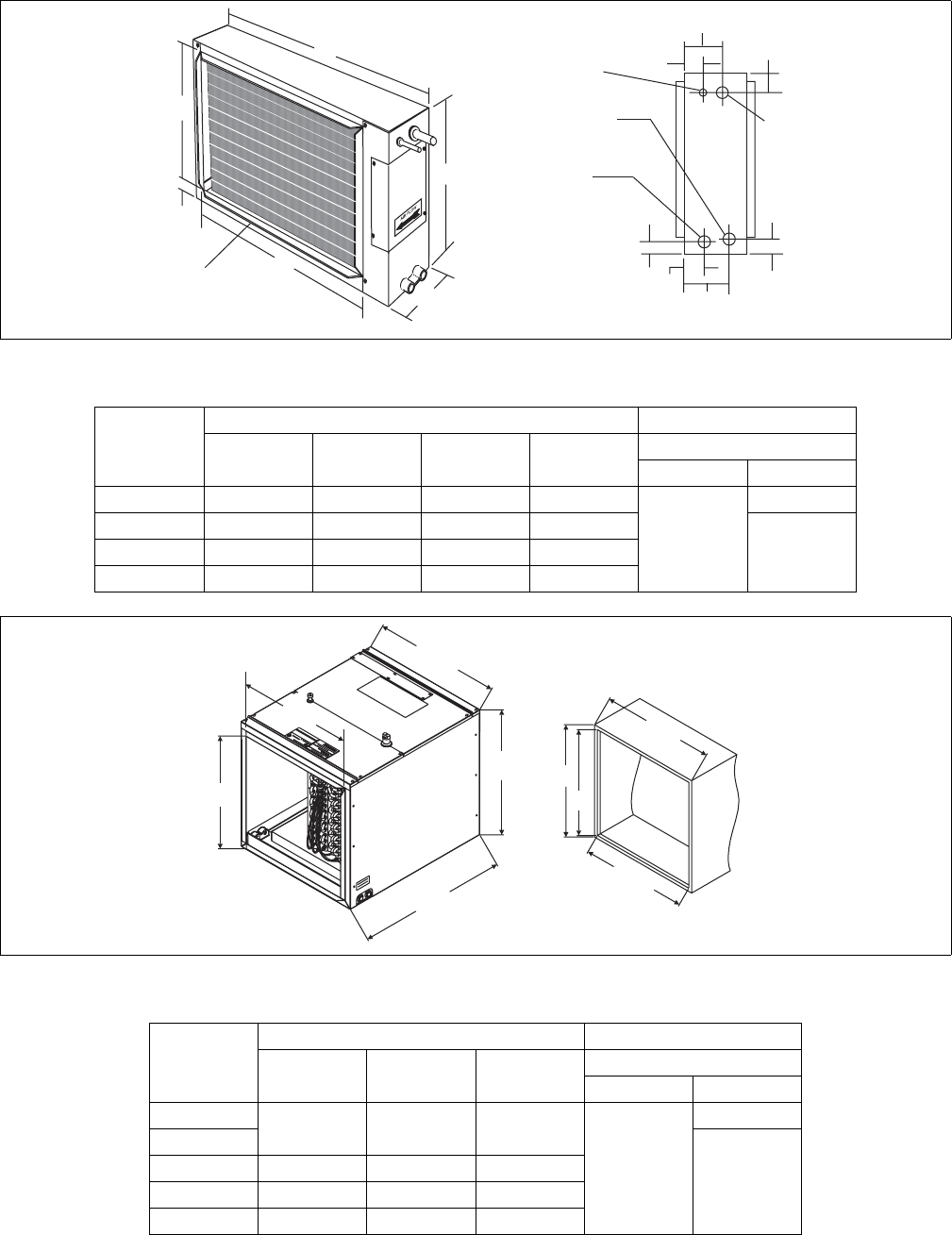
COIL - HD
1-3/4
C
5-5/8
B
A
D
3-3/4
2-5/8
1-3/8
VAPOR
CONN.
LIQUID
CONN.
3/4 MPT
SECONDARY
DRAIN CONN.
3/4 MPT
PRIMARY
DRAIN CONN.
7/8
1-7/8
4-1/8
1-3/8
OUTLET SAME
SIZE AS INLET
(ALL FLANGES 3/4” THICK
Dimensions - HD Coils
Model
Dimensions — Inches Refrigerant Connections
ABCD Line Size
Liquid Vapor
HD24A**H1 28-3/4 24 23-3/4 21-5/8
3/8
3/4
HD36B**H1 28-3/4 28 23-3/4 25-5/8
7/8HD48C**H1 34-3/4 28 29-3/4 25-5/8
HD60D**H1 34-3/4 30 29-3/4 27-5/8
COIL - HC
B
19-1/2
25-1/2
A
21-1/2
A
C
20-1/4
21-1/2
INLET
OPENING
Dimensions - HD Coils
Model
Dimensions — Inches Refrigerant Connections
ABC Line Size
Liquid Vapor
HC18A**H1 15-5/16 13-1/4 14-3/16
3/8
3/4
HC30A**H1
7/8
HC36B**H1 17-9/16 15-1/2 16-7/16
HC42C**H1 21-5/16 19-1/4 20-3/16
HC60D**H1 25-5/16 23-1/4 24-3/16
258931-BTG-A-0606
14 Unitary Products Group
NOTES
258931-BTG-A-0606
Unitary Products Group 15
NOTES

Subject to change without notice. Printed in U.S.A. 258931-BTG-A-0606
Copyright © by York International Corp. 2006. All rights reserved. Supersedes: 251366/036-21668-001 Rev. B (0306)
Unitary 5005 Norman
Products York OK
Group Drive 73069
NOTES
