York Millennium Nd360 Users Manual 628767 YTG C 0910
ND600 to the manual 5b9cc7c5-93bb-445e-b6fd-13735280cf63
2015-02-02
: York Millennium-Nd360-Users-Manual york-millennium-nd360-users-manual-455124 york pdf
Open the PDF directly: View PDF ![]() .
.
Page Count: 38
- Description
- Table of Contents
- Description 1
- Table of Contents 2
- Nomenclature 3
- Air Handling Unit Features and Benefits 4
- Guide Specifications 5
- Physical Data 7
- Unit Limitations 8
- Cooling and Heating Ratings 8
- Capacity Performance 9
- Air Handling Unit and Hot Water Coil Accessory Heating Capacity 15
- Air Handling Unit and Steam Coil Accessory Heating Capacity 16
- Fan Performance 17
- Sound Performance 19
- Electrical Data 20
- Typical Wiring Diagrams 21
- Weights And Dimensions 22
- Unit Mounting 32
- Typical Field Wiring Diagrams 36
- Nomenclature
- Air Handling Unit Features and Benefits
- Guide Specifications
- MILLENNIUM™
- Split System Air-Cooled Air Handler Models: NC300 and ND360, 480 and 600
- General
- Description
- Unit Cabinet
- a. A steel angle frame to provide the rigid support required for shipping, rigging and years of dependable operation.
- b. Exterior panels of 18 gauge steel, finished with baked enamel to provide a long-lasting quality appearance.
- c. Removable panels to provide easy access to the internal components for maintenance and service.
- d. A filter rack with 1" or 2" filters.
- Indoor (Evaporator) Fan Assembly
- Refrigerant Components
- a. Evaporator coils shall have aluminum plate fins mechanically bonded to seamless internally enhanced copper tubes with all joints brazed.
- b. Evaporator coil shall be of the direct expansion, draw through design.
- a. Include factory-mounted distributors, adjustable thermal expansion valves and solenoid valves for both capacity reduction and refrigerant pump out on start- up.
- b. Include factory installed auxiliary side connectors for the addition of field installed hot gas bypass.
- c. Shall include filter/strainer to eliminate any foreign matter.
- Controls
- The Installer Shall:
- Unit Operating Characteristics
- Electrical Requirements
- Each Unit Shall Include The Following Accessories:
- Physical Data
- Unit Limitations
- Cooling and Heating Ratings
- Capacity Performance
- Air Handling Unit and Hot Water Coil Accessory Heating Capacity
- Air Handling Unit and Steam Coil Accessory Heating Capacity
- Fan Performance
- Sound Performance
- Electrical Data
- Typical Wiring Diagrams
- Weights And Dimensions
- Corner Weights & Center of Gravity ND360, 480 & 600 Unit
- Unit Dimensions ND360
- Unit Dimensions ND360 (Continued)
- Unit Dimensions ND480
- Unit Dimensions ND480 (Continued)
- Unit Dimensions ND600
- Unit Dimensions M1CZ600 Evaporator Section
- Unit Dimensions ND600 Airhandler & M1CZ600 Evaporator Coil
- Dimensions Hot Water Coil
- Dimensions Steam Coil
- Dimensions Base Section
- Unit Mounting
- Typical Field Wiring Diagrams
TECHNICAL GUIDE
R-410A
SPLIT-SYSTEM
AIR HANDLERS
MILLENNIUM™
ND360, 480 & 600
30 - 50 Ton
60 Hertz
ND600 AIRHANDLER & M1CZ600 EVAPORATOR SECTION
®
628767-YTG-C-0910
ISO 9001
Certified Quality
Management System
Description
These air handling units are completely assembled units,
including a well-insulated cabinet, a DX cooling coil with copper
tubing, aluminum fins, expansion valve(s), distributor(s), 2”
throwaway filters, a centrifugal blower, a blower motor, an
adjustable belt drive, a blower motor contactor and a small
holding charge of nitrogen.
Units are shipped in the vertical position ready for field
installation, but can be easily converted to horizontal position.

628767-YTG-C-0910
2Johnson Controls Unitary Products
Table of Contents
Description . . . . . . . . . . . . . . . . . . . . . . . . . . . . . . . . . . . . . . . . . . . . . . . . . . . . . . . . . . . . . . . . . . . . . . . . . . . . . . . . . . . . . . . . . 1
Table of Contents . . . . . . . . . . . . . . . . . . . . . . . . . . . . . . . . . . . . . . . . . . . . . . . . . . . . . . . . . . . . . . . . . . . . . . . . . . . . . . . . . . . . 2
Nomenclature . . . . . . . . . . . . . . . . . . . . . . . . . . . . . . . . . . . . . . . . . . . . . . . . . . . . . . . . . . . . . . . . . . . . . . . . . . . . . . . . . . . . . . . 3
Air Handling Unit Features and Benefits . . . . . . . . . . . . . . . . . . . . . . . . . . . . . . . . . . . . . . . . . . . . . . . . . . . . . . . . . . . . . . . . . 4
Guide Specifications . . . . . . . . . . . . . . . . . . . . . . . . . . . . . . . . . . . . . . . . . . . . . . . . . . . . . . . . . . . . . . . . . . . . . . . . . . . . . . . . . 5
Physical Data . . . . . . . . . . . . . . . . . . . . . . . . . . . . . . . . . . . . . . . . . . . . . . . . . . . . . . . . . . . . . . . . . . . . . . . . . . . . . . . . . . . . . . . 7
Unit Limitations. . . . . . . . . . . . . . . . . . . . . . . . . . . . . . . . . . . . . . . . . . . . . . . . . . . . . . . . . . . . . . . . . . . . . . . . . . . . . . . . . . . . . . 8
Cooling and Heating Ratings. . . . . . . . . . . . . . . . . . . . . . . . . . . . . . . . . . . . . . . . . . . . . . . . . . . . . . . . . . . . . . . . . . . . . . . . . . . 8
Capacity Performance . . . . . . . . . . . . . . . . . . . . . . . . . . . . . . . . . . . . . . . . . . . . . . . . . . . . . . . . . . . . . . . . . . . . . . . . . . . . . . . . 9
Air Handling Unit and Hot Water Coil Accessory Heating Capacity . . . . . . . . . . . . . . . . . . . . . . . . . . . . . . . . . . . . . . . . . . 15
Air Handling Unit and Steam Coil Accessory Heating Capacity . . . . . . . . . . . . . . . . . . . . . . . . . . . . . . . . . . . . . . . . . . . . . 16
Fan Performance . . . . . . . . . . . . . . . . . . . . . . . . . . . . . . . . . . . . . . . . . . . . . . . . . . . . . . . . . . . . . . . . . . . . . . . . . . . . . . . . . . . 17
Sound Performance . . . . . . . . . . . . . . . . . . . . . . . . . . . . . . . . . . . . . . . . . . . . . . . . . . . . . . . . . . . . . . . . . . . . . . . . . . . . . . . . . 19
Electrical Data . . . . . . . . . . . . . . . . . . . . . . . . . . . . . . . . . . . . . . . . . . . . . . . . . . . . . . . . . . . . . . . . . . . . . . . . . . . . . . . . . . . . . . 20
Typical Wiring Diagrams . . . . . . . . . . . . . . . . . . . . . . . . . . . . . . . . . . . . . . . . . . . . . . . . . . . . . . . . . . . . . . . . . . . . . . . . . . . . . 21
Weights And Dimensions . . . . . . . . . . . . . . . . . . . . . . . . . . . . . . . . . . . . . . . . . . . . . . . . . . . . . . . . . . . . . . . . . . . . . . . . . . . . 22
Unit Mounting . . . . . . . . . . . . . . . . . . . . . . . . . . . . . . . . . . . . . . . . . . . . . . . . . . . . . . . . . . . . . . . . . . . . . . . . . . . . . . . . . . . . . . 32
Typical Field Wiring Diagrams . . . . . . . . . . . . . . . . . . . . . . . . . . . . . . . . . . . . . . . . . . . . . . . . . . . . . . . . . . . . . . . . . . . . . . . . 36
628767-YTG-C-0910
Johnson Controls Unitary Products 3
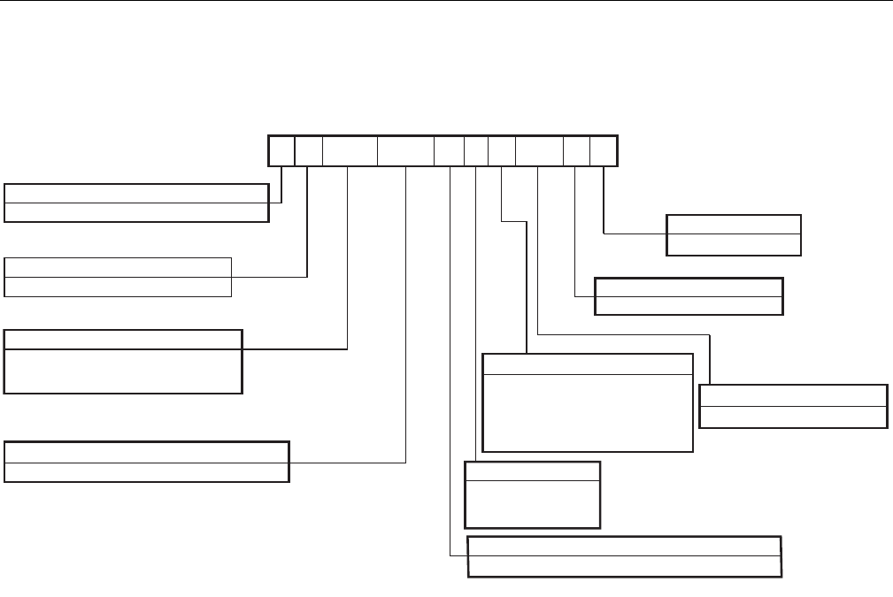
Nomenclature
Product Category
N = Split System, Air Handler, AC R-410A
Product Identifier
D = Standard Efficiency, 4-Pipe (30-50T)
* Motors, drives, overloads are not shipped with 30-50 ton AH units.
Nominal Cooling Capacity - MBH
360 = 30 Ton
480 = 40 Ton
600 = 50 Ton
C00 = Cooling Only
Product Options
AA = No Options Installed
5 = 575-3-60
6 = 208/230/460-3-60
7 = 380/415-3-50
Configured Split Air Handler Model Number Nomenclature
N = None (Motor, Motor Dr. & Motor Overload Kits Req.)
Airflow
Product Generation
1 = First Generation
Voltage
Heat Type & Nominal Heat Capacity
ND360 C00 N 6AAA 1A
Product Style
A = Style A
** ND600C00ANAAA1 airhandler
does not include evaporator coil.
Customer must order M1CZ600A
Standard Coil or M1CZ600T
Technical Coil.
Installation Options
A = None
C = YCCS Ctrl CV Cooling/Elec Ht
D = YCCS Ctrl COBP Cooling/Elec Ht
E = YCCS Ctrl CV w/H
2
0
F = YCCS Ctrl COBP w/H
2
0

628767-YTG-C-0910
4Johnson Controls Unitary Products
Air Handling Unit Features and Benefits
Features
These air handlers can be arranged for a variety of air
discharge patterns in either the horizontal or vertical position.
Refer to the unit installation instructions for other application
possibilities.
Benefits
Air handling units are designed with two distinct modules to
provide maximum application flexibility. ND360 and 480
Models are shipped as single packages with the blower
module mounted on top of the coil module. The ND600
Blower Section and the M1CZ600 Evaporator Section are
shipped separately and must be assembled on the job site.
All blower modules can be repositioned in the field to meet a
large number of vertical and horizontal applications.
The blower module includes the blower wheels and room for
a field-mounted motor and drive. All models offer multiple
motor horsepower and drive options to meet both standard
and high static airflow requirements. The coil module
includes direct expansion coils, 2 in. throwaway filters, liquid
line solenoid valves for capacity reduction, thermal expansion
valves, distributors and a condensate drain pan.
Every air handling coil is pressurized with air and leak tested
under water. After the headers are brazed onto the coil and
the coil is installed in the unit, the coil is pressurized with
nitrogen for pressure testing and additional leak testing. After
the coil is evacuated and dehydrated, it is pressurized with a
holding charge of nitrogen for storage and/or shipping.
These air handlers, combined with condensing units, provide
years of quiet, efficient and dependable operation. These
units are manufactured under ISO 9001 Quality System
Certification.
Unit Installation
Units may be bottom-supported or ceiling-suspended and
can be arranged to meet almost any space or duct
requirements. Each unit is available with a choice of blower
motor horsepower, drive packages and other accessories to
make them suitable for most applications.
Blower Motors: Different HP motors are available for each
unit to meet almost any air delivery requirement. All motors
are UL approved, have permanently lubricated ball bearings
and are field-mounted within the insulated cabinet of the units
to minimize the transmission of sound to the surrounding
space.
Air Handling units are available in four pipe configurations
from 30 to 50 tons. The dual circuit options provide a wide
variety of application and unit matchup possibilities.
Starters and Heater Elements : These blower motors do not
have inherent protection and require external motor overload
protection. See details in Overload Elements Table.
NOTE: Power wiring for blower motors is field supplied.
Factory-Mounted Components
Part Load Operation: These air handlers have multiple DX
(Direct Expansion) coils with pre-piped distributors,
expansion valves and solenoid valves. Field modifications
are not required for part load operations. Capacity reduction
not only provides economical operation, but also maintains
stable temperature and humidity levels in the conditioned
space.
BAS Control: York Commercial Comfort System (YCCS)
provides split system integration for YCCS single zone,
change-over bypass and VAV systems.
Easy Service: Serviceable expansion valves are provided on
every unit. These valves are factory-installed to provide many
years of trouble-free operation. If service is required, it is not
necessary to unbraze any joints. The expansion valves also
include a tee fitting to allow easy installation of hot gas
bypass if required.
Coil Protection: The indoor coils of these air handlers can be
factory Technicoated to provide extended life to the indoor
coil in standard applications and additional corrosion
protection on those applications in sea coast or corrosive
environments.
Blower Motors: Different HP motors are available for each
unit to meet almost any air delivery requirement. 5 HP motors
are inherently protected. 7.5 thru 15 HP motors require motor
overload protection.
NOTE: Power wiring for blower motor is field supplied on all
Unit Models.
Accessories
Base Sections (30 and 40 ton): Base sections can be used to
elevate units above the floor. If desired, a moderate
percentage of outdoor air may be introduced through these
sections by cutting an access opening to accommodate the
outdoor air duct connection. These bases include a durable
finish to match the evaporator blower unit. The base may
have to be insulated for certain applications.
Hot Water Coils: Drainable water coils are available for field
installation between the blower and the coil modules of both
horizontal and vertical units. Since their casings match the
dimensions and the finish of the basic units, they become an
integral part of the unit after installation. The coils slide out of
their casings for easy installation. Hot water coils have
copper tubes that have been mechanically expanded into
aluminum fins. Both headers are located on the same end of
the coil. Coils are leak-tested at 325 psig under water and
dried before their connections are capped for storage and
shipping.
Steam Coils (30 ton only): Steam coils are available for
installation between the blower and coil modules of both
horizontal and vertical units. Since the casing matches the
dimensions and the finish of the basic unit, it becomes an
integral part of the unit after installation. The coil slides out of
the casings for easy installation and is pitched in the casings
to facilitate condensate drainage. The coil has copper tubes
that have been mechanically expanded into aluminum fins.
Both headers are located on the same end of the coil. The
coil is leak-tested at 325 psig and dried before the
connections are capped for storage and shipping.

628767-YTG-C-0910
Johnson Controls Unitary Products 5
Guide Specifications
MILLENNIUM™
Split System Air-Cooled Air Handler
Models: NC300 and ND360, 480 and 600
General
Units shall be manufactured by Johnson Controls, Unitary
Products Group in an ISO 9001 certified facility. These
factory-assembled units include a well-insulated cabinet, a
DX cooling coil with copper tubes and aluminum fins,
expansion valve(s), distributor(s), throwaway filters, a
centrifugal blower, a blower motor, an adjustable belt drive, a
blower motor contactor and a small holding charge of
nitrogen. The units are shipped in the vertical position ready
for field installation. The air handler units can be installed for
horizontal operation by reversing the position of the solid
bottom panel with the return air duct flange on the front of the
unit. The products must be tested per ARI 340/360 and
Underwriter Laboratories U.L. 1995 and carry both CSA and
ARI certification.
Description
The NC/ND indoor units are completely piped and wired at
the factory and are shipped ready for immediate installation.
Only the interconnecting liquid and suction lines, control
wiring, and the main power wiring are required to complete
the installation. Every coil is dehydrated, evacuated, leak
tested and pressure tested at 450 psig before being
pressurized with a holding charge of nitrogen for shipment
and/or storage.
To eliminate the costly cabinet deterioration problems usually
associated with outdoor equipment, all sheet metal parts are
constructed of commercial grade (G90) galvanized steel.
After fabrication, each part is thoroughly cleaned to remove
any grease or dirt from its surfaces. The parts that will be
exposed to the weather are then coated with a powder paint
to assure a quality finish for many years. This coating system
has passed the 1000-hour, salt spray test per ASTM
Standard B117.
Unit Cabinet
Cabinet shall be constructed of 18 gauge, zinc coated steel,
finished with a powder paint process capable of withstanding
a minimum of 1000 salt spray hours according to ASTM
B117. Cabinet screws shall comply with the ASTM B117 salt
spray test for a minimum of 1000 hours. Panels shall be
removable for easy access to all internal components during
maintenance and service. A filter rack shall be included to
accommodate 1" or 2" filters. Cabinet shall feature a
separate access panel for the controls so that unit airflow
need not be disturbed during servicing. The NC300, ND360-
480 units are shipped in the vertical position ready for field
installation. The blower module can be repositioned in the
field for maximum flexibility. The ND600 product ships with a
separate M1CZ600A evaporator coil and can be assembled
in the vertical or horizontal position in the field.
Each unit shall have:
a. A steel angle frame to provide the rigid support
required for shipping, rigging and years of dependable
operation.
b. Exterior panels of 18 gauge steel, finished with baked
enamel to provide a long-lasting quality appearance.
c. Removable panels to provide easy access to the
internal components for maintenance and service.
d. A filter rack with 1" or 2" filters.
Indoor (Evaporator) Fan Assembly
Fan shall be a belt drive assembly and include an adjustable
pitch motor pulley. Job site selected brake horsepower shall
not exceed the motors nameplate horsepower rating plus the
service factor. Units shall be designed to operate within the
service factor. Fan wheel shall be double-inlet type with
forward-curved blades, dynamically balanced to operate
smoothly throughout the entire range of operation. Airflow
design shall be constant air volume. Bearings shall be sealed
and permanently lubricated for longer life and no
maintenance. Blower motors and drive kits are ordered
separately. Power wiring for blower motor is field supplied.
Refrigerant Components
Coils:
a. Evaporator coils shall have aluminum plate fins
mechanically bonded to seamless internally enhanced
copper tubes with all joints brazed.
b. Evaporator coil shall be of the direct expansion, draw
through design.
Refrigerant Circuit and Refrigerant Safety Components:
a. Include factory-mounted distributors, adjustable
thermal expansion valves and solenoid valves for both
capacity reduction and refrigerant pump out on start-
up.
b. Include factory installed auxiliary side connectors for
the addition of field installed hot gas bypass.
c. Shall include filter/strainer to eliminate any foreign
matter.
Controls
Unit controls shall include 208/230/460 or 575 volt
transformer, blower motor contactor and relay, as well as a
low voltage terminal block. Unit wiring shall be color-coded
for easy service and trouble shooting.

628767-YTG-C-0910
6Johnson Controls Unitary Products
The Installer Shall:
Furnish condensing units in accordance with the
performance schedules shown on the plans. Install each unit
as shown on the plans in accordance with the manufacturer's
recommendations and all applicable national and local
codes.
Unit Operating Characteristics
Unit shall be capable of starting and running at 125º F
outdoor temperature, exceeding maximum load criteria ARI
Standard 360. The compressor, with standard controls, shall
be capable of operation down to 40º F outdoor temperature.
Electrical Requirements
All unit wiring shall enter unit cabinet at a single factory
provided location to minimize cabinet penetrations and avoid
unit field modifications.
Each Unit Shall Include The Following Accessories:
• "Suspension kit
• "Return air grille
• "Hot water coil
•"Steam coil
• "Decorative base
• Metal skid
• "Wood skid
628767-YTG-C-0910
Johnson Controls Unitary Products 7
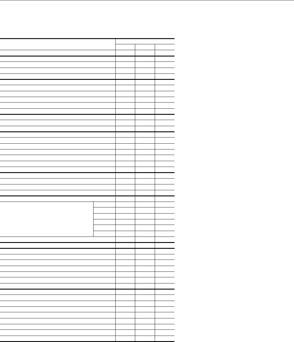
Physical Data
ND360, 480 & 600 Physical Data
Component Models
ND360 ND480 ND6001
1ND600 and M1CZ600A Combined
Nominal Tonnage 30 40 50
DIMENSIONS (inches)
Length 100.1 103.1 105.1
Width 38.1 45.4 53.7
Height 74.6 89.4 99.0
WEIGHTS2 (lb)
2Motor, Motor Drive and Motor Overload Kits must be ordered separately,
The Motor, Motor Drive and Overload Kits are to be field installed.
Unit Shipping 1122 1246 1684
Unit Operating With
5 hp Motor and Drive 1184 --- ---
7.5 hp Motor and Drive 1208 1348 1742
10 hp Motor and Drive 1224 1364 1859
INDOOR BLOWER
Diameter x Width 18 X 18 18 X 18 20 x 18
Qty. 222
INDOOR COIL
Face area (Sq. Ft.) 25.8 33.3 41.3
Rows 444
Fins per inch 16 16 16
Tube diameter 3/8 3/8 3/8
Circuitry Type Interlaced Interlaced Interlaced
Refrigerant Control TEV TEV TEV
SYSTEM DATA
No. Refrigeration Circuits 222
Suction Line OD (in.) 1 1/8 1 3/8 2 1/8
Liquid Line OD (in.) 7/8 7/8 7/8
FILTERS
Size and Quantity Per Model (In.)
16 x 20 x 2 --- 6 ---
20 x 20 x 2 --- 3 ---
20 x 22 x 2 --- --- ---
16 x 25 x 2 --- --- 6
20 x 25 x 2 10 6 3
25 x 25 x 2 --- --- 6
Face area (Sq. Ft.) 34.7 42.6 53.1
ACCESSORY
HOT WATER COIL DATA
Face area (Sq. Ft.) 21.2 27.2 27.2
Rows 222
Fins per inch 12 12 8
Tube diameter (Copper) OD (In.) 1/2 1/2 1/2
Connections (Supply and Return) OD (In.) 1 3/8 1 5/8 1 5/8
Weight (lb) 150 190 190
STEAM COIL DATA
Face area (Sq. Ft.) 18.2 --- ---
Rows 1 --- ---
Fins per inch 8 --- ---
Tube diameter (Copper) (In.) 1 --- ---
Connection, (NPTE) (In.)
Inlet 2 --- ---
Outlet 1-1/2 --- ---
Weight (lb) 160 --- ---
628767-YTG-C-0910
8Johnson Controls Unitary Products
Unit Limitations
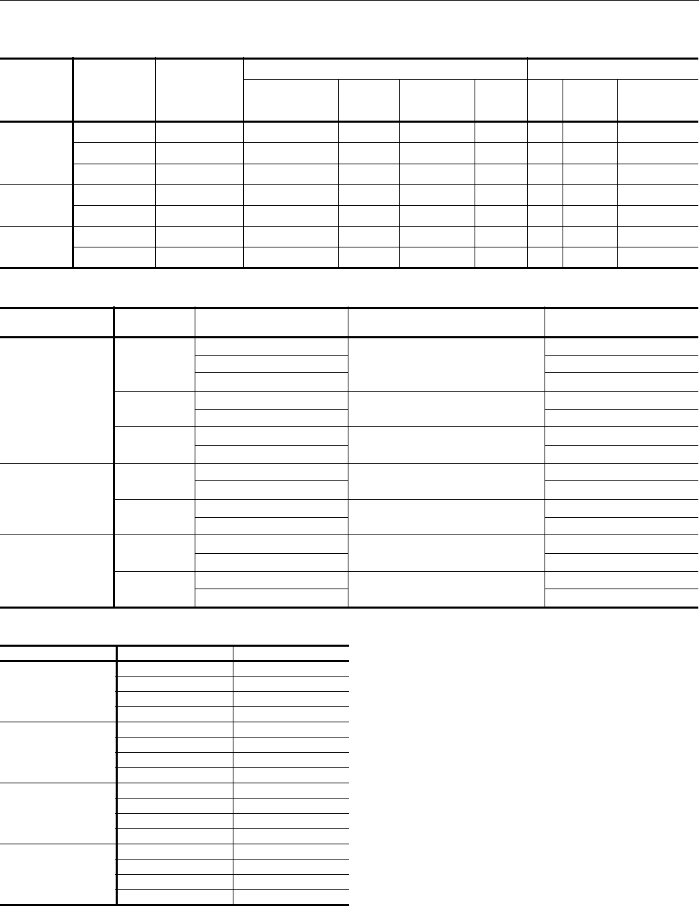
Cooling and Heating Ratings
Cooling Ratings
EER = Energy Efficiency Ratio at full load - the cooling capacity in Btu’s per hour (Btuh) divided by the power input in watts, expressed in Btuh per
watt (Btuh/watt).
EER; condensing unit only ratings based on 45º F SST and 95ºF entering outdoor air temperature.
IEER - A single number cooling part-load efficiency figure that is calculated based on equipment stages and EER at these capacity stages (ANSI/
ARI STD 340/360 - 2007)
LEGEND
EER = Energy Efficiency Ratio
SST = Saturated Suction Temperature
ARI = Air Conditioning and Refrigeration Institute
IEER = Integrated Energy Efficiency Ratio
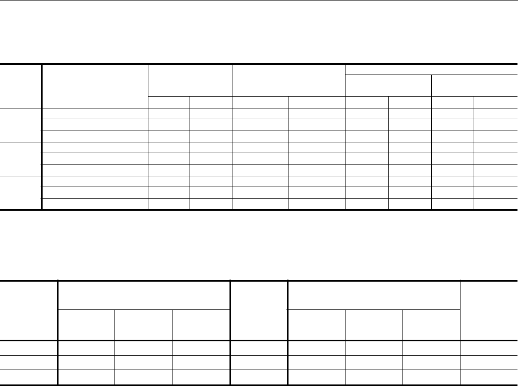
Air Handling Unit Limitations
Model Power Supply Voltage Voltage Variation Supply Air Range CFM
Entering Air Temperature Degrees °F
Cooling
DB/WB Heating DB1
1Heating Min/Max temperatures apply to steam and hot water coils. NOTE: Do not apply steam to hot water coils.
Min. Max. Min. Max. Min. Max. Min. Max.
ND360
208/230-3-60 187 253 10,000 14,000 65/57 95/72 40 77
460-3-60 414 506 10,000 14,000 65/57 95/72 40 77
575-3-60 540 630 10,000 14,000 65/57 95/72 40 77
ND480
208/230-3-60 187 253 12,800 19,200 65/57 95/72 40 77
460-3-60 414 506 12,800 19,200 65/57 95/72 40 77
575-3-60 540 630 12,800 19,200 65/57 95/72 40 77
ND600
208/230-3-60 187 253 16,000 24,000 65/57 95/72 40 77
460-3-60 414 506 16,000 24,000 65/57 95/72 40 77
575-3-60 540 630 16,000 24,000 65/57 95/72 40 77
Outdoor
Unit
Condensing Unit Only
Indoor
Unit
System Cooling Capacity1
1Certified in accordance with the Unitary Large Equipment certification program, which is based on ARI Standard 340/360.
Rated
Airflow
(CFM)
Gross Capacity2
(MBH)
2Condensing unit only ratings are at 45 F SST and 95 F entering-air temperature.
kW EER Gross Capacity3
(MBH)
3Deduct 1 MBH when a unit operates at 208 volts.
EER IEER
YD360 333 29.9 11.1 ND360 375 10.0 11.1 12,000
YD480 469 37.4 12.5 ND480 500 10.0 10.8 16,000
YD600 576 50.0 11.5 ND600 620 10.0 10.4 17,500
628767-YTG-C-0910
Johnson Controls Unitary Products 9
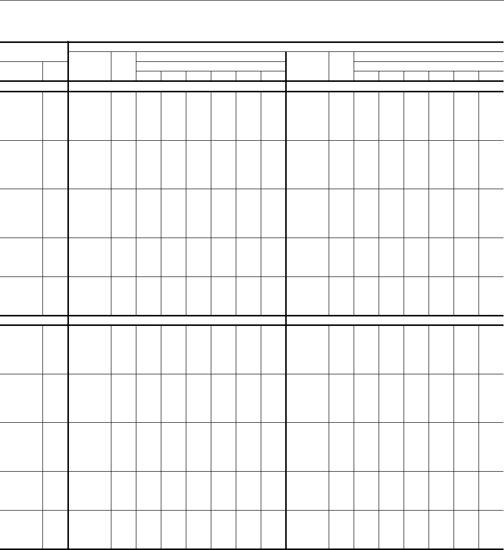
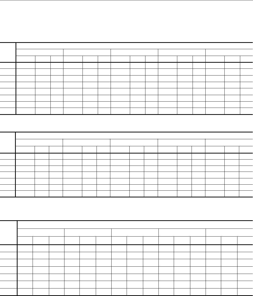
Capacity Performance
Condenser and Air Handling Cooling Capacities
YD360/ND360
Air on
Evaporator Coil
Temperature of Air on Condenser Coil
Total
Capacity1
(MBh)
Total
Input
(kW)2
Sensible Capacity (MBh) Total
Capacity1
(MBh)
Total
Input
(kW)2
Sensible Capacity (MBh)
CFM WB
(°F)
Return Dry Bulb (°F) Return Dry Bulb (°F)
90 85 80 75 70 65 90 85 80 75 70 65
75°F 85°F
9000
77 440.3 26.1 221.9 185.2 148.6 - - - 424.8 28.5 215.2 179.0 142.8 - - -
72 411.6 25.5 272.6 235.9 199.2 162.5 - - 396.5 28.0 265.3 229.1 192.9 156.7 - -
67 382.9 24.9 323.2 286.6 249.9 213.2 176.5 - 368.3 27.5 315.5 279.3 243.1 206.8 170.6 -
62 318.5 24.4 318.5 301.8 265.1 228.4 191.8 155.1 311.2 26.9 311.2 300.3 264.1 227.9 191.7 155.5
57 347.4 24.2 347.4 347.4 312.7 276.0 239.3 202.7 335.5 26.8 335.5 335.5 304.9 268.7 232.5 196.3
10500
77 454.2 26.4 247.9 202.9 157.8 - - - 437.9 28.7 236.3 194.0 151.8 - - -
72 424.6 25.8 301.8 256.7 211.7 166.6 - - 408.7 28.2 289.6 247.3 205.1 162.8 - -
67 394.9 25.2 355.6 310.6 265.5 220.5 175.4 - 379.6 27.7 342.9 300.6 258.4 216.1 173.9 -
62 328.6 24.6 328.6 320.2 281.7 238.2 191.6 146.6 320.8 27.2 320.8 315.4 280.7 238.5 196.2 154.0
57 358.3 24.4 358.3 358.3 332.3 290.0 242.2 197.1 345.9 27.0 345.9 345.9 324.2 281.9 239.6 197.4
12000
77 468.1 26.7 274.0 220.6 167.1 - - - 451.0 29.0 257.4 209.1 160.8 - - -
72 437.5 26.1 331.0 277.6 224.1 170.7 - - 421.0 28.5 313.9 265.5 217.2 168.9 - -
67 407.0 25.4 388.0 334.6 281.1 227.7 174.3 - 391.0 27.9 370.3 322.0 273.7 225.4 177.1 -
62 338.6 24.9 338.6 338.6 298.3 248.0 191.5 138.1 330.4 27.4 330.4 330.4 297.4 249.1 200.8 152.4
57 369.3 24.7 369.3 369.3 351.8 303.9 245.0 191.6 356.2 27.2 356.2 356.2 343.4 295.1 246.7 198.4
13500
72 448.4 26.2 338.1 287.0 235.8 184.6 - - 430.4 28.6 326.0 277.3 228.5 179.8 - -
67 417.1 25.5 399.7 346.9 295.7 244.5 193.3 - 399.7 28.0 385.4 336.7 288.0 239.2 190.5 -
62 347.0 25.0 347.0 347.0 313.7 264.1 211.4 160.2 337.8 27.5 337.8 337.8 312.9 264.2 215.4 166.7
57 378.4 24.8 378.4 378.4 369.7 321.3 267.3 216.1 364.1 27.3 364.1 364.1 357.7 309.0 260.3 211.5
15000
72 459.3 26.3 345.3 296.3 247.4 198.4 - - 439.7 28.7 338.2 289.0 239.9 190.7 - -
67 427.2 25.7 411.4 359.3 310.3 261.3 212.3 - 408.4 28.1 400.5 351.4 302.2 253.1 203.9 -
62 355.5 25.1 355.5 355.5 329.2 280.2 231.2 182.3 345.2 27.6 345.2 345.2 328.4 279.3 230.1 181.0
57 387.6 24.9 387.6 387.6 387.6 338.6 289.6 240.7 372.1 27.4 372.1 372.1 372.1 322.9 273.8 224.7
95°F 105°F
9000
77 409.2 30.9 208.5 172.7 137.0 - - - 388.6 34.2 199.2 164.5 129.8 - - -
72 381.4 30.4 258.1 222.4 186.6 150.9 - - 362.5 33.7 248.3 213.6 178.9 144.2 - -
67 353.7 30.0 307.7 272.0 236.2 200.5 164.8 - 336.3 33.2 297.4 262.7 228.0 193.3 158.6 -
62 303.9 29.5 303.9 298.8 263.1 227.3 191.6 155.8 295.7 32.8 295.7 293.1 262.5 227.8 193.1 158.4
57 323.6 29.4 323.6 323.6 297.2 261.4 225.7 189.9 309.1 32.7 309.1 309.1 286.3 251.6 216.9 182.2
10500
77 421.5 31.1 224.6 185.1 145.7 - - - 400.6 34.3 223.8 179.3 138.3 - - -
72 392.9 30.6 277.4 237.9 198.5 159.0 - - 373.6 33.9 272.7 231.7 190.7 149.6 - -
67 364.3 30.2 330.2 290.7 251.2 211.8 172.3 - 346.6 33.4 321.6 284.0 243.0 202.0 160.9 -
62 313.1 29.7 313.1 310.6 279.8 238.8 200.8 161.3 304.8 33.0 304.8 303.5 279.8 238.0 197.8 156.8
57 333.4 29.6 333.4 333.4 316.1 273.8 237.1 197.6 318.6 32.9 318.6 318.6 305.2 262.8 223.1 182.1
12000
77 433.9 31.3 240.8 197.6 154.4 - - - 412.5 34.5 248.5 194.2 146.9 - - -
72 404.4 30.9 296.7 253.5 210.3 167.1 - - 384.7 34.0 297.2 249.8 202.4 155.1 - -
67 375.0 30.4 352.7 309.5 266.3 223.0 179.8 - 357.0 33.6 345.8 305.4 258.0 210.7 163.3 -
62 322.3 29.9 322.3 322.3 296.5 250.2 210.1 166.8 313.9 33.1 313.9 313.9 297.2 248.3 202.4 155.1
57 343.2 29.8 343.2 343.2 334.9 286.2 248.5 205.3 328.1 33.1 328.1 328.1 324.0 273.9 229.3 181.9
13500
72 412.3 31.0 313.9 267.6 221.3 175.1 - - 384.1 34.2 311.6 263.0 214.5 165.9 - -
67 382.3 30.5 371.2 326.5 280.2 234.0 187.7 - 356.4 33.8 350.8 319.0 273.4 224.8 176.2 -
62 328.6 30.0 328.6 328.6 312.1 264.2 219.5 173.3 313.2 33.3 313.2 313.2 303.0 253.7 205.9 157.3
57 349.9 29.9 349.9 349.9 345.7 296.7 253.2 206.9 327.6 33.3 327.6 327.6 325.5 275.5 228.4 179.8
628767-YTG-C-0910
10 Johnson Controls Unitary Products
15000
72 420.2 31.0 331.0 281.7 232.4 183.1 - - 383.5 34.4 326.1 276.3 226.5 176.7 - -
67 389.7 30.6 389.7 343.5 294.2 244.9 195.6 - 355.8 34.0 355.8 332.7 288.7 239.0 189.2 -
62 334.9 30.1 334.9 334.9 327.6 278.3 229.0 179.7 312.5 33.5 312.5 312.5 308.9 259.1 209.3 159.5
57 356.6 29.9 356.6 356.6 356.6 307.3 257.9 208.6 327.0 33.5 327.0 327.0 327.0 277.2 227.4 177.6
115°F 125°F
9000
77 368.1 37.4 189.9 156.2 122.6 - - - 347.5 40.7 180.6 148.0 115.4 - - -
72 343.5 37.0 238.5 204.8 171.2 137.5 - - 324.5 40.2 228.6 196.0 163.4 130.8 - -
67 318.9 36.5 287.0 253.4 219.7 186.1 152.4 - 301.5 39.7 276.7 244.1 211.5 178.9 146.3 -
62 287.4 36.1 287.4 287.4 262.0 228.3 194.7 161.0 279.1 39.5 279.1 279.1 261.4 228.8 196.2 163.6
57 294.6 36.1 294.6 294.6 275.4 241.8 208.1 174.5 280.1 39.5 280.1 280.1 264.5 231.9 199.3 166.7
10500
77 379.6 37.5 223.1 173.6 131.0 - - - 358.7 40.7 222.3 167.8 123.6 - - -
72 354.3 37.1 268.0 225.4 182.9 140.3 - - 335.0 40.3 263.3 219.2 175.1 131.0 - -
67 328.9 36.6 313.0 277.3 234.8 192.2 149.6 - 311.2 39.8 304.4 270.6 226.5 182.4 138.3 -
62 296.4 36.3 296.4 296.4 279.9 237.3 194.7 152.2 288.1 39.5 288.1 288.1 280.0 236.6 191.7 147.6
57 303.9 36.2 303.9 303.9 294.3 251.7 209.1 166.5 289.1 39.6 289.1 289.1 283.4 240.6 195.1 151.0
12000
77 391.2 37.6 256.2 190.9 139.4 - - - 369.9 40.8 264.0 187.5 131.9 - - -
72 365.1 37.2 297.6 246.1 194.6 143.1 - - 345.4 40.3 298.0 242.4 186.7 131.1 - -
67 338.9 36.7 338.9 301.3 249.8 198.3 146.8 - 320.9 39.9 320.9 297.2 241.6 185.9 130.3 -
62 305.5 36.4 305.5 305.5 297.8 246.3 194.8 143.3 297.1 39.6 297.1 297.1 297.1 244.4 187.2 131.6
57 313.1 36.4 313.1 313.1 313.1 261.6 210.1 158.6 298.1 39.7 298.1 298.1 298.1 249.3 190.9 135.3
13500
72 355.9 37.5 309.4 258.5 207.6 156.7 - - 327.7 40.8 307.1 253.9 200.8 147.6 - -
67 330.4 37.0 330.4 311.6 266.5 215.7 164.8 - 304.5 40.3 304.5 304.2 259.7 206.5 153.3 -
62 297.8 36.7 297.8 297.8 294.0 243.1 192.2 141.4 282.4 40.0 282.4 282.4 282.4 232.5 178.6 125.4
57 305.2 36.7 305.2 305.2 305.2 254.4 203.5 152.6 282.9 40.1 282.9 282.9 282.9 233.2 178.6 125.5
15000
72 346.7 37.8 321.1 270.9 220.7 170.4 - - 310.0 41.2 310.0 265.5 214.8 164.1 - -
67 321.9 37.3 321.9 321.9 283.3 233.0 182.8 - 288.0 40.7 288.0 288.0 277.8 227.1 176.4 -
62 290.1 37.0 290.1 290.1 290.1 239.9 189.6 139.4 267.7 40.4 267.7 267.7 267.7 220.7 170.0 119.3
57 297.4 37.0 297.4 297.4 297.4 247.1 196.9 146.7 267.8 40.5 267.8 267.8 267.8 217.1 166.4 115.7
1These capacities are gross ratings. For net capacity, deduct supply air blower motor, MBh. Example: Refer to the appropriate Blower
Performance Table for the BHP of the supply air blower motor, MBh = 3.415 x kW and kW = BHP x 0.746 nameplate rated motor
efficiency.
2These ratings include the condenser fan motors and the compressor motors but not the supply air blower motor.
YD360/ND360 (Continued)
Air on
Evaporator Coil
Temperature of Air on Condenser Coil
Total
Capacity1
(MBh)
Total
Input
(kW)2
Sensible Capacity (MBh) Total
Capacity1
(MBh)
Total
Input
(kW)2
Sensible Capacity (MBh)
CFM WB
(°F)
Return Dry Bulb (°F) Return Dry Bulb (°F)
90 85 80 75 70 65 90 85 80 75 70 65
628767-YTG-C-0910
Johnson Controls Unitary Products 11
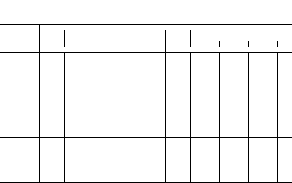
YD480/ND480
Air on
Evaporator Coil
Temperature of Air on Condenser Coil
Total
Capacity1
(MBh)
Total
Input
(kW)2
Sensible Capacity (MBh) Total
Capacity1
(MBh)
Total
Input
(kW)2
Sensible Capacity (MBh)
CFM WB
(°F)
Return Dry Bulb (°F) Return Dry Bulb (°F)
90 85 80 75 70 65 90 85 80 75 70 65
75°F 85°F
12000
77 579.6 32.8 292.9 247.9 202.9 - - - 530.5 35.1 268.7 224.3 179.9 - - -
72 530.4 31.6 355.0 310.0 265.0 220.0 - - 496.5 34.4 333.0 288.6 244.2 199.8 - -
67 481.2 30.3 417.1 372.1 327.1 282.2 237.2 - 462.6 33.7 397.3 352.9 308.5 264.1 219.7 -
62 451.0 30.3 455.0 418.2 373.2 328.2 283.2 238.2 429.4 33.2 429.4 389.1 344.7 300.3 255.9 211.5
57 448.9 29.6 448.9 448.9 437.7 392.7 347.7 302.7 421.3 33.0 421.3 421.3 395.3 351.0 306.6 262.2
14000
77 600.7 32.8 308.8 259.6 210.4 - - - 556.3 35.3 292.2 242.4 192.5 - - -
72 549.4 31.5 372.5 323.3 274.1 224.9 - - 520.6 34.6 361.0 311.2 261.3 211.4 - -
67 498.0 30.3 436.1 386.9 337.7 288.5 239.3 - 485.0 34.0 429.8 380.0 330.1 280.2 230.3 -
62 466.9 30.3 468.9 435.1 385.9 337.8 287.4 238.2 450.2 33.4 450.2 418.7 368.8 318.9 269.0 219.1
57 464.9 29.5 464.9 464.9 453.3 406.6 354.9 305.7 441.7 33.2 441.7 441.7 423.0 373.1 323.2 273.3
16000
77 621.8 32.8 324.8 271.4 217.9 - - - 582.0 35.6 315.8 260.4 205.1 - - -
72 568.3 31.5 390.0 336.6 283.1 229.7 - - 544.7 34.9 389.1 333.7 278.4 223.0 - -
67 514.9 30.3 455.2 401.7 348.3 294.9 241.4 - 507.4 34.2 462.4 407.0 351.6 296.3 240.9 -
62 482.8 30.2 482.8 452.0 398.5 347.3 291.7 238.2 471.1 33.6 471.1 448.2 392.9 337.5 282.1 226.7
57 481.0 29.5 481.0 481.0 468.9 420.5 362.1 308.6 462.2 33.5 462.2 462.2 450.6 395.2 339.9 284.5
18000
72 583.2 32.0 421.4 367.3 313.2 259.1 - - 554.4 35.0 419.5 362.4 305.3 248.3 - -
67 528.6 30.8 498.7 439.6 385.5 331.4 277.3 - 516.5 34.4 493.9 442.9 385.8 328.7 271.6 -
62 495.6 30.7 495.6 480.2 440.9 387.9 332.7 278.6 479.4 33.8 479.4 468.0 431.0 373.9 316.8 259.7
57 493.6 30.0 493.6 493.6 487.6 435.9 379.4 325.3 470.4 33.6 470.4 470.4 464.6 407.5 350.4 293.3
20000
72 598.1 32.5 452.8 398.0 343.3 288.5 - - 564.1 35.2 450.0 391.2 332.3 273.5 - -
67 542.3 31.3 542.3 477.4 422.6 367.9 313.1 - 525.5 34.5 525.5 478.7 419.9 361.0 302.2 -
62 508.4 31.2 508.4 508.4 483.2 428.5 373.7 318.9 487.8 33.9 487.8 487.8 469.1 410.3 351.4 292.6
57 506.2 30.5 506.2 506.2 506.2 451.4 396.7 341.9 478.6 33.8 478.6 478.6 478.6 419.8 361.0 302.1
95°F 105°F
12000
77 481.4 37.4 244.5 200.7 156.9 - - - 462.2 41.8 256.0 212.6 169.1 - - -
72 462.7 37.3 311.0 267.2 223.4 179.6 - - 446.3 41.6 315.8 272.4 229.0 185.5 - -
67 443.9 37.1 377.5 333.7 289.9 246.1 202.3 - 430.4 41.4 375.6 332.2 288.8 245.4 201.9 -
62 407.8 36.1 403.8 360.0 316.2 272.4 228.6 184.8 405.5 40.9 403.5 363.1 319.7 276.2 232.8 189.4
57 393.7 36.5 393.7 393.7 353.0 309.2 265.4 221.6 382.2 41.0 382.2 382.2 345.7 302.2 258.8 215.4
14000
77 511.8 37.9 275.6 225.1 174.5 - - - 487.2 42.1 293.1 237.7 185.2 - - -
72 491.9 37.7 349.6 299.0 248.5 197.9 - - 470.4 41.8 355.9 303.4 250.8 198.3 - -
67 472.0 37.6 423.5 373.0 322.4 271.9 221.3 - 453.7 41.6 418.7 369.0 316.5 264.0 211.5 -
62 433.6 36.5 431.5 402.2 351.7 300.0 250.6 200.0 427.3 41.1 426.3 402.4 350.3 297.2 245.2 192.7
57 418.5 37.0 418.5 418.5 392.7 339.6 291.6 241.0 402.8 41.2 402.8 402.8 378.9 325.2 273.9 221.4
16000
77 542.2 38.3 306.8 249.5 192.2 - - - 512.1 42.3 330.2 262.8 201.2 - - -
72 521.1 38.2 388.2 330.9 273.6 216.3 - - 494.5 42.1 395.9 334.3 272.7 211.1 - -
67 500.0 38.1 469.6 412.3 355.0 297.7 240.4 - 476.9 41.8 461.7 405.8 344.2 282.6 221.0 -
62 459.3 37.0 459.3 444.5 387.2 327.6 272.6 215.3 449.1 41.4 449.1 441.7 380.9 318.2 257.7 196.1
57 443.4 37.4 443.4 443.4 432.3 370.0 317.7 260.4 423.4 41.4 423.4 423.4 412.2 348.1 289.0 227.4
18000
72 525.6 38.1 417.7 357.6 297.5 237.4 - - 497.0 42.1 415.9 352.5 289.0 225.5 - -
67 504.3 37.9 489.1 446.1 386.0 325.9 265.9 - 479.3 41.8 471.7 428.5 365.1 301.6 238.1 -
62 463.3 36.9 463.3 455.9 421.1 359.8 300.9 240.8 451.3 41.4 451.3 447.6 403.8 339.7 276.8 213.4
57 447.2 37.3 447.2 447.2 441.7 379.1 321.5 261.4 425.6 41.4 425.6 425.6 420.0 355.3 293.0 229.6
20000
72 530.1 37.9 447.2 384.3 321.4 258.5 - - 499.5 42.1 435.9 370.6 305.3 240.0 - -
67 508.6 37.8 508.6 480.0 417.1 354.2 291.3 - 481.7 41.8 481.7 451.2 385.9 320.6 255.2 -
62 467.2 36.7 467.2 467.2 454.9 392.0 329.2 266.3 453.5 41.3 453.5 453.5 426.7 361.3 296.0 230.7
57 451.0 37.1 451.0 451.0 451.0 388.2 325.3 262.4 427.7 41.4 427.7 427.7 427.7 362.4 297.0 231.7
628767-YTG-C-0910
12 Johnson Controls Unitary Products
115°F 125°F
12000
77 443.0 46.3 267.5 224.4 181.3 - - - 423.8 50.8 278.9 236.2 193.6 - - -
72 430.0 46.0 320.6 277.6 234.5 191.5 - - 413.6 50.3 325.5 282.8 240.1 197.4 - -
67 416.9 45.6 373.8 330.7 287.7 244.6 201.6 - 403.4 49.8 372.0 329.3 286.6 243.9 201.2 -
62 403.3 45.7 403.3 366.2 323.1 280.1 237.0 193.9 401.0 50.6 401.0 369.3 326.6 283.9 241.2 198.5
57 370.8 45.5 370.8 370.8 338.3 295.2 252.2 209.1 359.3 50.0 359.3 359.3 331.0 288.3 245.6 202.9
14000
77 462.5 46.3 310.5 250.3 195.8 - - - 437.9 50.5 328.0 262.8 206.4 - - -
72 448.9 45.9 362.1 307.7 253.2 198.7 - - 427.4 50.0 368.4 312.0 255.5 199.1 - -
67 435.3 45.6 413.8 365.1 310.6 256.1 201.6 - 417.0 49.6 408.9 361.1 304.7 248.2 191.8 -
62 421.1 45.7 421.1 402.5 348.8 294.4 239.9 185.4 414.8 50.3 414.8 402.6 347.4 291.5 234.5 178.1
57 387.1 45.5 387.1 387.1 365.2 310.8 256.3 201.8 371.4 49.8 371.4 371.4 351.5 296.3 238.6 182.2
16000
77 482.1 46.3 353.6 276.1 210.2 - - - 452.0 50.2 377.0 289.4 219.2 - - -
72 467.9 45.9 403.6 337.7 271.9 206.0 - - 441.3 49.8 411.4 341.2 271.0 200.8 - -
67 453.7 45.6 453.7 399.4 333.5 267.6 201.7 - 430.6 49.3 430.6 392.9 322.7 252.5 182.3 -
62 438.8 45.7 438.8 438.8 374.6 308.7 242.8 176.9 428.6 50.1 428.6 428.6 368.2 299.2 227.8 157.7
57 403.5 45.5 403.5 403.5 392.2 326.3 260.4 194.5 383.5 49.5 383.5 383.5 372.1 304.4 231.7 161.5
18000
72 468.4 46.1 414.2 347.3 280.5 213.7 - - 439.8 50.1 412.4 342.2 272.0 201.8 - -
67 454.2 45.7 454.2 410.9 344.1 277.3 210.4 - 429.2 49.6 429.2 393.3 323.1 252.9 182.7 -
62 439.3 45.9 439.3 439.3 386.5 319.6 252.8 186.0 427.4 50.4 427.4 427.4 369.2 299.5 228.8 158.5
57 403.9 45.6 403.9 403.9 398.3 331.4 264.6 197.8 382.3 49.8 382.3 382.3 376.6 307.6 236.2 165.9
20000
72 469.0 46.2 424.7 356.9 289.1 221.4 - - 438.4 50.4 413.5 343.2 273.0 202.8 - -
67 454.8 45.9 454.8 422.5 354.7 286.9 219.1 - 427.8 49.9 427.8 393.8 323.5 253.3 183.1 -
62 439.8 46.0 439.8 439.8 398.4 330.6 262.8 195.0 426.1 50.6 426.1 426.1 370.1 299.9 229.7 159.4
57 404.4 45.8 404.4 404.4 404.4 336.6 268.8 201.0 381.1 50.1 381.1 381.1 381.1 310.8 240.6 170.3
1These capacities are gross ratings. For net capacity, deduct supply air blower motor, MBh. Example: Refer to the appropriate Blower
Performance Table for the BHP of the supply air blower motor, MBh = 3.415 x kW and kW = BHP x 0.746 nameplate rated motor
efficiency.
2These ratings include the condenser fan motors and the compressor motors but not the supply air blower motor.
YD480/ND480 (Continued) (Continued)
Air on
Evaporator Coil
Temperature of Air on Condenser Coil
Total
Capacity1
(MBh)
Total
Input
(kW)2
Sensible Capacity (MBh) Total
Capacity1
(MBh)
Total
Input
(kW)2
Sensible Capacity (MBh)
CFM WB
(°F)
Return Dry Bulb (°F) Return Dry Bulb (°F)
90 85 80 75 70 65 90 85 80 75 70 65
628767-YTG-C-0910
Johnson Controls Unitary Products 13
YD600/ND600 Air Handler with M1CZ600A Evaporator Section
Air on
Evaporator Coil
Temperature of Air on Condenser Coil
Total
Capacity1
(MBh)
Total
Input
(kW)2
Sensible Capacity (MBh) Total
Capacity1
(MBh)
Total
Input
(kW)2
Sensible Capacity (MBh)
CFM WB
(°F)
Return Dry Bulb (°F) Return Dry Bulb (°F)
90 85 80 75 70 65 90 85 80 75 70 65
75°F 85°F
15000
77 778.4 38.3 415.3 359.0 302.7 - - - 739.6 44.5 405.1 348.7 292.3 - - -
72 711.3 40.7 471.4 415.1 358.8 302.5 - - 679.6 45.7 463.0 406.7 350.3 293.9 - -
67 644.1 43.1 527.5 471.2 415.0 358.7 302.4 - 619.5 46.8 521.0 464.7 408.3 351.9 295.5 -
62 618.5 41.7 618.5 580.0 523.8 467.5 411.2 354.9 599.2 45.6 599.2 560.7 504.3 447.9 391.6 335.2
57 629.2 40.1 629.2 573.3 517.0 460.7 404.4 348.1 616.4 44.2 616.4 561.2 504.8 448.4 392.1 335.7
17500
77 803.9 38.1 456.4 392.7 329.1 - - - 760.9 44.6 443.3 379.7 316.2 - - -
72 734.5 40.5 517.4 453.8 390.2 326.6 - - 699.1 45.7 506.0 442.5 378.9 315.4 - -
67 665.2 42.9 578.5 514.9 451.3 387.7 324.1 - 637.4 46.9 568.7 505.2 441.6 378.1 314.6 -
62 638.8 41.5 638.8 619.6 569.5 508.3 442.3 378.7 616.4 45.7 616.4 597.1 545.5 482.0 418.4 354.9
57 649.9 39.9 649.9 621.9 562.2 501.2 435.0 371.4 634.1 44.3 634.1 606.5 546.1 482.5 419.0 355.5
20000
77 829.3 37.9 497.4 426.5 355.6 - - - 782.2 44.7 481.5 410.8 340.1 - - -
72 757.8 40.3 563.4 492.5 421.6 350.7 - - 718.7 45.8 549.0 478.3 407.6 336.9 - -
67 686.3 42.7 629.5 558.5 487.6 416.7 345.8 - 655.2 46.9 616.4 545.7 475.0 404.3 333.6 -
62 659.1 41.2 659.1 659.1 615.2 549.1 473.3 402.4 633.6 45.7 633.6 633.6 586.7 516.0 445.3 374.6
57 670.6 39.7 670.6 670.6 607.4 541.7 465.5 394.6 651.9 44.3 651.9 651.9 587.3 516.6 445.9 375.2
21750
72 784.2 39.9 617.2 540.1 463.0 386.0 - - 737.6 45.5 588.6 512.9 437.2 361.5 - -
67 710.3 42.3 681.9 612.8 535.7 458.7 381.6 - 672.4 46.6 653.0 585.3 509.6 433.8 358.1 -
62 682.2 40.8 682.2 682.2 670.1 595.4 515.9 438.8 650.3 45.4 650.3 650.3 626.8 551.1 475.4 399.7
57 694.3 39.3 694.3 694.3 667.1 592.6 513.0 435.9 669.0 44.0 669.0 669.0 630.0 554.3 478.6 402.9
23500
72 810.6 39.5 671.0 587.7 504.5 421.2 - - 756.4 45.1 628.3 547.5 466.8 386.1 - -
67 734.3 41.9 734.3 667.1 583.9 500.6 417.4 - 689.6 46.3 689.6 624.8 544.1 463.4 382.7 -
62 705.3 40.5 705.3 705.3 725.0 641.7 558.5 475.2 666.9 45.1 666.9 666.9 666.9 586.2 505.5 424.8
57 717.9 38.9 717.9 717.9 726.8 643.6 560.4 477.1 686.1 43.7 686.1 686.1 672.7 592.0 511.3 430.6
95°F 105°F
15000
77 700.8 50.7 394.8 338.4 281.9 - - - 643.6 56.8 367.7 311.4 255.1 - - -
72 647.9 50.6 454.7 398.2 341.8 285.3 - - 603.3 56.7 434.4 378.1 321.8 265.5 - -
67 595.0 50.4 514.5 458.1 401.6 345.2 288.7 - 563.1 56.6 501.2 444.9 388.6 332.3 276.0 -
62 579.8 49.5 579.8 541.3 484.9 428.4 371.9 315.5 542.8 55.9 542.8 508.1 451.8 395.5 339.2 282.9
57 603.6 48.3 603.6 549.1 492.7 436.2 379.7 323.3 564.5 55.9 564.5 510.2 453.9 397.6 341.3 285.0
17500
77 717.9 51.1 430.2 366.7 303.3 - - - 663.4 56.8 416.1 342.4 277.3 - - -
72 663.7 50.9 494.6 431.1 367.6 304.2 - - 621.9 56.7 480.2 415.1 350.0 284.9 - -
67 609.5 50.8 559.0 495.5 432.0 368.6 305.1 - 580.5 56.7 544.4 487.8 422.7 357.5 292.4 -
62 594.0 49.8 594.0 574.7 521.6 455.7 394.6 331.2 559.6 56.0 559.6 542.3 491.3 425.0 361.0 295.9
57 618.3 48.7 618.3 591.1 530.0 463.9 403.0 339.6 581.9 55.9 581.9 554.8 493.5 427.0 363.2 298.1
20000
77 735.0 51.5 465.6 395.1 324.6 - - - 683.2 56.9 464.5 373.4 299.5 - - -
72 679.5 51.3 534.5 464.0 393.5 323.0 - - 640.5 56.8 526.0 452.1 378.1 304.2 - -
67 624.1 51.2 603.4 532.9 462.4 391.9 321.5 - 597.9 56.7 587.6 530.7 456.8 382.8 308.9 -
62 608.1 50.2 608.1 608.1 558.3 483.0 417.3 346.8 576.4 56.0 576.4 576.4 530.7 454.4 382.8 308.9
57 633.1 49.0 633.1 633.1 567.2 491.6 426.3 355.8 599.3 56.0 599.3 599.3 533.0 456.5 385.1 311.1
21750
72 690.9 51.1 560.0 485.7 411.3 337.0 - - 648.5 56.6 546.8 470.5 394.3 318.0 - -
67 634.5 50.9 624.1 557.7 483.4 409.0 334.7 - 605.3 56.5 600.2 552.5 476.2 400.0 323.7 -
62 618.3 49.9 618.3 618.3 583.6 506.8 434.9 360.6 583.5 55.8 583.5 583.5 553.4 476.0 400.9 324.7
57 643.7 48.8 643.7 643.7 593.0 516.0 444.3 369.9 606.8 55.8 606.8 606.8 555.8 478.3 403.3 327.1
23500
72 702.3 50.8 585.6 507.4 429.2 351.0 - - 656.5 56.4 567.5 488.9 410.4 331.9 - -
67 644.9 50.7 644.9 582.5 504.3 426.1 347.9 - 612.7 56.3 612.7 574.2 495.7 417.2 338.6 -
62 628.5 49.7 628.5 628.5 608.9 530.7 452.5 374.3 590.7 55.6 590.7 590.7 576.1 497.5 419.0 340.5
57 654.3 48.5 654.3 654.3 618.7 540.5 462.3 384.1 614.2 55.6 614.2 614.2 578.6 500.0 421.5 343.0
628767-YTG-C-0910
14 Johnson Controls Unitary Products
115°F 125°F
15000
77 586.4 62.8 340.6 284.5 228.3 - - - 529.2 68.8 313.5 257.5 201.5 - - -
72 558.8 62.8 414.2 358.1 301.9 245.8 - - 514.2 68.8 394.0 338.0 282.0 226.0 - -
67 531.1 62.7 487.8 431.7 375.5 319.4 263.2 - 499.2 68.9 474.4 418.4 362.5 306.5 250.5 -
62 505.9 62.3 505.9 475.0 418.8 362.7 306.5 250.4 468.9 68.7 468.9 441.8 385.8 329.8 273.8 217.9
57 525.3 63.4 525.3 471.3 415.2 359.0 302.9 246.7 486.2 70.9 486.2 432.4 376.4 320.4 264.4 208.5
17500
77 608.8 62.6 402.0 318.1 251.3 - - - 554.3 68.3 387.9 293.8 225.3 - - -
72 580.2 62.5 465.9 399.1 332.3 265.5 - - 538.4 68.3 451.6 383.1 314.7 246.2 - -
67 551.5 62.5 529.8 480.1 413.3 346.5 279.7 - 522.4 68.3 515.2 472.4 404.0 335.5 267.1 -
62 525.2 62.1 525.2 509.8 461.0 394.2 327.4 260.6 490.9 68.2 490.9 477.3 430.7 363.5 293.8 225.4
57 545.4 63.2 545.4 518.4 457.0 390.2 323.4 256.6 509.0 70.4 509.0 482.1 420.5 353.3 283.6 215.1
20000
77 631.3 62.4 463.4 351.8 274.3 - - - 579.4 67.8 462.4 330.1 249.2 - - -
72 601.5 62.3 517.6 440.2 362.7 285.3 - - 562.6 67.8 509.2 428.3 347.3 266.4 - -
67 571.8 62.3 571.8 528.6 451.2 373.7 296.3 - 545.7 67.8 545.7 526.4 445.5 364.6 283.7 -
62 544.6 61.9 544.6 544.6 503.2 425.8 348.3 270.9 512.8 67.7 512.8 512.8 475.7 397.1 313.8 232.9
57 565.5 63.0 565.5 565.5 498.8 421.4 343.9 266.5 531.8 69.9 531.8 531.8 464.6 386.2 302.7 221.8
21750
72 606.1 62.2 533.5 455.3 377.2 299.0 - - 563.8 67.7 520.2 440.2 360.1 280.0 - -
67 576.2 62.1 576.2 547.3 469.1 390.9 312.8 - 547.0 67.7 547.0 542.0 462.0 381.9 301.8 -
62 548.7 61.7 548.7 548.7 523.2 445.1 366.9 288.8 514.0 67.6 514.0 514.0 493.1 414.2 332.9 252.9
57 569.8 62.8 569.8 569.8 518.7 440.5 362.3 284.2 532.9 69.8 532.9 532.9 481.5 402.7 321.4 241.3
23500
72 610.7 62.0 549.4 470.5 391.6 312.7 - - 565.0 67.6 531.3 452.0 372.8 293.6 - -
67 580.5 61.9 580.5 565.9 487.1 408.2 329.3 - 548.3 67.6 548.3 548.3 478.4 399.2 320.0 -
62 552.9 61.5 552.9 552.9 543.3 464.4 385.5 306.6 515.1 67.5 515.1 515.1 510.5 431.2 352.0 272.8
57 574.2 62.6 574.2 574.2 538.5 459.6 380.8 301.9 534.1 69.7 534.1 534.1 498.4 419.2 340.0 260.8
1These capacities are gross ratings. For net capacity, deduct supply air blower motor, MBh. Example: Refer to the appropriate Blower
Performance Table for the BHP of the supply air blower motor, MBh = 3.415 x kW and kW = BHP x 0.746 nameplate rated motor
efficiency.
2These ratings include the condenser fan motors and the compressor motors but not the supply air blower motor.
YD600/ND600 Air Handler with M1CZ600A Evaporator Section (Continued)
Air on
Evaporator Coil
Temperature of Air on Condenser Coil
Total
Capacity1
(MBh)
Total
Input
(kW)2
Sensible Capacity (MBh) Total
Capacity1
(MBh)
Total
Input
(kW)2
Sensible Capacity (MBh)
CFM WB
(°F)
Return Dry Bulb (°F) Return Dry Bulb (°F)
90 85 80 75 70 65 90 85 80 75 70 65
628767-YTG-C-0910
Johnson Controls Unitary Products 15
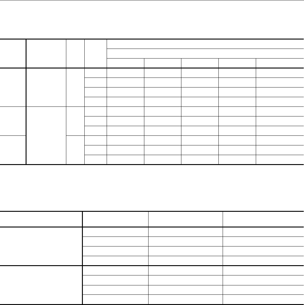
Air Handling Unit and Hot Water Coil Accessory Heating Capacity
ND360 / 1HW0406, ND480 & ND600 / 1HW04071
1These capacities do not include any blower motor heat.
NOTE: Temperature Water Drop (ºF) = (2 X MBH) / GPM.
UNIT
MODEL HOT WATER
COIL MODEL GPM CFM
CAPACITY (MBH)
ENTERING WATER TEMPERATURE MINUS ENTRY AIR TEMPERATURE °F.
70 90 110 130 150
ND360 1HW0406 50
8,000 236 304 372 440 508
10,000 265 341 416 492 568
12,000 291 374 457 540 623
14,000 315 405 495 585 675
ND480
1HW0407
75
12,800 348 447 547 646 746
16,000 389 500 611 722 833
19,200 425 547 668 790 911
ND600 75
16,000 389 500 611 722 833
20,000 436 561 686 810 935
24,000 473 610 746 882 1,019
Hot Water Coil Capacity Correction And Pressure Drop Vs GPM1
1For pressure drop in feet (water), multiply these values by 2.31.
HOT WATER COIL MODEL GPM PRESSURE DROP
PSI CAPACITY CORRECTION
FACTOR
1HW0406
25 0.4 0.79
50 1.0 1.00
75 1.8 1.04
100 3.4 1.07
1HW0407
50 1.0 0.95
75 1.5 1.00
100 2.4 1.03
125 3.5 1.05
628767-YTG-C-0910
16 Johnson Controls Unitary Products
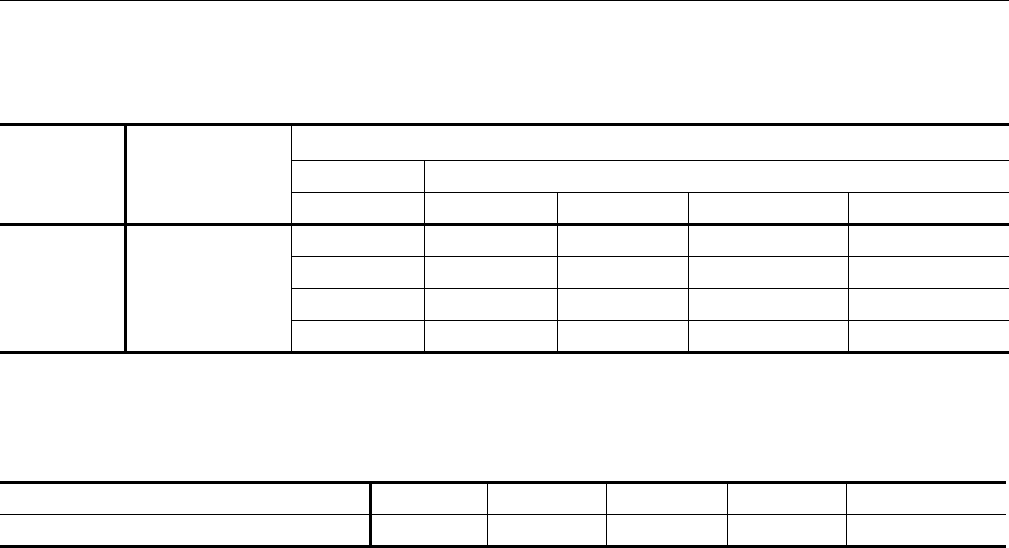
Air Handling Unit and Steam Coil Accessory Heating Capacity
NOTE: Steam Rate = (lbs/Hr.) = 1.025 x MBH
ND360 / 1NF0454
UNIT
MODEL STEAM COIL
MODEL
CAPACITY (MBH) @ 2 PSIG1
1These capacities do not include any blower motor heat.
CFM DRY BULB TEMPERATURE OF AIR ENTERING COIL (°F)
10 30 50 70
ND360 1NF0454
8,000 535 483 432 380
10,000 592 535 478 422
12,000 642 580 518 456
14,000 687 621 555 489
Steam Coil Capacity Correction Factors For High Steam Pressure
STEAM PRESSURE (PSIG) 5101520 25
CAPACITY CORRECTION FACTOR 1.05 1.12 1.19 1.25 1.30
628767-YTG-C-0910
Johnson Controls Unitary Products 17
Fan Performance
ND360, 480 & 600 Fan Performance
ND360 Fan Performance Data - 30 Ton
RPM
CFM
10,000 11,000 12,000 13,000 14,000
SP BHP kW SP BHP kW SP BHP kW SP BHP kW SP BHP kW
600 0.20 3.1 2.9 0.02 3.6 3.4 - - - - - - - - -
635 0.31 3.3 3.1 0.13 3.8 3.5 - - - - - - - - -
700 0.54 3.7 3.5 0.38 4.2 3.9 0.20 4.8 4.5 0.03 5.3 5.0 - - -
775 0.85 4.4 4.1 0.70 4.8 4.5 0.54 5.3 5.0 0.39 5.8 5.5 0.20 6.4 6.0
800 0.97 4.7 4.4 0.82 5.1 4.8 0.66 5.6 5.2 0.52 6.1 5.7 0.35 6.7 6.3
875 1.34 5.6 5.2 1.19 6.0 5.7 1.04 6.6 6.2 0.93 7.1 6.6 0.77 7.7 7.2
900 1.47 5.9 5.5 1.33 6.4 6.0 1.17 7.0 6.5 1.07 7.5 7.0 0.90 8.2 7.6
940 1.70 6.5 6.1 1.55 7.0 6.6 1.40 7.7 7.2 1.31 8.3 7.8 1.09 9.0 8.4
ND480 Fan Performance Data - 40 Ton
RPM
CFM
12,800 14,400 16,000 17,600 19,200
SP BHP kW SP BHP kW SP BHP kW SP BHP kW SP BHP kW
600 0.84 6.0 5.2 0.63 7.2 6.2 0.40 8.4 7.2 0.13 9.7 8.4 - - -
660 1.19 7.3 6.3 1.00 8.5 7.3 0.78 9.8 8.5 0.50 11.2 9.7 0.19 12.7 11.0
700 1.42 8.2 7.1 1.25 9.4 8.1 1.03 10.7 9.2 0.75 12.2 10.5 0.45 13.7 11.8
760 1.78 9.5 8.2 1.63 10.8 9.3 1.43 12.3 10.6 1.16 13.8 11.9 0.86 15.6 13.5
800 2.02 10.4 9.0 1.89 11.8 10.2 1.69 13.3 11.5 1.43 14.9 12.9 1.14 16.9 14.6
900 2.62 12.8 11.0 2.53 14.5 12.5 2.40 16.0 13.8 - - - - - -
930 2.80 13.5 11.6 2.72 15.3 13.2 - - - - - - - - -
ND600 Fan Performance Data - 50 Ton
RPM
CFM
16,000 18,000 20,000 22,000 24,000
SP BHP kW SP BHP kW SP BHP kW SP BHP kW SP BHP kW
600 0.82 6.0 5.2 0.59 7.2 6.2 0.35 8.4 7.2 0.08 9.7 8.4 - - -
660 1.17 7.3 6.3 0.96 8.5 7.3 0.73 9.8 8.5 0.45 11.2 9.7 0.14 12.7 11.0
700 1.40 8.2 7.1 1.21 9.4 8.1 0.98 10.7 9.2 0.70 12.2 10.5 0.40 13.7 11.8
760 1.76 9.5 8.2 1.59 10.8 9.3 1.38 12.3 10.6 1.11 13.8 11.9 0.81 15.6 13.5
800 2.00 10.4 9.0 1.85 11.8 10.2 1.64 13.3 11.5 1.38 14.9 12.9 1.09 16.9 14.6
900 2.60 12.8 11.0 2.49 14.5 12.5 2.35 16.0 13.8 - - - - - -
930 2.78 13.5 11.6 2.68 15.3 13.2 - - - - - - - - -
628767-YTG-C-0910
18 Johnson Controls Unitary Products
ND360, 480 & 600 Drive Kit Data
UNIT MODEL DRIVE KIT
MODEL
NUMBER
BLOWER
RPM
RANGE
ADJUSTABLE MOTOR PULLEY FIXED BLOWER PULLEY BELTS
PITCH DIA.
(IN.) BORE
(IN.) PITCH DIA.
(IN.) BORE
(IN.) QTY. PITCH
LENGTH
(IN.) DESIGNATION
ND360
1LD0415 636 - 795 4.0 - 5.0 1 3/8 11.0 1 3/16 2 63.3 A62
1LD0407 668 - 827 4.2 - 5.2 1 3/8 11.0 1 3/16 2 63.3 A62
1LD0408 827 - 986 5.3 - 6.3 1 3/8 11.0 1 3/16 2 59.7 A59
ND480 1LD0409 607 - 776 4.3 - 5.5 1 3/8 12.4 1 3/16 2 85.1 B84
1LD0410 776 - 917 5.4 - 6.6 1 3/8 12.4 1 3/16 2 86.8 B85
ND600 1LD0411 692 - 833 4.8 - 6.0 1 3/8 12.4 1 3/16 2 78.6 B78
1LD0412 762 - 931 5.4 - 6.6 1 5/8 12.4 1 3/16 2 76.8 B75
ND360, 480 & 600 Motor Kit Data
UNIT MODEL HP MOTOR KIT MODEL NUMBER FRAME SIZE VOLTAGE
(3PH-60-HZ)
ND360
5.0
2LR04605023
184
208/230/460
2LR04605032 208/230/460
2LR04605158 575
7.5 2LP04607133 213 208/230/460
2LP04607158 575
10 2LP04610133 215 208/230/460
2LP04610158 575
ND480
7.5 2LP04607133 213 208/230/460
2LP04607158 575
10 2LP04610133 215 208/230/460
2LP04610158 575
ND600
10 2LP04610133 215 208/230/460
2LP04610158 575
15 2LP04615133 254 208/230/460
2LP04615158 575
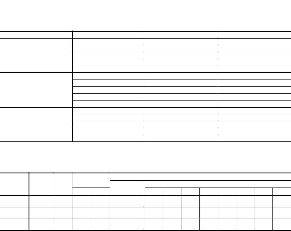
ND360, 480 & 600 Motor Overload Elements1
1These units are equipped from the factory with a correctly
sized motor starter; overload elements are not factory
supplied. Three elements required per unit.
MOTOR HP VOLTAGE MODEL NUMBER
5
208 2MP04704600
230 2MP04704600
460 2MP04704900
575 2MP04705000
7.5
208 2MP04703700
230 2MP04704500
460 2MP04704300
575 2MP04704000
10
208 2MP04701600
230 2MP04704100
460 2MP04704200
575 2MP04704300
15
208 2MP04704400
230 2MP04701700
460 2MP04704500
575 2MP04704600
628767-YTG-C-0910
Johnson Controls Unitary Products 19
Static Resistance
Static Resistance
Sound Performance
Indoor Sound Power Levels
Model CFM Hot Water Coil Steam Coil
ND360
10000 0.08 0.11
11000 0.09 0.14
12000 0.10 0.17
13000 0.12 0.20
14000 0.14 0.23
ND480
12800 0.11 -
14400 0.13 -
16000 0.15 -
17600 0.17 -
19200 0.20 -
ND600
16000 0.15 -
18000 0.18 -
20000 0.21 -
22000 0.24 -
24000 0.28 -
Model
(Tons) CFM ESP
(IWG)
Blower Sound Power, dB (10-12) Watts
Sound Rating1
dB (A)
1These values have been accessed using a model of sound propagation from a point source into the hemispheric/free field. The dBA
values provided are to be used for reference only. Calculation of dBA values cover matters of system design and the fan
manufacture has no way of knowing the details of each system. This constitutes an exception to any specification or guarantee
requiring a dBA value of sound data in any other form than sound power level ratings.
Octave Band Centerline Frequency (Hz)
RPM BHP 63 125 250 500 1000 2000 4000 8000
ND360
(30) 12000 0.75 755 5.66 86 84 84 82 81 81 77 74 69
ND480
(40) 16000 0.80 800 8.9 92 90 90 88 90 86 84 81 76
ND6002
(50)
2ND600 Combined with M1CZ600 Evaporator Section
20000 1.13 700 10.7 88 87 87 85 86 82 80 78 73
628767-YTG-C-0910
20 Johnson Controls Unitary Products
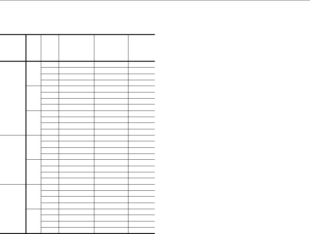
Electrical Data
Electrical Data
UNIT
MODEL HP FLA VOLTAGE
(3PH-60HZ)
MIN
CIRCUIT
AMPACITY
MAX.
FUSE
SIZE
(Amps)
ND360
5.0
16.7 208 21 35
15.2 230 19 30
7.6 460 10 15
6.1 575 8 15
7.5
24.2 208 30 50
22 230 28 45
11 460 14 20
9 575 11 20
10
30.8 208 39 60
28 230 35 60
14 460 18 30
11 575 14 20
ND480
7.5
24.2 208 30 50
22 230 28 45
11 460 14 20
9 575 11 20
10
30.8 208 39 60
28 230 35 60
14 460 18 30
11 575 14 20
ND600
10
30.8 208 39 60
28 230 35 60
14 460 18 30
11 575 14 20
15
46.2 208 58 100
42 230 53 90
21 460 26 45
17 575 21 35
628767-YTG-C-0910
Johnson Controls Unitary Products 21
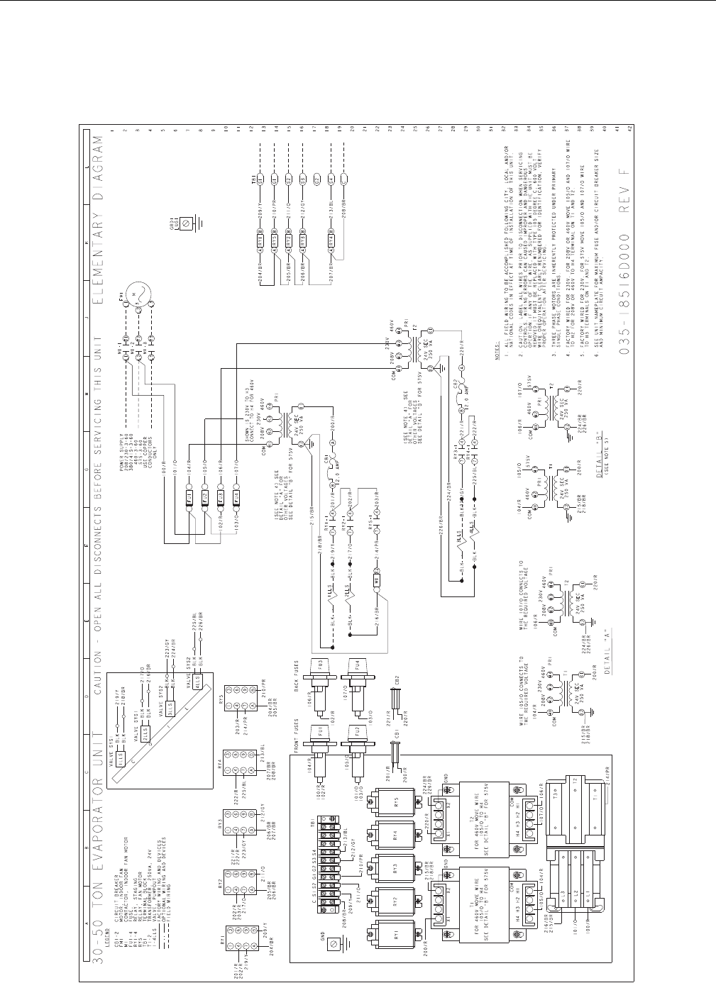
Typical Wiring Diagrams
Air Handling Units
Typical ND360, 480 & 600 Wiring Diagram
628767-YTG-C-0910
22 Johnson Controls Unitary Products
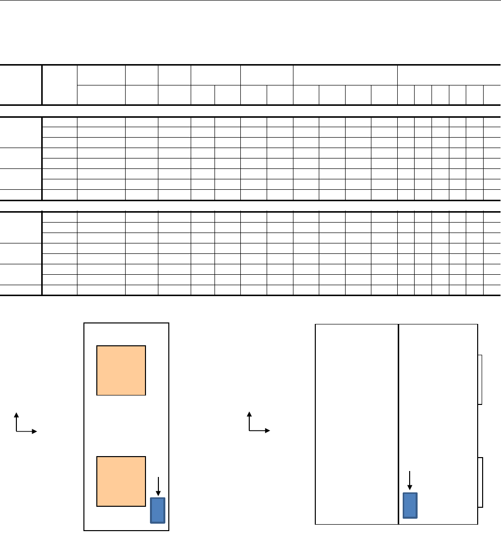
Weights And Dimensions
Corner Weights & Center of Gravity ND360, 480 & 600 Unit
Model Drive HP
Evaporator
Section Blower
Section Drive
Section Weight
(lbs.) Center of
Gravity 4 Point Load Location
(lbs.) 6 Point Load Location
(lbs.)
Cabinet
Wt (lb) Cabinet
Wt (lb) Cabinet
Wt (lb) Ship
ping Opera
ting CG XCG Y A B C D ABCDEF
Vertical Airflow
ND360
5.0 567 490 110 1122 1184 20.1 44.3 297 363 288 236 200 244 215 191 157 176
7.5 567 490 134 1122 1208 20.3 44.0 301 376 295 236 202 252 222 197 158 178
10 567 490 150 1122 1224 20.5 43.8 304 385 299 236 203 257 226 201 159 179
ND480 7.5 654 527 141 1246 1348 24.6 45.1 334 424 330 260 223 283 249 221 174 196
10 654 527 157 1246 1364 24.8 44.9 336 434 334 259 224 288 254 226 175 197
ND600 10 ~ 645 155 705 17421
1Operating weight includes ND600 Airhandler and M1CZ600 Evaporator Coil Combined.
31.4 46.1 393 570 461 318 267 387 341 303 209 235
15 ~ 645 272 705 1859132.4 45.0 408 639 496 318 272 426 376 333 213 240
M1CZ600 ~ ~ ~ ~ 979 ~ ~ ~ ~ ~ ~ ~ ~ ~ ~ ~ ~ ~
Horizontal Airflow
ND360
5.0 567 490 110.2 1122 1184 36.4 44.3 332 328 260 264 224 221 195 173 175 197
7.5 567 490 134 1122 1208 36.5 44.0 339 338 265 266 227 226 199 177 178 200
10 567 490 150 1122 1224 36.6 43.8 345 344 268 268 230 230 202 180 180 203
ND480 7.5 654 527 140.7 1246 1348 43.1 45.1 387 371 288 301 258 248 218 194 202 228
10 654 527 156.9 1246 1364 43.2 44.9 392 378 291 303 261 251 221 196 204 230
ND600 10 908.5 645 154.9 705 1742152.1 46.1 446 517 418 361 303 351 309 275 237 267
15 908.5 645 271.7 705 1859152.5 45.0 480 567 440 373 320 378 333 296 250 282
M1CZ600 ~ ~ ~ ~ 979 ~ ~ ~ ~ ~ ~ ~ ~ ~ ~ ~ ~ ~
D (E) (D) C D (E) (D) C
(F) (C) (F) (C)
A (A) (B) B A (A) (B) B
Vertical
Horizontal
X
YCG
X
YCG
MOTOR
MOTOR
628767-YTG-C-0910
Johnson Controls Unitary Products 23
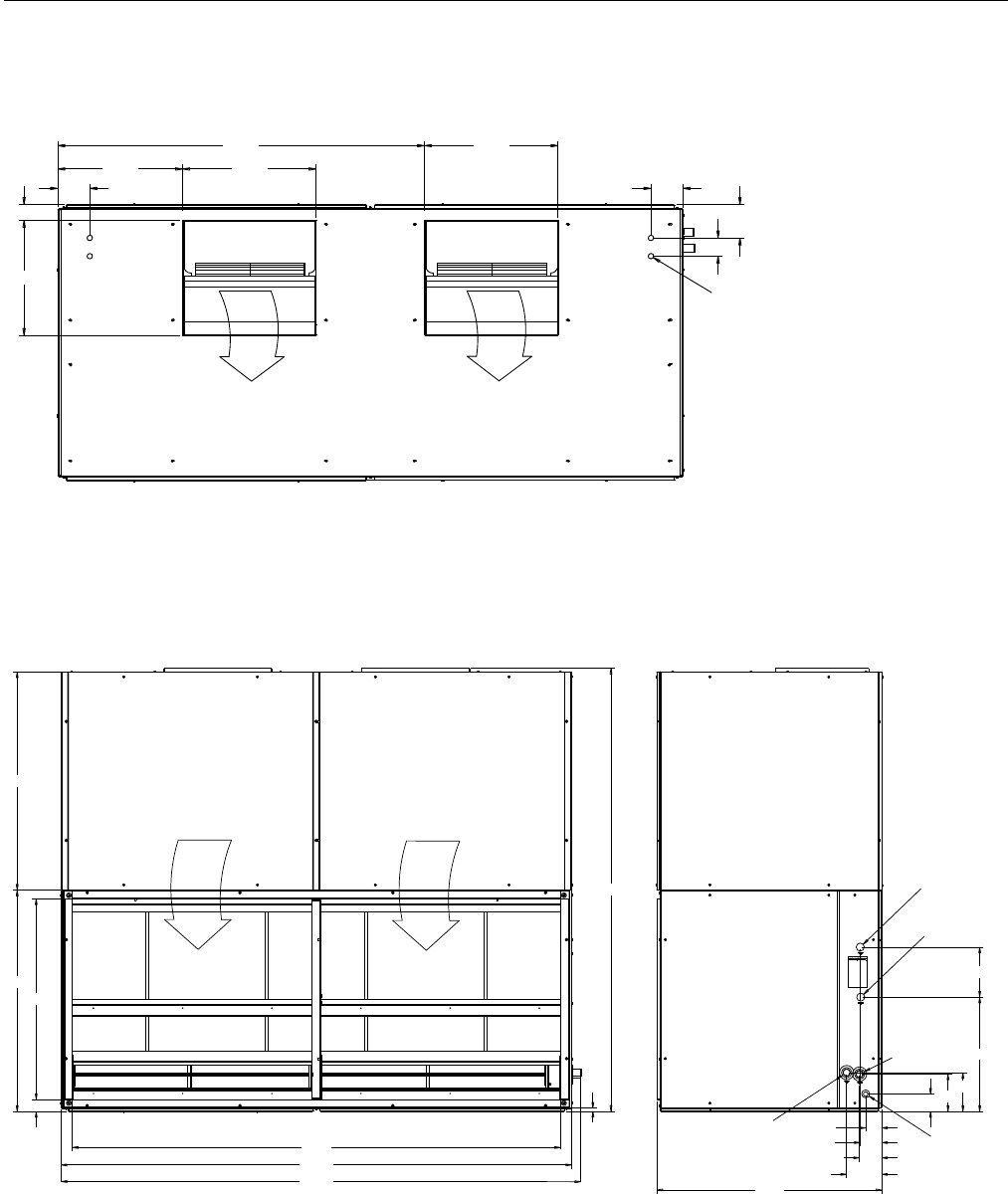
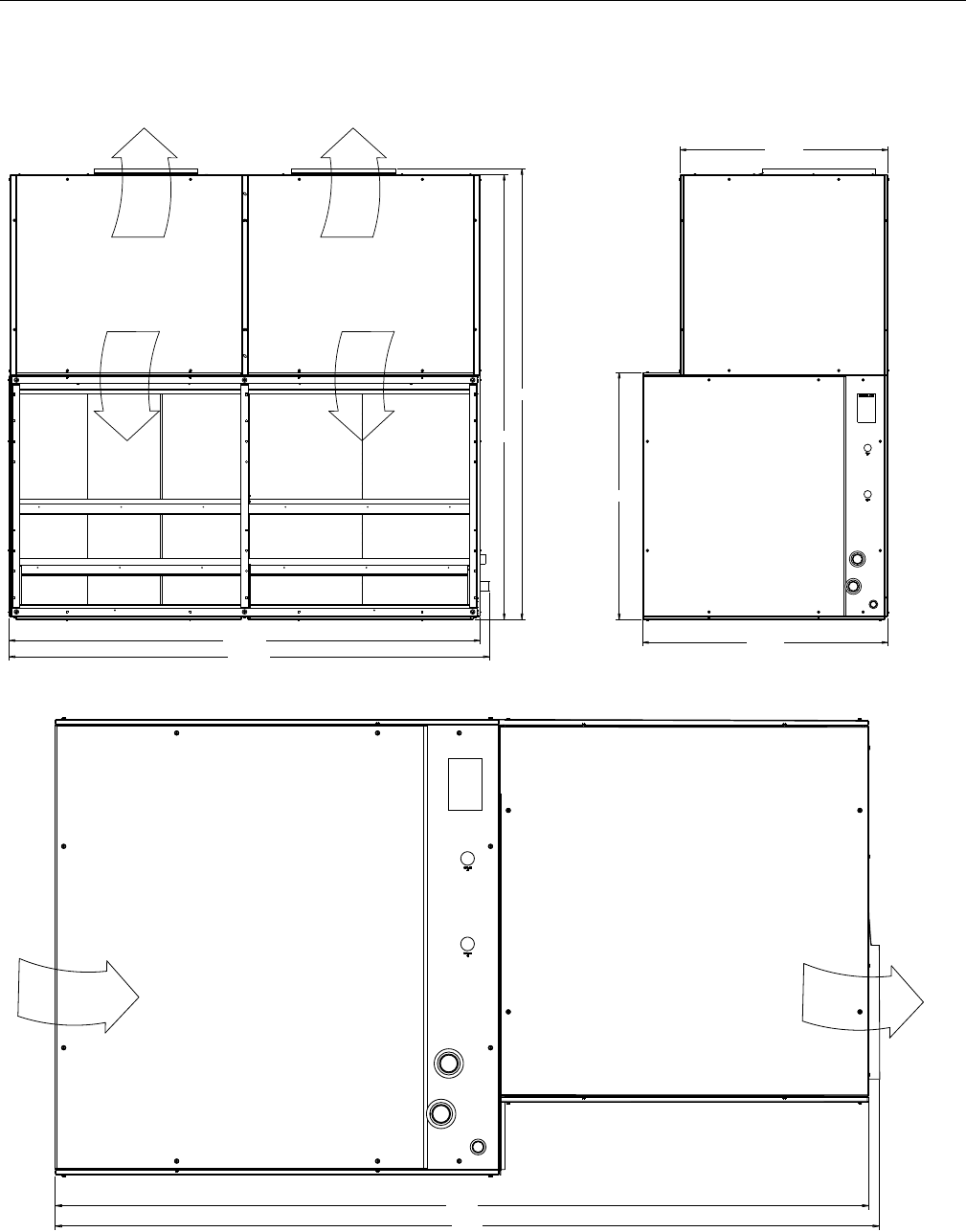
TOP
FRONT SIDE
Unit Dimensions ND360
57.7 Ø0.88 KO
ELECTRIC HEAT
CONNECTION
15.9
4X Ø0.88 KO
CONTROLS
CONNECTION
3.0
9.1
5.3
22.0
62.4
22.0
22.5
5.3
2.6
19.0
SUPPLY
AIR
SUPPLY
AIR
100.1
95.6
2.4
33.2
7.3
6.7
Ø0.88 LIQUID
CONNECTION
SYSTEM 2
Ø1.125 SUCTION
CONNECTION
SYSTEM 1
Ø0.88 DRAIN
CONNECTION
Ø1.125 SUCTION
CONNECTION
SYSTEM 2
38.1
3.4
4.1
5.1
6.1
3.6 5.5
23.6
5.9
74.7
0.63
Ø0.88 LIQUID
CONNECTION
SYSTEM 1
RETURN
AIR
RETURN
AIR
628767-YTG-C-0910
24 Johnson Controls Unitary Products
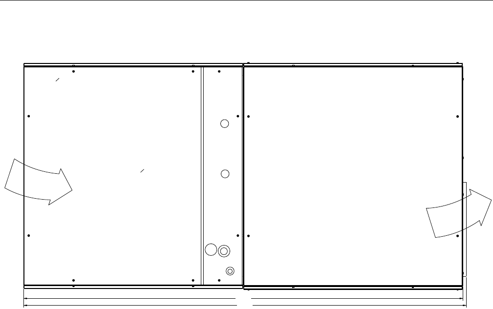
HORIZONTAL CONFIGURATION
Unit Dimensions ND360 (Continued)
73.3
74.0
SUPPLY
AIR
RETURN
AIR
628767-YTG-C-0910
Johnson Controls Unitary Products 25
TOP
FRONT SIDE
Unit Dimensions ND480
4X Ø0.88 KO
CONTROLS
CONNECTION
3.0
5.5
5.3
22.0
60.5
22.0
20.6
5.3
2.6
19.0
SUPPLY
AIR
SUPPLY
AIR
44.0
44.7
40.5
2.4
98.5
103.1
0.63
89.4
10.1
23.1
7.9
7.6
3.5
3.2
4.3
4.5
7.1
45.4
Ø0.88 LIQUID
CONNECTION
SYSTEM 1
Ø0.88 LIQUID
CONNECTION
SYSTEM 2
Ø1.375 SUCTION
CONNECTION
SYSTEM 1
Ø0.88 DRAIN
CONNECTION
Ø1.375 SUCTION
CONNECTION
SYSTEM 2
RETURN
AIR
RETURN
AIR
105.1
628767-YTG-C-0910
26 Johnson Controls Unitary Products
HORIZONTAL CONFIGURATION
Unit Dimensions ND480 (Continued)
88.2
88.8
RETURN
AIR
SUPPLY
AIR
628767-YTG-C-0910
Johnson Controls Unitary Products 27
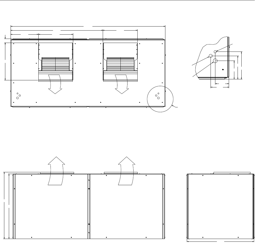
TOP
FRONT SIDE
Unit Dimensions ND600
103.1
23.061.7
23.018.5
2.6
24.9
6.1
4.6
6.1
7.8
9.1
Ø0.88 KO
CONTROLS
CONNECTION
Ø1.13 KO
CONTROLS
CONNECTION
Ø1.38 KO
CONTROLS
CONNECTION
DETIAL A
SCALE 0.375
(2X TYP)
SEE DETAIL A
SUPPLY
AIR
SUPPLY
AIR
45.5
45.4
44.0
SUPPLY
AIR
SUPPLY
AIR
628767-YTG-C-0910
28 Johnson Controls Unitary Products
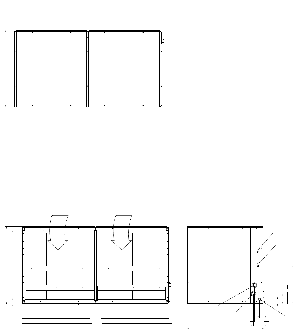
TOP
FRONT SIDE
Unit Dimensions M1CZ600 Evaporator Section
53.7
54.4
49.5
2.4
2.3
53.7
98.5
103.1
105.1
RETURN
AIR
RETURN
AIR
Ø0.88 LIQUID
CONNECTION
SYSTEM 2
Ø0.88 LIQUID
CONNECTION
SYSTEM 1
Ø.88 DRAIN
CONNECTION
Ø2.13 SUCTION
CONNECTION
SYSTEM 2
Ø2.13 SUCTION
CONNECTION
SYSTEM 1 3.2
6.7
7.6
3.47.3
13.3
27.6
10.2
628767-YTG-C-0910
Johnson Controls Unitary Products 29
VERTICAL CONFIGURATION
FRONT SIDE
HORIZONTAL CONFIGURATION
Unit Dimensions ND600 Airhandler & M1CZ600 Evaporator Coil
53.7
54.4
45.5
99.0
97.8
103.1
105.1
SUPPLY
AIR
SUPPLY
AIR
RETURN
AIR
RETURN
AIR
98.4
97.2
SUPPLY
AIR
RETURN
AIR
NAMEPLATE
628767-YTG-C-0910
30 Johnson Controls Unitary Products
Unit Connection Sizes
Model ND360 ND480 ND600 M1CZ600A
Dimensions (inches)
Length 100.1 103.1 103.1 103.1
Width 38.1 45.4 45.5 53.7
Height 74.7 89.4 45.4 54.4
System Data
No. Refrigeration Circuits 2 2 2
Suction Line OD (in.) 1 1/8 1 3/8 - 2 1/8
Liquid Line OD (in.) 7/8 7/8 - 7/8
Power Wiring Knockout 7/8 7/8 1 3/8 -
Control Wiring Knockout 7/8 7/8 7/8 -
Drain Line 7/8 7/8 - 7/8
Blower Outlet
Number 222 -
Width 19.0 19.0 24.9 -
Length 22.0 22.0 23.0 -
Return Air Inlet
Width 33.2 40.5 - 49.5
Length 95.6 98.5 - 98.5
Minimum Clearances
Top with Supply Air Opening1
1This dimension will vary if a supply air plenum or a base is
used.
24”
Front with Return Air Opening 24”
Right Side with access for Piping, Power & Control
Wiring Connections2
2This dimension is required for normal installation and service.
24”
Left Side 24”
Rear3
3Although no clearance is required for service and operation,
some clearance may be required for routing the power and
control wiring.
N/A
Bottom4
4Allow enough clearance to trap the condensate drain line.
N/A
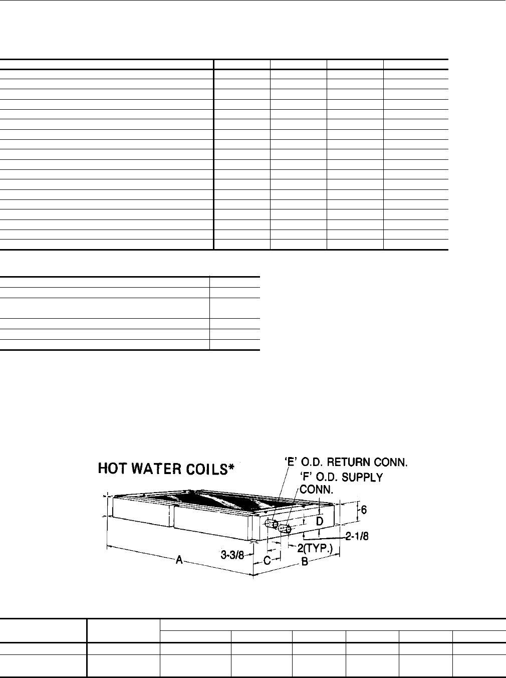
Dimensions Hot Water Coil
Dimensions Hot Water Coil
COIL
MODEL UNIT
MODEL
DIMENSIONS
ABCDEF
1HW0406 ND360 100-1/8 37-7/8 6-3/4 3-7/8 1-3/8 1-3/8
1HW0407 ND480
ND600 103-1/8 45-1/4 6-1/2 4 1-5/8 1-5/8
628767-YTG-C-0910
Johnson Controls Unitary Products 31
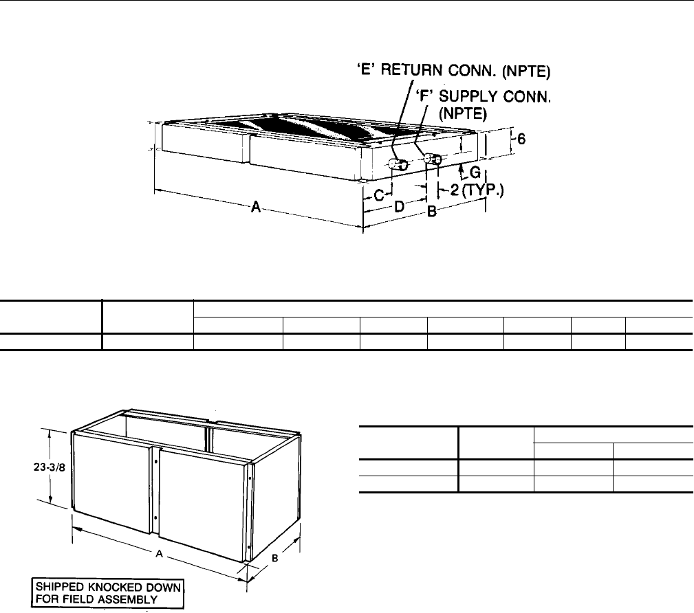
Dimensions Steam Coil
Dimensions Steam Coil1
COIL
MODEL UNIT
MODEL
DIMENSIONS
ABCDEFG
1NF0454 ND360 100-1/8 37-7/8 4-3/8 18-3/8 1-1/2 2 2-1/2
1Coils are field-installed between the evaporator coil and the blower section of the unit.
Dimensions Base Section
Dimensions Base Sections1
1Ventilation air can be brought into the unit through the
base section providing the base section is fully insu-
lated in the field.
BASE
MODEL UNIT
MODEL
DIMENSIONS
AB
1BS0406 ND360 100-1/8 37-7/8
1BS0407 ND480 103-1/8 45-1/4
628767-YTG-C-0910
32 Johnson Controls Unitary Products
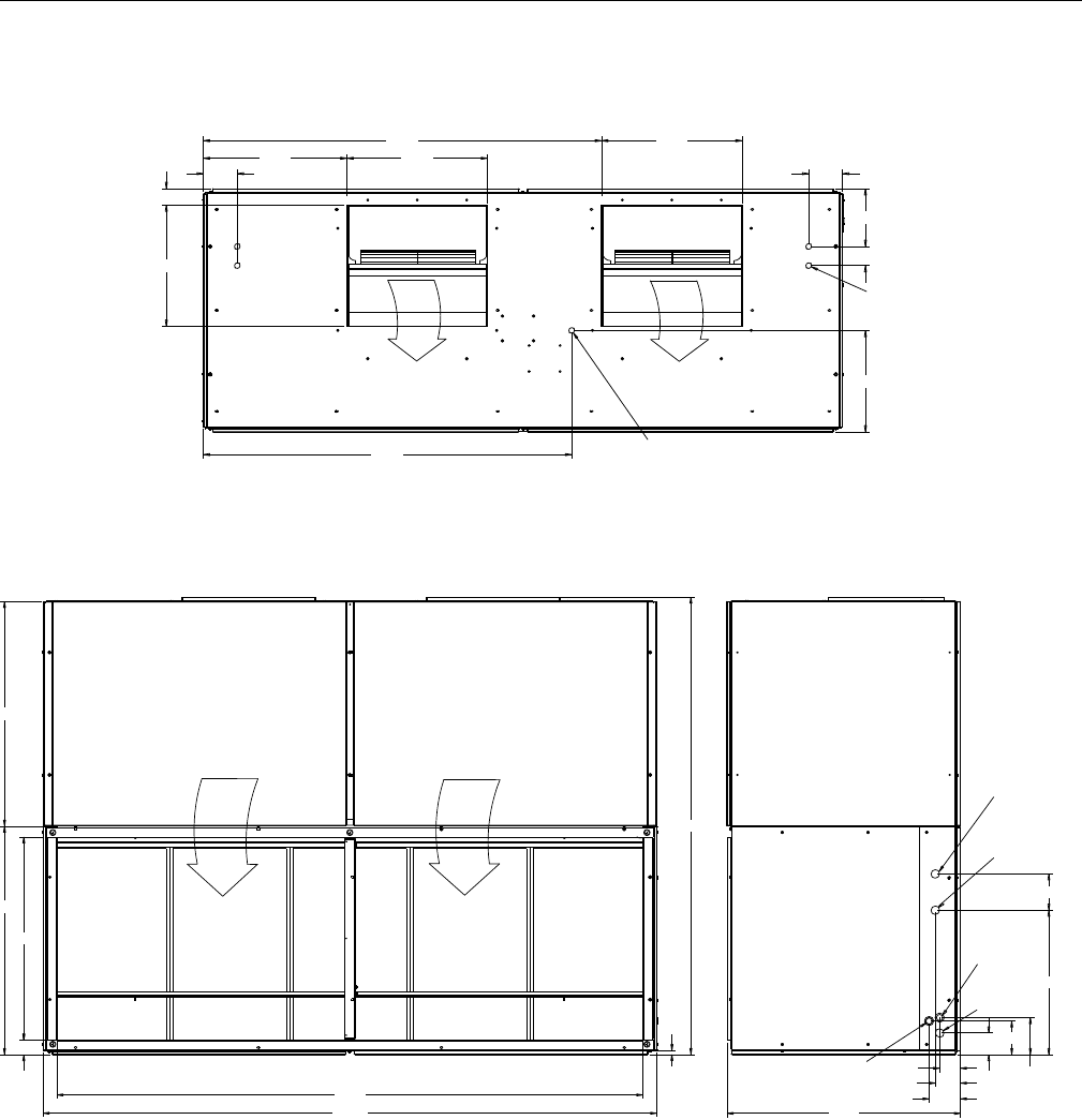
Unit Mounting
ND360, 480 & 600
The ND Series evaporator units may be suspended from
joists with isolation type hangers or hooks. Suspension
accessories 1HH0403 (ND360), 1HH0404 (ND480) and
1HH0405 (ND600 Air Handler with M1CZ600 Evaporator
Section) may be ordered separately. All Suspension
accessories include three suspension channels and
hardware. The channels extend across the evaporator
section, the heating section (if included) and the blower
section. Each channel is to be bolted to both sections as
shown in Weight Distribution with Suspension Application
Figures. Refer to the Unit Mounting Dimensions Table for
mounting details and Corner Weights Tables for unit weight
distribution.
ND360 & 480 Mounting Detail
ND480/ND360 Weight Distribution With Suspension Application
AX
3
1-1/2
EVAP. C OIL
SECTION
BLOWER
SECTION
U
3
O
U
HEATING COIL 2
SUSPENSION
ANGLES 1
BLOWER
SECTION
EVAP.
COIL
SECTION
CX
1
2
3
3
4
4
VERTICAL UNIT SUPPORTED
FROM BELOW
F
A
B
E
D
B
A
E
AX BX
BX
BX
BX
HORIZONTAL
UNIT SUSPENDED
FROM ABOVE
The same channels can be used in either position. When used to
support a vertical unit, these channels should be cut to match the
bottom dimension of the evaporator section.
The suspension channels have two sets of mounting holes to
accommodate horizontal units with or without a heating coil. On
a horizontal unit without a heating coil, the suspension channels
will extend 3” beyond both ends of the unit.
The same channels can be used to support a horizontal, floor-
mounted unit from below.
After these bottom channels are cut per Note 1, a new hole will have
to be drilled at the cut end if the unit is to be mounted on isolators.
C
D
C
F
628767-YTG-C-0910
Johnson Controls Unitary Products 33
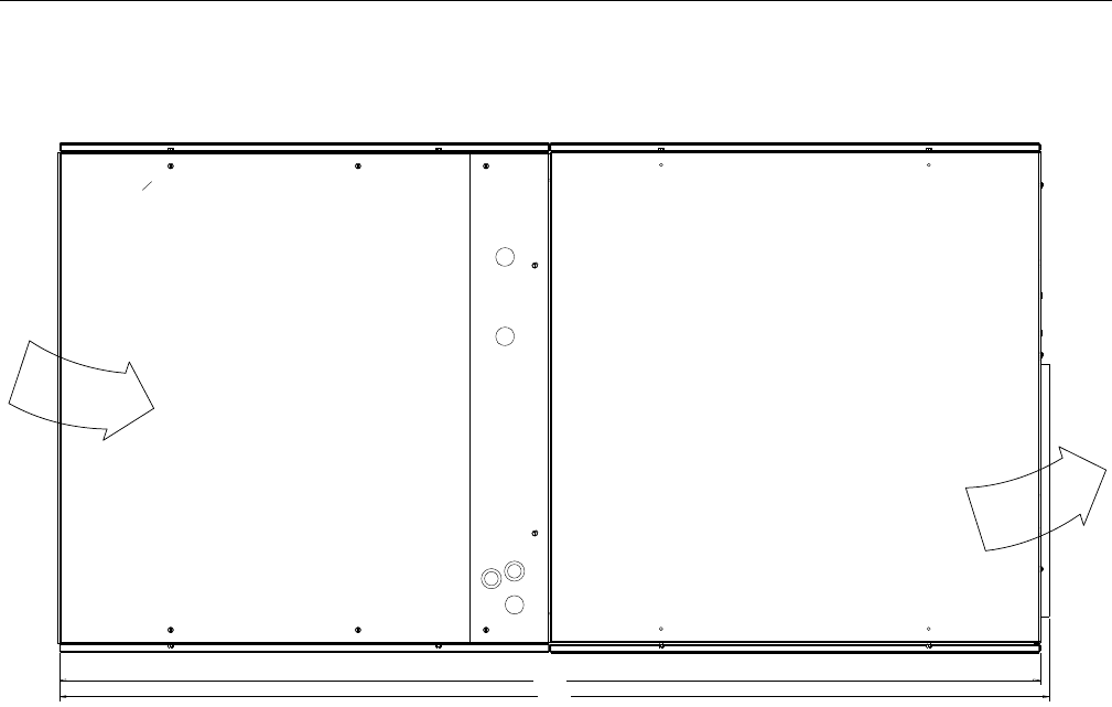
ND360/ND480 Details For Securing Suspension Channels
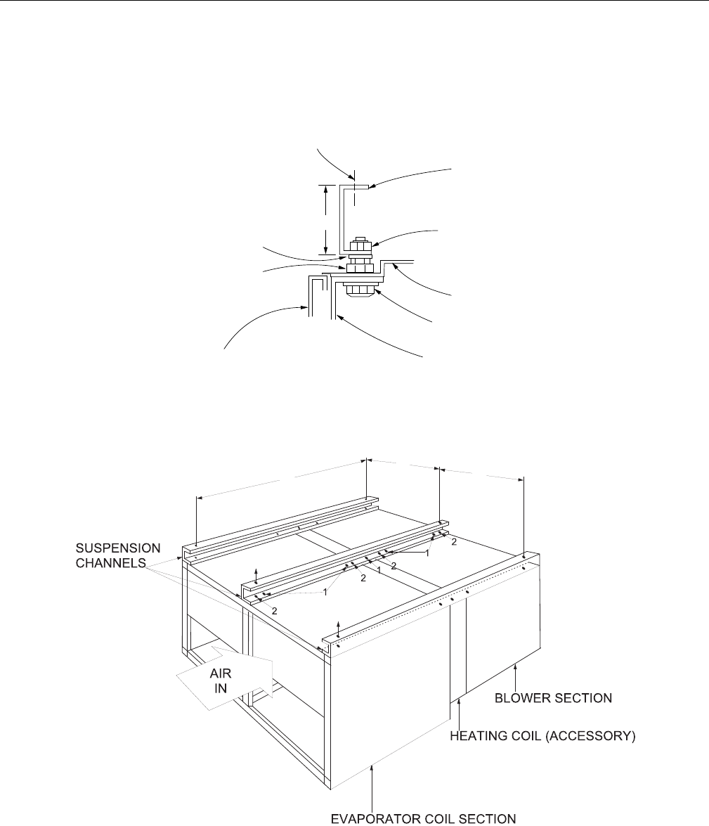
ND600 & M1CZ600 Weight Distribution With Suspension Application
3
NOTE: The following illustration shows how the channels
should be secured to the unit using the hardware
provided with the suspension accessory.
(2) 9/16 HOLES FOR 1/2
HANGER RODS
SUSPENSION
CHANNEL
5/16 NUT,
LOCKWASHER,
FLATWASHER
UNIT PANEL
5/16 BOLT,
FLAT-WASHER
UNIT ANGLE
SIDE
PANEL
5/16 NUT,
FLATWASHER
3/8 NUT (USED
AS SPACER)
E
D
AX
C
BX
BX
B
A
F
628767-YTG-C-0910
34 Johnson Controls Unitary Products
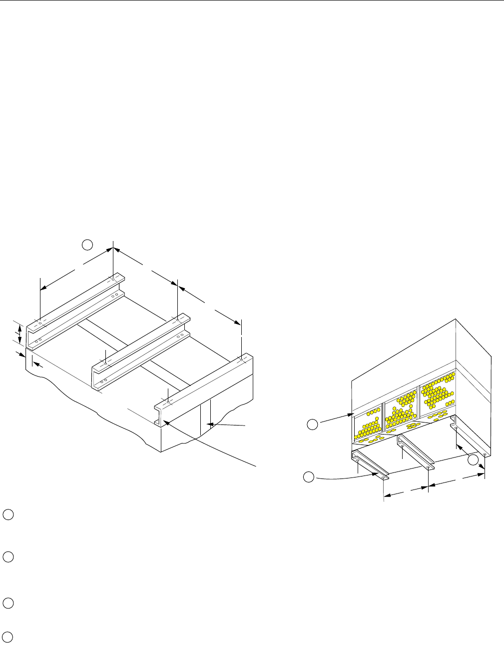
ND600 Mounting Detail
When arranged horizontally, the ND600 airhandler and
M1CZ600 evaporator coil can be suspended from joists with
hanger rods using a suspension accessory.
The suspension channels require no drilling or cutting. Each
channel has enough holes in its bottom flange for:
1. Four bolted connections to the evaporator coil section.
(Only two are used on the outside supports)
2. One bolted connection to the heating coil section.
3. Four bolted connections to the blower section. (Only two
are used on the outside supports)
See Figure details for securing suspension channels.
When the heating section is not included, each channel will
extend 3" beyond the front and the rear of the unit. Bolt holes
in the bottom flange of each channel will still align with the
holes provided in the top framework of the evaporator section
and the blower section.
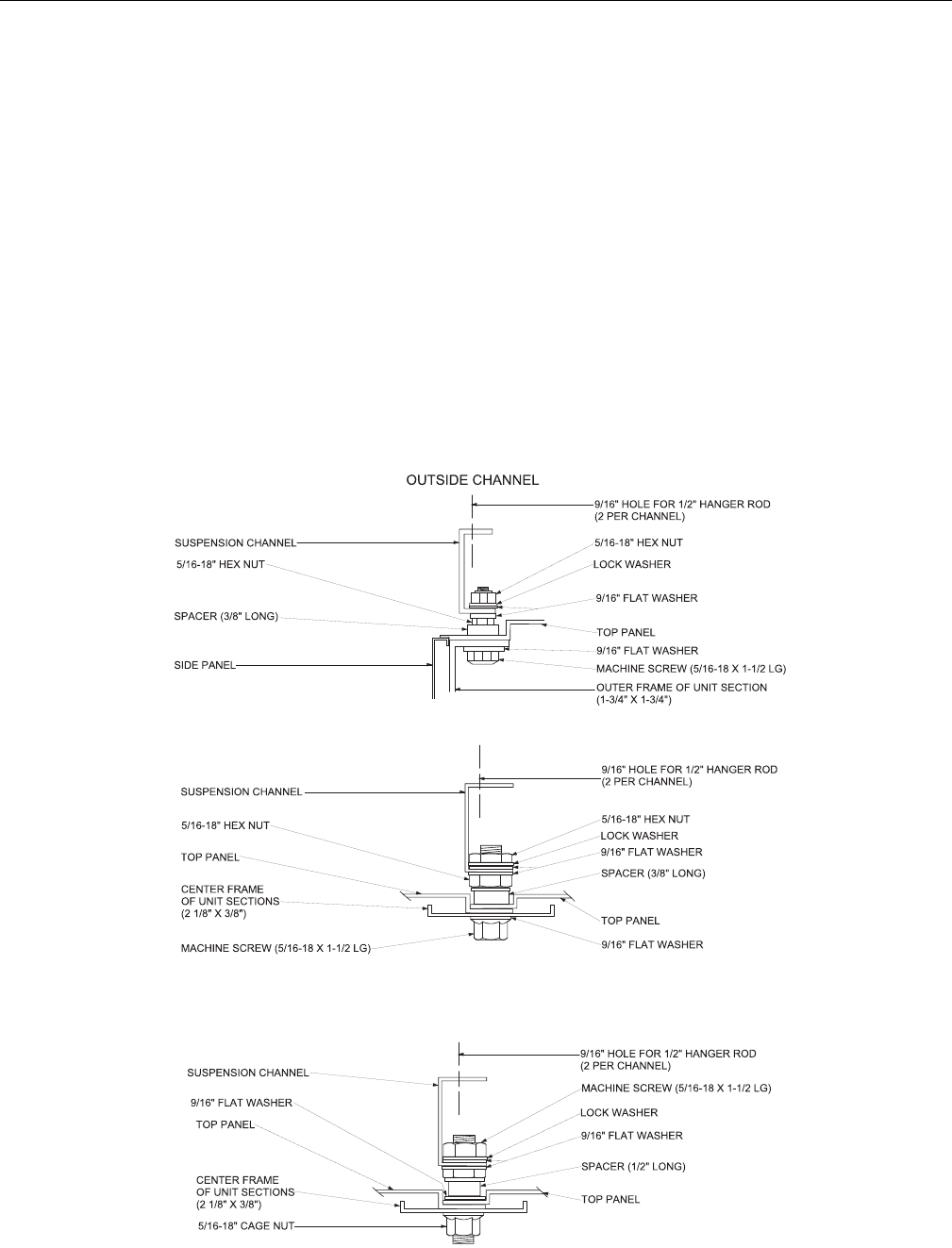
For both outside channels and for the Point 1 locations on the
center channel, the bolted connections are to be made where
the top sheet metal panels are attached to the unit
framework. The ¼” screws and cage nuts must be removed
and may be discarded. For the Point 2 locations on the center
channel, the bolted connections are to be made through the
knockouts in the top sheet metal panels. 5/16” cage nuts are
provided in the unit framework under these knockout
locations. Note that these cage nuts are part of the basic unit.
They are not supplied with the suspension accessory.
.
ND600 & M1CZ600 Details For Securing Suspension Channels
CENTER CHANNEL (Location “1”)
CENTER CHANNEL (Location “2”)
628767-YTG-C-0910
Johnson Controls Unitary Products 35
Unit Mounting Dimensions
UNIT DIMENSIONS, INCHES
AX BX CX
ND360 69-1/4 49-1/16 26-5/8
ND480 84 50-9/16 34
ND600 87 51-1/2 ~
628767-YTG-C-0910
36 Johnson Controls Unitary Products
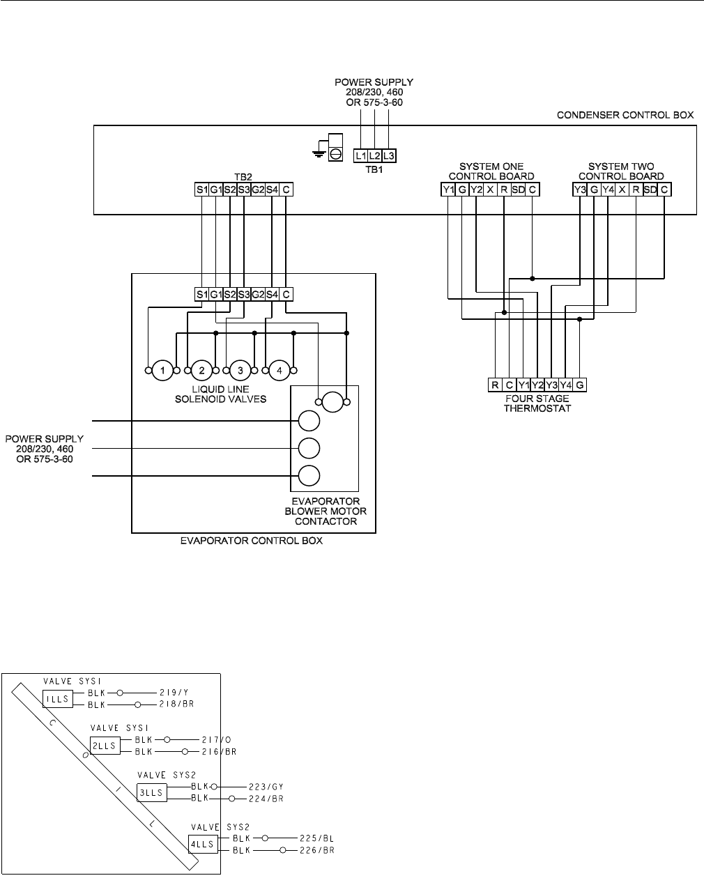
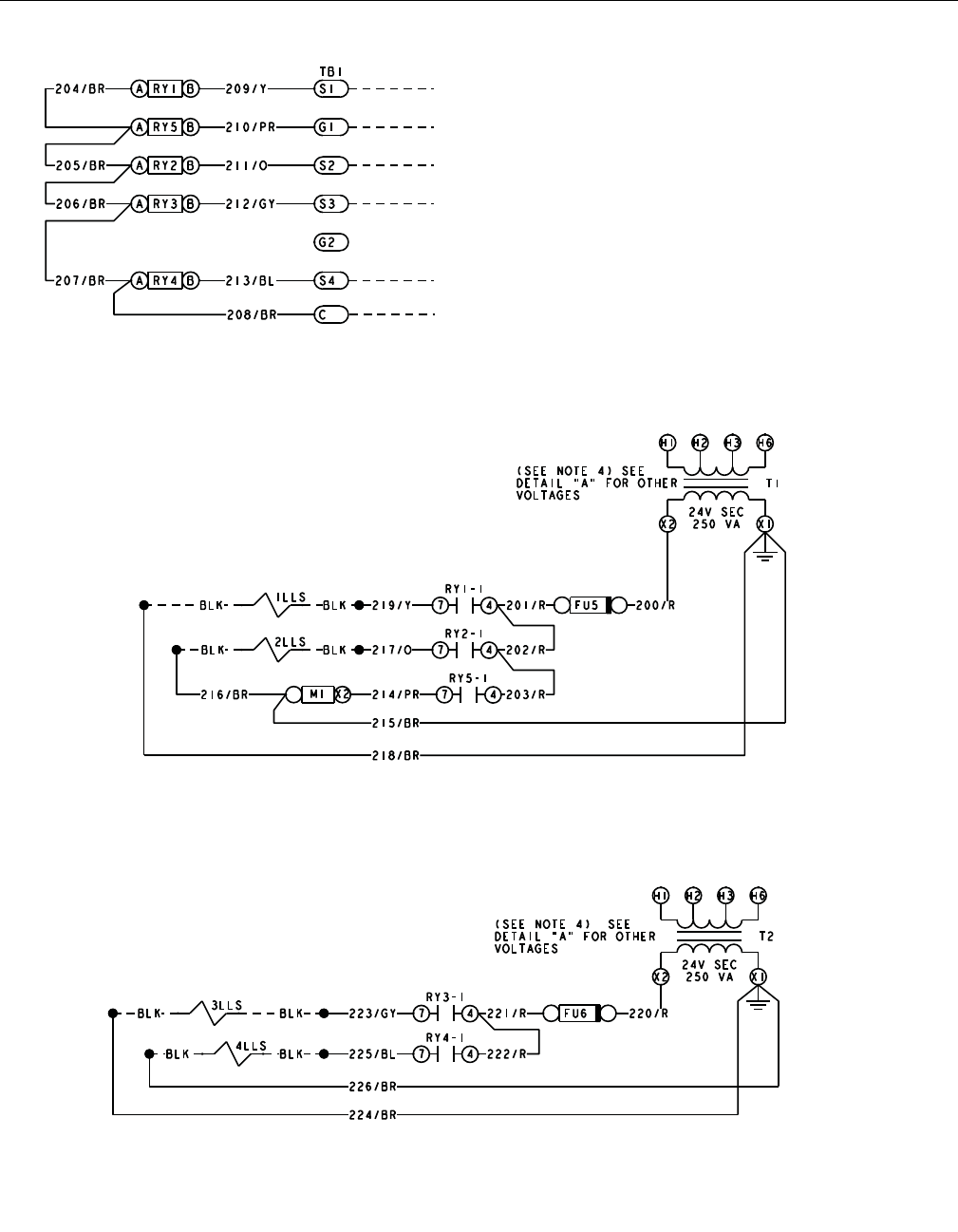
Typical Field Wiring Diagrams
Typical Field Wiring Diagram ND360/480 Evaporator Units, ND600 Air Handler and M1CZ600A Evaporator Coil when
Matched with YD360/480/600 Condenser
NOTE: On non ND evaporator models, isolation relays must be installed to avoid overloading on 75VA transformers on the
condensing unit.
Typical ND360/480 & M1CZ600A Liquid Line Solenoid
628767-YTG-C-0910
Johnson Controls Unitary Products 37
Typical Liquid Line Solenoid Wiring
Standard Terminal Block on NC300, ND360/480
and ND600 with M1CZ600A models. On non
NC/ND models isolation relays must be installed to
avoid overloading on 75 VA transformer on
condensing unit.
Non NC/ND units may not include any or all of
the components required to wire the unit. Use
the diagram as general reference only.
Primary side of transformer
connect to line side of power
supply.
Primary side of transformer
connect to line side of power
supply.

Subject to change without notice. Printed in U.S.A. 628767-YTG-C-0910
Copyright © 2010 by Johnson Controls, Inc. All rights reserved. Supersedes: 628767-YTG-B-0810
Johnson Controls Unitary Products
5005 York Drive
Norman, OK 73069
