York Millennium Yk M3 G4 Thru S6 S4 J2 Lb Se Sc J4 Users Manual 160.49 O2 (1296)
YK M3 M3 G4 THRU YK S6 S4 J2, YK LB LB G4 THRU YK SE SC J4 to the manual 81018b13-6dc3-4ce4-bda3-5313d6441b37
2015-02-02
: York Millennium-Yk-M3-M3-G4-Thru-Yk-S6-S4-J2-Yk-Lb-Lb-G4-Thru-Yk-Se-Sc-J4-Users-Manual york-millennium-yk-m3-m3-g4-thru-yk-s6-s4-j2-yk-lb-lb-g4-thru-yk-se-sc-j4-users-manual-455336 york pdf
Open the PDF directly: View PDF ![]() .
.
Page Count: 60
- 160.49-O2 (1296)
- CENTRIFUGAL LIQUID CHILLERS
- OPERATING & MAINTENANCE
- MODEL YK M3 M3 G4 THRU YK S6 S4 J2 (STYLE C)
- MODEL YK LB LB G4 THRU YK SE SC J4 (STYLE C)
- W ARNING
- TABLE OF CONTENTS
- REFERENCE INSTRUCTIONS
- NOMENCLATURE
- SECTION 1
- SECTION 2
- MICROCOMPUTER CONTROL CENTER
- PROGRAMMING
- THE MICROCOMPUTER CONTROL CENTER
- PROGRAMMING SYSTEM SETPOINTS
- FIG. 5 – KEYPAD – PROGRAMMING SYSTEMSETPOINTS
- FIG. 6 – KEYPAD – PROGRAMMING “LEAVING CHILLED WATER TEMP” SETPOINT
- FIG. 7 – KEYPAD – PROGRAMMING “% CURRENT LIMIT” SETPOINT
- FIG. 8 – KEYPAD – PROGRAMMING “PULL DOWN DEMAND” SETPOINT
- FIG. 9 – KEYPAD – PROGRAMMING “CLOCK” SETPOINT
- FIG. 10 – KEYPAD – PROGRAMMING “DAILY SCHEDULE” SETPOINT
- FIG. 11 – KEYPAD – PROGRAMMING “HOLIDAY” SETPOINT
- FIG. 12 – KEYPAD – PROGRAMMING “REMOTE RESET TEMP RANGE
- THE MICROCOMPUTER CONTROL CENTER
- SERVICE KEYS
- OPERATING MODES
- COMPRESSOR SWITCH
- DISPLAY MESSAGES
- FIG. 14 – MICROCOMPUTER CONTROL CENTER LOCATION OF REAL TIME CLOCK U16 RTC IC CHIP
- SECTION 3
- SYSTEM OPERATING PROCEDURES
- WARNING
- START-UP PROCEDURE
- START-UP
- CHILLER OPERATION
- SYSTEM STARTING & SHUTDOWN SEQUENCE
- FIG. 15 – CHILLER STARTING SEQUENCE & SHUTDOWN SEQUENCE
- Condenser Water Temperature Control
- CHECKING OPERATION
- OPERATING LOG SHEET
- FIG. 16 – LIQUID CHILLER LOG SHEETS
- OPERATING INSPECTIONS – See Section 2
- NEED FOR MAINTENANCE OR SERVICE
- NORMAL AND SAFETY SYSTEM SHUTDOWNS
- SAFETY SHUTDOWNS
- CYCLING SHUTDOWNS
- STOPPING THE SYSTEM
- PROLONGED SHUTDOWN
- START-UP AFTER PROLONGED SHUTDOWN
- SYSTEM OPERATING PROCEDURES
- SECTION 4
- SYSTEM COMPONENTS DESCRIPTION
- FRONT VIEW
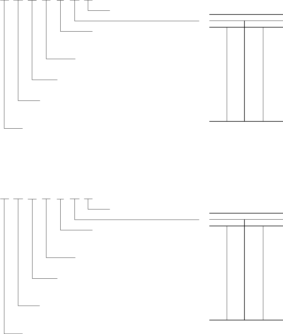
- FIG. 17 – SYSTEM COMPONENTS
- GENERAL
- COMPRESSOR
- CAPACITY CONTROL
- COMPRESSOR LUBRICATION SYSTEM
- OIL PUMP
- FIG. 18 – SCHEMATIC DRAWING – (YK) COMPRESSOR LUBRICATION SYSTEM
- OIL HEATER
- MOTOR DRIVELINE
- HEAT EXCHANGERS
- REFRIGERANT FLOW CONTROL
- MICROCOMPUTER CONTROL CENTER
- SOLID STATE STARTER
- VARIABLE SPEED DRIVE
- SYSTEM COMPONENTS DESCRIPTION
- SECTION 5
- SECTION 6
- SECTION 7
- MAINTENANCE
- RENEWAL PARTS
- CHECKING SYSTEM FOR LEAKS
- EVACUATION AND DEHYDRATION OF UNIT
- FIG. 21 – EVACUATION OF CHILLER
- TABLE 3 – SYSTEM PRESSURES
- VACUUM TESTING
- VACUUM DEHYDRATION
- OPERATION
- FIG. 22 – SATURATION CURVE
- REFRIGERANT CHARGING
- CHECKING THE REFRIGERANT CHARGE
- HANDLING REFRIGERANT FOR
- MEGGING THE MOTOR
- CONDENSERS AND COOLERS
- COMPRESSOR
- ELECTRICAL CONTROLS
- MAINTENANCE
- SECTION 8
- RETURN TO PREVIOUS MENU
- MAIN MENU
OPERATING & MAINTENANCE
Supersedes: Nothing Form 160.49-O2 (1296)
MILLENNIUM
TM
CENTRIFUGAL LIQUID CHILLERS
MODEL YK M3 M3 G4 THRU YK S6 S4 J2 (STYLE C)
R-22 (COOLING ONLY)
MODEL YK LB LB G4 THRU YK SE SC J4 (STYLE C)
R-134a (COOLING ONLY)
WITH MICROCOMPUTER CONTROL CENTER
PART #371-01200-010, 371-01200-011 & 371-01200-015
FOR ELECTRO-MECHANICAL STARTER,
SOLID STATE STARTER & VARIABLE SPEED DRIVE
WW
WW
WARNINGARNING
ARNINGARNING
ARNING
SYSTEM CONTAINS REFRIGERANT UNDER PRESSURE.
SERIOUS INJURY COULD RESULT IF PROPER PROCEDURES ARE NOT
FOLLOWED WHEN SERVICING SYSTEM. ALL SERVICE WORK SHALL
BE PERFORMED BY A QUALIFIED SERVICE TECHNICIAN IN ACCOR-
DANCE WITH YORK INSTALLATION/OPERATION MANUAL.
27385A

2 YORK INTERNATIONAL
TT
TT
TABLE OF CONTENTSABLE OF CONTENTS
ABLE OF CONTENTSABLE OF CONTENTS
ABLE OF CONTENTS
SECTION 1 – Description of System and
Fundamentals of Operation ......................................... 4
SECTION 2 – MicroComputer Control Center ...................................... 6
SECTION 3 – System Operating Procedures..................................... 30
SECTION 4 – System Component Description .................................. 37
SECTION 5 – Operational Maintenance ............................................. 42
SECTION 6 – Trouble Shooting........................................................... 44
SECTION 7 – Maintenance ................................................................. 49
SECTION 8 – Preventive Maintenance............................................... 58
REFERENCE INSTRREFERENCE INSTR
REFERENCE INSTRREFERENCE INSTR
REFERENCE INSTRUCTIONSUCTIONS
UCTIONSUCTIONS
UCTIONS
DESCRIPTION FORM NO.
Solid State Starter – Operation & Maintenance 160.46-OM3.1
Variable Speed Drive – Operation 160.00-O1
Installation 160.49-N5
Installation and Operation of Printers 160.49-N7
Wiring Diagram – Unit with Electro-Mechanical Starter 160.49-PW7
Wiring Diagram – Field Connections (E-M Starter) 160.49-PW10
Wiring Diagram – Field Control Modifications 160.49-PW13
Wiring Diagram – Control Center with SS Starter 160.49-PW8
Wiring Diagram – Field Connections (SS Starter) 160.49-PW11
Wiring Diagram – Solid State Starter 160.49-PW14
Wiring Diagram – Unit with Solid State Starter 160.49-PW8
Wiring Diagram – Unit with Variable Speed Drive 160.49-PW9
Wiring Diagram – Field Connections (V.S.D.) 160.49-PW12
Wiring Diagram – Variable Speed Drive 160.49-PW15
Page
YORK INTERNATIONAL 3
FORM 160.49-O2
R-22 UNITS
YK N2 N1 H1 – CX C
DESIGN LEVEL (C)
POWER SUPPLY
– for 60 HZ
5 for 50 HZ
COMPRESSOR CODE
G4, H0, H1, H2, J1, J2
CONDENSER CODE
M3, M4, N3, N4, P3, P4, Q3, Q4, R3, R4, S3, S4
COOLER CODE
M3, M4, N3, N4, P3, P4, P5, P6, Q3, Q4, Q5, Q6,
R3, R4, R5, R6, S5, S6
MODEL
{MOTOR CODE:
60 HZ 50 HZ
CH CX 5CE 5CT
CJ CY 5CF 5CU
CK CZ 5CG 5CV
CL CA 5CH 5CW
CM CB 5CI 5CX
CN DA 5CJ 5DA
CP DB 5CK 5DB
CR DC 5CL 5DC
CS DD 5CM 5DD
CT DE 5CN 5DE
CU DF 5CO 5OF
CV DH 5CP 5OG
CW DJ 5CQ 5OH
5CR 5OJ
5CS
R-134a
YK NB PB H1 – CX C
DESIGN LEVEL (C)
POWER SUPPLY
– for 60 HZ
5 for 50 HZ
COMPRESSOR CODE
G4, H0, H1, H2, J1, J2, J3, J4
CONDENSER CODE
LB, LC, MB, MC, NB, NC,
PB, PC, QB, QC, RB, RC, SB, SC
COOLER CODE
LB, LC, MB, MC, NB, NC, PB, PC, PD, PE,
QB, QC, QD, QE, RB, RC, RD, RE, SD, SE
MODEL
{MOTOR CODE:
60 HZ 50 HZ
CH CX 5CE 5CT
CJ CY 5CF 5CU
CK CZ 5CG 5CV
CL CA 5CH 5CW
CM CB 5CI 5CX
CN DA 5CJ 5DA
CP DB 5CK 5DB
CR DC 5CL 5DC
CS DD 5CM 5DD
CT DE 5CN 5DE
CU DF 5CO 5DF
CV DH 5CP 5DG
CW DJ 5CQ 5DH
5CR 5OJ
5CS
NOMENCLATURE
4 YORK INTERNATIONAL
SECTION 1
DESCRIPTION OF SYSTEM AND FUNDAMENTALS OF OPERATION
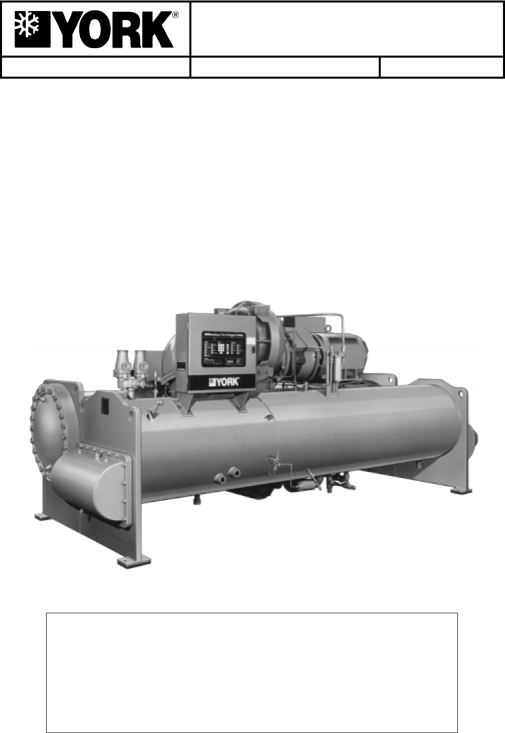
FIG. 1 – MODEL YK MILLENNIUM CHILLER
SYSTEM OPERATION DESCRIPTION (See Fig. 2)
The YORK Model YK Millennium Chiller is commonly
applied to large air conditioning systems, but may be
used on other applications. The chiller consists of an
open motor mounted to a compressor (with integral
speed increasing gears) condenser, cooler and flow
control chamber.
The chiller is controlled by a modern state of the art
MicroComputer Control Center which monitors its op-
eration. The Control Center is programmed by the op-
erator to suit job specifications. Automatic timed start-
ups and shutdowns are also programmed to suit
nighttime, weekends, and holidays. The operating sta-
tus, temperatures, pressures, and other information per-
tinent to operation of the chiller are automatically dis-
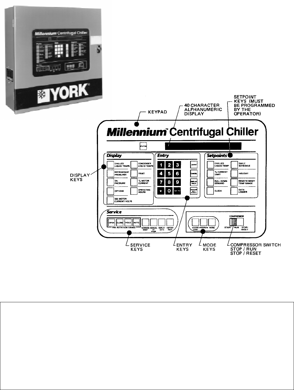
played and read on a 40 character alphanumeric
message display. Other displays can be observed by
pressing the keys as labeled on the Control Center.
The chiller with the MicroComputer Control Center is
applied with an electro-mechanical starter, YORK Solid
State Starter (optional), or Variable Speed Drive (op-
tional).
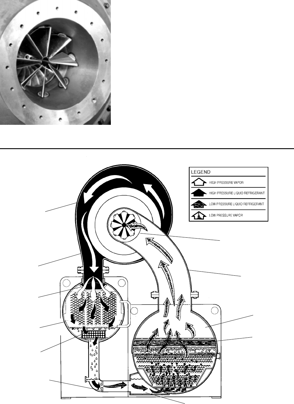
In operation, a liquid (water or brine to be chilled) flows
through the cooler, where boiling refrigerant absorbs
heat from the water. The chilled liquid is then piped to
fan coil units or other air conditioning terminal units,
where it flows through finned coils, absorbing heat from
the air. The warmed liquid is then returned to the chiller
to complete the chilled liquid circuit.
The refrigerant vapor, which is produced by the boiling
action in the cooler, flows to the compressor where the
rotating impeller increases its pressure and tempera-
ture and discharges it into the condenser. Water flowing
through the condenser tubes absorbs heat from the re-
frigerant vapor, causing it to condense. The condenser
water is supplied to the chiller from an external source,
usually a cooling tower. The condensed refrigerant drains
from the condenser into the flow control chamber, where
the flow restrictor meters the flow of liquid refrigerant
to the cooler to complete the refrigerant circuit.
The major components of a chiller are selected to handle
the refrigerant which would be evaporated at full load
CONTROL
CENTER
COMPRESSOR
MOTOR
COOLER
27382A
DISCHARGE LINE PRE-ROTATION
VANE
ACTUATOR
CONDENSER
OIL RESERVOIR/
PUMP
27385A
YORK INTERNATIONAL 5
FORM 160.49-O2
7619A(D)
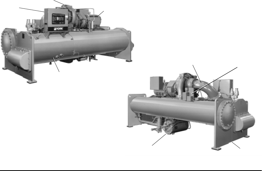
DETAIL A – COMPRESSOR PREROTATION VANES
design conditions. However, most systems will be called
upon to deliver full load capacity for only a relatively
small part of the time the unit is in operation.
CAPACITY CONTROL
The major components of a chiller are selected for full
load capacities, therefore capacity must be controlled to
maintain a constant chilled liquid temperature leaving
the cooler. Prerotation vanes (PRV), located at the en-
trance to the compressor impeller, compensate for varia-
tion in load (See Fig. 2. Detail A).
The position of these vanes is automatically controlled
through a lever arm attached to an electric motor lo-
cated outside the compressor housing. The automatic
adjustment of the vane position in effect provides the
performance of many different compressors to match
various load conditions from full load with vanes wide
open to minimum load with vanes completely closed.
FIG. 2 – REFRIGERANT FLOW-THRU CHILLER
PREROTATION VANES
(See Detail A)
SUCTION
COOLER
ELIMINATOR
OIL COOLER
LD00924
FLOW CONTROL
ORIFICE
SUB-COOLER
CONDENSER
DISCHARGE
BAFFLE
DISCHARGE
COMPRESSOR
6 YORK INTERNATIONAL
SECTION 2
MICROCOMPUTER CONTROL CENTER
LD00953
26879A
FIG. 3 – MICROCOMPUTER CONTROL CENTER AND KEYPAD
NOTE: This instruction covers operation of chillers equipped with Electro-Mechanical or Solid State Starters. If chiller
is equipped with Variable Speed Drive, Form 160.00-O1 is to be used in conjunction with this manual.
WARNING
This equipment generates, uses and can radiate radio frequency energy and if not installed and used in accor-
dance with the instructions manual, may cause interference to radio communications. Operation of this equip-
ment in a residential area is likely to cause interference in which case the user at his own expense will be
required to take whatever action may be required to correct the interference.
Additionally, any electronic equipment can generate EMI (electromagnetic interference) which, depending upon
the installation and magnitude, may affect other electronic equipment. The amount of EMI generated is deter-
mined by the source inductance, load inductance, and circuit impedances. Responsibility for assuring the
satisfactory operation of other equipment included in the same power source as the YORK equipment rests
solely with the user. YORK disclaims any liability resulting from any interference or for the correction thereof.
YORK INTERNATIONAL 7
FORM 160.49-O2
INTRODUCTION
The YORK MicroComputer Control Center is a micro-
processor based control system for R-22 or R134a cen-
trifugal chillers. It controls the leaving chilled water tem-
perature via pre-rotation vane control and has the ability
to limit motor current via control of the pre-rotation vanes.
Further, it is compatible with YORK Solid State Starter
(optional), Variable Speed Drive (optional), and electro-
mechanical starter applications.
A keypad mounted on the front of the Control Center
(see Fig. 3) allows the operator to display system oper-
ating parameters on a 40 character alphanumeric dis-
play that is part of the keypad. These readings are dis-
played via “Display” keypad as follows: (In the English
mode; temperatures in °F, pressures in (PSIG) (in the
metric mode, temperatures in °C, Pressures in KPa).
If unit is equipped with EPROM version C.02F(T).12 or
later, the Control Center can be equipped with an op-
tional Chinese language display, either as a field retrofit
or factory supplied option on new units. This display
mounts on the control center door, directly above the
standard display. Both the standard and Chinese dis-
play will be present, providing display messages simul-
taneously in both English and Chinese language.
The Control Center must be configured for Chinese dis-
play by a qualified service technician. Instructions are
contained in YORK service manual, Form 160.49-M3.
• CHILLED LIQUID TEMPERATURES – LEAVING AND
RETURN
• REFRIGERANT PRESSURES – EVAPORATOR AND
CONDENSER
• DIFFERENTIAL OIL PRESSURE
• CONDENSER LIQUID TEMPERATURES – OPTIONAL
FIELD INSTALLED – LEAVING AND RETURN
• OPTIONS
• PRINT *
• HISTORY PRINT *
• MOTOR CURRENT IN % OF FULL LOAD AMPS
• SATURATION TEMPERATURES – EVAPORATOR AND
CONDENSER
• DISCHARGE TEMPERATURE
• OIL TEMPERATURE
• HIGH & LOW OIL PRESSURE TRANSDUCER PRES-
SURE
• SOLID STATE STARTER MOTOR CURRENT / VOLTS
(When Supplied)
• CONDENSER REFRIGERANT LEVEL
The system setpoints (see Fig. 3) are operator entered
on the front control center Setpoints keypad. These
setpoints can also be displayed on the 40 character al-
phanumeric display. The system setpoints are:
• CHILLED LIQUID TEMPERATURE (LCWT)
• % CURRENT LIMIT
• PULLDOWN DEMAND LIMIT
• CLOCK (TIME-OF-DAY)
• DAILY SCHEDULE (7 DAY TIME-CLOCK PROGRAM-
MING)
• HOLIDAY
• REMOTE RESET TEMPERATURE RANGE
• DATA LOGGER
• CONDENSER REFRIGERANT LEVEL
The cause of all system shutdowns (safety or cycling) is
preserved (until the system is reset or restarts) in the
microcomputer’s memory for subsequent viewing on the
keypad display. The operator is continually advised of
system operating conditions by various background and
warning messages. The keypad contains special ser-
vice keys for use by the service technician when per-
forming system troubleshooting.
The MicroComputer Control Center is designed to be
compatible with most Energy Management Systems
(EMS) in use today. The standard design allows for the
following EMS interface:
1. Remote Start
2. Remote Stop
3. Remote LCWT Setpoint (Pulse Width Modulated sig-
nal)
4. Remote Current Limit Setpoint (Pulse Width Modulated
signal)
5. A “Remote Mode Ready to Start” Status Contacts
6. Safety Shutdown Status Contacts
7. Cycling Shutdown Status Contacts
As an enhancement to the standard EMS features, an
optional card file with plug-in printed circuit boards is
available. These optional cards will accept a remote
LCWT 0 to 10°F or 0 to 20°F setpoint offset and/or re-
mote current limit setpoint interface from three user in-
put choices.
1. 4-20mA
2. 0-10VDC
3. Contact Closures
* These keys provide a print-out when the customer connects a com-
patible printer to the Micro Board RS-232 serial port. (See Form
160.49-N7.)

8 YORK INTERNATIONAL
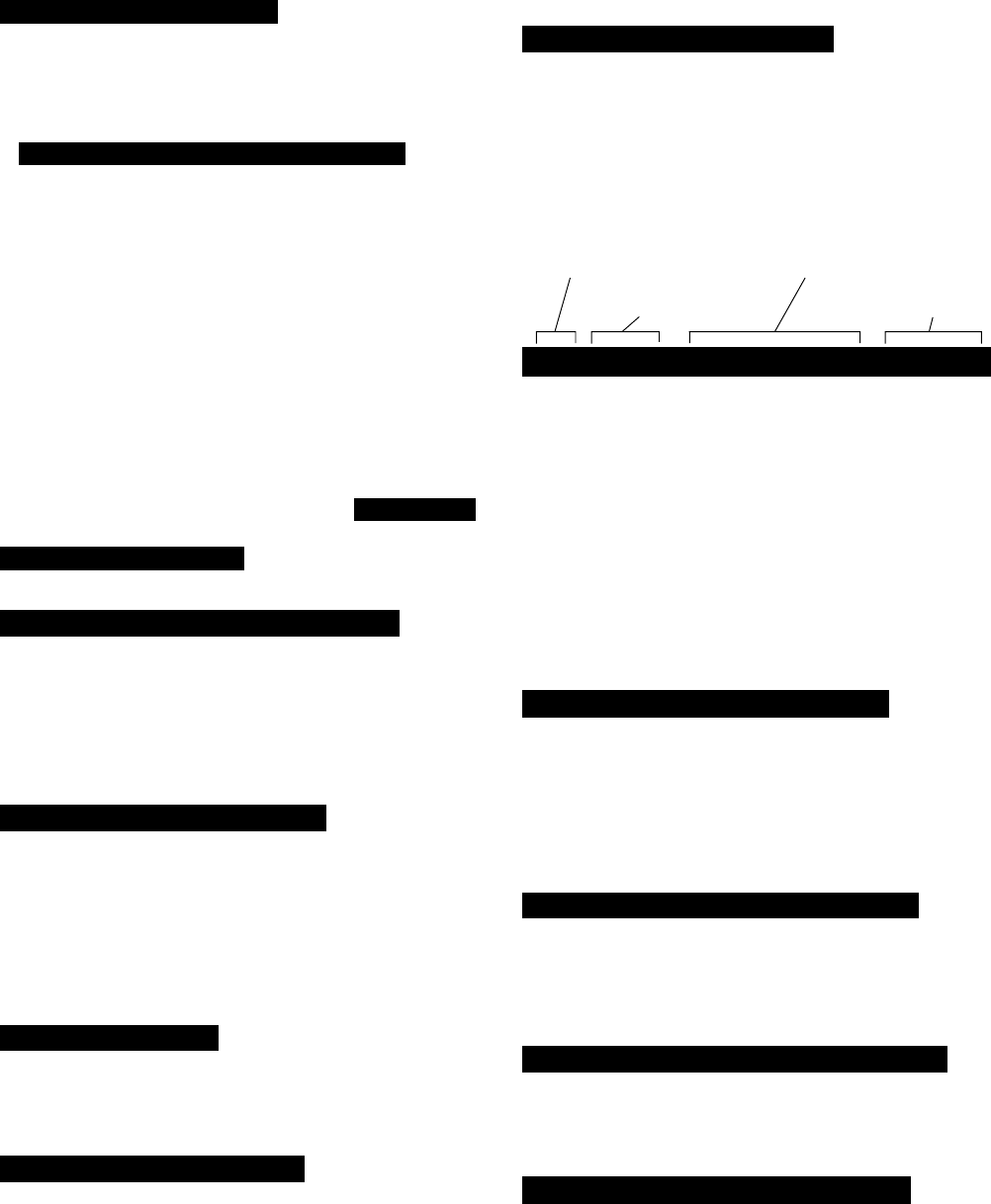
CONTROL CENTER
The Control Center front panel layout consists of five
key groups, one switch and a 1 line by 40 character al-
phanumeric vacuum fluorescent display: (see Fig. 3.)
CHARACTERISTIC DISPLAY – The alphanumeric
vacuum fluorescent display is located to the right of the
STATUS key. All messages, parameters, set points, and
data can be viewed at this location. The main communi-
cations between the operator or service technician and
the MicroComputer Control Center occurs on this dis-
play.
DISPLAY – Provide a direct readout of each monitored
parameter on the alphanumeric display.
ENTRY – These keys are used to enter the values for
the operator programmed setpoints. These keys are used
in conjunction with the Setpoint keys while in PRO-
GRAM mode.
SETPOINTS – These keys are used as follows:
1. To view each setpoint, in any mode, or
2. To select the individual setpoints that are programmed
by the operator in PROGRAM mode only.
Pressing the appropriate key enables the operator to
program that setpoint pressing the Entry keys.
SERVICE – Included in this group of keys are those func-
tions that are only relevant to servicing the chiller.
Typically, these keys would not be used for daily chiller
operation.
ACCESS CODE – Permits operator to access the pro-
gram.
PROGRAM – Permits operator to program the Control
Center.
MODE – Permits operator to check what mode the Con-
trol Center is presently in (LOCAL, REMOTE or SER-
VICE).
1. Service – allows manual PRV control with visual
display readout of PRV operation.
2. Local – allows manual compressor start from the
COMPRESSOR switch on the Control Center front.
3. Program – allows operator programming of system
setpoints.
4. Remote – allows remote start, remote stop of com-
pressor and remote reset of LCWT and % current
limit.
COMPRESSOR-START, RUN, STOP/RESET
SWITCH – This 3-position rocker switch is used to start
(except in REMOTE mode), stop/run/reset the system.
OPERATION
DISPLAYING SYSTEM PARAMETERS
The Display keys are used to display selected
monitored parameters as follows: (Refer to Fig. 3.)
• Press and release the appropriate Display key – the
message will be displayed for 2 seconds.
– or –
• Press and hold the appropriate Display key – the mes-
sage will be displayed and updated every 0.5 sec-
onds until the Display key is released.
– or –
• Press and release appropriate Display key, then press
and release the DISPLAY HOLD key – the message
will be displayed and updated every 2 seconds until
the DISPLAY HOLD key is again pressed and re-
leased, or 10 minutes have elapsed, whichever comes
first.
NOTE: If the display actually displays X’s, then the
monitored parameter is out of normal operat-
ing range (refer to Fig. 4). If the “English/Metric”
jumper is installed on the Micro Board, all tem-
peratures are displayed in degrees Fahrenheit
(°F) and all pressures are displayed in pounds
per sq. inch gauge (PSIG) except oil pressure
which is displayed in pounds per sq. inch differ-
ential (PSID). If the “English/Metric” jumper is
not installed, all temperatures are displayed in
degrees Centigrade (°C) and all pressures are
displayed in Kilo-Pascals (kPa).

YORK INTERNATIONAL 9
FORM 160.49-O2
To Display CHILLED LIQUID TEMPERATURES:
Press CHILLED LIQUID TEMPS display key as de-
scribed on page 7 to produce the following alphanu-
meric display message:
CHILLED LEAVING = XXX.X°F, RETURN = XXX.X°F
To Display REFRIGERANT PRESSURE:
Use REFRIGERANT PRESSURE display key as
described on page 7 to produce the following alpha-
numeric display message:
EVAP = XXX.X PSIG; COND = XXX.X PSIG
To Display OIL PRESSURE:
Use OIL PRESSURE display key as described on
page 7 to produce the following alphanumeric dis-
play message:
OIL PRESSURE = XXXX.X PSID
The differential pressure displayed is the pressure dif-
ference between the high side oil pressure transducer
(output of oil filter) and the low side oil pressure trans-
ducer (compressor housing). Displayed value includes
offset pressure derived from auto-zeroing during
“START SEQUENCE INITIATED”. If either transducer
is out-of-range, XX.X is displayed. Oil pressure is
calculated as follows:
______ PSID = (HOP – LP) – OFFSET PRESSURE
OFFSET PRESSURE: Pressure differential between
the HOP transducer and LOP transducer outputs dur-
ing a 3 second period beginning 10 seconds after the
start of “START SEQUENCE INITIATED”. During this
time, the transducers will be sensing the same pres-
sure and their outputs should indicate the same pres-
sure. However, due to accuracy tolerances in trans-
ducer design, differences can exist. Therefore, to com-
pensate for differences between transducers and as-
sure differential pressure sensing accuracy, the OFF-
SET PRESSURE is subtracted algebraically from the
differential pressure. The offset pressure calculation
will not be performed if either transducer is out-of-range.
The offset value will be taken as 0 PSI in this instance.
To Display OPTIONS:
This key is not used.
NO OPTIONS INSTALLED
is displayed when this key is pressed.
To Display SSS MOTOR CURRENT / VOLTS:
(Solid State Starter Applications Only)
If chiller is equipped with a YORK Solid State Starter,
use SSS MOTOR CURRENT / VOLTS key to dis-
play 3-phase compressor motor current and 3-phase
Solid State Starter input line voltage.
Continuously pressing this key will display the mo-
tor current and line voltage alternately. When used
with the DISPLAY HOLD key, motor current and
line voltage will alternately be displayed each time
this key is pressed. The messages are as follows:
A AMPS = XXXX; B AMPS = XXXX; C AMPS = XXXX
V A-B = XXXX; V B-C = XXXX; V C-A = XXXX
If chiller is not equipped with a Solid State Starter,
this key produces the following message:
SOLID STATE STARTER NOT INSTALLED
In PROGRAM mode, this key is used to display the
applicable line voltage range (200-208VAC, 220-
240VAC, 380VAC, 400VAC, 415VAC, 440-480VAC,
500-600VAC, Supply Voltage Range Disabled). The
correct line voltage range is programmed at the
YORK factory and is checked by the service tech-
nician at start-up. For security reasons, a special
access code is required to program the line volt-
age range. The line voltage range is used to deter-
mine a low line voltage threshold for cycling shut-
down. Refer to “System Setpoints” for Trip/Reset
values.
DISPLAY
READS
CONDENSER PRESS. = < 6.8 PSIG, or > 300 PSIG XX.X PSIG
EVAPORATOR PRESS. = < 50 PSIG, or > 125 PSIG XX.X PSIG
EVAP. PRESS. (BRINE) = < 25 PSIG, or > 100 PSIG XX.X PSIG
HOP TRANSDUCER = < 59.1 PSIG, or > 314.9 PSIG XX.X PSIG
LOP TRANSDUCER = < 23.2 PSIG, or > 271.8 PSIG XX.X PSIG
DISCHARGE TEMP. = < 20.3°F; > 226.4°F XXX.X°F
OIL TEMP. = < 20.3°F; > 226.4°F XXX.X°F
LEAVING CONDENSER
WATER TEMP. = < 8.4°F; > 134.1°F XXX.X°F
ENTERING CONDENSER
WATER TEMP. = < 8.4°F; > 134.1°F XXX.X°F
LEAVING EVAPORATOR = < 0°F XX.X°F
WATER TEMP. = > 81.1°F XX.X°F
ENTERING EVAPORATOR = < .1°F XX.X°F
WATER TEMP. = > 93°F XX.X°F
FIG. 4 – SYSTEM PARAMETERS – OUT OF
RANGE READINGS

10 YORK INTERNATIONAL
To Display CONDENSER LIQUID TEMPERATURES
(Field Installed Option Package):
Use CONDENSER LIQUID TEMPS display key as
described above to produce the following alphanu-
meric display message:
COND LEAVING = XXX.X°F; RETURN = XXX.X°F
NOTE: If the condenser liquid thermistors are not con-
nected, or both thermistors are “out of range”,
the display will blank when this key is pressed.
To Initiate a PRINT to Printer:
Press the PRINT key to initiate a printout to an op-
tional printer. When the key is pressed,
PRINT ENABLE
is displayed.
Refer to “MicroComputer Control Center – System
Status Printers” instruction, Form 160.49-N7 for de-
tails of the optional printers.
To Display MOTOR CURRENT:
Press the % MOTOR CURRENT display key as
described above to display motor current as a per-
cent of Full Load Amps (FLA). The message is as
follows:
MOTOR CURRENT = XXX% FLA
NOTE: • Liquid-Cooled Solid State Starter Applications
– the % Motor Current displayed is the highest
of three line currents divided by the programmed
chiller FLA value x 100%.
• Electro-Mechanical Starter Applications – the
% Motor Current displayed is the highest of the
three line currents.
To Display OPERATING HOURS and STARTS
COUNTER:
Use the OPERATING HOURS key as described on
page 8, to produce the following message:
OPER. HOURS = XXXXX; START COUNTER = XXXXX
NOTE: The operating hours and starts counter can be
reset to zero. Refer to “Programming the Micro-
Computer Control Center”, page 14. However,
the purpose of the OPERATING HOURS key
is to display the total accumulated chiller run
time. Therefore, the operating hours should not
be arbitrarily reset.
SYSTEM SETPOINTS
The system setpoints may be programmed by the sys-
tem operator. The Setpoints keys are located on the
Control Center keypad (see Fig. 3). To program, see “Pro-
gramming System Setpoints”, page 14. The following
is a description of these setpoints (with the English/
Metric jumper installed on the Micro Board):
CHILLED LIQUID TEMP – This key displays the leav-
ing chilled water temperature (LCWT) setpoint in degrees
Fahrenheit. If not programmed, the default value is 45°F.
See “Programming System Setpoints”, page 15).
NOTE: If an Energy Management System is interfaced
to the Control Center for the purpose of remote
LCWT setpoint reset, then the operator-pro-
grammed chilled liquid temperature will be the
base or lowest setpoint available to the Energy
Management System (EMS). This chilled liquid
temperature value must also be entered into the
EMS. Further, any subsequent change to this
value must also be entered into the EMS.
% CURRENT LIMIT – This key displays the maximum
value of motor current permitted by its programmed set-
ting. The value is in terms of percent of Full Load Amps
(FLA). If not programmed, the default value is 100%. (See
“Programming System Setpoints”, page 15.)
If chiller is equipped with a YORK Solid State Starter,
the system FLA is also displayed. This value is pro-
grammed by the factory and should never be changed.
The Micro Board uses this value to calculate and dis-
play the % motor current parameter that is displayed
when the % MOTOR CURRENT display key is pressed.
Also, proper current limit control depends on the cor-
rectly programmed FLA value. For security reasons, a
special access code is required to program the FLA value.
It should only be changed by a service technician.
PULL DOWN DEMAND – This function is used to pro-
vide energy savings following the chiller start-up. This
key displays a programmable motor current limit and a
programmable period of time. Operation is as follows:
Whenever the system starts, the Pull Down Demand
Limit is maintained for the programmed time, then the
current limit control returns to % current limit setpoint.
The maximum permitted motor current is in terms of %
FLA. The duration of time that the current is limited is in

YORK INTERNATIONAL 11
FORM 160.49-O2
terms of minutes (to a maximum of 255). If not pro-
grammed, the default value is 100% FLA for 00 min-
utes. (See “Programming Systems Setpoints”, page 16.)
Thus, no pull down demand limit is imposed following
system start, and the % current limit setpoint is used.
CLOCK – This key displays the day of the week, time of
day and calendar date. If not programmed, the default
value is
SUNDAY 12:00 AM 1/1/92 .
(See “Programming System Setpoints”, page 16.)
DAILY SCHEDULE – This key displays the programmed
daily start and stop times, from Sunday thru Saturday
plus Holiday. If desired, the Control Center can be pro-
grammed to automatically start and stop the chiller as
desired. This schedule will repeat on a 7-day calendar
basis. If the Daily Schedule is not programmed, the de-
fault value is 00:00 AM start and stop times for all days
of the week and the holiday. (Note that the system will
not automatically start and stop on a daily basis with
these default values because 00:00 is an “Impossible”
time for the Micro Board. See “Programming System
Setpoints”, page 17.) Finally, one or more days in the
week can be designated as a holiday (see description
under HOLIDAY setpoint) and the Control Center can
be programmed (usually Daily Schedule setpoint) to
automatically start and stop the chiller on those days so
designated. The operator can override the time clock
at any time using the COMPRESSOR switch.
Note that if only a start time is entered for a particular
day, the compressor will not automatically stop until a
scheduled stop time is encountered on a subsequent
day.
HOLIDAY – This key indicates which days in the upcom-
ing week are holidays. On those designated days, the
chiller will automatically start and stop via the holiday
start and stop times programmed in the DAILY SCHED-
ULE setpoint. It will do this one time only and the follow-
ing week will revert to the normal daily schedule for that
day.
REMOTE / RESET TEMP RANGE – This key displays
the maximum offset of remote LCWT setpoint reset. This
offset is either 10° or 20°F as programmed. When in the
REMOTE mode, this value is added to the operator pro-
grammed CHILLED LIQUID TEMP setpoint and the sum
equals the temperature range in which the LCWT can
be reset. For example, if the operator programmed
CHILLED LIQUID TEMP setpoint is programmed with a
value of 10°F, then the CHILLED LIQUID TEMP setpoint
can be remotely reset over a range of 46°F to 56°F (46
+ 10 = 56). If not programmed, the default value for this
parameter is 20°F.
For additional information on remote LCWT reset, refer
to Form 160.49-PW13.
NOTE: If an Energy Management System is interfaced
to the Control Center for the purpose of remote
LCWT setpoint reset, then the operator pro-
grammed REMOTE RESET TEMP RANGE
value determines the maximum value of tem-
perature reset controlled by the Energy Man-
agement System.
DATE LOGGER – This key is used when an optional
printer is connected to the MicroComputer Control Cen-
ter. Refer to Form 160.49-N7 for operation instructions.
SSS MOTOR CURRENT/VOLTS – This key is used on
Solid State Starter applications only. Although this is a
display key, it is used to program the applicable AC
power line voltage range (380VAC, 400VAC, 415VAC,
440-480VAC, 550-600VAC). The MicroComputer Con-
trol Center uses this entry to determine the under-volt-
age and overvoltage shutdown threshold. For each
line voltage category, there is an undervoltage and ov-
ervoltage shutdown threshold. If the AC power line volt-
age exceeds these thresholds for 20 continuous sec-
onds, the chiller shuts down and displays
MON 10:00 AM LOW LINE VOLTAGE
– or –
MON 10:00 AM HIGH LINE VOLTAGE
This overvoltage and undervoltage protection can be
disabled. Refer to chart below:
For security reasons, a special access code is required
to program the supply voltage range. The supply voltage
range is programmed at the factory and should only be
changed by a service technician.
LOW / HIGH LINE VOLTAGE TRIP / RESET VALUES
COMPRESSOR LOW LINE VOLTAGE HIGH LINE VOLTAGE
MOTOR OPERATING POINT OPERATING POINT
SUPPLY VOLTAGE CUTOUT-(V) CUTIN-(V) CUTOUT-(V) CUTIN-(V)
RANGE – (V) (ON FALL) (ON RISE) (ON RISE) (ON FALL)
380 305 331 415 414
400 320 349 436 435
415 335 362 454 453
440-480 370 400 524 523
550-600 460 502 655 654
Supply Voltage NONE 0 NONE 0
Range Disabled

12 YORK INTERNATIONAL
DISPLAYING SYSTEM SETPOINTS
The currently programmed Setpoint values can be
viewed at any time (see page 22) in SERVICE, LOCAL
or REMOTE operating mode as follows:
• Press and release the appropriate Setpoint key – the
message will be displayed for 2 seconds.
– or –
• Press and hold the appropriate Setpoint key – the
message will be displayed as long as the key is
pressed.
– or –
• Press and release the appropriate Setpoint key, then
press and release the DISPLAY HOLD key. The mes-
sage will be displayed until the DISPLAY HOLD key is
again pressed and released, or 10 minutes have
elapsed, whichever comes first.
To Display CHILLED LIQUID TEMP Setpoint:
Use CHILLED LIQUID TEMP setpoint key as de-
scribed on page 10 to produce the following mes-
sage:
LEAVING SETPOINT = XX.X °F
NOTE: The value displayed is the actual LCWT setpoint.
For example, the value displayed in LOCAL
or
PROGRAM modes is that which is operator pro-
grammed. The value displayed in the REMOTE
mode is that base setpoint with added tempera-
ture reset by an Energy Management System,
via remote LCWT setpoint (PWM signal) if a re-
mote reset signal was received within 30 min-
utes.
To Display % CURRENT LIMIT Setpoint:
Use % CURRENT LIMIT setpoint key as described
above to produce the following message:
CURRENT LIMIT = XXX % FLA
NOTE: The value displayed is the actual % current limit
setpoint. For example, the value displayed in
LOCAL or PROGRAM mode is that which is
operator programmed. The value displayed in
the REMOTE mode is that which has been pro-
grammed by the Energy Management System
via the remote current limit setpoint input.
If chiller is equipped with a YORK Solid State Starter,
the message is:
CURRENT LIMIT = XXX % FLA; *MTR CUR = 000 FLA
NOTE: On Solid State Starter applications, this value is
programmed at the YORK factory. A special ac-
cess code is required.
To Display PULL DOWN DEMAND Setpoint:
Use PULL DOWN DEMAND setpoint key as de-
scribed on page 10 to produce the following mes-
sage:
SETPOINT = XXX MIN @ XX % FLA XXX MIN LEFT
To Display CLOCK Setpoint (Time of Day):
Use CLOCK setpoint key as described above to
produce the following message:
TODAY IS DAY XX:XX AM/PM 1/1/92
To Display DAILY SCHEDULE Setpoints:
• Press and hold the DAILY SCHEDULE setpoint key.
The chiller start and stop times for each day of the
week are sequentially displayed, beginning with Sun-
day and ending with Holiday. The display will continu-
ously scroll until the DAILY SCHEDULE key is re-
leased. – or –
• Press and release the DAILY SCHEDULE setpoint key.
Then press and release the DISPLAY HOLD key. The
chiller start and stop times for each day of the week
are sequentially displayed beginning with Sunday and
ending with Holiday. The display will continuously scroll
until the DISPLAY HOLD key is again pressed and
released, or 10 minutes have elapsed, whichever
comes first.
The display message for DAILY SCHEDULE will scroll
in the following sequence:
SUN START = 08:30 AM STOP = 06:00 PM
MON START = 05:00 AM STOP = 07:00 PM

YORK INTERNATIONAL 13
FORM 160.49-O2
TUE START = 05:00 AM STOP = 07:00 PM
WED START = 05:00 AM STOP = 07:00 PM
THU START = 05:00 AM STOP = 07:00 PM
FRI START = 05:00 AM STOP = 07:00 PM
SAT START = 05:00 AM STOP = 01:00 PM
HOL START = 00:00 AM STOP = 00:00 PM
To Display HOLIDAY Setpoints:
Use HOLIDAY setpoint key as described in the be-
ginning of this section to produce the following mes-
sage:
S_ M_ T_ W_ T_ F_ S_ HOLIDAY NOTED BY *
NOTE: On the days that are designated by an *, the
chiller will automatically start and stop per the
holiday schedule established in DAILY SCHED-
ULE setpoints.
To Display REMOTE RESET TEMP RANGE Setpoint:
Use REMOTE RESET TEMP RANGE setpoint key
as described above to produce the following mes-
sage:
REMOTE RESET TEMP RANGE = 10°F
– or –
REMOTE RESET TEMP RANGE = 20°F
To Display DATA LOGGER setpoints:
Refer to YORK, Form 160.49-N7 for operation of this
key.
To Display UNDERVOLTAGE setpoints:
(Solid State Starter Applications Only)
Press SSS MOTOR CURRENT/VOLTS key in PRO-
GRAM mode to display the selected voltage range.
One of the following messages will be displayed.
SUPPLY VOLTAGE RANGE 380
– or –
SUPPLY VOLTAGE RANGE 400
– or –
SUPPLY VOLTAGE RANGE 415
– or –
SUPPLY VOLTAGE RANGE 440-480
– or –
SUPPLY VOLTAGE RANGE 550-600
– or –
SUPPLY VOLTAGE RANGE DISABLED
A special access code is required to program the Sup-
ply Voltage Range. The Supply Voltage Range is pro-
grammed at the factory and checked at system start-up.
(Note to service technician: Refer to programming in-
structions in Service Instruction, Form 160.49-M3.)
14 YORK INTERNATIONAL
PROGRAMMING
THE MICROCOMPUTER CONTROL CENTER
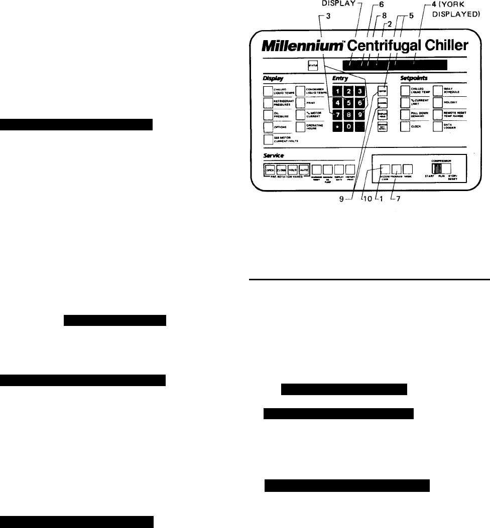
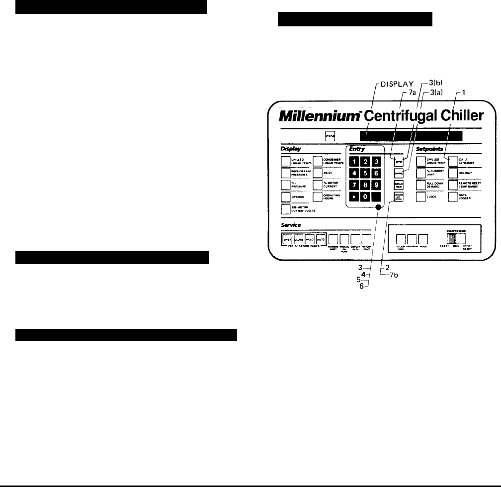
FIG. 5 – KEYPAD – PROGRAMMING SYSTEM
SETPOINTS
PROGRAMMING SYSTEM SETPOINTS
The system setpoints can be entered at any time . . . . .
even when the system is running. Proceed as follows to
enter system setpoints. (Refer to Fig. 5.)
1. Press ACCESS CODE key.
2.
ENTER VALID ACCESS CODE _ _ _ _
is displayed.
3. Using ENTRY keys, enter 9 6 7 5.
4. As each digit is entered, the characters Y O R K are
displayed.
NOTE: If digits other than 9 6 7 5 are entered,
YORKis still displayed.
NOTE: For ease in remembering the code, note that
the letters YORKcorrespond to the dig-
its 9675on a telephone dial
.
5. Press ENTER key.
NOTE: If digits other than 9675 were entered in step
No. 4,
INVALID ACCESS CODE
is displayed
when the ENTER key is pressed. If this oc-
curs, enter the correct access code (9675)
and proceed.
6.
ACCESS TO PROGRAM KEY AUTHORIZED
is displayed.
NOTE: Unless terminated by pressing the ACCESS
CODE key again, the operator will have ac-
cess to the PROGRAM key for 10 minutes.
When 10 minutes have elapsed, access to
PROGRAM key will be automatically disabled
and the operator must return to step No. 1 to
gain access.
7. Press PROGRAM key.
8.
PROGRAM MODE, SELECT SETPOINT
is displayed.
9. Enter setpoints as detailed below. If you make a mis-
take when entering a value, press CANCEL key and
then ENTER key. The display will revert to the default
values and the cursor will return to the first change-
able digit. You can then proceed to enter the correct
values. If the entered value exceeds acceptable lim-
its,
OUT OF RANGE – TRY AGAIN!
message will be displayed for 2 seconds, then the
PROGRAM MODE, SELECT SETPOINT
message will re-
appear.
10.When all the desired setpoints have been entered,
press the ACCESS CODE key to exit PROGRAM
mode and terminate access to PROGRAM mode.
ACCESS TO PROGRAM MODE DISABLED
is displayed.
The Control Center will automatically return to LO-
CAL, REMOTE or SERVICE mode . . . . whichever
was last selected.
LD00954
YORK INTERNATIONAL 15
FORM 160.49-O2
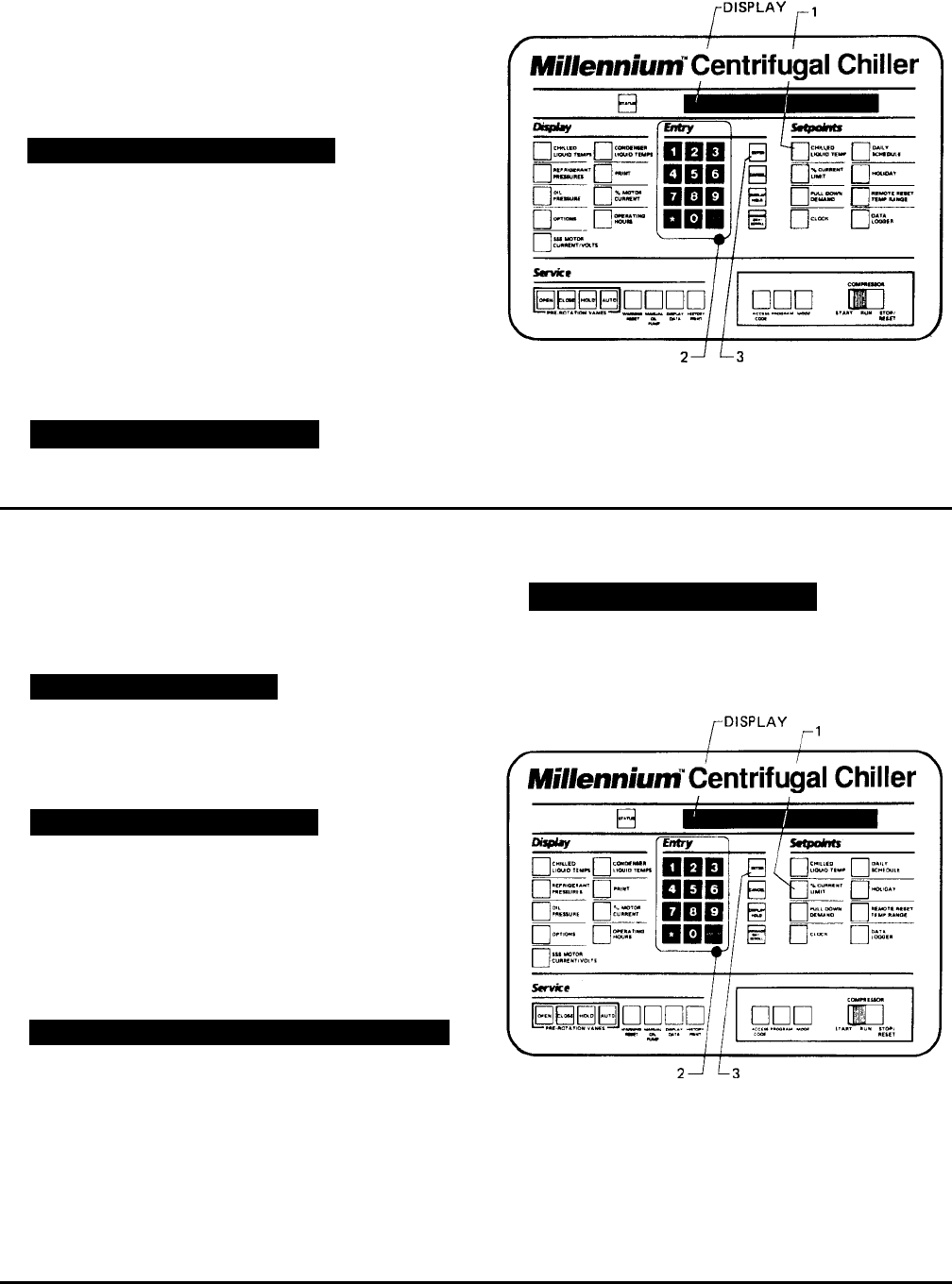
To enter CHILLED LIQUID TEMP Setpoint: (Refer to
Fig. 6.)
1. Press and release CHILLED LIQUID TEMP setpoint
key. The following program prompt message will be
displayed:
LEAVING SETPOINT = XX.X °F (BASE)
(BASE) refers to the base or lowest setpoint avail-
able to an Energy Management System. If any En-
ergy Management System is applied, this value must
be entered into the Energy Management System.
Refer to previous explanation or REMOTE/RESET
TEMP RANGE, page 11.
2. Use ENTRY keys to enter desired value.
3. Press and release ENTER key.
PROGRAM MODE, SELECT SETPOINT
message is displayed.
FIG. 6 – KEYPAD – PROGRAMMING “LEAVING
CHILLED WATER TEMP” SETPOINT
To Enter % CURRENT LIMIT Setpoint:
(Electro-Mechanical Starter, refer to Fig. 7)
1. Press and release % CURRENT LIMIT setpoint key.
The following program prompt message is displayed:
CURRENT LIMIT = XXX% FLA
2. Use ENTRY keys to enter desired value.
3. Press and release ENTER key.
PROGRAM MODE, SELECT SETPOINT
message is displayed.
(Solid State Starter, refer to Fig. 7)
1. Press and release % CURRENT LIMIT setpoint key.
The following program prompt message is displayed:
CURRENT LIMIT = XXX% FLA; MTR CUR = _ _ _ FLA
2. Use ENTRY keys to enter desired value.
NOTE: Motor Current FLA value is entered by YORK
factory and checked at system start-up. It
cannot be changed without special access
code. (Note to service technician: refer to
“Programming Instructions” in Service in-
struction, Form 160.49-M3.
3. Press and release ENTER key.
PROGRAM MODE, SELECT SETPOINT
message is displayed.
FIG. 7 – KEYPAD – PROGRAMMING “% CURRENT
LIMIT” SETPOINT
LD00955
LD00956
16 YORK INTERNATIONAL
To Enter PULL DOWN DEMAND Setpoint:
(Refer to Fig. 8.)
1. Press and release PULL DOWN DEMAND setpoint
key. The following program prompt message is dis-
played:
SETPOINT = XXX MIN @ XXX % FLA, XXX MIN LEFT
2. Use Entry keys to enter desired values. For expla-
nation, see PULL DOWN DEMAND, page 12. Note
that “XX min left” is not an operator entered value.
3. Press and release ENTER key.
PROGRAM MODE, SELECT SETPOINT
message is displayed.
FIG. 8 – KEYPAD – PROGRAMMING “PULL DOWN
DEMAND” SETPOINT
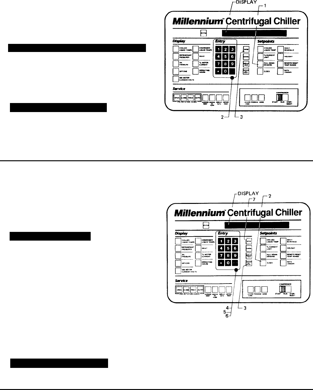
To Enter CLOCK Setpoint: (Refer to Fig. 9.)
1. Assure Micro Board Program jumper J57 is in
“CLKON” position.
2. Press and release CLOCK setpoint key. The follow-
ing program prompt message is displayed:
TODAY IS MON 10:30 PM 1/1/92
3. Press ADVANCE DAY / SCROLL key until the pro-
gram per day of week appears on the display.
4. Use Entry keys to enter proper time of day.
5. Press AM/PM key to change the AM to PM or vice
versa.
6. Use Entry keys to enter proper calendar date,
(MONTH/DAY/YR). If month and day are single digit
entries, precede the entry with “0”. For example,
02/04/88.
7. Press and release ENTER key.
PROGRAM MODE, SELECT SETPOINT
message is displayed.
FIG. 9 – KEYPAD – PROGRAMMING “CLOCK”
SETPOINT
LD00957
LD00958
YORK INTERNATIONAL 17
FORM 160.49-O2
To Enter DAILY SCHEDULE Setpoint:
(Refer to Fig. 10.)
1. Press and release DAILY SCHEDULE setpoint key.
The following prompt message is displayed:
SUN START = XX:XX AM, STOP = XX:XX AM
2. If the displayed start and stop time is not the desired
schedule, enter the desired start and stop times as
follows:
a. If you do not want the chiller to automatically start
and stop on this day, press CANCEL key.
b. Use the Entry keys to enter desired hours and
minutes start time.
c. If necessary, press the AM/PM key to change “AM”
to “PM” or vice versa.
d. Use the Entry keys to enter desired hours and
minutes stop time.
e. If necessary, press the AM/PM key to change “AM”
to “PM” or vice versa.
3. Press and release ADVANCE DAY/SCROLL key. The
following prompt message is displayed:
MON START = XX:XX AM, STOP = XX:XX AM
4. Enter the desired start and stop time per Step 2.
5. Press and release ADVANCE DAY/SCROLL key. The
following prompt message is displayed:
REPEAT MON SCHEDULE MON-FRI? YES = 1; NO = 0
a. If you press the 1 Entry key, Monday’s start and
stop time will be automatically entered for Tues-
day through Friday.
– or –
b. If you press the 0 Entry key, Tuesday through Fri-
day can be programmed with different start and
stop times.
6. Use the ADVANCE DAY / SCROLL key with proce-
dure in Step 2. To enter start and stop times for
remainder of the week plus a holiday schedule if
required.
7. Press the ENTER key.
PROGRAM MODE, SELECT SETPOINT
is displayed.
FIG. 10 – KEYPAD – PROGRAMMING “DAILY
SCHEDULE” SETPOINT
LD00959
18 YORK INTERNATIONAL
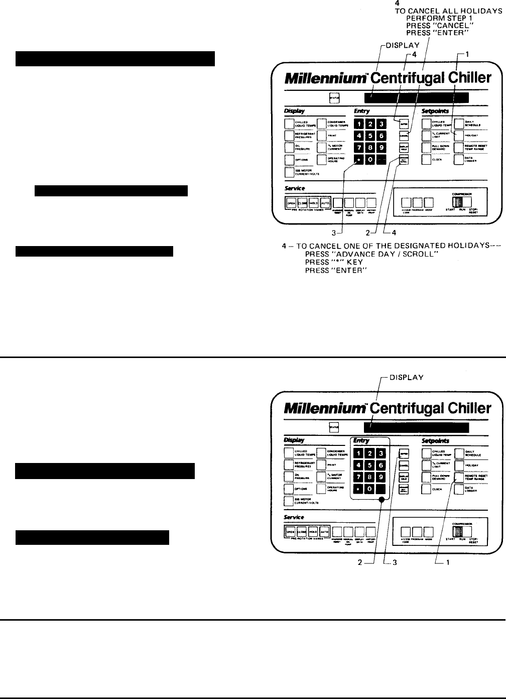
To Enter HOLIDAY Setpoint: (Refer to Fig. 11.)
1. Press and release HOLIDAY setpoint key. The fol-
lowing program prompt message is displayed:
S_ M_ T_ W_ T_ F_ S_ HOLIDAY NOTED BY
r
2. Press and release ADVANCE DAY/SCROLL key to
move cursor to the day that you wish to designate as
a holiday.
3. Press and release r entry key. An r will appear
next to the selected day.
4. After you have placed an r next to each of the days
that you wish to designate a holiday, press ENTER
key
PROGRAM MODE, SELECT SETPOINT
message is displayed.
To cancel all of the designated holidays: perform Step
1, press CANCEL key, and then press ENTER key.
PROGRAM MODE, SELECT SETPOINT
message is displayed.
To cancel one of the designated holidays: perform
Step 1, press ADVANCE DAY / SCROLL key until
the cursor appears to the right of the desired day,
press the
r key, then press the ENTER key.
FIG. 11 – KEYPAD – PROGRAMMING “HOLIDAY”
SETPOINT
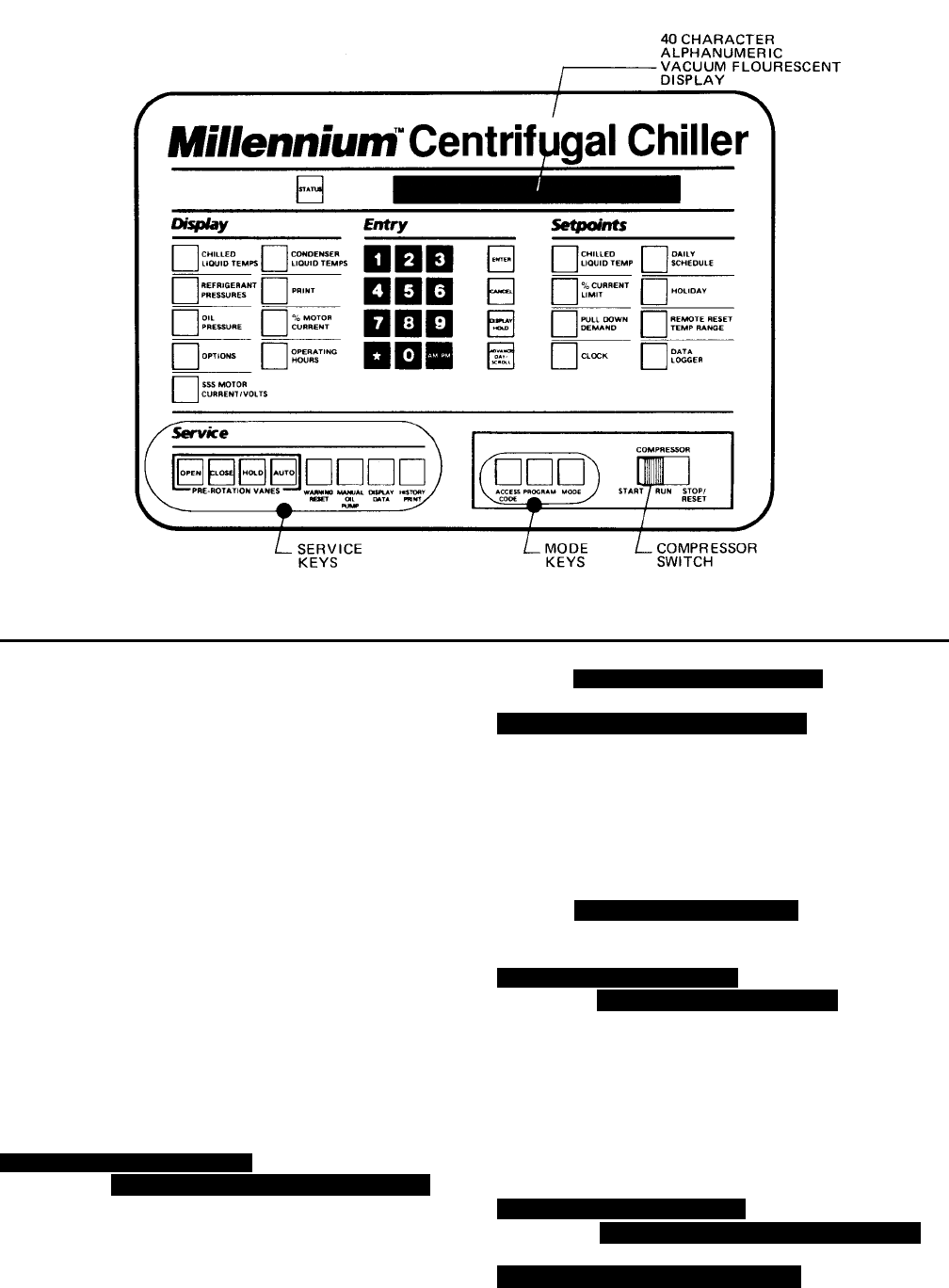
To Enter REMOTE/ RESET TEMP RANGE Setpoint:
(Refer to Fig. 12.)
1. Press and release REMOTE/RESET TEMP RANGE
setpoint key. The following program prompt message
is displayed:
REMOTE TEMP SETPOINT RANGE = XX °F
2. Use Entry keys desired value (10 or 20).
3. Press and release ENTER key.
PROGRAM MODE, SELECT SETPOINT
message is displayed.
To Enter DATA LOGGER Setpoint:
Refer to Form 160.49-N7 for operation of this key.
FIG. 12 – KEYPAD – PROGRAMMING “REMOTE
RESET” TEMP RANGE
LD00961
LD00962
YORK INTERNATIONAL 19
FORM 160.49-O2
FIG. 13 – KEYPAD – SERVICE KEYS LOCATION
The Service keys are provided for the service techni-
cian’s use when performing routine maintenance or when
troubleshooting the system. The WARNING RESET and
PRE-ROTATION VANES keys are enabled in SERVICE
mode only. The remainder of the Service keys are en-
abled in SERVICE, LOCAL or REMOTE mode.
PRE-ROTATION VANES KEYS
If chiller is equipped with the REFRIGERANT LEVEL
CONTROL (and EPROM version C.02F(T).13 or later),
the pre-rotation vanes keys can be used to manually
control the refrigerant level variable orifice or the pre-
rotation vanes. The procedure to select either manual
vane or manual variable orifice control is contained in
“Special Setpoints and Programming Procedures” sec-
tion of Service manual, Form 160.49-M3 and must be
performed by a qualified service technician only.
OPEN – Press and release this key to drive the pre-
rotation vanes open. If the chiller is running,
SYSTEM RUN – VANES OPENING
is displayed. If chiller is
not running,
SYS READY TO START – VANES OPENING
is
displayed. The vanes will continue to open until the
CLOSE, HOLD, or AUTO (if temperature error requires
it) keys are pressed and released.
HOLD – Press and release this key to hold the pre-
rotation vanes in their present position. If the chiller is
running,
SYSTEM RUN – VANES HOLDING
is displayed.
If chiller is not running,
SYS READY TO START – VANES HOLDING
is displayed. The
vanes will remain stationary until the OPEN, HOLD, or
AUTO keys are pressed and released.
AUTO – Press and release this key to put the pre-rota-
tion vanes under LCWT control as long as the current
limit setpoint is not reached, which causes the current
limit function to override the LCWT control. If system is
running,
SYSTEM RUN – AUTO VANES
is displayed. The
actual opening and closing of the vanes is indicated on
the display. When the vanes are opening,
SYSTEM RUN – VANES OPENING
is displayed. If the vanes
are closing,
SYSTEM RUN – VANES CLOSING
is displayed.
Whenever the Control Center is in LOCAL, REMOTE or
PROGRAM mode, the vane control circuitry is automati-
cally placed in AUTO mode and the vanes operate to
control the leaving chilled water temperature to the pro-
grammed setpoint.
CLOSE – Press and release this key to drive the pre-
rotation vanes closed. If the chiller is running,
SYSTEM RUN – VANES CLOSING
is displayed. If chiller is
not running,
SYS READY TO START – VANES CLOSING
is
displayed. When the vanes are full closed,
SYS READY TO START – VANES CLOSED
is displayed. The
vanes will continue to close until the OPEN, HOLD, or
AUTO keys are pressed.
SERVICE KEYS
LD00963

20 YORK INTERNATIONAL
OTHER SERVICE KEYS
WARNING RESET – Press and release this key to re-
set any “WARNING” or “STATUS” message that can be
reset with this key, unless the condition still exists. To
reset any cycling or warning message, place the Con-
trol Center in SERVICE mode and press WARNING
RESET key. To reset any safety shutdown message,
press WARNING RESET key in SERVICE mode with
the COMPRESSOR switch in the STOP/RESET posi-
tion.
MANUAL OIL PUMP – This key is operational in any
mode. Press and release this key to run the oil pump.
Press and release the key again to stop the oil pump. A
10-minute maximum is imposed on the running of the oil
pump (i.e., the oil pump will automatically shut off after
10 minutes). If a longer running time is desired, the key
must be pressed again. The manual oil pump feature is
disabled during “START SEQUENCE INITIALIZED” to
allow for auto-zeroing of oil pressure transducers.
DISPLAY DATA – This key is operational in any three
of the Control Center modes of operation (SERVICE,
LOCAL or REMOTE). It is used to display certain sys-
tem operating parameters that are relevant to trouble-
shooting the chiller system.
Press and the DISPLAY DATA key. The following mes-
sages will sequentially scroll on the display. Each mes-
sage will be displayed for 2 seconds.
Messages 1 and 2 are only displayed if unit is equipped
with EPROM version C.02F(T).13 or later and Refriger-
ant Level Control has been enabled by a qualified ser-
vice technician using the “Special Setpoints and Pro-
gramming” procedures section of Service manual, Form
160.49-M3.
NO. 1
MANUAL VANE OPERATION ALLOWED
– Displayed when the
PRE-ROTATION VANES service keys have been se-
lected for manual VANE control. This allows these keys
to manually control the vanes in Service mode. The pro-
cedure to select manual vanes control is in Service
manual, Form 160.49-M3 and should be performed only
by a qualified service technician.
– or –
NO. 1
MANUAL LEVEL CONTROL ALLOWED
– Displayed when the
PRE-ROTATION VANES keys have been selected for
manual REFRIGERANT LEVEL control. This allows
these keys to manually control the refrigerant level con-
trol variable orifice in Service mode. When manual re-
frigerant level control is selected, the pre-rotation vanes
Service keys cannot be used to control the vanes. The
procedure to select manual refrigerant level control is in
Service manual, Form 160.49-M3 and should be per-
formed only by a qualified service technician.
NO. 2
PULLDN LEVEL = XXX%; SETP = XXX%; ACTUAL = XXX%
– Displayed when there is a refrigerant level setpoint
pulldown (ramp) in effect. PULLDN LEVEL is the refrig-
erant level setpoint that is presently in effect. SETP is
the refrigerant level setpoint that has been programmed
by the service technician and ACTUAL is the refrigerant
level in the condenser. The pulldown period is 15 min-
utes in duration. During the pulldown period, a linearly
increasing ramp is applied to the level setpoint. This
causes the setpoint to increase from 0% to the pro-
grammed value over a period of 15 minutes. After the 15
minutes have elapsed, the setpoint remains the pro-
grammed value and this message is replaced by the
message
ACTUAL = XXX%; LEVEL SETP = XXX%
as
described below.
A refrigerant level setpoint pulldown is put into effect when
the vanes are driven from a fully closed to an open posi-
tion, if the actual refrigerant level is less than the level
setpoint when the vane motor end switch (VMS) opens.
If the actual level is greater than the setpoint when the
VMS opens, the level is controlled to the programmed
setpoint. Whenever the vanes go to the fully closed po-
sition (VMS closed), any pulldown that is in effect is can-
celled.
– or –
NO. 2
ACTUAL LEVEL = XXX%; LEVEL SETP = XXX%
– Displays
the actual refrigerant level in the condenser and the re-
frigerant level setpoint programmed by the service tech-
nician. This message replaces the previous message
after a refrigerant level setpoint pulldown period termi-
nates.
NO. 3
SAT TEMPS EVAP = XX.X°F; COND = XX.X°F
– This is the
refrigerant saturation temperatures for the evaporator and
condenser.
NO. 4
DISCHARGE TEMP = XXX.X°F; OIL TEMP = XXX.X°F
NO. 5
HOP = XX.X PSIG; LOP = XX.X PSIG
– This is the low oil
pressure (LOP) as measured at the oil sump and the
high oil pressure (HOP) as measured at the compres-
sor bearing input.

YORK INTERNATIONAL 21
FORM 160.49-O2
NO. 6
ACTUAL POS = XX MILS; REF = YY MILS
– ACTUAL POS is
the distance between the high speed thrust collar and
the proximity probe that is used to measure the position.
REF is the reference position established at time of com-
pressor manufacture.
NO. 7
HIGH SPEED DRAIN TEMP = XXX.X °F
– Temperature of oil
in high speed drain line.
To hold any of the above messages, press the DISPLAY
DATA key, then press the DISPLAY HOLD key. The
message will be displayed and updated every 2 sec-
onds until the DISPLAY DATA key is pressed again,
whereupon the next message is displayed. To return to
the normal foreground messages, press the DISPLAY
HOLD key.
HISTORY PRINT – This key is used to initiate a history
print to the optional printer. Refer to Form 160.49-N7 for
operation of this key.
OPERATING MODES
The MicroComputer Control Center can be operated in
four different operating modes as follows:
SERVICE – enables all the Service keys except DIS-
PLAY DATA, MANUAL OIL PUMP, and HISTORY
PRINT, which are enabled in all modes. See “Service
Keys”, page 20.
LOCAL – This is the normal operating mode. The com-
pressor can be started and stopped from the Control
Center. Also, the Display and Setpoints parameters can
be displayed.
PROGRAM – Allows the operator to program the Set-
points parameters, and change operating modes.
REMOTE – In this mode, the Control Center will ac-
cept control signals from a remote device (i.e., Energy
Management System) or cycling input. The control sig-
nal inputs are:
1. Remote Start
2. Remote Stop
3. Remote LCWT Setpoint
4. Remove Current Limit Setpoint
NOTE: The compressor can be stopped by the COM-
PRESSOR switch, regardless of the operating
mode. The switch must be in RUN position to
enable REMOTE mode. The operator cannot
locally start the compressor using the COM-
PRESSOR switch when in the REMOTE mode.
To determine which operating mode the Control Center
is presently in, simply press the MODE key.
• If the Control Center is in LOCAL mode,
LOCAL OPERATING MODE IN EFFECT
is displayed.
• If the Control Center is in REMOTE mode,
REMOTE OPERATING MODE IN EFFECT
is displayed.
• If the Control Center is in SERVICE mode,
SERVICE OPERATING MODE IN EFFECT
is displayed.
To change operating mode, proceed as follows:
1. Press ACCESS CODE key.
2.
ENTER VALID ACCESS CODE _ _ _ _
is displayed.
3. Using Entry keys, enter 9 6 7 5.
4. As each digit is entered, the characters Y O R K are
displayed.
NOTE: If digits other than 9 6 7 5 are entered, YORK
is still displayed.
5. Press ENTER key.
NOTE: If digits other than 9 6 7 5 were entered in
step No. 4,
INVALID ACCESS CODE
is dis-
played when the ENTER key is pressed. If
this occurs, enter the correct access code
(9675) and proceed.
6.
ACCESS TO PROGRAM KEY AUTHORIZED
is displayed.
NOTE: Unless terminated by pressing the ACCESS
CODE key again, the operator will have ac-
cess to the PROGRAM key for 10 minutes.
When 10 minutes have elapsed, access to
PROGRAM key will be automatically dis-
abled and the operator must return to step
No. 1 to gain access.

22 YORK INTERNATIONAL
7. Press PROGRAM key.
8.
PROGRAM MODE, SELECT SETPOINT
is displayed.
9. Press MODE key.
10.The mode that has been previously selected will be
displayed as follows:
LOCAL MODE SELECTED
– or –
SERVICE MODE SELECTED
– or –
REMOTE MODE SELECTED
11.Press ADVANCE DAY key to scroll to desired mode.
Each time this key is pressed, a different mode is
displayed as above:
12.When the desired mode is displayed, press EN-
TER key.
13.
PROGRAM MODE, SELECT SETPOINT
is displayed.
14.Press ACCESS CODE key to exit PROGRAM mode
and terminate access to PROGRAM mode.
15.
ACCESS TO PROGRAM MODE DISABLED
is displayed.
COMPRESSOR SWITCH
(See Fig. 13, page 19.)
This rocker switch is used to locally operate the com-
pressor. It is used to start, run and stop the compres-
sor. Also, it resets the Control Center after a safety
shutdown.
To START* chiller compressor in LOCAL mode:
Move COMPRESSOR switch from STOP/RESET
to START position. Switch will spring-return to RUN
position.
To STOP compressor:
Move switch from RUN to STOP/RESET position.
To RESET Control Center:
Following a safety shutdown, the operator is re-
quired to reset the Control Center prior to restart-
ing the system. Move switch from RUN to STOP/
RESET position.
*NOTE: The operator cannot start the compressor (us-
ing this switch) when the Control Center is in
REMOTE mode.
DISPLAY MESSAGES
The following displayed messages will be automatically
displayed unless the operator is requesting additional
information via the keypad.
SYSTEM RUN - CURRENT LIMIT IN EFFECT
Displayed when the chiller is running, and the motor
current is equal-to or greater-than the operator-pro-
grammed “XXX % FLA” current limit value. When the
motor current reaches 100% of this value, the pre-
rotation vanes are not permitted to open further. If the
current continues to rise to 104% of this value, the
vanes will be driven closed – not fully closed; only far
enough to allow the current to decrease to a value less
than 104% of the operator-programmed “XXX % FLA”
current limit.
For example:
With the operator-programmed “% CURRENT LIMIT”
set at 50% and the FLA of the chiller equal to 200A, the
current limit circuit would perform as follows:
(100%) (50% x FLA) = Vanes inhibited from open-
ing further.
(104%) (50% x FLA) = Vanes driven toward close
position.

YORK INTERNATIONAL 23
FORM 160.49-O2
Therefore:
(100%) (50% x 200) = 100A = Vanes stop open-
ing
(104%) (50% x 200) = 104A = Vanes driven to-
ward close position.
SYSTEM RUN – AUTO VANES
Displayed when the chiller is running, the MicroCom-
puter Control Center is in SERVICE mode, and the
vanes are operating in AUTO mode.
SYSTEM RUN – VANES OPENING
Displayed when the chiller is running, the MicroCom-
puter Control Center is in SERVICE mode with:
• The vanes operating in AUTO mode and opening to
maintain the leaving chilled water temperature
setpoint. – or –
• The operator has pressed the vanes OPEN key on
the keypad.
SYSTEM RUN – VANES CLOSING
Displayed when the chiller is running, the MicroCom-
puter Control Center is in SERVICE mode with:
• The vanes operating in AUTO mode and closing to
maintain the leaving chilled water temperature
setpoint. – or –
• The operator has pressed the vanes CLOSE key on
the keypad.
SYSTEM RUN - VANES HOLDING
Displayed when the chiller is running, the MicroCom-
puter Control Center is in SERVICE mode, and the
operator has pressed the vanes HOLD key.
SYS READY TO START – VANES OPENING
Displayed when the chiller is running and the operator
has pressed the vanes OPEN key on the keypad.
SYS READY TO START – VANES CLOSING
Displayed when the chiller is not running and the op-
erator has pressed the vanes CLOSE key on the key-
pad.
SYS READY TO START – VANES HOLDING
Displayed when the chiller is running and the operator
has pressed the vanes HOLD key on the keypad.
SYSTEM RUN – LEVEL VALVE OPENING
Displayed as a foreground message when manual re-
frigerant level control has been selected using the “Spe-
cial Setpoints Procedure” in Service manual, Form
160.49-M3 and operating in SERVICE mode. Indicates
an “OPEN” command is being output to the variable
orifice. Manual level control should be selected only by
a qualified service technician.
SYSTEM RUN – LEVEL VALVE CLOSING
Displayed as a foreground message when manual re-
frigerant level control has been selected using the “Spe-
cial Setpoints Procedure” in Service manual, Form
160.49-M3 and operating in SERVICE mode. Indicates
a “CLOSE” command is being output to the variable
orifice. Manual level control should be selected only by
a qualified service technician.
SYSTEM RUN – AUTO LEVEL CONTROL
Displayed as a foreground message when manual re-
frigerant level control has been selected using the “Spe-
cial Setpoints Procedure” in Service manual, Form
160.49-M3 and operating in SERVICE mode. Indicates
that neither a “CLOSE” nor “OPEN” command is being
output to the variable orifice but is in “AUTO” mode.
Manual level control should be selected only by a quali-
fied service technician.
SYSTEM RUN – LOW PRESSURE LIMIT IN EFFECT
Displayed when the chiller is running and the evapora-
tor pressure falls to 56.2 PSIG (R-22); 27 PSIG (R-
134a). Simultaneously, the pre-rotation vanes will be
prevented from further opening. This action maintains
chiller operation to prevent low-evaporator-pressure
shutdown at 54.3 PSIG (R-22); 25 PSIG (R-134a).
When the evaporator pressure rises to 57.5 PSIG (R-
22); 28 PSIG (R-134a), the vanes will be permitted to
open. Low pressure limit feature is not used when pro-
gram jumper (JP3) is cut (Brine application).
SYSTEM RUN – HIGH PRESSURE LIMIT IN EFFECT
Displayed when the chiller is running and the condenser
pressure rises to 246.3 PSIG (R-22); 162.5 PSIG (R-
134a). Simultaneously, the pre-rotation vanes will be
inhibited from further opening. This action occurs to
prevent system shutdown on high condenser pressure
24 YORK INTERNATIONAL
at 265 PSIG (R-22); 180 PSIG (R-134a). When the con-
denser pressure falls to 245 PSIG (R-22); 160 PSIG
(R-134a), the vanes will be permitted to open.
SYSTEM RUN – PRESSURE STATUS
Displayed when the chiller is running. It instructs the
operator to press the STATUS key, whereupon one of
the following messages will be displayed:
•
WARNING: COND OR EVAP TRANSDUCER ERROR
Indicates a probable condenser or evaporator trans-
ducer problem, because the output is unreasonable.
The microprocessor arrives at this conclusion by
subtracting the evaporator transducer output from
the condenser transducer output. The result must be
zero or some positive number. If the result is a nega-
tive number, it concludes that there is a probable
condenser or evaporator transducer problem. This
function is inhibited for the first 10 minutes of chiller
run-time, and is checked every 10 minutes thereaf-
ter. Message is reset by pressing the WARNING RE-
SET key in the Service mode.
NOTE: If the STATUS key is arbitrarily pressed, with-
out the operator being prompted by the
PRESS STATUS
message, the following message shall be displayed.
NO MALFUNCTION DETECTED
WARNING – REFRIGERANT LEVEL OUT OF RANGE
Displayed when the refrigerant level sensor output goes
to > 4.4VDC. While this is displayed, the variable ori-
fice is driven open until the level is within range. This
message is automatically cleared when output is within
range.
SYSTEM RUN – LEAVING TEMP CONTROL
Displayed while the chiller is running. Indicates that
the pre-rotation vanes are being controlled by the leaving
chilled water temperature (LCWT). This is the normal
mode of chiller operation. Thus, if the LCWT is above
the setpoint, but pulling down rapidly, the vanes will
pulse closed as the LCW nears the setpoint.
SYSTEM READY TO START
Indicates that the system is not running, but will start
upon application of a start signal.
SYSTEM SHUTDOWN – PRESS STATUS
Displayed when chiller is shut down on a cycling shut-
down, safety shutdown (operator must move the COM-
PRESSOR switch to STOP/RESET in order to restart)
or operator-initiated shutdown (within 30 minutes of
initial start-up). The status message consists of the
day and time of shutdown, cause of shutdown, and
type of restart required. Upon pressing STATUS key,
System Shutdown Message will be displayed for 2 sec-
onds and then return to
SYSTEM SHUTDOWN – PRESS STATUS
Display can be held indefinitely by depressing DIS-
PLAY key. For examples of System Shutdown Mes-
sages, see below.
Chiller was shut down on Monday at 10:00 AM be-
cause the LCWT has decreased to a value that is 4°F
below the operator-programmed chilled liquid tempera-
ture setpoint. However, if the setpoint is less than 40°F,
the chiller will always shut down at 36°F. Further, if the
chiller is running and the setpoint is changed, the (Low
Water Temperature) cutout will be 36°F for 10 minutes
in order to eliminate nuisance trips. Finally, for brine
chilling applications, the LWT cutout is always 4°F be-
low the setpoint. (The water jumper on the Micro Board
must be removed for a brine unit.)
MON XX:XX AM – FLOW SWITCH – AUTOSTART
Chiller is shut down because a chilled-liquid flow switch
has opened. The flow switch must open for a minimum
of 2 seconds in order to cause a shutdown. The flow
switch is checked 25 seconds into “Start Sequence
Initiated” and continuously thereafter.
MON XX:XX AM – SYSTEM CYCLING – AUTOSTART
A remote command (computer relay contact or manual
switch) connected to the Remote/Local cycling input
of the digital input board has shut down the chiller.
MON XX:XX AM – MULTI UNIT CYCLING – AUTOSTART
Lead/Lag sequence control accessory has shut down
the chiller.
MON XX:XX AM – POWER FAILURE – AUTOSTART
The chiller is shut down because there has been a
power interruption or failure. The chiller will automati-
cally restart when power is restored. This message
SYSTEM SHUTDOWN MESSAGES
Day of Week Cause of Shutdown
Time of Day Type of Restart
MON 10:00 AM – LOW WATER TEMP – AUTOSTART

YORK INTERNATIONAL 25
FORM 160.49-O2
will be displayed if the Micro Board is configured for
AUTO-RESTART AFTER POWER FAILURE. The Mi-
cro Board is factory set for manual restart after power
failure. To convert it to auto-restart after power failure,
remove one of the two-pin program jumpers from the
cloth bag located inside the Control Center and place it
on the terminals labeled “Auto R” (J60) on the Micro
Board.
MON XX:XX AM – POWER FAILURE
The chiller is shut down because there has been a
power interruption or failure. When power is restored,
the chiller can be restarted by pressing the COMPRES-
SOR switch to STOP/RESET position and then to
START position. This message will be displayed if the
Micro Board is configured for MANUAL RESTART AF-
TER POWER FAILURE. The Micro Board is factory
set for manual restart after power failure. This has been
accomplished by removing the two-pin jumper from
the terminals labeled “Auto R” (J60) on the Micro Board.
AC UNDERVOLTAGE – AUTOSTART
The chiller is shut down because the MicroComputer
Control Center was in RUN mode, displaying
SYSTEM RUN – LEAVING TEMP CONTROL
, but the motor
current was less than 10% FLA for 25 continuous sec-
onds. This is indicative of an AC undervoltage condi-
tion that has caused the start relay (1R) in the Micro-
Computer Control Center to de-energize. This condi-
tion is checked when the MicroComputer Control Cen-
ter goes into RUN mode (after 30 second pre-lube).
This condition can be caused by failure of any compo-
nent that would cause a loss of the start signal from
the Control Center. In essence, this check assures
that the compressor is running when the Control Cen-
ter is displaying
SYSTEM RUN – LEAVING TEMP CONTROL .
This check is not performed when program jumper JP4
is removed (Steam Turbine applications).
MON XX:XX AM – INTERNAL CLOCK – AUTOSTART
The operator-programmed daily stop schedule has shut
down the chiller. The chiller will automatically restart
when the operator-programmed daily start schedule
indicates a start. It can be overriddden by pressing the
COMPRESSOR switch to the START position.
REMOTE STOP
This message will be displayed when a remote device
(typically an Energy Management System) has com-
manded the chiller to shut down. The chiller will restart
upon application of a separate start signal from the
remote device. This message will only be displayed
when Control Center is in REMOTE mode.
ANTI-RECYCLE, XX MIN LEFT
The chiller may not restart more frequently than every
30 minutes. Displayed when chiller is shut down and
there is time remaining on the anti-recycle timer. In
normal operation, chiller cannot be restarted until
ANTI-RECYCLE, 00 MIN LEFT
is displayed. However, when
servicing the chiller, it may be desirable to inhibit this
30-minute timer. If so, simply install a jumper plug in
the unmarked terminals of the Micro Board directly
under Auto-Restart jack.
This feature eliminated when program jumper JP4 is
removed (Steam Turbine applications).
WARNING: Remove this jumper after servicing.
Failure to do this voids the Warranty.
MON XX:XX AM – LOW EVAP PRESSURE
The chiller is shut down because the evaporator pres-
sure has decreased to 54.3 PSIG (R-22); 25.0 PSIG
(R-134a). The chiller will be allowed to start when the
pressure increases to 54.4 PSIG (R-22); 25.1 PSIG
(R-134a). To restart chiller, press the COMPRESSOR
switch to the STOP/RESET position and then to the
START position.
MON XX:XX AM – LOW EVAP PRESSURE – BRINE
The chiller is shut down because the brine Low Evapo-
rator Pressure (LEP, not included with standard Con-
trol Center) safety contacts have opened. The brine
LEP safety is located external to the Control Center.
Safety cut-out settings will vary with the brine applica-
tion. To restart the chiller, wait until the safety contacts
close, press the COMPRESSOR switch to the STOP/
RESET position and then to the START position.
MON XX:XX AM – LOW OIL PRESSURE
The chiller is shut down because the oil pressure has
decreased to 15 PSID while running, or never achieved
25 PSID prior to compressor start during the oil pump
pre-lube run. The chiller will be allowed to restart when
the pressure increases to 25 PSID. Differential pres-
sure is sensed by two pressure transducers. To re-
start chiller, press COMPRESSOR switch to STOP/
RESET position and then to the START position.
MON XX:XX AM – HIGH PRESSURE
The chiller is shut down because condenser pressure

26 YORK INTERNATIONAL
has increased to 265 PSIG (R-22); 180 PSIG (R-134a).
System will be allowed to restart when pressure de-
creases to 205 PSIG (R-22); 120 PSIG (R-134a). Pres-
sure is sensed by a High Pressure (HP) safety control
that is located on a mounting bracket above the oil-
pump starter located on the condenser. This message
is prompted by the opening of the HP safety control
contacts. To restart chiller, press COMPRESSOR
switch to the STOP/RESET position and then to the
START position.
MON XX:XX AM – EVAP TRANS OR PROBE ERROR
The chiller is shut down because the leaving chilled
water temperature minus the evaporator saturation tem-
perature is outside the range of –2.5°F to +25°F con-
tinuously for 10 minutes. To restart the chiller, press
COMPRESSOR switch to STOP/RESET switch to
STOP/RESET position and then to START position. On
Brine applications (program jumper JP3 removed), this
check is not performed when the evaporator transducer
is reading a pressure below its “out-of-range” thresh-
old.
On Steam Turbine applications (Micro Board program
jumper JP4 removed), with EPROM version C.02F
(T).12 or later, this check is bypassed for the first 20
minutes of chiller run time and then performed at the
regular 10 minute intervals thereafter. This is to allow
for the additional time required to decrease the evapo-
rator pressure due to the longer acceleration time of
the steam turbine.
MON XX:XX AM – MOTOR CONTROLLER – EXT. RESET
The chiller is shut down because a current module
(CM-2 Electro-Mechanical starter application), or the
YORK Solid State Starter or the Variable Speed Drive
initiated a shutdown. To restart system, reset the ex-
ternal device that caused the shutdown. The chiller will
then automatically restart.
NOTE: The following motor controller shutdowns do
not require an external reset to restart chiller.
Solid State Starter 110°F start inhibit. Anytime the
chiller has been shut down for any reason, this mes-
sage will be displayed until the SCR heatsink tempera-
tures decrease to below 110°F.
MON XX:XX AM – POWER FAULT – AUTOSTART
The chiller is shut down because of a Solid State Starter
or current module (CM-2 Electro-Mechanical starter
application) “Power Fault” shutdown. The chiller will
automatically restart. This function is sensed by the
motor controller input to the digital input board. A power-
fault shutdown is initiated by the motor controller con-
tacts (CM-1) opening and reclosing in one second. If
Solid State Starter application, the shutdown could have
been caused by any of the following reasons. The ap-
propriate light on the Solid State Starter Logic Board
will be illuminated.
• Phase rotation/loss
• Trigger Board out of lock (OOL)
• Power Fault
• Half Phase
MON XX:XX AM – HIGH DISCHARGE TEMP
The chiller is shut down because the discharge tem-
perature has increased to 220°F. The system will be
allowed to restart when the temperature has decreased
to 219°F. Temperature is sensed by a thermistor RT2.
To restart the chiller, press COMPRESSOR switch to
STOP/RESET position and then to the START posi-
tion.
MON XX:XX AM – HIGH OIL TEMP
The chiller is shut down because the oil temperature
has increased to 180°F. The system will be allowed to
restart when the temperature decreases to 179°F. The
temperature is sensed by thermistor RT3. To restart
the chiller, press COMPRESSOR switch to STOP/RE-
SET position and then to the START position.
MON XX:XX AM – OIL PRESSURE TRANSDUCER
The chiller is shut down because the oil pressure has
increased to 125 PSID (during the first 7 minutes of
compressor operation) 60 PSID (after the first minutes
of compressor operation). The chiller will be allowed to
restart when the oil pressure decreases to 59 PSID. To
restart the chiller, press COMPRESSOR switch to
STOP/RESET position and then to the START posi-
tion.
MON XX:XX AM – FAULTY COND PRESSURE XDCR
The chiller is shut down because the condenser trans-
ducer is indicating a pressure of less than 24.2 PSIG
(R-22), 6.8 PSIG (R-134a); or a pressure greater than
300 PSIG (R-22 or R-134a). This is generally indica-
tive of a defective condenser transducer or the trans-
ducer has been disconnected. After the problem has
been corrected, the chiller can be restarted. To restart,
press COMPRESSOR switch to STOP/RESET posi-
tion and then to START position.
MON XX:XX AM – FAULTY OIL PRESSURE XDCR
The chiller is shut down because either the high side
or low side oil pressure transducer was out-of-range
(displaying x’s) while chiller was running. To restart

YORK INTERNATIONAL 27
FORM 160.49-O2
chiller, press COMPRESSOR switch to STOP/RESET
position and then to START position.
VANE MOTOR SWITCH OPEN
The chiller is shut down because a system-start se-
quence has been initiated, but the pre-rotation vanes
are not fully closed.
MON XX:XX AM – STARTER MALFUNCTION DETECTED
The chiller is shut down because the Control Center
has detected a motor-current value greater than 15%
FLA for 10 seconds minimum anytime when the com-
pressor-start signal is not energized. To restart the
chiller, press COMPRESSOR switch to STOP/RESET
position and then to the START position.
MON XX:XX AM – PROGRAM INITIATED RESET
The chiller is shut down because Micro Board did not
receive a hardware-generated interrupt on schedule.
Typical is an Analog/Digital Converter interrupt. This
message is indicative of a Micro Board hardware fail-
ure or electrical noise on Micro Board. The chiller will
automatically restart. This message indicates that the
watchdog timer-circuit has reset the microprocessor.
This occurs when the time needed to step through pro-
gram is longer than allowable, thus the software pro-
gram is initialized at its beginning.
SYSTEM READY TO START – PRESS STATUS
The chiller was shut down on a safety shutdown and
will start upon application of a local or remote start
signal. Since the message states that the chiller is
“Ready to Start”, it means that the shutdown no longer
exists and the Control Center has been manually re-
set. When the STATUS key is pressed, a message is
displayed that describes the reason for shutdown. The
message will be displayed for 2 seconds and then re-
turn to
SYSTEM READY TO START – PRESS STATUS
.
Those messages that could be displayed are any of
the previously described safety-shutdown messages
or warning messages. They can be cleared from the
display by entering Service mode and pressing WARN-
ING RESET key. Or, the message will be cleared by
initiating a compressor start.
START SEQUENCE INITIATED
Indicates that the Micro Board has received a local or
remote start signal and has initiated the chiller start-
up routine.
This is the compressor pre-lube period. The duration
of this period is controlled by the “Prerun” (JP6) wire
jumper on the Micro Board as follows:
FUNCTION JUMPER POSITION
50 Sec. Oil Pump Prerun Installed
180 Sec. Oil Pump Prerun Cut
SYSTEM COASTDOWN
Displayed while motor is decelerating after a chiller
shutdown. The oil pump is running during this period.
The duration of this period is 150 seconds.
If unit is configured for a Steam Turbine application
(program jumper JP4 removed), this period is extended
to allow for a longer coastdown time. EPROM version
C.02F(T).11 provides a 6 minute coastdown period.
EPROM version C.02F(T).12 or later provides a 10
minute coastdown period.
MON XX:XX AM – MTR PHASE CURRENT UNBALANCE
(Solid State Starter applications only)
The chiller is shut down because the compressor-motor
current was unbalanced while the chiller was running.
The current balance is only checked after the motor
has been running for a minimum of 45 seconds and the
motor current is 80% FLA or greater. If the current in
any phase deviates from the average (a + b3+ c ) current
by greater than 30% for a minimum of 45 consecutive
seconds, a shutdown is initiated. To restart the sys-
tem, press the COMPRESSOR switch to STOP/RE-
SET position and then to the START position. An ex-
ample of the conditions for shutdown is as follows:
IF:
I∅A= 200A
I∅B= 200A
I∅C= 118A
THEN:
IAV = 200 + 200 + 118
3
IAV = 173A
IACCEPTABLE = 173 ± 30% = 121A or 225A
THEREFORE:
Since I∅C = 118A which is less than the accept-
able 121A, the chiller would shut down if this
unbalance exists for 45 consecutive seconds.
MON XX:XX AM – LOW LINE VOLTAGE
(Solid State Starter applications only)
Chiller is shut down because the voltage in any phase
of line voltage has decreased below the under-volt-
age-shutdown threshold for 20 consecutive seconds,

28 YORK INTERNATIONAL
or failed to achieve the minimum required starting line-
voltage. Refer to explanation under “System Setpoints
– SSS Motor Current/Volts”, page 11. The system will
automatically restart when all phases of line voltage
increase to the minimum required starting voltage.
MON XX:XX AM
–
HIGH LINE VOLTAGE
(Solid State Starter applications only)
Chiller is shut down because the voltage in any phase
of line voltage has increased above the over-voltage
threshold for 20 consecutive seconds. Refer to expla-
nation under “System Setpoints – SSS Motor Current/
Volts”, page 11. The system will automatically restart
when all phases of line voltage decrease to the maxi-
mum allowable line voltage to start the chiller.
MON 09:30 AM – LOW OIL TEMPERATURE – AUTOSTART
The chiller is running and the oil temperature (as indi-
cated by thermistor RT3) falls below 55°F, the chiller
will shut down and display this message. The chiller
will automatically restart when the oil temperature in-
creases to >71°F AND is greater than the condenser
saturated temperature by 20°F or 30°F depending upon
how long the chiller was shut down. Refer to the mes-
sage “
MON XX:XX AM LOW OIL TEMP DIFF – AUTOSTART
”.
MON XX:XX AM – LOW OIL TEMP DIFF – AUTOSTART
Indicates the chiller is shut down for one of the follow-
ing reasons:
1. The chiller has been shut down for 30 minutes or
less and the oil temperature minus the condenser
saturation temperature is less than 30°F.
– or –
2. The chiller has been shut down for more than 30
minutes and the oil temperature minus the con-
denser saturation temperature is less than 40°F.
– or –
3. Following a power failure, the oil temperature mi-
nus the condenser saturation temperature is less
than 40°F.
The chiller will restart automatically after the condition
clears if the COMPRESSOR switch is in the RUN po-
sition.
NOTE: This check is made only when the chiller is
shut down. It is not checked when the chiller is
running or in “Start Sequence Initiated”.
DAY – TIME – OIL PRESSURE XDCR ERROR
Indicates the chiller has shut down because the differ-
ence between the High Side Oil Pressure Transducer
Output and the Low Side Transducer Output was greater
than 15.0 PSID during the “Transducer Auto-Zeroing
Sequence” that occurs 10 seconds after a chiller start
is initiated. Message is displayed immediately after the
Auto-Zeroing sequence has completed. This indicates
that one of the transduce outputs is incorrect, possibly
due to an incorrect or defective transducer. To restart
the chiller, press COMPRESSOR switch to STOP/
RESET position and then to START position.
MON XX:XX AM – FAULTY DISCHARGE TEMP SENSOR
Whenever the discharge temperature falls below 30°F,
or the discharge temperature sensor is disconnected
from the Micro Board, the preceding message will ap-
pear. To restart the system when the discharge tem-
perature rises or the sensor has been connected, press
the COMPRESSOR switch to the STOP/RESET posi-
tion and then to the START position.
MON XX:XX AM – PROX SENSOR SAFETY SHUTDOWN
The chiller is shut down because the “Proximity/Tem-
perature Sensor” has detected that the distance be-
tween the compressor high speed thrust collar and the
sensor probe has increased > 10 mils or decreased >
20 mils (25 mils with EPROM version C.02F(T).12 or
later) from the “Reference Position”.
NOTE: With EPROM version C.02F (T).11, if the ref-
erence position is < 42 mils, the minimum al-
lowed distance is 22 mils. With EPROM ver-
sion C.02F(T).12 or later, if the reference posi-
tion is < 44 mils, the minimum allowed distance
is 19 mils.
IMPORTANT: If the chiller has shut down displaying
this message, it cannot be restarted until a qualified
service technician performs a visual inspection of the
high speed thrust bearing and performs a special reset
procedure. This special reset procedure is detailed in
YORK Service manual, Form 160.49-M3. Failure to
perform the visual inspection prior to restarting the
chiller could result in severe compressor damage!!!
DAY – TIME – FAULTY PROXIMITY PROBE
The chiller has shut down because the “Proximity/Tem-
perature Sensor” has detected that the distance be-
tween the compressor high speed thrust collar and the
sensor probe has decreased to ≤ 17 mils.
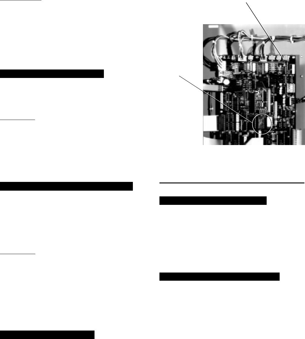
YORK INTERNATIONAL 29
FORM 160.49-O2
IMPORTANT!!!: Although this message is generally
indicative of a defective proximity probe, it is possible
that the compressor has been damaged. If the high
speed thrust bearing is not inspected by a qualified
service technician prior to starting the chiller, further
severe compressor damage could result. The chiller
cannot be restarted until the “Special Reset Proce-
dure” in YORK Service manual, Form 160.49-M3 is per-
formed by a qualified service technician.
MON XX:XX AM – HIGH SPEED DRAIN TEMP
The chiller has shut down because the “Proximity/Tem-
perature Sensor” has detected the temperature of the
high speed drain line has reached 250.0°F or greater.
IMPORTANT: If the chiller has shut down displaying
this message, it cannot be restarted until a qualified
service technician performs visual inspection of the
high speed thrust bearing and performs a special reset
procedure. This special reset procedure is detailed in
YORK Service manual, Form 160.49-M3. Failure to
perform the visual inspection prior to restarting the
chiller could result in severe compressor damage!!!
MON XX:XX AM – OPEN DRAIN TEMP THERMOCOUPLE
The chiller is shut down because the “Proximity/Tem-
perature Sensor” thermocouple or high speed drain tem-
perature wiring between the “Proximity/Temperature
Sensor” module and the MicroComputer Control Cen-
ter has been disconnected or has a poor electrical con-
nection.
IMPORTANT: Open thermocouple shutdowns would
typically indicate hardware or wiring defects and should
not result in any damage to the compressor high speed
thrust bearing. Therefore, a bearing inspection is not
required. However, due to the critical nature of these
circuits, anytime this shutdown occurs, a special re-
set procedure must be performed by a qualified ser-
vice technician before the chiller can be restarted.
This procedure is detailed in Service manual, Form
160.49-M3.
MON XX:XX AM – DC UNDERVOLTAGE
The “Proximity/Temperature Sensor” module becomes
unstable in operation when the +24VDC supply de-
creases to +17VDC. Therefore, the Micro Board moni-
tors the +24VDC supply and when it decreases to
+19VDC, it shuts down the chiller and displays this
message, preventing invalid “Proximity Sensor Safety”
or “High Speed Drain Temp” safety shutdowns. The
chiller will automatically restart when the voltage in-
creases to greater than +19.7 VDC.
MON XX:XX AM – AUX SAFETY SHUTDOWN
The system is shut down because an external device,
connected to digital input board TB1-31 (Auxiliary Safety
Shutdown Input), has initiated a system shutdown. This
input is a general purpose input that can be used to
annunciate a user-defined safety shutdown. To restart
chiller, press COMPRESSOR switch to STOP-RESET
position and then to START position.
REPLACE RTC. U16 – REPROGRAM SETPOINTS
Indicates that the battery located inside the REAL-
TIME CLOCK IC chip (U16 on the Micro Board) is
defective. This battery provides back-up power to the
RTC memory (RAM) in the event of a utility AC power
failure. This assures the system setpoints will be main-
tained. If this message appears, the RTC IC chip (U16)
on the Micro Board must be replaced. If there had been
a power failure while this message is displayed, the
setpoints will have been lost and must be repro-
grammed. Order a replacement RTC IC chip (YORK
part number 031-00955-000) from the YORK Parts Dis-
tribution Center. With AC power removed from system,
locate RTC chip U16 on the Micro Board and remove
existing RTC chip from socket and discard. Observe
anti-static precautions and install new RTC chip in
socket. Assure proper IC orientation – orientation notch
must be UP. (Refer to Fig. 14.)
FIG. 14 – MICROCOMPUTER CONTROL CENTER
LOCATION OF REAL TIME CLOCK U16
RTC IC CHIP
24673A
MICRO BOARD
U16 RTC
IC CHIP
REAL
TIME
CLOCK
30 YORK INTERNATIONAL
SECTION 3
SYSTEM OPERATING PROCEDURES
WARNING
OIL HEATERS
If the oil heater is de-energized during a shut-
down period, they must be energized for 12 hours
prior to starting compressor, or remove all oil and
recharge compressor with new oil. (See “Charg-
ing Unit With Oil”, page 43.)
NOTE: The oil heater is thermostatically controlled
and remains energized as long as the
fused disconnect switch to the starter or
turbo-modulator is energized.
CHECKING THE OIL LEVEL IN THE OIL
RESERVOIR
Proper operating oil level – the middle of the up-
per sight glass.
If the oil is excessively high after start-up, the
excess oil may be drained from the oil filter drain
valve while the compressor is running.
If oil level is low, oil should be added to the com-
pressor. (See “Charging Unit With Oil”, page 43.)
START-UP PROCEDURE
PRE-STARTING
Prior to starting the chiller, observe the MicroCom-
puter Control Center. Make sure the display reads
SYSTEM READY TO START
.
To pre-start the chiller, use the following procedure:
1. Oil Heater – The oil heater must be energized for
12 hours prior to starting the chiller. The unit will
not start if the oil is less than 71°F. If not possible
the compressor oil should be drained and new oil
must be charged into the oil sump. (See “Charging
Unit With Oil”, page 43.)
2. Oil Pump – To check, press and release the
MANUAL OIL PUMP key under Service on the
Control Center. The oil pump will run for 10 min-
utes and shut down. Press and release the
MANUAL OIL PUMP key to stop the operation of
the oil pump for less than 10 minutes of operation.
3. Pre-Rotation Vanes – To perform this test the
starter interlock terminals 3 and 4 must be
jumpered to allow vanes to open (remove the
jumper after test). Make sure the Control Center
is in the SERVICE mode, then press the prerotation
vanes OPEN and CLOSE keys to observe the
operation of the prerotation vanes. The Control
Center supplies a signal to operate the prerotation
vanes. The movement of the vanes will be dis-
played on the Control Center. The display readout
is active whenever power is supplied to the Con-
trol Center. Return from the SERVICE mode to
LOCAL, PROGRAM, or REMOTE mode to suit
the method of operation selected for the chiller
application. Refer to “Section 2”.
4. % Current Limit – Press the % CURRENT LIMIT
setpoint key on the Control Center. The “Display”
should read
CURRENT LIMIT = 100% FLA
on (Solid
State Starter units only, the display is
CURRENT LIMIT = 100% FLA, MTR CUR = XXXX FLA
)
if the Control Center was not programmed. If the
setpoint is not 100% and was predetermined for
the job application the Control Center should be
programmed to that specification. To program, re-
fer to “Section 2”.
5. All Control Center setpoints should be programmed
before the chiller is started. (Refer to “Section 2”.)
Prior to start, the clock must be programmed for
the proper day and time. Any setpoints which are
desired to be changed may be programmed. If not
programmed the “default” value setpoints are as
follows:
LCWT = 45°F
% Current Limit = 100% FLA
Pulldown Demand = None
Clock = Sun 12:00 A.M.
Daily Schedule = None
Holiday = None
Remote Reset Temp. Range = 20°F
Data Logger = No operation

YORK INTERNATIONAL 31
FORM 160.49-O2
START-UP
1. If the chilled water pump is manually operated,
start the pump. The Control Center will not allow
the chiller to start unless chilled liquid flow is es-
tablished through the unit. (A field supplied chilled
water flow switch is required.) If the chilled liquid
pump is wired to the MicroComputer Control Cen-
ter the pump will automatically start, therefore,
this step is not necessary.
2. To start the chiller, press the COMPRESSOR
START switch. This switch will automatically spring
return to the RUN position. (If the unit was previ-
ously started, press the STOP/RESET side of the
COMPRESSOR switch and then press the START
side of the switch to start the chiller.) When the
start switch is energized, the Control Center is
placed in an operating mode and any malfunction
will be noted by messages on the 40 character
alphanumeric display. (See Fig. 3.)
NOTE: Any malfunctions which occur during
STOP/RESET are also displayed.
When the chiller is shut down, the prerotation vanes
will close automatically to prevent loading the com-
pressor on start-up. When the prerotation vanes
are fully closed the “Display” will read
SYSTEM READY TO START – VANES CLOSED
when in SERVICE mode.
When the chiller starts to operate, the following auto-
matic sequences are initiated: (Refer to Fig. 15, “Chiller
Starting & Shutdown Sequence Chart”.)
1. The MicroComputer Control center alphanumeric
display message will read
START SEQUENCE INITIATED
for the first 50 seconds of the starting sequence,
(3 minutes if Micro Board JP6 removed).
2. The compressor vent line solenoid valve will open
after the first 5.83 minutes of operation. The sole-
noid will close automatically after the compressor
shuts down.
3. The 1R-1 contacts of the 1R start relay will re-
main open for the first 50 seconds of oil pump
operation. These contacts will close, starting the
compressor motor and the condenser water pump
at the end of the 50 second period.
4. The oil pump will start to circulate oil for a 50
second pre-run to establish oil flow and adequate
lubrication to all bearings, gears, and rotating sur-
faces within the compressor.
The high and low oil pressure transducers (OP)
and the oil temperature sensor (RT3) will sense
any malfunction in the lubrication system and ac-
tivate one of the following display messages:
DAY 10:30 AM – LOW OIL PRESSURE
DAY 10:30 AM – HIGH OIL TEMPERATURE
DAY 10:30 AM – LOW OIL TEMP – AUTOSTART
DAY 11:30 AM – OIL PRESSURE TRANSDUCER
5. The anti-recycle timer software function will oper-
ate after the 50 seconds of pre-run time. At this
time, the timer will be initiated and will run for 30
minutes after the compressor starts. If the chiller
shuts down during this period of time, it cannot be
started until the timer completes the 30 minute
cycle.
6. The chilled liquid pump contacts will close start-
ing the chilled liquid pump to allow liquid flow
through the cooler when the COMPRESSOR start
switch is energized.
7. After the first 50 seconds of operation, the com-
pressor will start and the Control Center display
message will read
SYSTEM RUN – CURRENT LIMIT IN EFFECT
while the
motor is accelerating to full speed. When the mo-
tor reaches full speed and the current falls below
100% FLA the message will read
SYSTEM RUN – LEAVING TEMP. CONTROL
8. For additional display messages and information
pertaining to the operation of the MicroComputer
Control Center, refer to “Section 2”.
9. Low Oil Temp. Differential.
CHILLER OPERATION
After the compressor reaches its operating speed, the
Prerotation Vanes will begin to open under the control
of the Microprocessor Board which senses the leaving
chilled liquid temperature. The unit capacity will vary
to maintain the leaving CHILLED LIQUID TEMPERA-
TURE setpoint. The Prerotation Vanes are modulated
by an actuator under the control of the Microprocessor
Board. The vane control routine employs proportional
plus derivative (rate) control action. A drop in chilled
liquid temperature will cause the actuator to close the
Prerotation Vanes to decrease chiller capacity. When
the chilled liquid temperature rises, the actuator will
open the Prerotation Vanes to increase the capacity of
the chiller.
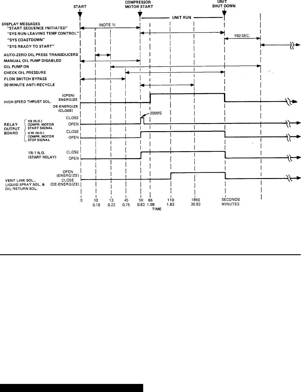
32 YORK INTERNATIONAL
However, the current draw (amperes) by the compres-
sor motor cannot exceed the setting of the % CUR-
RENT LIMIT at any time during the unit operation, since
the MicroComputer Control Center 40 to 100% three-
phase peak current limit software function, plus the 3-
phase 100% solid state overload current limiter (CM-
2) on Electro-Mechanical Starter applications or the
Solid State Starter current Limit function will override
the temperature control function and prevent the Pre-
rotation Vanes from opening beyond the % CURRENT
LIMIT setting.
If the load continues to decrease, after the Prerotation
Vanes are entirely closed, the chiller will be shut down
by the Low Water Temperature control (LWT) function
which is displayed on the Control Center as:
MON 10:30 AM – LOW WATER TEMPERATURE – AUTOSTART
This occurs when the leaving water temperature falls
to 4°F below setpoint or 36°F, whichever is higher. The
LWT is part of the Micro Board.
NOTE: If the temperature setpoint has been repro-
grammed within the last 10 minutes, the LWT
cutout is 36°F for 10 minutes.
Condenser Water Temperature Control
The YORK Millennium chiller is designed to use less
power by taking advantage of lower than design tem-
peratures that are naturally produced by cooling tow-
ers throughout the operating year. Exact control of con-
denser water such as a cooling tower bypass, is not
necessary for most installations. The chiller requires
only that the minimum condenser water temperature
SYSTEM STARTING & SHUTDOWN SEQUENCE
OPERATOR INITIATED
FIG. 15 – CHILLER STARTING SEQUENCE & SHUTDOWN SEQUENCE
NOTES: 1. REF. MICROBOARD PROGRAM JUMPER JP6
2. REF. MICROBOARD PROGRAM JUMPER JP4
(NOTE 2)
LD00952
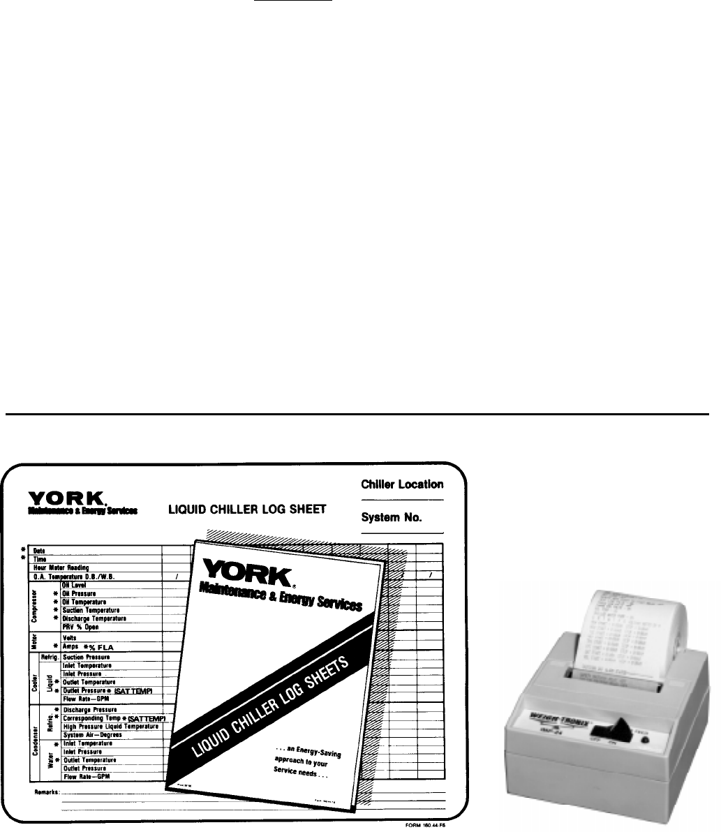
YORK INTERNATIONAL 33
FORM 160.49-O2
be no lower than the value determined by referring to
the formula below:
100
Min. ECWT = LCHWT—C RANGE + 5 + (15 x % LOAD)
where:
ECWT = entering condensing water temperature
LCHWT = leaving chilled water temperature
C RANGE = condensing water temperature range
At start-up, the entering condenser water temperature
may be as much as 25°F colder than the standby re-
turn chilled water temperature. Cooling tower fan
cycling will normally provide adequate control of the
entering condenser water temperature on most instal-
lations.
CHECKING OPERATION
During operation, the following conditions should be
periodically checked:
1. On starting, the prerotation vanes should remain
closed until the compressor motor is up to speed
on the run winding; then the vane motor should cause
the vanes to modulate with load requirements.
2. Be sure the oil pump is operating while unit is run-
ning.
3. Check Oil Pressure display. A gradual decrease in
bearing oil pressure of 5 to 10 psi (with constant
suction and discharge pressures) may be an indi-
cation of a dirty filter. The filter should be replaced
when pressure loss is 30% or more of the original
pressure. The actual bearing oil pressure will vary
with compressor suction and discharge pressures.
When a new system is first operated under normal
full load conditions, the bearing oil pressure should
be recorded as a reference point with which to com-
pare subsequent readings.
OPERATING LOG SHEET
A permanent daily record of system operating condi-
tions (temperatures and pressures) recorded at regu-
lar intervals throughout each 24 hour operating period
should be kept.
An optional status printer is available for this purpose
or Fig. 16 shows a log sheet used by YORK Personnel
for recording test data on chiller systems. It is avail-
able from the factory in pads of 50 sheets each under
Form 160.44-F6 and may be obtained through the nearest
FIG. 16 – LIQUID CHILLER LOG SHEETS
*NOTE: These items can be printed by an electronic printer connected to TB8 of the Micro Board and pressing the PRINT key on the
Micro Board or automatically using the Data Logger feature.
LD00467 23889A
34 YORK INTERNATIONAL
YORK office. Automatic data logging is possible by
connecting the optional printer and programming the
DATA LOGGER function; refer to Form 160.49-N7.
An accurate record of readings serves as a valuable
reference for operating the system. Readings taken
when a system is newly installed will establish normal
conditions with which to compare later readings.
For example, an increase in condenser approach tem-
perature (condenser temperature minus leaving con-
denser water temperature) may be an indication of dirty
condenser tubes.
OPERATING INSPECTIONS – See Section 2
By following a regular inspection using the display read-
ings of the MicroComputer Control Center, and main-
tenance procedure, the operator will avoid serious op-
erating difficulty. The following list of inspections and
procedures should be used as a guide.
Daily
1. Check MicroComputer Control Center displays.
2. If the compressor is in operation, check the bear-
ing oil pressure by pressing OIL PRESSURE key
to read the display on the Control Center. Also check
the oil level in the oil reservoir. Operating oil level
should be between the upper and lower sight
glasses. Drain or add oil if necessary.
3. Check entering and leaving condenser water pres-
sure and temperatures for comparison with job de-
sign conditions. Condenser water temperatures can
be checked by pressing CONDENSER LIQUID
TEMPERATURES display key.
4. Check the entering and leaving chilled liquid tem-
peratures and evaporator pressure for comparison
with job design conditions. This can be accomplished
by pressing the CHILLED LIQUID TEMPS key and
the REFRIGERANT PRESSURES key.
5. Check the condenser saturation temperature (based
upon condenser pressure sensed by the condenser
transducer). Press the DISPLAY DATA key. This
key may be depressed repeatedly after depressing
the DISPLAY HOLD key to display three different
parameters.
6. Check the compressor discharge temperature.
Press DATA DISPLAY key. During normal opera-
tion discharge temperature should not exceed 220°F.
7. Check the compressor motor voltage and current
(amps) at E-M starter (or Variable Speed Drive), or
on the Control Center display for Solid State Starter
units.
8. Check for any signs of dirty or fouled condenser
tubes. (The temperature difference between water
leaving condenser and liquid refrigerant leaving the
condenser should not exceed the difference re-
corded for a new unit by more than 4°F.)
9. Press the STATUS key whenever the display indi-
cates so. This allows any warning messages to be
displayed.
Weekly
1. Check the refrigerant charge. (See “Checking The
Refrigerant Charge”, page 52.)
Quarterly
1. Perform chemical analysis of oil.
Semi-Annually (or more often as required)
1. Change and inspect compressor oil filter element.
2. Oil return system.
a. Change dehydrator.
b. Check nozzle of eductor for foreign particles.
3. Check controls and safety cutouts.
Annually (more often if necessary)
1. Drain and replace the oil in the compressor oil
sump. (See “Charging The Unit With Oil”, page 43.)
2. Cooler and Condenser.
a. Inspect and clean water strainers.
b. Inspect and clean tubes as required.
c. Inspect end sheets.
3. Compressor Drive Motor (See motor manufactur-
ers maintenance and service instruction supplied
with unit)
a. Clean air passages and windings per manufac-
turers instructions.
b. Meg motor windings – See Fig. 23 for details.
c. Re-lubricate ball bearings.
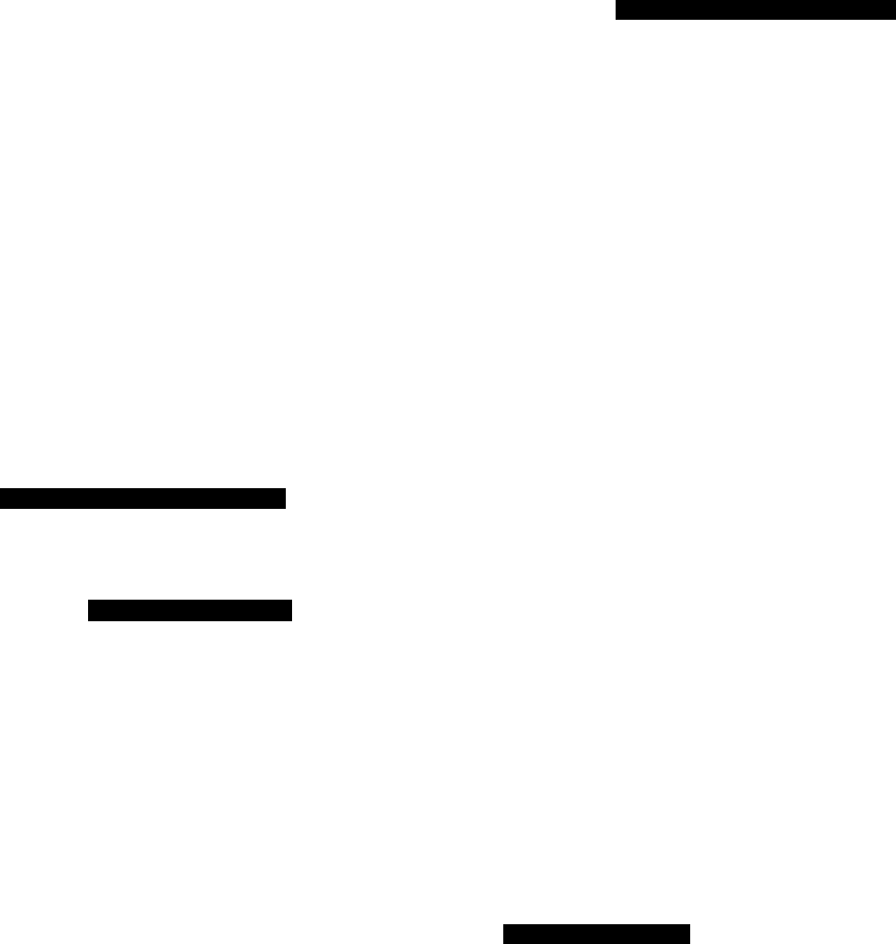
YORK INTERNATIONAL 35
FORM 160.49-O2
4. Inspect and service electrical components as nec-
essary.
5. Perform chemical analysis of system.
NEED FOR MAINTENANCE OR SERVICE
If the system is malfunctioning in any manner or the
unit is stopped by one of the safety controls, consult
the “Operation Analysis Chart”, pages 47 through 48
of this instruction. After consulting this chart, if you
are unable to make the proper repairs or adjustments
to start the compressor or the particular trouble con-
tinues to hinder the performance of the unit, please
call the nearest YORK District Office. Failure to report
constant troubles could damage the unit and increase
the cost of repairs considerably.
NORMAL AND SAFETY SYSTEM SHUTDOWNS
Normal and safety system shutdowns have been built
into the chiller to protect it from damage during certain
operating conditions. Therefore, it should be understood
that at certain pressures and temperatures the sys-
tem will be stopped automatically by controls that re-
spond to high temperatures, low temperatures, and low
and high pressures, etc. Table 1 is an explanation of
each specific shutdown. If the chiller shuts down on a
“Safety” shutdown, the display will read
SYSTEM SHUTDOWN – PRESS STATUS
Upon pressing the STATUS key, the day-of-week, time-
of-day and cause of shutdown is displayed. Safety shut-
downs require the operator to manually reset the Con-
trol Center prior to restarting the chiller. When the dis-
play reads
START SEQUENCE INITIATED
, the cause of the
safety shutdown is automatically cleared from the
memory.
SAFETY SHUTDOWNS
• Power Failure (If auto restart programming jumper is
not installed on the Micro Board)
• Low Evaporator Pressure
• Low Oil Pressure
• High Condenser Pressure
• Evaporator Transducer or Probe Error
• High Discharge Temp
• High Oil Temp
• Oil Pressure Transducer
• Starter Malfunction Detected
• Faulty Discharge Temp Sensor
• Aux. Safety Shutdown
• Motor Phase Current Unbalance (Solid State Starter
Unit only)
• Proximity sensor
• Faulty Prox. Probe
• Open Drain Thermocouple
If the chiller shuts down on a “Cycling” shutdown the
display will read
SYSTEM SHUTDOWN – PRESS STATUS
.
Upon pressing the STATUS key, the day-of-week, time-
of-day and cause of shutdown are displayed. These
shutdowns do not require the operator to manually re-
set the Control Center prior to re-starting the chiller.
The chiller will automatically restart when the cycling
condition is removed.
CYCLING SHUTDOWNS
• Power Failure (If auto re-start programming jumper
is installed on the Micro Board)
• Low Water Temp
• Flow Switch
• System Cycling
• Multi-Unit Cycling
• Internal Clock
• Anti-Recycle
• Motor Controller (Manual reset of the CM-2 module
on E-M starter units; the logic board of the Solid
State Starter may be required)
• Power Fault
• Program Initiated Reset
• Low Oil Temp
• AC Undervoltage
• DC Undervoltage
• Low Line Voltage (Solid State Starter units only)
• High Line Voltage (Solid State Starter units only)
• Low Oil Temp. Differential
STOPPING THE SYSTEM (See Fig. 3, page 6)
The MicroComputer Control Center can be programmed
to start and stop automatically (maximum, once each
day) whenever desired. Refer to “Section 2”. To stop
the chiller, proceed as follows:
1. Push the COMPRESSOR STOP/RESET switch. The
Control Center display will show
SYSTEM COASTDOWN
for 150 seconds. If unit is
configured for a STEAM TURBINE application (pro-
gram jumper JP4 removed), this period is extended
to allow for a longer coastdown time. EPROM ver-
sion C.02F(T).11 provides a 6 minute coastdown

36 YORK INTERNATIONAL
period. EPROM version C.02F(T).12 or later pro-
vides a 10 minute coastdown period. The compres-
sor, condenser water, and cooling tower fans will
stop automatically. The oil pump will continue to run
for coastdown period. The oil pump will then stop
automatically. Once stopped, the
SYSTEM COASTDOWN
display will be replaced by
SYSTEM READY TO START
.
2. Stop the chilled water pump (if not wired into the
MicroComputer Control Center, in which case it will
shut off automatically simultaneously with the oil
pump.) (The actual water pump contact operation
is dependent upon the postion of Micro Board jumper
J54.)
3. Open the switch to the cooling tower fan motors, if
used.
4. The compressor sump oil heater (thermostatically
controlled) is energized when the unit is stopped.
PROLONGED SHUTDOWN
If the chiller is to be shut down for an extended period
of time (for example, over the winter season), the fol-
lowing paragraphs outline the procedure to be followed.
1. Test all system joints for refrigerant leaks with a
leak detector. If any leaks are found, they should
be repaired before allowing the system to stand for
a long period of time.
During long idle periods, the tightness of the sys-
tem should be checked periodically.
2. If freezing temperatures are encountered while the
system is idle, carefully drain the cooling water from
the cooling tower, condenser, condenser pump, and
the chilled water system-chilled water pump and
coils.
Open the drains on the cooler and condenser liquid
heads to assure complete drainage. (If a Variable
Speed Drive, drain its water cooling system. If Solid
State Starter. drain water from starter cooling loop.)
3. Move jumper J-57 on the Micro Board from CLOCK
ON position (CLKON) to CLOCK OFF position
(CLKOFF) while 115VAC control power is applied.
This conserves the battery.
4. Open the main disconnect switches to the com-
pressor motor, condenser water pump and the chilled
water pump. Open the 115 volt circuit to the Control
Center.
START-UP AFTER PROLONGED SHUTDOWN
1. When putting the system into operation after pro-
longed shutdown (during the winter), remove all oil
from the compressor. Install a new filter element
and charge compressor with fresh oil. Move jumper
J-57 on the Micro Board from CLOCK OFF position
(CLKOFF) to CLOCK ON position (CLKON) and re-
set the clock. Energize the 115 volt circuit to the
Control Center to energize the compressor sump
oil heater for at least 12 hours.
2. Operate the Oil Pump (press and release the MAN-
UAL OIL PUMP key) until steady oil pressure is
established. Then press and release the OIL PUMP
key to stop operation of the oil pump. If the water
systems were drained, fill the condenser water cir-
cuit and chilled liquid circuit.
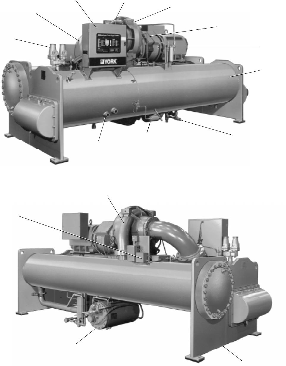
YORK INTERNATIONAL 37
FORM 160.49-O2
SECTION 4
SYSTEM COMPONENTS DESCRIPTION
27385A
FRONT VIEW
DUAL RELIEF
VALVES
MICROCOMPUTER
CONTROL CENTER
SUCTION
DISCHARGE
COMPRESSOR
ADAPTER MOTOR
SUPPORT & COVER
MOTOR
COOLER
REFRIGERANT
CHARGING VALVE
DEHYDRATOR
SIGHT
GLASSES
FIG. 17 – SYSTEM COMPONENTS
27382A
OIL PUMP
STARTER
DISCHARGE LINE
CONDENSER
OIL RESERVOIR/
PUMP
38 YORK INTERNATIONAL
GENERAL
The YORK Model YK Millennium Centrifugal Liquid
Chiller is completely factory-packaged including cooler,
condenser, compressor, motor, lubrication system,
MicroComputer Control Center, and all interconnect-
ing unit piping and wiring.
The initial charge of refrigerant and oil is supplied for
each unit. Oil is shipped in containers with the chiller.
Refrigerant is shipped to the jobsite in cylinders at the
time of installation.
The services of a YORK factory-trained, field service
representative are included to supervise the final leak
testing, charging and the initial start-up and concur-
rent operator instructions.
COMPRESSOR
The compressor is a single-stage centrifugal type pow-
ered by an open-drive electric motor.
The rotor assembly consists of a heat-treated alloy
steel drive shaft and impeller shaft with a cast alumi-
num, fully shrouded impeller. The impeller is designed
for balanced thrust and is dynamically balanced and
over-speed tested.
The inserted type journal and thrust bearings are fabri-
cated of aluminum alloy. Single helical gears with
crowned teeth are designed so that more than one tooth
is in contact at all times. Gears are integrally as-
sembled in the compressor rotor support and are film
lubricated. Each gear is individually mounted in its own
journal and thrust bearings.
The open-drive compressor shaft seal consists of a
spring-loaded, precision carbon ring, high temperature
elastomer “O” ring static seal, and stress-relieved, pre-
cision lapped collars. The seal is oil-flooded at all times
and is pressure-lubricated during operation.
CAPACITY CONTROL
Prerotation vanes (PRV) modulate chiller capacity from
100% to as low as 15% of design for normal air condi-
tioning applications. Operation is by an external, elec-
tric PRV actuator which automatically controls the vane
position to maintain a constant leaving chilled liquid
temperature.
COMPRESSOR LUBRICATION SYSTEM
(See Fig. 18)
The chiller lubrication system consists of the oil pump,
oil filter, oil cooler and all interconnecting oil piping and
passages. There are main points within the motor-com-
pressor which must be supplied with forced lubrication
as follows:
1. COMPRESSOR DRIVE SHAFT (Low Speed)
a. Shaft seal.
b. Front and rear journal bearings – one on each
side of driving gear.
c. Low speed thrust bearing (forward and reverse).
2. COMPRESSOR DRIVEN SHAFT (High Speed)
a. Forward and reverse high speed thrust bearing.
b. Two journal bearings.
3. SPEED INCREASING GEARS
a. Meshing surfaces of drive and pinion gear teeth.
To provide the required amount of oil under the neces-
sary pressure to properly lubricate these parts, a mo-
tor driven submersible oil pump is located in a remote
oil sump.
Upon pressing of the COMPRESSOR START switch
on the Control Center, the oil pump is immediately en-
ergized. After a 50 second delay to allow the system
oil pressure to stabilize, the compressor motor will start.
The oil pump will continue to run during the entire op-
eration of the compressor, and for 150 seconds during
compressor coastdown.
The submerged oil pump takes suction from the sur-
rounding oil and discharges it to the oil cooler where
heat is rejected. The oil flows from the oil cooler to the
oil filter. The oil leaves the filter and flows to the emer-
gency oil reservoir where it is distributed to the com-
pressor bearings. The oil lubricates the compressor
rotating components and is returned to the oil sump.
Since the emergency oil reservoir is at the highest
point in the lubrication system, it provides an oil sup-
ply to the various bearings and gears in the event of a
system shutdown due to power failure. The reservoir,
located on the top of the compressor, allows the oil to
be distributed through the passages by gravity flow,
thus providing necessary lubrication during the com-
pressor coastdown.
OIL PUMP
For normal operation, the oil pump should operate at
all times during chiller operation. Manual pump opera-
tion may be used to establish stable oil pressure be-
fore starting. When depressed and released, the
MANUAL OIL PUMP key will operate the oil pump for
10 minutes and then automatically shut off. To stop the
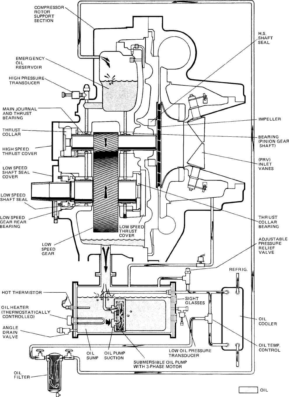
YORK INTERNATIONAL 39
FORM 160.49-O2
FIG. 18 – SCHEMATIC DRAWING – (YK) COMPRESSOR LUBRICATION SYSTEM LD00951

40 YORK INTERNATIONAL
oil pump sooner, depress the MANUAL OIL PUMP key
again.
On shutdown of the system for any reason, the oil pump
operates and continues to run for 150 seconds. The
system cannot restart during that time interval.
OIL HEATER
During long idle periods, the oil in the compressor oil
reservoir tends to absorb as much refrigerant as it can
hold, depending upon the temperature of the oil and
the pressure in the reservoir. As the oil temperature is
lowered, the amount of refrigerant absorbed will be in-
creased. If the quantity of refrigerant in the oil becomes
excessive, violent oil foaming will result as the pres-
sure within the system is lowered on starting. This foam-
ing is caused by refrigerant boiling out of the oil as the
pressure is lowered. If this foam reaches the oil pump
suction, the bearing oil pressure will fluctuate with pos-
sible temporary loss of lubrication, causing the oil pres-
sure safety cutout to actuate and stop the system. See
“Control Center, Section 2”.
To maintain the lowest possible concentration of re-
frigerant in the oil, the compressor oil reservoir is
equipped with a 115 volt electric reservoir oil heater.
The oil heater is thermostatically controlled at all times
during compressor shutdown to maintain the sump oil
at 145°F to 155°F. If the oil temperature falls below
55°F, the display will read
SYSTEM SHUTDOWN – PRESS STATUS
.
Pressing the STATUS key causes the message to read
DAY 10:00 AM – LOW OIL TEMP – AUTO START
. The system
will be allowed to automatically restart when oil tem-
perature rises to 30°F above condenser temperature.
MOTOR DRIVELINE
The compressor motor is an open-drip-proof, squirrel
cage, induction type constructed to YORK design speci-
fications. 60 hertz motors operate at 3570 rpm. 50 hertz
motors operate at 2975 rpm.
(For 60 hertz motors 1750 HP and smaller; and 50
hertz motors 1400 HP and smaller) . . . the open motor
is provided with a D-flange, factory mounted to a cast
iron adapter mounted on the compressor.
(For 2000 HP 60 hertz motors; and 50 hertz motors
above 1400 HP) . . . a separate structural steel base is
furnished to provide rigid mounting of the compressor
and motor, independent of the evaporator shell, to en-
sure controlled alignment of the assembly. Motor is
mounted with final alignment at start-up.
Motor drive shaft is directly connected to the com-
pressor shaft with a flexible disc coupling. Coupling
has all metal construction with no wearing parts to
assure long life, and no lubrication requirements to pro-
vide low maintenance.
For units utilizing remote electro-mechanical starters,
a terminal box is provided for field connected conduit.
Motor terminals are brought through the motor casing
into the terminal box. Jumpers are furnished for three-
lead type of starting. Motor terminal lugs are not fur-
nished. Overload/overcurrent transformers are fur-
nished with all units. For units furnished with factory
packaged Solid State Starters, (optional) see right.
HEAT EXCHANGERS
Evaporator and condenser shells are fabricated from
rolled carbon steel plates with fusion welded seams.
Heat exchanger tubes are internally enhanced type.
The evaporator is a shell and tube, flooded type heat
exchanger. A distributor trough provides uniform distri-
bution of refrigerant over the entire shell length. Alumi-
num mesh eliminators are located above the tube bundle
to prevent liquid refrigerant carryover into the com-
pressor. Two 1-1/2" liquid level sight glasses are lo-
cated on the side of the shell to aid in determining
proper refrigerant charge. The evaporator shell con-
tains a dual refrigerant relief valve.
The condenser is a shell and tube type, with a dis-
charge gas baffle to prevent direct high velocity im-
pingement on the tubes. A separate subcooler is lo-
cated in the condenser.
The removable compact water boxes are fabricated of
steel. The design working pressure is 150 psig and the
boxes are tested at 225 psig. Integral steel water baffles
provide the required pass arrangements. Stub-out wa-
ter nozzle connections with Victaulic grooves are
welded to the water boxes. These nozzle connections
are suitable for Victaulic couplings, welding or flanges,
and are capped for shipment. Plugged 3/4" drain and
vent connections are provided in each water box.
REFRIGERANT FLOW CONTROL
Refrigerant flow to the evaporator is controlled by a
single fixed-orifice (or variable orifice).
Chillers can be provided with a REFRIGERANT LEVEL
CONTROL (EPROM version C.02.F(T).13 or later sup-
ports this feature). A level sensor senses the refriger-
ant level in the condenser and outputs an analog volt-

YORK INTERNATIONAL 41
FORM 160.49-O2
age to the Micro Board that represents this level (0% =
empty; 100% = full). Under program control, the Micro
Board modulates a variable orifice to control the con-
denser refrigerant level to a programmed setpoint. Other
setpoints affect the control sensitivity and response.
These setpoints must be entered at chiller commis-
sioning by a qualified service technician. Only a quali-
fied service technician may modify these settings.
Manual operation of the refrigerant level control can be
selected. This allows the prerotation vanes keypad keys
to manually control the variable orifice. This manual
control can also be used to position the variable orifice
in a fixed position. Instructions for selecting manual
level control and entering the level control setpoints
are contained in the “Special Setpoints and Program-
ming Procedures” section of Service manual, Form
160.49-M3.
While the chiller is shut down, the orifice will be in the
fully open position causing the sensed level to be ap-
proximately 0%. When the chiller is started, after the
vane motor end switch (VMS) opens when entering
“SYSTEM RUN”, if actual level is less than the level
setpoint, a linearly increasing ramp is applied to the
level setpoint. This ramp causes the setpoint to go from
the initial refrigerant level (approximately 0%) to the
programmed setpoint over a period of 15 minutes. While
this ramp is in effect,
PULLDN LEVEL = XXX%; SETP = XXX%; ACTUAL = XXX%
is
one of the scrolled messages under the DISPLAY DATA
key. “PULLDN LEVEL” is the ramping setpoint that will
ramp up to the programmed setpoint “SETP”. “SETP”
is the level setpoint programmed by the service tech-
nician. “ACTUAL” is the present refrigerant level in the
condenser. After the 15 minute pulldown period has
elapsed, this message is replaced by
ACTUAL LEVEL = XXX%; LEVEL SETP = XXX%
.
If the actual level is greater than the setpoint when the
VMS opens, there is no pulldown period, it immedi-
ately begins to control to the programmed setpoint.
While the chiller is running, the refrigerant level is nor-
mally controlled to the level setpoint. However, any-
time the vanes fully close (VMS closes), normal level
control is terminated, any refrigerant level setpoint
pulldown in effect is cancelled and the outputs to the
level control will be opposite that which is supplied to
the vane motor (i.e., when a close pulse is applied to
the vane motor, an open pulse is applied to the level
control, etc.). When the VMS opens, if the refrigerant
level is less than the level setpoint, a refrigerant level
setpoint pulldown is initiated as described above. Oth-
erwise, the level is controlled to the programmed
setpoint.
If the refrigerant level sensor output ever goes to greater
than 4.4VDC, indicating a level greater than 100%,
WARNING-REFRIGERANT LEVEL OUT OF RANGE
is dis-
played and the level control actuator is driven open
until the level has decreased to a level within range.
When within range, the warning message is automati-
cally cleared and normal control is resumed.
MICROCOMPUTER CONTROL CENTER
(See Section 2)
The MicroComputer Control Center is factory mounted,
wired and tested. The electronic panel automatically
controls the operation of the unit in meeting system
cooling requirements while minimizing energy usage.
For detailed information on the Control Center, refer to
“Section 2” of this manual.
SOLID STATE STARTER (Optional)
The Solid State Starter is a reduced voltage starter
that controls and maintains a constant current flow to
the motor during start-up. It is mounted on the chiller.
Power and control wiring between the starter and chiller
are factory installed. Available for 380-600 volts, the
starter enclosure is NEMA-1 with a hinged access door
with lock and key. Electrical lugs for incoming power
wiring are provided.
VARIABLE SPEED DRIVE (Optional)
A 460V – 3-Ph – 60/50Hz Variable Speed Drive can be
factory packaged with the chiller. It is designed to vary
the compressor motor speed and prerotation vane po-
sition by controlling the frequency and voltage of the
electrical power to the motor. Operational information
is contained in Form 160.00-O1. The control logic au-
tomatically adjusts motor speed and compressor
prerotation vane position for maximum part load effi-
ciency by analyzing information fed to it by sensors
located throughout the chiller.
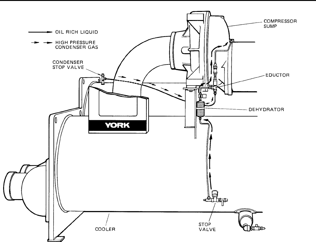
42 YORK INTERNATIONAL
SECTION 5
OPERATIONAL MAINTENANCE
OIL RETURN SYSTEM
The oil return system continuously maintains the proper
oil level in the compressor oil sump. (See Figs. 18 &
19.)
High pressure condenser gas flows continuously
through the eductor inducing the low pressure, oil rich
liquid to flow from the evaporator, through the dehydra-
tor to the compressor sump.
CHANGING THE DEHYDRATOR
To change the dehydrator, use the following procedure:
1. Shut the stop valves on the condenser gas line, oil
return line to rotor support and inlet end of the de-
hydrator.
2. Remove the dehydrator. Refer to Fig. 19.
3. Assemble the new filter-drier.
4. Open condenser stop valve and check dehydrator
connections for refrigerant leaks.
5. Open all the dehydrator stop valves to allow the
liquid refrigerant to flow through the dehydrator and
condenser-gas through the eductor.
FIG. 19 – OIL RETURN SYSTEM
LD00950
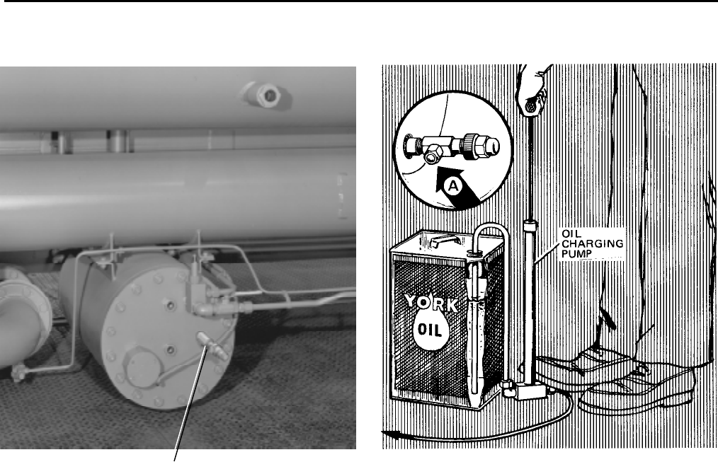
YORK INTERNATIONAL 43
FORM 160.49-O2
THE OIL CHARGE
The nominal oil charge for the compressor is 20 gal.,
type “F” for R-22 application or type “K” for R-134a
application.
New YORK Refrigeration oil must be used in the cen-
trifugal compressor. Since oil absorbs moisture when
exposed to the atmosphere, it should be kept tightly
capped until used.
OIL CHARGING PROCEDURE
The oil should be charged into the oil reservoir using
the YORK Oil Charging Pump – YORK Part No. 070-
10654. To charge oil into the oil reservoir, proceed as
follows:
1. The unit must be shut down.
2. Immerse the suction connection of the oil charging
pump in a clean container of new oil and connect
the pump discharge connection to the oil charging
valve (A) located on the remote oil reservoir cover
plate. (See Fig. 20.) Do not tighten the connection
at the charging valve until after the air is forced out
by pumping a few strokes of the oil pump. This fills
the lines with oil and prevents air from being pumped
into the system.
3. Open the oil charging valve and pump oil into the
system until oil level in the compressor oil reser-
voir is about midway in the upper sight glass. Then,
close the charging valve and disconnect the hand
oil pump.
4. As soon as oil charging is complete, close the power
supply to the starter to energize the oil heater. (See
“Section 3, System Operating Procedures”.) This
will keep the concentration of refrigerant in the oil
to a minimum.
When the oil reservoir is initially charged with oil, the
oil pump should be started manually to fill the lines,
passages, oil cooler and oil filter. This will lower the oil
level in the reservoir. It will then be necessary to add
oil to bring the level back to the center of the upper
sight glass.
FIG. 20 – CHARGING OIL RESERVOIR WITH OIL
LD00472
OIL CHARGING
VALVE
25721A

44 YORK INTERNATIONAL
SECTION 6
TROUBLESHOOTING
TABLE 1 – CAUSES OF NORMAL AND SAFETY SYSTEM SHUTDOWNS IN ACCORDANCE WITH THE MICROCOMPUTER CONTROL,
CENTER DISPLAY
SHUTDOWN CAUSE GOVERNING CONTROL FUNCTION
CONTROL CENTER DISPLAY
OPERATING PROGRAMMED START-UP OF PROBABLE CAUSE
DAY OF TIME OF CAUSE OF METHOD OF DESCRIPTION POINT SETPOINTS SYSTEM AFTER AND SERVICE
WEEK DAY SHUTDOWN RESTART ON ON BY OPERATOR SHUTDOWN REQUIRED
RISE FALL
MON. 10:00 AM Low Water Autostart Low Water Chilled 4°F below 4°F below chilled Automatic Restart System load is less
Temp. (LWT) water chiller water setpoint when water reaches than minimum
setpoint water (If set to 40°F setpoint; if system capacity
setpoint would be 36°F) is running and set-
(36°F minimum point is increased
4°F, system will
continue to run, as
LWT cutout shifts
to a fixed 36°F for
10 minutes.
MON. 10:00 AM Flow Switch Autostart Flow Switch Automatic Restart Lack of water flow.
when water flow is Check operation of
Restored to close chilled water pump
flow switch.
MON. 10:00 AM System Autostart A remote com- Automatic Restart Contact-connected to
Cycling mand (computer upon remote the Remote/Local
relay contact or command. cycling input of the
manual switch) Digital input board
MON. 10:00 AM Multi-Unit Autostart (Optional) Lead- Automatic Restart Contact-connected to
Lag Sequence upon remote the Multi-Unit cycling
Control command. input of the Digital
input board
MON. 10:00 AM Internal Autostart Internal Clock Daily Schedule Will automatically Pressing Compressor
Clock Programmed to restart when pro- Start Switch over-
Shutdown Unit grammed schedule rides the program
permits
MON. 10:00 AM AC under- Autostart <15% FLA for Cycling shutdown oc-
voltage 25 continuous curs when motor cur-
seconds rent is >15% FLA for
25 seconds during
chiller operation
MON. 10:00 AM Power Fault Autostart CM-2 Current Will start automatic- Motor Controller con-
Module or tically following tacts opening and
Solid State coastdown closing in less than 3
Starter seconds due to a power
fault condition
Remote Stop Energy manage- Start up by start Remote Stop Contact
ment System signal from remote Closure
start switch
MON. Anti-Recycle, Anti-Recycle Will not start Will restart when Min. Time between
20 Min. Left timer until 30 Min. time left = 00 Min. successive compres-
timer is timed sor starts is 30 min.

YORK INTERNATIONAL 45
FORM 160.49-O2
MON. 10:00 AM Low Evap. Low Evap. 54.3 54.4 To restart, press See OPERATION
Pressure Pressure
PSIG (R-22) PSIG (R-22)
compressor switch ANALYSIS Table 2
Transducer 25 25.1 from STOP/RESET Symptom 2
(LEP)
PSIG (R-134a) PSIG (R-134a)
to START position
MON. 10:00 AM Low Evap. LEP external Set to Job Set to Job To restart, press See OPERATION
Pressure control (Brine Spec. Spec. compressor switch ANALYSIS Table 2
Brine units only) from STOP/RESET Symptom 2.
to START position
MON. 10:00 AM Low Oil Low Oil 25 15 Will restart when Refer to OPERATION
Pressure Pressure PSID PSID pressure increases ANALYSIS Table 2
Transducer to 25 PSID. To Symptoms 4, 5, 6, 7,
(OP) restart, press com- 9, 10, 11
pressor switch from
STOP/RESTART to
START position.
MON. 10:00 AM High High Pressure 265 205 Will restart when See Operational
Pressure Safety Control
PSIG (R-22) PSIG (R-22)
Pressure falls to Analysis Table 2
(HP) 180 120 205 PSIG. To restart Symptom 1 High
PSIG (R-134a) PSIG (R-134a)
press compressor Discharge Pressure
switch from STOP/
RESET to START
position
MON. 10:00 AM Evap. Trans. Evap. Pressure To restart press Defective Evap. Pressure
or Probe Transducer or compressor switch Transducer or Leaving
Error Leaving Chilled from STOP/RESET Chilled Water thermistor
Water Thermis- to START position (RS1). LCWT minus satu-
tor (RS1) ration temperature is less
than –2.5°F or greater than
25°F. Checked every 10
minutes following a 10 min.
bypass at start-up.
MON. 10:00 AM Motor Con- CM2 or Solid Reset the device CM2, or Solid State
troller – Ext. State Starter that caused the shut- Starter has shutdown
Reset (RT2) down. Chiller will chiller
start automatically.
MON. 10:00 AM High Discharge Temp. 220°F 219°F To restart press Condenser tubes dirty or
Discharge Thermistor compressor switch scaled or high condenser
Temp. (RT2) from STOP/RESET water temperature. (See
to START position. Symptom 1, Table 1.)
MON. 10:00 AM High Oil Oil Temperature 170°F 169°F To restart press Dirty oil filter or restricted
Temp. Thermistor compressor switch oil cooler line. Change oil
(RT3) from STOP/RESET filter. Refer to OPERATION
to START position ANALYSIS Table 2,
Symptom 9.
MON. 10:00 AM Power Auto-Restart Micro Board 8.29VDC 7.84VDC Optional AUTO Will restart automa- Power Failure.
Failure undervoltage Restart Plug is tically when voltage
circuit on 5V installed on reaches 8.29VDC.
unregulated Micro Board An undervoltage
supply circuit on the Micro
Board monitors the
5VC unregulated
supply for an under-
voltage condition.
MON. 10:00 AM Power Micro Board 8.29VDC 7.84VDC Auto restart plug To restart, press Power Failure
Failure undervoltage is removed on compressor switch
circuit on 5V Micro Board to STOP-RESET
unregulated Position and then to
supply START position (Continued on page 46)

46 YORK INTERNATIONAL
TABLE 1 – CAUSES OF NORMAL AND SAFETY SYSTEM SHUTDOWNS IN ACCORDANCE WITH THE MICROCOMPUTER CONTROL,
CENTER DISPLAY
SHUTDOWN CAUSE GOVERNING CONTROL FUNCTION
CONTROL CENTER DISPLAY
OPERATING PROGRAMMED START-UP OF PROBABLE CAUSE
DAY OF TIME OF CAUSE OF METHOD OF DESCRIPTION POINT SETPOINTS SYSTEM AFTER AND SERVICE
WEEK DAY SHUTDOWN RESTART ON ON BY OPERATOR SHUTDOWN REQUIRED
RISE FALL
MON. 10:00 AM Oil Pressure High Oil Press. 100 PSID (Dur- 59 Will start at 59 This Shutdown is provided
Transducer Transducer ing first 7 min. of PSID PSID when compr. to check on Oil Pressure
Error Compr. Oper.) switch is placed to Transducers for failure in
60 PSID (After STOP/RESET and the high state. Replace
first 7 min. of then START Oil Press. Transducer in
Compr. Oper.) oil sump or compressor
Vane Motor Autostart Vane Motor Restart automatically Vanes are set improperly,
Switch Open Switch after Vane Motor arm reset vane linkage check
linkage is set pro- vane positions using
perly. Press STOP/ the SERVICE key switch
RESET and then and proper keys on the
START switch MicroComputer Control
Center
MON. 10:00 AM Starter Motor Current > Press compressor Check motor starter
Malfunction 15% for 10 swc. STOP/RESET operation. Motor current
Detected with Control Cen- switch and then value greater than 15%
ter not calling for FLA
motor to run
MON. 10:00 AM Program Autostart Micro Board Watchdog timer circuit
Initiated has reset software pro-
Reset gram – Chiller will
automatically restart.
Replace RTC RTC-IC chip Reprogram the Con- Weak battery
IC chip trol Center Setponts Replace RTC-IC chip
Reprogram & proceed with U16
Setpoints Normal Start-up
MON. 10:00 AM Low Oil Autostart Oil Temp. 71.0°F 55°F Press STOP/ Oil Temp. Thermistor
Temperature Thermistor RESET switch & disconnected from
(RT3) then START Analog Input Board.
switch Reconnect or replace
open sensor.
MON. 10:00 AM Faulty Dis- Discharge Temp. 30.0°F 29.9°F Press STOP/ Faulty Discharge Temp.
charge Temp. Thermistor START switch & Thermistor (RT2) or dis-
Sensor (RT2) discon- then START connected from Analog
nected or faulty switch Input Board. Connect or
operating temp. replace open sensor.
= 32°F
MON. 100.00 AM Low Line SSS Logic See legend on wiring Chiller will automa- Low AC Line Voltage
Voltage (SSS Board diagram tically restart when
Units only) all phases of line vol-
tage increase to the
minimum required
starting level.
MON. 10:00 AM MTR Phase SSS Logic See “Section 2” Press STOP/START Motor Phase Current
Current Board switch then START Unbalance
unbalance switch
(SSS Units
only)

YORK INTERNATIONAL 47
FORM 160.49-O2
TABLE 2 – OPERATING ANALYSIS CHART
RESULTS POSSIBLE CAUSE REMEDY
1. SYMPTOM: ABNORMALLY HIGH DISCHARGE PRESSURE
Temperature difference between liquid Air in condenser.
refrigerant out and water off condenser
higher than normal.
High discharge pressure. Condenser tubes dirty or . Clean condenser tubes. Check water
scaled conditioning.
High condenser water Reduce condenser water inlet
temperature. temperature. (Check cooling tower
and water circulation.)
Temperature difference between conden- Insufficient condensing Increase the quantity of water through
ser water on and water off higher than water flow. the condenser to proper value.
normal, with normal cooler pressure.
2. SYMPTOM: ABNORMALLY LOW SUCTION PRESSURE
Temperature difference between leaving Insufficient charge of Check for leaks and charge
chilled water and refrigerant in cooler refrigerant. refrigerant into system.
greater than normal with high discharge Flow orifice blocked. Remove obstruction.
temperature.
Temperature difference between leaving Cooler tubes dirty or Clean cooler tubes.
chilled water and refrigerant in the cooler restricted.
greater than normal with normal discharge
temperature.
Temperature of chilled water too low with Insufficient load for Check prerotation vane motor opera-
with low motor amperes. system capacity. tion and setting of low water temper-
ature cutout.
3. SYMPTOM: HIGH COOLER PRESSURE
High chilled water temperature. Prerotation vanes fail to Check the prerotation vane motor
open. positioning circuit.
System overload. Be sure the vanes are wide open
(without overloading the motor) until
the load decreases.
4. SYMPTOM: NO OIL PRESSURE WHEN SYSTEM START BUTTON PUSHED
Low oil pressure displayed on control Oil pump running in wrong Check rotation of oil pump
center; compressor will not start. direction. (Electrical Connections).
Oil pump not running. Check electrical connections to oil
pump and press manual reset on oil
pump starter mounted on condenser
shell.
5. SYMPTOM: COMPRESSOR STARTS, NORMAL OIL PRESSURE DEVELOPS, FLUCTUATES FOR
SHORT WHILE, THEN COMPRESSOR STOPS ON OIL PRESSURE CUTOUT
Oil pressure normal, fluctuates then Unusual starting conditions Drain the oil from the compressor and
compressor stops on Oil Pressure exist, i.e., oil foaming in charge new oil into the compressor.
Cutout. Display reading resevoir and piping due to (Refer to “Charging The System With
LOW OIL PRESSURE .
lowered system pressure. Oil”, page 39.)
Burned out oil heater. Replace oil heater.

48 YORK INTERNATIONAL
TABLE 2 – OPERATING ANALYSIS CHART (Continued)
RESULTS POSSIBLE CAUSE REMEDY
6. SYMPTOM: USUALLY HIGH OIL PRESSURE DEVELOPS WHEN OIL PUMP RUNS
Unusually high oil pressure is displayed High oil pressure. Trans- Replace low or high oil pressure
when the oil pressure display key is ducer defective. Relief transducer. Adjust external relief
pressed when the oil pump is running. valve is misadjusted. valve.
7. SYMPTOM: OIL PUMP VIBRATES OR IS NOISY
Oil pump vibrates or is extremely noisy Misalignment of pump or Correct condition or replace faulty
with some oil pressure when pressing Mounting bolts loose. part.
OIL PRESSURE display key. Bent shaft.
Worn pump parts.
NOTE: When oil pump is run without Oil not reaching pump Check oil supply and oil piping.
an oil supply it will vibrate and suction inlet in sufficient
become extremely noisy. quantity.
8. SYMPTOM: OIL PRESSURE GRADUALLY DECREASES (Noted by Observation of Daily Log Sheets)
Oil pressure (noted when pressing OIL Oil filter is dirty. Change oil filter.
PRESSURE display key) drops to 70%
of oil pressure when compressor was Extreme bearing wear. Inspect compressor.
originally started.
9. SYMPTOM: OIL PRESSURE SYSTEM CEASES TO RETURN AN OIL/REFRIGERANT SAMPLE
Oil refrigerant return not functioning. Filter-drier in oil return Replace old filter-drier with new.
system dirty.
Jet or orifice of oil return Remove jet, inspect for dirt. Remove
jet clogged. dirt using solvent and replace.
10. SYMPTOM: OIL PUMP FAILS TO DELIVER OIL PRESSURE
No oil pressure registers when pressing Faulty oil pressure Replace oil pressure transducer.
OIL PRESSURE display key when oil transducer
pump runs. Faulty wiring/connectors.
11. SYMPTOM: REDUCED OIL PUMP CAPACITY
Oil pump pumping capacity. Excessive end clearance Inspect and replace worn parts.
pump.
Other worn pump parts.
Partially blocked oil supply Check oil inlet for blockage.
inlet.
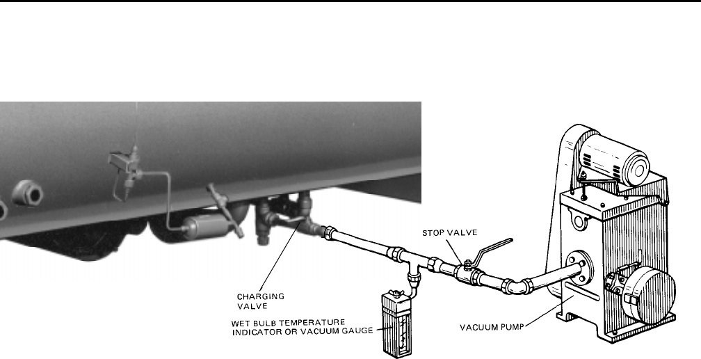
YORK INTERNATIONAL 49
FORM 160.49-O2
SECTION 7
MAINTENANCE
RENEWAL PARTS
For any required Renewal Parts, refer to “Parts Lists”
shown in “Reference Instructions”, page 2.
CHECKING SYSTEM FOR LEAKS
LEAK TESTING DURING OPERATION
The refrigerant side of the system is carefully pres-
sure tested and evacuated at the factory.
After the system is in operation under load, the high
pressure components should be carefully leak tested
with a leak detector to be sure all joints are tight.
If any leaks are indicated, they must be repaired im-
mediately. Usually, leaks can be stopped by tightening
flare nuts or flange bolts. However, if it is necessary to
repair a welded joint, the refrigerant charge must be
removed. (See “Handling Refrigerant for Dismantling
and Repair”, page 53.)
CONDUCTING R-22 PRESSURE TEST
With the R-22 charge removed and all known leaks
repaired, the system should be charged with a small
amount of R-22 mixed with dry nitrogen so that a ha-
lide torch or electronic leak detector can be used to
detect any leaks too small to be found by the soap
test.
To test with R-22, proceed as follows:
1. With no pressure in the system, charge R-22 gas
into the system through the charging valve to a
pressure of 2 psig.
2. Build up the system pressure with dry nitrogen to
approximately 10 psig. To be sure that the concen-
tration of refrigerant has reached all part of the sys-
tem, slightly open the oil charging valve and test
for the presence of refrigerant with a leak detector.
3. Test around each joint and factory weld. It is impor-
tant that this test be thoroughly and carefully done,
spending as much time as necessary and using a
good leak detector.
4. To check for refrigerant leaks in the cooler and con-
denser, open the vents in the cooler and condenser
heads and test for the presence of refrigerant. If no
refrigerant is present, the tubes and tube sheets
may be considered tight. If refrigerant is detected
at the vents, the heads must be removed, the leak
located (by means of soap test or leak detector)
and repaired.
EVACUATION AND DEHYDRATION OF UNIT
FIG. 21 – EVACUATION OF CHILLER
27385A(D)
LD00949
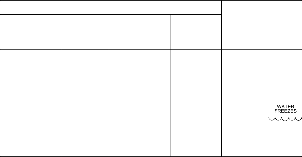
50 YORK INTERNATIONAL
VACUUM TESTING
After the pressure test has been completed, the vacuum
test should be conducted as follows:
1. Connect a high capacity vacuum pump, with indi-
cator, to the system charging valve as shown in
Fig. 22 and start the pump. (See “Vacuum Dehydra-
tion”.)
2. Open wide all system valves, including the purge
and gauge valves. Be sure all valves to the atmo-
sphere are closed.
3. Operate the vacuum pump in accordance with
VACUUM DEHYDRATION until a wet bulb tempera-
ture of +32°F or a pressure of 5 mm Hg is reached.
See Table 3 for corresponding values of pressure.
4. To improve evacuation circulate hot water (not to
exceed 125°F) through the cooler and condenser
tubes to thoroughly dehydrate the shells. If a source
of hot water is not readily available, a portable wa-
ter heater should be employed. DO NOT USE
STEAM. A suggested method is to connect a hose
between the source of hot water under pressure
and the cooler head drain connection, out the cooler
vent connection, into the condenser head drain and
out the condenser vent. To avoid the possibility of
causing leaks, the temperature should be brought
up slowly so that the tubes and shell are heated
evenly.
5. Close the system charging valve and the stop valve
between the vacuum indicator and the vacuum
pump. Then disconnect the vacuum pump leaving
the vacuum indicator in place.
6. Hold the vacuum obtained in Step 3 in the system
for 8 hours; the slightest rise in pressure indicates
a leak or the presence of moisture, or both. If, after
8 hours the wet bulb temperature in the vacuum
indicator has not risen above 40°F or a pressure of
6.3 mm Hg, the system may be considered tight.
NOTE: Be sure the vacuum indicator is valved off
while holding the system vacuum and be
sure to open the valve between the vacuum
indicator and the system when checking
the vacuum after the 8 hour period.
7. If the vacuum does not hold for 8 hours within the
limits specified in Step 6 above, the leak must be
found and repaired.
TABLE 3 – SYSTEM PRESSURES
*GAUGE ABSOLUTE BOILING
INCHES OF TEMPERATURES
MERCURY (HG) MILLIMETERS OF
BELOW ONE PSIA OF MERCURY MICRONS WATER
STANDARD (HG) °F
ATMOSPHERE
0 14.696 760. 760,000 212
10.24" 9.629 500. 500,000 192
22.05" 3.865 200. 200,000 151
25.98" 1.935 100. 100,000 124
27.95" .968 50. 50,000 101
28.94" .481 25. 25,000 78
29.53" .192 10. 10,000 52
29.67" .122 6.3 6,300 40
29.72" .099 5. 5,000 35
29.842" .039 2. 2,000 15
29.882" .019 1.0 1,000 +1
29.901" .010 .5 500 –11
29.917" .002 .1 100 –38
29.919" .001 .05 50 –50
29.9206" .0002 .01 10 –70
29.921" 0 0 0
*One standard atmosphere = 14.696 PSIA
= 760 mm Hg. absolute pressure at 32°F
= 29.921 inches Hg. absolute at 32°F
NOTES: PSIA = Lbs. per sq. in. gauge pressure
= Pressure above atmosphere
PSIA = Lbs. per sq. in. absolute pressure
= Sum of gauge plus atmospheric pressure
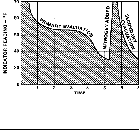
YORK INTERNATIONAL 51
FORM 160.49-O2
VACUUM DEHYDRATION
To obtain a sufficiently dry system, the following in-
structions have been assembled to provide an effec-
tive method for evacuating and dehydrating a system
in the field. Although there are several methods of de-
hydrating a system, we are recommending the follow-
ing, as it produces one of the best results, and affords
a means of obtaining accurate readings as to the ex-
tent of dehydration.
The equipment required to follow this method of dehy-
dration consists of a wet bulb indicator or vacuum
gauge, a chart showing the relation between dew point
temperature and pressure in inches of mercury
(vacuum), (see Table 3) and a vacuum pump capable
of pumping a suitable vacuum on the system.
OPERATION
Dehydration of a refrigerant system can be obtained
by this method because the water present in the sys-
tem reacts much as a refrigerant would. By pulling down
the pressure in the system to a point where its satura-
tion temperature is considerably below that of room
temperature, heat will flow from the room through the
walls of the system and vaporize the water, allowing a
large percentage of it to be removed by the vacuum
pump. The length of time necessary for the dehydra-
tion of a system is dependent on the size or volume of
the system, the capacity and efficiency of the vacuum
pump, the room temperature and the quantity of water
present in the system. By the use of the vacuum indi-
cator as suggested, the test tube will be evacuated to
the same pressure as the system, and the distilled
water will be maintained at the same saturation tem-
perature as any free water in the system, and this tem-
perature can be observed on the thermometer.
If the system has been pressure tested and found to
be tight prior to evacuation, then the saturation tem-
perature recordings should follow a curve similar to
the typical saturation curve shown as Fig. 22.
The temperature of the water in the test tube will drop
as the pressure decreases, until the boiling point is
reached, at which point the temperature will level off
and remain at this level until all of the water in the shell
is vaporized. When this final vaporization has taken
place the pressure and temperature will continue to
drop until eventually a temperature of 35°F or a pres-
sure of 5 mm Hg. is reached.
When this point is reached, practically all of the air
has been evacuated from the system, but there is still
a small amount of moisture left. In order to provide a
medium for carrying this residual moisture to the
vacuum pump, nitrogen should be introduced into the
system to bring it to atmospheric pressure and the
indicator temperature will return to approximately am-
bient temperature. Close off the system again, and start
the second evacuation.
The relatively small amount of moisture left will be car-
ried out through the vacuum pump and the tempera-
ture or pressure shown by the indicator should drop
uniformly until it reaches a temperature of 35°F or a
pressure of 5 mm Hg.
When the vacuum indicator registers this temperature
or pressure, it is a positive sign that the system is
evacuated and dehydrated to the recommended limit.
If this level cannot be reached, it is evident that there
is a leak somewhere in the system. Any leaks must be
corrected before the indicator can be pulled down to
35°F or 5 mm Hg. in the primary evacuation.
During the primary pulldown, keep a careful watch on
the wet bulb indicator temperature, and do not let it fall
below 35°F. If the temperature is allowed to fall to 32°F,
the water in the test tube will freeze, and the result will
be a faulty temperature reading.
FIG. 22 – SATURATION CURVE
LD00474

52 YORK INTERNATIONAL
REFRIGERANT CHARGING
To avoid the possibility if freezing liquid within the
cooler tubes when charging an evacuated sys-
tem, only refrigerant vapor from the top of the
drum or cylinder must be admitted to the system
pressure until the system pressure is raised above
the point corresponding to the freezing point of
the cooler liquid. For water, the pressure corre-
sponding to the freezing point is 57.5 PSIG for R-
22 or 8.54 PSIG for R-134a (at sea level).
While charging, every precaution must be taken
to prevent moisture laden air from entering the
system. Make up a suitable charging connection
from new copper tubing to fit between the system
charging valve and the fitting on the charging drum.
This connection should be as short as possible
but long enough to permit sufficient flexibility for
changing drums. The charging connection should
be purged each time a full container of refrigerant
is connected and changing containers should be
done as quickly as possible to minimize the loss
of refrigerant.
Refrigerant may be furnished in drums containing
either 30, 50, 125 or 1750 lbs. of refrigerant. These
drums are not returnable and they should be
stored for future use if it should ever become nec-
essary to remove refrigeration from the system.
TABLE 4 – REFRIGERANT CHARGE
R-22
SHELL CODES LBS.
COOLER COND.
M M 1,425
M N 1,600
N M 1,675
N N 1,800
N P 1,800
P N 1,875
P P 1,875
P Q 2,175
Q P 2,225
Q Q 2,500
Q R 2,800
R Q 3,050
R R 3,300
R S 3,500
S R 3,500
S S 3,500
R-134a
SHELL CODES LBS.
COOLER COND.
L L 1,150
L M 1,150
M L 1,400
M M 1,400
M N 1,585
N M 1,650
N N 1,805
N P 1,805
P N 1,900
P P 1,900
P Q 2,205
Q P 2,235
Q Q 2,515
Q R 2,800
R Q 3,075
R R 3,325
R S 3,450
S R 3,450
S S 3,575
CHECKING THE REFRIGERANT CHARGE
DURING UNIT SHUTDOWN
The refrigerant charge is specified for each chiller model
(see Table 4). Charge the correct amount of refrigerant
and record the level in the cooler sight glass.
The refrigerant charge should always be checked and
trimmed when the system is shut down.
The refrigerant charge level must be checked after the
pressure and temperature have equalized between the
condenser and cooler. This would be expected to be 4
hours or more after the compressor and water pumps
are stopped. The level should be at the center of the
sight glass + 1/4 inch.
Charge the refrigerant in accordance with the method
shown under the “Refrigerant Charging”, above. The
refrigerant level should be observed and the level re-
corded after initial charging.

YORK INTERNATIONAL 53
FORM 160.49-O2
HANDLING REFRIGERANT FOR
DISMANTLING AND REPAIRS
MEGGING THE MOTOR
If it becomes necessary to open any part of the refriger-
ant system for repairs, it will be necessary to remove the
charge before opening any part of the unit.
While the main disconnect switch and compressor
motor starter are open, meg the motor as follows:
1. Using a megohm meter (megger), meg between
phases and each phase to ground (see Fig. 23);
these readings are to be interpreted using the graph
shown in Fig. 24.
2. If readings fall below shaded area, remove external
leads from motor and repeat test.
NOTE: Motor is to be megged with the starter at
ambient temperature after 24 hours of idle
standby.
FIG. 23 – DIAGRAM, MEGGING MOTOR WINDINGS
LD00475
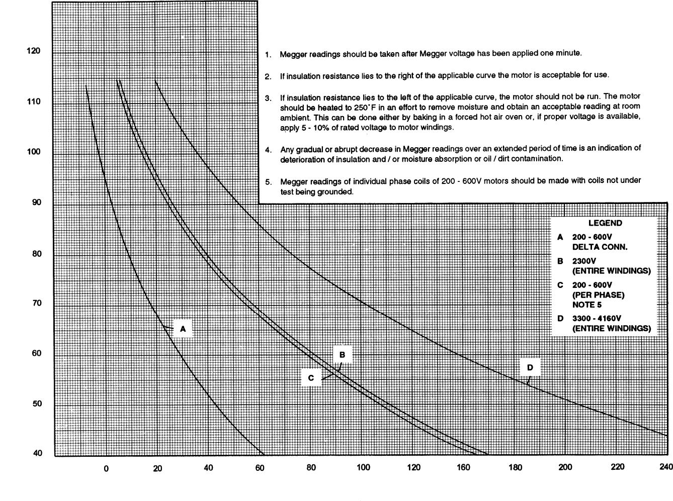
54 YORK INTERNATIONAL
FIG. 24 – MOTOR STATOR TEMPERATURE AND INSULATION RESISTANCES
LD00476
TEMPERATURE – °F
MEGOHMS
Minimum Insulation Resistance vs. Temperature (per IEEE Std 43)
Open Motors
YORK INTERNATIONAL 55
FORM 160.49-O2
CONDENSERS AND COOLERS
GENERAL
Maintenance of condenser and cooler shells is impor-
tant to provide trouble free operation of the chiller. The
water side of the tubes in the shell must be kept clean
and free from scale. Proper maintenance such as tube
cleaning, and testing for leaks, is covered on the fol-
lowing pages.
CHEMICAL WATER TREATMENT
Since the mineral content of the water circulated
through coolers and condensers varies with almost
every source of supply, it is possible that the water
being used may corrode the tubes or deposit heat re-
sistant scale in them. Reliable water treatment compa-
nies are available in most larger cities to supply a wa-
ter treating process which will greatly reduce the cor-
rosive and scale forming properties of almost any type
of water.
As a preventive measure against scale and corrosion
and to prolong the life of cooler and condenser tubes, a
chemical analysis of the water should be made prefer-
ably before the system is installed. A reliable water
treatment company can be consulted to determine
whether water treatment is necessary, and if so, to
furnish the proper treatment for the particular water
condition.
CLEANING COOLER AND CONDENSER TUBES
COOLER
It is difficult to determine by any particular test whether
possible lack of performance of the water cooler is due
to fouled tubes alone or due to a combination of
troubles. Trouble which may be due to fouled tubes is
indicated when, over a period of time, the cooling ca-
pacity decreases and the split (temperature difference
between water leaving the cooler and the refrigerant
temperature in the cooler) increases. A gradual drop-
off in cooling capacity can also be caused by a gradual
leak of refrigerant from the system or by a combina-
tion of fouled tubes and shortage of refrigerant charge.
An excessive quantity of oil in the cooler can also con-
tribute to erratic performance.
CONDENSER
In a condenser, trouble due to fouled tubes is usually
indicated by a steady rise in head pressure, over a
period of time, accompanied by a steady rise in con-
densing temperature, and noisy operation. These symp-
toms may also be due to foul gas buildup. Purging will
remove the foul gas revealing the effect of fouling.
TUBE FOULING
Fouling of the tubes can be due to deposits of two
types as follows:
1. Rust or sludge – which finds its way into the tubes
and accumulates there. This material usually does
not build up on the inner tube surfaces as scale,
but does interfere with the heat transfer. Rust or
sludge can generally be removed from the tubes by
a thorough brushing process.
2. Scale – due to mineral deposits. These deposits,
even though very thin and scarcely detectable upon
physical inspection, are highly resistant to heat
transfer. They can be removed most effectively by
circulating an acid solution through the tubes.
TUBE CLEANING PROCEDURES
BRUSH CLEANING OF TUBES
If the tube consists of dirt and sludge, it can usually be
removed by means of the brushing process. Drain the
water sides of the circuit to be cleaned (cooling water
or chilled water) remove the heads and thoroughly clean
each tube with a soft bristle bronze brush. DO NOT
USE A STEEL BRISTLE BRUSH. A steel brush may
damage the tubes.
Improved results can be obtained by admitting water
into the tube during the cleaning process. This can be
done by mounting the brush on a suitable length of 1/8"
pipe with a few small holes at the brush end and con-
necting the other end by means of a hose to the water
supply.
The tubes should always be brush cleaned before acid
cleaning.
ACID CLEANING OF TUBES
If the tubes are fouled with a hard scale deposit, they
must be acid cleaned. It is important that before acid
cleaning, the tubes be cleaned by the brushing pro-
cess described above. If the relatively loose foreign
material is removed before the acid cleaning, the acid
solution will have less material to dissolve and flush
from the tubes with the result that a more satisfactory
cleaning job will be accomplished with a probable sav-
ing of time.
COMMERCIAL ACID CLEANING
In many major cities, commercial organizations now
offer a specialized service of acid cleaning coolers
and condensers. If acid cleaning is required, YORK

56 YORK INTERNATIONAL
recommends the use of this type of organization. The
Dow Industries Service Division of the Dow Chemical
Company, Tulsa, Oklahoma, with branches in principal
cities is one of the most reliable of these companies.
TESTING FOR COOLER AND CONDENSER
TUBE LEAKS
Cooler and condenser tube leaks in R-22 or R-134a
systems may result in refrigerant leaking into the wa-
ter circuit, or water leaking into the shell depending on
the pressure levels. If refrigerant is leaking into the
water, it can be detected at the liquid head vents after
a period of shutdown. If water is leaking into the refrig-
erant, system capacity and efficiency will drop off
sharply. If a tube is leaking and water has entered the
system, the cooler and condenser should be valved
off from the rest of the water circuit and drained imme-
diately to prevent severe rusting and corrosion. If a
tube leak is indicated, the exact location of the leak
may be determined as follows:
1. Remove the heads and listen at each section of
tubes for a hissing sound that would indicate gas
leakage. This will assist in locating the section of
tubes to be further investigated. If the probable lo-
cation of the leaky tubes has been determined, treat
that section in the following manner (if the location
is not definite, all the tubes will require investiga-
tions).
2. Wash off both tube heads and the ends of all tubes
with water.
NOTE: Do not use carbon tetrachloride for this pur-
pose since its fumes give the same flame
discoloration that the refrigerant does.
3. With nitrogen or dry air, blow out the tubes to clear
them of traces of refrigerant laden moisture from
the circulation water. As soon as the tubes are clear,
a cork should be driven into each end of the tube.
Repeat this with all of the other tubes in the sus-
pected section or if necessary, with all the tubes in
the cooler or condenser. Allow the cooler or con-
denser to remain corked up to 12 to 24 hours be-
fore proceeding. Depending upon the amount of leak-
age, the corks may blow from the end of a tube,
indicating the location of the leakage. If not, if will
be necessary to make a very thorough test with
the leak detector.
4. After the tubes have been corked for 12 to 24 hours,
it is recommended that two men working at both
ends of the cooler carefully test each tube – one
man removing corks at one end and the other at
the opposite end to remove corks and handle the
leak detector. Start with the top row of tubes in the
section being investigated, remove the corks at the
ends of one tube simultaneously and insert the ex-
ploring tube for 5 seconds – this should be long
enough to draw into the detector any refrigerant
gas that might have leaked through the tube walls.
A fan placed at the end of the cooler opposite the
detector will assure that any leakage will travel
through the tube to the detector.
5. Mark any leaking tubes for later identification.
6. If any of the tube sheet joints are leaking, the leak
should be indicated by the detector. If a tube sheet
leak is suspected, its exact location may be found
by using a soap solution. A continuous buildup of
bubbles around a tube indicates a tube sheet leak.

YORK INTERNATIONAL 57
FORM 160.49-O2
COMPRESSOR
ELECTRICAL CONTROLS
Maintenance for the compressor assembly consists of
checking the operation of the oil return system and
changing the dehydrator, checking and changing the
oil, checking and changing the oil filters, checking the
operation of the oil heater, checking the operation of
the oil pump, and observing the operation of the com-
pressor.
Internal wearing of compressor parts could be a seri-
ous problem caused by improper lubrication, brought
about by restricted oil lines, passages, or dirty oil fil-
ters. If the unit is shutting down on (HOT) High Oil
Temperature or Low Oil Pressure (OP), change the oil
filter element. Examine the oil filter element for the pres-
ence of aluminum particles. If aluminum particles are
noticeable and the same conditions continue to stop
the unit operation after a new filter element is installed,
notify the nearest YORK office to request the presence
of a YORK Service man.
For information covering the MicroComputer Control
Center operation, refer to “Section 2”.
The operating points of the pressure and temperature
cut outs are shown in the Wiring Diagrams. These
diagrams also contain a starting and stopping
sequence diagram.

58 YORK INTERNATIONAL
SECTION 8
PREVENTIVE MAINTENANCE
It is the responsibility of the owner to provide the nec-
essary daily, monthy and yearly maintenance require-
ments of the system.
IMPORTANT – If a unit failure
occurs due to improper maintenance during the war-
ranty period; YORK will not be liable for costs incurred
to return the system to satisfactory operation.
In any operating system it is most important to provide
a planned maintenance and inspection of its function-
ing parts to keep it operating at its peak efficiency.
Therefore, the following maintenance should be per-
formed when prescribed.
COMPRESSOR
1. Oil Filter – The oil filter must be changed when the
oil pressure drops 30% or semi-annually if not re-
quired earlier.
When the oil filter is changed, it should be inspected
thoroughly for any aluminum particles which would
indicate possible bearing wear. If aluminum particles
are found this should be brought to the attention of
the nearest YORK office for their further investiga-
tion and recommendations.
2. Oil Changing – The oil in the compressor must be
changed annually or earlier if it becomes dark or
cloudy.
COMPRESSOR MOTOR
1. Check motor mounting screws frequently to insure
tightness.
2. Meg motor windings annually to check for deterio-
ration of windings.
PRESSURE TESTING
The unit should be pressure tested annually. Any leaks
found must be repaired immediately. Air and moisture
are the worst enemies of these systems and experi-
ence has shown that units which are maintained tight,
are systems that provide trouble free efficient opera-
tion.
COOLER AND CONDENSER
The major portion of maintenance on the condenser
and cooler will deal with the maintaining the water side
of the condenser and cooler in a clean condition.
The use of untreated water in cooling towers, closed
water systems, etc. frequently results in one or more
of the following:
1. Scale Formation.
2. Corrosion or Rusting.
3. Slime and Algae Formation.
It is therefore to the benefit of the user to provide for
proper water treatment to provide for a longer and more
economical life of the equipment. The following recom-
mendation should be followed in determining the con-
dition of the water side of the condenser and cooler
tubes.
1. The condenser tubes should be cleaned annually
or earlier if conditions warrant. If the temperature
difference between the water off the condenser and
the condenser liquid temperature is more than 4°
greater than the difference recorded on a new unit,
it is a good indication that the condenser tubes re-
quire cleaning. They should be cleaned as instructed
on pages 38 to 39 of this manual.
2. The cooler tubes under normal circumstances will
not require cleaning. If however the temperature dif-
ference between the refrigerant and the chilled wa-
ter increases slowly over the operating season, it
is an indication that the cooler tubes may be fouling
or that there may be a water by-pass in the water
box requiring gasket relacement or refrigerant may
have leaked from the chiller.
OIL RETURN SYSTEM
1. Change the dehydrator in the oil return system semi-
annually or earlier if the oil return system fails to
operate.
2. When the dehydrator is changed, the nozzle of the
YORK INTERNATIONAL 59
FORM 160.49-O2
eductor should be checked for any foreign particles
that may be obstructing the jet.
ELECTRICAL CONTROLS
1. All electrical controls should be inspected for obvi-
ous malfunctions.
2. It is important that the factory settings of controls
(operation and safety) not be changed. If the set-
tings are changed without YORK’s approval, the
warranty will be jeopardized.
3. A 5-11 year life battery is part of the RTC-Real
Time Clock. To replace, refer to page 29.

P.O. Box 1592, York, Pennsylvania USA 17405-1592 Subject to change without notice. Printed in USA
Copyright © by York International Corporation 1997 ALL RIGHTS RESERVED
Form 160.49-O2 (1296)
Supersedes: Nothing
