York Minisplit High Wall Mlca Mlha 07 24 Users Manual
MLCA-MLHA-07-24 to the manual 8a933ecb-c119-44fe-9c9a-08afab9c09e6
2015-02-02
: York Minisplit-High-Wall-Mlca-Mlha-07-24-Users-Manual york-minisplit-high-wall-mlca-mlha-07-24-users-manual-455127 york pdf
Open the PDF directly: View PDF ![]() .
.
Page Count: 22
Installation & Owner’s Manual
MODELS
MLCA-MLHA 07-24
MLCB-MLHB 07-24
MACC-MAHC 07-24
MINISPLIT
HIGH WALL
AIR CONDITIONER
EN035M80013-000
The units comply with one or more of the following marks - see unit for details.
J199.pmd 31/03/2005, 9:52 PM1
CONTENTS
Safety Precautions ..................................................... 3
Part Names ................................................................. 4
Manual Operation ....................................................... 5
How the air conditioner works .................................. 5
Optimal operation ...................................................... 6
Preparation Before Installation ................................. 6
Installation Procedure ............................................... 8
Maintenance ............................................................. 15
Operation tips ........................................................... 16
Trouble Shooting Guide .......................................... 17
Technical Specification ........................................... 18
Declaration of conformity........................................ 22
Please read this installation
manual carefully before starting
the installation. It will tell you
necessary information.
Quality POLICY
We will continuously strive to satisfy
our customers with consistent reli-
ability in product, service and support
through superior quality, service
culture and distinctive technology.
R22 (50 Hz) R22 (60 Hz) R407C (50 Hz) R410A (50 Hz)
Set
MLCAxxFSAAAA MLCAxxFSAADA MLCBxxFSAAAA MACCxxFSAAA
MLHAxxFSAAAA MLHAxxFSAADA MLHBxxFSAAAA MAHCxxFSAAA
Outdoor
MLDAxxFS-AAA MLDAxxFS-ADA MLDBxxFS-AAA MADCxxFS-AAA
MLJAxxFS-AAA MLJAxxFS-ADA MLJBxxFS-AAA MAJCxxFS-AAA
Indoor
MLEAxxFS-AAA MLEAxxFS-ADA MLEBxxFS-AAA MAECxxFS-AAA
MLKAxxFS-AAA MLKAxxFS-ADA MLKBxxFS-AAA MAKCxxFS-AAA
J199.pmd 31/03/2005, 9:52 PM2
3
ENGLISH
EN
EXTENDED PARTS
1.
Refrigarant Pipe
2.
Pipe insulation material (Polyethylene foam 9 mm thick)
3.
Vinyl tape
4.
Putty
REQUIRED TOOLS
1.
Screw driver
9.
Manifold gauge
2.
Hexagonal wrench
10.
Gas leak detector
3.
Torque wrench
11.
Vacuum pump
4.
Spanner
12.
Pipe clamp
5.
Reamer
13.
Pipe cutter
6.
Hole core drill
14.
Flare tool set
7.
Tape measure
15.
Electrical circuit tester
8.
Thermometer
SAFETY PRECAUTIONS
• Please read this installation manual carefully before starting installation of the unit.
• This air conditioning system contains refrigerant under pressure, rotating parts and electrical connection which may
be dangerous and can cause injury. Installation and maintenance of this air conditioning system should only be carried
out by trained and qualified personnel.
• After unpacking, please check the unit carefully for possible damage.
• Before undertaking any work on the unit, make sure that the power supply has been disconnected.
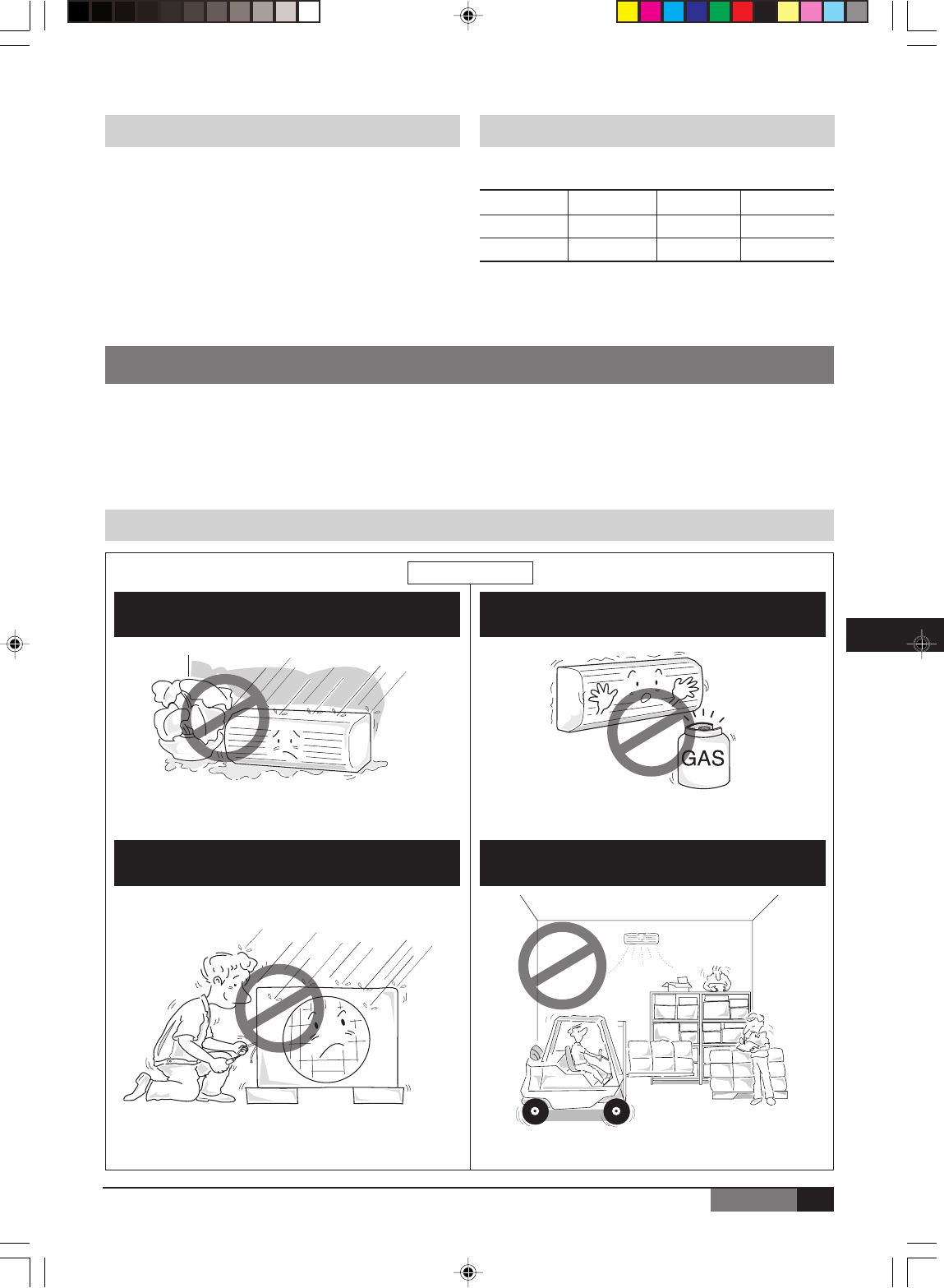
WARNING & CAUTIONS
Do not store or unpack the unit in a wet area or expose
to rain or water.
Do not install in a place where flammable gas may
leak.
Do not conduct installation in wet area or in the rain. This system is designed for domestic or residential
use only.
It may cause the unit to short circuit and may result electric
shocks or fire.
It may cause fire.
It is a high risk to cause the electrical shocks. If used in certain environments, such as a manufacturing
workplace, the equipment may not function efficiently.
INSTALLATION
Models
Liquid size 1/4 inch 1/4 inch 3/8 inch
Gas size 3/8 inch 1/2 inch 5/8 inch
07-09 12-18 24
J199.pmd 31/03/2005, 9:53 PM3
4
ENGLISH
(C
)
TEMP
AUTO
COOL
DRY
HEAT
FAN
HIGH
MED
LOW
MODEFAN SPEED
TIMERON
SLEEP
ON/OFF
TIMEROFF
AIR
DIRECTION
RESET LOCK
SET TEMPERATURE
SWING
LED
DISPLAY
TURBO
9
5
47
21
3
86
12
13
10
11
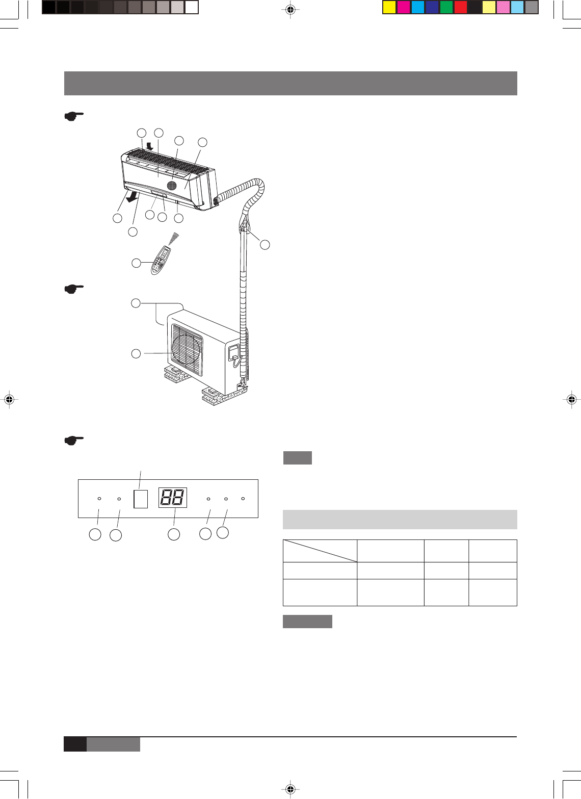
PART NAMES
CAUTIONS
1. If air conditioner is used outside of the above conditions,
certain safety protection features may come into operation
cause the unit to function abnormally.
2.
Room relative humidity less than 80%. If the air conditioner oper-
ates in excess of this figure, the surface of the air conditioner may
attract condensation. Please sets the vertical air flow louver to
its maximum angle (Vertically to the floor), and set HIGH fan mode.
3. Optimum performance will be achieved within these operating
temperature.
INDOOR UNIT
OUTDOOR UNIT
■ INDOOR & OUTDOOR UNIT
1Front panel
2Air inlet
3Air filter
4Air outlet
5Horizontal air flow grille
6Vertical air flow louver
7Display panel
■ DISPLAY PANEL
1AUTO indicator
This indicator illuminates when the air conditioner is in AUTO
operation.
2DEFROST indicator (For Cooling & Heating models only)
This indicator illuminates when the air conditioner starts
defrosting automatically or when the warm air control feature is
activated in heating operation.
3TEMPERATURE indicator
Displays the temperature settings when the air conditioner is
operational.
4OPERATION indicator
This indicator flashes after power is on and illuminates when
the unit is in operation.
5TIMER indicator
This indicator illuminates when TIMER is set ON/OFF.
NOTE
All the pictures in this manual are for explanation purpose only.
They may be slightly different from the air conditioner your
purchased. The actual shape shall prevail.
OPERATING TEMPERATURE
DISPLAY PANEL
122 345
DEFROSTDEFROST TIMERTIMER
AUTOAUTO OPERATIONOPERATION
Signal receptor
8Remote controller signal
receiver
9Remote controller
0Manual control button
-Connecting pipe, drain hose
=Air inlet (side and rear)
~Air outlet
Mode
Temperature
Room temperature
Cooling
operation
17°C-32°C
Heating
operation
17°C-30°C
Drying
operation
17°C-32°C
Outdoor
temperature 18°C-43°C -7°C-24°C 18°C-43°C
Bio Filter
The perfection of MasterGold begins with the innovative Bio
Screen for purifying air. This Bio Screen works in a twofold manner
to give you the maximum effect of purification and dust elimination.
J199.pmd 31/03/2005, 9:53 PM4
5
ENGLISH
EN
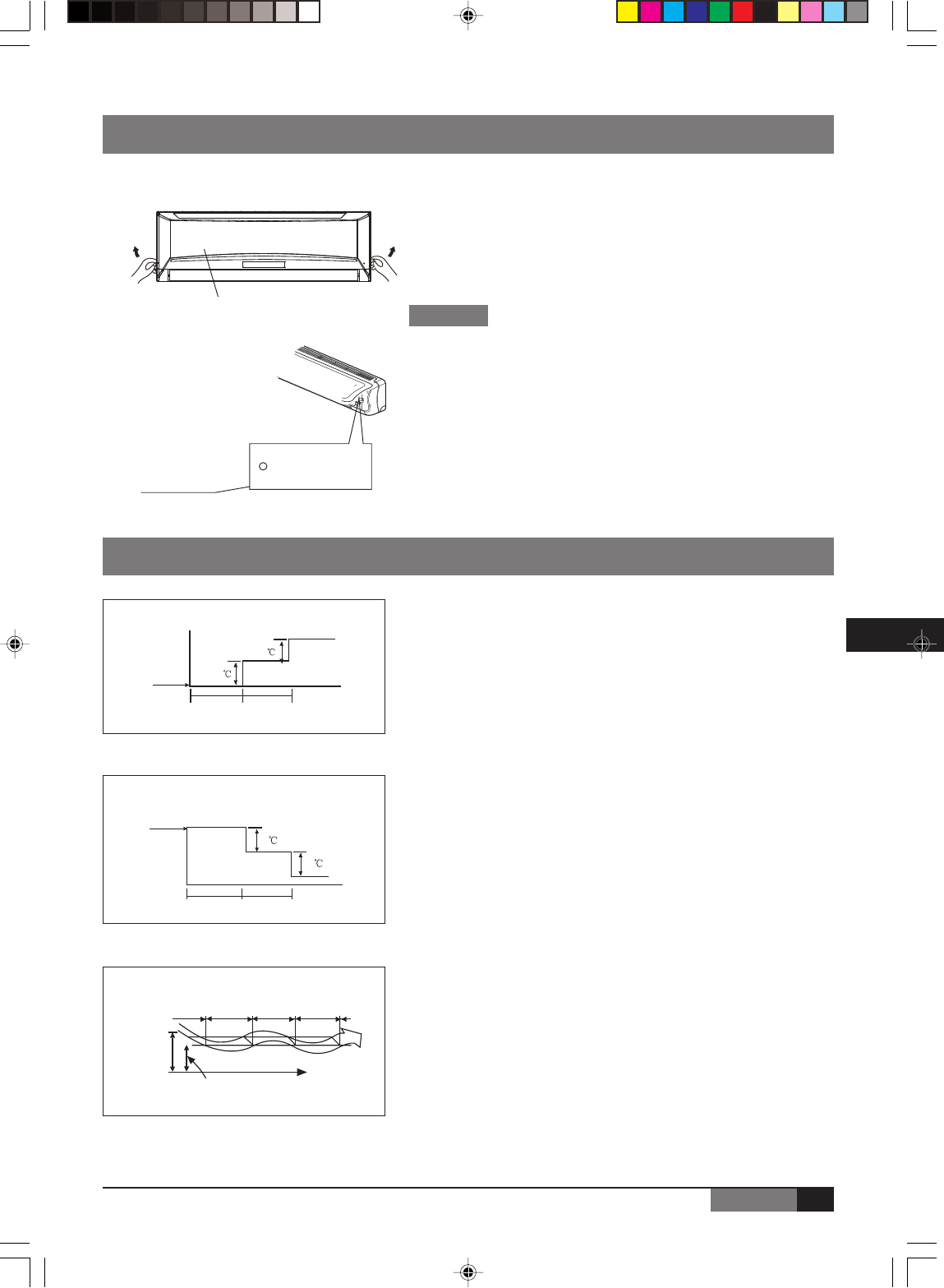
MANUAL OPERATION
1Open and lift the front panel up to an angle at which it remains
fixed with a clicking sound.
2Press the button until the AUTO indicator is lit, the unit will work in
forced AUTO mode.
3Close the panel firmly to its original position.
• Once you push the manual button, the operation mode is shifted in
an order as: AUTO, COOL, OFF.
• Push the button twice, the unit will operate in forced COOL mode.
This is used for testing purposes only .
•
Third press will stop the operation and turn off the air conditioner operation.
• To restore the remote controller operation, use the remote controller
directly.
Manual operation can be used temporarily in case you can not find the remote controller or its batteries are exhausted.
HOW THE AIR CONDITIONER WORKS
■ AUTOMATIC OPERATION
• When you set the air conditioner in AUTO mode, it will automatically
select cooling, heating (cooling/heating models only), or fan only
operation depending on what temperature you have selected and
the room temperature.
• The air conditioner will control room temperature automatically
around the temperature point set by you.
• If the AUTO mode is uncomfortable, you can select desired conditions
manually.
■ SLEEP OPERATION
• When you push SLEEP button during cooling, heating (cooling only
type without), or AUTO operation, the air conditioner will automatically
increase (cooling) or decrease (heating) 1°C per hour. The set
temperature will be steady 2 hours later.
• The fan speed will be automatically controlled.
■ DRYING OPERATION
• The dry mode will automatically select the drying operation based
on the difference between the set temperature and the actual
room temperature.
• The temperature is regulated while dehumidifying by repeating turning
on and off of the cooling operation or fan only. The fan is low.
Manual control button
Panel CAUTIONS
AUTO / COOL
1
1
1
1
Press Sleep button
Set
Temperature
1 hour 1 hour
Cooling
Press Sleep button
Set
Temperature
1 hour 1 hour
Heating
DRYING operation
Room
temperature
Time
set temperature
Cooling
Fan only
Cooling
Fan only
Cooling
J199.pmd 31/03/2005, 9:53 PM5
6
ENGLISH
OPTIMAL OPERATION
To achieve optimal performance, Please note the following:
• Adjust the air flow direction correctly so that it is not directed on people.
• Adjust the temperature to achieve the highest comfort level. Do not adjust the unit to excessive temperature levels.
• Close doors and windows on COOL or HEAT modes, or performance may be reduced.
• Use TIMER ON button on the remote controller to select a time you want to start your air conditioner.
• Do not put any object near air inlet or air outlet, as the efficiency of the air conditioner may be reduced and the air
conditioner may stop running.
• Clean the air filter periodically, otherwise cooling or heating performance may be reduced.
• Do not operate unit with horizontal louver in closed position.
PREPARATION BEFORE INSTALLATION
• Before doing any work, check the interior power supply cord and the main breaker capacity are sufficient and the
installation area is sufficient and complies with the requirements.
• Check that the power supply available agrees with name plate voltage.
• Electrical work, wiring and cables must be in compliance with national and local wiring codes and standard.
• Do not use the extension cables. In the case extended cables are needed, use the terminal block.
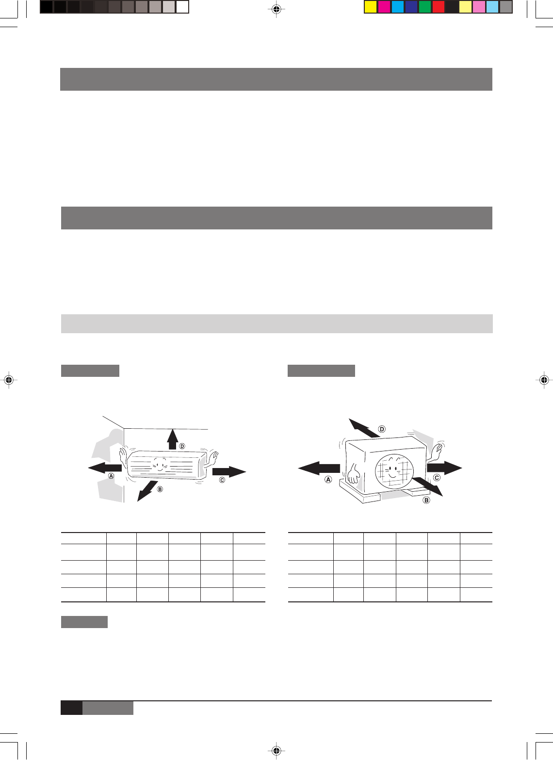
SELECTION OF THE LOCATION
• Select a place which provides the space around the units as shown in the diagram below.
INDOOR UNIT OUTDOOR UNIT
• Do not install in a place that cannot bear the weight of the unit.
CAUTION
Models 07 09 12 18 24
A 12cm 12cm 12cm 12cm 12cm
B 70cm 70cm 70cm 70cm 70cm
C 12cm 12cm 12cm 12cm 12cm
D 15cm 15cm 15cm 15cm 15cm
Models 07 09 12 18 24
A 30cm 30cm 30cm 30cm 30cm
B 200cm 200cm 200cm 200cm 200cm
C 60cm 60cm 60cm 60cm 60cm
D 30cm 30cm 30cm 30cm 30cm
J199.pmd 31/03/2005, 9:53 PM6
7
ENGLISH
EN
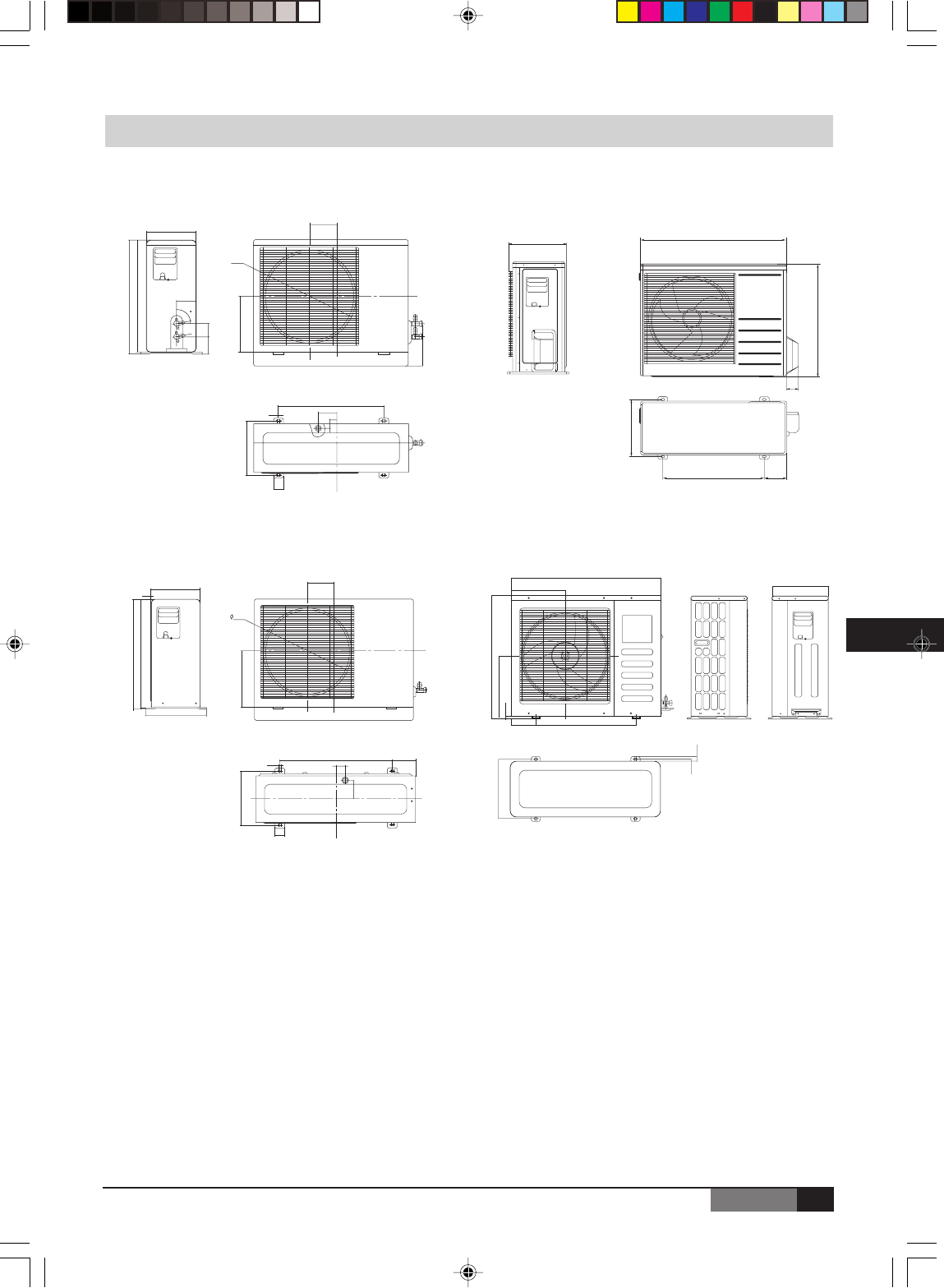
OUTDOOR UNIT PICTURES
540
525
225
75
404
88
700
458
5
35
250
88
33
60
261
6082
80
540
527
245
5
420
128
780
48
10 45
548 115
90
266
272
298
285
290
530 110
62
590
750
MLDA-MLJA 07-09, MLDB-MLJB 07-09, MADC-MAJC 07
MLDA-MLJA 12-18, MLDB-MLJB 12, MADC-MAJC 09-12
MLDA-MLJA 24, MLDB-MLJB 24, MADC-MAJC 18-24
MLDB-MLJB 18
335
125
560.1141.5
135
351.2
694.5
301.5
843
313
235
J199.pmd 31/03/2005, 9:53 PM7
8
ENGLISH
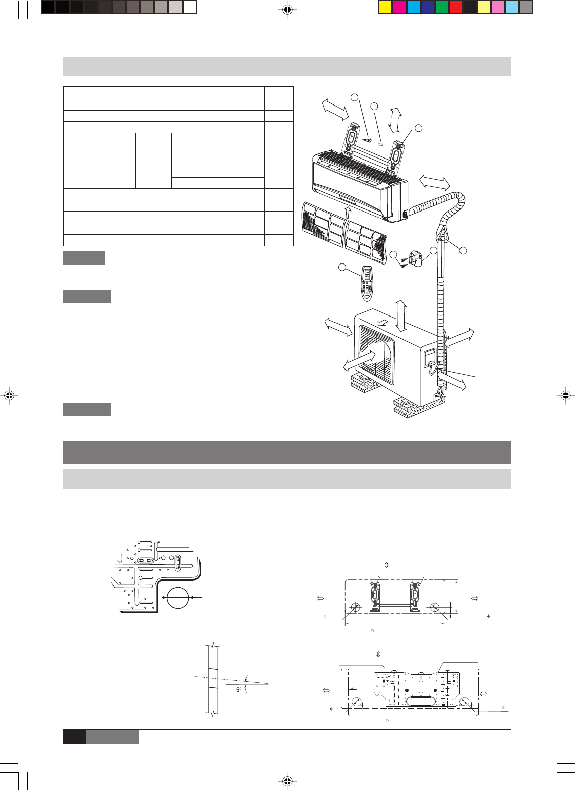
ø 65 mm
Number
Name of part Q’ty
1 Installation plate 1
2 Clip anchor 8
3 Self-tapping screw A ST3.9X25 8
Connecting
pipe
assembly
PARTS INSTALLATION
NOTES
INDOOR UNIT
INSTALLATION PROCEDURE
.
..
..
.
.
..
.....
.
....
.
.
..
.
.
.
.
.
.
..... .
..
.
..
.
....
..
..
.
.
.
.
.
...
..
.
.
.
.
..
.
.
.
..
.
...
.
.
.
.
...
.
...
.
.
.
..
.
....
...
.
..
.
.
...
.
..
.
..
.
..
.
.
..
..
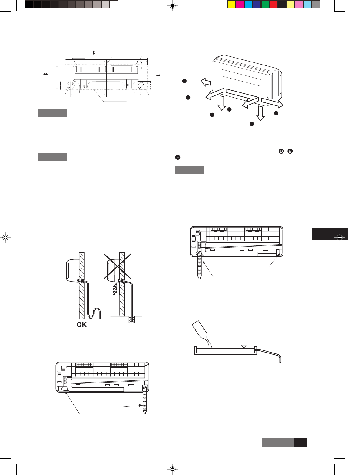
■Fixing
• Place the installation guide pattern on the designated
installation place and mark the hole position.
• Drill a hole and mount installation plate.
• After determining the pipe
hole position. Drill the hole
at a slight downward slant
towards the outdoor side.
Outdoor
Indoor
Note: When installing
the refrigerant pipes from
others side. A hole must
be place to allow fall
towards the outdoor unit.
•
Make 6 mm 4-6 holes, in the wall at the four corners of mouting
plate (bracket) then insert appropriate mouting devices.
•
Install the mounting plate using 4-6 pieces of mounting screw
securely at four corners and tighten the screw completely.
Do not over tighten the screws and deform the back plate.
CAUTIONS
• Ensure that the space around the left and right of the indoor
unit is more than 12cm.
The indoor unit should be installed allowing a minimum clear-
ance of 15cm from the ceiling.
• Use a stud finder to locate studs to prevent unnecessary
damage to the wall.
• A minimum pipe run of 3 metres is required to minimise
vibration & excessive noise.
• The indoor unit should be installed on the wall at a height of
2.3 metres or more from the floor .
•
A, B and C directions should be free from obstructions.
5 Remote controller 1
6 Self-tapping screw B ST3.9X10 2
7 Remote controller holder 1
8 Seal 1
9 Drain joint 1
Liquid side
4
Gas side
ø 6.35
ø 9.53 (<12000Btu/h model)
ø
12.7 (21000Btu/h model > Cooling
capacity f 12000Btu/h model)
ø 16 (f21000Btu/h model)
Parts
you
must
purchase
NOTES
• This illustration is for explanation purposes only.
• Copper lines must be insulated independently.
C
B
A
1
2
3
5
47
6
Self-tapping screw B
ST3.9X10
Loop the
connective
cable.
Remote Controller
Air Filter
Remote Controller
holer
30cm minimum
200cm minimum
60cm minimum
30cm minimum
12cm minimum
12cm minimum
15cm minimum
60cm minimum
Except the above parts provided, the other parts needed
during installation you must purchase.
750
45
250
Right refrigerant
pipe hole 65
Installation plate
Indoor unit outline
Left refrigerant
pipe hole 65
150mm or more to ceiling
120mm or more
to wall
120mm or more
to wall
150mm or more to ceiling
Indoor unit outline Installation plate
920
293
Right refrigerant
pipe hole 65
Left refrigerant
pipe hole 65
120mm or more
to wall
120mm or more
to wall
( 12000Btu/h model)
( 12000Btu/h model)
MODEL 07-12
MODEL 18
J199.pmd 31/03/2005, 9:53 PM8
9
ENGLISH
EN
•
Be careful when handling the sharp edge of the mounting plate.
■Wiring
• This indoor unit is ready for connection to the outdoor unit.
• Never modify the unit by removing any of the safety guards
or by passing any of the safety interlock swithces.
• Connect the interconnecting cable correctly and connect
the connecting cable to terminal as identified with their
respective marking.
•
Do not damage the conductor core or inner insulation of
power supply cables and do not deform or crush the cables.
■Piping
The auxiliary piping can be connected in the diections
shown the above diagram. To connect in the , and
direction, pipes will need to be extended.
• Bend pipes carefully to avoid flattening or obstructing
them if the pipes are bent incorrectly, the indoor unit
may be unstable on the wall.
• Carefully arrange pipes so that pipes do not stick out
of the rear plate of the indoor unit.
A
B
C
D
E
F
MODEL 24
Right
Right
Right
Right Left
Rear Bottom
■Drain hose
• Drain hose is flexible and can be routed to suit various
piping arrangements. The drain line must include elbow
trap (U bend). Connect a plastic condensate pipe with
an internal diameter of 12 mm.
•
The drain hose can be connected to the left or the right side.
Verification of condensate water drainage:
Fill the drain pan with water and observe evacuation.
Note: Do not put the drain hose end into water.
Drain hose
For left and left rear piping
Drain cap
Drain cap
Drain hose
For right and right rear piping
CAUTION
CAUTIONS
CAUTIONS
Above 150mm from the ceiling
Hooked Part
Indoor Unit Outline
Hooked Part
Pipe hole
Above 120mm from
the wall
432
58
465 465
115
50
Pipe hole
5850
115
Hooked Part
432
1080
Above 120mm from
the wall
330
108
22
95
95
J199.pmd 31/03/2005, 9:53 PM9
10
ENGLISH
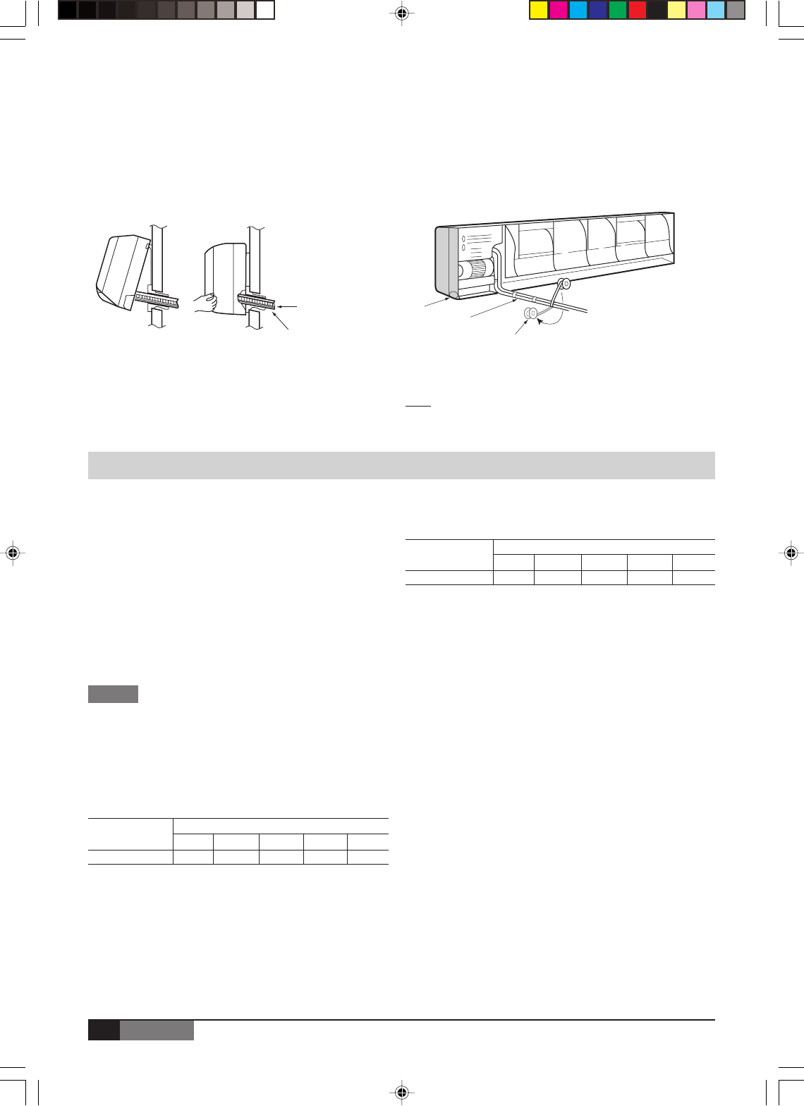
■Indoor Unit Fixing
• Thread the indoor unit piping and cable through the hole.
• Hang the top of the unit onto the upper ridge of them in mounting plate.
• Make sure that the unit is correctly hung in place by sliding it to the left, then to the right.
• Press the bottom left and bottom right hand corners of the unit against the mounting plate until the fixing prongs click
into place in the retainers provided to that effect.
Drainage line
Interconnection cable
Note: The condensate evacuation line should be taped to the
refrigerant lines with vinyl tape.
a) Access plate for the
condensate drainage
pump detection
(condensate pump is
available as an
accessory).
Condensate
drainage line Vinyl tape
a
OUTDOOR UNIT
■Fixing and Piping
• Piping must be performed by qualified personnel
according to good refrigeration systems practices.
• Piping materials and insulation materials must be of
refrigerant quality.
• Select the pipe diameters according to the size of unit
and cut the pipe to design length by using pipe cutter.
• Install the flare nuts and flare the end of the pipes.
• Check that no foreign bodies are inside the piping.
• Align the central of the connecting pipes and tighten
the flare nut.
• Fix piping with pipe clamps and check that any pipe
vibrations cannot be transmitted to the building
structure.
• Connect the pipe correctly.
• Do not apply the excessive torque.
• Use an appropriate bending tool to form curves and
avoid over-tightening the refrigerant tubes.
• To prevent heat loss, the two lines must be insulated
separately.
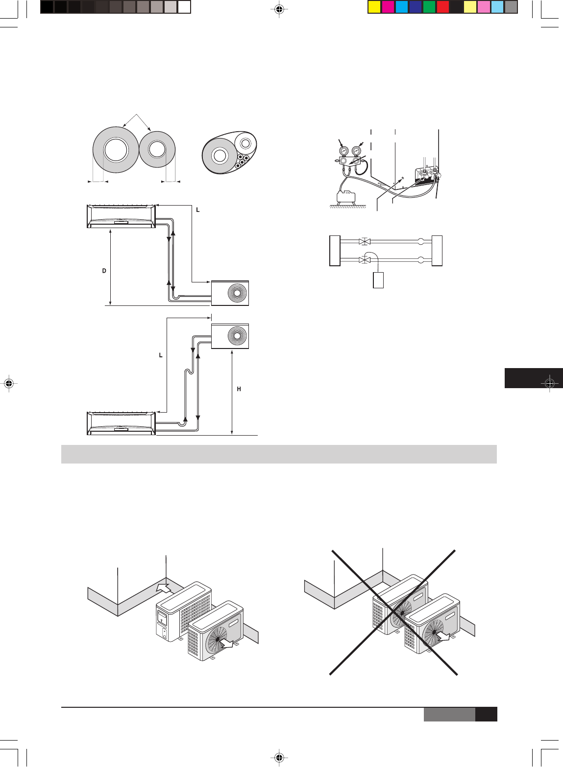
■ Maximum Piping Length
The suction line must have a 2% gradient up to the
compressor on horizontal sections.
Where piping lengths are unusually long and include a
large number of oil traps, it may be necessary to adjust
to compressor charge.
■Refrigerant piping connections
(FLARE connections)
To avoid alteration of unit capacities, check that piping lengths
and changes in elevation are kept to a strict minimum.
Before connectiong the refrigerant lines, follow the
procedures below (if pre-charged connection lines are
not supplied):
- Select copper pipe diameters according to the size of
unit to be installed.
- Install the refrigeration lines, checking that no foreign
boodies get inside the piping.
- Install the flare connectors and flare the ends of the pipes.
- Evacuate the piping. This operation, which should last
at least 15 minutes if there are large piping lengths and
changes in elevation, should be followed by a leak test.
Refrigerant charge to be added per extra meter
of piping length when more than 7.5 meters.
NOTES
Unit size MODELS
7 9 12 18 24
(m) 10 10 10 15 15
Unit size MODELS
7 9 12 18 24
g/m 15 15 15 40 40
J199.pmd 31/03/2005, 9:54 PM10
11
ENGLISH
EN
To this effect, when the piping has been evacuated, close the pressure gauge tap, note the value on the gauge, then
wait for 15 minutes. If the needle moves, there is a leak in the system. Make the necessary adjustments or repairs and
repeat this procedure until the needle no longer moves.
- Open the service valves and top up the refrigerant charge if necessary.
Installation
Minimum thickness 6 mm
Heat pump
Liquid
Cooling
Heat pump
(discharge)
Cooling
(suction)
Heat pump
(discharge)
Heat pump
This unit is shipped complete with a charge of R22/R407C/R 410A
refrigerant that will be sufficient for an interconnecting piping length
of 5 meters.
Liquid
Cooling
GAS
Cooling
(suction)
Low pressure High pressure
Manifold
Gas valve
Liquid valve
Pressure tap
Outdoor unit Indoor unit
Gas line
Liquid line
R22/R407C/R410A
- Outdoor heat pump unit : install the unit at least 10 cm above ground level to facilitate drainage of defrost water and
prevent accumulation of ice. In effect, defrost water can cause accumulation of ice under the unit during subfreezing
outdoor temperatures.
- In areas with heavy snowfall it is best to install the unit on wall supports.
- In some regions. It is necessary to heat the bottom of the condensate drainage pan and the condensate drainage
piping to avoid ice formation, and resulting ice build-up in the fan compartment (heater strip must be at least 25 w/m).
COLD AREA RECOMMENDATION
OK
J199.pmd 31/03/2005, 9:54 PM11
12
ENGLISH
■Wiring
Prepare the power source for exclusive with the air conditioner.
The supply voltage must comply with the rated voltage of the air conditioner: The plug socket shall be accessible after installation.
Remark: All the wiring must be based on the wiring nameplate which is shown on the model.
•Perform the wiring with sufficient capacity. Installation places legally require a short circuit isolator to be attached to
prevent electrical shock.
•Do not extend the power cable code by cutting.
•Power voltage should be in the range of 90%~110% of rated voltage.
•The plug of the air conditioner takes a grounding leg, and clients should use a grounding socket so that the air
conditioner can be grounded efficiently.
•If the power cord is damaged, replacement should be conducted by qualified technician or a serviceman.
Note Remark per EMC Directive 89/336/EEC
To prevent flicker impressions during the start of the compressor (technical process), following installation conditions do apply.
1. The power connection for the air conditioner has to be done at the main power distribution.
The distribution has to be of an low impedance, normally the required impedance reaches at a 32 A fusing point.
2. No other equipment has to be connected with this power line.
3. For detailed installation acceptance, please refer to your contract with the power supplier if restrictions do apply for
products like washing machines, air conditioner or electrical ovens.
4. For power details of the air conditioner, refer to the rating plate of the product.
5. For any question, contact your local dealer.
Cautions
•Never modify the unit by removing any of the safety guards or by bypassing any of the safety interlock swithces.
•Connect the connecting cable correctly and connect the connecting cable to terminal as identified with their respective marks.
•Do not scratch the conductive core & inner insulator of power supply cables and do not deform or smash on the surface of cables.
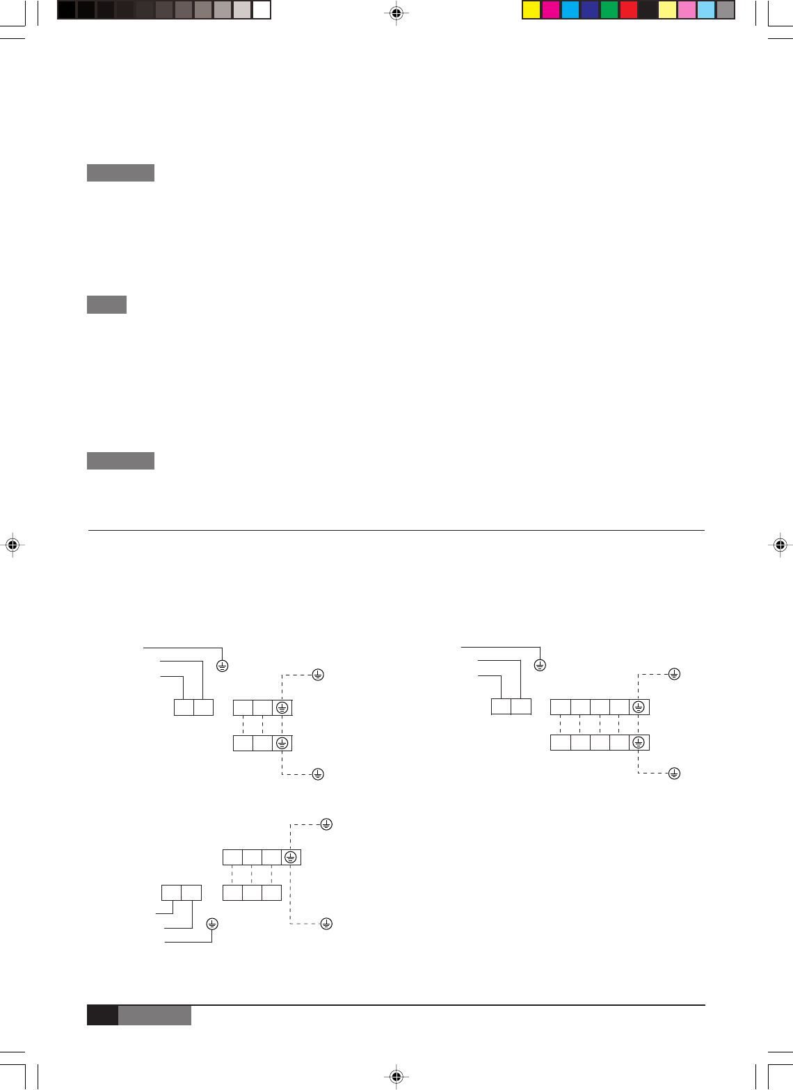
■ Electrical Connections
All electrical wiring and connections must comply with local codes and standards. Power supply cord and interconnection
cord used must not be lighter than Polychloroprene sheeted cord (245 IEC 57 or H05RN-F).
Disconnecting device must have a contact separation of at least 3 mm.
Models : 07-18 (Cooling only)
Power supply
220-240V/1Ph/50Hz
220-230V/1Ph/60Hz
Indoor
LN 12(N)
12(N)
Outdoor
NOTE
CAUTIONS
CAUTIONS
Models : 07-18 (Cooling and Heating)
Power supply
220-240V/1Ph/50Hz
220-230V/1Ph/60Hz
LN 12(N) 34
12(N) 34 Outdoor
Indoor
Models : 24 (Cooling only / Cooling and Heating)
Outdoor
Indoor
For correct installation, a proper ground connection must be made for unit.
Power supply
220-240V/1Ph/50Hz
220-230V/1Ph/60Hz
LN
12(N) S
12(N) S
J199.pmd 31/03/2005, 9:54 PM12
13
ENGLISH
EN
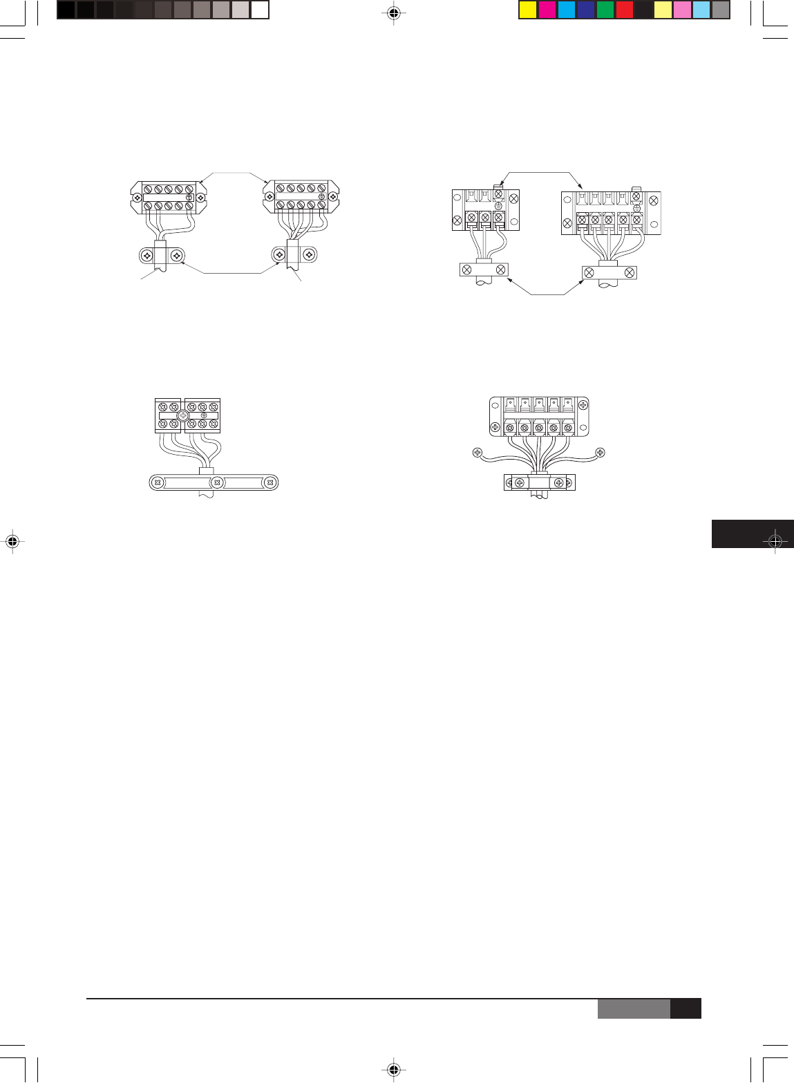
■Wiring Connection
Models : 07-18
Indoor Outdoor
Cooling only type Cooling & heating type Cooling only type Cooling & heating type
Models : 24
Indoor Outdoor
1 2(N) 3 4 1 2(N) 3 4
1 2(N) 1 2(N) 3 4
T
e
S
1 2 (N)
Cooling & heating type
Cord clamp
1
2(N)
3 4 5 6 7 8
Terminal block of Outdoor unit
1 2(N) S L N
Terminal block of indoor unit
Cooling only type / cooling & heating type
Terminal block of indoor unit
Cord clamp
To outdoor unit To outdoor unit
Terminal block of outdoor unit
Wire-holding
board
Terminal block of outdoor unit
Cooling only type / cooling & heating type
J199.pmd 31/03/2005, 9:54 PM13
14
ENGLISH
■Electrical Work
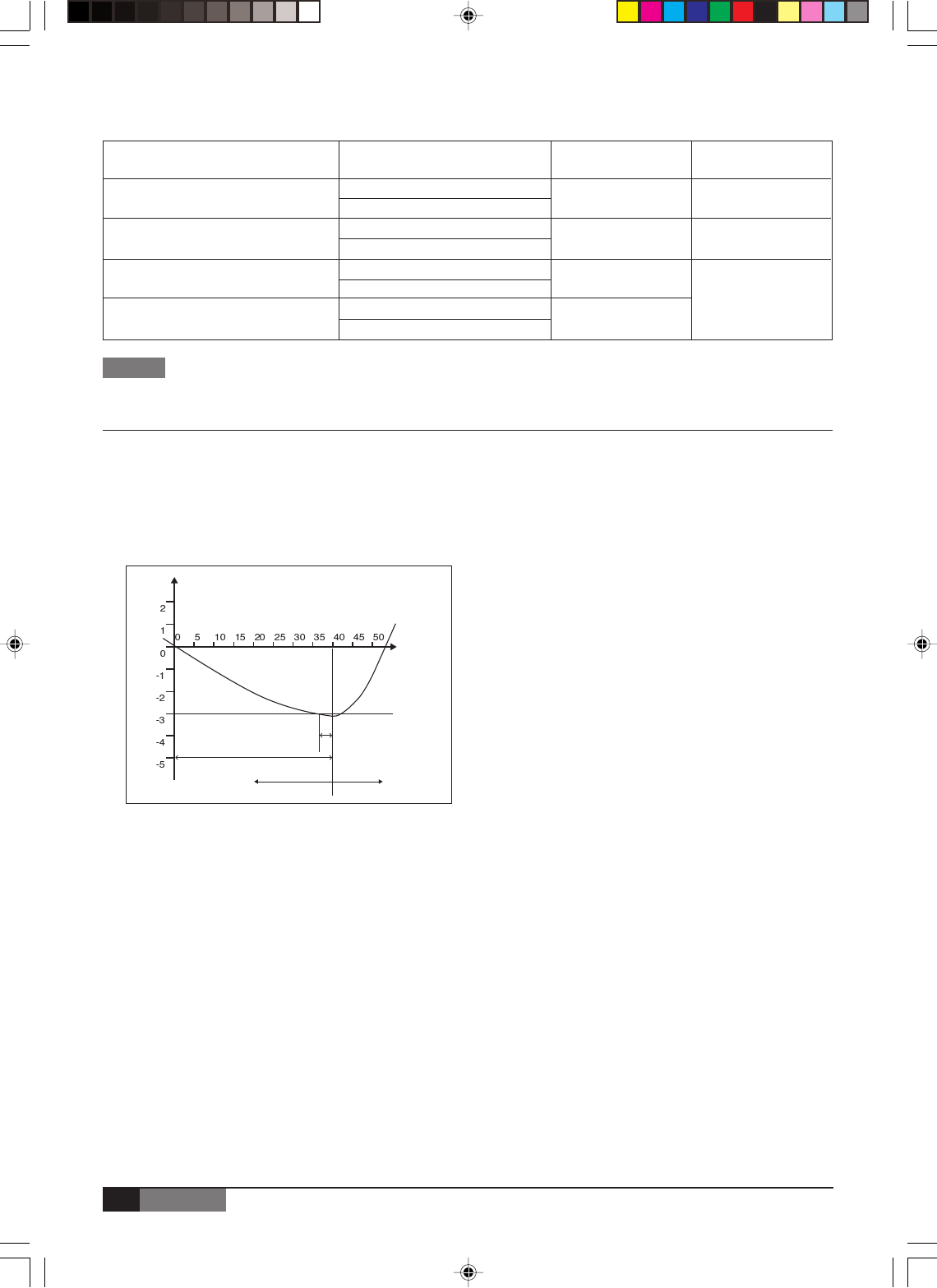
■Defrosting operation (Available for heating only)
1.
Condition to start defrosting: Units will switch to defrosting
mode when either of the following conditions is met.
a. Unit has been running under T3<0ºC for 40
minutes and T3<-3ºC for 3 minutes.
b. Unit has been running at high temperature
protection mode* for 90 minute. (*High temperature
protection mode: when coil temperature of indoor
unit reaches 55°C, outdoor unit will turn off external
unit fan but still keep compressor running).
2. Condition to stop defrosting: Units will switch back to
heating mode when either of the following conditions
is met.
a. Unit has been running at defrosting mode for 10
minutes.
b. T3>20 ºC
Remark: T3 is coil temperature of outdoor units.
T3 (°C)
3 min
40 min
Heating mode Defrosting mode
Time
Elapsed
(min)
Starting Defrosting Mode under condition a.
NOTE
The supply volyage must be consistent with the rate voltage of the air conditioner.
Wiring size
Switch and
Fuse rating
Power SourceModel
ff
ff
f 1.0 mm2
10A
220-240V ~ 50Hz
220-230V ~ 60Hz
7000-9000 Btu/h
ff
ff
f 1.5 mm2
16A
12000 Btu/h
ff
ff
f 2.5 mm2
25A
18000 Btu/h
32A
24000 Btu/h
220-240V ~ 50Hz
220-230V ~ 60Hz
220-240V ~ 50Hz
220-230V ~ 60Hz
220-240V ~ 50Hz
220-230V ~ 60Hz
J199.pmd 31/03/2005, 9:54 PM14
15
ENGLISH
EN
MAINTENANCE
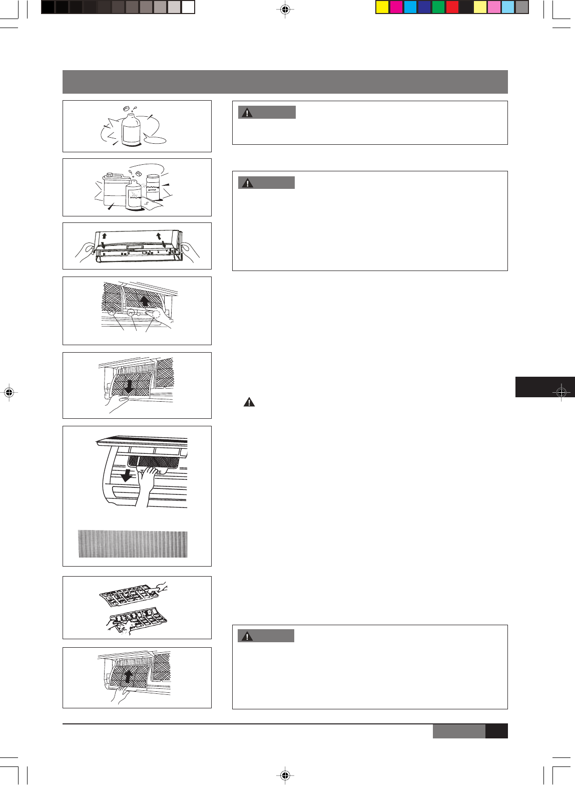
■Cleaning the air filter
A clogged air filter reduces the cooling efficiency of this unit. Please clean
the filter once every 2 weeks.
1.
Lift the indoor unit panel up to an angle until it stops with a clicking sound.
2. Take hold of the handle of the air filter and lift it up slightly to take it out
from the filter holder, then pull it downwards.
3. Remove the AIR FILTER from the indoor unit.
•Clean the AIR FILTER once two weeks.
•Clean the AIR FILTER with a vacuum cleaner or water, then dry it up
in cool place.
4. Remove the Electrostatic Filter from its support frame as shown in the
Figure on the left (Not applicable to the units without electrostatic filter).
Do not touch this Electrostatic Filter within 10 minutes after opening
the inlet grille, it may cause an electric shock.
•Clean the Electrostatic Filter with mild detergent or water and dry in
the sunlight for two hours.
•Before re-install the Electrostatic Filter, check whether the corona line
or support frame is damaged or not.
5. Install the AIR FILTER back into position.
6. Insert the upper portion of the AIR FILTER back into the unit taking care
that the left and right edges line up correctly and place filter into position.
■Maintenance
If you plan to idle the unit for a long time, perform the following:
(1) Operate the fan for about half a day to dry the inside of the unit.
(2) Stop the air conditioner and disconnect power.
Remove the batteries from the remote controller.
(3) The outdoor unit requires periodic maintenance and cleaning. Do not
attempt to do this yourself.
Contact your dealer or servicer.
■Checks before operation
•Check that the wiring is not broken off or disconnected.
•Check that the air filter is installed.
•Check if the air outlet or inlet is blocked after the air conditioner has not
been used for a long time.
•Do not touch the metal parts of the unit when removing the filter. Injuries
can occur when handling sharp metal edges.
•Do not use water to clean inside the air conditioner.
Exposure to water can destroy the insulation, leading to possible
electric shock.
•When cleaning the unit, first make sure that the power and circuit
breaker are turned off.
No
Household
Drain
Cleaner
It is necessary to stop the air conditioner and disconnect the power
supply before cleaning.
WARNING
■Cleaning the indoor unit and remote controller
•Use a dry cloth to wipe the indoor unit and remote controller.
•A cloth dampened with cold water may be used on the indoor unit if
it is very dirty.
•The front panel of the indoor unit can be removed and cleaned with
water. Then wipe it with a dry cloth.
•Do not use a chemically treated cloth or duster to clean the unit.
•Do not use benzine, thinner, polishing powder, or similar solvents for
cleaning. These may cause the plastic surface to crack or deform.
h
Tinenr
CAUTION
Filter Handle
CAUTION
J199.pmd 31/03/2005, 9:54 PM15
16
ENGLISH
OPERATION TIPS
The following events may occur during normal operation.
1. Protection of the air conditioner.
Compressor protection
•The compressor can’t restart for 3 minutes after it stops.
Anti-cold air (Cooling and heating models only)
•The unit is designed not to blow cold air on HEAT mode, when the indoor heat exchanger is in one of the following
three situations and the set temperature has not been reached.
A) When heating has just starting.
B) Defrosting.
C) Low temperature heating.
•The indoor or outdoor fan stop running when defrosting (Cooling and heating models only).
Defrosting (Cooling and heating models only)
•Frost may be generated on the outdoor unit during heat cycle when outdoor temperature is low and humidity is
high resulting in lower heating efficiency of the air conditioner.
•During this condition air conditioner will stop heating operation and start defrosting automatically.
•The time to defrost may vary from 4 to 10 minutes according to the outdoor temperature and the amount of frost
buildup on the outdoor unit.
2. A white mist coming out from the indoor unit.
•A white mist may generate due to a large temperature difference between air inlet and air outlet on COOL mode
in an indoor environment that has a high relative humidity.
•A white mist may generate due to moisture generated from defrosting process when the air conditioner restarts in
HEAT mode operation after defrosting.
3. Low noise of the air conditioner.
•You may hear a low hissing sound when the compressor is running or has just stopped running.
This sound is the sound of the refrigerant flowing or coming to a stop.
•You can also hear a low “squeak” sound when the compressor is running or has just stopped running. This is
caused by heat expansion and cold contraction of the plastic parts in the unit when the temperature is changing.
•A noise may be heard due to louver restoring to its original position when power is first turned on.
4. Dust in blown out from the indoor unit.
This is a normal condition when the air conditioner has not been used for a long time or during first use of the unit.
5. A peculiar smell come out from the indoor unit.
This is caused by the indoor unit giving off smells permeated from building material, from furniture, or smoke.
6. The air conditioner turns to FAN only mode from COOL or HEAT (for cooling and heating models only) mode.
When indoor temperature reaches the temperature setting on air conditioner, the compressor will stop automatically,
and the air conditioner turns to FAN only mode. The compressor will start again when the indoor temperature rises on
COOL mode or falls on HEAT mode (for cooling and heating models only) to the set point.
7. Dripping water may generate on the surface of the indoor unit when cooling in a high relatively humidity (relative
humidity higher than 80%). Adjust the horizontal louver to the maximum air outlet position and select HIGH fan speed.
8. Heating mode (For cooling and heating models only)
The air conditioner draws in heat from the outdoor unit and releases it via the indoor unit during heating operation.
When the outdoor temperature falls, heat drawn in by the air conditioner decreases accordingly. At the same time,
heat loading of the air conditioner increases due to larger difference between indoor and outdoor temperature. If a
comfortable temperature can’t be achieved by the air conditioner, we suggest you use a supplementary heating device.
9. Auto-restart function
Power failure during operation will stop the unit completely.
For the unit without Auto-restart feature, when the power restores, the OPERATION indicator on the indoor unit starts
flashing. To restart the operation, push the ON/OFF button on the remote controller. For the unit with Auto-restart
feature, when the power restores, the unit restarts automatically with all the previous settings preserved by the memory
function.
10.
Lightning or a car wireless telephone operating nearby may cause the unit to malfunction.
Disconnect the unit with power and then re-connect the unit with power again. Push the ON/OFF button on the remote
controller to restart operation.
J199.pmd 31/03/2005, 9:54 PM16
17
ENGLISH
EN
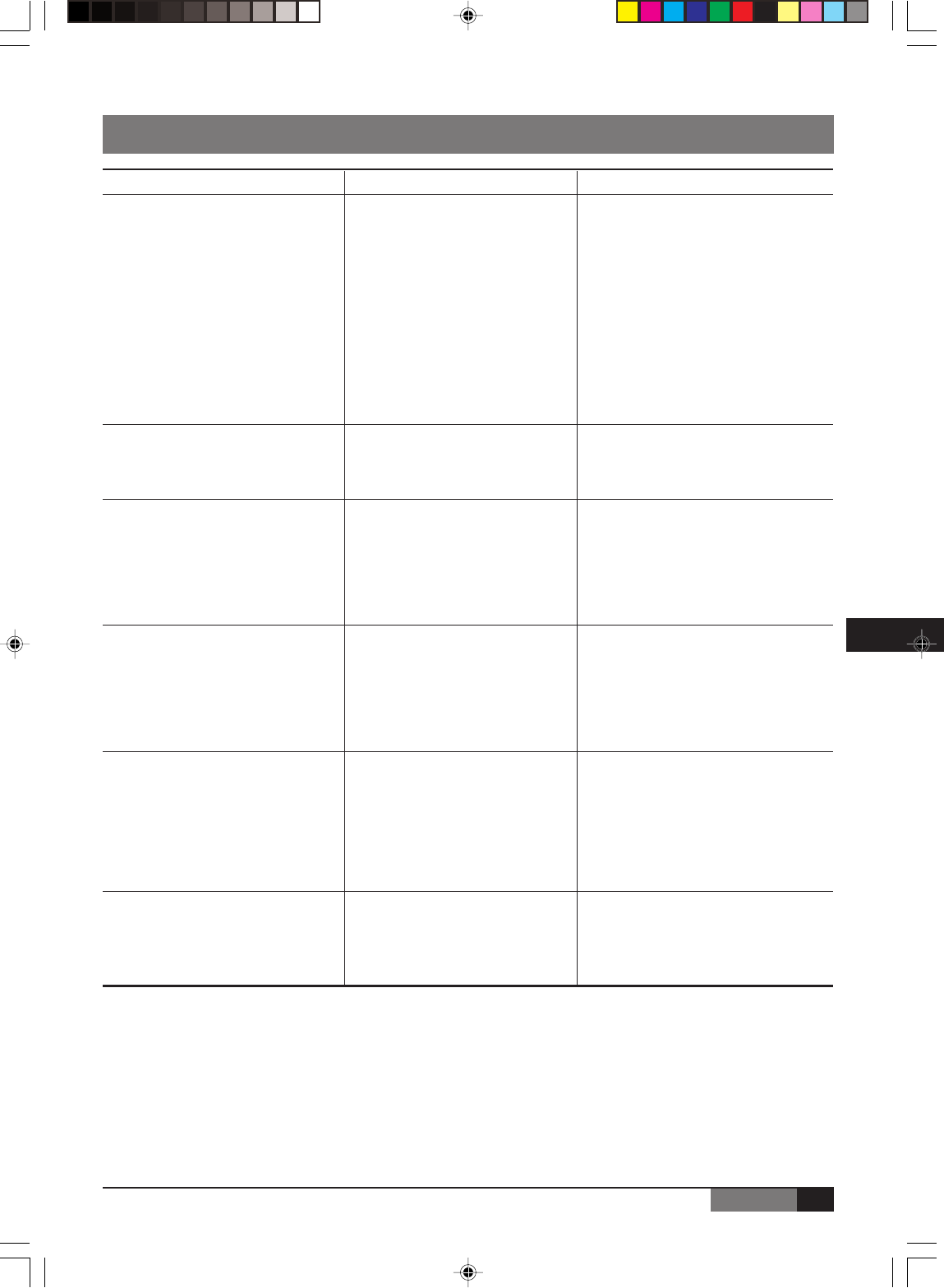
TROUBLE SHOOTING GUIDE
Problem Probable cause Remedy
A. The air conditioner does not run. 1. Power failure. 1. Wait for power resume.
2. Fuse blown or circuit breaker 2. Replace the fuse or reset the
open. breaker.
3. Voltage is too low. 3. Find the cause and fix it.
4. Faulty contactor or relay. 4. Replace the faulty component.
5. Electrical connections loose. 5. Retighten the connection.
6. Thermostat adjustment too low 6. Check thermostat setting.
(in heating mode) or too high
(in cooling mode).
7. Faulty capacitor. 7. Find the cause then replace
capacitor.
8. Incorrect wiring, terminal loose. 8. Check and retighten.
9. Pressure switch tripped. 9. Find the cause before reset.
B. The outdoor fan runs but the 1. Motor winding cut or grounded. 1. Check the wiring and the
compressor will not start. compressor winding resistance.
2. Faulty capacitor. 2. Find the cause then replace
capacitor.
C. There is insufficient heating or 1. There is a gas leak. 1. Remove charge, repair, evacuate
cooling. and recharge.
2. Liquid and gas line insulated 2. Insulate them separately.
together.
3. The room was probably very hot 3. Wait while unit has enough time to
(cool) when you started the cool the room.
system.
D.
The compressor runs continuously.
1. Thermostat adjustment too low 1. Check thermostat setting.
(in heating mode) or too high
(in cooling mode).
2. Faulty fan. 2. Check condenser air circulation.
3. Refrigerant charge too low, leak. 3. Find leak, repair and recharge.
4. Air or incondensables in 4. Remove charge, evacuate and
refrigerant circuit. recharge.
E. The compressor starts but shuts 1. Too much or too little refrigerant. 1. Remove charge, evacuate and
down quickly. recharge.
2. Faulty compressor. 2. Determine the cause and replace
compressor.
3. Air or incondensables in 3. Remove charge, evacuate and
refrigerant circuit. recharge.
4. Changeover valve damaged or 4. Replace it.
blocked open (heat pump unit).
F. Clicking sound is heard from In heating or cooling operation any In heating or cooling operation any
the air conditioner. plastic parts may expand or shrink plastic parts may expand or shrink due
due to a sudden temperature change
to a sudden temperature change in this
in this event, a clicking sound may event, a clicking sound may occur.
occur.
J199.pmd 31/03/2005, 9:54 PM17
18
ENGLISH
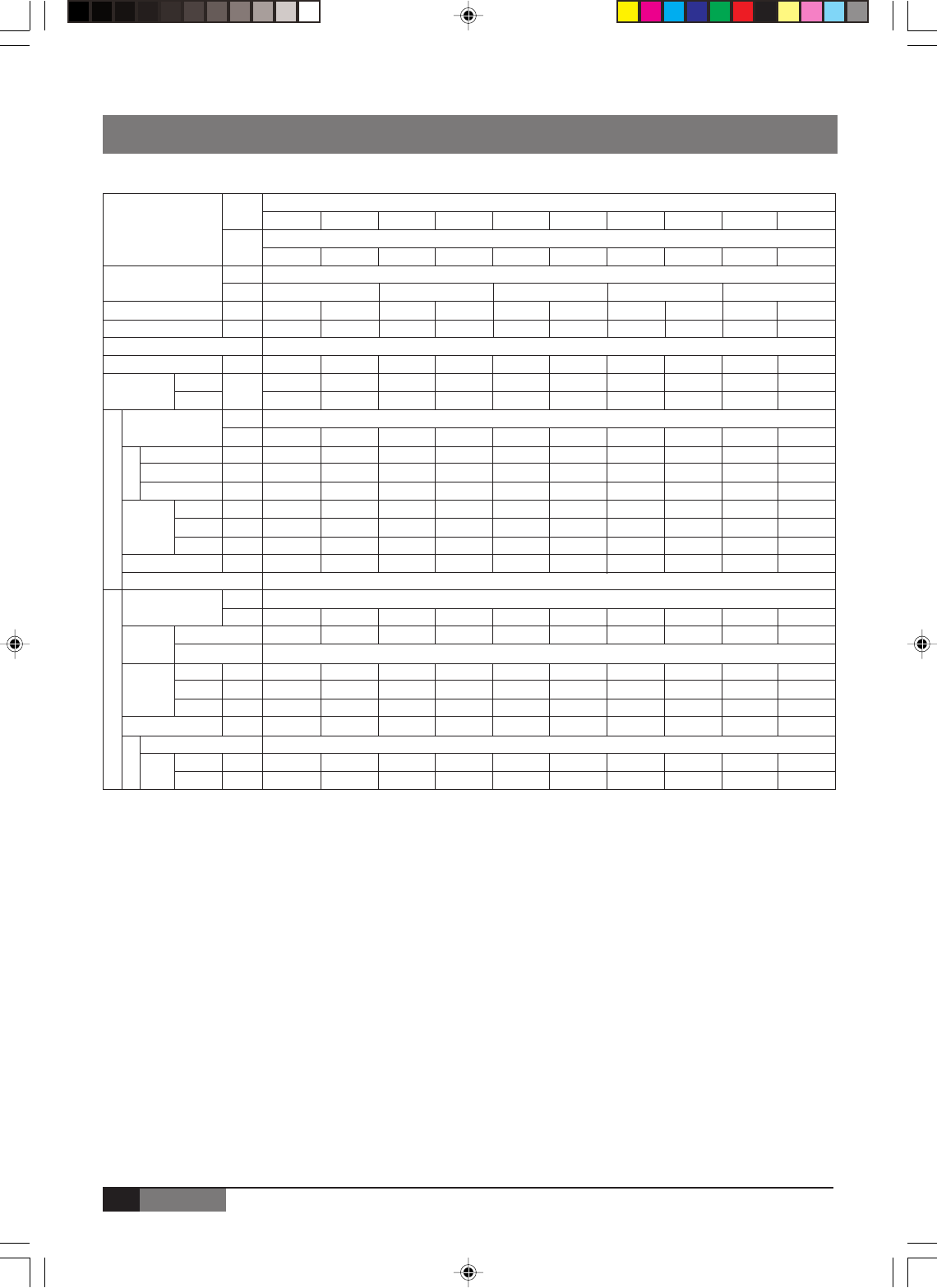
TECHNICAL SPECIFICATION
Technical Specifications : Master Gold “R22” - 50 Hz
Indoor
Models Unit
Outdoor
Unit
Power Supply V/Ph/Hz
Ph
Power Consumption KW
Running Current A
Refrigerant Type
Refrigerant Charge
Noise level Indoor dB(A)
Outdoor
Power Supply V/Ph/Hz
Ph
Air flow m
3
/h
Input Power W
Running Current A
Height mm
Dimension Width mm
Depth mm
Weight kg
System Operation Control
Power Supply V/Ph/Hz
Ph
Compressor
Qty
Compressor Type
Height mm
Dimension Width mm
Depth mm
Weight kg
Type
Pipe Suction inch
Size Liquid inch
Outdoor Unit Indoor Unit
Fan
Piping
Flare + Nut
Wireless Control with LCD Display
R22
MLDA-MLJA
MLEA-MLKA
220-240/1/50
220-240/1/50
220-240/1/50
MLEA07 MLKA07 MLEA09 MLKA09 MLEA12 MLKA12 MLEA18 MLKA18 MLEA24 MLKA24
MLDA07 MLJA07 MLDA09 MLJA09 MLDA12 MLJA12 MLDA18 MLJA18 MLDA24 MLJA24
0.8 0.8 1.01 1.01 1.35 1.35 1.96 1.96 2.8 2.8
3.5 3.5 4.6 4.6 6.0 6.0 9.4 9.4 12.5 12.5
111 11
530 570 580 800 850 900 1130 1400 1450 1900
35/32/30 35/32/30 37/34/32 37/34/32 37/32/28 37/32/28 42/40/38 42/40/38 45/42/39 45/42/39
49 49 50 50 54 54 56 56 55 55
1 111 1 11 1 11
400 400 450 450 580 580 800 800 1080 1080
39.5 39.5 39.5 39.5 38.5 38.5 53 53 65 65
0.17 0.17 0.17 0.17 0.17 0.17 0.24 0.24 0.29 0.29
250 250 250 250 265 265 292 292 330 330
710 710 710 710 790 790 920 920 1080 1080
190 190 190 190 195 195 225 225 225 225
8 8 8 8 9 9 13 13 17 17
1 111 1 11 1 11
1 111 1 11 1 11
Rotary
535 535 535 535 540 540 590 590 695 695
700 700 700 700 780 780 780 780 845 845
235 235 235 235 250 250 250 250 335 335
25.5 26 26.5 28.5 34 35 37 40 56 60
3/8 3/8 3/8 3/8 1/2 1/2 1/2 1/2 5/8 5/8
1/4 1/4 1/4 1/4 1/4 1/4 1/4 1/4 3/8 3/8
gr
Remark: The above design and specifications are subject to change without prior notice for product improvement.
J199.pmd 31/03/2005, 9:54 PM18
19
ENGLISH
EN
111 11
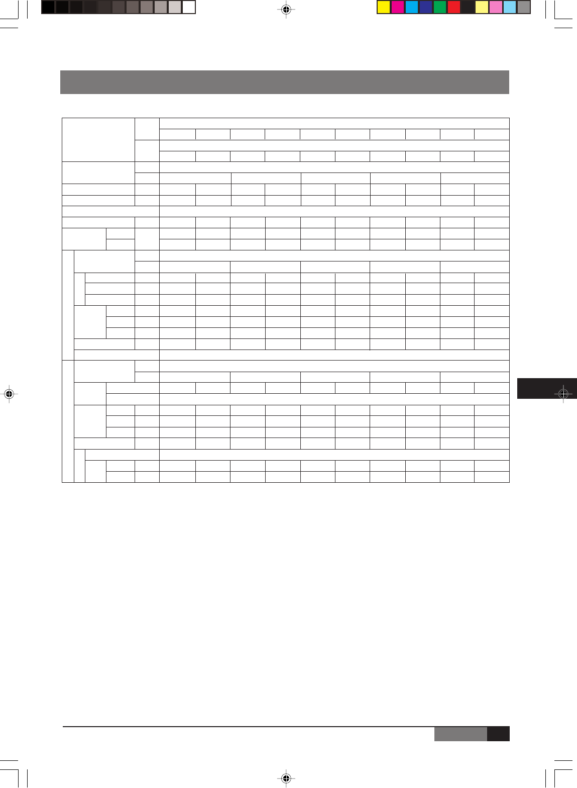
TECHNICAL SPECIFICATION
Technical Specifications : Master Gold “R22” - 60 Hz
Indoor
Models Unit
Outdoor
Unit
Power Supply V/Ph/Hz
Ph
Power Consumption KW
Running Current A
Refrigerant Type
Refrigerant Charge
Noise level Indoor dB(A)
Outdoor
Power Supply V/Ph/Hz
Ph
Air flow m
3
/h
Input Power W
Running Current A
Height mm
Dimension Width mm
Depth mm
Weight kg
System Operation Control
Power Supply V/Ph/Hz
Ph
Compressor
Qty
Compressor Type
Height mm
Dimension Width mm
Depth mm
Weight kg
Type
Pipe Suction inch
Size Liquid inch
Outdoor Unit Indoor Unit
Fan
Piping
Flare + Nut
Wireless Control with LCD Display
R22
MLDA-MLJA
MLEA-MLKA
220-230/1/60
220-230/1/60
220-230/1/60
MLEA07 MLKA07 MLEA09 MLKA09 MLEA12 MLKA12 MLEA18 MLKA18 MLEA24 MLKA24
MLDA07 MLJA07 MLDA09 MLJA09 MLDA12 MLJA12 MLDA18 MLJA18 MLDA24 MLJA24
0.71 0.71 0.95 0.95 1.21 1.21 1.95 1.95 2.67 2.67
3.2 3.2 4.5 4.5 5.5 5.5 8.9 8.9 12.1 12.1
111 11
530 590 630 650 780 1050 1180 1450 1450 1900
35/32/30 35/32/30 35/32/30 35/32/30 37/32/28 37/32/28 42/40/38 42/40/38 48/45/42 48/45/42
52 52 52 53 56 56 56 56 58 58
11111
400 400 400 400 580 580 800 800 1080 1080
31 31 31 31 31 31 53 53 150 150
0.14 0.14 0.14 0.14 0.14 0.14 0.24 0.24 0.68 0.68
250 250 250 250 265 265 292 292 330 330
710 710 710 710 790 790 920 920 1080 1080
190 190 190 190 195 195 225 225 225 225
8.5 8.5 8.5 8.5 9.0 9.0 13 13 17 17
1111111111
Rotary
535 535 535 535 540 540 540 540 695 695
700 700 700 700 780 780 780 780 845 845
235 235 235 235 250 250 250 250 335 335
27 28 32 30 34 36 37 40 58 60
3/8 3/8 3/8 3/8 1/2 1/2 1/2 1/2 5/8 5/8
1/4 1/4 1/4 1/4 1/4 1/4 1/4 1/4 3/8 3/8
gr
Remark: The above design and specifications are subject to change without prior notice for product improvement.
J199.pmd 31/03/2005, 9:54 PM19

20
ENGLISH
TECHNICAL SPECIFICATION
Technical Specifications : Master Gold “R407C” - 50 Hz
Indoor
Models Unit
Outdoor
Unit
Power Supply V/Ph/Hz
Ph
Power Consumption KW
Running Current A
Refrigerant Type
Refrigerant Charge
Noise level Indoor dB(A)
Outdoor
Power Supply V/Ph/Hz
Ph
Air flow m
3
/h
Input Power W
Running Current A
Height mm
Dimension Width mm
Depth mm
Weight kg
System Operation Control
Power Supply V/Ph/Hz
Ph
Compressor
Qty
Compressor Type
Height mm
Dimension Width mm
Depth mm
Weight kg
Type
Pipe Suction inch
Size Liquid inch
Outdoor Unit Indoor Unit
Fan
Piping
Flare + Nut
Wireless Control with LCD Display
R407C
MLDB-MLJB
MLEB-MLKB
220-240/1/50
220-240/1/50
220-240/1/50
MLEB07 MLKB07 MLEB09 MLKB09 MLEB12 MLKB12 MLEB18 MLKB18 MLEB24 MLKB24
MLDB07 MLJB07 MLDB09 MLJB09 MLDB12 MLJB12 MLDB18 MLJB18 MLDB24 MLJB24
0.78 0.78 1 1 1.35 1.35 1.96 1.96 2.73 2.73
3.5 3.5 4.4 4.4 6.0 6.0 9.4 9.4 12.5 12.5
111 11
680 700 820 850 900 1200 1400 1400 1950 2050
35/32/30 35/32/30 37/34/32 37/34/32 37/32/28 37/32/28 42/40/38 42/40/38 45/42/39 45/42/39
49 49 50 50 54 52 56 56 55 55
400 400 450 450 580 580 800 800 1080 1080
39.5 39.5 39.5 39.5 44 44 53 53 65 65
0.17 0.17 0.17 0.17 0.2 0.2 0.26 0.26 0.37 0.37
250 250 250 250 265 265 292 292 330 330
710 710 710 710 790 790 920 920 1080 1080
190 190 190 190 195 195 225 225 225 225
8 8 8 8 9 9 13 13 17 17
1 111 1 11 1 11
Rotary
535 535 535 535 540 540 590 590 695 695
700 700 700 700 780 780 760 760 845 845
235 235 235 235 250 250 285 285 335 335
25.5 26 27.5 28.5 34 36 42 43 61 62
3/8 3/8 3/8 3/8 1/2 1/2 1/2 1/2 5/8 5/8
1/4 1/4 1/4 1/4 1/4 1/4 1/4 1/4 3/8 3/8
111 11
111 11
gr
Remark: The above design and specifications are subject to change without prior notice for product improvement.
J199.pmd 31/03/2005, 9:54 PM20

21
ENGLISH
EN
TECHNICAL SPECIFICATION
Technical Specifications : Master Gold “R410A” - 50 Hz
Indoor
Models Unit
Outdoor
Unit
Power Supply V/Ph/Hz
Ph
Power Consumption KW
Running Current A
Refrigerant Type
Refrigerant Charge
Noise level Indoor dB(A)
Outdoor
Power Supply V/Ph/Hz
Ph
Air flow m
3
/h
Input Power W
Running Current A
Height mm
Dimension Width mm
Depth mm
Weight kg
System Operation Control
Power Supply V/Ph/Hz
Ph
Compressor
Qty
Compressor Type
Height mm
Dimension Width mm
Depth mm
Weight kg
Type
Pipe Suction inch
Size Liquid inch
Outdoor Unit Indoor Unit
Fan
Piping
Flare + Nut
Wireless Control with LCD Display
R410A
MADC-MAJC
MAEC-MAKC
220-240/1/50
220-240/1/50
220-240/1/50
MAEC07 MAKC07 MAEC09 MAKC09 MAEC12 MAKC12 MAEC18 MAKC18 MAEC24 MAKC24
MADC07 MAJC07 MADC09 MAJC09 MADC12 MAJC12 MADC18 MAJC18 MADC24 MAJC24
0.64 0.64 0.82 0.82 1.12 1.12 1.72 1.72 2.53 2.53
2.8 2.8 3.6 3.6 5.0 5.0 7.8 7.8 11.2 11.2
111 11
800 820 900 920 1050 1080 1690 1740 1900 1950
35/32/30 35/32/30 37/34/31 37/34/31 40/37/34 40/37/34 42/39/37 42/39/37 45/42/39 45/42/39
49 49 50 50 50 50 52 52 55 55
450 450 500 500 580 600 850 850 1080 1080
36.5 36.5 39.5 39.5 44 44 53 53 65 65
0.17 0.17 0.17 0.17 0.2 0.2 0.26 0.26 0.37 0.37
250 250 250 250 265 265 292 292 330 330
710 710 710 710 790 790 920 920 1080 1080
190 190 190 190 193 193 225 225 225 225
8 8 8 8 9 9 13 13 17 17
1 111 1 11 1 11
Rotary
535 535 540 540 540 540 695 695 695 695
700 700 780 780 780 780 845 845 845 845
235 235 250 250 250 250 335 335 335 335
31 32 36 37 37 38 52 52 59 60
3/8 3/8 3/8 3/8 1/2 1/2 1/2 1/2 5/8 5/8
1/4 1/4 1/4 1/4 1/4 1/4 1/4 1/4 3/8 3/8
111 11
111 11
gr
Remark: The above design and specifications are subject to change without prior notice for product improvement.
J199.pmd 31/03/2005, 9:54 PM21
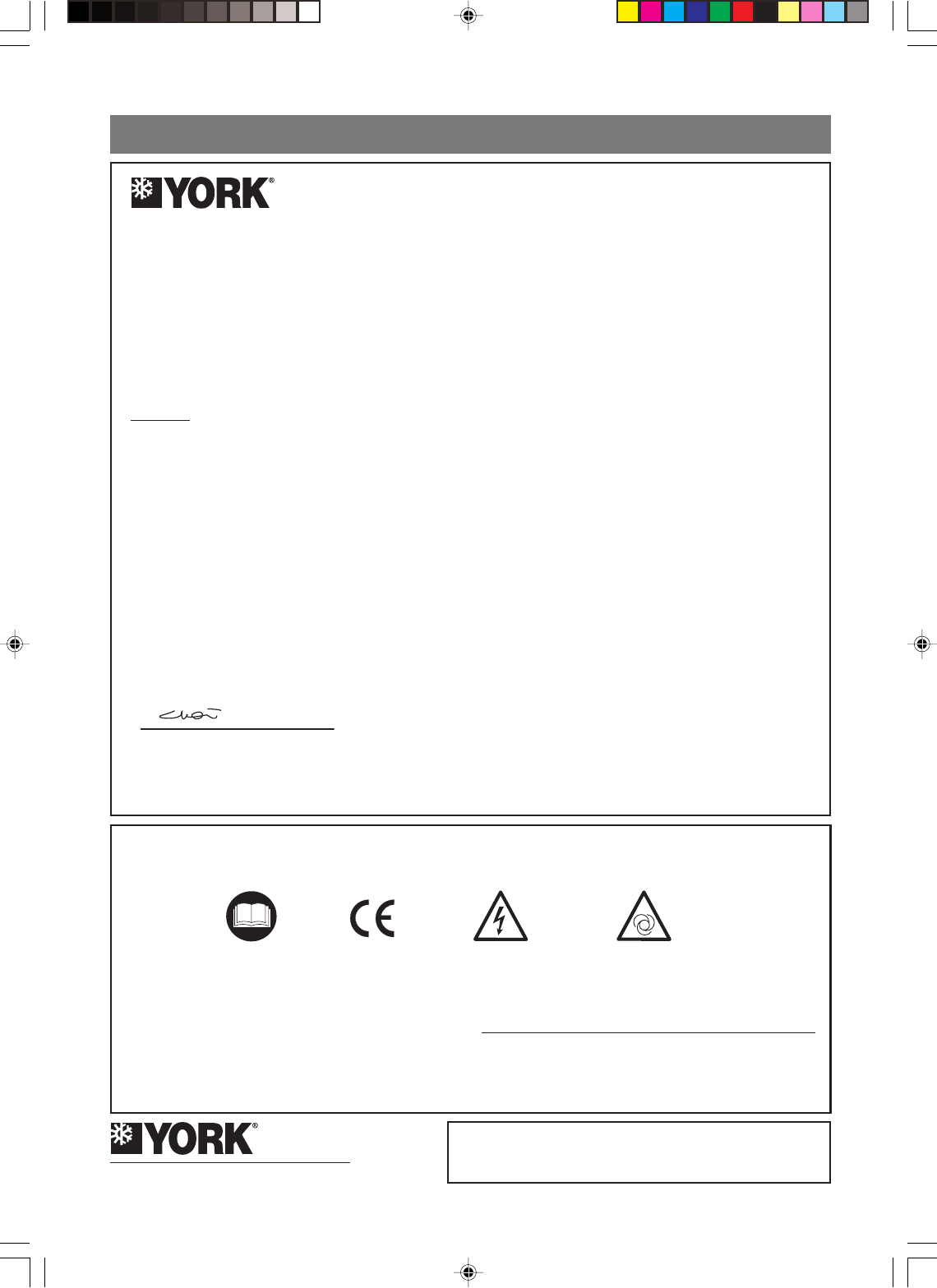
DECLARACIÓN DE CONFORMIDAD
CM Choi
Shipping Manager
The product complies with the harmonized European safety standards and harmonized EMC standards listed above.
We have internal production control system that ensures compliance between the manufacturer products and the technical documentation.
The product is CE mark.
We declare under our sold responsibility that the equipment follows the provisions Of the Directives stated above.
Authorized Representative:
Type of Equipment
Brand Name
Type Designation
Application of Council
Directive (s)
The following harmonized standards have been applied:
Standard (s)
EN 60335-2-40/A1:2000
EN 60335-2-40/A1:2000
EN 55014-1:2000/A2:2002
EN 55014-2:1997/A1:2001
EN 55022:1998/A1:2000
EN 61000-3-2:2000
EN 61000-3-3:1995/A1:2001
EN 61000-3-11:2000
EN 60825
EN 60335-1:1994+A11:1995+A1, A12:1996+A13, A14:1998+A15, A2:2000+A16:2001
EN 60335-2-40:1997+A1:2000
EN 55014-1:1993+A1:1997/A2:1999
EN 55104-2:1997
EN 61000-3-2:1995/A1:1998/A2:1998
EN 61000-3-2:1995/A14:2000
EN 61000-3-3:1995
EN 60335-2-40:2003
EN 50366:2003
DECLARATION OF CONFORMITY
YORK International (Northern Asia) Ltd.
15/F., Tower II, World Trade Square, 123 Hoi Bun Road, Kwun Tong, Kowloon, Hong Kong
Telephone: (852) 2331 9286 Fax: (852) 2331 9840
Technical Service Division: Telephone: (852) 2331 9286 Fax: (852) 2304 0068
YORK® International Corporation
DECLARATION OF CONFORMITY
1.1.
1.1.
1.
Isolate all sources of electrical supply to the unit including any control system supplies switched by the unit. Ensure that all points of electrical and
gas isolation are secured in the OFF position.
The supply cables and gas pipework may then be disconnected and removed. For points of
connection refer to unit installation instructions.
2.2.
2.2.
2. Remove all refrigerant from each system of the unit into a suitable container using a refrigerant reclaim or recovery unit. This refrigerant may then
be reused, if appropriate, or returned to the manufacturer for disposal. Under No circumstances should refrigerant be vented to atmosphere.Under No circumstances should refrigerant be vented to atmosphere.
Under No circumstances should refrigerant be vented to atmosphere.Under No circumstances should refrigerant be vented to atmosphere.
Under No circumstances should refrigerant be vented to atmosphere.
Where appropriate, drain the refrigerant oil from each system into a suitable container and dispose of according to local laws and regulations
governing disposal of oily wastes.
3.3.
3.3.
3. Packaged unit can generally be removed in one piece after disconnection as above. Any fixing down bolts should be removed and then unit lifted
from position using the points provided and equipment of adequate lifting capacity. Reference MUST be made to the unit installation instructions
for unit weight and correct methods of lifting. Note that any residual or spilt refrigerant oil should be mopped up and disposed of as described above.
4.4.
4.4.
4. After removal from position the unit parts may be disposed of according to local laws and regulations.
INSTALLATION, REMOVAL AND DISPOSALINSTALLATION, REMOVAL AND DISPOSAL
INSTALLATION, REMOVAL AND DISPOSALINSTALLATION, REMOVAL AND DISPOSAL
INSTALLATION, REMOVAL AND DISPOSAL
This product contains refrigerant under pressure, rotating parts, and electrical connections which may be a danger and cause injury!This product contains refrigerant under pressure, rotating parts, and electrical connections which may be a danger and cause injury!
This product contains refrigerant under pressure, rotating parts, and electrical connections which may be a danger and cause injury!This product contains refrigerant under pressure, rotating parts, and electrical connections which may be a danger and cause injury!
This product contains refrigerant under pressure, rotating parts, and electrical connections which may be a danger and cause injury!
All work must only be carried out by competent persons using suitable protective clothing and safety precautions.All work must only be carried out by competent persons using suitable protective clothing and safety precautions.
All work must only be carried out by competent persons using suitable protective clothing and safety precautions.All work must only be carried out by competent persons using suitable protective clothing and safety precautions.
All work must only be carried out by competent persons using suitable protective clothing and safety precautions.
Read the ManualRead the Manual
Read the ManualRead the Manual
Read the Manual Risk of electric shockRisk of electric shock
Risk of electric shockRisk of electric shock
Risk of electric shock
Unit is remotely controlled andUnit is remotely controlled and
Unit is remotely controlled andUnit is remotely controlled and
Unit is remotely controlled and
may start without warningmay start without warning
may start without warningmay start without warning
may start without warning
Air Conditioners
YORK
HAEA-HADA07/09/12FS, HAEB-HADB07/09/12FS, HAEC-HADC07/09/12FS, HAKA-HAJA07/09/12FS,
HAKB-HAJB07/09/12FS, HAKC-HAJC07/09/12FS, HEEB-HEDB07/09/12/18/24/30FS,
HEKB-HEJB07/09/12/18/21/24/30FS, HLEA-HLDA07/09/12/18/24FS, HLCA-HLHA24/28/FS,
HMEA09MC/MD/ME, HMDA18MC, HMDA21MD, HMDA27ME, HMKB09MC/MD/ME/MF,
HMKB12MD/MF, HMJB18MC, HMJB21MD, HMJB27ME, HMJB30MF, HRKB09AB/AG/AH,
HRKB12AG, HRJB18AB, HRJB21AG, HRJB27AH, HRKA09AB, HRJA18AB,
HSKB-HSJB07/09/12/18/24FS, HTEA-HTDA18/21/24/30FS, HVKA-HVJA09/12/21/24AS,
HVKC-HVJC07/09/12DS, HVKC-HVJC18AS, PECA09/12FD,
PECB09/12/14FS, PESA09/12FD, PESB09/12/14FS, PLCA09FC/FD, PLCB09FC/FD,
PLSA09FC/FD, PLSB09FC/FD
MACC-MAHC07/09/12/18/24FS, MECB-MEHB07/09/12/18/24FS, MLCA-MLHA07/09/12/18/24FS,
MLCB-MLHB07/09/12/18/24FS
EMC Directive 89/336/EEC, Low Voltage Directive 73/23/EEC and Machine Safety Directive: MSD 98/37/CE
J199.pmd 31/03/2005, 9:54 PM22
