York Optiview Remote Control Center 00497Vip Users Manual Form
00497VIP to the manual c0861755-76f6-4fd2-aa30-b88faa77b723
2015-02-02
: York Optiview-Remote-Control-Center-00497Vip-Users-Manual york-optiview-remote-control-center-00497vip-users-manual-455387 york pdf
Open the PDF directly: View PDF ![]() .
.
Page Count: 112 [warning: Documents this large are best viewed by clicking the View PDF Link!]
- Form 50.40-OM2 (601)
- IMPORTANT! READ BEFORE PROCEEDING! GENERAL SAFETY GUIDELINES injury to persons.
- TABLE OF CONTENTS
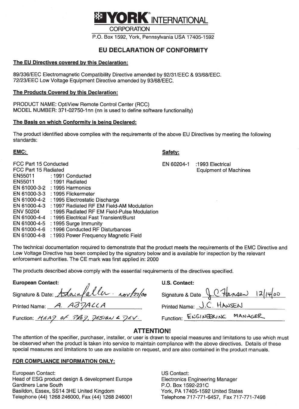
- EU DECLARATION OF CONFORMITY
- SECTION 1 – PRODUCT DESCRIPTION
- SECTION 2 – INSTALLATION
- SECTION 3 – OPERATION OPTIVIEW REMOTE CONTROL CENTER
- SCREEN DESCRIPTIONS AND USAGE
- OVERVIEW
- DISPLAY ONLY
- PROGRAMMABLE
- NAVIGATION
- HOME SCREEN
- UNIT SCREEN -EXAMPLES
- UNIT SCREEN
- SYSTEMS SCREEN -EXAMPLES
- SYSTEMS SCREEN
- INDIVIDUAL SYSTEM SCREEN
- HOURS AND STARTS SCREEN
- OPTIONS SCREEN
- TRENDING SCREEN
- TREND SETUP SCREEN
- SETPOINTS SCREEN -EXAMPLES
- SETPOINTS SCREEN
- HISTORY SCREEN
- HISTORY DETAILS SCREEN
- RCC SETPOINTS SCREEN
- RCC SETUP SCREEN
- COMMS SCREEN
- PRINTER SCREEN
- DIAGNOSTICS SCREEN
- DIAGNOSTICS I/O SCREEN
- DIAGNOSTICS RCC COMMS SCREEN
- DISPLAY MESSAGES
- SECTION 4 – PRINTERS
- SECTION 5 – SERVICE INTRODUCTION
- SYSTEM ARCHITECTURE
- MICROBOARD
- MICROBOARD PROGRAM JUMPERS
- MICROBOARD PROGRAM SWITCHES
- LIQUID CRYSTAL DISPLAY
- DISPLAY INTERFACE BOARD
- DISPLAY BACKLIGHT INVERTER BOARD
- KEYPAD
- POWER SUPPLY
- OFFLINE DIAGNOSTICS &TROUBLESHOOTING
- MAIN DIAGNOSTICS SCREEN
- KEYPAD TEST
- DISPLAY TEST
- BIT PATTERNS TEST SCREEN
- SERIAL INPUTS /OUTPUTS TESTS
- DIGITAL INPUTS /OUTPUTS TESTS
- ANALOG INPUTS TESTS
- SYSTEM COMMISSIONING CHECKLIST
- SECTION 6 – PART NUMBER AND RENEWAL PARTS
- SI METRIC CONVERSION
INSTALLATION, OPERATION & SERVICE
OPTIVIEWTM
REMOTE CONTROL CENTER
New Release Form 50.40-OM2 (601)
OPTIVIEW™ REMOTE CONTROL CENTER
00497VIP
YORK INTERNATIONAL2
WARNING indicates a potentially
hazardous situation which, if not
avoided, could result in death or
serious injury.
CAUTION identifies a hazard
which could lead to damage to the
machine, damage to other equip-
ment and/or environmental pollu-
tion. Usually an instruction will
be given, together with a brief
explanation.
DANGER indicates an imminently
hazardous situation which, if not
avoided, will result in death or seri-
ous injury.
IMPORTANT!
READ BEFORE PROCEEDING!
GENERAL SAFETY GUIDELINES
This equipment is a relatively complicated apparatus.
During installation, operation, maintenance or service,
individuals may be exposed to certain components or
conditions including, but not limited to: refrigerants,
oils, materials under pressure, rotating components,
and both high and low voltage. Each of these items
has the potential, if misused or handled improperly,
to cause bodily injury or death. It is the obligation
and responsibility of operating/service personnel to
identify and recognize these inherent hazards, protect
themselves, and proceed safely in completing their
tasks. Failure to comply with any of these requirements
could result in serious damage to the equipment and
the property in which it is situated, as well as severe
personal injury or death to themselves and people
at the site.
This document is intended for use by owner-authorized
operating/service personnel. It is expected that this
individual possesses independent training that will
enable them to perform their assigned tasks properly
and safely. It is essential that, prior to performing
any task on this equipment, this individual shall have
read and understood this document and any referenced
materials. This individual shall also be familiar with and
comply with all applicable governmental standards and
regulations pertaining to the task in question.
SAFETY SYMBOLS
The following symbols are used in this document to alert the reader to areas of potential hazard:
NOTE is used to highlight additional
information which may be helpful
to you.
External wiring, unless specied as an optional connection in the manufacturer’s product
line, is not to be connected inside the micro panel cabinet. Devices such as relays, switches,
transducers and controls may not be installed inside the micro panel. No external
wiring is allowed to be run through the micro panel. All wiring must be in accordance
with YORK’s published specications and must be performed only by qualied YORK
personnel. YORK will not be responsible for damages/problems resulting from improper
connections to the controls or application of improper control signals. Failure to follow
this will void the manufacturer’s warranty and cause serious damage to property or
injury to persons.

FORM 50.40-OM2
3YORK INTERNATIONAL
CHANGEABILITY OF THIS DOCUMENT
In complying with YORK’s policy for continuous
product improvement, the information contained in
this document is subject to change without notice.
While YORK makes no commitment to update or
provide current information automatically to the
manual owner, that information, if applicable, can be
obtained by contacting the nearest YORK Applied
Systems Service ofce.
It is the responsibility of operating/service personnel
as to the applicability of these documents to the
equipment in question. If there is any question in
the mind of operating/service personnel as to the
applicability of these documents, then, prior to
working on the equipment, they should verify with
the owner whether the equipment has been modied
and if current literature is available.

YORK INTERNATIONAL4
SECTION 1 PRODUCT DESCRIPTION ....................................................................... 8
Chiller/Condensing Control Panel(s) .......................................................... 9
SECTION 2 INSTALLATION........................................................................................ 10
Mounting .................................................................................................. 10
Installation Checklist ................................................................................ 10
Wiring ................................................................................................... 10
Lan Transient Installation ......................................................................... 14
Eprom Compatibility ................................................................................ 14
Troubleshooting ....................................................................................... 14
Safety ................................................................................................... 14
Proper Installation Practices ..................................................................... 15
SECTION 3 OPERATION............................................................................................. 18
OptiView Remote Control Center ............................................................. 18
Screen Descriptions and Usage................................................................. 19
Home Screen............................................................................................. 22
Unit Screen .......................................................................................... 24
Systems Screen............................................................................... 29
Individual System Screen.......................................................... 32
Hours/Starts Screen ........................................................................ 34
Options Screen ............................................................................... 36
Trending Screen ............................................................................. 38
Trend Setup Screen ................................................................... 40
Setpoints Screen ............................................................................. 44
History Screen ................................................................................ 47
History Details Screen .............................................................. 48
RCC Setpoints Screen ......................................................................... 49
RCC Setup Screen .......................................................................... 50
Comms Screen .......................................................................... 52
Printer Screen ............................................................................ 53
Diagnostics Screen .................................................................... 54
Diagnostics (I/O) Screen ..................................................... 55
Diagnostics (RCC Comms) Screen ..................................... 56
Display Messages ..................................................................................... 58
SECTION 4 PRINTERS ............................................................................................... 59
SECTION 5 SERVICE ................................................................................................. 65
Introduction............................................................................................... 65
TABLE OF CONTENTS

FORM 50.40-OM2
5YORK INTERNATIONAL
System Architecture.................................................................................. 66
Microboard................................................................................................ 68
Microboard Program Jumpers .................................................................. 76
Microboard Program Switches ................................................................. 78
Liquid Crystal Display.............................................................................. 81
Display Interface Board ............................................................................ 87
Display Backlight Inverter Board ............................................................. 89
Keypad .................................................................................................... 91
Power Supply ............................................................................................ 94
Ofine Diagnostics & Troubleshooting.................................................... 96
Main Diagnostics ...................................................................................... 97
Keypad Test............................................................................................... 98
Display Test .............................................................................................. 99
Bit Pattern Test ....................................................................................... 100
Serial Inputs / Outputs Tests ................................................................... 101
Digital Inputs / Outputs Tests ................................................................. 103
Analog Inputs Test .................................................................................. 104
System Commissioning Checklist .......................................................... 105
SECTION 6 PART NUMBER AND RENEWAL PARTS........................................... 106
LIST OF TABLES
TABLE 1 – Required Software Version of the Chiller/Condensing Unit Eproms .......... 11
TABLE 2 – Program Jumpers .........................................................................................76
TABLE 3 – Program Switches ........................................................................................78
TABLE 4 – Part Number ............................................................................................... 106
TABLE 5 – Renewal Parts ............................................................................................106
YORK INTERNATIONAL6
FIG. 1 – EU DECLARATION OF CONFORMITY ............... 7
FIG. 2 – FIELD WIRING ................................................... 12
FIG. 3 – CONTROL INSTALLATION ................................ 16
FIG. 4 – GROUNDING ..................................................... 16
FIG. 5 – SEPARATE CONDUIT INSTALLATION .............. 17
FIG. 6 – POWER & GROUND WIRE CONNECTIONS .... 17
FIG. 7 – OPTIVIEW REMOTE CONTROL CENTER ....... 18
FIG. 8 – SCREEN NAVIGATION LAYOUT ....................... 20
FIG. 9 – HOME SCREEN................................................. 22
FIG. 10 – UNIT SCREEN ................................................... 24
FIG. 11 – SYSTEMS SCREEN .......................................... 29
FIG. 12 – INDIVIDUAL SYSTEM SCREEN........................ 32
FIG. 13 – HOURS AND STARTS SCREEN ....................... 34
FIG. 14 – OPTIONS SCREEN ........................................... 36
FIG. 15 – TRENDING SCREEN......................................... 38
FIG. 16 – TRENDING SETUP SCREEN............................ 40
FIG. 17 – SETPOINTS SCREEN ....................................... 44
FIG. 18 – HISTORY SCREEN............................................ 47
FIG. 19 – HISTORY DETAILS SCREEN ............................ 48
FIG. 20 – RCC SETPOINTS SCREEN .............................. 49
FIG. 21 – RCC SETUP SCREEN....................................... 50
FIG. 22 – COMMS SCREEN.............................................. 52
FIG. 23 – PRINTER SCREEN............................................ 53
FIG. 24 – DIAGNOSTICS SCREEN................................... 54
FIG. 25 – DIAGNOSTICS I/O SCREEN ............................. 55
FIG. 26 – DIAGNOSTICS RCC COMMS SCREEN ........... 56
FIG. 27 – PRINTERS ......................................................... 59
FIG. 28 – EXAMPLE PRINTOUT (OPERATING DATA)...... 63
FIG. 29 – EXAMPLE PRINTOUT (HISTORY HEADER) .... 64
FIG. 30 – CONTROL CENTER BLOCK DIAGRAM ........... 67
FIG. 31 – MICROBOARD ................................................... 73
FIG. 32 – FLASH MEMORY CARD.................................... 74
FIG. 33 – BLOCK DIAGRAM, MICROBOARD .................. 75
FIG. 34 – MICROBOARD LAMP DIMMER CIRCUIT ......... 78
FIG. 35 – SERIAL DATA COMMUNICATIONS PORTS...... 79
FIG. 36 – CONFIGURABLE ANALOG INPUTS ................. 80
FIG. 37 – DISPLAY, MOUNTING........................................ 84
FIG. 38 – LCD TYPICAL CONTROL SIGNAL TIMING ...... 84
FIG. 39 – LG SEMICON LP104V2 DISPLAY ASSEMBLY - 85
FIG. 40 – SHARP LQ10D367 DISPLAY ASSEMBLY - ...... 85
FIG. 41 – SHARP LQ10D367 BACKLIGHT LAMP
REPLACEMENT ................................................ 86
FIG. 42 – LG SEMICON LP104V2 BACKLIGHT LAMP
REPLACEMENT................................................. 86
FIG. 43 – DISPLAY INTERFACE BOARD .......................... 88
FIG. 44 – DISPLAY BACKLIGHT INVERTER BOARD....... 90
FIG. 45 – KEYPAD ............................................................. 92
FIG. 46 – DIAGRAM, KEYPAD........................................... 93
FIG. 47 – BLOCK DIAGRAM, DC POWER DISTRIBUTION. 95
FIG. 48 – MAIN DIAGNOSTIC SCREEN ........................... 97
FIG. 49 – KEYPAD TEST SCREEN ................................... 98
FIG. 50 – DISPLAY TEST SCREEN................................... 99
FIG. 51 – BIT PATTERNS TEST SCREEN....................... 100
FIG. 52 – SERIAL INPUTS/OUTPUTS TESTS SCREEN 101
FIG. 53 – DIGITAL INPUTS/OUTPUTS TESTS SCREEN 103
FIG. 54 – ANALOG INPUTS TEST SCREEN .................. 104
FIG. 55 – FRONT OF OPTIVIEW RCC............................ 107
FIG.56 – INSIDE OF OPTIVIEW RCC ............................ 107
FIG.57 – INSIDE DOOR OF OPTIVIEW RCC ................ 108
FIG.58 – LOCATION OF FUSE, F1 & F2 ........................ 109
LIST OF FIGURES
FORM 50.40-OM2
7YORK INTERNATIONAL
FIG. 1 – EU DECLARATION OF CONFORMITY

YORK INTERNATIONAL8
SECTION 1 – PRODUCT DESCRIPTION
The YORK OptiView Remote Control Center is a
microprocessor based control system capable of
remotely monitoring certain chillers and condensing
units. It can monitor and individually control 1 to 8 of
these chiller/condensing units.
The panel comes congured with a full screen color
LCD Graphic Display mounted in the middle of a
keypad interface. The graphic display allows the
presentation of the current information all at once. In
addition, the operator may view a graphical representa-
tion of several operating parameters. For the novice
user, the locations of various parameters are clearly and
intuitively marked. Instructions for specic operations
are provided on many of the screens.
The graphic display also allows information to be
represented in Imperial units (temperatures in °F and
pressures in PSIG or PSID) or SI units (temperatures in
°C and pressures in BARG or BARD).
All values that are modiable at the Remote Control
Center are recorded in memory and preserved even
through a power failure condition. During operation, the
chillers are continually polled and the user is advised of
the operating conditions by various status and warning
messages. A complete listing of shutdown, status, and
warning messages is within the chiller/condensing
unit’s operation manual.
If the chiller/condensing unit is in remote control mode
the OptiView Remote Control Center provides the
capability to program the following:
1. Start Command
2. Stop Command
3. Local Setpoint
4. Local Control Range
5. Daily/Holiday Schedule
6. Current or Load Limit Setpoint
The Remote Control Center is also designed to enable
the user to obtain chiller/condensing unit printouts
directly from this panel.
This equipment has been tested and
found to comply with the limits for
a Class A digital device, pursuant
to part 15 of the FCC Rules. These
limits are designed to provide reason-
able protection against harmful
interference when the equipment is
operated in a commercial environ-
ment. This equipment generates,
uses, and can radiate radio frequency
energy and, if not installed and
used in accordance with the instruc-
tion manual, may cause harmful
interference to radio communica-
tions. Operation of this equipment in
a residential area is likely to cause
harmful interference in which case
the user will be required to correct
the interference at his own expense.
Product Description

FORM 50.40-OM2
9YORK INTERNATIONAL
CHILLER/CONDENSING CONTROL PANEL(S)
All communication with the chiller/condensing units
will occur over a single RS-485 port. Reference Figure
2 and the Installation instructions.
When the OptiView RCC is first turned on it will
initialize by requesting current data and history buffer
information from the units connected. After the history
buffers are lled, only current data will be continuously
requested. Every eight hours the OptiView RCC will re-
initialize. If the control panel updates the history buffer
(a safety shutdown has occurred), the control panel
will send the chiller shutdown data to the OptiView
RCC upon receipt of the next valid OptiView RCC
transmission. The OptiView RCC will recognize that
a safety shutdown has occurred by the Update History
Buffer bit being set. If this bit is ever 1, the data dump is
assumed to be a shutdown data dump and the OptiView
RCC will update its history buffers with the new data
and start a printout of the transmitted data through its
RS232 port. If the OptiView RCC had been requesting
another type of data dump (i.e. a daily schedule dump),
the OptiView RCC will repeat its request on the next
transmission.
While at the Home Screen, the OptiView RCC will
communicate with each unit in order. Once a unit has
been selected by entering the Unit Screen or any screen
below it, that unit will be polled between every unit
in order. This will allow the selected unit to update its
information quickly while still maintaining information
for the Home Screen.
A command string is used to indicate what data the
OptiView RCC is requesting and to modify control data
in the chiller control panel. If the chiller/condensing
unit is in remote control mode then its Local Set
Point, Local Range, Daily Schedule, Holiday, Start
/ Stop Command, and Current / Load Limit can be
programmed from the OptiView RCC. The OptiView
RCC will send a command string once any of these are
modied at the OptiView RCC. If the OptiView RCC
sends a Stop command, the chiller/condensing unit will
turn off. If the OptiView RCC sends a start command,
the chiller/condensing unit will be allowed to run if all
the other run requirements of the unit are made.
A chiller/condensing unit that is in remote control
mode will use local control (set points and start / stop
information), if a valid transmission has not been
received for 5 minutes from the OptiView RCC. The
remote commands will be used again once a valid
new transmission has been processed. The OptiView
RCC will display an error message indicating the
communications problem when such a condition
occurs.
A general status message for each unit is displayed
on the Home Screen. The messages displayed will
include communications status. Not Initialized will
be displayed upon power-up for all units until the
OptiView RCC begins to poll and receive data from
that unit. Initializing… will be displayed while the
OptiView RCC is polling a unit for all current, schedule,
and history data the rst time after power-up. Loss of
Comms will be displayed after 5 minutes have elapsed
with no response from a previously initialized unit. If
any of these messages is displayed, the unit’s button
will be disabled not allowing it to be selected.
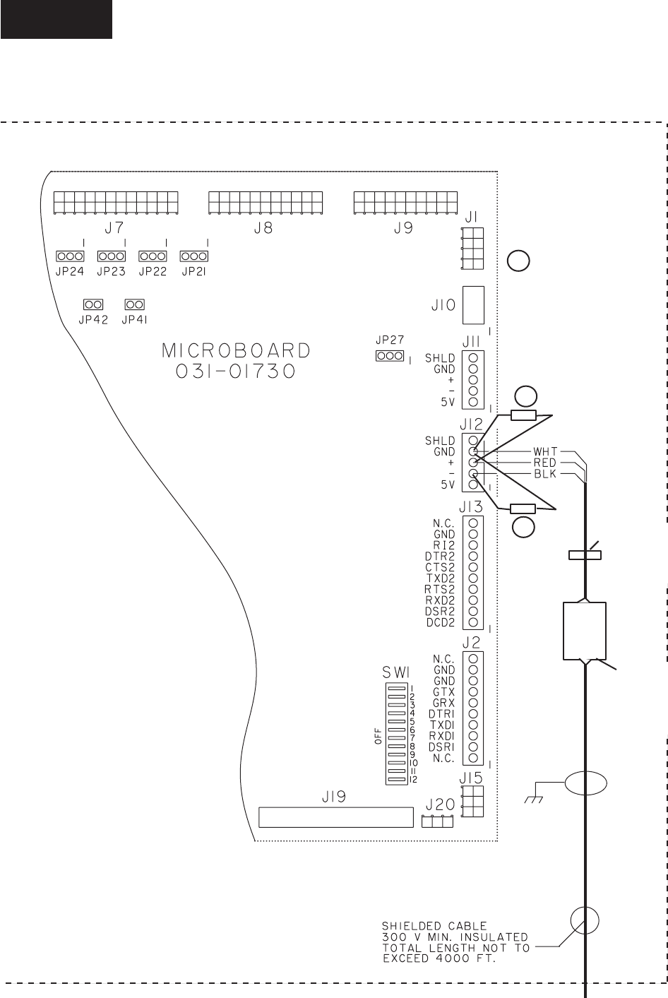
The Control Center Microboard (J12) communicates
with this board via a 0/+5VDC serial data communica-
tions link. If this communications link does not operate
properly, correct Microboard J12 serial port operation
can be veried using the Serial Inputs and Outputs
diagnostic procedure in the “Service” section of this
book.
1

YORK INTERNATIONAL10
• At the chiller/condenser control panel that uses
a rotary switch to set the ID, use a small screw
driver to rotate the rotary switch so that the arrow
points at the number that coincides with the Unit’s
Identication number (ID#). Unit 1 - Unit 8 coincide
to rotary switches 0 - 7. Otherwise program the
panel’s ID through keypad entry.
Never skip an ID#. For example, if
you have four units then they must be
identied from ID#0 - ID#3.
• At the chiller/condenser unit’s control panel, select
the type of control mode. Select REMOTE only if
remote control is desired. Select LOCAL to only
monitor this unit.
• From the Comms Screen of the OptiView RCC,
enter the RCC Poll Time. This is how often (time
in seconds) to request data. This time should be set
long enough to allow for receiving the data.
WIRING
A communications cable must connect the chiller to the
remote panel. This cable should be a three-conductor
with foil shield and drain wire, 20 awg or larger sized
wire, 300v, 80 Deg. C, U.L. Style 2464, U.L. listed
and CSA approved. Three sources are Alpha 5463,
Belden 9364, or Quabbin 0220. The cable length (sum
of lengths of all cables) must not exceed 4000 ft.
(1219 m.).
Never run the communication cable in
close proximity to any power wiring.
For best results, it should be run in
dedicated, grounded conduit. See
Proper Installation Practices.
SECTION 2 – INSTALLATION
MOUNTING
Mount the Remote Control Center at a level that
provides for easy viewing of the color graphic display
by all users. Securely mount it at the desired location.
The panel may be mounted away from the chiller as far
as 4000 ft. (1219 m.) of wiring will allow.
INSTALLATION CHECKLIST
(Reference Fig. 2 for wiring)
• A communications cable must connect the OptiView
RCC to the chiller/condenser control panel. This
cable should be a three-conductor with foil shield
and drain wire, 20 awg or larger wire, 300v, 80 Deg.
C, UL Style 2464, UL listed and CSA approved.
Three sources are Alpha 5463, Belden 9364, or
Quabbin 0220. The cable length (sum of lengths of
all cables) must not exceed 4000 ft. (1219 m.). The
cable is user supplied.
• Obtain ferrite (part number 025-35154-000) from
the cloth bag found in the OptiView RCC and
install it as shown on Fig. 2. This must be installed
to meet FCC and CE requirements.
• Make sure that the Transient Voltage Suppressors are
installed at J12. One is installed from “+” to “GND”
and one is installed from “-” to “GND”.
• At J12 of the OptiView RCC, red wire on RS485(+),
black wire on RS485(-) and white wire on Ground.
• At the OptiView RCC, connect the shield to the
panel.
• Use a tie wrap between the J12 connector and the
Ferrite (part number 025-35154-000) to secure the
shielded cable to the OptiView RCC. The tie wrap
can help prevent the wires from being accidentally
pulled out of the J12 connector by someone working
in the panel or by the weight of the ferrite.
• Install a LAN transient protection module at the
chiller/condenser control panel and connect the
cable according to the type of control panel.
• Make sure the correct EPROM is installed at the
chiller/condenser control panel(s). See Table 1.
• From the Setpoints Screen of the OptiView RCC,
enter the Number of Units Connected (Maximum
value allowed is 8).
Installation
FORM 50.40-OM2
11YORK INTERNATIONAL
The software version is printed on a label adhered to the EPROM chip’s surface. A revision level higher than the one
listed in the table is acceptable. An example version code is as follows:
REQUIRED SOFTWARE VERSION OF THE
CHILLER / CONDENSING UNIT EPROMS
C. ACS. 09. XX.
Revision Level. Increments 01, 02 etc.
Product Code
YCAS (RCP = YCAR, MMC =YCAL/YCUL)
Commercial
TABLE 1 – REQUIRED SOFTWARE VERSION OF THE CHILLER/CONDENSING UNIT EPROMS
UNIT TYPE EPROM PART NO. VERSION
YCAL / YCUL w/microboard 031-01314-000 031-02011-001 C.MMC.01.05
YCAL / YCUL w/microboard 031-02050-000 031-02049-001 C.MMC.03.02
YCAS - F 2 Compressors 031-01798-001 C.ACS.09.03
YCAS - F 3 & 4 Compressors 031-01798-002 C.ACS.10.02
YCAR 2 Compressors 031-02013-001 C.RCP.23.02
2
YORK INTERNATIONAL12
FIG. 2 – FIELD WIRING OPTIVIEW RCC PANEL
LD06725
Tie Wrap (To help
keep wires
connected)
Ferrite
(025-35154-000)
(FCC & CE
Requirement)
A
A
ATransient Voltage
Suppressor
(031-02076-000)
(Factory Installed)
OPTIVIEW REMOTE CONTROL CENTER
Installation
FORM 50.40-OM2
13YORK INTERNATIONAL
FIG. 2 – FIELD WIRING OPTIVIEW RCC PANEL (CONT.)
LD06726
SHLD
BLK
SHLD
RED
(TOTAL NOT TO
EXCEED 8)
WHT
BLK
SHLD
RED
FROM
OPTIVIEW RCC
WHT
BLK
RED
WHT
(COMPONENT
SIDE UP)
(COMPONENT
SIDE DOWN)
(COMPONENT
SIDE DOWN)
X
X
CUT PINS
AS SHORT
AS POSSIBLE
X
X
CUT PINS
AS SHORT
AS POSSIBLE
2

YORK INTERNATIONAL14
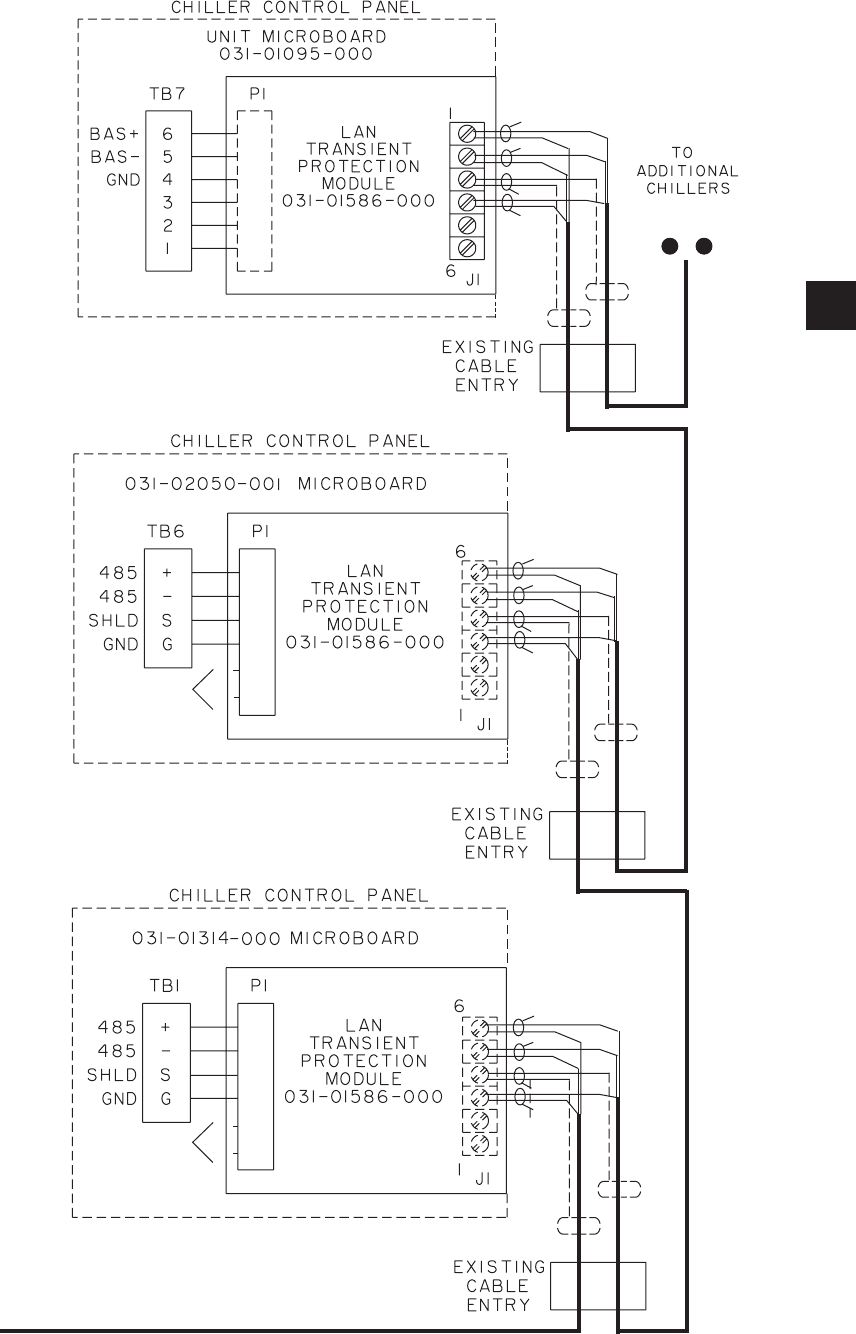
LAN TRANSIENT INSTALLATION
The properly installed Lan Transient Protection Module,
(part number 031-01586-000) will limit the voltage
levels seen by the chiller control panel’s RS-485 driver
while allowing normal RS-485 network operation under
non-transient conditions. For installation of the module
refer to Fig. 2 and the specic installation instructions
for the microboard.
Unit Microboard 031-01314-000 and
031-02050-001:
Step 1: Label all wires, cables, or components con-
nected to TB1.
Step 2: Carefully loosen each terminal of TB1. Remove
all wires, cables, or components. Be extremely careful
to not allow them to short together or to the enclosure.
Step 3: Refer to the Module. Replace all wires,
cables, or components taken from TB1 into the cor-
rect terminals of the Module terminal strip J1 being
extremely careful to not allow them to short together
or to the enclosure.
Step 4: Carefully tighten all screws on the Module
Terminal strip J1.
Step 5: Orient the Module as shown (component side
down) and cut the unused pins. Insert the four P1
Module pins into TB1 as shown.
Step 6: Carefully tighten each terminal of TB1. Double
check all wiring to the Module before closing up.
Unit Microboard 031-01095-000:
Step 1: Label all wires, cables, or components con-
nected to TB7.
Step 2: Carefully loosen each terminal of TB7. Remove
all wires, cables, or components. Be extremely careful
to not allow them to short together or to the enclosure.
Step 3: Replace all wires, cables, or components taken
from TB7 into the Module terminal strip J1 being
extremely careful to not allow them to short together
or to the enclosure.
Step 4: Carefully tighten all screws on the Module
Terminal strip J1.
Step 5: Orient the Module as shown (component side
up) and insert all six P1 Module pins into TB7 as
shown.
Step 6: Carefully tighten each terminal of TB7. Double
check all wiring to the Module before closing up.
EPROM COMPATIBILITY
Since the concept and design of the OptiView Remote
Control Center may have occurred after the original
EPROM (software) for the chiller/condenser control
panel, the EPROM may need to be replaced with
one that allows for OptiView Remote Control Center
operation. See Table 1.
TROUBLESHOOTING
From the Home Screen you can determine if you are
communicating to the chiller/condensing unit.
If the message Not Initialized.. remains shown on this
screen, proper communication between the panels has
not occurred and you will need to troubleshoot.
Step 1: If you are trying to communicate with more
than one unit, simplify the troubleshooting by isolating
the communication to one unit at a time. Remove any
wiring to a secondary unit and from the Setpoints
Screen of the OptiView RCC, enter one as the Number
of Units Connected and at the chiller/condenser control
panel set it’s ID to zero.
Step 2: Check if there is any communication problem
occurring on the Diagnostic RCC Comms Screen. See
the description of this screen.
You could also check that the RX3 I/O communication
activity LED on the OptiView Main Processor Board is
blinking as it receives data from the chiller/condensing
unit’s control panel. A steady lit RX3 LED is a sign of
improper wiring. If the RX3 LED is not blinking check
the wiring and the installation of the Lan Transient
Protection Module. If everything is properly connected
replace the 485 driver on the chiller/condenser
microboard (part number 031-02074-000).
SAFETY
It is recommended that all maintenance and service
repair work be performed by experienced personnel.
There must be recognition of the potential hazards
that can exist. Those hazards may include (but are
not limited to):
Installation

FORM 50.40-OM2
15YORK INTERNATIONAL
There can be electrical circuitry that
presents an electrocution hazard. Be
sure that the sources of all power
supplies have been properly isolated
and secured before attempting any
service related activities.
External wiring, unless specied as
an optional connection in the manu-
facturer’s product line, is not to be
connected inside the OptiView Remote
Control Center cabinet. Devices such
as relays, switches, transducers and
controls may not be installed inside
the OptiView Remote Control Center.
No external wiring is allowed to be
run through the OptiView Remote
Control Center. All wiring must be in
accordance with YORK’s published
specications and must be performed
only by qualified YORK personnel.
YORK will not be responsible for
damages/problems resulting from
improper connections to the controls
or application of improper control
signals. Failure to follow this will
void the manufacturer’s warranty and
cause serious damage to property or
injury to persons.
PROPER INSTALLATION PRACTICES
Earlier relay systems were virtually immune to radio
frequency interference (RFI), electromagnetic interfer-
ence (EMI), and ground loop currents. Installation
consisted of hooking up the point-to-point wiring and
sizing the wire properly.
In an electronic system, improper installation will
cause problems that outweigh the benets of electronic
control. Electronic equipment is susceptible to RFI,
EMI, and ground loop currents which can cause equip-
ment shutdowns, processor memory and program loss,
erratic behavior, and false readings. Manufacturers of
industrial electronic equipment take into consideration
the effects of RFI, EMI, and ground loop currents and
incorporate protection of the electronics in their designs.
These manufacturers require that certain installation
precautions be taken to protect the electronics from
these effects. All electronic equipment must be viewed
as sensitive instrumentation and therefore requires
careful attention to proper installation procedures.
There are a few basics, that if followed, will result in
a trouble-free installation. The National Electric Code
(N.E.C.) is a guideline for safe wiring practices, but
it does not deal with procedures used for electronic
control installation. Use the following procedures for
electronic equipment installation. These procedures are
to be used in conjunction with the N.E.C.
Wire Sizing
Size supply wires one size larger than required for
amperage draw to reduce instantaneous voltage dips
caused by large loads such as heaters, contactors
and solenoids. Sudden dips in voltage can cause the
processor to momentarily malfunction or cause a
complete reset of the control system. If the wire is
loaded to its maximum capacity, the voltage dips are
much larger, and the potential for a malfunction is
very high. If the wire is sized one size larger than
required, the voltage dips are smaller than in a fully
loaded supply wire, and the potential for malfunction
is much lower.
The NEC code requires specic wire sizes to be used
based on current draw. An example would be to use
#14 gauge wire for circuits up to 15 amp or #12 gauge
wire for circuits of up to 20 amp. Therefore, when
connecting the power feed circuit to an electronic
industrial control, use #12 gauge wire for a maximum
current draw of 15 amp and #10 wire for a maximum
current draw of 20 amp.
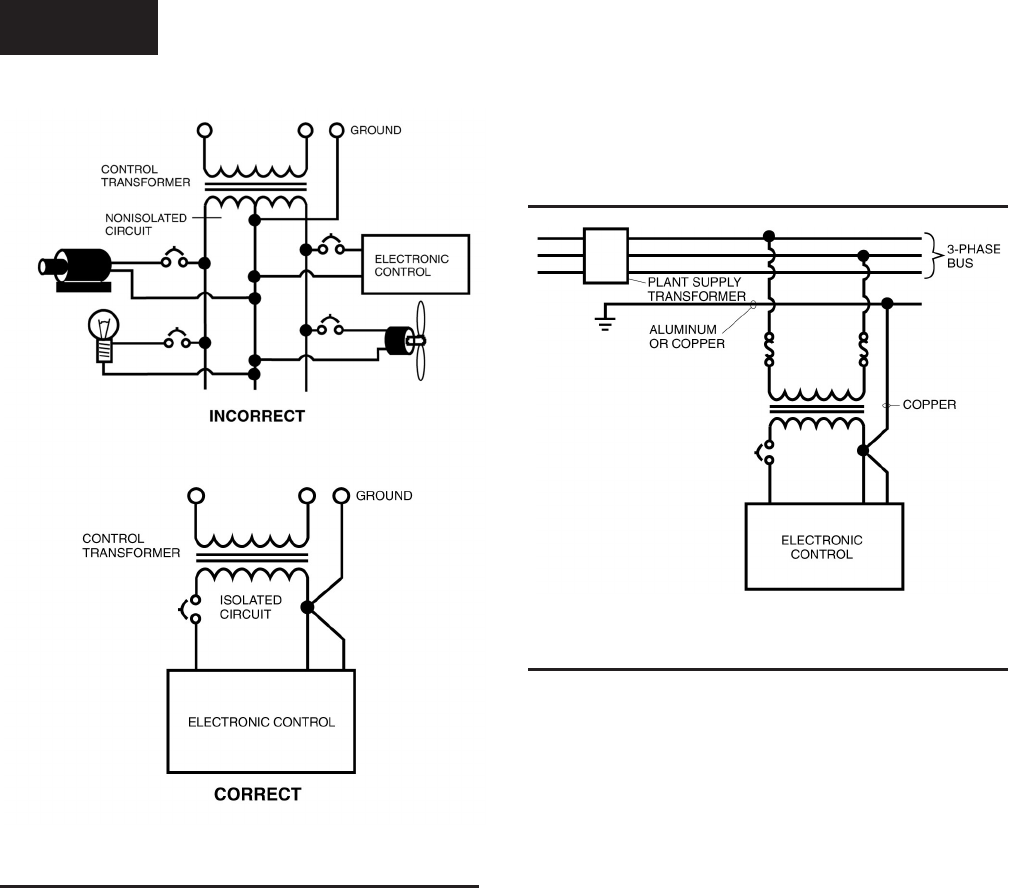
Voltage Source (Figure 3)
Selecting the voltage source is extremely important
for proper operation of electronic equipment in
an industrial environment. Standard procedure for
electronic instrumentation is to provide a “clean”
separate source voltage in order to prevent EMI, from
other equipment in the plant, from interfering with
the operation of the electronic equipment. Connecting
electronic equipment to a breaker panel (also known as
lighting panels and fuse panels) subjects the electronic
equipment to noise generated by other devices con-
nected to the breaker panel. This noise is known as
electromagnetic interference (EMI). EMI ows on
the wires that are common to a circuit. EMI cannot
travel easily through transformers and therefore can
be isolated from selected circuits. Use a control
transformer to isolate the electronic control panel from
other equipment in the plant that generate EMI.
2
YORK INTERNATIONAL16
FIG. 3 – CONTROL INSTALLATION
LD06727
Grounding
Grounding is the most important factor for successful
operation. Electronic equipment reacts to very small
currents and must have a good ground in order to
operate properly. The NEC states that control equipment
may be grounded by using the rigid conduit as a
conductor. This is not acceptable for electronic control
equipment. Conduit is a poor conductor compared
to a copper wire. Copper grounds are required for
proper operation.
Ground Wire Size (Figure 4)
The ground wire must be the same size as the supply
wires or one size smaller as a minimum. The three
phase power brought into the plant must also have a
ground wire, making a total of four wires. In many
installations that are having electronic control problems,
this essential wire is usually missing. A good ground
circuit must be continuous from the plant source
transformer to the electronic control panel for proper
operation. Driving a ground stake at the electronic
control will cause additional problems since other
equipment in the plant on the same circuits will ground
themselves to the ground stake causing large ground
ow at the electronic equipment.
LD06728
FIG 4 – GROUNDING
Wiring Practices (Figure 5)
Do not mix wires of different voltages in conduit. For
an example refer to Figure 5. The motor voltage is 480
volts and the panel control power is 120 volts. The 480
volt circuit must be run from the motor starter to the
motor in its own conduit. The 120 volt circuit must
be run from the motor starter control transformer to
the control panel in its own separate conduit. If the
two circuits are run in the same conduit, transients on
the 480 volt circuit will be inducted into the 120 volt
circuit causing functional problems with the electronic
control. Dividers must be used in wire way systems
(conduit trays) to separate unlike voltages. The same
rule applies for 120 volt wires and 220 volt wires.
Also, never run low voltage wires in the same conduit
with 120 volt wires.
Never run any wires through an electronic control
panel that do not relate to the function of the panel.
Electronic control panels should never be used as
a junction box. These wires may be carrying large
transients that will interfere with the operation of
the control.
When running conduit to an electronic control panel,
note that the access holes (knockouts) are strategically
placed so that the eld wiring does not interfere with
the electronics in the panel. Never allow eld wiring to
come in close proximity with the controller boards
since this will almost always cause problems.
Installation
FORM 50.40-OM2
17YORK INTERNATIONAL
FIG. 5 – SEPARATE CONDUIT INSTALLATION
Do not drill a control panel to locate conduit con-
nections. Drilling can cause metal chips to land in the
electronics and create a short circuit. If you must drill
the panel, take the following precautions:
1. Call the panel manufacturer, if possible, before
drilling the panel to be sure you are entering the
panel at the right place.
2. Cover the electronics with plastic. Tape the plastic
to the board with masking or electrical tape.
3. Place masking tape or duct tape on the inside of
the panel at the point of drill bit entry.
4. Remove all of the remaining chips from the panel
before removing the protective plastic.
When routing conduit to the top of an electronic control
panel, condensation must be taken into consideration.
Water can condense in the conduit and run into the panel
causing catastrophic failure. Route the conduit to the
sides or bottom of the panel and use a conduit drain.
If the conduit must be routed to the top of the panel,
use a sealable conduit tting which is poured with a
sealer after the wires have been pulled, terminated and
the control functions have been checked. A conduit
entering the top of the enclosure must have an
“O” ring-type tting between the conduit and the
enclosure, so that if water gets on top of the enclosure,
it cannot run in between the conduit and the enclosure.
This is extremely important in outdoor applications.
Never add relays, starters, timers, transformers,
etc. inside an electronic control panel without rst
contacting the manufacturer. Contact arcing and
EMI emitted from these devices can interfere with the
electronics. If you need to add these devices contact the
manufacturer for the proper device types and placement.
Never run refrigerant, water or brine tubing inside
an electronic control panel. A leak could damage or in
some cases totally destroy the electronics.
If the electronic control panel has a starter built into
the same panel, be sure to run the higher voltage
wires where indicated by the manufacturer. EMI
from the wires can interfere with the electronics if run
too close to the circuitry.
Never daisy-chain or parallel-connect power or
ground wires to electronic control panels. Each
electronic control panel must have its own supply
wires back to the power source. Multiple electronic
control panels on the same power wires create current
surges in the supply wires which can cause controller
malfunctions. Daisy-chaining ground wires allows
ground loop currents to ow between electronic control
panels which also causes malfunctions. (See Figure 6)
It is very important to read the installation instructions
thoroughly before beginning the project. Make sure you
have drawings and instructions with your equipment.
If not, call the manufacturer and have them send you
the proper instructions. Following correct wiring
procedures will ensure proper installation of your
electronic equipment.
LD06738
FIG. 6 – POWER & GROUND WIRE CONNECTIONS
LD06739
LD06740
2
YORK INTERNATIONAL18
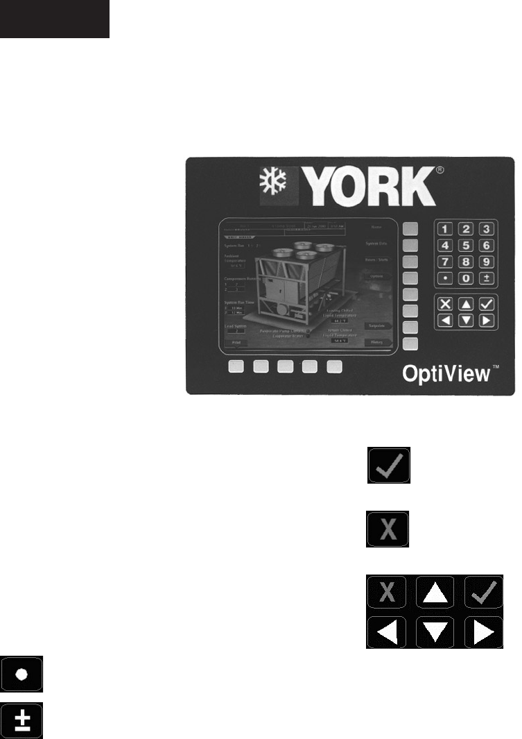
In order to accept changes made to the chiller
setpoints, the Check key is provided as a
universal ‘Enter’ key or ‘Accept’’ symbol.
In order to reject entry of a setpoint or dismiss
an entry form, the ‘X’ key is provided as a
universal ‘Cancel’ symbol.
Cursor Arrow keys are pro-
vided to allow movement on
screens which contain a large
amount of entry data. In addi-
tion, these keys can be used
to scroll through history and
event logs.
Operation
SECTION 3 – OPERATION
OPTIVIEW REMOTE CONTROL CENTER
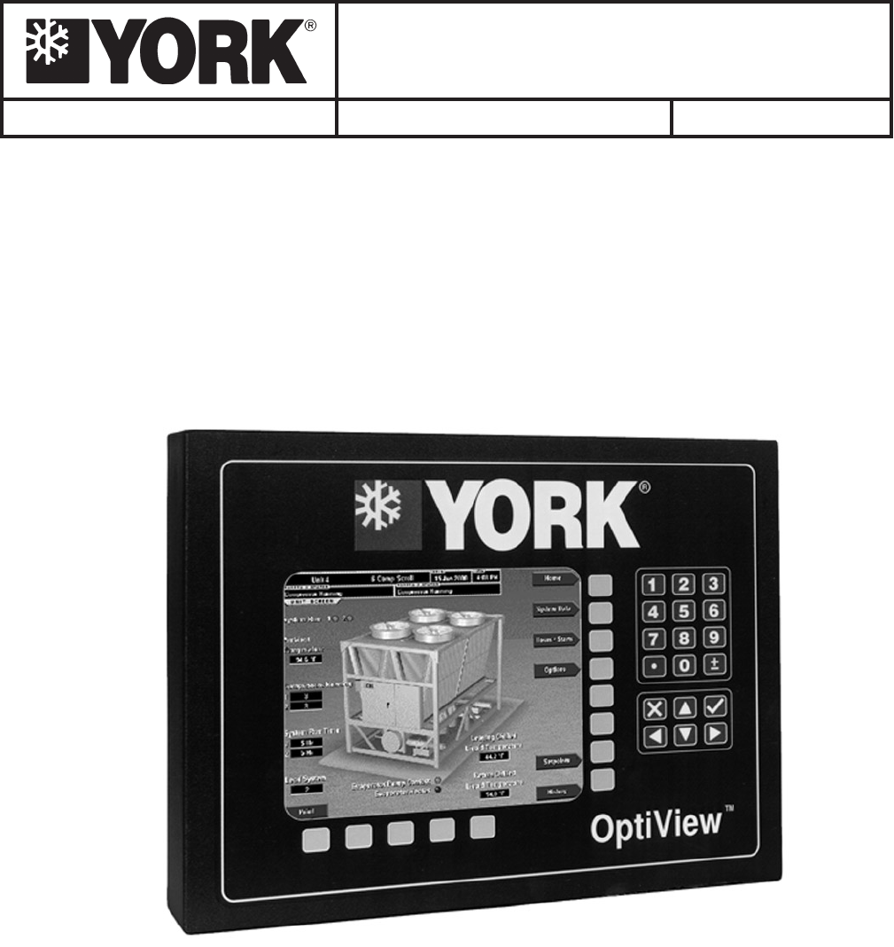
The OptiView Remote Control Center display is
highlighted by a full screen graphics display. This
display is nested within a standard keypad, and is
surrounded by “soft” keys which are redened based
on the currently displayed screen. Eight buttons are
available on the right side of the panel, and are primarily
used for navigation between the system screens. At the
base of the display are 5 additional buttons. The area
to the right of the keypad is used for data entry with a
standard numeric keypad provided for entry of system
setpoints and limits.
The Decimal key is used prior to entering
decimal values.
A +/- key has also been provided to allow entry
of negative values and AM/PM selection during
time entry.
00500VIP
FIG. 7

FORM 50.40-OM2
19YORK INTERNATIONAL
OVERVIEW
The new graphical display on each control panel allows
a wide variety of information to be presented to the
user. Each screen description in this document will
begin with a section entitled Overview which will
describe the graphical elements on the screen and
give a short summary of the functions available. Each
element on the screen will then be categorized into
three distinct groups: Display Only, Programmable, and
Navigation. Below is a short description of what types
of information are included in these groups.
DISPLAY ONLY
Values in this group are read-only parameters of
information about chiller operation. This type of
information may be represented by a numerical value,
a text string, or an LED image. For numerical values, if
the monitored parameter is above the normal operating
range, the high limit value will be displayed along with
the ‘>’ symbol; if it is below the normal operating range,
the low limit value will be displayed along with the
‘<’ symbol. In some cases, the value may be rendered
invalid by other conditions and the display will use
X’s to indicate this.
PROGRAMMABLE
Values in this group are available for change by the
user if the chiller/condensing unit is in remote mode.
If there are no values that can be changed then “None”
is shown.
Setpoint / Change Schedule
On screens containing programmable setpoints, a key
with one of these labels will be visible. This key allows
the user to modify setpoints on that screen.
Setpoints
Setpoint values are used to control chillers/condensing
units and other devices connected to the units. Setpoints
can fall into several categories. They could be numeric
values (such as 45.0°F for the Leaving Chilled Liquid
Temperature), or they could Enable/Yes or Disable/No
a feature or function.
Regardless of which setpoint is being programmed, the
following procedure applies:
1. Press the desired setpoint key. A dialog box appears
displaying the present value, the upper and lower
limits of the programmable range, and the default
value.
2. If the dialog box begins with the word “ENTER”,
use the numeric keys to enter the desired value.
Leading zeroes are not necessary. If a decimal point
is necessary, press the ‘•’ key (i.e. 45.0).
Pressing the ▲ key, sets the entry value to the
default for that setpoint. Pressing the ▼ key, clears
the present entry. The ◄ key is a backspace key and
causes the entry point to move back one space.
If the dialog box begins with “SELECT”, use the ◄
and ► keys to select the desired value.
If the previously dened setpoint is desired, press
the ‘X’ (Cancel) key to dismiss the dialog box.
3. Press the ‘ü’ (Enter) key.
If the value is within range, it is accepted and the
dialog box disappears. The chiller will begin to
operate based on the new programmed value. If
out of range, the value will not be accepted and the
user is prompted to try again.
Manual Controls
Some keys are used to perform manual control
functions. These may initiate/terminate processes
such as a report.
Free Cursor
On screens containing many setpoints, a specic “soft”
key may not be assigned to each setpoint value. A
soft key will be assigned to enable the cursor arrow
keys below the numeric keypad which are used to
“highlight” the desired setpoint eld. At this point,
the ‘ü’ key is pressed to bring up a dialog prompting
the user to enter a new setpoint value. The ‘X’ key
cancels cursor mode. (See “Change Schedule” from
the Setpoints Screen for an example.)
NAVIGATION
In order to maximize the amount of values which the
panel can display to the user, and in order to place
those values in context, multiple screens have been
designed to describe each unit’s operation. In order
to move from one screen to the next, navigation keys
have been dened. These keys allow the user to either
SCREEN DESCRIPTIONS AND USAGE
3

YORK INTERNATIONAL20
Home (page 22)
Unit Data (page 24)
System Data (page 29)
Individual System (page 32)
Hours/Starts (page 34)
Options (page 36)
Trending (page 38)
Trend Setup (page 40)
Setpoints (page 44)
History (page 47)
History Details (page 48)
RCC Setpoints (page 49)
RCC Setup (page 50)
Comms (page 52)
Printer (page 53)
Diagnostics (page 54)
Diagnostics (I/O) (page 55)
Diag. (RCC Comms) (page 56)
This section of the manual will describe each screen
in the order they are accessed as shown in this screen
navigation layout.
move “forward” to a sub-screen of the present screen,
or move “backward” to the previous screen. Except
for the Home Screen display, the upper-right “soft”
key will always return the user to the Home Screen.
Navigating with “soft” keys is as simple as pressing the
key next to the label containing the name of the desired
screen. The system will immediately refresh the display
with the graphics for that screen. Following is a layout
of all the screens and how they are connected.
FIG. 8 – SCREEN NAVIGATION LAYOUT
Operation

FORM 50.40-OM2
21YORK INTERNATIONAL
This page intentionally left blank to maintain formatting
3
YORK INTERNATIONAL22
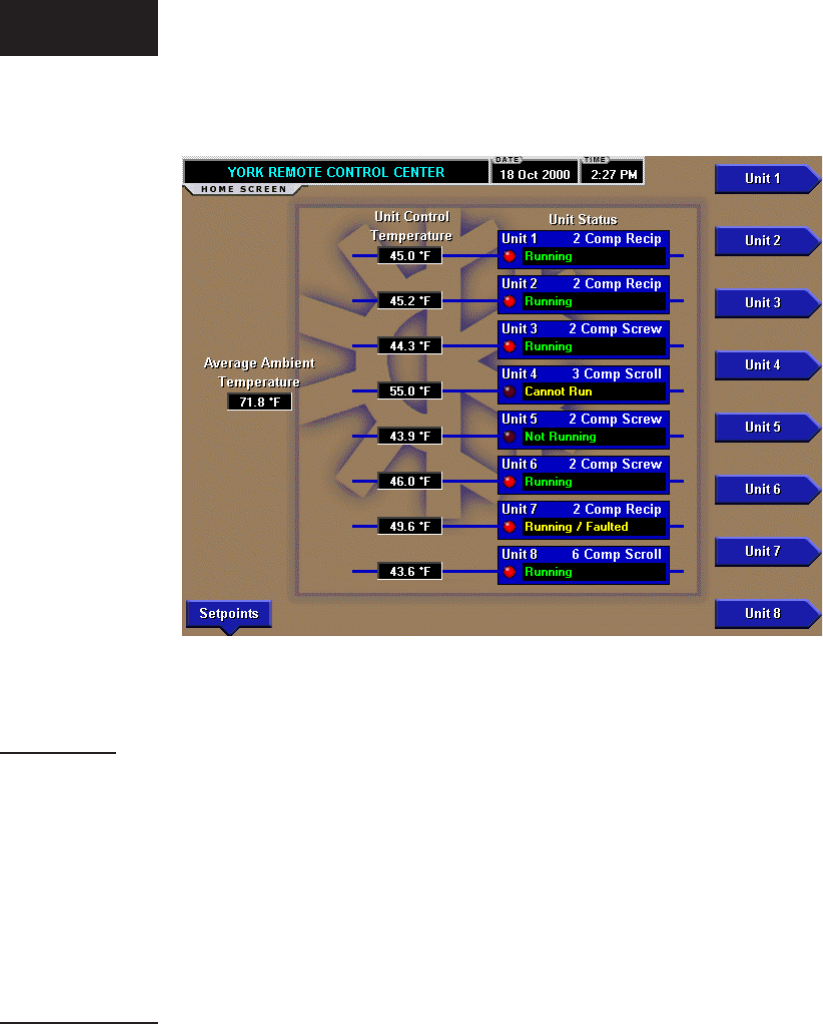
HOME SCREEN
OVERVIEW
When the OptiView Remote Control Center is powered
on, the above default display appears. This screen gives
a general overview of the operating status of each unit
connected to the OptiView Remote Control Center. The
data and control of an individual unit is accessed from
the Home Screen display. Fig. 9 is an example that
shows eight units were programmed.
DISPLAY ONLY
Unit Control Temperature
Displays the temperature of what the unit is using for
control such as leaving chilled liquid temperature.
This is not shown if suction pressure is being used
for control.
Unit Type
Displays the type of chiller the unit is.
Unit Status
Displays a general status message for the unit. The
general status message will include communications
status, running status, and fault status, etc. Following is
a complete listing of the general status messages:
• Not Initialized will be displayed upon power-up for
all units until the OptiView Remote Control Center
begins to poll and receive data from that unit. While
this message is displayed, the unit’s button will be
disabled, not allowing it to be selected.
• Initializing… will be displayed while the OptiView
Remote Control Center is polling a unit for all
current, schedule, and history data the rst time
after power-up. While this message is displayed,
the unit’s button will be disabled not allowing it
to be selected.
• Loss of Comms will be displayed after 5 minutes
have elapsed with no response from a previously
initialized unit. While this message is displayed,
the unit’s button will be disabled not allowing it
to be selected.
• Running will be displayed when at least 1 system is
running on a unit with no faults on any system. This
message will be displayed even if the chiller is in any
kind of limiting as long as there are no faults present.
While this message is displayed, the unit’s button
will be enabled allowing it to be selected.
• Not Running will be displayed when no systems
on the unit are running for a non-fault reason but
can run when demand requires. This would be
for the No Cool Load state. While this message
is displayed, the unit’s button will be enabled
allowing it to be selected.
• Faulted will be displayed when no systems on
the unit are running and there is a fault on one or
more systems or a unit fault. While this message
FIG. 9 – HOME SCREEN - EXAMPLE 00499VIPC
Operation

FORM 50.40-OM2
23YORK INTERNATIONAL
is displayed, the unit’s button will be enabled
allowing it to be selected.
• Running / Faulted will be displayed when at least
one system on the unit is running and at least one
system is faulted. While this message is displayed,
the unit’s button will be enabled allowing it to
be selected.
• Cannot Run will be displayed for any non-fault
condition preventing the entire chiller from run-
ning. This would include such things as the daily
schedule, unit switch, all system switches, run
perm, etc. While this message is displayed, the
unit’s button will be enabled allowing it to be
selected.
Unit Run Indicator (LED)
Is ON when the unit is running.
Average Ambient Temperature
Displays the average Ambient Air Temperature of all
the units connected.
PROGRAMMABLE
None
NAVIGATION
Unit #
A detailed view of data relevant to the specied (#) unit.
If the “Not Initialized” status message is displayed,
the unit’s button will be disabled, not allowing it to
be selected.
Setpoints
This screen provides the gateway to many of the
OptiView Remote Control Center’s general setup
parameters such as Date/Time, Comm Setup, Printer
Setup, etc.
3
YORK INTERNATIONAL24
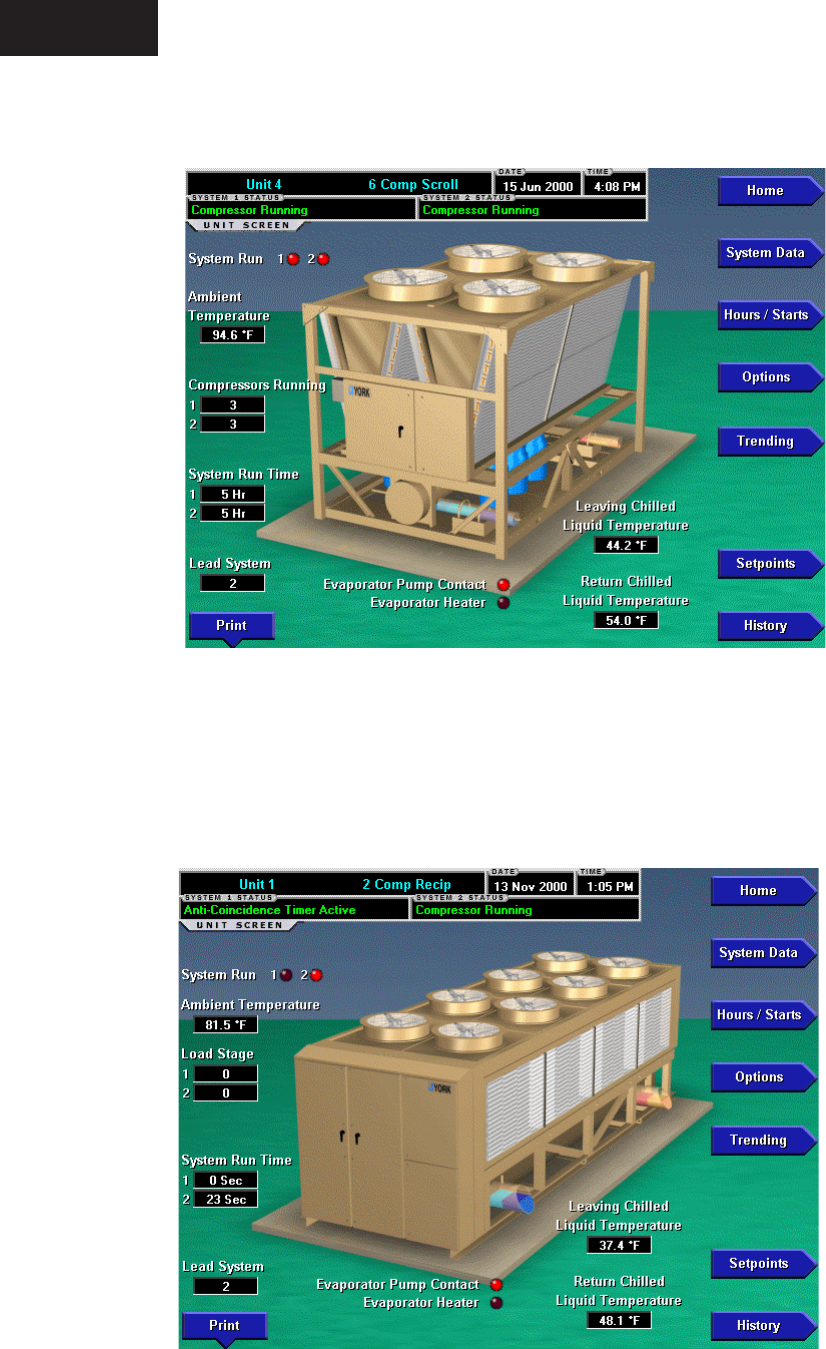
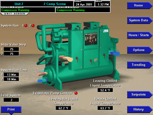
UNIT SCREEN - EXAMPLES
00569VIPC
FIG. 10A – YCAL CHILLER
FIG. 10B – YCAR CHILLER 00570VIPC
Operation
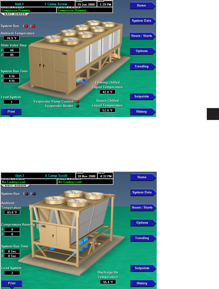
FORM 50.40-OM2
25YORK INTERNATIONAL
FIG. 10C – YCAS CHILLER 00571VIPC
FIG. 10D – YCUL CONDENSING UNIT
00572VIPC
UNIT SCREEN - EXAMPLES
3
YORK INTERNATIONAL26
FIG. 10E – YCWS CHILLER 00573VIPC
UNIT SCREEN - EXAMPLES

FORM 50.40-OM2
27YORK INTERNATIONAL
OVERVIEW
This screen is accessed from the Home Screen. The
primary values of the chiller or condensing unit which
must be monitored and controlled are shown on this
screen. The data available depends on the type of unit.
This screen display depicts a visual representation of
the unit itself. Animation indicates chilled liquid ow
and condenser fans running.
DISPLAY ONLY
Systems Statuses
Displays the individual refrigerant systems operational
statuses. The messages displayed include running
status, cooling demand, fault status, external cycling
device status, load limiting, and anti-recycle timer
status. The status message that is displayed on the
microprocessor is represented here.
System Run (LED)
Is ON when the individual refrigerant systems compres-
sor is running. If any of these are ON, the fans will be
animated to show that they are running.
Slide Valve Step (If Screw)
Displays the individual refrigerant systems slide valve
step.
Load Stage (If Recip)
Indicates the number of solenoids on the compressor of
a YCAR unit that are de-energized and loaded.
Number Of Compressors Running (If a system has
more than one)
Displays how many compressors are running on the unit.
System Run Time
Displays the individual refrigerant systems logged run
time since the last compressor start, in days (Days),
hours (Hr), minutes (Min) or seconds (Sec).
Lead System
This message indicates which system is in the lead.
Evaporator Pump Contact (LED)
Is ON when the evaporator pump signal from the
microprocessor is on. If this is ON, the chilled liquid
will be animated to show that it is owing.
Evaporator Heater (LED)
Is ON when the evaporator heater signal from the
microprocessor is on.
Leaving Chilled Liquid Temperature
Displays the temperature of the liquid as it leaves
the evaporator.
Return Chilled Liquid Temperature
Displays the temperature of the liquid as it enters
the evaporator.
Discharge Air Temperature
Displays the discharge air temperature leaving the
evaporator when the condensing unit is programmed
for Discharge Air control.
Systems Suction Pressure
Displays the suction pressure for each individual system
on a condensing unit when the unit was programmed
for Suction Pressure control.
Ambient Temperature
Displays the outdoor Ambient Air Temperature.
PROGRAMMABLE
Print
Initiates a printout of current system operating
parameters for the currently selected unit.
Cancel Print
Terminates the printing in process. This key is only
visible while printing is in process.
NAVIGATION
Home
Causes an instant return to the Home Screen.
System Data
Used to provide additional system information.
Hours/Starts
This screen shows the cumulative operating hours and
start count of each compressor.
Options
Used to provide information of the options that were
programmed at the Unit Control Panel.
Trending
This screen provides the user a view of trending data on
selected parameters of this chiller/condensing unit.
Setpoints
This screen provides a single location to program the
unit setpoints for the selected unit.
History
This screen provides access to a snapshot of system data
at each of the last 4-6 shutdown conditions.
UNIT SCREEN

YORK INTERNATIONAL28
Operation
This page intentionally left blank.
FORM 50.40-OM2
29YORK INTERNATIONAL
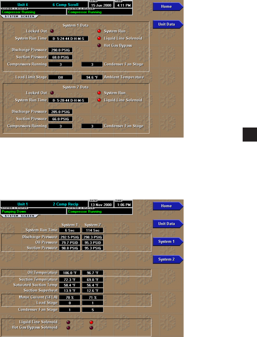
SYSTEMS SCREEN - EXAMPLES
FIG. 11A – YCAL CHILLER 00505VIPC
FIG. 11B – YCAR CHILLER 00506VIPC
3
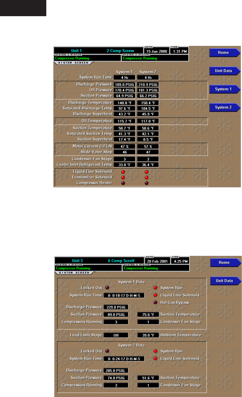
FIG. 11C – YCAS CHILLER 00507VIPC
FIG. 11D – YCUL CONDENSING UNIT 00508VIPC
SYSTEMS SCREEN - EXAMPLES
Operation

OVERVIEW
This screen is accessed from the Unit Screen. A chiller
can consist of separate refrigerant circuits. Each
refrigerant circuit is referred to as a system. This
screen shows system specic information for each of
the unit’s refrigerant systems. This information can
vary according to the type of chiller. Reference the
chiller’s Installation, Operation, Maintenance Manual
(IOM) for details.
DISPLAY ONLY
System Status
Displays this refrigerant systems operational status.
The messages displayed include running status, cooling
demand, fault status, external cycling device status,
load limiting, and antirecycle timer status. The status
message that is displayed on the Unit’s microprocessor
is represented here.
System Run (LED)
Displays this refrigerant systems operational status. Is
ON when the system is running.
Locked Out (LED)
Is ON when a system is locked out on a fault requiring
a manual reset at the chiller or condenser unit micro
panel.
System Run Time
Displays the amount of time the system has run.
Temperatures and pressures are either measured directly
by transducers and temperature sensors, or computed
from these measurements. Depending on the type of
chiller, the following temperatures and pressures could
be displayed:
• Discharge Pressure • Oil Pressure
• Suction Pressure • Oil Temperature
• Discharge Temperature • Suction Superheat
• Saturated Discharge Temperature
• Discharge Superheat
• Suction Temperature
• Saturated Suction Temperature
Motor Current (%FLA)
This displays the motor current of the system in percent
of full load amps.
Slide Valve Step (If screw)
This indicates the compressor slide valve step.
Compressors Running
(If more than one compressor per circuit)
Indicates the number of compressors running
Load Limit Stage
Indicates which stage of Load Limiting a unit is in.
Load Stage
Indicates the number of solenoids on the compressor of
a YCAR unit that are de-energized and loaded.
Condenser Fan Stage
Displays the stage of condenser fan operation on the
system.
Cooler Inlet Refrigerant temperature (Only if in
R-407c mode)
Displays the refrigerant temperature at the inlet of
the cooler.
Liquid Line Solenoid (LED)
Is ON when the Liquid Line Solenoid Valve is energized/
open.
Economizer Solenoid (LED)
Is ON when the economizer Thermal Expansion Valve
Solenoid is energized/open.
Oil Cooling Solenoid (LED)
Is ON when the Oil Cooling Solenoid Valve is energized/
open.
Compressor Heater (LED)
Is ON when the compressor heater is on.
Hot Gas Bypass (LED)
Is ON when the hot gas bypass valve is open.
PROGRAMMABLE
None
NAVIGATION
Home
Causes an instant return to the Home Screen.
Unit Data
Causes an instant return to the Unit Screen of the
selected unit.
System #
A detailed view of the specied (#) system information.
SYSTEMS SCREEN
3
YORK INTERNATIONAL32
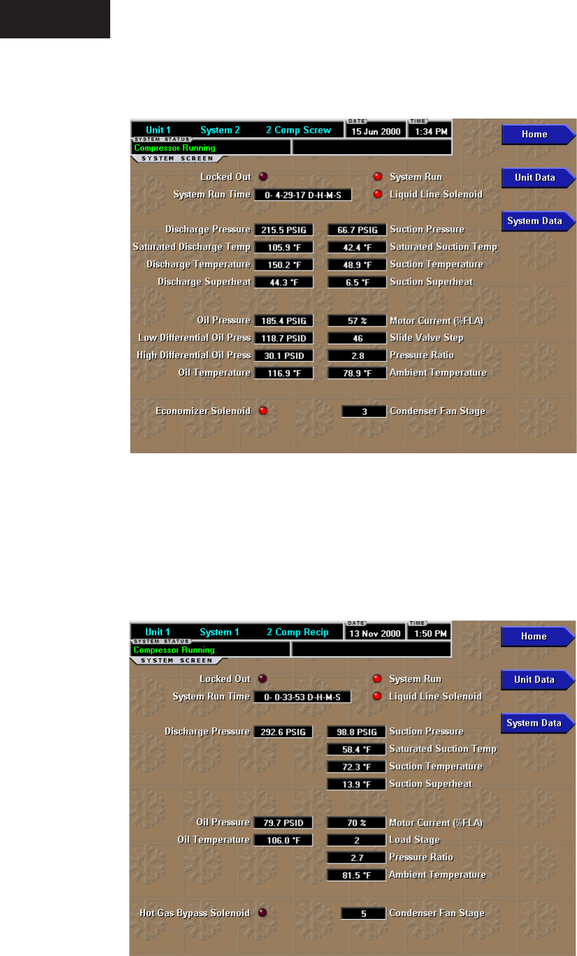
INDIVIDUAL SYSTEM SCREEN
FIG. 12A – YCAS CHILLER
FIG. 12B – YCAR CHILLER
00509VIPC
00510VIPC
Operation

FORM 50.40-OM2
33YORK INTERNATIONAL
OVERVIEW
This screen is accessible from the SYSTEM screen
when there is much data to view about an individual
system. It displays data only from the selected system.
Reference the chiller’s Installation, Operation, Main-
tenance Manual (IOM) for details about the data.
Depending on the type of chiller, the following data
might be displayed:
DISPLAY ONLY
The following system information is displayed at the
top of the screen:
Locked Out (LED)s
System Run Time
System Run (LED)
Liquid Line Solenoid (LED)
The following discharge readings are grouped together
and displayed:
Discharge Pressure
Saturated Discharge Temperature
Discharge Temperature
Discharge Superheat
The following suction readings are grouped together
and displayed:
Suction Pressure
Saturated Suction Temperature
Suction Temperature
Suction Superheat
The following oil readings are grouped together and
displayed:
Oil Pressure
Low Differential Oil Pressure
High Differential Oil Pressure
Oil Temperature
The following miscellaneous readings are grouped
together and displayed:
Motor Current (%FLA)
Slide Valve Step or Load Stage
Pressure Ratio
Ambient Temperature
The following miscellaneous information is displayed
separately:
Economizer Solenoid (LED)
Hot Gas Bypass Solenoid (LED)
Oil Cooling Solenoid (LED)
Condenser Fan Stage
PROGRAMMABLE
None
NAVIGATION
Home
Causes an instant return to the Home Screen.
Unit Data
Causes an instant return to the Unit Screen.
System Data
Causes an instant return to the System Screen.
3
YORK INTERNATIONAL34
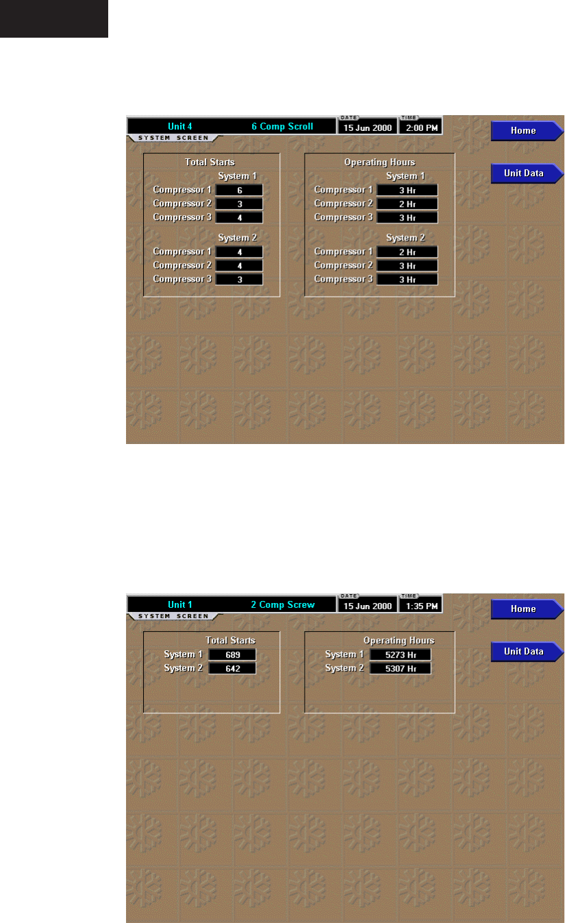
HOURS AND STARTS SCREEN
FIG. 13A – YCAL CHILLER 00511VIPC
FIG. 13B – YCAS CHILLER 00512VIPC
Operation

FORM 50.40-OM2
35YORK INTERNATIONAL
OVERVIEW
This screen, accessed from the UNIT screen, displays
the total operating hours and the total number of starts
for all systems on the unit.
DISPLAY ONLY
Total Starts
Displays the number of times the compressor has
been started.
Operating Hours
Displays the number of hours the compressor has
run.
PROGRAMMABLE
None
NAVIGATION
Home
Causes an instant return to the Home Screen.
Unit Data
Causes an instant return to the Unit Screen.
3
YORK INTERNATIONAL36
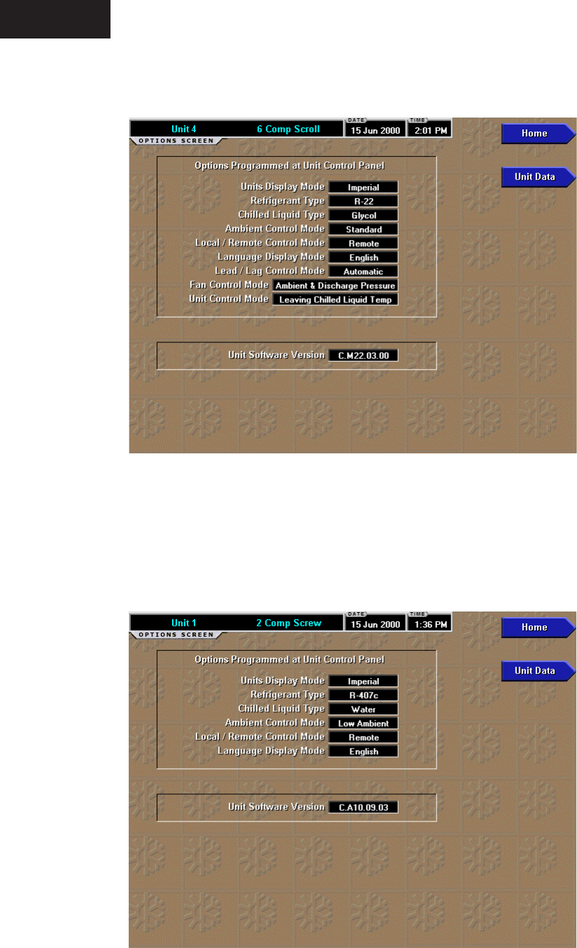
OPTIONS SCREEN
FIG. 14A – YCAL CHILLER
FIG. 14B – YCAS CHILLER / YCAR CHILLER
00513VIPC
00514VIPC
Operation

FORM 50.40-OM2
37YORK INTERNATIONAL
3
OVERVIEW
This screen, accessed from the UNIT screen, displays
all the dip switch settings and other programmable
options at the chiller micro panel. These items can only
be changed at the chiller micro panel and not at the
OptiView Control Center. Depending on the type of
chiller, the following data might be displayed:
DISPLAY ONLY
Units Display Mode
The units selected at the OptiView Remote Control
Center, either Imperial or SI, is displayed. In Imperial
Units temperatures will be in °F and pressures will be
in PSIG or PSID. In SI units temperatures will be in °C
and pressures will be in BARG or BARD.
The values at the OptiView Remote
Control Center will be displayed in
the units that are selected on it’s
Setpoints screen regardless of what is
programmed at the chiller/condensing
unit.
Refrigerant Type
The refrigerant, either R-407C or R-22, selected at the
chiller micro panel is displayed.
Chilled Liquid Type
The cooling mode, either Water or Glycol, selected at
the chiller micro panel is displayed.
Ambient Control Mode
The ambient mode, either Standard or Low Ambient,
selected at the chiller micro panel is displayed.
Local/Remote Control Mode
The control mode selected at the chiller micro panel,
either Local or Remote, is displayed.
Language Display Mode
The language selected at the chiller micro panel (i.e.
English) is displayed.
Lead/Lag Control Mode
The Lead/Lag control at the chiller micro panel is
displayed, either Automatic or Manual. This control
is used to select which compressor starts. See the unit’s
Installation, Operation and Maintenance Manual for
a description.
Fan Control Mode
The fan control at the unit’s micro panel is displayed,
either Discharge Pressure or Ambient and Discharge
Pressure.
Unit Control Mode
What the chiller/condensing unit control is based on
is displayed, either Leaving Liquid, Return Liquid,
Suction Pressure, or Discharge Air Temperature.
Unit Software Version
The software version of the EPROMS at the chiller/
condensing unit’s micro panel .
PROGRAMMABLE
None
NAVIGATION
Home
Causes an instant return to the Home Screen.
Unit Data
Causes an instant return to the Unit Screen.
YORK INTERNATIONAL38
OVERVIEW
This screen is accessed from the UNIT screen. As many
as six Operator selected parameters can be plotted in
an X/Y graph format. The X-Axis is scaled per the
selected Data Collection Interval and displayed in a
time of day or elapsed time format, as selected with
the X-axis toggle key. The Y-Axis is scaled for each
parameter per the selected minimum and maximum
value for each parameter. Analog parameters are scaled
in pressure, temperature, volts, amps, hertz or time.
Digital on/off parameters are scaled as zero (off) and
one (on). Only one Y-Axis label is displayed at a time.
The Y-Axis Toggle Key is used to toggle the Y-Axis
labels through the different parameters. The Y-Axis
label that is being displayed is identied at the top of the
graph. All parameters are displayed simultaneously. For
identication, each plotted parameter and associated
Y-Axis labeling is color coordinated.
The parameters are sampled at the selected Data
Collection Interval and plotted using 450 data points
across the X-Axis. If the actual value of the sampled
parameter is less than the Y-Axis label minimum for
that parameter, the value will be plotted at the minimum
value. Similarly, if the actual value is greater than the
Y-Axis label maximum for that parameter, the value
will be plotted at the maximum value.
There are two types of charts that can be created: ONE
SCREEN or CONTINUOUS. When the plotting has
reached the end of the X-Axis, one of the following
will occur, depending on which is selected: If ONE
SCREEN has been selected, the trending stops and the
data is frozen. If CONTINUOUS has been selected,
the oldest data is dropped from the left-hand side of the
graph at the next Data Collection Interval. Thereafter,
the oldest data is dropped from left-hand side of the
graph at each Data Collection Interval.
Only parameters from the selected Unit are trended.
The same parameters that have been selected for a Unit,
will be selected by default for the next selected Unit.
When on the Home screen, a Unit is not selected and
any trending is stopped. Trending is also stopped if a
power failure occurs while it is running. After trending
is stopped, the last screen of data that was collected will
be displayed on the trending screen and the START key
must be pressed to initiate a new trend screen.
DISPLAY ONLY
This screen allows the user to view the graphical
trending of the selected parameters and is also a
gateway to the graph setup screens.
TRENDING SCREEN
FIG. 15 TRENDING 00574VIPC
Operation

FORM 50.40-OM2
39YORK INTERNATIONAL
A red screen with the words “TREND
MAX MUST BE > TREND MIN”
will appear if the Y-Axis minimum
has been programmed to a value that
is greater than the Y-Axis maximum
for any parameter. If this appears,
proceed to the Trend Setup Screen to
change the values.
PROGRAMMABLE
Start
Pressing this key clears the graph, starts a new graph
and begins the trending. The trending will continue
until the STOP key is pressed, the Home screen is
displayed, or a power failure occurs. This key is only
available if trending is stopped.
Stop
Pressing this key stops the trending. The trend data
is frozen on the display until another graph is started
with the START key. The Stop key is only available
if trending is running.
Y-Axis
This key toggles the Y-Axis labels of the graph. Each
key press changes the label to another of the selected
parameters.
X-Axis
This key toggles the X-Axis labels of the graph.
Each key press alternates the scaling between time of
day and elapsed time. The Time of Day scaling is in
24-hour format. The Elapsed Time scaling is the time
elapsed since the START key was pressed, starting
the trending.
NAVIGATION
Home
Causes a return to the Home Screen.
Unit Data
Causes a return to the Unit Screen.
Trend Setup
Only displayed if the trending is stopped. Causes
a jump to a sub-screen for conguring the trending
display.
3
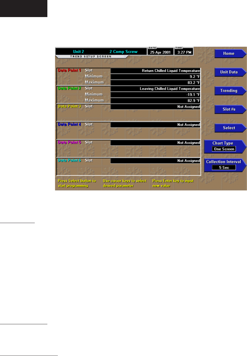
YORK INTERNATIONAL40
OVERVIEW
This screen is accessed from the Trending screen.
This screen is used to congure the trending screen.
The parameters to be trended are selected from the
Common Slots Screen or Common Slots Master list
and entered as Slot Numbers for Data Points 1 through
6. The Y-Axis minimum and maximum values for each
parameter are entered as Data Point Min and Data Point
Max for Data Points 1 through 6. The interval at which
all the parameters are sampled is selected as the Data
Collection Interval.
DISPLAY ONLY
None
PROGRAMMABLE
Chart Type
Selects either CONTINUOUS or ONE SCREEN type
of graph.
Collection Interval
Selects the interval at which the parameters are sampled.
There are 450 data points displayed across the X-Axis
of the graph. Each point represents the instantaneous
value of the parameter. The user selects the time
interval between these points. This is called the DATA
COLLECTION INTERVAL, or the interval at which
the parameter is sampled. This interval is programmable
over the range of 1 second to 3600 seconds (1 hour), in
one second increments. The selected interval not only
determines the sample interval, but also the full screen
time display. The full screen time display is a result
of the selected interval in seconds, multiplied by the 450
data points. For example, if the Data Collection Interval
is programmed for 900 seconds, the parameter would
be sampled every 900 seconds, with the last 112.5 hours
(4.7 days) of data viewable on the screen. Therefore, the
selected interval is a compromise between resolution
and full screen time display. Select the desired Data
Collection Interval as follows:
1. Determine the desired time interval (in seconds),
between data samples.
2. Calculate the full screen time display as follows:
• 450 x Data Collection Interval = full screen
seconds
• full screen seconds / 60 = full screen minutes
• full screen minutes / 60 = full screen hours
• full screen hours / 24 = full screen days
3. Decide if the resultant sample interval and full
screen display meet the requirements. If not, select
a different sample interval.
TREND SETUP SCREEN
FIG. 16 TREND SETUP 00575VIPC
Operation

FORM 50.40-OM2
41YORK INTERNATIONAL
Select
This key is used to enter the slot numbers and the
minimum and maximum Y-Axis values of each param-
eter to be trended. Pressing this key places a yellow
box around Data Point 1 Slot Number. Use the ▲ and
▼ navigation keys to place the box around the value of
Data Points 1 through 6 to be changed. With the desired
value selected, press the ‘4’ (Enter) key. A dialog box
is displayed permitting data entry.
Data Point Slot # (1-6)
Use the SELECT key as described above and enter
the slot number from the Trend Common Slots Screen
of the desired parameter to be trended. The selected
parameter description will be displayed for the Data
Point. Setting this slot number to zero will disable
trending for that particular Data Point. Any or all points
can be disabled.
Data Point Min (1-6)
Only displayed if the Associated Slot Number is not
Zero. This is the minimum value displayed for the
Y-Axis. Selecting a parameter for a Data Point sets
this to the default value, which is the lowest value
allowed for that parameter. It can be changed to a
value that provides a more appropriate resolution for
the parameter being monitored. To change, use the
SELECT key as described above and enter the desired
value. The value must always be set to a value less
than the Data Point Max. Otherwise, a red graph is
displayed on the Trend Screen with the words “TREND
MAX MUST BE > TREND MIN”. If the parameter
selected for this data point is a digital type (on/off),
this value must be set to zero (0). Zero indicates the
OFF state.
Data Point Max (1-6)
Only displayed if the associated slot number is not zero.
This is the maximum value displayed for the Y-Axis.
Selecting a parameter for a Data Point sets this to the
default value, which is the highest value allowed for that
parameter. It can be changed to a value that provides a more
appropriate resolution for the parameter being monitored.
To change, use the SELECT key as described above and
enter the desired value. The value must always be set to
a value greater than the Data Point Min. Otherwise, a red
graph is displayed on the Trend Screen with the words
“TREND MAX MUST BE > TREND MIN”. There are
20 Y-axis divisions. If a MIN-MAX span is selected that is
not evenly divided by 20, the Program will automatically
select the next higher MAX value that makes the span
evenly divided by 20. For example, if 0.0 is selected as
the MIN, and 69.0 as the MAX, the Program will insert
70.0 as the MAX value. If the parameter selected for this
data point is a digital type (on/off), this value must be set
to one (1). One indicates the on state.
NAVIGATION
Home
Causes a return to the Home Screen.
Unit Data
Causes a return to the Unit Screen.
Trending
Causes a return to the Trending Screen.
Slot Numbers
Causes a jump to the Trend Common Slots Screen.
The slot numbers of the most commonly monitored
parameters are listed on this screen. The parameters
are arranged to make it easier to nd the slot number
of the desired parameter to plot.
3
YORK INTERNATIONAL42
This page intentionally left blank.
FORM 50.40-OM2
43YORK INTERNATIONAL
This page intentionally left blank.
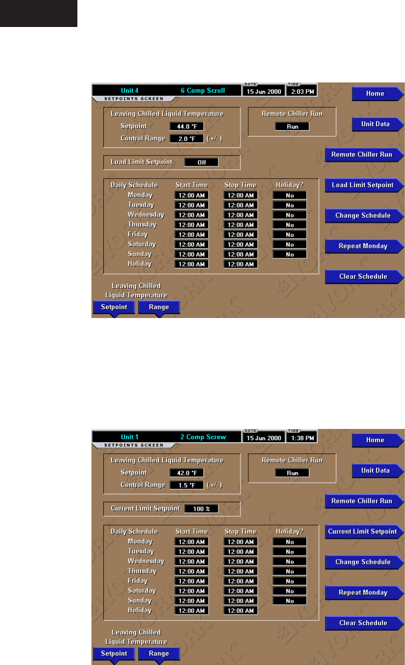
00515VIPC
YORK INTERNATIONAL44
SETPOINTS SCREEN - EXAMPLES
FIG. 17A – YCAL CHILLER
FIG. 17B – YCAS CHILLER 00516VIPC
Operation
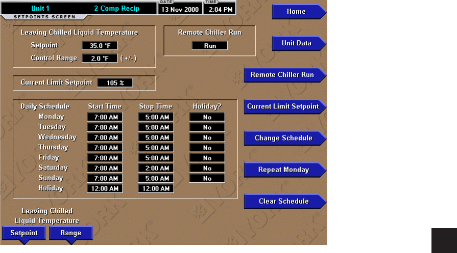
FORM 50.40-OM2
45YORK INTERNATIONAL
FIG. 17C – YCAR CHILLER 00517VIPC
3

YORK INTERNATIONAL46
SETPOINTS SCREEN
Operation
OVERVIEW
This screen, accessed from the Unit screen, provides a
convenient location for programming the most common
setpoints involved in the chiller/condensing unit control.
The setpoints depend on the type of unit.
Values on this screen are only pro-
grammable if the chiller/condensing
unit is in remote control mode. These
values are only viewable if the unit is
in local mode.
DISPLAY ONLY
None
PROGRAMMABLE
Leaving Chilled Liquid Temperature or
Return Chilled Liquid Temperature or Suction
Pressure or Discharge Air Temperature Setpoint
This value allows the user to dene the cooling setpoint
that is to be maintained by the chiller/condensing unit.
See the unit’s Installation, Operation and Maintenance
Manual (IOM) for it’s programmable range.
Leaving Chilled Liquid Temperature or Return
Chilled Liquid Temperature or Suction Pressure or
Discharge Air Temperature - Control Range
This is the maximum allowable positive and negative
deviation that is acceptable from setpoint in the system
application. See the unit’s Installation, Operation and
Maintenance Manual (IOM) for it’s programmable
range.
Remote Chiller Run or Remote Unit Run
The chiller/condensing unit can be selected to either
Run or Stop. Selecting Stop will command the
chiller/condensing unit to shut down. Selecting Run
will allow the chiller/condensing unit to turn on.
Current Limit Setpoint
This is the motor current limiting setpoint. The chiller
will be limited from loading when the motor current
equals or exceeds this value. Typically, for most instal-
lations, no limiting is required and the programmed
limiting will be set at or above 100%.
Load Limit Setpoint (YCAL Chillers)
Load Limiting can be programmed from 0 to 2.
Load Limit 0 = no load limit
Load Limit 1 = 50% load limit - 2/4 compressor units.
Load Limit 1 = 66% load limit - 3/6 compressor units.
Load Limit 2 = 33 % - 3/6 compressor units only.
Change Schedule
The daily schedule is a 1 week schedule and must
be programmed for the start and stop time for each
week day and a holiday if desired. A box is provided to
specify which days are to use the holiday schedule.
Programming the same time for both
Start and Stop times will cause the
display to enter 00.00 for both times
which will cause the chiller to always
be allowed to run.
Repeat Monday
The other days can be selected to change to the Monday
schedule.
Clear Schedule
In a situation where it is required to run the chiller
24 hours a day, 7 days a week, the Chiller Control
panel should rst have its entire Daily Schedule zeroed
(00.00) for all Start and Stop times. This puts the chiller
in the run mode at all times. The OptiView Remote
Control Center may now be programmed with all
zeroes (00.00) for all Start and Stop times by pressing
the Clear Schedule button. Since the chiller panel is
already in the run mode, programming the OptiView
Remote Control Center for all zeroes will keep the
chiller in this mode indenitely, allowing the chiller to
run whenever demand requires.
NAVIGATION
Home
Causes an instant return to the Home Screen.
Unit Data
Causes an instant return to the Unit Screen.
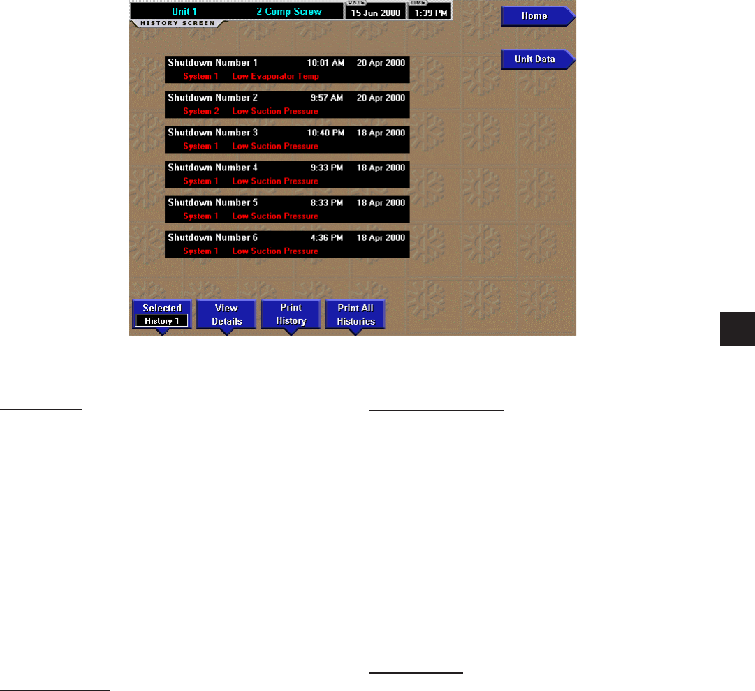
FORM 50.40-OM2
47YORK INTERNATIONAL
HISTORY SCREEN
OVERVIEW
This screen allows the user to browse through the faults.
In order to get a more thorough reporting of the system
conditions at the time of the recorded shutdown, move
to the sub-screen HISTORY DETAILS.
The user may use the Select Fault button to select
the history to view. At this point the View Details
button is used to jump to a sub-screen containing stored
chiller parameters values at the time of the shutdown.
Additionally, the Print History button can be used to
generate a hard-copy report of the parameter values at
the time of the shutdown.
DISPLAY ONLY
Last Faults
This window displays a chronological listing (most
recent rst) of the date and time and the description
of the last four to six safety shutdowns (depending
upon the type of chiller) that occurred while the system
was running.
PROGRAMMABLE
Print History
This generates a report listing the status of the chiller
parameters at the time of the selected shutdown.
Print All Histories
This generates a report listing the status of the chiller
parameters at the time of each of the stored shutdowns.
Cancel Print
Terminates the printing in process. This key is only
visible while printing is in process.
NAVIGATION
Home
Causes an instant return to the Home Screen.
Unit Data
Causes an instant return to the Unit Screen.
View Details
Causes a move to a sub-screen containing the value of
select chiller parameters at the time of the associated
shutdown.
00518VIPC
FIG. 18
3
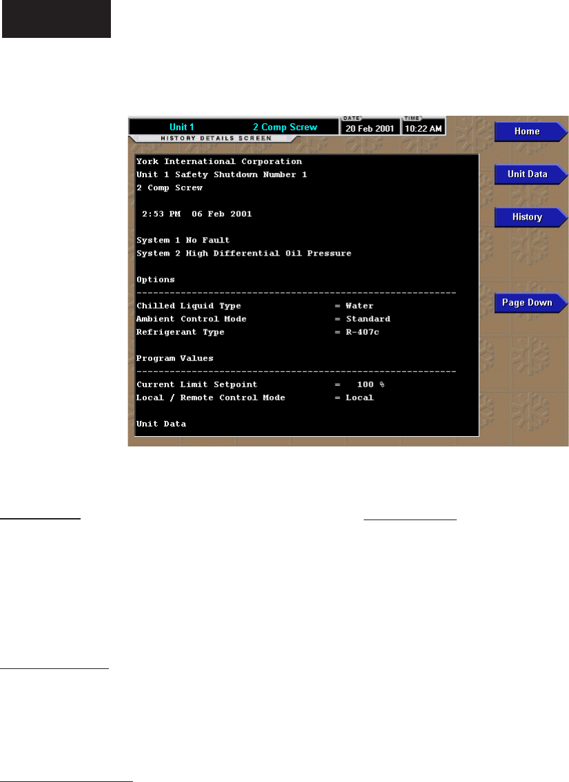
YORK INTERNATIONAL48
HISTORY DETAILS SCREEN
OVERVIEW
This screen allows the user to see an on-screen printout
of all the system parameters at the time of the selected
shutdown. Not all screens are shown above. The number
of screens required to display all of the data varies
according to the type of unit selected.
DISPLAY ONLY
History Printout
This is the on-screen printout of the system param-
eters.
PROGRAMMABLE
Page Up
Scroll up in the displayed data (if applicable).
Page Down
Scroll down in the displayed data (if applicable).
NAVIGATION
Home
Causes an instant return to the Home Screen.
Unit Data
Causes an instant return to the Unit Screen.
History
Causes a return to the History Screen.
FIG. 19 00519VIPC
Operation
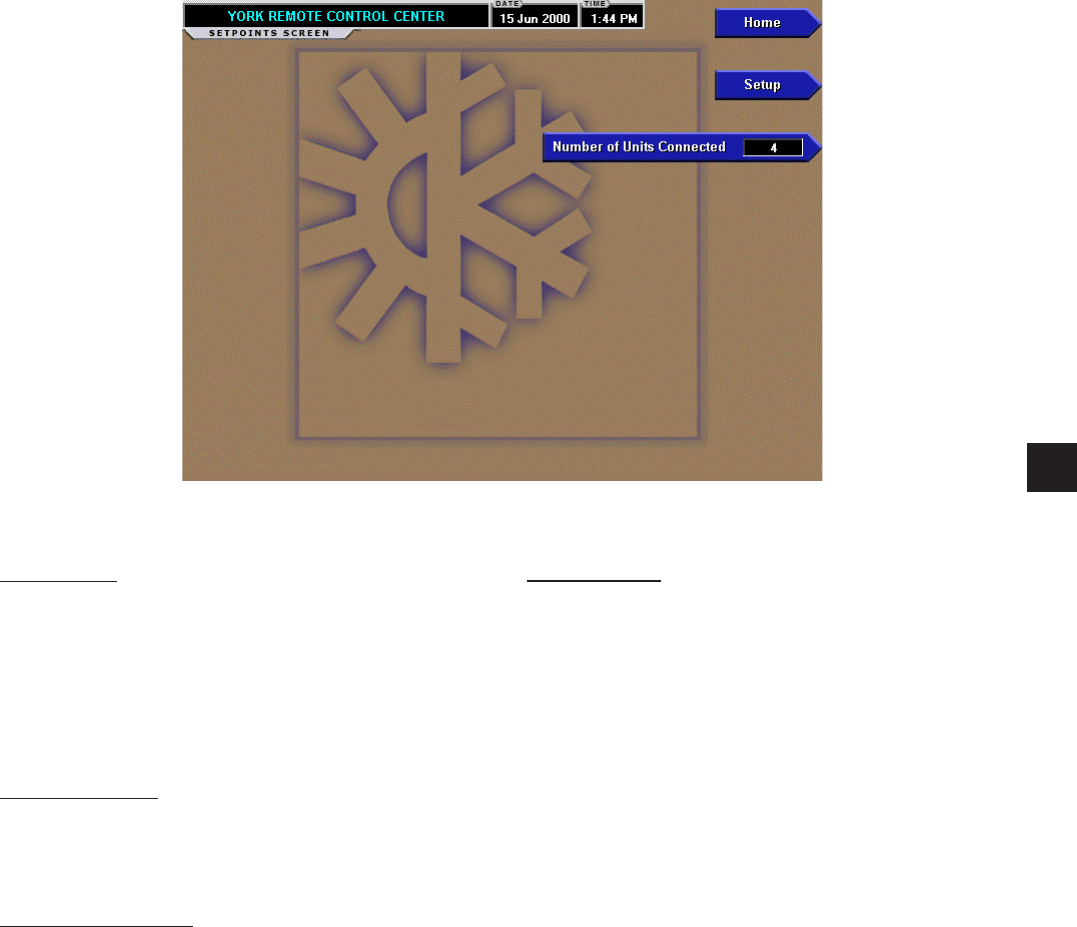
FORM 50.40-OM2
49YORK INTERNATIONAL
RCC SETPOINTS SCREEN
OVERVIEW
This screen is accessed from the Home Screen.
This screen shows conguration parameters for this
OptiView Remote Control Center. This screen also
serves as a gateway to more sub-screens for dening
general system parameters.
DISPLAY ONLY
None
PROGRAMMABLE
Number of Units Connected
Allows the user to program how many units the Control
Center will need to communicate to.
FIG. 20 00520VIPC
NAVIGATION
Home
Causes an instant return to the Home Screen.
Setup
This screen provides a single location to program the
general system setup parameters such as Date/Time.
It is also the gateway to many of the general system
setup parameters such as Communications, Printer
Setup, etc.
3
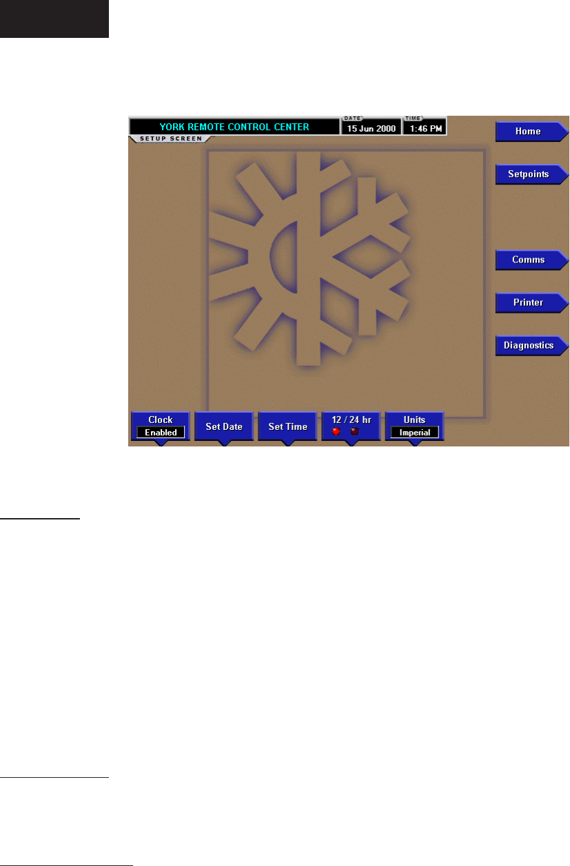
YORK INTERNATIONAL50
RCC SETUP SCREEN
OVERVIEW
This screen is accessed from the RCC Setpoint
Screen. This screen shows the general conguration
parameters for this OptiView Remote Control Center.
It allows programming of the time and date, along with
specications as to how the time will be displayed
(12 or 24 hour format). This time is used for display
purposes on the OptiView Remote Control Center. It
is not used to reset individual chiller clocks and has no
effect on individual chiller schedules. This screen also
serves as a gateway to more sub-screens for dening
general RCC system parameters.
DISPLAY ONLY
None
PROGRAMMABLE
Clock (Enabled / Disabled)
Allows the user to enable or disable the real-time clock
in order to conserve battery life. The clock will be
disabled during manufacturing and must be enabled at
system commissioning. In addition, when preparing
for prolonged shutdown the clock should once again be
disabled.
Set Date
Allows the user to specify the present date. When
prompted to enter a date value, the user must enter the
day, month, and four-digit year (using leading zeroes as
necessary). If within range, the value will be accepted.
If out of range, the user is prompted for the information
again. At this point the user may retry the date entry, or
cancel the programming attempt.
Set Time
Allows the user to specify the present time. When
prompted to enter a time value, the user must enter
the hour and minute desired (using leading zeroes as
necessary). If the chiller is presently set to 24-hour
mode, the time must be entered in the 24-hour format.
Otherwise, the user must also select AM or PM for the
entered time. If out of range, the user is prompted for
the information again. At this point the user may retry
the time entry, or cancel the programming attempt.
12/24 Hr
Allows the user to specify the format in which the time
will be presented to the user. This setpoint will only affect
the display of the time on the OptiView RCC panel and
on all reports generated. 12-Hour time format will include
the AM and PM modiers and show the range of time
between 1:00 and 12:59, while the 24-Hour time format
will show the range of time between 0:00 and 23:59.
FIG. 21 00521VIPC
Operation

FORM 50.40-OM2
51YORK INTERNATIONAL
Units
Dene the unit system (Imperial or SI) used by the
OptiView RCC display. This selection has no effect on
the chiller/condensing unit micro panel.
NAVIGATION
Home
Causes an instant return to the Home Screen.
Setpoints
Causes a return to the Setpoints Screen.
Comms
Moves to the sub-screen allowing configuration of
system communications.
Printer
Moves to the sub-screen allowing conguration and
control of printer functions.
Diagnostics
Moves to the sub-screen allowing limited diagnostic
capability while operating.
3
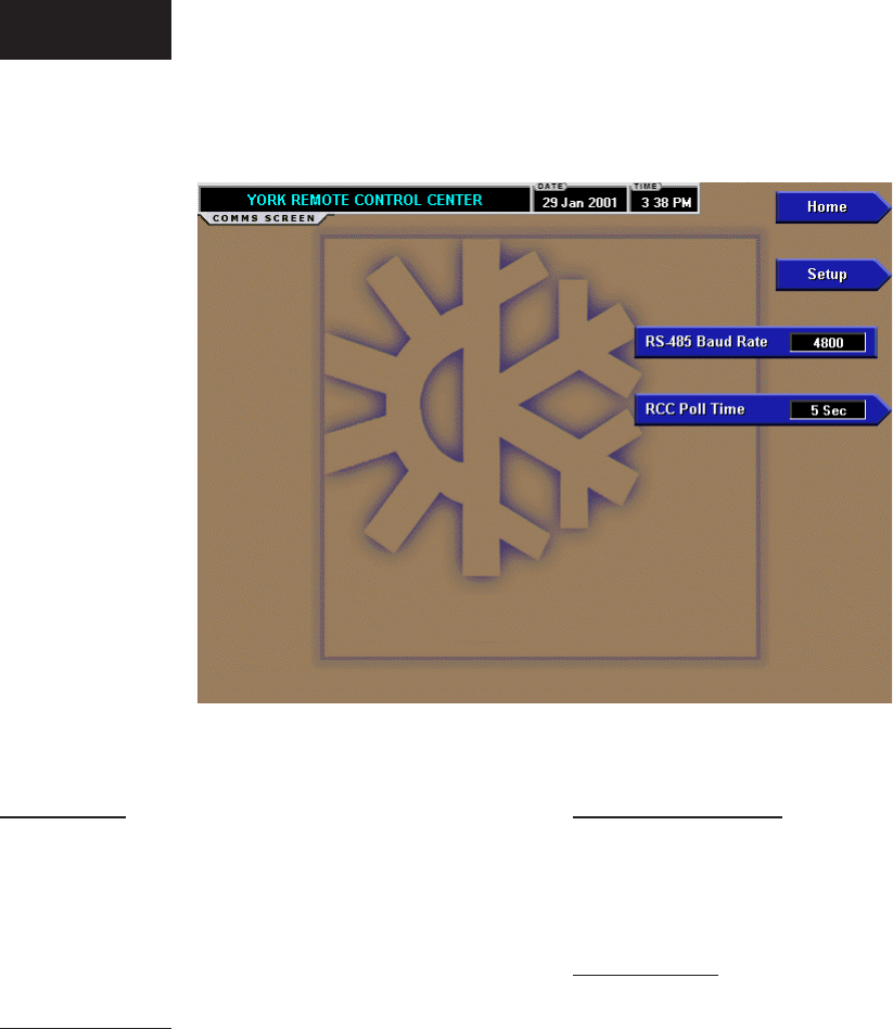
YORK INTERNATIONAL52
COMMS SCREEN
OVERVIEW
This screen is accessed from the RCC Setup Screen.
This screen allows denition of the necessary com-
munications parameters. Refer to PRINTER Section
of this book for details of the Printer connections
and setup.
DISPLAY ONLY
RS-485 Baud Rate 4800
Shows the baud rate at which the panel shall com-
municate through the Com3 port to the remote control
panel(s). The baud rate of the remote control panel(s)
must be set for 4800 in the EPROM. Make sure the
correct EPROM is installed at the chiller/condenser
control panel(s). See Table 1.
PROGRAMMABLE
RCC Poll Time (5-30 sec.)
Dene the poll time (how frequently) this panel requests
for data from another panel through the Com3 port.
NAVIGATION
Home
Causes an instant return to the Home Screen.
Setup
Return to the Setup Screen.
FIG. 22 00522VIPC
Operation
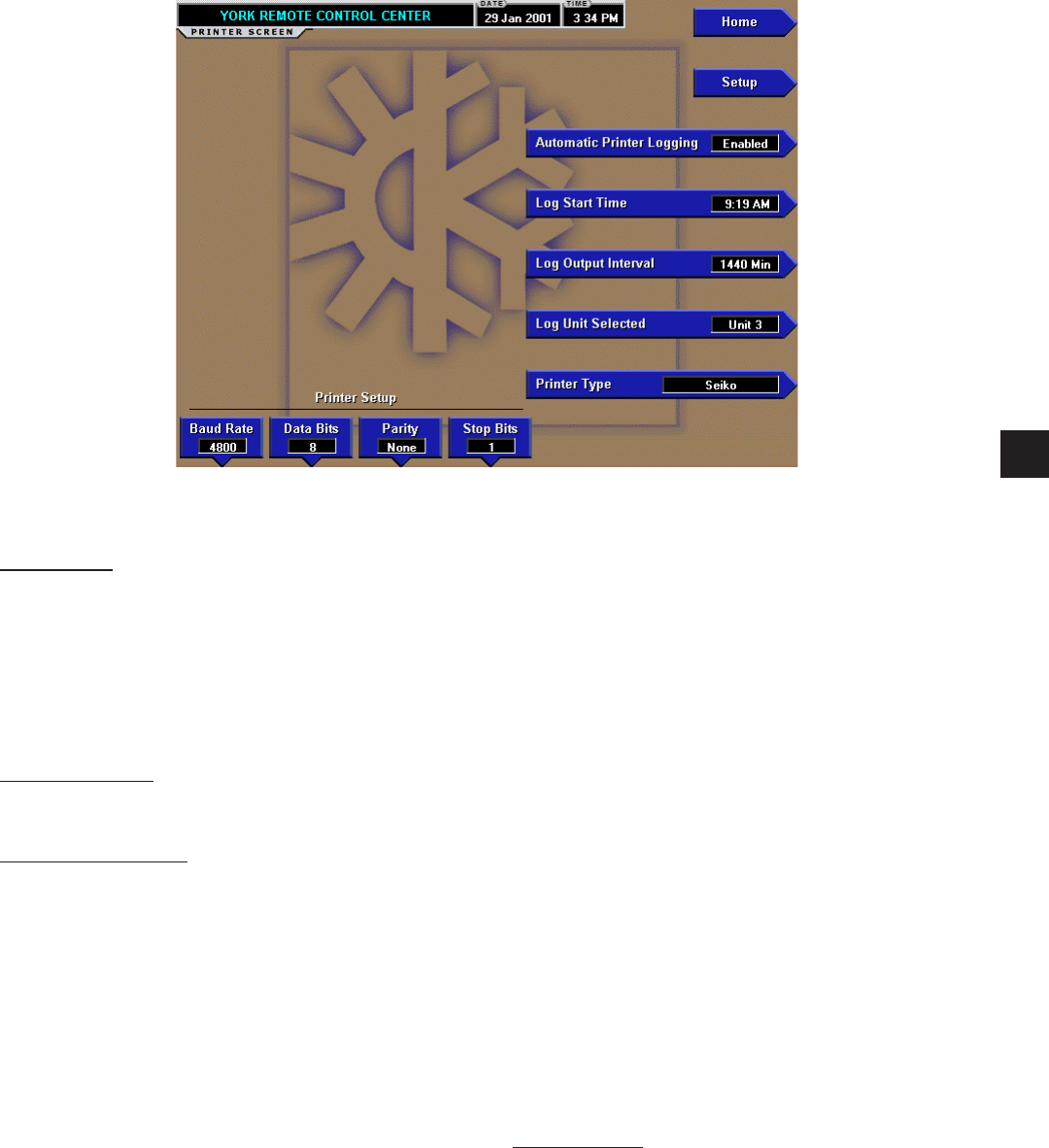
FORM 50.40-OM2
53YORK INTERNATIONAL
PRINTER SCREEN
OVERVIEW
This screen is accessed from the RCC Setup Screen.
This screen allows denition of the necessary com-
munications parameters for the printer. Refer to
PRINTER section of this book for details of the Printer
connections and setup.
DISPLAY ONLY
None.
PROGRAMMABLE
Automatic Printer Logging (Enabled / Disabled)
Enable the printer to begin printing status reports
beginning at the programmed start time and recurring
at the interval dened above.
Log Start Time
Set the time at which scheduled logs will begin.
Log Output Interval
Dene the interval at which logging will occur. We
suggest you select a reasonable amount of time so that
it is not occurring too much.
Log Unit Selected
Select a unit or all units to logs of.
Printer Type
Dene the printer type connected to the OptiView RCC.
Printer Baud Rate
Dene the baud rate at which the panel shall com-
municate to the printer.
Printer Data Bit(s)
Dene the number of data bits with which the panel
shall communicate to the printer.
Printer Parity Bit(s)
Dene the number of parity bits with which the panel
shall communicate to the printer.
Printer Stop Bit(s)
Dene the number of stop bits with which the panel
shall communicate to the printer.
Cancel Print
Terminates the printing in process. This key is only
visible while printing is in process.
NAVIGATION
Home
Causes an instant return to the Home Screen.
Setup
Return to the Setup Screen.
FIG. 23 00523VIPC
3
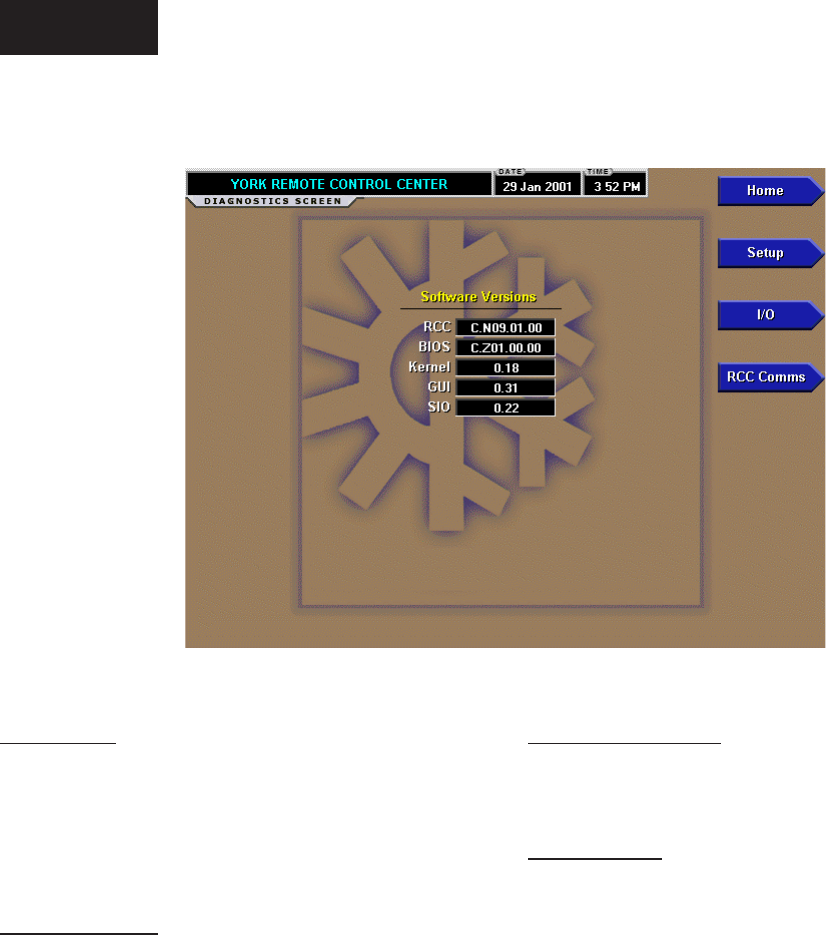
YORK INTERNATIONAL54
DIAGNOSTICS SCREEN
FIG. 24
OVERVIEW
This screen is accessed from the RCC Setup Screen.
This screen provides a view of what software is in use
and provides access to a screen for troubleshooting
analog and digital inputs.
DISPLAY ONLY
Software Versions
The following software versions are displayed:
• RCC - FLASH Memory Card on Microboard
• BIOS - BIOS EPROM on Microboard
• Kernel - Software that is part of FLASH Memory
Card
• GUI - Software that is part of FLASH Memory
Card
• SIO - Software that is part of FLASH Memory
Card
PROGRAMMABLE
None
NAVIGATION
Home
Causes an instant return to the Home Screen.
Setup
Return to the Setup Screen.
I/O
Moves to the sub-screen allowing diagnostics of the
analog and digital inputs.
RCC Comms
Moves to the sub-screen allowing diagnostics of
communications with the RCC.
00524VIPC
Operation
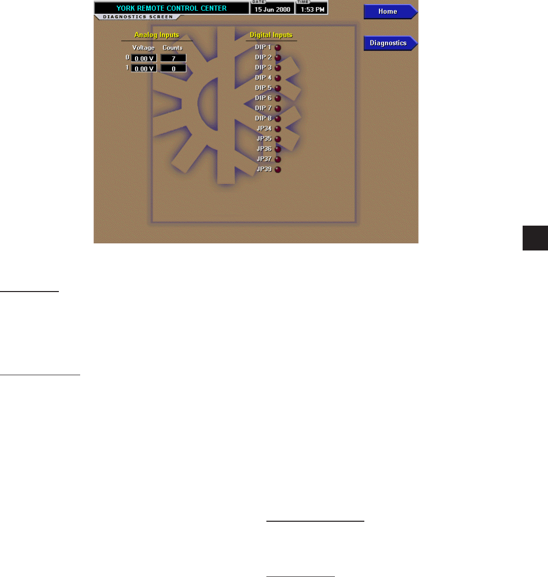
FORM 50.40-OM2
55YORK INTERNATIONAL
FIG. 25
DIAGNOSTICS I/O SCREEN
OVERVIEW
This screen is accessed from the Diagnostics Screen.
This screen provides a view of the analog and digital
inputs for troubleshooting .
DISPLAY ONLY
Diagnostics is used to analyze the Analog Inputs at the
Microboard. The voltage level of each Analog Input, as
interpreted by the Microboard, is displayed. “Counts”
is an Analog-to-Digital (A/D) converter value and is for
manufacturing and engineering use only.
Diagnostics is also used to analyze the state of each
Microboard Program Jumper and Program DIP Switch
as interpreted by the Microboard. These are depicted
by an LED.
PROCEDURE
Digital Inputs:
1. The Digital Inputs are listed on this screen according
to a.) Microboard Program Jumpers and Program
DIP Switches. Tables 2 and 3 list the functions of
the Program Jumpers and Switches.
2. If a Program Jumper is present, the applicable
LED should be extinguished. If the LED is not
extinguished, the Microboard is defective.
3. If a Program Jumper is not present, the applicable
LED should be illuminated. If the LED is not
illuminated, the Microboard is defective.
4. If a Program Switch (DIP) is in the ON position, the
applicable LED should be illuminated. If the LED is
not illuminated, the Microboard is defective.
5. If the Program Switch (DIP) is in the OFF position,
the applicable LED should be extinguished. If
the LED is not extinguished, the Microboard is
defective.
6. When all desired tests have been performed,
press DIAGNOSTICS key to return to MAIN
DIAGNOSTICS Screen.
PROGRAMMABLE
None
NAVIGATION
Home
Causes an instant return to the Home Screen.
Diagnostics
Causes a return to the previous screen.
00525VIPC
3

YORK INTERNATIONAL56
DIAGNOSTICS RCC COMMS SCREEN
OVERVIEW
This screen is accessed from the Diagnostics Screen.
This screen provides a view of communication for
troubleshooting .
Communication between the OptiView RCC and the
chiller/condenser control panel(s) should consist of
the RCC polling (requesting a response from) each
chiller/condenser control panel starting with Unit 1
and continuing to Unit “x”, where “x” is the Number
of Units Connected as entered on the RCC Setpoints
Screen. Each poll will increment the Poll Count. A
reply should be sent back to the RCC from the Unit that
was polled within a certain amount of time. If this reply
does not happen within this time period the Timeout
Count will be incremented. If the reply is returned but
contains improper data, then the Bad Csum Count will
be incremented. If the reply is successfully received by
the RCC then the Reply Count is incremented.
Good communication is indicated by the Poll Count
and the Reply Count keeping close to the same
count. A high Timeout Count could imply that the
chiller/condenser control panel did not properly receive
the request or it did not properly send a response.
Check the wiring and the Installation Checklist. A high
Bad Csum Count could be indicative of noise being
transmitted. This can happen because of improper
wiring or grounding.
DISPLAY ONLY
Unit Type
Displays the chiller type, whether it is a “Screw”,
“Recip”, or Scroll” and the number of compressors for
the “Unit x”, where x is the number of the unit.
Poll Indicator (LED)
Is on when the last noted communication through the
Com3 port was to poll a chiller/condenser control
panel.
Reply Indicator (LED)
Is on when the last noted communication through
the Com3 port was to receive a reply from a chiller/
condenser control panel.
Poll Count
A count of each poll request through the Com3 port to
a chiller/condenser control panel.
Reply Count
A count of each reply successfully received through the
Com3 port from a chiller/condenser control panel.
Bad Csum Count
A count of each reply received through the Com3 port
from a chiller/condenser control panel that had a bad
Csum calculation. This indicates that improper data
was received.
FIG. 26 00526VIPC
Operation

FORM 50.40-OM2
57YORK INTERNATIONAL
Timeout Count
A count of each poll request through the Com3 port
to a chiller/condenser control panel that did not get
a reply within the timeout period (time to wait for
a reply).
PROGRAMMABLE
Clear Counters
Resets all the counts to zero.
NAVIGATION
Home
Causes an instant return to the Home Screen.
Diagnostics
Causes a return to the previous screen.
3

YORK INTERNATIONAL58
DISPLAY MESSAGES
A title bar will be displayed on all screens. This title
bar will contain the OptiView Remote Control Center
date and time on all RCC screens. This title bar will
contain the Chiller/Condensing unit’s date and time on
all unit screens. On the Home Screen the message will
read “YORK REMOTE CONTROL CENTER”. On
all other screens it will contain the unit selected and
either the chiller type or will be based on the number
of compressors of that unit.
When a unit has been selected the title bar will display
a dual message on every screen. The rst message
will display the Unit Selected in the format “Unit x”,
where x is the number (1 – 8) of the unit selected. The
second message will display the chiller type, whether
it is a “Screw”, “Recip” or “Scroll” and the number
of compressors.
On the Unit Screen and all System Screens the title bar
contains another message called a Status. The current
status of each unit is displayed in this message. These
messages will include running status, cooling demand,
fault status, external cycling device status, load limiting
and anti-recycle timer status, etc. A System Status
message and a Unit Status message are never displayed
simultaneously. A single message is displayed for a
Unit Status message, while a separate System Status
message will display for each system on multi-circuit
units.
Status messages fall into the categories of warning,
safety, and normal with each of the categories discussed
following:
• Warning messages are denoted by yellow message
text. A warning message is shown for any special
running condition and for all unit warnings.
Any kind of load limiting would be an example
of a warning message. An incorrect refrigerant
programmed warning would also be an example
of a warning message.
• Safety messages are denoted by red message text.
A safety message is shown for any type of safety
shutdown, lock-out, or run inhibit. High discharge
pressure would be an example of a safety shutdown
message.
• Normal messages are denoted by green text.
A normal message is shown for any non-fault
normal condition. The compressor running and
no cooling load messages would be examples of
normal messages.
Note that there are two types of shutdowns. If the
chiller shuts down on a SAFETY shutdown, it requires
the operator to perform a manual reset at the keypad. A
NORMAL shutdown occurs from a properly requested
or scheduled shutdown. The event that caused the
shutdown is displayed on the Status Line.
STATUS MESSAGES
Status messages will be much like those displayed at
the chiller panel. Explanation of these displays will be
outlined in the Installation Manual for each specic
chiller. Subtle differences may be noted in the exact
wording displayed versus the display which is shown
on the chiller panel. An example of this is apparent
in the anti-recycle and anti-coincidence timers. In
the case of these messages, the chiller control panel
indicates actual time left on the timers. The OptiView
Remote Control Center will only indicate that the
timers are “Active”.
The new message “Loss of Communications” indicates
that the communications link between the chiller
control panel and the OptiView Remote Control Center
has been lost. This loss of communications is normally
a result of disconnecting the RS-485 communications
cable between the two panels or the loss of power to
the chiller control panel.
If communications is lost and not re-established, local
chiller setpoints will command chiller control after
5 minutes.
In addition to the chiller status messages there are
the Optiview Remote Control Center general status
messages that are displayed on a single line on the
Home Screen for each chiller. See the description of
the Home Screen in this manual.
SAFETY SHUTDOWN MESSAGE
“WATCHDOG – SOFTWARE REBOOT”
The Microboard’s software Watchdog initiated a
Microprocessor reset because it detected that a portion
of the chiller operating Program was not being executed.
The result of this reset is a Safety shutdown and
re-initialization of the Program. This is generally
indicative of a severe electrical power disturbance
or impending Microboard Failure. The chiller can be
started after the COMPRESSOR switch is placed in
the Stop-Reset (O) position.
Operation
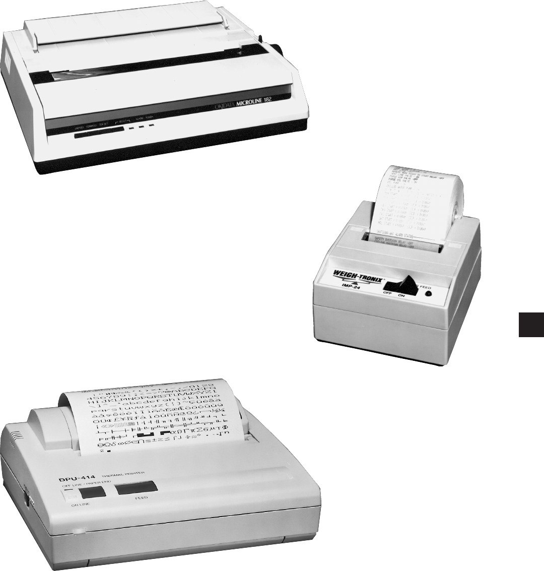
FORM 50.40-OM2
59YORK INTERNATIONAL
FIG. 27 – PRINTERS
23887A
OKIDATA MICROLINE 184
23889A
WEIGH-TRONIX
SEIKO DPU-414
00085VIP
SECTION 4 – PRINTERS
4

YORK INTERNATIONAL60
PRINTERS
A printer can be connected to the OptiView Remote
Control Center’s Microboard to print the following
reports. The screen from which each report can be
generated is listed in parenthesis.
• Operating Data - Present system parameters
(Unit)
• History - System parameters at the time of the
last fault while running and last saved faults
(History)
The printer can be permanently connected to the Remote
Control Center or connected as required to produce a
report. If permanently connected, a DATA LOGGING
feature can produce a Status report automatically,
beginning at an Operator selected start time and occurring
at an Operator selected interval thereafter.
The following gures are examples of the different
print reports.
• Figure 28 - Operating Data
• Figure 29 - History (Header)
PRINTERS
The following Printers can be used. Printers must be
equipped with an RS-232 Serial interface.
• Okidata –
Models: 182,182 turbo, 184 turbo
Dimensions: 14 in. wide x 10.5 in. deep
Paper: 8.5 in. wide
Type: Dot matrix impact
• Weigh-Tronix –
Models: 2600, 1220
Dimensions: 2.3 in. wide x 2.8 in. deep
Paper: 2.25 in. wide
Type: Dot matrix impact
• Seiko –
Model: DPU414-30B (Power supply PW4007-U
I required)
Dimensions: 6.3 in. wide x 6.7 in. deep
Paper: 4.4 in. wide
Type: Thermal
Purchase: Contact your local
YORK Service Ofce
The OptiView Remote Control Center provides the
required formatting control codes for the printers above
when the printer is selected on the PRINTER Screen
in the instructions below. These codes are transmitted
through the serial interface to the printer to provide a
proper print format. Different printers require different
formatting control codes. Other printers might provide
proper operation when connected to the OptiView
Remote Control Center. However, the print format
may not be correct or as desired. Proceed with caution
and use the following guidelines if an unlisted printer
is selected:
1. All must be capable of RS-232 Serial communications.
2. Primary differences between printers involve the
formatting control codes required by the printer.
These codes are sent from the Control Center to
the printer. For example, Weigh-Tronix printers
require a control code to select 40 column width.
This same code is interpreted by the Okidata printer
as an instruction to print wide characters. In some
instances, a printer will ignore a code it cannot
interpret.
3. The OptiView Remote Control Center requires
a busy signal from the printer when the printer
receive buffer is full. This causes the OptiView
Remote Control Center to momentarily terminate
data transmission until the printer can accept more
data. The busy signal polarity must be asserted
low when busy.
PRINTER CONNECTIONS
Connect the printers to the Control Center Microboard as
follows. Only one printer can be connected at a time.
• OKIDATA 182, 182 turbo, 184 turbo
Microboard Printer Function
J2-4 pin 3 Tx (data to printer)
J2-2 pin 11 DSR (busy signal from printer)
J2-9 pin 7 Gnd
Cabinet shield
• WEIGH-TRONIX
Microboard Printer Function
J2-4 pin 2 Tx (data to printer)
J2-2 pin 5 DSR (busy signal from printer)
J2-9 pin 7 Gnd
Cabinet shield
Printers

FORM 50.40-OM2
61YORK INTERNATIONAL
• SEIKO
Microboard Printer Function
J2-4 pin 3 Tx (data to printer)
J2-2 pin 8 DSR (busy signal from printer)
J2-9 pin 5 Gnd
Cabinet shield
Hardware required:
Cable – #18 AWG stranded 50ft. maximum length.
Connectors –
- Microboard: None. Strip 1/4" insulation from wire
and insert into screw terminal block.
- Printers: Okidata - 25 pin plug DB-25P or equiva-
lent; Shell DB-C2-J9 or equivalent. Weigh-Tronix
- Same as Okidata. Cable assembly available from
Weigh-Tronix. Seiko - 9-Pin D-type Subminiature
(DB-9 pin male).
PRINTER SETUP
The selected printer must be congured as follows.
Refer to manual provided by Printer manufacturer with
respective Printer.
• OKIDATA 182, 182 turbo, 184 turbo Printer
CONTROL BOARD Switch settings:
SW1 - on Unslashed 0
2 - off Unslashed 0
3 - off Unslashed 0
4 - off Form Length 11 in.
5 - on Form Length 11 in.
6 - off Auto Line Feed off
7 - on 8 bit data
8 - off Enable front panel
If equipped with a SUPER SPEED serial Board:
SW1-1 - on Odd or even parity
1-2 - on No parity
1-3 - on 8 bit data
1-4 - on Protocol ready/busy
1-5 - on Test select
1-6 - on Print mode
1-7 - off SDD(-) pin 11
1-8 - on SDD(-) pin 11
2-1 - on 1200 Baud*
2-2 - on 1200 Baud*
2-3 - off 1200 Baud*
2-4 - off DSR active
2-5 - on Buffer threshold 32 bytes
2-6 - on Busy signal 200ms
2-7 - on DTR space after power on
2-8 - not used
If equipped with HIGH SPEED serial board:
SW1 - off (-) Low when busy
2 - off 1200 Baud*
3 - off 1200 Baud*
4 - on 1200 Baud*
5 - not used
6 - off no parity
7 - off Pin 20 & pin 11 act as busy line
• WEIGH-TRONIX Printer
- IMP-24 Model 2600
SW1 - off 1200 Baud*
2 - on 1200 Baud*
Model 1220
- Congure Menu
Baud= 1200
Data Bits = 8
Stop Bits = 1
Hshake = Busy-Line
Cols = 32
Invert = No
Font = 5 x 8
Mag = None
- Custom Menu
Auto Seq = No
Zero = 0
Pound sign = #
_(Underscore)
Busy invert = no
Online/ofine = yes
Ext Ch Set = no
Print ready = yes
Set Clock = not used
Reset Seq = not used
• SEIKO
DipSW1-1 = off Input-Serial
1-2 = on Printing speed high
1-3 = on Auto loading - on
1-4 = off Auto LF - off
1-5 = on Setting Command - Enable
1-6 = off Printing density - 100%
1-7 = on Printing density - 100%
1-8 = on Printing, density - 100%
4

YORK INTERNATIONAL62
DipSW 2-1= on Printing Columns - 40
2-2 = on User Font Back-up - on
2-3 = on Character Select - normal
2-4 = off Zero - slash
2-5 = on International character set -
American
2-6 = on International character set -
American
2-7 = on International character set -
American
2-8 = off International character set -
American
DipSW 3-1= on Data length - 8 bits
3-2 = on Parity Setting - no
3-3 = on Parity condition - odd
3-4 = on Busy control - H/W busy
3-5 = on Baud rate select - 1200*
3-6 = off Baud rate select - 1200*
3-7 = on Baud rate select - 1200*
3-8 = off Baud rate select - 1200*
* Settings shown for 1200 Baud. Other Baud rates can
be selected. Refer to Printer manufacturer’s manual
supplied with Printer.
OPTIVIEW REMOTE CONTROL CENTER SETUP
Number of Units Connected
Using the Setpoints Screen, enter the number of chiller
units to communicate with. The identication number
of the chiller unit which is setup at the unit’s control
panel can not exceed this number. The identication
number will appear at the top of each report.
Printer Setup
Using the PRINTER Screen, the OptiView Remote
Control Center must be congured to transmit data in
the same format as the Printer is congured to receive
the data. The following values must be entered.
• Baud Rate - Set as desired. Value selected must be
the same as Printer conguration above.
• Data Bits - 8
• Parity - None
• Stop Bits - 1
Printer Type
Using the PRINTER Screen, the actual Printer type
connected to the OptiView Remote Control Center
must be entered. Selection determines the control codes
that are sent to the Printer. These codes determine
such things as lines per inch, character width and
general formatting. Available selections are: Okidata,
Weigh-Tronix and Seiko.
Automatic Data Logging
If automatic data logging is desired, a Status Report
can be automatically printed at a specied interval
beginning at a specified time, using the PRINTER
Screen. The interval is programmable over the range of
1 minute to 1440 minutes in 1 minute increments. The
rst print will occur at the programmed START time
and occur at the programmed OUTPUT INTERVAL
thereafter. The time remaining until the next print is
displayed on the PRINTER Screen.
• Automatic Printer Logging - Enables and disables
automatic data logging
• Log Start Time - Enter the time the rst print is
desired.
• Log Unit Selected - Select a unit or all units to
print logs of.
• Output Interval - Enter the desired interval between
prints.
Print
Pressing the Print button from the Unit Screen allows
the operator to obtain a printout of current system
operating parameters for the currently selected unit.
A sample operating data printout for a YCAS chiller
is shown following.
Printers

FORM 50.40-OM2
63YORK INTERNATIONAL
FIG. 28 – OPERATING DATA PRINTOUT EXAMPLE (YCAS CHILLER)
4
York International Corporation
Unit X Status
X Comp Screw
2:04PM 18 JUN 01
System 1 No Cooling Load
System 2 Compressor Running
System 3 No Cooling Load
System 4 Compressor Running
Options
Chilled Liquid Type = Water
Ambient Control Mode = Standard
Refrigerant Type = R-22
Program Values
Current Limit Setpoint = 100 %
Local/Remote Control Mode = Remote
Unit Data
Leaving Chilled Liquid Temperature = 49.0 °F
Return Chilled Liquid Temperature = 58.2 °F
Leaving Chilled Liquid Setpoint = 20.0 °F
Control Range = 2.0 °F
Ambient Temerature = 74.8 °F
Lead System = 2
Evaporator Pump Contact = On
Evaporator Heater = Off
Software Version = C.ACS.09.03
System 1 Data
System Run = Off
System Run Time = 0 Min
Motor Current (%FLA) = 0 %
Suction Pressure = 125.4 Psig
Discharge Pressure = 131.3 Psig
Oil Pressure = 130.6 Psig
Suction Temperature = 68.4 °F
Discharge Temperature = 68.8 °F
Oil Temperature = 68.8 °F
Saturated Suction Temp = 71.8 °F
Suction Superheat = 3.4 °F
Saturated Discharge Temp = 74.5 °F
Discharge Superheat = 6.3 °F
Slide Valve Step = 0
Cooler Inlet Refrig Temp = 44.6 °F
Liquid Line Solenoid = On
Economizer Solenoid = Off
Condenser Fan Stage = 0
Compressor Heater = On
System 2 Data
System Run = On
System Run Time = 15 Min
Motor Current (%FLA) = 87 %
Suction Pressure = 57.2 Psig
Discharge Pressure = 233.1 Psig
Oil Pressure = 218.0 Psig
Suction Temperature = 42.9 °F
Discharge Temperature = 145.5 °F
Oil Temperature = 102.8 °F
Saturated Suction Temp = 31.7 °F
Suction Superheat = 11.2 °F
Saturated Discharge Temp = 112.1 °F
Discharge Superheat = 33.4 °F
Slide Valve Step = 70
Cooler Inlet Refrig Temp = 23.6 °F
Liquid Line Solenoid = On
Economizer Solenoid = On
Condenser Fan Stage = 3
Compressor Heater = Off
System 3 Data
System Run = Off
System Run Time = 0 Min
Motor Current (%FLA) = 0 %
Suction Pressure = 125.4 Psig
Discharge Pressure = 131.3 Psig
Oil Pressure = 130.6 Psig
Suction Temperature = 68.4 °F
Discharge Temperature = 68.8 °F
Oil Temperature = 68.8 °F
Saturated Suction Temp = 71.8 °F
Suction Superheat = 3.4 °F
Saturated Discharge Temp = 74.5 °F
Discharge Superheat = 6.3 °F
Slide Valve Step = 0
Cooler Inlet Refrig Temp = 44.6 °F
Liquid Line Solenoid = Off
Economizer Solenoid = Off
Condenser Fan Stage = 0
Compressor Heater = On

YORK INTERNATIONAL64
FIG. 28 – CONTINUED
York International Corporation
Unit X Status
X Comp Screw
2:04PM 18 JUN 01
System 1 No Cooling Load
System 2 Compressor Running
System 3 No Cooling Load
System 4 Compressor Running
Options
Liquid Line Solenoid = On
Economizer Solenoid = Off
Condenser Fan Stage = 0
Compressor Heater = On
System 2 Data
System Run = On
System Run Time = 15 Min
Motor Current (%FLA) = 87 %
Suction Pressure = 57.2 Psig
Discharge Pressure = 233.1 Psig
Oil Pressure = 218.0 Psig
Suction Temperature = 42.9 °F
Discharge Temperature = 145.5 °F
Oil Temperature = 102.8 °F
Saturated Suction Temp = 31.7 °F
Suction Superheat = 11.2 °F
Saturated Discharge Temp = 112.1 °F
Discharge Superheat = 33.4 °F
Slide Valve Step = 70
The history printout is similar to the operational data
printout shown previously. The differences are in
the header and the schedule information. The daily
schedule is not printed for a history print. One example
history buffer header printout is shown following. The
data part of the printout will be exactly the same as the
operating data printout.
York International Corporation
Unit X Safety Shutdown Number X
X Comp Screw
2:04PM 18 JUN 01
System 1 High Dsch Press Shutdown
System 2 No Faults
System 3 No Faults
System 4 No Faults
FIG. 29 – HISTORY HEADER PRINTOUT
EXAMPLE (YCAS CHILLER)
Printers

FORM 50.40-OM2
65YORK INTERNATIONAL
This document explains the operation of the printed
circuit boards and major components of the OptiView
Remote Control Center to a level that allows a Service
Technician to troubleshoot and locate the source of
a problem.
The overall system architecture is described and
illustrated with block diagrams. This describes the
general function of each component and provides the
system interface and signal ow. The function of each
component and signal ow between components must
be understood before effective troubleshooting can
commence.
The operation of each printed circuit board is described
and illustrated with a block diagram that is a simplied
representation of board circuitry. The expected voltage
level at all inputs and outputs of each board for any
operating condition is provided.
Included in this document are procedures that have to
be performed at commissioning or during service. They
should not be performed by anyone other than a Service
Technician. For example, calibration procedures have
to be performed or veried at commissioning or when
a component is replaced. Since the operating program
supplied in each OptiView Remote Control Center is
universal to all applications, special setpoints, program
jumpers and program switches are required to congure
the OptiView Remote Control Center for this locations
operating conditions.
SECTION 5 – SERVICE
INTRODUCTION
A System Commissioning Checklist is provided as
reference of items to be performed during control panel
commissioning.
Diagnostic Routines allow service analysis of the
following functions:
• Display
• Analog inputs
• Dip switches and jumpers
Before beginning any troubleshooting, observe all
display messages. The conditions required to produce
the message must be clearly understood before
proceeding. (If this is not heeded, much time will
be wasted). Armed with a knowledge of the overall
system architecture and the function of each printed
circuit board and signal ow provided by this manual,
proceed with the appropriate Wiring Diagram listed
above to trace the problem through the system. Use the
Diagnostic Routines where appropriate.
5

YORK INTERNATIONAL66
SYSTEM ARCHITECTURE
(REFER TO FIG. 28)
The OptiView Remote Control Center (RCC) performs
the following functions:
• Displays chiller operating conditions, alarms,
shutdown messages and history data.
• Accepts operator-programmed setpoints.
• Provides chiller operating data and status to remote
devices via serial communications.
• Allows real-time data and history data to be printed
on an optional printer.
The RCC is a microprocessor based control system
that receives analog and serial data inputs and controls
serial data outputs per instructions in the operating
program. A panel mounted display and touch-sensitive
keypad permit remote operation.
In some applications, overall system temperatures
are sensed by thermistors connected to the Remote
Control Center. The output of each thermistor is a
DC voltage that is analogous to the temperature it is
sensing. Typical output voltage range of both is 0.5
to 4.5VDC. These are analog inputs to the Remote
Control Center.
Serial Data is transmitted to and received from devices
in RS-232, RS-485 and TX/RX (opto-couple) form.
All OptiView Remote Control Centers contain the
following standard components:
• Microboard
• Keypad
• Display
• Power Supply
Figure 33 is a Remote Control Center block diagram
of the standard components.
The microprocessor and all supporting logic circuits,
along with the memory devices containing the operating
program, reside on the Microboard. All remote control
decisions are made here. In some applications it receives
analog inputs from devices. The analog inputs are
connected directly to the Microboard.
A front panel-mounted Keypad allows Operator and
Service Technician user interface. Membrane keys are
used to display chiller and system parameters, enter
setpoints and perform chiller and Remote Control
Center diagnostics.
A front panel mounted liquid crystal Display allows
graphic animated display of the connected chiller units,
chiller unit subsystems and system parameters. The
chiller and working components of the chiller are
displayed, along with chiller operating pressures and
temperatures. The Keypad is used to select displays
showing increasing levels of detail of chiller working
components.
A self-contained Power Supply supplies the necessary
DC voltages for all the components within the Remote
Control Center.
Serial data interface to the YORK ISN Building
Automation System is through the J12 connector.
Service
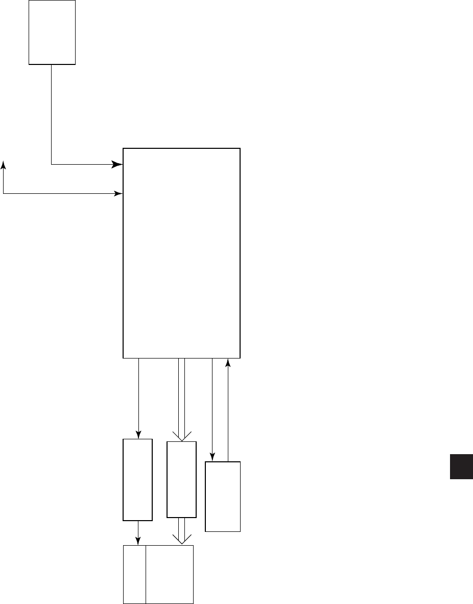
FORM 50.40-OM2
67YORK INTERNATIONAL
5
FIG. 30 – CONTROL CENTER
LD06742
POWER
SUPPLY
MICRO BOARD
KEYPAD
DISPLAY
INTERFACE
BOARD
LIQUID
CRYSTAL
DISPLAY
LAMP BACKLIGHT
INVERTER
BOARD
LAMP
CONTROL
ROW IN
COLUMN OUT
DISPLAY DATA
+12 / +5 VDC
RS-232 / RS-485 SERIAL DATA

YORK INTERNATIONAL68
MICROBOARD
(REFER TO FIG. 31 - 36)
The Microboard contains the operating software
(Program), microprocessor (Micro), and supporting
circuits for the Micro.
The Program is a set of instructions to control remote
chillers and the display. It also contains the Display
messages and screens. It is stored in a memory device
called a ash memory card. This is a type of nonvolatile
memory that can be read from or written to, but requires
the locations to be erased before they are written to. With
the exception of a write/read sequence that occurs during
the Boot-up process explained below, this device is used
primarily as read-only in this application. A write protect
switch is located on the left edge of the card as shown in
Fig. 32. It must be placed in the “Write Enabled” position
in order to allow successful Boot-up. The card is located
in socket location U46 (Ref. Fig. 31). It connects to the
Board via an Elastomeric connector that is a silicon rubber
strip embedded with silver conductors. The Card can
be removed from its socket by using the thumb to press
down on the socket’s plastic tension spring. The card
is installed by inserting it into the socket/holder and
pressing on the surface of the Card until it snaps into
place. The Memory card is a replaceable component.
Refer to the YORK Renewal Parts List. The version of
the Memory card is an alphanumeric code that represents
the application and revision level. The version is printed
on a label adhered to the memory card’s surface. The
version code is as follows:
The Micro monitors and controls the chiller by reading
and executing the Program instructions in a sequence
determined by the Program. Under Program control, the
Micro communicates with the chillers via RS-485 serial
communications to determine the operating conditions.
As operating conditions require, status messages are
retrieved and displayed. The Keypad is read as Digital
Inputs. When an operator presses a key to request a
display, the Micro interprets the request, retrieves the
display from the Program and displays it. The Program
assembles data in the correct format for transmission
through the Serial Data Ports to the chiller(s) and
peripheral devices. The Program also instructs the Micro
to respond to requests from peripheral devices for serial
data transmissions.
The Mux (multiplexer) is a switching device that only
allows one analog input through at a time. The inputs
are selected sequentially by the Micro per Program
instructions.
The A/D Converter converts each analog input to a
12-bit word. In this form, the values can be stored in
memory devices, compared to values in the Program,
transmitted through Serial Ports or sent to the Display
Controller for display. Control signals to start conversion
process are from the Micro via the FPGA.
The Watchdog circuit monitors the +5VDC supply from
the Power Supply to determine when a power failure is
occurring. Just prior to the supply decreasing to a level
where the Micro and supporting circuits can no longer
operate, it applies a reset signal to the Micro. The Micro
responds by shutting down the remote control center and
retrieving the Power Failure message from the Program
and sending it to the Display Controller for display.
Similarly, when power is first applied after a power
failure, it maintains the Micro in a reset state until the
+5VDC has returned to a sufcient level. The Watchdog
circuit also assures that all the Program instructions are
being performed and that the Program has not latched-up,
bypassing important safety thresholds. If the Program
has latched-up, the Micro displays WATCHDOG –
SOFTWARE REBOOT message.
The Program Jumpers (Table 2) and Program Switches
(Table 3) are used to alter the Program operation or
congure the Microboard hardware for specic operation.
This allows the Program and Microboard to be universal
for all applications. Refer to Table 2 and 3 for the function
of each jumper and switch. The position of some can be
determined and set by the Service Technician to meet the
desired operation. The position of others is dictated by the
size, type or style of certain Control Center components
and thus the position is determined by the YORK Factory.
The required position of each is listed in these tables. The
Program Jumpers are wire bridges that are either left in
place or cut. The Program Switches are miniature switches
that are placed in either the ON or OFF position.
C. RCC. 01. XX.
Revision level. Increments 00, 01 etc.
Product Code for OptiView RCC
Remote Control Center
Commercial
Service

FORM 50.40-OM2
69YORK INTERNATIONAL
The DRAM (dynamic random access memory) is a
non battery-backed memory device. The Micro stores
data here temporarily for further processing. Data
in this device is lost during power failures. DRAM
differs from RAM in that DRAM must be periodically
refreshed in circuit.
The BIOS EPROM (basic input/output system erasable
programmable read only memory) is a memory device
that contains the bootstrap or power-up program. It
is located in socket location U45. This EPROM is
replaceable. Refer to the YORK Renewal Parts List.
The EPROM version is an alphanumeric code that
represents the application and revision level. The
version is printed on a label adhered to the EPROM’s
surface. The version code is as follows:
When power is applied to the Control Center following
a power failure, the Micro executes the instructions
in the BIOS EPROM program to initialize, congure
and start operation of certain Microboard components
before the main program (stored in the Flash Memory
Card) is started. Depending upon the application, the
Microboard could be equipped with an EPROM that
has either 128K, 256K or 512K capacity. Microboard
Program Jumper JP38 must be positioned according to
the actual EPROM installed. Refer to Table 2 (Program
Jumpers). There are 5 steps to the boot-up process.
During the boot-up process, there is a visual indication
as each step is performed, followed by a Pass/Fail
status of the step. On the Microboard, a green LED
ashes to indicate the step was successful. If a step
is unsuccessful, a red LED ashes and the Boot-up
process terminates. The execution and Pass/Fail status
of steps 3 through 5 are displayed on a white Keypad
Display Screen as they are performed. This white
display screen also lists the BIOS EPROM Version.
The steps of the Boot-up process are as follows. Also,
below is listed the LED activity associated with each
step.
BOOT-UP STEP AND DESCRIPTION
1. First initiate table complete.
Registers in the Micro are congured to allow it to
perform basic memory read/write functions.
2. FPGA conguration.
The Field Programmable Gate Array (FPGA) is
congured to process Digital Inputs and Outputs.
3. Mini-card signature test.
A location in the Flash Memory Card that contains
a code identifying the Manufacturer is compared to
other locations that contain the manufacturer’s name.
If these values are the same, it is pass. If they are
different, it is fail.
4. Mini-card checksum.
The Flash Memory Card checksum is calculated and
compared to the checksum value that is stored in the
Card at the time the Card was initially programmed
at the YORK factory. If both values are the same, it is
considered pass. If the calculated value is different than
the stored value, it is considered fail.
5. BRAM quick test.
Test data is written to and then read from several
memory locations to verify BRAM operation.
LED INDICATORS
When power is applied to the Control Center, both
the red and green LED’s simultaneously illuminate
for 1 second, then the Boot-up process begins in the
following sequence (Note: While one LED ashes the
other is off.). When all steps have been completed, both
the green and the red LED’s illuminate and remain
illuminated.
STEP PASS FAIL
1 Green on, Red off Watchdog will
initiate a re-boot.
2 Green ash once Boot-up process halts.
One red ash repeating
3 Green ash once Boot-up process halts.
Two red ashes repeating
4 Green ash once Boot-up process halts.
Three red ashes repeating
5 Green ash once Boot-up process halts.
Four red ashes repeating
C. MLM. 00. XX.
Revision level. Increments 01, 02 etc.
OptiView BIOS EPROM
MILLENNIUM
Commercial
5

YORK INTERNATIONAL70
The BRAM (battery backed random access memory) is
a memory device that contains a battery that preserves
the data during power failures. It is a replaceable part.
Refer to the YORK Renewal Parts List. It is located
in socket location U52. The Micro stores the setpoints
programmed by the Operator or Service Technician,
History Data and other data that requires preservation,
in this device. Also, the day of week, time of day and
calendar date time-keeping are done here.
The keypad is a matrix of conductors arranged in rows
and columns (ref. Fig. 45 & 46). There are 4 rows
and 8 columns. When a key is pressed, the conductors
are pressed together at that point, creating continuity
between that row conductor and the column conductor.
The Keypad is read by applying a logic low to a row
while leaving +5VDC pullup on all the other rows. The
Micro then reads the 8 columns. If any column has a
logic low on it, the key corresponding to that coordinate
(row, column) is being pressed. The Micro reads the
entire Keypad by repeating this routine beginning
with row 1 and ending with row 4. The entire Keypad
is read every Program cycle. The Micro selects the
MUX inputs (Microboard J7, J8, J9) for input to the
A/D Converter by writing sequential addresses to the
FPGA. The FPGA holds each address until a new one
is received from the Micro. As each address is applied
to the MUX, the input corresponding to that address
is passed through the MUX to the A/D Converter.
The A/D Converter will convert the analog value to a
digital word when the Micro writes a “start conversion”
pulse to the FPGA. The FPGA passes this to the A/D
Converter. The Micro allows access to the PC-104
port (Microboard J16, J17) by writing an enable
pulse to the FPGA. The FPGA applies this to the data
transceiver, allowing data to be output to or input from
the PC-104 Port.
To provide flexibility for future Analog Inputs (to
Microboard J7), 2 analog inputs can be congured for either
0-10VDC or 4-20mA, Transducer or Thermistor inputs
using Program Jumpers JP21 and JP22. The position of the
jumper determines which type of input can be connected.
Refer to Fig. 36 and Table 2, “Program Jumpers”.
These inputs are for future YORK
Factory expansion use only. They
are not general application spare
inputs that will support arbitrarily
installed devices. Devices CANNOT
be connected to these inputs until
the program has been modified to
read and process the input. Unless
YORK documentation shows a device
connected to the input with a dened
function, the input cannot be used.
The Microboard receives 2 supply voltages (Microboard
J1) from the Power Supply; +12VDC, +5VDC and
Ground. The +12VDC and +5VDC are input to Voltage
Regulators to derive other regulated voltages. The
+5VDC is input to a +3.3VDC regulator. The output is
a 3.3VDC regulated voltage. The +12VDC is input to
a 5VDC regulator. The output of this regulator powers
only the Analog circuits. This includes the MUX, A/D
converter, and Thermistors. As depicted on Fig. 33,
these voltages can be monitored at Test Posts TP1
through TP6.
The Microboard is equipped with 5 Serial Data Ports
(ref. Fig. 35). Connector J2 is shared with both COM
1 and COM 4B. Each Port is dedicated for a specic
function as follows:
a. COM 1 (J2) - RS-232. Printer.
b. COM 2 (J13) - RS-232. Not Used.
c. COM 3 (J12) - RS-485. Chiller panel communica-
tions .
d. COM 4 (4A-J11), (4B-J2) - This port is actually two
ports. However, they cannot be used simultaneously;
only one of these ports can be connected to a device
at a time. The position of Microboard Program
Jumper J27 determines which port can be used
(refer to Table 2). COM 4A (J11) is an RS-485
port that is used for Multi-Unit Communications.
COM 4B (J2) is an RS-232 port that is used for
MicroGateway.
e. COM 5 (J15) – Not Used.
Service

FORM 50.40-OM2
71YORK INTERNATIONAL
COM 1 is connected directly to the Micro. COM
2 through 5 are connected directly to the UART
(Universal Asynchronous Receive Transmit). The
UART converts the parallel data to serial form for
transmission to the peripheral device and converts the
incoming serial data to parallel form for use by the
Micro. It also generates and processes control signals
for the Modem communications (DTR, CTS, DSR,
RTS). Under Program control, the Micro instructs the
UART of the desired data transmission Baud rate. A
crystal oscillator provides the frequency reference.
Each port is equipped with two LED’S; a red one
indicates when data is being transmitted to the remote
device and a green one indicates when data is being
received from the remote device. The RS-232 output
voltages are industry standard +3 to +15VDC, with
+9VDC typical. The RS-485 output voltages are
industry standard +1.5 to +5VDC, with +2.5VDC
typical. A loopback diagnostic test can be performed
on each serial port. This test permits verication of
the data transmitted from the serial port. Refer to the
“Serial Inputs / Outputs Tests” description in this book
for details of these tests. The graphic screens that are
displayed on the Liquid Crystal Display are created
from preformed graphics and messages that are stored
in the Program (FLASH Memory Card), and real-time
system operating parameters, such as temperatures.
The graphics, message and number data are in the form
of digital words. The Display Controller converts this
data into display drive signals and sends them to the
Display from Microboard J5. The Display has 307,200
pixels arranged in a 640 columns x 480 rows matrix
conguration. Each pixel consists of 3 windows; red,
green and blue, through which a variable amount of
light from the Display backlight is permitted to pass
through the front of the display. Imbedded in each
window of the pixel is a transistor, the conduction of
which determines the amount of light that will pass.
The drive signal determines the amount of conduction
of the transistor and therefore the amount of light
passed through the window. The overall pixel color
becomes a result of the gradient of red, green and blue
light allowed to pass. The drive signal for each pixel is
an 18 bit binary word; 6 for each of the 3 colors, red,
green and blue. The greater the binary value, the greater
the amount of light permitted to pass. The pixels are
driven sequentially from left to right, beginning with
the top row. To coordinate the drive signals and assure
the pixels in each row are driven sequentially from
left to right and the columns are driven from top to
bottom, each drive signal contains a horizontal and
vertical sync signal.
The Display DRAM is a memory device that supports
the operation of the display controller. This device
could be either of two types; FPM (fast page mode) or
EDO (extended data out) type. Program Jumper JP6
must be positioned according to the type of DRAM
device installed in the Microboard; JP6 in - EDO,
out - FPM. Refer to Table 2, “Program Jumpers”.
Depending upon the requirement, there could be one
or two DRAM devices installed in the Microboard.
If the design requires only one DRAM, it is installed
in socket U27. If an additional one is required, it is
installed in socket U25.
During the power-up sequence, the program in the
BIOS EPROM reads Program Jumper JP6 to determine
the type of Display DRAM installed (as explained
above). It also reads wire jumpers PID0 through PID3
(via Microboard J5) on the Display Interface Board
to determine the manufacturer of the display (refer to
description of Display Interface Board). Each display
manufacturer requires a slightly different control.
The program in the BIOS EPROM then congures
the Display Controller for operation with the actual
display that is present.
Different Display manufacturers can require different
supply and control voltages for their displays and
backlights. Program Jumpers JP 2 through 4 and 5
through 8 must be congured to provide the required
supply and control voltages to the display and backlight
control. Table 2 lists the required Program Jumper
conguration for the Display. Also, a label attached to
the Display mounting plate lists the required Program
Jumper conguration for that particular Display.
The power supply voltage that operates the Display
is provided by the Microboard J5. The position of
Program Jumper JP2 determines whether this supply
voltage is +5VDC or +3.3VDC. The Display requires a
specic power-up and power-off sequencing to prevent
damage. During power-up, the supply voltage must
be applied to the Display before the drive signals are
applied. Similarly, during power-off sequencing, the
display drive signals must be removed prior to removing
the supply voltage. The Display Controller applies the
supply voltage and data drive signals to the Display in
the proper sequence. The Display Controller controls
the Display Backlight by applying control signals
(from Microboard J6) to the Backlight Inverter Board.
The Backlight Inverter Board converts low voltage
DC (+12VDC or +5VDC, depending on position of
5

YORK INTERNATIONAL72
Program Jumper JP5) to high voltage AC (500 to
1500VAC). This high voltage AC is applied to the lamp
to cause it to illuminate. The Backlight is turned on
and off with the “Enable Backlight” (J6-5) signal. The
position of Program Jumper JP4 determines whether
this is a +12VDC or +5VDC signal. In some displays,
the Backlight turns on when this signal transitions
from low to high; others turn on when it transitions
from high to low. The position of Program Jumper
JP3 determines the transition that will occur when the
Display Controller outputs the “Enable Backlight”
signal. Program Jumper JP3 must be positioned accord-
ing to the Display manufacturer’s requirement.
Under Program control, the Display Controller controls
the Backlight brightness via the Lamp Dimmer circuit.
In order to extend the life of the backlight lamp, the lamp
brightness is driven to 50% brightness after 10 minutes
of Keypad inactivity. At this brightness level, the Display
can still be read. Subsequently, when Keypad activity is
detected (i.e. a Keypad key is pressed), the lamp is driven
back to full brightness (100% brightness). Some display
manufacturers require a variable voltage to vary the
brightness; others require a variable resistance. Program
Jumpers JP7 and JP8 allow either method to be used.
The Lamp Dimmer is an integrated circuit that is
the electrical equivalent of a 10K ohm potentiometer
with 100 positions or steps (ref. Fig. 34). The Display
Controller controls the position of the potentiometer. The
Lamp Dimmer varies the brightness of the Backlight
by applying either a variable voltage (0-5.0VDC) or
a variable resistance (0-10K ohms), to the Backlight
Inverter Board. If Program Jumpers JP7 and JP8 are
installed, the Lamp Dimmer output is a variable voltage;
if both are removed, the output is a variable resistance.
The Lamp Dimmer outputs “Brightness Control Wiper”
(J6-7) and “Brightness Control -“ (J6-8) to the Backlight
Inverter Board. If configured for variable voltage
output, the voltage between J6-7 and J6-8 can be varied
from 0 (100% brightness) to 5.0VDC (0% brightness). If
congured for variable resistance, the resistance between
J6-7 and J6-8 would vary from 0 ohms (0% brightness)
to 10K ohms (100% brightness).
The PC-104 Port (J16 & J17) is an industry standard
arrangement of two connectors that allows the stacking
of 3.6 x 3.8 inch printed circuit boards (PC-104
Modules) on the Microboard. The circuits on these
boards have access to the Microboard’s address/data bus,
and therefore become an extension of the Microboard.
This provides expansion of the Microboard’s capabili-
ties without redesigning or changing the size of the
Microboard. PC-104 Modules are not used in all
Remote Control Center applications.
System temperatures, in the form of analog DC
voltages from temperature thermistors, are input to
the MUX (multiplexers). Under Program control, the
Micro selects these values, one at a time, for input
to the Analog to Digital (A/D) converter. As each
one is selected, it is passed to the A/D Converter for
conversion to a 12-bit digital word that is then input in
parallel form to the Micro. The Micro stores each value
in the DRAM for display requests, further processing
or Serial Port transmission. Each value is also stored in
the BRAM for History data.
Service Replacement: Microboards are supplied as
Service Replacement parts without the following
components:
• BRAM (U52)
• Flash Memory Card (U46)
• BIOS EPROM (U45)
Upon receipt of the replacement Microboard, remove
these components from the Board being replaced
and install in the replacement Board. Although these
components have YORK Part Numbers as listed in
the Parts List and can be individually replaced, it is
recommended that these existing components be used
in the new Board since the BRAM memory device
contains all of the programmed setpoints.
Service
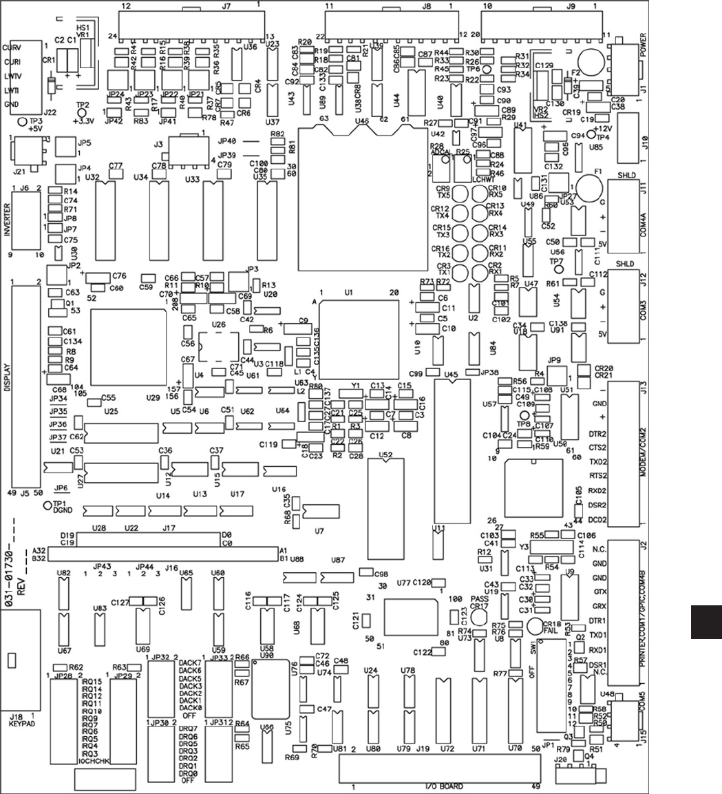
FORM 50.40-OM2
73YORK INTERNATIONAL
FIG. 31 – MICROBOARD
LD06743
FLASH
MEMORY
CARD
BIOS EPROM
BRAM
RS485
Driver
RS485
Driver
5
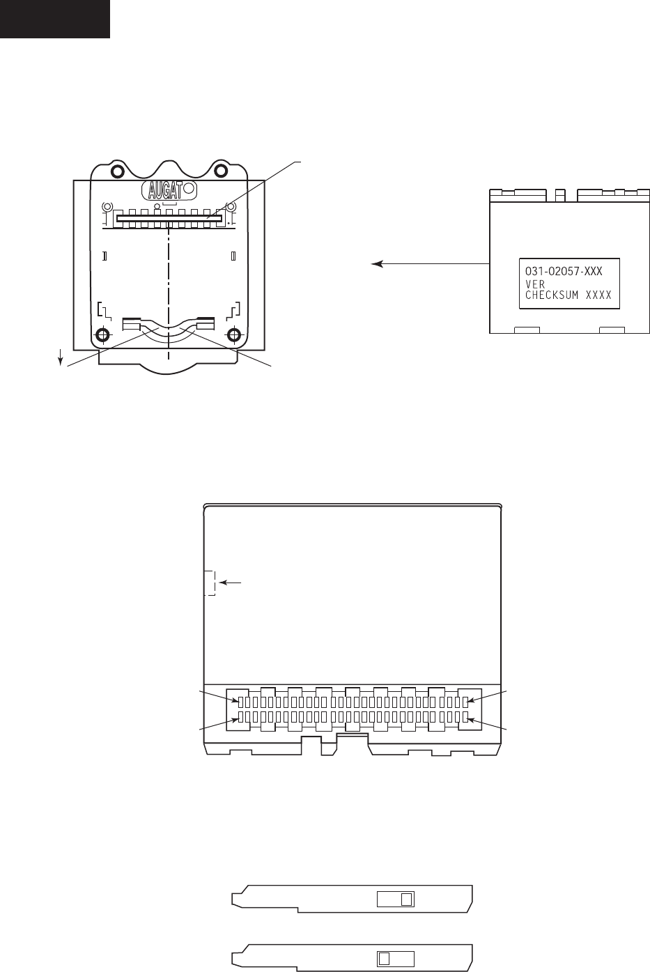
YORK INTERNATIONAL74
R
AUGAT
R
MEMORY CARD
RETAINER CLIP
PRESS DOWN
TO RELEASE CARD
ELASTOMERIC
CONNECTOR
FIG. 32 – FLASH MEMORY CARD
LD06745
LD06746
LD06744
MEMORY CARD SOCKET
MEMORY CARD -
TOP SURFACE
MEMORY CARD - BOTTOM SURFACE
MEMORY CARD - SIDE VIEW
TOP SURFACE
WRITE PROTECT SWITCH (OPTIONAL)
(MUST BE IN "ENABLED POSITION")
CINSCINS GND
VCC 3V/5V
KEY
ALIGNMENT
NOTCH
PAD 60
PAD 30
PAD 31
PAD 1
WRITE ENABLED
WRITE DISABLED
LD06747
Service
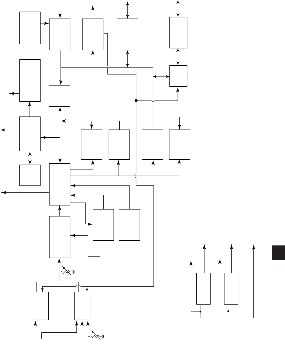
FORM 50.40-OM2
75YORK INTERNATIONAL
FPGA
MUX
MUX
A/D
CONVERTER
WATCH-
DOG
PROGRAM
SWITCHES
MICRO
DRAM DISPLAY
CONTROLLER
DRAM
FLASH
EPROM
BIOS
EPROM
BRAM XCVR PC-104
PORT
UART
INPUT
BUFFER
PROGRAM
JUMPERS
BACKLIGHT
CONTROL
DATA
BUS
XCVR
SERIAL DATA
PORT 1
DISPLAY INTERFACE
BOARD
BACKLIGHT INVERTER
BOARD
DIGITAL
INPUTS
DIGITAL
OUTPUTS
SERIAL
DATA PORTS
2 THROUGH 5
ANALOG
INPUTS
+5VDC REF
LVG CHILLED
WATER TEMP R25
R28
VOLTAGE
REG
VOLTAGE
REG
+ 12VDC
+ 5VDC
GND
Y
Y
Y
Y
TP2
TP1
TP4
TP3
+ 12VDC
+ 5VDC (ANALOG)
+ 5VDC (DIGITAL)
+ 3.3VDC
FROM
POWER
SUPPLY
FIG. 33 – MICROBOARD
LD06748
5

YORK INTERNATIONAL76
TABLE 2 – MICROBOARD PROGRAM JUMPERS
MICROBOARD PROGRAM JUMPERS
JP1 - Watchdog enable/disable. The position of this
jumper, in conjunction with Program switch SW
1 position 12 enables or disables the program
Watchdog protection.
Never disable the watchdog protec-
tion. Severe compressor or chiller
damage could result. The ability to
disable the watchdog protection is
provided for factory testing only!!!
IN - Watchdog protection enabled.
OUT - Permits Program switch SW1 position 12 to
enable or disable the program
Watchdog protection as follows:
Position 12 ON - Watchdog protection enabled
OFF - Watchdog protection disabled
JP2 - Display power and logic levels. Determines the
power supply voltage applied to the display.
Pins 1-2: +5VDC SHARP LQ10D367
Pins 2-3: +3.3VDC LG Semicon LP104V2
displays.
If this jumper is not correctly installed
the display could become damaged.
JP3 - Display backlight enable signal level polarity.
Jumper must be positioned according to the
voltage level required to turn on the Display
Backlight.
Pins 1-2: 0VDC (Not used)
Pins 2-3: +12VDC or +5VDC as determined
by position of JP4. SHARP LQ10D367 and LG
Semicon LP104V2 displays.
JP4 - Display backlight enable signal logic levels.
Determines the logic levels of the Backlight
enable signal.
Pins 1-2: +12VDC/0VD (Not used)
Pins 2-3:+5VDC/0VDC LG Semicon LP104V2
displays.
JP5 - Display backlight power. Determines the power
supply voltage applied to the Display Backlight
Inverter Board.
Pins 1-2: +12VDC. SHARP LQ10D367 and
LG Semicon LP104V2 displays.
Pins 2-3: +5VDC. (Not used)
JP6 - Display memory type. Jumper must be posi-
tioned according to type of RAM used for
display memory devices (U25 & U27).
IN - EDO: (extended data out) type. Jumper
should be IN.
OUT - FPM: (fast page mode) type. Not used
at this time.
JP7, JP8 - Display brightness control technique.
Determines whether the display brightness is
controlled by a variable voltage or variable
resistance.
IN: Variable voltage (0-5.0VDC). SHARP
LQ10D367 and LG Semicon LP104V2 displays.
OUT: Variable resistance. (Not used)
JP9 - COM 2 serial communications port. Congures
COM 4 port to be either RS-485 or RS-232.
Pins 1-2: RS-232
Pins 2-3: RS-485
JP10 - JP26 - Not used.
Service

FORM 50.40-OM2
77YORK INTERNATIONAL
JP27 - COM 4 serial communications port. Congures
COM 4 port to be either RS-485 for Multi-Unit
Communications (COM 4A) or RS-232 for
MicroGateway board (COM4B).
Pins 1-2: Enables port 4A. Allows an RS-485
connection to Microboard J11 for MultiUnit
Communications.
Pins 2-3: Enables port 4B. Allows an RS-232
connection to Microboard J2 for MicroGateway
communications.
JP28 - PC-104 Port interrupt assignment. Assigns
selected PC-104 interrupt request to PDRQ7 on
the microprocessor. Interrupt request selections
are silk screened on the Microboard adjacent to
the program jumper. Not used.
JP29 - PC-104 Port interrupt assignment. Assigns
selected PC-104 interrupt request to PDRQ6
on the microprocessor. Interrupt request selec-
tions are silk screened on the Microboard
adjacent to the program jumper. Future modem
application.
JP30 - PC-104 Port DMA assignment. Assigns selected
PC-104 DMA request to PDRQ0 on the micro-
processor. DMA request selections are silk
screened on the Microboard adjacent to the
program jumper. Not used.
JP31 - PC-104 Port DMA assignment. Assigns selected
PC-104 DMA request to PDRQ1 on the micro-
processor. DMA request selections are silk
screened on the Microboard adjacent to the
program jumper. Not used.
JP32 - PC-104 Port DMA acknowledge assignment.
Assigns selected PC-104 DMA acknowledge
to PDACK0 on the microprocessor. DMA
acknowledge selections are silk screened on the
Microboard adjacent to the program jumper.
Not used.
JP33 - PC-104 Port DMA acknowledge assignment.
Assigns selected PC-104 DMA acknowledge
to PDACK1 on the microprocessor. DMA
acknowledge selections are silk screened on the
Microboard adjacent to the program jumper.
Not used.
JP34, JP35, JP36, JP37 - Not Used
JP38 - BIOS EPROM U45 size. Jumper must be
positioned according to size of U45. Jumper is
a 10 Ohm resistor that is soldered to board. It
is not a shunt jumper.
IN: 512K
OUT: 128K or 256K. Should be OUT for
OptiView Remote Control Center applications.
JP39, JP40, JP41, JP42 - Not used.
5
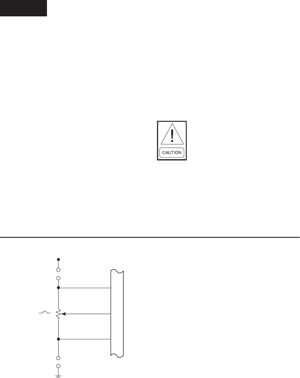
YORK INTERNATIONAL78
5 - 11 Not Used
12 - Watchdog Protection -Used in conjunction with
Program Jumper JP1 (see above) to enable/disable
the program watchdog protection. With JP1
IN, this switch setting has no effect. With JP1
OUT, this switch setting determines whether the
watchdog protection is enabled or disabled.
NEVER disable the watchdog protec-
tion! Severe compressor or chiller
damage could result. The ability to dis-
able the watchdog protection is provided
for YORK factory testing only.
ON: Watchdog protection enabled.
OFF: Watchdog protection disabled.
SW1
1 - Simulator mode - When this switch is closed
or in the ON position, the RCC simulates the
data from 4 chillers and will not communicate
with any attached units.
ON: Simulator mode enabled. Used for dem-
onstration.
OFF: Simulator mode is disabled. The unit
must be powered on with the switch in this
position for the RCC to communicate with
attached units and operate normally.
2 - Not Used
3 - Not Used
4 - Diagnostics - Enables or disables software
diagnostics
ON: Enables software diagnostics. Disables
normal control center operation
OFF: Disables software diagnostics. Enables
normal control center operation.
TABLE 3 – MICROBOARD PROGRAM SWITCHES
NOTES:
1. J6-6 not connected (N.C.) to Backlight Inverter Board when display is manufactured by Sharp or NEC.
2. The position of Program Jumpers JP7 & JP8 determine the output at J6-7; In = Variable Voltage; Out = Variable Resistance. Refer to
Program Jumper Listing in Table 2 for applications.
3. Potentiometer is actually an integrated circuit that is the electrical equivalent of a 10K potentiometer.
FIG. 34 – MICROBOARD LAMP DIMMER CIRCUIT
6
7
8
J6
BRIGHTNESS CONTROL (+) OR (N.C.)
BRIGHTNESS CONTROL (WIPER)
BRIGHTNESS CONTROL (-)
TO
BACKLIGHT
INVERTER
BOARD
JP8
JP7
5.0 VDC
10 K
LD04054
Service
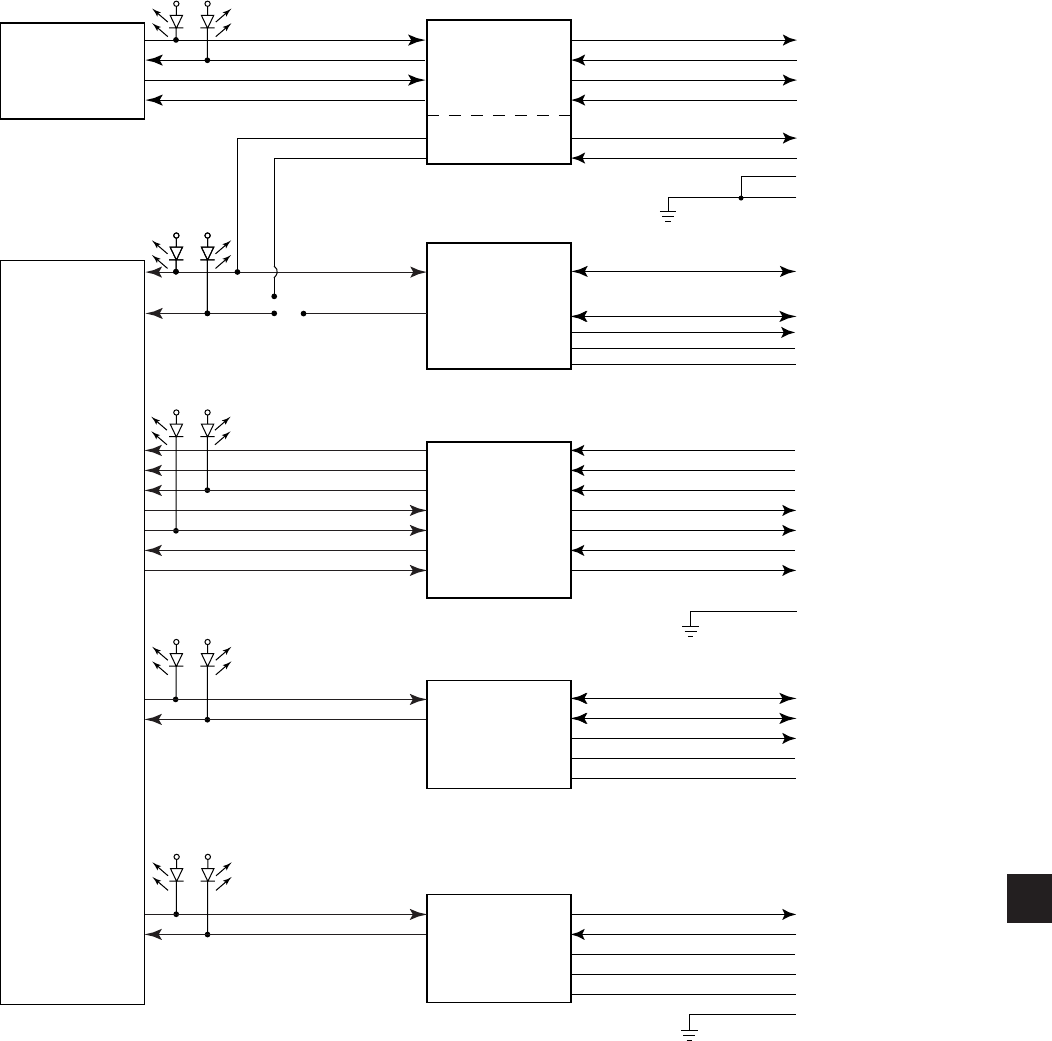
FORM 50.40-OM2
79YORK INTERNATIONAL
FIG. 35 – MICROBOARD SERIAL DATA COMMUNICATIONS PORTS
LD06749
NOTE:
1. Microboard Program Jumper JP27 determines whether COM 4A or 4B can be used. 1 & 2 - 4A, 2 & 3, 4B. Refer to Table 2.
MICRO
UART
COM 1
COM 4B
(NOTE 1)
COM 4A
(NOTE 1)
COM 2
COM 3
COM 5
OPTO-COUPLE
RS-485
RS-232
RS-485
RS-232
MICROGATEWAY
PRINTER
NOT USED
NOT USED
CONNECTION
TO CHILLER /
CONDENSING
CONTROL PANELS
NOT USED
4
3
5
2
7
6
8
9
3
2
1
4
5
1
2
3
4
5
6
7
9
3
2
1
4
5
1
2
3
4
5
6
J2
J11
J13
J12
J15
TX
RX
COMMON
NOTE 2
NOTE 2
+
--
+ 5VDC
GND
SHIELD
DCD
DSR
RX
RTS
TX
CTS
DTR
GND
--
+ 5VDC
GND
SHIELD
+
TX
RX
DTR
DSR
GTX
GRX
12
3
TX1 RX1
TX4 RX4
TX2 RX2
TX3 RX3
TX5 RX5
JP27
5
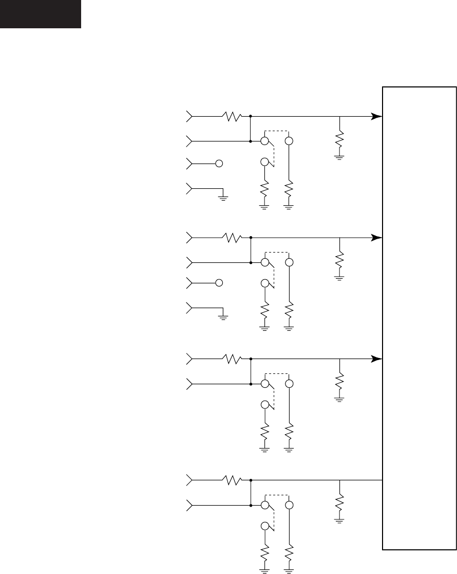
YORK INTERNATIONAL80
FIG. 36 – CONFIGURABLE ANALOG INPUTS
LD04636
NOTE:
1. Program Jumpers JP21 – JP24 must be positioned on pins 1-2 or 3-4 according to input signal type. Refer to Table 2.
NOT USED
NOT USED
NOT USED
NOT USED
0 10 VDC
4 - 20 MA
0-10 VDC
4 - 20 MA
4
3
1
2
16
4
14
2
13
1
MUX
47K
JP21
JP22
JP23
JP24
200
7.5 K
1
2
3
1
2
3
1
2
3
1
2
3
71.5 K
+5V
3
15 +5V
J7
J22
0-10 VDC /
0 - 20 MA /
2-10 VDC
4 - 20 MA
0-10 VDC /
0 - 20 MA /
2-10 VDC
4 - 20 MA
Service

FORM 50.40-OM2
81YORK INTERNATIONAL
LIQUID CRYSTAL DISPLAY
(REFER TO FIG. 37 - 42)
A 10.4 inch color Liquid Crystal Display, along with
supporting components Display Interface Board and
Backlight Inverter Board are mounted on a plate that
is attached to the OptiView Control Center door. A clear
plexiglass faceplate prevents display surface damage.
System operating parameters are displayed on various
color graphic screens. The various display screens are
selected for display using the Keypad keys.
The Display provided in the OptiView RCC or from
YORK as a service replacement part, could be manufac-
tured by any of several approved manufacturers. Each
Display requires a specific Display Interface Board,
Backlight Inverter Board, Inverter Board interface cable
and Program command set. Therefore, Service replace-
ment Displays or supporting components cannot be
arbitrarily selected!!! As explained below, replacement
Displays are provided from YORK as kits to assure
compatibility of all components. Non-compatibility of
components will result in incorrect operation!!! Refer
to “Display Interface Board” and “Backlight Inverter
Board” descriptions that follow. The following displays
could be provided from YORK in new OptiView RCCs
or as replacement parts:
• LG SEMICON LP104V2
• SHARP LQ10D367
The YORK part numbers of the Display Interface Board,
Backlight Inverter Board and Inverter ribbon cable provided,
are listed on a label attached to the Display mounting plate.
These are the part numbers of the supporting components
that are compatible with the installed display. These
supporting components can be individually replaced.
However, if the Liquid Crystal Display fails, Display
replacement kit 331-02053-000 must be ordered as detailed
below. This kit contains a replacement Display and all
compatible supporting components.
The Display has 307,200 pixels arranged in a 640 columns
X 480 rows matrix conguration. Each pixel consists of
3 windows; red, green and blue, through which a variable
amount of light from the Display Backlight is permitted
to pass through the front of the display. Imbedded in
each window of the pixel is a transistor, the conduction
of which determines the amount of light that will pass
through the window. The conduction of each transistor
is controlled by a signal from the Display Controller on
the Microboard. The overall pixel color is a result of the
gradient of red, green and blue light allowed to pass.
Under Program control, the Display Controller on the
Microboard sends a drive signal for each pixel to create
the image on the display. Each pixel’s drive signal is an
18 bit binary word; 6 bits for each of the 3 colors, red
green and blue. The greater the binary value, the greater
the amount of light permitted to pass. The columns of
pixels are driven from left to right and the rows are
driven top to bottom. To coordinate the drive signals
and assure the columns are driven from left to right and
the rows are driven from top to bottom, each drive signal
contains a horizontal and vertical sync signal. The
Display Interface Board receives these display drive
signals from the Microboard J5 and applies them to the
Display at connector CN1. Refer to Fig. 43.
Although there are variations in control signal timing
between different display manufacturers, Fig. 38 depicts
typical control signals. Since these control signals occur
at rates greater than can be read with a Voltmeter, the
following description is for information only. There are
480 horizontal rows of pixels. Each row contains 640
3-window pixels. Beginning with the top row, the drive
signals are applied within each row, sequentially left
to right, beginning with the left most pixel and ending
with the right most pixel. The rows are driven from top
to bottom. The Vertical Sync (VSYNC) pulse starts the
scan in the upper left corner. The rst Horizontal Sync
(HSYNC) pulse initiates the sequential application of
RGB drive signals to the 640 pixels in row 1. Upon
receipt of the ENABLE signal, an RGB drive signal
is applied to the rst pixel. As long as the ENABLE
signal is present, RGB drive signals are then applied to
the remaining 639 pixels at the CLK rate of 25.18MHz,
or one every 39.72 nanoseconds. Typically it takes 31
microseconds to address all 640 pixels. Similarly, the
next HSYNC pulse applies drive signals to row 2. This
continues until all 480 rows have been addressed. Total
elapsed time to address all 480 rows is approximately 16
milliseconds. The next VSYNC pulse causes the above
cycle to repeat. Displays can be operated in FIXED
mode or DISPLAY ENABLE mode. In FIXED mode,
the rst pixel drive signal is applied a xed number
(48) of clock (CLK) cycles from the end of the HSYNC
pulse and the drive signals are terminated a xed number
(16) of CLK cycles prior to the next HSYNC pulse.
In DISPLAY ENABLE mode, the pixel drive signals
are applied to the pixels only while ENABLE signal is
present. This signal is typically present 4-48 CLKS after
the end of the HSYNC pulse and 2-16 CLKS prior
5

YORK INTERNATIONAL82
to the next HSYNC pulse. All YORK applications
operate in the DISPLAY ENABLE mode. The state of
the ENABLE (Display Interface Board J1-27) signal
from the Microboard places the Display in the desired
mode as follows:
• LG SEMICON Display does not have the xed
mode feature.
As described above, in OptiView Control Center
applications, the Display scan is left to right, beginning
with the top row and continuing sequentially through the
rows to the last row. However, in Display applications
other than OptiView Control Centers, image reversal is
sometimes required. In image reversal applications, the
scan is reversed; the scan is right to left, beginning with
the last row and proceeding to the top row.
Displays by different manufacturers can require
different timing and control signals. The Microboard
must know which Display is present in order to provide
the correct signals. Therefore, when AC control power
is rst applied to the OptiView Control Center, as part
of the power-up sequence, the Microboard reads the
Panel ID wire jumpers P1D0 - P1D3 on the Display
Interface Board and determines which Display is
present. It can then provide the correct timing and
control signals to produce the graphic image, as
required by the Display manufacturer. Since the
Display Interface Board identies the Display for
the Microboard, there is a different Display Interface
Board required for each Display application and each
has a unique jumper conguration that identies the
Display. A complete explanation of this process is
included in the preceding “Microboard” description
and the “Display Interface Board” description that
follows.
The DC power source to operate the Display is provided
by the Microboard J5. Some Display manufacturers
require +5VDC; others require +3.3VDC. The position
of Microboard Program Jumper JP2 determines which of
these power sources is supplied to the Display. JP2 must
be positioned according to the Display manufacturers
requirements. Refer to Table 2, “Program Jumpers”.
The Backlight Lamp provides the illumination for the
display. Average lamp life is 25000 hours (2.9 years).
Some displays use one lamp. Others use two lamps.
Lamps are replaceable, but not interchangeable between
different displays. Each Display manufacturer species
the required lamp for their display. Refer to replacement
parts list for appropriate replacement lamp. Service
replacement lamps are stocked in the YORK Service Parts
Distribution Center. The lamp is illuminated by applying a
high voltage AC (500 to 1500VAC) to it. This illumination
voltage is created from a low level DC voltage (+12VDC
or +5VDC as required by the Display manufacturer) by the
Backlight Inverter Board. Lamp brightness is controlled
by varying the high voltage AC. The greater the voltage
the brighter the illumination. The lamp is controlled by
on/off commands and brightness control signals applied
to the Backlight Inverter Board from the Microboard.
The Microboard Program determines when the lamp is
turned on and off and the lamp brightness. Each Display
manufacturer species the Backlight Inverter Board
to be used. Therefore, it will vary according to the
Display manufacturer. The ribbon cable that connects the
Microboard to the Backlight Inverter Board also varies
according to the Display manufacturer’s requirements.
Refer to Fig. 44. Microboard Program Jumpers JP3, 4,
5, 7 and 8 determine the voltage levels of the control
signals sent to the Backlight Inverter Board and must be
congured per the Display manufacturer’s requirements as
listed in Table 2. A detailed description of the operation of
this board is in the “Backlight Inverter Board” description
that follows. Also refer to the preceding “Microboard”
description for a detailed description of the Lamp
Dimmer circuit.
The actual Display that is installed in the OptiView
Control Center of the new chiller is determined by the
Display manufacturer contractual agreement in place
during the time of OptiView Control Center production.
Displays stocked for Service replacement are a result of
that same agreement. Therefore, the Display received for
service replacement may be by a different manufacturer
than the one in the OptiView Control Center. Since
each Display manufacturer requires a specic Display
Interface Board, Backlight Inverter Board and Inverter
Ribbon Cable, replacement Displays are ordered and
supplied as a Display Replacement Kit (YORK Part
Number 331-02053-000) to assure component compat-
ibility. The items supplied in the kit are compatible with
the supplied Display. The kit consists of the following
items mounted on a Display mounting plate:
Display Replacement Kit 331-02053-000:
1. Liquid Crystal Display with Lamp
2. Appropriate Display Interface Board for item 1
3. Appropriate Backlight Inverter Board for item 1
4. Appropriate ribbon cable (Backlight Inverter Board
to Microboard) for item 1
5. Ribbon cable (Display Interface Board to
Microboard)
6. All mounting hardware
7. Installation instructions. A label attached to the
Service

FORM 50.40-OM2
83YORK INTERNATIONAL
Display mounting plate lists the YORK part numbers
of the Display supporting components mounted
on the Display mounting plate and the required
Microboard Program Jumper (JP2 through 8)
congurations. Microboard Program Jumpers
JP2 - JP8 will have to be congured appropriately
for the replacement display. Refer to Table 2
“Program Jumpers”.
Display Handling:
1. The display is made of glass. It could break if
dropped.
2. The display front surface is easily scratched. If
soiled, wipe with a dry cotton cloth. Use no water
or chemicals.
3. The display is static sensitive. Electrostatic dis-
charges may damage the display.
4. A laminated lm is adhered to the display front
glass surface to prevent it from being scratched. Peel
off very slowly to prevent static damage.
Always remove control power from
the OptiView Remote Control Center
before connecting or disconnecting
wires to the display. Connecting or
disconnecting wires to the display
with power applied will damage the
display!!!
BACKLIGHT LAMP REPLACEMENT:
SHARP LQ10D367 Display: (Refer to Fig. 41)
Removal:
The Lamp slides into the Display from left to right and
is secured with a locking tab.
1. Remove Control Power from the OptiView Control
Center.
2. Remove protective cover from rear of Display.
3. Disconnect Lamp AC power connector from
Backlight Inverter Board.
4. Using ngernail or thin at blade screwdriver, bend
the locking tab outward slightly to clear the Lamp
housing protrusion.
5. Grasp Lamp AC power connector and gently pull
until Lamp housing clears locking tab.
6. Grasp Lamp housing and pull until Lamp housing is
completely removed from the Display.
Installation:
1. Slide new Lamp into Display from left to right
until Lamp housing protrusion locks into Display
locking tab.
2. Connect Lamp AC power connector to Backlight
Inverter Board.
3. Apply Control Power to OptiView Control Center.
LG Semicon LP104V2 Display (refer to Fig. 42)
Removal:
The Lamp slides into the Display from left to right and
is secured with a screw.
1. Remove Control Power from the OptiView Remote
Control Center.
2. Remove protective cover from rear of Display.
3. Disconnect Lamp AC power connector from Back-
light Inverter Board.
4. Using small Phillips screwdriver, remove lamp
retaining screw.
5. Grasp Lamp AC power connector and gently pull
until Lamp housing is completely removed from
the Display.
Installation:
1. Slide new Lamp into Display from left to right until
Lamp housing is fully inserted.
2. Secure Lamp with Lamp retaining screw.
3. Connect Lamp AC power connector to Backlight
Inverter Board.
4. Apply AC power to OptiView Remote Control
Center.
5
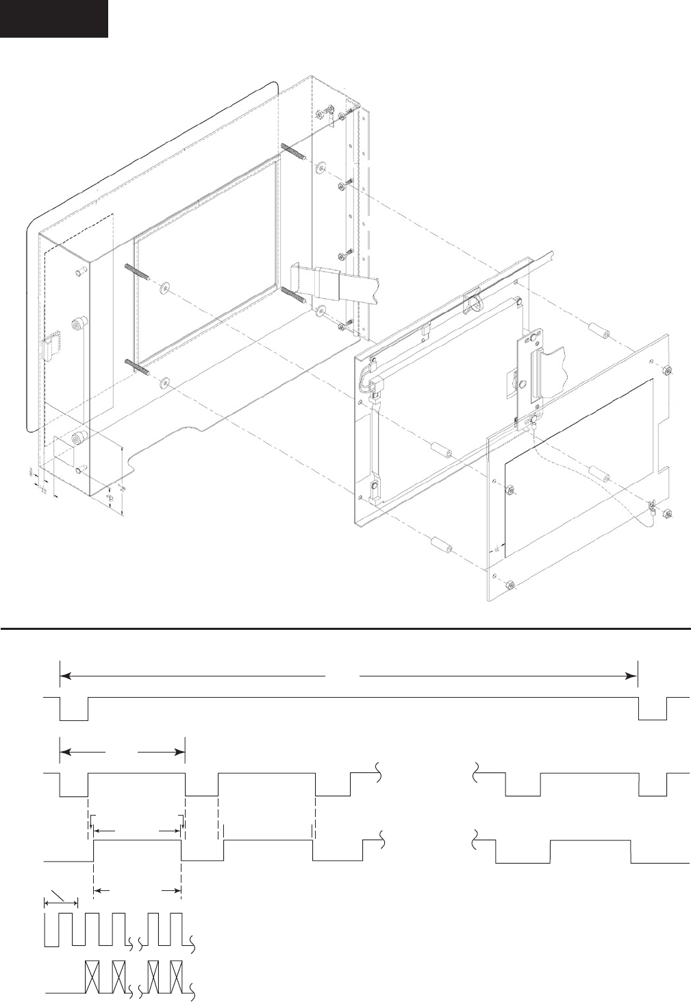
YORK INTERNATIONAL84
FIG. 37 – DISPLAY, MOUNTING
LD06751
FIG. 38 – LIQUID CRYSTAL DISPLAY TYPICAL CONTROL SIGNAL TIMING
LD04066
NOTES:
1. BP = Back Porch = 4-48 CLKS
2. FP = Front Porch = 2-16 CLKS
640 CLKS
640
COLUMNS
31US
VSYNC
480 ROWS
16MS
ROW 480
ROW 1 ROW 2
BP FP
DISPLAY
PERIOD
DISPLAY
PERIOD
DISPLAY
PERIOD
HSYNC
ENABLE
CLK
(25.18
MHz)
RGB
39.72 NS
Service
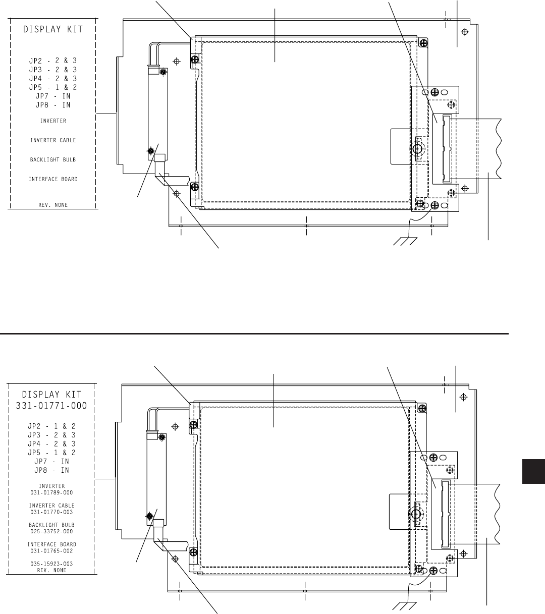
FORM 50.40-OM2
85YORK INTERNATIONAL
LIQUID CRYSTAL DISPLAY
SHARP LQ10D367
MOUNTING
PLATE
DISPLAY INTERFACE
BOARD 031-01765-002
DISPLAY CABLE
031-01769-000
INVERTER CABLE
031-01770-003
BACKLIGHT
INVERTER
BOARD
031-01789-000
LABEL
BACKLIGHT BULB
025-33752-000
FIG. 39 – LIQUID CRYSTAL DISPLAY ASSEMBLY - LG SEMICON LP104V2
LD06752
NOTE:
1. Congure Microboard Program Jumpers per label.
FIG. 40 – LIQUID CRYSTAL DISPLAY ASSEMBLY - SHARP LQ10D367
LD06753
NOTE:
1. Congure Microboard Program Jumpers
per label.
LIQUID CRYSTAL DISPLAY
LG SEMICON LP104V2
MOUNTING
PLATE
DISPLAY INTERFACE
BOARD 031-01765-001
DISPLAY CABLE
031-02055-000
INVERTER CABLE
031-02054-001
BACKLIGHT
INVERTER
BOARD
031-01789-000
LABEL
BACKLIGHT BULB
025-34564-000
331-02053-000
031-02054-001
035-17813-002
031-01789-000
025-34564-000
031-01765-001
5
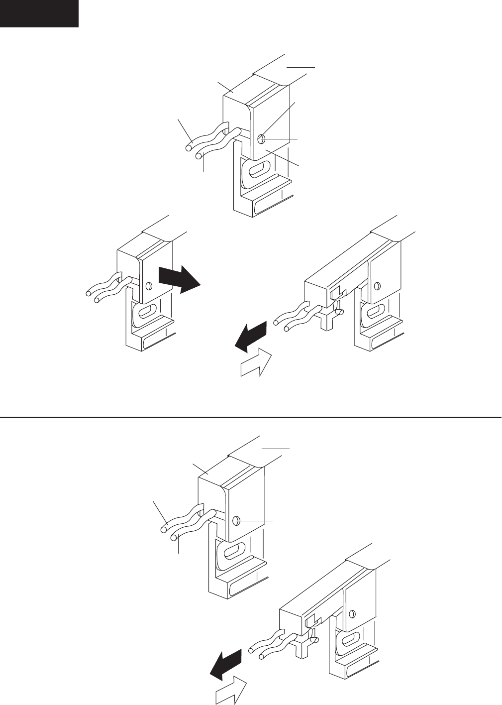
YORK INTERNATIONAL86
FIG. 42 – DISPLAY (LG SEMICON LP104V2) LAMP REPLACEMENT
LD06754
LAMP HOLDER
BEZEL
PROTRUSION
HOLE
LOCKING TAB
WIRE
(white/GND side)
WIRE
(pink/HOT side)
DIRECTION A
DIRECTION B
DIRECTION C
FIG. 41 – DISPLAY (SHARP LQ10D367) LAMP REPLACEMENT
LD04067
LAMP HOLDER
BEZEL
RETAINING SCREW
WIRE
(white/GND side)
WIRE
(pink/HOT side)
DIRECTION B
DIRECTION C
Service

FORM 50.40-OM2
87YORK INTERNATIONAL
DISPLAY INTERFACE BOARD
(REFER TO FIG. 43)
The Display Interface Board is located on the Liquid
Crystal Display mounting plate and is part of the
Microboard interface to the Display. It permits the use
of Displays by different manufacturers, by providing the
Microboard with a means of automatically determining
which Display is present.
Since different Display manufacturers require different
timing and control signals, the Display Controller on the
Microboard must be congured to meet the requirements
of the actual Display installed. When AC power is
applied to the OptiView Remote Control Center, as part
of the power-up sequence, the Microboard reads the
four Panel ID wire jumpers, PID0 through PID3, on the
Display Interface Board to determine which Display is
present. The conguration of these jumpers indicates the
actual Display that is installed on the OptiView Remote
Control Center door. The Display Controller on the
Microboard is then congured appropriately.
On Sharp displays the conguration of wire jumpers
P30 and P31 determines whether the Display scan
orientation is Normal or Reverse (image reversal) scan.
As described in the preceding “Display” description,
Normal scan is left to right, beginning with the top row
and continuing sequentially through the rows to the
bottom row. Normal scan is used in OptiView Remote
Control Center applications. In Display applications
other than OptiView RCC applications, image reversal
is sometimes required. In image reversal applications,
the scan is reversed; the scan is right to left, beginning
with the bottom row and proceeding to the top row.
The jumper congurations determine the voltage level
at Display Interface Board J1-30 (P30) and J1-31
(P31). If P30 is IN, the voltage at J1-30 is +5.0VDC or
+3.3VDC (as determined by position of Microboard
Program Jumper JP2); if OUT, 0VDC. If P31 is IN,
the voltage at J1-31 is GND; if OUT, 0VDC. The
Display reads these voltages and adopts a scan mode
as follows:
SHARP LQ10D367 & LQ10D421 Displays:
SHARP displays require conguration of both jumpers
to achieve total image reversal.
P30 IN - Normal scan; left to right
OUT - Reverse scan: right to left
P31 IN - Normal scan; top to bottom
OUT - Reverse scan; bottom to top
The wire jumpers on this board are not eld congu-
rable, as with typical Program Jumpers. There are two
variations of the Display Interface Board. Each board
has the wire jumpers congured appropriately for the
display to which it is attached, as shown below. Display
Interface Boards are available individually for service
replacement. The YORK part number of the Display
Interface Board compatible with the installed Display is
listed on a label attached to the Display mounting plate.
However, service replacement Displays are provided
as a kit (331-02053-000) that includes, among other
items, the appropriate Display Interface Board for
the Display included in the kit. Refer to explanation in
“Liquid Crystal Display” description.
031-01765-001:
Display applicability - LG Semicon LP104V2
Jumper conguration - PID0 - IN
PID1 - OUT
PID2 - OUT
PID3 - OUT
P30 - OUT
P31 - OUT
031-01765-002:
Display applicability - SHARP LQ10D367
Jumper conguration - PID0 - OUT
PID1 - IN
PID2 - OUT
PID3 - OUT
P30 - IN
P31 - IN
The red, green and blue display drive and control signals
are simply passed through the Display Interface Board.
The value of VCC is either +5VDC or +3.3VDC,
as determined by the position of Program Jumper
JP2 on the Microboard. PID0 through PID3, when
installed, connect their respective Microboard (J5)
inputs to GND; when removed, the Microboard pulls
these signals up to +5VDC. When P30 is installed, the
Display input (CN1-30) is connected to VCC (+5VDC
or +3.3VDC as determined by Microboard Program
Jumper JP2). When P31 is installed, the Display input
(CN1-31) is connected to GND.
5
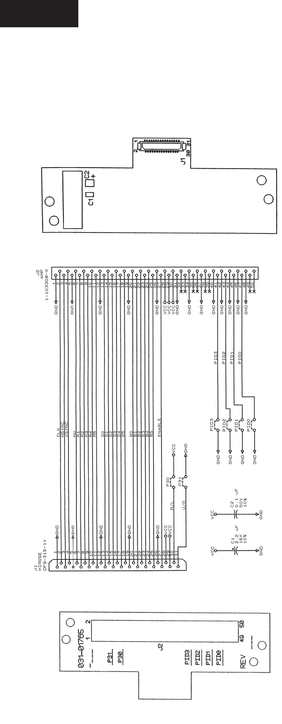
YORK INTERNATIONAL88
FIG. 43 – DISPLAY INTERFACE BOARD
LD04070
LG SEMICON LP104V2
031-01765-001 - PID0 IN
PID1-3 OUT
P30, P31 OUT
SHARP LQ10D367
031-01765-002 - PID0 OUT
PID1 IN
PID2, 3 OUT
P30, 31 IN
Service

FORM 50.40-OM2
89YORK INTERNATIONAL
DISPLAY BACKLIGHT INVERTER BOARD
(REFER TO FIG. 44)
The Display Backlight Inverter Board generates a
high voltage AC signal that is applied to the backlight
lamp, causing it to illuminate. The magnitude of the
signal determines the lamp brightness. Displays by some
manufacturers have two lamps; one at the top and one at
the bottom of the display. Other Display manufacturers
have only a lamp at the top of the display.
An Inverter converts low level DC voltage (+12VDC
or +5VDC, as required by the manufacturer) from the
Microboard to a 500 to 1500VAC 60KHz signal that
is applied to the lamp. The higher the AC voltage, the
greater the brightness of the lamp. When this voltage
is not present, the lamp is turned off.
High voltage, up to 1500VAC, is pres-
ent at the output of the backlight
inverter board. Refer to Figure 44
and locate the output connectors. Use
extreme caution when working in this
area!!!
Different Display manufacturers require different Backlight
Inverter Boards. The different board designs require different
control voltage inputs. To accommodate these variations,
Microboard Program Jumpers JP3 - JP5, JP7 and JP8 must
be congured to provide the required voltage levels. A label
attached to the Display mounting plate lists the required
Program Jumper conguration for that particular display.
Refer to Table 2 for required Program Jumper congurations
for the various Display applications.
Under Program control, the Microboard generates the
control signals that are applied to the Backlight Inverter
Board. The Program determines when the lamp is turned
on and off. It also adjusts the lamp brightness. To increase
the average lamp life of 25000 hours, the lamp brightness
is normally adjusted to 50%. This brightness level will
still allow the display to be visible. When the Program
senses a Keypad key has been pressed, it adjusts the
brightness to 100% (maximum).
The lamp illumination high voltage AC is generated
from either +12VDC or +5VDC as required by the
manufacturer. Microboard Program Jumper JP5 must
be positioned to provide the required voltage. The
Microboard provides the Backlight Enable signal. This
signal turns the lamp on and off. Some manufacturers
require this signal to be +12VDC, others require +5VDC.
Program Jumper JP4 must be positioned to provide the
required voltage. Further, some applications require this
signal to be a +VDC (+12VDC or +5VDC) to turn on
the lamp. Others require this signal to be 0VDC to turn
on the lamp. Program Jumper JP3 must be positioned to
provide the required polarity.
Depending upon the Display manufacturer, the brightness
control input from the Microboard must be either a variable
voltage or a variable resistance. Microboard Program
Jumpers JP7 and JP8 are used to provide the appropriate
technique (refer to Fig. 34). The lamp dimmer circuit on
the Microboard is an IC that is the electrical equivalent
of a 10K ohm potentiometer with 100 positions or steps.
The Program adjusts the position of the potentiometer.
When congured for variable voltage (JP7 & JP8 installed),
the output between Microboard J6-7 and J6-8 is a 0 to
+5.0VDC signal. Not all applications require the full
5.0VDC range. If congured for variable resistance (JP7
and JP8 removed), the output between Microboard J6-7 and
J6-8 is a 0 to 10K ohm variable resistance.
The OptiView Remote Control Center could be supplied
with any of several approved Displays. Each Display
requires a specic Backlight Inverter Board. This board
is available as a service replacement part (the required
Backlight Inverter Board part number is listed on the
label attached to the Display mounting plate). However,
service replacement Displays are provided in a kit
(YORK P/N 331-02053-000) that includes the appropriate
Backlight Inverter Board (refer to “Liquid Crystal Display”
description).
SHARP model LQ10D367 and LG Semicon LP104V2
display requires a TDK CXA-LO612-VJL Backlight
Inverter Board (YORK P/N 031-01789-000) (ref. Fig. 39
and Fig. 40). These boards generate a lamp illumination
high voltage AC from +12VDC. When the Backlight
Enable signal at connector CN1-3 is +5VDC, the high
voltage signal is applied to the lamp. When CN1-3 is
0VDC, the high voltage signal is removed from the lamp,
turning it off. The lamp brightness is controlled by a
variable voltage signal, developed by the lamp dimmer
circuit (ref. Fig. 34) on the Microboard and applied
to connector CN1-4. The lamp dimmer circuit varies
the voltage at CN1-4 over the range of 0 to +3.0VDC.
0VDC produces maximum (100%) brightness; +3.0VDC
produces minimum (0%) brightness. Voltages between
these values produce a linear brightness 0 and 100%.
Connector CN2 applies the high voltage lamp illumination
signal to the lamp.
5
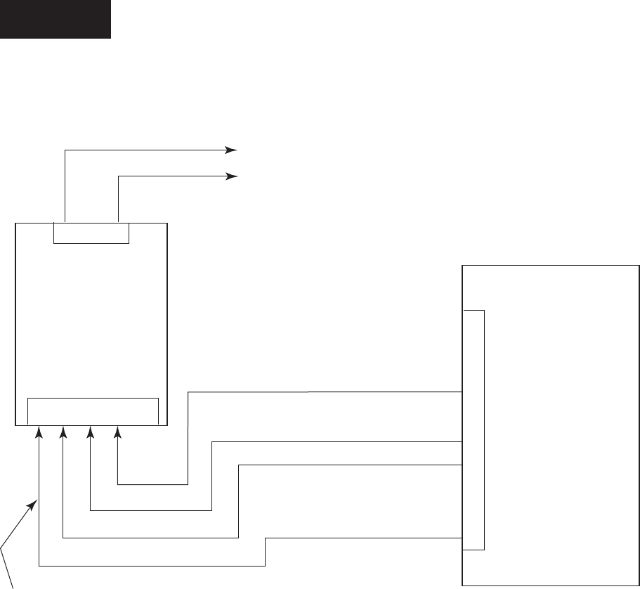
YORK INTERNATIONAL90
J6
10
9
8
7
6
5
4
3
2
1
N.C.
N.C.
N.C.
N.C.
N.C.
N.C.
MICRO
BOARD
INVERTER
BOARD
1 2 3 4 5
N.C.
CN1
CN2
3 2 1
N.C.
RETURN
500 - 1400 VAC
BACKLIGHT
LAMP
BRIGHTNESS CONTROL (NOTE 2)
BACKLIGHT ENABLE (NOTE 1)
GND
+ 12 VDC (NOTE 3)
INVERTER CABLE 031-02054-001
DISPLAY BACKLIGHT INVERTER BOARD
TYPE: TDK CXA-L0612-VJL
PART NUMBER: 031-01789-000
FOR: SHARP LQ10D367 &
LG SEMICON LP104V2-W DISPLAYS
FIG. 44 – DISPLAY BACKLIGHT INVERTER BOARD
LD06755
NOTES:
1. OFF = 0VDC; ON = +5VDC. Refer to
Microboard Program Jumpers JP3 & JP4 in
Table 2.
2. 0 - +3.0VDC. 0VDC = MAX (100%) Brightness;
+3.0VDC = MIN (0%) Brightness. Refer to Fig.
34 and Microboard Jumpers JP7 & JP8.
3. Refer to Microboard Program Jumper JP5.
4. N.C. = No Connection.
Service

FORM 50.40-OM2
91YORK INTERNATIONAL
KEYPAD
(REFER TO FIGURES 45 & 46)
The Keypad contains touch-sensitive keys that allow
the Operator to interface with the Control Center. The
Operator presses the keys to request the desired screens
of information and enter System Setpoints.
The top layer of the Keypad contains embossed areas
identifying the keys. Under each embossed key area are
two conductors, one on top of the other, separated by
an air space. The conductors are arranged in a matrix
of rows and columns and connected to the Keypad
connector as shown in Fig. 46. The embossed area
of each key is located directly over the intersection
point of the conductors. Pressing the embossed key
area causes contact and electrical continuity between
the two conductors. For example, pressing the “1” key
creates continuity between the Keypad connector pin
5 (column 3) and pin 13 (row 4). Since this connector
is interfaced to the Microboard (J18), the Microboard
senses this continuity as described below and concludes
the “1” key is pressed.
The Microboard Program continuously scans the Keypad
to determine if a key is pressed. Beginning with row 1
and proceeding through all rows, the Program places a
“logic low” (<1VDC) on a row, a “logic high” (>4VDC)
on the remaining rows and reads the columns. A logic
low in any column indicates a key in that column and
row is pressed. For example, if at the time row 4 is
being driven low, if column 3 is low, then the Micro
concludes the key at coordinate of row 4 and column 3
is pressed. Since the coordinates of all keys are stored
in the Microboard’s Program, it can identify which key
is at this coordinate and responds accordingly. In this
example the “1” key is pressed.
In order for the Microboard to reliably detect closed
and open keys, each key must meet a closed circuit
and open circuit resistance requirement. When a key
is pressed, the contact resistance must be < 100 Ohms.
When a key is not pressed, the contact resistance must
be > 1 Meg Ohm. If the Microboard is not responding to
a pressed key, or if it’s detecting a closed key when none
are pressed, it could be because the contact resistance
requirements are not being met. The operation of each
key can be checked with an Ohmmeter. To check the
open and closed contact resistance of any key, refer
to the “Diagnostics and Troubleshooting” description
in this book.
The Keypad is attached to the front of the Remote
Control Center door with an adhesive backing. If
service replacement is required, start at one corner
and slowly peel the Keypad from the door. The rear
side of the replacement Keypad is coated with an
adhesive covered with a paper backing. Remove the
paper backing, align the Display opening and apply
the Keypad to the door.
5
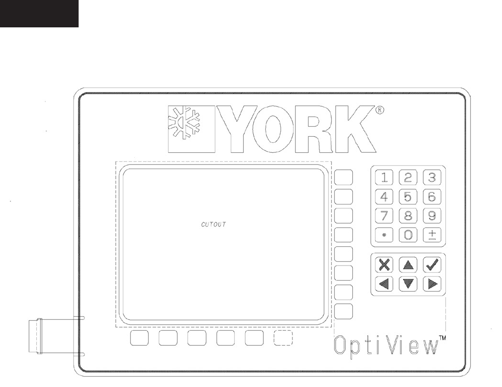
YORK INTERNATIONAL92
LD06756
FIG. 45 – KEYPAD
Service
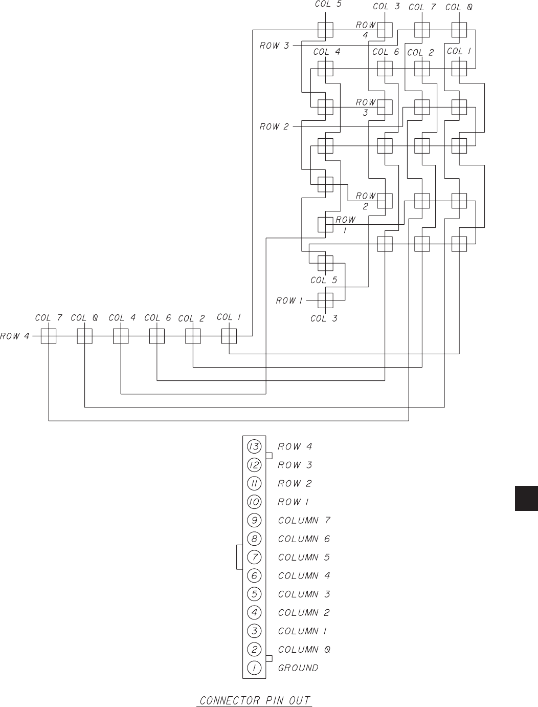
FORM 50.40-OM2
93YORK INTERNATIONAL
FIG. 46 – KEYPAD
LD04075
LD04076
5

YORK INTERNATIONAL94
POWER SUPPLY
(REFER TO FIG 47)
The Power Supply provides the DC power for the LCD
Display and all the printed circuit boards in the Control
Center. It receives a 100 to 250VAC input from an
external power source and provides the following DC
outputs:
• +12VDC
• +5VDC
• Ground
The +12VDC, Gnd and +5VDC outputs are applied to
the Microboard. There, these voltages are applied to
the circuits requiring the respective voltage. From the
Microboard, the +12VDC and +5VDC are distributed
to other system components requiring these voltages.
These include the MicroGateway, LCD Display and
Display Backlight Inverter Board.
As shown in Fig. 47, the Microboard contains two
voltage regulators that create separate +5VDC and
+3.3VDC supplies. The +5VDC supply is dedicated
to all the Microboard Analog circuits and is labeled
as the +5VDC (Analog) supply. It is also routed to
all Temperature Thermistors. This permits all Analog
circuits to be powered by the same supply, eliminating
any offsets caused by voltage regulator drift. The
+3.3VDC supply is utilized by the Microprocessor,
Flash Memory Card and other digital circuits. It
could also be applied to the Backlight Inverter Board,
depending on the Display manufacturer’s requirements
as explained next.
Different Display manufacturers can require different
supply voltages for their display and supporting circuits.
To accommodate the different Display manufacturer’s
voltage requirements, Microboard Program Jumpers JP2
and JP5 must be positioned to provide the required supply
voltages to the Display and the Display Backlight Inverter
Board. Either +5VDC or +3.3VDC, as determined
by JP2, is applied to the Display. Either +12VDC or
+5VDC, as determined by JP5, is applied to the Display
Backlight Inverter Board. Refer to Table 2 “Microboard
Program Jumpers”.
Service
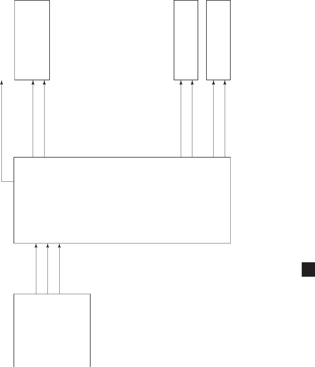
FORM 50.40-OM2
95YORK INTERNATIONAL
FIG. 47 – POWER SUPPLY – DC POWER DISTRIBUTION (REFER TO CONTROL CENTER WIRING DIAGRAM FOR WIRE CONNECTIONS)
LD06757
NOTES:
1. +5 or +3.3VDC as determined by Microboard Program Jumper JP2
& display requirements.
2. +12 or +5VDC as determined by Microboard Program Jumper JP5
& display requirements.
DC
POWER
SUPPLY
MICRO
BOARD
MICROGATEWAY
LCD
DISPLAY
DISPLAY BACKLIGHT
INVERTER BOARD
+5VDC (ANALOG) ALL TRANSDUCERS & THERMISTORS
+12VDC
GND
VDD (NOTE 1)
GND
+V (NOTE 2)
GND
+12VDC
GND
+5VDC
5

YORK INTERNATIONAL96
The problems that could be encountered in the Control
Center are in the following categories:
• Keypad
• Display
• Serial Input/Output (I/O)
• Digital Input/Output (I/O)
• Analog Inputs
There is a Diagnostic and associated Troubleshooting
procedure for each category. They are described
on the following pages. The ofine diagnostics are
accessed from the Diagnostics Main Screen, which is
entered using the procedure below. If there is a Remote
Control Center problem, determine the category of
the problem. Then perform the applicable Diagnostic.
If the Diagnostic reveals a malfunction, perform the
Troubleshooting procedure to locate the defective
component.
There are several documents that must be referred to
while performing the Diagnostics and Troubleshooting
procedures. Each procedure references the Section and
gures of this book that describe the operation of the
component being tested.
The Offline diagnostic screens are only available
when the panel is powered on (or rebooted) with the
Diagnostics Enable dip switch in the Enabled position.
When in this mode all normal RCC functions are
disabled. If the Diagnostics Enable dip switch is placed
in the Disabled position while the panel is in the Ofine
Diagnostics mode, the Diagnostics task will cause the
panel to reboot into the online diagnostics mode.
OFFLINE DIAGNOSTICS & TROUBLESHOOTING
(REFER TO FIG 48 & 49)
Service
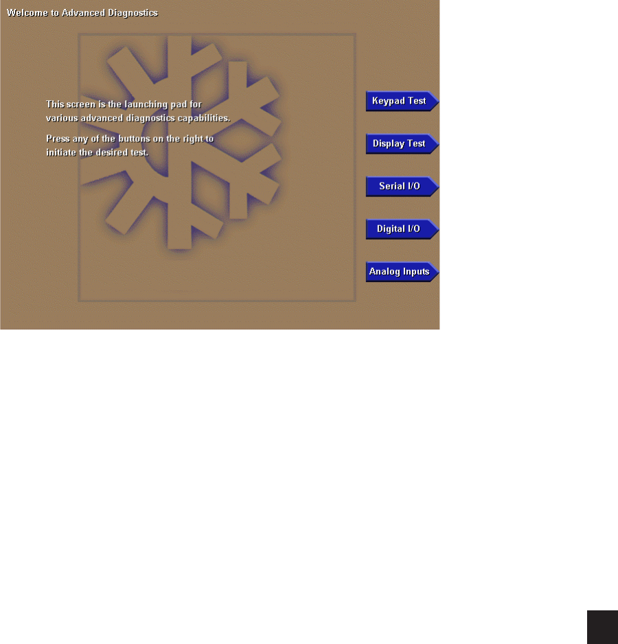
FORM 50.40-OM2
97YORK INTERNATIONAL
Each of the Ofine Diagnostics is accessed from this
screen. Press the appropriate key to select the desired
diagnostic. After each diagnostic is performed, return
to this MAIN Screen, from which the next diagnostic
can be selected.
Some of the diagnostics have sub-screens that are
accessed from the selected diagnostic screen. The
sub-screens are shown indented:
Main screen
- Keypad test
- Display test
- Bit patterns test
- All red
- All green
- All blue
- All white
- All black
- Serial 1/0
- Digital 1/0
- Analog Inputs
MAIN DIAGNOSTICS SCREEN
FIG. 48 00527VIPC
5

YORK INTERNATIONAL98
KEYPAD TEST
This diagnostic is used to verify Keypad operation and
the Microboard’s ability to respond to a pressed key.
Refer to description of Keypad operation in Section
5 of this book.
Procedure
1. Press each keypad key. As the key is pressed, an
illuminated LED is displayed corresponding to
the key location on the keypad.
2. Press the DIAGNOSTICS key to return to the
MAIN DIAGNOSTICS Screen.
Troubleshooting
If an LED is not displayed when a key is pressed, the
Keypad, Keypad ribbon cable or Microboard could be
defective. Use the following procedure to locate the
defective component.
1. Keypad
a. Disconnect the ribbon cable from the Keypad.
b. Identify row/column coordinate of the key to
be tested. Refer to Figure 46.
c. In the Keypad connector, locate the pins of
the row/column coordinate of the key of the
key to be tested.
d. Insert the leads of an Ohmmeter into the pins
identied in step “c” above.
e. Press the key to be tested. If the contact
resistance is >100 Ohms, the Keypad is defec-
tive.
f. Release the key. If the contact resistance is < 1
Meg Ohm, the Keypad is defective.
2. Ribbon Cable
Using an Ohmmeter, perform a continuity test on
all conductors in the ribbon cable. An open circuit
would indicate the ribbon Cable is defective.
3. Microboard
There are no checks or measurements to be
made on the Microboard. If the Keypad and
Ribbon Cable check OK per the above procedures,
the Microboard is most likely the cause of the
problem.
FIG. 49 00568VIPC
Service
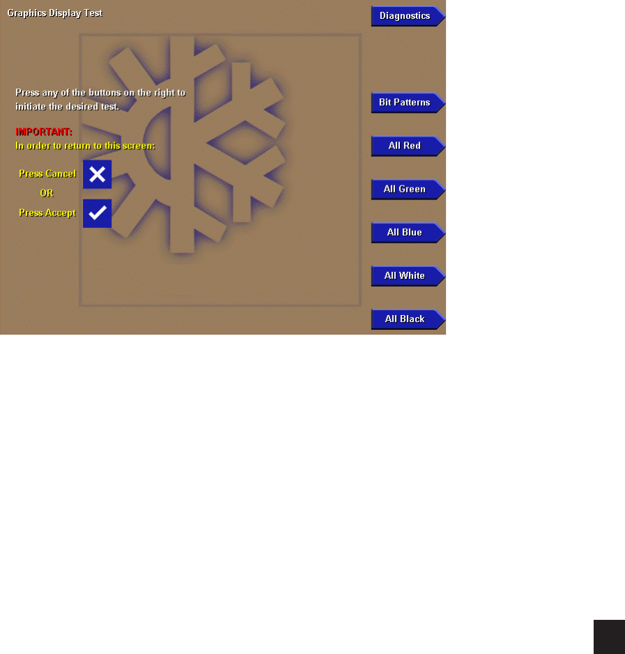
FORM 50.40-OM2
99YORK INTERNATIONAL
Each of the Display Diagnostics is accessed from this
screen. After each diagnostic is performed, return to
this screen, from which the next diagnostic can be
selected. Refer to description of Display operation in
Section 5 of this book.
PROCEDURE
1. Press the appropriate keypad key to perform the
desired test from the list below.
2. Press the CANCEL (X) or ENTER (T) key to
terminate test and return to DISPLAY TEST MAIN
Screen, from which another test can be selected.
3. When all the desired tests have been performed,
press the DIAGNOSTICS key to return to the
MAIN DIAGNOSTICS Screen.
• Bit Patterns - This test is used to detect
jitter and alignment defects. It veries proper
operation and compatibility of the Microboard
Display Controller with the display. Four
vertical bars of green, dark blue, light blue and
yellow, outlined by a red border are displayed.
If the vertical bars are not stable or straight, or
the red border is not completely visible, then
either the Microboard Program Jumpers are not
congured correctly for the installed display or
the Microboard Display controller is defective.
Refer to Figure 51.
• All Red - This test veries the operation of all
of the red pixels. All of the red pixels are turned
on to create a completely red screen. Any red
pixels that do not turn on will appear as black
dots on the display. If any black dots appear, rst
ascertain it is not caused by dirt that is lodged
between the display surface and the protective
plastic cover. It is normal for a small number of
randomly spaced pixels to not illuminate. It is not
necessary to replace the display if a small number
of black dots appear. They will not be visible
on the normal screens displayed outside of this
diagnostic mode. However, large black areas
would be indicative of a defective display.
• All Green - This test verifies the operation
of all of the green pixels. All of the green
pixels are turned on to create a completely
green screen. Refer to description of “All Red”
test above.
• All Blue - This test veries the operation of
all of the blue pixels. All of the blue pixels are
turned on to create a completely blue screen.
Refer to description of “All Red” test above.
• All White - This test veries the display’s ability
to turn on all pixels to display a completely
white screen. Any pixel that does not turn on
will appear as a black dot. Refer to description
of “All Red” test above.
• All Black - This test veries the display’s ability
to turn off all pixels to display a completely
black screen. Any pixel that does not turn off
will appear as a red, green, blue or white dot.
Refer to description “All Red” test above.
DISPLAY TEST
FIG. 50 00528VIPC
5

YORK INTERNATIONAL100
BIT PATTERNS TEST SCREEN
TROUBLESHOOTING
If any of the above tests do not perform correctly as
described above, perform the applicable procedure
below:
Test Failed:
Bit Patterns - If the vertical bars are not straight
or if the red border is not completely visible, either
the Microboard Program Jumpers are not congured
correctly or for the installed Display or the Microboard
is defective.
All Red, All Green, All Blue, All White or All Black:
If these tests do not produce appropriate solid color
screens, the Display Ribbon Cable, Display Interface
Board, Microboard or Display could be defective. To
locate the defective component perform tests in the
following order:
1. Display Ribbon Cable:
Using an Ohmmeter, perform a continuity
test on all conductors in the ribbon cable. An
open circuit would indicate the ribbon cable
is defective.
2. Display Interface Board:
Using an Ohmmeter, perform a continuity test
on all conductors of the Interface Board. An
open circuit would indicate the Interface Board
is defective.
3. Microboard:
a. With the “All Red” test selected, the voltage
at Microboard J5-6 through J5-11 (Red drivers
bits 0-5), as measured to Gnd, should be >
3.0VDC. If not, the Microboard is defective.
b. With the “All Green” test selected, the voltage
at Microboard J5-13 through J5-18 (Green
drivers bits 0-5), as measured to Gnd, should be
>3.0VDC. If not, the Microboard is defective.
c. With the “All Blue” test selected, the voltage at
Microboard J5-20 through J5-25 (Blue drivers
bits 0-5), as measured to Grid, should be
>3.0VDC. If not, the Microboard is defective.
d. With the “All White” test selected, the voltage at
Microboard J5-6 through J5-11, J5-13 through
J5-18 and J5-20 through J5-25 should be
>3.0VDC. If not, the Microboard is defective.
e. With “All Black” selected, the voltage at
Microboard J5-6 through J5-11, J5-13 through
J5-18 and J5-20 through J5-25 should be
<1.0VDC. If not, the Microboard is defective.
4. Display:
If the Display Ribbon Cable, Display Interface
Board and Microboard check OK per the above
procedures, the Display is most likely the cause
of the problem.
FIG. 51 00529VIPC
Service
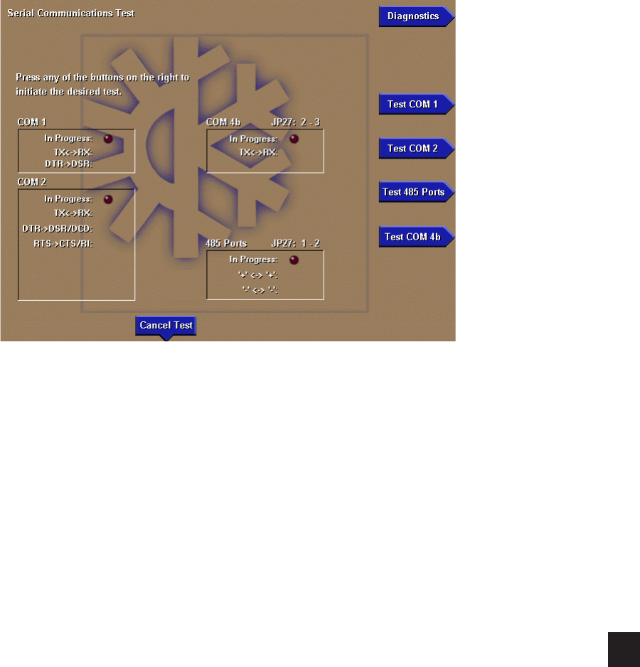
FORM 50.40-OM2
101YORK INTERNATIONAL
SERIAL INPUTS / OUTPUTS TESTS
This diagnostic is used to verify correct operation of
the Serial Data Ports. There is a test for each of the
five Serial Data Ports. Each RS-232 port (COM 1,
2 and 4b) is tested by transmitting serial test data
from outputs to inputs of each port. Both the transmit
and receive functions as well as the control lines are
tested. The RS-485 ports (COM 3 and 4a) are tested
by transmitting serial test data from one RS-485 port
to another. The TX/RX opto-coupled port (COM 5)
is tested by transmitting serial test data from the TX
output to the RX input. If the received data matches the
transmitted data, PASS is displayed, indicating the serial
port is OK. Otherwise, FAIL is displayed, indicating
the serial port is defective. Prior to performing each
test, the Service Technician must install a wire loop-
back connection as described below. Refer to Section
5 and Figure 35 of this book for description of the
Serial data Ports.
PROCEDURE
1. Using small gauge wire, fabricate loop-back
connections and install as follows for each
port to be tested. Failure to install the loop-
back connection or congure the Microboard
Program jumper as noted will result in a FAIL
outcome for the test.
From To
COM 1 J2-4 (TX) J2-3 (RX)
J2-5 (DTR) J2-2 (DSR)
From To
COM 2 J13-5 (TX) J13-3 (RX)
J13-7 (DTR) J13-1(DCD) &
J13-2(DSR)
J13-4 (RTS) J13-6 (CTS) &
J13-8 (RI)
RS-485 From To
(COM J12-3 (+) J11-3 (+)
3 & 4a) J12-2 (-) J11-2 (-)
Microboard Program Jumper JP27 must be installed
in position 1 & 2.
From To
COM 4b J2-7 (GTX) J2-6 (GRX)
Microboard Program Jumper JP27 must be installed
in position 2 & 3
2. After connecting appropriate loop-back con-
nections above, press the appropriate key to
initiate the desired test. An LED will illuminate
indicating the test is in progress. If it is desired
to terminate the test, press the CANCEL TEST
key. Test data is sent from an output to an input
as described below. At the completion of
each test, if the data received matches the
data sent, the Serial Port operates properly
and PASS is displayed. Otherwise, FAIL is
FIG. 52 00530VIPC
5

YORK INTERNATIONAL102
displayed, indicating the Serial Port is defective.
A FAIL result would be indicative of a defective
Microboard. The following is a description
of each test.
COM 1 – Two tests are performed. Test data is
sent from TX (J2-4) to RX (J2-3) at 9600 Baud
and DTR (J2-5) is set to a Logic High level and
read at DSR (J2-2). If any test fails, COM 1
tests are terminated.
COM 2 – Three tests are performed. Test data
is sent from TX (J13-5) to RX (J13-3) at 19200
Baud. DTR (J13-7) is set to a Logic High and
read at DSR (J13-2) & DCD (J13-1). RTS
(J13-4) is set to a Logic High and read at CTS
(J13-6) & R1 (J13-8). If any test fails, COM 2
tests are terminated.
RS-485 (COM 3 & 4a) – Test data is sent from
COM 3 RS-485 port to COM 4a RS-485 Port at
19200 Baud. Test data is then sent from COM
4a to COM 3 at the same rate. If either test fails,
RS-485 tests are terminated.
COM 4b – Test data is sent from GTX (J2-7)
to GRX (J2-6) at 19200 Baud.
3. After all desired tests have been performed,
press the DIAGNOSTICS key to return to the
MAIN DIAGNOSTICS Screen.
Service
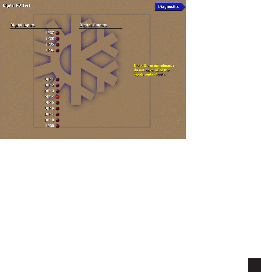
FORM 50.40-OM2
103YORK INTERNATIONAL
DIGITAL INPUTS / OUTPUTS TESTS
This diagnostic is used to analyze the digital inputs and
outputs of the Microboard.
The state of each Microboard Program Jumper and
Program DIP Switch, as interpreted by the Microboard,
is depicted by an LED. If the Microboard interprets its
input as being at a Logic Low (<1.0VDC) level, the
LED is illuminated. If interpreted as being at a Logic
High (>4.0VDC) level, the LED is extinguished.
PROCEDURE
Digital Inputs:
1. The Digital Inputs are listed on this screen
according to Microboard Program Jumpers
and Program DIP Switches. Tables 2 and 3
list the functions of the Program Jumpers and
Switches.
2. If a Program Jumper is present, the applicable
LED should be extinguished. If the LED is not
extinguished, the Microboard is defective.
3. If a Program Jumper is not present, the appli-
cable LED should be illuminated. If the LED is
not illuminated, the Microboard is defective.
4. If a Program Switch (DIP) is in the ON position,
the applicable LED should be illuminated. If
the LED is not illuminated, the Microboard
is defective.
5. If the Program Switch (DIP) is in the OFF posi-
tion, the applicable LED should be extinguished.
If the LED is not extinguished, the Microboard
is defective.
6. When all desired tests have been performed,
press DIAGNOSTICS key to return to MAIN
DIAGNOSTICS Screen.
FIG. 53 00531VIPC
5

YORK INTERNATIONAL104
ANALOG INPUTS TESTS
This diagnostic is used to analyze the Analog Inputs to
the Microboard. The voltage level of each Analog input,
as interpreted by the Microboard, is displayed. The
“Counts” listed for each parameter is the Analog-to-
Digital (A/D) converter value and is for manufacturing
and engineering use only.
The following is a list of the Analog inputs displayed.
Channel
0 - Presently Not Used.
1 - Presently Not Used.
FIG. 54 00532VIPC
Service

FORM 50.40-OM2
105YORK INTERNATIONAL
SYSTEM COMMISSIONING CHECKLIST
5
Use the following checklist during commissioning to
assure all Setpoints have been programmed to the desired
value and all calibrations have been performed. The
Setpoints are grouped under the Display Screen in which
they appear. The indented screens are subscreens of the
numbered screens and are accessed from the numbered
screens. An explanation of each setpoint or Calibration
Procedure below is contained in the reference document
listed in parenthesis adjacent to each item. If any of
the Setpoints have to be changed, use the standard
programming procedures in the Operation Section.
Thresholds, values and calibrations of items marked with
an asterisk “*” have been determined and entered/set at
the YORK Factory at the time of manufacture.
1. PROGRAM JUMPERS/SWITCHES:
____ Verify Microboard Program Jumpers and
Program Switches are congured appropriately.
2. SETPOINTS Screen:
The setpoints listed on the SETPOINTS Screen have
already been programmed at the chiller/condensing unit.
The values shown reect the previously programmed
values. However, the setpoints listed here can be changed
on this screen if desired only if the chiller/condensing
unit is in remote conrol mode. This screen is used
primarily as a central location from which most setpoints
can be programmed. If it is not desired to change any
of the listed setpoints, proceed to the following RCC
SETPOINTS Screen.
3. RCC SETPOINTS Screen:
____ Number of Units Connected
RCC SETUP Screen:
____ Enable Clock
____ Enter CLOCK Time and Date
____ Select 12 or 24 hour display mode
COMMS Screen:
Enter the following parameters as required for com-
munication to the remote chiller panel(s):
____ RCC Poll Time
PRINTER Screen:
If Printer is connected to Microboard serial ports,
enter the following:
____ Baud rate
____ Number of data bits
____ Number of stop bits
____ Parity
____ Automatic printer logging Enable/disable
____ Log start time
____ Log output interval
____ Log Unit Selected (1-8, All)
____ Printer type

YORK INTERNATIONAL106
SECTION 6 – PART NUMBER AND RENEWAL PARTS
ITEM DESCRIPTION FIG. NO. QTY. PART NO.
1 MICROPROCESSOR BOARD (NOTE 2) 56 1 031-01730-002
2 POWER SUPPLY ASSY 56 1 371-02750-411
3 KEYPAD 55 1 024-30974-001
4 TERMINAL BLOCK 56 1 025-35120-000
5 DISPLAY KIT (NOTE 1) 55 1 331-02053-000
6 CABLE ASSY. POWER SUPPLY 56 1 571-02750-421
7 KEYPAD TO MICRO RIBBON CABLE 56 1 031-02056-000
8 EPROM, BIOS (U45) 56 1 031-01796-001
9 FLASH MEMORY CARD, PROGRAMMED (U46) 56 1 031-02057-001
10 IC, BRAM (U52) 56 1 031-02028-000
11 FLAT CABLE FERRITE CLAMP 56 1 025-34172-000
12 SLEEVE SNAP FERRITE 56 1 025-35154-000
13 BACKLIGHT BULB 57 1 See Note 4
14 BACKLIGHT INVERTER BOARD 57 1 See Note 4
15 BACKLIGHT INVERTER BOARD RIBBON CABLE 57 1 See Note 4
16 DISPLAY INTERFACE BOARD 57 1 See Note 4
17 DISPLAY INTERFACE BOARD RIBBON CABLE 57 1 031-02055-000
18 LAN TRANSIENT PROTECTION MODULE 2 1 031-01586-000
19 TRANSIENT VOLTAGE SUPPRESSOR 2 2 031-02076-000
20 IC, RS-485 DRIVER 56 4 031-02074-000
21 FUSE, F1 & F2, 5 AMP (Rev. E and later Microboards) 58 2 025-34592-000
22 MICROGATEWAY OPTIVIEW KIT (future option) 56 1 371-03609-001
23 EPROM, MICROGATEWAY 56 1 See 450.RP1
TABLE 5 - RENEWAL PARTS
NOTES:
1. The replacement Liquid Crystal Display supplied by YORK might not be by the same manufacturer as the original Display. Each Display
requires a specific Display Interface Board (Item 16), Backlight Inverter Board (Item 14), and Backlight Inverter Board ribbon cable (Item
15). Therefore, the Liquid Crystal Display is not available separately. Service replacement Displays or supporting components must
not be arbitrarily selected! Non-compatibility of components will result in incorrect operation! To assure compatible supporting
components, the Display is supplied as a kit (part number 331-02053-000), which contains a replacement Display and all compatible
supporting components on a mounting plate. For future reference, a label attached to the side of the mounting plate (Fig. 57) lists
the YORK part numbers of these compatible components and the required configuration of the Microboard Program Jumpers. These
Program Jumpers must be configured for this Display by a qualified Service Technician following instructions in this manual. The
contents of the kit are as follows:
a. Liquid Crystal Display
b. Backlight Bulb (Item 13)
c. Appropriate Display Interface Board (Item 16) for Display
d. Appropriate Display Interface Board ribbon cable (Item 17) for Item16.
e. Appropriate Backlight Inverter Board (Item 14) for Display.
f. Appropriate Backlight Inverter Board ribbon cable (Item 15) for Item 14.
g. All mounting hardware.
h. Installation instructions.
2. Replacement Microboards are shipped without Flash Memory Cards (U46) or BRAM (U52). Remove these devices from defective Board
and use them in replacement Board. If a new Eprom, Flash Memory Card or BRAM is required, refer to the previous table for part number.
Return all unused Flash Memory Cards with Warranty return boards.
3. Ferrites are shipped in cloth bag. They are applied to the chiller communication RS-485 cable and the MicroGateway LAN cable prior
to exiting the Remote Control Center enclosure.
4. Refer to label (Fig. 57) on Display mounting plate for YORK part number of applicable replacement part. Service replacement Display
supporting components must not be arbitrarily selected! Non-compatibility of components will result in incorrect operation!
Renewal Parts
TABLE 4 - PART NUMBER
DESCRIPTION PART NO.
COMPLETE OPTIVIEW RCC PANEL 371-02750-101
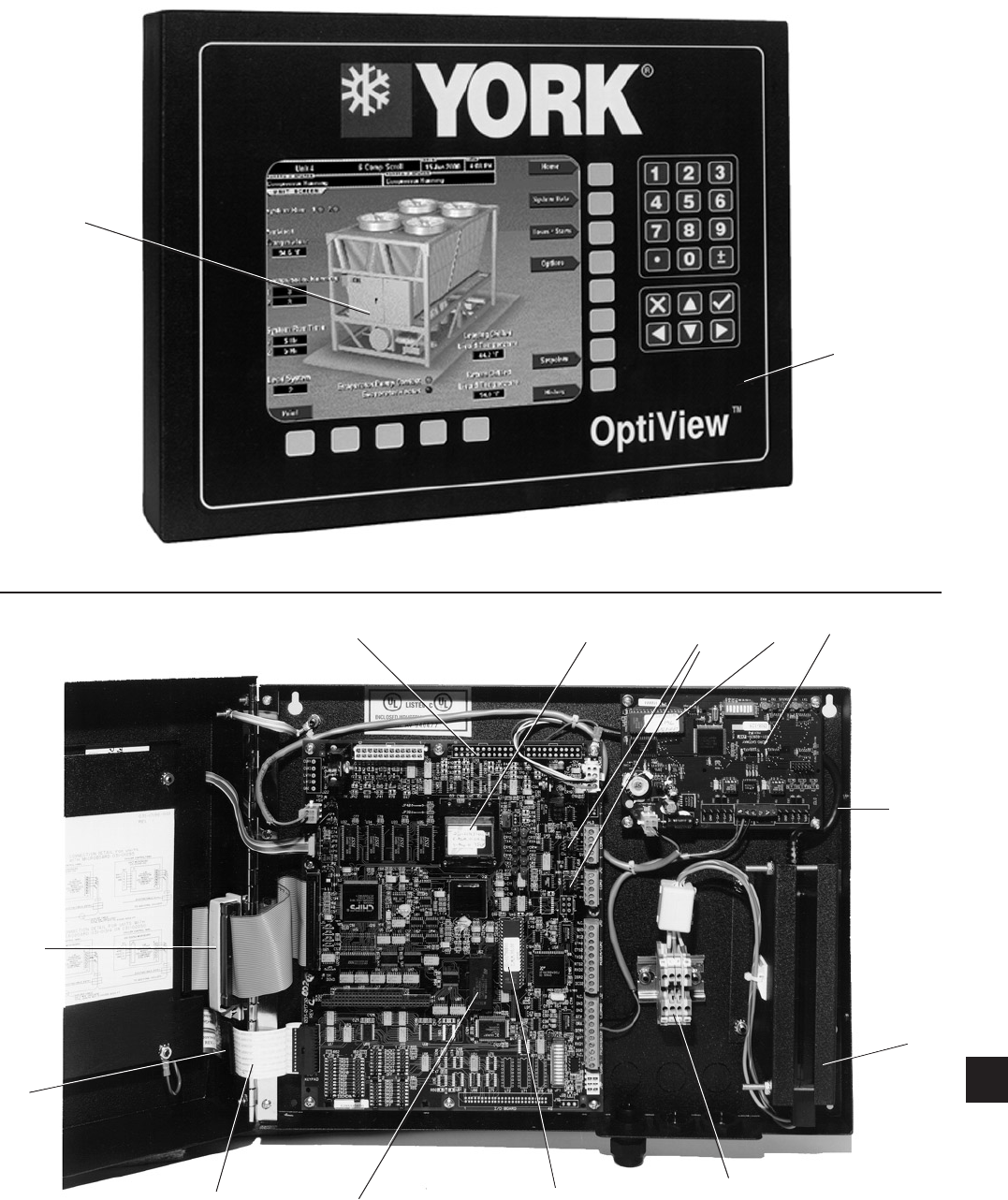
FORM 50.40-OM2
107YORK INTERNATIONAL
5
3
00533VIP
FIG. 55 – FRONT OF OPTIVIEW REMOTE CONTROL CENTER
FIG. 56 – INSIDE OF OPTIVIEW REMOTE CONTROL CENTER
00534VIP
22
2
4
8
10
12
11
19
7
6
20 23
6
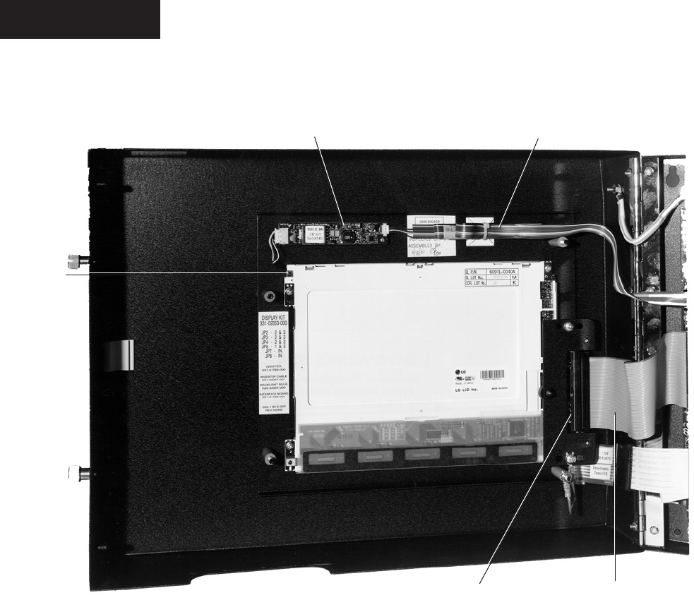
YORK INTERNATIONAL108
13
16 17
15
14
FIG. 57 – INSIDE DOOR OF OPTIVIEW REMOTE CONTROL CENTER
00535VIP
Renewal Parts
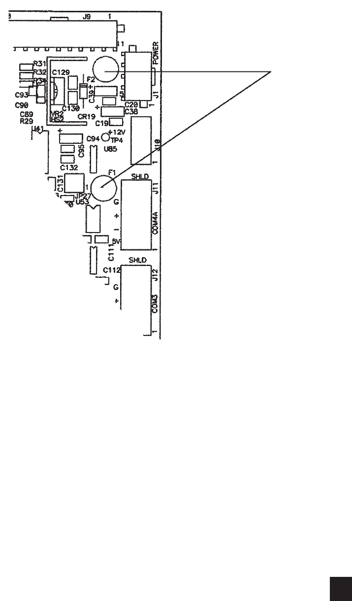
FORM 50.40-OM2
109YORK INTERNATIONAL
FIG. 58 – LOCATION OF FUSE, F1 & F2
LD06513
21
6

YORK INTERNATIONAL110
The following factors can be used to convert from English to the most common SI Metric values.
TEMPERATURE
To convert degrees Fahrenheit (°F) to degrees Celsius (°C), subtract 32° and multiply by 5/9 or 0.5556.
To convert a temperature range (i.e. 10°F or 12°F chilled water range) from Fahrenheit to Celsius, multiply
by 5/9 or 0.5556.
MEASUREMENT MULTIPLY THIS BY TO OBTAIN THIS
ENGLISH VALUE METRIC VALUE
CAPACITY TONS REFRIGERANT EFFECT (ton) 3,516 KILOWATTS (kW)
POWER KILOWATTS (kW) NO CHANGE KILOWATTS (kW)
HORSEPOWER (hp) 0.7457 KILOWATTS (kW)
FLOW RATE GALLONS/MINUTE (gpm) 0.0631 LITERS/SECOND (l/s)
LENGTH FEET (ft) 304.8 MILLIMETERS (mm)
INCHES (in.) 25.4 MILLIMETERS (mm)
WEIGHT POUNDS (lb.) 0.4536 KILOGRAMS (kg)
VELOCITY FEET/SECOND (fps) 0.3048 METERS/SECOND (m/s)
PRESSURE DROP FEET OF WATER (ft) 2.989 KILOPASCALS (kPa)
POUNDS/SQ. INCH (psi) 6.895 KILOPASCALS (kPa)
SI METRIC CONVERSION
Renewal Parts

P.O. Box 1592, York, Pennsylvania USA 17405-1592 Subject to change without notice. Printed in USA
Copyright © by York International Corporation 2001 ALL RIGHTS RESERVED
Form 50.40-OM2 (601)
New Release
