York R123 Users Manual 160.55 O1
R123 to the manual bd843a30-488e-4b69-bd48-51b4334830e0
2015-02-02
: York R123-Users-Manual york-r123-users-manual-455408 york pdf
Open the PDF directly: View PDF ![]() .
.
Page Count: 156 [warning: Documents this large are best viewed by clicking the View PDF Link!]
- Form 160.55-O1 (604)
- SAFETY GUIDELINES
- NOMENCLATURE
- TABLE OF CONTENTS
- LIST OF FIGURES
- SECTION 1
- SECTION 2
- CONTROL CENTER
- INTERFACE CONVENTIONS
- ANALOG INPUT RANGES
- HOME SCREEN
- SYSTEM SCREEN
- EVAPORATOR SCREEN
- CONDENSER SCREEN
- PURGE SCREEN
- REFRIGERANT LEVEL CONTROL SCREEN
- COMPRESSOR SCREEN
- HOT GAS BYPASS SCREEN
- SURGE PROTECTION SCREEN
- PRE-ROTATION VANES CALIBRATION SCREEN
- VSD TUNING SCREEN
- OIL SUMP SCREEN
- ELECTRO-MECHANICAL STARTER SCREEN
- MOD .A. SOLID STATE STARTER SCREE
- MOD .B. SOLID STATE STARTER SCREEN
- VARIABLE SPEED DRIVE SCREEN
- VARIABLE SPEED DRIVE DETAILS SCREEN
- ADAPTIVE CAPACITY CONTROL DETAILS SCREEN
- HARMONIC FILTER DETAILS SCREEN
- SETPOINTS SCREEN
- SETUP SCREEN
- SCHEDULE SCREEN
- USER SCREEN
- COMMS SCREEN
- PRINTER SCREEN
- SALES ORDER SCREEN
- OPERATIONS SCREEN
- HISTORY SCREEN
- HISTORY DETAILS SCREEN
- SECURITY LOG SCREEN
- SECURITY LOG DETAILS SCREEN
- TREND SCREEN
- TREND SETUP SCREEN
- ADVANCED TREND SETUP SCREEN
- COMMON SLOTS SCREEN
- CUSTOM VIEW SCREEN
- CUSTOM VIEW SETUP
- DISPLAY MESSAGES
- STATUS MESSAGES
- RUN MESSAGES
- START INHIBIT MESSAGES
- WARNING MESSAGES
- CYCLING SHUTDOWN MESSAGES
- MOD .B. SOLID STATE STARTER CYCLING SHUT DOWN MES SAG ES
- SAFETY SHUTDOWN MESSAGES
- SECTION 3
- SECTION 4
- SECTION 5
- SECTION 6
- SECTION 7
- SECTION 8
- SECTION 9
- SECTION 10
OPERATING & MAINTENANCE
MILLENNIUM ®
CENTRIFUGAL LIQUID CHILLERS
Supersedes: 160.55-O1 (402) Form 160.55-O1 (604)
MODEL YT (STYLE J)
R123 COOLING ONLY
WITH OPTIVIEW™ CONTROL CENTER
FOR ELECTRO-MECHANICAL STARTER,
SOLID STATE STARTER & VARIABLE SPEED DRIVE
29509A
YORK INTERNATIONAL
2
FORM 160.55-O1 (604)
FORM 160.55-O1 (604)
3
YORK INTERNATIONAL
This equipment is a relatively complicated apparatus.
During installation, operation, maintenance or service,
in di vid u als may be exposed to certain components or
conditions including, but not limited to: refrigerants,
oils, materials under pressure, rotating components and
both high and low voltage. Each of these items has the
po ten tial, if misused or handled improperly, to cause
bodi ly injury or death. It is the obligation and re spon -
si bil i ty of operating/service per son nel to identify and
rec og nize these inherent hazards, protect themselves
and pro ceed safely in completing their tasks. Failure
to com ply with any of these requirements could result
in se ri ous dam age to the equipment and the property in
IMPORTANT!
READ BEFORE PROCEEDING!
GENERAL SAFETY GUIDELINES
which it is sit u at ed, as well as severe personal injury or
death to them selves and people at the site.
This document is intended for use by owner-authorized
operating/service personnel. It is expected that this in-
di vid u al possesses independent training that will en able
them to perform their assigned tasks properly and safe ly.
It is essential that, prior to performing any task on this
equipment, this individual shall have read and un der -
stood this document and any referenced materials. This
in di vid u al shall also be familiar with and comply with
all ap pli ca ble governmental standards and regulations
per tain ing to the task in question.
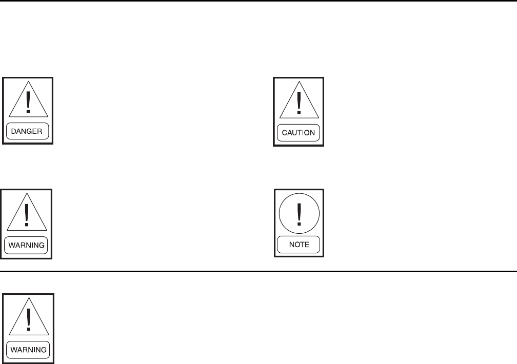
SAFETY SYMBOLS
The following symbols are used in this document to alert the reader to areas of potential hazard:
WARNING indicates a potentially
haz ard ous sit u a tion which, if not
avoid ed, could result in death or se-
ri ous in ju ry.
DANGER indicates an im mi nent ly
hazardous situation which, if not
avoid ed, will re sult in death or se ri ous
injury.
CAUTION identifi es a hazard which
could lead to damage to the ma chine,
damage to other equip ment and/or
en vi ron men tal pollution. Usually an
in struc tion will be given, together with
a brief ex pla na tion.
External wiring, unless specifi ed as an optional connection in the man u fac tur er’s prod uct
line, is NOT to be connected inside the micro pan el cab i net. De vic es such as re lays, switch es,
transducers and controls may NOT be installed inside the mi cro pan el. NO external wiring
is al lowed to be run through the micro panel. All wir ing must be in ac cor dance with YORK’s
pub lished spec i fi ca tions and must be per formed ONLY by qual i fi ed YORK personnel. YORK
will not be re spon si ble for dam ag es/problems re sult ing from im prop er con nec tions to the
con trols or ap pli ca tion of im prop er con trol sig nals. Failure to fol low this will void the
man u fac tur er’s warranty and cause serious dam age to property or injury to per sons.
NOTE is used to highlight ad di tion al
information which may be helpful to
you.
YORK INTERNATIONAL
4
FORM 160.55-O1 (604)
CHANGEABILITY OF THIS DOCUMENT
In complying with YORK’s policy for continuous
prod uct improvement, the information contained in
this doc u ment is subject to change without notice.
While YORK makes no commitment to update or
pro vide current in for ma tion automatically to the
manual own er, that in for ma tion, if applicable, can
be ob tained by con tact ing the nearest YORK Applied
Systems Service ofÞ ce.
It is the responsibility of operating/service personnel
as to the applicability of these documents to the equip-
ment in question. If there is any question in the mind
of op er at ing/service personnel as to the applicability of
these documents, then, prior to working on the equip-
ment, they should verify with the owner wheth er the
equipment has been modiÞ ed and if current lit er a ture
is available.
REFERENCE INSTRUCTIONS
DESCRIPTION FORM NO.
SOLID STATE STARTER (MOD “A”) – OPERATION & MAINTENANCE 160.46-OM3.1
SOLID STATE STARTER (MOD “B”) – OPERATION & MAINTENANCE 160.00-02
VARIABLE SPEED DRIVE – OPERATION 160.00-O1
VARIABLE SPEED DRIVE – SERVICE INSTRUCTIONS 160.00-M1
INSTALLATION 160.55-N1
OPTIVIEW CONTROL CENTER - SERVICE INSTRUCTIONS 160.55-M1
WIRING DIAGRAM – UNIT WITH ELECTRO-MECHANICAL STARTER 160.55-PW1
WIRING DIAGRAM – UNIT WITH SOLID STATE STARTER (MOD “B”) 160.55-PW2
WIRING DIAGRAM – UNIT WITH VARIABLE SPEED DRIVE 160.55-PW3
RENEWAL PARTS – UNIT 160.48-RP5
RENEWAL PARTS – GRAPHIC CONTROL CENTER 160.55-RP1
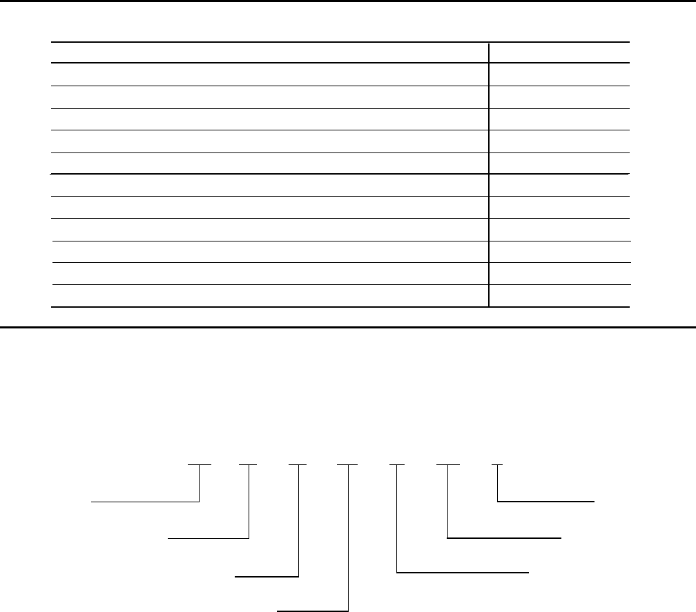
NOMENCLATURE
The model number denotes the following characteristics of the unit
YT K3 C4 E2 — CR J
Model Design Level
Cooler Code Motor Code
Condenser Code Power Supply
— for 60 Hz
Compressor Code 5 for 50 Hz

FORM 160.55-O1 (604)
5
YORK INTERNATIONAL
SECTION 1 Description of System and Fundamentals of Operation............................... 7
SECTION 2 OptiView Control Center ............................................................................. 9
SECTION 3 Printers ..................................................................................................... 112
SECTION 4 System Operating Procedures .................................................................. 124
SECTION 5 System Components Description ............................................................. 131
SECTION 6 Operational Maintenance ......................................................................... 135
SECTION 7 Troubleshooting........................................................................................ 138
SECTION 8 Maintenance ............................................................................................. 144
SECTION 9 Preventive Maintenance ........................................................................... 152
SECTION 10 OptiSave Energy Analyser Feature .......................................................... 154
TABLE OF CONTENTS
YORK INTERNATIONAL
6
FORM 160.55-O1 (604)
LIST OF FIGURES
FIG. 1 – MODEL YT MILLENNIUM CHILLER.................... 7
FIG. 2 – REFRIGERANT FLOW-THROUGH CHILLER..... 8
DETAIL A – COMPRESSOR PREROTATION
VANES.................................................................. 8
FIG. 3 – CONTROL CENTER .......................................... 12
FIG. 4 – HOME SCREEN................................................. 16
FIG. 5 – SYSTEM SCREEN............................................. 18
FIG. 6 – EVAPORATOR SCREEN ................................... 20
FIG. 7 – CONDENSER SCREEN..................................... 22
FIG. 8 – PURGE SCREEN............................................... 24
FIG. 9 – REFRIGERANT LEVEL CONTROL SCREEN ... 26
FIG. 10 – COMPRESSOR SCREEN.................................. 28
FIG. 11 – HOT GAS BYPASS SCREEN ............................ 30
FIG. 12 – SURGE PROTECTION SCREEN ...................... 32
FIG. 13 – PRE-ROTATION VANES CALIBRATION
SCREEN............................................................. 36
FIG. 14 – VSD TUNING SCREEN ..................................... 38
FIG. 15 – OIL SUMP SCREEN........................................... 40
FIG. 16 – ELECTRO-MECHANICAL STARTER SCREEN 41
FIG. 17 – SOLID STATE STARTER
(MOD A) SCREEN.............................................. 42
FIG. 18 – SOLID STATE STARTER
(MOD B) SCREEN ............................................. 44
FIG. 19 – VARIABLE SPEED DRIVE SCREEN................. 46
FIG. 20 – VARIABLE SPEED DRIVE DETAILS SCREEN
(All VSD except Part Number 371-02767-XXX
(60 Hz) or 371-03700-XXX (50 Hz))................... 48
FIG. 21 – VARIABLE SPEED DRIVE DETAILS SCREEN
(VSD with Part Number 371-02767-XXX
(60 Hz) or 371-03700-XXX (50 Hz))................... 50
FIG. 22 – ADAPTIVE CAPACITY CONTROL DETAILS
SCREEN............................................................. 52
FIG. 23 – HARMONIC FILTER DETAILS SCREEN
(All VSD except Part Number 371-02767-XXX
(60 Hz) or 371-03700-XXX (50 Hz))................... 54
FIG. 24 – HARMONIC FILTER DETAILS SCREEN
(VSD with Part Number 371-02767-XXX (60 Hz)
or 371-03700-XXX (50 Hz))................................ 56
FIG. 25 – SETPOINTS SCREEN ....................................... 58
FIG. 26 – SETUP SCREEN................................................ 60
FIG. 27 – SCHEDULE SCREEN........................................ 64
FIG. 28 – USER SCREEN.................................................. 66
FIG. 29 – COMMS SCREEN.............................................. 68
FIG. 30 – PRINTER SCREEN............................................ 70
FIG. 31 – SALES ORDER SCREEN.................................. 72
FIG. 32 – OPERATIONS SCREEN .................................... 74
FIG. 33 – HISTORY SCREEN............................................ 76
FIG. 34 – HISTORY DETAILS SCREEN ............................ 78
FIG. 35 – SECURITY LOG SCREEN................................. 79
FIG. 36 – SECURITY LOG DETAILS SCREEN ................. 80
FIG. 37 – TREND SCREEN ............................................... 82
FIG. 38 – TREND SETUP SCREEN .................................. 84
FIG. 39 – ADVANCED TREND SETUP SCREEN.............. 86
FIG. 40 – COMMON SLOTS SCREEN.............................. 88
FIG. 41 – CUSTOM VIEW SCREEN.................................. 89
FIG. 42 – CUSTOM VIEW SETUP SCREEN..................... 90
FIG. 43 – PRINTERS ........................................................112
FIG. 44 – SAMPLE PRINTOUT (STATUS)........................116
FIG. 45 – SAMPLE PRINTOUT (SETPOINTS).................110
FIG. 46 – SAMPLE PRINTOUT (SCHEDULE)..................119
FIG. 47 – SAMPLE PRINTOUT (SALES ORDER)........... 120
FIG. 48 – SAMPLE PRINTOUT (HISTORY) .................... 121
FIG. 49 – SAMPLE PRINTOUT (SECURITY LOG).......... 122
FIG. 50 – SAMPLE PRINTOUT (TREND)........................ 123
FIG. 51 – SAMPLE PRINTOUT
(CUSTOM SCREEN REPORT)........................ 123
FIG. 52 – SAMPLE PRINTOUT
(ADAPTIVE CAPACITY CONTROL NEW MAP
POINT REPORT) ............................................ 123
FIG. 53 – SAMPLE PRINTOUT
(ADAPTIVE CAPACITY CONTROL EXISTING
MAP POINTS REPORT) .................................. 123
FIG. 54 – OPERATION SEQUENCE & TIMING
DIAGRAM (ELECTRO-MECHANICAL
& SOLID STATE STARTER APPLICATIONS).. 126
FIG. 55 – OPERATION SEQUENCE & TIMING
DIAGRAM (COMPRESSOR MOTOR
VARIABLE SPEED DRIVE APPLICATIONS) ... 126
FIG. 56 – MINIMUM ENTERING CONDENSING
WATER TEMPERATURE ................................. 127
FIG. 57 – LIQUID CHILLER LOG SHEETS ..................... 127
FIG. 58 – TURBOGUARD PURGE UNIT......................... 129
FIG. 59 – SCHEMATIC DRAWING (YT) COMPRESSOR
LUBRICATION SYSTEM.................................. 132
FIG. 60 – OIL RETURN SYSTEM .................................... 135
FIG. 61 – ASSEMBLY OF DEHYDRATOR....................... 136
FIG. 62 – CHARGING OIL RESERVOIR WITH OIL ........ 137
FIG. 63 – EVACUATION OF CHILLER ............................ 145
FIG. 64 – SATURATION CURVE ..................................... 147
FIG. 65 – DIAGRAM - MEGGING MOTOR WINDINGS .. 149
FIG. 66 – MOTOR STATOR TEMPERATURE &
INSULATION RESISTANCES .......................... 150
FORM 160.55-O1 (604)
7
YORK INTERNATIONAL
combination Logic/Trigger Board that interfaces the
Con trol Center with a serial communications link. Ear-
li er vintage chillers, such as those encountered in Con trol
Cen ter retroÞ t ap pli ca tions are equipped with the Mod
“A” starter. This Start er con tains a Trig ger Board that
in ter fac es to a Logic Board that is in stalled inside of the
Control Cen ter.
In operation, a liquid (water or brine to be chilled) ß ows
through the cooler, where boiling refrigerant absorbs heat
from the liquid. The chilled liquid is then piped to fan
coil units or other air conditioning terminal units, where
it ß ows through Þ nned coils, absorbing heat from the
air. The warmed liquid is then returned to the chiller to
complete the chilled liquid circuit.
The refrigerant vapor, which is produced by the boil ing
action in the cooler, ß ows to the compressor where the
rotating impeller increases its pressure and tem per a ture
and discharges it into the condenser. Water ß ow ing
through the condenser tubes absorbs heat from the re frig -
er ant va por, causing it to condense. The con dens er water
is sup plied to the chiller from an external source, usually
a cool ing tower. The condensed re frig er ant drains from
the con dens er into the liquid return line, where the vari-
SECTION 1
DESCRIPTION OF SYSTEM AND FUNDAMENTALS OF OPERATION
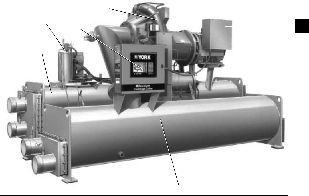
29509A
CONDENSER
CONTROL
CENTER
COMPRESSOR
MOTOR
COOLER
FIG. 1 – MODEL YT MILLENNIUM CHILLER
SYSTEM OPERATION DESCRIPTION (SEE FIG. 2)
The YORK Model YT Millennium Chiller is commonly
ap plied to large air conditioning systems, but may be
used on other applications. The chiller consists of an
open motor mounted to a compressor (with integral
speed in creas ing gears) condenser, cooler and vari able
ß ow con trol.
The chiller is controlled by a modern state of the art
OptiView Control Center that monitors its op er a tion. The
Control Center is programmed by the op er a tor to suit job
speciÞ cations. Automatic timed start-ups and shut downs
are also programmable to suit night time, week ends and
holidays. The operating status, tem per a tures, pressures
and other information per ti nent to op er a tion of the chiller
are automatically dis played and read on a graphic mes-
sage display. Other displays can be ob served by press ing
the keys as labeled on the Con trol Center. The chill er
with the OptiView Control Cen ter is applied with an
electro-mechanical start er, YORK Solid State Start er
(optional) or Variable Speed Drive (optional).
There could be either of two different Solid State Start-
ers applied. New production chillers are equipped with
the Mod “B” Solid State Starter. This starter contains a
1
PURGE
UNIT
YORK INTERNATIONAL
8
FORM 160.55-O1 (604)
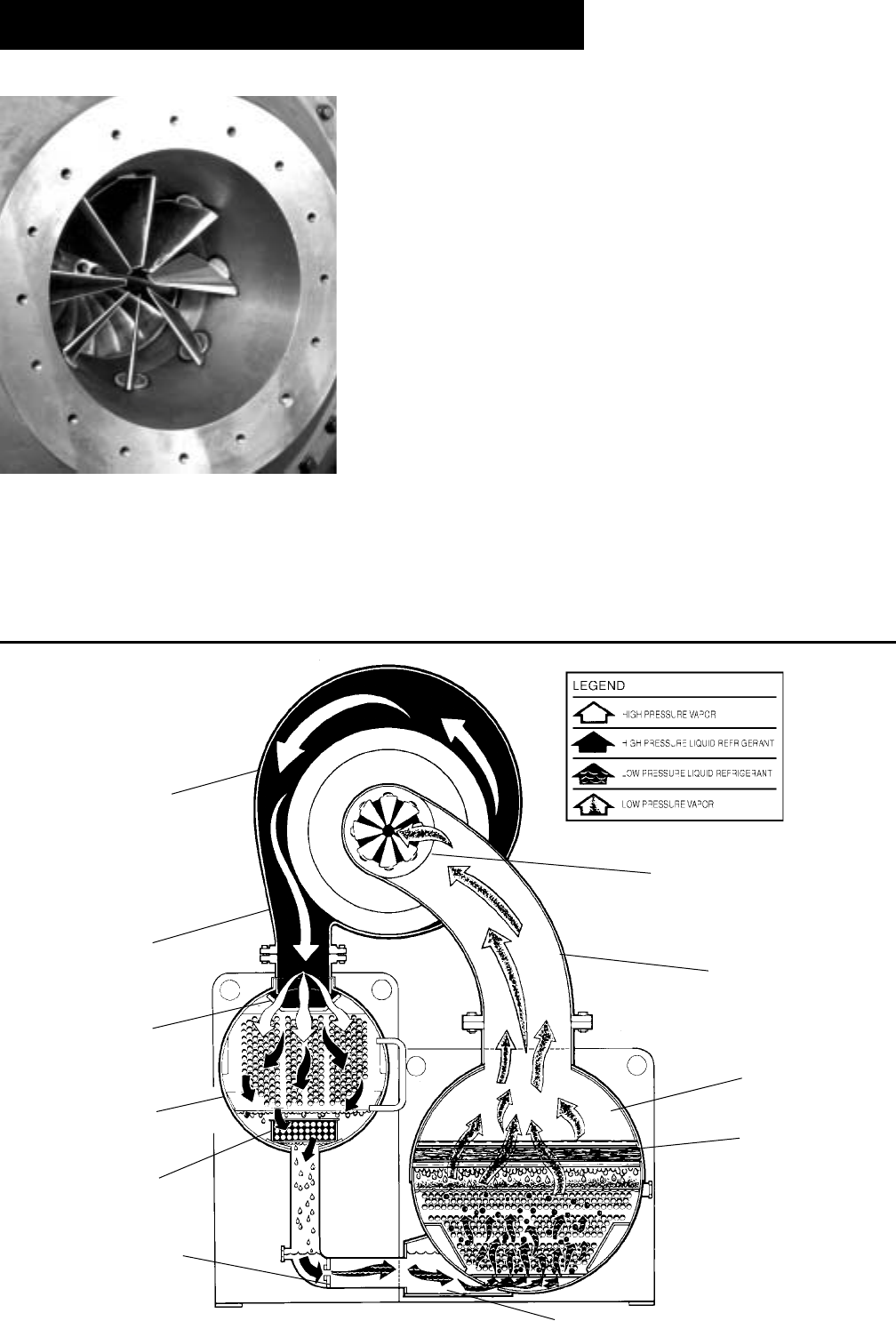
FIG. 2 – REFRIGERANT FLOW-THRU CHILL ER
PREROTATION VANES
(See Detail A)
SUCTION
COOLER
ELIMINATOR
OIL COOLER
LD00924
FLOW CON-
TROL
SUB-COOL-
CON-
DISCHARGE
BAFFLE
DISCHARGE
COMPRESSOR
able oriÞ ce meters the ß ow of liquid re frig er ant to the
cooler to com plete the refrigerant cir cuit.
The major components of a chiller are selected to han dle
the refrigerant, which would be evaporated at full load
design conditions. However, most systems will be called
upon to deliver full load capacity for only a relatively
small part of the time the unit is in operation.
CAPACITY CONTROL
The major components of a chiller are selected for full
load capacities, therefore capacity must be controlled
to maintain a constant chilled liquid temperature leav-
ing the cooler. Prerotation vanes (PRV), located at the
en trance to the compressor impeller, compensate for
vari a tion in load (See Fig. 2, Detail A).
The position of these vanes is automatically controlled
through a lever arm attached to an electric motor lo cat ed
outside the compressor housing. The automatic adjust-
ment of the vane position in effect provides the perfor-
mance of many different compressors to match various
load conditions from full load with vanes wide open to
minimum load with vanes completely closed.
7619A(D)
DETAIL A – COMPRESSOR PREROTATION VANES
Description of System and Fun da men tals of Operation

FORM 160.55-O1 (604)
9
YORK INTERNATIONAL
SECTION 2
OPTIVIEW CONTROL CEN TER
INTRODUCTION
The YORK OptiView Control Center is a mi cro pro -
ces sor based control system for R-11 or R123 cen trif u gal
chillers. It controls the leaving chilled liq uid tem per a ture
via pre-rotation vane controls and has the abil i ty to limit
motor current via control of the pre-ro ta tion vanes. It is
com pat i ble with YORK Sol id State Start er (optional),
Variable Speed Drive (op tion al) and Electro-Mechanical
starter ap pli ca tions.
The panel comes conÞ gured with a full screen LCD
Graphic Display mounted in the middle of a keypad
in ter face. The graphic display allows the presentation
of several operating parameters at once. In addition,
the operator may view a graphical representation of the
his tor i cal operation of the chiller as well as the present
operation. For the novice user, the locations of various
chiller parameters are clearly and intuitively marked.
Instructions for speciÞ c operations are provided on
many of the screens.
The graphic display also allows information to be rep re -
sent ed in both English (temperatures in °F and pres sures
in PSIA) and Metric (temperatures in °C and pres sures in
kPa) mode. The advantages are most ap par ent, however,
in the ability to display many languages.
The Control Center continually monitors the system op-
eration and records the cause of any shutdowns (Safe ty,
Cycling or Normal). This information is re cord ed in
memory and is preserved even through a pow er fail ure
condition. The user may recall it for view ing at any
time. During operation, the user is con tin u al ly advised
of the operating conditions by various sta tus and warn ing
messages. In addition, it may be con Þ g ured to notify the
user of certain con di tions via alarms. A complete listing
of shutdown, status and warning messages is at tached in
the Display Messages section of this book.
There are certain screens, displayed values, pro gram -
ma ble Setpoints and manual control shown in this book
that are for Service Technician use only. They are only
displayed when logged in at SERVICE access level
or higher. The Setpoints and pa ram e ters displayed on
these screens are explained in detail in YORK Service
Man u al 160.55-M1. These parameters affect chiller
op er a tion and should NEVER be modifi ed by anyone
oth er than a qualifi ed Service Technician. They are
shown in this book for reference only.
Advanced Diagnostics and troubleshooting in for ma tion
for Service Technicians are included in YORK Service
Manual 160.55-M1. Also included in the Service man-
u al are detailed descriptions of chiller features, such as
the Refrigerant Level Control (Future), Purge sys tem,
Hot Gas By pass, Remote Setpoints and Smart Freeze
Pro tec tion.
The control center expands the capabilities of re mote
control and communications. By providing a com mon
networking protocol through the ISN GPIC YORK
Chill ers not only work well in di vid u al ly, but also as
a team. This new protocol allows in creased remote
con trol of the chiller, as well as 24-hour performance
mon i tor ing via a remote site. In ad di tion, compatibility
is main tained with the present net work of ISN com mu -
ni ca tions. The chiller also main tains the standard digital
remote ca pa bil i ties as well. Both of these remote con trol
capabilities allow for the standard Energy Man age ment
System (EMS) in ter face:
1. Remote Start
2. Remote Stop
3. Remote Leaving Chilled Liquid Temperature
Setpoint adjustment (0-20mA or 4-20mA, 0-10VDC
or 2-10VDC) or Pulse Width Modulation
4. Remote Current Limit Setpoint adjustment (0-20mA
or 4-20mA, 0-10VDC or 2-10VDC) or Pulse Width
Mod u la tion
5. Remote “Ready to Start” Contacts
6. Safety Shutdown Contacts
7. Cycling Shutdown Contacts
The chiller operating program resides in the Optiview
control center Microboard. The control center could be
equipped with either of the following Microboards:
• 031-01730-000 – shipped in new production chill-
ers until September 2003. The program resides in
a replaceable Flash Memory Card. The software
version (C.MLM.02.xx.yzz) is printed on label
adhered to card. Program can be upgraded by
replacing the card.
• 031-02430-000 – shipped in new production chill-
ers after September 2003. The program resides in
non-removable onboard memory. The software
2

YORK INTERNATIONAL
10
FORM 160.55-O1 (604)
version is C.OPT.02.xx.yzz, and is viewable on
the DIAGNOSTICS Screen in SERVICE access
level. The program can be upgraded by download-
ing a new program from a Program Card. Program
Cards are shirt-pocket-size portable memory stor-
age devices available from YORK.
Earlier vintage chillers could be equipped with a later
Microboard due to service replacement.
Software versions (C.MLM.02.xx.yzz or
C.OPT.02.xx.yzz) are alpha-numeric codes that rep-
resent the application, language package and revision
levels per below. Each time the controls portion or lan-
guage section is revised, the respective revision level
increments.
• C – Commercial chiller
• MLM – Used on Microboard 031-01730-
000
• OPT - Used on Microboard 031-02430-
000
• 02 – YT chiller
• xx - controls revision level (00, 01, etc)
• y – language package (0=English only,
1=NEMA, 2=CE, 3=NEMA/CE )
• zz – language package revision level (00,
01, etc)
Throughout this book, reference is made to functions and
features that are only available in certain Flash Memory
Card revision levels (C.MLM.02.xx.xxx). To cross refer-
ence C.MLM software to C.OPT software, refer to the
controls revision level. Software version
C.OPT.02.04B.xxx is of the same controls revision
level as C.MLM.02.04.xxx. From this starting point,
both receive the same updates at each revision. Soft-
ware upgrades should only be performed by a Service
Technician.
Description of System and Fun da men tals of Operation
FORM 160.55-O1 (604)
11
YORK INTERNATIONAL
THIS PAGE INTENTIONALLY LEFT BLANK
TO MAINTAIN FORMAT

YORK INTERNATIONAL
12
FORM 160.55-O1 (604)
When in this position, the chiller will not run un der
any condition. For safe ty reasons, this po si tion is
re quired for many maintenance tasks to be com plet ed
(such as prox im i ty probe and vane cal i bra tion). In
ad di tion, the switch must be placed in this state
fol low ing a Safety shut down before the chill er is
al lowed to re start. This guar an tees that manual in ter -
ven tion has tak en place and the shut down has been
ac knowl edged.
The switch can only remain in this po si tion when
being acted upon by a man u al force. Once the user
has re leased the switch, it au to mat i cal ly re verts to
the RUN po si tion. Gen er al ly, this state only occurs
mo men tari ly as the operator at tempts to locally start
the unit. Once this po si tion has been sensed, if all
fault con di tions are cleared, the unit will en ter the
sys tem prelube (start se quence).
When in this position, the chiller is able to op er ate.
The switch spring-re turns to this state after it has
been tog gled to the START po si tion. When in this
state, the chiller is al lowed to function normally and
will also al low the chill er to au to mat i cal ly re start fol-
low ing a Cy cling shut down. The switch must be in
this state to re ceive a val id re mote start signal when
op er at ing under a re mote con trol source.
CONTROL CENTER
The OptiView Control Center display is high light ed by a
full screen graph ics display. This dis play is nested with in
a stan dard keypad and is sur round ed by “soft” keys
which are re de Þ ned based on the currently dis played
screen. Eight buttons are avail able on the right side of the
pan el and are primarily used for navigation between the
sys tem screens. At the base of the display are 5 ad di tion al
but tons. The area to the right of the key pad is used for
data entry with a stan dard numeric key pad provided for
en try of system setpoints and lim its.
The Decimal key provides accurate entry of
setpoint values.
A +/- key has also been provided to allow en try
of neg a tive values and AM/PM selection dur ing
time entry.
In order to accept changes made to the chiller
setpoints, the Check key is provided as a uni-
ver sal ‘En ter’ key or ‘Accept’’ symbol.
In order to reject entry of a setpoint or dismiss
an entry form, the ‘X’ key is provided as a uni-
ver sal ‘Can cel’ sym bol.
Cursor Arrow keys are pro-
vid ed to allow move ment on
screens which contain a large
amount of entry data. In ad-
di tion, these keys can be used
to scroll through his to ry and
event logs.
The Start/Stop control is op er at ed via a three-position
rocker switch. When toggled all the way to the right, it is
considered in the STOP/RESET position. When in the
middle position, this is considered the RUN state. When
toggled to the left-most position, it is considered in the
START state. Each state is described in detail below:
• STOP / RESET (O)
• START (◄)
• RUN ( )
00134VIP
FIG. 3
OptiView Control Center

FORM 160.55-O1 (604)
13
YORK INTERNATIONAL
OVERVIEW
The new graphical display on each control pan el al lows
a wide variety of information to be pre sent ed to the
user. Each screen description in this document will be gin
with a section entitled Overview which will de scribe
the graphical elements on the screen and give a short
summary of the functions available. Each el e ment on
the screen will then be categorized into three dis tinct
groups: Display Only, Programmable and Nav i ga tion.
Below is a short description of what types of in for ma tion
are included in these groups.
The Programmable values and Navigation commands
are also subject to access level restrictions as de scribed
below. For each of these elements, an in di ca tion is giv en
to show the minimum access level required to program
the value or navigate to the subscreen.
DISPLAY ONLY
Values in this group are read-only parameters of in for -
ma tion about the chiller operation. This type of in for -
ma tion may be represented by a numerical value, a text
string or an LED image. For numerical values, if the
monitored parameter is above the normal operating
range, the high limit value will be displayed along with
the ‘>’ symbol; if it is below the normal operating range,
the low limit value will be displayed along with the
‘<’ sym bol. In some cases, the value may be rendered
in valid by other conditions and the display will use X’s
to in di cate this.
PROGRAMMABLE
Values in this group are available for change by the user.
In order to program any setpoints on the sys tem, the user
must Þ rst be logged in with the ap pro pri ate access level.
Each of the programmable values re quires a spe ciÞ c Ac-
cess Level which will be indicated beside the speciÞ ed
value. All of the pro gram ma ble controls in the system
fall into one of the categories described below:
Access Level
In order to program any setpoints on the sys tem, the user
must Þ rst login with an appropriate ac cess level. When
power is applied to the chiller, the system begins with an
Access Level of VIEW. This will allow the user to navi-
gate to most screens and observe the values displayed
there. However, the user will not be allowed to change
any values. To change any values, the user must return to
the Home Screen (shown by de fault when pow er is ap-
plied to the system) and use the LO G IN but ton or uti lize
the CHANGE SETPOINTS key de scribed be low. At
this point, the user will be prompt ed to enter a User ID
and the corresponding Password. By default, the User
ID is zero (0). In order to gain stan dard OP ER A TOR
level access, the Pass word would be en tered as 9 6 7 5,
us ing the numeric keypad. OP ER A TOR ac cess reverts
to the VIEW lev el after 10 con tin u ous min utes without
a keypress. If a custom User ID and Pass word have been
deÞ ned (see User Screen ), the user may enter that User
ID and the cor re spond ing Password value.
If the correct password is received, the user is au tho -
rized with the appropriate Access Level. If an incorrect
pass word is entered, the user is notiÞ ed of the failure
and prompted again. At this point the user may retry the
password entry or cancel the login attempt.
Change Setpoints
On screens containing setpoints programmable at the
OPERATOR access level, a key with this label will be
visible if the present access level is VIEW. This key
brings up the Access Level prompt described above. It
allows the user to login at a higher Access Level with out
returning to the Home Screen. After login, the user may
then modify setpoints on that screen.
Setpoints
The control center uses the setpoint values to control the
chiller and other devices connected to the chiller system.
Setpoints can fall into several categories. They could be
numeric values (such as 45.0°F for the Leav ing Chilled
Liquid Temperature) or they could Enable or Disable a
feature or function.
Regardless of which setpoint is being programmed, the
following procedure applies:
1. Press the desired setpoint key. A dialog box ap pears
dis play ing the present value, the up per and low er
limits of the programmable range and the de fault
value.
2. If the dialog box begins with the word “ENTER”,
use the numeric keys to enter the desired value.
INTERFACE CONVENTIONS
2
YORK INTERNATIONAL
14
FORM 160.55-O1 (604)
Lead ing zeroes are not necessary. If a dec i mal point
is nec es sary, press the ‘•’ key (i.e. 45.0).
Pressing the ▲ key, sets the entry value to the de fault
for that setpoint. Pressing the ▼ key, clears the pres-
ent entry. The ◄ key is a backspace key and causes
the entry point to move back one space.
If the dialog box begins with “SELECT”, use the
◄ and ► keys to select the desired value.
If the previously deÞ ned setpoint is de sired, press
the ‘X’ (Cancel) key to dismiss the di a log box.
3. Press the ‘!’ (Enter) key.
If the value is within range, it is accepted and the
dialog box disappears. The chiller will be gin to op-
er ate based on the new programmed value. If out of
range, the val ue will not be ac cept ed and the user is
prompt ed to try again.
Manual Controls
Some keys are used to perform manual control func-
tions. These may involve manual control of items such
as the pre-rotation vanes, variable oriÞ ce (future) or
hot gas bypass valve. Other keys in this category are
used to ini tiate/ter mi nate processes such as cal i bra tions
or re ports.
Free Cursor
On screens containing many setpoints, a speciÞ c “soft”
key may not be assigned to each setpoint value. A soft
key will be assigned to enable the cursor arrow keys
below the numeric keypad which are used to “high light”
the desired setpoint Þ eld. At this point, the ‘!’ key is
pressed to bring up a dialog prompting the user to enter
a new setpoint value. The ‘X’ key cancels cursor mode.
(See the Schedule Screen [Fig. 24] for an example.)
NAVIGATION
In order to maximize the amount of values which the
panel can display to the user and in order to place those
values in context, multiple screens have been de signed to
describe the chiller operation. In order to move from one
screen to the next, navigation keys have been de Þ ned.
These keys allow the user to either move “for ward” to
a subscreen of the present screen or move “back ward”
to the previous screen. Except for the Home Screen
dis play, the upper-right “soft” key will always return
the user to the Home Screen. Navigating with “soft”
keys is as simple as pressing the key next to the label
con tain ing the name of the desired screen. The system
will im me di ate ly refresh the display with the graph ics
for that screen. Following is a layout of all the screens
and how they are connected.
Home Screen (page 14)
System Screen (page 16)
Evaporator (page 18)
Condenser (page 20)
Purge (page 22)
Refrig. Level Control (page 24)
Compressor (page 26)
Hot Gas Bypass (page 28)
Surge Protection Screen (page 30)
Vane Calibration (page 32)
VSD Tuning (page 34)
Oil Sump (page 36)
Motor (page 37)
EM Starter Version (page 37)
Mod “A” Solid State Starter (page 38)
Mod “B” Solid State Starter (page 40)
VSD Version (page 42)
VSD Details (page 44)
ACC Details (page 48)
Harmonic Filter Details (page 50)
Setpoints (page 54)
Setup (page 56)
Schedule (page 58)
User (page 60)
Comms (page 62)
Printer (page 64)
Sales Order (page 66)
Operations (page 68)
Diagnostics (Refer to YORK
Service Man u al 160.55-M1)
History (page 70)
History Details (page 72)
Security Log (page 73)
Security Log Details (page 74)
Trend (page 76)
Trend Setup (page 78)
Advanced Trend Setup (page 80)
Common Slots (page 82)
Custom View (page 83)
Custom Setup (page 84)
OptiView Control Center
FORM 160.55-O1 (604)
15
YORK INTERNATIONAL
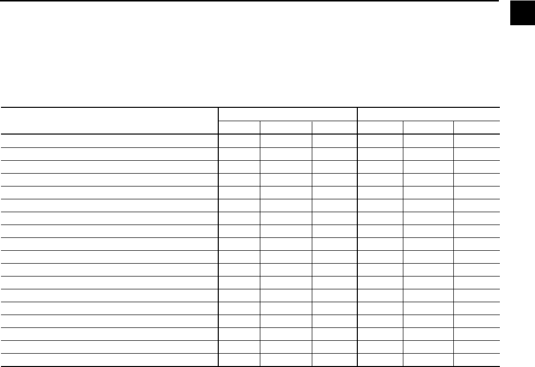
ANALOG INPUT RANGES
The following table indicates the valid display range for each of the analog input values. In the event that the input
sensor is reading a value outside of these ranges, the < or > symbols will be displayed beside the min i mum or maxi-
mum value, respectively.
*Saturation temperatures are calculated values. They will dis play XXX if the pressure used for the calculation is out of range.
ANALOG INPUT ENGLISH RANGE METRIC RANGE
LOW HIGH UNITS LOW HIGH UNITS
Leaving Chilled Liquid Temperature 0.0 82.0 °F -17.7 27.7 °C
Return Chilled Liquid Temperature 0.0 94.1 °F -17.7 34.5 °C
Leaving Condenser Liquid Temperature 8.0 133.5 °F -13.3 56.3 °C
Return Condenser Liquid Temperature 8.0 133.5 °F -13.3 56.3 °C
Evaporator Refrigerant Temperature 0.0 126.1 °F -17.7 52.3 °C
Discharge Temperature 19.0 226.3 °F -7.2 107.9 °C
Oil Temperature 19.0 226.3 °F -7.2 107.9 °C
Condenser Pressure 2.5 35.3 PSIA 17.2 243.4 KPAA
Condenser Temperature (R11)* -1.4 124.2 °F -18.5 51.2 °C
Condenser Temperature (R123)* 7.2 130.1 °F -13.7 54.5 °C
Evaporator Pressure 0.0 12.5 PSIA 6.9 86.2 KPAA
Evaporator Temperature (R11)* -31.2 66.8 °F -35.7 19.3 °C
Evaporator Temperature (R123)* -22.4 74.2 °F -30.2 23.4 °C
Oil Sump Pressure 2.9 20.9 PSIA 20.0 144.1 KPAA
Oil Pump Pressure 14.3 78.2 PSIA 98.6 539.2 KPAA
Purge Pressure 0.0 100.0 PSIA 6.9 689.5 KPAA
Refrigerant Level (Future) 0.0 100.0 % 0.0 100.0 %
Drop Leg Refrigerant Temperature 0.0 121.8 °F -17.7 49.8 °C
2
LANGUAGES
The Screens can be displayed in various languages. Lan-
guage selection is done on the USER Screen. The desired
language is selected from those avail able. Not all lan guag es
are available. English is the default language. If a language
other than English is being displayed, an English-only speak-
ing person should nav i gate to the USER Screen using the
preceding Navigation chart and select English per the USER
Screen in struc tions in this book.
YORK INTERNATIONAL
16
FORM 160.55-O1 (604)
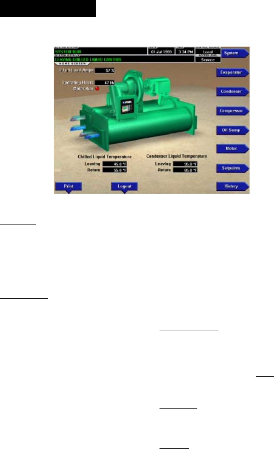
HOME SCREEN
OVERVIEW
When the chiller system is powered on, the above de-
fault display appears. The primary values which must
be monitored and controlled are shown on this screen.
The Home Screen display depicts a visual rep re sen ta tion
of the chiller itself. Animation indicates chilled liq uid
ß ow.
DISPLAY ONLY
Chilled Liquid Temperature - Leaving
Displays the temperature of the liquid as it leaves the
evaporator.
Chilled Liquid Temperature - Return
Displays the temperature of the liquid as it enters the
evaporator.
Condenser Liquid Temperature - Leaving
Displays the temperature of the liquid as it leaves the
condenser.
Condenser Liquid Temperature - Return
Displays the temperature of the liquid as it enters the
condenser.
Motor Run (LED)
Is ON when the digital output controlling the Motor
Start er contact is on.
Input Power (kW)
Available only if the chiller system is utilizing a Vari-
able Speed Drive motor controller or Mod “B” Solid
State Start er. This dis plays the total in put power used
by the sys tem.
% Full Load Amps
This displays the percentage of full load amps utilized
by the system.
Operating Hours
Displays the cumulative operating hours of the chiller.
PROGRAMMABLE
Login
Access Level Re quired: VIEW
The Control Center restricts certain op er a tions based
on password entry by the operator. Three dif fer ent ac-
cess lev els are provided as follows: VIEW: The panel
de faults to the low est access level which is termed
VIEW. In this mode, the chiller op er at ing val ues and
setpoints can be ob served, but no changes can be made.
OP ER A TOR: The second ac cess level is termed OP-
ER A TOR and will allow the cus tom er to change all
of the setpoints re quired to op er ate the chill er system.
The OP ER A TOR access level reverts to the VIEW
lev el af ter 10 continuous minutes without a keypress.
SER VICE: In the event that advanced di ag nos tics are
nec es sary, a SER VICE ac cess level has been pro vid ed.
00347VIP
FIG. 4
OptiView Control Center

FORM 160.55-O1 (604)
17
YORK INTERNATIONAL
Only qual i Þ ed service personnel utilize this access lev el.
This lev el provides advanced control over many of the
chiller func tions and allows cal i bra tion of many of the
chiller con trols. The access lev els are listed above in
hierarchical order be gin ning with the lowest level and
proceeding to the high est level. Users logged in under
higher access levels may perform any actions per mit ted
by lower access levels.
The OPERATOR access level is ac com pa nied by a
10-minute timeout. After ten (10) suc ces sive minutes
with out a keypress, the panel will re vert to the VIEW
ac cess level. This prevents un au tho rized changes to the
chiller if a user was logged in at a higher access level
and failed to logout. Proper pro ce dure requires that af ter
making necessary setpoint ad just ments the user re turn
to the Home Screen and logout.
Logout
Access Level Required: OP ER A TOR
This key is displayed when a user is logged in at any
level other than VIEW. Pressing it will return the ac cess
level to VIEW.
Print
Access Level Required: VIEW
Use this key to generate a hard-copy report of the present
system status. This provides a snapshot of the primary
operating conditions at the time the key is pressed. The
History page provides enhanced reporting ca pa bil i ty.
(See HISTORY below.) This option will not be present
if the chill er is pres ent ly conÞ gured to log any in com ing
Adap tive Ca pac i ty Con trol map points. (See the Adap-
tive Capacity Control Details screen.)
Message Clear
Access Level Required: SER VICE
When certain safety or cycling conditions have been
detected and the chiller has been shutdown, the main
status display of the chiller will continue to display a
message indicating the cause of the shutdown. Using
this key, the message can be cleared once the condition
has been removed.
Warning Reset
Access Level Re quired: OP ER A TOR
Use of this key acknowledges a warning condition and
resets the message display associated with it.
NAVIGATION
System
Used to provide additional system information.
Evaporator
A detailed view of all evaporator parameters, in clud ing
the programmable Leaving Chilled Liq uid Setpoints.
Condenser
A detailed view of all condenser parameters, in clud ing
control of the purge functions.
Compressor
A detailed view of all the compressor pa ram e ters. This
includes pre-rotation vane control, Hot Gas Bypass
Control and PRV cal i bra tion.
Oil Sump
A detailed view of all the oil pump and oil sump pa-
ram e ters.
Motor
A detailed view of the motor controller pa ram e ters, spe-
ciÞ c to the controller type presently utilized on the chill er
system. This allows programming of the Cur rent Limit
and the Pulldown Demand Lim it values. For a VSD
system, the Adaptive Capacity Control and Har mon ic
Filter information is con trolled under this screen.
Setpoints
This screen provides a single location to pro gram the
most common system setpoints. It is also the gateway
to many of the general system setup pa ram e ters such as
Date/Time, Display Units, Sched ul ing, Printer Setup,
etc.
History
This screen provides access to a snapshot of system data
at each of the last 10 shutdown con di tions.
2

YORK INTERNATIONAL
18
FORM 160.55-O1 (604)
SYSTEM SCREEN
OVERVIEW
This screen gives a general overview of common chill er
parameters for both shells.
DISPLAY ONLY
Discharge Temperature
Displays the temperature of the refrigerant in its gas-
eous state at discharge of the compressor as it travels
to the condenser.
Chilled Liquid Temperature - Leaving
Displays the temperature of the liquid as it leaves the
evaporator.
Chilled Liquid Temperature - Return
Displays the temperature of the liquid as it enters the
evaporator.
Chilled Liquid Temperature - Setpoint
Displays the active temperature setpoint to which the
chiller is controlling the evaporator liquid. This value
could come from a 0-20mA or 4-20mA, 0-10VDC or 2-
10VDC input in An a log Remote mode, PWM signal in
Digital Remote mode, MicroGateway interface in ISN
mode or a locally pro grammed value in local mode.
Evaporator Pressure
Displays the present refrigerant pressure in the evap o ra tor.
Evaporator Saturation Temperature
Displays the present saturation temperature in the
evap o ra tor.
Condenser Liquid Temperature - Leaving
Displays the temperature of the liquid as it leaves the
condenser.
Condenser Liquid Temperature - Return
Displays the temperature of the liquid as it enters the
condenser.
Condenser Pressure
Displays the refrigerant pressure in the condenser.
Condenser Saturation Temperature
Displays the saturation temperature in the condenser.
Oil Sump Temperature
Displays the temperature of the oil in the sump.
Oil Pressure
Displays the pressure differential between the pump oil
pressure transducer and the sump oil pressure trans duc er.
If either of the transducers used to cal cu late this dif fer -
en tial is out of range, the display Þ eld will show XX.X.
% Full Load Amps
This displays the percentage of full load amps utilized
by the system.
00348VIP
FIG. 5
OptiView Control Center

FORM 160.55-O1 (604)
19
YORK INTERNATIONAL
Current Limit
Displays the current limit value in use. This value could
come from a 0-20mA or 4-20mA, 0-10VDC or 2-10VDC
input in An a log Remote mode, PWM signal in Digital
Remote mode, MicroGateway interface in ISN mode or
a locally pro grammed value.
PROGRAMMABLE
None
NAVIGATION
Home
Access Level Re quired: VIEW
Causes an instant return to the Home Screen.
2
YORK INTERNATIONAL
20
FORM 160.55-O1 (604)
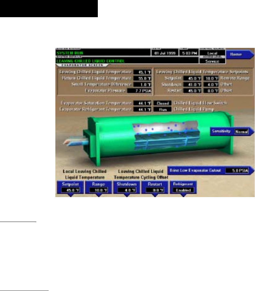
EVAPORATOR SCREEN
OVERVIEW
This screen displays a cutaway view of the chiller evap-
o ra tor. All setpoints relating to the evaporator side of
the chiller are maintained on this screen. Animation of
the evaporation process indicates whether the chill er is
presently in a RUN condition. Animation of the liq uid
ß ow indicates chilled liquid ß ow.
DISPLAY ONLY
Chilled Liquid Flow Switch (Open / Closed)
Displays whether the liquid ß ow is present in the
evap o ra tor.
Chilled Liquid Pump
Displays the command presently sent by the control
center to the Chilled Liquid Pump (RUN or STOP).
Evaporator Pressure
Displays the present refrigerant pressure in the evap o ra tor.
Evaporator Saturation Temperature
Displays the present saturation temperature in the evap-
o ra tor.
Return Chilled Liquid Temperature
Displays the temperature of the liquid as it enters the
evaporator.
Leaving Chilled Liquid Temperature
Displays the temperature of the liquid as it leaves the
evaporator.
Evaporator Refrigerant Temperature
Displays the temperature of the refrigerant in the evap o -
ra tor, if the sensor is present.
Small Temperature Difference
Displays the difference between the Leaving Chilled
Liquid temperature and the Evaporator Refrigerant tem-
per a ture. The Evaporator Refrigerant temperature will be
represented by the Refrigerant Temperature sensor input
if the sensor is present, otherwise it will be rep re sent ed
by the Evaporator Saturation temperature.
Leaving Chilled Liquid Temperature Setpoints –
Setpoint
Displays the present setpoint to which the chiller is op er -
at ing, whether controlled locally or remotely.
Leaving Chilled Liquid Temperature Setpoints
– Shut down
Displays the Leaving Chilled Liquid Tem per a ture at which
the chiller will shut down to avoid over-cooling the build-
ing. By default this value is 4°F below the Leav ing Chilled
Setpoint.
Leaving Chilled Liquid Temperature Setpoints
– Restart
Displays the Leaving Chilled Liquid Tem per a ture at
which the chiller will restart after it has shut down due
to over-cooling temperature. By default, the chiller
will restart at the Leaving Chilled Liquid Tem per a ture
Setpoint.
00349VIP
FIG. 6
OptiView Control Center

FORM 160.55-O1 (604)
21
YORK INTERNATIONAL
PROGRAMMABLE
Local Leaving Chilled Liquid Tem per a ture -
Range Access Level Re quired: OP ER A TOR
This is the range over which an analog (0-20mA or 4-
20mA, 0-10VDC or 2-10VDC) in Analog Remote Mode
or a digital signal (PWM) in Digital remote mode can reset
the Leaving Chilled Liquid Temperature setpoint above
the operator programmed Base Setpoint (see be low).
Pro gram ma ble as ei ther 10°F or 20°F, with a de fault
of 20°F, it is added to the Base value to create a range
over which the re mote device can reset the setpoint. For
example, if this setpoint is pro grammed for 10°F and
the operator pro grammed value is 45°F, then the remote
device can set the Leav ing Chilled Liq uid Tem per a ture
setpoint over the range 45.0° - 55.0°F.
Local Leaving Chilled Liquid Temperature -
Setpoint
Access Level Re quired: OPERATOR
This value allows the user to deÞ ne the Leav ing Chilled
Liquid Temperature that is to be maintained by the chill er.
It is programmable over the range of 38.0°F to 70.0°F
(water) or 10.0°F to 70.0°F (brine). If Smart Freeze (see
below) is enabled, the range is 36.0°F to 70.0°F (water).
A remote device can provide an analog signal (0-20mA
or 4-20mA, 0-10VDC or 2-10VDC) in An a log Remote
mode or PWM signal in Digital Remote mode that chang-
es the setpoint by creating an offset above the operator
pro grammed Base Leaving Chilled Liquid Tem per a ture
setpoint. This offset may be de Þ ned up to 10.0°F or
20.0°F above the Base setpoint (see the Remote Leav ing
Chilled Liquid Temperature Setpoint Range de scrip tion
above). Additionally, a MicroGateway (in ISN Re mote
mode) can deÞ ne the setpoint through a serial data
stream. In this case, the in com ing setpoint is not an
off set that is applied to the locally programmed Base
setpoint value, but rath er is the setpoint value it self.
Leaving Chilled Liquid Temperature Cycling
Offset - Shutdown
Access Level Re quired: OP ER A TOR
This value allows the user to specify the Leaving Chilled
Liquid Temperature at which the chiller will shut down
on a LEAVING CHILLED LIQUID – LOW TEM-
PER A TURE cycling shutdown. This is done by de Þ n ing
an offset below the Leaving Chilled Liquid Tem per a ture
setpoint. It is programmable over a range of 1°F to 64°F
below the setpoint, to a minimum cutout of 36°F (water),
34°F (water with Smart Freeze enabled) or 6°F (brine). It
establishes the minimum allowable tem per a ture for the
Leaving Chilled Liquid Temperature and pre vents over-
cooling of the building. Anytime the Leaving Chilled
Liquid Temperature setpoint is in creased, the shut down
threshold is 36.0°F (water) or 6.0°F (brine) for the next
ten (10) minutes. If Smart Freeze (see be low) is enabled,
the threshold is 34.0°F for the next 10 minutes. After
ten (10) minutes have elapsed, the shut down thresh old
becomes the pro grammed setpoint val ue.
Leaving Chilled Liquid Temperature Cycling
Offset - Restart
Access Level Re quired: OP ER A TOR
This value allows the user to specify the Leaving Chilled
Liquid Temperature at which the chiller will restart
af ter a shutdown on a LEAVING CHILLED LIQ UID
– LOW TEMPERATURE cycling shutdown. This is
done by deÞ ning an offset above the Leaving Chilled
Liquid Temperature setpoint. It is pro gram ma ble over a
range of 0°F to 70°F above the setpoint, to a max i mum
restart value of 80°F. The chiller will au to mat i cal ly re-
start when this temperature is reached. This setpoint can
be used to reduce chiller cycling by de lay ing the chiller
restart until the cooling load has in creased.
Brine Low Evaporator Cutout
Ac cess Level Re quired: SERVICE
This value is only available in Brine mode. It allows
the user to specify the Evaporator Pressure at which a
safe ty shutdown is initiated. Service Technicians refer
to YORK Service Manual 160.55-M1.
Sensitivity
Access Level Re quired: SER VICE
This value allows the user to adjust the sen si tiv i ty of the
Leaving Chilled Liquid Temperature con trol. Service
Tech ni cians refer to YORK Service Manual 160.55-
M1.
Smart Freeze (Off / On)
Access Level Re quired: SER VICE
This value is only available if the chiller is not in Brine
mode. It allows the user to enable the Smart Freeze Point
Operation which allows the chiller to run closer to the
freeze point without shutting down. Service Tech ni cians
refer to YORK Service Manual 160.55-M1.
Refrigerant (Enabled / Disabled)
Access Level Re quired: SER VICE
When an Evaporator Refrigerant Sensor has been in stalled
it must be enabled via this toggle before the sys tem will
utilize the new, enhanced resolution input. Ser vice Tech-
ni cians refer to YORK Service Manual 160.55-M1.
NAVIGATION
Home
Access Level Re quired: VIEW
Causes an instant return to the Home Screen.
2

YORK INTERNATIONAL
22
FORM 160.55-O1 (604)
CONDENSER SCREEN
OVERVIEW
This screen displays a cutaway view of the chiller
con dens er. All setpoints relating to the condenser side
of the chiller are maintained on this screen. Animation
indicates condenser liquid ß ow. This screen also serves
as a gateway to controlling the Refrigerant Level.
DISPLAY ONLY
Leaving Condenser Liquid Temperature
Displays the water temperature as it leaves the con dens er.
Return Condenser Liquid Temperature
Displays the water temperature as it enters the con-
dens er.
Condenser Pressure
Displays the refrigerant pressure in the condenser.
Condenser Saturation Temperature
Displays the saturation temperature in the condenser.
Small Temperature Difference
Displays the difference between the Condenser Re frig -
er ant temperature and the Leaving Condenser Liq uid
tem per a ture. The Condenser Refrigerant tem per a ture
will be represented by the Condenser Saturation tem-
per a ture.
Drop Leg Refrigerant Temperature
Displays the temperature of the refrigerant in the drop
leg between the condenser and evaporator shells, if the
sensor is present.
Sub-Cooling Temperature
Displays the difference between the Condenser Re frig -
er ant temperature and the Drop Leg Refrigerant tem-
per a ture. The Condenser Refrigerant temperature will
be represented by the Condenser Saturation tem per a ture.
If the Drop Leg sensor is not present, this tem per a ture
is not displayed.
High Pressure Switch (Open / Closed)
Displays the present position of the high pressure switch.
This will indicate whether a High Pres sure fault is pres-
ent.
Condenser Liquid Flow Switch
Indicates whether ß ow is present in the con dens er.
Condenser Liquid Pump (Run / Stop)
Indicates whether Condenser liquid pump is operat-
ing.
Refrigerant Level Position
Displays the present position of the refrigerant level if
this function is enabled.
00350VIP0
FIG. 7
OptiView Control Center

FORM 160.55-O1 (604)
23
YORK INTERNATIONAL
Refrigerant Level Setpoint
Displays the setpoint to which the refrigerant level is
being con trolled.
Ramp Up Time Remaining
Displays the time remaining in the period in which
the Re frig er ant Level Setpoint is being ramped to the
Re frig er ant Level Target Setpoint. This only dis played
if the Re frig er ant Ramp is in effect and the value is
non-zero. Service Technicians refer to YORK Service
Man u al 160.55-M1.
PROGRAMMABLE
High Pressure Warning Threshold
Access Level Re quired: SER VICE
This value allows the user to deÞ ne the con dens er pres-
sure at which the chiller will initiate a warn ing.
Drop Leg (Enabled / Disabled)
Access Level Required: SERVICE
When a Drop Leg Refrigerant Sensor has been in stalled
it must be enabled via this toggle before the system will
utilize the new, enhanced resolution input. Service Tech-
ni cians refer to YORK Ser vice Manual 160.55-M1.
NAVIGATION
Home
Ac cess Level Re quired: VIEW
Causes an instant return to the Home Screen.
Purge
Access Level Re quired: VIEW
Moves to the subscreen al low ing programming of the
Purge System Setpoints.
Refrigerant Level Control
Access Level Re quired: SERVICE
Moves to the sub-screen allowing programming of the
Refrigerant Level control setpoints.
2
YORK INTERNATIONAL
24
FORM 160.55-O1 (604)
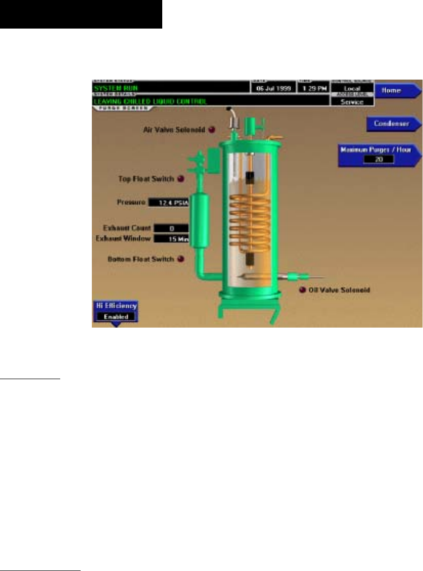
PURGE SCREEN
00351VIP
FIG. 8
OVERVIEW
This screen displays a cutaway view of the Purge Tank.
LED’s depict the state of the Float switches, Oil Valve
solenoid and Air Valve solenoid and the purge exhaust
count is displayed. All setpoints relating to the purge
sys tem are maintained on this screen. The Purge tank
oil level, based on the position of the ß oat switches,
is de pict ed through animation. When both the Float
Switch es are closed, the oil level is shown at its lowest
(empty) level. When both Float switches are open, the
level is shown at its highest (full) level. Levels be tween
these ex tremes are shown at midpoint.
DISPLAY ONLY
Air Valve Solenoid (LED)
Illuminated when the Air Valve Solenoid is energized
(open), venting non-condensibles from the Purge tank.
Oth er wise, extinguished. For High EfÞ ciency (pump
assisted) purge systems, the valve is en er gized at >90.0
PSIA and de-energizes when the pressure decreases to
<80.0 PSIA. For non-assisted purge systems, the valve
is energized at >34.7 PSIA and de-energized when the
pressure decreases to <29.7 PSIA.
Top Float Switch (LED)
Illuminated when the Top Float Switch is closed,
in di cat ing the Purge Tank oil level is less than full.
Ex tin guished when it is open, indicating the level is at
max i mum (full).
Bottom Float Switch (LED)
Illuminated when the Bottom Float Switch is closed, in-
di cat ing the Purge Tank oil level is at minimum (emp ty).
Extinguished when it is open, indicating the oil level is
above minimum.
Oil Valve Solenoid (LED)
Illuminated when the Oil Valve Solenoid is energized,
Þ lling the Purge Tank with oil. Extinguished when it is
de-energized, draining the oil from the Purge tank.
Pressure
Displays the pressure in the Purge Tank.
Exhaust Count
Displays the number of purge exhausts that have oc-
curred within the last 0 to 60 minutes, as displayed in
the Exhaust Window. After a 60 minute bypass at chill er
start, purge exhausts are counted until the Excess Purge
threshold is reached or the chiller shuts down, where-
up on the count is frozen. The count will be reset when
the chiller starts.
Exhaust Window
Displayed as 0 to 60 minutes. After a 60 minute bypass
at chiller start, the Exhaust Window increments from 0
OptiView Control Center

FORM 160.55-O1 (604)
25
YORK INTERNATIONAL
to 60. During this period, purge exhausts are counted
and the Exhaust Count displayed is that which has oc-
curred in the last number of minutes displayed in the
Exhaust Window. After the Exhaust Window reaches
60, the purge exhausts that occurred in the oldest min-
ute are discarded from the Exhaust Count and exhausts
from the most recent minute are shifted in, providing a
roll ing count of purge exhausts that occurred in the last
60 minutes. It remains at 60 until the chiller is restarted,
whereupon it is reset to 0.
Bypass Time Left
Replaces “Exhaust Window” label during the Þ rst 60
minutes of chiller run. Counts down the 60 minute purge
count bypass.
PROGRAMMABLE
High Effi ciency Purge System (Enabled/Disabled)
Access Level Required: SERVICE
Selects the appropriate control and purge exhaust
thresh olds for the installed purge system. High EfÞ -
ciency (pump assisted) purge systems exhaust at >90.0
PSIA. Non pump-assisted purge systems exhaust at
>34.7 PSIA.
Maximum Purges/Hour
Access Level Required: OP ER A TOR/SERVICE
Allows the user to deÞ ne the number of purge air ex-
hausts permitted before an Excess Purge Warning is dis-
played. With OPERATOR access lev el, the value can be
pro grammed over a range of 10 to 30 Purges/Hour. Ser-
vice Technicians, in SERVICE ac cess level can pro gram
this setpoint over a greater range. Service Tech ni cians
refer to YORK Service Manual 160.55-M1.
NAVIGATION
Home
Access Level Required: VIEW
Causes an instant return to the Home Screen.
Condenser
Access Level Required: VIEW
Causes an instant return to the Condenser Screen.
2

YORK INTERNATIONAL
26
FORM 160.55-O1 (604)
REFRIGERANT LEVEL CONTROL SCREEN
FIG. 9 00303VIP
OVERVIEW
This screen displays a cutaway view of the chiller con-
dens er, along with the liquid refrigerant level sensor and
the ß ow control valve. All setpoints relating to the liq uid
level control are maintained on this screen. Through
animation, the variable oriÞ ce position is dis played. In
addition, the refrigerant ß ow control valve (variable
or i Þ ce) can be man u al ly op er at ed.
Requires a login ac cess level of
SERVICE. Service Tech ni cians re fer
to YORK Service Manual 160.55-M1
for operation in struc tions and ex pla -
na tion of all pro gram ma ble setpoints
and dis played values.
DISPLAY ONLY
Refrigerant Level Position
Displays the present position of the liquid level. The
re frig er ant level is animated in the cutaway view of the
condenser. When the actual level is 0% to 15%, the level
is shown about 50% full. When the actual level is 16%
to 31%, the level is shown about 60% full. When the
actual lev el is 32% to 47%, the level is shown about 70%
full. When the actual level is 48% to 63%, the level is
shown about 80% full. When the actual level is 64% to
79%, the level is shown as about 90% full. Ac tu al levels
above 79%, shown as 100% full.
Refrigerant Level Control Mode
Indicates whether the liquid level control is under man-
u al or automatic control.
Raise (LED)
Is ON when the digital output controlling the Level
Raise contact is on.
Lower (LED)
Is ON when the digital output controlling the Level
Low er contact is on.
PROGRAMMABLE
[Refrigerant Level] Setpoint
Service Technicians refer to YORK Service Manual
160.55-M1.
[Refrigerant Level Control] Period
Service Technicians refer to YORK Service Manual
160.55-M1.
[Refrigerant Level Control] Proportional
Limit Open
Service Technicians refer to YORK Service Manual
160.55-M1.
OptiView Control Center

FORM 160.55-O1 (604)
27
YORK INTERNATIONAL
[Refrigerant Level Control] Proportional
Limit Close
Service Technicians refer to YORK Service Manual
160.55-M1.
[Refrigerant Level Control] Rate Limit Open
Service Technicians refer to YORK Service Manual
160.55-M1.
[Refrigerant Level Control] Rate Limit Close
Service Technicians refer to YORK Service Manual
160.55-M1.
[Refrigerant Level Control] Raise (Man u al)
This key puts the level control into manual mode and
sends a RAISE command to the variable oriÞ ce.
[Refrigerant Level Control] Lower (Manual)
This key puts the level control into manual mode and
sends a LOWER command to the variable oriÞ ce.
[Refrigerant Level Control] Hold (Manual)
This key puts the level control into manual mode and
sends a HOLD command to the variable oriÞ ce.
[Refrigerant Level Control] Auto
Returns the Level Control to automatic mode.
NAVIGATION
Home
Ac cess Level Re quired: VIEW
Causes an instant return to the Home Screen.
Condenser
Ac cess Level Re quired: VIEW
Return to the Condenser Screen.
2

YORK INTERNATIONAL
28
FORM 160.55-O1 (604)
COMPRESSOR SCREEN
OVERVIEW
This screen displays a cutaway view of the chiller com-
pres sor, revealing the impeller and shows all con di tions
as so ci at ed with the compressor. In addition, with the
proper Access Level, the pre-rotation vanes may be
manually controlled. Animation of the com pres sor
im pel ler indicates whether the chiller is pres ent ly in a
RUN condition. This screen also serves as a gateway
to subscreens for cal i brat ing the pre-rotation vanes, cal-
i brat ing the proximity probe, conÞ guring the Hot Gas
By pass or providing advanced control of the com pres sor
motor Variable Speed Drive.
DISPLAY ONLY
Oil Pressure
Displays the pressure differential between the high side
oil pressure transducer (compressor bearing input) and
the low side oil pressure transducer (oil sump). If ei ther
of the trans duc ers used to calculate this dif fer en tial is
out of range, the display Þ eld will show XX.X.
Oil Sump Temperature
Displays the temperature of the oil in the sump
Discharge Temperature
Displays the temperature of the refrigerant in its gas eous
state at discharge of the compressor as it travels to the
condenser.
Superheat Temperature
Displays the discharge superheat temperature, cal cu -
lat ed as (Discharge temperature – Condenser Sat u rat ed
temperature).
Vane Motor Switch (LED)
Illuminates when the vanes are completely closed.
Vent Line Solenoid (LED)
Illuminates when the solenoid is energized.
Pre-Rotation Vanes Control Mode
Access Level Re quired: SER VICE
Indicates whether the vanes are under manual or au to -
mat ic control.
[Pre-Rotation Vanes] Open (LED)
Access Level Required: SERVICE
Indicates whether the vanes are in the process of open ing.
[Pre-Rotation Vanes] Close (LED)
Access Level Re quired: SER VICE
Indicates whether the vanes are in the process of clos ing.
Pre-Rotation Vanes Position
(Variable Speed Drive only)
Access Level Required: SERVICE
This value displays the present position of the pre-ro-
ta tion vanes as a percentage between 0 and 100%.
00483VIP
FIG. 10
OptiView Control Center

FORM 160.55-O1 (604)
29
YORK INTERNATIONAL
Full Load Amps
Access Level Re quired: SER VICE
Displays the motor current as a percentage of the Full
Load Amps (FLA) value.
Phase A, B, C Current (Solid State Starter only)
Access Level Required: SERVICE
Displays the 3-phase motor current values being read
from the Solid State Starter.
PROGRAMMABLE
[Pre-Rotation Vanes] Open (Manual)
Access Level Required: SERVICE
This key puts the vane control into manual mode and
sends an OPEN command to the vanes.
[Pre-Rotation Vanes] Close (Manual)
Access Level Required: SERVICE
This key puts the vane control into manual mode and
sends a CLOSE command to the vanes.
[Pre-Rotation Vanes] Hold (Manual)
Access Level Re quired: SER VICE
This key puts the vane control into manual mode and
sends a HOLD command to the vanes.
[Pre-Rotation Vanes] Auto
Access Level Required: SERVICE
This key returns the vane control to automatic mode.
NAVIGATION
Home
Access Level Required: VIEW
Causes an instant return to the Home Screen.
Pre-Rotation Vane Calibration
Access Level Re quired: SER VICE
Only available if the chiller is stopped and the system
uses a Variable Speed Drive or Hot Gas Bypass con-
trol. Moves to the subscreen allowing calibration of the
Pre-rotation vanes. Service Technicians refer to YORK
Service Manual 160.55-M1.
VSD TUNING (Variable Speed Drive only)
Access Level Required: SERVICE
Moves to the subscreen allowing advanced tuning of
the Variable Speed Drive. Service Technicians refer to
YORK Service Manual 160.55-M1.
Hot Gas
Access Level Required: SERVICE
Moves to the subscreen that allows programming of the
Hot Gas Bypass control setpoints and manual con trol
of the Hot Gas Bypass valve. Only displayed if Hot gas
Bypass feature has been enabled on the OP ER A TIONS
Screen. Service technicians refer to YORK Service
Manual 160.55-M1.
Surge
(Flash memory Card version C.MLM.02.02.xxx and
lat er)
Access Level Required: VIEW
Moves to the sub-screen that allows viewing and
pro gram ming of the Surge Protection feature. Service
Tech ni cians refer to Service Manual 160.55-M1.
2
YORK INTERNATIONAL
30
FORM 160.55-O1 (604)
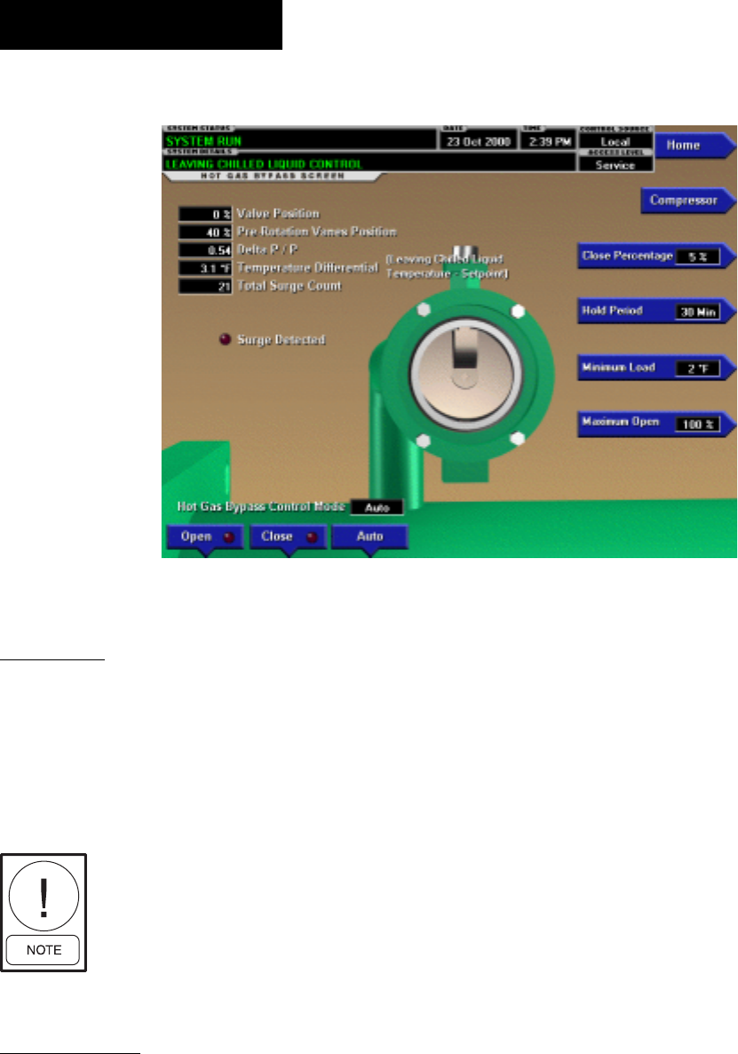
OVERVIEW
This screen displays a cutaway view of the Hot Gas By pass
Valve. All setpoints relating to Hot Gas Bypass con trol are
maintained on this screen. Also, related Hot Gas Bypass
control parameters are displayed for ref er ence. Through
animation, the relative valve position is dis played. In ad-
dition, the valve can be manually op er at ed.
Requires access level of SERVICE.
Ser vice Tech ni cians refer to YORK
Service Man u al 160.55-M1 for op-
er a tion in struc tions and explanation
of all pro gram ma ble setpoints and
dis played val ues.
DISPLAY ONLY
Valve Position
Displays the position of the Hot Gas valve over the
range of 0% (closed) to 100% (fully open). The valve
position is animated. When the actual position is 0% to
19%, the valve is shown fully closed. When actual posi-
tion is 20% to 39% the valve is shown 25% open. When
ac tu al po si tion is 40% to 59%, the valve is shown 50%
open. When actual position is 60% to 79%, the valve is
shown as 75% open. Positions greater than 79% shown
as full open.
Pre-rotation Vanes Position
Displays the position of the Pre-Rotation Vanes over the
range of 0% (closed) to 100% (fully open). Dis played
at XXX until calibration procedure is per formed by
service technician.
Delta P/P
A parameter that represents system differential or
“Head”. It is calculated as [(condenser pressure – evap o -
ra tor pressure) / evaporator pressure].
Temperature Differential
The difference between the Leaving Chilled Liquid Tem-
per a ture and the Leaving Chilled Liquid Tem per a ture
Setpoint. It is cal cu lat ed by sub tract ing the Leav ing
Chilled Liq uid tem per a ture from the Leav ing Chilled
Liquid Tem per a ture Setpoint.
Total Surge Count
This is the total number of surge events that have been
detected over the lifetime of the chiller. These are the
surge events detected by the Surge Protection feature.
The surge events detected by the compressor Variable
Speed Drive Adaptive Capacity Control Board are not
included in this total.
Surge Detected (LED)
Illuminated for 5 seconds each time a surge is detected
by the Surge Protection feature. It does not illuminate
FIG. 11
HOT GAS BYPASS SCREEN
OptiView Control Center
00476VIP
OptiView Control Center

FORM 160.55-O1 (604)
31
YORK INTERNATIONAL
in response to surge events detected by the compres-
sor Variable Speed Drive Adaptive Capacity Control
Board.
Hot Gas Bypass Control Mode
Indicates whether the Hot Gas Bypass is under au to mat ic,
manual or override control. “Override” is dis played dur-
ing Minimum Load over ride conditions or when the
Compressor Motor Variable Speed (if equipped) Drive
is run ning at less than maximum speed.
PROGRAMMABLE
Close Percentage
Service technicians refer to YORK Service Manual
160.55-M1.
Hold Period
Service technicians refer to YORK Service Manual
160.55-M1.
Surge Sensitivity
(Flash Memory Card version C.MLM.02.01.xxx and
earlier. On SURGE PRO TEC TION Screen in later
Flash Memory Card ver sions)
Service technicians refer to YORK Service Manual
160.55-M1.
Minimum Load
Service technicians refer to YORK Service Manual
160.55-M1.
Maximum Open
(Flash Memory Card version C.MLM.02.02.xxx
and later)
Service Technicians refer to YORK Ser vice Man u al
160.55-M1.
[Hot Gas Bypass Control] Open (Manual)
This key puts the Hot Gas Bypass Control in manual
mode and increases the valve position by 5%.
[Hot Gas Bypass Control] Close (Manual)
This key puts the Hot Gas Bypass Control in manual
mode and decreases the valve position by 5%.
[Hot Gas Bypass Control] Auto
Returns the Hot Gas Bypass Control to automatic
mode.
NAVIGATION
Home
Access Level Required: VIEW
Causes an instant return to the Home Screen.
Compressor
Access Level Required: VIEW
Causes an instant return to the Compressor Screen.
2
YORK INTERNATIONAL
32
FORM 160.55-O1 (604)
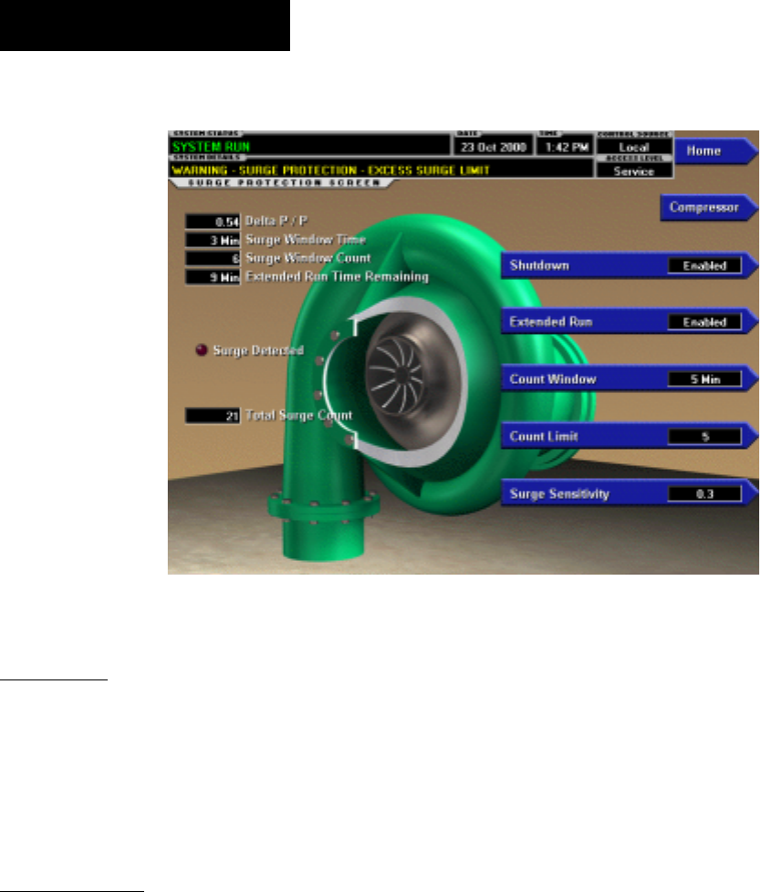
OVERVIEW
(This feature applies to Flash Memory Card ver sion
C.MLM.02.02.xxx and later)
This screen displays a cutaway view of the chiller
com pres sor and all parameters relating to the Surge
Pro tec tion feature. All setpoints relating to this fea ture
are maintained on this screen.
DISPLAY ONLY
Delta P/P
A parameter that represents the system differential or
“Head pressure”. It is calculated as (condenser pres sure
– evaporator pressure) / evaporator pres sure.
Surge Window Time
When the chiller enters run mode, this value counts
up to the time pro grammed as the COUNT WIN DOW
setpoint. When it reach es the COUNT WIN DOW min-
utes, the num ber of surge events in the oldest minute is
dis card ed and the number of surge events in the most
recent minute is added, thus pro vid ing a rolling count
of the total surge events that have occurred in the last
COUNT WINDOW min utes. This val ue is reset when
the chiller shuts down.
Surge Window Count
Displays the number of surge events that have oc-
SURGE PROTECTION SCREEN
curred in the last 1 to 5 minutes as programmed with
the COUNT WINDOW setpoint. If the chiller has been
running for less than the COUNT WINDOW minutes, it
is the number of surge events that have occurred with in
the last number of minutes dis played as the SURGE
WINDOW TIME. The count is cleared when the chiller
shuts down.
Surge Detected (LED)
Illuminates for 5 seconds each time a surge is de tect ed
by the Surge Protection feature. It does not illuminate
in response to surge events detected by the compres-
sor Variable Speed Drive Adaptive Capacity Control
Board.
Total Surge Count
Displays the total number of surge events detected over
the lifetime of the unit (up to a maximum of 65535).
These are the surge events detected by the Surge Protec-
tion feature. The surge events detected by the compressor
Variable Speed Drive Adaptive Capacity Control Board
are not included in this total.
Extended Run Time Remaining
Displays the time remaining in the 10-minute “EX-
TEND ED RUN” period. During this period, the Pre-
rotation vanes are driven closed and “Warning – Surge
Protection – Excess Surge Limit” is dis played. Refer to
operation under “Count Limit” below.
FIG. 12 00482VIP
OptiView Control Center

FORM 160.55-O1 (604)
33
YORK INTERNATIONAL
PROGRAMMABLE
Shutdown (Enabled/Disabled)
Access Level Required: OPERATOR
Allows the user to select whether the chiller will shut-
down or continue to run when an Excess Surge sit u a tion
has been detected.
If this setpoint is Enabled and the EXTENDED RUN
setpoint is Disabled, a safety shutdown is per formed
when the SURGE WINDOW COUNT exceeds the
COUNT LIMIT setpoint.
If this setpoint is Enabled and the EXTENDED RUN
setpoint is Enabled, a safety shutdown is per formed if
the SURGE WINDOW COUNT exceeds the COUNT
LIMIT setpoint at the completion of the 10 minute Ex-
tend ed Run period.
“Surge Protection – Excess Surge” is displayed with
either shutdown.
If this setpoint is Disabled, refer to operation under
“Count Limit” below.
With Software version C.MLM.02.05.xxx (and later) or
C.OPT.02.05.xxx (and later):
• If equipped with a compressor Variable Speed
Drive (VSD), the VSD output frequency must
be at maximum before the SHUTDOWN feature
is implemented or surge warning messages are
displayed.
• If equipped with a VSD and Hot Gas Bypass
(Enabled), the VSD output frequency must be
at maximum AND the Hot Gas Valve must be
at 100% before the SHUTDOWN feature is
implemented or surge warning messages are
displayed.
Extended Run (Enabled/Disabled)
Access Level Required: OPERATOR
Allows the user to select the surge correction/avoid ance
EXTENDED RUN mode. This will be im ple ment ed
when an Excess surge situation is detected as follows:
Anytime the SURGE WINDOW COUNT exceeds the
COUNT LIMIT, the Pre-rotation vanes are driven closed
for the next 10 minutes. While this load inhibit is in ef-
fect, “Warn ing – Surge Protection – Excess Surge Limit”
is dis played. When 10 minutes have elapsed, the warn-
ing message and load inhibit are automatically cleared,
provided the SURGE WINDOW COUNT is less than
or equal to the COUNT LIM IT. If the SHUT DOWN
setpoint is Enabled, and the SURGE WIN DOW COUNT
exceeds the COUNT LIMIT at the com ple tion of this
period, a safety shutdown is performed and “Surge
Pro tec tion – Excess Surge” is displayed.
If the Hot Gas Bypassed control is Enabled, the Hot Gas
By pass Valve position must be 100% before the Ex tend ed
Run mode is implemented. If the chill er is equipped with a
compressor motor Variable Speed Drive, output fre quen cy
must be at full speed (50 Hz/60 Hz) before the Ex tend ed
Run mode is implemented. If the chiller is equipped with
both Hot Gas Bypass and com pres sor motor Variable Speed
Drive, both of the con di tions must be met before Extended
Run is im ple ment ed.
Count Window
Access Level Required: OPERATOR
Allows the user to deÞ ne the period of time (1 to 5
minutes; default 5 ; default 3 with Software version
C.MLM.02.05.xxx {and later} or C.OPT.02.05.xxx {and
later}) in which the number of surge events (SURGE
WIN DOW COUNT) are compared to the max i mum al-
lowed (COUNT LIMIT), for the purpose of de tect ing
an excess surge situation.
Count Limit
Access Level Required: OPERATOR
Allows the user to deÞ ne the maximum number of surge
events (4 to 20; default 4; default 15 with Software ver-
sion C.MLM.02.05.xxx {and later} or C.OPT.02.05.xxx
{and later}) that can occur within a de Þ ned period of time
before an Excess Surge situation is de tect ed. If the SURGE
WINDOW COUNT exceeds the COUNT LIM IT, an Ex-
cess Surge situation has oc curred.
When an Excess Surge situation is detected, the action
de pends upon the following:
• If both the SHUTDOWN and EXTENDED RUN
setpoints are Disabled, the chiller will continue to
run, dis play ing the message “Warning – Excess
Surge detected”. See Hot Gas Bypass and Variable
Speed Drive exceptions above.
• If the SHUTDOWN setpoint is Enabled and the
EX TEND ED RUN setpoint is Disabled, the chiller
will per form a safety shutdown and display “Surge
Protection – Excess Surge”. See Hot Gas Bypass
and Variable Speed Drive exceptions above.
• If the SHUTDOWN setpoint is Disabled and the
EX TEND ED RUN setpoint is Enabled, the Pre-ro-
tation Vanes are driven closed for 10 minutes and
“Warning – Surge Pro tec tion – Excess Surge Lim it”
is displayed. When the 10 minutes have elapsed,
2

YORK INTERNATIONAL
34
FORM 160.55-O1 (604)
if the SURGE WINDOW COUNT is less than or
equal to the COUNT LIMIT, this message and load
inhibit are au to mat i cal ly cleared. Al ter nat ing with
this message is “Warning – Excess Surge De tect ed”
that continues after the 10 minute pe ri od has elapsed
until man u al ly cleared with the Warning Reset key.
See Hot Gas By pass and Variable Speed Drive ex-
ception above.
• If both the SHUTDOWN and EXTENDED RUN
setpoint are Enabled, the 10 minute Extended RUN
mode is in voked as described above. However, if the
SURGE WIN DOW COUNT exceeds the COUNT
LIMIT at the completon of the 10 minute extended
run period, a safety shutdown is per formed and
“Surge Protection – Excess Surge” is dis played. See
Hot Gas By pass and Variable Speed Drive exception
above.
Surge Sensitivity
Access Level Required: SERVICE
Allows the user to deÞ ne the surge detection sen si tiv i ty.
Se lect able over the range of 0.3 to 1.3; default 0.3. The
smaller the number, the greater the sensitivity.
Clear Surge Count
Access Level Required: ADMIN
Allows user to set the Total Surge Count to zero.
NAVIGATION
Home
Access Level Required: VIEW
Causes an instant return to the Home Screen
Compressor
Access Level Required: VIEW
Causes an instant return to the Compressor Screen.
OptiView Control Center

FORM 160.55-O1 (604)
35
YORK INTERNATIONAL
THIS PAGE INTENTIONALLY LEFT BLANK
TO MAINTAIN FORMAT
2
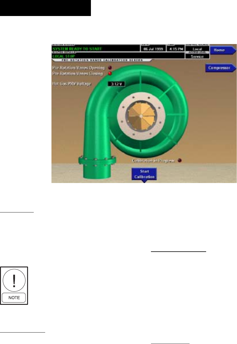
YORK INTERNATIONAL
36
FORM 160.55-O1 (604)
PRE-ROTATION VANES CALIBRATION SCREEN
OVERVIEW
This screen displays a cutaway view of the chiller com-
pres sor, revealing the pre-rotation vanes and pro vides
the capability of calibrating the pre-rotation vanes for
either Variable Speed Drive or Hot Gas By pass ap pli -
ca tions.
Requires a login ac cess level of SER-
VICE. Service Technicians refer to
YORK Service Manual 160.55-M1
for operation instructions and ex pla -
na tion of all programmable setpoints
and displayed values.
DISPLAY ONLY
Pre-Rotation Vanes Opening (LED)
Indicates the vanes are opening.
Pre-Rotation Vanes Closing (LED)
Indicates the vanes are closing.
Calibration in Progress (LED)
Indicates the calibration sequence is in progress.
Calibration Messages
These are text messages which step the user through the
calibration process and indicate its success or fail ure.
Hot Gas PRV Voltage
Displays the Pre-rotation Vanes position potentiom-
eter feed back voltage when the Hot Gas Feature is
En abled.
PROGRAMMABLE
Start Calibration
This option is hidden after cal i bra tion has start ed.
Ser vice Technicians refer to YORK Ser vice Manual
160.55-M1 for an ex pla na tion of this setpoint.
Cancel Calibration
This option only becomes available after calibration
has started. Service Technicians refer to YORK Service
Man u al 160.55-M1 for an explanation of this setpoint.
NAVIGATION
Home
Access Level Required: VIEW
Causes an instant return to the Home Screen.
Compressor
Access Level Required: VIEW
Return to the Compressor Screen.
00354VIP
FIG. 13
OptiView Control Center

FORM 160.55-O1 (604)
37
YORK INTERNATIONAL
THIS PAGE INTENTIONALLY LEFT BLANK
TO MAINTAIN FORMAT
2
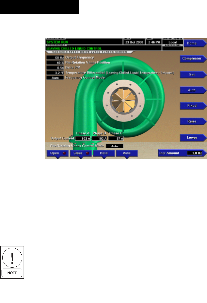
YORK INTERNATIONAL
38
FORM 160.55-O1 (604)
VSD TUNING SCREEN
OVERVIEW
This screen displays a cutaway view of the chiller com-
pres sor, revealing the pre-rotation vanes and pro vides
the capability of manually controlling the pre-rotation
vanes. Animation of the pre-rotation vanes indicates
the pre-rotation vane position. In addition, this screen
al lows manual control of the fre quen cy com mand be ing
sent to the Variable Speed Drive.
Re quires a login access level of
SERVICE. Service Technicians re fer
to YORK Service Manual 160.55-M1
for operation instructions and ex pla -
na tion of all programmable setpoints
and displayed values.
DISPLAY ONLY
Output Frequency
Displays the Output Frequency reported by the Vari able
Speed Drive.
Temperature Differential
Displays the differential between the Leaving Chilled
Liquid Temperature and Setpoint.
Delta P/P
Displays a value based on the pressure differential
be tween the Evaporator and Condenser pressures.
[(Condenser – Evaporator) / Evaporator]
Pre-Rotation Vanes Control Mode
Indicates whether the vanes are under manual or au to -
mat ic control.
[Pre-Rotation Vanes] Open (LED)
Indicates whether the vanes are in the process of
opening.
[Pre-Rotation Vanes] Close (LED)
Indicates whether the vanes are in the process of
closing.
Pre-Rotation Vane Position
This value displays the present position of the pre-ro-
ta tion vanes as a percentage between 0 and 100%.
[VSD] Command Frequency
Displays the frequency value being sent to the Adap tive
Capacity Control.
[VSD] Frequency Control Mode (Manual / Auto)
Displays the present state of the command frequency
control.
00477VIP
FIG. 14
OptiView Control Center

FORM 160.55-O1 (604)
39
YORK INTERNATIONAL
Output Current – Phase A, B, C
(Flash Memory Card version C.MLM.02.02.xxx
and later)
Displays the phase current measured to the motor.
PROGRAMMABLE
Set
Allows manual programming of the command fre quen cy
value. Manually programming this value will put the
VSD frequency control into manual mode.
Auto
Following manual programming of the command fre-
quen cy, this returns the system to automatic control.
Fixed
This key puts the VSD frequency control into Þ xed speed
mode and constantly sends the maximum fre quen cy to
the Variable Speed Drive control.
Incr Amount
DeÞ nes the amount by which the Increase and De crease
commands will modify the present VSD command fre-
quen cy.
Increase
This key puts the VSD frequency control into manual
mode and increases the present command fre quen cy by
the deÞ ned frequency increment. It will not raise the
value above the maximum allowed frequency.
Decrease
This key puts the VSD frequency control into manual
mode and decreases the present command frequency by
the deÞ ned frequency increment. It will not lower the
value below one (1) Hz.
[Pre-Rotation Vanes] Open (Manual)
This key puts the vane control into manual mode and
sends an OPEN command to the contacts.
[Pre-Rotation Vanes] Close (Manual)
This key puts the vane control into manual mode and
sends a CLOSE command to the contacts.
[Pre-Rotation Vanes] Hold (Manual)
This key puts the vane control into manual mode and
sends a HOLD command to the contacts.
[Pre-Rotation Vanes] Auto
Returns Vane Control to automatic mode.
NAVIGATION
Home
Access Level Required: VIEW
Causes an instant return to the Home Screen.
Compressor
Access Level Required: VIEW
Return to the Compressor Screen.
2
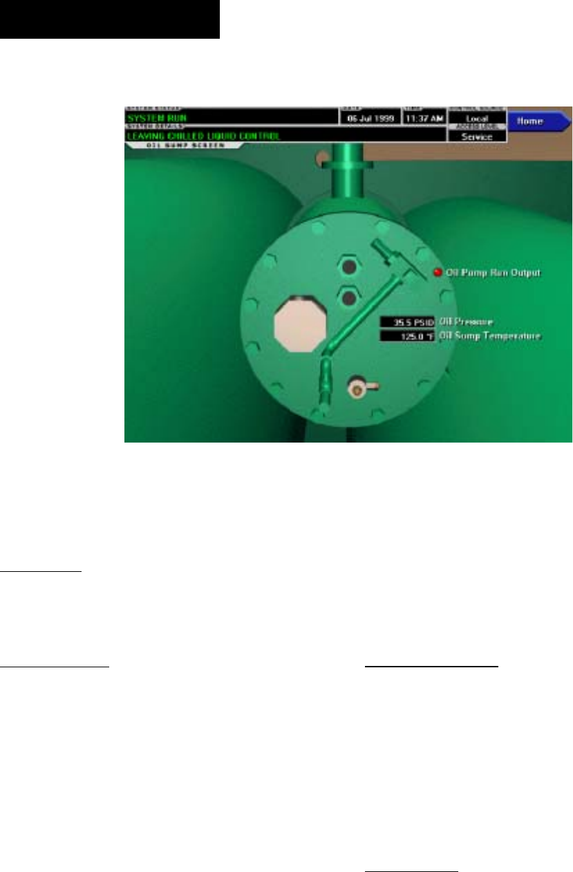
YORK INTERNATIONAL
40
FORM 160.55-O1 (604)
OIL SUMP SCREEN
OVERVIEW
This screen displays a close-up of the chiller oil
sump.
DISPLAY ONLY
Oil Sump Temperature
Displays the temperature of the oil in the sump.
Oil Pressure
Displays the pressure differential between the high side
oil pressure transducer (output of oil Þ lter) and the low
side oil pressure transducer (compressor housing). If
either of the transducers used to calculate this dif fer -
en tial is out of range, the display Þ eld will show XX.X.
Oil Pump Run Output (LED)
Indicates whether the Oil Pump is being commanded
to operate.
Manual Oil Pump Operation Time Left
Displays the time remaining in the 10-minute manual
oil pump operation described below.
PROGRAMMABLE
Manual Pump
Access Level Required: OPERATOR
This key puts the Oil Pump control in Manual Mode and
forces it to RUN. The Oil Pump is limited to run ning for
a maximum of ten (10) minutes. If a longer running time
is desired, this key must be pressed again. Manual Oil
Pump control is disabled (and the button hidden) during
system prelube, system run and system coastdown.
NAVIGATION
Home
Access Level Required: VIEW
Causes an instant return to the Home Screen.
00356VIP
FIG. 15
OptiView Control Center
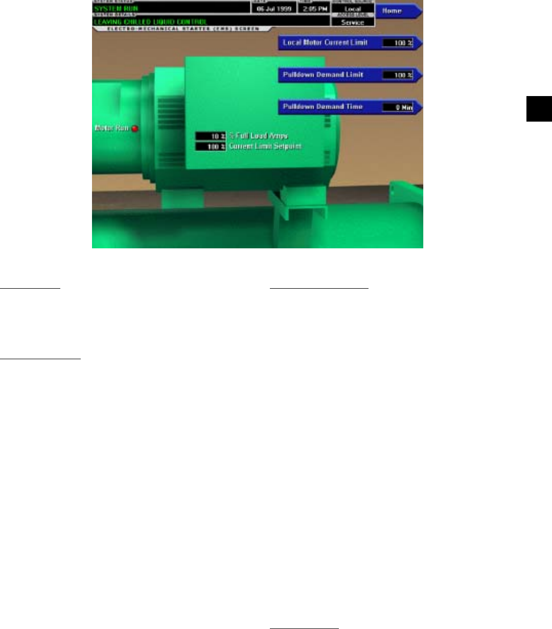
FORM 160.55-O1 (604)
41
YORK INTERNATIONAL
ELECTRO-MECHANICAL STARTER SCREEN
OVERVIEW
This screen displays all information pertaining to an
Electro-Mechanical Starter.
DISPLAY ONLY
Motor Run (LED)
Indicates whether the digital output from the controls
is commanding the motor to RUN.
Motor Current % Full Load Amps
Displays the motor current as a percentage of the Full
Load Amps (FLA) value. For the Electro-Mechanical
Starter this is the data returned by the CM-2 board.
Current Limit Setpoint
Displays the current limit value in use. This value could
come from a 0-20mA, 4-20mA, 0-10VDC or 2-10VDC
input in An a log Re mote mode, PWM signal in Digital
Re mote mode, MicroGateway in ter face in ISN mode
or a lo cal ly pro grammed value.
Pulldown Demand Time Left
Displays the time remaining in the programmed pull-
down period if the value is non-zero.
PROGRAMMABLE
Local Motor Current Limit
Access Level Required: OPERATOR
Allows the user to specify the maximum allowed mo-
tor current (as a percentage of FLA). When the motor
cur rent reaches this value, the pre-rotation vanes will
not be permitted to open further. If the motor current
rises above this value, the pre-rotation vanes will close
to reduce the current to this value.
Pulldown Demand Limit
Access Level Required: OPERATOR
Allows the user to specify the current limit value (as a
percentage of FLA) to which the chiller will be limited
during the speciÞ ed pulldown limit time. This value will
override the Motor Current Limit value during this time
period. This function is used to provide energy savings
following chiller start-up.
Pulldown Demand Time
Access Level Required: OPERATOR
Allows the user to set a period of time for which the pull-
down demand limit will be in effect after the chiller starts.
NAVIGATION
Home
Access Level Required: VIEW
Causes an instant return to the Home Screen.
00357VIP
FIG. 16
2
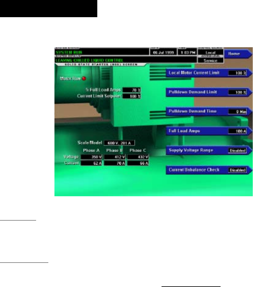
YORK INTERNATIONAL
42
FORM 160.55-O1 (604)
MOD “A” SOLID STATE STARTER SCREEN
OVERVIEW
This screen displays all information pertaining to the
Mod “A” Solid State Starter.
DISPLAY ONLY
Motor Run (LED)
Indicates whether the digital output from the controls is
commanding the motor to RUN.
Motor Current % Full Load Amps
Displays the motor current as a percentage of the Full
Load Amps (FLA) value. For the Solid State Starter this
is the data returned by the Starter Logic board.
Current Limit Setpoint
Displays the current limit value in use. This value could
come from a 0-20mA, 4-20mA, 0-10VDC or 2-10VDC
input in An a log Remote mode, PWM signal in Digital
Remote mode, MicroGateway interface in ISN mode or
a lo cal ly pro grammed value in local mode.
Pulldown Demand Time Left
Displays the time remaining in the pro grammed pull-
down period.
Scale/Model
Display information about the Liquid Cooled-Solid
State Starter Rating and the maximum allowed Full
Load Amps.
Voltage - Phase A, B, C
Display the 3-phase input line voltage values being read
from the Solid State Starter.
Current - Phase A, B, C
Display the 3-phase motor current values being read
from the Solid State Starter.
PROGRAMMABLE
Local Motor Current Limit
Access Level Required: OP ER A TOR
Allows the user to specify the maximum al lowed mo-
tor current (as a percentage of FLA). When the motor
cur rent reaches this value, the pre-rotation vanes will
not be permitted to open further. If the motor current
rises above this value, the pre-rotation vanes will close
to reduce the current to this value.
Pulldown Demand Limit
Access Level Required: OP ER A TOR
Allows the user to specify the current limit val ue (as a
percentage of FLA) to which the chiller will be limited
during the speciÞ ed pulldown limit time. This value will
override the Motor Current Limit value during this time
period. This function is used to provide energy sav ings
following chiller start-up.
Pulldown Demand Time
Access Level Required: OP ER A TOR
0058VIP
FIG. 17
OptiView Control Center

FORM 160.55-O1 (604)
43
YORK INTERNATIONAL
Allows the user to set a period of time for which the
pulldown demand limit will be in effect after the chiller
starts.
Full Load Amps
Access Level Required: SER VICE
DeÞ ne the maximum amps at which the motor can op-
er ate. This value is viewable when logged in under the
Operator or View access level. Service Technicians re fer
to YORK Service Manual 160.55-M1.
Supply Voltage Range
Access Level Required: SERVICE
Allows the user to select a speciÞ c voltage range for volt-
age checking. When not disabled, this line voltage range
is used to determine a low line and high line volt age
threshold for initiating a shutdown. Service Tech ni cians
refer to YORK Service Manual 160.55-M1.
Current Unbalance Check (Enabled / Dis abled)
Access Level Re quired: SER VICE
Allows the user to control whether the logic checks for
current unbalance and initiates a shutdown as a result.
Service Technicians refer to YORK Service Manual
160.55-M1.
NAVIGATION
Home
Access Level Re quired: VIEW
Causes an instant return to the Home Screen.
2
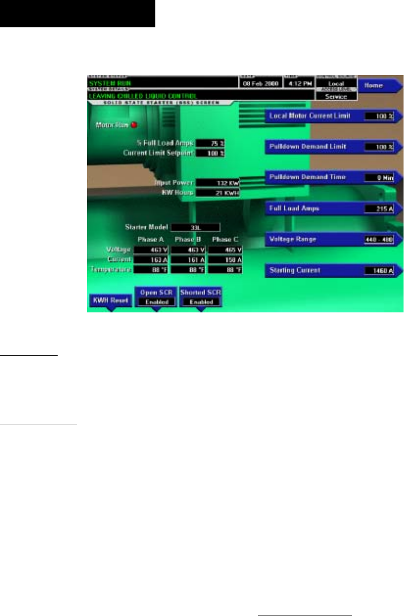
YORK INTERNATIONAL
44
FORM 160.55-O1 (604)
MOD “B” SOLID STATE STARTER SCREEN
00359VIP
FIG. 18
OVERVIEW
This screen displays all information pertaining to the
Mod “B” Solid State Starter.
DISPLAY ONLY
Motor Run (LED)
Indicates whether the digital output from the controls is
commanding the motor to RUN.
Motor Current % Full Load Amps
Displays the motor current as a percentage of the Full
Load Amps (FLA) value.
Current Limit Setpoint
Displays the current limit in use. This value could come
from a 0-20mA, 4-20mA, 0-10VDC or 2-10VDC input
in Analog Remote Mode, PWM signal in Digital Re mote
Mode, MicroGateway interface in ISN remote Mode or
a lo cal ly programmed value in Local Mode.
Pulldown Demand Time Left
Displays the time remaining in the programmed pull-
down period.
Input Power
Displays the Kilowatts measured by the Solid State
Start er.
kW Hours
Displays the cumulative amount of kilowatts used over
time.
Starter Model
Displays the Solid State Starter model that is applied to
the chiller. Starter Models are 7L, 14L, 26L or 33L.
Voltage – Phase A, B, C
Displays the 3-phase input line voltage measured by the
Solid State Starter.
Current – Phase A, B, C
Displays the 3-phase motor current values measured by
the Solid State Starter.
Temperature – Phase A, B, C
Displays the temperatures of the Silicon Controlled
Rec ti Þ er assemblies.
PROGRAMMABLE
Local Motor Current Limit
Access Level Required: OPERATOR
Allows the user to specify the maximum al lowed mo tor
current (as percentage of FLA). When the mo tor cur rent
reaches this value, the Pre-rotation Vanes will not be
permitted to open fur ther. If the motor rises above this
value, the Pre-ro ta tion Vanes will close to reduce the
current to this value.
OptiView Control Center

FORM 160.55-O1 (604)
45
YORK INTERNATIONAL
Pulldown Demand Limit
Access Level Required: OPERATOR
Allows the user to specify the current limit val ue (as a
per cent age of FLA) to which the chill er will be limited
dur ing the speciÞ ed pulldown time. This value will
over ride the Motor Cur rent Limit value dur ing this time
pe ri od. This function is used to provide energy sav ings
fol low ing chiller start.
Pulldown Demand Time
Access Level Required: OPERATOR
Allows the user to set a period of time for which the
pulldown demand limit will be in effect after the chill er
starts.
Full Load Amps
Access Level Required: SERVICE
DeÞ nes the maximum amps at which the motor can oper-
ate. This value is viewable when logged in at Op er a tor
or View access level. Service technicians refer to YORK
Service Manual 160.55-M1.
Voltage Range
Access Level Required: SERVICE
Allows the user to select speciÞ c line voltage range for
voltage checking. When not disabled, this line voltage
range is used to determine a low line and high line volt-
age threshold for initiating a shutdown. Service Tech ni -
cians refer to YORK Service Manual 160.55-M1.
Starting Current
Access Level Required: SERVICE
DeÞ nes the maximum allowed motor starting amps. The
Solid State Starter will limit the motor starting current
to this value. Service technicians refer to YORK Ser vice
manual 160.55-M1.
Open SCR (Enabled/Disabled)
Access Level Required: SERVICE
Allows the user to enable or disable the Solid State
Start er Open SCR safety detection. This must never
be dis abled unless under advisement of the YORK
Fac to ry. Service Technicians refer to YORK Service
Man u al 160.55-M1.
Shorted SCR (Enabled/Disabled)
(Flash Memory Card version C.MLM.02.01 or later)
Access Level required: SERVICE
Allows the user to enable or disable the Solid State
Start er Shorted SCR safety detection. This must never
be dis abled unless under advisement of the York Fac-
to ry. Service Technicians refer to YORK Service Man u al
160.55-M1.
kWH Reset
Access Level Required: SER VICE
Allows the user to reset the cumulative Kilowatt Hours.
Service technicians refer to YORK Service Manual
160.55-M1.
NAVIGATION
HOME
Access Level Required: VIEW
Causes an instant return to the HOME Screen.
2
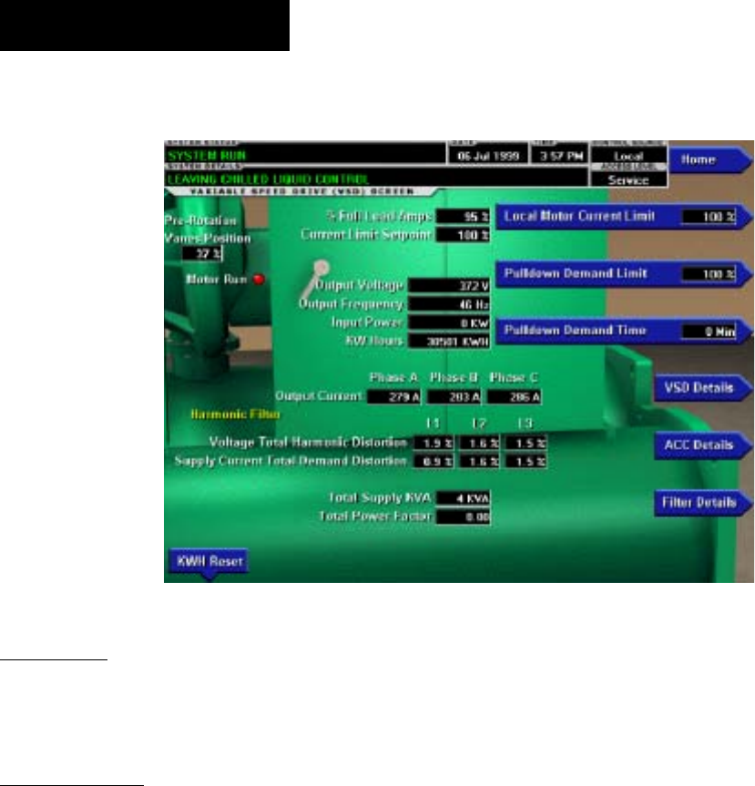
YORK INTERNATIONAL
46
FORM 160.55-O1 (604)
VARIABLE SPEED DRIVE SCREEN
OVERVIEW
This screen displays information per tain ing to a Vari able
Speed Drive (VSD).
DISPLAY ONLY
Motor Run (LED)
Indicates whether the digital output from the controls is
commanding the motor to RUN.
Motor Current % Full Load Amps
Displays the motor current as a per cent age of the Full
Load Amps (FLA) value.
Current Limit Setpoint
Displays the current limit value in use. This value could
come from a 0-20mA, 4-20mA, 0-10VDC or 2-10VDC
input in An a log Remote mode, PWM signal in Digital
Remote mode, MicroGateway interface in ISN mode or
a lo cal ly pro grammed value.
Pulldown Demand Time Left
Displays the time remaining in the pro grammed pull-
down period if the value is non-zero.
Output Voltage
Displays the output voltage measured to the motor.
Output Frequency
Displays the present output frequency to the motor.
Output Current - Phase A, B, C
Displays the phase current measured to the motor.
Input Power
Displays the total Kilowatts measured by the VSD or
Harmonic Filter, if installed.
kW Hours
Displays the cumulative amount of kilowatts used over
time as the VSD motor controller operates.
Pre-Rotation Vane Position
Displays the pre-rotation vane position as a value be-
tween 0 and 100%.
Harmonic Filter Data (Harmonic Fil ter
installed only)
Supply kVA
Displays the supply kva measured by the Þ lter.
Total Power Factor
Displays the relationship between the Input Power and
the Supply kVA.
Voltage Total Harmonic Distortion - L1, L2, L3
Displays the Total Harmonic Distortion (THD) for each
of the voltage lines as calculated by the Þ lter.
00360VIP
FIG. 19
OptiView Control Center

FORM 160.55-O1 (604)
47
YORK INTERNATIONAL
Supply Current Total Demand Distortion -
L1, L2, L3
Displays the Total Dynamic Distortion (TDD) for each
of the supply current lines as calculated by the Þ lter.
PROGRAMMABLE
Local Motor Current Limit
Access Level Required: OP ER A TOR
Allows the user to specify the maximum al lowed mo-
tor current (as a percentage of FLA). When the motor
cur rent reaches this value, the pre-rotation vanes will
not be permitted to open further. If the motor current
rises above this value, the pre-rotation vanes will close
to reduce the current to this value.
Pulldown Demand Limit
Access Level Required: OP ER A TOR
Allows the user to specify the current limit val ue (as a
percentage of FLA) to which the chiller will be limited
during the speciÞ ed pulldown limit time. This value will
override the Motor Current Limit value during this time
period. This function is used to provide energy sav ings
following chiller start-up.
Pulldown Demand Time
Access Level Required: OP ER A TOR
Allows the user to set a period of time for which the
pulldown demand limit will be in effect after the chill er
starts.
kWH Reset
Access Level Required: SER VICE
Allows the user to reset the cumulative Kilowatt Hours.
Service Technicians refer to YORK Ser vice Man u al
160.55-M1.
Filter Inhibit (Harmonic Filter installed only)
Access Level Required: SERVICE
Disable the Þ lter logic from activating, although the
sys tem will still communicate with the device. Only
avail able when chiller is stopped.
NAVIGATION
Home
Access Level Re quired: VIEW
Causes an instant return to the Home Screen.
VSD Details
Access Level Required: VIEW
Moves to the subscreen which provides more in for -
ma tion about the Variable Speed Drive.
ACC Details
Access Level Required: SER VICE
Moves to the subscreen which provides more in for -
ma tion about the Adaptive Capacity Control.
Filter Details (Harmonic Filter installed only)
Access Level Required: VIEW
Moves to the subscreen which provides more in for -
ma tion about the Harmonic Filter.
2
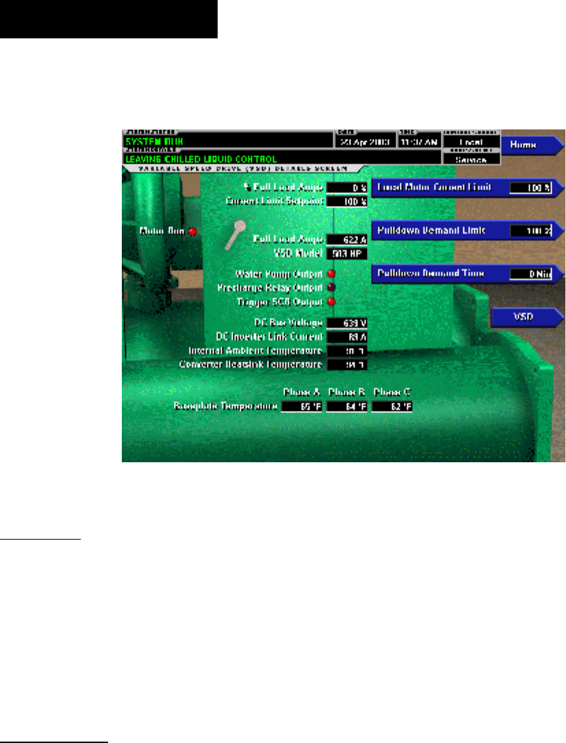
YORK INTERNATIONAL
48
FORM 160.55-O1 (604)
VARIABLE SPEED DRIVE DETAILS SCREEN
(STYLE D VSD AND VSD WITH PART NUMBER 371-03789-XXX
(503 HP 60 HZ; 410 HP 50 HZ)
OVERVIEW
This screen displays more detailed information pertain-
ing to a Variable Speed Drive (VSD). Flash Memory
Card version C.MLM.02.04.xxx (and later) is required
for VSD part number 371-03789-xxx (503HP 60Hz;
419 HP 50Hz). Service Tech ni cians refer to YORK
Service Manual 160.55-M1 for operation instructions
and explanation of all pro gram ma ble setpoints and
displayed values.
DISPLAY ONLY
Motor Run (LED)
Indicates whether the digital output from the controls is
commanding the motor to RUN.
Motor Current % Full Load Amps
Displays the motor current as a percentage of the Full
Load Amps (FLA) value. For the Variable Speed Drive
this is the data returned by the VSD Logic board.
Current Limit Setpoint
Displays the current limit value in use. This value could
come from a 0-20mA, 4-20mA, 0-10VDC or 2-10VDC
input in An a log Remote mode, PWM signal in Digital
Remote mode, MicroGateway interface in ISN mode or
a locally pro grammed value.
Pulldown Demand Time Left
Displays the time remaining in the pro grammed pull-
down period if the value is non-zero.
Water Pump Output (LED)
Indicates whether the relay controlling the wa ter pump
output is energized.
Precharge Relay Output (LED)
Indicates whether the relay controlling the precharge
output is energized.
Trigger SCR Output (LED)
Indicates whether the relay controlling the trig ger SCR
output is energized.
DC Bus Voltage
Displays the DC Bus voltage as reported by the VSD.
DC Inverter Link Current
Displays the DC Inverter link current as re port ed by
the VSD.
LD09096
FIG. 20
OptiView Control Center

FORM 160.55-O1 (604)
49
YORK INTERNATIONAL
Internal Ambient Temperature
Displays the ambient temperature inside the VSD cab-
i net as reported by the VSD.
Converter Heatsink Temperature
Displays the heatsink temperature of the con vert er as
reported by the VSD.
Baseplate Temperature - Phase A, B, C
(“Labeled “Heatsink Temperatures on VSD Style D)
Displays the baseplate temperature of each of the 3-
phase voltage regulators as reported by the VSD
VSD Model
Ac cess Level Re quired: SER VICE
Displays the Horsepower conÞ guration of the Variable
Speed Drive control.
100% Full Load Amps
Displays the full load amps value as reported by the
VSD.
PROGRAMMABLE
Local Motor Current Limit
Access Level Required: OP ER A TOR
Allows the user to specify the maximum al lowed mo-
tor current (as a percentage of FLA). When the motor
cur rent reaches this value, the pre-rotation vanes will
not be permitted to open further. If the motor current
rises above this value, the pre-rotation vanes will close
to reduce the current to this value.
Pulldown Demand Limit
Access Level Required: OP ER A TOR
Allows the user to specify the current limit val ue (as a
percentage of FLA) to which the chiller will be limited
during the speciÞ ed pulldown limit time. This value will
override the Motor Current Limit value during this time
period. This function is used to provide energy sav ings
following chiller start-up.
Pulldown Demand Time
Access Level Re quired: OP ER A TOR
Allows the user to set a period of time for which the
pulldown demand limit will be in effect after the chill er
starts.
NAVIGATION
Home
Access Level Re quired: VIEW
Causes an instant return to the Home Screen.
VSD
Access Level Required: VIEW
Returns to the VSD Screen.
2
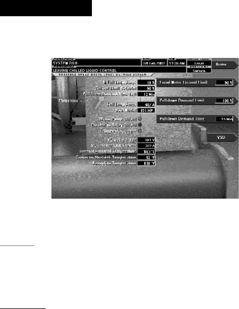
YORK INTERNATIONAL
50
FORM 160.55-O1 (604)
VARIABLE SPEED DRIVE DETAILS SCREEN
(APPLICABLE TO VSD WITH PART NUMBER 371-02767-XXX (60 HZ) OR 371-03700-XXX (50 HZ))
OVERVIEW
This screen displays more detailed information per-
tain ing to a Variable Speed Drive (VSD). Service
Tech ni cians refer to YORK Service Manual 160.55-
M1 for op er a tion instructions and explanation of all
pro gram ma ble setpoints and displayed values.
DISPLAY ONLY
Motor Run (LED)
Indicates whether the digital output from the controls is
commanding the motor to RUN.
Motor Current % Full Load Amps
Displays the motor current as a percentage of the Full
Load Amps (FLA) value. For the Variable Speed Drive
this is the data returned by the VSD Logic board.
Current Limit Setpoint
Displays the current limit value in use. This value could
come from a 0-20mA, 4-20mA, 0-10VDC or 2-10VDC
input in An a log Remote mode, PWM signal in Digital
Remote mode, MicroGateway interface in ISN mode or
a locally pro grammed value.
Pulldown Demand Time Left
Displays the time remaining in the pro grammed pull-
down period if the value is non-zero.
Water Pump Output (LED)
Indicates whether the relay controlling the wa ter pump
output is energized.
Precharge Relay Output (LED)
Indicates whether the relay controlling the precharge
output is energized.
Trigger SCR Output (LED)
Indicates whether the relay controlling the trig ger SCR
output is energized.
DC Bus Voltage
Displays the DC Bus voltage as reported by the VSD.
DC Inverter Link Current
Displays the DC Inverter link current as re port ed by
the VSD.
00562VIP
FIG. 21
OptiView Control Center

FORM 160.55-O1 (604)
51
YORK INTERNATIONAL
Internal Ambient Temperature
Displays the ambient temperature inside the VSD cab-
i net as reported by the VSD.
Converter Heatsink Temperature
Displays the heatsink temperature of the con vert er as
reported by the VSD.
Baseplate Temperature
Displays the Baseplate temperature of the 3-phase volt-
age regulators as reported by the VSD.
VSD Model
Ac cess Level Re quired: SER VICE
Displays the Horsepower conÞ guration of the Variable
Speed Drive control.
100% Full Load Amps
Displays the full load amps value as reported by the
VSD.
PROGRAMMABLE
Local Motor Current Limit
Access Level Required: OP ER A TOR
Allows the user to specify the maximum al lowed mo-
tor current (as a percentage of FLA). When the motor
cur rent reaches this value, the pre-rotation vanes will
not be permitted to open further. If the motor current
rises above this value, the pre-rotation vanes will close
to reduce the current to this value.
Pulldown Demand Limit
Access Level Required: OP ER A TOR
Allows the user to specify the current limit val ue (as a
percentage of FLA) to which the chiller will be limited
during the speciÞ ed pulldown limit time. This value will
override the Motor Current Limit value during this time
period. This function is used to provide energy sav ings
following chiller start-up.
Pulldown Demand Time
Access Level Re quired: OP ER A TOR
Allows the user to set a period of time for which the
pulldown demand limit will be in effect after the chill er
starts.
NAVIGATION
Home
Access Level Re quired: VIEW
Causes an instant return to the Home Screen.
VSD
Access Level Required: VIEW
Returns to the VSD Screen.
2
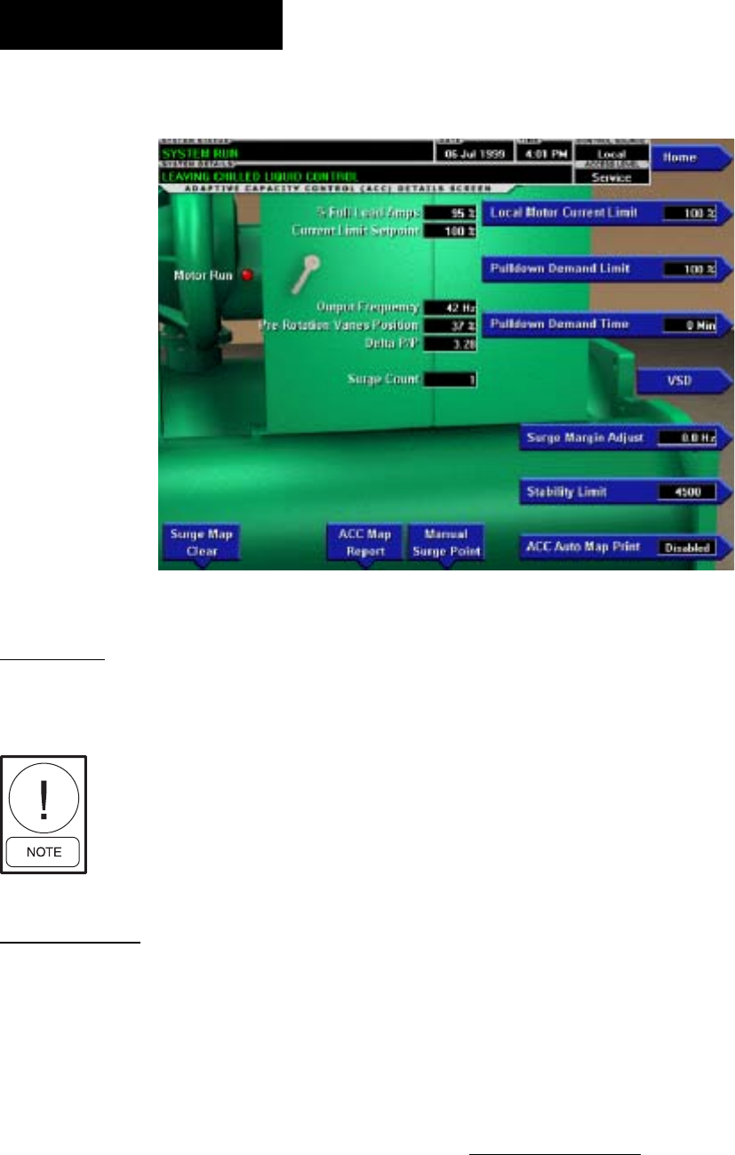
YORK INTERNATIONAL
52
FORM 160.55-O1 (604)
ADAPTIVE CAPACITY CONTROL DETAILS SCREEN
OVERVIEW
This screen displays more detailed in for ma tion per-
tain ing to a Adaptive Capacity Control (ACC).
Requires a login access level of SER-
VICE. Service Technicians refer to
YORK Service Manual 160.55-M1
for operation instructions and ex pla -
na tion of all programmable setpoints
and dis played values.
DISPLAY ONLY
Motor Run (LED)
Indicates whether the digital output from the controls is
commanding the motor to RUN.
Motor Current % Full Load Amps
Displays the motor current as a percentage of the Full
Load Amps (FLA) value. For the Variable Speed Drive
this is the data returned by the VSD Logic board.
Current Limit Setpoint
Displays the current limit value in use. This value could
come from a 0-20mA, 4-20mA, 0-10VDC or 2-10VDC
input in An a log Remote mode, PWM signal in Digital
Remote mode, MicroGateway interface in ISN mode or
a locally pro grammed value.
Pulldown Demand Time Left
Displays the time remaining in the pro grammed pull-
down period if the value is non-zero.
VSD Output Frequency
Displays the frequency at which the VSD is operating
the motor.
Pre-Rotation Vane Position
Displays the pre-rotation vane position as a value be-
tween 0 and 100%.
Surge Count
The total number of surge conditions detected by the Adap-
tive Capacity Control. The surge events detected by the
Surge Protection feature are not included in this total.
Delta P/P
The value calculated by the Condenser and Evaporator
pressures as reported by the Adaptive Ca pac i ty Con trol.
PROGRAMMABLE
Local Motor Current Limit
Allows the user to specify the maximum al lowed mo-
tor current (as a percentage of FLA). When the motor
cur rent reaches this value, the pre-rotation vanes will
not be permitted to open further. If the motor current
rises above this value, the pre-rotation vanes will close
to reduce the current to this value.
00362VIP
FIG. 22
OptiView Control Center

FORM 160.55-O1 (604)
53
YORK INTERNATIONAL
Pulldown Demand Limit
Allows the user to specify the current limit val ue (as a
percentage of FLA) to which the chiller will be limited
during the speciÞ ed pulldown limit time. This value will
override the Motor Current Limit value during this time
period. This function is used to provide energy sav ings
following chiller start-up.
Pulldown Demand Time
Allows the user to set a period of time for which the
pulldown demand limit will be in effect after the chiller
starts.
Stability Limit
Adjusting this value modiÞ es the pre-rotation vane con-
trol algorithm when used in conjunction with an ACC.
Surge Margin Adjust
When the ACC maps a surge point, it will begin to
ad just the chiller command frequency and vane con-
trols at a certain “margin” from the mapped point. This
pro gram ma ble value allows the service technician to
mod i fy the “margin” at which these adjustments will
begin to take place.
Manual Surge Point
This key will force the ACC to map a surge detection
at the present operating con di tions. Mapping a point at
these conditions will cause the ACC to make ad just -
ments to the command frequency in the future in order
to pre vent the chiller from operating at the con di tions
mapped. USE WITH CAUTION.
ACC Auto Map Print (Enabled / Disabled)
The chiller monitors the ACC communications and
when a surge point is mapped, a short report of system
pa ram e ters is printed. When this function is active, all
other printing capability is disabled.
ACC Map Report
The chiller requests the entire surge map from the ACC.
As the map is received, the parameters for each point
are printed.
Surge Map Clear
This key instructs the ACC to clear all of the surge points
presently mapped. This key will require con Þ r ma tion of
its selection by entry of a special pass word. USE WITH
CAUTION.
NAVIGATION
Home
Access Level Re quired: VIEW
Causes an instant return to the Home Screen.
VSD
Access Level Required: VIEW
Returns to the VSD Screen.
2
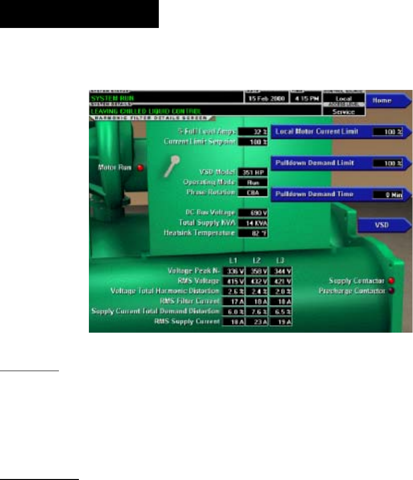
YORK INTERNATIONAL
54
FORM 160.55-O1 (604)
HARMONIC FILTER DETAILS SCREEN
(STYLE D VSD AND VSD WITH PART NUMBER 371-03789-XXX
(503 HP 60 HZ; 410 HP 50 HZ
OVERVIEW
This screen displays more detailed in for ma tion per-
tain ing to the IEEE-519 Harmonic Filter. Flash Memory
Card version C.MLM.02.04.xxx (and later) is required
for VSD part number 371-03789-xxx (503HP 60Hz;
419 HP 50Hz).
DISPLAY ONLY
Motor Run (LED)
Indicates whether the digital output from the controls
is commanding the motor to RUN.
Motor Current % Full Load Amps
Displays the motor current as a percentage of the Full
Load Amps (FLA) value. For the Variable Speed Drive
this is the data returned by the VSD Logic board.
Current Limit Setpoint
Displays the current limit value in use. This value could
come from a 0-20mA, 4-20mA, 0-10VDC or 2-10VDC
input in An a log Remote mode, PWM signal in Digital
Remote mode, MicroGateway interface in ISN mode
or a locally pro grammed value.
Pulldown Demand Time Left
Displays the time remaining in the pro grammed pull-
down period if the value is non-zero.
Operating Mode (Run / Stop)
Indicates whether the Harmonic Filter is op er at ing.
VSD Model
Access Level Required: SER VICE
Displays the horsepower for which the attached Har-
mon ic Filter is conÞ gured.
DC Bus Voltage
Displays the DC Bus voltage as measured by the Har-
mon ic Filter.
Supply Contactor (LED)
Indicates whether the output to the Sup ply Contactor
is energized.
Precharge Contactor (LED)
Indicates whether the output to the Precharge Contactor
is energized.
Phase Rotation
Displays the phase rotation detected by the Harmonic
Filter (A, B, C or C, B, A)
Total Supply kVA
Displays the total supply KiloVolt-Amps mea sured by
the Harmonic Filter.
00363VIP
FIG. 23
OptiView Control Center

FORM 160.55-O1 (604)
55
YORK INTERNATIONAL
Heatsink Temperature
(Labeled “Baseplate Temperatures” on VSD with
part number 371-03789-xxx {503HP 60Hz; 419HP
50Hz}).
Displays the temperature of the Harmonic Fil ter Heat-
sink.
Voltage Peak (N-L1, N-L2, N-L3)
Displays the 3-phase peak voltages as mea sured by the
Harmonic Filter (Neutral to Line).
RMS Voltage (L1-L2, L2-L3, L3-L1)
Displays the 3-phase RMS Voltages across each line.
Voltage Total Harmonic Distortion (L1, L2, L3)
Displays the 3-phase voltage Total Harmonic Dis tor tion
(THD) measurements.
RMS Filter Current (L1, L2, L3)
Displays the 3-phase Filter current values as measured
by the Harmonic Filter.
Supply Current Total Demand Distortion
(L1, L2, L3)
Displays the 3-phase Current Total Demand Distortion
(TDD) measurements.
RMS Supply Current (L1, L2, L3)
Displays the 3-phase RMS Voltages across each line.
PROGRAMMABLE
Local Motor Current Limit
Access Level Required: OP ER A TOR
Allows the user to specify the maximum al lowed mo-
tor current (as a percentage of FLA). When the motor
cur rent reaches this value, the pre-rotation vanes will
not be permitted to open further. If the motor current
rises above this value, the pre-rotation vanes will close
to reduce the current to this value.
Pulldown Demand Limit
Access Level Required: OP ER A TOR
Allows the user to specify the current limit val ue (as a
percentage of FLA) to which the chiller will be limited
during the speciÞ ed pulldown limit time. This value will
override the Motor Current Limit value during this time
period. This function is used to provide energy sav ings
following chiller start-up.
Pulldown Demand Time
Access Level Required: OP ER A TOR
Allows the user to set a period of time for which the
pulldown demand limit will be in effect after the chill er
starts.
NAVIGATION
Home
Access Level Re quired: VIEW
Causes an instant return to the Home Screen.
VSD
Access Level Required: VIEW
Returns to the VSD Screen.
2
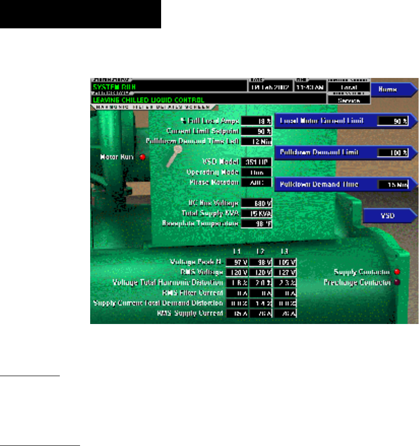
YORK INTERNATIONAL
56
FORM 160.55-O1 (604)
HARMONIC FILTER DETAILS SCREEN
(VSD WITH PART NUMBER 371-02767-XXX (60 HZ) OR 371-03700-XXX (50 HZ))
OVERVIEW
This screen displays more detailed in for ma tion per-
tain ing to the IEEE-519 Harmonic Filter.
DISPLAY ONLY
Motor Run (LED)
Indicates whether the digital output from the controls
is commanding the motor to RUN.
Motor Current % Full Load Amps
Displays the motor current as a percentage of the Full
Load Amps (FLA) value. For the Variable Speed Drive
this is the data returned by the VSD Logic board.
Current Limit Setpoint
Displays the current limit value in use. This value could
come from a 0-20mA, 4-20mA, 0-10VDC or 2-10VDC
input in An a log Remote mode, PWM signal in Digital
Remote mode, MicroGateway interface in ISN mode
or a locally pro grammed value.
Pulldown Demand Time Left
Displays the time remaining in the pro grammed pull-
down period if the value is non-zero.
Operating Mode (Run / Stop)
Indicates whether the Harmonic Filter is op er at ing.
VSD Model
Access Level Required: SER VICE
Displays the horsepower for which the attached Har-
mon ic Filter is conÞ gured.
DC Bus Voltage
Displays the DC Bus voltage as measured by the Har-
mon ic Filter.
Supply Contactor (LED)
Indicates whether the output to the Sup ply Contactor
is energized.
Precharge Contactor (LED)
Indicates whether the output to the Precharge Contactor
is energized.
Phase Rotation
Displays the phase rotation detected by the Harmonic
Filter ( A, B, C or C, B, A )
Total Supply KVA
Displays the total supply KiloVolt-Amps mea sured by
the Harmonic Filter.
Baseplate Temperature
Displays the temperature of the Harmonic Filter Base-
plate.
00567VIP
FIG. 24
OptiView Control Center

FORM 160.55-O1 (604)
57
YORK INTERNATIONAL
Voltage Peak ( N-L1, N-L2, N-L3 )
Displays the 3-phase peak voltages as mea sured by the
Harmonic Filter (Neutral to Line).
RMS Voltage ( L1-L2, L2-L3, L3-L1 )
Displays the 3-phase RMS Voltages across each line.
Voltage Total Harmonic Distortion ( L1, L2, L3 )
Displays the 3-phase voltage Total Harmonic Dis tor tion
(THD) measurements.
RMS Filter Current ( L1, L2, L3 )
Displays the 3-phase Filter current values as measured
by the Harmonic Filter.
Supply Current Total Demand Distortion
( L1, L2, L3 )
Displays the 3-phase Current Total Demand Distortion
(TDD) measurements.
RMS Supply Current L1, L2, L3
Displays the 3-phase RMS Voltages across each line.
PROGRAMMABLE
Local Motor Current Limit
Access Level Required: OP ER A TOR
Allows the user to specify the maximum al lowed mo-
tor current (as a percentage of FLA). When the motor
cur rent reaches this value, the pre-rotation vanes will
not be permitted to open further. If the motor current
rises above this value, the pre-rotation vanes will close
to reduce the current to this value.
Pulldown Demand Limit
Access Level Required: OP ER A TOR
Allows the user to specify the current limit val ue (as a
percentage of FLA) to which the chiller will be limited
during the speciÞ ed pulldown limit time. This value will
override the Motor Current Limit value during this time
period. This function is used to provide energy sav ings
following chiller start-up.
Pulldown Demand Time
Access Level Required: OP ER A TOR
Allows the user to set a period of time for which the
pulldown demand limit will be in effect after the chill er
starts.
NAVIGATION
Home
Access Level Re quired: VIEW
Causes an instant return to the Home Screen.
VSD
Access Level Required: VIEW
Returns to the VSD Screen.
2

YORK INTERNATIONAL
58
FORM 160.55-O1 (604)
SETPOINTS SCREEN
OVERVIEW
This screen provides a convenient location for pro gram -
ming the most common setpoints involved in the chiller
control. This screen also serves as a gate way to a subscreen
for deÞ ning the setup of general system parameters.
DISPLAY ONLY
Leaving Chilled Liquid Temperature - Setpoint
Displays the present setpoint to which the chill er is op er -
at ing whether controlled remotely or locally. This val ue
could come from a 0-20mA, 4-20mA, 0-10VDC or 2-
10VDC input in An a log Remote mode, PWM sig nal in
Digital Remote mode, MicroGateway interface in ISN
mode or a locally pro grammed value.
Leaving Chilled Liquid Temperature Cy cling - Shut-
down
Displays the Leaving Chilled Liquid Tem per a ture at
which the chiller will shut down to avoid over-cooling
the build ing. This value is calculated by sub tract ing the
Leaving Chilled Liquid Temperature Cy cling Offset
– Shutdown from the Leaving Chilled Liq uid Tem-
per a ture Setpoint. If this value is below the absolute
min i mum allowed shut down temperature the minimum
val ue is displayed.
Leaving Chilled Liquid Temperature Cy cling – Re-
start
Displays the Leaving Chilled Liquid Tem per a ture at which
the chiller will restart after it has shut down due to over-
cooling temperature. This value is calculated by adding
the Leaving Chilled Liquid Tem per a ture Cycling Offset
– Re start to the Leaving Chilled Liquid Tem per a ture
Setpoint.
Current limit Setpoint
Displays the active Current Limit setpoint. In Local
mode, this is the locally programmed Current Limit
setpoint. In ISN remote mode, this is the setpoint re-
ceived from the MicroGateway interface. In Analog re-
mote mode, this is the setpoint received via 0-10VDC,
2-10VDC, 0-20mA or 4-20mA input. In Digital remote
mode, this is the Pulse Width Modulation input.
PROGRAMMABLE
Local Leaving Chilled Liquid Tem per a ture -
Range Access Level Re quired: OPERATOR
This is the range over which an analog signal (0-20mA, 4-
20mA, 0-10VDC or 2-10VDC) in Analog Re mote Mode
or a digital sig nal (PWM) in Digital remote mode can reset
the Leav ing Chilled Liquid Temperature setpoint above
the op er a tor programmed Base Setpoint (see be low).
Pro gram ma ble as either 10°F or 20°F, with a de fault
of 20°F, it is added to the BASE value to cre ate a range
over which the remote device can reset the setpoint. For
ex am ple, if this setpoint is pro grammed for 10°F and
the operator programmed value is 45°F, then the remote
device can set the Leaving Chilled Liq uid Tem per a ture
setpoint over the range 45.0° - 55.0°F.
00364VIP
FIG. 25
OptiView Control Center

FORM 160.55-O1 (604)
59
YORK INTERNATIONAL
Local Leaving Chilled Liquid Tem per a ture -
Setpoint
Access Level Required: OPERATOR
This value allows the user to deÞ ne the Leav ing Chilled
Liquid Temperature that is to be maintained by the chill er.
It is programmable over the range of 38.0°F to 70.0°F
(water) or 10.0°F to 70.0°F (brine). If Smart Freeze is
enabled, the range is 36.0°F to 70.0°F (water). A re mote
device can provide an analog signal (0-20mA, 4-20mA,
0-10VDC or 2-10VDC) in Analog Remote mode or PWM
signal in Digital Remote mode that changes the setpoint
by cre at ing an off set above the operator pro grammed
BASE Leaving Chilled Liquid Tem per a ture setpoint.
This off set may be deÞ ned up to 10.0°F or 20.0°F above
the BASE setpoint (see the Remote Leav ing Chilled Liq-
uid Tem per a ture Setpoint Range de scrip tion above).
Ad di tion al ly, a MicroGateway (in ISN Remote mode)
can de Þ ne the setpoint through a serial data stream. In
this case, the incoming setpoint is not an offset that is
ap plied to the locally programmed BASE setpoint value,
but rath er is the setpoint value itself.
Leaving Chilled Liquid Temperature
Cycling Off set - Shutdown
Access Level Re quired: OPERATOR
This value allows the user to specify the Leaving Chilled
Liquid Temperature at which the chiller will shut down
on a LEAVING CHILLED LIQUID – LOW TEM-
PER A TURE cycling shutdown. This is done by de Þ n ing
an offset below the Leaving Chilled Liquid Tem per a ture
setpoint. It is programmable over a range of 1°F to 64°F
below the setpoint, to a minimum cutout of 36°F (water),
34°F (water with Smart Freeze enabled) or 6°F (brine).
It es tab lish es the minimum allowed tem per a ture for the
Leaving Chilled Liquid Temperature and pre vents over-
cooling of the building. Anytime the Leaving Chilled
Liquid Temperature setpoint is in creased, the shutdown
threshold is 36.0°F (water) or 6.0°F (brine) for the next
ten (10) minutes. If Smart Freeze is enabled, the thresh-
old is 34.0°F for the next 10 minutes. After ten (10)
minutes have elapsed, the shutdown threshold be comes
the programmed setpoint value.
Leaving Chilled Liquid Temperature
Cycling Off set - Restart
Access Level Re quired: OPERATOR
This value allows the user to specify the Leaving Chilled
Liquid Temperature at which the chiller will restart af ter a
shutdown on a LEAVING CHILLED LIQUID – LOW
TEMPERATURE cycling shut down. This is done by
deÞ ning an offset above the Leaving Chilled Liq uid
Temperature setpoint. It is programmable over a range
of 0°F to 70°F above the setpoint, to a max i mum restart
value of 80°F. The chiller will au to mat i cal ly re start when
this tem per a ture is reached. This setpoint can be used
to reduce chiller cycling by de lay ing the chiller restart
until the cooling load has in creased.
Remote Analog Input Range
Access Level Required: OPERATOR
This setpoint deÞ nes, for the Control Center, the re mote
signal range applied for remote reset of the Leav ing
Chilled Liquid Temperature Setpoint and Current Limit
Setpoint in ANALOG remote mode. If the re mote
signal is 0-10VDC or 0-20mA, this setpoint must be
programmed for 0-10VDC. If the remote signal is 2-
10VDC or 4-20mA, this setpoint must be programmed
for 2-10VDC.
Local Motor Current Limit
Access Level Required: OP ER A TOR
Allows the user to specify the maximum al lowed mo-
tor current (as a percentage of FLA). When the motor
cur rent reaches this value, the pre-rotation vanes will
not be permitted to open further. If the motor current
rises above this value, the pre-rotation vanes will close
to reduce the current to this value.
Pulldown Demand Limit
Access Level Required: OP ER A TOR
Allows the user to specify the current limit val ue (as
a percentage of Full Load Amps) to which the chill er
will be limited during the speciÞ ed pulldown limit time.
This value will override the Motor Current Limit value
dur ing this time period. This function is used to provide
energy savings following chiller start-up.
Pulldown Demand Time
Access Level Required: OP ER A TOR
Allows the user to set a period of time for which the pulldown
demand limit will be in effect after the chiller starts.
Print
Access Level Required: VIEW
Generates Setpoints print report.
NAVIGATION
Home
Access Level Re quired: VIEW
Causes an instant return to the Home Screen.
Setup
Access Level Re quired: VIEW
Moves to the subscreen allowing setup of gen er al sys tem
parameters.
2
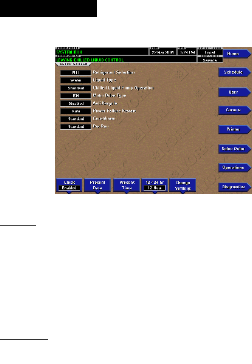
YORK INTERNATIONAL
60
FORM 160.55-O1 (604)
SETUP SCREEN
OVERVIEW
This screen is the top level of the general con Þ g u ra tion
pa ram e ters. It allows programming of the time and
date, along with speciÞ cations as to how the time will
be dis played (12 or 24 hour format). In addition, the
chill er con Þ g u ra tion, as determined by the state of the
Microboard Program Jump ers and Program Switches
is dis played. A qualiÞ ed Service Technician, follow-
ing in struc tions in YORK Service Man u al 160.55-M1,
es tab lish es this con Þ g u ra tion per the desired operation.
This screen also serves as a gateway to more subscreens
for de Þ n ing general sys tem parameters
DISPLAY ONLY
031-01730-000 Microboard
Chilled Liquid Pump Operation:
Displays Standard or Enhanced
Motor Type:
Displays Fixed Speed or Variable Speed
Refrigerant Selection:
Displays R-11 or R123
Anti-Recycle:
Displays Disabled or Enabled
Power Failure Restart:
Displays Manual or Automatic
Liquid Type:
Displays Water or Brine
Coastdown:
Displays Standard (150 seconds) or En hanced (15
minutes – Steam Turbine applications)
Pre-Run:
Displays Standard (30 seconds) or Ex tend ed (180
sec onds)
Power Line Frequency (VSD only):
Displays 60 Hz or 50 Hz
031-02430-000 Microboard
Refrigerant Selection
Displays R11 or R123
Liquid Type
Displays Water or Brine
LD09562
FIG. 26
OptiView Control Center

FORM 160.55-O1 (604)
61
YORK INTERNATIONAL
PROGRAMMABLE
Set Date
Access Level Re quired: OP ER A TOR
Allows the user to specify the present date. This value is criti-
cal to logging system shutdowns accurately and for uti liz ing
the scheduling ca pa bil i ties. When prompt ed to en ter a date
value, the user must enter the day, month and four-digit year
(using leading zeroes as necessary). If with in range, the value
will be accepted. If out of range, the user is prompt ed for the
information again. At this point the user may retry the date
entry or cancel the programming at tempt.
Set Time
Access Level Re quired: OP ER A TOR
Allows the user to specify the present time. This value
is critical to logging system shutdowns accurately and
for utilizing the scheduling ca pa bil i ties. When prompt ed
to enter a time value, the user must enter the hour and
minute desired (using leading zeroes as nec es sary). If
the chiller is presently set to 24-hour mode, the time
must be entered in the 24-hour format. Otherwise, the
user must also select AM or PM for the entered time. If
out of range, the user is prompted for the in for ma tion
again. At this point the user may retry the time entry or
cancel the programming attempt.
Clock (Enabled / Disabled)
Access Level Required: OP ER A TOR
Allows the user to enable or disable the real-time clock in
order to conserve battery life. The clock will be dis abled
during manufacturing and must be en abled at sys tem com-
missioning. In addition, when pre par ing for pro longed
shutdown the clock should once again be dis abled.
12/24 Hr
Access Level Re quired: OPERATOR
Allows the user to specify the format in which the time
will be pre sent ed to the user. This setpoint will affect the
display of the time on the chiller panel and on all reports
generated. 12-Hour time format will include the AM and
PM mod i Þ ers and show the range of time be tween 1:00
and 12:59, while the 24-Hour time format will show the
range of time between 0:00 and 23:59.
. 031-02430-000 Microboard only
Change Settings
Access Level Required: OPERATOR
Used to enter the following setpoints. Pressing this key
places a green selection box around the Þ rst changeable
setpoint. The access level determines which setpoints
can be changed. Use the ▲ and ▼ keys to place the
selection box around the desired setpoint. With the
setpoint selected, press the ENTER (√) key. A dialog
box appears with the range of settings.
Chilled Liquid Pump Operation
Access Level Required: SERVICE
Allows a Service Technician to select chilled liquid
pump control contacts (I/O Board TB2-44/45) opera-
tion as either Standard or Enhanced. Service Technicians
refer to YORK Service Manual 160.55-M1.
Motor Drive Type
Access Level Required: SERVICE
Allows a Service Technician to enter the applied com-
pressor motor type as either electro-mechanical (EM),
Solid State Starter (SSS-Mod A), Solid State starter (SSS
– Mod B), Variable Speed Drive-60Hz or Variable Speed
Drive-50Hz. Service Technicians refer to YORK Service
manual 160.55-M1.
Anti-Recycle
Access level Required: SERVICE
Allows a Service Technician to Enable or Disable the
anti-recycle timer. Service Technicians refer to YORK
Service manual 160.55-M1.
Power Failure Restart
Access Level Required: OPERATOR
Allows the user to select Manual or Automatic restart
after power failure.
Coastdown
Access Level Required: SERVICE
Allows a Service Technician to select either Standard
(150 seconds) or Enhanced 15 minutes –Steam Turbine
applications). Service Technicians refer to YORK Ser-
vice manual 160.55-M1.
Pre-Run
Access Level Required: SERVICE
Allows Service Technician to select either Standard (30
seconds) or Extended (180 seconds)
NAVIGATION
Home
Access Level Re quired: VIEW
Causes an instant return to the Home Screen.
2

YORK INTERNATIONAL
62
FORM 160.55-O1 (604)
Schedule
Access Level Required: VIEW
Moves to the subscreen allowing deÞ nition of the chill er
operation schedule.
Diagnostics
Access Level Required: SER VICE
Moves to the subscreen allowing limited di ag nos tic
ca pa bil i ty while operating. Refer to YORK Service
Man u al 160.55-M1
Comms
Access Level Required: VIEW
Moves to the subscreen allowing con Þ g u ra tion of sys tem
communications.
Printer
Access Level Required: VIEW
Moves to the subscreen allowing con Þ g u ra tion and
con trol of printer functions.
Sales Order
Access Level Required: VIEW
Moves to the subscreen displaying the Sales Order in for -
ma tion for the chiller system.
Operations
Access Level Required: VIEW
Moves to the subscreen displaying operating pa ram e ters
of the chiller system.
User
Access Level Required: VIEW
Moves to the subscreen allowing con Þ g u ra tion of user
preferences.
OptiView Control Center

FORM 160.55-O1 (604)
63
YORK INTERNATIONAL
THIS PAGE INTENTIONALLY LEFT BLANK
TO MAINTAIN FORMAT
2
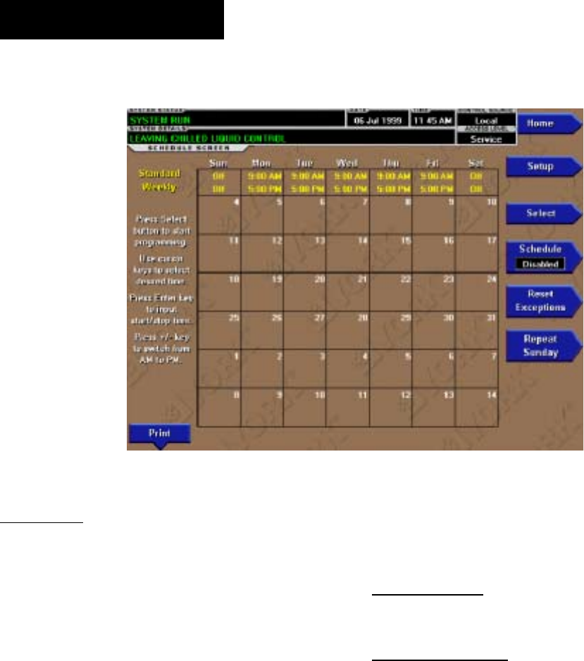
YORK INTERNATIONAL
64
FORM 160.55-O1 (604)
SCHEDULE SCREEN
OVERVIEW
The schedule screen contains more pro gram ma ble val ues
than a normal display screen. As such, each pro gram -
ma ble value is not linked to a speciÞ c but ton. In stead the
Select key is used to enable the cur sor ar rows which
are used to highlight the day and the start or stop time
the user wishes to modify. At this point the user may
press the ‘!’ (ENTER) key to pro gram the Start / Stop
times for that day.
In order for the Start / Stop combination to be utilized,
each Start time must have a cor re spond ing Stop time
which occurs later in the day. The presently pro grammed
schedule for a given day can be cancelled by setting
both the Start time and Stop time to 12:00AM. If the
Start time equals the Stop time (with any time other
than 12:00AM), the chiller is OFF for that day. If the
user desires the chiller to operate continuously through
several days, the Stop time of Day 1 can be set to 11:
59 PM and the Start time of Day 2 can be set to 12:00
AM. The chiller will not stop but continue to operate
until the stop of Day 2.
The user has the ability to deÞ ne a standard set of Start /
Stop times which are utilized every week. The user may
then specify exception Start / Stop combinations for any
day of the week up to 6 weeks in advance. At the end
of each week the schedule for the next week is created
by com bin ing the standard week deÞ nition and the next
de Þ ned exception week. The schedule is then updated
as each of the exception weeks “shifts down”, leaving a
new, blank exception week in the 6th week slot.
DISPLAY ONLY
None
PROGRAMMABLE
Standard Week Start/Stop Times
Access Level Re quired: OPERATOR
For each day of the week, the user may spec i fy a time
for the chiller to start and a time for the chiller to stop.
The times speciÞ ed in this entry week will be used as
the default for every week of chiller operation.
Exception Start/Stop Times
Access Level Re quired: OPERATOR
For each day of the week, the user may specify a time
for the chiller to start and a time for the chiller to stop.
These Start / Stop combinations may be scheduled up to
Þ ve (5) weeks in advance and also for the present week.
As each week goes by, the new schedule will be created
for the present week using the Exception spec i Þ ca tion
in com bi na tion with the Standard week deÞ ni tion, as
de scribed above.
Schedule (Enabled / Disabled)
Access Level Re quired: OP ER A TOR
Allows the user to enable or disable the mon i tor ing func-
00365VIP
FIG. 27
OptiView Control Center

FORM 160.55-O1 (604)
65
YORK INTERNATIONAL
tion which enforces the scheduled starting and stop ping
of the chiller.
Repeat Sunday Schedule
Access Level Re quired: OP ER A TOR
Duplicates the schedule deÞ ned for Sunday for the
re main der of the standard weekdays.
Reset All Exception Days
Access Level Required: OPERATOR
Deletes all programming for exception days within the
next 6 weeks.
Select
Access Level Required: OPERATOR
Places a selection box around a start time for a given day.
Use ◄ , ► , ▲ or ▼ cursor arrows to place the box
around the desired start or stop time for a given day.
Print
Access Level Required: VIEW
Generates a Schedule print report.
NAVIGATION
Home
Access Level Re quired: VIEW
Causes an instant return to the Home Screen.
Setup
Access Level Re quired: VIEW
Return to the previous setup screen.
2
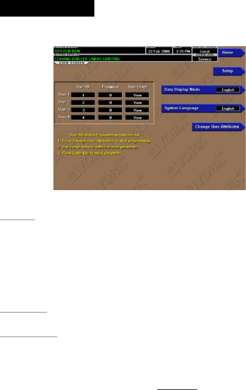
YORK INTERNATIONAL
66
FORM 160.55-O1 (604)
USER SCREEN
OVERVIEW
This screen allows deÞ nition of custom User ID’s and
matching passwords. This allows the building ad min -
is tra tor to assign custom passwords to those who are
authorized to maintain the chiller.
Each Custom User value is not linked to a speciÞ c but ton.
Instead, the Change button is pressed which en ables the
cursor arrows which are used to highlight the Custom User
parameter the user wishes to modify. At this point the ‘!’
(Enter) button is pressed and the val ue may be entered.
DISPLAY ONLY
None
PROGRAMMABLE
System Language
Access Level Required: OP ER A TOR
Allows the user to deÞ ne the language for all Screens.
The desired language is selected by scrolling through the
list of those available. English is the Default lan guage
and is selected by pressing the ▲ key when the dialog
box appears during the selection process. The selected
language will not be displayed until after the user
navigates from the USER Screen to another Screen.
English / Metric Units
Access Level Required: OP ER A TOR
DeÞ ne the unit system (English or Metric) used by the
chiller display.
Custom User ID (4)
Access Level Re quired: SER VICE
This allows the user to specify up to four (4) Custom User
ID values. Each user ID will then require a cor re spond ing
Password and User Level. A User ID can be deÞ ned for
various maintenance personnel. Service Tech ni cians refer
to YORK Service Manual 160.55-M1.
Custom User Password (4)
Access Level Required: SERVICE
This allows the user to specify up to four (4) Custom
Password values. Each Password will then re quire a cor-
responding User ID and User Level. Service Tech ni cians
refer to YORK Service Manual 160.55-M1.
Custom User Access Level (4)
Access Level Re quired: SERVICE
This allows the user to specify up to four (4) Custom User
Access Levels. Each Access Level will then re quire a cor-
responding Password and User ID. Service Tech ni cians
refer to YORK Service Manual 160.55-M1.
NAVIGATION
Home
Access Level Re quired: VIEW
Causes an instant return to the Home Screen.
Setup
Access Level Re quired: VIEW
Return to the Setup Screen.
00366VIP
FIG. 28
OptiView Control Center

FORM 160.55-O1 (604)
67
YORK INTERNATIONAL
2
THIS PAGE INTENTIONALLY LEFT BLANK
TO MAINTAIN FORMAT
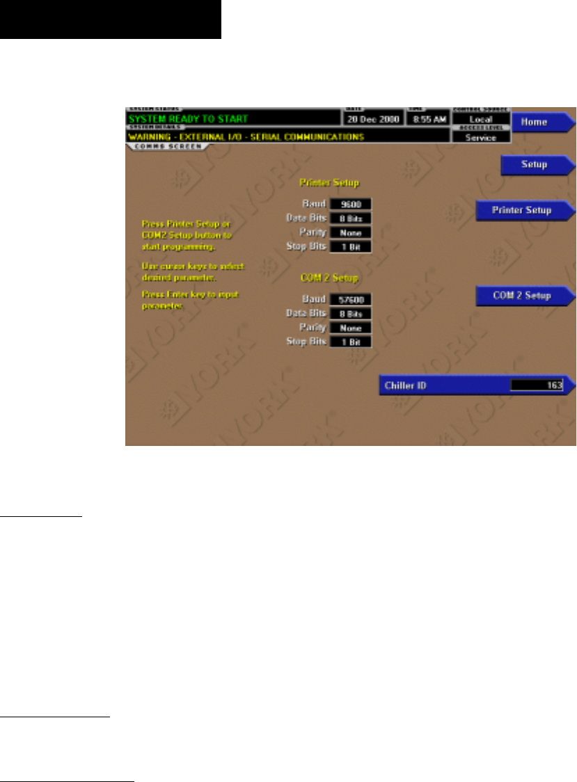
YORK INTERNATIONAL
68
FORM 160.55-O1 (604)
COMMS SCREEN
OVERVIEW
(Screen shown from Flash Memory Card version
C.MLM.02.02.xxx and later. Screen layout from
earlier versions slightly different)
This screen allows deÞ nition of the nec es sary com-
mu ni ca tions parameters. Refer to PRINTER Sec tion
of this book for details of the Printer connections and
set up. Presently, there are no COM 2 com mu ni ca tions
fea tures avail able.
DISPLAY ONLY
None
PROGRAMMABLE
Chiller ID
Ac cess Level Re quired: OP ER A TOR
DeÞ ne the numeric chiller ID when used with in an ISN
network of chillers. This ID number is also print ed at
the top of reports obtained with a local printer.
Printer Setup and COM 2 Setup
Access Level Required: OPERATOR
Pressing either key places a green selection boxa around
the Þ rst changeable parameter. Use the ▲ and ▼ keys
to place the selection box around the desired parameter
to be changed. With the selection box around the de sired
parameter, press the ENTER (✓) key. A dialog box is
displayed permitting data entry.
Printer Baud Rate
DeÞ ne the baud rate at which the panel shall com mu -
ni cate to the printer.
Printer Data Bit(s)
DeÞ ne the number of data bits with which the pan el shall
communicate to the printer.
Printer Parity Bit(s)
DeÞ ne the number of parity bits with which the pan el
shall communicate to the printer.
Printer Stop Bit(s)
DeÞ ne the number of stop bits with which the pan el shall
communicate to the printer.
COM 2 Baud Rate
DeÞ ne the baud rate at which the panel shall com mu -
ni cate through the modem port.
COM 2 Data Bit(s)
DeÞ ne the number of data bits at which the panel shall
com mu ni cate through the modem port.
COM 2 Parity Bit(s)
DeÞ ne the number of parity bits at which the panel shall
com mu ni cate through the modem port.
00478VIP
FIG. 29
OptiView Control Center

FORM 160.55-O1 (604)
69
YORK INTERNATIONAL
2
COM 2 Stop Bit(s)
DeÞ ne the number of stop bits at which the panel shall
com mu ni cate through the modem port.
NAVIGATION
Home
Access Level Re quired: VIEW
Causes an instant return to the Home Screen.
Setup
Access Level Re quired: VIEW
Return to the Setup Screen.
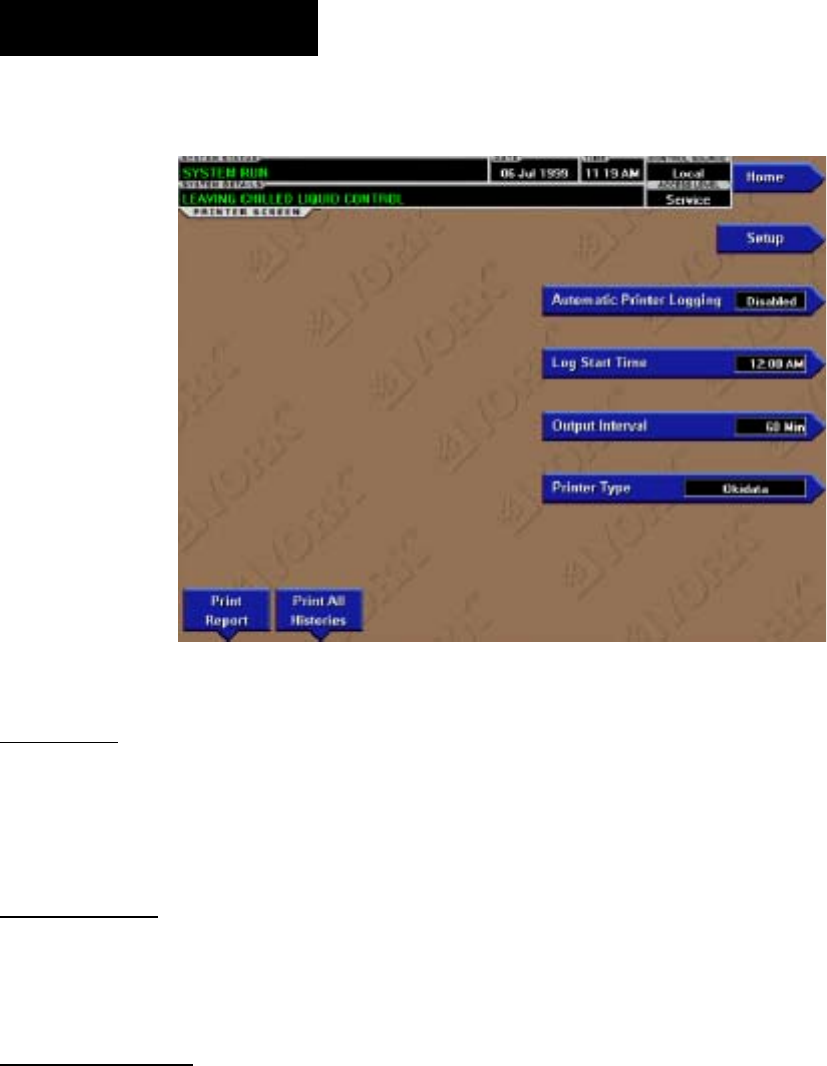
YORK INTERNATIONAL
70
FORM 160.55-O1 (604)
PRINTER SCREEN
OVERVIEW
This screen allows deÞ nition of the necessary com mu -
ni ca tions parameters for the printer. Refer to PRINT ER
section of this book for details of the Printer con nec tions
and setup.
DISPLAY ONLY
Time Remaining Until Next Print
Displays the time until the next print log will occur, if
the function is enabled.
PROGRAMMABLE
Log Start Time
Access Level Re quired: OP ER A TOR
Set the time at which scheduled print logs will begin.
Output Interval
Access Level Re quired: OP ER A TOR
DeÞ ne the interval at which log printing will occur.
Automatic Printer Logging (Enabled / Disabled)
Access Level Required: OPERATOR
Enable the printer to begin printing status re ports be-
gin ning at the programmed start time and re cur ring at
the interval deÞ ned above.
Printer Type
Access Level Required: OP ER A TOR
DeÞ ne the printer type connected to the chiller system.
ACC Auto Map Print (Enabled / Disabled)
Access Level Required: SERVICE
Only available if the chiller system utilizes a Variable
Speed Drive motor controller. The chiller monitors
the ACC communications and when a surge point is
mapped, a short report of system parameters is printed.
When this function is active, all other printing ca pa bil i ty
is disabled.
ACC Map Report
Access Level Required: SERVICE
Only available if the chiller system utilizes a Variable
Speed Drive motor controller. The chiller requests the
entire surge map from the ACC. As the map is re ceived,
the parameters for each point are printed.
Print Report
Access Level Required: OP ER A TOR
Select the report type to print when the Print Report key is
selected. This can vary from Status report (present system
parameters), Setpoints report (present value of the system
setpoints), Schedule report (present value of the system
schedule times) or a Sales Order Data re port (informa-
tion provided on the Sales Order screen). A print report
is generated upon completion of se lec tion.
Print All Histories
Access Level Re quired: OP ER A TOR
Generate a report of the system data at the time of all
stored shutdowns.
00368VIP
FIG. 30
OptiView Control Center

FORM 160.55-O1 (604)
71
YORK INTERNATIONAL
NAVIGATION
Home
Access Level Re quired: VIEW
Causes an instant return to the Home Screen.
Setup
Access Level Re quired: VIEW
Return to the Setup Screen.
2
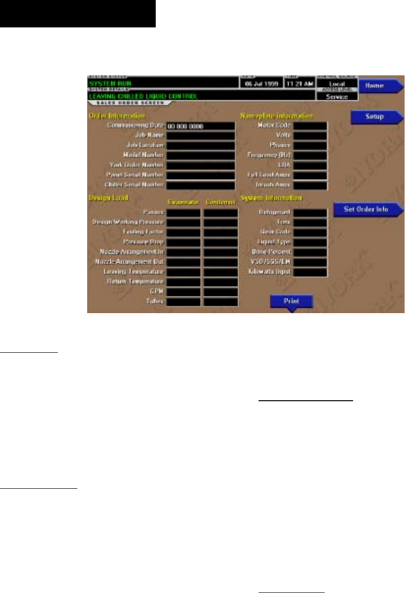
YORK INTERNATIONAL
72
FORM 160.55-O1 (604)
SALES ORDER SCREEN
OVERVIEW
This screen allows deÞ nition of the sales order pa ram e ters.
The Commissioning date is entered by the YORK Service
Technician at the time of chiller com mis sion ing. These
values should never be changed or en tered by any one other
than a qualiÞ ed Service Tech ni cian. Entry in struc tions are
included in the YORK Ser vice Manual 160.55-M1. The
remainder of the values are entered at the YORK Factory
during the man u fac tur ing of the chill er.
DISPLAY ONLY
Model Number
Factory deÞ ned model number of the chiller system.
Panel Serial Number
Factory deÞ ned serial number for the micropanel.
Chiller Serial Number
Factory deÞ ned serial number for the chiller system.
YORK Order Number
Factory deÞ ned order number under which the chiller
was sold.
System Information
Factory deÞ ned conditions for which the chiller was
originally rated and sold.
Condenser and Evaporator Design Load In for ma tion
Factory deÞ ned description of the condenser and evap o -
ra tor conÞ guration at time of shipment.
Nameplate Information
Factory de Þ ned information about the chiller motor
con Þ g u ra tion.
PROGRAMMABLE
Commissioning Date
Access Level Required: SER VICE
Define the date at which the chiller was com mis -
sioned.
Job Name and Location
Access Level Required: SERVICE
Factory deÞ ned job name and location the chill er is
des tined for.
Print
Access Level Required: VIEW
This generates a listing of the Sales Order data
NAVIGATION
Home
Access Level Re quired: VIEW
Causes an instant return to the Home Screen.
Setup
Access Level Re quired: VIEW
Return to the Setup Screen.
00369VIP
FIG. 31
OptiView Control Center

FORM 160.55-O1 (604)
73
YORK INTERNATIONAL
THIS PAGE INTENTIONALLY LEFT BLANK
TO MAINTAIN FORMAT
2
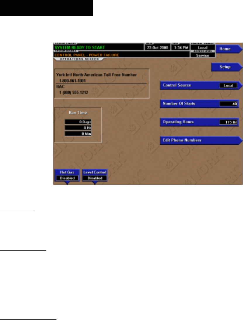
YORK INTERNATIONAL
74
FORM 160.55-O1 (604)
OPERATIONS SCREEN
OVERVIEW
This screen allows deÞ nition of general pa ram e ters hav-
ing to do with the operation of the chiller.
DISPLAY ONLY
Chiller Run Time
(Flash memory Card version C.MLM.02.01 or later)
Displays the amount of time the chiller has been run ning
since the last start signal was received. Value is reset to
zero when the chiller enters Coastdown. It re mains at
zero while shutdown and during “System Prelube”.
PROGRAMMABLE
Control Source
Access Level Required: OP ER A TOR
DeÞ ne whether the control of the chiller will be Local,
Digital Remote, Analog Remote, Modem Remote or
ISN Re mote.
Number of Starts
Access Level Required: ADMIN
Displays the number of the starts the chiller has ini ti at ed.
This may be reprogrammed to a desired value, (gen er al ly
when this value has been reset due to a Microboard re-
placement), but should not be done so ar bi trari ly.
Operating Hours
Access Level Required: ADMIN
Displays the total accumulated run time of the chiller.
This may be reprogrammed to a desired value (gen er al ly
when this value has been reset due to a Microboard re-
placement), but should not be done so arbitrarily.
Hot Gas Bypass (Enabled/Disabled)
Access level required: SERVICE
Enables and dis ables the hot gas bypass feature.
Refrigerant Level Control (Enabled/Disabled)
Access Level Required: SERVICE
Enables and Disables the Refrigerant Level Control
feature.
Service Phone Numbers
(Flash Memory Card version C.MLM.02.02.xxx
and later)
Access Level Required: SERVICE
Displays up to two service phone numbers. The Re gion al
service phone number is displayed as the Þ rst number.
Although the label and number can be changed appro-
priately, the default for this entry is “York Intl North
American Toll Free Number 1-800-861-1001”. The
Local service phone number is displayed as the second
number. Although blank by default, the appropriate la bel
and number can be entered by a Service Tech ni cian. Ser-
vice Tech ni cians refer to Service Manual 160.55-M1.
00479VIP
FIG. 32
OptiView Control Center

FORM 160.55-O1 (604)
75
YORK INTERNATIONAL
2
NAVIGATION
Home
Access Level Re quired: VIEW
Causes an instant return to the Home Screen.
Setup
Access Level Re quired: VIEW
Return to the Setup Screen.
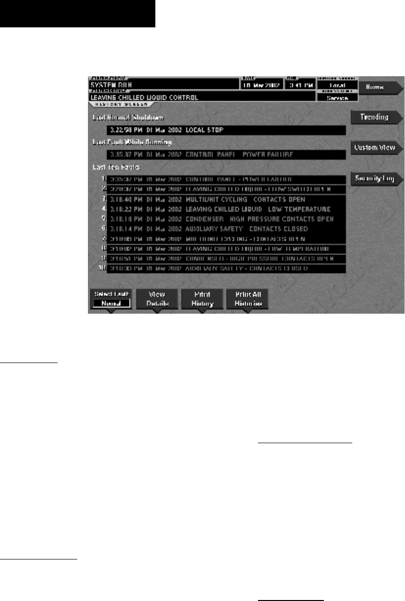
YORK INTERNATIONAL
76
FORM 160.55-O1 (604)
HISTORY SCREEN
OVERVIEW
This screen allows the user to browse through the faults.
In order to get a more thorough reporting of the system
conditions at the time of the recorded shut down, move
to the subscreen HISTORY DETAILS.
The user may use the Select Fault button to select the
history to view. At this point the View Details button
is used to jump to a subscreen containing stored chiller
parameters values at the time of the shutdown. Ad di -
tion al ly, the Print History button can be used to gen er ate
a hard-copy report of the parameter values at the time
of the shutdown.
DISPLAY ONLY
Last Normal Shutdown
This window displays the date and time and the de scrip -
tion of the last normal shutdown. A normal shut down
is deÞ ned as:
- Local (Panel rocker switch)
- Remote (Digital, Analog or ISN)
Last Fault While Running
This window displays the date and time and the de-
scrip tion of the last safety or cycling shutdown while
the system was running.
Last Ten Faults
This window displays a chronological listing (most
re cent Þ rst) of the date and time and the de scrip tion of
the last ten safety or cy cling shut downs that occur while
the sys tem is run ning or stopped.
PROGRAMMABLE
Print History
Access Level Required: VIEW
This generates a report listing the status of the chiller
parameters at the time of the selected shut down.
Print All Histories
Access Level Required: VIEW
This generates a report listing the status of the chiller
parameters at the time of each of the stored shut downs.
NAVIGATION
Home
Access Level Re quired: VIEW
Causes an instant return to the Home Screen.
View Details
Access Level Required: VIEW
Causes a move to a subscreen containing the value of
select chiller parameters at the time of the associated
shutdown.
00565VIP
FIG. 33
OptiView Control Center

FORM 160.55-O1 (604)
77
YORK INTERNATIONAL
2
Trending
Access Level Re quired: VIEW
Causes a move to a subscreen allowing the user to view
trending data on selected chiller parameters.
Custom View
(Flash memory Card version C.MLM.02.01 or later)
Access Level required: VIEW
Causes a move to a sub-screen allowing the user to view
the Custom Setup Screen.
Security Log
(Flash Memory Card version C.MLM.02.03.xxx
and lat er)
Access Level Required: SERVICE
Causes a move to a sub-screen allowing the user to view
a record of the last 75 setpoint changes.
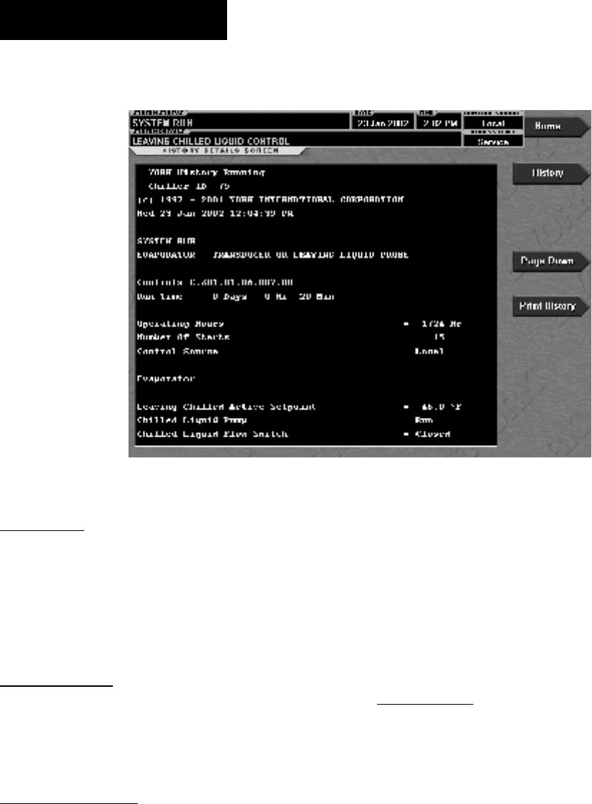
YORK INTERNATIONAL
78
FORM 160.55-O1 (604)
FIG. 34
HISTORY DETAILS SCREEN
OVERVIEW
This screen allows the user to see an on-screen printout
of all the system parameters at the time of the selected
shutdown. Not all screens are shown above. Number
of screens required to display all of the data varies ac-
cord ing to type of motor starter and options applied.
DISPLAY ONLY
History Printout
This is the on-screen printout of the system pa ram e-
ters.
PROGRAMMABLE
Page Up
Access Level Required: VIEW
Scroll up in the displayed data (if applicable).
Page Down
Access Level Required: VIEW
Scroll down in the displayed data (if applicable).
Print History
Access Level Required: VIEW
This generates a report listing the status of the chiller
parameters at the time of the selected shut down.
NAVIGATION
Home
Access Level Re quired: VIEW
Causes an instant return to the Home Screen.
History
Access Level Required: VIEW
Causes a return to the History Screen.
00566VIP
OptiView Control Center

FORM 160.55-O1 (604)
79
YORK INTERNATIONAL
2
SECURITY LOG SCREEN
OVERVIEW
(This screen only available with Flash Memory Card
version C.MLM.02.03.xxx and later)
This screen displays a listing of the last 75 setpoint
chang es. They are listed and numbered in reverse or der
in which they were changed, with the most recent listed as
number 1. Multiple pages are necessary to dis play all 75
changes. Not all setpoints are logged. Ser vice technicians
refer to list in YORK Service Manual 160.55-M1.
Requires a login access level of
SER VICE.
DISPLAY ONLY
Category
Displays the category of the setpoint (motor, evap o ra tor,
condenser, etc.)
Setpoint
Displays the setpoint that was changed.
New Value
Displays the value that was entered at the time of the
setpoint change.
PROGRAMMABLE
Log Entry
Allows the user to select a particular setpoint change
for detail viewing.
Print
Generates a detailed report of all setpoint changes list ed
in the setpoint change log.
Page Up
Scroll up in the displayed data (if applicable).
Page Down
Scroll down in the displayed data (if applicable).
NAVIGATION
Home
Access Level Re quired: SERVICE
Causes an instant return to the Home Screen.
History
Access Level Required: SERVICE
Causes an instant return to the History Screen.
View Details
Access Level Required: SERVICE
Causes a move to a sub-screen containing the details of
the setpoint change selected with the Log Entry key.
FIG. 35 00563VIP
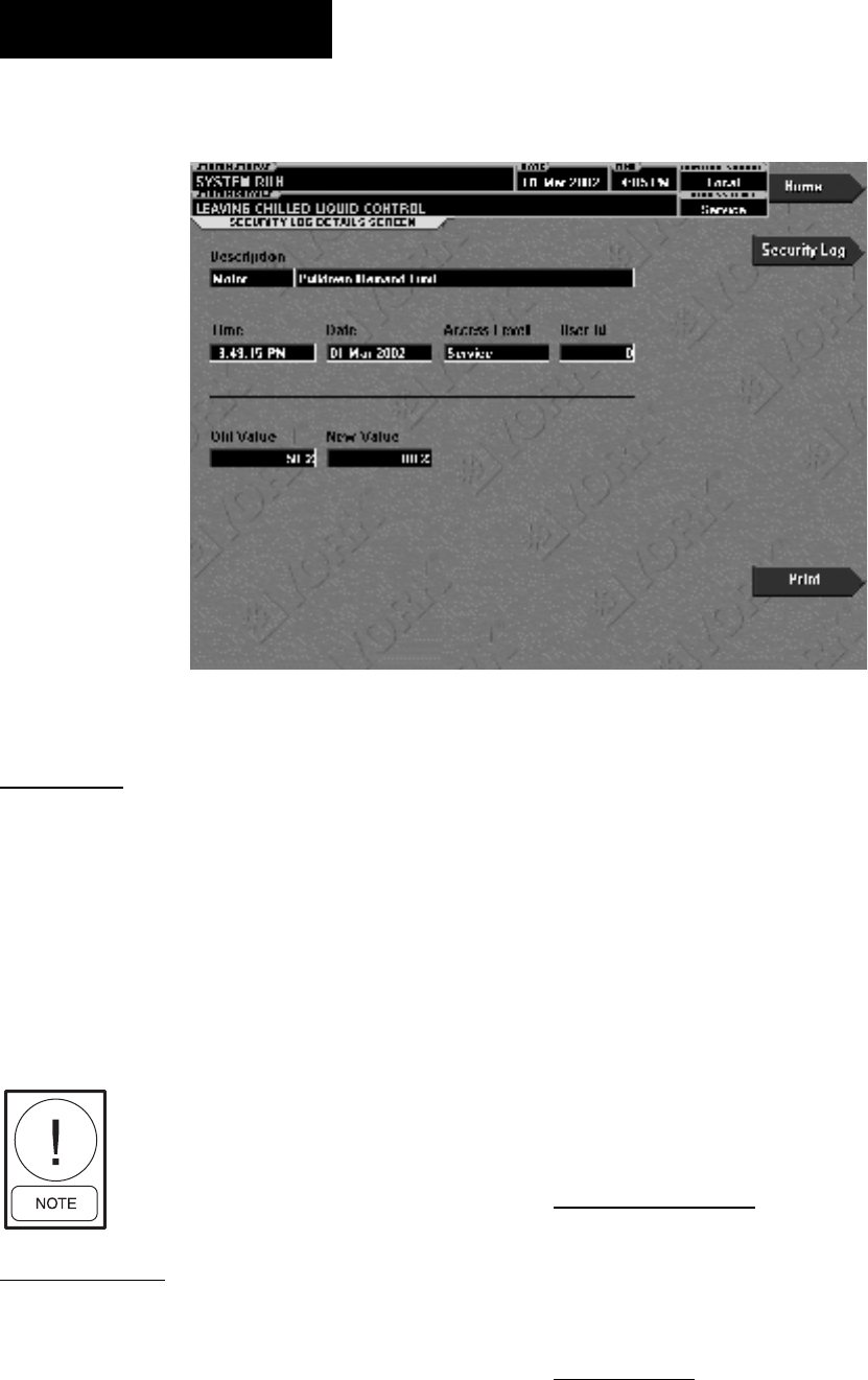
YORK INTERNATIONAL
80
FORM 160.55-O1 (604)
SECURITY LOG DETAILS SCREEN
OVERVIEW
(This screen only available with Flash Memory Card
version C.MLM.02.03.xxx and later)
This screen allows the user to view the details of a logged
setpoint change, selected from the list on the Security
Log Screen. The date and time the setpoint was changed,
the new and old setpoint value and ac cess level and user
ID used to make the change are displayed. The data on
this screen can be printed.
Requires a login access level of
SER VICE.
DISPLAY ONLY
Description
Displays the setpoint/category that was changed.
Time
Displays the time the setpoint was changed.
Date
Displays the date the setpoint was changed.
Access Level
Displays the Login Access Level used to make the
setpoint change.
User ID
Displays the Login User ID used to make the setpoint
change.
Old Value
Displays the previous setpoint value.
New Value
Displays the value entered at the time of the setpoint
change.
PROGRAMMABLE
Print
Generates a report of change parameters displayed on
this screen.
NAVIGATION
Home
Access Level Re quired: SERVICE
Causes an instant return to the Home Screen.
FIG. 36 00564VIP
OptiView Control Center

FORM 160.55-O1 (604)
81
YORK INTERNATIONAL
Security Log
Access Level Required: SERVICE
Causes an instant return to the Security Log Screen.
View Details
Access Level Required: SERVICE
Causes a move to a sub-screen containing the details of
the setpoint change selected with the Log Entry key.
2
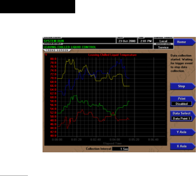
YORK INTERNATIONAL
82
FORM 160.55-O1 (604)
TREND SCREEN
00480VIP
FIG. 37
OVERVIEW
As many as six Operator selected parameters (Data
Points) can be plotted in an X/Y graph format. The X-
Axis is scaled per the selected Data Collection Interval
and dis played in a time of day or elapsed time format, as
se lect ed with the X-axis toggle key. The Y-Axis is scaled
for each parameter per the selected minimum and max-
i mum val ue for each parameter. Analog pa ram e ters are
scaled in pressure, temperature, volts, amps, hertz or time.
Dig i tal on/off parameters are scaled as zero (off) and one
(on). Only one Y-Axis label is displayed at a time. The
Y-Axis Toggle Key is used to toggle the Y-Axis labels
through the different pa ram e ters. The Y-Axis la bel that
is being displayed is iden ti Þ ed at the top of the graph.
For iden ti Þ ca tion, each plot ted parameter and as so ci at ed
Y-Axis labeling is color coordinated.
With Flash Memory Card version C.MLM.02.01.xxx
and earlier, all trended Data Points are displayed
si mul ta neous ly. With Flash Memory Card version
C.MLM.02.02.xxx and later, the DATA SELECT key
is used to display all trended Data Points si mul ta neous ly
or select a single Data Point for display.
The parameters are sampled at the selected Data Col-
lec tion Interval and plotted using 450 data points across
the X-Axis. If the actual value of the sampled pa ram e ter
is less than the Y-Axis label minimum for that pa ram e ter,
the value will be plotted at the minimum val ue. Simi-
larly, if the actual value is greater than the Y-Axis label
maximum for that parameter, the value will be plot ted
at the maximum value.
There are three types of charts that can be created:
ONE SCREEN, CONTINUOUS or TRIG GERED
(not applicable to Flash Memory Card version
C.MLM.02.01.xxx and earlier). When plot ting reaches
the end of the X-axis, if ONE SCREEN is selected,
trending stops and data is frozen. If CONTINUOUS is
selected, the oldest data is dropped from the left-hand
side of the graph at the next collection interval. There-
af ter, the oldest data is dropped from the left hand-side
of the graph at each data collection interval. If TRIG-
GERED is selected, data collection can be set to start
or stop based upon the selected TRIGGER ACTION
(START or STOP). If START is selected, data col lec tion
will not begin until the Triggers have been satisÞ ed and
any selected TRIGGER DELAY has elapsed. Data col-
lection will stop at the completion of one screen of data
as with the ONE SCREEN. If STOP is selected, data col-
lection will not stop un til the Trig gers have been satisÞ ed
and any selected TRIGGER DELAY has elapsed.
If a power failure occurs while the trend ing is running,
the trending is stopped. Upon restoration of power, the
last screen of data that was collected will be displayed
on the trending screen. The START key must be pressed
to initiate a new trend screen.
OptiView Control Center
FORM 160.55-O1 (604)
83
YORK INTERNATIONAL
DISPLAY ONLY
This screen allows the user to view the graphical trend-
ing of the selected pa ram e ters and is also a gateway to
the graph setup screens.
A red screen with the words “TREND
MAX MUST BE > TREND MIN” will
ap pear if the Y-Axis min i mum has
been programmed to a value that is
greater than the Y-Axis maximum for
any pa ram e ter. If this appears, pro ceed
to the Trend Setup Screen to change
the val ues.
PROGRAMMABLE
Start
Access Level Required: OPERATOR
Pressing this key clears the graph, starts a new graph,
sets the time of day to the present clock time and be gins
the trending. This key is only available if trend ing is
stopped. If the selected Chart Type is TRIG GERED and
TRIGGER ACTION is set to START, data col lec tion
will not begin until the Trig gers have been satisÞ ed and
any selected TRIG GER DELAY has elapsed. Oth er wise,
data col lec tion will begin im me di ate ly.
Stop
Access Level Required: OPERATOR
Pressing this key stops the trending. The trend data
is frozen on the display until another graph is started
with the START key. The STOP key is only available if
trend ing is running.
Data Select
(Flash Memory Card version C.MLM.02.02.xxx
and later)
Access Level required: VIEW
Allows the user to display all trended data points si mul -
ta neous ly or select a single trended data point for dis play,
hiding the other data points. Selections are ALL DATA
or DATA POINT X (1-6).
Print
(Flash Memory Card version C.MLM.02.02.xxx
and later)
Access Level Required: VIEW
Allows the data on the trend screen to be printed in
tabular format. If set to EXISTING, a snapshot of the
data presently on the screen is sent to the print er. If set
to NEW, all data collected after pressing this key will be
sent to the printer as it is collected. If set to DIS ABLED,
no data is sent to the printer. Refer to PRINT ERS section
of this book for print out example.
Y-Axis
Access Level Required: VIEW
This key toggles the Y-Axis labels of the graph. Each
key press changes the label to another of the selected
parameters.
X-Axis
Access Level Required: VIEW
This key toggles the X-Axis labels of the graph. Each
key press alternates the scaling between time of day and
elapsed time. The Time of Day scaling is in 24-hour for-
mat. The Elapsed Time scaling is the time elapsed since
the START key was pressed, starting the trend ing.
NAVIGATION
Home
Access Level Required: VIEW
Causes a return to the Home Screen.
History
(Flash memory Card version C.MLM.02.01.xxx and
earlier)
Access Level Required: VIEW
Causes a return to the Home Screen.
Trend Setup
Access Level Required:
Only displayed if the trending is stopped. Causes a jump
to a subscreen for conÞ guring the trending display.
2

YORK INTERNATIONAL
84
FORM 160.55-O1 (604)
TREND SETUP SCREEN
OVERVIEW
This screen is used to conÞ gure the trending screen.
The parameters to be trended are selected from the
Common Slots Screen or Common Slots Master list
and entered as Slot Numbers for Data Points 1 through
6. The Y-Axis minimum and maximum values for each
parameter are entered as Data Point Min and Data Point
Max for Data Points 1 through 6. The interval at which
all the parameters are sampled is selected as the Data
Collection Interval.
DISPLAY ONLY
None
PROGRAMMABLE
Chart Type
Access Level Required: OPERATOR
(Flash Memory Card version (C.MLM.02.02.xxx and
lat er) Selects CONTINUOUS, ONE SCREEN or
TRIG GERED type of graph.
Collection Interval
Access Level Required: OPERATOR
Selects the interval at which the parameters are sam pled.
There are 450 data points displayed across the X-Axis
of the graph. Each point represents the instantaneous
value of the parameter. The user selects the time in-
ter val between these points. This is called the DATA
COL LEC TION INTERVAL or the interval at which the
pa ram e ter is sampled. This interval is programmable
over the range of 1 second to 3600 seconds (1 hour), in
one second increments. The selected interval not only
de ter mines the sample interval, but also the full screen
time display. The full screen time display is a result of the
selected interval in seconds, multiplied by the 450 data
points. For example, if the Data Collection In ter val is
programmed for 900 seconds, the parameter would be
sampled every 900 seconds, with the last 112.5 hours
(4.7 days) of data viewable on the screen. There fore, the
selected interval is a compromise between res o lu tion
and full screen time display. Select the desired Data
Collection Interval as follows:
1. Determine the desired time interval (in sec onds),
be tween data samples.
2. Calculate the full screen time display as follows:
450 x Data Collection Interval = full screen sec onds
full screen seconds / 60 = full screen minutes
full screen minutes / 60 = full screen hours
full screen hours / 24 = full screen days
3. Decide if the resultant sample interval and full screen
display meet the requirements. If not, select a dif-
fer ent sample interval.
00481VIP
FIG. 38
OptiView Control Center

FORM 160.55-O1 (604)
85
YORK INTERNATIONAL
Select
Access Level Required: OPERATOR
This key is used to enter the slot numbers and the min-
i mum and maximum Y-Axis values of each parameter
to be trended. Pressing this key places a yellow box
around Data Point 1 Slot Number. Use the ▲ and ▼
navigation keys to place the box around the value of
Data Points 1 through 6 to be changed. With the de sired
value selected, press the ✓ key. A dialog box is dis played
permitting data entry.
Data Point Slot # (1-6)
Access Level Required: OPERATOR
Use the SELECT key as described above and enter the
slot number from the Common Slots Screen or Master
Slot Number List of the desired parameter to be trend ed.
The selected parameter description will be displayed
for the Data Point. Setting this slot number to zero will
disable trending for that par tic u lar Data Point. Any or
all points can be dis abled.
Data Point Min (1-6)
Access Level Required: OPERATOR
Only displayed if the Associated Slot Number is not
Zero. This is the minimum value displayed for the Y-
Axis. Selecting a parameter for a Data Point sets this
to the default value, which is the lowest value allowed
for that parameter. It can be changed to a value that
pro vides a more appropriate resolution for the pa ram e ter
being monitored. To change, use the SELECT key as
described above and enter the desired value. The value
must always be set to a value less than the Data Point
Max. Otherwise, a red graph is displayed on the Trend
Screen with the words “TREND MAX MUST BE >
TREND MIN”. If the parameter selected for this data
point is a digital type (on/off), this value must be set to
zero (0). Zero indicates the OFF state.
Data Point Max (1-6)
Access Level Required: OPERATOR
Only displayed if the associated slot number is not zero.
This is the maximum value displayed for the Y-Axis.
Se lect ing a parameter for a Data Point sets this to the
de fault value, which is the highest value allowed for
that pa ram e ter. It can be changed to a value that pro-
vides a more appropriate resolution for the parameter
being mon i tored. To change, use the SELECT key as
described above and enter the desired value. The value
must al ways be set to a value greater than the Data Point
Min. Otherwise, a red graph is displayed on the Trend
Screen with the words “TREND MAX MUST BE >
TREND MIN”. There are 20 Y-Axis divisions. If a MIN-
MAX span is selected that is not evenly divided by 20,
the Pro gram will automatically select the next higher
MAX val ue that makes the span evenly di vid ed by 20.
For ex am ple, if 0.0 is selected as the MIN and 69.0 is
selected as the MAX, the Program will insert 70.0 as
the MAX value. If the parameter se lect ed for this data
point is a digital type (on/off), this value must be set to
one (1). One indicates the on state.
NAVIGATION
Home
Causes a return to the Home Screen.
Trending
Causes a return to the Trending Screen.
Slot Numbers
Causes a jump to a subscreen that lists the slot num bers of
the most commonly monitored parameters. The de sired
parameters to be plotted are selected from this screen.
Triggers
(Flash Memory Card version C.MLM.02.02.xxx
and later)
Causes a jump to the Advanced Trend Setup Screen,
where the start/stop Triggers can be setup. Only dis-
played if TRIGGERED has been selected as Chart
Type.
2
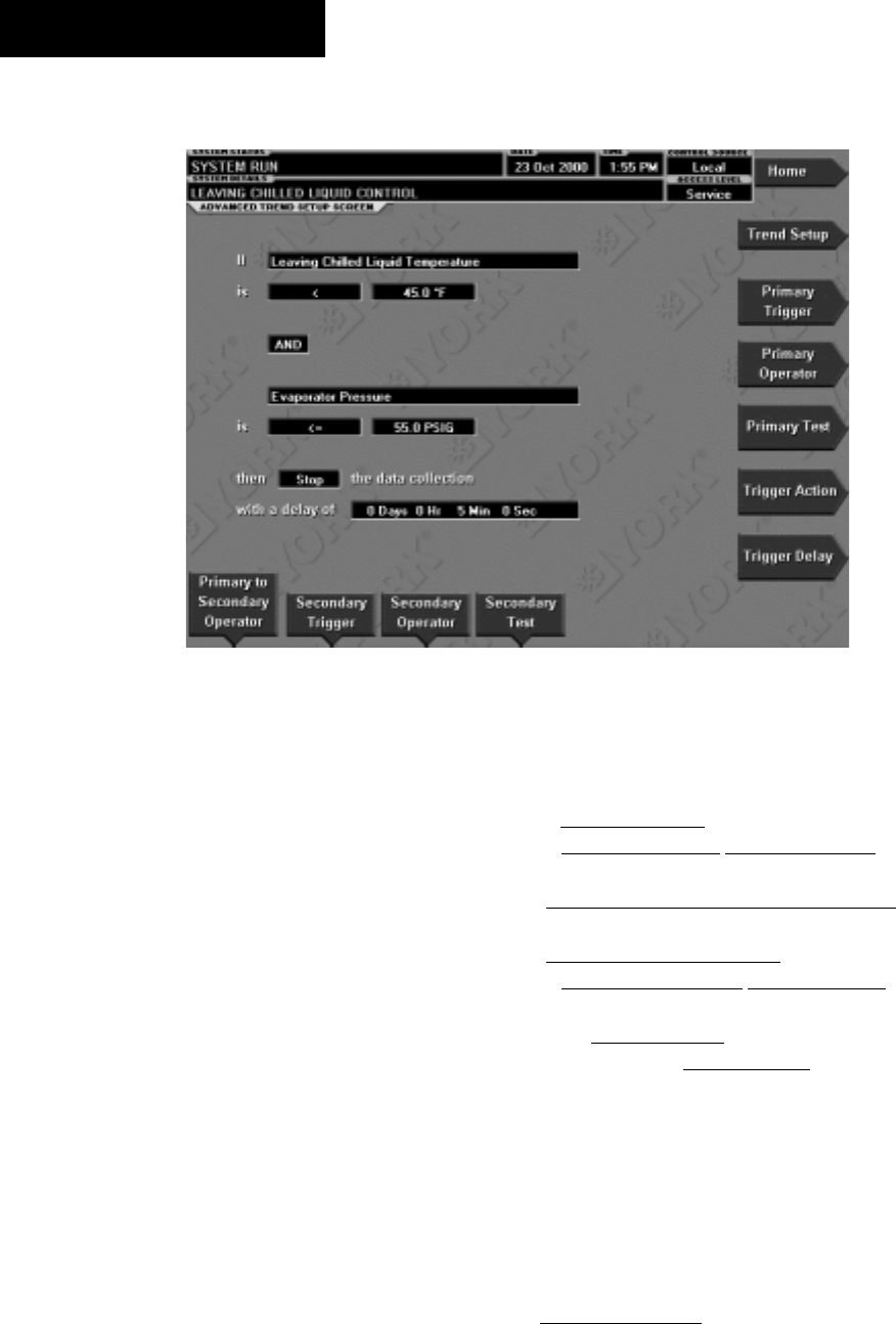
YORK INTERNATIONAL
86
FORM 160.55-O1 (604)
OVERVIEW
(Flash Memory Card version C.MLM.02.02.xxx
and later)
The desired data collection start/stop triggers are set up
on this screen. The trend data collection can be set to start
or stop based upon the status of up to two selected Trig-
gers. The Triggers can consist of dig i tal events or analog
parameters compared to thresh olds. The Trig gers can
be used individually or in combination. The digital and
analog parameters are selected from the Common Slots
Screen (or Mas ter Slot Numbers List in this book).
The parameter selected as the Primary Trigger is com-
pared to a value selected as the Primary Test, using the
Primary Operator as a comparator. If it is eval u at ed as
true, then the data collection is started or stopped (after
any selected Trigger delay) per the selected Trigger
Action.
A Secondary Trigger can be evaluated with the Pri ma ry
Trigger to start/stop data collection. The Pri ma ry to Sec-
ondary Operator is used to deÞ ne the Trigger combina-
tions required to be true to start/stop data col lec tion. The
Secondary Trigger is setup and evaluated the same as
the Primary Trigger.
ADVANCED TREND SETUP SCREEN
FIG. 39
Entry Þ elds are as follows:
If Primary Trigger
Is Primary Operator Primary Test
Primary to Secondary Operator
Secondary Trigger
Is Secondary Operator Secondary Test
Then Trigger Action the Data Collection
With a delay of Trigger Delay
After the desired Triggers are set, the START key on
the TREND Screen must be manually pressed before
the triggers will be evaluated. While waiting for the
trig gers to start or stop data collection, a status message
is displayed in the upper right corner of the TREND
Screen describing the pending action.
DISPLAY ONLY
None
00484VIP
OptiView Control Center

FORM 160.55-O1 (604)
87
YORK INTERNATIONAL
PROGRAMMABLE
Primary Trigger
Access Level Required: OPERATOR
Selects the Þ rst parameter to be evaluated. Selection is
made from the Slot Numbers listing on the Trend Com-
mon Slots Screen or the Master Slot Numbers List in
this book. Setting this slot number to zero disables the
Primary Trigger.
Primary Operator
Access Level Required: OPERATOR
Selects the comparator for the Primary Trigger’s re la -
tion ship to the Primary Test. If the Primary Trigger is
an analog value, selections are: <, <=, =, =>, >. If the
Primary Trigger is a digital event, selections are: Equal
To, Not Equal To.
Primary Test
Access Level Required: OPERATOR
Selects the value or condition that the Primary Trigger
is compared to. Selection ranges from the Primary Trig-
ger minimum value to the Primary Trigger maximum
value.
Trigger Action
Access Level Required: OPERATOR
Selects whether the trend data collection will Start or
Stop when the Trigger comparisons are true. If set to
Start, data collection will stop after one screen of data
is collected.
Trigger Delay
Access Level Required: OPERATOR
Allows the data collection start or stop to be delayed
after the Triggers evaluate as true. The delay is se-
lect able from 1 to 864000 seconds (10 days). Display
is in days, hours, minutes and seconds. The delay timer
be gins when the triggers evaluate as true. If the Trigger
Action is set to Start, data collection will begin after the
triggers evaluate as true and the delay timer has elapsed.
If the Trigger Action is set to Stop, data collection will
stop after the Triggers evaluate as true and the delay
timer has elapsed.
Primary to Secondary Operator
Access Level Required: OPERATOR
Selects whether the Primary Trigger, Secondary Trig-
ger or both have to be true in order to start or stop data
collection. Selections are AND, OR, XOR and None. If
NONE is selected, the Secondary Trigger is disabled.
Data collection will start/stop (as selected with Trigger
Action) when:
• If AND selected: Both Primary AND Sec ond ary are
true
• If OR selected: Either Primary OR Secondary (or
both) are true
• If XOR selected: Either Primary OR Sec ond ary (but
not both) are true
Secondary Trigger
Access Level Required: OPERATOR
Selects the second parameter to be evaluated. Se lec tion
is made from the Slot Numbers listing on the Trend
Common Slots Screen or the Master Slot Numbers List
in this book. Setting this slot number to zero disables
the Secondary Trigger.
Secondary Operator
Access Level required: OPERATOR
Selects the comparator for the Secondary Trigger’s re la -
tion ship to the Secondary Test. If the Secondary trig ger
is an Analog value, selections are: <, <=, =, =>, >. If
the Secondary Trigger is a digital event, selections are:
Equal To, Not Equal To.
Secondary Test
Access Level Required: OPERATOR
Selects the value or condition that the Secondary Trig ger
is compared to. Selection ranges from the Sec ond ary Trig-
ger minimum to the Secondary Trig ger max i mum.
NAVIGATION
HOME
Causes an instant return to the Home Screen.
TREND SETUP
Causes an instant return to the Trend Setup Screen.
2
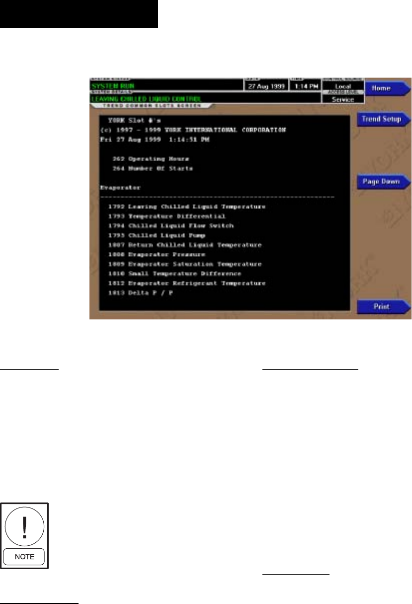
YORK INTERNATIONAL
88
FORM 160.55-O1 (604)
COMMON SLOTS SCREEN
OVERVIEW
This screen displays the slot numbers of the com-
monly monitored parameters. The slot numbers for the
re main der of the available parameters are listed on the
Master Slot Numbers List that fol lows.
From these lists, select up to six pa ram e ters to be trend ed.
Return to the Trend Setup Screen and enter the pa ram e ters
Slot Numbers into Data Points 1 through 6.
Re quires a login access level of
OPERATOR or high er.
DISPLAY ONLY
Slot Numbers
These are the slot numbers of the most commonly used
parameters.
PROGRAMMABLE
Page Down
Access Level required: OPERATOR
Scroll down in the displayed data.
Page Up
Access Level Required: OPERATOR
Scroll up in the displayed data.
Print
Access Level Required: OPERATOR
Generates a list of the slot numbers of the available
parameters.
NAVIGATION
Home
Causes an instant return to the Home Screen.
Trend Setup
Causes a return to the Trend Setup Screen.
00374VIP
FIG. 40
OptiView Control Center
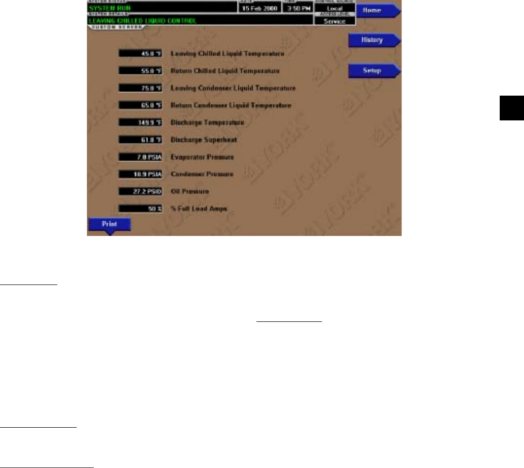
FORM 160.55-O1 (604)
89
YORK INTERNATIONAL
CUSTOM VIEW SCREEN
OVERVIEW
(Flash memory Card version C.MLM.02.01 or later)
This screen allows up to 10 Service Technician se lect ed
parameters to be displayed. These parameters are se-
lect ed from a list on the Custom View Setup Screen.
This allows the Service Technician to display pa ram e ters
pertinent to a particular problem during trou ble shoot ing.
At completion of the service call, the display can be
cleared or the parameters can be left there for monitor-
ing by operations personnel.
DISPLAY ONLY
None
PROGRAMMABLE
Print
Access Level Required: VIEW
This generates a listing of the parameters displayed on
this screen.
NAVIGATION
Home
Access Level Required: VIEW
Causes an instant return to the Home Screen.
History
Access Level required: VIEW
Causes an instant return to the History Screen.
Setup
Access Level required: SERVICE
Causes a jump to the sub-screen that allows selection of
the parameters to be displayed.
FIG. 41 00375VIP
2
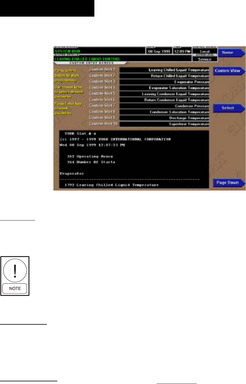
YORK INTERNATIONAL
90
FORM 160.55-O1 (604)
CUSTOM VIEW SETUP
OVERVIEW
(Flash memory Card version C.MLM.02.01 or later)
This screen allows the Service technician to select up to
10 parameters for display on the Custom View Screen.
Requires a login ac cess level of SER-
VICE. Ser vice Technicians refer to
YORK Ser vice Manual 160.55-M1
for operation in struc tions and ex pla -
na tion of all programmable setpoints
and dis played values.
DISPLAY ONLY
Slot Numbers
Lists the available parameters that can be displayed.
The desired parameters for display are selected from
this list.
PROGRAMMABLE
Page Up
Scroll up through list of available parameters.
Page Down
Scroll down through list of available parameters.
Select
First use the Page Up and Page Down keys to scroll
through the Slot Numbers list and note the number of
the parameter(s) to be displayed. Pressing the Select key
places a green colored selection box around Cus tom Slot
1. If it is desired to change an already entered pa ram e ter,
use the 5 and 6 keys to place the selection box around
the slot number to be changed. With the se lec tion box
around the slot number to be changed or en tered, press
the ENTER (!) key. A dialog box is dis played permit-
ting data entry. Using the numeric key pad keys, enter the
desired slot num ber and press the EN TER (!) key.
Custom Slot (1-10)
Use the Select key and numeric keypad keys as de scribed
above and enter the slot number from Slot Num bers
list. Setting the Slot number to zero clears the dis play
of this slot number.
Clear Display
Pressing this key clears all selected parameters from the
Custom View screen.
NAVIGATION
Home
Access Level Required: VIEW
Causes a return to the Home Screen.
Custom View
Access Level Required: SERVICE
Causes a return to the Custom View Screen.
FIG. 42 00376VIP
OptiView Control Center

FORM 160.55-O1 (604)
91
YORK INTERNATIONAL
MASTER SLOT NUMBERS LIST FOR USE WITH TREND FEA TURE
SLOT
NO. DESCRIPTION
256 System: Chiller State
257 System: Coastdown Time Remaining
258 System: Prelube Time Remaining
259 System: Are Safety Shut down Contacts Closed
260 System: Are Cy cling Shutdown Contacts Closed
261 System: Are An tic i pa to ry Alarm Contacts Closed
262 System: Operating Hours
264 System: Number of Starts
265 System: Is Stop Switch Closed
266 System: Is Start Switch Closed
267 System: Is Remote Ready to Start
280 External Contact: Is Re mote Stop Closed
281 External Contact: Is Re mote Start Closed
282 External Contact: Is MultiUnit Cycling Closed
283 External Contact: Is Re mote Cycling Closed
284 External Contact: Is Aux il ia ry Safety Open
285 Jumper: Is Anti-Recycle Enabled
286 Jumper: Coastdown Operation
287 Jumper: Is Di ag nos tics Enabled
288 Jumper: Liquid Type
289 Jumper: Chilled Liq uid Pump Operation
290 Jumper: Motor Type
291 Jumper: Power Fail ure Restart
292 Jumper: Pre-Run Op er a tion
293 Jumper: Refrigerant Selection
294 Jumper: VSD Motor Sup ply Line Frequency
304 Options: Control Mode
305 Options: System Lan guage
307 Options: Display Mode
512 Sched: Is Schedule Enabled
1280 Pre-Rotation Vanes: Is Motor Switch Closed
1281 Pre-Rotation Vanes: Position
1282 Pre-Rotation Vanes: Are Vanes Opening
1283 Pre-Rotation Vanes: Are Vanes Closing
1284 Pre-Rotation Vanes: Are Vanes Holding
1285 Pre-Rotation Vanes: Control Mode
1296 Discharge: Temperature
1536 Oil: Differential Pressure
1537 Oil: Sump Temperature
1538 Oil Pump: Control Mode
1539 Oil Pump: Is Pump On
1540 Oil Pump: Manual Time Left
SLOT
NO. DESCRIPTION
1792 Leaving Chilled Liquid: Temperature
1793 Leaving Chilled Liquid: Temperature Differential
1794 Leaving Chilled Liquid: Is Flow Switch Closed
1795 Leaving Chilled Liquid: Is Pump On
1796 Leaving Chilled Liquid: Local Temperature Setpoint
1797 Leaving Chilled Liquid: Remote Analog Tem per a ture
Setpoint
1798 Leaving Chilled Liquid: Remote ISN Temperature
Setpoint
1799 Leaving Chilled Liquid: Remote Modem Tem per a ture
Setpoint
1800 Leaving Chilled Liquid: Selected Temperature
Setpoint
1801 Leaving Chilled Liquid: Control Sensitivity
1802 Leaving Chilled Liquid: Remote Temperature
Range
1803 Leaving Chilled Liquid: Restart Temperature Off set
1804 Leaving Chilled Liquid: Restart Temperature
Setpoint
1805 Leaving Chilled Liquid: Shutdown Temperature Off-
set
1806 Leaving Chilled Liquid: Shutdown Temperature
Setpoint
1807 Return Chilled Liquid: Temperature
1808 Evaporator: Pressure
1809 Evaporator: Saturation Temperature
1810 Evaporator: Small Temperature Difference
1811 Evaporator: Is Refrigerant Sensor Present
1812 Evaporator: Refrigerant Temperature
1813 Evaporator: Delta P / P
1814 Evaporator: Brine Low Cutout
1815 Smart Freeze Protection: Is Control Enabled
1818 Leaving Chilled Liquid: Remote Digital Tem per a ture
Setpoint
2048 Leaving Condenser Liquid: Temperature
2049 Leaving Condenser Liquid: Is Flow Switch Closed
2050 Leaving Condenser Liquid: Is Pump On
2051 Return Condenser Liquid: Temperature
2052 Condenser: Pressure
2053 Condenser: Saturation Temperature
2054 Condenser: Small Temperature Difference
2057 Condenser: Is High Pressure Switch Closed
2058 Condenser: High Pressure Warning Threshold
2

YORK INTERNATIONAL
92
FORM 160.55-O1 (604)
SLOT
NO. DESCRIPTION
2059 SubCooling: Temperature
2060 Drop Leg Refrigerant: Is Sensor Present
2061 Drop Leg Refrigerant: Temperature
2063 Vent Line Solenoid: Is Solenoid On
2304 Motor: Starter Type
2305 Motor: Is Motor Starter On
2306 Motor: Current %FLA
2307 Motor: Is Motor Controller Switch Open
2308 Motor: Current Limit Local Setpoint
2309 Motor: Current Limit Remote Analog Setpoint
2310 Motor: Current Limit Remote ISN Setpoint
2312 Motor: Current Limit Selected Setpoint
2313 Motor: Pulldown Demand Time Remaining
2314 Motor: Pulldown Demand Limit Setpoint
2315 Motor: Pulldown Demand Time Setpoint
2316 Motor: Anti-Recycle Time Remaining
2317 Motor: Current Limit Remote Digital Setpoint
Mod "A" SSS ONLY
2560 SSS: Phase A Current
2561 SSS: Phase B Current
2562 SSS: Phase C Current
2563 SSS: Phase A Voltage
2564 SSS: Phase B Voltage
2565 SSS: Phase C Voltage
2566 SSS: Scale/Model
2567 SSS: Full Load Amps
2568 SSS: Supply Voltage Range
2569 SSS: Is Current Unbalance Check Enabled
Mod "B" SSS ONLY
2570 LcSss: Input Power
2571 LcSss: Kilowatt Hours
2572 LcSss: Phase A Current
2573 LcSss: Phase B Current
2574 LcSss: Phase C Current
2575 LcSss: Phase A Voltage
2576 LcSss: Phase B Voltage
2577 LcSss: Phase C Voltage
2578 LcSss: Phase A Temperature
2579 LcSss: Phase B Temperature
2580 LcSss: Phase C Temperature
2581 LcSss: Starter Model
2582 LcSss: Full Load Amps
2583 LcSss: Voltage Range
2584 LcSss: Starting Current
2585 LcSss: Is Serial Communications OK
2586 LcSss: Panel to Sss Comm Errors
2587 LcSss: Sss to Panel Comm Errors
SLOT
NO. DESCRIPTION
2816 VSD: Motor HP
2817 VSD: 100% Full Load Amps
2818 VSD: Input Power
2819 VSD: Kilowatt Hours
2820 VSD: DC Bus Voltage
2821 VSD: DC Inverter Link Current
2822 VSD: Output Frequency
2823 VSD: Output Voltage
2824 VSD: Phase A Current
2825 VSD: Phase B Current
2826 VSD: Phase C Current
2827 VSD: Is Precharge Relay On
2828 VSD: Is Trigger SCR On
2829 VSD: Is Water Pump On
2830 VSD: Control Mode
2831 VSD: Command Frequency
2832 VSD: Manual Frequency Increment
2833 VSD: Internal Ambient Temperature
2834 VSD: Converter Heatsink Temperature
2835 VSD: Phase A Heatsink Temperature
2836 VSD: Phase B Heatsink Temperature
2837 VSD: Phase C Heatsink Temperature
2838 VSD: Is Communications OK
2839 VSD: Panel to ACC Comms Error Count
2840 VSD: ACC to Panel Comms Error Count
2841 VSD: ACC to VSD Comms Error Count
2842 VSD: VSD to ACC Comms Error Count
2843 VSD: VSD to Filter Comms Error Count
2844 VSD: Filter to ACC Comms Error Count
2845 ACC: Delta P/P
2846 ACC: Stability Limit
2847 ACC: Surge Margin
2848 ACC: Manual Surge Command
2849 ACC: Surge Map Count
2850 ACC: Surge Type
2857 ACC: Surge Map Point Count
2858 ACC: Surge Map Delta P/P
2859 ACC: Surge Map Output Frequency
2860 ACC: Surge Map PRV Position
2861 Filter: Is Filter Installed
2862 Filter: Is Operation Inhibited
2863 Filter: Is Filter Running
2864 Filter: Is Precharge Contactor Closed
2865 Filter: Is Supply Contactor Closed
2866 Filter: Phase Rotation
2867 Filter: Motor HP
2868 Filter: Supply KVA
2869 Filter: Total Power Factor
2870 Filter: DC Bus Voltage
OptiView Control Center

FORM 160.55-O1 (604)
93
YORK INTERNATIONAL
SLOT
NO. DESCRIPTION
2871 Filter: Heatsink Temperature
2872 Filter: L1 - L2 RMS Voltage
2873 Filter: L2 - L3 RMS Voltage
2874 Filter: L3 - L1 RMS Voltage
2875 Filter: L1 - N Peak Voltage
2876 Filter: L2 - N Peak Voltage
2877 Filter: L3 - N Peak Voltage
2878 Filter: L1 Total Harmonic Distortion
2879 Filter: L2 Total Harmonic Distortion
2880 Filter: L3 Total Harmonic Distortion
2881 Filter: L1 RMS Filter Current
2882 Filter: L2 RMS Filter Current
2883 Filter: L3 RMS Filter Current
2884 Filter: L1 RMS Supply Current
2885 Filter: L2 RMS Supply Current
2886 Filter: L3 RMS Supply Current
2887 Filter: L1 Total De mand Distortion
2888 Filter: L2 Total De mand Distortion
2889 Filter: L3 Total De mand Distortion
2890 Filter: Maximum Total Harmonic Distortion
2891 Filter: Maximum Total Demand Distortion
2
SLOT
NO. DESCRIPTION
8205 Refrigerant Level: Is Control Enabled
8206 Refrigerant Level: Position
8207 Refrigerant Level: Is Valve Closing
8208 Refrigerant Level: Is Valve Opening
8209 Refrigerant Level: Control Mode
8210 Refrigerant Level: Is Pulldown In Effect
8211 Refrigerant Level: Pulldown Time Remaining
8212 Refrigerant Level: Target Setpoint
8213 Refrigerant Level: Setpoint
8214 Refrigerant Level: Period
8215 Refrigerant Level: Proportional Limit Close
8216 Refrigerant Level: Proportional Limit Open
8217 Refrigerant Level: Rate Limit Close
8218 Refrigerant Level: Rate Limit Open
12288 Purge: Pressure
12289 Purge: Is Air Purge Valve Closed
12290 Purge: Is Oil Purge Valve Closed
12291 Purge: Is Bottom Float Switch Closed
12292 Purge: Is Top Float Switch Closed
12293 Purge: Exhaust Count
12294 Purge: Window Time
12295 Purge: Is High Ef fi cien cy Enabled
12296 Purge: Maximum Purg es Per Hour
2

YORK INTERNATIONAL
94
FORM 160.55-O1 (604)
DISPLAY MESSAGES
The Status Bar of the Display contains a Status Line
and, beneath it a Details Line. The Status Line con tains
a message describing the operating state of the chiller;
whether it is stopped, running, starting or shutting down.
The Details Line displays Warning, Cycling, Safety,
Start Inhibit and other messages that provide further
details of the Status Bar messages. The Status Mes sag es
list ed be low are displayed on the Status Line. All other
mes sag es are displayed on the Details Line.
To aid in the meaning of the message, messages are
displayed in different colors as follows:
Normal Operation mes sag es - Green
Warning messages - Yellow
Cycling Shutdown mes sag es - Orange
Safety Shutdown mes sag es - Red
STATUS MESSAGES
“SYSTEM READY TO START”
The chiller is shut down but will start upon receipt of a
Local or Remote start signal.
“CYCLING SHUTDOWN – AUTO RESTART”
The chiller is shut down on a CYCLING shutdown. The
cause of the shutdown is still in effect and is dis played
on the Details line of the Status Bar. The chiller will
au to mat i cal ly restart when the CYCLING con di tion
clears.
“SAFETY SHUTDOWN – MANUAL RESTART”
The chiller is shut down on a SAFETY shutdown. The
cause of the shutdown is still in effect and is displayed
on the Details line of the Status Bar. The chiller can be
started after the Safety condition clears and the Op er a tor
moves the COMPRESSOR switch to the STOP-RESET
(O) position.
“SYSTEM PRELUBE”
A chiller start has been initiated and the pre-start lu-
bri ca tion is being performed. The Prelube duration is
ei ther 30 seconds or 180 seconds, as conÞ gured with
a Microboard Program Switch. The Pre-lube duration
must nev er be changed by anyone other than a quali-
Þ ed Ser vice Tech ni cian. The standard Prelube duration
is 30 sec onds.
“SYSTEM RUN”
The chiller is running under the condition described in
the Details Line of the Status Bar.
“SYSTEM COASTDOWN”
The chiller has shut down and the Post-run lubrication is
being performed. On electric motor drive ap pli ca tions,
the Postlube duration is 150 seconds. On Steam Tur bine
applications, it is 15 minutes. The actual du ra tion is de-
ter mined by a Microboard Program Jumper, con Þ g ured
by a qualiÞ ed Service technician.
“START INHIBIT”
The chiller is prevented from being started due to the
reason displayed on the Details Line of the Status bar.
RUN MESSAGES
“MOTOR – HIGH CURRENT LIM IT”
The Compressor Motor current is > the Local or Re mote
Current Limit Setpoint. The Current Limit Setpoint is
pro grammed over a range of 30 to 100% of the Chill er
Full Load Amps (FLA). When the motor current in-
creas es to the “inhibit open” threshold, the Pre-rotation
Vanes are inhibited from further opening. This prevents
a fur ther cur rent rise. If the current continues to rise
to the “start close” threshold, the Vanes begin closing
until the current falls to the “stop close” threshold. Au-
to mat ic Vane operation is resumed and this message
au to mat i cal ly clears when the motor current decreases to
the “allow open” thresh old. The thresholds are dif fer ent
for the var i ous motor start er applications. To allow Þ eld
calibration of the Solid State Starter (Mod “A”) Logic
Board or CM-2 Current Module, pressing the Slide Valve
Load key in Service access level, starts a 10 minute timer
during which the current limit thresh olds are elevated.
Refer to table on next page.
Vane Control Motor Current (%FLA)
Electro-Me chan i cal/ VSD Ser vice Mode
Solid state starter
On rise, inhibit open 100 100 107
On fall, allow open 98 98 106
On rise, start close 104 103 110
On fall, stop close 102 101 109
An example of current limit is as follows: If a Solid Sate
Starter chiller FLA is 100 Amps and the Current Limit
Setpoint is 50%, the following will occur:
50 Amps – inhibit vane open
52 Amps – vanes begin closing
51 Amps – vanes stop closing
49 Amps – allow automatic vane control
“LEAVING CHILLED LIQUID CONTROL”
The chiller is running, controlling the Leaving Chilled
Liq uid to the Leaving Chilled Liquid Temperature
Setpoint. There are no system conditions inhibiting
this operation.
OptiView Control Center

FORM 160.55-O1 (604)
95
YORK INTERNATIONAL
“MOTOR PULLDOWN LIMIT”
The Pulldown Demand Limit Setpoint timer is in ef fect
and the Compressor Motor current is > the Pulldown
Demand Current Limit Setpoint value. The Pre-rotation
vane operation is being inhibited as de scribed in “ MO-
TOR – HIGH CURRENT LIMIT” message above.
START INHIBIT MESSAGES
“ANTI-RECYCLE XXMin/Sec”
The chiller is inhibited from starting because the 30
minute anti-recycle time has not yet elapsed. Time re-
main ing is displayed.
“VANE MOTOR SWITCH OPEN”
The chiller is inhibited from starting because the Pre-
rotation Vanes are not fully closed.
“MOTOR CURRENT >15% FLA”
The OptiView Control Center has detected a Com-
pres sor Motor Current of a magnitude that is >15% of
the chiller Full Load Amps for 10 continuous seconds,
while the chiller is shutdown. As long as this condi-
tion ex ists, the oil pump is turned on. This is generally
in dic a tive of a failure of the motor starter, Control
Cen ter start cir cuits or motor current feedback circuits.
After motor current is no long er detected, a SYS TEM
COASTDOWN is per formed. The chiller can be start ed
after motor current is no long er detected, the SYS TEM
COASTDOWN has com plet ed and the COM PRES SOR
switch is placed in the STOP-RE SET (O) po si tion.
“LCSSS – HIGH TEMPERATURE PHASE X
– STOPPED”
(Mod. “B” Solid State Starter only)
The chiller is stopped and the Liquid Cooled Solid
State Starter Logic/Trigger Board has detected that the
tem per a ture of phase A, B or C (designated as X in the
message) Silicon Controlled RectiÞ er (SCR) module is
>110°F. The starter cooling pump will run and the chill er
will be inhibited from starting until the tem per a ture de-
creas es to <109°F.
WARNING MESSAGES
“WARNING – REAL TIME CLOCK FAILURE”
During the initialization process that occurs when pow er
is applied to the OptiView Control Center, test data is
written to a location in the BRAM battery backed mem-
o ry device (IC location U52 on Microboard). This data
is then read from the BRAM and compared to the test
data. If the read data is not the same as that which was
written to the device, it is assumed the BRAM and Real
time Clock operation is defective and this mes sage is
dis played. The BRAM should be replaced by a qualiÞ ed
Service Technician. This message au to mat i cal ly clears
when the BRAM problem has been solved.
“WARNING – CONDENSER OR EVAP O RA TOR
XDCR ERROR”
The Evaporator pressure Transducer is indicating a high er
pressure than the Condenser pressure Trans duc er after the
chiller has been running for 10 minutes. This is in dic a tive
of a Condenser or Evaporator Trans duc er fail ure. This
message will be displayed until the condition clears and
the WARNING RESET Keypad key is pressed on the
home screen in OPERATOR (or high er) ac cess mode.
Condition not checked in Brine mode.
“WARNING – SETPOINT OVERRIDE”
A blank BRAM battery-backed memory device (IC
lo ca tion U52 on Microboard) or a failure of this device
was detected during the initialization process that oc-
curs when power is applied to the OptiView Control
Center. Due to this failure, any or all of the pro grammed
Setpoints could have been corrupted. Therefore, all Set-
points have been automatically changed to their Default
val ues. All Setpoints will have to be pro grammed to
their de sired values. This message will clear when the
WARN ING RESET key is pressed on the home screen
in OP ER A TOR (or high er) access mode.
“WARNING – CONDENSER – HIGH PRES SURE
LIMIT”
The Condenser Pressure exceeds the High Pressure
Warning Setpoint threshold, programmed by a Service
technician logged in at SERVICE access level. While
this condition is in effect, the Pre-rotation Vanes are
inhibited from further opening. This message au to -
mat i cal ly clears and the Vanes are permitted to open
when the Condenser pressure decreases to 0.1 PSIA
be low the Setpoint.
“WARNING – EVAPORATOR – LOW PRES SURE
LIMIT”
The Evaporator pressure has decreased to the Warn ing
threshold. This threshold is Þ xed in Water cooling ap pli -
ca tions. In Brine cooling applications, the thresh old is a
Þ xed amount above the programmable safety shut down
threshold. The Safety threshold in Brine ap pli ca tions is
determined by the Brine solution and is de ter mined by
the YORK Factory. While this condition is in effect,
the Pre-rotation Vanes are inhibited from fur ther open-
2

YORK INTERNATIONAL
96
FORM 160.55-O1 (604)
ing. This message automatically clears and the Vanes
are permitted to open when the Evap o ra tor pres sure
in creas es to the reset value.
Warning Threshold (PSIA) Reset Thresh old (PSIA)
Water Brine Wa ter Brine
R11 5.5 0.1 >Safety Setpoint 5.6 0.3>Safety Setpoint
R123 4.5 0.1 >Safety Setpoint 4.7 0.3>Safety Setpoint
“WARNING – VANES UNCALIBRATED – FIXED
SPEED”
The Compressor Motor Variable Speed Drive (VSD) is
operating Fixed Speed (full speed) mode because the
Pre-rotation Vanes position potentiometer calibration
has not been performed. Message automatically clears
when calibration has been performed.
“WARNING – HARMONIC FILTER –
OPERATION INHIBITED”
The compressor Motor variable Speed Drive (VSD) Har-
mon ic Filter has been inhibited. Refer to VSD Ser vice
manual 160.00-M1. Harmonic Þ lter operation should not be
altered by anyone other than a qualiÞ ed Service tech ni cian.
Message automatically clears when Þ lter is en abled.
“WARNING – HARMONIC FILTER –
DATA LOSS”
Communications between the Harmonic Filter Logic Board
and the Compressor Motor Variable Speed Drive (VSD)
Logic Board or the Adaptive Capacity Control Board is not
occurring. While this condition exists, all Fil ter related pa-
ram e ters are displayed as X’s. This mes sage au to mat i cal ly
clears when communications are re stored.
“WARNING – HARMONIC FILTER –
INPUT FREQUENCY RANGE”
The power line frequency detected by the Compressor
motor Variable Speed Drive (VSD) Harmonic Filter is
outside the range of 58 to 62 Hz (60 Hz) or 49 to 51 Hz
(50 Hz). While this condition exists, all Filter related pa-
ram e ters are displayed as X’s. This message au to mat i cal ly
clears when the line frequency is within range.
“WARNING – PURGE – HIGH PRESSURE”
With the chiller running, the purge pressure in creased to
>55.0 PSIA (standard purge units) or > 95.0 PSIA (high
efÞ ciency purge units) con tin u ous ly for 4 min utes. This
message will be displayed until the purge pressure de creas es
to the reset threshold of < 55.0 PSIA (stan dard purge units),
< 95.0 PSIA (high efÞ ciency purge units) or the chiller is
not running and the WARN ING RESET key is pressed on
the HOME Screen is OP ER A TOR (or high er) access mode.
This warning will not be dis played if the Purge Float Switch
Error warn ing (below) is in ef fect.
“WARNING – PURGE – FLOAT SWITCH ER ROR”
With the chiller running, the Purge Float Switches were
in invalid states. Typically this is caused by the Bottom
Float Switch being in the closed position and the Top
Float Switch in the open position, indicating the oil lev el
is si mul ta neous ly below the bottom switch and above
the top switch, an impossible condition. This message
will be displayed until the ß oat switches are in di cat ing
valid positions (or the chiller is not run ning) and the
WARNING RESET key is pressed on the HOME
Screen in OPERATOR (or high er) access mode. While
this message is displayed, the Purge Oil Solenoid Valve
is de-energized, draining the Purge Tank.
“WARNING – EXCESS PURGE”
The purge EXHAUST COUNT has equaled the pro-
grammed MAXIMUM PURGES PER HOUR set point.
While this message is displayed, purging continues but
the EXHAUST COUNT is not incremented. Clearing
this message resets the ex haust count and exhaust win-
dow. If the chiller is run ning, the exhaust window will
then in cre ment from 0 to 60 minutes and the exhaust
count will increment as ex hausts occur. This message
will be displayed until the WARNING RESET key is
pressed on the HOME Screen in OPERATOR (or high er)
access mode.
“WARNING – PURGE – CANISTER #1 FULL”
(Flash Memory Card version C.MLM.02.02.xxx
and later)
The Purge Canister Alarm on the Lower Emis sions Purge
Canister #1 indicates the canister has captured its ca pac i ty
of refrigerant. The can is ter must be re placed fol low ing
instructions on label inside Purge Panel door. This mes-
sage is trig gered when the Purge Canister Alarm output
increases to > 2.20VDC. This message will be displayed
until the Alarm signal is < 0.90VDC and the WARNING
RESET key is pressed on the HOME Screen in OPERA-
TOR (or higher) access mode.
“WARNING – VANES UNCALIBRATED”
The Hot Gas Bypass feature is enabled, but the Pre-rota-
tion Vanes calibration procedure has not yet been per-
formed. Message automatically clears when cal i bra tion
has been performed.
“WARNING – EXTERNAL I/O – SERIAL COM-
MU NI CA TIONS”
Serial communications between the Microboard and the
optional Analog I/O Board has been interrupted for at
least 20 seconds. Message automatically clears when
communications are restored.
OptiView Control Center

FORM 160.55-O1 (604)
97
YORK INTERNATIONAL
“WARNING – REFRIGERANT LEVEL OUT OF
RANGE”
(Flash Memory Card version C.MLM.02.02C.xxx
and earlier)
The output of the Condenser Refrigerant Level Sensor is
> 5.1VDC. This is indicative of a Level Sensor fail ure.
While this condition exists, the Refrigerant Vari able Or-
i Þ ce is driven to the full open po si tion. This mes sage
au to mat i cal ly clears when the Refrigerant Level sensor
out put is within range.
“WARNING - EXCESS SURGE DE TECT ED”
(Flash Memory Card version C.MLM.02.02.xxx
and later)
(Applies only if Surge Protection SHUTDOWN fea ture
is Disabled.) The Surge Window Count has ex ceed ed
the Count Lim it. Message can be manually cleared
after the Surge Win dow Count is < the Count Limit,
the SHUT DOWN fea ture is Enabled or the chill er is
stopped. To clear mes sage press WARNING RE SET
key on HOME Screen when logged in at OP ER A TOR
(or higher) access lev el.
“WARNING – SURGE PROTECTION – EX CESS
SURGE LIMIT”
(Flash Memory Card version C.MLM.02.02.xxx
and later)
(Applies only if Surge Protection EXTENDED RUN
feature is Enabled.) Displayed during the Surge Pro tec -
tion 10 minute Ex tend ed Run period. This period begins
when the Surge Window Count exceeds the Count Lim it.
During this period, the Pre-rotation Vanes are driv en
closed. When 10 minutes have elapsed, this mes sage
and the Pre-rotation Vanes load inhibit are au to mat i cal ly
cleared. Message and load inhibit are also cleared when
the chill er is shutdown.
If the optional Hot Gas Bypass fea ture
is en abled, the valve position must be
at 100% be fore the Ex tend ed Run is
im ple ment ed. If the chiller is chill er is
equipped with a compressor motor Vari-
able Speed Drive, the output fre quen cy
must be at full speed (50 Hz/60 Hz) be-
fore this con trol can be im ple ment ed.
ROUTINE SHUTDOWN MES SAG ES
“REMOTE STOP”
A shutdown command has been received from a re-
mote device. Remote Stop commands can be received
in Dig i tal Remote mode via I/O Board TB4-7/8 or in
ISN (In te grat ed Systems Network) Remote mode via
the MicroGateway serial com mu ni ca tions.
“LOCAL STOP”
A local shutdown command has been received by plac-
ing the Keypad Start-Run-Stop/Reset Switch in the stop
(O) position.
“PLACE COMPRESSOR SWITCH IN RUN PO-
SI TION”
The OptiView Control Center is in either Digital or ISN
(In te grat ed Systems Network) Remote mode. The Op-
er a tor is requested to place the COMPRESSOR Switch
in the RUN position. The OptiView Control Center
will not ac cept a Remote start/stop command unless
the switch is in the RUN position.
CYCLING SHUTDOWN MESSAGES
“MULTIUNIT CYCLING – CONTACTS OPEN”
The Multiunit Cycling contacts connected to I/O Board
TB4-9, have opened to initiate a cycling shutdown. The
chiller will automatically restart when the contacts close.
“SYSTEM CYCLING – CONTACTS OPEN”
The System Cycling contacts connected to I/O Board
TB4-13, have opened to initiate a cycling shutdown.
The chiller will automatically restart when the contacts
close.
“OIL – LOW TEMPERATURE”
The oil temperature has decreased to < 55°F. The chill er
will automatically restart when the temperature in creas es
to > 71.0°F.
“CONTROL PANEL – POWER FAILURE”
A Control Power failure has occurred. If the power
fail ure occurred while the chiller was running, it will
au to mat i cal ly restart when power is restored. How ev er,
if the power failure duration was < the duration of the
ap pli ca ble “Coastdown” period (2.5 minutes standard;
15 minutes steam turbine) when power is restored, the
re main der of the “Coastdown” will be performed, prior
to the chiller starting. This mes sage can indicate a Cy-
cling (auto-restart after power failure) or Safety (man u al
re start after power failure) shutdown, depending upon
OptiView Con trol Center con Þ g u ra tion. It indicates a
cycling shut down when displayed in orange characters;
Safety shut down when displayed in red characters. The
OptiView Control Center is conÞ gured for auto-restart
or manual restart after power failure by a qualiÞ ed Ser-
vice Technician following in struc tions in YORK Ser vice
Manual 160.55-M1.
2

YORK INTERNATIONAL
98
FORM 160.55-O1 (604)
“LEAVING CHILLED LIQUID – LOW
TEMPERATURE”
The Leaving Chilled Liquid Temperature has de creased
to the programmed Shutdown Temperature Setpoint. The
chiller will automatically restart when the tem per a ture
increases to the programmed Restart Tem per a ture
Setpoint.
“LEAVING CHILLED LIQUID –
FLOW SWITCH OPEN”
The Chilled Liquid Flow Switch has remained open for
2 continuous seconds while the chiller was running or
failed to close during the System Pre-lube period. The
chiller will automatically restart when the ß ow switch
closes.
“CONDENSER – FLOW SWITCH OPEN”
The Condenser water ß ow switch has remained open for
2 continuous seconds while the chiller was run ning. This
check is bypassed for the Þ rst 30 seconds of “Sys tem
Run”. The chiller will automatically restart when the
ß ow switch closes.
“MOTOR CONTROLLER –
CONTACTS OPEN”
The CM-2 Current module (Electromechanical starter
applications) or Solid State Starter Logic Board (Mod
“A” Solid State Starter applications) has shutdown the
chill er. When detecting a fault condition that places the
starter or motor at risk, these devices open the Mo tor
Con trol ler contacts “CM” (located on the re spec tive de-
vice and connected between TB6-16 and TB6-53 in the
OptiView Control Center) to initiate a shutdown. Since
there are several different faults that are mon i tored,
LED’s on the respective device illuminate to iden ti fy
the spe ciÞ c fault that has occurred. Refer to YORK
Manual 160.46-OM3.1 for details of Mod “A” Solid
State Start er initiated shut downs and 160.55-M1 for
CM-2 initiated shut downs. The chiller will au to mat i cal ly
re start when the Motor Controller contacts close. On
some shut downs, the re spec tive device au to mat i cal ly
closes the con tacts when the fault condition clears. Other
shut downs re quire the Operator to perform a Manual
Reset at the respective device.
Device Manual Reset Fault Automatic Re set Fault
CM-2 Module Overload None
Overload Phase Rotation/Loss
Solid State Starter High Temp(>212°F) High Temp start inhibit (>110°F)
Fault Current Trigger Board Out-of-Lock
“MOTOR CONTROLLER – LOSS OF
CURRENT”
The Compressor Motor current decreased to 10% Full
Load Amps (FLA) for 25 continuous seconds while the
chiller was running. This could be caused by the starter
de-energizing during run or a defect in the motor cur-
rent feedback circuitry to the OptiView Control Cen ter.
The chill er will automatically restart at the com ple tion
of “System Coastdown”.
“POWER FAULT”
The CM-2 Current Module (Electro-mechanical start er
applications) or Solid State Starter Logic Board (Mod
“A”) (Solid State Starter applications) has shutdown the
chill er be cause it detected a fault condition that plac es
the motor at risk. These devices open and close the Mo-
tor con trol ler “CM” contacts (located on the re spec tive
device and connected between TB6-16 and TB6-53 in
the OptiView Control Center) in < 3 sec onds to initiate
the shutdown and produce this mes sage. An LED on
the respective device illuminates to iden ti fy the spe-
ciÞ c fault that has occurred. Refer to YORK Manual
160.46-OM3.1 for de tails of Mod “A” Solid State Start er
ini ti at ed shut downs and 160.55-M1 for CM-2 initiated
shut downs. The chiller will au to mat i cal ly restart when
the contacts close.
Device Shutdown
CM-2 Module Power fault
Solid State Starter Pow er Fault
Half Phase
“CONTROL PANEL – SCHEDULE”
The programmed Daily Schedule Setpoint has shut down
the chiller. The chiller will automatically re start at the
next scheduled start time.
“STARTER – LOW SUPPLY LINE VOLTAGE”
(Mod “A” Solid State Starter”)
The voltage in any phase of the AC Power Line Volt age
supplying the Solid State Starter has decreased to the low
line voltage threshold for 20 continuous sec onds. The
chiller will automatically restart when the voltage returns
to the restart level. The thresholds are as follows:
Supply Voltage Range (Volts) Shutdown (Volts) Restart (Volts)
380 305 331
400 320 349
415 335 362
440-480 370 400
550-600 460 502
Supply Voltage Range disabled none N/A
OptiView Control Center

FORM 160.55-O1 (604)
99
YORK INTERNATIONAL
“STARTER – HIGH SUPPLY LINE VOLTAGE”
(Mod “A” Solid State Starter”)
The voltage in any phase of the AC Power Line Volt age
supplying the Solid State Starter has increased to the
high line voltage threshold for 20 continuous sec onds.
The chiller will automatically restart when the voltage
returns to the restart level. The thresholds are as fol-
lows:
Supply Voltage Range (Volts) Shutdown (Volts) Restart (Volts)
380 415 414
400 436 435
415 454 453
440-480 524 523
550-600 655 654
Supply Voltage Range disabled none N/A
MOD “B” SOLID STATE STARTER
CYCLING SHUT DOWN MES SAG ES
“LCSSS – INITIALIZATION FAILED”
When AC Power is restored to the system after a pow er
failure, an initialization process occurs wherein the
OptiView Con trol Center attempts to establish com mu -
ni ca tions through the serial communications link with
the Liquid Cooled Solid State Starter. If com mu ni ca tions
are not es tab lished within 10 consecutive at tempts, a
Cycling shut down is performed and this message is
displayed. The Control Center attempts to establish
com mu ni ca tions un til suc cess ful.
“LCSSS – SERIAL COMMUNICATIONS”
After communications have been successfully es tab -
lished in the INITIALIZATION process, the OptiView
Control Center initiates a data transmission to the Liq uid
Cooled Solid State Starter on the serial com mu ni ca tions
link every 2 seconds. After these com mu ni ca tions have
been established, if the Control Center does not receive
a reply within 10 consecutive attempts, a Cy cling shut-
down is performed and this message is dis played. This
same Cycling shutdown is performed, along with the
same message, if the Liquid Cooled Sol id State Starter
does not receive a response from the con trol center
after 10 consecutive attempts to com mu ni cate with the
Control Center after INITIALIZATION has been suc-
cess ful ly completed. The Control Center at tempts to
es tab lish communications until successful.
“LCSSS SHUTDOWN – REQUESTING FAULT
DATA . . .”
The Liquid Cooled State Starter Logic/Trigger Board
has shut down the chiller but the OptiView Control
Cen ter has not yet received the cause of the fault from
the LCSSS, via the serial communications link. The
LCSSS shuts down the chiller by opening the Motor
Controller LCSSS Stop Contacts (K1 relay located on
the start er Logic/Trig ger Board and connected between
TB6-16 and TB6-53 in the OptiView Control Center).
The Microboard, in the Control Center then sends a
request for the cause of the fault to the Logic/Trigger
Board over the serial com mu ni ca tions link. Since serial
com mu ni ca tions are initiated every 2 seconds, this mes-
sage is typically displayed for a few seconds and then
re placed with one of the below listed fault messages.
“LCSSS – STOP CONTACTS OPEN”
Refer to “LCSSS SHUTDOWN – REQUESTING
FAULT DATA ...” above. If the OptiView Control
Cen ter’s Microboard does not receive the cause of
a starter initiated shutdown with 20 seconds of the
shut down, it is as sumed it is not forthcoming and that
mes sage is re placed with this message. The chiller can
be started when the Motor Controller LCSSS Stop
Con tacts close.
A missing interlock jumper between Start er Log ic/Trig ger
Board J1-1 and J1-12 will also produce this mes sage.
“LCSSS – POWER FAULT”
The Liquid Cooled Solid State Starter Logic/Trigger
Board has detected that the compressor motor current in
one or more phases has decreased to <10% of the FLA
for a minimum of 1 line cycle. This check is in hib it ed
during the Þ rst 4 seconds of SYSTEM RUN and until
the motor current is >25% of the FLA. The chiller will
automatically restart upon completion of SYSTEM
COASTDOWN.
“LCSSS – LOW PHASE X TEMPERATURE SEN-
SOR”
The Liquid Cooled Solid State Starter Logic/Trigger
Board has detected that the temperature of the starter
phase A, B or C (designated as X in the message) Sil i con
Controlled RectiÞ er (SCR) Module has decreased to
<37°F. This would generally be indicative of a dis con -
nect ed or defective sensor. If all three SCR Mod ules
are indicating a temperature of <37°F, the SCR Module
cooling pump turns on. This is accomplished by discon-
necting all three sensors. This feature allows Ser vice
Technicians to run the cooling pump while Þ ll ing the
cooling system by disconnecting plugs P2, P3 and P4
in the LCSSS.
“LCSSS – RUN SIGNAL”
The Liquid Cooled Solid State Starter receives two
start signals from the OptiView Control Center si mul -
2

YORK INTERNATIONAL
100
FORM 160.55-O1 (604)
ta neous ly; one via the serial communications link and
one via the start re lay TB6-24 in the OptiView Control
Cen ter. If they are not re ceived within 5 seconds of
one another, a cycling shut down is performed and this
mes sage is displayed. This is generally indicative of
de fec tive wiring.
“LCSSS – INVALID CURRENT SCALE
SELECTION”
There is an invalid compressor motor current scale
jump er combination installed in the Liquid Cooled
Sol id Starter Logic/Trigger Board J1. Jumper combina-
tion determines allowable “100% FLA” setpoint range;
7L-35 to 260A, 14L-65 to 510A, 26L-125 to 850A and
33L-215 to 1050A. The chiller will be permitted to
start when the jumpers are conÞ gured correctly. Refer
to YORK Starter service manual 160.00-O2 for valid
jump er con Þ g u ra tions.
“LCSSS – PHASE LOCKED LOOP”
The Liquid Cooled Solid State Starter Logic/Trigger
Board phase locked loop circuit was not able to main-
tain lock with phase A of the power line. This could be
caused by a power line anomaly such as sag or jitter. A
power line frequency jitter of up to 3 Hz/second can be
tolerated. The chiller will automatically restart when
lock has resumed.
“LCSSS – LOW SUPPLY LINE VOLTAGE”
The Liquid Cooled Solid State Starter Logic/Trigger
Board has detected that the compressor motor AC
pow er line voltage, in any phase, decreased below the
low line voltage threshold continuously for 20 seconds.
The chill er will automatically restart when the voltage
in all phases returns to the restart level. The thresholds
are as follows:
Supply Voltage Range (Volts) Shutdown(Volts) Restart(Volts)
Disabled None N/A
200-208 160 174
220-240 185 200
380 305 331
400 320 349
415 335 362
440-480 370 400
550-600 460 502
“LCSSS – HIGH SUPPLY LINE VOLTAGE”
The Liquid Cooled Solid State Starter Logic/Trigger
Board has detected that the compressor motor AC pow er
line voltage, in any phase, exceeded the high line volt age
thresh old continuously for 20 seconds. The chiller will
automatically restart when the voltage in all phases re turns
to the restart level. The thresholds are as follows:
Supply Voltage Range (Volts) Shutdown(Volts) Restart(Volts)
Disabled None N/A
200-208 227 226
220-240 262 261
380 415 414
400 436 435
415 454 453
440-480 524 523
550-600 655 654
“LCSSS – LOGIC BOARD PROCESSOR”
Communication between the V25 Microprocessor and
Digital Signal Processor (DSP) on the Liquid Cooled
Solid State Starter Logic/Trigger Board has been in-
ter rupt ed. The chiller will automatically restart when
com mu ni ca tions are restored.
“LCSSS - PHASE LOSS”
(Flash Memory Card version C.MLM.02.01 or
later)
The Liquid Cooled Solid State Starter Logic/Trigger
Board has detected the line-to-line RMS voltage in any
phase has decreased to < 30% of the lowest value of the
programed voltage range. If the pro grammed volt age
range is “Disabled”, a value of 60VAC is used as the
threshold. The chiller will automatically restart when the
line voltage is > the shutdown threshold. The volt age
range is pro grammed by a Service technician fol low ing
in struc tions in Service Manual 160.55-M1.
“LCSSS – PHASE ROTATION/LOSS”
(Flash Memory Card version C.MLM.02.00 only)
The Liquid cooled Solid State Starter Logic/Trigger
Board has detected that the three-phase compressor
motor power line voltage phase rotation is not correct
or the line-to-line voltage in any phase has decreased to
<30% of nominal. The chiller will automatically re start
when the power line conditions are acceptable.
“LCSSS – LOGIC BOARD POWER SUPPLY”
Following application of power, this message is dis-
played and a snapshot of the LCSSS parameters and
time of power failure are sent to the OptiView Control
Center.
COMPRESSOR MOTOR VARIABLE
SPEED DRIVE:
CYCLING SHUTDOWN MESSAGES
The following Cycling shutdown messages are dis played
on Compressor Motor Variable Speed Drive (VSD) ap-
plications only. These messages are gen er at ed by events
that occur within the VSD. The chiller will au to mat i cal ly
OptiView Control Center

FORM 160.55-O1 (604)
101
YORK INTERNATIONAL
restart when the cycling condition clears. Ser vice and
troubleshooting information is con tained in YORK
Manual 160.00-M1.
“VSD SHUTDOWN – REQUESTING
FAULT DATA”
The VSD has shut down the chiller and the OptiView
Control Cen ter has not yet received the cause of the
fault from the VSD, via the serial communications link.
The VSD shuts down the chiller by opening the Motor
Controller VSD Stop Contacts (located on the VSD
Logic Board and connected between TB6-16 and TB6-
53 in the OptiView Control Center). The Microboard
in the OptiView Control Cen ter then sends a request
for the cause of the fault to the VSD Logic Board via
the Adaptive Capacity Control Board, over the serial
link. Since serial com mu ni ca tions are ini ti at ed every 2
sec onds, this message is typically dis played for a few
sec onds and then re placed with one of the below listed
fault messages.
“VSD – STOP CONTACTS OPEN”
Refer to “VSD Shutdown – Requesting Fault Data”
message above. If the OptiView Control Center’s
Microboard does not receive the cause of the Fault
over the Serial Link within 20 seconds, it is assumed it
is not forth com ing and that message is replaced with VSD
– STOP CON TACTS OPEN message.
“VSD INITIALIZATION FAILED”
Upon application of power, all boards go through the
ini tial iza tion process. At this time, memory locations are
cleared, program jumper positions are checked and se ri al
communications links are established. There are sev er al
causes for an unsuccessful ini tial iza tion as fol lows:
• The OptiView Control Center and the VSD must be
en er gized at the same time. The practice of pull ing
the fuse in the Control Center to remove pow er from
the Con trol Center will create a problem. Pow er-
up must be accomplished by closing the main dis-
con nect on the VSD cab i net with all fuses in place.
A power in ter rup tion to the VSD Logic board will
also gen er ate this mes sage.
• The EPROMS must be of the correct version for
each VSD board and they must be installed cor rect ly.
The EPROMS are created as a set and can not be
in ter changed be tween earlier and later ver sions.
• Serial data communications must be es tab lished.
Re fer to VSD - Serial Communications fault. If
com mu ni ca tions between the VSD Logic Board,
Har mon ic Filter Logic Board, ACC Board and Con-
trol Center Microboard does not take place during
ini tial iza tion, this mes sage will be gen er at ed. The
Se ri al com mu ni ca tions can be veriÞ ed by se lect ing
the VSD DETAILS screen from the MO TOR screen
and observing the Full Load amps val ue. A zero dis-
played for this and other VSD pa ram e ters, in di cates
a serial com mu ni ca tions link prob lem.
• If the Harmonic Filter option is included, make sure
the Filter Logic Board is not in con tin u ous reset.
This condition is evidenced by the Filter Logic
Board’s LED’s alternately blink ing. The Þ lter can
be elim i nat ed as a cause of initialization failure by
dis con nect ing the Fil ter by placing switch SW1 on
the Fil ter Logic Board in the OFF position and re-
mov ing the ribbon cable be tween the Filter Logic
Board and the VSD Logic Boards.
• VSD and Har mon ic Filter Horsepower ratings do
not agree.
“VSD – HIGH PHASE A
INSTANTANEOUS CURRENT”
This shutdown is generated by the VSD if the motor
current in phase “A” exceeds a given limit. The mo-
tor current is sensed by the current transformers on the
VSD output pole assemblies and the signals are sent to
the VSD Logic Board for processing. Maximum in stan -
ta neous permissible currents are:
351/292 HP = 771 Amps
503/419 HP = 1200 Amps
790/658 HP = 1890 Amps
If an overcurrent trip occurs, but the chiller restarts and
runs without a problem, the cause may be attributed to a
voltage sag on the utility power feeding the VSD that is
in excess of the speciÞ ed voltage range for this prod uct.
Thus is especially true if the chiller was running at or
near full load. If there should be a sudden dip in line
voltage, the current to the motor will increase, since the
motor wants to draw constant horsepower. The chill er
Prerotation Vanes cannot close quickly enough to cor rect
for this sudden increase in current and the chiller will
trip on an overcurrent fault.
If the chiller will not restart, but keeps tripping on this
same shutdown, an output pole problem is the most
like ly cause. The VSD would require service under
these conditions.
“VSD – HIGH PHASE B
INSTANTANEOUS CURRENT”
See “High Phase A Instantaneous Current” mes sage
above.
2

YORK INTERNATIONAL
102
FORM 160.55-O1 (604)
Hz applications), the drive will initiate a system shut-
down. A common cause for this shutdown is a severe
sag in the incoming power to the drive. Monitor the
in com ing three-phase AC line for severe sags and also
monitor the DC link with a voltmeter.
“VSD – DC BUS VOLTAGE IMBALANCE”
The DC link is Þ ltered by many large electrolytic ca-
pac i tors, rated for 450VDC. These capacitors are wired
in series to achieve 900VDC capability for the DC link.
It is important that the voltage be shared equally from the
junction of the center or series capacitor con nec tion, to the
negative bus and the positive bus. This cen ter point should
be ap prox i mate ly ½ of the total DC link voltage. Most
actual bus voltage imbalance con di tions are caused by a
shorted capacitor or a leaky or shorted IGBT tran sis tor
in an output phase bank as sem bly. This usually in di cates
the VSD requires ser vice.
“VSD – PRECHARGE – DC BUS VOLTAGE IM-
BAL ANCE”
This message indicates the same as the “VSD-DC Bus
Voltage imbalance” message above, except the con di tion
occurred during the Pre-lube period.
“VSD – HIGH INTERNAL AMBIENT TEM PER A-
TURE”
The ambient temperature monitored is actually the
tem per a ture detected by a component mounted on the
VSD logic board. The high ambient trip threshold is set
for 140°F. Some potential causes for this shutdown are:
in ter nal VSD fan failure, VSD water pump failure or an
entering condenser water temperature that exceeds the
allowable limit for the job. Additional causes for the
shutdown are:
• Plugged Strainer – The standard 1.5” Y-strain er
con tains a woven mesh element with 20 stain less
steel wires per inch. This has been found to work ad-
e quate ly on most ap pli ca tions. Some users may have
very dirty condenser water, which can cause the
strainer to plug. Lo ca tions with special con di tions
may want to consider a dual strainer ar range ment
with quar ter turn valves, to permit cleaning of one
strain er with the unit still on line.
• Plugged Heat-exchanger – In cases where the
strain er plugs frequently, the heat-exchanger may
even tu al ly plug or become restricted to the point of
re duced ß ow. At this point, we sug gest you back-
ß ush the heat-exchanger by re vers ing the two rub ber
hoses which supply condenser water to-from the
heat-exchanger. If the rust cannot be back-ß ushed,
the heat-exchanger might have to be re placed.
“VSD – HIGH PHASE C
INSTANTANEOUS CURRENT”
See “High Phase A Instantaneous Current” mes sage
above.
“VSD – PHASE A GATE DRIVER”
A second level of current protection exists on the VSD
driver boards themselves. The collector-to-emitter sat-
u ra tion voltage of each IGBT is checked con tin u ous ly
while the device is gated on. If the voltage across the
IGBT is greater than a set threshold, the IGBT is gated
off and a shutdown pulse is sent to the VSD logic board
shutting down the entire VSD sys tem. A gate driver fault
can be initiated when the VSD is not running.
“VSD – PHASE B GATE DRIVER”
See “Phase A Gate Driver” message above.
“VSD – PHASE C GATE DRIVER”
See “Phase A Gate Driver” message above.
“VSD – SINGLE PHASE INPUT POWER”
This shutdown is generated by the SCR trigger control
and relayed to the VSD logic board to initiate a system
shutdown. The SCR Trigger control uses circuitry to
detect the loss of any one of the three input phases. The
Trigger will detect the loss of a phase within one half line
cycle of the phase loss. This message is also dis played
every time power to the VSD is removed or if the input
power dips to a very low level.
“VSD – HIGH DC BUS VOLTAGE”
The VSD’s DC link voltage is continuously monitored
and if the level exceeds 745VDC, a Bus Over-Voltage
shutdown is initiated. If this shutdown occurs, it will be
necessary to look at the level of the 460VAC ap plied to
the drive. The speciÞ ed voltage range is 414 to 508VAC.
If the incoming voltage is in excess of 508VAC, steps
should be taken to reduce the voltage to within the
spec i Þ ed limits.
“VSD – LOGIC BOARD POWER SUPPLY”
This shutdown is generated by the VSD logic board and
it indicates that the low voltage power supplies for the
logic boards have dropped below their allowable op er -
at ing limits. The power supplies for the logic boards
are derived from the secondary of the 120 to 24VAC
trans form er, which in turn, is derived from the 480 to
120VAC control power transformer. This message usu-
al ly means the power to the VSD has been removed.
“VSD – LOW DC BUS VOLTAGE’
If the DC link drops below 500VDC (or 414VDC for 50
OptiView Control Center

FORM 160.55-O1 (604)
103
YORK INTERNATIONAL
• Low Condenser Flow – The VSD sys tem re quires
8 feet of pressure drop across the heat ex chang er
to maintain adequate GPM. If the pres sure drop is
less than 8 feet, it will be nec es sary to correct the
ß ow prob lem or add a boost er pump as is applied
on ret ro Þ t chill ers.
“VSD – INVALID CURRENT SCALE
SELECTION”
Since the part number of the VSD Logic Board is the
same on all horsepower sizes, the position of Program
Jumpers tells the Logic Board the size of the VSD
em ployed. This allows the VSD to properly scale the
out put current. If the Jumper conÞ guration is invalid, a
shut down is performed and this message is generated.
Re fer to YORK VSD Service manual 160.00-M1.
“VSD – LOW PHASE A INVERTER HEATSINK
TEMPERATURE”
(Style D VSD)
A Heatsink temperature sensor indicating a tem per a ture
<37°F will cause the chiller to shut down and dis play
this message. In most cases, the problem will be an open
thermistor or broken wiring to the ther mistor. The nor-
mal thermistor resistance is 10K ohms at 77°F.
“VSD – LOW PHASE B INVERTER HEATSINK
TEMPERATURE”
(Style D VSD)
See “Low Phase A Inverter Heatsink Tem per a ture”
message above.
“VSD – LOW PHASE C INVERTER HEATSINK
TEMPERATURE”
(Style D VSD
See “Low Phase A Inverter Heatsink Tem per a ture”
message above.
“VSD – LOW CONVERTER HEATSINK
TEMPERATURE”
If VSD part number is 371-02767-XXX (60 Hz) or
371-03700-XXX (50 Hz), a heatsink temperature sen sor
in di cat ing a temperature of <37ºF will cause the chiller
to shutdown and display this message. In most cases,
the problem will be an open thermistor or broken wir-
ing to the thermistor. The normal thermistor re sis tance
is 10K ohms at 77ºF.
“VSD – LOW PHASE A INVERTER BASEPLATE
TEMPERATURE”
(VSD part number 371-03789-xxx (503HP 60Hz; 419HP
50Hz (Flash Memory Card version C.MLM.02.04.xxx
and later)
The chiller has shutdown because the baseplate tem-
perature has decreased to <37 ºF.
“VSD – LOW PHASE B INVERTER BASEPLATE
TEMPERATURE”
(VSD part number 371-03789-xxx (503HP 60Hz; 419HP
50Hz (Flash Memory Card version C.MLM.02.04.xxx
and later)
The chiller has shutdown because the baseplate tem-
perature has decreased to <37 ºF.
“VSD – LOW PHASE C INVERTER BASEPLATE
TEMPERATURE”
(VSD part number 371-03789-xxx (503HP 60Hz; 419HP
50Hz (Flash Memory Card version C.MLM.02.04.xxx
and later)
The chiller has shutdown because the baseplate tem-
perature has decreased to <37 ºF.
“VSD – LOW INVERTER BASEPLATE TEM-
PER A TURE”
(Applicable to VSD with part number 371-02767-
XXX (60 Hz) or 371-03700-XXX (50 Hz))
(Requires Flash Memory Card version C.MLM.-
02.02A.xxx and later)
A baseplate temperature sensor indicating a tem per a ture
of <37ºF will cause the chiller to shut down and display
this message. In most cases, the problem will be an open
thermistor or broken wiring to the thermistor. The nor-
mal ther mistor resistance is 5K ohms at 77ºF.
“VSD – PRECHARGE – LOW DC BUS
VOLTAGE”
During Pre-charge, the DC link must be equal to or
great er than 50VDC (41VDC for 50 Hz) within ½ sec ond
and 500VDC within 15 seconds after the Pre-charge re-
lay is en er gized. If this con di tion is not met, a shut down
is per formed and this mes sage is generated.
“VSD – LOGIC BOARD PROCESSOR”
This shutdown is generated if a communications prob-
lem occurs between the two microprocessors on the
VSD Logic Board.
“VSD – RUN SIGNAL”
Redundant RUN signals are generated by the OptiView
Control Center; one via TB6-24 and the second via the
Serial Communications link. Upon receipt of either of
the two RUN commands by the VSD, a 5 second timer
shall commence timing. If both run commands are not
re ceived by the VSD Logic Board within 5 seconds, a
shutdown is performed and this message is displayed.
2

YORK INTERNATIONAL
104
FORM 160.55-O1 (604)
This is generally indicative of a wiring problem be tween
the OptiView Control Center and the VSD.
“VSD – SERIAL COMMUNICATIONS”
This message is generated when communications be-
tween the Adaptive Capacity Control (ACC) Board
and the VSD Logic Board or between the OptiView
Con trol Center Microboard and the VSD Logic Board,
is disrupted. This is generally indicative of defective
wir ing between J11 on the VSD Logic Board and J8 on
the ACC Board.
“HARMONIC FILTER – LOGIC BOARD OR
COMMUNICATIONS”
This message is generated when communications be-
tween the Harmonic Þ lter and the VSD Logic Board, is
disrupted. If equipped with Flash Memory Card version
C.MLM.02.03.xxx and later, the communications must
be interrupted for 10 con tin u ous communications cy cles
(20 seconds) before the shutdown will occur.
“HARMONIC FILTER – HIGH DC BUS
VOLTAGE”
The Harmonic Þ lter’s DC Link voltage is continuously
monitored and if the level exceeds 860VDC, this shut-
down is performed. The Harmonic Filter has its own
DC bus as part of the Filter power assembly and this
DC Link is not connected in any way with the VSD’s
DC link. If this shutdown occurs, it will be necessary
to look at the level of 460VAC applied to the Har mon ic
Filter. The speciÞ ed voltage range is 414 to 508. If the
incoming voltage is in excess of 508, steps should be
taken to reduce the level to within speciÞ ed limits. The
cause of this message is typically high line voltage or a
surge on the utility supply.
“HARMONIC FILTER – HIGH PHASE A
CURRENT”
The maximum instantaneous harmonic Þ lter current is
monitored and compared to a preset limit. If this limit
is exceeded, a shutdown is performed and this message
is generated. The Filter current is monitored using two
DCCT’s and these signals are processed by the Þ lter
logic board. The preset limits are as follows:
351/292 HP = 356 Amps
503/419 HP = 496 Amps
790/658 HP = 745 Amps
If the VSD automatically restarts after this shutdown and
continues to operate properly with the Þ lter op er at ing,
it is likely the Þ lter tripped due to a sag or surge in the
voltage feeding the VSD. If this message re oc curs, pre-
venting the chiller from starting, the VSD will re quire
service.
“HARMONIC FILTER – HIGH PHASE B
CURRENT”
See “Harmonic Filter – High Phase A Current” mes-
sage above.
“HARMONIC FILTER – HIGH PHASE C
CURRENT”
See “Harmonic Filter – High Phase A Current” mes-
sage.
“HARMONIC FILTER – PHASE LOCKED
LOOP”
This shutdown indicates that a circuit called “Phase
Locked Loop” on the Þ lter logic board has lost syn chro -
ni za tion with the incoming power line. This is usu al ly
indicative of an open fuse in one of the Þ lter’s in com ing
power line. Filter power fuses 11FU, 12FU and 13FU
should be checked.
“HARMONIC FILTER – PRECHARGE –
LOW DC BUS VOLTAGE”
During pre-charge, the Þ lter’s DC link must be equal
to or greater than 50VDC (41VDC for 50 Hz) within
1/10 second after the pre-charge relay is energized. If
this condition is not met, a shutdown is performed and
this message is generated.
“HARMONIC FILTER – LOW DC BUS
VOLTAGE”
The Harmonic Filter generates its own Þ lter DC link
voltage by switching its IGBT’s. This DC level is ac-
tu al ly higher than the level that one could obtain by sim-
ply rectifying the input line voltage. Thus, the har mon ic
Þ l ter actually performs a voltage “boost” function. This
is necessary in order to permit current to ß ow into the
power line from the Þ lter when the input line is at its
peak level. This shutdown occurs when the Þ lter’s DC
link voltage decreases to a level less than 60VDC be-
low the Þ lter DC link voltage setpoint. This Setpoint is
determined by the Þ lter logic board via the sensing of
the three phase input line-to-line voltage. This setpoint
is set to the peak of the sensed input line-to-line volt age
plus 32 volts, not to exceed 760 volts and it varies with
the input line-to-line voltage. If this shutdown oc curs
occasionally, the likely cause is a severe sag in the input
line voltage.
“HARMONIC FILTER – DC BUS VOLTAGE IM-
BAL ANCE”
The Þ lter DC link is Þ ltered by large, electrolytic ca-
pac i tors, rated for 450VDC. These capacitors are wired
OptiView Control Center
FORM 160.55-O1 (604)
105
YORK INTERNATIONAL
in series to achieve a 900VDC capability for the DC
link. It is important the voltage is shared equally from
the junction of the center or series capacitor con nec tion,
to the negative bus and to the positive bus. This center
point should be approximately ½ of the total DC link
voltage.
“HARMONIC FILTER – INPUT
CURRENT OVERLOAD”
The three phases of RMS Þ lter current are monitored
and if any one of the three phases continuously ex ceeds
a given threshold for 7 seconds, a chiller shutdown is
performed and this message is displayed. The max i mum
permissible continuous RMS current ratings for the har-
monic Þ lter are:
351/292 HP = 128 AMPS
503/419 HP = 176 AMPS
790/658 HP = 277 AMPS
“HARMONIC FILTER – LOGIC BOARD
POWER SUPPLY”
The low voltage power supplies on the Þ lter logic board
have decreased below their permissible operating range.
The Þ lter logic board receives its power from the VSD
logic board via the ribbon cable, connecting the two
boards.
“HARMONIC FILTER – RUN SIGNAL”
When a digital run command is received at the Þ lter logic
board from the VSD logic board via the 16 po si tion rib-
bon cable, a 1/10 second timer is started. If a redundant
run command does not occur on the serial data link from
the VSD logic board before the timer expires, a shut-
down is performed and this message is generated.
“HARMONIC FILTER – DC CURRENT
TRANSFORMER 1”
During initialization, with no current ß owing through the
DC Current Transformers (DCCT’s), the DCCT out put
voltages are measured and compared with a preset limit
via the Þ lter logic board. If the measured values exceed
the preset limits, the DCCT’s are presumed to be defec-
tive and this shutdown is generated.
“HARMONIC FILTER – DC CURRENT
TRANSFORMER 2”
See “Harmonic Filter – DC Current Transformer 1”
message above.
SAFETY SHUTDOWN MESSAGES
“EVAPORATOR – LOW PRESSURE”
(This message is applicable only if the Smart Freeze
feature is not activated. If Smart Freeze is activated and
has initiated the shutdown, “Evaporator – Low Pres sure
– Smart Freeze” is displayed as described next.)
The evaporator pressure, as sensed by the Evaporator
Transducer, has decreased to the Safety shutdown thresh-
old. For water cooling applications, the safety shut down
threshold is a Þ xed value for the respective re frig er ant. For
Brine cooling applications, the safety shut down thresh old
varies according to the con cen tra tion of the Brine solu-
tion. The Brine shutdown thresh old is pro grammed at the
YORK Factory. It should not be changed by any one other
than a qualiÞ ed Service Technician fol low ing instructions
in YORK Service Manual 160.55-M1. The chiller can be
started after the evaporator pres sure in creas es to the restart
threshold and the COM PRES SOR switch is placed in the
Stop-Reset (O) po si tion.
Shutdown (PSIA) Restart (PSIA)
Water cooling - R11 <5.4 >5.4
R123 <4.4 >4.4
Brine cooling - R11/R123 0.0 to 12.5 >
as programmed Shutdown threshold
“EVAPORATOR – LOW PRESSURE – SMART
FREEZE”
Smart Freeze Protection is activated and has shut down
the chiller because the evaporator tem per a ture has been
below the Smart Freeze thresh old for greater than the al-
lowable num ber of seconds. If the evaporator re frig er ant
tem per a ture sensor RT7 is Enabled (using pro ce dure in
Service Man u al 160.55-M1), this pa ram e ter is used as
the evaporator refrigerant tem per a ture and the freeze
threshold is 32.8°F. If RT7 is not Enabled, the evaporator
refrigerant temperature used is the Evap o ra tor Satura-
tion Temperature, derived from the Evap o ra tor Pres sure
Trans duc er and the freeze threshold is 34.0°F.
The count is incremented once for every second the
evaporator refrigerant temperature is below the freeze
threshold (but is never decremented below zero). The
number of seconds it will take the chilled liquid to
freeze is based on how far the evaporator refrigerant
tem per a ture is below the freeze threshold as follows:
Number of seconds to freezing = (4053.7) / (freeze
thresh old-evaporator refrigerant temperature)
Smart Freeze is activated only if the feature has been
2

YORK INTERNATIONAL
106
FORM 160.55-O1 (604)
Enabled by a Service Technician (fol low ing in struc tions
in Service Manual 160.55-M1) and the Leaving Chilled
Liquid temperature Setpoint is <38.0°F.
“EVAPORATOR – TRANSDUCER OR LEAV ING
LIQUID PROBE”
A possible defective Evaporator pressure Transducer
or Leaving Chilled Liquid temperature Thermistor has
been detected. The pressure and temperature that these
devices are indicating are not in the correct re la tion ship
to each other. The OptiView Control Center con verts the
evap o ra tor pressure to a Saturated Tem per a ture value
and compares this value to the Leaving Chilled Liquid
tem per a ture (difference = chilled liquid temp – evap o -
ra tor saturated temp). The difference should not be out-
side the range of –2.5°F to +25.0°F. If the Transducer
and Thermistor are accurate, the Evap o ra tor Saturated
tem per a ture should not be > 2.5°F warm er nor > 25.0°F
colder than the leaving chilled liq uid temperature. In or-
der to initiate a shutdown, the dif fer ence must be out side
the acceptable range con tin u ous ly for 10 minutes. For
Steam Turbine drive ap pli ca tions, this check is by passed
for the Þ rst 20 min utes of chiller operation. The chiller
can be started af ter the COMPRESSOR switch is placed
in the Stop-Reset (O) position.
“EVAPORATOR – TRANSDUCER OR
TEMPERATURE SENSOR”
A possible defective Evaporator pressure Transducer
or Refrigerant Temperature Sensor has been detected.
The OptiView Control Center converts the evaporator
pressure to a Saturated Temperature value and com-
pares this value to the optional Evaporator Refrigerant
Tem per a ture Sensor. If the difference between these
tem per a tures is greater than 3.0°F, continuously for 1
minute, this shutdown is performed. This check is only
performed under the following conditions:
• Chiller has been running for at least 10 minutes
• Evaporator Refrigerant temperature (RT7) has been
enabled by a Service technician using in struc tions
in YORK Service Manual 160.55.M1
• Not in Brine cooling mode
• Smart Freeze is enabled (Flash Memory Card ver-
sion C.MLM.02.02.xxx and later)
• Evaporator Temperature Sensor (RT7) or Evap o -
ra tor Saturation Temperature is indicating a tem-
per a ture of <32.0ºF (Flash Memory Card version
C.MLM.02.02.xxx and later)
The chill er can be start ed af ter the tem per a tures are
within 3.0°F of one another and the COM PRES SOR
switch is placed in the Stop-re set (O) po si tion.
“CONDENSER – HIGH PRES SURE
CONTACTS OPEN”
The contacts of the electro-mechanical high pressure
safety device, located on the condenser shell, have
opened be cause this device has detected a pressure >
29.7 PSIA. The contacts will automatically close when
the con dens er pressure de creas es to < 23.7 PSIA. The
chill er can be started after the contacts close and the
COM PRES SOR switch is placed in the Stop-Re set
(O) po si tion.
“CONDENSER – HIGH PRESSURE”
The condenser pressure, as sensed by the Condenser
Transducer, has increased to >29.7 PSIA. The chiller
can be start ed after the pressure decreases to <23.7 PSIA
and the COM PRES SOR switch is placed in the Stop-
Reset (O) position.
“CONDENSER – HIGH PRESSURE –
STOPPED”
(Software versions C.MLM.02.06.xxx and later or
C.OPT.02.06.303 and later)
The condenser pressure exceeded 26.7 PSIA while the
chiller was stopped. High temperature condenser water
ß owing through the condenser while the chiller is shut-
down can cause a condenser high pressure condition
resulting in loss of refrigerant. This safety fault antici-
pates this problem by annunciating the condenser high
pressure condition. The chiller can be restarted after a
Service Technician performs a special reset preset proce-
dure contained in YORK Service Manual 160.55-M1.
“CONDENSER – PRESSURE TRANSDUCER OUT
OF RANGE”
The Condenser Pressure Transducer is indicating a
pres sure that is >35.3 PSIA. This is outside the nor mal
op er at ing range of the trans duc er. This is generally in-
di cates a defective trans duc er. The chiller can be start ed
after the transducer is in di cat ing a pressure that is < 35.3
PSIA and the COM PRES SOR switch is placed in the
Stop-Reset (O) po si tion.
“AUXILIARY SAFETY – CONTACTS CLOSED”
The Auxiliary Safety shutdown contacts, connected
to I/O Board TB4-31 have closed, initiating a safety
shut down. This input is a general-purpose, user deÞ ned
safe ty shutdown input. The chiller can be started after
the con tacts open and the COM PRES SOR switch is
placed in the Stop-Reset (O) position.
OptiView Control Center

FORM 160.55-O1 (604)
107
YORK INTERNATIONAL
“DISCHARGE – HIGH TEMPERATURE”
The discharge temperature, as sensed by the Dis charge
Temperature Thermistor, has increased to > 220.0°F. The
chiller can be started after the tem per a ture de creas es to
< 220.0°F and the COMPRESSOR switch is placed in
the Stop-Reset (O) position.
“DISCHARGE – LOW TEMPERATURE”
The discharge temperature, as sensed by the Dis charge
Temperature Thermistor, has decreased to < 30.0°F. The
chiller can be started after the tem per a ture in creas es to
> 30.0°F and the COMPRESSOR switch is placed in
the Stop-Reset (O) position.
“OIL – HIGH TEMPERATURE”
The oil temperature, as sensed by the Oil Temperature
Thermistor, has increased to > 180.0°F. The chiller can
be started after the temperature decreases to < 180.0°F
and the Compressor switch is placed in the Stop-Re set
(O) position.
“OIL – LOW DIFFERENTIAL PRESSURE”
The differential oil pressure decreased to < 15.0 PSID
while the chiller was running or failed to achieve 20.0
PSID during the last 5 seconds of the “System Prelube”
pe ri od. The differential oil pressure is the difference
be tween the output of the Sump Oil Pressure Trans duc er
(system low pressure) and the output of the Pump Oil
Pressure Transducer (system high pres sure). The chill er
can be started after the COM PRES SOR switch is placed
in the Stop-Reset (O) position.
“OIL - HIGH DIFFERENTIAL PRESSURE”
The differential oil Pressure increased to > 60.0 PSID
while the oil pump was running. The differential oil
pres sure is the difference between the output of the
Sump Oil Pressure Transducer (system low pressure)
and the output of the Pump Oil Pressure Transducer
(system high pressure). The chiller can be started after
the dif fer en tial oil pressure decreases to < 60.0 PSID
and the COMPRESSOR switch is placed in the Stop-
reset (O) position.
“CONTROL PANEL – POWER FAILURE”
A Control Power failure has occurred. If the power
fail ure duration was < the duration of the applicable
“Coastdown” period (2.5 minutes standard; 15 min utes
steam turbine), the remainder of the “Coastdown” is
performed upon restoration of power. The chiller can
be started after the COMPRESSOR switch is placed in
the Stop-reset (O) position. This message can in di cate
a Cycling (auto-restart after power failure) or Safe ty
(manual restart after power failure) shutdown, de pend ing
upon Control Center conÞ guration. It indicates a Cy-
cling shutdown when displayed in orange char ac ters;
Safety shutdown when displayed in red char ac ters. The
OptiView Control center is conÞ gured for auto-restart
or manual restart after power failure by a qualiÞ ed Ser-
vice tech ni cian following instructions in YORK Service
Manual 160.55-M1.
“MOTOR OR STARTER – CURRENT
IMBALANCE”
The three phase com pres sor mo tor current imbalance
was > 30% con tin u ous ly for 45 sec onds. The imbalance
is not checked until the chill er has been running for at
least 45 seconds and the av er age of the three phases of
motor current is > 80% of the pro grammed 100% chiller
Full Load Amps. The av er age is calculated as: Iave =
(Ia+Ib+Ic) ÷ 3. The im bal ance is calculated as:
(Ia-Iave) + (Ib-Iave) + (Ic-Iave) x 100
2(Iave)
The Style B Solid State Starter detects the unbalance
condition and advise the Optiview Control Center
Microboard via serial communications. The Style A
Solid State Starter and Variable Speed Drives returns
the 3-phase motor current values to the Optiview Control
Center Microboard where the unbalance calculation is
performed. This safety shutdown is not performed on
Electro-mechanical starter applications
“WATCHDOG – SOFTWARE REBOOT”
The Microboard’s software Watchdog initiated a Mi-
cro pro ces sor reset because it detected that a portion of
the chiller op er at ing Program was not be ing executed.
The result of this reset is a Safety shut down and re-ini-
tialization of the Program. This is generally in dic a tive
of a severe elec tri cal power disturbance or im pend ing
Microboard Failure. The chill er can be start ed af ter the
COM PRES SOR switch is placed in the Stop-Re set (O)
po si tion.
“SURGE PROTECTION – EXCESS SURGE”
(Flash Memory Card version C.MLM.02.02.xxx
and later)
(Applies only if Surge Protection SHUTDOWN fea ture
is Enabled) The Surge Window Count surge events ex-
ceeded the Count Limit setpoint. If the Surge Pro tec tion
Ex tend ed Run feature is Disabled, the chiller shutsdown
as soon as the count exceeds the limit. If the Ex tend ed
Run feature is Enabled, this shutdown oc curs only if the
count exceeds the limit at completion of the 10 minute
Ex tend ed Run period. The chiller can be start ed after
the COMPRESSOR Switch is placed in the Stop-Reset
(O) position.
2

YORK INTERNATIONAL
108
FORM 160.55-O1 (604)
MOD “B” SOLID STATE STARTER
SAFE TY SHUTDOWN MES SAG ES
“LCSSS SHUTDOWN – REQUESTING FAULT
DATA...”
The Liquid Cooled Solid State Starter Logic/Trigger Board
has shut down the chiller but the Control Center has not
yet received the cause of the fault from the LCSSS, via
the serial communications link. The LCSSS shuts down
the chiller by opening the Motor Controller LCSSS Stop
Contacts (K1 relay located on the Log ic/Trigger Board
and connected between TB6-16 and TB6-53 in the Con-
trol Center). The Microboard, in the Control Center,
then sends a request for the cause of the fault to the
Logic/Trigger Board over the serial com mu ni ca tions
link. Since serial communications are ini ti at ed every 2
sec onds, this message is typically dis played for a few
sec onds and then replaced with the one of the below
listed fault messages.
“LCSSS – HIGH INSTANTANEOUS CUR RENT”
The Liquid Cooled Solid State Starter Logic/Trigger
Board detected that the compressor motor current in
any phase exceeded 1.1(1.414xRMS value of the pro-
grammed Start Current) for a minimum of 1 second. The
chiller can be started after the COMPRESSOR switch
is placed in the Stop-Reset (O) position.
“LCSSS – HIGH TEMPERATURE PHASE X
– RUN NING”
The Liquid Cooled Solid State Starter Logic/Trigger
Board has detected the temperature of phase A, B or
C (de signed as X in the message) Silicon Controlled
Rec ti Þ er (SCR) Modules has exceeded 212°F while
the chill er was running. The safety can be reset after all
SCR tem per a tures are < 210°F and the COM PRES SOR
switch is placed in the Stop-Reset position (O). However,
the chiller cannot be start ed until all SCR tem per a tures
are < 109°F. During the shutdown, the start er cooling
pump runs until the tem per a ture is < 109°F.
“LCSSS – 105% MOTOR CURRENT OVER-
LOAD”
The highest phase of the compressor motor current in-
creased to > 105% of the programmed 100% chiller Full
Load Amps continuously for 40 seconds. The chill er can
be started after the COMPRESSOR switch is placed in
the Stop-Reset (O) position.
“LCSSS – PHASE X SHORTED SCR”
A shorted Silicon Controlled RectiÞ er (SCR) in phase
A, B or C (designated as X in the message) has been
detected by the Liquid Cooled Solid State Starter
Log ic/Trigger Board. The voltage across each SCR in
mon i tored to detect the shorted condition. The shorted
con di tion must exist continuously for 5 seconds in order
to annunciate the fault. This check is disabled while the
chiller is running. The chiller can be started after the
condition has been corrected and the COMPRESSOR
switch is placed in the Stop-Reset (O) position.
“LCSSS – OPEN SCR”
An open Silicon Controlled RectiÞ er (SCR) has been
de tect ed by the Liquid Cooled Solid State Starter
Log ic/Trigger Board. The open condition must exist
con tin u ous ly for 5 seconds in order to annunciate the
fault. The chiller can be started after the condition has
been cor rect ed and the COMPRESSOR switch is placed
in the Stop-Reset (O) position. This check is disabled
when the chiller is shut down. In certain applications,
local power line conditions could interfere with the open
SCR detection technique. This requires a qualiÞ ed Ser-
vice Technician to disable this check. Refer to YORK
Ser vice Manual 160.55-M1.
“LCSSS – PHASE (X) OPEN SCR”
(Software versions C.MLM.02.06.xxx and later or
C.OPT.02.06.303 and later)
An open SCR in phase A, B or C (designated as X in
message) has been detected. This safety shutdown has
the same criteria as “LCSSS – OPEN SCR” above.
However, when the Solid State Starter Logic/Trigger
Board is equipped with Eprom version C.SSS.01.03 (and
later) and the Optiview Control Center is equipped with
above software, the phase in which the open SCR oc-
curred is identiÞ ed
“LCSSS – PHASE ROTATION”
(Flash memory Card version C.MLM.02.01 or later)
The Liquid Cooled Solid State Starter Logic/Trig ger Board
has detected the three phase com pres sor motor power line
voltage phase ro ta tion is not correct. The chiller can be start ed
after the phase rotation is correct and the COM PRES SOR
Switch is placed in the Stop-Reset (O) po si tion.
COMPRESSOR MOTOR VARI ABLE
SPEED DRIVE:
SAFETY SHUTDOWN MES SAG ES
The following Safety shutdown messages are dis played
on Compressor Motor vari able Speed Drive (VSD) ap-
pli ca tions only. These messages are gen er at ed by events
that occur within the VSD. The chiller can be started
after manual resets are per formed as de tailed below.
Service and trou ble shoot ing information is contained
in YORK Manual 160.00-M1.
OptiView Control Center

FORM 160.55-O1 (604)
109
YORK INTERNATIONAL
“VSD SHUTDOWN – REQUESTING FAULT
DATA”
The VSD has shut down the chiller and the control
cen ter has not yet received the cause of the fault from
the VSD, via the serial com mu ni ca tions link. The VSD
shuts down the chiller by opening the Motor Control-
ler “VSD Stop Contacts” (located on the VSD Logic
Board and connected between TB6-16 and TB6-53 in
the Con trol Center). The Microboard in the Control
Cen ter then sends a request for the cause of the fault to
the VSD Logic Board via the Adaptive Capacity Control
Board, over the serial link. Since serial com mu ni ca tions
are ini ti at ed every 2 seconds, this message is typ i cal ly
dis played for a few seconds and then re placed with one
of the following fault mes sag es.
“VSD – 105% MOTOR CURRENT OVER LOAD”
This shutdown is generated by the VSD Logic Board
and it indicates that a motor overload has occurred. The
shutdown is generated when the VSD Logic Board has
detected that at least 1 of the 3 output phase currents has
exceeded 105% of the chiller Full Load Amps (FLA)
value for > 7 seconds. The chiller FLA value is set
by adjustment of the FLA potentiometer on the VSD
Log ic Board. The chiller can be started after the RE SET
push-button on the VSD Logic Board is pressed and
the COMPRESSOR switch is placed in the Stop-reset
position (O).
“VSD – HIGH PHASE A INVERTER HEATSINK
TEMPERATURE”
(Style D VSD)
This shutdown will occur if the heatsink temperature
ex ceeds 158°F on any of the output pole assemblies.
This shutdown will seldom occur. In most cases where
the coolant temperature has risen abnormally, the VSD
will shut down on “Ambient Temperature” @ 140.0 °F
be fore the heatsinks can reach 158°F. If this message
is displayed, make sure there is adequate coolant level,
as cer tain the pump is operating when the chiller is run-
ning and check the strainer in the primary of the heat
ex chang er for clogs and silt. The chiller can be started
after the fault con di tion clears, the RESET button on the
VSD Logic Board is pressed and the COM PRES SOR
switch is placed in the Stop-re set position (O).
“VSD – HIGH PHASE B INVERTER
HEATSINK TEMPERATURE”
(Style D VSD)
See Phase A message above.
2
“VSD – HIGH PHASE C INVERTER
HEATSINK TEMPERATURE”
(Style D VSD)
See Phase A mes sage above.
“VSD – HIGH CONVERTER HEATSINK TEM-
PER A TURE”
(Style D VSD)
See Phase A message above.
“VSD – HIGH CONVERTER HEATSINK TEM-
PER A TURE”
(Applicable to VSD with part number 371-02767-
XXX (60 Hz) and 371-03700-XXX (50 Hz))
(Requires Flash Memory Card version C.MLM.-
02.02A.xxx and later)
This shutdown will occur if the heatsink tem per a ture
exceeds 170ºF. The chiller can be started after the fault
condition clears and the COM PRES SOR Switch is
placed in the Stop-reset (O) position.
“VSD - HIGH INVERTER BASEPLATE TEM-
PER A TURE”
(Applicable to VSD with part number 371-02767-
XXX (60 Hz) and 371-03700-XXX (50 Hz))
(Requires Flash Memory Card version C.MLM.-
02.02A.xxx and later)
This shutdown will occur if the baseplate tem per a ture
exceeds 175ºF. The chiller can be started after the fault
condition clears, the RESET but ton on the VSD Logic
Board is pressed and the COMPRESSOR Switch is
placed in the Stop-reset position (O).
“VSD – HIGH PHASE A INVERTER BASE-
PLATE TEMPERTURE”
(VSD part number 371-03789-xxx (503HP 60Hz; 419HP
50Hz (Flash Memory Card version C.MLM.02.04.xxx
and later)
The chiller has shutdown because the baseplate tempera-
ture has increased to >158 ºF. The chiller can be stated
after the fault condition clears, the RESET button on the
VSD Logic Board is pressed and the COMPRESSOR
switch is placed in the Stop-reset (O) position.
“VSD – HIGH PHASE B INVERTER BASE-
PLATE TEMPERATURE”
(VSD part number 371-03789-xxx (503HP 60Hz; 419HP
50Hz (Flash Memory Card version C.MLM.02.04.xxx
and later)
The chiller has shutdown because the baseplate tempera-
ture has increased to >158 ºF. The chiller can be stated
after the fault condition clears, the RESET button on the

YORK INTERNATIONAL
110
FORM 160.55-O1 (604)
VSD Logic Board is pressed and the COMPRESSOR
switch is placed in the Stop-reset (O) position.
"VSD – HIGH PHASE C INVERTER BASE-
PLATE TEMPERATURE”
(VSD part number 371-03789-xxx (503HP 60Hz; 419HP
50Hz (Flash Memory Card version C.MLM.02.04.xxx
and later)
The chiller has shutdown because the baseplate tempera-
ture has increased to >158 ºF. The chiller can be stated
after the fault condition clears, the RESET button on the
VSD Logic Board is pressed and the COMPRESSOR
switch is placed in the Stop-reset (O) position.
“VSD – PRECHARGE LOCKOUT”
If the VSD fails to make Pre-charge, the Pre-charge
re lay shall drop out for 10 sec onds during which time
the VSD’s fans and water pumps shall remain en er gized
in order to permit the Pre-charge resistors to cool. Fol-
low ing this 10-second cool down period, Pre-charge
shall again be initiated. The VSD shall attempt to make
Pre-charge 3 consecutive times. If the VSD fails to
make Pre-charge on 3 consecutive tries, the unit will
shut down, lockout and display this message. The chill er
can be start ed after the COMPRESSOR switch is placed
in the Stop-reset (O) position.
“HARMONIC FILTER – HIGH HEATSINK TEM-
PER A TURE”
(Style D VSD)
The Harmonic Filter power assembly has one heatsink
thermistor on the 351 and 503 HP units and two heatsink
ther mistors on the 790 HP units. If the temperature on
any heatsink exceeds 167°F, the unit will shut down.
This mes sage is usually an indication of a low cool-
ant level in the VSD cooling loop. The chiller can be
start ed after the fault condition clears, the OVERTEMP
RE SET button on the Filter Logic Board is pressed and
the COM PRES SOR switch is placed in the Stop-reset
(O) position.
“HARMONIC FILTER – HIGH BASEPLATE
TEM PER A TURE”
(Applicable to VSD with part number 371-02767-
XXX (60 Hz) and 371-03700-XXX (50 Hz))
(Requires Flash Memory Card version C.MLM.-
02.02A.xxx and later)
This shutdown occurs when the Baseplate tem per a ture
ex ceeds 174ºF (79ºC). The chiller can be started after the
fault condition clears, the OVERTEMP RESET button
on the Filter Logic Board is pressed and the COMPRES-
SOR Switch is placed in the Stop-reset po si tion (O).
“HARMONIC FILTER – HIGH BASEPLATE
TEMPERATURE”
(VSD part number 371-03789-xxx (503HP 60Hz; 419HP
50Hz (Flash Memory Card version C.MLM.02.04.xxx
and later)
The chiller has shutdown because the Baseplate tem-
perature has increased to >194 ºF. The chiller can be
started after the fault condition clears, the OVERTEMP
reset button on the Filter Logic Board is pressed and
the COMPRESSOR switch is placed in the stop-reset
(O) position
“HARMONIC FILTER – HIGH TOTAL
DEMAND DISTORTION”
This shutdown indicates the Þ lter is not operating cor-
rect ly and the input current to the VSD/Filter is not si-
nu so i dal. This shut down will occur if the TDD ex ceeds
25% con tin u ous ly for 45 seconds. TDD is an ac ro nym
for Total De mand Distortion, a term deÞ ned by the IEEE
Std 519-1992 stan dard as the “total root-sum-square har-
monic cur rent distortion, in percent of the maximum
demand load current (15 or 30 min de mand)”. In the
Filter option sup plied by YORK, the displayed TDD is
the total RMS val ue of all the har mon ic cur rent sup plied
by the main power to the VSD di vid ed by the chiller
Full Load Amps, in per cent. A standard VSD, less the
op tion al Þ lter typ i cal ly has an input current TDD level
on the order of 28-30%. The chiller can be started after
the COM PRES SOR switch is placed in the Stop-re set
position (O).
OptiView Control Center

FORM 160.55-O1 (604)
111
YORK INTERNATIONAL
THIS PAGE INTENTIONALLY LEFT BLANK
TO MAINTAIN FORMAT
2
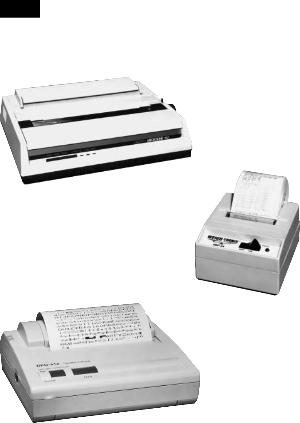
YORK INTERNATIONAL
112
FORM 160.55-O1 (604)
SECTION 3
PRINTERS
FIG. 43 – PRINTERS
23887A
OKIDATA MICROLINE 184
23889A
WEIGH-TRONIX
SEIKO DPU-414
00085VIP
Printers

FORM 160.55-O1 (604)
113
YORK INTERNATIONAL
A printer can be connected to the Control Center’s
Microboard to print the following reports. The screen
from which each report can be generated is listed in
pa ren the sis.
• Status - Present system parameters (Printer,
Home)
• Setpoints - Present programmed values of all set-
points (Printer, Setpoints)
• Schedule - Present value of programmed daily
sched ule (Printer, Schedule)
• Sales Order - Information on Sales Order Screen
(Print er, Sales Order)
• History - System parameters at the time of the last
normal stop, last fault while running and last 10
faults, whether running or not (Printer, History)
• Cycling or Safety shutdown initiated Print - Snap-
shot of all system parameters at instant of shut down.
Automatically occurs if printer is connected at time
of shutdown.
• Adaptive Capacity Control (ACC) surge Map
- Sys tem conditions at instant all surge points were
mapped. (Compressor Motor Variable Speed Drive
ap pli ca tions; requires SERVICE access level)
(Print er, ACC)
• Trend (Flash Memory card version C.MLM.
02.02.xxx and later) - Prints a snap shot of the ex-
isting trend screen data or prints new data col lect ed
af ter the trend print key is pressed.
The printer can be permanently connected to the Con trol
Center or connected as required to produce a re port. If
permanently connected, a DATA LOGGING fea ture
can produce a Status report automatically, be gin ning
at an Operator selected start time and oc cur ring at an
Operator selected interval thereafter.
The following Þ gures are examples of the different print
reports. Solid State Starter application print reports
shown. Electro-mechanical starter and Variable Speed
Drive reports are similar but print parameters ap pli ca ble
to those devices.
• Figure 44 - Status
• Figure 45 - Setpoints
• Figure 46 - Schedule
• Figure 47 - Sales Order
• Figure 48 - History
• Figure 49 - Security Log (Flash Memory Card ver-
sion C.MLM.02.03.xxx and later)
• Figure 50 - Trend (Flash Memory Card version
C.MLM.02.02.xxx and later)
• Figure 51 - Custom Screen
• Figure 52 - Adap tive Capacity Control New Map
point Report
• Figure 53 - Adaptive Capacity Control
Existing Map points Report
PRINTERS
The following Printers can be used. Printers must be
equipped with an RS-232 Serial interface.
• Okidata –
Models: 182,182 turbo, 184 turbo
Dimensions: 14 in. wide x 10.5 in. deep
Paper: 8.5 in. wide
Type: Dot matrix impact
Purchase: 800-OKIDATA
• Weigh-Tronix –
Models: 2600, 1220
Dimensions: 2.3 in. wide x 2.8 in. deep
Paper: 2.25 in. wide
Type: Dot matrix impact
Purchase: USA 800-982-6622
International 707-527-5555
• Seiko –
Model: DPU414-30B (Power supply PW4007-U I
re quired)
Dimensions: 6.3 in. wide x 6.7 in. deep
Paper: 4.4 in. wide
Type: Thermal
Purchase: Reptron Electronics, Inc
Phone: 800-800-5441 ext. 4686
Fax: 813-891-4056
Attn: Nancy Arthur, Account Mgr.
(narthur@reptron.com)
The Control Center provides the required formatting
control codes for the printers above when the printer
is selected on the PRINTER Screen in the instructions
below. These codes are transmitted through the serial
interface to the printer to provide a proper print for mat.
Different printers require different formatting control
codes. Oth er printers might provide proper op er a tion
when connected to the Control Center. How ev er, the
print format may not be correct or as desired. Proceed
with caution and use the following guidelines if an un-
list ed printer is selected:
1. All must be capable of RS-232 Serial com mu ni c-
a tions.
2. Primary differences between printers involve the for-
mat ting control codes required by the printer. These
3

YORK INTERNATIONAL
114
FORM 160.55-O1 (604)
codes are sent from the Control Center to the print er.
For example, Weigh -Tronix printers require a con trol
code to select 40 column width. This same code is
interpreted by the Okidata printer as an in struc tion
to print wide characters. In some in stanc es, a printer
will ignore a code it cannot interpret.
3. The Control Center requires a busy signal from the
printer when the printer receive buffer is full. This
causes the Control Center to mo men tari ly ter mi nate
data transmission until the printer can accept more
data. The busy signal polarity must be as sert ed low
when busy.
PRINTER CONNECTIONS
Connect the printers to the Control Center Microboard as
follows. Only one printer can be connected at a time.
• OKIDATA 182, 182 turbo, 184 turbo
Microboard Printer Function
J2-4 pin 3 Tx (data to printer)
J2-2 pin 11 DSR (busy signal from print er)
J2-9 pin 7 Gnd
Cabinet shield
• WEIGH-TRONIX
Microboard Printer Func tion
J2-4 pin 2 Tx (data to printer)
J2-2 pin 5 DSR (busy signal from print er)
J2-9 pin 7 Gnd
Cabinet shield
• SEIKO
Microboard Printer Function
J2-4 pin 3 Tx (data to printer)
J2-2 pin 8 DSR (busy signal from print er)
J2-9 pin 5 Gnd
Cabinet shield
Hardware required:
Cable – #18 AWG stranded 50ft. maximum length.
Connectors –
- Microboard: None. Strip 1/4" insulation from
wire and insert into screw ter mi nal block.
- Printers: Okidata - 25 pin plug DB-25P or equiv-
a lent; Shell DB-C2-J9 or equivalent. Weigh-Tronix
- Same as Okidata. Cable assembly available from
Weigh-Tronix. Seiko - 9-Pin D-type Subminiature
(DB-9 pin male).
PRINTER SETUP
The selected printer must be conÞ gured as follows.
Refer to manual provided by Printer manufacturer with
respective Printer.
• OKIDATA 182, 182 turbo, 184 turbo Printer
CONTROL BOARD Switch settings:
SW1 - on Unslashed 0
2 - off Unslashed 0
3 - off Unslashed 0
4 - off Form Length 11 in.
5 - on Form Length 11 in.
6 - off Auto Line Feed off
7 - on 8 bit data
8 - off Enable front panel
If equipped with a SUPER SPEED serial Board:
SW1-1 - on Odd or even parity
1-2 - on No parity
1-3 - on 8 bit data
1-4 - on Protocol ready/busy
1-5 - on Test select
1-6 - on Print mode
1-7 - off SDD(-) pin 11
1-8 - on SDD(-) pin 11
2-1 - on 1200 Baud*
2-2 - on 1200 Baud*
2-3 - off 1200 Baud*
2-4 - off DSR active
2-5 - on Buffer threshold 32 bytes
2-6 - on Busy signal 200ms
2-7 - on DTR space after power on
2-8 - not used
If equipped with HIGH SPEED serial board:
SW1 - off (-) Low when busy
2 - off 1200 Baud*
3 - off 1200 Baud*
4 - on 1200 Baud*
5 - not used
6 - off no parity
7 - off Pin 20 & pin 11 act as busy line
• WEIGH-TRONIX Printer
- IMP-24 Model 2600
SW1 - off 1200 Baud*
2 - on 1200 Baud*
Printers

FORM 160.55-O1 (604)
115
YORK INTERNATIONAL
Model 1220
- ConÞ gure Menu
Baud= 1200
Data Bits = 8
Stop Bits = 1
Hshake = Busy-Line
Cols = 32
Invert = No
Font = 5 x 8
Mag = None
- Custom Menu
Auto Seq = No
Zero = 0
Pound sign = #
_(Underscore)
Busy invert = no
Online/ofß ine = yes
Ext Ch Set = no
Print ready = yes
Set Clock = not used
Reset Seq = not used
• SEIKO
DipSW1-1 = off Input-Serial
1-2 = on Printing speed high
1-3 = on Auto loading - on
1-4 = off Auto LF - off
1-5 = on Setting Command - Enable
1-6 = off Printing density - 100%
1-7 = on Printing density - 100%
1-8 = on Printing, density - 100%
DipSW 2-1= on Printing Columns - 40
2-2 = on User Font Back-up - on
2-3 = on Character Select - normal
2-4 = off Zero - slash
2-5 = on International character set -
American
2-6 = on International character set -
American
2-7 = on International character set -
American
2-8 = off International character set -
American
DipSW 3-1= on Data length - 8 bits
3-2 = on Parity Setting - no
3-3 = on Parity condition - odd
3-4 = on Busy control - H/W busy
3-5 = on Baud rate select - 1200*
3-6 = off Baud rate select - 1200*
3-7 = on Baud rate select - 1200*
3-8 = off Baud rate select - 1200*
* Settings shown for 1200 Baud. Other Baud rates can
be selected. Refer to Printer manufacturer’s manual
supplied with Printer.
CONTROL CENTER SETUP
Chiller ID
Access Level Required: OPERATOR or Higher
Using the COMMS Screen, assign an IdentiÞ cation
number to the chiller. This number will appear at the
top of each report.
Printer Setup
Access Level Required: OPERATOR or Higher
Using the COMMS Screen, the Control Center must be
conÞ gured to transmit data in the same format as the
Printer is conÞ gured to receive the data. The following
values must be entered.
• Baud Rate - Set as desired. Value selected must be
the same as Printer conÞ guration above.
• Data Bits - 8
• Parity - None
• Stop Bits - 1
Printer Type
Access Level required: OPERATOR or Higher
Using the PRINTER Screen, the actual Printer type con-
nected to the Control Center must be entered. Se lec tion
determines the control codes that are sent to the Printer.
These codes determine such things as lines per inch,
character width and general formatting. Avail able selec-
tions are: Okidata, Weigh-Tronix and Seiko.
Automatic Data Logging
Access Level required: OP ER A TOR or Higher.
If automatic data logging is desired, a Status Report can
be automatically printed at a speciÞ ed interval be gin ning
at a speciÞ ed time, using the PRINTER Screen. The
interval is programmable over the range of 1 minute
to 1440 minutes in 1 minute increments. The Þ rst print
will occur at the programmed START time and occur at
the programmed OUTPUT INTERVAL thereafter. The
time remaining until the next print is displayed on the
PRINTER Screen.
• Automatic Printer Logging - Enables and disables
au to mat ic data logging
• Log Start Time - Enter the time the Þ rst print is
de sired.
• Output Interval - Enter the desired interval be tween
prints.
3

YORK INTERNATIONAL
116
FORM 160.55-O1 (604)
YORK UPDATE
CHILLER ID 0
YORK Update Chiller ID
-------------------------------------------------------------------------
(c) 1997 – 2001 YORK INTERNATIONAL
CORPORATION
SYSTEM RUN
LEAVING CHILLED LIQUID CONTROL
WARNING – PURGE – FLOAT SWITCH ERROR
[List all warnings presently active]
Controls C.MLM.02.03.102
Run Time 0 Days 2 Hr 59 Min
Operating Hours = 298 Hr
Number Of Starts = 106
Control Source = Local
Evaporator
-------------------------------------------------------------------------
Leaving Chilled Active Setpoint = 45.0 ~F
Chilled Liquid Pump = Run
Chilled Liquid Flow Switch = Closed
Leaving Chilled Liquid Temperature = 50.0 ~F
Return Chilled Liquid Temperature = 59.3 ~F
Evaporator Pressure = 7.2 Psia
Evaporator Saturation Temperature = 41.1 ~F
Evaporator Refrigerant Temperature = 40.0 ~F
[If Refrigerant Sensor enabled]
Small Temperature Difference = 10.0 ~F
Condenser
-------------------------------------------------------------------------
Condenser Liquid Pump = Run
Condenser Liquid Flow Switch = Closed
Leaving Condenser Liquid Temperature = 85.0 ~F
Return Condenser Liquid Temperature = 94.9 ~F
Condenser Pressure = 13.8 Psia
Condenser Saturation Temperature = 71.7 ~F
Small Temperature Difference = -13.3 ~F
Drop Leg Refrigerant Temperature = 85.0 ~F
[If Drop Leg Sensor enabled]
Sub Cooling Temperature = 2.0 ~F
[If Drop Leg Sensor enabled]
Compressor
-------------------------------------------------------------------------
Discharge Temperature = 121.6 ~F
Vent Line Solenoid = On
Oil Sump
-------------------------------------------------------------------------
Oil Pump Run Output = On
Oil Pressure = 30.7 Psid
Oil Sump Temperature = 137.9 ~F
[Skip the following section if Hot Gas Bypass is not
enabled]
Hot Gas
-------------------------------------------------------------------------
FIG. 44 – SAMPLE PRINTOUT (STATUS)
Valve Position = 15 %
Pre-Rotation Vanes Position = 75 %
Surge
-------------------------------------------------------------------------
Total Surge Count = 127
Surge Window Time = 1 Min
Surge Window Count = 0
[Skip the following section if Liquid Level is not
enabled]
Refrigerant Level Control
-------------------------------------------------------------------------
Refrigerant Level Position = 35 %
Ramp Up Time Remaining = 15 Sec
[If Ramp Up in effect]
Purge Control
-------------------------------------------------------------------------
Pressure = 42.8 Psia
Exhaust Count = 0
Exhaust Window = 60 Min
[Skip the following section if Motor Type is not EM]
Electro-Mechanical Starter
-------------------------------------------------------------------------
Motor Run = On
% Full Load Amps = 94 %
[Skip the following section if Motor Type is not Mod A
SSS]
Liquid-Cooled Solid State Starter
-------------------------------------------------------------------------
Motor Run = On
% Full Load Amps = 94 %
Phase A Voltage = 447 V
Phase B Voltage = 409 V
Phase C Voltage = 442 V
Phase A Current = 193 A
Phase B Current = 204 A
Phase C Current = 190 A
[Skip the following section if Motor Type is not Mod B
SSS]
Liquid-Cooled Solid State Starter
-------------------------------------------------------------------------
Motor Run = On
% Full Load Amps = 94 %
Starter Model = 33L
KW Hours = 20723 KWH
Input Power = 145 KW
Phase A Voltage = 447 V
Phase B Voltage = 409 V
Phase C Voltage = 442 V
Phase A Current = 193 A
Phase B Current = 204 A
Printers

FORM 160.55-O1 (604)
117
YORK INTERNATIONAL
Phase C Current = 190 A
Phase A Temperature = 88 ~F
Phase B Temperature = 89 ~F
Phase C Temperature = 75 ~F
[Skip the following section if Motor Type is not VSD]
Variable Speed Drive
-------------------------------------------------------------------------
Motor Run = On
% Full Load Amps = 94 %
Pre-Rotation Vanes Position = 75 %
Full Load Amps = 402 A
Precharge Relay Output = Off
Trigger SCR Output = On
Water Pump Output = On
KW Hours = 14528 KWH
Input Power = 150 KW
Output Frequency = 60 Hz
Output Voltage = 800 V
DC Bus Voltage = 600 V
DC Inverter Link Current = 300 A
Phase A Output Current = 195 A
Phase B Output Current = 198 A
Phase C Output Current = 193 A
Internal Ambient Temperature = 88 ~F
Converter Heatsink Temperature = 102 ~F
Phase A Heatsink Temperature = 93 ~F
Phase B Heatsink Temperature = 99 ~F
Phase C Heatsink Temperature = 97 ~F
[Skip the following section if Motor Type is not VSD,
or Filter
is not present]
Harmonic Filter Data
-------------------------------------------------------------------------
Precharge Contactor = Off
Supply Contactor = On
Operating Mode = Running
Phase Rotation = ABC
Total Supply KVA = 148 KVA
Total Power Factor = 0.97
DC Bus Voltage = 608 V
Heatsink Temperature = 102 ~F
Voltage Peak N-L1 = 200 V
Voltage Peak N-L2 = 200 V
Voltage Peak N-L3 = 200 V
L1-L2 RMS Voltage = 215 V
L2-L3 RMS Voltage = 215 V
L3-L1 RMS Voltage = 215 V
L1 RMS Filter Current = 150 A
L2 RMS Filter Current = 150 A
L3 RMS Filter Current = 150 A
L1 RMS Supply Current = 152 A
L2 RMS Supply Current = 152 A
L3 RMS Supply Current = 152 A
L1 Voltage Total Harmonic Distortion = 1.5 %
FIG. 44 – CONTINUED
3

YORK INTERNATIONAL
118
FORM 160.55-O1 (604)
FIG. 45 – SAMPLE PRINTOUT (SETPOINT REPORT)
YORK SETPOINTS
CHILLER ID 0
-------------------------------------------------------------------------
© 1997 - 1999 YORK INTERNATIONAL COR PO -
RA TION
Mon 21 jun 1999 1:27 :39 PM
Software Versions
-------------------------------------------------------------------------
Controls = C.MLM.02.03.102
BIOS = C.MLM.00.03
Kernel = 0.18
GUI = 0.25
SIO = 0.21
GPIC = 0.03
Ext I/O [Skip if Hot Gas Disabled] = 19962021101
VSD [Skip if Motor Type is not VSD] = C.VSD.01.14
SSS [Skip if Motor Type is not Serial SSS] =
C.SSS.01.01
System Information
-------------------------------------------------------------------------
System Language = English
Data Display Mode = English
Control Source = Local
Remote Analog Input Range = 0 – 10 Volts
Clock = Enabled
Jumper Settings
-------------------------------------------------------------------------
Pre-Run = Standard
Coastdown = Standard
Chilled Liquid Pump Operation = Standard
Refrigerant Selection = R11
Anti-Recycle = Enabled
Power Failure Restart = Auto
Liquid Type = Water
Motor Type = LCSSS
Printer Setup
-------------------------------------------------------------------------
Automatic Printer Logging = Disabled
Log Start Time = 12:00 am
Output Interval = 60 Min
Printer Type = Okidata
Baud = 9600 Baud
Data Bits = 8 Bits
Parity = None
Stop Bits = 1 Bit
COM 2 Setup
-------------------------------------------------------------------------
Baud = 19200 Baud
Data Bits = 8 Bits
Parity = Odd
Stop Bits = 1 Bit
Evaporator
-------------------------------------------------------------------------
Printers
Leaving Chilled Local Setpoint = 45.0 ~F
Leaving Chilled ISN Setpoint = 45.0 ~F
Leaving Chilled Modem Setpoint = 45.0 ~F
Leaving Chilled Analog Setpoint = 45.0 ~F
Leaving Chilled Digital Setpoint = 45.0 ~F
Remote Range = 10.0 ~F
Sensitivity = Normal
Restart Offset = 0.0 ~F
Restart Setpoint = 45.0 ~F
Shutdown Offset = 4.0 ~F
Shutdown Setpoint = 41.0 ~F
Brine Low Evaporator Cutout = 5.0 Psia
Smart Freeze = Off
Refrigerant = Disabled
Condenser
-------------------------------------------------------------------------
High Pressure Warning Threshold = 28.8 Psia
Drop Leg = Disabled
[Skip the following section if Hot Gas Bypass is not
enabled]
Hot Gas
-------------------------------------------------------------------------
Hot Gas = Disabled
Hold Period = 30 Min
Close Percentage = 5 %
Minimum Load = 1 ~F
Maximum Open = 80 %
Surge
-------------------------------------------------------------------------
Surge Sensitivity = 0.3
Shutdown = Enabled
Extended Run = Disabled
Count Limit = 15
Count Window = 5 Min
[Skip the following section if Liquid Level is not
enabled]
Refrigerant Level Control
-------------------------------------------------------------------------
Level Control = On
Setpoint = 50 %
Period = 3.5 Sec
Proportion Limit Open = 15 %
Proportion Limit Close = 45 %
Rate Limit Open = 10 %
Rate Limit Close = 10 %
Purge Control
-------------------------------------------------------------------------
Hi Effi ciency = Off
Maximum Purges / Hour = 20
[Skip the following section if Motor Type is not EM]
Electro-Mechanical Starter
-------------------------------------------------------------------------
Local Motor Current Limit = 100 %
Remote ISN Current Limit = 100 %
Remote Analog Current Limit = 100 %
Remote Digital Current Limit = 100 %

FORM 160.55-O1 (604)
119
YORK INTERNATIONAL
FIG. 45 – CONTINUED
3
Remote Modem Current Limit = 100 %
Pulldown Demand Limit = 100 %
Pulldown Demand Time = 0 Min
[Skip the following section if Motor Type is not Mod A
SSS]
Liquid-Cooled Solid State Starter
-------------------------------------------------------------------------
Local Motor Current Limit = 100 %
Remote ISN Current Limit = 100 %
Remote Analog Current Limit = 100 %
Remote Digital Current Limit = 100 %
Remote Modem Current Limit = 100 %
Pulldown Demand Limit = 100 %
Pulldown Demand Time = 0 Min
Scale/Model = 600 V, 281 A
Supply Voltage Range = Disabled
Full Load Amps = 150 A
Current Imbalance Check = Disabled
[Skip the following section if Motor Type is not Mod B
SSS]
Liquid-Cooled Solid State Starter
-------------------------------------------------------------------------
Local Motor Current Limit = 100 %
Remote ISN Current Limit = 100 %
Remote Analog Current Limit = 100 %
Remote Digital Current Limit = 100 %
Remote Modem Current Limit = 100 %
Pulldown Demand Limit = 100 %
Pulldown Demand Time = 0 Min
Starter Model = 33L
Voltage Range = Disabled
Full Load Amps = 215 A
Starting Current = 1460 A
Open SCR = Disabled
[Skip the following section if Motor Type is not VSD]
Variable Speed Drive
-------------------------------------------------------------------------
Local Motor Current Limit = 100 %
Remote ISN Current Limit = 100 %
Remote Analog Current Limit = 100 %
Remote Digital Current Limit = 100 %
Remote Modem Current Limit = 100 %
Pulldown Demand Limit = 100 %
Pulldown Demand Time = 0 Min
Motor HP = 351 HP
Power Line Frequency = 60 Hz
[Skip the following section if Motor Type is not VSD]
Harmonic Filter Data
-------------------------------------------------------------------------
Filter Operation = Enabled
Motor HP = 351 HP
YORK SCHEDULE
CHILLER ID 0
© 1997 - 1999 YORK international corporation
mon 21 jun 1999 1:28:25 pm
schedule = OFF
Standard Schedule
---------------------------------------------------------------------------
Sun StarT = Off Stop = Off
MOn Start = 06:00 AM Stop = 06:00 PM
Tue Start = 06:00 AM Stop = 06:00 PM
Wed Start = 06:00 AM Stop = 06:00 PM
Th u Start = 06:00 AM Stop = 06:00 PM
Fri Start = 06:00 AM Stop = 06:00 PM
Sat Start = Off Stop = Off
Exception Days
---------------------------------------------------------------------------
15 jul 1999 start = 08:00 am stop = 08:00 pm
16 jul 1999 start = 08:00 am stop = 08:00 pm
17 jul 1999 start = 08:00 am stop = 08:00 pm
18 jul 1999 start = 08:00 am stop = 08:00 pm
FIG. 46 – SAMPLE PRINTOUT
(SCHEDULE RE PORT)

YORK INTERNATIONAL
120
FORM 160.55-O1 (604)
FIG. 47 – SAMPLE PRINTOUT (SALES ORDER RE PORT)
YORK SALES ORDER
CHILLER ID 0
© 1997 - 1999 YORK INTERNATIONAL COR PO RA TION
Mon 21 jun 1999 1:28:46 PM
Order Information
---------------------------------------------------------------------------
Commissioning date
Job Name
Job Location
Model Number YTFBFAH6-CVJ
YORK Order Number 99102014-01
Panel Serial Number 12345678
Chiller Serial Number 12345678
Design Load - Evaporator
---------------------------------------------------------------------------
Passes 2
Design Working Pressure 150
Fouling Factor 0.00010
Pressure Drop 21.1
Nozzle Arrangement In 2
Nozzle Arrangement Out 3
Leaving Temperature 44.0
Return Temperature 56.0
GPM 1500.0
Tubes 181
Design Load - condenser
---------------------------------------------------------------------------
Passes 2
Design Working Pressure 150
Fouling Factor 0.00025
Pressure Drop 28.0
Nozzle Arrangement In 1
Nozzle Arrangement Out
Leaving Temperature 94.3
Return Temperature 85.0
GPM 2250.0
Tubes 230
Nameplate Information
---------------------------------------------------------------------------
Motor Code CV
Power (Volts) 460
Phases 3
Frequency (Hz) 60
Looked Rotor Amps 4400
Full Load Amps 642
Inrush Amps 655
System Information
---------------------------------------------------------------------------
Refrigerant R123
Tons 150
Gear Code RK
Liquid Type water
Brine Percent
Kilowatts Input 467
VSD / sss / em VSD
Printers

FORM 160.55-O1 (604)
121
YORK INTERNATIONAL
3
YORK HISTORY 1
CHILLER ID 0
---------------------------------------------------------------------------
© 1997 - 1999 YORK INTERNATIONAL COR PO RA TION
MSYSTEM READY TO START
LCSSS – LOGIC BOARD POWER SUPPLY
[List any warnings that were active at the time of
shutdown]
Controls C.MLM.02.03.102
Run Time 0 Days 2 Hr 59 Min
Operating Hours = 294 Hr
Number Of Starts = 105
Control Source = Local
Evaporator
---------------------------------------------------------------------------
Leaving Chilled Active Setpoint = 45.0 ~F
Chilled Liquid Pump = Stop
Chilled Liquid Flow Switch = Open
Leaving Chilled Liquid Temperature = 50.0 ~F
Return Chilled Liquid Temperature = 59.3 ~F
Evaporator Pressure = 7.2 Psia
Evaporator Saturation Temperature = 41.1 ~F
Evaporator Refrigerant Temperature = 40.0 ~F
[If Refrigerant Sensor enabled]
Small Temperature Difference = 10.0 ~F
Condenser
---------------------------------------------------------------------------
Condenser Liquid Pump = Stop
Condenser Liquid Flow Switch = Open
Leaving Condenser Liquid Temperature = 85.0 ~F
Return Condenser Liquid Temperature = 94.9 ~F
Condenser Pressure = 13.8 Psia
Condenser Saturation Temperature = 71.7 ~F
Small Temperature Difference = -13.3 ~F
Drop Leg Refrigerant Temperature = 85.0 ~F
[If Drop Leg Sensor enabled]
Sub Cooling Temperature = 2.0 ~F
[If Drop Leg Sensor enabled]
Compressor
---------------------------------------------------------------------------
Discharge Temperature = 121.6 ~F
Vent Line Solenoid = Off
Oil Sump
---------------------------------------------------------------------------
Oil Pump Run Output = Off
Oil Pressure = 0.0 Psid
Oil Sump Temperature = 137.9 ~F
[Skip the following section if Hot Gas Bypass is not
enabled]
Hot Gas
---------------------------------------------------------------------------
FIG. 48 – SAMPLE PRINTOUT (HISTORY REPORT)
Valve Position [If Hot Gas enabled] = 0 %
Pre-Rotation Vanes Position = 0 %
Surge
---------------------------------------------------------------------------
Total Surge Count = 127
Surge Window Time = 1 Min
Surge Window Count = 0
[Skip the following section if Liquid Level is not
enabled]
Refrigerant Level Control
---------------------------------------------------------------------------
Refrigerant Level Position = 35 %
Ramp Up Time Remaining = 15 Sec
[If Ramp Up in effect]
Purge Control
---------------------------------------------------------------------------
Pressure = 42.8 Psia
Exhaust Count = 0
Exhaust Window = 60 Min
[Skip the following section if Motor Type is not EM]
Electro-Mechanical Starter
---------------------------------------------------------------------------
Motor Run = Off
% Full Load Amps = 0 %
[Skip the following section if Motor Type is not Mod A
SSS]
Liquid-Cooled Solid State Starter
---------------------------------------------------------------------------
Motor Run = Off
% Full Load Amps = 0 %
Phase A Voltage = 447 V
Phase B Voltage = 409 V
Phase C Voltage = 442 V
Phase A Current = 0 A
Phase B Current = 0 A
Phase C Current = 0 A
[Skip the following section if Motor Type is not Mod B
SSS]
Liquid-Cooled Solid State Starter
---------------------------------------------------------------------------
Motor Run = Off
% Full Load Amps = 0 %
Starter Model = 33L
KW Hours = 20723 KWH
Input Power = 145 KW
Phase A Voltage = 447 V
Phase B Voltage = 409 V
Phase C Voltage = 442 V
Phase A Current = 0 A
Phase B Current = 0 A

YORK INTERNATIONAL
122
FORM 160.55-O1 (604)
FIG. 48 – CONTINUED
Printers
YORK SETPOINT CHANGE LOG
CHILLER ID 163
© 1997 – 2000 YORK INTERNATIONAL COR PO RA TION
Mon 09 Oct 2000 3:33:47 PM
Log Entry 1 Evaporator - Leaving Chilled Local Setpoint
---------------------------------------------------------------------------
Date = 05 Oct 2001
Time = 4:23:49 PM
Access Level = Service
User Id = 4268
Old Value = 46.5 ~F
New Value = 48.0 ~F
Log Entry 2 Condenser - High Pressure Warning Threshold
---------------------------------------------------------------------------
Date = 05 Oct 2001
Time = 1:36:12 PM
Access Level = Service
User Id = 4268
Old Value = 162.5 Psig
New Value = 225.0 Psig
Log Entry 3 Condenser - Drop Leg
---------------------------------------------------------------------------
Date = 05 Oct 2001
Time = 1:36:02 PM
Access Level = Service
User Id = 4268
Old Value = Disabled
New Value = Enabled
Log Entry 4 Evaporator - Refrigerant
---------------------------------------------------------------------------
Date = 05 Oct 2001
Time = 1:35:48 PM
Access Level = Service
User Id = 4268
Old Value = Disabled
New Value = Enabled
FIG. 49 – SAMPLE PRINTOUT (SECURITY LOG)
[Skip the following section if Motor Type is not VSD]
Variable Speed Drive
--------------------------------------------------------------------------
Motor Run = Off
% Full Load Amps = 0 %
Pre-Rotation Vanes Position = 0 %
Full Load Amps = 402 A
Precharge Relay Output = Off
Trigger SCR Output = Off
Water Pump Output = Off
KW Hours = 14528 KWH
Input Power = 150 KW
Output Frequency = 0 Hz
Output Voltage = 800 V
DC Bus Voltage = 600 V
DC Inverter Link Current = 300 A
Phase A Output Current = 0 A
Phase B Output Current = 0 A
Phase C Output Current = 0 A
Internal Ambient Temperature = 88 ~F
Converter Heatsink Temperature = 102 ~F
Phase A Heatsink Temperature = 93 ~F
Phase B Heatsink Temperature = 99 ~F
Phase C Heatsink Temperature = 97 ~F
[Skip the following section if Motor Type is not VSD,
or Filter is not
present]
Harmonic Filter Data
--------------------------------------------------------------------------
Precharge Contactor = Off
Supply Contactor = Off
Operating Mode = Stopped
Phase Rotation = ABC
Total Supply KVA = 148 KVA
Total Power Factor = 0.97
DC Bus Voltage = 608 V
Heatsink Temperature = 102 ~F
Voltage Peak N-L1 = 200 V
Voltage Peak N-L2 = 200 V
Voltage Peak N-L3 = 200 V
L1-L2 RMS Voltage = 215 V
L2-L3 RMS Voltage = 215 V
L3-L1 RMS Voltage = 215 V
L1 RMS Filter Current = 150 A
L2 RMS Filter Current = 150 A
L3 RMS Filter Current = 150 A
L1 RMS Supply Current = 152 A
L2 RMS Supply Current = 152 A
L3 RMS Supply Current = 152 A
L1 Voltage Total Harmonic Distortion = 1.5 %
L2 Voltage Total Harmonic Distortion = 1.2 %
L3 Voltage Total Harmonic Distortion = 1.1 %
L1 Supply Current Total Demand Distortion = 2.6 %
L2 Supply Current Total Demand Distortion = 2.3 %

FORM 160.55-O1 (604)
123
YORK INTERNATIONAL
3
FIG. 50 – SAMPLE PRINTOUT (TREND DATA NEW
OR EXISTING POINTS)
YORK TREND
CHILLER ID 163
© 1997 – 2000 YORK INTERNATIONAL COR PO RA TION
Mon 09 Oct 2000 3:33:47 PM
Data 1: Leaving Chilled Liquid Temperature
Data 2: Return Chilled Liquid Temperature
Data 3: Evaporator Pressure
Data 4: Leaving Condenser Liquid Temperature
Data 5: Return Condenser Liquid Temperature
Data 6: Condenser Pressure
Time Data 1 Data 2 Data 3 Data 4 Data 5 Data 6
3:33:47 PM45.5 °F55.0 °F 6.3 PSIA 95.0 °F 85.0 °F 1 8 . 7
PSIA
3:33:48 PM45.5 °F55.0 °F 6.3 PSIA 95.0 °F 85.0 °F 1 8 . 7
PSIA
3:33:49 PM45.5 °F55.0 °F 6.3 PSIA 95.0 °F 85.0 °F 1 8 . 7
PSIA
FIG. 51 – SAMPLE PRINTOUT
(CUSTOM SCREEN REPORT))
FIG. 52 – SAMPLE PRINTOUT
(ADAPTIVE CAPACITY CON TROL
NEW MAP POINT REPORT)
Log Time: Mon 12:45:39 PM 21 Jun 1999
D-P/P= 0.92; Prv Pos= 56; Freq= 39 Hz
Surge Type = Delta P/P Surge
Leaving Chilled Active Setpoint = 45.0 ~F
Leaving Chilled Liquid Temperature = 50.0 ~F
Return Chilled Liquid Temperature = 59.3 ~F
Leaving Condenser Liquid Temperature = 85.0 ~F
Return Condenser Liquid Temperature = 94.9 ~F
Evaporator Pressure = 7.2 Psia
Condenser Pressure = 13.8 Psia
% Full Load Amps = 94 %
D-P/P = 1.20; Prv Pos = 89; Freq = 58 Hz
D-P/P = 1.41; Prv Pos = 71; Freq = 46 Hz
D-P/P = 0.98; Prv Pos = 73; Freq = 52 Hz
D-P/P = 0.71; Prv Pos = 86; Freq = 39 Hz
D-P/P = 0.86; Prv Pos = 53; Freq = 48 Hz
D-P/P = 1.14; Prv Pos = 76; Freq = 51 Hz
D-P/P = 0.84; Prv Pos = 84; Freq = 37 Hz
D-P/P = 0.99; Prv Pos = 63; Freq = 46 Hz
FIG. 53 – SAMPLE PRINTOUT
(ADAPTIVE CAPACITY CONTROL EX IST ING
MAP POINTS REPORT)
YORK CUSTOM VIEW
CHILLER ID 0
(c) 1997 – 2001 YORK INTERNATIONAL CORPORATION
Mon 21 Jun 1999 1:28:25 PM
Leaving Chilled Liquid Temperature = 45.0 ~F
Return Chilled Liquid Temperature = 55.0 ~F
Leaving Condenser Liquid Temperature = 95.0 ~F
Return Condenser Liquid Temperature = 85.0 ~F
Evaporator Saturation Temperature = 41.0 ~F
Condenser Saturation Temperature = 78.5 ~F
Evaporator Pressure = 17.0 Psid
Condenser Pressure = 64.0 Psid
Oil Pressure = 45.0 Psid
% Full Load Amps = 50 %
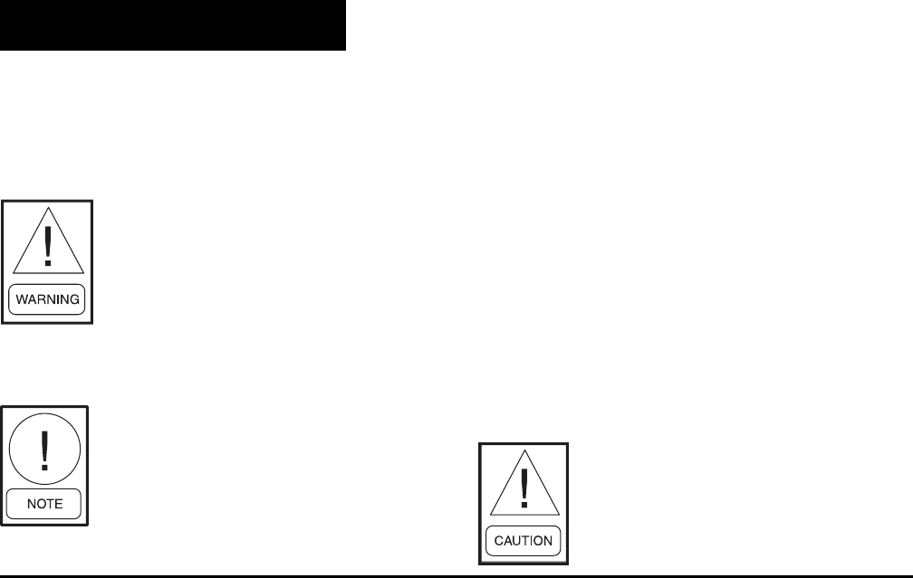
YORK INTERNATIONAL
124
FORM 160.55-O1 (604)
START-UP PROCEDURE
Pre-Starting
Prior to starting the chiller ob serve the OptiView Con-
trol Center. Make sure the Display reads “SYS TEM
READY TO START”.
To pre-start the chiller use the fol low ing pro ce dure:
1. OIL HEAT ER - The oil heater must be en er gized
for 12 hours prior to starting the chiller. The unit will
not start if the oil is less than 71°F. If not pos si ble the
com pres sor oil should be drained and new oil must
be charged into the oil sump. (See “Oil Charg ing
Procedure”, page 129)
2. OIL PUMP - To check, press and release the “MAN-
U AL OIL PUMP” key under “Service” on the Con-
trol Center. The oil pump will run for 10 minutes and
shut down. Press and release the “MAN U AL OIL
PUMP” key to stop the op er a tion of the oil pump
for less than 10 minutes of op er a tion.
3. All Control Center setpoints should be pro grammed
before the chiller is started. Prior to start, the clock
must be pro grammed for the prop er day and time.
Any setpoints which are de sired to be changed may
be pro grammed. If not pro grammed the “de fault”
value setpoints are as follows:
SECTION 4
SYSTEM OPERATING PROCEDURES
OIL HEATERS
If the oil heater is de-energized dur-
ing a shut down pe ri od, it must be
energized for 12 hours prior to start-
ing compressor, or remove all oil
and re charge com pres sor with new
oil. (See “Oil Charging Pro ce dure”,
page 129.)
The oil heater is thermostatically
con trolled and remains energized as
long as the fused dis con nect switch
to the starter or Variable Speed Drive
is en er gized.
CHECKING THE OIL LEVEL
IN THE OIL RESERVOIR
Proper operating oil level – the middle of the upper
sight glass.
If the oil is excessively high after start-up, the ex cess
oil may be drained from the oil Þ lter drain valve while
the compressor is running.
If oil level is low, oil should be added to the com-
pres sor. (See “Oil Charging Pro ce dure”, page 129.)
Comply with EPA and Local reg u -
la tions when re mov ing or disposing
of Re frig er a tion System oil!
System Op er at ing Pro ce dures
LCWT = 45°F
% Cur rent Limit = 100% FLA
Pulldown Demand = None
Clock = Sun 12:00A.M.
Daily Schedule = None
Holiday = None
Remote Reset Temp. Range = 20°F
Data Logger = No Operation
Start-Up
1. If the chilled water pump is manually op er at ed,
start the pump. The Control Center will not allow
the chill er to start unless chilled liquid ß ow is es-
tab lished through the unit. (A Þ eld supplied chilled
wa ter ß ow switch is required.) If the chilled liquid
pump is wired to the OptiView Control Center the
pump will au to mat i cal ly start, therefore, this step is
not nec es sary.
2. To start the chiller, press the “COMPRESSOR
START” switch. This switch will au to mat i cal ly
spring return to the “RUN” position. (If the unit
was pre vi ous ly started press the “STOP/RE SET”
side of the “COMPRESSOR” switch and then press
the “START” side of the switch to start the chiller.)
When the start switch is en er gized the Control Cen ter
is placed in an op er at ing mode and any mal func tion
will be not ed by mes sag es on the OptiView Con trol
Center. (See Fig. 3)
FORM 160.55-O1 (604)
125
YORK INTERNATIONAL
4
Any mal func tions which oc cur dur ing
“STOP/ RE SET” are also dis played.
When the chiller is shut down, the prerotation vanes
will close au to mat i cal ly to pre vent loading the com-
pres sor on start-up. When the chill er starts to op er ate,
the fol low ing au to mat ic sequences are ini ti at ed: (Re-
fer to Fig. 54 & 55, “Operation Sequence Tim ing
Diagram”.)
1. The OptiView Con trol Center display mes sage
will read “SYSTEM PRELUBE” for the Þ rst
30 sec onds of the start ing sequence. (3 min. if
Microboard Pro gram Switch SW1-3 is “ON”;
“OFF” = 30 sec onds.)
2. The com pres sor vent line solenoid valve will open
af ter the Þ rst 5 minutes of unit operation. The so-
le noid will close au to mat i cal ly after the com pres sor
shuts down.
3. The 1R-1 con tacts of the 1R start relay will remain
open for the Þ rst 30 seconds of oil pump operation.
These con tacts will close, start ing the com pres sor
motor and the con dens er water pump at the end of
the 30 sec ond period.
4. The chilled liq uid pump contacts will close, start ing
the chilled liquid pump to allow liquid ß ow through
the cooler when the “COM PRES SOR” start switch
is energized.
5. After the Þ rst 30 seconds of operation, the com-
pres sor will start and the Graphic Control Center
dis play mes sage will read “SYSTEM RUN”.
Chiller Operation
After the com pres sor reaches its operating speed the
prerotation vanes will begin to open under the con trol
of the micro processor board or the logic section of the
Variable Speed Drive which senses the leaving chilled
liq uid tem per a ture. The unit capacity will vary to main-
tain the leaving chilled liquid temperature setpoint. The
prerotation vanes are mod u lat ed by an actuator under
the control of the microprocessor board or logic sec tion
of the Variable Speed Drive. The vane control rou tine
em ploys pro por tion al plus derivative (rate) con trol ac-
tion. A drop in chilled liquid temperature will cause
the actuator to close the prerotation vanes (and also
de creas es the speed of the mo tor if equipped with a
Vari able Speed Drive) to de crease chill er capacity. When
the chilled liquid tem per a ture ris es, the actuator will open
the prerotation vanes and in crease the com pres sor mo tor
speed of the chiller (if controlled by the Variable Speed
Drive), to in crease the capacity of the unit.
However, the cur rent draw (amperes) by the com pres sor
motor can not ex ceed the set ting of the “% CUR RENT
LIMIT” at any time during the unit operation, since the
Graphic Control Cen ter 30 to 100% three phase peak
current limit software function, plus the 3 phase 100%
solid state overload cur rent limiter (CM-2) on Electro-
Mechanical Starter applications or the solid state starter
current limit function will override the tem per a ture con-
trol func tion (or the logic section of the Vari able Speed
Drive) and pre vent the prerotation vanes from open ing
beyond the “% CUR RENT LIM IT” setting.
If the load continues to de crease, after the prerotation
vanes are entirely closed, the chiller will be shut down
by the Low Water Tem per a ture con trol (LWT) func tion
which is displayed on the Con trol Cen ter as: “LEAV ING
CHILLED LIQUID – LOW TEM PER A TURE”.
This occurs when the leav ing water tem per a ture falls
to programmed shutdown setpoint or 36°F, which ev er
is higher.
If the temperature setpoint has been
re pro grammed within the last 10 min-
utes, the LWT cutout is 36°F for 10
minutes.
Condenser Water Tem per a ture Con trol
The YORK Millennium chiller is de signed to use
less pow er by tak ing ad van tage of lower than design
tem per a tures that are nat u ral ly produced by cooling
tow ers through out the op er at ing year. Exact control of
con dens er wa ter, such as a cooling tower bypass, is not
nec es sary for most in stal la tions. The chiller requires only
that the min i mum con dens er water temperature be no
low er than the val ue de ter mined by re fer ring to Fig. 56.
At start-up the en ter ing con dens er water tem per a ture may
be as much as 25°F cold er than the stand by return chilled
wa ter tem per a ture. Cooling tow er fan cy cling will nor-
mal ly pro vide ad e quate control of the en ter ing con dens er
wa ter tem per a ture on most in stal la tions.
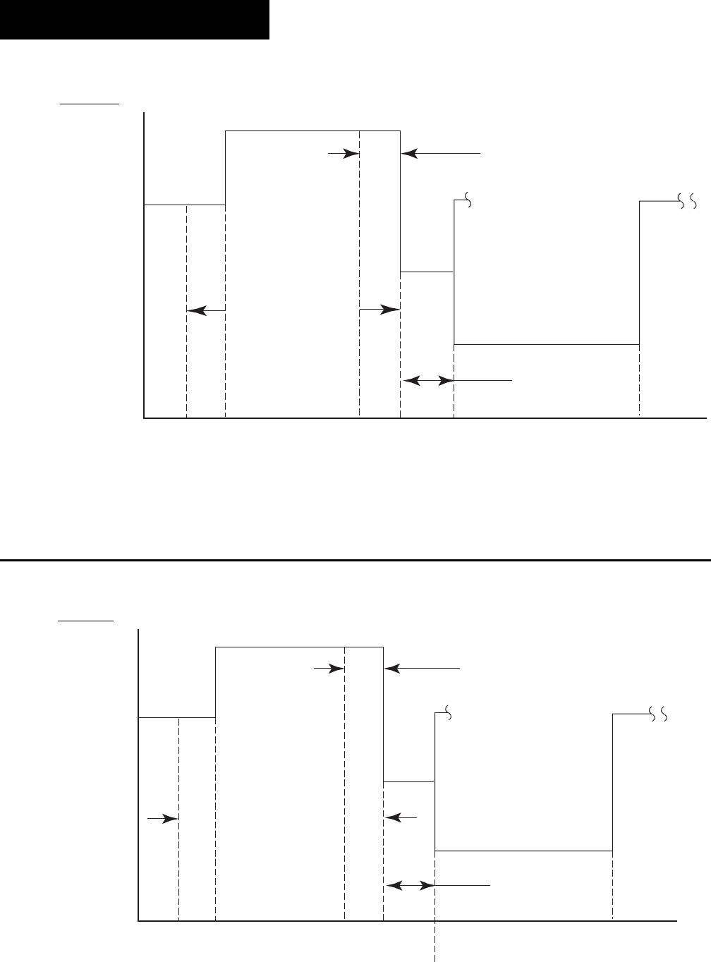
YORK INTERNATIONAL
126
FORM 160.55-O1 (604)
"SYSTEM SHUTDOWN"
DISPLAY
MESSAGE
"SYSTEM RUN"
"SYSTEM PRELUBE"
(OIL PUMP PRE-RUN)
"SYSTEM COASTDOWN"
(OIL PUMP POST-RUN)
0 25 30 330 1800
(0.4) (0.5) (5.5) (30)
START
RESTART (IF
FIVE SUCCESSIVE
RESTARTS HAVE
NOT OCCURRED)
RESTART (ONLY
AFTER THE FIFTH
SUCCESSIVE RESTART)
TIME IN SECONDS (MINUTES)
ENERGIZE
(OPEN)
VENT
SOLENOID
CHECK
OIL PRESS.
150 SEC.
(2.5 MIN.)
"SYSTEM SHUTDOWN"
DISPLAY
MESSAGE
"SYSTEM RUN"
"SYSTEM PRELUBE"
(OIL PUMP PRE-RUN)
"SYSTEM COASTDOWN"
(OIL PUMP POST-RUN)
0 25 30 330 1800
(0.4) (0.5) (5.5) (30)
START
TIME IN SECONDS (MINUTES)
ENERGIZE
(OPEN)
VENT LINE
SOLENOID
CHECK
OIL PRESS.
150 SEC.
(2.5 MIN.)
RESTART
FIG. 54 – OPERATION SEQUENCE TIMING DIAGRAM
(ELECTRO-MECHANICAL AND SOLID STATE STARTER APPLICATIONS)
LD04643
System Op er at ing Pro ce dures
FIG. 55 – OPERATION SEQUENCE TIMING DIAGRAM
(COMPRESSOR MOTOR VARIABLE SPEED DRIVE APPLICATIONS)
LD04644
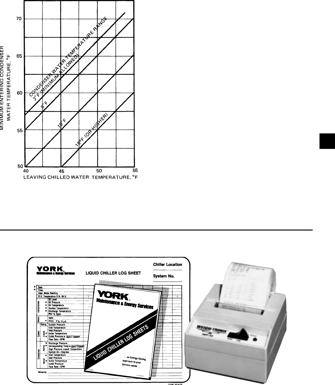
FORM 160.55-O1 (604)
127
YORK INTERNATIONAL
CHECKING OP ER A TION
During operation, the fol low ing con di tions should be
periodically checked:
1. On start ing, the prerotation vanes should re main
closed.
2. Be sure the oil pump is operating while unit is run-
ning.
3. Check Oil Pressure display. A gradual de crease in
bearing oil pres sure of 5 to 10 PSI (with con stant
suc tion and discharge pres sures) may be an in di -
ca tion of a dirty Þ lter. The Þ lter should be replaced
when pres sure loss is 30% or more of the orig i nal
pres sure. The actual bearing oil pressure will vary
with com pres sor suction and discharge pres sures.
When a new sys tem is Þ rst operated under nor mal
full load conditions, the bearing oil pressure should
be re cord ed as a ref er ence point with which to com-
pare sub se quent read ings.
OPERATING LOG SHEET
A per ma nent daily record of system operating con di -
tions (tem per a tures and pres sures) recorded at regular
intervals throughout each 24 hour operating period
should be kept.
LD00466
FIG. 56 – MINIMUM ENTERING CONDENSING
WATER TEMPERATURE
FIG. 57 – LIQUID CHILLER LOG SHEETS
*NOTE: These items can be printed by an electronic printer connected to the Microboard
and pressing the PRINT key on the Keypad or automatically using the Data Logger feature.
LD00467 23889A
4

YORK INTERNATIONAL
128
FORM 160.55-O1 (604)
System Op er at ing Pro ce dures
An optional sta tus printer is available for this purpose;
or, Fig. 48 shows a log sheet used by YORK personnel
for recording test data on chillers. It is avail able from
the factory in pads of 50 sheets each under Form No.
160.44-F6 and may be ob tained through the nearest
YORK ofÞ ce. Automatic data logging is possible by
con nect ing the optional printer and programming the
DATA LOG GER function.
An ac cu rate record of read ings serves as a valuable
ref er ence for op er at ing the system. Readings taken
when a system is newly in stalled will establish normal
con di tions with which to compare later readings.
For ex am ple, dirty condenser tubes may be indicated
by higher than normal tem per a ture differences be tween
leav ing con dens er water and refrigerant leaving the
condenser.
OPERATING INSPECTIONS
By following a regular in spec tion using the display read-
ings of the OptiView Control Cen ter, and main te nance
pro ce dure, the op er a tor will avoid se ri ous op er at ing dif-
Þ cul ty. The following list of in spec tions and pro ce dures
should be used as a guide.
Daily
1. Check OptiView Control Center dis plays.
2. If the compressor is in operation, check the bear-
ing oil pressure by pressing “OIL SUMP” key to
read the dis play on the Control Center. Also check
the oil level in the oil reservoir. Drain or add oil if
nec es sary.
3. Check entering and leaving con dens er water pres-
sure and tem per a tures for com par i son with job de-
sign con di tions. Condenser water tem per a tures can
be checked by press ing “CONDENSER” dis play
key.
4. Check the en ter ing and leaving chilled liquid tem-
per a tures and evaporator pressure for comparison
with job design conditions. This can be ac com plished
by press ing the “EVAPORATOR” key and the “RE-
FRIG ER ANT PRES SURES” key.
5. Check the condenser sat u ra tion temperature (based
upon condenser pres sure sensed by the con dens er
trans duc er). Press the “CONDENSER” key.
6. Check the com pres sor dis charge temperature. Press
“COMPRESSOR” key. During nor mal operation
dis charge tem per a ture should not ex ceed 220°F.
7. Check the com pres sor motor voltage and current
(amps) at E-M starter (or Variable Speed Drive), or
on the OptiView Control Cen ter motor display for
Sol id State Start er units.
8. Check for any signs of dirty or fouled con dens er
tubes. (The tem per a ture dif fer ence between water
leav ing con dens er and liquid re frig er ant leav ing the
con dens er should not ex ceed the difference re cord ed
for a new unit by more than 4°F.)
9. Verify proper water treatment.
10. If the chiller is con trolled by a YORK Variable Speed
Drive, check the op er at ing lights on the logic sec tion.
(Re fer to 160.00-O1)
11. Monitor Graphic Display for Warning Messages.
Weekly
1.Check the re frig er ant charge. (See “Checking the
Refrigerant Charge”, page 140)
Quarterly
1. Change the purge unit de hy dra tor at least quarterly,
or more of ten if required.
2. Clean purge foul gas strainer.
3. Perform chemical anal y sis of oil.
4. Clean water strainer on VSD (if equipped).
Semi-An nu al ly (or more of ten as re quired.)
1. Change and inspect com pres sor oil Þ lter el e ment.
2. Oil re turn system
a. Change dehydrator.
b. Check nozzle of eductor for foreign par ti cles.
3. Check con trols and safety cut outs.
4. Check level of coolant if equipped with SSS or
VSD.
Annually (more often if necessary.)
1. Drain and re place the oil in the com pres sor oil sump
(See “Oil Charging Procedure”, page 129).
2. Cooler and Condenser
a. Inspect and clean water strain ers.
b. Inspect and clean tubes as required.
c. Inspect end sheets.
d. Backß ush heat exchanger on VSD (if equipped).
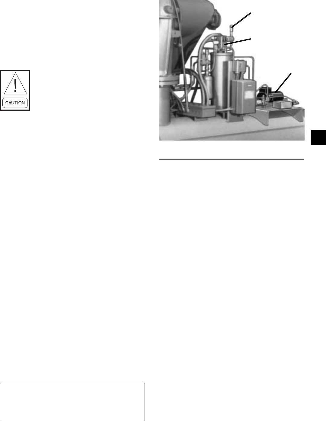
FORM 160.55-O1 (604)
129
YORK INTERNATIONAL
3. Compressor Drive Motor (See motor man u fac tur er’s
main te nance and service in struc tion sup plied with
unit)
a.Clean air passages and windings per
manufacturer’s in struc tions.
b. Meg motor wind ings - See Fig. 65 for de tails.
c. Relubricate ball bear ings.
Don’t over look motor drive end bear-
ing lo cat ed in mo tor support of F1, F2
com pres sors.
4. Purge unit.
a. Clean and in spect all valves.
b. Drain and ß ush purge shell.
c. Clean or i Þ c es.
5. Inspect and service elec tri cal com po nents as
necessary.
6. Perform chemical anal y sis of system.
Every Two Years
1. If unit is equipped with SSS or VSD, ß ush cool ing
circuit and replace with new coolant solution, YORK
Part # 013-02987-000.
NEED FOR PURGING THE SYSTEM
To assure sat is fac to ry operation, it is important that these
systems be kept free of moisture laden air and noncon-
densible gas es. Air in the system usually col lects in the
con dens er, blanketing some of the con dens ing surface,
causing the dis charge pressure and tem per a ture to rise,
re sult ing in high operating cost, and possibly surg ing, or
shut down of system by high pres sure cutout. Mois ture
in the system causes acid for ma tion which is de struc tive
to internal system parts.
A Turboguard purge unit is fur nished and mounted at the
rear of the system (See Fig. 58). The purpose of this unit
is to au to mat i cal ly remove the mixture of nonconden-
sible gases and re frig er ant from the top of the con dens er,
expel the noncondensibles to the at mo sphere and return
the re frig er ant to the system.
IMPORTANT!
The purge unit operates con tin u ous ly
when the system is in operation.
FIG. 58 – TURBOGUARD PURGE UNIT 27046A(D)
CHECK VALVE
FLOAT SWITCH ASS’Y.
PUMP
The Turboguard purge unit in cludes a display mes-
sage on the control center dis play. The message reads
“WARN ING – EXCESS PURGE” if an ex ces sive
air leak is present with in the chill er. The “WARN ING
RE SET” should be pushed with the OptiView Control
Cen ter in “SER VICE” mode to reset the display. Leak
check and cor rect the leak if the dis play continues to
show this mes sage.
NORMAL AND SAFE TY SYS TEM SHUTDOWNS
Normal and safety system shutdowns have been built
into the chiller to protect it from dam age during certain
op er at ing conditions. There fore, it should be un der stood
that at certain pres sures and tem per a tures the system will
be stopped au to mat i cal ly by controls that respond to high
tem per a tures, low tem per a tures, and low and high pres-
sures, etc. The “Display Messages” section is an ex pla -
na tion of each spe ciÞ c shut down. If the chiller shuts down
on a “Safe ty” shut down the cause is dis played.
STOPPING THE SYSTEM
The OptiView Control Cen ter can be pro grammed to start
and stop au to mat i cal ly (max i mum, once each day) when-
ev er desired. To stop the chill er pro ceed as fol lows:
1. Push the compressor switch to “STOP/RESET”. The
OptiView Control Center display will show “SYS-
TEM COASTDOWN” for 150 seconds (6 min. if
Microboard jumper JP36 removed). The com pres sor,
4

YORK INTERNATIONAL
130
FORM 160.55-O1 (604)
System Op er at ing Pro ce dures
con dens er wa ter, and cool ing tower fans will stop
au to mat i cal ly. The oil pump will continue to run
for a pe ri od of 150 sec onds. The oil pump will then
stop au to mat i cal ly. Once stopped, the “SYS TEM
COASTDOWN” display will be re placed by “SYS-
TEM READY TO START”.
2. Stop the chilled water pump (if not wired into the
OptiView Control Center, in which case it will
shut off au to mat i cal ly si mul ta neous ly with the oil
pump.) (The actual water pump contact op er a tion is
de pen dent upon the po si tion of Microboard Program
Switch SW1-8.)
3. Open the switch to the cooling tower fan mo tors, if
used.
4. The com pres sor sump oil heat er (ther mo stat i cal ly
controlled) is en er gized when the unit is stopped.
PROLONGED SHUTDOWN
If the chiller is to be shut down for an extended period of
time (for example, over the winter season), the fol low ing
paragraphs outline the procedure to be fol lowed.
1. After the system pressure has risen above at mo -
spher ic, test all system joints for refrigerant leaks
with a leak detector. If equipment room is below
70°F, circulate hot water (not to exceed 100°F)
through the cooler tubes to raise the system pres-
sure. If any leaks are found, they should be repaired
before al low ing the system to stand for a long pe ri od
of time.
During long idle periods, the tightness of the sys tem
should be checked periodically.
2. If freezing temperatures are encountered while the
system is idle, carefully drain the cooling water from
the cooling tower, condenser, condenser pump, and
the chilled water system-chilled water pump and
coils. Open the drains on the cool er and con dens er
liq uid heads to assure com plete drain age. (If a Vari-
able Speed Drive, drain its water cool ing system. If
Sol id State Start er, drain water from start er cooling
loop. Isolate the Turboguard purge unit from the
main sys tem.)
3. Isolate the Turboguard purge unit from the main
sys tem.
4. Disable clock on SETUP Screen. This con serves the
bat tery.
5. Open the main dis con nect switches to the com pres sor
motor, con dens er water pump and the chilled water
pump. Open the 115 volt circuit to the Con trol Cen-
ter.
START UP AFTER PRO LONGED SHUT DOWN
1. When put ting the system into op er a tion after pro-
longed shut down (during the win ter), re move all
oil from the com pres sor. Install a new Þ lter element
and charge com pres sor with fresh oil. Re place purge
unit and oil re turn Þ lters. Enable clock on SETUP
Screen.
2. Operate the “OIL PUMP” (press and re lease the
man u al oil pump key) un til steady oil pressure is es-
tab lished. Then press and release the “OIL PUMP”
key to stop operation of the oil pump. If the water
sys tems were drained, Þ ll the con dens er water cir cuit
and chilled liquid circuit.

FORM 160.55-O1 (604)
131
YORK INTERNATIONAL
Hz immersion type. A separate three phase pow er sup-
ply is required except when ordered with a YORK Solid
State Starter or Variable Speed Drive. A gravity ß ow oil
res er voir is pro vid ed to feed the bearings and gears dur-
ing coast down in the event of a power failure.
CAPACITY RE DUC TION - Prerotation vanes (PRV)
mod u late the unit capacity from 100% to 10% of de sign,
on normal air conditioning jobs. The prerotation vanes
are air foil-shaped and made of man ga nese bronze. An
external, electric PRV operator au to mat i cal ly con trols
the vane position through a sim ple, re li able link age.
SHAFT SEAL - The com pres sor drive shaft seal
con sists of a spring-loaded, pre ci sion lapped car bon
ring, high tem per a ture elastomer O-ring static seal, and
stress-re lieved, pre ci sion lapped cast iron collar. The
seal fea tures a small face area and low rub bing speed. It
pro vides an ef Þ cient seal under bothVacuum and pres-
sure conditions. The seal is oil-ß ooded at all times and
is pres sure-lu bri cat ed dur ing compressor op er a tion.
OPEN MO TOR - The 3600 RPM open motor is a
drip-proof, squir rel cage, induction type constructed
to YORK design speciÞ cations by na tion al ly-known
man u fac tur ers. Stan dard low voltage (208 through
600V-3Ph-60/50 Hz) motors are available for full-volt-
age (across-the-line) or re duced-voltage (solid state, star
delta or auto transformer) start ing. Standard high volt age
(2300 through 4160V-3Ph60/50 Hz) motors are avail able
for full-volt age (across-the-line) or reduced-volt age (pri-
ma ry re ac tor or auto trans form er) starting. Open close
cou pled motors are built with a cast iron adapter ß anged
be tween the motor and compressor. This unique de sign
allows the mo tor to be coupled to the com pres sor.
MOTOR TER MI NAL BOX - The casing is fab ri -
cat ed of heavy gauge steel. There are six terminals
(three for high volt age) in the terminal box. Provisions
are fur nished for 208 through 600 volts for three-lead
types of starting (solid state, across-the-line, and auto
trans form er). Mo tor terminal lugs are furnished with
the YORK Current Guard Starter and the Variable
Speed Drive mount ed in the pow er section. Over load/
overcurrent trans form ers (CTs) are fur nished as listed
below; in motor ter mi nal box, as fol lows:
5
CASING - The casing is ac ces si ble with ver ti cal cir cu lar
joints and fab ri cat ed of close-grain cast iron. The mo tor
as sem bly is com plete ly removable from the com pres sor
rotor and scroll assembly. Com pres sor cast ings are de-
signed for 15 PSIG working pres sure and hy dro stat i cal ly
pressure tested at 50 PSIG.
COMPRESSOR - The rotor assembly consists of a
heat treated alloy steel drive shaft (integral with pin ion
gear) and a light weight, high strength, fully shroud ed
cast alu mi num impeller. The impeller is designed for
bal anced thrust. The im pel ler is dy nam i cal ly bal anced
to in sure vi bra tion free op er a tion and is overspeed test ed
for safe ty.
BEARINGS - Insert type journal and thrust bearings
are fab ri cat ed of alu mi num alloy and are precision bored
and ax i al ly grooved.
INTERNAL GEARS - Single he li cal gears with
crowned teeth are em ployed so that more than one tooth
is in con tact at all times to pro vide even dis tri bu tion of
the compressor load with quiet operation. Gears are in te -
gral ly as sem bled in the compressor rotor sup port and are
oil Þ lm lu bri cat ed. Each gear is in di vid u al ly mount ed in
jour nal bearings with individual thrust bear ings to in sure
prop er bal ance of forces from the im pel ler and mo tor.
LUBRICATION SYS TEM - YORK lu bri cat ing oil
is force fed to all bear ings and Þ ltered by an ex ter -
nal ly mounted 15 mi cron replaceable car tridge oil
Þ lter equipped with service valves. An au to mat ic oil
re cov ery sys tem re turns oil to the com pres sor that has
mi grat ed into the re frig er ant system. Heat is re moved
from the oil by a re frig er ant-cooled oil cooler, located
in the evap o ra tor. All oil piping is completely factory-
in stalled and test ed. A thermostatically con trolled heater
is sup plied in the oil res er voir to limit the amount of
re frig er ant ab sorbed by the oil when the compressor is
not op er at ing.
Oil (under pressure) is supplied from the oil reservoir by
an internally-mounted sub mers ible oil pump. Oil Pump
motors are available in 208 through 600V-3Ph-60/50 Hz
to match the application and are supplied com plete with
starter and current sensing overloads for ex tra pro tec tion.
The oil reservoir heater is 1000 watts, 115V-1Ph-60/50
SECTION 5
SYSTEM COMPONENTS DESCRIPTION -
COMPRESSOR / MOTOR ASSEMBLY
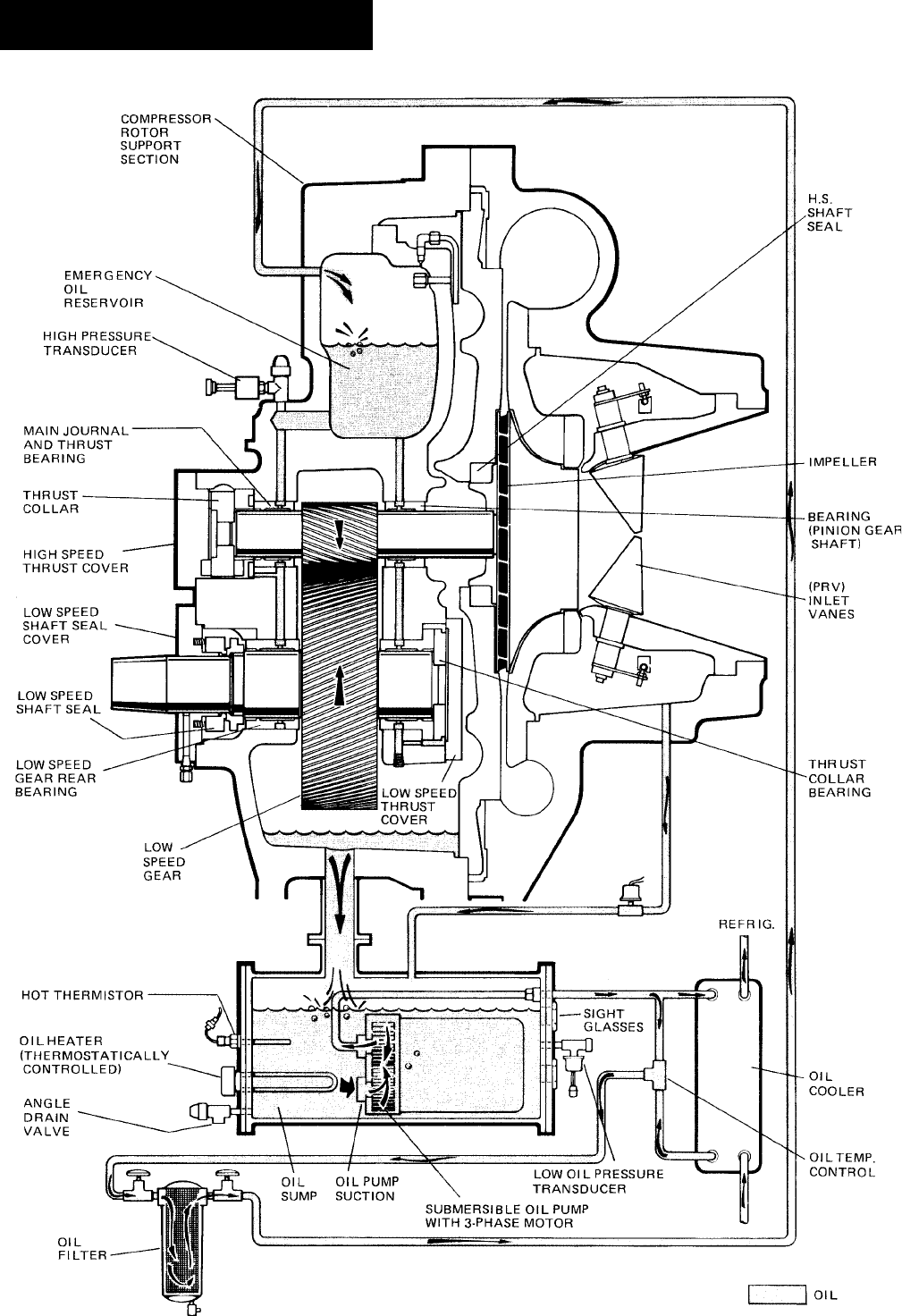
YORK INTERNATIONAL
132
FORM 160.55-O1 (604)
FIG. 59 – SCHEMATIC DRAWING – (YT) COM PRES SOR LUBRICATION SYSTEM LD03278
System Components De scrip tion

FORM 160.55-O1 (604)
133
YORK INTERNATIONAL
Application #CT’s Furnished in Motor Ter mi nal Box
E-M Starter 3
SS Starter 0
VS Drive 0
COMPRESSOR LUBRICATION SYSTEM
The chiller lubrication system consists of the oil pump,
oil Þ l ter, oil cooler and all interconnecting oil pip ing
and passages. (See Fig. 59) There are seven main points
with in the motor-compressor which must be sup plied
with forced lubrication as follows:
1. Compressor Drive Shaft (Low Speed)
a. Shaft seal.
b. Front and rear journal bearings - one on each
side of driving gear.
c. Low speed thrust bearing (for ward and re verse).
2. Compressor Driven Shaft (High Speed)
a. Forward and reverse high speed thrust bear ing.
b. Three jour nal bearings (YDTJ67 through 95 and
YDTL108 through 126). Two journal bearings
(YDTL131 and 144).
3. Speed Increasing Gears
a. Meshing sur fac es of drive and pinion gear teeth.
To pro vide the re quired amount of oil under the nec-
es sary pressure to properly lu bri cate these parts, a motor
driv en sub mers ible oil pump is lo cat ed in a re mote oil
sump.
Upon press ing of the “COM PRES SOR START”
switch on the con trol cen ter, the oil pump is im me -
di ate ly en er gized. After a 30 sec ond delay to allow the
system oil pressure to sta bi lize, the compressor motor
will start. The oil pump will continue to run during the
entire op er a tion of the compressor, and for 150 sec onds
during compressor coastdown.
The sub merged oil pump takes suction from the sur-
round ing oil and dis charg es it to the oil cooler where heat
is rejected. The oil ß ows from the oil cooler to the oil
Þ lter. The oil leaves the Þ lter and ß ows to the emer gen cy
oil res er voir where it is dis trib ut ed to the com pres sor
bear ings. The oil lu bri cates the com pres sor ro tat ing
com po nents and is re turned to the oil sump.
Since the emer gen cy oil res er voir is at the high est point
in the lu bri ca tion sys tem, it provides an oil supply to
the var i ous bear ings and gears in the event of a sys tem
shutdown due to power failure. The reservoir, lo cat ed on
the top of the compressor, al lows the oil to be dis trib ut ed
through the pas sag es by grav i ty ß ow, thus pro vid ing nec-
essary lu bri ca tion dur ing the com pres sor coastdown.
OIL PUMP
For normal operation the oil pump should operate at
all times dur ing the chiller operation. Man u al pump
op er a tion may be used to es tab lish sta ble oil pres-
sure be fore start ing. When de pressed and re leased,
the “MAN U AL OIL PUMP” key will operate the oil
pump for 10 min utes and then au to mat i cal ly shut off.
To stop the oil pump sooner, de press the “MAN U AL
OIL PUMP” key again.
On shutdown of the sys tem for any reason, the oil pump
op er ates and con tin ues to run for 150 sec onds. The sys-
tem can not restart during that time in ter val.
OIL HEAT ER
During long idle pe ri ods, the oil in the com pres sor oil
res er voir tends to absorb as much re frig er ant as it can
hold, de pend ing upon the tem per a ture of the oil and
the pressure in the reservoir. As the oil tem per a ture is
low ered, the amount of re frig er ant ab sorbed will be in-
creased. If the quantity of re frig er ant in the oil be comes
excessive, vi o lent oil foaming will result as the pressure
within the sys tem is low ered on start ing. This foaming is
caused by re frig er ant boil ing out of the oil as the pres sure
is lowered. If this foam reaches the oil pump suc tion,
the bearing oil pres sure will ß uc tu ate with pos si ble
tem po rary loss of lu bri ca tion, caus ing the oil pres sure
safe ty cutout to actuate and stop the system.
SHELLS - The cooler and con dens er shells are rolled
carbon steel plate with fu sion welded seams. A thick tube
sheet is welded to each end of the shell and is drilled
and reamed to ac com mo date the tubes. All shells have
a design work ing pres sure of 15 PSIG and are pres sure-
tested at 30 PSIG.
TUBES - In di vid u al ly-re place able, 3/4" O.D., in te gral-
Þ nned copper heat ex chang er tubes are used in the cool er
and con dens er. The tubes are roller-ex pand ed into the
tube sheets, pro vid ing a leak-proof seal.
COMPACT WATER BOXES - Re mov able water
box es are fabricated of steel. The stan dard design
work ing pres sure is 150 PSIG and the box es are tested
at 225 PSIG. Integral steel water bafß es are lo cat ed and
weld ed with in the water box to provide re quired 1, 2,
or 3-pass arrangements. Water nozzle con nec tions with
5

YORK INTERNATIONAL
134
FORM 160.55-O1 (604)
System Components De scrip tion
Victaulic grooves are welded to the water boxes. These
nozzle connections are suit able for Victaulic cou plings,
weld ing or ß anges (300 PSI has ß ang es). 1/2" cou pling
and separable well are lo cat ed in the entering and leav ing
chilled liquid nozzles for tem per a ture sensing el e ments.
Plugged 1/2" or 3/4" drain and vent connections are
pro vid ed in each water box.
COOLER - The cooler is a hor i zon tal, ß ooded, shell-
and-tube type, with a dis tri bu tion system consisting
of a distributor trough to give uniform distribution
through out the shell length and a perforated distributor
plate, lo cat ed under the entire tube bundle, to equally
dis trib ute re frig er ant. Intermediate steel tube supports
are spaced at intervals of less than four feet. High ly ef-
Þ cient, alu mi num mesh eliminators are lo cat ed above
the tube bun dle to prevent liquid refrigerant carryover
into the compressor.
A liquid level sight glass is con ve nient ly located on the
side of the cooler to aid in de ter min ing proper re frig -
er ant charge.
CONDENSER - The con dens er is a hor i zon tal, shell-
and-tube type, with a dis charge gas bafß e to prevent di-
rect high ve loc i ty im pinge ment on the tubes. This baf ß e
is also used to dis trib ute the refrigerant gas ß ow prop er ly
for most ef Þ cient heat transfer. A purge con nec tion is
located in the con dens er for ef Þ cient elim i na tion of
noncondensibles. Intermediate steel tube sup ports are
spaced at in ter vals of less than four feet.
REFRIGERANT FLOW CON TROL - The ß ow con-
trol chamber is welded to the bottom of the con dens er to
allow complete drain age of liquid refrigerant from the
condenser. The chamber con tains a single Þ xed-oriÞ ce
ß ow control with no moving parts.
BURSTING DISC - A 2" or 3" frangible carbon burst-
ing disc relief device is located in the compressor suc-
tion line.
SOLID STATE STARTER (OP TION AL)
The Solid State Starter is a re duced-voltage liquid cooled
starter that controls and maintains a constant current
ß ow to the motor during start-up. The starter is mount ed
on the chiller. The power wiring from the start er to the
mo tor and from the starter control trans form er to the
Control Center is fac to ry wired and test ed. Available
for 200-600V-3Ph-60/50 Hz power; 2 or 3 barrel lug
connections per phase are provided on the starter. The
starter en clo sure is NEMA Type1 and is provided with
a hinged door with lock and key.
VARIABLE SPEED DRIVE (OPTIONAL)
A 460V-3ph-60/50 Hz Variable Speed Drive can be fac-
to ry pack aged with the chiller. It is de signed to vary the
compressor motor speed and prerotation vane position
by con trol ling the fre quen cy and voltage of the elec tri cal
pow er to the motor. Op er a tion al information is con tained
in Form 160.00-O1. The con trol log ic au to mat i cal ly
ad justs mo tor speed and com pres sor prerotation vane
po si tion for max i mum part load efÞ ciency by an a lyz ing
in for ma tion fed to it by sen sors located through out the
chiller.
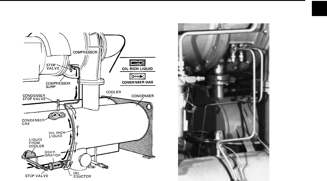
FORM 160.55-O1 (604)
135
YORK INTERNATIONAL
SECTION 6
OPERATIONAL MAINTENANCE
OIL RETURN SYSTEM
6
OIL RETURN
The oil return system con tin u ous ly main tains the prop er
oil level in the compressor oil sump. (See Fig. 57.)
High pressure condenser gas ß ows con tin u ous ly through
the eductor inducing the low pressure, oil rich liquid to
ß ow from the evaporator, through the de hy dra tor to the
com pres sor sump.
CHANGING THE DE HY DRA TOR
To change the de hy dra tor use the following proce-
dure:
1. Shut the stop valves on the condenser gas line, oil
re turn line to rotor sup port and inlet end of de hy -
dra tor.
2. Remove the de hy dra tor as follows: Refer to Fig.
58.
a. Remove connection on the inlet end of de hy -
dra tor.
b. Place wrench es on the dehydrator outlet and in let
ends and the ß are nut. Loosen the ß are nut and
unscrew the de hy dra tor.
3. Assemble the new Þ lter-drier as follows:
a. Place the outlet and inlet ends of the dehydrator
be tween the ß are nuts.
b. Tighten the ß are nuts.
4. Open condenser stop valve and check de hy dra tor
connections for refrigerant leaks.
5. Open all the de hy dra tor stop valves to allow the liq-
uid re frig er ant to ß ow through the de hy dra tor and
con dens er-gas through the eductor.
FIG. 60 – OIL RETURN SYSTEM
LD00469 22621A(D)
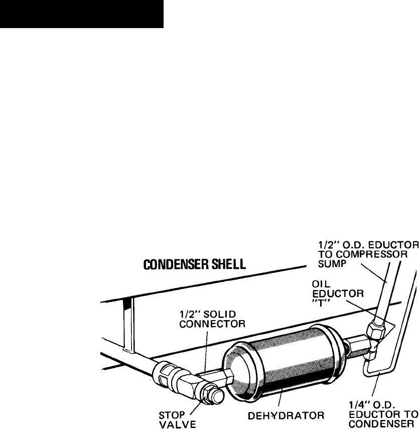
YORK INTERNATIONAL
136
FORM 160.55-O1 (604)
Operational Maintenance
LD00470
FIG. 61 – ASSEMBLY OF DEHYDRATOR
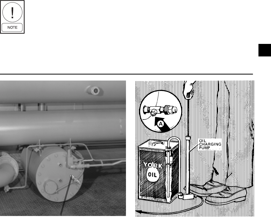
FORM 160.55-O1 (604)
137
YORK INTERNATIONAL
FIG. 62 – CHARGING OIL RESERVOIR WITH OIL
25721A
OIL CHARG ING VALVE LD00472
at the charg ing valve until after the air is forced out
by pumping a few strokes of the oil pump. This Þ lls
the lines with oil and pre vents air from being pumped
into the sys tem.
3. Open the oil charging valve and pump oil into the
sys tem until oil level in the com pres sor oil res er voir
is about midway in the upper sight glass. Then,
close the charg ing valve and dis con nect the hand
oil pump.
4. As soon as oil charg ing is com plete, close the pow er
sup ply to the starter or Variable Speed Drive to en-
er gize the oil heater. This will keep the con cen tra tion
of re frig er ant in the oil to a minimum.
When the oil res er voir is initially charged with oil, the
oil pump should man u al ly be start ed to Þ ll the lines,
pas sag es, oil cooler and oil Þ lter. This will low er the
oil level in the res er voir. It will then be nec es sary to
add oil to bring the level back to the center of the upper
sight glass.
The nominal oil charge for the com pres sor is: 10 gal. “B”
and “C” com pres sor; 15 gal. “E” and “F’ com pres sor.
New oil YORK Refrigeration Type “C” must be used in
the centrifugal compressor. Since oil absorbs mois ture
when ex posed to the atmosphere it should be kept tight ly
capped until used.
OIL CHARG ING PRO CE DURE
The oil should be charged into the oil res er voir using the
YORK Oil Charging Pump - YORK Part No. 070-10654.
To charge oil into the oil res er voir pro ceed as follows:
1. The unit should be shut down.
If charg ing oil to restore the cor rect
lev el, the unit may be kept in op-
er a tion.
2. Immerse the suc tion con nec tion of the oil charg ing
pump in a clean con tain er of new oil and con nect
the pump dis charge con nec tion to the oil charg ing
valve (A) lo cat ed on the remote oil reservoir cover
plate. (See Fig. 62). Do not tight en the connection
CHARGING THE UNIT WITH OIL
6

YORK INTERNATIONAL
138
FORM 160.55-O1 (604)
Troubleshooting
SECTION 7
TROUBLE SHOOTING
TABLE 1 – CAUSES OF NOR MAL AND SAFE TY SYS TEM SHUT DOWNS IN AC COR DANCE WITH THE
CONTROL CENTER DISPLAY
CONTROL CENTER DISPLAY GOVERNING CONTROL FUNCTION
DAY OF TIME CAUSE OF METHOD OF DESCRIPTION OPERATING POINT
WEEK OF DAY SHUTDOWN RESTART ON RISE ON FALL
MON. 10:00 AM Low Water Autostart Low Water (LWT) Chilled water 4°F below chilled
Temperature setpoint water setpoint
MON. 10:00 AM Low Water Autostart Low Water (LWT) Chilled water 4°F below chilled
Temperature VSD setpoint water setpoint
MON. 10:00 AM Flow Switch Autostart Flow Switch
MON. 10:00 AM System Cycling Autostart A remote command
(computer relay contact or
manual switch)
MON. 10:00 AM Multi-Unit Cycling Autostart (Optional)
Lead-Lag Sequence Control
MON. 10:00 AM Internal Clock Autostart Internal Clock
MON. 10:00 AM AC Undervoltage Autostart <15% FLA for 25
continuous seconds
MON. 10:00 AM Power Fault Autostart CM-2 Current Module or
Solid State Starter
Remote Stop Energy Management System
MON. Anti-Recycle, Anti-Recycle
20 Min. Left Timer
MON. 10:00 AM Low Evap. Press. Low Evap. Pressure 5.43 PSIA 5.42 PSIA
Transducer (LEP)
MON. 10:00 AM Low Evap. Press. LEP external control Set to Job Spec. Set to Job Spec.
Brine (Brine units only)
MON. 10:00 AM Low Oil Low Oil Press. Transducer (OP) 20 PSID 15 PSID
Pressure High Oil Press. Transducer (OP)
MON. 10:00 AM High Pressure High Pressure 15 PSIG 9 PSIG
Safety Control (HP)
MON. 10:00 AM Evap. Transducer Evap. Pressure Transducer
or Probe Error or Leaving Chilled Water
Thermistor (RS1)
MON. 10:00 AM Motor Controller - CM-2 or Solid State Starter or
Ext. Reset Variable Speed Drive
MON. 10:00 AM High Discharge Discharge Temperature 220°F 219°F
Temperature Thermistor (RT2)
MON. 10:00 AM High Oil Oil Temperature 180°F 179°F
Temperature Thermistor (RT3)
MON. 10:00 AM Power Autostart Microboard undervoltage 8.29VDC 7.84VDC
Failure circuit on 5V unregulated
supply
MON. 10:00 AM Power Microboard undervoltage 8.29VDC 7.84VDC
Failure circuit on 5V unregulated
supply
SHUTDOWN CAUSE
CONTROL CENTER DISPLAY

FORM 160.55-O1 (604)
139
YORK INTERNATIONAL
7
TABLE 1 – CAUSES OF NOR MAL AND SAFE TY SYS TEM SHUT DOWNS IN AC COR DANCE WITH THE
CONTROL CENTER DISPLAY - CONTINUED
PROGRAMMED START-UP OF PROBABLE CAUSE
SETPOINTS SYSTEM AFTER AND SERVICE
BY OPERATOR SHUTDOWN REQUIRED
4°F below chilled water Automatic Restart when water reaches setpoint. System load is less than minimum capacity.
setpoint (If set to 40°F would If system is running and setpoint is increased
be 36°F.) (36°F minimum) 4°F, system will continue to run, as LWT cutout
shifts to a fixed 36°F for 10 minutes.
4°F below chilled water If system is running and setpoint is increased System load is less than minimum capacity.
setpoint (If set to 40°F would 4°, VSD will Initiate Shutdown. Automatic Restart
be 36°F.) (36°F minimum) when water temperature reaches setpoint.
Automatic Restart when water flow is restored to Lack of water flow.
close flow switch. Check operation of chilled water pump.
Automatic Restart upon remote command. Contact - connected to the Remote/Local
cycling input of the Digital Input Board.
Automatic Restart upon remote command. Contact - connected to the Multi-Unit
cycling input of the Digital Input Board.
Daily Schedule programmed Will automatically restart when programmed Pressing Compressor Start Switch
to shut down unit. schedule permits. overrides the program.
Cycling shutdown occurs when motor current is
>15% FLA for 25 seconds during chiller operation.
Will start automatically following coastdown. Motor Controller contacts opening and closing in less
than 3 seconds due to a power fault condition.
Start up by start signal from remote start switch. Remote Stop Contact Closure.
Will not start until 30 minute Will restart when time left = 00 minutes. Minimum time between successive compressor
timer is timed out. starts is 30 minutes.
To restart, press compressor switch from See OPERATING ANALYSIS, Table 2
STOP/RESET to START position. Symptom 2.
To restart, press compressor switch from See OPERATING ANALYSIS, Table 2
STOP/RESET to START position. Symptom 2.
Will restart when pressure increases to 20 PSID. See OPERATING ANALYSIS, Table 2
To restart, press compressor switch from Symptom 4, 5, 6, 7, 9, 10, 11.
STOP/RESET to START position.
Will restart when pressure falls to 9 PSIG. See OPERATING ANALYSIS, Table 2
To restart, press compressor switch from Symptom 1 - High Discharge Pressure.
STOP/RESET to START position.
To restart, press compressor switch from Defective Evap. Pressure Transducer or Leaving
STOP/RESET to START position. Chiller Water thermistor (RS1). LCWT minus
saturation temp. is less than -2.5°F or greater than
25°F. Checked every 10 minutes following a 10-min.
bypass at start-up.
Reset the device that caused the shutdown. CM-2 or Solid State Starter or Variable Speed
Chiller will start automatically. Drive has shut down chiller.
To restart, press compressor switch from Condenser tubes dirty or scaled or high condenser
STOP/RESET to START position. water temperature. See Symptom 1, Table 2.
To restart, press compressor switch from Dirty oil filter or restricted oil cooler line. Change oil
STOP/RESET to START position. filter. See Symptom 9, Table 2.
Optional AUTO Restart Plug Will restart automatically when voltage reaches Power Failure.
is installed on Microboard. 8.29VDC. An undervoltage circuit on Microboard
monitors the 5VDC unregulated supply for an
undervoltage condition.
Auto restart plug is removed To restart, press compressor switch to STOP/ Power Failure.
on Microboard. RESET position and then to START position.

YORK INTERNATIONAL
140
FORM 160.55-O1 (604)
TABLE 1 – CAUSES OF NOR MAL AND SAFE TY SYS TEM SHUT DOWNS IN AC COR DANCE WITH THE
CONTROL CENTER DISPLAY - CONTINUED
SHUTDOWN CAUSE CON TROL CENTER DISPLAY GOVERNING CONTROL FUNCTION
DAY OF TIME CAUSE OF METHOD OF DESCRIPTION OPERATING POINT
WEEK OF DAY SHUTDOWN RESTART ON RISE ON FALL
MON. 10:00 AM Oil Pressure High Oil Pressure 60 PSID 59 PSID
Transducer Error Transducer or Low
Oil Pressure Transducer
Vane Motor Autostart Vane Motor Switch
Switch Open
MON. 10:00 AM Starter Motor Current >15% for 10
Malfunction seconds with Control Center
Detected not calling for motor to run.
MON. 10:00 AM Program Initiated Autostart Microboard
Reset
Replace RTC-IC RTC-IC Chip
Chip Reprogram
Setpoints
MON. 10:00 AM Low Oil Autostart Oil Temperature 71.0°F 55°F
Temperature Thermistor (RT3)
MON. 10:00 AM Faulty Discharge Discharge Temp. Thermistor 30.0°F 29.9°F
Temperature (RT2) disconnected or faulty
Sensor (min. system operating
temp. = 32°F)
MON. 10:00 AM Low Line Voltage SSS Logic Board See legend on
(SSS units only) wiring diagram.
MON. 10:00 AM Motor Phase SSS Logic Board See Section 2.
Current Unbalance
(SSS units only)
Troubleshooting

FORM 160.55-O1 (604)
141
YORK INTERNATIONAL
TABLE 1 – CAUSES OF NOR MAL AND SAFE TY SYS TEM SHUT DOWNS IN AC COR DANCE WITH THE
CONTROL CENTER DISPLAY - CONTINUED
PROGRAMMED START-UP OF PROBABLE CAUSE
SETPOINTS SYSTEM AFTER AND SERVICE
BY OPERATOR SHUTDOWN REQUIRED
Will start at 59 PSID when compressor switch is This Shutdown is provided to check on Oil pressure
placed to STOP/RESET and then START. Transducers for failure in the high state. Replace Oil
Pressure Transducer in oil sump or compressor.
Restart automatically after Vane Motor arm linkage Vanes are set improperly. Reset vane linkage, check
is set properly. Press STOP/RESET and then vane positions using the Service key switch and proper
START switch. keys on the OptiView Control Center or switch
of capacity board of Variable Speed Drive.
Press compressor STOP/RESET switch and then Check motor starter operation. Motor current value
START switch. greater than 15%.
Watchdog timer circuit has reset software program.
Chiller will automatically restart.
Reprogram the Control Center Setpoints and Weak Battery.
proceed with Normal Start-up. Replace RTC-IC chip U16.
Press STOP/RESET switch and then START Oil Temperature Thermistor disconnected from Analog
switch. Input Board. Reconnect or replace open sensor.
Press STOP/START switch and then START Faulty Discharge Temperature Thermistor (RT2) or
switch. disconnected from Analog Input Board. Connect or
replace open sensor.
Chiller will automatically restart when all phases of line Low AC Line Voltage
voltage increase to the minimum required starting level.
Press STOP/RESET switch and then START Motor Phase Current Unbalance
switch.
7

YORK INTERNATIONAL
142
FORM 160.55-O1 (604)
Troubleshooting
TABLE 2 – OPERATING ANALYSIS CHART
RESULTS POSSIBLE CAUSE REMEDY
1. SYMP TOM: ABNORMALLY HIGH DIS CHARGE PRESSURE
Temperature difference between liquid Air in condenser. Purge unit operates automatically to take
refrigerant out and water off condenser care of this condition. Test for air leaks if
higher than normal. display reads:
“WARNING – EXCESS PURGE”
High dis charge pressure. Condenser tubes dirty or scaled. Clean condenser tubes.
Check wa ter con di tion ing.
High con dens er water temperature. Reduce con dens er water inlet tem per a ture.
(Check cooling tow er and water cir cu la tion.)
Temperature dif fer ence be tween con- Insufficient con dens ing water flow. Increase the quantity of wa ter through the
denser water on and water off higher condenser to proper value.
than normal, with normal cooler pressure.
2. SYMP TOM: ABNORMALLY LOW SUC TION PRESSURE
Temperature dif fer ence between leav ing Insufficient charge of refrigerant. Check for leaks and charge re frig er ant into
chilled water and refrigerant in cooler system.
greater than normal with high discharge
temperature. Flow orifice blocked. Remove obstruction.
Temperature dif fer ence be tween leav ing Cooler tubes dirty or restricted. Clean cooler tubes.
chilled water and re frig er ant in the cooler
greater than normal with normal dis charge
temperature.
Temperature of chilled water too low with Insufficient load for system capacity. Check prerotation vane motor operation
low motor amperes. and setting of low water temperature cutout.
3. SYMP TOM: HIGH COOL ER PRES SURE
High chilled water tem per a ture. Prerotation vanes fail to open. Check the prerotation vane motor
positioning circuit.
System over load ed. Be sure the vanes are wide open
(without overloading the motor) until the
load decreases.
4. SYMP TOM: NO OIL PRES SURE WHEN SYSTEM START BUTTON PUSHED
Low oil pres sure dis played on control Oil pump run ning in wrong direction. Check ro ta tion of oil pump.
center; compressor will not start. (Electrical Connections)
Oil pump not running. Check electrical connections to oil pump
and press manual reset on oil pump starter
(on condenser shell in front of purge unit).
5. SYMPTOM: COM PRES SOR STARTS, NORMAL OIL PRESSURE DE VEL OPS, FLUCTUATES FOR SHORT WHILE, THEN
COMPRESSOR STOPS ON OIL PRES SURE CUTOUT
Oil pressure normal, fluctuates, then com- Unusual starting conditions exist, i.e., oil Drain the oil from the compressor and
pressor stops on Oil Pressure Cutout. foaming in reservoir and piping due to charge new oil into the compressor. (See
Display reading: “LOW OIL PRESSURE” lowered system pressure. “Oil Charging Procedure”, page 129.)
Burned out oil heater. Replace oil heater.
FORM 160.55-O1 (604)
143
YORK INTERNATIONAL
RESULTS POSSIBLE CAUSE REMEDY
6. SYMP TOM: UNUSUALLY HIGH OIL PRESSURE DEVELOPS WHEN OIL PUMP RUNS
Unusually high oil pressure is displayed High oil pressure. Transducer defective. Replace low or high oil pressure trans duc er.
when the oil pressure display key is Relief valve is misadjusted. Adjust external relief valve.
pressed when the oil pump is running.
7. SYMP TOM: OIL PUMP VIBRATES OR IS NOISY
Oil pump vibrates or is extremely noisy Misalignment of pump or piping. Correct condition or replace faulty part.
with some oil pressure when pressing Mounting bolts loose.
“Oil Pressure” display key. Bent shaft.
Worn pump parts.
NOTE: When oil pump is run without Oil not reaching pump suction inlet in Check oil supply and oil piping.
an oil supply it will vibrate and sufficient quantity.
become extremely noisy.
8. SYMP TOM: OIL PRES SURE GRADUALLY DECREASES (NOTED BY OBSERVATION OF DAILY LOG SHEETS)
Oil pressure (noted when pressing “Oil Oil filter is dirty. Change oil filter.
Pressure” display key) drops to 70% of
oil pressure when compressor was Extreme bearing wear. Inspect compressor.
originally started.
9. SYMP TOM: OIL RETURN SYSTEM CEASES TO RETURN AN OIL/REFRIGERANT SAMPLE
Oil refrigerant return not functioning. Filter-drier in oil return system dirty. Replace oil filter-drier with new.
Jet or orifice of oil return jet clogged. Remove jet, inspect for dirt.
Remove dirt using solvent and replace.
10. SYMPTOM: OIL PUMP FAILS TO DELIVER OIL PRESSURE
No oil pressure registers when pressing Faulty oil pressure transducer. Replace oil pressure transducer.
“Oil Pressure” display key when oil pump Faulty writing/connectors.
runs.
11. SYMPTOM: REDUCED OIL PUMP CAPACITY
Oil pump pumping capacity low. Excessive end clearance in pump. Inspect and replace worn parts.
Other worn pump parts.
Partially blocked oil supply inlet. Check oil inlet for blockage.
12. SYMPTOM: IMPROPER PURGE UNIT OPERATION
Purge unit not purging and air is 1. Faulty float switch assembly. Check these components and replace
present in the unit. 2. Faulty three-way oil solenoid valve. where necessary.
3. Faulty exhaust solenoid valve.
4. Faulty pressure transducer.
Purge unit purging air and refrigerant 1. Faulty exhaust solenoid valve. Restore refrigerant liquid cooling supply.
2. Faulty pressure transducer.
3. Lack of cooling.
7
TABLE 2 – OPERATING ANALYSIS CHART - CONTINUED

YORK INTERNATIONAL
144
FORM 160.55-O1 (604)
Maintenance
SECTION 8
MAINTENANCE
RENEWAL PARTS
For any required Renewal Parts re fer to Forms listed on page 4.
LEAK TEST ING DUR ING OP ER A TION
The refrigerant side of the sys tem is care ful ly pressure
test ed and evac u at ed at the factory.
After the system is in op er a tion under load, the high
pressure components should be carefully leak test ed
with a leak detector to be sure all joints are tight. If a
leak exists frequent purg ing will be required or re frig -
er ant will be lost.
If any leaks are indicated, they must be repaired im-
me di ate ly. Usu al ly, leaks can be stopped by tight en ing
ß are nuts or ß ange bolts. However, if it is nec es sary to
re pair a weld ed joint, the refrigerant charge must be
re moved (See “Han dling Refrigerant for Dis man tling
and Re pairs”, page 140).
CONDUCTING PRES SURE TEST
With the refrigerant charge removed and all known
leaks repaired, the system should be charged with a
small amount of R-22 mixed with dry ni tro gen so that
a ha lide torch or elec tron ic leak de tec tor can be used to
detect any leaks too small to be found by the soap test.
Do not use ex ces sive amounts of R-22; use only enough
for proper leak detection.
To test with R-22, proceed as fol lows:
1. With no pres sure in the sys tem, charge R-22 gas into
the system through the charg ing valve to a pres sure
of 2 PSIG.
2. Build up the system pressure with dry nitrogen to
ap prox i mate ly 10 PSIG. To be sure that the con-
cen tra tion of refrigerant has reached all parts of the
sys tem, slight ly open the oil charging valve and test
for the pres ence of refrigerant with a leak detector.
3. Test around each joint and factory weld. It is im por -
tant that this test by thoroughly and carefully done,
spending as much time as necessary and using a good
leak detector.
4. To check for re frig er ant leaks in the cooler and con-
dens er, open the vents in the cooler and condenser
heads and test for the presence of re frig er ant. If
no refrigerant is present, the tubes and tube sheets
may be con sid ered tight. If re frig er ant is de tect ed
at the vents, the heads must be removed, the leak
lo cat ed (by means of soap test or leak de tec tor) and
re paired.
5. When absolute tight ness of the sys tem has been es-
tab lished, blow the mixture of ni tro gen and re frig -
er ant through the charg ing valve.
CHECKING SYSTEM FOR LEAKS
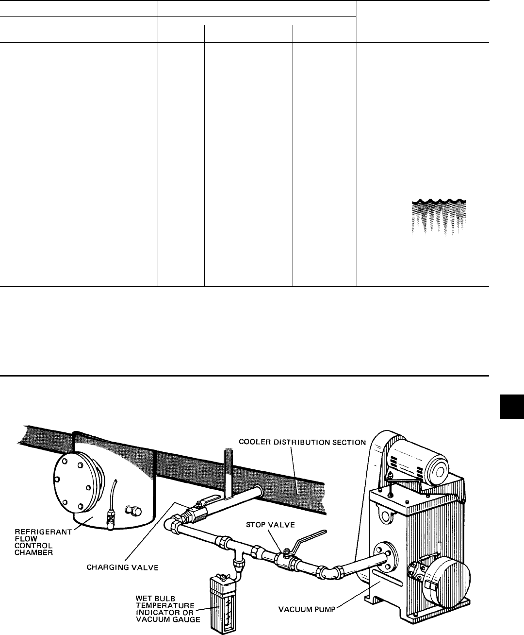
FORM 160.55-O1 (604)
145
YORK INTERNATIONAL
8
*GAUGE ABSOLUTE
INCHES OF MERCURY (HG) PSIA MILLIMETERS OF MICRONS
BELOW ONE STANDARD ATMOSPHERE MERCURY (HG)
0 14.696 760 760,000 212
10.24* 9.629 500 500,000 192
22.05* 3.865 200 200,000 151
25.98* 1.935 100 100,000 124
27.95* .968 50 50,000 101
28.94* .481 25 25,000 78
29.53* .192 10 10,000 52
29.67* .122 6.3 6,300 40
29.72* .099 5 5,000 35 WATER
29.842* .039 2 2,000 15 FREEZES
29.882* .019 1.0 1,000 +1
29.901* .010 .5 500 -11
29.917* .002 .1 100 -38
29.919* .001 .05 50 -50
29.9206* .0002 .01 10 -70
29.921* 0 0 0
* One standard atmosphere = 14.696 PSIA NOTES: PSIG = Lbs. per sq. in. gauge pressure
= 760 mm Hg. absolute pressure at 32°F = Pressure above atmospheric
= 29.921 inches Hg. absolute at 32°F PSIA = Lbs. per sq. in. absolute pressure
= Sum of gauge plus at mo spher ic pressure
TABLE 3 – SYSTEM PRESSURES
FIG. 63 – EVACUATION OF CHILLER
LD00473
BOILING
TEMPERATURES
OF WATER °F

YORK INTERNATIONAL
146
FORM 160.55-O1 (604)
Maintenance
EVACUATION AND DEHYDRATION OF UNIT
VACUUM TESTING
After the pressure test has been completed theVacuum
test should be conducted as follows:
1. Connect a high ca pac i tyVacuum pump, with in di -
ca tor, to the sys tem charg ing valve as shown in
Fig. 63 and start the pump (see “Vacuum De hy -
dra tion”).
2. Open wide all sys tem valves, in clud ing the purge and
gauge valves. Be sure all valves to the at mo sphere
are closed.
3. Operate theVacuum pump in accordance with “Vac-
u um Dehydration” until a wet bulb tem per a ture of
+32°F or a pressure of 5mm Hg. is reached. See Table
3 for cor re spond ing values of pres sure.
4. To im prove evac u a tion circulate hot water (not to
exceed 125°F) through the cooler and condenser
tubes to thor ough ly de hy drate the shells. If a source
of hot water is not readily avail able, a portable
wa ter heat er should be employed. DO NOT USE
STEAM. A sug gest ed meth od is to connect a hose
between the source of hot water under pressure and
the cool er head drain con nec tion, out the cooler vent
con nec tion, into the con dens er head drain and out the
con dens er vent. To avoid the pos si bil i ty of caus ing
leaks, the tem per a ture should be brought up slow ly
so that the tubes and shell are heated evenly. Close
the sys tem charg ing valve and the stop valve be tween
theVacuum indicator and theVacuum pump. (See Fig.
63) Then disconnect theVacuum pump leav ing the-
Vacuum indicator in place.
5. Hold theVacuum ob tained in Step 3 in the sys tem for
8 hours; the slightest rise in pressure in di cates a leak
or the pres ence of moisture, or both. If, after 8 hours
the wet bulb tem per a ture in theVacuum in di ca tor has
not risen above 40°F or a pres sure of 6.3mm Hg, the
sys tem may be con sid ered tight.
Be sure theVacuum indicator is valved
off while holding the systemVacuum
and be sure to open the valve be tween
theVacuum in di ca tor and the system
when check ing theVacuum af ter the 8
hour period.
6. If theVacuum does not hold for 8 hours within the
limits spec i Þ ed in Step 5 above, the leak must be
found and repaired.
VACUUM DEHYDRATION
To ob tain a sufÞ ciently dry system, the following in-
struc tions have been as sem bled to provide an ef fec tive
meth od for evacuating and dehydrating a system in
the Þ eld. Although there are several methods of de hy -
drat ing a system, we are recommending the fol low ing,
as it pro duc es one of the best results, and af fords a
means of obtaining accurate read ings as to the extent
of de hy dra tion.
The equip ment required to follow this method of de-
hy dra tion consists of a wet bulb indicator orVacuum
gauge, a chart showing the relation between dew point
tem per a ture and pressure in inches of mercury (vac u um),
(see Table 3) and aVacuum pump capable of pumping a
suitableVacuum on the system.
OPERATION
Dehydration of a refrigeration system can be ob tained
by this method because the water present in the sys tem
reacts much as a refrigerant would. By pulling down
the pres sure in the system to a point where its sat u -
ra tion tem per a ture is considerably below that of room
tem per a ture, heat will ß ow from the room through the
walls of the system and va por ize the water, allowing
a large percentage of it to be removed by theVacuum
pump. The length of time necessary for the de hy dra tion
of a system is de pen dent on the size or volume of the
sys tem, the ca pac i ty and efÞ ciency of theVacuum pump,
the room tem per a ture and the quantity of water present
in the sys tem. By the use of theVacuum in di ca tor as
suggested, the test tube will be evacuated to the same
pressure as the system, and the distilled water will be
maintained at the same saturation temperature as any
free water in the system, and this temperature can be
observed on the thermometer.
If the system has been pressure test ed and found to be
tight prior to evac u a tion, then the sat u ra tion tem per a ture
recordings should follow a curve sim i lar to the typ i cal
saturation curve shown as Fig. 64.
The tem per a ture of the water in the test tube will drop as
the pressure decreases, until the boiling point is reached,
at which point the temperature will level off and remain
at this level until all of the water in the shell is vapor-
ized. When this Þ nal va por iza tion has taken place the
pressure and temperature will con tin ue to drop until
eventually a tem per a ture of 35°F or a pressure of 5mm
Hg. is reached.
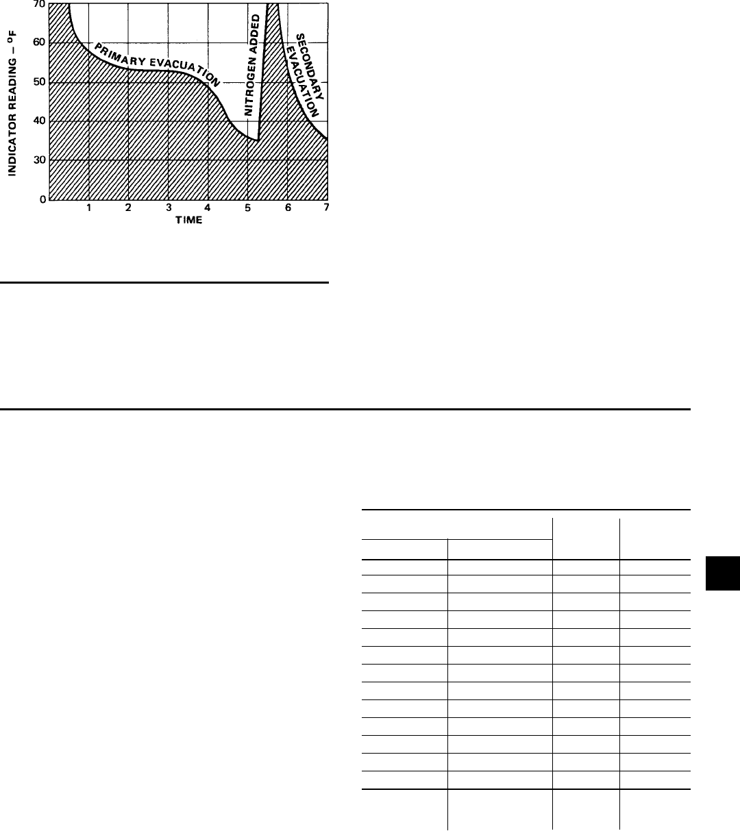
FORM 160.55-O1 (604)
147
YORK INTERNATIONAL
FIG. 64 – SATURATION CURVE
LD00474
SHELL CODES
COOLER COMPRESSOR
G0, G1, G3 B 890 900
G0, G1, G3 C 890 900
H1, H3 − 970 975
J1, J3 − 1130 1125
K1, K3 − 1270 1275
G0, G1, G3 E 890 900
H1, H3 − 970 975
J1, J3 − 1130 1125
K1, K3 − 1270 1275
L1, L3 − 1390 1400
K4, K6 F 1390 1400
K7, K9 − 1530 1550
L4, L6 − 1590 1600
FACTORY
CHARGE SHIPPED
LBS.
When this point is reached, practically all of the air has
been evacuated from the system, but there is still a small
amount of moisture left. In order to provide a medium
for carrying this residual moisture to theVacuum pump,
nitrogen should be in tro duced into the system to bring
REFRIGERANT CHARGING
it to at mo spher ic pressure and the indicator tem per a ture
will re turn to approximately am bi ent tem per a ture. Close
off the system again, and start the second evac u a tion.
The relatively small amount of moisture left will be car-
ried out through theVacuum pump and the tem per a ture or
pressure shown by the indicator should drop uni form ly
until it reaches a tem per a ture of 35°F or a pres sure of
5mm Hg.
When theVacuum indicator registers this tempera-
ture or pres sure it is a positive sign that the system is
evac u at ed and de hy drat ed to the recommended limit.
If this level can not be reached, it is evident that there
is a leak somewhere in the system. Any leaks must be
cor rect ed before the in di ca tor can be pulled down to
35°F or 5mm Hg. in the primary evac u a tion. During
the pri ma ry pull down keep a careful watch on the wet
bulb indicator tem per a ture, and do not let it fall below
35°F. If the tem per a ture is allowed to fall to 32°F the
water in the test tube will freeze, and the result will be
a faulty tem per a ture reading.
To avoid the possibility of freezing the liquid within the
cooler tubes when charg ing an evacuated system, only
refrigerant vapor from the top of the drum or cyl in der
must be ad mit ted to the system until the system pres sure
is raised above the point corresponding to the freez ing
point of the cooler liquid. For water, the pres sure cor-
re spond ing to the freez ing point is 20.4 in Hg.Vacuum
for R-123 (at sea level).
While charg ing, every pre cau tion must be taken to
pre vent mois ture laden air from entering the sys tem.
Make up a suit able charging con nec tion from new cop-
per tubing to Þ t be tween the sys tem charging valve
and the Þ tting on the charging drum. This connection
should be as short as possible but long enough to per mit
suf Þ cient ß ex i bil i ty for chang ing drums. The charg ing
con nec tion should be purged each time a full con tain er
of re frig er ant is con nect ed and changing con tain ers
should be done as quickly as possible to min i mize the
loss of re frig er ant.
Refrigerant may be fur nished in drums con tain ing ei ther
100, 200 or 650 lbs. of re frig er ant. These drums are not
re turn able and they should be stored for future use if
it should ever become nec es sary to re move re frig er ant
from the system.
TABLE 4 – REFRIGERANT CHARGE
8

YORK INTERNATIONAL
148
FORM 160.55-O1 (604)
CHECKING THE REFRIGERANT CHARGE DURING UNIT SHUT DOWN
HANDLING REFRIGERANT FOR
DISMANTLING AND REPAIRS
The refrigerant charge is speciÞ ed for each chiller mod el
(See Table 4). Charge the cor rect amount of re frig er ant
and record the level in the cooler sight glass.
The re frig er ant charge should al ways be checked and
trimmed when the system is shut down.
The refrigerant charge level must be checked after the
pressure and tem per a ture has equalized between the
con dens er and cooler. This would be expected to be 4
hours or more after the com pres sor and water pumps are
stopped. The level should be at the center of the sight
glass ±1/4 inch.
Charge the refrigerant in ac cor dance with the method
shown under “Refrigerant Charging” above. The re frig -
er ant lev el should be observed and the level re cord ed
af ter initial charg ing.
If it becomes necessary to open any part of the re frig er ant
system for repairs, the fol low ing para graphs out line the
procedure for handling the re frig er ant while the sys tem
is open.
Since Re frig er ant-123 boils at 82°F under at mo spher ic
pressure, it will not be necessary to remove the re frig -
er ant if the system it to be open for only a few hours. Any
part of the system which is above the liquid level will be
ac ces si ble without disturbing the re frig er ant charge.
If the system must re main open for more than a few
hours the refrigerant should be drained and stored in
clean drums for the duration of the repair pe ri od.
If con di tions permit, the system pressure should be as
near as possible to at mo spher ic before opening the sys-
tem and the re frig er ant charge should be kept as near
as possible to 82°F to keep ei ther the re frig er ant loss or
the air intake to a min i mum. After the system has been
re-as sem bled, the air should be removed by means of
the purge unit. (See “Purging the System”.)
MEGGING THE MOTOR
While the main disconnect switch and compressor mo tor
starter are open, meg the motor as follows:
1. Using a megohm meter (megger), meg between
phas es and each phase to ground (see Fig. 65); these
readings are to be interpreted using the graph shown
in Fig. 66.
2. If readings fall below shaded area, remove ex ter nal
leads from motor and repeat test.
Motor is to be megged with the starter
at ambient temperature after 24 hours
of idle stand by.
Maintenance
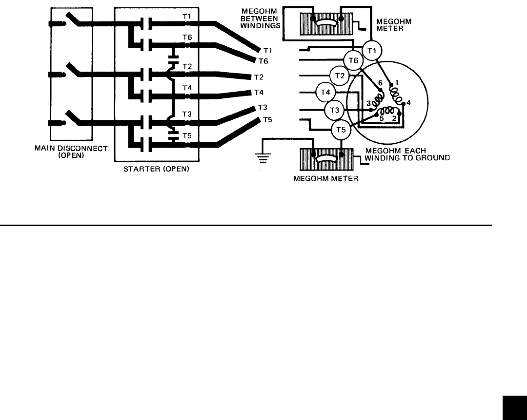
FORM 160.55-O1 (604)
149
YORK INTERNATIONAL
LD00475
FIG. 65 – DIAGRAM, MEGGING MOTOR WIND INGS
GENERAL
Maintenance of condenser and cooler shells is im-
por tant to provide trouble free op er a tion of the chiller.
The wa ter side of the tubes in the shell must be kept
clean and free from scale. Proper main te nance such as
tube clean ing, and testing for leaks, is covered on the
fol low ing pages.
CHEMICAL WATER TREAT MENT
Since the mineral content of the water circulated through
coolers and condensers varies with almost ev ery source
of supply, it is possible that the water being used may
cor rode the tubes or deposit heat resistant scale in them.
Reliable water treatment companies are avail able in most
larger cities to supply a water treating process which will
great ly reduce the corrosive and scale form ing prop er ties
of almost any type of water.
As a pre ven tive measure against scale and corrosion
and to pro long the life of cooler and con dens er tubes, a
chemical analysis of the water should be made pref er a bly
before the system is installed. A reliable water treat ment
com pa ny can be consulted to determine whether water
treat ment is nec es sary, and if so, to furnish the proper
treat ment for the particular water condition.
CLEANING COOLER AND CON DENS ER TUBES
Cooler
It is difÞ cult to de ter mine by any par tic u lar test wheth er
pos si ble lack of per for mance of the water cool er is due
to fouled tubes alone or due to a com bi na tion of trou bles.
Trouble which may be due to fouled tubes is indicated
when, over a period of time, the cool ing ca pac i ty de-
creas es and the split (tem per a ture dif fer ence between
water leav ing the cool er and the re frig er ant tem per a ture
in the cooler) in creas es. A grad u al drop-off in cool ing
ca pac i ty can also be caused by a gradual leak of re frig -
er ant from the sys tem or by a com bi na tion of foul ed
tubes and shortage of re frig er ant charge. An ex ces sive
quan ti ty of oil in the cooler can also contribute to erratic
per for mance.
Condenser
In a condenser, trou ble due to fouled tubes is usu al ly
indicated by a steady rise in head pres sure, over a pe ri od
of time, ac com pa nied by a steady rise in con dens ing
tem per a ture, and noisy operation. These symp toms may
also be due to foul gas buildup. Purging will re move the
foul gas re veal ing the effect of fouling.
TUBE FOULING
Fouling of the tubes can be due to deposits of two types
as follows:
1. Rust or sludge, which Þ nds its way into the tubes
and ac cu mu lates there. This ma te ri al usu al ly does
not build up on the inner tube sur fac es as scale, but
does interfere with heat trans fer. Rust or sludge can
gen er al ly be re moved from the tubes by a thorough
brush ing process.
2. Scale, due to mineral de pos its. These de pos its, even
though very thin and scarce ly de tect able upon phys-
i cal in spec tion, are high ly re sis tant to heat transfer.
They can be removed most ef fec tive ly by cir cu lat ing
an acid so lu tion through the tubes.
CONDENSERS AND COOLERS
8
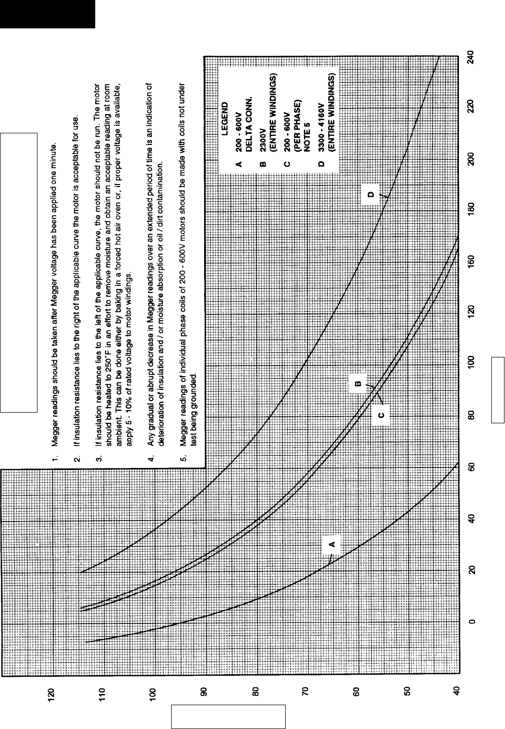
YORK INTERNATIONAL
150
FORM 160.55-O1 (604)
LD00476
TEMPERATURE – °F
MEGOHMS
FIG. 66 – MOTOR STATOR TEMPERATURE AND INSULATION RE SIS TANC ES
Minimum Insulation Resistance vs. Temperature (per IEEE Std 43)
Open Motors
Maintenance

FORM 160.55-O1 (604)
151
YORK INTERNATIONAL
TUBE CLEAN ING PRO CE DURES
Brush Cleaning of Tube
If the tube foul ing con sists of dirt and sludge, it can
usu al ly be re moved by means of the brushing process.
Drain the water sides of the circuit to be cleaned (cool ing
wa ter or chilled water) remove the heads and thor ough ly
clean each tube with a soft bristle bronze brush. DO
NOT USE A STEEL BRISTLE BRUSH. A steel brush
may damage the tubes.
Improved results can be ob tained by admitting water into
the tube during the clean ing process. This can be done
by mounting the brush on a suitable length of 1/8" pipe
with a few small holes at the brush end and con nect ing
the other end by means of a hose to the water supply.
The tubes should always be brush cleaned be fore acid
cleaning.
Acid Cleaning of Tubes
If the tubes are fouled with a hard scale deposit, they
must be acid cleaned. It is im por tant that before acid
cleaning, the tubes be cleaned by the brush ing pro cess
described above. If the rel a tive ly loose for eign ma te ri al
is re moved before the acid cleaning, the acid so lu tion
will have less ma te ri al to dis solve and ß ush from the
tubes with the result that a more satisfactory clean ing job
will be ac com plished with a probable sav ing of time.
COMMERCIAL ACID CLEANING
In many major cities, com mer cial organizations now
of fer a spe cial ized ser vice of acid cleaning coolers
and condensers. If acid cleaning is required, YORK
rec om mends the use of this type of or ga ni za tion. The
Dow Industries Service Division of the Dow Chem i cal
Com pa ny, Tul sa, Okla ho ma, with branch es in prin ci pal
cit ies is one of the most reliable of these companies.
TESTING FOR COOL ER AND CON DENS ER TUBE
LEAKS
Cooler and con dens er tube leaks may result in re frig er ant
leaking into the water cir cuit, or water leak ing into the
shell de pend ing on the pressure levels. If re frig er ant is
leaking into the water it can be detected at the liquid head
vents after a period of shutdown. If wa ter is leak ing into
the refrigerant, fre quent purging will be nec es sary and
sys tem capacity and efÞ ciency will drop off sharply. If
a tube is leaking and water has en tered the system, the
cooler and con dens er should be valved off from the rest
of the water circuit and drained im me di ate ly to prevent
severe rust ing and corrosion. If a tube leak is indicated,
the exact location of the leak may be determined as
follows:
1. Allow the system to warm up until a substantial
pres sure is reached for testing. Dry nitrogen (pres-
sure not to exceed 12 PSIG) may be ad mit ted to the
unit to in crease pressure in the shell. Re move the
heads and lis ten at each section of tubes for a hiss-
ing sound that would indicate gas leakage. This will
as sist in locating the section of tubes to be further
in ves ti gat ed. If the prob a ble location of the leaky
tubes has been de ter mined, treat that section in the
fol low ing manner (if the lo ca tion is not deÞ nite, all
the tubes will require in ves ti ga tion).
2. Wash off both tube heads and the ends of all tubes
with wa ter.
Do not use car bon tet ra chlo ride for
this pur pose since its fumes give the
same fl ame dis col or a tion that the re-
frig er ant does.
3. With nitrogen or dry air blow out the tubes to clear
them of traces of re frig er ant laden mois ture from the
cir cu la tion wa ter. As soon as the tubes are clear, a cork
should be driven into each end of the tube. Re peat this
with all of the other tubes in the sus pect ed section or if
nec es sary, with all the tubes in the cool er or con dens er.
Allow the cooler or conden ser to re main corked up to
12 to 24 hours before pro ceed ing. De pend ing upon
the amount of leak age, the corks may blow from the
end of a tube, in di cat ing the lo ca tion of the leakage.
If not, it will be nec es sary to make a very thorough
test with the ha lide torch.
4. After the tubes have been corked for 12 to 24 hours,
it is recommended that two men working at both
ends of the cooler care ful ly test each tube - one man
re mov ing corks at one end and the oth er at the op-
po site end to remove corks and handle the test torch.
Start with the top row of tubes in the section being
in ves ti gat ed, remove the corks at the ends of one
tube si mul ta neous ly and insert the ex plor ing tube
for 5 sec onds - this should be long enough to draw
into the de tec tor any refrigerant gas that might have
leaked through the tube walls. A fan placed at the end
of the cooler op po site the torch will assure that any
leakage will travel through the tube to the torch.
5. Mark any leak ing tubes for later identiÞ cation.
6. If any of the tube sheet joints are leaking, the leak
should be de tect ed by the test torch. If a tube sheet
leak is suspected, its exact lo ca tion may be found
by using a soap solution. A con tin u ous buildup of
bub bles around a tube indicates a tube sheet leak.
8

YORK INTERNATIONAL
152
FORM 160.55-O1 (604)
COMPRESSOR
ELECTRICAL CONTROLS
Maintenance for the compressor assembly consists of
check ing the operation of the oil return system and chang-
ing the dehydrator, checking and changing the oil, check-
ing and changing the oil Þ lters, checking the op er a tion of
the oil heater, checking the operation of the oil pump and
observing the operation of the com pres sor.
Internal wearing of compressor parts could be a se ri ous
problem caused by improper lubrication, brought about
by restricted oil lines, passages or dirty oil Þ l ters. If the
unit is shutting down on (HOT) High Oil Tem per a ture
or Low Oil Pressure (OP), change the oil Þ lter el e ment.
Examine the oil Þ lter element for the pres ence of alu-
mi num particles. Aluminum gas seal rings can contact
the impeller and account for some alu mi num particles
to ac cu mu late in the oil Þ lter, es pe cial ly dur ing the
initial start up and Þ rst several months of op er a tion.
How ev er, if aluminum particles continue to accumu-
late and the same conditions con tin ue to stop the unit
operation after a new Þ lter el e ment is in stalled, notify
the nearest YORK of Þ ce to re quest the pres ence of a
YORK Ser vice Tech ni cian.
For information covering the OptiView Control Center
operation, refer to “Section 2”. The operating points
of the pressure and tem per a ture cut outs are shown in
the Wiring Diagrams. These diagrams also contain a
start ing and stop ping se quence and timing sequence
di a gram.
Systems's Service offi ce for evaluation.
After the 500 hour replacement, the oil
fi lter should be replaced semi-annually, or
when the operating oil pressure drops 30%
from the oil pressure measured at the time
of the previous replacement.
COMPRESSOR MOTOR
1. Check motor mounting screws frequently to insure
tight ness.
2. Meg motor windings annually to check for de te -
ri o ra tion of windings.
PRESSURE TESTING
The chiller should be pressure tested annually. Any leaks
found must be repaired im me di ate ly. If frequent purg ing
has occurred, the unit must be pres sure tested as soon
as pos si ble to prevent air and mois ture from en ter ing
the until. Air and moisture are the worst enemies of
the R-123 system and ex pe ri ence has shown that units
which are maintained tight, are systems that will pro vide
trouble free efÞ cient op er a tion.
It is the responsibility of the owner to provide the nec-
es sary daily, monthly and yearly maintenance re quire -
ments of the sys tem. IM POR TANT: If a unit fail ure
oc curs due to im prop er main te nance dur ing the war ran ty
pe ri od; YORK will not be liable for costs in curred to
re turn the system to sat is fac to ry op er a tion.
In any op er at ing system it is most important to provide
a planned maintenance and in spec tion of its func tion ing
parts to keep it operating at its peak efÞ ciency. There fore,
the following maintenance should be per formed when
pre scribed.
COMPRESSOR
Oil Filter
Oil Filter: On all new chiller start-ups, the
oil fi lter must be changed after the fi rst 200
hours of operation and again at 500 hours
of operation to insure proper lubrication
quality for the compressor. These fi lters
should be inspected for excessive debris,
and if found containing excessive debris,
report this to the local YORK Engineered
SECTION 9
PREVENTIVE MAINTENANCE
Preventive Maintenance

FORM 160.55-O1 (604)
153
YORK INTERNATIONAL
COOLER AND CONDENSER
The major por tion of maintenance on the condenser and
cooler will deal with the maintaining of the water side
of the con dens er and cooler in a clean condition.
The use of un treat ed water in cool ing tow ers, closed
water systems, etc. frequently re sults in one or more of
the following:
1. Scale Formation
2. Corrosion or Rusting
3. Slime and Algae Formation
It is there fore to the beneÞ t of the user to provide for
proper water treatment to provide for a longer and more
economical life of the equipment. The following rec-
om men da tion should be fol lowed in de ter min ing the
con di tion of the water side of the condenser and cooler
tubes.
1. The condenser tubes should be cleaned annually or
earlier if conditions warrant. If the temperature dif-
fer ence be tween the water off the con dens er and the
condenser liquid temperature is more than 4° great er
than the dif fer ence recorded on a new unit it is a good
in di ca tion that the condenser tubes re quire clean ing.
They should be cleaned as instructed on page 143 of
this manual.
2. The cooler tubes under normal cir cum stanc es will
not require cleaning. If how ev er the temperature
difference between the re frig er ant and the chilled
wa ter increases slowly over the op er at ing season, it
is an indication that the cooler tubes may be fouling
or that there may be a water by-pass in the water box
requiring gasket re place ment.
PURGE UNIT
Every Three Months
1. Change the purge unit dehydrator.
a. If the unit is operating;
1) When the purge unit is in the drain cycle,
close the valve in the high pres sure oil sup-
ply line and allow the unit to com plete the
drain cy cle.
2) Close con dens er gas and oil return valves and
re place the dehydrator.
3) Open all valves to return the purge unit to
nor mal operation.
Annually
1. Clean and in spect all valves which are part of the
purge unit sys tem.
2. Drain and ß ush the oil and refrigerant from the purge
unit shell.
a. Before ß ushing remove the ß oat as sem bly from
the purge unit shell.
b. Disconnect the oil line from he bottom of the
purge unit shell.
c. To clean - ß ush refrigerant from the top of the
purge unit shell and let the re frig er ant drain from
the bottom through the oil line connection.
d. After a complete ß ush ing, replace the ß oat as-
sem bly and the oil drain line.
3. Clean the following or i Þ ce.
a. One (1) oriÞ ce in the liq uid line feed to the cool-
ing coil.
b. Purge unit ex haust oriÞ ce.
4. Inspect the foul gas inlet check valve.
OIL RE TURN SYS TEM
1. Change the de hy dra tor in the oil re turn system semi-
annually or earlier if the oil re turn system fails to
operate.
2. When the dehydrator is changed the noz zle of the
eductor should be checked for any for eign particles
that may be obstructing the jet.
ELECTRICAL CON TROLS
1. All electrical controls should be in spect ed for ob-
vi ous mal func tions.
2. It is im por tant that the fac to ry set tings of controls
(op er a tion and safety) not be changed. If the set tings
are changed with out YORK’s ap prov al the war ran ty
will be jeop ar dized.
3. A 5-11 year life bat tery is part of the RTC-Real Time
Clock. To replace refer to Section 2.
9
YORK INTERNATIONAL
154
FORM 160.55-O1 (604)
SECTION 10
OPTISAVE ENERGY ANALYSER FEATURE
The OptiSave Energy Analyzer Feature reveals the
advantage of a compressor motor variable speed drive.
It calculates the amount of energy that has been saved
by having a variable speed drive instead of a constant
speed drive. The savings are determined by calculating
the energy consumption of a constant speed drive and
subtracting the measured energy consumption of the
variable speed drive. The resulting difference is the
energy savings.
This data is displayed but does not affect chiller op-
eration or performance. This feature is available in
software versions C.MLM.02.05.xxx (and later) and
C.OPT.02.05.301 (and later). It is not operational until
enabled using a special procedure. A complete descrip-
tion and all required installation, enable and setup in-
formation is contained in YORK Service Information
Letter SI0068.
FORM 160.55-O1 (604)
155
YORK INTERNATIONAL
NOTES

800-861-1001
www.york.com
P.O. Box 1592, York, Pennsylvania USA 17405-1592 Subject to change without notice. Printed in USA
Copyright © by York International Corporation 2004 ALL RIGHTS RESERVED
Form 160.55-O1 (604)
Supersedes: 160.55-O1 (402)
