York Ul R134A Users Manual FORM 201.23 EG1 (1007)
R134A to the manual 5fa1d3a6-e2be-45e7-9d0e-1590f8eed68a
2015-02-02
: York Ul-R134A-Users-Manual york-ul-r134a-users-manual-455384 york pdf
Open the PDF directly: View PDF ![]() .
.
Page Count: 140 [warning: Documents this large are best viewed by clicking the View PDF Link!]
- FORM 201.23-EG1 (1007)
- Introduction
- Specifications
- Accessories and Options
- Nomenclature
- Temperatures and Flows
- Water Pressure Drop
- Standard Efficiency Ratings – English - 460V/60Hz
- High Efficiency Ratings – English - 460V/60Hz
- Standard Efficiency Ratings – SI - 460V/60Hz
- High Efficiency Ratings – SI - 460V/60Hz
- Standard Efficiency Ratings – SI - 400V/50Hz
- High Efficiency Ratings – SI - 400V/50Hz
- Standard Efficiency Ratings – English - 380V/60Hz
- High Efficiency Ratings – English - 380V/60Hz
- Standard Efficiency Ratings – SI - 380V/60Hz
- High Efficiency Ratings – SI - 380V/60Hz
- Physical Data (English - Standard Efficiency)
- Physical Data (English - High Efficiency)
- Physical Data (SI - Standard Efficiency)
- Physical Data (SI - High Efficiency)
- Dimensions – English
- Dimensions – SI
- Isolator Locations – English
- Isolator Locations – SI
- Isolator Details
- Electrical Data - 2 Comp Standard Efficiency
- Electrical Data - 2 Comp High Efficiency
- Electrical Data - 3 Comp Standard Efficiency
- Electrical Data - 3 Comp High Efficiency
- Electrical Notes
- Power Wiring
- Typical Control Wiring - Two Compressor
- Typical Control Wiring - Three Compressor
- Application Data
- Guide Specifications
FORM 201.23-EG1 (1007)
Air Cooled Screw Liquid Chillers
150 - 385 TONS
(527 - 1354 kWi)
2 and 3 Compressor
50 and 60 Hz
ASHRAE 90.1 Compliant
R134a
�
140-200 Tons
60Hz

JOHNSON CONTROLS2
Introduction ........................................................................................................................................................................................................... 3
Specications ....................................................................................................................................................................................................... 4
Accessories and Options ................................................................................................................................................................................... 7
Nomenclature........................................................................................................................................................................................................ 9
Temperatures and Flows ................................................................................................................................................................................... 10
Water Pressure Drop .......................................................................................................................................................................................... 12
Standard Efciency Ratings – English - 460V/60Hz ....................................................................................................................................... 16
High Efciency Ratings – English - 460V/60Hz............................................................................................................................................... 20
Standard Efciency Ratings – SI - 460V/60Hz................................................................................................................................................. 24
High Efciency Ratings – SI - 460V/60Hz ........................................................................................................................................................ 28
Standard Efciency Ratings – SI - 400V/50Hz................................................................................................................................................. 32
High Efciency Ratings – SI - 400V/50Hz ........................................................................................................................................................ 36
Standard Efciency Ratings – English - 380V/60Hz ....................................................................................................................................... 40
High Efciency Ratings – English - 380V/60Hz............................................................................................................................................... 44
Standard Efciency Ratings – SI - 380V/60Hz................................................................................................................................................. 48
High Efciency Ratings – SI - 380V/60Hz ........................................................................................................................................................ 52
Physical Data (English - Standard Efciency) ................................................................................................................................................. 56
Physical Data (English - High Efciency)......................................................................................................................................................... 58
Physical Data (SI - Standard Efciency)........................................................................................................................................................... 60
Physical Data (SI - High Efciency) .................................................................................................................................................................. 62
Dimensions – English ........................................................................................................................................................................................ 64
Dimensions – SI .................................................................................................................................................................................................. 84
Isolator Locations – English ............................................................................................................................................................................ 104
Isolator Locations – SI ..................................................................................................................................................................................... 108
Isolator Details ...................................................................................................................................................................................................112
Electrical Data - 2 Comp Standard Efciency .................................................................................................................................................116
Electrical Data - 2 Comp High Efciency ........................................................................................................................................................118
Electrical Data - 3 Comp Standard Efciency ................................................................................................................................................ 120
Electrical Data - 3 Comp High Efciency ....................................................................................................................................................... 122
Electrical Notes................................................................................................................................................................................................. 124
Power Wiring ..................................................................................................................................................................................................... 125
Typical Control Wiring - Two Compressor ..................................................................................................................................................... 128
Typical Control Wiring - Three Compressor .................................................................................................................................................. 130
Application Data ............................................................................................................................................................................................... 132
Guide Specications ........................................................................................................................................................................................ 133
Table of Contents

JOHNSON CONTROLS
FORM 201.23-EG1 (1007)
3
YORK has a proud history of innovation in both compressor design and variable-speed-drive (VSD)
technology. The LatitudeTM air cooled chiller uses the best of modern screw compressor design
and manufacturing techniques and combines them with the latest in a long line of chiller variable
speed drives. The result is superior control and industry leading efciency at real world conditions.
In addition, by slowing the speed of the chiller to match system requirements at off-design condi-
tions, the chiller sound output is reduced when it is the most sensitive to neighbors – evenings and
weekends.
With the introduction of the YCIV model air cooled chiller, system designers are given the Latitude™to
design around the traditional benets of air cooled chillers and still offer building owners energy ef-
cient system design. In the past, the choice to use an air cooled chiller came with the expectation
of compromise, where simplicity of design and maintenance were traded for performance and ef-
ciency. Now combining the best of both worlds can provide a design that truly delivers the lowest
total cost of ownership.
YORK YCIV Air Cooled Screw Liquid Chillers
Introduction

JOHNSON CONTROLS4
Specications
POWER AND ELECTRICAL
• Johnson Controls has over 25 years of experience
designing variable speed drives specically for chiller
applications. The result is an extremely reliable air
cooled chiller system that offers industry leading ef-
ciency at real world operating conditions, valve-less
compressor loading/unloading, excellent capacity
control, high power factor and soft start.
• All controls and motor starting equipment necessary
for unit operation shall be factory wired and function
tested.
• VSD Power/Control Panel includes main power
connection(s), VSD and fan motor contactors, cur-
rent overloads, and factory wiring. Standard design
includes NEMA 3R (IP55) rating, powder painted steel
cabinet with hinged, latched, and gasket sealed outer
doors equipped with wind struts for safer servicing.
• VSD section of power panel includes a dedicated
inverter for each compressor.
• The panel includes control display access door so
display and control features can be accessed without
opening main cabinet doors.
• Two and three compressor models come standard with
single point power connection. In addition, all models
are supplied with a factory mounted and wired control
transformer that will supply all unit control voltage from
the main unit power supply. The transformer utilizes
scheduled line voltage on the primary side and pro-
vides 115V/1Ø on secondary.
• The standard power panel is equipped with terminal
block electrical connections at the point of incoming
power. An optional factory mounted circuit breaker is
available, at point of incoming single point connection,
that provides the means to disconnect power and short
circuit protection. The optional lockable operating
handle extends through the power panel door so that
power may be disconnected without opening any panel
doors.
• Short Circuit Withstand Rating of the chiller electri-
cal enclosure is 30,000 Amps for standard terminal
block connection. Ratings IAW (in accordance with)
UL508. (See Accessories and Options section: Can
be increased to 65,000 Amps for 380, 400 & 460V).
• Compressor motors are powered by a variable speed
drive. Therefore, motor current never exceeds the
rated load amps (RLA), providing soft starts with no
electrical inrush. This eliminates the motor heating
and stress always found with conventional motor
starters. In addition, by eliminating the heat build up
during starting, the required off-time between starts is
reduced to a maximum of two minutes.
• Many utility companies charge an additional fee
if power factor is below 0.95. These power factor
adjustments/penalties can affect both regular tariff
rates, as well as demand charges. All YCIV models
have a full load power factor of 95% and maintain this
level throughout the operating range. Specications
should always require the installing contractor to be
responsible for additional cost to furnish and install
power factor correction capacitors if they are not fac-
tory mounted and wired.
SEMI-HERMETIC YORK TWIN SCREW
COMPRESSORS
Johnson Controls Engineered Systems’ Chiller Design
Team has developed a world class compressor with un-
equaled performance:
• Continuous function, microprocessor controlled, VSD
provides valveless, smooth capacity control from 100%
down to 10% of chiller capacity for two compressor
chillers and 100% down to 7.5% for three compressor
chillers. In addition, elimination of the slide valve and
associated unloading components resulted in a 50%
reduction in compressor moving parts.
• Compressors are direct drive, semihermetic, rotary
twin-screw type, including: mufer, temperature ac-
tuated ‘off-cycle’ heater, rain-tight (IP55) terminal
box, discharge shut-off service valve, and precision
machined cast iron housing mounted on neoprene
isolators.
• Reliable suction gas cooled, high efciency, acces-
sible hermetic compressor motor, full suction gas ow
through 0.006” maximum mesh screen, with inherent
internal thermal overload protection and external cur-
rent overload on all three phases.
• Suction gas screen and serviceable, 0.5 micron full
ow oil lter within the compressor housing.
• Cast iron compressor housing precisely machined
for optimal clearances and superb efciency. Entire
compressor, from suction to discharge has a Design
Working Pressure of 350 PSIG (24 bar) or higher.
REFRIGERANT CIRCUIT
• Independent refrigerant circuits per compressor, each
using copper refrigerant pipe formed on computer
controlled bending machines. This eliminates over
60% of system piping brazed joints as compared to
designs that use ttings, resulting in a highly reliable
and leak resistant system.
• Liquid line components include: liquid line shut-off
valve with charging port, low side pressure relief de-
vice, high adsorption removable core lter-drier, sight
glass with moisture-indicator, and electronic expansion
valve.

JOHNSON CONTROLS
FORM 201.23-EG1 (1007)
5
• Discharge line provided with manual compressor
shutoff service valve (See Options and Accessories for
suction line valve). Suction line equipped with closed-
cell insulation.
• Insulated external oil separators with no moving parts,
450 PSIG (31 bar) design working pressure, and UL
listing. Refrigerant system differential pressure pro-
vides oil ow through service replaceable, 0.5 micron,
full ow, cartridge type oil lter internal to compres-
sor.
• Oil cooling provided by dedicated air cooled nned
tube type heat exchanger located in the condenser
section of the machine.
• A ash tank is located in each refrigerant circuit to
increase the system efciency. The design working
pressure is 450 PSIG (31 bar).
• Suction lines, oil separators and ash tanks are cov-
ered with closed-cell insulation.
EVAPORATOR
• High efciency, direct-expansion type cooler with re-
frigerant in tubes and chilled liquid through the bafed
shell. Independent circuits provided for each compres-
sor.
• Design working pressure of the shell waterside is 150
PSIG (10.3 bar), and 235 PSIG (16 bar) for the refrig-
erant side. Constructed and tested IAW applicable
sections of ASME Pressure Vessel Code, Section VIII,
Division (1). Water side exempt per paragraph U-1, ©,
(6).
• Removable heads allow access to internally-en-
hanced, seamless, copper tubes. Water vent and drain
connections included.
• The evaporator is equipped with a thermostatically
controlled heater for protection to -20°F (-29°C) am-
bient, and shell is covered with 3/4” (19mm), exible,
closed-cell insulation, thermal conductivity of 0.26k
(BTU/HR-Ft2-°F/in.) maximum.
• Water nozzles have grooves for mechanical (ANSI/
AWWA C-606) couplings, and shall be insulated by
Contractor after pipe installation. (See the Accessories
and Options section for ange options.
CONDENSER SECTION
• Condenser fans are dynamically and statically bal-
anced, direct drive, corrosion resistant glass ber
reinforced composite blades molded into low noise,
full airfoil cross section, providing vertical air discharge
from extended orices. Guards of heavy gauge, PVC
(polyvinyl chloride) coated.
• Standard and reduced sound level models have
condensers tted with single speed fans. Low sound
models have two speed fans tted.
• The fan motors are the high efciency, direct drive, 6
pole on standard sound models and 8 pole on reduced
and low sound models, 3 phase, Class-“F”, current
overload protected, totally enclosed (TEAO) type with
double sealed, permanently lubricated, ball bearings
• Fin and tube condenser coils of seamless, internally
enhanced, high condensing coefcient, corrosion re-
sistant copper tubes arranged in staggered rows and
mechanically bonded to corrosion resistant aluminum
alloy ns with full height n collars. Design working
pressure is 450 PSIG (31 bar).
MICROPROCESSOR CONTROLS
• Microprocessor control system provides automatic
control of chiller operation including compressor start/
stop and load/unload, anti-recycle timers, condenser
fans, evaporator pump, evaporator heater, unit alarm
contacts and run signal contacts.
• Chiller automatically resets to normal chiller operation
after power failure.
• Unit operating software is stored in non-volatile
memory. Field programmed set points are retained
in lithium battery backed regulated time clock (RTC)
memory for minimum 5 years.
• Alarm contacts are provided to remote alert contacts
for any unit or system safety fault.
• Display and Keypad:
♦ 80 character liquid crystal display that is both view-
able in direct sunlight and has LED backlighting for
nighttime viewing. One keypad and display panel
is provided with every chiller.
♦ Display and keypad is accessible through display
access door without opening main control/electrical
cabinet doors.
♦ Display provides unit setpoints, status, electrical
data, temperature data, pressures, safety lock-
outs and diagnostics without the use of a coded
display.
♦ Descriptions in English (or available language op-
tions), numeric data in English (or Metric) units.
♦ Sealed keypad shall include unit On/Off switch.
• Programmable Setpoints (within Manufacturer limits):
display language; leaving chilled liquid temperature:
setpoint, control range; local or remote control; units of
measure; compressor lead/lag; and maximum chilled
water setpoint reset temperature range.
• Display Data: Chiller liquid return and leaving tempera-
tures, ambient, lead compressor identication, clock

JOHNSON CONTROLS6
and schedule, (variable) out of range, remote input
indication, chilled liquid reset setpoint, and history
data for last ten shutdown faults. Compressor suc-
tion, discharge, and oil pressures and temperatures,
suction and discharge superheats, percent of full-load,
operating hours, starts, and anti-recycle timer status.
Status Messages for manual override, unit switch off,
compressor run, run permissive, remote controlled
shut down, no cooling load, daily/holiday shut down,
anti-recycle timer.
• During extreme or unusual conditions (i.e. blocked
condenser coils, ambient above scheduled maximum,
etc.) the chiller control system will avoid safety shut-
down by varying the chiller controls and cooling load
output to stay online and avoid safety limits being
reached. This allows maximum possible cooling ca-
pacity until the unusual condition is cleared and avoids
costly shutdowns. The system monitors the following
parameters and maintain the maximum cooling output
possible without shutdown of the equipment: motor
current, suction pressure and discharge pressure.
• System Safeties are provided for individual compres-
sor systems to perform auto-reset shut down (manual
reset required after the third trip in 90 minutes). Safe-
ties include: high discharge pressure or temperature,
low suction pressure, high / low motor current, high
motor temperature, high pressure switch, high / low
differential oil pressure, high oil temperature, low suc-
tion superheat, critical sensor malfunction, low or high
current, phase loss/single phase power, overload of
motor windings, and low voltage.
• Unit Safeties are provided for the chiller to perform
auto-reset shut down for the following conditions: high
or low ambient, low leaving chilled liquid temperature,
under voltage, and ow switch operation.
COMPLETE FACTORY PACKAGE
• These air cooled chillers are shipped as a complete
factory package. Each unit is completely assembled
with all interconnecting refrigerant piping and internal
wiring, ready for eld installation:
• Each compressor is installed on its own independent
refrigerant circuit, which is factory pressure tested,
evacuated, then fully charged with R134a refrigerant
and oil.
• After assembly, an operational test is performed with
water owing through the cooler to ensure each circuit
operates correctly.
• Unit panels, structural elements, control boxes and
heavy gauge structural base shall be constructed
of galvanized steel. Unit panels, control boxes and
structural base are nished with a baked on powder
paint. All painted surfaces shall be coated with baked
on powder paint which, when subject to ASTMB117,
1,000 hour, 5% salt spray test, yields minimum ASTM
1654 rating of “6”.
• Design is IAW applicable sections of ASME Pressure
Vessel Code, NFPA 70 (National Electrical Code), U.L.
and cU.L. Standards , and ASHRAE/ANSI-15 Safety
Code for Mechanical Refrigeration.
• Units are Rated (all) and Certied (140 - 200 tons) IAW
ARI Standard 550/590-98.
•Design is IAW ASHRAE 90.1 Energy Standard for
Building Except Low-Rise Residential Buildings and
ARI 70 Sound Rating of Large Outdoor Refrigeration
and Air Conditioning Equipment.
• YCIV chillers are designed within EN ISO 9001 and
built within an EN ISO 9002 accredited manufacturing
organization.
• All exposed power wiring routed through liquid-tight,
UV-stabilized, non-metallic conduit.
• When required, chillers have the option available to
conform with the following European Directives (50
Hz only):
♦ Machinery Directive (89/9/EEC)
♦ Low Voltage Directive (7//EEC, EN 600)
♦ EMC Directive (89/6/EEC)
♦ Pressure Equipment Directive (97//EC)
♦ Safety Code for Mechanical Refrigeration (EN78)
Specications (Continued)

JOHNSON CONTROLS
FORM 201.23-EG1 (1007)
7
Accessories and Options
SOUND REDUCTION OPTIONS – The standard chiller
has fans that operate at normal speed, no compressor
enclosure, and is typically used in non-sensitive sound
areas such as industrial areas or locations with loud trafc
background noise. One or more of the following sound re-
duction options may be employed by the system designer
as normally generated machine noise is considered in the
overall project design.
Ultra Quiet Fans (Factory Mounted) – With this option,
the basic chiller is equipped with specially designed fans
and motors to provide lower sound levels and retain ap-
propriate airow. The result is reduced fan generated
noise with no adverse effect on the chiller capacity or
efciency performance.
Two-Speed Fans (Factory Mounted) – With this option,
the basic chiller is equipped with fans designed with two
operating speeds. At high ambient conditions the fans
operate at the normal speed with sound levels equivalent
to Ultra Quiet Fans. As the ambient temperature falls the
fans automatically reduce to slow speed reducing sound
levels. If very low sound is required at all ambient condi-
tions normal fan speed can be inhibited.
Reduced Sound Option (Factory Mounted) – With this
option the chiller is equipped with an unlined compres-
sor enclosure. This option is typically used for daytime
operation where background noise is lower than normal
city trafc etc.
Low Sound Option (Factory Mounted) – This option
is only available with the selection of Ultra Quiet Fans or
Two-Speed Fans. The chiller is equipped with an acousti-
cally lined compressor enclosure. This option is typically
for locations near residential areas, hotels, or hospitals
etc where background noise is limited. When paired with
the Two-Speed Fan option the unit can operate at normal
speed during the day, when background noise levels are
noticeable, and at low speed in the evening and at night
when background levels are lower.
SilentNight™ - Standard variable speed compressors
result in a chiller system that has lower part load sound
values than conventional air-cooled chillers. Over 99%
of chiller operating hours occur when building loads are
less than design and/or ambient temperatures are less
than design. As a result, all YCIV model chillers will
operate with less than full load sound output nearly all
the time – this is especially important on evenings and
weekends when neighbors are home the most. Due to
time of day based sound regulations it may be desirable
to force the chiller to a lower sound level on demand.
The SilentNight™ control option provides a control input
to limit sound output of the chiller based on time of day.
This feature is programmable at the chiller panel or can
be controlled remotely via signal (4-20mA or 0-10 VDC)
from a BAS system.
CIRCUIT BREAKER – Power panel will come equipped
with a factory mounted circuit breaker at point of incom-
ing single or multi-point connection that provides the
following:
• Means to disconnect power mounted on chiller.
• Circuit breaker sized to provide the motor branch
circuit protection, short circuit protection and ground
fault protection for the motor branch-circuit conductors,
the motor control apparatus and the motors. (Chiller
mounted circuit breaker option sized for branch circuit
protection eliminates the need to provide a separate
‘line of sight’ disconnect and separate branch circuit
protection device.)
• Lockable operating handle that extends through power
panel door so that power may be disconnected without
opening any panel doors.
• Short Circuit Withstand Rating of the chiller electrical
enclosure when using circuit breaker option is 380,
400, & 460V: 65,000 Amps. Rating IAW UL508.
CONDENSER COIL PROTECTION – Standard con-
denser coil construction materials include aluminum ns,
copper tubes, and galvanized tube supports for generally
good corrosion resistance. However, these materials are
not adequate for all environments. The system designer
can take steps to inhibit coil corrosion in harsh applica-
tions and enhance equipment life by choosing from these
options based on project design parameters and related
environmental factors. (Factory Mounted)
• PRE-COATED FIN CONDENSER COILS – The air
cooled condenser coils are constructed of epoxy-
coated aluminum ns. This can provide corrosion
resistance comparable to copper-n coils in typical
seashore locations. Either these or the post coated
coils (below), are recommended for units being in-
stalled at the seashore or where salt spray may hit
the unit.
• POST-COATED EPOXY DIPPED CONDENSER
COILS – The unit is built with dipped-cured epoxy
condenser coils. This is another choice for seashore
and other corrosive applications (with the exception
of strong alkalies, oxidizers and wet bromine, chlo-
rine and uorine in concentrations greater than 100
ppm).
• COPPER FIN CONDENSER COILS – The unit con-
structed with copper tube condenser coils, which have
copper ns. (This is not recommended for units in
areas where they may be exposed to acid rain.)
PROTECTIVE CHILLER PANELS:
• Wire Panels (full unit) – UV stabilized black polyvi-
nyl chloride coated, heavy gauge, welded wire mesh
guards mounted on the exterior of the unit. Protects
condenser coil faces and prevents unauthorized ac-
cess to refrigerant components (compressors, pipes,

JOHNSON CONTROLS8
Accessories and Options (Continued)
BUILDING AUTOMATION SYSTEM INTERFACE:
• Chiller to accept 4 to 20mA or 0 to 10 VDC input to
reset the leaving chilled liquid temperature. (Factory
Mounted)
MULTI-UNIT SEQUENCE CONTROL:
Separate sequencing control center provided to permit
control of up to eight chillers in parallel based of mixed
liquid temperature (interconnecting wiring by others).
(Field Mounted)
VIBRATION ISOLATION:
• Neoprene Isolation – Recommended for normal in-
stallations. Provides very good performance in most
applications for the least cost. (Field mounted)
• 1” Spring Isolators – Level adjustable, spring and
cage type isolators for mounting under the unit base
rails. 1” nominal deection may vary slightly by appli-
cation. (Field mounted)
• 2” Seismic Spring Isolators – Restrained Spring-Flex
Mountings incorporate a rugged welded steel hous-
ing with vertical and horizontal limit stops. Housings
designed to withstand a minimum 1.0g accelerated
force in all directions to 2” (51mm). Level adjustable,
deection may vary slightly by application. (Field
mounted)
BUY AMERICAN ACT COMPLIANCE - In keeping with
the “Buy America Act”, products will be comprised of 50%
or more U.S. content and manufactured (nal assembly)
in the U.S.A.
SERVICE ISOLATION VALVE – Service suction isola-
tion added to unit for each refrigerant circuit. (Factory
Mounted)
CHICAGO CODE RELIEF VALVE - Special relief valves
per Chicago code. (Factory Mounted)
PRESSURE RELIEF (CE/PED) SERVICE VALVE KIT
- Each relief valve is mounted on a sealable ball valve to
aid maintenance. (Factory Mounted)
cooler, etc.), yet provides free air ow. This can cut
installation cost by eliminating the need for separate,
expensive fencing. (Factory mounted)
• Louvered Panels (condenser coils only) – Painted
steel to match unit panels, louvered panels are
mounted over the exterior condenser coil faces on the
sides of the unit to visually screen and protect coils.
(Factory mounted)
• Louvered Panels (full unit) – Painted steel to match
unit panels, to protect condenser coils from incidental
damage, visually screen internal components, and
prevent unauthorized access to internal components.
(Factory mounted)
• Louvered (Condensers)/Wire Panels (Mechanical)
– Louvered steel panels on external condenser coil
faces, painted to match unit panels. Heavy gauge,
welded wire-mesh, coated to resist corrosion, around
base of machine to restrict unauthorized access. (Fac-
tory Mounted)
EVAPORATOR OPTIONS:
• 1-1/2” Insulation – Double thickness insulation pro-
vided. (Factory Mounted)
• Raised Face Flange Accessory for cooler nozzles:
♦ 150 PSIG (10.3 bar), welded anges (eld kit,
matching pipe ange by contractor).
♦ 150 PSIG (10.3 bar) companion weld anges. (eld
kit - Not available with 460V units).
♦ 150 PSIG (10.3 bar), ANSI/AWWA C-606 COU-
PLINGS (eld kit, matching pipe ange by contrac-
tor).
• Opposite Handed evaporator water connections
for ease of installation. Standard water connections
are on the left-hand side of the unit, when viewed from
the control panel end.
FLOW SWITCH ACCESSORY : Vapor proof SPDT, NEMA
3R switch, 150 PSIG (10.3 bar) DWP, 20°F to 250°F
(-28.9°C to 121.1°C) with 1” NPT (IPS) connection for
upright mounting in horizontal pipe (This ow switch or
equivalent must be furnished with each unit). (Field
Mounted).
DIFFERENTIAL PRESSURE SWITCH - Alternative to the
paddle-type ow switch. 3-45 PSIG (0.2-3 bar) range with
1/4" NPTE pressure connections. (Field Mounted)

JOHNSON CONTROLS
FORM 201.23-EG1 (1007)
9
NOMENCLATURE
The Model Number denotes the following characteristics of the unit:
Nomenclature

JOHNSON CONTROLS10
Temperatures and Flows
TEMPERATURE AND FLOWS
(English Units)
NOTES:
1. For leaving brine temperature below 40°F (4.4°C), contact your nearest Johnson Controls ofce for application requirements.
2. For leaving water temperature higher than 60°F (15.6°C), contact the nearest Johnson Controls ofce for application guidelines.
3. The evaporator is protected against freezing to -20°F (-28.8°C) with an electric heater as standard.
MODEL
NUMBER
YCIV
LEAVING WATER
TEMPERATURE (°F)
COOLER3 FLOW
(GPM) AIR ON CONDENSER (°F)
MIN.1MAX.2
MIN. MAX. MIN. MAX
50 Hz 60 Hz
0600(S/P) 0157(S/P) 40 60 140 675 0 125
0590(E/V) 0157(E/V) 40 60 160 750 0 125
0650(S/P) 0177(S/P) 40 60 160 750 0 125
0630(E/V) 0177(E/V) 40 60 160 750 0 125
0720(S/P/) 0187(S/P) 40 60 160 750 0 125
0700(E/V) 0187(E/V) 40 60 160 750 0 125
0760(E/V) 0197(E/V) 40 60 180 750 0 125
0770(S/P) 0207(S/P) 40 60 180 800 0 125
0800(E/V) 0207(E/V) 40 60 180 750 0 125
0840(S/P) 0227(S/P) 40 60 180 800 0 125
0830(E/V) 0227(E/V) 40 60 180 750 0 125
0920(S/P) 0247(S/P) 40 60 180 800 0 125
0930(E/V) 0247(E/V) 40 60 180 800 0 125
1000(S/P) 0267(S/P) 40 60 180 800 0 125
1050(E/V) 0267(E/V) 40 60 250 1200 0 125
1070(S/P) 0287(S/P) 40 60 250 1200 0 125
1120(E/V) 0287(E/V) 40 60 250 1200 0 125
1180(S/P) 0307(S/P) 40 60 300 1200 0 125
1220(E/V) 0327(E/V) 40 60 300 1200 0 125
1340(S/P) 0357(S/P) 40 60 300 1200 0 125
1380(E/V) 0357(E/V) 40 60 300 1200 0 125
1500(S/P) 0397(S/P) 40 60 300 1200 0 125
JOHNSON CONTROLS
FORM 201.23-EG1 (1007)
11
TEMPERATURE AND FLOWS
(SI Units)
NOTES:
1. For leaving brine temperature below 4.4°C, contact your nearest Johnson Controls ofce for application requirements.
2. For leaving water temperature higher than 15.6°C, contact the nearest Johnson Controls ofce for application guidelines.
3. The evaporator is protected against freezing to -28.8°C with an electric heater as standard.
MODEL
NUMBER
YCIV
LEAVING WATER
TEMPERATURE (°C)
COOLER3 FLOW
(l/s) AIR ON CONDENSER (°C)
MIN.1MAX.2MIN. MAX. MIN. MAX
50 Hz 60 Hz
0600(S/P) 0157(S/P) 4.4 15.6 8.8 42.6 -17.8 51.7
0590(E/V) 0157(E/V) 4.4 15.6 10.1 47.3 -17.8 51.7
0650(S/P) 0177(S/P) 4.4 15.6 10.1 47.3 -17.8 51.7
0630(E/V) 0177(E/V) 4.4 15.6 10.1 47.3 -17.8 51.7
0720(S/P/) 0187(S/P) 4.4 15.6 10.1 47.3 -17.8 51.7
0700(E/V) 0187(E/V) 4.4 15.6 10.1 47.3 -17.8 51.7
0760(E/V) 0197(E/V) 4.4 15.6 11.4 47.3 -17.8 51.7
0770(S/P) 0207(S/P) 4.4 15.6 11.4 50.5 -17.8 51.7
0800(E/V) 0207(E/V) 4.4 15.6 11.4 47.3 -17.8 51.7
0840(S/P) 0227(S/P) 4.4 15.6 11.4 50.5 -17.8 51.7
0830(E/V) 0227(E/V) 4.4 15.6 11.4 47.3 -17.8 51.7
0920(S/P) 0247(S/P) 4.4 15.6 11.4 50.5 -17.8 51.7
0930(E/V) 0247(E/V) 4.4 15.6 10.1 47.3 -17.8 51.7
1000(S/P) 0267(S/P) 4.4 15.6 11.4 50.5 -17.8 51.7
1050(E/V) 0267(E/V) 4.4 15.6 11.4 50.5 -17.8 51.7
1070(S/P) 0287(S/P) 4.4 15.6 15.8 75.7 -17.8 51.7
1120(E/V) 0287(E/V) 4.4 15.6 15.8 75.7 -17.8 51.7
1180(S/P) 0307(S/P) 4.4 15.6 18.9 75.7 -17.8 51.7
1220(E/V) 0327(E/V) 4.4 15.6 18.9 75.7 -17.8 51.7
1340(S/P) 0357(S/P) 4.4 15.6 18.9 75.7 -17.8 51.7
1380(E/V) 0357(E/V) 4.4 15.6 18.9 75.7 -17.8 51.7
1500(S/P) 0397(S/P) 4.4 15.6 18.9 75.7 -17.8 51.7

JOHNSON CONTROLS12
Water Pressure Drop
ENGLISH UNITS
COOLER MODEL NUMBER YCIV
60Hz 50Hz
A0157(S/P) 0600(S/P)
B
0157(E/V) 0590(E/V)
0177(S/P/E/V) 0630(E/V), 0650(S/P)
0187(S/P/E/V) 0700(E/V), 0720(S/P)
C
0197(E/V) 0760(E/V)
0207(E/V) 0800(E/V)
0227(E/V) 0830(E/V)
D
0207(S/P) 0770(S/P)
0227(S/P) 0840(S/P)
0247(S/P/E/V) 0920(S/P), 0930(E/V)
0267(S/P) 1000(S/P)

JOHNSON CONTROLS
FORM 201.23-EG1 (1007)
13
SI UNITS
COOLER MODEL NUMBER YCIV
60Hz 50Hz
A0157(S/P) 0600(S/P)
B
0157(E/V) 0590(E/V)
0177(S/P/E/V) 0630(E/V), 0650(S/P)
0187(S/P/E/V) 0700(E/V), 0720(S/P)
C
0197(E/V) 0760(E/V)
0207(E/V) 0800(E/V)
0227(E/V) 0830(E/V)
D
0207(S/P) 0770(S/P)
0227(S/P) 0840(S/P)
0247(S/P/E/V) 0920(S/P), 0930(E/V)
0267(S/P) 1000(S/P)

JOHNSON CONTROLS14
EVAP YCIV MODELS
60Hz 50Hz
A
0267EA/VA 1050(E/V)
0287SA/PA 1070(S/P)
0287EA/VA 1120(E/V)
B
0307SA/PA 1180(S/P)
0327EA/VA 1220(E/V)
0357SA/PA 1340(S/P)
0357EA/VA 1380(E/V)
0397SA/PA 1500(S/P)
1
10
100
100 1000
Water Flow Rate (GPM)
Pressure Drop
(f
t H2
O)
2000
A
B
Pressure Drop Through Three Circuit YCIV Evaporators
Water Pressure Drop – continued
ENGLISH UNITS

JOHNSON CONTROLS
FORM 201.23-EG1 (1007)
15
EVAP YCIV MODELS
60Hz 50Hz
A
0267EA/VA 1050(E/V)
0287SA/PA 1070(S/P)
0287EA/VA 1120(E/V)
B
0307SA/PA 1180(S/P)
0327EA/VA 1220(E/V)
0357SA/PA 1340(S/P)
0357EA/VA 1380(E/V)
0397SA/PA 1500(S/P)
SI UNITS

JOHNSON CONTROLS16
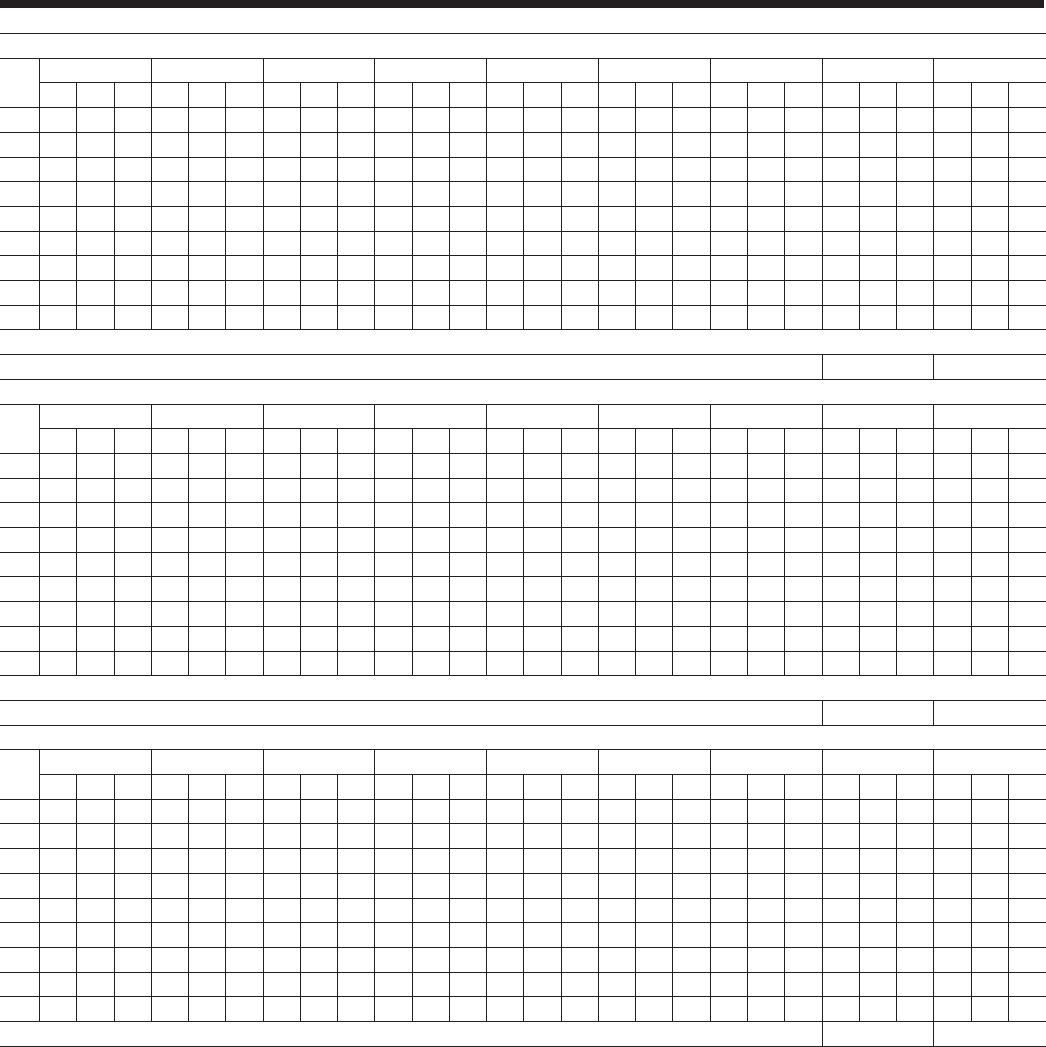
Standard Efciency Ratings – English - 460V/60Hz
NOTES:
1. kWi = Compressor Input Power
2. EER = Chiller EER (includes power from compressors, fans, and control panels 0.8 KWi)
3. LCWT = Leaving Chilled Water Temperature
4. Ratings based on 2.4 GPM cooler water per ton
5. Rated IAW ARI Standard 550/590-98
6. Certied IAW the ARI Water-Chilling Packages Using the Vapor Compression Cycle Certication Program,
which is based on ARI Standard 550/590.
MODEL: YCIV0157S/P S_IPLV = 13.2 P_IPLV = 14.5
AIR TEMPERATURE ON - CONDENSER (°F)
LCWT 75.0 80.0 85.0 90.0 95.0 100.0 105.0 110.0 115.0
(°F) TONS KW EER TONS KW EER TONS KW EER TONS KW EER TONS KW EER TONS KW EER TONS KW EER TONS KW EER TONS KW EER
40.0 149.1 131.5 12.3 148.0 141.8 11.4 146.7 152.6 10.6 145.4 164.1 9.8 143.9 176.0 9.1 142.2 189.4 8.4 138.9 202.0 7.7 133.5 212.3 7.1 127.9 223.1 6.5
42.0 153.7 132.5 12.6 152.5 142.6 11.7 151.2 153.5 10.9 149.8 165.0 10.1 148.2 177.0 9.3 146.5 190.5 8.6 142.7 202.7 7.9 137.0 213.2 7.3 131.3 223.9 6.6
44.0 158.3 133.5 12.9 157.1 143.6 12.0 155.7 154.4 11.1 154.3 165.9 10.3 152.6 177.9 9.6 150.8 191.5 8.8 146.5 203.4 8.1 140.6 214.0 7.4 134.7 224.7 6.8
45.0 160.7 134.0 13.1 159.4 144.1 12.1 158.1 154.9 11.3 156.5 166.4 10.4 154.9 178.4 9.7 153.0 192.0 8.9 148.4 203.7 8.2 142.5 214.3 7.5 136.5 225.0 6.9
46.0 163.1 134.6 13.2 161.8 144.6 12.3 160.4 155.4 11.4 158.8 166.9 10.6 157.1 178.9 9.8 155.2 192.5 9.0 150.4 204.0 8.3 144.3 214.7 7.6 138.3 225.4 6.9
48.0 167.9 135.7 13.5 166.6 145.7 12.6 165.1 156.5 11.7 163.5 167.9 10.8 161.7 180.0 10.0 159.7 193.6 9.3 154.3 204.7 8.5 148.1 215.4 7.8 141.8 226.3 7.1
50.0 172.8 137.0 13.8 171.4 146.9 12.8 169.9 157.7 11.9 168.2 169.0 11.1 166.4 181.1 10.3 164.3 194.7 9.5 158.2 205.4 8.7 151.9 216.1 7.9 145.5 227.0 7.3
52.0 177.8 138.4 14.0 176.4 148.2 13.1 174.8 158.9 12.2 173.1 170.2 11.3 171.2 182.3 10.5 168.6 195.6 9.7 162.2 206.1 8.9 155.8 216.8 8.1 149.2 227.6 7.4
55.0 185.4 140.6 14.4 184.0 150.3 13.5 182.3 160.8 12.6 180.5 172.1 11.7 178.5 184.1 10.8 175.0 196.8 10.0 168.3 207.2 9.2 161.7 217.8 8.4 151.7 218.9 7.8
MODEL: YCIV0177S/P S_IPLV = 13.0 P_IPLV = 14.8
AIR TEMPERATURE ON - CONDENSER (°F)
LCWT 75.0 80.0 85.0 90.0 95.0 100.0 105.0 110.0 115.0
(°F) TONS KW EER TONS KW EER TONS KW EER TONS KW EER TONS KW EER TONS KW EER TONS KW EER TONS KW EER TONS KW EER
40.0 165.7 144.7 12.6 164.2 156.2 11.6 162.4 168.5 10.7 160.5 181.2 9.9 158.4 194.4 9.1 154.6 205.6 8.5 149.9 214.6 7.9 143.5 222.1 7.3 130.1 211.5 6.9
42.0 170.9 145.7 12.9 169.3 157.3 11.9 167.5 169.5 11.0 165.5 182.3 10.1 163.3 195.6 9.4 159.1 206.2 8.7 154.0 215.3 8.1 147.5 222.8 7.5 131.8 207.2 7.2
44.0 176.1 146.8 13.2 174.6 158.3 12.2 172.8 170.6 11.3 170.7 183.5 10.4 168.4 196.8 9.6 163.8 206.8 8.9 158.3 215.8 8.3 151.5 223.4 7.7 133.6 203.1 7.4
45.0 178.8 147.5 13.3 177.2 158.9 12.3 175.4 171.1 11.4 173.3 184.0 10.5 171.0 197.5 9.7 166.1 207.1 9.0 160.5 216.0 8.4 153.5 223.7 7.8 134.5 200.9 7.5
46.0 181.5 148.2 13.5 179.9 159.5 12.5 178.1 171.7 11.5 175.9 184.6 10.7 173.5 197.8 9.9 168.5 207.3 9.2 162.6 216.2 8.5 155.6 224.0 7.9 135.3 198.6 7.7
48.0 186.9 149.5 13.8 185.4 160.8 12.8 183.5 173.0 11.8 181.3 185.9 10.9 178.4 198.3 10.1 173.3 207.9 9.4 167.0 216.6 8.7 159.8 224.5 8.1 137.0 194.3 7.9
50.0 192.4 151.0 14.0 190.8 162.2 13.0 189.0 174.3 12.1 186.7 187.2 11.2 183.4 198.8 10.4 178.2 208.4 9.6 171.5 217.0 8.9 162.8 221.6 8.3 138.3 189.5 8.2
52.0 198.0 152.6 14.3 196.4 163.7 13.3 194.5 175.8 12.3 192.2 188.6 11.4 188.5 199.4 10.6 183.1 209.0 9.9 176.0 217.4 9.1 164.7 216.6 8.6 139.6 184.9 8.4
55.0 206.4 155.2 14.7 204.9 166.1 13.7 202.9 178.1 12.7 200.6 190.9 11.8 196.2 200.4 11.0 190.7 209.9 10.2 182.9 217.9 9.5 167.5 209.1 9.0 141.5 178.2 8.9
MODEL: YCIV0187S/P S_IPLV = 13.1 P_IPLV = 14.9
AIR TEMPERATURE ON - CONDENSER (°F)
LCWT 75.0 80.0 85.0 90.0 95.0 100.0 105.0 110.0 115.0
(°F) TONS KW EER TONS KW EER TONS KW EER TONS KW EER TONS KW EER TONS KW EER TONS KW EER TONS KW EER TONS KW EER
40.0 180.3 156.2 12.6 178.8 168.2 11.7 177.1 181.1 10.8 175.3 194.7 10.0 173.4 208.9 9.3 171.1 224.9 8.6 166.1 236.3 7.9 159.4 245.3 7.3 152.8 253.9 6.8
42.0 185.9 157.4 12.9 184.4 169.4 12.0 182.6 182.3 11.1 180.7 195.8 10.3 178.7 210.1 9.5 176.4 226.2 8.8 170.5 236.8 8.1 163.7 245.8 7.5 156.9 254.5 7.0
44.0 191.7 158.8 13.2 190.0 170.7 12.3 188.2 183.5 11.4 186.3 197.1 10.5 184.2 211.3 9.8 181.7 227.5 9.0 175.1 237.3 8.3 168.0 246.3 7.7 160.9 255.1 7.1
45.0 194.6 159.6 13.4 192.9 171.4 12.4 191.1 184.2 11.5 189.1 197.7 10.7 186.9 212.0 9.9 184.3 228.0 9.1 177.4 237.5 8.4 170.2 246.5 7.8 163.0 255.4 7.2
46.0 197.5 160.4 13.5 195.8 172.1 12.5 193.9 184.9 11.6 191.9 198.4 10.8 189.7 212.7 10.0 186.9 228.3 9.2 179.7 237.7 8.5 172.5 246.7 7.9 165.1 255.6 7.3
48.0 203.5 162.1 13.8 201.7 173.7 12.8 199.8 186.3 11.9 197.6 199.8 11.0 195.3 214.1 10.2 191.9 228.9 9.4 184.5 238.1 8.7 177.0 247.1 8.1 169.5 256.1 7.5
50.0 209.5 163.8 14.1 207.7 175.3 13.1 205.7 187.8 12.2 203.5 201.3 11.3 201.1 215.5 10.5 196.8 229.3 9.7 189.3 238.4 9.0 181.6 247.5 8.3 171.2 249.6 7.8
52.0 215.7 165.8 14.3 213.8 177.1 13.3 211.7 189.5 12.4 209.4 202.8 11.5 206.9 217.0 10.7 201.9 229.8 9.9 194.1 238.9 9.2 186.3 247.9 8.5 172.9 242.8 8.0
55.0 225.2 169.0 14.7 223.2 180.0 13.7 221.0 192.2 12.8 218.6 205.4 11.9 215.9 219.6 11.0 209.6 230.6 10.2 201.5 239.5 9.5 193.4 248.5 8.8 175.7 233.3 8.5

JOHNSON CONTROLS
FORM 201.23-EG1 (1007)
17
NOTES:
1. kWi = Compressor Input Power
2. EER = Chiller EER (includes power from compressors, fans, and control panels 0.8 KWi)
3. LCWT = Leaving Chilled Water Temperature
4. Ratings based on 2.4 GPM cooler water per ton
5. Rated IAW ARI Standard 550/590-98
6. Certied IAW the ARI Water-Chilling Packages Using the Vapor Compression Cycle Certication Program,
which is based on ARI Standard 550/590.
MODEL: YCIV0207S/P S_IPLV = 13.2 P_IPLV = 14.7
AIR TEMPERATURE ON - CONDENSER (°F)
LCWT 75.0 80.0 85.0 90.0 95.0 100.0 105.0 110.0 115.0
(°F) TONS KW EER TONS KW EER TONS KW EER TONS KW EER TONS KW EER TONS KW EER TONS KW EER TONS KW EER TONS KW EER
40.0 194.8 168.3 12.7 192.9 182.2 11.7 190.9 197.4 10.8 188.7 213.5 9.9 186.4 230.3 9.1 181.9 244.1 8.4 176.0 254.8 7.8 168.7 261.6 7.3 149.2 238.0 7.1
42.0 200.9 169.6 13.1 199.0 183.3 12.0 196.8 198.2 11.1 194.6 214.3 10.2 192.1 231.2 9.4 187.1 244.4 8.7 180.7 254.7 8.0 173.2 261.8 7.5 151.0 232.8 7.3
44.0 207.2 171.2 13.3 205.2 184.5 12.3 202.9 199.3 11.4 200.5 215.2 10.4 197.6 231.3 9.6 192.4 244.6 8.9 185.4 254.4 8.3 177.7 261.8 7.7 152.8 227.3 7.6
45.0 210.4 172.0 13.5 208.3 185.2 12.5 206.0 199.8 11.5 203.6 215.7 10.6 200.4 231.4 9.8 195.0 244.7 9.0 187.9 254.3 8.4 180.0 261.8 7.8 153.7 224.5 7.7
46.0 213.6 173.0 13.6 211.5 185.9 12.6 209.1 200.4 11.6 206.6 216.3 10.7 203.2 231.5 9.9 197.8 244.8 9.1 190.3 254.1 8.5 182.0 260.9 7.9 154.6 221.8 7.8
48.0 220.2 175.1 13.9 218.0 187.6 12.9 215.5 201.8 11.9 212.9 217.5 11.0 208.9 231.7 10.2 203.3 245.0 9.4 195.3 253.7 8.7 184.0 254.4 8.2 156.2 216.6 8.1
50.0 226.9 177.4 14.1 224.5 189.6 13.2 222.0 203.5 12.2 219.2 218.9 11.2 214.8 232.1 10.4 208.8 245.0 9.6 200.4 253.2 9.0 186.1 247.7 8.5 157.8 211.5 8.4
52.0 233.7 180.1 14.4 231.3 191.8 13.4 228.6 205.3 12.4 225.7 220.5 11.5 220.7 232.5 10.7 214.2 244.6 9.9 205.5 252.8 9.2 188.1 241.3 8.8 159.3 206.5 8.6
55.0 244.3 184.7 14.7 241.7 195.6 13.8 238.8 208.5 12.8 235.4 222.5 11.9 229.8 233.6 11.1 222.4 244.2 10.3 213.4 252.2 9.6 191.0 232.5 9.3 161.6 199.2 9.0
MODEL: YCIV0227S/P S_IPLV = 12.9 P_IPLV = 14.7
AIR TEMPERATURE ON - CONDENSER (°F)
LCWT 75.0 80.0 85.0 90.0 95.0 100.0 105.0 110.0 115.0
(°F) TONS KW EER TONS KW EER TONS KW EER TONS KW EER TONS KW EER TONS KW EER TONS KW EER TONS KW EER TONS KW EER
40.0 211.3 180.4 12.9 209.4 194.3 11.9 207.3 209.2 11.0 205.1 224.8 10.2 202.7 241.3 9.4 199.9 259.8 8.7 193.1 269.8 8.1 185.3 277.1 7.6 177.5 283.8 7.1
42.0 218.0 182.0 13.2 216.0 195.7 12.2 213.8 210.5 11.3 211.4 226.2 10.4 208.9 242.7 9.7 206.0 261.3 8.9 198.2 270.0 8.3 190.2 277.4 7.8 182.1 284.2 7.3
44.0 224.9 183.7 13.5 222.7 197.3 12.5 220.4 212.0 11.6 218.0 227.7 10.7 215.3 244.2 9.9 211.9 262.1 9.1 203.5 270.1 8.5 195.2 277.6 8.0 186.9 284.5 7.4
45.0 228.3 184.7 13.6 226.2 198.2 12.6 223.8 212.8 11.7 221.3 228.5 10.8 218.5 245.1 10.0 214.7 262.2 9.2 206.2 270.2 8.6 197.7 277.7 8.1 189.3 284.6 7.5
46.0 231.8 185.7 13.7 229.6 199.1 12.8 227.2 213.7 11.8 224.6 229.3 11.0 221.8 245.9 10.1 217.5 262.2 9.4 208.9 270.2 8.7 200.3 277.7 8.2 191.8 284.7 7.6
48.0 238.9 187.8 14.0 236.7 201.1 13.0 234.2 215.4 12.1 231.4 231.0 11.2 228.5 247.5 10.4 223.2 262.4 9.6 214.4 270.3 9.0 205.6 277.8 8.4 195.3 281.4 7.9
50.0 246.2 190.1 14.3 243.8 203.1 13.3 241.2 217.4 12.4 238.4 232.8 11.5 235.3 249.2 10.6 229.0 262.5 9.8 219.9 270.4 9.2 210.9 277.8 8.6 197.2 274.6 8.1
52.0 253.6 192.7 14.5 251.2 205.4 13.6 248.5 219.5 12.6 245.5 234.9 11.7 242.3 251.2 10.8 234.9 262.7 10.1 225.6 270.4 9.4 216.3 277.8 8.8 199.3 267.5 8.4
55.0 264.9 196.7 14.9 262.4 209.2 13.9 259.5 223.0 13.0 256.4 238.2 12.1 253.1 254.3 11.2 243.9 263.0 10.5 234.3 270.6 9.8 224.6 277.9 9.1 202.2 256.3 8.9
MODEL: YCIV0247S/P S_IPLV = 12.7 P_IPLV = 14.8
AIR TEMPERATURE ON - CONDENSER (°F)
LCWT 75.0 80.0 85.0 90.0 95.0 100.0 105.0 110.0 115.0
(°F) TONS KW EER TONS KW EER TONS KW EER TONS KW EER TONS KW EER TONS KW EER TONS KW EER TONS KW EER TONS KW EER
40.0 231.8 198.8 12.8 229.8 213.8 11.9 227.6 229.8 11.0 225.2 246.7 10.2 222.7 264.4 9.4 219.7 284.3 8.7 213.4 297.6 8.1 206.3 308.8 7.6 199.1 319.5 7.1
42.0 239.1 200.6 13.1 236.9 215.6 12.1 234.6 231.5 11.3 232.1 248.4 10.4 229.5 266.1 9.7 226.4 286.1 8.9 219.3 298.4 8.3 211.9 309.5 7.8 204.4 320.4 7.2
44.0 246.5 202.6 13.4 244.3 217.4 12.4 241.9 233.3 11.5 239.2 250.2 10.7 236.4 268.0 9.9 232.9 287.5 9.1 225.3 299.1 8.5 217.6 310.3 7.9 208.9 318.7 7.4
45.0 250.2 203.7 13.5 248.0 218.4 12.6 245.5 234.3 11.7 242.8 251.2 10.8 239.9 268.9 10.0 236.1 287.8 9.2 228.3 299.4 8.6 220.5 310.7 8.0 210.1 315.4 7.6
46.0 254.0 204.8 13.7 251.7 219.4 12.7 249.2 235.2 11.8 246.5 252.1 10.9 243.5 269.9 10.1 239.2 288.2 9.4 231.4 299.7 8.7 223.4 311.1 8.1 211.3 311.8 7.7
48.0 261.7 207.1 13.9 259.4 221.6 13.0 256.7 237.3 12.0 253.9 254.1 11.2 250.8 271.9 10.4 245.7 288.9 9.6 237.6 300.4 8.9 229.4 311.7 8.3 213.6 304.4 7.9
50.0 269.6 209.5 14.2 267.1 223.9 13.2 264.4 239.5 12.3 261.4 256.2 11.4 258.2 274.0 10.6 252.2 289.6 9.8 243.9 301.1 9.2 235.5 312.4 8.5 215.8 296.4 8.2
52.0 277.6 212.2 14.4 275.1 226.4 13.5 272.2 241.9 12.5 269.1 258.5 11.7 265.8 276.2 10.8 258.9 290.4 10.1 250.3 301.8 9.4 241.7 313.0 8.8 217.8 288.1 8.5
55.0 289.9 215.9 14.8 287.2 230.3 13.9 284.2 245.7 12.9 281.0 262.2 12.0 277.4 279.7 11.2 269.0 291.7 10.4 260.2 302.9 9.7 251.2 314.1 9.1 220.5 275.9 9.0
JOHNSON CONTROLS18
Standard Efciency Ratings – English - 460V/60Hz
NOTES:
1. kW = Compressor Input Power
2. EER = Chiller EER (includes power from compressors, fans, and control panels 0.8 KWi)
3. LCWT = Leaving Chilled Water Temperature
4. Ratings based on 2.4 GPM cooler water per ton
5. Rated IAW ARI Standard 550/590-98
MODEL: YCIV0267S/P S_IPLV = 12.3 P_IPLV = 14.9
AIR TEMPERATURE ON - CONDENSER (°F)
LCWT 75.0 80.0 85.0 90.0 95.0 100.0 105.0 110.0 115.0
(°F) TONS KW EER TONS KW EER TONS KW EER TONS KW EER TONS KW EER TONS KW EER TONS KW EER TONS KW EER TONS KW EER
40.0 252.3 217.0 12.8 250.2 233.1 11.9 247.9 250.3 11.0 245.4 268.3 10.2 242.7 287.2 9.5 239.6 308.5 8.7 233.9 325.1 8.1 227.3 340.0 7.6 220.8 354.7 7.1
42.0 260.2 219.0 13.1 258.0 235.2 12.1 255.6 252.2 11.3 252.9 270.4 10.4 250.1 289.2 9.7 246.8 310.7 9.0 240.4 326.4 8.3 233.6 341.3 7.8 226.8 356.2 7.2
44.0 268.2 221.2 13.3 265.9 237.3 12.4 263.3 254.3 11.5 260.6 272.4 10.7 257.6 291.5 9.9 254.0 312.6 9.2 247.1 327.6 8.5 240.1 342.6 7.9 231.8 354.5 7.4
45.0 272.2 222.5 13.5 269.9 238.4 12.5 267.3 255.5 11.6 264.5 273.6 10.8 261.4 292.5 10.0 257.5 313.2 9.3 250.5 328.3 8.6 243.4 343.2 8.0 233.0 350.2 7.5
46.0 276.3 223.6 13.6 273.9 239.5 12.7 271.3 256.6 11.8 268.4 274.7 10.9 265.3 293.6 10.1 261.0 313.9 9.4 253.9 328.9 8.7 246.7 344.0 8.1 234.2 345.8 7.7
48.0 284.6 226.1 13.9 282.1 242.0 12.9 279.4 258.9 12.0 276.4 276.9 11.2 273.1 296.0 10.4 268.2 315.2 9.6 260.9 330.1 8.9 253.4 345.2 8.3 236.7 336.8 8.0
50.0 293.1 228.7 14.1 290.5 244.5 13.2 287.7 261.3 12.3 284.6 279.3 11.4 281.1 298.4 10.6 275.5 316.5 9.8 267.9 331.5 9.1 260.2 346.5 8.5 239.1 327.9 8.2
52.0 301.7 231.6 14.4 299.1 247.1 13.4 296.1 264.0 12.5 292.9 281.8 11.6 289.3 300.9 10.8 282.9 317.8 10.0 275.1 332.8 9.4 267.2 347.8 8.7 241.5 319.2 8.5
55.0 315.0 234.9 14.8 312.1 251.1 13.8 309.0 268.1 12.9 305.6 286.0 12.0 301.9 304.8 11.1 294.2 320.1 10.4 286.1 334.8 9.7 277.9 349.8 9.0 244.8 307.1 9.0
MODEL: YCIV0287S/P S_IPLV = 13.0 P_IPLV = 14.7
AIR TEMPERATURE ON - CONDENSER (°F)
LCWT 75.0 80.0 85.0 90.0 95.0 100.0 105.0 110.0 115.0
(°F) TONS KW EER TONS KW EER TONS KW EER TONS KW EER TONS KW EER TONS KW EER TONS KW EER TONS KW EER TONS KW EER
40.0 268.2 228.0 12.9 265.7 246.5 11.9 262.9 266.4 10.9 259.9 287.2 10.1 256.7 308.8 9.3 251.3 328.6 8.6 244.3 345.3 8.0 234.1 356.5 7.4 209.5 332.8 7.1
42.0 276.6 229.7 13.2 274.1 248.0 12.2 271.2 267.7 11.2 268.0 288.6 10.4 264.6 310.3 9.6 258.7 329.7 8.8 250.9 345.8 8.2 240.4 357.3 7.6 211.9 325.4 7.3
44.0 285.2 231.6 13.5 282.6 249.6 12.5 279.6 269.2 11.5 276.3 290.0 10.6 272.7 311.7 9.8 266.3 330.6 9.1 257.7 346.2 8.4 246.8 357.8 7.8 214.8 318.9 7.6
45.0 289.6 232.6 13.7 286.9 250.5 12.6 283.9 270.0 11.7 280.6 290.8 10.8 276.7 312.1 9.9 270.2 331.0 9.2 261.2 346.3 8.5 250.0 358.2 7.9 216.1 315.4 7.7
46.0 294.0 233.7 13.8 291.3 251.4 12.8 288.3 270.8 11.8 284.9 291.6 10.9 280.7 312.5 10.1 274.1 331.5 9.3 264.7 346.4 8.6 253.4 358.4 8.0 217.5 311.9 7.8
48.0 303.0 236.1 14.1 300.2 253.5 13.1 297.1 272.7 12.1 293.5 293.3 11.2 288.9 313.4 10.3 282.0 332.3 9.6 271.7 346.6 8.9 258.9 355.8 8.2 220.1 304.8 8.1
50.0 312.1 238.8 14.4 309.3 255.8 13.4 306.0 274.7 12.4 302.4 295.2 11.4 297.2 314.4 10.6 290.1 333.3 9.8 278.9 346.7 9.1 261.9 347.2 8.5 222.4 297.7 8.4
52.0 321.4 241.7 14.6 318.5 258.5 13.6 315.2 277.1 12.7 311.4 297.4 11.7 305.7 315.5 10.9 298.2 334.0 10.1 286.2 346.8 9.3 264.9 338.8 8.8 224.6 290.7 8.6
55.0 335.7 246.8 15.0 332.7 262.8 14.0 329.2 280.9 13.0 325.3 300.9 12.1 318.6 317.4 11.3 310.1 334.5 10.4 297.4 346.9 9.7 269.4 327.1 9.3 227.7 280.5 9.0
MODEL: YCIV0307S/P S_IPLV = 12.6 P_IPLV = 14.6
AIR TEMPERATURE ON - CONDENSER (°F)
LCWT 75.0 80.0 85.0 90.0 95.0 100.0 105.0 110.0 115.0
(°F) TONS KW EER TONS KW EER TONS KW EER TONS KW EER TONS KW EER TONS KW EER TONS KW EER TONS KW EER TONS KW EER
40.0 298.0 251.5 13.0 295.2 272.2 12.0 292.2 294.8 11.0 289.0 318.9 10.1 285.6 344.0 9.3 279.8 366.7 8.6 271.4 384.3 8.0 260.3 394.8 7.5 229.5 358.3 7.2
42.0 307.4 253.3 13.3 304.5 273.7 12.3 301.3 296.0 11.3 297.9 320.0 10.4 294.3 345.1 9.6 287.9 367.5 8.8 278.6 384.1 8.2 267.2 395.1 7.7 232.1 349.9 7.5
44.0 317.0 255.6 13.6 314.0 275.5 12.6 310.6 297.5 11.6 307.1 321.3 10.7 302.9 345.6 9.8 296.2 368.1 9.1 286.0 383.8 8.4 274.2 395.1 7.9 235.1 342.1 7.7
45.0 321.9 256.9 13.8 318.8 276.5 12.8 315.4 298.3 11.8 311.7 322.0 10.8 307.3 345.8 10.0 300.4 368.5 9.2 289.7 383.6 8.5 277.7 395.0 8.0 236.5 338.1 7.8
46.0 326.9 258.2 13.9 323.7 277.6 12.9 320.2 299.2 11.9 316.4 322.7 11.0 311.7 346.1 10.1 304.7 368.8 9.3 293.5 383.3 8.7 280.1 392.1 8.1 237.9 334.0 8.0
48.0 336.9 261.3 14.2 333.6 280.0 13.2 329.9 301.2 12.2 326.0 324.5 11.2 320.6 346.9 10.4 313.4 369.4 9.6 301.2 382.7 8.9 283.2 382.4 8.4 240.7 326.4 8.3
50.0 347.2 264.7 14.5 343.7 282.9 13.5 339.9 303.5 12.5 335.8 326.6 11.5 329.8 347.7 10.7 322.0 369.6 9.8 309.0 382.1 9.1 286.4 372.5 8.7 243.0 318.5 8.5
52.0 357.7 268.6 14.7 354.1 286.1 13.7 350.1 306.2 12.7 345.8 328.8 11.8 339.1 348.7 10.9 330.3 369.0 10.1 317.0 381.4 9.4 289.6 362.8 9.0 245.3 311.0 8.8
55.0 373.9 275.3 15.0 370.0 291.6 14.1 365.8 310.9 13.1 360.8 332.0 12.2 353.5 350.8 11.3 343.0 368.4 10.5 329.2 380.5 9.8 294.2 349.6 9.5 248.8 300.0 9.2
JOHNSON CONTROLS
FORM 201.23-EG1 (1007)
19
NOTES:
1. kW = Compressor Input Power
2. EER = Chiller EER (includes power from compressors, fans, and control panels 0.8 KWi)
3. LCWT = Leaving Chilled Water Temperature
4. Ratings based on 2.4 GPM cooler water per ton
5. Rated IAW ARI Standard 550/590-98
MODEL: YCIV0357S/P S_IPLV = 13.5 P_IPLV = 15.1
AIR TEMPERATURE ON - CONDENSER (°F)
LCWT 75.0 80.0 85.0 90.0 95.0 100.0 105.0 110.0 115.0
(°F) TONS KW EER TONS KW EER TONS KW EER TONS KW EER TONS KW EER TONS KW EER TONS KW EER TONS KW EER TONS KW EER
40.0 336.3 288.0 12.8 333.4 309.9 11.9 330.1 333.5 11.0 326.6 358.2 10.2 322.9 384.1 9.4 318.6 413.2 8.7 309.3 432.1 8.1 298.3 446.9 7.6 287.4 460.8 7.1
42.0 346.9 290.6 13.1 343.8 312.4 12.2 340.4 335.8 11.3 336.7 360.5 10.4 332.8 386.5 9.7 328.3 415.8 8.9 317.7 433.0 8.3 306.3 447.8 7.7 295.0 462.0 7.2
44.0 357.7 293.3 13.4 354.5 315.0 12.4 350.9 338.3 11.5 347.1 363.1 10.7 342.9 389.0 9.9 338.1 418.1 9.1 326.3 433.8 8.5 314.6 448.7 7.9 302.8 463.1 7.4
45.0 363.2 294.8 13.6 359.9 316.4 12.6 356.3 339.6 11.7 352.3 364.3 10.8 348.1 390.4 10.0 342.7 418.5 9.2 330.7 434.1 8.6 318.7 449.1 8.0 304.8 459.0 7.5
46.0 368.8 296.5 13.7 365.4 317.8 12.7 361.7 341.0 11.8 357.6 365.7 10.9 353.3 391.7 10.1 347.2 418.9 9.3 335.1 434.5 8.7 322.9 449.5 8.1 306.7 454.4 7.6
48.0 380.1 299.7 14.0 376.6 320.9 13.0 372.7 343.8 12.1 368.5 368.5 11.2 363.9 394.5 10.4 356.5 419.7 9.6 344.0 435.2 8.9 331.5 450.3 8.3 310.2 444.4 7.9
50.0 391.6 303.2 14.2 387.9 324.2 13.3 383.9 347.0 12.3 379.5 371.4 11.4 374.8 397.4 10.6 366.0 420.5 9.8 353.1 435.9 9.2 340.2 450.9 8.5 313.5 433.3 8.2
52.0 403.4 307.0 14.5 399.6 327.7 13.5 395.4 350.3 12.6 390.8 374.5 11.7 385.9 400.4 10.8 375.7 421.3 10.1 362.4 436.7 9.4 349.2 451.6 8.8 316.5 421.3 8.5
55.0 421.3 312.6 14.9 417.2 333.5 13.9 412.9 355.6 13.0 408.1 379.9 12.0 402.9 405.5 11.2 390.4 422.8 10.4 376.6 437.8 9.7 362.8 452.6 9.1 320.4 402.9 8.9
MODEL: YCIV0397S/P S_IPLV = 13.2 P_IPLV = 15.2
AIR TEMPERATURE ON - CONDENSER (°F)
LCWT 75.0 80.0 85.0 90.0 95.0 100.0 105.0 110.0 115.0
(°F) TONS KW EER TONS KW EER TONS KW EER TONS KW EER TONS KW EER TONS KW EER TONS KW EER TONS KW EER TONS KW EER
40.0 377.3 324.5 12.8 374.2 348.7 11.9 370.7 374.4 11.0 366.9 401.4 10.2 362.9 429.8 9.5 358.2 461.7 8.7 350.0 486.9 8.1 340.3 509.2 7.6 330.6 531.2 7.1
42.0 389.1 327.5 13.1 385.8 351.6 12.1 382.2 377.3 11.3 378.2 404.5 10.4 374.0 432.8 9.7 369.0 464.8 8.9 359.8 488.8 8.3 349.7 511.2 7.8 339.5 533.5 7.2
44.0 401.2 330.7 13.3 397.8 354.8 12.4 394.0 380.3 11.5 389.8 407.5 10.7 385.3 436.0 9.9 380.1 468.1 9.2 369.8 490.8 8.5 359.3 513.2 7.9 348.7 535.6 7.4
45.0 407.4 332.4 13.5 403.8 356.4 12.5 399.9 382.1 11.6 395.7 409.1 10.8 391.0 437.7 10.0 385.4 469.1 9.3 374.9 491.7 8.6 364.2 514.2 8.0 350.8 530.1 7.5
46.0 413.5 334.3 13.6 410.0 358.1 12.7 406.0 383.7 11.8 401.6 410.9 10.9 396.9 439.3 10.1 390.7 470.2 9.4 380.0 492.6 8.7 369.2 515.1 8.1 352.7 523.5 7.6
48.0 426.1 337.9 13.9 422.4 361.6 12.9 418.2 387.1 12.0 413.7 414.2 11.2 408.7 442.9 10.4 401.5 472.0 9.6 390.5 494.5 8.9 379.2 517.2 8.3 356.3 510.3 7.9
50.0 439.0 341.8 14.2 435.1 365.5 13.2 430.8 390.7 12.3 426.0 417.8 11.4 420.9 446.4 10.6 412.6 474.0 9.8 401.1 496.5 9.1 389.5 519.0 8.5 360.0 496.9 8.2
52.0 452.0 346.1 14.4 448.0 369.4 13.5 443.5 394.7 12.5 438.6 421.5 11.7 433.2 450.1 10.8 423.8 476.0 10.0 411.9 498.5 9.3 400.0 521.0 8.7 363.7 483.8 8.5
55.0 471.7 350.8 14.9 467.3 375.7 13.8 462.8 400.7 12.9 457.8 427.6 12.0 452.3 455.9 11.2 441.0 479.4 10.4 428.7 501.5 9.7 416.1 524.0 9.0 368.8 465.1 8.9
MODEL: YCIV0157E/V E_IPLV = 13.5 V_IPLV = 14.6

JOHNSON CONTROLS20
High Efciency Ratings – English - 460V/60Hz
AIR TEMPERATURE ON - CONDENSER (°F)
LCWT 75.0 80.0 85.0 90.0 95.0 100.0 105.0 110.0 115.0
(°F) TONS KW EER TONS KW EER TONS KW EER TONS KW EER TONS KW EER TONS KW EER TONS KW EER TONS KW EER TONS KW EER
40.0 148.1 121.7 13.1 146.8 130.5 12.2 145.2 139.6 11.4 143.4 149.1 10.6 141.4 158.9 9.8 139.1 170.1 9.1 136.1 181.5 8.4 130.1 190.6 7.7 124.0 200.1 7.0
42.0 152.7 122.8 13.4 151.5 131.6 12.5 149.9 140.8 11.7 148.1 150.3 10.9 146.1 160.2 10.1 143.7 171.4 9.3 140.1 182.5 8.6 133.9 191.5 7.8 127.6 200.9 7.1
44.0 157.4 123.9 13.8 156.2 132.8 12.8 154.7 142.0 11.9 152.8 151.6 11.1 150.8 161.6 10.3 148.3 172.8 9.6 144.2 183.5 8.8 137.7 192.5 8.0 131.3 201.8 7.3
45.0 159.8 124.4 13.9 158.6 133.4 13.0 157.1 142.6 12.1 155.2 152.2 11.2 153.2 162.2 10.5 150.7 173.5 9.7 146.3 184.0 8.9 139.7 193.0 8.1 133.2 202.2 7.4
46.0 162.2 125.1 14.1 161.0 134.0 13.1 159.5 143.2 12.2 157.7 152.9 11.4 155.6 162.9 10.6 153.0 174.2 9.8 148.3 184.5 9.0 141.7 193.5 8.2 135.1 202.6 7.5
48.0 167.0 126.2 14.4 165.9 135.2 13.4 164.4 144.6 12.5 162.6 154.2 11.6 160.4 164.3 10.8 157.9 175.6 10.0 152.5 185.5 9.2 145.7 194.5 8.4 138.9 203.6 7.7
50.0 171.9 127.3 14.7 170.8 136.4 13.7 169.3 145.9 12.8 167.5 155.7 11.9 165.4 165.8 11.1 162.7 177.2 10.2 156.7 186.5 9.4 149.8 195.5 8.6 142.7 204.7 7.9
52.0 176.8 128.5 15.0 175.8 137.7 14.0 174.4 147.2 13.0 172.6 157.1 12.1 170.4 167.2 11.3 167.7 178.7 10.5 161.0 187.6 9.6 153.9 196.5 8.8 146.7 205.7 8.0
55.0 184.4 130.2 15.4 183.5 139.6 14.4 182.1 149.2 13.4 180.3 159.2 12.5 178.1 169.5 11.7 174.8 180.6 10.8 167.5 189.3 9.9 160.2 198.1 9.1 152.8 207.2 8.3
MODEL: YCIV0177E/V E_IPLV = 13.5 V_IPLV = 14.7
AIR TEMPERATURE ON - CONDENSER (°F)
LCWT 75.0 80.0 85.0 90.0 95.0 100.0 105.0 110.0 115.0
(°F) TONS KW EER TONS KW EER TONS KW EER TONS KW EER TONS KW EER TONS KW EER TONS KW EER TONS KW EER TONS KW EER
40.0 157.1 131.4 13.0 156.3 137.3 12.3 155.0 147.6 11.4 153.5 158.6 10.6 151.9 170.1 9.8 150.0 183.2 9.1 147.0 195.7 8.4 142.2 207.3 7.7 136.2 217.9 7.0
42.0 162.5 128.7 13.6 161.3 138.3 12.6 159.9 148.5 11.7 158.3 159.4 10.9 156.6 171.0 10.1 154.7 184.1 9.3 151.2 196.5 8.6 146.1 207.9 7.9 139.9 218.6 7.2
44.0 167.6 129.9 13.9 166.3 139.3 12.9 164.8 149.5 12.0 163.2 160.4 11.2 161.5 171.9 10.4 159.4 185.0 9.6 155.6 197.2 8.8 150.1 208.5 8.1 143.6 219.3 7.4
45.0 170.2 130.5 14.0 168.9 139.9 13.1 167.4 150.1 12.2 165.7 160.9 11.3 163.9 172.4 10.5 161.8 185.5 9.7 157.8 197.6 8.9 152.1 208.8 8.2 145.5 219.6 7.4
46.0 172.8 131.2 14.2 171.4 140.5 13.2 169.9 150.6 12.3 168.2 161.4 11.4 166.4 172.9 10.6 164.3 186.0 9.8 160.0 198.0 9.0 154.1 209.1 8.3 147.5 219.9 7.5
48.0 178.0 132.6 14.5 176.7 141.8 13.5 175.1 151.8 12.6 173.4 162.5 11.7 171.5 174.0 10.9 169.1 186.9 10.0 164.6 198.7 9.2 158.3 209.7 8.4 151.4 220.5 7.7
50.0 183.4 134.1 14.8 182.0 143.1 13.8 180.4 153.0 12.9 178.6 163.7 12.0 176.6 175.1 11.1 173.9 187.8 10.3 169.2 199.6 9.5 162.5 210.3 8.7 154.4 218.2 7.9
52.0 188.9 135.7 15.0 187.5 144.6 14.1 185.8 154.4 13.2 183.9 165.0 12.3 181.9 176.3 11.4 178.7 188.7 10.5 173.9 200.5 9.7 166.8 210.9 8.9 156.2 212.7 8.2
55.0 197.4 138.4 15.4 195.8 147.0 14.5 194.1 156.6 13.6 192.2 167.0 12.7 190.0 178.3 11.8 186.2 190.2 10.9 180.8 201.5 10.0 173.3 211.9 9.2 158.8 204.8 8.7
MODEL: YCIV0187E/V E_IPLV = 13.2 V_IPLV = 15.1
AIR TEMPERATURE ON - CONDENSER (°F)
LCWT 75.0 80.0 85.0 90.0 95.0 100.0 105.0 110.0 115.0
(°F) TONS KW EER TONS KW EER TONS KW EER TONS KW EER TONS KW EER TONS KW EER TONS KW EER TONS KW EER TONS KW EER
40.0 174.7 145.0 13.1 173.7 152.7 12.3 172.2 164.6 11.4 170.5 177.2 10.5 168.7 190.5 9.8 166.5 205.3 9.0 163.0 217.8 8.3 158.0 227.5 7.8 151.4 235.7 7.2
42.0 180.2 146.1 13.4 179.2 153.6 12.6 177.7 165.4 11.7 175.9 178.0 10.8 174.0 191.3 10.0 171.7 206.3 9.2 167.8 218.3 8.6 162.4 227.9 8.0 155.6 236.2 7.4
44.0 185.8 147.5 13.7 184.8 154.7 12.9 183.2 166.4 12.0 181.4 178.9 11.1 179.4 192.1 10.3 177.0 207.2 9.5 172.7 218.7 8.8 166.9 228.3 8.2 159.9 236.6 7.6
45.0 189.0 144.5 14.1 187.6 155.3 13.1 186.0 166.9 12.2 184.2 179.4 11.3 182.1 192.6 10.4 179.7 207.7 9.6 175.2 218.8 8.9 169.2 228.4 8.3 162.1 236.8 7.7
46.0 191.8 145.2 14.2 190.4 155.8 13.2 188.8 167.4 12.3 187.0 179.9 11.4 184.9 193.1 10.6 182.5 208.1 9.7 177.7 219.0 9.0 171.5 228.5 8.4 164.3 237.0 7.8
48.0 197.5 146.7 14.5 196.2 157.1 13.5 194.5 168.6 12.6 192.6 180.9 11.7 190.5 194.1 10.8 188.0 209.1 10.0 182.8 219.4 9.3 176.2 228.7 8.6 168.7 237.3 8.0
50.0 203.4 148.3 14.8 202.0 158.6 13.8 200.3 169.8 12.9 198.4 182.1 12.0 196.2 195.2 11.1 193.3 209.5 10.2 188.0 219.7 9.5 181.0 228.9 8.8 173.3 237.5 8.2
52.0 209.3 150.0 15.1 207.9 160.1 14.1 206.2 171.3 13.2 204.2 183.4 12.2 202.0 196.4 11.4 198.6 210.0 10.5 193.2 220.1 9.8 185.8 229.1 9.1 177.4 236.6 8.4
55.0 218.4 153.0 15.4 217.0 162.7 14.5 215.3 173.6 13.6 213.2 185.5 12.6 210.9 198.4 11.8 206.8 210.7 10.9 201.2 220.7 10.2 193.2 229.4 9.4 180.3 227.5 8.9
MODEL: YCIV0197E/V E_IPLV = 12.9 V_IPLV = 15.0
NOTES:
1. kW = Compressor Input Power
2. EER = Chiller EER (includes power from compressors, fans, and control panels 0.8 KWi)
3. LCWT = Leaving Chilled Water Temperature
4. Ratings based on 2.4 GPM cooler water per ton
5. Rated IAW ARI Standard 550/590-98
6. Certied IAW the ARI Water-Chilling Packages Using the Vapor Compression Cycle Certication Program,
which is based on ARI Standard 550/590.

JOHNSON CONTROLS
FORM 201.23-EG1 (1007)
21
AIR TEMPERATURE ON - CONDENSER (°F)
LCWT 75.0 80.0 85.0 90.0 95.0 100.0 105.0 110.0 115.0
(°F) TONS KW EER TONS KW EER TONS KW EER TONS KW EER TONS KW EER TONS KW EER TONS KW EER TONS KW EER TONS KW EER
40.0 189.8 153.1 13.4 188.2 165.6 12.4 186.4 179.5 11.4 184.5 194.4 10.5 182.5 210.2 9.6 180.1 227.8 8.8 176.4 243.2 8.1 169.4 250.7 7.6 162.4 257.3 7.1
42.0 195.8 154.3 13.7 194.1 166.4 12.7 192.2 180.0 11.7 190.3 194.8 10.8 188.1 210.6 9.9 185.6 228.4 9.1 181.3 242.8 8.4 174.0 250.6 7.8 166.7 257.5 7.3
44.0 201.9 155.8 14.0 200.1 167.5 13.0 198.2 180.8 12.0 196.1 195.4 11.1 193.9 211.0 10.2 191.3 228.9 9.3 186.2 242.3 8.6 178.7 250.3 8.0 171.2 257.5 7.5
45.0 205.0 156.6 14.2 203.2 168.2 13.2 201.3 181.3 12.2 199.1 195.7 11.2 196.8 211.2 10.4 194.2 229.1 9.5 188.7 242.1 8.7 181.1 250.1 8.1 173.5 257.4 7.6
46.0 208.1 157.6 14.3 206.3 168.8 13.3 204.3 181.8 12.3 202.2 196.0 11.4 199.8 211.5 10.5 197.1 229.4 9.6 191.2 241.8 8.9 183.6 249.9 8.3 175.8 257.3 7.7
48.0 214.5 159.6 14.6 212.6 170.4 13.6 210.6 182.9 12.7 208.3 196.9 11.7 205.8 212.2 10.8 203.0 230.0 9.9 196.4 241.2 9.1 188.5 249.4 8.5 180.5 256.9 7.9
50.0 221.0 162.1 14.8 219.1 172.3 13.9 216.9 184.3 12.9 214.5 198.1 12.0 212.0 213.1 11.1 209.0 230.9 10.1 201.6 240.6 9.4 193.5 248.8 8.7 185.3 256.5 8.1
52.0 227.7 164.8 15.0 225.7 174.5 14.2 223.4 186.1 13.2 221.0 199.4 12.3 218.3 214.2 11.3 215.2 231.7 10.4 206.9 240.1 9.7 198.5 248.2 9.0 190.2 255.9 8.4
55.0 237.9 169.6 15.3 235.8 178.3 14.5 233.4 189.1 13.6 230.8 201.8 12.7 228.0 216.1 11.7 223.7 231.3 10.8 214.9 239.4 10.1 206.3 247.4 9.4 197.7 255.0 8.7
MODEL: YCIV0207E/V E_IPLV = 13.4 V_IPLV = 15.0
AIR TEMPERATURE ON - CONDENSER (°F)
LCWT 75.0 80.0 85.0 90.0 95.0 100.0 105.0 110.0 115.0
(°F) TONS KW EER TONS KW EER TONS KW EER TONS KW EER TONS KW EER TONS KW EER TONS KW EER TONS KW EER TONS KW EER
40.0 201.7 161.2 13.5 200.1 173.9 12.5 198.3 187.9 11.5 196.4 203.1 10.6 194.4 219.0 9.8 192.0 237.1 9.0 188.3 252.6 8.3 182.0 262.6 7.8 174.6 269.6 7.3
42.0 208.1 162.5 13.8 206.4 175.0 12.8 204.5 188.7 11.8 202.5 203.7 10.9 200.4 219.6 10.1 197.9 237.7 9.3 193.7 252.8 8.6 186.9 262.5 8.0 179.3 269.8 7.5
44.0 214.6 164.1 14.1 212.8 176.2 13.1 210.9 189.7 12.2 208.8 204.4 11.2 206.5 220.3 10.4 203.9 238.4 9.5 199.2 253.0 8.8 191.9 262.3 8.2 184.1 269.8 7.7
45.0 217.9 165.0 14.3 216.1 176.9 13.3 214.1 190.2 12.3 211.9 204.8 11.4 209.6 220.6 10.5 206.9 238.8 9.7 202.0 253.0 8.9 194.5 262.2 8.3 186.6 269.7 7.8
46.0 221.3 165.9 14.4 219.4 177.6 13.4 217.4 190.8 12.5 215.1 205.4 11.5 212.8 221.1 10.7 210.0 239.2 9.8 204.8 253.1 9.1 197.1 262.0 8.4 189.0 269.7 7.9
48.0 228.1 168.1 14.7 226.1 179.3 13.7 224.0 192.2 12.8 221.7 206.5 11.8 219.2 222.0 10.9 216.2 239.8 10.0 210.6 253.2 9.3 202.3 261.6 8.7 194.0 269.4 8.1
50.0 235.0 170.4 14.9 233.0 181.3 14.0 230.8 193.8 13.0 228.4 207.7 12.1 225.8 223.0 11.2 222.3 240.0 10.3 216.2 252.8 9.6 207.7 261.1 8.9 199.1 269.0 8.3
52.0 242.1 173.1 15.2 240.0 183.4 14.3 237.7 195.6 13.3 235.2 209.2 12.4 232.5 224.3 11.5 228.5 240.3 10.6 221.8 252.4 9.8 213.1 260.7 9.2 203.0 265.7 8.6
55.0 252.7 177.6 15.5 250.6 187.2 14.6 248.2 198.7 13.7 245.6 211.9 12.8 242.7 226.5 11.9 238.0 241.0 11.0 230.5 251.9 10.2 221.4 260.0 9.5 206.3 254.8 9.1
MODEL: YCIV0227E/V E_IPLV = 13.1 V_IPLV = 15.0
AIR TEMPERATURE ON - CONDENSER (°F)
LCWT 75.0 80.0 85.0 90.0 95.0 100.0 105.0 110.0 115.0
(°F) TONS KW EER TONS KW EER TONS KW EER TONS KW EER TONS KW EER TONS KW EER TONS KW EER TONS KW EER TONS KW EER
40.0 209.5 167.1 13.4 207.9 179.8 12.5 206.1 193.4 11.6 204.2 208.1 10.7 202.1 223.5 10.0 199.8 241.0 9.2 197.2 259.1 8.5 190.9 269.7 7.9 183.3 277.2 7.4
42.0 216.1 168.5 13.7 214.5 181.0 12.8 212.6 194.6 11.9 210.6 209.1 11.0 208.4 224.5 10.2 205.9 242.0 9.4 203.2 260.3 8.7 196.1 269.8 8.1 188.3 277.4 7.6
44.0 222.9 170.1 14.1 221.2 182.3 13.1 219.2 195.8 12.2 217.1 210.2 11.3 214.9 225.6 10.5 212.2 243.1 9.7 209.4 261.4 8.9 201.5 269.9 8.3 193.4 277.4 7.8
45.0 226.4 171.0 14.2 224.6 183.1 13.3 222.6 196.4 12.3 220.4 210.8 11.5 218.1 226.1 10.6 215.4 243.7 9.8 212.4 261.7 9.0 204.2 269.8 8.4 196.0 277.5 7.9
46.0 229.8 171.9 14.4 228.0 183.9 13.4 226.0 197.1 12.5 223.8 211.4 11.6 221.4 226.8 10.8 218.6 244.2 9.9 215.2 261.7 9.2 206.9 269.8 8.6 198.6 277.5 8.0
48.0 236.9 173.9 14.7 235.0 185.6 13.7 232.9 198.7 12.8 230.6 212.8 11.9 228.1 228.0 11.0 225.2 245.5 10.2 221.0 261.7 9.4 212.5 269.8 8.8 203.9 277.4 8.2
50.0 244.0 176.0 14.9 242.1 187.5 14.0 239.9 200.3 13.1 237.6 214.2 12.2 235.0 229.3 11.3 232.0 246.8 10.4 226.9 261.7 9.7 218.1 269.7 9.0 209.3 277.4 8.4
52.0 251.1 178.3 15.2 249.2 189.5 14.3 247.0 202.1 13.3 244.6 215.9 12.4 242.0 230.8 11.6 238.9 248.2 10.7 232.9 261.7 9.9 223.9 269.6 9.3 214.8 277.2 8.7
55.0 262.1 182.1 15.6 260.1 192.9 14.6 257.8 205.1 13.7 255.3 218.6 12.8 252.5 233.3 12.0 249.2 250.5 11.0 242.1 261.8 10.3 232.7 269.6 9.6 223.2 277.1 9.0
MODEL: YCIV0247E/V E_IPLV = 12.8 V_IPLV = 14.9
NOTES:
1. kW = Compressor Input Power
2. EER = Chiller EER (includes power from compressors, fans, and control panels 0.8 KWi)
3. LCWT = Leaving Chilled Water Temperature
4. Ratings based on 2.4 GPM cooler water per ton
5. Rated IAW ARI Standard 550/590-98
6. Certied IAW the ARI Water-Chilling Packages Using the Vapor Compression Cycle Certication Program,
which is based on ARI Standard 550/590.
JOHNSON CONTROLS22
High Efciency Ratings – English - 460V/60Hz
NOTES:
1. kW = Compressor Input Power
2. EER = Chiller EER (includes power from compressors, fans, and control panels 0.8 KWi)
3. LCWT = Leaving Chilled Water Temperature
4. Ratings based on 2.4 GPM cooler water per ton
5. Rated IAW ARI Standard 550/590-98
AIR TEMPERATURE ON - CONDENSER (°F)
LCWT 75.0 80.0 85.0 90.0 95.0 100.0 105.0 110.0 115.0
(°F) TONS KW EER TONS KW EER TONS KW EER TONS KW EER TONS KW EER TONS KW EER TONS KW EER TONS KW EER TONS KW EER
40.0 232.7 192.6 13.1 230.8 206.9 12.2 228.7 222.3 11.3 226.4 238.6 10.5 223.9 255.8 9.7 221.1 275.2 9.0 216.9 292.5 8.3 210.2 305.1 7.8 202.9 316.2 7.2
42.0 240.0 194.4 13.4 238.0 208.6 12.5 235.8 223.9 11.6 233.4 240.2 10.8 230.8 257.3 10.0 227.9 276.8 9.2 223.2 293.8 8.5 216.0 305.8 8.0 208.5 317.0 7.4
44.0 247.4 196.3 13.7 245.4 210.4 12.8 243.1 225.6 11.9 240.6 241.8 11.0 237.9 259.0 10.2 234.7 278.3 9.4 229.7 294.9 8.7 221.9 306.4 8.2 213.0 315.2 7.6
45.0 251.2 197.4 13.9 249.1 211.4 12.9 246.8 226.5 12.0 244.2 242.7 11.1 241.4 259.9 10.3 238.1 278.9 9.6 232.8 295.2 8.9 225.0 306.8 8.3 214.3 311.7 7.7
46.0 255.1 198.5 14.0 252.9 212.3 13.1 250.5 227.4 12.1 247.9 243.6 11.3 245.1 260.7 10.5 241.5 279.6 9.7 236.0 295.5 9.0 228.0 307.1 8.4 215.6 308.1 7.9
48.0 262.8 200.8 14.3 260.6 214.5 13.3 258.1 229.4 12.4 255.4 245.4 11.5 252.4 262.6 10.7 248.4 280.9 9.9 242.4 296.1 9.2 234.2 307.7 8.6 218.0 300.5 8.2
50.0 270.8 203.3 14.5 268.5 216.8 13.6 265.9 231.5 12.7 263.1 247.5 11.8 260.0 264.5 11.0 255.5 282.2 10.1 248.9 296.8 9.4 240.5 308.3 8.8 220.2 292.4 8.5
52.0 278.9 205.9 14.8 276.5 219.2 13.9 273.8 233.8 12.9 270.9 249.6 12.0 267.7 266.6 11.2 262.8 283.6 10.4 255.5 297.5 9.7 246.9 308.9 9.0 222.2 284.1 8.8
55.0 291.2 209.7 15.2 288.7 223.1 14.2 285.9 237.5 13.3 282.8 253.1 12.4 279.5 269.8 11.6 273.9 286.0 10.7 265.7 298.6 10.0 256.7 309.9 9.3 225.0 272.3 9.2
MODEL: YCIV0267E/V E_IPLV = 13.3 V_IPLV = 14.9
AIR TEMPERATURE ON - CONDENSER (°F)
LCWT 75.0 80.0 85.0 90.0 95.0 100.0 105.0 110.0 115.0
(°F) TONS KW EER TONS KW EER TONS KW EER TONS KW EER TONS KW EER TONS KW EER TONS KW EER TONS KW EER TONS KW EER
40.0 264.2 211.7 13.5 261.9 228.6 12.5 259.3 246.9 11.5 256.4 266.4 10.6 253.3 286.8 9.8 249.7 309.7 9.0 244.9 331.1 8.3 234.7 343.0 7.7 224.5 353.9 7.1
42.0 272.6 213.3 13.8 270.3 229.9 12.8 267.6 248.0 11.8 264.6 267.4 10.9 261.3 287.9 10.1 257.6 310.9 9.2 251.8 331.4 8.5 241.3 343.4 7.9 230.7 354.6 7.3
44.0 281.2 215.2 14.1 278.8 231.4 13.1 276.0 249.2 12.1 272.9 268.5 11.2 269.5 288.9 10.4 265.6 312.2 9.5 258.9 331.4 8.8 247.9 343.6 8.1 237.1 355.1 7.5
45.0 285.5 216.3 14.3 283.1 232.3 13.3 280.3 249.9 12.3 277.2 269.1 11.4 273.7 289.5 10.5 269.7 312.7 9.6 262.4 331.4 8.9 251.3 343.7 8.2 240.3 355.3 7.6
46.0 289.9 217.4 14.4 287.4 233.2 13.4 284.6 250.7 12.5 281.4 269.8 11.5 277.9 290.1 10.6 273.8 313.4 9.8 266.0 331.5 9.0 254.7 343.8 8.3 243.5 355.5 7.7
48.0 298.8 219.9 14.7 296.3 235.3 13.7 293.4 252.4 12.8 290.1 271.2 11.8 286.5 291.4 10.9 282.2 314.7 10.0 273.3 331.4 9.2 261.7 343.8 8.5 250.2 355.6 7.9
50.0 307.8 222.7 15.0 305.3 237.6 14.0 302.3 254.4 13.1 299.0 273.0 12.1 295.2 293.0 11.2 290.8 316.1 10.3 280.7 331.3 9.5 268.8 343.8 8.8 256.9 355.8 8.1
52.0 317.0 225.8 15.3 314.5 240.3 14.3 311.5 256.6 13.3 308.0 274.9 12.4 304.2 294.7 11.5 299.6 317.8 10.5 288.2 331.3 9.7 276.0 343.8 9.0 263.8 355.8 8.3
55.0 331.1 231.1 15.6 328.5 244.8 14.7 325.4 260.5 13.8 321.9 278.2 12.8 317.9 297.6 11.9 312.4 319.0 10.9 299.8 331.4 10.1 287.1 343.7 9.4 274.4 355.8 8.7
MODEL: YCIV0287E/V E_IPLV = 12.9 V_IPLV = 14.8
AIR TEMPERATURE ON - CONDENSER (°F)
LCWT 75.0 80.0 85.0 90.0 95.0 100.0 105.0 110.0 115.0
(°F) TONS KW EER TONS KW EER TONS KW EER TONS KW EER TONS KW EER TONS KW EER TONS KW EER TONS KW EER TONS KW EER
40.0 281.2 222.4 13.6 278.8 240.6 12.6 276.1 260.6 11.6 273.1 282.2 10.7 270.0 304.7 9.8 266.3 330.2 9.0 261.8 354.9 8.3 251.2 365.8 7.7 240.7 375.4 7.2
42.0 290.1 224.2 14.0 287.6 241.7 12.9 284.8 261.4 11.9 281.7 282.7 11.0 278.4 305.4 10.1 274.6 331.0 9.3 269.1 354.4 8.5 258.1 365.7 7.9 247.2 375.7 7.4
44.0 299.3 226.2 14.3 296.7 243.2 13.3 293.8 262.4 12.3 290.5 283.5 11.3 287.1 306.0 10.4 283.1 331.8 9.5 276.5 353.7 8.8 265.1 365.4 8.1 253.9 375.8 7.6
45.0 303.9 227.4 14.4 301.3 244.2 13.4 298.3 263.1 12.4 295.0 284.0 11.5 291.5 306.4 10.5 287.4 332.2 9.6 280.3 353.4 8.9 268.7 365.1 8.3 257.3 375.7 7.7
46.0 308.6 228.7 14.6 305.9 245.2 13.6 302.9 263.9 12.6 299.6 284.5 11.6 296.0 306.8 10.7 291.8 332.6 9.8 284.1 353.0 9.0 272.4 364.8 8.4 260.8 375.6 7.8
48.0 318.1 231.7 14.9 315.4 247.4 13.9 312.2 265.5 12.9 308.8 285.7 11.9 305.0 307.8 11.0 300.7 333.6 10.1 291.8 352.3 9.3 279.8 364.2 8.6 267.8 375.1 8.0
50.0 327.8 235.1 15.1 325.0 250.0 14.2 321.8 267.5 13.2 318.2 287.4 12.2 314.3 309.2 11.3 309.8 334.6 10.3 299.7 351.5 9.5 287.3 363.4 8.9 274.9 374.6 8.3
52.0 337.8 239.0 15.3 334.8 253.2 14.4 331.5 269.9 13.5 327.8 289.4 12.5 323.8 310.7 11.6 319.1 335.8 10.6 307.7 350.8 9.8 295.0 362.6 9.1 282.2 373.9 8.5
55.0 353.0 245.8 15.6 349.9 258.6 14.8 346.5 274.4 13.9 342.7 292.8 12.9 338.4 313.4 12.0 333.2 337.9 11.0 320.0 349.8 10.2 306.7 361.6 9.5 293.5 372.7 8.9
MODEL: YCIV0327E/V E_IPLV = 13.8 V_IPLV = 14.8

JOHNSON CONTROLS
FORM 201.23-EG1 (1007)
23
NOTES:
1. kW = Compressor Input Power
2. EER = Chiller EER (includes power from compressors, fans, and control panels 0.8 KWi)
3. LCWT = Leaving Chilled Water Temperature
4. Ratings based on 2.4 GPM cooler water per ton
5. Rated IAW ARI Standard 550/590-98
AIR TEMPERATURE ON - CONDENSER (°F)
LCWT 75.0 80.0 85.0 90.0 95.0 100.0 105.0 110.0 115.0
(°F) TONS KW EER TONS KW EER TONS KW EER TONS KW EER TONS KW EER TONS KW EER TONS KW EER TONS KW EER TONS KW EER
40.0 305.7 244.9 13.5 303.0 264.3 12.5 300.2 285.6 11.5 297.2 308.6 10.6 293.9 332.8 9.8 290.2 360.1 9.0 283.6 382.0 8.3 273.3 395.7 7.8 262.0 405.9 7.3
42.0 315.4 246.9 13.8 312.6 265.9 12.8 309.7 286.8 11.8 306.4 309.5 10.9 303.0 333.8 10.1 299.1 361.2 9.2 291.6 382.1 8.6 280.6 395.6 8.0 269.0 406.3 7.5
44.0 325.4 249.3 14.1 322.5 267.8 13.1 319.3 288.4 12.2 315.9 310.7 11.2 312.3 334.8 10.4 308.2 362.3 9.5 299.7 382.2 8.8 288.1 395.4 8.2 276.1 406.4 7.6
45.0 330.4 250.7 14.3 327.5 268.8 13.3 324.3 289.2 12.3 320.8 311.4 11.4 317.1 335.4 10.5 312.8 362.9 9.6 303.9 382.1 8.9 292.0 395.2 8.3 279.7 406.4 7.7
46.0 335.5 252.1 14.4 332.5 270.0 13.4 329.2 290.1 12.5 325.7 312.3 11.5 321.9 336.1 10.6 317.5 363.6 9.8 308.1 382.2 9.0 295.9 395.0 8.4 283.4 406.3 7.9
48.0 345.9 255.3 14.7 342.8 272.5 13.7 339.4 292.2 12.8 335.6 313.9 11.8 331.6 337.6 10.9 326.7 364.4 10.0 316.6 382.0 9.3 303.7 394.5 8.6 290.9 406.0 8.1
50.0 356.6 258.9 15.0 353.3 275.5 14.0 349.7 294.7 13.1 345.8 315.9 12.1 341.7 339.2 11.2 335.8 364.4 10.3 325.0 381.4 9.6 311.7 393.8 8.9 298.5 405.5 8.3
52.0 367.5 262.9 15.2 364.0 278.9 14.3 360.3 297.4 13.3 356.2 318.2 12.4 351.9 341.2 11.5 345.0 364.6 10.6 333.5 380.8 9.8 319.9 393.2 9.1 304.6 401.2 8.5
55.0 384.2 270.0 15.5 380.5 284.7 14.7 376.6 302.2 13.7 372.3 322.4 12.8 367.7 344.7 11.9 359.2 365.2 11.0 346.6 380.1 10.2 332.4 392.2 9.5 309.4 385.0 9.0
MODEL: YCIV0357E/V E_IPLV = 12.2 V_IPLV = 15.3
AIR TEMPERATURE ON - CONDENSER (°F)
LCWT 75.0 80.0 85.0 90.0 95.0 100.0 105.0 110.0 115.0
(°F) TONS KW EER TONS KW EER TONS KW EER TONS KW EER TONS KW EER TONS KW EER TONS KW EER TONS KW EER TONS KW EER
40.0 346.6 284.0 13.2 343.6 304.5 12.3 340.1 326.6 11.4 336.3 349.9 10.6 332.2 374.5 9.9 327.5 402.4 9.1 321.2 428.4 8.4 311.7 448.5 7.8 301.2 466.3 7.3
42.0 357.6 286.7 13.5 354.5 307.2 12.6 351.0 329.1 11.7 347.0 352.4 10.9 342.7 376.9 10.1 337.8 404.9 9.3 330.8 430.1 8.6 320.6 449.8 8.0 309.7 467.6 7.5
44.0 368.9 289.8 13.8 365.6 310.1 12.9 362.0 331.8 12.0 357.9 355.0 11.1 353.5 379.5 10.4 348.3 407.5 9.5 340.5 431.9 8.8 329.7 451.1 8.2 318.4 468.9 7.7
45.0 374.5 291.4 14.0 371.3 311.6 13.0 367.6 333.3 12.1 363.5 356.4 11.3 358.9 380.9 10.5 353.7 408.8 9.7 345.5 432.8 9.0 334.4 451.7 8.3 322.9 469.5 7.8
46.0 380.3 293.1 14.1 377.0 313.1 13.2 373.3 334.8 12.3 369.0 358.0 11.4 364.4 382.4 10.6 359.1 410.3 9.8 350.5 433.7 9.1 339.1 452.3 8.4 327.3 470.2 7.8
48.0 391.9 296.6 14.4 388.6 316.4 13.5 384.7 337.9 12.5 380.4 361.0 11.7 375.7 385.3 10.8 369.9 412.9 10.0 360.8 435.5 9.3 348.7 453.5 8.6 336.5 471.4 8.0
50.0 403.8 300.3 14.7 400.4 320.0 13.7 396.5 341.3 12.8 392.0 364.1 11.9 387.1 388.4 11.1 380.7 415.0 10.3 370.9 436.8 9.5 358.4 454.8 8.9 341.0 461.4 8.3
52.0 415.9 304.4 14.9 412.4 323.7 14.0 408.4 344.9 13.1 403.8 367.5 12.2 398.8 391.7 11.3 391.6 417.1 10.5 381.1 438.3 9.8 368.3 456.1 9.1 344.4 448.8 8.6
55.0 434.4 309.8 15.3 431.1 328.9 14.4 426.7 350.6 13.4 422.0 373.0 12.6 416.7 397.1 11.7 408.3 420.6 10.9 396.9 440.6 10.1 383.6 458.1 9.4 349.0 430.4 9.1

JOHNSON CONTROLS24
Standard Efciency Ratings – SI - 460V/60Hz
MODEL:YCIV0157S/P
AIR TEMPERATURE ON - CONDENSER (°C)
LCWT 25.0 30.0 35.0 40.0 45.0 46.0
(°C) KWo KWi COP KWo KWi COP KWo KWi COP KWo KWi COP KWo KWi COP KWo KWi COP
5.0 530.8 136.0 3.6 522.8 155.4 3.1 513.7 176.5 2.7 499.1 200.2 2.3 463.8 219.1 2.0 456.5 223.0 1.9
6.0 545.3 136.8 3.6 537.0 156.2 3.2 527.4 177.3 2.8 511.2 200.8 2.4 474.8 219.8 2.0 467.3 223.8 2.0
7.0 560.0 137.7 3.7 551.5 157.0 3.2 541.5 178.2 2.8 523.4 201.5 2.4 485.9 220.6 2.1 478.5 224.4 2.0
8.0 575.0 138.7 3.8 566.2 157.9 3.3 555.8 179.1 2.9 535.6 202.1 2.5 497.2 221.4 2.1 489.4 225.3 2.1
9.0 590.3 139.8 3.9 581.1 158.9 3.4 570.3 180.1 3.0 548.1 202.7 2.5 508.9 222.0 2.2 500.9 225.9 2.1
10.0 605.7 140.9 3.9 596.3 159.9 3.4 585.2 181.0 3.0 560.7 203.3 2.6 520.8 222.7 2.2 512.5 226.6 2.1
11.0 621.5 142.1 4.0 611.8 161.0 3.5 600.2 182.2 3.1 573.5 203.9 2.6 532.7 223.3 2.3 524.4 227.2 2.2
12.0 637.4 143.3 4.1 627.5 162.1 3.6 615.5 183.2 3.1 586.4 204.6 2.7 544.7 223.9 2.3 532.9 224.8 2.2
13.0 653.6 144.7 4.1 643.4 163.3 3.6 631.1 184.4 3.2 599.5 205.2 2.7 556.9 224.5 2.3 538.3 219.6 2.3
MODEL:YCIV0177S/P
AIR TEMPERATURE ON - CONDENSER (°C)
LCWT 25.0 30.0 35.0 40.0 45.0 46.0
(°C) KWo KWi COP KWo KWi COP KWo KWi COP KWo KWi COP KWo KWi COP KWo KWi COP
5.0 589.6 149.7 3.6 578.8 171.5 3.1 565.6 195.0 2.7 538.2 213.3 2.4 492.4 222.8 2.1 463.3 210.6 2.1
6.0 606.1 150.7 3.7 595.1 172.5 3.2 581.5 196.0 2.8 552.4 213.9 2.4 497.6 218.6 2.1 469.4 207.0 2.1
7.0 622.9 151.8 3.8 611.6 173.5 3.3 597.7 197.2 2.8 566.1 214.3 2.5 503.6 214.6 2.2 475.1 203.1 2.2
8.0 639.9 152.9 3.9 628.5 174.5 3.3 613.5 197.9 2.9 579.9 214.7 2.5 510.0 210.8 2.3 480.5 199.1 2.3
9.0 657.2 154.0 3.9 645.6 175.6 3.4 629.2 198.4 3.0 594.0 215.1 2.6 516.0 206.7 2.3 485.4 194.9 2.3
10.0 674.6 155.3 4.0 663.0 176.8 3.5 645.1 198.8 3.0 608.1 215.4 2.7 521.6 202.5 2.4 489.9 190.8 2.4
11.0 692.1 156.8 4.1 680.4 178.1 3.6 661.1 199.4 3.1 622.6 215.7 2.7 526.8 198.2 2.5 494.2 186.7 2.5
12.0 709.9 158.3 4.1 698.1 179.4 3.6 677.3 199.9 3.2 637.2 216.0 2.8 531.5 194.0 2.6 498.3 182.6 2.5
13.0 727.9 159.9 4.2 716.1 180.9 3.7 693.6 200.5 3.2 651.9 216.4 2.8 535.6 189.9 2.6 502.4 178.6 2.6
MODEL:YCIV0187S/P
AIR TEMPERATURE ON - CONDENSER (°C)
LCWT 25.0 30.0 35.0 40.0 45.0 46.0
(°C) KWo KWi COP KWo KWi COP KWo KWi COP KWo KWi COP KWo KWi COP KWo KWi COP
5.0 641.8 161.5 3.6 631.1 184.4 3.2 619.0 209.5 2.8 596.6 234.8 2.4 553.9 250.7 2.1 545.4 253.9 2.0
6.0 659.7 162.7 3.7 648.7 185.5 3.2 636.0 210.6 2.8 610.9 235.2 2.4 566.9 251.3 2.1 558.2 254.4 2.1
7.0 677.8 163.9 3.8 666.5 186.6 3.3 653.4 211.7 2.9 625.6 235.5 2.5 580.4 251.8 2.2 571.3 254.9 2.1
8.0 696.4 165.3 3.9 684.6 187.8 3.4 670.9 213.0 2.9 640.5 235.9 2.6 594.1 252.2 2.2 584.8 255.4 2.2
9.0 715.2 166.8 3.9 703.0 189.1 3.4 688.8 214.2 3.0 655.7 236.3 2.6 608.1 252.5 2.3 598.5 255.7 2.2
10.0 734.4 168.3 4.0 721.8 190.5 3.5 707.0 215.5 3.1 670.9 236.6 2.7 622.1 252.9 2.3 606.6 251.7 2.3
11.0 753.9 170.0 4.1 740.8 191.9 3.6 725.6 216.9 3.1 686.2 237.0 2.7 636.6 253.2 2.4 611.8 245.4 2.4
12.0 773.7 171.7 4.1 760.2 193.5 3.6 744.4 218.4 3.2 701.9 237.4 2.8 651.2 253.5 2.4 617.5 239.5 2.4
13.0 793.8 173.7 4.2 780.0 195.2 3.7 763.6 219.9 3.3 717.8 237.8 2.8 661.2 250.2 2.5 623.0 233.6 2.5
NOTES:
1. kWo = Unit kW Cooling Capacity Output
2. kW
i
= Compressor kW Input
3. COP = Coefcient of Performance (includes condenser fan power)
4. LCWT = Leaving Chilled Water Temperature
5. Ratings based on 0.15 l/s cooler water per ton, and 0.018 (m2 – °C)/kW

JOHNSON CONTROLS
FORM 201.23-EG1 (1007)
25
MODEL:YCIV0207S/P
AIR TEMPERATURE ON - CONDENSER (°C)
LCWT 25.0 30.0 35.0 40.0 45.0 46.0
(°C) KWo KWi COP KWo KWi COP KWo KWi COP KWo KWi COP KWo KWi COP KWo KWi COP
5.0 693.1 174.3 3.7 680.1 201.0 3.2 665.5 230.8 2.7 632.2 253.2 2.4 557.5 252.1 2.1 531.3 236.9 2.1
6.0 712.6 175.4 3.7 699.0 201.8 3.2 683.3 231.2 2.8 647.3 253.1 2.4 570.9 246.7 2.2 537.4 232.2 2.2
7.0 732.5 176.7 3.8 718.4 202.7 3.3 700.8 231.3 2.8 662.7 252.8 2.5 577.4 241.7 2.3 543.2 227.2 2.2
8.0 752.9 178.3 3.9 738.1 203.7 3.4 718.6 231.5 2.9 678.4 252.4 2.5 583.6 236.4 2.3 548.8 222.3 2.3
9.0 773.6 180.1 4.0 758.3 205.0 3.5 736.7 231.8 3.0 694.4 252.0 2.6 589.7 231.1 2.4 554.1 217.6 2.4
10.0 794.6 182.1 4.0 778.7 206.4 3.5 755.2 232.1 3.1 710.5 251.6 2.7 595.5 226.1 2.5 559.1 213.0 2.5
11.0 816.1 184.3 4.1 799.6 208.0 3.6 773.9 232.5 3.1 726.8 251.2 2.7 601.1 221.2 2.5 563.9 208.4 2.5
12.0 838.1 186.7 4.2 820.9 209.8 3.7 792.9 233.0 3.2 743.5 250.9 2.8 606.2 216.5 2.6 568.7 204.0 2.6
13.0 860.4 189.5 4.2 842.6 211.8 3.7 812.3 233.7 3.3 760.5 250.5 2.9 611.2 211.9 2.7 573.4 199.6 2.7
MODEL:YCIV0227S/P
AIR TEMPERATURE ON - CONDENSER (°C)
LCWT 25.0 30.0 35.0 40.0 45.0 46.0
(°C) KWo KWi COP KWo KWi COP KWo KWi COP KWo KWi COP KWo KWi COP KWo KWi COP
5.0 752.2 186.5 3.7 738.8 212.9 3.2 723.6 242.0 2.8 693.5 268.4 2.4 643.3 281.4 2.2 633.5 283.7 2.1
6.0 773.4 188.0 3.8 759.5 214.2 3.3 743.6 243.3 2.9 710.2 268.5 2.5 658.6 281.7 2.2 648.3 284.1 2.2
7.0 795.1 189.5 3.9 780.6 215.6 3.4 763.9 244.8 2.9 727.2 268.6 2.6 674.1 281.9 2.3 663.6 284.3 2.2
8.0 817.1 191.3 3.9 802.1 217.0 3.4 784.7 246.2 3.0 744.5 268.7 2.6 690.0 282.0 2.3 679.1 284.4 2.3
9.0 839.7 193.2 4.0 824.0 218.7 3.5 805.9 247.7 3.1 762.0 268.7 2.7 706.0 282.1 2.4 692.1 282.7 2.3
10.0 862.6 195.2 4.1 846.3 220.4 3.6 827.6 249.2 3.1 779.7 268.8 2.7 722.5 282.1 2.4 698.4 276.5 2.4
11.0 886.0 197.3 4.1 869.1 222.3 3.6 849.6 251.0 3.2 797.8 268.9 2.8 739.2 282.1 2.5 704.8 270.1 2.5
12.0 909.5 199.6 4.2 892.3 224.2 3.7 872.1 252.8 3.2 816.2 269.0 2.9 753.8 280.5 2.5 710.7 263.3 2.5
13.0 933.5 202.1 4.3 915.7 226.3 3.8 895.1 254.7 3.3 834.8 269.1 2.9 760.7 273.7 2.6 717.4 256.8 2.6
MODEL:YCIV0247S/P
AIR TEMPERATURE ON - CONDENSER (°C)
LCWT 25.0 30.0 35.0 40.0 45.0 46.0
(°C) KWo KWi COP KWo KWi COP KWo KWi COP KWo KWi COP KWo KWi COP KWo KWi COP
5.0 825.0 205.6 3.7 811.0 234.0 3.2 794.9 265.2 2.8 765.8 295.7 2.4 719.7 315.7 2.2 710.5 319.5 2.1
6.0 848.1 207.2 3.8 833.5 235.5 3.3 816.6 266.8 2.9 784.8 296.4 2.5 737.1 316.5 2.2 727.6 320.3 2.2
7.0 871.6 209.0 3.8 856.4 237.1 3.4 838.7 268.6 2.9 804.0 297.0 2.6 755.0 317.1 2.3 741.6 318.7 2.2
8.0 895.5 211.0 3.9 879.7 238.9 3.4 861.4 270.3 3.0 823.6 297.6 2.6 773.2 317.8 2.3 749.4 312.4 2.3
9.0 919.9 213.0 4.0 903.5 240.8 3.5 884.4 272.1 3.0 843.3 298.2 2.7 791.6 318.4 2.4 756.9 305.6 2.3
10.0 944.8 215.1 4.0 927.8 242.7 3.6 908.0 273.9 3.1 863.4 298.8 2.7 806.3 316.2 2.4 763.9 298.4 2.4
11.0 970.0 217.4 4.1 952.4 244.9 3.6 931.9 276.0 3.2 883.9 299.5 2.8 814.2 308.9 2.5 770.5 291.0 2.5
12.0 995.6 219.9 4.2 977.6 247.0 3.7 956.3 278.0 3.2 904.8 300.1 2.8 821.5 301.3 2.6 776.6 283.5 2.6
13.0 1021.7 221.9 4.3 1002.9 249.3 3.7 981.2 280.2 3.3 925.9 300.8 2.9 828.3 293.5 2.7 782.1 276.2 2.7
NOTES:
1. kWo = Unit kW Cooling Capacity Output
2. kW
i
= Compressor kW Input
3. COP = Coefcient of Performance (includes condenser fan power)
4. LCWT = Leaving Chilled Water Temperature
5. Ratings based on 0.15 l/s cooler water per ton, and 0.018 (m2 – °C)/kW

JOHNSON CONTROLS26
MODEL:YCIV0267S/P
AIR TEMPERATURE ON - CONDENSER (°C)
LCWT 25.0 30.0 35.0 40.0 45.0 46.0
(°C) KWo KWi COP KWo KWi COP KWo KWi COP KWo KWi COP KWo KWi COP KWo KWi COP
5.0 898.1 224.4 3.7 883.4 254.8 3.2 866.4 288.2 2.8 838.4 322.8 2.4 796.3 349.6 2.2 787.8 354.9 2.1
6.0 923.0 226.2 3.8 907.7 256.6 3.3 889.9 290.2 2.9 859.6 323.9 2.5 816.0 350.8 2.2 807.2 356.2 2.1
7.0 948.4 228.2 3.8 932.5 258.5 3.4 913.9 292.1 2.9 881.1 325.0 2.6 836.1 352.0 2.3 823.0 354.5 2.2
8.0 974.1 230.3 3.9 957.7 260.5 3.4 938.4 294.1 3.0 902.9 326.1 2.6 856.7 353.2 2.3 830.7 346.5 2.3
9.0 1000.4 232.5 4.0 983.4 262.6 3.5 963.2 296.3 3.0 924.9 327.3 2.7 877.6 354.4 2.3 838.5 338.4 2.3
10.0 1027.2 234.8 4.0 1009.5 264.8 3.5 988.6 298.4 3.1 947.5 328.5 2.7 894.1 352.2 2.4 846.3 330.4 2.4
11.0 1054.4 237.3 4.1 1036.0 267.2 3.6 1014.5 300.6 3.2 970.4 329.6 2.8 902.4 343.6 2.5 854.0 322.4 2.5
12.0 1081.9 240.0 4.2 1063.1 269.6 3.7 1040.8 302.9 3.2 993.6 330.9 2.8 910.6 335.1 2.6 861.4 314.7 2.6
13.0 1110.1 241.5 4.2 1090.4 272.1 3.7 1067.6 305.4 3.3 1017.3 332.1 2.9 918.5 326.8 2.7 868.2 307.6 2.7
MODEL:YCIV0287S/P
AIR TEMPERATURE ON - CONDENSER (°C)
LCWT 25.0 30.0 35.0 40.0 45.0 46.0
(°C) KWo KWi COP KWo KWi COP KWo KWi COP KWo KWi COP KWo KWi COP KWo KWi COP
5.0 954.4 236.0 3.7 936.9 271.1 3.2 916.5 309.6 2.8 877.6 343.2 2.4 793.2 350.5 2.1 746.0 331.2 2.1
6.0 981.3 237.5 3.8 963.2 272.4 3.3 942.0 311.0 2.8 899.5 343.6 2.5 800.8 343.6 2.2 754.0 324.7 2.2
7.0 1008.7 239.2 3.9 990.1 273.8 3.4 967.5 312.0 2.9 921.4 343.8 2.5 809.9 337.1 2.3 763.4 318.9 2.2
8.0 1036.6 241.0 3.9 1017.4 275.2 3.4 992.9 312.7 3.0 943.6 344.0 2.6 820.0 330.9 2.3 772.1 312.5 2.3
9.0 1065.0 243.1 4.0 1045.3 276.9 3.5 1018.8 313.5 3.0 966.3 344.1 2.6 829.3 324.3 2.4 780.4 306.1 2.4
10.0 1093.8 245.4 4.1 1073.7 278.7 3.6 1045.2 314.4 3.1 989.4 344.2 2.7 838.5 317.7 2.5 787.8 299.7 2.5
11.0 1123.1 248.0 4.2 1102.5 280.7 3.6 1071.9 315.4 3.2 1012.6 344.3 2.8 847.0 311.1 2.5 794.9 293.5 2.5
12.0 1152.9 250.7 4.2 1131.8 282.9 3.7 1099.0 316.5 3.3 1036.2 344.4 2.8 855.1 304.7 2.6 801.6 287.2 2.6
13.0 1183.2 253.6 4.3 1161.7 285.3 3.8 1126.6 317.6 3.3 1060.1 344.5 2.9 862.0 298.3 2.7 808.3 281.1 2.7
MODEL:YCIV0307S/P
AIR TEMPERATURE ON - CONDENSER (°C)
LCWT 25.0 30.0 35.0 40.0 45.0 46.0
(°C) KWo KWi COP KWo KWi COP KWo KWi COP KWo KWi COP KWo KWi COP KWo KWi COP
5.0 1060.5 260.2 3.7 1041.2 300.1 3.2 1019.7 344.5 2.8 975.0 381.9 2.4 870.2 379.2 2.2 817.1 356.4 2.2
6.0 1090.3 262.0 3.8 1070.2 301.3 3.3 1046.9 345.3 2.8 998.2 381.7 2.5 878.4 371.1 2.2 826.0 349.2 2.2
7.0 1120.9 263.9 3.9 1099.9 302.6 3.4 1074.3 345.7 2.9 1022.0 381.3 2.5 888.4 363.6 2.3 835.5 342.1 2.3
8.0 1152.1 266.2 4.0 1130.1 304.1 3.5 1102.2 346.2 3.0 1046.2 380.8 2.6 897.9 355.6 2.4 844.5 334.7 2.4
9.0 1183.8 268.8 4.1 1161.0 305.9 3.5 1130.7 346.9 3.1 1070.9 380.2 2.7 907.5 347.9 2.4 853.1 327.6 2.4
10.0 1216.2 271.7 4.1 1192.5 307.9 3.6 1159.8 347.7 3.1 1095.9 379.6 2.7 916.7 340.3 2.5 860.8 320.7 2.5
11.0 1249.2 274.8 4.2 1224.5 310.3 3.7 1189.3 348.6 3.2 1121.1 379.1 2.8 925.4 333.0 2.6 868.4 313.9 2.6
12.0 1282.9 278.4 4.3 1257.3 312.9 3.7 1219.4 349.7 3.3 1147.0 378.5 2.9 933.7 326.0 2.7 875.7 307.2 2.7
13.0 1317.1 282.4 4.3 1290.6 315.7 3.8 1249.9 351.1 3.3 1173.3 378.0 2.9 941.3 319.2 2.8 883.0 300.7 2.7
Standard Efciency Ratings – SI - 460V/60Hz
NOTES:
1. kWo = Unit kW Cooling Capacity Output
2. kW
i
= Compressor kW Input
3. COP = Coefcient of Performance (includes condenser fan power)
4. LCWT = Leaving Chilled Water Temperature
5. Ratings based on 0.15 l/s cooler water per ton, and 0.018 (m2 – °C)/kW

JOHNSON CONTROLS
FORM 201.23-EG1 (1007)
27
MODEL:YCIV0357S/P
AIR TEMPERATURE ON - CONDENSER (°C)
LCWT 25.0 30.0 35.0 40.0 45.0 46.0
(°C) KWo KWi COP KWo KWi COP KWo KWi COP KWo KWi COP KWo KWi COP KWo KWi COP
5.0 1197.0 297.9 3.7 1176.3 339.5 3.2 1152.8 385.3 2.8 1110.2 429.5 2.4 1039.5 455.9 2.2 1025.5 460.9 2.1
6.0 1230.7 300.2 3.8 1209.2 341.6 3.3 1184.5 387.4 2.9 1137.3 430.2 2.5 1064.3 456.9 2.2 1049.7 461.9 2.2
7.0 1265.0 302.6 3.8 1242.6 343.9 3.4 1216.8 389.8 2.9 1165.0 430.9 2.5 1089.8 457.7 2.3 1074.7 462.8 2.2
8.0 1300.0 305.4 3.9 1276.7 346.4 3.4 1249.8 392.3 3.0 1193.1 431.5 2.6 1115.8 458.4 2.3 1087.6 455.1 2.3
9.0 1335.7 308.3 4.0 1311.6 348.9 3.5 1283.5 394.8 3.0 1221.8 432.2 2.7 1142.3 459.1 2.4 1099.0 446.1 2.3
10.0 1372.1 311.4 4.1 1347.0 351.7 3.6 1317.8 397.4 3.1 1250.7 432.9 2.7 1169.1 459.8 2.4 1109.6 436.2 2.4
11.0 1409.1 314.6 4.1 1383.1 354.6 3.6 1352.9 400.1 3.2 1280.3 433.5 2.8 1182.0 450.6 2.5 1119.3 425.5 2.5
12.0 1446.3 318.2 4.2 1419.9 357.8 3.7 1388.6 403.1 3.2 1310.4 434.2 2.8 1193.1 439.9 2.6 1128.3 414.4 2.6
13.0 1484.4 321.4 4.3 1456.9 361.0 3.8 1425.0 406.2 3.3 1340.9 434.9 2.9 1203.2 428.5 2.6 1136.4 403.3 2.6
MODEL:YCIV0397S/P
AIR TEMPERATURE ON - CONDENSER (°C)
LCWT 25.0 30.0 35.0 40.0 45.0 46.0
(°C) KWo KWi COP KWo KWi COP KWo KWi COP KWo KWi COP KWo KWi COP KWo KWi COP
5.0 1343.1 335.5 3.7 1321.0 381.2 3.2 1295.4 431.2 2.8 1254.8 483.3 2.4 1192.2 523.5 2.2 1179.6 531.4 2.1
6.0 1380.7 338.2 3.8 1357.6 383.8 3.3 1330.9 434.0 2.9 1286.2 485.1 2.5 1221.4 525.5 2.2 1208.2 533.5 2.1
7.0 1419.0 341.1 3.8 1395.0 386.6 3.4 1367.0 437.0 2.9 1318.4 486.8 2.6 1251.4 527.3 2.2 1237.8 535.4 2.2
8.0 1458.1 344.2 3.9 1433.1 389.7 3.4 1403.9 439.9 3.0 1351.3 488.5 2.6 1282.0 529.1 2.3 1250.9 524.8 2.3
9.0 1497.8 347.6 4.0 1472.0 392.8 3.5 1441.5 443.2 3.0 1384.7 490.2 2.7 1313.2 530.8 2.3 1262.6 512.7 2.3
10.0 1538.4 351.0 4.0 1511.6 396.0 3.6 1479.9 446.4 3.1 1418.5 492.0 2.7 1344.9 532.7 2.4 1274.4 500.6 2.4
11.0 1579.6 354.7 4.1 1551.9 399.4 3.6 1519.1 449.7 3.2 1453.1 493.8 2.8 1358.8 520.8 2.5 1286.1 488.6 2.5
12.0 1620.2 358.5 4.2 1592.8 403.1 3.7 1559.0 453.1 3.2 1488.3 495.6 2.8 1371.2 508.0 2.6 1297.4 477.0 2.6
13.0 1662.5 360.8 4.3 1633.1 406.7 3.7 1599.6 456.7 3.3 1524.1 497.4 2.9 1383.3 495.4 2.6 1308.1 465.9 2.6
NOTES:
1. kWo = Unit kW Cooling Capacity Output
2. kW
i
= Compressor kW Input
3. COP = Coefcient of Performance (includes condenser fan power)
4. LCWT = Leaving Chilled Water Temperature
5. Ratings based on 0.15 l/s cooler water per ton, and 0.018 (m2 – °C)/kW

JOHNSON CONTROLS28
MODEL:YCIV0157E/V
AIR TEMPERATURE ON - CONDENSER (°C)
LCWT 25.0 30.0 35.0 40.0 45.0 46.0
(°C) KWo KWi COP KWo KWi COP KWo KWi COP KWo KWi COP KWo KWi COP KWo KWi COP
5.0 527.1 125.7 3.8 517.8 142.0 3.3 505.5 159.6 2.9 490.0 180.2 2.5 451.1 196.7 2.2 443.3 200.1 2.1
6.0 542.0 126.7 3.9 532.6 143.2 3.4 520.3 160.8 3.0 503.0 181.1 2.6 462.9 197.4 2.2 454.9 200.9 2.1
7.0 557.0 127.7 4.0 547.7 144.3 3.5 535.2 162.0 3.1 516.0 182.0 2.6 475.0 198.2 2.2 466.7 201.6 2.2
8.0 572.2 128.8 4.0 563.0 145.5 3.5 550.4 163.2 3.1 529.3 182.9 2.7 487.0 199.2 2.3 478.7 202.4 2.2
9.0 587.6 129.9 4.1 578.6 146.6 3.6 565.9 164.4 3.2 542.6 183.8 2.8 499.2 200.1 2.3 490.5 203.4 2.3
10.0 603.1 130.9 4.2 594.3 147.8 3.7 581.5 165.8 3.2 556.1 184.8 2.8 511.8 201.0 2.4 503.0 204.3 2.3
11.0 618.9 132.0 4.3 610.2 149.0 3.8 597.4 167.1 3.3 569.7 185.7 2.9 524.6 201.9 2.4 515.5 205.2 2.4
12.0 634.8 133.1 4.3 626.4 150.2 3.8 613.5 168.4 3.4 583.4 186.7 2.9 537.5 202.8 2.5 528.3 206.1 2.4
13.0 650.9 134.2 4.4 642.7 151.5 3.9 629.9 169.8 3.4 597.3 187.7 3.0 550.6 203.7 2.5 541.2 207.0 2.5
MODEL:YCIV0177E/V
AIR TEMPERATURE ON - CONDENSER (°C)
LCWT 25.0 30.0 35.0 40.0 45.0 46.0
(°C) KWo KWi COP KWo KWi COP KWo KWi COP KWo KWi COP KWo KWi COP KWo KWi COP
5.0 561.0 131.9 3.8 552.5 150.2 3.3 542.5 170.5 2.9 527.1 193.7 2.5 494.1 213.9 2.2 486.2 217.8 2.1
6.0 576.9 132.9 3.9 568.1 151.1 3.4 557.6 171.3 3.0 540.8 194.4 2.6 505.9 214.6 2.2 498.0 218.4 2.1
7.0 593.0 133.9 4.0 583.9 152.0 3.5 573.0 172.2 3.1 554.8 195.0 2.6 518.3 215.1 2.3 510.0 219.0 2.2
8.0 609.4 135.1 4.1 600.0 152.9 3.6 588.7 173.1 3.1 569.0 195.7 2.7 530.8 215.7 2.3 522.3 219.6 2.2
9.0 626.1 136.3 4.1 616.5 154.0 3.7 604.7 174.1 3.2 583.5 196.4 2.8 543.5 216.2 2.4 534.8 220.2 2.3
10.0 643.1 137.6 4.2 633.2 155.1 3.7 621.1 175.1 3.3 598.3 197.2 2.8 556.5 216.8 2.4 546.5 219.8 2.3
11.0 660.4 139.0 4.3 650.2 156.3 3.8 637.7 176.2 3.3 613.3 198.0 2.9 569.7 217.3 2.5 552.4 214.9 2.4
12.0 678.1 140.5 4.4 667.6 157.6 3.9 654.7 177.3 3.4 628.6 198.8 2.9 583.1 217.9 2.5 558.1 210.0 2.5
13.0 696.0 142.1 4.4 685.2 159.0 3.9 672.0 178.5 3.5 644.1 199.6 3.0 596.6 218.4 2.6 563.6 205.3 2.6
MODEL:YCIV0187E/V
AIR TEMPERATURE ON - CONDENSER (°C)
LCWT 25.0 30.0 35.0 40.0 45.0 46.0
(°C) KWo KWi COP KWo KWi COP KWo KWi COP KWo KWi COP KWo KWi COP KWo KWi COP
5.0 623.4 146.4 3.8 614.0 167.5 3.3 602.4 190.9 2.9 585.1 216.1 2.5 549.2 232.7 2.2 540.6 235.6 2.1
6.0 640.9 147.4 3.9 631.3 168.3 3.4 619.4 191.6 3.0 600.4 216.4 2.6 562.9 233.1 2.3 554.1 236.1 2.2
7.0 658.7 148.5 4.0 648.9 169.1 3.5 636.6 192.4 3.0 616.1 216.7 2.6 576.8 233.4 2.3 567.8 236.4 2.2
8.0 676.6 149.6 4.1 666.7 170.1 3.6 654.2 193.3 3.1 632.0 217.0 2.7 591.0 233.7 2.4 581.8 236.7 2.3
9.0 694.9 150.9 4.1 684.8 171.1 3.6 671.9 194.2 3.2 648.3 217.3 2.8 605.5 233.9 2.4 596.0 237.0 2.4
10.0 713.4 152.3 4.2 703.1 172.2 3.7 690.0 195.2 3.3 664.8 217.7 2.8 620.2 234.1 2.5 610.4 237.2 2.4
11.0 732.2 153.7 4.3 721.7 173.5 3.8 708.3 196.2 3.3 681.4 218.0 2.9 635.0 234.3 2.5 625.1 237.4 2.5
12.0 751.3 155.3 4.4 740.7 174.8 3.9 727.0 197.4 3.4 698.3 218.4 3.0 650.2 234.5 2.6 633.7 233.4 2.5
13.0 770.6 157.1 4.4 759.9 176.2 3.9 745.9 198.7 3.5 715.5 218.8 3.0 665.6 234.6 2.7 639.4 227.8 2.6
High Efciency Ratings – SI - 460V/60Hz
NOTES:
1. kWo = Unit kW Cooling Capacity Output
2. kW
i
= Compressor kW Input
3. COP = Coefcient of Performance (includes condenser fan power)
4. LCWT = Leaving Chilled Water Temperature
5. Ratings based on 0.15 l/s cooler water per ton, and 0.018 (m2 – °C)/kW

JOHNSON CONTROLS
FORM 201.23-EG1 (1007)
29
MODEL:YCIV0197E/V
AIR TEMPERATURE ON - CONDENSER (°C)
LCWT 25.0 30.0 35.0 40.0 45.0 46.0
(°C) KWo KWi COP KWo KWi COP KWo KWi COP KWo KWi COP KWo KWi COP KWo KWi COP
5.0 675.6 158.4 3.9 664.4 182.6 3.3 651.5 210.4 2.9 634.0 241.4 2.5 588.6 254.9 2.2 579.6 257.2 2.1
6.0 694.6 159.5 3.9 683.0 183.1 3.4 669.6 210.7 2.9 649.6 241.0 2.5 603.0 254.8 2.2 593.6 257.3 2.2
7.0 714.1 160.7 4.0 702.0 183.8 3.5 688.0 211.1 3.0 665.3 240.6 2.6 617.6 254.6 2.3 608.0 257.2 2.2
8.0 733.9 162.2 4.1 721.3 184.7 3.6 706.8 211.7 3.1 681.5 240.0 2.7 632.4 254.4 2.3 622.7 256.9 2.3
9.0 754.1 163.9 4.2 741.1 185.7 3.7 726.0 212.3 3.2 697.9 239.5 2.7 647.7 254.0 2.4 637.5 256.6 2.3
10.0 774.6 165.9 4.2 761.2 186.9 3.7 745.5 213.1 3.2 714.6 239.0 2.8 663.1 253.5 2.5 652.8 256.2 2.4
11.0 795.6 168.1 4.3 781.7 188.3 3.8 765.5 214.0 3.3 731.5 238.5 2.9 678.8 253.0 2.5 668.2 255.7 2.5
12.0 816.9 170.6 4.4 802.5 190.1 3.9 785.8 215.1 3.4 748.7 238.0 2.9 694.6 252.5 2.6 683.9 255.2 2.5
13.0 838.5 173.4 4.4 823.7 191.9 4.0 806.5 216.4 3.5 765.9 237.7 3.0 710.7 251.9 2.6 699.7 254.7 2.6
MODEL:YCIV0207E/V
AIR TEMPERATURE ON - CONDENSER (°C)
LCWT 25.0 30.0 35.0 40.0 45.0 46.0
(°C) KWo KWi COP KWo KWi COP KWo KWi COP KWo KWi COP KWo KWi COP KWo KWi COP
5.0 718.2 166.7 3.9 706.8 191.3 3.4 693.9 219.3 2.9 675.0 250.0 2.5 632.9 267.0 2.2 623.4 269.5 2.2
6.0 738.5 167.9 4.0 726.6 192.0 3.5 713.1 219.9 3.0 692.4 250.2 2.6 648.1 267.0 2.3 638.4 269.5 2.2
7.0 759.2 169.2 4.0 746.8 192.9 3.5 732.7 220.5 3.1 710.1 250.3 2.6 663.8 266.8 2.3 653.8 269.5 2.3
8.0 780.3 170.8 4.1 767.4 193.9 3.6 752.7 221.3 3.1 728.2 250.4 2.7 679.7 266.6 2.4 669.4 269.3 2.3
9.0 801.8 172.6 4.2 788.5 195.0 3.7 773.1 222.1 3.2 746.7 250.5 2.8 695.8 266.3 2.4 685.3 269.0 2.4
10.0 823.7 174.5 4.3 809.9 196.4 3.8 793.9 223.0 3.3 765.5 250.6 2.8 712.3 265.9 2.5 701.5 268.7 2.4
11.0 846.0 176.7 4.3 831.6 198.0 3.8 815.1 224.1 3.4 784.3 250.7 2.9 728.9 265.5 2.6 718.0 268.3 2.5
12.0 868.2 179.1 4.4 853.7 199.7 3.9 836.7 225.4 3.4 802.6 250.5 3.0 746.0 265.1 2.6 725.0 261.8 2.6
13.0 890.8 181.8 4.5 875.8 201.6 4.0 858.4 226.9 3.5 821.2 250.2 3.1 763.2 264.7 2.7 731.2 255.0 2.7
MODEL:YCIV0227E/V
AIR TEMPERATURE ON - CONDENSER (°C)
LCWT 25.0 30.0 35.0 40.0 45.0 46.0
(°C) KWo KWi COP KWo KWi COP KWo KWi COP KWo KWi COP KWo KWi COP KWo KWi COP
5.0 746.1 172.7 3.9 734.9 196.8 3.4 721.8 224.0 3.0 705.9 256.0 2.6 664.2 274.4 2.3 654.5 277.0 2.2
6.0 767.2 173.9 4.0 755.5 197.9 3.5 741.9 224.9 3.0 725.2 257.0 2.6 680.5 274.4 2.3 670.4 277.1 2.3
7.0 788.7 175.4 4.0 776.6 199.0 3.5 762.4 225.9 3.1 744.9 258.1 2.7 696.9 274.5 2.4 686.7 277.2 2.3
8.0 810.6 176.9 4.1 798.1 200.2 3.6 783.3 227.0 3.2 765.1 259.1 2.7 713.7 274.5 2.4 703.2 277.2 2.4
9.0 833.0 178.6 4.2 820.0 201.5 3.7 804.6 228.1 3.2 785.3 260.0 2.8 730.9 274.4 2.5 720.0 277.1 2.4
10.0 855.3 180.4 4.3 842.2 203.0 3.8 826.4 229.3 3.3 804.2 260.0 2.9 748.4 274.3 2.5 737.2 277.1 2.5
11.0 877.9 182.4 4.3 864.4 204.6 3.9 848.4 230.6 3.4 823.1 260.1 2.9 766.1 274.2 2.6 754.6 277.0 2.5
12.0 900.9 184.5 4.4 887.0 206.2 3.9 870.4 232.1 3.5 842.6 260.1 3.0 784.0 274.2 2.7 772.4 276.8 2.6
13.0 924.2 186.8 4.5 909.9 208.1 4.0 892.9 233.6 3.5 861.9 260.2 3.1 802.3 274.1 2.7 790.3 276.8 2.7
NOTES:
1. kW = Compressor Input Power
2. EER = Chiller EER (includes power from compressors, fans, and control panels 0.8 KW)
3. LCWT = Leaving Chilled Water Temperature
4. Ratings based on 2.4 GPM cooler water per ton
5. Rated IAW ARI Standard 550/590-98. ARI 550/590 does not provide certication for 50Hz ratings. The unique use of the YCIV variable speed drive allows compressor operation at the output
speed regardless of the input power frequency. This allows for common unit/heat exchanger congurations between 60Hz and 50Hz with closely matching capacity.

JOHNSON CONTROLS30
MODEL:YCIV0247E/V
AIR TEMPERATURE ON - CONDENSER (°C)
LCWT 25.0 30.0 35.0 40.0 45.0 46.0
(°C) KWo KWi COP KWo KWi COP KWo KWi COP KWo KWi COP KWo KWi COP KWo KWi COP
5.0 828.3 199.0 3.8 815.0 226.2 3.3 799.5 256.6 2.9 777.0 289.8 2.5 733.7 312.2 2.2 724.3 316.2 2.2
6.0 851.5 200.6 3.9 837.7 227.7 3.4 821.5 258.0 3.0 797.5 290.9 2.6 751.7 312.9 2.3 742.1 316.9 2.2
7.0 875.2 202.4 3.9 860.9 229.2 3.5 844.0 259.5 3.0 818.3 292.0 2.6 770.1 313.5 2.3 756.5 315.1 2.3
8.0 899.4 204.3 4.0 884.5 230.9 3.5 867.0 261.1 3.1 839.6 293.1 2.7 789.0 314.1 2.4 764.6 308.6 2.3
9.0 924.0 206.3 4.1 908.5 232.7 3.6 890.3 262.7 3.2 860.3 293.9 2.7 808.2 314.6 2.4 772.2 301.7 2.4
10.0 949.1 208.5 4.2 933.1 234.6 3.7 914.2 264.5 3.2 881.2 294.5 2.8 823.3 312.2 2.5 779.4 294.4 2.5
11.0 974.5 210.8 4.2 958.0 236.7 3.7 938.5 266.3 3.3 902.3 295.1 2.9 831.3 304.8 2.6 786.1 287.0 2.6
12.0 1000.3 213.3 4.3 983.4 238.8 3.8 963.3 268.3 3.3 923.9 295.7 2.9 838.8 297.0 2.6 792.4 279.5 2.6
13.0 1026.6 215.3 4.4 1009.0 241.1 3.9 988.4 270.3 3.4 945.7 296.4 3.0 845.6 289.2 2.7 798.0 272.6 2.7
MODEL:YCIV0267E/V
AIR TEMPERATURE ON - CONDENSER (°C)
LCWT 25.0 30.0 35.0 40.0 45.0 46.0
(°C) KWo KWi COP KWo KWi COP KWo KWi COP KWo KWi COP KWo KWi COP KWo KWi COP
5.0 940.7 218.9 3.9 924.4 251.2 3.4 904.8 287.4 2.9 879.7 328.6 2.5 814.9 350.0 2.2 801.9 353.9 2.1
6.0 967.4 220.4 4.0 950.7 252.2 3.5 930.4 288.3 3.0 902.6 328.8 2.6 835.2 350.4 2.2 821.7 354.4 2.2
7.0 994.6 222.1 4.1 977.5 253.4 3.5 956.6 289.3 3.1 925.6 328.9 2.6 855.8 350.7 2.3 842.0 354.8 2.2
8.0 1022.3 223.9 4.1 1004.8 254.8 3.6 983.3 290.3 3.1 948.4 328.9 2.7 876.8 350.9 2.3 862.7 355.1 2.3
9.0 1050.5 226.0 4.2 1032.6 256.3 3.7 1010.5 291.5 3.2 971.8 328.9 2.8 898.2 351.0 2.4 883.6 355.2 2.3
10.0 1079.0 228.4 4.3 1060.9 258.0 3.8 1038.2 293.0 3.3 995.5 328.8 2.8 920.0 351.1 2.5 905.0 355.3 2.4
11.0 1108.1 231.0 4.4 1089.7 259.9 3.9 1066.5 294.5 3.4 1019.6 328.8 2.9 942.3 351.1 2.5 926.8 355.4 2.5
12.0 1137.7 233.9 4.4 1119.0 262.1 3.9 1095.2 296.1 3.4 1044.0 328.8 3.0 964.9 351.0 2.6 949.1 355.3 2.5
13.0 1167.7 237.0 4.5 1148.7 264.4 4.0 1124.5 298.0 3.5 1068.4 329.0 3.0 987.7 351.0 2.6 971.7 355.3 2.6
MODEL:YCIV0287E/V
AIR TEMPERATURE ON - CONDENSER (°C)
LCWT 25.0 30.0 35.0 40.0 45.0 46.0
(°C) KWo KWi COP KWo KWi COP KWo KWi COP KWo KWi COP KWo KWi COP KWo KWi COP
5.0 1001.1 230.1 3.9 984.0 265.1 3.4 964.1 304.9 2.9 940.0 351.6 2.5 872.8 371.8 2.2 859.2 375.2 2.2
6.0 1029.6 231.6 4.0 1011.9 265.9 3.5 991.2 305.6 3.0 964.6 351.7 2.6 894.2 371.8 2.3 880.2 375.4 2.2
7.0 1058.6 233.4 4.1 1040.4 266.9 3.6 1018.8 306.3 3.1 988.5 351.1 2.6 916.0 371.7 2.3 901.6 375.3 2.3
8.0 1088.2 235.5 4.2 1069.4 268.2 3.7 1047.0 307.0 3.2 1012.6 350.5 2.7 938.3 371.3 2.4 923.5 375.1 2.3
9.0 1118.3 237.9 4.3 1099.0 269.6 3.7 1075.9 307.9 3.2 1037.5 349.7 2.8 960.9 370.8 2.4 945.9 374.7 2.4
10.0 1149.0 240.7 4.3 1129.2 271.3 3.8 1105.3 309.2 3.3 1062.7 349.0 2.8 984.1 370.2 2.5 968.4 374.2 2.4
11.0 1180.1 243.9 4.4 1159.9 273.3 3.9 1135.3 310.5 3.4 1088.2 348.4 2.9 1007.7 369.5 2.6 991.7 373.5 2.5
12.0 1212.1 247.5 4.4 1191.2 275.8 4.0 1165.9 312.0 3.5 1114.2 347.8 3.0 1031.8 368.8 2.6 1015.3 372.8 2.6
13.0 1244.5 251.4 4.5 1223.0 278.5 4.0 1197.1 313.8 3.5 1140.4 347.3 3.1 1056.2 368.1 2.7 1039.4 372.1 2.6
High Efciency Ratings – SI - 460V/60Hz
NOTES:
1. kWo = Unit kW Cooling Capacity Output
2. kW
i
= Compressor kW Input
3. COP = Coefcient of Performance (includes condenser fan power)
4. LCWT = Leaving Chilled Water Temperature
5. Ratings based on 0.15 l/s cooler water per ton, and 0.018 (m2 – °C)/kW

JOHNSON CONTROLS
FORM 201.23-EG1 (1007)
31
MODEL:YCIV0327E/V
AIR TEMPERATURE ON - CONDENSER (°C)
LCWT 25.0 30.0 35.0 40.0 45.0 46.0
(°C) KWo KWi COP KWo KWi COP KWo KWi COP KWo KWi COP KWo KWi COP KWo KWi COP
5.0 1088.2 253.3 3.9 1070.0 290.7 3.4 1049.4 333.3 2.9 1017.6 378.6 2.5 949.6 402.1 2.2 935.1 405.8 2.2
6.0 1119.2 255.1 4.0 1100.1 291.8 3.5 1078.5 334.2 3.0 1043.2 378.7 2.6 972.3 402.2 2.3 957.5 406.0 2.2
7.0 1150.8 257.1 4.1 1130.9 293.2 3.5 1108.3 335.1 3.1 1069.5 378.6 2.6 995.6 402.1 2.3 980.3 406.0 2.3
8.0 1183.0 259.5 4.1 1162.4 294.7 3.6 1138.6 336.4 3.1 1096.4 378.6 2.7 1019.4 401.8 2.4 1003.5 405.8 2.3
9.0 1215.9 262.2 4.2 1194.4 296.6 3.7 1169.7 337.7 3.2 1123.7 378.5 2.8 1043.6 401.4 2.4 1027.4 405.5 2.4
10.0 1249.4 265.2 4.3 1227.1 298.7 3.8 1201.5 339.2 3.3 1151.6 378.5 2.8 1068.3 400.9 2.5 1051.6 405.0 2.4
11.0 1283.6 268.6 4.3 1260.4 301.1 3.8 1233.9 341.0 3.4 1179.4 378.3 2.9 1093.3 400.4 2.6 1076.4 404.5 2.5
12.0 1318.5 272.3 4.4 1294.4 303.8 3.9 1266.8 343.0 3.4 1207.0 377.9 3.0 1119.0 399.8 2.6 1087.7 395.4 2.6
13.0 1353.8 276.4 4.5 1329.1 306.7 4.0 1300.4 345.2 3.5 1235.1 377.6 3.1 1144.9 399.1 2.7 1096.9 385.2 2.7
MODEL:YCIV0357E/V
AIR TEMPERATURE ON - CONDENSER (°C)
LCWT 25.0 30.0 35.0 40.0 45.0 46.0
(°C) KWo KWi COP KWo KWi COP KWo KWi COP KWo KWi COP KWo KWi COP KWo KWi COP
5.0 1234.1 293.3 3.8 1212.4 332.4 3.3 1186.6 375.7 2.9 1151.9 424.6 2.5 1089.0 459.9 2.2 1075.4 466.3 2.2
6.0 1269.1 295.9 3.9 1246.9 334.7 3.4 1220.2 377.9 3.0 1182.6 426.2 2.6 1116.8 461.0 2.3 1102.7 467.4 2.2
7.0 1304.7 298.6 4.0 1282.0 337.2 3.5 1254.5 380.3 3.1 1214.1 427.8 2.7 1145.1 462.2 2.3 1130.7 468.5 2.3
8.0 1341.0 301.5 4.0 1317.7 339.9 3.6 1289.3 383.0 3.1 1246.2 429.4 2.7 1174.2 463.3 2.4 1159.1 469.7 2.3
9.0 1377.9 304.7 4.1 1354.1 342.7 3.6 1325.0 385.6 3.2 1278.9 431.1 2.8 1203.7 464.4 2.4 1188.4 470.8 2.4
10.0 1415.4 308.0 4.2 1391.2 345.7 3.7 1361.2 388.4 3.3 1312.0 432.9 2.8 1234.0 465.5 2.5 1207.1 464.6 2.4
11.0 1453.6 311.5 4.3 1428.9 348.9 3.8 1398.1 391.4 3.3 1345.4 434.6 2.9 1264.5 466.7 2.5 1218.0 453.2 2.5
12.0 1492.3 315.3 4.3 1467.2 352.3 3.8 1435.7 394.5 3.4 1378.7 436.0 3.0 1295.8 467.8 2.6 1228.2 441.9 2.6
13.0 1531.8 318.0 4.4 1506.1 355.8 3.9 1473.9 397.8 3.4 1412.4 437.4 3.0 1310.2 457.9 2.7 1237.8 431.0 2.7
NOTES:
1. kWo = Unit kW Cooling Capacity Output
2. kW
i
= Compressor kW Input
3. COP = Coefcient of Performance (includes condenser fan power)
4. LCWT = Leaving Chilled Water Temperature
5. Ratings based on 0.15 l/s cooler water per ton, and 0.018 (m2 – °C)/kW
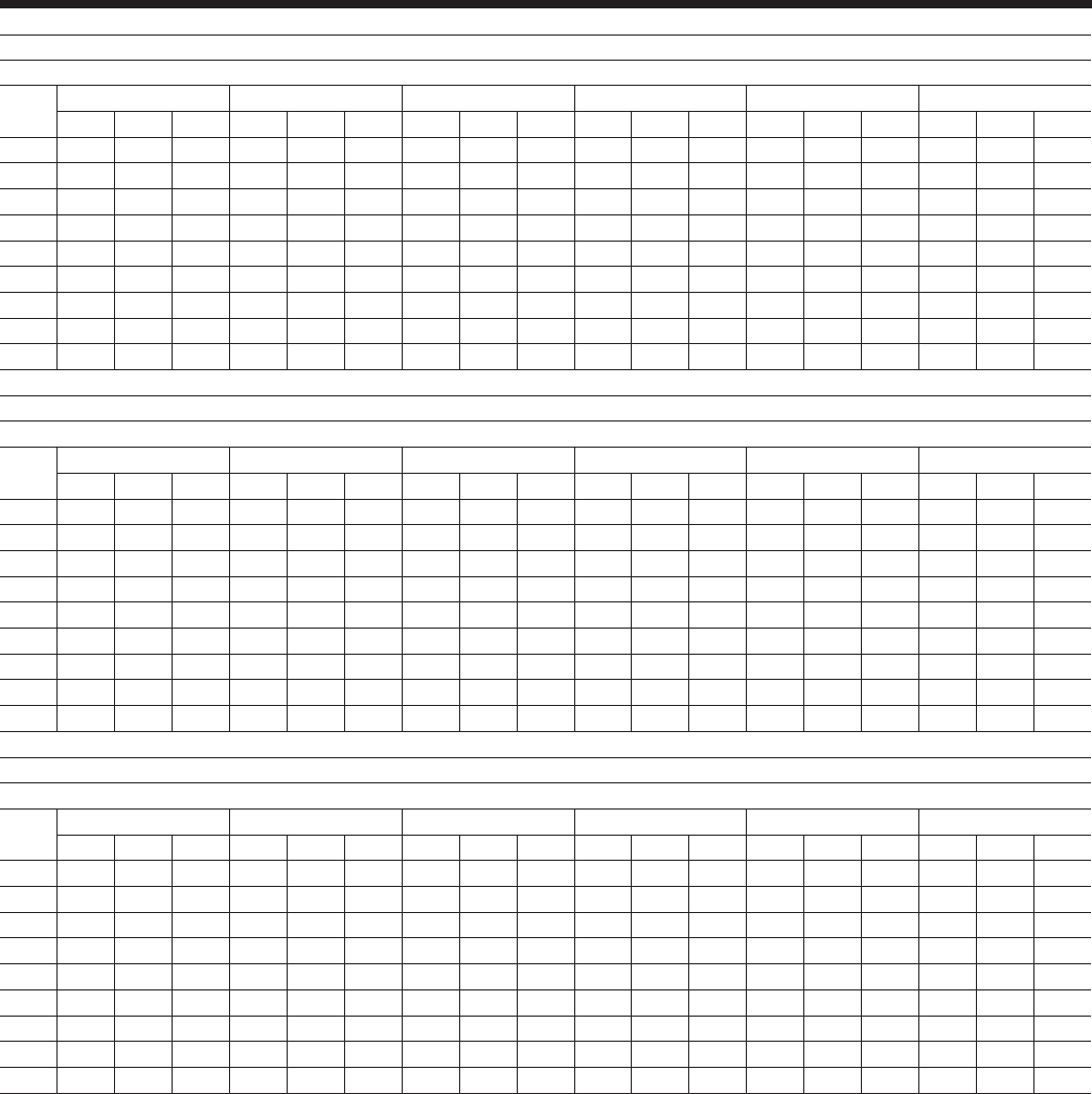
JOHNSON CONTROLS32
Standard Efciency Ratings – SI - 400V/50Hz
MODEL: YCIV0600S/P
AIR TEMPERATURE ON - CONDENSER (°C)
LCWT 25.0 30.0 35.0 40.0 45.0 46.0
(°C) KWi KWi COP KWi KWi COP KWi KWi COP KWi KWi COP KWi KWi COP KWi KWi COP
5.0 528.8 133.1 3.6 520.9 152.2 3.2 511.8 172.8 2.8 497.4 196.1 2.4 462.2 214.6 2.0 455.0 218.5 2.0
6.0 543.2 134.0 3.7 535.0 152.9 3.2 525.5 173.7 2.8 509.5 196.7 2.4 473.3 215.3 2.1 465.8 219.2 2.0
7.0 557.9 134.9 3.8 549.4 153.8 3.3 539.5 174.5 2.9 521.7 197.3 2.5 484.5 216.0 2.1 476.8 219.9 2.0
8.0 572.9 135.8 3.8 564.1 154.6 3.4 553.7 175.4 2.9 533.9 197.9 2.5 495.5 216.9 2.2 487.9 220.6 2.1
9.0 588.0 136.8 3.9 578.9 155.6 3.4 568.2 176.3 3.0 546.3 198.5 2.6 507.2 217.5 2.2 499.2 221.3 2.1
10.0 603.4 137.9 4.0 594.1 156.6 3.5 583.0 177.3 3.1 558.9 199.1 2.6 519.0 218.1 2.2 510.8 222.0 2.2
11.0 619.1 139.1 4.1 609.5 157.6 3.6 598.0 178.4 3.1 571.6 199.7 2.7 531.0 218.7 2.3 522.6 222.6 2.2
12.0 635.0 140.3 4.1 625.1 158.7 3.6 613.2 179.4 3.2 584.5 200.3 2.7 542.9 219.3 2.3 532.1 221.1 2.3
13.0 651.2 141.6 4.2 641.0 159.8 3.7 628.7 180.5 3.2 597.5 201.0 2.8 555.1 219.9 2.4 537.5 215.9 2.3
MODEL: YCIV0650S/P
AIR TEMPERATURE ON - CONDENSER (°C)
LCWT 25.0 30.0 35.0 40.0 45.0 46.0
(°C) KWi KWi COP KWi KWi COP KWi KWi COP KWi KWi COP KWi KWi COP KWi KWi COP
5.0 587.3 146.6 3.7 576.4 167.9 3.2 563.2 190.9 2.8 536.0 208.9 2.4 491.4 218.9 2.1 462.3 206.9 2.1
6.0 603.7 147.6 3.8 592.6 168.9 3.3 579.1 192.0 2.8 550.1 209.5 2.5 496.5 214.8 2.2 467.9 203.3 2.2
7.0 620.4 148.6 3.8 609.2 169.9 3.3 595.2 193.1 2.9 563.9 210.0 2.5 502.4 210.9 2.2 474.0 199.7 2.2
8.0 637.4 149.7 3.9 626.0 170.9 3.4 611.2 193.9 3.0 577.7 210.4 2.6 508.8 207.2 2.3 479.4 195.7 2.3
9.0 654.7 150.8 4.0 643.0 171.9 3.5 626.8 194.3 3.0 591.8 210.7 2.6 514.8 203.2 2.4 484.4 191.6 2.4
10.0 672.0 152.0 4.1 660.4 173.1 3.5 642.6 194.8 3.1 605.9 211.0 2.7 520.5 199.0 2.5 488.9 187.6 2.4
11.0 689.4 153.4 4.1 677.8 174.4 3.6 658.6 195.3 3.2 620.3 211.4 2.8 525.7 194.9 2.5 493.2 183.6 2.5
12.0 707.1 154.9 4.2 695.4 175.6 3.7 674.7 195.8 3.2 634.8 211.7 2.8 530.6 190.8 2.6 497.4 179.6 2.6
13.0 725.1 156.4 4.3 713.3 177.0 3.7 691.0 196.4 3.3 649.5 212.0 2.9 534.7 186.7 2.7 501.5 175.7 2.7
MODEL: YCIV0720S/P
AIR TEMPERATURE ON - CONDENSER (°C)
LCWT 25.0 30.0 35.0 40.0 45.0 46.0
(°C) KWi KWi COP KWi KWi COP KWi KWi COP KWi KWi COP KWi KWi COP KWi KWi COP
5.0 639.4 158.1 3.7 628.8 180.6 3.2 616.7 205.2 2.8 594.6 230.0 2.4 551.9 245.6 2.1 543.3 248.7 2.1
6.0 657.2 159.2 3.8 646.3 181.6 3.3 633.7 206.2 2.9 608.9 230.4 2.5 564.8 246.2 2.2 556.2 249.2 2.1
7.0 675.3 160.5 3.9 664.0 182.7 3.4 651.0 207.3 2.9 623.5 230.8 2.5 578.2 246.7 2.2 569.2 249.7 2.2
8.0 693.7 161.8 3.9 682.0 183.9 3.4 668.4 208.5 3.0 638.4 231.1 2.6 591.9 247.1 2.3 582.6 250.2 2.2
9.0 712.5 163.2 4.0 700.4 185.1 3.5 686.2 209.8 3.1 653.5 231.5 2.7 605.8 247.4 2.3 596.2 250.6 2.2
10.0 731.6 164.7 4.1 719.0 186.5 3.6 704.3 211.0 3.1 668.7 231.8 2.7 619.9 247.8 2.4 605.6 247.6 2.3
11.0 751.0 166.3 4.1 738.0 187.9 3.6 722.8 212.3 3.2 683.9 232.2 2.8 634.3 248.1 2.4 610.8 241.4 2.4
12.0 770.7 168.0 4.2 757.3 189.4 3.7 741.6 213.7 3.2 699.5 232.6 2.8 648.9 248.4 2.5 616.4 235.6 2.5
13.0 790.7 169.9 4.3 776.9 191.0 3.8 760.7 215.3 3.3 715.3 233.0 2.9 660.2 246.2 2.5 621.8 229.7 2.5
NOTES:
1. kWo = Unit kW Cooling Capacity Output
2. kW
i
= Compressor kW Input
3. COP = Coefcient of Performance (includes condenser fan power)
4. LCWT = Leaving Chilled Water Temperature
5. Ratings based on 0.168 l/s cooler water per ton, and 0.018 (m2 – °C)/kW
6. ARI 550/590 does not provide certication for 50Hz ratings. The unique use of the YCIV variable speed drive allows compressor operation at the output speed regardless of the input
power frequency. This allows for common unit/heat exchanger congurations between 60Hz and 50Hz with closely matching capacity.
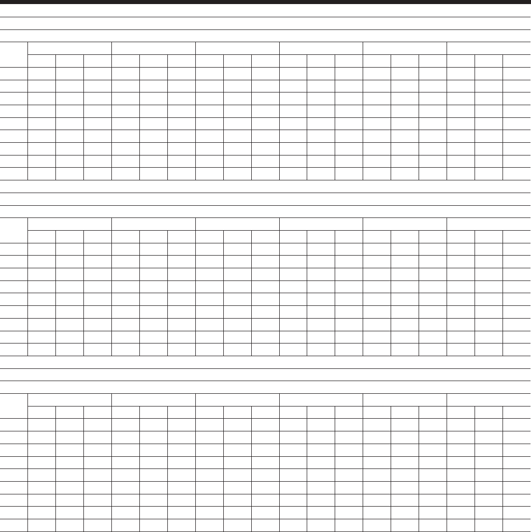
JOHNSON CONTROLS
FORM 201.23-EG1 (1007)
33
MODEL: YCIV0770S/P
AIR TEMPERATURE ON - CONDENSER (°C)
LCWT 25.0 30.0 35.0 40.0 45.0 46.0
(°C) KWi KWi COP KWi KWi COP KWi KWi COP KWi KWi COP KWi KWi COP KWi KWi COP
5.0 689.5 170.6 3.7 676.6 196.8 3.2 662.1 226.0 2.8 629.2 248.2 2.4 564.5 248.2 2.1 530.0 233.3 2.1
6.0 709.0 171.7 3.8 695.5 197.6 3.3 680.0 226.6 2.8 644.2 248.0 2.5 569.7 242.9 2.2 536.2 228.8 2.2
7.0 728.8 173.0 3.9 714.8 198.5 3.4 697.4 226.7 2.9 659.6 247.8 2.5 576.2 238.0 2.3 542.0 223.9 2.3
8.0 749.1 174.4 4.0 734.4 199.5 3.4 715.2 226.8 3.0 675.3 247.4 2.6 582.3 232.8 2.4 547.6 219.0 2.3
9.0 769.7 176.1 4.0 754.5 200.6 3.5 733.3 227.1 3.0 691.2 247.0 2.6 588.4 227.7 2.4 553.1 214.3 2.4
10.0 790.7 178.1 4.1 774.9 202.0 3.6 751.7 227.4 3.1 707.2 246.7 2.7 594.3 222.6 2.5 558.1 209.8 2.5
11.0 812.1 180.2 4.2 795.7 203.6 3.6 770.3 227.8 3.2 723.6 246.3 2.8 599.9 217.8 2.6 563.0 205.4 2.6
12.0 834.0 182.6 4.2 816.9 205.3 3.7 789.3 228.2 3.2 740.2 245.9 2.8 605.2 213.2 2.7 567.7 200.9 2.6
13.0 856.2 185.1 4.3 838.5 207.2 3.8 808.6 228.9 3.3 757.1 245.6 2.9 610.1 208.7 2.7 572.5 196.6 2.7
MODEL: YCIV0840S/P
AIR TEMPERATURE ON - CONDENSER (°C)
LCWT 25.0 30.0 35.0 40.0 45.0 46.0
(°C) KWi KWi COP KWi KWi COP KWi KWi COP KWi KWi COP KWi KWi COP KWi KWi COP
5.0 748.4 182.6 3.8 735.1 208.5 3.3 720.1 236.9 2.8 690.4 263.0 2.5 640.3 275.7 2.2 630.5 278.0 2.1
6.0 769.6 184.0 3.8 755.7 209.7 3.3 739.9 238.2 2.9 707.1 263.1 2.5 655.5 276.0 2.2 645.2 278.3 2.2
7.0 791.1 185.5 3.9 776.7 211.0 3.4 760.1 239.6 3.0 724.0 263.2 2.6 671.0 276.2 2.3 660.4 278.6 2.2
8.0 813.1 187.2 4.0 798.1 212.4 3.5 780.9 241.0 3.0 741.2 263.3 2.7 686.8 276.3 2.3 676.0 278.7 2.3
9.0 835.5 189.0 4.1 819.9 214.1 3.6 802.0 242.4 3.1 758.8 263.3 2.7 702.9 276.4 2.4 690.9 278.2 2.3
10.0 858.4 190.9 4.1 842.2 215.7 3.6 823.6 244.0 3.2 776.3 263.4 2.8 719.2 276.5 2.5 697.1 272.2 2.4
11.0 881.7 193.0 4.2 864.9 217.5 3.7 845.6 245.6 3.2 794.4 263.5 2.8 735.9 276.4 2.5 703.5 266.0 2.5
12.0 905.3 195.2 4.3 888.1 219.4 3.8 867.9 247.4 3.3 812.7 263.6 2.9 752.5 276.2 2.6 710.1 259.7 2.6
13.0 929.1 197.6 4.3 911.5 221.4 3.8 890.8 249.3 3.4 831.3 263.7 3.0 759.3 269.5 2.7 716.0 253.0 2.7
MODEL: YCIV0920S/P
AIR TEMPERATURE ON - CONDENSER (°C)
LCWT 25.0 30.0 35.0 40.0 45.0 46.0
(°C) KWi KWi COP KWi KWi COP KWi KWi COP KWi KWi COP KWi KWi COP KWi KWi COP
5.0 821.2 201.2 3.7 807.2 229.1 3.3 791.2 259.7 2.8 762.5 289.7 2.5 716.5 309.3 2.2 707.4 313.0 2.1
6.0 844.2 202.8 3.8 829.7 230.5 3.3 812.9 261.2 2.9 781.4 290.3 2.5 733.9 310.0 2.2 724.3 313.8 2.2
7.0 867.7 204.5 3.9 852.5 232.1 3.4 834.9 262.9 3.0 800.6 290.9 2.6 751.6 310.7 2.3 740.0 313.3 2.2
8.0 891.5 206.4 4.0 875.8 233.9 3.5 857.5 264.6 3.0 820.1 291.5 2.7 769.8 311.3 2.3 747.8 307.2 2.3
9.0 915.8 208.4 4.0 899.5 235.7 3.5 880.5 266.3 3.1 839.9 292.1 2.7 788.2 311.9 2.4 755.3 300.7 2.4
10.0 940.5 210.4 4.1 923.7 237.6 3.6 904.0 268.2 3.2 859.8 292.8 2.8 804.7 311.1 2.4 762.4 293.8 2.4
11.0 965.7 212.7 4.2 948.2 239.6 3.7 927.8 270.0 3.2 880.3 293.4 2.8 812.6 304.1 2.5 769.0 286.5 2.5
12.0 991.2 215.1 4.2 973.3 241.7 3.7 952.1 272.1 3.3 901.1 294.0 2.9 820.0 296.6 2.6 775.2 279.1 2.6
13.0 1017.2 217.0 4.3 998.6 243.9 3.8 976.9 274.2 3.3 922.2 294.7 2.9 826.9 289.0 2.7 780.9 272.0 2.7
NOTES:
1. kWo = Unit kW Cooling Capacity Output
2. kW
i
= Compressor kW Input
3. COP = Coefcient of Performance (includes condenser fan power)
4. LCWT = Leaving Chilled Water Temperature
5. Ratings based on 0.168 l/s cooler water per ton, and 0.018 (m2 – °C)/kW
6. ARI 550/590 does not provide certication for 50Hz ratings. The unique use of the YCIV variable speed drive allows compressor operation at the output speed regardless of the input
power frequency. This allows for common unit/heat exchanger congurations between 60Hz and 50Hz with closely matching capacity.

JOHNSON CONTROLS34
Standard Efciency Ratings – SI - 400V/50Hz
MODEL: YCIV1000S/P
AIR TEMPERATURE ON - CONDENSER (°C)
LCWT 25.0 30.0 35.0 40.0 45.0 46.0
(°C) KWi KWi COP KWi KWi COP KWi KWi COP KWi KWi COP KWi KWi COP KWi KWi COP
5.0 894.3 219.6 3.7 879.6 249.4 3.3 862.6 282.2 2.9 834.9 316.1 2.5 793.0 342.4 2.2 784.6 347.5 2.1
6.0 919.1 221.4 3.8 903.8 251.2 3.3 886.1 284.0 2.9 856.0 317.2 2.5 812.6 343.6 2.2 803.8 348.8 2.2
7.0 944.5 223.3 3.9 928.6 253.0 3.4 909.9 286.0 3.0 877.4 318.3 2.6 832.6 344.8 2.3 821.7 348.8 2.2
8.0 970.2 225.4 4.0 953.7 255.0 3.5 934.4 287.9 3.0 899.1 319.4 2.7 853.0 345.9 2.3 829.3 341.0 2.3
9.0 996.3 227.5 4.0 979.4 257.0 3.5 959.2 290.0 3.1 921.3 320.5 2.7 873.9 347.1 2.4 837.1 333.1 2.4
10.0 1023.0 229.8 4.1 1005.4 259.2 3.6 984.6 292.1 3.2 943.6 321.7 2.8 892.6 346.7 2.4 844.9 325.2 2.5
11.0 1050.0 232.2 4.2 1031.8 261.5 3.7 1010.4 294.2 3.2 966.5 322.9 2.8 900.9 338.2 2.5 852.6 317.4 2.5
12.0 1077.5 234.8 4.2 1058.8 263.8 3.7 1036.6 296.5 3.3 989.7 324.0 2.9 909.1 329.9 2.6 860.1 309.8 2.6
13.0 1105.6 236.2 4.3 1086.0 266.3 3.8 1063.2 298.9 3.3 1013.3 325.3 2.9 917.1 321.7 2.7 867.0 302.7 2.7
MODEL: YCIV1070S/P
AIR TEMPERATURE ON - CONDENSER (°C)
LCWT 25.0 30.0 35.0 40.0 45.0 46.0
(°C) KWi KWi COP KWi KWi COP KWi KWi COP KWi KWi COP KWi KWi COP KWi KWi COP
5.0 949.5 231.0 3.8 932.1 265.4 3.2 911.8 303.1 2.8 873.5 336.2 2.4 791.6 344.8 2.2 743.1 325.2 2.1
6.0 976.3 232.5 3.8 958.3 266.7 3.3 937.2 304.4 2.9 895.5 336.6 2.5 799.7 338.3 2.2 752.1 319.4 2.2
7.0 1003.6 234.1 3.9 985.0 268.0 3.4 962.8 305.6 2.9 917.2 336.9 2.6 808.0 331.5 2.3 761.5 313.7 2.3
8.0 1031.4 235.8 4.0 1012.3 269.5 3.5 988.1 306.3 3.0 939.4 337.1 2.6 818.0 325.4 2.4 770.3 307.5 2.3
9.0 1059.7 237.8 4.1 1040.1 271.0 3.6 1013.9 307.0 3.1 962.0 337.2 2.7 827.4 319.0 2.4 778.7 301.3 2.4
10.0 1088.5 240.0 4.2 1068.4 272.8 3.6 1040.2 307.9 3.2 985.0 337.2 2.7 836.6 312.5 2.5 786.4 295.0 2.5
11.0 1117.8 242.5 4.2 1097.2 274.7 3.7 1066.9 308.9 3.2 1008.2 337.3 2.8 845.3 306.1 2.6 793.4 288.8 2.6
12.0 1147.6 245.2 4.3 1126.5 276.9 3.8 1094.0 309.9 3.3 1031.7 337.4 2.9 853.4 299.8 2.7 800.2 282.7 2.6
13.0 1177.9 248.0 4.4 1156.3 279.2 3.8 1121.6 311.1 3.4 1055.6 337.6 2.9 860.6 293.5 2.7 806.8 276.6 2.7
MODEL: YCIV1180S/P
AIR TEMPERATURE ON - CONDENSER (°C)
LCWT 25.0 30.0 35.0 40.0 45.0 46.0
(°C) KWi KWi COP KWi KWi COP KWi KWi COP KWi KWi COP KWi KWi COP KWi KWi COP
5.0 1055.2 254.8 3.8 1036.1 294.0 3.3 1014.7 337.5 2.8 970.6 374.3 2.4 868.6 373.3 2.2 815.4 351.0 2.2
6.0 1084.9 256.5 3.9 1064.9 295.1 3.3 1042.0 338.3 2.9 993.7 374.1 2.5 876.5 365.3 2.3 824.1 343.8 2.2
7.0 1115.3 258.3 4.0 1094.4 296.3 3.4 1069.2 338.7 3.0 1017.4 373.7 2.6 885.7 357.6 2.3 833.7 336.9 2.3
8.0 1146.3 260.4 4.0 1124.5 297.7 3.5 1097.1 339.2 3.0 1041.6 373.3 2.6 896.0 350.3 2.4 842.6 329.7 2.4
9.0 1178.0 262.8 4.1 1155.3 299.4 3.6 1125.4 339.9 3.1 1066.2 372.7 2.7 905.5 342.6 2.5 851.2 322.6 2.5
10.0 1210.2 265.6 4.2 1186.6 301.4 3.7 1154.3 340.6 3.2 1091.1 372.1 2.8 914.9 335.1 2.6 859.2 315.8 2.5
11.0 1243.0 268.7 4.3 1218.5 303.7 3.7 1183.7 341.5 3.2 1116.3 371.6 2.8 923.7 327.9 2.6 866.8 309.2 2.6
12.0 1276.6 272.1 4.3 1251.1 306.1 3.8 1213.7 342.5 3.3 1142.1 371.0 2.9 932.2 321.0 2.7 874.2 302.6 2.7
13.0 1310.6 276.0 4.4 1284.3 308.9 3.9 1244.1 343.9 3.4 1168.3 370.5 3.0 939.9 314.3 2.8 881.4 296.1 2.8
NOTES:
1. kWo = Unit kW Cooling Capacity Output
2. kW
i
= Compressor kW Input
3. COP = Coefcient of Performance (includes condenser fan power)
4. LCWT = Leaving Chilled Water Temperature
5. Ratings based on 0.168 l/s cooler water per ton, and 0.018 (m2 – °C)/kW
6. ARI 550/590 does not provide certication for 50Hz ratings. The unique use of the YCIV variable speed drive allows compressor operation at the output speed regardless of the input
power frequency. This allows for common unit/heat exchanger congurations between 60Hz and 50Hz with closely matching capacity.
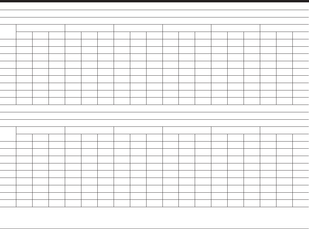
JOHNSON CONTROLS
FORM 201.23-EG1 (1007)
35
MODEL: YCIV1340S/P
AIR TEMPERATURE ON - CONDENSER (°C)
LCWT 25.0 30.0 35.0 40.0 45.0 46.0
(°C) KWi KWi COP KWi KWi COP KWi KWi COP KWi KWi COP KWi KWi COP KWi KWi COP
5.0 1191.3 291.5 3.7 1170.8 332.4 3.3 1147.5 377.2 2.8 1105.5 420.8 2.5 1034.8 446.6 2.2 1020.8 451.5 2.1
6.0 1224.9 293.8 3.8 1203.5 334.4 3.3 1179.0 379.3 2.9 1132.5 421.5 2.5 1059.6 447.6 2.2 1045.0 452.5 2.2
7.0 1259.1 296.1 3.9 1236.8 336.6 3.4 1211.2 381.6 3.0 1160.1 422.2 2.6 1085.1 448.4 2.3 1070.0 453.4 2.2
8.0 1294.0 298.7 4.0 1270.8 339.0 3.5 1244.0 384.0 3.0 1188.2 422.8 2.6 1111.1 449.1 2.3 1085.2 447.5 2.3
9.0 1329.5 301.6 4.1 1305.4 341.5 3.5 1277.5 386.5 3.1 1216.8 423.4 2.7 1137.4 449.8 2.4 1096.7 438.8 2.4
10.0 1365.7 304.6 4.1 1340.7 344.2 3.6 1311.7 389.0 3.2 1245.7 424.1 2.8 1164.1 450.5 2.4 1107.5 429.2 2.4
11.0 1402.6 307.8 4.2 1376.7 347.0 3.7 1346.7 391.6 3.2 1275.0 424.8 2.8 1179.6 443.2 2.5 1117.3 418.9 2.5
12.0 1439.8 311.3 4.3 1413.4 350.1 3.8 1382.2 394.5 3.3 1305.0 425.4 2.9 1190.8 432.9 2.6 1126.4 408.1 2.6
13.0 1477.6 314.5 4.3 1450.3 353.2 3.8 1418.5 397.5 3.3 1335.5 426.1 3.0 1201.1 421.9 2.7 1134.7 397.2 2.7
MODEL: YCIV1500S/P
AIR TEMPERATURE ON - CONDENSER (°C)
LCWT 25.0 30.0 35.0 40.0 45.0 46.0
(°C) KWi KWi COP KWi KWi COP KWi KWi COP KWi KWi COP KWi KWi COP KWi KWi COP
5.0 1337.3 328.4 3.7 1315.3 373.1 3.3 1289.8 422.2 2.9 1249.5 473.4 2.5 1187.1 512.7 2.2 1174.5 520.5 2.1
6.0 1374.7 331.0 3.8 1351.8 375.7 3.3 1325.2 424.9 2.9 1280.8 475.2 2.5 1216.1 514.6 2.2 1203.0 522.5 2.2
7.0 1412.9 333.8 3.9 1389.0 378.4 3.4 1361.1 427.8 3.0 1312.9 476.8 2.6 1246.0 516.4 2.3 1232.4 524.3 2.2
8.0 1451.9 336.8 4.0 1426.9 381.4 3.5 1397.9 430.7 3.0 1345.7 478.4 2.7 1276.5 518.2 2.3 1248.8 516.4 2.3
9.0 1491.4 340.1 4.0 1465.7 384.4 3.5 1435.3 433.8 3.1 1379.2 480.1 2.7 1307.7 519.9 2.4 1260.5 504.6 2.4
10.0 1531.8 343.5 4.1 1505.1 387.5 3.6 1473.6 436.9 3.2 1412.8 481.9 2.8 1339.2 521.7 2.4 1272.3 492.8 2.4
11.0 1572.9 347.0 4.2 1545.3 390.8 3.7 1512.7 440.1 3.2 1447.4 483.6 2.8 1356.6 512.7 2.5 1283.9 481.0 2.5
12.0 1613.6 350.8 4.2 1586.1 394.5 3.7 1552.4 443.5 3.3 1482.4 485.4 2.9 1369.0 500.1 2.6 1295.3 469.5 2.6
13.0 0.0 0.0 0.0 1626.5 398.0 3.8 1593.0 447.0 3.3 1518.1 487.2 2.9 1381.2 487.7 2.7 1306.2 458.5 2.7
NOTES:
1. kWo = Unit kW Cooling Capacity Output
2. kW
i
= Compressor kW Input
3. COP = Coefcient of Performance (includes condenser fan power)
4. LCWT = Leaving Chilled Water Temperature
5. Ratings based on 0.168 l/scooler water per ton, and 0.018 (m2 – °C)/kW
6. ARI 550/590 does not provide certication for 50Hz ratings. The unique use of the YCIV variable speed drive allows compressor operation at the output speed regardless of the input
power frequency. This allows for common unit/heat exchanger congurations between 60Hz and 50Hz with closely matching capacity.

JOHNSON CONTROLS36
High Efciency Ratings – SI - 400V/50Hz
MODEL: YCIV0590E/V
AIR TEMPERATURE ON - CONDENSER (°C)
LCWT 25.0 30.0 35.0 40.0 45.0 46.0
(°C) KWi KWi COP KWi KWi COP KWi KWi COP KWi KWi COP KWi KWi COP KWi KWi COP
5.0 525.0 123.1 3.9 515.6 139.0 3.4 503.3 156.2 3.0 487.8 176.4 2.6 449.0 192.6 2.2 441.1 196.0 2.1
6.0 539.7 124.0 3.9 530.4 140.2 3.5 518.1 157.4 3.0 500.9 177.3 2.6 460.8 193.4 2.2 452.7 196.7 2.2
7.0 554.7 125.0 4.0 545.4 141.3 3.5 533.0 158.5 3.1 514.0 178.2 2.7 472.8 194.1 2.3 464.5 197.5 2.2
8.0 569.9 126.1 4.1 560.7 142.4 3.6 548.1 159.7 3.2 527.2 179.1 2.7 484.9 195.0 2.3 476.5 198.2 2.3
9.0 585.2 127.1 4.2 576.2 143.5 3.7 563.5 161.0 3.2 540.5 180.0 2.8 497.0 195.9 2.4 488.4 199.1 2.3
10.0 600.7 128.2 4.2 591.8 144.7 3.7 579.1 162.2 3.3 554.0 180.9 2.9 509.5 196.8 2.4 500.6 200.0 2.4
11.0 616.4 129.2 4.3 607.7 145.8 3.8 594.9 163.5 3.4 567.6 181.9 2.9 522.3 197.7 2.5 513.2 200.9 2.4
12.0 632.2 130.3 4.4 623.8 147.0 3.9 610.9 164.8 3.4 581.2 182.9 3.0 535.2 198.6 2.5 525.9 201.8 2.4
13.0 648.3 131.3 4.5 640.1 148.3 4.0 627.2 166.2 3.5 595.0 183.8 3.0 548.3 199.5 2.6 538.8 202.7 2.5
MODEL: YCIV0630E/V
AIR TEMPERATURE ON - CONDENSER (°C)
LCWT 25.0 30.0 35.0 40.0 45.0 46.0
(°C) KWi KWi COP KWi KWi COP KWi KWi COP KWi KWi COP KWi KWi COP KWi KWi COP
5.0 558.7 129.2 3.9 550.3 147.1 3.4 540.3 167.0 3.0 525.1 189.7 2.6 492.2 209.6 2.2 484.3 213.4 2.1
6.0 574.5 130.1 4.0 565.7 147.9 3.5 555.3 167.8 3.0 538.7 190.4 2.6 504.1 210.2 2.2 496.2 213.9 2.2
7.0 590.5 131.1 4.0 581.5 148.8 3.6 570.6 168.6 3.1 552.7 191.0 2.7 516.4 210.7 2.3 508.1 214.6 2.2
8.0 606.9 132.2 4.1 597.5 149.7 3.6 586.3 169.5 3.2 566.8 191.7 2.7 528.8 211.3 2.3 520.3 215.1 2.3
9.0 623.5 133.4 4.2 613.9 150.7 3.7 602.3 170.4 3.3 581.3 192.4 2.8 541.5 211.8 2.4 532.8 215.7 2.3
10.0 640.4 134.6 4.3 630.5 151.8 3.8 618.5 171.4 3.3 596.0 193.1 2.9 554.4 212.3 2.4 545.5 216.2 2.4
11.0 657.7 136.0 4.4 647.5 153.0 3.9 635.1 172.5 3.4 610.9 193.9 2.9 567.6 212.9 2.5 551.5 211.4 2.4
12.0 675.2 137.4 4.4 664.8 154.3 3.9 652.0 173.6 3.5 626.1 194.7 3.0 580.9 213.4 2.5 557.2 206.6 2.5
13.0 693.1 139.0 4.5 682.3 155.6 4.0 669.2 174.8 3.5 641.6 195.5 3.1 594.4 214.0 2.6 562.8 202.0 2.6
MODEL: YCIV0700E/V
AIR TEMPERATURE ON - CONDENSER (°C)
LCWT 25.0 30.0 35.0 40.0 45.0 46.0
(°C) KWi KWi COP KWi KWi COP KWi KWi COP KWi KWi COP KWi KWi COP KWi KWi COP
5.0 621.1 143.4 3.9 611.6 164.1 3.4 600.1 187.0 3.0 582.8 211.7 2.6 547.1 228.0 2.2 538.6 230.9 2.2
6.0 638.5 144.3 4.0 628.9 164.8 3.5 617.0 187.7 3.0 598.1 212.0 2.6 560.8 228.4 2.3 552.0 231.3 2.2
7.0 656.2 145.3 4.1 646.4 165.6 3.5 634.2 188.4 3.1 613.8 212.3 2.7 574.6 228.7 2.3 565.6 231.6 2.3
8.0 674.1 146.4 4.1 664.2 166.5 3.6 651.7 189.3 3.2 629.7 212.6 2.7 588.8 229.0 2.4 579.5 232.0 2.3
9.0 692.3 147.7 4.2 682.2 167.5 3.7 669.4 190.2 3.2 645.8 212.9 2.8 603.2 229.2 2.5 593.7 232.2 2.4
10.0 710.7 149.0 4.3 700.4 168.6 3.8 687.3 191.1 3.3 662.3 213.3 2.9 617.8 229.4 2.5 608.1 232.4 2.4
11.0 729.4 150.5 4.4 719.0 169.8 3.9 705.6 192.2 3.4 678.9 213.6 3.0 632.7 229.6 2.6 622.8 232.6 2.5
12.0 748.4 152.0 4.4 737.8 171.1 3.9 724.1 193.3 3.5 695.7 214.0 3.0 647.8 229.7 2.6 632.7 229.6 2.6
13.0 767.7 153.7 4.5 756.9 172.4 4.0 742.9 194.5 3.5 712.8 214.4 3.1 663.1 229.9 2.7 638.4 224.0 2.7
NOTES:
1. kWo = Unit kW Cooling Capacity Output
2. kW
i
= Compressor kW Input
3. COP = Coefcient of Performance (includes condenser fan power)
4. LCWT = Leaving Chilled Water Temperature
5. Ratings based on 0.168 l/s cooler water per ton, and 0.018 (m2 – °C)/kW
6. ARI 550/590 does not provide certication for 50Hz ratings. The unique use of the YCIV variable speed drive allows compressor operation at the output speed regardless of the input
power frequency. This allows for common unit/heat exchanger congurations between 60Hz and 50Hz with closely matching capacity.

JOHNSON CONTROLS
FORM 201.23-EG1 (1007)
37
MODEL: YCIV0760E/V
AIR TEMPERATURE ON - CONDENSER (°C)
LCWT 25.0 30.0 35.0 40.0 45.0 46.0
(°C) KWi KWi COP KWi KWi COP KWi KWi COP KWi KWi COP KWi KWi COP KWi KWi COP
5.0 672.7 155.1 3.9 661.6 178.9 3.4 648.7 206.1 2.9 631.4 236.7 2.5 586.1 249.7 2.2 577.1 252.0 2.2
6.0 691.7 156.1 4.0 680.1 179.4 3.5 666.7 206.4 3.0 647.0 236.3 2.6 600.4 249.7 2.3 591.1 252.1 2.2
7.0 711.0 157.3 4.1 699.0 180.0 3.6 685.1 206.8 3.1 662.9 235.8 2.6 614.9 249.6 2.3 605.4 252.0 2.3
8.0 730.8 158.7 4.2 718.3 180.9 3.6 703.9 207.3 3.1 678.8 235.3 2.7 629.7 249.3 2.4 620.0 251.8 2.3
9.0 750.9 160.4 4.2 737.9 181.8 3.7 723.0 207.9 3.2 695.2 234.8 2.8 645.0 249.0 2.4 634.8 251.6 2.4
10.0 771.3 162.3 4.3 758.0 183.0 3.8 742.4 208.8 3.3 711.9 234.3 2.8 660.3 248.5 2.5 650.0 251.1 2.4
11.0 792.1 164.4 4.4 778.4 184.3 3.9 762.2 209.6 3.4 728.8 233.8 2.9 675.9 248.0 2.6 665.4 250.7 2.5
12.0 813.3 166.8 4.4 799.1 186.0 3.9 782.4 210.6 3.4 745.9 233.3 3.0 691.8 247.5 2.6 681.0 250.2 2.6
13.0 834.9 169.5 4.5 820.2 187.8 4.0 803.0 211.8 3.5 763.0 233.0 3.1 707.8 247.0 2.7 696.9 249.6 2.6
MODEL: YCIV0800E/V
AIR TEMPERATURE ON - CONDENSER (°C)
LCWT 25.0 30.0 35.0 40.0 45.0 46.0
(°C) KWi KWi COP KWi KWi COP KWi KWi COP KWi KWi COP KWi KWi COP KWi KWi COP
5.0 715.1 163.2 3.9 703.9 187.3 3.4 691.1 214.8 3.0 672.4 245.0 2.6 630.3 261.6 2.3 620.8 264.1 2.2
6.0 735.3 164.3 4.0 723.6 188.0 3.5 710.2 215.4 3.0 689.7 245.2 2.6 645.5 261.6 2.3 635.9 264.1 2.3
7.0 755.9 165.6 4.1 743.7 188.9 3.6 729.7 216.0 3.1 707.4 245.3 2.7 661.1 261.5 2.4 651.2 264.1 2.3
8.0 776.9 167.1 4.2 764.2 189.8 3.7 749.5 216.7 3.2 725.4 245.4 2.8 677.0 261.3 2.4 666.7 264.0 2.4
9.0 798.4 168.8 4.3 785.1 191.0 3.8 769.8 217.5 3.3 743.7 245.5 2.8 693.1 261.0 2.5 682.6 263.7 2.4
10.0 820.2 170.7 4.3 806.4 192.3 3.8 790.5 218.4 3.3 762.5 245.6 2.9 709.5 260.7 2.5 698.7 263.4 2.5
11.0 842.4 172.9 4.4 828.1 193.8 3.9 811.6 219.5 3.4 781.3 245.8 3.0 726.1 260.3 2.6 715.2 263.0 2.5
12.0 864.5 175.1 4.5 850.1 195.4 4.0 833.1 220.7 3.5 799.5 245.5 3.0 743.1 259.9 2.7 723.9 257.8 2.6
13.0 887.0 177.7 4.5 872.1 197.2 4.0 854.8 222.1 3.6 818.1 245.3 3.1 760.3 259.5 2.7 730.1 251.0 2.7
MODEL: YCIV0830E/V
AIR TEMPERATURE ON - CONDENSER (°C)
LCWT 25.0 30.0 35.0 40.0 45.0 46.0
(°C) KWi KWi COP KWi KWi COP KWi KWi COP KWi KWi COP KWi KWi COP KWi KWi COP
5.0 743.0 169.0 3.9 731.8 192.7 3.4 718.8 219.4 3.0 703.0 250.7 2.6 661.8 268.9 2.3 652.0 271.4 2.2
6.0 764.0 170.2 4.0 752.3 193.7 3.5 738.8 220.3 3.1 722.2 251.7 2.7 678.0 268.9 2.3 667.8 271.6 2.3
7.0 785.4 171.7 4.1 773.3 194.8 3.6 759.2 221.2 3.2 741.8 252.8 2.7 694.3 269.0 2.4 684.1 271.6 2.3
8.0 807.2 173.1 4.2 794.7 196.0 3.7 780.0 222.3 3.2 761.9 253.8 2.8 711.1 269.0 2.5 700.6 271.6 2.4
9.0 829.4 174.8 4.3 816.5 197.2 3.8 801.2 223.4 3.3 782.3 254.8 2.9 728.2 268.9 2.5 717.3 271.6 2.5
10.0 851.7 176.5 4.3 838.7 198.7 3.8 822.9 224.6 3.4 801.1 254.8 2.9 745.6 268.9 2.6 734.4 271.5 2.5
11.0 874.2 178.4 4.4 860.8 200.2 3.9 844.9 225.8 3.4 820.0 254.9 3.0 763.3 268.8 2.6 751.8 271.4 2.6
12.0 897.1 180.5 4.5 883.2 201.8 4.0 866.8 227.3 3.5 839.3 254.9 3.1 781.0 268.7 2.7 769.5 271.3 2.6
13.0 920.3 182.6 4.5 906.1 203.6 4.1 889.1 228.7 3.6 858.7 255.0 3.1 799.3 268.6 2.8 787.3 271.3 2.7
NOTES:
1. kWo = Unit kW Cooling Capacity Output
2. kW
i
= Compressor kW Input
3. COP = Coefcient of Performance (includes condenser fan power)
4. LCWT = Leaving Chilled Water Temperature
5. Ratings based on 0.168 l/s cooler water per ton, and 0.018 (m2 – °C)/kW
6. ARI 550/590 does not provide certication for 50Hz ratings. The unique use of the YCIV variable speed drive allows compressor operation at the output speed regardless of the input
power frequency. This allows for common unit/heat exchanger congurations between 60Hz and 50Hz with closely matching capacity.

JOHNSON CONTROLS38
High Efciency Ratings – SI - 400V/50Hz
MODEL: YCIV0930E/V
AIR TEMPERATURE ON - CONDENSER (°C)
LCWT 25.0 30.0 35.0 40.0 45.0 46.0
(°C) KWi KWi COP KWi KWi COP KWi KWi COP KWi KWi COP KWi KWi COP KWi KWi COP
5.0 824.5 194.8 3.8 811.2 221.5 3.4 795.7 251.2 2.9 773.5 283.8 2.5 730.4 305.9 2.2 721.2 309.7 2.2
6.0 847.7 196.4 3.9 833.8 222.9 3.4 817.7 252.6 3.0 793.8 284.9 2.6 748.4 306.5 2.3 738.8 310.5 2.2
7.0 871.3 198.1 4.0 856.9 224.4 3.5 840.1 254.0 3.1 814.6 286.0 2.7 766.7 307.1 2.3 754.9 309.8 2.3
8.0 895.3 199.9 4.1 880.5 226.0 3.6 863.0 255.6 3.1 835.8 287.1 2.7 785.5 307.7 2.4 763.0 303.6 2.4
9.0 919.9 201.9 4.1 904.5 227.8 3.7 886.3 257.2 3.2 856.8 287.9 2.8 804.7 308.2 2.5 770.6 296.9 2.4
10.0 944.8 204.0 4.2 928.9 229.6 3.7 910.1 258.9 3.3 877.5 288.5 2.8 821.6 307.2 2.5 777.9 289.9 2.5
11.0 970.3 206.2 4.3 953.8 231.6 3.8 934.4 260.7 3.3 898.6 289.1 2.9 829.7 300.0 2.6 784.7 282.6 2.6
12.0 995.9 208.6 4.4 979.1 233.6 3.9 959.0 262.6 3.4 920.1 289.7 3.0 837.3 292.4 2.7 791.0 275.3 2.7
13.0 1022.2 210.5 4.4 1004.7 235.9 3.9 984.2 264.6 3.5 941.9 290.4 3.0 844.2 284.8 2.8 796.8 268.3 2.8
MODEL: YCIV1050E/V
AIR TEMPERATURE ON - CONDENSER (°C)
LCWT 25.0 30.0 35.0 40.0 45.0 46.0
(°C) KWi KWi COP KWi KWi COP KWi KWi COP KWi KWi COP KWi KWi COP KWi KWi COP
5.0 935.9 214.3 3.9 919.5 246.0 3.4 900.1 281.3 3.0 875.5 321.9 2.5 811.1 342.9 2.2 798.1 346.7 2.2
6.0 962.5 215.7 4.0 945.8 247.0 3.5 925.6 282.3 3.0 898.2 322.2 2.6 831.3 343.3 2.3 817.8 347.2 2.2
7.0 989.5 217.3 4.1 972.5 248.1 3.6 951.7 283.3 3.1 921.3 322.3 2.7 851.9 343.6 2.3 838.0 347.6 2.3
8.0 1017.1 219.1 4.2 999.6 249.4 3.7 978.3 284.3 3.2 944.1 322.3 2.7 872.7 343.8 2.4 858.7 347.9 2.3
9.0 1045.2 221.1 4.3 1027.4 250.9 3.7 1005.4 285.5 3.3 967.3 322.3 2.8 894.2 343.9 2.4 879.6 348.1 2.4
10.0 1073.8 223.4 4.4 1055.6 252.5 3.8 1033.0 286.9 3.3 991.0 322.2 2.9 915.8 344.0 2.5 901.0 348.2 2.4
11.0 1102.8 225.9 4.4 1084.4 254.3 3.9 1061.2 288.3 3.4 1015.0 322.2 2.9 938.0 344.0 2.6 922.6 348.2 2.5
12.0 1132.3 228.7 4.5 1113.6 256.4 4.0 1089.8 289.9 3.5 1039.3 322.2 3.0 960.5 344.0 2.6 944.8 348.2 2.5
13.0 1162.3 231.7 4.6 1143.3 258.7 4.1 1119.1 291.7 3.6 1063.8 322.3 3.1 983.3 344.0 2.7 967.4 348.1 2.6
MODEL: YCIV1120E/V
AIR TEMPERATURE ON - CONDENSER (°C)
LCWT 25.0 30.0 35.0 40.0 45.0 46.0
(°C) KWi KWi COP KWi KWi COP KWi KWi COP KWi KWi COP KWi KWi COP KWi KWi COP
5.0 996.2 225.3 4.0 979.2 259.7 3.4 959.5 298.8 3.0 935.5 344.4 2.5 869.0 364.4 2.2 855.4 367.7 2.2
6.0 1024.5 226.7 4.1 1007.0 260.4 3.5 986.4 299.5 3.0 960.5 344.8 2.6 890.3 364.4 2.3 876.3 367.9 2.2
7.0 1053.4 228.4 4.2 1035.3 261.3 3.6 1013.9 300.0 3.1 984.3 344.2 2.7 912.1 364.3 2.3 897.7 367.9 2.3
8.0 1082.9 230.4 4.2 1064.2 262.5 3.7 1042.0 300.7 3.2 1008.6 343.5 2.7 934.3 363.9 2.4 919.5 367.6 2.3
9.0 1112.9 232.7 4.3 1093.7 263.9 3.8 1070.7 301.6 3.3 1033.1 342.9 2.8 956.7 363.5 2.5 941.8 367.2 2.4
10.0 1143.5 235.4 4.4 1123.7 265.6 3.9 1100.0 302.8 3.4 1058.1 342.2 2.9 979.9 362.9 2.5 964.3 366.8 2.5
11.0 1174.4 238.5 4.5 1154.4 267.5 3.9 1129.9 304.0 3.4 1083.6 341.5 3.0 1003.4 362.3 2.6 987.4 366.2 2.5
12.0 1206.4 241.9 4.5 1185.5 269.8 4.0 1160.4 305.5 3.5 1109.5 340.9 3.0 1027.4 361.6 2.7 1011.0 365.5 2.6
13.0 1238.7 245.7 4.6 1217.3 272.4 4.1 1191.4 307.2 3.6 1135.6 340.4 3.1 1051.7 360.9 2.7 1034.9 364.8 2.7
NOTES:
1. kWo = Unit kW Cooling Capacity Output
2. kW
i
= Compressor kW Input
3. COP = Coefcient of Performance (includes condenser fan power)
4. LCWT = Leaving Chilled Water Temperature
5. Ratings based on 0.168 l/s cooler water per ton, and 0.018 (m2 – °C)/kW
6. ARI 550/590 does not provide certication for 50Hz ratings. The unique use of the YCIV variable speed drive allows compressor operation at the output speed regardless of the input
power frequency. This allows for common unit/heat exchanger congurations between 60Hz and 50Hz with closely matching capacity.
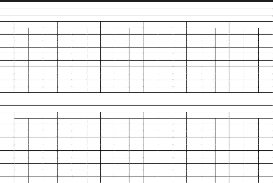
JOHNSON CONTROLS
FORM 201.23-EG1 (1007)
39
MODEL: YCIV1220E/V
AIR TEMPERATURE ON - CONDENSER (°C)
LCWT 25.0 30.0 35.0 40.0 45.0 46.0
(°C) KWi KWi COP KWi KWi COP KWi KWi COP KWi KWi COP KWi KWi COP KWi KWi COP
5.0 1082.7 247.9 3.9 1064.7 284.7 3.4 1044.3 326.4 3.0 1013.0 371.0 2.6 945.2 394.1 2.3 930.6 397.6 2.2
6.0 1113.5 249.6 4.0 1094.7 285.8 3.5 1073.2 327.3 3.0 1038.5 371.1 2.6 967.8 394.2 2.3 953.0 397.8 2.2
7.0 1145.0 251.6 4.1 1125.3 287.1 3.6 1102.8 328.3 3.1 1064.7 371.1 2.7 991.1 394.1 2.4 975.8 397.9 2.3
8.0 1177.1 253.9 4.2 1156.5 288.5 3.7 1133.0 329.5 3.2 1091.4 371.0 2.7 1014.9 393.9 2.4 999.0 397.7 2.4
9.0 1209.8 256.5 4.3 1188.4 290.3 3.8 1164.0 330.7 3.3 1118.6 370.9 2.8 1039.0 393.5 2.5 1022.8 397.4 2.4
10.0 1243.2 259.3 4.3 1221.0 292.3 3.8 1195.5 332.2 3.3 1146.4 370.9 2.9 1063.6 393.0 2.5 1047.0 397.0 2.5
11.0 1277.2 262.6 4.4 1254.2 294.7 3.9 1227.8 333.8 3.4 1174.3 370.9 3.0 1088.5 392.5 2.6 1071.6 396.5 2.5
12.0 1311.9 266.1 4.5 1288.1 297.2 4.0 1260.7 335.7 3.5 1201.8 370.4 3.0 1114.1 391.9 2.7 1085.7 389.4 2.6
13.0 1347.3 270.1 4.5 1322.6 300.0 4.1 1294.1 337.9 3.6 1229.8 370.1 3.1 1139.9 391.3 2.7 1095.0 379.4 2.7
MODEL: YCIV1380E/V
AIR TEMPERATURE ON - CONDENSER (°C)
LCWT 25.0 30.0 35.0 40.0 45.0 46.0
(°C) KWi KWi COP KWi KWi COP KWi KWi COP KWi KWi COP KWi KWi COP KWi KWi COP
5.0 1228.4 287.0 3.9 1206.7 325.4 3.4 1181.0 367.8 3.0 1146.5 415.9 2.6 1083.9 450.5 2.3 1070.4 456.8 2.2
6.0 1263.2 289.6 4.0 1241.1 327.6 3.5 1214.5 370.0 3.0 1177.1 417.5 2.6 1111.7 451.6 2.3 1097.6 457.9 2.3
7.0 1298.8 292.2 4.0 1276.1 330.0 3.5 1248.7 372.3 3.1 1208.5 419.0 2.7 1139.9 452.8 2.4 1125.5 459.0 2.3
8.0 1334.9 295.0 4.1 1311.8 332.6 3.6 1283.4 374.9 3.2 1240.5 420.6 2.8 1168.8 453.8 2.4 1153.8 460.1 2.4
9.0 1371.6 298.1 4.2 1348.0 335.4 3.7 1318.9 377.4 3.2 1273.1 422.2 2.8 1198.3 454.9 2.5 1183.0 461.2 2.4
10.0 1409.1 301.3 4.3 1384.9 338.3 3.8 1355.0 380.2 3.3 1306.1 424.0 2.9 1228.4 456.0 2.5 1205.0 457.4 2.5
11.0 1447.1 304.6 4.3 1422.5 341.3 3.8 1391.8 383.1 3.4 1339.8 425.7 2.9 1258.9 457.1 2.6 1215.9 446.2 2.6
12.0 1485.7 308.3 4.4 1460.6 344.7 3.9 1429.2 386.1 3.4 1372.9 427.0 3.0 1290.1 458.2 2.6 1226.3 435.1 2.6
13.0 1525.2 311.0 4.5 1499.4 348.1 4.0 1467.3 389.3 3.5 1406.5 428.4 3.1 1308.1 450.8 2.7 1236.0 424.3 2.7
NOTES:
1. kWo = Unit kW Cooling Capacity Output
2. kW
i
= Compressor kW Input
3. COP = Coefcient of Performance (includes condenser fan power)
4. LCWT = Leaving Chilled Water Temperature
5. Ratings based on 0.168 l/s cooler water per ton, and 0.018 (m2 – °C)/kW
6. ARI 550/590 does not provide certication for 50Hz ratings. The unique use of the YCIV variable speed drive allows compressor operation at the output speed regardless of the input
power frequency. This allows for common unit/heat exchanger congurations between 60Hz and 50Hz with closely matching capacity.

JOHNSON CONTROLS40
Standard Efciency Ratings – English - 380V/60Hz
MODEL: YCIV0157S/P S_IPLV = 13.4 P_IPLV = 14.7
AIR TEMPERATURE ON - CONDENSER (°F)
LCWT 75.0 80.0 85.0 90.0 95.0 100.0 105.0 110.0 115.0
(°F) TONS KW EER TONS KW EER TONS KW EER TONS KW EER TONS KW EER TONS KW EER TONS KW EER TONS KW EER TONS KW EER
40.0 149.1 128.9 12.6 148.0 138.9 11.7 146.7 149.6 10.8 145.4 160.8 10.0 143.9 172.5 9.3 142.2 185.6 8.6 138.9 197.9 7.9 133.5 208.0 7.2 127.9 218.6 6.6
42.0 153.7 129.8 12.9 152.5 139.8 11.9 151.2 150.4 11.1 149.8 161.7 10.3 148.2 173.4 9.5 146.5 186.7 8.8 142.7 198.6 8.1 137.0 208.9 7.4 131.3 219.4 6.8
44.0 158.3 130.8 13.2 157.1 140.7 12.2 155.7 151.3 11.3 154.3 162.6 10.5 152.6 174.4 9.8 150.8 187.7 9.0 146.5 199.3 8.3 140.6 209.7 7.6 134.7 220.2 6.9
45.0 160.7 131.3 13.3 159.4 141.2 12.4 158.1 151.8 11.5 156.5 163.1 10.6 154.9 174.8 9.9 153.0 188.2 9.1 148.4 199.6 8.4 142.5 210.1 7.7 136.5 220.5 7.0
46.0 163.1 131.9 13.5 161.8 141.7 12.5 160.4 152.3 11.6 158.8 163.6 10.8 157.1 175.3 10.0 155.2 188.7 9.2 150.4 200.0 8.5 144.3 210.4 7.7 138.3 220.9 7.1
48.0 167.9 133.0 13.8 166.6 142.8 12.8 165.1 153.4 11.9 163.5 164.6 11.0 161.7 176.4 10.2 159.7 189.7 9.4 154.3 200.6 8.6 148.1 211.1 7.9 141.8 221.8 7.2
50.0 172.8 134.3 14.0 171.4 144.0 13.1 169.9 154.5 12.1 168.2 165.6 11.3 166.4 177.4 10.5 164.3 190.8 9.7 158.2 201.3 8.8 151.9 211.8 8.1 145.5 222.5 7.4
52.0 177.8 135.6 14.3 176.4 145.3 13.3 174.8 155.7 12.4 173.1 166.8 11.5 171.2 178.6 10.7 168.6 191.7 9.9 162.2 202.0 9.0 155.8 212.5 8.3 149.2 223.0 7.6
55.0 185.4 137.8 14.7 184.0 147.3 13.7 182.3 157.6 12.8 180.5 168.7 11.9 178.5 180.4 11.0 175.0 192.8 10.2 168.3 203.1 9.3 161.7 213.5 8.5 151.7 214.5 8.0
MODEL: YCIV0177S/P S_IPLV = 13.3 P_IPLV = 15.0
AIR TEMPERATURE ON - CONDENSER (°F)
LCWT 75.0 80.0 85.0 90.0 95.0 100.0 105.0 110.0 115.0
(°F) TONS KW EER TONS KW EER TONS KW EER TONS KW EER TONS KW EER TONS KW EER TONS KW EER TONS KW EER TONS KW EER
40.0 165.7 141.8 12.8 164.2 153.1 11.8 162.4 165.1 10.9 160.5 177.6 10.1 158.4 190.5 9.3 154.6 201.5 8.6 149.9 210.4 8.0 143.5 217.6 7.5 130.1 207.3 7.1
42.0 170.9 142.8 13.1 169.3 154.1 12.1 167.5 166.1 11.2 165.5 178.7 10.3 163.3 191.6 9.6 159.1 202.1 8.9 154.0 211.0 8.2 147.5 218.3 7.6 131.8 203.1 7.3
44.0 176.1 143.9 13.4 174.6 155.2 12.4 172.8 167.2 11.5 170.7 179.8 10.6 168.4 192.9 9.8 163.8 202.6 9.1 158.3 211.5 8.4 151.5 218.9 7.8 133.6 199.1 7.5
45.0 178.8 144.5 13.6 177.2 155.7 12.6 175.4 167.7 11.6 173.3 180.4 10.7 171.0 193.5 9.9 166.1 202.9 9.2 160.5 211.7 8.6 153.5 219.3 7.9 134.5 196.9 7.7
46.0 181.5 145.2 13.7 179.9 156.3 12.7 178.1 168.3 11.8 175.9 180.9 10.9 173.5 193.9 10.0 168.5 203.2 9.3 162.6 211.9 8.7 155.6 219.5 8.0 135.3 194.7 7.8
48.0 186.9 146.5 14.0 185.4 157.6 13.0 183.5 169.5 12.0 181.3 182.1 11.1 178.4 194.4 10.3 173.3 203.7 9.6 167.0 212.3 8.9 159.8 220.0 8.2 137.0 190.4 8.1
50.0 192.4 148.0 14.3 190.8 158.9 13.3 189.0 170.8 12.3 186.7 183.4 11.4 183.4 194.9 10.6 178.2 204.3 9.8 171.5 212.6 9.1 162.8 217.2 8.5 138.3 185.7 8.3
52.0 198.0 149.5 14.6 196.4 160.4 13.6 194.5 172.2 12.6 192.2 184.9 11.6 188.5 195.4 10.8 183.1 204.8 10.1 176.0 213.0 9.3 164.7 212.2 8.8 139.6 181.2 8.6
55.0 206.4 152.1 15.0 204.9 162.8 13.9 202.9 174.5 13.0 200.6 187.0 12.0 196.2 196.4 11.2 190.7 205.7 10.4 182.9 213.5 9.7 167.5 204.9 9.2 141.5 174.7 9.0
MODEL: YCIV0187S/P S_IPLV = 13.3 P_IPLV = 15.1
AIR TEMPERATURE ON - CONDENSER (°F)
LCWT 75.0 80.0 85.0 90.0 95.0 100.0 105.0 110.0 115.0
(°F) TONS KW EER TONS KW EER TONS KW EER TONS KW EER TONS KW EER TONS KW EER TONS KW EER TONS KW EER TONS KW EER
40.0 180.3 153.0 12.9 178.8 164.8 11.9 177.1 177.5 11.0 175.3 190.8 10.2 173.4 204.7 9.5 171.1 220.4 8.7 166.1 231.6 8.1 159.4 240.4 7.5 152.8 248.8 6.9
42.0 185.9 154.3 13.2 184.4 166.1 12.2 182.6 178.6 11.3 180.7 191.9 10.5 178.7 205.9 9.7 176.4 221.7 8.9 170.5 232.1 8.3 163.7 240.9 7.7 156.9 249.4 7.1
44.0 191.7 155.7 13.5 190.0 167.3 12.5 188.2 179.9 11.6 186.3 193.1 10.7 184.2 207.1 9.9 181.7 222.9 9.2 175.1 232.5 8.5 168.0 241.4 7.9 160.9 250.0 7.3
45.0 194.6 156.4 13.6 192.9 168.0 12.6 191.1 180.5 11.7 189.1 193.8 10.9 186.9 207.7 10.1 184.3 223.4 9.3 177.4 232.7 8.6 170.2 241.6 8.0 163.0 250.3 7.4
46.0 197.5 157.2 13.8 195.8 168.7 12.8 193.9 181.2 11.9 191.9 194.4 11.0 189.7 208.4 10.2 186.9 223.7 9.4 179.7 232.9 8.7 172.5 241.8 8.1 165.1 250.5 7.5
48.0 203.5 158.8 14.0 201.7 170.2 13.1 199.8 182.6 12.1 197.6 195.8 11.2 195.3 209.8 10.4 191.9 224.3 9.6 184.5 233.3 8.9 177.0 242.2 8.3 169.5 250.9 7.6
50.0 209.5 160.6 14.3 207.7 171.8 13.3 205.7 184.1 12.4 203.5 197.2 11.5 201.1 211.2 10.7 196.8 224.7 9.8 189.3 233.7 9.1 181.6 242.6 8.5 171.2 244.6 7.9
52.0 215.7 162.4 14.6 213.8 173.6 13.6 211.7 185.7 12.7 209.4 198.8 11.7 206.9 212.7 10.9 201.9 225.2 10.1 194.1 234.1 9.3 186.3 242.9 8.7 172.9 237.9 8.2
55.0 225.2 165.6 15.0 223.2 176.4 14.0 221.0 188.4 13.0 218.6 201.3 12.1 215.9 215.2 11.3 209.6 225.9 10.4 201.5 234.7 9.7 193.4 243.5 9.0 175.7 228.6 8.7
NOTES:
1. kW = Compressor Input Power
2. EER = Chiller EER (includes power from compressors, fans, and control panels 0.8 KWi)
3. LCWT = Leaving Chilled Water Temperature
4. Ratings based on 2.4 GPM cooler water per ton
5. Rated IAW ARI Standard 550/590-98
6. Certied IAW the ARI Water-Chilling Packages Using the Vapor Compression Cycle Certication Program,
which is based on ARI Standard 550/590.

JOHNSON CONTROLS
FORM 201.23-EG1 (1007)
41
MODEL: YCIV0207S/P S_IPLV = 13.5 P_IPLV = 14.9
AIR TEMPERATURE ON - CONDENSER (°F)
LCWT 75.0 80.0 85.0 90.0 95.0 100.0 105.0 110.0 115.0
(°F) TONS KW EER TONS KW EER TONS KW EER TONS KW EER TONS KW EER TONS KW EER TONS KW EER TONS KW EER TONS KW EER
40.0 194.8 164.9 13.0 192.9 178.5 12.0 190.9 193.4 11.0 188.7 209.2 10.1 186.4 225.7 9.3 181.9 239.3 8.6 176.0 249.7 8.0 168.7 256.4 7.5 149.2 233.3 7.2
42.0 200.9 166.2 13.3 199.0 179.6 12.3 196.8 194.3 11.3 194.6 210.0 10.4 192.1 226.6 9.5 187.1 239.5 8.8 180.7 249.6 8.2 173.2 256.6 7.6 151.0 228.1 7.5
44.0 207.2 167.7 13.6 205.2 180.8 12.6 202.9 195.3 11.6 200.5 210.9 10.6 197.6 226.7 9.8 192.4 239.7 9.1 185.4 249.4 8.4 177.7 256.6 7.8 152.8 222.7 7.7
45.0 210.4 168.6 13.7 208.3 181.5 12.7 206.0 195.8 11.7 203.6 211.4 10.8 200.4 226.8 9.9 195.0 239.8 9.2 187.9 249.2 8.5 180.0 256.5 8.0 153.7 220.0 7.8
46.0 213.6 169.5 13.9 211.5 182.2 12.9 209.1 196.4 11.9 206.6 211.9 10.9 203.2 226.8 10.1 197.8 239.9 9.3 190.3 249.0 8.6 182.0 255.7 8.1 154.6 217.4 8.0
48.0 220.2 171.6 14.2 218.0 183.8 13.1 215.5 197.8 12.1 212.9 213.1 11.2 208.9 227.1 10.4 203.3 240.1 9.6 195.3 248.6 8.9 184.0 249.3 8.4 156.2 212.3 8.2
50.0 226.9 173.9 14.4 224.5 185.8 13.4 222.0 199.4 12.4 219.2 214.5 11.5 214.8 227.4 10.6 208.8 240.1 9.8 200.4 248.2 9.1 186.1 242.8 8.7 157.8 207.3 8.5
52.0 233.7 176.5 14.6 231.3 187.9 13.7 228.6 201.2 12.7 225.7 216.0 11.7 220.7 227.9 10.9 214.2 239.7 10.1 205.5 247.7 9.4 188.1 236.5 9.0 159.3 202.4 8.8
55.0 244.3 181.1 14.9 241.7 191.7 14.0 238.8 204.4 13.1 235.4 218.1 12.1 229.8 228.9 11.3 222.4 239.3 10.5 213.4 247.1 9.8 191.0 227.9 9.4 161.6 195.2 9.2
MODEL: YCIV0227S/P S_IPLV = 13.2 P_IPLV = 15.0
AIR TEMPERATURE ON - CONDENSER (°F)
LCWT 75.0 80.0 85.0 90.0 95.0 100.0 105.0 110.0 115.0
(°F) TONS KW EER TONS KW EER TONS KW EER TONS KW EER TONS KW EER TONS KW EER TONS KW EER TONS KW EER TONS KW EER
40.0 211.3 176.8 13.1 209.4 190.4 12.1 207.3 205.0 11.2 205.1 220.3 10.4 202.7 236.5 9.6 199.9 254.6 8.8 193.1 264.4 8.2 185.3 271.6 7.7 177.5 278.1 7.2
42.0 218.0 178.3 13.4 216.0 191.8 12.4 213.8 206.3 11.5 211.4 221.7 10.6 208.9 237.9 9.8 206.0 256.1 9.1 198.2 264.6 8.5 190.2 271.9 7.9 182.1 278.5 7.4
44.0 224.9 180.0 13.7 222.7 193.4 12.7 220.4 207.8 11.8 218.0 223.2 10.9 215.3 239.3 10.1 211.9 256.9 9.3 203.5 264.7 8.7 195.2 272.0 8.1 186.9 278.8 7.6
45.0 228.3 181.0 13.9 226.2 194.2 12.9 223.8 208.6 11.9 221.3 223.9 11.0 218.5 240.2 10.2 214.7 256.9 9.4 206.2 264.8 8.8 197.7 272.1 8.2 189.3 278.9 7.7
46.0 231.8 182.0 14.0 229.6 195.1 13.0 227.2 209.4 12.1 224.6 224.7 11.2 221.8 240.9 10.3 217.5 257.0 9.5 208.9 264.8 8.9 200.3 272.2 8.3 191.8 279.0 7.8
48.0 238.9 184.1 14.3 236.7 197.0 13.3 234.2 211.1 12.3 231.4 226.4 11.4 228.5 242.5 10.6 223.2 257.1 9.8 214.4 264.9 9.1 205.6 272.2 8.5 195.3 275.8 8.0
50.0 246.2 186.3 14.5 243.8 199.1 13.6 241.2 213.1 12.6 238.4 228.2 11.7 235.3 244.3 10.8 229.0 257.3 10.0 219.9 265.0 9.4 210.9 272.3 8.8 197.2 269.1 8.3
52.0 253.6 188.8 14.8 251.2 201.3 13.8 248.5 215.1 12.9 245.5 230.2 11.9 242.3 246.2 11.1 234.9 257.4 10.3 225.6 265.0 9.6 216.3 272.3 9.0 199.3 262.1 8.6
55.0 264.9 192.8 15.2 262.4 205.0 14.2 259.5 218.6 13.2 256.4 233.4 12.3 253.1 249.2 11.4 243.9 257.8 10.7 234.3 265.1 10.0 224.6 272.3 9.3 202.2 251.2 9.1
MODEL: YCIV0247S/P S_IPLV = 13.0 P_IPLV = 15.1
AIR TEMPERATURE ON - CONDENSER (°F)
LCWT 75.0 80.0 85.0 90.0 95.0 100.0 105.0 110.0 115.0
(°F) TONS KW EER TONS KW EER TONS KW EER TONS KW EER TONS KW EER TONS KW EER TONS KW EER TONS KW EER TONS KW EER
40.0 231.8 194.8 13.0 229.8 209.5 12.1 227.6 225.2 11.2 225.2 241.7 10.4 222.7 259.1 9.6 219.7 278.6 8.9 213.4 291.6 8.3 206.3 302.6 7.7 199.1 313.1 7.2
42.0 239.1 196.6 13.3 236.9 211.3 12.4 234.6 226.9 11.5 232.1 243.4 10.6 229.5 260.8 9.9 226.4 280.4 9.1 219.3 292.4 8.5 211.9 303.4 7.9 204.4 314.0 7.4
44.0 246.5 198.5 13.6 244.3 213.1 12.7 241.9 228.6 11.7 239.2 245.2 10.9 236.4 262.6 10.1 232.9 281.7 9.3 225.3 293.1 8.7 217.6 304.1 8.1 208.9 312.4 7.6
45.0 250.2 199.6 13.8 248.0 214.0 12.8 245.5 229.6 11.9 242.8 246.2 11.0 239.9 263.6 10.2 236.1 282.1 9.4 228.3 293.4 8.8 220.5 304.5 8.2 210.1 309.1 7.7
46.0 254.0 200.7 13.9 251.7 215.0 12.9 249.2 230.5 12.0 246.5 247.1 11.1 243.5 264.5 10.3 239.2 282.4 9.5 231.4 293.7 8.9 223.4 304.8 8.3 211.3 305.6 7.8
48.0 261.7 202.9 14.2 259.4 217.2 13.2 256.7 232.5 12.3 253.9 249.0 11.4 250.8 266.5 10.6 245.7 283.1 9.8 237.6 294.4 9.1 229.4 305.5 8.5 213.6 298.3 8.1
50.0 269.6 205.3 14.5 267.1 219.4 13.5 264.4 234.7 12.5 261.4 251.1 11.6 258.2 268.5 10.8 252.2 283.8 10.0 243.9 295.1 9.3 235.5 306.1 8.7 215.8 290.5 8.4
52.0 277.6 208.0 14.7 275.1 221.8 13.7 272.2 237.0 12.8 269.1 253.3 11.9 265.8 270.7 11.0 258.9 284.6 10.3 250.3 295.8 9.6 241.7 306.7 8.9 217.8 282.3 8.7
55.0 289.9 211.6 15.1 287.2 225.7 14.1 284.2 240.8 13.2 281.0 256.9 12.2 277.4 274.1 11.4 269.0 285.9 10.6 260.2 296.8 9.9 251.2 307.8 9.2 220.5 270.4 9.2
NOTES:
1. kW = Compressor Input Power
2. EER = Chiller EER (includes power from compressors, fans, and control panels 0.8 KWi)
3. LCWT = Leaving Chilled Water Temperature
4. Ratings based on 2.4 GPM cooler water per ton
5. Rated IAW ARI Standard 550/590-98
6. Certied IAW the ARI Water-Chilling Packages Using the Vapor Compression Cycle Certication Program,
which is based on ARI Standard 550/590.

JOHNSON CONTROLS42
Standard Efciency Ratings – English - 380V/60Hz
MODEL: YCIV0267S/P S_IPLV = 12.5 P_IPLV = 15.2
AIR TEMPERATURE ON - CONDENSER (°F)
LCWT 75.0 80.0 85.0 90.0 95.0 100.0 105.0 110.0 115.0
(°F) TONS KW EER TONS KW EER TONS KW EER TONS KW EER TONS KW EER TONS KW EER TONS KW EER TONS KW EER TONS KW EER
40.0 252.3 212.7 13.0 250.2 228.4 12.1 247.9 245.3 11.2 245.4 262.9 10.4 242.7 281.5 9.7 239.6 302.4 8.9 233.9 318.6 8.3 227.3 333.2 7.7 220.8 347.6 7.2
42.0 260.2 214.7 13.3 258.0 230.5 12.4 255.6 247.2 11.5 252.9 265.0 10.6 250.1 283.5 9.9 246.8 304.5 9.1 240.4 319.9 8.5 233.6 334.5 7.9 226.8 349.1 7.4
44.0 268.2 216.8 13.6 265.9 232.5 12.6 263.3 249.2 11.7 260.6 267.0 10.9 257.6 285.6 10.1 254.0 306.3 9.3 247.1 321.1 8.7 240.1 335.8 8.1 231.8 347.4 7.6
45.0 272.2 218.0 13.7 269.9 233.6 12.8 267.3 250.4 11.9 264.5 268.1 11.0 261.4 286.7 10.2 257.5 306.9 9.4 250.5 321.7 8.8 243.4 336.4 8.2 233.0 343.2 7.7
46.0 276.3 219.2 13.9 273.9 234.7 12.9 271.3 251.4 12.0 268.4 269.2 11.1 265.3 287.8 10.3 261.0 307.6 9.6 253.9 322.3 8.9 246.7 337.1 8.3 234.2 338.8 7.8
48.0 284.6 221.6 14.1 282.1 237.1 13.2 279.4 253.7 12.2 276.4 271.4 11.4 273.1 290.1 10.6 268.2 308.8 9.8 260.9 323.5 9.1 253.4 338.3 8.5 236.7 330.1 8.1
50.0 293.1 224.1 14.4 290.5 239.6 13.4 287.7 256.1 12.5 284.6 273.7 11.6 281.1 292.4 10.8 275.5 310.1 10.0 267.9 324.9 9.3 260.2 339.6 8.7 239.1 321.4 8.4
52.0 301.7 227.0 14.7 299.1 242.2 13.7 296.1 258.7 12.7 292.9 276.2 11.9 289.3 294.9 11.0 282.9 311.5 10.2 275.1 326.1 9.5 267.2 340.8 8.9 241.5 312.8 8.7
55.0 315.0 230.2 15.1 312.1 246.1 14.1 309.0 262.7 13.1 305.6 280.2 12.2 301.9 298.7 11.4 294.2 313.7 10.6 286.1 328.1 9.9 277.9 342.8 9.2 244.8 300.9 9.1
MODEL: YCIV0287S/P S_IPLV = 13.2 P_IPLV = 14.9
AIR TEMPERATURE ON - CONDENSER (°F)
LCWT 75.0 80.0 85.0 90.0 95.0 100.0 105.0 110.0 115.0
(°F) TONS KW EER TONS KW EER TONS KW EER TONS KW EER TONS KW EER TONS KW EER TONS KW EER TONS KW EER TONS KW EER
40.0 268.2 223.5 13.1 265.7 241.6 12.1 262.9 261.0 11.2 259.9 281.5 10.3 256.7 302.7 9.5 251.3 322.1 8.8 244.3 338.4 8.1 234.1 349.4 7.6 209.5 326.1 7.2
42.0 276.6 225.1 13.4 274.1 243.0 12.4 271.2 262.4 11.5 268.0 282.8 10.6 264.6 304.1 9.7 258.7 323.1 9.0 250.9 338.9 8.3 240.4 350.1 7.8 211.9 318.9 7.5
44.0 285.2 226.9 13.8 282.6 244.6 12.7 279.6 263.8 11.7 276.3 284.2 10.8 272.7 305.5 10.0 266.3 324.0 9.2 257.7 339.3 8.6 246.8 350.7 8.0 214.8 312.5 7.7
45.0 289.6 228.0 13.9 286.9 245.5 12.9 283.9 264.6 11.9 280.6 285.0 11.0 276.7 305.9 10.1 270.2 324.4 9.4 261.2 339.4 8.7 250.0 351.0 8.0 216.1 309.1 7.8
46.0 294.0 229.0 14.1 291.3 246.4 13.0 288.3 265.4 12.0 284.9 285.7 11.1 280.7 306.3 10.3 274.1 324.8 9.5 264.7 339.5 8.8 253.4 351.2 8.2 217.5 305.6 8.0
48.0 303.0 231.4 14.4 300.2 248.5 13.3 297.1 267.2 12.3 293.5 287.4 11.4 288.9 307.1 10.5 282.0 325.7 9.7 271.7 339.6 9.0 258.9 348.7 8.4 220.1 298.7 8.2
50.0 312.1 234.0 14.6 309.3 250.7 13.6 306.0 269.2 12.6 302.4 289.3 11.7 297.2 308.1 10.8 290.1 326.7 10.0 278.9 339.7 9.3 261.9 340.2 8.7 222.4 291.8 8.5
52.0 321.4 236.9 14.9 318.5 253.3 13.9 315.2 271.5 12.9 311.4 291.4 11.9 305.7 309.2 11.1 298.2 327.3 10.2 286.2 339.8 9.5 264.9 332.1 9.0 224.6 284.9 8.8
55.0 335.7 241.8 15.3 332.7 257.6 14.3 329.2 275.3 13.3 325.3 294.8 12.3 318.6 311.0 11.5 310.1 327.8 10.6 297.4 340.0 9.9 269.4 320.5 9.4 227.7 274.9 9.2
MODEL: YCIV0307S/P S_IPLV = 12.9 P_IPLV = 14.9
AIR TEMPERATURE ON - CONDENSER (°F)
LCWT 75.0 80.0 85.0 90.0 95.0 100.0 105.0 110.0 115.0
(°F) TONS KW EER TONS KW EER TONS KW EER TONS KW EER TONS KW EER TONS KW EER TONS KW EER TONS KW EER TONS KW EER
40.0 298.0 246.4 13.2 295.2 266.7 12.2 292.2 288.9 11.2 289.0 312.5 10.3 285.6 337.1 9.5 279.8 359.4 8.8 271.4 376.6 8.1 260.3 386.9 7.6 229.5 351.1 7.4
42.0 307.4 248.3 13.6 304.5 268.2 12.5 301.3 290.1 11.5 297.9 313.6 10.6 294.3 338.2 9.8 287.9 360.2 9.0 278.6 376.5 8.4 267.2 387.2 7.8 232.1 342.9 7.6
44.0 317.0 250.5 13.9 314.0 270.0 12.8 310.6 291.6 11.8 307.1 314.8 10.9 302.9 338.6 10.0 296.2 360.8 9.2 286.0 376.2 8.6 274.2 387.2 8.0 235.1 335.3 7.9
45.0 321.9 251.7 14.0 318.8 270.9 13.0 315.4 292.4 12.0 311.7 315.5 11.0 307.3 338.9 10.2 300.4 361.1 9.4 289.7 375.9 8.7 277.7 387.1 8.1 236.5 331.3 8.0
46.0 326.9 253.1 14.2 323.7 272.0 13.1 320.2 293.2 12.1 316.4 316.3 11.2 311.7 339.2 10.3 304.7 361.4 9.5 293.5 375.7 8.8 280.1 384.3 8.2 237.9 327.3 8.1
48.0 336.9 256.1 14.5 333.6 274.4 13.4 329.9 295.1 12.4 326.0 318.0 11.5 320.6 339.9 10.6 313.4 362.0 9.8 301.2 375.1 9.1 283.2 374.7 8.5 240.7 319.9 8.4
50.0 347.2 259.4 14.7 343.7 277.2 13.7 339.9 297.5 12.7 335.8 320.0 11.7 329.8 340.7 10.9 322.0 362.2 10.0 309.0 374.4 9.3 286.4 365.0 8.8 243.0 312.2 8.7
52.0 357.7 263.2 15.0 354.1 280.3 14.0 350.1 300.1 13.0 345.8 322.2 12.0 339.1 341.8 11.1 330.3 361.6 10.3 317.0 373.8 9.6 289.6 355.6 9.2 245.3 304.8 9.0
55.0 373.9 269.8 15.3 370.0 285.8 14.4 365.8 304.7 13.4 360.8 325.3 12.4 353.5 343.8 11.5 343.0 361.0 10.7 329.2 372.9 10.0 294.2 342.6 9.6 248.8 294.0 9.4
NOTES:
1. kW = Compressor Input Power
2. EER = Chiller EER (includes power from compressors, fans, and control panels 0.8 KWi)
3. LCWT = Leaving Chilled Water Temperature
4. Ratings based on 2.4 GPM cooler water per ton
5. Rated IAW ARI Standard 550/590-98

JOHNSON CONTROLS
FORM 201.23-EG1 (1007)
43
NOTES:
1. kW = Compressor Input Power
2. EER = Chiller EER (includes power from compressors, fans, and control panels 0.8 KWi)
3. LCWT = Leaving Chilled Water Temperature
4. Ratings based on 2.4 GPM cooler water per ton
5. Rated IAW ARI Standard 550/590-98
MODEL: YCIV0357S/P S_IPLV = 13.7 P_IPLV = 15.4
AIR TEMPERATURE ON - CONDENSER (°F)
LCWT 75.0 80.0 85.0 90.0 95.0 100.0 105.0 110.0 115.0
(°F) TONS KW EER TONS KW EER TONS KW EER TONS KW EER TONS KW EER TONS KW EER TONS KW EER TONS KW EER TONS KW EER
40.0 336.3 282.3 13.1 333.4 303.7 12.1 330.1 326.9 11.2 326.6 351.0 10.4 322.9 376.4 9.6 318.6 404.9 8.9 309.3 423.4 8.2 298.3 437.9 7.7 287.4 451.6 7.2
42.0 346.9 284.7 13.4 343.8 306.1 12.4 340.4 329.1 11.5 336.7 353.3 10.6 332.8 378.7 9.8 328.3 407.4 9.1 317.7 424.3 8.4 306.3 438.9 7.9 295.0 452.8 7.4
44.0 357.7 287.5 13.7 354.5 308.7 12.7 350.9 331.5 11.7 347.1 355.8 10.9 342.9 381.2 10.1 338.1 409.8 9.3 326.3 425.1 8.7 314.6 439.7 8.1 302.8 453.8 7.6
45.0 363.2 288.9 13.8 359.9 310.1 12.8 356.3 332.9 11.9 352.3 357.1 11.0 348.1 382.6 10.2 342.7 410.2 9.4 330.7 425.4 8.8 318.7 440.1 8.2 304.8 449.8 7.7
46.0 368.8 290.5 13.9 365.4 311.4 13.0 361.7 334.2 12.0 357.6 358.4 11.1 353.3 383.9 10.3 347.2 410.5 9.5 335.1 425.8 8.9 322.9 440.5 8.3 306.7 445.3 7.8
48.0 380.1 293.7 14.2 376.6 314.5 13.2 372.7 337.0 12.3 368.5 361.1 11.4 363.9 386.6 10.6 356.5 411.3 9.8 344.0 426.5 9.1 331.5 441.3 8.5 310.2 435.5 8.1
50.0 391.6 297.1 14.5 387.9 317.7 13.5 383.9 340.0 12.6 379.5 364.0 11.7 374.8 389.5 10.8 366.0 412.1 10.0 353.1 427.2 9.3 340.2 441.9 8.7 313.5 424.6 8.3
52.0 403.4 300.9 14.8 399.6 321.1 13.8 395.4 343.3 12.8 390.8 367.0 11.9 385.9 392.4 11.0 375.7 412.9 10.3 362.4 427.9 9.6 349.2 442.5 8.9 316.5 412.9 8.6
55.0 421.3 306.4 15.2 417.2 326.8 14.2 412.9 348.5 13.2 408.1 372.3 12.3 402.9 397.4 11.4 390.4 414.3 10.6 376.6 429.0 9.9 362.8 443.6 9.3 320.4 394.8 9.1
MODEL: YCIV0397S/P S_IPLV = 13.4 P_IPLV = 15.5
AIR TEMPERATURE ON - CONDENSER (°F)
LCWT 75.0 80.0 85.0 90.0 95.0 100.0 105.0 110.0 115.0
(°F) TONS KW EER TONS KW EER TONS KW EER TONS KW EER TONS KW EER TONS KW EER TONS KW EER TONS KW EER TONS KW EER
40.0 377.3 318.0 13.0 374.2 341.7 12.1 370.7 366.9 11.2 366.9 393.4 10.4 362.9 421.2 9.6 358.2 452.5 8.9 350.0 477.2 8.3 340.3 499.0 7.7 330.6 520.6 7.2
42.0 389.1 320.9 13.3 385.8 344.5 12.4 382.2 369.8 11.5 378.2 396.4 10.6 374.0 424.1 9.9 369.0 455.5 9.1 359.8 479.0 8.5 349.7 501.0 7.9 339.5 522.9 7.4
44.0 401.2 324.1 13.6 397.8 347.7 12.6 394.0 372.7 11.7 389.8 399.4 10.9 385.3 427.3 10.1 380.1 458.7 9.3 369.8 481.0 8.7 359.3 502.9 8.1 348.7 524.9 7.5
45.0 407.4 325.7 13.7 403.8 349.3 12.8 399.9 374.5 11.9 395.7 400.9 11.0 391.0 428.9 10.2 385.4 459.7 9.4 374.9 481.9 8.8 364.2 503.9 8.2 350.8 519.5 7.7
46.0 413.5 327.6 13.9 410.0 350.9 12.9 406.0 376.1 12.0 401.6 402.7 11.1 396.9 430.5 10.3 390.7 460.7 9.5 380.0 482.8 8.9 369.2 504.8 8.3 352.7 513.1 7.8
48.0 426.1 331.2 14.1 422.4 354.4 13.2 418.2 379.4 12.3 413.7 406.0 11.4 408.7 434.0 10.6 401.5 462.6 9.8 390.5 484.6 9.1 379.2 506.8 8.5 356.3 500.1 8.1
50.0 439.0 335.0 14.4 435.1 358.2 13.4 430.8 382.9 12.5 426.0 409.4 11.6 420.9 437.5 10.8 412.6 464.5 10.0 401.1 486.6 9.3 389.5 508.7 8.7 360.0 487.0 8.4
52.0 452.0 339.1 14.7 448.0 362.0 13.7 443.5 386.8 12.8 438.6 413.1 11.9 433.2 441.1 11.0 423.8 466.5 10.2 411.9 488.5 9.5 400.0 510.5 8.9 363.7 474.1 8.7
55.0 471.7 343.8 15.1 467.3 368.2 14.1 462.8 392.7 13.1 457.8 419.1 12.2 452.3 446.8 11.4 441.0 469.8 10.6 428.7 491.5 9.9 416.1 513.5 9.2 368.8 455.8 9.1
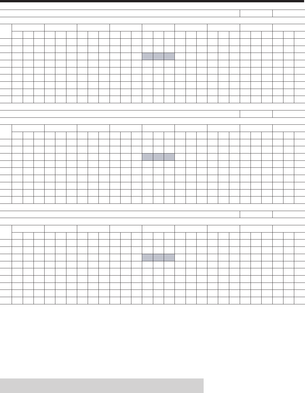
JOHNSON CONTROLS44
High Efciency Ratings – English - 380V/60Hz
MODEL: YCIV0157E/V E_IPLV = 13.8 V_IPLV = 14.9
AIR TEMPERATURE ON - CONDENSER (°F)
LCWT 75.0 80.0 85.0 90.0 95.0 100.0 105.0 110.0 115.0
(°F) TONS KW EER TONS KW EER TONS KW EER TONS KW EER TONS KW EER TONS KW EER TONS KW EER TONS KW EER TONS KW EER
40.0 148.1 119.3 13.4 146.8 127.9 12.5 145.2 136.8 11.6 143.4 146.1 10.8 141.4 155.8 10.0 139.1 166.7 9.3 136.1 177.9 8.5 130.1 186.8 7.8 124.0 196.1 7.1
42.0 152.7 120.3 13.7 151.5 129.0 12.8 149.9 138.0 11.9 148.1 147.3 11.1 146.1 157.0 10.3 143.7 168.0 9.5 140.1 178.8 8.7 133.9 187.6 8.0 127.6 196.9 7.3
44.0 157.4 121.4 14.0 156.2 130.1 13.1 154.7 139.2 12.2 152.8 148.6 11.3 150.8 158.3 10.5 148.3 169.3 9.7 144.2 179.8 9.0 137.7 188.7 8.2 131.3 197.7 7.5
45.0 159.8 122.0 14.2 158.6 130.7 13.2 157.1 139.8 12.3 155.2 149.2 11.5 153.2 159.0 10.7 150.7 170.0 9.9 146.3 180.3 9.1 139.7 189.1 8.3 133.2 198.1 7.6
46.0 162.2 122.6 14.3 161.0 131.3 13.4 159.5 140.4 12.4 157.7 149.8 11.6 155.6 159.7 10.8 153.0 170.7 10.0 148.3 180.8 9.2 141.7 189.6 8.4 135.1 198.6 7.6
48.0 167.0 123.7 14.6 165.9 132.5 13.6 164.4 141.7 12.7 162.6 151.2 11.9 160.4 161.0 11.0 157.9 172.1 10.2 152.5 181.8 9.4 145.7 190.6 8.6 138.9 199.6 7.8
50.0 171.9 124.8 14.9 170.8 133.7 13.9 169.3 143.0 13.0 167.5 152.5 12.1 165.4 162.5 11.3 162.7 173.6 10.4 156.7 182.8 9.6 149.8 191.6 8.8 142.7 200.6 8.0
52.0 176.8 125.9 15.2 175.8 134.9 14.2 174.4 144.3 13.3 172.6 153.9 12.4 170.4 163.9 11.5 167.7 175.1 10.7 161.0 183.8 9.8 153.9 192.6 9.0 146.7 201.5 8.2
55.0 184.4 127.6 15.7 183.5 136.8 14.7 182.1 146.3 13.7 180.3 156.0 12.8 178.1 166.1 11.9 174.8 177.0 11.0 167.5 185.5 10.1 160.2 194.1 9.3 152.8 203.1 8.5
MODEL: YCIV0177E/V E_IPLV = 13.7 V_IPLV = 14.9
AIR TEMPERATURE ON - CONDENSER (°F)
LCWT 75.0 80.0 85.0 90.0 95.0 100.0 105.0 110.0 115.0
(°F) TONS KW EER TONS KW EER TONS KW EER TONS KW EER TONS KW EER TONS KW EER TONS KW EER TONS KW EER TONS KW EER
40.0 157.1 128.7 13.3 156.3 134.6 12.5 155.0 144.6 11.6 153.5 155.4 10.8 151.9 166.7 10.0 150.0 179.5 9.3 147.0 191.8 8.5 142.2 203.1 7.8 136.2 213.6 7.1
42.0 162.5 126.2 13.8 161.3 135.5 12.8 159.9 145.6 11.9 158.3 156.2 11.1 156.6 167.5 10.3 154.7 180.4 9.5 151.2 192.5 8.7 146.1 203.7 8.0 139.9 214.2 7.3
44.0 167.6 127.3 14.1 166.3 136.5 13.2 164.8 146.6 12.2 163.2 157.2 11.4 161.5 168.4 10.6 159.4 181.3 9.7 155.6 193.3 9.0 150.1 204.3 8.2 143.6 214.9 7.5
45.0 170.2 127.9 14.3 168.9 137.1 13.3 167.4 147.1 12.4 165.7 157.7 11.5 163.9 168.9 10.7 161.8 181.8 9.9 157.8 193.6 9.1 152.1 204.6 8.3 145.5 215.2 7.6
46.0 172.8 128.6 14.4 171.4 137.7 13.5 169.9 147.6 12.5 168.2 158.2 11.7 166.4 169.4 10.8 164.3 182.2 10.0 160.0 194.0 9.2 154.1 204.9 8.4 147.5 215.5 7.7
48.0 178.0 129.9 14.7 176.7 138.9 13.8 175.1 148.7 12.8 173.4 159.2 11.9 171.5 170.5 11.1 169.1 183.2 10.2 164.6 194.8 9.4 158.3 205.5 8.6 151.4 216.1 7.9
50.0 183.4 131.4 15.0 182.0 140.3 14.1 180.4 150.0 13.1 178.6 160.4 12.2 176.6 171.6 11.4 173.9 184.0 10.5 169.2 195.6 9.6 162.5 206.1 8.8 154.4 213.8 8.1
52.0 188.9 133.0 15.3 187.5 141.7 14.3 185.8 151.3 13.4 183.9 161.7 12.5 181.9 172.8 11.6 178.7 184.9 10.7 173.9 196.4 9.9 166.8 206.7 9.0 156.2 208.5 8.4
55.0 197.4 135.6 15.7 195.8 144.1 14.8 194.1 153.5 13.8 192.2 163.7 12.9 190.0 174.7 12.0 186.2 186.4 11.1 180.8 197.5 10.2 173.3 207.7 9.3 158.8 200.7 8.8
MODEL: YCIV0187E/V E_IPLV = 13.5 V_IPLV = 15.3
AIR TEMPERATURE ON - CONDENSER (°F)
LCWT 75.0 80.0 85.0 90.0 95.0 100.0 105.0 110.0 115.0
(°F) TONS KW EER TONS KW EER TONS KW EER TONS KW EER TONS KW EER TONS KW EER TONS KW EER TONS KW EER TONS KW EER
40.0 174.7 142.1 13.3 173.7 149.6 12.5 172.2 161.3 11.6 170.5 173.7 10.7 168.7 186.7 9.9 166.5 201.2 9.2 163.0 213.5 8.5 158.0 223.0 7.9 151.4 231.0 7.3
42.0 180.2 143.2 13.7 179.2 150.5 12.9 177.7 162.1 11.9 175.9 174.5 11.0 174.0 187.5 10.2 171.7 202.1 9.4 167.8 213.9 8.7 162.4 223.4 8.1 155.6 231.5 7.5
44.0 185.8 144.5 14.0 184.8 151.6 13.2 183.2 163.0 12.2 181.4 175.3 11.3 179.4 188.3 10.5 177.0 203.0 9.7 172.7 214.3 9.0 166.9 223.7 8.3 159.9 231.9 7.7
45.0 189.0 141.6 14.3 187.6 152.1 13.3 186.0 163.6 12.4 184.2 175.8 11.5 182.1 188.8 10.6 179.7 203.5 9.8 175.2 214.5 9.1 169.2 223.8 8.4 162.1 232.1 7.8
46.0 191.8 142.3 14.5 190.4 152.7 13.5 188.8 164.1 12.5 187.0 176.3 11.6 184.9 189.2 10.8 182.5 204.0 9.9 177.7 214.6 9.2 171.5 223.9 8.5 164.3 232.3 7.9
48.0 197.5 143.8 14.8 196.2 154.0 13.8 194.5 165.2 12.8 192.6 177.3 11.9 190.5 190.3 11.0 188.0 204.9 10.2 182.8 215.0 9.5 176.2 224.2 8.8 168.7 232.5 8.1
50.0 203.4 145.3 15.1 202.0 155.4 14.1 200.3 166.4 13.1 198.4 178.4 12.2 196.2 191.3 11.3 193.3 205.3 10.4 188.0 215.3 9.7 181.0 224.4 9.0 173.3 232.8 8.3
52.0 209.3 147.0 15.3 207.9 156.9 14.4 206.2 167.8 13.4 204.2 179.7 12.5 202.0 192.4 11.6 198.6 205.8 10.7 193.2 215.7 10.0 185.8 224.5 9.2 177.4 231.9 8.6
55.0 218.4 149.9 15.7 217.0 159.4 14.8 215.3 170.1 13.8 213.2 181.8 12.9 210.9 194.4 12.0 206.8 206.5 11.1 201.2 216.3 10.4 193.2 224.8 9.6 180.3 223.0 9.0
NOTES:
1. kW = Compressor Input Power
2. EER = Chiller EER (includes power from compressors, fans, and control panels 0.8 KWi)
3. LCWT = Leaving Chilled Water Temperature
4. Ratings based on 2.4 GPM cooler water per ton
5. Rated IAW ARI Standard 550/590-98
6. Certied IAW the ARI Water-Chilling Packages Using the Vapor Compression Cycle Certication Program,
which is based on ARI Standard 550/590.

JOHNSON CONTROLS
FORM 201.23-EG1 (1007)
45
MODEL: YCIV0197E/V E_IPLV = 13.1 V_IPLV = 15.2
AIR TEMPERATURE ON - CONDENSER (°F)
LCWT 75.0 80.0 85.0 90.0 95.0 100.0 105.0 110.0 115.0
(°F) TONS KW EER TONS KW EER TONS KW EER TONS KW EER TONS KW EER TONS KW EER TONS KW EER TONS KW EER TONS KW EER
40.0 189.8 150.0 13.7 188.2 162.3 12.6 186.4 175.9 11.6 184.5 190.5 10.7 182.5 206.0 9.8 180.1 223.2 9.0 176.4 238.4 8.3 169.4 245.7 7.7 162.4 252.2 7.2
42.0 195.8 151.2 14.0 194.1 163.1 12.9 192.2 176.4 11.9 190.3 190.9 11.0 188.1 206.3 10.1 185.6 223.8 9.3 181.3 238.0 8.5 174.0 245.6 8.0 166.7 252.4 7.4
44.0 201.9 152.7 14.3 200.1 164.2 13.3 198.2 177.1 12.3 196.1 191.4 11.3 193.9 206.8 10.4 191.3 224.3 9.5 186.2 237.5 8.8 178.7 245.3 8.2 171.2 252.3 7.6
45.0 205.0 153.5 14.4 203.2 164.8 13.4 201.3 177.6 12.4 199.1 191.8 11.5 196.8 207.0 10.6 194.2 224.6 9.7 188.7 237.3 8.9 181.1 245.1 8.3 173.5 252.2 7.7
46.0 208.1 154.4 14.6 206.3 165.5 13.6 204.3 178.1 12.6 202.2 192.1 11.6 199.8 207.3 10.7 197.1 224.8 9.8 191.2 237.0 9.0 183.6 244.9 8.4 175.8 252.1 7.8
48.0 214.5 156.4 14.9 212.6 167.0 13.9 210.6 179.3 12.9 208.3 193.0 11.9 205.8 208.0 11.0 203.0 225.4 10.1 196.4 236.4 9.3 188.5 244.4 8.7 180.5 251.8 8.1
50.0 221.0 158.8 15.1 219.1 168.8 14.2 216.9 180.6 13.2 214.5 194.2 12.2 212.0 208.9 11.3 209.0 226.2 10.3 201.6 235.8 9.6 193.5 243.8 8.9 185.3 251.3 8.3
52.0 227.7 161.5 15.3 225.7 171.0 14.4 223.4 182.4 13.5 221.0 195.4 12.5 218.3 209.9 11.6 215.2 227.1 10.6 206.9 235.3 9.8 198.5 243.3 9.2 190.2 250.8 8.5
55.0 237.9 166.2 15.6 235.8 174.7 14.8 233.4 185.3 13.9 230.8 197.8 12.9 228.0 211.8 12.0 223.7 226.6 11.0 214.9 234.6 10.3 206.3 242.4 9.5 197.7 249.9 8.9
MODEL: YCIV0207E/V E_IPLV = 13.6 V_IPLV = 15.2
AIR TEMPERATURE ON - CONDENSER (°F)
LCWT 75.0 80.0 85.0 90.0 95.0 100.0 105.0 110.0 115.0
(°F) TONS KW EER TONS KW EER TONS KW EER TONS KW EER TONS KW EER TONS KW EER TONS KW EER TONS KW EER TONS KW EER
40.0 201.7 158.0 13.7 200.1 170.5 12.7 198.3 184.2 11.7 196.4 199.0 10.8 194.4 214.7 10.0 192.0 232.3 9.2 188.3 247.5 8.5 182.0 257.3 7.9 174.6 264.2 7.4
42.0 208.1 159.3 14.0 206.4 171.5 13.0 204.5 184.9 12.1 202.5 199.6 11.1 200.4 215.2 10.3 197.9 233.0 9.4 193.7 247.7 8.7 186.9 257.3 8.1 179.3 264.4 7.6
44.0 214.6 160.8 14.4 212.8 172.7 13.4 210.9 185.9 12.4 208.8 200.3 11.4 206.5 215.9 10.6 203.9 233.7 9.7 199.2 247.9 9.0 191.9 257.1 8.4 184.1 264.4 7.8
45.0 217.9 161.7 14.5 216.1 173.3 13.5 214.1 186.4 12.5 211.9 200.7 11.6 209.6 216.2 10.7 206.9 234.0 9.8 202.0 248.0 9.1 194.5 256.9 8.5 186.6 264.4 7.9
46.0 221.3 162.6 14.7 219.4 174.1 13.7 217.4 187.0 12.7 215.1 201.3 11.7 212.8 216.6 10.9 210.0 234.4 10.0 204.8 248.1 9.2 197.1 256.7 8.6 189.0 264.3 8.0
48.0 228.1 164.7 14.9 226.1 175.7 14.0 224.0 188.3 13.0 221.7 202.3 12.0 219.2 217.6 11.1 216.2 235.0 10.2 210.6 248.2 9.5 202.3 256.4 8.8 194.0 264.0 8.2
50.0 235.0 167.0 15.2 233.0 177.7 14.3 230.8 189.9 13.3 228.4 203.6 12.3 225.8 218.6 11.4 222.3 235.2 10.5 216.2 247.7 9.7 207.7 255.9 9.1 199.1 263.6 8.5
52.0 242.1 169.6 15.4 240.0 179.8 14.5 237.7 191.7 13.6 235.2 205.0 12.6 232.5 219.8 11.7 228.5 235.5 10.8 221.8 247.3 10.0 213.1 255.5 9.3 203.0 260.4 8.7
55.0 252.7 174.0 15.8 250.6 183.4 14.9 248.2 194.7 14.0 245.6 207.6 13.0 242.7 222.0 12.1 238.0 236.2 11.2 230.5 246.9 10.4 221.4 254.8 9.7 206.3 249.7 9.2
MODEL: YCIV0227E/V E_IPLV = 13.3 V_IPLV = 15.3
AIR TEMPERATURE ON - CONDENSER (°F)
LCWT 75.0 80.0 85.0 90.0 95.0 100.0 105.0 110.0 115.0
(°F) TONS KW EER TONS KW EER TONS KW EER TONS KW EER TONS KW EER TONS KW EER TONS KW EER TONS KW EER TONS KW EER
40.0 209.5 163.7 13.7 207.9 176.2 12.7 206.1 189.6 11.8 204.2 203.9 10.9 202.1 219.1 10.1 199.8 236.1 9.4 197.2 254.0 8.6 190.9 264.3 8.1 183.3 271.6 7.5
42.0 216.1 165.1 14.0 214.5 177.4 13.0 212.6 190.7 12.1 210.6 204.9 11.2 208.4 220.0 10.4 205.9 237.1 9.6 203.2 255.1 8.9 196.1 264.5 8.3 188.3 271.8 7.7
44.0 222.9 166.7 14.3 221.2 178.7 13.3 219.2 191.9 12.4 217.1 206.0 11.5 214.9 221.0 10.7 212.2 238.3 9.9 209.4 256.2 9.1 201.5 264.5 8.5 193.4 271.9 7.9
45.0 226.4 167.6 14.5 224.6 179.4 13.5 222.6 192.5 12.6 220.4 206.6 11.7 218.1 221.6 10.8 215.4 238.8 10.0 212.4 256.5 9.2 204.2 264.5 8.6 196.0 271.9 8.1
46.0 229.8 168.5 14.6 228.0 180.3 13.7 226.0 193.2 12.7 223.8 207.2 11.8 221.4 222.2 11.0 218.6 239.4 10.1 215.2 256.5 9.3 206.9 264.4 8.7 198.6 271.9 8.2
48.0 236.9 170.4 14.9 235.0 181.9 14.0 232.9 194.7 13.0 230.6 208.5 12.1 228.1 223.4 11.2 225.2 240.6 10.4 221.0 256.5 9.6 212.5 264.4 9.0 203.9 271.9 8.4
50.0 244.0 172.5 15.2 242.1 183.7 14.2 239.9 196.3 13.3 237.6 210.0 12.4 235.0 224.8 11.5 232.0 241.9 10.6 226.9 256.4 9.8 218.1 264.3 9.2 209.3 271.8 8.6
52.0 251.1 174.8 15.5 249.2 185.7 14.5 247.0 198.0 13.6 244.6 211.6 12.7 242.0 226.2 11.8 238.9 243.2 10.9 232.9 256.4 10.1 223.9 264.3 9.4 214.8 271.7 8.8
55.0 262.1 178.5 15.8 260.1 189.1 14.9 257.8 201.0 14.0 255.3 214.2 13.1 252.5 228.6 12.2 249.2 245.5 11.3 242.1 256.6 10.5 232.7 264.2 9.8 223.2 271.5 9.2
NOTES:
1. kW = Compressor Input Power
2. EER = Chiller EER (includes power from compressors, fans, and control panels 0.8 KWi)
3. LCWT = Leaving Chilled Water Temperature
4. Ratings based on 2.4 GPM cooler water per ton
5. Rated IAW ARI Standard 550/590-98
6. Certied IAW the ARI Water-Chilling Packages Using the Vapor Compression Cycle Certication Program,
which is based on ARI Standard 550/590.

JOHNSON CONTROLS46
High Efciency Ratings – English - 380V/60Hz
MODEL: YCIV0247E/V E_IPLV = 13.0 V_IPLV = 15.2
AIR TEMPERATURE ON - CONDENSER (°F)
LCWT 75.0 80.0 85.0 90.0 95.0 100.0 105.0 110.0 115.0
(°F) TONS KW EER TONS KW EER TONS KW EER TONS KW EER TONS KW EER TONS KW EER TONS KW EER TONS KW EER TONS KW EER
40.0 232.7 188.7 13.4 230.8 202.8 12.4 228.7 217.8 11.5 226.4 233.8 10.7 223.9 250.7 9.9 221.1 269.7 9.2 216.9 286.7 8.5 210.2 299.0 7.9 202.9 309.9 7.4
42.0 240.0 190.5 13.7 238.0 204.4 12.7 235.8 219.4 11.8 233.4 235.4 11.0 230.8 252.2 10.2 227.9 271.2 9.4 223.2 287.9 8.7 216.0 299.7 8.1 208.5 310.7 7.6
44.0 247.4 192.4 14.0 245.4 206.2 13.0 243.1 221.0 12.1 240.6 237.0 11.2 237.9 253.8 10.4 234.7 272.7 9.6 229.7 289.0 8.9 221.9 300.3 8.3 213.0 308.9 7.8
45.0 251.2 193.5 14.1 249.1 207.1 13.2 246.8 222.0 12.2 244.2 237.9 11.4 241.4 254.7 10.5 238.1 273.3 9.7 232.8 289.3 9.0 225.0 300.6 8.4 214.3 305.5 7.9
46.0 255.1 194.5 14.3 252.9 208.1 13.3 250.5 222.9 12.4 247.9 238.7 11.5 245.1 255.5 10.7 241.5 274.0 9.9 236.0 289.6 9.1 228.0 301.0 8.5 215.6 302.0 8.0
48.0 262.8 196.7 14.5 260.6 210.2 13.6 258.1 224.8 12.6 255.4 240.5 11.8 252.4 257.3 10.9 248.4 275.2 10.1 242.4 290.2 9.4 234.2 301.6 8.7 218.0 294.5 8.3
50.0 270.8 199.2 14.8 268.5 212.4 13.9 265.9 226.9 12.9 263.1 242.5 12.0 260.0 259.2 11.2 255.5 276.5 10.3 248.9 290.9 9.6 240.5 302.2 9.0 220.2 286.6 8.6
52.0 278.9 201.8 15.1 276.5 214.8 14.1 273.8 229.1 13.2 270.9 244.6 12.3 267.7 261.2 11.4 262.8 277.9 10.6 255.5 291.5 9.8 246.9 302.8 9.2 222.2 278.4 8.9
55.0 291.2 205.5 15.5 288.7 218.6 14.5 285.9 232.8 13.6 282.8 248.1 12.7 279.5 264.4 11.8 273.9 280.3 10.9 265.7 292.6 10.2 256.7 303.7 9.5 225.0 266.8 9.4
MODEL: YCIV0267E/V E_IPLV = 13.5 V_IPLV = 15.2
AIR TEMPERATURE ON - CONDENSER (°F)
LCWT 75.0 80.0 85.0 90.0 95.0 100.0 105.0 110.0 115.0
(°F) TONS KW EER TONS KW EER TONS KW EER TONS KW EER TONS KW EER TONS KW EER TONS KW EER TONS KW EER TONS KW EER
40.0 264.2 207.4 13.7 261.9 224.0 12.7 259.3 242.0 11.7 256.4 261.1 10.8 253.3 281.0 10.0 249.7 303.5 9.2 244.9 324.5 8.4 234.7 336.1 7.8 224.5 346.9 7.3
42.0 272.6 209.1 14.1 270.3 225.3 13.0 267.6 243.0 12.0 264.6 262.0 11.1 261.3 282.1 10.3 257.6 304.7 9.4 251.8 324.8 8.7 241.3 336.5 8.0 230.7 347.6 7.5
44.0 281.2 210.9 14.4 278.8 226.8 13.4 276.0 244.2 12.4 272.9 263.1 11.4 269.5 283.1 10.5 265.6 305.9 9.7 258.9 324.8 8.9 247.9 336.7 8.3 237.1 348.0 7.7
45.0 285.5 211.9 14.6 283.1 227.6 13.5 280.3 244.9 12.5 277.2 263.7 11.6 273.7 283.7 10.7 269.7 306.5 9.8 262.4 324.8 9.0 251.3 336.8 8.4 240.3 348.2 7.8
46.0 289.9 213.1 14.7 287.4 228.5 13.7 284.6 245.7 12.7 281.4 264.4 11.7 277.9 284.3 10.8 273.8 307.1 9.9 266.0 324.8 9.2 254.7 336.9 8.5 243.5 348.4 7.9
48.0 298.8 215.5 15.0 296.3 230.5 14.0 293.4 247.4 13.0 290.1 265.8 12.0 286.5 285.6 11.1 282.2 308.4 10.2 273.3 324.8 9.4 261.7 337.0 8.7 250.2 348.5 8.1
50.0 307.8 218.3 15.3 305.3 232.8 14.3 302.3 249.3 13.3 299.0 267.6 12.3 295.2 287.1 11.4 290.8 309.8 10.5 280.7 324.7 9.7 268.8 336.9 8.9 256.9 348.7 8.3
52.0 317.0 221.3 15.5 314.5 235.4 14.6 311.5 251.5 13.6 308.0 269.4 12.6 304.2 288.8 11.7 299.6 311.4 10.7 288.2 324.7 9.9 276.0 336.9 9.2 263.8 348.7 8.5
55.0 331.1 226.5 15.9 328.5 239.9 15.0 325.4 255.3 14.0 321.9 272.6 13.0 317.9 291.6 12.1 312.4 312.6 11.2 299.8 324.7 10.3 287.1 336.8 9.6 274.4 348.6 8.8
MODEL: YCIV0287E/V E_IPLV = 13.2 V_IPLV = 15.1
AIR TEMPERATURE ON - CONDENSER (°F)
LCWT 75.0 80.0 85.0 90.0 95.0 100.0 105.0 110.0 115.0
(°F) TONS KW EER TONS KW EER TONS KW EER TONS KW EER TONS KW EER TONS KW EER TONS KW EER TONS KW EER TONS KW EER
40.0 281.2 217.9 13.9 278.8 235.8 12.8 276.1 255.4 11.8 273.1 276.5 10.9 270.0 298.6 10.0 266.3 323.6 9.2 261.8 347.8 8.4 251.2 358.5 7.9 240.7 367.9 7.3
42.0 290.1 219.7 14.2 287.6 236.9 13.2 284.8 256.2 12.1 281.7 277.1 11.2 278.4 299.3 10.3 274.6 324.3 9.4 269.1 347.3 8.7 258.1 358.4 8.1 247.2 368.2 7.5
44.0 299.3 221.7 14.5 296.7 238.4 13.5 293.8 257.2 12.5 290.5 277.8 11.5 287.1 299.9 10.6 283.1 325.2 9.7 276.5 346.7 8.9 265.1 358.1 8.3 253.9 368.3 7.7
45.0 303.9 222.9 14.7 301.3 239.3 13.7 298.3 257.8 12.6 295.0 278.3 11.7 291.5 300.3 10.7 287.4 325.6 9.8 280.3 346.3 9.1 268.7 357.8 8.4 257.3 368.2 7.8
46.0 308.6 224.2 14.9 305.9 240.3 13.8 302.9 258.6 12.8 299.6 278.8 11.8 296.0 300.7 10.9 291.8 326.0 10.0 284.1 345.9 9.2 272.4 357.5 8.5 260.8 368.0 8.0
48.0 318.1 227.0 15.1 315.4 242.4 14.1 312.2 260.2 13.1 308.8 280.0 12.1 305.0 301.7 11.2 300.7 326.9 10.2 291.8 345.2 9.5 279.8 356.9 8.8 267.8 367.6 8.2
50.0 327.8 230.4 15.4 325.0 245.0 14.4 321.8 262.2 13.4 318.2 281.7 12.4 314.3 303.0 11.5 309.8 327.9 10.5 299.7 344.4 9.7 287.3 356.1 9.0 274.9 367.1 8.4
52.0 337.8 234.2 15.6 334.8 248.1 14.7 331.5 264.5 13.7 327.8 283.6 12.7 323.8 304.4 11.8 319.1 329.1 10.8 307.7 343.7 10.0 295.0 355.3 9.3 282.2 366.4 8.6
55.0 353.0 240.9 15.9 349.9 253.4 15.1 346.5 268.9 14.1 342.7 286.9 13.2 338.4 307.1 12.2 333.2 331.2 11.2 320.0 342.8 10.4 306.7 354.4 9.7 293.5 365.2 9.0
NOTES:
1. kW = Compressor Input Power
2. EER = Chiller EER (includes power from compressors, fans, and control panels 0.8 KWi)
3. LCWT = Leaving Chilled Water Temperature
4. Ratings based on 2.4 GPM cooler water per ton
5. Rated IAW ARI Standard 550/590-98

JOHNSON CONTROLS
FORM 201.23-EG1 (1007)
47
MODEL: YCIV0327E/V E_IPLV = 14.1 V_IPLV = 15.0
AIR TEMPERATURE ON - CONDENSER (°F)
LCWT 75.0 80.0 85.0 90.0 95.0 100.0 105.0 110.0 115.0
(°F) TONS KW EER TONS KW EER TONS KW EER TONS KW EER TONS KW EER TONS KW EER TONS KW EER TONS KW EER TONS KW EER
40.0 305.7 240.0 13.7 303.0 259.0 12.7 300.2 279.9 11.7 297.2 302.4 10.8 293.9 326.1 10.0 290.2 352.9 9.2 283.6 374.3 8.5 273.3 387.8 7.9 262.0 397.8 7.4
42.0 315.4 242.0 14.1 312.6 260.6 13.1 309.7 281.0 12.1 306.4 303.3 11.1 303.0 327.1 10.3 299.1 353.9 9.4 291.6 374.4 8.7 280.6 387.7 8.1 269.0 398.2 7.6
44.0 325.4 244.3 14.4 322.5 262.4 13.4 319.3 282.6 12.4 315.9 304.5 11.4 312.3 328.1 10.6 308.2 355.1 9.7 299.7 374.5 9.0 288.1 387.5 8.3 276.1 398.3 7.8
45.0 330.4 245.6 14.5 327.5 263.4 13.5 324.3 283.4 12.5 320.8 305.2 11.6 317.1 328.7 10.7 312.8 355.7 9.8 303.9 374.5 9.1 292.0 387.3 8.5 279.7 398.2 7.9
46.0 335.5 247.0 14.7 332.5 264.6 13.7 329.2 284.3 12.7 325.7 306.0 11.7 321.9 329.3 10.8 317.5 356.3 9.9 308.1 374.5 9.2 295.9 387.1 8.6 283.4 398.2 8.0
48.0 345.9 250.2 15.0 342.8 267.1 14.0 339.4 286.3 13.0 335.6 307.7 12.0 331.6 330.8 11.1 326.7 357.1 10.2 316.6 374.4 9.5 303.7 386.6 8.8 290.9 397.8 8.2
50.0 356.6 253.7 15.2 353.3 270.0 14.3 349.7 288.8 13.3 345.8 309.6 12.3 341.7 332.5 11.4 335.8 357.1 10.5 325.0 373.7 9.7 311.7 386.0 9.1 298.5 397.4 8.4
52.0 367.5 257.7 15.5 364.0 273.3 14.6 360.3 291.5 13.6 356.2 311.9 12.6 351.9 334.3 11.7 345.0 357.3 10.8 333.5 373.2 10.0 319.9 385.3 9.3 304.6 393.2 8.7
55.0 384.2 264.6 15.8 380.5 279.0 14.9 376.6 296.2 14.0 372.3 315.9 13.0 367.7 337.8 12.1 359.2 357.9 11.2 346.6 372.5 10.4 332.4 384.3 9.7 309.4 377.3 9.2
MODEL: YCIV0357E/V E_IPLV = 12.4 V_IPLV = 15.6
AIR TEMPERATURE ON - CONDENSER (°F)
LCWT 75.0 80.0 85.0 90.0 95.0 100.0 105.0 110.0 115.0
(°F) TONS KW EER TONS KW EER TONS KW EER TONS KW EER TONS KW EER TONS KW EER TONS KW EER TONS KW EER TONS KW EER
40.0 346.6 278.3 13.5 343.6 298.4 12.5 340.1 320.0 11.7 336.3 342.9 10.8 332.2 367.0 10.0 327.5 394.3 9.3 321.2 419.8 8.6 311.7 439.6 8.0 301.2 457.0 7.4
42.0 357.6 281.0 13.8 354.5 301.0 12.8 351.0 322.5 11.9 347.0 345.4 11.1 342.7 369.4 10.3 337.8 396.8 9.5 330.8 421.5 8.8 320.6 440.8 8.2 309.7 458.3 7.6
44.0 368.9 284.0 14.1 365.6 303.9 13.1 362.0 325.2 12.2 357.9 347.9 11.4 353.5 371.9 10.5 348.3 399.3 9.7 340.5 423.3 9.0 329.7 442.0 8.4 318.4 459.5 7.8
45.0 374.5 285.5 14.2 371.3 305.4 13.3 367.6 326.6 12.4 363.5 349.3 11.5 358.9 373.2 10.7 353.7 400.6 9.8 345.5 424.1 9.1 334.4 442.6 8.5 322.9 460.1 7.9
46.0 380.3 287.3 14.4 377.0 306.9 13.4 373.3 328.1 12.5 369.0 350.8 11.6 364.4 374.8 10.8 359.1 402.0 10.0 350.5 425.0 9.2 339.1 443.2 8.6 327.3 460.8 8.0
48.0 391.9 290.7 14.7 388.6 310.1 13.7 384.7 331.2 12.8 380.4 353.7 11.9 375.7 377.6 11.1 369.9 404.7 10.2 360.8 426.8 9.5 348.7 444.4 8.8 336.5 462.0 8.2
50.0 403.8 294.3 14.9 400.4 313.6 14.0 396.5 334.4 13.0 392.0 356.8 12.2 387.1 380.6 11.3 380.7 406.7 10.5 370.9 428.1 9.7 358.4 445.7 9.0 341.0 452.1 8.5
52.0 415.9 298.3 15.2 412.4 317.3 14.2 408.4 338.0 13.3 403.8 360.2 12.4 398.8 383.9 11.6 391.6 408.8 10.7 381.1 429.5 9.9 368.3 447.0 9.3 344.4 439.8 8.8
55.0 434.4 303.6 15.6 431.1 322.3 14.7 426.7 343.6 13.7 422.0 365.5 12.8 416.7 389.1 11.9 408.3 412.2 11.1 396.9 431.8 10.3 383.6 449.0 9.6 349.0 421.8 9.3
NOTES:
1. kW = Compressor Input Power
2. EER = Chiller EER (includes power from compressors, fans, and control panels 0.8 KWi)
3. LCWT = Leaving Chilled Water Temperature
4. Ratings based on 2.4 GPM cooler water per ton
5. Rated IAW ARI Standard 550/590-98

JOHNSON CONTROLS48
Standard Efciency Ratings – SI - 380V/60Hz
MODEL: YCIV0157S/P
AIR TEMPERATURE ON - CONDENSER (°C)
LCWT 25.0 30.0 35.0 40.0 45.0 46.0
(°C) KWi KWi COP KWi KWi COP KWi KWi COP KWi KWi COP KWi KWi COP KWi KWi COP
5.0 528.8 133.1 3.6 520.9 152.2 3.2 511.8 172.8 2.8 497.4 196.1 2.4 462.2 214.6 2.0 455.0 218.5 2.0
6.0 543.2 134.0 3.7 535.0 152.9 3.2 525.5 173.7 2.8 509.5 196.7 2.4 473.3 215.3 2.1 465.8 219.2 2.0
7.0 557.9 134.9 3.8 549.4 153.8 3.3 539.5 174.5 2.9 521.7 197.3 2.5 484.5 216.0 2.1 476.8 219.9 2.0
8.0 572.9 135.8 3.8 564.1 154.6 3.4 553.7 175.4 2.9 533.9 197.9 2.5 495.5 216.9 2.2 487.9 220.6 2.1
9.0 588.0 136.8 3.9 578.9 155.6 3.4 568.2 176.3 3.0 546.3 198.5 2.6 507.2 217.5 2.2 499.2 221.3 2.1
10.0 603.4 137.9 4.0 594.1 156.6 3.5 583.0 177.3 3.1 558.9 199.1 2.6 519.0 218.1 2.2 510.8 222.0 2.2
11.0 619.1 139.1 4.1 609.5 157.6 3.6 598.0 178.4 3.1 571.6 199.7 2.7 531.0 218.7 2.3 522.6 222.6 2.2
12.0 635.0 140.3 4.1 625.1 158.7 3.6 613.2 179.4 3.2 584.5 200.3 2.7 542.9 219.3 2.3 532.1 221.1 2.3
13.0 651.2 141.6 4.2 641.0 159.8 3.7 628.7 180.5 3.2 597.5 201.0 2.8 555.1 219.9 2.4 537.5 215.9 2.3
MODEL: YCIV0177S/P
AIR TEMPERATURE ON - CONDENSER (°C)
LCWT 25.0 30.0 35.0 40.0 45.0 46.0
(°C) KWi KWi COP KWi KWi COP KWi KWi COP KWi KWi COP KWi KWi COP KWi KWi COP
5.0 587.3 146.6 3.7 576.4 167.9 3.2 563.2 190.9 2.8 536.0 208.9 2.4 491.4 218.9 2.1 462.3 206.9 2.1
6.0 603.7 147.6 3.8 592.6 168.9 3.3 579.1 192.0 2.8 550.1 209.5 2.5 496.5 214.8 2.2 467.9 203.3 2.2
7.0 620.4 148.6 3.8 609.2 169.9 3.3 595.2 193.1 2.9 563.9 210.0 2.5 502.4 210.9 2.2 474.0 199.7 2.2
8.0 637.4 149.7 3.9 626.0 170.9 3.4 611.2 193.9 3.0 577.7 210.4 2.6 508.8 207.2 2.3 479.4 195.7 2.3
9.0 654.7 150.8 4.0 643.0 171.9 3.5 626.8 194.3 3.0 591.8 210.7 2.6 514.8 203.2 2.4 484.4 191.6 2.4
10.0 672.0 152.0 4.1 660.4 173.1 3.5 642.6 194.8 3.1 605.9 211.0 2.7 520.5 199.0 2.5 488.9 187.6 2.4
11.0 689.4 153.4 4.1 677.8 174.4 3.6 658.6 195.3 3.2 620.3 211.4 2.8 525.7 194.9 2.5 493.2 183.6 2.5
12.0 707.1 154.9 4.2 695.4 175.6 3.7 674.7 195.8 3.2 634.8 211.7 2.8 530.6 190.8 2.6 497.4 179.6 2.6
13.0 725.1 156.4 4.3 713.3 177.0 3.7 691.0 196.4 3.3 649.5 212.0 2.9 534.7 186.7 2.7 501.5 175.7 2.7
MODEL: YCIV0187S/P
AIR TEMPERATURE ON - CONDENSER (°C)
LCWT 25.0 30.0 35.0 40.0 45.0 46.0
(°C) KWi KWi COP KWi KWi COP KWi KWi COP KWi KWi COP KWi KWi COP KWi KWi COP
5.0 639.4 158.1 3.7 628.8 180.6 3.2 616.7 205.2 2.8 594.6 230.0 2.4 551.9 245.6 2.1 543.3 248.7 2.1
6.0 657.2 159.2 3.8 646.3 181.6 3.3 633.7 206.2 2.9 608.9 230.4 2.5 564.8 246.2 2.2 556.2 249.2 2.1
7.0 675.3 160.5 3.9 664.0 182.7 3.4 651.0 207.3 2.9 623.5 230.8 2.5 578.2 246.7 2.2 569.2 249.7 2.2
8.0 693.7 161.8 3.9 682.0 183.9 3.4 668.4 208.5 3.0 638.4 231.1 2.6 591.9 247.1 2.3 582.6 250.2 2.2
9.0 712.5 163.2 4.0 700.4 185.1 3.5 686.2 209.8 3.1 653.5 231.5 2.7 605.8 247.4 2.3 596.2 250.6 2.2
10.0 731.6 164.7 4.1 719.0 186.5 3.6 704.3 211.0 3.1 668.7 231.8 2.7 619.9 247.8 2.4 605.6 247.6 2.3
11.0 751.0 166.3 4.1 738.0 187.9 3.6 722.8 212.3 3.2 683.9 232.2 2.8 634.3 248.1 2.4 610.8 241.4 2.4
12.0 770.7 168.0 4.2 757.3 189.4 3.7 741.6 213.7 3.2 699.5 232.6 2.8 648.9 248.4 2.5 616.4 235.6 2.5
13.0 790.7 169.9 4.3 776.9 191.0 3.8 760.7 215.3 3.3 715.3 233.0 2.9 660.2 246.2 2.5 621.8 229.7 2.5
NOTES:
1. kWo = Unit kW Cooling Capacity Output
2. kW
i
= Compressor kW Input
3. COP = Coefcient of Performance (includes condenser fan power)
4. LCWT = Leaving Chilled Water Temperature
5. Ratings based on 0.168 l/s cooler water per ton, and 0.018 (m2 – °C)/kW

JOHNSON CONTROLS
FORM 201.23-EG1 (1007)
49
MODEL: YCIV0207S/P
AIR TEMPERATURE ON - CONDENSER (°C)
LCWT 25.0 30.0 35.0 40.0 45.0 46.0
(°C) KWi KWi COP KWi KWi COP KWi KWi COP KWi KWi COP KWi KWi COP KWi KWi COP
5.0 689.5 170.6 3.7 676.6 196.8 3.2 662.1 226.0 2.8 629.2 248.2 2.4 564.5 248.2 2.1 530.0 233.3 2.1
6.0 709.0 171.7 3.8 695.5 197.6 3.3 680.0 226.6 2.8 644.2 248.0 2.5 569.7 242.9 2.2 536.2 228.8 2.2
7.0 728.8 173.0 3.9 714.8 198.5 3.4 697.4 226.7 2.9 659.6 247.8 2.5 576.2 238.0 2.3 542.0 223.9 2.3
8.0 749.1 174.4 4.0 734.4 199.5 3.4 715.2 226.8 3.0 675.3 247.4 2.6 582.3 232.8 2.4 547.6 219.0 2.3
9.0 769.7 176.1 4.0 754.5 200.6 3.5 733.3 227.1 3.0 691.2 247.0 2.6 588.4 227.7 2.4 553.1 214.3 2.4
10.0 790.7 178.1 4.1 774.9 202.0 3.6 751.7 227.4 3.1 707.2 246.7 2.7 594.3 222.6 2.5 558.1 209.8 2.5
11.0 812.1 180.2 4.2 795.7 203.6 3.6 770.3 227.8 3.2 723.6 246.3 2.8 599.9 217.8 2.6 563.0 205.4 2.6
12.0 834.0 182.6 4.2 816.9 205.3 3.7 789.3 228.2 3.2 740.2 245.9 2.8 605.2 213.2 2.7 567.7 200.9 2.6
13.0 856.2 185.1 4.3 838.5 207.2 3.8 808.6 228.9 3.3 757.1 245.6 2.9 610.1 208.7 2.7 572.5 196.6 2.7
MODEL: YCIV0227S/P
AIR TEMPERATURE ON - CONDENSER (°C)
LCWT 25.0 30.0 35.0 40.0 45.0 46.0
(°C) KWi KWi COP KWi KWi COP KWi KWi COP KWi KWi COP KWi KWi COP KWi KWi COP
5.0 748.4 182.6 3.8 735.1 208.5 3.3 720.1 236.9 2.8 690.4 263.0 2.5 640.3 275.7 2.2 630.5 278.0 2.1
6.0 769.6 184.0 3.8 755.7 209.7 3.3 739.9 238.2 2.9 707.1 263.1 2.5 655.5 276.0 2.2 645.2 278.3 2.2
7.0 791.1 185.5 3.9 776.7 211.0 3.4 760.1 239.6 3.0 724.0 263.2 2.6 671.0 276.2 2.3 660.4 278.6 2.2
8.0 813.1 187.2 4.0 798.1 212.4 3.5 780.9 241.0 3.0 741.2 263.3 2.7 686.8 276.3 2.3 676.0 278.7 2.3
9.0 835.5 189.0 4.1 819.9 214.1 3.6 802.0 242.4 3.1 758.8 263.3 2.7 702.9 276.4 2.4 690.9 278.2 2.3
10.0 858.4 190.9 4.1 842.2 215.7 3.6 823.6 244.0 3.2 776.3 263.4 2.8 719.2 276.5 2.5 697.1 272.2 2.4
11.0 881.7 193.0 4.2 864.9 217.5 3.7 845.6 245.6 3.2 794.4 263.5 2.8 735.9 276.4 2.5 703.5 266.0 2.5
12.0 905.3 195.2 4.3 888.1 219.4 3.8 867.9 247.4 3.3 812.7 263.6 2.9 752.5 276.2 2.6 710.1 259.7 2.6
13.0 929.1 197.6 4.3 911.5 221.4 3.8 890.8 249.3 3.4 831.3 263.7 3.0 759.3 269.5 2.7 716.0 253.0 2.7
MODEL: YCIV0247S/P
AIR TEMPERATURE ON - CONDENSER (°C)
LCWT 25.0 30.0 35.0 40.0 45.0 46.0
(°C) KWi KWi COP KWi KWi COP KWi KWi COP KWi KWi COP KWi KWi COP KWi KWi COP
5.0 821.2 201.2 3.7 807.2 229.1 3.3 791.2 259.7 2.8 762.5 289.7 2.5 716.5 309.3 2.2 707.4 313.0 2.1
6.0 844.2 202.8 3.8 829.7 230.5 3.3 812.9 261.2 2.9 781.4 290.3 2.5 733.9 310.0 2.2 724.3 313.8 2.2
7.0 867.7 204.5 3.9 852.5 232.1 3.4 834.9 262.9 3.0 800.6 290.9 2.6 751.6 310.7 2.3 740.0 313.3 2.2
8.0 891.5 206.4 4.0 875.8 233.9 3.5 857.5 264.6 3.0 820.1 291.5 2.7 769.8 311.3 2.3 747.8 307.2 2.3
9.0 915.8 208.4 4.0 899.5 235.7 3.5 880.5 266.3 3.1 839.9 292.1 2.7 788.2 311.9 2.4 755.3 300.7 2.4
10.0 940.5 210.4 4.1 923.7 237.6 3.6 904.0 268.2 3.2 859.8 292.8 2.8 804.7 311.1 2.4 762.4 293.8 2.4
11.0 965.7 212.7 4.2 948.2 239.6 3.7 927.8 270.0 3.2 880.3 293.4 2.8 812.6 304.1 2.5 769.0 286.5 2.5
12.0 991.2 215.1 4.2 973.3 241.7 3.7 952.1 272.1 3.3 901.1 294.0 2.9 820.0 296.6 2.6 775.2 279.1 2.6
13.0 1017.2 217.0 4.3 998.6 243.9 3.8 976.9 274.2 3.3 922.2 294.7 2.9 826.9 289.0 2.7 780.9 272.0 2.7
NOTES:
1. kWo = Unit kW Cooling Capacity Output
2. kW
i
= Compressor kW Input
3. COP = Coefcient of Performance (includes condenser fan power)
4. LCWT = Leaving Chilled Water Temperature
5. Ratings based on 0.168 l/s cooler water per ton, and 0.018 (m2 – °C)/kW

JOHNSON CONTROLS50
Standard Efciency Ratings – SI - 380V/60Hz
MODEL: YCIV267S/P
AIR TEMPERATURE ON - CONDENSER (°C)
LCWT 25.0 30.0 35.0 40.0 45.0 46.0
(°C) KWi KWi COP KWi KWi COP KWi KWi COP KWi KWi COP KWi KWi COP KWi KWi COP
5.0 894.3 219.6 3.7 879.6 249.4 3.3 862.6 282.2 2.9 834.9 316.1 2.5 793.0 342.4 2.2 784.6 347.5 2.1
6.0 919.1 221.4 3.8 903.8 251.2 3.3 886.1 284.0 2.9 856.0 317.2 2.5 812.6 343.6 2.2 803.8 348.8 2.2
7.0 944.5 223.3 3.9 928.6 253.0 3.4 909.9 286.0 3.0 877.4 318.3 2.6 832.6 344.8 2.3 821.7 348.8 2.2
8.0 970.2 225.4 4.0 953.7 255.0 3.5 934.4 287.9 3.0 899.1 319.4 2.7 853.0 345.9 2.3 829.3 341.0 2.3
9.0 996.3 227.5 4.0 979.4 257.0 3.5 959.2 290.0 3.1 921.3 320.5 2.7 873.9 347.1 2.4 837.1 333.1 2.4
10.0 1023.0 229.8 4.1 1005.4 259.2 3.6 984.6 292.1 3.2 943.6 321.7 2.8 892.6 346.7 2.4 844.9 325.2 2.5
11.0 1050.0 232.2 4.2 1031.8 261.5 3.7 1010.4 294.2 3.2 966.5 322.9 2.8 900.9 338.2 2.5 852.6 317.4 2.5
12.0 1077.5 234.8 4.2 1058.8 263.8 3.7 1036.6 296.5 3.3 989.7 324.0 2.9 909.1 329.9 2.6 860.1 309.8 2.6
13.0 1105.6 236.2 4.3 1086.0 266.3 3.8 1063.2 298.9 3.3 1013.3 325.3 2.9 917.1 321.7 2.7 867.0 302.7 2.7
MODEL: YCIV287S/P
AIR TEMPERATURE ON - CONDENSER (°C)
LCWT 25.0 30.0 35.0 40.0 45.0 46.0
(°C) KWi KWi COP KWi KWi COP KWi KWi COP KWi KWi COP KWi KWi COP KWi KWi COP
5.0 949.5 231.0 3.8 932.1 265.4 3.2 911.8 303.1 2.8 873.5 336.2 2.4 791.6 344.8 2.2 743.1 325.2 2.1
6.0 976.3 232.5 3.8 958.3 266.7 3.3 937.2 304.4 2.9 895.5 336.6 2.5 799.7 338.3 2.2 752.1 319.4 2.2
7.0 1003.6 234.1 3.9 985.0 268.0 3.4 962.8 305.6 2.9 917.2 336.9 2.6 808.0 331.5 2.3 761.5 313.7 2.3
8.0 1031.4 235.8 4.0 1012.3 269.5 3.5 988.1 306.3 3.0 939.4 337.1 2.6 818.0 325.4 2.4 770.3 307.5 2.3
9.0 1059.7 237.8 4.1 1040.1 271.0 3.6 1013.9 307.0 3.1 962.0 337.2 2.7 827.4 319.0 2.4 778.7 301.3 2.4
10.0 1088.5 240.0 4.2 1068.4 272.8 3.6 1040.2 307.9 3.2 985.0 337.2 2.7 836.6 312.5 2.5 786.4 295.0 2.5
11.0 1117.8 242.5 4.2 1097.2 274.7 3.7 1066.9 308.9 3.2 1008.2 337.3 2.8 845.3 306.1 2.6 793.4 288.8 2.6
12.0 1147.6 245.2 4.3 1126.5 276.9 3.8 1094.0 309.9 3.3 1031.7 337.4 2.9 853.4 299.8 2.7 800.2 282.7 2.6
13.0 1177.9 248.0 4.4 1156.3 279.2 3.8 1121.6 311.1 3.4 1055.6 337.6 2.9 860.6 293.5 2.7 806.8 276.6 2.7
MODEL: YCIV307S/P
AIR TEMPERATURE ON - CONDENSER (°C)
LCWT 25.0 30.0 35.0 40.0 45.0 46.0
(°C) KWi KWi COP KWi KWi COP KWi KWi COP KWi KWi COP KWi KWi COP KWi KWi COP
5.0 1055.2 254.8 3.8 1036.1 294.0 3.3 1014.7 337.5 2.8 970.6 374.3 2.4 868.6 373.3 2.2 815.4 351.0 2.2
6.0 1084.9 256.5 3.9 1064.9 295.1 3.3 1042.0 338.3 2.9 993.7 374.1 2.5 876.5 365.3 2.3 824.1 343.8 2.2
7.0 1115.3 258.3 4.0 1094.4 296.3 3.4 1069.2 338.7 3.0 1017.4 373.7 2.6 885.7 357.6 2.3 833.7 336.9 2.3
8.0 1146.3 260.4 4.0 1124.5 297.7 3.5 1097.1 339.2 3.0 1041.6 373.3 2.6 896.0 350.3 2.4 842.6 329.7 2.4
9.0 1178.0 262.8 4.1 1155.3 299.4 3.6 1125.4 339.9 3.1 1066.2 372.7 2.7 905.5 342.6 2.5 851.2 322.6 2.5
10.0 1210.2 265.6 4.2 1186.6 301.4 3.7 1154.3 340.6 3.2 1091.1 372.1 2.8 914.9 335.1 2.6 859.2 315.8 2.5
11.0 1243.0 268.7 4.3 1218.5 303.7 3.7 1183.7 341.5 3.2 1116.3 371.6 2.8 923.7 327.9 2.6 866.8 309.2 2.6
12.0 1276.6 272.1 4.3 1251.1 306.1 3.8 1213.7 342.5 3.3 1142.1 371.0 2.9 932.2 321.0 2.7 874.2 302.6 2.7
13.0 1310.6 276.0 4.4 1284.3 308.9 3.9 1244.1 343.9 3.4 1168.3 370.5 3.0 939.9 314.3 2.8 881.4 296.1 2.8
NOTES:
1. kWo = Unit kW Cooling Capacity Output
2. kW
i
= Compressor kW Input
3. COP = Coefcient of Performance (includes condenser fan power)
4. LCWT = Leaving Chilled Water Temperature
5. Ratings based on 0.168 l/s cooler water per ton, and 0.018 (m2 – °C)/kW

JOHNSON CONTROLS
FORM 201.23-EG1 (1007)
51
MODEL: YCIV357S/P
AIR TEMPERATURE ON - CONDENSER (°C)
LCWT 25.0 30.0 35.0 40.0 45.0 46.0
(°C) KWi KWi COP KWi KWi COP KWi KWi COP KWi KWi COP KWi KWi COP KWi KWi COP
5.0 1191.3 291.5 3.7 1170.8 332.4 3.3 1147.5 377.2 2.8 1105.5 420.8 2.5 1034.8 446.6 2.2 1020.8 451.5 2.1
6.0 1224.9 293.8 3.8 1203.5 334.4 3.3 1179.0 379.3 2.9 1132.5 421.5 2.5 1059.6 447.6 2.2 1045.0 452.5 2.2
7.0 1259.1 296.1 3.9 1236.8 336.6 3.4 1211.2 381.6 3.0 1160.1 422.2 2.6 1085.1 448.4 2.3 1070.0 453.4 2.2
8.0 1294.0 298.7 4.0 1270.8 339.0 3.5 1244.0 384.0 3.0 1188.2 422.8 2.6 1111.1 449.1 2.3 1085.2 447.5 2.3
9.0 1329.5 301.6 4.1 1305.4 341.5 3.5 1277.5 386.5 3.1 1216.8 423.4 2.7 1137.4 449.8 2.4 1096.7 438.8 2.4
10.0 1365.7 304.6 4.1 1340.7 344.2 3.6 1311.7 389.0 3.2 1245.7 424.1 2.8 1164.1 450.5 2.4 1107.5 429.2 2.4
11.0 1402.6 307.8 4.2 1376.7 347.0 3.7 1346.7 391.6 3.2 1275.0 424.8 2.8 1179.6 443.2 2.5 1117.3 418.9 2.5
12.0 1439.8 311.3 4.3 1413.4 350.1 3.8 1382.2 394.5 3.3 1305.0 425.4 2.9 1190.8 432.9 2.6 1126.4 408.1 2.6
13.0 1477.6 314.5 4.3 1450.3 353.2 3.8 1418.5 397.5 3.3 1335.5 426.1 3.0 1201.1 421.9 2.7 1134.7 397.2 2.7
MODEL: YCIV397S/P
AIR TEMPERATURE ON - CONDENSER (°C)
LCWT 25.0 30.0 35.0 40.0 45.0 46.0
(°C) KWi KWi COP KWi KWi COP KWi KWi COP KWi KWi COP KWi KWi COP KWi KWi COP
5.0 1337.3 328.4 3.7 1315.3 373.1 3.3 1289.8 422.2 2.9 1249.5 473.4 2.5 1187.1 512.7 2.2 1174.5 520.5 2.1
6.0 1374.7 331.0 3.8 1351.8 375.7 3.3 1325.2 424.9 2.9 1280.8 475.2 2.5 1216.1 514.6 2.2 1203.0 522.5 2.2
7.0 1412.9 333.8 3.9 1389.0 378.4 3.4 1361.1 427.8 3.0 1312.9 476.8 2.6 1246.0 516.4 2.3 1232.4 524.3 2.2
8.0 1451.9 336.8 4.0 1426.9 381.4 3.5 1397.9 430.7 3.0 1345.7 478.4 2.7 1276.5 518.2 2.3 1248.8 516.4 2.3
9.0 1491.4 340.1 4.0 1465.7 384.4 3.5 1435.3 433.8 3.1 1379.2 480.1 2.7 1307.7 519.9 2.4 1260.5 504.6 2.4
10.0 1531.8 343.5 4.1 1505.1 387.5 3.6 1473.6 436.9 3.2 1412.8 481.9 2.8 1339.2 521.7 2.4 1272.3 492.8 2.4
11.0 1572.9 347.0 4.2 1545.3 390.8 3.7 1512.7 440.1 3.2 1447.4 483.6 2.8 1356.6 512.7 2.5 1283.9 481.0 2.5
12.0 1613.6 350.8 4.2 1586.1 394.5 3.7 1552.4 443.5 3.3 1482.4 485.4 2.9 1369.0 500.1 2.6 1295.3 469.5 2.6
13.0 0.0 0.0 0.0 1626.5 398.0 3.8 1593.0 447.0 3.3 1518.1 487.2 2.9 1381.2 487.7 2.7 1306.2 458.5 2.7
NOTES:
1. kWo = Unit kW Cooling Capacity Output
2. kW
i
= Compressor kW Input
3. COP = Coefcient of Performance (includes condenser fan power)
4. LCWT = Leaving Chilled Water Temperature
5. Ratings based on 0.168 l/s cooler water per ton, and 0.018 (m2 – °C)/kW

JOHNSON CONTROLS52
High Efciency Ratings – SI - 380V/60Hz
MODEL: YCIV0157E/V
AIR TEMPERATURE ON - CONDENSER (°C)
LCWT 25.0 30.0 35.0 40.0 45.0 46.0
(°C) KWi KWi COP KWi KWi COP KWi KWi COP KWi KWi COP KWi KWi COP KWi KWi COP
5.0 525.0 123.1 3.9 515.6 139.0 3.4 503.3 156.2 3.0 487.8 176.4 2.6 449.0 192.6 2.2 441.1 196.0 2.1
6.0 539.7 124.0 3.9 530.4 140.2 3.5 518.1 157.4 3.0 500.9 177.3 2.6 460.8 193.4 2.2 452.7 196.7 2.2
7.0 554.7 125.0 4.0 545.4 141.3 3.5 533.0 158.5 3.1 514.0 178.2 2.7 472.8 194.1 2.3 464.5 197.5 2.2
8.0 569.9 126.1 4.1 560.7 142.4 3.6 548.1 159.7 3.2 527.2 179.1 2.7 484.9 195.0 2.3 476.5 198.2 2.3
9.0 585.2 127.1 4.2 576.2 143.5 3.7 563.5 161.0 3.2 540.5 180.0 2.8 497.0 195.9 2.4 488.4 199.1 2.3
10.0 600.7 128.2 4.2 591.8 144.7 3.7 579.1 162.2 3.3 554.0 180.9 2.9 509.5 196.8 2.4 500.6 200.0 2.4
11.0 616.4 129.2 4.3 607.7 145.8 3.8 594.9 163.5 3.4 567.6 181.9 2.9 522.3 197.7 2.5 513.2 200.9 2.4
12.0 632.2 130.3 4.4 623.8 147.0 3.9 610.9 164.8 3.4 581.2 182.9 3.0 535.2 198.6 2.5 525.9 201.8 2.4
13.0 648.3 131.3 4.5 640.1 148.3 4.0 627.2 166.2 3.5 595.0 183.8 3.0 548.3 199.5 2.6 538.8 202.7 2.5
MODEL: YCIV0177E/V
AIR TEMPERATURE ON - CONDENSER (°C)
LCWT 25.0 30.0 35.0 40.0 45.0 46.0
(°C) KWi KWi COP KWi KWi COP KWi KWi COP KWi KWi COP KWi KWi COP KWi KWi COP
5.0 558.7 129.2 3.9 550.3 147.1 3.4 540.3 167.0 3.0 525.1 189.7 2.6 492.2 209.6 2.2 484.3 213.4 2.1
6.0 574.5 130.1 4.0 565.7 147.9 3.5 555.3 167.8 3.0 538.7 190.4 2.6 504.1 210.2 2.2 496.2 213.9 2.2
7.0 590.5 131.1 4.0 581.5 148.8 3.6 570.6 168.6 3.1 552.7 191.0 2.7 516.4 210.7 2.3 508.1 214.6 2.2
8.0 606.9 132.2 4.1 597.5 149.7 3.6 586.3 169.5 3.2 566.8 191.7 2.7 528.8 211.3 2.3 520.3 215.1 2.3
9.0 623.5 133.4 4.2 613.9 150.7 3.7 602.3 170.4 3.3 581.3 192.4 2.8 541.5 211.8 2.4 532.8 215.7 2.3
10.0 640.4 134.6 4.3 630.5 151.8 3.8 618.5 171.4 3.3 596.0 193.1 2.9 554.4 212.3 2.4 545.5 216.2 2.4
11.0 657.7 136.0 4.4 647.5 153.0 3.9 635.1 172.5 3.4 610.9 193.9 2.9 567.6 212.9 2.5 551.5 211.4 2.4
12.0 675.2 137.4 4.4 664.8 154.3 3.9 652.0 173.6 3.5 626.1 194.7 3.0 580.9 213.4 2.5 557.2 206.6 2.5
13.0 693.1 139.0 4.5 682.3 155.6 4.0 669.2 174.8 3.5 641.6 195.5 3.1 594.4 214.0 2.6 562.8 202.0 2.6
MODEL: YCIV0187E/V
AIR TEMPERATURE ON - CONDENSER (°C)
LCWT 25.0 30.0 35.0 40.0 45.0 46.0
(°C) KWi KWi COP KWi KWi COP KWi KWi COP KWi KWi COP KWi KWi COP KWi KWi COP
5.0 621.1 143.4 3.9 611.6 164.1 3.4 600.1 187.0 3.0 582.8 211.7 2.6 547.1 228.0 2.2 538.6 230.9 2.2
6.0 638.5 144.3 4.0 628.9 164.8 3.5 617.0 187.7 3.0 598.1 212.0 2.6 560.8 228.4 2.3 552.0 231.3 2.2
7.0 656.2 145.3 4.1 646.4 165.6 3.5 634.2 188.4 3.1 613.8 212.3 2.7 574.6 228.7 2.3 565.6 231.6 2.3
8.0 674.1 146.4 4.1 664.2 166.5 3.6 651.7 189.3 3.2 629.7 212.6 2.7 588.8 229.0 2.4 579.5 232.0 2.3
9.0 692.3 147.7 4.2 682.2 167.5 3.7 669.4 190.2 3.2 645.8 212.9 2.8 603.2 229.2 2.5 593.7 232.2 2.4
10.0 710.7 149.0 4.3 700.4 168.6 3.8 687.3 191.1 3.3 662.3 213.3 2.9 617.8 229.4 2.5 608.1 232.4 2.4
11.0 729.4 150.5 4.4 719.0 169.8 3.9 705.6 192.2 3.4 678.9 213.6 3.0 632.7 229.6 2.6 622.8 232.6 2.5
12.0 748.4 152.0 4.4 737.8 171.1 3.9 724.1 193.3 3.5 695.7 214.0 3.0 647.8 229.7 2.6 632.7 229.6 2.6
13.0 767.7 153.7 4.5 756.9 172.4 4.0 742.9 194.5 3.5 712.8 214.4 3.1 663.1 229.9 2.7 638.4 224.0 2.7
NOTES:
1. kWo = Unit kW Cooling Capacity Output
2. kW
i
= Compressor kW Input
3. COP = Coefcient of Performance (includes condenser fan power)
4. LCWT = Leaving Chilled Water Temperature
5. Ratings based on 0.168 l/s cooler water per ton, and 0.018 (m2 – °C)/kW

JOHNSON CONTROLS
FORM 201.23-EG1 (1007)
53
MODEL: YCIV0197E/V
AIR TEMPERATURE ON - CONDENSER (°C)
LCWT 25.0 30.0 35.0 40.0 45.0 46.0
(°C) KWi KWi COP KWi KWi COP KWi KWi COP KWi KWi COP KWi KWi COP KWi KWi COP
5.0 672.7 155.1 3.9 661.6 178.9 3.4 648.7 206.1 2.9 631.4 236.7 2.5 586.1 249.7 2.2 577.1 252.0 2.2
6.0 691.7 156.1 4.0 680.1 179.4 3.5 666.7 206.4 3.0 647.0 236.3 2.6 600.4 249.7 2.3 591.1 252.1 2.2
7.0 711.0 157.3 4.1 699.0 180.0 3.6 685.1 206.8 3.1 662.9 235.8 2.6 614.9 249.6 2.3 605.4 252.0 2.3
8.0 730.8 158.7 4.2 718.3 180.9 3.6 703.9 207.3 3.1 678.8 235.3 2.7 629.7 249.3 2.4 620.0 251.8 2.3
9.0 750.9 160.4 4.2 737.9 181.8 3.7 723.0 207.9 3.2 695.2 234.8 2.8 645.0 249.0 2.4 634.8 251.6 2.4
10.0 771.3 162.3 4.3 758.0 183.0 3.8 742.4 208.8 3.3 711.9 234.3 2.8 660.3 248.5 2.5 650.0 251.1 2.4
11.0 792.1 164.4 4.4 778.4 184.3 3.9 762.2 209.6 3.4 728.8 233.8 2.9 675.9 248.0 2.6 665.4 250.7 2.5
12.0 813.3 166.8 4.4 799.1 186.0 3.9 782.4 210.6 3.4 745.9 233.3 3.0 691.8 247.5 2.6 681.0 250.2 2.6
13.0 834.9 169.5 4.5 820.2 187.8 4.0 803.0 211.8 3.5 763.0 233.0 3.1 707.8 247.0 2.7 696.9 249.6 2.6
MODEL: YCIV0207E/V
AIR TEMPERATURE ON - CONDENSER (°C)
LCWT 25.0 30.0 35.0 40.0 45.0 46.0
(°C) KWi KWi COP KWi KWi COP KWi KWi COP KWi KWi COP KWi KWi COP KWi KWi COP
5.0 715.1 163.2 3.9 703.9 187.3 3.4 691.1 214.8 3.0 672.4 245.0 2.6 630.3 261.6 2.3 620.8 264.1 2.2
6.0 735.3 164.3 4.0 723.6 188.0 3.5 710.2 215.4 3.0 689.7 245.2 2.6 645.5 261.6 2.3 635.9 264.1 2.3
7.0 755.9 165.6 4.1 743.7 188.9 3.6 729.7 216.0 3.1 707.4 245.3 2.7 661.1 261.5 2.4 651.2 264.1 2.3
8.0 776.9 167.1 4.2 764.2 189.8 3.7 749.5 216.7 3.2 725.4 245.4 2.8 677.0 261.3 2.4 666.7 264.0 2.4
9.0 798.4 168.8 4.3 785.1 191.0 3.8 769.8 217.5 3.3 743.7 245.5 2.8 693.1 261.0 2.5 682.6 263.7 2.4
10.0 820.2 170.7 4.3 806.4 192.3 3.8 790.5 218.4 3.3 762.5 245.6 2.9 709.5 260.7 2.5 698.7 263.4 2.5
11.0 842.4 172.9 4.4 828.1 193.8 3.9 811.6 219.5 3.4 781.3 245.8 3.0 726.1 260.3 2.6 715.2 263.0 2.5
12.0 864.5 175.1 4.5 850.1 195.4 4.0 833.1 220.7 3.5 799.5 245.5 3.0 743.1 259.9 2.7 723.9 257.8 2.6
13.0 887.0 177.7 4.5 872.1 197.2 4.0 854.8 222.1 3.6 818.1 245.3 3.1 760.3 259.5 2.7 730.1 251.0 2.7
MODEL: YCIV0227E/V
AIR TEMPERATURE ON - CONDENSER (°C)
LCWT 25.0 30.0 35.0 40.0 45.0 46.0
(°C) KWi KWi COP KWi KWi COP KWi KWi COP KWi KWi COP KWi KWi COP KWi KWi COP
5.0 743.0 169.0 3.9 731.8 192.7 3.4 718.8 219.4 3.0 703.0 250.7 2.6 661.8 268.9 2.3 652.0 271.4 2.2
6.0 764.0 170.2 4.0 752.3 193.7 3.5 738.8 220.3 3.1 722.2 251.7 2.7 678.0 268.9 2.3 667.8 271.6 2.3
7.0 785.4 171.7 4.1 773.3 194.8 3.6 759.2 221.2 3.2 741.8 252.8 2.7 694.3 269.0 2.4 684.1 271.6 2.3
8.0 807.2 173.1 4.2 794.7 196.0 3.7 780.0 222.3 3.2 761.9 253.8 2.8 711.1 269.0 2.5 700.6 271.6 2.4
9.0 829.4 174.8 4.3 816.5 197.2 3.8 801.2 223.4 3.3 782.3 254.8 2.9 728.2 268.9 2.5 717.3 271.6 2.5
10.0 851.7 176.5 4.3 838.7 198.7 3.8 822.9 224.6 3.4 801.1 254.8 2.9 745.6 268.9 2.6 734.4 271.5 2.5
11.0 874.2 178.4 4.4 860.8 200.2 3.9 844.9 225.8 3.4 820.0 254.9 3.0 763.3 268.8 2.6 751.8 271.4 2.6
12.0 897.1 180.5 4.5 883.2 201.8 4.0 866.8 227.3 3.5 839.3 254.9 3.1 781.0 268.7 2.7 769.5 271.3 2.6
13.0 920.3 182.6 4.5 906.1 203.6 4.1 889.1 228.7 3.6 858.7 255.0 3.1 799.3 268.6 2.8 787.3 271.3 2.7
NOTES:
1. kWo = Unit kW Cooling Capacity Output
2. kW
i
= Compressor kW Input
3. COP = Coefcient of Performance (includes condenser fan power)
4. LCWT = Leaving Chilled Water Temperature
5. Ratings based on 0.168 l/s cooler water per ton, and 0.018 (m2 – °C)/kW

JOHNSON CONTROLS54
High Efciency Ratings – SI - 380V/60Hz
MODEL: YCIV0247E/V
AIR TEMPERATURE ON - CONDENSER (°C)
LCWT 25.0 30.0 35.0 40.0 45.0 46.0
(°C) KWi KWi COP KWi KWi COP KWi KWi COP KWi KWi COP KWi KWi COP KWi KWi COP
5.0 824.5 194.8 3.8 811.2 221.5 3.4 795.7 251.2 2.9 773.5 283.8 2.5 730.4 305.9 2.2 721.2 309.7 2.2
6.0 847.7 196.4 3.9 833.8 222.9 3.4 817.7 252.6 3.0 793.8 284.9 2.6 748.4 306.5 2.3 738.8 310.5 2.2
7.0 871.3 198.1 4.0 856.9 224.4 3.5 840.1 254.0 3.1 814.6 286.0 2.7 766.7 307.1 2.3 754.9 309.8 2.3
8.0 895.3 199.9 4.1 880.5 226.0 3.6 863.0 255.6 3.1 835.8 287.1 2.7 785.5 307.7 2.4 763.0 303.6 2.4
9.0 919.9 201.9 4.1 904.5 227.8 3.7 886.3 257.2 3.2 856.8 287.9 2.8 804.7 308.2 2.5 770.6 296.9 2.4
10.0 944.8 204.0 4.2 928.9 229.6 3.7 910.1 258.9 3.3 877.5 288.5 2.8 821.6 307.2 2.5 777.9 289.9 2.5
11.0 970.3 206.2 4.3 953.8 231.6 3.8 934.4 260.7 3.3 898.6 289.1 2.9 829.7 300.0 2.6 784.7 282.6 2.6
12.0 995.9 208.6 4.4 979.1 233.6 3.9 959.0 262.6 3.4 920.1 289.7 3.0 837.3 292.4 2.7 791.0 275.3 2.7
13.0 1022.2 210.5 4.4 1004.7 235.9 3.9 984.2 264.6 3.5 941.9 290.4 3.0 844.2 284.8 2.8 796.8 268.3 2.8
MODEL: YCIV0267E/V
AIR TEMPERATURE ON - CONDENSER (°C)
LCWT 25.0 30.0 35.0 40.0 45.0 46.0
(°C) KWi KWi COP KWi KWi COP KWi KWi COP KWi KWi COP KWi KWi COP KWi KWi COP
5.0 935.9 214.3 3.9 919.5 246.0 3.4 900.1 281.3 3.0 875.5 321.9 2.5 811.1 342.9 2.2 798.1 346.7 2.2
6.0 962.5 215.7 4.0 945.8 247.0 3.5 925.6 282.3 3.0 898.2 322.2 2.6 831.3 343.3 2.3 817.8 347.2 2.2
7.0 989.5 217.3 4.1 972.5 248.1 3.6 951.7 283.3 3.1 921.3 322.3 2.7 851.9 343.6 2.3 838.0 347.6 2.3
8.0 1017.1 219.1 4.2 999.6 249.4 3.7 978.3 284.3 3.2 944.1 322.3 2.7 872.7 343.8 2.4 858.7 347.9 2.3
9.0 1045.2 221.1 4.3 1027.4 250.9 3.7 1005.4 285.5 3.3 967.3 322.3 2.8 894.2 343.9 2.4 879.6 348.1 2.4
10.0 1073.8 223.4 4.4 1055.6 252.5 3.8 1033.0 286.9 3.3 991.0 322.2 2.9 915.8 344.0 2.5 901.0 348.2 2.4
11.0 1102.8 225.9 4.4 1084.4 254.3 3.9 1061.2 288.3 3.4 1015.0 322.2 2.9 938.0 344.0 2.6 922.6 348.2 2.5
12.0 1132.3 228.7 4.5 1113.6 256.4 4.0 1089.8 289.9 3.5 1039.3 322.2 3.0 960.5 344.0 2.6 944.8 348.2 2.5
13.0 1162.3 231.7 4.6 1143.3 258.7 4.1 1119.1 291.7 3.6 1063.8 322.3 3.1 983.3 344.0 2.7 967.4 348.1 2.6
MODEL: YCIV0287E/V
AIR TEMPERATURE ON - CONDENSER (°C)
LCWT 25.0 30.0 35.0 40.0 45.0 46.0
(°C) KWi KWi COP KWi KWi COP KWi KWi COP KWi KWi COP KWi KWi COP KWi KWi COP
5.0 996.2 225.3 4.0 979.2 259.7 3.4 959.5 298.8 3.0 935.5 344.4 2.5 869.0 364.4 2.2 855.4 367.7 2.2
6.0 1024.5 226.7 4.1 1007.0 260.4 3.5 986.4 299.5 3.0 960.5 344.8 2.6 890.3 364.4 2.3 876.3 367.9 2.2
7.0 1053.4 228.4 4.2 1035.3 261.3 3.6 1013.9 300.0 3.1 984.3 344.2 2.7 912.1 364.3 2.3 897.7 367.9 2.3
8.0 1082.9 230.4 4.2 1064.2 262.5 3.7 1042.0 300.7 3.2 1008.6 343.5 2.7 934.3 363.9 2.4 919.5 367.6 2.3
9.0 1112.9 232.7 4.3 1093.7 263.9 3.8 1070.7 301.6 3.3 1033.1 342.9 2.8 956.7 363.5 2.5 941.8 367.2 2.4
10.0 1143.5 235.4 4.4 1123.7 265.6 3.9 1100.0 302.8 3.4 1058.1 342.2 2.9 979.9 362.9 2.5 964.3 366.8 2.5
11.0 1174.4 238.5 4.5 1154.4 267.5 3.9 1129.9 304.0 3.4 1083.6 341.5 3.0 1003.4 362.3 2.6 987.4 366.2 2.5
12.0 1206.4 241.9 4.5 1185.5 269.8 4.0 1160.4 305.5 3.5 1109.5 340.9 3.0 1027.4 361.6 2.7 1011.0 365.5 2.6
13.0 1238.7 245.7 4.6 1217.3 272.4 4.1 1191.4 307.2 3.6 1135.6 340.4 3.1 1051.7 360.9 2.7 1034.9 364.8 2.7
NOTES:
1. kWo = Unit kW Cooling Capacity Output
2. kW
i
= Compressor kW Input
3. COP = Coefcient of Performance (includes condenser fan power)
4. LCWT = Leaving Chilled Water Temperature
5. Ratings based on 0.168 l/s cooler water per ton, and 0.018 (m2 – °C)/kW

JOHNSON CONTROLS
FORM 201.23-EG1 (1007)
55
MODEL: YCIV0327E/V
AIR TEMPERATURE ON - CONDENSER (°C)
LCWT 25.0 30.0 35.0 40.0 45.0 46.0
(°C) KWi KWi COP KWi KWi COP KWi KWi COP KWi KWi COP KWi KWi COP KWi KWi COP
5.0 1082.7 247.9 3.9 1064.7 284.7 3.4 1044.3 326.4 3.0 1013.0 371.0 2.6 945.2 394.1 2.3 930.6 397.6 2.2
6.0 1113.5 249.6 4.0 1094.7 285.8 3.5 1073.2 327.3 3.0 1038.5 371.1 2.6 967.8 394.2 2.3 953.0 397.8 2.2
7.0 1145.0 251.6 4.1 1125.3 287.1 3.6 1102.8 328.3 3.1 1064.7 371.1 2.7 991.1 394.1 2.4 975.8 397.9 2.3
8.0 1177.1 253.9 4.2 1156.5 288.5 3.7 1133.0 329.5 3.2 1091.4 371.0 2.7 1014.9 393.9 2.4 999.0 397.7 2.4
9.0 1209.8 256.5 4.3 1188.4 290.3 3.8 1164.0 330.7 3.3 1118.6 370.9 2.8 1039.0 393.5 2.5 1022.8 397.4 2.4
10.0 1243.2 259.3 4.3 1221.0 292.3 3.8 1195.5 332.2 3.3 1146.4 370.9 2.9 1063.6 393.0 2.5 1047.0 397.0 2.5
11.0 1277.2 262.6 4.4 1254.2 294.7 3.9 1227.8 333.8 3.4 1174.3 370.9 3.0 1088.5 392.5 2.6 1071.6 396.5 2.5
12.0 1311.9 266.1 4.5 1288.1 297.2 4.0 1260.7 335.7 3.5 1201.8 370.4 3.0 1114.1 391.9 2.7 1085.7 389.4 2.6
13.0 1347.3 270.1 4.5 1322.6 300.0 4.1 1294.1 337.9 3.6 1229.8 370.1 3.1 1139.9 391.3 2.7 1095.0 379.4 2.7
MODEL: YCIV0357E/V
AIR TEMPERATURE ON - CONDENSER (°C)
LCWT 25.0 30.0 35.0 40.0 45.0 46.0
(°C) KWi KWi COP KWi KWi COP KWi KWi COP KWi KWi COP KWi KWi COP KWi KWi COP
5.0 1228.4 287.0 3.9 1206.7 325.4 3.4 1181.0 367.8 3.0 1146.5 415.9 2.6 1083.9 450.5 2.3 1070.4 456.8 2.2
6.0 1263.2 289.6 4.0 1241.1 327.6 3.5 1214.5 370.0 3.0 1177.1 417.5 2.6 1111.7 451.6 2.3 1097.6 457.9 2.3
7.0 1298.8 292.2 4.0 1276.1 330.0 3.5 1248.7 372.3 3.1 1208.5 419.0 2.7 1139.9 452.8 2.4 1125.5 459.0 2.3
8.0 1334.9 295.0 4.1 1311.8 332.6 3.6 1283.4 374.9 3.2 1240.5 420.6 2.8 1168.8 453.8 2.4 1153.8 460.1 2.4
9.0 1371.6 298.1 4.2 1348.0 335.4 3.7 1318.9 377.4 3.2 1273.1 422.2 2.8 1198.3 454.9 2.5 1183.0 461.2 2.4
10.0 1409.1 301.3 4.3 1384.9 338.3 3.8 1355.0 380.2 3.3 1306.1 424.0 2.9 1228.4 456.0 2.5 1205.0 457.4 2.5
11.0 1447.1 304.6 4.3 1422.5 341.3 3.8 1391.8 383.1 3.4 1339.8 425.7 2.9 1258.9 457.1 2.6 1215.9 446.2 2.6
12.0 1485.7 308.3 4.4 1460.6 344.7 3.9 1429.2 386.1 3.4 1372.9 427.0 3.0 1290.1 458.2 2.6 1226.3 435.1 2.6
13.0 1525.2 311.0 4.5 1499.4 348.1 4.0 1467.3 389.3 3.5 1406.5 428.4 3.1 1308.1 450.8 2.7 1236.0 424.3 2.7
NOTES:
1. kWo = Unit kW Cooling Capacity Output
2. kW
i
= Compressor kW Input
3. COP = Coefcient of Performance (includes condenser fan power)
4. LCWT = Leaving Chilled Water Temperature
5. Ratings based on 0.168 l/s cooler water per ton, and 0.018 (m2 – °C)/kW

JOHNSON CONTROLS56
Contact your nearest Johnson Controls Sales Ofce for weight data.
Physical Data (English - Standard Efciency)
Refrigerant R-134a STANDARD EFFICIENCY
MODEL NUMBER (YCIV____ S/P)
General Unit Data 60Hz 0157 0177 0187 0207 0227 0247 0267
50Hz 0600 0650 0720 0770 0840 0920 1000
Number of Independent Refrigerant Circuits 2 2 2 2 2 2 2
Refrigerant Charge, R-134a, Ckt.-1/Ckt.-2, lbs 162/162 170/170 185/170 192/175 192/192 230/195 230/230
Oil Charge, Ckt.-1/Ckt.-2, gal. 5/5 5/5 5/5 5/5 5/5 5/5 5/5
Compressors, Semi-hermetic Screw Qty per Chiller 2 2 2 2 2 2 2
Condensers, High Efciency Fin/Tube with Integral Subcooler
Total Chiller Coil Face Area, ft2235 235 264 264 293 323 352
Number of Rows 3 3 3 3 3 3 3
Fins per Inch 17 17 17 17 17 17 17
Condenser Fans
Number, Ckt.-1/Ckt.-2 4/4 4/4 5/4 5/4 5/5 6/5 6/6
Low Noise Fans
Fan Motor, HP 2 2 2 2 2 2 2
Total Chiller Airow, cfm 104000 104000 117000 117000 130000 143000 156000
Ultra Quiet Fans
Fan Motor, HP 2 2 2 2 2 2 2
Total Chiller Airow, cfm 104000 104000 117000 117000 130000 143000 156000
Dual Speed Fans - Normal Speed
Fan Motor, hp 2 2 2 2 2 2 2
Total Chiller, CFM 88000 88000 99000 99000 110000 121000 132000
Dual Speed Fans - Lower Speed
Fan Motor, hp 2 2 2 2 2 2 2
Total Chiller, CFM 67200 67200 75600 75600 84000 92400 100800
High Static Fans
Fan Motor, hp 5 5 5 5 5 5 5
Total Chiller, CFM 104000 104000 117000 117000 130000 143000 156000
Evaporator, Direct Expansion
Water Volume, gals. 67.0 95.0 95.0 140.0 140.0 140.0 140.0
Maximum Water Side Pressure, PSIG1150 150 150 150 150 150 150
Maximum Refrigerant Side Pressure, PSIG 235 235 235 235 235 235 235
Minimum Chilled Water Flow Rate, gpm 140 160 160 180 180 180 180
Maximum Chilled Water Flow Rate, gpm 675 750 750 800 800 800 800
Water Connections, inches 8 10 10 10 10 10 10

JOHNSON CONTROLS
FORM 201.23-EG1 (1007)
57
Contact your nearest Johnson Controls Sales Ofce for weight data.
Refrigerant R-134a STANDARD EFFICIENCY
MODEL NUMBER (YCIV____ S/P)
General Unit Data 60Hz 0287 0307 0357 0397
50Hz 1070 1180 1340 1500
Number of Independent Refrigerant Circuits 3 3 3 3
Refrigerant Charge, R-134a, Ckt.-1/Ckt.-2, lbs 185/170/170 185/185/170 185/185/230 230/230/230
Oil Charge, Ckt.-1/Ckt.-2, gal. 5/4/4 5/4/4 5/5/5 5/5/5
Glycol Charge (43% concentration), gal 5.4 5.5 6.0 6.3
Comp.s, Semihermetic Screw
Quantity per Chiller 3 3 3 3
Condensers, High Efciency Fin/Tube with Integral Subcooler
Total Chiller Coil Face Area, ft2 381 411 469 528
Number of Rows 3 3 3 3
Fins per Inch 17 17 17 17
Condenser Fans
Number, Ckt.-1/Ckt.-2 5/4/4 5/4/4 5/5/6 6/6/6
Low Noise Fans
Fan Motor, HP/kWi 2/1.8 2/1.8 2/1.8 2/1.8
Total Chiller Airow, cfm 169000 182000 208000 234000
Ultra Quiet Fans
Fan Motor, HP/kWi 2/1.50 2/1.50 2/1.50 2/1.50
Total Chiller Airow, cfm 169000 182000 208000 234000
Dual Speed Fans - Normal Speed
Fan Motor, hp 2 2 2 2
Total Chiller, CFM 143000 143000 165000 165000
Dual Speed Fans - Lower Speed
Fan Motor, hp 2 2 2 2
Total Chiller, CFM 109200 109200 126000 126000
High Static Fans
Fan Motor, hp 5 5 5 5
Total Chiller, CFM 169000 182000 208000 234000
Evaporator, Direct Expansion
Water Volume, gals. 202.0 236.0 236.0 236.0
Maximum Water Side Pressure, PSIG 150 150 150 150
Maximum Refrigerant Side Pressure, PSIG 235 235 235 235
Minimum Chilled Water Flow Rate, gpm 250 300 300 300
Maximum Chilled Water Flow Rate, gpm 1200 1200 1200 1200
Water Connections, inches 10 10 10 10

JOHNSON CONTROLS58
Physical Data (English - High Efciency)
Refrigerant R-134a HIGH EFFICIENCY
MODEL NUMBER (YCIV____ E/V)
General Unit Data 60Hz 0157 0177 0187 0197 0207 0227 0247
50Hz 0590 0630 0700 0760 0800 0830 0930
Number of Independent Refrigerant Circuits 222222 2
Refrigerant Charge, R-134a, Ckt.-1/Ckt.-2, lbs 170/170 185/170 185/185 192/192 225/192 225/225 230/230
Oil Charge, Ckt.-1/Ckt.-2, gal. 5/5 5/5 5/5 5/5 5/5 5/5 5/5
Compressors, Semihermetic Screw Qty per Chiller 2 2 2 2 2 2 2
Condensers, High Efciency Fin/Tube with Integral Subcooler
Total Chiller Coil Face Area, ft2 235 264 293 293 323 352 352
Number of Rows 333333 3
Fins per Inch 17 17 17 17 17 17 17
Condenser Fans
Number, Ckt.-1/Ckt.-2 4/4 5/4 5/5 5/5 6/5 6/6 6/6
Low Noise Fans
Fan Motor, HP 222222 2
Total Chiller Airow, cfm 104000 117000 130000 130000 143000 156000 156000
Ultra Quiet Fans
Fan Motor, HP 222222 2
Total Chiller Airow, cfm 104000 117000 130000 130000 143000 156000 156000
Dual Speed Fans - Normal Speed
Fan Motor, hp 222222 2
Total Chiller, CFM 88000 99000 110000 110000 121000 132000 132000
Dual Speed Fans - Lower Speed
Fan Motor, hp 222222 2
Total Chiller, CFM 67200 75600 84000 84000 92400 100800 100800
High Static Fans
Fan Motor, hp 5 5 5 5 5 5 5
Total Chiller, CFM 104000 117000 130000 130000 143000 156000 156000
Evaporator, Direct Expansion
Water Volume, gals. 95.0 95.0 95.0 110.0 110.0 110.0 140.0
Maximum Water Side Pressure, PSIG1150 150 150 150 150 150 150
Maximum Refrigerant Side Pressure, PSIG 235 235 235 235 235 235 235
Minimum Chilled Water Flow Rate, gpm 160 160 160 180 180 180 180
Maximum Chilled Water Flow Rate, gpm 750 750 750 750 750 750 800
Water Connections, inches 10 10 10 10 10 10 10

JOHNSON CONTROLS
FORM 201.23-EG1 (1007)
59
Refrigerant R-134a HIGH EFFICIENCY
MODEL NUMBER (YCIV____ E/V)
General Unit Data 60Hz 0267 0287 0327 0357
50Hz 1550 1120 1220 1380
Number of Independent Refrigerant Circuits 3 3 3 3
Refrigerant Charge, R-134a, Ckt.-1/Ckt.-2, lbs 185/185/170 185/185/230 185/185/230 230/230/230
Oil Charge, Ckt.-1/Ckt.-2, gal. 5/5/4 5/5/5 5/5/5 5/5/5
Glycol Charge (43% concentration), gal 5.5 5.7 6.0 6.3
Comp.s, Semihermetic Screw
Quantity per Chiller 3 3 3 3
Condensers, High Efciency Fin/Tube with Integral Subcooler
Total Chiller Coil Face Area, ft2 411 469 469 528
Number of Rows 3 3 3 3
Fins per Inch 17 17 17 17
Condenser Fans
Number, Ckt.-1/Ckt.-2 5/5/4 5/5/6 5/5/6 6/6/6
Low Noise Fans
Fan Motor, HP/kWi 2/1.8 2/1.8 2/1.8 2/1.8
Total Chiller Airow, cfm 182000 208000 208000 234000
Ultra Quiet Fans
Fan Motor, HP/kWi 2/1.50 2/1.50 2/1.50 2/1.50
Total Chiller Airow, cfm 182000 208000 208000 234000
Dual Speed Fans - Normal Speed
Fan Motor, hp 2 2 2 2
Total Chiller, CFM 154000 176000 176000 198000
Dual Speed Fans - Lower Speed
Fan Motor, hp 2 2 2 2
Total Chiller, CFM 117600 134400 134400 151200
High Static Fans
Fan Motor, hp 5 5 5 5
Total Chiller, CFM 195000 247000 247000 273000
Evaporator, Direct Expansion
Water Volume, gals. 202.0 202.0 236.0 236.0
Maximum Water Side Pressure, PSIG 150 150 150 150
Maximum Refrigerant Side Pressure, PSIG 235 235 235 235
Minimum Chilled Water Flow Rate, gpm 250 250 300 300
Maximum Chilled Water Flow Rate, gpm 1200 1200 1200 1200
Water Connections, inches 10 10 10 10
Contact your nearest Johnson Controls Sales Ofce for weight data.

JOHNSON CONTROLS60
Physical Data (SI - Standard Efciency)
Refrigerant R-134a STANDARD EFFICIENCY
MODEL NUMBER (YCIV____ S/P)
General Unit Data 60Hz 0157 0177 0187 0207 0227 0247 0267
50Hz 0600 0650 0720 0770 0840 0920 1000
Number of Independent Refrigerant Circuits 2222222
Refrigerant Charge, R-134a, Ckt.-1/Ckt.-2, kg. 74/74 77/77 84/77 87/80 87/87 105/89 105/105
Oil Charge, Ckt.-1/Ckt.-2, liters 19/19 19/19 19/19 19/19 19/19 19/19 19/19
Compressors, Semihermetic Screw Qty per Chiller 2222222
Condensers, High Efciency Fin/Tube with Integral Subcooler
Total Chiller Coil Face Area, m2 21.8 21.8 24.5 24.5 27.2 30.0 32.7
Number of Rows 3333333
Fins per meter 669 669 669 669 669 669 669
Condenser Fans
Number, Ckt.-1/Ckt.-2 4/4 4/4 5/4 5/4 5/5 6/5 6/6
Low Noise Fans
Fan Motor, HP/kWi 2/1.50 2/1.50 2/1.50 2/1.50 2/1.50 2/1.50 2/1.50
Total Chiller Airow, l/sec. 49082 49082 55218 55218 61353 67488 73624
Ultra Quiet Fans
Fan Motor, HP/kWi 2/1.50 2/1.50 2/1.50 2/1.50 2/1.50 2/1.50 2/1.50
Total Chiller Airow, l/sec. 49082 49082 55218 55218 61353 67488 73624
Dual Speed Fans - Normal Speed
Fan, KWi 1.5 1.5 1.5 1.5 1.5 1.5 1.5
Total Chiller, m3/s 42 42 47 47 52 57 62
Dual Speed Fans - Lower Speed
Fan, KWi 1.5 1.5 1.5 1.5 1.5 1.5 1.5
Total Chiller, m3/s 32 32 36 36 40 44 48
High Static Fans
Fan, KWi 3.7 3.7 3.7 3.7 3.7 3.7 3.7
Total Chiller, m3/s 49 49 55 55 61 67 74
Evaporator, Direct Expansion
Water Volume, liters 253.6 359.6 359.6 529.9 529.9 529.9 529.9
Maximum Water Side Pressure, Bar110 10 10 10 10 10 10
Maximum Refrigerant Side Pressure, Bar 16 16 16 16 16 16 16
Minimum Chilled Water Flow Rate, l/sec. 8.8 10.1 10.1 11.4 11.4 11.4 11.4
Maximum Chilled Water Flow Rate, l/sec. 42.6 47.3 47.3 50.5 50.5 50.5 50.5
Water Connections, inches 8 10 10 10 10 10 10

JOHNSON CONTROLS
FORM 201.23-EG1 (1007)
61
Refrigerant R-134a STANDARD EFFICIENCY
MODEL NUMBER (YCIV____ S/P)
General Unit Data 60Hz 0287 0307 0357 0397
50Hz 1070 1180 1340 1500
Number of Independent Refrigerant Circuits 3 3 3 3
Refrigerant Charge, R-134a, Ckt.-1/Ckt.-2, kg. 84 / 77 / 77 84 / 84 / 77 84 / 84 / 105 105 / 105 / 105
Oil Charge, Ckt.-1/Ckt.-2, liters 19 / 15 / 15 19 / 19 / 15 19 / 19 / 19 19 / 19 / 19
Glycol Charge (43% concentration), liters 0 0 0 0
Compressors, Semihermetic Screw
Quantity per Chiller 3 3 3 3
Condensers, High Efciency Fin/Tube with Integral Subcooler
Total Chiller Coil Face Area, m235 38 44 49
Number of Rows 3 3 3 3
Fins per meter 669 669 669 669
Condenser Fans
Number, Ckt.-1/Ckt.-2 5/4/4 5/5/4 5/5/6 6/6/6
Low Noise Fans
Fan Motor, HP/kWi 2/1.50 2/1.50 2/1.50 2/1.50
Total Chiller Airow, l/sec. 79768 85904 98176 110448
Ultra Quiet Fans
Fan Motor, HP/kWi 2/1.50 2/1.50 2/1.50 2/1.50
Total Chiller Airow, l/sec. 79768 85904 98176 110448
Dual Speed Fans - Normal Speed
Fan, KWi 1.5 1.5 1.5 1.5
Total Chiller, m3/s 67 67 78 78
Dual Speed Fans - Lower Speed
Fan, KWi 1.5 1.5 1.5 1.5
Total Chiller, m3/s 52 52 59 59
High Static Fans
Fan, KWi 3.7 3.7 3.7 3.7
Total Chiller, m3/s 80 86 98 110
Evaporator, Direct Expansion
Water Volume, liters 764.6 893.3 893.3 893.3
Maximum Water Side Pressure, Bar 10 10 10 10
Maximum Refrigerant Side Pressure, Bar 16 16 16 16
Minimum Chilled Water Flow Rate, l/sec. 16 19 19 19
Maximum Chilled Water Flow Rate, l/sec. 76 76 76 76
Water Connections, mm 245 245 245 245
Contact your nearest Johnson Controls Sales Ofce for weight data.
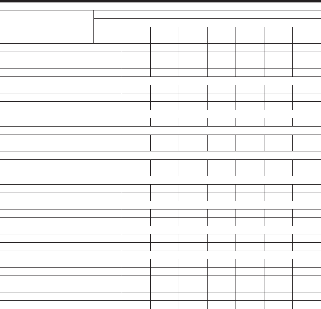
JOHNSON CONTROLS62
Physical Data (SI - High Efciency)
Refrigerant R-134a HIGH EFFICIENCY
MODEL NUMBER (YCIV____ E/V)
General Unit Data 60Hz 0157 0177 0187 0197 0207 0227 0247
50Hz 0590 0630 0700 0760 0800 0830 0930
Number of Independent Refrigerant Circuits 2222222
Refrigerant Charge, R-134a, Ckt.-1/Ckt.-2, kg. 77/77 84/77 84/84 87/87 102/87 102/102 105/105
Oil Charge, Ckt.-1/Ckt.-2, liters 19/19 19/19 19/19 19/19 19/19 19/19 19/19
Compressors, Semihermetic Screw Qty per Chiller 2222222
Condensers, High Efciency Fin/Tube with Integral Subcooler
Total Chiller Coil Face Area, m2 21.8 24.5 27.2 27.2 30.0 32.7 32.7
Number of Rows 3333333
Fins per meter 669 669 669 669 669 669 669
Condenser Fans
Number, Ckt.-1/Ckt.-2 4/4 5/4 5/5 5/5 6/5 6/6 6/6
Low Sound Fans
Fan Motor, HP/kWi 2/1.50 2/1.50 2/1.50 2/1.50 2/1.50 2/1.50 2/1.50
Total Chiller Airow, l/sec. 49082 55218 61353 61353 67488 73624 73624
Ultra Quiet Fans
Fan Motor, HP/kWi 2/1.50 2/1.50 2/1.50 2/1.50 2/1.50 2/1.50 2/1.50
Total Chiller Airow, l/sec. 49082 55218 61353 61353 67488 73624 73624
Dual Speed Fans - Normal Speed
Fan, KWi 1.5 1.5 1.5 1.5 1.5 1.5 1.5
Total Chiller, m3/s 42 47 52 52 57 62 62
Dual Speed Fans - Lower Speed
Fan, KWi 1.5 1.5 1.5 1.5 1.5 1.5 1.5
Total Chiller, m3/s 32 36 40 40 44 48 48
High Static Fans
Fan, KWi 3.7 3.7 3.7 3.7 3.7 3.7 3.7
Total Chiller, m3/s 49 55 61 61 67 74 74
Evaporator, Direct Expansion
Water Volume, liters 359.6 359.6 359.6 416.4 416.4 416.4 529.9
Maximum Water Side Pressure, Bar110 10 10 10 10 10 10
Maximum Refrigerant Side Pressure, Bar 16 16 16 16 16 16 16
Minimum Chilled Water Flow Rate, l/sec. 10.1 10.1 10.1 11.4 11.4 11.4 11.4
Maximum Chilled Water Flow Rate, l/sec. 47.3 47.3 47.3 47.3 47.3 47.3 50.5
Water Connections, inches 10 10 10 10 10 10 10
Contact your nearest Johnson Controls Sales Ofce for weight data.

JOHNSON CONTROLS
FORM 201.23-EG1 (1007)
63
Refrigerant R-134a HIGH EFFICIENCY
MODEL NUMBER (YCIV____ E/V)
General Unit Data 60Hz 0267 0287 0327 0357
50Hz 1550 1120 1220 1380
Number of Independent Refrigerant Circuits 3 3 3 3
Refrigerant Charge, R-134a, Ckt.-1/Ckt.-2, kg. 84 / 84 / 77 84 / 84 / 105 84 / 84 / 105 105 / 105 / 105
Oil Charge, Ckt.-1/Ckt.-2, liters 19 / 19 / 15 19 / 19 / 19 19 / 19 / 19 19 / 19 / 19
Glycol Charge (43% concentration), liters 0 0 0 0
Compressors, Semihermetic Screw
Quantity per Chiller 3 3 3 3
Condensers, High Efciency Fin/Tube with Integral Subcooler
Total Chiller Coil Face Area, m238 44 44 49
Number of Rows 3 3 3 3
Fins per meter 669 669 669 669
Condenser Fans
Number, Ckt.-1/Ckt.-2 05/05/04 05/05/06 05/05/06 06/06/06
Low Noise Fans
Fan Motor, HP/kWi 2/1.50 2/1.50 2/1.50 2/1.50
Total Chiller Airow, l/sec. 85904 98176 98176 110448
Ultra Quiet Fans
Fan Motor, HP/kWi 2/1.50 2/1.50 2/1.50 2/1.50
Total Chiller Airow, l/sec. 85904 98176 98176 110448
Dual Speed Fans - Normal Speed
Fan, KWi 1.5 1.5 1.5 1.5
Total Chiller, m3/s 73 83 83 93
Dual Speed Fans - Lower Speed
Fan, KWi 1.5 1.5 1.5 1.5
Total Chiller, m3/s 56 63 63 71
High Static Fans
Fan, KWi 3.7 3.7 3.7 3.7
Total Chiller, m3/s 92 117 117 129
Evaporator, Direct Expansion
Water Volume, liters 764.6 764.6 893.3 893.3
Maximum Water Side Pressure, Bar 10 10 10 10
Maximum Refrigerant Side Pressure, Bar 16 16 16 16
Minimum Chilled Water Flow Rate, l/sec. 16 16 19 19
Maximum Chilled Water Flow Rate, l/sec. 76 76 76 76
Water Connections, mm 245 245 245 245
Contact your nearest Johnson Controls Sales Ofce for weight data.
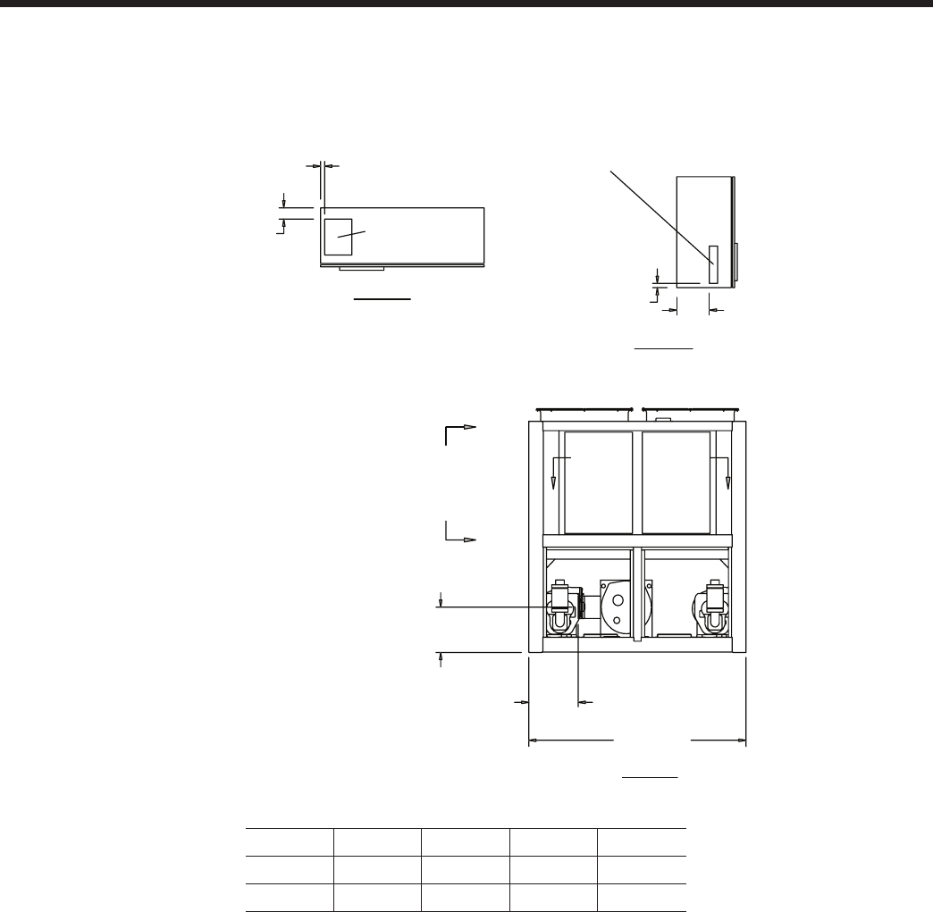
JOHNSON CONTROLS64
Dimensions – English
Notes:
1. Placement on a level surface free of obstructions (including snow, for winter operation) or air recirculation ensures rated performance,
reliable operation, and ease of maintenance. Site restrictions may compromise minimum clearances indicated below, resulting in unpre-
dictable air patters and possible diminished performance. Johnson Controls’ unit controls will optimize the operation without nuisance
high pressure safety cutouts; however, the system designer MUST consider potential performance degradation.
Access to the unit control center stipulates the unit is no higher than on spring isolators. Recommended minimum clearances: side to wall
- 6’; rear to wall - 6’; control panel end to wall - 4’; top - no obstructions whatsoever; distance between adjacent units - 10’. No more than
one adjacent wall may be higher than the unit.
VIEW C-C
VIEW B-B
12"
CONTROL ENTRY
3" WIDE X 13 1/2" HIGH
1 1/2"
4" POWER ENTRY
10" WIDE X 13" HIGH
1 3/4"
POWER ENTRY IS ON BOTTOM OF PANEL
B
(EDGE OF UNIT
TO COOLER
CONNECTION)
88 1/8"
A
VIEW A-A
C
C
BB
Models YCIV0157E/V and YCIV0157S/P
YCIV A B C D
0157E/V 19.1" 28.1" 84.5" 112.8"
0157S/P 17.4" 29.1" 90.0" 110.1"

JOHNSON CONTROLS
FORM 201.23-EG1 (1007)
65
33 5/16"
103 3/8"
80"
230"
101 5/8" 50" 50 5/16" 9 1/8"
93 15/16"
1 5/16" (TYP)
X
G
C
Y
(3) RIGGING HOLES
EACH SIDE (3 X 2)
10"
WATER OUTLET 10"
WATER INLET
VIEW D-D
X
G
C
Z
D
D
A
A
5/8" MOUNTING
HOLES (TYP)
ORIGIN
POWER: SINGLE POINT WITH TERMINAL BLOCK
CONTROL PANEL
45 5/16"
60"
14 1/8"
CD

JOHNSON CONTROLS66
Dimensions – English - continued
Notes:
1. Placement on a level surface free of obstructions (including snow, for winter operation) or air recirculation ensures rated performance,
reliable operation, and ease of maintenance. Site restrictions may compromise minimum clearances indicated below, resulting in unpre-
dictable air patters and possible diminished performance. Johnson Controls’ unit controls will optimize the operation without nuisance
high pressure safety cutouts; however, the system designer MUST consider potential performance degradation.
Access to the unit control center stipulates the unit is no higher than on spring isolators. Recommended minimum clearances: side to wall
- 6’; rear to wall - 6’; control panel end to wall - 4’; top - no obstructions whatsoever; distance between adjacent units - 10’. No more than
one adjacent wall may be higher than the unit.
VIEW C-C
VIEW B-B 12"
CONTROL ENTRY
3" WIDE X 13 1/2" HIGH
1 1/2"
4"
POWER ENTRY
10" WIDE X 13" HIGH
1 3/4"
POWER ENTRY IS ON BOTTOM OF PANEL
88 1/8"
28 1/8" (EDGE OF UNIT
TO COOLER
CONNECTION)
19 1/8"
C
C
B
B
VIEW A-A
Models YCIV0177E/V, YCIV0177S/P, YCIV0187E/V and YCIV0187S/P
YCIV A B
0177E/V 88.1" 274.0"
0177S/P 80.0" 230.0"
0187E/V 88.1" 274.0"
0187S/P 88.1" 274.0"
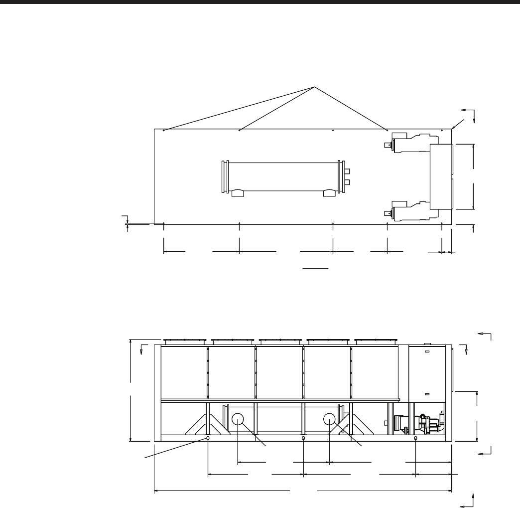
JOHNSON CONTROLS
FORM 201.23-EG1 (1007)
67
POWER: SINGLE POINT WITH TERMINAL BLOCK
XG
C
Y
VIEW D-D
B
33 5/16"
103 5/16"
A
112 13/16"
84 1/2"
93 15/16"
D D
X
G
C
Z
10" (WATER INLET)
10" (WATER OUTLET)
A
A
9 1/8"
50 5/16"50"86 5/16"69 11/16"
1 5/16" (TYP)
5/8" MOUNTING
HOLES (TYP)
(3) RIGGING HOLES
EACH SIDE 3 X 2
CONTROL PANEL
45 5/16"
60"
14 1/8"
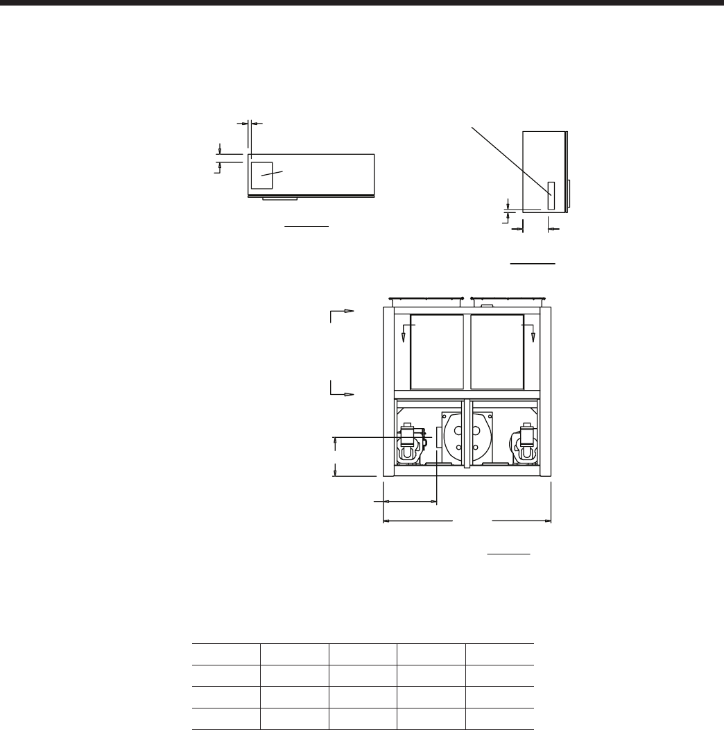
JOHNSON CONTROLS68
Dimensions – English - continued
Models YCIV0197E/V, YCIV0207S/P, and YCIV0227S/P
Notes:
1. Placement on a level surface free of obstructions (including snow, for winter operation) or air recirculation ensures rated performance,
reliable operation, and ease of maintenance. Site restrictions may compromise minimum clearances indicated below, resulting in unpre-
dictable air patters and possible diminished performance. Johnson Controls’ unit controls will optimize the operation without nuisance
high pressure safety cutouts; however, the system designer MUST consider potential performance degradation.
Access to the unit control center stipulates the unit is no higher than on spring isolators. Recommended minimum clearances: side to wall
- 6’; rear to wall - 6’; control panel end to wall - 4’; top - no obstructions whatsoever; distance between adjacent units - 10’. No more than
one adjacent wall may be higher than the unit.
VIEW C-C
VIEW B-B 12"
CONTROL ENTRY
3" WIDE X 13 1/2" HIGH
1 1/2"
4"
POWER ENTRY
10" WIDE X 13" HIGH
1 3/4"
POWER ENTRY IS ON BOTTOM OF PANEL
88 1/8"
B (EDGE OF UNIT
TO COOLER
CONNECTION)
A
C
B
B
VIEW A-A
C
YCIV A B C D
0197E/V 20.4" 28.1" 85.6" 112.3"
0207S/P 22.2" 26.0" 79.1" 113.3"
0227S/P 22.2" 26.0" 79.1" 113.3
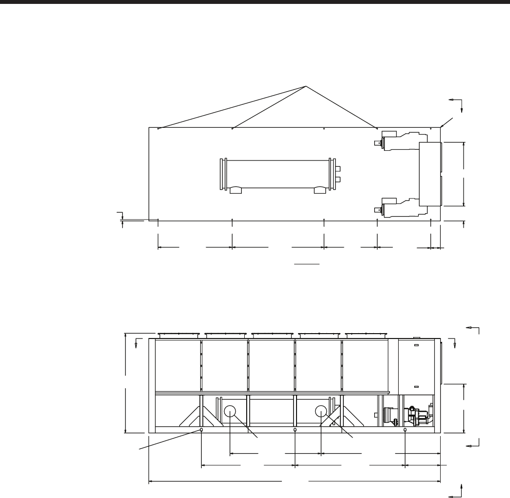
JOHNSON CONTROLS
FORM 201.23-EG1 (1007)
69
POWER: SINGLE POINT WITH TERMINAL BLOCK
XG
C
Y
VIEW D-D
274"
33 5/16"
103 5/16"
88"
D
C
93 15/16"
DD
X
Z
10" (WATER INLET)
10" (WATER OUTLET)
A
A
9 1/8"
50 5/16"50"86 5/16"69 11/16"
1 5/16" (TYP)
5/8" MOUNTING
HOLES (TYP)
(3) RIGGING HOLES
EACH SIDE 3 X 2
CONTROL PANEL
45 5/16"
14 1/8"
60"

JOHNSON CONTROLS70
Dimensions – English - continued
Models YCIV0207E/V and YCIV0227E/V
Notes:
1. Placement on a level surface free of obstructions (including snow, for winter operation) or air recirculation ensures rated performance,
reliable operation, and ease of maintenance. Site restrictions may compromise minimum clearances indicated below, resulting in unpre-
dictable air patters and possible diminished performance. Johnson Controls’ unit controls will optimize the operation without nuisance
high pressure safety cutouts; however, the system designer MUST consider potential performance degradation.
Access to the unit control center stipulates the unit is no higher than on spring isolators. Recommended minimum clearances: side to wall
- 6’; rear to wall - 6’; control panel end to wall - 4’; top - no obstructions whatsoever; distance between adjacent units - 10’. No more than
one adjacent wall may be higher than the unit.
VIEW C-C
VIEW B-B
12"
CONTROL ENTRY
3" WIDE X 13 1/2" HIGH
1 1/2"
4" POWER ENTRY
10" WIDE X 13" HIGH
1 3/4"
POWER ENTRY IS ON BOTTOM OF PANEL
88 1/8"
28 1/8" (EDGE OF UNIT
TO COOLER
CONNECTION)
20 3/8"
C
C
BB
VIEW A-A
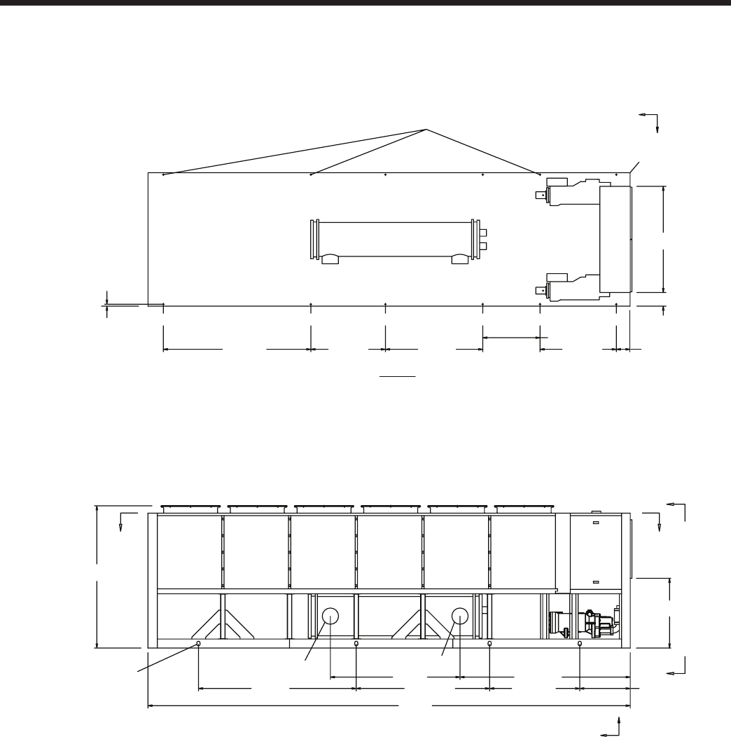
JOHNSON CONTROLS
FORM 201.23-EG1 (1007)
71
POWER: SINGLE POINT WITH TERMINAL BLOCK
CONTROL PANEL
VIEW D-D
9 1/8"
50 5/16"
37 13/16"
64 3/16"49 3/16"60"
318"
33 5/16"
92 11/16"
180 11/16"284 7/8"
112 5/16"
85 5/8"
10" (WATER OUTLET) 10" (WATER INLET)
A
A
D
D
93 15/16"
5/8" MOUNTING HOLES (TYP)
(4) RIGGING HOLES
EACH SIDE 3 X 2
XG
C
Z
ORIGIN
XG
C
Y
1 5/16" (TYP)
45 5/16"
14 1/8"
60"
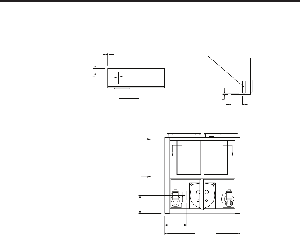
JOHNSON CONTROLS72
Dimensions – English - continued
Models YCIV0247S/P, YCIV0247E/V, and YCIV0267S/P
Notes:
1. Placement on a level surface free of obstructions (including snow, for winter operation) or air recirculation ensures rated performance,
reliable operation, and ease of maintenance. Site restrictions may compromise minimum clearances indicated below, resulting in unpre-
dictable air patters and possible diminished performance. Johnson Controls’ unit controls will optimize the operation without nuisance
high pressure safety cutouts; however, the system designer MUST consider potential performance degradation.
Access to the unit control center stipulates the unit is no higher than on spring isolators. Recommended minimum clearances: side to wall
- 6’; rear to wall - 6’; control panel end to wall - 4’; top - no obstructions whatsoever; distance between adjacent units - 10’. No more than
one adjacent wall may be higher than the unit.
VIEW C-C
VIEW B-B
12"
CONTROL ENTRY
3" WIDE X 13 1/2" HIGH
1 1/2"
4"
POWER ENTRY
10" WIDE X 13" HIGH
1 3/4"
POWER ENTRY IS ON BOTTOM OF PANEL
88 1/8"
26" (EDGE OF UNIT
TO COOLER
CONNECTION)
22 3/16"
C
C
BB
VIEW A-A

JOHNSON CONTROLS
FORM 201.23-EG1 (1007)
73
POWER: SINGLE POINT WITH TERMINAL BLOCK
CONTROL PANEL
VIEW D-D
9 1/8"
50 5/16"
37 13/16"
64 3/16"49 3/16"60"
318"
33 5/16"
92 11/16"180 11/16"284 7/8"
113 5/16"
79 1/8"
10" (WATER OUTLET) 10" (WATER INLET)
A
A
DD
93 15/16"
APPROX. OPERATING
WEIGHT DISTRIBUTING (LB)
5/8" MOUNTING HOLES (TYP)
(4) RIGGING HOLES
EACH SIDE 3 X 2
XG
C
Z
ORIGIN
XG
C
Y
1 5/16" (TYP)
45 5/16"
14 1/8"
60"
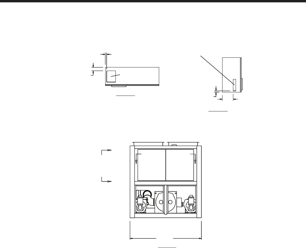
JOHNSON CONTROLS74
Dimensions – English - continued
Models YCIV0267E/V, and YCIV0287S/P
Notes:
1. Placement on a level surface free of obstructions (including snow, for winter operation) or air recirculation ensures rated performance,
reliable operation, and ease of maintenance. Site restrictions may compromise minimum clearances indicated below, resulting in unpre-
dictable air patters and possible diminished performance. Johnson Controls’ unit controls will optimize the operation without nuisance
high pressure safety cutouts; however, the system designer MUST consider potential performance degradation.
Access to the unit control center stipulates the unit is no higher than on spring isolators. Recommended minimum clearances: side to wall
- 6’; rear to wall - 6’; control panel end to wall - 4’; top - no obstructions whatsoever; distance between adjacent units - 10’. No more than
one adjacent wall may be higher than the unit.
VIEW C-C
VIEW B-B
12"
CONTROL ENTRY
3" WIDE X 13 1/2" HIGH
1 1/2"
4" POWER ENTRY
10" WIDE X 13" HIGH
1 3/4"
POWER ENTRY IS ON BOTTOM OF PANEL
88 1/8"
VIEW A-A
BB
C
C
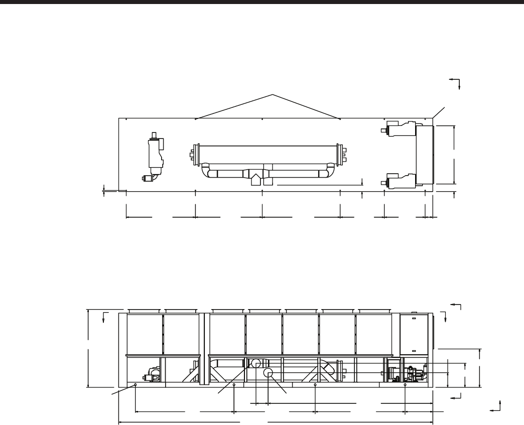
JOHNSON CONTROLS
FORM 201.23-EG1 (1007)
75
POWER: SINGLE POINT WITH TERMINAL BLOCK
45 5/16"
29 7/8"
17 5/8"
A
A
XG
C
Z
D
D
93 15/16"
CONTROL PANEL
337 3/16"
197 13/16"14 5/8"
141 1/8"238 5/8"
357" 33 3/16"
10" (WATER INLET)
10" (WATER OUTLET)
(4) RIGGING HOLES
EACH SIDE 3 X 2
70"
9 1/8"
49"53"93 5/8"80 3/16"83 1/8" 9 1/8"
ORIGIN
1 5/16" (TYP)
5/8" MOUNTING HOLES (TYP)
XG
C
Y
7 5/8"
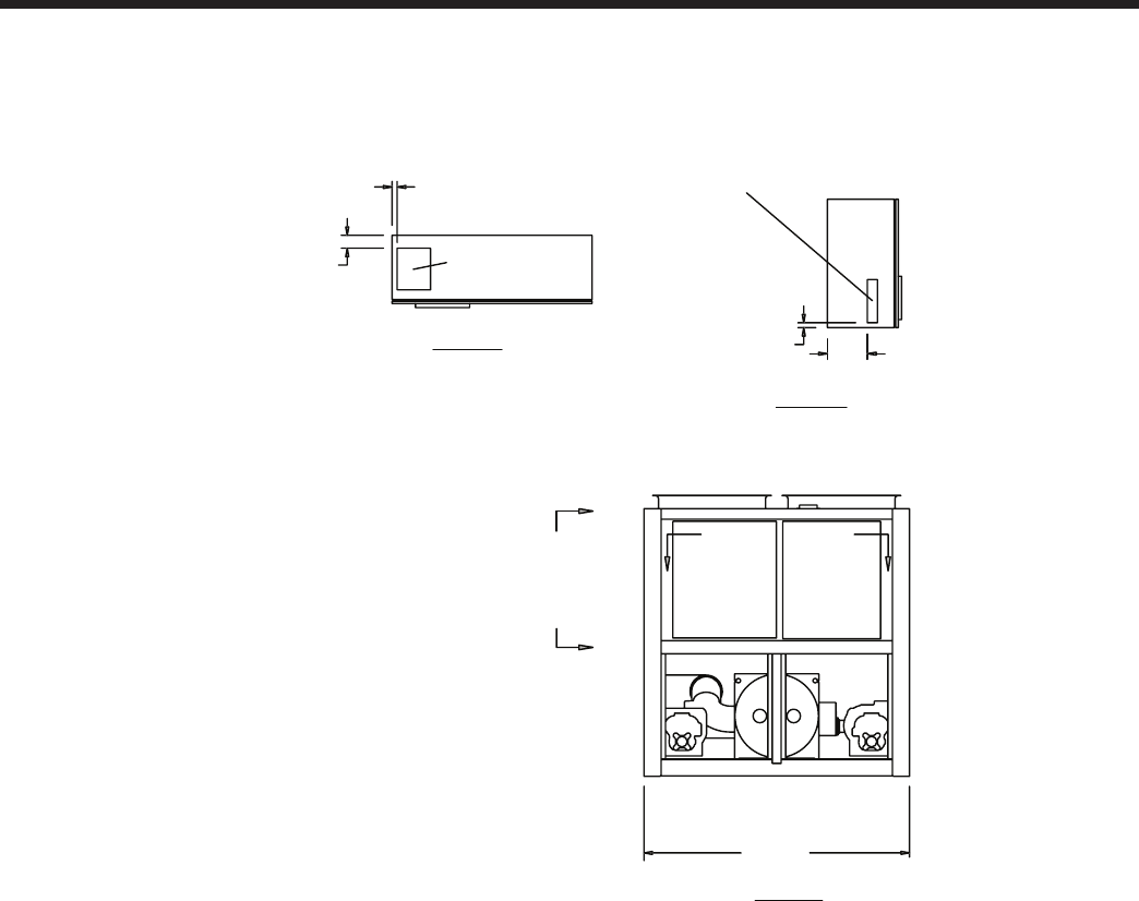
JOHNSON CONTROLS76
Dimensions – English - continued
Models YCIV0287E/V
Notes:
1. Placement on a level surface free of obstructions (including snow, for winter operation) or air recirculation ensures rated performance,
reliable operation, and ease of maintenance. Site restrictions may compromise minimum clearances indicated below, resulting in unpre-
dictable air patters and possible diminished performance. Johnson Controls’ unit controls will optimize the operation without nuisance
high pressure safety cutouts; however, the system designer MUST consider potential performance degradation.
Access to the unit control center stipulates the unit is no higher than on spring isolators. Recommended minimum clearances: side to wall
- 6’; rear to wall - 6’; control panel end to wall - 4’; top - no obstructions whatsoever; distance between adjacent units - 10’. No more than
one adjacent wall may be higher than the unit.
VIEW C-C
VIEW B-B 12"
CONTROL ENTRY
3" WIDE X 13 1/2" HIGH
1 1/2"
4"
POWER ENTRY
10" WIDE X 13" HIGH
1 3/4"
POWER ENTRY IS ON BOTTOM OF PANEL
88 1/8"
VIEW A-A
C
C
B B
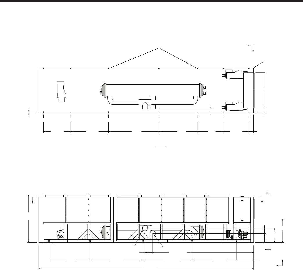
JOHNSON CONTROLS
FORM 201.23-EG1 (1007)
77
POWER: SINGLE POINT WITH TERMINAL BLOCK
50 5/16"
50"
76"
99"
19"
53 3/8" 9 1/8"
1 5/16" (TYP)
7 5/8"
17 5/8"
29 7/8"
93 15/16"
DD
XG
C
Z
XG
C
Y
CONTROL PANEL
ORIGIN
A
A
421 1/4"
123 11/16"216 11/16"320 1/2"401" 37 3/16"
197 13/16"
14 5/8"
10" (WATER OUTLET) 10" (WATER INLET)
(5) RIGGING HOLES
EACH SIDE 3 X 2
VIEW D-D
5/8" MOUNTING HOLES (TYP)
45 5/16"
9 1/8"
70"
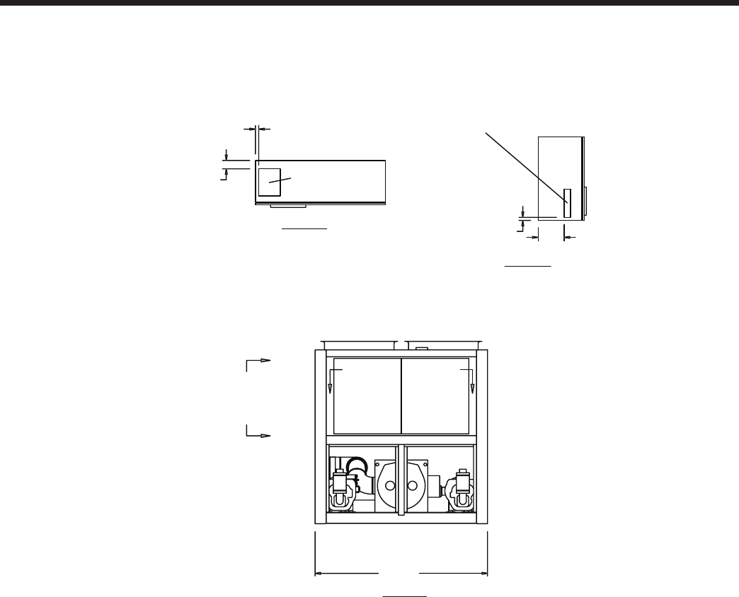
JOHNSON CONTROLS78
Dimensions – English - continued
Models YCIV0307S/P
Notes:
1. Placement on a level surface free of obstructions (including snow, for winter operation) or air recirculation ensures rated performance,
reliable operation, and ease of maintenance. Site restrictions may compromise minimum clearances indicated below, resulting in unpre-
dictable air patters and possible diminished performance. Johnson Controls’ unit controls will optimize the operation without nuisance
high pressure safety cutouts; however, the system designer MUST consider potential performance degradation.
Access to the unit control center stipulates the unit is no higher than on spring isolators. Recommended minimum clearances: side to wall
- 6’; rear to wall - 6’; control panel end to wall - 4’; top - no obstructions whatsoever; distance between adjacent units - 10’. No more than
one adjacent wall may be higher than the unit.
VIEW C-C
VIEW B-B
12"
CONTROL ENTRY
3" WIDE X 13 1/2" HIGH
1 1/2"
4"
POWER ENTRY
10" WIDE X 13" HIGH
1 3/4"
POWER ENTRY IS ON BOTTOM OF PANEL
88 1/8"
VIEW A-A
BB
C
C
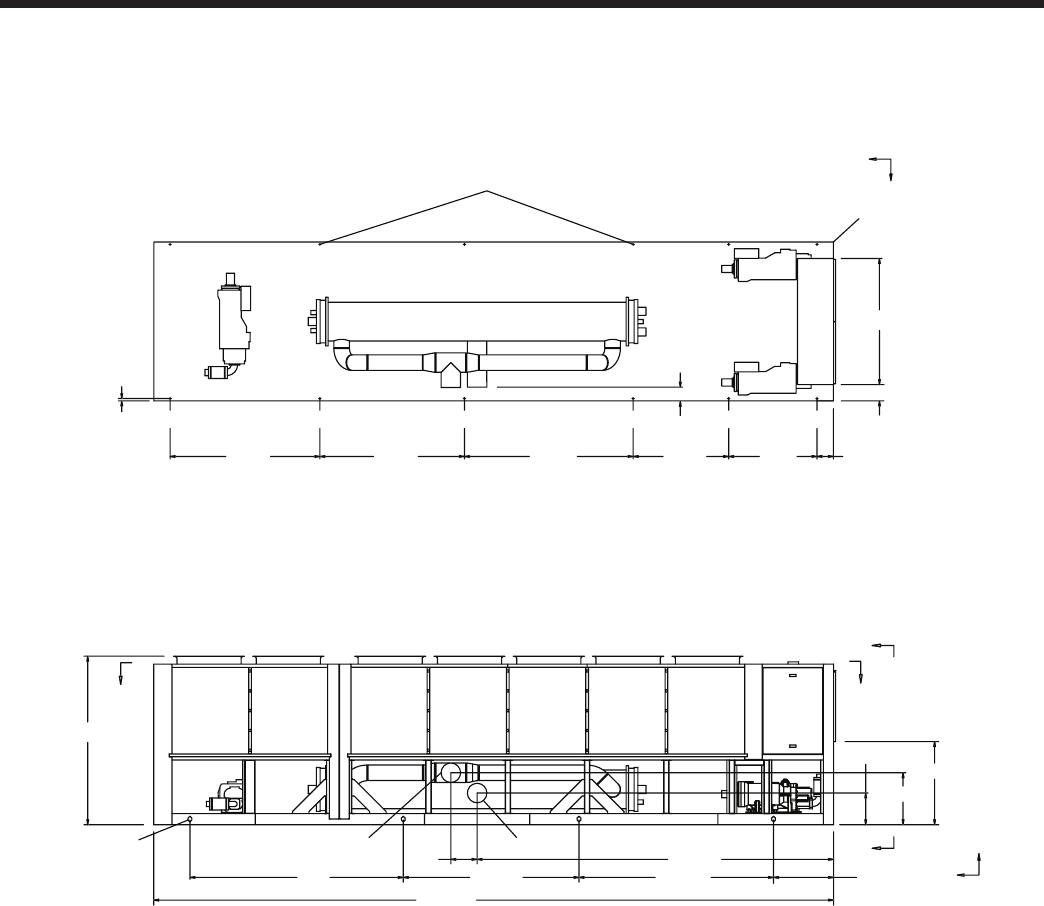
JOHNSON CONTROLS
FORM 201.23-EG1 (1007)
79
POWER: SINGLE POINT WITH TERMINAL BLOCK
45 5/16"
26 3/8"
16 3/16"
A
A
XG
C
Z
D
D
93 15/16"
CONTROL PANEL
337 3/16"
197 13/16"15"
141 1/8"238 5/8"
357" 33 3/16"
10" (WATER INLET)
10" (WATER OUTLET)
(4) RIGGING HOLES
EACH SIDE 3 X 2
70"
9 1/8"
49"53"93 5/8"80 3/16"83 1/8" 9 1/8"
ORIGIN
1 5/16" (TYP)
5/8" MOUNTING HOLES (TYP)
XG
C
Y
7 5/8"
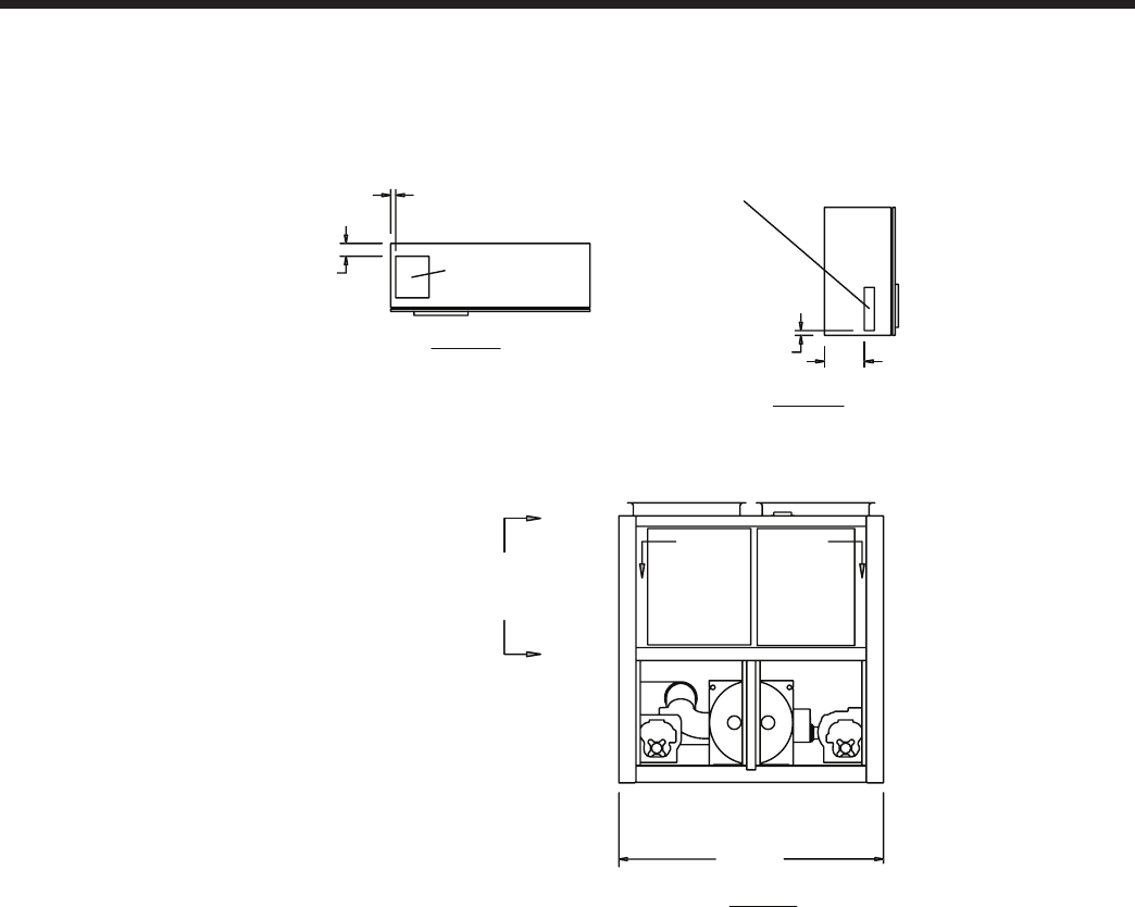
JOHNSON CONTROLS80
Dimensions – English - continued
Models YCIV0327E/V and YCIV0357S/P
Notes:
1. Placement on a level surface free of obstructions (including snow, for winter operation) or air recirculation ensures rated performance,
reliable operation, and ease of maintenance. Site restrictions may compromise minimum clearances indicated below, resulting in unpre-
dictable air patters and possible diminished performance. Johnson Controls’ unit controls will optimize the operation without nuisance
high pressure safety cutouts; however, the system designer MUST consider potential performance degradation.
Access to the unit control center stipulates the unit is no higher than on spring isolators. Recommended minimum clearances: side to wall
- 6’; rear to wall - 6’; control panel end to wall - 4’; top - no obstructions whatsoever; distance between adjacent units - 10’. No more than
one adjacent wall may be higher than the unit.
VIEW C-C
VIEW B-B
12"
CONTROL ENTRY
3" WIDE X 13 1/2" HIGH
1 1/2"
4"
POWER ENTRY
10" WIDE X 13" HIGH
1 3/4"
POWER ENTRY IS ON BOTTOM OF PANEL
88 1/8"
VIEW A-A
C
B B
C
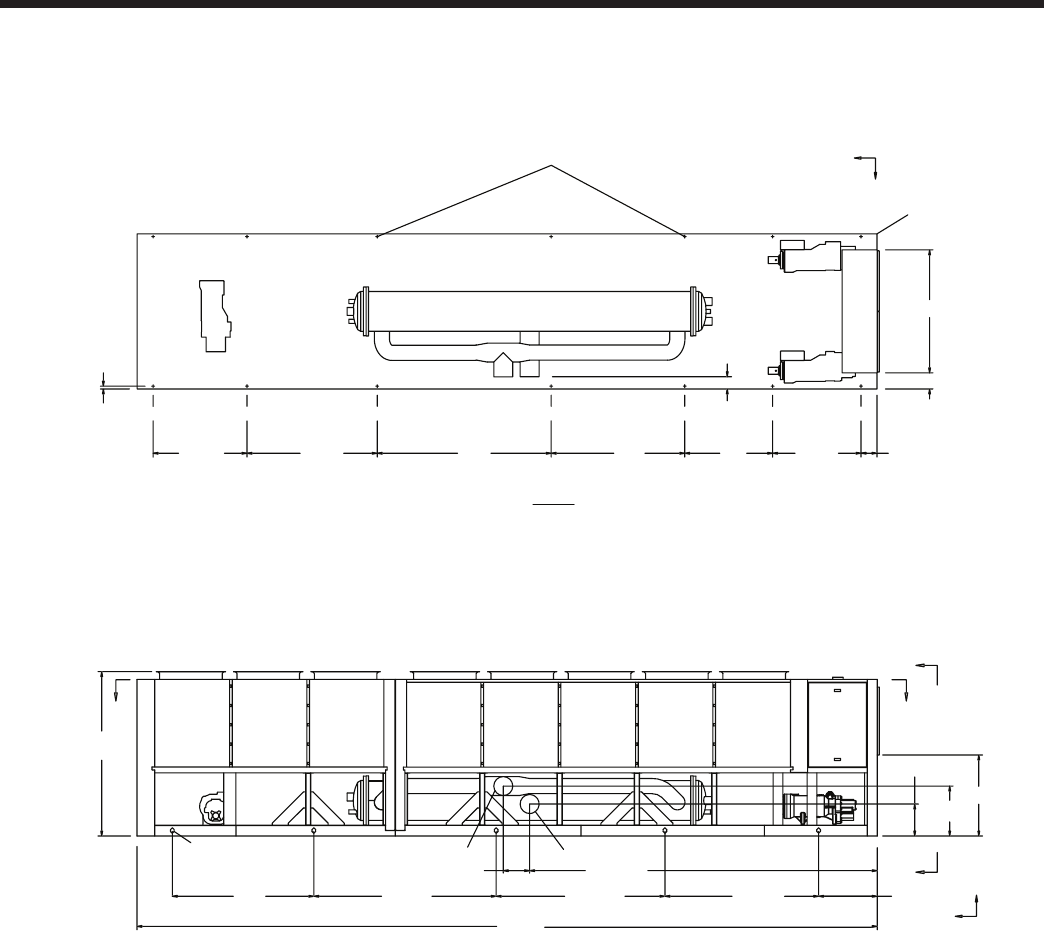
JOHNSON CONTROLS
FORM 201.23-EG1 (1007)
81
POWER: SINGLE POINT WITH TERMINAL BLOCK
50 5/16"
50"
76"
99"
74 1/8"
53 3/8" 9 1/8"
1 5/16" (TYP)
6 7/8"
18 3/16"
25 1/8"
93 15/16"
DD
XG
C
Z
XG
C
Y
CONTROL PANEL
ORIGIN
A
A
421 1/4"
120 11/16"216 11/16"320 1/2"401" 33 3/16"
197 13/16"
15"
10" (WATER OUTLET) 10" (WATER INLET)
(5) RIGGING HOLES
EACH SIDE 3 X 2
VIEW D-D
5/8" MOUNTING HOLES (TYP)
45 5/16"
9 1/8"
70"
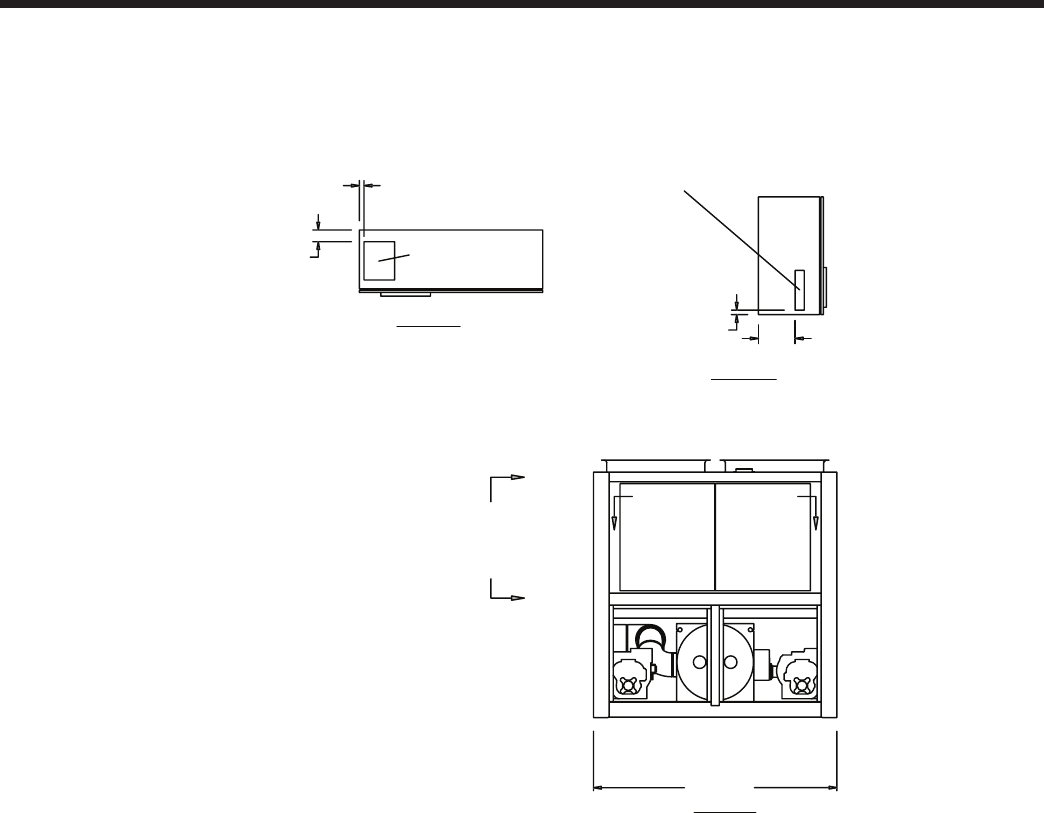
JOHNSON CONTROLS82
Dimensions – English - continued
Models YCIV0357E/V and YCIV0397S/P
Notes:
1. Placement on a level surface free of obstructions (including snow, for winter operation) or air recirculation ensures rated performance,
reliable operation, and ease of maintenance. Site restrictions may compromise minimum clearances indicated below, resulting in unpre-
dictable air patters and possible diminished performance. Johnson Controls’ unit controls will optimize the operation without nuisance
high pressure safety cutouts; however, the system designer MUST consider potential performance degradation.
Access to the unit control center stipulates the unit is no higher than on spring isolators. Recommended minimum clearances: side to wall
- 6’; rear to wall - 6’; control panel end to wall - 4’; top - no obstructions whatsoever; distance between adjacent units - 10’. No more than
one adjacent wall may be higher than the unit.
VIEW C-C
VIEW B-B
12"
CONTROL ENTRY
3" WIDE X 13 1/2" HIGH
1 1/2"
4"
POWER ENTRY
10" WIDE X 13" HIGH
1 3/4"
POWER ENTRY IS ON BOTTOM OF PANEL
88 1/8"
C
B B
C
VIEW A-A
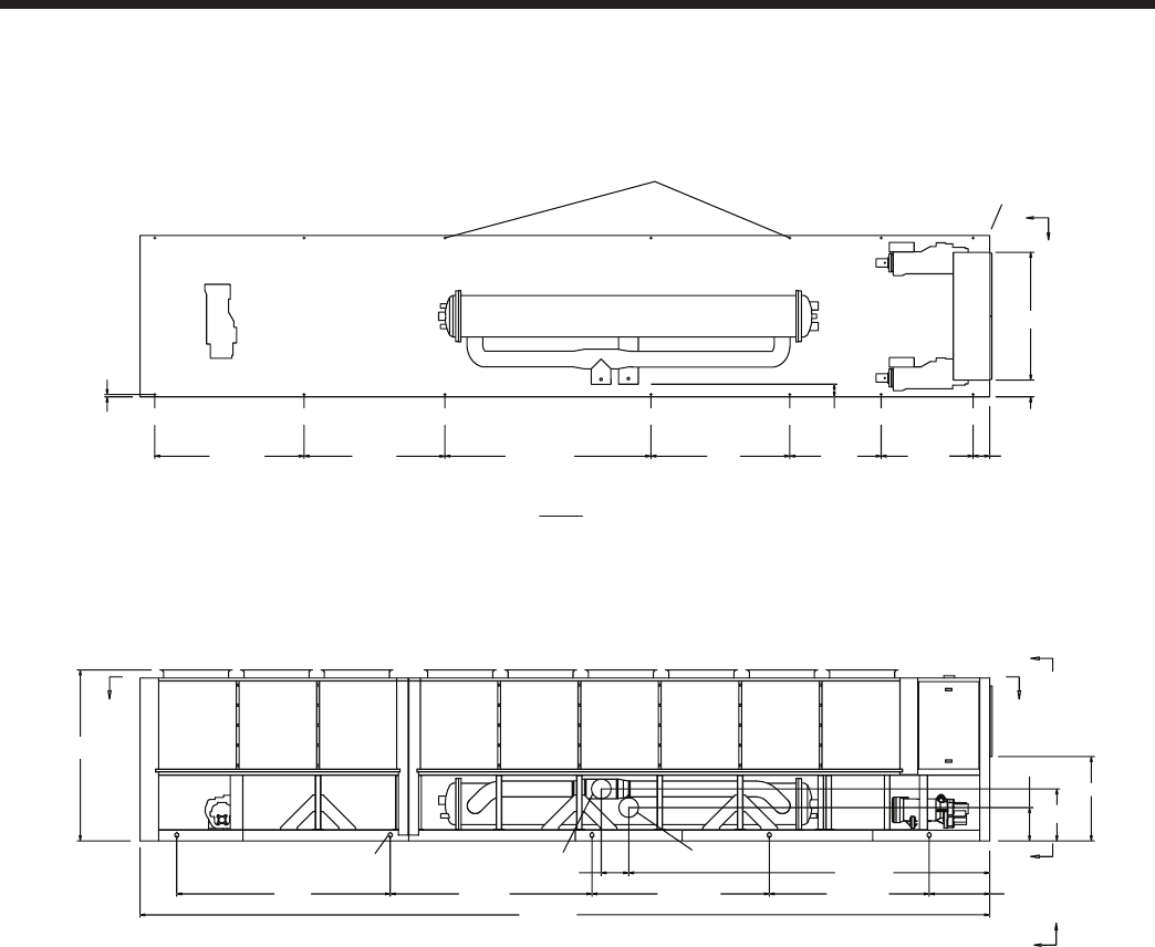
JOHNSON CONTROLS
FORM 201.23-EG1 (1007)
83
93 15/16"
6 7/8"
CONTROL PANEL
ORIGIN
53 3/8" 9 1/8"
50 5/16"50"76"112 11/16"19"
POWER: SINGLE POINT WITH TERMINAL BLOCK
VIEW D-D
5/8" MOUNTING HOLES (TYP)
15" 197 13/16"
120 11/16" 33 3/16"
217 13/16"328 1/8"445"
465 3/16"
18 3/16"
28 3/8"
A
A
D
D
10" (WATER INLET)10" (WATER OUTLET)
(5) RIGGING HOLES
EACH SIDE 3 X 2
1 5/16" (TYP)
XG
C
Y
XG
C
Z
45 5/16"
70"
9 1/8"

JOHNSON CONTROLS84
Dimensions – SI
Notes:
1. Placement on a level surface free of obstructions (including snow, for winter operation) or air recirculation ensures rated performance,
reliable operation, and ease of maintenance. Site restrictions may compromise minimum clearances indicated below, resulting in unpre-
dictable air patters and possible diminished performance. Johnson Controls’ unit controls will optimize the operation without nuisance
high pressure safety cutouts; however, the system designer MUST consider potential performance degradation.
Access to the unit control center stipulates the unit is no higher than on spring isolators. Recommended minimum clearances: side to wall
- 2m; rear to wall - 2m; control panel end to wall - 1.2m; top - no obstructions whatsoever; distance between adjacent units - 10’. No more
than one adjacent wall may be higher than the unit.
YCIV A B C D
0590E/V 485 714 2146 2865
0600S/P 442 739 2286 2797
VIEW C-C
VIEW B-B
305
CONTROL ENTRY
76 WIDE X 343 HIGH
38
102
POWER ENTRY
254 WIDE X 330 HIGH
44
POWER ENTRY IS ON BOTTOM OF PANEL
B
(EDGE OF UNIT
TO COOLER
CONNECTION)
2238
A
VIEW A-A
C
C
BB
YCIV0590E/V and YCIV0600S/P

JOHNSON CONTROLS
FORM 201.23-EG1 (1007)
85
846
2626
2032
D
C
5842
2581 1270 1278 231
2387
33 (TYP)
X
G
C
Y
(3) RIGGING HOLES
EACH SIDE (76 X 51)
10"
WATER OUTLET 10"
WATER INLET
VIEW D-D
X
G
C
Z
D
D
A
A
16 MOUNTING
HOLES (TYP)
ORIGIN
POWER: SINGLE POINT WITH TERMINAL BLOCK
CONTROL PANEL
1151
1524
358
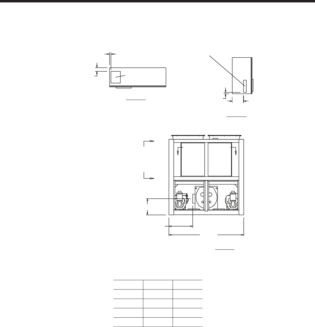
JOHNSON CONTROLS86
Dimensions – SI - continued
Notes:
1. Placement on a level surface free of obstructions (including snow, for winter operation) or air recirculation ensures rated performance,
reliable operation, and ease of maintenance. Site restrictions may compromise minimum clearances indicated below, resulting in unpre-
dictable air patters and possible diminished performance. Johnson Controls’ unit controls will optimize the operation without nuisance
high pressure safety cutouts; however, the system designer MUST consider potential performance degradation.
Access to the unit control center stipulates the unit is no higher than on spring isolators. Recommended minimum clearances: side to wall
- 2m; rear to wall - 2m; control panel end to wall - 1.2m; top - no obstructions whatsoever; distance between adjacent units - 10’. No more
than one adjacent wall may be higher than the unit.
YCIV0630E/V, YCIV0650S/P, YCIV0700E/V and YCIV0720S/P
VIEW C-C
VIEW B-B 305
CONTROL ENTRY
76 WIDE X 343 HIGH
38
102
POWER ENTRY
254 WIDE X 330 HIGH
44
POWER ENTRY IS ON BOTTOM OF PANEL
2238
714 (EDGE OF UNIT
TO COOLER
CONNECTION)
485
C
C
B
B
VIEW A-A
YCIV A B
06307E/V 2238 6960
0650S/P 2032 5842
0700E/V 2238 6960
0720S/P 2238 6960
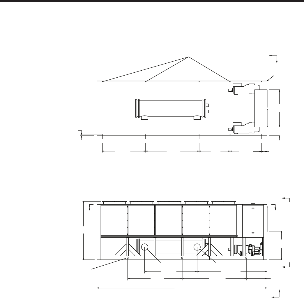
JOHNSON CONTROLS
FORM 201.23-EG1 (1007)
87
DIMENSIONS (mm) UNLESS OTHERWISE NOTED
POWER: SINGLE POINT WITH TERMINAL BLOCK
XG
C
Y
VIEW D-D
B
846
2624
A
2865
2146
2387
DD
X
Z
10" (WATER INLET)
10" (WATER OUTLET)
A
A
231
1278127021921770
33 (TYP)
16 MOUNTING
HOLES (TYP)
(3) RIGGING HOLES
EACH SIDE 76 X 51
ORIGIN
CONTROL PANEL
1151
1524
358
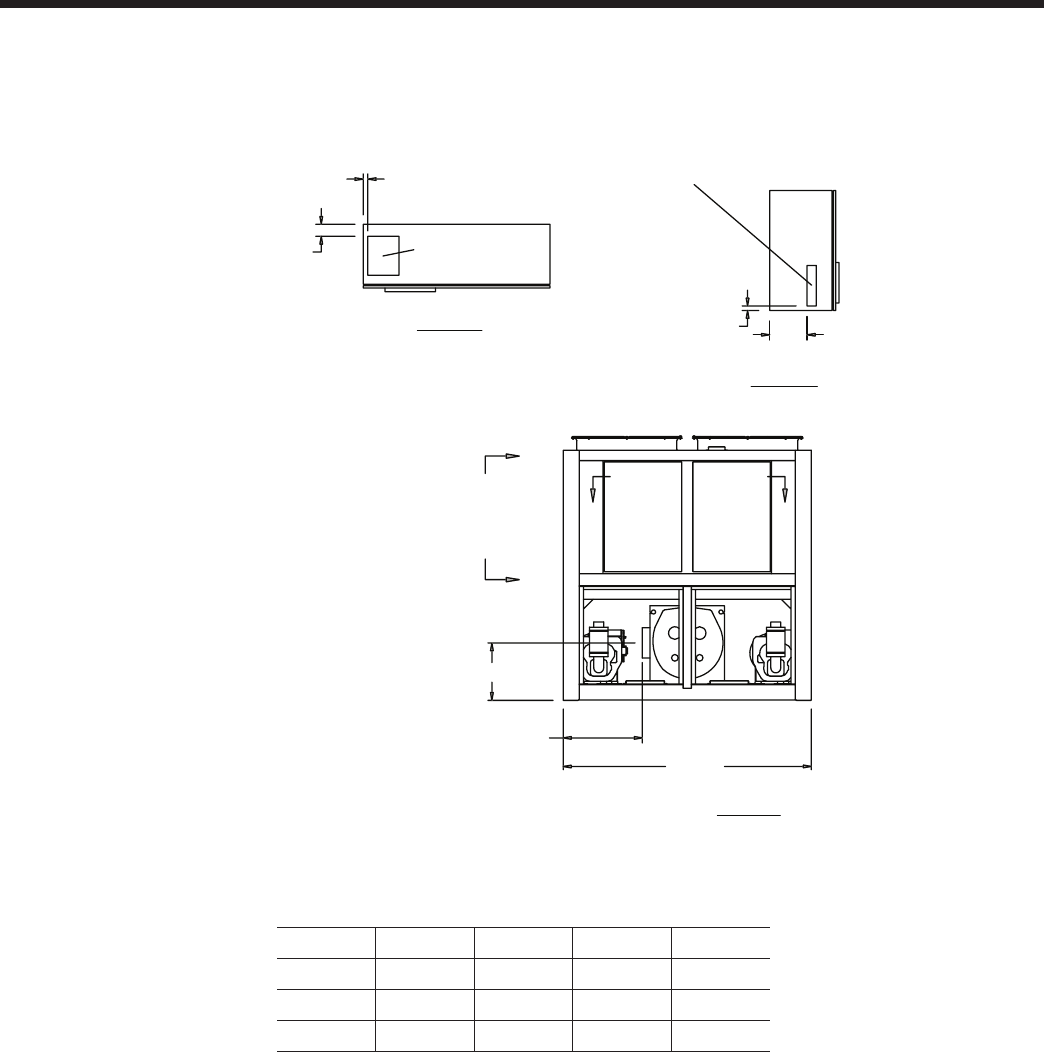
JOHNSON CONTROLS88
Dimensions – SI - continued
Notes:
1. Placement on a level surface free of obstructions (including snow, for winter operation) or air recirculation ensures rated performance,
reliable operation, and ease of maintenance. Site restrictions may compromise minimum clearances indicated below, resulting in unpre-
dictable air patters and possible diminished performance. Johnson Controls’ unit controls will optimize the operation without nuisance
high pressure safety cutouts; however, the system designer MUST consider potential performance degradation.
Access to the unit control center stipulates the unit is no higher than on spring isolators. Recommended minimum clearances: side to wall
- 2m; rear to wall - 2m; control panel end to wall - 1.2m; top - no obstructions whatsoever; distance between adjacent units - 10’. No more
than one adjacent wall may be higher than the unit.
YCIV A B C D
0760E/V 518 714 2174 2852
0770S/P 564 660 2009 2878
0890S/P 564 660 2009 2878
VIEW C-C
VIEW B-B 305
CONTROL ENTRY
76 WIDE X 343 HIGH
38
102
POWER ENTRY
254 WIDE X 330 HIGH
44
POWER ENTRY IS ON BOTTOM OF PANEL
2238
B (EDGE OF UNIT
TO COOLER
CONNECTION)
A
C
B
B
VIEW A-A
C
YCIV0760E/V, YCIV0770S/P, and YCIV0890S/P
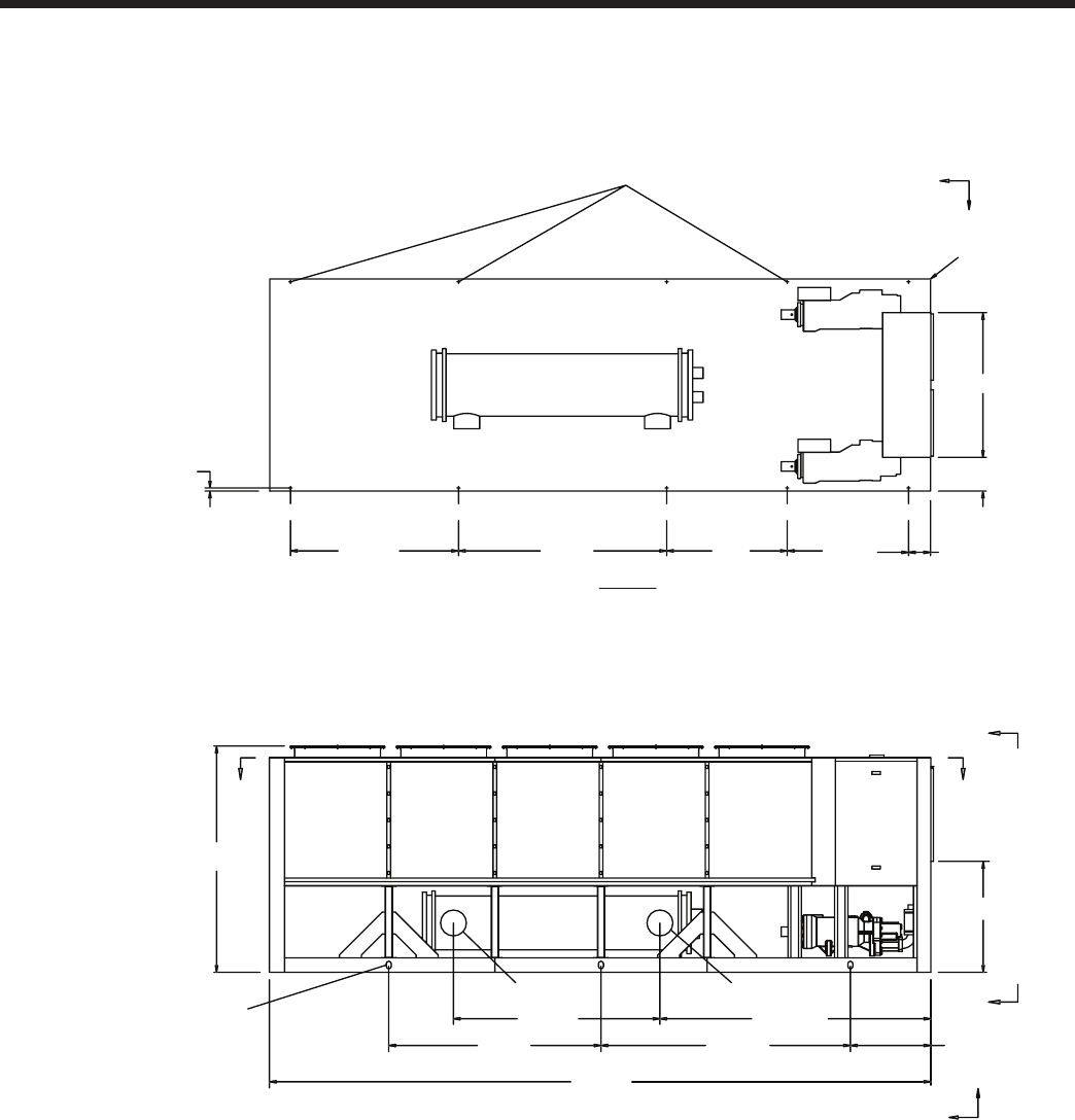
JOHNSON CONTROLS
FORM 201.23-EG1 (1007)
89
POWER: SINGLE POINT WITH TERMINAL BLOCK
XG
C
Y
VIEW D-D
6960
846
2624
2235
D
C
2387
D D
X
G
C
Z
10" (WATER INLET)
10" (WATER OUTLET)
A
A
231
1278127021921770
33 (TYP)
16 MOUNTING
HOLES (TYP)
(3) RIGGING HOLES
EACH SIDE 76 X 51
ORIGIN
CONTROL PANEL
1151
358
1524
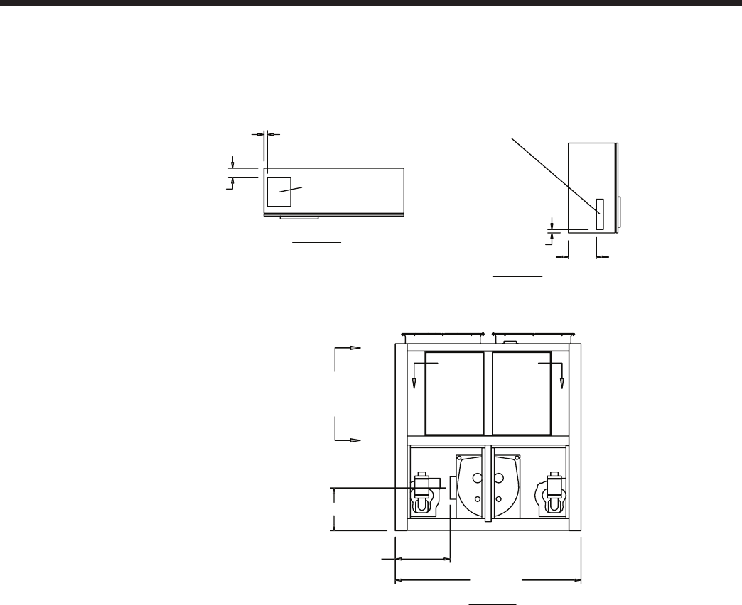
JOHNSON CONTROLS90
Dimensions – SI - continued
Notes:
1. Placement on a level surface free of obstructions (including snow, for winter operation) or air recirculation ensures rated performance,
reliable operation, and ease of maintenance. Site restrictions may compromise minimum clearances indicated below, resulting in unpre-
dictable air patters and possible diminished performance. Johnson Controls’ unit controls will optimize the operation without nuisance
high pressure safety cutouts; however, the system designer MUST consider potential performance degradation.
Access to the unit control center stipulates the unit is no higher than on spring isolators. Recommended minimum clearances: side to wall
- 2m; rear to wall - 2m; control panel end to wall - 1.2m; top - no obstructions whatsoever; distance between adjacent units - 10’. No more
than one adjacent wall may be higher than the unit.
YCIV0800E/V and YCIV0830E/V
VIEW C-C
VIEW B-B
305
CONTROL ENTRY
76 WIDE X 343 HIGH
38
102
POWER ENTRY
254 WIDE X 330 HIGH
44
POWER ENTRY IS ON BOTTOM OF PANEL
2238
714 (EDGE OF UNIT
TO COOLER
CONNECTION)
518
C
C
BB
VIEW A-A
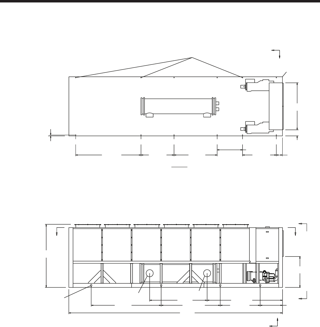
JOHNSON CONTROLS
FORM 201.23-EG1 (1007)
91
POWER: SINGLE POINT WITH TERMINAL BLOCK
CONTROL PANEL
VIEW D-D
231
1278
960
163112501524
8077
846
235545907236
2852
2174
10" (WATER OUTLET) 10" (WATER INLET)
A
A
DD
2387
16 MOUNTING HOLES (TYP)
(4) RIGGING HOLES
EACH SIDE 76 X 51
XG
C
Z
ORIGIN
XG
C
Y
33 (TYP)
1151
358
1524
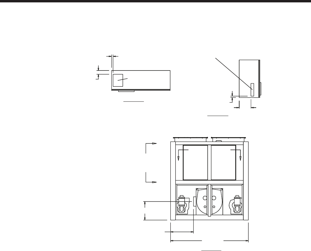
JOHNSON CONTROLS92
Dimensions – SI - continued
Notes:
1. Placement on a level surface free of obstructions (including snow, for winter operation) or air recirculation ensures rated performance,
reliable operation, and ease of maintenance. Site restrictions may compromise minimum clearances indicated below, resulting in unpre-
dictable air patters and possible diminished performance. Johnson Controls’ unit controls will optimize the operation without nuisance
high pressure safety cutouts; however, the system designer MUST consider potential performance degradation.
Access to the unit control center stipulates the unit is no higher than on spring isolators. Recommended minimum clearances: side to wall
- 2m; rear to wall - 2m; control panel end to wall - 1.2m; top - no obstructions whatsoever; distance between adjacent units - 10’. No more
than one adjacent wall may be higher than the unit.
YCIV0920S/P, YCIV0930E/V, and YCIV1000S/P
VIEW C-C
VIEW B-B
305
CONTROL ENTRY
76 WIDE X 343 HIGH
38
102
POWER ENTRY
254 WIDE X 330 HIGH
44
POWER ENTRY IS ON BOTTOM OF PANEL
2238
660 (EDGE OF UNIT
TO COOLER
CONNECTION)
564
C
C
BB
VIEW A-A
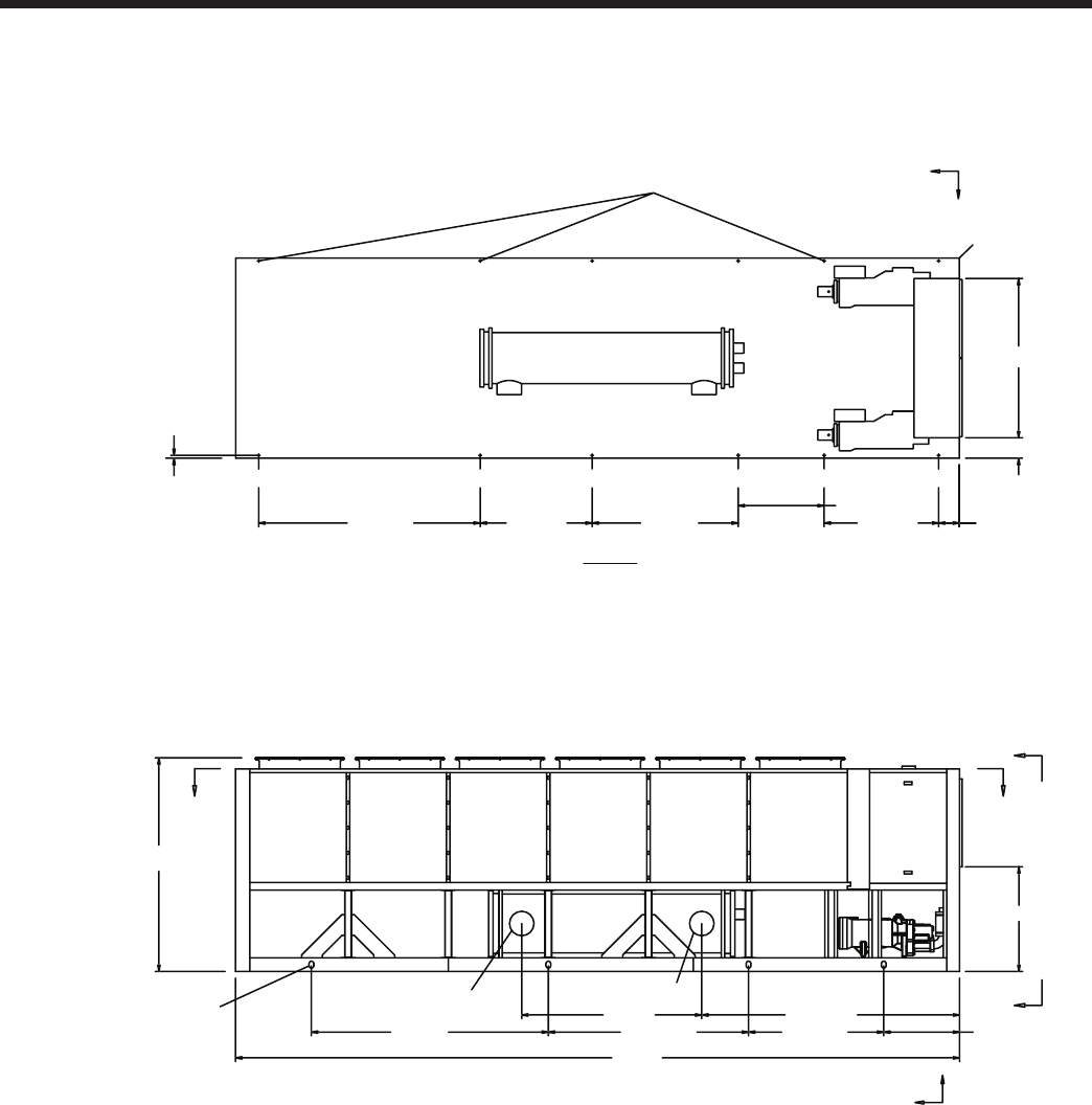
JOHNSON CONTROLS
FORM 201.23-EG1 (1007)
93
POWER: SINGLE POINT WITH TERMINAL BLOCK
CONTROL PANEL
VIEW D-D
231
1278
960
163112501524
8077
846
235545907236
2878
2009
10" (WATER OUTLET) 10" (WATER INLET)
A
A
D
D
2387
16 MOUNTING HOLES (TYP)
(4) RIGGING HOLES
EACH SIDE 76 X 51
XG
C
Z
ORIGIN
XG
C
Y
33 (TYP)
1151
358
1524

JOHNSON CONTROLS94
Dimensions – SI - continued
Notes:
1. Placement on a level surface free of obstructions (including snow, for winter operation) or air recirculation ensures rated performance,
reliable operation, and ease of maintenance. Site restrictions may compromise minimum clearances indicated below, resulting in unpre-
dictable air patters and possible diminished performance. Johnson Controls’ unit controls will optimize the operation without nuisance
high pressure safety cutouts; however, the system designer MUST consider potential performance degradation.
Access to the unit control center stipulates the unit is no higher than on spring isolators. Recommended minimum clearances: side to wall
- 2m; rear to wall - 2m; control panel end to wall - 1.2m; top - no obstructions whatsoever; distance between adjacent units - 10’. No more
than one adjacent wall may be higher than the unit.
YCIV1050E/V and YCIV1070S/P
VIEW C-C
VIEW B-B
305
CONTROL ENTRY
76 WIDE X 343 HIGH
38
102
POWER ENTRY
254 WIDE X 330 HIGH
44
POWER ENTRY IS ON BOTTOM OF PANEL
2238
VIEW A-A
BB
C
C
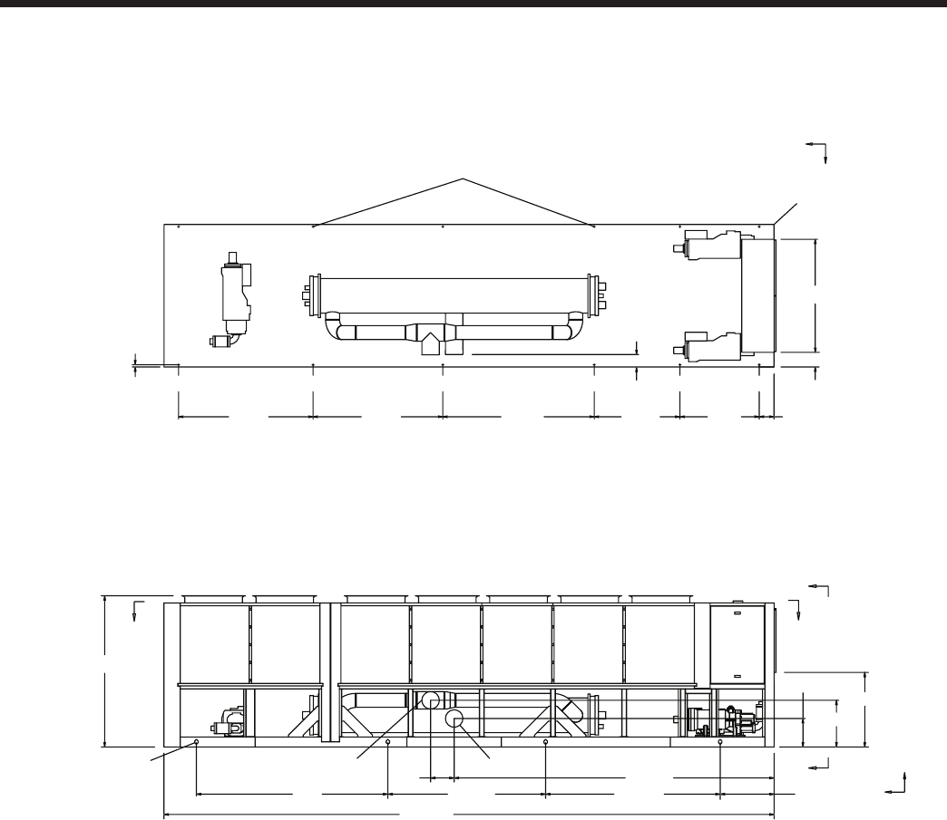
JOHNSON CONTROLS
FORM 201.23-EG1 (1007)
95
POWER: SINGLE POINT WITH TERMINAL BLOCK
1151
759
447
A
A
XG
C
Z
D
D
2387
CONTROL PANEL
8565
5024371
35846060
9068 843
10" (WATER INLET)
10" (WATER OUTLET)
(4) RIGGING HOLES
EACH SIDE 76 X 51
1778
231
12451346237720372111 231
ORIGIN
33 (TYP)
16 MOUNTING HOLES (TYP)
XG
C
Y
193

JOHNSON CONTROLS96
Dimensions – SI - continued
Notes:
1. Placement on a level surface free of obstructions (including snow, for winter operation) or air recirculation ensures rated performance,
reliable operation, and ease of maintenance. Site restrictions may compromise minimum clearances indicated below, resulting in unpre-
dictable air patters and possible diminished performance. Johnson Controls’ unit controls will optimize the operation without nuisance
high pressure safety cutouts; however, the system designer MUST consider potential performance degradation.
Access to the unit control center stipulates the unit is no higher than on spring isolators. Recommended minimum clearances: side to wall
- 2m; rear to wall - 2m; control panel end to wall - 1.2m; top - no obstructions whatsoever; distance between adjacent units - 10’. No more
than one adjacent wall may be higher than the unit.
YCIV1120E/V
VIEW C-C
VIEW B-B
305
CONTROL ENTRY
76 WIDE X 343 HIGH
38
102
POWER ENTRY
254 WIDE X 330 HIGH
44
POWER ENTRY IS ON BOTTOM OF PANEL
2238
VIEW A-A
C
C
B B
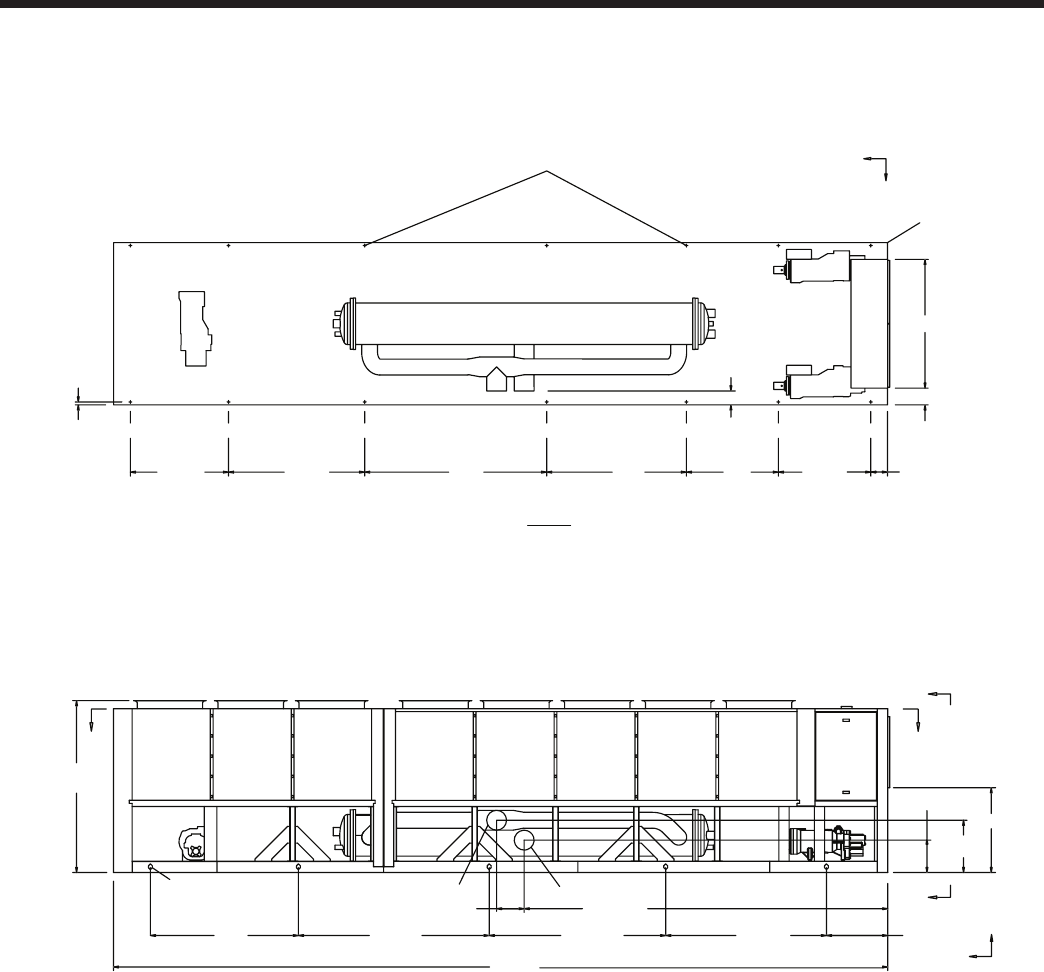
JOHNSON CONTROLS
FORM 201.23-EG1 (1007)
97
POWER: SINGLE POINT WITH TERMINAL BLOCK
1278
1270
1930
2515
483
1356 231
33 (TYP)
193
447
759
2387
DD
XG
C
Z
XG
C
Y
CONTROL PANEL
ORIGIN
A
A
10699
31425504814110185 945
5024
371
10" (WATER OUTLET) 10" (WATER INLET)
(5) RIGGING HOLES
EACH SIDE 76 X 51
VIEW D-D
16 MOUNTING HOLES (TYP)
1151
231
1778
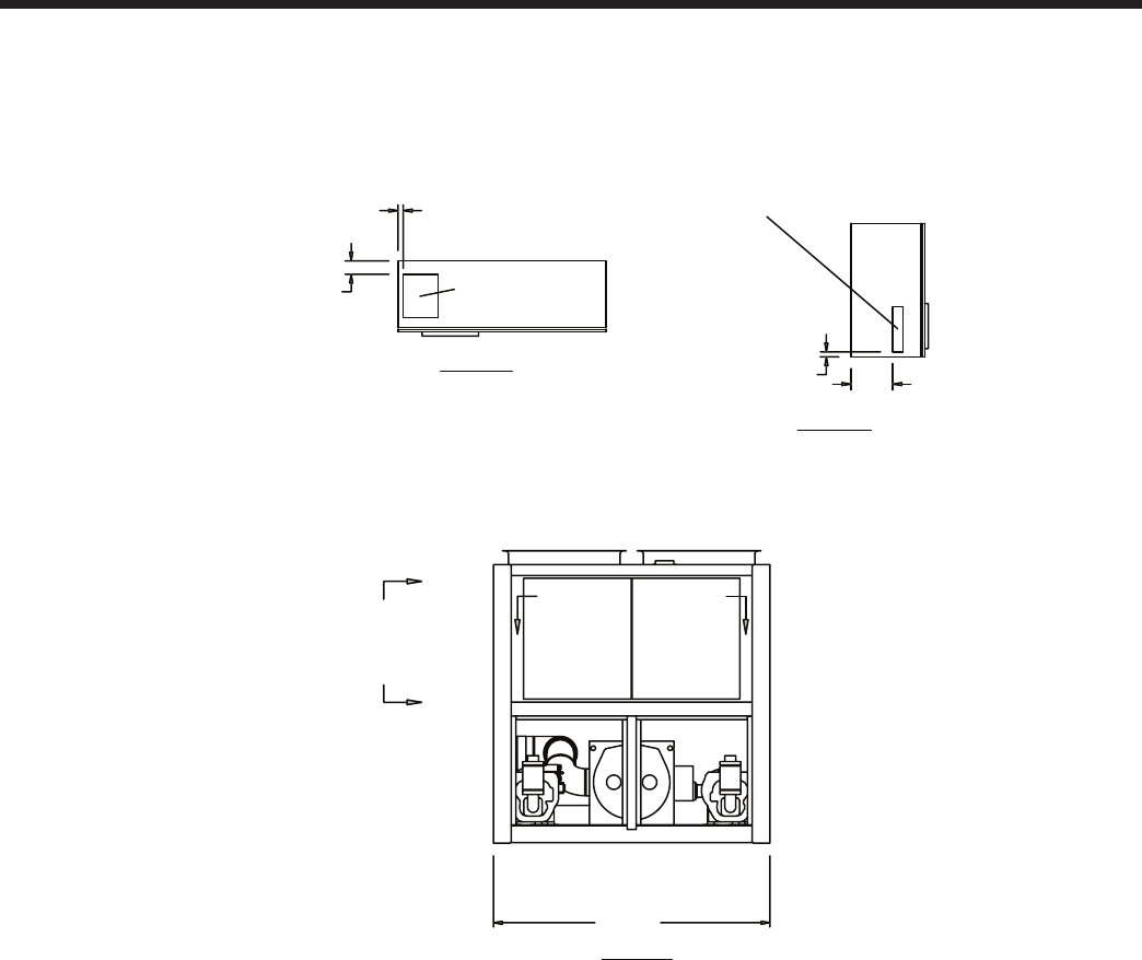
JOHNSON CONTROLS98
Dimensions – SI - continued
Notes:
1. Placement on a level surface free of obstructions (including snow, for winter operation) or air recirculation ensures rated performance,
reliable operation, and ease of maintenance. Site restrictions may compromise minimum clearances indicated below, resulting in unpre-
dictable air patters and possible diminished performance. Johnson Controls’ unit controls will optimize the operation without nuisance
high pressure safety cutouts; however, the system designer MUST consider potential performance degradation.
Access to the unit control center stipulates the unit is no higher than on spring isolators. Recommended minimum clearances: side to wall
- 2m; rear to wall - 2m; control panel end to wall - 1.2m; top - no obstructions whatsoever; distance between adjacent units - 10’. No more
than one adjacent wall may be higher than the unit.
YCIV1180S/P
VIEW C-C
VIEW B-B
305
CONTROL ENTRY
76 WIDE X 343 HIGH
38
102
POWER ENTRY
254 WIDE X 330 HIGH
44
POWER ENTRY IS ON BOTTOM OF PANEL
2238
VIEW A-A
BB
C
C
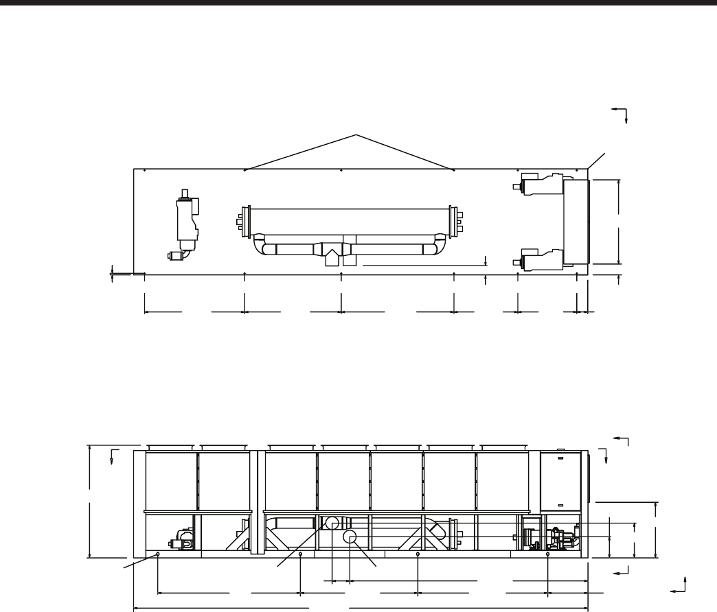
JOHNSON CONTROLS
FORM 201.23-EG1 (1007)
99
POWER: SINGLE POINT WITH TERMINAL BLOCK
1151
671
411
A
A
XG
C
Z
D
D
2387
CONTROL PANEL
8565
5024381
35846060
9068 843
10" (WATER INLET)
10" (WATER OUTLET)
(4) RIGGING HOLES
EACH SIDE 76 X 51
1778
231
12451346237720372111 231
ORIGIN
33 (TYP)
16 MOUNTING HOLES (TYP)
XG
C
Y
193

JOHNSON CONTROLS100
Dimensions – SI - continued
Notes:
1. Placement on a level surface free of obstructions (including snow, for winter operation) or air recirculation ensures rated performance,
reliable operation, and ease of maintenance. Site restrictions may compromise minimum clearances indicated below, resulting in unpre-
dictable air patters and possible diminished performance. Johnson Controls’ unit controls will optimize the operation without nuisance
high pressure safety cutouts; however, the system designer MUST consider potential performance degradation.
Access to the unit control center stipulates the unit is no higher than on spring isolators. Recommended minimum clearances: side to wall
- 2m; rear to wall - 2m; control panel end to wall - 1.2m; top - no obstructions whatsoever; distance between adjacent units - 10’. No more
than one adjacent wall may be higher than the unit.
YCIV1220E/V and YCIV1340S/P
VIEW C-C
VIEW B-B
305
CONTROL ENTRY
76 WIDE X 343 HIGH
38
102 POWER ENTRY
254 WIDE X 330 HIGH
44
POWER ENTRY IS ON BOTTOM OF PANEL
2238
VIEW A-A
C
B B
C
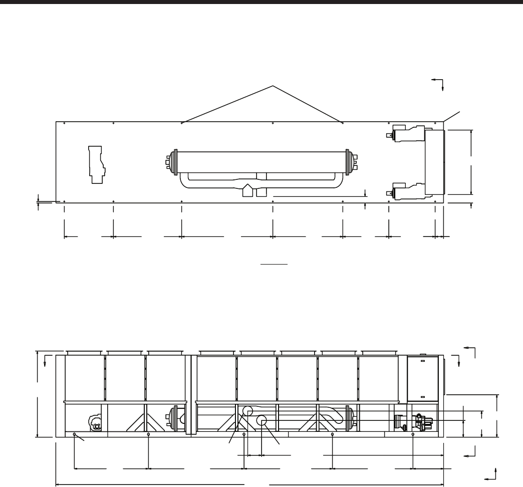
JOHNSON CONTROLS
FORM 201.23-EG1 (1007)
101
POWER: SINGLE POINT WITH TERMINAL BLOCK
1278
1270
1930
2515
1882
1356 231
33 (TYP)
175
462
638
2387
D
D
XG
C
Z
XG
C
Y
CONTROL PANEL
ORIGIN
A
A
10700
30665504814110185 843
5024
381
10" (WATER OUTLET) 10" (WATER INLET)
(5) RIGGING HOLES
EACH SIDE 76 X 51
VIEW D-D
16 MOUNTING HOLES (TYP)
1151
231
1778
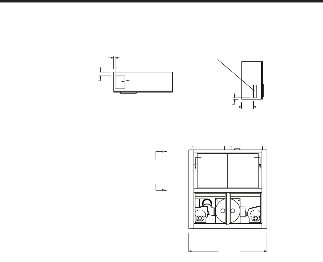
JOHNSON CONTROLS102
Dimensions – SI - continued
Notes:
1. Placement on a level surface free of obstructions (including snow, for winter operation) or air recirculation ensures rated performance,
reliable operation, and ease of maintenance. Site restrictions may compromise minimum clearances indicated below, resulting in unpre-
dictable air patters and possible diminished performance. Johnson Controls’ unit controls will optimize the operation without nuisance
high pressure safety cutouts; however, the system designer MUST consider potential performance degradation.
Access to the unit control center stipulates the unit is no higher than on spring isolators. Recommended minimum clearances: side to wall
- 2m; rear to wall - 2m; control panel end to wall - 1.2m; top - no obstructions whatsoever; distance between adjacent units - 10’. No more
than one adjacent wall may be higher than the unit.
YCIV1380E/V and YCIV1500S/P
VIEW C-C
VIEW B-B
305
CONTROL ENTRY
76 WIDE X 343 HIGH
38
102
POWER ENTRY
254 WIDE X 330 HIGH
44
POWER ENTRY IS ON BOTTOM OF PANEL
2238
C
B B
C
VIEW A-A
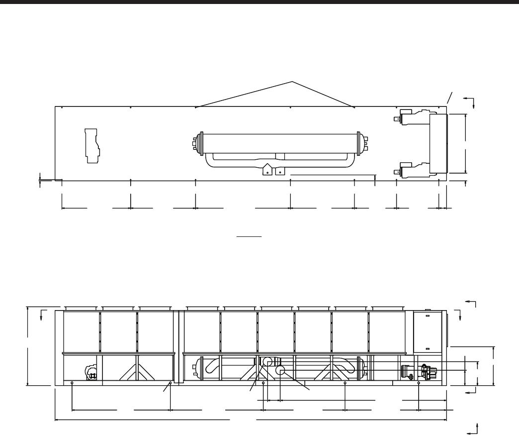
JOHNSON CONTROLS
FORM 201.23-EG1 (1007)
103
2387
175
CONTROL PANEL
ORIGIN
1356 231
1278127019302863483
POWER: SINGLE POINT WITH TERMINAL BLOCK
VIEW D-D
16 MOUNTING HOLES (TYP)
381 5024
3066 843
5532833411303
11816
462
721
A
A
DD
10" (WATER INLET)10" (WATER OUTLET)
(5) RIGGING HOLES
EACH SIDE 76 X 51
33 (TYP)
XG
C
Y
XG
C
Z
1151
1778
231
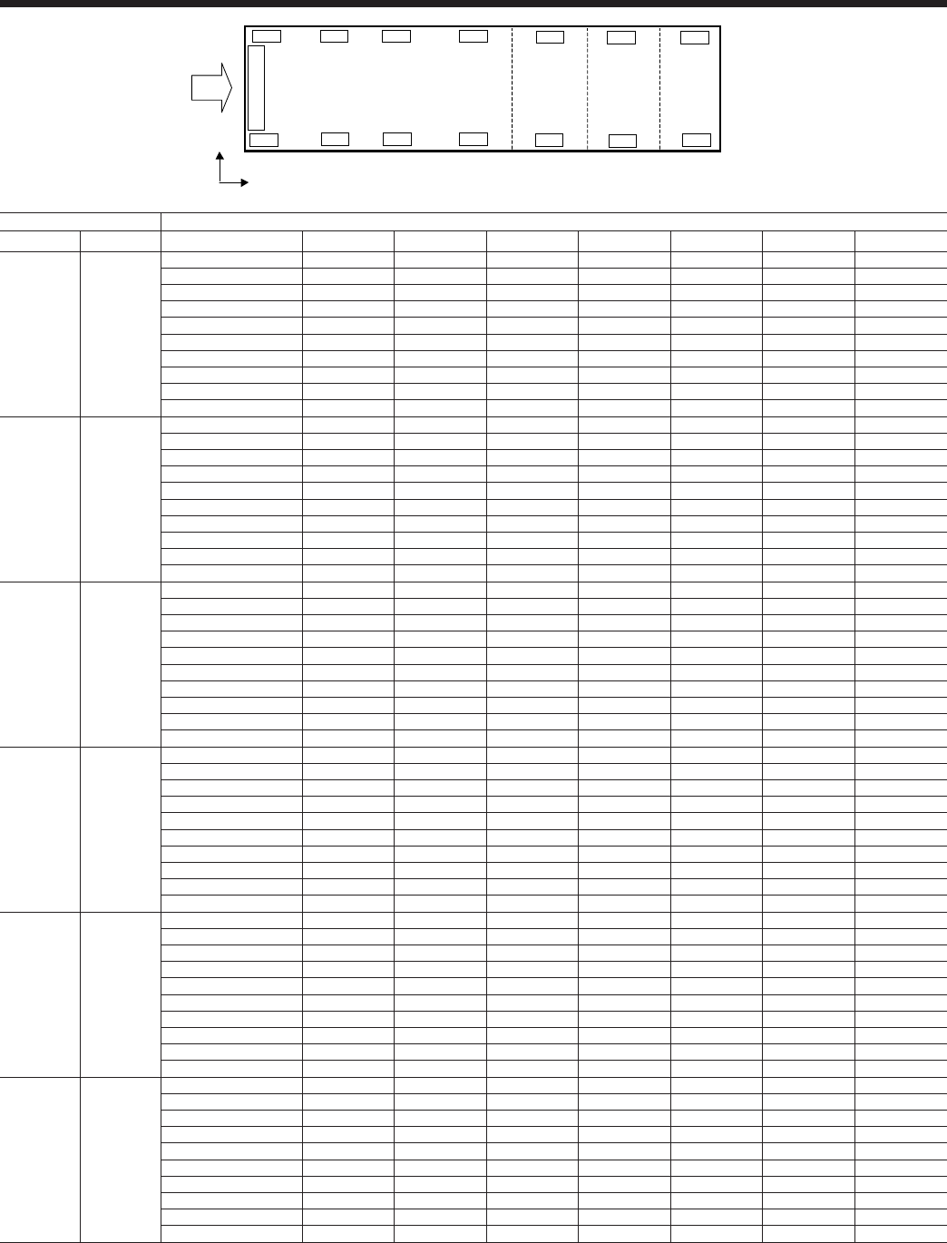
JOHNSON CONTROLS104
Isolator Locations – English
CONTROL PANEL
L1
L2
R6
R1
L6
L5
L4
L3
R2
R3
R4
R5
R7
L7
x
y
STANDARD EFFICIENCY - ENGLISH
MODEL Isolator Locations ( x , y ) - in. and Point Loads - lbs
60 Hz 50 Hz 1 2 3 4 5 6 7
YCIV0157S/P YCIV0600S/P
LEFT - L ( 9.1 , 86.8 ) ( 59.4 , 86.8 ) ( 109.4 , 86.8 ) ( 211 , 86.8 )
Al Fin Coils 1702 1592 1396 1340
Cu Fin Coils 1702 1704 1739 1682
RS&LS1 / Al Fin Coils 1881 1770 1396 1340
RS&LS1 / Cu Fin Coils 1881 1883 1739 1682
RIGHT - R ( 9.1 , 1.3 ) ( 59.4 , 1.3 ) ( 109.4 , 1.3 ) ( 211 , 1.3 )
Al Fin Coils 1702 1592 1396 1340
Cu Fin Coils 1702 1704 1739 1682
RS&LS1 / Al Fin Coils 1881 1770 1396 1340
RS&LS1 / Cu Fin Coils 1881 1883 1739 1682
YCIV0177S/P YCIV0650S/P
LEFT - L ( 9.1 , 86.8 ) ( 59.4 , 86.8 ) ( 109.4 , 86.8 ) ( 211 , 86.8 )
Al Fin Coils 1720 1614 1667 1609
Cu Fin Coils 1720 1726 2011 1951
RS&LS1 / Al Fin Coils 1898 1792 1667 1609
RS&LS1 / Cu Fin Coils 1898 1905 2011 1951
RIGHT - R ( 9.1 , 1.3 ) ( 59.4 , 1.3 ) ( 109.4 , 1.3 ) ( 211 , 1.3 )
Al Fin Coils 1702 1594 1667 1609
Cu Fin Coils 1702 1706 2011 1951
RS&LS1 / Al Fin Coils 1881 1773 1667 1609
RS&LS1 / Cu Fin Coils 1881 1885 2011 1951
YCIV0187S/P YCIV0720S/P
LEFT - L ( 9.1 , 86.8 ) ( 59.4 , 86.8 ) ( 109.4 , 86.8 ) ( 195.7 , 86.8 ) ( 265.4 , 86.8 )
Al Fin Coils 1715 1579 1559 1274 774
Cu Fin Coils 1715 1700 1898 1653 935
RS&LS1 / Al Fin Coils 1894 1757 1559 1274 774
RS&LS1 / Cu Fin Coils 1894 1878 1898 1653 935
RIGHT - R ( 9.1 , 1.3 ) ( 59.4 , 1.3 ) ( 109.4 , 1.3 ) ( 195.7 , 1.3 ) ( 265.4 , 1.3 )
Al Fin Coils 1698 1559 1559 1241 664
Cu Fin Coils 1698 1680 1898 1620 825
RS&LS1 / Al Fin Coils 1876 1737 1559 1241 664
RS&LS1 / Cu Fin Coils 1876 1858 1898 1620 825
YCIV0207S/P YCIV0770S/P
LEFT - L ( 9.1 , 86.8 ) ( 59.4 , 86.8 ) ( 109.4 , 86.8 ) ( 195.7 , 86.8 ) ( 265.4 , 86.8 )
Al Fin Coils 1728 1680 1768 1512 915
Cu Fin Coils 1728 1801 2108 1892 1076
RS&LS1 / Al Fin Coils 1907 1858 1768 1512 915
RS&LS1 / Cu Fin Coils 1907 1980 2108 1892 1076
RIGHT - R ( 9.1 , 1.3 ) ( 59.4 , 1.3 ) ( 109.4 , 1.3 ) ( 195.7 , 1.3 ) ( 265.4 , 1.3 )
Al Fin Coils 1728 1676 1764 1475 800
Cu Fin Coils 1728 1797 2108 1854 961
RS&LS1 / Al Fin Coils 1907 1854 1764 1475 800
RS&LS1 / Cu Fin Coils 1907 1975 2103 1854 961
YCIV0277S/P YCIV0840S/P
LEFT - L ( 9.1 , 86.8 ) ( 59.4 , 86.8 ) ( 109.4 , 86.8 ) ( 195.7 , 86.8 ) ( 265.4 , 86.8 )
Al Fin Coils 1728 1680 1768 1523 959
Cu Fin Coils 1728 1801 2108 1903 1120
RS&LS1 / Al Fin Coils 1907 1858 1768 1523 959
RS&LS1 / Cu Fin Coils 1907 1980 2108 1903 1120
RIGHT - R ( 9.1 , 1.3 ) ( 59.4 , 1.3 ) ( 109.4 , 1.3 ) ( 195.7 , 1.3 ) ( 265.4 , 1.3 )
Al Fin Coils 1728 1676 1764 1519 955
Cu Fin Coils 1728 1797 2103 1898 1116
RS&LS1 / Al Fin Coils 1907 1854 1764 1519 955
RS&LS1 / Cu Fin Coils 1907 1975 2103 1898 1116
YCIV0247S/P YCIV0920S/P
LEFT - L ( 9.1 , 86.8 ) ( 59.4 , 86.8 ) ( 97.2 , 86.8 ) ( 161.4 , 86.8 ) ( 210.6 , 86.8 ) ( 307.9 , 86.8 )
Al Fin Coils 1728 1638 1248 1160 1261 959
Cu Fin Coils 1728 1728 1488 1435 1609 1199
RS&LS1 / Al Fin Coils 1907 1817 1248 1160 1261 959
RS&LS1 / Cu Fin Coils 1907 1907 1488 1435 1609 1199
RIGHT - R ( 9.1 , 1.3 ) ( 59.4 , 1.3 ) ( 97.2 , 1.3 ) ( 161.4 , 1.3 ) ( 210.6 , 1.3 ) ( 307.9 , 1.3 )
Al Fin Coils 1720 1625 1239 1153 1237 955
Cu Fin Coils 1720 1715 1479 1429 1585 1195
RS&LS1 / Al Fin Coils 1898 1803 1239 1153 1237 955
RS&LS1 / Cu Fin Coils 1898 1894 1479 1429 1590 1195

JOHNSON CONTROLS
FORM 201.23-EG1 (1007)
105
MODEL Isolator Locations ( x , y ) - in. and Point Loads - lbs
60 Hz 50 Hz 1 2 3 4 5 6 7
YCIV0267S/P YCIV1000S/P
LEFT - L ( 9.1 , 86.8 ) ( 59.4 , 86.8 ) ( 97.2 , 86.8 ) ( 161.4 , 86.8 ) ( 210.6 , 86.8 ) ( 307.9 , 86.8 )
Al Fin Coils 1728 1638 1248 1160 1265 1005
Cu Fin Coils 1728 1728 1488 1435 1614 1246
RS&LS1 / Al Fin Coils 1907 1817 1248 1160 1265 1005
RS&LS1 / Cu Fin Coils 1907 1907 1488 1435 1614 1246
RIGHT - R ( 9.1 , 1.3 ) ( 59.4 , 1.3 ) ( 97.2 , 1.3 ) ( 161.4 , 1.3 ) ( 210.6 , 1.3 ) ( 307.9 , 1.3 )
Al Fin Coils 1728 1638 1248 1160 1265 1005
Cu Fin Coils 1728 1728 1488 1435 1614 1246
RS&LS1 / Al Fin Coils 1907 1817 1248 1160 1265 1005
RS&LS1 / Cu Fin Coils 1907 1907 1488 1435 1618 1246
YCIV0287S/P YCIV1070S/P
LEFT - L ( 9.1 , 86.8 ) ( 58.1 , 86.8 ) ( 111.1 , 86.8 ) ( 204.7 , 86.8 ) ( 284.9 , 86.8 ) ( 368 , 86.8 )
Al Fin Coils 1753 1585 1821 1810 2123 1175
Cu Fin Coils 1775 1757 2165 2156 2467 1347
RS&LS1 / Al Fin Coils 1929 1761 1821 1810 2189 1462
RS&LS1 / Cu Fin Coils 1885 1933 2165 2156 2533 1634
RIGHT - R ( 9.1 , 1.3 ) ( 58.1 , 1.3 ) ( 111.1 , 1.3 ) ( 204.7 , 1.3 ) ( 284.9 , 1.3 ) ( 368 , 1.3 )
Al Fin Coils 1753 1596 2407 2414 2635 1179
Cu Fin Coils 1775 1768 2751 2760 2978 1351
RS&LS1 / Al Fin Coils 1929 1773 2407 2414 2701 1466
RS&LS1 / Cu Fin Coils 1951 1944 2751 2760 3045 1638
YCIV0307S/P YCIV1180S/P
LEFT - L ( 9.1 , 86.8 ) ( 58.1 , 86.8 ) ( 111.1 , 86.8 ) ( 204.7 , 86.8 ) ( 284.9 , 86.8 ) ( 368 , 86.8 )
Al Fin Coils 1753 1585 1953 1978 2304 1184
Cu Fin Coils 1775 1757 2297 2324 2648 1356
RS&LS1 / Al Fin Coils 1929 1761 1953 1978 2370 1470
RS&LS1 / Cu Fin Coils 1951 1933 2297 2324 2714 1642
RIGHT - R ( 9.1 , 1.3 ) ( 58.1 , 1.3 ) ( 111.1 , 1.3 ) ( 204.7 , 1.3 ) ( 284.9 , 1.3 ) ( 368 , 1.3 )
Al Fin Coils 1753 1596 2540 2632 2897 1188
Cu Fin Coils 1775 1768 2884 2978 3241 1338
RS&LS1 / Al Fin Coils 1929 1773 2540 2632 2963 1475
RS&LS1 / Cu Fin Coils 1951 1944 2884 2978 3307 1647
YCIV0357S/P YCIV1340S/P
LEFT - L ( 9.1 , 86.8 ) ( 59.4 , 86.8 ) ( 109.4 , 86.8 ) ( 185.4 , 86.8 ) ( 284.4 , 86.8 ) ( 358.5 , 86.8 ) ( 411.9 , 86.8 )
Al Fin Coils 1753 1585 1953 1978 1953 1140 946
Cu Fin Coils 1775 1733 2238 2363 2339 1424 1065
RS&LS1 / Al Fin Coils 1929 1761 1953 1978 1953 1316 1122
RS&LS1 / Cu Fin Coils 1951 1909 2238 2363 2339 1601 1241
RIGHT - R ( 9.1 , 1.3 ) ( 59.4 , 1.3 ) ( 109.4 , 1.3 ) ( 185.4 , 1.3 ) ( 284.4 , 1.3 ) ( 358.5 , 1.3 ) ( 411.9 , 1.3 )
Al Fin Coils 1753 1596 2540 2632 2540 1151 946
Cu Fin Coils 1775 1715 2824 3018 2926 1435 1065
RS&LS1 / Al Fin Coils 1929 1773 2540 2632 2540 1327 1122
RS&LS1 / Cu Fin Coils 1951 1892 2824 3018 2926 1612 1241
YCIV0397S/P YCIV1500S/P
LEFT - L ( 9.1 , 86.8 ) ( 59.4 , 86.8 ) ( 109.4 , 86.8 ) ( 185.4 , 86.8 ) ( 298.1 , 86.8 ) ( 375.2 , 86.8 ) ( 456 , 86.8 )
Al Fin Coils 1766 1607 1953 1978 2041 1404 1056
Cu Fin Coils 1788 1755 2238 2363 2427 1689 1175
RS&LS1 / Al Fin Coils 1942 1784 1953 1978 2041 1581 1232
RS&LS1 / Cu Fin Coils 1964 1931 2238 2363 2427 1865 1351
RIGHT - R ( 9.1 , 1.3 ) ( 59.4 , 1.3 ) ( 109.4 , 1.3 ) ( 185.4 , 1.3 ) ( 298.1 , 1.3 ) ( 375.2 , 1.3 ) ( 456 , 1.3 )
Al Fin Coils 1766 1618 2540 2632 2628 1415 1056
Cu Fin Coils 1788 1737 2824 3018 3014 1700 1175
RS&LS1 / Al Fin Coils 1942 1795 2540 2632 2628 1592 1232
RS&LS1 / Cu Fin Coils 1964 1914 2824 3018 3014 1876 1351
NOTES:1. RS = Reduced Sound Option, LS = Low Sound Option

JOHNSON CONTROLS106
Isolator Locations – English – continued
CONTROL PANEL
L1
L2
R6
R1
L6
L5
L4
L3
R2
R3
R4
R5
R7
L7
x
y
HIGH EFFICIENCY - ENGLISH
MODEL Isolator Locations ( x , y ) - in. and Point Loads - lbs
60 Hz 50 Hz 1 2 3 4 5 6 7
YCIV0157E/V YCIV0590E/V
LEFT - L ( 9.1 , 86.8 ) ( 59.4 , 86.8 ) ( 109.4 , 86.8 ) ( 211 , 86.8 )
Al Fin Coils 1702 1594 1667 1609
Cu Fin Coils 1702 1706 2011 1951
RS&LS1 / Al Fin Coils 1881 1773 1667 1609
RS&LS1 / Cu Fin Coils 1881 1885 2011 1951
RIGHT - R ( 9.1 , 1.3 ) ( 59.4 , 1.3 ) ( 109.4 , 1.3 ) ( 211 , 1.3 )
Al Fin Coils 1702 1594 1667 1609
Cu Fin Coils 1702 1706 2011 1951
RS&LS1 / Al Fin Coils 1881 1773 1667 1609
RS&LS1 / Cu Fin Coils 1881 1885 2011 1951
YCIV0177E/V YCIV0630E/V
LEFT - L ( 9.1 , 86.8 ) ( 59.4 , 86.8 ) ( 109.4 , 86.8 ) ( 195.7 , 86.8 ) ( 265.4 , 86.8 )
Al Fin Coils 1698 1559 1559 1274 774
Cu Fin Coils 1698 1680 1898 1653 935
RS&LS1 / Al Fin Coils 1876 1737 1559 1274 774
RS&LS1 / Cu Fin Coils 1876 1858 1898 1653 935
RIGHT - R ( 9.1 , 1.3 ) ( 59.4 , 1.3 ) ( 109.4 , 1.3 ) ( 195.7 , 1.3 ) ( 265.4 , 1.3 )
Al Fin Coils 1698 1559 1559 1241 664
Cu Fin Coils 1698 1680 1898 1620 825
RS&LS1 / Al Fin Coils 1876 1737 1559 1241 664
RS&LS1 / Cu Fin Coils 1876 1858 1898 1620 825
YCIV0187E/V YCIV0700E/V
LEFT - L ( 9.1 , 86.8 ) ( 59.4 , 86.8 ) ( 109.4 , 86.8 ) ( 195.7 , 86.8 ) ( 265.4 , 86.8 )
Al Fin Coils 1715 1581 1676 1287 820
Cu Fin Coils 1715 1702 2015 1667 981
RS&LS1 / Al Fin Coils 1894 1759 1676 1287 820
RS&LS1 / Cu Fin Coils 1894 1881 2015 1667 981
RIGHT - R ( 9.1 , 1.3 ) ( 59.4 , 1.3 ) ( 109.4 , 1.3 ) ( 195.7 , 1.3 ) ( 265.4 , 1.3 )
Al Fin Coils 1698 1561 1561 1287 820
Cu Fin Coils 1698 1682 1900 1667 981
RS&LS1 / Al Fin Coils 1876 1739 1561 1287 820
RS&LS1 / Cu Fin Coils 1876 1861 1900 1667 981
YCIV0197E/V YCIV0760E/V
LEFT - L ( 9.1 , 86.8 ) ( 59.4 , 86.8 ) ( 109.4 , 86.8 ) ( 195.7 , 86.8 ) ( 265.4 , 86.8 )
Al Fin Coils 1720 1609 1618 1354 860
Cu Fin Coils 1720 1731 1958 1733 1021
RS&LS1 / Al Fin Coils 1898 1788 1618 1354 860
RS&LS1 / Cu Fin Coils 1898 1909 1958 1733 1021
RIGHT - R ( 9.1 , 1.3 ) ( 59.4 , 1.3 ) ( 109.4 , 1.3 ) ( 195.7 , 1.3 ) ( 265.4 , 1.3 )
Al Fin Coils 1720 1609 1618 1354 860
Cu Fin Coils 1720 1731 1958 1733 1021
RS&LS1 / Al Fin Coils 1898 1788 1618 1354 860
RS&LS1 / Cu Fin Coils 1898 1909 1958 1733 1021
YCIV0207E/V YCIV0800E/V
LEFT - L ( 9.1 , 86.8 ) ( 59.4 , 86.8 ) ( 97.2 , 86.8 ) ( 161.4 , 86.8 ) ( 210.6 , 86.8 ) ( 307.9 , 86.8 )
Al Fin Coils 1720 1614 1082 994 1093 952
Cu Fin Coils 1720 1704 1323 1270 1442 1193
RS&LS1 / Al Fin Coils 1898 1792 1082 994 1093 952
RS&LS1 / Cu Fin Coils 1898 1883 1323 1270 1442 1193
RIGHT - R ( 9.1 , 1.3 ) ( 59.4 , 1.3 ) ( 97.2 , 1.3 ) ( 161.4 , 1.3 ) ( 210.6 , 1.3 ) ( 307.9 , 1.3 )
Al Fin Coils 1720 1614 1082 994 1078 955
Cu Fin Coils 1720 1704 1323 1270 1426 1195
RS&LS1 / Al Fin Coils 1898 1792 1082 994 1078 955
RS&LS1 / Cu Fin Coils 1898 1883 1323 1270 1431 1195
JOHNSON CONTROLS
FORM 201.23-EG1 (1007)
107
MODEL Isolator Locations ( x , y ) - in. and Point Loads - lbs
60 Hz 50 Hz 1 2 3 4 5 6 7
YCIV0227E/V YCIV0830E/V
LEFT - L ( 9.1 , 86.8 ) ( 59.4 , 86.8 ) ( 97.2 , 86.8 ) ( 161.4 , 86.8 ) ( 210.6 , 86.8 ) ( 307.9 , 86.8 )
Al Fin Coils 1720 1616 1085 999 1102 1003
Cu Fin Coils 1720 1706 1325 1274 1451 1243
RS&LS1 / Al Fin Coils 1898 1795 1085 999 1102 1003
RS&LS1 / Cu Fin Coils 1898 1885 1325 1274 1451 1243
RIGHT - R ( 9.1 , 1.3 ) ( 59.4 , 1.3 ) ( 97.2 , 1.3 ) ( 161.4 , 1.3 ) ( 210.6 , 1.3 ) ( 307.9 , 1.3 )
Al Fin Coils 1720 1616 1085 999 1102 1003
Cu Fin Coils 1720 1706 1325 1274 1451 1243
RS&LS1 / Al Fin Coils 1898 1795 1085 999 1102 1003
RS&LS1 / Cu Fin Coils 1898 1885 1325 1274 1455 1243
YCIV0247E/V YCIV0930E/V
LEFT - L ( 9.1 , 86.8 ) ( 59.4 , 86.8 ) ( 97.2 , 86.8 ) ( 161.4 , 86.8 ) ( 210.6 , 86.8 ) ( 307.9 , 86.8 )
Al Fin Coils 1728 1638 1248 1160 1265 1005
Cu Fin Coils 1728 1728 1488 1435 1614 1246
RS&LS1 / Al Fin Coils 1907 1817 1248 1160 1265 1005
RS&LS1 / Cu Fin Coils 1907 1907 1488 1435 1614 1246
RIGHT - R ( 9.1 , 1.3 ) ( 59.4 , 1.3 ) ( 97.2 , 1.3 ) ( 161.4 , 1.3 ) ( 210.6 , 1.3 ) ( 307.9 , 1.3 )
Al Fin Coils 1720 1629 1248 1160 1265 1005
Cu Fin Coils 1720 1720 1488 1435 1614 1246
RS&LS1 / Al Fin Coils 1898 1808 1248 1160 1265 1005
RS&LS1 / Cu Fin Coils 1898 1898 1488 1435 1618 1246
YCIV0267E/V YCIV1050E/V
LEFT - L ( 9.1 , 86.8 ) ( 58.1 , 86.8 ) ( 111.1 , 86.8 ) ( 204.7 , 86.8 ) ( 284.9 , 86.8 ) ( 368 , 86.8 )
Al Fin Coils 1753 1585 1821 1839 2163 1175
Cu Fin Coils 1775 1757 2165 2185 2507 1347
RS&LS1 / Al Fin Coils 1929 1761 1821 1839 2229 1396
RS&LS1 / Cu Fin Coils 1951 1933 2165 2185 2573 1634
RIGHT - R ( 9.1 , 1.3 ) ( 58.1 , 1.3 ) ( 111.1 , 1.3 ) ( 204.7 , 1.3 ) ( 284.9 , 1.3 ) ( 368 , 1.3 )
Al Fin Coils 1753 1596 2407 2493 2756 1179
Cu Fin Coils 1775 1768 2751 2840 3100 1351
RS&LS1 / Al Fin Coils 1929 1773 2407 2493 2822 1466
RS&LS1 / Cu Fin Coils 1951 1944 2751 2840 3166 1638
YCIV0287E/V YCIV1120E/V
LEFT - L ( 9.1 , 86.8 ) ( 59.4 , 86.8 ) ( 109.4 , 86.8 ) ( 185.4 , 86.8 ) ( 284.4 , 86.8 ) ( 358.5 , 86.8 ) ( 411.9 , 86.8 )
Al Fin Coils 1753 1585 1847 1870 1574 1049 928
Cu Fin Coils 1775 1733 2132 2255 1960 1334 1047
RS&LS1 / Al Fin Coils 1929 1761 1847 1870 1574 1226 1105
RS&LS1 / Cu Fin Coils 1885 1909 2132 2255 1960 1510 1224
RIGHT - R ( 9.1 , 1.3 ) ( 59.4 , 1.3 ) ( 109.4 , 1.3 ) ( 185.4 , 1.3 ) ( 284.4 , 1.3 ) ( 358.5 , 1.3 ) ( 411.9 , 1.3 )
Al Fin Coils 1753 1596 2434 2524 2344 1120 928
Cu Fin Coils 1775 1715 2718 2910 2729 1404 1047
RS&LS1 / Al Fin Coils 1929 1773 2434 2524 2344 1296 1105
RS&LS1 / Cu Fin Coils 1951 1892 2718 2910 2729 1581 1224
YCIV0327E/V YCIV1220E/V
LEFT - L ( 9.1 , 86.8 ) ( 59.4 , 86.8 ) ( 109.4 , 86.8 ) ( 185.4 , 86.8 ) ( 284.4 , 86.8 ) ( 358.5 , 86.8 ) ( 411.9 , 86.8 )
Al Fin Coils 1753 1585 1953 1978 1953 1140 928
Cu Fin Coils 1775 1733 2238 2363 2339 1424 1047
RS&LS1 / Al Fin Coils 1929 1761 1953 1978 1953 1316 1105
RS&LS1 / Cu Fin Coils 1951 1931 2238 2363 2339 1601 1224
RIGHT - R ( 9.1 , 1.3 ) ( 59.4 , 1.3 ) ( 109.4 , 1.3 ) ( 185.4 , 1.3 ) ( 284.4 , 1.3 ) ( 358.5 , 1.3 ) ( 411.9 , 1.3 )
Al Fin Coils 1753 1596 2540 2632 2540 1151 928
Cu Fin Coils 1775 1715 2824 3018 2926 1435 1047
RS&LS1 / Al Fin Coils 1929 1773 2540 2632 2540 1327 1105
RS&LS1 / Cu Fin Coils 1951 1892 2824 3018 2926 1612 1224
YCIV0357E/V YCIV1380E/V
LEFT - L ( 9.1 , 86.8 ) ( 59.4 , 86.8 ) ( 109.4 , 86.8 ) ( 185.4 , 86.8 ) ( 298.1 , 86.8 ) ( 375.2 , 86.8 ) ( 456 , 86.8 )
Al Fin Coils 1766 1607 1953 1978 2041 1404 1038
Cu Fin Coils 1788 1755 2238 2363 2427 1689 1157
RS&LS1 / Al Fin Coils 1942 1784 1953 1978 2041 1581 1215
RS&LS1 / Cu Fin Coils 1964 1931 2238 2363 2427 1865 1334
RIGHT - R ( 9.1 , 1.3 ) ( 59.4 , 1.3 ) ( 109.4 , 1.3 ) ( 185.4 , 1.3 ) ( 298.1 , 1.3 ) ( 375.2 , 1.3 ) ( 456 , 1.3 )
Al Fin Coils 1766 1618 2540 2632 2628 1415 1038
Cu Fin Coils 1788 1737 2824 3018 3014 1700 1157
RS&LS1 / Al Fin Coils 1942 1795 2540 2632 2628 1592 1215
RS&LS1 / Cu Fin Coils 1964 1914 2824 3018 3014 1876 1334
NOTES:1. RS = Reduced Sound Option, LS = Low Sound Option
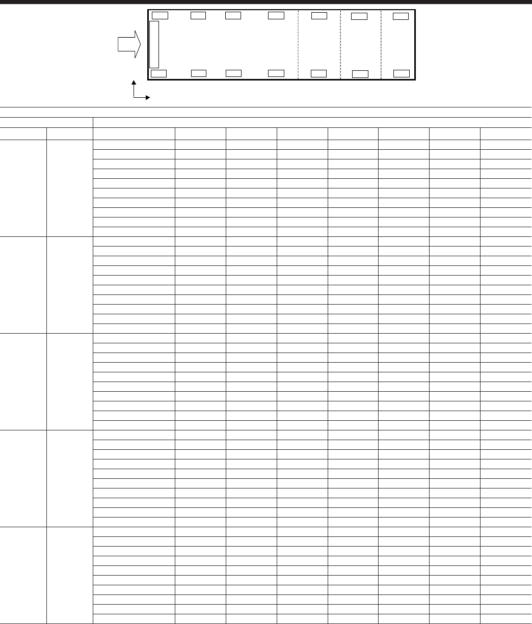
JOHNSON CONTROLS108
CONTROL PANEL
L1
L2
R6
R1
L6
L5
L4
L3
R2
R3
R4
R5
R7
L7
x
y
Isolator Locations – SI
STANDARD EFFICIENCY - SI
MODEL Isolator Locations ( x , y ) - mm and Point Loads - kg
60 Hz 50 Hz 1 2 3 4 5 6 7
YCIV0157S/P YCIV0600S/P
LEFT - L ( 230 , 2204 ) ( 1510 , 2204 ) ( 2780 , 2204 ) ( 5360 , 2204 )
Al Fin Coils 772 722 633 608
Cu Fin Coils 772 773 789 763
RS&LS1 / Al Fin Coils 853 803 633 608
RS&LS1 / Cu Fin Coils 853 854 789 763
RIGHT - R ( 230 , 32 ) ( 1510 , 32 ) ( 2780 , 32 ) ( 5360 , 32 )
Al Fin Coils 772 722 633 608
Cu Fin Coils 772 773 789 763
RS&LS1 / Al Fin Coils 853 803 633 608
RS&LS1 / Cu Fin Coils 853 854 789 763
YCIV0177S/P YCIV0650S/P
LEFT - L ( 230 , 2204 ) ( 1510 , 2204 ) ( 2780 , 2204 ) ( 5360 , 2204 )
Al Fin Coils 780 732 756 730
Cu Fin Coils 780 783 912 885
RS&LS1 / Al Fin Coils 861 813 756 730
RS&LS1 / Cu Fin Coils 861 864 912 885
RIGHT - R ( 230 , 32 ) ( 1510 , 32 ) ( 2780 , 32 ) ( 5360 , 32 )
Al Fin Coils 772 723 756 730
Cu Fin Coils 772 774 912 885
RS&LS1 / Al Fin Coils 853 804 756 730
RS&LS1 / Cu Fin Coils 853 855 912 885
YCIV0187S/P YCIV0720S/P
LEFT - L ( 230 , 2204 ) ( 1510 , 2204 ) ( 2780 , 2204 ) ( 4970 , 2204 ) ( 6740 , 2204 )
Al Fin Coils 778 716 707 578 351
Cu Fin Coils 778 771 861 750 424
RS&LS1 / Al Fin Coils 859 797 707 578 351
RS&LS1 / Cu Fin Coils 859 852 861 750 424
RIGHT - R ( 230 , 32 ) ( 1510 , 32 ) ( 2780 , 32 ) ( 4970 , 32 ) ( 6740 , 32 )
Al Fin Coils 770 707 707 563 301
Cu Fin Coils 770 762 861 735 374
RS&LS1 / Al Fin Coils 851 788 707 563 301
RS&LS1 / Cu Fin Coils 851 843 861 735 374
YCIV0207S/P YCIV0770S/P
LEFT - L ( 230 , 2204 ) ( 1510 , 2204 ) ( 2780 , 2204 ) ( 4970 , 2204 ) ( 6740 , 2204 )
Al Fin Coils 784 762 802 686 415
Cu Fin Coils 784 817 956 858 488
RS&LS1 / Al Fin Coils 865 843 802 686 415
RS&LS1 / Cu Fin Coils 865 898 956 858 488
RIGHT - R ( 230 , 32 ) ( 1510 , 32 ) ( 2780 , 32 ) ( 4970 , 32 ) ( 6740 , 32 )
Al Fin Coils 784 760 800 669 363
Cu Fin Coils 784 815 956 841 436
RS&LS1 / Al Fin Coils 865 841 800 669 363
RS&LS1 / Cu Fin Coils 865 896 954 841 436
YCIV0277S/P YCIV0840S/P
LEFT - L ( 230 , 2204 ) ( 1510 , 2204 ) ( 2780 , 2204 ) ( 4970 , 2204 ) ( 6740 , 2204 )
Al Fin Coils 784 762 802 691 435
Cu Fin Coils 784 817 956 863 508
RS&LS1 / Al Fin Coils 865 843 802 691 435
RS&LS1 / Cu Fin Coils 865 898 956 863 508
RIGHT - R ( 230 , 32 ) ( 1510 , 32 ) ( 2780 , 32 ) ( 4970 , 32 ) ( 6740 , 32 )
Al Fin Coils 784 760 800 689 433
Cu Fin Coils 784 815 954 861 506
RS&LS1 / Al Fin Coils 865 841 800 689 433
RS&LS1 / Cu Fin Coils 865 896 954 861 506

JOHNSON CONTROLS
FORM 201.23-EG1 (1007)
109
MODEL Isolator Locations ( x , y ) - mm and Point Loads - kg
60 Hz 50 Hz 1 2 3 4 5 6 7
YCIV0247S/P YCIV0920S/P
LEFT - L ( 230 , 2204 ) ( 1510 , 2204 ) ( 2470 , 2204 ) ( 4100 , 2204 ) ( 5350 , 2204 ) ( 7820 , 2204 )
Al Fin Coils 784 743 566 526 572 435
Cu Fin Coils 784 784 675 651 730 544
RS&LS1 / Al Fin Coils 865 824 566 526 572 435
RS&LS1 / Cu Fin Coils 865 865 675 651 730 544
RIGHT - R ( 230 , 32 ) ( 1510 , 32 ) ( 2470 , 32 ) ( 4100 , 32 ) ( 5350 , 32 ) ( 7820 , 32 )
Al Fin Coils 780 737 562 523 561 433
Cu Fin Coils 780 778 671 648 719 542
RS&LS1 / Al Fin Coils 861 818 562 523 561 433
RS&LS1 / Cu Fin Coils 861 859 671 648 721 542
YCIV0267S/P YCIV1000S/P
LEFT - L ( 230 , 2204 ) ( 1510 , 2204 ) ( 2470 , 2204 ) ( 4100 , 2204 ) ( 5350 , 2204 ) ( 7820 , 2204 )
Al Fin Coils 784 743 566 526 574 456
Cu Fin Coils 784 784 675 651 732 565
RS&LS1 / Al Fin Coils 865 824 566 526 574 456
RS&LS1 / Cu Fin Coils 865 865 675 651 732 565
RIGHT - R ( 230 , 32 ) ( 1510 , 32 ) ( 2470 , 32 ) ( 4100 , 32 ) ( 5350 , 32 ) ( 7820 , 32 )
Al Fin Coils 784 743 566 526 574 456
Cu Fin Coils 784 784 675 651 732 565
RS&LS1 / Al Fin Coils 865 824 566 526 574 456
RS&LS1 / Cu Fin Coils 865 865 675 651 734 565
YCIV0287S/P YCIV1070S/P
LEFT - L ( 230 , 2204 ) ( 1475 , 2204 ) ( 2823 , 2204 ) ( 5199 , 2204 ) ( 7236 , 2204 ) ( 9346 , 2204 )
Al Fin Coils 795 719 826 821 963 533
Cu Fin Coils 805 797 982 978 1119 611
RS&LS1 / Al Fin Coils 875 799 826 821 993 663
RS&LS1 / Cu Fin Coils 855 877 982 978 1149 741
RIGHT - R ( 230 , 32 ) ( 1475 , 32 ) ( 2823 , 32 ) ( 5199 , 32 ) ( 7236 , 32 ) ( 9346 , 32 )
Al Fin Coils 795 724 1092 1095 1195 535
Cu Fin Coils 805 802 1248 1252 1351 613
RS&LS1 / Al Fin Coils 875 804 1092 1095 1225 665
RS&LS1 / Cu Fin Coils 885 882 1248 1252 1381 743
YCIV0307S/P YCIV1180S/P
LEFT - L ( 230 , 2204 ) ( 1475 , 2204 ) ( 2823 , 2204 ) ( 5199 , 2204 ) ( 7236 , 2204 ) ( 9346 , 2204 )
Al Fin Coils 795 719 886 897 1045 537
Cu Fin Coils 805 797 1042 1054 1201 615
RS&LS1 / Al Fin Coils 875 799 886 897 1075 667
RS&LS1 / Cu Fin Coils 885 877 1042 1054 1231 745
RIGHT - R ( 230 , 32 ) ( 1475 , 32 ) ( 2823 , 32 ) ( 5199 , 32 ) ( 7236 , 32 ) ( 9346 , 32 )
Al Fin Coils 795 724 1152 1194 1314 539
Cu Fin Coils 805 802 1308 1351 1470 607
RS&LS1 / Al Fin Coils 875 804 1152 1194 1344 669
RS&LS1 / Cu Fin Coils 885 882 1308 1351 1500 747
YCIV0357S/P YCIV1340S/P
LEFT - L ( 230 , 2204 ) ( 1510 , 2204 ) ( 2780 , 2204 ) ( 4710 , 2204 ) ( 7225 , 2204 ) ( 9105 , 2204 ) ( 10463 , 2204 )
Al Fin Coils 795 719 886 897 886 517 429
Cu Fin Coils 805 786 1015 1072 1061 646 483
RS&LS1 / Al Fin Coils 875 799 886 897 886 597 509
RS&LS1 / Cu Fin Coils 885 866 1015 1072 1061 726 563
RIGHT - R ( 230 , 32 ) ( 1510 , 32 ) ( 2780 , 32 ) ( 4710 , 32 ) ( 7225 , 32 ) ( 9105 , 32 ) ( 10463 , 32 )
Al Fin Coils 795 724 1152 1194 1152 522 429
Cu Fin Coils 805 778 1281 1369 1327 651 483
RS&LS1 / Al Fin Coils 875 804 1152 1194 1152 602 509
RS&LS1 / Cu Fin Coils 885 858 1281 1369 1327 731 563
YCIV0397S/P YCIV1500S/P
LEFT - L ( 230 , 2204 ) ( 1510 , 2204 ) ( 2780 , 2204 ) ( 4710 , 2204 ) ( 7572 , 2204 ) ( 9530 , 2204 ) ( 11582 , 2204 )
Al Fin Coils 801 729 886 897 926 637 479
Cu Fin Coils 811 796 1015 1072 1101 766 533
RS&LS1 / Al Fin Coils 881 809 886 897 926 717 559
RS&LS1 / Cu Fin Coils 891 876 1015 1072 1101 846 613
RIGHT - R ( 230 , 32 ) ( 1510 , 32 ) ( 2780 , 32 ) ( 4710 , 32 ) ( 7572 , 32 ) ( 9530 , 32 ) ( 11582 , 32 )
Al Fin Coils 801 734 1152 1194 1192 642 479
Cu Fin Coils 811 788 1281 1369 1367 771 533
RS&LS1 / Al Fin Coils 881 814 1152 1194 1192 722 559
RS&LS1 / Cu Fin Coils 891 868 1281 1369 1367 851 613
NOTES:
1. RS = Reduced Sound Option, LS = Low Sound Option
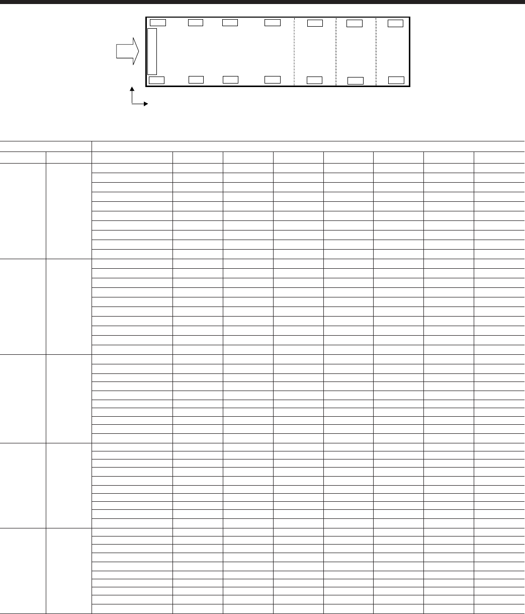
JOHNSON CONTROLS110
CONTROL PANEL
L1
L2
R6
R1
L6
L5
L4
L3
R2
R3
R4
R5
R7
L7
x
y
Isolator Locations – SI – continued
HIGH EFFICIENCY - SI
MODEL Isolator Locations ( x , y ) - mm and Point Loads - kg
60 Hz 50 Hz 1234567
YCIV0157E/V YCIV0590E/V
LEFT - L ( 230 , 2204 ) ( 1510 , 2204 ) ( 2780 , 2204 ) ( 5360 , 2204 )
Al Fin Coils 772 723 756 730
Cu Fin Coils 772 774 912 885
RS&LS1 / Al Fin Coils 853 804 756 730
RS&LS1 / Cu Fin Coils 853 855 912 885
RIGHT - R ( 230 , 32 ) ( 1510 , 32 ) ( 2780 , 32 ) ( 5360 , 32 )
Al Fin Coils 772 723 756 730
Cu Fin Coils 772 774 912 885
RS&LS1 / Al Fin Coils 853 804 756 730
RS&LS1 / Cu Fin Coils 853 855 912 885
YCIV0177E/V YCIV0630E/V
LEFT - L ( 230 , 2204 ) ( 1510 , 2204 ) ( 2780 , 2204 ) ( 4970 , 2204 ) ( 6740 , 2204 )
Al Fin Coils 770 707 707 578 351
Cu Fin Coils 770 762 861 750 424
RS&LS1 / Al Fin Coils 851 788 707 578 351
RS&LS1 / Cu Fin Coils 851 843 861 750 424
RIGHT - R ( 230 , 32 ) ( 1510 , 32 ) ( 2780 , 32 ) ( 4970 , 32 ) ( 6740 , 32 )
Al Fin Coils 770 707 707 563 301
Cu Fin Coils 770 762 861 735 374
RS&LS1 / Al Fin Coils 851 788 707 563 301
RS&LS1 / Cu Fin Coils 851 843 861 735 374
YCIV0187E/V YCIV0700E/V
LEFT - L ( 230 , 2204 ) ( 1510 , 2204 ) ( 2780 , 2204 ) ( 4970 , 2204 ) ( 6740 , 2204 )
Al Fin Coils 778 717 760 584 372
Cu Fin Coils 778 772 914 756 445
RS&LS1 / Al Fin Coils 859 798 760 584 372
RS&LS1 / Cu Fin Coils 859 853 914 756 445
RIGHT - R ( 230 , 32 ) ( 1510 , 32 ) ( 2780 , 32 ) ( 4970 , 32 ) ( 6740 , 32 )
Al Fin Coils 770 708 708 584 372
Cu Fin Coils 770 763 862 756 445
RS&LS1 / Al Fin Coils 851 789 708 584 372
RS&LS1 / Cu Fin Coils 851 844 862 756 445
YCIV0197E/V YCIV0760E/V
LEFT - L ( 230 , 2204 ) ( 1510 , 2204 ) ( 2780 , 2204 ) ( 4970 , 2204 ) ( 6740 , 2204 )
Al Fin Coils 780 730 734 614 390
Cu Fin Coils 780 785 888 786 463
RS&LS1 / Al Fin Coils 861 811 734 614 390
RS&LS1 / Cu Fin Coils 861 866 888 786 463
RIGHT - R ( 230 , 32 ) ( 1510 , 32 ) ( 2780 , 32 ) ( 4970 , 32 ) ( 6740 , 32 )
Al Fin Coils 780 730 734 614 390
Cu Fin Coils 780 785 888 786 463
RS&LS1 / Al Fin Coils 861 811 734 614 390
RS&LS1 / Cu Fin Coils 861 866 888 786 463
YCIV0207E/V YCIV0800E/V
LEFT - L ( 230 , 2204 ) ( 1510 , 2204 ) ( 2470 , 2204 ) ( 4100 , 2204 ) ( 5350 , 2204 ) ( 7820 , 2204 )
Al Fin Coils 780 732 491 451 496 432
Cu Fin Coils 780 773 600 576 654 541
RS&LS1 / Al Fin Coils 861 813 491 451 496 432
RS&LS1 / Cu Fin Coils 861 854 600 576 654 541
RIGHT - R ( 230 , 32 ) ( 1510 , 32 ) ( 2470 , 32 ) ( 4100 , 32 ) ( 5350 , 32 ) ( 7820 , 32 )
Al Fin Coils 780 732 491 451 489 433
Cu Fin Coils 780 773 600 576 647 542
RS&LS1 / Al Fin Coils 861 813 491 451 489 433
RS&LS1 / Cu Fin Coils 861 854 600 576 649 542
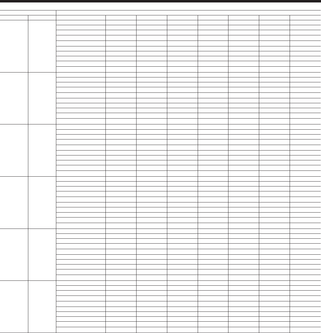
JOHNSON CONTROLS
FORM 201.23-EG1 (1007)
111
MODEL Isolator Locations ( x , y ) - mm and Point Loads - kg
60 Hz 50 Hz 1234567
YCIV0227E/V YCIV0830E/V
LEFT - L ( 230 , 2204 ) ( 1510 , 2204 ) ( 2470 , 2204 ) ( 4100 , 2204 ) ( 5350 , 2204 ) ( 7820 , 2204 )
Al Fin Coils 780 733 492 453 500 455
Cu Fin Coils 780 774 601 578 658 564
RS&LS1 / Al Fin Coils 861 814 492 453 500 455
RS&LS1 / Cu Fin Coils 861 855 601 578 658 564
RIGHT - R ( 230 , 32 ) ( 1510 , 32 ) ( 2470 , 32 ) ( 4100 , 32 ) ( 5350 , 32 ) ( 7820 , 32 )
Al Fin Coils 780 733 492 453 500 455
Cu Fin Coils 780 774 601 578 658 564
RS&LS1 / Al Fin Coils 861 814 492 453 500 455
RS&LS1 / Cu Fin Coils 861 855 601 578 660 564
YCIV0247E/V YCIV0930E/V
LEFT - L ( 230 , 2204 ) ( 1510 , 2204 ) ( 2470 , 2204 ) ( 4100 , 2204 ) ( 5350 , 2204 ) ( 7820 , 2204 )
Al Fin Coils 784 743 566 526 574 456
Cu Fin Coils 784 784 675 651 732 565
RS&LS1 / Al Fin Coils 865 824 566 526 574 456
RS&LS1 / Cu Fin Coils 865 865 675 651 732 565
RIGHT - R ( 230 , 32 ) ( 1510 , 32 ) ( 2470 , 32 ) ( 4100 , 32 ) ( 5350 , 32 ) ( 7820 , 32 )
Al Fin Coils 780 739 566 526 574 456
Cu Fin Coils 780 780 675 651 732 565
RS&LS1 / Al Fin Coils 861 820 566 526 574 456
RS&LS1 / Cu Fin Coils 861 861 675 651 734 565
YCIV0267E/V YCIV1050E/V
LEFT - L ( 230 , 2204 ) ( 1475 , 2204 ) ( 2823 , 2204 ) ( 5199 , 2204 ) ( 7236 , 2204 ) ( 9346 , 2204 )
Al Fin Coils 795 719 826 834 981 533
Cu Fin Coils 805 797 982 991 1137 611
RS&LS1 / Al Fin Coils 875 799 826 834 1011 633
RS&LS1 / Cu Fin Coils 885 877 982 991 1167 741
RIGHT - R ( 230 , 32 ) ( 1475 , 32 ) ( 2823 , 32 ) ( 5199 , 32 ) ( 7236 , 32 ) ( 9346 , 32 )
Al Fin Coils 795 724 1092 1131 1250 535
Cu Fin Coils 805 802 1248 1288 1406 613
RS&LS1 / Al Fin Coils 875 804 1092 1131 1280 665
RS&LS1 / Cu Fin Coils 885 882 1248 1288 1436 743
YCIV0287E/V YCIV1120E/V
LEFT - L ( 230 , 2204 ) ( 1510 , 2204 ) ( 2780 , 2204 ) ( 4710 , 2204 ) ( 7225 , 2204 ) ( 9105 , 2204 ) ( 10463 , 2204 )
Al Fin Coils 795 719 838 848 714 476 421
Cu Fin Coils 805 786 967 1023 889 605 475
RS&LS1 / Al Fin Coils 875 799 838 848 714 556 501
RS&LS1 / Cu Fin Coils 855 866 967 1023 889 685 555
RIGHT - R ( 230 , 32 ) ( 1510 , 32 ) ( 2780 , 32 ) ( 4710 , 32 ) ( 7225 , 32 ) ( 9105 , 32 ) ( 10463 , 32 )
Al Fin Coils 795 724 1104 1145 1063 508 421
Cu Fin Coils 805 778 1233 1320 1238 637 475
RS&LS1 / Al Fin Coils 875 804 1104 1145 1063 588 501
RS&LS1 / Cu Fin Coils 885 858 1233 1320 1238 717 555
YCIV0327E/V YCIV1220E/V
LEFT - L ( 230 , 2204 ) ( 1510 , 2204 ) ( 2780 , 2204 ) ( 4710 , 2204 ) ( 7225 , 2204 ) ( 9105 , 2204 ) ( 10463 , 2204 )
Al Fin Coils 795 719 886 897 886 517 421
Cu Fin Coils 805 786 1015 1072 1061 646 475
RS&LS1 / Al Fin Coils 875 799 886 897 886 597 501
RS&LS1 / Cu Fin Coils 885 876 1015 1072 1061 726 555
RIGHT - R ( 230 , 32 ) ( 1510 , 32 ) ( 2780 , 32 ) ( 4710 , 32 ) ( 7225 , 32 ) ( 9105 , 32 ) ( 10463 , 32 )
Al Fin Coils 795 724 1152 1194 1152 522 421
Cu Fin Coils 805 778 1281 1369 1327 651 475
RS&LS1 / Al Fin Coils 875 804 1152 1194 1152 602 501
RS&LS1 / Cu Fin Coils 885 858 1281 1369 1327 731 555
YCIV0357E/V YCIV1380E/V
LEFT - L ( 230 , 2204 ) ( 1510 , 2204 ) ( 2780 , 2204 ) ( 4710 , 2204 ) ( 7572 , 2204 ) ( 9530 , 2204 ) ( 11582 , 2204 )
Al Fin Coils 801 729 886 897 926 637 471
Cu Fin Coils 811 796 1015 1072 1101 766 525
RS&LS1 / Al Fin Coils 881 809 886 897 926 717 551
RS&LS1 / Cu Fin Coils 891 876 1015 1072 1101 846 605
RIGHT - R ( 230 , 32 ) ( 1510 , 32 ) ( 2780 , 32 ) ( 4710 , 32 ) ( 7572 , 32 ) ( 9530 , 32 ) ( 11582 , 32 )
Al Fin Coils 801 734 1152 1194 1192 642 471
Cu Fin Coils 811 788 1281 1369 1367 771 525
RS&LS1 / Al Fin Coils 881 814 1152 1194 1192 722 551
RS&LS1 / Cu Fin Coils 891 868 1281 1369 1367 851 605
NOTES:
1. RS = Reduced Sound Option, LS = Low Sound Option
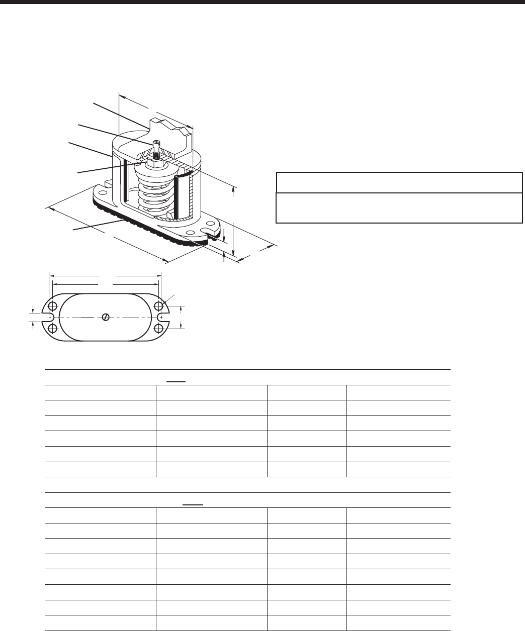
JOHNSON CONTROLS112
FOR UNITS WITH ALL POINT LOADS LESS THATN 1404 LBS (637 KG)
Weight Range (lbs) Weight Range (kg) Model Number Color
239 to 384 lbs 108 to 174 kg CIP-B- Red
384 to 639 lbs 174 to 290 kg CIP-B- White
639 to 851 lbs 290 to 386 kg CIP-B- Blue
851 to 1064 lbs 386 to 483 kg CIP-B- Gray
1064 to 1404 lbs 483 to 637 kg CIP-B- Black
FOR UNITS WITH ANY POINT LOAD ABOVE 1404 LBS (637 KG)
Weight Range (lbs) Weight Range (kg) Model Number Color
Up to 851 lbs Up to 386 kg CIP-C- Black
851 to 1149 lbs 386 to 521 kg CIP-C- Yellow
1149 to 1489 lbs 521 to 675 kg CIP-C- Black
1489 to 1786 lbs 675 to 910 kg CIP-C- Yellow w/ Red
1786 to 2028 lbs 910 to 920 kg CIP-C- Yellow w/ Green
2028 to 2254 lbs 920 to 1022 kg CIP-C- Red w/ Red
2254 to 2936 lbs 1022 to 1332 kg CIP-C- Red w/ Green
Isolator Details
CIP-X-
ONE INCH DEFLECTION SPRING ISOLATOR CROSS-REFERENCE
E
Illustration shows single spring CIP-B or CIP-C mount.
HCL
SBC
Slot Width - SW HCW
MAX BOLT
DIA. - MBD
BASE PLATE DIMENSIONS
NON-SKID NEOPRENE
A
COUSTICAL ISOLATION PAD
(Bolting to floor is not necessary for
indoor applications)
All springs have additional
travel to solid equal to 50%
of the rated deflection.
A
L
FREE &
OPERATING
HEIGHT
TW
FERROUS HOUSING
SIDE ACCESS INTERNAL
ADJUSTMENT BOLT
Turn clockwise to load
spring and maintain Free
& Operating Height.
Dowel Pin is 3/8" dia. for
CIP-A & 1/2" thereafter
Mounting may be
operated 1/2" above
Free & Operating
Height.
NOTE-
CIP Mounts are not
to be used in seismic
or wind load
applications.
EQUIPMENT BASE
TYPE CIP DIMENSIONS (inches)†
†Casting dimensions may vary ±1/8"
Size A L T W SW HCL HCW MBD SBC
Free
Ht.
CIP-B 8 /4/2/16 8
CIP-C 6 /8/16 /8
5
117
7
3
3
/8
1
6 /4
3
/
5/4
3
8/8
7/16
9
2/4
3
3/2
1
/2
/4
1
1
6
7
/2
/4
1
3
1
1
/4
/8
1
7
7
7
Min
Ht.
5 /4
1
6 /4
3
6
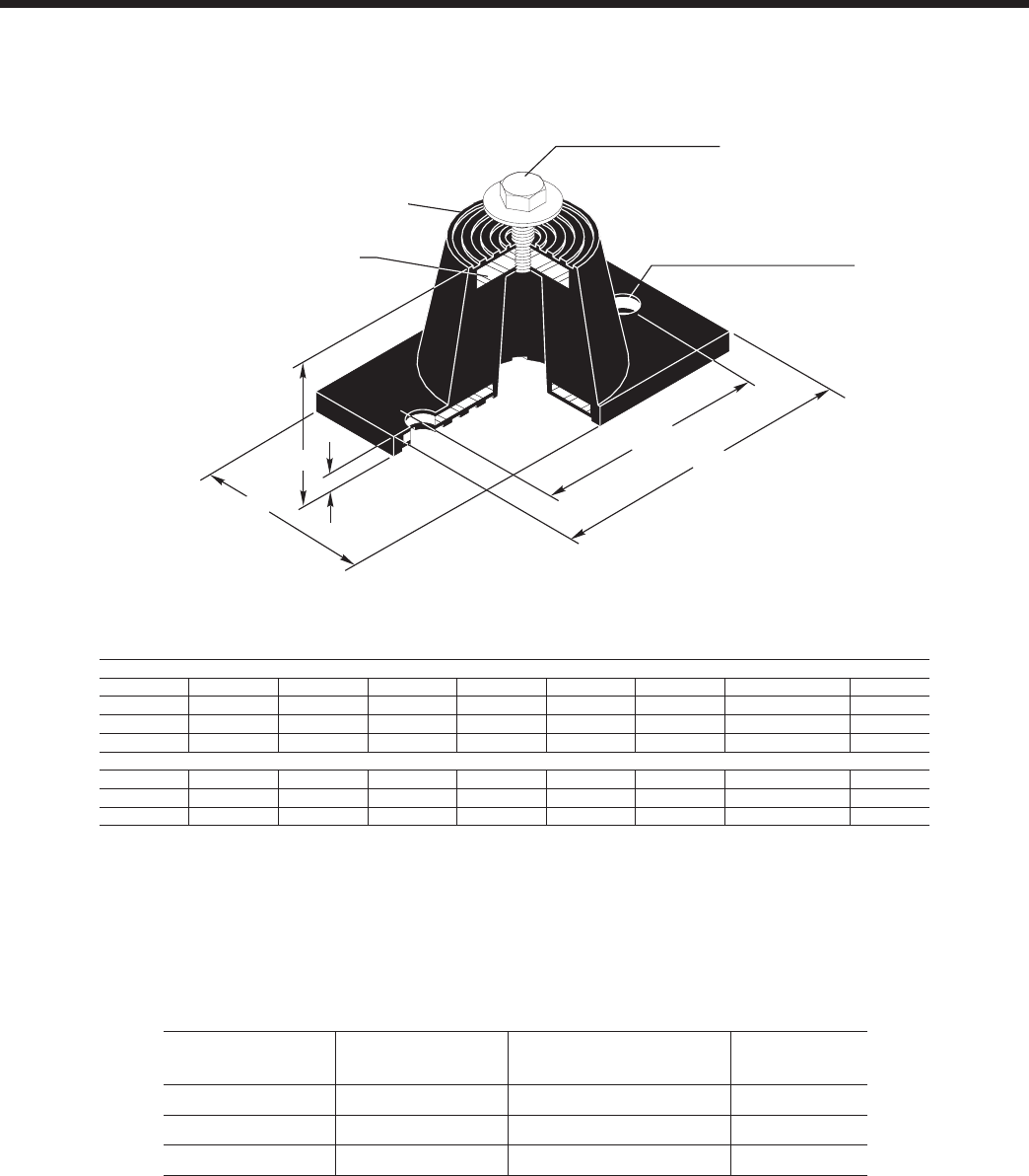
JOHNSON CONTROLS
FORM 201.23-EG1 (1007)
113
Weight Range
(lbs)
Weight Range
(kg) Model Number Color
Up to 751 lbs Up to 341 kg ND-C Yellow
751 to 1651 lbs 341 to 749 kg ND-D Yellow
1651 to 3226 lbs 749 to 1463 kg ND-DS Yellow
"CS" Cap Screw
BC
"MBD" Max. Bolt Dia.
Steel Plate - Top &
Bottom Neoprene
covered to prevent
corrosion
L
T
H
W
D
ENGLISH
Size D H L T W BC CS MBD
ND-C 2 9/16 2 3/ 4 5 1/ 2 1/ 4 2 5/16 4 1/80 1/2- 13 x 1” 1/ 2"
ND-D 3 3/ 8 2 3/ 4 6 1/ 4 5/16 4 5 1/2- 13 x 1” 1/ 2"
ND-DS 3 3/ 8 2 3/ 4 6 1/ 4 5/16 4 5 1/2- 13 x 1” 1/ 2"
SI
ND-C 65.1 69.9 139.7 6.4 58.7 101.9 1/2- 13 x 1” 1/ 2"
ND-D 85.7 69.9 158.8 7.9 101.6 127.0 1/2- 13 x 1” 1/ 2"
ND-DS 85.7 69.9 158.8 7.9 101.6 127.0 1/2- 13 x 1” 1/ 2"
ND-X
NEOPRENE ISOLATOR CROSS-REFERENCE
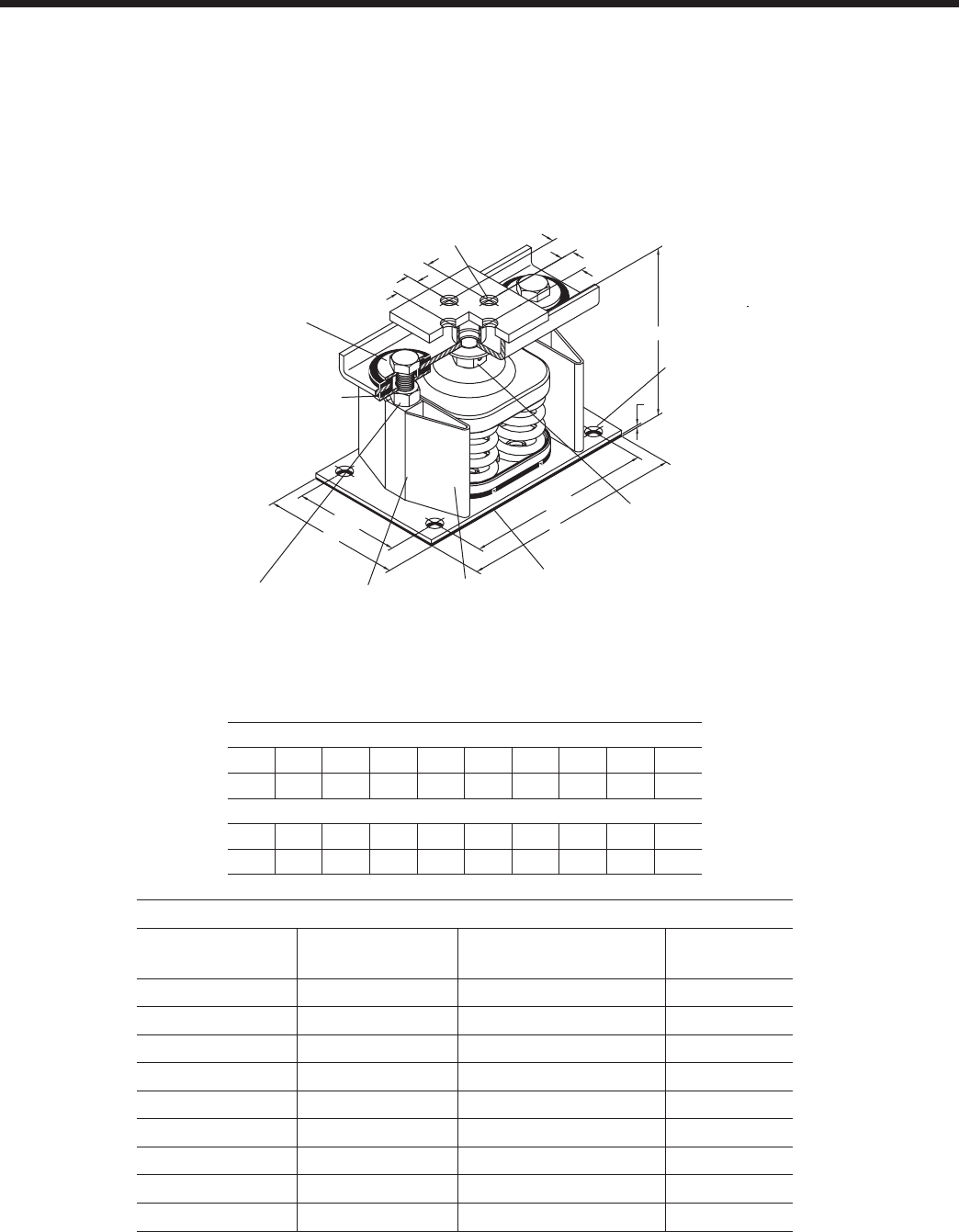
JOHNSON CONTROLS114
Isolator Details (cont'd)
ENGLISH
SIZE H T D E L HCL W HCW MBD
2-C2 8 1/2 3/8 5/8 1 3/8 14 12 1/4 5 1/4 3 1/ 2 5/8"
SI
SIZE H T D E L HCL W HCW MBD
2-C2 215.9 9.5 15.9 34.9 355.6 311.2 133.4 88.9 5/8"
SLRS
*Weight Range
(lbs)
Weight Range
(kg) Model Number Color
Up to 358 lbs Up to 162 kg SLRS-2-C2- Red
358 to 443 lbs 162 to 201 kg SLRS-2-C2- White
443 to 582 lbs 201 to 264 kg SLRS-2-C2- Black
582 to 783 lbs 264 to 335 kg SLRS-2-C2- Blue
783 to 1038 lbs 335 to 471 kg SLRS-2-C2- Green
1038 to 1497 lbs 471 to 679 kg SLRS-2-C2- Gray
1497 to 2058 lbs 679 to 933 kg SLRS-2-C2- Silver
2058 to 2619 lbs 933 to 1188 kg SLRS-2-C2- Gray w/ red
2619 to 3180 lbs 1188 to 1442 kg SLRS-2-C2- Silver w/ red
TWO INCH DEFLECTION, SEISMIC SPRING ISOLATOR CROSS-REFERENCE
‡‡
‡‡
SLRS-2-C2 has 2 springs.
E
E
E
E
H
T
HCW
WL
HCL
"D" Tap - 4 Holes unless
otherwise requested
Adjustment
Bolt
Vertical Limit
Stops-Out of
contact during
normal operation
Non-Skid Neoprene Pad-
Pad can be removed if
mounts are welded
into position.
Enclosed
Steel
Housing
Internal
Neoprene
Acoustical
Pad
Lower
Restraining
Nut
Rubber
Snubbing
Collar
MBD -Max
Bolt
Diameter

JOHNSON CONTROLS
FORM 201.23-EG1 (1007)
115
INTENTIONALLY LEFT BLANK
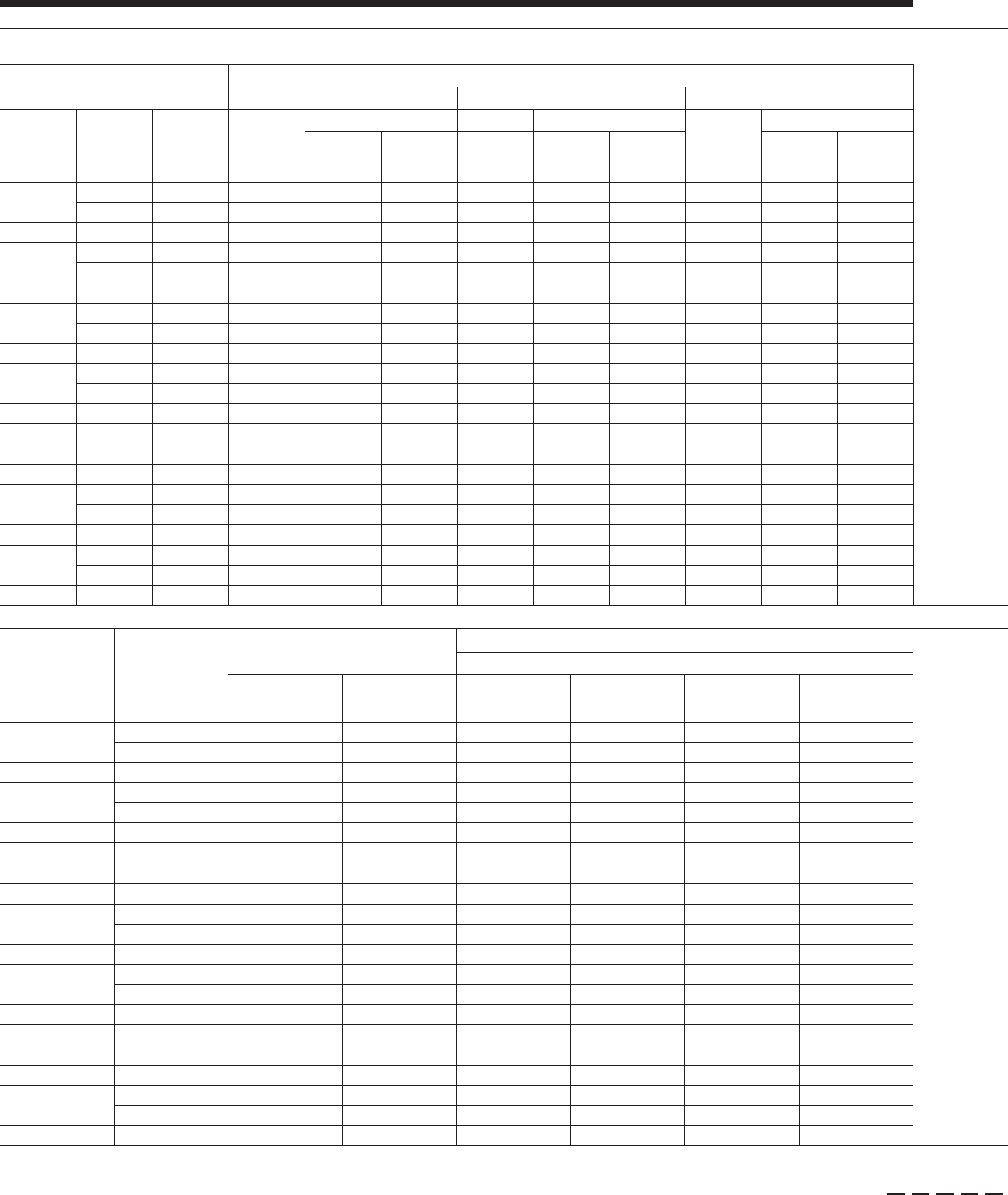
JOHNSON CONTROLS116
Electrical Data - 2 Comp Standard Efciency
See page 192 for Electrical Data footnotes.
Standard Efciency YCIV_ _ _ _ S/P Standard Efciency YCIV_ _ _ _ S/P
Model No./Nameplate System 1 System 2
Std. & Ultra Quiet Cond. Fans High Head/Static Cond. Fans Two-Speed Cond. Fans Std. & Ultra Quiet Cond. Fans High Head/Static Cond. Fans Two-Speed Cond. Fans
YCIV S/P Input Volts
(9) Input Freq Compressor
RLA (5)
Condenser Fans Compressor Condenser Fans
Compressor
RLA (5)
Condenser Fans
Compressor
RLA (5)
Condenser Fans
Compressor
RLA (5)
Condenser Fans
Compressor
RLA (5)
Condenser Fans
Qty. FLA (EA) RLA (5) Qty. FLA (EA) Qty. FLA (EA) Qty. FLA (EA) Qty. FLA (EA) Qty. FLA (EA)
0157
460 60 120 4 2.8 120 4 2.8
380 60 152 4 3.5 152 4 9.3 152 4 3.5 152 4 9.3
0600 400 50 144 4 3.1 144 4 9.3 152 4 3.8 144 4 3.1 144 4 9.3 152 4 3.8
0177
460 60 159 4 2.8 105 4 2.8
380 60 201 4 3.5 201 4 9.3 133 4 3.5 133 4 9.3
0650 400 50 191 4 3.1 191 4 9.3 198 4 3.8 127 4 3.1 127 4 9.3 132 4 3.8
0187
460 60 162 5 2.8 120 4 2.8
380 60 205 5 3.5 205 5 9.3 152 4 3.5 152 4 9.3
0720 400 50 195 5 3.1 195 5 9.3 207 5 3.8 144 4 3.1 144 4 9.3 152 4 3.8
0207
460 60 145 5 2.8 162 4 2.8
380 60 184 5 3.5 184 5 9.3 206 4 3.5 206 4 9.3
0770 400 50 174 5 3.1 174 5 9.3 185 5 3.8 195 4 3.1 195 4 9.3 201 4 3.8
0227
460 60 162 5 2.8 162 5 2.8
380 60 205 5 3.5 205 5 9.3 205 5 3.5 205 5 9.3
0840 400 50 194 5 3.1 194 5 9.3 206 5 3.8 194 5 3.1 194 5 9.3 206 5 3.8
0247
460 60 193 6 2.8 160 5 2.8
380 60 245 6 3.5 245 6 9.3 203 5 3.5 203 5 9.3
0920 400 50 232 6 3.1 232 6 9.3 246 6 3.8 192 5 3.1 192 5 9.3 204 5 3.8
0267
460 60 191 6 2.8 191 6 2.8
380 60 242 6 3.5 242 6 9.3 242 6 3.5 242 6 9.3
1000 400 50 230 6 3.1 230 6 9.3 243 6 3.8 230 6 3.1 230 6 9.3 243 6 3.8
YCIV S/P Control
KVA (7)
Unit Short Circuit Withstand (KA) Field Wiring & Protection
Std. & Ultra Quiet Cond. Fans High Head/High Static Fans Two-Speed Cond. Fans
Terminal Block
(STD)
Circuit Breaker
(OPT)
Minimum Ckt.
Ampacity (MCA) (3)
Recommended
Fuse/Ckt. Breaker
Rating (4)
Max. Inverse Time
Ckt. Brkr. Rating (2)
Max Dual Element
Fuse Size (2)
Minimum Ckt. Am-
pacity (MCA) (3)
Recommended
Fuse/Ckt. Breaker
Rating (4)
Max. Inverse Time
Ckt. Brkr. Rating (2)
Max Dual Element
Fuse Size (2)
Minimum Ckt. Am-
pacity (MCA) (3)
Recommended
Fuse/Ckt. Breaker
Rating (4)
Max. Inverse Time
Ckt. Brkr. Rating (2)
Max Dual Element
Fuse Size (2)
0157
1.8 30KA 65KA 293 350 400 400
1.8 30KA 65KA 370 450 500 500 417 500 500 500
0600 1.8 30KA 65KA 350 400 450 450 373 450 500 500 399 450 500 500
0177
1.8 30KA 65KA 326 400 450 450
1.8 30KA 65KA 413 500 600 600 459 600 600 600
0650 1.8 30KA 65KA 390 450 500 500 410 500 600 600 440 500 600 600
0187
1.8 30KA 65KA 348 400 500 500
1.8 30KA 65KA 440 500 600 600 492 600 700 700
0720 1.8 30KA 65KA 416 500 600 600 445 500 600 600 472 600 600 600
0207
1.8 30KA 65KA 373 450 500 500
1.8 30KA 65KA 472 600 600 600 525 600 700 700
0770 1.8 30KA 65KA 446 500 600 600 471 600 600 600 502 600 700 700
0227
1.8 30KA 65KA 392 450 500 500
1.8 30KA 65KA 496 600 700 700 554 700 700 700
0840 1.8 30KA 65KA 468 600 600 600 502 600 700 700 530 600 700 700
0247
1.8 30KA 65KA 433 500 600 600
1.8 30KA 65KA 547 700 700 700 610 700 800 800
0920 1.8 30KA 65KA 517 600 700 700 553 700 800 800 585 700 800 800
0267
1.8 30KA 65KA 464 600 600 600
1.8 30KA 65KA 587 700 800 800 657 800 800 800
1000 1.8 30KA 65KA 555 700 700 700 593 700 800 800 629 700 800 800
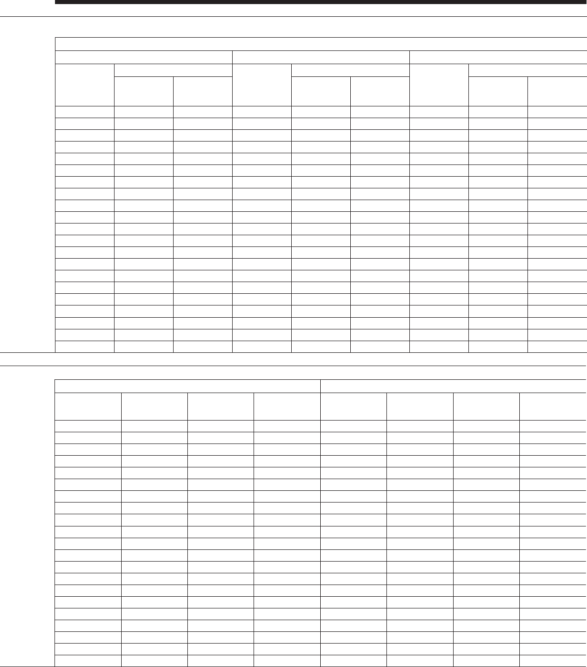
JOHNSON CONTROLS
FORM 201.23-EG1 (1007)
117
Standard Efciency YCIV_ _ _ _ S/P Standard Efciency YCIV_ _ _ _ S/P
Model No./Nameplate System 1 System 2
Std. & Ultra Quiet Cond. Fans High Head/Static Cond. Fans Two-Speed Cond. Fans Std. & Ultra Quiet Cond. Fans High Head/Static Cond. Fans Two-Speed Cond. Fans
YCIV S/P Input Volts
(9) Input Freq Compressor
RLA (5)
Condenser Fans Compressor Condenser Fans
Compressor
RLA (5)
Condenser Fans
Compressor
RLA (5)
Condenser Fans
Compressor
RLA (5)
Condenser Fans
Compressor
RLA (5)
Condenser Fans
Qty. FLA (EA) RLA (5) Qty. FLA (EA) Qty. FLA (EA) Qty. FLA (EA) Qty. FLA (EA) Qty. FLA (EA)
0157
460 60 120 4 2.8 120 4 2.8
380 60 152 4 3.5 152 4 9.3 152 4 3.5 152 4 9.3
0600 400 50 144 4 3.1 144 4 9.3 152 4 3.8 144 4 3.1 144 4 9.3 152 4 3.8
0177
460 60 159 4 2.8 105 4 2.8
380 60 201 4 3.5 201 4 9.3 133 4 3.5 133 4 9.3
0650 400 50 191 4 3.1 191 4 9.3 198 4 3.8 127 4 3.1 127 4 9.3 132 4 3.8
0187
460 60 162 5 2.8 120 4 2.8
380 60 205 5 3.5 205 5 9.3 152 4 3.5 152 4 9.3
0720 400 50 195 5 3.1 195 5 9.3 207 5 3.8 144 4 3.1 144 4 9.3 152 4 3.8
0207
460 60 145 5 2.8 162 4 2.8
380 60 184 5 3.5 184 5 9.3 206 4 3.5 206 4 9.3
0770 400 50 174 5 3.1 174 5 9.3 185 5 3.8 195 4 3.1 195 4 9.3 201 4 3.8
0227
460 60 162 5 2.8 162 5 2.8
380 60 205 5 3.5 205 5 9.3 205 5 3.5 205 5 9.3
0840 400 50 194 5 3.1 194 5 9.3 206 5 3.8 194 5 3.1 194 5 9.3 206 5 3.8
0247
460 60 193 6 2.8 160 5 2.8
380 60 245 6 3.5 245 6 9.3 203 5 3.5 203 5 9.3
0920 400 50 232 6 3.1 232 6 9.3 246 6 3.8 192 5 3.1 192 5 9.3 204 5 3.8
0267
460 60 191 6 2.8 191 6 2.8
380 60 242 6 3.5 242 6 9.3 242 6 3.5 242 6 9.3
1000 400 50 230 6 3.1 230 6 9.3 243 6 3.8 230 6 3.1 230 6 9.3 243 6 3.8
YCIV S/P Control
KVA (7)
Unit Short Circuit Withstand (KA) Field Wiring & Protection
Std. & Ultra Quiet Cond. Fans High Head/High Static Fans Two-Speed Cond. Fans
Terminal Block
(STD)
Circuit Breaker
(OPT)
Minimum Ckt.
Ampacity (MCA) (3)
Recommended
Fuse/Ckt. Breaker
Rating (4)
Max. Inverse Time
Ckt. Brkr. Rating (2)
Max Dual Element
Fuse Size (2)
Minimum Ckt. Am-
pacity (MCA) (3)
Recommended
Fuse/Ckt. Breaker
Rating (4)
Max. Inverse Time
Ckt. Brkr. Rating (2)
Max Dual Element
Fuse Size (2)
Minimum Ckt. Am-
pacity (MCA) (3)
Recommended
Fuse/Ckt. Breaker
Rating (4)
Max. Inverse Time
Ckt. Brkr. Rating (2)
Max Dual Element
Fuse Size (2)
0157
1.8 30KA 65KA 293 350 400 400
1.8 30KA 65KA 370 450 500 500 417 500 500 500
0600 1.8 30KA 65KA 350 400 450 450 373 450 500 500 399 450 500 500
0177
1.8 30KA 65KA 326 400 450 450
1.8 30KA 65KA 413 500 600 600 459 600 600 600
0650 1.8 30KA 65KA 390 450 500 500 410 500 600 600 440 500 600 600
0187
1.8 30KA 65KA 348 400 500 500
1.8 30KA 65KA 440 500 600 600 492 600 700 700
0720 1.8 30KA 65KA 416 500 600 600 445 500 600 600 472 600 600 600
0207
1.8 30KA 65KA 373 450 500 500
1.8 30KA 65KA 472 600 600 600 525 600 700 700
0770 1.8 30KA 65KA 446 500 600 600 471 600 600 600 502 600 700 700
0227
1.8 30KA 65KA 392 450 500 500
1.8 30KA 65KA 496 600 700 700 554 700 700 700
0840 1.8 30KA 65KA 468 600 600 600 502 600 700 700 530 600 700 700
0247
1.8 30KA 65KA 433 500 600 600
1.8 30KA 65KA 547 700 700 700 610 700 800 800
0920 1.8 30KA 65KA 517 600 700 700 553 700 800 800 585 700 800 800
0267
1.8 30KA 65KA 464 600 600 600
1.8 30KA 65KA 587 700 800 800 657 800 800 800
1000 1.8 30KA 65KA 555 700 700 700 593 700 800 800 629 700 800 800
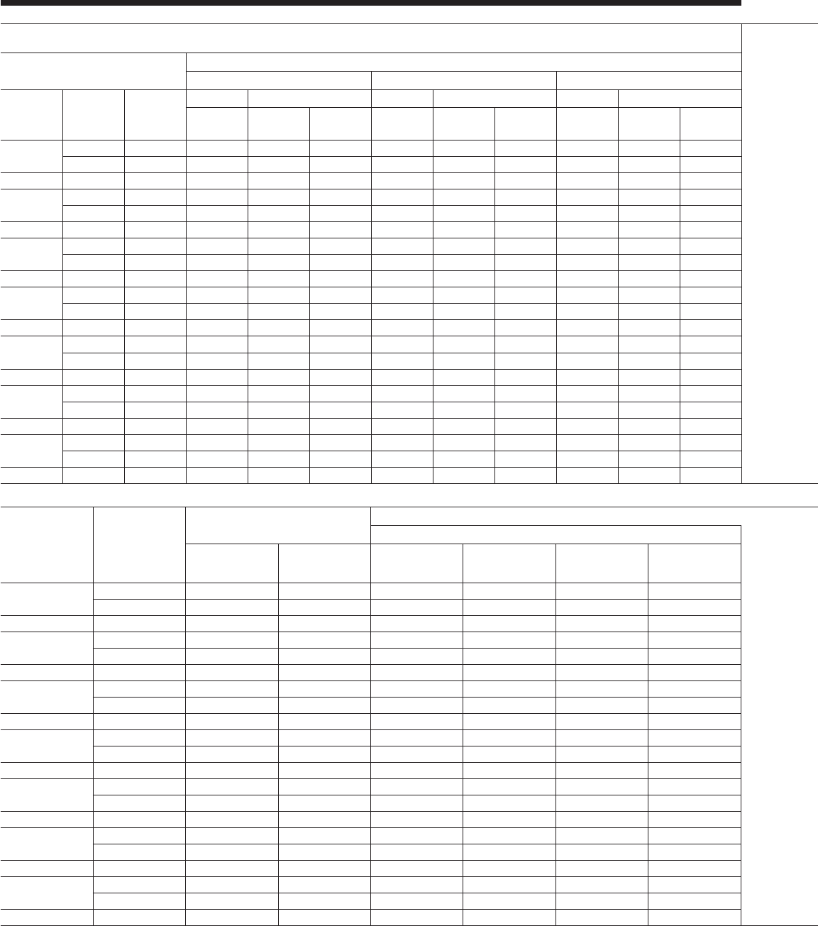
JOHNSON CONTROLS118
Electrical Data - 2 Comp High Efciency
High Efciency YCIV_ _ _ _ E/V High Efciency YCIV_ _ _ _ E/V
Model No./Nameplate System 1 System 2
Std. & Ultra Quiet Cond. Fans High Head/Static Cond. Fans Two-Speed Cond. Fans Std. & Ultra Quiet Cond. Fans High Head/Static Cond. Fans Two-Speed Cond. Fans
YCIV E/V Input Volts
(9) Input Freq
Compressor Condenser Fans Compressor Condenser Fans Compressor Condenser Fans Compressor Condenser Fans Compressor Condenser Fans Compressor Condenser Fans
RLA (5) Qty. FLA (EA) RLA (5) Qty. FLA (EA) RLA (5) Qty. FLA (EA) RLA (5) Qty. FLA (EA) RLA (5) Qty. FLA (EA) RLA (5) Qty. FLA (EA)
0157
460 60 110 4 2.8 110 4 2.8
380 60 139 4 3.5 139 4 9.3 139 4 3.5 139 4 9.3
0590 400 50 132 4 3.1 132 4 9.3 138 4 3.8 132 4 3.1 132 4 9.3 138 4 3.8
0177
460 60 111 5 2.8 122 4 2.8
380 60 141 5 3.5 141 5 9.3 154 4 3.5 154 4 9.3
0630 400 50 134 5 3.1 134 5 9.3 139 5 3.8 146 4 3.1 146 4 9.3 154 4 3.8
0187
460 60 154 5 2.8 105 5 2.8
380 60 195 5 3.5 195 5 9.3 132 5 3.5 132 5 9.3
0700 400 50 185 5 3.1 185 5 9.3 196 5 3.8 126 5 3.1 126 5 9.3 131 5 3.8
0197
460 60 141 5 2.8 141 5 2.8
380 60 179 5 3.5 179 5 9.3 179 5 3.5 179 5 9.3
0760 400 50 170 5 3.1 170 5 9.3 180 5 3.8 170 5 3.1 170 5 9.3 180 5 3.8
0207
460 60 141 6 2.8 152 5 2.8
380 60 179 6 3.5 179 6 9.3 193 5 3.5 193 5 9.3
0800 400 50 170 6 3.1 170 6 9.3 178 6 3.8 183 5 3.1 183 5 9.3 195 5 3.8
0227
460 60 150 6 2.8 150 6 2.8
380 60 190 6 3.5 190 6 9.3 190 6 3.5 190 6 9.3
0830 400 50 180 6 3.1 180 6 9.3 189 6 3.8 180 6 3.1 180 6 9.3 189 6 3.8
0247
460 60 194 6 2.8 149 6 2.8
380 60 245 6 3.5 245 6 9.3 188 6 3.5 188 6 9.3
0930 400 50 233 6 3.1 233 6 9.3 246 6 3.8 178 6 3.1 178 6 9.3 187 6 3.8
YCIV E/V Control
KVA (7)
Unit Short Circuit Withstand (KA) Field Wiring & Protection
Std. & Ultra Quiet Cond. Fans High Head/High Static Fans Two-Speed Cond. Fans
Terminal Block
(STD)
Circuit Breaker
(OPT)
Minimum Ckt.
Ampacity (MCA) (3)
Recommended
Fuse/Ckt. Breaker
Rating (4)
Max. Inverse Time
Ckt. Brkr. Rating (2)
Max Dual Element
Fuse Size (2)
Minimum Ckt. Am-
pacity (MCA) (3)
Recommended
Fuse/Ckt. Breaker
Rating (4)
Max. Inverse Time
Ckt. Brkr. Rating (2)
Max Dual Element
Fuse Size (2)
Minimum Ckt.
Ampacity (MCA) (3)
Recommended
Fuse/Ckt. Breaker
Rating (4)
Max. Inverse Time
Ckt. Brkr. Rating (2)
Max Dual Element
Fuse Size (2)
0157 1.8 30KA 65KA 270 300 350 350
1.8 30KA 65KA 341 400 450 450 388 450 500 500
0590 1.8 30KA 65KA 322 400 450 450 372 450 500 500 342 400 450 450
0177 1.8 30KA 65KA 288 350 400 400
1.8 30KA 65KA 365 450 500 500 417 500 500 500
0630 1.8 30KA 65KA 344 400 450 450 400 450 500 500 366 450 500 500
0187 1.8 30KA 65KA 325 400 450 450
1.8 30KA 65KA 411 500 600 600 469 600 600 600
0700 1.8 30KA 65KA 388 450 500 500 450 500 600 600 414 500 600 600
0197 1.8 30KA 65KA 345 400 450 450
1.8 30KA 65KA 437 500 600 600 495 600 600 600
0760 1.8 30KA 65KA 412 500 500 500 474 600 600 600 442 500 600 600
0207 1.8 30KA 65KA 362 450 500 500
1.8 30KA 65KA 458 600 600 600 522 600 700 700
0800 1.8 30KA 65KA 433 500 600 600 501 600 600 600 463 600 600 600
0227 1.8 30KA 65KA 371 450 500 500
1.8 30KA 65KA 469 600 600 600 539 600 700 700
0830 1.8 30KA 65KA 443 500 600 600 517 600 700 700 472 600 600 600
0247 1.8 30KA 65KA 424 500 600 600
1.8 30KA 65KA 536 700 700 700 606 700 800 800
0930 1.8 30KA 65KA 506 600 700 700 581 700 800 800 541 700 700 700
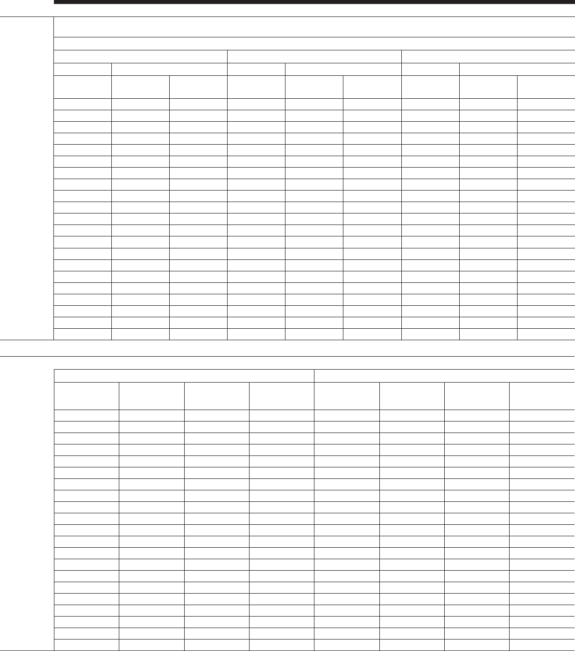
JOHNSON CONTROLS
FORM 201.23-EG1 (1007)
119
High Efciency YCIV_ _ _ _ E/V High Efciency YCIV_ _ _ _ E/V
Model No./Nameplate System 1 System 2
Std. & Ultra Quiet Cond. Fans High Head/Static Cond. Fans Two-Speed Cond. Fans Std. & Ultra Quiet Cond. Fans High Head/Static Cond. Fans Two-Speed Cond. Fans
YCIV E/V Input Volts
(9) Input Freq
Compressor Condenser Fans Compressor Condenser Fans Compressor Condenser Fans Compressor Condenser Fans Compressor Condenser Fans Compressor Condenser Fans
RLA (5) Qty. FLA (EA) RLA (5) Qty. FLA (EA) RLA (5) Qty. FLA (EA) RLA (5) Qty. FLA (EA) RLA (5) Qty. FLA (EA) RLA (5) Qty. FLA (EA)
0157
460 60 110 4 2.8 110 4 2.8
380 60 139 4 3.5 139 4 9.3 139 4 3.5 139 4 9.3
0590 400 50 132 4 3.1 132 4 9.3 138 4 3.8 132 4 3.1 132 4 9.3 138 4 3.8
0177
460 60 111 5 2.8 122 4 2.8
380 60 141 5 3.5 141 5 9.3 154 4 3.5 154 4 9.3
0630 400 50 134 5 3.1 134 5 9.3 139 5 3.8 146 4 3.1 146 4 9.3 154 4 3.8
0187
460 60 154 5 2.8 105 5 2.8
380 60 195 5 3.5 195 5 9.3 132 5 3.5 132 5 9.3
0700 400 50 185 5 3.1 185 5 9.3 196 5 3.8 126 5 3.1 126 5 9.3 131 5 3.8
0197
460 60 141 5 2.8 141 5 2.8
380 60 179 5 3.5 179 5 9.3 179 5 3.5 179 5 9.3
0760 400 50 170 5 3.1 170 5 9.3 180 5 3.8 170 5 3.1 170 5 9.3 180 5 3.8
0207
460 60 141 6 2.8 152 5 2.8
380 60 179 6 3.5 179 6 9.3 193 5 3.5 193 5 9.3
0800 400 50 170 6 3.1 170 6 9.3 178 6 3.8 183 5 3.1 183 5 9.3 195 5 3.8
0227
460 60 150 6 2.8 150 6 2.8
380 60 190 6 3.5 190 6 9.3 190 6 3.5 190 6 9.3
0830 400 50 180 6 3.1 180 6 9.3 189 6 3.8 180 6 3.1 180 6 9.3 189 6 3.8
0247
460 60 194 6 2.8 149 6 2.8
380 60 245 6 3.5 245 6 9.3 188 6 3.5 188 6 9.3
0930 400 50 233 6 3.1 233 6 9.3 246 6 3.8 178 6 3.1 178 6 9.3 187 6 3.8
YCIV E/V Control
KVA (7)
Unit Short Circuit Withstand (KA) Field Wiring & Protection
Std. & Ultra Quiet Cond. Fans High Head/High Static Fans Two-Speed Cond. Fans
Terminal Block
(STD)
Circuit Breaker
(OPT)
Minimum Ckt.
Ampacity (MCA) (3)
Recommended
Fuse/Ckt. Breaker
Rating (4)
Max. Inverse Time
Ckt. Brkr. Rating (2)
Max Dual Element
Fuse Size (2)
Minimum Ckt. Am-
pacity (MCA) (3)
Recommended
Fuse/Ckt. Breaker
Rating (4)
Max. Inverse Time
Ckt. Brkr. Rating (2)
Max Dual Element
Fuse Size (2)
Minimum Ckt.
Ampacity (MCA) (3)
Recommended
Fuse/Ckt. Breaker
Rating (4)
Max. Inverse Time
Ckt. Brkr. Rating (2)
Max Dual Element
Fuse Size (2)
0157 1.8 30KA 65KA 270 300 350 350
1.8 30KA 65KA 341 400 450 450 388 450 500 500
0590 1.8 30KA 65KA 322 400 450 450 372 450 500 500 342 400 450 450
0177 1.8 30KA 65KA 288 350 400 400
1.8 30KA 65KA 365 450 500 500 417 500 500 500
0630 1.8 30KA 65KA 344 400 450 450 400 450 500 500 366 450 500 500
0187 1.8 30KA 65KA 325 400 450 450
1.8 30KA 65KA 411 500 600 600 469 600 600 600
0700 1.8 30KA 65KA 388 450 500 500 450 500 600 600 414 500 600 600
0197 1.8 30KA 65KA 345 400 450 450
1.8 30KA 65KA 437 500 600 600 495 600 600 600
0760 1.8 30KA 65KA 412 500 500 500 474 600 600 600 442 500 600 600
0207 1.8 30KA 65KA 362 450 500 500
1.8 30KA 65KA 458 600 600 600 522 600 700 700
0800 1.8 30KA 65KA 433 500 600 600 501 600 600 600 463 600 600 600
0227 1.8 30KA 65KA 371 450 500 500
1.8 30KA 65KA 469 600 600 600 539 600 700 700
0830 1.8 30KA 65KA 443 500 600 600 517 600 700 700 472 600 600 600
0247 1.8 30KA 65KA 424 500 600 600
1.8 30KA 65KA 536 700 700 700 606 700 800 800
0930 1.8 30KA 65KA 506 600 700 700 581 700 800 800 541 700 700 700
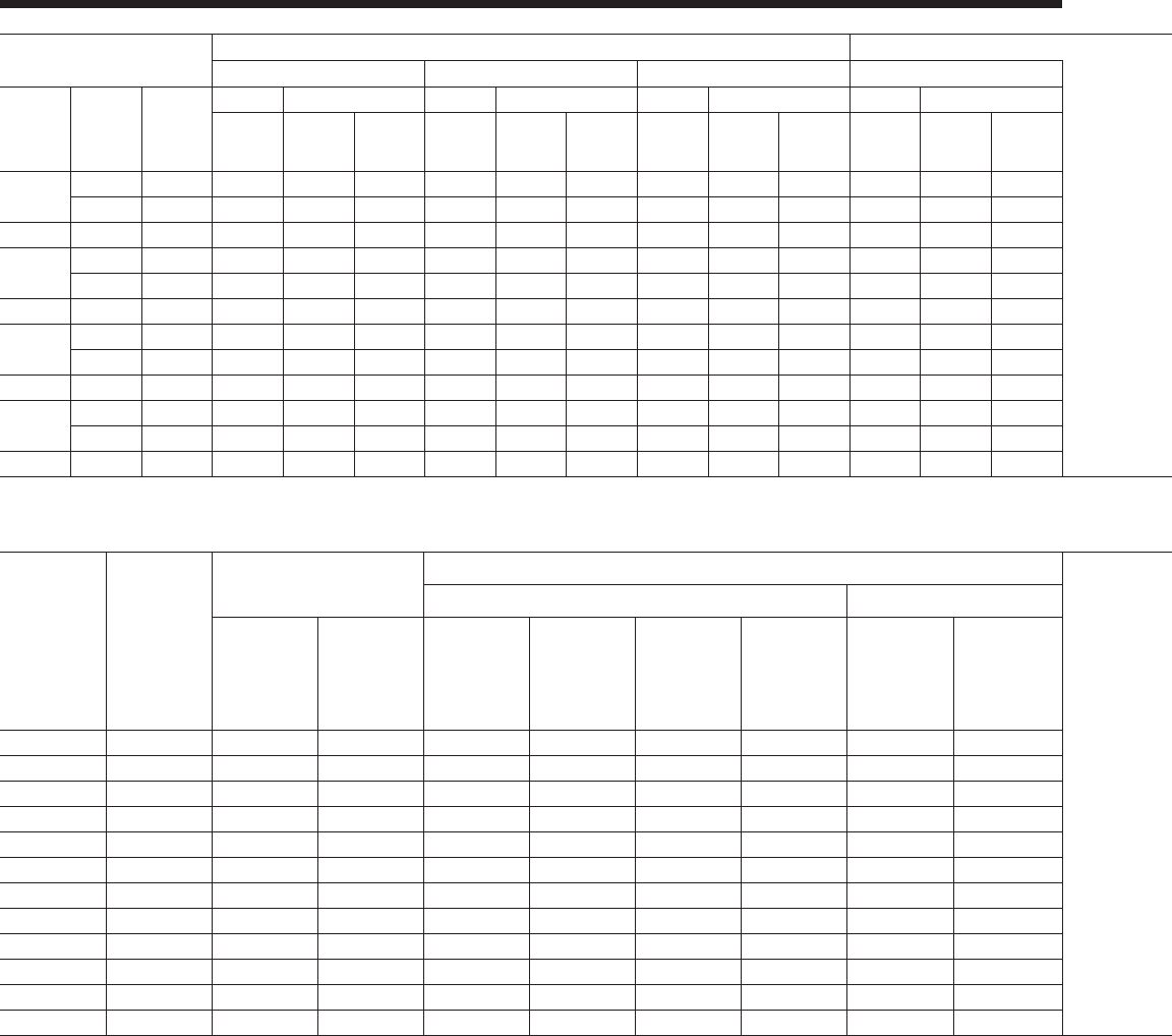
JOHNSON CONTROLS120
Electrical Data - 3 Comp Standard Efciency
See page 192 for Electrical Data footnotes.
Model No./Nameplate System 1 System 2 System 2 System 3
Std. & Ultra Quiet Cond. Fans High Head/Static Cond. Fans Two-Speed Cond. Fans Std. & Ultra Quiet Cond. Fans High Head/Static Cond. Fans Two-Speed Cond. Fans Std. & Ultra Quiet Cond. Fans High Head/Static Cond. Fans Two-Speed Cond. Fans
YCIV S/P Input Volts
(9) Input Freq
Comp. Condenser Fans Comp. Condenser Fans Comp. Condenser Fans Comp. Condenser Fans Comp. Condenser Fans Comp. Condenser Fans Comp. Condenser Fans Comp. Condenser Fans Comp. Condenser Fans
RLA (5) Qty. FLA (EA) RLA (5) Qty. FLA (EA) RLA (5) Qty. FLA (EA) RLA (5) Qty. FLA (EA) RLA (5) Qty. FLA (EA) RLA (5) Qty. FLA (EA) RLA (5) Qty. FLA (EA) RLA (5) Qty. FLA (EA) RLA (5) Qty. FLA (EA)
0287
460 60 146 5 2.8 164 4 2.8 108 4 2.8
380 60 184 5 3.5 184 5 9.3 207 4 3.5 207 4 9.3 136 4 3.5 136 4 9.3
1070 400 50 175 5 3.1 175 5 9.3 186 5 3.8 196 4 3.1 196 4 9.3 202 4 3.8 129 4 3.1 129 4 9.3 135 4 3.8
0307
460 60 147 5 2.8 147 5 2.8 165 4 2.8
380 60 186 5 3.5 186 5 9.3 186 5 3.5 186 5 9.3 208 4 3.5 208 4 9.3
1180 400 50 177 5 3.1 177 5 9.3 188 5 3.8 177 5 3.1 177 5 9.3 188 5 3.8 198 4 3.1 198 4 9.3 203 4 3.8
0357
460 60 160 5 2.8 160 5 2.8 193 6 2.8
380 60 202 5 3.5 202 5 9.3 202 5 3.5 202 5 9.3 244 6 3.5 244 6 9.3
1340 400 50 192 5 3.1 192 5 9.3 204 5 3.8 192 5 3.1 192 5 9.3 204 5 3.8 232 6 3.1 232 6 9.3 245 6 3.8
0397
460 60 191 6 2.8 191 6 2.8 191 6 2.8
380 60 241 6 3.5 241 6 9.3 241 6 3.5 241 6 9.3 241 6 3.5 241 6 9.3
1500 400 50 229 6 3.1 229 6 9.3 243 6 3.8 229 6 3.1 229 6 9.3 243 6 3.8 229 6 3.1 229 6 9.3 243 6 3.8
YCIV S/P Control
KVA (7)
Unit Short Circuit
Withstand (KA)
Field Wiring & Protection Field Wiring & Protection Field Wiring Lugs
Std. & Ultra Quiet Cond. Fans High Head/High Static Fans High Head/High Static Fans Two-Speed Cond. Fans
STD Terminal Block OPT Circuit Breaker
Terminal Block
(STD)
Circuit Breaker
(OPT)
Minimum Ckt.
Ampacity (MCA)
(3)
Recommended
Fuse/Ckt.
Breaker Rating
(4)
Max. Inverse
Time Ckt. Brkr.
Rating (2)
Max Dual
Element Fuse
Size (2)
Minimum Ckt.
Ampacity (MCA)
(3)
Recommended
Fuse/Ckt.
Breaker Rating
(4)
Max. Inverse
Time Ckt. Brkr.
Rating (2)
Max Dual
Element Fuse
Size (2)
Minimum Ckt.
Ampacity (MCA)
(3)
Recommended
Fuse/Ckt.
Breaker Rating
(4)
Max. Inverse
Time Ckt. Brkr.
Rating (2)
Max Dual
Element Fuse
Size (2)
Lugs/ Phase (1) Lug Wire Range Lugs/ Phase (1) Lug Wire Range
0287 2.4 30KA 65KA 494 600 600 600 4 #2 - 600 KCM 4#4/0 - 500 KCM
2.4 30KA 65KA 624 700 800 800 676 800 800 800 4 #2 - 600 KCM 4#4/0 - 500 KCM
1070 2.4 30KA 65KA 590 700 700 700 671 800 800 800 623 700 800 800 4 #2 - 600 KCM 4#4/0 - 500 KCM
0307 2.4 30KA 65KA 540 600 700 700 4 #2 - 600 KCM 4#4/0 - 500 KCM
2.4 30KA 65KA 682 800 800 800 731 800 800 800 4 #2 - 600 KCM 4#4/0 - 500 KCM
1180 2.4 30KA 65KA 644 700 800 800 731 800 800 800 683 800 800 800 4 #2 - 600 KCM 4#4/0 - 500 KCM
0357 2.4 30KA 65KA 607 700 800 800 4 #2 - 600 KCM 4#4/0 - 500 KCM
2.4 30KA 65KA 766 1000 1000 1000 827 1000 1000 1000 4 #2 - 600 KCM 4#4/0 - 500 KCM
1340 2.4 30KA 65KA 724 800 800 800 824 1000 1000 1000 776 1000 1000 1000 4 #2 - 600 KCM 4#4/0 - 500 KCM
0397 2.4 30KA 65KA 671 800 800 800 4 #2 - 600 KCM 4#4/0 - 500 KCM
2.4 30KA 65KA 847 1000 1000 1000 911 1000 1000 1000 4 #2 - 600 KCM 4#4/0 - 500 KCM
1500 2.4 30KA 65KA 801 1000 1000 1000 913 1000 1000 1000 857 1000 1000 1000 4 #2 - 600 KCM 4#4/0 - 500 KCM
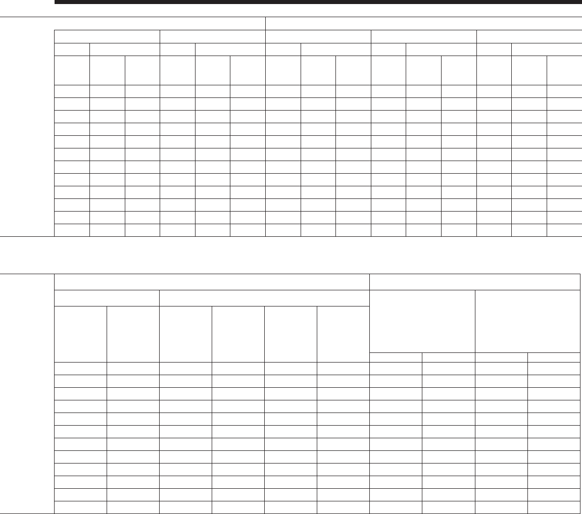
JOHNSON CONTROLS
FORM 201.23-EG1 (1007)
121
Model No./Nameplate System 1 System 2 System 2 System 3
Std. & Ultra Quiet Cond. Fans High Head/Static Cond. Fans Two-Speed Cond. Fans Std. & Ultra Quiet Cond. Fans High Head/Static Cond. Fans Two-Speed Cond. Fans Std. & Ultra Quiet Cond. Fans High Head/Static Cond. Fans Two-Speed Cond. Fans
YCIV S/P Input Volts
(9) Input Freq
Comp. Condenser Fans Comp. Condenser Fans Comp. Condenser Fans Comp. Condenser Fans Comp. Condenser Fans Comp. Condenser Fans Comp. Condenser Fans Comp. Condenser Fans Comp. Condenser Fans
RLA (5) Qty. FLA (EA) RLA (5) Qty. FLA (EA) RLA (5) Qty. FLA (EA) RLA (5) Qty. FLA (EA) RLA (5) Qty. FLA (EA) RLA (5) Qty. FLA (EA) RLA (5) Qty. FLA (EA) RLA (5) Qty. FLA (EA) RLA (5) Qty. FLA (EA)
0287
460 60 146 5 2.8 164 4 2.8 108 4 2.8
380 60 184 5 3.5 184 5 9.3 207 4 3.5 207 4 9.3 136 4 3.5 136 4 9.3
1070 400 50 175 5 3.1 175 5 9.3 186 5 3.8 196 4 3.1 196 4 9.3 202 4 3.8 129 4 3.1 129 4 9.3 135 4 3.8
0307
460 60 147 5 2.8 147 5 2.8 165 4 2.8
380 60 186 5 3.5 186 5 9.3 186 5 3.5 186 5 9.3 208 4 3.5 208 4 9.3
1180 400 50 177 5 3.1 177 5 9.3 188 5 3.8 177 5 3.1 177 5 9.3 188 5 3.8 198 4 3.1 198 4 9.3 203 4 3.8
0357
460 60 160 5 2.8 160 5 2.8 193 6 2.8
380 60 202 5 3.5 202 5 9.3 202 5 3.5 202 5 9.3 244 6 3.5 244 6 9.3
1340 400 50 192 5 3.1 192 5 9.3 204 5 3.8 192 5 3.1 192 5 9.3 204 5 3.8 232 6 3.1 232 6 9.3 245 6 3.8
0397
460 60 191 6 2.8 191 6 2.8 191 6 2.8
380 60 241 6 3.5 241 6 9.3 241 6 3.5 241 6 9.3 241 6 3.5 241 6 9.3
1500 400 50 229 6 3.1 229 6 9.3 243 6 3.8 229 6 3.1 229 6 9.3 243 6 3.8 229 6 3.1 229 6 9.3 243 6 3.8
YCIV S/P Control
KVA (7)
Unit Short Circuit
Withstand (KA)
Field Wiring & Protection Field Wiring & Protection Field Wiring Lugs
Std. & Ultra Quiet Cond. Fans High Head/High Static Fans High Head/High Static Fans Two-Speed Cond. Fans
STD Terminal Block OPT Circuit Breaker
Terminal Block
(STD)
Circuit Breaker
(OPT)
Minimum Ckt.
Ampacity (MCA)
(3)
Recommended
Fuse/Ckt.
Breaker Rating
(4)
Max. Inverse
Time Ckt. Brkr.
Rating (2)
Max Dual
Element Fuse
Size (2)
Minimum Ckt.
Ampacity (MCA)
(3)
Recommended
Fuse/Ckt.
Breaker Rating
(4)
Max. Inverse
Time Ckt. Brkr.
Rating (2)
Max Dual
Element Fuse
Size (2)
Minimum Ckt.
Ampacity (MCA)
(3)
Recommended
Fuse/Ckt.
Breaker Rating
(4)
Max. Inverse
Time Ckt. Brkr.
Rating (2)
Max Dual
Element Fuse
Size (2)
Lugs/ Phase (1) Lug Wire Range Lugs/ Phase (1) Lug Wire Range
0287 2.4 30KA 65KA 494 600 600 600 4 #2 - 600 KCM 4#4/0 - 500 KCM
2.4 30KA 65KA 624 700 800 800 676 800 800 800 4 #2 - 600 KCM 4#4/0 - 500 KCM
1070 2.4 30KA 65KA 590 700 700 700 671 800 800 800 623 700 800 800 4 #2 - 600 KCM 4#4/0 - 500 KCM
0307 2.4 30KA 65KA 540 600 700 700 4 #2 - 600 KCM 4#4/0 - 500 KCM
2.4 30KA 65KA 682 800 800 800 731 800 800 800 4 #2 - 600 KCM 4#4/0 - 500 KCM
1180 2.4 30KA 65KA 644 700 800 800 731 800 800 800 683 800 800 800 4 #2 - 600 KCM 4#4/0 - 500 KCM
0357 2.4 30KA 65KA 607 700 800 800 4 #2 - 600 KCM 4#4/0 - 500 KCM
2.4 30KA 65KA 766 1000 1000 1000 827 1000 1000 1000 4 #2 - 600 KCM 4#4/0 - 500 KCM
1340 2.4 30KA 65KA 724 800 800 800 824 1000 1000 1000 776 1000 1000 1000 4 #2 - 600 KCM 4#4/0 - 500 KCM
0397 2.4 30KA 65KA 671 800 800 800 4 #2 - 600 KCM 4#4/0 - 500 KCM
2.4 30KA 65KA 847 1000 1000 1000 911 1000 1000 1000 4 #2 - 600 KCM 4#4/0 - 500 KCM
1500 2.4 30KA 65KA 801 1000 1000 1000 913 1000 1000 1000 857 1000 1000 1000 4 #2 - 600 KCM 4#4/0 - 500 KCM
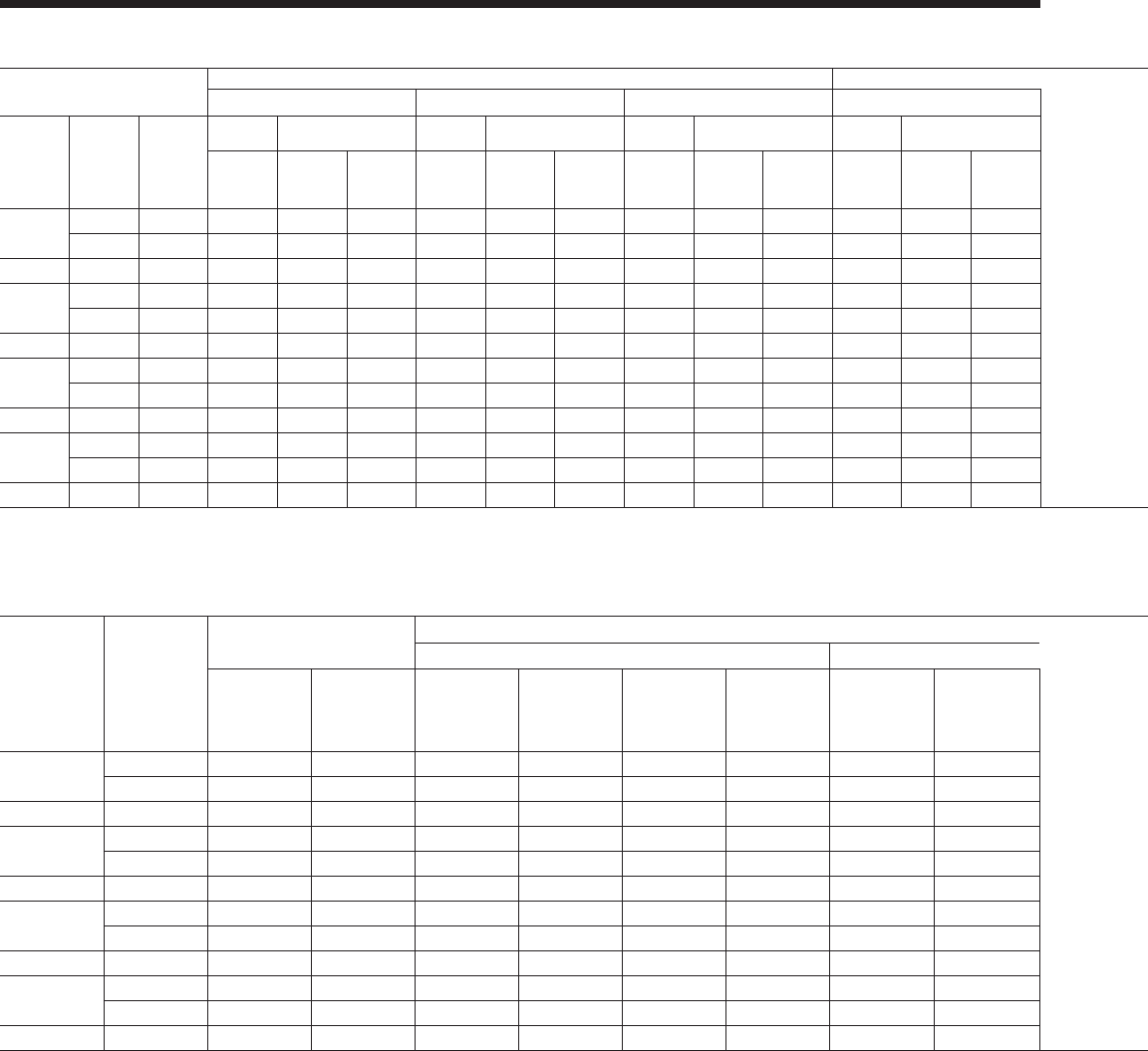
JOHNSON CONTROLS122
Electrical Data - 3 Comp High Efciency
See page 192 for Electrical Data footnotes.
Model No./Nameplate System 1 System 2 System 2 System 3
Std. & Ultra Quiet Cond. Fans High Head/Static Cond. Fans Two-Speed Cond. Fans Std. & Ultra Quiet Cond. Fans High Head/Static Cond. Fans Two-Speed Cond. Fans Std. & Ultra Quiet Cond. Fans High Head/Static Cond. Fans Two-Speed Cond. Fans
YCIV E/V Input Volts
(9) Input Freq
Comp. Condenser Fans Comp. Condenser Fans Comp. Condenser Fans Comp. Condenser Fans Comp. Condenser Fans Comp. Condenser Fans Comp. Condenser
Fans Comp. Condenser
Fans Comp. Condenser Fans
RLA (5) Qty. FLA (EA) RLA (5) Qty. FLA (EA) RLA (5) Qty. FLA (EA) RLA (5) Qty. FLA (EA) RLA (5) Qty. FLA (EA) RLA (5) Qty. FLA (EA) RLA (5) Qty. FLA (EA) RLA (5) Qty. FLA (EA) RLA (5) Qty. FLA (EA)
0267
460 60 142 5 2.8 142 5 2.8 105 4 2.8
380 60 179 5 3.5 179 5 9.3 179 4 3.5 179 4 9.3 133 4 3.5 133 4 9.3
1050 400 50 170 5 3.1 170 5 9.3 180 5 3.8 170 5 3.1 170 5 9.3 180 5 3.8 126 4 3.1 126 4 9.3 132 4 3.8
0287
460 60 137 5 2.8 137 5 2.8 137 5 2.8
380 60 173 5 3.5 173 5 9.3 173 5 3.5 173 5 9.3 173 4 3.5 173 4 9.3
1120 400 50 164 5 3.1 164 5 9.3 173 5 3.8 164 5 3.1 164 5 9.3 173 5 3.8 164 5 3.1 164 5 9.3 173 5 3.8
0327
460 60 152 5 2.8 152 5 2.8 141 6 2.8
380 60 193 5 3.5 193 5 9.3 193 5 3.5 193 5 9.3 178 6 3.5 178 6 9.3
1220 400 50 183 5 3.1 183 5 9.3 194 5 3.8 183 5 3.1 183 5 9.3 194 5 3.8 169 6 3.1 169 6 9.3 178 6 3.8
0357
460 60 181 6 2.8 181 6 2.8 139 6 2.8
380 60 229 6 3.5 229 6 9.3 229 6 3.5 229 6 9.3 176 6 3.5 176 6 9.3
1380 400 50 218 6 3.1 218 6 9.3 229 6 3.8 218 6 3.1 218 6 9.3 229 6 3.8 167 6 3.1 167 6 9.3 175 6 3.8
YCIV S/P Control
KVA (7)
Unit Short Circuit
Withstand (KA)
Field Wiring & Protection Field Wiring & Protection Field Wiring Lugs
Std. & Ultra Quiet Cond. Fans High Head/High Static Fans High Head/High Static Fans Two-Speed Cond. Fans STD Terminal Block OPT Circuit Breaker
Terminal Block
(STD)
Circuit Breaker
(OPT)
Minimum Ckt.
Ampacity (MCA)
(3)
Recommended
Fuse/Ckt.
Breaker Rating
(4)
Max. Inverse
Time Ckt. Brkr.
Rating (2)
Max Dual
Element Fuse
Size (2)
Minimum Ckt.
Ampacity (MCA)
(3)
Recommended
Fuse/Ckt.
Breaker Rating
(4)
Max. Inverse
Time Ckt. Brkr.
Rating (2)
Max Dual
Element Fuse
Size (2)
Minimum Ckt.
Ampacity (MCA)
(3)
Recommended
Fuse/Ckt.
Breaker Rating
(4)
Max. Inverse
Time Ckt. Brkr.
Rating (2)
Max Dual
Element Fuse
Size (2)
Lugs/ Phase
(1) Lug Wire Range Lugs/ Phase
(1) Lug Wire Range
0287
2.4 30KA 65KA 463 600 600 600 4 #2 - 600 KCM 4#4/0 - 500 KCM
2.4 30KA 65KA 581 700 700 700 632 800 800 800 4 #2 - 600 KCM 4#2 - 600 KCM
1070 2.4 30KA 65KA 552 600 700 700 639 700 800 800 590 700 700 700 4 #2 - 600 KCM 4#2 - 600 KCM
0307
2.4 30KA 65KA 486 600 600 600 4 #2 - 600 KCM 4#2 - 600 KCM
2.4 30KA 65KA 610 700 700 700 659 800 800 800 4 #2 - 600 KCM 4#2 - 600 KCM
1180 2.4 30KA 65KA 580 700 700 700 673 800 800 800 621 700 700 700 4 #2 - 600 KCM 4#2 - 600 KCM
0357
2.4 30KA 65KA 528 600 600 600 4 #2 - 600 KCM 4#2 - 600 KCM
2.4 30KA 65KA 667 800 800 800 728 800 800 800 4 #2 - 600 KCM 4#2 - 600 KCM
1340 2.4 30KA 65KA 631 700 800 800 730 800 800 800 676 800 800 800 4 #2 - 600 KCM 4#2 - 600 KCM
0397
2.4 30KA 65KA 598 700 700 700 4 #2 - 600 KCM 4#2 - 600 KCM
2.4 30KA 65KA 755 800 800 800 818 1000 1000 1000 4 #2 - 600 KCM 4#2 - 600 KCM
1500 2.4 30KA 65KA 713 800 800 800 824 1000 1000 1000 760 800 800 800 4 #2 - 600 KCM 4#2 - 600 KCM
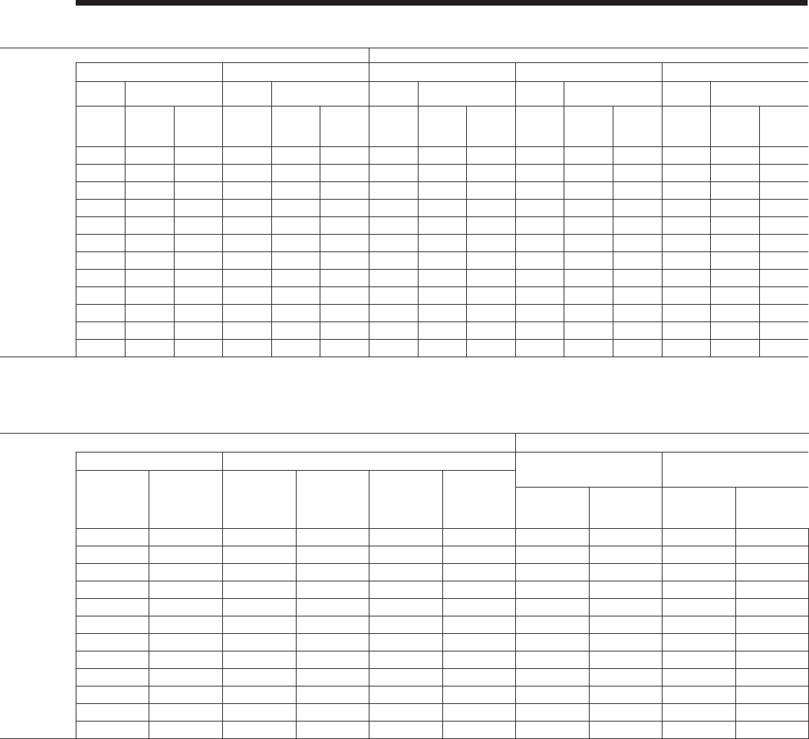
JOHNSON CONTROLS
FORM 201.23-EG1 (1007)
123
Model No./Nameplate System 1 System 2 System 2 System 3
Std. & Ultra Quiet Cond. Fans High Head/Static Cond. Fans Two-Speed Cond. Fans Std. & Ultra Quiet Cond. Fans High Head/Static Cond. Fans Two-Speed Cond. Fans Std. & Ultra Quiet Cond. Fans High Head/Static Cond. Fans Two-Speed Cond. Fans
YCIV E/V Input Volts
(9) Input Freq
Comp. Condenser Fans Comp. Condenser Fans Comp. Condenser Fans Comp. Condenser Fans Comp. Condenser Fans Comp. Condenser Fans Comp. Condenser
Fans Comp. Condenser
Fans Comp. Condenser Fans
RLA (5) Qty. FLA (EA) RLA (5) Qty. FLA (EA) RLA (5) Qty. FLA (EA) RLA (5) Qty. FLA (EA) RLA (5) Qty. FLA (EA) RLA (5) Qty. FLA (EA) RLA (5) Qty. FLA (EA) RLA (5) Qty. FLA (EA) RLA (5) Qty. FLA (EA)
0267
460 60 142 5 2.8 142 5 2.8 105 4 2.8
380 60 179 5 3.5 179 5 9.3 179 4 3.5 179 4 9.3 133 4 3.5 133 4 9.3
1050 400 50 170 5 3.1 170 5 9.3 180 5 3.8 170 5 3.1 170 5 9.3 180 5 3.8 126 4 3.1 126 4 9.3 132 4 3.8
0287
460 60 137 5 2.8 137 5 2.8 137 5 2.8
380 60 173 5 3.5 173 5 9.3 173 5 3.5 173 5 9.3 173 4 3.5 173 4 9.3
1120 400 50 164 5 3.1 164 5 9.3 173 5 3.8 164 5 3.1 164 5 9.3 173 5 3.8 164 5 3.1 164 5 9.3 173 5 3.8
0327
460 60 152 5 2.8 152 5 2.8 141 6 2.8
380 60 193 5 3.5 193 5 9.3 193 5 3.5 193 5 9.3 178 6 3.5 178 6 9.3
1220 400 50 183 5 3.1 183 5 9.3 194 5 3.8 183 5 3.1 183 5 9.3 194 5 3.8 169 6 3.1 169 6 9.3 178 6 3.8
0357
460 60 181 6 2.8 181 6 2.8 139 6 2.8
380 60 229 6 3.5 229 6 9.3 229 6 3.5 229 6 9.3 176 6 3.5 176 6 9.3
1380 400 50 218 6 3.1 218 6 9.3 229 6 3.8 218 6 3.1 218 6 9.3 229 6 3.8 167 6 3.1 167 6 9.3 175 6 3.8
YCIV S/P Control
KVA (7)
Unit Short Circuit
Withstand (KA)
Field Wiring & Protection Field Wiring & Protection Field Wiring Lugs
Std. & Ultra Quiet Cond. Fans High Head/High Static Fans High Head/High Static Fans Two-Speed Cond. Fans STD Terminal Block OPT Circuit Breaker
Terminal Block
(STD)
Circuit Breaker
(OPT)
Minimum Ckt.
Ampacity (MCA)
(3)
Recommended
Fuse/Ckt.
Breaker Rating
(4)
Max. Inverse
Time Ckt. Brkr.
Rating (2)
Max Dual
Element Fuse
Size (2)
Minimum Ckt.
Ampacity (MCA)
(3)
Recommended
Fuse/Ckt.
Breaker Rating
(4)
Max. Inverse
Time Ckt. Brkr.
Rating (2)
Max Dual
Element Fuse
Size (2)
Minimum Ckt.
Ampacity (MCA)
(3)
Recommended
Fuse/Ckt.
Breaker Rating
(4)
Max. Inverse
Time Ckt. Brkr.
Rating (2)
Max Dual
Element Fuse
Size (2)
Lugs/ Phase
(1) Lug Wire Range Lugs/ Phase
(1) Lug Wire Range
0287
2.4 30KA 65KA 463 600 600 600 4 #2 - 600 KCM 4#4/0 - 500 KCM
2.4 30KA 65KA 581 700 700 700 632 800 800 800 4 #2 - 600 KCM 4#2 - 600 KCM
1070 2.4 30KA 65KA 552 600 700 700 639 700 800 800 590 700 700 700 4 #2 - 600 KCM 4#2 - 600 KCM
0307
2.4 30KA 65KA 486 600 600 600 4 #2 - 600 KCM 4#2 - 600 KCM
2.4 30KA 65KA 610 700 700 700 659 800 800 800 4 #2 - 600 KCM 4#2 - 600 KCM
1180 2.4 30KA 65KA 580 700 700 700 673 800 800 800 621 700 700 700 4 #2 - 600 KCM 4#2 - 600 KCM
0357
2.4 30KA 65KA 528 600 600 600 4 #2 - 600 KCM 4#2 - 600 KCM
2.4 30KA 65KA 667 800 800 800 728 800 800 800 4 #2 - 600 KCM 4#2 - 600 KCM
1340 2.4 30KA 65KA 631 700 800 800 730 800 800 800 676 800 800 800 4 #2 - 600 KCM 4#2 - 600 KCM
0397
2.4 30KA 65KA 598 700 700 700 4 #2 - 600 KCM 4#2 - 600 KCM
2.4 30KA 65KA 755 800 800 800 818 1000 1000 1000 4 #2 - 600 KCM 4#2 - 600 KCM
1500 2.4 30KA 65KA 713 800 800 800 824 1000 1000 1000 760 800 800 800 4 #2 - 600 KCM 4#2 - 600 KCM

JOHNSON CONTROLS124
LEGEND
C.B. CIRCUIT BREAKER
D.E. DUAL ELEMENT FUSE
DISC SW DISCONNECT SWITCH
FACT CB FACTORY-MOUNTED CIRCUIT BREAKER
FLA FULL LOAD AMPS
HZ HERTZ
MAX MAXIMUM
MCA MINIMUM CIRCUIT AMPACITY
MIN MINIMUM
MIN NF MINIMUM NON-FUSED
RLA RATED LOAD AMPS
S.P. WIRE SINGLE-POINT WIRING
Electrical Notes
NOTES:
1. U.L. Label is provided on 50 and 60 Hz units for these electrical wiring congurations.
2. –– –– –– –– –– –– Dashed Line = Field Provided Wiring.
3. The above recommendations are based on the National Electric Code and using copper conductors only. Field wiring must also comply
with local codes. Group Rated breaker must be HACR type for cUL machines.
1. As standard, all units have single point power connection. Contact factory for information regarding dual
point power units.
2. Maximum Inverse Time Circuit Breaker or Dual Element Fuse - 225% of the largest compressor RLA
plus the sum of all other loads per NEC 440.22 (A).
3. MCA - Minimum Circuit Ampacity - 125% of the largest compressor RLA plus 100% of the remaining
compressor RLA's plus the sum of all condenser fan FLA's per NEC 440.33
4. Recommended time delay or dual element fuse size - 150%of the largest compressor RLA plus 100%
of the remaining compressor RLA's plus the sum of all condenser fan FLA's.
5. RLA - Rated Load Amps - rated in accordance with UL standard 1995.
6. Local codes may take precedence.
7. Control KVA includes operational controls and evaporator heaters.
8. System inrush current is less than RLA due to the use of York Variable Speed Drive technology. Typical
Compressor Starting Current ( rst four seconds of startup):
Rated Voltage Typical Starting Current per Compressor
380-400/50/3 28A
380/60/3 29A
460/60/3 23A
9. Voltage Utilization Range:
Rated Voltage Utilization Range
380-415/50/3 360 - 440
380/60/3 342 - 402
460/60/3 414 - 508
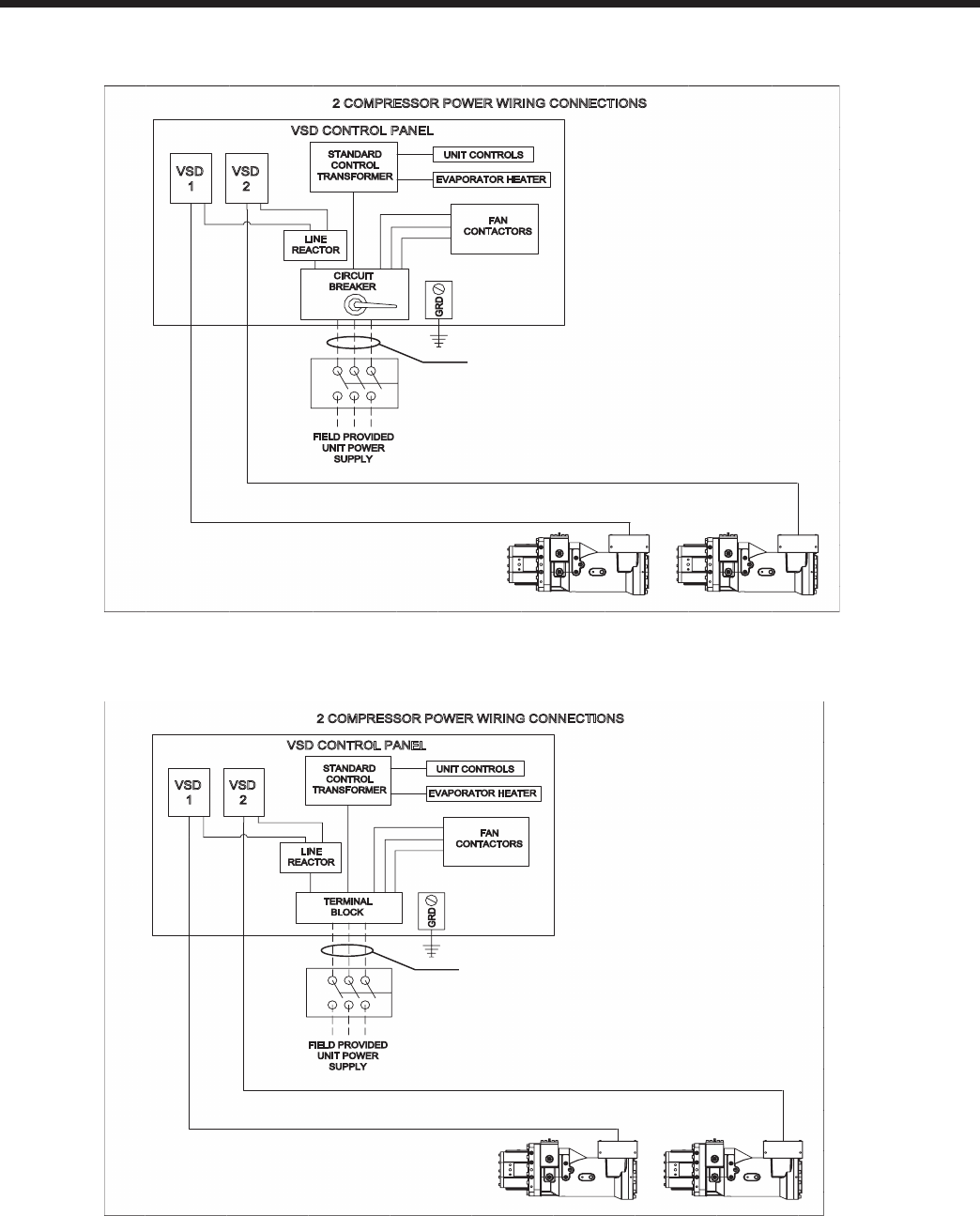
JOHNSON CONTROLS
FORM 201.23-EG1 (1007)
125
FIG. 1 – TWO COMPRESSOR WIRING DIAGRAM WITH CIRCUIT BREAKER
2 COMPRESSOR POWER WIRING CONNECTIONS
FIG. 2 – TWO COMPRESSOR WIRING DIAGRAM WITH TERMINAL BLOCK
Power Wiring
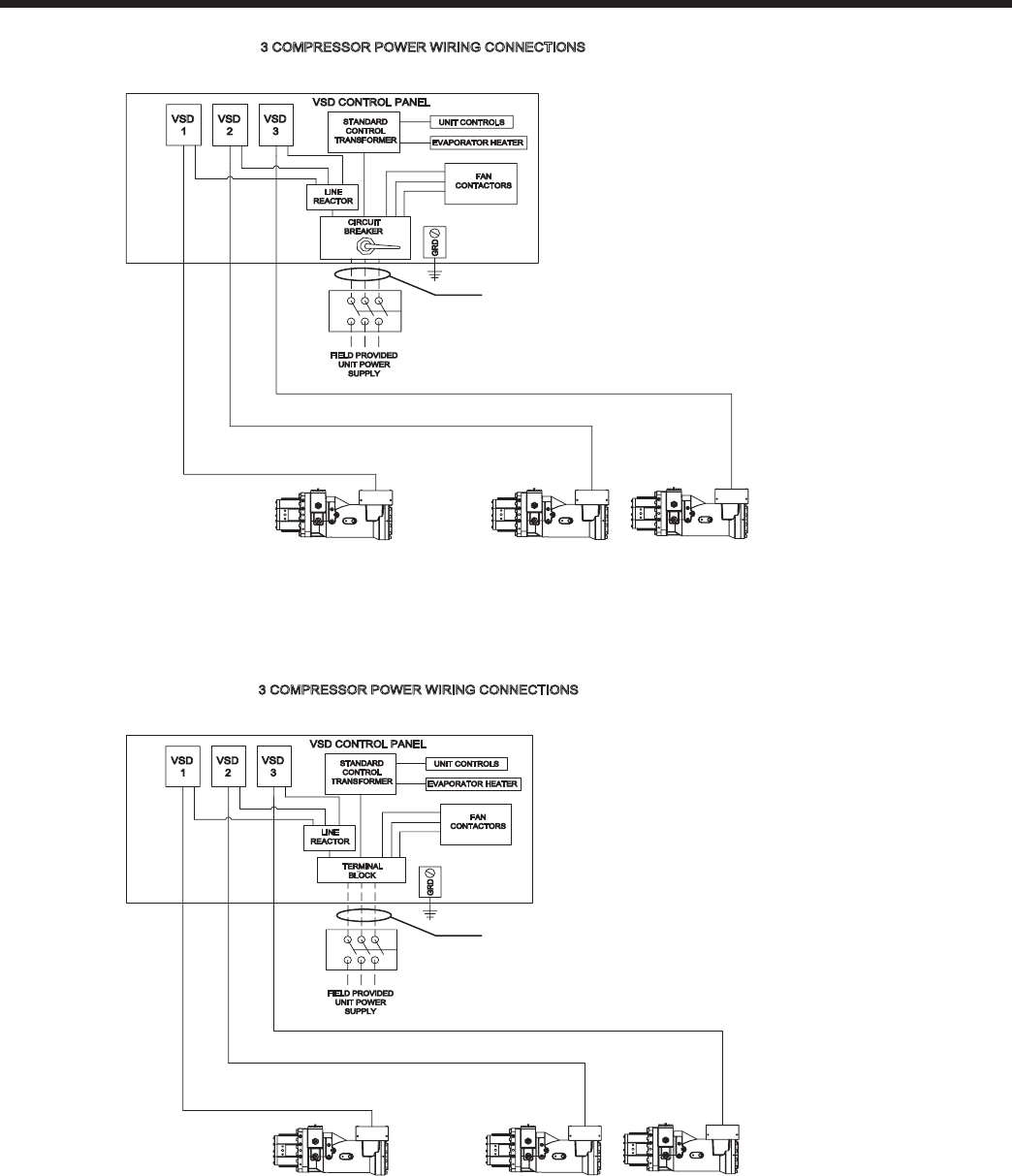
JOHNSON CONTROLS126
Power Wiring – continued
FIG. 3 – THREE COMPRESSOR WIRING DIAGRAM WITH CIRCUIT BREAKER – SINGLE POINT
FIG. 4 – THREE COMPRESSOR WIRING DIAGRAM WITH TERMINAL BLOCK – SINGLE POINT
3 COMPRESSOR POWER WIRING CONNECTIONS
VSD CONTROL PANEL
VSD
2
VSD
3
STANDARD
CONTROL
TRANSFORMER
UNIT CONTROLS
EVAPORATOR HEATER
FAN
CONTACTORS
GRD
FIELD PROVIDED
UNIT POWER
SUPPLY
LINE
REACTOR
VSD
1
TERMINAL
BLOCK
See Note 3

JOHNSON CONTROLS
FORM 201.23-EG1 (1007)
127
INTENTIONALLY LEFT BLANK
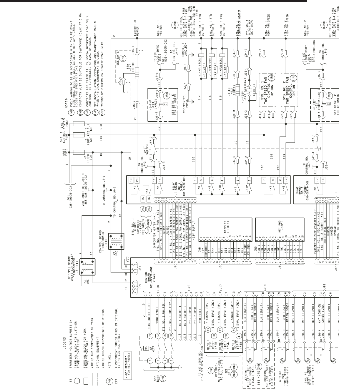
JOHNSON CONTROLS128
Typical Control Wiring - Two Compressor
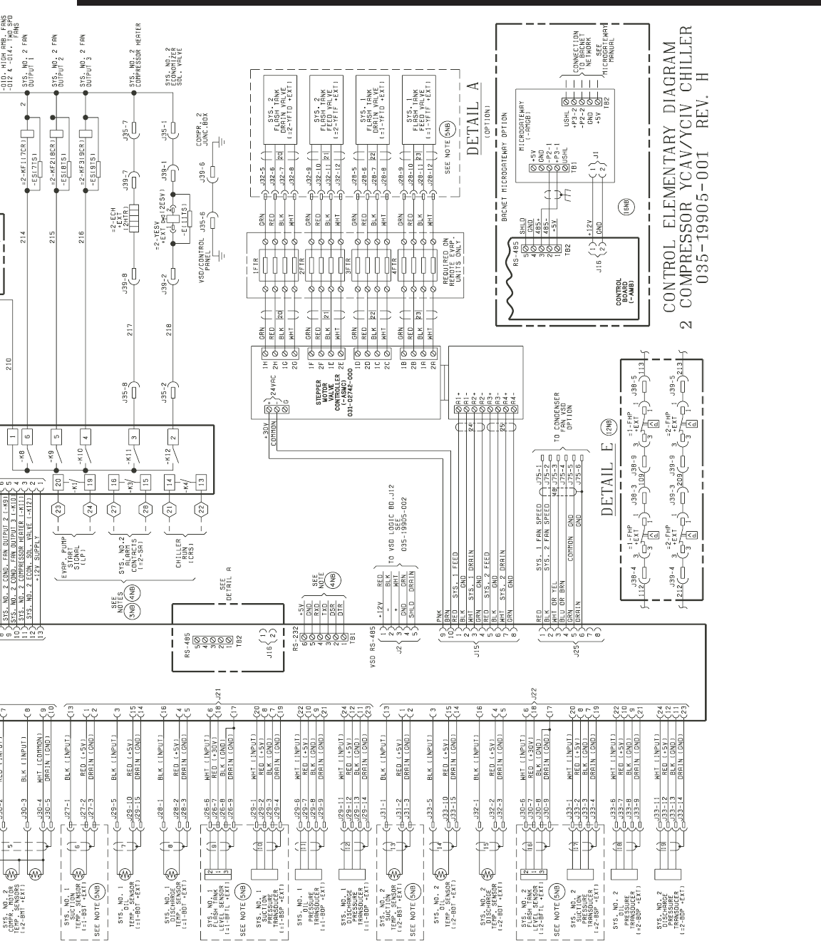
JOHNSON CONTROLS
FORM 201.23-EG1 (1007)
129
For informational purposes only. Do not attempt to tie into wiring without a proper wiring diagram.
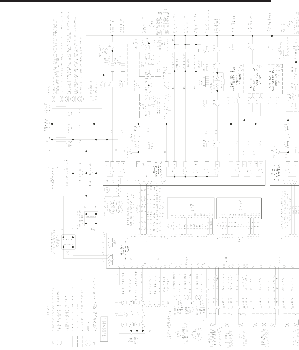
JOHNSON CONTROLS130
Typical Control Wiring - Three Compressor
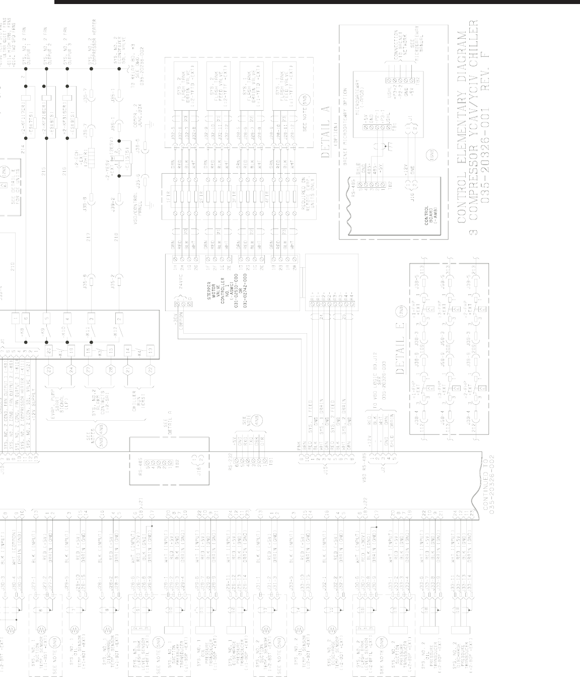
JOHNSON CONTROLS
FORM 201.23-EG1 (1007)
131
For informational purposes only. Do not attempt to tie into wiring without a proper wiring diagram.

JOHNSON CONTROLS132
UNIT LOCATION
The YCIV chillers are designed for outdoor installation.
When selecting a site for installation, be guided by the
following requirements:
1. Installation sites may be either on a roof or on ground
level. (See FOUNDATION)
2. Select a place having an adequate supply of fresh air
for the condensers. Recommended clearances for all
units are shown on the DIMENSIONS pages.
3. Avoid locations near windows or structures where
normal operating sounds may be objectionable.
4. The standard condenser fans are propeller-type and
are not recommended for use with ductwork, lters
or other impedements to airow in the condenser air
stream.
5. When it is desirable to surround the unit(s), it is rec-
ommended that the screening be able to pass the
required chiller CFM without exceeding 0.1" external
static pressure.
6. Protection against corrosive environments is available
by supplying the units with either copper ns, or cured
epoxy-coating on the condenser coils. Epoxy-coated
coils should be utilized with any units being installed at
the seashore, or where salt spray may hit the units, or
where acid rain is prevalent (copper condenser coils
are not recommended where they may be exposed
to acid rain).
7. On installations where winter operation is intended and
snow accumulations are expected, additional eleva-
tion must be provided to insure normal condenser air
ow.
FOUNDATION
The unit should be mounted on a at and level founda-
tion, ground or roof, capable of supporting the entire
operating weight of the equipment. Please contact your
nearest Johnson Controls Sales Ofce for shipping and
operating weights.
Roof Locations – Adequate structural strength to safely
support the entire weight of the unit and service person-
nel must be provided. Care must be taken not to damage
the roof during installation. If the roof is “bonded”, consult
building contractor or architect for special installation re-
quirements. Roof installations should incorporate the use
of spring-type isolators to minimize the transmission of
vibration into building structure. Additional support should
be provided to the roof at the spring-isolator locations.
Ground Locations – Units must be installed on a sub-
stantial base that will not settle and cause strain on the
refrigerant lines, resulting in possible leaks. A one-piece
concrete slab, with footers extending below the frost line,
is recommended. The slab should not be tied to the main
building foundation as noises will telegraph.
Mounting holes (5/8") are provided in the base rails for
bolting the unit to its foundation. See DIMENSIONS for
location of the mounting holes.
For ground installations, precautions should be taken to
protect the unit from tampering by, or injury to, unauthor-
ized persons. Fasteners on access panels will prevent
casual tampering; however, further safety precautions,
such as unit enclosure options, a fenced-in enclosure, or
locking devices on the panels may be advisable. Check
local authorities for safety regulations.
CHILLED LIQUID PIPING
The chilled liquid piping system should be laid out so that
the circulating pump discharges into the cooler. The inlet
and outlet cooler-liquid connections are given in DIMEN-
SIONS. Hand stop valves are recommended for use in
all lines to facilitate servicing. Drain connections should
be provided at all low points to permit complete drainage
of the cooler and system piping.
A strainer (40 mesh) is recommended for use on the INLET
line to the cooler, and must be in place at initial operation
of the water pumps.
Pressure-gauge connections are recommended for instal-
lation in the inlet and outlet water lines. Gauges are not
provided with the unit and are to be furnished by others.
Chilled liquid lines exposed to the weather should be
wrapped with a supplemental heater cable and insulated,
or glycol should be added to the chilled liquid to protect
against freezing if low-ambient periods are expected.
A ow switch is available as an accessory on all units. A
ow switch must be installed in the leaving water piping
of the cooler and must not be used to start and stop the
unit.
Application Data

JOHNSON CONTROLS
FORM 201.23-EG1 (1007)
133
Guide Specications
PART 1 — GENERAL
1.01 SCOPE
A. The requirements of the General Conditions, Supple-
mentary Conditions, and Drawings apply to all work
herein.
B. Provide Microprocessor controlled, twin-screw com-
pressor, air-cooled, liquid chillers of the scheduled
capacities as shown and indicated on the Drawings,
including but not limited to:
1. Chiller package
2. Charge of refrigerant and oil.
3. Electrical power and control connections
4. Chilled water connections
5. Factory start-up
1.02 QUALITY ASSURANCE
A. Products shall be Designed, Tested, Rated and Certi-
ed IAW, and installed in compliance with applicable
sections of the following Standards and Codes:
1. ARI 550/590 – Water Chilling Packages Using
the Vapor Compression Cycle
2. ARI 70 – Sound Rating of Large Outdoor Refrig-
erating and Air Conditioning Equipment
3. ANSI/ASHRAE Standard 15 – Safety Code for
Mechanical Refrigeration
4. ASHRAE 34 – Number Designation and Safety
Classication of Refrigerants
5. ASHRAE 90.1 – Energy Standard for Buildings
Except Low-Rise Residential Buildings
6. ANSI/NFPA Standard 70 – National Electrical
Code (N.E.C).
7. ASME Boiler and Pressure Vessel Code, Section
VIII, Division 1.
8. ASTM A48 – Gray Iron Castings
9. OSHA – Occupational Safety and Health Act
10.Manufactured in facility registered to ISO
9001
11. Conform to Underwriters Laboratories (U.L.) for
construction of chillers and provide U.L./cU.L.
listing label.
B. Factory Test: Chiller shall be pressure-tested, evacu-
ated and fully charged with refrigerant and oil, and shall
be factory operational run tested with water owing
through the vessel.
C. Chiller manufacturer shall have a factory trained and
supported service organization.
D. Warranty: Manufacturer shall Warrant all equipment
and material of its manufacture against defects in
workmanship and material for a period of eighteen
(18) months from date of initial start-up or date of
availability.
1.03 DELIVERY AND HANDLING
A. Unit shall be delivered to job site fully assembled and
charged with refrigerant and oil by the Manufacturer.
B. During shipment, provide protective covering over
vulnerable components. Fit nozzles and open ends
with plastic enclosures.
C. Unit shall be stored and handled per Manufacturer’s
instructions.
PART 2 — PRODUCTS
2.01 GENERAL
A. Manufacturers: The design shown on the drawings is
based on Johnson Controls. Alternate equipment will
be acceptable if their equipment meets the scheduled
performance and complies with these specications.
If equipment manufactured by a manufacturer other
than that scheduled is utilized, then the Mechanical
Contractor shall be responsible for coordinating with
the General Contractor and all affected Subcontrac-
tors to insure proper provisions for installation of the
furnished unit. This coordination shall include, but not
be limited to, the following:
1. Structural supports for units.
2. Piping size and connection/header locations.
3. Electrical power requirements and wire/conduit
and overcurrent protection sizes.
4. Chiller physical size on plant layout.
5. Site noise considerations.
The Mechanical Contractor shall be responsible for all
costs incurred by the General Contractor, Subcontrac-
tors, and Consultants to modify the building provisions to
accept the furnished units.
B. Description: Install and commission, as shown on the
schedules and plans, factory assembled, charged,
and operational tested air cooled screw compressor
chiller(s) as specied herein. Chiller shall include,
but is not limited to: a complete system with multiple
independent refrigerant circuits, semihermetic twin
screw compressors, shell and tube type evaporator,
air-cooled condenser, R134a refrigerant, lubrication

JOHNSON CONTROLS134
Guide Specications – continued
system, interconnecting wiring, safety and operating
controls including capacity controller, control center,
motor starting components, and special features
as specied herein or required for safe, automatic
operation.
C. Operating Characteristics:
1. Provide low ambient control and high ambient
options as required to ensure unit is capable
of operation from 0°F to 125°F (-18°C to 52°C)
ambient.
2. Provide capacity control system capable of
reducing unit capacity to (10% for 2 compres-
sor units and 7.5% for 3 compressor units) of
full load. Compressor shall start in unloaded
condition. Application of factory installed hot
gas bypass shall be acceptable as required to
meet specied minimum load.
D. Cabinet: Unit panels, structural elements, control
boxes and heavy gauge structural base shall be
constructed of galvanized steel. Unit panels, control
boxes and structural base are nished with a baked
on powder paint. All painted surfaces shall be coated
with baked on powder paint which, when subject to
ASTMB117, 1,000 hour, 5% salt spray test, yields
minimum ASTM 1654 rating of “6”.
E. Unit shall ship in one piece and shall require installer
to provide only a single evaporator inlet and outlet
pipe connection. If providing chiller model that ships
in multiple pieces, bid shall include all the material
and eld labor costs for factory authorized personnel
to install a trim kit to connect the pieces as well as
all interconnecting piping and wiring.
2.02 COMPRESSORS AND MOTORS
A. Compressors: Shall be direct drive, semihermetic,
rotary twin-screw type, including: mufer, tempera-
ture actuated ‘off-cycle’ heater, rain-tight terminal
box, discharge shut-off service valve, and precision
machined cast iron housing mounted on neoprene
isolators Design working pressure of entire compres-
sor, suction to discharge, shall be 350 PSIG (24bar)
or higher. Compressor shall be U.L. Recognized.
B. Motors: Refrigerant suction gas cooled accessible
hermetic compressor motor, full suction gas ow
through 0.006” maximum mesh screen, with inher-
ent internal thermal overload protection and external
current overload on all three phases.
C. Lubrication: External oil separators with no moving
parts, 450 PSIG design working pressure, and UL
listing. Refrigerant system differential pressure shall
provide oil ow through service replaceable, 0.5 micron,
full ow, cartridge type oil lter internal to compressor.
Filter bypass, less restrictive media, or oil pump not ac-
ceptable.
D. Capacity Control: Compressors shall start at minimum
load. Provide Microprocessor control to command com-
pressor capacity to balance compressor capacity with
cooling load. When required to meet minimum load, hot
gas bypass shall be factory installed and integrated into
standard control system.
2.03 REFRIGERANT CIRCUIT COMPONENTS
A. Each independent refrigerant circuit shall include: liquid
line shutoff valve with charging port, low side pressure
relief device, removable core lter-drier, sight glass with
moisture indicator, and electronic expansion valve.
B. Chiller manufacturer shall provide independent circuit
for each compressor to provide maximum redundancy.
If equipment does not have independent circuits per
compressor, manufacturer shall provide owner one spare
compressor of each unique size.
C. Discharge lines shall be provided with manual compres-
sor shutoff service valves. Suction line shall be covered
with closed cell foam insulation.
2.04 HEAT EXCHANGERS
A. Evaporator:
1. Direct expansion type or ooded type shell and
tube evaporator with high efciency copper tubes.
Independent refrigerant circuits shall be provided
per compressor.
2. Constructed, tested, and stamped IAW applicable
sections of ASME pressure vessel code for mini-
mum 235 PSIG (16 bar) refrigerant side design
working pressure and 150 PSIG (10 bar) water
side design working pressure.
3. Shell covered with 3/4” (19mm), exible, closed-
cell insulation, thermal conductivity of 0.26k
(BTU/HR-Ft2-°F/in.) maximum. Water nozzles with
grooves for mechanical couplings, and insulated
by Contractor after pipe installation.
4. Provide vent and drain ttings, and thermostati-
cally controlled heaters to protect to -20°F (-29°C)
ambient in off-cycle.
B. Air Cooled Condenser:
1. Coils: Internally enhanced, seamless copper tubes,
mechanically expanded into aluminum alloy ns

JOHNSON CONTROLS
FORM 201.23-EG1 (1007)
135
with full height collars. Subcooling coil an
integral part of condenser. Design working
pressure shall be 450 PSIG (31 bar).
2. Low Sound Fans: Shall be dynamically and
statically balanced, direct drive, corrosion re-
sistant glass ber reinforced composite blades
molded into low noise, full airfoil cross section,
providing vertical air discharge from extended
orices. Guards of heavy gauge, PVC (polyvi-
nyl chloride) coated or galvanized steel.
3. Fan Motors: High efciency, direct drive, 3-
phase, insulation class “F”, current protected,
Totally Enclosed Air Over (TEAO), with double
sealed, permanently lubricated ball bear-
ings.
2.05 POWER AND ELECTRICAL REQUIREMENTS
A. Power/Control Panel:
1. NEMA 3R (IP55), powder painted steel cabi-
nets with hinged, latched, and gasket sealed
outer doors equipped with wind struts for safer
servicing. Provide main power connection(s),
compressor starters and fan motor contactors,
current overloads, and factory wiring.
2. Panel shall include control display access
door.
B. Single Point Power (As standard for 2 and 3 com-
pressor chillers)
1. Provide single point power connection to chill-
er, shall be 3 phase of scheduled voltage.
2. Terminal Block connections shall be provided
at the point of incoming single point connec-
tion.
C. Control Transformer: Power panel shall be supplied
with a factory mounted and wired control transformer
that will supply all unit control voltage from the main
unit power supply. Transformer shall utilize sched-
uled line voltage on the primary side and provide
115V/1Ø on secondary.
D. Short Circuit Withstand Rating of the chiller electrical
enclosure shall be (380, 400, & 460V: 65,000 Amps).
Rating shall be IAW UL508.
E. Motor Starters: Motors starters shall be reduced
inrush type (Wye-Delta or Solid State) for minimum
electrical inrush. Across the line type starters will
not be acceptable.
F. Power Factor:
1. Provide equipment with power factor correc-
tion capacitors as required to maintain a power
factor of 95% at all load conditions.
2. The installing contractor is responsible for ad-
ditional cost to furnish and install power factor
correction capacitors if they are not factory
mounted and wired.
G. Exposed compressor and fan motor power wiring
shall be routed through liquid tight conduit.
2.06 CONTROLS
A. General:
1. Provide automatic control of chiller operation
including compressor start/stop and load/un-
load, anti-recycle timers, condenser fans,
evaporator pump, evaporator heater, unit
alarm contacts and run signal contacts.
2. Chiller shall automatically reset to normal
chiller operation after power failure.
3. Unit operating software shall be stored in
non-volatile memory. Field programmed
set points shall be retained in lithium battery
backed regulated time clock (RTC) memory
for minimum 5 years.
4. Alarm contacts shall be provided to remote
alert for any unit or system safety fault.
B. Display and Keypad:
1. Provide minimum 80 character liquid crystal
display that is both viewable in direct sunlight
and has LED backlighting for nighttime view-
ing. Provide one keypad and display panel
per chiller.
2. Display and keypad shall be accessible
through display access door without opening
main control/electrical cabinet doors.
3. Display shall provide a minimum of unit
setpoints, status, electrical data, temperature
data, pressures, safety lockouts and diagnos-
tics without the use of a coded display.
4. Descriptions in English (or available language
options), numeric data in English (or Metric)
units.
5. Sealed keypad shall include unit On/Off
switch.
C. Programmable Setpoints (within Manufacturer limits):
display language; leaving chilled liquid temperature:
setpoint, control range; local or remote control; units
of measure; compressor lead/lag; and maximum
chilled water setpoint reset temperature range.
D. Display Data: Chiller liquid return and leaving temper-

JOHNSON CONTROLS136
atures, ambient, lead compressor identication, clock
and schedule, (variable) out of range, remote input
indication, chilled liquid reset setpoint, and history
data for last ten shutdown faults. Compressor suc-
tion, discharge, and oil pressures and temperatures,
suction and discharge superheats, percent of full-
load, operating hours, starts, and anti-recycle timer
status. Status Messages for manual override, unit
switch off, compressor run, run permissive, remote
controlled shut down, no cooling load, daily/holiday
shut down, anti-recycle timer.
E. Predictive Control Points: Unit controls shall avoid
safety shutdown when operating outside design
conditions by optimizing the chiller controls and cool-
ing load output to stay online and avoid safety limits
being reached. The system shall monitor the follow-
ing parameters and maintain the maximum cooling
output possible without shutdown of the equipment:
motor current, suction pressure and discharge pres-
sure.
F. System Safeties: Shall cause individual compressor
systems to perform auto-reset shut down; manual
reset required after the third trip in 90 minutes.
Includes: high discharge pressure or temperature,
low suction pressure, high / low motor current, high
motor temperature, high pressure switch, high / low
differential oil pressure, high oil temperature, low
suction superheat, critical sensor malfunction, low
or high current, phase loss/single phase power,
overload of motor windings, and low voltage.
G. Unit Safeties: Shall be automatic reset and cause
compressors to shut down if: high or low ambient,
low leaving chilled liquid temperature, under voltage,
and ow switch operation. Contractor shall provide
ow switch and wiring per chiller manufacturer re-
quirements.
H. Manufacturer shall provide any controls not listed
above, necessary for automatic chiller operation.
Mechanical Contractor shall provide eld control
wiring necessary to interface sensors to the chiller
control system.
2.07 ACCESSORIES AND OPTIONS
Some accessories and options supersede standard
product features. Your Johnson Controls representative
will be pleased to provide assistance.
A. Sound Reduction
1. Provide the following options as required to
meet scheduled sound performance data at all
load points.
a. Normal speed fans and unlined compressor
enclosure. (Factory Mounted)
b. Two-speed fans and acousticallly lined enclo-
sure. (Factory Mounted)
c. Sound power octave band data, dB per ARI
standard 70 and IAW ISO3744 at 35°C ambient
and 7°C leaving chilled water.
2. Provide optional control input to limit sound out-
put of the chiller based on time of day. Shall be
programmable at the chiller panel or controlled
remotely via signal (4-20mA or 0-10 VDC) from
BAS system. Chillers without this feature shall
be provided with the necessary sound attenuation
to meet the scheduled sound performance data at
all load points.
B. Power Supply/Connections:
1. Circuit breaker is optional at point of incoming
single point connection to provide disconnecting
means AND be sized to provide the motor branch
circuit protection, short circuit protection and
ground fault protection for the motor branch-circuit
conductors, the motor control apparatus and the
motors. Circuit breaker shall be equipped with
lockable operating handle that shall extend through
power panel door so that power may be discon-
nected without opening any panel doors.
C. Condenser Coil Environmental Protection:
1. PRE-COATED FIN CONDENSER COILS –
The air-cooled condenser coils are constructed of
epoxy-coated aluminum ns.
2. COPPER FIN – Provide condenser coils with cop-
per ns in lieu of aluminum ns.
3. POST-COATED EPOXY DIPPED CONDENSER
COILS – The unit is built with dipped-cured con-
denser coils.
D. Protective Chiller Panels (Factory Mounted):
1. Louvered Panels (condenser coils only): Painted
steel to match unit panels, over external condenser
coil faces.
2. Wire Panels (full unit): Heavy gauge, welded wire
mesh, coated to resist corrosion, to protect con-
denser coils from incidental damage and restrict
unauthorized access to internal components.
3. Louvered Panels (full unit): Painted steel to match
unit panels, to protect condenser coils from inci-
dental damage, visually screen internal compo-
nents, and prevent unauthorized access to internal
Guide Specications – continued

JOHNSON CONTROLS
FORM 201.23-EG1 (1007)
137
components.
4. Louvered/Wire Panels: Louvered steel panels
on external condenser coil faces, painted to
match unit panels. Heavy gauge, welded wire-
mesh, coated to resist corrosion, around base
of machine to restrict unauthorized access.
E. Evaporator options:
1. Provide 1-1/2” (38mm) cooler insulation in lieu
of standard 3/4” (19mm).
2. Provide Raised Face Flanges for cooler
nozzles:
a. 150 PSIG (10.3 bar), welded anges (eld
kit, matching pipe ange by contractor).
b. 150 PSIG (10.3 bar) companion anges.
(not available with 460V units)
c. 150 PSIG (10.3 bar), ANSI/AWWA C-606
couplings (eld kit, matching pipe ange
by contractor).
F. Flow Switch (Field Mounted): Vapor proof SPDT,
NEMA 3R switch [ ___150 PSIG (10.3 bar) or
___300 PSIG (20.7 bar)], -20°F to 250°F (-28.9°C
to 121.1°C).
G. Building Automation System Interface:
1. Chiller to accept 4 to 20mA or 0 to 10 VDC
input to reset the leaving chilled liquid tem-
perature. (Factory Mounted)
H. Multi-Unit Sequence Control (Field Mounted): Sepa-
rate Sequencing control center provided to permit
control of up to eight chillers in parallel based on
mixed liquid temperature.
I. Vibration Isolation (Field Mounted):
1. Neoprene Isolators.
2. 1 Inch Deection Spring Isolators: Level ad-
justable, spring and cage type isolators for
mounting under the unit base rails.
3. 2 Inch Deection Seismic Isolators: Level
adjustable, restrained mounts in rugged welded
steel housing with vertical and horizontal limit
stops. Housings shall be designed to withstand a
minimum 1.0g accelerated force in all directions
to 2” (50.8 mm).
J. Service Shut-Off Valve: Provide suction service shut-off
valve for each compressor. (Factory Mounted)
PART 3 — EXECUTION
3.01 INSTALLATION
A. General: Rig and Install in full accordance with Manu-
facturer’s requirements, Project drawings, and Contract
documents.
B. Location: Locate chiller as indicated on drawings, includ-
ing cleaning and service maintenance clearance per
Manufacturer instructions. Adjust and level chiller on
support structure.
C. Components: Installing Contractor shall provide and install
all auxiliary devices and accessories for fully operational
chiller.
D. Electrical: Coordinate electrical requirements and con-
nections for all power feeds with Electrical Contractor
(Division 16).
E. Controls: Coordinate all control requirements and con-
nections with Controls Contractor.
F. Finish: Installing Contractor shall paint damaged and
abraded factory nish with touch-up paint matching fac-
tory nish.

JOHNSON CONTROLS138

JOHNSON CONTROLS
FORM 201.23-EG1 (1007)
139
Form 201.23-EG1 (1007)
Supersedes: 201.23-EG1 (607)
File in ET2
