York Air Conditioner 1 2 Thru 5 Ton 10 Seer Users Manual IO D1EB018 060,k 1.5
D1EB018 THRU 060 to the manual 80e6d678-4dfd-4a57-b54c-83b7e1418d7d
2015-02-02
: York York-Air-Conditioner-1-1-2-Thru-5-Ton-10-Seer-Users-Manual york-york-air-conditioner-1-1-2-thru-5-ton-10-seer-users-manual-455225 york pdf
Open the PDF directly: View PDF ![]() .
.
Page Count: 17
GENERAL
Model D1EB units are factory assembled cooling only air condi-
tioners designed for outdoor installation on a rooftop or a slab.
Field-installed electric heater accessories are available to provide
electric heat combined with electric cooling. All units and heaters
are certified by AGA and CGA.
The units are completely assembled on rigid, but easily remov-
able base rails. All piping, refrigerant charge, and electrical wir-
ing is factory installed and tested. The units require only electric
power and duct connections at the point of installation.
The electric heaters have nickel-chrome resistance wire ele-
ments and utilize single point power connection.
INSPECTION
As soon as a unit is received, it should be inspected for possible
damage during transit. If damage is evident, the extent of the
damage should be noted on the carrier's freight bill. Aseparate
request for inspection by the carrier's agent should be made in
writing. Refer to Form 50.15-NM for additional information.
REFERENCE
Additional information on the design, installation, operation
and service of this equipment is available in the following refer-
ence forms:
•55.70-N1 -General Installation
•55.70-N2 -Pre-start & Post-start Check List
•511.26-N1.1V -Electric Heater Accessory
REPLACEMENT PARTS
•Refer to Replacement Parts Manual for complete listing of
replacement parts on this equipment.
All forms referenced in this instruction may be ordered from:
Standard Register
Norman, OK 73069
Toll Free: Tel. 877-318-9675/Fax. 877-379-7920
Installer should pay particular attention to the words: NOTE, CAUTION and WARNING. Notes are intended to clarify or make
the installation easier. Cautions are given to prevent equipment damage. Warnings are given to alert installer that personal injury
and/or equipment damage may result if installation procedure is not handled properly.
CAUTION
THE ENCLOSED INSTALLATION INSTRUCTIONS AND ANY APPLICABLE
LOCAL, STATE, AND NATIONAL CODES INCLUDING, BUT NOT LIMITED
TO, BUILDING, ELECTRICAL, AND MECHANICAL CODES.
THIS PRODUCT MUST BE INSTALLED IN STRICT COMPLIANCE W ITH
WARNING
OPERATION OF THE PRODUCT COULD CAUSE PERSONAL INJURY
OR PROPERTY DAMAGE.
INCORRECT INSTALLATION MAY CREATE A CONDITION WHERE THE
CHAMPION®SERIES
SINGLE PACKAGE AIR CONDITIONERS
ELECTRIC/ELECTRIC, AIR-COOLED
Supersedes: 035-16703-000-A-0701 035-16703-001-A-0202
INSTALLATION INSTRUCTION
MODELS D1EB018 THRU 060
1-1/2 THRU 5 TON
(10 SEER)

LIMITATIONS
These units must be installed in accordance with the following
national and local safety codes.
1. National Electrical Code ANSI/NFPS No. 70 or Canadian
Electrical Code Part 1, C22.1 (latest editions).
2. Local plumbing and waste water codes and other applica-
ble local codes.
Refer to Table 1 for unit application data and to Table 5 for elec-
tric heat application data.
If components are to be added to a unit to meet local codes, they
are to be installed at the dealer's and/or the customer's expense.
Size of unit for proposed installation should be based on heat
loss/heat gain calculations made in accordance with industry
recognized procedures identified by the Air Conditioning Con-
tractors of America.
LOCATION
Use the following guidelines to select a suitable location for
these units.
1. Unit is designed for outdoor installation only.
2. Condenser must have an unlimited supply of air. Where a
choice of location is possible, position unit on either north or
east side of building.
3. For ground level installation, a level pad or slab should be
used. The thickness and size of the pad or slab used should
meet local codes and unit weight. Do not tie the slab to the
building foundation.
4. For roof top installation, be sure the structure will support
the weight of the unit plus any field installed components.
Unit must be installed on a level roof curb or appropriate an-
gle iron frame providing adequate support under the
compressor/condenser section.
5. Maintain level tolerance of unit to 1/8" maximum.
RIGGING OR HANDLING
Care must be exercised when moving the unit. Do not remove
any packaging until the unit is near the place of installation. Rig
unit with slings placed under the unit. Spreader bars of suffi-
cient length should be used across the top of the unit.
BEFORE LIFTING A UNIT, MAKE SURE THAT ITS WEIGHT
IS DISTRIBUTED EQUALLY ON THE CABLES SO THAT IT
WILL LIFT EVENLY.
Units may also be moved or lifted with a fork-lift. Slotted open-
ings in the skid are provided for this purpose. Forks must pass
completely through the base.
Refer to Table 2 for unit weights and to Figure 1 for approximate
center of gravity.
035-16703-001-A-0202
2 Unitary Products Group
Voltage Variation
Min. / Max.1
208/230V3187 / 2533
460V 414 / 504
575V 518 / 630
Wet Bulb Temperature (°F) of Air on
Evaporator Coil, Min. / Max. 57 / 72
Dry Bulb Temperature (°F) of Air on
Condenser Coil, Min.2/ Max. 45 / 120
1Rated in accordance with ARI Standard 110, utilization range “A”.
2A low ambient accessory is available for operation down to 0°F
3“T1" transformer primary tap must be moved from the 230 volt connection to the 208 volt
connection for low voltage applications of 208 volt and below.
TABLE 1 - UNIT APPLICATION DATA
FIG. 1 - CENTER OF GRAVITY
26
CENTER OF GRAVITY
FRONT
OF
UNIT
“A”
“B”
“C”
“D”
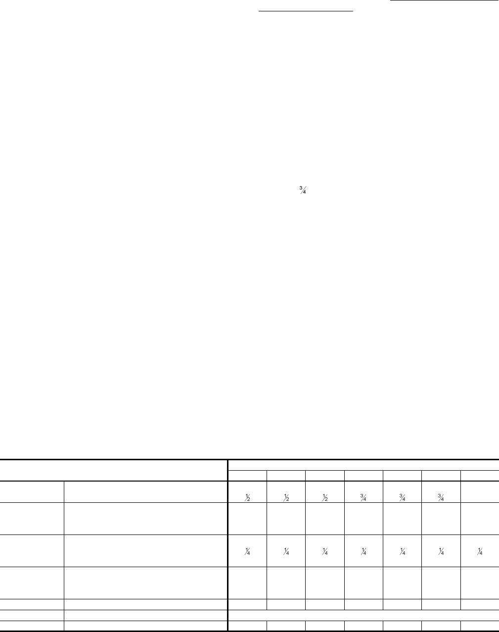
UNIT
SIZE
SHIPPING
WEIGHT
(lbs.)
OPERAT-
ING
WEIGHT
(lbs.)
CORNER WEIGHTS
(location, lbs.)
“A” “B” “C” “D”
018 318 313 86 76 73 83
024 324 319 88 77 75 85
030 333 328 85 81 82 86
036 338 333 91 80 78 88
042 347 342 94 83 80 91
048 368 363 92 88 92 97
060 376 371 105 100 84 87
TABLE 2 - UNITS WEIGHTS
D1 E B A
PRODUCT NOMENCLATURE
PRODUCT GENERATION
1 = NEW or Current Design
PRODUCT CATEGORY
D = Single Package Air Conditioner
(Air Cooled)
PRODUCT IDENTIFIER
EB = 10 SEER Cooling Models
20 4 0 6
FACTORY
INSTALLED ELECTRIC HEAT
A = No Electric Heat Installed
VOLTAGE CODE
06 = 208/230-1-60
25 = 208/230-3-60
46 = 460-3-60
58 = 575-3-60
NOMINAL COOLING
CAPACITY (MBH)
018 = 18,000 BTUH
024 = 24,000 BTUH
030 = 30,000 BTUH
036 = 36,000 BTUH
042 = 42,000 BTUH
048 = 48,000 BTUH
060 = 60,000 BTUH
INSTALLATION
CLEARANCES
All units require certain clearances for proper operation and
service. Refer to Figure 3 for the clearances required for com-
bustion, construction, servicing and proper unit operation.
WARNING:Do not permit overhanging structures or shrubs to
obstruct the condenser air discharge outlet.
DUCT WORK
These units are adaptable to downflow use as well as rear sup-
ply and return air duct openings. To convert to downflow, use
the following steps:
1. Remove the duct covers found in the bottom return and
supply air duct openings. There are four (4) screws secur-
ing each duct cover (save these screws to use later).
2. Install the duct covers, removed in step one, to the rear sup-
ply and return air duct openings. Secure with the four (4)
screws used in step one.
3. Seal the duct covers with silicone caulking.
Downflow units must have an L-shaped supply duct without
any outlets or registers located directly below the supply outlet
of the unit.
Duct work should be designed and sized according to the
methods of the Air Conditioning Contractors of America
(ACCA), as set forth in their Manual D.
A closed return duct system shall be used. This shall not pre-
clude use of economizers or ventilation air intake. Flexible
joints may be used in the supply and return duct work to mini-
mize the transmission of noise.
CAUTION: When fastening duct work to the side duct flanges on
the unit, insert the screws through the duct flanges only.
DO NOT insert the screws through the casing. Outdoor
duct work must be insulated and waterproofed.
NOTE: Be sure to note supply and return openings.
Refer to Figure 3 for information concerning rear and bottom
supply and return air duct openings.
FILTERS
Single phase units are shipped without a filter and is the responsi-
bility of the installer to secure a filter in the return air ductwork or
install a Filter/Frame Kit (1FF0114).
A filter rack and a filters are standard on three phase units.
Filters must always be used and must be kept clean. When fil-
ters become dirt laden, insufficient air will be delivered by the
blower, decreasing your units efficiency and increasing operat-
ing costs and wear-and-tear on the unit and controls.
Filters should be checked monthly especially since this unit
may be used for both heating and cooling.
CONDENSATE DRAIN
A condensate trap is required to be installed in the condensate
drain. The plumbing must conform to local codes. Use a seal-
ing compound on male pipe threads. Install the condensate
drain line ( “ NPTF) to spill into an open drain.
SERVICE ACCESS
Access to all serviceable components is provided by the follow-
ing removable panels:
•Blower service access
•Electrical/filter access
•Compressor service access
Refer to Figure 3 for location of these access panels and mini-
mum clearance.
THERMOSTAT
The room thermostat should be located on an inside wall ap-
proximately 56" above the floor where it will not be subject to
drafts, sun exposure or heat from electrical fixtures or appli-
ances. Follow manufacturer's instructions enclosed with the
thermostat for general installation procedure. Four or five color
coded insulated wires (minimum #18 AWG) should be used to
connect thermostat to unit. See Figure 2.
035-16703-001-A-0202
Unitary Products Group 3
MODELS DEB
018 024 030 036 042 048 060
EVAPORATOR
BLOWER CENTRIFUGAL BLOWER (Dia. x Wd. in.) 9 X 6 10 X 8 10 X 8 10 x 8 11 X 10 11 x 10 11 x 10
FAN MOTOR HP (Three Speed) 1
EVAPORATOR
COIL
ROWS DEEP 2222223
FINS PER INCH 13 15 15 15 15 13 16
FACE AREA (Sq. Ft.) 2.19 2.81 4.38 4.38 4.38 5.62 5.26
CONDENSER
FAN
PROPELLER DIA. (in.) 22 22 22 22 22 22 22
FAN MOTOR HP
NOM. CFM TOTAL 1,800 2,200 2,400 2,400 2,400 2,800 2,800
CONDENSER
COIL
ROWS DEEP 1111111
FINS PER INCH 18 16 20 18 16 13 20
FACE AREA (Sq. Ft.) 8.3 8.3 8.3 8.3 11.7 16.4 16.4
CHARGE REFRIGERANT 22 (lbs./oz.) 3 / 4 3 / 5 3 / 13 3 / 10 4 / 7 5 / 15 5 / 15
FILTER FACE AREA (Sq. Ft. / Qty. / Size) 2.14 / 2 / 14" x 22"
COMPRESSOR HERMETIC Type, (Qty. = 1) Recip Recip Recip Recip Recip Scroll Scroll
TABLE 3 - PHYSICAL DATA
POWER AND CONTROL WIRING
Field wiring to the unit must conform to provisions of the current
N.E.C. ANSI/NFPA No. 70 or C.E.C. and/or local ordinances.
The unit must be electrically grounded in accordance with local
codes or, in their absence, with the N.E.C./C.E.C. Voltage toler-
ances which must be maintained at the compressor terminals
during starting and running conditions are indicated on the unit
Rating Plate and Table 3.
The wiring entering the cabinet must be provided with me-
chanical strain relief.
A fused or HACR breaker disconnect switch should be field pro-
vided for the unit. If any of the wire supplied with the unit must be
replaced, replacement wire must be of the type shown on the wir-
ing diagram.
Electrical line must be sized properly to carry the load. Each
unit must be wired with a separate branch circuit fed directly
from the meter panel and properly fused.
Refer to Figure 2 for typical field wiring and to the appropriate unit
wiring diagram for control circuit and power wiring information.
COMPRESSORS
Units are shipped with compressor mountings factory-adjusted
for shipping. CAUTION: Loosen compressor mounting bolts
half turn before operating unit.
035-16703-001-A-0202
4 Unitary Products Group
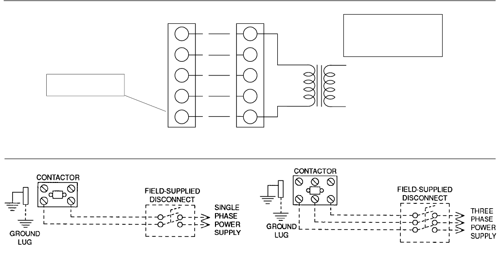
FIG. 2 - TYPICAL FIELD WIRING DIAGRAM
POWER WIRING
R
G
W
R
G
C
YY
W
C
24 VOLT TRANSFORMER
UNIT TERMINAL STRIP
THERMOSTAT NOTE:
HEAT ANTICIPATOR
SHOULD BE SET AT 0.25
AMPS FOR ALL MODELS.
CAUTION: Label all wires prior to disconnection when servicing controls. Wiring errors can
cause improper and dangerous operation. Verify proper operation after servicing.
PROGRAMMABLE
THERMOSTAT ONLY
CONTROL WIRING
** = Minimum wire size of 18 AWG
wire should be used for all field
installed 24 volt wire.
**
*
* = Only required on units with
supplemental electric heat.
REFER TO ELECTRICAL DATA
TABLES TO SIZE THE DISCON-
NECT SWITCH, WIRING &
OVERCURRENT PROTECTION.
REFER TO ELECTRICAL DATA
TABLES TO SIZE THE DISCON-
NECT SWITCH, WIRING &
OVERCURRENT PROTECTION.
035-16703-001-A-0202
Unitary Products Group 5
MODEL
DEB POWER SUP-
PLY
VOLTAGE
LIMITATIONS
1COMPRESSOR COND.
FAN
MOTOR,
FLA
SUPPLY
AIR
BLOWER
MOTOR,
FLA
MINIMUM
CIRCUIT
AMPACITY
MAX.
FUSE
SIZE,
AMPS
2
MAX.
HACR
BREAKER
SIZE,
AMPS
UNIT
POWER
FACTOR
TRANSFORMER
SIZE (VA)
MIN. MAX. RLA LRA
018 208/230-1-60 187 253 9.0 48.0 1.1 2.6 14.9 20 20 .96 40
024 208/230-1-60 187 253 11.5 60.0 1.1 2.6 18.1 25 25 .96 40
030 208/230-1-60 187 253 14.7 73.0 1.1 2.6 22.1 30 30 .96 40
036 208/230-1-60 187 253 17.3 94.0 1.1 3.5 26.2 35 35 .96 40
042 208/230-1-60 187 253 20.5 120.0 1.1 3.5 30.2 40 40 .96 40
048 208/230-1-60 187 253 24.4 140.0 1.3 4.0 35.8 45 45 .96 40
060 208/230-1-60 187 253 28.9 165.0 1.3 4.0 44.4 60 60 .96 40
036 208/230-3-60 187 253 10.9 78.0 1.1 3.5 18.2 25 25 .96 75
042 208/230-3-60 187 253 14.1 110.0 1.1 3.5 22.2 30 30 .96 75
048 208/230-3-60 187 253 14.1 105.0 0.7 4.0 22.3 30 30 .96 75
060 208/230-3-60 187 253 16.0 125.0 1.3 7.0 28.3 40 40 .96 75
036 460-3-60 414 504 5.8 40.0 0.6 1.8 9.6 15 15 .96 75
042 460-3-60 414 504 7.1 54.0 0.6 1.8 11.2 15 15 .96 75
048 460-3-60 414 504 7.1 55.0 0.6 2.0 11.5 15 15 .96 75
060 460-3-60 414 504 8.0 67.0 0.7 3.5 14.2 20 20 .96 75
036 575-3-60 518 630 4.5 32.0 0.4 1.5 7.6 15 15 .96 75
042 575-3-60 518 630 5.8 44.0 0.4 1.5 9.1 15 15 .96 75
048 575-3-60 518 630 5.6 44.0 0.6 1.6 9.3 15 15 .96 75
060 575-3-60 518 630 6.4 50.0 0.6 2.8 11.4 15 15 .96 75
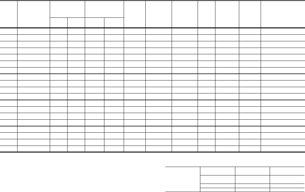
1= Rated in accordance with ARI Standard 110, utilization range “A”. 2= Dual element, time delay type.
TABLE 4 - ELECTRICAL DATA (BASIC UNIT)
*= KW listed is for 240 volts, use this table for 208 or 230 volts.
ELECTRIC HEAT
CORRECTION
FACTORS
NOMINAL VOLTAGE VOLTAGE KW CAP. MULTI-
PLIER
240 208
230 .75
.92
480 460 .92
600 575 .92

035-16703-001-A-0202
6 Unitary Products Group
DEB
POWER
SUPPLY
COMPRESSOR COND.
FAN
MOTOR
FLA
SUPPLY
AIR
BLOWER
MOTOR,
FLA
ELECTRIC HEAT ACCESSORY
MINIMUM
CIRCUIT
AMPACITY
MAX.
FUSE
SIZE,1
AMPS
MAX.
HACR2
BREAKER
SIZE
MODEL
RLA LRA MODEL NO.
STAGE
KW TOTAL
AMPS
018 208/230-1-60 9.0 48.0 1.1 2.6 2NH04500506
2NH04500706 1
23.8/5.0 *
5.6/7.5 * 18.1/20.8
27.1/31.3 25.8/29.3
37.1/42.3 30/30
40/45 30/30
40/45
024 208/230-1-60 11.2 60.0 1.1 2.6 2NH04500506
2NH04500706
2NH04501006
1
2
2
3.8/5.0 *
5.6/7.5 *
7.5/10.0 *
18.1/20.8
27.1/31.3
36.1/41.7
25.8/29.3
37.1/42.3
48.4/55.3
30/30
40/45
50/60
30/30
40/45
50/60
030 208/230-1-60 12.0 73.0 1.1 2.6
2NH04500506
2NH04500706
2NH04501006
2NH04501506
1
2
2
2
3.8/5.0 *
5.6/7.5 *
7.5/10.0 *
11.3/15.0 *
18.1/20.8
27.3/31.3
36.1/41.7
54.2/62.5
25.8/29.3
37.1/42.3
48.4/55.3
71.0/81.4
30/30
40/45
50/60
80/90
30/30
40/45
50/60
80/90
036 208/230-1-60 17.3 94.0 1.1 3.5 2NH04501006
2NH04501506 2
27.5/10.0 *
11.3/15.0 * 36.1/41.7
54.2/62.5 49.5/56.5
72.1/82.5 50/60
80/90 50/60
80/90
042 208/230-1-60 20.5 120.0 1.1 3.5
2NH04500506
2NH04500706
2NH04501006
2NH04501506
1
2
2
2
3.8/5.0 *
5.6/7.5 *
7.5/10.0 *
11.3/15.0 *
18.1/20.8
27.1/31.3
36.1/41.7
54.2/62.5
30.2/30.4
38.2/43.4
49.5/56.5
72.1/82.5
40/40
50/50
50/60
80/90
40/40
50/50
50/60
80/90
048 208/230-1-60 24.4 140.0 1.3 4.0
2NH04501006
2NH04501506
2NH04502006
2NH04502506
2
2
2
2
7.5/10.0 *
11.3/15.0 *
15.0/20.0 *
18.8/25.0 *
36.1/41.7
54.2/62.5
72.2/83.3
90.3/104.2
50.1/57.1
72.1/83.1
95.3/109.2
117.8/135.2
60/60
80/90
100/110
125/150
60/60
80/90
100/110
125/150
060 208/230-1-60 28.9 165.0 1.3 7.0
2NH04501006
2NH04501506
2NH04502006
2NH04502506
2
2
2
2
7.5/10.0 *
11.3/15.0 *
15.0/20.0 *
18.8/25.0 *
36.1/41.7
54.2/62.5
72.2/83.3
90.3/104.2
53.9/60.8
76.5/86.9
99.0/112.9
121.6/139.0
70/70
80/90
100/125
125/150
70/70
80/90
100/125
125/150
036 208/230-3-60 10.9 78.0 1.1 3.5 2NH04501025
2NH04501525 1
17.5/10.0 *
11.3/15.0 * 20.8/24.1
31.3/36.1 30.4/34.4
43.5/49.5 35/35
45/50 35/35
45/50
042 208/230-3-60 14.1 110.0 1.1 3.5 2NH04501025
2NH04501525 1
17.5/10.0 *
11.3/15.0 * 20.8/24.1
31.3/36.1 30.4/34.4
43.5/49.5 35/35
45/50 35/35
45/50
048 208/230-3-60 14.1 105.0 0.7 4.0
2NH04501025
2NH04501525
2NH04502025
2NH04502525
1
1
2
2
7.5/10.0 *
11.3/15.0 *
15.0/20.0 *
18.8/25.0 *
20.8/24.1
31.3/36.1
41.7/48.1
52.1/60.1
31.1/35.1
44.1/50.1
57.1/65.1
70.2/80.2
35/40
45/60
60/70
80/90
35/40
45/60
60/70
80/90
060 208/230-3-60 16.0 125.0 1.3 7.0
2NH04501025
2NH04501525
2NH04502025
2NH04502525
1
1
2
2
7.5/10.0 *
11.3/15.0 *
15.0/20.0 *
18.8/25.0 *
20.8/24.1
31.3/36.1
41.7/48.1
52.1/60.1
34.8/38.8
47.8/53.9
60.9/68.9
73.9/83.9
40/40
50/60
70/70
80/90
40/40
50/60
70/70
80/90
036 460-3-60 5.8 40.0 0.6 1.8 2NH04501046
2NH04501546 1
110.0 **
15.0 ** 12.0
18.0 17.3
24.8 20
25 20
25
042 460-3-60 7.1 54.0 0.6 1.8 2NH04501046
2NH04501546 1
110.0 **
15.0 ** 12.0
18.0 17.3
24.8 20
25 20
25
048 460-3-60 7.1 55.0 0.6 2.0
2NH04501046
2NH04501546
2NH04502046
2NH04502546
1
1
2
2
10.0 **
15.0 **
20.0 **
25.0 **
12.0
18.0
24.1
30.1
17.5
25.1
32.6
40.1
20
30
35
45
20
30
35
45
060 460-3-60 8.0 67.0 0.7 3.5
2NH04501046
2NH04501546
2NH04502046
2NH04502546
1
1
2
2
10.0 **
15.0 **
20.0 **
25.0 **
12.0
18.0
24.1
30.1
19.4
26.9
34.4
42.0
20
30
35
45
20
30
35
45
036 575-3-60 4.5 32.0 0.4 1.5 2NH04501058
2NH04501558 1
110.0 ***
15.0 *** 9.6
14.4 13.9
19.9 15
20 15
20
042 575-3-60 5.8 44.0 0.4 1.5 2NH04501058
2NH04501558 1
110.0 ***
15.0 *** 9.6
14.4 13.9
19.9 15
20 15
20
048 575-3-60 5.6 44.0 0.6 1.6
2NH04501058
2NH04501558
2NH04502058
2NH04502558
1
1
2
2
10.0 ***
15.0 ***
20.0 ***
25.0 ***
9.6
14.4
19.2
24.1
14.0
20.0
26.1
32.1
15
25
30
35
15
25
30
35
060 575-3-60 6.4 50.0 0.6 2.8
2NH04501058
2NH04501558
2NH04502058
2NH04502558
1
1
2
2
10.0 ***
15.0 ***
20.0 ***
25.0 ***
9.6
14.4
19.2
24.1
15.5
21.5
27.6
33.6
20
25
30
35
20
25
30
35
1= Dual element, time delay type. * = KW listed is for 240 volts, use table on previous page for 208 or 230 volts.
2= Standard circuit breakers may be used in Canada and on applications ** = KW listed is for 480 volts, use table on previous page for 460 volts.
over 60 amps where the heaters are separately fused. *** = KW listed is for 600 volts, use table on previous page for 575 volts.
TABLE 5 - ELECTRICAL DATA (COOLING / ELECTRIC HEAT)
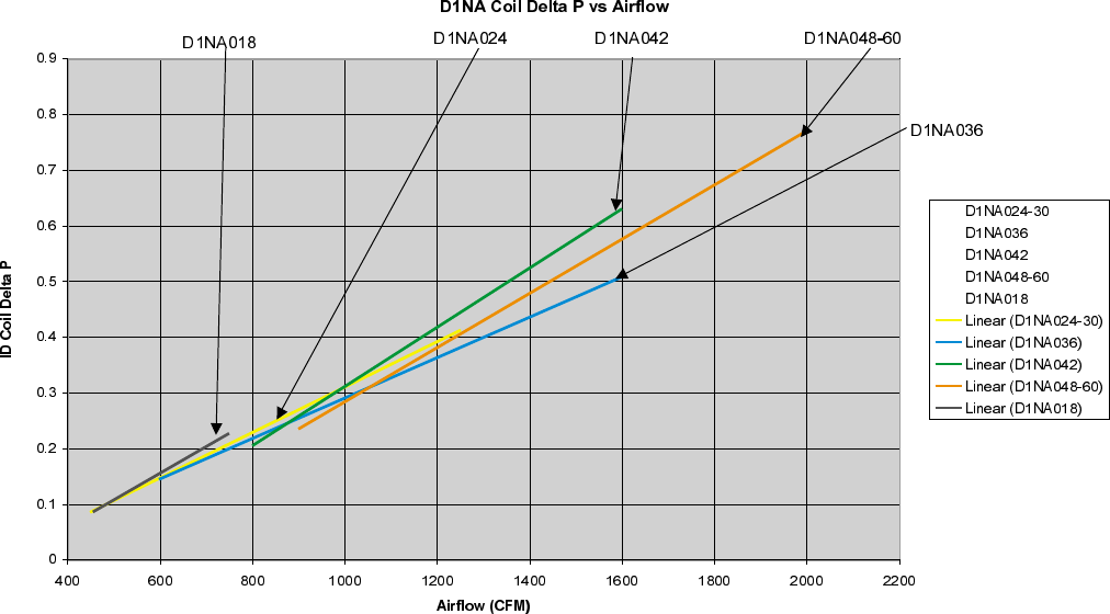
Checking Supply Air CFM
To check the supply air CFM after the initial balancing has been
completed:
1.Remove the two ¼ inch dot plugs in the duct panel.
2.Insert at least 8 inches of ¼ inch tubing into each of these
holes for sufficient penetration into the airflow on both sides of
the indoor coil.
3.Using an inclined manometer, determine the pressure drop
across the dry evaporator coil. Since the moisture on an evapo-
rator coil may vary greatly, measuring the pressure drop across
a wet coil under field conditions would be inaccurate. To ensure
a dry coil, the compressors should be deactivated while the test
is being run.
4.Knowing the pressure drop across a dry coil, the actual CFM
through the unit can be determined from the curve in Coil Delta
P vs. Supply Air CFM figure.
WARNING! Failure to properly adjust the total system air quan-
tity can result in extensive system damage.
After readings have been obtained, remove the tubes and rein-
stall the two ¼ inch plugs removed in Step 1.
NOTE: De-energize the compressors before taking any test
measurements to ensure a dry indoor coil.
Unitary Products Group 7
035-16703-001-A-0202
8 Unitary Products Group
035-16703-001-A-0202
TABLE 7 - SUPERHEAT CHARGING TABLE FOR MODEL D1EB024
OUTDOOR
TEMPERATURE
(F)
SUPERHEAT AT COMPRESSOR SUCTION (F), AIRFLOW = 800 CFM/TON
INDOOR WB TEMPERATURE (F)
55 57 59 61 63 65 67 69 71 73 75
65 13.5 15.0 16.5 18.0 19.6 21.1 22.6 23.9 25.3 26.6 27.9
70 10.1 11.8 13.5 15.2 16.9 18.6 20.3 21.9 23.4 25.0 26.5
75 6.7 8.6 10.5 12.4 14.3 16.2 18.1 19.8 21.6 23.4 25.2
80 - 5.4 7.5 9.6 11.6 13.7 15.8 17.8 19.8 21.8 23.8
85 - - - 6.7 9.0 11.2 13.5 15.7 17.9 20.2 22.4
90 - - - 6.3 8.3 10.3 12.3 14.5 16.7 19.0 21.2
95 - - - 6.0 7.6 9.3 11.0 13.3 15.5 17.8 20.0
100 - - - 5.3 6.6 7.8 9.1 11.1 13.1 15.0 17.0
105 ----5.56.47.28.910.6 12.3 14.0
110 ------5.36.78.29.611.0
115 --------5.76.88.0
TABLE 8 - SUPERHEAT CHARGING TABLE FOR MODEL D1EB030
OUTDOOR
TEMPERATURE
(F)
SUPERHEAT AT COMPRESSOR SUCTION (F), AIRFLOW = 1,000 CFM/TON
INDOOR WB TEMPERATURE (F)
55 57 59 61 63 65 67 69 71 73 75
65 21.6 22.5 23.4 24.3 25.3 26.2 27.1 27.5 28.0 28.4 28.8
70 18.0 19.3 20.5 21.7 23.0 24.2 25.4 26.0 26.6 27.1 27.7
75 14.5 16.0 17.6 19.1 20.7 22.2 23.8 24.5 25.2 25.9 26.6
80 11.0 12.8 14.7 16.5 18.4 20.3 22.1 23.0 23.8 24.7 25.5
85 7.4 9.6 11.8 14.0 16.1 18.3 20.5 21.5 22.4 23.4 24.4
90 - 5.6 7.9 10.3 12.6 15.0 17.3 18.8 20.3 21.9 23.4
95 - - - 6.6 9.1 11.6 14.1 16.2 18.3 20.3 22.4
100 - - - 5.4 7.2 9.1 10.9 13.5 16.1 18.7 21.3
105 ----5.36.67.810.9 14.0 17.1 20.3
110 -------8.311.915.5 19.2
115 -------5.79.814.0 18.1
TABLE 6 - SUPERHEAT CHARGING TABLE FOR MODEL D1EB018
OUTDOOR
TEMPERATURE
(F)
SUPERHEAT AT COMPRESSOR SUCTION (F), AIRFLOW = 600 CFM/TON
INDOOR WB TEMPERATURE (F)
55 57 59 61 63 65 67 69 71 73 75
65 17.8 19.8 21.8 23.9 25.9 27.9 29.9 31.1 32.3 33.6 34.8
70 12.2 14.9 17.5 20.2 22.8 25.4 28.1 29.3 30.6 31.9 33.1
75 6.6 9.9 13.2 16.4 19.7 23.0 26.3 27.6 28.9 30.2 31.5
85 - - - 9.0 13.6 18.1 22.6 24.0 25.4 26.8 28.3
90 - - - 8.0 12.0 16.0 19.9 21.7 23.4 25.1 26.8
95 - - - 6.9 10.4 13.8 17.3 19.3 21.3 23.3 25.3
100 - - - 5.3 8.0 10.6 13.3 16.0 18.7 21.4 24.1
105 ----5.57.49.212.7 16.1 19.5 22.9
110 ------5.29.313.4 17.6 21.7
115 -------6.010.8 15.7 20.5
TABLE 9 - SUPERHEAT CHARGING TABLE FOR MODEL D1EB036
OUTDOOR
TEMPERATURE
(F)
SUPERHEAT AT COMPRESSOR SUCTION (F), AIRFLOW = 1,200 CFM/TON
INDOOR WB TEMPERATURE (F)
55 57 59 61 63 65 67 69 71 73 75
65 11.5 13.4 15.4 17.4 19.4 21.4 23.4 24.6 25.9 27.1 28.4
70 9.3 11.4 13.4 15.5 17.6 19.6 21.7 23.3 24.9 26.4 28.0
75 7.1 9.3 11.4 13.6 15.8 17.9 20.1 22.0 23.9 25.7 27.6
80 - 7.2 9.4 11.7 13.9 16.2 18.4 20.6 22.8 25.1 27.3
85 - 5.1 7.5 9.8 12.1 14.5 16.8 19.3 21.8 24.4 26.9
90 - 5.5 7.4 9.2 11.0 12.8 14.6 17.6 20.6 23.6 26.5
95 - 5.9 7.3 8.6 9.9 11.2 12.5 15.9 19.3 22.8 26.2
100 - 5.5 6.6 7.8 9.0 10.2 11.4 15.0 18.5 22.1 25.6
105 - - 6.0 7.1 8.2 9.3 10.3 14.0 17.7 21.4 25.1
110 - - 5.4 6.4 7.3 8.3 9.2 13.1 16.9 20.7 24.5
115 - - - 5.7 6.5 7.3 8.1 12.1 16.1 20.0 24.0
Unitary Products Group 9
035-16703-001-A-0202
TABLE 10 - SUPERHEAT CHARGING TABLE FOR MODEL D1EB042
OUTDOOR
TEMPERATURE
(F)
SUPERHEAT AT COMPRESSOR SUCTION (F), AIRFLOW = 1,400 CFM/TON
INDOOR WB TEMPERATURE (F)
55 57 59 61 63 65 67 69 71 73 75
65 20.3 21.9 23.5 25.0 26.6 28.1 29.7 30.6 31.6 32.6 33.6
70 16.7 18.5 20.3 22.1 23.9 25.7 27.5 28.6 29.7 30.8 32.0
75 13.0 15.1 17.1 19.2 21.2 23.2 25.3 26.6 27.8 29.1 30.4
80 9.4 11.7 13.9 16.2 18.5 20.8 23.1 24.5 25.9 27.3 28.7
85 5.7 8.2 10.8 13.3 15.8 18.4 20.9 22.5 24.0 25.6 27.1
90 - 6.5 9.1 11.7 14.2 16.8 19.4 21.0 22.6 24.1 25.7
95 - - 7.4 10.0 12.7 15.3 17.9 19.5 21.1 22.7 24.3
100 - - 5.8 7.9 10.0 12.0 14.1 16.3 18.4 20.6 22.8
105 - - - 5.8 7.3 8.7 10.2 13.0 15.8 18.6 21.4
110 -----5.56.49.813.2 16.5 19.9
115 -------6.510.5 14.5 18.5
TABLE 11 - SUPERHEAT CHARGING TABLE FOR MODEL D1EB048
OUTDOOR
TEMPERATURE
(F)
SUPERHEAT AT COMPRESSOR SUCTION (F), AIRFLOW = 1,600 CFM/TON
INDOOR WB TEMPERATURE (F)
55 57 59 61 63 65 67 69 71 73 75
65 13.5 15.4 17.3 19.1 21.0 22.8 24.7 26.1 27.6 29.0 30.5
70 10.7 12.7 14.7 16.8 18.8 20.9 22.9 24.7 26.5 28.2 30.0
75 7.8 10.0 12.2 14.5 16.7 18.9 21.2 23.3 25.4 27.5 29.6
80 - 7.3 9.7 12.1 14.5 17.0 19.4 21.8 24.2 26.7 29.1
85 - - 7.2 9.8 12.4 15.0 17.6 20.4 23.1 25.9 28.6
90 - - 6.1 7.7 9.4 11.0 12.7 16.6 20.5 24.4 28.3
95 - - - 5.7 6.3 7.0 7.7 12.7 17.8 22.8 27.9
100 - - - 5.3 5.9 6.5 7.1 11.1 15.1 19.1 23.0
105 ----5.56.06.69.512.4 15.3 18.2
110 ----5.05.56.07.89.711.613.4
115 ------5.46.27.07.88.6
TABLE 12 - SUPERHEAT CHARGING TABLE FOR MODEL D1EB060
OUTDOOR
TEMPERATURE
(F)
SUPERHEAT AT COMPRESSOR SUCTION (F), AIRFLOW = 2,000 CFM/TON
INDOOR WB TEMPERATURE (F)
55 57 59 61 63 65 67 69 71 73 75
65 25.3 25.8 26.3 26.8 27.3 27.8 28.3 28.7 29.1 29.6 30.0
70 22.2 23.0 23.7 24.4 25.1 25.9 26.6 27.4 28.2 28.9 29.7
75 19.2 20.1 21.1 22.1 23.0 24.0 24.9 26.1 27.2 28.3 29.4
80 16.1 17.3 18.5 19.7 20.9 22.1 23.3 24.7 26.2 27.7 29.1
85 13.1 14.5 15.9 17.3 18.8 20.2 21.6 23.4 25.2 27.0 28.9
90 10.3 11.7 13.1 14.5 15.9 17.3 18.6 21.1 23.5 25.9 28.3
95 7.6 8.9 10.3 11.6 13.0 14.3 15.7 18.7 21.8 24.8 27.8
100 6.6 7.7 8.9 10.1 11.3 12.5 13.6 16.7 19.7 22.7 25.8
105 5.6 6.6 7.6 8.6 9.6 10.6 11.6 14.6 17.6 20.7 23.7
110 - 5.4 6.2 7.0 7.9 8.7 9.5 12.5 15.6 18.6 21.6
115 - - - 5.5 6.2 6.8 7.5 10.5 13.5 16.5 19.5
10 Unitary Products Group
035-16703-001-A-0202
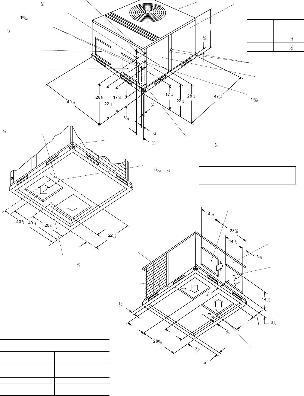
FIG. 3 - DIMENSIONS AND CLEARANCES
CLEARANCES
(Minimum)
Front 12"
Back 0"
Left Side (Filter Access) 24"
Right Side 24"
Below Unit10"
Above Unit236" (For Condenser
Air Discharge)
1Units may be installed on combustible floors made from wood or class A,
B or C roof covering material.
2Units must be installed outdoors. Overhanging structures or shrubs
should not obstruct outdoor air discharge outlet.
CONDENSATE
DRAIN “ NPTI
HIGH VOLTAGE
CONN. “ x “ DIA.
KNOCKOUT
6
OUTDOOR
COIL
15
4
BACK
SIDE RETURN
AIR OPENING
SIDE SUPPLY
AIR OPENING
BOTTOM RETURN
AIR OPENING
15
2
1
1
1
15
BOTTOM SUPPLY
AIR OPENING
2
LOW VOLTAGE CONN.
“ DIA. KNOCKOUT
HIGH VOLTAGE CONN.
" DIA. KNOCKOUT
FRONT
ELECTRICAL/FILTER
SERVICE ACCESS
COMPARTMENT PANEL
(OVERALL)
(OVERALL)
4
1
2
All dimensions are in inches. They are
subject to change without notice. Certified
dimensions will be provided upon request.
UNIT CONDENSATE
CONNECTION “ NPTI
(TRAP REQUIRED)
(OVERALL)
SIDE SUPPLY
AIR OPENING
SIDE RETURN
AIR OPENING
COMPRESSOR
SERVICE ACCESS
COMPARTMENT PANEL
HIGH VOLTAGE CONN.
" DIA. KNOCKOUT
HIGH VOLTAGE CONN.
" DIA. KNOCKOUT
REFRIGERANT
CONNECTIONS
“A” UNIT SIZE DIMENSION
“A”
018 - 042 33
048 - 060 41
FRONT
LOW VOLTAGE CONN.
“ DIA. KNOCKOUT
Cooling
The following sequences of operation are based on using a
standard single-stage cooling thermostat.
WITH POWER TO UNIT AND THERMOSTAT IN COOLING
MODE.
1. If the fan switch on the thermostat is in the “ON” position,
the 24 volts at “G” will energize the “K1" relay on the fan
control board, close the ”K1" relay contacts, and energize
the indoor blower motor. If the fan switch is in the “AUTO”
position, the blower will operate only when there is a call for
cooling by the thermostat.
2. On a call for cooling, the thermostat will send 24 volts to “Y”
on the fan control board. The 24 volt signal will energize
contactor “M1", and power will be supplied to the compres-
sor and outdoor fan motor. If the fan switch on the thermo-
stat is on the ”AUTO" position, the thermostat will also send
a 24 volt signal to “G” on the fan control board and the in-
door blower will operate as indicated in step 1.
3. When the demand for cooling has been satisfied, the “M1"
contactor will be de-energized when the 24 volt ”Y" signal is
removed. If the fan switch on the thermostat is energized
when the 24 volt “Y” signal is removed. If the fan switch on
the thermostat is in the “ON” position, the indoor blower will
continue to run. If the fan switch is in the “AUTO” posi-
tion, the 24 volt “G” signal will be removed, and after a
60 second delay, the “K1" relay will open and de-
energize the indoor blower motor,
Heating
WITH POWER TO UNIT AND THERMOSTAT IN HEATING
MODE.
1. If the fan switch on the thermostat is in the “ON” position,
the 24 volts at “G” will energize the “K1" relay contacts, and
energize the indoor blower motor. If the fan switch on the
thermostat is in the ”AUTO" position, the blower will oper-
ate only when there is a call for heating by the thermostat.
2. On a call for heating, the thermostat will send 24 volts to
“W1" on the fan control board. The 24 volts signal will ener-
gize relay ”K2" on the fan control board, and the first stage
of electric heat will be energized.
3. When the heating demand is satisfied, the electric heat will
be de-energized when the 24 volt “W1" and ”W2" signals
are removed. If the fan switch on the thermostat is in the
“ON” position, the indoor blower will continue to run. If the
fan switch is in the “AUTO” position, the “K1" relay will open
and de-energize the indoor blower motor after the appropri-
ate time delay.
Please refer to Table 13 and 14 for more information.
Unitary Products Group 11
035-16703-001-A-0202
SEQUENCE OF OPERATION
TABLE 13 - THERMOSTAT SIGNALS (SINGLE PHASE UNITS)
SIGNAL
STATE
BOARD FUNCTION
SIGNAL
STATE
BOARD FUNCTION
“G” ON FAN INSTANT ON
OFF FAN INSTANT OFF
“G”
“Y”
ON FAN INSTANT ON
COMPRESSOR AND OUTDOOR FAN INSTANT ON “W1"
ON FAN INSTANT ON
HEATER BANK 1 ELEC. HEAT INSTANT ON
OFF COMPRESSOR AND OUTDOOR FAN INSTANT OFF
FAN 60 SECOND DELAY OFF OFF HEATER BANK 1 ELEC. HEAT INSTANT OFF
FAN 5 SECOND DELAY OFF
“G”
“W1"
ON FAN INSTANT ON
HEATER BANK 1 ELEC. HEAT INSTANT ON
”W2"
ON FAN INSTANT ON
HEATER BANK 1 ELEC. HEAT SEC. DELAY OFF
HEATER BANK 2 ELEC. HEAT INSTANT ON
OFF HEATER BANK 1 ELEC. HEAT INSTANT OFF
FAN 5 SECOND DELAY OFF OFF HEATER BANK 1 ELEC. HEAT SEC. DELAY OFF
HEATER BANK 2 ELEC. HEAT INSTANT OFF
FAN 5 SECOND DELAY OFF
“G”
“W1"
”W2"
ON
FAN INSTANT ON
HEATER BANK 1 ELEC. HEAT INSTANT ON
HEATER BANK 2 ELEC. HEAT 10 SECOND DELAY ON
HEATER BANK 3 ELEC. HEAT 20 SECOND DELAY ON “W1"
”W2"
ON
FAN INSTANT ON
HEATER BANK 1 ELEC. HEAT INSTANT ON
HEATER BANK 2 ELEC. HEAT 10 SECOND DELAY ON
HEATER BANK 3 ELEC. HEAT 20 SECOND DELAY ON
OFF
HEATER BANK 1 ELEC. HEAT INSTANT OFF
HEATER BANK 2 ELEC. HEAT SECOND DELAY ON
HEATER BANK 3 ELEC. HEAT 1 SECOND DELAY ON
FAN 6SECOND DELAY OFF
OFF
STAGE 1 ELEC. HEAT INSTANT OFF
HEATER BANK 2 ELEC. HEAT SECOND DELAY ON
HEATER BANK 3 ELEC. HEAT 1 SECOND DELAY ON
FAN 6SECOND DELAY OFF
12 Unitary Products Group
035-16703-001-A-0202
NORMAL MAINTENANCE
WARNING:Prior to any of the following maintenance proce-
dures, shut off all power to the unit, to avoid per-
sonal injury.
Periodic maintenance consists of changing or cleaning filters
and general cleaning of the outdoor coil.
FILTERS - Inspect once a month. Replace Disposable or clean
Permanent Type as necessary. DO NOT replace Permanent
Type with Disposable.
MOTORS - Indoor and outdoor fan motors are permanently lu-
bricated and require no maintenance.
OUTDOOR COIL- Dirt should not be allowed to accumulate on
the outdoor coil surface or other parts in the air circuit. Cleaning
should be as often as necessary to keep the coil clean. Use a
brush, vacuum cleaner attachment, or other suitable means. If
water is used to clean the coil, be sure that the power to the unit
is shut off prior to cleaning.
CAUTION: Exercise care when cleaning the coil so that the
coil fins are not damaged.
Do not permit the hot condenser air discharge to be
obstructed by overhanging structures or shrubs.
MAINTENANCE
SECURE OWNER'S APPROVAL:When the system is functioning properly, secure the owner's approval. Show him the
location of all disconnect switches and the thermostat. Teach him how to start and stop the unit and how to adjust temperature
settings within the limitations of the system.
SIGNAL
STATE
BOARD FUNCTION
SIGNAL
STATE
BOARD FUNCTION
“G” ON FAN INSTANT ON
OFF FAN INSTANT OFF
“G”
“Y”
ON FAN INSTANT ON
COMPRESSOR AND OUTDOOR FAN INSTANT ON “W1"
ON FAN INSTANT ON
HEATER BANK 1, 2 AND 3 ELEC. HEAT INSTANT ON
OFF COMPRESSOR AND OUTDOOR FAN INSTANT OFF
FAN 60 SECOND DELAY OFF OFF HEATER BANK 1, 2 AND 3 ELEC. HEAT INSTANT OFF
FAN 5 SECOND DELAY OFF
“G”
“W1"
ON FAN INSTANT ON
HEATER BANK 1, 2 AND 3 ELEC. HEAT INSTANT ON ”W2"
ON FAN INSTANT ON
HEATER BANK 1, 2 AND 3 ELEC. HEAT INSTANT ON
OFF HEATER BANK 1, 2 AND 3 ELEC. HEAT INSTANT OFF
FAN 5 SECOND DELAY OFF OFF HEATER BANK 1, 2 AND 3 ELEC. HEAT INSTANT OFF
FAN 5 SECOND DELAY OFF
“G”
“W1"
”W2"
ON FAN INSTANT ON
HEATER BANK 1, 2 AND 3 ELEC. HEAT INSTANT ON “W1"
”W2"
ON FAN INSTANT ON
HEATER BANK 1, 2 AND 3 ELEC. HEAT INSTANT ON
OFF HEATER BANK 1, 2 AND 3 ELEC. HEAT INSTANT OFF
FAN 6SECOND DELAY OFF OFF HEATER BANK 1, 2 AND 3 ELEC. HEAT INSTANT OFF
FAN 6SECOND DELAY OFF
TABLE 14 - THERMOSTAT SIGNALS (THREE PHASE UNITS)
Unitary Products Group 13
035-16703-001-A-0202
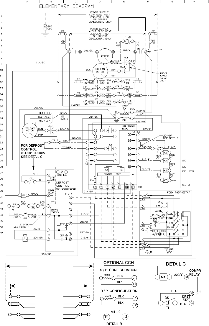
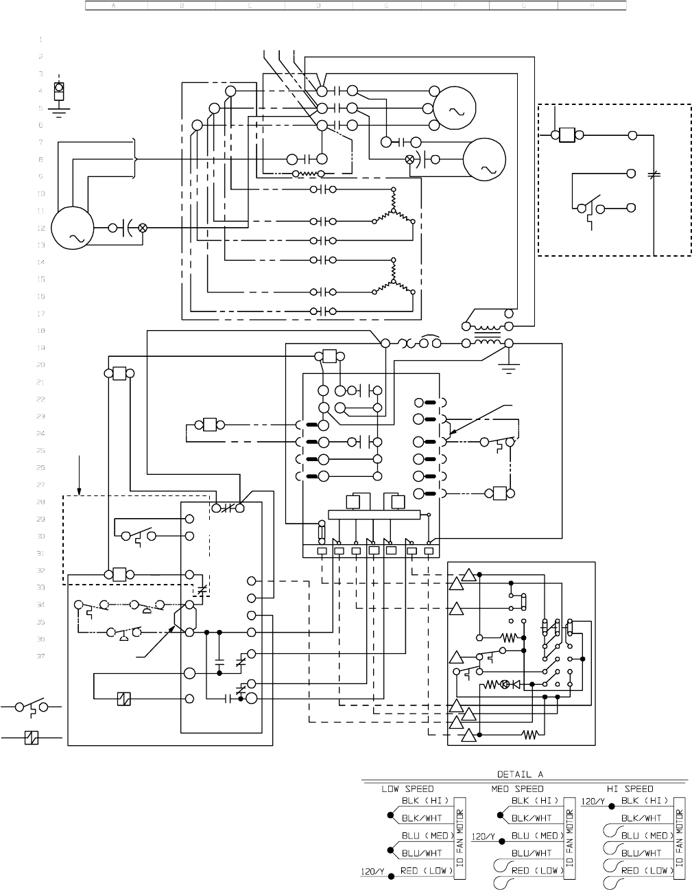
FIG. 4 - TYPICAL WIRING DIAGRAM (208/230-1-60 POWER SUPPLY)
POWER SUPPLY
POWER SUPPLY
208/230-1-60
208/230-1-60
USE COPPER
USE COPPER
CONDUCTORS ONLY
CONDUCTORS ONLY
SECONDARY POWER SUPPLY
SECONDARY POWER SUPPLY
FOR DUAL POINT ELEC HEAT
FOR DUAL POINT ELEC HEAT
208/230-1-60
208/230-1-60
USE COPPER
USE COPPER
CONDUCTORS ONLY
CONDUCTORS ONLY
(HTR5)
(HTR5)
(HTR4)
(HTR4)
(HTR3)
(HTR3)
(HTR2)
(HTR2)
(M1)
(M1)
705/PR
705/PR
708/PR
708/PR
716/PR
716/PR
713/PR
713/PR
710/PR
710/PR
F6
F6
F4
F4
F2
F2
(K6)
(K6)
(K4)
(K4)
(K5)
(K5)
(K3)
(K3)
(M1)
(M1)
714/BK
714/BK
706/BK
706/BK
711/BK
711/BK
703/BK
703/BK
709/BK
709/BK
F1
F1
F3
F3
F5
F5
DUAL POINT ELECTRIC HEAT (SEE NOTE 9)
DUAL POINT ELECTRIC HEAT (SEE NOTE 9)
DETAIL A
DETAIL A
SEE
DETAIL
"B"
FOR DUAL POINT
FOR DUAL POINT
ELECTRIC HEAT
ELECTRIC HEAT
POWER SUPPLY
POWER SUPPLY
SEE DETAIL A
SEE DETAIL A
14 Unitary Products Group
035-16703-001-A-0202
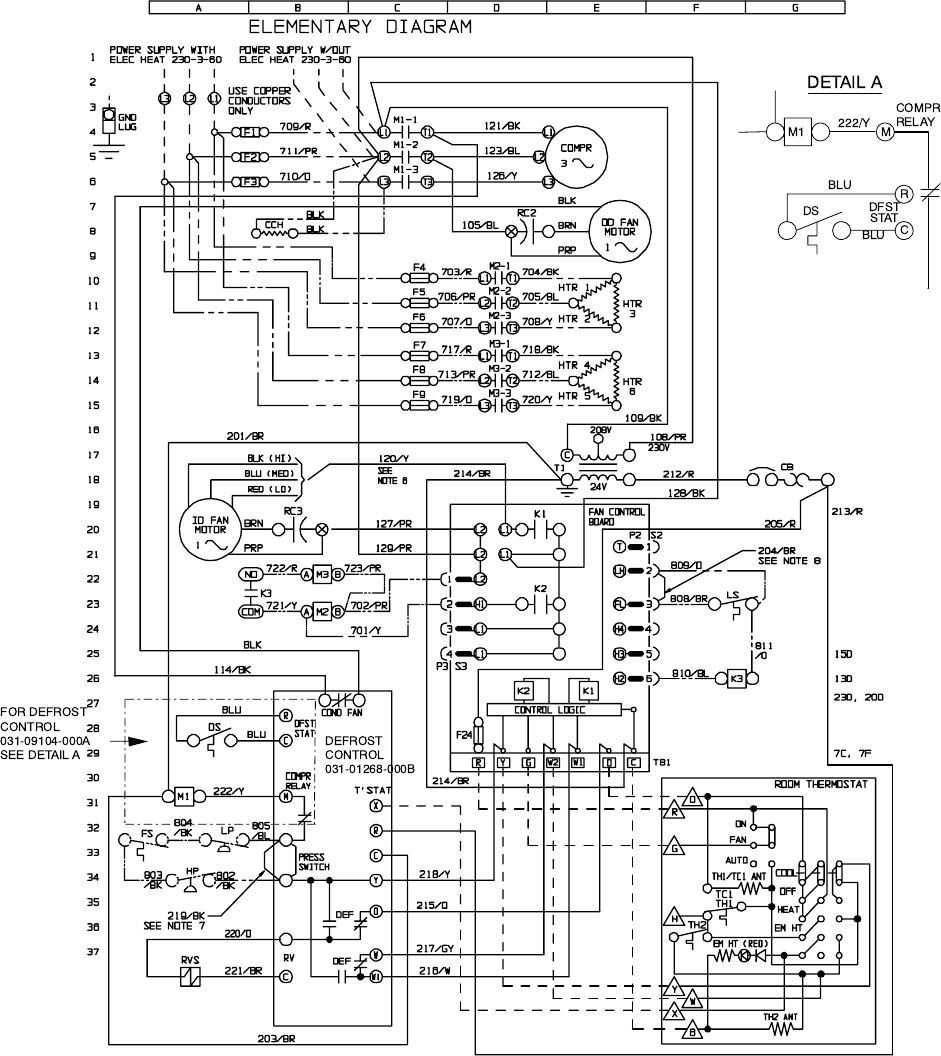
FIG. 5 - TYPICAL WIRING DIAGRAM (230-3-60 POWER SUPPLY)
Unitary Products Group 15
035-16703-001-A-0202
L2
L1
POW ER SUPPLY W /OUT
ELEC HEAT 460-3-60
O R 5 7 5 -3 -6 0
USE COPPER
CONDUCTORS
ONLY
GND
LU G
POW ER SUPPLY W /
ELEC HEAT 460-3-60
O R 5 7 5 -3 -6 0
(SEE DET A)
(SEE DET A)
(SEE DET A)
120/Y
SEE NO TE 6
709/R
711/P R
710/O
L1
L2
L3 L3
M1-1
M1-2
M1-3
T1
T2
T3
L1
L2
L3
121/B K
114/B K
123/B L
126/Y
COMPR
3
L1 T1
M3-1 BLK
BRN
PRP
RC2
105/B L
00 FA N
MOTOR
1
110
/O
M2-1
T1 L1
CCH
BLK
K3-1
703/R 74
BLK
706/P R K3-2
704/B K
705/B L
85
96
K3-3
707/0 708/Y
HTR
1
HTR
2
HTR
3
IO F A N
MOTOR
1
BRN
PRP
RC3
130/P R
717/R K4-1 718/BK
74
K4-2
713/P R 712/B L
85
K4-3
719/0 720/Y
96
HTR
4
HTR
5
HTR
6
223/B R
201/B R
M3
213/R
205/R CB
M2
208/P R
207/B R
206/B R
212
/R
C
T1
109/B K
24V
108
/P R
480 O R 600
214/B R
8D
7E
AB
K3 813/B R
814/Y
L2
L2
L21
2
3
H1
L1
L1
L1
K1
209\R
K2
FAN CONTROL
BOARD
T
LH
FL
H4
1
2
3
4
P2 S2
809/O
808/B R
204/B R
SEE NO TE 8
11D , 14D , 15D
LS
811/0
K4
21D , 24D
810/B L
5
6
H3
H2
K1
K2
L1
4
P3 S3
CONTROL LOGIC
RYG
W2 W1 OC
TB1
F24
213/R
202/Y 224/R
BLU
COND FAN
DFST
STAT DEFROST
CONTROL
DS BLU
R
C
203/B R 222/Y
M1
FS
804
/B K LP
805
/B L
COMPR
RELAY
M
803
/B K
HP 802
/B K
PRESS
SW ITCH
X
R
C
Y218/Y
T'STAT
ROOM THERMOSTAT
ON
FAN
AUTO
O
R
G
TH 1/TC 1 ANT COOL
OFF
4 D , 5 D , 6 D
TC1
TH1
HTH2
EM HT (RED)
HEAT
EM HT
215/O
217/G Y
216/W
Y
W
X
B
TH2 AN T
DEF
DEF
O
W
W1
C
RV
220/O
221/B R
219/B K
SEE NO TE 7
RVS
203/B R
BLU DS B LU
221/B R
RVS
220/O
ELEM ENTARY DIAG RAM
M1
COMPR
RELAY
DFST
STAT
R
C
DETAIL B
FOR DEFROST
CONTROL
031-09104-000A
SEE DETAIL B
031-01268-000B
M
FIG. 6 - TYPICAL WIRING DIAGRAM (460-3-60 & 575-3-60 POWER SUPPLY)
16 Unitary Products Group
035-16703-001-A-0202
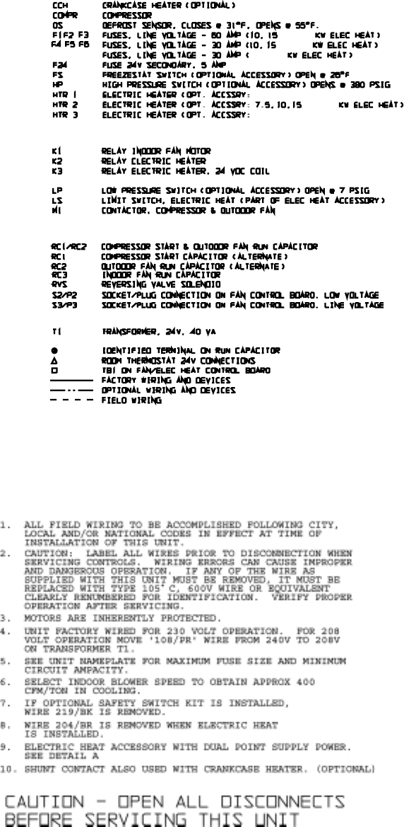
TYPICAL WIRING DIAGRAM NOTES
TYPICAL WIRING DIAGRAM LEGEND
HTR 5 ELECTRIC HEATER (OPT. ACCSSRY: 20 & 25 KW ELEC HEAT)
HTR 4 ELECTRIC HEATER (OPT. ACCSSRY: 15, 20, & 25 KW ELEC HEAT)
, 20, & 25
ALL KW ELEC HEAT)
20 & 25 KW ELEC HEAT)
PTCR START ASSIST (OPTIONAL DEVICE)
, 20, & 25
, 20, & 25
20 & 25
CB CIRCUIT BREAKER 24V, 3 AMP
F7 F8 F9
TB2 TERMINAL BLOCK ECM MOTOR "SPEED" CONNECTIONS
M2 CONTACTOR, ELECTRIC HEAT, 230V COIL
M3 CONTACTOR, ELECTRIC HEAT, 230V COIL
S4/P4
S3/P3
SOCKET/PLUG CONNECTION ON ID FAN MOTOR,24V
SOCKET/PLUG CONNECTION ON ID FAN MOTOR, 230V
HTR 6 ELECTRIC HEATER (OPT. ACCSSRY: 20 & 25 KW ELEC HEAT)
K7 RELAY LIMIT TRIP, 24 VDC COIL

Unitary Products Group
5005 York Drive, Norman Oklahoma 73069
Subject to change without notice. Printed in U.S.A.
Copyright by York International Corporation 2001. All Rights Reserved. Supersedes 035-16703-000-A-0701 035-16703-001-A-0202
