York Heat Pump B3Ch 048 And 060 Users Manual Y IO, Sunline 2000 Single Package Pumps, S (50 Hz)
B3CH 048 and 060 to the manual 2ed05618-b46c-4026-96a2-773dd9f2cd00
2015-02-02
: York York-Heat-Pump-B3Ch-048-And-060-Users-Manual york-york-heat-pump-b3ch-048-and-060-users-manual-455365 york pdf
Open the PDF directly: View PDF ![]() .
.
Page Count: 16

GENERAL
YORK Model BCH units are single package heat pumps
designed for outdoor installation on a rooftop or a slab.
Supplemental electric heaters are available as field-installed
accessories. The units are manufactured under ISO 9002
Quality System Certification.
Units are completely assembled on rigid, permanently
attached base rails. All piping, refrigerant charge, and electrical
wiring is factory-installed and tested. The units require only
electric power and duct connections at the point of installation.
The supplemental electric heaters have nickel-chrome
elements and utilize single point power connection.
INSPECTION
As soon as a unit is received, it should be inspected for possible
damage during transit. If damage is evident, the extent of the
damage should be noted on the carrier's freight bill. Aseparate
request for inspection by the carrier's agent should be made in
writing. See local distributor for additional information.
REFERENCE
Additional information on the design, installation, operation
and service of this equipment is available in the following
reference forms:
•55.70-N1 -General Installation
•55.70-N2 -Pre-start & Post-start Check List
•530.18-N1.2V -Economizer Accessory
•530.18-N1.4V -Fixed Outdoor Air Damper Accessory
•530.18-N1.6V -Motorized Outdoor Air Damper Accy.
•530.18-N7.1V -Electric Heater Accessory
•530.18-N7.2V -Fuse Block Accessory
Renewal Parts:
•Refer to Parts Manual for complete listing of replacement
parts on this equipment.
All forms referenced in this instruction may be ordered from:
Standard Register
Toll Free Tel: (405) 691-1126
Toll Free Fax: (405) 799-7746
APPROVALS
These units are designed and manufactured as follows:
1. For use as a heat pump only unit or a heat pump unit with
supplemental electric heat.
2. For outdoor installation only.
®
SUNLINE 2000
SINGLE PACKAGE HEAT PUMPS
INSTALLATION INSTRUCTION Supersedes: 511.13-N1YI (900)/035-12984-000 035-12984-001-A-0204
Installer should pay particular attention to the words: NOTE, CAUTION and WARNING. Notes are intended to clarify or make the
installation easier. Cautions are given to prevent equipment damage. Warnings are given to alert installer that personal injury
and/or equipment damage may result if installation procedure is not handled properly.
MODELS B3CH 048 AND 060
(WORLD 50 HZ)
CAUTION
THE ENCLOSED INSTALLATION INSTRUCTIONS AND ANY APPLICABLE
LOCAL, STATE, AND NATIONAL CODES INCLUDING, BUT NOT LIMITED
TO, BUILDING, ELECTRICAL, AND MECHANICAL CODES.
TH IS P RO DUC T M US T B E IN STALLED IN STRICT CO MP LIANC E W ITH
WARNING
OPERATION OF THE PRODUCT COULD CAUSE PERSONAL INJURY
OR PROPERTY DAMAGE.
INCORRECT INSTALLATION MAY CREATE A CONDITION WHERE THE
035-12984-001-A-0204
2 Unitary Products Group
General................................................................................1
Inspection ............................................................................1
Reference............................................................................1
Approvals ............................................................................1
Nomenclature ......................................................................2
INSTALLATION
Limitations ...........................................................................3
Location...............................................................................3
Condensate Drainage Precaution .......................................3
Rigging and Handling ..........................................................3
Clearances ..........................................................................3
Ductwork .............................................................................3
Filters...................................................................................4
Condensate Drain ...............................................................4
Service Access....................................................................4
Blower Speed Selection ......................................................4
Disconnect Switch Bracket For Optional Belt-Drive ............4
Compressors .......................................................................4
Thermostat ..........................................................................4
Power and Control Wiring ...................................................4
Electric Heaters ...................................................................4
Optional Economizer Rain Hood .........................................6
OPERATION
Cooling System .................................................................12
Preliminary Operation Cooling ..........................................12
Cooling Sequence of Operation ........................................12
Heating Sequence of Operation ........................................12
Defrost Sequence of Operation.........................................12
Lockout Control .................................................................13
Checking Supply Airflow....................................................13
Secure Owner's Approval..................................................14
MAINTENANCE
Normal Maintenance .........................................................14
TABLES
No. Description Page
1 Unit Application Data.................................. 3
2 Air Flow Limitations.................................... 5
3 Physical Data ............................................. 7
4 Supply Air Perferformance — BCH048...... 10
5 Supply Air Performance — BCH060.......... 10
6 Motor and Drive Data - Belt-Drive Blower.. 10
7 Static Resistances...................................... 10
8 Electrical Data — Basic Unit ...................... 11
9 Electrical Data — Heat Pump .................... 11
10 Belt-Drive Supply Air Motor Pulley Adj........ 13
FIGURES
No. Description Page
1 Center of Gravity........................................ 3
2 Recommended Drain Piping ...................... 4
3 Typical Field Wiring.................................... 5
4 Economizer Rain Hood Assembly.............. 6
5 Adjusting Enthalpy Setpoint ....................... 7
6 Dimensions and Clearances ...................... 8 & 9
7 Defrost Initiation Times .............................. 12
8 Ambient Modified Time/Temp. Control ....... 12
9 Belt Adjusment........................................... 13
10 Hole Loc. for Press. Drop Readings........... 13
11 Press. Drop versus Supply Airflow............. 13
TABLE OF CONTENTS
B 3 C H A
PRODUCT NOMENCLATURE
PRODUCT GENERATION
3 = Third Generation
PRODUCT CATEGORY
B = Single Package Heat Pump
(Air Cooled)
PRODUCT IDENTIFIER
CH = Heat Pump
VOLTAGE CODE
50 = 380/415-3+N-50
048 = 4 Ton
060 = 5 Ton
40 8 5 0
FACTORY INSTALLED HEAT
A = No Supplemental Heat
NOMINAL COOLING CAPACITY
LIMITATIONS
These units must be installed in accordance with national and
local or municiple safety codes: Refer to Table 1 for Unit
Application Data.
If components are to be added to a unit to meet local codes, they
are to be installed at the dealer's and / or the customer's expense.
LOCATION
Use the following guidelines to select a suitable location for
these units.
1. Unit is designed for outdoor installation only.
2. Outdoor coil must have an unlimited supply of air.
3. For ground level installation, use a level concrete slab with
a minimum thickness of 102mm (4 in.). The length and
width should be at least 152mm (6 in.) greater than the unit
base rails. Do not tie slab to the building foundation.
4. Roof structures must be able to support the weight of the unit
and its options and / or accessories. Unit must be installed on
a solid level roof curb or appropriate angle iron frame.
CAUTION: If a unit is to be installed on a roof curb or special frame
other than a YORK roof curb, gasketing must be applied
to all surfaces that come in contact with the unit underside.
5. Maintain level tolerance to 13mm ( in.) maximum across
the entire length or width of the unit.
6. Elevate the unit sufficiently to prevent any blockage of the
air entrances by snow in areas where there will be snow ac-
cumulation. Check the local weather bureau for the ex-
pected snow accumulation in your area.
OUTDOOR COIL CONDENSATE DRAINAGE PRECAUTION
Condensate drains from the outdoor coil during the heating and
defrost cycles. Normally this condensate may be allowed to
drain directly onto the ground/roof. A gravel bed is
recommended to prevent mud splashing.
WARNING:The unit should not be installed in an area where mud
or ice could cause personal injury. Remember that
condensate drips from the outdoor coil during heat
and defrost cycles and that this condensate freezes
when the temperature of the outdoor air is below 0°C
(32 F).
RIGGING AND HANDLING
Exercise care when moving the unit. Do not remove any
packaging until the unit is near the place of installation. Rig the
unit by attaching chain or cable slings to the lifting holes
provided in the base rails. Spreaders, whose length exceeds
the largest dimension across the unit, MUST be used across
the top of the unit.
BEFORE LIFTING A UNIT, MAKE SURE THAT ITS WEIGHT
IS DISTRIBUTED EQUALLY ON THE CABLES SO THAT IT
WILL LIFT EVENLY.
Units may also be moved or lifted with a forklift. Slotted
openings in the base rails are provided for this purpose.
LENGTH OF FORKS MUST BE A MINIMUM OF 1067mm
(42 in.).
Remove the nesting brackets from the four corners on top of
the unit. All screws that are removed when taking these
brackets off must be replaced on the unit.
Refer to Table 3 for unit weights and to Figure 1 for approximate
center of gravity.
CLEARANCES
All units require certain clearances for proper operation and
service. Refer to Figure 6 for the clearances required for
combustible construction, servicing, and proper unit operation.
WARNING:Do not permit overhanging structures or shrubs to
obstruct outdoor air discharge outlet.
DUCTWORK
A closed return duct system shall be used. This does not
preclude use of economizers or outdoor fresh air intake. The
supply and return air duct connections at the unit should be
made with flexible joints to minimize the transmission of noise.
The supply and return air duct systems should be designed for
the airflow and static requirements of the job. They should NOT
be sized to match the dimensions of the duct connections on
the unit.
CAUTION: When fastening ductwork to the side duct flanges
on the unit, insert the screws through the duct
flanges only. DO NOT insert the screws through
the casing.
Outdoor ductwork must be insulated and water-
proofed.
Refer to Figure 6 for information concerning side and bottom
supply and return air duct openings.
FILTERS
Each unit is supplied with 25mm (1 in.) filters . Replacement
51mm (2 in.) filters may be used without modification to the
filter racks. Filters must always be installed ahead of the
evaporator coil and must be kept clean or replaced with same
035-12984-001-A-0204
Unitary Products Group 3
INSTALLATION
FIG. 1 - CENTER OF GRAVITY
2089
“
1035
“
1140
“
502“
APPROXINATE
CENTER OF
GRAVITY
FRONT
BACK CONDENSER
COIL END
Voltage Variation
Min. / Max. 342 / 457
Cooling
Wet Bulb Temperature of Air
on Indoor Coil, Min./Max.
°C 14 / 22
°F 57 / 72
Dry Bulb Temperature of Air
on Outdoor Coil, Min./Max.
°C 7 / 49
°F 45 / 120
Heating Minimum Dry Bulb Temperature
of Air on Outdoor Coil
°C -23
°F -10
TABLE 1 - UNIT APPLICATION DATA
size and type. Dirty filters reduce the capacity of the unit and
result in frosted coils or safety shutdown. Minimum filter area
and required sizes are shown in Table 3.
CONDENSATE DRAIN
Plumbing must conform to local codes. Use a sealing
compound on male pipe threads. Install a condensate drain
line from the 19mm ( in.) PVC female connection on the unit to
spill into an open drain.
NOTE: The condensate drain line MUST be trapped to pro-
vide proper drainage. See Figure 2.
SERVICE ACCESS
Access to all serviceable components is provided by the
following removable panels:
•Compressor compartment
•Heater compartment
•Blower compartment
•Main control box
•Filter compartment
•Motor Access (on units w/belt-drive option)
Refer to Figure 6 for location of these access panels.
BLOWER SPEED SELECTION
Three blower motor speeds are available on the BCH048 units.
The speed selection is determined by the airflow and ESP
requirements of the applications. BCH060 units have an
adjustable motor pulley to achieve the above conditions.
BCH048 units are shipped with the black wire (labeled #8)
connected to the high speed tap on the blower motor. If a lower
blower speed is desired, this wire should be moved to the
medium or low speed tap on the motor.
DISCONNECT SWITCH BRACKET FOR UNITS
WITH OPTIONAL BELT-DRIVE BRACKET
A special bracket for mounting a field-supplied disconnect
switch is provided in each BCH060. The bracket is shipped
inside the blower compartment taped to the top of the blower
housing. Install the bracket on the left hand side of the unit as
shown in Figure 6. Several existing screws at the top of the unit
and one approximately midway down from the top will be used
for mounting the bracket. Screws should be loosened only -
NOT REMOVED. Mounting holes in the bracket have
elongated keyways allowing easy installation. Re-tighten
screws after bracket is in place to ensure panels will remain
leak tight.
COMPRESSORS
On some units the compressor is mounted on springs which
have been tightened down for shipment only.
After this unit is installed, back out the compressor bolts until
the sleeve clears the top grommet.
CAUTION: Do Not loosen compressor mounting bolts.
THERMOSTAT
The room thermostat should be located on an inside wall
approximately 1422mm (56 in.) above the floor where it is not
subjected to drafts, sun exposure, or heat from electrical
fixtures or appliances. Follow manufacturer's instructions
enclosed with thermostat for general installation procedure.
Color coded insulated wires (#18 AWG) should be used to
connect thermostat to unit. See Figure 3 for wiring details.
NOTE: On units with economizer, remove jumper “J1" from
terminals 8 and 10 on plug connector J3/P7 on the re-
lay board in the unit control box. Refer to the unit wiring
labels located on the inside of the control box access
panel.
An “Emergency Heat” position is provided with the
thermostat. In the “Emergency Heat” position, the thermostat
allows electric resistance heat only. The compressor is locked
out. A pilot light on the thermostat indicates that the switch is
on “EM HT”.
POWER AND CONTROL WIRING
Voltage tolerances which must be maintained at the compressor
terminals during starting and running conditions are indicated on
the unit Rating Plate and Table 1.
The wiring harness furnished with this unit is an integral part of
the unit. Field alteration to comply with electrical codes should
not be required.
A disconnect switch should be field provided for the unit. The
switch must be separate from all other circuits. Refer to Figure
6 for installation location. If any of the wire supplied with the unit
must be replaced, replacement wire must be of the type shown
on the wiring diagram.
Electrical lines must be sized properly to carry the load. USE
COPPER CONDUCTORS ONLY. Each unit must be wired with
a separate branch circuit fed directly from the meter panel and
properly protected.
CAUTION: When connecting electrical power and control wir-
ing to the unit, waterproof type connectors MUST
BE USED so that water or moisture cannot be
drawn into the unit during normal operation. The
above waterproofing conditions also apply when
installing a field-supplied disconnect switch.
Refer to Figure 3 for typical field wiring and to the appropriate
unit wiring diagram for control circuit and power wiring
information. Refer to Tables 8 and 9 for electrical data.
ELECTRIC HEATERS
Supplemental electric heaters may be ordered as a field-
installed accessory. Refer to Form 530.18-N7.1V for
installation instruction. These approved heaters are located
within the central compartment of the unit (see Figure 6 for
access panel) with the heating elements extending into the
supply air chamber.
Fuses are supplied, where required, by the factory. Some kW
sizes require fuses and others do not. Refer to the electric
035-12984-001-A-0204
4 Unitary Products Group
FIG. 2 - RECOMMENDED DRAIN PIPING
76
3"
51
2"
035-12984-001-A-0204
Unitary Products Group 5
FIG. 3 - TYPICAL FIELD WIRING
CONTROL WIRING
POWER WIRING
NOMINAL
HEATER
SIZE
KW
VOLTAGE
UNIT MODEL SIZE, NOMINAL TONS
45
MINIMUM SUPPLY AIR CFM
7
10
15
20
30
380/415-3+N-50
1,300
1,300
1,300
1,300
–
1,600
1,600
1,600
1,600
1,600
TABLE 2 - AIR FLOW LIMITATIONS
TO REMOTE SENSOR
2ET04701324 IF USED
1Typical 24-volt thermostat with subbase
-2ET03700424 for manual changeover.
2Only required on units with supplemental electric heat.
1 Typical Electronic programmable thermostat 2ET04701124 with subbase for
either manual or automatic changeover.
2Only required on units with economizer. Remove jumper L2 from terminals
4 and 9 on jumper plug P7. The outdoor air intake dampers will return to their
fully closed position when the thermostat switches to the “unoccupied” mode.
3Second stage cooling may be used on units with economizer. Remove jumper
J1 from terminals 8 and 10 on jumper plug connector P7.
4Only required on units with supplemental electric heat.
REFER TO ELECTRICAL DATA
TABLES TO SIZE THE DISCONNECT
SWITCH, THE WIRING AND THE
OVERCURRENT PROTECTION.
GROUND
LUG
NEUTRAL
TERMINAL
BLOCK
CONTACTOR
FIELD-SUPPLIED
DISCONNECT
Note: The thermostat terminals shown
above are typical. Check thermostat
and unit wiring diagrams for correct
wiring connections.
heater accessory installation instruction for the heater
electrical data.
The minimum air flow limitations across these heaters are
listed in Table 2.
OPTIONAL ECONOMIZER RAIN HOOD
The following procedure should be used when assembling an
economizer rain hood onto a unit. Refer to Figure 4. The
outdoor and return air dampers, damper actuator, the linkage
and all the controls are factory mounted as part of the
economizer option.
All of the hood components, including the filters, the gasketing
and the hardware for assembling are located above the top
filter racks within the filter section. The outdoor air sensor is in
the bag of parts located at the bottom of the return air section.
1. With filter section access panel removed, take out hood
components, filters and sensor described above. Remove
and discard outdoor air opening cover on back unit (Upper
right hand corner).
2. Remove the 13mm ( in.) knockout (A) in the units rear
panel (located to the right side of the outdoor air opening).
Insert the two loose wires from inside the unit, into the
13mm ( in.) bushing provided. Insert wires and bushing
into knockout. Snap bushing into place.
3. Mount the outdoor air sensor to the rear panel, just below
the knockout described in Step 2. Secure with two self-
drilling screws at dimples (B) provided in the panel.
NOTE: Sensor must be positioned so that the sensing ports
are at the top (louvers pointing downward) and termi-
nal connections to the right.
4. Connect the two wires, indicated in Step 2, to the sensor as
follows:
•Wire #73 to terminal (+)
•Wire #74 to terminal (S)
5. Assemble the LH and RH side plates to the top cover (2
screws each side) to form the hood. Apply gasketing to the
flange surface on each side plate. Extend gasketing 6mm (
in.) beyond top and bottom of each flange to insure ade-
quate corner sealing. Secure this assembly to the unit back
panel (upper right hand corner). First, remove screw (C) on
unit top cover. Then slip flange of hood cover in under
flange of unit top cover, replace screw (C), engaging hole
(E) in hood flange and tighten. Attach the two side plates to
the unit panel by using two self-drilling screws for each side
plate at dimples (D) provided in the panel.
6. Position fillpiece at bottom of hood, between the two side
plates but do not secure at this time. (Slotted openings
MUST be downward for drainage). After fillpiece is properly
positioned, note where contact is made with the unit panel.
Remove fillpiece and apply gasket material to this area to
provide a seal. Reposition fillpiece and secure with 2
screws.
7. Install the two filters into the hood assembly, sliding down
along retainers on side plates, into fillpiece at bottom of
hood.
NOTE: Install filters so that “Air Flow” arrows point toward the
unit.
8. Install filter cover over the end of the hood with one screw
(center of hood), securing filters into position.
CAUTION: When proceeding with steps 9 and 10, extreme
care must be exercised while turning both the set
point and minimum position adjusting screws to
prevent twisting them off.
9. The enthalpy set point for the dampers may now be set by
selecting the desired set-point from graph in Figure 5. For a
single enthalpy economizer, carefully turn the set-point ad-
justing screw to the “A”, “B”, “C” or “D” setting correspond-
ing to the lettered curve. For a dual enthalpy economizer,
carefully turn the set-point adjusting screw fully clockwise
past the “D” setting.
10. To check that the damper blades move smoothly without
binding, carefully turn the minimum position adjusting
035-12984-001-A-0204
6 Unitary Products Group
FIG. 4 - ECONOMIZER RAIN HOOD ASSEMBLY (OPTION)
BGASKET
C
HOOD
COVER OUTDOOR AIR
SENSOR
A
FILTER SECTION
ACCESS PANEL
D
GASKETED
FLANGE
R. H.
SIDE
PLATE
D
ED
D
GASKETED
FLANGE
FILTER
COVER
L. H. SIDE
PLATE
FILTERS
FILLPIECE
OUTDOOR AIR
OPENING COVER
SIDE DUCT
APPLICATION SHOWN
035-12984-001-A-0204
Unitary Products Group 7
FIG. 5 - ENTHALPY SET POINT ADJUSTMENT
MODELS BCH
048 060
SUPPLY AIR
BLOWER
CENTRIFUGAL BLOWER (Dia. x
Wd.,mm/in.)
FAN MOTOR HP (Direct-Drive Units)
FAN MOTOR HP (Belt-Drive Units)
305 x254
12 x 10
0.75
NA
305 x 254
12 x 10
NA
1.5
INDOOR
COIL
ROWS DEEP
FINS PER 25mm (1 inch)
FACE AREA (m2/ft2)
3
15
0.47 / 5.1
3
15
0.47 / 5.1
OUTDOOR
FAN
PROPELLER DIA. (mm/in.)
FAN MOTOR kW/HP
NOM. CFM TOTAL
610 / 24
0.37 / 0.5
4,200
610 / 24
0.37 / 0.5
4,500
OUTDOOR
COIL
ROWS DEEP
FINS PER 25mm (1 inch)
FACE AREA (m2/ft2)
1
20
17.1
1
20
17.1
AIR
FILTERS
(SEE NOTE)
QUANTITY PER UNIT (14" x 20" x 1")
QUANTITY PER UNIT (14" X 25" X 1")
TOTAL FACE AREA (m2/ ft2.)
2
1
6.3
2
1
6.3
CHARGE REFRIGERANT 22 (kg / lbs./oz.) 4.2 / 9.2 3.7 / 8/4
NOTE: Filter racks are adapted for 1" or 2" thick filters.
TABLE 3 - PHYSICAL DATA
WEIGHTS (kg/lbs)
Basic Unit 048 270 / 595
060 281 / 620
OPTIONS / ACCESSORIES
Electric Heat
(Nominal Kw)
5 - 7 kW 8.2 / 18
10 - 15 kW 10.4 / 23
20 - 30 kW 12.7 / 28
Economizer 22.7 / 50
Motorized Outdoor Air
Damper 21.8 / 48
Barometric Relief/Fixed
Outdoor Air Intake Damper 4.5 / 10
Roof Mounting Curb 41.7 / 92
Belt-Drive Blower 2.3 / 5
035-12984-001-A-0204
8 Unitary Products Group
FIGURE 6 - DIMENSIONS & CLEARANCES
Front 610mm (24")
Back 25mm (12") (Less Economizer)
914mm (36") (With Economizer)
Left Side (Filter Access) 610mm (24") (Less Economizer)
914mm (36") (With Economizer)
Right Side (OD Coil) 610mm (24")
Below Unit10mm (0")
Above Unit21829mm (72") (For Outdoor Air
Discharge)
NOTE:
Units and ductwork are approved for zero clearance to combustible materials when
equipped with electric heaters.
1Units may be installed on combustible floors made from wood or class A, B or C
roof covering material.
2Units must be installed outdoors. Overhanging structures or shrubs should not
obstruct outdoor air discharge outlet.
HOLE KNOCKOUT
SIZE
(DIA.) USED FOR
A 5mm (7/8") * Control Wiring
(Side or Bottom)**
B 51mm (2") * Power Wiring
(Side or Bottom)
*Knockouts in the bottom of the unit can be located by the slice
in the insulation.
**Do not remove the 2" knockout ring.
OUTDOOR COIL
(Direct-Drive Units)
829
32-5/8"
1140
44-7/8"
2090
82-1/4"
292
11-1/2"
445
17-1/2"
445
17-1/2"
165
6-1/2"
171
6-3/4"
137
5-3/8
200
7-7/8" 206
8-1/8"
213
8-3/8"
64
2-1/2
UTILITIES ENTRY DATA
All dimensions are in millimeters and
inches. They are subject to change without
notice. Certified dimensions will be pro-
vided upon request.
RETURN AIR
SUPPLY AIR
OUTDOOR AIR
OUTDOOR AIR
(Economizer)
035-12984-001-A-0204
Unitary Products Group 9
DETAIL “B”
UNIT WITH FIXED OUTDOOR AIR / BAROMETRIC RELIEF RAINHOOD
111
“
260“89“
210
A
B
454“184
“
416“
260“
117
“
1340
“
L.H. END VIEW
REAR VIEW
L.H. END VIEW
REAR VIEW
638“
41“
698
267“1140
“
502“
“ CONDEN-
SATE
DRAIN CONN.
(Must be trapped)
DETAIL “A”
UNIT WITH ECONOMIZER RAINHOOD
REAR VIEW
SIDE SUPPLY AND RETURN AIR
DUCT OPENINGS
437“
76
3"
292“
117
“
437“
292“
200
“
165
“
DUCT COVERS - Units are shipped with all air duct
openings covered.
For side duct applications;
1.Remove and discard the supply and return air duct
covers.
2.Connect ductwork to duct flanges on the rear of the
unit.
For bottom duct applications;
1. Remove the side supply air duct cover to gain ac-
cess
to the bottom supply air knockout panel.
2. Remove and discard the bottom knockout panel.
3. Replace the side duct cover.
4. With filter section access panel removed from the
unit, remove and discard the bottom return air
knockout panel.
FIGURE 6 - DIMENSIONS & CLEARANCES (continued)
035-12984-001-A-0204
10 Unitary Products Group
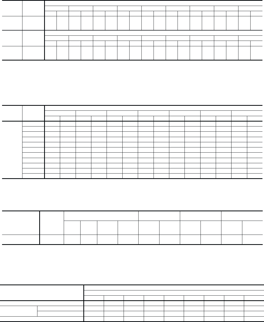
TABLE 4 - SUPPLY AIR PERFORMANCE - BCH048
MODEL AIR FLOW
m3/s / CFM
Available External Static Pressure -Pa/ IWG*
223 / 0.90 248 / 1.00 273 / 1.10 298 / 1.20 322 / 1.30 347 / 1.40 372 / 1.50
RPM Watts RPM Watts RPM Watts RPM Watts RPM Watts RPM Watts RPM Watts
060
1.18 / 2500 --------------
1.13 / 2400 1193 1665 ------------
1.08 / 2300 1170 1580 1202 1620 ----------
1.04 / 2200 1148 1480 1180 1530 ----------
0.99 / 2100 1121 1385 1155 1425 1190 1475 --------
0.94 / 2000 1100 1285 1133 1340 1169 1385 1205 1445 ------
0.90 / 1900 1079 1180 1110 1240 1143 1280 1178 1330 1222 1375 ----
0.85 / 1800 1058 1060 1090 1135 1122 1190 1158 1240 1196 1295 ----
0.80 / 1700 1035 960 1071 1030 1103 1100 1134 1140 1164 1175 1197 1205 - -
0.75 / 1600 1020 900 1056 965 1088 1035 1118 1065 1145 1105 1170 1130 1198 1150
0.71 / 1500 1004 860 1038 880 1070 925 1101 980 1130 1045 1158 1075 1184 1110
*INCLUDES ALLOWANCES FOR A WET INDOOR COIL AND 1" FILTERS. REFER TO THE STATIC RESISTANCES TABLE FOR RESISTANCE VALUES ON APPLICATIONS OTHER
THAN
HEAT PUMP UNITS WITH SIDE DUCT AIRFLOWS.
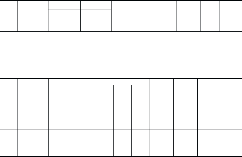
TABLE 5 - SUPPLY BLOWER PERFORMANCE - BCH060
MODEL BLOWER
RANGE
(RPM)
MOTOR* ADJUSTABLE
MOTOR PULLEY FIXED
BLOWER PULLEY BELT
kW/HP RPM FRAME
SIZE SERVICE
FACTOR
PITCH
DIA.
mm (in.)
BORE
mm (in.)
PITCH
DIA.
mm (in.)
BORE
mm (in.)
PITCH
LENGTH
(mm in.)
DESIG-
NATION
BCH060 850 - 1180 0.75/1.0 1450 56 1.15 71 - 97
(2.8 - 3.8) 22 127 (5.0) 25 (1) 947 (37.3) A36
*All motors have solid bases and are inherently protected. These motors can be selected to operate into their service factor because they are located in the moving air, upstream of any
heating device.
TABLE 6 - MOTOR AND DRIVE DATA - Belt-Drive Blower
MODEL MOTOR
SPEED
Available External Static Pressure - Pa*
m3/s Watts m3/s Watts m3/s Watts m3/s Watts m3/s Watts m3/s Watts m3/s Watts m3/s Watts m3/s Watts
048 HI
MED
LOW
-
0.85
0.77
-
910
810
-
0.84
0.76
-
880
780
0.94
0.82
0.75
1010
850
760
0.92
0.80
0.73
975
825
740
0.90
0.79
0.73
945
800
730
0.87
0.76
0.71
910
775
715
0.83
0.74
0.69
825
740
690
0.78
0.70
0.66
825
700
660
0.72
0.66
0.61
775
660
615
MODEL MOTOR
SPEED
Available External Static Pressure - IWG*
0.20 0.30 0.40 0.50 0.60 0.70 0.80 0.90 1.00
CFM Watts CFM Watts CFM Watts CFM Watts CFM Watts CFM Watts CFM Watts CFM Watts CFM Watts
048 HI
MED
LOW
-
1810
1635
-
910
810
-
1780
1610
-
880
780
2000
1740
1580
1010
850
760
1950
1700
1555
975
825
740
1905
1665
1540
945
800
730
1840
1620
1510
910
775
715
1770
1560
1460
825
740
690
1660
1480
1400
825
700
660
1530
1390
1300
775
660
615
*INCLUDES ALLOWANCES FOR A WET INDOOR COIL AND 1" FILTERS. REFER TO THE STATIC RESISTANCES TABLE FOR RESISTANCE VALUES ON APPLICATIONS OTHER
THAN HEAT PUMP UNITS WITH SIDE DUCT AIRFLOWS.
380 / 415 VOLTS - SIDE DUCT APPLICATIONS
EXTERNAL STATIC PRESSURE DROP
DESCRIPTION
RESISTANCE, Pa/IWG
m3/s/CFM
0.47/1000 0.57/1200 0.66/1400 0.75/1600 0.85/1800 0.94/2000 1.04/2200 1.13/2400 1.232600
Economizer/Motorized Damper1, 2 17 / 0.07 20 / 0.08 22 / 0.09 27 / 0.11 32 / 0.13 37 / 0.15 42 / 0.17 50 / 0.20 57 / 0.23
Electric Heaters15 - 15 KW 10 / 0.04 12 / 0.05 15 / 0.06 17 / 0.07 20 / 0.08 25 / 0.10 30 / 0.12 35 / 0.14 40 / 0.16
20 - 30 KW 15 / 0.06 17 / 0.07 20 / 0.08 22 / 0.09 27 / 0.11 32 / 0.13 37 / 0.15 42 / 0.17 50 / 0.20
Bottom Duct Connections115 / 0.06 17 / 0.07 20 / 0.08 22 / 0.09 25 / 0.10 27 / 0.11 30 / 0.12 35 / 0.14 40 / 0.16
1Deduct these resistance values from the available external static pressure shown in the respective Blower Performance Table.
2The pressure thru the economizer is greater for 100% outdoor air than for 100% return air. If the resistance of the return air duct system is less than 0.25 IWG, the unit will deliver less CFM
during full economizer operation.
TABLE 7 - STATIC RESISTANCES*
035-12984-001-A-0204
Unitary Products Group 11
MODEL
BCH POWER SUPPLY
VOLTAGE
LIMITATIONS COMPRESSOR OUTDOOR
FAN
MOTOR,
FLA
SUPPLY
AIR
BLOWER
MOTOR,
FLA
TOTAL
UNIT
AMPACITY,
AMPS
MAX.
FUSE
SIZE,
(SEE NOTE 1)
AMPS
MAX.
HACR
BREAKER
SIZE,
AMPS
MIN.
WIRE
SIZE,
AWG
(SEE NOTE 2)
MIN. MAX. RLA LRA
048 380/415-3+N-50 342 457 9.6 66 1.8 4.0 18.3 25 25 10 (6MM2)
060 380/415-3+N-50 342 457 10.0 75 1.8 2.6 16.9 25 25 10 (6MM2)
NOTES: 1. Dual element, time delay type.
2. Based on 75°C copper conductors.
TABLE 8 - ELECTRICAL DATA - Basic Unit
MODEL
BCH POWER
SUPPLY
HEATER
ACCESSORY
MODEL
NUMBER
SUPPLY
AIR
BLOWE
R
MOTOR
FLA
ELECTRIC HEATERS TOTAL
UNIT
AMPACITY
AMPS
MAX.
FUSE
SIZE,
(SEE NOTE 1)
AMPS
MAX.
HACR
BREAKER
SIZE,
AMPS
MIN.
WIRE
SIZE,
AWG
(SEE NOTE 2)
KW STAGES TOTAL
AMPS
048 380/415-3+N-50
2CE04510746*
2CE04511046*
2CE04511546*
2CE04512046*
4.0
4.3 / 5.1
6.3 / 7.5
8.5 /
10.2
12 / 14.6
1
1
1
2
7.1
10.5
14.1
20.3
26.5
30.3
34.5
41.1
30
35
40
45
30
35
40
45
10 (6mm2)
8 (10mm2)
8 (10mm2)
8 (10mm2)
060 380/415-3+N-50
2CE04510746*
2CE04511046*
2CE04511546*
2CE04512046*
2CE04513046*
2.6
4.3 / 5.1
6.3 / 7.5
8.5 /
10.2
12 / 14.6
18 / 22
1
1
1
2
2
7.1
10.5
14.1
20.3
30.0
25.7
30.0
34.6
42.2
54.3
30
35
40
45
60
30
35
40
45
60
10 (6mm2)
8 (10mm2)
8 (10mm2)
8 (10mm2)
6 (16mm2)
TABLE 9 - ELECTRICAL DATA - Heat Pump with Supplemental Electric Heat
screw fully clockwise and then energize and de-energize
terminals “R” to “G”. With terminals “R” to “G” energized,
turn the minimum position screw counterclockwise until the
desired minimum position has been attained.
11. Replace the filter section access panel.
COOLING SYSTEM
The unit has an air-cooled condenser and is factory-charged
with Refrigerant-22.
The compressor is hermetically sealed, internally sprung,
mounted on spring isolators and inherently (internally)
protected. If there is an abnormal temperature rise in the
compressor, the protector opens to shut down the compressor.
PRELIMINARY OPERATION COOLING
After the installation has been completed, the crankcase
heater of the compressor must be energized for at least 4 hours
before starting the unit. After this initial warm-up, the
compressor should be given three false starts (energized just
long enough to make a few revolutions) with a 5 minute delay
between each start before being put into full time service.
NOTE: Prior to each cooling season, the crankcase heater
must be energized at least 10 hours before the system
is put into operation.
COOLING SEQUENCE OF OPERATION
When the thermostat calls for cooling, the compressor and the
outdoor fan motor will be energized through terminal “Y1" and
the supply air blower motor will be energized through terminal
”G" (if the fan switch on the subbase is set in the “AUTO”
position). The supply air blower motor will run continuously if
the fan switch is set in the “ON” position.
The reversing valve is energized thru the “O” circuit when the
subbase is in the cooling mode.
HEATING SEQUENCE OF OPERATION
The following sequence of operation is based on using a
standard YORK heat pump thermostat with two heating stages.
FIRST STAGE HEAT
When the thermostat calls for heating, the compressor and the
outdoor fan motor will be energized through terminal “Y1" and
the supply air blower motor will be energized through terminal
”G" (if the fan switch on the subbase is set in the “AUTO”
position). The supply air blower motor will run continuously if
the fan switch is set in the “ON” position.
SECOND STAGE HEAT
If compressor operation can not satisfy the heating
requirements, second stage heat will energize supplemental
electric heat (if supplied) thru the “W1" circuit.
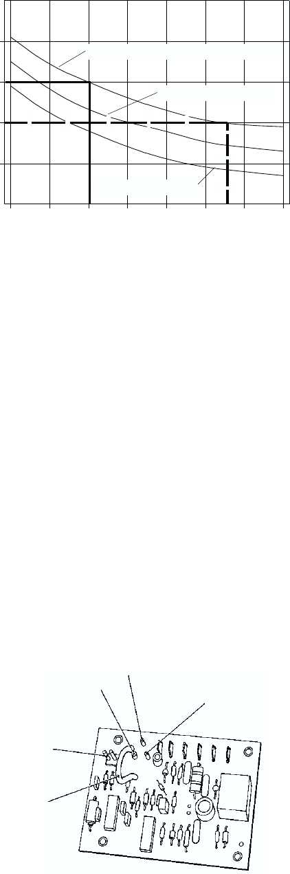
DEFROST SEQUENCE OF OPERATION
The BCH has a unique “ambient modified” time-temperature
defrost control that automatically adjusts to changes in the
outdoor temperature. The defrost control will shorten the
defrost initiation time periods above 2°C (35°F) and will extend
the defrost initiation time periods below 2°C (35°F). The control
is factory set to defrost at 110 minutes (T3), but it can be field
adjusted to defrost at 80 minutes (T2) or 50 minutes (T1) in
areas with high humidity.
The curve in Figure 7 shows how defrost initiation times are
automatically compensated for changes in outdoor
temperature.
EXAMPLE: If the time is factory set on pin T-3 (110 minutes at
2°C (35°F) outdoor) and the outdoor temperature climbs to 7°C
(45°F), the time initiation cycle decreases to 100 minutes.
If the outdoor temperature drops to -12°C (10°F) where ice is
less likely to form, the 110 minute interval increases to 150
minutes.
Two requirements must be met before a defrost cycle can be
initiated.
1. The defrost time cycle must be complete.
2. The liquid line temperature must be less than -2°C (28°F).
Defrost terminates when the liquid line sensor reaches 13°C
(55°F) or after 10 minutes.
The defrost time cycle restarts 10 minutes after the start of the
defrost cycle even though the liquid sensor terminated defrost
after 3 minutes.
035-12984-001-A-0204
12 Unitary Products Group
FIG. 7 - DEFROST INITIATION TIMES
FIG. 8 - AMBIENT MODIFIED TIME/TEMPERATURE
CONTROL
T1 - 50 Minute Setting
T3 - 110 Minute Setting (Factory Set Point)
T2 - 80 Minute Setting
200
-10 010 20 30 40 50
250
150
100
50
0
60
OUTDOOR AMBIENT, DEG. F
TIME BETWEEN DEFROST CYCLES, MINUTES
OPERATION
T1 - 50 MINUTE SETTING
T2 - 80 MINUTE SETTING
T3 - 110 MINUTE SETTING
(Factory Set Point)
SHORTING PEGS TO
OVERRIDE TIMER
FOR SERVICE
MOVABLE JUMPER
WIRE TO CHANGE
DEFROST TIMER
During troubleshooting, the defrost time can be reduced to 20
seconds by shorting out the SW1 test pegs on the module. The
pegs are 13mm ( in.) long, 1mm ( in.) apart and are
mounted on a white base. See Figure 8.
LOCKOUT CONTROL
Any one of four conditions will put the system into a lock-out
condition during the heating or cooling mode:
1. The discharge line temperature reaches 124°C (255°F)
(102°C [215°F] reset) or,
2. The discharge pressure reaches 2770 kPa (398 PSIG)
(2158 kPa [310 PSIG] reset) or,
3. The suction line freezestat equals -3°C (26°F) (3°C [38°F]
reset) or,
4. The low-pressure cut-out equals 49 kPa (7 PSIG) (153 kPa
[22 PSIG] reset).
A lock-outl energizes the emergency heat light on the
thermostat and the red LED light on the unit relay board.
Turning the thermostat switch to “Off” then back to “On”, will
reset the system.
NOTICE TO OWNER:
If a lockout occurs, check for the following problems before
calling a serviceman:
1. Dirty filters.
2. Snow accumulation.
3. Leaf or debris blockage.
After eliminating the problem, attempt to restart the system as
follows:
•turn the system switch on the thermostat to its “OFF”
position for 10 seconds.
•turn it back to its original position.
If the unit doesn't start, call a serviceman.
NOTE: Models with an anti-recycle accessory will have a 5-
minute delay before starting.
CHECKING SUPPLY AIRFLOW
The speed of the supply air blower will depend on the required
airflow, the unit accessories and the static resistances of both
the supply and the return air duct systems. With this
information, the speed for the supply air blower can be
determined from the blower performance and static resistance
data on Tables 4, 5 and 7.
Knowing the required blower RPM and the blower motor kW
(HP), the speed setting for the supply air motor can be
determined.
The setting (turns open) for the optional belt-drive supply air
pulley can be determined from Table 10.
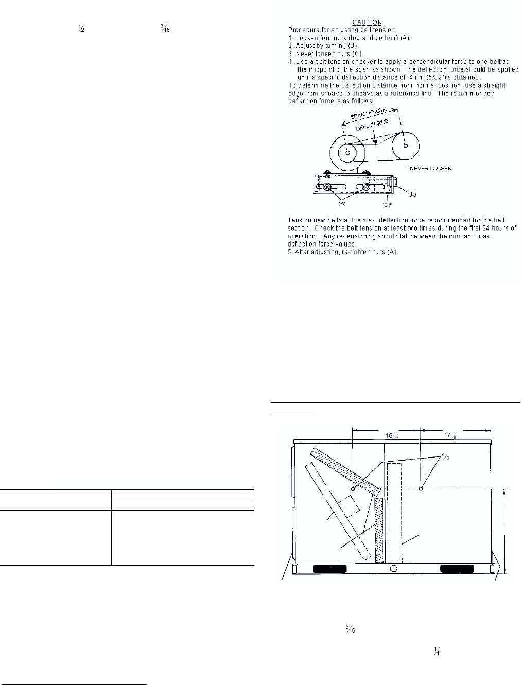
OPTIONAL BELT-DRIVE BLOWER
All units with belt-drive blowers have single speed motors. The
variable pitch pulley on the blower motor can be adjusted to
obtain the desired supply airflow. Refer to Table 6 for blower
motor drive data. The tension on the belts should be adjusted
as shown in Figure 9.
Start the supply air blower motor. Adjust the resistances in both
the supply and the return air duct systems to balance the air
distribution throughout the conditioned space. The job
specifications may require that this balancing be done by
someone other than the equipment installer.
To check the supply airflow after the initial balancing has been
completed:
1. Drill two 8mm ( in.) holes in the side panels as shown in
Figure 10.
2. Insert at least 203mm (8 in.) of 6mm ( in.) tubing into each
of these holes for sufficient penetration into the air flow on
both sides of the indoor coil.
NOTE: The tubes must be inserted and held in a position per-
pendicular to the air flow so that velocity pressure does
not affect the static pressure readings.
035-12984-001-A-0204
Unitary Products Group 13
TURNS
OPEN* BLOWER DRIVE RANGE (RPM)
060
5
4
3
2
1
0
850
916
982
1048
1114
1180
*Pulley can be adjusted in half-turn increments.
TABLE 10 - BELT-DRIVE SUPPLY AIR
MOTOR PULLEY ADJUSTMENT
FIG. 9 - BELT ADJUSTMENT
FIG. 10 - HOLE LOCATIONS (PRESS. DROP READING)
419“435“
533
21"
“ HOLES
DUCT FLANGES
(Back of Unit)
DAMPER
ASSEMBLY
FILTERS
INDOOR
COIL
FRONT OF UNIT
L.H. END VIEW
(Filter Access End)
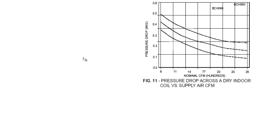
3. Using an inclined manometer, determine the pressure drop
across a dry indoor coil. Since the moisture on an indoor
coil may vary greatly, measuring the pressure drop across a
wet coil under field conditions would be inaccurate. To
ensure a dry coil, the compressors should be de-energized
while the test is being run.
4. Knowing the pressure drop across a dry coil, the actual airflow
through the unit can be determined from the curve in Figure 11.
WARNING:Failure to properly adjust the total system air quan-
tity can result in poor system performance.
After readings have been obtained, remove the tubes and seal
the drilled holes in the side panels. 8mm ( in.) dot plugs (P/N
029-13880) are available through normal parts ordering
procedures.
NOTE: DE-ENERGIZE THE COMPRESSORS BEFORE
TAKING ANY TEST MEASUREMENTS TO ENSURE
A DRY INDOOR COIL.
NORMAL MAINTENANCE
CAUTION: Prior to any of the following maintenance proce-
dures, shut off all power to the unit to prevent per-
sonal injury.
FILTERS - Inspect once a month. Replace disposable or clean
permanent type as necessary. DO NOT replace permanent
type with disposable.
MOTORS - Indoor fan and outdoor fan motors are permanently
lubricated and require no maintenance.
OUTDOOR COIL- Dirt should not be allowed to accumulate on
the outdoor coil surface or other parts in the air circuit. Cleaning
should be as often as necessary to keep coil clean. Use a
brush, vacuum cleaner attachment, or other suitable means. If
water is used to clean coil, be sure power to the unit is shut off
prior to cleaning.
NOTE: Exercise care when cleaning the coil so that the coil
fins are not damaged.
Do not permit the outdoor air discharge to be ob-
structed by overhanging structures of shrubs.
035-12984-001-A-0204
14 Unitary Products Group
MAINTENANCE
SECURE OWNER'S APPROVAL: When the system is functioning properly, secure the owner's approval. Show him the location
of all disconnect switches and the thermostat. Teach him how to start and stop the unit and how to adjust temperature settings
within the limitations of the system.
035-12984-001-A-0204
Unitary Products Group 15

Unitary Products Group
5005 York Drive, Norman, Ok 73069
Subject to change without notice. Printed in U.S.A.
Copyright by York International Corporation 2004. All Rights Reserved. Supersedes: 511.13-N1YI (900) / 035-12984-000 035-12984-001-A-0204
