Yuneec Technology CGO4 Wireless Camera User Manual PROACTION CGO4
Yuneec Technology Co., Limited Wireless Camera PROACTION CGO4
UserManual.wiki
>
Yuneec Technology
>
CGO4 User Manual
User Manual
Navigation menu
Upload a User Manual
Namespaces
Wiki Guide
HTML
PDF
Info
Views
User Manual
Discussion / Help
Navigation
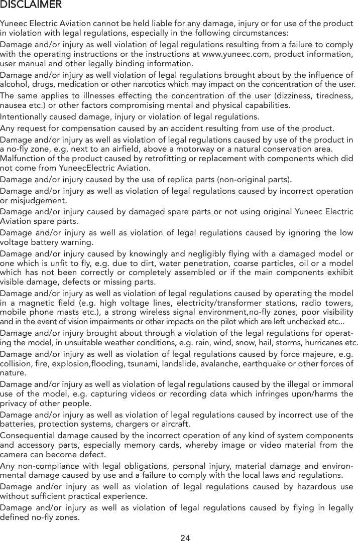
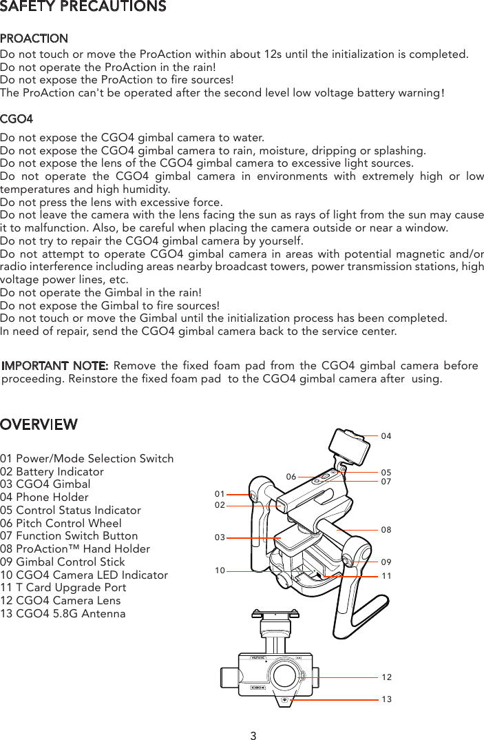
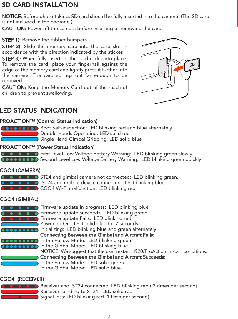
![INTRODUCTIONThe TORNADO ProAction™ is a ground imaging system designed to extend your Panason-ic® camera GH4 and SONY® α7 with real-time imaging transmission. The system includes the ProAction™ ground handle and GB603 gimbal. The ProAction™ features pitch controller, allowing for precise camera angle control. The GB603 gimbal, 3-Axis self-stabilizing gimbal, enables you to capture smooth and fluent photographs and video footage. The CGO4 is an independent high end professional all in one gimbal camera module, specially developed for professional users who require ultra-high aerial imaging quali-ty and resolution. The dream of an adjustable, all-function, remote-controlled, 4/3 inch sensor and aerial capturing system is now a reality.CGO4 incorporates a true Panasonic GH4 camera with a 3x optical zoom lens and an integrated 5.8GHz video link module all housed in purpose designed casing. It can be installed on both the TORNADO H920 copter and the ProAction ground SteadyGrip system. All the regular Panasonic GH4 camera settings can be freely and remotely adjusted through Yuneec ST24 transmitter which totally transforms and reshapes the boundaries of aerial imaging creation. Through the user friendly control app interface in the ST24, the CGO4 becomes an incredible tool to realize the highest levels of aerial photographic and video graphic imagery.SPECIFICATIONSPROACTION™DIMENSIONS: 14.17x10.04x14.57in (360x255x370mm)WEIGHT (without battery): 52.91oz (1.5kg)BATTERY WEIGHT: 7.72oz (219g)INCLUDED BATTERY: 4S/14.4V 0.3C 2600mAh 37.44 Wh Lithium-Ion BatteryRUNTIME: 2.5 HoursWORKING VOLTAGE: 12.0~16.8VWORKING CURRENT: 0.68~1.0ACOMPATIBLE DEVICE: GB603 / CGO4CGO4DIMENSION: 6.5 x 8.6 x 7.7 in (165 x 219 x 196 mm)WEIGHT: 1200 gGIMBAL AXES: 3CONTROL ANGLE ACCURACY: ±0.01°MAXIMUM CONTROL RANGE: Pitch [-90° to 0° (for H920) /- 90° to 30° (for ProAction)] Yaw [360° limitless]MECHANICAL RANGE: Pitch [-120° to 45°] Roll [ -40° to 40°] Yaw [360° limitless]MAXIMUM CONTROL SPEED: Pitch: 30° /s Yaw: 30° /sINPUT/OPERATING VOLTAGE: 24VCURRENT CONSUMPTION/OPERATING CURRENT: 1ASTORAGE TEMPERATURE: 10°C - 30°CWORKING TEMPERATURE: -5°C - 45°CIMAGE SENSOR: 4/3 inch Live CMOS SensorEFFECTIVE PIXELS: 16MegapixelsMAX VIDEO RESOLUTION: 4K 30FPS, 100 MbpsDIGITAL VIDEO DOWNLINK: IntegratedCOMPATIBLE LENS: [ 3x Optical zoom 14-42mm (standard configuration)] [OLYMPUS M.ZUIKO DIGITAL ED 12mm f2.0 ] [ OLYMPUS M.ZUIKO DIGITAL 45mm f1.8 ]FOCUS MODE: AFS/MFSHUTTER SPEED: 1/8000s to 60sISO RANGE: 100 to 256001](https://usermanual.wiki/Yuneec-Technology/CGO4/User-Guide-2873904-Page-3.png)
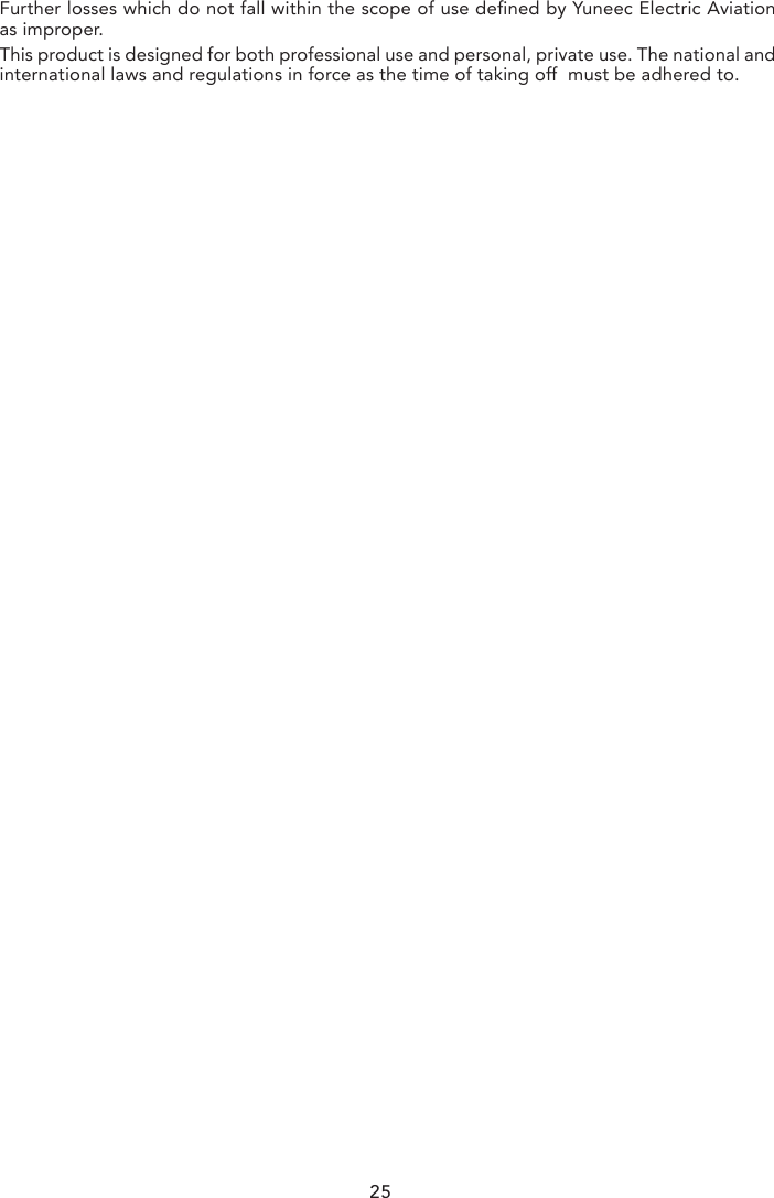
![AERIAL IMAGING SOLUTIONATTACHING CGO4 GIMBAL CAMERA TO MULTICOPTERSTEP 1): Mount the Rubber Dumpers to H920 fixing eyelet, install the two thread-off proof screws to fix the gimbal damping plate and then tighten all the screws.STEP 2):Insert the Gimbal Connection Cord to the inner side of Gimbal Damping Plate (relative to the direction of H920 Power Connection Port)STEP 3):Mount the Gimbal Thumb Screws and lock washers (4 pcs) to the Gimbal and rotate the screws until they’re secured into the Gimbal Damping Plate.STEP 4):Connect the Gimbal Power Cord to H920 Power Connection Port.NOTICE: The “Front” of the gimbal camera should be installed in the direction of the nose of H920.NOTICE: Use the dedicated lock washers when rotating the screwsBINDING CGO4 GIMBAL CAMERA TO THE ST24 (SINGLE MODE)STEP 1): Power on the ST24, press [ ] button to go to the main interface. Choose FPV, and enter Model Select.STEP 2): The default Model type is Multi-copter. Tap the “H920 CGO4” icon and press OK to enter the flight control interface. NOTE: The pre-set model in the “Model Select” interface cannot be deleted.NOTE: The pre-set model can only be bound to one multi-copter. If the user wants to bind to the other copters, press and hold the “H920 CGO4” icon, select “copy” on the pop-up menu. Wait for a few seconds and then tap the newly created icon. Press OK to enter the flight control interface.STEP 3): Switch on the TORNADO H920. Wait for a moment until the H920 Main LED indica-tor blinks blue, the CGO4 LED indicator blinks green and then start the binding procedures. STEP 4): Lean the H920 in the forward direction twice (45°), until the Main LED indicator blinks yellow.STEP 5): Tap the Refresh icon, and the codes of the H920 and CGO4 will be shown on screen. Choose the right codes and press Bind.STEP 6): If it is the first time to bind your CGO4 to the ST24, you need to insert the password: 1234567890. Press OK on the pop-up window to continue.STEP 7): Press Camera Select and choose CGO4. Press Select, then press OK.CGO4STEP 2 STEP 5NOTICE: We recommend users to power on the aircraft in the angle mode.NOTICE: When returns back to the FPV interface, you will hear two long beeps. That means the binding is complete. The Real-time images can now be seen on the screen.5](https://usermanual.wiki/Yuneec-Technology/CGO4/User-Guide-2873904-Page-7.png)
![AERIAL IMAGING SOLUTIONATTACHING CGO4 GIMBAL CAMERA TO MULTICOPTERSTEP 1): Mount the Rubber Dumpers to H920 fixing eyelet, install the two thread-off proof screws to fix the gimbal damping plate and then tighten all the screws.STEP 2):Insert the Gimbal Connection Cord to the inner side of Gimbal Damping Plate (relative to the direction of H920 Power Connection Port)STEP 3):Mount the Gimbal Thumb Screws and lock washers (4 pcs) to the Gimbal and rotate the screws until they’re secured into the Gimbal Damping Plate.STEP 4):Connect the Gimbal Power Cord to H920 Power Connection Port.NOTICE: The “Front” of the gimbal camera should be installed in the direction of the nose of H920.NOTICE: Use the dedicated lock washers when rotating the screwsBINDING CGO4 GIMBAL CAMERA TO THE ST24 (SINGLE MODE)STEP 1): Power on the ST24, press [ ] button to go to the main interface. Choose FPV, and enter Model Select.STEP 2): The default Model type is Multi-copter. Tap the “H920 CGO4” icon and press OK to enter the flight control interface. NOTE: The pre-set model in the “Model Select” interface cannot be deleted.NOTE: The pre-set model can only be bound to one multi-copter. If the user wants to bind to the other copters, press and hold the “H920 CGO4” icon, select “copy” on the pop-up menu. Wait for a few seconds and then tap the newly created icon. Press OK to enter the flight control interface.STEP 3): Switch on the TORNADO H920. Wait for a moment until the H920 Main LED indica-tor blinks blue, the CGO4 LED indicator blinks green and then start the binding procedures. STEP 4): Lean the H920 in the forward direction twice (45°), until the Main LED indicator blinks yellow.STEP 5): Tap the Refresh icon, and the codes of the H920 and CGO4 will be shown on screen. Choose the right codes and press Bind.STEP 6): If it is the first time to bind your CGO4 to the ST24, you need to insert the password: 1234567890. Press OK on the pop-up window to continue.STEP 7): Press Camera Select and choose CGO4. Press Select, then press OK.CAMERA CONTROL ON MULTICOPTRER (SINGLE MODE)CAUTION: The gimbal can only be controlled through ST24 When being attached to H920.Gimbal Pitch Control Gimbal Pitch Control There is a gimbal pitch mode switch on ST24---S1. When the switch is in up/middle position, the CGO4 gimbal camera is in Angle Mode. Use the slider on the left side of the ST24 to set the pitch/tilt position of the gimbal camera. When the S1 is in bottom position, the gimbal camera is in Velocity Mode. When the slider is in the middle position, it means the velocity rate is 0 for the CGO4 gimbal camera, and it will stop pitching up/down. When the slider is above the middle position, the CGO4 will start pitching up. When the slider is below the middle position, the CGO4 will start pitching down. The distance between the slider and the middle position decides the velocity rate, the further distance, the higher velocity it would be.Gimbal Yaw ControlThere is a gimbal yaw mode switch on ST24---S2. When the switch position is up and middle, the gimbal camera is in Follow Mode. The yaw control of the gimbal camera is now disabled. The gimbal camera will adjust its yaw direction according to the aircraft’s movements. When the switch position is down, the gimbal camera is in NOTICE: We recommend users to power on the aircraft in the angle mode.NOTICE: When returns back to the FPV interface, you will hear two long beeps. That means the binding is complete. The Real-time images can now be seen on the screen.Button A = Take Still PhotoButton B = Start/Stop Recording Video6Global Mode. The Gimbal Yaw control knob (K1) is now activated.When the user rotates the knob in the right direction, the gimbal camera will rotate to the right side, and vice versa.](https://usermanual.wiki/Yuneec-Technology/CGO4/User-Guide-2873904-Page-8.png)
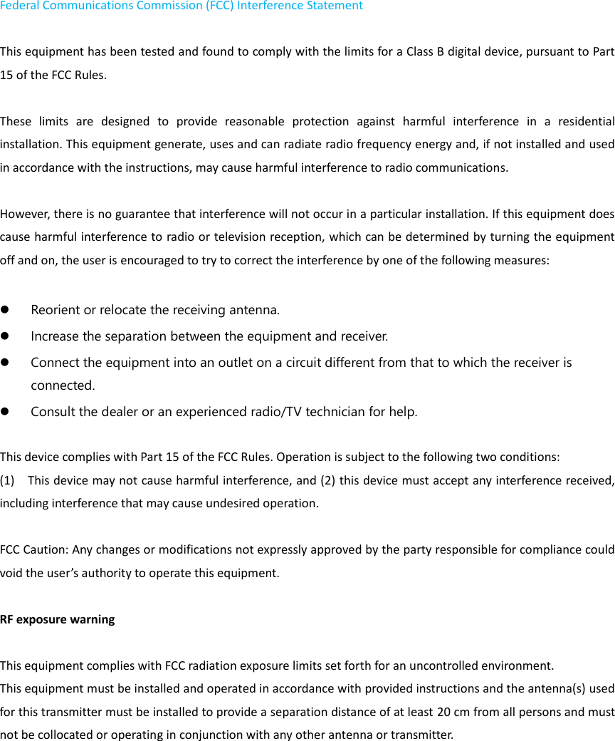
![7BINDING CGO4 GIMBAL CAMERA TO THE ST24 (TEAM MODE)STEP 1): Power on the ST24, tap [ ] to go to the main interface.STEP 2): Switch on the TORNADO H920. Wait until the gimbal LED blinks green. That means the Wi-Fi has been started up.STEP 3): Tap System Settings icon to enter the Bind interface.STEP 4): Tap the Refresh icon, and the code of the Aircraft Model (it indicates the code of the CGO4 receiver) and Camera will both be shown on the screen. Select the right codes and tap the Bind icon. Tap OK when a pop-up window comes out.NOTICE: If it is the first time to bind your CGO4 gimbal camera to the ST24, you need to insert the password: 1234567890. Press OK on the pop-up window to continue.STEP 5): Tap Camera Select and select CGO4, and then tap Select.STEP 6): Tap “OK” to confirm the setting and tap [ ] to go back to the flight control interface.BINDING H920 MULTICOPTER TO THE ST12 (TEAM MODE)STEP 1): Power on the ST12 and tap “RC” on the main interfaceSTEP 2): Tap Model Select and if required press “OK” to bypass any pop up warning/alerts. STEP 3): Tap to create a new model and if required press “OK” to bypass any pop up warnings/alerts.STEP 4): Tap Flight Settings and if required press “OK” to bypass any pop up warnings/alerts.STEP 5): Lift the H920 back end upward approximately 45° , then back down to “level” twice till the main LED indicator blinks yellow.STEP 6): Tap the Refresh icon. Select the code of the H920 listed in the column under ”Model” and tap Bind ,then tap “OK” after the connection has been establishedSTEP 7): When tapping, you will hear two long beeps from the aircraft. That means the ST12 is bound to the H920 successfully.STEP 8): Tap [ ] twice to return to the main screen and the model /receiver should automat-ically connect to ST12NOTICE: The H920 main LED indicator will blink red and white if the TORNADO loses GPS signal /lock. The H920 main LED indicator will be solid color of the current mode if the GPS signal/lock is acquired.Model: 4K Welcome,Pilot 10:48:28 pm 10SR24_16042SR24_16042 Not connectedModel CameraModel: 4K Welcome,Pilot 10:48:28 pm 10Model SelectNew Model TORNADO H920](https://usermanual.wiki/Yuneec-Technology/CGO4/User-Guide-2873904-Page-9.png)
![8BINDING H920 MULTICOPTER TO THE ST12 (TEAM MODE)STEP 1): Power on the ST12 and tap “RC” on the main interfaceSTEP 2): Tap Model Select and if required press “OK” to bypass any pop up warning/alerts. STEP 3): Tap to create a new model and if required press “OK” to bypass any pop up warnings/alerts.STEP 4): Tap Flight Settings and if required press “OK” to bypass any pop up warnings/alerts.STEP 5): Lift the H920 back end upward approximately 45° , then back down to “level” twice till the main LED indicator blinks yellow.STEP 6): Tap the Refresh icon. Select the code of the H920 listed in the column under ”Model” and tap Bind ,then tap “OK” after the connection has been establishedSTEP 7): When tapping, you will hear two long beeps from the aircraft. That means the ST12 is bound to the H920 successfully.CAMERA CONTROL ON MULTICOPTER (TEAM MODE)GIMBAL PITCH CONTROLThere is a gimbal pitch mode switch on ST24---S1. When the switch is in up/middle position, the gimbal camera is in Angle Mode. Use K5 to set the pitch/tilt position of the gimbal camera. When the S1 is in bottom position, the gimbal camera is in Velocity Mode. When the right-hand stick is in the middle position, it means the velocity rate is 0 for the CGO4, and it will stop pitching up/down. When the right-hand stick is above the middle position, the CGO4 will start pitching up. When the right-hand stick is below the middle position, the CGO4 will start pitching down. The distance between the right-hand stick and the middle position decides the velocity rate, the further distance, the higher velocity it would be.GIMBAL YAW CONTROLThere is a gimbal yaw mode switch on ST24---S2. When the switch position is up, the gimbal camera is in Follow Mode. The yaw control of the gimbal camera is now disabled; when the switch is in the middle position, the gimbal camera is still in Follow Mode, however, at this time, the yaw control is activated. The gimbal camera will adjust its yaw direction according to the aircraft’s movements. When the switch position is down, the gimbal camera is in Global Mode. The Aileron/Roll Control and Elevator/Pitch Control of the right-hand stick take control of the CGO4 in yaw and pitch directions.NOTICE: When the CGO4 is attached to the TORNADO H920, the control knob (K6) is activated. Users can zoom in by rotating the knob (K6) in the clockwise direction (the move-ment speed of the CGO4 gimbal camera in pitch and yaw directions will become slow in the velocity mode), and vice versa (the movement speed of the CGO4 gimbal camera in pitch and yaw directions will become fast in the velocity mode).CAUTION: Each time the K6 is pushed to a certain position, it should be pushed back to the middle position to confirm the setting. Otherwise, the gimbal camera will continue to zoom in/out until it achieves the maximum/minimum value.STEP 8): Tap [ ] twice to return to the main screen and the model /receiver should automat-ically connect to ST12NOTICE: The H920 main LED indicator will blink red and white if the TORNADO loses GPS signal /lock. The H920 main LED indicator will be solid color of the current mode if the GPS signal/lock is acquired.S2](https://usermanual.wiki/Yuneec-Technology/CGO4/User-Guide-2873904-Page-10.png)
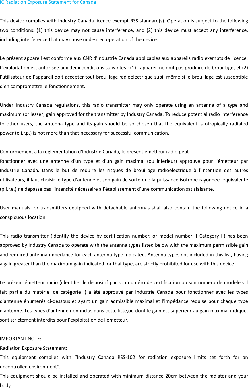
![10CAMERA MODE INTRODUCTIONThe CGO4 gimbal camera has eight camera modes in total,providing photographers with a multiple of choices for different shooting scenes.INTELLIGENT AUTO MODE: The subjects are recorded using settings automaticallyselected by the camera.NOTE: In this mode, the camera makes the optimal settings for the subject and scene, so we recommend it when you wish to leave the settings to the camera and record without thinking about them.NOTICE: [iA] is set if none of the scene are applicable, and the standard settings are set. INTELLIGENT AUTO PLUS MODE: Allows you to adjust the brightness and color hue when in Intelligent Auto Mode.PROGRAM AE MODE: The camera automatically sets the shutter speed and the aperture value according to the brightness of the subject.You can take picture with greater freedom by changing various settings in the Menu Settings.CAUTION: The Aperture and Shutter Speed cannot be adjusted separately under P mode; it can only be controlled through the Union Picker.APERTURE-PRIORITY AE MODE: The shutter speed is automatically determined by the aperture value you set.SHUTTER-PRIORITY AE MODE: The aperture value is automatically determined by the shutter speed you set.MANUAL EXPOSURE MODE: The exposure is adjusted by the aperture value and the shutter speed which are manually adjustedPROGRAM AE MODE: Records at the aperture value and shutter speed set by the camera. The camera automatically sets the shutter speed and the aperture value according to the brightness of the subject during video-recording.You can take picture with greater freedom by changing various settings in the Menu Settings.SHUTTER-PRIORITY AE MODE: When you set the shutter speed, the camera automatically optimizes the aperture value for the brightness of the subject during video-recording.Changing the brightness Available Not AvailableChanging the hue Available Not AvailableIA+ (INTELLIGENT AUTO PLUS MODE) IA (INTELLIGENT AUTO MODE)SPThe following two modes are under Creative Movie Mode:](https://usermanual.wiki/Yuneec-Technology/CGO4/User-Guide-2873904-Page-12.png)
![ADJUSTING THE WHITE BALANCEIn sunlight, under incandescent lights or in other such conditions where the color of white takes on a reddish or bluish tinge, this item adjusts to the color of white which is closest to what is seen by the eye in accordance with light source.SETTING THE LIGHT SENSITIVITYThis allows the sensitivity to light (ISO sensitivity) to be set. Setting to a higher figure enables pictures to be taken even in dark places without the resulting pictures coming out.COMPENSATING THE EXPOSUREExposure Value (EV) is a number that represents a combination of camera’s shutter speed and f-number.Use this function when you cannot achieve appropriate exposure due to the difference in brightness between the subject and the background.SPECIFYING THE APERTURE/ SHUTTER SPEEDNOTICE: The effect of the set aperture value and shutter speed will not be visible on the recording screen.NOTE:If the photographer wants to highlight the background, set a relatively high aperture value; if the photographer wants a soft background, set a relatively low level.NOTICE: It will operate as [AWB] during motion picture recording.AWB: Automatic Adjustment Daylight: When taking pictures outdoors under a clear skyCloudy: When taking pictures under a cloudy sky Shade: When taking pictures outdoors in the shade Halogon: When taking pictures under the incandescent lights AWBDaylightCloudyHalogonShadeISOISO 200ISO 400ISO 800ApertureUnionShuer SpeedF3.5F4.01/10s1/13s1/8s------Auto / Intelligent ISO (i-ISO) /100 (Extended) /200/400 /800/ 1600/3200/6400/12800/25600(changeable to 1/3 EV STEP)(Up to ISO 6400 in motion picture recording)(ISO Auto in M mode)Exposure Compensation 1/3 EV STEP +/-5EV(+/-3 EV for motion pictureExposure Accuracy +/- 1/3 EVMaximum Aperture F3.5(Wide)~F5.6(Tele)Minimum Aperture F22NOTE: If the photographer wants to capture fast-move subjects, set a relatively high shutter speed; if the photographer wants to track-shooting, set a relatively low shutter speed.When CGO4 gimbal camera is in Aperture-Priority AE Mode, the camera automatically optimizes the shutter speed for the brightness of the subject.When CG04 gimbal camera is in shutter-priority AE Mode, the camera automatically optimizes the aperture value for the brightness of the subject.When CGO4 gimbal camera is in Manual Exposure Mode: the photographer can determine First, tap Mode button on the lower portion of the screen and a virtual mode dial will pop up on the screen and then set the mode dial to [M].Slide the aperture value picker and shutter speed picker to set the appropriate aperture value and shutter speed.11](https://usermanual.wiki/Yuneec-Technology/CGO4/User-Guide-2873904-Page-13.png)
![MENU SETTING INTRODUCTIONVIDEO SYSTEMThis allows you to set different system frequency. In different system frequencies, the video qualities are different.SPECIFYING THE APERTURE/ SHUTTER SPEEDNOTICE: The effect of the set aperture value and shutter speed will not be visible on the recording screen.NOTE:If the photographer wants to highlight the background, set a relatively high aperture value; if the photographer wants a soft background, set a relatively low level.NTSC 4K/100M/30P; FHD/28M/60P; FHD/20M/30P; HD/10M/30P; VGA/4M/30PPAL 4K/100M/25P; FHD/28M/50P; FHD/20M/25P; HD/10M/25P; VGA/4M/25PCINEMA C4K/100M/24P; 4K/100M/24P; FHD/ALL-intra/200M/24P; FHD/50M/24PMP4 The MP4 data format is suitable for playback on a PC, etc.MP4(LPCM) The MP4 data format for image editingMOV Data format for image editing.Mechanical Shutter Speed [Still image] Bulb(Max. 60minutes),1/8000-60 [Motion picture]: 59.94Hz: 1/16,ooo-1/30; 50.00Hz: 1/16,ooo-1/25; 23.98Hz: 1/16,ooo-1/24Shutter Life Approx.200,000 imagesBurst speed MECHANICAL SHUTTER: H: 12 frames/sec(AFS), 7 frames/sec(AFC) M: 7 frames/sec(Live View) L: 2 frames/sec(Live View) Electronic shutter: SH: 4O frames/sec NOTE: If the photographer wants to capture fast-move subjects, set a relatively high shutter speed; if the photographer wants to track-shooting, set a relatively low shutter speed.When CGO4 gimbal camera is in Aperture-Priority AE Mode, the camera automatically optimizes the shutter speed for the brightness of the subject.When CG04 gimbal camera is in shutter-priority AE Mode, the camera automatically optimizes the aperture value for the brightness of the subject.When CGO4 gimbal camera is in Manual Exposure Mode: the photographer can determine First, tap Mode button on the lower portion of the screen and a virtual mode dial will pop up on the screen and then set the mode dial to [M].Slide the aperture value picker and shutter speed picker to set the appropriate aperture value and shutter speed.VIDEO ENCODINGThis allows you to set different video formats.IMAGE SIZEThis sets the number of pixels. The higher the numbers of pixels, the finer the detail of the pictures will appear even when they are printed onto large sheets. (16M/8M/4M)IMAGE FORMATThis sets the file format for the pictures you take.(Fine / Standard / RAW+ fine / RAW+ / standard RAW)VIDEO QUALITYThis sets up the picture quality for motion pictures:OPTIONS: MP4 30P 100Mbps 4K; MP4 24P 100Mbps 4K; MP4 60P 28Mbps 4K; MP4 30P 20M 12](https://usermanual.wiki/Yuneec-Technology/CGO4/User-Guide-2873904-Page-14.png)
![Angle of viewFocal LengthWide(f=14mm):75°~Tele(f=42mm):29°F=14mm-42mmPHOTO STYLEThis selects effects to match the type of image you wish to record and adjust the color and image quality of the effects.(Standard / Vivid / Natural / Monochrome / Scenery / Portrait)FOCUS MODEBy setting the optimum Focus Mode for the subject or recording condition, you can let the camera automatically adjust focus in various scenes.MANUAL FOCUS MODEUse this function when you want to fix the focus or when the distance between the lens and the subject is determined and you do not want to achieve Auto Focus.NOTE: The maximum/minimum/current value will be displayed on the up right corner of the screen.AF MODEThis allows the focusing method that suits the positions and number of the subjects to be selected. IMAGE FORMATCAUTION: If you delete a RAW file from the camera, the corresponding JPEG image will also be deleted.NOTICE: It is fixed to maximum recordable pixels [L] for each image aspect ratio.ASPECT RATIOThis allows you to select the aspect ratio of the pictures to suit printing or the playback method.NOTICE: The ends of the recorded pictures may be cut at printing so check before printing.4:33:216:9[Aspect Ratio] of a 4:3 TV 4608x3456 (16M) ; 3264X2448 (8M); 2336X1752 (4M)1:1[Aspect Ratio] of a 35mm film camera[Aspect Ratio] of a high-definition TV, etcSpare aspect ratio4608X3072 (14M); 3264X2176 (7M); 2336X1560 (3.5M) 4608x2592; 3804x2156; 1920X10803456X3456; 2448X2448; 1744X17441-Area: The camera focuses on the subject in the AF area on the center of the screen.Position and Size of the AF area can be changed.49 point: Up to 49 AF areas can be focused.This is effective when a subject is not in the center of the screen.You can select areas to be in focus.Touch the eye to be in focus: touch the eye in the yellow frame. If you touch any other location, the AF area setting screen will be displayed.13AFSFocus Mode Continuous AF Description of settingsMFON: The camera automatically keeps focusing on subjects during recording.OFF: The camera maintains the focus position at the start of recording.ON / OFF: You can focus manually. A focus bar will pop up on the left side of the screen for users to adjust the value.](https://usermanual.wiki/Yuneec-Technology/CGO4/User-Guide-2873904-Page-15.png)
![PHOTO STYLEYou can select effects to match the type of image you wish to record. You can adjust the color and image quality of the effects. STANDARD / VIVID / NATURAL / MONOCHROME / SCENERY / PORTRAITDRIVE MODESlide the menu and select Drive Mode. A menu will pop up with two menu items: Normal, Burst for the photographer to select with.LIGHT METERINGThe photographer can set the light metering method for still for measuring brightness.[Multiple] This is the method in which the camera measures the most suitable exposure by judging the allocation of brightness on the whole screen automatically. Usually, we recom-mend using this method.[Center Weighted] This is the method used to focus on the subject on the center of the screen and measure the whole screen evenly.[Spot] This is the method to measure the subject in the spot metering target. Taking pictures using Burst ModePictures taken with a burst speed of [SH] will be recorded as a single burst group.Slide the Menu and Select Driving Mode. Focus on the subject and take a picture.Changing the burst speedPictures taken with a burst speed of [SH] will be recorded as a single burst group.Slide the Menu and Select Driving Mode. Focus on the subject and take a picture.NORMAL When the shutter button is pressed, only one picture is recorded.BURST Recordings are made in succession while the shutter button is pressed[L] (Low Speed)[M] (Middle Speed)[H] (High Speed)12(AFS) 7(AFC) 7 2None Available AvailableBURST SPEED(PICTURES/SECOND)LIVE VIEW DURING BURST MODE14ON: The camera automatically keeps focusing on subjects during recording.OFF: The camera maintains the focus position at the start of recording.](https://usermanual.wiki/Yuneec-Technology/CGO4/User-Guide-2873904-Page-16.png)

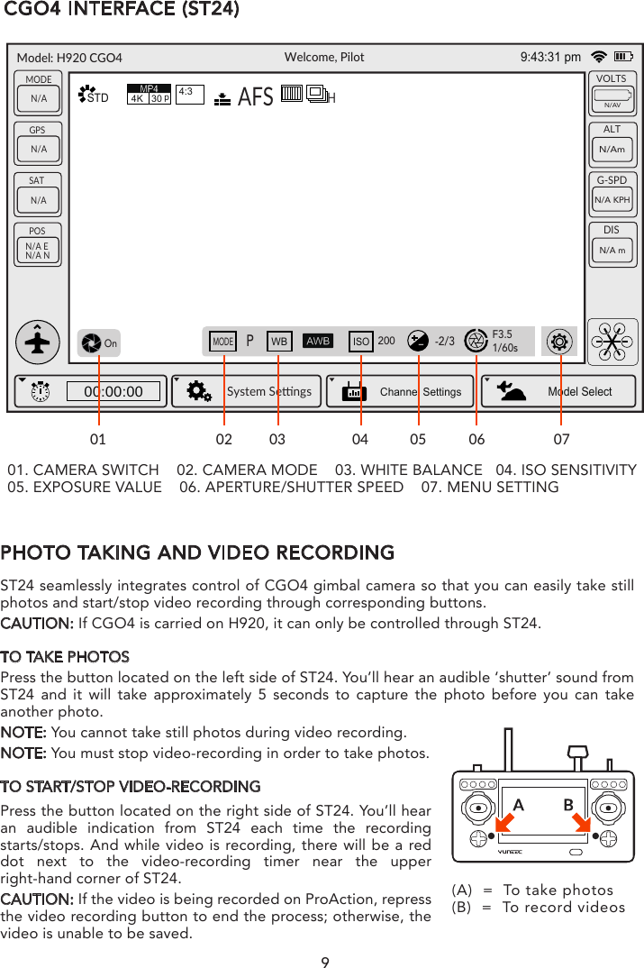
![PHOTO TAKING AND VIDEO RECORDINGTO TAKE PHOTOSSTEP 1): Tap the APP icon on your mobile device and you’ll come to the Camera Control Interface.STEP 2): Press “Camera” and CGO4 gimbal camera will be ready to work.STEP 3): Press the [ ] button and you can start to take photos.NOTICE: If you have successfully entered photo-taking, an audible ‘shutter’ sound will be heard and a notice will pop up on the screen, reading “picture of success”CAUTION: You cannot take photos while recording video. You must stop recording video in order to take still photos.TO START/STOP VIDEO RECORDINGPress [ ] button and you can start to record the video. If you have successfully entered video-recording, the button will turn red and a video recording timer will appear on the top right corner of the screen. CAUTION: If the video is being recorded, repress the video recording button to end the process before powering off the gimbal, or the video is unable to be saved.APP INTERFACE01050607081002030401. WHITE BALANCE 02. EXPOSURE VALUE/ISO SENSITIVITY 03. APERTURE/SHUTTER SPEED 04. FULL SCREEN DISPLAY 05. FOCAL LENGTH 06. CONTROL MENU 07. VIDEO-RECORDING 08. BUTTONPHOTO-TAKING BUTTON 09. LEFT STORAGE 10. SETTING MENU ASTD4K30p4:3AFSYUNEEC_81004F16:55:08AWB5739 picEV: Len:F: SS:0918](https://usermanual.wiki/Yuneec-Technology/CGO4/User-Guide-2873904-Page-20.png)
![19ADJUSTING THE WHITE BALANCEIn sunlight, under incandescent lights or in other such conditions where the color of white takes on a reddish or bluish tinge, this item adjusts to the color of white which is closest to what is seen by the eye in accordance with light source.CAMERA MODE INTRODUCTIONThe CGO4 gimbal camera has eight camera modes in total,providing photographers with a multiple of choices for different shooting scenes.INTELLIGENT AUTO MODE: The subjects are recorded using settings automaticallyselected by the camera.NOTE: In this mode, the camera makes the optimal settings for the subject and scene, so we recommend it when you wish to leave the settings to the camera and record without thinking about them.NOTICE: [iA] is set if none of the scene are applicable, and the standard settings are set. INTELLIGENT AUTO PLUS MODE: Allows you to adjust the brightness and color hue when in Intelligent Auto Mode.PROGRAM AE MODE: Records at the aperture value and shutter speed set by the camera.The camera automatically sets the shutter speed and the aperture value according to the brightness of the subject.You can take picture with greater freedom by changing various settings in the Menu Settings.CAUTION: The Aperture and Shutter Speed cannot be adjusted separately under P mode; it can only be controlled through the Union Picker.APERTURE-PRIORITY AE MODE: The shutter speed is automatically determined by the aperture value you set.SHUTTER-PRIORITY AE MODE: When you set the shutter speed, the camera automatically optimizes the aperture value for the brightness of the subject.MANUAL EXPOSURE MODE: The exposure is adjusted by the aperture value and the shutter speed which are manually adjustedPROGRAM AE MODE: Records at the aperture value and shutter speed set by the camera. The camera automatically sets the shutter speed and the aperture value according to the brightness of the subject during video-recording.You can take picture with greater freedom by changing various settings in the Menu Settings.SHUTTER-PRIORITY AE MODE: When you set the shutter speed, the camera automatically optimizes the aperture value for the brightness of the subject during video-recording.Changing the brightness Available Not AvailableChanging the hue Available Not AvailableIA+ (INTELLIGENT AUTO PLUS MODE) IA (INTELLIGENT AUTO MODE)SPThe following two modes are under Creative Movie Mode:NOTE: If the photographer wants to capture fast-move subjects, set a relatively high shutter speed; if the photographer wants to track-shooting, set a relatively low shutter speed.When CGO4 gimbal camera is in Aperture-Priority AE Mode, the camera automatically optimizes the shutter speed for the brightness of the subject.When CG04 gimbal camera is in shutter-priority AE Mode, the camera automatically optimizes the aperture value for the brightness of the subject.When CGO4 gimbal camera is in Manual Exposure Mode: the photographer can determine First, tap Mode button on the lower portion of the screen and a virtual mode dial will pop up on the screen and then set the mode dial to [M].Slide the aperture value picker and shutter speed picker to set the appropriate aperture value and shutter speed.](https://usermanual.wiki/Yuneec-Technology/CGO4/User-Guide-2873904-Page-21.png)
![20SETTING THE LIGHT SENSITIVITYThis allows the sensitivity to light (ISO sensitivity) to be set. Setting to a higher figure enables pictures to be taken even in dark places without the resulting pictures coming out.COMPENSATING THE EXPOSUREExposure Value (EV) is a number that represents a combination of camera’s shutter speed and f-number.Use this function when you cannot achieve appropriate exposure due to the difference in brightness between the subject and the background.SPECIFYING THE APERTURE/ SHUTTER SPEEDNOTICE: The effect of the set aperture value and shutter speed will not be visible on the recording screen.NOTE:If the photographer wants to highlight the background, set a relatively high aperture value; if the photographer wants a soft background, set a relatively low level.NOTICE: It will operate as [AWB] during motion picture recording.AWB: Automatic Adjustment Daylight: When taking pictures outdoors under a clear skyCloudy: When taking pictures under a cloudy sky Shade: When taking pictures outdoors in the shade Halogon: When taking pictures under the incandescent lights AWBDaylightCloudyHalogonShadeExposure Compensation 1/3 EV STEP +/-5EV(+/-3 EV for motion pictureExposure Accuracy +/- 1/3 EVMaximum Aperture F3.5(Wide)~F5.6(Tele)Minimum Aperture F22NOTE: If the photographer wants to capture fast-move subjects, set a relatively high shutter speed; if the photographer wants to track-shooting, set a relatively low shutter speed.When CGO4 gimbal camera is in Aperture-Priority AE Mode, the camera automatically optimizes the shutter speed for the brightness of the subject.When CG04 gimbal camera is in shutter-priority AE Mode, the camera automatically optimizes the aperture value for the brightness of the subject.Mechanical Shutter Speed [Still image] Bulb(Max. 60minutes),1/8000-60 [Motion picture]: 59.94Hz: 1/16,ooo-1/30; 50.00Hz: 1/16,ooo-1/25; 23.98Hz: 1/16,ooo-1/24Shutter Life Approx.200,000 imagesBurst speed MECHANICAL SHUTTER: H: 12 frames/sec(AFS), 7 frames/sec(AFC) M: 7 frames/sec(Live View) L: 2 frames/sec(Live View) Electronic shutter: SH: 4O frames/sec ISOISO 200ISO 400ISO 800ApertureUnionShuer SpeedF3.5F4.01/10s1/13s1/8s------Auto / Intelligent ISO (i-ISO) /100 (Extended) /200/400 /800/ 1600/3200/6400/12800/25600(changeable to 1/3 EV STEP)(Up to ISO 6400 in motion picture recording)(ISO Auto in M mode)When CGO4 gimbal camera is in Manual Exposure Mode: the photographer can determine First, tap Mode button on the lower portion of the screen and a virtual mode dial will pop up on the screen and then set the mode dial to [M].Slide the aperture value picker and shutter speed picker to set the appropriate aperture value and shutter speed.](https://usermanual.wiki/Yuneec-Technology/CGO4/User-Guide-2873904-Page-22.png)
![MENU SETTING INTRODUCTIONVIDEO SYSTEMThis allows you to set different system frequency. In different system frequencies, the video qualities are different.ADJUSTING THE FOCAL LENGTHUse this function when you want to fix the focus or when the distance between the lens and the subject is determined and you do not want to achieve Auto Focus.CONTROL MENU INTRODUCTIONFIXING THE FOCUS AND THE EXPOSURE (AF/AE LOCK)This is useful when you want to take a picture of a subject outside the AF area or the contrast is too strong and you cannot achieve appropriate exposure.[AE LOCK] Only the exposure is locked. When the exposure is set, [AEL],the aperture value, the shutter speed are displayed.[AF LOCK] Only the focus is locked. When the subject is focused,[AFL],the focus indication, the aperture value and the shutter speed are displayed.[AF/AE LOCK] Both focus and exposure are locked. [AFL],[AEL],the focus indication, aperture value and shutter speed are displayed when the focus and the exposure are optimized. [AF-ON] Auto Focus is performed.CAMERA-SThis allows you to switch on/off the camera when operating CGO4 on ProAction.STEP 1): Tap [ ] icon on the right-hand column and tap “Camera-S”STEP 2): A camera setting bar will pop up on the screen.STEP 3): Slide the Camera ON/OFF switch to the right to turn on the camera.STEP 4): Slide the Camera ON/OFF switch to the left to turn off the camera.GUIDELINESS:When there are obstacles, the position judgment of the photographer may be biased. The guidelines function can help to correct their judgment in the horizontal and vertical direction and to create a better photo composition.STEP 1): Tap [ ] icon on the right-hand column and tap “Guidelines”.STEP 2): A guideline status menu will pop up on the screen. STEP 3): Slide the guideline switch to the right to turn on the camera.STEP 4}: Slide the guideline switch to the left to turn off the camera. Angle of view Wide(f=14mm):75°~Tele(f=42mm):29°Focal Length F=14mm-42mm21NOTE: If the photographer wants to capture fast-move subjects, set a relatively high shutter speed; if the photographer wants to track-shooting, set a relatively low shutter speed.When CGO4 gimbal camera is in Aperture-Priority AE Mode, the camera automatically optimizes the shutter speed for the brightness of the subject.When CG04 gimbal camera is in shutter-priority AE Mode, the camera automatically optimizes the aperture value for the brightness of the subject.NTSC 4K/100M/30P; FHD/28M/60P; FHD/20M/30P; HD/10M/30P; VGA/4M/30PPAL 4K/100M/25P; FHD/28M/50P; FHD/20M/25P; HD/10M/25P; VGA/4M/25PCINEMA C4K/100M/24P; 4K/100M/24P; FHD/ALL-intra/200M/24P; FHD/50M/24PWhen CGO4 gimbal camera is in Manual Exposure Mode: the photographer can determine First, tap Mode button on the lower portion of the screen and a virtual mode dial will pop up on the screen and then set the mode dial to [M].Slide the aperture value picker and shutter speed picker to set the appropriate aperture value and shutter speed.](https://usermanual.wiki/Yuneec-Technology/CGO4/User-Guide-2873904-Page-23.png)
![PHOTO STYLEThis selects effects to match the type of image you wish to record and adjust the color and image quality of the effects.(Standard / Vivid / Natural / Monochrome / Scenery / Portrait)ASPECT RATIOThis allows you to select the aspect ratio of the pictures to suit printing or the playback method.NOTICE: The ends of the recorded pictures may be cut at printing so check before printing.4:33:216:9[Aspect Ratio] of a 4:3 TV 4608x3456 (16M) ; 3264X2448 (8M); 2336X1752 (4M)1:1[Aspect Ratio] of a 35mm film camera[Aspect Ratio] of a high-definition TV, etcSpare aspect ratio4608X3072 (14M); 3264X2176 (7M); 2336X1560 (3.5M) 4608x2592; 3804x2156; 1920X10803456X3456; 2448X2448; 1744X174422NOTE: If the photographer wants to capture fast-move subjects, set a relatively high shutter speed; if the photographer wants to track-shooting, set a relatively low shutter speed.When CGO4 gimbal camera is in Aperture-Priority AE Mode, the camera automatically optimizes the shutter speed for the brightness of the subject.When CG04 gimbal camera is in shutter-priority AE Mode, the camera automatically optimizes the aperture value for the brightness of the subject.MP4 The MP4 data format is suitable for playback on a PC, etc.MP4(LPCM) The MP4 data format for image editingMOV Data format for image editing.VIDEO ENCODINGThis allows you to set different video formats.IMAGE SIZEThis sets the number of pixels. The higher the numbers of pixels, the finer the detail of the pictures will appear even when they are printed onto large sheets. (16M/8M/4M)IMAGE FORMATThis sets the file format for the pictures you take.(Fine / Standard / RAW+ fine / RAW+ / standard RAW)VIDEO QUALITYThis sets up the picture quality for motion pictures:OPTIONS: MP4 30P 100Mbps 4K; MP4 24P 100Mbps 4K; MP4 60P 28Mbps 4K; MP4 30P 20M Angle of viewFocal LengthWide(f=14mm):75°~Tele(f=42mm):29°F=14mm-42mmFOCUS MODEBy setting the optimum Focus Mode for the subject or recording condition, you can let the camera automatically adjust focus in various scenes.MANUAL FOCUS MODEUse this function when you want to fix the focus or when the distance between the lens and the subject is determined and you do not want to achieve Auto Focus.NOTE: The maximum/minimum/current value will be displayed on the up right corner of the screen.AFSFocus Mode Continuous AF Description of settingsMFON: The camera automatically keeps focusing on subjects during recording.OFF: The camera maintains the focus position at the start of recording.ON / OFF: You can focus manually. A focus bar will pop up on the left side of the screen for users to adjust the value.When CGO4 gimbal camera is in Manual Exposure Mode: the photographer can determine First, tap Mode button on the lower portion of the screen and a virtual mode dial will pop up on the screen and then set the mode dial to [M].Slide the aperture value picker and shutter speed picker to set the appropriate aperture value and shutter speed.](https://usermanual.wiki/Yuneec-Technology/CGO4/User-Guide-2873904-Page-24.png)
![PHOTO STYLEYou can select effects to match the type of image you wish to record. You can adjust the color and image quality of the effects. STANDARD / VIVID / NATURAL / MONOCHROME / SCENERY / PORTRAITDRIVE MODESlide the menu and select Light Metering. A menu will pop up with three menu items: Multiple, Center Weighted, Spot for the photographer to select with.LIGHT METERINGThe photographer can set the light metering method for still for measuring brightness.[Multiple] This is the method in which the camera measures the most suitable exposure by judging the allocation of brightness on the whole screen automatically. Usually, we recom-mend using this method.[Center Weighted] This is the method used to focus on the subject on the center of the screen and measure the whole screen evenly.[Spot] This is the method to measure the subject in the spot metering target. Taking pictures using Burst ModePictures taken with a burst speed of [SH] will be recorded as a single burst group.Slide the Menu and Select Driving Mode. Focus on the subject and take a picture.Changing the burst speedPictures taken with a burst speed of [SH] will be recorded as a single burst group.Slide the Menu and Select Driving Mode. Focus on the subject and take a picture.NORMAL When the shutter button is pressed, only one picture is recorded.BURST Recordings are made in succession while the shutter button is pressedAF MODEThis allows the focusing method that suits the positions and number of the subjects to be selected. IMAGE FORMATCAUTION: If you delete a RAW file from the camera, the corresponding JPEG image will also be deleted.NOTICE: It is fixed to maximum recordable pixels [L] for each image aspect ratio.[L] (Low Speed)[M] (Middle Speed)[H] (High Speed)12(AFS) 7(AFC) 7 2None Available AvailableBURST SPEED(PICTURES/SECOND)LIVE VIEW DURING BURST MODEFocus and exposure will keep on following the subject even if it moves.1-Area: The camera focuses on the subject in the AF area on the center of the screen.Position and Size of the AF area can be changed.49 point: Up to 49 AF areas can be focused.This is effective when a subject is not in the center of the screen.You can select areas to be in focus.Touch the eye to be in focus: touch the eye in the yellow frame. If you touch any other location, the AF area setting screen will be displayed.23](https://usermanual.wiki/Yuneec-Technology/CGO4/User-Guide-2873904-Page-25.png)