Yunlink Technology CPE150P24 Outdoor AP User Manual
Shenzhen Yunlink Technology Co., Ltd Outdoor AP
UserManual.wiki
>
Yunlink Technology
>
CPE150P24 User Manual
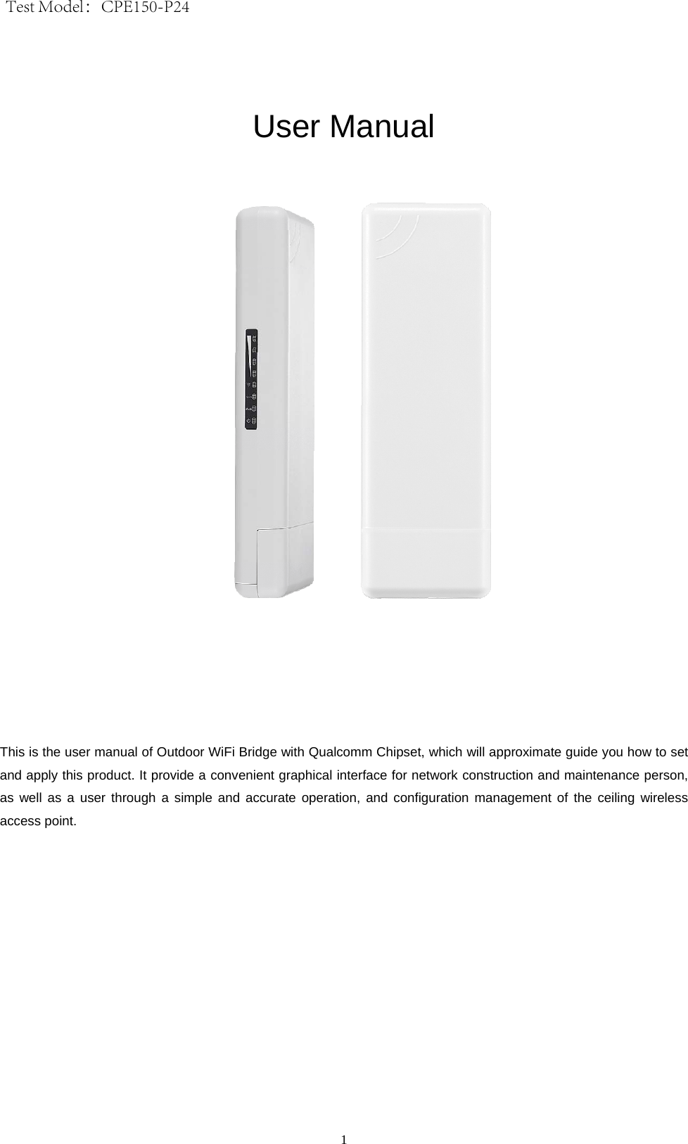
User Manual
Navigation menu
Upload a User Manual
Namespaces
Wiki Guide
HTML
PDF
Info
Views
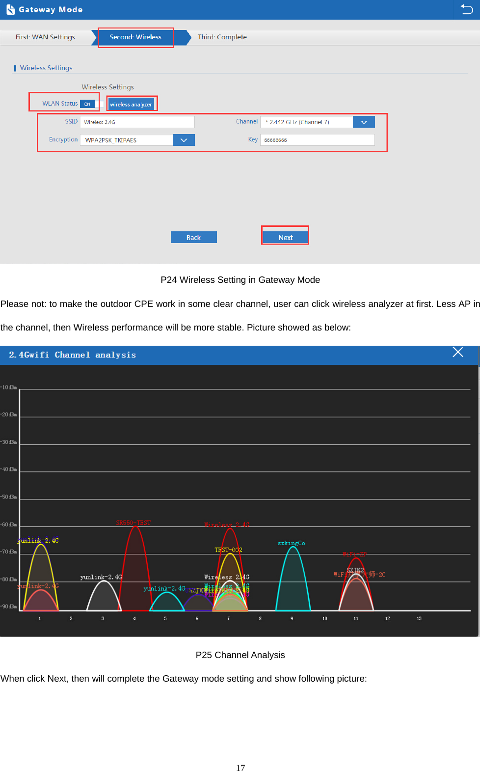
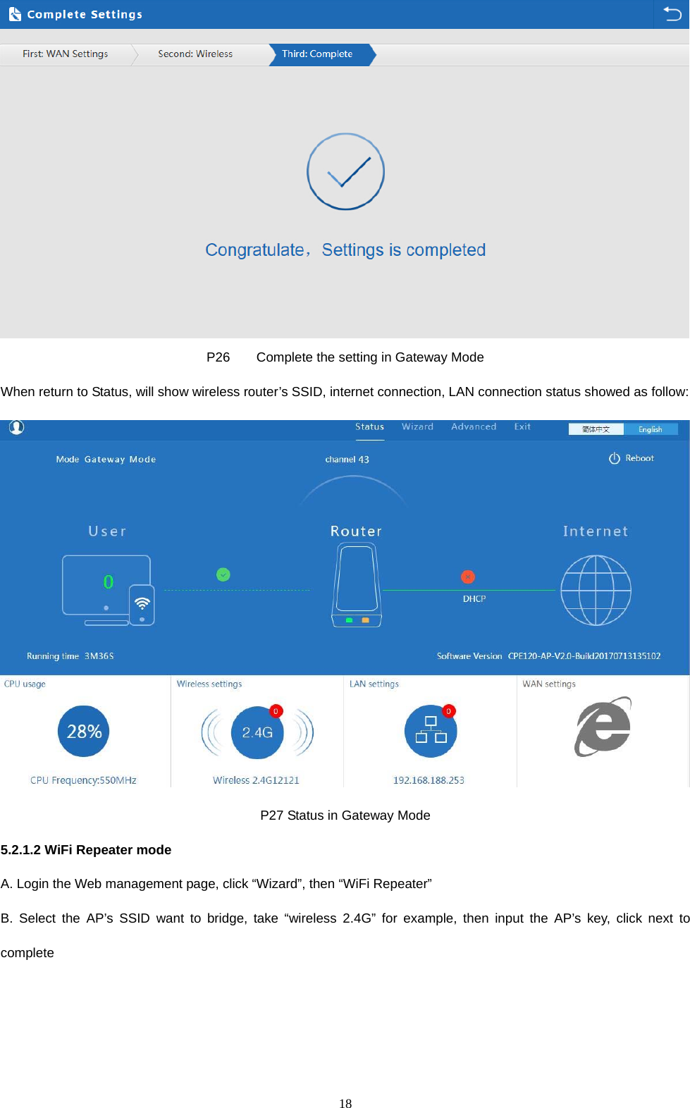
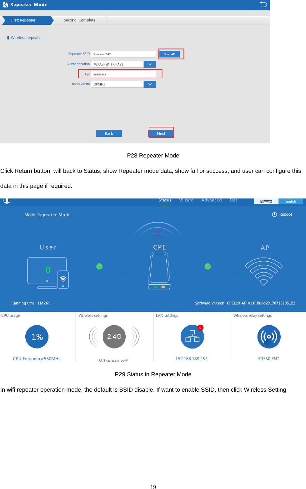
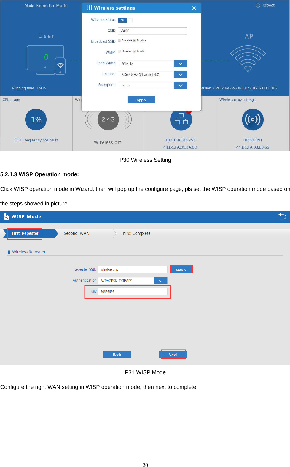
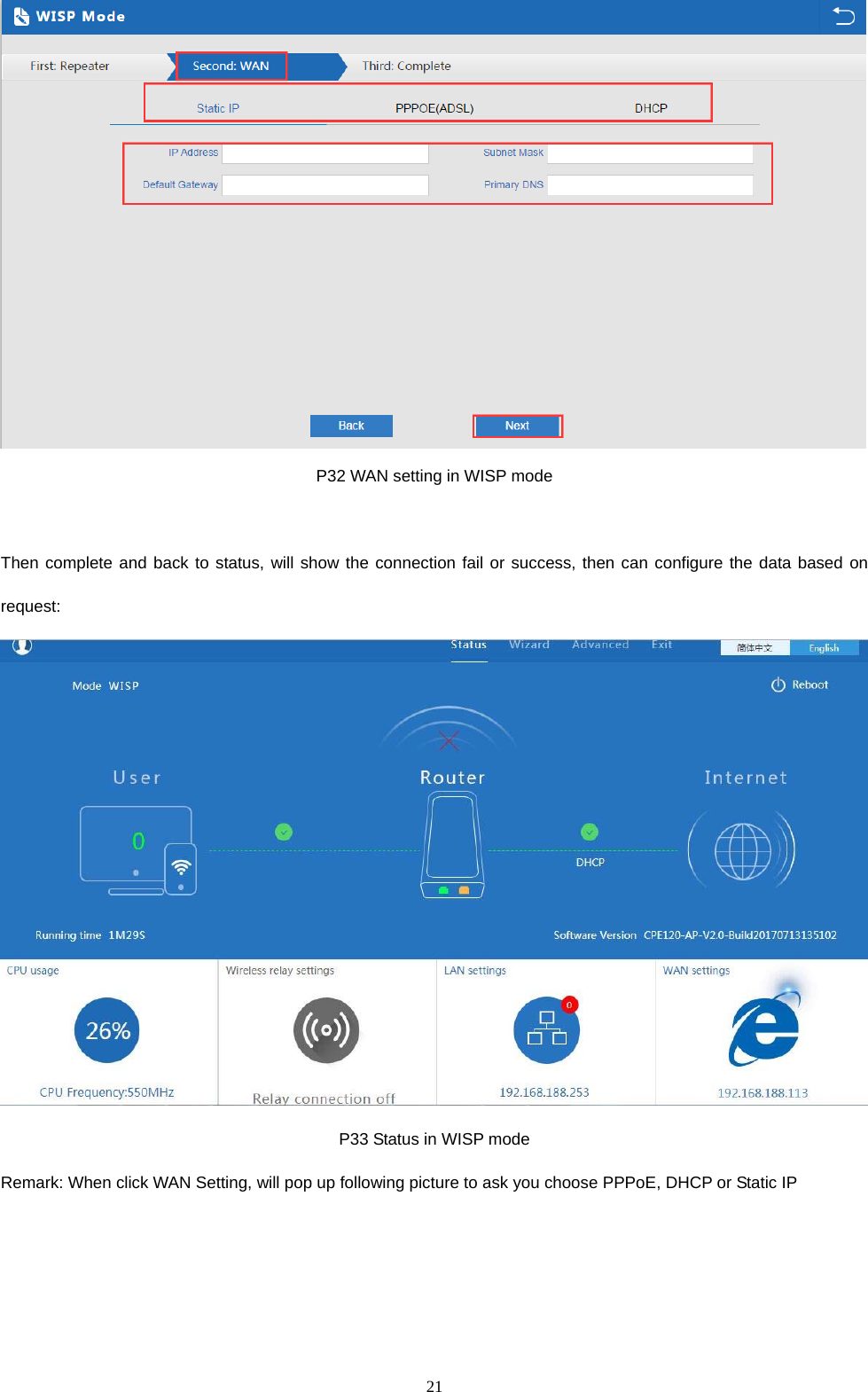
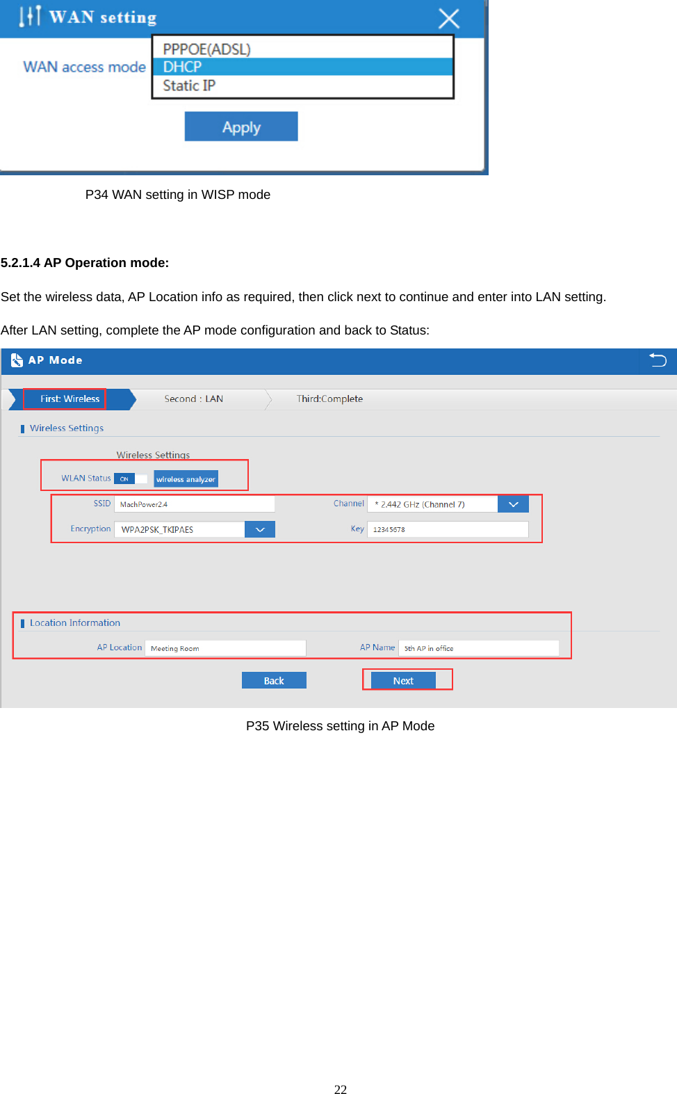
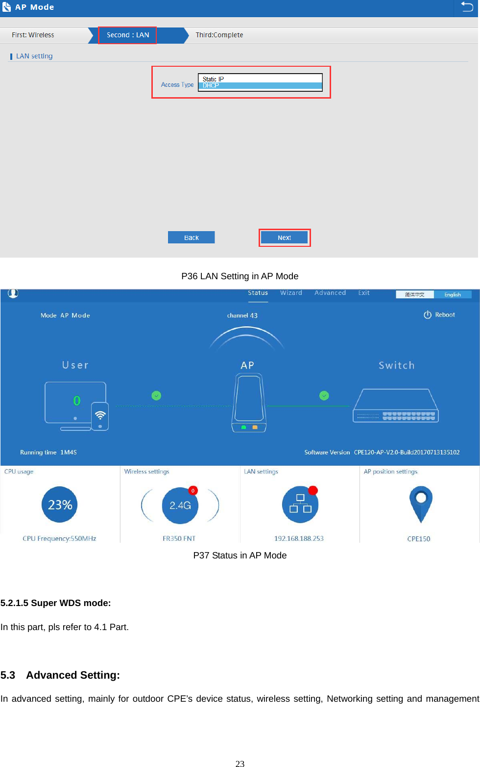
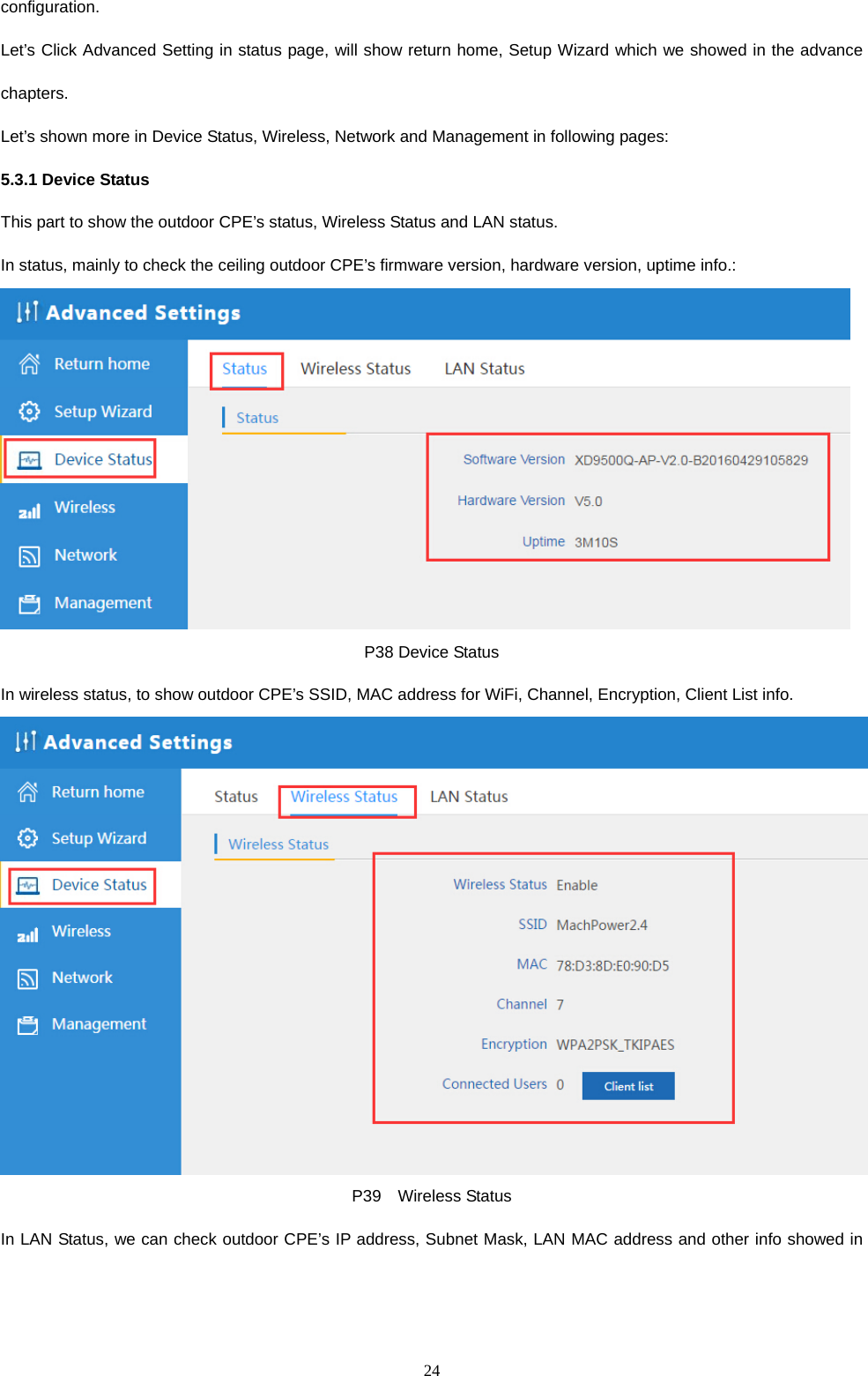
User Manual
Discussion / Help
Navigation