Z Com 002250 802.11b Wireless Router User Manual
Z Com Inc 802.11b Wireless Router
UserManual.wiki
>
Z Com
>
002250 User Manual
User Manual
Navigation menu
Upload a User Manual
Namespaces
Wiki Guide
HTML
PDF
Info
Views
User Manual
Discussion / Help
Navigation
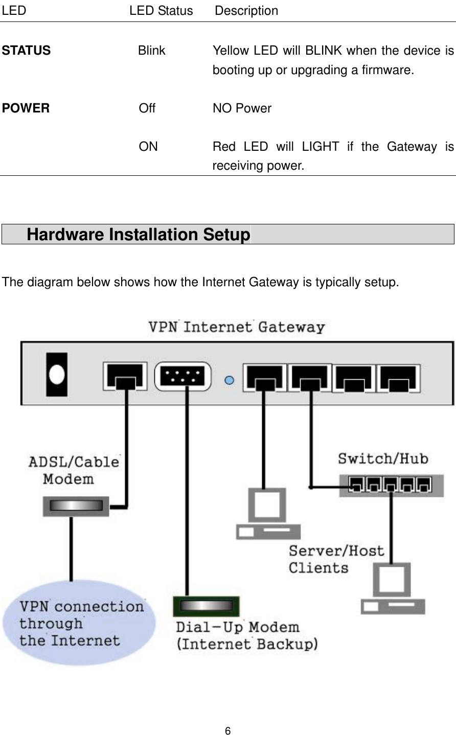
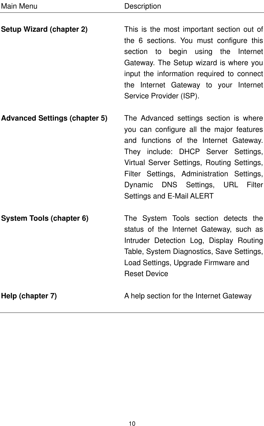
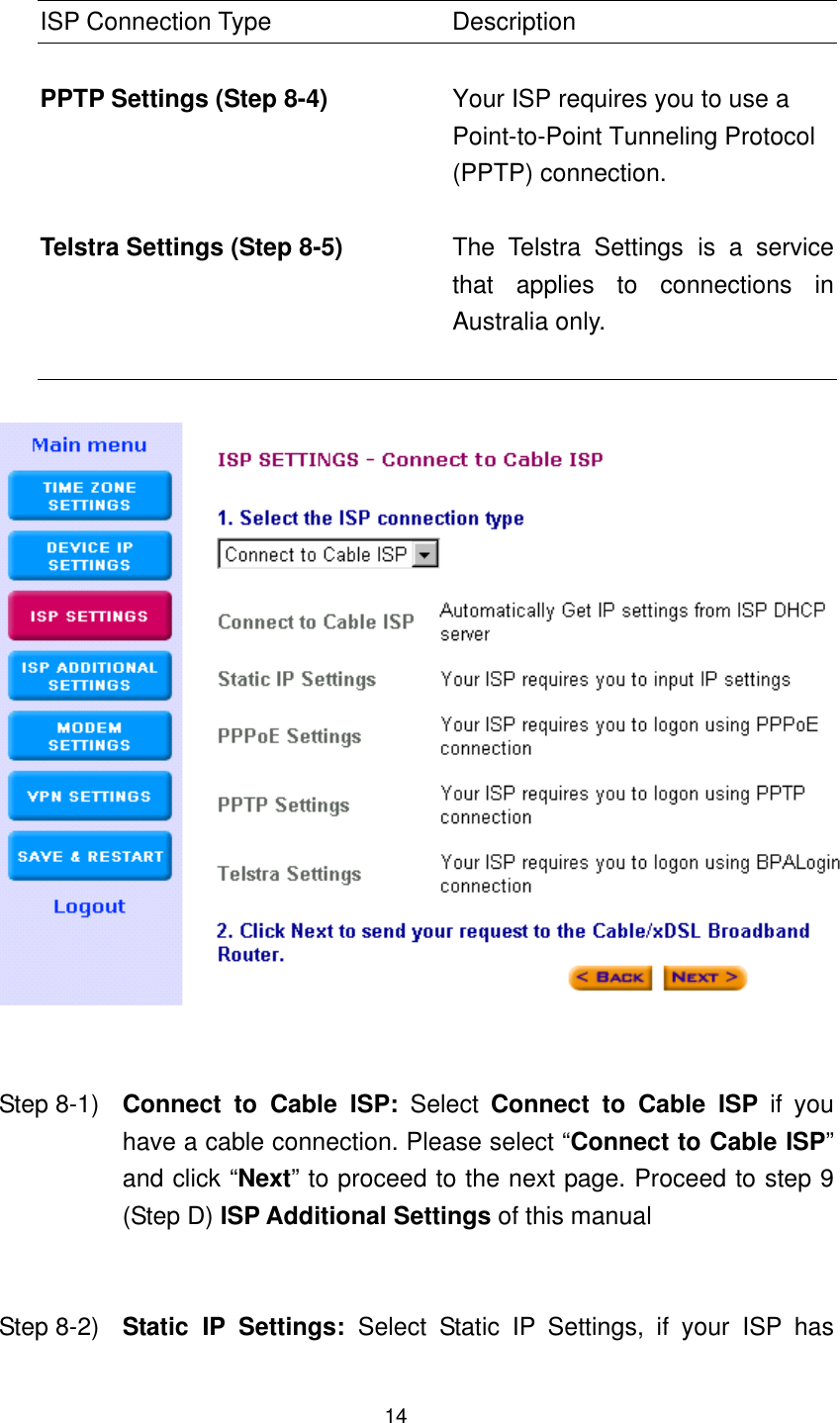
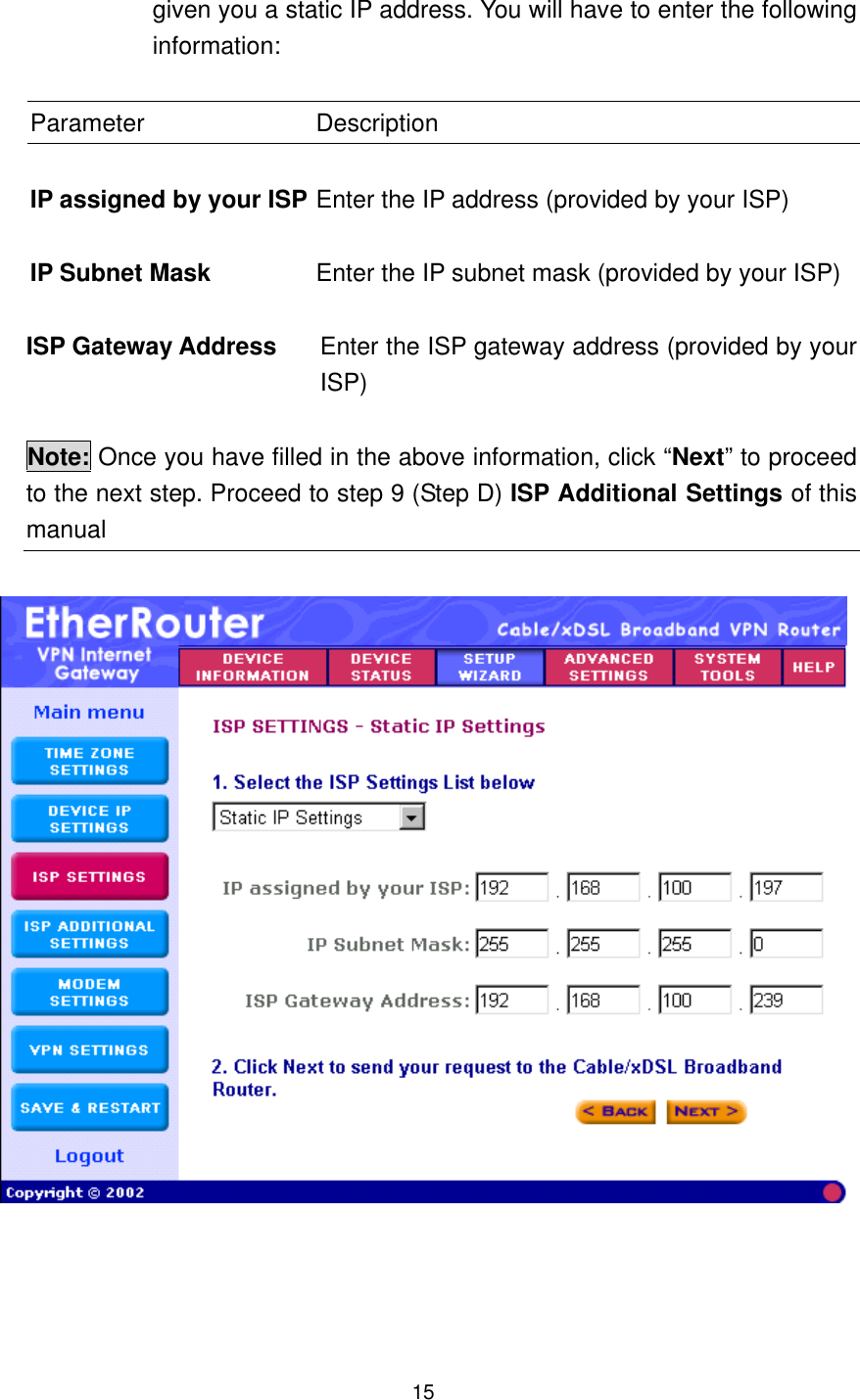
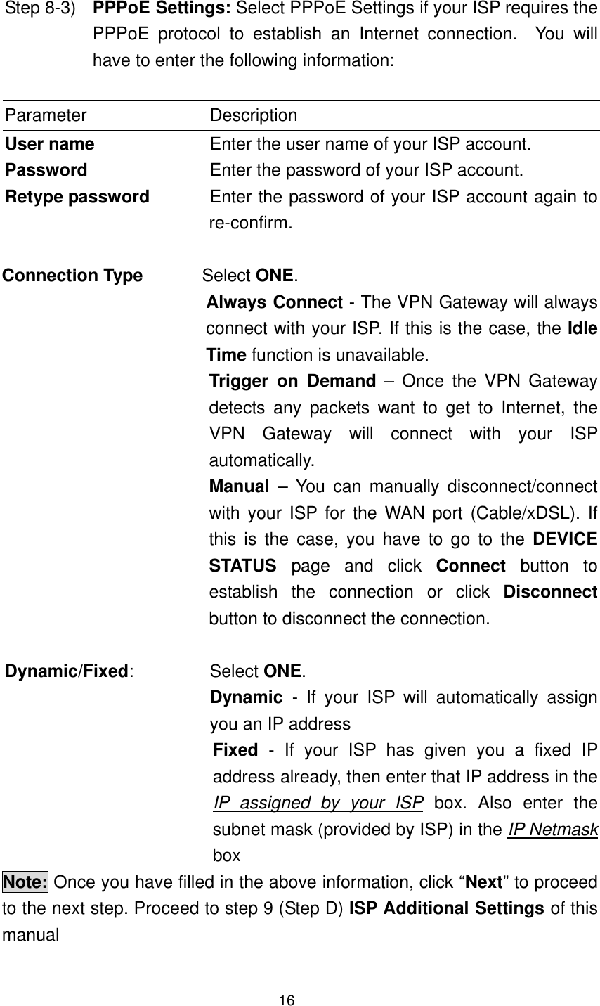
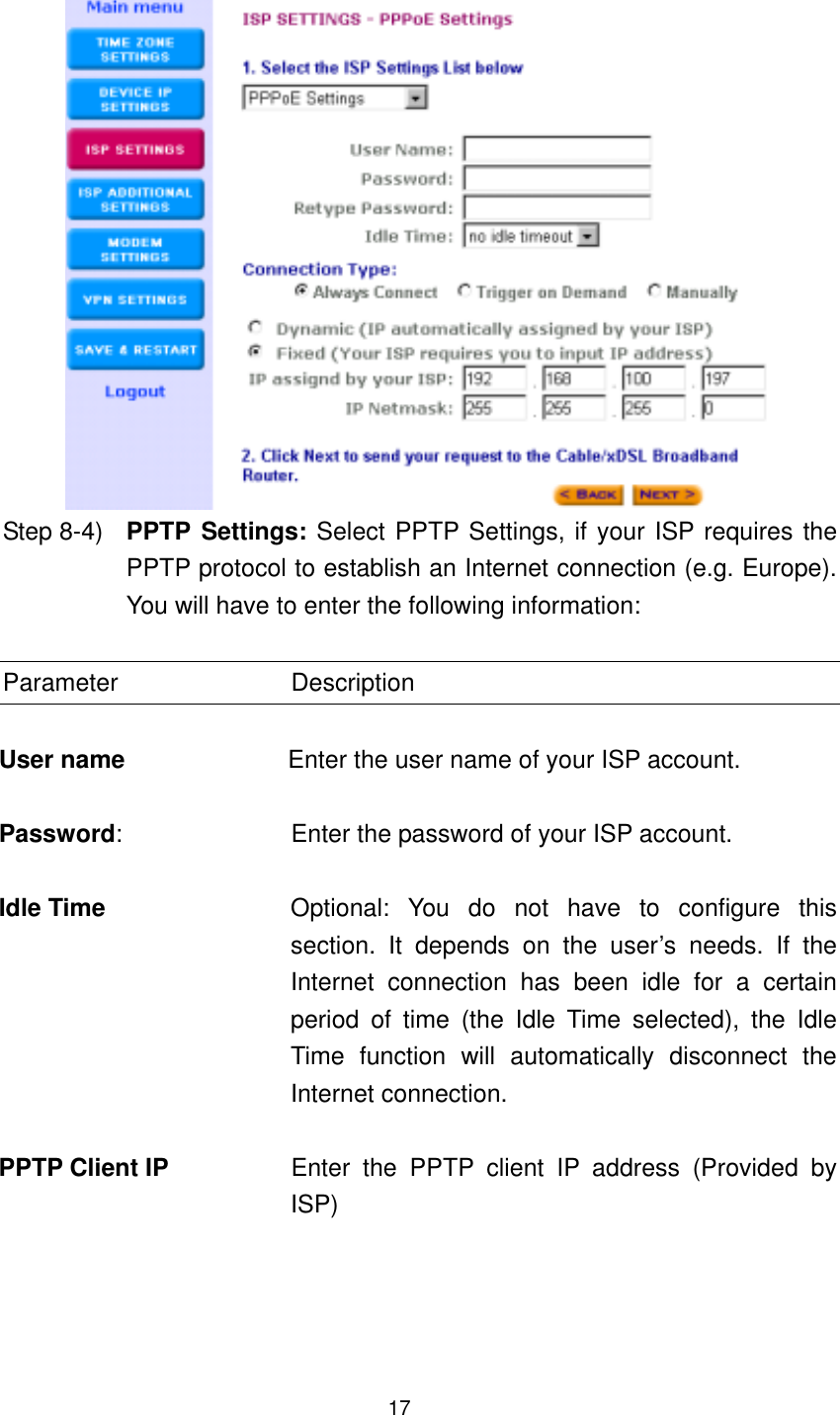
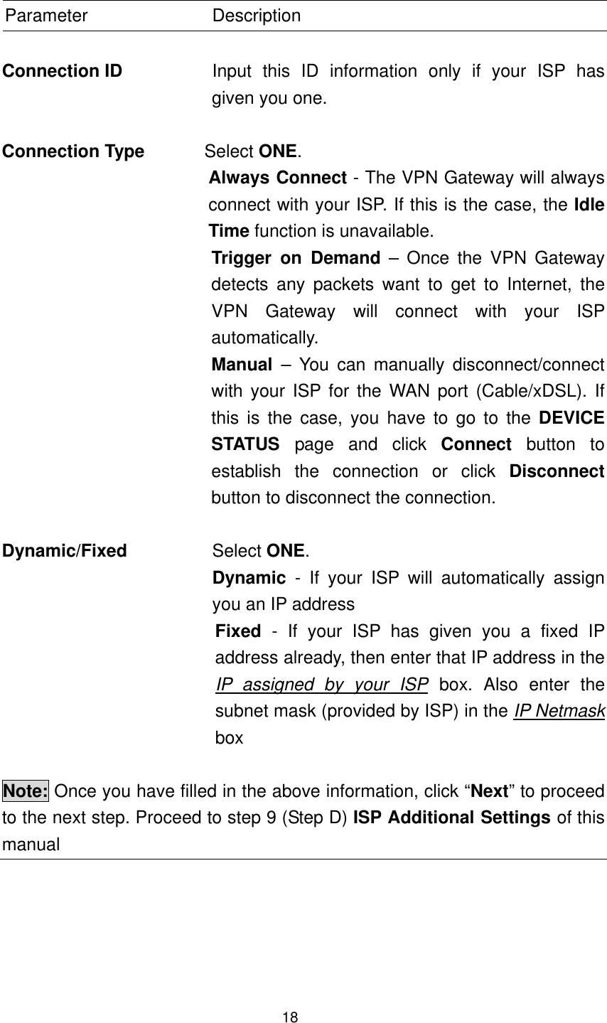
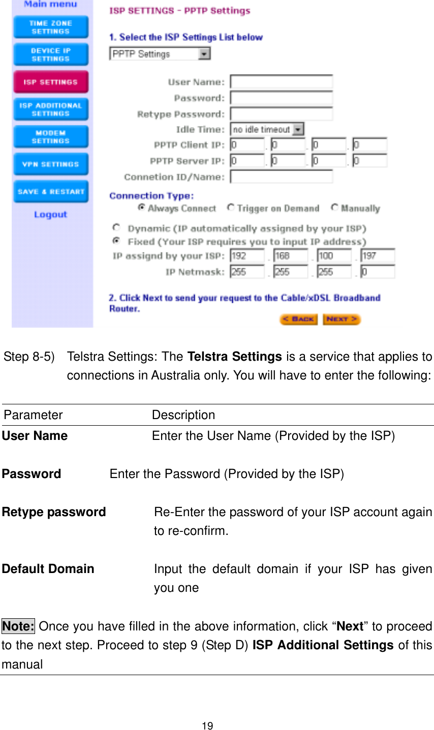
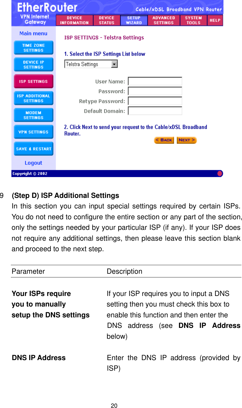
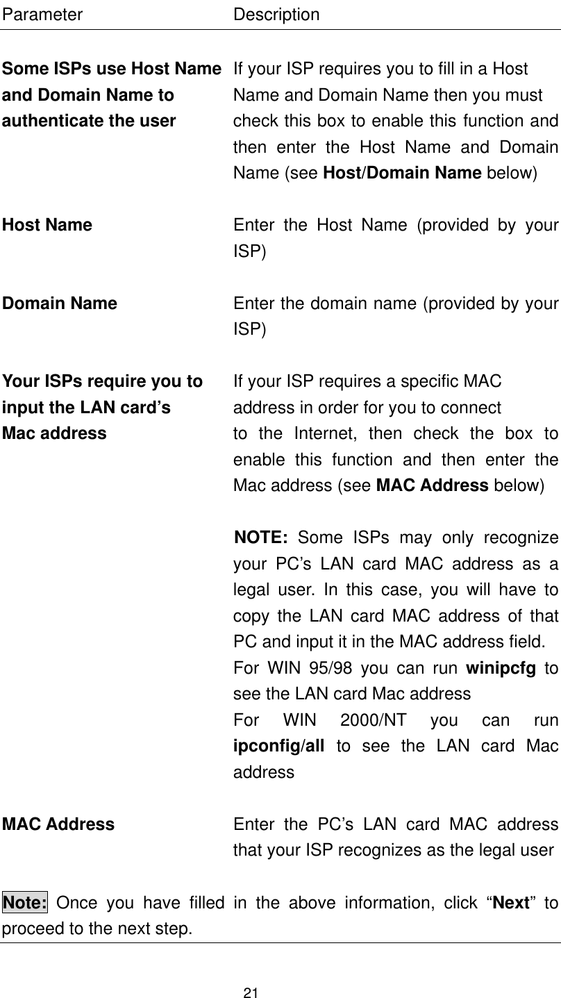
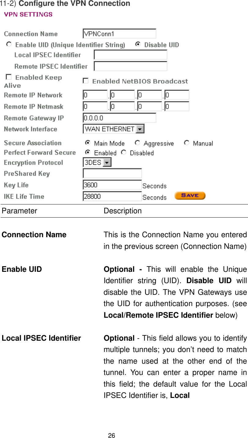

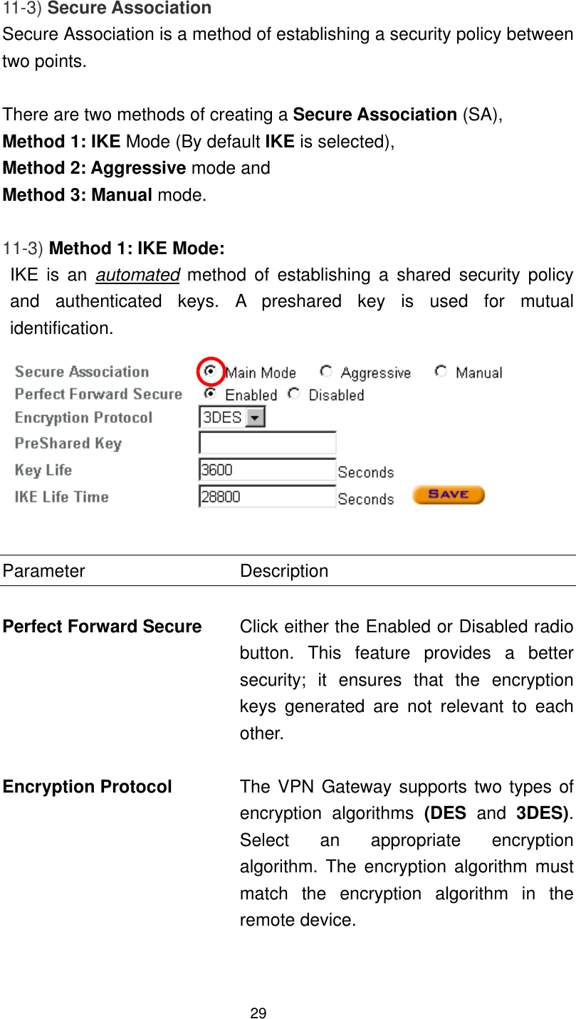
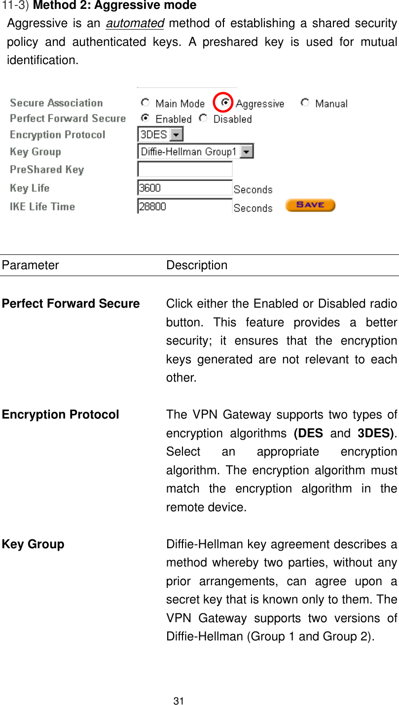
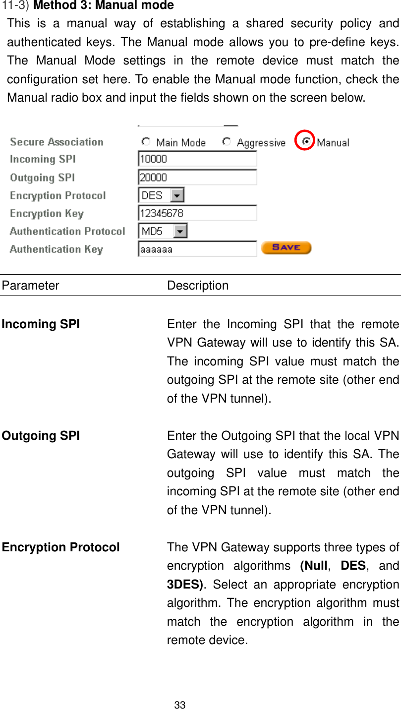
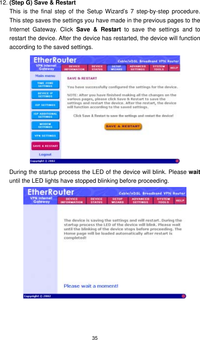
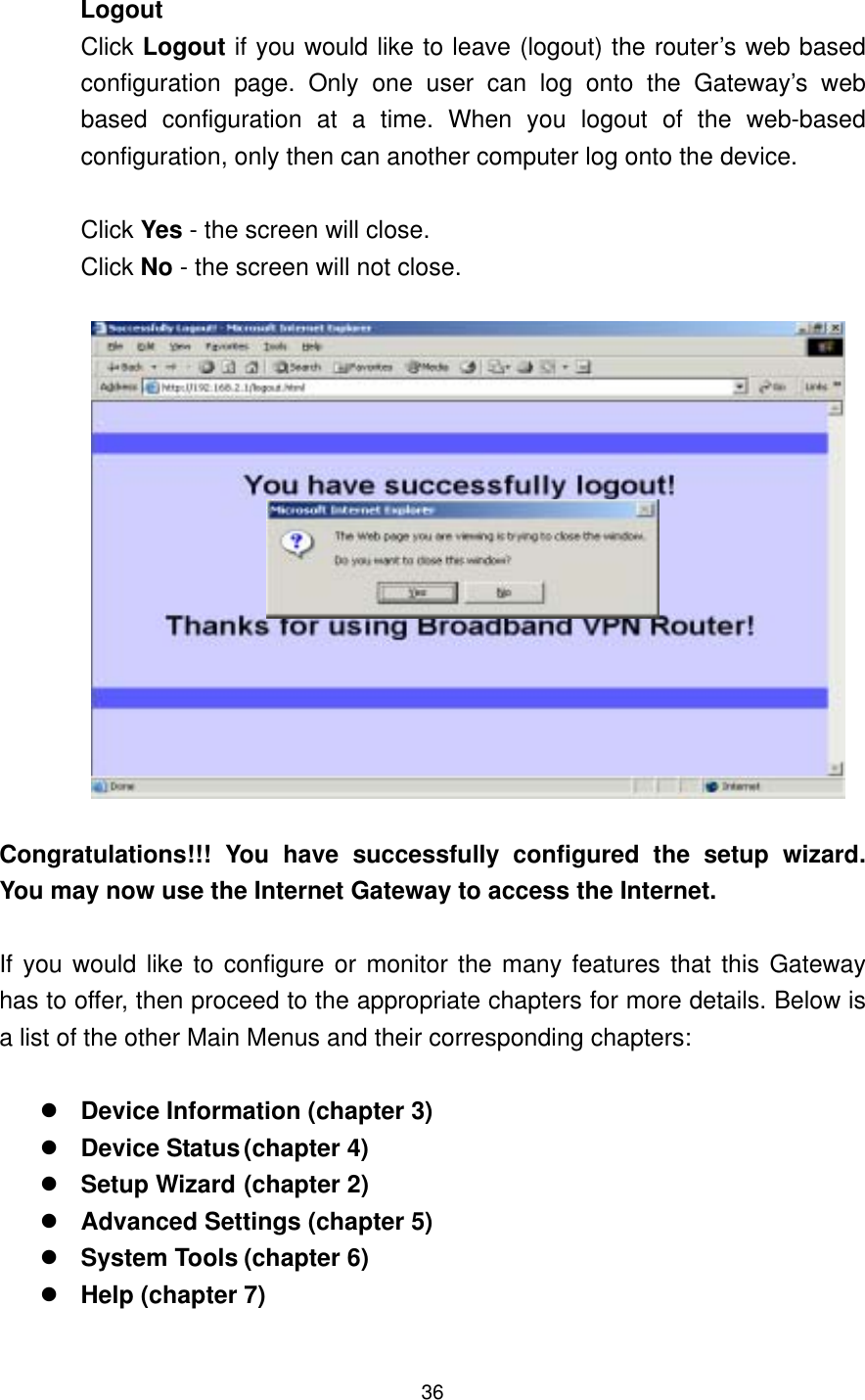
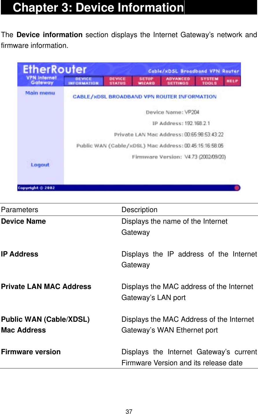
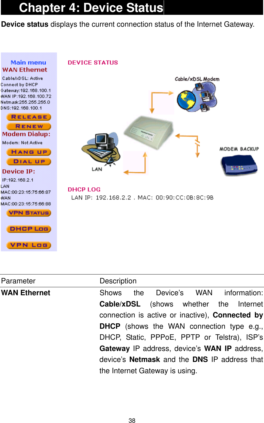
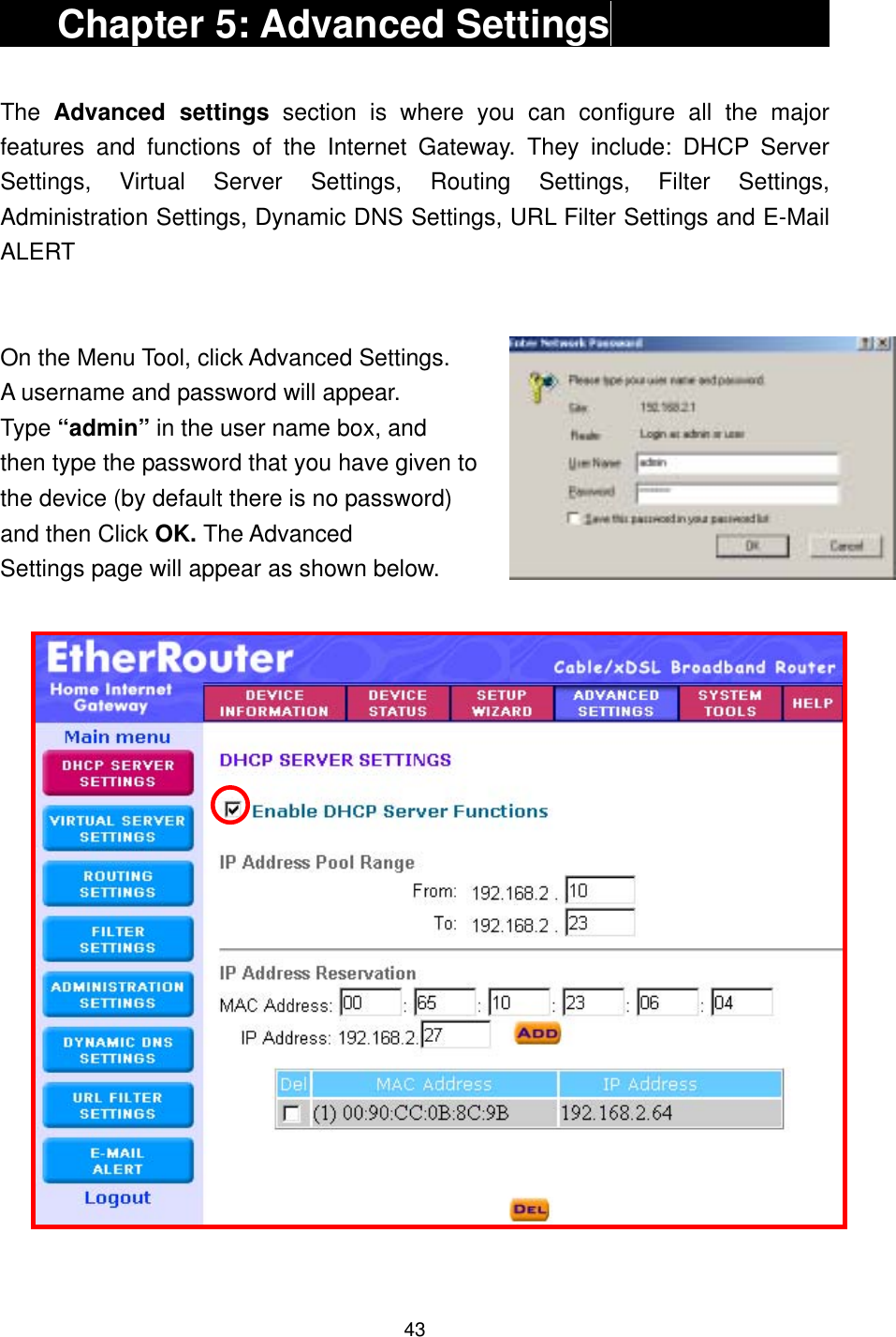
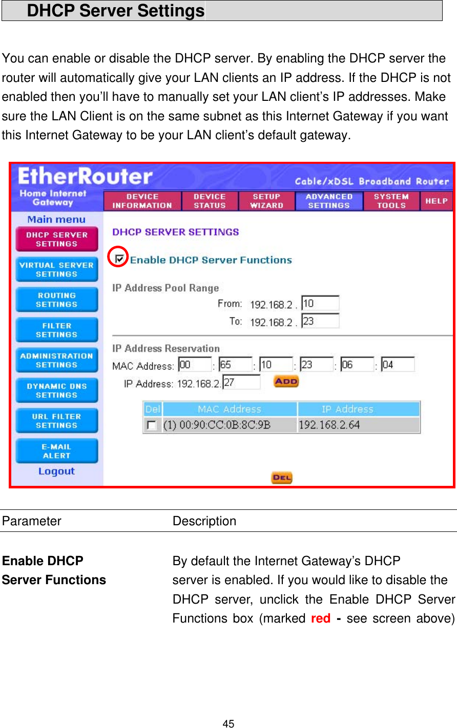
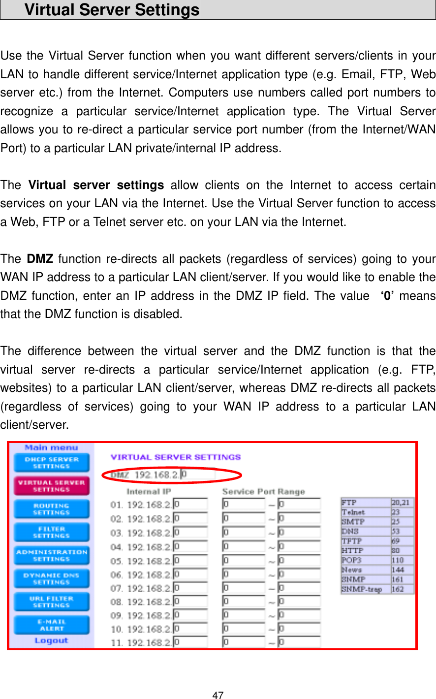
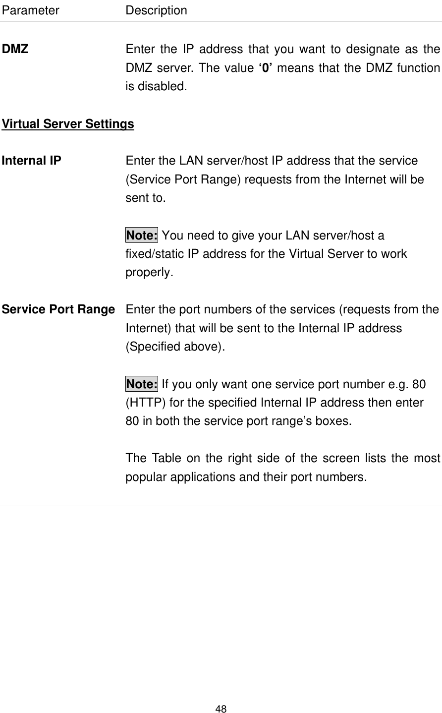
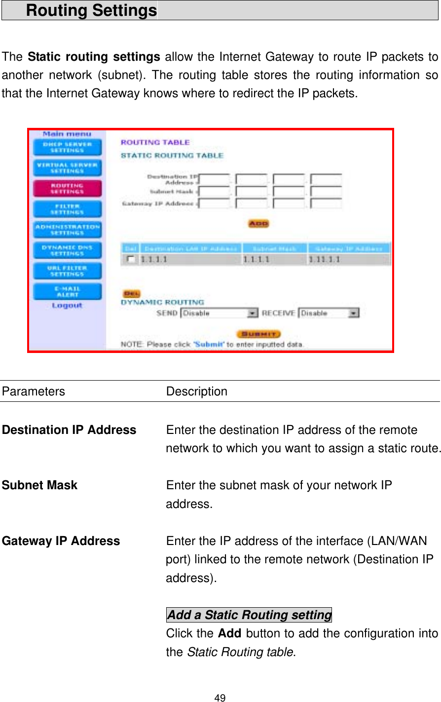
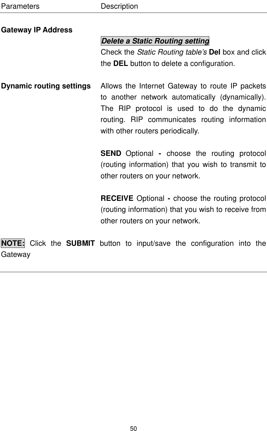

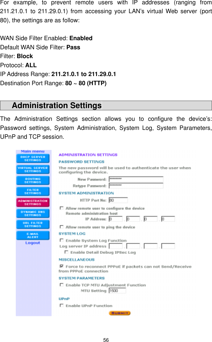
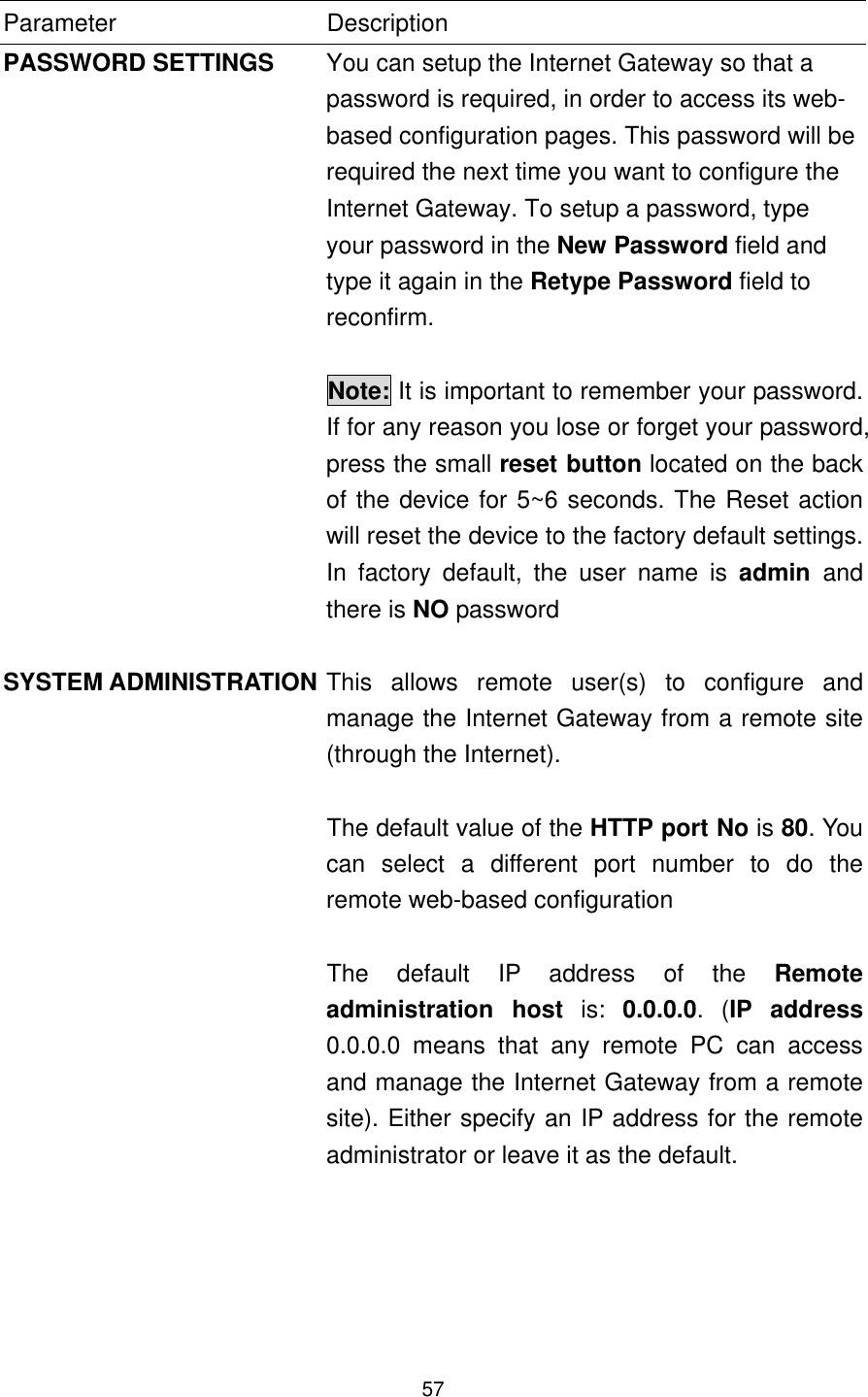
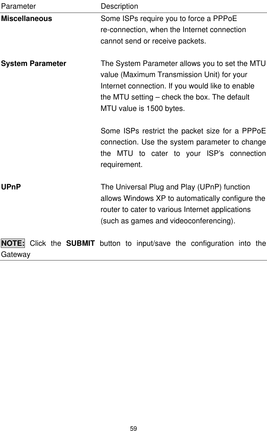
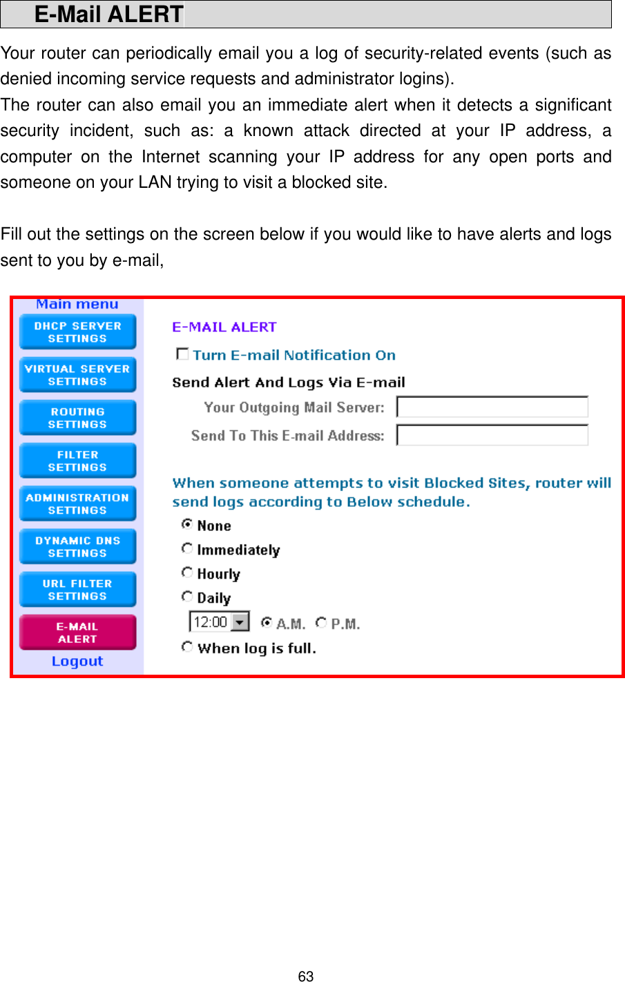
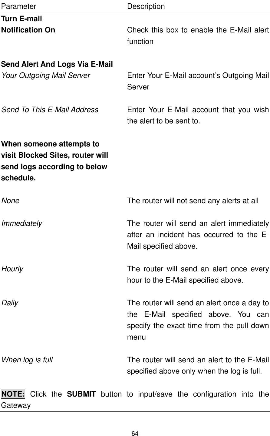
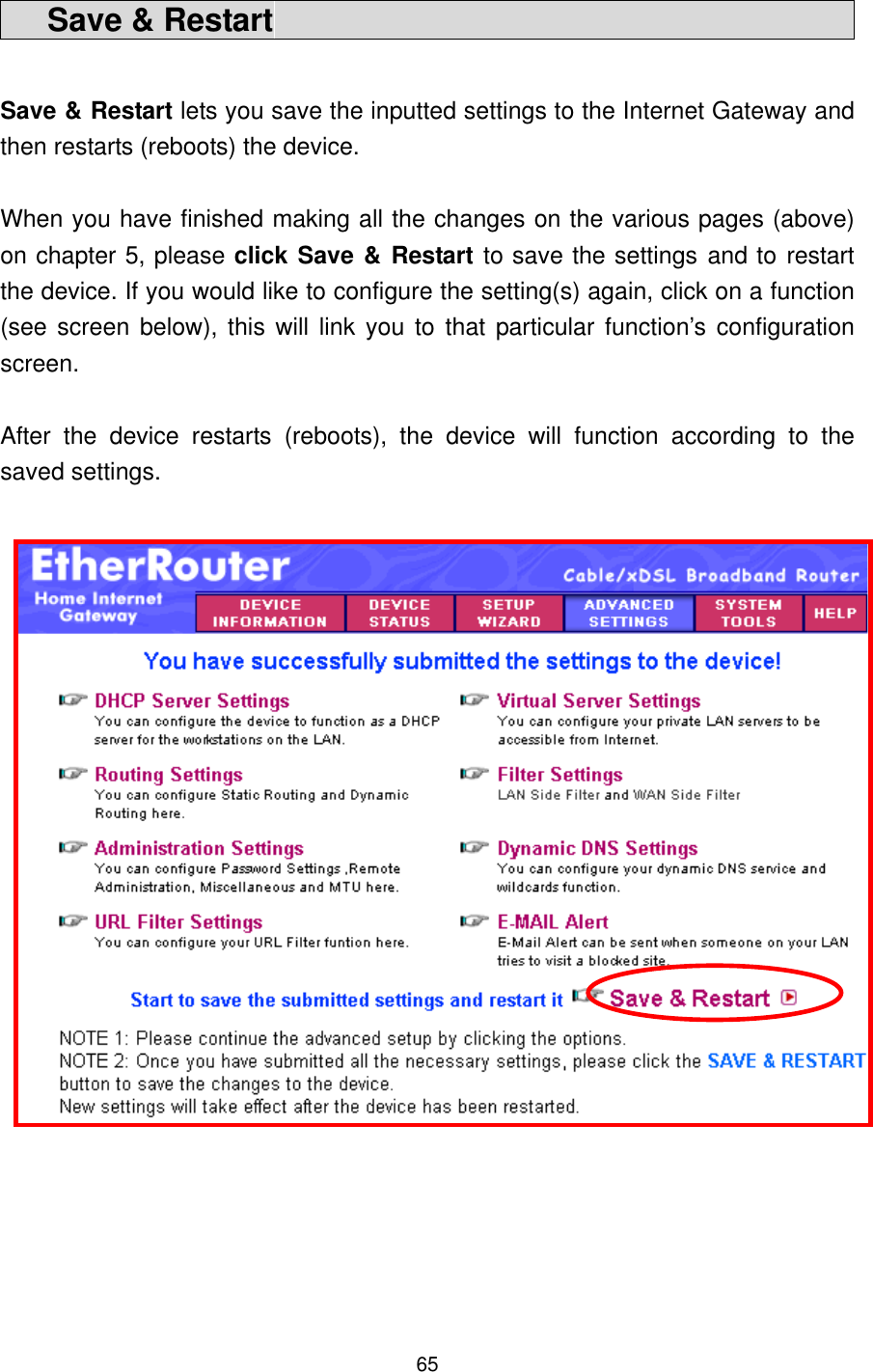
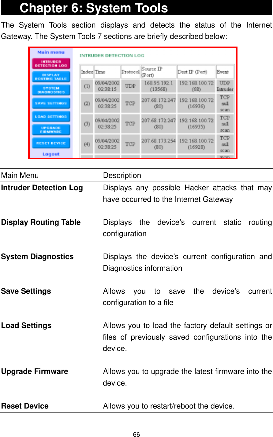
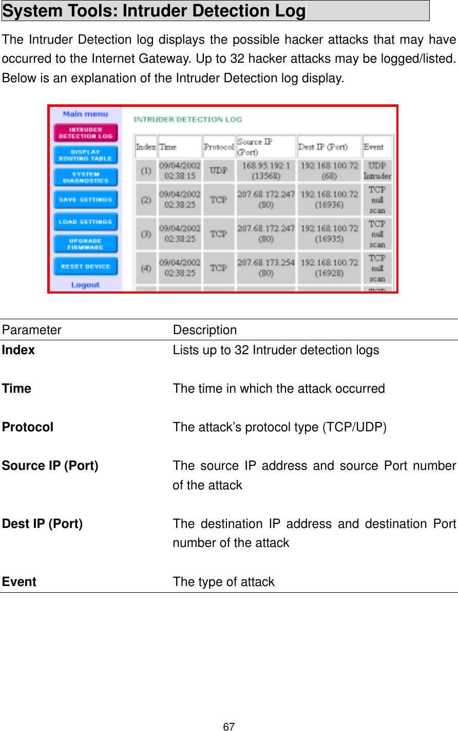
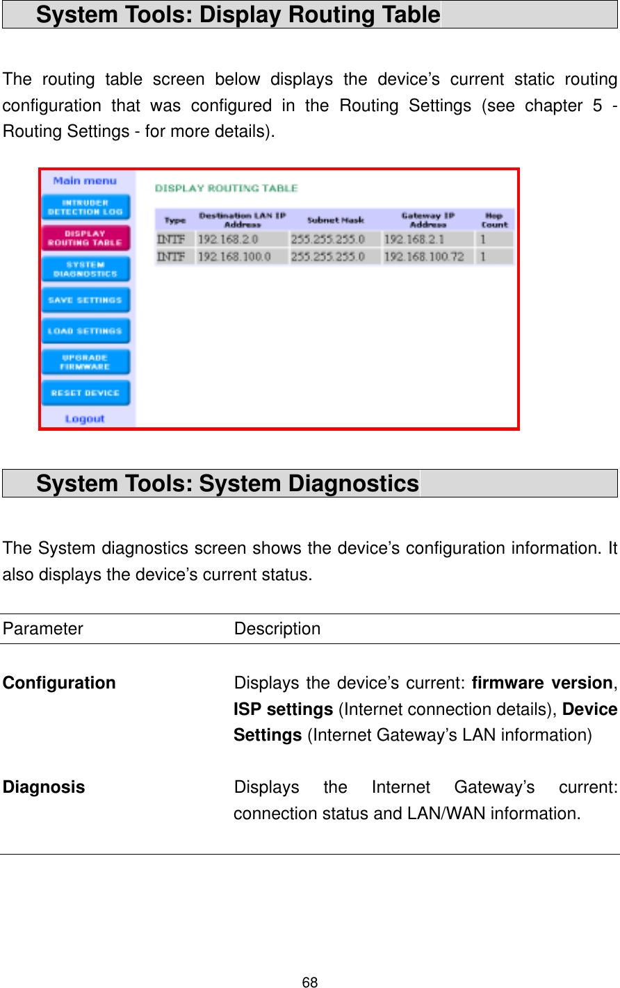
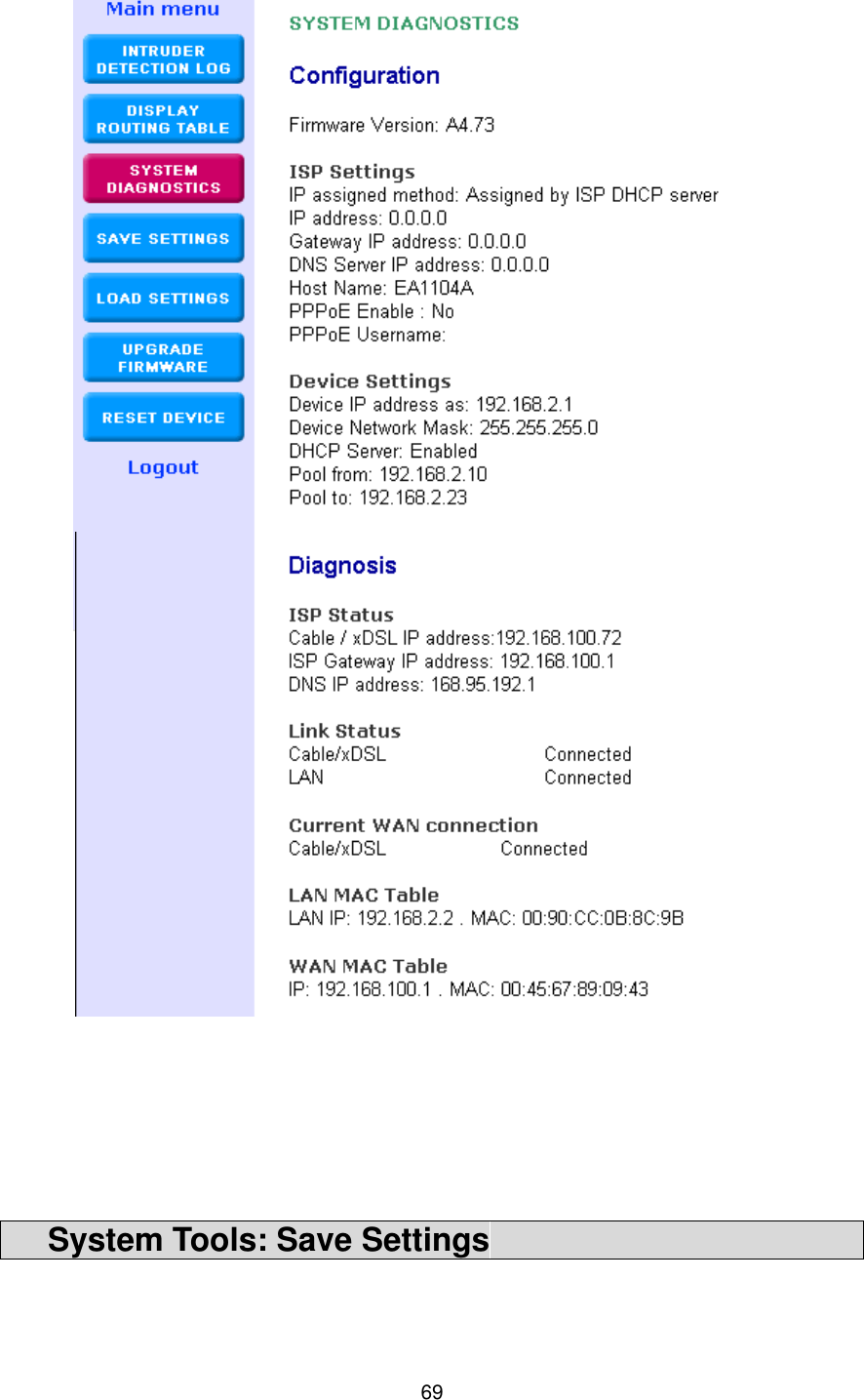
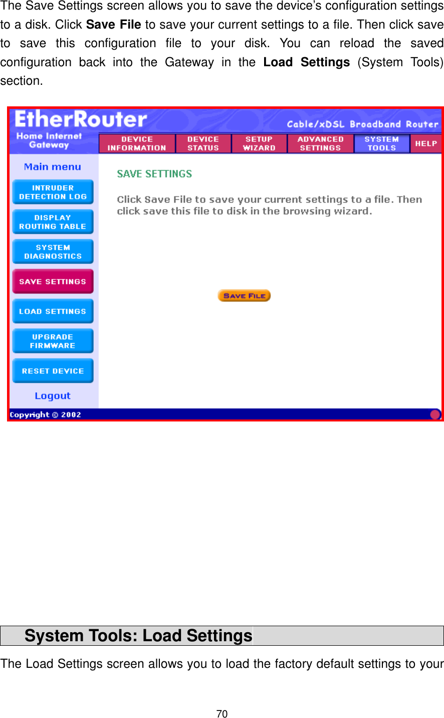
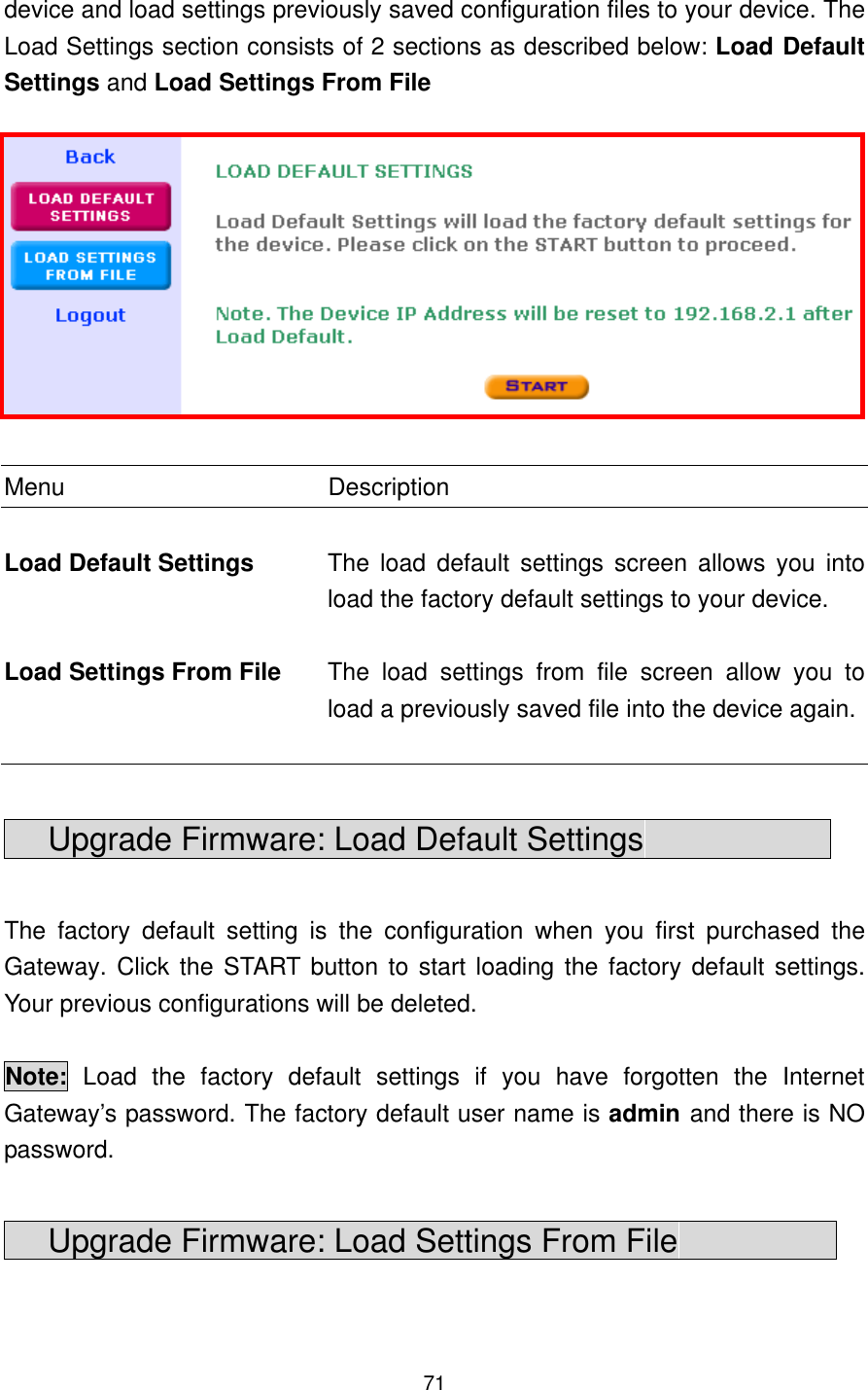
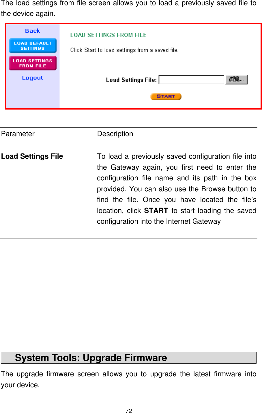
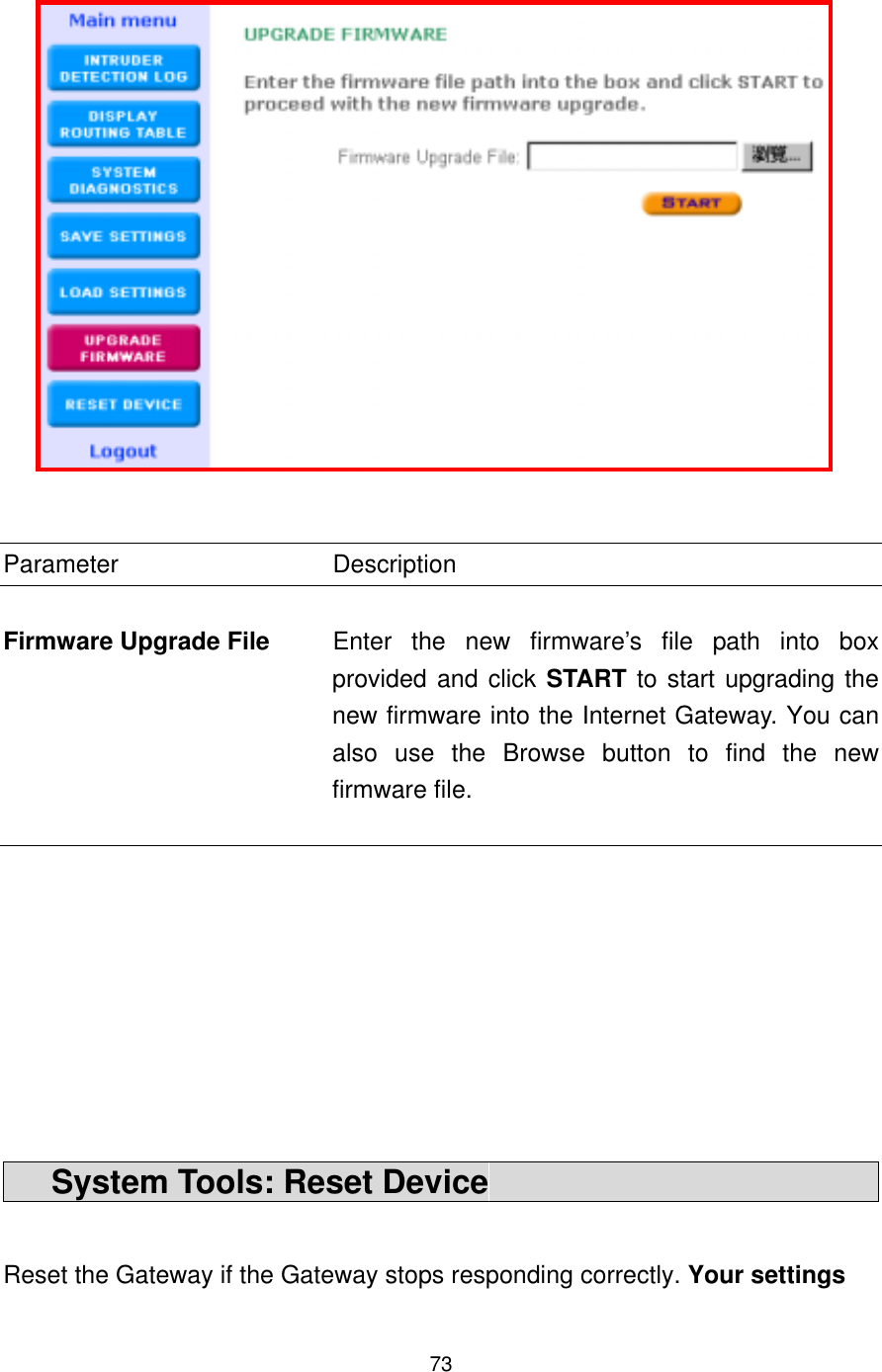
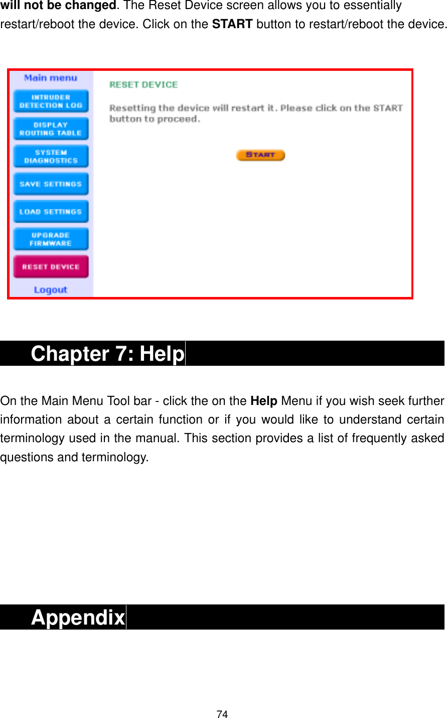
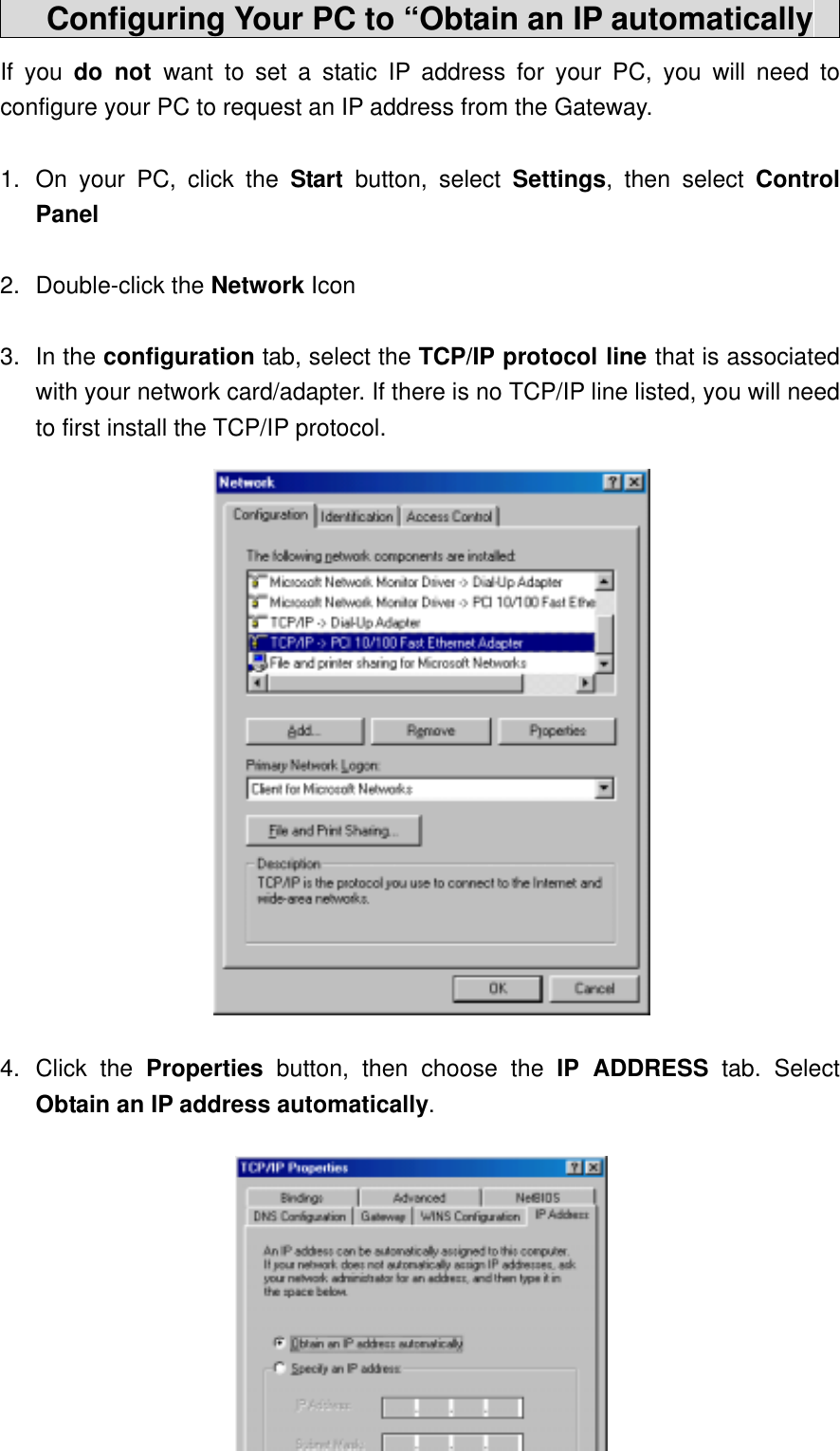
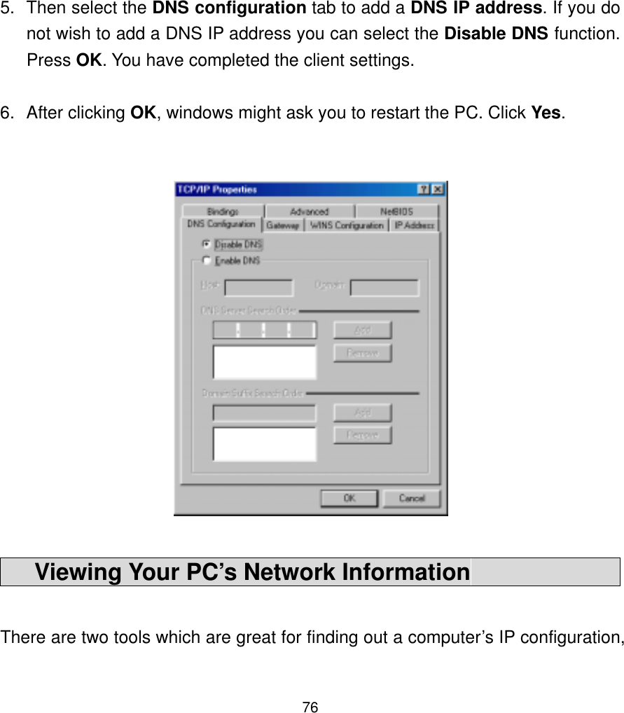
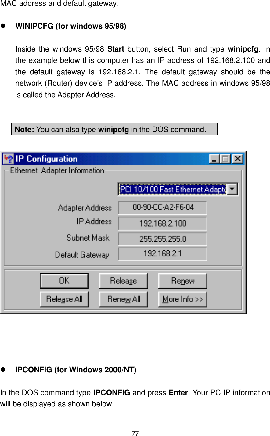
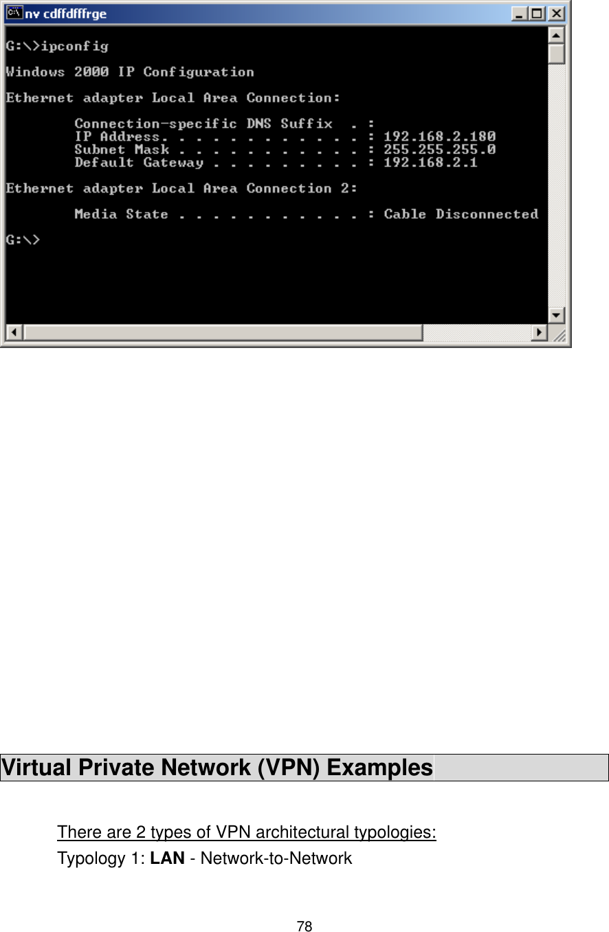
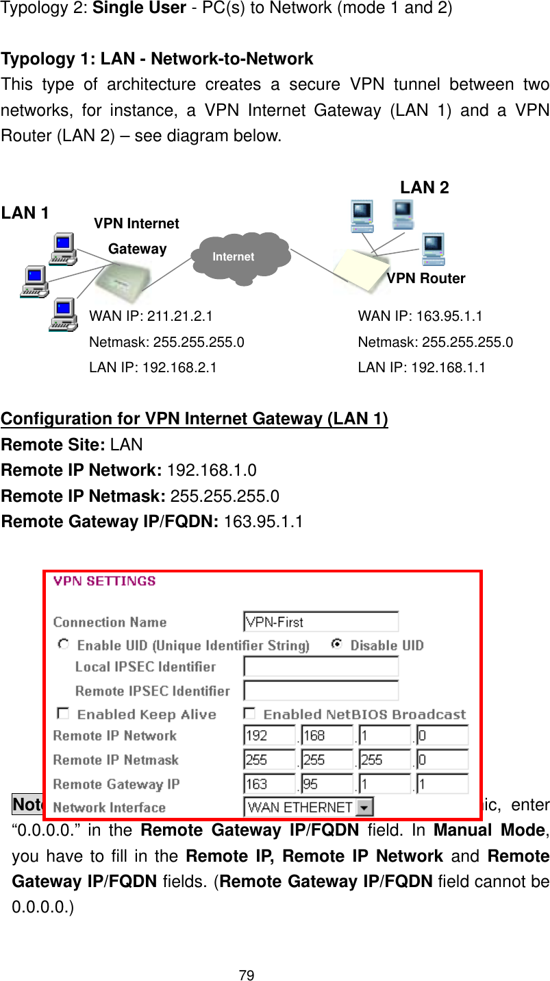
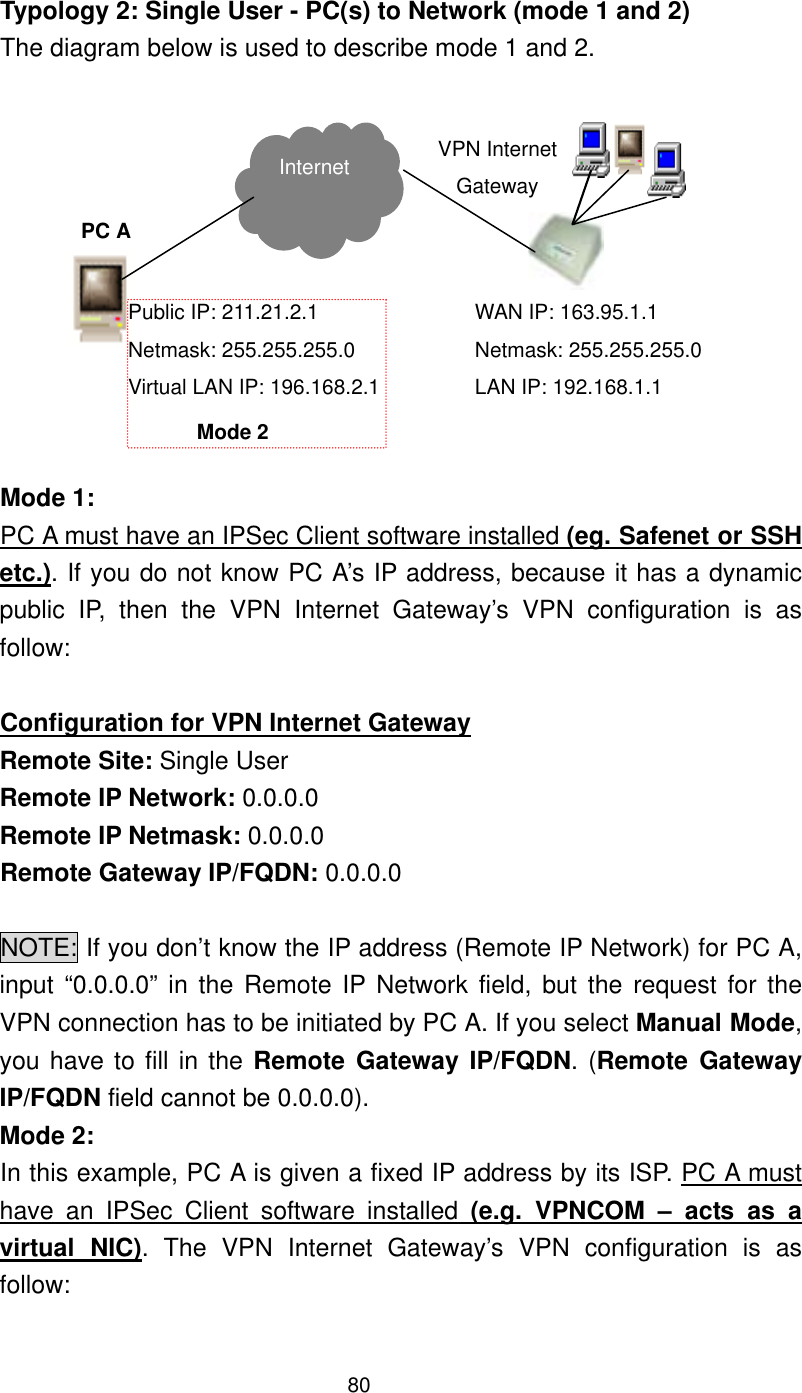
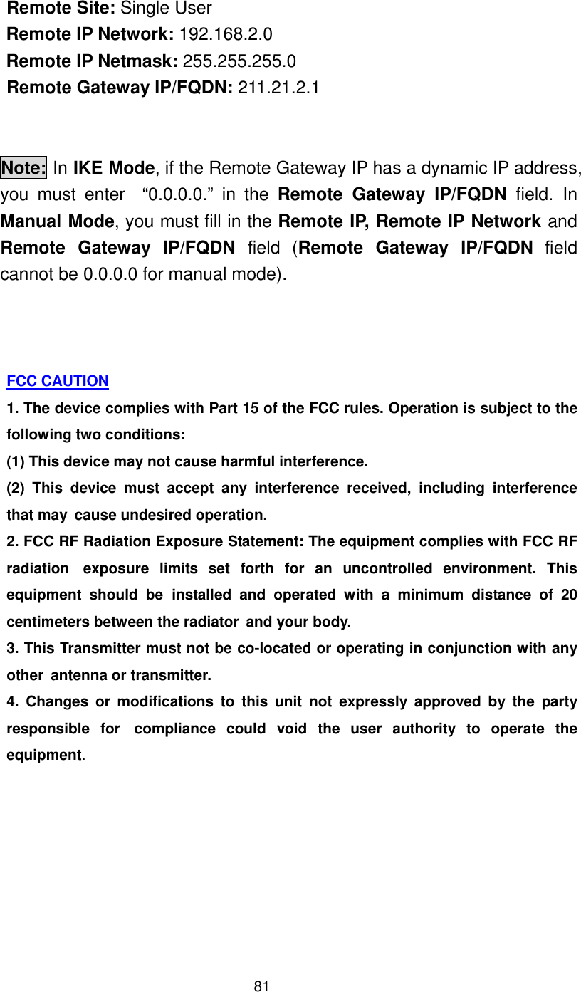
![58http://<WAN IP Address>:<Port No>Parameter Description SYSTEM ADMIN You will have to enable the Allow remote user to configure the device to use the remote web-based configuration function. Once you have enabled this function, type the device’s WAN IP address and the HTTP port No (e.g. http://202.19.100.1:1023) into the browser of the specified remote administrator. If the HTTP port number, is NOT the default PORT No. 80, then the LAN administrator must also enter the new port number, specified in HTTP port No, in order to access the device’s web-based configuration, e.g. Device LAN IP address with HTTP port no 1023 (http://192.168.2.1:1023) Allow remote user to ping the device: If you enable this function – the device will respond to any pings it gets from the Internet. If you disable this function, the device will not respond to any ping requests. SYSTEM LOG The System Log function allows the administrator to assign an IP address to a server on which a log server is running. When a particular event occurs, the router will send a notification to the log server. The log server can then present the log to the administrator. [Free log server can be downloaded from Internet, such as Kiwis SysLog Daemon]](https://usermanual.wiki/Z-Com/002250/User-Guide-340897-Page-58.png)