Z Com 05-3220 802.11a/b/g SMB Wireless Access Point User Manual
Z Com Inc 802.11a/b/g SMB Wireless Access Point
Z Com >
Users Manual
0
802.11 a/b/g SMB
Wireless Access Point
User’s Manual

1
FCC Information
This device complies with Part 15 of the FCC Rules. Operation is subject to the following two
conditions: (1) this device may not cause harmful interference, and (2) this device must accept
any interference received; including interference that may cause undesired operation.
Federal Communications Commission (FCC) Statement
This Equipment has been tested and found to comply with the limits for a Class B digital
device, pursuant to Part 15 of the FCC rules. These limits are designed to provide reasonable
protection against harmful interference in a residential installation. This equipment generates,
uses and can radiate radio frequency energy and, if not installed and used in accordance with
the instructions, may cause harmful interference to radio communications. However, there is
no guarantee that interference will not occur in a particular installation. If this equipment does
cause harmful interference to radio or television reception, which can be determined by
turning the equipment off and on, the user is encouraged to try to correct the interference by
one or more of the following measures:
- Reorient or relocate the receiving antenna.
- Increase the separation between the equipment and receiver.
- Connect the equipment into an outlet on a circuit different from that to which the receiver is
connected.
-Consult the dealer or an experienced radio/TV technician for help.
FCC RF Radiation Exposure Statement:
1. This Transmitter must not be co-located or operating in conjunction with any other
antenna or transmitter.
2. This equipment complies with FCC RF radiation exposure limits set forth for an
uncontrolled environment. This equipment should be installed and operated with a
minimum distance of 20 centimeters between the radiator and your body.
2
Table of Content
Chapter 1 Introduction.......................................................................................................3
1-1 Features and Benefits..................................................................................................3
1-2 Applications ................................................................................................................4
Chapter 2 Hardware Installation.......................................................................................5
2-1 Package Contents........................................................................................................ 5
2-2 System Requirements..................................................................................................5
2-3 Mechanical Description .............................................................................................. 6
2-4 Hardware Installation.................................................................................................. 8
2-5 Safety Notification...................................................................................................... 9
Chapter 3 Configuring your Access Point with the Web-Based User Interface..........10
3-1 Start-up and Log in ...................................................................................................10
3-2 IP Setup.....................................................................................................................12
3-3 Wireless Setup........................................................................................................... 19
3-4 AP Status................................................................................................................... 33
3-5 Management..............................................................................................................35
Chapter 4 Troubleshooting...............................................................................................41
Limited Warranty.............................................................................................................. 44
3
Chapter 1 Introduction
The 802.11 a/b/g SMB Wireless Access Point provides you Dual-Band Wireless connectivity.
The802.11 a/b/g SMB Wireless Access Point contains two separate wireless connectivity
radio transceivers, which support all three popular wireless networking specifications. The
first radio uses the 2.4GHz band, supporting Wireless-G/B. The second radio uses 5GHz band,
supporting Wireless-A. Although the two radios operate in different bands, they can work
simultaneously, communicating with other mobile devices enabled for 802.11a, 802.11b/g
standard-based wireless LAN connectivity.
This high-speed wireless device lets you quickly network multiple PCs and notebooks without
laying new cables, and gives users the freedom to roam throughout the workplace and stay
connected to corporate resources, e-mail, and the Internet.
1-1 Features and Benefits
Dual-Band Access Point supports three WLAN technologies, including popular
802.11b/g 2.4 frequency band and 802.11a 5GHz frequency band.
Integrate Power Over Ethernet (POE) / Power Through Ethernet (PTE).
Two wireless types to switch: AP and AP + Bridging.
Enhanced Security: WEP Encryption (64, 128 and 152-bit), WPA/WPA-PSK, WPA with
Radius, Wireless MAC Access Control List.
Interfaces directly to IEEE 802.3 (10/100-BaseTX RJ-45 LAN port) Fast Ethernet
networks.
Supports 1, 2, 5.5, 11, 6, 9,12,18, 24, 36, 48, and 54 Mbps data rates.
Advanced features: SNMP V2 Agent: Private MIB, 802.11 MIB Supported..
Easy WEB-UI configuration for any WEB-Browser.
4
1-2 Applications
The 802.11 a/b/g SMB Wireless Access Point offers a fast, reliable, high-speed, and high
security solution for wireless clients access to the network in applications like these:
1. Remote access to corporate network information
E-mail, file transfer and terminal emulation.
2. Difficult-to-wire environments
Historical or old buildings, asbestos installations, and open area where wiring is difficult
to deploy.
3. Frequently changing environments
Retailers, manufacturers and those who frequently rearrange the workplace and change
location.
4. Temporary LANs for special projects or peak time
♦ Trade shows, exhibitions and construction sites where a temporary network will be
practical.
♦ Retailers, airline and shipping companies need additional workstations during peak
period.
♦ Auditors requiring workgroups at customer sites.
5. Access to database for mobile workers
Doctors, nurses, retailers, accessing their database while being mobile in the hospital,
retail store or office campus.
6. High security connection
The secure wireless network can be installed quickly and provide flexibility.
5
Chapter 2 Hardware Installation
This chapter describes initial setup of the 802.11 a/b/g SMB Wireless Access Point.
2-1 Package Contents
The package you have received should contain the following items: If any of the above items
are not included or damaged, please contact your local vendor for support.
• 802.11 a/b/g SMB Wireless Access Point…….…..…………...……..….……..x1
• Dipole Antenna. ....…………………………………..………………….……..x2
• Power Adapter…………………………………………………………….……x1
• Product CD….………………………………………………………….………x1
• Quick Installation Guide...………………..…………………………………….x1
2-2 System Requirements
Before installing the 802.11 a/b/g SMB Wireless Access Point, please make sure that these
requirements have been met:
A 10/100 Mbps Local Area Network device such as a hub or switch.
Category 5 networking cable.
An A/C power adapter (12V DC).
A Web browser for configuration: Microsoft IE 4.0 or above, or Netscape Navigator 4.5
or later version.
Installing TCP/IP protocol to the computer.
6
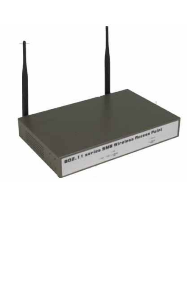
2-3 Mechanical Description
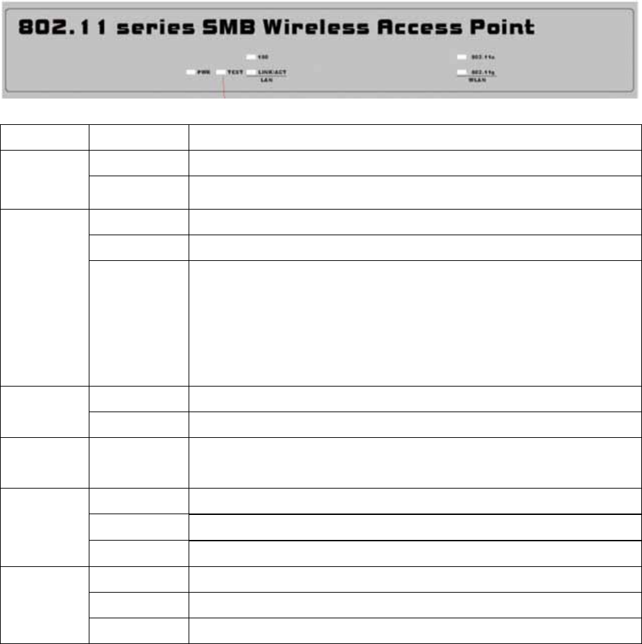
Front Panel
The front panel provides LED’s for device status. Refer to the following table for the meaning
of each feature.
LED STATUS Description
Off 802.11 a/b/g SMB Wireless Access Point is off.
PWR On 802.11 a/b/g SMB Wireless Access Point is in service.
Off Indicates that leaving boot-code mode.
On Indicates that entering boot-code mode.
TEST
Blinking
1. Reset button is pressed around 3 seconds (slow blinking).
2. Reset button is pressed after 3 seconds (fast blinking).
3. While you upgrade firmware or reset to factory default, the
TEST LED is blinking. After firmware is upgraded or reset to
factory default, the Access Point will reboot automatically.
Off 10 Mbps Ethernet link is detected but no activity.
LAN
(100) On 100Mbps Fast Ethernet link is detected but no activity.
LAN
(LINK/ACT) Blinking Indicates that Data processing. (Frequency depends on traffic)
Off Indicates no 802.11g/b wireless links.
On Wireless LAN is in service but no activity.
802.11g
WLAN Blinking Indicates the device is linking or active data through wireless links.
Off Indicates no 802.11a wireless links.
On Wireless LAN is in service but no activity.
802.11a
WLAN Blinking Indicates the device is linking or active data through wireless links.

7
Rear Panel
To know the rear panel features, please refer to the following table for the meaning of each
feature.
Power
Socket
(DC 12v)
Connect the DV 12V/1.2A power supply. ONLY use the power adapter
supplied with the 802.11 a/b/g SMB Wireless Access Point. Otherwise,
the product may be damaged.
Reset Simply press the reset button and keep pressing it for around 5
seconds. The 802.11 a/b/g SMB Wireless Access Point will be restored
to factory default settings.
LAN/POE Use the Ethernet RJ-45 port to connect to the 10/100Mbps Ethernet
network and Ethernet through a device such as a hub, switch, or router.
Primary Here you can combine the antenna (5GHz band) with the 802.11 a/b/g
SMB Wireless Access Point to wirelessly connect to the 802.11a
networks. In order to improve the RF signal radiation of your antenna,
proper antenna placement is necessary.
Secondary Here you can combine the antenna (2.4GHz band) with the 802.11
a/b/g SMB Wireless Access Point to wirelessly connect to the
802.11g/b networks. In order to improve the RF signal radiation of
your antenna, proper antenna placement is necessary.
Note: Each of these two antennas must be connected to its corresponding connector to
receive RF. Otherwise it will fail.
8
2-4 Hardware Installation
Before installing the 802.11 a/b/g SMB Wireless Access Point, you should make sure that
your Ethernet network is up and working with a computer. You'll be connecting the access
point to the Ethernet network so that computers with 802.11 a/b/g wireless adapters will be
able to communicate with computers on the Ethernet network.
Please take the following steps to successfully set up the Access Point.
Note: We suggest you first install the 802.11 a/b/g SMB Wireless Access Point with default
settings.
Site Selection
Before installation, it is very important to decide on the location of the 802.11 a/b/g SMB
Wireless Access Point. Proper placement of the 802.11 a/b/g SMB Wireless Access Point
is critical to ensure optimum radio range and performance. Typically, the best location to
place the 802.11 a/b/g SMB Wireless Access Point at your site is the center of your
wireless coverage area. Try to place your mobile stations within the line of sight.
Obstructions may impede performance of the 802.11 a/b/g SMB Wireless Access Point.
802.11 a/b/g SMB Wireless Access Point Placement
You can place the 802.11 a/b/g SMB Wireless Access Point on a flat surface such as a
table or cabinet, or mount the unit on a vertical surface like a wall. The integrated
antenna of your Access Point performs best in an open environment with as few
obstructions as possible. In most situations placing the 802.11 a/b/g SMB Wireless
Access Point will provide satisfactory performance results.
Note: We suggest you configure and verify the 802.11 a/b/g SMB Wireless Access Point
operations first before you are planning to mount the 802.11 a/b/g SMB Wireless Access
Point on a wall or in a remote location.
Connect the Ethernet Cable
The 802.11 a/b/g SMB Wireless Access Point supports 10/100M Ethernet connection.
Attach your UTP Ethernet cable to the RJ-45 connector on the 802.11 a/b/g SMB
Wireless Access Point. Then connect the other end of the RJ-45 cable to a hub or a
station.
9
Connect the Power Cable
Connect the power adapter to the power socket on the 802.11 a/b/g SMB Wireless
Access Point, and plug the other end of the power into an electrical outlet.
Warning: We cannot assume the responsibility for the damage from using with the other
power adapter supplier.
Verify wireless connectivity to the network
Using a computer with the wireless adapter, browsing Internet or checking file access on
the network. If everything is functioning properly, then you have successfully installed
the 802.11 a/b/g SMB Wireless Access Point.
2-5 Safety Notification
Your Wireless AP should be placed in a safe and secure location. To ensure proper operation,
please keep the unit away from water and other damaging elements.
Please read the user manual thoroughly before you install the device.
This device should only be repaired by authorized and qualified personnel.
Please do not try to open or repair the device yourself.
Do not place the device in a damp or humid location, i.e. a bathroom.
Please do not expose the device to direct sunlight or other heat sources. The housing and
electronic components may be damaged by direct sunlight or heat sources.
10
Chapter 3 Configuring your Access Point
with the Web-Based User Interface
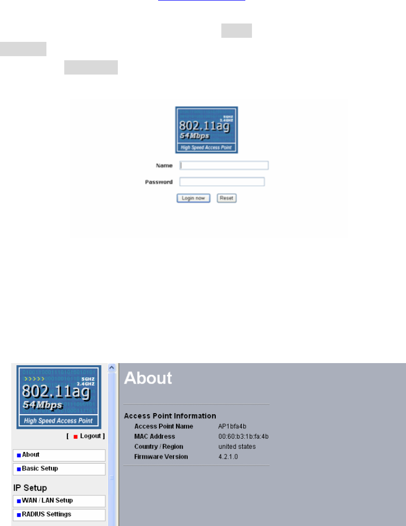
3-1 Start-up and Log in
In order to configure the Access Point, you must use your web browser and please do the
following:
1. Type this Access Point’s address http://192.168.1.1 in the Location (for IE) or Address
field and press Enter.
2. Enter the system name (the default setting is “admin”) and password (the default setting is
“password”).
3. Click on the “Login now” button.
4. The main page will appear.
After you have logged-in the main page, the About, IP Setup, Wireless Setup, AP Status,
Management buttons will be shown. The main menu provides links to the whole sections of
the web configuration interface.
About
The About screen describes the product information briefly. The Access Point information
includes Access Point Name, MAC Address, Country / Region and Firmware Version.
11
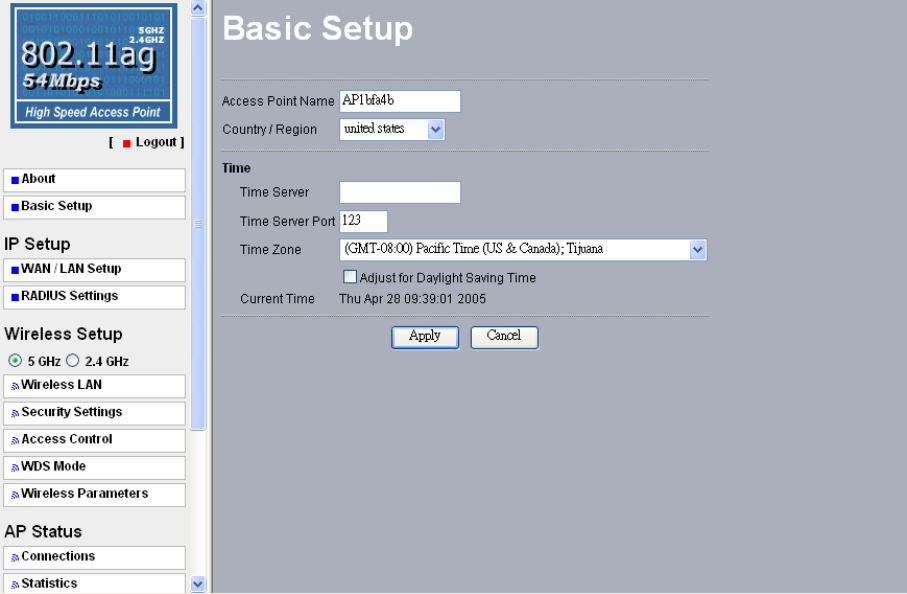
Basic Setup
The Access Point Name is used to give a name to your Access Point. This will enable you to
manage your Access Point more easily if you have multiple Access Points on your network.
Country / Region: Allow you to select country domain in case there is any chances that you
would use wireless network in other countries.
Time: While you connect the AP to Internet, the Access Point could automatically
synchronize the current time of the access point with the Time Server that you have set.
Time Server: the central time of the Time Server.
Time Server Port: the port of the Time Server.
Time Zone: You may select the appropriate local time zone for your Access Point from a list
of all available time zones. Default: GMT.
Note: If you complete the settings, please click on “Apply” for changes to take effect.
12
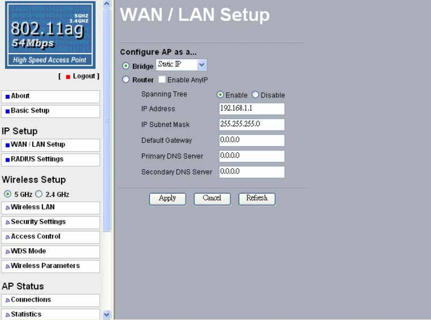
3-2 IP Setup
WAN/LAN Setup
By default, the Access Point can be configured as a Bridge or a Router. If you want the AP to
act as a DHCP server gateway for the wireless clients, use this feature. This AP accepts both
static and DHCP clients.
As a Bridge mode:
Static IP: The Access Point can provide you to assign a proper IP address to your wireless
access point manually.
DHCP Client: Enable this function to support the wireless access point to obtain the IP
address from the DHCP server on your network automatically.
Spanning Tree: This function provides network traffic optimization in settings with multiple
802.11 a/b/g SMB Access Points. You may Enable or Disable the Spanning Tree Protocol
used in the Access Point.
13
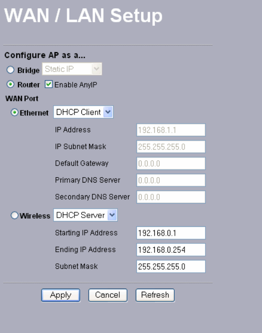
As a Router mode:
Enable AnyIP: When enable AnyIP, the Access Point will support wireless client with DHCP
enabled and the static IP configured to access Internet.
Note: While enabling AnyIP, the wireless clients with static IP settings should input any
Gateway IP address.
14
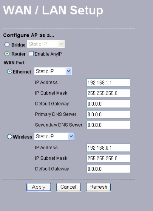
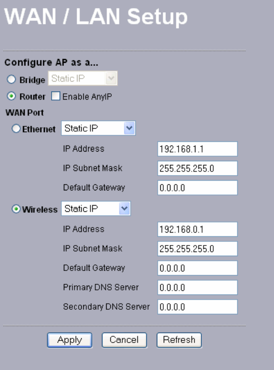
WAN Port:
Ethernet: This access point is function as a router connecting to Internet with Ethernet Cable.
That is, the wireless clients can access Internet through this wireless access point.
Static IP: The wireless access point is configured with the following private static IP address.
-IP Address: 192.168.1.1
-IP Subnet Mask: 255.255.255.0
-Default Gateway: 0.0.0.0
-Primary DNS Server: 0.0.0.0
-Secondary DNS Server: 0.0.0.0
15
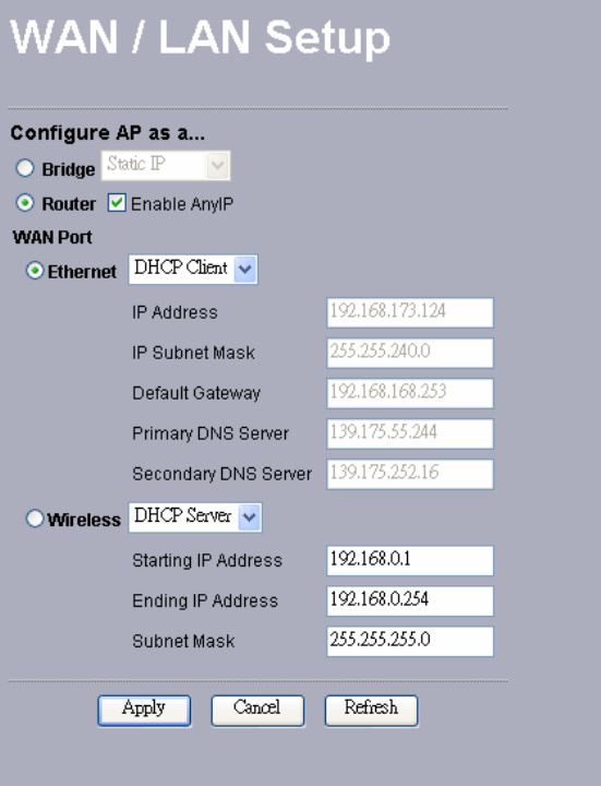
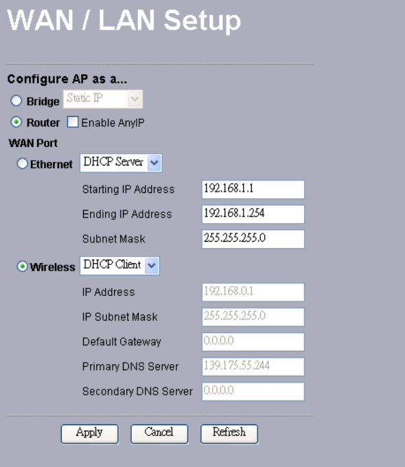
DHCP Client: The access point will get the IP address, subnet mask, default gateway and
Primary / Secondary DNS Server automatically from the DHCP server if DHCP client is
enabled. Meanwhile, these IP Addresses will highlight. While enabling DHCP Client here, the
“Wireless” side will become DHCP Server.
16
Wireless: This makes your network more flexible for wireless connectivity (Such as WDS).
Static IP: The wireless access point is configured with the following private static IP address.
-IP Address: 192.168.0.1
-IP Subnet Mask: 255.255.255.0
-Default Gateway: 0.0.0.0
-Primary DNS Server: 0.0.0.0
-Secondary DNS Server: 0.0.0.0
17
DHCP Client: The access point will get the IP address, subnet mask, default gateway and
Primary / Secondary DNS Server automatically from the DHCP server if DHCP client is
enabled. Meanwhile, these IP Addresses will highlight. While enabling DHCP Client here, the
“Ethernet” side will become DHCP Server.
Note: If you complete the settings, please click on “Apply” for changes to take effect.
18
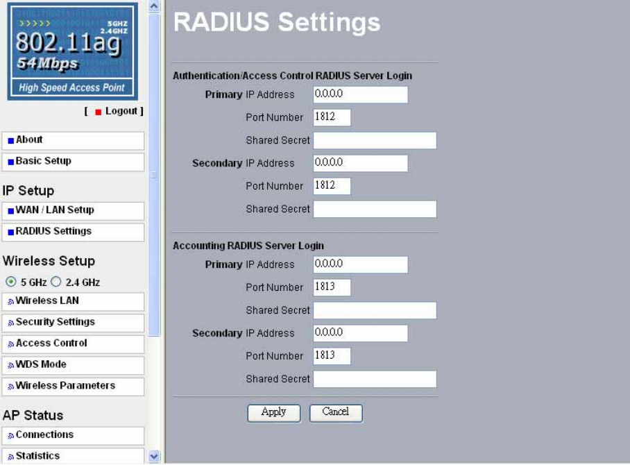
RADIUS Settings
Authentication/Access Control of RADIUS Server Login
This configuration is required for authentication using Radius Server. Here you may have two
choices. Primary and Secondary.
IP Address- The IP Address of the Radius Server. Default: 0.0.0.0.
Port Number- The Port Number of the Radius Server. Default: 1812.
Shared Secret- This is required between your Access Point and the Radius Server while
authenticating. You may input up to 31 characters.
The Secondary Radius Server is used when the Primary Radius Server cannot be found.
Accounting RADIUS Server Login
The configuration is required for Accounting using Radius Server by viewing the logs
generated at Radius Server.
IP Address- The IP Address of the Radius Server. Default: 0.0.0.0.
Port Number- The Port Number of the Radius Server. Default: 1813.
Shared Secret- This is required between your Access Point and the Radius Server while
authenticating. You may input up to 31 characters.
The Secondary Radius Server is used when the Primary Radius Server cannot be found.
Note: If you complete the settings, please click on “Apply” for changes to take effect.
19
3-3 Wireless Setup
This section provides you to configure the wireless connections. Both 802.11a and 802.11g
can work simultaneously and configurations are located in this section. For the setting of each
band, please do the following.
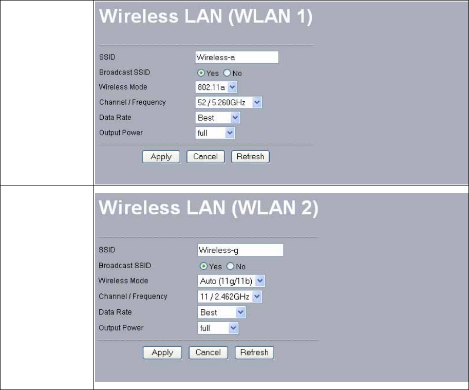
Wireless LAN
The Wireless LAN Setup page lets you make changes to the wireless network settings. From
this window you can make changes to the wireless network name SSID, Broadcast SSID,
Wireless Mode, Channel/Frequency, Data Rate, and Output Power.
For 802.11a configuration, go to (WLAN1); for 802.11g, go to (WLAN2).
802.11a (5GHz)
802.11g (2.4GHz)
SSID: The SSID is a unique ID used by Access Points and Stations to identify a wireless
LAN. Wireless clients associating to any Access Point must have the same SSID. For 802.11a,
the default SSID is “Wireless-a”. For 802.11g, the default is “Wireless-g”. To change the
SSID, type in the SSID you like to use. It is case sensitive and must not exceed 32 characters.
20
Broadcast SSID: For security concern, you can choose not to broadcast your network’s SSID.
To turn off the broadcast of the SSID, click “No” check box next to “Broadcast SSID”. And
your Access Point will refuse the connection requests from whose are not aware the Network
ID. But certainly the Access Point can be easily connected well when you realize the Network
ID. The default setting is “Yes”.
Wireless Mode: W hen enable 5GHz mode, the wireless mode will switch to 802.11a. When
select 2.4GHz mode, the wireless mode will switch to 802.11b/g mode. In Auto (11g/11b)
mode, the access point is compatible with a mix of both 802.11g and 802.11b clients. You
will see that the factory-set default “Auto (11b/11g)” will prove the most efficient. 802.11b
only mode is compatible with 802.11b clients only. This mode can be used only if you do not
allow any 802.11g clients to access to the network. 802.11g only mode is compatible with
802.11g clients only. This mode can be used only if you do not allow any 802.11b clients to
access to the network. To switch the mode, select the desired mode form the pull-down menu
next to “Wireless Mode”.
Channel / Frequency: Select the appropriate channel/Frequency from the list provided to
correspond with your network settings. For 802.11a, the default value is “52/5.260GHz”. For
802.11g, the default is “11/2.462GHz”.
Date Rate: The basic transfer rates should be set depending on the speed of your wireless
network. Specifies rate of data transmission. For 802.11a, there are Best, 6, 9, 12, 18, 24, 36,
48, 54Mbps. For 802.11g, there are Best, 1, 2, 5.5, 6, 9, 11, 12, 18, 24, 36, 48, 54Mbps. Select
the desired rate from the drop-down menu or choose “Best” to adapt the rate to the best
available.
Output Power: Set the transmit signal strength of the access point. The options are full, half, quarter,
eighth and min. Decrease the transmit power if necessary. The default is “full”.
Note: If you complete the settings, please click on “Apply” for changes to take effect.
21
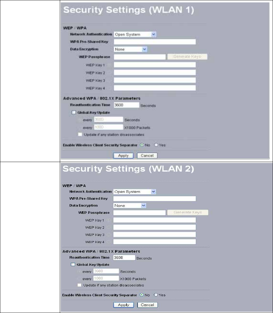
Security Settings
The WEP / WPA Key setting is shown on the screen for both 802.11a and 802.11b wireless
devices.
WEP / WPA
To prevent unauthorized wireless stations from accessing data transmitted over the network,
the Access Point Security Settings window offers WEP / WPA features, making your data
transmission over air more secure and allows you to specify Encryption Key(s) if you enable
encryption for the Access Point.
For 802.11a configuration, go to (WLAN1); for 802.11g, go to (WLAN2).
802.11a (5GHz)
802.11g (2.4GHz)
22
Network Authentication
Choose the Network Authentication Type.
Open System: Requires NO authentication, since it allows any device to join a network
without performing any security check. The Authentication Type default is set to “Open
System”. We recommend that you use the default setting.
Shared Key: Requires that the station and the access point use the same WEP key to
authenticate. This basically means that WEP must be enabled and configured on both the
access point and the client with a same key. All points on your network must use the same
authentication type.
Legacy 802.1x: If selected, you must configure the Radius Server Setting Screen.
WPA with Radius: If selected, you must configure the Radius Server Setting Screen.
WPA-PSK: If selected, you must use TKIP encryption, and enter the WPA Pre-Shared Key.
WPA Pre-Shared Key: In the WAP-PSK field, you may enter 8-63 characters ranging from
“a-z”, “A-Z”, and “0-9”.
Data Encryption:
Select the desired potion. If enabled (64 bit WEP, 128 bit WEP, 152 bit WEP), the keys must
have the same encryption strength and must be the same with the keys that other wireless
stations use. The TKIP option is automatically activated when either “WPA with Radius”, or
“WPA-PSK” is enabled.
WEP Passphrase:
There are two methods for creating WEP data encryption:
z Using a Passphrase: Type in a passphrase and click “Generate Keys”. Passphrase can
be a mixture of numbers and letters. When entering passphrase, you must not exceed 32
characters. As you type, the wireless access point will use an algorithm to generate 4
keys automatically. Select one key from the 4 WEP keys.
z Manually:
64 bits WEP: Enter 10 hexadecimal digits (between 0-9, a-f and A-F).
128 bits WEP: Enter 26 hexadecimal digits (between 0-9, a-f and A-F).
152 bits WEP: Enter 32 hexadecimal digits (between 0-9, a-f and A-F).
23
Note: The WEP key must be set up exactly the same on the Wireless Access Points as they
are on the wireless clients. If you set “0011223344” for the Wireless Access Point, the same
WEP key “0011223344” must be assigned to other client stations.
Advanced WPA / 802.1X Parameters
Here you can use Reauthentication Time and Global-Key Update to check if any association
is working well on the time and packets units you set.
Enable Wireless Client Security Separator
Enable this function to let associated clients be able to separate from each other when security
is required. The default setting is Disable.
Note: If you complete the settings, please click on “Apply” for changes to take effect.
24
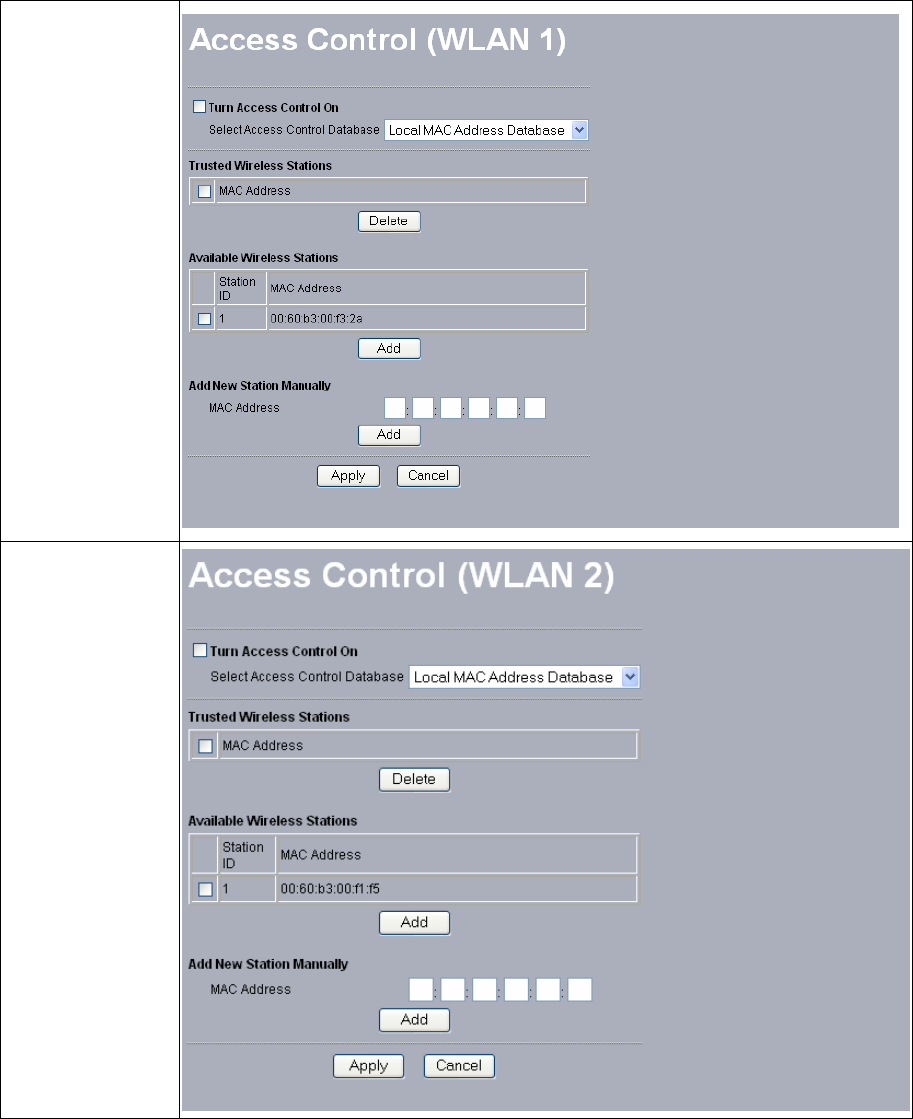
Access Control
The Access Control allows you to restrict wireless access by MAC Address. This provides an
additional layer of security.
On 802.11a page, this AP can scan the clients surroundings are using 5GHz band. On 802.11g
page, this AP can scan the clients surroundings are using 2.4GHz band.
For 802.11a configuration, go to (WLAN1); for 802.11g, go to (WLAN2).
802.11a (5GHz)
802.11g
(2.4GHz)
25
Follow these steps while using Access Control:
1. In this Wireless Access Point’s left page, choose the Access Control option from the
Wireless Setup.
2. If you want to enable Access Control feature, click the check box next to “Turn Access
Control on”.
3. Select the desired Access Control Database: Local MAC Address Database and RADIUS
MAC Address Database.
Local MAC Address Database: The Access Point will use the local MAC address table
for Access Control.
RADIUS MAC Address Database: The Access Point will use the MAC address table
located on the external Radius server on the network for Access Control.
4. Then, either select form the list of available wireless stations that your Access Point has
found or enter the MAC address for each client. After enter the MAC Address, click
“Add” button in the MAC Address field to be managed.
5. Click “Delete” button if you wish to remove the MAC address from the list.
6. If you complete the settings, please click on “Apply” for changes to take effect.
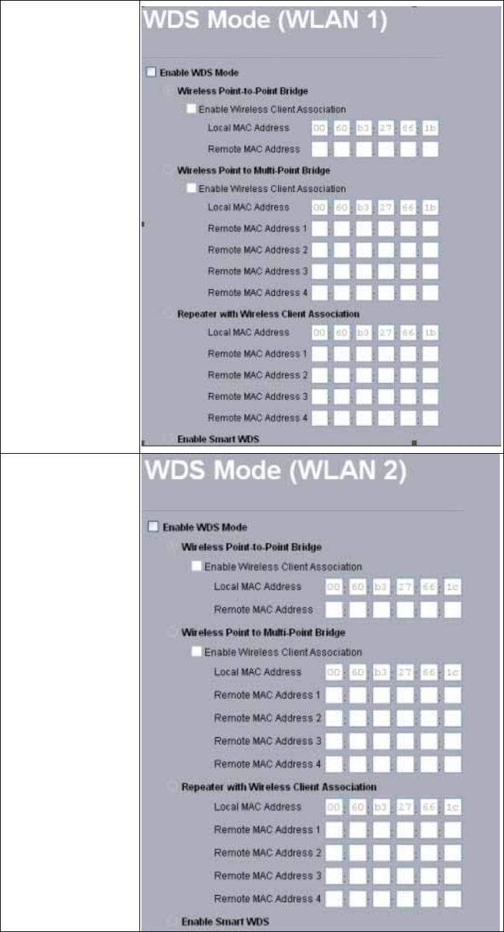
WDS Mode
The feature lets you extend the range of your network without having to use cables to link the
Access Point, meaning that you can link wirelessly the Access Points. To use WDS by
clicking the check box next to “Enable WDS Mode”. There are four modes in which an
access point can be configured. Select the desired mode for your environment.
z Wireless Point-to-Point Bridge
z Wireless Point to Multi-Point Bridge
z Repeater with Wireless Client Association
z Enable Smart WDS
26
For 802.11a configuration, go to (WLAN1); for 802.11g, go to (WLAN2).
802.11a (5GHz)
802.11g (2.4GHz)
27
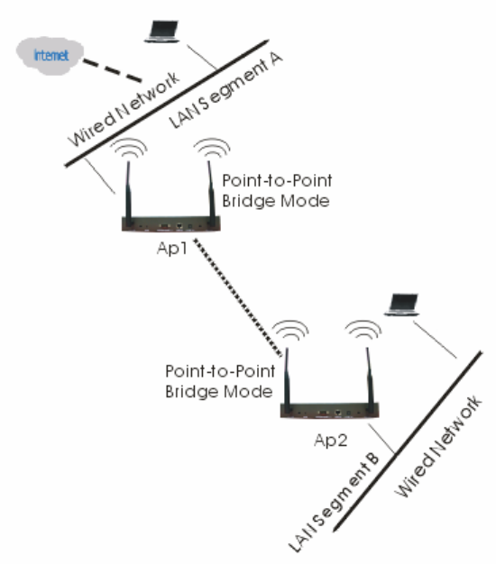
Configure a Wireless Point-to-Point Bridge
To activate the Point-to-Point Bridge mode please do the following:
1. Configure WDS mode for both Access Point:
¾ Configure both AP1 on LAN Segment A and AP2 on LAN Segment B in Point-to-Point
Bridge mode.
¾ AP1 must have AP2’s Mac address and enter it in the Remote MAC Address field.
¾ AP2 must have AP1’s Mac address and enter it in the Remote MAC Address field.
2. Enable Wireless Client Association:
¾ If enabled, your Access Point is functioning as a regular Access Point, which can
provide the link services to wireless clients. Then, wireless clients can communicate
with other wireless clients that are located in different LAN Segments.
¾ Verify that AP1 and AP2 are both configured in the same LAN network address range
as wireless clients with which associated.
¾ Make sure that Mode, SSID, Channel and encryption settings are set the same for both
of your WDS-compliant Access Points.
3. After you complete the settings, please click on “Apply” for changes to take effect.
28
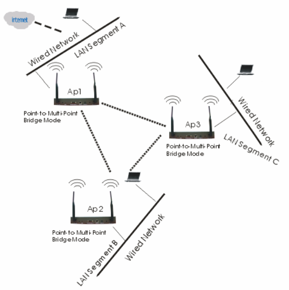
Configure a Wireless Point to Multi-Point Bridge
To activate the Point-to Multi-Point Bridge mode please do the following:
1. Configure WDS mode for each Access Point:
¾ Configure AP1, AP2, and AP3 in Point-to Multi-Point Bridge mode.
¾ Verify that AP1 on LAN Segment A with the Remote MAC Address of AP2 and AP3.
¾ Verify that AP2 on LAN Segment B with the Remote MAC Address of AP1 and AP3.
¾ Verify that AP3 on LAN Segment C with the Remote MAC Address of AP1 and AP2.
2. Enable Wireless Client Association:
¾ If enabled, your Access Point is functioning as a regular Access Point, which can
provide the link services to wireless clients. Then, wireless clients can communicate
with other wireless clients that are located in different LAN Segments.
¾ Verify that all access points are configured in Point-to Multi-Point Bridge mode.
¾ All the access points’ IP Address must be set in the same network.
¾ Make sure that Mode, SSID, Channel and encryption settings are set the same for all
of your WDS-compliant Access Points.
3. After you complete the settings, please click on “Apply” for changes to take effect.
Note: Under Point-to Multi-Point Bridge mode, you can extend this multi-point bridge by
adding additional 802.11 a/b/g SMB Wireless Access Points for each additional LAN
Segment.
29
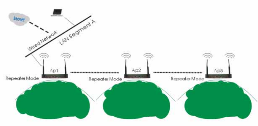
Configure a Repeater with Wireless Client Association
To activate the Repeater with Wireless Client Association, please do the following:
1. Configure WDS mode for each Access Point:
¾ Configure AP1 on LAN Segment A in Repeater mode with the Remote MAC Address
of AP2.
¾ Configure AP2 on LAN Segment B in Repeater mode with the Remote MAC Address
of AP1 and AP3.
¾ Configure AP3 on LAN Segment C in Repeater mode with the Remote MAC Address
of AP2.
2. After you complete the settings, please click on “Apply” for changes to take effect.
Note: Under Repeater Bridge mode, you can extend this repeater bridge by adding additional
802.11 a/b/g SMB Wireless Access Points for each additional LAN Segment.
Enable Smart WDS
If this feature is selected, a WDS Service Group ID is required and must be the same with the
ID of other remote Access Points. You can input up to 32 characters. After you complete the
settings, please click on “Apply” for changes to take effect.
30
Wireless Parameters
These parameters can be changed if needed, but the default advanced setting usually work
well. It is recommended that you keep all these values in factory default.
This screen is shown in (WLAN1) for 802.11a wireless parameters setting and (WLAN2) for
802.11g wireless parameters configuration.
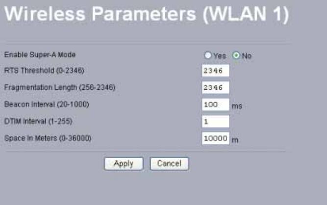
802.11a (5GHz):
Enable Super-A Mode: Enable Super-A may enhance the wireless throughput. The default
setting is Disable.
RTS Threshold: RTS Threshold is a mechanism implemented to prevent the “Hidden Node”
problem. If you have more collisions, it is recommended to enable RTS. If you have fewer
collisions, it is not necessary to enable RTS. Forcing the access point to implement the
RTS/CTS handshake will significantly increase the overhead and reduce throughput. If the
size of the packet transmitted is larger than the value you set, the RTS should be enabled.
Fragmentation Length: Fragmentation mechanism is used for improving the efficiency
when there is high traffic within the wireless network. If you transmit large files in a wireless
network, you can enable the Fragmentation Threshold and specify the packet size. This
specifies the maximum size a data packet will be before splitting and creating a new packet.
The setting range is 256-2346. For example: If you set value as 256, it means the packet will
be fragmented into “256” bytes while transmitting.
Beacon Interval: This value indicates the frequency interval of the beacon. The beacon
interval is the amount of time between access point beacon transmissions.
31
DTIM: This value indicates the interval of the Delivery Traffic Indication Message (DTIM).
When the Access Point has buffered broadcast or multicast messages for associated clients, it
sends the next DTIM with a DTIM Interval value. Clients can hear the beacons and awaken to
receive the broadcast and multicast messages. A DTIM interval is a count of the number of
beacon frames. For example: a DTIM interval equal to one means that the multicast frames
are sent after each beacon frame. Generally speaking, as the access point transmits a multicast
frame, it is recommended to set value as 1.
Space In Meter: This space in meter is used for extending ACK time-out destination. The
setting range is 0-36000.
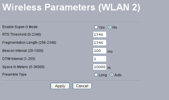
802.11g (2.4GHz):
Enable Super-G Mode: Enable Super-G may enhance the wireless throughput. The default
setting is Disable.
RTS Threshold: RTS Threshold is a mechanism implemented to prevent the “Hidden Node”
problem. If you have more collisions, it is recommended to enable RTS. If you have fewer
collisions, it is not necessary to enable RTS. Forcing the access point to implement the
RTS/CTS handshake will significantly increase the overhead and reduce throughput. If the
size of the packet transmitted is larger than the value you set, the RTS should be enabled.
Frag Threshold: Fragmentation mechanism is used for improving the efficiency when there
is high traffic within the wireless network. If you transmit large files in a wireless network,
you can enable the Fragmentation Threshold and specify the packet size. This specifies the
maximum size a data packet will be before splitting and creating a new packet. The setting
range is 256-2346. For example: If you set value as 256, it means the packet will be
fragmented into “256” bytes while transmitting.
32
Beacon Interval: This value indicates the frequency interval of the beacon. The beacon
interval is the amount of time between access point beacon transmissions.
DTIM: This value indicates the interval of the Delivery Traffic Indication Message (DTIM).
When the Access Point has buffered broadcast or multicast messages for associated clients, it
sends the next DTIM with a DTIM Interval value. Clients can hear the beacons and awaken to
receive the broadcast and multicast messages. A DTIM interval is a count of the number of
beacon frames. For example: a DTIM interval equal to one means that the multicast frames
are sent after each beacon frame. Generally speaking, as the access point transmits a multicast
frame, it is recommended to set value as 1.
Space In Meter: This space in meter is used for extending ACK time-out destination. The
setting range is 0-36000.
Preamble: The Preamble defines the length of the PLCP synchronization field for
communication between the Access Point and Network Card. Select the appropriate preamble
type and press the Apply button to set it. The default setting is ‘Auto’.
Note: Advanced parameters vary in accordance with operating mode you configure.
33
3-4 AP Status
802.11a: 5 GHz
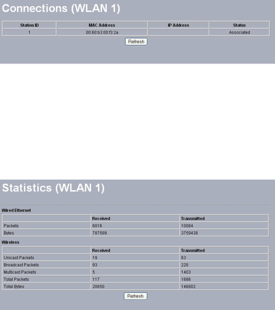
Connections
When set to 802.11a, you may see the association condition of the AP, including Station ID,
MAC Address, I P Address and Status.
To display the Station List, follow these steps:
1. Choose the Connections option from AP Status.
2. The Station List window will display.
3. By clicking the “Refresh” button, the AP Browser will reload and show the associated
wireless stations that are currently part of its Basic Service Set (BBS).
Statistics
The Statistics screen provides various Ethernet and Wireless TX/RX packet statistics on the
Access Point. Click the Refresh button to update the statistics on this screen.
34
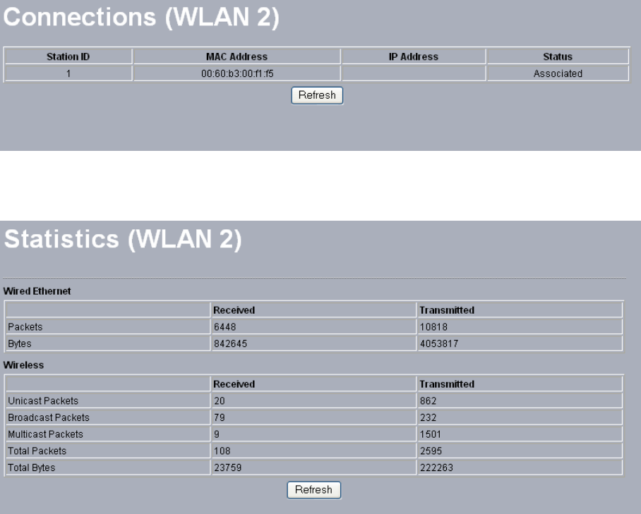
802.11g: 2.4 GHz
When set to 802.11g, the association condition of the AP will display as below.
The Statistics page will refresh the Ethernet and Wireless TX/RX packet statistics for
802.11b/g wireless connections.
35
3-5 Management
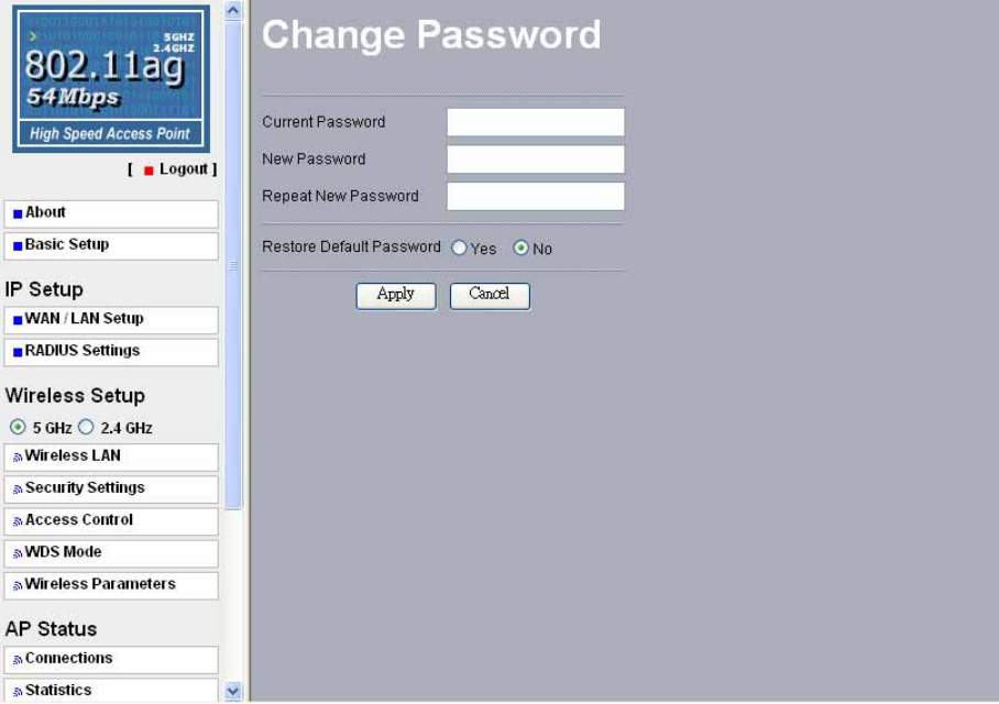
Change Password
Here allow you to change the Access Point’s password, do the following:
1. To change the current password, choose the “Change Password” option from the
“Management” section in the Wireless Access Point’s left page. Key in the default
password “password” in the “Current Password” filed.
2. Changing password for the Access Point is as easy as typing the password into the New
Password field. Then, type it again into the Retype New Field to confirm. Click the
“Apply” button to save the setting.
Note: After you change password, please take note of your new password. Otherwise, you
will not able to access the Wireless Access Point setup. If you forget the password, you could
restore the default password “password” by clicking the “Yes” check box in the “Restore
Default Password” field or pressing the Reset button on the back panel of your Wireless
Access Point for at least 10 second – and all previous configurations will need to be input
again.
36
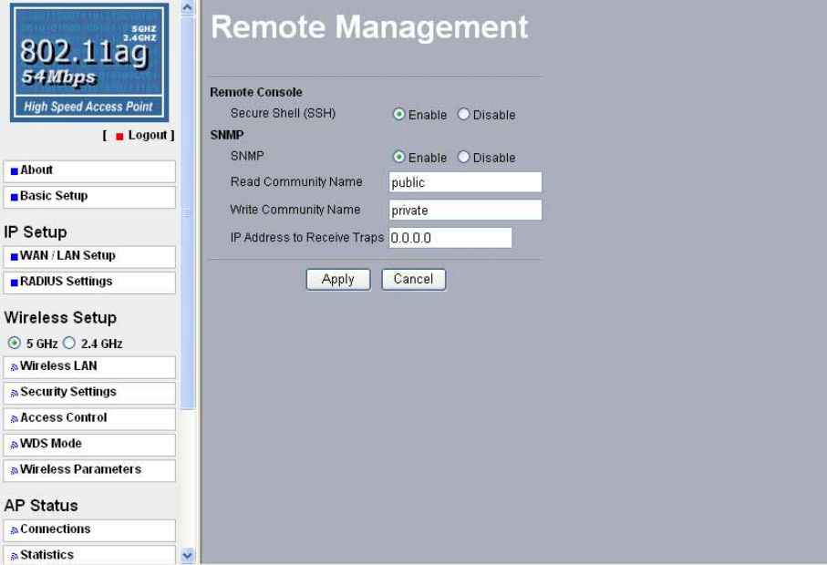
Remote Management
Remote Console
Secure Shell (SSH)
If enable Secure Shell, the Wireless Access Point will only allow remote access via Secure
Telnet.
SNMP
Enable SNMP to allow the SNMP network management software to manage the wireless
access point via SNMPv2 protocol.
Read Community Name: Allow the SNMP manager to read the MIB objects of the wireless
access point. The default setting is “public”.
Write Community Name: Allow the SNMP manager to write the MIB objects of the
wireless access point. The default setting is “private”.
IP Address to Receive Traps: The IP address of the SNMP manager to receive traps sent
from the wireless access point.
Click “Apply” if you make any changes.
37
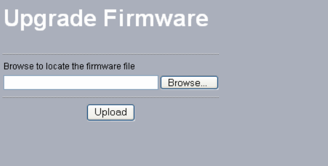
Upgrade Firmware
The Upgrade Firmware menu will display the Upgrade Firmware window so that you could
update the latest firmware on the 802.11 a/b/g SMB Wireless Access Point.
Please make sure that you have downloaded the latest and correct firmware from the product
support website and store it in local drive before upgrading the firmware of the 802.11 a/b/g
SMB Wireless Access Point.
To upgrade the latest firmware, complete the following:
z Using browser to access (192.168.1.1) AP’s main page.
1. Select Upgrade Firmware from the Management section.
2. Input the exact file path and name by clicking Browse button, then press Upload
button to upgrade the firmware.
3. Please wait for few seconds.
z If download fail, please repeat the step 1~3 to download again.
z Note! Do not power off the unit when it is being upgraded.
38
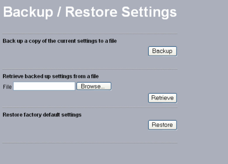
Backup / Restore Settings
The current system settings can be backup as a file onto the local hard drive by clicking
“Backup”. The saved file can be loaded back on the Access Point by clicking “Browse”.
When you have selected the settings file, click “Retrieve” to begin the process.
Furthermore, you may click “Restore” to factory default settings.
39
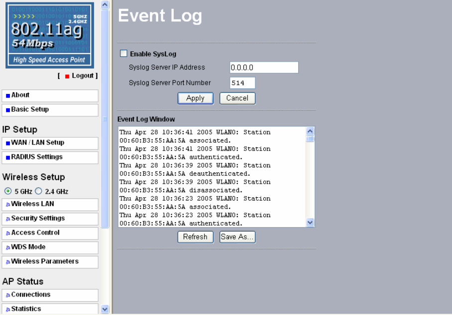
Event Log
Enable SysLog if you have a Syslog Server on your network environment. If enable, you need
to input the Syslog Server IP Address (default is 0.0.0.0) and the port number your Syslog
Server is configured to use. The default port number is 514. Click “Apply” if you made any
changes.
The Event Log Window lists access point events. Click on “Refresh” to update the network
events or “Save As…” to save the event into a file on your computer.
40
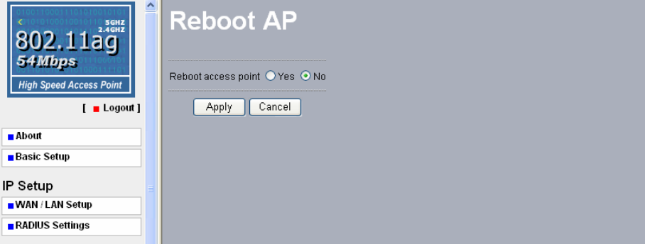
Reboot AP
The Reboot AP screen enables you to reboot your Wireless Access Point. If any changes are
made and you want them to take effect, you need to reboot the access point. Select the “Yes”
check box and click “Apply”. It will take you about 50 seconds to go through reboot. The
Web-browser will not be accessible until the access point has finished its reboot process.
41
Chapter 4 Troubleshooting
Q1. Why can’t I connect to Internet? 1. Make sure that your DSL or Cable modem is
running correctly.
2. The cable is connected properly form the WAN
port of the access point to your DSL or Cable
modem.
3. Make sure that the right WAN Setup is used in
the web configuration.
4. Make sure that the username and password input
in the WAN Setup is correct.
Q2. Why can’t I access my 802.11
a/b/g Wireless AP?
1. Make sure that your AP is powered on.
2. Make sure that your computer has a compatible
IP address. Be sure that the IP address used on
your computer is set to the same as the AP. For
example, if the AP is set to 192.1681.1, change
the IP address of your computer to 192.168.1.15
or another unique IP that corresponds to the
192.168.1.X subnet.
3. Use the Reset Button locates on the rear of the
AP to revert to the default settings.
42
Q3. How can I reset my 802.11 a/b/g
Wireless AP to factory default?
1. Follow these steps to perform a Factory Reset
using the Reset button on the back of the 802.11
a/b/g Wireless AP.
z With the unit on, press and hold the Reset
button with a pen or paper clip.
z Hold the reset button for about 10 seconds
until the Status LED on the front panel blinks
very quickly and then release.
z Wait a few seconds for the AP to reboot using
default settings.
2. A Factory Reset can also be performed through
the web configuration interface. Follow these
steps to perform a factory reset using the web
configuration interface.
z Log into the Wireless AP web configuration
interface.
z Click on the Reboot AP from the menu.
z Select “Yes” and click “Apply”.
3. You should reboot the AP to have the change take
effect.
Q4. What should I do if I forget my
password?
1. The only way is to restore factory configuration
to the Wireless AP. Please refer to question 3.
43
Q5. Why can’t I access the Wireless
AP from a wireless network card?
1. Make sure that Mode, SSID, Channel and
encryption settings are set the same on each
wireless adapters.
2. Make sure that your computer is within range and
free from any strong electrical devices that may
cause interference.
3. Check your IP address to make sure that it is
compatible with the Wireless AP.
Q6. How do I know if my computer
is connected to the Wireless AP?
1. Try the following procedure
Click “Start”-> “Programs”-> “Accessories”->
“Command prompt”.
2. At your MS-DOS prompt, you can use the ping
command to check if your computer has
successfully connected to the Wireless AP.
3. Execute the ping command: ping 192.168.1.1.
4. Check if you can access the Wireless AP’s setup
page by typing “192.168.1.1” in the Location (for
IE) or Address field.
Q7. Dose this wireless AP function
as a firewall?
No, The Access Point is a bridge from Ethernet to
wireless clients.
Q8. Can the Access Point function
as a DHCP server?
No. The Access Point can’t be configured to serve
DHCP clients.
44
Limited Warranty
This Warranty constitutes the sole and exclusive remedy of any buyer or reseller’s equipment
and the sole and exclusive liability of the supplier in connection with the products and is in
lieu of all other warranties, express, implied or statutory, including, but not limited to, any
implied warranty of merchantability of fitness for a particular use and all other obligations or
liabilities of the supplier.
In no even will the supplier or any other party or person be liable to your or anyone else for
any damages, including lost profits, lost savings or other incidental or consequential damages,
or inability to use the software provided on the software media even if the supplier or the
other party person has been advised of the possibility of such damages.
The following are special terms applicable to your hardware warranty as well as services you
may use during part of the warranty period. Your formal Warranty Statement, including the
warranty applicable to our Wireless LAN products, appears in the Quick Installation Guide
that accompanies your products.
Duration of Hardware Warranty: 13 months
Replacement, Repair or Refund Procedure for Hardware:
If your unit needs a repair or replacement, return it to your dealer/distributor in its original
packaging. When returning a defective product for Warranty, always include the following
documents:
The Warranty Repair Card
A copy of the invoice/proof of purchase, and
The RMA Report Form (To receive a Return Materials Authorization form (RMA),
please contact the party from whom you purchased the product).
Upon proof-of-purchase we shall, at its option, repair or replace the defective item at no cost
to the buyer.
This warranty is contingent upon proper use in the application for which the products are
intended and does not cover products which have been modified without the reseller’s
approval or which have been subjected to unusual physical or electrical demands or damaged
in any way.

45
Please complete the information below and include it along with your products.
Name:
Title:
Company:
Telephone:
Fax:
Email:
City/State/Zip code:
Country:
Product Name:
Serial Number:
MAC Address:
Invoice Date:
Product Description:
If you have any further questions, please contact your local authorized reseller for support.