Z Com XG1020V04 Wireless LAN Access Point User Manual
Z Com Inc Wireless LAN Access Point Users Manual
UserManual.wiki
>
Z Com
>
XG1020V04 User Manual
Users Manual
Navigation menu
Upload a User Manual
Namespaces
Wiki Guide
HTML
PDF
Info
Views
User Manual
Discussion / Help
Navigation


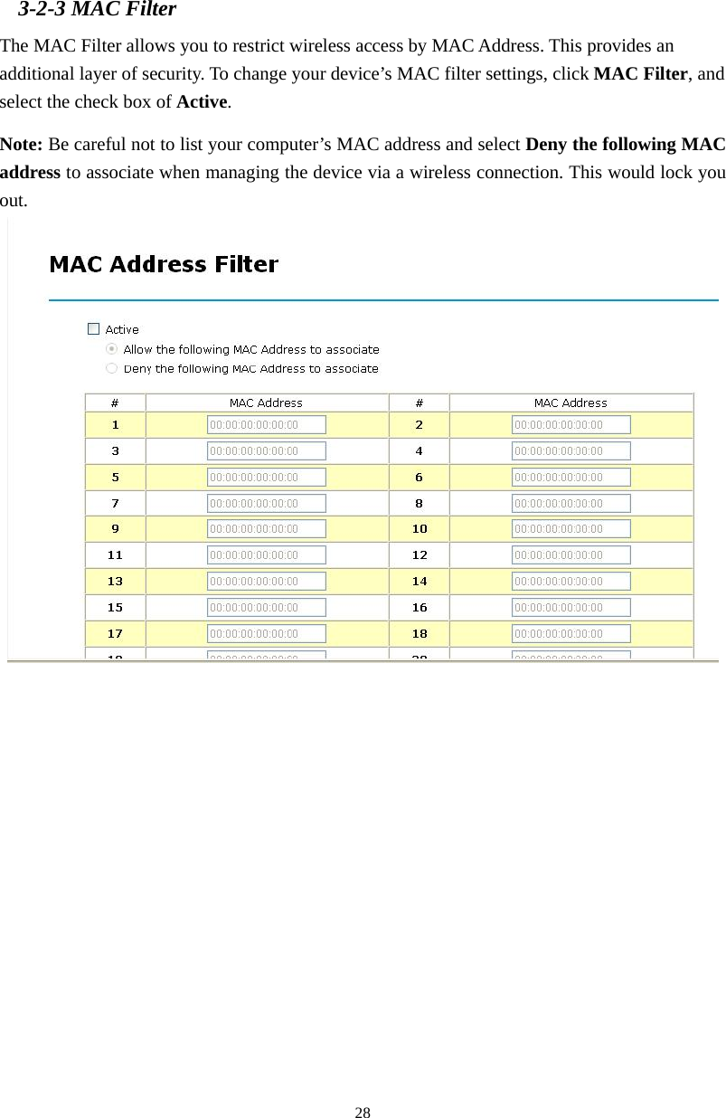
![6 2-3 Mechanical Description Front Panel The front panel provides LED’s for device status. Refer to the following table for the meaning of each feature. LED STATUS Description Off 802.11g SOHO Wireless Access Point is off. PWR/SYS On 802.11g SOHO Wireless Access Point is in service. Green Off No ethernet link is detected. Green On 10Mbps Ethernet link is detected. Green Blinking Data sending/receiving. Amber On 100Mbps Ethernet link is detected. ETHN Amber Blinking Data sending/receiving. Off Indicates no 802.11g wireless links. On Wireless LAN is in service but no activity. WLAN Blinking Indicates the device is linking or active data through wireless links. EZ Button The button to make user easy to setup wireless security. 註解 [NH1]: Front Panel Picture](https://usermanual.wiki/Z-Com/XG1020V04/User-Guide-781640-Page-6.png)
![7 Rear Panel To know the rear panel features, please refer to the following table for the meaning of each feature. Power Socket (DC 12v) Connect the DV 12V/1.2A power supply. ONLY use the power adapter supplied with the 802.11g SOHO Wireless Access Point. Otherwise, the product may be damaged. Reset Simply press the reset button and keep pressing it for around 5 seconds. The 802.11g SOHO Wireless Access Point will be restored to factory default settings. LAN Use the Ethernet RJ-45 port to connect to the 10/100Mbps Ethernet network and Ethernet through a device such as a hub, switch, or router. ANT. This is connector for anntena. 註解 [NH2]: Rear Panel Picture](https://usermanual.wiki/Z-Com/XG1020V04/User-Guide-781640-Page-7.png)