Z Com XG621 IEEE 802.11 g/b Mini-PCI Module User Manual AG 320 Manual 20030624
Z Com Inc IEEE 802.11 g/b Mini-PCI Module AG 320 Manual 20030624
UserManual.wiki
>
Z Com
>
XG621 User Manual
User Manual
Navigation menu
Upload a User Manual
Namespaces
Wiki Guide
HTML
PDF
Info
Views
User Manual
Discussion / Help
Navigation

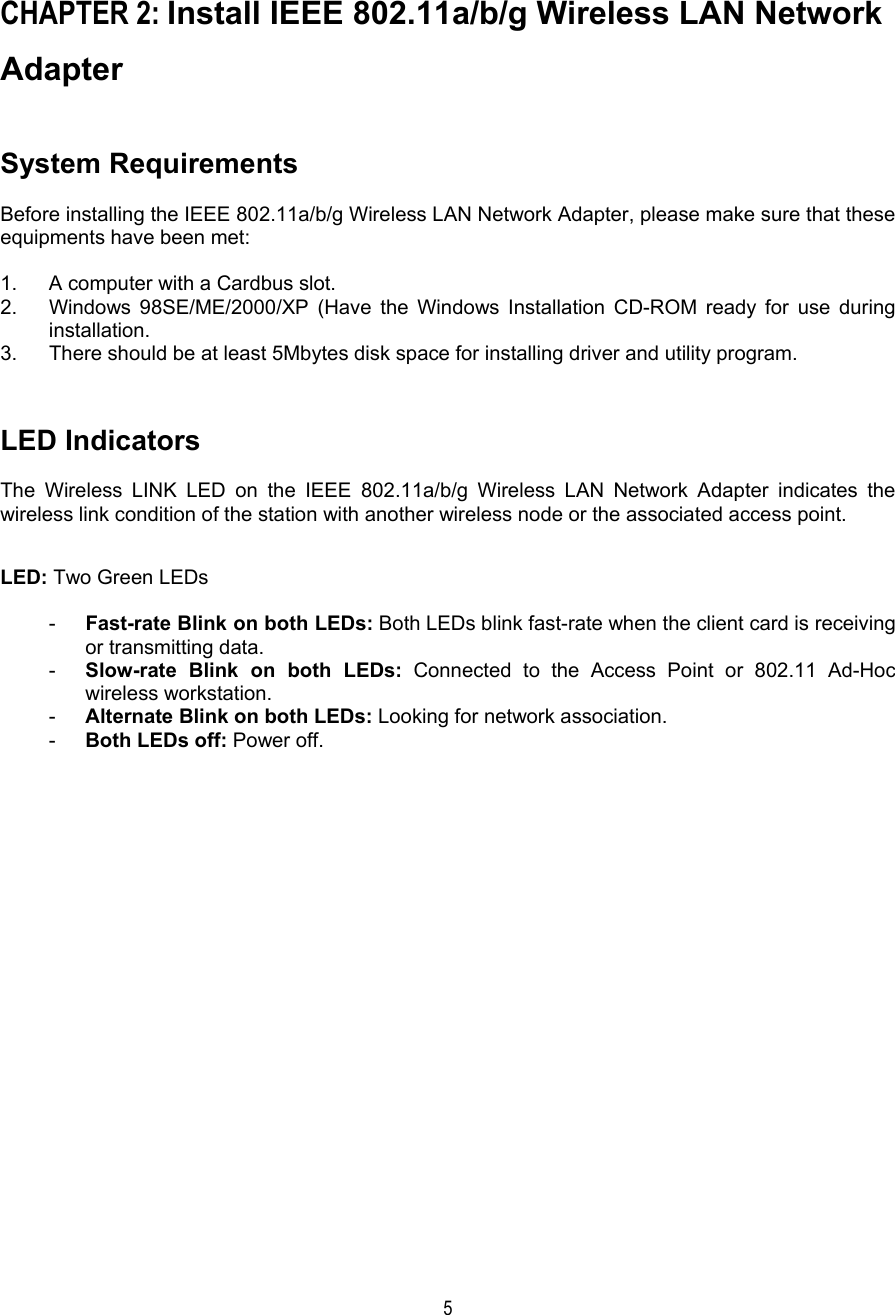
![6Windows 98SE/ME/2000/XP Installation 1. Turn on the computer. 2. With the LED indicators facing up, properly insert the IEEE 802.11a/b/g Wireless LAN Network Adapter into the Cardbus slot on your computer as shown below. 3. The Windows will automatically detect the IEEE802.11a/b/g Wireless LAN Network Adapter and the Found New Hardware Wizard dialog box appears for the driver (only applies to Windows 98SE, Me, 2000 and XP. 4. Follow the on-screen instructions to install the driver for the IEEE 802.11a/b/g Wireless LAN Network Adapter. 5. For Windows 98SE/ME, once the [Please insert the disk labeled “Windows 98SE/ME CD-ROM”, and then click OK] window appears, enter the path corresponding to the appropriate drives and click OK. Usually these files can be found at C:\Windows or C:\Windows\system. 6. For Windows 2000, a Digital Signature Not Found message may appear. Click Yes to proceed. 7. For Windows XP, a Windows Logo Testing Not Found dialog box may appear. Click Continue Anyway to proceed. 8. Click Finish to complete the installation. Verifying Driver Installation Verifying Driver Installation under Windows 98SE 1. From the Windows 98SE desktop, double-click My Computer. 2. Double-click Control Panel. Double-click the System icon. 3. Click on the Device Manager folder tab. 4. Double-click Network Adapter. There should be no yellow exclamation mark or red cross-sign on the IEEE 802.11a/b/g Wireless LAN Network Adapter selection. 5. Double-click IEEE 802.11a/b/g Wireless LAN Network Adapter. The Device Status windows should indicate that the PC Card is working properly. The installation of the IEEE 802.11a/b/g Wireless LAN Network Adapter driver in Windows 98SE is complete. Proceed to Chapter 4: Wireless LAN Configuration.](https://usermanual.wiki/Z-Com/XG621/User-Guide-376657-Page-6.png)