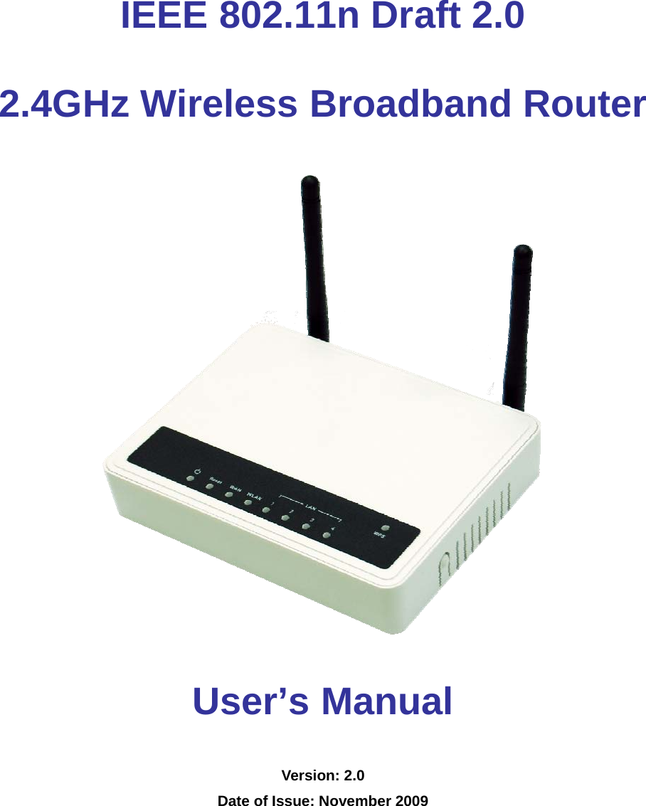
Z Com XN2050V01 Wireless Broadband Router User Manual

Z Com Inc Wireless Broadband Router

User Manual

      IEEE 802.11n Draft 2.0   2.4GHz Wireless Broadband Router    User’s Manual Version: 2.0 Date of Issue: November 2009
   Copyright Copyright © 2009 all rights reserved. No part of this publication may be reproduced, adapted, stored in a retrieval system, translated into any language, or transmitted in any form or by any means without the written permission of the supplier. About This Manual This user’s manual is intended to guide professional installer to install the Wireless Broadband Router and how to build the infrastructure centered on it. It includes procedures to assist you in avoiding unforeseen problems. Conventions For your attention on important parts, special characters and patterns are used in this manual:       This indicates a warning or caution that you have to abide.     This indicates an important note that you must pay attention to.  Bold: Indicates the function, important words, and so on. Note: Warning:
   FCC Information  This device complies with Part 15 of the FCC Rules. Operation is subject to the following two conditions: (1) this device may not cause harmful interference, and (2) this device must accept any interference received; including interference that may cause undesired operation. Federal Communications Commission (FCC) Statement This Equipment has been tested and found to comply with the limits for a Class B digital device, pursuant to Part 15 of the FCC rules. These limits are designed to provide reasonable protection against harmful interference in a residential installation. This equipment generates uses and can radiate radio frequency energy and, if not installed and used in accordance with the instructions, may cause harmful interference to radio communications. However, there is no guarantee that interference will not occur in a particular installation. If this equipment does cause harmful interference to radio or television reception, which can be determined by turning the equipment off and on, the user is encouraged to try to correct the interference by one or more of the following measures: - Reorient or relocate the receiving antenna. - Increase the separation between the equipment and receiver. - Connect the equipment into an outlet on a circuit different from that to which the receiver is connected. -Consult the dealer or an experienced radio/TV technician for help. Warning: Any changes or modifications to this unit not expressly approved by the party responsible for compliance could void the user authority to operate the equipment.                                                                                                     Trade name                                                                                                   Model number  FCC RF Radiation Exposure Statement: 1.  This Transmitter must not be co-located or operating in conjunction with any other antenna or transmitter.
   2.  This equipment complies with FCC RF radiation exposure limits set forth for an uncontrolled environment. This equipment should be installed and operated with a minimum distance of 20 centimeters between the radiator and your body. For product available in the USA market, only channel 1~11 can be operated. Selection of other channels is not possible.       ࠉᖕʳʳ ܅פ෷ሽंᘿ୴ࢤሽᖲጥ෻ᙄऄʳʳรԼԲයʳʳ ᆖীڤᎁᢞٽ௑հ܅פ෷୴᙮ሽᖲΔॺᆖ๺ױΔֆ׹Ε೸ᇆࢨࠌشृ݁լ൓ᖐ۞᧢ޓ᙮෷ΕףՕפ෷ࢨ᧢ޓ଺๻ૠհ௽ࢤ֗פ౨ΖʳʳรԼ؄යʳʳ ܅פ෷୴᙮ሽᖲհࠌشլ൓ᐙ᥼ଆ౰ڜ٤֗եឫٽऄຏॾΙᆖ࿇෼ڶեឫ෼ွழΔᚨمܛೖشΔࠀޏ࿳۟ྤեឫழֱ൓ᤉᥛࠌشΖছႈٽऄຏॾΔਐࠉሽॾ๵ࡳ܂ᄐհྤᒵሽॾΖ܅פ෷୴᙮ሽᖲႊݴ࠹ٽऄຏॾࢨՠᄐΕઝᖂ֗᠔᛭شሽंᘿ୴ࢤሽᖲ๻ໂհեឫΖʳ
   CONTENTS Chapter 1 Introduction .......................................................................................2 Introduction .......................................................................................................2 Key Feature and Benefits..................................................................................2 Typical Application.............................................................................................3 Wireless Infrastructure.................................................................................3 Wireless Infrastructure with Stations Attaching to a Wired LAN ...................3 Connecting the Wireless LAN Micro Access Point to your network..............3 Chapter 2 Hardware Installation ........................................................................4 Product Package...............................................................................................4 System Requirements .......................................................................................4 Mechanical Description .....................................................................................5 Chapter 3 Setup Wizard......................................................................................7 How to Access the Web-based Configuration Utility..........................................7 Setup Wizard.....................................................................................................8 Chapter 4 Advance Settings ............................................................................12 Operation Mode...............................................................................................12 Wireless Settings.............................................................................................13 Basic ..........................................................................................................13 AP Mode...............................................................................................13 Client Mode ..........................................................................................16 WDS .....................................................................................................17 AP+WDS ..............................................................................................18 Advance.....................................................................................................19 Security......................................................................................................21 WEP .....................................................................................................22 WPA & WPA2........................................................................................24 Access Control...........................................................................................26 WDS Setting ..............................................................................................27 Site Survey.................................................................................................28 WPS...........................................................................................................28 Schedule....................................................................................................30 TCP/IP Settings...............................................................................................31 LAN Interface Setup:..................................................................................31 WAN Interface Setup: ................................................................................32 Static IP: ...............................................................................................33 DHCP Client: ........................................................................................34
   PPPoE:.................................................................................................36 PPTP: ...................................................................................................38 L2TP:....................................................................................................41 Firewall............................................................................................................43 Port Filtering...............................................................................................43 IP Filtering..................................................................................................44 MAC Filtering .............................................................................................45 Port Forwarding .........................................................................................46 URL Filtering ..............................................................................................47 DMZ...........................................................................................................47 QoS.................................................................................................................48 Chapter 5 Management ....................................................................................49 Status ..............................................................................................................49 Statistics ..........................................................................................................50 DDNS..............................................................................................................50 Time Zone Setting ...........................................................................................51 Denial-of-Service.............................................................................................52 Log ..................................................................................................................53 Upgrade Firmware...........................................................................................53 Save/Load Setting...........................................................................................54 Password ........................................................................................................55 Chapter 6 Universal Repeater and WISP Concept .........................................56 Universal Repeater..........................................................................................56 How to Configure Universal Repeater Mode..............................................56 WISP Mode .....................................................................................................58 How to Configure WISP Mode ...................................................................59 Chapter 7 Limited Warranty .............................................................................61 Chapter 8 Service Support...............................................................................63
   FIGURE Figure 1 The Wireless Broadband Router Application ..........................................3 Figure 2 The Wireless Broadband Router LED Panel...........................................5 Figure 3 The Wireless Broadband Router Back Panel..........................................6 Figure 4 Login Page..............................................................................................7 Figure 5 Step1 - Setup Operation Mode ...............................................................8 Figure 6 Step2 – Time Zone Settings....................................................................9 Figure 7 Step3 – LAN Interface Settings...............................................................9 Figure 8 Step4 – WAN Interface Settings............................................................10 Figure 9 Step5 – Wireless Basic Settings ........................................................... 11 Figure 10 Step6 – Wireless Security Settings..................................................... 11 Figure 11 Operation Mode Settings ....................................................................12 Figure 12 Wireless Basic Settings ......................................................................13 Figure 13 Client Mode Settings...........................................................................16 Figure 14 WDS Settings .....................................................................................17 Figure 15    AP+WDS Settings............................................................................18 Figure 16 Wireless Advance Settings .................................................................19 Figure 17 Wireless Security Settings ..................................................................21 Figure 18 WEP Encryption..................................................................................22 Figure 19 802.1x Enable.....................................................................................23 Figure 20 WPA Settings......................................................................................24 Figure 21 WPA2 Settings....................................................................................24 Figure 22 WPA-Mixed Settings ...........................................................................25 Figure 23 Access Control Settings......................................................................26 Figure 24 WDS Settings .....................................................................................27 Figure 25 WDS Application.................................................................................28 Figure 26 Wireless Site Survey...........................................................................28 Figure 27 WPS Setting- AP Mode.......................................................................29 Figure 28 WPS Setting – Client Mode ................................................................29 Figure 29 Wireless Schedule Settings ................................................................30 Figure 30 LAN Interface Settings........................................................................31 Figure 31 WAN Static IP Settings........................................................................33 Figure 32 DHCP Client Settings..........................................................................34
   Figure 33 PPPoE Settings ..................................................................................36 Figure 34 PPTP Settings ....................................................................................38 Figure 35 L2TP Settings .....................................................................................41 Figure 36 Port Filter Settings ..............................................................................43 Figure 37 IP Filtering Settings.............................................................................44 Figure 38 MAC Filter Settings.............................................................................45 Figure 39 Port Forwarding Settings ....................................................................46 Figure 40 URL Filter Settings..............................................................................47 Figure 41 DMZ Settings......................................................................................47 Figure 42 QoS Settings.......................................................................................48 Figure 43 QoS Rules Table.................................................................................48 Figure 44 Status Page ........................................................................................49 Figure 45 Statistics Page ....................................................................................50 Figure 46 DDNS Settings....................................................................................50 Figure 47 Time Zone Settings.............................................................................51 Figure 48 Denial-of-Service Settings ..................................................................52 Figure 49 System Log Page ...............................................................................53 Figure 50 Upgrade Firmware ..............................................................................53 Figure 51 Save/Reload Settings .........................................................................54 Figure 52 Password Settings ..............................................................................55 Figure 53 Universal Repeater Application...........................................................56 Figure 54 Universal Repeater Configure Progress .............................................57 Figure 55 WISP Application ................................................................................58 Figure 56 WISP Step1 - Setup the Mode Settings ..............................................59 Figure 57 WISP Step2 - Setup Operation Mode Settings ...................................60 Figure 58 WISP Step3 - Setup WAN Port Settings .............................................60
   TABLE Table 1 LED Description Table..............................................................................5 Table 2 The Wireless Broadband Router Port Description Table ..........................6
  Chapter 1 Introduction                                                             Page 2 Chapter 1   Introduction  Introduction Congratulations on your purchase of the outstanding Wireless Broadband Router. This product is specifically designed for small office and home office needs. It provides a complete SOHO solution for Internet surfing and is easy to configure and operate even for non-technical users. Instructions for installing and configuring the Wireless Router can be found in this manual. Before you install and use this product, please read this manual carefully to ensure that you take full advantage of its functionality. Key Feature and Benefits  Ultimate Performance   Cost-effective Firewall Router   EZ Security Setup (Wi-Fi Protection Setup)   Enhanced Multimedia Support (WMM)   Universal Repeater Mode support   WISP feature support
  Chapter 2 Hardware Installation                                                     Page 3 Typical Application The IEEE802.11n (Draft 2.0) 2.4GHz Wireless Broadband Router can be configured in a variety of network system configurations. Wireless Infrastructure In a wireless infrastructure, the IEEE 802.11n (Draft 2.0) 2.4GHz Wireless Broadband Router can act as an Access Point with repeater. The Access Point connects the wireless clients together. The Access Point acts as a center point for all wireless communications. This would increase efficiency of the communications since the wireless adapters do not need to be within direct range of each other. Wireless Infrastructure with Stations Attaching to a Wired LAN The IEEE 802.11n (Draft 2.0) 2.4GHz Wireless Broadband Router will provide access to your local LAN. An integrated wireless and wired LAN is called an Infrastructure configuration. A group of wireless LAN PC users and an Access Point construct a Basic Service Set (BSS). Each wireless PC in this BSS can talk to any computer on your network via the Access Point. Connecting the Wireless LAN Micro Access Point to your network Connecting with Cable/DSL mode, the IEEE 802.11n (Draft 2.0) 2.4GHz Wireless Broadband Router provides you high speed broadband-sharing gateway. A typical Internet access application of the Wireless LAN Access Point is shown below:  Figure 1 The Wireless Broadband Router Application
  Chapter 2 Hardware Installation                                                     Page 4 Chapter 2 Hardware Installation This chapter describes initial setup of the Wireless Broadband Router. Product Package Before installation, make sure that you have the following items:   IEEE 802.11n (Draft 2.0) 2.4GHz Wireless Broadband Router…………………. x 1  Ethernet Cable……………………………………………………….…..…….….…..x 1  Power Adapter………………………………………………………….……….….….x 1   Product CD  ………………………………………………………….……………….x 1 If any of the above items is not included or damaged, please contact your local dealer for support.  System Requirements Installation of the IEEE 802.11n (Draft 2.0) 2.4GHz Wireless Router requires:  1. An AC power outlet (100~240V, 50~60Hz) which supplies the power for the Access Point.     Please use the power adapter that contain in the package, not to change to use the one that make up by non-original factory. The supplier is irresponsible when the product damage if the user use irregular power adapter.  2. A 10/100 Base-T (UTP) Ethernet cable drop. Note:
  Chapter 2 Hardware Installation                                                     Page 5 Mechanical Description Top panel of the Wireless Router: The following table provides an overview of each LED activity:  Figure 2 The Wireless Broadband Router LED Panel LED Definition  Color  Description  Steady Green  Power enabled Reset Green On/Off: Press Reset button more then 6 seconds, the LED will on and then off to indicate reset progress start.On: An active device is connected to the 10/100MB WAN port. WAN Green Blinking: The WAN port is sending or receiving data. WLAN  Green  Blinking: Sending or receiving data via wireless link. On: An active device is connected to the corresponding 10/100MB LAN port. LAN 1-4  Green  Blinking: The corresponding LAN port is sending or receiving data. WPS LED  Green Wi-Fi Protected Setup compliant. Push WPS button for 3 seconds to enter WPS mode. When enter WPS PBC mode, the LED will steady blink for 2 minutes. And if wireless client that enable WPS associate, the LED become bright. Table 1 LED Description Table
  Chapter 2 Hardware Installation                                                     Page 6 Back panel of the Wireless Router:  Figure 3 The Wireless Broadband Router Back Panel  Ports: Port  Description Reset To reset the system settings to factory defaults. Push the reset button and hold it for more than 6 seconds and the Reset LED will on and off. Then release the button, and the Wireless Broadband Router will reboot. ANT. 1-2 Combine the antenna with the Router to wirelessly connect to the 802.11b/g/n networks. Note: The antenna can rotate around 180° only, not up to 360°. PWR  Power socket: DC 12V, 1.0A (minimum) WAN  The port for connecting your ADSL or cable modem LAN 1-4  4 switch ports for your networked computers and/or other devices Table 2 The Wireless Broadband Router Port Description Table
  Chapter 3 Setup Wizard                                                           Page 7 Chapter 3   Setup Wizard The IEEE 802.11n (Draft 2.0) 2.4GHz Wireless Broadband Router allows configuration only via Web. This chapter descripts how to configure the Wireless Broadband Router via Web page, and the basic configuration. How to Access the Web-based Configuration Utility The following gives instructions guiding you through the installations of the Wireless Broadband Router. Connect your computer to the wireless router either through wireless or wired connection.    Please set a fixed IP address, within the range of 192.168.1.X (X can’t be 254), to your computer. If you attempt to use a wireless connection, you must also set a configuration in your computer in advance as below. SSID: Wireless WEP: disable Channel: 11 Activate your web browser and type in the IP address of your Wireless Router in the Address or location field and press Enter. The default value of the Wireless Broadband Router is http://192.168.1.254.  Figure 4 Login Page The web-based configuration utility provides several items for you to monitor and configure the Wireless Broadband Router: Setup Wizard, Operation Mode, Wireless, TCP/IP Settings, Firewall, QoS and Management.
  Chapter 3 Setup Wizard                                                           Page 8 Setup Wizard Use the following buttons to navigate the wizard screens:  Cancel:  Click Cancel in any wizard screen to return to the main wizards screen. All unsaved custom settings will be lost.  Back:  Click Back to return to the last screen.  Next:  Click Next to continue to the next screen.  The setup wizard consists of a series of screens to help you configure router. No configuration settings will be saved to the Wireless Broadband Router until you go through the entire setup process and click Finished.  Step1. Configure the Operation Mode to let the device to as a Gateway, or Bridge, or Wireless ISP, and click Next.  Figure 5 Step1 - Setup Operation Mode
  Chapter 3 Setup Wizard                                                           Page 9 Step2. Configure the Time Zone Setting. Check the Enable NTP client update and select the Time Zone and NTP server for your geographical location if need, and click Next.  Figure 6 Step2 – Time Zone Settings Step3. Configure the LAN interface, you may change the IP address and Subnet Mask of the device and click Next, or if not to change the IP address and Subnet Mask, click Next to the next step. The default IP Address is http://192.168.1.254.   Figure 7 Step3 – LAN Interface Settings Step4. Configure the WAN interface, you may configure the WAN Access Type as Static IP, DHCP Client, PPPoE, PPTP, and L2TP according to the WAN access type of your ISP that you connect, and click Next.
  Chapter 3 Setup Wizard                                                           Page 10  Figure 8 Step4 – WAN Interface Settings
  Chapter 3 Setup Wizard                                                           Page 11 Step5. Configure the Wireless Basic Setting, you may configure the Wireless Basic Settings include Band, Mode, Network Type, SSID, Channel Width, Control Sideband, and Channel Number, and click Next.  Figure 9 Step5 – Wireless Basic Settings Step6. Configure Wireless Security; you may configure the wireless security setting to WEP, WPA (TKIP), WPA2 (AES) or WPA2 Mixed, and click Finish to complete the setup wizard.  Figure 10 Step6 – Wireless Security Settings
  Chapter 4 Advance Settings                                                        Page 12 Chapter 4   Advance Settings Operation Mode The Wireless Broadband Router supports three modes for the network application. You can select the operation mode according to your network environment.  Gateway: This is traditional gateway configuration. It always connects internet via ADSL/Cable Modem. LAN interface, WAN interface, Wireless interface, NAT and Firewall modules are applied to this mode.  Bridge: This mode all interface (LAN, WAN and Wireless) regards as bridge. NAT, Firewall and all routers’ functions are not supported    Wireless ISP: This mode switch Wireless interface to WAN port and all Ethernet ports are in bridge mode. Wireless interface can do all routers’ functions.  Figure 11 Operation Mode Settings
  Chapter 4 Advance Settings                                                        Page 13 Wireless Settings Basic Your wireless settings will impact the coverage and the performance of your wireless LAN. The wireless settings allow you to set the following configuration items: AP Mode You can configure the Wireless Broadband Router to AP Mode to be an Access Point of the real world. When set to AP Mode, you can configure the SSID, Channel Number, Broadcast SSID, and Multiple AP.  Figure 12 Wireless Basic Settings  Disable Wireless LAN Interface: Select this check box to disable the wireless Radio.  Band: Select the wireless band from drop-down list. There are 2.4GHz (B), 2.4GHz (G), 2.4GHz (N),
  Chapter 4 Advance Settings                                                        Page 14 2.4GHz (B+G), 2.4GHz (G+N), and 2.4GHz (B+G+N) six options to be selected.  Mode:  You may select the Mode from the drop-down list. The options are AP, Client, WDS, and AP+WDS.  Multiple AP: The device support multiple SSID, press Multiple AP button to configure the settings.    SSID: Network ID is used for identifying the wireless LAN (WLAN). Client stations can roam freely using this product and other Access Points that have the same Network ID. (The factory setting is “Wireless”.)  Channel Width: Specify the wireless channel bandwidth mode. Select 20MHz to set the device to transmit at up to 20MHz to other wireless device (including draft-N compatible wireless devices). Select 40MHz to set the device to transmit at up to 40MHz to other wireless device.  Control Sideband: This option is for 802.11n only, when the select to 2.4GHz (N), 2.4GHz (G+N), or 2.4GHz (B+G+N), the option can be configured. When Channel Width is 20MHz, then the Control Sideband is display only, and the Channel Number will be 1~11 (1~13 for ETSI domain). When Channel Width is 40MHz, you can configure the Control Sideband to Upper or Lower. If Control Sideband is Upper, the Channel Number will be 5~11 (5~13 for ETSI domain); if Control Sideband is Lower, the Channel Number will be 1~9.  Channel Number: The permissible radio channels range from channel 1 to 11 (1~13 for ETSI domain), default is 11, depending on the regulatory domain. For restrictions please refer to the first page of this manual.  Broadcast SSID: You can also do something to logically hide the Access Point. Disable the broadcast SSID, your Access Point will refuse the connection request from whom is not aware the Network ID (SSID). Note that when you realized the Network ID and specify the SSID for but certainly the Access Point can be easily connected well when you realize the Network ID.  WMM: WMM (Wi-Fi Multimedia) is a subset of 802.11e. It allows wireless communication to define a priority limit on the basis of data type, thus those time-sensitive data, like video/audio data, may own a higher priority than common one.    To enable WMM, the wireless client should support it. The default value is Enable, but when the Band set to 2.4GHz (N), 2.4GHz (G+N) or 2.4GHz (B+G+N), this option will be display only.  Data Rate:
  Chapter 4 Advance Settings                                                        Page 15 The basic transfer rates should be set depending on the speed of your wireless network. Specify rate of data transmission. Select the desired rate from the drop-down menu and choose “Auto” to adapt the rate to the best available.  Associated Clients: Press Show Active Clients button to display the associated client list.  Enable Universal Repeater Mode (Acting as AP and client simultaneously) Select the check box to enable Universal Repeater function. (More setting and application for Universal Repeater, refer to Chapter 6)  SSID of Extended Interface: Input the SSID of the Access Point that the Wireless Broadband Router wants to associate when Universal Repeater enable. (More setting and application for Universal Repeater, refer to Chapter 6)
  Chapter 4 Advance Settings                                                        Page 16 Client Mode You can configure the Wireless Broadband Router to Client Mode to be the wireless client of the real world. When set the mode to Client Mode, you can configure the Network Type, SSID, and to enable Broadcast SSID or disable.  Figure 13 Client Mode Settings  Enable Mac Clone (Single Ethernet Client) Select the check box to enable this function when set to Client Mode. The wireless router will clone the MAC address of the computer to be the Ethernet MAC of the Wireless Broadband Router.  Enable Universal Repeater Mode (Acting as AP and client simultaneously) / SSID of Extended Interface: Select the check box to enable Universal Repeater feature, and input the extended SSID in the field. (Refer to Chapter 6 to get more detail settings)
  Chapter 4 Advance Settings                                                        Page 17 WDS You can configure the device to WDS Mode to be a wireless bridge and establish a wireless link with other Access Points. When set the mode to WDS, you can configure the Channel Width, Channel Number, and to enable Broadcast SSID or disable.  Figure 14 WDS Settings
  Chapter 4 Advance Settings                                                        Page 18 AP+WDS You can configure the device to AP+WDS Mode to be a wireless bridge and Access Points. When set the mode to AP+WDS, you can configure the SSID, Channel Width, Channel Number, and to enable Broadcast SSID or disable.  Figure 15  AP+WDS Settings
  Chapter 4 Advance Settings                                                        Page 19 Advance This page provides more technical settings on wireless LAN. These settings should not be changed unless you know what effect will take.  Figure 16 Wireless Advance Settings  Fragment Threshold: Fragmentation mechanism is used for improving the efficiency when there is high traffic within the wireless network. If you transmit large files in a wireless network, you can enable the Fragmentation Threshold and specify the packet size. This specifies the maximum size a data packet will be before splitting and creating a new packet. The setting range is 256-2346. For example: If you set value as 256, it means the packet will be fragmented into “256” bytes while transmitting.  RTS Threshold: RTS Threshold is a mechanism implemented to prevent the “Hidden Node” problem. If the size of the packet transmitted is larger than the value you set, the RTS will be enabled. When the RTS is activated, the station and its Access Point will use a (RTS/CTS) mechanism for data transmission. The setting range is 0-2347.  Beacon Interval: This value indicates the frequency interval of the beacon.    A beacon is a packet broadcast by the Access Point to keep the network synchronized. A beacon includes the wireless LAN service area, the AP address, the Broadcast destination addresses, a time stamp, Delivery
  Chapter 4 Advance Settings                                                        Page 20 Traffic Indicator Maps, and the Traffic Indicator Message (TIM).  Preamble Type: The Preamble defines the length of the PLCP synchronization field for communication between the Access Point and Network Card. Select the appropriate preamble type and press the Apply button to set it. The default setting is “Long Preamble”.  IAPP The IEEE 802.11f Inter-Access Point Protocol (IAPP) supports Access Point Vendor interoperability, enabling roaming of 802.11 Stations within IP subnet. IAPP defines messages and data to be exchanged between Access Points and between the IAPP and high layer management entities to support roaming. The IAPP protocol uses TCP for inter-Access Point communication and UDP for RADIUS request/response exchanges. It also uses Layer 2 frames to update the forwarding tables of Layer 2 devices. Select Enable to turn on this feature.  Protection Select Enable to turn on this function.  Aggregation Select Enable to turn on this function.  Short GI Select Enable to turn on this function.  WLAN Partition WLAN Partition is to separate the traffic between wireless stations in the same BSS.    Disable WLAN Partition to allow wireless stations connected to the device to communicate with each other. Enable WLAN Partition to only allow wireless stations to communicate with wired network, not with each other.  RF Output Power Set the RF output power of the access point. The options are 100%, 70%, 50%, 35%, and 15%. Decrease the transmit power if necessary. The default is “100%”.
  Chapter 4 Advance Settings                                                        Page 21 Security Wireless security is to protect the wireless communication between wireless stations, Access Points, and your wired network. Select the SSID that you want to enable the wireless security, and configure the encryption settings.  Figure 17 Wireless Security Settings  Encryption:  You may select encryption type to WEP, WPA, WPA2, and WPA-Mixed from the drop-down list.
  Chapter 4 Advance Settings                                                        Page 22 WEP To prevent unauthorized wireless stations from accessing data transmitted over the network, the Access Point Security Settings window offers WEP features, making your data transmission over air more secure and allows you to specify Encryption Key(s) if you enable encryption for the Access Point.  Figure 18 WEP Encryption
  Chapter 4 Advance Settings                                                        Page 23  Figure 19 802.1x Enable  802.1x Authentication:   802.1x Authentication is for WEP with RADIUS Server. When you select the 802.1x Authentication check box, please input the RADIUS server information. IEEE 802.1x is a standard for network access control (port based), which was introduced especially for distributing encryption keys in a wireless network. The Access Point supports IEEE 802.1x for keeping out unauthorized users and for verifying the credentials of users with RADIUS so that authorized users can access the network and services. To use IEEE 802.1x, you will need at least one common Extensible Authentication Protocol (EAP) method on your authentication server, APs (authenticator) and stations (supplicant). IEEE 802.1x is also used to perform generation and distribution of encryption keys from AP to the station as part of or after the authentication process. A further factor here is dynamic WEP, which is based on legacy RC4 WEP encryption and is available in this Access Point under the setting for enabling IEEE 802.1x security in association with disabled Wired Equivalent Privacy (WEP) settings. There are two options for the key length, i.e. 64 and 128bits.    The longer the key length, the greater security it will offer.  Authentication: You can select Authentication to Open System, Shared Key or Auto. But when the 802.1x Authentication check box is selected, the Authentication options will be gray out, and default use Open System.
  Chapter 4 Advance Settings                                                        Page 24  Key Length/Key Format/Encryption Key:   You may drop-down the list to set WEP key length, Key Format, and input Encryption Key. You may enter key value manually:   64 bits WEP: Enter 5 ASCII characters or 10 hexadecimal digits (between 0-9, a-f and A-F). 128 bits WEP: Enter 13 ASCII characters or 26 hexadecimal digits (between 0-9, a-f and A-F).    The WEP key must be set up exactly the same on the Wireless Broadband Router as they are on the wireless clients. If you set “0011223344” for the Wireless Access Point, the same WEP key “0011223344” must be assigned to other client stations. WPA & WPA2 The IEEE 802.11n (Draft 2.0) 2.4GHz Wireless Broadband Router provides WPA and WPA2 settings for advance wireless security setting. Wi-Fi Protected Access (WPA) is a subset of the IEEE 802.11i standard. WPA2 is a wireless security standard that defines stronger encryption, authentication and key management than WPA.  Figure 20 WPA Settings  Figure 21 WPA2 Settings Note:
  Chapter 4 Advance Settings                                                        Page 25  Figure 22 WPA-Mixed Settings  Authentication Mode: The wireless router provides two options to user: Enterprise (RADIUS) and Personal (Pre-Shared Key). If you select Enterprise, then you must enter RADIUS Server information, otherwise, you should enter Pre-Shared Key Format and key value.  WPA/WPA2/WPA-Mixed Cipher Suite: If encryption is WPA, then the WPA cipher default value is TKIP only. If encryption is WPA2, then the WPA2 cipher default value is AES only. If encryption is WPA-Mixed, then the WPA cipher default value is TKIP, and WPA2 cipher default value is AES.  Pre-Shared Key Format: The item provides two options for choice: Passphrase and Hex (64 characters). If select Passphrase, type the pre-shared key from 8 to 63 ASCII characters, otherwise, type the key from 8 to 64 Hex characters.  Pre-Shared Key: Type a pre-shared key from 8 to 63 characters if the Pre-Shared Key Format selected Passphrase, otherwise type a pre-shared key from 8 to 64 characters if the Pre-Shared Key Format selected Hex.
  Chapter 4 Advance Settings                                                        Page 26 Access Control The Access Control allows you to configure AP to give exclusive access to wireless stations or exclude them from accessing AP. Select Allow Listed to allow the wireless stations to access wireless network. Input the MAC Address, Comment and press Apply Changes to add the allow rule into the Current Access Control List. Otherwise, select Deny Listed to deny the wireless stations to access wireless network. Input the MAC Address, Comment and press Apply Changes to add the deny rule into the Current Access Control List. The default of Wireless Access Control is disable.  Figure 23 Access Control Settings
  Chapter 4 Advance Settings                                                        Page 27 WDS Setting Extend the range of your network without having to use cables to link the Access Points by using the Wireless Distribution System (WDS): Put simply, you can link the Access Points wirelessly. Under WDS, your Access Points are still functioning as a regular Access Point, which can provide the link services to wireless clients.      If Wireless mode set to AP Mode or Client Mode, then WDS function doesn’t support.  Figure 24 WDS Settings Enable WDS check box and enter the MAC address of another AP you wirelessly want to connect to into the appropriate field either by clicking Apply Changes. The implementation can be done as below. Note:
  Chapter 4 Advance Settings                                                        Page 28  Figure 25 WDS Application   Site Survey The Wireless Broadband Router provide scan tool to scan the wireless network that exist in your environment. If you set to Client Mode, you can select the SSID and presses Connect button to associate the Access Point. Press the Refresh button to flash Access Point list and select the AP to connect.  Figure 26 Wireless Site Survey WPS The WPS (Wi-Fi Protected Setup) feature is defined by Wi-Fi Alliance and the primary goal is to simplify the security setup and management of Wi-Fi networks. The router supports three types of WPS configuration mode including Client PIN Number, Self-PIN Number and Push Button. When use Client PIN Number, input the PIN key that generate by the wireless client that want to
  Chapter 4 Advance Settings                                                        Page 29 connect to AP in the Client PIN Number field, and then press Start PIN to start WPS progress. When use Self-PIN Number, input that Self-PIN Number that generate by the Wireless Broadband Router to wireless station utility, and start to WPS progress. When use Push Button, press “Start PBC” to start Push Button mode WPS or just push the WPS button on the Wireless Router side.    When the wireless mode set to WDS, this function will be disabled.  Figure 27 WPS Setting- AP Mode   Figure 28 WPS Setting – Client Mode Note:
  Chapter 4 Advance Settings                                                        Page 30 Schedule The Wireless Broadband Router provides to setup wireless schedule rule function, select the Enable Wireless Schedule check box to start this feature. Before enable this feature, remember to configure the system time first.  Figure 29 Wireless Schedule Settings
  Chapter 4 Advance Settings                                                        Page 31 TCP/IP Settings The configuration page provides 2 items for you to monitor and configure the Wireless Router: Wide Area Network and Local Area Network.     Wide Area Network (WAN) The status of the WAN port will be displayed as well as the connection type.   Local Area Network (LAN) The IP address, DHCP server and DHCP IP arrange are displayed. LAN Interface Setup: This item allows you to manage the IP, and DHCP Server setting for the wireless router.  Figure 30 LAN Interface Settings  IP Address/Subnet Mask/Default Gateway: Input the IP Address, Subnet Mask, and Default Gateway of the Wireless Broadband Router.  DHCP: If you plan to use any external DHCP server, select Disable. Otherwise set the LAN address to Static and select Server. If you set the DHCP server and configure your computers as “automatic IP allocation” mode, the clients will automatically load the proper TCP/IP settings from the AP when the computer is powered up. The default setting is “Server”.
  Chapter 4 Advance Settings                                                        Page 32  DHCP Client Range: If the DHCP Server setting is “Enable”, you may specify the start and end address of the IP address pool.      Static DHCP: This function allow you to reserve IP addresses, and assign the same IP address to the network device with the specified MAC address any time it requests an IP address. This is almost the same as when a device has a static IP address except that the device must still request an IP address from the DHCP server. Select Enable to turn on this function, and press Set Static DHCP button to edit.  Domain Name: Select the DHCP Server and set the Domain Name, configure Clients as “automatic IP allocation” mode, the Connection – specific DNS Suffix will display the Domain Name on Clients.  802.1d Spanning Tree: Enable the 802.1d Spanning Tree, and then the broadcast storm will be prevented.  Clone MAC Address: Input the MAC Address that wants to be cloned. WAN Interface Setup: This section allows you to connect to your Internet Service Provider (ISP). There are a total of 5 WAN types for you to choose: Static IP, DHCP Client, PPPoE, PPTP, and L2TP.
  Chapter 4 Advance Settings                                                        Page 33 Static IP:   You may enter WAN IP Address, Subnet Mask, Gateway settings provided by your ISP.  Figure 31 WAN Static IP Settings  IP Address/Subnet Mask/Default Gateway: Input a fix IP Address, Subnet Mask, and Default Gateway that provide by your ISP.  MTU Size:   Change the MTU size that your ISP provided. The default value is 1500 and range is 1400 to 1500 bytes.  DNS1/2/3: Enter Domain Name Server IP address that your ISP provided.  Clone MAC Address: Input the MAC Address that wants to be cloned.  Enable uPNP:   You can select it according to your request.
  Chapter 4 Advance Settings                                                        Page 34  Enable IGMP Proxy You can select it according to your request.  Enable Ping Access on WAN You can select it to enable WAN ICMP response.  Enable Web Server Access on WAN You can select it when you want to configure the Wireless Broadband Router from the WAN interface.  Enable IPsec/PPTP/L2TP pass through on VPN connection:   You can select the VPN protocol according your request. DHCP Client:   This setting is default value. Host Name is optional. It required by some ISPs, for example at home.  Figure 32 DHCP Client Settings  Host Name:   If you select the WAN Access Type to DHCP client mode and set the Host Name, you can find
  Chapter 4 Advance Settings                                                        Page 35 the Host Name on DHCP Server.  MTU Size:   Change the MTU size that your ISP provided. The default value is 1492 and range is 1400 to 1492 bytes.  Attain DNS Automatically: You can select this option to get DNS address from the DHCP server.    Set DNS Manually: You can select Set DNS Manually, and input at most three DNS servers in the below field.  DNS 1/2/3: Enter Domain Name Server IP address that your ISP provided.  Clone MAC Address: Input the MAC Address that wants to be cloned.  Enable uPNP:   You can select it according to your request.  Enable IGMP Proxy You can select it according to your request.  Enable Ping Access on WAN You can select it to enable WAN ICMP response.  Enable Web Server Access on WAN You can select it when you want to configure the Wireless Broadband Router from the WAN interface.  Enable IPsec/PPTP/L2TP pass through on VPN connection:   You can select the VPN protocol according your request.
  Chapter 4 Advance Settings                                                        Page 36 PPPoE:  When you select PPPoE for WAN interface, you need to input user name, password, connection type, and idle time.  Figure 33 PPPoE Settings  User Name and Password:   The account and password are that your ISP assigned to you. For security, this field appears blank. If you don't want to change the password, leave it empty.  Service Name:   This field is optional. Input the service name if your ISP requires it. Otherwise, leave it blank.  Connection Type:
  Chapter 4 Advance Settings                                                        Page 37 You can select the connection type from pull-down list. There are Continuous, Connect on Demand and Manual three types to select. Continuous connection type means to setup the connection through PPPoE protocol whenever this Wireless Broadband Router is powered on.   Connect on Demand connection type means to setup the connection through PPPoE protocol whenever you send the data packets out through the WAN interface; there are a watchdog implemented to close the PPPoE connection while there are no data sent out longer than the idle time set. Manual connection type means to setup the connection through the PPPoE protocol by clicking the Connect button manually, and clicking the Disconnect button manually.    Idle Time:   You may enter the number of time when connection type set to Connect on Demand.  MTU Size:   Change the MTU size that your ISP provided. The default value is 1452 and range is 1360 to 1492 bytes.  Attain DNS Automatically: You can select this option to get DNS address from the DHCP server.    Set DNS Manually: You can select Set DNS Manually, and input at most three DNS servers in the below field.  DNS 1/2/3: Enter Domain Name Server IP address that your ISP provided.  Clone MAC Address Input the MAC Address that wants to be cloned.  Enable uPNP:   You can select it according to your request.  Enable IGMP Proxy You can select it according to your request.  Enable Ping Access on WAN You can select it to enable WAN ICMP response.  Enable Web Server Access on WAN You can select it when you want to configure the Wireless Broadband Router from the WAN interface.  Enable IPsec/PPTP/L2TP pass through on VPN connection:   You can select the VPN protocol according your request.
  Chapter 4 Advance Settings                                                        Page 38 PPTP:  The PPTP (Point-to-Point Tunneling Protocol) allow user to make a tunnel with remote site directly to secure the data transmission among the connection. User can use embedded PPTP client supported by this Wireless Broadband Router to make a VPN connection  Figure 34 PPTP Settings  IP Address and Subnet Mask:   Input the private IP address and subnet mask that your ISP assigned to you.  Server IP Address:
  Chapter 4 Advance Settings                                                        Page 39 Input the IP address of the PPTP server that your ISP provided.  User Name and Password:   Input the user name and password that your ISP assigned to you to login PPTP server. I   Connection Type: You can select the connection type from pull-down list. There are Continuous, Connect on Demand and Manual three types to select. Continuous connection type means to setup the connection through PPTP protocol whenever this Wireless Broadband Router is powered on.   Connect on Demand connection type means to setup the connection through PPTP protocol whenever you send the data packets out through the WAN interface; there are a watchdog implemented to close the PPTP connection while there are no data sent out longer than the idle time set. Manual connection type means to setup the connection through the PPTP protocol by clicking the Connect button manually, and clicking the Disconnect button manually.   Idle Time:   You may enter the number of time when connection type set to Connect on Demand.  MTU Size:   Change the MTU size that your ISP provided. The default value is 1460 and range is 1400 to 1460 bytes.  Request MPPE Encryption: You can select the check box to enable MPPE Encryption (Microsoft Point to Point Encryption) for your network.  Request MPPC Compression: You can select the check box to enable MPPC Compression (Microsoft Point to Point Compression) for your network.  Attain DNS Automatically: You can select this option to get DNS address from the DHCP server.    Set DNS Manually: You can select Set DNS Manually, and input at most three DNS servers in the below field.  DNS 1/2/3: Enter Domain Name Server IP address that your ISP provided.  Clone MAC Address Input the MAC Address that wants to be cloned.  Enable uPNP:   You can select it according to your request.  Enable IGMP Proxy You can select it according to your request.
  Chapter 4 Advance Settings                                                        Page 40  Enable Ping Access on WAN You can select it to enable WAN ICMP response.  Enable Web Server Access on WAN You can select it when you want to configure the Wireless Broadband Router from the WAN interface.  Enable IPsec/PPTP/L2TP pass through on VPN connection:   You can select the VPN protocol according your request.
  Chapter 4 Advance Settings                                                        Page 41 L2TP:  L2TP (Layer 2 Tunneling Protocol) is a tunneling protocol used to support virtual private networks (VPNs).  Figure 35 L2TP Settings  IP Address and Subnet Mask:   The private IP address and subnet mask that your ISP assigned to you.  Server IP Address:   Input the IP address of the L2TP server that your ISP provided.
  Chapter 4 Advance Settings                                                        Page 42  User Name and Password:   Input the user name and password that your ISP assigned to you.    Connection Type: You can select the connection type from pull-down list. There are Continuous, Connect on Demand and Manual three types to select. Continuous connection type means to setup the connection through L2TP protocol whenever this Wireless Broadband Router is powered on.   Connect on Demand connection type means to setup the connection through L2TP protocol whenever you send the data packets out through the WAN interface; there are a watchdog implemented to close the L2TP connection while there are no data sent out longer than the idle time set. Manual connection type means to setup the connection through the L2TP protocol by clicking the Connect button manually, and clicking the Disconnect button manually.   Idle Time:   You may enter the number of time when connection type set to Connect on Demand.  MTU Size:   Change the MTU size that your ISP provided. The default value is 1460 and range is 1400 to 1460 bytes.  Attain DNS Automatically: You can select this option to get DNS address from the DHCP server.    Set DNS Manually: You can select Set DNS Manually, and input at most three DNS servers in the below field.  DNS 1/2/3: Enter Domain Name Server IP address that your ISP provided.  Clone MAC Address Input the MAC Address that wants to be cloned.  Enable uPNP:   You can select it according to your request.  Enable IGMP Proxy You can select it according to your request.  Enable Ping Access on WAN You can select it to enable WAN ICMP response.  Enable Web Server Access on WAN You can select it when you want to configure the Wireless Broadband Router from the WAN interface.  Enable IPsec/PPTP/L2TP pass through on VPN connection:   You can select the VPN protocol according your request.
  Chapter 4 Advance Settings                                                        Page 43 Firewall The firewall is a system or group of systems that enforce an access control policy between two networks. It may also be defined as a mechanism used to protect a trusted network from an un-trusted network. The wireless router has capabilities of Port Filtering, IP Filtering, MAC Filtering, Port Forwarding, URL filtering, and DMZ. Port Filtering The Port Filtering gives you the ability to block access only the port that you specify.  Figure 36 Port Filter Settings Select Enable Port Filtering to activate this setting. Clear this check box to disable it. Enter the Port Range that you want to filter and select Protocol from the drop-down list box. You can assign the filter protocol to TCP, UDP or both. After fill in the settings, click Apply Changes to save the settings. Click Reset to start configuring this part of the screen again.
  Chapter 4 Advance Settings                                                        Page 44 IP Filtering The IP Filtering gives you the ability to block access only the IP address that you specify.  Figure 37 IP Filtering Settings Select Enable IP Filtering to activate this setting. Clear this check box to disable it. Enter the Local IP Address that you want to filter and select Protocol from the drop-down list box. You can assign the filter protocol to TCP, UDP or both. After fill in the settings, click Apply Changes to save the settings. Click Reset to start configuring this part of the screen again.
  Chapter 4 Advance Settings                                                        Page 45 MAC Filtering The MAC filter allows you to configure the device to exclude devices from accessing the Wireless Broadband Router. Every Ethernet device has a unique MAC address. The MAC address is assigned at the factory and consists of six pairs of hexadecimal characters, for example, 001970000002. You need to know the MAC address of the devices to configure this screen.  Figure 38 MAC Filter Settings Select Enable MAC Filtering to activate this setting. Clear this check box to disable it. Enter the MAC Address that you want to filter and fill in the comment, click Apply Changes to save the settings. Click Reset to start configuring this part of the screen again.
  Chapter 4 Advance Settings                                                        Page 46 Port Forwarding Entries in this table allow you to automatically redirect common network services to a specific machine behind the NAT firewall. These settings are only necessary if you wish to host some sort of server like a web server or mail server on the private local network behind your Gateway's NAT firewall.   Figure 39 Port Forwarding Settings Select Enable Port Forwarding to activate this setting. Clear this check box to disable it. Select Protocol from the drop-down list box. You can assign the filter protocol to TCP, UDP or both. After that you may enter a range of port numbers to be forwarded, and the local IP address of the desired server. Click Apply Changes to save the settings. Click Reset to start configuring this part of the screen again.
  Chapter 4 Advance Settings                                                        Page 47 URL Filtering The URL Filtering gives you the ability to block access only to the URL address you specify.  Figure 40 URL Filter Settings Enter the URL Address and click Apply Changes to save the settings. Click Reset to start configuring this part of the screen again. DMZ The DMZ (Demilitarized Zone) provides a way for public servers such as Web (HTTP) servers, FTP servers, SMTP (e-mail) servers and DNS servers to be visible to the outside world.  Figure 41 DMZ Settings Select Enable DMZ to activate this setting. Clear this check box to disable it. Enter the DMZ Host IP Address and click Apply Changes to save the settings. Click Reset to start configuring this part of the screen again.
  Chapter 4 Advance Settings                                                        Page 48 QoS The Wireless Broadband Router, provide the QoS to let the users setup the QoS rules to control the network traffic.  Figure 42 QoS Settings You can setup the QoS rule to Restricted maximum bandwidth or Guaranteed minimum bandwidth by input MAC address or IP address according to your network environment. And the QoS rules table will be list below.  Figure 43 QoS Rules Table
  Chapter 5 Management                                                          Page 49 Chapter 5   Management Status You may check current status, device information and basic settings of the Wireless Broadband Router on this page.  Figure 44 Status Page
  Chapter 5 Management                                                          Page 50 Statistics You may check the packet counters for transmission and reception regarding to wireless and Ethernet networks on this page.  Figure 45 Statistics Page DDNS Dynamic DNS is a service that provides you with a valid, unchanging internet domain name (an URL) to go with that (possibly ever changing) IP-address.  Figure 46 DDNS Settings
  Chapter 5 Management                                                          Page 51 Time Zone Setting You may synchronize System Log’s timestamp with a publish time server over the Internet.  Figure 47 Time Zone Settings
  Chapter 5 Management                                                          Page 52 Denial-of-Service The firewall must be active to protect against Denial of Service (DoS) attacks. A denial-of-service attack is characterized by an explicit attempt by hackers to prevent legitimate users of a service from using that service.  Figure 48 Denial-of-Service Settings
  Chapter 5 Management                                                          Page 53 Log You can view logs and alert messages in the screen. Once the log table is full, old logs are deleted as new logs are created. Enable the system log, and select the category event that you need.  Figure 49 System Log Page Upgrade Firmware This page allows you upgrade firmware via WEB.    Figure 50 Upgrade Firmware The Upgrade Firmware menu will display the Upgrade Firmware window so that you could update the latest firmware on the IEEE 802.11n (Draft 2.0) 2.4GHz Wireless Broadband Router.
  Chapter 5 Management                                                          Page 54 Please make sure that you have downloaded the latest and correct firmware from the product support website and store it in local drive before upgrading the firmware of the IEEE 802.11n (Draft 2.0) 2.4GHz Wireless Broadband Router. To upgrade the latest firmware, complete the following: Using browser to access (http://192.168.1.254) AP’s main page. 1. Select Upgrade Firmware from the Management section. 2.  Input the exact file path and name by clicking Browse button, then press Upload button to upgrade the firmware. 3.  Please wait for 80 seconds.  If download fail, please repeat the step 1~3 to download again.    Do not power off the unit when it is being upgraded.  Save/Load Setting This page allows you to save current settings to a file or restore from a file.  Figure 51 Save/Reload Settings  Save Settings to File:   Allow back up your current configuration to your computer.  Load Settings from File:   Restore your configuration from a previously saved configuration file.  Reset Settings to Defaults:   The reset button will clear all user-entered configurations and will reset the device settings back to its factory default value. -LAN IP address: 192.168.1.254  Warning: Warning:
  Chapter 5 Management                                                          Page 55  Do not power off the unit when it is being resetting.  Password Here allow you to change the Access Point’s password, do the following:  Figure 52 Password Settings 1.  To change the current password, choose the “Password” option from the “Management” section in the Wireless Router’s left page.   2.  Changing password for the Wireless Router is as easy as typing the password into the New Password field. Then, type it again into the Confirmed Password Field to confirm. Click the “Apply Changes” button to save the setting.     After you change password, please take note of your new password. Otherwise, you will not able to access the Wireless Router setup. If you forget the password, you could restore the default password by pressing the Reset button on the back panel of your Wireless Access Point for at least 3 seconds, and all previous configurations will need to be input again. Note:
  Chapter 6 Universal Repeater and WISP Concept                                    Page 56 Chapter 6   Universal Repeater and WISP Concept Universal Repeater The Wireless Broadband Router supports Universal Repeater Mode to extend the wireless network coverage. When enable Universal Repeater Mode, the Wireless Broadband Router acts as a Wireless Access Point and Wireless Client at the same time. It uses Wireless Client function to connect to a Root AP (any AP) and uses AP function to service all wireless stations within its coverage. All the stations within the coverage of the Wireless Broadband Router can be bridged to the Root AP. This Mode is a very convenient way to extend the coverage of your wireless network.  Figure 53 Universal Repeater Application How to Configure Universal Repeater Mode Step1. Set Mode to AP Mode under Wireless Basic Settings page. Step2. Select the check box Enable Universal Repeater Mode (Acting as AP and Client simultaneously). Step3. Input the SSID in the SSID of Extended Interface field to be a client to connect to the AP1 that can access Internet. Step4. Set Channel Number the same with the channel of AP1 that can access Internet.
  Chapter 6 Universal Repeater and WISP Concept                                    Page 57 Step5. After configure all settings, press “Apply Changes”.  Figure 54 Universal Repeater Configure Progress
  Chapter 6 Universal Repeater and WISP Concept                                    Page 58 WISP Mode The Wireless Broadband Router provides the Wireless ISP Mode to let user access Internet via wireless WAN. In this mode, all Ethernet will be bridge together and wireless will be client mode to connect to the ISP’s Access Point and access Internet. Follow the steps to configure the WISP Mode.  Figure 55 WISP Application
  Chapter 6 Universal Repeater and WISP Concept                                    Page 59 How to Configure WISP Mode Step1. Configure to Client Mode under Wireless Basic Settings page, and input SSID of the AP1 that connect to ISP.  Figure 56 WISP Step1 - Setup the Mode Settings
  Chapter 6 Universal Repeater and WISP Concept                                    Page 60 Step2. Configure the Operation Mode to Wireless ISP.  Figure 57 WISP Step2 - Setup Operation Mode Settings Step3. Configure the WAN Access Type that the ISP provided via AP1.  Figure 58 WISP Step3 - Setup WAN Port Settings
  Chapter 7 Limited Warranty                                                       Page 61 Chapter 7 Limited Warranty This Warranty constitutes the sole and exclusive remedy of any buyer or reseller’s equipment and the sole and exclusive liability of the supplier in connection with the products and is in lieu of all other warranties, express, implied or statutory, including, but not limited to, any implied warranty of merchantability of fitness for a particular use and all other obligations or liabilities of the supplier. In no even will the supplier or any other party or person be liable to your or anyone else for any damages, including lost profits, lost savings or other incidental or consequential damages, or inability to use the software provided on the software media even if the supplier or the other party person has been advised of the possibility of such damages. The following are special terms applicable to your hardware warranty as well as services you may use during part of the warranty period.    Your formal Warranty Statement, including the warranty applicable to our Wireless LAN products, appears in the Quick Installation Guide which accompanies your products.  Duration of Hardware Warranty: One Year Replacement, Repair or Refund Procedure for Hardware: This product is design based on the 802.11n draft 2.0 standards, do not guarantee the compatibility with the products that design by other vendors based on 802.11n draft or the products that design according to the 802.11n formal standard that announce in the future. The maximum performance defines based on 802.11g and 802.11n draft standard. The actual throughput will be different because of using environment and conditions, including network bandwidth, building materials, building structure, and wireless working range. These are possible to reduce the wireless performance. If there is an unexpected power failure or operate unsuitable artificially when firmware upgrade. Please contact with local commercial agent.  If your unit needs a repair or replacement, return it to your dealer/distributor in its original packaging.   When returning a defective product for Warranty, always include the following documents:   The Warranty Repair Card   A copy of the invoice/proof of purchase, and     The RMA Report Form (To receive a Return Materials Authorization form (RMA); please contact the party from whom you purchased the product).  Upon proof-of-purchase we shall, at its option, repair or replace the defective item at no cost to the buyer. This warranty is contingent upon proper use in the application for which the products are intended and does not cover products which have been modified without the reseller’s approval or which have been subjected to unusual physical or electrical demands or damaged in any way.
  Chapter 7 Limited Warranty                                                       Page 62 Please complete the information below and include it along with your products. Name:  Title:  Company:  Telephone:  Fax:  Email:  City/State/ZIP code:   Country:  Product Name:   Serial Number:   MAC Address:   Invoice Date:   Product Description:             If you have any further questions, please contact your local authorized reseller for support.
  Chapter 8 Service Support                                                        Page 63 Chapter 8 Service Support If you have any further trouble using the Wireless Broadband Router or you would like to require additional support, you may contact the supplier for support.

Navigation menu