Z Com XN750V1 IEEE802.11N Wireless USB Adaptor User Manual XN 750 20090716
Z Com Inc IEEE802.11N Wireless USB Adaptor XN 750 20090716
Z Com >
User Manual
IEEE802.11N
Wireless USB Adaptor
User’s Manual
V1.1 July 2009

Contents
Chapter 1 Welcome to the Wireless USB Adaptor User’s Manual.............7
Chapter 2 About your Wireless USB Adaptor..............................................8
What is Wireless USB Adaptor!....................................................................8
Features and Benefits ..................................................................................8
Applications..................................................................................................8
System requirements ...................................................................................9
Chapter 3 Inside the Box.............................................................................10
Chapter 4 Starting Up ..................................................................................11
For Windows XP users............................................................................... 11
Note.1 for Windows XP users.................................................................20
Note.2 for Windows XP users.................................................................21
Note.3 for Windows XP users.................................................................22
For Windows Vista users............................................................................23
Note.1 for Windows Vista users..............................................................29
Note.2 for Windows Vista users..............................................................30
Note.1 for Windows 2000 users..............................................................38
Chapter 5 Utility Overview ..........................................................................39
Connection: ................................................................................................39
Profiles: ......................................................................................................40
Power Save Mode: .................................................................................44
Wireless Mode:.......................................................................................44
Adhoc Channel: ......................................................................................44
Preamble Mode: .....................................................................................44
Turbo Mode: ...........................................................................................44
RTS Threshold:.......................................................................................44
Fragment Threshold: ..............................................................................44
Security Settings ........................................................................................52
Data Encryption with WEP......................................................................52
Authentication with WEP: Open System authentication and Shared Key
authentication .........................................................................................53
IEEE 802.1X ...........................................................................................54
EAP Authentication .................................................................................54
WPA (2)...................................................................................................54
WPA ....................................................................................................54
WPA-PSK............................................................................................55
WPA2 ..................................................................................................56

WPA2-PSK..........................................................................................57
Encryption Mode.....................................................................................58
IEEE 802.1X Authentication....................................................................58
EAP Type................................................................................................59
Link Test: ....................................................................................................65
Site Survey:................................................................................................66
Join:........................................................................................................66
Rescan: ..................................................................................................66
Advanced scan: ......................................................................................66
About:.........................................................................................................67
Chapter 6 Troubleshooting .........................................................................68
Chapter 7 Warranty......................................................................................69

Figures
Figure 1 Setup Icon in Windows XP.........................................................................................11
Figure 2 Setup in Windows XP-Initial Screen ........................................................................11
Figure 3 Setup in Windows XP-Select Driver Files............................................................... 12
Figure 4 Setup in Windows XP-Select Destination Folder.................................................... 12
Figure 5 Setup in Windows XP-Select Program Folder........................................................ 13
Figure 6 Setup in Windows XP-Add Shortcuts ..................................................................... 13
Figure 7 Setup in Windows XP-Installation Processing........................................................ 14
Figure 8 Setup in Windows XP-Installation Completed ........................................................ 15
Figure 9 Wireless LAN Utility Icon in Windows XP.................................................................. 15
Figure 10 Found New Hardware Wizard-Step 1 ................................................................... 16
Figure 11 Found New Hardware Wizard-Step 2 ................................................................... 16
Figure 12 Hardware Installation Note...................................................................................... 17
Figure 13 Found New Hardware Wizard-Step 3 ................................................................... 17
Figure 14 Wireless Configuration Utility-Connection ............................................................ 18
Figure 15 Wireless Configuration Utility-Site Survey ............................................................ 18
Figure 16 Enjoy the Internet ....................................................................................................19
Figure 17 Wireless Configuration Utility-Console ................................................................. 20
Figure 18 Wireless Configuration Utility-Warning Sign......................................................... 20
Figure 19 Wireless Zero Configuration Icon............................................................................ 20
Figure 20 Wireless Network Connection List .......................................................................... 21
Figure 21 Wireless LAN Utility Icon in Windows XP................................................................ 21
Figure 22 Wireless Configuration Utility-Console ................................................................. 22
Figure 23 Wireless Configuration Utility-Warning Sign......................................................... 22
Figure 24 Setup Icon in Windows Vista................................................................................... 23
Figure 25 Setup in Windows Vista-Initial Screen.................................................................. 23
Figure 26 Setup in Windows Vista-Select Driver Files.......................................................... 24
Figure 27 Setup in Windows Vista-Select Destination Folder............................................... 24
Figure 28 Setup in Windows Vista-Select Program Folder................................................... 25
Figure 29 Setup in Windows Vista-Add Shortcuts ................................................................ 25
Figure 30 Setup in Windows Vista-Installation Processing................................................... 26
Figure 31 Windows Security.................................................................................................... 26
Figure 32 Setup in Windows Vista-Installation Completed ................................................... 27
Figure 33 Successful Driver Installation Sign.......................................................................... 27
Figure 34 Wireless Configuration Utility-Connection ............................................................ 28
Figure 35 Wireless Configuration Utility-Site Survey ............................................................ 28
Figure 36 Enjoy the Internet ....................................................................................................29

Figure 37 Wireless Zero Configuration Icon............................................................................ 29
Figure 38 Wireless Network Connection List .......................................................................... 30
Figure 39 Setup Icon in Windows 2000................................................................................... 31
Figure 40 Setup in Windows 2000-Initial Screen.................................................................. 31
Figure 41 Setup in Windows 2000-Select Driver Files ......................................................... 32
Figure 42 Setup in Windows 2000-Select Destination Folder .............................................. 32
Figure 43 Setup in Windows 2000-Select Program Folder................................................... 33
Figure 44 Setup in Windows 2000-Add Shortcuts ................................................................ 33
Figure 45 Setup in Windows 2000-Installation Processing................................................... 34
Figure 46 Setup in Windows 2000-Installation Completed ................................................... 34
Figure 47 Digital Signature Not Fount Sign............................................................................. 35
Figure 48 Wireless Configuration Utility Icon .......................................................................... 35
Figure 49 Wireless Configuration Utility-Console ................................................................. 36
Figure 50 Wireless Configuration Utility-Site Survey ............................................................ 36
Figure 51 Enjoy the Internet ....................................................................................................37
Figure 52 Wireless Configuration Utility-Connection ............................................................ 39
Figure 53 More Status Information .......................................................................................... 40
Figure 54 Wireless Configuration Utility-Profiles................................................................... 41
Figure 55 Adding a Profile ....................................................................................................... 41
Figure 56 Security Settings .....................................................................................................42
Figure 57 TCP/IP Settings.......................................................................................................43
Figure 58 Advanced Settings................................................................................................... 43
Figure 59 Confirm Information................................................................................................. 45
Figure 60 Wireless Configuration Utility-Profiles................................................................... 45
Figure 61 Wi-Fi Protected Setup ............................................................................................. 46
Figure 62 WPS Setup-Initial Screen ..................................................................................... 47
Figure 63 WPS Setup-Select a Mode................................................................................... 48
Figure 64 WPS Setup-Select a Mode................................................................................... 48
Figure 65 WPS Setup-Select an AP ..................................................................................... 49
Figure 66 WPS Setup-Select a Mode................................................................................... 49
Figure 67 WPS Setup-Select a Mode................................................................................... 50
Figure 68 WPS Setup-Select an AP ..................................................................................... 50
Figure 69 WPS Setup-Searching for WPS Network ............................................................. 51
Figure 70 WPS Setup-Successfully Connected.................................................................... 51
Figure 71 Security Settings .....................................................................................................52
Figure 72 Security Settings .....................................................................................................53
Figure 73 Security Settings .....................................................................................................55
Figure 74 Security Settings .....................................................................................................56

Figure 75 Security Settings .....................................................................................................57
Figure 76 Security Settings .....................................................................................................58
Figure 77 Security Settings .....................................................................................................59
Figure 78 Certificate ................................................................................................................ 60
Figure 79 Certificate-PEAP................................................................................................... 61
Figure 80 Certificate-TLS...................................................................................................... 62
Figure 81 Certificate-TTLS.................................................................................................... 63
Figure 82 Certificate-SIM ...................................................................................................... 64
Figure 83 Wireless Configuration Utility-Link Test ................................................................ 65
Figure 84 Wireless Configuration Utility-Site Survey ............................................................ 66
Figure 85 Wireless Configuration Utility-About ..................................................................... 67

Federal Communication Commission Interference Statement
This equipment has been tested and found to comply with the limits for a Class B digital
device, pursuant to Part 15 of the FCC Rules. These limits are designed to provide reason-
able protection against harmful interference in a residential installation. This equipment
generates, uses and can radiate radio frequency energy and, if not installed and used in
accordance with the instructions, may cause harmful interference to radio communications.
However, there is no guarantee that interference will not occur in a particular installation. If
this equipment does cause harmful interference to radio or television reception, which can be
determined by turning the equipment off and on, the user is encouraged to try to correct the
interference by one of the following measures:
- Reorient or relocate the receiving antenna.
- Increase the separation between the equipment and receiver.
- Connect the equipment into an outlet on a circuit different from that
to which the receiver is connected.
- Consult the dealer or an experienced radio/TV technician for help.
This device complies with Part 15 of the FCC Rules. Operation is subject to the following
two conditions: (1) This device may not cause harmful interference, and (2) this device must
accept any interference received, including interference that may cause undesired operation.
FCC Caution: Any changes or modifications not expressly approved by the party respon-
sible for compliance could void the user's authority to operate this equipment.
IEEE 802.11b or 802.11g operation of this product in the U.S.A. is firmware-limited to
channels 1 through 11.
IMPORTANT NOTE:
FCC Radiation Exposure Statement:
This equipment complies with FCC radiation exposure limits set forth for an uncontrolled
environment. This equipment should be installed and operated with minimum distance 20cm
between the radiator & your body.
This transmitter must not be co-located or operating in conjunction with any other antenna or
transmitter.
Federal Communication Commission (FCC) Radiation Exposure Statement
This EUT is compliance with SAR for general population/uncontrolled exposure limits in
ANSI/IEEE C95.1-1999 and had been tested in accordance with the measurement methods
and procedures specified in OET Bulletin 65 Supplement C. This equipment should be
installed and operated with minimum distance 0.5 cm between the radiator & your body.

Chapter 1 Welcome to the Wireless USB Adaptor User’s Manual Page 7
Chapter 1 Welcome to the Wireless
USB Adaptor User’s Manual
Welcome to the Wireless USB Adaptor User’s
Manual
Congratulations on your purchase of the Wireless USB Adaptor. The User’s Manual will assist
you to get the full picture of it.
We’ve arranged this user’s manual in a way that contains both getting started with Wireless
USB Adaptor as well as everything about it. First of all, the manual starts from the introduction
of Wireless USB Adaptor like features, benefits, etc. Then, it goes as hypothetically the first
time you open the box and will walk you through the features we think that you may want to
know or use right away when you plug Wireless USB Adaptor into your PC/laptop. Afterwards,
the user’s manual offers the basic/advanced information about the “Wireless Configuration
Utility” which can make the best of Wireless USB Adaptor, configure your wireless network and
even monitor the status of Wireless USB Adaptor.
Enjoy the journey and your Wireless USB Adaptor for a richly wireless life!

Chapter 2 About your Page 8
Chapter 2 About your Wireless USB
Adaptor
What is Wireless USB Adaptor!
The IEEE 802.11n Wireless LAN USB Adapter is a standard USB adapter that fits into every
standard USB 2.0 and 1.1 ports of a PC/laptop. By complying with the IEEE 802.11n draft 2.0,
Wireless USB Adaptor is able to support the transmission rate up to 150Mbps, giving itself the
speed equivalent with Ethernet to access corporate network or the Internet wirelessly. When
Wireless USB Adaptor is installed, it is able to communicate with every IEEE 802.11b/g/n
compliant devices.
Features and Benefits
z Enable your PC/laptop to enjoy the wireless connection to the Internet.
z Free of cable and embracing the mobility.
z Support IEEE 802.11b/g/n solution in 2.4GHz frequency band.
z Automatic rate selection
z Easy setup and user friendly configuration.
z With built-in antenna.
z Security supported: WEP, WPA, WPA2.
z OS supported: Windows 2000, Windows XP and Windows Vista.
Applications
Wireless USB Adaptor offers a fast, reliable, cost-effective solution for wireless client to access
to the network with applications (not limited to) as below:
z Remote access to corporate network information
- E-mail, file transfer and terminal emulation.
z Difficult-to-wire environments
- Historical or old buildings, asbestos installations, and open area where wiring is difficult
to deploy.
z Frequently-changing environments
- For retailers, manufacturers and those who frequently change the workplace and
locations.
z Temporary LANs for special projects or peak time

Chapter 2 About your Page 9
- Trade shows, exhibitions and construction sites where a temporary network will be
practical.
- Retailers, airline and shipping companies need additional workstations during peak
period.
- Auditors require workgroups at customer sites.
z Access to database for mobile workers
- Doctors, nurses, retailers, accessing their database while being mobile in the hospital,
retail store or office campus.
z SOHO (Small Office and Home Office) users
- SOHO users need easy and quick installation of a small computer network.
z High security connection
- The secure wireless network needs to be installed quickly and full of flexibility.
System requirements
Before installing Wireless USB Adaptor, please make sure your system complies with the
following conditions:
z A minimum of 10MB available hard disk space.
z A minimum of 32 MB RAM
z A computer equipped with a USB port, and socket services compliant with revision 1.1 or
2.0 of USB specification.
z A CD-ROM drive.
z OS with Windows Vista/XP/2000.

Chapter 3 Inside the Box Page 10
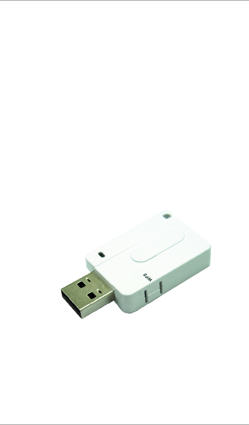
Chapter 3 Inside the Box
You should find the following items inside the box.
z IEEE 802.11n Wireless LAN USB Adapter ……x 1
z Product CD (Driver, Utility and Manual are inside)……………………...x1
Chapter 4 Starting Up Page 11
Chapter 4 Starting Up
For Windows XP users
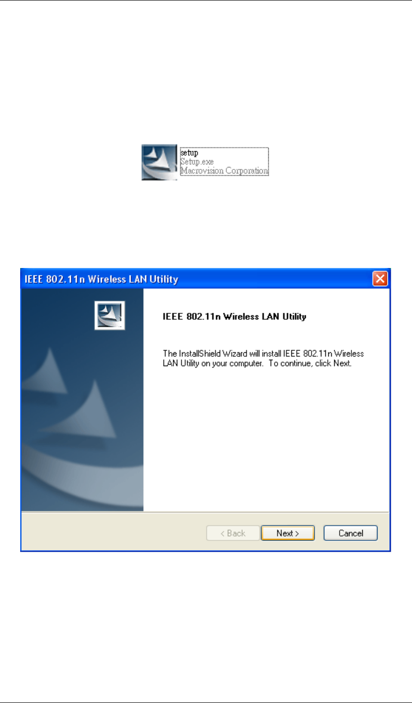
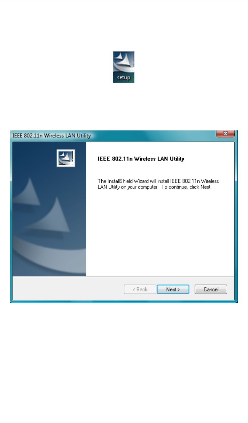
1. Insert the product CD into the CD-ROM on your computer. Locate setup.exe in the CD
and then double-click it.
Figure 1 Setup Icon in Windows XP
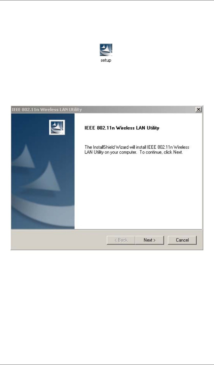
2. Click Next to continue the installation of IEEE 802.11n Wireless LAN Utility. This utility
will help configuring your wireless network and monitoring the status of Wireless USB
Adaptor after it is done.
Figure 2 Setup in Windows XP-Initial Screen
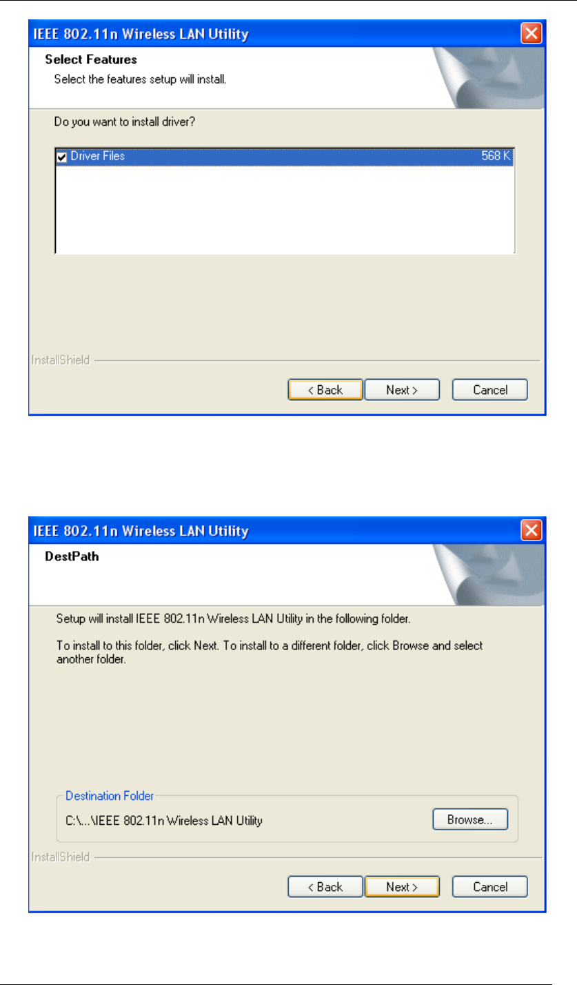
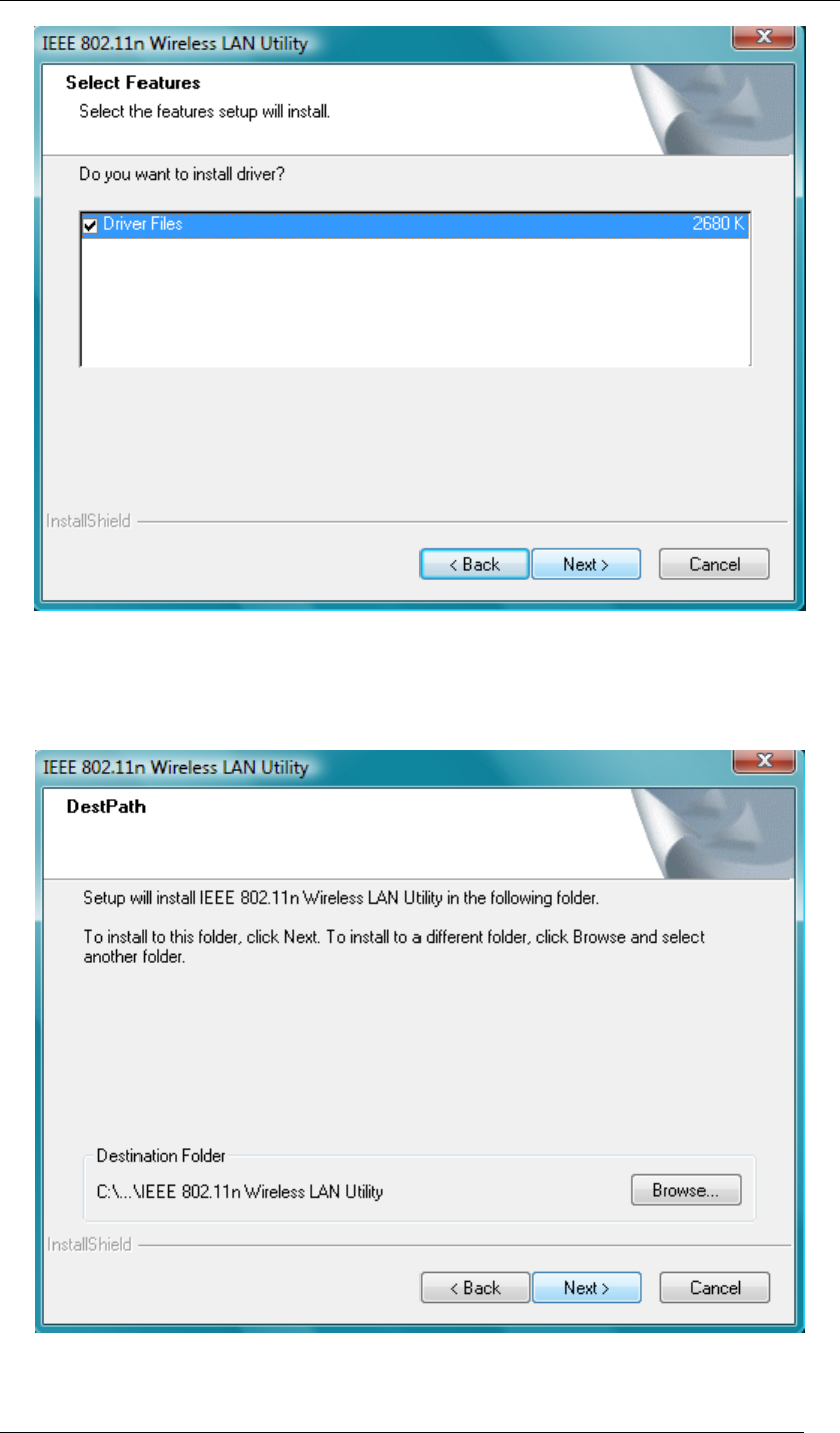
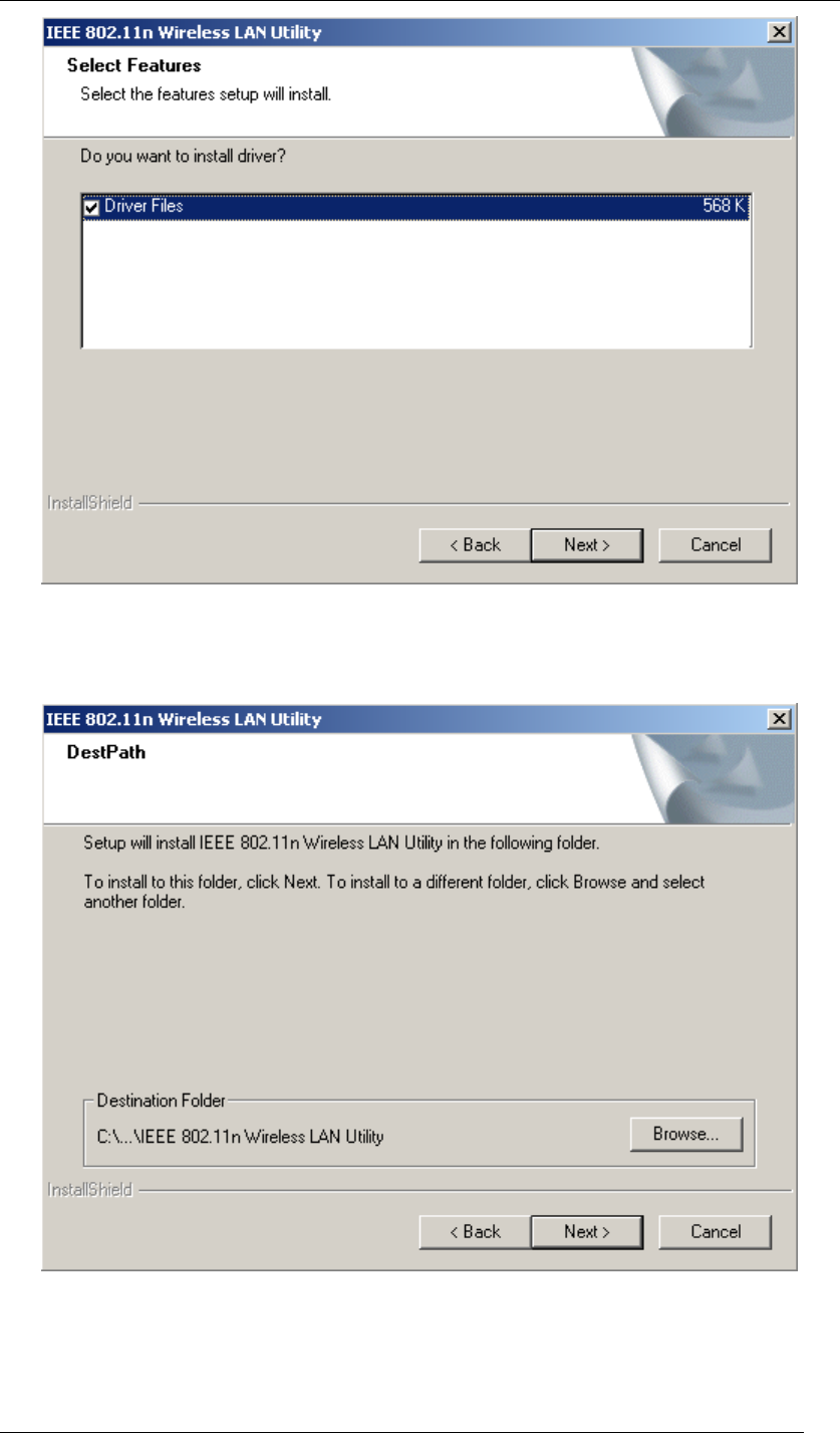
3. Click Next to install the driver.
Chapter 4 Starting Up Page 12
Figure 3 Setup in Windows XP-Select Driver Files
4. Click Next to install the utility into the designated folder; or click Browse to choose your
preferred folder.
Figure 4 Setup in Windows XP-Select Destination Folder
Chapter 4 Starting Up Page 13
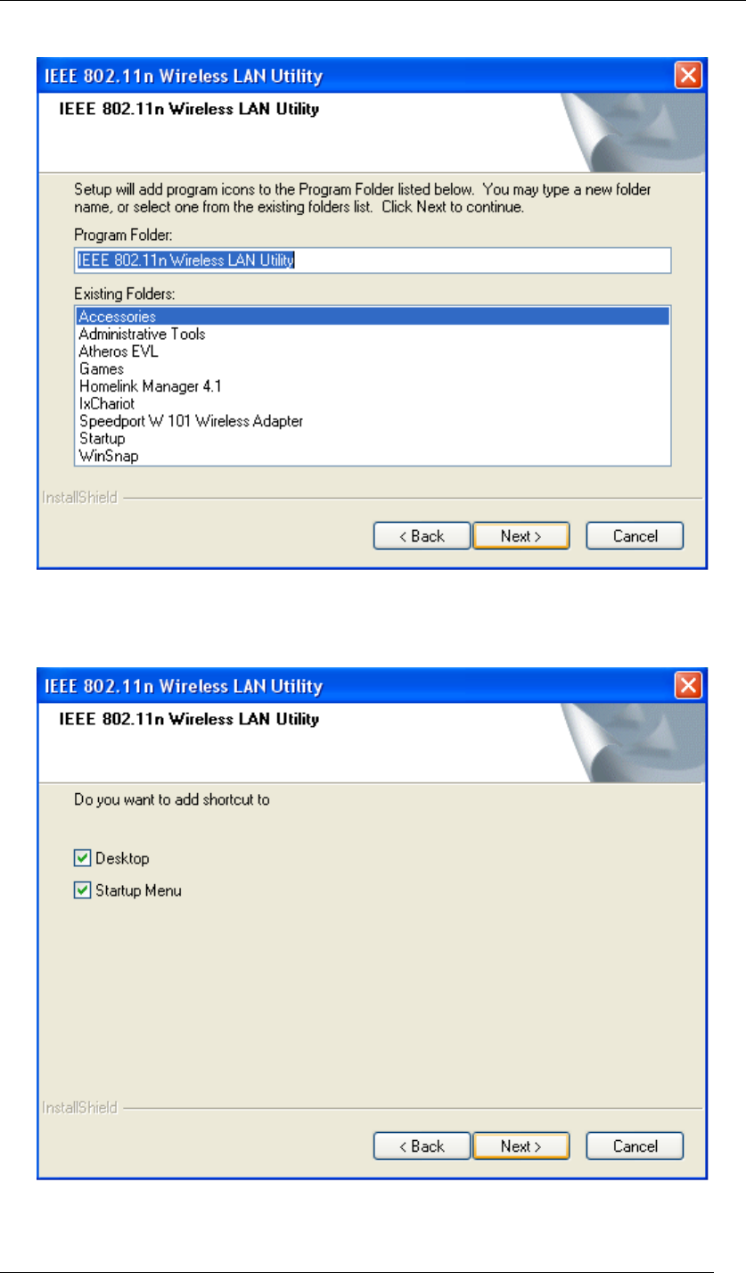
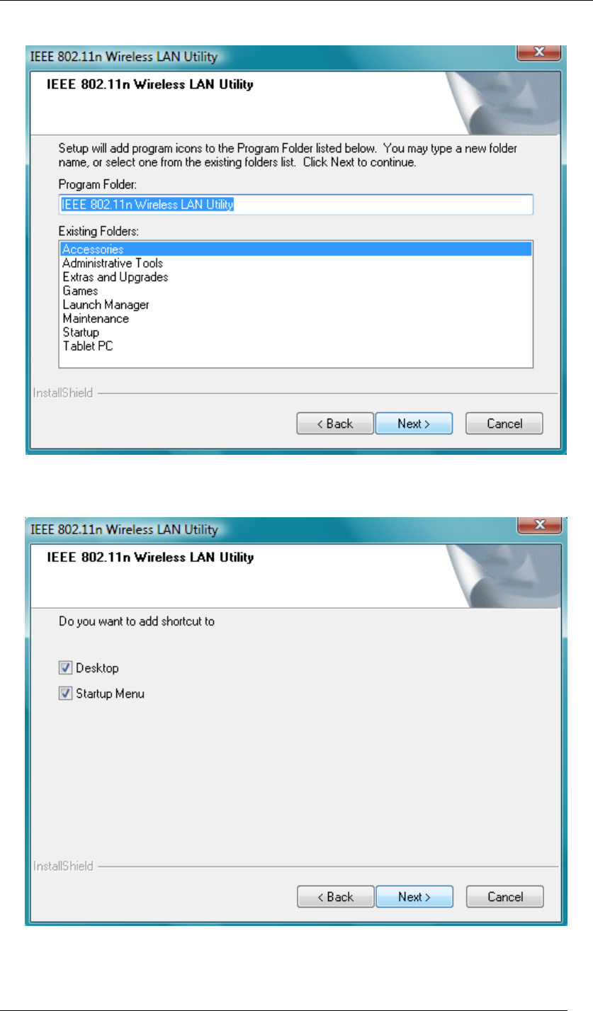
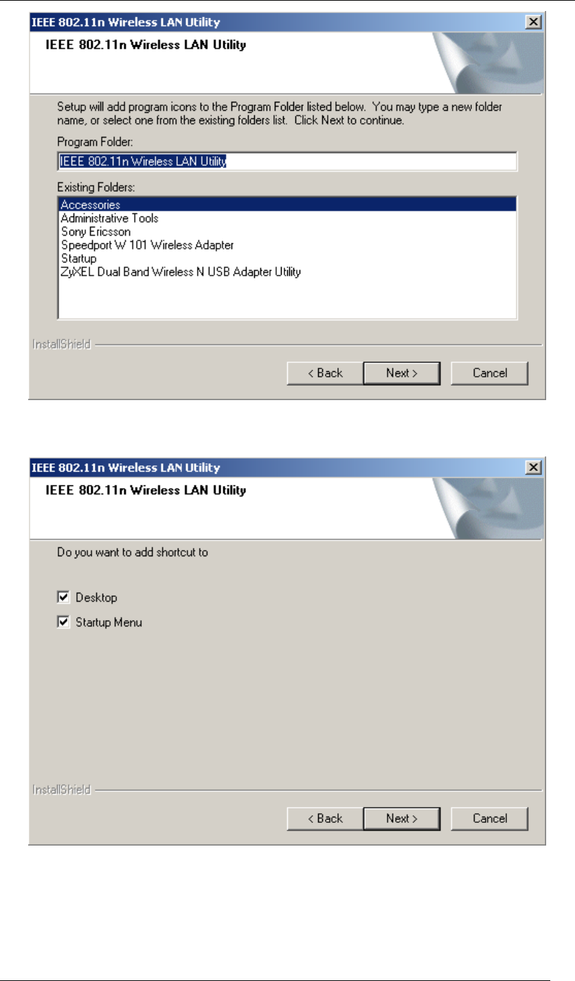
5. Click Next to continue.
Figure 5 Setup in Windows XP-Select Program Folder
6. Select the item you like to add the shortcut to it. Then Click Next.
Figure 6 Setup in Windows XP-Add Shortcuts
Chapter 4 Starting Up Page 14
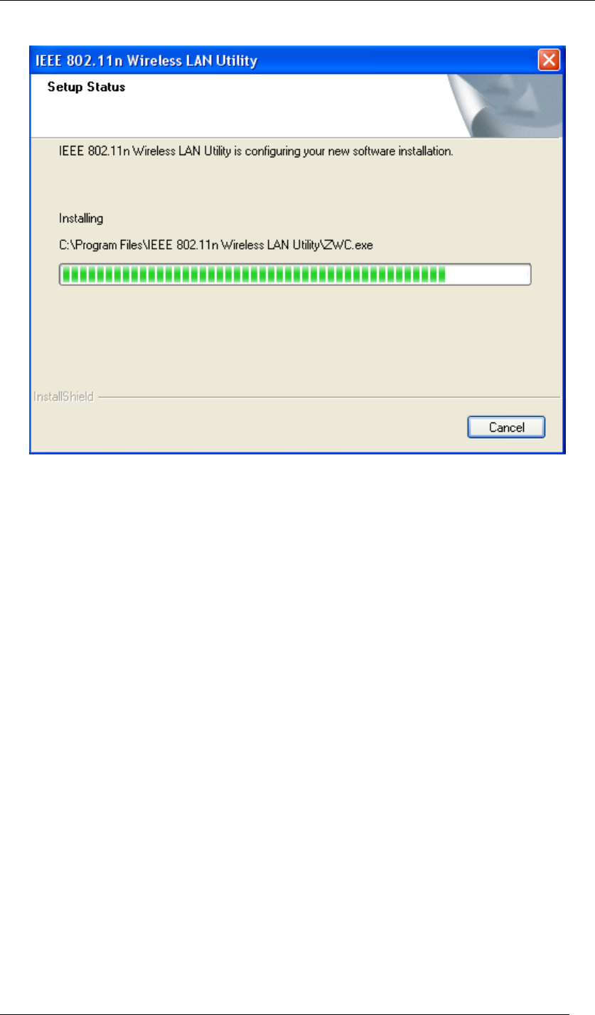
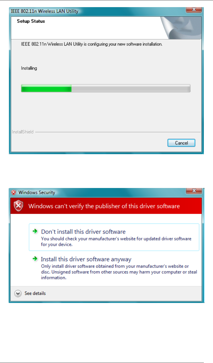
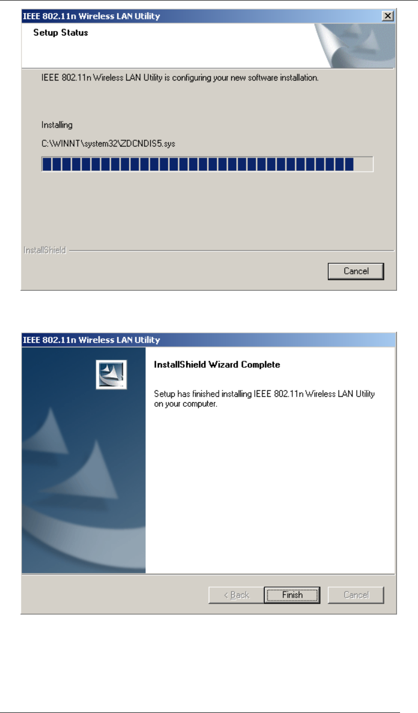
7. Installation is successfully processing. (Click Cancel to stop it.)
Figure 7 Setup in Windows XP-Installation Processing
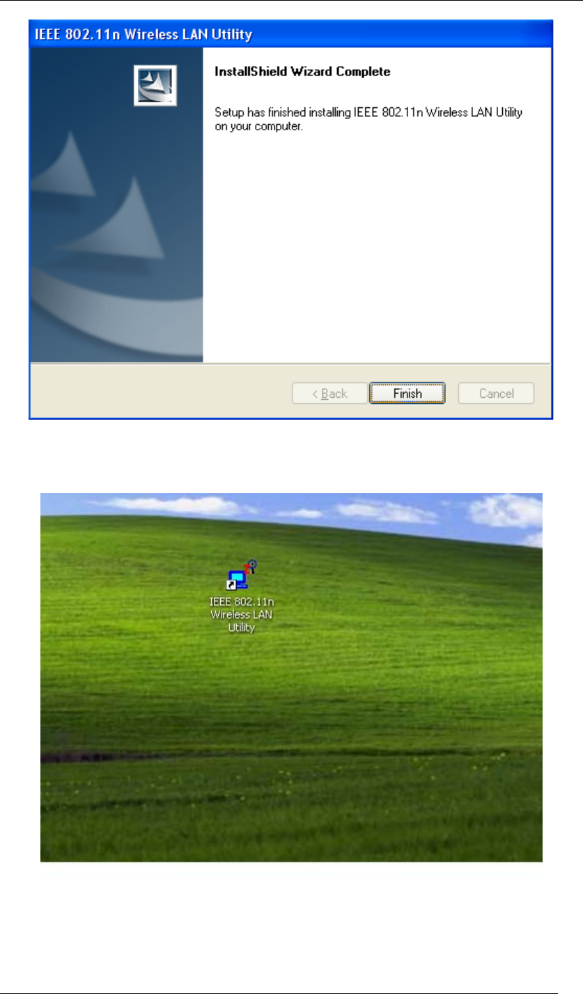
8. Installation is successfully done. Click Finish and you will find the IEEE 802.11n
Wireless LAN Utility on the desktop.
Chapter 4 Starting Up Page 15
Figure 8 Setup in Windows XP-Installation Completed
9. IEEE 802.11n Wireless LAN Utility is now on the desktop.
Figure 9 Wireless LAN Utility Icon in Windows XP
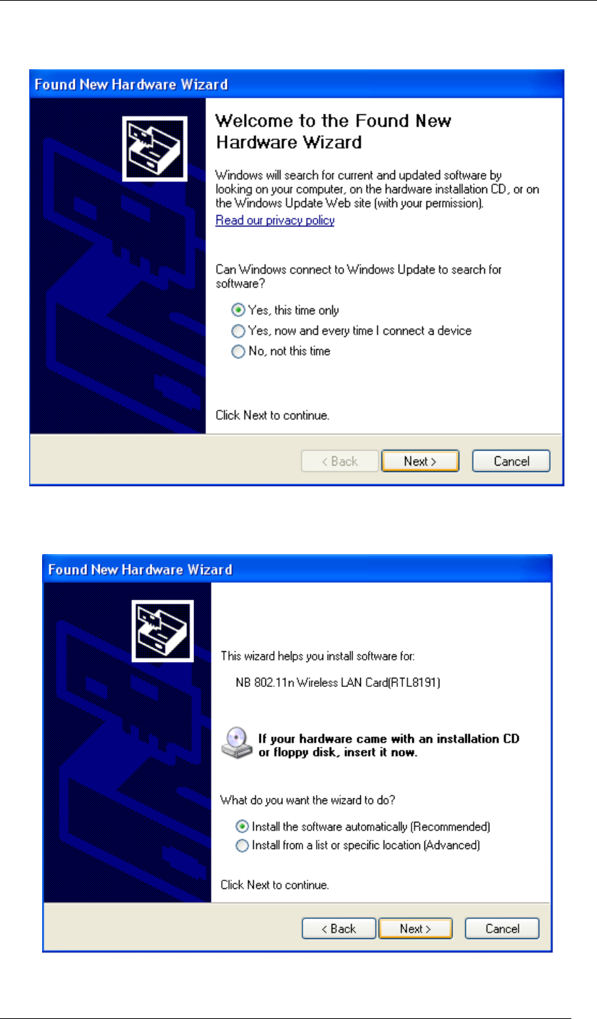
10. Plug Wireless USB Adaptor to your PC through the USB port, and the following Wizard
window will show up to guide you for the rest of the processes. Select Yes, this time
Chapter 4 Starting Up Page 16
only to allow Windows to search the driver for Wireless USB Adaptor automatically. Then,
click Next to go on.
Figure 10 Found New Hardware Wizard-Step 1
11. Select Install the software automatically (Recommended), and click Next to continue.
Figure 11 Found New Hardware Wizard-Step 2
Chapter 4 Starting Up Page 17
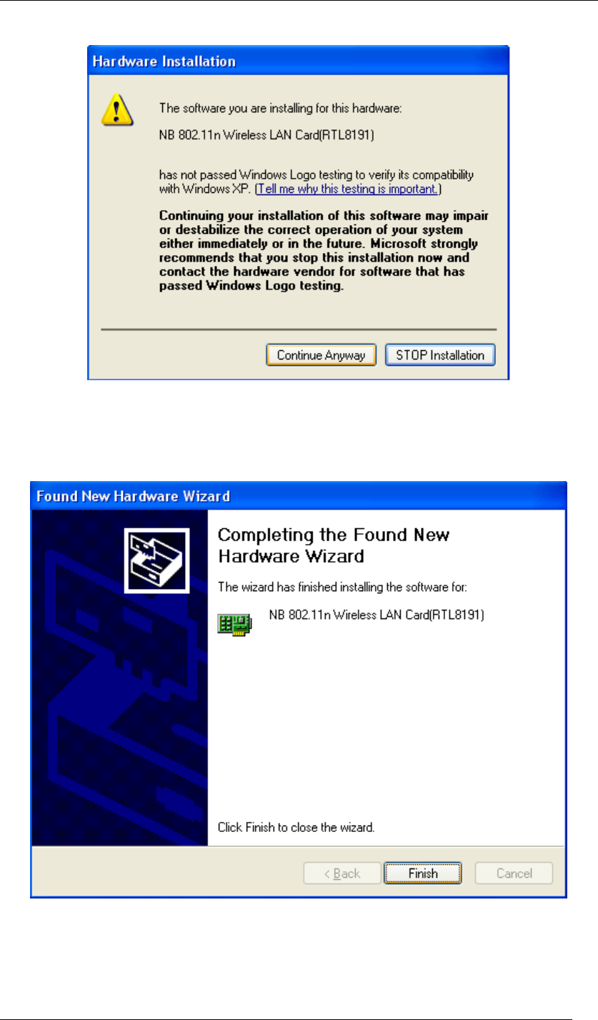
12. If the sign of “Windows Logo testing” shows up, please click Continue Anyway.
Figure 12 Hardware Installation Note
13. Wireless USB Adaptor is now successfully activated and ready for you. Click Finish to
close the wizard.
Figure 13 Found New Hardware Wizard-Step 3
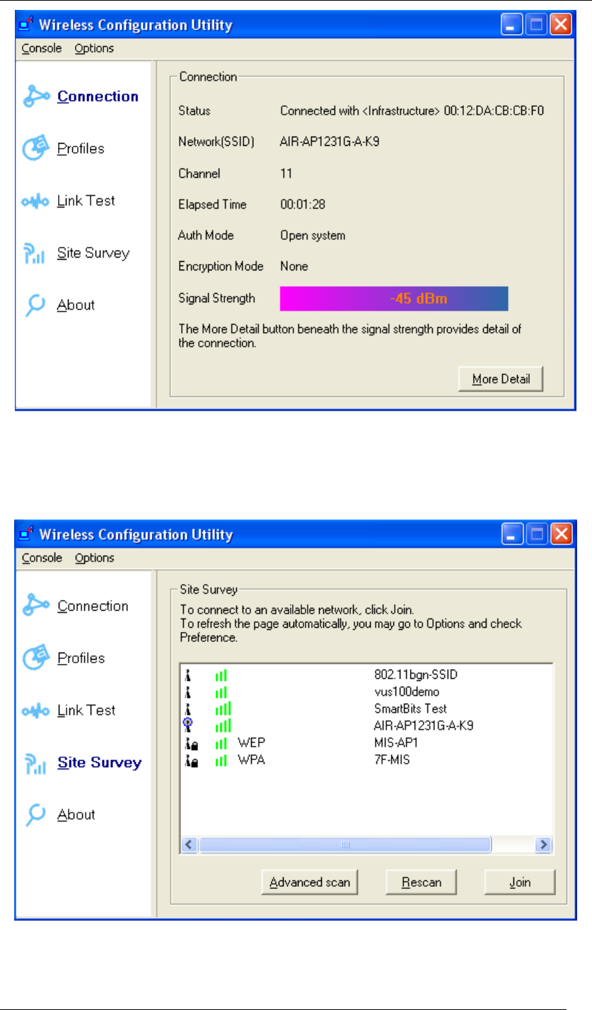
14. The “Wireless Configuration Utility” will show up automatically when the previous step
has finished.
Chapter 4 Starting Up Page 18
Figure 14 Wireless Configuration Utility-Connection
15. Click Site Survey in the left column, and you will see all the currently available access
points in the right page. Choose the one you are allowed to use by single-clicking it, and
then click Join. (Password required, if needed)
Figure 15 Wireless Configuration Utility-Site Survey
16. Open your web browser and enjoy the Internet now!

Chapter 4 Starting Up Page 19
Figure 16 Enjoy the Internet
Chapter 4 Starting Up Page 20
Note.1 for Windows XP users
If you prefer to use the built-in “Wireless Zero Configuration” of Windows XP to connect to a
wireless network, please follow the steps below.
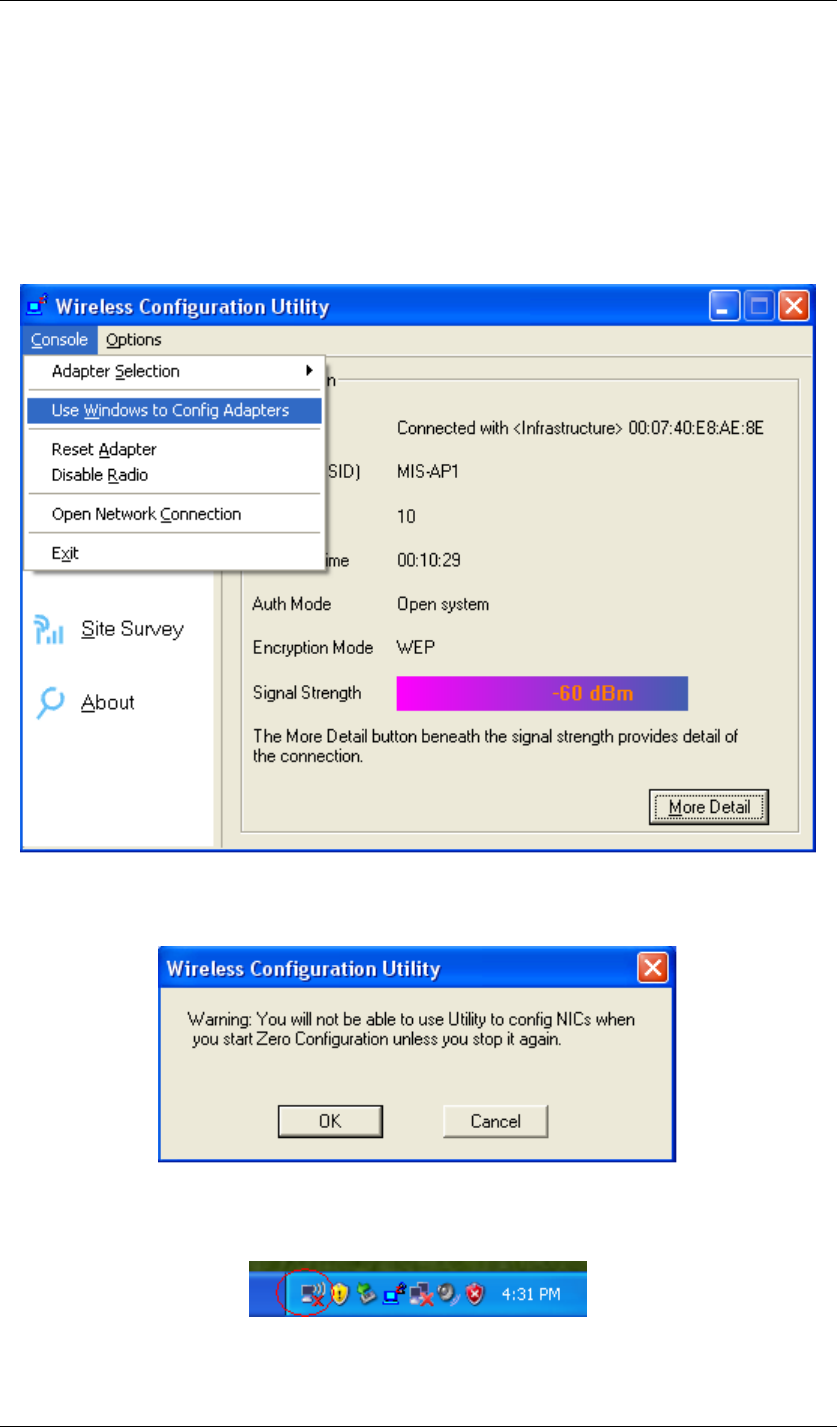
1. When the “Wireless Configuration Utility” shows up as the previous step. 14 did, please
click Console at the top left side, and select Use Windows to Config Adapters.
Figure 17 Wireless Configuration Utility-Console
2. Click OK.
Figure 18 Wireless Configuration Utility-Warning Sign
3. Click the icon “Wireless Zero Configuration” at the bottom right desktop.
Figure 19 Wireless Zero Configuration Icon
4. A window will show up as below, and all the currently available access points are listed in
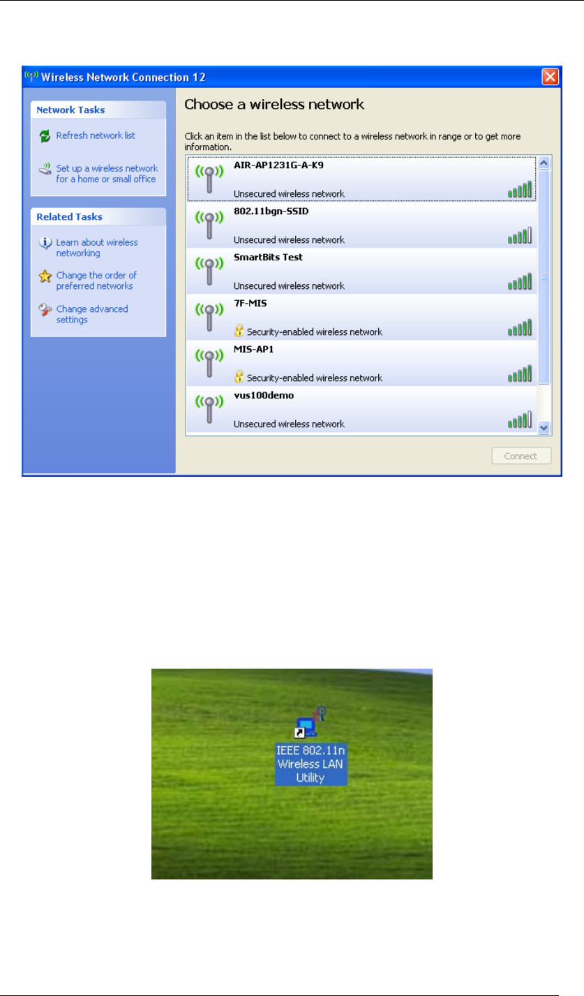
Chapter 4 Starting Up Page 21
the right side. Choose the one you are allowed to use by single-clicking it, and then click
Connect. (Password required, if needed)
Figure 20 Wireless Network Connection List
Note.2 for Windows XP users
If you would like to switch back from “Wireless Zero Configuration” to “Wireless Configuration
Utility”, please follow the steps below.
1. Locate the icon “IEEE 802.11n Wireless LAN Utility” on the desktop, and double-click it.
Figure 21 Wireless LAN Utility Icon in Windows XP
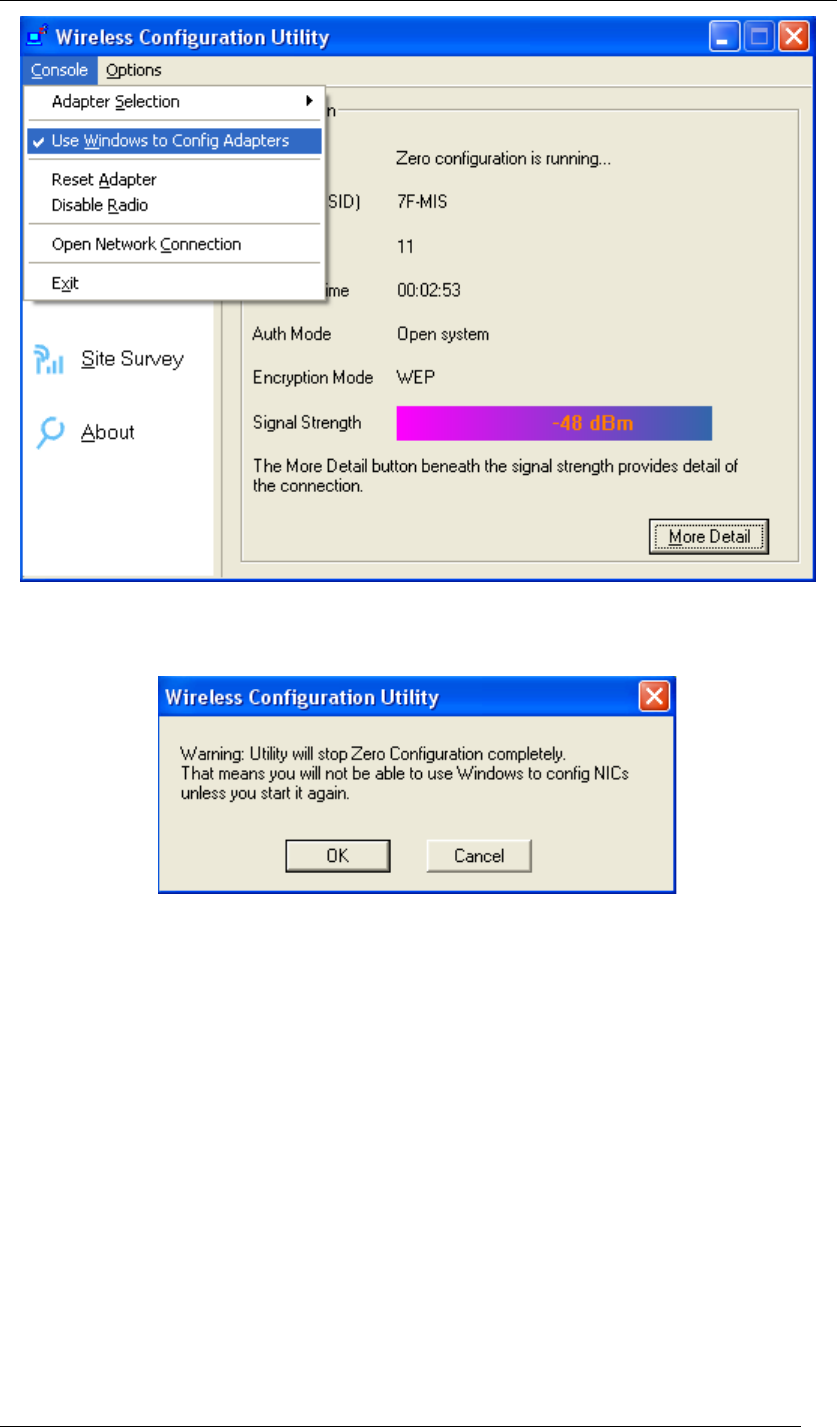
2. When the “Wireless Configuration Utility” shows up, please click Console at the top left
side, and unselect Use Windows to Config Adapters.
Chapter 4 Starting Up Page 22
Figure 22 Wireless Configuration Utility-Console
3. Click OK. And the “Wireless Configuration Utility” is again ready for you.
Figure 23 Wireless Configuration Utility-Warning Sign
Note.3 for Windows XP users
“Wireless Configuration Utility”, which comes with Wireless USB Adaptor, provides you with
more tools to configure and monitor it. Tools like “Link Test” or “Profiles” allow you to test the
connection of your network or even create your own list for common used places (access
points/routers) for convenience. In addition, the WiFi Protected Setup (WPS) function is able to
be easily activated by using “Wireless Configuration Utility”.
For more information about “Wireless Configuration Utility”, please refer to the chapter 5 of this
manual.
Chapter 4 Starting Up Page 23
For Windows Vista users
1. Insert the product CD into the CD-ROM on your computer. Locate setup.exe in the CD
and then double-click it.
Figure 24 Setup Icon in Windows Vista
2. Click Next to continue the installation of IEEE 802.11n Wireless LAN Utility. This utility
will help configuring your wireless network and monitoring the status of Wireless USB
Adaptor after it is done.
Figure 25 Setup in Windows Vista-Initial Screen
3. Click Next to install the driver.
Chapter 4 Starting Up Page 24
Figure 26 Setup in Windows Vista-Select Driver Files
4. Click Next to install the utility into the designated folder; or click Browse to choose your
preferred folder.
Figure 27 Setup in Windows Vista-Select Destination Folder
Chapter 4 Starting Up Page 25
5. Click Next to continue.
Figure 28 Setup in Windows Vista-Select Program Folder
6. Select the item you like to add the shortcut to it. Then Click Next.
Figure 29 Setup in Windows Vista-Add Shortcuts
7. Installation is successfully processing. (Click Cancel to stop it.)
Chapter 4 Starting Up Page 26
Figure 30 Setup in Windows Vista-Installation Processing
8. A sign of “Windows can’t verify the publisher of this driver software” will show up. Please
click Install this driver software anyway to go on.
Figure 31 Windows Security
9. Installation is successfully done. Click Finish to close the window.
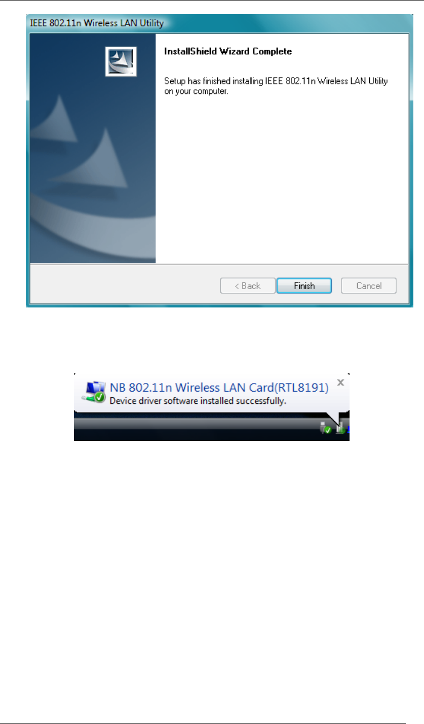
Chapter 4 Starting Up Page 27
Figure 32 Setup in Windows Vista-Installation Completed
10. Plug Wireless USB Adaptor to your PC through the USB port, and after a few seconds,
the successful installation dialogue will pop up as below.
Figure 33 Successful Driver Installation Sign
11. The “Wireless Configuration Utility” will show up automatically when the previous step
has finished.
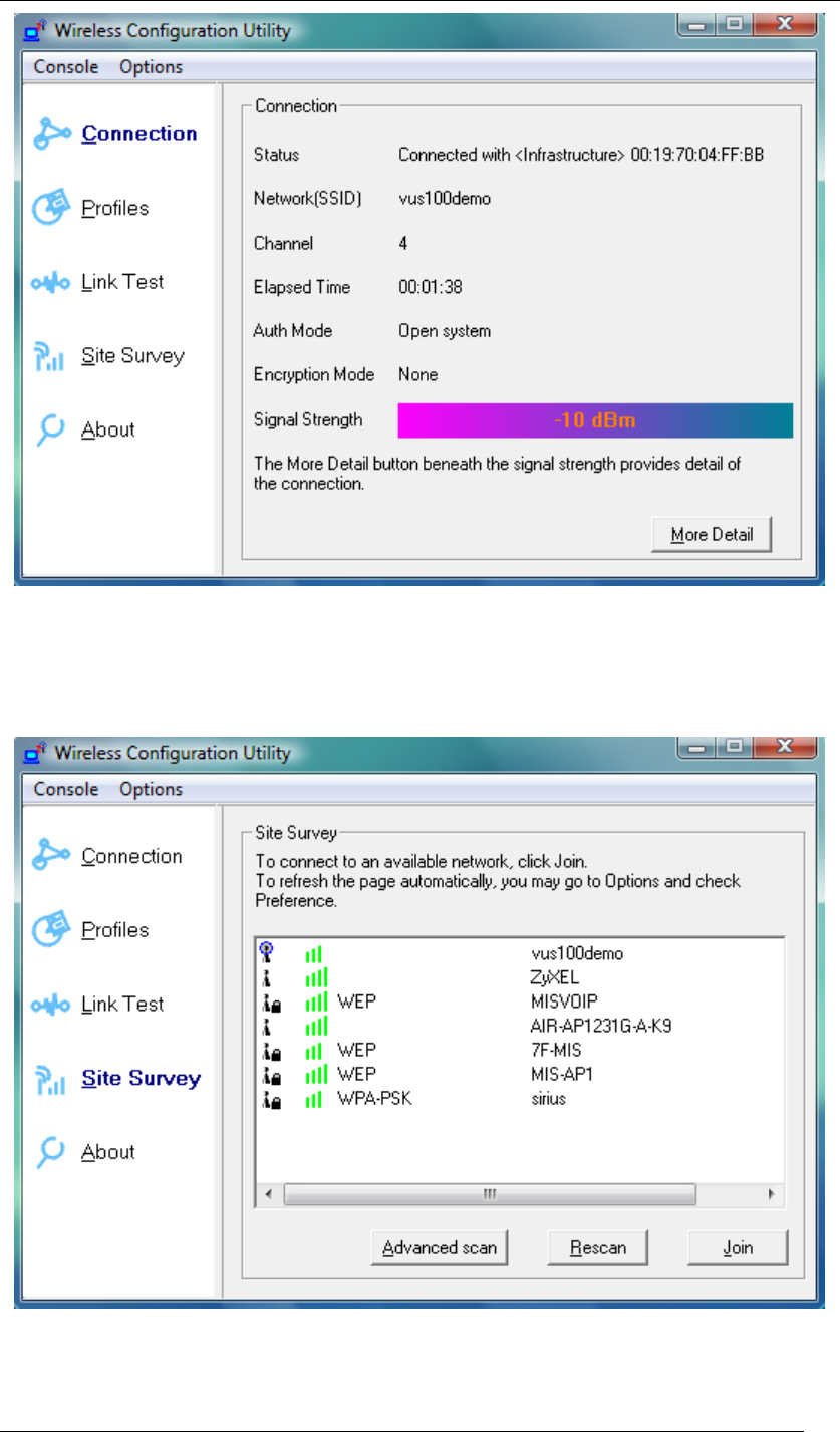
Chapter 4 Starting Up Page 28
Figure 34 Wireless Configuration Utility-Connection
12. Click Site Survey in the left column, and you will see all the currently available access
points in the right page. Choose the one you are allowed to use by single-clicking it, and
then click Join. (Password required, if needed)
Figure 35 Wireless Configuration Utility-Site Survey
13. Open your web browser and enjoy the Internet now!
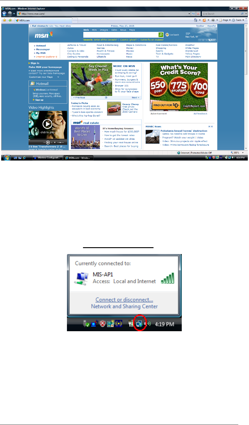
Chapter 4 Starting Up Page 29
Figure 36 Enjoy the Internet
Note.1 for Windows Vista users
If you prefer to use the built-in “Wireless Zero Configuration” of Windows Vista to connect to a
wireless network, please follow the steps below.
1. Click the icon in the red circle as below on the side bar of the desktop, and a small
window will pop up. Click Connect or disconnect….
Figure 37 Wireless Zero Configuration Icon
2. A window will show up as below, and all the currently available access points are listed in
the right side. Choose the one you are allowed to use and then double click it to connect
to it. (Password required, if needed)
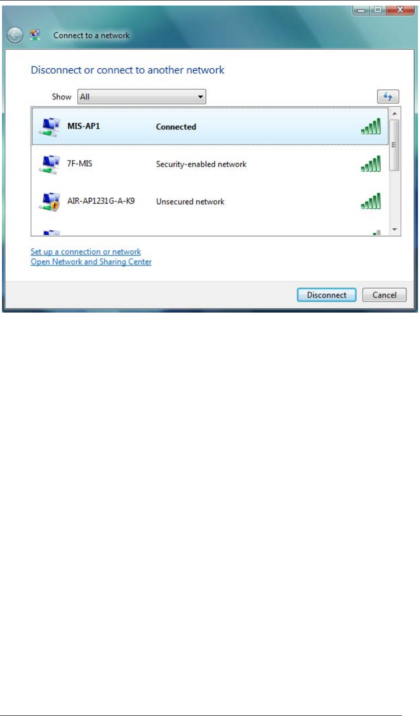
Chapter 4 Starting Up Page 30
Figure 38 Wireless Network Connection List
Note.2 for Windows Vista users
“Wireless Configuration Utility”, which comes with Wireless USB Adaptor, provides you with
more tools to configure and monitor it. Tools like “Link Test” or “Profiles” allow you to test the
connection of your network or even create your own list for common used places (access
points/routers) for convenience. In addition, the WiFi Protected Setup (WPS) function is able to
be easily activated by using “Wireless Configuration Utility”.
For more information about “Wireless Configuration Utility”, please refer to the chapter 5 of this
manual.
Chapter 4 Starting Up Page 31
For Windows 2000 users
1. Insert the product CD into the CD-ROM on your computer. Locate setup.exe in the CD
and then double-click it.
Figure 39 Setup Icon in Windows 2000
2. Click Next to continue the installation of IEEE 802.11n Wireless LAN Utility. This utility
will help configuring your wireless network and monitoring the status of Wireless USB
Adaptor after it is done.
Figure 40 Setup in Windows 2000-Initial Screen
3. Click Next to install the driver.
Chapter 4 Starting Up Page 32
Figure 41 Setup in Windows 2000-Select Driver Files
4. Click Next to install the utility into the designated folder; or click Browse to choose your
preferred folder.
Figure 42 Setup in Windows 2000-Select Destination Folder
5. Click Next to continue.
Chapter 4 Starting Up Page 33
Figure 43 Setup in Windows 2000-Select Program Folder
6. Select the item you like to add the shortcut to it. Then Click Next.
Figure 44 Setup in Windows 2000-Add Shortcuts
7. Installation is successfully processing. (Click Cancel to stop it.)
Chapter 4 Starting Up Page 34
Figure 45 Setup in Windows 2000-Installation Processing
8. Installation is successfully done. Click Finish to close the window.
Figure 46 Setup in Windows 2000-Installation Completed
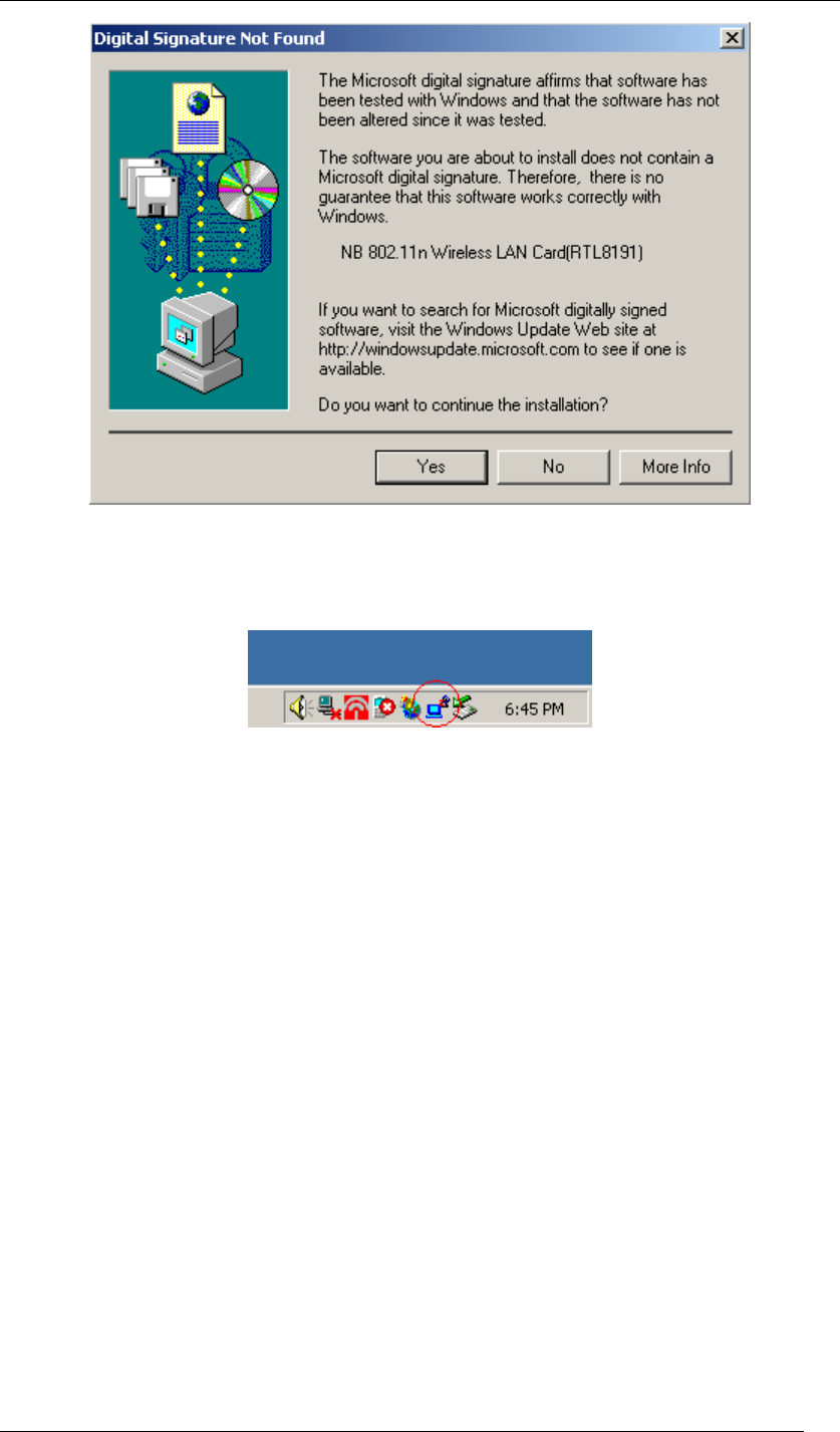
9. Plug Wireless USB Adaptor to your PC through the USB port. If the sign of “Digital
Signature Not Found” shows up, please click Yes.
Chapter 4 Starting Up Page 35
Figure 47 Digital Signature Not Fount Sign
10. Wireless USB Adaptor is successfully installed once the icon below is listed in the side
bar of the desktop. Click the icon.
Figure 48 Wireless Configuration Utility Icon
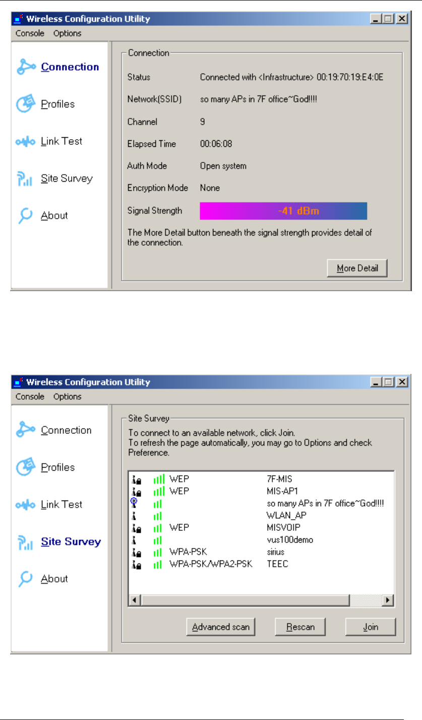
11. Wireless Configuration Utility will show up. This utility can help configuring your wireless
network and monitoring the status of Wireless USB Adaptor.
Chapter 4 Starting Up Page 36
Figure 49 Wireless Configuration Utility-Console
12. Click Site Survey in the left column, and you will see all the currently available access
points in the right page. Choose the one you are allowed to use by single-clicking it, and
then click Join. (Password required, if needed)
Figure 50 Wireless Configuration Utility-Site Survey
13. Open your web browser and enjoy the Internet now!

Chapter 4 Starting Up Page 37
Figure 51 Enjoy the Internet

Chapter 4 Starting Up Page 38
Note.1 for Windows 2000 users
“Wireless Configuration Utility”, which comes with Wireless USB Adaptor, provides you with
more tools to configure and monitor it. Tools like “Link Test” or “Profiles” allow you to test the
connection of your network or even create your own list for common used places (access
points/routers) for convenience. In addition, the WiFi Protected Setup (WPS) function is able to
be easily activated by using “Wireless Configuration Utility”.
For more information about “Wireless Configuration Utility”, please refer to the chapter 5 of this
manual.
Chapter 5 Utility Overview Page 39
Chapter 5 Utility Overview
This chapter introduces the functions of the utility and how you can take advantage of it. After
going through this chapter, you will be able to optimize your wireless network.
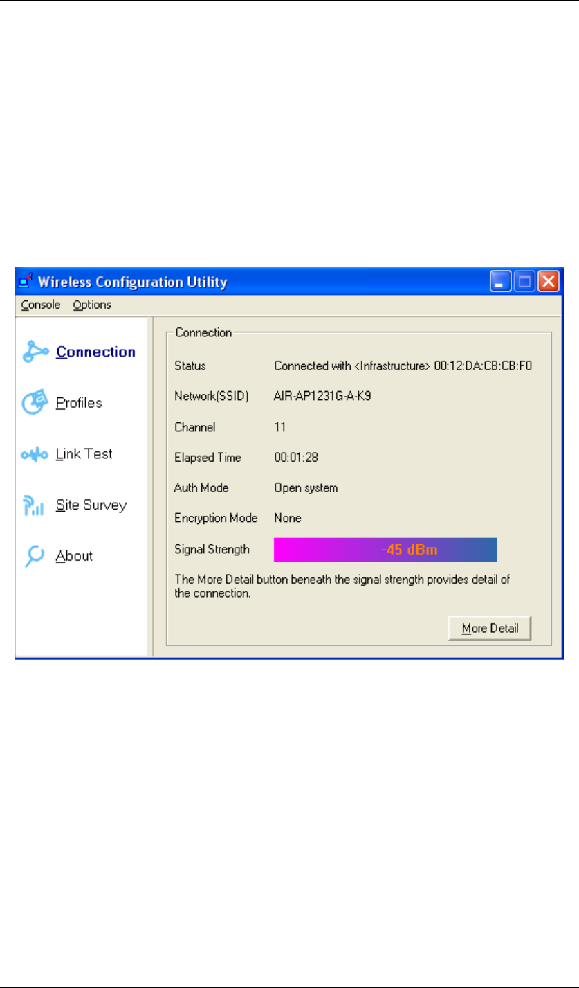
Connection:
Here shows the status of your current wireless network which is built by the Wireless USB
Adaptor and the access point it connects to.
Figure 52 Wireless Configuration Utility-Connection
Status: Shows the MAC address and the network type of the access point or router you
connected to.
Network(SSID): Service set identifier, or SSID, is a friendly name that identifies a
particular IEEE 802.11 wireless LAN. The SSID can be up to 32 characters long. By the SSID,
you are able to know exactly which network you are in.
Channel: Shows the RF channel you are using.
Elapsed Time: Shows the duration of your current connection.
Chapter 5 Utility Overview Page 40
Auth Mode: Shows the authentication way of your current connection to an access point
or router.
Encryption Mode: Shows the encryption way of your current connection to an access
point or router.
Signal Strength: The longer the bar is, the stronger the signal you get from access
point or router. This item shows the connection strength.
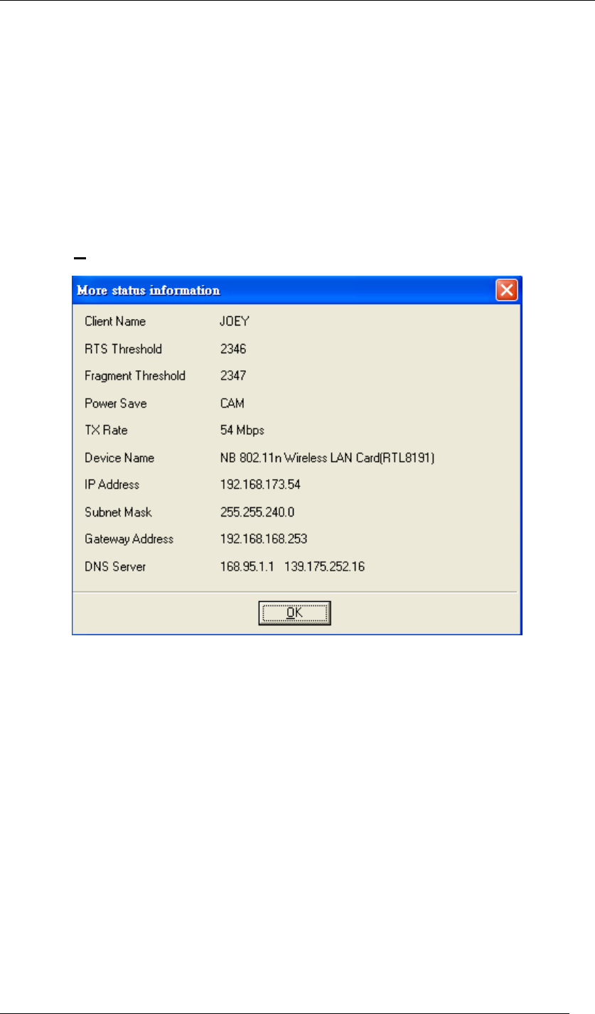
By clicking More Detail at the bottom right, you can get more information as below.
Figure 53 More Status Information
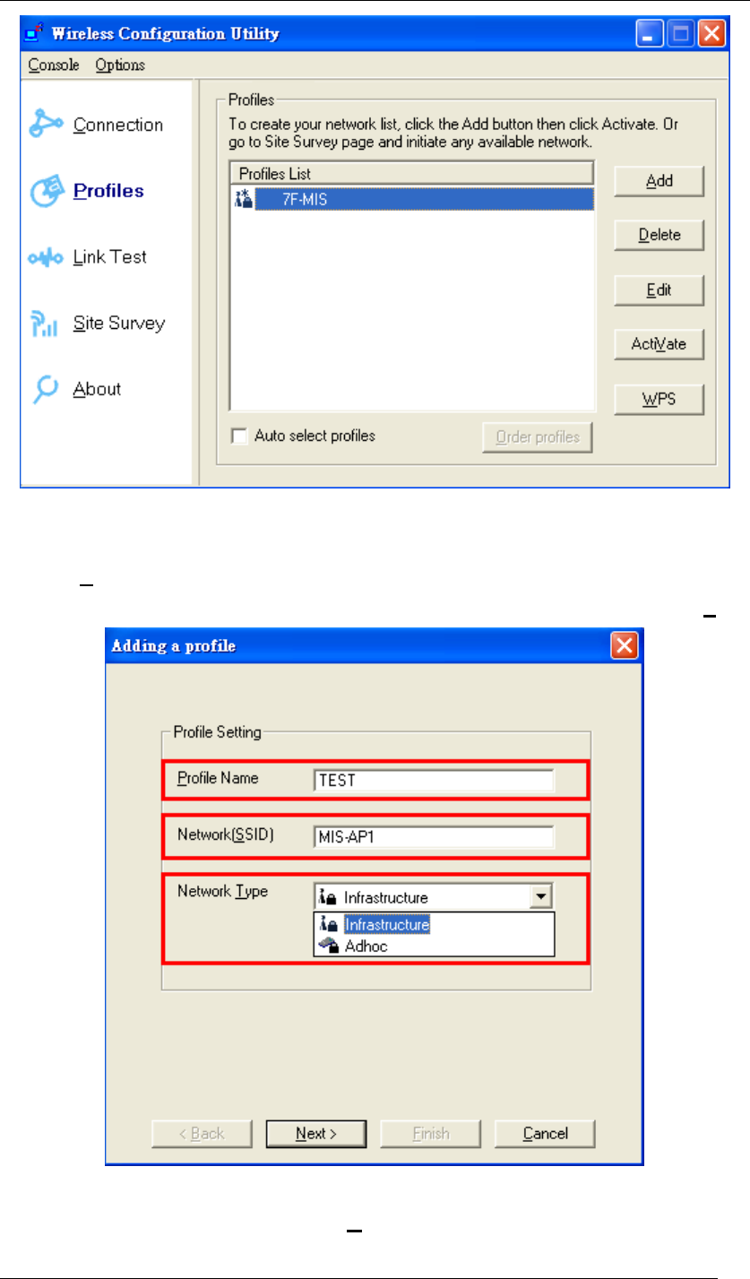
Profiles:
To create a list of your most common used network, you can add new access points, edit the
current access points, or even delete any access point which you will never use again in the
future. You can arrange your own Profiles for your convenience anytime.
Chapter 5 Utility Overview Page 41
Figure 54 Wireless Configuration Utility-Profiles
To add a new network to the Profiles List:
1. Click Add.
2. Fill out the Profile Name, Network (SSID), and choose the Network Type. Then, click Next.
Figure 55 Adding a Profile
3. Select Security if required. Then click Next. (Detailed security settings will be brought
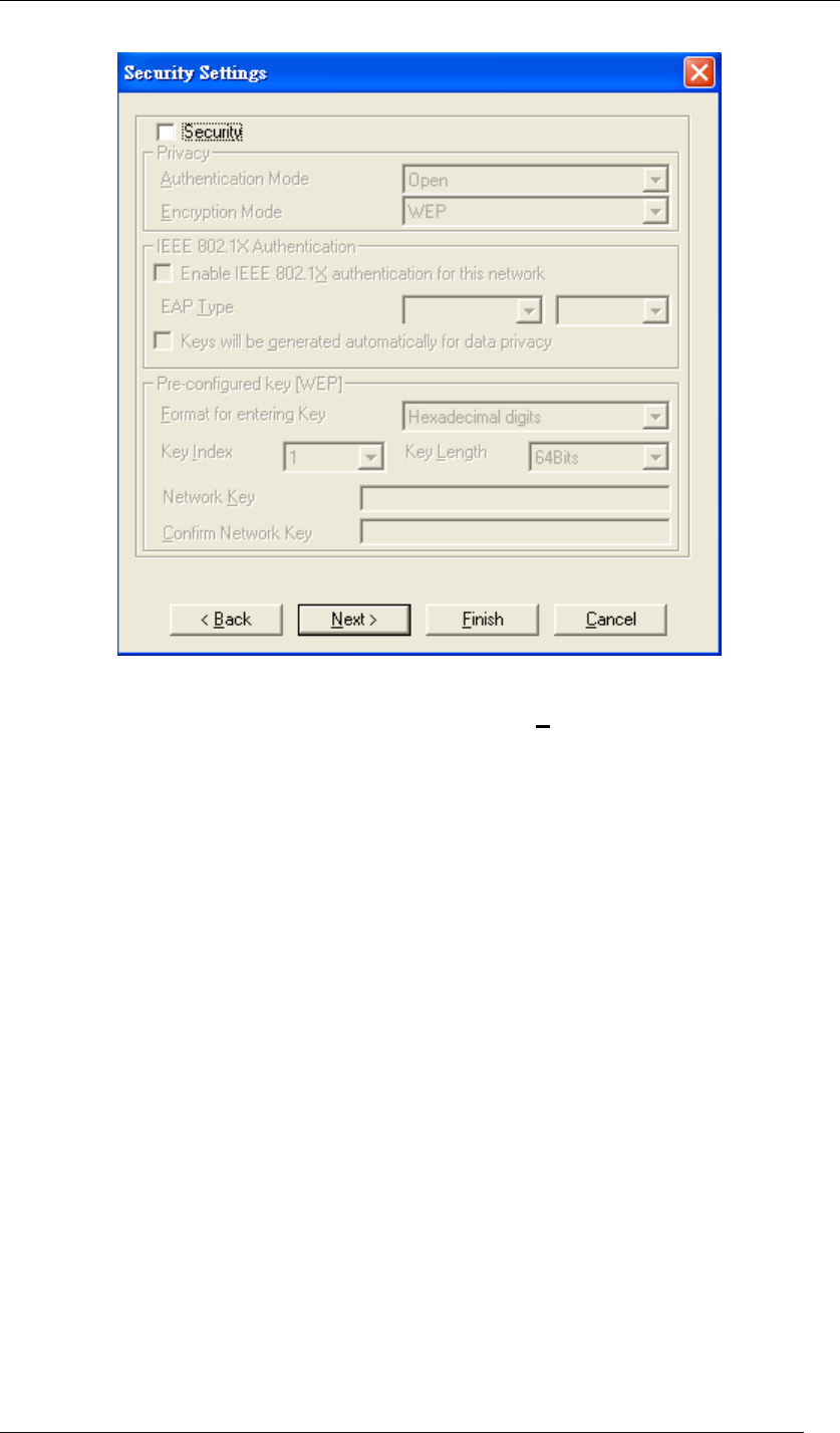
Chapter 5 Utility Overview Page 42
up on Page.49.)
Figure 56 Security Settings
4. Select Change current IP setting if needed. Then click Next. The default is “Obtain an IP
address automatically”, or you can select “Specify IP address” and fill in the related
information below to use the static IP address.
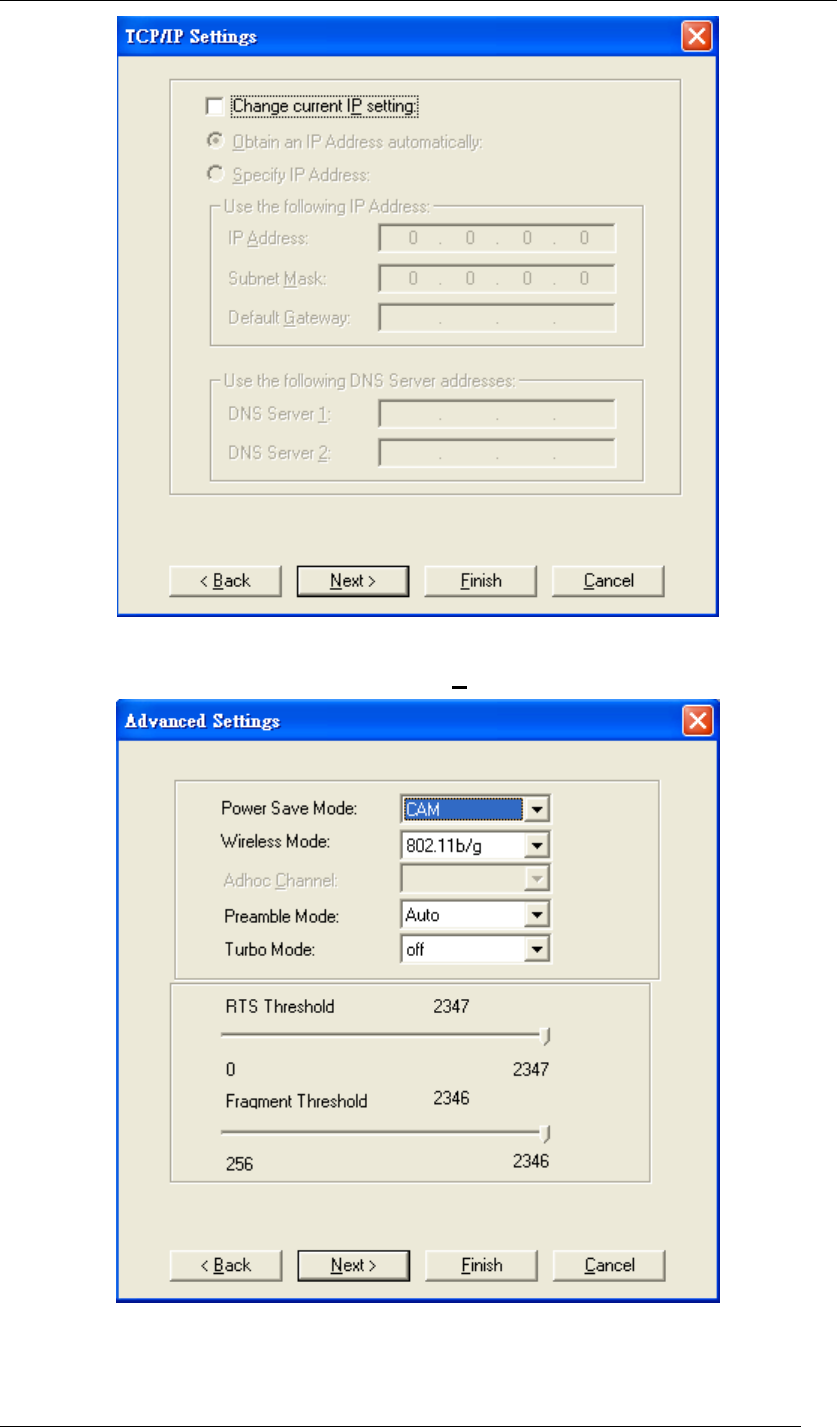
Chapter 5 Utility Overview Page 43
Figure 57 TCP/IP Settings
5. Do advanced settings if you want. Then click Next.
Figure 58 Advanced Settings

Chapter 5 Utility Overview Page 44
Power Save Mode:
z CAM = Constantly Awake Mode.
z MAX = Maximum Power Save.
z Fast: = Fast Power Save.
Power-saving ability
CAM < Fast < MAX
Wireless Mode:
The wireless Mode supports three options 802.11b, 802.11b/g, and 802.11b/g/n.
Adhoc Channel:
Selects bands and channels for device to device (ad hoc) networks.
* This item will be available while network type is set to be Adhoc.
Preamble Mode:
Select it between Auto, long or short. The default is Auto.
Turbo Mode:
Turn it on to increase the throughput; however, this mode is supported only if the access point /
router you connected to also supports this mode.
RTS Threshold:
The Request-To-Send threshold specifies the packet size of an RTS transmission. This helps
control traffic flow through an access point, especially one with many clients.
* If you are not familiar with this parameter, please leave it as the default.
Fragment Threshold:
If you experience a high packet error rate, try to slightly increase your Fragmentation
Threshold. Default is set to the maximum of 2346. Setting the Fragmentation Threshold too
low may result in very poor performance.
Chapter 5 Utility Overview Page 45
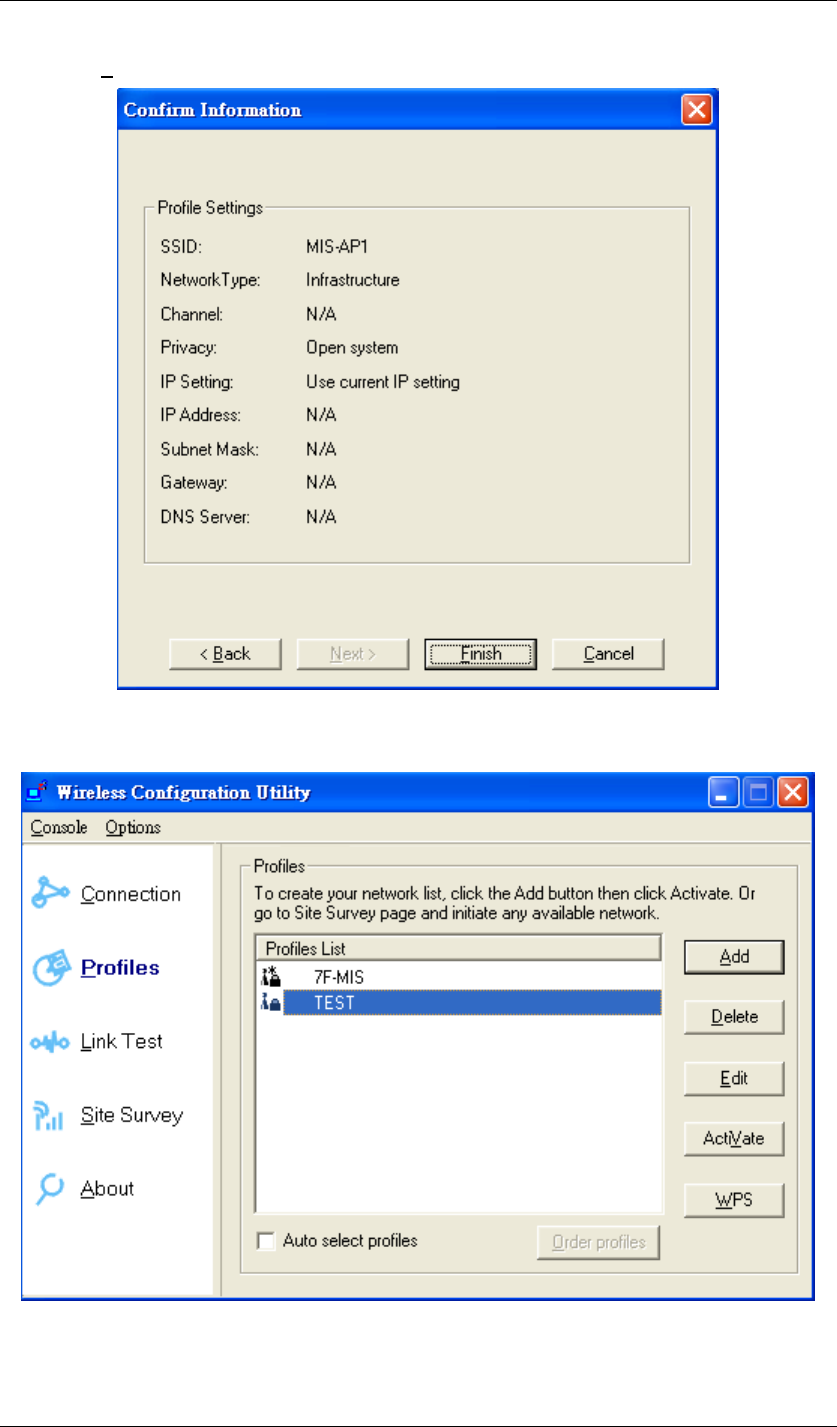
6. Click Finish to confirm the information.
Figure 59 Confirm Information
7. The new network (TEST) has successfully been added to the Profiles List.
Figure 60 Wireless Configuration Utility-Profiles
To delete a current network from the Profiles List:
Chapter 5 Utility Overview Page 46
1. Choose the network you would like to delete in the Profiles List.
2. Click Delete.
To edit a current network from the Profiles List:
1. Choose the network you would like to edit in the Profiles List.
2. Click Edit.
3. Follow the same steps in To add a new network to the Profiles List to edit the variables.
To activate a current network from the Profiles List:
1. Choose the network you would like to activate in the Profiles List.
2. Click ActiVate.
To enable WPS:
Wi-Fi Protected Setup (WPS) is a standard for easy and secure establishment of a wireless
home network, defined by the Wi-Fi Alliance. The goal of the WPS is to simplify the process of
connecting any home device to the wireless network.
WPS can be easily activated by pressing the WPS button on the body of Wireless USB
Adaptor as well as the one on your access point / router. After both of them are pressed, wait
about 2 minutes, and the successful message will show up as below.
Figure 61 Wi-Fi Protected Setup
Chapter 5 Utility Overview Page 47
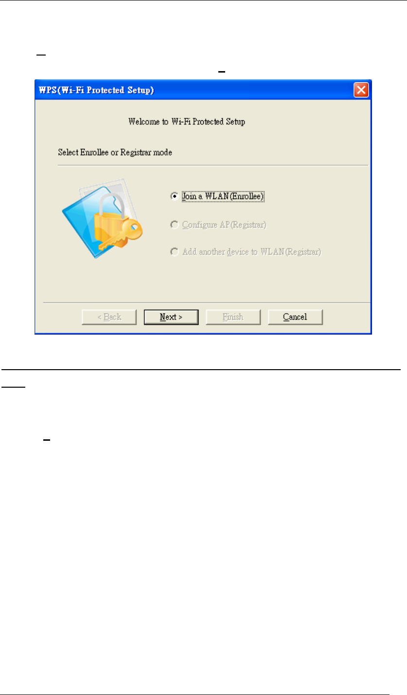
In addition, WPS could also be activated from Profiles List by the following steps.
1. Click WPS.
2. Choose Join a WLAN (Enrollee), and then click Next.
Figure 62 WPS Setup-Initial Screen
The step.3 will have many scenarios. Please choose the one that suits your environment the
most.
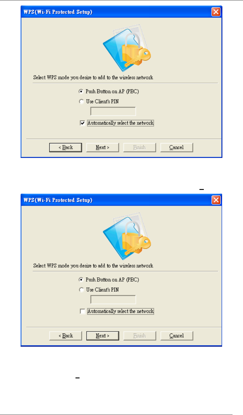
3.1 Choose “Push Button on AP (PBC)” and select “Automatically select the network”. Then
click Next.
Chapter 5 Utility Overview Page 48
Figure 63 WPS Setup-Select a Mode
3.2 If you would like to connect to a specified WPS-enabled AP, please choose “Push Button
on AP (PBC)” and unselect “Automatically select the network”. Then click Next.
Figure 64 WPS Setup-Select a Mode
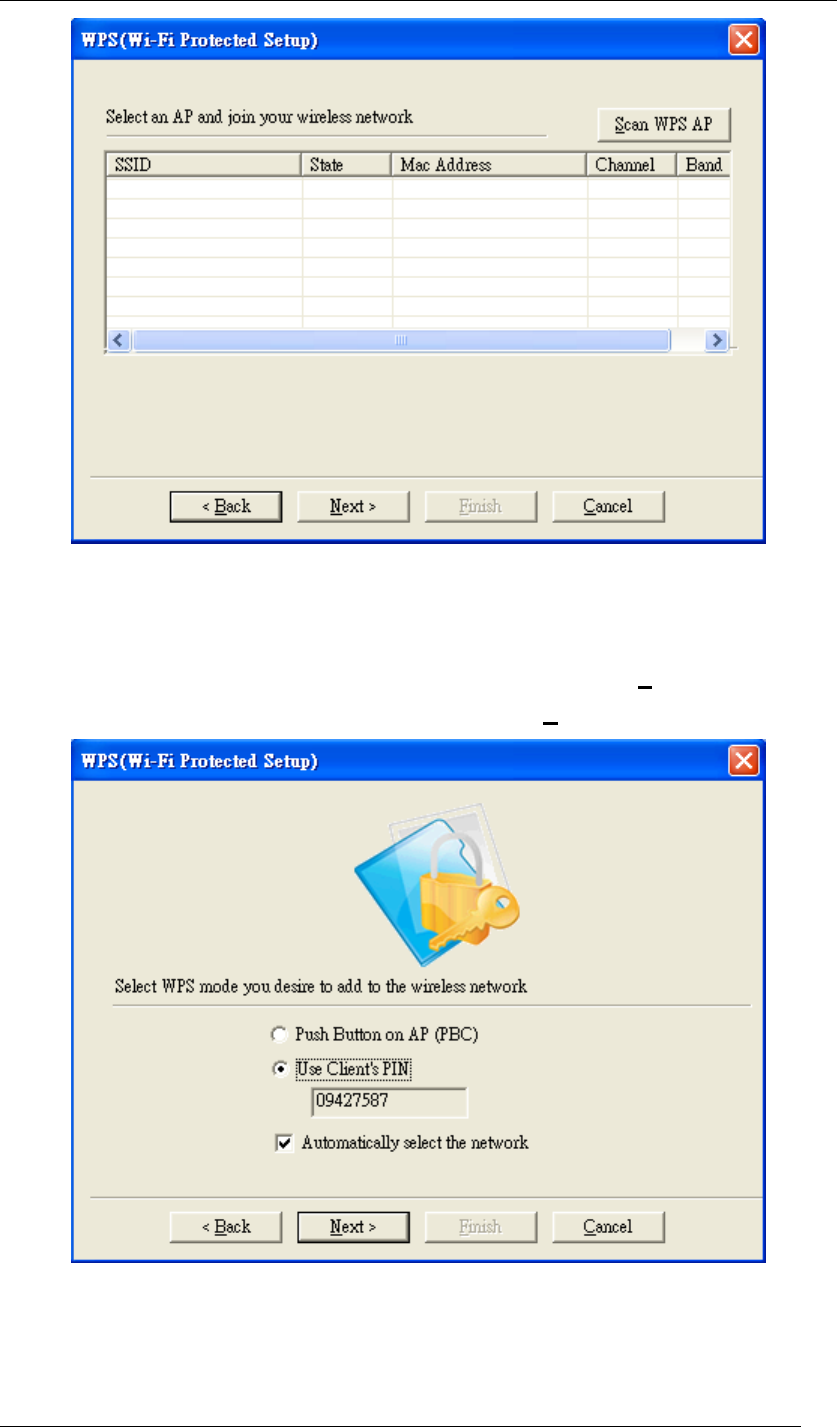
A window will appear and show every currently available WPS-enabled AP on the list. Choose
the one you prefer, and click Next.
Chapter 5 Utility Overview Page 49
Figure 65 WPS Setup-Select an AP
3.3 Choose “Use Client PIN” and select “Automatically select the network”. When you choose
“Use Client PIN”, a random series of numbers will come out. Remember to use these
numbers as the PIN key in your access point / router before clicking Next. When your
access point / router is done with the same PIN key, click Next to build the connection.
Figure 66 WPS Setup-Select a Mode
3.4 Choose “Use Client PIN” and unselect “Automatically select the network”. When you
choose “Use Client PIN”, a random series of numbers will come out. Remember to use
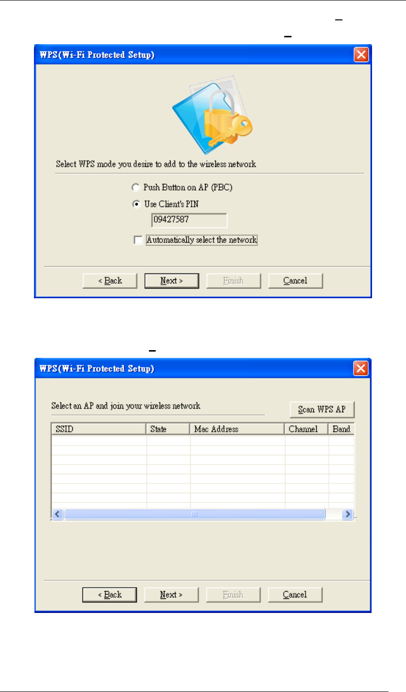
Chapter 5 Utility Overview Page 50
these numbers as the PIN key in your access point / router before clicking Next. When
your access point / router is done with the same PIN key, click Next.
Figure 67 WPS Setup-Select a Mode
A window will appear and show every currently available WPS-enabled AP on the list. Choose
the one you designated, and click Next to build the connection.
Figure 68 WPS Setup-Select an AP
4. When any of previous scenarios has been done, the processing message will be shown
as below. It might take about 2 minutes to make the connection.
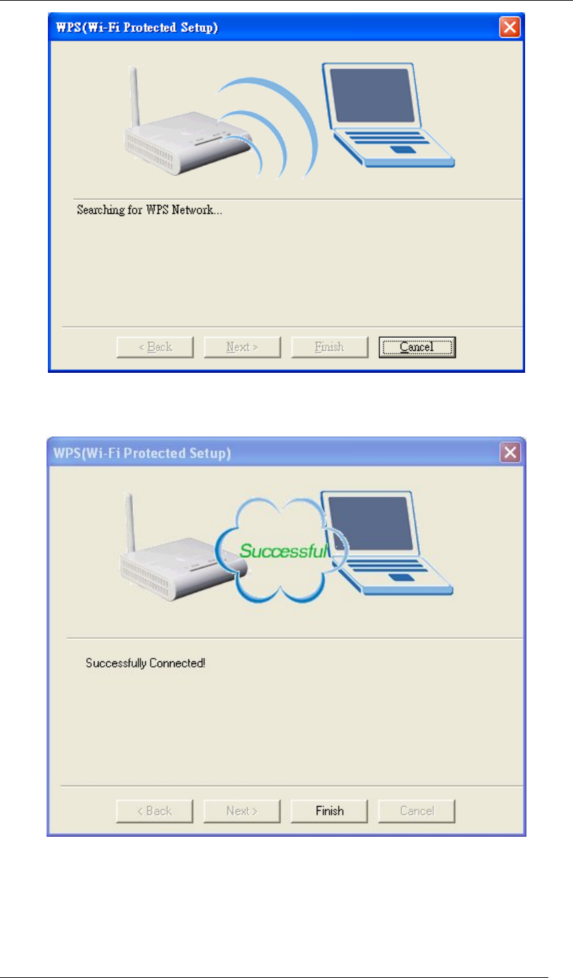
Chapter 5 Utility Overview Page 51
Figure 69 WPS Setup-Searching for WPS Network
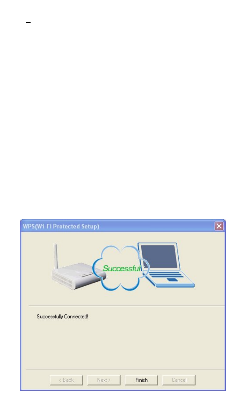
5. WPS connection has been successfully built.
Figure 70 WPS Setup-Successfully Connected
Chapter 5 Utility Overview Page 52
Security Settings
Wireless LAN security is vital to your network to protect wireless communications against
hacker entering your system and prevent unauthorized wireless station from accessing data
transmitted over the network; the WLAN Utility offers a sophisticated security algorithm.
Select Security. A privacy Configuration window will appear as below.
Figure 71 Security Settings
If you do not enable any wireless security on your IEEE 802.11n Wireless LAN USB Adapter,
the wireless communication is accessible by any wireless networking device that is in the
coverage area.
Data Encryption with WEP
WEP (Wired Equivalent Privacy) encryption scrambles all data packets transmitted between
the wireless LAN adapter and the AP or other wireless station to keep network communication
private.
Both the wireless stations and the access points must use the same WEP key for data
encryption and decryption.

Chapter 5 Utility Overview Page 53
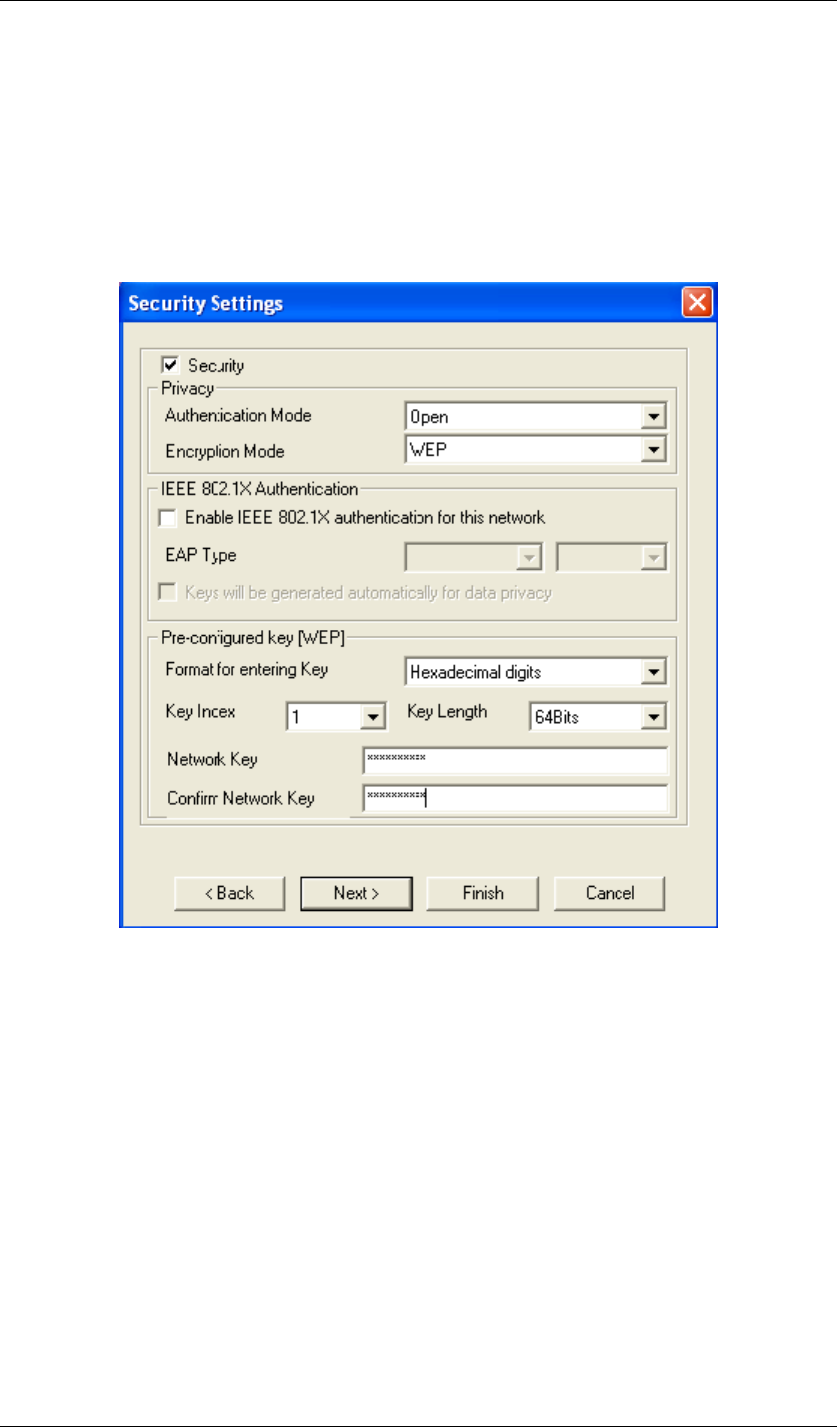
Figure 72 Security Settings
The IEEE 802.11n Wireless LAN USB Adapter allows you to configure up to four 64-bit, or
128-bit WEP keys and only one key is used as the default key at one time. The Key index field
allows you to specify the key index you desire to use for transmitting data on your wireless
LAN. You can change the default key by clicking on the up or down arrow and make sure the
default key is set up exactly the same on the Wireless LAN stations as they are on the wireless
Access Point.
z For 64bit encryption you may choose:
Alphanumeric: entering 5 characters (case sensitive) ranging from “a-z”, “A-Z” “0-9” to
special characters like “@”, “#”, “$” and so on as long as they are in the ASCII table. (e.g.
My&12).
Hexadecimal: entering 10 hexadecimal digits in the range of “A-F”, “a-f” and “0-9” (e.g.
11AA22BB33, shown as below).
z For 128bit encryption you may choose:
Alphanumeric: entering 5 characters (case sensitive) ranging from “a-z”, “A-Z” “0-9” to
special characters like “@”, “#”, “$” and so on as long as they are in the ASCII table. (e.g.
My#$%12345678).
Hexadecimal: entering 26 hexadecimal digits in the range of “A-F”, “a-f” and “0-9” (e.g.
00112233445566778899AABBCC).
Authentication with WEP: Open System authentication and
Shared Key authentication
z Open system mode is implemented for ease-of-use and when security is not an issue. It
requires NO authentication, since it allows any device to join a network without
performing any security check. The wireless station and the AP do not share a secret key.
Thus the wireless stations can associate with any AP and listen to any data transmitted
plaintext.
z Shared key mode involves a shared secret key to authenticate the wireless station to the
AP. It requires that the station and the access point use the same WEP key to

Chapter 5 Utility Overview Page 54
authenticate. This basically means that WEP must be enabled and configured on both
the AP and the other wireless stations with a same key.
IEEE 802.1X
The IEEE 802.1X standard outlines enhanced security methods for both the authentication of
wireless stations and encryption key management. Authentication can be done by using an
external RADIUS server.
EAP Authentication
EAP (Extensible Authentication Protocol) is an authentication protocol which runs on the top of
IEEE 802.1x transport mechanism in order to support multiple types of user authentication. By
using EAP to interact with an EAP-compatible RADIUS server, an Access Point helps a
wireless station and a RADIUS server perform authentication.
The type of authentication you use depends on the RADIUS server and an intermediary AP
that supports IEEE 802.1X. You must first have a wired connection to the network and obtain
the certificate from a certificate authority (CA). A certificate can be used to authenticate users
and a CA issues certificates and guarantees the identity of each certificate owner.
WPA (2)
Wi-Fi Protected Access (WPA) is a subset of the IEEE 802.11i standard. WPA2 is a wireless
security standard that defines stronger encryption, authentication and key management than
WPA.
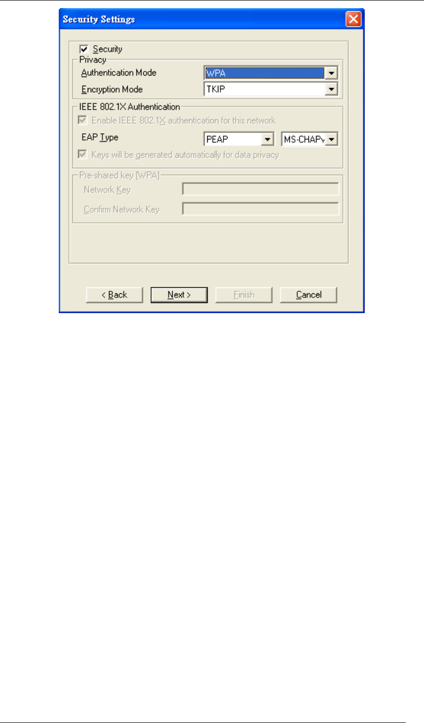
WPA
WPA allows you to gain access to a more secured wireless network that requires mutual
authentication between client and access point with a Radius authentication server or other
authentication server on the network. WPA uses 802.1X and Extensible Authentication
Protocol (EAP) for authentication. WPA offers Enterprise and individual needs to meet the
different market segments. This product supports various EAP types (TLS and PEAP), which
require different credential authentication. In order to access the wireless network, you must
select EAP type your service provider supplied in the section of IEEE802.11X Authentication.
Choose WPA2 if needed from Authentication Mode.
Chapter 5 Utility Overview Page 55
Figure 73 Security Settings
WPA-PSK
WPA-PSK offers a Personal mode of operation. In the Personal mode of operation, a
pre-shared key is used for authentication. WPA-PSK allows you to gain access to a secured
wireless network that the station and the access point use the same pre-shared key to
authenticate. You must type a mixture of numbers and letters in the Pre-shared key section of
this menu. You may input either 8-63 ASCII characters or 64 HEX characters. Choose
WPA-PSK if needed from Authentication Mode.

Chapter 5 Utility Overview Page 56
Figure 74 Security Settings
WPA2
WPA2 provides a stronger encryption mechanism than WPA. WPA2 is the second generation
of WPA security, providing personal and enterprise users with a high level of assurance that
only authorized users can access to their wireless network. There is no difference between
WPA and WPA2. The only difference is that WPA2 provides a stronger data encryption via the
AES, contrast to WPA, which uses Temporal Key Integrity Protocol (TKIP). Choose WPA2 if
needed from Authentication Mode.

Chapter 5 Utility Overview Page 57
Figure 75 Security Settings
WPA2-PSK
Like WPA, WPA2-Personal offers authentication via a pre-shared key. Pre-shared key is
usually used for Personal authentication. Personal mode requires only an access point and
client on the network. Similarly, you need to type a mixture of numbers and letters in the
Pre-shared key section of this menu. You may input either 8-63 ASCII characters or 64 HEX
characters. Choose WPA2-PSK if needed from Authentication Mode.
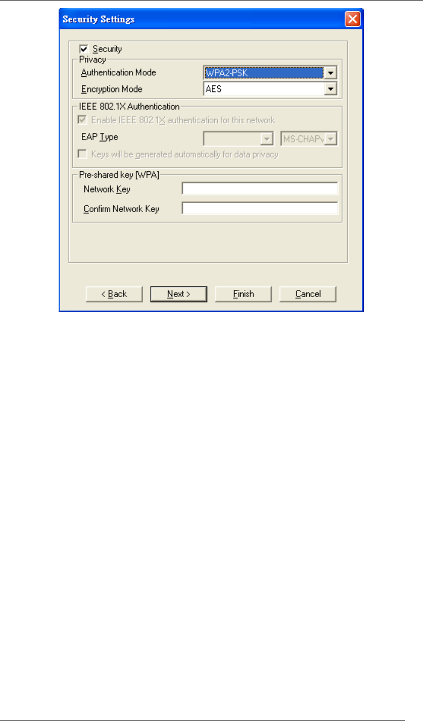
Chapter 5 Utility Overview Page 58
Figure 76 Security Settings
Encryption Mode
WPA improves data encryption by using Temporal Key Integrity Protocol (TKIP), Message
Integrity Check (MIC) and IEEE 802.1X. WPA2 use Advanced Encryption Standard (AES) in
the Counter mode with Cipher block chaining Message authentication code Protocol (CCMP)
to offer stronger encryption than TKIP.
The encryption mechanism used for WPA(2) and WPA(2)-PSK are the same. The only
difference between them is that WPA(2)-PSK uses a simple common password, instead of
user specific credentials. The common password approach makes WPA(2)-PSK susceptible to
brute-force password-guessing attacks but it’s still an improvement over WEP as it employs a
consistent, single, alphanumeric password to derive a PMK which is used to generate unique
temporal encryption keys.
IEEE 802.1X Authentication
WPA and WPA2 apply IEEE 802.1X and Extensible Authentication Protocol (EAP) to
authenticate wireless stations using an external RADIUS database. WPA2 reduces the
number of key exchange messages from six to four (CCMP 4 way handshake) and shortens
the time required to connect to a network. Other WPA2 authentication features that are
different from WPA include key caching and pre-authentication.
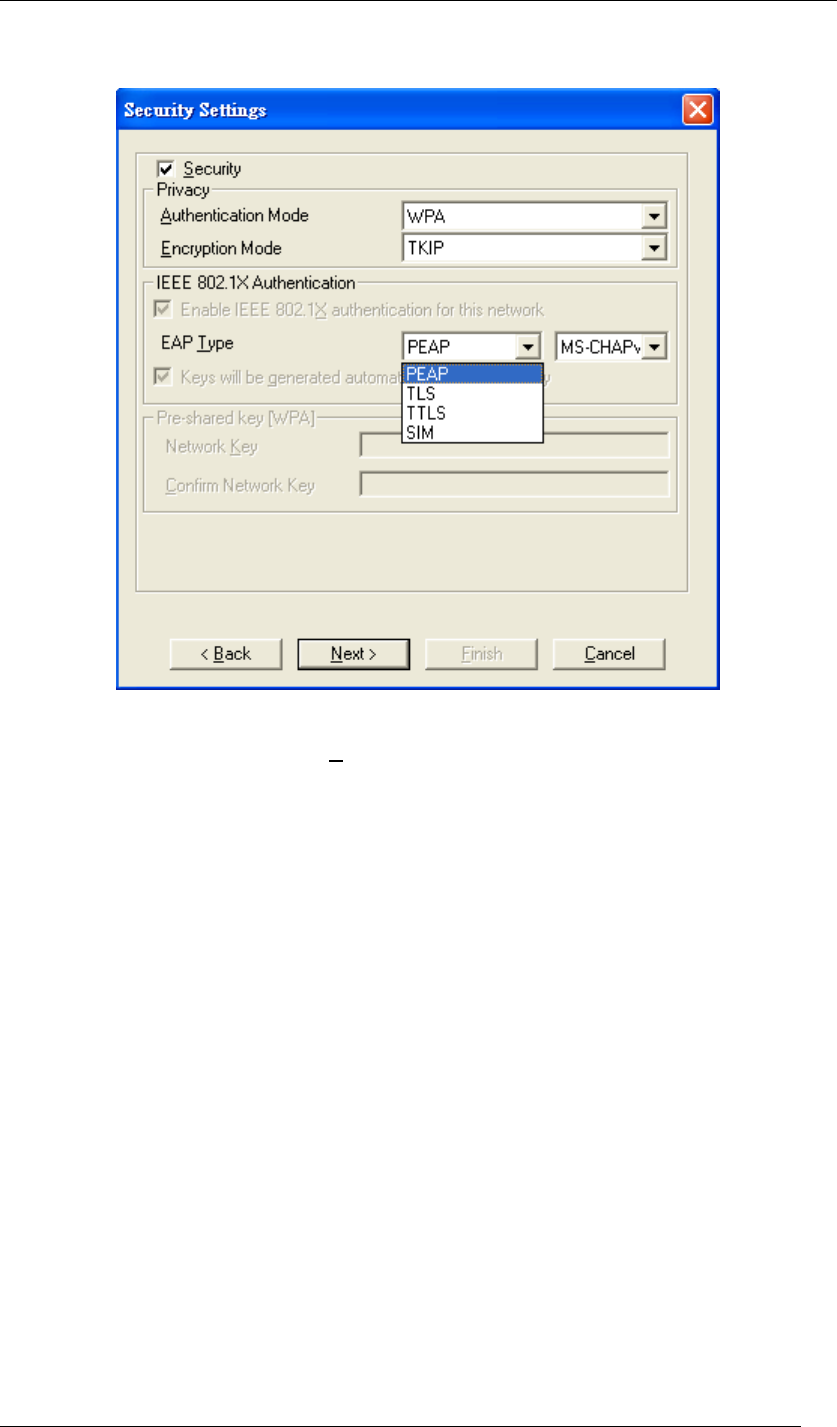
Chapter 5 Utility Overview Page 59
EAP Type
There are 4 types available in EAP including PEAP, TLS, TTLS, and SIM.
Figure 77 Security Settings
Choose the one you prefer and click Next, and then you will be guided to a new window
named “Certificate”.
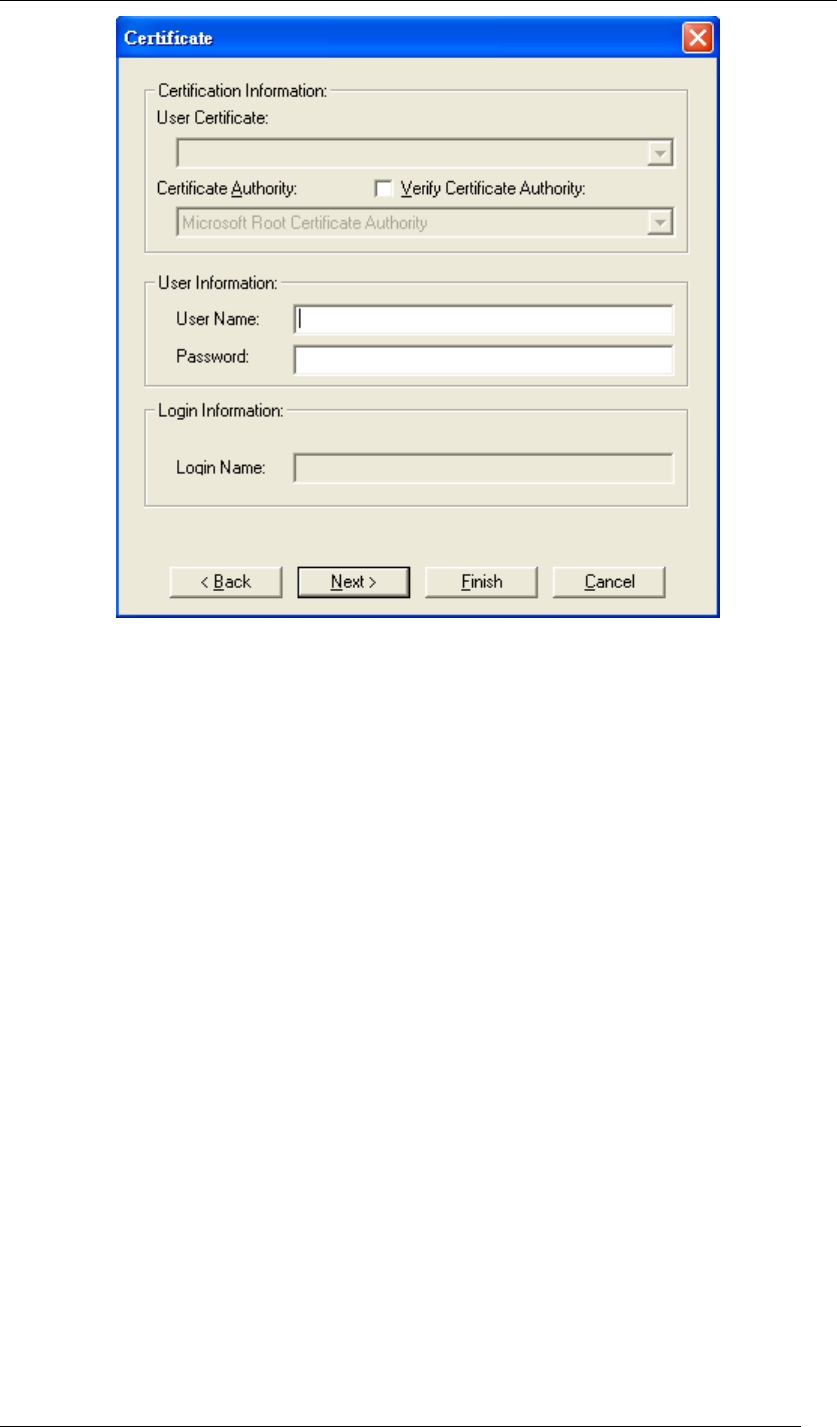
Chapter 5 Utility Overview Page 60
Figure 78 Certificate
You have to fill out the required information before going to the next step. The following will
show the process of each type.
z PEAP
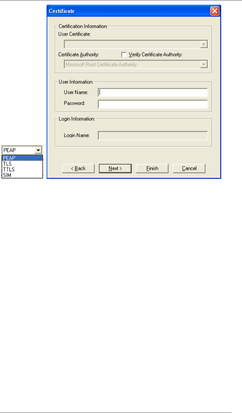
Chapter 5 Utility Overview Page 61
Figure 79 Certificate-PEAP
PEAP requires the use of Certificate Information and User Information. This utility will
automatically identify Certificate Information and Login Information for users to configure
PEAP easily. You only need to enter User Name and Password in the User information filed to
authenticate. If you click the “Verify Certificate Authority” check box, you are able to choose
one of User Certificate from the drop-down menu. Furthermore, you need to input User Name
and Password in the User Name field on the screen.
Chapter 5 Utility Overview Page 62
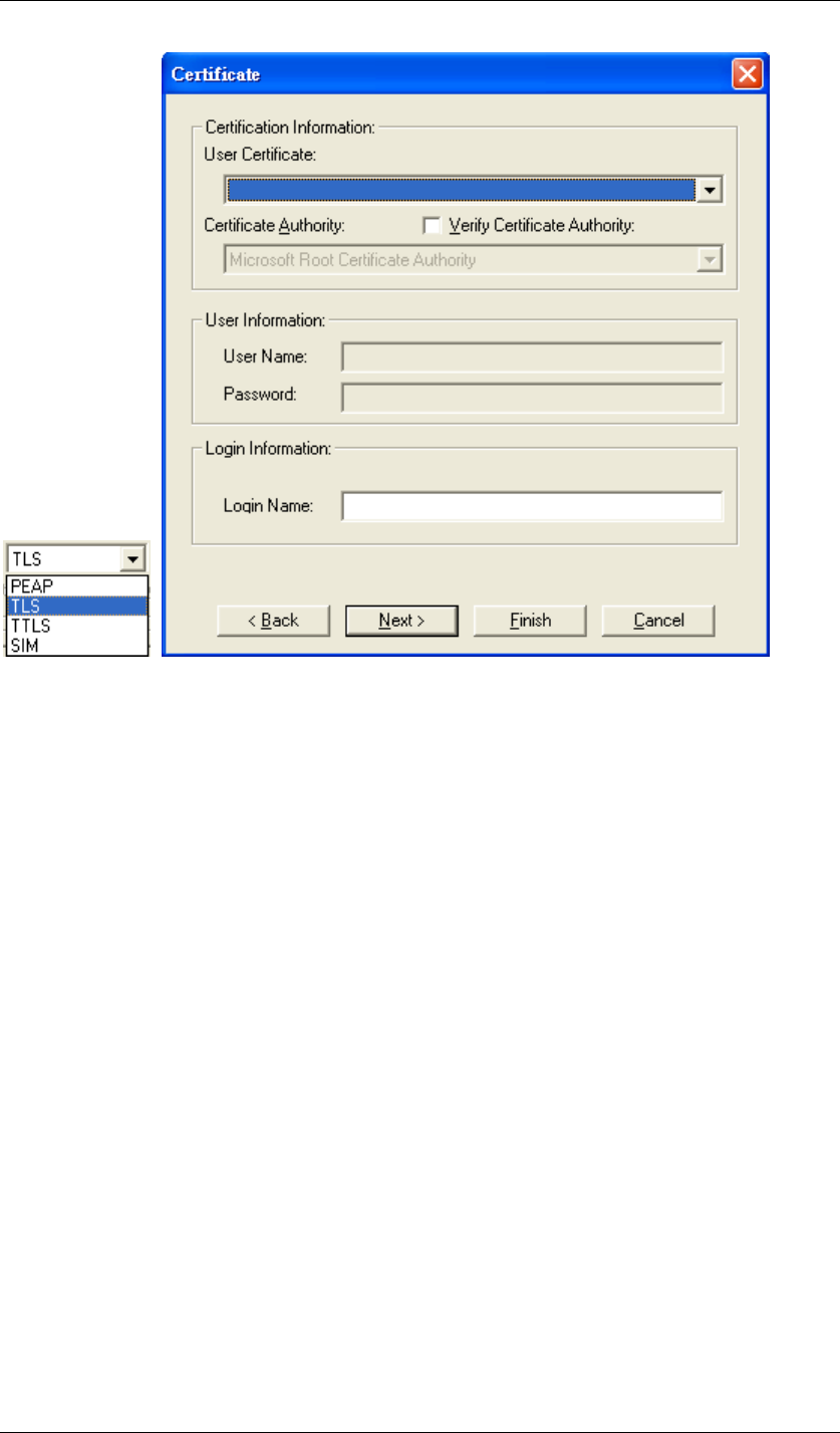
z TLS
Figure 80 Certificate-TLS
TLS requires the entry of Certificate Information and Login Information for mutual
authentication. This utility will auto-detect the Certificate Information for you to configure
TLS easily. You only need to enter the Login Name in the Login information filed to
authenticate. If you desire to use the Certificate Authority manually, you can click the
check box next to “Verify Certificate Authority” and choose the usable selection in the
User Certificate field using drop-down menu.
User Certificate: select one of user certificates you have enrolled.
TLS is used to create a secure tunnel through which authentication and encryption keys
can be passed and require server and client side keys.
Chapter 5 Utility Overview Page 63
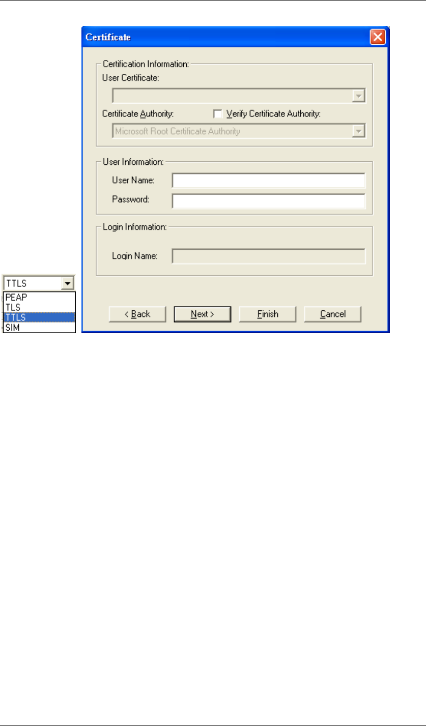
z TTLS
Figure 81 Certificate-TTLS
TTLS requires the mutual authentication between station and access points. You must present
a User Name and Password in the User Information field that will be verified by
TTLS-capable server. This mutual authentication ensures that only authorized users are
allowed access to the network.
Chapter 5 Utility Overview Page 64
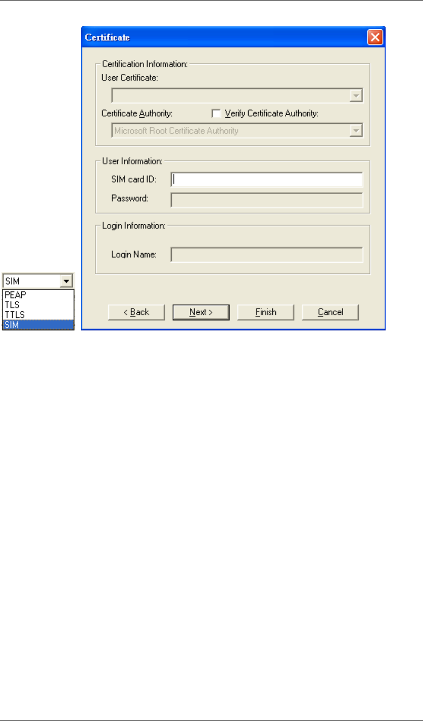
z SIM
Figure 82 Certificate-SIM
SIM requires a valid PIN to the SIM card, which must match the PIN stored on the SIM. Please
enter the PIN in the SIM Card ID field. When the configuration takes effect, the EAP
authentication process begins automatically, and the client adapter will use the saved PIN to
access the SIM card.
To verify authentication, double-click My Computer, Control Panel, and Network
Connections. The status appears to the right of your Wireless Network Connection. Click
View and Refresh to obtain the current status. If the client adapter is authenticated, the status
reads, "Authentication succeeded."
Chapter 5 Utility Overview Page 65
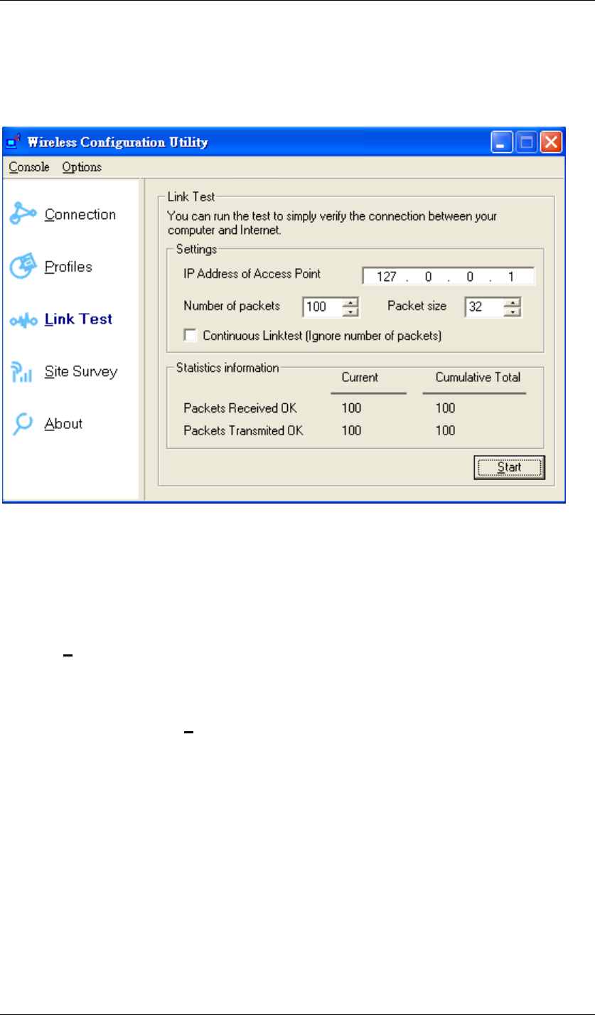
Link Test:
Link Test is provided to test the connection quality between Wireless USB Adaptor and access
point / router you connected to. You may follow the steps below to test the connection quality.
Figure 83 Wireless Configuration Utility-Link Test
1. Enter the IP address of the access point you connected to.
2. Choose the numbers and size of the packet.
3. Select the Continuous Link test to test the connection quality until you stop it; or leave
the Continuous Link test blank to test it only once.
4. Click Start to find out the result.
If Packets Received Ok equals to Packet Transmitted OK, the connection quality is great;
however, if not, please go to Site Survey to choose other available access point / router in
order to get better connection quality.
Chapter 5 Utility Overview Page 66
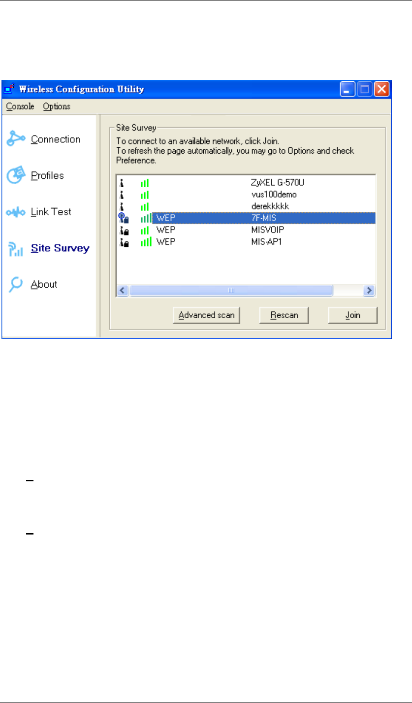
Site Survey:
Here shows all the currently available access points.
Figure 84 Wireless Configuration Utility-Site Survey
Join:
Choose the one you are allowed to use by single-clicking it, and then click Join to get into that
network. (Password required, if needed)
Rescan:
Click Rescan to refresh the Site Survey list.
Advanced scan:
Click Advanced scan to get the detailed scan information.
Chapter 5 Utility Overview Page 67
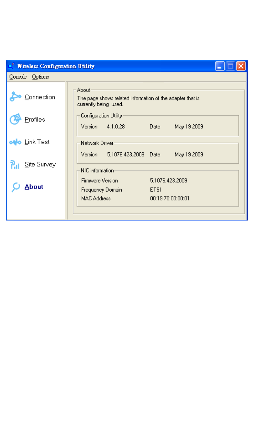
About:
Here shows the detailed information about Wireless USB Adaptor and Wireless Configuration
Utility themselves like versions, MAC address, etc.
Figure 85 Wireless Configuration Utility-About

Chapter 6 Troubleshooting Page 68
Chapter 6 Troubleshooting
Q1. Why can’t I go into the Internet after successfully following all the steps for
installation?
Check the availability of the Internet for the access point or router you connected to by opening
“Wireless Configuration Utility”, choosing Connection, and clicking More Detail. You will find
IP Address there. If the IP Address is listed as 169.254.xxx.xxx or N/A, it represents the access
point or router you connected to is useless. Please choose the access point or router you are
notified or allowed to use again.
Q2. I am successfully going into the Internet, but the quality of surfing the Internet
is unstable or bad. How could I solve it?
Open “Wireless Configuration Utility”. Click Connection to see the Signal Strength. If the
Signal Strength is weak or unstable, please click Site Survey to choose another available
access point or router for better connection.
Or click Link Test, fill up the IP address of the access point you connected to, and click Start
to see the connection results. If the result is not good, please click Site Survey to choose
another available access point or router for better connection.
Q3. How would I know if my Wireless USB Adaptor is properly working now?
Once Wireless USB Adaptor is plugged into the PC or laptop, the built-in 2 LEDs will light up
dedicating statuses. Normally, the red LED will keep on lighting, and the other yellow LED will
blink, if Wireless USB Adaptor is properly working.
The red LED ON/OFF: Power ON/OFF
The yellow LED blinks: Data are transmitting/receiving.

Chapter 7 Warranty Page 69
Chapter 7 Warranty
This Warranty constitutes the sole and exclusive remedy of any buyer or reseller’s equipment
and the sole and exclusive liability of the supplier in connection with the products and is in lieu
of all other warranties, express, implied or statutory, including, but not limited to, any implied
warranty of merchantability of fitness for a particular use and all other obligations or liabilities of
the supplier.
In no even will the supplier or any other party or person be liable to your or anyone else for any
damages, including lost profits, lost savings or other incidental or consequential damages, or
inability to use the software provided on the software media even if the supplier or the other
party person has been advised of the possibility of such damages.
The following are special terms applicable to your hardware warranty as well as services you
may use during part of the warranty period. Your formal Warranty Statement, including the
warranty applicable to our Wireless LAN products, appears in the Quick Installation Guide
which accompanies your products.
Duration of Hardware Warranty: One Year
Replacement, Repair or Refund Procedure for Hardware:
1. This product is design based on the 802.11n draft 2.0 standards, do not guarantee the
compatibility with the products that design by other vendors based on 802.11n draft or
the products that design accroding to the 802.11n formal standard that announce in
the future.
2. The maximum performance defines based on 802.11g and 802.11n draft standard.
The actual throughput will be different because of using environment and conditions,
including network bandwidth, building materials, building structure, and wireless
working range. These are possible to reduce the wireless performance.
3. Don’t dismantle the housing of the device as your wish to avoid the product damage.
If your unit needs a repair or replacement, return it to your dealer/distributor in its original
packaging. When returning a defective product for Warranty, always include the following
documents:
z A copy of the invoice/proof of purchase.
z The RMA Report Form (To receive a Return Materials Authorization form (RMA), please
contact the party from whom you purchased the product).
Upon proof-of-purchase we shall, at its option, repair or replace the defective item at no cost to
the buyer.

Chapter 7 Warranty Page 70
This warranty is contingent upon proper use in the application for which the products are
intended and does not cover products which have been modified without the reseller’s
approval or which have been subjected to unusual physical or electrical demands or damaged
in any way.