Z Com ZAC10235IO IEEE 802.11a/n Outdoor Wireless CPE User Manual ZCN 1523H 2 8
Z Com Inc IEEE 802.11a/n Outdoor Wireless CPE ZCN 1523H 2 8
UserManual.wiki
>
Z Com
>
ZAC10235IO User Manual
User Manual_ver01
Navigation menu
Upload a User Manual
Namespaces
Wiki Guide
HTML
PDF
Info
Views
User Manual
Discussion / Help
Navigation


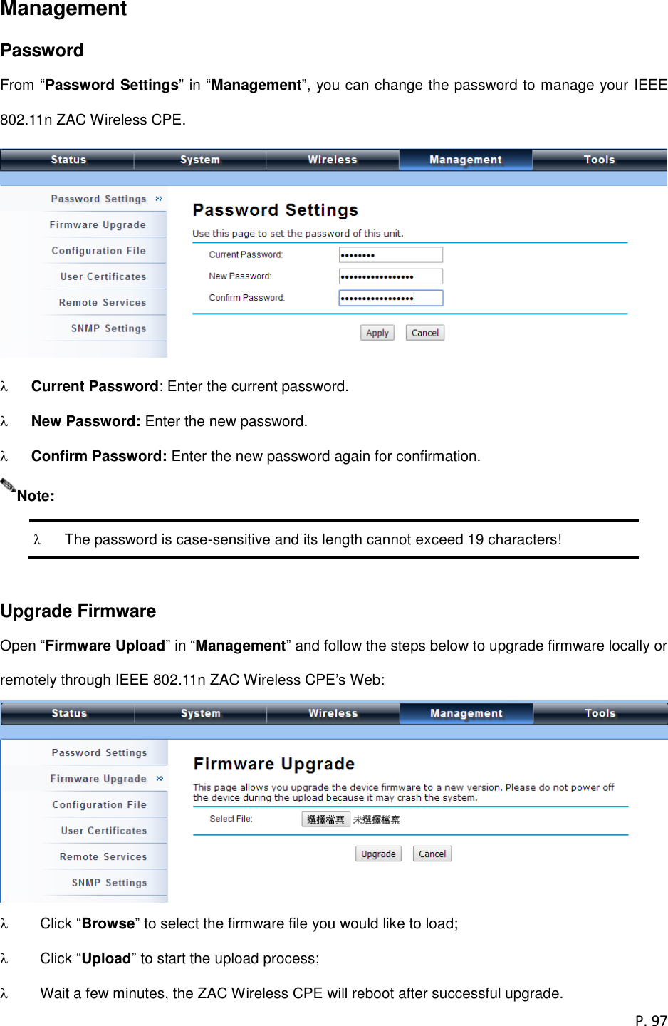


![P. 105 Appendix A. ASCII WEP can be configured with a 64-bit, 128-bit or 152-bit Shared Key (hexadecimal number or ACSII). As defined, hexadecimal number is represented by 0-9, A-F or a-f; ACSII is represented by 0-9, A-F, a-f or punctuation. Each one consists of two-digit hexadecimal. Table 1 ACSII ASCII Character Hex Equivalent ASCII Character Hex Equivalent ASCII Character Hex Equivalent ASCII Character Hex Equivalent ! 21 9 39 Q 51 i 69 " 22 : 3A R 52 j 6A # 23 ; 3B S 53 k 6B $ 24 < 3C T 54 l 6C % 25 = 3D U 55 m 6D & 26 > 3E V 56 n 6E ‘ 27 ? 3F W 57 o 6F ( 28 @ 40 X 58 p 70 ) 29 A 41 Y 59 q 71 * 2A B 42 Z 5A r 72 + 2B C 43 [ 5B s 73 , 2C D 44 \ 5C t 74 - 2D E 45 ] 5D u 75 . 2E F 46 ^ 5E v 76 / 2F G 47 _ 5F w 77 0 30 H 48 ` 60 x 78 1 31 I 49 a 61 y 79 2 32 J 4A b 62 z 7A 3 33 K 4B c 63 { 7B 4 34 L 4C d 64 | 7C 5 35 M 4D e 65 } 7D 6 36 N 4E f 66 ~ 7E 7 37 O 4F g 67 8 38 P 50 h 68](https://usermanual.wiki/Z-Com/ZAC10235IO/User-Guide-2626818-Page-105.png)