B079F5W7V6 Home Seer HS WS200 Switch Manual
2018-07-30
: Z-Wave B079F5W7V6 Homeseer Hs-Ws200 Switch Manual B079F5W7V6_HomeSeer_HS-WS200__Switch_Manual 713 docs
Open the PDF directly: View PDF ![]() .
.
Page Count: 4
HomeSeer | 10 Commerce Park North, Unit 10 | Bedford, NH 03110 | HomeSeer.com | Doc: HS-WS200-en-v4
WARNING RISK OF FIRE | RISK OF ELECTRICAL SHOCK | RISK OF BURNS
DO NOT USE THIS SWITCH TO CONTROL DEVICES OR APPLIANCES THAT MAY PRESENT A HAZARD WHEN CONTROLLED REMOTELY
OR USED IN AN UNATTENDED FASHION. DO NOT USE WITH MEDICAL AND LIFE SUPPORT INSTRUMENTS.
HS-WS200+ Z-Wave Wall Switch
INSTALLATION
Tools required: medium standard and Phillips head screwdrivers, wire strippers/cuers
1 Shut o power to the circuit at the circuit breaker or fuse box. VERIFY power is OFF before connuing!
2 Remove exisng switch’s wall plate and mounng screws. Carefully remove the exisng switch from the electrical box but
leave the wires connected.
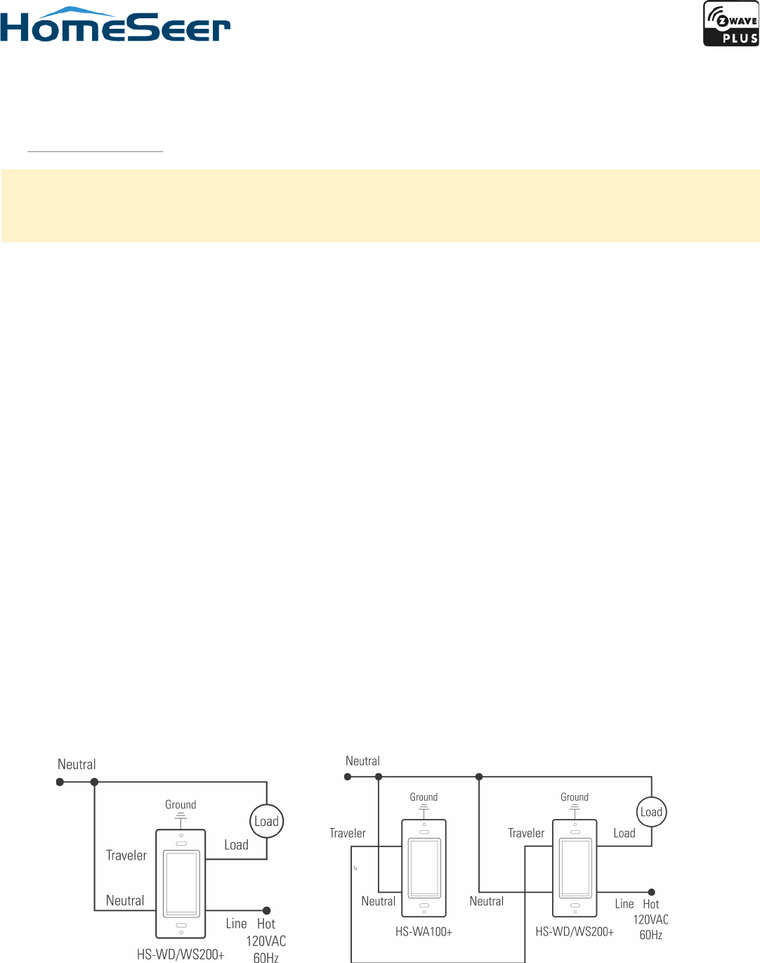
3 There may be up to ve wires connected to the exisng switch. Make note of these wires and label, if necessary, to ensure
correct installaon of the HS-WS200+. You will need to match these wires with the corresponding screw terminals on the HS-
WS200+. Note: LINE, NEUTRAL and LOAD wires are required for every installaon
• LINE (Hot) - Black (connected to power)
• NEUTRAL - White (this wire is oen ed to other neutral wires and may require a jumper to connect with the HS-WS200+)
• LOAD - Black (connected to load)
• GROUND — Green or Bare
• TRAVELER — Red/Other (only used in 3-way circuits)
4 Disconnect the wires from the exisng switch and aach those wires to the HS-WS200+ using the screw terminal connectors
on the back with the following procedure:
1 Strip 16 mm (5/8”) insulaon from each wire*.
2 With a screw driver, loosen each screw terminal by rotang the screw counter-clockwise a few turns unl resistance is felt.
3 There are two holes on the back of the switch near each screw terminal. Insert the stripped wire into one of these holes and
ghten the screw terminal to secure the connecon. Connecons should be snug.
*all wires should be 14 AWG or larger rated at 80°C or higher. Tightening torque should be 12 lbf-in (14kgf-cm).
5 Carefully install the wired switch back into the electrical box and reaach the trim plate.
OVERVIEW
HS-WS200+ is a Z-Wave wall switch that’s designed for wireless on-o control of connected lighng and appliance loads.
See HomeSeer.com/lighng for a complete list of features and applicaons.
Single-pole circuit 3-way circuit
HomeSeer | 10 Commerce Park North, Unit 10 | Bedford, NH 03110 | HomeSeer.com | Doc: HS-WS200-en-v4
COMPATIBILITY
Your new HomeSeer switch is Z-Wave cered and is ready to be used with a wide variety of home automaon hubs and control-
lers. All features are fully supported by HomeSeer systems but some ADVANCED FEATURES (see below) may not be fully supported
by other controllers. If you’re using another brand of controller, be sure to check with that company to determine compability.
Z-WAVE INCLUSION
Follow this 2-step procedure to add your new HomeSeer switch to your Z-Wave network:
1 Put your Z-Wave controller into inclusion mode. Consult your controller manual if you’re unsure how to do this.
HomeSeer users: press “Add Device” on your Z-Tool+ mobile app
2 Tap the paddle of your new HomeSeer switch to begin the inclusion process. This will take a few moments to complete.
HomeSeer users: Be sure to name the switch and assign it to a locaon using Z-Tool+ when inclusion is done
MANUAL RESET - To be used only in the event that the network primary controller is lost or otherwise inoperable.
(1) Turn switch on by tapping the top of the paddle once. (2) Quickly tap top of the paddle 3 mes. (3) Quickly tap boom of pad-
dle 3 mes. (4) If light turns o and then on again, switch is reset. If not, repeat manual reset.
ASSOCIATION - This product supports associaon group #1 for lifeline communicaon. Refer to your controller manual for in-
strucons on seng the lifeline associaon.
OPERATION
Your new HomeSeer switch may be operated locally (manually) or remotely using a Z-Wave compable controller or home auto-
maon system.
Local Control:
• Press (tap) the top of the paddle to power the load
• Press (tap) the boom of the paddle to cut power to the load
Remote Control:
• On / O control is available remotely. Consult your controller manual for details.
HomeSeer users: this switch creates 3 devices; a root device, central scene device and control device. The root device may
be used to manage Z-Wave sengs. The central scene device may be used as a trigger for events. The control device will
will send on / o commands to the switch.
ADVANCED FEATURES
Your new HomeSeer switch includes advanced features that may be accessed with HomeSeer (and other*) systems.
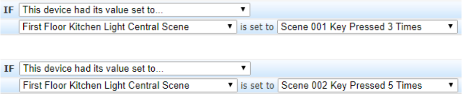
Mul-tap triggering - Tapping the top or boom of the paddle 1, 2, 3, 4 or 5 mes in rapid succession may be used as a trigger to
launch HomeSeer events. In the example below (using HomeSeer HS3 soware), the trigger is set to the top of the paddle being
pressed 3 mes. You must use the trigger “device had its value set to” and apply it to the “Central Scene” device. Note that “Scene
001” refers to the top of the paddle.
In this example, the trigger is set to the boom of the paddle (Scene 002) being pressed 5 mes.
Note that pressing the top or boom of the paddle once will also control the aached load.

HomeSeer | 10 Commerce Park North, Unit 10 | Bedford, NH 03110 | HomeSeer.com | Doc: HS-WS200-en-v4
ADVANCED FEATURES (connued)
RGB LED Indicator - The color of the LED indicator may be controlled with Z-Wave commands using HS3 event acons.
In normal mode, the LED indicator glows to reect the on/o status of the connected circuit using a palee of 7 possible colors
(red, green, blue, cyan, magenta, yellow, white). HS-WS200+ switches will operate in normal mode by default. In the example be-
low (using HomeSeer HS3 soware), this event acon will set the normal mode color of all HS-WS200+ switches (and all HS-
WD200+ dimmers) to Magenta.
In status mode, the LED indicator can be controlled to reect the status of nearly anything in the home. In the example below
(using HomeSeer HS3 soware), this event acon will change the LED indicator of the First Floor Kitchen Overhead Light to blink
red.
Switching between normal mode and status mode: HS-WS200+ switches will operate in normal mode by default. Sending a color
status command to the LED will automacally enable status mode. The switch will remain in status mode unl its LED status is set
to “O”. In the example below (using HomeSeer HS3 soware), this event acon will clear status from all switches (and dimmers)
on the network, causing all devices to revert to normal mode.
COMPATIBILITY (with Non-HomeSeer systems)
The special features of this switch are supported using a number of dierent Z-Wave technologies. HomeSeer systems are de-
signed to support these technologies and will provide the most seamless operaon of these features. However, other systems may
also provide sasfactory results depending on the level of support they provide for these same technologies. If you’re using a non-
HomeSeer system, use the informaon below and consult with your system manufacturer to determine the level of compability.
Mul-tap Triggers: This feature uses the Z-Wave CENTRAL SCENE command class. If the system supports this command class AND
ulizes a general interrogaon process for inclusion, this feature should work. However, if the system employs an inclusion process
based on the Z-Wave product ID, then specic product support would need to be implemented.
Instant Status: This feature is supported using a Z-Wave BINARY REPORT and the CENTRAL SCENE command class. All Z-Wave cer-
ed systems should support the BINARY REPORT feature.
RGB LED Control: This feature is supported using Z-Wave parameter commands. Most Z-Wave cered systems provide a method
for issuing parameter commands to individual products. HomeSeer systems simplify the use of this feature by providing event ac-
ons to send parameter commands. A complete list of parameters may be found on the next page.
*Be sure to check our support page (hps://homeseer.com/support-home/) for informaon about integraons with other smart
hubs and controller.

HomeSeer | 10 Commerce Park North, Unit 10 | Bedford, NH 03110 | HomeSeer.com | Doc: HS-WS200-en-v4
SPECIFICATIONS
Power Requirements 120VAC / 60 Hz
Max Load Incandescent | LED
| Resisve | Motor
900 was | 200 was | 1800
was | 1/2 Horsepower
Z-Wave Frequency 908.4 / 916 MHz
Range 100 . (open air)
Cercaons UL (US, Canada), FCC/IC, Z-Wave Plus
WARRANTY
HomeSeer warrants to the original purchaser that this product, for the warranty period,
will be free from material defects and workmanship. This warranty is subject to proper
installaon and operaon of the product. HomeSeer’s sole obligaon, under this warranty,
is to repair, replace or correct any defect that was present at the me of delivery. This
warranty does not extend to consequenal or incidental damage to other products that
may be used with this product. Warranty claims must be submied in wring directly to
HomeSeer at HomeSeer.com. Warranty period: limited 1 year from date of purchase
FCC/IC Statement - see hp://homeseer.com/lighng.html
Z-Wave Parameters
Parameter Descripon Bytes Value Default
3 Sets LED operaon (in normal mode) 1 0= LED ON if load is OFF
1= LED OFF if load is OFF 0
4 Sets paddle’s load orientaon 1 0 = Top of Paddle turns load ON
1 = Boom of Paddle turns load ON 0
13 Sets switch mode of operaon 1 0=Normal mode (load status)
1=Status mode (custom status) 0
14 Sets the Normal mode LED color 1
Possible values: 0-6
0=White, 1=Red, 2=Green, 3=Blue, 4=Magenta,
5=Yellow, 6=Cyan
0
21 Sets the Status mode LED color 1
Possible values: 0-7
0=O, 1=Red, 2=Green, 3=Blue, 4=Magenta,
5=Yellow, 6=Cyan, 7=White
0
31 Sets the switch LED Blink frequency 1 Possible values: 0, 1-255
0=No blink, 1=100ms ON then 100ms OFF 0
