ZAVIO 5113F Wireless IP CAM User Manual
ZAVIO Inc. Wireless IP CAM
UserManual.wiki
>
ZAVIO
>
5113F User Manual
User Manual
Navigation menu
Upload a User Manual
Namespaces
Wiki Guide
HTML
PDF
Info
Views
User Manual
Discussion / Help
Navigation
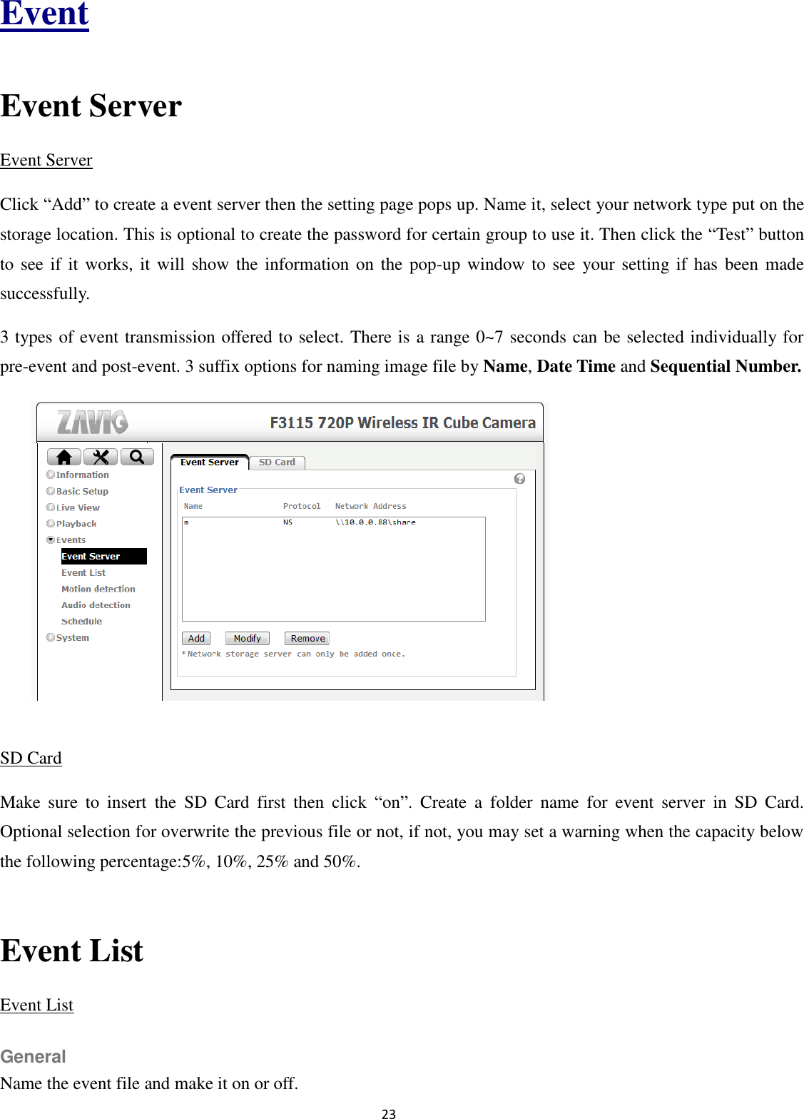
![2 User Manual Safety Instruction Before you use this product This product has been designed with safety in mind. However, the electrical products can cause fires which may lead to serious body injury if it is not used properly. To avoid such accidents, be sure to heed the following. Legal Caution Video and audio surveillance can be forbidden by laws that vary from country to country. Check the laws in your local region before using this product for surveillance purposes. Don't open the housing of the product Don't try to open the housing or remove the covers which may expose yourself to dangerous voltage or other hazards. Don't use the accessories not recommend by the manufacturer Heed the safety precautions Be sure to follow the general safety precautions and the “Operation Notice.” Operation Notice - Operating or storage location Avoid operating or storing the camera in the following locations: Extremely hot or cold places (Operating temperature: 0 °C to + 40 °C [32 °F to 104°F] ) Exposed to direct sunlight for a long time, or close to heating equipment (e.g., near heaters) Close to water (e.g.,near a bathtub, kitchen sink, laundry tub) Close to sources of strong magnetism Close to sources of powerful electromagnetic radiation, such as radios or TV transmitters Locations subject to strong vibration or shock](https://usermanual.wiki/ZAVIO/5113F/User-Guide-2005317-Page-3.png)