ZAVIO W115M IP Cam User Manual Hardware
ZAVIO Inc. IP Cam Hardware
UserManual.wiki
>
ZAVIO
>
W115M User Manual
>
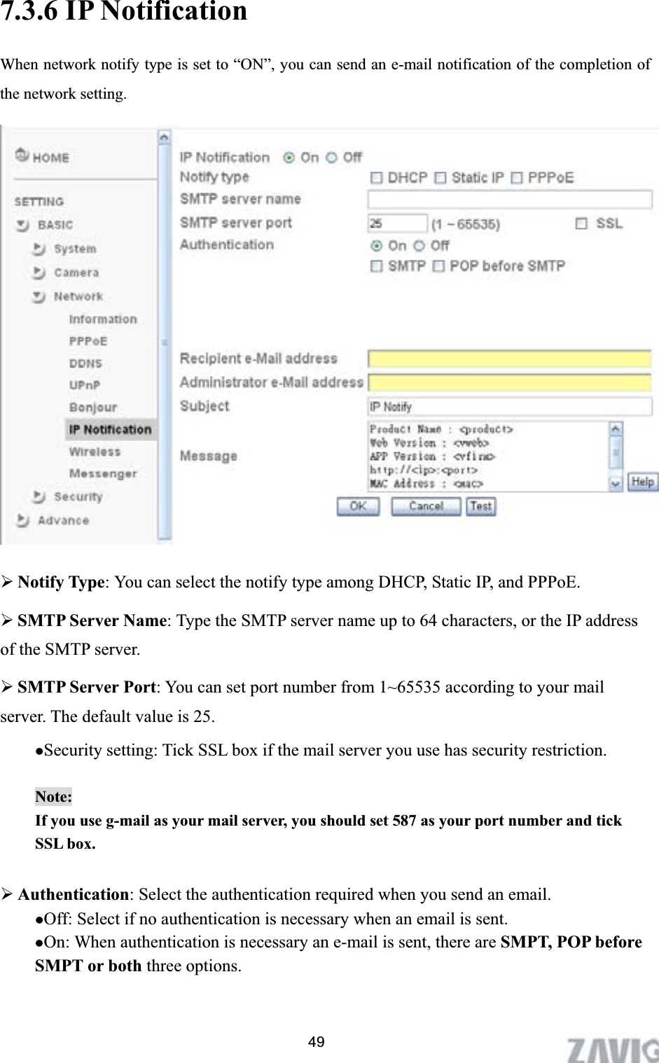
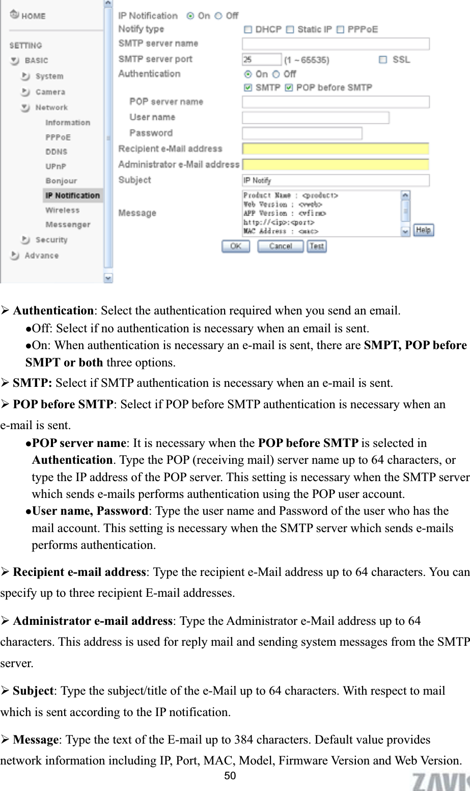
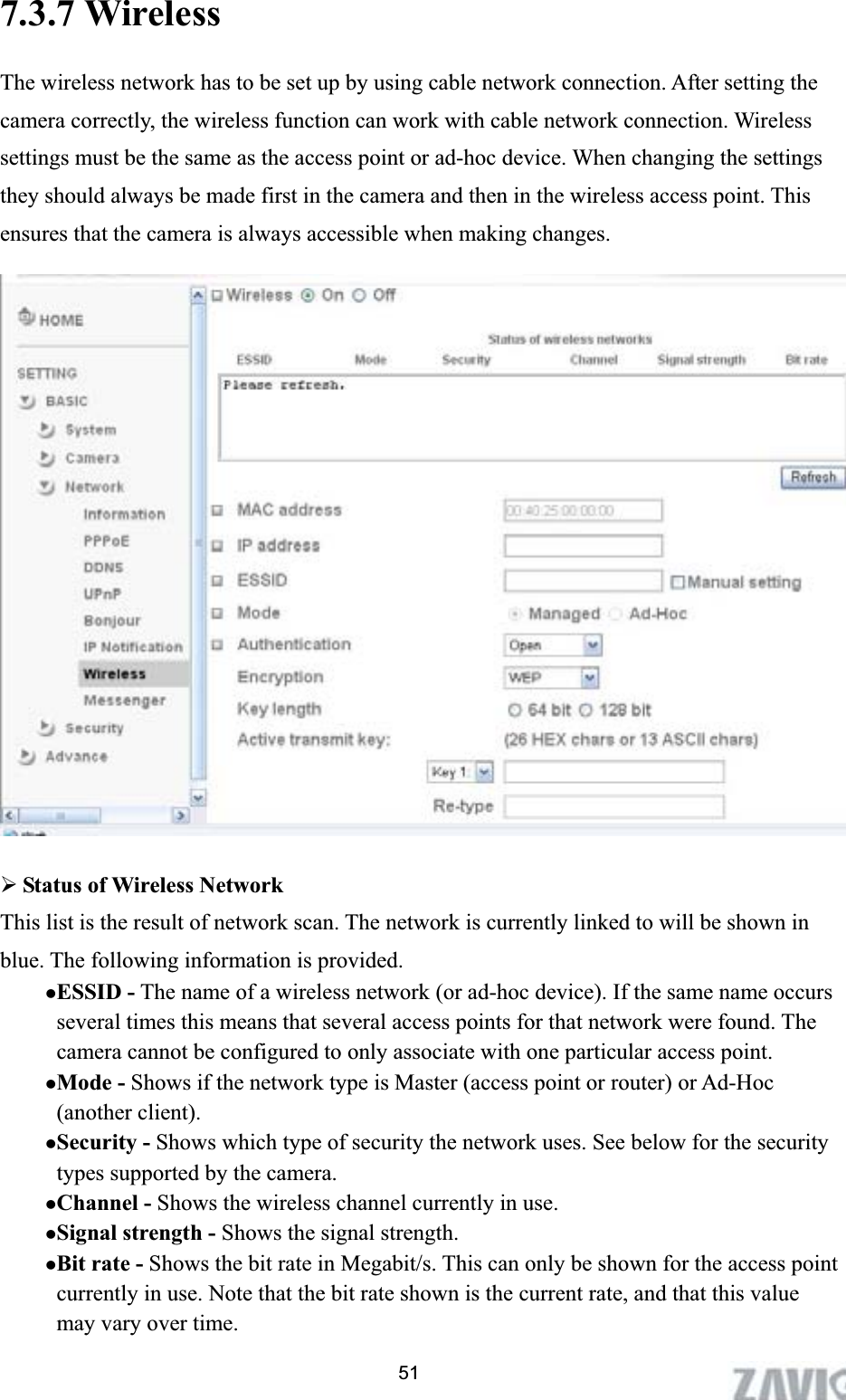
Users Manual 1
Contents
1.
Users Manual 1
2.
Users Manual 2
Users Manual 1
Navigation menu
Upload a User Manual
Namespaces
Wiki Guide
HTML
PDF
Info
Views
User Manual
Discussion / Help
Navigation