ZENITH VCR Manual 97120029
User Manual: ZENITH ZENITH VCR Manual ZENITH VCR Owner's Manual, ZENITH VCR installation guides
Open the PDF directly: View PDF ![]() .
.
Page Count: 44
Features
VRCA275HF
• Built-in VCR Plus
Recording wit_ Cable
Box Control
p. 12-1
•MTS Hi-Fi Stereo
2_1Aud_
Ray/Record
p. 13-2
•Bilingual (English-
Spanish) Menus
On-Screen Display
p. 4-2
• Multi-Brand Zenith
Remote Con_ol
MBR4275
p. 3-1
•Shuttle Remote
ControlPlayback
Options
p. 7-2
• Message Center
DL_plays
p. 5-2
• Index Search
p. 7-2
•On-Screen
Programming
p. 4-1
•On-Screen Display
p. 5-I
• 1 Year, 8Event Timer
p. 9-1, 10-2
•Instant Recording
p. 8-1, 10-1
" 181 Channel
Capability
• Auto Channel Search
p.4-3
• Auto Digital
Picture Tracldng
p. 7-2
•QuickStart Loading
p. 7-1
• Auto Head Cleaner
p. 14-3
•Auto Playback
System
p. 7-1
•Auto Counter Reset
p. 7-1
• Auto Tape Speed
Switching
p. 13-1
• Counter Memory
p. 13-1
• Auto Daylight
Savings Adjust
p. 13-1
•VCR Flashback
p. 3-3
• HQ Citc_Jib'y
All VCR |eatures
subject to ch_=Lnge
without prior nodoe.
Video Cassette: Recorder
Operating Guide and Warranty
Made by Zenith
exclusively for Circuit City
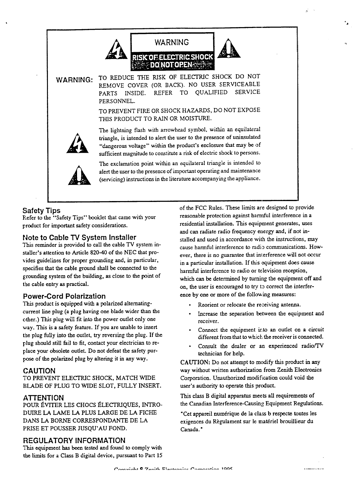
WARNING: TO REDUCE THE RISK OF ELECTRIC SHOCK DO NOT
REMOVE COVER (OR BACK). NO USER SERVICEABLE
PARTS INSIDE. REFER TO QUALIFIED SERVICE
PERSONNEL.
TO PREVENT FIRE OR SHOCK HAZARDS, DO NOT EXPOSE
THIS PRODUCT TO RAIN OR MOISTURE.
The lightning flash with arrowhead symbol, within an equilateral
triangle, is intended to alert the user to the presence of uninsulated
"dangerous voltage" within the product's enclosure that may be of
sufficient magnitude to constitute a risk of electric shock to persons.
The exclamation point within an equilateral triangle is intended to
alert the user to the presence of important operating and maintenance
(servicing) instructions in the literature accompanying the appliance.
Safety Tips
P,efer to the ";Safety Tips" booklet that came with your
product for irnportant safety considerations.
Note to Cable TV System Installer
This reminder is provided to call the cable TV system in-
staLler's attention to Article 820-40 of the NEC that pro-
rides guidelines for proper grounding and, in particular,
specifies that the cable ground shall be connected to the
grounding system of the building, as close to the point of
the cable entry as practical.
Power-Cord Polarization
"]?hisproduct is equipped with apolarized alternating-
current line plug (a plug having one blade wider than the
other.) This plug will fit into the power outlet only one
way. This is a safety feature. If you are unable to insert
the plug fully into the outlet, try reversing the plug. If the
plug should still fail to fit, contact your electrician to re-
place your obsolete outlet. Do not defeat the safety pur-
l:_Se of the polarized plug by altering it in any way.
CAUTION
TO PREVENT ELECTRIC SHOCK, MATCH WIDE
BLADE OF F'LUG TO WIDE SLOT, FULLY INSERT.
ATTENTION
POUR _VITER LES CHOCS t_LECTRIQUES, INTRO-
DUIRE LA LAME LA PLUS LARGE DE LA FICHE
I)ANS LA BORNE CORRESPONDANTE DE LA
PRISE ET POUSSER JUSQU'AU FOND.
REGULATORY INFORMATION
"].'hisequipment has been tested and found to comply with
the limits for a Class B digital device, pursuant to Part 15
of the FCC Rules. These limits are designed to provide
reasonable protection against harnfful interference in a
residential installation. This equipment generate;, uses
and can radiate radio frequency energy and, if not in-
stalled and used in accordance with the instructions, may
cause harmful interference to r_.dia communications. How-
ever, there is no guarantee that imerference will not occur
in a particular installation. If this ,_luipment does cause
harmful interference to radio or television recept'ion,
which can be determined by turning the equipment off and
on, the user is encouraged to tr.¢ ta correct the interfer-
ence by one or more of the follov, ing measures:
• Reorient or relocate the rezeiving antenna.
• Increase the separation between the equipment and
receiver.
• Connect the equipment into an outlet on a circuit
different from that to wkich the receiver is connected.
• Consult the dealer or an experienced radio/TV
technician for help.
CAUTION: Do not attempt to mcxtify this pro&act in any
way without written authorization from Zenith Filectronics
Corporation. Unauthorized modification could void the
user's authority to operate this prcxtuct.
This class Bdigital apparatus rnee:ts all requirements of
the Canadian Interference-Causing; Equipment Regulations.
"Cet appareil num4rique de la class b respecte txmtes les
exigences du R_gulament sur le materiel brouiliJeur du
Canada."
ONTF_.NT-S
I
ii General Information
Introduction. Installation Considerations.
um • •
1 Installation/Step A
VCR Setup ChecMist.
Connections with antenna or a cable box.
Audio/Video and accessories connections.
Front Audio/Video IN Connections.
Ch3--4 Switch.
10 Recording with a Cable Box
Recording Cable TV (CATV) subscriber" program-
ming that requires a cable/converter box.
Recording what you see on your TV screen.
Timer Recording broadcasts with a cable box.
I 1 VCR Plus Recordiing
Recording using VCR Plus.
Recording using VCR Plus, with a cable box.
m
2VCR Front Pane! Controls
Overview of VCR buttons. VCR Accessories.
3 Remote Controls
i
12 VCR Plus Recording Setup/Step C
Setting up the VCR to record using VCF' Plus.
Setting up the VCR to record VCR Plus with ca-
ble/converter box.
Simple instructions for using Remotes.
Installing Batteries; readies Remote to operate
VCR etc.
Programming Remote Control Brand Codes.
Remote Control Key Descriptions.
4 VCR Features Setup/Step B
Personalize VCR On-screen Menus before playing
or recording tapes.
5 VCR/TV Displays
VCR Display on TV screen.
VCR Message Center Displays.
i
13 Additional Inform,ation
AUX Channel
Index Search
Real-Time Tape Counter
Special Menu
--Auto Clock Set
--Auto Daylight Savings Ac[justment
Auto Tape Recording Speed Switching
Audio Record Mode
Audio Playback Mode
VCR+ Recording Setup Double Channel Mapping
I
6WatchingTV
TV Antenna In Connections
TV Audio/Video In Connections
Overview of three t-uning options.
TV Tuning, VCR Tuning, Cable Box Tuning.
7 Playing Tapes (Playback)
Playing pre-recorded tapes.
Re_,ordingJPlaying Tapes Times Chart.
Playback Options
Playback Shuttle Operation.
8Instant Recording
Recording what you see on your TV screen.
14 Service Information
Resolving operating difficulties.
Video heads and cabinet clie_ming.
System Overview--VCR, TV and Cable Box.
15 VCR Features Chal_
VCR Features Listing.
Your Circuit City Warranty
Warranty coverage for your VCR.
Notes: All VCR features, graphics and identifica-
tion labeling are subject to clnangewithout prior no-
tice. Features 'vary.between models_not all
features listed may be available on your particular
VCR, see VCR Features Chart.
9 Timer Recording
Re_.'ording while you are away (VCR turned off.)
lira
GENERAL INFORMATION
Introduction
Welcome into the family of Zenith Video Recorder owners.
This guide provides instructions on how to operate your.new
VCR. It is supplemented by a booklet containing Safety Tips.
We urge you to read these publications carefully so that you
will receive full enjoyment from your new Zenith VCR for
m;uay years to come.
Your new Zenith VCR has _ designed and built to give you
the very best in quality, features and performance.
Should your VCR require repair, please contact your nearest
Circuit City store to arrange for service. If you live outside
at, area serviced by Circuit City, there are many approved
Z_.nith video recorder service centers throughout the U.S.,
Canada and Mexico who can promptly and effectively attend
to ordinary service needs.
If you should have an unusual performance or service prob-
lem that cannot be satisfactorily resolved by your local Cir-
cuit City or Zenith service center, please write or call:
Circuit City Answer City
2040 Thalbro Street
Richmond, VA 23230
1-800-950--9000
Monday-Saturday, 10:00 a.m. --. 9:00 p.m.
Sunday, Noon -- 8:00 p.m.
Send the model number, serial rumber, and date of purchase
or original installation, with a full explanation of the problem
and the service history. We will welcome the opportunity to
look into your specific question or problem and to be of assis-
tance in resolving it promptly.
The model and serial number:; cf your new VCR are located
on the VCR cabinet. For your fi._tureconvenience and protec-
tion, we suggest that you record these numbers here:
Model No.
Serial No.
Installation Considerations
Before you install your VCR...
Ventilation -- Proper ventilation keeps your
VCR running cool. Air circulates through perfora-
tions in the back and bottom of the cabinet. Do
not block these vents or you will shorten the life
of your VCR.
Power Source -- Your VCR is designed to oper-
ate on normal household current, 120 volt 60
Hertz AC. Do not attempt to operate it on DC cur-
rel_t.
Power Cord -- Your VCR power cord has a po-
_ arized plug as required by Underwriters' Labora-
tories. It has one regular blade and one wide
blade and fits only one way into a standard electri-
cal outlet. If the blades will not enter either way,
your outlet is very old and non-standard. A new outlet should
I:e installed by aqualified electrician.
Safe Operation -- Your VCR is manufactured
A nd tested with your safety in mind. However, un-
usual stress caused by dropping or mishandling,
exposure to flood, fire, rain or moisture, or acci-
dental spilling: of liquids into the VCR, can result in potential
electrical shock or fire hazards. If this happens, have your
VCR checked by a service technician before using it again.
].:'lease read and observe each safety point in the "Safety
".rips" folder when installing and using your VCR.
•Plugging in Your VCR -- Be sure to plug your VCR into
an "unswitched'" AC power source. The "switched" AC
outlets found on some video equipment will not continue
supplying power to the VCR once the equil')ment is turned
off. If the power to the VCE is interrupted for an extended
time, you will have to reset the clock in the VCR.
• Keep the video recorder and video cassette away from
strong magnetic fields.
•Use only Zenith approved :and recommended accessory
units with your Zenith vide,o recorder to avoid potential
hazards.
• Save the shipping carton and packing material. They will
come in handy if you ever have to ship your video re-
corder. For maximum prolection, re-pack the:video re-
corder as it was originally shipped from the factory.
Moisture condensation is apt to occur under the following
conditions:
• When the video recorder i:; moved from a cold place to a
warm place.
• Under extremely humid conditions.
In locations where moisture condensation may occur:
•Keep the :power cord plugl_,ed into an AC. outlet and the
POWER .switch set to ON. This will help prevent con-
densation from occurring.
• When condensation has occurred, it will not evaporate
quickly once the power is switched on. Wait a few hours
for the vMeo recorder to l:ecome dry betore using the
video recorder.
iii ccnmvu
INSTALLATION/Step A
m
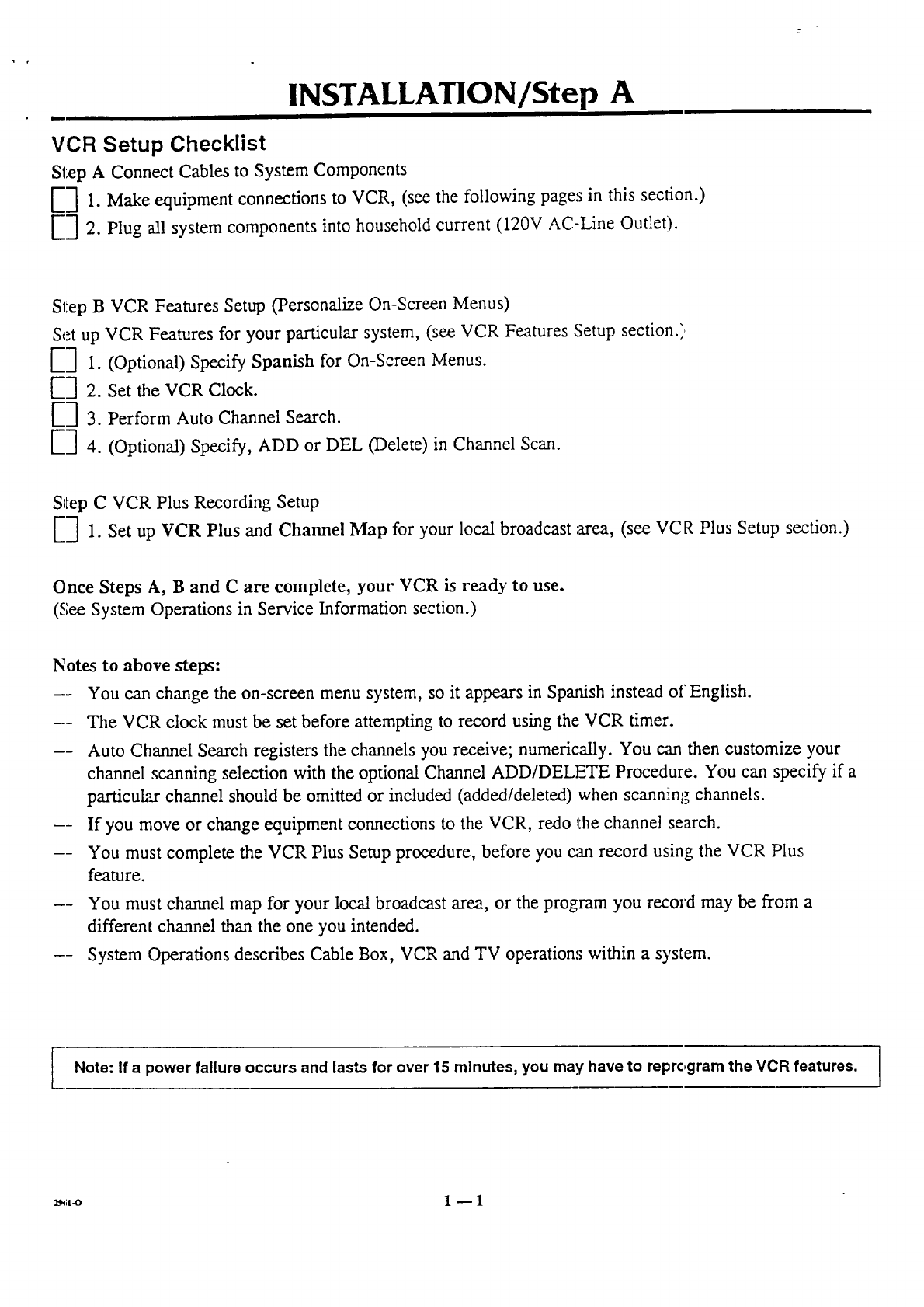
VCR Setup Checklist
Step A Connect Cables to System Components
[-] 1. Make: equipment connections to VCR, (see the following pages in this section.)
[-"] 2. Plug all system components into household current (120V AC-Line Outlet).
Step B VCR Features Setup ('Personalize On-Screen Menus)
Set up VCR Features for your particular system, (see VCR Features Setup section.)
E-] 1.
E] 2.
E] 3.
E] 4.
(Optional) Specify Spanish for On-Screen Menus.
Set the VCR Clock.
Perform Auto Channel Search.
(Optional) Specify, ADD or DEL (Delete) in Channel Scan.
Step C VCR Plus Recording Setup
E3 1. Set up VCR Plus and Channel Map for your local broadcast area, (see VCR Plus Setup section.)
Once Steps A, Band C are complete, your VCR is ready to use.
(See System Operations in Service Information section.)
Notes to above steps:
-- You cart change the on-screen menu system, so it appears in Spanish instead of English.
-- The VCR clock must be set before attempting to record using the VCR timer.
-- Auto Channel Search registers the channels you receive; numerically. You can then customize your
channel scanning selection with the optional Channel ADD/DELETE Procedure. You can specify if a
particular channel should be omitted or included (added/deleted) when scanniintgchannels.
-- If you move or change equipment connections to the VCR, redo the channel search.
-- You must complete the VCR Plus Setup procedure, before you can record using the VCR Plus
feature.
-- You must channel map for your local broadcast area, or the program you record may be from a
different channel than the one you intended.
-- System Operations describes Cable Box, VCR and TV operation:; within a system.
Note: If a power failure occurs and lasts for over 15 minutes, you may have to reprc,gram the VCR features.
..-v
INSTALLATION/Step A
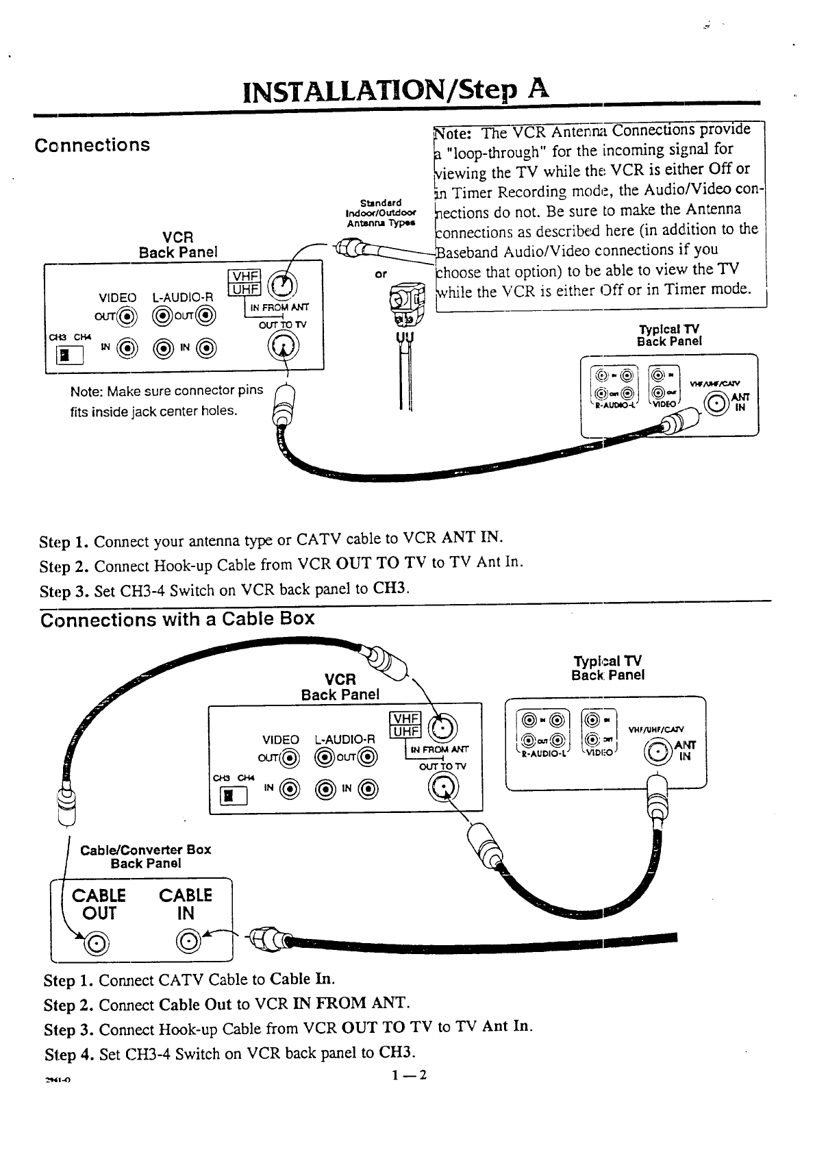
Connections
VCR
Back Panel
VIDEO L-AUDIO-R
®ouT® OUTTO "IV
ote: The VCR Antenr_ Connections provide
"loop-through for the incoming signal for
ewing the TV while the,.VCR is either Off or
m Timer Recording mode, the Audio/Video con-
Standard I
n,_=,r_o_=,, taections do not. Be sure to make the Antenna
An_mn="ryp_ f-
_onnections as describe, d here (in addLition to the
__aseband Audio/Video connections if you
or _hoose that option) to be able to view the TV
_ _vhile the VCR is either Off or in Timer mode.
CH3 CH4
Note: Make sure connector pins
fits inside jack center holes.
(_ I1_ BT_aP/C_laneTVi
Step 1. Connect your antenna type or CATV cable to VCR ANT IN.
Step 2. Connect Hook-up Cable from VCR OUT TO TV to TV Ant In.
Step 3. Set CH3-4 Switch on VCR back panel to CH3.
Connections with a Cable Box
Cable/Converter Box
jBack Panel
I_TLE C_L_.
Typi,:al TV
Back: Panel
Step 1. Commct CATV Cable to Cable In.
Step 2. Cormect Cable Out to VCR IN FROM ANT.
Step 3. Comlect Hook-up Cable from VCR OUT TO TV to TV Ant In.
Step 4. Set (7H3-4 Switch on VCR back panel to CH3.
_,-o 1 _ 2
,]NSTALLAT]ON/S epA
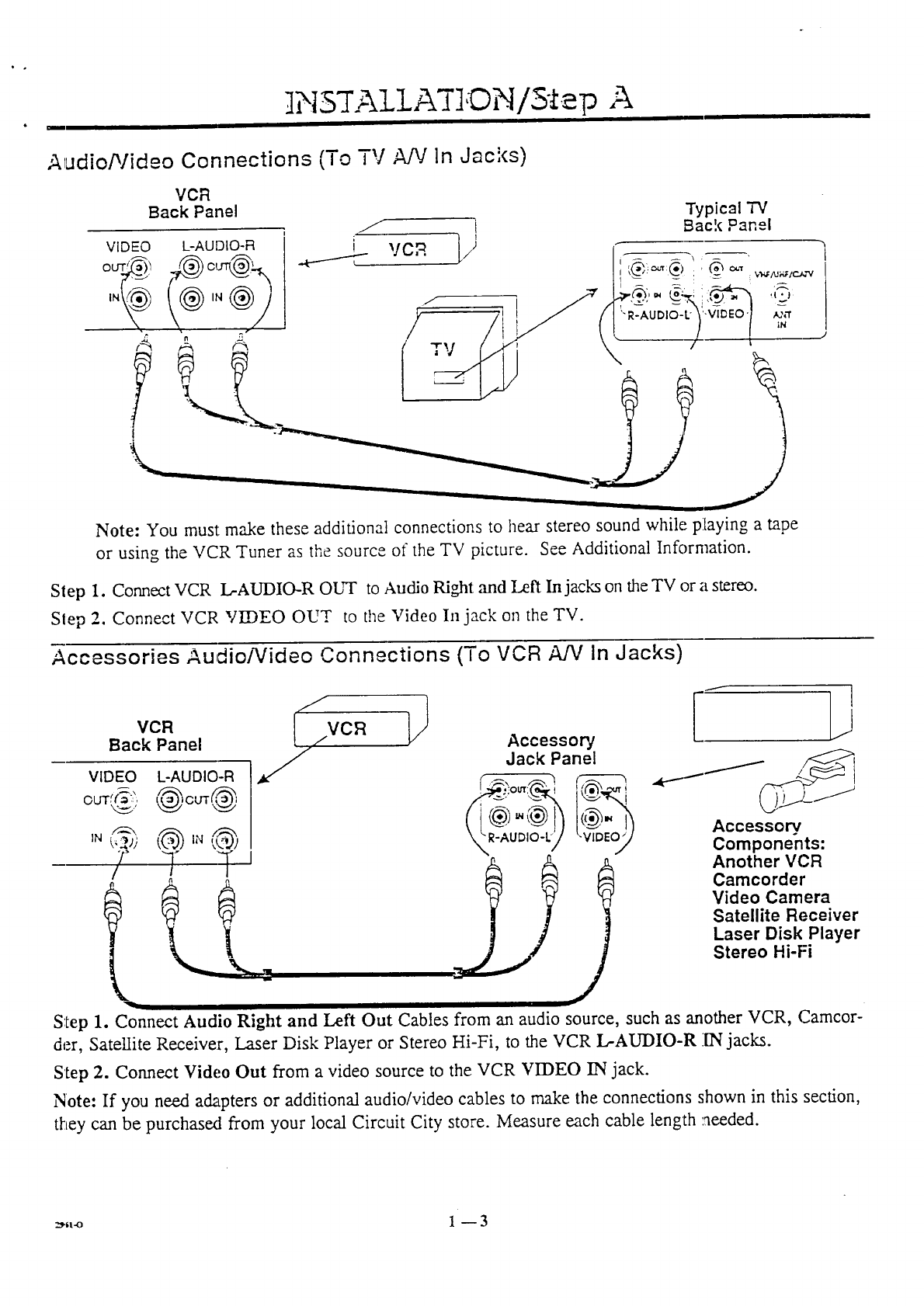
Audio/Video Connections (To TV A/V In Jacks)
VCR
Back Panel Typical "iV
,f i Back Panel
VIDEO L-AUDIO-FI ' i VCR 1)
IN . _,Q_.,i ill l o/.i l;,tl) II \ q_.)
/ / I
A "- A -- TV i -_- l
Note: You must: rnnke these additional connections to hear stereo sound while playin Z a rope
or using the VCR Tuner as the source of the TV picture. See Additiona] Information.
Slep 1. Connect VCR L-AUDIO-R ObH" to Audio Right and Left Injacks on the TV or a stereo.
Slep 2. Connect VCR VIDEO OUT to the Video In jack on the TV.
Accessories Audio/Video Connections (To VCR A/V in Jacks)
VCR [ ,/VCFI
Back Panel
I//
Accessor]
Jack Panel
Accessory,
Components:
Another VCR
Camcorder
Video Camera
Satellite Receiver
Laser Disk Player
Stereo Hi-Fi
Step 1. Connect Audio Right and Left Out Cables from an audio source, such as another VCR, Camcor-
der, Sate!lite Receiver, Laser Disk Player or Stereo Hi-Fi, to the VCR L-AUDIO-R 1N jacks.
Step 2. Connect Video Out from a video source to the VCR VIDEO IN jack.
Note: If you need adapters or additional audio/video cables to make the connections shown in this section,
they can be purchasext from your local Circuit City store. Measure each cable length needed.
z_ll-o 1-- 3
INSTALLATION/Step A
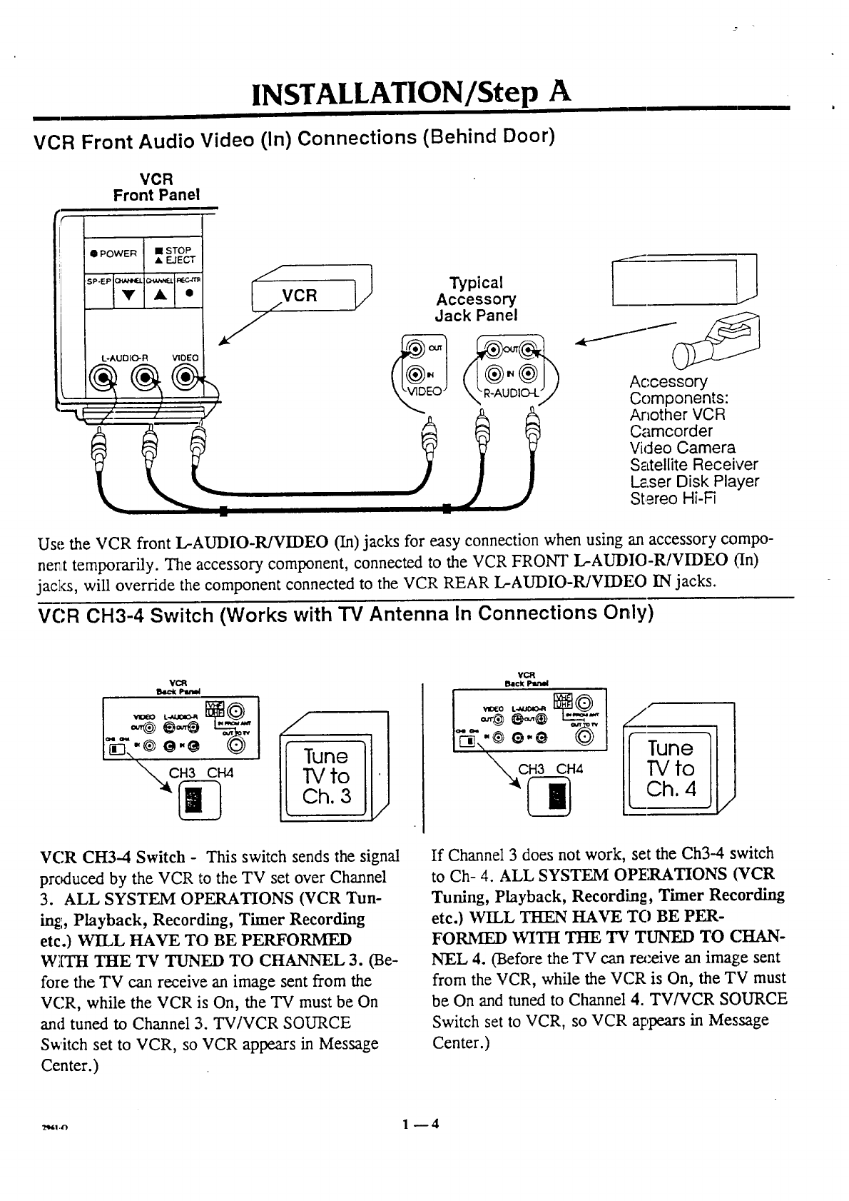
VCR Front Audio Video (In) Connections (Behind Door)
"L
VCR
Front Panel
I POWER •STOP
• EJECT
L-AUDIO-R VIDEO
//' ,/
""" _ Typical
/VCR Accessory
Jack Panel
Accessory
Components:
Another VCR
Camcorder
Vicleo Camera
S__LtelliteReceiver
Laser Disk Player
Stereo Hi-Fi
Use the VCR front L-AUDIO-R/VIDEO (In) jacks for easy connection when using an accessory compo-
nent temporarily. The accessory component, connected to the VCR FRONT L-AUDIO-R/VIDEO (,'In)
jac]_, will override the component connected to the VCR REAR L.-AUDIO-R/VIDF,,O IN jacks.
VCR CH3-4 Switc:h (Works with TV Antenna In Connections Only)
VCR
B4_k p-en_
I Tune
TVto
Ch. 3
VCR CH3-4 Switch - This switch sends the signal
produced by the VCR r,othe TV set over Channel
3. ALL SYSTEM OPERATIONS (VCR Tun-
in_:, Playback, Recording, Timer Recording
etc.) WILL HAVE TO BE PERFORMED
W_[TH THE TV TUNED TO CHANNEL 3. (Be-
fore the TV can receive an image sent from the
VCR, while the VCR is On, the TV must be On
and tuned to Channel 21.TV/VCR SOURCE
Switch set to VCR, so VCR appears in Message
Center.)
_/iune
| TVto
L Ch. 4
If Channel 3 does not work, set the Ch3--4 switch
to Ch- 4. ALL SYSTEM OP]_.ATIONS (¥CR
Tuning, Playback, Recordi[ng, Timer Recording
etc.) WILL THEN HAVE TO BE PER-
FORMED WITH THE TV TUNED TO (.'3tA.N-
NEL 4. (Before the TV can receive an image sent
from the VCR, while the VCR is On, the TV must
be On and tuned to Channel 4. TV/VCR SOURCE
Switch set to VCR, so VCR appears in Message
Center.)
_,,,.,_ 1-- 4
I
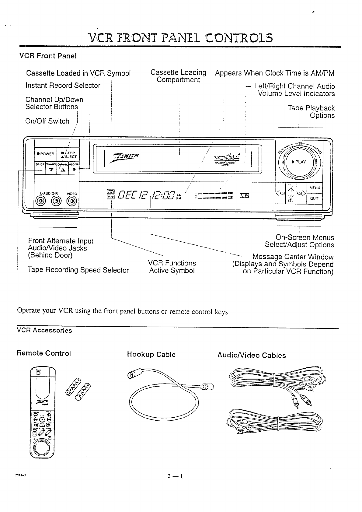
VCR Front Panel
VCR ._]{.DN7PANZ.]-C OMTR DIS
Cassette Loaded in VCR Symbol
Instant Record Selector
Channel Up/Down
Selector Buttons
On/Off Switch j
/
Cassette Loading
Compartment Appears When Clock Time is AM/PM
-- LeffJRight Channel Audio
Volume Level indicators
Tape Playback
Options
r/
' L-AUDIO-R VIDEO
@@@
I
Front Alternate Input
Audio/Video Jacks
(Behind Door)
Ji JJ"I--=-
-- I
i//
1/ ,
r_5] /
r_ DEE/2 '_"-"-_ ' "....--"
tiz.'uu _ R.... -=,
!1
! i
l
VCR Functions
Tape Recording Speed Selector Active Symbol
_" MENU
SEL QUIT
i
1
On-Screen Menus
SelecUAdjust Options
Message Center Window
(Displays anc Symbols Depend
on Particular VCR Function)
Operate your VCR using the front panel buttons or remote control key's.
VCR Accessories
Remote Control
I_G_
Hookup Cable Audio/Video Cables
a,l.e 2 _ 1
REMOTE CONTROl MBR4275
I
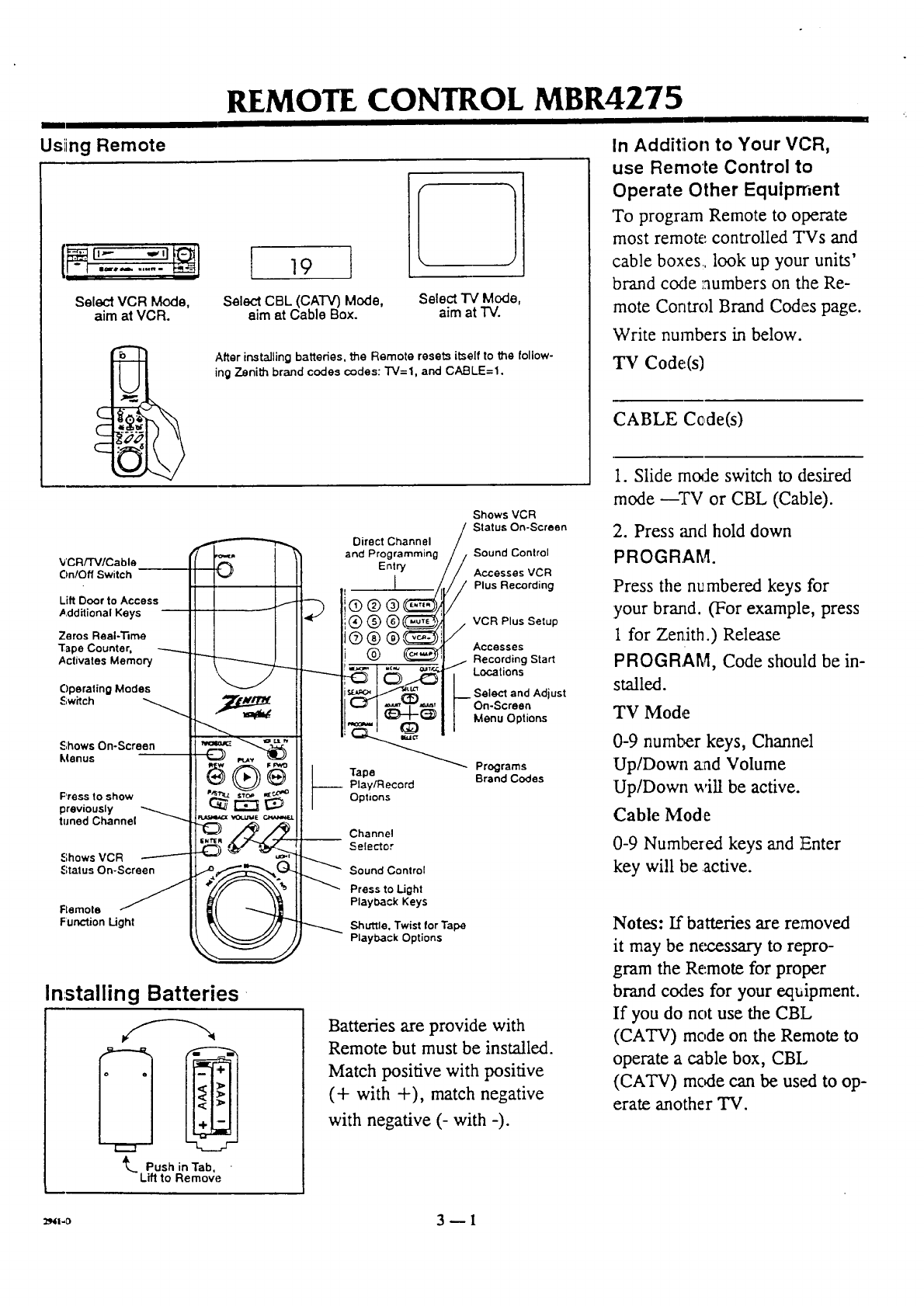
Usiing Remote
Select VCR Mode,
aim at VCR.
c
C
19
Select CBL (CA'I'V) Mode,
aim at Cable Box.
Select TV Mode,
aim at "IV.
After installing batteries, the Remote resets itself to the follow-
ing Zenith brand codes codes: TV=I, and CA.BLE=I.
In Addition to Your VCR,
use Remote Control to
Operate Other Equiprnent
To program Remote to operate
most remote controlled TVs and
cable boxes, look up your units'
brand code numbers on the Re-
mote Control Brand Codes page.
Write numbers in below.
"IN Code(s)
CABLE Cede(s)
1. Slide rnode switch to desired
VCRFI'V/Cable
On/Off Switch
Lift Door to Access
Additional Keys
Zeros Real-33me
"rape Counter, ----..._
Activates Memory
Operating Modes
Switch
Shows On-Screen
Menus
Press to show
previously
tuned Channel
.=;hows VCR
Status On-Screen
Flemole
Function Ught
Installing Batteries-
L Push in Tab,
Lift to RemovE.=
)
Direct Channel
and Programming
Entry
®®
®®®_
Shows VCR
//j Status On-Screen
Sound Control
_Acoesses VCR
Plus Recording
VCR Plus Setup
/
_Accesses
' _ Recording Start
.._ I_._ _-_ _Locations
_L_ ,_,,=,!t_ !Select and Adjust
On.Screen(lZ)
_(_ ] /Menu Options
Programs
Tape Brand Codes
__ Play/Record
Opt=ons
Channel
Selector
Sound Control
Press to Light
Playback Keys
Shuttle. Twist for Tape
Playback Options
Batteries are provide with
Remote but must be installed.
Match positive with positive
(+ with +), match negative
with negative (- with -).
mode ---TV or CBL (Cable).
2. Press anti hold down
PROGRAM.
Press the numbered keys for
your brand. (For example, press
1 for Zen,ith.) Release
PROGRAM, Code should be in-
stalled.
TV Mode
0-9 number keys, Channel
Up/Down a:ad Volume
Up/Down will be active.
Cable Mode
0-9 Numbered keys and !Enter
key will be active.
Notes: If batteries are removed
it may be m_.essary to repro-
gram the Remote for proper
brand codes for your equipment.
If you do not use the CBL
(CATV) mode on the Remote to
operate a cable box, CBL
(CATV) mc_le can be used to op-
erate another TV.
_l-o 3 -- I
REMOTE CONTROL MBR4275 BRAND' CODES
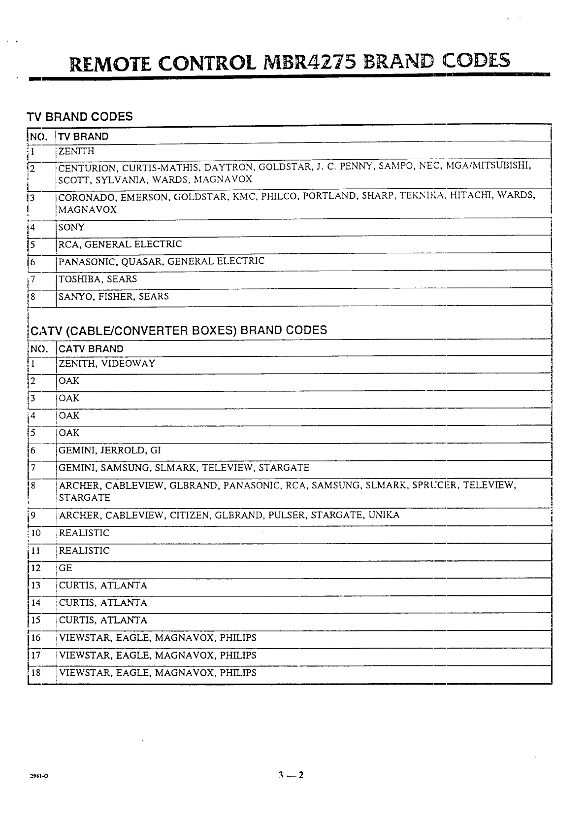
TV BRAND CODES
!NO.
il
I
!3
i4
V
i6
7
8
"IV BRAND
iZENITH
tCENTURION, CURTIS-MATHIS, DAYTRON, GOLDSTAR, J. C. PENNY, SAMPO, NEC, MGA_flTSUBISHI,
SCOTT, SYLVANIA, WARDS, MAGNAVOX
CORONADO, EMF.RSON, GOLDSTAR, KMC, PHILCO, PORTLAND, SHARP, TEKNIKA, HITACHI, WARDS,
MAGNAVOX
SONY
RCA, GENERAL ELECTRIC
(PANASONIC, QUASAR, GENERAL ELECTRIC
TOSHIBA, SEARS
SANYO, FISHER, SEARS
CATV (CABLE/CONVERTER BOXES) BRAND CODES
-_>.IcArvBRAND
Z .NIr.,V,D OWA¥
_ oAK
i4 !OAK
[5 OAK
6 GEMINI, JERROLD, GI
7 GEMINI, SAMSUNG, SLMARK, TELEVIEW, STARGATE
8 ARCHER, CABLEVIEW, GLBRAND, PANASONIC, RCA, SAMSUNG, SLMARK, SPRUCER, TELEVIEW,
iSTARGATE
I
ARCHER, CABLEVIEW, CITIZEN, GLBRAND, PULSER, STARGATE, UNIKA
REALISTIC
i 11 REALISTIC
m
GE
CURTIS, ATLANTA
!CURTIS, ATLANTA
.1-5 ,CURTIS, ATLANTA
16 VIEWSTAR, EAGLE, MAGNAVOX, PHILIPS
VIEWSTAR, EAGLE, MAGNAVOX, PHILIPS
VIEWSTAR, EAGLE, MAGNAVOX, PH[LIPS
(
i
REMOTE CONTROL MBR4275
m
ADJUST, ADJ--Use', to change
options when programming.
CI_ANNEL-- Press tJ3p or bot-
tom of key to choose next or pre-
vious channel.
MENU-- Press to display on-
screen menus.
MUTE--Press to turn off
sound, press again to restore
sound.
CH MAP-- (Channel Map)
Press to begin channel mapping
procedure.
EI_I'ER-- Use to exit: any on-
screen menu, and Direct Chan-
nel Entry.
FLASHBACK-- Press to re-
turn to channel previously se-
lected with VCR Tuner.
F FWD-- (Fast Forward) Use
to advance tape.
FWD-- (Forward) Twist play-
back Shuttle in this direction to
begin forward tape movement.
LIGHT-- Press to light VCR
Play/Record function keys.
MEMORY--Press to access
Memory feature and zero Real-
Time Tape Counter.
Numbered Keys--Use to
choose channels or input pro-
gramming information.
POWER-- Use to turn VCR on
and off.
PLAY-- Press to begin playing
tape (playback).
PROGRAM-- Press to begin
brand code programming proce-
dure.
P/STILL-- (Pause/Still) Press
to freeze tape playback or re-
cord, press again to resume. Use
to activate playback Shuttle op-
tions.
QUIT/CC-- (Quit/Closed Cap-
tions) Use to exit any on-screen
menu, and to access Closed Cap-
tions (CaptionVision) if avail-
able on your TV.
KEY DESCRIPTION
RECORD-- Use to begin tape
recording.
REV-- (Reverse) Twist play-
back Shuttle in this direx'tion to
begin reverse tape movement.
REW-- (Rewind) Use to re-
wind taps.
SEARCH-- Use to access an In-
dex recording start location.
SELECT, SEL--Use to choose
options when programming.
SHUTTLE,-- Use for variable
speed For, yard/Reverse Play-
back options.
STOP--- Press to halt tape move-
ment.
TV/VCR SOURCE--Use to
choose source of TV picture
(VCR functions or TV Tuner.) ..
VCR CBL TV-- Slide to
choose operating mode for Re-
mote Control (VCR, Cable or
TV.)
VCR+--Press to begin VCR
plus recording.
VOLUME-- Use to increase or
decrease', sound level.
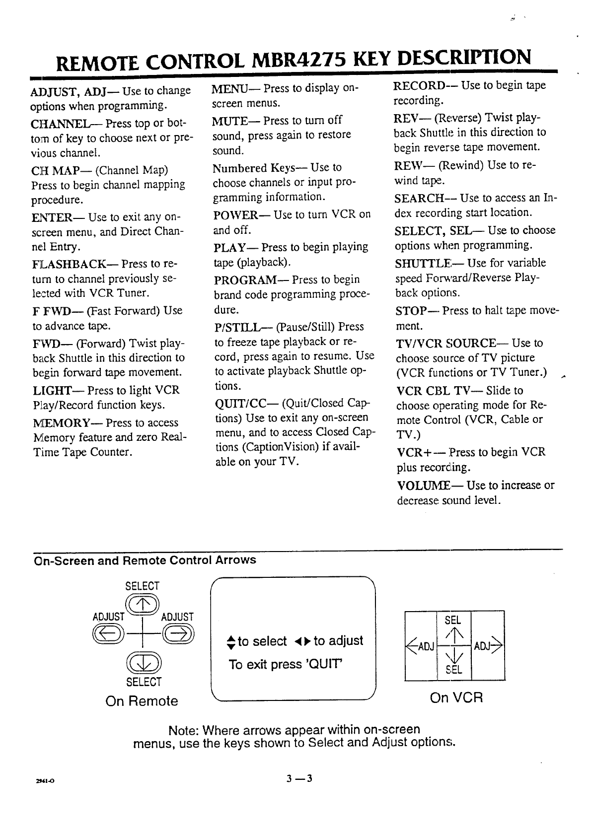
On-Screen and Remote Control Arrows
SEI.ECT
ADJUST_
C,D
SELECT
On Remote
€to select • !, to adjust
To exit press 'QUIT'
\
l-q I I
i J1
I- IADj I
!"4/
On VCR
Note: Where arrows appear within on-screen
menus, use the keys shown to Select and Adjust options.
=,,vo 3-- 3
REMOTE CONTROL MBR3370-02
m
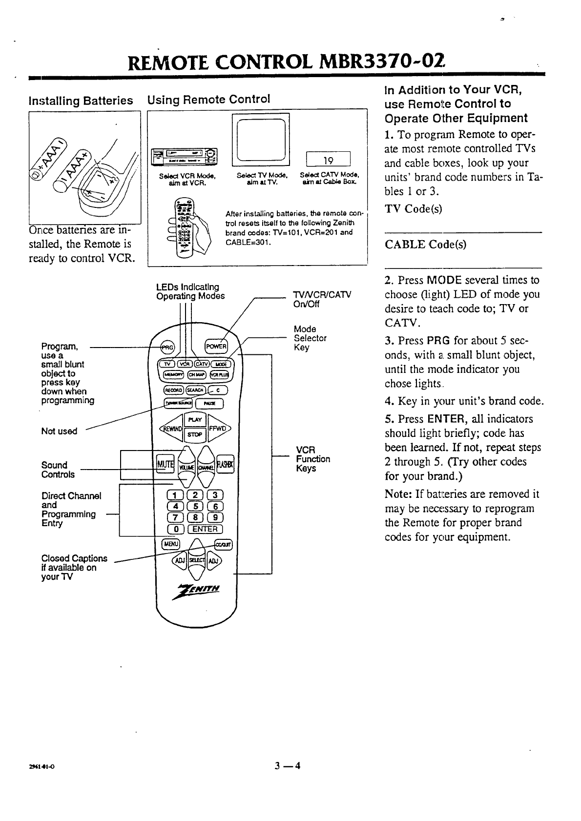
Installing Batteries
Once batteries are in-
stalled, the Remote is
re_tdy to control VCR.
Using Remote Control
Sek_ctVCR Mode,
aim la VCR.
[ 19 ]
S_:_ TV Mode, Seled CA'I'V Mode,
aJrn tt 1M aim at C.ab_ Box.
After installing batteries, the remote con-
trol resets itself to the following Zenith
brand codes: "1"V=101,VCR=201 and
CABLE=301.
In Additiion to Your VCR,
use Remol!e Control to
Operate Other Equipment
1. To progr;,un Remote to oper-
ate most remote controlled TVs
and cable boxes, look up your
units' brand code numbe:rs in Ta-
bles 1 or 3.
TV Code(s)
CABLE Code(s)
Program,
USea
small blunt
objectto
presskey
downwhen
programming
Not used
Sound
Controls
DirectChannel
and
Programming
Entry
Closed Captions
if available on
your'IV
LEDs Indicating
Operating Modes "FVNCR/CATV
On/Off
Mode
Selector
Key
VCR
Function
Keys
2. Press IVlODE several times to
choose (light) LED of mode you
desire to teach code to; TV or
CATV.
3. Press PRG for about 5 sec-
onds, with 2 small blunt ,object,
until the mode indicator you
chose lights
4. Key in your unit's brand code.
5. Press ENTER, all indicators
should light briefly; code', has
been leanaext. If not, retx_at steps
2 through 5, (Try other codes
for your brand.)
Note: If bat_:eries are removed it
may be necessary to reprograrn
the Remote for proper brand
codes for your equipment.
2,,,4,-o 3-- 4
MBR3370-02 "TV, VCR AND CABLE DECODER
t
,Table 1. "IV Codes by Brand ITable 1. "IV Codes
iTV Brand Name Codes
i
iAdmiral 1116, 121
iAkai ! 104
IAmarf< !103, 146
IAOC i104
Bell & Howell 1121
iBroksonic t131, 136
ICandle !139
!Centurion 1119
iCitizen 1139
Contec !141
Coronado 1103
[Crown _,103
}Curtis Mathes
IiDaewoo
Daylron
Emerson
!Fisher
Funai TV/VCR
General
IElectric
IGoldstar
iGoldstar TV/VC R
iHitachi
tJ.C. Penney
I
JVC
KMC
IKTV
I
iLodgenet
!Logik
ILXl
i116, 119., 121
i149
1119
124. 131, 136,
103, 104. 123, 145
109, 118
!154
116, 106, 107,
1114, 117
!119, 103, 104, 147
i153
1102, 103, 129
i104'110'114'17,119
1125, 13R
,103
1103. 104
!121
i121
i133, 13Z I
iMagnavox 112, i0"3, 113,
1 i117, 119, 127,
i r128, 139 i
;stic 1121 _'
antz 1104.12() ,
IMegatron i146 i
Memorex i121 '
' _ I
iMG,_V'Mitsubishi }120, 10.4, 119, 1301
'Montgomery Ward 133, 103, 104,
[105, 113, 114,
j119,121,13o
NEC /104, 119 {
IPanasonic !107, 106
Philco 103, 104, 112, I
113, 139 I
Phi,ip. 1112,113 i
Pioneer /135 'I
Portland 1103
OPERATING CODES BY BRAND NAME
by Brand
TV Brand Name Codes
F
1Proscan !116
ti
i 1Quasar i106, 107
!RCA 116, 104, 126
I IRealistic !105, 123, 124
iSampo !I 19
Samsung 1134, 103, 119, 141
1118, 108, 109,
,Scott 1119
ISears '103, 108, 109,
i 110, 111,118, 134
I !133, 137, 103,
!Sharp
;1105, 122,
.Signature 2000 103, 104, 10:,5,
;1113, 114, 119,
', !121, 130, 133
I
" iSoundesJgn i139
, iSony i151, 115
}Sylvania '112,113,117,
' _ .19, 127, 128, 139
!Tatung ! 106
Teknika 1124,103.113912,121.
!Teleren! i102, 121
'Toshiba 111, 110. 134
!Yorx 119
,Zenith 101,149
Zenrth TVNCR 1153, 154 i
tI
Table 2. Zenith VCR Codes
I
Zenith VCRs Codes !
Zenith t201,224, 225, 229 ;
Zenith Laser Disk !245
Table 3. Cable Decoder
:Codes by Brand
Cable Decoder i
Brand Name ICodes
!Allegro i358
Gemini 1305, 331
}General 305,306
!Instrument
IHam/in !302, 303, 34.5
Jerro!d 307, 304, 308,
309, 310
Kale Vision I335
Macom i314, 321
Macom 322
Satellite l
Magnavox 1334
NSC 1335
Oak 1311,332, 342
Panasonic 1313, 320
iTable 3. Cable Decoder
iCodes by Brand
Cable Deccde- I
tBrand Name iCodes
!Paragon i333
I [L_,,RiLI I)
i Pi_ilips 347, 350, 352,
: _,,, 355
!Pioneer 315
I
i Regency 329
.bamsunq 335
iSciemdic 316,323, 336
Atlan[a
ISpr-'_cer 313
1 335;Standard
, C,.wRDo,q er:s
!STS Satel:,te 324
iTeleca_bcn -:C00 325
iTocom 317, 318
tTosh_ba 322
iTosh;ca 319
iSatelhle
iUnika 348
;Umversal 358
ViCec V¢a,_ ._49
V_ewstar 354, 355
Zenith 301,322, 327
Zenr, n Dra,_e 312, 330
iSatelhte
'Zenith HT-200) 353 I
I
:Zenizh Salelhl_ 328 I
: j
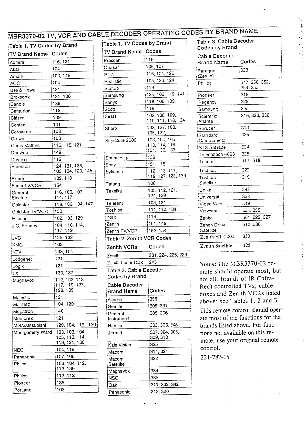
Notes: The MBR3370-02 re-
mote should operate most, but
not all, brands of IR (Infra-
Red) controlled TVs, cable
boxes and Zenith VCRs listed
above; see Tables 1, 2 and 3.
This remote control should oper-
ate most of the functions :for the
brands listed above. For func-
tions not available on this re-
mote, use ycur original remote
control.
221-782-05
'i
.?
REMOTE CONTROL
• /
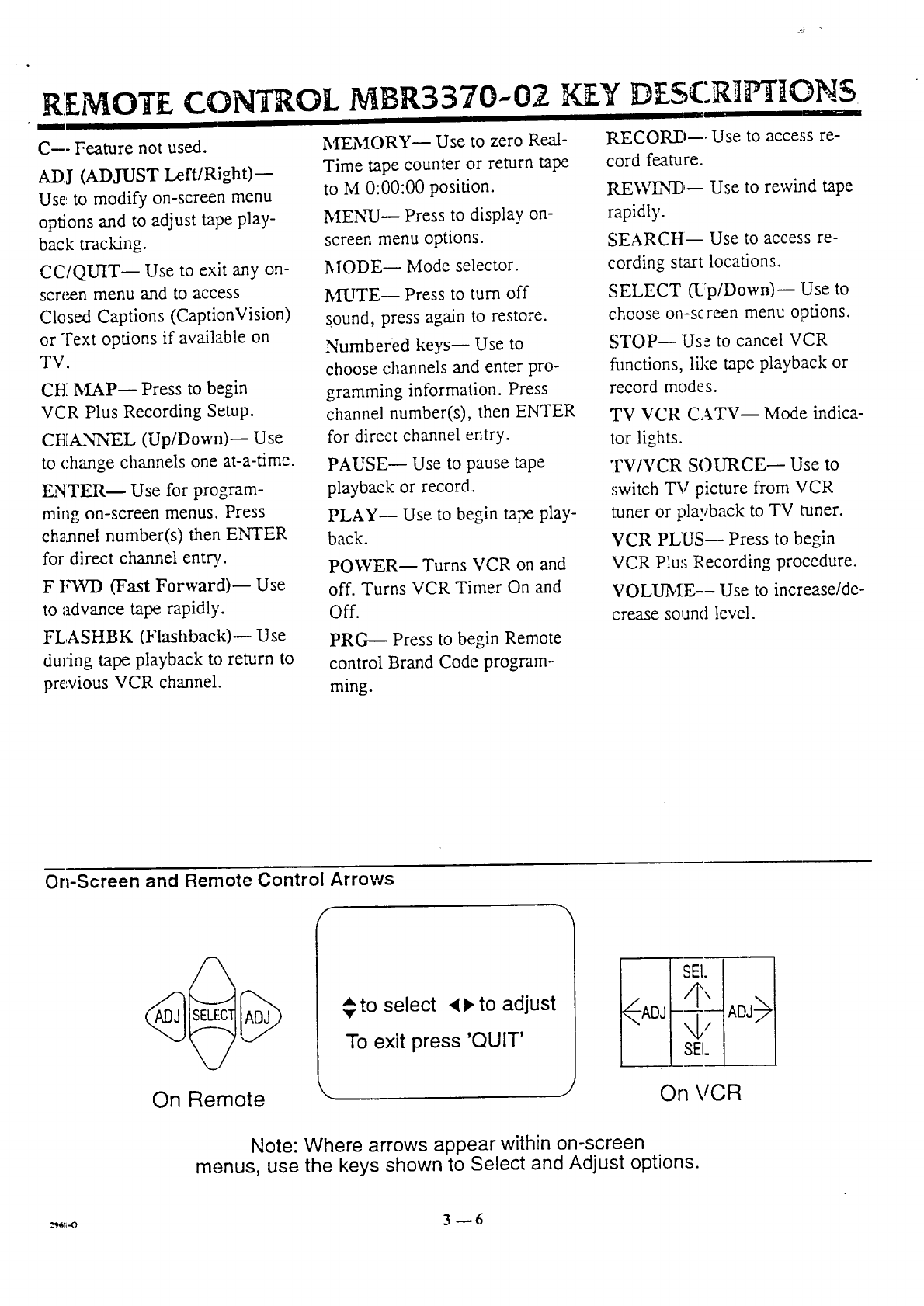
C--- Feature not used.
ADJ (ADJUST Left/Right)-
Use: to modify on-screen menu
options and to adjust tape play-
back tracking.
MBR3370--02 KEY DESCPdP't' ONS
CC/QUIT-- Use to exit any on-
screen menu and to access
Closed Captions (CaptionVision)
or Text options if available on
TV.
CH MAP-- Press to begin
VCR Plus Recording Setup.
CHANNEL (Up/Down)-- Use
to change channels one at-a-time.
ENTERm Use for program-
ming on-screen menus. Press
chzxmel number(s) then ENTER
for direct channel entr3,.
F FWD (Fast Forward)-- Use
to advance tape rapidly.
MEMORY-- Use to zero Real-
Time tape counter or return tape
to M 0:00:00 position.
MEN-U-- Press to display on-
screen menu options.
FL,ASHBK (Flashback)-- Use
duFing tape playback to return to
previous VCR channel.
MODE-- Mode selector.
MUTE-- Press to turn off
sound, press again to restore.
Numbered keys_ Use to
choose channels and enter pro-
gramming information. Press
channel number(s), then ENTER
for direct channel entry.
PAUSE_ Use to pause tape
playback or record.
PLAY-- Use to begin tape play-
back.
POWER--Turns VCR on and
off. Turns VCR Timer On and
Off.
PRG---- Press to begin Remote
control Brand Code program-
ming.
RECORD--. Use to access re-
cord feature.
REIVEN"D_ Use to rewind tape
rapidly.
SEARCH-- Use to access re-
cording start locations.
SELECT (Up/Down)--Use to
choose on-screen menu options.
STOP_ Use to cancel VCR
functions, like tape playback or
record modes.
TV VCR CATV_ Mode indica-
tor lights.
TV/VCR SOURCE-- Use to
switch TV picture from VCR
tuner or playback to TV tuner.
VCR PLUS_ Press to begin
VCR Plus Recording procedure.
VOLUME--Use to increase/de-
crease sound level.
On-Screen and Remote Control Arrows
/.
On Remote \
_, to select • l, to adjust
To exit press 'QUIT'
t I SEt.
On VCR
Note: Where arrows appear within on-screen
menus, use the keys shown to Select and Adjust options.
,'VCR,]:EATL]2. .5 5- 7LtP/Step :B
I II II III
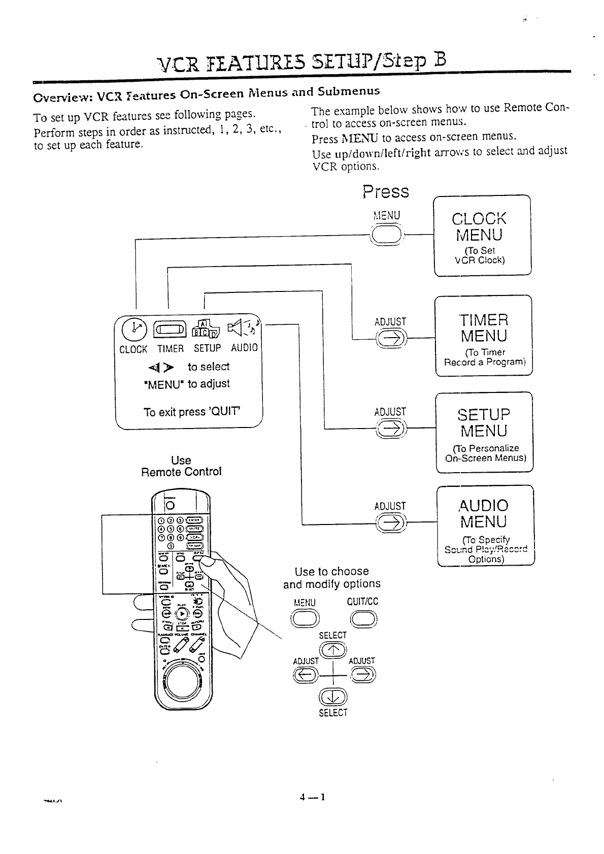
Overview: VCR Features On-Screen Menus and Submenus
To set up VCR features see following pages.
Perform steps in order as instructed, 1, 2, 3, etc.,
to set up each feature.
The example below shows how to use Remote Con-
trol to access on-screen menus.
Press 3IE,_ to access on-screen menus.
Use up/down/left/right an:ov,'s to select rand adjust
VCR options.
Press
,_.IENU (:::;LOCK
MENU
(To Set
k/CR Clock)
t
'-".1--"_
CLOCK TIMER SETUP AUDIO
> to select
"MENU" to adjust
To exit press 'QUIT'
Use
Remote Control
Use to choose
and modify options
MEI',!U QUIT/CC
O o
SELECT
ADJUST i@) ADJUST
SELECT
ADJUST
ADJUST
ADJUST
TIMER
MENU
(To Timer
Record a Program)
"m
SETUP
MENU
(']b Personalize
On--Screen Menus)
AUDIO
MENU
('To Specify
S e,tln d Dl-_,,l_ _.... 4
Options)
VCR FEATLIRES SETLIP/Step B
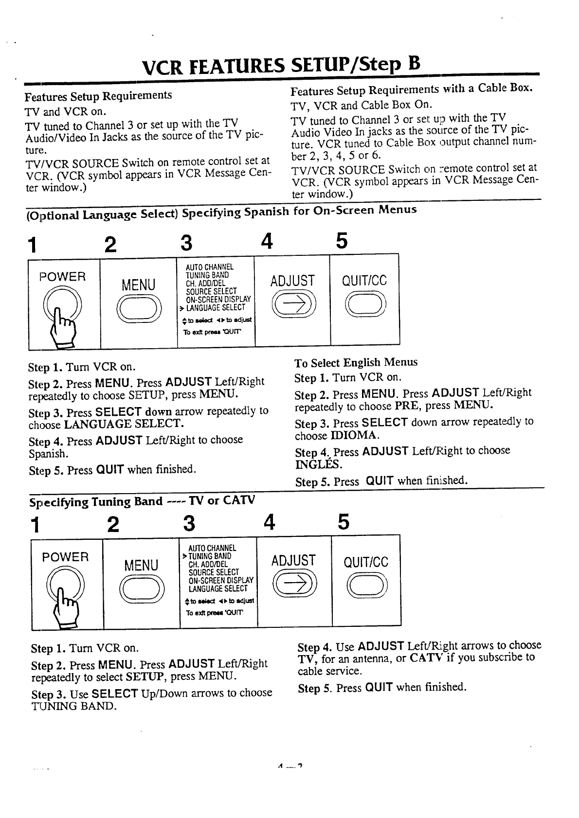
F_,tures Setup Requirements
"IV and VCR on.
TV tuned to Channel 3 or set up with the TV
Audio/Video In Jacks as the source of the TV pic-
ture.
TV/VCR SOURCE Switch on remote control set at
VCR. (VCR symbol appears in VCR Message Cen-
ter window.)
Features Setup Requirements with a Cable Box.
TV, VCR and Cable Box On.
TV tuned to Channel 3 or set up with the TV
Audio Video In jacks as the source of the TV pic-
ture. VCR tuned to Cable Box output channel num-
ber 2, 3, 4, 5 or 6.
TV/VCR SOURCE Switch on ::emote control set at
VCR. (VCR symbol appears in VCR Message Cen-
ter window.)
(Optional Language Select) Specifying Spanish for On-Screen Menus
1 2 3 4 5
POWER MENU
AUTOCHANNEL
TUNINGBAND
CH.ADD/DEL
SOURCESELECT
ON-SCREENDISPLAY
_-LANGUAGESELECT
$ _ seled 41,_ edit_
To e)a'__'ourr
ADJUST
@QUIT/CC
Step 1. Turn VCR on.
Step 2. Press MENU. Press ADJUST Left/Right
repeatedly to choose SETUP, press MENU.
Step 3. Press SELECT down arrow repeatedly to
choose LANGUAGE SELECT.
Step 4. Press ADJUS'r Left/Right to choose
Spanish.
Step 5. Press QUIT When finished.
Specifying Tuning Band .... "iV or CATV
To Select English Menus
Step 1. Turn VCR on.
Step 2. Press MENU. Press ADJUST Left/Right
repeatedly to choose PRE, press MENU.
Step 3. Press SELECT down arrow repeatedly to
choose IDIOMA.
Step 4; Press ADJUST LefVRight to choose
INGLES.
Step 5. Press QUIT when finiLshed.
123 4 5
POWER MENU
AUTOCHANNEL
_'TUNINGBAND
CH.AOD/DEL
SOURCESELECT
ON-SCREENDISPLAY
LANGUAGESELECT
€to =ww4ct4_. to _jt,tst
To e_ _'(XIIT'
ADJUST QUIT/CC
Step 1. Turn VCR on
Step 2. Press MENU. Press ADJUST Left!Right
repeatedly to select SETUP, press MENU.
Step 3. Use SELECT Up/Down arrows to choose
TUNING BAND.
Step 4. Use ADJUST LeftfRight arrows tochoose
TV, for an antenna, or CA'IW if you subscribe to
cable service.
Step 5. Press QUIT when finished.
"- d__q=
VCR FEATURES SETUP/Step B
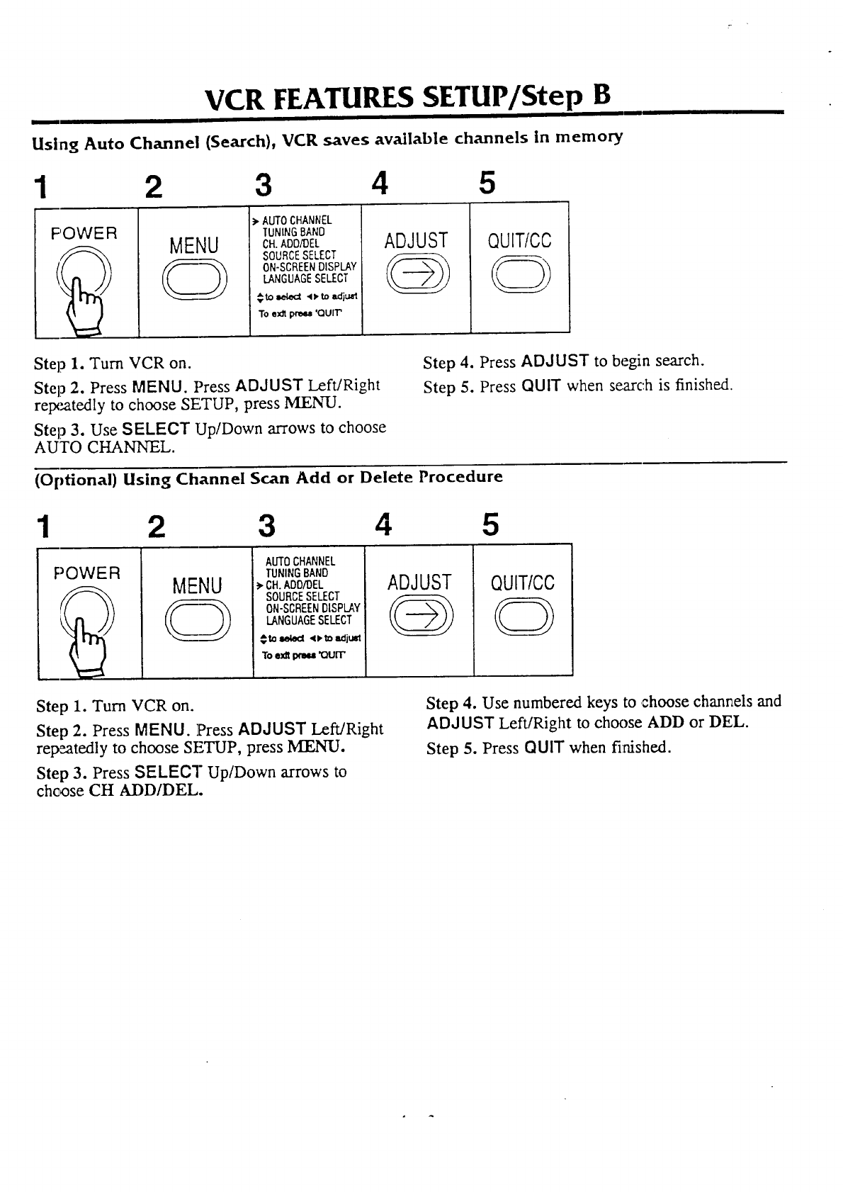
Using Auto Channel (Search), VCR saves available channels In memory
1 2 3 4 5
POWER MENU
),AUTOCHANNEL
TUNINGBAND
CH.ADD/DEL
SOURCESELECT
ON-SCREENDISPLAY
LANGUAGESELECT
€to=el_ ,D,to=Klju_
Toe_dt_ 'QUIT'
ADJUST QUIT/CC
Step 1. Turn VCR on.
Step 2. Press MENU. Press ADJUST Left/Right
retx_atedly to choose SETUP, press MENU.
Step 3. Use SELECT Up/Down arrows to choose
AUTO CHANNEL.
Step 4. Press ADJUST to begin search,
Step 5. Press QUIT when search is finished
(Optional) Using Channel Scan Add or Delete Procedure
123 45
POWER MENU
AUTOCHANNEL
TUNINGBAND
3,CH.ADO/DEL
SOURCESELECT
ON-SCREENDISPLAY
LANGUAGESELECT
_ to =_wecl <D,to adjusl
To e._dtixma '(_Jrl"
ADJUST
@QUIT/CC
Step 1. Turn VCR on.
Step 2. Press MENU. Press ADJUST Left/Right
rep,eatedly to choose SETUP, press MENU.
Step 3. Press SELECT Up/Down arrows to
ch¢_)se CH ADD/DEL.
Step 4. Use numbered keys to choose channels and
ADJUST Left/Right to choose ADD or DEL.
Step 5. Press QUIT when fi:aished.
7.ATI3 S 5ZTHPiStep Bi
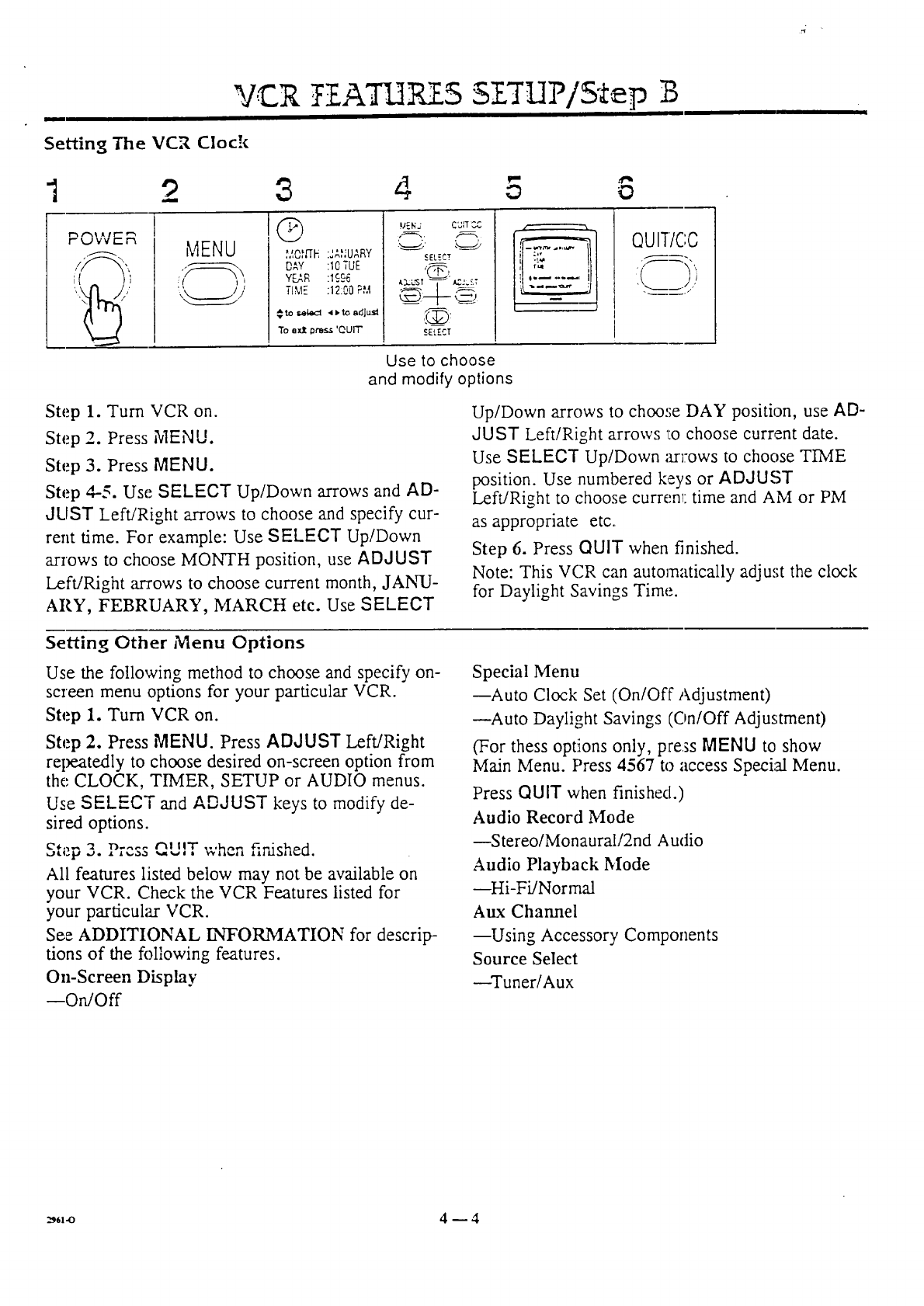
Setting The VCR Clock
12 3 4 5 8
MENU
( t I
Q
;,a,QNIE :JA,_;UARY
DAY :10 TUE
YEAR :1996
TIME :12:00FM
ere r,_ct 41)10 adJt._l
To e:dt Oress 'QUIT'
MENd CUR CC
SELECT
),:3..L,ST "q--" _';5,r
.EL..T
f
Use to choose
and modify options
QUIT/C:C
Step 1. Turn VCR on.
Step 2. Press MENU.
Step 3. Press MENU.
Step 4--5. Use SELECT Up/Down arrows and AD-
JLIST Left/Right arrows to choose and specify cur-
rent time. For example: Use SELECT Up/Down
arrows to choose MONTH position, use ADJUST
Left/Right m-_rows to choose current month, JANU-
ARY, FEBRUARY, MARCH etc. Use SELECT
Up/Down arrows to choose DAY position, use AD-
JUST Left/Right arrows :o choose current date.
Use SELECT Up/Down arl:ows to choose TIME
position. Use :numbered keys or ADJUST
Left/Right to choose currenl: time and AM or PM
as appropriate etc.
Step 6. Press QUIT when finished.
Note: This VCR can automatically adjust the clock
for Daylight Savings Time.
Setting Other Menu Options
Use the following method to choose and specify on-
screen menu options for your particular VCR.
Step 1. Turn VCR on.
Step 2. Press MENU. Press ADJUST Left/Right
repeatedly to choose desired on-screen option from
the; CLOCK, TIMER, SETUP or AUDIO menus.
Use SELECT and ADJUST keys to modify de-
sired options.
c,,,_ 3. r_.... _, ,,'rwhen fir,ished.
All features listed below may not be available on
your VCR. Check the VCR Features listed for
your particular VCR.
See ADDITIONAL £NFORMATION for descrip-
tions of the following features.
On-Screen Display
--O_Off
Special Menu
--Auto Clock Set (On/Off Adjustment)
--Auto Daylight Savings (On/Off Adjustment)
(For thess options only, press MENU to show
Main Menu. Press 4567 to access Special Menu.
Press QUIT when finished.)
Audio Record Mode
--Stereo/Monaural/2nd Audio
Audio Playback Mode
--Hi-FiYNormal
Aux Channel
--Using Accessory Components
Source Select
--Tuner/Aux
_6,_ 4-- 4
Ycur VCR is ,controlled by both the remote control
and the buttons on the VCR. Some VCR functions
can be initiated by both units, but mostly the remote.
control must te used.
D]SPLAY5
Notes: For all operations botL1the VCR mad TV
power should be ON. To control the VCR, the re-
mote control should be in VCR mode.
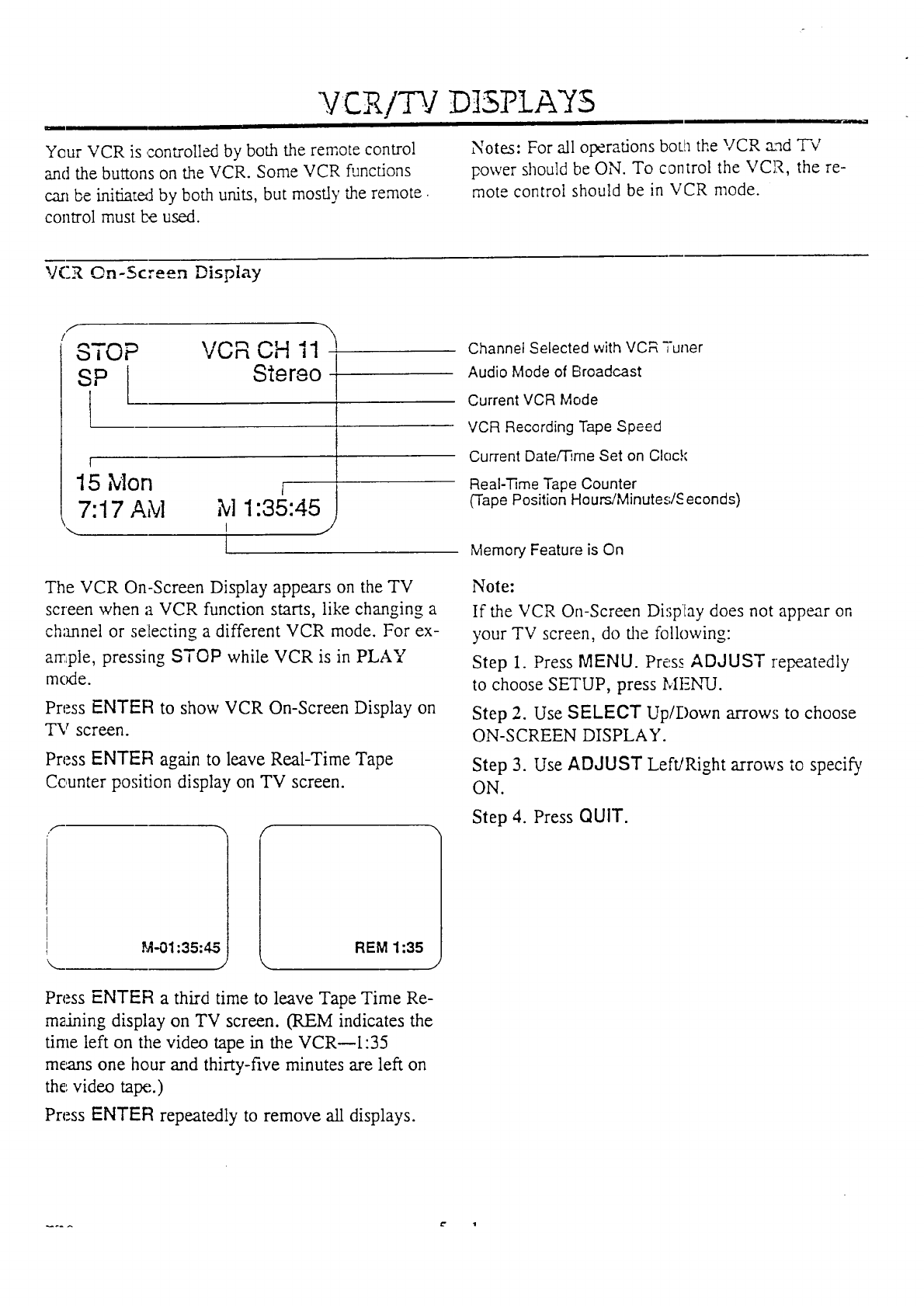
VCR On-Screen Display
f
STOP
SP
t
VCR CH 11-
Stereo-
l
15 Mort a
7:17 AM M 1:35:45
\ I ...,
I
The VCR On-Screen Display appears on the TV
screen when a VCR function starts, like changing a
ch;mnel or selecting a different VCR mode. For ex-
ample, pressing STOP while VCR is in PLAY
mcxJe.
Press ENTER to show VCR On-Screen Display on
TV screen.
Press ENTER again to leave Real-Time Tape
Counter position display on TV screen.
f _, f
Channel Selected with VCR "Tuner
Audio Mode of Broadcast
Current VCR Mode
VCR Recording Tape Speed
Current Date/'lqme Set on Clock
Real-Time Tape Counter
(Tape Position HoursiMinute-_#S econds)
Memory Feature is On
Note:
If the VCR On-Screen Disptay does not appear on
your TV screen, do the following:
Step 1. Press MENU. Press ADdUST repeatedly
to choose SE'T'UP, press MF_.NqJ.
Step 2. Use SELECT Up/1-)own arrows to choose
ON-SCREEN DISPLAY.
Step 3. Use ADJUST Left/Right arrows to specify
ON.
Step 4. Press QUIT.
M-01:35:45 REM 1:35
J
Press ENTER a third time to leave Tape Time Re-
maining display on TV screen. (REM indicates the
time left on the video tape in the VCR_I:35
means one hour and thirty-five minutes are left on
the video ta_'..)
Press ENTER repeatedly to remove all displays.
.... t" 1
NtESSAGE CENTER DIISPLA S
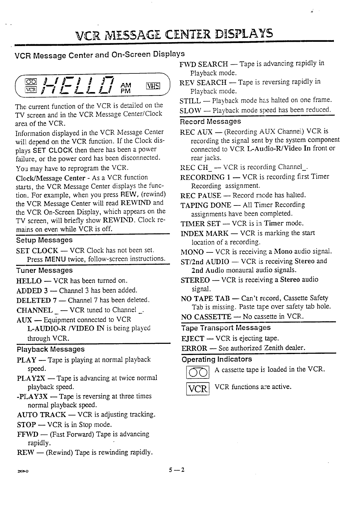
VCR Message Center and On-Screen Displays
/ iL L/.-./_I AMpM
The current function of the VCR is detailed on the
TV screen and in the VCR Message Center/Clock
area of the VCR.
Information displayed in the VCR Message Center
will depend on the VCR function. If the Clock dis-
plays SET CLOCK then there has been a power
failure, or the power cord has been disconnected.
Yoga may have., to reprogram the VCR.
Clock/Message Center - As a VCR function
starts, the VCR Message Center displays the func-
tion. For example, when you press REW, (rewind)
the VCR Message Center will read REWIND and
the VCR On-.Screen Display, which appears on the
TV screen, will briefly show REWEYD. Clock re-
mains on even while VCR is off.
Setup Messages
SET CLOCK -- VCR Clock has not been set.
Press MENU twice, follow-screen instructions.
Tuner Messages
HELLO -- VCR has been turned on.
ADDED 3 -- Channel 3 has been added.
DELETED 7-- Channel 7 has been deleted.
CHANNEL --VCR tuned to Channel _.
AUX -- Equipment connected to VCR
L-AUDIO-R/VIDEO IN is being played
through VCR.
Playback Messages
PLAY -- Tape is playing at normal playback
speed.
PLAY2X --'rape is advancing at twice normal
playback ,;peed.
-PLAY3X -- Tape is reversing at three times
normal playback speed.
AUTO TRACK -- VCR is adjusting tracking.
STOP --VCR is in Stop mode.
FF3VD -- (Fast Forward) Tape is advancing
rapidly.
REW -- (Rewind) Tape is rewinding rapidly.
F3,VI) SEARCH -- Tape is advancing rapidly in
Playback mode.
REV SEARCH -- Tape is reversing rapidly in
Playback mode.
STILL -- Playback mode has halted on one frame.
SLOW -- Playback mode speed has been reduced.
Record Messages
REC AUX -- (Recording AUX Channe]L) VCR is
recording the signal sent by the system component
connected to VCR L-Audio-R/Video In front or
rear jacks.
REC CH --VCR is recording Channel_.
RECORDING 1 -- VCR is recording first Timer
Recording assignment.
REC PAUSE --- Record racde has halted.
TAPING DONE -- All Timer Recording
assignments have been completed.
TI3,IER SET --- VCR is in 'rimer mode.
INDEX MARK -- VCR is marking the start
location of a recording.
MONO -- VCR is receiving a Mono audio signal.
ST/2nd AUDIO --. VCR is receiving Stereo and
2nd Audio monaural audio signals.
STEREO -- VCR is receixing a Stereo audio
signal.
NO TAPE TAB -- Can't record, Cassette Safety
Tab is missing. Paste tat:e over safety tab hole.
NO CASSETTE -- No cas,;ette in VCR.
Tape Transport Messages
EJECT -- VC,R is ejecting tape.
ERROR -- See authoriz_:t Zenith dealer.
Operating Indicators
(_) A cassette tape is loaded in the VCR.
VCR functions a:re active.
_5.o 5 -- 2
WATCH]N6 TV (TV An±enna ]In'Zonnec± ons)
OPOWER I ISTOP
•EJECT
siEp _EJ _ai_:cJ_t°
I• PLAY
L-AUDIO VIDEO [_ OE[ /_ /.._.n#-'_ L.... Ill rm _/i_ _/--_,
®@® .... _.
--_, _ \ _ ===P--
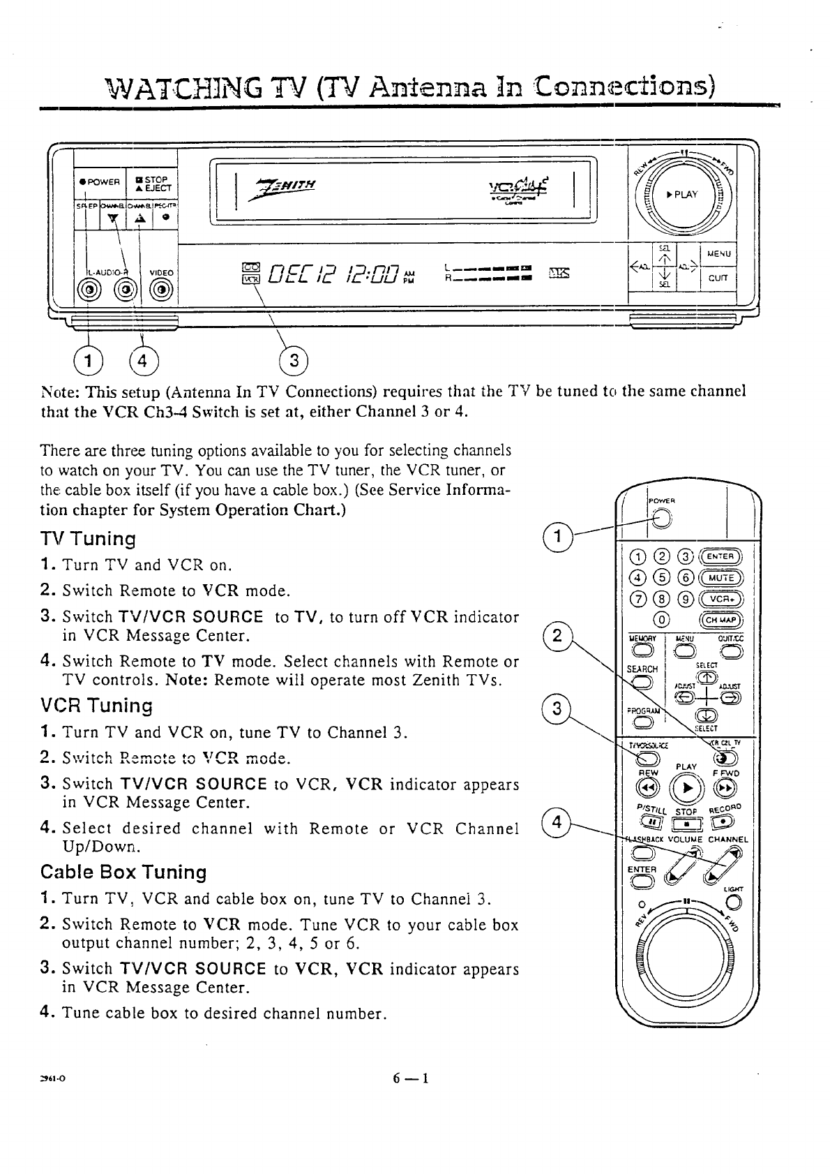
Note: This setup (Antenna In TV Connections) requires that the TV be tuned to the same channel
that the VCR Ch3-4 Switch is set at, either Channel 3 or 4.
There are three tuning options available to you for selecting channels
to watch on your TV. You can use the TV tuner, the VCR tuner, or
the: cable box itself (if you have a cable box.) (See Service Informa-
tion chapter for System Operation Chart.)
"iA! Tuning
1. Turn TV and VCR on.
2. Switch Remote to VCR mode.
3. Switch TV/VCR SOURCE to TV, to turn off VCR indicator
in VCR Message Center.
4. Switch Remote to TV mode. Select channels with Remote or
TV controls. Note: Remote will operate most Zenith TVs.
VCR Tuning
1. Turn TV and VCR on, tune TV to Channel 3.
9 Switch D.... ,,_ ,,, vP_ mode
ib,=l l_,_lllt_..tl, lb./ _%J • %....J.'tb. .
3. Switch TV/VCR SOURCE to VCR, ¥CR indicator appears
in VCR Message Center.
4. Select desired channel with Remote or VCR Channel
Up/Down.
Cable Box Tuning
1. Turn TV, VCR and cable box on, tune TV to Channel 3.
2. Switch Remote to ¥CR mode. Tune VCR to your cable box
output channel number; 2, 3, 4, 5 or 6.
3. Switch TV/VCR SOURCE to VCR, YCR indicator appears
in VCR Message Center.
4. Tune cable box to desired channel number.
_,-o 6-- I
WATCHING TV (TV Audio/Video in Connections)
•POWER • STOP
• EJECT
IL-AUDIO-_ VIDEO
®®® DEC12 '_''"_ '_
/Z_ "U!.J
\\
L------laa
R .... ma
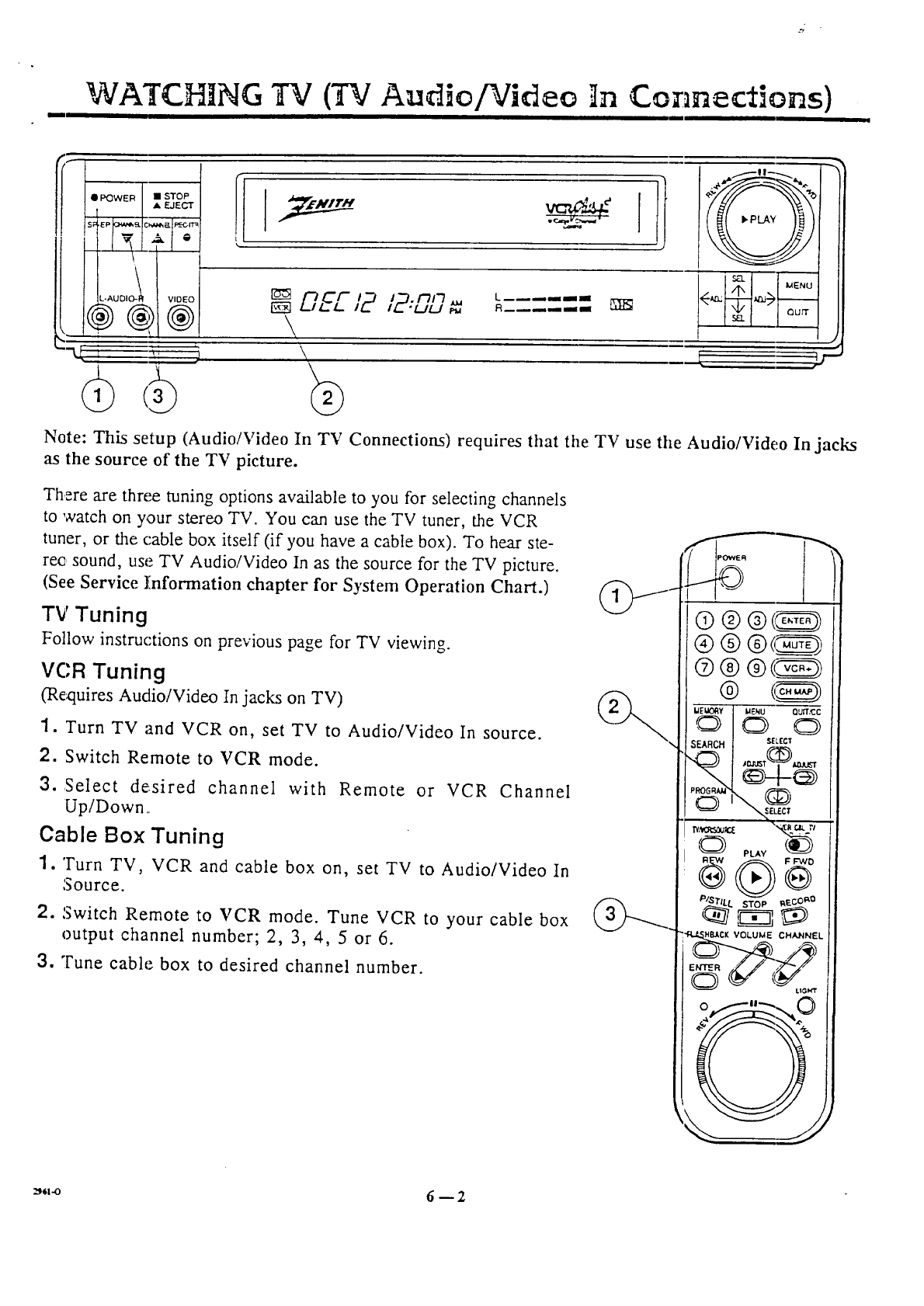
Note: This setup (Audio/Video In TV Connections) requires that the TV use tile AudiolVideo In jacks
as the source of the TV picture.
There are three tuning options available to you for selecting channels
to ';catch on your stereo TV. You can use the TV tuner, the VCR
tuner, or the cable box itself (if you have a cable box). To hear ste-
reo sound, use TV Audio/Video In as the source for the TV picture.
(See Service Information chapter for System Operation Chart.)
TV Tuning
Follow instructions on previous page for TV viewing.
VC:R Tuning
(Requires Audio/Video In jacks on TV)
1. Turn TV and VCR on, set TV to Audio/Video In source.
2. Switch Remote to VCR mode.
3. Select desired channel with Remote or VCR Channel
Up/Down.
Cable Box Tuning
1. Turn TV, VCR and cable box on, set TV to Audio/Video In
Source.
2. Switch Remote to VCR mode. Tune VCR to your cable box
output channel number; 2, 3, 4, 5 or 6.
3. Tune cable box to desired channel number.
_,,-o 6-- 2
PLA NG TAP 5 (P]ayba k)
QPOWER -'1 STOP
•EJECT
/ //v,oEo
®
'--t_
I '!!
L_J_a_J
!F
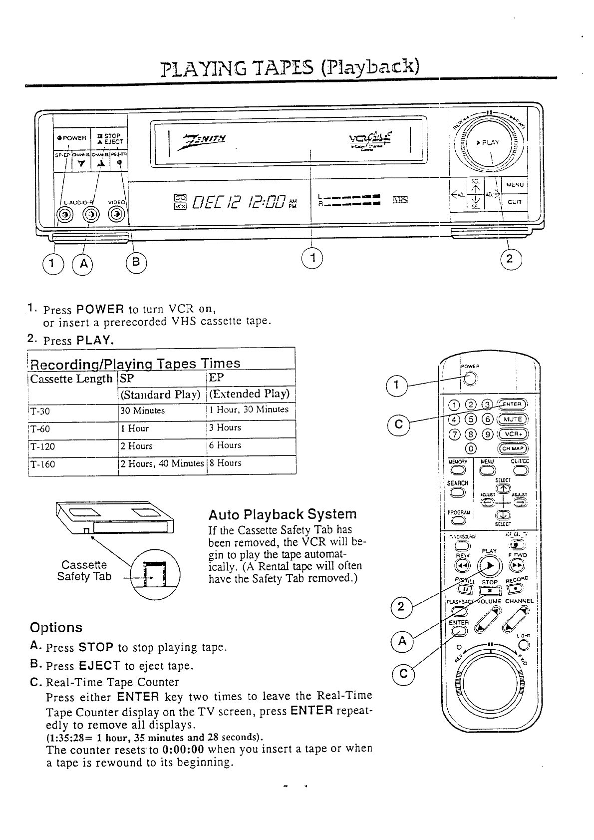
1. Press POWER to turn VCR on,
or insert a prerecorded VHS cassette tape.
2. Press PLAY.
!Recordinq/Playing Tapes Times
!Cassette Len_h (staSP,,dard EP
[Play) [(Extended Play)
!T-30 30 Minutes II Hour, 30 Minutes
!T4i0 1 Hour i3 Hours
IT-120 22Hours i6 Hours
T-t60 Hours, 40 Minutes 8 Hours
\ n{_l
Cassei_e_h__
Safety Tab -__)
Auto Playback System
If the Cassette Safety Tab has
been removed, the VCR will be-
gin to play the tape automat-
ically. (A Rental tape will often
have the Safety Tab removed.)
®@ @_@
@ t_
Options
A. Press STOP to stop playing tape.
B. Press EJECT to eject tape.
C. Real-Time Tape Counter
Press either ENTER key two times to leave the Real-Time
Tape Counter display on the TV screen, press ENTER repeat-
edly to remove all displays.
(1:35:28= 1 hour, 35 minutes and 28 seconds).
The counter resetsto 0:00:00 when you insert a tape or when
a tape is rewound to its beginning.
PLAYING TAPES (Playback. Options)
,%_
• POVV'IER • STOP
•EJECT
L.AUDtO-FI VIDEO
\
J
'--k J, I
[_ L_,==_ ='='==
jr"
/
Use these controls
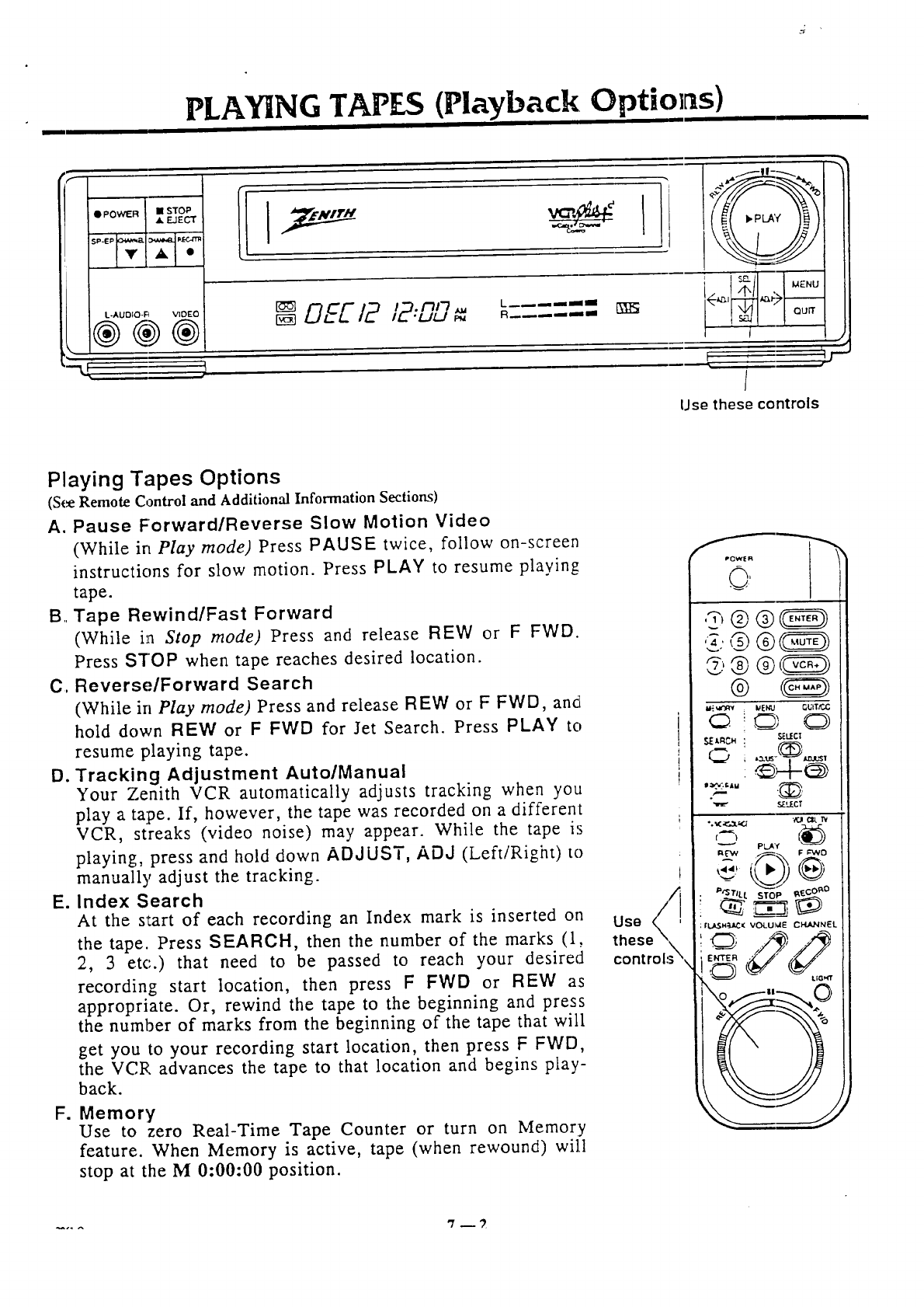
Playing Tapes Options
(S(_ Remote Control and Additional Information Sections)
A. Pause Forward/Reverse Slow Motion Video
(While in Play mode) Press PAUSE twice, follow on-screen
instructions for slow motion. Press PLAY to resume playing
tape.
B.. Tape Rewind/Fast Forward
(While in Stop mode) Press and release REW or FFWD.
Press STOP when tape reaches desired location.
C. Reverse/Forward Search
(While in Play mode) Press and release REW or FFWD, and[
hold down REW or F FWD for Jet Search. Press PLAY to
resume playing tape.
D. Tracking Adjustment Auto/Manual
Your Zenith VCR automatically adjusts tracking when you
play a tape. If, however, the tape was recorded on a different
VCR, streaks (video noise) may appear. While the tape is
playing, press and hold down ADJUST, ADd (Left/Right) to
manually adjust the tracking.
E. Index Search
At the s_:art of each recording an Index mark is inserted on
the tape. Press SEARCH, then the number of the marks (1,
2, 3 etc.) that need to be passed to reach your desired
recording start location, then press F FWD or REW as
appropriate. Or, rewind the tape to the beginning and press
the number of marks from the beginning of the tape that will
get you to your recording start location, then press F FWD,
the VCR advances the tape to that location and begins play-
back.
F. Memory
Use to :zero Real-Time Tape Counter or turn on Memory
feature. When Memory is active, tape (when rewound) will
stop at the M 0:00:00 position.
Uso
control:_
.... '7_
?LA NG TAP£-S
(P ayba kSh t ]e
aPOWER I • STOP
I AEJ. ECT l
L
L-AUDIO-R VIDEO
@@@
--R J
IL "LII_Ip_
L__--imml
R__
I
I
Use these controls
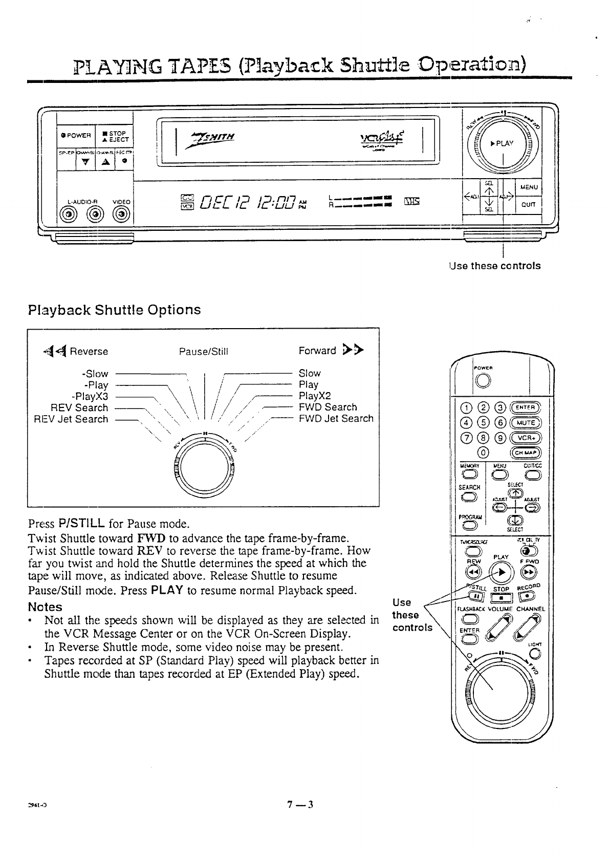
Playback Shuttle Options
_-_ Reverse Pause/Still Forward ,_)_
-Slow
-Play \
-PlayX3 --\, \
REV Search \ , \\
RI=V Jet Search "" "" \ ',
"\, \ .
O
Slow
Play
PlayX2
FWD Search
/FWD Jet Search
/
/
Press PISTILL for Pause mode.
Twist Shuttle toward FWI) to advance the tape frame-by-frame.
Twist Shuttle toward REV to reverse the tape frame-by-frame. How
far you twist :rod hold the Shuttle determines the speed at which the
tape will move, as indicated above. Release Shuttle to resume
Pause/Still m(xle. Press PLAY to resume normal Playback speed.
Notes
•Not all the speeds shown will be displayed as they are sel_ted in
the VCR Message Center or on the VCR On-Screen Display.
• In Reverse: Shuttle mode, some video noise may be present.
• Tapes recorded at SP (Standard Play) speed will playback better in
Shuttle mode than tapes recorded at EP (Extended Play) speed.
Use _
these
controls "\
©
®@®<_
®® ®<_------_
CD !C_ C_
SEARCH $FL(-.c'r
NiLECT
r,¢_illNl;7_ ,'{:RCIL IY
g_gM;( VOLUM[ CHA.NNEL
OO
UG_rT
O ||_ C
=.t.a 7_ 3
INSTANT R _CO RD]NG
g-_/-JL!-/_ R..... --
IL "L-/LIJeu
I
P,'::l,_:':1_lJ]
, i :a I T I
[ ]j
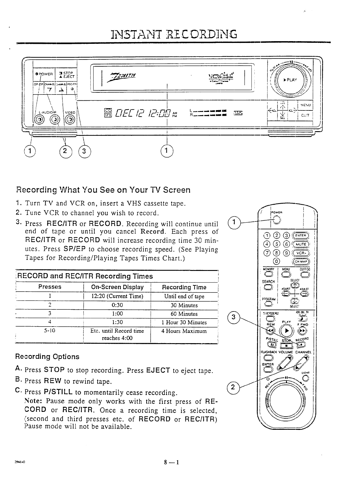
Recording What You See on Your "iV Screen
1. Turn TV and VCR on, insert a VHS cassette tape.
2. Tune VCP, to channel you wish to record.
3. Press REClITR or RECORD. Recording will continue until
end of tape or until you cancel Record. Each press of
REC/ITR or RECORD will increase recording time 30 min-
utes. Press SP/EP to choose recording speed. (See Playing
Tapes for Recording/Playing Tapes Times Chart.)
RE-CORD and REC/ITR Recording Times i
Presses j On-Screen Display ! Recording Time I
i
:1 I 12:20 (Current Time) Until end of tape i
2 i 0:30 { 30 Minutes ;
3 ! 1:00 !60 Minutes ;
4 _ 1:30 1 Hour 30 Minutes
5-10 t Etc. until Record time 4 Hours Maximum
J! reaches 4:00
Ji
Recording Options
A. Press STOP to stop recording. Press EJECT to eject tape.
B. Press R EW to rewind tape.
C. Press P/STILL to momentarily cease recording.
Note: Pause mode only works with the first press of RE-
,CORD or REC/ITR. Once a recording time is selected,
,:,second and third presses etc. of RECORD or REC/ITR)
:Pause mode will not be available.
,@POWER ,",,4STOP
L-i_UF..IO-R vzoEo ]
I "'-:="-" i
!
t
DEE/2 ,_.n,'7
I
I
L --_ _mlll -'r_l
R----,=,*_ m _1 ' -,--.,2" _,__._.7,L---- i
_! i '-'U'T!
i/
Use these buttons
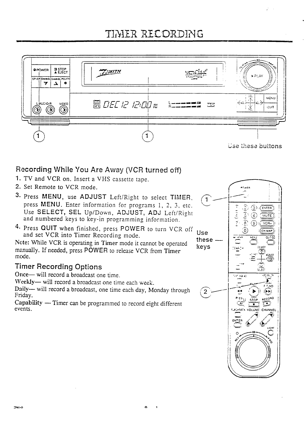
Recording While You Are Away (VCR turned off)
1. TV and VCR on. Insert a VHS cassette tape.
2. Set Remote to VCR mode.
3. Press MENU, use ADJUST Left/Right to select TIMER,
press MENU. Enter information for programs 1, 2, 3, etc.
Use SELECT, SEk UplDown, ADJUST, ADd LeftlRight
and numbered keys to key-in programming information.
4. Press QUIT when finished, press POWER to turn VCR off
and set VCR into Timer Recording mode.
Note: While VCR is operating in Timer mode it cannot be operated
manually. If needed, press POWER to release VCR from Timer
mc_e.
Timer Recording Options
Once-- will record a broadcast one time.
Weekly-- will record a broadcast one time each --'-
Daily- will :record a broadcast, one time each day, Monday through
Friday.
Capability --- Timer can be programmed to record eight different
events.
Use
these --
keys
I
I
i
,_h2.
w- o*._v t,E_13 CLiT P-,_
C ,7, '@
-- r.E.ECT
Ii
"z ,_r i!_!:
_' _'_'Lt £'_._ ,_--CO_'O
IJt_,_t.t_ VOLUM[" CHANNFL
-- /I,.,'- /
L!G_(T
2)614) _ 1
INSTANT RECORDING WITH A CA I.E
it
tPOWER • STOP
& EJECT
I
s, ,i
L__--aid|
-EL MENU
SEL]
QUIT
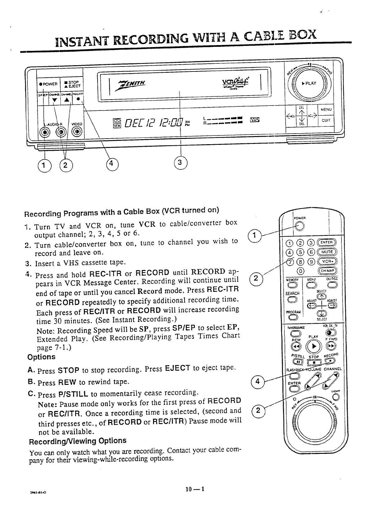
Recording Programs with a Cable Box (VCR turned on)
1. Turn TV and VCR on, tune VCR to cable/converter box
output rhannel; 2, 3, 4, 5 or 6.
2. Turn cable/converter box on, tune to channel you wish to
record and leave on.
3. Insert a VHS cassette tape.
4. Press and hold REC-ITR or RECORD until RECORD ap-
pears in VCR Message Center. Recording will continue until
end of 1tapeor until you cancel Record mode. Press REC-iTR
or RECORD repeatedly to specify additional recording time.
Each press of REC/ITR or RECORD will increase recording
time 30 minutes. (See Instant Recording.)
Note: Recording Speed will be SP, press SP/EP to select EP,
Extended Play. (See RecordinglPlaying Tapes Times Chart
page 7-1.)
Options
A. Press STOP to stop recording. Press EJECT to eject tape.
B. Press REW to rewind tape.
C. Press P/STILL to momentarily cease recording.
Note: Pause mode only works for the first press of RECORD
or REC/ITR. Once a recording time is selected, (second and
third presses etc., of RECORD or REC/ITR) Pause mode will
not be available.
Recording/Viewing Options
You can onl)t watch what you are recording. Contact your cable com-
pany for then- viewing-while-recording options.
44@@@
C:_ 0
N
I_ PLAY ",_h'
REW _
/:'/S_LL STOP taE_ _
LUME CHANNEL
_*,_i=o 10 -- 1
•_i_IER _{©_...]NG W_TH A CA]BLE BOX
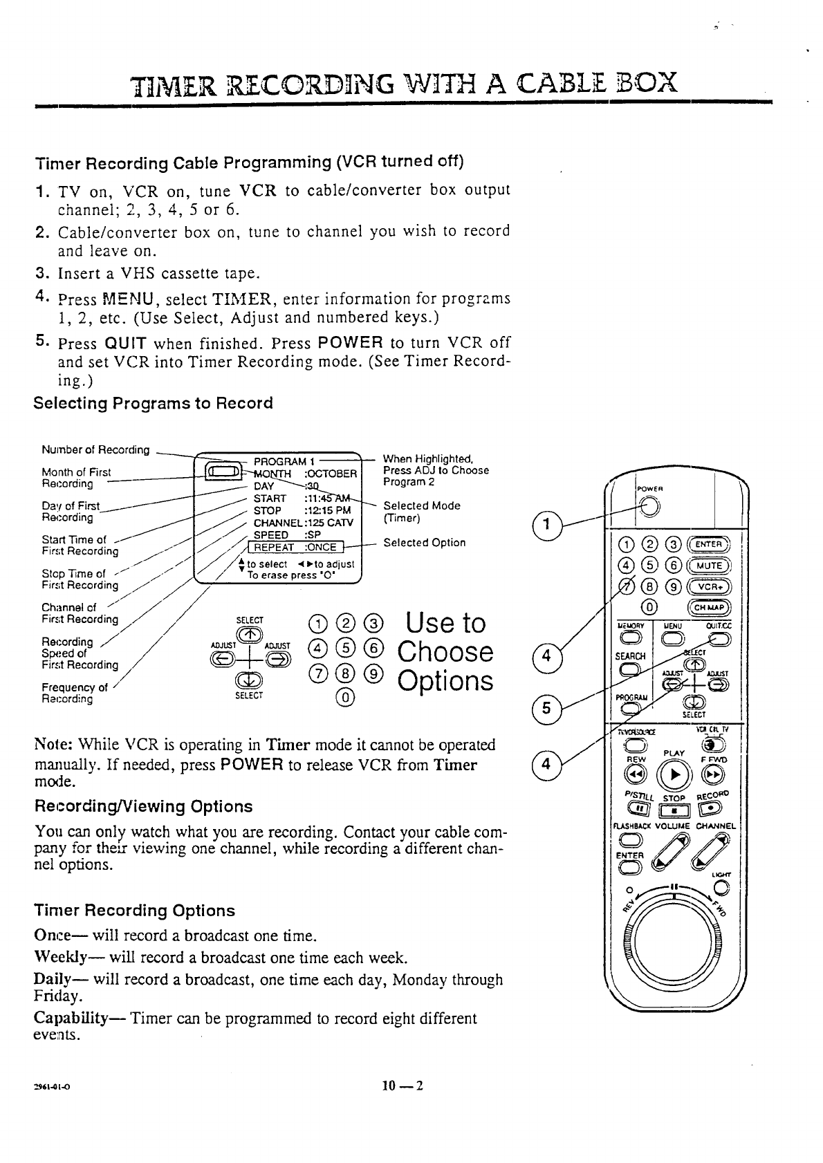
Timer Recording Cable Programming (VCR turned off)
1. TV on, VCR on, tune VCR to cable/converter box output
channel; 2, 3, 4, 5 or 6.
2. Cable/converter box on, tune to channel you wish to record
and leave on.
3. Insert a VHS cassette tape.
4. Press MENU, select TIMER, enter information for programs
1, 2, etc. (Use Select, Adjust and numbered keys.)
5. Press QUIT when finished. Press POWER to turn VCR off
and set VCR into Timer Recording mode. (See Timer Record-
ing.)
Selecting Programs to Record
Number of Recording PROGRAM 1 When Highlighted,
Month of First Press ADJ Io Choose
Recording DAY Program 2
START
Day of STOP Selected Mode
Recording (Timer)
Start Time of
First Recording ./ .//
/
Stop -time of .--/" /./
First Recording / /
//
Channel cf // /
First Recording ji /
ae,_ording ./ /
Sp_.ed of /
Fir.';t Recording///
Frequency of /
Racording
SPEED
to select
SELECT
ILDJ_T_ _ADJIJST
_?----_
03D
SELECT
Selected Option
Q ® @ Use to
® ® ® Choose
Q ® ® Options
®
Note: While VCR is operating in Timer mode it cannot be operated
manually. If needed, press POWER to release VCR from Timer
mode.
Recording/Viewing Options
You can on] 7 watch what you are recording. Contact your cable com-
pany for their viewing one channel, while recording a different chan-
nel options.
Timer Recording Options
Once-- will record a broadcast one time.
Weeklym wil[ record a broadcast one time each week.
Daily-- will record a broadcast, one time each day, Monday through
Friday.
Capability_ 'Timer can be programmed to record eight different
eve';Its.
_,t._,-o 10 -- 2
VCR PLUS RECORDING
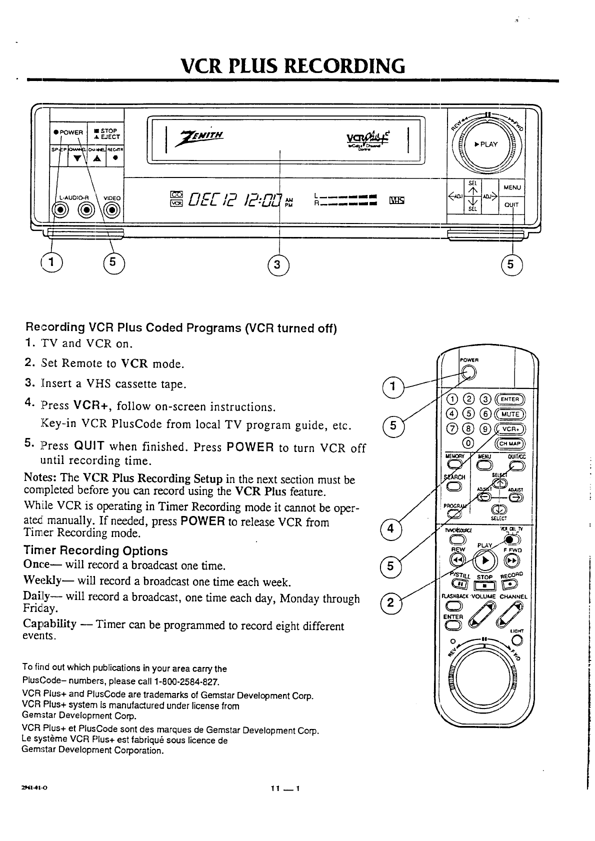
Recording VCR Plus Coded Programs (VCR turned off)
1. TV and VCR on.
2. ;Set Remote to VCR mode.
.
4.
Insert a VHS cassette tape.
Press VCR+, follow on-screen instructions.
Key-in VCR PlusCode from local TV program guide, etc.
5. ]Press QUIT when finished. Press POWER to turn VCR off
until recording time.
Notes: The VCR Plus Recording Setup in the next section must be
completed before you can record using the VCR Plus feature.
While VCR is operating in Timer Recording mode it cannot be oper-
ated manually. If needed, press POWER to release VCR from
Timer Recording mode.
Timer Recording Options
Once-- will record a broadcast one time.
Weekly-- will record a broadcast one time each week.
Daily-- will record a broadcast, one time each day, Monday through
Friday.
Capability _ Timer can be programmed to record eight different
events.
To find out which publications in your area carry the
PlusC,ode- numbers, please call 1-800-2584-827.
VCR Plus+ and PlusCode are trademarks of Gemstar Development Corp.
VCR Plus+ system Is manufactured under license from
Gem:star Development Corp.
VCR Plus+ et PlusCode sont des marques de Gemstar Development Corp.
Le syst_me VCR Plus+ est fabriqu6 sous licence de
Gemstar Development Corporation.
SEU"CT
leLASHSJt,CK VOLUMI= CHANNF:L
_l.41.o 1 1 -- 1
-r
VCR PLHS P -CORDING W TH A CABLZ BOX
I
r-,cr /2:CL7 .... -=
t
I
•I
mq
t
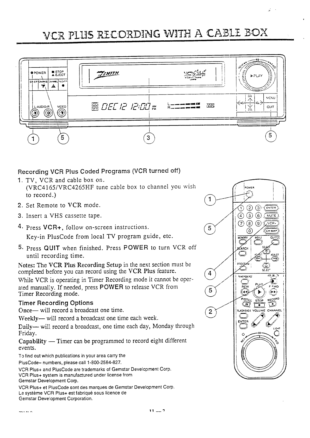
Recording VCR Plus Coded Programs (VCR turned off)
1. TV, VCR and cable box on.
(VRC4165/VRC4265HF tune cable box to ctlannel you wish
to record.)
2, Set Remote to VCR mode.
3. Insert a VHS cassette tape.
4. Press VCR+, follow on-screen instructions.
Key-in PlusCode from local TV program guide, etc.
5. Press QUIT when finished. Press POWER to turn VCR off
until recording time.
Notes: The VCR Plus Recording Setup in the next section must be
completed before you can record using the VCR Plus feature.
While VCR is operating in Timer Recording mode it cannot be oper-
ated manual],y. If needed, press POWER to release VCR from
Timer Recording mode.
Timer Recording Options
Once-- will record a broadcast one time.
Weetdy-- will record a broadcast one time each week.
Dailyn will record a broadcast, one time each day, Monday through
Friday.
Capability --- Timer can be programmed to record eight different
events.
To find out which publications in your area carry the
PlusCode- numbers, please call 1-800-2584-827.
VCR Plus+ and PlusCode are trademarks of Gemstar Development Corp.
VCR Plus+ system is manufactured under license from
Gemstar Development Corp.
VCR Plus+ et PlusCode sont des marques de Gemstar Development Corp.
Le syst_me VC,R Plus+ est tabriqu_ sous licence de
Gemstar Development Corporation.
i
...... 11 __'}
VCR PLHS RECORDING SETHP/Ste:p C
III
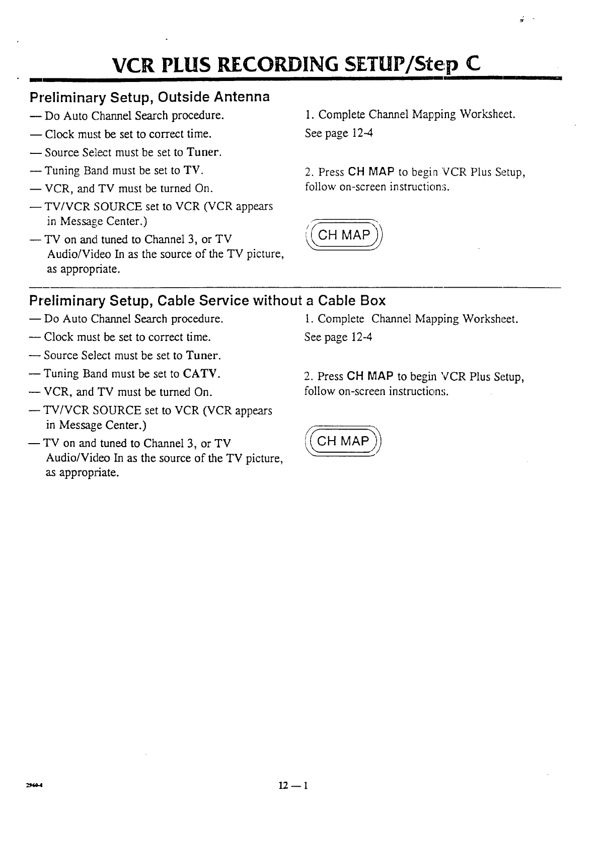
Preliminary Setup, Outside Antenna
m Do Auto Channel Search procedure.
-- Clock must be set to correct time.
Source Select must be set to Tuner.
-- Tuning Band must be set to TV.
-- VCR, and TV must be turned On.
TV/VCR SOURCE set to VCR (VCR appears
in Message Center.)
"IV on and tuned to Channel 3, or TV
Audio/Video In as the source of the TV picture,
as appropriate.
1. Complete C.hannel Mapping Worksheet.
See page 12-4
2. Press CH MAP to begin VCR Plus Setup,
follow on-screen instruction:;.
Preliminary Setup, Cable Service without a Cable Box
-- Do Auto Channel Search procedure.
Clock must be set to correct time.
Source Select must be set to Tuner.
-- Tuning Band must be set to CATV.
VCR, and TV must be turned On.
-- TV/VCR SOURCE set to VCR (VCR appears
in Message Center.)
-- TV on and tuned to Channel 3, or TV
Audio/Video In as the source of the TV picture,
as appropriate.
1. Complete C.hannel Mapping Worksheet.
See page 12--4
2. Press CH MAP to begfi_ VCR Plus Setup,
follow on-screen instructions.
12D1
VCR PLUS RECO ING SEeP/Step C
L
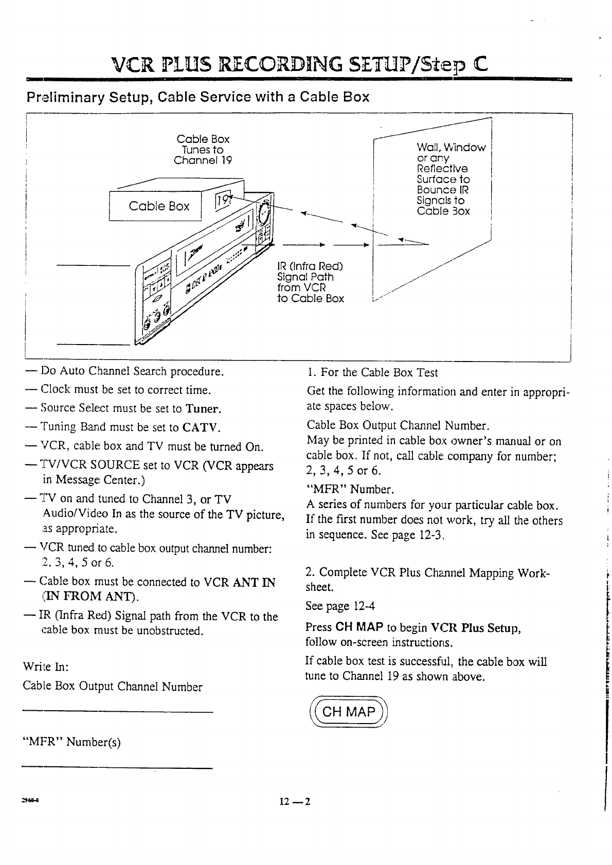
Preliminary Setup, Cable Service with a Cable Box
Cable Box [--J
Tunes to
Channel 19
IR (Infra Red)
Signal Path
from VCR
to Cable Box
Wall, Window
or any
Reflective
Surface to
Bounce IR
SignaLs to
Cable Box
_ .qlC_
I
13o Auto Channel Search procedure.
Clock must be set to correct time.
Source Select must be set to Tuner.
Tuning Bax_d must be set to CATV.
VCR, cable box and TV must be turned On.
w TV/VCR SOURCE set to VCR (VCR appears
in Message', Center.)
_.W on and tuned to Channel 3, or TV
Audio/Video In as the source of the TV picture,
:as approprSate.
VCR tuned to cable box output channel number:
2, 3, 4, 5 or 6.
Cab!e box must be connected to VCR ANT IN
ChNFROM ANT).
IR 0nfra Red) Signal path from the VCR to the
cable box must be unobstructed.
Write In:
Cable Box Output Channel Number
"Mt:'R" Number(s)
1. For the Cable Box Test
Get the following information and enter in appropri-
ate spaces below.
Cable Box Output Channel Number.
May be printed in cable box owner's manual or on
cable box. If not, call cable: company for number;
2, 3, 4, 5 or 6.
"MFR" Number.
A series of numbers for your particular cable box.
If the first number does not work, try all the others
in sequence. See page 12-3.
2. Complete VCR Plus Channel Mapping Work-
sheet.
See page 12--4
Press CH MAP to begin VCR Plus Setup,
follow on-screen instructions.
If cable box test is successful, the cable box will
tune to Channel 19 as shown above.
i
:_0-0 12 _ 2
m
VCR PLUS RECORDINGSETUP/Step C
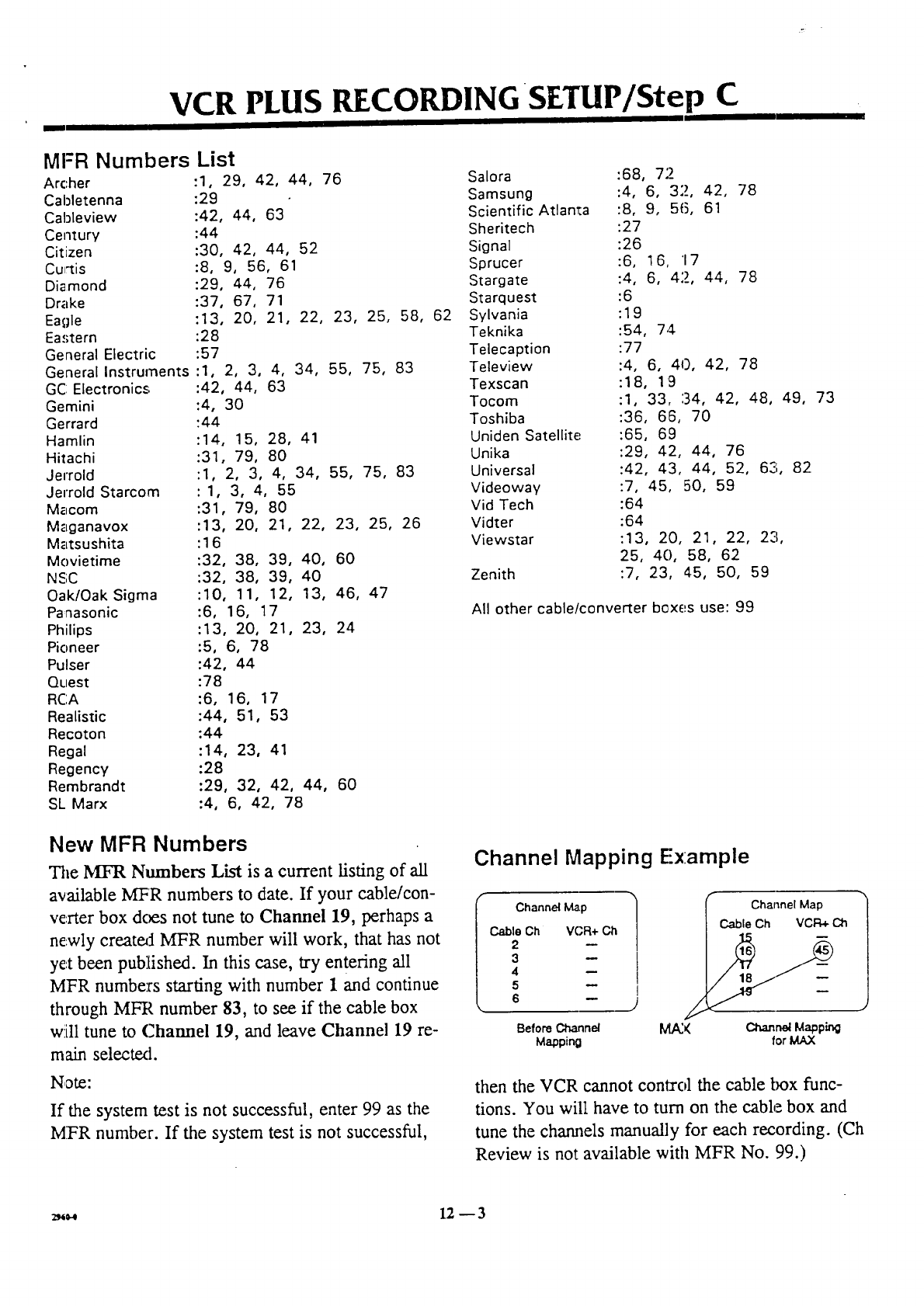
MFR Numbers List
Arc:her :1, 29, 42, 44, 76
Cabletenna :29
Cableview :42, 44, 63
Century :44
Citizen :30, 42, 44, 52
Cu,'tis :8, 9, 56, 61
Diamond :29, 44, 76
Drake :37, 67, 71
Eagle :13, 20, 21, 22, 23, 25, 58, 62
Eastern :28
General Electric :57
General Instrurnents :1, 2, 3, 4, 34, 55, 75, 83
GC Electronics :42, 44, 63
Gemini :4, 30
Gerrard "44
Hamlin :14, 15, 28, 41
Hitachi :31, 79, 80
Jerrold :1, 2, 3, 4, 34, 55, 75, 83
Jerrold Starcom :1, 3, 4, 55
Macom :31, 79, 80
Maganavox :13, 20, 21, 22, 23, 25, 26
Matsushita :16
Movietime :32, 38, 39, 40, 60
NSC :32, 38, 39, 40
Oak/Oak Sigma :10, 11, 12, 13, 46, 47
Panasonic :6, 16, 17
Philips :13, 20, 21, 23, 24
Pioneer :5, 6, 78
Pulser :42, 44
Qtlest :78
RCA :6, 16, 17
Realistic :44, 51, 53
Recoton :44
Regal :14, 23, 41
Regency :28
Rembrandt :29, 32, 42, 44, 60
SL Marx :4, 6, 42, 78
Salora :68, 7"2
Samsung :4, 6, 32, 42, 78
Scientific Atlanta :8, 9, 56, 61
Sheritech :27
Signal :26
Sprucer :6, 16, '17
Stargate :4, 6, 42, 44, 78
Starquest :6
Sylvania : 19
Teknika :54, 74
Telecaption :77
Teleview :4, 6, 40, 42, 78
Texscan :18, 19
Tocom :1, 33, :34, 42, 48, 49, 73
Toshiba :36, 66, 70
Uniden Satellite :65, 69
Unika :29, 42, 44, 76
Universal :42, 43, 44, 52, 621, 82
Videoway :7, 45, 50, 59
Vid Tech :64
Vidter :64
Viewstar :13, 20, 21, 22, 23,
25, 40, 58, 62
Zenith :7, 23, 45, 50, 59
All other cable/converter boxes use: 99
New MFR Numbers
The MFR Numbers List is a current listing of all
available MFR numbers to date. If your cable/con-
verter box does not tune to Channel 19, perhaps a
ne.wly createA MFR number will work, that has not
yet been published. In this case, try entering all
MFR numbers starting with number 1 and continue
through MFR number 83, to see if the cable box
will tune to Channel 19, and leave Channel 19 re-
main selectext.
Note:
If the system test is not successful, enter 99 as the
MT:R number. If the system test is not successful,
Channel Mapping E'x:ample
I Channel Map
Cable Ch VCR+ Oh
2
3
4
5
6
Before Channel
Mapping
Channel Map
Cable Ch VCFI_ Cih
34
C_r'_ Mapping
for MAX
then the VCR cannot conta'ol the cable box func-
tions. You will have to turn on the cable box and
tune the charmels manually for each recording. (Ch
Review is not available with MFR No. 99.)
_12 _ 3
VCR Plus Channel Mapping Worksheet
I
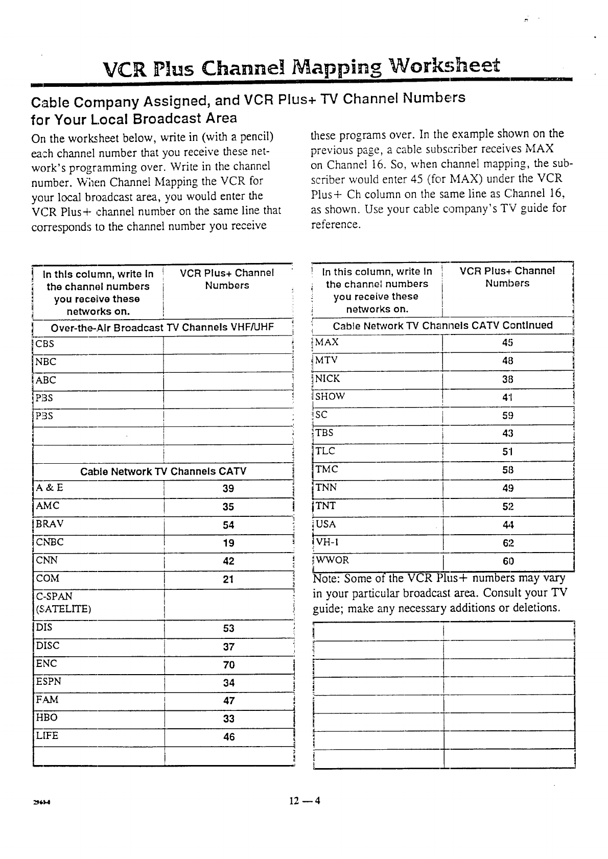
Oable Company Assigned, and VCR Plus+ TV Channel Numbers
fer Your Local Broadcast Area
On the worksheet below, write in (with a pencil)
each channel number that you receive these net-
work's programming over. Write in the channel
number. Wimn Channel Mapping the VCR for
your local broadcast area, you would enter the
VCR Plus+ channel number on the same line that
corresponds to the channel number you receive
these programs over. In the example shown on the
previous page, a cable subscriber receives MAX
on Channel 16. So, when channel mapping, the sub-
scriber would enter 45 (for MAX) under the VCR
Plus+ Ch column on the same line as Channel 16,
as shown. Use your cable company's TV guide for
reference.
In this column, write In VCR Plus+ Channel
the channel numbers Numbers
you recetve these
networks on.
Over-the-Air Broadcast TV Channels VHF/UHF
GBS
NBG
ABG
-_13s I
-_'3s !
I
t
Cable Network'IV Channels CATV
A&E i 39
AMC 35
BRAV 54
_,'_c 19
i
_c_ i 42
OM I 21
[C-SPAN I
[(£ATELITE) I
DIS 53
DISC 137
ENC t 70
ESPN 34
F.AM i47
HBO 33
LIFE 46
In this column, write In VCR Plus4. Channel
the channe',l numbers Numbers
iyou receive these
_networks on.
, Cable Network TV Channels CATV Continued
i
i MA× [
i
i_' itMTV .l 48
!!_iSHOW 41
, SC i 5!)
I
T
TBS t 43
I 51
TLC
TMC 58
! TNN 49
1 TNT 52
;i :b
::_USA 44
i VH-I 62
:,t
WWOR 61)
I Note: Some of the VCR Plus+ numbers may vary
in your particular broadcast area. Consult your TV
i
;I guide; make any necessary additions or deletions.
! ;i t
i =
,
_,_ 12 -- 4
ADD T]ONAL ]N OR ]AT ON
AUX Channel (Use to Play or Record from Accessory System Components)
(Connected to the VCR Audio/Video In Jacks)
Step 1. Press MENU. Press ADJUST Left/Right
r,_F_,,_dlv_,_._ -. t,-,._choose _--£_TTTP-__ press MENU.
Step 2. Use SELECT Up/Down to choose
SOUR CE S ELECT.
Step 3. Use ADJUST Left!Right to specify AUX.
This sets up the VCR to receive the signal from the
system component (Video Disk Player, Hi-Fi Ste-
rex), TV, Video Camera, Camcorder another VCR
etc.,) connected to the VCR AUDIO/VIDEO IN
(Rear or Front) connection jacks.
Note: When finished with the AUX char_nel, use
the previously described method to choose
TUNER.
AUX Channel Direct Access
Another method of choosing the AUX channel is to
use CHANNEL Up/Down. The AUX Channe!, is
the lowesffhighest number in the channel scan.
When you wish to return to normal VCR opera-
tion, simply use CHANNEL up/down to choose a
different channel.
Index Search (Use to access each recorded
Each time a recording starts, the VCR marks that
location with an index mark; Index i, Index 2, In-
dex 3, etc. These locations can then be accessed by
using the Search mode. (From the Stop or Play
mcxte) Press SEARCH to begin Index Search
mcxte.
segment's beginning)
For example, :rewind the tape to the beginning.
Press SEARCH. To advance the tape to Index loca-
tion three, follow on-screen instructions, then press
3. The tape will move to recording start Index loca-
tion 3 and start playback. Note: This feature only
works with tapes recorded on this VCR.
Real-Time Tape Counter
The Real-Time Tape Counter will only count re-
corded segments on VHS cassette tapes. If the on-
screen tape counter stops at a location while the
tape is moving, then the recorded segments have
ended and blank segments are being passed over at
that location on the tape; the Real-Time Tape
Counter will not count the blank (unrecorded) seg-
ments of a tape.
MEMORY-- Press while a tape is being played or
recorded, to zero the Real-time tape counter. If
you activate the Counter Memory feature, the VCR
will automatically stop at the M 0:00:00 position
when the tape is rewound.
Special Menu
_AUTO CLOCK SET On/Off.
_AUTO DAYLIGHT SAVINGS Adjustment
On/Off.
Step 1. Press MENU to place VCR Main Menu on
TV screen.
Step 2. Press 4567 to access the Special Menu.
Use SELECT and ADJUST keys to choose and
specify:
Auto Clock Set On-- VCR will automatically set
the clock.
Auto Daylight Savings A(justment On-- VCR wiU
automatically :adjust the VCP.. clock for Daylight
savings time.
Press QUIT when finished.
Note: Choose one option .--Auto Clock Set and
Auto Daylight Savings cannot be active at the same
time.
Auto Tape Recording Speed Switching
While recording in SP (Standard Play) mode, if the
VCR detects a shortage of tape necessary to com-
plete the recording in SP mode it will automatically
switch to EP (Extended Play) mode to complete the
recording assignment.
-_,,._ 1Z -- 1
t
ADD. IHONAL N O,R IA' ON
ALIdio Record Mode
Step 1. Press MENU. PressADJUST Lea/Right
ret:eatedly to choose AUDIO, press MENU.
Step 2. Use SELECT Up/Down to specify
AUDIO RECORD MODE.
Step 3. Use ADdUST Left/Right arrows to spec-
ify:--STERF;O, MONO or 2ND AUDIO.
Stereo-- Records sound frora the left and right
sound tracks as supplied by the program source.
Mono (Monaural)--Record:; Monaural sound only.
2nd Audio-- Records the 2nd Audio sound track,
if available.
Audio Playback Mode
Step 1. Press MENU. Press ADJUST Left/Right
repeatedly to choose AUDIO, press MENU.
Sa:p 2. Use SELECT Up/Down to specify
AUDIO PLAYBACK MODE.
Step 3. Use ADJUST Left/Right arrows to spec-
ify:--Hi-Fi, or Normal.
Hi-Fi m Sound will be heard in Stereo, if available.
Normal-- Sound will be heard in Monaural,
whether Audio source is Stereo, Monaural or 2nd
Audio.
Notes: Broadcast programs can be heard in Stereo
as supplied by the broadcast signal to the TV
Tuner. However, to hear Stereo sound from the
VCR Tuner or during tape: Flayback, you must use
the VCR AUDIO/VIDEO Cut jacks as the source.
The TV, or sound source, must be set up to use (as
the picture and sound source) the TV Audio/Video
In jacks. Only the VCR Audio/Video Out jacks pro-
vide Stereo output for a tape:playing in the VCR.
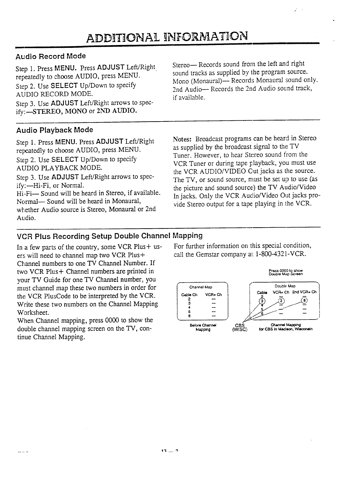
VCR Plus Recording Setup Double Channel Mapping
For further information on this special condition,
call the Gemstar company a_:1-800-4321-VCR.
In a few part_; of the country, some VCR Plus + us-
ers will need to channel map two VCR Plus+
Channel numbers to one TV Channel Number. If
two VCR Plus+ Channel numbers are printed in
your TV Guide for one TV Channel number, you
must channel map these two numbers in order for
the VCR PlusCode to be interpreted by the VCR.
Write these two numbers on the Channel Mapping
Worksheet.
When Channel mapping, press 0000 to show the
double channel mapping screen on the TV, con-
tinue Channel Mapping.
I Channel Map
Cable Ch VCR+ Ch
2--
3--
Befo_ Channel
f_plng CBS
(WlSC)
Press 0(300 to show
Double M;q:) Screen
Double Map C_ 1
VCR+ Ch 2r',dVCP,+
__ !
}
I_ CBS In M_I_. _n
5ERVJ F_..:F_.
]N$O tA71©N
i
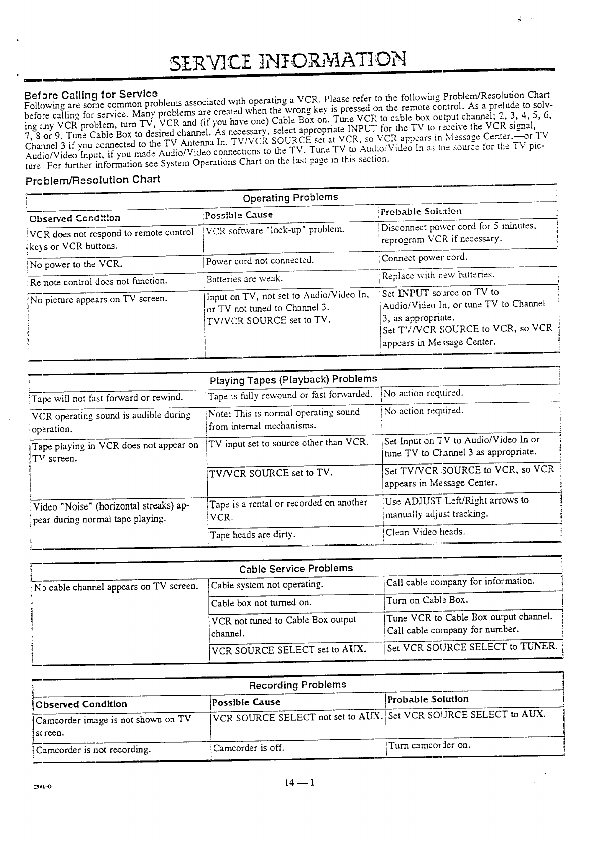
Before Calling for Service
Following are some common problems associated with operating a VCR. Please refer to the following ProblerrdResoi[udon Chart
before callin__ for se_'ice. Many problems are created when the wrong key is pressed on the remote control. As a prelude to sob-
i.ng zmy VCRTproblem, turn TV, VCR and (if you have one) Cable Box on. Tune VCR to cable box output channel; 2, 3, 4, 5, 6,
7, 8 or 9. Tune Cable Box to desired channel. As necessary.', select appropriate INPL-F for the TV to r_.ceive the VCR sig'nal,
Channel 3 if you c.onnected to the TV Antenna In. TV/VCR SOURCE set at VCR, so VCR appears in Message Center.---or TV
Audio/Video'Input, if you made Audio!Video connections to the TV. Tune TV to Audio:Video In .-1-.;the source for ti:e TV pic-
ture For further information see System Operations Chart on the last page in this section.
Problern_esolutlon Chart
i Operating Problems !
-I
,.¢nd,,.on iPoss,ol _ Cause':Observed i.- t,, ', -,, iProbable Solt._!on
VCR I
!VCR does not respond to remote control software "lock-up" problem. IDisconnect power cord for 5minutes,
'ikeys or VCR buttons. !reprogram VC R if necessary, i
No power to the VCR. IPower cord not connected, iCormect power cord.
!
_Remote control does not function, iBatteries are weak. iReplace with new batteries.
!No_ picture appears on TV screen. Input on TV, not set to Audio;Video In, lSet, .hNPUT. source on TV to :
_or TV not tuned to Channel 3. Audlo/V,deo In, or tune TV to Channel i
! TV/VCR Set "
i SOURCE set to TV. 3, as approFriate. ,
'; TV/VCR SOURCE to VCR, so VCR 1
:' lappears in Message Center. _
I i .....
Playing Tapes (Playback) Problem.,; 'i
I
!Tape will not fast forward or rewind, iTape is fully rewound or fast forwarded.
VCR operating sound is audible during Note: This is normal operating sound
operation, tfrom internal mechanisms.
TV input set to source other than VCR.iTape playing in VCR does not appear on
:!'IW screen.
:Video "Noise" (horizontal streaks) ap-
ipear during normal tape playing.
TV/VCR SOURCE set to TV.
Tape is a rental or recorded on another
VCR.
Tape heads are dirt','.
1 "
!No action required.
iNo action required.
Set Input on "rv to Audio/Video In or
tune TV to Cl'_annel 3 as appropriate.
SetvwvcK g2, Vcp,
appears in Messa=e_,, Center.
1
!Use ADJUST LefdRight arrows to
imanually adjust tracking.
iClean Video heads.
1
'l
I
i No cable cha_el appears on TV screen.
i
a
i
I
L
Cable Service Problems
_ ystem not operating.
box not turned on.
VCR not tuned to Cable Box output
channel.
VCR SOURCE SELECT set to AUX.
i
Call cable company for info:mation, l
1
Turn on CaN _ Box. j
1
iTune VCR to Cable Box oul,put channel, i
!Call cable company for number. ]
!Set VCR SOURCE SELECt to TUNER. i
Observed Condition
tCamcorder irmige is not shown on TV
t screeQ.
Camcorder is not recording.
Recording Problems
Possible C_use IProbable :Solution
VCR SOURCE SELECT not set to AUX. _Set VCR SOURCE SELECT
Camcorder is off. Turn camcorrler on.
i
to AUX.
_*t-o 14 _ 1
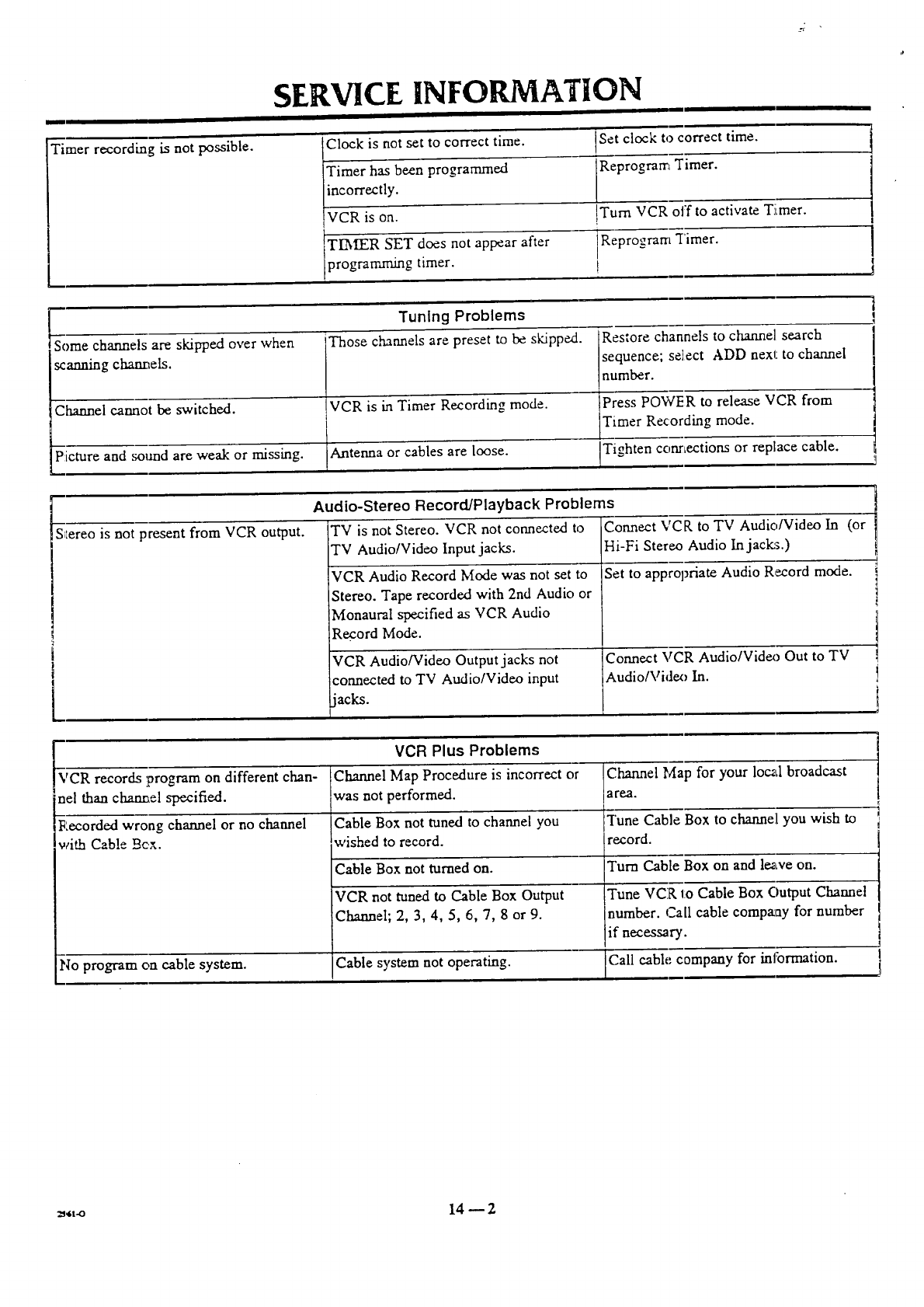
SERVICE INFORMATION
Timer recording is not possible. not set to correct time.
linco_ectly.
IVCR is on.
TIMER SET does not appear after
programming timer.
Set clock to correct time.
Reprogram Timer.
!Turn VCR off to activate Timer.
Reprogram Timer.
!
Tuning Problems
Somechannels are s_Fpe.x:loverwhen Those cMrmelsare presetto be s_ppe.d. Restore channels to c_'me] search
scaz_mg ch,_me[s, sequence; select ADD next to charnel
number. _......
Channel cannot be switched. VCR is in Timer Recording mode. Press POW'FR to release VCR from
Timer Recording mode.
Picture and solmd are weak or missing. Antenna or cables are loose. Tighten conrtections or replace cable.
Audio-Stereo Record/Playback Problems
S_Iereois not present from VCR output. TV is not Stereo. VCR not connected to
TV Audio/Video Input jacks.
VCR Audio Record Mode was not set to
Stereo. Tape recorded with 2nd Audio or
Monaural specified as VCR Audio
Record Mode.
VCR Audio/Video Output jacks not
connected to TV AudiolVideo input
jacks.
Connect VCP, to TV Audio/Video In (or
Hi-Fi Stereo Audio In jacks.)
Set to appropriate Audio Record mode.
Connect VCR AudiolVideo Out to TV
Audio/Videx_ In.
VCR records program on different chan-
nel than chan_,el specified.
Recorded wrong channel or no channel
with Cable Bcx.
VCR Plus Problems
Channel Map Procedure is incorrect or
was not performed.
Cable Box not tuned to channel you
wished to record.
Cable Box not turned on.
VCR not tuned to Cable Box Output
Channel; 2, 3, 4, 5, 6, 7, 8 or 9.
No program on cable system. Cable system not operating.
Channel Map for your local broadcast
a rP..a.
Tune Cable Box to channel you wish to
record.
Turn Cable Box on and leave on.
Tune VCR to Cable Box Output Channel
number. Call cable compa_ay_,for number
if necessary.
Call cant; company for information.
!
=,Jt-o 14 _ 2
SERVICE INFORMATION
MAINTENANCE
Auto Head Cleaning]Video Head Cleaning
The VCR automatically cleans the heads as it is used. However after long periods of use, the video heads
may become clogged with accumulated dirt, causing distortion. When this occurs, t_se do-it-yourself wet
head cleaning cassettes available through your nearest Circuit City Store or Service Center.
Caution: Do not use dry head cleaning systems. They may seriously damage both the video recorder and
cassette. When visual signs appear (snow, streaking in picture and horizontal pullin.g of picture) indicating
the need for video head cleaning, please see your nearest Circuit City Store or Setvice Center.
Cabinet Cleaning
Tae outside _;urfaces of the VCR may be cleaned with a soft lint-free cloth as required. Use care not to
scratch the VCR during cleaning.
:_.-o 14 -- 3
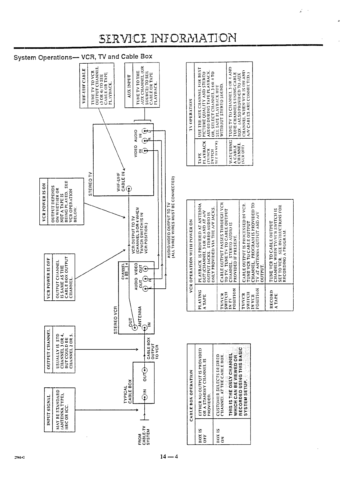
3ZR.%qCZ
System Operatlons-- VCR, TV and Cable Box
O--
=b
= £
z
U _zo_u_
o
g
\
Z ozo_:
o__-
o
>
u. rn
>
c z__
_/ --v
0 D_Z
>
g
>
o
,=,
e4
<Z_Z
,v ._
Z>-
C
,.1
Z
N
z
_- _0
a.J
_.-w &9 (n
D D" t_ O
07O
_ °g_-"
o©_
;=
%.?=
juu)--
..Ion
"5 .a f--
O_n
t_<>-
u. o _t_
]N ..O %IAT]ON
z
g_ .
_=__ - _
_ _z_
_>_ _ zO
E
uJ
u,t
7
-7
o
,,<
z
> './
>.-'u
< -
<o_
_-_r-
_z
p.,
:_
O0
m_m
_.Z_
Z
>_zO
:,.di::::::!Y,1_& !:i:::
F. °
- = :z ,_ _ : :
z _ 5
• . f.- U ::_
_,_ :-=_ _ _::
-_r--am= V.
>-
I
I..- _; =:: {;t)
U
._,_ 14 -- 4
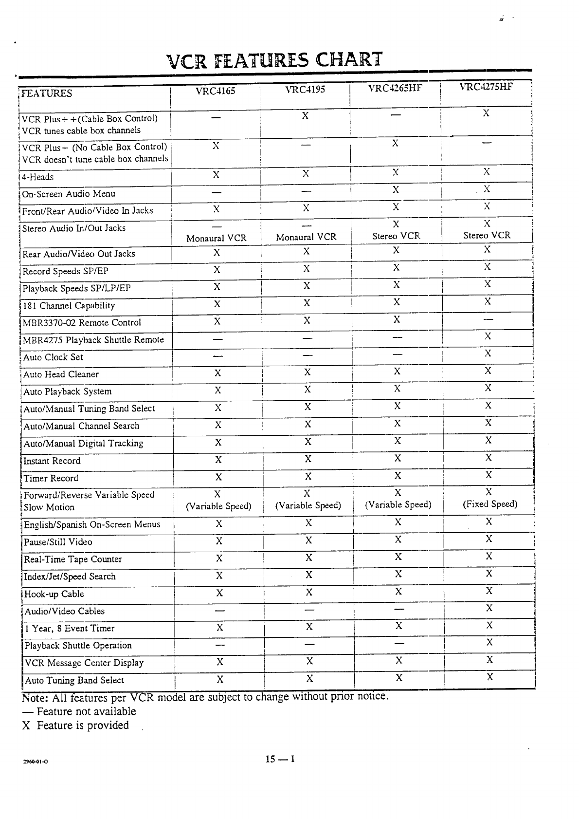
VCR IFEATHR CHART
i FEATURES
VCR Plus + + (Cable Box Control)
IVCR cable box channels
tunes
!VCR Plus + (No C_.ableBox Control)
i VCR doesn't tune cable box channels
r
!4-Heads
lOn-Screen Audio Menu
_Front/Rear Audio/Video In Jacks
Stereo Audio In/Out Jacks
l Rear Audio/Videx_ Out Jacks
t Record Speeds SP/EP
!Playback Speeds SP/LP/EP
181 Channel Capability
IMBR3370-02 Remote Control
IMBR4275 Playback Shuttle Remote
i Auto Clock Set
I'
_Auto Head Cleaner
!1Auto Playback System
Auto/Manual Ttmmg Band Select
Auto/Manual Channel Search
kuto/Manual Digital Tracking
nst_m Record
Timer Record
_Forward/Reverse Variable Speed
Slow Motion
English/Spanish On-Screen Menus
Paine/Still Video
Real-Time Tape Counter
Index/Jet/Speed Search
Hook-up Cable
1Audio/Video Cables
1 Year, 8 Event;Fimer
iPlayback Shuttle Operation
VCR Message Center Display
[ VRC4165
[
i
VRC4195 VRC4265Hl? VRC4275ttF
X
X m
X -- X --
XX
X
Xi
Monaural VCR
X
X
X
X
X
I
I
i
X
X
Monaural VCR
X
X
X
X
X
i
I
I
i
I
X
X
X
X
X
X
X
X
(Variable Speed)
X
X
X
X
X
X
t
X
X
X
X
Stereo VCR
X
X
X
X
X
X
X
Stereo VCR
X
D
X
X
X
X
X
X
X
X
(Variable Speed)
X
X
X
X
X
X
X
X
X
X
X
X
X
X
!X
I
X
i x
1
, X
: X
L
t (Fixed Speed)
X
X
X
X
X
X
X
X
! X
X
-- i X
i
I
X
X
t x
X
[ (Variable Speed)
t
F X
i
X
t x
I
_ X
I-
1X
X
X
X X
X
Auto Tuning Band Select X X
Note: All features per VCR model are subject to change without pnor nouce.
-- Feature not available
X Feature is provided
i
,r
__.01-o 15 _ 1
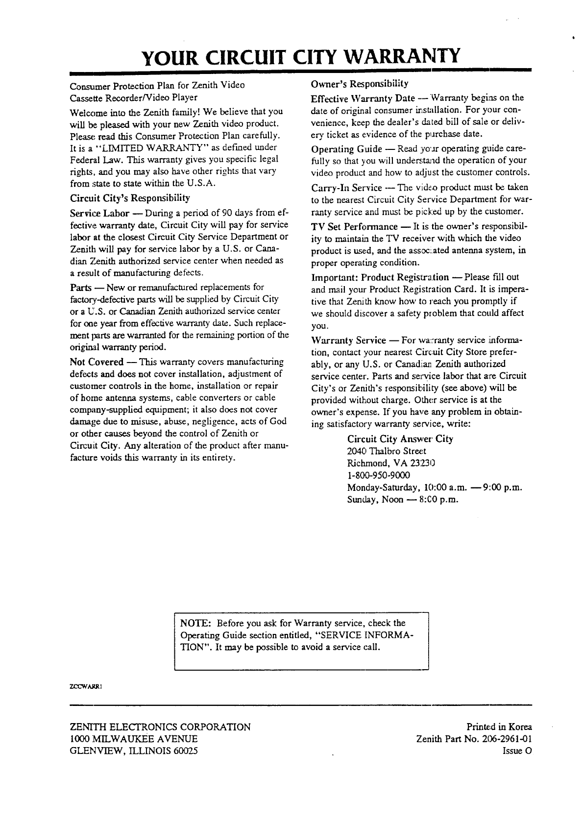
YOUR CIRCUIT CITY WARRANTY
Consumer Protection Plan for Zenith Video
Cassette Recorder/Video Player
Welcome into the Zenith family! We believe that you
will be pleased with your new Zenith video product.
Please read this Consumer Protection Plan carefully.
It is a "LIMITED WARRANTY" as def'med under
Federal Law. This warranty gives you specific legal
rights, and you may also have other rights that vary
from :state to state within the U.S.A.
Circuit City's Responsibility
Service Labor -- During a period of 90 days from ef-
fective warranty date, Circuit City will pay for service
labor at the closest Circuit City Service Department or
Zenith will pay for service labor by a U.S. or Cana-
dian Zenith authorized service center when needed as
a result of manufacturing defects.
Parts -- New or remanufactured replacements for
factory-defective parts will be supplied by Circuit City
or aU.S. or Canadian Zenith authorized service center
for one year from effective warranty date. Such replace-
ment parts are warranted for the remaining portion of the
original warranty period.
Not C.overed m This warranty covers manufacturing
defects and does not cover installation, adjustment of
customer controls in the home, installation or repair
of home antenna systems, cable converters or cable
company-supplied equipment; it also does not cover
damage due to misuse, abuse, negligence, acts of God
or other causes beyond the control of Zenith or
Circuiit City. Any alteration of the product after manu-
facture voids this warranty in its entirety.
Owner's Responsibility
Effective Warranty Date --Warranty begins on the
date of original consumer irtstallation. For your con-
venience, keep the dealer's dated bill of sale or deliv-
ery ticket as evidence of the purchase date.
Operating Guide -- Read yo'ar operating guide care-
fully so that you will under;tread the operation of your
video product and how to adjust the customer controls.
Carry-In Service --The video product must be taken
to the nearest Circuit City Service Department for war-
rarity service and must be picked up by the customer.
TV Set Performance m It is the owner's responsibil-
ity to maintain the TV receiver with which tbe video
product is tw,ed, and the associated antenna system, in
proper operating condition.
Important: Product Regisl:r._.tion _ Please f'dl out
and mail your Product Registration Card. It is impera-
tive that Zenith know how to reach you promptly if
we should discover a safety problem that could affect
you.
Warranty Service -- For wa::ranty service ihaforma-
tion, contact your nearest Circuit City Store prefer-
ably, or any U.S. or Canadiiar Zenith authorized
service center'. Parts and service labor that a_reCircuit
City's or Zenith's responsibility (see above) will be
provided without charge. Other service is at the
owner's expense. If you have any problem in obtain-
ing satisfactory warranty service, write:
Circuit City Answer City
2040 Thalbro Street
Richmond, VA 23Z30
1-800-950-9000
Monday-Saturday, 10:00 a.m. _ 9::00 p.m.
Sunday, Noon _ 8:C0 p.m.
NOTE: Before you ask for Warranty service, check the
Operating Guide section entitled, "SERVICE INFORMA-
TION". It may be possible to avoid a service call.
ZO2WARRI
ZENrTH ELECTRONICS CORPORATION
1000 MILWAUKEE AVENUE
GLENVIEW, ILLINOIS 60025
Printe:d in Korea
Zenith Part No. 206-2961-01
Issue O
