ZF Autocruise France AC20 Vehicle mounted field disturbance sensor User Manual PRO SPC 276 B
0013393723, AUTOCRUISE S.A. Vehicle mounted field disturbance sensor PRO SPC 276 B
User Manual
Report No : PRO_SPC_276
Issue : B
Date : 06/06/2005
Commercially Confidential
Ce document n’est maîtrisé que s’il est identifié “copie maîtrisée” ou examiné d’une zone autorisée du système informatique
d’Autocruise. Les informations contenues dans ce document sont la propriété d’Autocruise SA et ne peuvent être utilisés par une
tierce partie sans l’accord écrit d’Autocruise SA
Page 1 sur 14 S01-010_A
AC20 User Manual
Background & Summary
Background
AUTOCRUISE / TRW is an established player in the ACC market place. The
purpose of the ACC system is to provide an extension to cruise control and to
control the vehicle’s speed, in accordance with a driver’s set speed, or
headway, taking account of the traffic conditions.
Summary
This document provides the potential user with information about the top level
functionality of this AC20 radar sensor to be fitted on a vehicle by a car or
truck manufacturer
Approvals
Name
Signature
Date
Author:
(Last issue)
P.MALLEJAC
Project Manager, Autocruise
02/05/05
Checked by:
Approved
by:

Report No : PRO_SPC_276
Issue : B
Commercially Confidential
Ce document n’est maîtrisé que s’il est identifié “copie maîtrisée” ou examiné d’une zone autorisée du système informatique
d’Autocruise. Les informations contenues dans ce document sont la propriété d’Autocruise SA et ne peuvent être utilisés par une
tierce partie sans l’accord écrit d’Autocruise SA
Page 2 sur 14 S01-010_A
Printed 06-Jun-05
Release History
Issue Date Author Details
A 02/05/05 P. MALLEJAC First issue
B 06/06/05 P. MALLEJAC Section 6.2 completed

Report No : PRO_SPC_276
Issue : B
Commercially Confidential
Ce document n’est maîtrisé que s’il est identifié “copie maîtrisée” ou examiné d’une zone autorisée du système informatique
d’Autocruise. Les informations contenues dans ce document sont la propriété d’Autocruise SA et ne peuvent être utilisés par une
tierce partie sans l’accord écrit d’Autocruise SA
Page 3 sur 14 S01-010_A
Printed 06-Jun-05
Table of Contents
APPROVALS.......................................................................................................................................... 1
1 SCOPE............................................................................................................................................. 4
2 SAMPLE SYSTEM SCHEMATIC ..............................................................................................5
2.1 ACC SYSTEM COMMUNICATIONS STRATEGY............................................................................5
3 ACC VEHICLE SYSTEMS COMMUNICATIONS ..................................................................6
4 CONFIGURING THE ACC SYSTEM ........................................................................................ 6
4.1 INITIAL CONFIGURATION...........................................................................................................6
4.2 ELECTRICAL INTERFACE............................................................................................................6
4.2.1 Power Supply....................................................................................................................6
4.3 MECHANICAL DESCRIPTION ......................................................................................................8
4.3.1 AC20 Sensor Illustrations.................................................................................................8
4.4 OUTLINE DRAWING ...................................................................................................................8
4.4.1 Sensor Alignment Process ..............................................................................................10
4.4.2 Radar Alignment Principles ...........................................................................................10
5 INSTALLATION ......................................................................................................................... 12
6 WARNINGS / STATEMENTS ................................................................................................... 14
6.1 WARNING REQUIRED BY 15.21 ................................................................................................14
6.2 STATEMENT REQUIRED BY 15.19 AND RSS210 .......................................................................14
6.3 STATEMENT REQUIRED BY 15.105 ........................................................................................... 14
7 REFERENCES ............................................................................................................................. 14

Report No : PRO_SPC_276
Issue : B
Commercially Confidential
Ce document n’est maîtrisé que s’il est identifié “copie maîtrisée” ou examiné d’une zone autorisée du système informatique
d’Autocruise. Les informations contenues dans ce document sont la propriété d’Autocruise SA et ne peuvent être utilisés par une
tierce partie sans l’accord écrit d’Autocruise SA
Page 4 sur 14 S01-010_A
Printed 06-Jun-05
1 Scope
Autocruise/TRW is an established player in the ACC market place. This
document provides a product summary of the AC20 sensor that is suitable for
integration into cars and trucks.
The products offered will be comfort assistance ACC system, as well as
providing some meaningful steps along the road to driver warning systems.
This document provides the user with information about the top functionality
of this AC20 radar sensor to be fitted on a vehicle by a car or truck
manufacturer
The AC20 radar sensor needs a number of inputs to allow it to function
correctly. These include the following
• Electrical Power
• Mounting instructions
• Yaw rate information
• Vehicle speed information
The data interface to the AC20 radar sensor is via a CAN communications
link.
Report No : PRO_SPC_276
Issue : B
Commercially Confidential
Ce document n’est maîtrisé que s’il est identifié “copie maîtrisée” ou examiné d’une zone autorisée du système informatique
d’Autocruise. Les informations contenues dans ce document sont la propriété d’Autocruise SA et ne peuvent être utilisés par une
tierce partie sans l’accord écrit d’Autocruise SA
Page 5 sur 14 S01-010_A
Printed 06-Jun-05
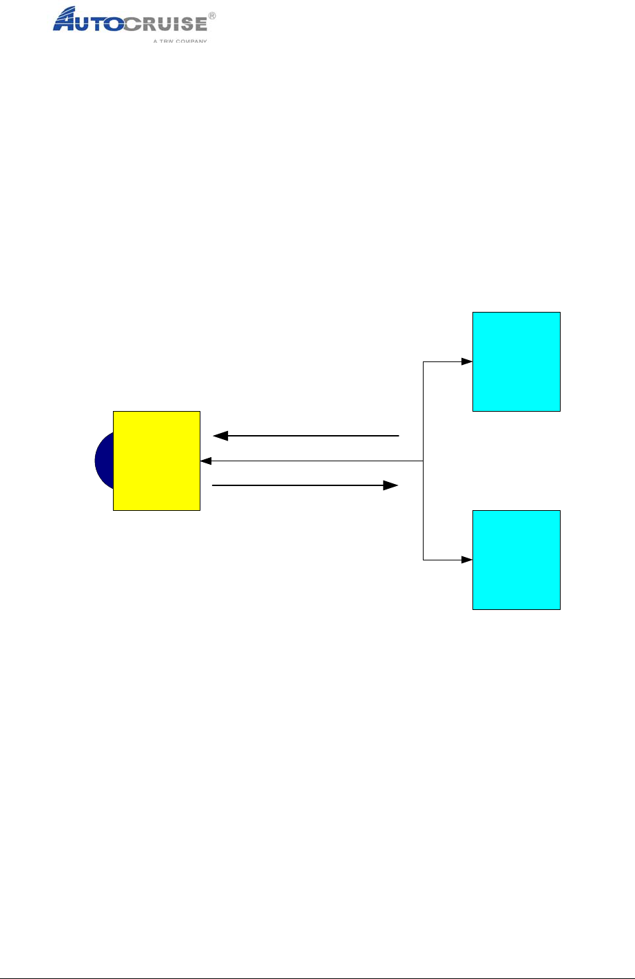
2 Sample System Schematic
An ACC system can be configured which will supply data that can be
monitored or used as an input to a control system to control a vehicle. It can
also be connected to a PC running the CCP protocol [Ref. 1] for re-
programming and monitoring what is happening inside the radar sensor.
The AC20 radar sensor requires yaw and vehicle speed data and will give out
the distances and speeds of the vehicles in front.
AC20
radar
sensor
Monitor
tool or
ACC
controller
PC
Vehicle Speed &
Yaw Rate
ACC targets &
Vehicle Information
CCP
Figure 1 - Sample System Schematic
2.1 ACC System Communications Strategy
At power up, the AC20 radar sensor will automatically report the speed and
relative velocity of vehicles sensed by the radar if it has received yaw and
vehicle speed data.
The radar requires the vehicle speed and vehicle yaw rate. This should be
transmitted to the radar at an update rate of between 20mSec to 40mSec.
This message is referred to as the vehicle dynamics message.
CAN interfaces are detailed in a separate document Ref. [2]. These CAN
interface can be customized according to customer’s requirements.

Report No : PRO_SPC_276
Issue : B
Commercially Confidential
Ce document n’est maîtrisé que s’il est identifié “copie maîtrisée” ou examiné d’une zone autorisée du système informatique
d’Autocruise. Les informations contenues dans ce document sont la propriété d’Autocruise SA et ne peuvent être utilisés par une
tierce partie sans l’accord écrit d’Autocruise SA
Page 6 sur 14 S01-010_A
Printed 06-Jun-05
3 ACC Vehicle Systems Communications
This protocol allows the ACC to be connected to an external longitudinal
controller or a monitoring device.
Vehicle speed and yaw rate are needed by the ACC radar sensor. These
must be transmitted to it via the CAN bus. The ACC radar then transmits a set
of messages describing vehicles in the ACC radar field of view. A message is
also transmitted by the ACC radar to indicate its status.
CAN interfaces are detailed in a separate document Ref. [2]. These CAN
interface can be customized according to customer’s requirements.
4 Configuring the ACC System
The AC20 radar sensor should to be mounted onto a vehicle, connected to a
power supply and CAN bus.
4.1 Initial Configuration
Initial configuration of the ACC system is achieved through the following
steps:
1. Mount the sensor on the front of the vehicle ensuring that the
connector is at the top or bottom.
NOTE: Do not mount side-ways.
2. Connect a 12v power supply (see section 3.2).
3. Connect to CAN bus and PC running CANape.
4. Set the mounting orientation parameter to either –1 (connector at
the top) or +1 (connector at the bottom) depending on mounting
orientation.
5. Set vehicles application parameter in the radar ACC radar.
6. Connect to system transmitting yaw rate and vehicle speed.
7. Align the sensor
Note that the AC20 radar sensor software will automatically compensate for
driving in left or right hand drive countries after several Km of driving in traffic.
4.2 Electrical Interface
4.2.1 Power Supply
The AC20 radar sensor is powered by a 12 V supply on ignition:
• Power current : < 2A (average 1.0 A)

Report No : PRO_SPC_276
Issue : B
Commercially Confidential
Ce document n’est maîtrisé que s’il est identifié “copie maîtrisée” ou examiné d’une zone autorisée du système informatique
d’Autocruise. Les informations contenues dans ce document sont la propriété d’Autocruise SA et ne peuvent être utilisés par une
tierce partie sans l’accord écrit d’Autocruise SA
Page 7 sur 14 S01-010_A
Printed 06-Jun-05
• Protection against over-current: 5 A delayed fuse (not provided).
Connections are made via one 10 way connector (FEP type 4209-13 10 way)
to the pins as indicated below:
Pin Function
2 Case GND
3 CAN Screen
4 CAN_H
5 CAN_L
9 GND
10 IGN+ (12V)
Do not use other pins.
Report No : PRO_SPC_276
Issue : B
Commercially Confidential
Ce document n’est maîtrisé que s’il est identifié “copie maîtrisée” ou examiné d’une zone autorisée du système informatique
d’Autocruise. Les informations contenues dans ce document sont la propriété d’Autocruise SA et ne peuvent être utilisés par une
tierce partie sans l’accord écrit d’Autocruise SA
Page 8 sur 14 S01-010_A
Printed 06-Jun-05
4.3 Mechanical Description
4.3.1 AC20 Sensor Illustrations
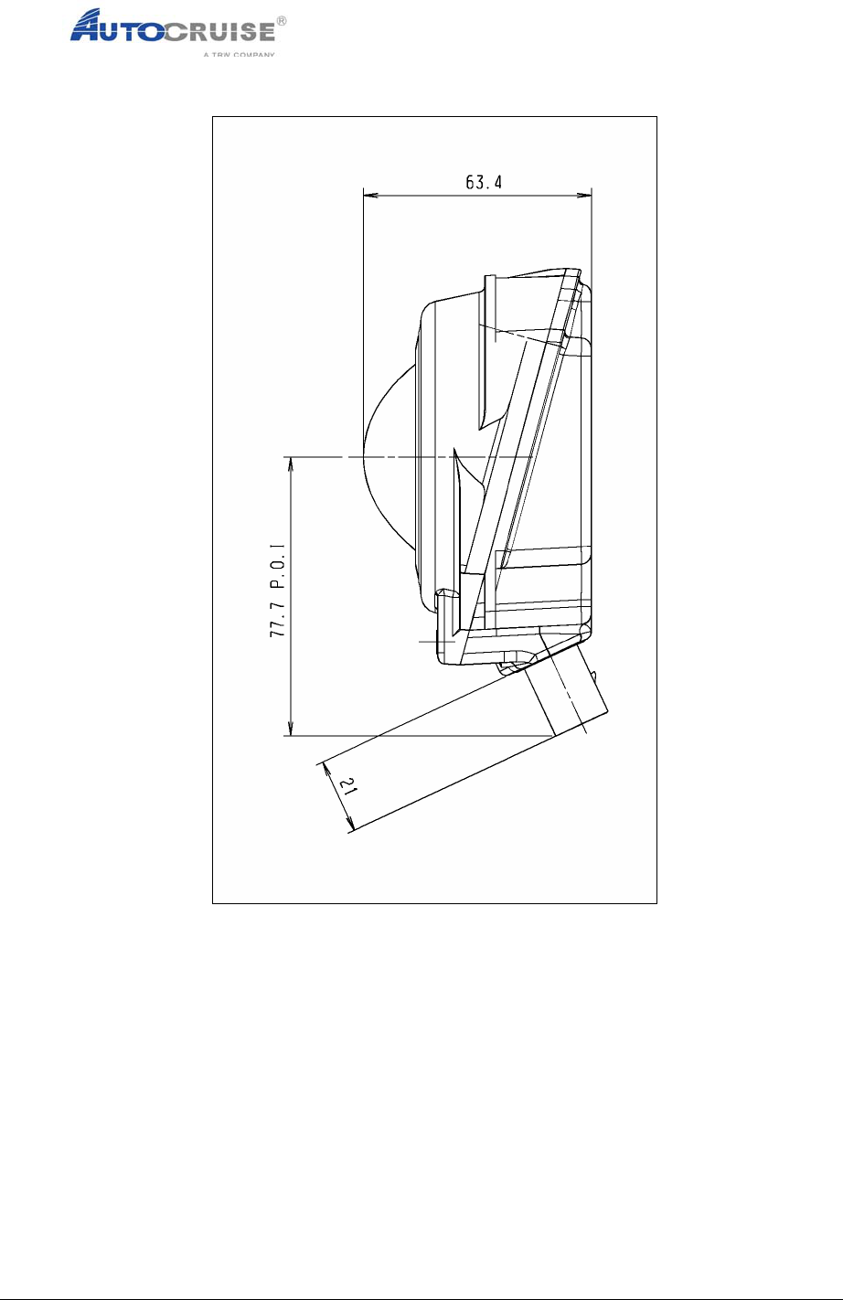
The AC20.1 L sensor has external dimensions of 98mm x 98mm x 63mm.
Three mounting “ears” are provided for attachment to the vehicle chassis.
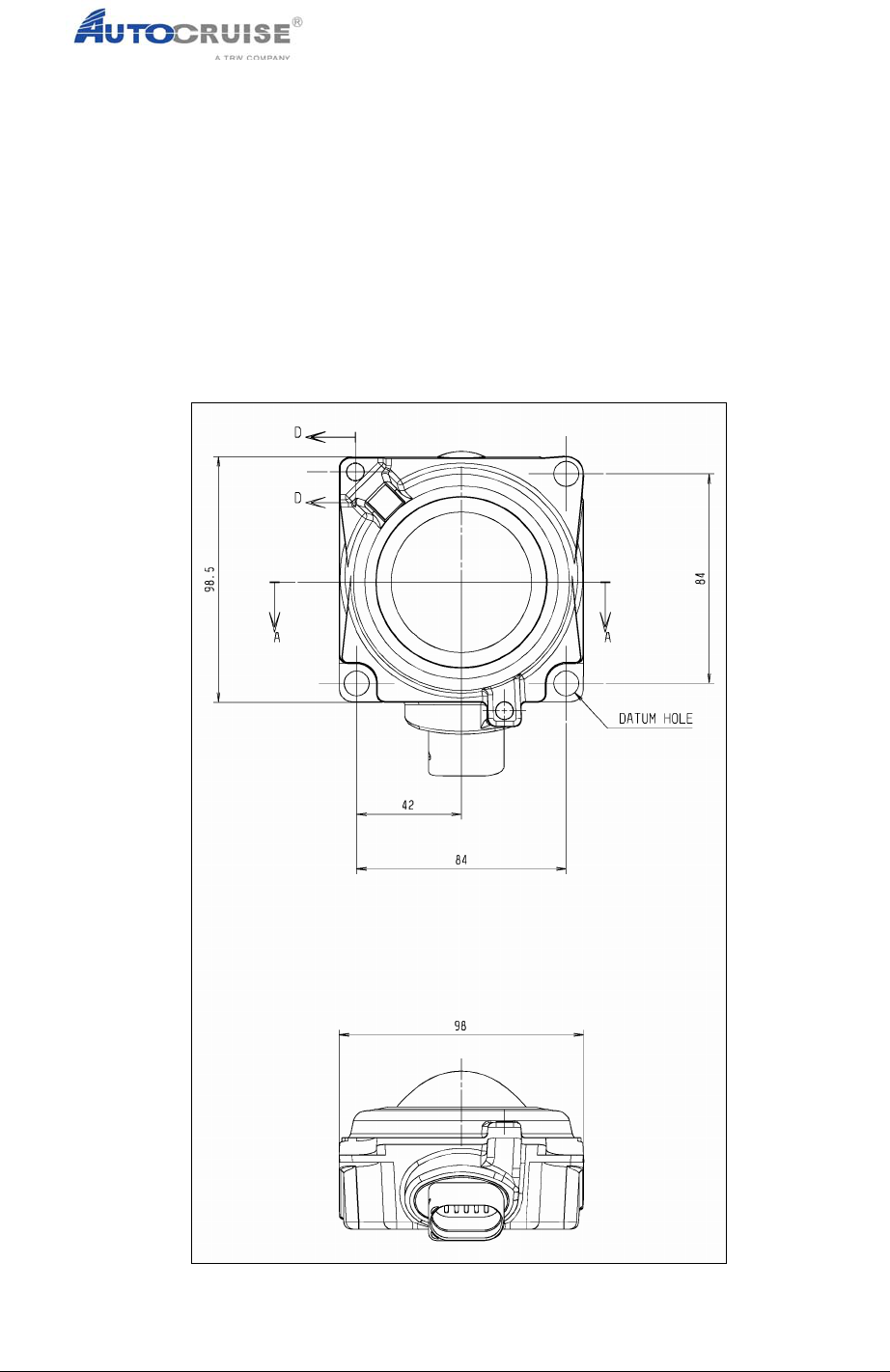
4.4 Outline Drawing
As per drawing 59306083A – ACC Outline Drawing for External use.
Mass – 500g
Figure 2 : AC20 Radar Sensor (Front View)
Report No : PRO_SPC_276
Issue : B
Commercially Confidential
Ce document n’est maîtrisé que s’il est identifié “copie maîtrisée” ou examiné d’une zone autorisée du système informatique
d’Autocruise. Les informations contenues dans ce document sont la propriété d’Autocruise SA et ne peuvent être utilisés par une
tierce partie sans l’accord écrit d’Autocruise SA
Page 9 sur 14 S01-010_A
Printed 06-Jun-05
Figure 3 - Sensor Dimensions (Side View)
Report No : PRO_SPC_276
Issue : B
Commercially Confidential
Ce document n’est maîtrisé que s’il est identifié “copie maîtrisée” ou examiné d’une zone autorisée du système informatique
d’Autocruise. Les informations contenues dans ce document sont la propriété d’Autocruise SA et ne peuvent être utilisés par une
tierce partie sans l’accord écrit d’Autocruise SA
Page 10 sur 14 S01-010_A
Printed 06-Jun-05
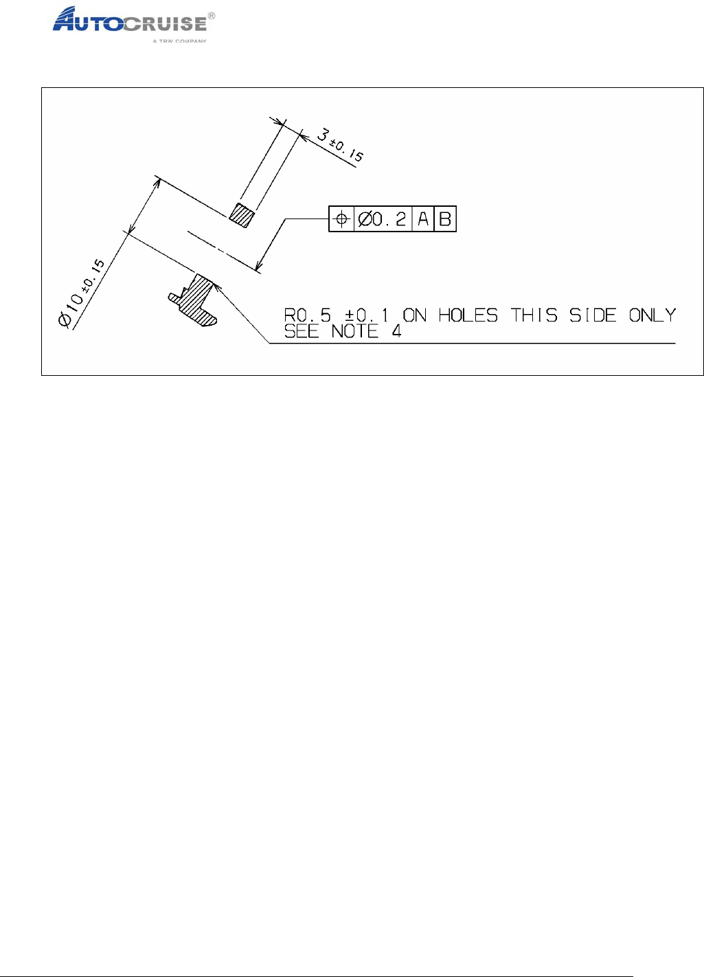
Figure 4 - Sensor Mounting Hole Dimensions
4.4.1 Sensor Alignment Process
Attached to the front of the radar is a mirror. At the sensor end of line process
a calibration procedure measures the difference between the microwave
central axis and the axis of the mirror. This alignment difference is
programmed into the radar as two parameters representing the inherent
azimuth and elevation offsets of the sensor (AZOF and ELOF). The alignment
procedure therefore requires the radar to be aligned using an optical beam
process with the mirror and then a quick compensation applied in accordance
with the parameters AZOF and ELOF.
The equipment to carry out this procedure can easily be adapted for both the
vehicle production line, as well as for in service garage re-alignment. This can
be done with equipment that is already traditionally used for aligning the
vehicle wheel tracking the vehicle thrust axis.
Internally the radar calculates a misalignment figure. This figure is used to
correct the angular measurements of the radar between the ranges of +/- 1
degree. If misalignment outside this range is identified then a system
shutdown will be requested.
4.4.2 Radar Alignment Principles
Report No : PRO_SPC_276
Issue : B
Commercially Confidential
Ce document n’est maîtrisé que s’il est identifié “copie maîtrisée” ou examiné d’une zone autorisée du système informatique
d’Autocruise. Les informations contenues dans ce document sont la propriété d’Autocruise SA et ne peuvent être utilisés par une
tierce partie sans l’accord écrit d’Autocruise SA
Page 11 sur 14 S01-010_A
Printed 06-Jun-05
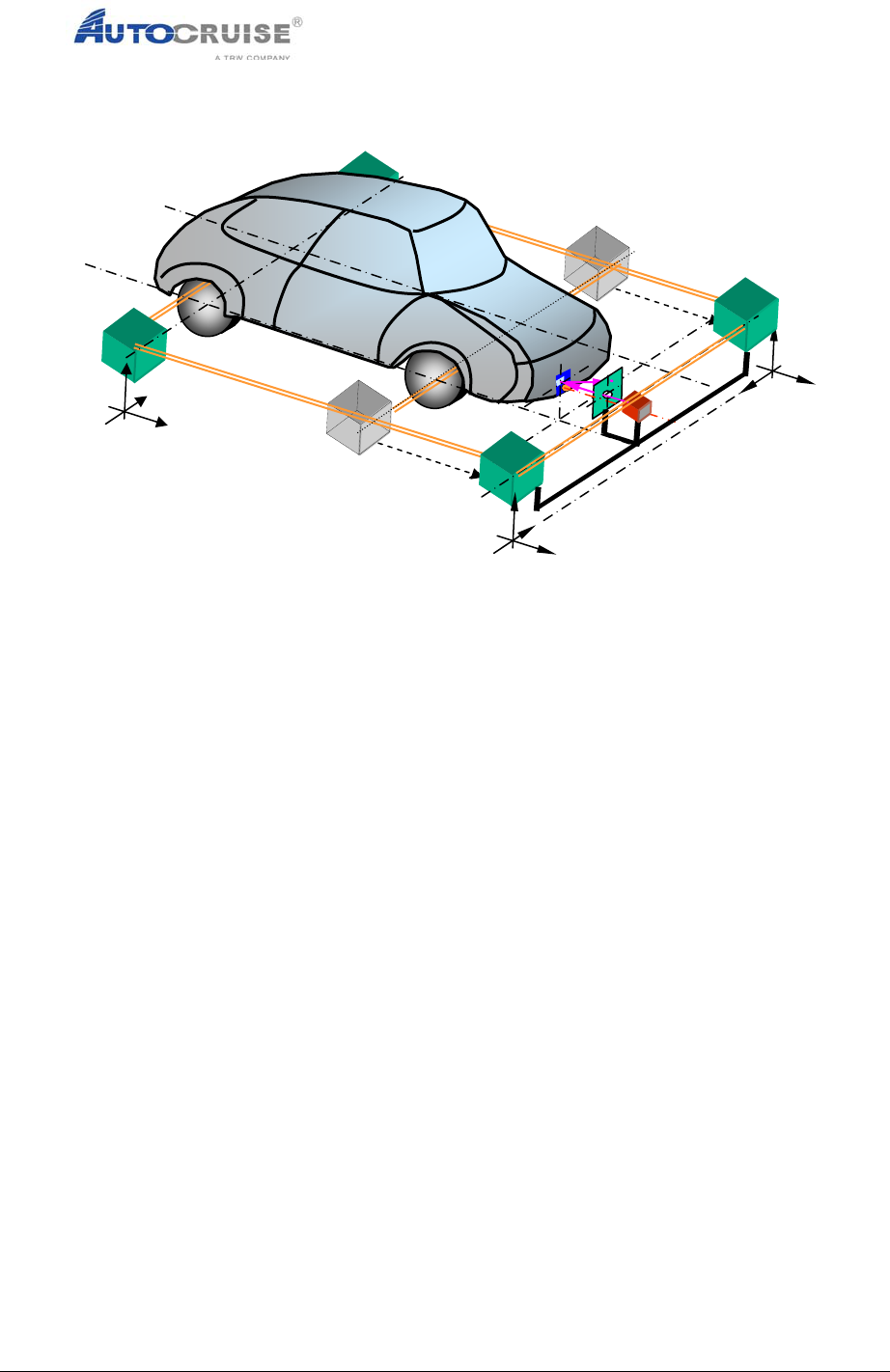
Figure 5 – Radar alignment principle
The radar is aligned by utilising an external laser device. This device is used
in conjunction with the car or truck end of line wheel alignment equipment. A
mirror on the radar along with two internal parameters provides the
information required to align the radar. These parameters define the offset
between the mirror axis and the microwave axis.

Report No : PRO_SPC_276
Issue : B
Commercially Confidential
Ce document n’est maîtrisé que s’il est identifié “copie maîtrisée” ou examiné d’une zone autorisée du système informatique
d’Autocruise. Les informations contenues dans ce document sont la propriété d’Autocruise SA et ne peuvent être utilisés par une
tierce partie sans l’accord écrit d’Autocruise SA
Page 12 sur 14 S01-010_A
Printed 06-Jun-05
5 Installation
The radar should be installed on the vehicle with the constraints described
below: -
The radar shall be fixed onto the vehicle chassis
• The radar lateral position must be located within ±50cm of the vehicle
centre axis
• The radar height must be between 0.3m and 0.7m from the vehicle rolling
axis.
• The static pitch of the vehicle has to be between +0.8° (upwards) and -
0.2°.
• The dynamic pitch has to be < ±1°.
• The radar housing references are given by the normal axis of a mirror fixed
on The radar housing must be set:
• In azimuth, parallel ±0.2° with the vehicle thrust axis, corrected with the
radar azimuth offset angle (x)
• In elevation, parallel ±0.2° to the vehicle rolling plane, corrected by the
radar elevation offset angle (y)
Note: the offset angles x & y are specific for each radar and indicate
the location of the beam axis of the radar in azimuth and elevation
referenced with the mirror’s normal axis. They are measured during the
Autocruise final radar verification test and stored in the radar’s non
volatile memory.
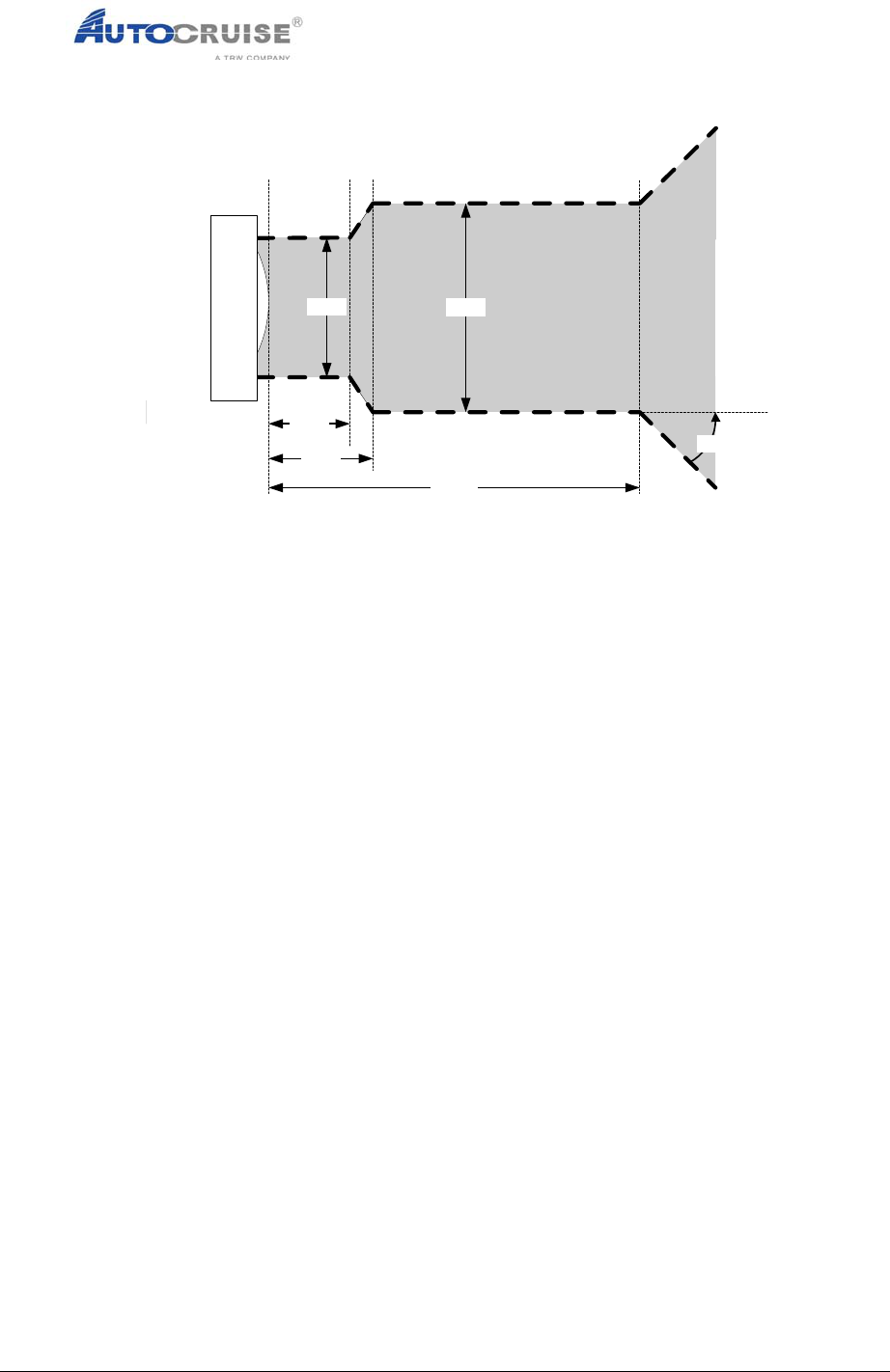
• There must be a clear view in front of the radar. The requirements for both
azimuth and in elevation are given in the diagram below. The shaded area
must not contain materials that affect radar performance; in particular
metal or carbon loaded plastics or paints.
Report No : PRO_SPC_276
Issue : B
Commercially Confidential
Ce document n’est maîtrisé que s’il est identifié “copie maîtrisée” ou examiné d’une zone autorisée du système informatique
d’Autocruise. Les informations contenues dans ce document sont la propriété d’Autocruise SA et ne peuvent être utilisés par une
tierce partie sans l’accord écrit d’Autocruise SA
Page 13 sur 14 S01-010_A
Printed 06-Jun-05
70mm 90mm
45°
30mm
40mm
120mm
Figure 6 - Clearance area in front of radar

Report No : PRO_SPC_276
Issue : B
Commercially Confidential
Ce document n’est maîtrisé que s’il est identifié “copie maîtrisée” ou examiné d’une zone autorisée du système informatique
d’Autocruise. Les informations contenues dans ce document sont la propriété d’Autocruise SA et ne peuvent être utilisés par une
tierce partie sans l’accord écrit d’Autocruise SA
Page 14 sur 14 S01-010_A
Printed 06-Jun-05
6 Warnings / Statements
6.1 Warning required by 15.21
Warning: Changes or modifications made to this AC20 sensor not expressly
approved by AUTOCRUISE S.A. may void the FCC authorization to operate
this equipment.
6.2 Statement required by 15.19 and RSS210
This device complies with Part 15 of the FCC Rules and with RSS-210 of
Industry Canada.
Operation is subject to the following two conditions:
(1) this device must not cause harmful interference, and
(2) this device must accept any interference received, including
interference that may cause undesired operation.
6.3 Statement required by 15.105
This equipment has been tested and found to comply with the limits for a
Class B digital device, pursuant to Part 15 of the FCC Rules. These limits are
designed to provide reasonable protection against harmful interference in a
residential installation. This equipment generates uses and can radiate radio
frequency energy and, if not installed and used in accordance with the
instructions, may cause harmful interference to radio communications.
However, there is no guarantee that interference will not occur in a particular
installation.
7 References
Ref. # Title Comments
1 CCP CAN Calibration Protocol Version
2.1
CCP21.PDF Supplied by Vector GmbH
2 ACC generic interface Specification AC20_PRO_0302_SPC_0025_issue A