ZHUHAI ISMART DIGITAL C1109DN2W IP Camera User Manual
ZHUHAI ISMART DIGITAL CO., LTD IP Camera
User manual
Wireless LCD NVR COMBO

Wireless LCD NVR Combo User manual
1
1 Overview
1A Statement
Sincerely thanks for purchasing our products, please contact us if any problem or requirement.
This manual is for Wireless LCD network video recorder combo.
This user manual may contain incorrect place in technology, place not matching with product function or operation, or
printing mistake. We will update our user manual according to our updating in product, and will periodically Improve or
updating the product and programming. The updating content will add in the new user manual, we won’t inform.
If the product’s description in user manual is inconsistent with the real products, please be based on the real products.
1B Safety cautions
• Make sure product is fixed correctly and stable if fastened in place.
• Do not operate if wires and terminals are exposed.
• Please don’t put a container with liquid near NVR (like vase).
• NVR should put at a ventilation place, and prevent clogged the ventilation hole.
• Check the power voltage, in case if damage by wrong voltage.
2 Package contents
When you unpack the DVR, you should find the following items in the box. If anything is missing please notify your
place of purchase.
No. Item Quantity
1 Wireless LCD NVR Combo 1pcs
2 Mounting bracket for NVR 1pcs
3 Wireless IP Camera 2 or4pcs
4 Antenna for NVR 2pcs
5 AC/DC adapter for NVR(12V/2A) 1pcs
6 AC/DC adapter for IP Camera(12V/1A) 2 or4pcs
7 USB MOUSE 1pcs
8 Hard Disk Mounting Screws 4pcs
9 IP Camera Mounting Packet 2 or4pcs
10 Quick Start Guide 1pcs
11 Support CD 1pcs
Wireless LCD NVR Combo User manual
2
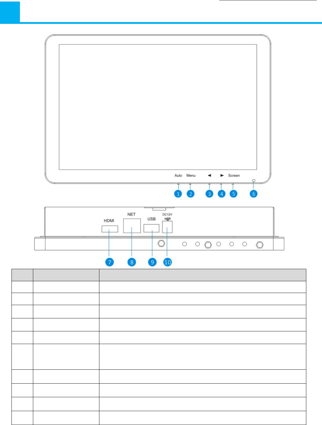
3 Appearance
Inde
x
Name Function
1 AUTO key Adjusts the screen display automatically.
2 MENU key Activates and exits the On Screen Display.(Monitor)
3 ← key Moves the OSD menu or decreases the selected item value.
4 → key Moves the OSD menu or increases the selected item value.
5 Screen key Turn on/turn off the display screen.(Monitor)
6 LED Indicator The power LED lights with green when the display screen is turned on.
The power LED lights with red when the display screen is turned off.
7 HDMI connector HDMI output signal can be connected to another HD monitor for display.
8 Net For a wired connection, connect this to a spare port on your home router.
9 USB Ports USB 2.0 Ports for mouse & external device(U-disk)
10 Power socket Connect the power adapter here.(DC12V/2A)
Wireless LCD NVR Combo User manual
3
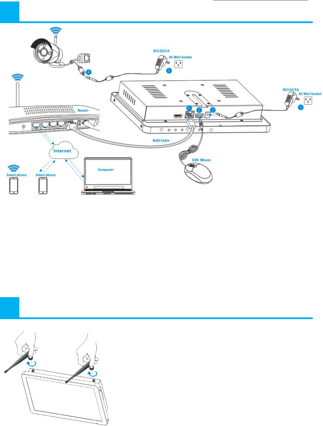
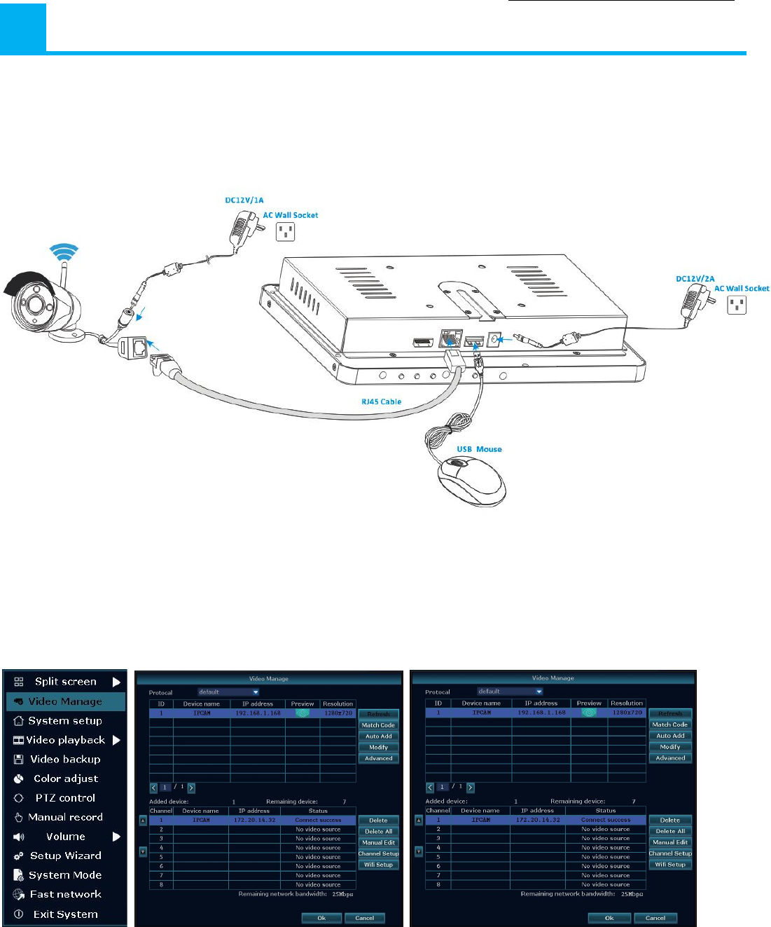
4 System diagram
① Plug in the included USB mouse to this connector.
② Connect the output of the supplied 12V power adapter into the power socket on the NVR.
③ Plug the power adapter into the wall socket.
④ Connect the output of the supplied 12V power adapter into the power socket on the Camera.
⑤ Plug the power adapter into the wall socket.
Wait for a few minutes till the NVR and the IP cameras finished startup. So far, the local surveillance
system was done.
⑥If you want to remote access this system with a smart phone or computer, you should connect the NVR
to your home wireless router with a RJ45 network cable and make sure the router has been linked to
internet.
5 Antenna installation
Use a clockwise motion to connect the antenna.
Make sure the antenna is connected firmly but not excessively.
You can adjust antenna horizontal or vertical direction to get
best reception.
Wireless LCD NVR Combo User manual
4
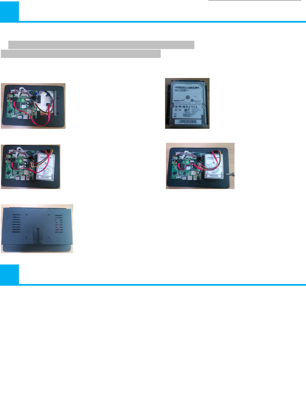
6 Hard disk installation
Note: Select HDD recommended by manufactures and suitable for devices.
HDD need be formatted manually for normal recording.
Install Steps:
1.Remove the screws of the device back cover. 2. Combine the HDD bracket and HDD with screws.
3. Connect the HDD cable and power line. 4. Fix HDD to the device mid-plate with screws.
5. Close the back cover and fix it.
7 Installing the mobile App
The wireless LCD NVR can work with iPhone, iPad and Android devices.
Install the mobile App and use your mobile for remote viewing/control your NVR.
The mobile App is free to download for you, and is available from the respective Apple App Store and Google Play
Store.
After installing ISmView App on your mobile device, just locate the ISmView App and tap the icon to run. The
App will load and take you directly to Login screen.
7B To install App on iPhone/iPad
① Open the App Store.
② Search for “ISmView”.
③ Tap INSTALL APP to download.
7A To install App on Android
① Open Google Play Store.
② Search for “ISmView”.
③ Tap INSTALL.
④ Review the App’s permissions,
then tap ACCEPT to download.
Wireless LCD NVR Combo User manual
5
8 Software operation
8A Add camera to NVR
The included cameras in the kits have been paired with NVR at the factory, no need execute this operation.
If you want to add more cameras to NVR, please operate follow below steps:
① Connect a new IP camera to the NVR with a network cable, then power supply for both the IP camera and the NVR,
wait for about over 1 minute.
②Click the mouse right button on the main interface -> Click “Video Manage” ->“refresh”->select the camera in the search
list-> “Match code” ->“OK”.
③ After about 30 seconds the new camera will be occurred in the “added device” list, and status displays ”Connect
success”.
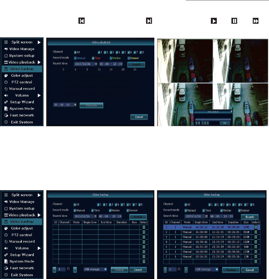
8B Video playback
Step: Click the mouse right button on the main interface ->Video playback ->choose channel NO. ->choose record mode
Wireless LCD NVR Combo User manual
6
->in Search time, input the beginning time and end time ->click search, recording will come out ,drag time bar ->click
playback to start
Tips: Playback icon introduction: playback 1 fram previous playblack 1 frame next play puse fast
forward x2,x4,x8
8C Video backup
Step: Click the mouse right button on the main interface->Video backup ->choose channel No. ->choose record mode ->in
Search time ,input the beginning time and end time ->click search, recording will come out ->choose the video which need
to backup ->click video backup.
Tips: Support 32GB U disk backup max, recording video file will be packed every one hour.
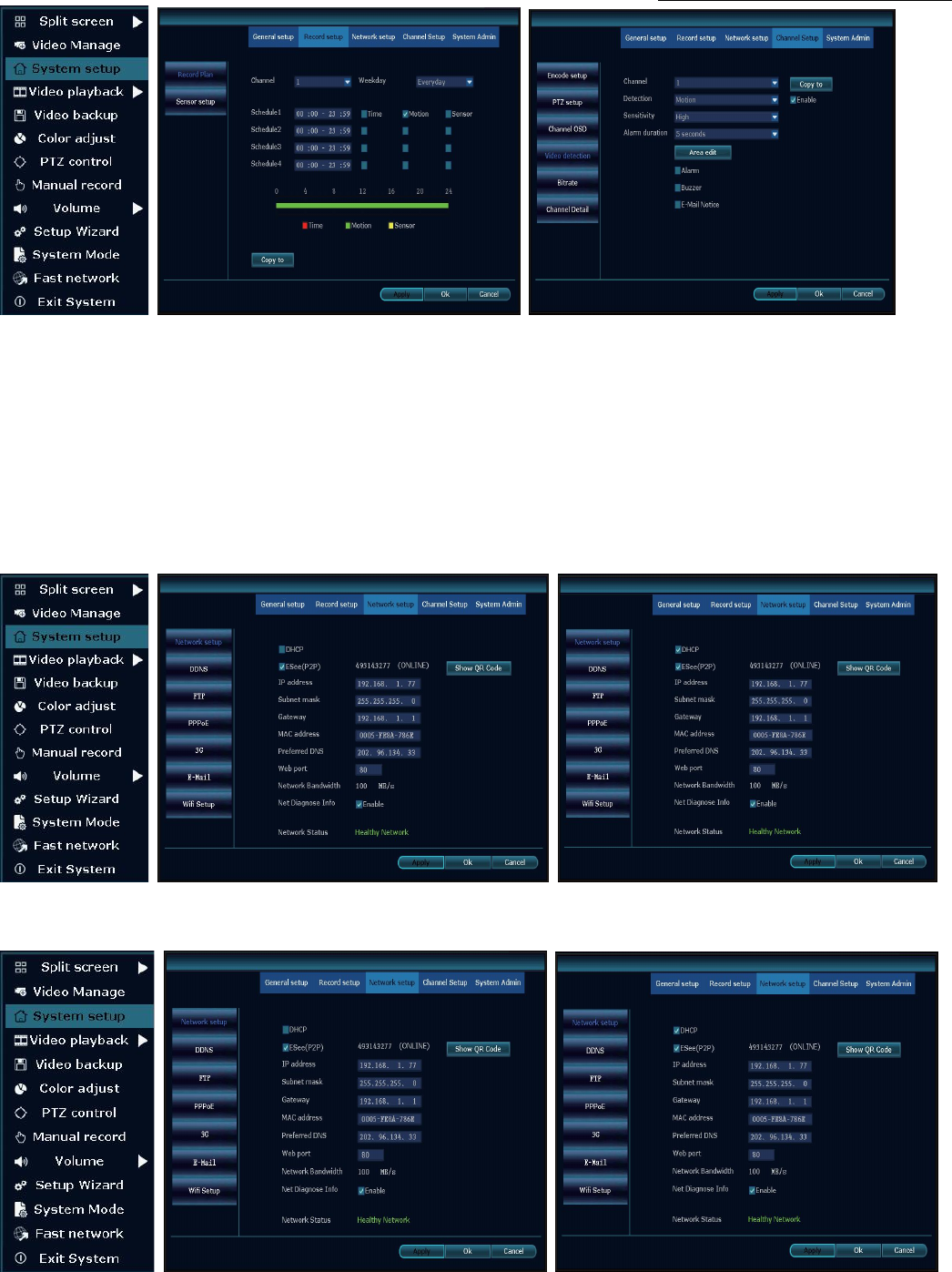
8D Video detection
Step 1: Click the mouse right button on the main interface->System setup ->Record setup->choose motion->choose all
->click Copy to ->click OK to save setting.
Step 2: Choose Video detection ->set sensitivity as required- > choose motion->set Alarm/Buzzer or Email as
required->click Copy to->click OK to save setting .
Wireless LCD NVR Combo User manual
7
8E Generate P2P ID
Note: The precondition to generate P2P ID is that make sure the NVR is connected with internet, and IP address is
available.
Step : Click the mouse right button on the main interface->System setup->Network setup.
If user is familiar with LAN, then no need to choose DHCP which help to get IP address automatically .Manually input IP
address and DNS address, NVR will generate ID by network, once generate, it will appear in menu.
If user not familiar with LAN,or NVR is in independent network,can choose DHCP to get availableIP address.
After NVR gets IP address ,it will generate P2P ID automatically.
Wireless LCD NVR Combo User manual
8
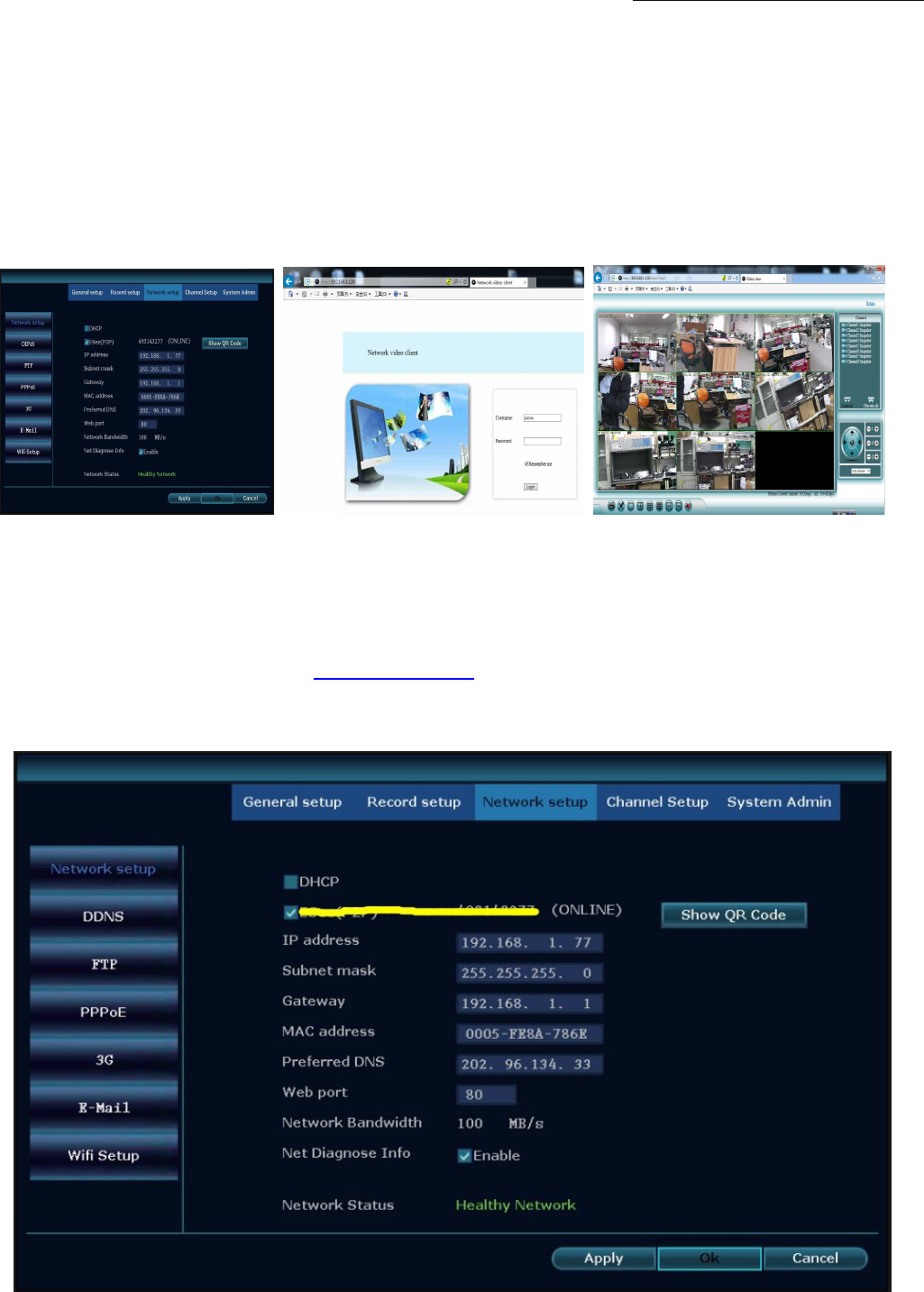
8F Access in LAN
Step 1: Click the mouse right button on the main interface-> System setup ->Network setup ->check videorecorder IP
address.
Step 2:Access by computer in the same LAN ,input NVR’s IP address and prot( If prot is 80, no need to input)in IE prowser
or any other browser.Then it will access LAN log in webpage,input user name and password,click login.
Step 3:Once access successfully,can get video.
Tips: Please make sure the NVR and computer be working in the same network segement.
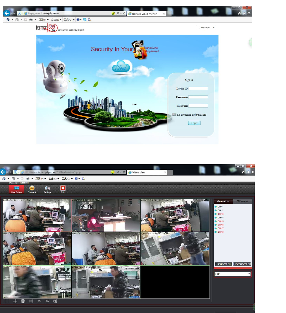
8G Access in WAN
Step 1: Click the mouse right button on the main interface-> System setup->Network setup ->check video recorder IP
address.
Step 2: Access by computer in WAN, input www.ismartp2p.com in IE browser or any other browser. Then it will access log
in webpage, input ID, user name and password, click login.
Step 3: Once access successfully, can get video.
Wireless LCD NVR Combo User manual
9
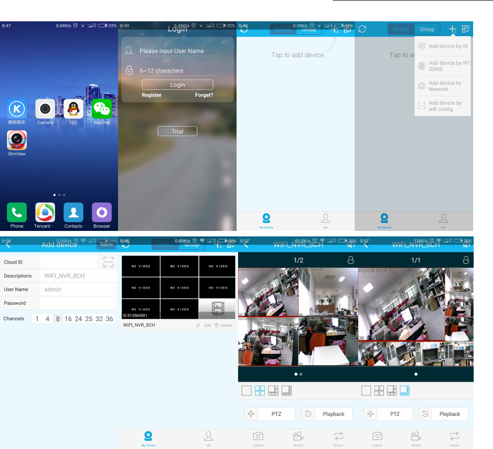
8H Mobile application (iSmView)
■Add device
Step 1: Log in iSmView application
Step 2: Click “+”icon.Add device by ID
Step 2: Enter device edit page. You can edit device name. Pay attention to correct selection of channel number
Step 3: Input video recorder log in information
Step 4: Added successfully .it will show below page
Step 5: Click channel No.to get video. The default 4 Video
Wireless LCD NVR Combo User manual
10
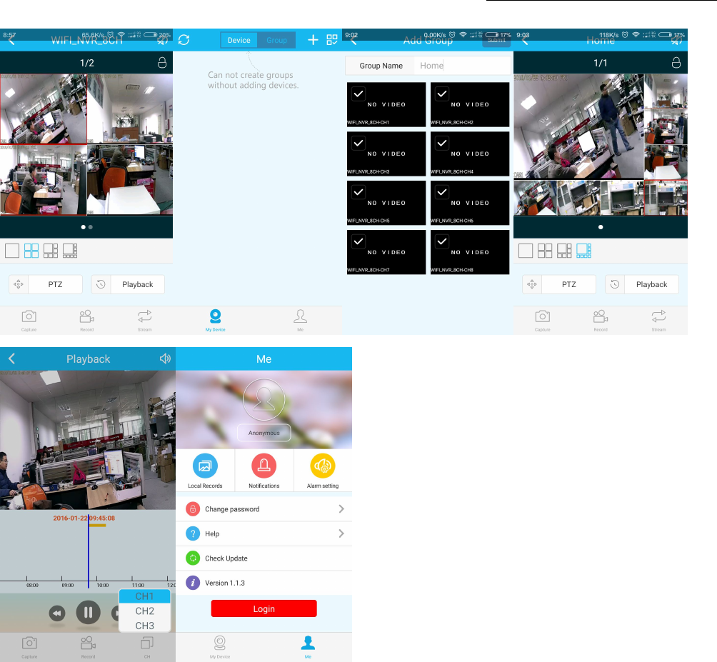
■Function
Step 1: It will connect channel 4video by default, click “+”to add more channel
Step 2: Click this icon to edit video recor log in in formation
Step 3: Add device group
Step 4: Capture/Rerord/Stream
Step 5: Video Playback. The right choice you want to see the video channel
Step 6: File management and more settings
Wireless LCD NVR Combo User manual
11
■Troubleshooting
Q1: How to register a new account?
A1: Were registered with account button on the "login" screen, click to enter the "registration" interface, registered
accounts need to fill in a valid email, at the same time easy to see the cloud will send an email to the email to
activate.The user can choose not to activate the account, this will not affect the use of the easy media cloud, but
not activated account cannot perform the function of forget password.
Q2: What is the difference between login mode and Trial mode?
A1: Login mode, the device or group of users to add data managed by the server, or even delete all the data in the
mobile phone in the mobile phone, data is not lost.As long as reinstall the application and log in to the old
account, you can restore all the data.And Trial mode, users to add equipment and grouped data is stored locally,
once the data is missing, unable to restore.In addition, the login mode, we provide users with equipment state
warning, alarm, news feeds, and other auxiliary functions.

Wireless LCD NVR Combo User manual
12
9 Specifications
Wireless NVR Specification
Display device Screen 10.1inch LED LCD,1280*800
Viewing angle Horizontal: 170deg. Vertical : 170deg.
AV(audio/video)input Network Video 4CH IP cameras
AV(audio/video) output HDMI output 1ch,resolution:1024x768,1366x768,
1440x900,1920x1080p
AV CODEC Video Resolution D1/720P
synch-playback 4CH
Video Control
Video/Capture mode Manual、Time、Motion
Playback mode Real time、Routine、Event
Backup USB backup
Hard Disk Type 1*SATA interface
Max Capacity Up to 4 TB each HDD(2.5")
External Interface Network Interface 1 adaptable RJ45 10M/100M, 2 WIFI interface
USB Interface 2 USB 2.0
Network Protocol UPnP (plug & play)/SMTP (email service)/PPPoE
(dial-up)/DHCP etc.
Others
Power Supply DC12V2A
Power Consumption (W) ≤15W(Without HDD)
Operate Temperature (°C) -10℃~+55℃
Working Humidity (%) RH 10%~90%
Size 250x36x166mm(W × D × H) without bracket
Weight(excluding HDD) 1kg(with bracket)
IPC Specification
Image
Sensor
1/4” Progressive Scan Sensor
Signal System PAL/NTSC
Resolution 1280 x 720 ,16 : 9 High Defini
tion
Minimum illumination Color: 0.1 Lux; B/W: 0.01 Lux
Lens f=4mm
Day&Night Auto / Color / BW
3D-DNR Auto
Network Protocol RJ45 / WIFI 802.11b/g/n
General Specification
Working Temperature/Humidity -10℃ to +50℃ / 30% to 80% RH
Power Input DC12V-1A
Power consumption ≤6W
Size 205(L)×70(W)×55 (H)mm
Weight 500g
Level of Protection IP66
FCC STATEMENT :
This device complies with Part 15 of the FCC Rules. Operation is subject to the following
two conditions:
(1) This device may not cause harmful interference, and
(2) This device must accept any interference received, including interference that may
cause undesired operation.
Warning: Changes or modifications not expressly approved by the party responsible for
compliance could void the user's authority to operate the equipment.
NOTE: This equipment has been tested and found to comply with the limits for a Class B
digital device, pursuant to Part 15 of the FCC Rules. These limits are designed to provide
reasonable protection against harmful interference in a residential installation.
This equipment generates uses and can radiate radio frequency energy and, if not
installed and used in accordance with the instructions, may cause harmful interference to
radio communications. However, there is no guarantee that interference will not occur in a
particular installation. If this equipment does cause harmful interference to radio or
television reception, which can be determined by turning the equipment off and on, the
user is encouraged to try to correct the interference by one or more of the following
measures:
Reorient or relocate the receiving antenna.
Increase the separation between the equipment and receiver.
Connect the equipment into an outlet on a circuit different from that to which the
receiver is connected.
Consult the dealer or an experienced radio/TV technician for help.
FCC Radiation Exposure Statement
This equipment complies with FCC radiation exposure limits set forth for an uncontrolled
environment. This equipment should be installed and operated with minimum distance
20cm between the radiator & your body