ZKTECO KR300 ID/MiFare Read the first User Manual
ZKTECO CO., LTD. ID/MiFare Read the first Users Manual
ZKTECO >
15_KR300 UserMan r1

Non-contact radio frequency ID card reader
KR300 series products
1. overview
The KR300 series products are125KHz non-contact rf ID card reader, which is based on the
ISO/IEC14443A international standard protocol developed non-contact smart card serial number
card reader. It was designed by our company's self-designed high performance rfid circuit. It is
characterized by high level of integration, strong anti-jamming ability, small volume, stable
performance and high price performance. It provides the wegen 34 or wegen 26 communication
interface, which is suitable for all kinds of rfid applications such as door prohibiting, attendance,
charging, burglar, and patrol.
2. characteristic
2.1 The card reader comes with the card antenna, which is the same as PCBA. The
difference is the software version, the shell, the length of the wire
2.2 Different versions of software support different CARDS
2.3 Effective range from 0 to 5cm (depending on the work environment and different
CARDS)
2.4 The receiving time is less than 80ms within the valid distance
2.5 Single dc power + 12V power supply, operating current is less than 100mA
2.6 The IC section is Wiegand34bits and ID parts for Wiegand26bits standard format
data output
2.7 Fully enclosed adhesive, waterproof, moisture-proof
3. Line description
RED: VCC
BLACK: GND
WHITE: Wiegand D1
GREEN: Wiegand D0
PURPLE: BEEPER
GRAY: Green LED
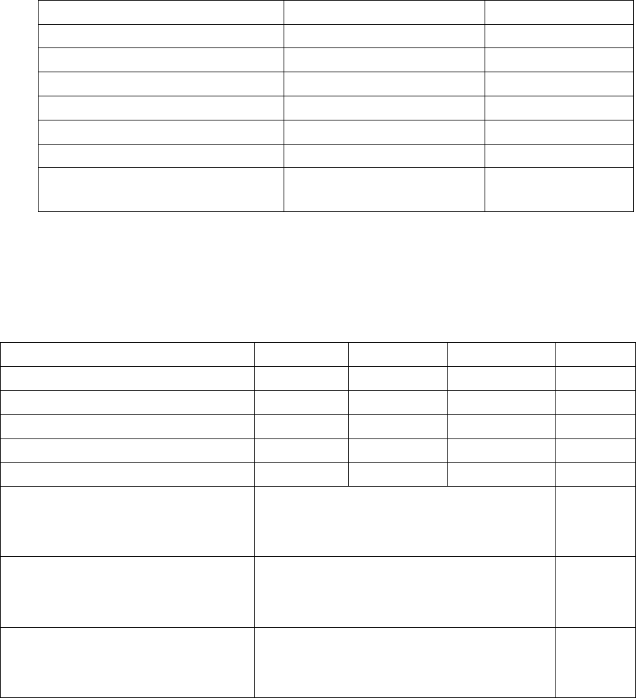
4. Characteristic parameters
4.1 The limit parameter
project
numerical
unit
+12V,Vcc
12.5
V
Data0,I0/Clock,ICK
25
mA
Data1,I1/Data,ID
25
mA
Hold,IH/Card Present,ICP
25
mA
antenna,IAN
82
mA
Working temperature,TOPR
-1070
C
Storage temperature,TSTR
-55~+125
C
4.2 Electrical, mechanical properties (not specify TA = 25 °, Vcc =
5 v)
project
minimum
typical
maximum
unit
+12V,Vcc
7
12
14
V
Working current,Ic
82
98
mA
ID Working frequency,FRES
124.8
125
125.6
KHz
ID Effective distance,D *
30
40
55
mm
Decoding time,TDEC
65
100
ms
Data0,Data1,Hold/
ata,Clock,Card, The Present end
outputs high potential,VoH
2.4(IoH=80uA), 0.75Vcc(IoH=30uA)
0.9Vcc(IoH=12uA)
V
Data0,Data1,Hold/
ata,Clock,Card, Present end
output is high potential, VoH
0.5
( IoL=20mA,Vcc=5V,IoL=20mA,Vcc=3.3V)
V
The dimensions, L, X, W, X H (not
counting the length of the
wiring)
77.5*42.8*15.2 (error±3mm)
mm
Effective distance and the power supply voltage, using IC, ID card
and use related to the environment.
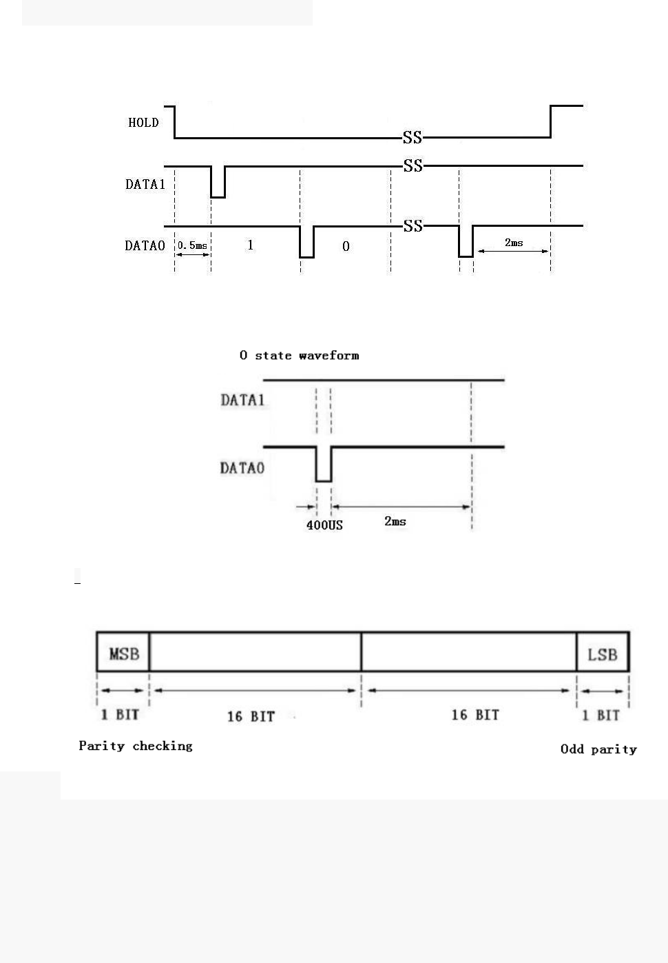
5. Wigan code format specification
5.1 W34 Sequence diagram
5.2 W34 data format
32 BITS SERIAL NUMBER = 4BYTE (HEX)
Note: MSB is sent first;
MSB is a 16-bit parity BIT; LSB is a low 16 BIT parity BIT;
Even if the number of 1 in 16 BIT is even, MSB is 1; When the number of 1 is odd, MSB is 0;
Parity definition: the LSB is 0 when the number of 1 is even. When the number of 1 is odd, the LSB is 1.
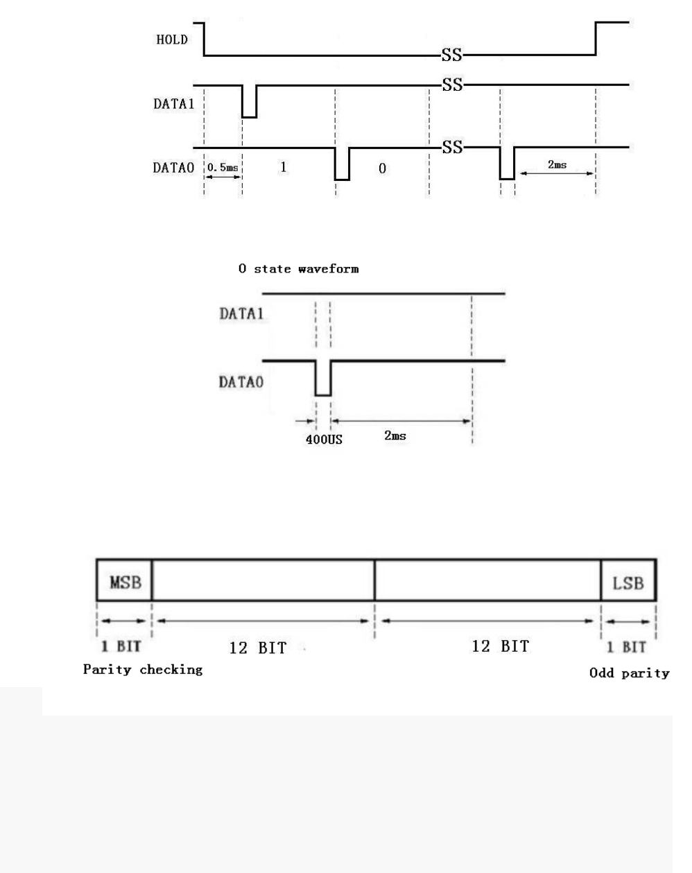
5.3 W26 Sequence diagram
5.4 W26 data format
24 BITS SERIAL NUMBER = 3BYTE (HEX)
Note: MSB is sent first;
MSB is an even check BIT of 12 bits; LSB is a low 12 BIT parity BIT;
Parity definition: MSB is 1 when the number of 1 in 12 BIT is even. When the number of 1 is odd, MSB is
0;
Parity definition: the LSB is 0 when the number of 1 is even. When the number of 1 is odd, the LSB is 1.
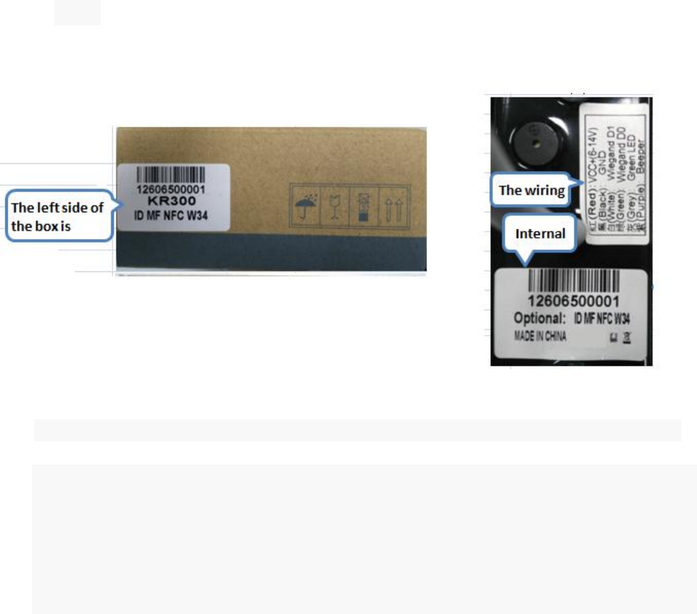
6. label
7. Matters needing attention in operation and maintenance warnings
7.1 connect cable should rear can power wiring.
7.2 maintenance may not arbitrarily change the product in the Ann circuit component model,
specification and parameter.
7.3 light with light.
7.4 products specified in the instructions for only with equipment connection using device to
connect with others subject to explosion proof test.
NOTE: This equipment has been tested and found to comply with the limits for a
Class B digital device, pursuant to part 15 of the FCC Rules. These limits are
designed to provide reasonable protection against harmful interference in a
residential installation. This equipment generates uses and can radiate radio
frequency energy and, if not installed and used in accordance with the instructions,
may cause harmful interference to radio communications. However, there is no
guarantee that interference will not occur in a particular installation. If this
equipment does cause harmful interference to radio or television reception, which
can be determined by turning the equipment off and on, the user is encouraged to
try to correct the interference by one or more of the following measures:
- Reorient or relocate the receiving antenna.
- Increase the separation between the equipment and receiver.
-Connect the equipment into an outlet on a circuit different from that to which the
receiver is connected.
-Consult the dealer or an experienced radio/TV technician for help
Changes or modifications not expressly approved by the party responsible for compliance
could void the user's authority to operate the equipment.
This device complies with Part 15 of the FCC Rules. Operation is subject to the following two conditions:
(1) this device may not cause harmful interference, and
(2) this device must accept any interference received, including interference that may
cause undesired operation.