ZOLL Medical Israel U3CMCT CMCT Monitoring System User Manual CMCT IFU FDA March 2017x
ZOLL Medical Israel Ltd. CMCT Monitoring System CMCT IFU FDA March 2017x
Manual
CMCT Monitoring System
Rx Only
Instructions for Use

CMCT Monitoring System
Instructions for Use
Page 2 of 31
For assistance with the µCor 3.0 System, please contact ZOLL at:
121 Gamma Drive
Pittsburgh, PA 15238 USA
Phone toll free (USA) 1.888.592.3798
Copyright Notice
© 2016, ZOLL Medical Corporation. All rights reserved
Trademarks
ZOLL is a trademark or registered trademark of ZOLL Medical Corporation in the United States.
Disclaimer
Information, operation, specifications, and product appearance may change without notice.
Symbols Glossary
The symbols glossary is located in Section 9 of this Instructions for Use
User Guide RA-72-002-034-ENG
Version 1 ∙ March 2017
PLEASE READ THIS ENTIRE INSTRUCTIONS FOR USE
BEFORE OPERATING THE CMCT SYSTEM

CMCT Monitoring System
Instructions for Use
Page 3 of 31
TABLE OF CONTENTS
Part I: General Information ....................................................................................................5
1 Introduction .............................................................................................................. 6
2 Conditions for Use ........................................................... Error! Bookmark not defined.
2.1 Intended Use and Indications for Use ...................................................................... 6
2.2 Contraindications ....................................................... Error! Bookmark not defined.
3 General Warnings and Precautions .................................. Error! Bookmark not defined.
3.1 Warnings .................................................................... Error! Bookmark not defined.
3.2 Precautions ................................................................ Error! Bookmark not defined.
4 Detailed Descripton of the CMCT System ................................................................... 7
4.1 System Components................................................................................................ 8
4.2 How CMCT System works ........................................................................................ 9
4.3 Prescription Duration and Measurement Scheduling ............................................... 9
4.4 Patch ..................................................................................................................... 10
4.5 Sensor ................................................................................................................... 10
4.6 Charger ................................................................................................................. 11
4.7 Data transmission device (Gateway) ...................................................................... 12
4.8 Server ................................................................................................................... 12
4.9 Device (sensor + Patch) Placement Location .......................................................... 12
5 Directions for Use .................................................................................................... 13
5.1 Getting started ...................................................................................................... 13
5.1.1 Locate the components of the CMCT System: .................................................. 13
5.1.2 Connect the Charger ............................................ Error! Bookmark not defined.
5.1.3 Confirm that the Sensor is ready for use .............. Error! Bookmark not defined.
5.1.4 Confirm that the Gateway is ready for use ...................................................... 13
5.2 Connecting the Sensor to the Patch ....................................................................... 14
5.3 Preparing the Skin ................................................................................................. 14
5.4 Applying the Device ............................................................................................... 15
5.4.1 Side Location .................................................................................................. 15
5.4.2 Front Location ................................................................................................ 17
5.5 How to USe the Gateway....................................................................................... 18
5.6 Replacing the Patch ............................................................................................... 18
5.7 Recharging the Sensor ........................................................................................... 19
5.8 Sensor and light Indicator statuses ........................................................................ 19
6 TroubleShooting ...................................................................................................... 20
7 Cleaning and Return of System ................................................................................ 20
8 Maintenance ........................................................................................................... 21
9 Symbols Glossary .................................................................................................... 21
Part II: Technical Specifications ............................................................................................ 23
10 Technical Specifications ........................................................................................... 24
10.1 Accuracies ............................................................................................................. 24
10.2 Electrical (Power) Requirements ........................................................................... 25

CMCT Monitoring System
Instructions for Use
Page 4 of 31
10.3 Wireless Transmission Specifications ..................................................................... 25
10.4 Sensor Dimensions ................................................................................................ 26
10.5 Environmental & Other Specifications ................................................................... 27
11 Compliances ............................................................................................................ 28
11.1 Electrical Safety ..................................................................................................... 28
11.2 Electromagnetic compatibility (EMC) ..................................................................... 28

CMCT Monitoring System
Instructions for Use
Page 5 of 31
Part I:
General
Information

CMCT Monitoring System
Instructions for Use
Page 6 of 31
1 INTRODUCTION
The CMCT System is a wearable, wireless system that is used to aid clinicians in the
diagnosis and identification of various clinical conditions, events and/or trends. It consists
of the CMCT wearable Sensor and Patch, a portable data transmission device (Gateway),
and a Charger. The Sensor unit continuously records and transmits ECG data to the data
transmission device, and from there to the ZOLL monitoring center. Other physiological
parameters such as thoracic impedance, heart rate, respiration rate, activity and posture
are recorded periodically and are also transmitted, via the data transmission device to the
monitoring center. Certified technicians at the ZOLL Monitoring Center review received
data and prepare clinical reports to the prescribing physician. The CMCT System is designed
for use in outpatient clinic and home settings for up to 30 days.
2 INDICATIONS FOR USE
The CMCT System is intended to continuously record, store, and transmit ECG, Heart Rate,
Activity, and Posture to medical professionals. The CMCT System also periodically records,
stores, and transmits Respiration Rate and Thoracic Impedance to medical professionals.
The CMCT System is indicated for patients who are 21 years of age or older:
i. Who require monitoring for the detection of non-lethal cardiac arrhythmias, such
as, but not limited to, supraventricular tachycardias (e.g. atrial fibrillation, atrial
flutter, paroxysmal SVTs), ventricular ectopy, bradyarrhythmias and conduction
disorders
ii. with fluid-management problems;
iii. taking diuretic medication;
iv. living with heart failure;
v. living with end-stage renal disease;
vi. recovering from a coronary artery disease-related event; and/or suffering from
recurrent dehydration.

CMCT Monitoring System
Instructions for Use
Page 7 of 31
3 WARNINGS AND PRECATIONS
• Do not use the CMCT System if you:
- Have allergies or skin sensitivities to electrode hydrogel and/or acrylic based
adhesives.
- Are pregnant (the CMCT System has not been tested on pregnant women).
- Have skin breakdown in areas where device (Patch + Sensor) placement is required.
• The CMCT System is not intended to be an alarm or to alert patients or physicians, and
will not summon emergency response in the event help is needed
• The CMCT System is not intended to replace direct communication with healthcare
providers.
• Data provided by the system should be used by physicians along with all other clinical
findings and exams to come to a diagnosis.
• Patients should talk to their healthcare provider immediately if there are any concerns
or if their condition changes.
• Remove the device (Patch + Sensor) from your body prior to an MRI scan, or any
emergency medical procedure. The CMCT System is not compatible for use with MRI
machines.
• If you have an implanted pacemaker or defibrillator, do not place the Sensor directly
on top of the implanted device. Consult with your physician about the correct
placement of the device for you.
• Sensor and Data Transmission Device must be turned OFF prior to boarding an
airplane. Remove Sensor from Patch and call ZOLL for further instructions.
• Do not wear the Patch for more than 5 days. Replace the Patch every 3 days, or more
frequently when needed. The Patch is designed for a maximum of 5 days use only.
• No creams of lotions should be applied to the skin immediately prior to the
application of the Patch.
• Do not re-use the Patch. Once the Patch is peeled off or removed, discard
immediately. The Patch is designed for single use. Re-using the Patch may result in
poor adhesion to the body and may affect measurements.
• Remove the device (Patch +Sensor) if any pain or discomfort occurs. If skin irritation,
discomfort, redness, itching or rash persists after the device is removed, a topical,
CMCT Monitoring System
Instructions for Use
Page 8 of 31
anti-inflammatory cream may be applied (in consultation with your health care
provider).
• Do not submerge the Sensor in water by swimming or sitting in a tub. The Sensor is
water-resistant, but not waterproof. Wearing the Sensor while showering is okay.
• Keep the Charger and Data Transmission Device away from water.
• The power adapter connector should not be touched or manipulated when the Power
Adapter is connected to the supply mains.
• Do not change, modify, or disassemble any parts or components of the CMCT System.
The system contains no user-serviceable components. Any changes, modification, or
servicing of the CMCT System will only be performed by ZOLL.
• Connect the Charger to the AC adapter that is provided with the system in the original
packaging. Using any other AC adapter may damage the Charger and may have
electric hazards.
• Place the Sensor in the Charger when not in use.
• When using the µCor 3.0 System, use only cables and accessories provided by ZOLL.
Using non-approved cables and accessories may affect the EMC performance
• Do not stack the µCor 3.0 system with other devices or equipment.
• Discontinue use and contact ZOLL if the CMCT System shows signs of damage or is not
working correctly.
• Keep the CMCT System out of reach of children.
4 DETAILED DESCRIPTON OF THE CMCT SYSTEM
4.1 SYSTEM COMPONENTS
The CMCT System consists of the following components:
• Patch
• Sensor
• Charger
• Data transmission device (Gateway)
• Server
Each component will be further described within this Section.
CMCT Monitoring System
Instructions for Use
Page 9 of 31
4.2 HOW CMCT SYSTEM WORKS
Once activated, the wearable Sensor automatically acquires ECG, thoracic impedance,
Heart Rate, Respiration Rate, Activity, and Posture measurements. Patients can also
activate a patient trigger when they experience symptoms by double tapping the Sensor
when it is on the body. Data are automatically transmitted from the Sensor to the Data
transmission device, and from there to the Server for analysis. Certified technicians at
the Monitoring Center review the data generated by the Server and prepare reports
according to the pre-defined criteria as requested by the prescribing physician. Data
provided in the report will aid the prescribing physicians in the diagnosis and
identification of various clinical conditions, events and/or trends. The CMCT System is
designed for use in outpatient clinic and home settings.
4.3 PRESCRIPTION DURATION AND MEASUREMENT SCHEDULING
The CMCT System is intended for up to 30 days of monitoring.
During the prescription period, the Sensor will automatically acquire your clinical
measurements. As described previously, data acquired by the body-worn Sensor will be
transmitted wirelessly to the data transmission device, which will then be forwarded to
the remote Server for data analysis, and subsequently to the Monitoring Center for
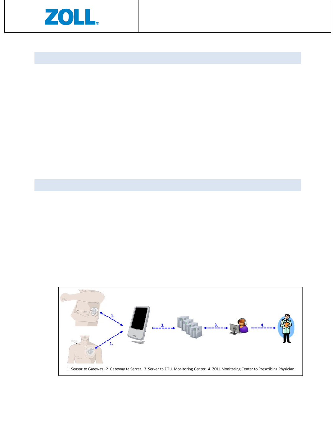
review and report generation. See Figure 1 for a graphical illustration of the data
transmission.
Figure 1: Data transmission of the CMCT System
CMCT Monitoring System
Instructions for Use
Page 10 of 31
4.4 PATCH
The Patch (as shown in Figure 2) consists of a plastic frame intended for housing the
Sensor, and two ECG electrodes on each side of
the frame. It is applied to your body.
The Patch is a single-use disposable item. As
described in the General Warnings and
Precaution Section, it should not be worn for
more than 3 days. At the end of 3 days, it should
be replaced with a new Patch.
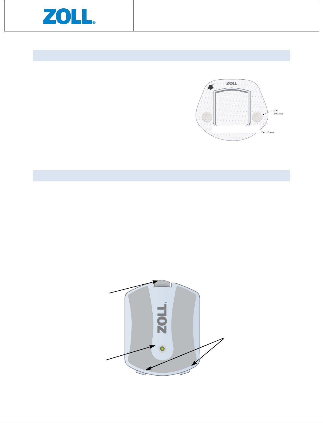
4.5 SENSOR
The Sensor (as shown in Figure 3) is a battery powered unit that acquires your
measurements. The Sensor connects to the Patch via the snap-in clip and positioning
tabs. Through the adhesive backing on the Patch, the device becomes wearable.
The Sensor is not disposable and needs to be returned to ZOLL upon the completion of
the prescription.
As shown in Figure 3, a light indicator is located close to the center and serves to
communicate the Sensor’s status at different points of use. Note that the light indicator
is visible only when lit.
Figure 2: Patch
Snap-in Clip for
Patch attachment
Light Indicator
Positioning tabs for
Patch attachment
CMCT Monitoring System
Instructions for Use
Page 11 of 31
Figure 3: Sensor
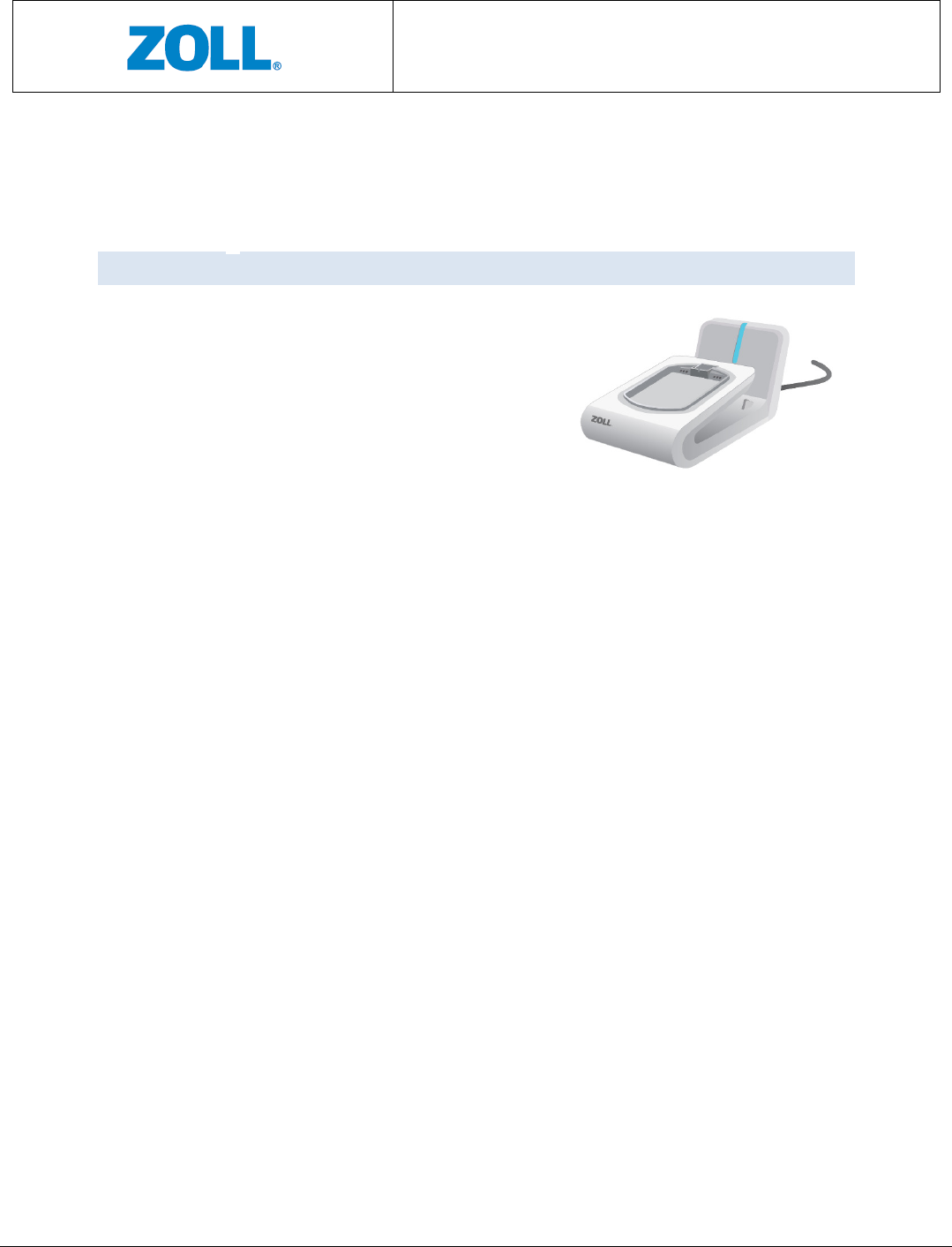
4.6 CHARGER
A dedicated Charger (as shown in Figure 4) is
supplied with the CMCT System for recharging the
Sensor and the Data Transmission Device. A blue
light appears when the Charger is connected to an
AC outlet.
Figure
4
: Charger
CMCT Monitoring System
Instructions for Use
Page 12 of 31
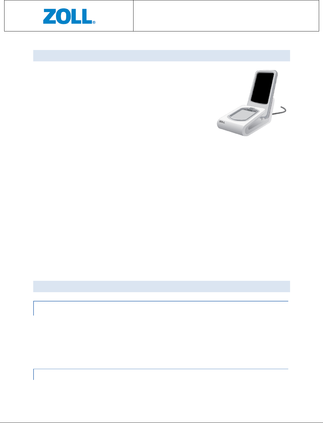
4.7 DATA TRANSMISSION DEVICE (GATEWAY)
A Data Transmission Device or Gateway is responsible for
sending data from the Sensor to the Server for data
analysis. When the screen display is on, the gateway
battery status is visible on the screen. Once the battery
status is under a certain level, a short beeping sound will
be made every few minutes until the battery is depleted
or the Gateway is placed in the Charger. Make sure you
charge the gateway daily.
4.8 SERVER
The Server refers to the hardware and the processing software and resides in a remote
cyber-secure location. The software analyzes the data recevied from the Sensor via the
Gateway and processes the data into clinical values for presentation to your healthcare
provider after review by certified technicians at the Monitoring Center.
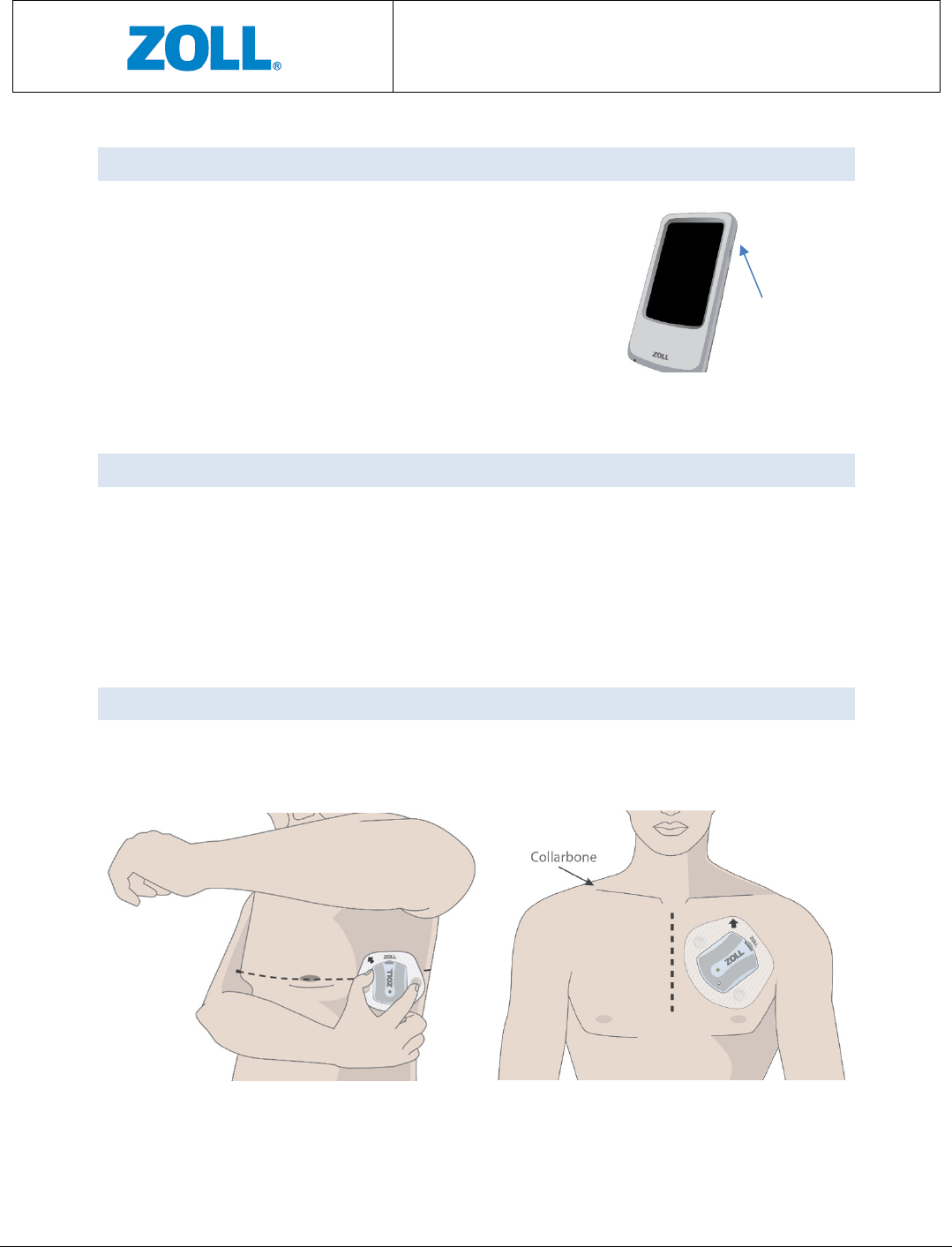
4.9 DEVICE (SENSOR + PATCH) PLACEMENT LOCATION
There are two locations for device (Sensor + Patch) placement: (1) below left armpit
(side location); and (2) upper left chest (front location). See Figure 6.
Figure 6: Device (Sensor + Patch) placement location
Figure 5: Gateway
Display/ Power
on/off button
Front
S
ide
CMCT Monitoring System
Instructions for Use
Page 13 of 31
5 DIRECTIONS FOR USE
5.1 GETTING STARTED
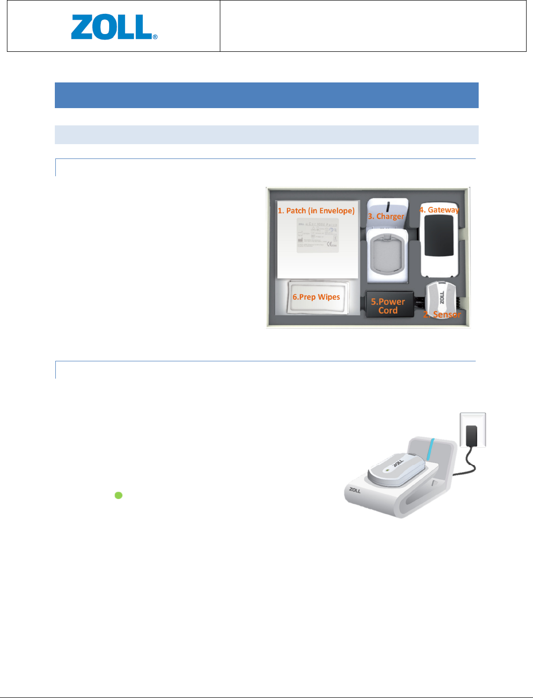
5.1.1 LOCATE THE COMPONENTS OF THE CMCT SYSTEM:
1. Patch in Envelope
2. Sensor
3. Charger
4. Gateway
5. Power Cord (or AC Adapter)
6. Preparation Wipes
See Figure 7.
5.1.2 CHARGING THE SENSOR – FIRST USE AND EVERY 3 DAYS
IMPORTANT: Set up Charger in bedroom or room where you sleep. This allows device to send
data to ZOLL at least once a day.
1. Connect the Charger to a power outlet in your
bedroom. A Blue light on the Charger means the
Charger has power.
1. Place the Sensor on the Charger. Wait for a solid green
light to appear on the Sensor, this means it is fully
charged and ready for use. Once removed from the
Charger, the green light will disappear.
2. The Sensor, typically, takes about one hour to charge.
See Figure 8.
Figure 8: Charging the
Sensor
CMCT Monitoring System
Instructions for Use
Page 14 of 31
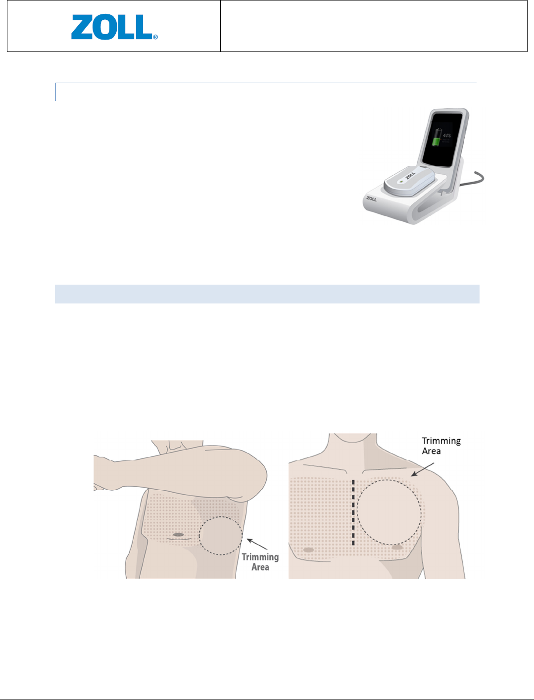
5.1.3 CHARGING THE GATEWAY – FIRST USE AND EVERY DAY
1. Place the Gateway on the Charger in its designated area.
2. The Gateway screen should light up and display it is being
charged. Once removed from the Charger, the Gateway
screen will display battery status in percent.
3. The Gateway, typically, takes about three hours to charge.
See Figure 9.
5.2 PREPARING THE SKIN
IMPORTANT: This step ensures good adhesion to skin.
1. Remove your bra/ undershirt.
2. If hair is present, trim hair at the Patch location indicated by your physician. See images
below.
3. Use provided Prep Wipes to clean area where Patch will be applied and allow skin to
dry.
Figure 9: Charging the
Gateway
Figure 10: Trimming area
CMCT Monitoring System
Instructions for Use
Page 15 of 31
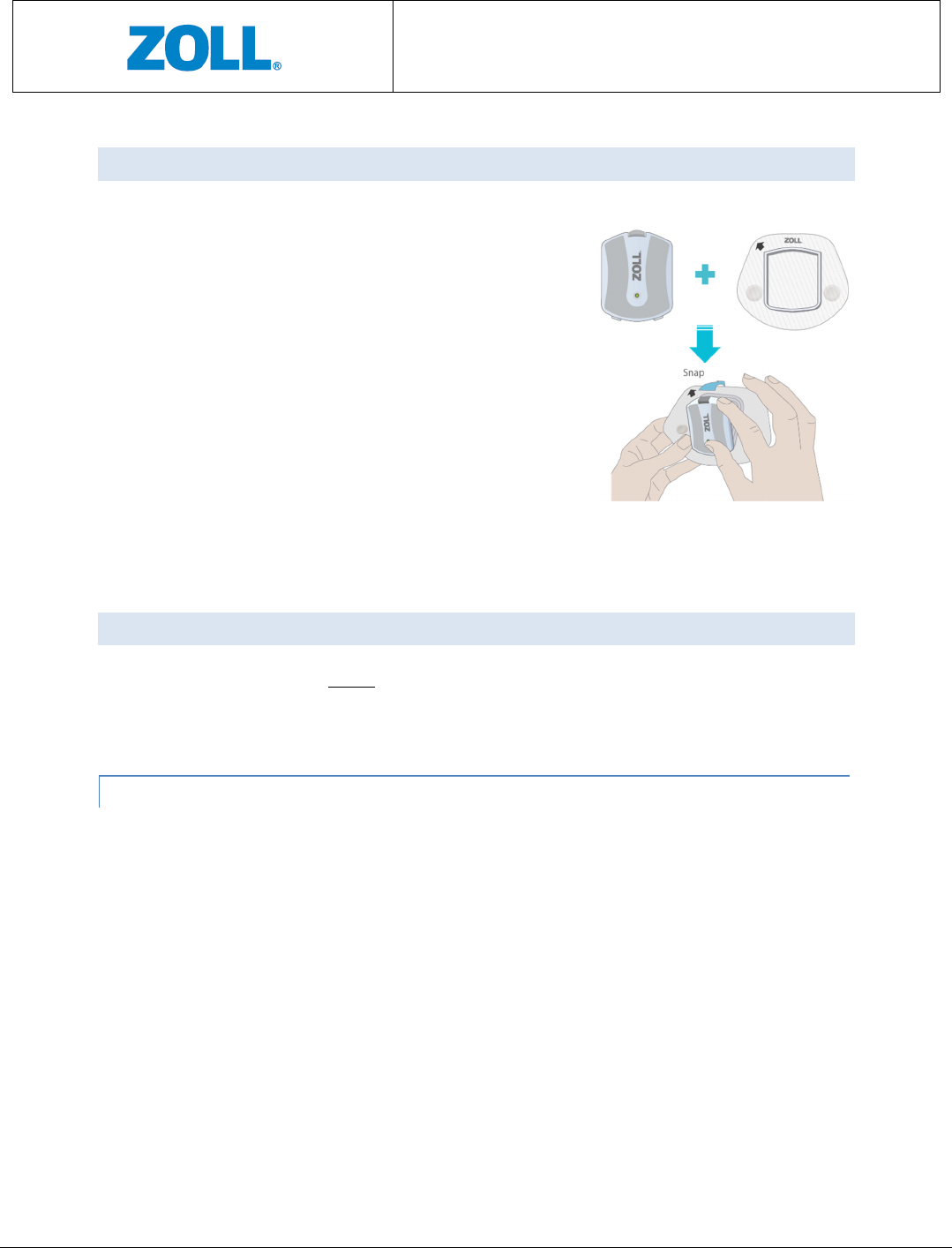
5.3 CONNECTING THE SENSOR TO THE PATCH
1. Remove the Sensor from the Charger.
2. Hold the Patch so that the word “ZOLL” on the Patch
is right-side up.
3. Place the lower tabs of the Sensor on the lower part
of the Patch frame.
4. Press the rest of the Sensor onto the Patch until you
hear a snap. The Sensor should be firmly attached to
the Patch.
See Figure 11.
5.4 APPLYING THE DEVICE
The device can be applied to either of the two locations detailed below. Once you wear the
device in one location, you will continue to wear the device at the same location for the entire
duration of your prescription.
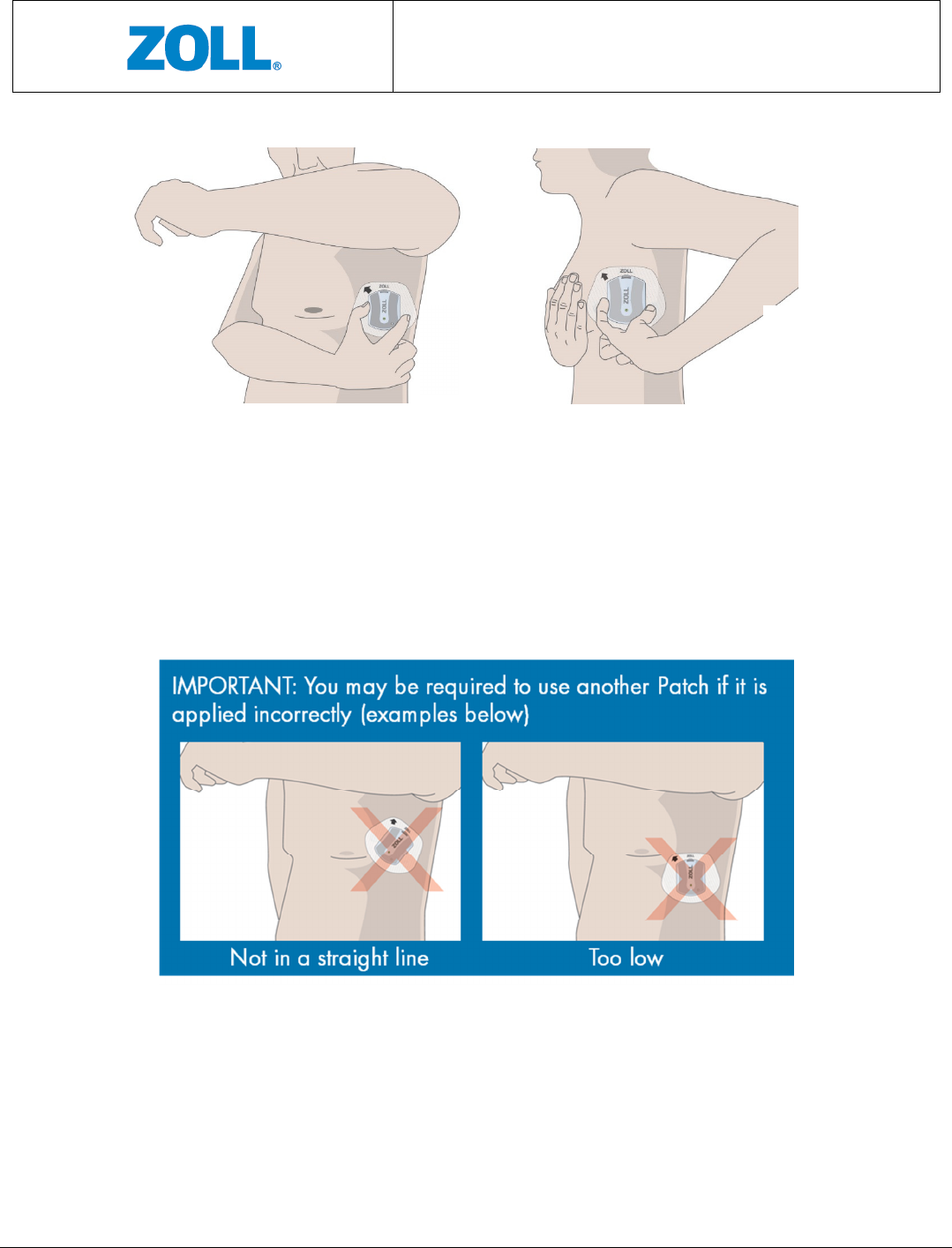
5.4.1 LEFT-SIDE LOCATION
1. Stand in front of a mirror.
2. Remove both parts of the Patch liner.
3. Turn the Patch so that the word “ZOLL” on the Patch is at the top.
4. Raise the left arm to shoulder height.
5. If needed, slightly move the breast aside when applying the Patch.
6. Place the Patch below the left arm pit with the nipple aligned anywhere between the
top and middle of the Sensor. See Figure 12.
7. Ensure the Patch is completely adhered to the skin.
Figure 11: Sensor Patch
attachment
CMCT Monitoring System
Instructions for Use
Page 16 of 31
8. Stay still and wait for a green light to appear on the Sensor, which signals it is ready to
monitor (refer to Section 6 Trouble Shooting if a blinking amber light appears instead).
Note that the green light will last for several seconds, after which the light indicator will
remain off. Figure 13 illustrates examples of incorrect device placements for the side
locations.
Figure 63: Side location incorrect placement
Figure
5
2: De
vice (Sensor + Patch) applied to left
-
side location
Left side
Left side

CMCT Monitoring System
Instructions for Use
Page 17 of 31
5.4.2 CHEST LOCATION
1. Stand in front of a mirror.
2. Remove both parts of the Patch liner.
3. Position the Patch on the upper left chest, just below the collarbone, and angle the
device towards the nipple. The arrow on the Patch should point up (↑). See Figure 14.
4. Ensure the Patch is completely adhered to the skin.
5. Stay still and wait for a green light to appear on the Sensor, which signals it is ready to
monitor (refer to Section 6 Troubleshooting if a blinking amber light appears instead).
Note that the green light will last for several seconds, after which the light indicator will
remain off.
6. Figure 15 illustrates examples of incorrect device placements for the front location.
Figure 8: Chest location incorrect placement
Figure
7
4: Device (Sensor + Patch) applied to front
CMCT Monitoring System
Instructions for Use
Page 18 of 31
5.5 HOW TO USE THE GATEWAY
1. Make sure to keep the Gateway not more that 10 meters
away from the body at all times to allow proper
communication with the Sensor.
• During the day, carry the Gateway with you
2. At night, keep the Gateway on a nightstand close to you
while you sleep
3. The Gateway may be turned ON and OFF manually by
pressing and holding the Power button for several
seconds.
• When boarding an airplane, make sure to turn the Gateway OFF to prevent
interference with aircraft systems.
• Otherwise, please keep the Gateway ON at all times to allow proper
communication with the Sensor.
4. Charge the Gateway daily, (for example, every night while you sleep)
• The Gateway takes about 3 hours to fully charge
• With an adequate charge, the Gateway can be used for up to 18 hours before
needing to be recharged.
See Figure 16.
5.6 REPLACING THE PATCH
5.6.1 REMOVE THE SENSOR FROM THE PATCH
1. Press the blue upper snap-in clip.
2. Tilt and remove the Sensor from the Patch while pressing the clip.
3. Place the Sensor in the Charger. Whenever the Sensor is not on the body, it should be
kept in the Charger.
5.6.2 REMOVE THE PATCH FROM THE BODY
1. Hold the skin with one hand while using the other to gently peel-off the Patch. You may
use a wet cloth to assist you in the process
F
igure
9
6: Gateway Charging
CMCT Monitoring System
Instructions for Use
Page 19 of 31
2. Discard the Patch immediately. Do not reuse.
If required, replace the Patch with a new one according to the instructions in Sections 6.2 to 6.4.
The Patch should be replaced at least once every five days. Make sure to place the new Patch
on the same spot (or as closely as possible to the location) of the previous Patch).
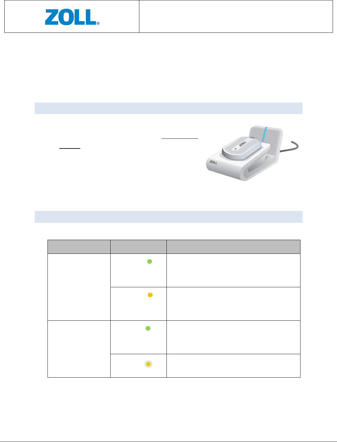
5.7 RECHARGING THE SENSOR
1. The Sensor should be charged every three days, or
with every replacement of the Patch, the sooner of
the two.
2. Place the Sensor in the Charger. See Figure 17.
The color of the light indicator on the Sensor will
be amber when being charged. It will turn green
when the Sensor is fully charged and ready to go.
5.8 SENSOR AND LIGHT INDICATOR STATUSES
The following is a summary of the light indicator statuses of the Sensor:
Sensor Position Light Color Meaning
Sensor in Charger
Solid green Battery is fully charged and is ready for use.
The solid green light will continue until the
Sensor is removed from the Charger.
Solid amber Battery is not full and is being charged. The
light will change to green once battery is
charged and Sensor is ready for use.
Sensor on the body
Solid green Sensor is ready for monitoring. This solid
green light will last for several seconds, after
which it will disappear.
Blinking
amber
Sensor error. Call ZOLL customer service at
1.888.592.3798.
Figure
10
7: Sensor
Charging
CMCT Monitoring System
Instructions for Use
Page 20 of 31
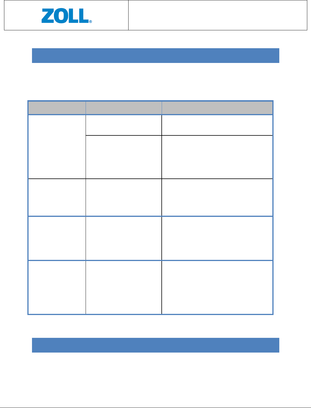
6 TROUBLESHOOTING
The following table lists the recommended actions for potential issues with the CMCT
System. Please call ZOLL at +972-9-9603900 if you need assistance with any of these
instructions
.
Signs Possible Causes Actions
Sensor light indicator
is not on while sitting
in the Charger for
charging.
The Sensor does not sit
properly in the Charger.
Remove the Sensor from the Charger and
reinsert back to the Charger.
The Charger is not connected
to the power outlet.
Plug in the Charger to the power outlet using
the power cable provided in the CMCT
packaging. When properly connected, the
light indicator on the Charger should be on
and is green.
Sensor light turns
blinking amber after
being applied on the
patient’s body.
Sensor Error. Contact ZOLL customer service
at
1.888.592.3798.
Charger light indicator
is not on.
The Charger is not connected
to the power outlet.
Plug in the Charger to the power outlet using
the power cable provided in the CMCT
packaging. When properly connected, the
light indicator on the Charger should be on
and is green.
The Gateway screen
does not indicate the
Gateway is being
charged while sitting
in the Charger for
charging.
The Gateway does not sit
properly in the Charger.
Remove the Gateway from the Charger and
reinsert back to the Charger.
7 CLEANING AND RETURN OF SYSTEM
Users are not required to clean the CMCT System. When the monitoring period is over, use
the box provided in the original packaging to return the CMCT System (Sensor, Charger,
Gateway, power cable, and any unused Patches) to ZOLL.
CMCT Monitoring System
Instructions for Use
Page 21 of 31
8 MAINTENANCE
Users are not required to perform any maintenance for the CMCT System.
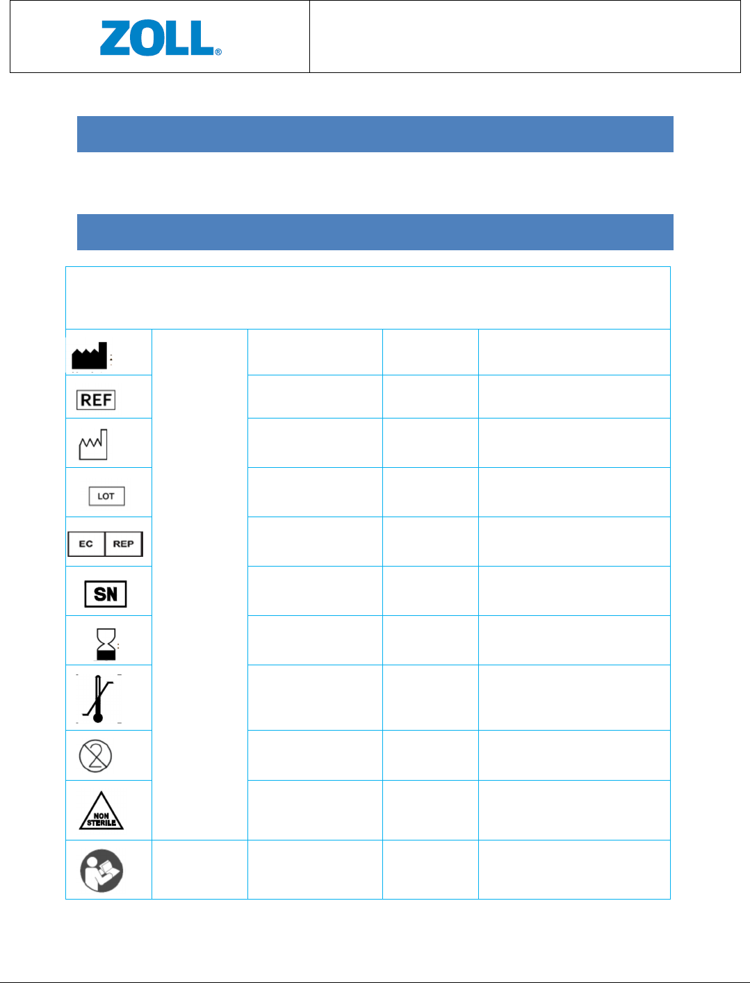
9 SYMBOLS GLOSSARY
Symbol
Title and
designation # of
the Standard
Title of Symbol Symbol Ref # Explanatory Text
ANSI/AAMI/ISO
15223-1:2012,
Medical devices
– Symbols to be
used with
medical device
labels, labeling
and information
to be supplied –
Part 1: General
requirements
Manufacturer 5.1.1 Device’s manufacturer.
Catalogue number 5.1.6 Product catalogue number.
Date of manufacturer 5.1.3 Date when the device was made.
Batch code 5.1.5 Batch or lot number for device
traceabiltiy.
European
representative
5.1.2 European representative
Serial number 5.1.7 Serial number for device
traceability.
Use-by date 5.1.4 Date after which the device is not
to be used.
Temperature limit 5.3.7 Storage temperature limits to
which the device can be safetly
exposed.
Do not re-use 5.4.2 The device is for single use only and
not to be re-used.
Non-sterile 5.2.7 The device is not sterile.
ANSI/AAMI
ES60601-
Refer to instruction
manual/booklet
#10 (Table D.2) See Instructions For Use.
CMCT Monitoring System
Instructions for Use
Page 22 of 31
1:2005/(R)2012
and A1:2012,
C1:2009/(R)201
2 and
A2:2010/(R)201
2, Medical
electrical
equipment –
Part 1: General
requirements
for basic safety
and essential
performance
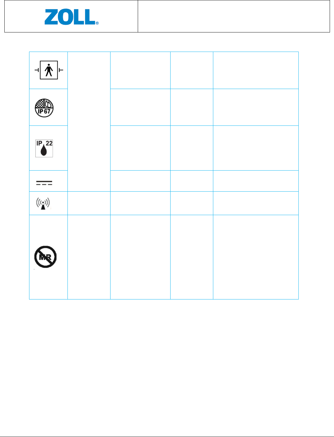
Type BF applied part #19 (Table D.1) Device intended to deliver
electrophysiological signal to or
from the patient.
Ingress protection #2 (Table D.3) Indicates that Sensor is protected
from light dust and against the
effects of temporary immersion in
water.
Ingress protection #2 (Table D.3) Indicates that the Gateway is
protected against solid foreign
objects of 12.5mm or greater, and
against vertically falling water
drops.
Direct current #5 (Table D.1) Direct current.
No-ionizing radiation Emits non-ionizing radiation
ASTM F2503-13,
Standard
practice for
marking
medical devices
and other items
for safety in the
magnetic
resonance
environment
MR Unsafe Figure 9 Indicates that the device may cause
unacceptable risks to the patients,
medical staff or other persons
within the MR environment. The
device should be removed prior to
any MR scanning procedure.

CMCT Monitoring System
Instructions for Use
Page 23 of 31
Part II:
Technical
Specifications
CMCT Monitoring System
Instructions for Use
Page 24 of 31
10 TECHNICAL SPECIFICATIONS
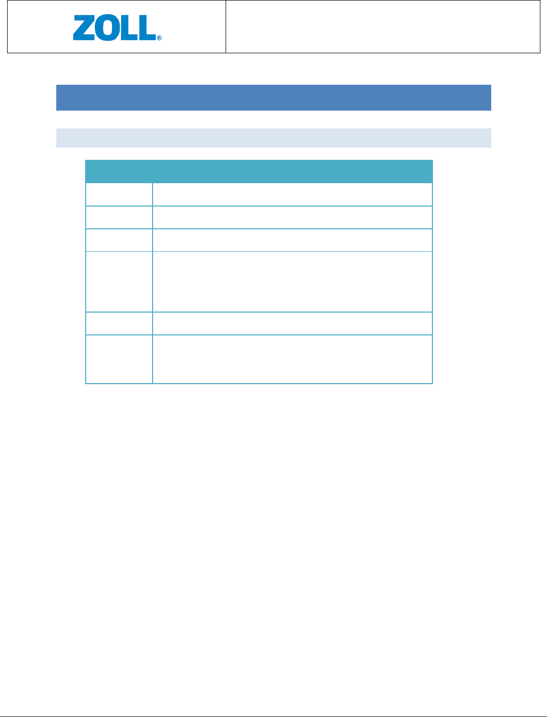
10.1 ACCURACIES
Parameter Measurement Accuracy
TFC* Error of less than 50cc fluid at a confidence level of 90%
HR Accuracy higher than ±2 bpm or ±2%, the higher of the two
RR Maximum error of ±2 bpm or 10% , the higher of the two
Activity Active vs resting accuracy > 99%
Walking time in hours per day. Error less than ±10% or ±5
minutes, the larger of the two.
Posture Posture classification accuracy > 90%
Arrhythmias
• QRS Sensitivity >99% PPV> 99%**
• VEB : Sensitivity > 94.9% PPV>93% **
• AF: Sensitivity > 93% PPV>86%***
*
As measured in experiments conducted in the laboratory
** Based on algorithm testing preformed using the AHA Database for Evaluation of Ventricular
Arrhythmia Detectors
*** Based on algorithm testing preformed using the MIT-BIH Arrhythmia Database
NOTE: Probability of acquiring p-waves signal is higher at the front location
Heart Rate Calculation
The CMCT system algorithm detects the peak of each R-wave and calculates the time interval
between successive R peaks known as the RR interval. Heart Rate is calculated based on a 60
second moving average time window. For each window where valid ECG was detected, Heart
Rate is computed in bpm as 60 divided by the average RR interval.
Pause Detection
The CMCT system algorithm is based on QRS detection. An RR interval longer than a
configurable threshold is a potential pause. Verified intervals are declared as pause.
CMCT Monitoring System
Instructions for Use
Page 25 of 31
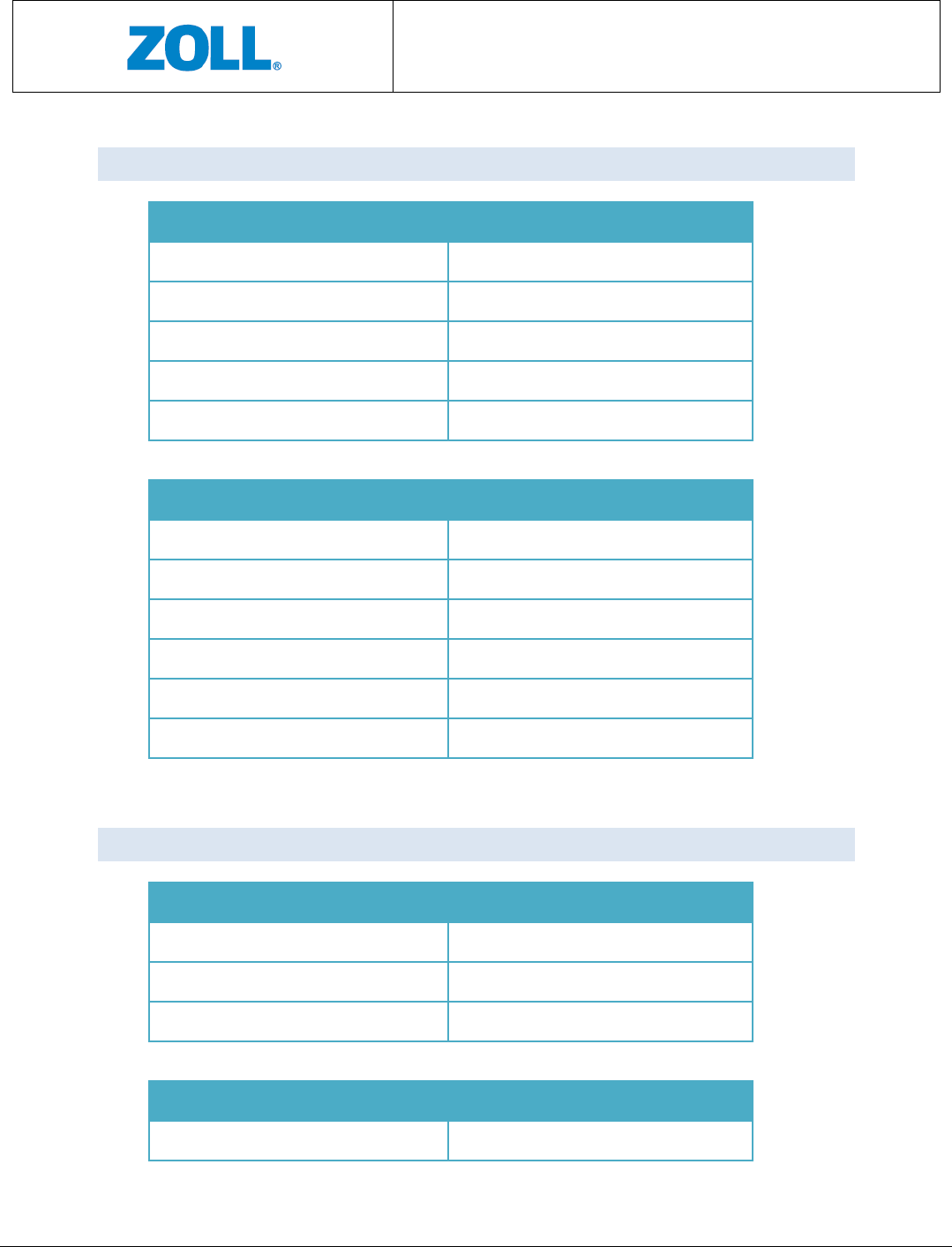
10.2 ELECTRICAL (POWER) REQUIREMENTS
Sensor
Max Power Consumption 0.85W
Nominal Power Consumption 0.02W
Max Rating 4.2V, 0.2A
Nominal Rating 3.7V, 0.01A
Battery Type Li-Pol, 3.7V, 1050mAh
Charger
Consumption during charging 14W
- Input (plug) 5VDC, 2.8A
Adapter
- Part Number UE24WCP1-050300SPA
- Input 100 to 240 VAC at 50/60Hz; 0.8A
- Output 5VDC; 3A
10.3 WIRELESS TRANSMISSION SPECIFICATIONS
Data Transmission
Sensor to Gateway Bluetooth (BT) 802.15, class 2
- BT Transmission Range 9 meters
Gateway to Server Internet
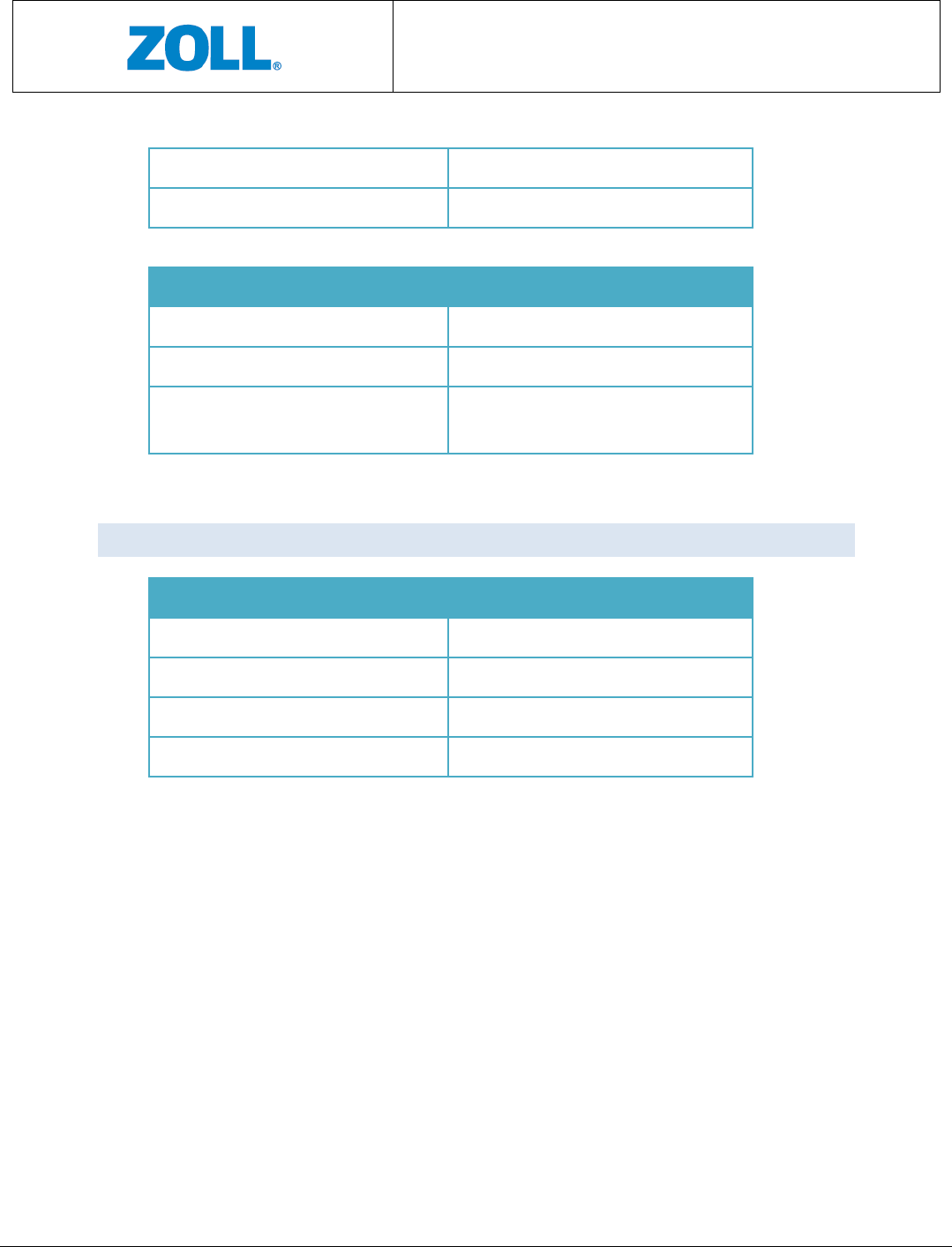
BT Transmission
Frequency range 2400-2483.5 MHz
CMCT Monitoring System
Instructions for Use
Page 26 of 31
Modulation GFSK; PSK
PEAK OUTPUT POWER 9 dBm
RF Sensor
Frequency range 0.5-2.5 GHz
Modulation CW
PEAK OUTPUT POWER -10dBm max. and below CISPR 11
levels
10.4 SENSOR DIMENSIONS
Sensor
Height 69 mm (2.72”)
Width 53.44 mm (2.10”)
Depth 15.96 mm (0.63”)
Weight 66 gram (0.145 lb)
CMCT Monitoring System
Instructions for Use
Page 27 of 31
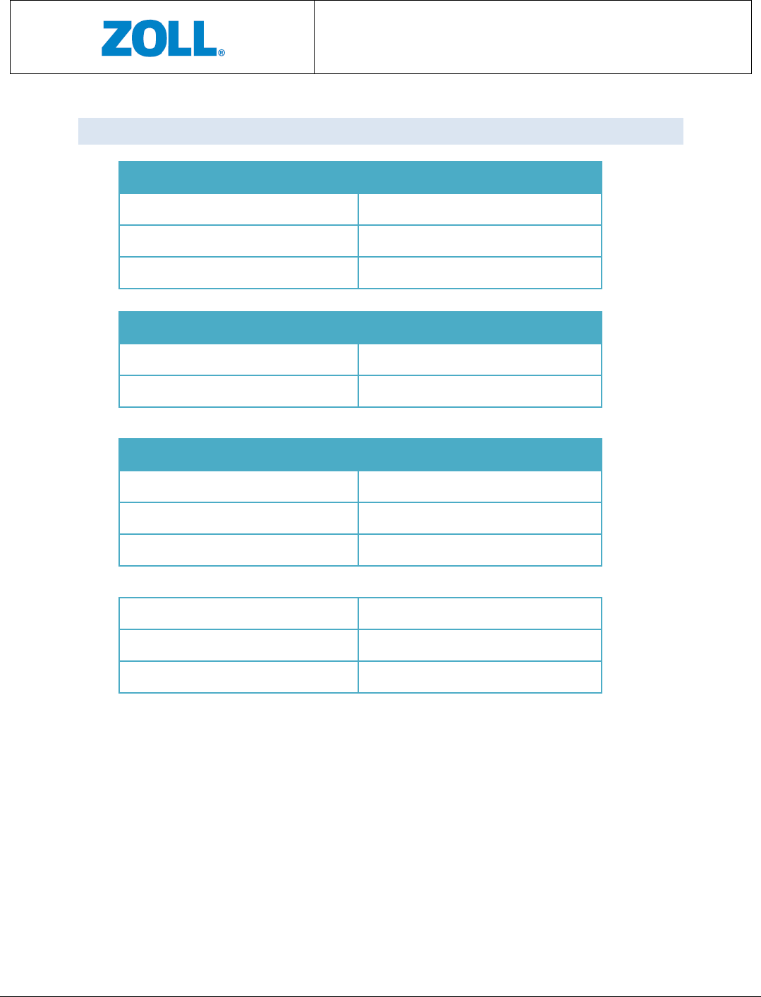
10.5 ENVIRONMENTAL & OTHER SPECIFICATIONS
Operating Conditions for the CMCT System
Temperature 0°C and 40°C (or 32°F and 104°F)
Relative humidity 5%-93% non-condensing
Pressure 700hPa to 1060hPa
Storage Conditions for the CMCT System
Temperature
10°C to 32°C (or 50°F to 89.6°F)
Relative Humidity 5%-93%, non-condensing
Shipping and Transport Conditions for the CMCT System
Temperature
-30°C to 60°C (or -22°F to 140°F)
Relative Humidity [RH%] 5%-93%
Pressure
700hPa to 1060hPa
Patch Shelf Life 1 year
Sensor Battery Life 2 years or 300 charging cycles
Sensor Battery Operation Time 3 days average
CMCT Monitoring System
Instructions for Use
Page 28 of 31
11 COMPLIANCES
11.1 ELECTRICAL SAFETY
• The device complies with IEC/EN 60601-1, Edition 3.1 for general requirements of
medical electrical equipment safety:
- Mode of operation: spot measurement
- Degree of mobility: portable
• The device complies with IEC 60601-1-11.
• The device complies with IEC 60601-2-47.
• The device complies with EC 57.
11.2 ELECTROMAGNETIC COMPATIBILITY (EMC)
• The device complies with IEC 60601-1-2, Edition 4, Class B.
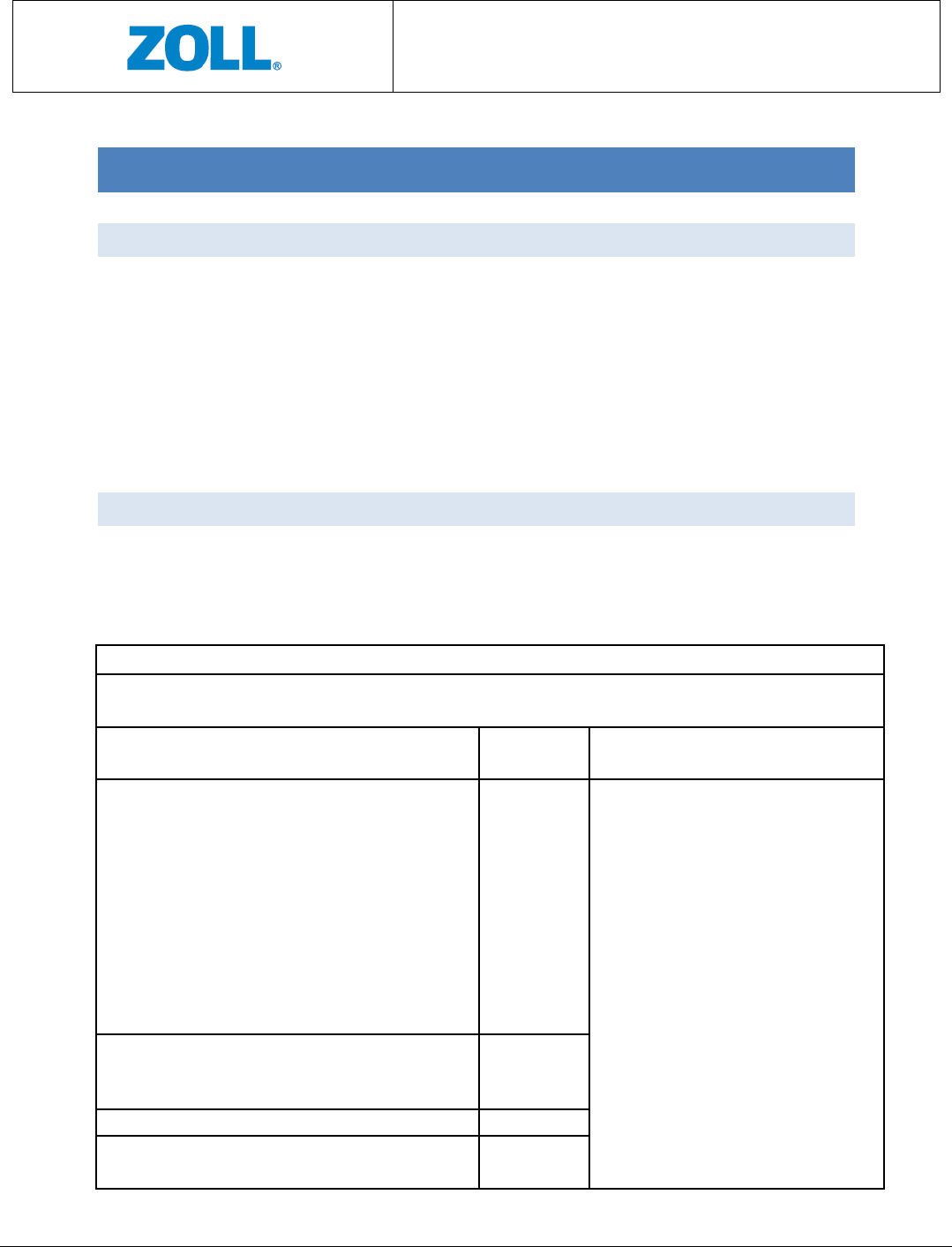
Guidance and Manufacturer’s Declaration – Electromagnetic Compatibility
Guidance and manufacturer’s declaration- electromagnetic emissions
The
CMCT
is intended for use in the electromagnetic environment specified below.
The customer or
the user of the CMCT should assure that it is used in such an environment.
Emissions Test Compliance
Electromagnetic environment-
guidance
RF emissions CISPR11
Class B
The CMCT isn’t suitable for
interconnection with other
equipment.
The CMCT is suitable for use in all
establishments other than
domestic establishments and
those
directly connected to the public
low voltage power supply network
that supplies buildings used for
domestic purposes.
Conducted Emissions from AC main
CISPR 11 Class B
Harmonic emissions IEC 61000
-
3
-
2
Class B
Voltage fluctuations/ flicker emissions
IEC 61000-3-3
Class B

CMCT Monitoring System
Instructions for Use
Page 29 of 31
Guidance and manufacturer’s declaration- electromagnetic immunity
The CMCT is intended for use in the electromagnetic environment specified below. The customer or
the user of the CMCT should assure that it is used in such an environment.
Immunity Test IEC 60601
Test Level
Compliance
Level
Electromagnetic environment-
guidance
Electrostatic discharge
IEC 61000-4-2
±8 kV contact
±15 kV air
±8 kV contact
±15 kV air
Floors should be wood, concrete or
ceramic tile. If floors are covered
with synthetic material, the relative
humidity should be at least 30%.
Immunity to Magnetic Field
IEC 61000-4-8
30 A/m ,
50Hz/60Hz
30 A/m Power frequency magnetic fields
should be at levels characteristic of a
typical location in a typical
commercial or hospital environment.
Electrical fast
transient/burst
IEC 61000-4-4
±2 kV, 100 kHz
Repetition
frequency
±2 kV
Mains power quality should be that
of a typical commercial or hospital
environment.
Conductive Surges
IEC 61000-4-5
±1 kV line to
line
±0.5, ±1 Mains power quality should be that
of a typical commercial or hospital
environment.
Conducted Disturbances
IEC 61000-4-6
3V frequency
0.15MHz-
80MHz
6V in ISM and
amateur radio
bands between
0.15MHz and
80MHz
3V
6V
Mains power quality should be that
of a typical commercial or hospital
environment.
Voltage Dips and Short
Interruptions
IEC 61000-4-11
0 %
U
T; 0,5
cycle
At 0°, 45°, 90
°, 135°, 180
°, 225°, 270
° and 315°
0 % UT; 1 cycle
and
70 % UT; 25/30
cycles
Single phase: at
0°
0 %
U
T; 0,5
cycle
At 0°, 45°, 90°,
135°, 180°,
225°, 270° and
315°.0 % UT; 1
cycle
and
70 % U
T; 25/30
cycles
Single phase:
at 0°
Mains power quality should be that
of a typical commercial or hospital
environment.
If the user of the device requires
continued operation during power
mains interruptions, it is
recommended that the device be
powered from an uninterruptible
power source.
CMCT Monitoring System
Instructions for Use
Page 30 of 31
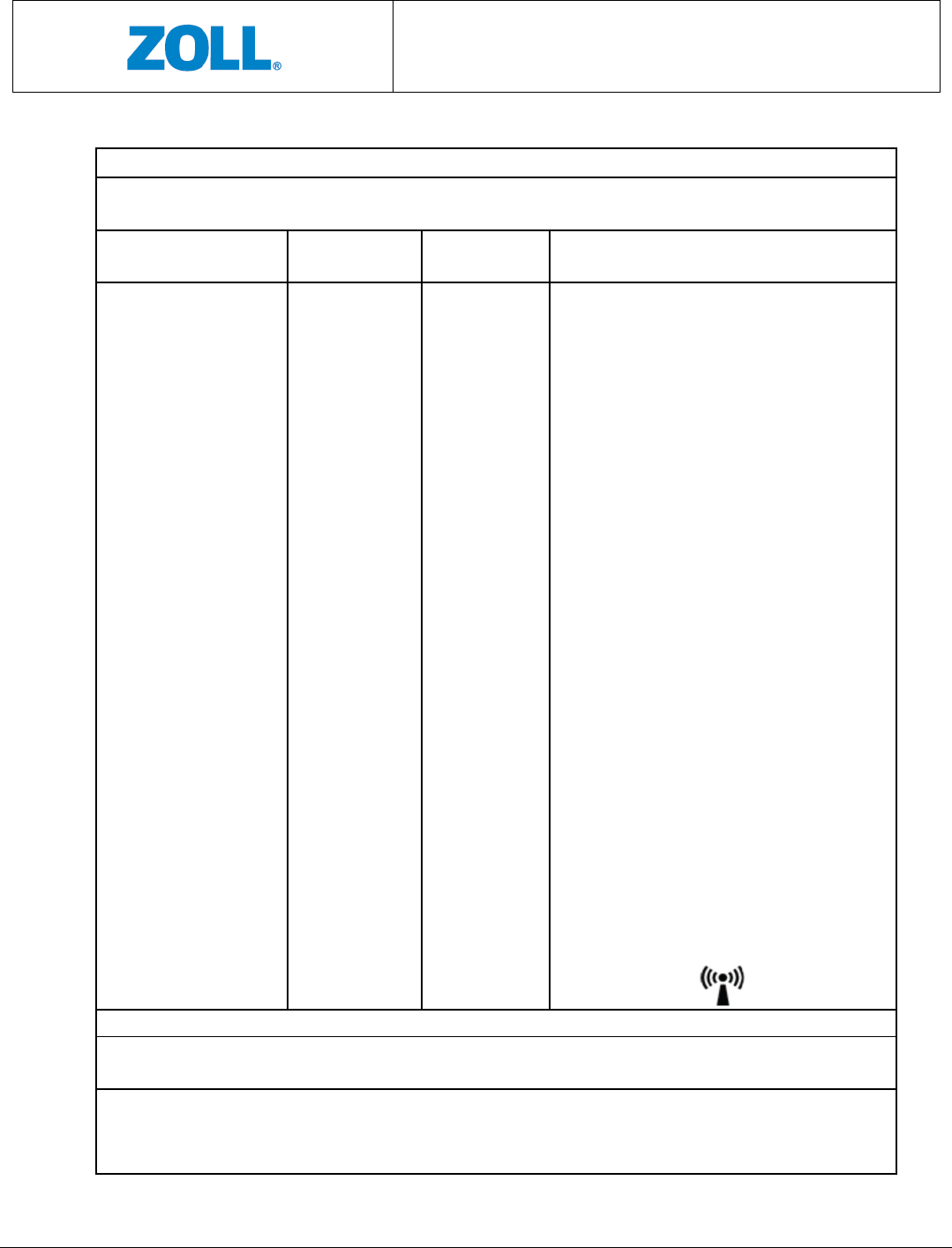
Guidance and manufacturer’s declaration- electromagnetic immunity
The
CMCT
is intended for use in the electromagnetic environment specified below.
The customer or
the user of the CMCT should assure that it is used in such an environment.
Immunity Test
IEC 60601 Test
Level
Compliance
Level
Electromagnetic environment- guidance
Radiated Immunity
IEC 61000-4-3
10 V/m,
frequency
80MHz-2500
MHz
358-5800MHz
PM
18Hz, 217Hz
10 V/m
9-28 V/m
Portable and mobile RF communications
equipment should be used no closer to
any part of the ZOLL CMCT including
cables, than the recommended separation
distance calculated from the equation
appropriate to the frequency of the
transmitter.
Recommend separation distance
d = 1.2 √P
d = 1.2 √P 80 MHz to 800 MHz
d = 2.3 √P 800 MHz to 2.5 GHz
where P is the maximum output power
rating of the transmitter in watts (W)
according to the transmitter
manufacturer and d is the recommended
separation distance in meters (m).
Field strengths from fixed RF transmitters
as determined by an electromagnetic site
survey,
a
should be less than the
compliance level in each frequency
range.
b
Interference may occur in the vicinity of
equipment marked with the following
symbol:
NOTE 1 At 80 MHz and 800 MHz, the higher frequency range applies.
NOTE 2 These guidelines may not apply in all situations. Electromagnetic propagation is affected by
absorption and reflection from structures, objects and people.
a
Field strengths from fixed transmitters, such as base stations for radio (cellular/cordless) telephones
and land mobile radios, amateur radio, AM and FM radio broadcast and TV broadcast cannot be
predicted theoretically with accuracy. To assess the electromagnetic environment due to fixed RF

CMCT Monitoring System
Instructions for Use
Page 31 of 31
transmitters, an electromagnetic site survey should be considered. If the measured field
strength in
the location in which the CMCT is used exceeds the applicable RF compliance level above, the CMCT
System should be observed to verify normal operation. If abnormal performance is observed,
additional measures may be necessary, such as re-orienting or relocating the CMCT.
b
Over the frequency range 150 kHz to 80 MHz, field strengths should be less than 10 V/m.
11.3 FCC COMPLIANCE STATEMENT
This device complies with part 15 of the FCC Rules. Operation is subject to the following
two conditions: (1) This device may not cause harmful interference, and (2) this device
must accept any interference received, including interference that may cause undesired
operation.
This equipment has been tested and found to comply with the limits for a Class B
digital device, pursuant to Part 15 of the FCC rules. These limits are designed to
provide reasonable protection against harmful interference in a residential
installation. This equipment generates, uses and can radiate radio frequency energy
and, if not installed and used in accordance with the instructions, may cause harmful
interference to radio communications. However, there is no guarantee that
interference will not occur in a particular installation. If this equipment does cause
harmful interference to radio or television reception, which can be determined by
turning the equipment off and on, the user is encouraged to try to correct the
interference by one or more of the following measures:
a) Reorient or relocate the receiving antenna.
b) Increase the separation between the equipment and receiver.
c) Connect the equipment to an outlet on a circuit different from that to which
the receiver is connected.
d) Consult the dealer or an experienced radio/TV technician.
Changes or modifications not expressly approved by the manufacturer could void the
user authority to operate the equipment under FCC Rules.
THE MANUFACTURER IS NOT RESPONSIBLE FOR ANY RADIO OR TV INTERFERENCE
CAUSED BY UNAUTHORIZED MODIFICATIONS TO THIS EQUIPMENT. SUCH
MODIFICATIONS COULD VOID THE USER’S AUTHORITY TO OPERATE THE EQUIPMENT.